Technical Service Manualmarking.com.ua/INSTRUKCII/MANUAL PRINTERA/Citronix ci Series...
175
The Citronix ciSeries Technical Service Manual Revision 1.11 Firmware Version 5.XXx Part Number: 012-1002-005
Transcript of Technical Service Manualmarking.com.ua/INSTRUKCII/MANUAL PRINTERA/Citronix ci Series...

The Citronix ciSeries
Technical Service Manual
Revision 1.11 Firmware Version 5.XXx
Part Number: 012-1002-005
ciSeries Technical Service Manual
Revision 1.11 Page 2
This manual explains how to install, program, replace components, service the machine and perform in depth troubleshooting for the Citronix ciSeries Continuous Ink Jet Systems. To the best of our knowledge, the information contained in this manual was correct at the time of printing. However, continual enhancement of our products can result in some differences between instructions represented in this manual and your ciSeries System. Citronix and Codes of Excellence are trademarks of Citronix. This guide was written by: Citronix Fort Worth, Texas 76140 USA www.citronix.com [email protected] © Copyright Citronix 2003 - 2009 All rights reserved. Reproducing this publication in whole or in part without written permission is expressly prohibited.
ciSeries Technical Service Manual
Revision 1.11 Page 3
DECLARATION of CONFORMITY
We: Citronix Located at: 3030 SE Loop 820 Fort Worth, Texas 76140 Tel: 817.568.9800 Fax: 817.568.1970 Email: [email protected] Declare under sole responsibility that the product identified herein, has been designed, manufactured and tested in accordance to the following European Council Directives: EN 61000-6-4:2001 Electromagnetic Compatibility (EMC). Generic Standards. Emission standard for industrial environments. EN61000-6-2:2001 Electromagnetic Compatibility (EMC). Generic Standards. Immunity Standard for industrial environments. EN55022-1 1998 Class A: Electromagnetic Compatibility (Radiated) EN60204-1:1998 Safety of Machinery – Electrical Equipment of Machines. General Requirements. EN60950:2000 Safety of Information Technology Equipment. 73/23/EEC: Low Voltage Directive as amended by 93/68/EEC and 2006/95/EEC 89/336/EEC: EMC Directive as amended by 92/31/EEC, 93/68/EEC and 2004/108/EEC Each Product marketed, is identical to the representative unit tested and found to be with the standards. Trade Name: Citronix Type of Product: Ink Jet Printing System Model: ci500, ci580, ci700, ci1000, ci2000 Fort Worth, Texas USA, 2008-12-12 *Original signed and available from local distributor* __________________________ Richard Fox President

ciSeries Technical Service Manual
Revision 1.11 Page 4
Marking form for the name of the contents and its concentration of toxic and hazardous substances or elements (Table 1)
(In accordance with SJ/T 11364 –2006)
Citronix has verified this product against the requirements of China Ministry of Information Industry, Order No 39 and has established that at the time of printing of this document, that there are certain items specified by the part numbers given in the table below, which have a concentration of one or more of the listed toxic or hazardous substances or elements specified in Order 39. Component Hazardous Substances or Elements or Assembly part number
Lead (Pb)
Cadmium (Cd)
Mercury (Hg)
Chromium VI Compounds (CR6+)
Polybrominated Biphenyls (PBB)
Polybrominated Diphenyl Ethers (PBDE)
PCB, CPU 004-2004-001 004-2005-001 004-2008-001
X
O
O
O
O
O
PCB, Phase Assy. 002-1073-002
X
O
O
O
O
O
Table 1
The presence of an “X” symbol in Table 1, indicates that one or more of the assemblies nominated in Table 1 above, contains a toxic and hazardous substance or element at a level which is above the limits specified in China EIP Standard SJ/T 11363 - 2006. When an “O” symbol is shown in any of the columns, this indicates that the particular substance or element is below the limits specified in China EIP standard SJ/T 11363 – 2006. Signed *Original signed and available from local distributor* Richard Fox President Citronix Signature Dated 27 December 2006

ciSeries Technical Service Manual
Revision 1.11 Page 5
有毒有害物质或元素名称及含量标识样式 (表1)
(依照SJ/T 11364 –2006标准)
Citronix_已查证过此产品不符合中华人民共和国信息产业部第39号令,此声明文件认定在以下
表格中所列零件号指明的组件存在第39号令中所规定的一种或多种有毒有害物质或元素的含量。 部件名称
或
装配零件号码
有毒有害物质或元素
铅
(Pb)
镉
(Cd)
汞
(Hg)
六价格
(CR6+)
多溴联苯
(PBB)
多溴二苯醚
(PBDE) PCB, CPU 004-2004-001 004-2005-001 004-2008-001
X
O
O
O
O
O
PCB, Phase Assy. 002-1073-002
X
O
O
O
O
O
表格1 表1中标注为“X”,表示在以上表格1中的一种或多种指定组件含有的有毒有害物质或元素含量超
出中国电子信息产品标准SJ/T 11363–2006规定的限量要求。 当任何一列中标注为“O”, 表示该种有毒有害物质或元素的含量在中国电子信息产品标准SJ/T
11363-2006规定的限量要求以下。 Signed *Original signed and available from local distributor* Richard Fox President Citronix Signature dated 27 December 2006

ciSeries Technical Service Manual
Revision 1.11 Page 6
Technical Service Manual Owner’s Record Manual Owner: ___________________ Date of Citronix Qualification: ___________________ Company: ___________________ Telephone: ___________________ Email: ___________________ Date Received: ___________________ Manual Update/Technical Bulletins (Bulletins should be located in the last section of this manual):
Date of Update Title of Technical Bulletin
ciSeries Technical Service Manual
Revision 1.11 Page 7
Table of Contents
Section Description Page Section 1 General Information 9
1.1 Welcome to the Citronix ciSeries System 1.2 Before Using this Manual 1.3 Safety Information
Section 2 ciSeries System Specification and Capabilities 11
2.1 ciSeries Controller 2.2 ciSeries Printhead 2.3 Consumable and Delivery 2.4 ciSeries Controller and Printhead Physical Characteristics 2.5 Print Speeds and Print Quality Charts 2.6 Dimension Drawings – ciSeries Controllers 2.7 Dimension Drawings – ciSeries Printheads
Section 3 System Installation 27
3.1 Installation Checklist 3.2 Mounting 3.3 Commission a ciSeries System 3.4 Connecting Peripherals and Communications 3.5 Connecting Power
Section 4 System Operation 34
4.1 Turning Power On / Off 4.2 Starting the Jet 4.3 Selecting a Print Message 4.4 Add Ink and Makeup Safety 4.5 Add Ink and Makeup 4.6 Shutting the System Down
Section 5 Programming 39
5.1 The Keyboard and Display 5.2 The Main Screen Display 5.3 Menu Operation 5.4 System Properties 5.5 Creating and Editing Messages 5.6 Graphic Editor 5.7 System Status Screen 5.8 Help Screen 5.9 System Error Screens 5.10 Service Screens and Settings 5.11 Remote Communications

ciSeries Technical Service Manual
Revision 1.11 Page 8
Section 6 Languages and Alternate Fonts 95 6.1 Alternate Fonts 6.2 Keyboard Swap 6.3 PINYIN (Simplified Chinese)
Section 7 Cleaning and Maintenance 106 7.1 Maintenance Chart 7.2 Check and Clean the Printhead 7.3 Backflush Routine 7.4 Clean Controller, Umbilical and Printhead Enclosures 7.5 Replace Air Filter 7.6 Replace Ink System Filters
Section 8 Technical Description and Troubleshooting 116
8.1 Introduction 8.2 The Printing Process 8.3 The Controller Enclosure 8.4 The User Interface 8.5 Electrical Components 8.6 Ink System 8.7 Printhead
Section 9 Service Routines 142
9.1 Changing or Cleaning the Nozzle Insert 9.2 Nozzle Alignment 9.3 Nozzle Cleaning Routine (Ultrasonic Bath) 9.4 Changing or Emptying Ink or Makeup Tank (ci1000) 9.5 Shipping / Long Term Storage Preparation 9.6 Changing the Ink System Pump 9.7 Changing / Cleaning an Ink System Valve and Gasket 9.8 Changing / Removing the Pressure Transducer 9.9 Changing / Cleaning the Pressure Restrictor 9.10 Changing / Cleaning the Venturi Restrictors
Section 10 Reference Information 156
10.1 Ink and Makeup Consumption 10.2 Shaft Encoder Assembly 10.3 ciSeries Installation Report and Checklist 10.4 Routine Cleaning and Maintenance 10.5 1200-2000/3-6 Month Scheduled Maintenance Checklist
Section 11 Fault Diagnosis 164
ciSeries Technical Service Manual
Revision 1.11 Page 9
Section 1 General Information
1.1 Welcome to the ciSeries Ink Jet Printing Systems
The Citronix ciSeries Continuous Ink Jet Printing Systems uniquely combine simplicity and performance. The systems feature an intuitive user interface.
What this This manual covers the following: manual covers:
• Safety information • Description of operation • Installation guidelines • Programming the system • Service configuration settings • Performing routine maintenance • Component replacement • Troubleshoot problems
Where to find Refer to the ciSeries Operation Guide for information about more information: basic operation and basic maintenance procedures.
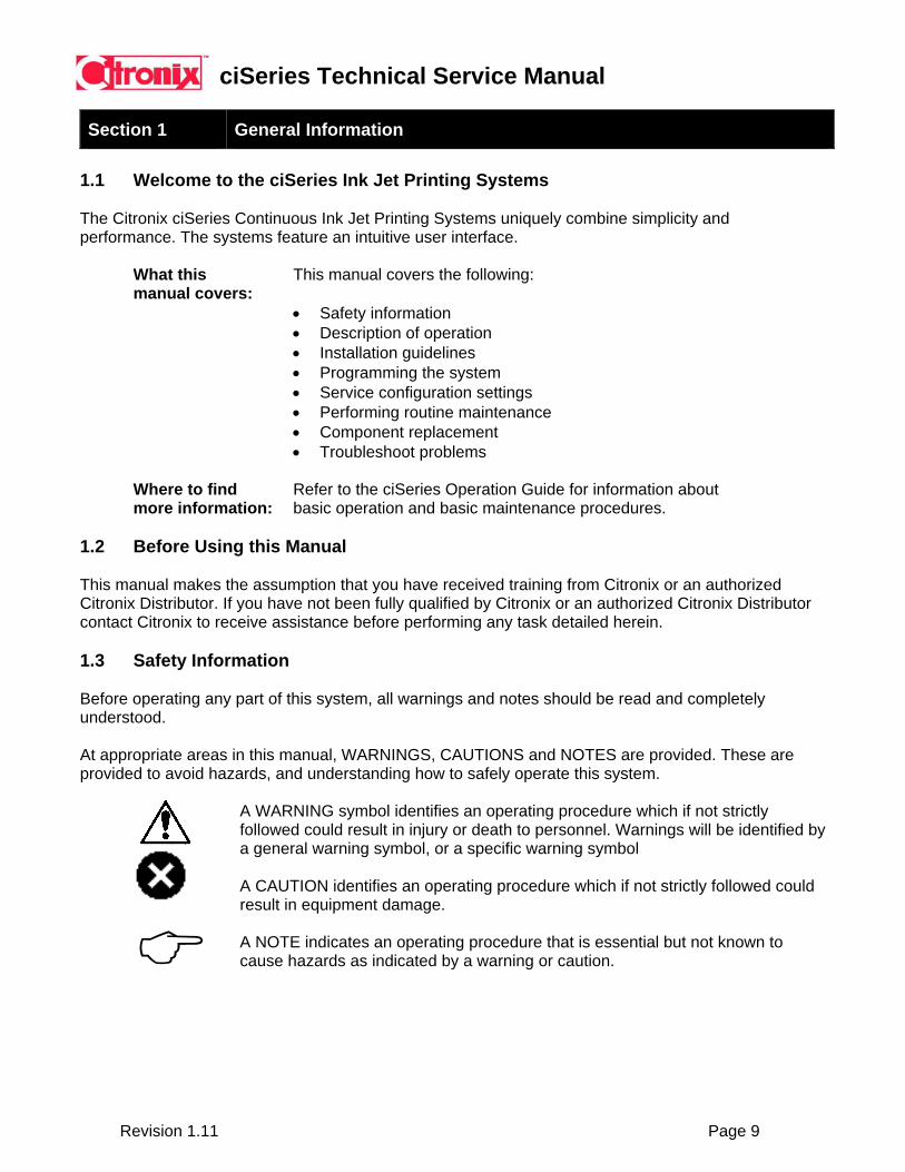
1.2 Before Using this Manual This manual makes the assumption that you have received training from Citronix or an authorized Citronix Distributor. If you have not been fully qualified by Citronix or an authorized Citronix Distributor contact Citronix to receive assistance before performing any task detailed herein. 1.3 Safety Information Before operating any part of this system, all warnings and notes should be read and completely understood. At appropriate areas in this manual, WARNINGS, CAUTIONS and NOTES are provided. These are provided to avoid hazards, and understanding how to safely operate this system.
A WARNING symbol identifies an operating procedure which if not strictly followed could result in injury or death to personnel. Warnings will be identified by a general warning symbol, or a specific warning symbol A CAUTION identifies an operating procedure which if not strictly followed could result in equipment damage. A NOTE indicates an operating procedure that is essential but not known to cause hazards as indicated by a warning or caution.
ciSeries Technical Service Manual
Revision 1.11 Page 10
The following WARNINGS should be read and understood by all personnel involved in the operation and maintenance of this system.
Specific WARNINGS:
PERSONAL INJURY: The system uses extremely high voltages only trained and authorized personnel must complete maintenance work. PERSONAL INJURY: Use goggles or face mask when using ink, makeup, or solvents to prevent from entering the eyes. FIRE HAZARD: The ink, makeup, and solvents are flammable, do not smoke or use a flame in the vicinity of the system, or chemicals. General WARNINGS: PERSONAL INJURY: Wear protective gloves and clothing when handling ink, makeup, or solvent. PERSONAL INJURY: Do not drink, ink, makeup, and solvents are poisonous if taken internally. PERSONAL INJURY: Prolonged exposure to ink, makeup, or solvent vapors may cause drowsiness and effects similar to alcohol intoxication. Use only in a well ventilated open areas. PERSONAL INJURY: Immediately after use remove paper towels or cloths that are saturated with ink, makeup, or solvent. Dispose of in a manner to ensure there is no danger of a fire or health hazard. WARNING: Experienced, trained personnel must perform electrical troubleshooting. WARNING: Remove power from the system prior to servicing.
Print Testing When test printing, to avoid the risk of fire, it is required that the ink used for printing be earthed to dissipate the charge that is applied during the print process. Use only metal containers with a wire connected to an earth point.
ciSeries Technical Service Manual
Revision 1.11 Page 11
Section 2 ciSeries System Specifications and Capabilities
2.1 ciSeries Controller
Hardware Single Printhead Control Dual Processor: Motorola Coldfire / DSP Speed: 66Mhz Memory: 4 Mbytes Flash/16 Mbytes RAM
Interface ci580 ci700 ci1000/ci2000
1 RS232 1 RS232 or RS485 1 Ethernet 1 RS232 1 RS232 or RS485 (1200 up to 115.2KB)
1 PS2 1 RS232 (1200 up to 115.2KB) 1 PS2 Inputs (opto-isolated, open collector or TTL type) ci580 1 photocell 1 shaft encoder ci700/ci1000/ci2000
2 photocell* 1 shaft encoder 6 programmable** *Programmable options for Photocell 2 **Remote message selection – 64 possible selections) Outputs 3 programmable alarms – warning and failure (Open Collector, 150mA sinking) Programmable dry contact relay External Power (+24VDC 500mA) Printhead Umbilical ci580 ci700 ci1000/ci2000 6 feet (2.5 Meter) 9 feet (3 Meter) 9 feet (3 Meter) or 15 feet (4.5 Meter)
User Interface and Firmware Capabilities Full size QWERTY keyboard Graphic downloadable Quarter VGA backlit graphical display Integrated graphic creator / editor
Intuitive icon based operation Automatic diagnostics WYSIWYG message editing Error and activity logs Drag / drop field based formatting Service reminders Message Storage – ci580 – 50 messages Tower Printing Functions ci700/ci1000/ci2000 - ~1000 messages Continuous print capability Single button start and stop operation Backup / restore functions Programmable Password security Multiple operator languages Real and expiration time and date coding Multi-national character printing (Unicode) Shift and rollover time and date coding Downloadable firmware updates (Ethernet) Product and batch counting coding ci1000/ci2000-internet browser interface Graphic Creation and Printing
ciSeries Technical Service Manual
Revision 1.11 Page 12
Operating Environment Temperature: 35 – 113 F (5 – 45 C)
% Relative Humidity: 10-90% (non-condensing)
Electrical Requirements Auto Ranging: 90-260VAC (3 Amp) Frequency: 50-60 Hz
2.2 ciSeries Printhead
Technology: Continuous Ink Jet (CIJ) Lines of Print: ci580 – 2 lines (16 pixel)
ci700 – 3 lines (25 pixel) ci1000 / ci2000 – 5 lines (31 pixel) Print: Text, Graphics, Bar codes Line Speed: See speed charts (section 2.5) Printhead Orientation: Omni-directional Image Height: ci580 macro drop size - .25” (6mm)-.50” (12mm)
ci700, ci1000, normal drop size – .10” (2.5mm)-.50” (12mm) ci2000 macro drop size – .25” (6mm)-.50” (12mm)
ci1000, ci2000 micro size – .025” (.6mm)-.25” (6mm) hs50 size - .06” (1.5mm)-.50” (12mm)
Throw Distance: ci580 macro drop size – up to 1.50” (38mm)
ci700, ci1000, normal drop size – up to .50” (12mm)
ci2000 macro drop size – up to 1.50” (38mm)
ci1000/ci2000 micro size - up to .25” (6mm) hs50 - up to .50” (12mm)
All models feature automatic maintenance and cleaning at startup and shutdown.
2.3 Consumable and Delivery
Ink Types: Full range – MEK, Ethanol, Acetone Ink Colors: Black, Red, Blue, Yellow, Green, White, UV Ink Dry Time: Quick dry to immediate Ink Bottles: 16oz (473ml) Makeup Bottles: 16oz (473ml) Fluid Capacities: ci580 – 32 oz (1L)
ci700/ci1000/ci2000 - 64oz (1.9L)
ciSeries Technical Service Manual
Revision 1.11 Page 13
2.4 ciSeries Controller and Printhead Physical Characteristics: ci580 ci700
Enclosure: Painted Steel Stainless Steel Environmental: Nema 4 (IP55) Nema 4 (IP55) Weight Controller: 40 lbs 43lbs Weight Printhead: 2lbs 2lbs
ci1000 ci2000
Enclosure: Stainless Steel Stainless Steel Environmental: Nema 4 (IP55) Nema 4X (IP65) Weight Controller: 43 lbs 45lbs Weight Printhead: 2lbs 2lbs

ciSeries Technical Service Manual
Revision 1.11 Page 14
2.5 Print Speeds and Print Quality Charts
The line speed at which the product passes the printhead will affect print quality. The following pages show how to determine the maximum line speeds per print quality setting.
When determining the ciSeries settings for the application, the following needs to be considered:
- Line Speed - Pixel Setting (vertical resolution) - Print Resolution (horizontal resolution or raster pitch) - Whether using an external or internal (autoprint) encoder
Based on the above, the best Print Quality (speed) setting should be chosen.
ciSeries Technical Service Manual
Revision 1.11 Page 15
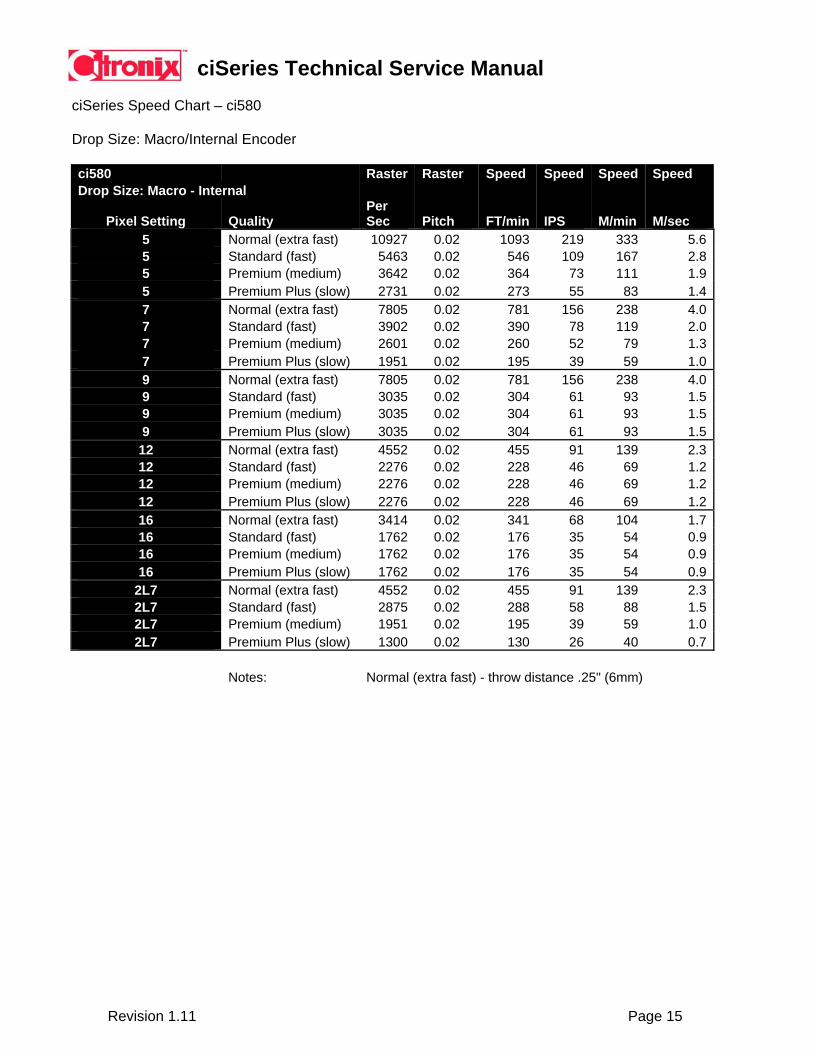
ciSeries Speed Chart – ci580 Drop Size: Macro/Internal Encoder
ci580 Raster Raster Speed Speed Speed Speed Drop Size: Macro - Internal
Pixel Setting Quality Per Sec Pitch FT/min IPS M/min M/sec
5 Normal (extra fast) 10927 0.02 1093 219 333 5.65 Standard (fast) 5463 0.02 546 109 167 2.85 Premium (medium) 3642 0.02 364 73 111 1.95 Premium Plus (slow) 2731 0.02 273 55 83 1.47 Normal (extra fast) 7805 0.02 781 156 238 4.07 Standard (fast) 3902 0.02 390 78 119 2.07 Premium (medium) 2601 0.02 260 52 79 1.37 Premium Plus (slow) 1951 0.02 195 39 59 1.09 Normal (extra fast) 7805 0.02 781 156 238 4.09 Standard (fast) 3035 0.02 304 61 93 1.59 Premium (medium) 3035 0.02 304 61 93 1.59 Premium Plus (slow) 3035 0.02 304 61 93 1.512 Normal (extra fast) 4552 0.02 455 91 139 2.312 Standard (fast) 2276 0.02 228 46 69 1.212 Premium (medium) 2276 0.02 228 46 69 1.212 Premium Plus (slow) 2276 0.02 228 46 69 1.216 Normal (extra fast) 3414 0.02 341 68 104 1.716 Standard (fast) 1762 0.02 176 35 54 0.916 Premium (medium) 1762 0.02 176 35 54 0.916 Premium Plus (slow) 1762 0.02 176 35 54 0.9
2L7 Normal (extra fast) 4552 0.02 455 91 139 2.32L7 Standard (fast) 2875 0.02 288 58 88 1.52L7 Premium (medium) 1951 0.02 195 39 59 1.02L7 Premium Plus (slow) 1300 0.02 130 26 40 0.7
Notes: Normal (extra fast) - throw distance .25" (6mm)
ciSeries Technical Service Manual
Revision 1.11 Page 16
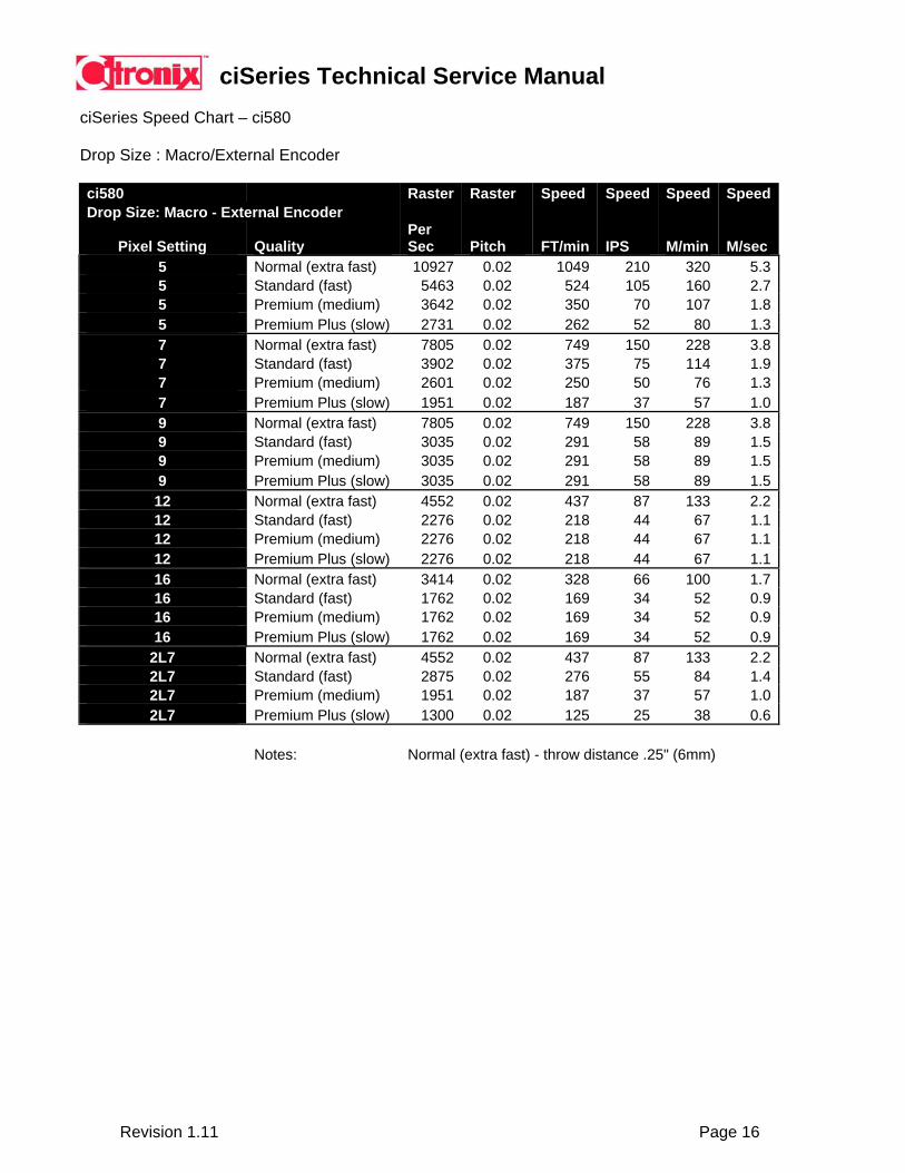
ciSeries Speed Chart – ci580 Drop Size : Macro/External Encoder
ci580 Raster Raster Speed Speed Speed SpeedDrop Size: Macro - External Encoder
Pixel Setting Quality Per Sec Pitch FT/min IPS M/min M/sec
5 Normal (extra fast) 10927 0.02 1049 210 320 5.35 Standard (fast) 5463 0.02 524 105 160 2.75 Premium (medium) 3642 0.02 350 70 107 1.85 Premium Plus (slow) 2731 0.02 262 52 80 1.37 Normal (extra fast) 7805 0.02 749 150 228 3.87 Standard (fast) 3902 0.02 375 75 114 1.97 Premium (medium) 2601 0.02 250 50 76 1.37 Premium Plus (slow) 1951 0.02 187 37 57 1.09 Normal (extra fast) 7805 0.02 749 150 228 3.89 Standard (fast) 3035 0.02 291 58 89 1.59 Premium (medium) 3035 0.02 291 58 89 1.59 Premium Plus (slow) 3035 0.02 291 58 89 1.512 Normal (extra fast) 4552 0.02 437 87 133 2.212 Standard (fast) 2276 0.02 218 44 67 1.112 Premium (medium) 2276 0.02 218 44 67 1.112 Premium Plus (slow) 2276 0.02 218 44 67 1.116 Normal (extra fast) 3414 0.02 328 66 100 1.716 Standard (fast) 1762 0.02 169 34 52 0.916 Premium (medium) 1762 0.02 169 34 52 0.916 Premium Plus (slow) 1762 0.02 169 34 52 0.9
2L7 Normal (extra fast) 4552 0.02 437 87 133 2.22L7 Standard (fast) 2875 0.02 276 55 84 1.42L7 Premium (medium) 1951 0.02 187 37 57 1.02L7 Premium Plus (slow) 1300 0.02 125 25 38 0.6
Notes: Normal (extra fast) - throw distance .25" (6mm)
ciSeries Technical Service Manual
Revision 1.11 Page 17
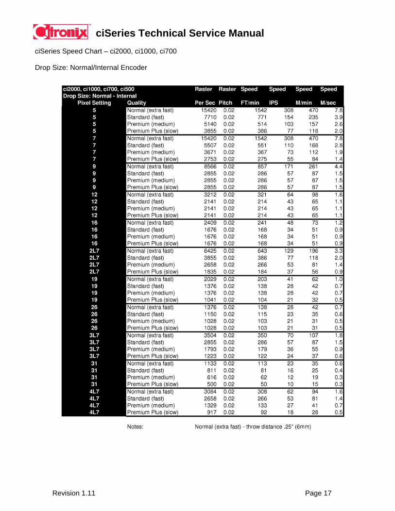
ciSeries Speed Chart – ci2000, ci1000, ci700
Drop Size: Normal/Internal Encoder

ciSeries Technical Service Manual
Revision 1.11 Page 18
ciSeries Speed Chart – ci2000, ci1000, ci700
Drop Size: Normal/External Encoder

ciSeries Technical Service Manual
Revision 1.11 Page 19
ciSeries Speed Chart – ci2000, ci1000, ci700
Drop Size: Macro/Internal Encoder
ciSeries Technical Service Manual
Revision 1.11 Page 20
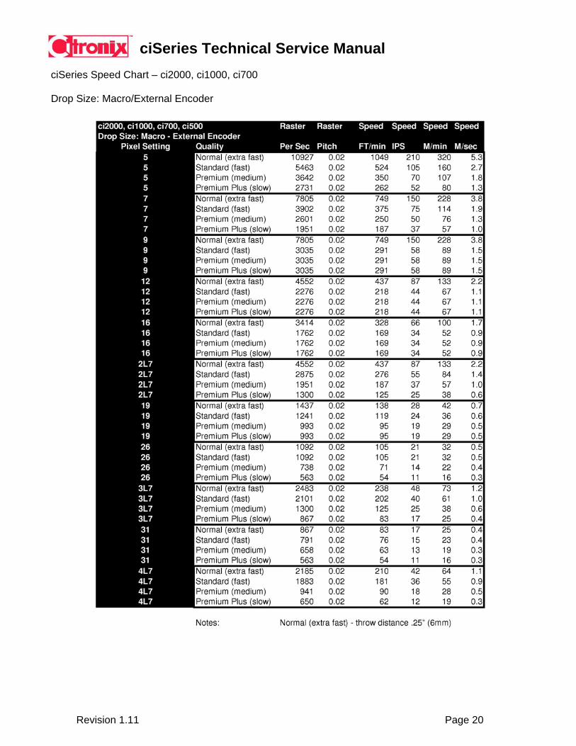
ciSeries Speed Chart – ci2000, ci1000, ci700
Drop Size: Macro/External Encoder
ciSeries Technical Service Manual
Revision 1.11 Page 21
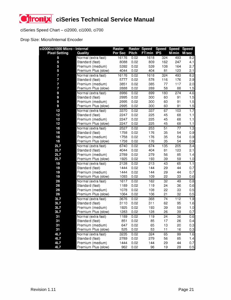
ciSeries Speed Chart – ci2000, ci1000, ci700
Drop Size: Micro/Internal Encoder
ciSeries Technical Service Manual
Revision 1.11 Page 22
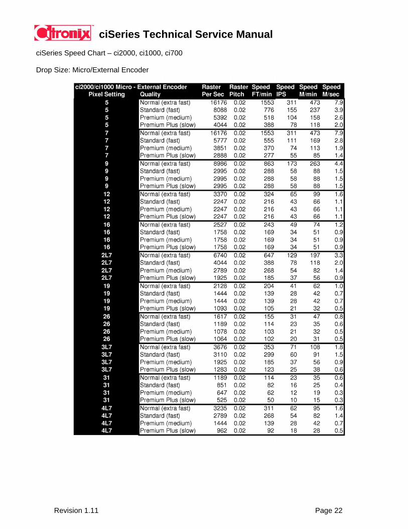
ciSeries Speed Chart – ci2000, ci1000, ci700
Drop Size: Micro/External Encoder

ciSeries Technical Service Manual
Revision 1.11 Page 23
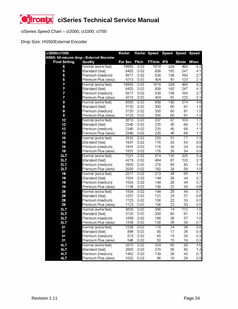
ciSeries Speed Chart – ci2000, ci1000, ci700 Drop Size: HS50/Internal Encoder
ciSeries Technical Service Manual
Revision 1.11 Page 24
ciSeries Speed Chart – ci2000, ci1000, ci700 Drop Size: HS50/External Encoder
ciSeries Technical Service Manual
Revision 1.11 Page 25
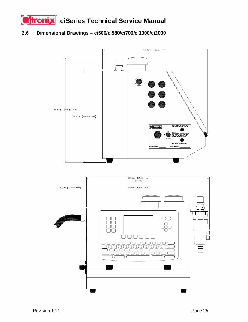
2.6 Dimensional Drawings – ci500/ci580/ci700/ci1000/ci2000
ciSeries Technical Service Manual
Revision 1.11 Page 26
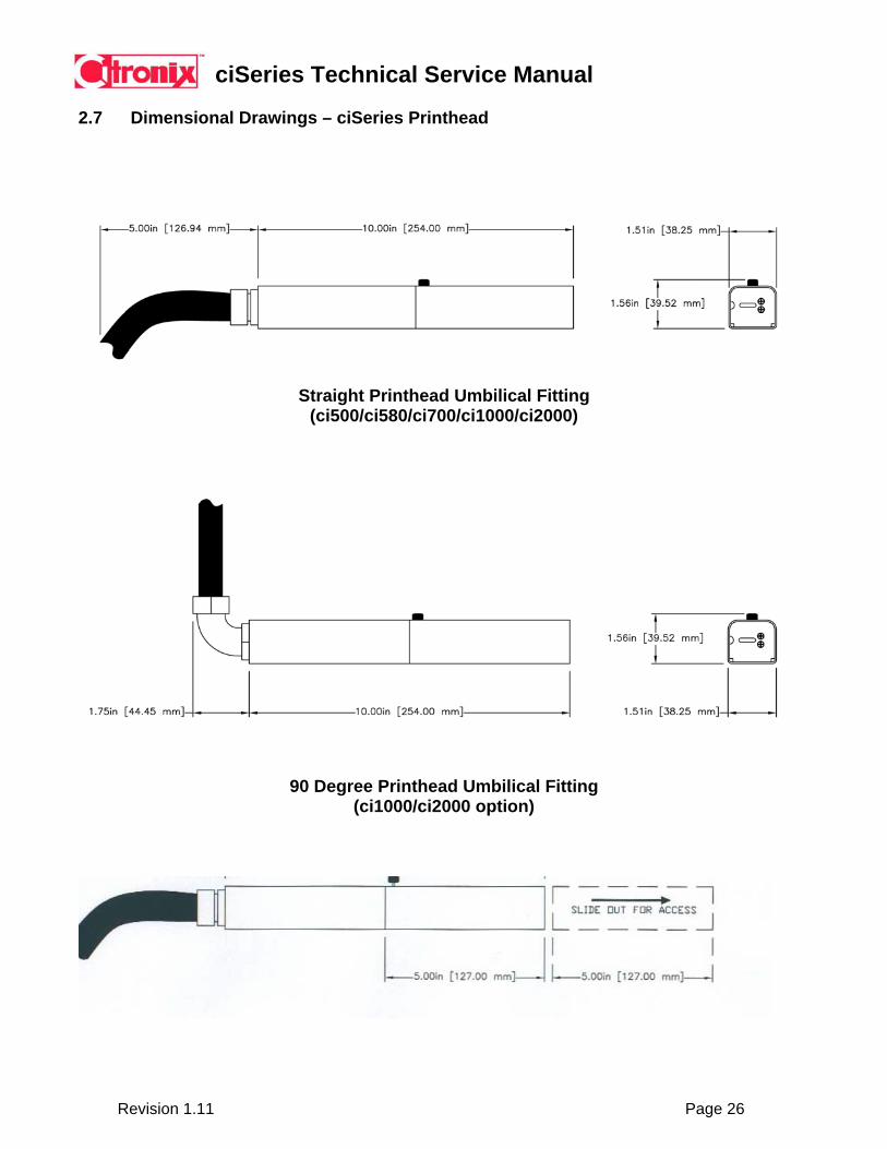
2.7 Dimensional Drawings – ciSeries Printhead
Straight Printhead Umbilical Fitting
(ci500/ci580/ci700/ci1000/ci2000)
90 Degree Printhead Umbilical Fitting
(ci1000/ci2000 option)

ciSeries Technical Service Manual
Revision 1.11 Page 27
Section 3 System Installation
3.1 Installation Checklist
Consider the following when mounting / installing a ciSeries printer:
• Ensure a dedicated power source is available. • Ensure the controller and printhead will be accessible for maintenance. • Ensure printhead can be mounted solid to minimize vibration. • Ensure the distance from the printhead to the controller is within 9 feet (3Meters)
or an optional printhead umbilical length distance. • Ensure the photocell can be mounted with or close to the printhead. • Ensure positive air kit is installed in dusty environments or wet environments. • Ensure a method to collect waste is provided / instructed when cleaning the
printhead.
Install, mount and configure the system in the order indicated.
1. _____ Un-pack all equipment and check against packing slip 2. _____ Install Bracket Components – floor stand, conveyor side bracket, controller cart
3. _____ Install Printhead Wash Station (optional) 4. _____ Mount Photocell
5. _____ Mount Shaft Encoder (optional)
6. _____ Mount Alarm Beacon (optional)
7. _____ Install Integral Positive Air Kit or External Positive Air (optional)
8. _____ Mount Printhead
9. _____ Setup / Mount Controller
10. _____ Connect Peripherals – photocell, shaft encoder, alarm beacon, remote communications
11. _____ Connect Power
12. _____ Initialize System (Turn Power On)
13. _____ Commission the ciSeries Ink System – see page 28.
14. _____ Setup System Properties
15. _____ Setup Application Properties
16. _____ Setup Message Default Values
17. _____ Create Messages 18. _____ Start Printing
19. _____ Establish and program Filter Times for the application.
20. _____ Document all printer settings, leave a copy with the customer and keep a copy for your office 21. _____ Perform an Operating and Technical Training

ciSeries Technical Service Manual
Revision 1.11 Page 28
3.2 Mounting ciSeries Controller
A ciSeries controller should be positioned on a sturdy tabletop surface. The controller contains four rubber feet that raise the controller off the mounting surface allowing air circulation through the bottom of the controller for proper operation. Citronix offers an open shelf portable cart for this purpose.
Dimensional illustrations in section 2 indicate the area required for normal operation and servicing of a ciSeries system.
NOTE: If alternative mounting is used, it is necessary to allow ventilation at the bottom of the controller. Allow a minimum of ½” (12mm) area.
The controller as standard can be mounted up to 9 feet (3 meters) from the print process location. Optional printhead umbilical lengths are available to allow mounting at further distances.
Printhead
The ciSeries printhead should be installed in a manner to ensure there is no movement during the print process. The printhead should be positioned at an optimum throw distance based on the printhead type being used – see Technical Specifications. The printhead can print in any orientation allowing for top down, side coding, or bottom coding applications. Citronix offers a printhead stand or conveyor side bracket kit for this purpose.
NOTE: Positioning the printhead too close to the substrate can cause drop splash back resulting in ink build-up in the printhead that could result in frequent system errors. NOTE: The printhead should be positioned no greater than 5 feet (1.5 meter) above or below the controller.
The printhead as standard can be mounted up to 9 feet (3 meters) from a ciSeries controller. Optional printhead umbilical lengths are available to allow mounting at further distances.
Dimensional illustrations in Section 2 should be used to determine the area required for normal operation and servicing of a ciSeries printhead.
ciSeries Technical Service Manual
Revision 1.11 Page 29
Photocell
The photocell is used as a method to detect the product requiring marking or coding allowing the ciSeries to know when to print. The photocell should be fixed mounted with a close relationship to the printhead. Placement of the photocell should be positioned to allow a minimum print delay to minimize the time used for the print process. This is important in high speed or high throughput applications.
NOTE: Excess delay will result in printing every other product. In this event, move the photocell closer to the printhead. The optimum location is directly in line with the printhead = Delay 0.
NOTE: Multiple photocell types are available depending on the product being sensed. Use of the incorrect photocell type can result in improper detection and misplaced or inconsistent print location. Contact Citronix for a review of your application to assist determining the correct photocell type.
Citronix photocells are delivered with mounting hardware to allow mounting to the printhead floor stand or conveyor side bracket kit.
Shaft Encoder
A shaft encoder is used to detect the speed of the product to allow the print to occur at the same speed as the product. Shaft encoders are typically used in variable speed applications as the speed may vary.
The shaft encoder assembly contains four mounting holes to allow fix mounting and adaptation to particular applications. Dimensional illustrations in Section 8 detail the area required for normal operation. Alarm Beacon
Citronix alarm beacons provide notification to the operator when an error has occurred. Three alarm beacons are offered – single, dual and three stage. The single stage alarm beacon provides a red flashing light in any error condition; the two-stage alarm beacon provides a red flashing light when the system has any error condition and a yellow light when a warning condition is present and the three stage provides an additional green light when there are NO error conditions or warnings (the three stage beacon utilizes the solid state relay connection in addition to the alarm connection).
The alarm beacon should be fixed mounted with a close relationship to the printhead or controller. The alarm beacon is delivered with mounting hardware to allow fix mounting to the printhead floor stand or conveyor side bracket kit. Integral Positive Air Kit or Connecting External Air Source
The Citronix Integral Positive Air Kit delivers clean, dry air from the electronics compartment of the controller to the ciSeries printhead.
The pump system is automatically turned-on when the jet is started and turned off 4 minutes after a jet stop process. This lengthens the life of the air pump. The pump is rated for 4,000 hours.
ciSeries Technical Service Manual
Revision 1.11 Page 30
Floor Stand The floor stand provides mounting of a ciSeries printhead to the floor. Assembly instructions are included. Conveyor Side Bracket Kit The conveyor side bracket kit provides mounting of a ciSeries printhead to a conveyor. Assembly instructions are included.
ciSeries Technical Service Manual
Revision 1.11 Page 31
3.3 Commission a new ciSeries System
To commission a ciSeries Ink System an understanding of basic operating procedures is required.
Step 1: Insert three bottles of ink / makeup (wait until emptied before removing).
NOTE: Filling reservoirs with less than three bottles prior to starting may cause damage.
Step 2: Start Jet – will need to start / stop jet a minimum of 3 (3) times to eliminate air from system.
Step 2a: In the event the jet misses the Gutter – perform a nozzle cleaning
and possibly a Backflush will be required. Multiple cleanings or Backflush procedures may be required to start correctly for the first time.
Step 3: Monitor Viscometer operation over a period of 2 hours to ensure correct
operation.
ciSeries Technical Service Manual
Revision 1.11 Page 32
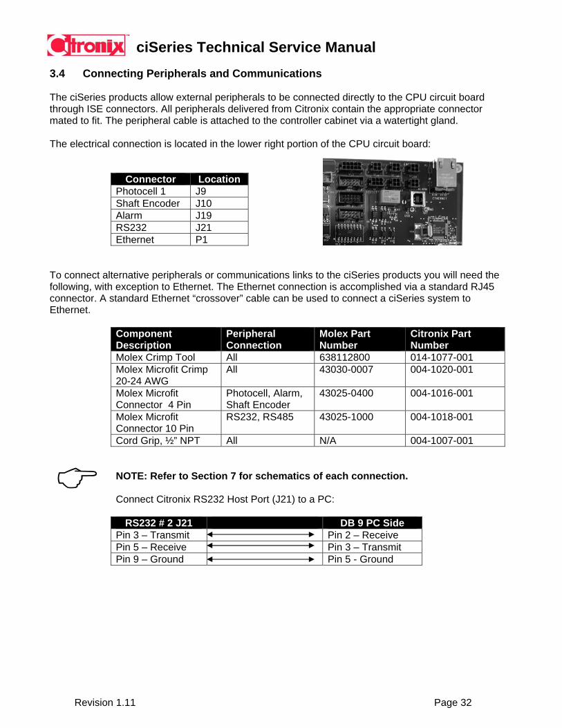
3.4 Connecting Peripherals and Communications
The ciSeries products allow external peripherals to be connected directly to the CPU circuit board through ISE connectors. All peripherals delivered from Citronix contain the appropriate connector mated to fit. The peripheral cable is attached to the controller cabinet via a watertight gland.
The electrical connection is located in the lower right portion of the CPU circuit board:
Connector Location Photocell 1 J9 Shaft Encoder J10 Alarm J19 RS232 J21 Ethernet P1
To connect alternative peripherals or communications links to the ciSeries products you will need the following, with exception to Ethernet. The Ethernet connection is accomplished via a standard RJ45 connector. A standard Ethernet “crossover” cable can be used to connect a ciSeries system to Ethernet.
Component Description
Peripheral Connection
Molex Part Number
Citronix Part Number
Molex Crimp Tool All 638112800 014-1077-001 Molex Microfit Crimp 20-24 AWG
All 43030-0007 004-1020-001
Molex Microfit Connector 4 Pin
Photocell, Alarm, Shaft Encoder
43025-0400 004-1016-001
Molex Microfit Connector 10 Pin
RS232, RS485 43025-1000 004-1018-001
Cord Grip, ½” NPT All N/A 004-1007-001 NOTE: Refer to Section 7 for schematics of each connection. Connect Citronix RS232 Host Port (J21) to a PC:
RS232 # 2 J21 DB 9 PC Side Pin 3 – Transmit Pin 2 – Receive Pin 5 – Receive Pin 3 – Transmit Pin 9 – Ground Pin 5 - Ground

ciSeries Technical Service Manual
Revision 1.11 Page 33
3.5 Connecting Power Connect the power cord to a suitable power source as indicated below:
Single Phase - 90VAC (3 amp) to 260VAC (1 amp) Frequency - 50/60 Hz
The socket-outlet shall be installed near the equipment and shall be easily accessible.
Due to the variety of plugs used worldwide, the power cords that ship with ciSeries systems are currently limited to standard US plug, standard European plug or standard United Kingdom plug. If you need a power cord with a different type of plug, purchase a power cord approved by local government or identified with an HAR (Harmonized Standard) label.
NOTE: To help protect and ensure reliable performance from your system, Citronix recommends the use of a surge suppressor, line conditioner, uninterruptible power supply and dedicated line from the main power source.
WARNING: THIS PRINTER MUST BE EARTHED/GROUNDED.
Installing an Alternate Power Cord
1) Remove existing power cord delivered with the system. 2) As the colors on the main leads of this equipment may not correspond with the
markings identifying the terminals on your plug, proceed as follows:
• The green and yellow wire must be connected to the terminal colored green and yellow, or marked with the earth symbol.
• The blue wire must be connected to the terminal colored blue or marked
“neutral”.
• The brown wire must be connected to the terminal colored brown or marked “live”.

ciSeries Technical Service Manual
Revision 1.11 Page 34
Section 4 System Operation 4.1 Turning Power On / Off
The power switch is located on the left hand side of a ciSeries controller.
Power Switch ON Power Switch OFF Powering the System On Turning the power switch to the ON position powers and initializes the system. After the initialization screen appears, the Citronix Main Screen will appear.
Powering the System Off
The system does not require the power switch to be turned off, unless the system is not going to be used for a lengthy period of time (several days). The power switch should be left in the ON position over weekends or short periods of non-use. Refer to Shutting the System Down for more information.
CAUTION: DO NOT TURN THE POWER SWITCH OFF WITHOUT SHUTTING DOWN THE JET.

ciSeries Technical Service Manual
Revision 1.11 Page 35
4.2 Starting the Jet
After powering on the system, the jet must be started to print. To start the Jet, press the START key. “Jet Start” will appear in the upper right hand corner of the screen and a timer will countdown in the lower right hand corner. This timer will display the time remaining until jet is started. Other screens and/or functions may be accessed while the jet is starting.
After the start process is complete, a graphic in the upper right hand corner of the screen displays that the jet is on.
NOTE: If system indicates a Phase, Charge, Gutter, or HV Trip error, perform a Daily Printhead Cleaning routine. If error persists, potentially a Backflush Routine can correct. See Cleaning and Maintenance.
ciSeries Technical Service Manual
Revision 1.11 Page 36
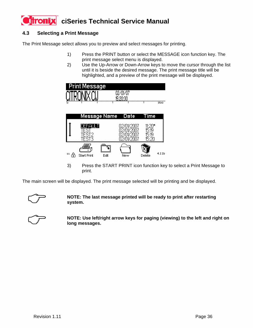
4.3 Selecting a Print Message
The Print Message select allows you to preview and select messages for printing.
1) Press the PRINT button or select the MESSAGE icon function key. The
print message select menu is displayed. 2) Use the Up-Arrow or Down-Arrow keys to move the cursor through the list
until it is beside the desired message. The print message title will be highlighted, and a preview of the print message will be displayed.
3) Press the START PRINT icon function key to select a Print Message to print.
The main screen will be displayed. The print message selected will be printing and be displayed.
NOTE: The last message printed will be ready to print after restarting system. NOTE: Use left/right arrow keys for paging (viewing) to the left and right on long messages.
ciSeries Technical Service Manual
Revision 1.11 Page 37
4.4 Add Ink and Makeup Safety
PERSONAL INJURY: Do not remove foil seal on bottle prior to filling. EQUIPMENT DAMAGE: Ensure ink and makeup being used has the same part number as indicated on the machine ink and makeup labels. EQUIPMENT DAMAGE: Do not fill ink or makeup reservoirs unless the ink low, ink out or makeup low, makeup out message is displayed. EQUIPMENT DAMAGE: Do not insert makeup in ink filler assembly, or ink in makeup filler assembly.
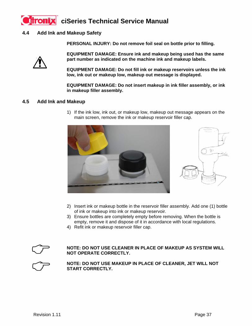
4.5 Add Ink and Makeup
1) If the ink low, ink out, or makeup low, makeup out message appears on the main screen, remove the ink or makeup reservoir filler cap.
2) Insert ink or makeup bottle in the reservoir filler assembly. Add one (1) bottle of ink or makeup into ink or makeup reservoir.
3) Ensure bottles are completely empty before removing. When the bottle is empty, remove it and dispose of it in accordance with local regulations.
4) Refit ink or makeup reservoir filler cap.
NOTE: DO NOT USE CLEANER IN PLACE OF MAKEUP AS SYSTEM WILL NOT OPERATE CORRECTLY. NOTE: DO NOT USE MAKEUP IN PLACE OF CLEANER, JET WILL NOT START CORRECTLY.
ciSeries Technical Service Manual
Revision 1.11 Page 38
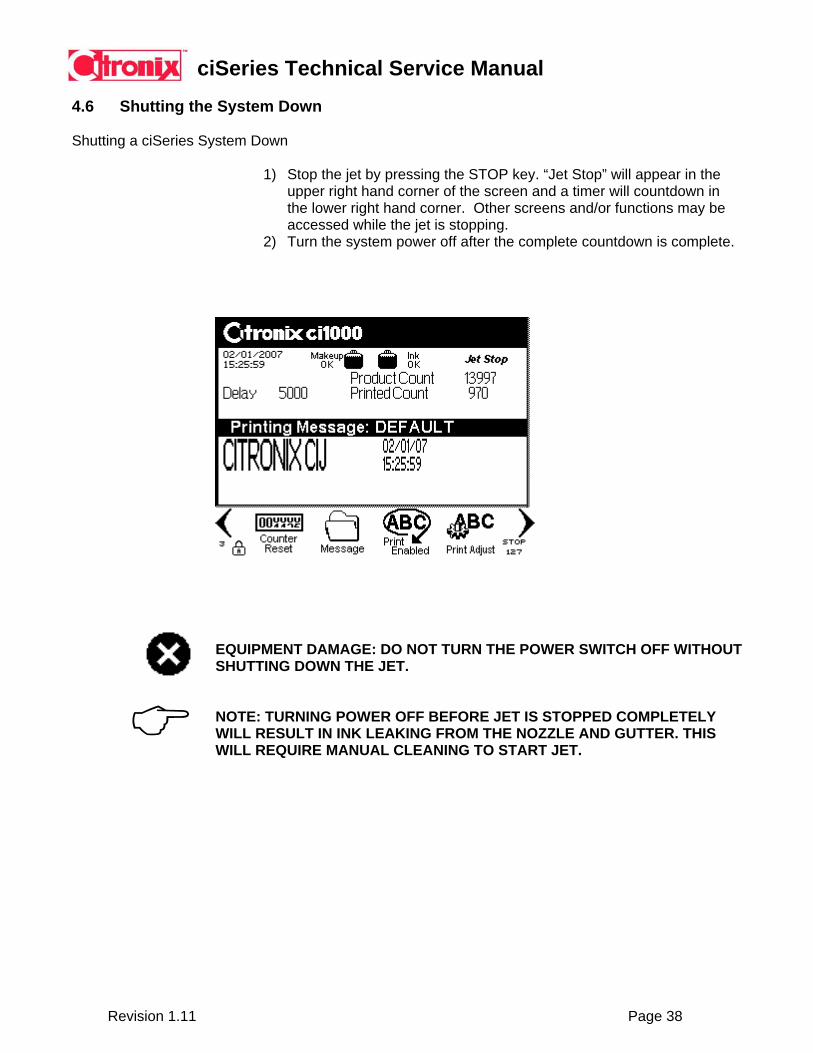
4.6 Shutting the System Down
Shutting a ciSeries System Down
1) Stop the jet by pressing the STOP key. “Jet Stop” will appear in the
upper right hand corner of the screen and a timer will countdown in the lower right hand corner. Other screens and/or functions may be accessed while the jet is stopping.
2) Turn the system power off after the complete countdown is complete.
EQUIPMENT DAMAGE: DO NOT TURN THE POWER SWITCH OFF WITHOUT SHUTTING DOWN THE JET. NOTE: TURNING POWER OFF BEFORE JET IS STOPPED COMPLETELY WILL RESULT IN INK LEAKING FROM THE NOZZLE AND GUTTER. THIS WILL REQUIRE MANUAL CLEANING TO START JET.

ciSeries Technical Service Manual
Revision 1.11 Page 39
Section 5 Programming 5.1 The Keyboard and Display
On the front of the controller is the user interface made up of a display and a keyboard. The display and keyboard are used to control and program the system.
The keyboard is comprised of several keys for operation:
• Alphanumeric and special character keys in QWERTY form are used for programming.
• Operation keys are used for moving around during programming. • Icon function keys are used for operation.
Operation Keys Icon Keys Up Arrow Moves cursor up Start Starts the jet Down Arrow Moves cursor down Stop Stops the jet Right Arrow Moves cursor right Menu Listing of commands Left Arrow Moves cursor left Properties System setup Function Selects icons on display Help Help with programming Enter Selects or saves changes Edit Edit the selected message Escape Aborts changes Print Select a message to print Delete Deletes character behind cursor Delay Enter print delay value Caps Lock Toggles upper/lower case Bold Enter message bold value Shift Toggles upper/lower case Width Enter message width value Alt 1 Selects special characters Status View system status Alt 2 Selects special characters Service System service functions Space Enter space into message Security Login/logout of system Accent Selects accent marks for characters
Menu Key
Display
Setup Key
Function Keys
Arrow Keys
Help Key
Icon Keys
Jet On/Off Keys
ciSeries Technical Service Manual
Revision 1.11 Page 40
5.2 Main Screen Display
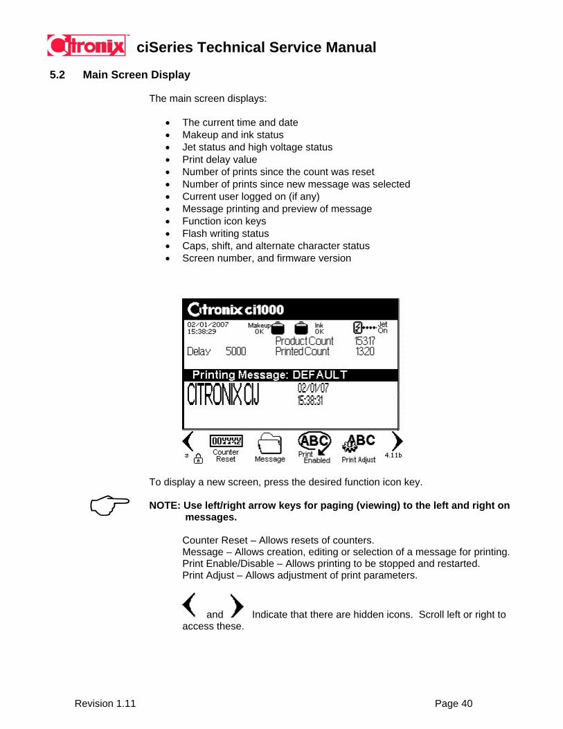
The main screen displays:
• The current time and date • Makeup and ink status • Jet status and high voltage status • Print delay value • Number of prints since the count was reset • Number of prints since new message was selected • Current user logged on (if any) • Message printing and preview of message • Function icon keys • Flash writing status • Caps, shift, and alternate character status • Screen number, and firmware version
To display a new screen, press the desired function icon key. NOTE: Use left/right arrow keys for paging (viewing) to the left and right on
long messages. Counter Reset – Allows resets of counters. Message – Allows creation, editing or selection of a message for printing. Print Enable/Disable – Allows printing to be stopped and restarted. Print Adjust – Allows adjustment of print parameters.
and Indicate that there are hidden icons. Scroll left or right to access these.

ciSeries Technical Service Manual
Revision 1.11 Page 41
Graphic Edit – Opens the on-board graphic editor. Backflush – Begins a system backflush (See Section 6). Backflush is only enabled is Jet is off and Printhead Cover is open.
NOTE: When the clock graphic is displayed in the lower left hand corner the system is writing information to flash. Recent changes made will not be saved if system is shutdown while writing to flash.
Print Trigger – Triggers the machine to print one time for diagnostics. Active Alarms – Displays any alarm conditions currently active. Message Sequence – Allows messages to be added or deleted from a sequence. See Message Sequence Section ___ for detailed instructions.

ciSeries Technical Service Manual
Revision 1.11 Page 42
5.3 Menu Operation
The menu icon key provides an alternative method to gain quick access to printer functions. Press the Menu icon key the following screen is displayed:
Use the up / down arrow keys to highlight the desired function. Upon highlighting the desired function, press the ENTER key, or press the ESCAPE to escape the menu.
5.4 System Properties
The Properties function icon key enters the system setup screens. Enter specific information related to the application.
NOTE: All settings and values listed are the factory defaults. Use the up / down arrow keys to highlight the desired setting. Upon highlighting the desired setting, press the right arrow key to toggle through the options, or a pop-up box will open to allow entry of the desired setting. Use the delete/backspace keys to assist during entry of the desired setting value. Press ENTER to save the settings, ESCAPE to abort the changes.

ciSeries Technical Service Manual
Revision 1.11 Page 43
System Properties
Settings Action Options Time Set current time HH:MM:SS Date Set current date MM/DA/YYYY Date Format Set display date format MMDDYYY, DDMMYYY or YYYYMMDD Measurement Set display measurement
format USCS or Metric
Language Set display language English, Spanish, French, German, Italian, Chinese, Russian, Bulgarian, Arabic, Vietnamese, Korean, Polish, Turkish, Thai, Hebrew, Greek, Danish, Swedish, Norwegian, Finnish, Brazilian Portuguese, Romanian, Dutch, Japanese
Security Turn security on / off On/Off Global Lock Set message settings format On/Off
On = message settings are global Off = message settings are per message
Alternate Fonts Allows use of languages using a non-Roman font set
On/Off On allows Chinese, Arabic, Vietnamese, Korean, and Russian font sets
Rollover Set a rollover time Set a positive or negative HH:MM when the date will change (before or after midnight)
Icon Keys Function Application Setup screen for specific application properties. Interface Setup screen for host communication interface (RS232, RS485). Message Setup screen message default values for all future new messages. Security Setup screen for security – user and password. Alarm Setup Setup alarm 1, alarm 2, alarm 3 and relay functionality.
ciSeries Technical Service Manual
Revision 1.11 Page 44
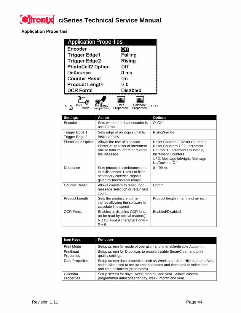
Application Properties
Settings Action Options Encoder Sets whether a shaft encoder is
used or not On/Off
Trigger Edge 1 Trigger Edge 2
Sets edge of print-go signal to begin printing
Rising/Falling
PhotoCell 2 Option Allows the use of a second PhotoCell to reset or increment one or both counters or reverse the message
Reset Counter 1, Reset Counter 2, Reset Counters 1 / 2, Increment Counter 1, Increment Counter 2, Increment Counters 1 / 2, Message left/right, Message Up/Down or Off
Debounce Sets photocell 1 debounce time in milliseconds. Useful to filter secondary electrical signals given by mechanical relays.
0 – 99 ms
Counter Reset Allows counters to reset upon message selection or retain last count
On/Off
Product Length Sets the product length in inches allowing the software to calculate line speed
Product length in tenths of an inch
OCR Fonts Enables or disables OCR fonts (to be read by optical readers). NOTE: Font 9 characters only – 0 – 9.
Enabled/Disabled
Icon Keys Function
Print Mode Setup screen for mode of operation and to enable/disable Autoprint. Printhead Properties
Setup screen for Drop size, to enable/disable SmartClean and print quality settings.
Date Properties Setup screen date properties such as Week start date, Hijri date and Atlas code. Also used to set up encoded dates and times and to select date and time delimiters (separators).
Calendar Properties
Setup screen for days, week, months, and year. Allows custom programmed autocodes for day, week, month and year.

ciSeries Technical Service Manual
Revision 1.11 Page 45
Print Mode
Settings Action Options Mode of Operation Sets the operation of the
system for the application – see details below.
Normal, Measurement, Message Sequence, Message Code, One for One.
AutoPrint Allows the ability print continuously. Use Delay to separate distance between printing. NOTE: Too little delay will cause a Phase Error.
Enabled / Disabled.
Message Data Command
Status – indicates if remote communications is able to operated in the specific modes of operation.
No options – just status.
Mode of Operations Defined:
Normal mode is the common mode of operation. A Message is selected to be printed and the same Message prints on all products. One-For-One mode is designed for applications that need to print new data on each product. The new data must be sent by an external computer – for each print. This mode of operation guarantees that the same data will not print twice. If new data does not arrive before a photocell trigger, the photocell is ignored and nothing will print on the product. Message Codes uses a six line connector to signal a binary number from 0 to 63. This number indicates the Message Code of the Message to be printed. When Message Code mode is selected, each Message may be assigned a Message Code. There is no transmission of data for this mode. The only control is the four lines of input. These lines are read at the time of the photocell trigger. Message Sequence uses a list of Messages to be printed. Each photocell trigger will switch to the next Message in the list. The list will wrap from bottom back up to the top. There may be up to twenty Messages in the list. There is only one Message Sequence stored for use.
ciSeries Technical Service Manual
Revision 1.11 Page 46
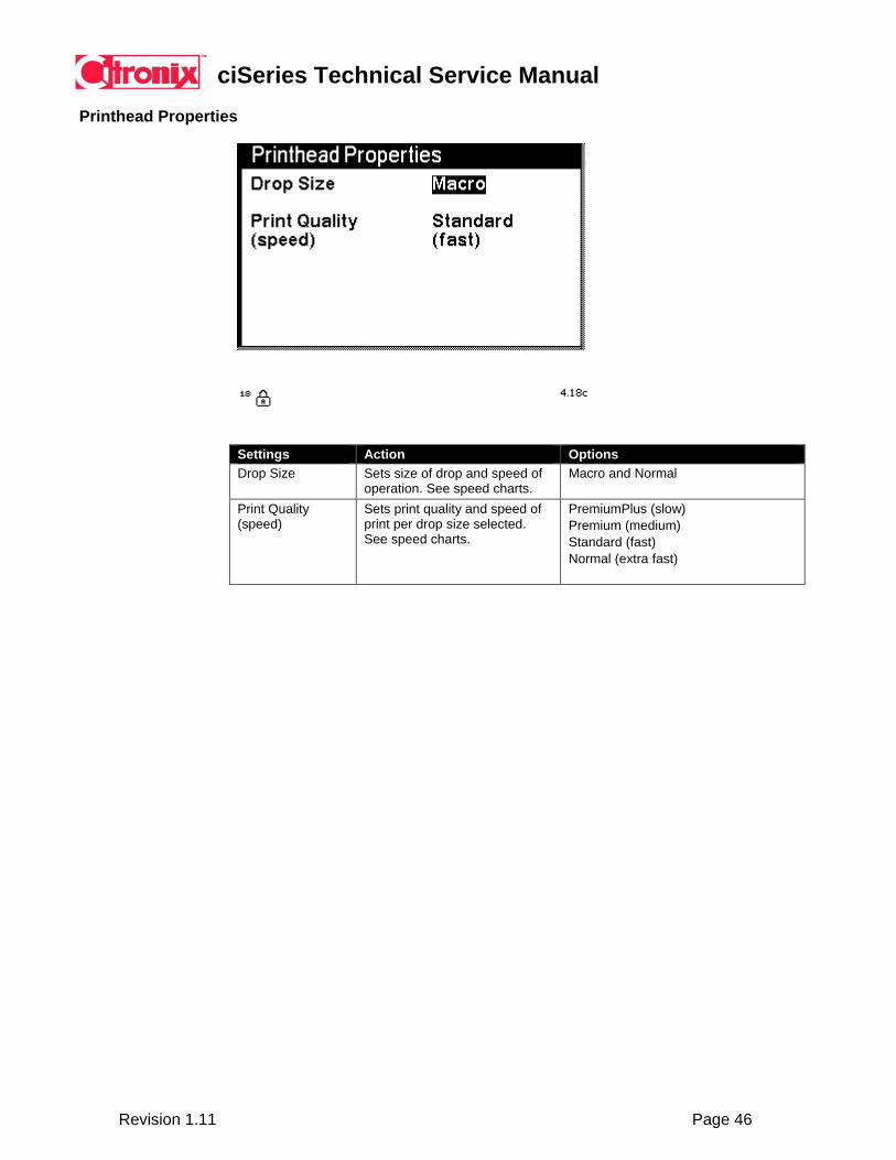
Printhead Properties
Settings Action Options Drop Size Sets size of drop and speed of
operation. See speed charts. Macro and Normal
Print Quality (speed)
Sets print quality and speed of print per drop size selected. See speed charts.
PremiumPlus (slow) Premium (medium) Standard (fast) Normal (extra fast)
ciSeries Technical Service Manual
Revision 1.11 Page 47
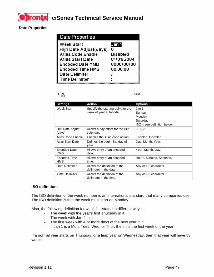
Date Properties
Settings Action Options Week Start Specify the starting point for the
week of year autocode. Jan 1 Sunday Monday Saturday ISO – see definition below.
Hijri Date Adjust (days)
Allows a day offset for the Hijri calendar.
0, 1, 2.
Atlas Code Enable Enables the Atlas code option. Enabled, Disabled. Atlas Start Date Defines the beginning day of
year. Day, Month, Year.
Encoded Date YMD
Allows entry of an encoded date.
Year, Month, Day.
Encoded Time HMS
Allows entry of an encoded time.
Hours, Minutes, Seconds.
Date Delimiter Allows the definition of the delimeter in the date.
Any ASCII character.
Time Delimiter Allows the definition of the delimeter in the time.
Any ASCII character.
ISO definition: The ISO definition of the week number is an international standard that many companies use. The ISO definition is that the week must start on Monday. Also, the following definition for week 1 – stated in different ways –
- The week with the year’s first Thursday in it. - The week with Jan 4 in it. - The first week with 4 or more days of the new year in it. - If Jan 1 is a Mon, Tues, Wed, or Thur, then it is the first week of the year.
If a normal year starts on Thursday, or a leap year on Wednesday, then that year will have 53 weeks.
ciSeries Technical Service Manual
Revision 1.11 Page 48
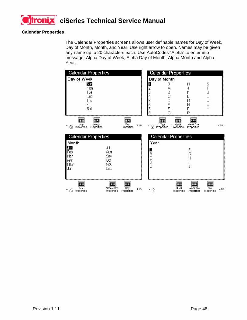
Calendar Properties
The Calendar Properties screens allows user definable names for Day of Week, Day of Month, Month, and Year. Use right arrow to open. Names may be given any name up to 20 characters each. Use AutoCodes “Alpha” to enter into message: Alpha Day of Week, Alpha Day of Month, Alpha Month and Alpha Year.
ciSeries Technical Service Manual
Revision 1.11 Page 49
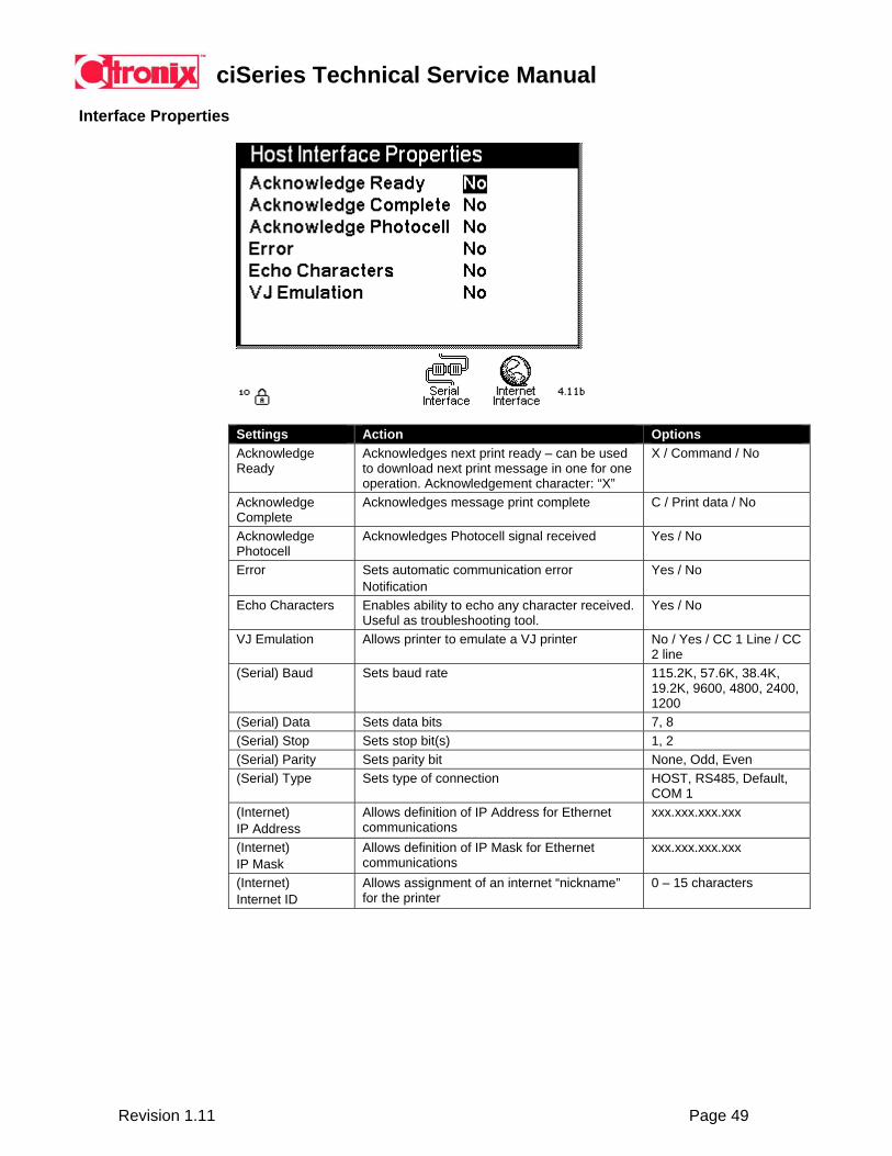
Interface Properties
Settings Action Options Acknowledge Ready
Acknowledges next print ready – can be used to download next print message in one for one operation. Acknowledgement character: “X”
X / Command / No
Acknowledge Complete
Acknowledges message print complete C / Print data / No
Acknowledge Photocell
Acknowledges Photocell signal received Yes / No
Error Sets automatic communication error Notification
Yes / No
Echo Characters Enables ability to echo any character received. Useful as troubleshooting tool.
Yes / No
VJ Emulation Allows printer to emulate a VJ printer No / Yes / CC 1 Line / CC 2 line
(Serial) Baud Sets baud rate 115.2K, 57.6K, 38.4K, 19.2K, 9600, 4800, 2400, 1200
(Serial) Data Sets data bits 7, 8 (Serial) Stop Sets stop bit(s) 1, 2 (Serial) Parity Sets parity bit None, Odd, Even (Serial) Type Sets type of connection HOST, RS485, Default,
COM 1 (Internet) IP Address
Allows definition of IP Address for Ethernet communications
xxx.xxx.xxx.xxx
(Internet) IP Mask
Allows definition of IP Mask for Ethernet communications
xxx.xxx.xxx.xxx
(Internet) Internet ID
Allows assignment of an internet “nickname” for the printer
0 – 15 characters
ciSeries Technical Service Manual
Revision 1.11 Page 50
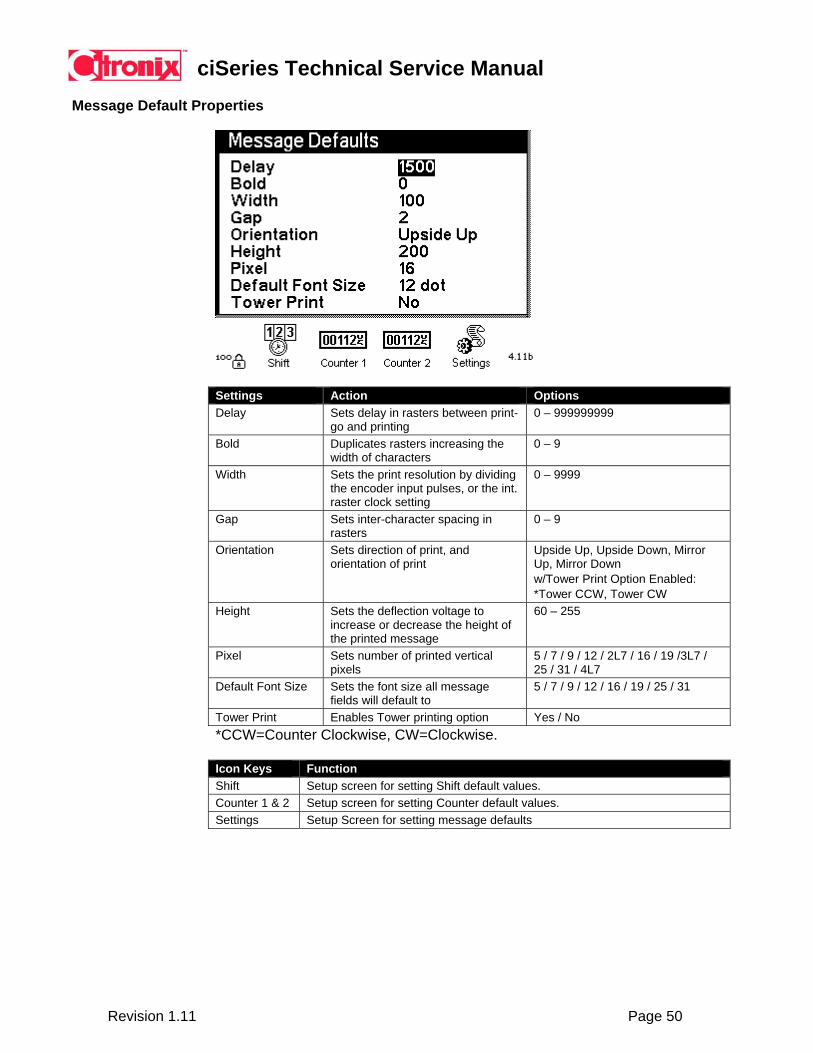
Message Default Properties
Settings Action Options Delay Sets delay in rasters between print-
go and printing 0 – 999999999
Bold Duplicates rasters increasing the width of characters
0 – 9
Width Sets the print resolution by dividing the encoder input pulses, or the int. raster clock setting
0 – 9999
Gap Sets inter-character spacing in rasters
0 – 9
Orientation Sets direction of print, and orientation of print
Upside Up, Upside Down, Mirror Up, Mirror Down w/Tower Print Option Enabled: *Tower CCW, Tower CW
Height Sets the deflection voltage to increase or decrease the height of the printed message
60 – 255
Pixel Sets number of printed vertical pixels
5 / 7 / 9 / 12 / 2L7 / 16 / 19 /3L7 / 25 / 31 / 4L7
Default Font Size Sets the font size all message fields will default to
5 / 7 / 9 / 12 / 16 / 19 / 25 / 31
Tower Print Enables Tower printing option Yes / No *CCW=Counter Clockwise, CW=Clockwise.
Icon Keys Function Shift Setup screen for setting Shift default values. Counter 1 & 2 Setup screen for setting Counter default values. Settings Setup Screen for setting message defaults

ciSeries Technical Service Manual
Revision 1.11 Page 51
Shift Default Properties
Settings Action Options Shifts Sets number of shifts for shift autocode 1, 2, 3 Shift 1 Sets shift 1 begin time HH:MM Shift 1 Code Sets shift 1 code 5 places - Full character set Shift 2 Sets shift 2 begin time, and shift 1 end time HH:MM Shift 2 Code Sets shift 2 code 5 places - Full character set Shift 3 Sets shift 3 begin time, and shift 2 end time HH:MM Shift 3 Code Sets shift 3 code 5 places - Full character set
ciSeries Technical Service Manual
Revision 1.11 Page 52
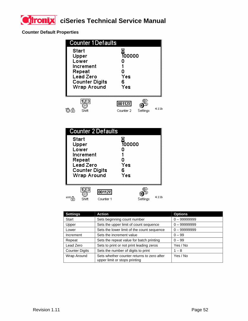
Counter Default Properties
Settings Action Options Start Sets beginning count number 0 – 99999999 Upper Sets the upper limit of count sequence 0 – 99999999 Lower Sets the lower limit of the count sequence 0 – 99999999 Increment Sets the increment value 0 – 99 Repeat Sets the repeat value for batch printing 0 – 99 Lead Zero Sets to print or not print leading zeros Yes / No Counter Digits Sets the number of digits to print 1 – 8 Wrap Around Sets whether counter returns to zero after
upper limit or stops printing Yes / No
ciSeries Technical Service Manual
Revision 1.11 Page 53
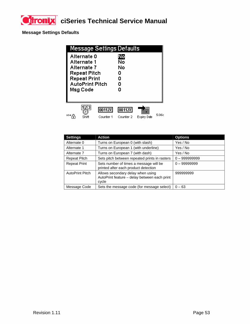
Message Settings Defaults
Settings Action Options Alternate 0 Turns on European 0 (with slash) Yes / No Alternate 1 Turns on European 1 (with underline) Yes / No Alternate 7 Turns on European 7 (with dash) Yes / No Repeat Pitch Sets pitch between repeated prints in rasters 0 – 999999999 Repeat Print Sets number of times a message will be
printed after each product detection 0 – 99999999
AutoPrint Pitch Allows secondary delay when using AutoPrint feature – delay between each print cycle
999999999
Message Code Sets the message code (for message select) 0 – 63
ciSeries Technical Service Manual
Revision 1.11 Page 54
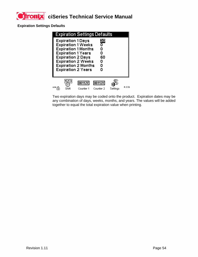
Expiration Settings Defaults
Two expiration days may be coded onto the product. Expiration dates may be any combination of days, weeks, months, and years. The values will be added together to equal the total expiration value when printing.
ciSeries Technical Service Manual
Revision 1.11 Page 55
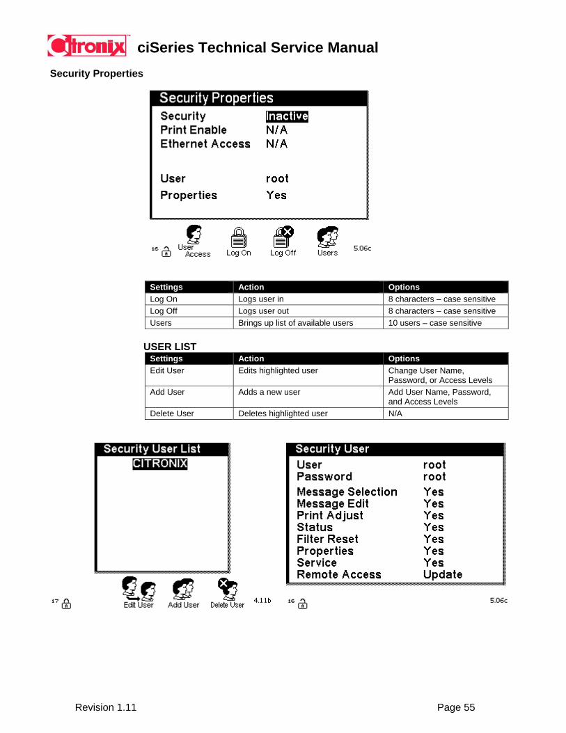
Security Properties
Settings Action Options Log On Logs user in 8 characters – case sensitive Log Off Logs user out 8 characters – case sensitive Users Brings up list of available users 10 users – case sensitive
USER LIST Settings Action Options Edit User Edits highlighted user Change User Name,
Password, or Access Levels Add User Adds a new user Add User Name, Password,
and Access Levels Delete User Deletes highlighted user N/A
ciSeries Technical Service Manual
Revision 1.11 Page 56
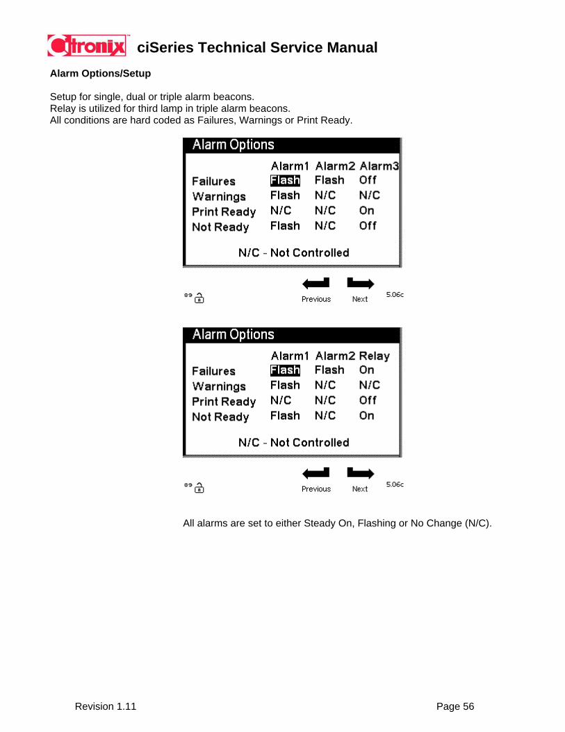
Alarm Options/Setup
Setup for single, dual or triple alarm beacons. Relay is utilized for third lamp in triple alarm beacons. All conditions are hard coded as Failures, Warnings or Print Ready.
All alarms are set to either Steady On, Flashing or No Change (N/C).

ciSeries Technical Service Manual
Revision 1.11 Page 57
5.5 Creating and Editing Messages
1) Select the Message icon key from the Main Screen. 2) Select New or Edit Message icon key. 3) If creating a new message: Enter the New Message Name, press Enter. 4) If editing, or after entering a New Message Name, the following screens
are displayed to finish creating a message or edit an existing message:
Field Select Message creation or editing Scrolling displays additional icons
Editor Controls Add Field Adds a data field *Delay Use “D” to adjust Delay Edit Text Edit information in text data field *Font Use “F” to adjust Font Next Field Moves between fields *Width Use “W” to adjust Width Delete Field Delete data field *Gap Use “G” to adjust Gap Left Arrow Moves data field left *Orientation Use “O” to adjust Orientation Right Arrow Moves data field right *Bold Use “B” to adjust Bold Up Arrow Moves data field up *Height Use “H” to adjust Height Down Arrow Moves data field down *Pixel Use “X” to adjust Pixel Alt 1 Selects special characters *Caps Lock Toggles between upper/lower Alt 2 Selects special characters *Shift Toggles between upper/lower *Page Use “P” to page screens (large
messages).
NOTE: *The Caps Lock and Shift keys operate dual function during editing. Shift and Caps Lock are used in the traditional sense for selecting upper and lower case characters during data entry, and also operate during the adjustment of a setting between a positive and negative increment of the setting.
Note: Pixel defines vertical print area and print speed. Refer to speed charts.
5) After editing or creating a new message, press the Enter key to save. If editing a message, the current message name will pop-up to allow the ability to save as a new name (copy/save as function). Should the same name be kept, a separate file will be created based on time and date.

ciSeries Technical Service Manual
Revision 1.11 Page 58
Font Chart
The following fonts are available for selection: Font Name Description Ci580 Ci7 Ci700 Ci1000/2000
5 Dot 5 x 5 Dot Matrix 1 or 2 Line 1 to 4 Line 1 to 5 Line 7 Dot 7 x 5 Dot Matrix 1 or 2 Line 1 to 3 Line 1 to 4 Line 9 Dot 9 x 7 Dot Matrix 1 Line 1 to 3 Line 1 to 3 Line 12 Dot 12 x 8 Dot Matrix 1 Line 1 or 2 Line 1 or 2 Line 16 Dot 16 x 12 Dot Matrix 1 Line 1 Line 1 Line 19 Dot 19 x 15 Dot Matrix N/A 1 Line 1 Line 25 Dot 25x18 Dot Matrix N/A 1 Line 1 Line 31 Dot 31x20 Dot Matrix N/A N/A 1 Line
Pixel Chart
The following pixel settings are available for selection: Pixel Description Ci580 Ci700 Ci1000/2000
5 5 x 5 Dot Matrix 1 or 2 Line 1 to 4 Line 1 to 5 Line 7 7 x 5 Dot Matrix 1 or 2 Line 1 to 3 Line 1 to 4 Line 9 9 x 7 Dot Matrix 1 Line 1 to 3 Line 1 to 3 Line
12 12 x 8 Dot Matrix 1 Line 1 or 2 Line 1 or 2 Line 2L7 2 Lines of 7 x 5 Dot Matrix 2 Line 1 Line 2 Line 16 16 x 12 Dot Matrix 1 Line 1 Line 1 Line 19 19 x 15 Dot Matrix N/A 1 Line 1 Line
3L7 3 Lines of 7 x 5 Dot Matrix N/A 3 Line 3 Line 25 25x18 Dot Matrix N/A 1 Line 1 Line 31 31x20 Dot Matrix N/A N/A 1 Line
4L7 4 Lines of 7 x 5 Dot Matrix N/A N/A 4 Line
NOTE: The pixel parameter should be set to the lowest value in relation to the largest character or characters. NOTE: Using Pixel 2L7, 3L7, 4L7 will provide optimum speed and quality for dedicated 2 line, 3 line or 4 line 7x5 character printing.
Optional Fields
The following fields are available for selection when creating or editing a message:
Text Allows alphanumeric text to be inserted Autocode Allows Times, Dates or Shift (See section 10.5) to be inserted. Counters Allows one or two counters to be inserted. Barcode Allows a barcode (See section 10.6) to be inserted. Graphic Allows a downloaded Graphic to be inserted. User Defined Allows a User Defined Text or Barcode field to be inserted.
ciSeries Technical Service Manual
Revision 1.11 Page 59
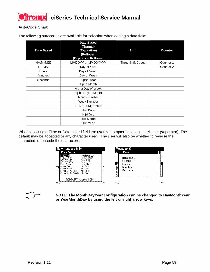
AutoCode Chart
The following autocodes are available for selection when adding a data field:
Time Based
Date Based (Normal)
(Expiration) (Rollover)
(Expiration Rollover)
Shift
Counter
HH:MM:SS MMDDYY or MMDDYYYY Three Shift Codes Counter 1 HH:MM Day of Year Counter 2 Hours Day of Month
Minutes Day of Week Seconds Alpha Year
Alpha Month Alpha Day of Week Alpha Day of Month
Month Number Week Number 1, 2, or 4 Digit Year Hijri Date Hijri Day Hijri Month Hijri Year
When selecting a Time or Date based field the user is prompted to select a delimiter (separator). The default may be accepted or any character used. The user will also be whether to reverse the characters or encode the characters.
NOTE: The MonthDayYear configuration can be changed to DayMonthYear or YearMonthDay by using the left or right arrow keys.

ciSeries Technical Service Manual
Revision 1.11 Page 60
Time, date, shift and counter codes are based on the following:
AutoCode AutoCode Basis Time Based on real time setup in System Properties Date Based on real date setup in System Properties
Expiration Date Based on real date and expiration date setup in System Properties and Application Properties
Rollover Date Based on real date and rollover time setup in System Properties and Application Properties
Expiration Rollover Date Based on real date, rollover time and expiration date setup in System Properties and Application Properties
Shift Based on real time and shift time setup in System Properties and Application Properties
Counter Based on counter setup in Application Properties
NOTE: ROLLOVER TIME IS A OFFSET OF THE 12:00AM CALENDAR DAY CHANGE. IF ROLLOVER IS SET TO 2:00 (AM), THE CALENDAR DAY WILL ADVANCE AT 2:00 (AM), NOT 12:00AM.

ciSeries Technical Service Manual
Revision 1.11 Page 61
Bar codes The following bar codes are available for selection:
Description Input (enter data) Human Readable Text Available (yes/no)
Check Digit
I 2 of 5 Up to 256 numeric characters or Counter
Yes Automatic or Disabled
Code 39 Up to 256 alpha-numeric characters or Counter
Yes Manual – must enter
Code 128 Up to 256 alpha-numeric characters or Counter
Yes Manual – must enter
UPC A (11) 11 numeric characters Yes Automatic UPC E (6) 6 numeric characters No Automatic EAN13 (12) 12 numeric characters Yes Automatic EAN8 (7) 7 numeric characters Yes Automatic Datamatrix Variable based on matrix No N/A
NOTE: Utilize the “Bold” setting to increase size of the bar code. The bold setting defines the number of printed columns used for the wide and narrow spaces and bars.

ciSeries Technical Service Manual
Revision 1.11 Page 62
Printable Character Chart
Normal Shift Alt 1 Alt 1 +
Caps Lock Alt 2 Alt 2 +
Caps Lock 1 ! 2 @ 3 # 4 $ 5 % 6 ¢ 7 & 8 * 9 ( 0 ) - _ = + q Q â  À à w W æ Æ µ µ e E ë Ë È è r R é É ~ ~ t T ™ ™ © © y Y ÿ Ÿ Ý ý u U ù Ù Ú ú I I ï Ï Í í o O ò Ò Ó ó p P ô Ô Õ õ [ [ { { } } ] ] | | \ \ a A å Å Ä ä s S § § Š š d D ð Ð f F ê Ê g G ü Ü h H û Û j J ì Ì k K î Î ' ' l L ö Ö Ø ø ; ; ¤ ¤ £ £ : : " " ® ® z Z á Á ¼ ¼ x X ã à ½ ½ c C ç Ç ¾ ¾ v V þ Þ b B ß ß n N ñ Ñ m M œ Œ , , < < ° ° . . > > € € / / ? ? ¥ ¥
ciSeries Technical Service Manual
Revision 1.11 Page 63
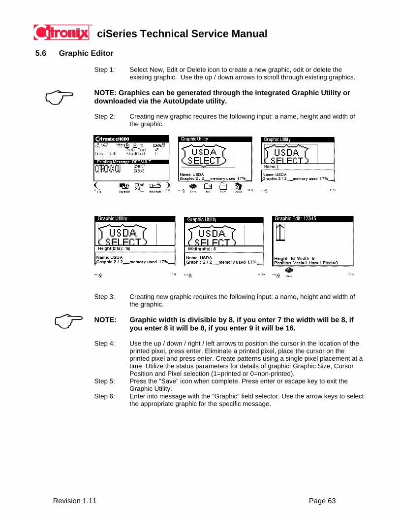
5.6 Graphic Editor
Step 1: Select New, Edit or Delete icon to create a new graphic, edit or delete the existing graphic. Use the up / down arrows to scroll through existing graphics.
NOTE: Graphics can be generated through the integrated Graphic Utility or downloaded via the AutoUpdate utility.
Step 2: Creating new graphic requires the following input: a name, height and width of
the graphic.
Step 3: Creating new graphic requires the following input: a name, height and width of the graphic.
NOTE: Graphic width is divisible by 8, if you enter 7 the width will be 8, if
you enter 8 it will be 8, if you enter 9 it will be 16. Step 4: Use the up / down / right / left arrows to position the cursor in the location of the
printed pixel, press enter. Eliminate a printed pixel, place the cursor on the printed pixel and press enter. Create patterns using a single pixel placement at a time. Utilize the status parameters for details of graphic: Graphic Size, Cursor Position and Pixel selection (1=printed or 0=non-printed).
Step 5: Press the “Save” icon when complete. Press enter or escape key to exit the
Graphic Utility. Step 6: Enter into message with the “Graphic” field selector. Use the arrow keys to select
the appropriate graphic for the specific message.
ciSeries Technical Service Manual
Revision 1.11 Page 64
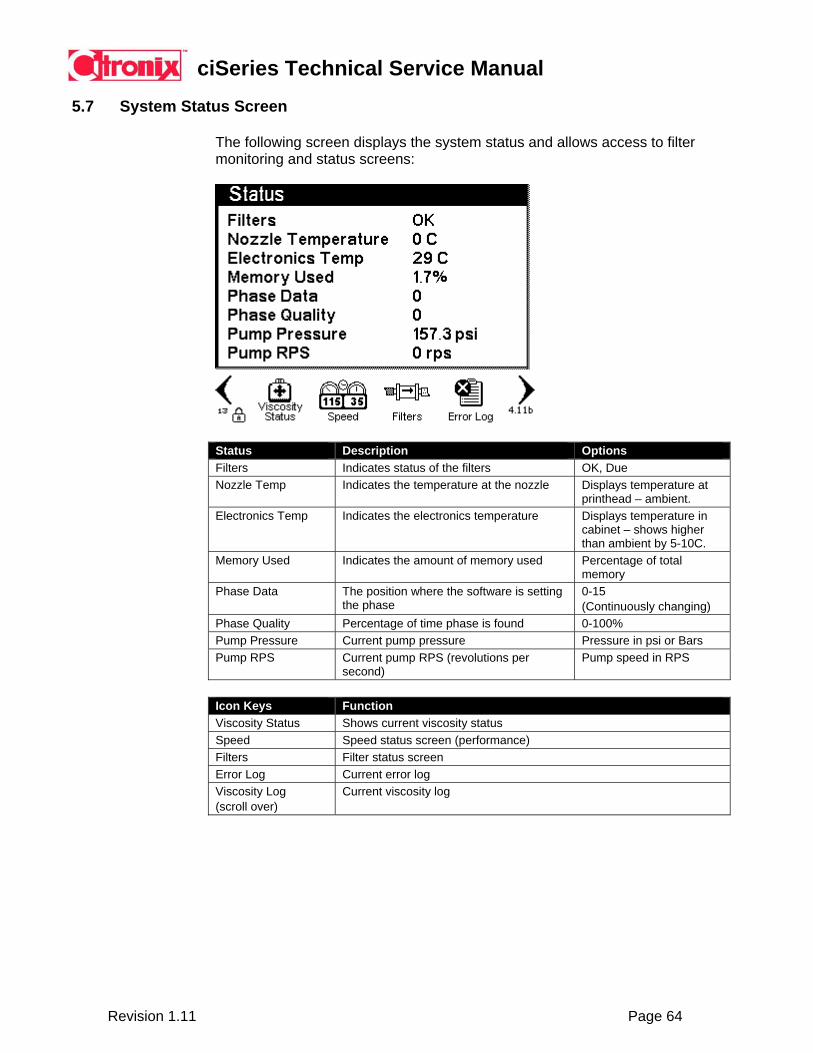
5.7 System Status Screen
The following screen displays the system status and allows access to filter monitoring and status screens:
Status Description Options Filters Indicates status of the filters OK, Due Nozzle Temp Indicates the temperature at the nozzle Displays temperature at
printhead – ambient. Electronics Temp Indicates the electronics temperature Displays temperature in
cabinet – shows higher than ambient by 5-10C.
Memory Used Indicates the amount of memory used Percentage of total memory
Phase Data The position where the software is setting the phase
0-15 (Continuously changing)
Phase Quality Percentage of time phase is found 0-100% Pump Pressure Current pump pressure Pressure in psi or Bars Pump RPS Current pump RPS (revolutions per
second) Pump speed in RPS
Icon Keys Function Viscosity Status Shows current viscosity status Speed Speed status screen (performance) Filters Filter status screen Error Log Current error log Viscosity Log (scroll over)
Current viscosity log
ciSeries Technical Service Manual
Revision 1.11 Page 65
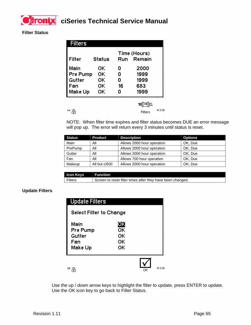
Filter Status
NOTE: When filter time expires and filter status becomes DUE an error message will pop up. The error will return every 3 minutes until status is reset.
Status Product Description Options Main All Allows 2000 hour operation OK, Due PrePump All Allows 2000 hour operation OK, Due Gutter All Allows 2000 hour operation OK, Due Fan All Allows 700 hour operation OK, Due Makeup All but ci500 Allows 2000 hour operation OK, Due
Icon Keys Function Filters Screen to reset filter times after they have been changed.
Update Filters
Use the up / down arrow keys to highlight the filter to update, press ENTER to update. Use the OK icon key to go back to Filter Status.

ciSeries Technical Service Manual
Revision 1.11 Page 66
Speed Screen
Field Description Options Encoder Freq Actual frequency of encoder Frequency in DPI Print Freq Actual printing frequency Encoder Freq divided
by the Width plus 1 Average Drops Average number of drops used per raster of
current message Frequency in DPI
Max Print Freq Maximum frequency the message can be printed with current settings and parameters
Drop Freq divided by Max Drops
Line Speed Shows line speed based on product Length input on Applications Properties screen.
Speed Status
MPC Missing Product Count. Message too large for the speed.
Count
TFC Too Fast Count. Attempting to print faster than processor’s capability.
Count
DNRC Did Not Receive Count. In one-for-one mode, product was detected but new message was not received.
Count
NOTE: For optimum performance Print Frequency should never exceed Max Print Frequency.
ciSeries Technical Service Manual
Revision 1.11 Page 67
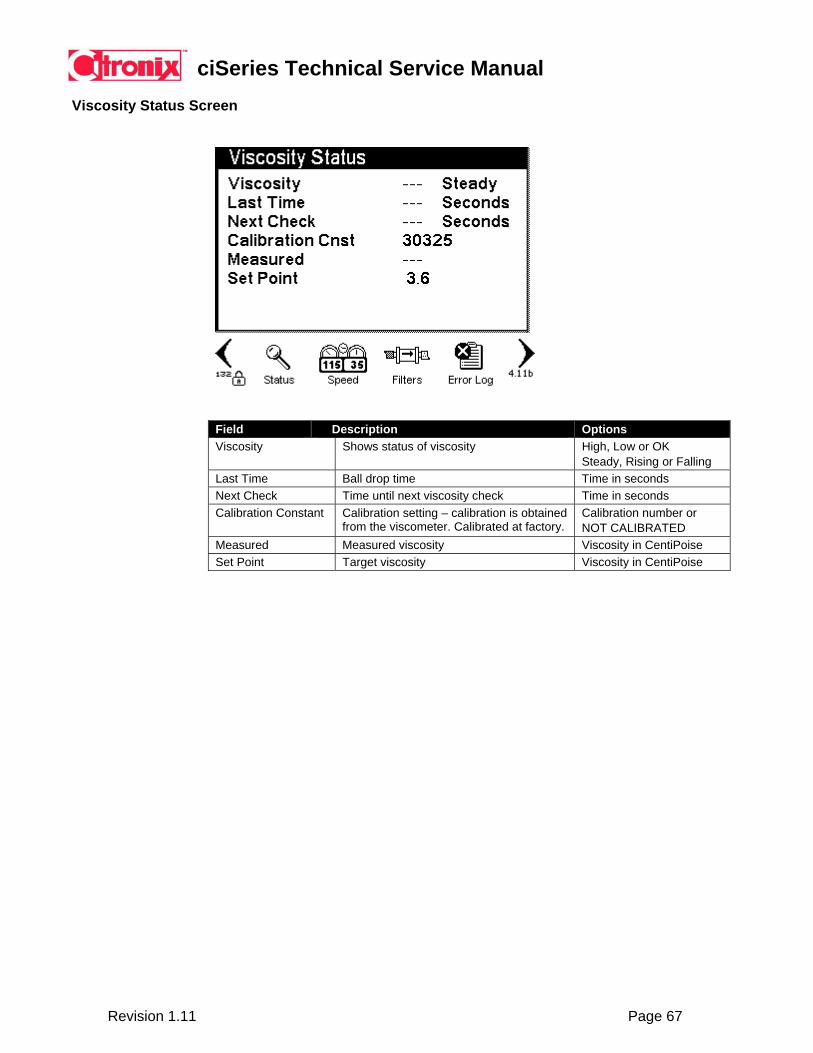
Viscosity Status Screen
Field Description Options Viscosity Shows status of viscosity High, Low or OK
Steady, Rising or Falling Last Time Ball drop time Time in seconds Next Check Time until next viscosity check Time in seconds Calibration Constant Calibration setting – calibration is obtained
from the viscometer. Calibrated at factory. Calibration number or NOT CALIBRATED
Measured Measured viscosity Viscosity in CentiPoise Set Point Target viscosity Viscosity in CentiPoise
ciSeries Technical Service Manual
Revision 1.11 Page 68
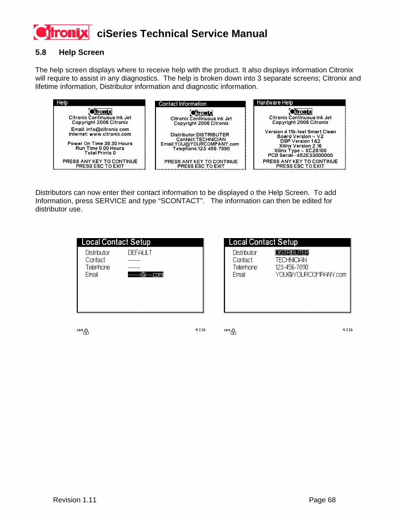
5.8 Help Screen The help screen displays where to receive help with the product. It also displays information Citronix will require to assist in any diagnostics. The help is broken down into 3 separate screens; Citronix and lifetime information, Distributor information and diagnostic information.
Distributors can now enter their contact information to be displayed o the Help Screen. To add Information, press SERVICE and type “SCONTACT”. The information can then be edited for distributor use.
ciSeries Technical Service Manual
Revision 1.11 Page 69
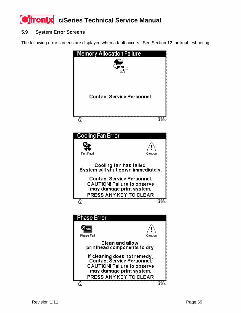
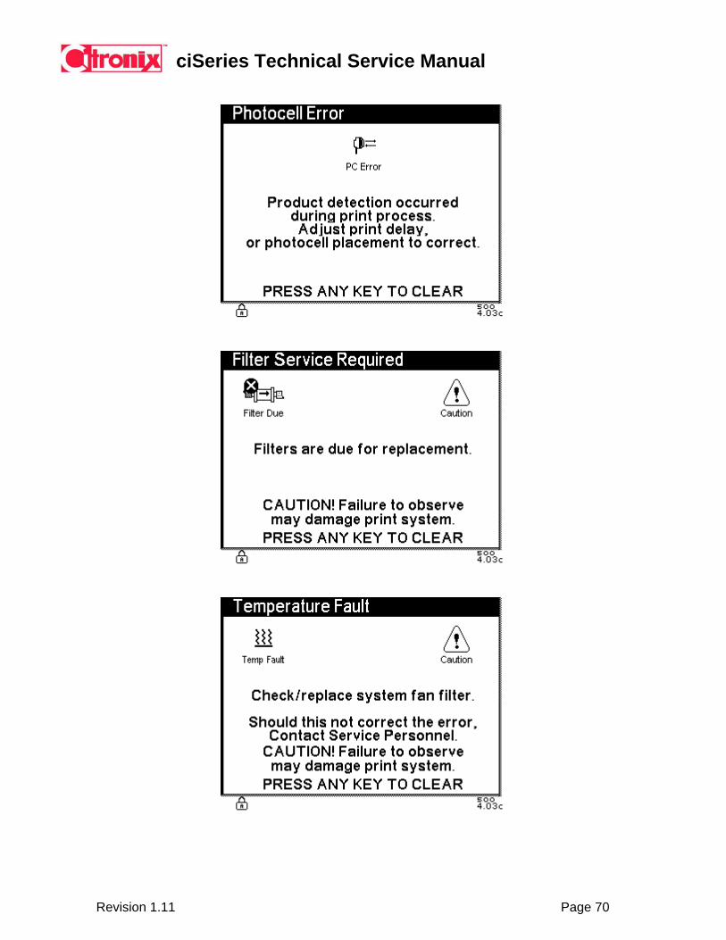
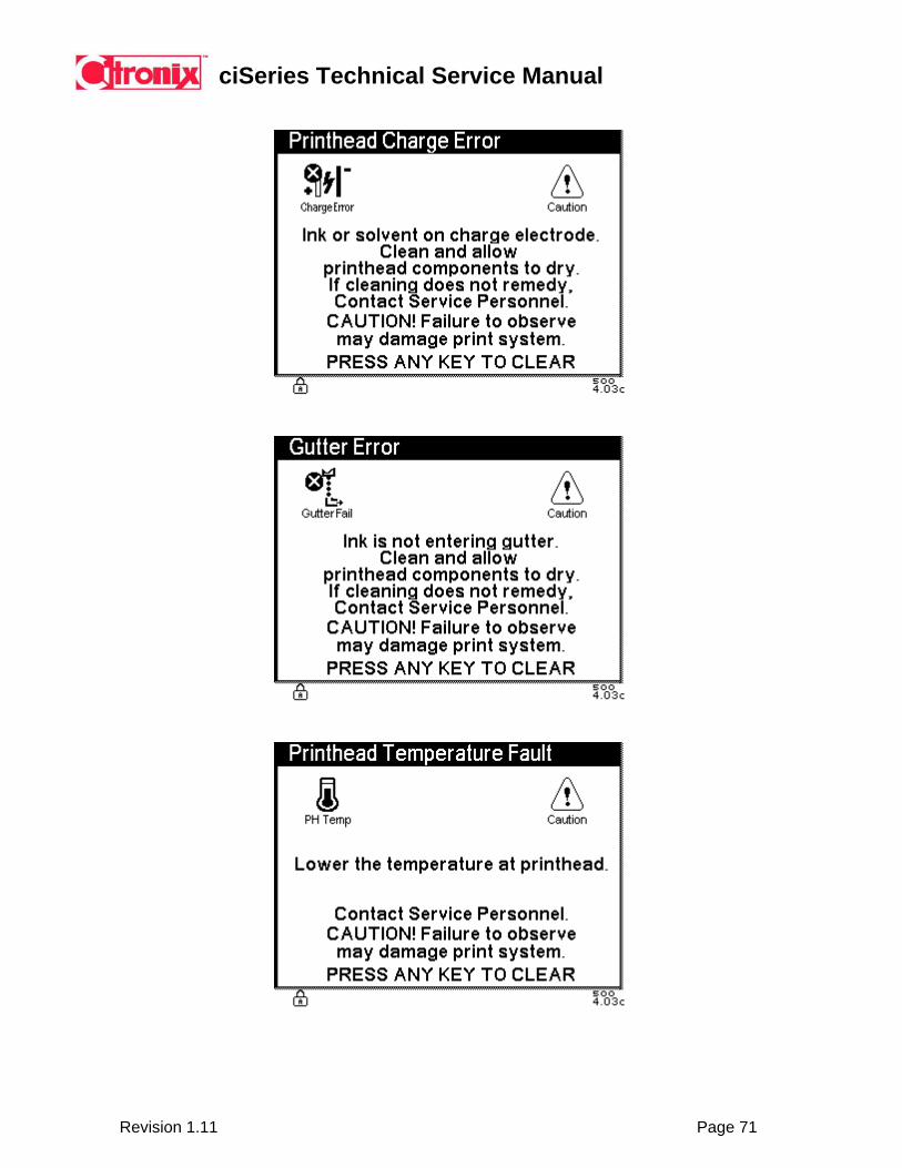
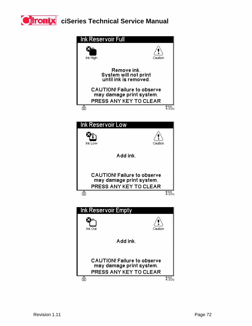
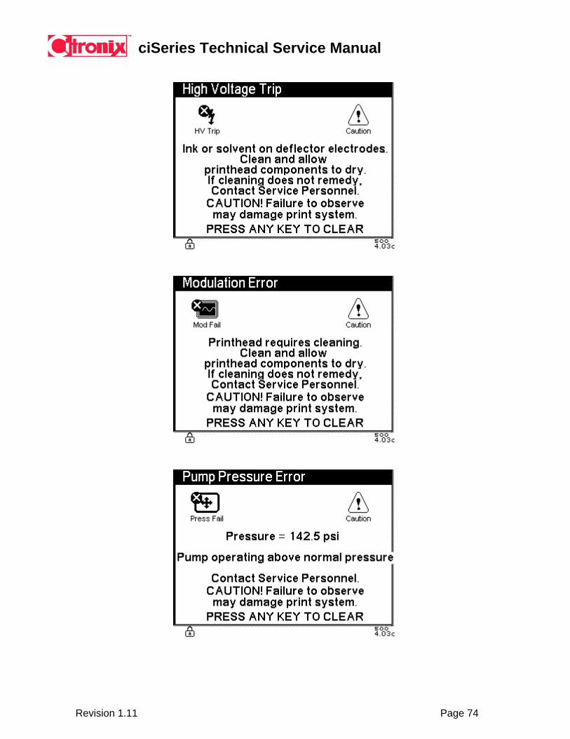
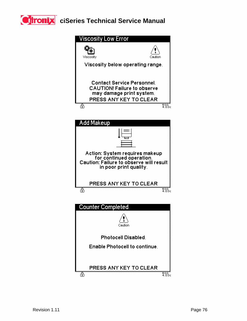
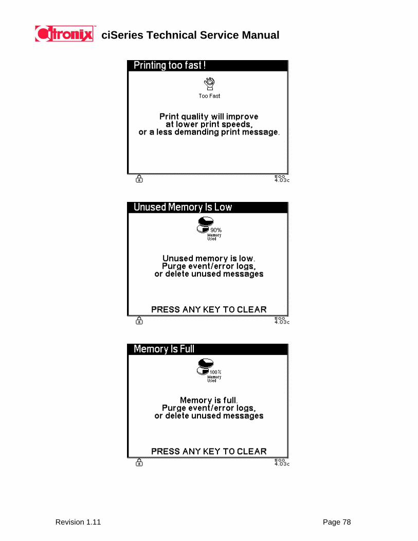
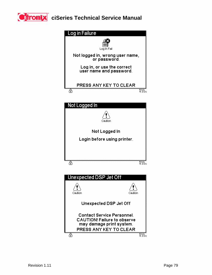
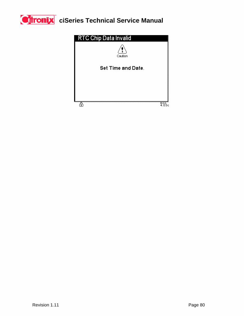
5.9 System Error Screens The following error screens are displayed when a fault occurs. See Section 12 for troubleshooting.
ciSeries Technical Service Manual
Revision 1.11 Page 70
ciSeries Technical Service Manual
Revision 1.11 Page 71
ciSeries Technical Service Manual
Revision 1.11 Page 72

ciSeries Technical Service Manual
Revision 1.11 Page 73
ciSeries Technical Service Manual
Revision 1.11 Page 74

ciSeries Technical Service Manual
Revision 1.11 Page 75
ciSeries Technical Service Manual
Revision 1.11 Page 76

ciSeries Technical Service Manual
Revision 1.11 Page 77
ciSeries Technical Service Manual
Revision 1.11 Page 78
ciSeries Technical Service Manual
Revision 1.11 Page 79
ciSeries Technical Service Manual
Revision 1.11 Page 80
ciSeries Technical Service Manual
Revision 1.11 Page 81
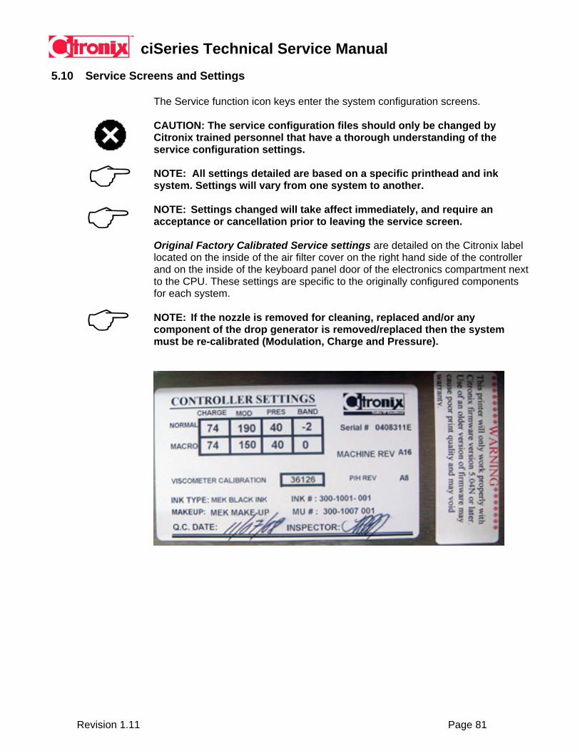
5.10 Service Screens and Settings
The Service function icon keys enter the system configuration screens. CAUTION: The service configuration files should only be changed by Citronix trained personnel that have a thorough understanding of the service configuration settings. NOTE: All settings detailed are based on a specific printhead and ink system. Settings will vary from one system to another.
NOTE: Settings changed will take affect immediately, and require an acceptance or cancellation prior to leaving the service screen. Original Factory Calibrated Service settings are detailed on the Citronix label located on the inside of the air filter cover on the right hand side of the controller and on the inside of the keyboard panel door of the electronics compartment next to the CPU. These settings are specific to the originally configured components for each system.
NOTE: If the nozzle is removed for cleaning, replaced and/or any component of the drop generator is removed/replaced then the system must be re-calibrated (Modulation, Charge and Pressure).

ciSeries Technical Service Manual
Revision 1.11 Page 82
Service Status
Use the function icon keys to access service settings or functions. The Service Status screen displays four service function icon keys; using the function icon arrow keys can access additional service function icon keys.
5.10.2 Calibrate Modulation, Charge and Pressure: Drop Size, Charge Setting, Modulation Setting, Viscometer Calibration Constant and Pump Pressure are changed by scrolling to the desired command and using the left and right arrow keys to adjust.
NOTE: Each drop size has independent values for Modulation, Charge and Pressure.
Step 1 Modulation –
Set Charge: 72 Pressure: 40 Modulation: a) Set Modulation to 150.
b) Set Band to 0 and make a print sample. c) Advance the Band until the print quality looks good. (Use both + and – ranges). d) When a good band is found - check for a 100 volt good print window and set the modulation in the center of this window. Eg. If the window is 100 to 220 then set the modulation at 160. e) If an acceptable window cannot be found then advance to the next band.
Step 2 Charge –
Adjust between 68-76, ensure range is good, set value to optimum print quality.
Step 3 Pressure – Adjust value between 37-43, ensure range is good, set value to optimum print quality. If pressure range fails, find another modulation band – repeat steps 1-3.
NOTE: It is necessary to follow this procedure should a change be made to the drop generator: nozzle removal/clean, nozzle replacement, resonator seal change, resonator replacement. In addition, should an ink type change be made this procedure should be followed.
ciSeries Technical Service Manual
Revision 1.11 Page 83
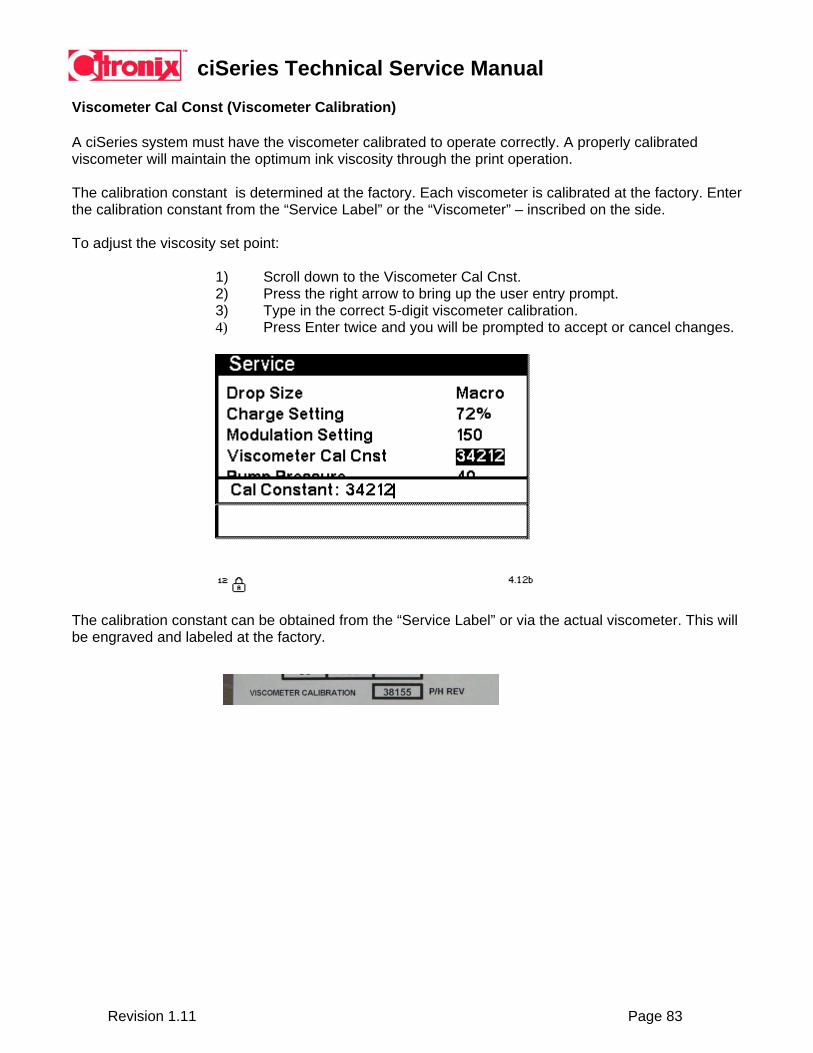
Viscometer Cal Const (Viscometer Calibration)
A ciSeries system must have the viscometer calibrated to operate correctly. A properly calibrated viscometer will maintain the optimum ink viscosity through the print operation.
The calibration constant is determined at the factory. Each viscometer is calibrated at the factory. Enter the calibration constant from the “Service Label” or the “Viscometer” – inscribed on the side.
To adjust the viscosity set point:
1) Scroll down to the Viscometer Cal Cnst. 2) Press the right arrow to bring up the user entry prompt. 3) Type in the correct 5-digit viscometer calibration. 4) Press Enter twice and you will be prompted to accept or cancel changes.
The calibration constant can be obtained from the “Service Label” or via the actual viscometer. This will be engraved and labeled at the factory.
ciSeries Technical Service Manual
Revision 1.11 Page 84
Gutter Offset: Offers the ability to make software adjustments to prevent build-up on gutter - Do not use unless needed. It will have some effects on the drop placement, and therefore the print quality. Gutter Offset is a "fine tuning" adjustment to the position of the ink drops. Positive values move the ink away from the gutter, negative values move the ink towards the gutter. Acceptable values are -3 to +10. Rarely needed, suggest using only with Micro printers or with Pixel 31 or in situations that Height is set above 200. Mostly a small plus number will move the drops far enough away from the edge of the gutter to avoid clipping.
ciSeries Technical Service Manual
Revision 1.11 Page 85
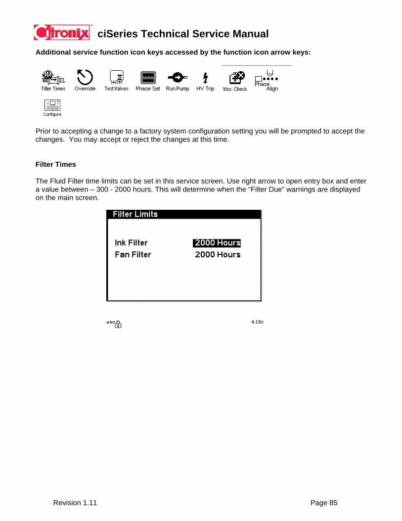
Additional service function icon keys accessed by the function icon arrow keys:
Prior to accepting a change to a factory system configuration setting you will be prompted to accept the changes. You may accept or reject the changes at this time. Filter Times
The Fluid Filter time limits can be set in this service screen. Use right arrow to open entry box and enter a value between – 300 - 2000 hours. This will determine when the “Filter Due” warnings are displayed on the main screen.

ciSeries Technical Service Manual
Revision 1.11 Page 86
HV Trip Setting
The high voltage trip setting sets the sensitivity to stop the jet and turn the high voltage off in the case of a high voltage arc between the ground and the high voltage plate.
The potential for a high voltage arc occurs when the printhead is wet (ink, cleaner or moisture in the environment). The HV Trip setting is now an automatic function.
To calibrate the HV Trip setting: 1) Ensure printhead is clean and dry. 2) Ensure the printhead cover is fitted. 3) Press the “automatic” button. 4) The system will self-calibrate the correct sensitivity.
ciSeries Technical Service Manual
Revision 1.11 Page 87
Viscosity Check
The system automatically checks viscosity every 2 minutes. Additionally, the viscosity can be checked manually by pressing the Viscosity Check icon. This will start the Viscosity check manually.
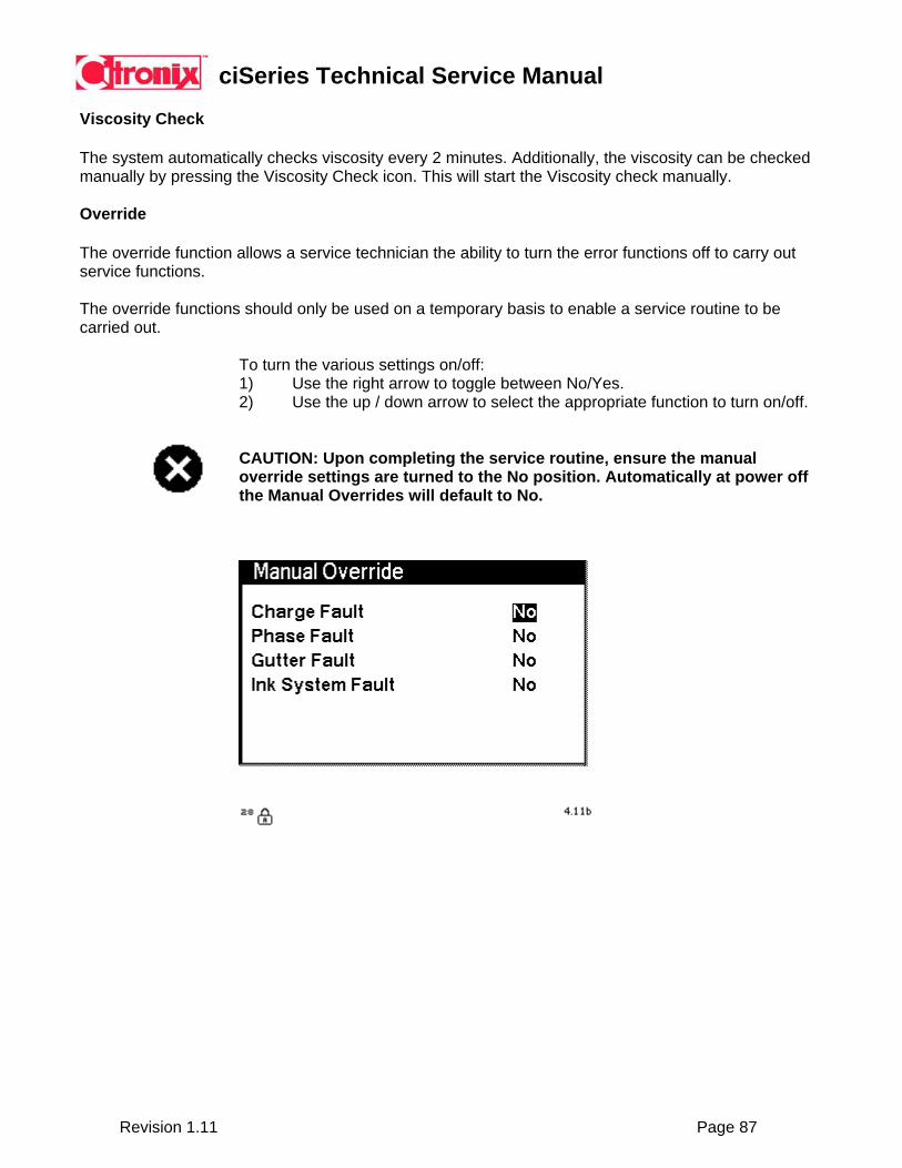
Override
The override function allows a service technician the ability to turn the error functions off to carry out service functions.
The override functions should only be used on a temporary basis to enable a service routine to be carried out.
To turn the various settings on/off: 1) Use the right arrow to toggle between No/Yes. 2) Use the up / down arrow to select the appropriate function to turn on/off.
CAUTION: Upon completing the service routine, ensure the manual override settings are turned to the No position. Automatically at power off the Manual Overrides will default to No.
ciSeries Technical Service Manual
Revision 1.11 Page 88
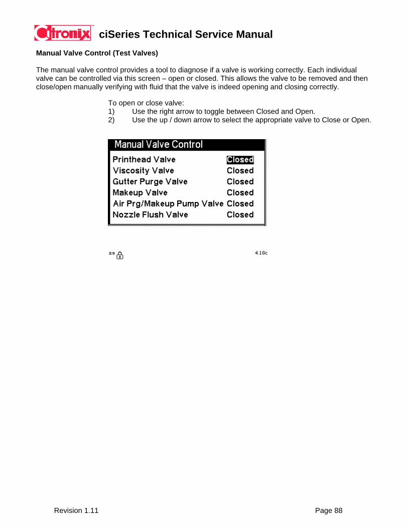
Manual Valve Control (Test Valves) The manual valve control provides a tool to diagnose if a valve is working correctly. Each individual valve can be controlled via this screen – open or closed. This allows the valve to be removed and then close/open manually verifying with fluid that the valve is indeed opening and closing correctly.
To open or close valve: 1) Use the right arrow to toggle between Closed and Open. 2) Use the up / down arrow to select the appropriate valve to Close or Open.

ciSeries Technical Service Manual
Revision 1.11 Page 89
Phase Set (Test Automatic Phasing)
The phase set is a tool to manually adjust the phasing process for diagnostic purposes. The manual phase set can only be adjusted during this screen as a diagnostic tool to check if automatic phasing is working correctly. When exiting this screen the automatic phasing will be re-enabled.
To manually adjust phasing: 1) Use the “+” or “–“ function icon keys to increase or decrease the phase value. 2) The adjustment will take place immediately. 3) When exiting the screen auto phasing will be implemented. Manual phasing
can only be operated when in this screen.
Diagnostic Use: Determine if the system is stable enough for the phase detector to perform correctly. o This tool disables the use of the phase detector. o 0-15 manual phase positions. Find a manual phase value that provides
consistent good print. o If a good manual phase value can be determined this proves the phase
detector could be faulty. Assuming phase detector will not provide good quality printing.
ciSeries Technical Service Manual
Revision 1.11 Page 90
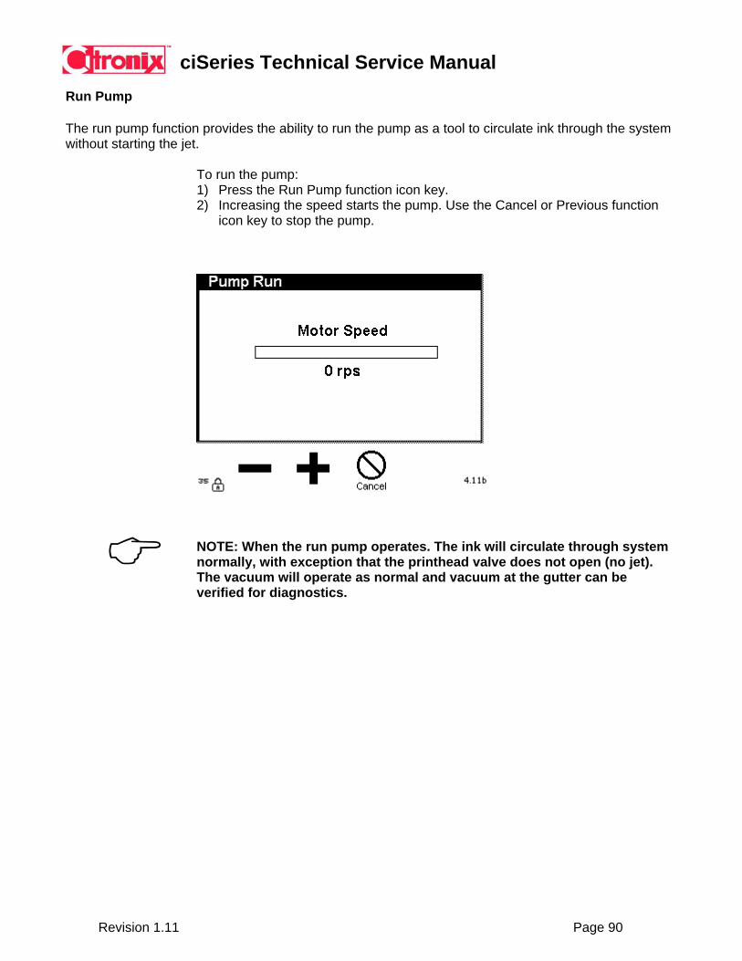
Run Pump
The run pump function provides the ability to run the pump as a tool to circulate ink through the system without starting the jet.
To run the pump: 1) Press the Run Pump function icon key. 2) Increasing the speed starts the pump. Use the Cancel or Previous function
icon key to stop the pump.
NOTE: When the run pump operates. The ink will circulate through system normally, with exception that the printhead valve does not open (no jet). The vacuum will operate as normal and vacuum at the gutter can be verified for diagnostics.
ciSeries Technical Service Manual
Revision 1.11 Page 91
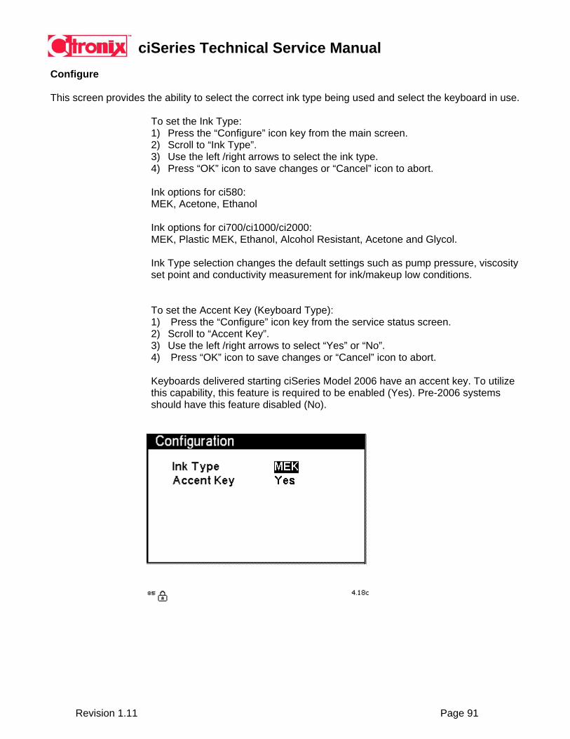
Configure
This screen provides the ability to select the correct ink type being used and select the keyboard in use.
To set the Ink Type: 1) Press the “Configure” icon key from the main screen. 2) Scroll to “Ink Type”. 3) Use the left /right arrows to select the ink type. 4) Press “OK” icon to save changes or “Cancel” icon to abort. Ink options for ci580: MEK, Acetone, Ethanol Ink options for ci700/ci1000/ci2000: MEK, Plastic MEK, Ethanol, Alcohol Resistant, Acetone and Glycol. Ink Type selection changes the default settings such as pump pressure, viscosity set point and conductivity measurement for ink/makeup low conditions. To set the Accent Key (Keyboard Type): 1) Press the “Configure” icon key from the service status screen. 2) Scroll to “Accent Key”. 3) Use the left /right arrows to select “Yes” or “No”. 4) Press “OK” icon to save changes or “Cancel” icon to abort. Keyboards delivered starting ciSeries Model 2006 have an accent key. To utilize this capability, this feature is required to be enabled (Yes). Pre-2006 systems should have this feature disabled (No).
ciSeries Technical Service Manual
Revision 1.11 Page 92
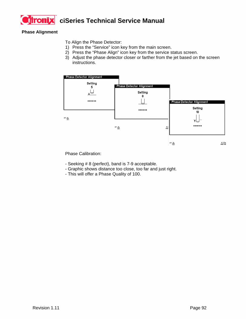
Phase Alignment
To Align the Phase Detector: 1) Press the “Service” icon key from the main screen. 2) Press the “Phase Align” icon key from the service status screen. 3) Adjust the phase detector closer or farther from the jet based on the screen
instructions.
Phase Calibration: - Seeking # 8 (perfect), band is 7-9 acceptable. - Graphic shows distance too close, too far and just right. - This will offer a Phase Quality of 100.

ciSeries Technical Service Manual
Revision 1.11 Page 93
Resetting the System
There are five different types of a reset that can be performed to a ciSeries system:
Soft Reset – 1) Press the Help key six times
This resets the system, maintaining all programmed settings including messages, system properties, and factory configuration files.
Message Reset – 1) Press the Service icon key 2) Press “MSG”
This resets the message files to the single factory default message. All message files are deleted. This will not delete or affect factory configuration settings, or system property settings.
Graphic Reset – 1) Press the Graphic Edit icon key 2) Press “GR”
This resets the Graphic Editor and deletes current graphic files stored. This will not delete or affect factory configuration settings, or system property settings.
Hard Reset – from the Main Screen: 1) Press the Service icon key 2) Press “ZZZ”
This resets all settings to firmware defaults. All messages, system properties, and factory configuration settings will be erased. Only qualified service engineers capable of configuring a ciSeries system should use function. System Recovery Reset – from the Main Screen: 1) Power Off 2) Press and hold the “Stop” key. 3) Turn the Power On, holding the “Stop” key until the Main Screen boots completely.
This reset provides the ability to recover from situation where the firmware fails to initialize. All settings will reset to firmware defaults. All messages, system properties, and factory configuration settings will be erased. Only qualified service engineers capable of configuring a ciSeries system should use this function.

ciSeries Technical Service Manual
Revision 1.11 Page 94
5.11 Remote Communications Introduction Citronix publishes a “Printer Communications Manual”. This can be referenced for the following topics:
• Update firmware on the printer. • Download Graphics to the printer. • Download Messages to the printer. • Backup and Restore all Graphics, Messages and Properties of the printer. • Perform certain commands to select messages and update text in messages. • Perform certain commands to control the printer.
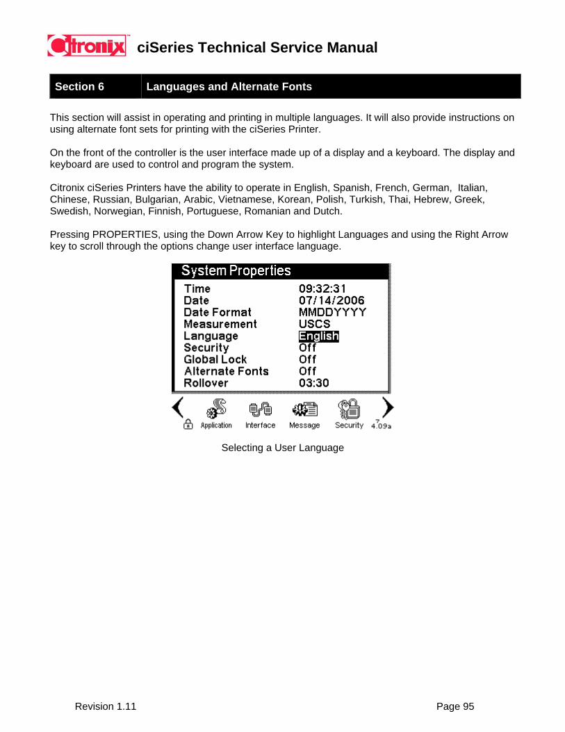
ciSeries Technical Service Manual
Revision 1.11 Page 95
Section 6 Languages and Alternate Fonts This section will assist in operating and printing in multiple languages. It will also provide instructions on using alternate font sets for printing with the ciSeries Printer. On the front of the controller is the user interface made up of a display and a keyboard. The display and keyboard are used to control and program the system. Citronix ciSeries Printers have the ability to operate in English, Spanish, French, German, Italian, Chinese, Russian, Bulgarian, Arabic, Vietnamese, Korean, Polish, Turkish, Thai, Hebrew, Greek, Swedish, Norwegian, Finnish, Portuguese, Romanian and Dutch. Pressing PROPERTIES, using the Down Arrow Key to highlight Languages and using the Right Arrow key to scroll through the options change user interface language.
Selecting a User Language

ciSeries Technical Service Manual
Revision 1.11 Page 96
Citronix currently offers keyboards in English, Arabic, Korean, Greek and Hebrew:
Citronix English Keyboard
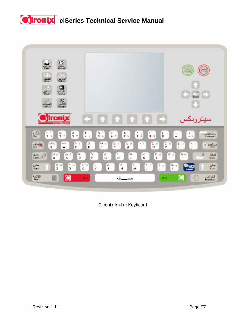
ciSeries Technical Service Manual
Revision 1.11 Page 97
Citronix Arabic Keyboard
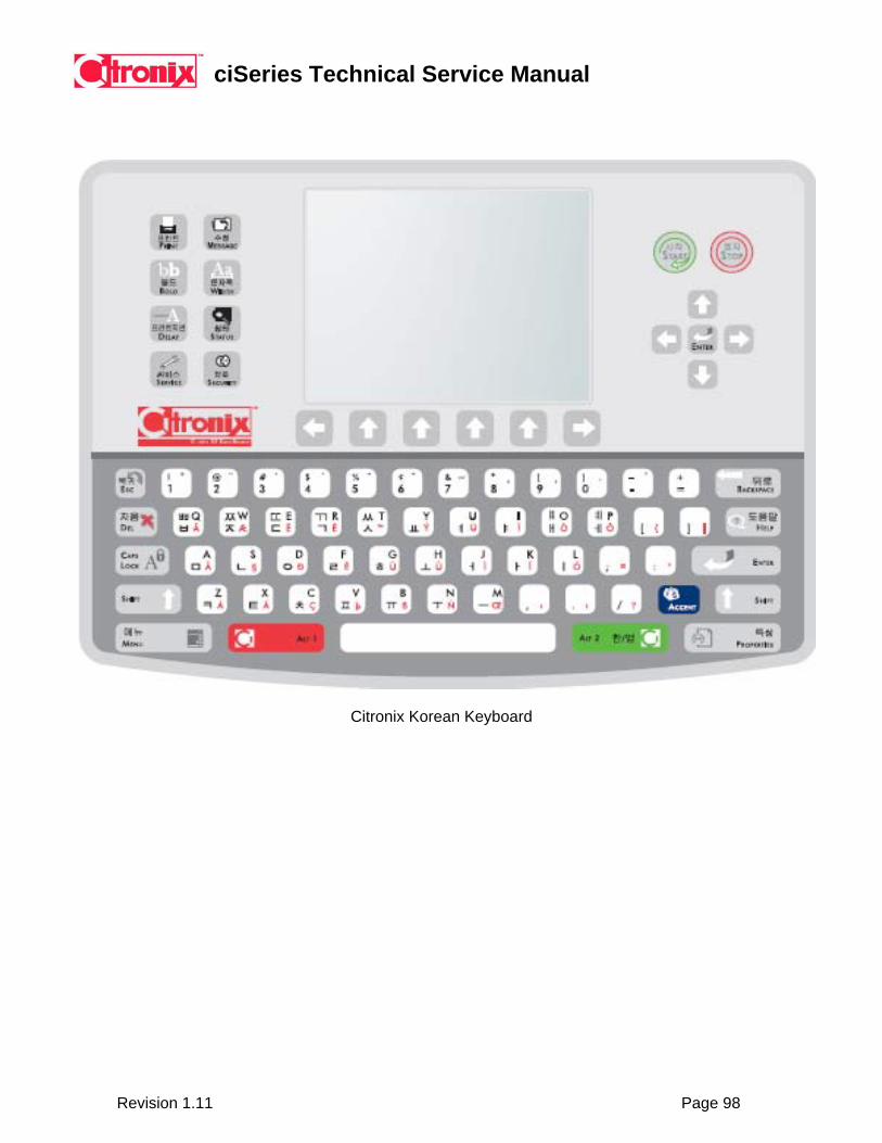
ciSeries Technical Service Manual
Revision 1.11 Page 98
Citronix Korean Keyboard

ciSeries Technical Service Manual
Revision 1.11 Page 99
Citronix Greek Keyboard

ciSeries Technical Service Manual
Revision 1.11 Page 100
Citronix Hebrew Keyboard
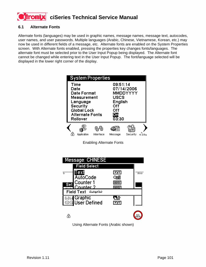
ciSeries Technical Service Manual
Revision 1.11 Page 101
6.1 Alternate Fonts Alternate fonts (languages) may be used in graphic names, message names, message text, autocodes, user names, and user passwords. Multiple languages (Arabic, Chinese, Vietnamese, Korean, etc.) may now be used in different fields of a message, etc. Alternate fonts are enabled on the System Properties screen. With Alternate fonts enabled, pressing the properties key changes fonts/languages. The alternate font must be selected prior to the User Input Popup being displayed. The Alternate font cannot be changed while entering text in the User Input Popup. The font/language selected will be displayed in the lower right corner of the display.
Enabling Alternate Fonts
Using Alternate Fonts (Arabic shown)

ciSeries Technical Service Manual
Revision 1.11 Page 102
6.2 Keyboard Swap Font Sets Each piece of text information entered into the printer has a font set associated with it. In usual mode of operation, this is the font set of the language the printer is operating in – the language set on the System Properties screen. Code Pages A code page is a set of characters associated with a language and its fonts. The number of characters is limited to 224 maximum. Most code pages have less. The main code page for English has many accented characters used by languages from Western Europe. This code page (1252) is properly called the Latin1 code page – not the English code page. For the non-Latin languages that use code pages, their characters have replaced many of the Latin characters, mostly the accented letters of the Latin code page. Therefore, text using their code page can include the non-accented Latin letters, but not the accented Latin letters. Also, most of the special characters may be used, but not all. Mixing Languages If the printer is operating in a non-English language, its fonts also have the English/Latin1 characters in them. If the font set is a Unicode font set, all the English/Latin1 characters are included in the font set, including accented letters and special characters If the font set is a non-English code page (code page other than 1252), the characters of that language have replaced some of the special English/Latin1 characters in the code page. These replaced English/Latin1 characters are not in the font set associated with this language. Several languages have the ability to switch keyboards from their native keyboard to the English/Latin1 keyboard. This keyboard swap is performed by pressing the ALT1 (or ALT2) key and then pressing the SPACE bar. Available languages may be found in the Language Table. These languages are allowed to mix English/Latin1 characters in with their native characters within one text field. This is allowed because their fonts have the English/Latin1 characters in them. If the language has Unicode fonts, all the English/Latin1 characters are allowed to be used. If the language has code page, only some of the characters may be used as shown in the Special Characters Table.
NOTE: When operating in Chinese mode the default font set is English/Latin1. It will be necessary to perform a keyboard swap prior to entering Chinese characters.

ciSeries Technical Service Manual
Revision 1.11 Page 103
Language Fonts Keyboard / Code Page
Keyboard Swap
English Latin 1252 na Arabic Arabic Unicode (0660-0669 &
FE80-FEFC) Yes
Brazilian Portuguese Latin 1252 na Bulgarian Cyrillic 1251 Yes Chinese - simplified Chinese Unicode (4E00-9FA5) Yes Finnish Latin 1252 na French Latin 1252 na German Latin 1252 na Greek Greek 1253 Yes Hebrew Hebrew 1255 Yes Italian Latin 1252 na Korean Korean Unicode (AC00-D7A3)
(Using 0100-0267) Yes
Norwegian Latin 1252 na Polish Latin 1252 na Romanian Latin 1252 na Russian Cyrillic 1251 Yes Spanish Latin 1252 na Swedish Latin 1252 na Thai Thai Unicode (0E00-0E60) Yes Turkish Turkish 1254 na Vietnamese Vietnamese Unicode (1E00-1EF9) Yes
Language Table
Arabic
Latin
Chinese
Greek
Hebrew
Korean
Russian
Thai
Turkish
Vietnamese
¢ ¢ ¢ ¢ ¢ ¢ ¢ ¢ ¢ £ £ £ £ £ £ £ £ £ ¥ ¥ ¥ ¥ ¥ ¥ ¥ ¥ ¥ ¼ ¼ ¼ ¼ ¼ ¼ ¼ ¼ ½ ½ ½ ½ ½ ½ ½ ½ ½ ¾ ¾ ¾ ¾ ¾ ¾ ¾ ¾
Special Characters Table
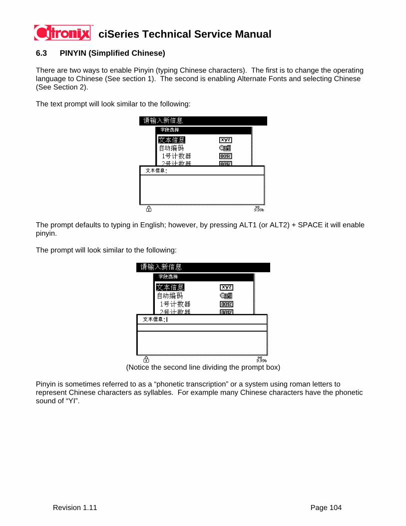
ciSeries Technical Service Manual
Revision 1.11 Page 104
6.3 PINYIN (Simplified Chinese) There are two ways to enable Pinyin (typing Chinese characters). The first is to change the operating language to Chinese (See section 1). The second is enabling Alternate Fonts and selecting Chinese (See Section 2). The text prompt will look similar to the following:
The prompt defaults to typing in English; however, by pressing ALT1 (or ALT2) + SPACE it will enable pinyin. The prompt will look similar to the following:
(Notice the second line dividing the prompt box)
Pinyin is sometimes referred to as a “phonetic transcription” or a system using roman letters to represent Chinese characters as syllables. For example many Chinese characters have the phonetic sound of “YI”.
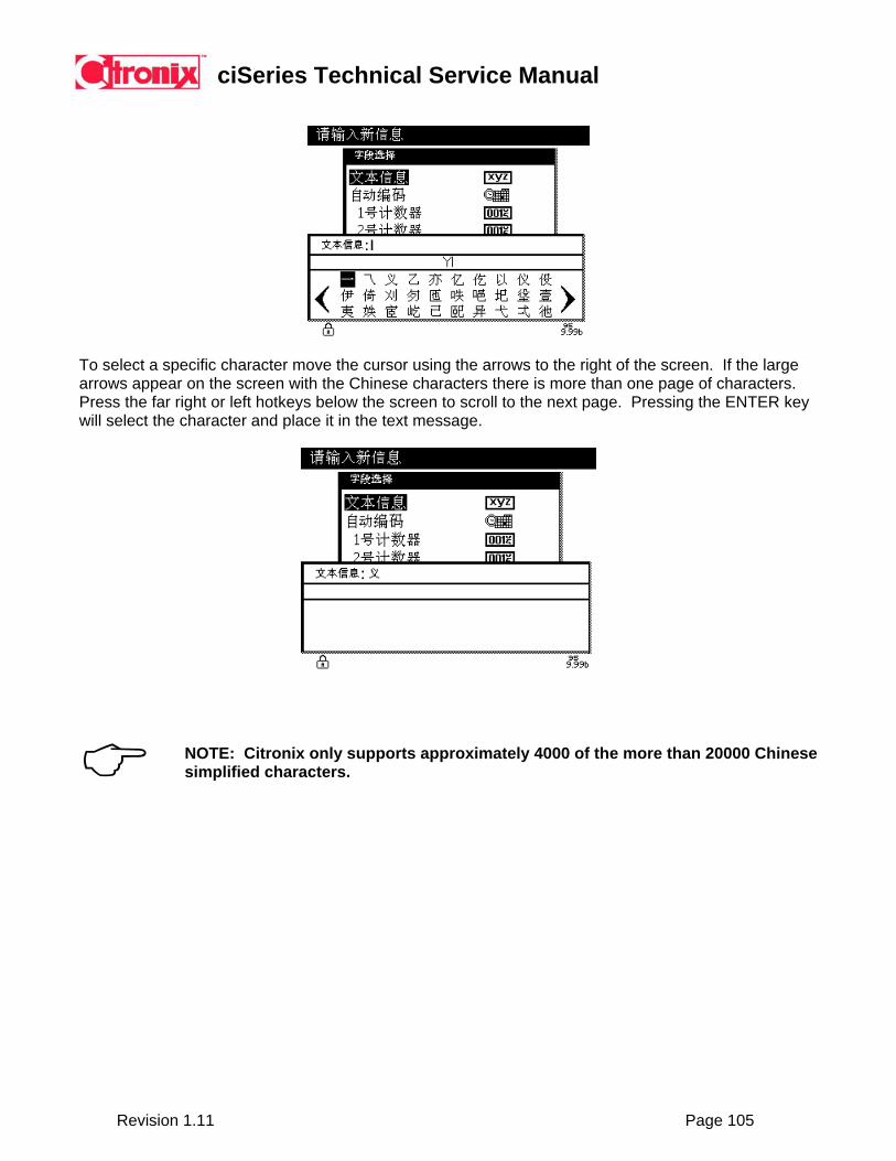
ciSeries Technical Service Manual
Revision 1.11 Page 105
To select a specific character move the cursor using the arrows to the right of the screen. If the large arrows appear on the screen with the Chinese characters there is more than one page of characters. Press the far right or left hotkeys below the screen to scroll to the next page. Pressing the ENTER key will select the character and place it in the text message.
NOTE: Citronix only supports approximately 4000 of the more than 20000 Chinese simplified characters.

ciSeries Technical Service Manual
Revision 1.11 Page 106
Section 7 Cleaning and Maintenance 7.1 Maintenance Chart
Period of Time Task Reference Every Day Every Week Every 3-6 months or 1200-2000 Hours Every 3-6 months or 1200 -2000 Hours Pigment (White and Yellow) Inks Every 3 months or 1200 Hours
Check and clean printhead, as required Clean controller, umbilical, and printhead enclosure Replace air filter Replace main ink filter Replace gutter filter Replace feed filter Replace makeup filter (ci1000/ci700) Replace main ink filter Replace gutter filter Replace feed filter Replace makeup filter (ci1000/ci700) Refresh ink in ink reservoir
Section 7.2/7.3 Section 7.4 Section 7.5 Section 7.6 Section 7.6
Note: The maintenance chart is a general guideline. Some applications will require more frequent filter changes dependent on the environment. Note: Pigment Inks – White and Yellow should be changed every 1200 hours. In addition, pigment inks should have the ink reservoir refreshed at this same interval (dispose of used ink and replenish with new). Note: The Filter Due error screen will popup when filters become due based on filter time settings. This error screen will popup every five minutes until filter status’s are reset.

ciSeries Technical Service Manual
Revision 1.11 Page 107
7.2 Check and Clean Printhead
The system will operate for a considerable time before the printhead will require cleaning. However, peak operating performance and reliability will only be maintained if the printhead is cleaned on a regular basis. To check and clean the printhead:
NOTE: Do not use Makeup fluids to wash printhead. The conductive properties in the Makeup fluids will cause HV Trip errors. NOTE: Make sure the Cleaning Solvent being used is compatible with the ink being used. 1) Stop the jet. 2) Release the thumbscrew securing the printhead front cover and slide off the
cover.
3) Check inside the printhead cover for a build up of ink deposits, if any deposits are evident then clean the inside of the cover.
4) Check the printhead for build up of ink deposits and where necessary use the
appropriate cleaning solvent compatible with the type of ink being used. Pay particular attention to the Nozzle, Charge Electrode, Phase Detector, Deflection Plates and Gutter.
5) Using a suitable container to catch excess cleaning solvent. Dispose of
excess cleaning solvent in accordance with local regulations.
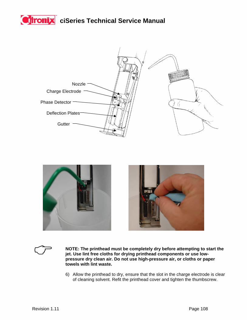
ciSeries Technical Service Manual
Revision 1.11 Page 108
Nozzle Charge Electrode
Phase Detector
Deflection Plates
Gutter
NOTE: The printhead must be completely dry before attempting to start the jet. Use lint free cloths for drying printhead components or use low-pressure dry clean air. Do not use high-pressure air, or cloths or paper towels with lint waste.
6) Allow the printhead to dry, ensure that the slot in the charge electrode is clear
of cleaning solvent. Refit the printhead cover and tighten the thumbscrew.
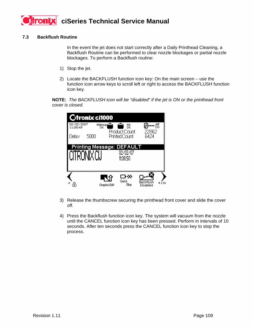
ciSeries Technical Service Manual
Revision 1.11 Page 109
7.3 Backflush Routine
In the event the jet does not start correctly after a Daily Printhead Cleaning, a Backflush Routine can be performed to clear nozzle blockages or partial nozzle blockages. To perform a Backflush routine:
1) Stop the jet. 2) Locate the BACKFLUSH function icon key: On the main screen – use the
function icon arrow keys to scroll left or right to access the BACKFLUSH function icon key.
NOTE: The BACKFLUSH icon will be “disabled” if the jet is ON or the printhead front cover is closed.
3) Release the thumbscrew securing the printhead front cover and slide the cover off.
4) Press the Backflush function icon key. The system will vacuum from the nozzle
until the CANCEL function icon key has been pressed. Perform in intervals of 10 seconds. After ten seconds press the CANCEL function icon key to stop the process.

ciSeries Technical Service Manual
Revision 1.11 Page 110
5) While the backflush operation is in process, apply the appropriate cleaning solvent to the nozzle. Observe the cleaning solvent being vacuumed through the nozzle.
Spray cleaning solvent into nozzle
6) If this does not clear the problem – repeat six times. If problem persists contact a maintenance technician.
7.4 Clean Controller, Umbilical, and Printhead Enclosures
Clean the system enclosures with stainless steel cleaner, and absorbent cloth.

ciSeries Technical Service Manual
Revision 1.11 Page 111
7.5 Replace Air Filter
The air filter is located on the right hand side of the cabinet, beneath the air filter protection cover. To replace the air filter:
1) Remove the air filter protection cover. 2) Remove the air filter. 3) Replace the air filter. 4) Replace the air filter cover.
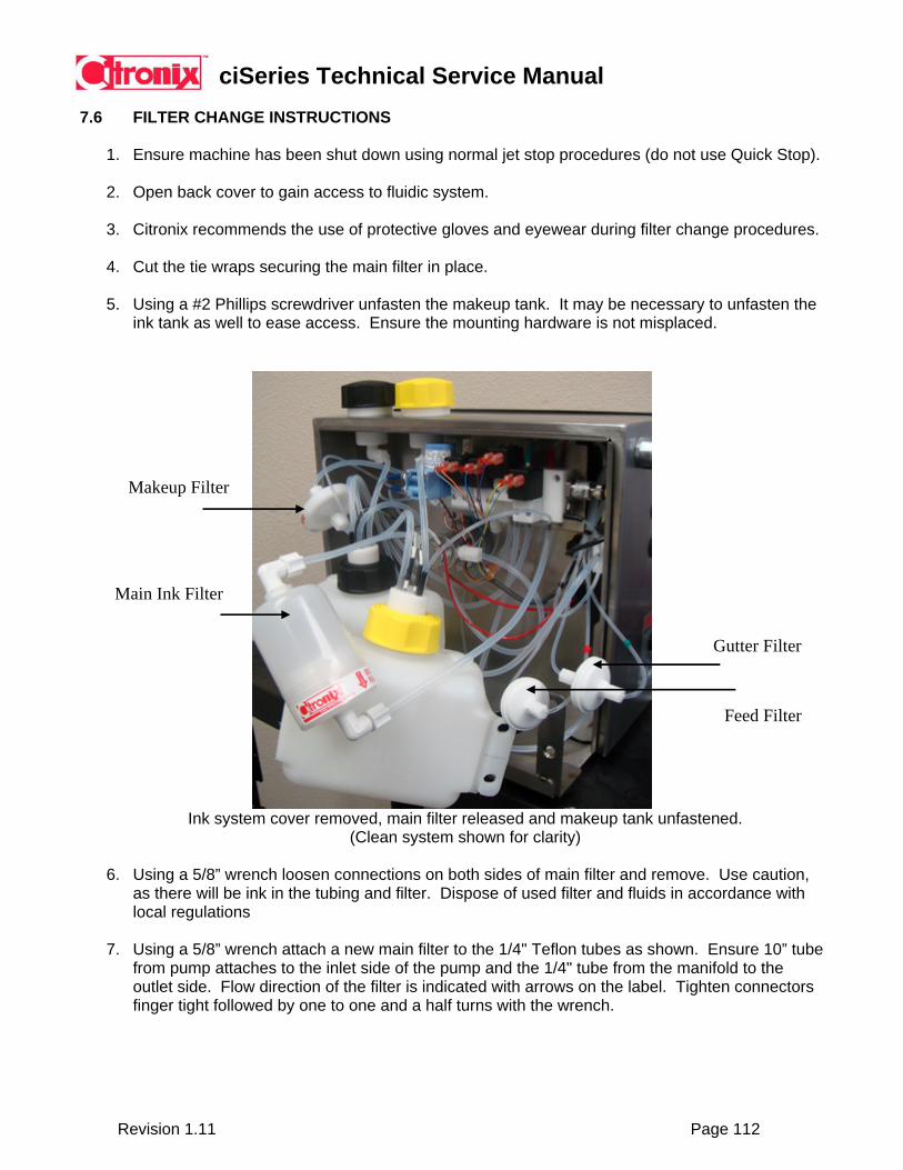
ciSeries Technical Service Manual
Revision 1.11 Page 112
7.6 FILTER CHANGE INSTRUCTIONS
1. Ensure machine has been shut down using normal jet stop procedures (do not use Quick Stop).
2. Open back cover to gain access to fluidic system.
3. Citronix recommends the use of protective gloves and eyewear during filter change procedures.
4. Cut the tie wraps securing the main filter in place.
5. Using a #2 Phillips screwdriver unfasten the makeup tank. It may be necessary to unfasten the ink tank as well to ease access. Ensure the mounting hardware is not misplaced.
Gutter Filter
Main Ink Filter
Makeup Filter
Feed Filter
Ink system cover removed, main filter released and makeup tank unfastened. (Clean system shown for clarity)
6. Using a 5/8” wrench loosen connections on both sides of main filter and remove. Use caution,
as there will be ink in the tubing and filter. Dispose of used filter and fluids in accordance with local regulations
7. Using a 5/8” wrench attach a new main filter to the 1/4" Teflon tubes as shown. Ensure 10” tube
from pump attaches to the inlet side of the pump and the 1/4" tube from the manifold to the outlet side. Flow direction of the filter is indicated with arrows on the label. Tighten connectors finger tight followed by one to one and a half turns with the wrench.
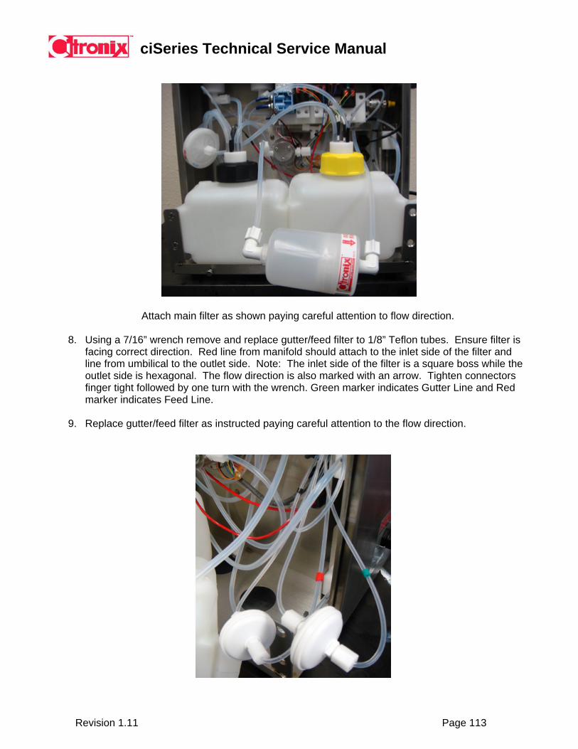
ciSeries Technical Service Manual
Revision 1.11 Page 113
Attach main filter as shown paying careful attention to flow direction.
8. Using a 7/16” wrench remove and replace gutter/feed filter to 1/8” Teflon tubes. Ensure filter is facing correct direction. Red line from manifold should attach to the inlet side of the filter and line from umbilical to the outlet side. Note: The inlet side of the filter is a square boss while the outlet side is hexagonal. The flow direction is also marked with an arrow. Tighten connectors finger tight followed by one turn with the wrench. Green marker indicates Gutter Line and Red marker indicates Feed Line.
9. Replace gutter/feed filter as instructed paying careful attention to the flow direction.

ciSeries Technical Service Manual
Revision 1.11 Page 114
10. Place gutter/feed filters behind makeup tank ensuring tubing is not kinked or pinched.
11. Using a 5/8” wrench loosen connections on both sides of makeup filter and remove. Use
caution, as there will be makeup in the tubing and filter. Dispose of used filter and fluids in accordance with local regulations
12. Using a 5/8” wrench attach a new makeup filter to the 1/4" Teflon tubes as shown. Ensure tube
from makeup tank attaches to the inlet side of the pump and the 1/4" tube from the manifold to the outlet side. Flow direction of the filter is indicated with arrows on the label. Tighten connectors finger tight followed by one to one and a half turns with the wrench.
Attach makeup filter as shown paying careful attention to flow direction.
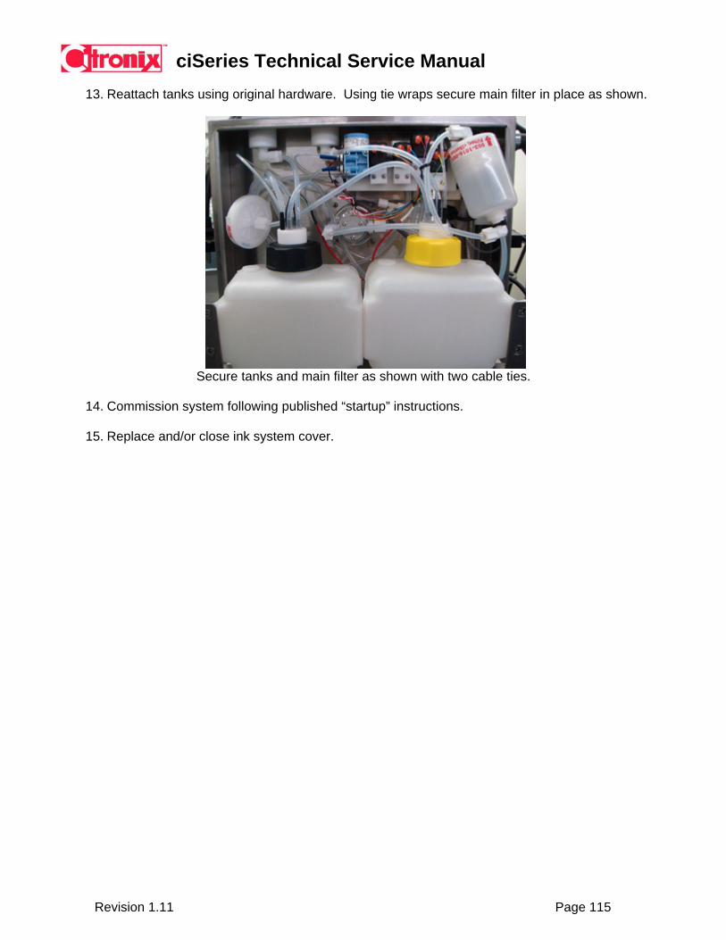
ciSeries Technical Service Manual
Revision 1.11 Page 115
13. Reattach tanks using original hardware. Using tie wraps secure main filter in place as shown.
Secure tanks and main filter as shown with two cable ties.
14. Commission system following published “startup” instructions. 15. Replace and/or close ink system cover.
ciSeries Technical Service Manual
Revision 1.11 Page 116
Section 8 Technical Description, Troubleshooting and Repair
8.1 Introduction
This section provides a technical description with function, troubleshooting of the components and repair procedures of a ciSeries system. 8.2 The Printing Process
Fluid pressure generated through the use of an internal pump pushes a steady stream of ink through the control valves and into the drop generator. Inside the drop generator, electric pulses vibrate the ink chamber to separate the ink stream into droplets. A programmable pattern of electric pulses per second creating 60,000 - 88,000 droplets a second.
The vibration is fast and steady providing a continuous, consistent formed stream of drops. Each drop is formed in the same location, while at the same time an electric charge is applied to give each drop a predetermined negative electrostatic charge. The amount of the charge on the drop determines its location to make up the printed code.
The negatively charged droplets leaving the charge electrode pass under a high voltage deflection plate, which has a fixed positive charge. The deflecting plate has a strong attraction for the droplets with the larger negative charges and pulls them higher in the pattern. The droplets with lower charges have less attraction and are deflected to lower positions. Droplets that are not needed for the pattern will not receive a negative charge as they pass; consequently, they will not be attracted to the deflection plate. The uncharged droplets shoot straight into the gutter and are delivered back to the ink reservoir for re-use.
To print a 7x5 matrix character, the printhead prints five vertical columns in which it may print up to 7 dots on each column. Allowing the uncharged drops of ink to return to the ink supply result in blank spaces in the figures on the printed surface. Print capabilities include printing alphanumeric characters, graphics, and bar codes. 8.3 Controller Cabinet
ci500 Painted Steel Construction
Nema 4 (IP55) Type Protection ci700/ci1000: Stainless Steel Construction
Nema 4 (IP55) Type Protection
Ci2000: Stainless Steel Construction Nema 4 (IP65) Type Protection
Nema 4 (IP55) – Protected against dust - limited ingress (no harmful deposit). Protected against low pressure jets of water from all directions - limited ingress permitted. Nema 4 (IP65) – Totally protected against dust. Protected against low pressure jets of water from all directions - limited ingress permitted.
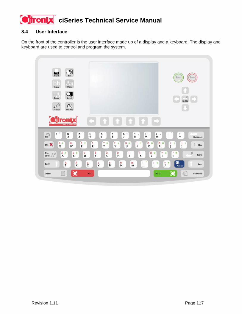
ciSeries Technical Service Manual
Revision 1.11 Page 117
8.4 User Interface
On the front of the controller is the user interface made up of a display and a keyboard. The display and keyboard are used to control and program the system.
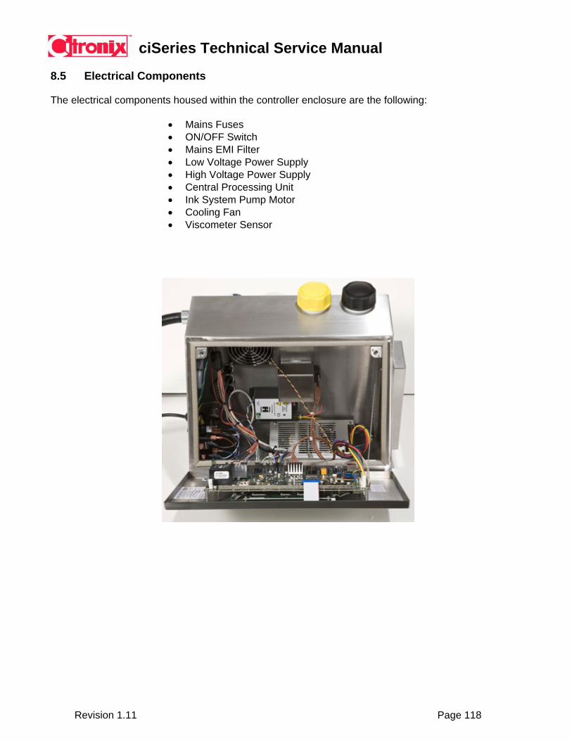
ciSeries Technical Service Manual
Revision 1.11 Page 118
8.5 Electrical Components
The electrical components housed within the controller enclosure are the following:
• Mains Fuses • ON/OFF Switch • Mains EMI Filter • Low Voltage Power Supply • High Voltage Power Supply • Central Processing Unit • Ink System Pump Motor • Cooling Fan • Viscometer Sensor
ciSeries Technical Service Manual
Revision 1.11 Page 119
Mains Fuses There are two mains supply fuses located on the left hand side of the controller enclosure. The fuses are 3.15 amp for both 110VAC and 240VAC operation.
Fuse: 3.15 amp Fuse Type: 5x20mm
Testing the fuses: 1) Turn power off, and disconnect power supply. 2) Remove fuse from fuse holder. 3) Perform a conductivity test. 4) Replace as necessary. ON/OFF Switch
The mains supply switch is located on the left hand side of the controller. The switch in the off position disables the mains supply to the system, and the switch in the on position enables the mains supply to the system. Testing the ON/OFF Switch: 1) Take caution, as high voltage is present when performing this test. 2) Open controller enclosure electrical door. 3) Turn the power switch to the on position. 4) Test for 120 or 240 volts on the input side of the mains EMI filter. 5) Replace as necessary.
Mains Filter
The mains EMI filter is located on the inside of the controller enclosure on the left hand side. This component isolates, and filters the mains supply from electrical noise and spikes from interfering with the operation, as well as preventing noise from being transmitted from the system to the mains supply.
Testing the mains filter: 1) Take caution, as high voltage is present when performing this test. 2) Open controller enclosure electrical door. 3) Turn the power switch to the on position, perform fuse and on/off switch test first. 4) Test for 120 or 240 volts on the load side of the mains filter. 5) Replace as necessary.
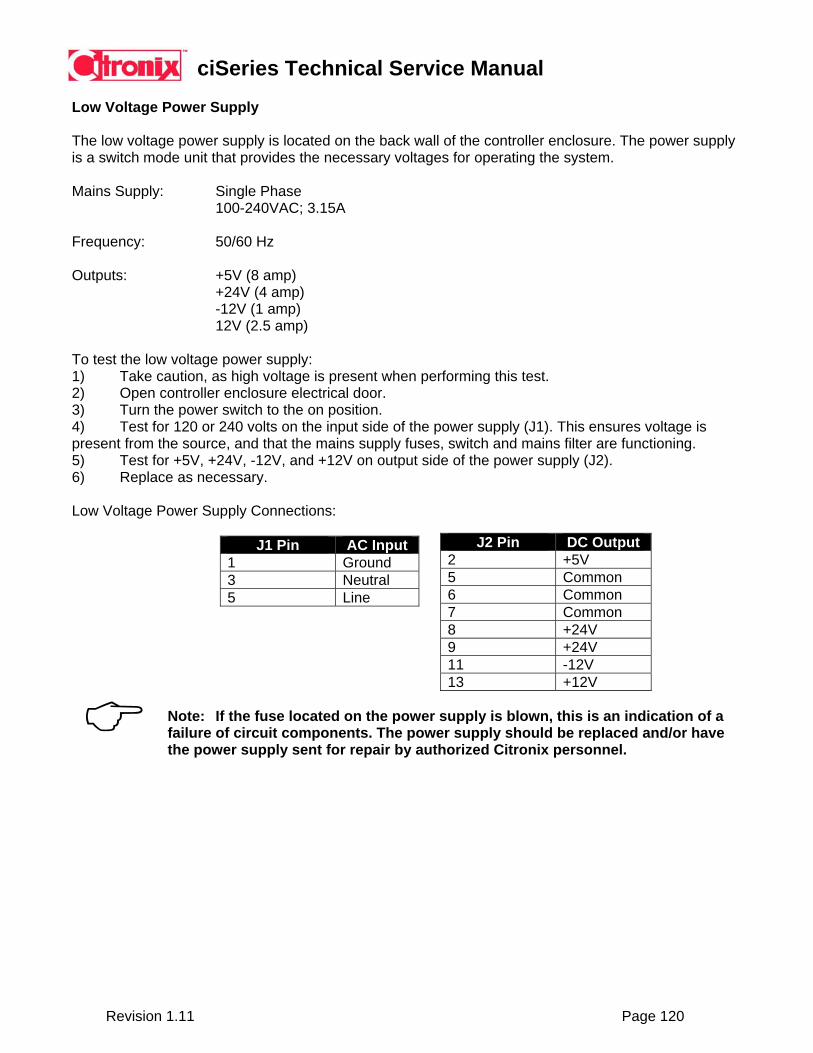
ciSeries Technical Service Manual
Revision 1.11 Page 120
Low Voltage Power Supply
The low voltage power supply is located on the back wall of the controller enclosure. The power supply is a switch mode unit that provides the necessary voltages for operating the system.
Mains Supply: Single Phase 100-240VAC; 3.15A
Frequency: 50/60 Hz
Outputs: +5V (8 amp) +24V (4 amp)
-12V (1 amp) 12V (2.5 amp)
To test the low voltage power supply: 1) Take caution, as high voltage is present when performing this test. 2) Open controller enclosure electrical door. 3) Turn the power switch to the on position. 4) Test for 120 or 240 volts on the input side of the power supply (J1). This ensures voltage is present from the source, and that the mains supply fuses, switch and mains filter are functioning. 5) Test for +5V, +24V, -12V, and +12V on output side of the power supply (J2). 6) Replace as necessary.
Low Voltage Power Supply Connections:
J1 Pin AC Input 1 Ground 3 Neutral 5 Line
J2 Pin DC Output 2 +5V 5 Common 6 Common 7 Common 8 +24V 9 +24V 11 -12V 13 +12V
Note: If the fuse located on the power supply is blown, this is an indication of a failure of circuit components. The power supply should be replaced and/or have the power supply sent for repair by authorized Citronix personnel.

ciSeries Technical Service Manual
Revision 1.11 Page 121
High Voltage Power Supply
The high voltage power supply is located on the back wall of the controller enclosure. This power supply generates high voltage necessary for the printhead deflector plates and is powered by a variable 0 - +23 V DC from the CPU circuit board.
A variable high voltage output of 0 – 8000 V at 120µ amps is provided to establish the electrostatic field between the deflector plates in the printhead.
Troubleshooting: 1) Take caution, as high voltage is present when performing this test. 2) Open controller enclosure electrical door. 3) Turn the power switch to the on position. 4) Measure the input voltage to the high voltage power supply. This voltage should be between 0
and ~+21 volts. Note this voltage. 5) Adjust the Height command to 255 via the Print Adjust screen. 6) Re-measure the input voltage to the high voltage power supply. This voltage should be ~+21
volts. 7) If the voltage changed from the original measurement to ~+21 volts, the next step is to print. a) Close the controller enclosure door. b) Start the jet, and print.
c) If the system does not print, or if the size of print is extremely small in height, it’s possible that the high voltage power supply is not functioning properly or the connection between the high voltage power supply and the deflection plates is open – perform a continuity measurement.
8) There is no suitable field test method for testing the output of the high voltage power supply. Should this module be suspect of failure after performing the input/print test, the component should be replaced.
Cable Connected Correctly Cable Connected Loose (Incorrect) Potential Solutions: Red high voltage cable (white connector) – Must be plugged firmly into module. Carries 0-8000VDC to the Positive Deflection Plate. If cable is loose or not connected no voltage will be on the deflection plates resulting in no print. System will increment counters, show high voltage present, but will not print.

ciSeries Technical Service Manual
Revision 1.11 Page 122
Central Processing Unit
The central processing unit (CPU) is located on the controller enclosure door. The CPU provides the intelligence and processing power necessary to generate, receive, and transmit the necessary electrical signals to operate the system.
Failure Modes:
• No Power • Input DC Fuses Fail • Battery Backup Discharge
To test the DC input: 1) Take caution, as high voltage is present when performing this test. 2) Open controller enclosure electrical door. 3) Turn the power switch to the on position. 4) Test for +5V, +24V, -12V, and +12V on the input of the CPU (J28). This ensures voltage is present from the source, and that the mains supply fuses, switch, mains filter and low voltage power supply are functioning.
J25 Pin DC Input
1 +5V 2 Common 3 Common 4 +24V 5 +24V 6 Power Fail 7 -12V 8 Common 9 +12V
To test the DC input fuses: 1) Turn power off, and disconnect power supply. 2) Perform a conductivity test, or review LED for fuse. 3) Replace as necessary.
LED / Fuse Voltage
+5V – 2 Amp +5V +24VHV – .5 Amp +24V +24VMTR – 2 Amp +24V +24VEXT/Fan – 2 Amp +24V
Note: Replacing +24VHV - .5 Amp fuse with 2 Amp fuse maybe result in PCB, CPU failure. This fuse protects the board from a short in the drop generator probe – typically a result of mishandling the printhead assembly. Note: If the external +24V fuse fails system will display an error indicating fan failure. System will not operate until fuse is replaced.
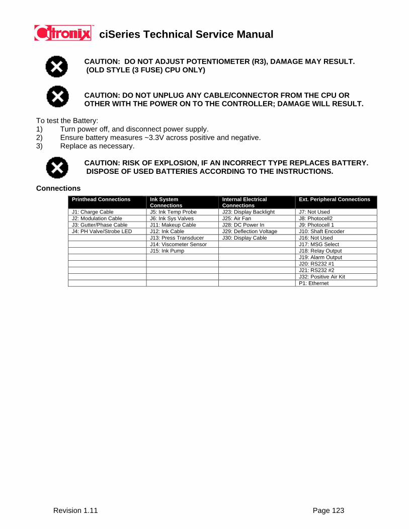
ciSeries Technical Service Manual
Revision 1.11 Page 123
CAUTION: DO NOT ADJUST POTENTIOMETER (R3), DAMAGE MAY RESULT. (OLD STYLE (3 FUSE) CPU ONLY)
CAUTION: DO NOT UNPLUG ANY CABLE/CONNECTOR FROM THE CPU OR OTHER WITH THE POWER ON TO THE CONTROLLER; DAMAGE WILL RESULT.
To test the Battery: 1) Turn power off, and disconnect power supply. 2) Ensure battery measures ~3.3V across positive and negative. 3) Replace as necessary.
CAUTION: RISK OF EXPLOSION, IF AN INCORRECT TYPE REPLACES BATTERY. DISPOSE OF USED BATTERIES ACCORDING TO THE INSTRUCTIONS.
Connections
Printhead Connections Ink System Connections
Internal Electrical Connections
Ext. Peripheral Connections
J1: Charge Cable J5: Ink Temp Probe J23: Display Backlight J7: Not Used J2: Modulation Cable J6: Ink Sys Valves J25: Air Fan J8: Photocell2 J3: Gutter/Phase Cable J11: Makeup Cable J28: DC Power In J9: Photocell 1 J4: PH Valve/Strobe LED J12: Ink Cable J29: Deflection Voltage J10: Shaft Encoder J13: Press Transducer J30: Display Cable J16: Not Used J14: Viscometer Sensor J17: MSG Select J15: Ink Pump J18: Relay Output J19: Alarm Output J20: RS232 #1 J21: RS232 #2 J32: Positive Air Kit P1: Ethernet
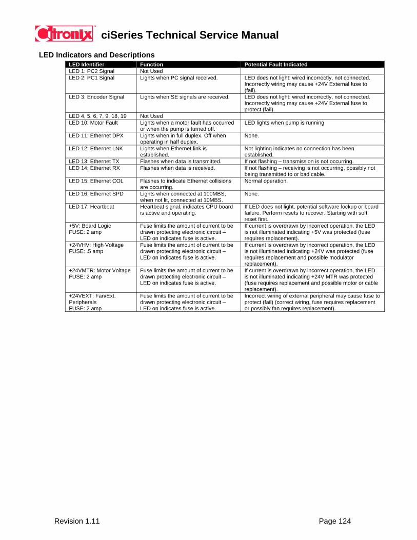
ciSeries Technical Service Manual
Revision 1.11 Page 124
LED Indicators and Descriptions
LED Identifier Function Potential Fault Indicated LED 1: PC2 Signal Not Used LED 2: PC1 Signal Lights when PC signal received. LED does not light: wired incorrectly, not connected.
Incorrectly wiring may cause +24V External fuse to (fail).
LED 3: Encoder Signal Lights when SE signals are received. LED does not light: wired incorrectly, not connected. Incorrectly wiring may cause +24V External fuse to protect (fail).
LED 4, 5, 6, 7, 9, 18, 19 Not Used LED 10: Motor Fault Lights when a motor fault has occurred
or when the pump is turned off. LED lights when pump is running
LED 11: Ethernet DPX Lights when in full duplex. Off when operating in half duplex.
None.
LED 12: Ethernet LNK Lights when Ethernet link is established.
Not lighting indicates no connection has been established.
LED 13: Ethernet TX Flashes when data is transmitted. If not flashing – transmission is not occurring. LED 14: Ethernet RX Flashes when data is received. If not flashing – receiving is not occurring, possibly not
being transmitted to or bad cable. LED 15: Ethernet COL Flashes to indicate Ethernet collisions
are occurring. Normal operation.
LED 16: Ethernet SPD Lights when connected at 100MBS, when not lit, connected at 10MBS.
None.
LED 17: Heartbeat Heartbeat signal, indicates CPU board is active and operating.
If LED does not light, potential software lockup or board failure. Perform resets to recover. Starting with soft reset first.
+5V: Board Logic FUSE: 2 amp
Fuse limits the amount of current to be drawn protecting electronic circuit – LED on indicates fuse is active.
If current is overdrawn by incorrect operation, the LED is not illuminated indicating +5V was protected (fuse requires replacement).
+24VHV: High Voltage FUSE: .5 amp
Fuse limits the amount of current to be drawn protecting electronic circuit – LED on indicates fuse is active.
If current is overdrawn by incorrect operation, the LED is not illuminated indicating +24V was protected (fuse requires replacement and possible modulator replacement).
+24VMTR: Motor Voltage FUSE: 2 amp
Fuse limits the amount of current to be drawn protecting electronic circuit – LED on indicates fuse is active.
If current is overdrawn by incorrect operation, the LED is not illuminated indicating +24V MTR was protected (fuse requires replacement and possible motor or cable replacement).
+24VEXT: Fan/Ext. Peripherals FUSE: 2 amp
Fuse limits the amount of current to be drawn protecting electronic circuit – LED on indicates fuse is active.
Incorrect wiring of external peripheral may cause fuse to protect (fail) (correct wiring, fuse requires replacement or possibly fan requires replacement).
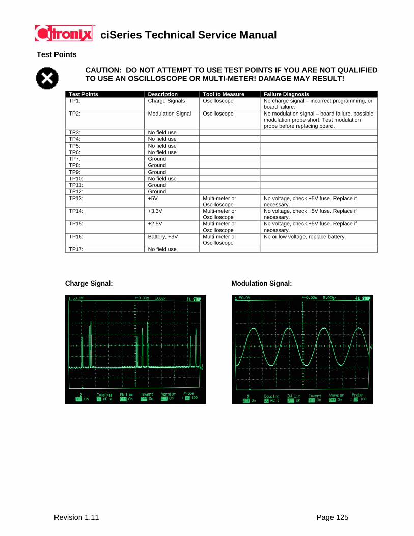
ciSeries Technical Service Manual
Revision 1.11 Page 125
Test Points
CAUTION: DO NOT ATTEMPT TO USE TEST POINTS IF YOU ARE NOT QUALIFIED TO USE AN OSCILLOSCOPE OR MULTI-METER! DAMAGE MAY RESULT!
Charge Signal: Modulation Signal:
Test Points Description Tool to Measure Failure Diagnosis TP1: Charge Signals Oscilloscope No charge signal – incorrect programming, or
board failure. TP2: Modulation Signal Oscilloscope No modulation signal – board failure, possible
modulation probe short. Test modulation probe before replacing board.
TP3: No field use TP4: No field use TP5: No field use TP6: No field use TP7: Ground TP8: Ground TP9: Ground TP10: No field use TP11: Ground TP12: Ground TP13: +5V Multi-meter or
Oscilloscope No voltage, check +5V fuse. Replace if necessary.
TP14: +3.3V Multi-meter or Oscilloscope
No voltage, check +5V fuse. Replace if necessary.
TP15: +2.5V Multi-meter or Oscilloscope
No voltage, check +5V fuse. Replace if necessary.
TP16: Battery, +3V Multi-meter or Oscilloscope
No or low voltage, replace battery.
TP17: No field use
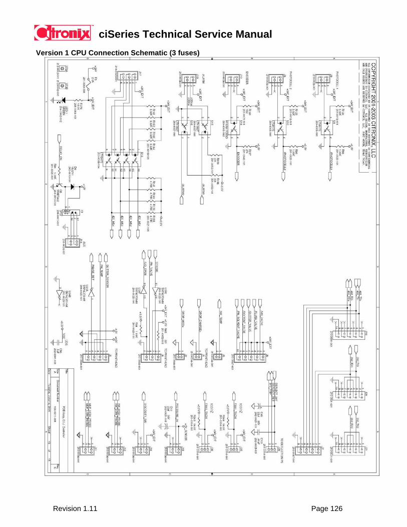
ciSeries Technical Service Manual
Revision 1.11 Page 126
Version 1 CPU Connection Schematic (3 fuses)
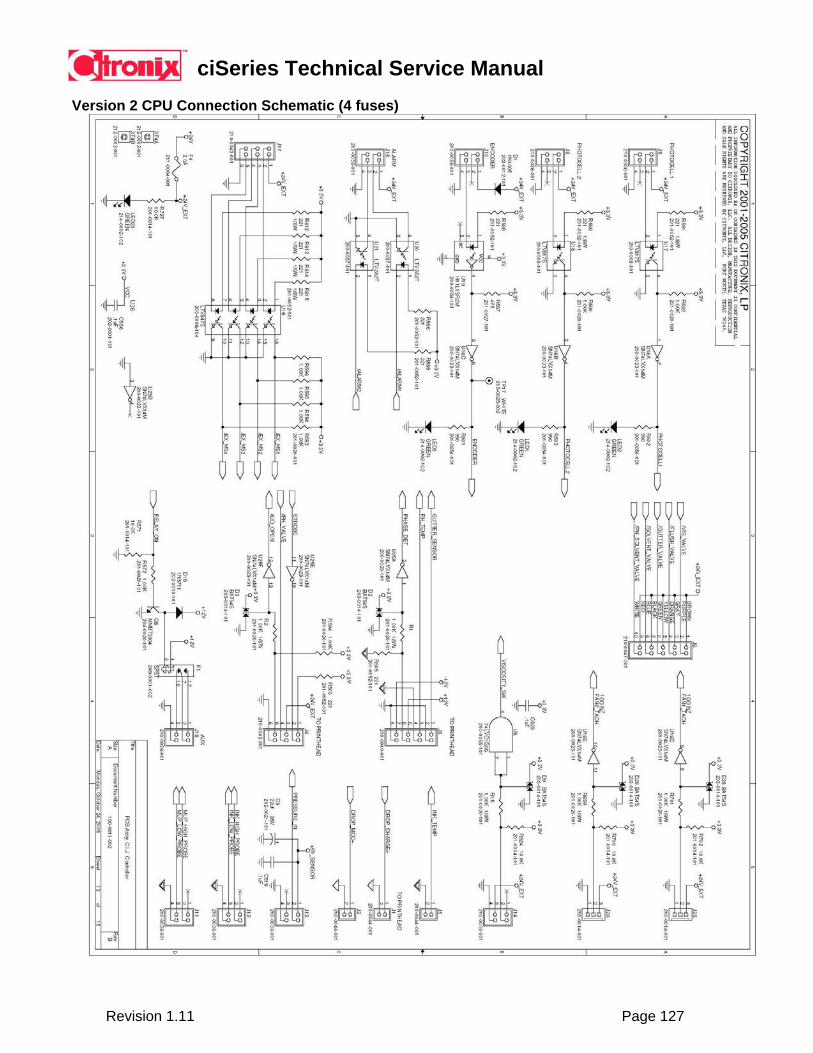
ciSeries Technical Service Manual
Revision 1.11 Page 127
Version 2 CPU Connection Schematic (4 fuses)
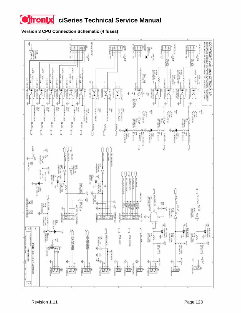
ciSeries Technical Service Manual
Revision 1.11 Page 128
Version 3 CPU Connection Schematic (4 fuses)

ciSeries Technical Service Manual
Revision 1.11 Page 129
¼ VGA LCD Display
The display is a 320x240 display allowing the ability to display text and graphics. The Citronix systems take full advantage of the graphical capability by providing a graphical icon based user interface with WYSIWYG message creation, editing and selection. The display is backlit, providing ease of operation in dim lit manufacturing environments. The backlight is software controlled to shut down after 20 minutes of inactivity; actuation of any keyboard button will turn backlight back on.
The display’s contrast adjustment is located in the center of the circuit board. To adjust the contrast:
Tool Required: Non-conductive screwdriver - # 1 cross tip.
To adjust display contrast: 1) Turn power off. 2) Open front system door. 3) Rotate contrast switch (left or right). 4) Power on to check adjustment. Repeat if necessary.
CAUTION: Equipment damage is possible. Do not attempt to adjust display contrast if power-on with conductive tools.
Ink System Pump Motor
The Ink System Pump Motor is mounted on the back wall of the controller enclosure. The pump motor is on the electrical side of the enclosure, and the Ink Pump is on the ink system side of the enclosure isolated through a Teflon seal. The motor is magnetically coupled to the pump to assure separation of the ink from the drive and electronic components.
CAUTION: Do not plug or unplug pump cable from CPU or Pump Motor with power on to the controller; damage to the pump motor and CPU will result.
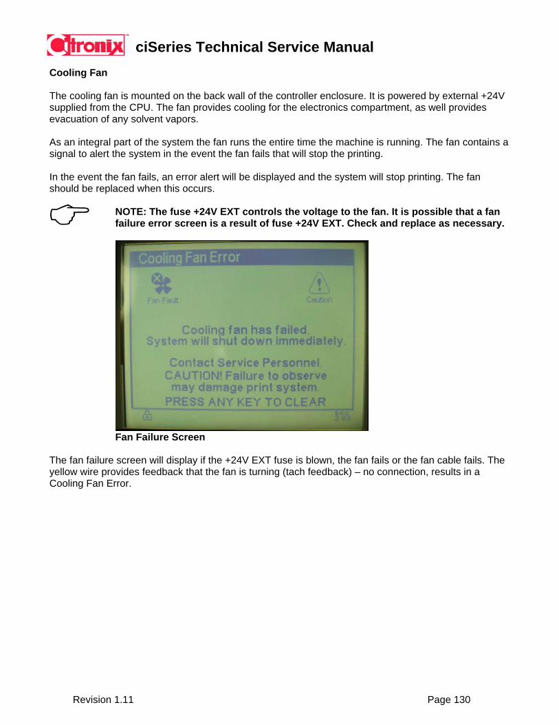
ciSeries Technical Service Manual
Revision 1.11 Page 130
Cooling Fan
The cooling fan is mounted on the back wall of the controller enclosure. It is powered by external +24V supplied from the CPU. The fan provides cooling for the electronics compartment, as well provides evacuation of any solvent vapors.
As an integral part of the system the fan runs the entire time the machine is running. The fan contains a signal to alert the system in the event the fan fails that will stop the printing.
In the event the fan fails, an error alert will be displayed and the system will stop printing. The fan should be replaced when this occurs.
NOTE: The fuse +24V EXT controls the voltage to the fan. It is possible that a fan failure error screen is a result of fuse +24V EXT. Check and replace as necessary.
Fan Failure Screen
The fan failure screen will display if the +24V EXT fuse is blown, the fan fails or the fan cable fails. The yellow wire provides feedback that the fan is turning (tach feedback) – no connection, results in a Cooling Fan Error.

ciSeries Technical Service Manual
Revision 1.11 Page 131
Viscometer Sensor
The viscometer sensor is located on the back wall, lower left hand corner. The sensor is an inductive sensor for detecting the viscometer ball made of stainless steel. The sensor detects when the ball moves upward to ensure viscometer is working. The sensor then detects when the ball returns detecting the ball fall time determining the thickness of the fluid, giving the viscosity time on the Viscosity Status screen. Troubleshooting: The sensor has an integrated LED and will light at the beginning cycle of the viscosity check and also at the end. This indicates the sensor is working and the ball is moving (correct operation). In the event the LED does not light at the beginning, the system will also display the following Error screen “Viscometer Error”. This indicates either the sensor has failed or the ball is stuck in the viscometer, or no fluid is present in the viscometer. Potential Solutions:
- Verify sensor is good or bad, replace as necessary. - Ensure sensor is plugged into the PCB correctly. - Verify the ball is stuck in viscometer, disassemble/clean viscometer. - The viscometer must be free of air to operate correctly. If the return line from the
viscometer to the ink reservoir is not submerged in the ink the line will allow air to collect in the viscometer. Verify no damage to tubing and correct as necessary.
- Ensure viscometer valve is functioning, use “Valve Test”. - Ensure the Pressure Restrictor is not clogged, clean/replace as necessary.

ciSeries Technical Service Manual
Revision 1.11 Page 132
8.6 Ink System
The components housed within the ink system enclosure are the following:
• Ink and Makeup Tank • Ink pump • Ink System Valves and Manifold • Venturi • Pressure Transducer • Ink Temperature Probe • Viscometer • Ink Filters
Ink System Diagram

ciSeries Technical Service Manual
Revision 1.11 Page 133
Algorithms for Start/Stop Jet (SmartFlush): Start Jet -
• If the jet is not running for more than 2 hours, then the system will perform a Flush Start. • Time is kept over power off in RTC. The flush start condition is not reset until the jet completes
the full start sequence. • The jet "part" of the jet start is complete when the counter goes to 0 - when the Jet Start icon is
replaced with the Jet On icon. • If there is an error in the 8 seconds between that and the HV icon coming on, the Flush Start is
considered complete. Stop Jet -
• If an ERROR stop, system stops without flush. • If jet is stopped during start jet (Pressing Stop Key during Start Process), stop without Flush. • If STOP key is pressed when the jet is off, then the system does a Flush Start. • If normal stop when jet is running, Heavy Pigment, always stop with Flush Stop. • If normal stop when jet is running, if not Heavy Pigment, Flush Stop if viscosity is greater than .3
below set point, otherwise stop without Flush. Add makeup algorithm after viscosity check -
• Viscosity still checked on the same schedule. • If Food Grade ink, wait for viscosity to stabilize before adding makeup. • If not Food Grade, wait for jet to be on for one hour before adding makeup. • Viscosity check will not take affect for 1 hour after Start Jet. After 1 hour of operation, if viscosity
is high, makeup will be added. If any problem stops the jet, when restarted, the system will wait another hour before acting on a viscosity check. It now takes longer before new ink’s viscosity will lower to 3.6.
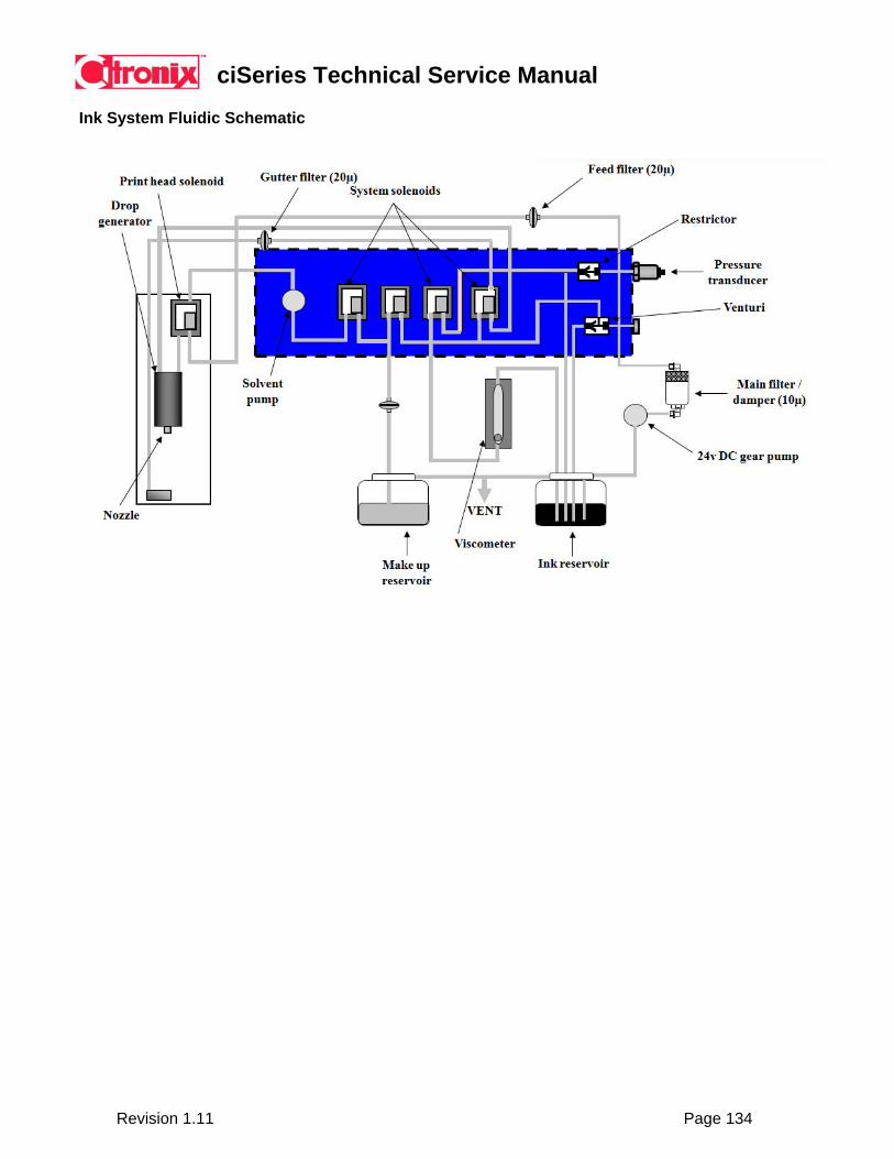
ciSeries Technical Service Manual
Revision 1.11 Page 134
Ink System Fluidic Schematic

ciSeries Technical Service Manual
Revision 1.11 Page 135
Ink and Makeup Tanks
ciSeries Ink and Makeup Tanks
The ci580 ink and makeup tanks hold 1 liter of ink or makeup. The ci700/ci1000/ci2000 ink and makeup tanks hold 1.9 liters of ink or makeup.
8.6.3 Ink Pump The Ink System is mounted on the back wall of the controller enclosure. The pump motor is on the electrical side of the enclosure, and the ink pump is on the ink system side of the enclosure isolated through a Teflon seal. The motor is magnetically coupled to the pump to assure separation of the ink from the drive components.
CAUTION: Dry ink residue in ink pump may cause pump lockup. +24V MTR will blow when this occurs. If leaving idle for more than two weeks, ensure the system is flushed completely of all ink residues or leave ink in system. To remedy ingest Cleaning Solution directly into the pump head via the inlet or outlet.
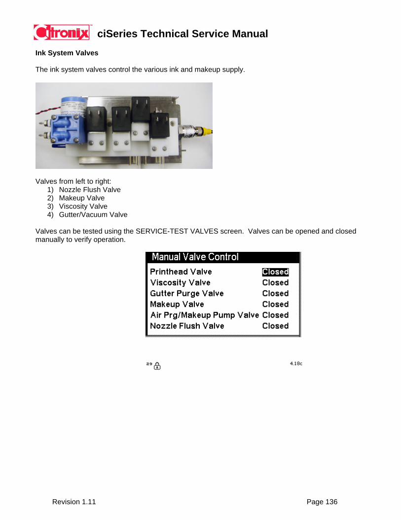
ciSeries Technical Service Manual
Revision 1.11 Page 136
Ink System Valves The ink system valves control the various ink and makeup supply.
Valves from left to right:
1) Nozzle Flush Valve 2) Makeup Valve 3) Viscosity Valve 4) Gutter/Vacuum Valve
Valves can be tested using the SERVICE-TEST VALVES screen. Valves can be opened and closed manually to verify operation.
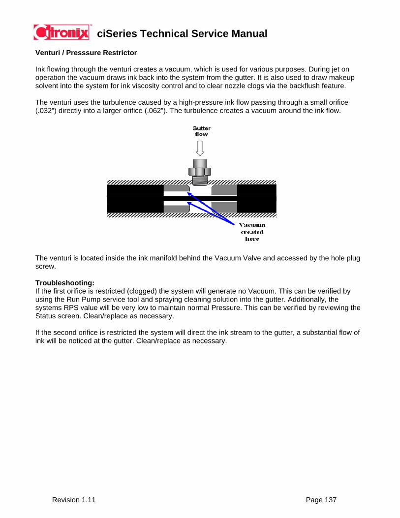
ciSeries Technical Service Manual
Revision 1.11 Page 137
Venturi / Presssure Restrictor
Ink flowing through the venturi creates a vacuum, which is used for various purposes. During jet on operation the vacuum draws ink back into the system from the gutter. It is also used to draw makeup solvent into the system for ink viscosity control and to clear nozzle clogs via the backflush feature.
The venturi uses the turbulence caused by a high-pressure ink flow passing through a small orifice (.032”) directly into a larger orifice (.062”). The turbulence creates a vacuum around the ink flow.
The venturi is located inside the ink manifold behind the Vacuum Valve and accessed by the hole plug screw. Troubleshooting: If the first orifice is restricted (clogged) the system will generate no Vacuum. This can be verified by using the Run Pump service tool and spraying cleaning solution into the gutter. Additionally, the systems RPS value will be very low to maintain normal Pressure. This can be verified by reviewing the Status screen. Clean/replace as necessary. If the second orifice is restricted the system will direct the ink stream to the gutter, a substantial flow of ink will be noticed at the gutter. Clean/replace as necessary.

ciSeries Technical Service Manual
Revision 1.11 Page 138
Pressure Transducer The pressure transducer monitors the operating ink pressure and feeds a signal to the CPU board for increasing/decreasing the pump rounds per second to maintain a set operating pressure. Viscometer
The viscometer is an instrument used to measure viscosity of the ink. The measuring method is to move a stainless ball to the top of the glass tube, then release. The release time is marked and timed. The timing is from the top of the viscometer to the bottom where an inductive sensor detects the ball. The quicker the time, the thinner the ink is and the slower the time the thicker the ink is.

ciSeries Technical Service Manual
Revision 1.11 Page 139
8.7 Printhead Components
The printhead components housed within the printhead enclosure are the following:
• Drop Generator • Nozzle • Charge Electrode and Strobe • Phase Detector • Deflector Plates • Gutter • Printhead Valve / Heater • Phase Circuit Board • Printhead Cover Sensor • Printhead Temperature Sensor
ciSeries Technical Service Manual
Revision 1.11 Page 140
Drop Generator The drop generator oscillates the ink stream that is supplied under pressure via the ink pump in effort to break the stream into uniform drops. The modulation voltage used for the oscillation determines the drop break up point, and is an individual characteristic to each printhead. The printhead is calibrated with the modulation voltage at the time of manufacturing, and so noted on the “Service Label”.
The modulation voltage must be correct ensuring the drop break up point occurs in the charge electrode slot. Should the drop break up point occur outside the slot, incorrect charging of the drops will occur. Charge Electrode The breakup caused by the drop generator is calibrated to occur within the charge electrode slot. The charge electrode applies a charge to drops required for printing, those drops that do not receive a charge will be returned to the ink system for re-use through the gutter.
A strobe LED situated underneath the charge electrode allows the drop break up to be viewed with a 10x or greater magnifying eyeglass.
Phase Detector
The phase detector provides feedback that the drop charging is occurring correctly. The drop charge timing is critical to the operation, thus a feedback circuit is required to ensure this timing to maintain optimum print quality.
Deflector Plates The deflector plates generate an electrostatic field. This field deflects drops by the amount of charge they received at the charge electrode. Drops with a greater charge will be deflected further than those with a lower charge. Drops that do not contain a charge will not be deflected passing through the electrostatic field to the gutter for re-use by the ink system.
Gutter
The printhead gutter collects non-charged droplets and delivers this reclaimed ink back to the ink system for re-use. The gutter primarily is only collecting the non-used ink allowing a sensor to monitor the gutter’s operation. In the event the gutter is not collecting non-printed drops during the printing process the sensor will detect a fault and display an error screen.
Printhead Valve / Printhead Heater
The printhead valve is a three-way valve: Turns the jet on / off Opens and closes to allow air to be purged from the system at startup. Through controlled pulse width modulation, the printhead valve is used as a heater for the printhead to allow operation in cold environments. Through the use of the temperature sensor, and this heating method the printhead is brought to 70 F, and maintained.
ciSeries Technical Service Manual
Revision 1.11 Page 141
Phase Circuit Board
The board receives a low voltage signal from the phase detector. The Phase Circuit Board amplifies and digitizes this signal for processing. Printhead Cover Sensor
The printhead cover and printhead body contain an integrated intrinsically sealed switch to turn the charge voltage (up to 300V), and deflector voltage (up to 8KV) off. These voltages are required to print, thus the system will not print without the printhead cover in place. The switch is integrated with the printhead body, and the magnet is integrated with the printhead cover. The cover switch will toggle an icon on the main screen to indicate if the printhead is open or closed.
Printhead Temperature Sensor
The printhead contains a temperature sensor to ensure the flammable fluid temperature ignition point is not exceeded. Set well below the ignition point, if the temperature at the printhead exceeds 60 degrees C the system will shutdown automatically, in addition an error screen will be displayed.
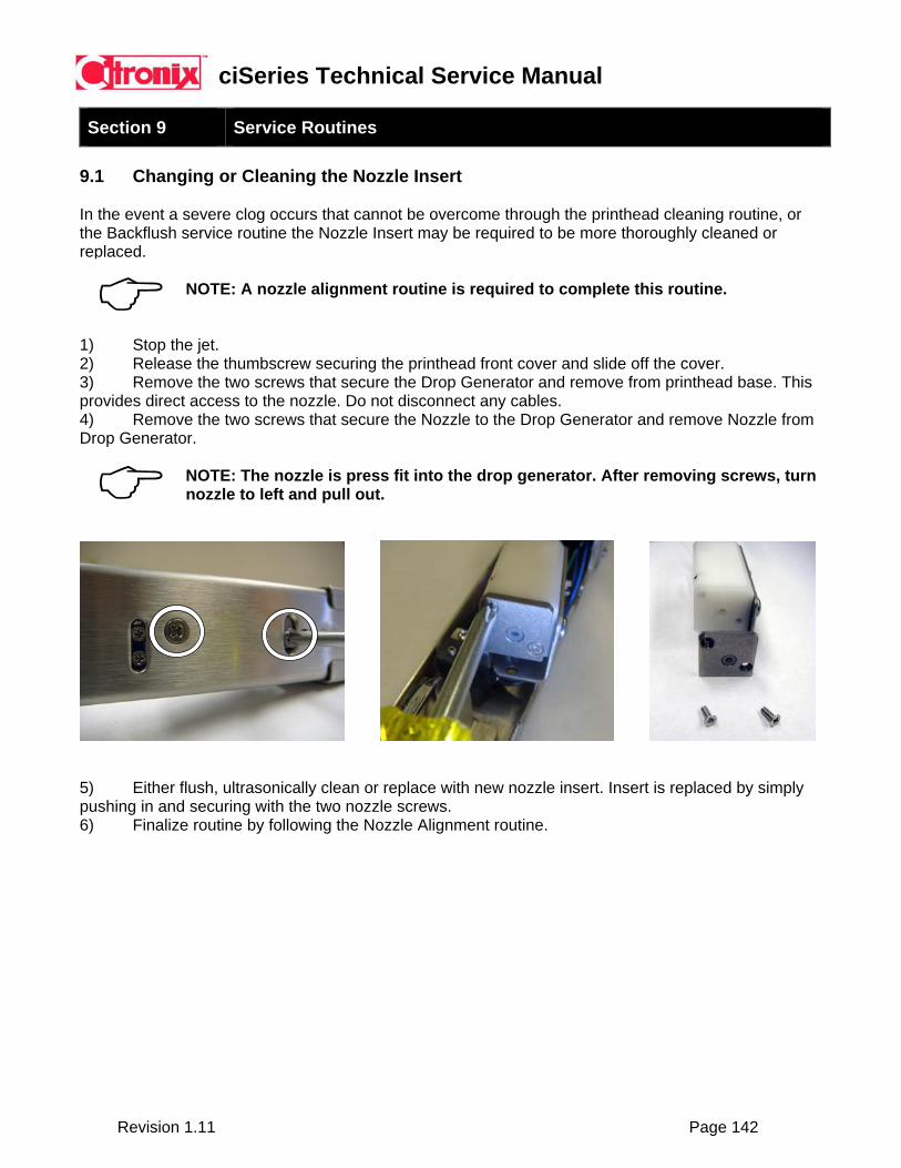
ciSeries Technical Service Manual
Revision 1.11 Page 142
Section 9 Service Routines
9.1 Changing or Cleaning the Nozzle Insert In the event a severe clog occurs that cannot be overcome through the printhead cleaning routine, or the Backflush service routine the Nozzle Insert may be required to be more thoroughly cleaned or replaced.
NOTE: A nozzle alignment routine is required to complete this routine.
1) Stop the jet. 2) Release the thumbscrew securing the printhead front cover and slide off the cover. 3) Remove the two screws that secure the Drop Generator and remove from printhead base. This provides direct access to the nozzle. Do not disconnect any cables. 4) Remove the two screws that secure the Nozzle to the Drop Generator and remove Nozzle from Drop Generator.
NOTE: The nozzle is press fit into the drop generator. After removing screws, turn nozzle to left and pull out.
5) Either flush, ultrasonically clean or replace with new nozzle insert. Insert is replaced by simply pushing in and securing with the two nozzle screws. 6) Finalize routine by following the Nozzle Alignment routine.
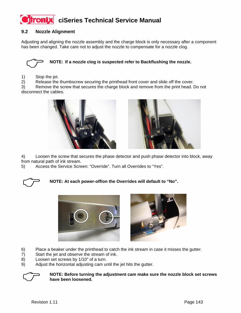
ciSeries Technical Service Manual
Revision 1.11 Page 143
9.2 Nozzle Alignment Adjusting and aligning the nozzle assembly and the charge block is only necessary after a component has been changed. Take care not to adjust the nozzle to compensate for a nozzle clog.
NOTE: If a nozzle clog is suspected refer to Backflushing the nozzle.
1) Stop the jet. 2) Release the thumbscrew securing the printhead front cover and slide off the cover. 3) Remove the screw that secures the charge block and remove from the print head. Do not disconnect the cables.
4) Loosen the screw that secures the phase detector and push phase detector into block, away from natural path of ink stream. 5) Access the Service Screen: “Override”. Turn all Overrides to “Yes”.
NOTE: At each power-off/on the Overrides will default to “No”.
6) Place a beaker under the printhead to catch the ink stream in case it misses the gutter. 7) Start the jet and observe the stream of ink. 8) Loosen set screws by 1/10” of a turn. 9) Adjust the horizontal adjusting cam until the jet hits the gutter.
NOTE: Before turning the adjustment cam make sure the nozzle block set screws have been loosened.
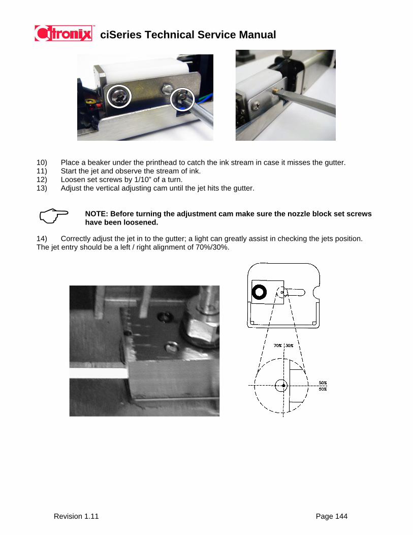
ciSeries Technical Service Manual
Revision 1.11 Page 144
10) Place a beaker under the printhead to catch the ink stream in case it misses the gutter. 11) Start the jet and observe the stream of ink. 12) Loosen set screws by 1/10” of a turn. 13) Adjust the vertical adjusting cam until the jet hits the gutter.
NOTE: Before turning the adjustment cam make sure the nozzle block set screws have been loosened.
14) Correctly adjust the jet in to the gutter; a light can greatly assist in checking the jets position. The jet entry should be a left / right alignment of 70%/30%.
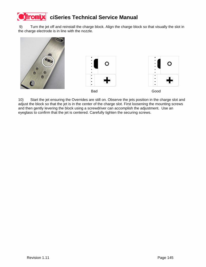
ciSeries Technical Service Manual
Revision 1.11 Page 145
9) Turn the jet off and reinstall the charge block. Align the charge block so that visually the slot in the charge electrode is in line with the nozzle.
Bad Good 10) Start the jet ensuring the Overrides are still on. Observe the jets position in the charge slot and adjust the block so that the jet is in the center of the charge slot. First loosening the mounting screws and then gently levering the block using a screwdriver can accomplish the adjustment. Use an eyeglass to confirm that the jet is centered. Carefully tighten the securing screws.
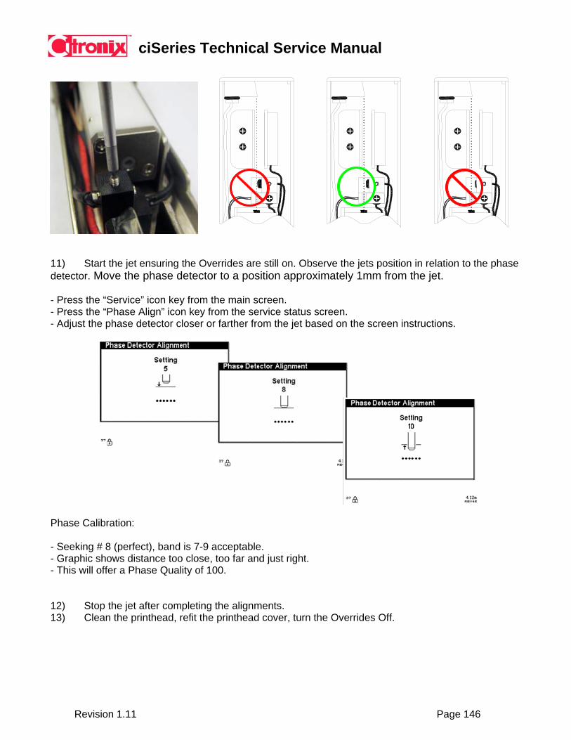
ciSeries Technical Service Manual
Revision 1.11 Page 146
11) Start the jet ensuring the Overrides are still on. Observe the jets position in relation to the phase detector. Move the phase detector to a position approximately 1mm from the jet. - Press the “Service” icon key from the main screen. - Press the “Phase Align” icon key from the service status screen. - Adjust the phase detector closer or farther from the jet based on the screen instructions.
Phase Calibration:
- Seeking # 8 (perfect), band is 7-9 acceptable. - Graphic shows distance too close, too far and just right. - This will offer a Phase Quality of 100. 12) Stop the jet after completing the alignments. 13) Clean the printhead, refit the printhead cover, turn the Overrides Off.
ciSeries Technical Service Manual
Revision 1.11 Page 147
9.3 Nozzle Cleaning Routine (Ultrasonic Bath) Tools/parts required:
Ultrasonic Cleaner (not heated) Microscope MEK Ethanol Water Clean dry air (canned air recommended)
CAUTION: DO NOT USE A HEATED ULTRASONIC BATH – DAMAGE WILL RESULT TO NOZZLE AND NOZZLE BODY.
Stage 1: 1) Clean substantial deposits of ink or other debris with MEK (using a wash bottle). 2) Place in an ultrasonic bath of MEK for 30 to 60 minutes in a non-heated ultrasonic cleaner. 3) Remove and dry with clean air. 4) Inspect interior of nozzle using a microscope. If debris remains continue to stage 2.
Stage 2:
1) Place in an ultrasonic bath of clean water for 30 to 60 minutes in a non-heated ultrasonic cleaner.
CAUTION: USE A CLEAN BEAKER (FREE OF MEK) FOR THIS PROCESS. MIXING OF SOLVENTS AND/OR WATER MAY CLOG THE NOZZLE BEOND RECOVERY.
2) Remove and dry with clean air. 3) Inspect interior of nozzle using a microscope. If debris remains continue to stage 3.
Stage 3:
1) Place in an ultrasonic bath of Ethanol for 30 to 60 minutes in a non-heated ultrasonic cleaner.
CAUTION: USE A CLEAN BEAKER (FREE OF MEK) FOR THIS PROCESS. MIXING OF SOLVENTS AND/OR WATER MAY CLOG THE NOZZLE BEOND RECOVERY.
2) Remove and dry with clean air. 3) Inspect interior of nozzle using a microscope. If debris remains nozzle cannot be recovered and
must be replaced.
ciSeries Technical Service Manual
Revision 1.11 Page 148
9.4 Changing Ink, Makeup or Ink, Makeup Tank (Ink Refresh)
It may be necessary to change the ink, makeup or change the ink, makeup tank for various reasons. This could be due to the machine not being used for a period of time and the ink shelf life expired or contamination from incorrect ink being used. This procedure can also be used to ensure correct viscosity of ink. Or this routine can be used to remove the fluid from the system prior to shipping (follow shipping preparation guidelines prior to shipping).
1) Turn the system power off using the appropriate shut down routine. 2) Remove the ink system housing cover. 3) Remove the two screws holding the tank assembly in place. 4) Unscrew the tank adapter assembly from the top of the tank. 5) Lift the ink tank up and out of the ink system. Use absorbent cloths to collect excess ink as the ink / makeup pickup and return lines are removed from the tank. 6) Pour ink or makeup into a suitable container or cap ink or makeup tank for future use. 7) Discard ink or makeup in accordance with local regulations. 8) Replace ink or makeup tank. 9) Refill the tank with new ink or makeup taking care to use the correct ink type. 10) Refit the ink system housing cover.
ciSeries Technical Service Manual
Revision 1.11 Page 149
9.5 Shipping / Long Term Storage Preparation
EQUIPMENT DAMAGE: The system should not be shipped or stored long term with makeup fluid, or ink fluids in any part of the system. The system should be completely flushed of all fluids prior to shipment or long term storage.
NOTE: It is unlawful to ship hazardous or flammable goods without declaring them. Following the procedure below will ensure there are no hazardous or flammable fluids contained in the system.
1) Turn the system power off using the appropriate shut down routine. 2) Remove the ink system housing cover. 3) Remove the two screws holding the ink and makeup tank assemblies in place. 4) Unscrew the ink tank adapter assembly from the top of the tank. 5) Lift the ink tank up and out of the ink system. Use absorbent cloths to collect excess ink as the pickup and return lines are removed from the tank. 6) Pour ink into a suitable waste container and discard in accordance with local regulations. 7) Unscrew the makeup tank adapter assembly from the top of the tank. 8) Lift the makeup tank up and out of the ink system. Use absorbent cloths to collect excess makeup as the pickup lines are removed from the tank. The makeup fluid can be used as a cleaning solution for the flush process. 9) Pour roughly 500ml of cleaning solvent or makeup in the ink tank, or utilize the makeup tank with makeup solution. Replace the tank, leaving the tank adapter loose. 10) Turn on the system power on. 11) Turn all “Override” conditions to “Yes”. This will ensure no errors will inhibit this process. 12) Start the Jet by pressing the “Start” button on the main screen. This will flush the system of ink. 13) During this process, go to the Service menu and select “Viscosity Check”. 14) Press the “Stop” button on the main screen to stop the system after 2 minutes. 15) Follow steps 5 and 6. 16) Follow steps 9 – 15, then 5 and 6 twice for shipping, and three times for long term storage. 17) Replace an empty tank, leaving the tank adapter loose also ensuring the pickup and return lines are above fluid levels during the process. The intent is to flush the system of all fluids. 18) Follow steps 10 – 15. 19) Follow steps 5 and 6. 20) If shipping, pressurize pickup and return fluid lines out with filtered air pressure of 1-3 psi for a period of 3 minutes each. During the process, go to the Service menu and select “Viscosity Check”. 21) If low filtered air pressure is not available: Install substantial absorbent cloths in the makeup tank and ink tank. Reinstall the ink and makeup tank with absorbent cloths, ensuring any excess fluid in system is collected/absorbed during transit instead of spilling onto other system components. 22) Perform a printhead daily cleaning procedure, ensuring all printhead components are free of ink and any debris. 23) Wrap printhead with absorbent cloths and wrap with plastic material to collect in excess fluid during transit.
ciSeries Technical Service Manual
Revision 1.11 Page 150
Shipping Material 1) Ensure original Citronix packaging material is used. 2) Wrap printhead with foam packaging and install into tube. 3) Install printing system into box with printhead wrapped around the controller. 4) Make sure both bottom and top foam pieces are used during the shipment process. Accessories, and other components should be placed on top of the top foam pieces wrapped appropriately with foam or bubble wrap material.
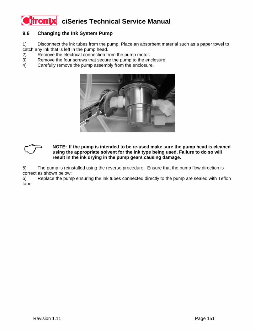
ciSeries Technical Service Manual
Revision 1.11 Page 151
9.6 Changing the Ink System Pump
1) Disconnect the ink tubes from the pump. Place an absorbent material such as a paper towel to catch any ink that is left in the pump head. 2) Remove the electrical connection from the pump motor. 3) Remove the four screws that secure the pump to the enclosure. 4) Carefully remove the pump assembly from the enclosure.
NOTE: If the pump is intended to be re-used make sure the pump head is cleaned using the appropriate solvent for the ink type being used. Failure to do so will result in the ink drying in the pump gears causing damage.
5) The pump is reinstalled using the reverse procedure. Ensure that the pump flow direction is correct as shown below: 6) Replace the pump ensuring the ink tubes connected directly to the pump are sealed with Teflon tape.

ciSeries Technical Service Manual
Revision 1.11 Page 152
9.7 Changing / Cleaning an Ink System Valve and Gasket
1) Remove the ink system housing cover, or access panel. 2) Remove the solenoid from the valve stem by removing the plastic hold-down clip on top of the solenoid and pulling the solenoid upwards. 3) Remove the two screws securing the valve to the ink manifold. Use a 1/16th inch hex key (003-1051-001). 4) Remove the valve from manifold taking care not to lose the valve gasket. Flush valve with solvent to prevent ink from drying in it. 5) Replace cleaned valve, replacement valve, or replacement gasket.
6) Replace cleaned valve, replacement valve, or replacement gasket.
NOTE: If the valve is intended to be re-used make sure the valve is cleaned using the appropriate solvent for the ink type being used. Failure to do so will result in the ink drying in the valve causing damage.
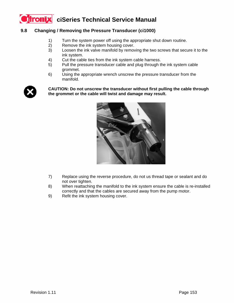
ciSeries Technical Service Manual
Revision 1.11 Page 153
9.8 Changing / Removing the Pressure Transducer (ci1000)
1) Turn the system power off using the appropriate shut down routine. 2) Remove the ink system housing cover. 3) Loosen the ink valve manifold by removing the two screws that secure it to the
ink system. 4) Cut the cable ties from the ink system cable harness. 5) Pull the pressure transducer cable and plug through the ink system cable
grommet. 6) Using the appropriate wrench unscrew the pressure transducer from the
manifold. CAUTION: Do not unscrew the transducer without first pulling the cable through the grommet or the cable will twist and damage may result.
7) Replace using the reverse procedure, do not us thread tape or sealant and do not over tighten.
8) When reattaching the manifold to the ink system ensure the cable is re-installed correctly and that the cables are secured away from the pump motor.
9) Refit the ink system housing cover.
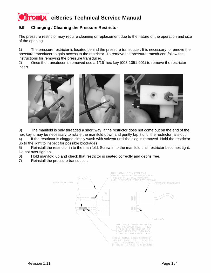
ciSeries Technical Service Manual
Revision 1.11 Page 154
9.9 Changing / Cleaning the Pressure Restrictor The pressure restrictor may require cleaning or replacement due to the nature of the operation and size of the opening. 1) The pressure restrictor is located behind the pressure transducer. It is necessary to remove the pressure transducer to gain access to the restrictor. To remove the pressure transducer, follow the instructions for removing the pressure transducer. 2) Once the transducer is removed use a 1/16” hex key (003-1051-001) to remove the restrictor insert.
3) The manifold is only threaded a short way, if the restrictor does not come out on the end of the hex key it may be necessary to rotate the manifold down and gently tap it until the restrictor falls out. 4) If the restrictor is clogged simply wash with solvent until the clog is removed. Hold the restrictor up to the light to inspect for possible blockages. 5) Reinstall the restrictor in to the manifold. Screw in to the manifold until restrictor becomes tight. Do not over tighten. 6) Hold manifold up and check that restrictor is seated correctly and debris free. 7) Reinstall the pressure transducer.

ciSeries Technical Service Manual
Revision 1.11 Page 155
9.10 Changing / Cleaning the Venturi Restrictors The venturi restrictors may require cleaning or replacement due to the nature of the operation and size of the opening.
1) The venturi restrictors are located behind A hole plug. It is necessary to remove this hole plug to gain access to the restrictors. To remove the plug loosen with a 7/16” wrench and remove.
2) Once the plug has been removed use a 1/16” hex key (003-1051-001) and remove the venturi insert.
3) The manifold is only threaded a short way, If the venturi insert does not come out on the end of the hex key turn the manifold down and gently tap it until the insert falls out.
4) Clean or replace the insert, before reinstalling hold it up to the light and ensure that it is clean. 5) The insert has to be screwed into the manifold to a precise depth. This is accomplished by first
removing the gutter valve. 6) Follow the steps illustrated above. 7) Replace the gutter valve and the temperature probe.

ciSeries Technical Service Manual
Revision 1.11 Page 156
Section 10 Reference Information
10.1 Ink and Makeup Consumption Ink Consumption
The following chart details an average number of characters that can be printed by ml, and by 16 oz (473ml) bottle. The data is based on 30% of the dot matrix being printed. Actual consumption will vary dependent on actual characters selected for printing.
Fonts 5 7 9 16 25 Characters/ml 150,602 109,529 63,412 22,732 9,268 Characters/16oz 71,234,940 51,807,229 29,993,659 10,752,444 4,383,689
Makeup Consumption
Makeup is consumed at a rate based on the environment (temperature). Makeup consumption may vary based on actual environment.
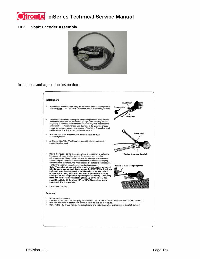
ciSeries Technical Service Manual
Revision 1.11 Page 157
10.2 Shaft Encoder Assembly
Installation and adjustment instructions:
ciSeries Technical Service Manual
Revision 1.11 Page 158
10.3 ciSeries Installation Report and Checklist The document detailed on the following page is used when installing a new ciSeries system and/or submitted with the order for a new ciSeries system. This document should be completed to ensure the appropriate steps are completed and left with the customer as part of the customer’s on-line training.

ciSeries Technical Service Manual
Revision 1.11 Page 159
Installation Report / Checklist
Date: Completed by: Customer Name: System Model:
Customer Email: System Serial #:
Customer Tel/Fax: Date of Install:
Customer Address: Comments:
Printing Information Print contents (sketch details)
Pixel: _____ Fonts: _____ Quality setting: _____
Installation Review: Installation Checklist
Jet starts straight multiple attempts Service settings are accurate Makeup is ejecting from nozzle – Jet Flush Current firmware is installed Viscosity measurement is accurate Customer has ink and makeup in stock Filter change interval determined and set Filter change interval reviewed with customer
Printing Conditions: Status Chart:
Operating hours/day: Printhead vibration present: Yes No Operating days/month: Heavy dust environment: Yes No Ambient temperature range: Wet environment: Yes No Line speed: Messages printed / minute: Raster pitch (print resolution): Ink type:
Operation and Maintenance Training: Training Checklist
Describe basic theory of CIJ printing Instruct start-up and shut-down procedures Point out and describe major components Demonstrate basic maintenance procedures Explain how and when to add ink / makeup Instruct user interface operation
Peripherals Installed and/or Recommended: Peripherals Installed and/or Recommended Comments/Recommendations
Customer Signoff: Customer Checklist
Demonstrated successful operation Customer Name:
Operation and maintenance staff are trained Customer Title:
Satisfied with installation and training Customer Signature:

ciSeries Technical Service Manual
Revision 1.11 Page 160
10.4 Routine Cleaning and Maintenance The document detailed on the following page is used when detailing to a customer how to maintain a ciSeries system on a regular basis. This document should be completed and left with the customer as part of the customer’s on-line training. An electronic version of this form can be downloaded from the Distributor section of the Citronix website.
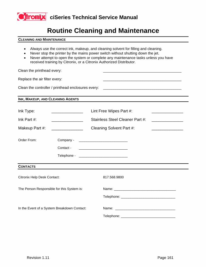
ciSeries Technical Service Manual
Revision 1.11 Page 161
Routine Cleaning and Maintenance CLEANING AND MAINTENANCE
• Always use the correct ink, makeup, and cleaning solvent for filling and cleaning. • Never stop the printer by the mains power switch without shutting down the jet. • Never attempt to open the system or complete any maintenance tasks unless you have
received training by Citronix, or a Citronix Authorized Distributor. Clean the printhead every: ______________________________________ Replace the air filter every: ______________________________________ Clean the controller / printhead enclosures every: ______________________________________
INK, MAKEUP, AND CLEANING AGENTS
Ink Type: ______________ Lint Free Wipes Part #: ______________ Ink Part #: ______________ Stainless Steel Cleaner Part #: ______________ Makeup Part #: ______________ Cleaning Solvent Part #: ______________ Order From: Company - __________________________ Contact - __________________________ Telephone - __________________________
CONTACTS
Citronix Help Desk Contact: 817.568.9800 The Person Responsible for this System is: Name: _________________________________ Telephone: _____________________________ In the Event of a System Breakdown Contact: Name: ________________________________ Telephone: _____________________________
ciSeries Technical Service Manual
Revision 1.11 Page 162
10.5 1200-2000 Hour / 3-6 Month Scheduled Maintenance Checklist The document detailed on the following page is used when completing a scheduled maintenance. This document should be completed to ensure the appropriate steps are completed.

ciSeries Technical Service Manual
Revision 1.11 Page 163
1200-2000 Hour / 3-6 Month Scheduled Maintenance Checklist
Date: Completed by: Customer Name: System Model:
Customer Email: System Serial #:
Customer Tel/Fax: Date of Install:
Customer Address: Comments:
System Status Information: Status Chart:
Run Time: Viscosity Measured: Filter Hours: Viscosity Calculated: Nozzle Temp: Pump Pressure: Ink Temp: Pump RPS: Electronics Temp: Firmware Version:
Maintenance Tasks: Maintenance Checklist
Speak with operators to determine problems Examine electronics wiring and connectors Examine and clean printing system Examine printhead components and clean Replace air filter Update firmware if required Replace Pre-pump filter Ensure service settings are correct Replace Main filter Start system and perform start / stop checks Replace Gutter (vacuum) filter Operate system on-line Replace Makeup filter (ci1000, ci700) Reset filter time intervals
Repairs / Comments: Repairs Completed Comments/Recommendations
Customer Signoff: Customer Checklist
System is clean and operational Customer Name:
Demonstrated successful starting and stopping Customer Title:
Satisfied with maintenance work Customer Signature:
ciSeries Technical Service Manual
Revision 1.11 Page 164
Section 11 Fault Diagnosis
1. No Power a. Check power to unit b. Check Power Switch c. Check mains fuses d. Check mains EMI filter
2. Power on – No display or display rolling
a. Check display connection to CPU b. Press MENU key – this acts as a display reset c. Possible ESD fault – reset printer
CiSeries printers can be detrimentally affected by electro-static discharge. Electro-Static Discharge, or ESD, is the discharge of electro-static buildup into electronic components. ESD failure in CiSeries printers often shows as a flickering screen and/or failure to boot up. Electrostatic charges can be generated from many sources. These include (but are not limited to):
1. Personnel – we are an electronic components worst nightmare! 2. Flooring – carpet, waxed, sealed concrete and vinyl floors. 3. Clothing – synthetic, non-conductive shoes and neck ties. 4. Paper – photocopied, plastic work folders. 5. Tools – soldering irons and solder suckers. 6. Packaging – coffee cups, foam and plastic bags.
Below are examples of the electrostatic voltages generated in different situations. The differences seen are primarily due to differences in relative humidity.
A. Walking across a carpet 1,500 to 35,000v B. Walking across a vinyl floor 250 to 12,000v C. A worker at a bench 100 to 6,000v D. Opening a vinyl plastic work folder 600 to 7,000v E. Picking up a common plastic bag 1,200 to 20,000v F. Sitting on a chair with Urethane foam 1,500 to 18,000v
Electronic equipment may be damaged by contacting a charged person or device (most common) or by entering the electrostatic field of a charged person or device. After contact there are three possible modes of failure:
1. No damage occurs (unusual) 2. Fatal damage occurs (also unusual) 3. Device is degraded but no problems are immediately observed.
When device is degraded it can fail days, weeks, or even MONTHS after the ESD originally occurred or it can cause intermittent faults.
NOTE: It is estimated that 90% of all ESD failures fail due to degradation and 70% of these were caused by UNGROUNDED PERSONNEL!

ciSeries Technical Service Manual
Revision 1.11 Page 165
3. Pressure High Error (RPS < 70)
a. Check restrictor(s) for clogs b. Check return line to ink tank for clogs c. Check pressure transducer (possibly incorrect reading)
4. Pressure Low Error (RPS > 110)
a. Filters clogged b. Ink pickup tube too close to return tubes c. Check connections at prepump filter and inlet side of pump d. Check location of pickup tube to ensure it is not pressed against the side of the
tank (blocking flow) High Pump RPS (on STATUS screen) and/or low Pump Pressure (high Pump RPS is between 110 and 130 and low Pump Pressure continually below 40 psi)). Probable Causes:
1. Filters dirty. Ensure filters have been changed recently/within the timeframe specified in the maintenance chart.
2. Air leak on the input side of the pump head.
5. Pump Motor Error a. Check fuses b. Check pump cable c. Disconnect pump head and check operation of pump motor d. Check pump head for seizure (if motor operates)
6. Cooling Fan Error
a. Check fuses b. If fan is turning, check wire
7. Phase Error
a. Check for ink stream breakup b. Check distance from ink stream to phase detector c. Ensure ink stream is in center of charge electrode d. Check pressure and viscosity (to verify jet velocity) e. Check location of phase amplifier to ensure it is NOT too close to the valve, valve
wires, or other possible source of noise f. Check phase amplifier connections
Phasing is an important aspect of continuous inkjet printing that is not always understood. This section will explain phasing; how it works, how it effects operation and what affects it.
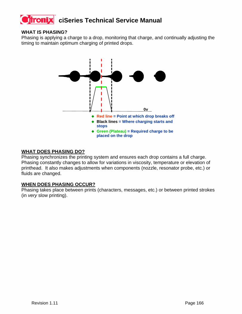
ciSeries Technical Service Manual
Revision 1.11 Page 166
WHAT IS PHASING? Phasing is applying a charge to a drop, monitoring that charge, and continually adjusting the timing to maintain optimum charging of printed drops.
Red line = Point at which drop breaks offBlack lines = Where charging starts and stopsGreen (Plateau) = Required charge to be placed on the drop
0v
WHAT DOES PHASING DO? Phasing synchronizes the printing system and ensures each drop contains a full charge. Phasing constantly changes to allow for variations in viscosity, temperature or elevation of printhead. It also makes adjustments when components (nozzle, resonator probe, etc.) or fluids are changed. WHEN DOES PHASING OCCUR? Phasing takes place between prints (characters, messages, etc.) or between printed strokes (in very slow printing).
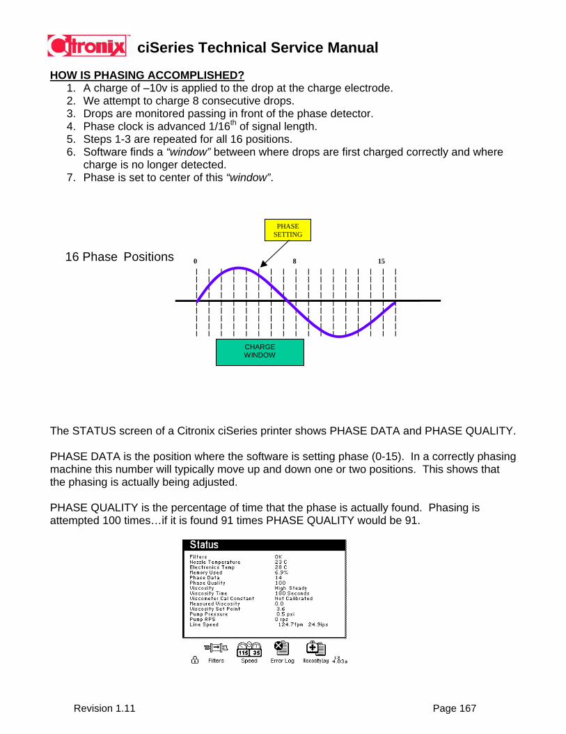
ciSeries Technical Service Manual
Revision 1.11 Page 167
HOW IS PHASING ACCOMPLISHED?
1. A charge of –10v is applied to the drop at the charge electrode. 2. We attempt to charge 8 consecutive drops. 3. Drops are monitored passing in front of the phase detector. 4. Phase clock is advanced 1/16th of signal length. 5. Steps 1-3 are repeated for all 16 positions. 6. Software finds a “window” between where drops are first charged correctly and where
charge is no longer detected. 7. Phase is set to center of this “window”.
0 8 15
16 Phase Positions
CHARGE WINDOW
8
PHASESETTING
The STATUS screen of a Citronix ciSeries printer shows PHASE DATA and PHASE QUALITY. PHASE DATA is the position where the software is setting phase (0-15). In a correctly phasing machine this number will typically move up and down one or two positions. This shows that the phasing is actually being adjusted. PHASE QUALITY is the percentage of time that the phase is actually found. Phasing is attempted 100 times…if it is found 91 times PHASE QUALITY would be 91.
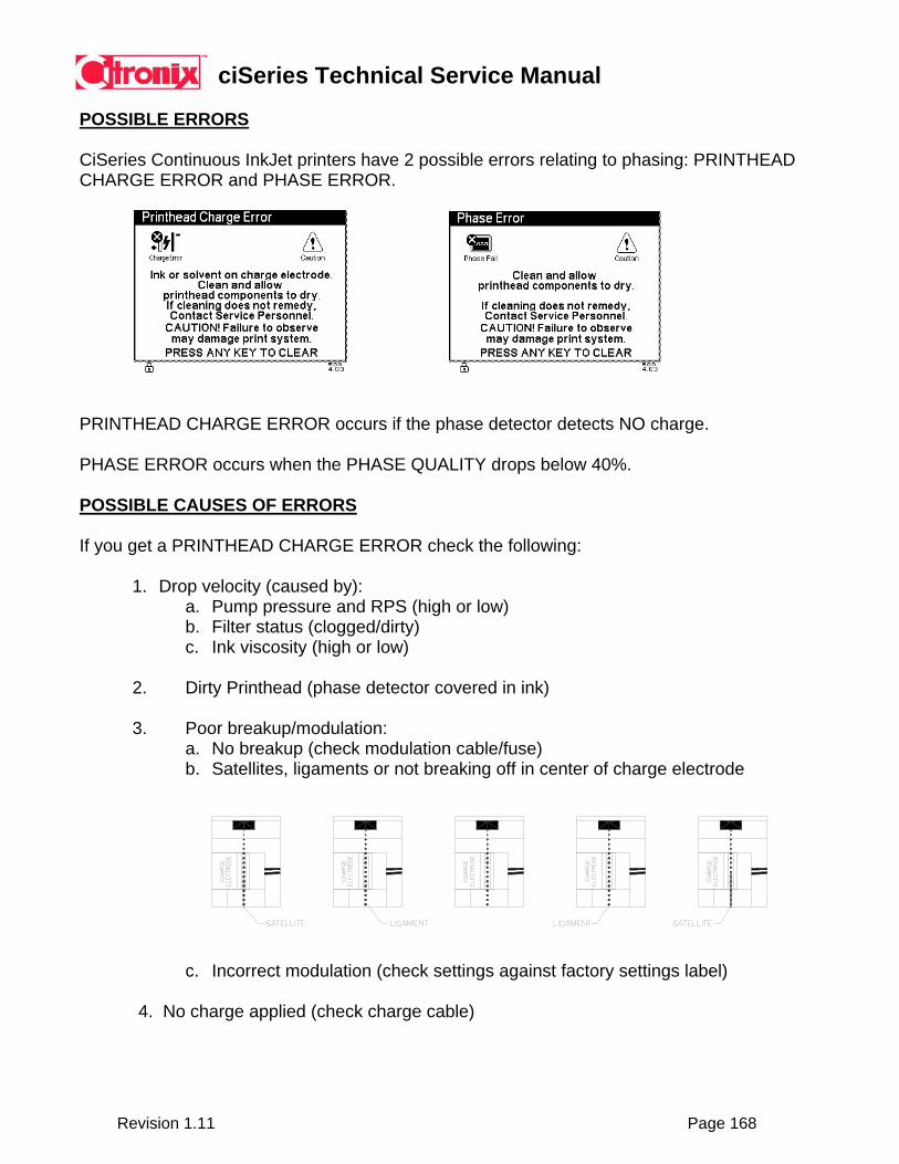
ciSeries Technical Service Manual
Revision 1.11 Page 168
POSSIBLE ERRORS CiSeries Continuous InkJet printers have 2 possible errors relating to phasing: PRINTHEAD CHARGE ERROR and PHASE ERROR.
PRINTHEAD CHARGE ERROR occurs if the phase detector detects NO charge. PHASE ERROR occurs when the PHASE QUALITY drops below 40%. POSSIBLE CAUSES OF ERRORS If you get a PRINTHEAD CHARGE ERROR check the following:
1. Drop velocity (caused by): a. Pump pressure and RPS (high or low) b. Filter status (clogged/dirty) c. Ink viscosity (high or low)
2. Dirty Printhead (phase detector covered in ink) 3. Poor breakup/modulation:
a. No breakup (check modulation cable/fuse) b. Satellites, ligaments or not breaking off in center of charge electrode
c. Incorrect modulation (check settings against factory settings label)
4. No charge applied (check charge cable)

ciSeries Technical Service Manual
Revision 1.11 Page 169
If you get a PHASE ERROR check the following:
1. Jet not in center of charge electrode (adjust)
No Good Good 2. Jet not passing center of phase detector (adjust or replace block)
Rotate phase detector Good Replace strobe block to center on jet or shim to raise up to jet
3. Dirty Printhead (phase detector covered in ink) 4. Phase detector too far from jet (adjust)
5. Phase Amplifier too close to valve, valve wires or other source of electronic noise.
NOTE: Most of the above symptoms may cause either a PHASE and/or a PRINTHEAD CHARGE ERROR.
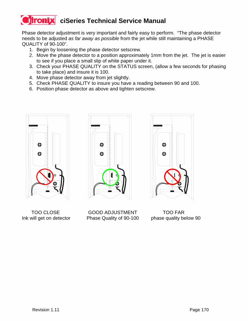
ciSeries Technical Service Manual
Revision 1.11 Page 170
Phase detector adjustment is very important and fairly easy to perform. “The phase detector needs to be adjusted as far away as possible from the jet while still maintaining a PHASE QUALITY of 90-100”.
1. Begin by loosening the phase detector setscrew. 2. Move the phase detector to a position approximately 1mm from the jet. The jet is easier
to see if you place a small slip of white paper under it. 3. Check your PHASE QUALITY on the STATUS screen, (allow a few seconds for phasing
to take place) and insure it is 100. 4. Move phase detector away from jet slightly. 5. Check PHASE QUALITY to insure you have a reading between 90 and 100. 6. Position phase detector as above and tighten setscrew.
TOO CLOSE GOOD ADJUSTMENT TOO FAR Ink will get on detector Phase Quality of 90-100 phase quality below 90
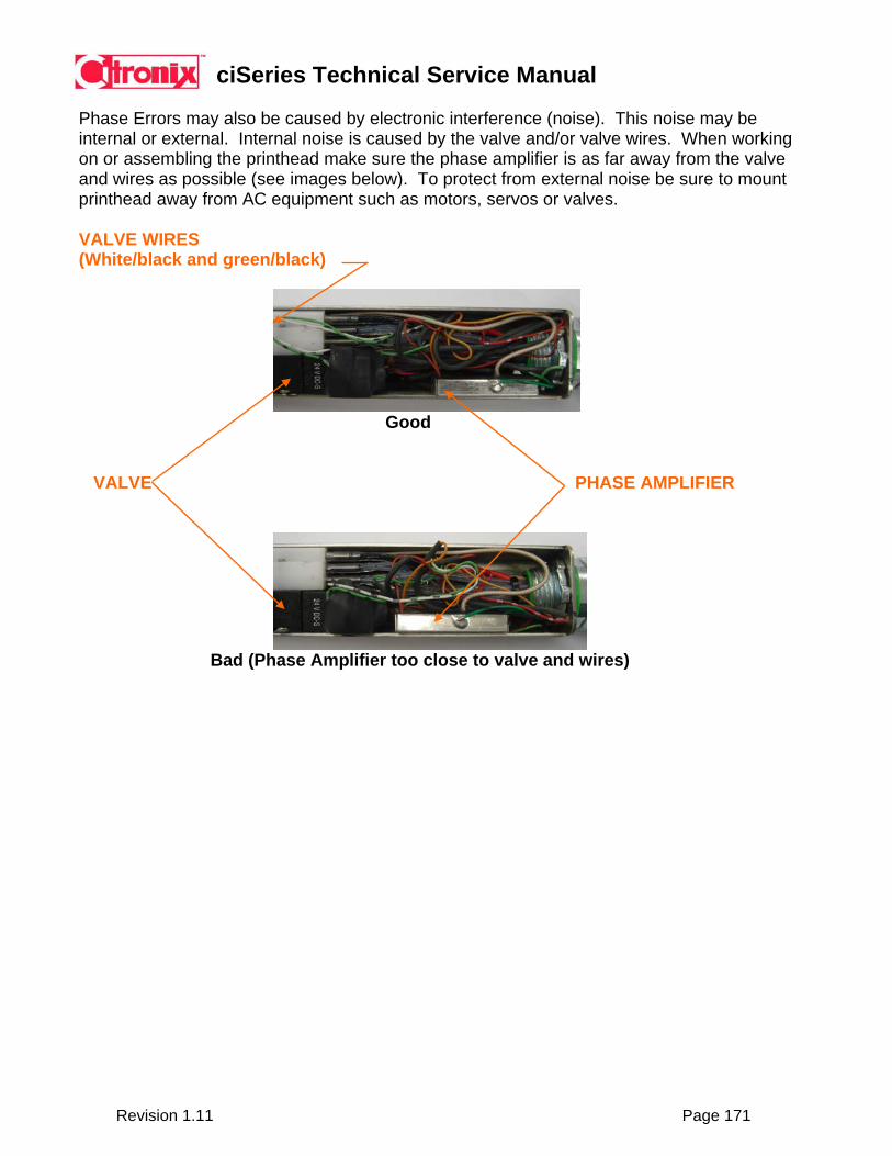
ciSeries Technical Service Manual
Revision 1.11 Page 171
Phase Errors may also be caused by electronic interference (noise). This noise may be internal or external. Internal noise is caused by the valve and/or valve wires. When working on or assembling the printhead make sure the phase amplifier is as far away from the valve and wires as possible (see images below). To protect from external noise be sure to mount printhead away from AC equipment such as motors, servos or valves. VALVE WIRES (White/black and green/black)
Good VALVE PHASE AMPLIFIER
Bad (Phase Amplifier too close to valve and wires)
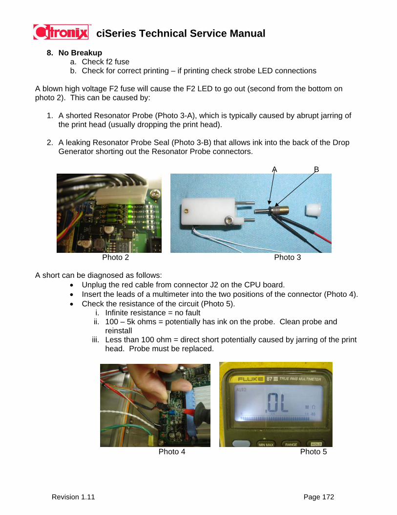
ciSeries Technical Service Manual
Revision 1.11 Page 172
8. No Breakup
a. Check f2 fuse b. Check for correct printing – if printing check strobe LED connections
A blown high voltage F2 fuse will cause the F2 LED to go out (second from the bottom on photo 2). This can be caused by:
1. A shorted Resonator Probe (Photo 3-A), which is typically caused by abrupt jarring of the print head (usually dropping the print head).
2. A leaking Resonator Probe Seal (Photo 3-B) that allows ink into the back of the Drop
Generator shorting out the Resonator Probe connectors. A B
Photo 2 Photo 3
A short can be diagnosed as follows:
• Unplug the red cable from connector J2 on the CPU board. • Insert the leads of a multimeter into the two positions of the connector (Photo 4). • Check the resistance of the circuit (Photo 5).
i. Infinite resistance = no fault ii. 100 – 5k ohms = potentially has ink on the probe. Clean probe and
reinstall iii. Less than 100 ohm = direct short potentially caused by jarring of the print
head. Probe must be replaced.
Photo 4 Photo 5

ciSeries Technical Service Manual
Revision 1.11 Page 173
Corrective Action: Prior to replacing fuse F2 (with a .5 amp only), the following corrective actions must be taken:
• For a shorted Resonator Probe the probe must be replaced. When replacing probe be sure to install new Resonator Probe Seal.
• For ink on the Resonator Probe the probe may be removed, cleaned, and replaced. When replacing be sure to use new seal as in above. If seal is not leaking fault will not reoccur.
To prevent non-repairable CPU damage to revision 1 CPU’s (3-fuse) as the result of these fault conditions Citronix now offers an in-line fuse (Photo 3):
PART NUMBER DESCRIPTION 004-1073-001 Fuse Assembly, HV, Rev 1 PCB
Photo 3 Photo 4
Photo 5 Photo 6 Installation Instructions:
1. Turn power off to machine 2. Disconnect modulation cable (Photos 4 and 5) 3. Attach in-line fuse to modulation cable and plug back into CPU (Photo 6)
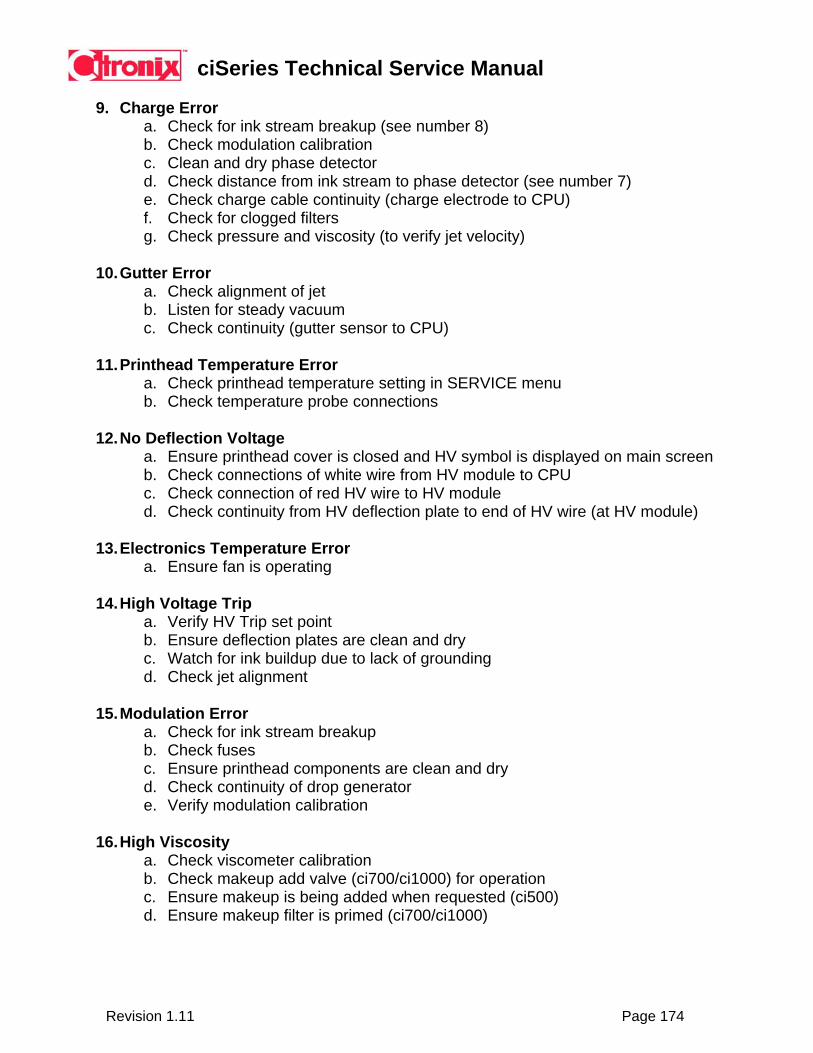
ciSeries Technical Service Manual
Revision 1.11 Page 174
9. Charge Error
a. Check for ink stream breakup (see number 8) b. Check modulation calibration c. Clean and dry phase detector d. Check distance from ink stream to phase detector (see number 7) e. Check charge cable continuity (charge electrode to CPU) f. Check for clogged filters g. Check pressure and viscosity (to verify jet velocity)
10. Gutter Error
a. Check alignment of jet b. Listen for steady vacuum c. Check continuity (gutter sensor to CPU)
11. Printhead Temperature Error
a. Check printhead temperature setting in SERVICE menu b. Check temperature probe connections
12. No Deflection Voltage
a. Ensure printhead cover is closed and HV symbol is displayed on main screen b. Check connections of white wire from HV module to CPU c. Check connection of red HV wire to HV module d. Check continuity from HV deflection plate to end of HV wire (at HV module)
13. Electronics Temperature Error
a. Ensure fan is operating
14. High Voltage Trip a. Verify HV Trip set point b. Ensure deflection plates are clean and dry c. Watch for ink buildup due to lack of grounding d. Check jet alignment
15. Modulation Error
a. Check for ink stream breakup b. Check fuses c. Ensure printhead components are clean and dry d. Check continuity of drop generator e. Verify modulation calibration
16. High Viscosity
a. Check viscometer calibration b. Check makeup add valve (ci700/ci1000) for operation c. Ensure makeup is being added when requested (ci500) d. Ensure makeup filter is primed (ci700/ci1000)
ciSeries Technical Service Manual
Revision 1.11 Page 175
17. Low Viscosity
a. Check viscometer calibration b. Ensure makeup add valve (ci700/ci1000) is not stuck open (this will also be
indicated be the ink tank being overfull while the makeup tank is in a low status c. Ensure 4 ounce cartridge is being added (ci500) and NOT a 16 ounce bottle.
18. Viscometer Sensor Error
a. Check viscometer calibration b. Check operation of viscometer valve c. Ensure ball is moving (use test sensor) d. Check operation of sensor (observe LED on sensor inside cabinet during
operation)
19. Ink Leaking From Gutter (poor vacuum) a. Check adjustment of Venturi b. Check for correct restrictors c. Ensure restrictors are not clogged d. Verify jet alignment
Citronix uses three restrictors in the operation of the Continuous InkJet (CIJ) CiSeries printers. Two restrictors are used in the Venturi to create vacuum and one is used to create and maintain pressure. There is the potential for ink to seep out of the gutter when coding on the side or bottom of a product. This has NOT been reported in any top coding applications. This issue can be recognized by a “slurping” sound from the gutter (the vacuum may seem to “come and go”). It can also be seen as ink leaking from the gutter into the printhead. If this issue is seen the following steps should be taken:
1. Remove and inspect all restrictors. 2. Clean or replace in necessary (dirty and/or partially clogged restrictors will cause the
same symptoms). 3. When reinstalling verify correct placement and/or adjustment.