TECHNICAL MicroHAWK ID-40 · barcode in the current image. You will need to determine the decode...
38
TECHNICAL NOTE MicroHAWK ID-40 360 o Barcode Reading to Omron NJ/NX Controller Solution Overview Solution Features Six MicroHAWK ID-40 readers are connected in daisy chain configuration to an Omron NJ/NX machine controller via EtherNet/IP. The NJ/NX controller sends a trigger to the readers, and once a reader decodes a symbol, the read cycle is stopped for all readers. This solution includes a basic HMI user interface and an NA series panel. This solution is useful in food and commodity applications in which a decode must be performed on a product's barcode, but the barcode's location on the product's perimeter is not known. One example is the need to decode a GS1 Data Matrix on a product as it travels down a conveyor. After the decoded data has been delivered to the NJ/NX controller, the data could be written to a database as part of a pharmaceutical company's serialization and traceability implementation. Supported Symbologies Maximum Picket Fence Orientation • Six-reader daisy chain of MicroHAWK ID-40 readers • Camera trigger via digital input or button on HMI • Three counters: Trigger, Cycles Read, Overruns • Counter resets via digital input or HMI • Decoded data displayed on HMI • Number ID of reader that decoded symbol displayed on HMI • Cycle timeout configurable on HMI • Read time displayed on HMI • Error detection: Timeout, Overrun, Communication fault on EtherNet/IP port • Linear (1D) barcodes down to 10 mil: • Ladder (Vertical) or Picket Fence (Horizontal) • Picket fence width should not exceed 60% of the diameter; see example of maximum-width picket fence 1D barcode in the image below. • Minimum 1D barcode height = 0.5 inches • 2D barcodes down to 15 mil • Data Matrix, Code 128, and UPC/EAN enabled in the supplied WebLink configuration file. Additional symbologies supported by modifying the ID-40’s decode setting. • 5.1 x 3.8 inch (129.5 x 96.5 millimeter) reader FOV when ID-40s are mounted as described. • Refer to MicroHAWK ID-40 Specification Sheet for full list of supported symbologies. 84-9220134-02 Rev A
Transcript of TECHNICAL MicroHAWK ID-40 · barcode in the current image. You will need to determine the decode...
TECHNICALNOTE
MicroHAWK ID-40360o Barcode Reading to Omron NJ/NX Controller
Solution Overview
Solution Features
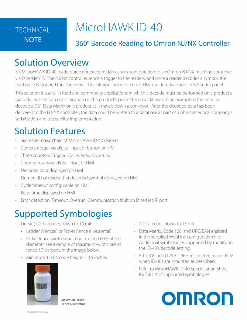
Six MicroHAWK ID-40 readers are connected in daisy chain configuration to an Omron NJ/NX machine controller via EtherNet/IP. The NJ/NX controller sends a trigger to the readers, and once a reader decodes a symbol, the read cycle is stopped for all readers. This solution includes a basic HMI user interface and an NA series panel.
This solution is useful in food and commodity applications in which a decode must be performed on a product's barcode, but the barcode's location on the product's perimeter is not known. One example is the need to decode a GS1 Data Matrix on a product as it travels down a conveyor. After the decoded data has been delivered to the NJ/NX controller, the data could be written to a database as part of a pharmaceutical company's serialization and traceability implementation.
Supported Symbologies
Maximum Picket Fence Orientation
• Six-reader daisy chain of MicroHAWK ID-40 readers
• Camera trigger via digital input or button on HMI
• Three counters: Trigger, Cycles Read, Overruns
• Counter resets via digital input or HMI
• Decoded data displayed on HMI
• Number ID of reader that decoded symbol displayed on HMI
• Cycle timeout configurable on HMI
• Read time displayed on HMI
• Error detection: Timeout, Overrun, Communication fault on EtherNet/IP port
• Linear (1D) barcodes down to 10 mil:
• Ladder (Vertical) or Picket Fence (Horizontal)
• Picket fence width should not exceed 60% of the diameter; see example of maximum-width picket fence 1D barcode in the image below.
• Minimum 1D barcode height = 0.5 inches
• 2D barcodes down to 15 mil
• Data Matrix, Code 128, and UPC/EAN enabled in the supplied WebLink configuration file. Additional symbologies supported by modifying the ID-40’s decode setting.
• 5.1 x 3.8 inch (129.5 x 96.5 millimeter) reader FOV when ID-40s are mounted as described.
• Refer to MicroHAWK ID-40 Specification Sheet for full list of supported symbologies.
84-9220134-02 Rev A
TECHNICALNOTE
Quantity Part Number Description Version
6 7412-2000-2005 MicroHAWK ID-40, SXGA, HD, Autofocus, WHT, HS, X 1.3.0.3009
6 97-000012-01 Power Supply, 100-240 VAC, +24 VDC, M12 12-Pin Socket
6 61-000163-03 QX Cordset, Host, Ethernet, M12 8-Pin Plug (Screw-On)-to-RJ45, 3 m
6 98-9000054-01 Kit, Mounting, APG, MicroHAWK
1 NJ301-1100 NJ301 Machine Automation Controller 1.16
1 HMC-SD291 2 GB Memory Card
1 NJ-PA3001 NJ Power Supply Unit
1 NX-ECC202 EtherCAT Coupler Unit 1.2
1 NX-ID5142-1 16-Point - DC Input Module 1.0
1 NX-OD4256 8-Point - Transistor Output, DC 1.0
1 S8VK-G12024 NA Power Supply
1 XS5W-T421-EMD-K EtherCAT I/O Cable
1 PFP-50N DIN Track - Length: 0.5 m; Height: 7.3 mm
1 NA5-9W001B 9” NA-HMI Panel
1 E3Z-T81 E3Z Through-Beam, Infrared, Pre-Wired
3 XS6W-6LSZH8SS200CM-Y Cat 6A Ethernet Cable, 2M, Yellow
1 N/A 16-Port 100 Mbps Ethernet Switch
Production Rates
Software
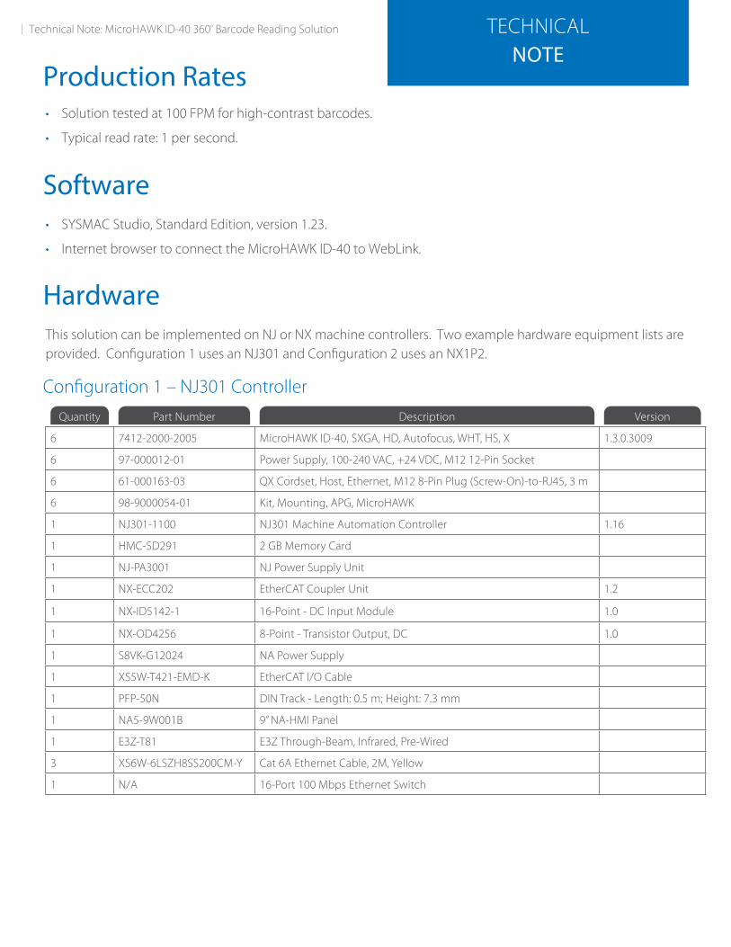
Configuration 1 – NJ301 Controller
Technical Note: MicroHAWK ID-40 360º Barcode Reading Solution
• Solution tested at 100 FPM for high-contrast barcodes.
• Typical read rate: 1 per second.
• SYSMAC Studio, Standard Edition, version 1.23.
• Internet browser to connect the MicroHAWK ID-40 to WebLink.
HardwareThis solution can be implemented on NJ or NX machine controllers. Two example hardware equipment lists are provided. Configuration 1 uses an NJ301 and Configuration 2 uses an NX1P2.
Quantity Part Number Description Version
6 7412-2000-2005 MicroHAWK ID-40, SXGA, HD, Autofocus, WHT, HS, X 1.3.0.3009
6 97-000012-01 Power Supply, 100-240 VAC, +24 VDC, M12 12-Pin Socket
6 61-000163-03 QX Cordset, Host, Ethernet, M12 8-Pin Plug (Screw-On)-to-RJ45, 3 m
6 98-9000054-01 Kit, Mounting, APG, MicroHAWK
1 NX1P2-9024DT1NX1P2 CPU Unit, 1.5 MB, 32 KB, 4 Single-Axis Position Control, 14 Discrete Input Points, 10 Discrete Output Points (PNP)
1.18
1 HMC-SD291 2 GB Memory Card
1 S8VK-C12024Single Phase Power Supply, Universal Input (100 to 240 VAC), 120 W Output (24 VDC @ 5 A)
1 PFP-50N DIN Track - Length: 0.5 m; Height: 7.3 mm
1 NA5-9W001B 9” NA-HMI Panel
1 E3Z-T81 E3Z Through-Beam, Infrared, Pre-Wired
3 XS6W-6LSZH8SS200CM-Y Cat 6A Ethernet cable, 2m, Yellow
1 N/A 16-Port 100 Mbps Ethernet Switch
Configuration Files
• SYSMAC Project file to import for Configuration 1: “6_ID40_NJ301_EIP_with_HMI_revD.smc2”
• SYSMAC Project file to import for Configuration 2: “6_ID40_NX1P2_EIP_with_HMI_revD.smc2”
• WebLink 1.3.0 Configuration file: “360_code_ID40_settings.wls”
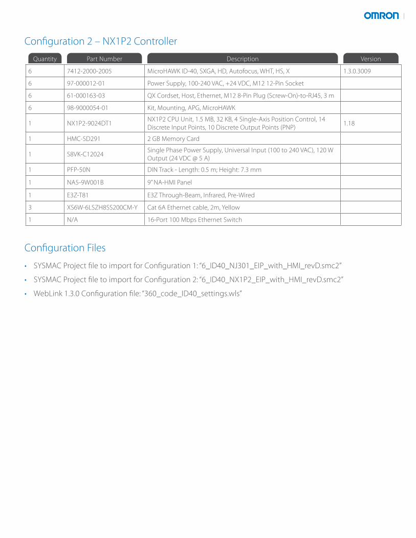
Configuration 2 – NX1P2 Controller
TECHNICALNOTE
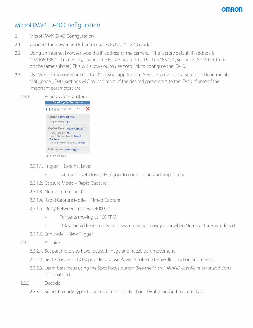
1.2 The ID-40 reader height should be adjusted so that the horizontal linear barcodes (picket fence orientation) are typically above or below the bright reflection of the reader’s illumination. The image below shows an example in which the barcode is below the bright reflection region.
MicroHAWK ID-40 Hardware Mounting
1 MicroHAWK ID-40 Hardware Mounting
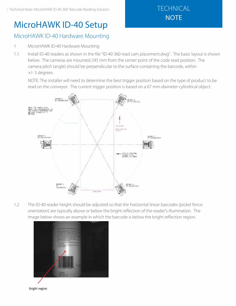
1.1 Install ID-40 readers as shown in the file “ID-40 360 read cam placement.dwg”. The basic layout is shown below. The cameras are mounted 245 mm from the center point of the code read position. The camera pitch (angle) should be perpendicular to the surface containing the barcode, within +/- 5 degrees.
NOTE: The installer will need to determine the best trigger position based on the type of product to be read on the conveyor. The current trigger position is based on a 67 mm diameter cylindrical object.
MicroHAWK ID-40 Setup
Technical Note: MicroHAWK ID-40 360º Barcode Reading Solution
MicroHAWK ID-40 Configuration
2 MicroHAWK ID-40 Configuration
2.1 Connect the power and Ethernet cables to ONLY ID-40 reader 1.
2.2. Using an internet browser type the IP address of the camera. (The factory default IP address is 192.168.188.2. If necessary, change the PC's IP address to 192.168.188.101, subnet 255.255.0.0, to be on the same subnet.) This will allow you to use WebLink to configure the ID-40.
2.3. Use WebLink to configure the ID-40 for your application. Select Start > Load a Setup and load the file “360_code_ID40_settings.wls” to load most of the desired parameters to the ID-40. Some of the important parameters are:
2.3.1. Read Cycle = Custom
2.3.1.1. Trigger = External Level
• External Level allows EIP trigger to control start and stop of read.
2.3.1.2. Capture Mode = Rapid Capture
2.3.1.3. Num Captures = 10
2.3.1.4. Rapid Capture Mode = Timed Capture
2.3.1.5. Delay Between Images = 4000 µs
• For parts moving at 100 FPM.
• Delay should be increased on slower moving conveyors or when Num Captures is reduced.
2.3.1.6. End cycle = New Trigger
2.3.2. Acquire
2.3.2.1. Set parameters to have focused image and freeze part movement.
2.3.2.2. Set Exposure to 1,000 µs or less to use Power Strobe (Extreme Illumination Brightness).
2.3.2.3. Learn best focus using the Spot Focus button (See the MicroHAWK ID User Manual for additional information.)
2.3.3. Decode
2.3.3.1. Select barcode types to be read in this application. Disable unused barcode types.
2.3.4. Gear icon > Advanced > Camera Setup
2.3.4.1. Illumination Brightness = Extreme (Power Strobe)
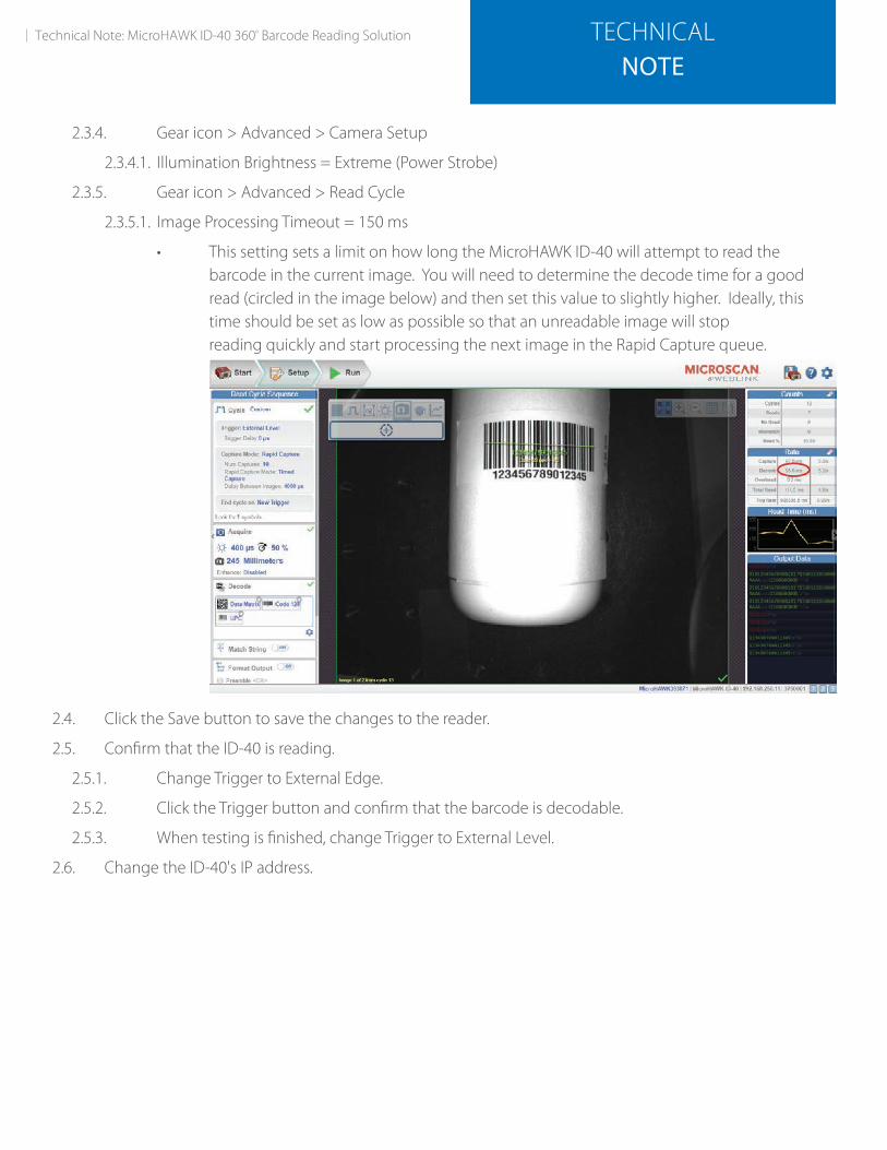
2.3.5. Gear icon > Advanced > Read Cycle
2.3.5.1. Image Processing Timeout = 150 ms
• This setting sets a limit on how long the MicroHAWK ID-40 will attempt to read thebarcode in the current image. You will need to determine the decode time for a goodread (circled in the image below) and then set this value to slightly higher. Ideally, thistime should be set as low as possible so that an unreadable image will stopreading quickly and start processing the next image in the Rapid Capture queue.
2.4. Click the Save button to save the changes to the reader.
2.5. Confirm that the ID-40 is reading.
2.5.1. Change Trigger to External Edge.
2.5.2. Click the Trigger button and confirm that the barcode is decodable.
2.5.3. When testing is finished, change Trigger to External Level.
2.6. Change the ID-40's IP address.
Technical Note: MicroHAWK ID-40 360º Barcode Reading Solution TECHNICALNOTE
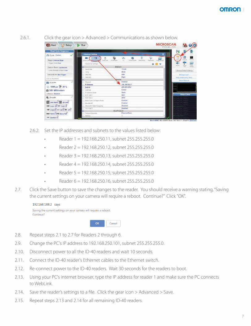
2.6.1. Click the gear icon > Advanced > Communications as shown below.
2.6.2. Set the IP addresses and subnets to the values listed below:
• Reader 1 = 192.168.250.11, subnet 255.255.255.0
• Reader 2 = 192.168.250.12, subnet 255.255.255.0
• Reader 3 = 192.168.250.13, subnet 255.255.255.0
• Reader 4 = 192.168.250.14, subnet 255.255.255.0
• Reader 5 = 192.168.250.15, subnet 255.255.255.0
• Reader 6 = 192.168.250.16, subnet 255.255.255.0
2.7. Click the Save button to save the changes to the reader. You should receive a warning stating, “Saving the current settings on your camera will require a reboot. Continue?” Click "OK".
2.8. Repeat steps 2.1 to 2.7 for Readers 2 through 6.
2.9. Change the PC's IP address to 192.168.250.101, subnet 255.255.255.0.
2.10. Disconnect power to all the ID-40 readers and wait 10 seconds.
2.11. Connect the ID-40 reader's Ethernet cables to the Ethernet switch.
2.12. Re-connect power to the ID-40 readers. Wait 30 seconds for the readers to boot.
2.13. Using your PC's internet browser, type the IP address for reader 1 and make sure the PC connects to WebLink.
2.14. Save the reader’s settings to a file. Click the gear icon > Advanced > Save.
2.15. Repeat steps 2.13 and 2.14 for all remaining ID-40 readers.
7
MicroHAWK ID-40 EDS File Download
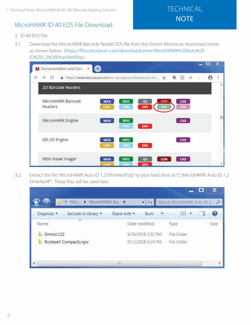
3. ID-40 EDS File
3.1. Download the MicroHAWK Barcode Reader EDS file from the Omron Microscan download center, as shown below. (https://files.microscan.com/downloadcenter/MicroHAWK%20Auto%20 ID%201.2%20EtherNetIP.zip.)
3.2. Extract the file “MicroHAWK Auto ID 1.2 EtherNetIP.zip” to your hard drive at “C:\MicroHAWK Auto ID 1.2 EtherNetIP”. These files will be used later.
8
Technical Note: MicroHAWK ID-40 360º Barcode Reading Solution TECHNICALNOTE
NJ/NX Controller and NA HMI Panel Connections
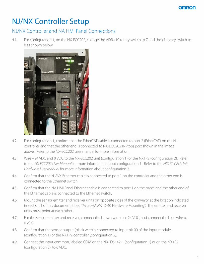
4.1. For configuration 1, on the NX-ECC202, change the ADR x10 rotary switch to 7 and the x1 rotary switch to 0 as shown below.
4.2. For configuration 1, confirm that the EtherCAT cable is connected to port 2 (EtherCAT) on the NJ controller and that the other end is connected to NX-ECC202 IN (top) port shown in the image above. Refer to the NX-ECC202 user manual for more information.
4.3. Wire +24 VDC and 0 VDC to the NX-ECC202 unit (configuration 1) or the NX1P2 (configuration 2). Refer to the NX-ECC202 User Manual for more information about configuration 1. Refer to the NX1P2 CPU Unit Hardware User Manual for more information about configuration 2.
4.4. Confirm that the NJ/NX Ethernet cable is connected to port 1 on the controller and the other end is connected to the Ethernet switch.
4.5. Confirm that the NA HMI Panel Ethernet cable is connected to port 1 on the panel and the other end of the Ethernet cable is connected to the Ethernet switch.
4.6. Mount the sensor emitter and receiver units on opposite sides of the conveyor at the location indicated in section 1 of this document, titled "MicroHAWK ID-40 Hardware Mounting". The emitter and receiver units must point at each other.
4.7. For the sensor emitter and receiver, connect the brown wire to + 24 VDC, and connect the blue wire to 0 VDC.
4.8. Confirm that the sensor output (black wire) is connected to input bit 00 of the input module (configuration 1) or the NX1P2 controller (configuration 2).
4.9. Connect the input common, labeled COM on the NX-ID5142-1 (configuration 1) or on the NX1P2 (configuration 2), to 0 VDC.
NJ/NX Controller Setup
9
4.10. Apply power to the power supplies powering the NJ/NX controller and NA HMI Panel.
4.11. Wait approximately 30 seconds for these components to fully power up.
4.12. At this point all components should be powered and connected to the Ethernet switch. Confirm that network activity is seen from the NJ/NX controller, the NA HMI Panel, and the six ID-40 readers.
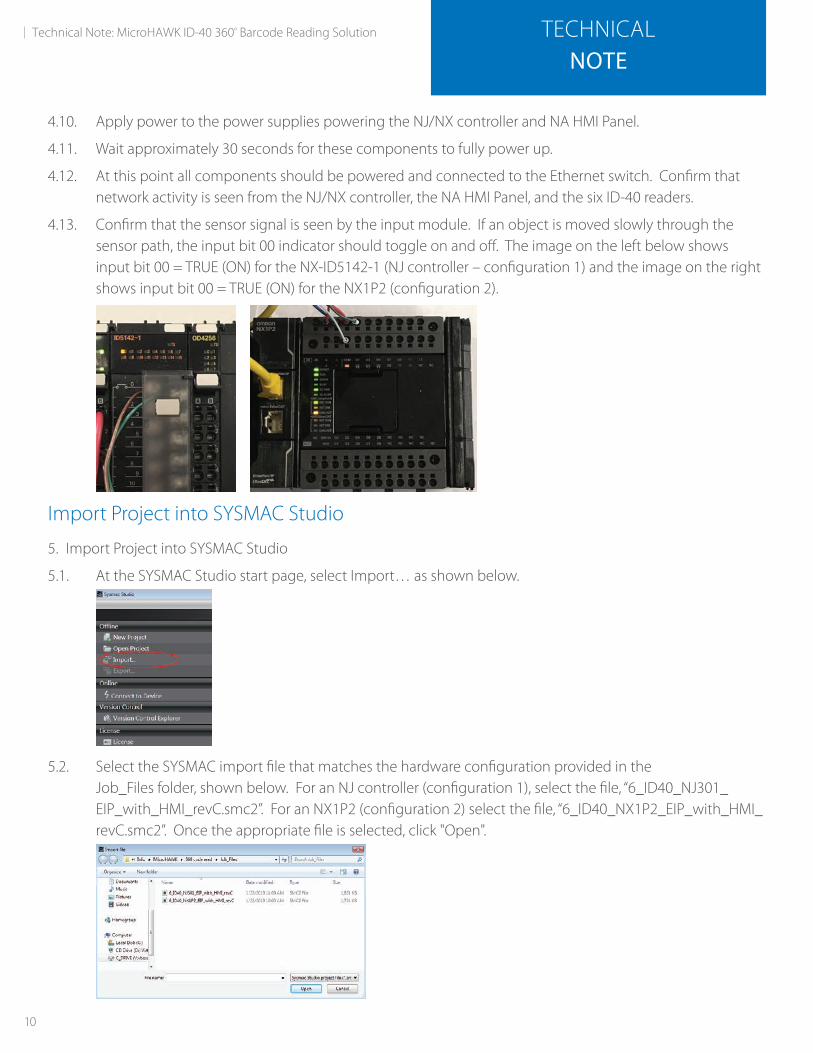
4.13. Confirm that the sensor signal is seen by the input module. If an object is moved slowly through the sensor path, the input bit 00 indicator should toggle on and off. The image on the left below shows input bit 00 = TRUE (ON) for the NX-ID5142-1 (NJ controller – configuration 1) and the image on the right shows input bit 00 = TRUE (ON) for the NX1P2 (configuration 2).
Import Project into SYSMAC Studio
5. Import Project into SYSMAC Studio
5.1. At the SYSMAC Studio start page, select Import… as shown below.
5.2. Select the SYSMAC import file that matches the hardware configuration provided in the Job_Files folder, shown below. For an NJ controller (configuration 1), select the file, “6_ID40_NJ301_ EIP_with_HMI_revC.smc2”. For an NX1P2 (configuration 2) select the file, “6_ID40_NX1P2_EIP_with_HMI_ revC.smc2”. Once the appropriate file is selected, click "Open".
10
Technical Note: MicroHAWK ID-40 360º Barcode Reading Solution TECHNICALNOTE
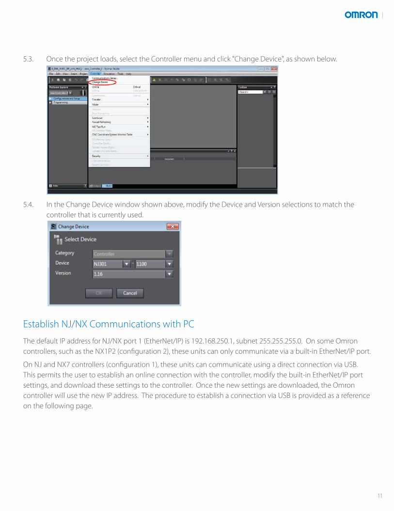
5.3. Once the project loads, select the Controller menu and click "Change Device", as shown below.
5.4. In the Change Device window shown above, modify the Device and Version selections to match the controller that is currently used.
Establish NJ/NX Communications with PC
The default IP address for NJ/NX port 1 (EtherNet/IP) is 192.168.250.1, subnet 255.255.255.0. On some Omron controllers, such as the NX1P2 (configuration 2), these units can only communicate via a built-in EtherNet/IP port.
On NJ and NX7 controllers (configuration 1), these units can communicate using a direct connection via USB. This permits the user to establish an online connection with the controller, modify the built-in EtherNet/IP port settings, and download these settings to the controller. Once the new settings are downloaded, the Omron controller will use the new IP address. The procedure to establish a connection via USB is provided as a reference on the following page.
11
Omron NJ Controller Direct USB Connection
This type of connection can be used for modifications to NJ/NX settings (such as the IP Address) or changes to logic, but for full configuration and testing of EtherNet/IP, use the Ethernet connection described in step 7 of the section "Omron NJ/NX Controller Ethernet Connection via a Hub".
6. NJ Direct USB Connection
6.1. Connect a USB cable from a PC to the PLC’s USB port.
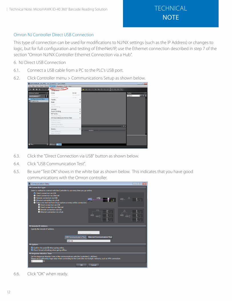
6.2. Click Controller menu > Communications Setup as shown below.
6.3. Click the "Direct Connection via USB" button as shown below.
6.4. Click "USB Communication Test".
6.5. Be sure “Test OK” shows in the white bar as shown below. This indicates that you have good communications with the Omron controller.
6.6. Click "OK" when ready.
12
Technical Note: MicroHAWK ID-40 360º Barcode Reading Solution TECHNICALNOTE

Omron NJ/NX Controller Ethernet Connection via a Hub
7. Omron NJ/NX Controller Ethernet Connection via a Hub
7.1. Click Controller menu > Communications Setup as shown on page 14.
7.2. Click the "Ethernet Connection via a Hub" button as shown below.
7.3. Enter the IP address of the NJ/NX controller. The default address for an NJ/NX controller is 192.168.250.1.
7.4. Click "Ethernet Communication Test".
7.5. Be sure “Test OK” shows in the white bar as shown above. This indicates that you have good communications with the Omron controller.
7.6. Click "OK" when ready.
13
Modify NJ/NX Controller IP Address
8. Modify NJ/NX Controller IP Address
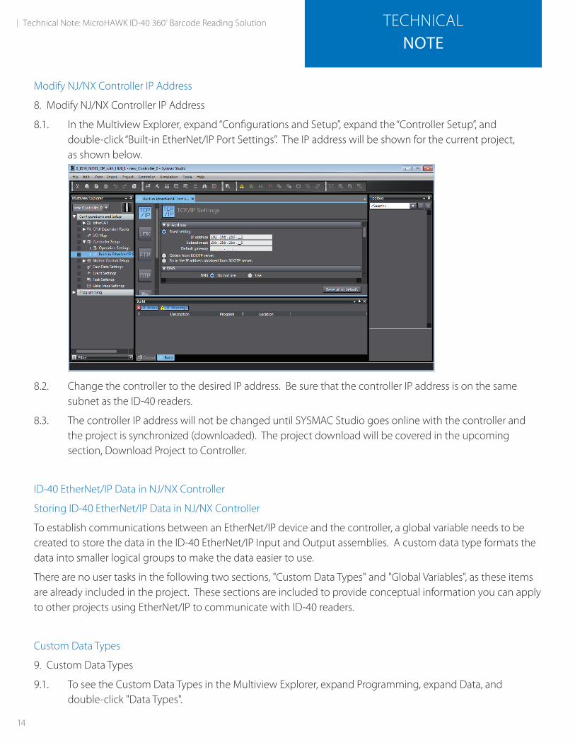
8.1. In the Multiview Explorer, expand “Configurations and Setup”, expand the “Controller Setup”, and double-click “Built-in EtherNet/IP Port Settings”. The IP address will be shown for the current project, as shown below.
8.2. Change the controller to the desired IP address. Be sure that the controller IP address is on the same subnet as the ID-40 readers.
8.3. The controller IP address will not be changed until SYSMAC Studio goes online with the controller and the project is synchronized (downloaded). The project download will be covered in the upcoming section, Download Project to Controller.
ID-40 EtherNet/IP Data in NJ/NX Controller
Storing ID-40 EtherNet/IP Data in NJ/NX Controller
To establish communications between an EtherNet/IP device and the controller, a global variable needs to be created to store the data in the ID-40 EtherNet/IP Input and Output assemblies. A custom data type formats the data into smaller logical groups to make the data easier to use.
There are no user tasks in the following two sections, "Custom Data Types" and "Global Variables", as these items are already included in the project. These sections are included to provide conceptual information you can apply to other projects using EtherNet/IP to communicate with ID-40 readers.
Custom Data Types
9. Custom Data Types
9.1. To see the Custom Data Types in the Multiview Explorer, expand Programming, expand Data, and double-click "Data Types".
14
Technical Note: MicroHAWK ID-40 360º Barcode Reading Solution TECHNICALNOTE

9.2. Two data types are created in this application. The data type for the Input Assembly 103 is called “s_ID40_ Input_type_103” and is shown below.
9.3. The data type for the Output Assembly 197 is called “s_ID40_Output_type_197” and is shown below. Note that when creating these data types, the Offset Type must be changed to “User”.
15
Global Variables
10. Global Variables
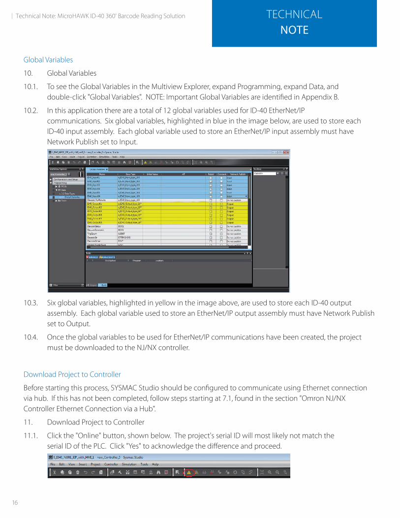
10.1. To see the Global Variables in the Multiview Explorer, expand Programming, expand Data, and double-click "Global Variables". NOTE: Important Global Variables are identified in Appendix B.
10.2. In this application there are a total of 12 global variables used for ID-40 EtherNet/IP communications. Six global variables, highlighted in blue in the image below, are used to store each ID-40 input assembly. Each global variable used to store an EtherNet/IP input assembly must have Network Publish set to Input.
10.3. Six global variables, highlighted in yellow in the image above, are used to store each ID-40 output assembly. Each global variable used to store an EtherNet/IP output assembly must have Network Publish set to Output.
10.4. Once the global variables to be used for EtherNet/IP communications have been created, the project must be downloaded to the NJ/NX controller.
Download Project to Controller
Before starting this process, SYSMAC Studio should be configured to communicate using Ethernet connection via hub. If this has not been completed, follow steps starting at 7.1, found in the section "Omron NJ/NX Controller Ethernet Connection via a Hub".
11. Download Project to Controller
11.1. Click the "Online" button, shown below. The project's serial ID will most likely not match the serial ID of the PLC. Click "Yes" to acknowledge the difference and proceed.
16
Technical Note: MicroHAWK ID-40 360º Barcode Reading Solution TECHNICALNOTE
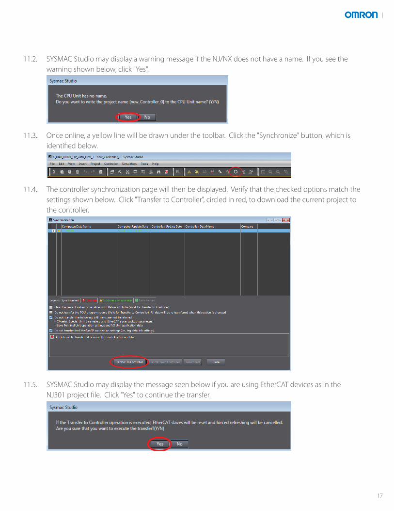
11.2. SYSMAC Studio may display a warning message if the NJ/NX does not have a name. If you see the warning shown below, click "Yes".
11.3. Once online, a yellow line will be drawn under the toolbar. Click the "Synchronize" button, which is identified below.
11.4. The controller synchronization page will then be displayed. Verify that the checked options match the settings shown below. Click "Transfer to Controller", circled in red, to download the current project to the controller.
11.5. SYSMAC Studio may display the message seen below if you are using EtherCAT devices as in the NJ301 project file. Click "Yes" to continue the transfer.
17
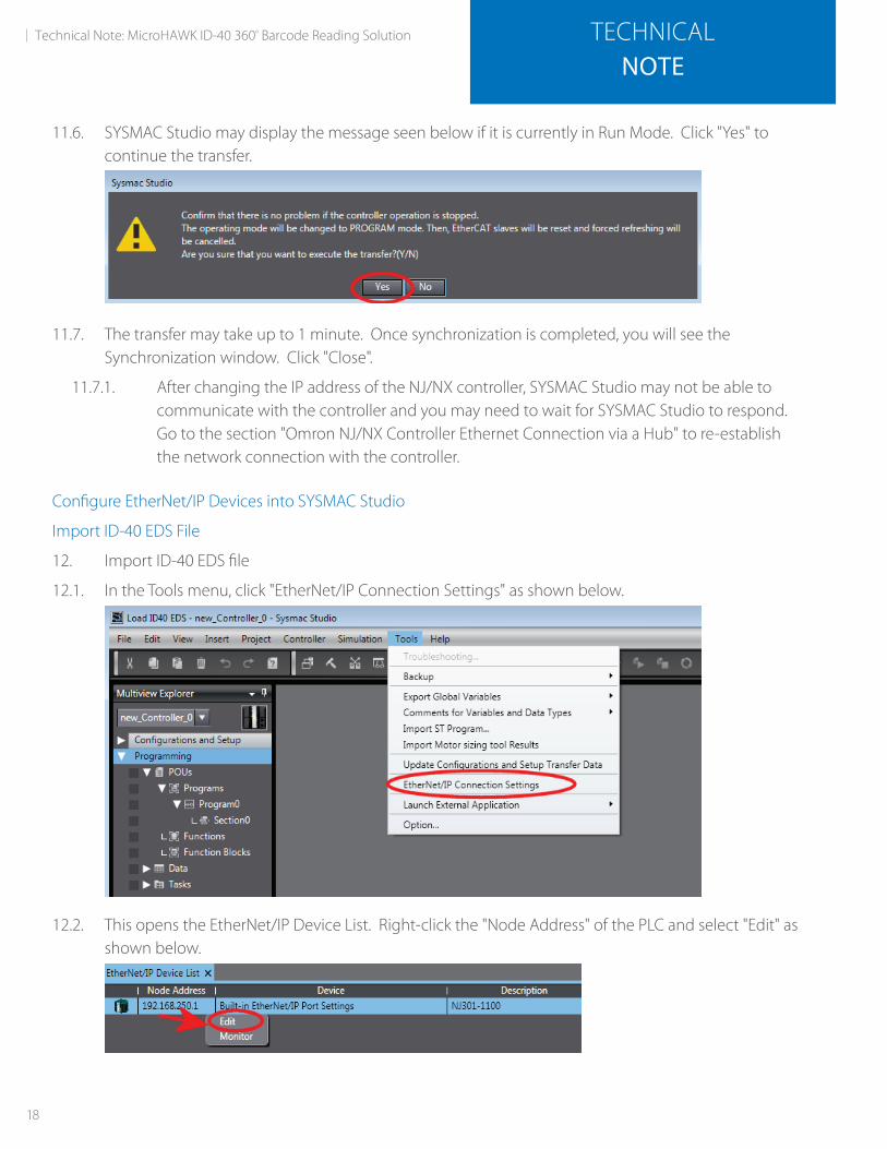
11.6. SYSMAC Studio may display the message seen below if it is currently in Run Mode. Click "Yes" to continue the transfer.
11.7. The transfer may take up to 1 minute. Once synchronization is completed, you will see the Synchronization window. Click "Close".
11.7.1. After changing the IP address of the NJ/NX controller, SYSMAC Studio may not be able to communicate with the controller and you may need to wait for SYSMAC Studio to respond. Go to the section "Omron NJ/NX Controller Ethernet Connection via a Hub" to re-establish the network connection with the controller.
Configure EtherNet/IP Devices into SYSMAC Studio
Import ID-40 EDS File
12. Import ID-40 EDS file
12.1. In the Tools menu, click "EtherNet/IP Connection Settings" as shown below.
12.2. This opens the EtherNet/IP Device List. Right-click the "Node Address" of the PLC and select "Edit" as shown below.
18
Technical Note: MicroHAWK ID-40 360º Barcode Reading Solution TECHNICALNOTE
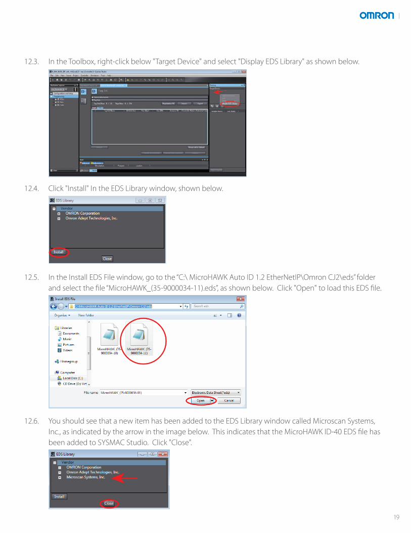
12.3. In the Toolbox, right-click below "Target Device" and select "Display EDS Library" as shown below.
12.4. Click "Install" In the EDS Library window, shown below.
12.5. In the Install EDS File window, go to the “C:\ MicroHAWK Auto ID 1.2 EtherNetIP\Omron CJ2\eds” folder and select the file “MicroHAWK_(35-9000034-11).eds”, as shown below. Click "Open" to load this EDS file.
12.6. You should see that a new item has been added to the EDS Library window called Microscan Systems, Inc., as indicated by the arrow in the image below. This indicates that the MicroHAWK ID-40 EDS file has been added to SYSMAC Studio. Click "Close".
19
Add ID-40s as EtherNet/IP Devices
13. Add ID-40s as EtherNet/IP Devices
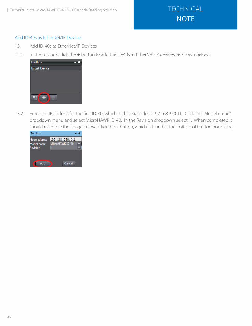
13.1. In the Toolbox, click the + button to add the ID-40s as EtherNet/IP devices, as shown below.
13.2. Enter the IP address for the first ID-40, which in this example is 192.168.250.11. Click the "Model name" dropdown menu and select MicroHAWK ID-40. In the Revision dropdown select 1. When completed it should resemble the image below. Click the + button, which is found at the bottom of the Toolbox dialog.
20
Technical Note: MicroHAWK ID-40 360º Barcode Reading Solution TECHNICALNOTE
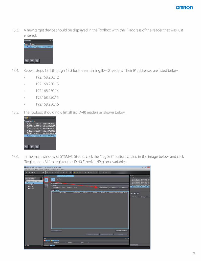
13.3. A new target device should be displayed in the Toolbox with the IP address of the reader that was just entered.
13.4. Repeat steps 13.1 through 13.3 for the remaining ID-40 readers. Their IP addresses are listed below.
• 192.168.250.12
• 192.168.250.13
• 192.168.250.14
• 192.168.250.15
• 192.168.250.16
13.5. The Toolbox should now list all six ID-40 readers as shown below.
13.6. In the main window of SYSMAC Studio, click the "Tag Set" button, circled in the image below, and click "Registration All" to register the ID-40 EtherNet/IP global variables.
21
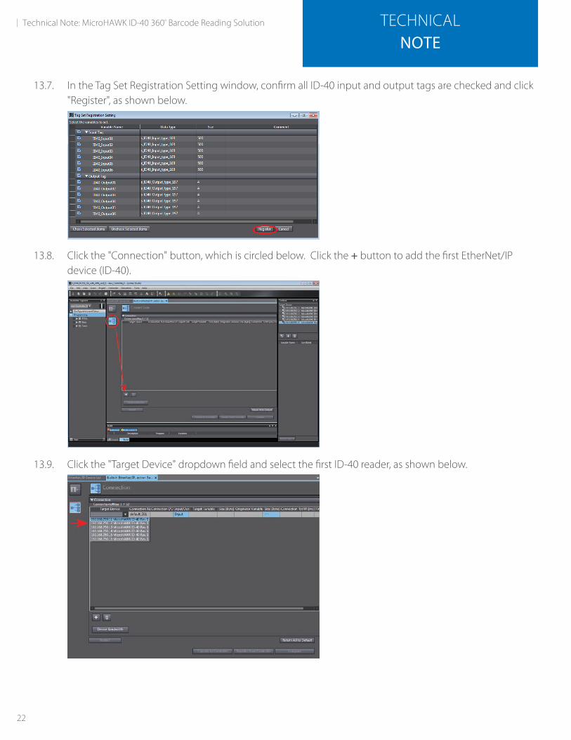
13.7. In the Tag Set Registration Setting window, confirm all ID-40 input and output tags are checked and click "Register", as shown below.
13.8. Click the "Connection" button, which is circled below. Click the + button to add the first EtherNet/IP device (ID-40).
13.9. Click the "Target Device" dropdown field and select the first ID-40 reader, as shown below.
22
Technical Note: MicroHAWK ID-40 360º Barcode Reading Solution TECHNICALNOTE
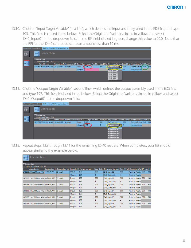
13.10. Click the "Input Target Variable" (first line), which defines the input assembly used in the EDS file, and type 103. This field is circled in red below. Select the Originator Variable, circled in yellow, and select ID40_Input01 in the dropdown field. In the RPI field, circled in green, change this value to 20.0. Note that the RPI for the ID-40 cannot be set to an amount less than 10 ms.
13.11. Click the "Output Target Variable" (second line), which defines the output assembly used in the EDS file, and type 197. This field is circled in red below. Select the Originator Variable, circled in yellow, and select ID40_Output01 in the dropdown field.
13.12. Repeat steps 13.8 through 13.11 for the remaining ID-40 readers. When completed, your list should appear similar to the example below.
23
Transfer EtherNet/IP Configuration to NJ/NX Controller
14. Check EtherNet/IP Communications
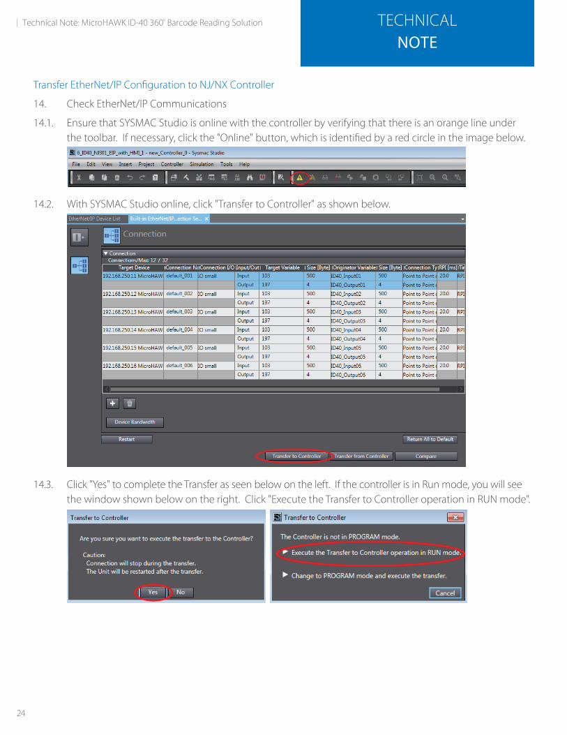
14.1. Ensure that SYSMAC Studio is online with the controller by verifying that there is an orange line under the toolbar. If necessary, click the "Online" button, which is identified by a red circle in the image below.
14.2. With SYSMAC Studio online, click "Transfer to Controller" as shown below.
14.3. Click "Yes" to complete the Transfer as seen below on the left. If the controller is in Run mode, you will see the window shown below on the right. Click "Execute the Transfer to Controller operation in RUN mode".
24
Technical Note: MicroHAWK ID-40 360º Barcode Reading Solution TECHNICALNOTE
Check EtherNet/IP Communications in SYSMAC Studio
15. Check EtherNet/IP Communications in SYSMAC Studio
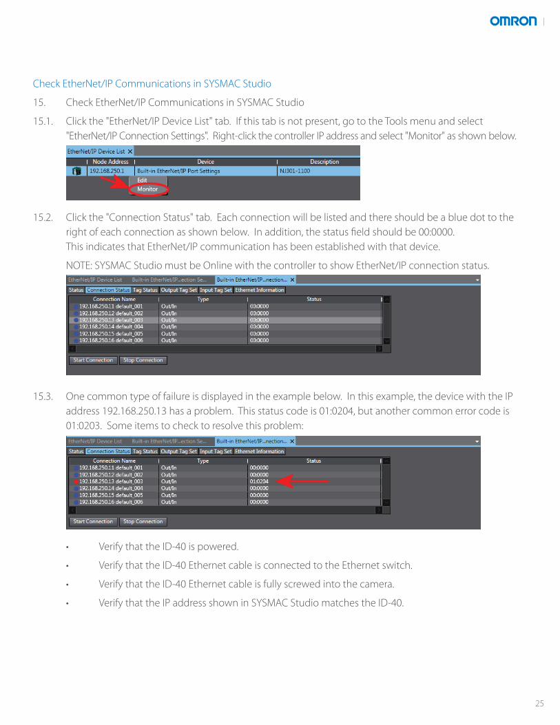
15.1. Click the "EtherNet/IP Device List" tab. If this tab is not present, go to the Tools menu and select "EtherNet/IP Connection Settings". Right-click the controller IP address and select "Monitor" as shown below.
15.2. Click the "Connection Status" tab. Each connection will be listed and there should be a blue dot to the right of each connection as shown below. In addition, the status field should be 00:0000. This indicates that EtherNet/IP communication has been established with that device.
NOTE: SYSMAC Studio must be Online with the controller to show EtherNet/IP connection status.
15.3. One common type of failure is displayed in the example below. In this example, the device with the IP address 192.168.250.13 has a problem. This status code is 01:0204, but another common error code is 01:0203. Some items to check to resolve this problem:
• Verify that the ID-40 is powered.
• Verify that the ID-40 Ethernet cable is connected to the Ethernet switch.
• Verify that the ID-40 Ethernet cable is fully screwed into the camera.
• Verify that the IP address shown in SYSMAC Studio matches the ID-40.
25

15.4. Once the issue has been corrected, it may take up to a minute for the Connection Status to update in SYSMAC Studio.
15.5. Once all the connections are established as shown below, the project should be saved by going to the File menu and selecting Save As and typing the project name.
15.6. The NJ/NX controller setup is completed.
NA-HMI Panel SetupNA-HMI Panel Not Present
If your integration of this solution does not include a NA-HMI panel, then the remaining sections of the HA-HMI panel setup can be skipped.
Establish NA-HMI Panel Communications
16. Establish NA-HMI Panel Communications
16.1. In the current open project, under the words “Multiview Explorer”, click the controller dropdown field and select HMI_NA5_0 as shown below.
16.2. Open the HMI menu and select Change Device as shown below.
26
Technical Note: MicroHAWK ID-40 360º Barcode Reading Solution TECHNICALNOTE

16.3. Change the Device and Version fields, shown below, to match the HMI panel that you are currently using.
16.4. Open the HMI menu and select Communications Setup as shown below.
16.5. Click the Ethernet connection via a hub button as shown below.
16.6. In the Specify IP Address field, enter the IP address for the NA-HMI panel. The default address for an NA-HMI panel, port 1, is: 192.168.250.2.
16.7. Click "Test".
16.8. Be sure “Test OK” shows in the white bar as shown below. This will indicate you have good communications with the Omron controller.
16.9. Click "OK" when ready.
27
Modify NA-HMI Panel IP Address
17. NA-HMI Panel Download
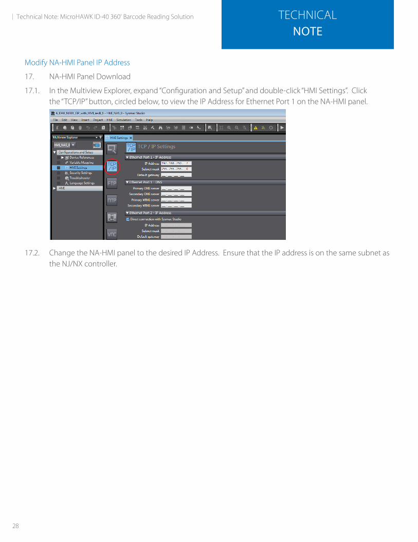
17.1. In the Multiview Explorer, expand “Configuration and Setup” and double-click “HMI Settings”. Clickthe “TCP/IP” button, circled below, to view the IP Address for Ethernet Port 1 on the NA-HMI panel.
17.2. Change the NA-HMI panel to the desired IP Address. Ensure that the IP address is on the same subnet as the NJ/NX controller.
28
Technical Note: MicroHAWK ID-40 360º Barcode Reading Solution TECHNICALNOTE

Download the Project to the NA-HMI Panel
18. Download the Project to the NA-HMI Panel
18.1. Click the "Online" button, which is identified in the image below.
• If this is the first time that you have used the NA-HMI panel, the firmware may need to be updated. Please go to https://www.youtube.com/watch?v=ETNHvv9KZ38 for a video showing the firmware update process.
• You may see a warning that that the HMI device has no name. Click “Yes” to continue.
18.2. Once online with the NA-HMI panel, a yellow line will appear under the toolbar. Click the "Synchronize" button, which is identified in the image below.
18.3. The synchronization page will be displayed as shown below. Verify that the "Store the HMI" option is checked and click "Transfer to Device".
29
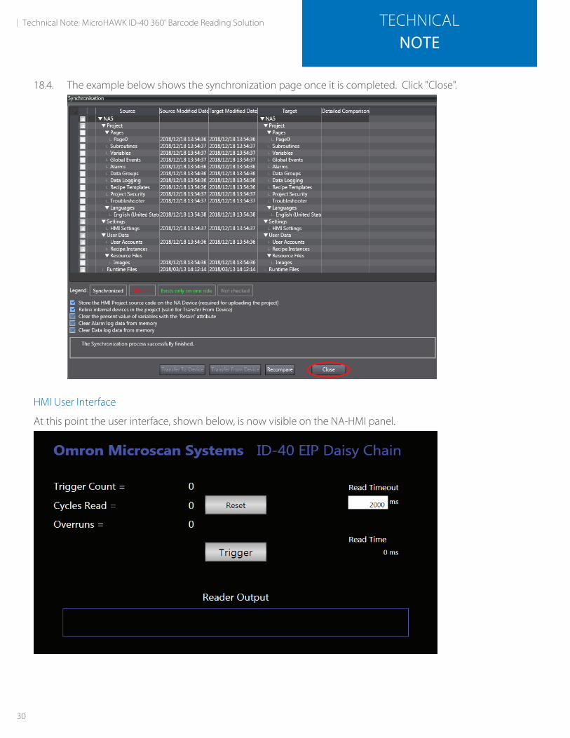
18.4. The example below shows the synchronization page once it is completed. Click "Close".
HMI User Interface
At this point the user interface, shown below, is now visible on the NA-HMI panel.
30
Technical Note: MicroHAWK ID-40 360º Barcode Reading Solution TECHNICALNOTE
Optimizing the Trigger Position
For the fastest read times, the trigger position should be adjusted so that the barcode is read on either the first or second image capture regardless of barcode orientation.
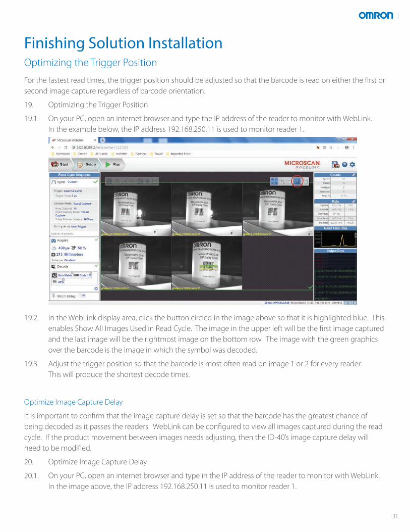
19. Optimizing the Trigger Position
19.1. On your PC, open an internet browser and type the IP address of the reader to monitor with WebLink. In the example below, the IP address 192.168.250.11 is used to monitor reader 1.
19.2. In the WebLink display area, click the button circled in the image above so that it is highlighted blue. This enables Show All Images Used in Read Cycle. The image in the upper left will be the first image captured and the last image will be the rightmost image on the bottom row. The image with the green graphics over the barcode is the image in which the symbol was decoded.
19.3. Adjust the trigger position so that the barcode is most often read on image 1 or 2 for every reader. This will produce the shortest decode times.
Optimize Image Capture Delay
It is important to confirm that the image capture delay is set so that the barcode has the greatest chance of being decoded as it passes the readers. WebLink can be configured to view all images captured during the read cycle. If the product movement between images needs adjusting, then the ID-40’s image capture delay will need to be modified.
20. Optimize Image Capture Delay
20.1. On your PC, open an internet browser and type in the IP address of the reader to monitor with WebLink. In the image above, the IP address 192.168.250.11 is used to monitor reader 1.
Finishing Solution Installation
31
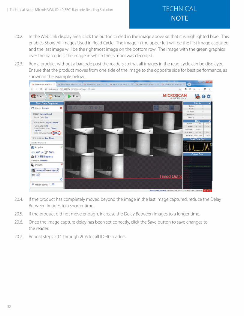
20.2. In the WebLink display area, click the button circled in the image above so that it is highlighted blue. This enables Show All Images Used in Read Cycle. The image in the upper left will be the first image captured and the last image will be the rightmost image on the bottom row. The image with the green graphics over the barcode is the image in which the symbol was decoded.
20.3. Run a product without a barcode past the readers so that all images in the read cycle can be displayed. Ensure that the product moves from one side of the image to the opposite side for best performance, as shown in the example below.
20.4. If the product has completely moved beyond the image in the last image captured, reduce the Delay Between Images to a shorter time.
20.5. If the product did not move enough, increase the Delay Between Images to a longer time.
20.6. Once the image capture delay has been set correctly, click the Save button to save changes to the reader.
20.7. Repeat steps 20.1 through 20.6 for all ID-40 readers.
32
Technical Note: MicroHAWK ID-40 360º Barcode Reading Solution TECHNICALNOTE
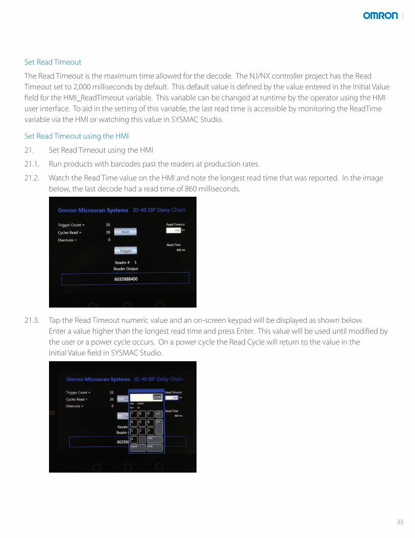
Set Read Timeout
The Read Timeout is the maximum time allowed for the decode. The NJ/NX controller project has the Read Timeout set to 2,000 milliseconds by default. This default value is defined by the value entered in the Initial Value field for the HMI_ReadTimeout variable. This variable can be changed at runtime by the operator using the HMI user interface. To aid in the setting of this variable, the last read time is accessible by monitoring the ReadTime variable via the HMI or watching this value in SYSMAC Studio.
Set Read Timeout using the HMI
21. Set Read Timeout using the HMI
21.1. Run products with barcodes past the readers at production rates.
21.2. Watch the Read Time value on the HMI and note the longest read time that was reported. In the image below, the last decode had a read time of 860 milliseconds.
21.3. Tap the Read Timeout numeric value and an on-screen keypad will be displayed as shown below. Enter a value higher than the longest read time and press Enter. This value will be used until modified by the user or a power cycle occurs. On a power cycle the Read Cycle will return to the value in the Initial Value field in SYSMAC Studio.
33

Change the Default Read Timeout
22. Change the Default Read Timeout
22.1. Open the Global Variable page in SYSMAC Studio. See step 10.1 in the section Global Variables.
22.2. Set the initial value field of the variable ReadTime to the desired timeout in milliseconds.
22.3. Go online to the NJ/NX controller and Synchronize the project. Follow the instructions starting at 11.1 in the section Download Project to Controller.
34
Technical Note: MicroHAWK ID-40 360º Barcode Reading Solution TECHNICALNOTE
Known Issues
23. Known Issues
23.1. The Min_OnTime (TOF) timer is used to extend short duration trigger signals to ensure that the ID-40 readers can have their EtherNet/IP triggers forced low (to stop the previous read if still reading), receive the acknowledgement that the units are no longer triggered, and then trigger the readers for the new cycle. This requires that the trigger be on for at least 3 times the RPI, which, in this project, is 20 milliseconds, for a total time of 60 milliseconds.
23.2. If the Min_OnTime timer is still executing the 60 millisecond timer and another trigger is received the new trigger is ignored. Once the 60 millisecond timer has expired a new trigger will be processed.
23.3. All ID-40s must have their trigger set to External Level and the end cycle set to New Trigger for the NJ/NX controller logic to function correctly.
23.4. On the first trigger after the project is downloaded to the NJ/NX controller, the ReadTime variable will be reported as 20,000. On subsequent triggers, the ReadTime variable will report the correct Trigger to Result time in milliseconds.
Appendix A
35
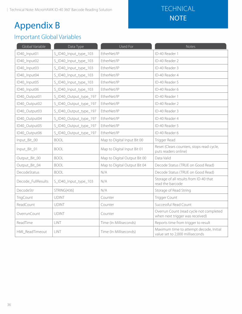
Important Global VariablesGlobal Variable Data Type Used For Notes
ID40_Input01 S_ID40_Input_type_103 EtherNet/IP ID-40 Reader 1
ID40_Input02 S_ID40_Input_type_103 EtherNet/IP ID-40 Reader 2
ID40_Input03 S_ID40_Input_type_103 EtherNet/IP ID-40 Reader 3
ID40_Input04 S_ID40_Input_type_103 EtherNet/IP ID-40 Reader 4
ID40_Input05 S_ID40_Input_type_103 EtherNet/IP ID-40 Reader 5
ID40_Input06 S_ID40_Input_type_103 EtherNet/IP ID-40 Reader 6
ID40_Output01 S_ID40_Output_type_197 EtherNet/IP ID-40 Reader 1
ID40_Output02 S_ID40_Output_type_197 EtherNet/IP ID-40 Reader 2
ID40_Output03 S_ID40_Output_type_197 EtherNet/IP ID-40 Reader 3
ID40_Output04 S_ID40_Output_type_197 EtherNet/IP ID-40 Reader 4
ID40_Output05 S_ID40_Output_type_197 EtherNet/IP ID-40 Reader 5
ID40_Output06 S_ID40_Output_type_197 EtherNet/IP ID-40 Reader 6
Input_Bit_00 BOOL Map to Digital Input Bit 00 Trigger Read
Input_Bit_01 BOOL Map to Digital Input Bit 01Reset (Clears counters, stops read cycle, puts readers online)
Output_Bit_00 BOOL Map to Digital Output Bit 00 Data Valid
Output_Bit_04 BOOL Map to Digital Output Bit 04 Decode Status (TRUE on Good Read)
DecodeStatus BOOL N/A Decode Status (TRUE on Good Read)
Decode_FullResults S_ID40_Input_type_103 N/AStorage of all results from ID-40 that read the barcode
DecodeStr STRING[436] N/A Storage of Read String
TrigCount UDINT Counter Trigger Count
ReadCount UDINT Counter Successful Read Count
OverrunCount UDINT CounterOverrun Count (read cycle not completed when next trigger was received)
ReadTime LINT Time (In Milliseconds) Reports time from trigger to result
HMI_ReadTimeout LINT Time (In Milliseconds)Maximum time to attempt decode, Initial value set to 2,000 milliseconds
36
Technical Note: MicroHAWK ID-40 360º Barcode Reading Solution TECHNICALNOTE
Appendix B
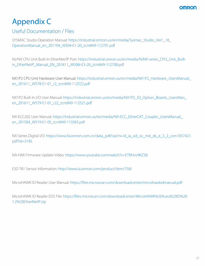
Useful Documentation / Files
SYSMAC Studio Operation Manual: https://industrial.omron.us/en/media/Sysmac_Studio_Ver1_18_OperationManual_en_201704_W504-E1-20_tcm849-112701.pdf
NJ/NX CPU Unit Built-In EtherNet/IP Port: https://industrial.omron.us/en/media/NJNX-series_CPU_Unit_Built-in_EtherNetIP_Manual_EN_201811_W506I-E3-20_tcm849-112708.pdf
NX1P2 CPU Unit Hardware User Manual: https://industrial.omron.us/en/media/NX1P2_Hardware_UsersManual_en_201611_W578-E1-01_r2_tcm849-112522.pdf
NX1P2 Built-In I/O User Manual: https://industrial.omron.us/en/media/NX1P2_IO_Option_Boards_UsersMan_en_201611_W579-E1-01_r22_tcm849-112521.pdf
NX-ECC202 User Manual: https://industrial.omron.us/en/media/NX-ECC_EtherCAT_Coupler_UsersManual_en_201504_W519-E1-05_tcm849-113365.pdf
NX-Series Digital I/O: https://www.fa.omron.com.cn/data_pdf/cat/nx-id_ia_od_oc_md_ds_e_3_2_csm1057421.pdf?id=3185
NA-HMI Firmware Update Video: https://www.youtube.com/watch?v=ETNHvv9KZ38
E3Z-T81 Sensor Information: http://www.ia.omron.com/product/item/758/
MicroHAWK ID Reader User Manual: https://files.microscan.com/downloadcenter/microhawkidmanual.pdf
MicroHAWK ID Reader EDS File: https://files.microscan.com/downloadcenter/MicroHAWK%20Auto%20ID%201.2%20EtherNetIP.zip
Appendix C
37
Controllers & I/O• Machine Automation Controllers (MAC) • Motion Controllers• Programmable Logic Controllers (PLC) • Temperature Controllers • Remote I/O
Robotics• Industrial Robots • Mobile Robots
Operator Interfaces• Human Machine Interface (HMI)
Motion & Drives• Machine Automation Controllers (MAC) • Motion Controllers • Servo Systems• Frequency Inverters
Vision, Measurement & Identification• Vision Sensors & Systems • Measurement Sensors • Auto Identification Systems
Sensing• Photoelectric Sensors • Fiber-Optic Sensors • Proximity Sensors• Rotary Encoders • Ultrasonic Sensors
Safety• Safety Light Curtains • Safety Laser Scanners • Programmable Safety Systems• Safety Mats and Edges • Safety Door Switches • Emergency Stop Devices• Safety Switches & Operator Controls • Safety Monitoring/Force-guided Relays
Control Components• Power Supplies • Timers • Counters • Programmable Relays• Digital Panel Meters • Monitoring Products
Switches & Relays• Limit Switches • Pushbutton Switches • Electromechanical Relays• Solid State Relays
Software• Programming & Configuration • Runtime
Printed on recycled paper.
MCD-128 Note: Specifications are subject to change. © 2019 Omron. All Rights Reserved. Printed in U.S.A.
OMRON CANADA, INC. • HEAD OFFICEToronto, ON, Canada • 416.286.6465 • 866.986.6766 • www.omron247.com
OMRON ELECTRONICS DE MEXICO • HEAD OFFICEMéxico DF • 52.55.59.01.43.00 • 01-800-226-6766 • [email protected]
OMRON ELECTRONICS DE MEXICO • SALES OFFICEApodaca, N.L. • 52.81.11.56.99.20 • 01-800-226-6766 • [email protected]
OMRON ELETRÔNICA DO BRASIL LTDA • HEAD OFFICESão Paulo, SP, Brasil • 55.11.2101.6300 • www.omron.com.br
OMRON ARGENTINA • SALES OFFICECono Sur • 54.11.4783.5300
OTHER OMRON LATIN AMERICA SALES54.11.4783.5300
OMRON AUTOMATION AMERICAS HEADQUARTERS • Chicago, IL USA • 847.843.7900 • 800.556.6766 • www.omron247.com
Authorized Distributor: