Technical Manual - hebel.com.au · aerated concrete (AAC) panels, and provides design tables and...
63
Technical Manual Part 4: Wall & Floor Panel Design & Construction
Transcript of Technical Manual - hebel.com.au · aerated concrete (AAC) panels, and provides design tables and...
Technical ManualPart 4: Wall & Floor Panel Design & Construction
CSR Hebel Technical Manual • August 2010
7
7.1
Wall & Floor Panel Design & Construction
7.1 Overview
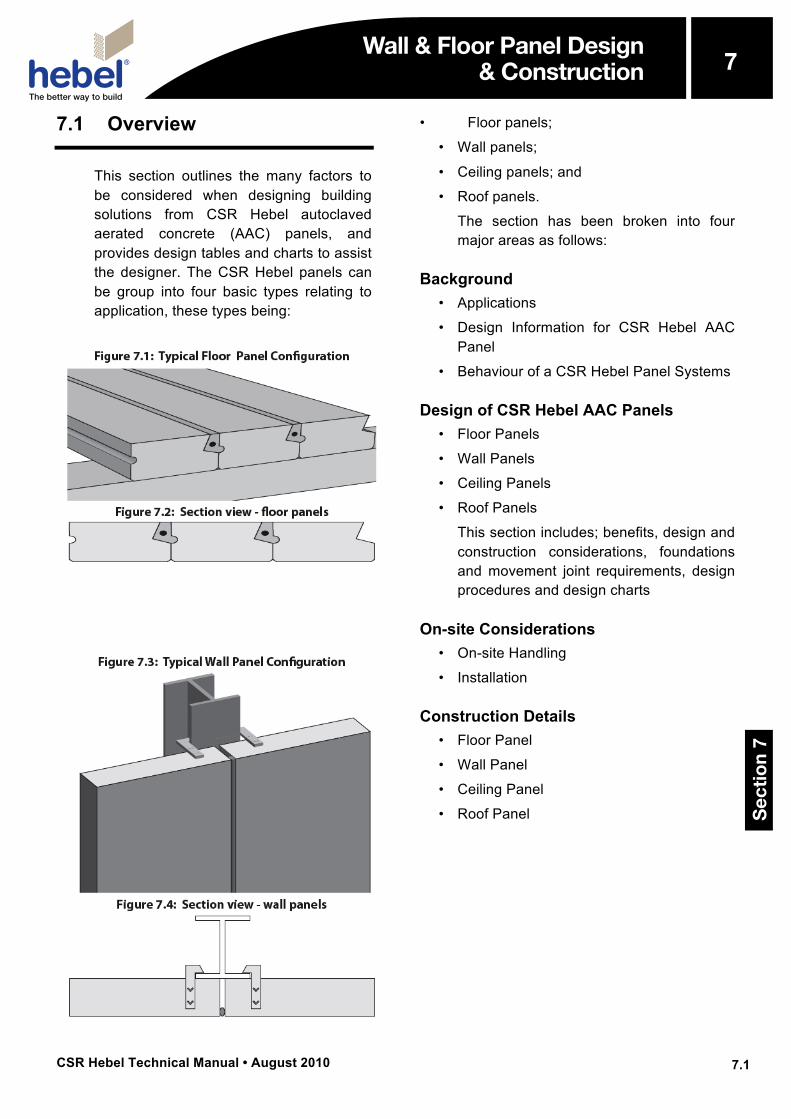
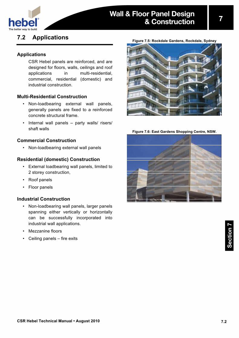
This section outlines the many factors to be considered when designing building solutions from CSR Hebel autoclaved aerated concrete (AAC) panels, and provides design tables and charts to assist the designer. The CSR Hebel panels can be group into four basic types relating to application, these types being:
• Floor panels;
• Wall panels;
• Ceiling panels; and
• Roof panels.
The section has been broken into fourmajor areas as follows:
Background • Applications
• Design Information for CSR Hebel AACPanel
• Behaviour of a CSR Hebel Panel Systems
Design of CSR Hebel AAC Panels • Floor Panels
• Wall Panels
• Ceiling Panels
• Roof Panels
This section includes; benefits, design andconstruction considerations, foundationsand movement joint requirements, designprocedures and design charts
On-site Considerations • On-site Handling
• Installation
Construction Details • Floor Panel
• Wall Panel
• Ceiling Panel
• Roof Panel
Wall & Floor Panel Design & Construction
Sec
tio
n 7
7
CSR Hebel Technical Manual • August 2010
7
7.2
Wall & Floor Panel Design & Construction
7.2 Applications
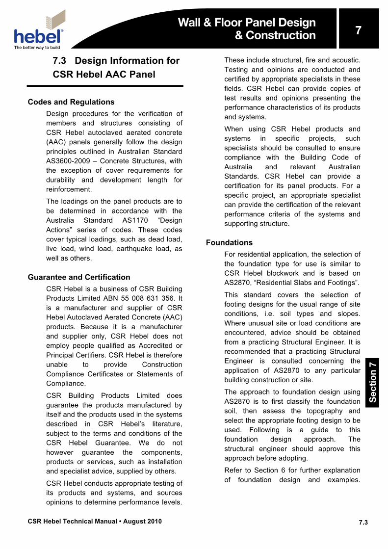
Applications CSR Hebel panels are reinforced, and are designed for floors, walls, ceilings and roof applications in multi-residential, commercial, residential (domestic) and industrial construction.
Multi-Residential Construction • Non-loadbearing external wall panels,
generally panels are fixed to a reinforcedconcrete structural frame.
• Internal wall panels – party walls/ risers/shaft walls
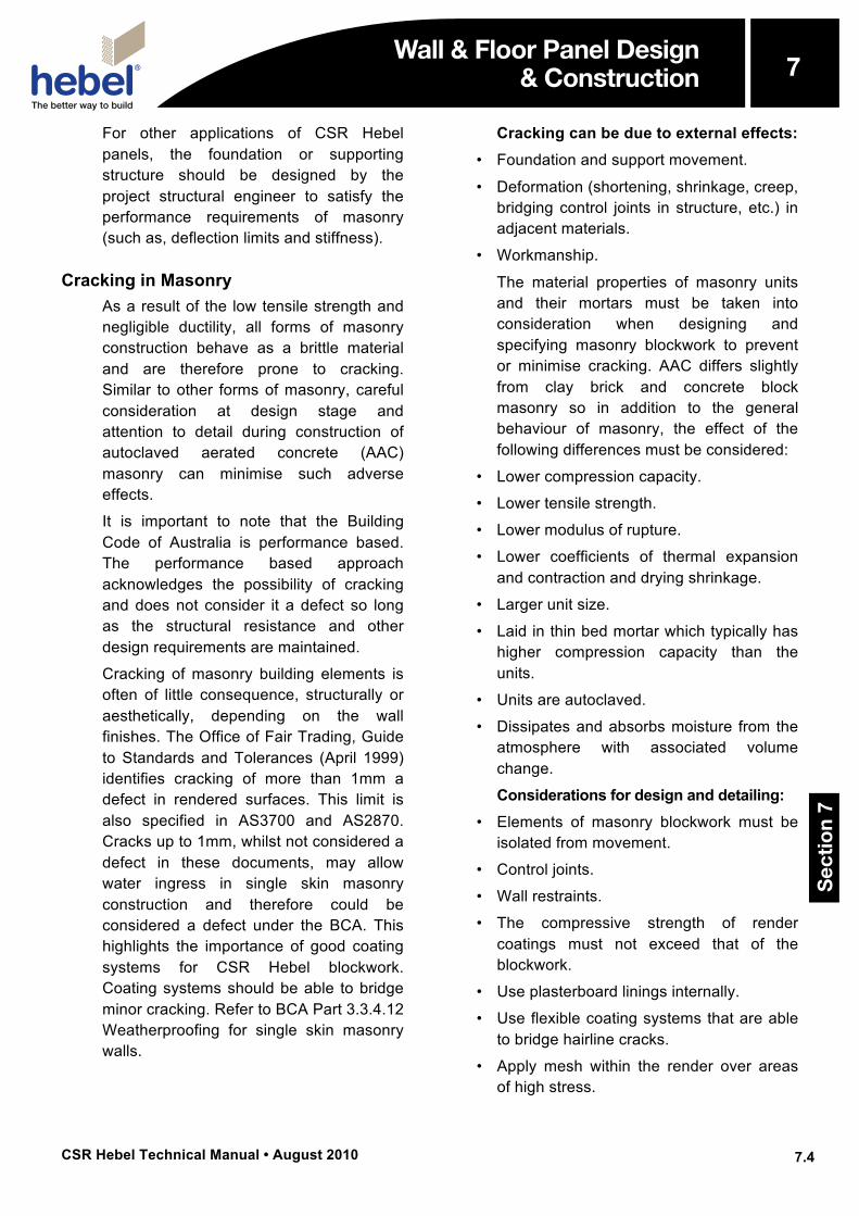
Commercial Construction • Non-loadbearing external wall panels
Residential (domestic) Construction • External loadbearing wall panels, limited to
2 storey construction,
• Roof panels
• Floor panels
Industrial Construction • Non-loadbearing wall panels, larger panels
spanning either vertically or horizontallycan be successfully incorporated intoindustrial wall applications.
• Mezzanine floors
• Ceiling panels – fire exits
Figure 7.5: Rockdale Gardens, Rockdale, Sydney
Figure 7.6: East Gardens Shopping Centre, NSW.
Wall & Floor Panel Design & Construction
Sec
tio
n 7
7
CSR Hebel Technical Manual • August 2010
7
7.3
Wall & Floor Panel Design & Construction
7.3 Design Information for CSR Hebel AAC Panel
Codes and Regulations Design procedures for the verification of members and structures consisting of CSR Hebel autoclaved aerated concrete (AAC) panels generally follow the design principles outlined in Australian Standard AS3600-2009 – Concrete Structures, with the exception of cover requirements for durability and development length for reinforcement.
The loadings on the panel products are to be determined in accordance with the Australia Standard AS1170 “Design Actions” series of codes. These codes cover typical loadings, such as dead load, live load, wind load, earthquake load, as well as others.
Guarantee and Certification CSR Hebel is a business of CSR Building Products Limited ABN 55 008 631 356. It is a manufacturer and supplier of CSR Hebel Autoclaved Aerated Concrete (AAC) products. Because it is a manufacturer and supplier only, CSR Hebel does not employ people qualified as Accredited or Principal Certifiers. CSR Hebel is therefore unable to provide Construction Compliance Certificates or Statements of Compliance.
CSR Building Products Limited does guarantee the products manufactured by itself and the products used in the systems described in CSR Hebel’s literature, subject to the terms and conditions of the CSR Hebel Guarantee. We do not however guarantee the components, products or services, such as installation and specialist advice, supplied by others.
CSR Hebel conducts appropriate testing of its products and systems, and sources opinions to determine performance levels.
These include structural, fire and acoustic. Testing and opinions are conducted and certified by appropriate specialists in these fields. CSR Hebel can provide copies of test results and opinions presenting the performance characteristics of its products and systems.
When using CSR Hebel products and systems in specific projects, such specialists should be consulted to ensure compliance with the Building Code of Australia and relevant Australian Standards. CSR Hebel can provide a certification for its panel products. For a specific project, an appropriate specialist can provide the certification of the relevant performance criteria of the systems and supporting structure.
Foundations For residential application, the selection of the foundation type for use is similar to CSR Hebel blockwork and is based on AS2870, “Residential Slabs and Footings”.
This standard covers the selection of footing designs for the usual range of site conditions, i.e. soil types and slopes. Where unusual site or load conditions are encountered, advice should be obtained from a practicing Structural Engineer. It is recommended that a practicing Structural Engineer is consulted concerning the application of AS2870 to any particular building construction or site.
The approach to foundation design using AS2870 is to first classify the foundation soil, then assess the topography and select the appropriate footing design to be used. Following is a guide to this foundation design approach. The structural engineer should approve this approach before adopting.
Refer to Section 6 for further explanation of foundation design and examples.
Wall & Floor Panel Design & Construction
Sec
tio
n 7
7
CSR Hebel Technical Manual • August 2010
7
7.4
Wall & Floor Panel Design & Construction
For other applications of CSR Hebel panels, the foundation or supporting structure should be designed by the project structural engineer to satisfy the performance requirements of masonry (such as, deflection limits and stiffness).
Cracking in Masonry As a result of the low tensile strength and negligible ductility, all forms of masonry construction behave as a brittle material and are therefore prone to cracking. Similar to other forms of masonry, careful consideration at design stage and attention to detail during construction of autoclaved aerated concrete (AAC) masonry can minimise such adverse effects.
It is important to note that the Building Code of Australia is performance based. The performance based approach acknowledges the possibility of cracking and does not consider it a defect so long as the structural resistance and other design requirements are maintained.
Cracking of masonry building elements is often of little consequence, structurally or aesthetically, depending on the wall finishes. The Office of Fair Trading, Guide to Standards and Tolerances (April 1999) identifies cracking of more than 1mm a defect in rendered surfaces. This limit is also specified in AS3700 and AS2870. Cracks up to 1mm, whilst not considered a defect in these documents, may allow water ingress in single skin masonry construction and therefore could be considered a defect under the BCA. This highlights the importance of good coating systems for CSR Hebel blockwork. Coating systems should be able to bridge minor cracking. Refer to BCA Part 3.3.4.12 Weatherproofing for single skin masonry walls.
Cracking can be due to external effects: • Foundation and support movement.
• Deformation (shortening, shrinkage, creep,bridging control joints in structure, etc.) inadjacent materials.
• Workmanship.
The material properties of masonry unitsand their mortars must be taken intoconsideration when designing andspecifying masonry blockwork to preventor minimise cracking. AAC differs slightlyfrom clay brick and concrete blockmasonry so in addition to the generalbehaviour of masonry, the effect of thefollowing differences must be considered:
• Lower compression capacity.
• Lower tensile strength.
• Lower modulus of rupture.
• Lower coefficients of thermal expansionand contraction and drying shrinkage.
• Larger unit size.
• Laid in thin bed mortar which typically hashigher compression capacity than theunits.
• Units are autoclaved.
• Dissipates and absorbs moisture from theatmosphere with associated volumechange.
Considerations for design and detailing:• Elements of masonry blockwork must be
isolated from movement.
• Control joints.
• Wall restraints.
• The compressive strength of rendercoatings must not exceed that of theblockwork.
• Use plasterboard linings internally.
• Use flexible coating systems that are ableto bridge hairline cracks.
• Apply mesh within the render over areasof high stress.
Wall & Floor Panel Design & Construction
Sec
tio
n 7
7
CSR Hebel Technical Manual • August 2010
7
7.5
Wall & Floor Panel Design & Construction
Movement Joints (M.J.) During the life cycle of a building, the building and the materials that it is constructed from will move. These movements are due to many factors working together or individually, such as foundation movement (shrinkage and swelling), thermal expansion and contraction, differential movements between materials, climate and soil condition. This movement, unless relieved or accommodated for, will induce stress in the materials, which may be relieved in the form of cracking. To accommodate these movements and relieve any induced stresses, which could potentially crack the wall, movement joints (vertical gaps) shall be installed. There are two categories of joints:
• Articulation joints (A.J.) are provided torelieve induced stresses due to foundationmovement. The joints make the wallsmore flexible by breaking the wall into aseries of small panels, which is especiallyrequired on reactive ground conditions(clay, peat). Differential movementbetween the AAC blockwork and adjacentstructural elements need to beaccommodated with articulation joints,such as blockwork infill between thestructural frame.
• Control joints (C.J.), (one type is anexpansion joint), are provided to relievethe induced stresses resulting fromthermal expansion or contraction of theAAC, or differential movement betweenthe AAC and another material or structure,such as abutting walls or columns ofconcrete or brickwork. Control joints candelineate coating shrinkage breaks. A jointmay perform the function of either anarticulation joint or control joint or both.
IMPORTANT: There are restrictions provided to the maximum length of wall:
• 6 metres maximum for continuous runs ofwalls.
• When measuring the 6 metre run of wall,the measurement continues aroundcorners till the end of the wall or amovement joint.
• At the perimeter of the CSR Hebel panelwall when enclosed by the structure of thebuilding, such as the interface withcolumns, walls, soffits and slabs.
• For horizontal panels, a vertical movementjoint shall be provided at the ends of thepanels.
Additionally, the BCA presents thefollowing requirements for articulationjoints in unreinforced masonry walls, whichis applicable for AAC masonryconstruction:
“b) Articulation joints must have a width not less than 10mm and be provided:
i. in straight, continuous walls having noopenings, at not more than 6m centresand not closer than the height of the wallaway from corners; and
ii. where the height of the wall changes bymore than 20% at the position of changein height; and
iii. where openings more than 900x900mmoccur, at more than 5m centres, andpositioned in line with one edge of theopening; and
iv. where walls change in thickness; and
v. at control or construction joints in thefooting slabs; and
vi. at junctions of walls constructed ofdifferent masonry materials; and
vii. at deep chases (rebates) for servicepipes.”
CSR Hebel recommends that movementjoints be provided in AAC masonryconstruction for all site soil classifications.
Wall & Floor Panel Design & Construction
Sec
tio
n 7
7
CSR Hebel Technical Manual • August 2010
7
7.6
Wall & Floor Panel Design & Construction
For further information refer to the Cement Concrete and Aggregates Australia, Technical Note - Joints in Concrete Buildings through website: www.concrete.net.eu
The project architect and engineer shall be responsible for determining the optimum location of movement joints, as their location is dependent on a variety of factors including most importantly the structural stability and bracing requirements of the building.
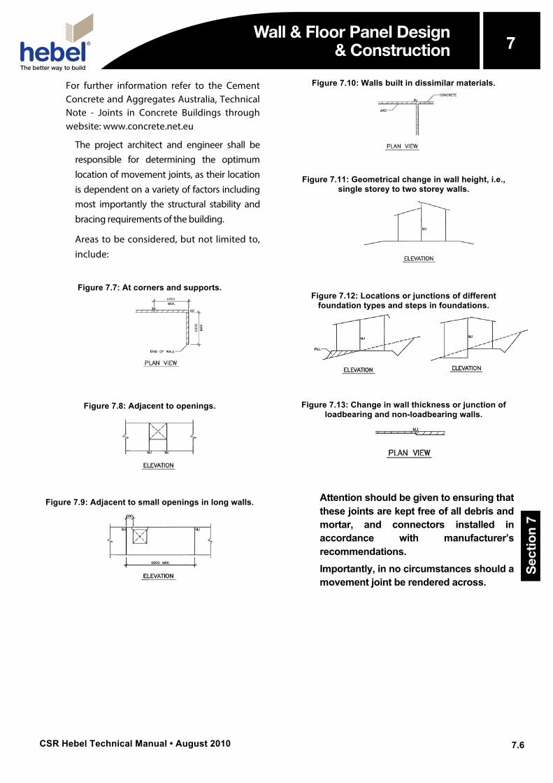
Areas to be considered, but not limited to, include:
Figure 7.7: At corners and supports.
Figure 7.8: Adjacent to openings.
Figure 7.9: Adjacent to small openings in long walls.
Figure 7.10: Walls built in dissimilar materials.
Figure 7.11: Geometrical change in wall height, i.e., single storey to two storey walls.
Figure 7.12: Locations or junctions of different foundation types and steps in foundations.
Figure 7.13: Change in wall thickness or junction of loadbearing and non-loadbearing walls.
Attention should be given to ensuring that these joints are kept free of all debris and mortar, and connectors installed in accordance with manufacturer’s recommendations. Importantly, in no circumstances should a movement joint be rendered across.
Wall & Floor Panel Design & Construction
Sec
tio
n 7
7
CSR Hebel Technical Manual • August 2010
7
7.7
Wall & Floor Panel Design & Construction
7.4 Behaviour of a CSR Hebel Panel System
CSR Hebel panels are designed as “one-way” spanning structural members. The behaviour (deflection and strength) of the panel is assessed as a function of the clear span of the panel and the design loadings to which the panel is subjected. The behaviour of the panel is predicted and checked against specified performance criterion.
The individual panels are held together with a “Ring Anchor System” to form a rigid plate or diaphragm, so that applied loadings can be directed to bracing elements and transferred to the foundations, or for the rigid plate or diaphragm to be the bracing element.
Design Method The strength design of the CSR Hebel AAC panels has been carried out using the Transformed Section Theory, as detailed in the text book, ‘Reinforced Concrete’ by Warner, Rangan and Hall (Longman Cheshire).
The servicability design (deflection) of the CSR Hebel AAC panels has been carried out using the Branson’s formula as detailed in the Reinforced Concrete text book. Slabs are classified “General” in accordance with AS1170.1 Clause 1.1. The serviceability factors are taken as Ψs = 0.7 and Ψl = 0.4.
For creep and shrinkage, the kcs factor is taken as 1. This is because the autoclaving process cures and stabilises the AAC material. Some short-term shrinkage will occur due to drying (loss of moisture content). After the moisture content of the panel has stabilised, minor shrinkage or expansion can occur as the AAC material dissipates moisture or takes moisture in, due to variation in
atmospheric conditions.
The design charts consider two long-term deflection criteria, those being:
• Span/deflection limit ≥ 250
• Span/deflection limit ≥ 600
The deflection criteria chosen shouldconsider type of floor coverings and wallsover, etc.
For the span/deflection ≥ 250 limit,typically used for flexible floor coverings,such as carpets, timber overlays, etc.
For the span/deflection ≥ 600 limit,typically used for brittle floor coverings,such as direct stick tiles or tiles on amortar bed, etc; or masonry walls over.
The design tables have been determinedincluding the above mentionedassumptions, for variations to theseassumptions contact CSR Hebel.
Imposed Design Actions The imposed design actions shall be determined from AS1170 series of codes and are to be provided by the designer. They will consider:
• fire resistance levels (FRL);
• type of loading (General or Storage, etc.);
• wind loads (Permissible);
• superimposed loads;
• live loads;
• earthquake loads; and
• snow loads, or others.
For the wind load, the value will have to bethe maximum after all effects, such asinternal, external, and local pressurefactors, etc. have been applied whereapplicable. This value is required as apermissible value.
Design Procedure 1. Layout of supporting members (columns,
walls and beams) to optimise the thickness
Wall & Floor Panel Design & Construction
Sec
tio
n 7
7
CSR Hebel Technical Manual • August 2010
7
7.8
Wall & Floor Panel Design & Construction
of the panels and supporting structure. Note, panels are generally one-way spanning, therefore a support must be provided at each end of the panel. For example, this would include providing beams over openings (doors and windows), and secondary structural steel framing around large penetrations (roller doors, windows and floors).
2. Design Criteria. Identify the PerformanceRequirements of the Building Solution.
– Purpose of structure (Class andimportance).
– Imposed design actions.
– Deflection criteria.
– Fire Resistance Level (FRL).
– Sound insulation performance (Rw, Ctr
values).
– Energy Efficiency (R-Value).
3. Panel thickness. Select a panel thicknessand connection type to satisfy the DesignCriteria.
4. Check the proposed Building Solutionincorporating the panel satisfies theDesign Criteria.
5. Complete detailed design(weathertightness) and documentation.
Panel Specification Importantly, the following factors are critical to the design and selection of an adequate panel:
• Magnitude of applied loading. Themagnitude of applied loads will provide apreliminary panel thickness, but the otherfactors can reduce the capacity of thepanel. Therefore a thicker panel mayberequired.
• Type of applied loading. The type ofloading will influence the level of live loadconsidered for assessing the long-termdeflection performance of the panel.
• Type of floor coverings and associateddeflection requirement. The type of floorcovering will influence the deflectioncriteria chosen. Generally, floor panelswith flexible floor coverings (e.g., carpet)are designed to satisfy span/250 deflectioncriteria. Topping slabs and tiles will requiretighter deflection criteria, like span/600 forthe creep and live load deflectioncomponent.
• Specified deflection performance.Should a tighter deflection limit be requiredplease advise your CSR Hebelrepresentative, prior to final sizing ofpanels and preparation of a quote; see‘Structural Framing’ in DesignConsiderations section below.
• Fire resistance level (FRL), AAC coverto reinforcement and location of fire.The fire rating level and magnitude of AACcover directly affect the performance of thepanel. More cover provides insulation tothe reinforcement and a high fire ratinglevel will provide time for the fire toovercome the insulation and reduce theavailable reinforcement capacity. When afire is acting from above a panel, theavailable panel depth is reduced with anincrease in the fire rating level. For moreinformation refer to Section 5 of thispublication.
Design Considerations The following are common issues requiring consideration and resolution in the application of CSR Hebel AAC panels to individual projects:
Dimensional Layout It is important at the preliminary design stage, that the 600mm module is adopted as the basic increment for setting out openings and penetrations in the wall. This will minimise the number of panel types on-site.
Wall & Floor Panel Design & Construction
Sec
tio
n 7
7
CSR Hebel Technical Manual • August 2010
7
7.9
Wall & Floor Panel Design & Construction
At corners, consideration should be given to starting point of the 600mm increment, as the increment starts at the corner on one wall and starts at an offset distance equal to the panel thickness plus the control joint gap (as required).
Structural Framing The designer should consider the effects of cumulative deflections of the panels and supporting structure. Should tighter deflection criteria be required for the panels, CSR Hebel should be advised in the preliminary design stage of a project.
Additionally, the designer should conservatively assume that any connection between the structural frame and CSR Hebel panels acts as a pin. Therefore does not provide rotational restraint.
One-way Panels are generally one-way spanning, therefore a support must be provided at each end of the panel. For example, this would include providing beams over openings (doors and windows), and secondary structural steel framing around large penetrations (roller doors, windows and floors)
Cantilevered Panels Contact CSR Hebel for the design of panels with a cantilever. Note, the design check is restricted to simple loadings. CSR Hebel recommends a secondary framing system to support complex or usual loadings on the cantilever. The design of this alternate support system would be provided by the project’s designer (structural engineer).
Foundations For residential application, the selection of the foundation type for use is similar to CSR Hebel blockwork and is based on AS2870, “Residential Slabs and Footings” (refer to Section 7.3).
For other applications of CSR Hebel panels, the foundation or supporting structure should be designed by the project structural engineer to satisfy the performance requirements of masonry (such as, deflection limits and stiffness).
Movement Joints Movement joints (M.J.) are required to minimise and control cracking in a wall by breaking the wall into separate masonry panels with points of weakness (articulation joints (A.J.) and control joints (C.J.)), which locate and allow movement. Joints should be included in all walls, both internal and external. (refer to Section 7.3).
Concentrated Loads The effect of concentrated loads acting at mid-span of floor panels, such as masonry walls perpendicular to the panels, has not been allowed for in the design tables in this section. Generally, the panel thickness will increase, and confirmation of panel thickness should be obtained from your CSR Hebel representative.
For large concentrated loads, such as steel beams or girder trusses, supported on CSR Hebel walls these are to be approved by the project engineer.
Weathertightness Only coating manufacturer recommended coating systems should be used on CSR Hebel AAC panels. Ensure coatings are suitable for use on CSR Hebel AAC, i.e., coating manufacturer’s specification. Refer to the CSR Hebel Technical Manual Part 9 for further information.
Sealants and flashings/cappings (metal or proprietary product) to be detailed by the designer.
Sealants The primary objective of the sealant is provide a flexible, durable barrier to water
Wall & Floor Panel Design & Construction
Sec
tio
n 7
7
CSR Hebel Technical Manual • August 2010
7
7.10
Wall & Floor Panel Design & Construction
ingress. Sealants in the CSR Hebel walls are used in movement joints and around openings, such as vertical control joints, the deflection gap between the top of the panel and the concrete soffit, and windows.
To accommodate the required movements, a sealant should be installed in accordance with manufacturer’s specifications. Typically a backing rod is used to control the depth of sealant and ensure the sealant is bonded on two sides only. Note, the surface may require some preparation depending upon the type of sealant.
Construction Considerations The following are common issues requiring consideration and resolution in the construction of CSR Hebel AAC panels to individual projects:
Approach All CSR Hebel panels are manufactured with reinforcement, to ensure structural adequacy during installation and the design life of the panel. Unlike reinforced concrete, the reinforcement in the CSR Hebel panels is anchored with transverse bars welded to the longitudinal reinforcement. The strength of panels can be detrimentally affected by:
• size and distribution of penetrations;
• size of notching;
• on-site cutting; and
• insufficient bearing lengths.
Penetrations Small service penetrations through the panel should allow for differential movement between the panel and the service.
All penetrations are a potential source for water ingress and should be sealed with an approved flexible sealant.
Notching All penetrations and notches should be clearly marked on the “Layout” drawings. The client of CSR Hebel shall ensure all penetrations are clearly marked. Penetrations and notches remove reinforcement from the panel and reduce the strength of the panel. This can be accounted for in design with the addition of reinforcement, if indicated on the drawings. All penetrations should be in a line parallel with the long edge of the panel, to minimise the amount of reinforcement removed from a panel.
On-site Cutting of Panels Panels which are clearly marked as “cutable” shall be cut on-site, as cutting may remove necessary transverse bars from the panel. The panel may be rendered inadequate and will require replacing at the client’s expense. All exposed reinforcement shall be painted with a liberal coating of CSR Hebel corrosion protection agent. To maintain fire resistance performance the ends of the panel shall be treated as specified in Section 5.
Bearing Length
CSR Hebel panels can be laid on any masonry or concrete wall or supporting structure. The load bearing wall must be levelled if necessary with mortar to achieve a true surface.
Sealant Installation Note, the external sealant in the control joints adjacent to windows should be extended to the inside face of the wall, beyond the sealant line of the windows. No gap should exist between both sealants. This sealant configuration is recommended at similar detailing issues.
Bond Breaker Layer A necessary part of a CSR Hebel AAC panel wall is the bond breaker layer, which is installed at the base of the wall between
Wall & Floor Panel Design & Construction
Sec
tio
n 7
7
CSR Hebel Technical Manual • August 2010
7
7.11
Wall & Floor Panel Design & Construction
the concrete foundation and the wall, and for floors between the CSR Hebel floor panels and a support other than CSR Hebel AAC. This layer accommodates the different shrinkage rates and differential movement/displacement of the CSR Hebel AAC panels and concrete by allowing localised slip to occur, which helps relieve any build up of stress. Typically, a damp-proof course (DPC) material is used with CSR Hebel AAC block walls to provide a slip plane, as well as prevent rising damp in the wall.
When a slip joint is required between CSR Hebel floor panels and non-CSR Hebel products. Two layers of greased galvanised steel is an acceptable slip joint system.
Damp Proof Course A damp proof course (DPC) membrane is recommended at the base of CSR Hebel panel walls, to prevent damp rising in masonry.
Movement Joints Attention should be given to ensuring that these joints are kept free of all debris and mortar, and connectors installed in accordance with manufacturer’s recommendations.
Importantly, in no circumstances should a movement joint be rendered across.
Ensure specified backing rod and sealant are installed in accordance with manufacturer’s recommendations.
Hebel Adhesive The Hebel Adhesive should be prepared in accordance with the instructions on the packaging. Importantly, the adhesive should not be re-tempered as this will have a detrimental affect on the bond strength.
Hebel HighBuild™ and Hebel
SkimCoat™ Render The Hebel HighBuild™ should be prepared in accordance with the instructions on the packaging. Importantly, the render should not be re-tempered as this will reduce the strength and affect the qualities of the render.
Chasing Refer to Sections 5.12 and 5.14 of Fire Design in this publication.
Steel Beams When steel beams are used in conjunction with construction with CSR Hebel products, the end bearing should be carefully checked. The principles of AS3700 can be adopted for the bearing under a point load, however as a guide for design, a bearing stress limit of 0.5MPa is conservative for local crushing under the beam. If high loads are involved bearing plates and steel SHS sections can be used. These should be designed by a practicing structural engineer.
Wall & Floor Panel Design & Construction
Sec
tio
n 7
7
CSR Hebel Technical Manual • August 2010
7
7.12
Wall & Floor Panel Design & Construction
7.5 Floor Panel Design
Introduction Light-weight floor panels were developed to provide a lightweight flooring system with excellent fire resistance properties and acoustic insulation performance.
The CSR Hebel floor panels are installed very quickly with a “Ring Anchor System” or concrete topping slab, which results in a monolithic floor plate. The CSR Hebel floor panels are available in a range of thicknesses, and manufactured to length and width.
For a guide to selection of the appropriate system and panel size refer to Design Procedure in Section 7.4 of this publication.
The CSR Hebel floor panel system provides many benefits to the designer, builder and owner.
Benefits The benefits of using a CSR Hebel floor panel system include:
• Factory Manufacture, panels manufactured to low tolerances.
• No Propping, low impedance of othertrades.
• Safe Working Platform, un-groutedpanels provide a flat work surface.
• Immediate Loading Platform, initial un-grouted panels can be used as a temporary loading platform, or floor can except loading 4 days after grouting.
• Rapid Installation, typical placementrates of 150m2/day can be achieved.
• Delivery to Suit Client’s Programme,minimal storage area required on-site.
• Excellent Fire Resistance Properties,AAC acts as an excellent insulator of heatfrom a fire.
• Good Sound Insulation Performance,
floor systems provide good resistance to sound and impact noise transfer.
• Excellent Thermal Qualities, the inherentthermal characteristics of AAC result in ahigher level of comfort and cost savings inmaintaining the comfortable environmentwithin the building.
• Environmentally Friendly, AACmanufacture has a minimum impact onenvironment.
• Less Waste, minimal site cutting. Panelscustom made to required height.
• Totally Dry Trade, minimal quantities ofwater required on-site.
• Modular Design results in speedyconstruction.
• Technical Support, our staff can assistwith systems advice and coordination ofthe preparation of floor panel “Layoutdrawings”.
• Single Trade, speedy delivery as onetrade can install the complete system,especially when coupled with HebelPowerWall 501, PowerWall 530 andPowerWall 550.
• Installed Panels, not affected by wetweather.
• Light-weight AAC, lower overall structureloads results in associated dollar savingsin the foundation materials.
Diaphragm Action Design for CSR Hebel Floor Panel Systems
Contact CSR Hebel for a “design method” guidelines for the assessment of diaphragm behaviour of the CSR Hebel panel systems.
An introduction to the design method is presented here. Basically, the method considers the diaphragm a long, deep beam supported by the bracing walls. There are to loading conditions that have to be assessed:
Wall & Floor Panel Design & Construction
Sec
tio
n 7
7
CSR Hebel Technical Manual • November 2010
7
7.13
Wall & Floor Panel Design & Construction
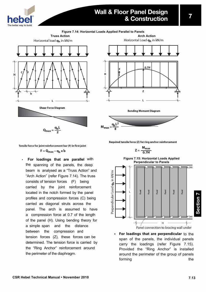
Figure 7.14: Horizontal Loads Applied Parallel to Panels Truss Action Arch Action
• For loadings that are parallel withthe spanning of the panels, the deepbeam is analysed as a “Truss Action” and“Arch Action” (refer Figure 7.14). The trussconsists of tension forces (F) beingcarried by the joint reinforcementlocated in the notch formed by the panelprofiles and compression forces (C) beingcarried as diagonal struts across thepanel. The arch is assumed to havea compression force at 0.7 of the lengthof the panel (H). Using bending theory fora simple span and the distancebetween the compression andtension forces (Z), these forces can bedetermined. The tension force is carried bythe “Ring Anchor” reinforcement aroundthe perimeter of the diaphragm.
Figure 7.15: Horizontal Loads Applied Perpendicular to Panels
• For loadings that are perpendicular to thespan of the panels, the individual panelscarry the loadings (refer Figure 7.15).Provided the “Ring Anchor” is installedaround the perimeter of the group of panelsforming the
Wall & Floor Panel Design & Construction
Sec
tio
n 7
7
CSR Hebel Technical Manual • November 2010
7
7.14
Wall & Floor Panel Design & Construction
diaphragm, then the loading can be shared equally across the panels in the group. That is, 5 panels would have to resist 20% of the loading. Contact CSR Hebel for a check of the panel capacity.
An explanation of the “Ring Anchor” system is detailed below.
Generally, where the floor panel system provides diaphragm action and sheds its loads to the support structure. The designer must ensure that these loads are adequately transferred. Methods include; friction, dowels, cleats (structural steel framed buildings), etc.
“Ring Anchor” System Typically, the “Ring Anchor System” consists of N12 reinforcement bars located in the DP profiled notch at the joint between consecutive panels and continuous around the perimeter of the group of CSR Hebel floor panels. The reinforcement bars are anchored at corners and the intersection of the DP profile and perimeter. The minimum lap length of the reinforcement is 400mm. Reinforcement should not be lapped over internal supports. The lap should be located at mid-span of the panels.
After the panels are laid, reinforcing bars (N12) are placed between the panels in the recess and around the perimeter of the floor to form the “Ring Anchor System” in accordance with the design specifications. The bars should be supported on chairs or equivalent to allow proper placing of grout. Panels may require propping before placing the “Ring Anchor System” when subject to temporary dead load variations.
The reinforcement is to be encased in a weak mix concrete grout. The joints and perimeter sections should be wetted, filled with minimum characteristic compressive strength concrete of 15MPa (maximum aggregate size 6mm and maximum slump 200mm). The grout should be compacted (“rodded”) to ensure the grout encases the
reinforcement and is “worked” into the groove of the DP profile. The grout cover that must be given to the reinforcement shall be in accordance with AS3600 “Concrete Structures”. The concrete should completely cover the reinforcement with 25mm minimum cover.
Where a higher strength connection is required, the designer should recommend an alternative such as, welded splices or threaded coupling. Note these connections are to be performed in accordance with relevant codes and guidelines, and manufacturer’s literature.
Design Considerations- FLOORS
The following are common issues requiring consideration and resolution in the application of AAC masonry to individual projects:
Structural Bracing of the Framework Provide structural bracing to the system, where the floor panel system is not acting as the horizontal bracing element.
Bearing Length For monolithic loads, such as suspended floor slabs and roof framing, ensure an adequate bearing width, and project engineer to consider the effects of eccentric loading.
Cantilevered Panels 200mm thick panel for 1200mm maximum cantilever and 150mm thick for a 900mm maximum cantilever. These panel thicknesses are based on conventional residential loadings (Dead Load = 0.5kPa, Live Load = 3.0kPa) and no point loading at the end of the cantilever. Note, concentrated loadings along the length of the cantilever are not recommended and secondary framing should be provided to carry these loadings. Note, there is a limit on the minimum length of the panel back-span, of greater than twice the length of the cantilever.
Wall & Floor Panel Design & Construction
Sec
tio
n 7
7
CSR Hebel Technical Manual • November 2010
7
7.15
Wall & Floor Panel Design & Construction
Cut Cantilevered Hebel Floor PanelsWhere Hebel floor panels (150mm-250mm thick) are installed and supported on either a steel framed support structure, masonry brick, concrete or Hebel block walls in both residential and commercial type applications, the following shall apply:
• It is preferable and recommended thatwhere such panels are designed tocantilever, these panels bemanufactured to the required length.
• Where it is deemed impractical anduse of a cut panel is unavoidable, thetrue (manufactured) end must be theend that cantilevers.
• Cut panel ends must not be orientatedsuch that they are at the cantileveredend.
Construction Tolerances A 40mm minimum gap should be allowed between the ends of abutting panels. This will provide access for grout and the cleat system on steel framed structures. The grout will ensure the panels are locked in, which stiffens the floor.
If these tolerances are not considered, the speed of installation will decrease as the preparation work (notching for cleat, trimming panel) will increase.
Flange Width Ensure support arrangements provide the required minimum end bearing lengths. Note, some supports may require a spreader plate.
External Application Galvanised reinforcement must be used for panels in external applications.
Construction Considerations - FLOORS The following are common issues requiring consideration and resolution in the application of AAC masonry to individual projects:
Construction Bracing of the Framework For steel framed construction, temporary bracing may be required during the installation to prevent the unsafe movement of the support framework. Excessive movement could result in the panels losing their bearing support, before the panels and “Ring Anchor” system are installed.
“Ring Anchor System” CSR Hebel recommends 3 days of curing for the “Ring Anchor System”, to ensure the grout has sufficient strength to carry construction loads (2kPa). Ensure reinforcement is chaired to provide required grout cover to the reinforcement.
WorkmanshipEnsure the panel are level before grouting and the grout is compacted around the reinforcement, so that the finish of the floor covering is not affected.
Panel Installation Prior to laying floor panels the top of the supporting masonry should be finished to give a level, unbroken surface. Slabs should be lifted into position one by one. It is important that the first panel is in perfect alignment so that other slabs do not need adjustment later in the installation.
Care should be taken to anchor the slabs so that they are not displaced by wind forces before the mortar has set.
Chasing The effect of chasing has to be considered, as it can detrimentally affect the structural capacity of the floor and reduce the performance under fire loading. Refer to Section 5 in the CSR Hebel Technical Manual.
Fire Performance The background to determining the fire performance characteristics of CSR Hebel AAC panels is outlined in Section 5 of this publication.
Wall & Floor Panel Design & Construction
Sec
tio
n 7
7
CSR Hebel Technical Manual • November 2010
7
7.16
Wall & Floor Panel Design & Construction
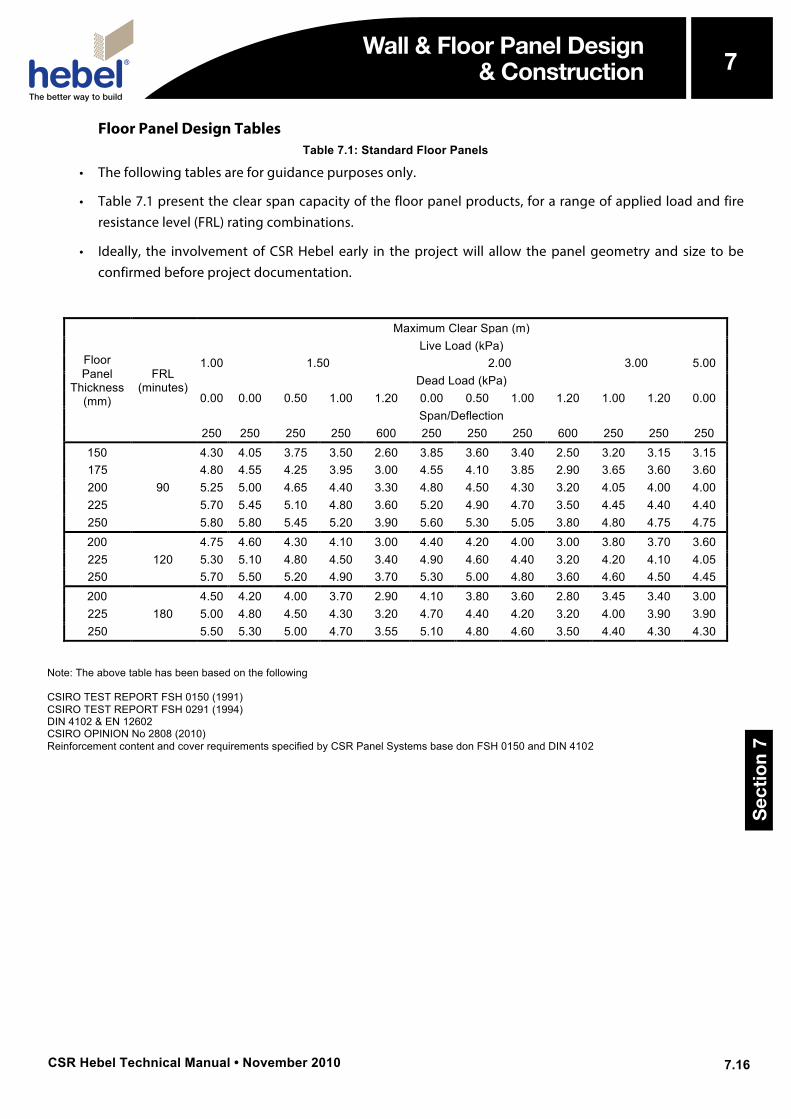
Floor Panel Design Tables Table 7.1: Standard Floor Panels
• The following tables are for guidance purposes only.
• Table 7.1 present the clear span capacity of the floor panel products, for a range of applied load and fireresistance level (FRL) rating combinations.
• Ideally, the involvement of CSR Hebel early in the project will allow the panel geometry and size to beconfirmed before project documentation.
Floor Panel
Thickness (mm)
FRL (minutes)
Maximum Clear Span (m) Live Load (kPa)
1.00 1.50 2.00 3.00 5.00 Dead Load (kPa)
0.00 0.00 0.50 1.00 1.20 0.00 0.50 1.00 1.20 1.00 1.20 0.00 Span/Deflection
250 250 250 250 600 250 250 250 600 250 250 250 150
90
4.30 4.05 3.75 3.50 2.60 3.85 3.60 3.40 2.50 3.20 3.15 3.15 175 4.80 4.55 4.25 3.95 3.00 4.55 4.10 3.85 2.90 3.65 3.60 3.60 200 5.25 5.00 4.65 4.40 3.30 4.80 4.50 4.30 3.20 4.05 4.00 4.00 225 5.70 5.45 5.10 4.80 3.60 5.20 4.90 4.70 3.50 4.45 4.40 4.40 250 5.80 5.80 5.45 5.20 3.90 5.60 5.30 5.05 3.80 4.80 4.75 4.75 200
120 4.75 4.60 4.30 4.10 3.00 4.40 4.20 4.00 3.00 3.80 3.70 3.60
225 5.30 5.10 4.80 4.50 3.40 4.90 4.60 4.40 3.20 4.20 4.10 4.05 250 5.70 5.50 5.20 4.90 3.70 5.30 5.00 4.80 3.60 4.60 4.50 4.45 200
180 4.50 4.20 4.00 3.70 2.90 4.10 3.80 3.60 2.80 3.45 3.40 3.00
225 5.00 4.80 4.50 4.30 3.20 4.70 4.40 4.20 3.20 4.00 3.90 3.90 250 5.50 5.30 5.00 4.70 3.55 5.10 4.80 4.60 3.50 4.40 4.30 4.30
Note: The above table has been based on the following
CSIRO TEST REPORT FSH 0150 (1991) CSIRO TEST REPORT FSH 0291 (1994) DIN 4102 & EN 12602 CSIRO OPINION No 2808 (2010) Reinforcement content and cover requirements specified by CSR Panel Systems base don FSH 0150 and DIN 4102
Wall & Floor Panel Design & Construction
Sec
tio
n 7
7
CSR Hebel Technical Manual • November 2010
7
7.17
Wall & Floor Panel Design & Construction
7.6 Wall Panel Design
Introduction CSR Hebel wall panels installed horizontally or vertically are suitable for commercial/industrial and multi-residential construction due to their modular layout, prefabricated methods and fast installation.
The CSR Hebel wall panel systems provide many benefits to the designer, builder and owner.
Benefits The many advantages of using a CSR Hebel wall panel building solutions wall are listed:
• Modular Design results in speedyconstruction and cost savings.
• Lightweight, lighter loads on the structurethan conventional masonry.
• Narrow Wall, thinner overall wall widths.
• Less Vertical CraneMovements, associated with less wasteand large face areas of wall contained ineach lift.
• No requirement for rigid scaffolding,as panels are lightweight and installed fromthe internal floor space.
• Less Waste, minimal site cutting.Panels manufactured to specified lengths.
• Dry Trade, minimal quantities of waterrequired on-site.
• Technical Support, our staff can assistwith systems advice.
• Single Trade, speedy delivery as one trade
can install the complete system, especially when coupled with Hebel PowerWall 501 and PowerWall 530.
• Installed Panels, not affected by wetweather.
• Excellent Thermal Qualities, the excellentthermal properties of AAC result in a higherlevel of comfort levels and cost savings inmaintaining the comfortable environmentwithin the building.
• Ecologically Responsible, AAC productionuses less raw materials and energy in theproduction process than other masonryproducts, and creates minimal wastes.
• Embodied Energy, refers to energy spentextracting raw materials, and in production,delivery and construction. CSR Hebel ratesvery well compared to other buildingmaterials.
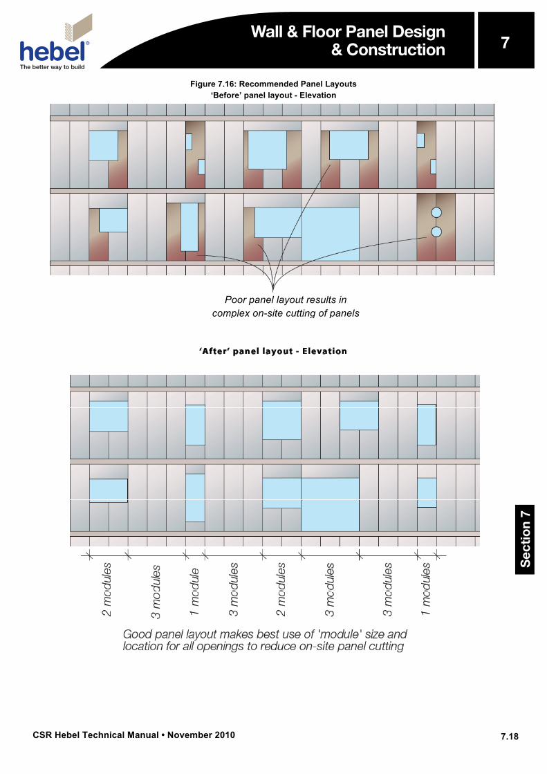
Openings and Penetrations At openings (windows), we recommend a 600mm width panel be installed adjacent to the opening. For large openings, it may be necessary to provide additional structural steel to support the loads shed from the opening. Alternatively, the panel adjacent to the opening could be thickened (confirm with CSR Hebel representative).
Planning the panel layout with consideration with special attention to the locations of penetrations can significantly reduce the amount of on-site cutting. A ‘Before’ and ‘After’ layout of vertical panels with various penetrations are shown below.
Wall & Floor Panel Design & Construction
Sec
tio
n 7
7
CSR Hebel Technical Manual • November 2010
7
7.18
Wall & Floor Panel Design & Construction
Figure 7.16: Recommended Panel Layouts ‘Before’ panel layout - Elevation
‘After’ panel layout - Elevation
Poor panel layout results in complex on-site cutting of panels
Wall & Floor Panel Design & Construction
Sec
tio
n 7
7
CSR Hebel Technical Manual • November 2010
7
7.19
Wall & Floor Panel Design & Construction
Design Considerations – WALLS The following are common issues requiring consideration and resolution in the application of AAC masonry to individual projects:
Structural Bracing of the Framework Provide structural bracing to the system, where the floor panel system is not acting as the horizontal bracing element.
Cantilevered Panels As a guide:
• 200mm thick panel for 1200mm maximumcantilever.
• 150mm thick for a 900mm maximumcantilever.
These panel thicknesses are based onconventional residential loadings and nopint loading at the end of the cantilever.Note, concentrated loadings along thelength of the cantilever are notrecommended and secondary framingshould be provided to carry these loadings.Note, there is a limit on the minimum lengthof the panel back-span, of greater thantwice the length of the cantilever.
Construction TolerancesA 20mm minimum gap should be allowedbetween the ends of abutting panels. Thiswill provide sufficient width for the backingrod and sealant system.
Flange WidthEnsure support arrangements provide therequired minimum end bearing lengths.
PenetrationsPenetrations and openings may requireadditional structural steelwork to support theinfill, such as window framing.
Construction Considerations – WALLS The following are common issues requiring consideration and resolution in the application of AAC masonry to individual projects:
Penetration Restrictions Generally, penetrations are required to pass services, such as fire sprinklers, power switches, or air conditioning ductwork. During the construction stage, penetrations maybe required for scaffolding supports and bracing. These penetrations will reduce the strength of the wall panel and fixing.
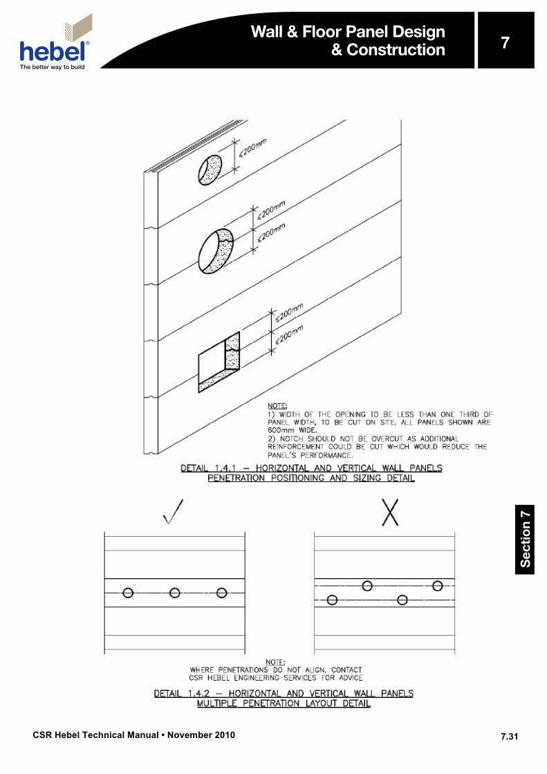
It is important that all penetration requirements are shown on the ‘Layout’ drawings. As a guide, the maximum penetration or rebate width shall be the minimum of 100mm or 20 percent of the panel’s width, panel width shall be greater than 400mm and one rebate per panel.
Workmanship Ensure that all joints are completely filled and are approximately 2-3mm thick.
Chasing The effect of chasing has to be considered, as it can detrimentally affect the structural capacity of the wall and reduce the performance under fire loading. Refer to Section 5 of this publication.
Wall & Floor Panel Design & Construction
Sec
tio
n 7
7
CSR Hebel Technical Manual • November 2010
7
7.20
Wall & Floor Panel Design & Construction
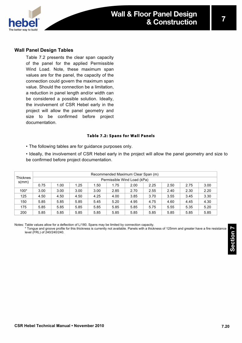
Wall Panel Design Tables Table 7.2 presents the clear span capacity of the panel for the applied Permissible Wind Load. Note, these maximum span values are for the panel, the capacity of the connection could govern the maximum span value. Should the connection be a limitation, a reduction in panel length and/or width can be considered a possible solution. Ideally, the involvement of CSR Hebel early in the project will allow the panel geometry and size to be confirmed before project documentation.
Table 7.2: Spans for Wall Panels
• The following tables are for guidance purposes only.
• Ideally, the involvement of CSR Hebel early in the project will allow the panel geometry and size tobe confirmed before project documentation.
Thickness(mm)
Recommended Maximum Clear Span (m) Permissible Wind Load (kPa)
0.75 1.00 1.25 1.50 1.75 2.00 2.25 2.50 2.75 3.00 100* 3.00 3.00 3.00 3.00 2.85 2.70 2.55 2.40 2.30 2.20 125 4.50 4.50 4.50 4.25 4.00 3.85 3.70 3.55 3.45 3.30 150 5.85 5.85 5.85 5.45 5.20 4.95 4.75 4.60 4.45 4.30 175 5.85 5.85 5.85 5.85 5.85 5.85 5.75 5.55 5.35 5.20 200 5.85 5.85 5.85 5.85 5.85 5.85 5.85 5.85 5.85 5.85
Notes: Table values allow for a deflection of L/180. Spans may be limited by connection capacity. * Tongue and groove profile for this thickness is currently not available. Panels with a thickness of 125mm and greater have a fire resistancelevel (FRL) of 240/240/240.
Wall & Floor Panel Design & Construction
Sec
tio
n 7
7

CSR Hebel Technical Manual • November 2010
7
7.21
Wall & Floor Panel Design & Construction
7.9 On-site Handling
The following are common issues requiring consideration and resolution in the application of AAC masonry to individual projects:
• Health and Safety
• Manual Handling
• Unloading Block Pallets
• Storage
• Personal Protective Equipment, PPE
• Cutting
• Installation Procedures
• Damaged Panels
• Mortars and Adhesives
• Waterproof Membrane
Health and Safety CSR Hebel products are cement-based, which may irritate the skin, resulting in itching and occasionally a red rash. The wearing of appropriate Personal Protective Equipment (PPE), such as gloves and suitable clothing to reduce abrasion and irritation of the skin is recommended when handling CSR Hebel products.
Approved respirators (AS/NZS1715 and AS/NZ1716) and eye protection (AS1336) should be worn at all times when cutting and chasing. Refer to the appropriate CSR Hebel Material Safety Data Sheet (MSDS), and Safe Work Method Statement (SWMS).
Manual Handling CSR Hebel recommends using a trolley or other mechanical apparatus to move the panels around the work site. Manual handling where people physically move a panel, should be kept to a minimum, with the weight being supported by an individual kept as small as possible. Any concerns regarding the weight to be handled should
be discussed with the panel installation contractor.
To minimise the possibility of manual handling injuries, CSR Hebel suggests the following:
1. Use mechanical aids, such as trolleys,forklifts, cranes and levers, or team lifting tomove panels.
2. Keep the work place clean to reduce therisk of slips, trips and falls, which can causeinjury.
3. Plan the sequence of installation tominimise panel movements and avoidawkward lifts.
4. Train employees in good lifting techniquesto minimise the risk of injury.
Unloading Panel Bundles Panel Bundles shall be unloaded and moved with only approved lifting devices. Before use, the lifting devices (block cage) should be checked for the required lifting tags. The pallets should be unloaded as close as possible to the intended installation area. This will increase work efficiency and minimise the need for secondary handling.
Note: Secondary handling increases the risk of panel damage. The repair of damage sustained during lifting and moving is the responsibility of the lifter. When damage is excessive, the product should be replaced.
Storage All materials must be kept dry and preferably stored undercover. Care should be taken to avoid sagging or damage to ends, edges and surfaces.
All CSR Hebel panel and lintel products must be stacked on edge and properly supported off the ground, on a level platform. Panel bundles can be stacked two high. The project engineer should be consulted as to the adequacy of the
Wall & Floor Panel Design & Construction
Sec
tio
n 7
7

CSR Hebel Technical Manual • November 2010
7
7.22
Wall & Floor Panel Design & Construction
structure to support the stacked bundles.
Wall & Floor Panel Design & Construction
Sec
tio
n 7
7
CSR Hebel Technical Manual • November 2010
7
7.23
Wall & Floor Panel Design & Construction
If outside, CSR Hebel wall panels must be stored off the ground and protected from the weather. Only single bundles positioned on the ground can be opened. To provide a level surface, we recommend placing temporary joists beneath the supporting cleats.
Cutting The use of power tools may cause dust, which contains respirable crystalline silica, with the potential to cause bronchitis, silicosis and lung cancer after repeated and prolonged exposure. When using power or hand tools, on CSR Hebel products, wear a P1 or P2 respirator and eye protection. When cutting, routing or chasing CSR Hebel products with power tools, use dust extraction equipment and wear hearing protection. Refer to CSR Hebel MSDS sheets and sample SWMS. For further information, contact CSR Hebel or visit the website.
Reinforcement exposed during cutting is to be coated with a liberal application of CSR Hebel corrosion protection paint. (Refer to Section 5 of this publication).
Packers The packer should be non-compressible, non-corrosive and stable (no deterioration over time). The installer should provide various packer thicknesses to ensure the panel can be installed to a vertical tolerance of ±2mm, or as per project specification.
Installation Procedures CSR promotes and advocates a safety conscious work place at all times. To assist builders and contractors to maintain their safety standards, CSR Hebel has produced guidelines for the installation and handling of their products.
These guidelines can be found in the following technical bulletins (see Appendix G):
• CSR Hebel PowerPanel™ Installation &Handling Guidelines, No HTB791; and
• CSR Hebel Wall Panel Installation &Handling Guidelines, No HTB799.
Damaged Panels CSR Hebel should be notified immediately of any block damage or cracking at occurs during the handling of the blocks. This damage may result in the block being structurally inadequate, and should be replaced.
Mortars and Adhesives The CSR Hebel bagged mortar and adhesive should be prepared in accordance with instructions on the packaging.
Waterproof Membrane Waterproofing membranes shall be nominated by the designer or specifier, and installed in accordance with manufacturer’s recommendations.
Wall & Floor Panel Design & Construction
Sec
tio
n 7
7
CSR Hebel Technical Manual • November 2010
7
7.24
Wall & Floor Panel Design & Construction
7.10 Installation
Panels Panels should not be cut on site unless they are identified as “cutable”, either on the panel or on the “layout” drawing. They should be ordered from the factory at the desired length. This is to ensure that the corrosion protection properties of the product are maintained. Where panels have been cut the exposed reinforcing should be coated with CSR Hebel corrosion protection compound or approved equivalent.
CSR Hebel panels are supplied ready for use. They can be simply and easily laid into position with only the joints needing to be mortared. Installation is therefore largely dry and generally no formwork or bracing is necessary. The reinforcing in the panels is custom designed for each project. All reinforcing is corrosion protected with a water based polymer prior to being placed in the mould.
Flooring CSR Hebel panels for flooring can be supplied in different lengths, thicknesses, widths and load carrying capacities. The thickness of slab should be in accordance with design calculations taking into account the required span, load, deflection and fire- rating requirements.
Prior to laying floor panels the top of the supporting masonry should be finished to give a level, unbroken surface. Slabs should be lifted into position one by one. It is important that the first panel is in perfect alignment so that other slabs do not need adjustment later in the installation.
After the panels are laid, reinforcing bars (N12) are placed between the panels in the recess and around the perimeter of the floor to form the ring anchor system in accordance with the design specifications.
The bars should be supported on chairs or equivalent to allow proper placing of mortar. Panels may require propping before placing the ring anchor system when subject to temporary dead load variations.
The joints and ring anchor sections should be wetted, filled with minimum 15MPa concrete (max. Aggregate size 6mm, max slump 200mm) and rodded. The concrete should completely cover the reinforcing with 25mm minimum cover.
Care should be taken to anchor the slabs so that they are not displaced by wind forces before the mortar has set.
The hardness of CSR Hebel floor panels is greater than the blocks. When placed accurately and ring anchors poured carefully and screeded properly, the surface is level and smooth. The finished surface is suitable for applying marble, quarry and ceramic tiles or carpet with a quality underlay.
Because of the initial moisture content in the panels, timber of particle board cannot be placed directly onto Hebel floor panels. An air gap must be provided by using battens.
The surface can be screeded with a self levelling mortar up to 10mm thick or a weak cement/lime mortar up to 20mm thick. Screeds greater than 25mm should be avoided as they increase the dead load on the floor system without any significant increase in load carrying capacity of protection of the floor surface from damage.
When Hebel panels are used in external floor areas such as patios or balconies, it is important to use a waterproof membrane. In these areas the ring anchor reinforcing bar should be galvanised.
Where the floor panel system has to act as a structural diaphragm, the structural engineer shall design the ring anchor
Wall & Floor Panel Design & Construction
Sec
tio
n 7
7
CSR Hebel Technical Manual • November 2010
7
7.25
Wall & Floor Panel Design & Construction
reinforcement, specifying lapping and anchorage requirements and checking adequacy of AAC material. Assistance and design advice is available from the CSR Hebel Engineering Services.
Walls CSR Hebel panels can be used for internal and external load-bearing walls in both housing and commercial building applications. Panels can be installed either horizontally or vertically. A crane or forklift is necessary to install the CSR Hebel wall panels. A damp course should be applied before installation to avoid rising damp.
Flat Roofs CSR Hebel roof panels are available in a range of thicknesses and lengths. The thickness can be calculated from the load-span tables.
Ventilated and non-ventilated roof structures are possible with CSR Hebel panels. The panels can be laid with flush edges or with up to 1.2m cantilever.
Sloping Roofs In the case of sloping roofs the panels are laid parallel to the eaves line on load-bearing bulkhead walls, either flush or with overhangs. Battens can be nailed to the panels and tiles or shingles installed. In some projects slip prevention devises should be used to anchor the slabs. Each slab in this instance should be fixed as it is installed.
The use of CSR Hebel roofing panels greatly increases the insulation value of the roof as well as providing significant levels of noise reduction and fire protection to the building.
Wall & Floor Panel Design & Construction
Sec
tio
n 7
7
CSR Hebel Technical Manual • November 2010
7
7.26
Wall & Floor Panel Design & Construction
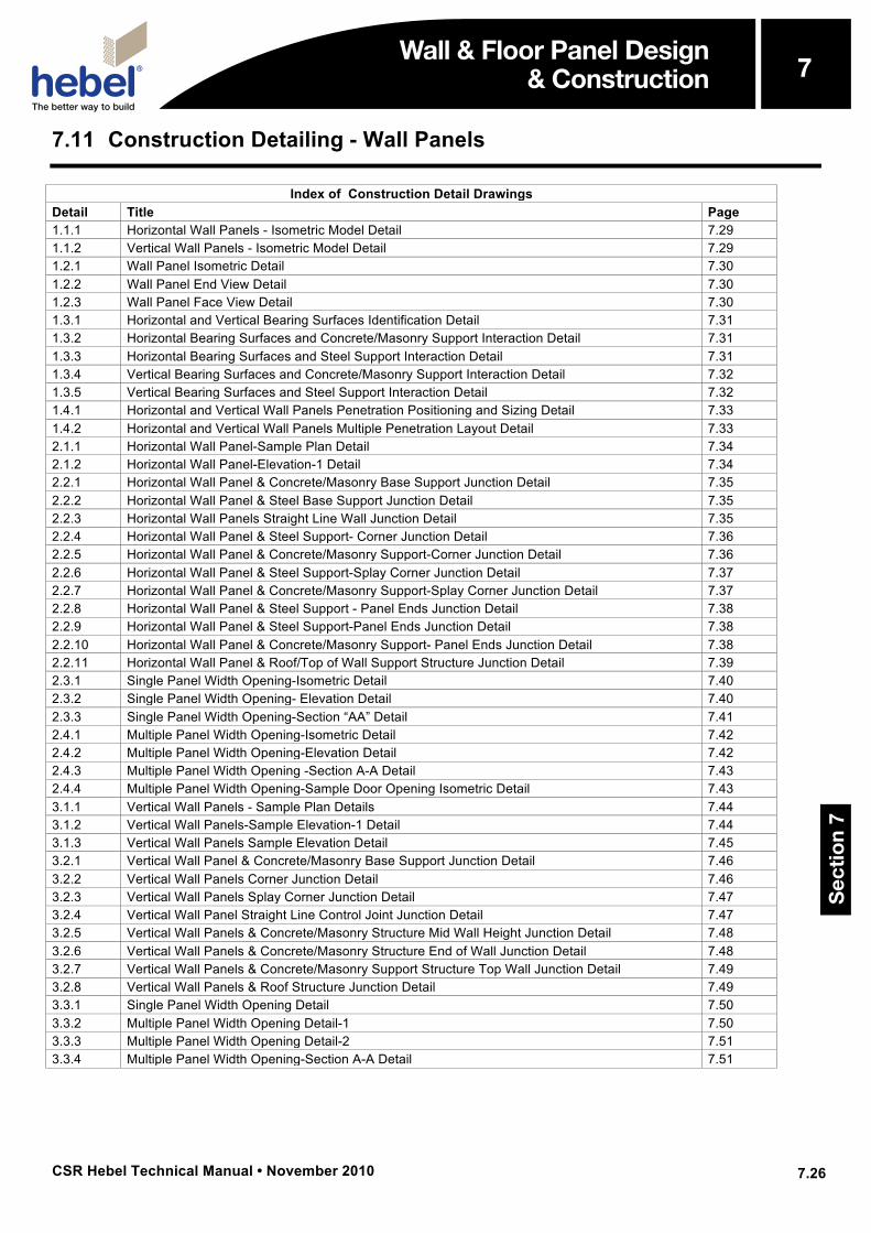
7.11 Construction Detailing - Wall Panels
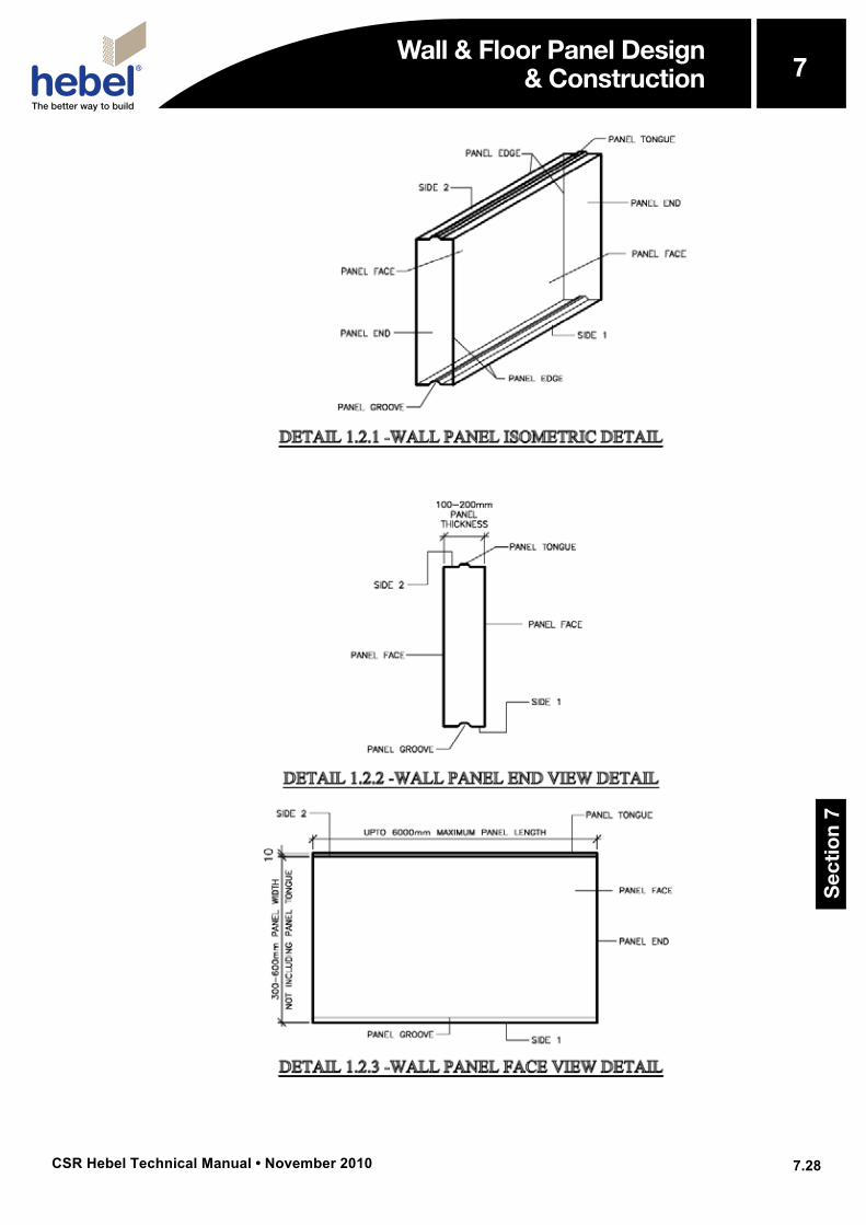
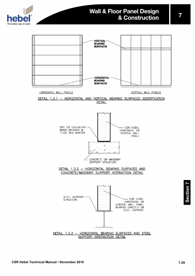
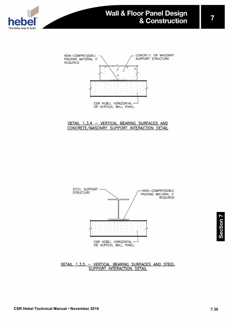
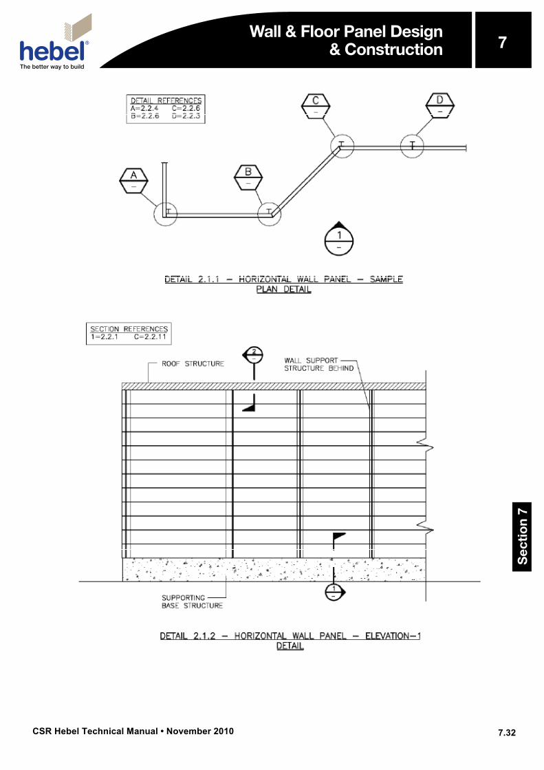
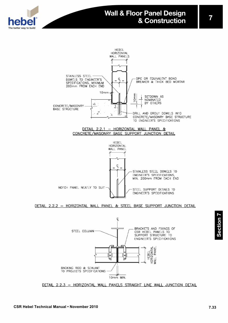
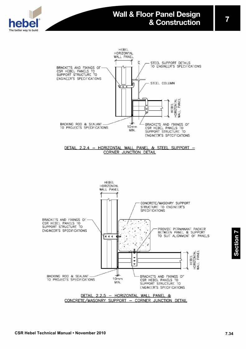
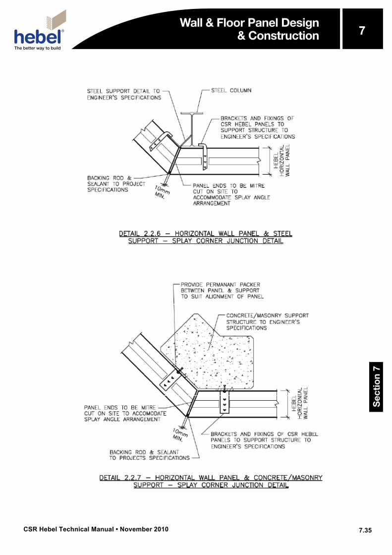
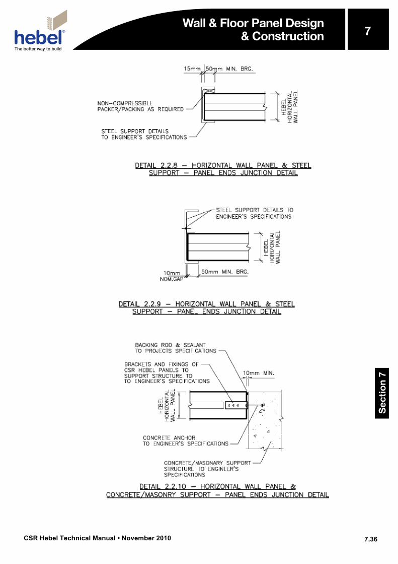
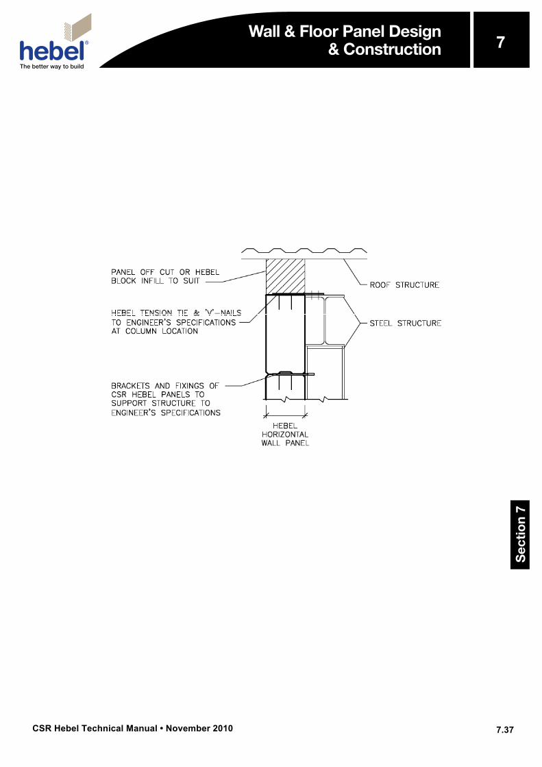
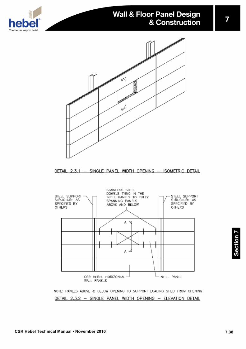
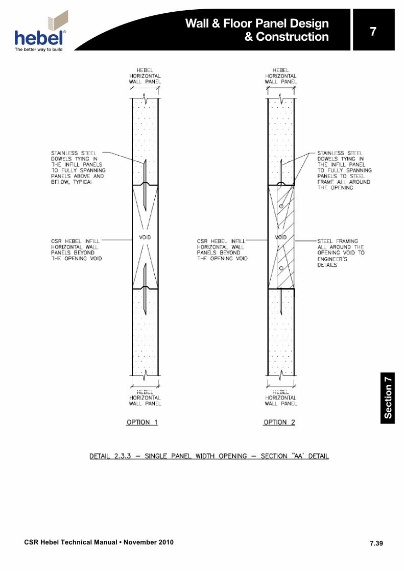
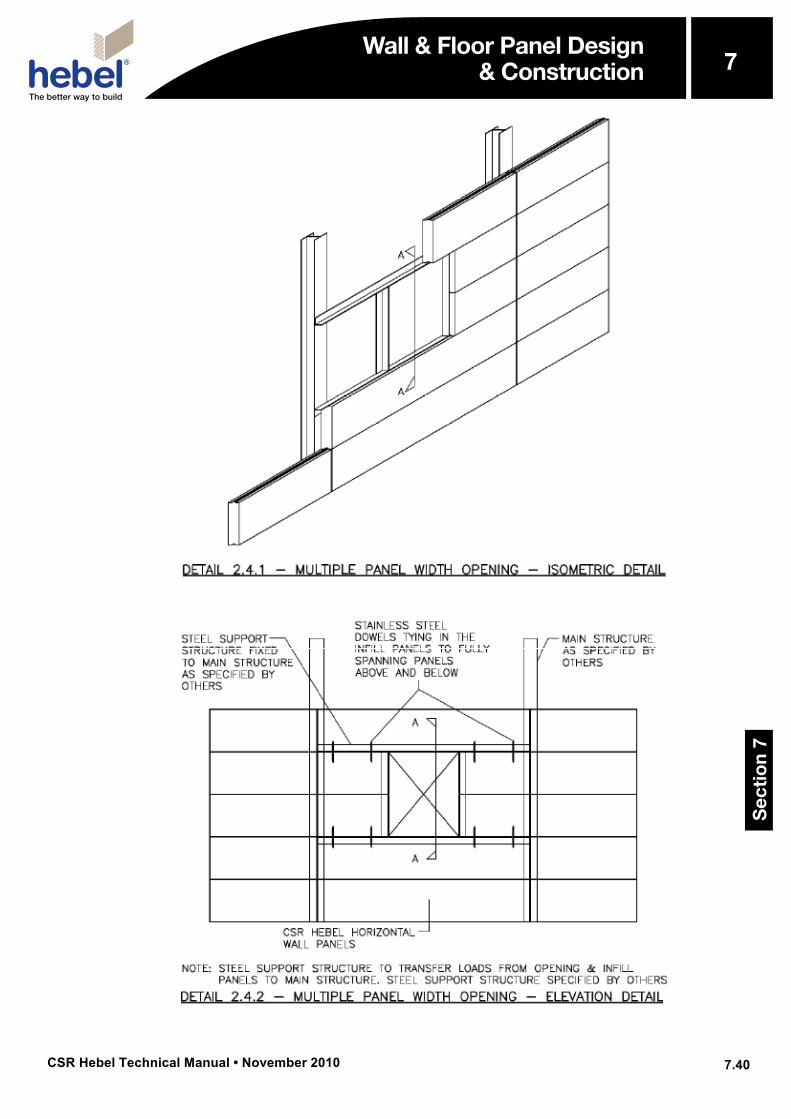
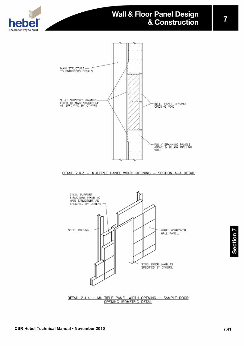
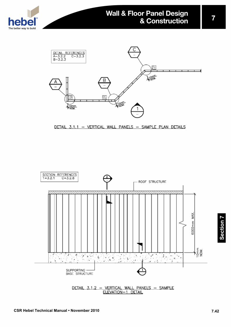
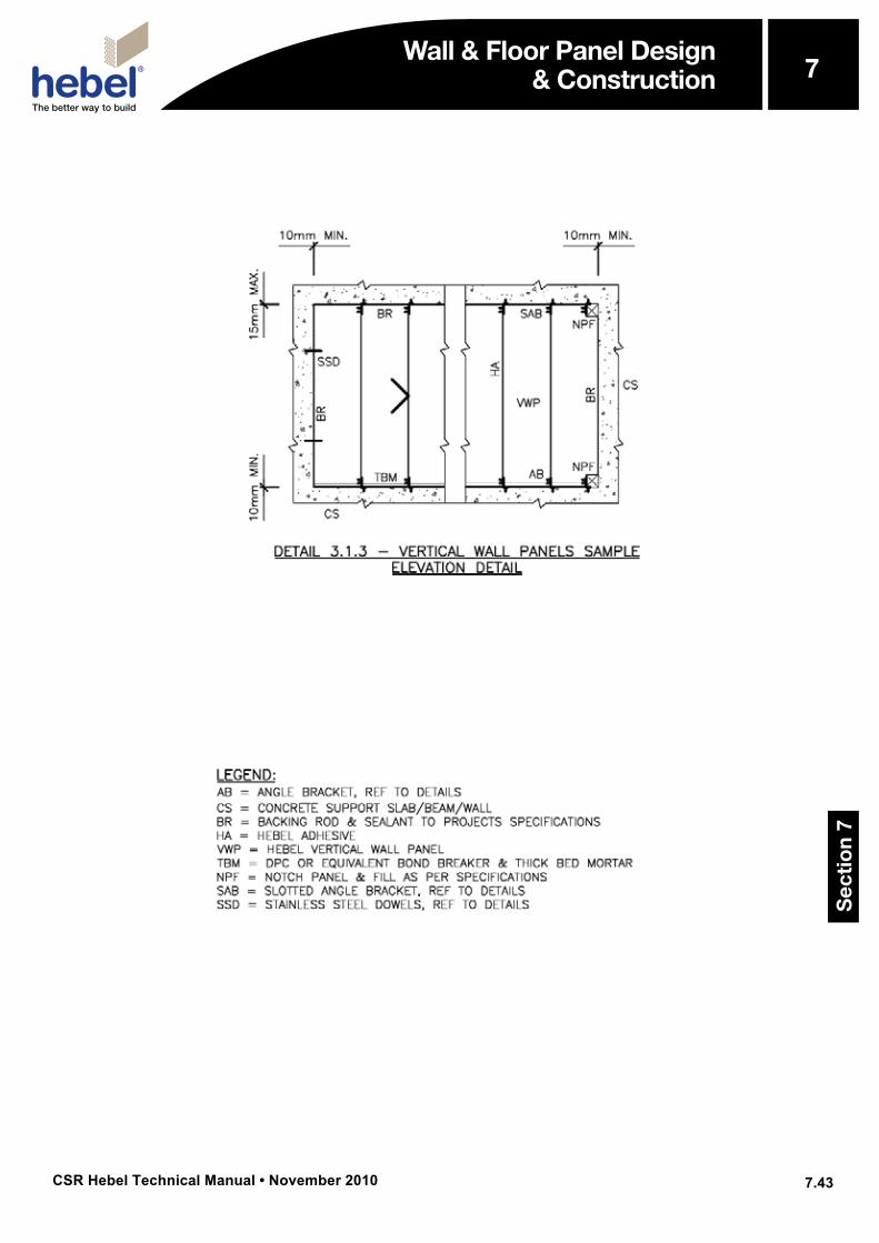
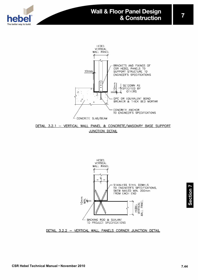
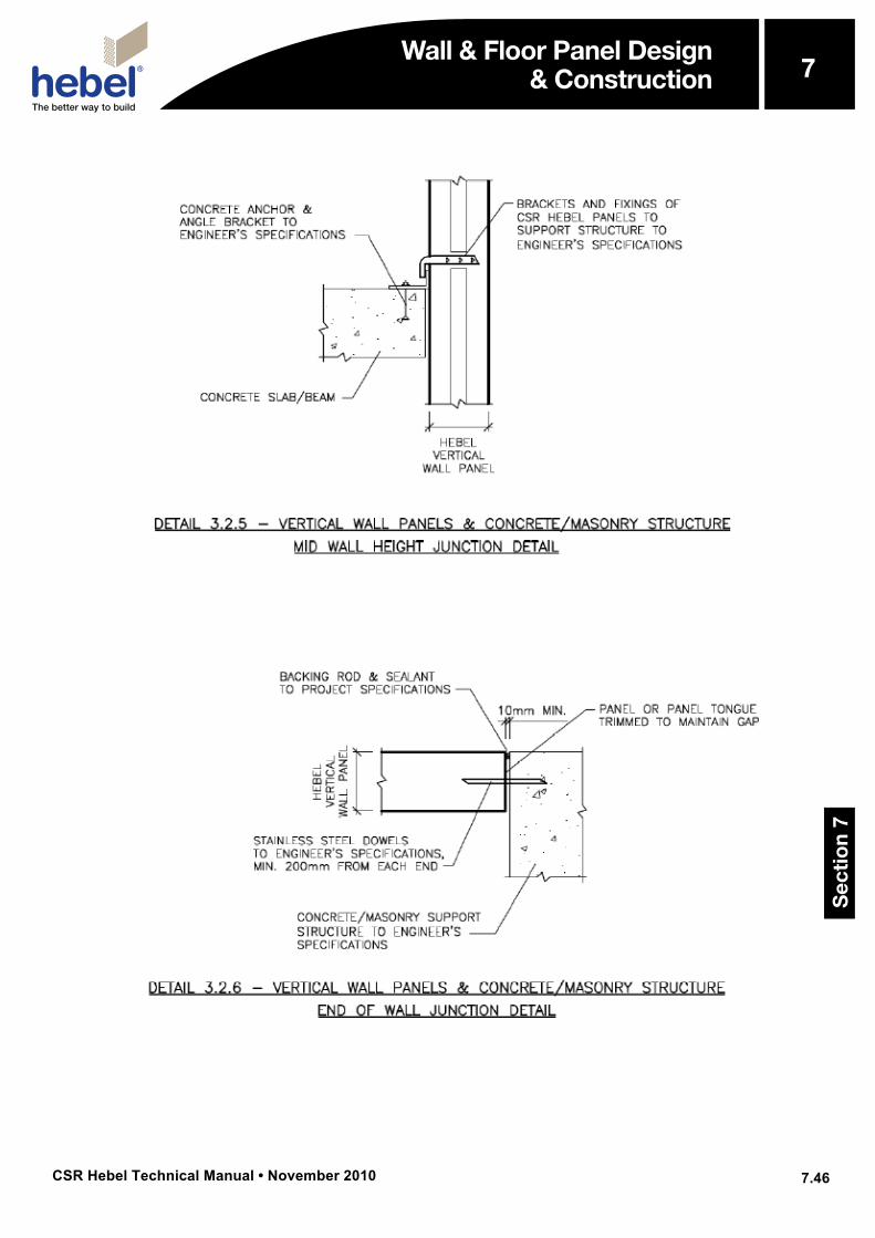
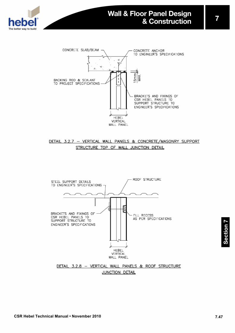
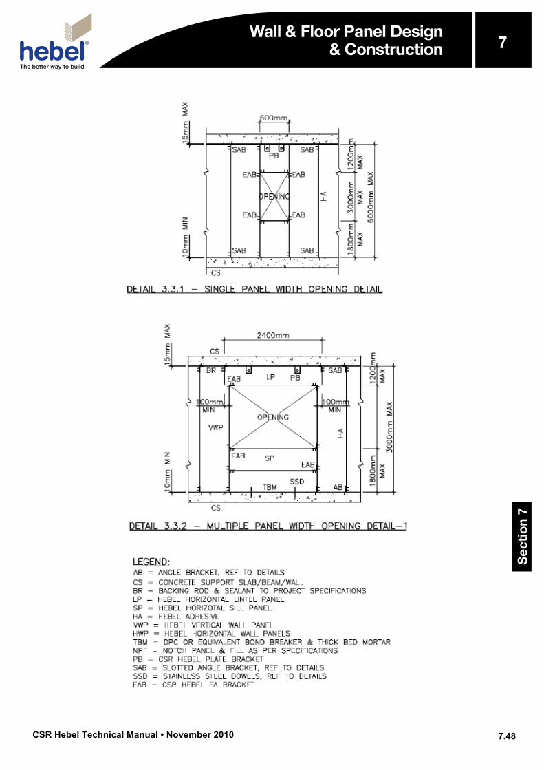
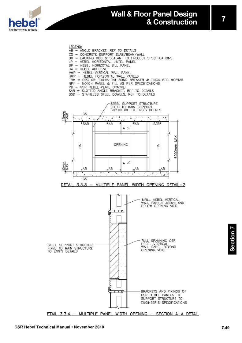
Index of Construction Detail Drawings Detail Title Page 1.1.1 Horizontal Wall Panels - Isometric Model Detail 7.29 1.1.2 Vertical Wall Panels - Isometric Model Detail 7.29 1.2.1 Wall Panel Isometric Detail 7.30 1.2.2 Wall Panel End View Detail 7.30 1.2.3 Wall Panel Face View Detail 7.30 1.3.1 Horizontal and Vertical Bearing Surfaces Identification Detail 7.31 1.3.2 Horizontal Bearing Surfaces and Concrete/Masonry Support Interaction Detail 7.31 1.3.3 Horizontal Bearing Surfaces and Steel Support Interaction Detail 7.31 1.3.4 Vertical Bearing Surfaces and Concrete/Masonry Support Interaction Detail 7.32 1.3.5 Vertical Bearing Surfaces and Steel Support Interaction Detail 7.32 1.4.1 Horizontal and Vertical Wall Panels Penetration Positioning and Sizing Detail 7.33 1.4.2 Horizontal and Vertical Wall Panels Multiple Penetration Layout Detail 7.33 2.1.1 Horizontal Wall Panel-Sample Plan Detail 7.34 2.1.2 Horizontal Wall Panel-Elevation-1 Detail 7.34 2.2.1 Horizontal Wall Panel & Concrete/Masonry Base Support Junction Detail 7.35 2.2.2 Horizontal Wall Panel & Steel Base Support Junction Detail 7.35 2.2.3 Horizontal Wall Panels Straight Line Wall Junction Detail 7.35 2.2.4 Horizontal Wall Panel & Steel Support- Corner Junction Detail 7.36 2.2.5 Horizontal Wall Panel & Concrete/Masonry Support-Corner Junction Detail 7.36 2.2.6 Horizontal Wall Panel & Steel Support-Splay Corner Junction Detail 7.37 2.2.7 Horizontal Wall Panel & Concrete/Masonry Support-Splay Corner Junction Detail 7.37 2.2.8 Horizontal Wall Panel & Steel Support - Panel Ends Junction Detail 7.38 2.2.9 Horizontal Wall Panel & Steel Support-Panel Ends Junction Detail 7.38 2.2.10 Horizontal Wall Panel & Concrete/Masonry Support- Panel Ends Junction Detail 7.38 2.2.11 Horizontal Wall Panel & Roof/Top of Wall Support Structure Junction Detail 7.39 2.3.1 Single Panel Width Opening-Isometric Detail 7.40 2.3.2 Single Panel Width Opening- Elevation Detail 7.40 2.3.3 Single Panel Width Opening-Section “AA” Detail 7.41 2.4.1 Multiple Panel Width Opening-Isometric Detail 7.42 2.4.2 Multiple Panel Width Opening-Elevation Detail 7.42 2.4.3 Multiple Panel Width Opening -Section A-A Detail 7.43 2.4.4 Multiple Panel Width Opening-Sample Door Opening Isometric Detail 7.43 3.1.1 Vertical Wall Panels - Sample Plan Details 7.44 3.1.2 Vertical Wall Panels-Sample Elevation-1 Detail 7.44 3.1.3 Vertical Wall Panels Sample Elevation Detail 7.45 3.2.1 Vertical Wall Panel & Concrete/Masonry Base Support Junction Detail 7.46 3.2.2 Vertical Wall Panels Corner Junction Detail 7.46 3.2.3 Vertical Wall Panels Splay Corner Junction Detail 7.47 3.2.4 Vertical Wall Panel Straight Line Control Joint Junction Detail 7.47 3.2.5 Vertical Wall Panels & Concrete/Masonry Structure Mid Wall Height Junction Detail 7.48 3.2.6 Vertical Wall Panels & Concrete/Masonry Structure End of Wall Junction Detail 7.48 3.2.7 Vertical Wall Panels & Concrete/Masonry Support Structure Top Wall Junction Detail 7.49 3.2.8 Vertical Wall Panels & Roof Structure Junction Detail 7.49 3.3.1 Single Panel Width Opening Detail 7.50 3.3.2 Multiple Panel Width Opening Detail-1 7.50 3.3.3 Multiple Panel Width Opening Detail-2 7.51 3.3.4 Multiple Panel Width Opening-Section A-A Detail 7.51
Wall & Floor Panel Design & Construction
Sec
tio
n 7
7

CSR Hebel Technical Manual • November 2010
7
7.27
Wall & Floor Panel Design & Construction Wall & Floor Panel Design
& Construction
Sec
tio
n 7
7
CSR Hebel Technical Manual • November 2010
7
7.28
Wall & Floor Panel Design & Construction Wall & Floor Panel Design
& Construction
Sec
tio
n 7
7
CSR Hebel Technical Manual • November 2010
7
7.29
Wall & Floor Panel Design & Construction Wall & Floor Panel Design
& Construction
Sec
tio
n 7
7
CSR Hebel Technical Manual • November 2010
7
7.30
Wall & Floor Panel Design & Construction Wall & Floor Panel Design
& Construction
Sec
tio
n 7
7
CSR Hebel Technical Manual • November 2010
7
7.31
Wall & Floor Panel Design & Construction Wall & Floor Panel Design
& Construction
Sec
tio
n 7
7
CSR Hebel Technical Manual • November 2010
7
7.32
Wall & Floor Panel Design & Construction Wall & Floor Panel Design
& Construction
Sec
tio
n 7
7
CSR Hebel Technical Manual • November 2010
7
7.33
Wall & Floor Panel Design & Construction Wall & Floor Panel Design
& Construction
Sec
tio
n 7
7
CSR Hebel Technical Manual • November 2010
7
7.34
Wall & Floor Panel Design & Construction
Wall & Floor Panel Design & Construction
Sec
tio
n 7
7
CSR Hebel Technical Manual • November 2010
7
7.35
Wall & Floor Panel Design & Construction
Wall & Floor Panel Design & Construction
Sec
tio
n 7
7
CSR Hebel Technical Manual • November 2010
7
7.36
Wall & Floor Panel Design & Construction
Wall & Floor Panel Design & Construction
Sec
tio
n 7
7
CSR Hebel Technical Manual • November 2010
7
7.37
Wall & Floor Panel Design & Construction Wall & Floor Panel Design
& Construction
Sec
tio
n 7
7
CSR Hebel Technical Manual • November 2010
7
7.38
Wall & Floor Panel Design & Construction
Wall & Floor Panel Design & Construction
Sec
tio
n 7
7
CSR Hebel Technical Manual • November 2010
7
7.39
Wall & Floor Panel Design & Construction Wall & Floor Panel Design
& Construction
Sec
tio
n 7
7
CSR Hebel Technical Manual • November 2010
7
7.40
Wall & Floor Panel Design & Construction Wall & Floor Panel Design
& Construction
Sec
tio
n 7
7
CSR Hebel Technical Manual • November 2010
7
7.41
Wall & Floor Panel Design & Construction
Wall & Floor Panel Design & Construction
Sec
tio
n 7
7
CSR Hebel Technical Manual • November 2010
7
7.42
Wall & Floor Panel Design & Construction Wall & Floor Panel Design
& Construction
Sec
tio
n 7
7
CSR Hebel Technical Manual • November 2010
7
7.43
Wall & Floor Panel Design & Construction
Wall & Floor Panel Design & Construction
Sec
tio
n 7
7
CSR Hebel Technical Manual • November 2010
7
7.44
Wall & Floor Panel Design & Construction
Wall & Floor Panel Design & Construction
Sec
tio
n 7
7

CSR Hebel Technical Manual • November 2010
7
7.45
Wall & Floor Panel Design & Construction Wall & Floor Panel Design
& Construction
Sec
tio
n 7
7
CSR Hebel Technical Manual • November 2010
7
7.46
Wall & Floor Panel Design & Construction
Wall & Floor Panel Design & Construction
Sec
tio
n 7
7
CSR Hebel Technical Manual • November 2010
7
7.47
Wall & Floor Panel Design & Construction
Wall & Floor Panel Design & Construction
Sec
tio
n 7
7
CSR Hebel Technical Manual • November 2010
7
7.48
Wall & Floor Panel Design & Construction
Wall & Floor Panel Design & Construction
Sec
tio
n 7
7
CSR Hebel Technical Manual • November 2010
7
7.49
Wall & Floor Panel Design & Construction
Wall & Floor Panel Design & Construction
Sec
tio
n 7
7
CSR Hebel Technical Manual • November 2010
7
7.50
Wall & Floor Panel Design & Construction
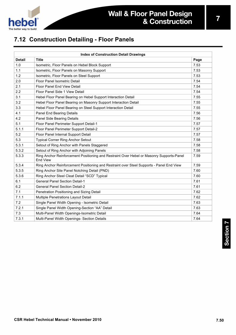
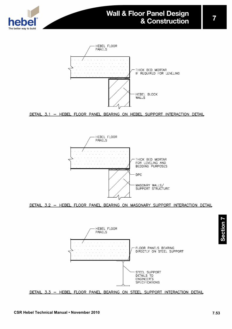
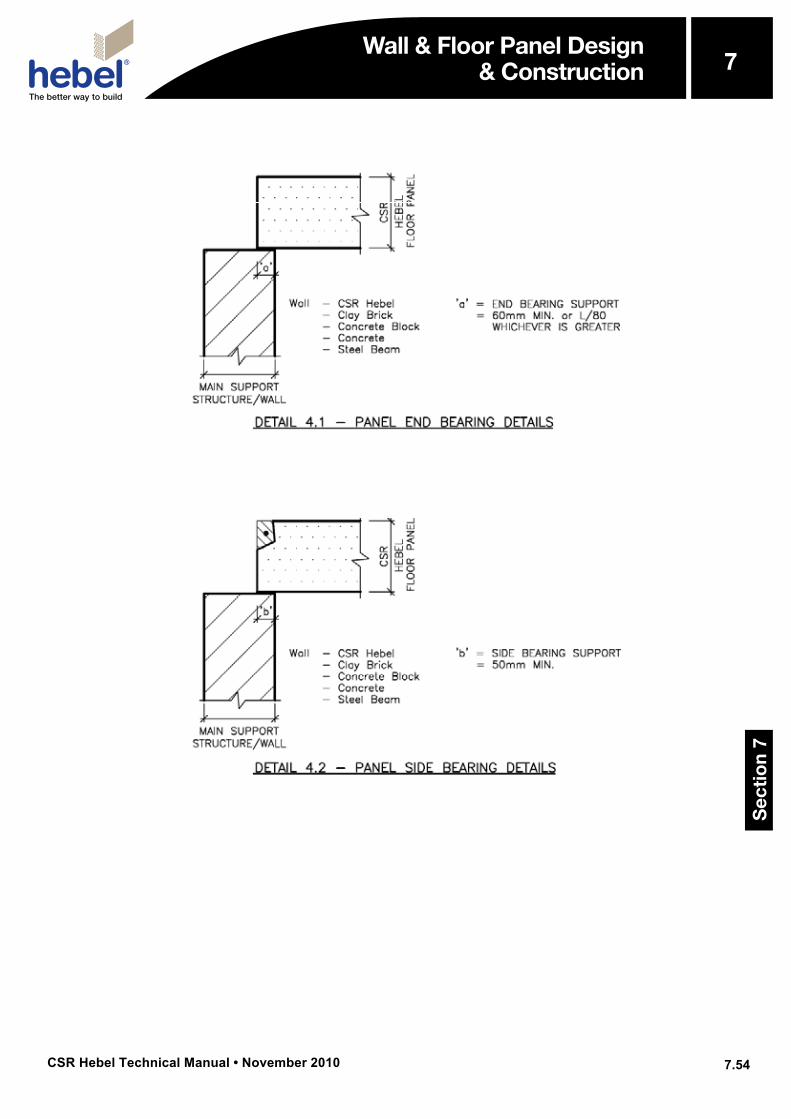
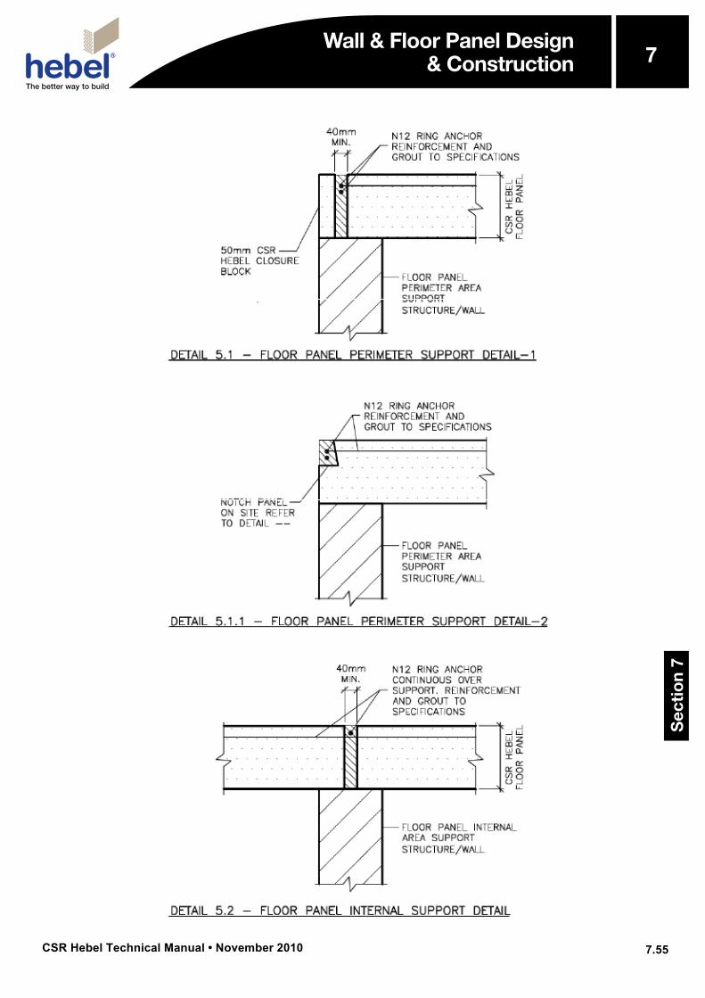
7.12 Construction Detailing - Floor Panels
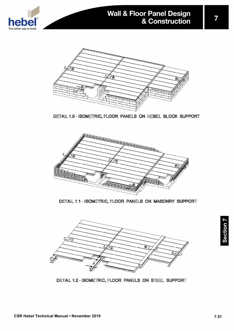
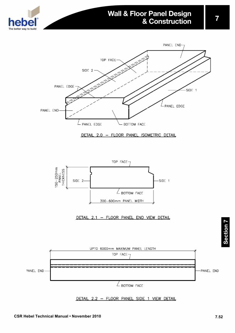
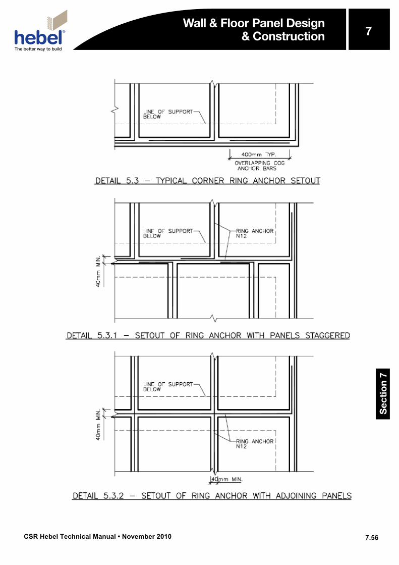
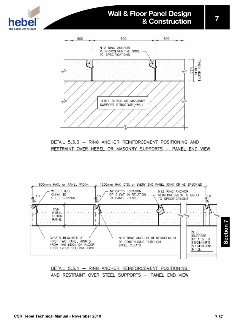
Index of Construction Detail Drawings Detail Title Page 1.0 Isometric, Floor Panels on Hebel Block Support 7.53 1.1 Isometric, Floor Panels on Masonry Support 7.53 1.2 Isometric, Floor Panels on Steel Support 7.53 2.0 Floor Panel Isometric Detail 7.54 2.1 Floor Panel End View Detail 7.54 2.2 Floor Panel Side 1 View Detail 7.54 3.1 Hebel Floor Panel Bearing on Hebel Support Interaction Detail 7.55 3.2 Hebel Floor Panel Bearing on Masonry Support Interaction Detail 7.55 3.3 Hebel Floor Panel Bearing on Steel Support Interaction Detail 7.55 4.1 Panel End Bearing Details 7.56 4.2 Panel Side Bearing Details 7.56 5.1 Floor Panel Perimeter Support Detail-1 7.57 5.1.1 Floor Panel Perimeter Support Detail-2 7.57 5.2 Floor Panel Internal Support Detail 7.57 5.3 Typical Corner Ring Anchor Setout 7.58 5.3.1 Setout of Ring Anchor with Panels Staggered 7.58 5.3.2 Setout of Ring Anchor with Adjoining Panels 7.58 5.3.3 Ring Anchor Reinforcement Positioning and Restraint Over Hebel or Masonry Supports-Panel
End View 7.59
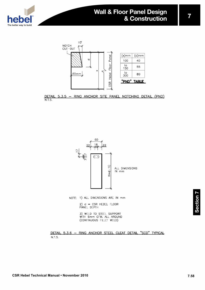
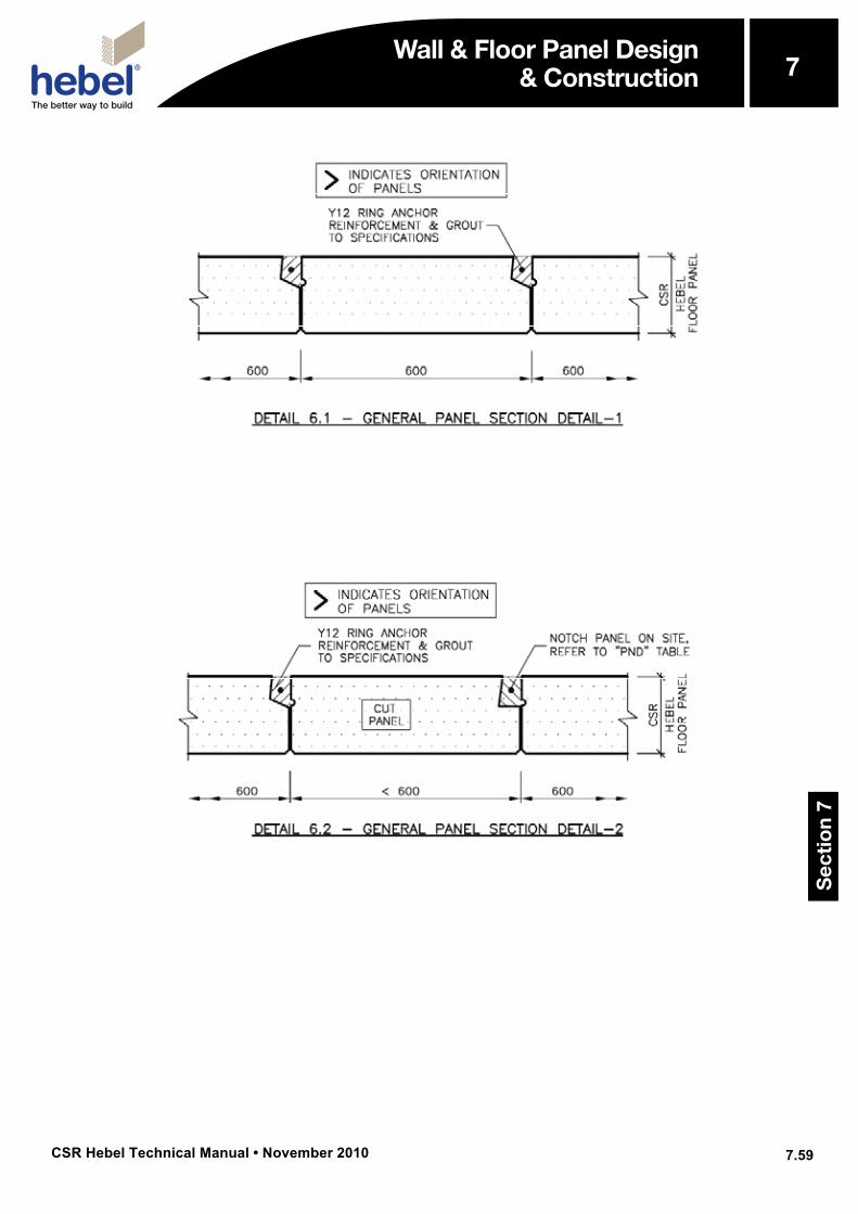
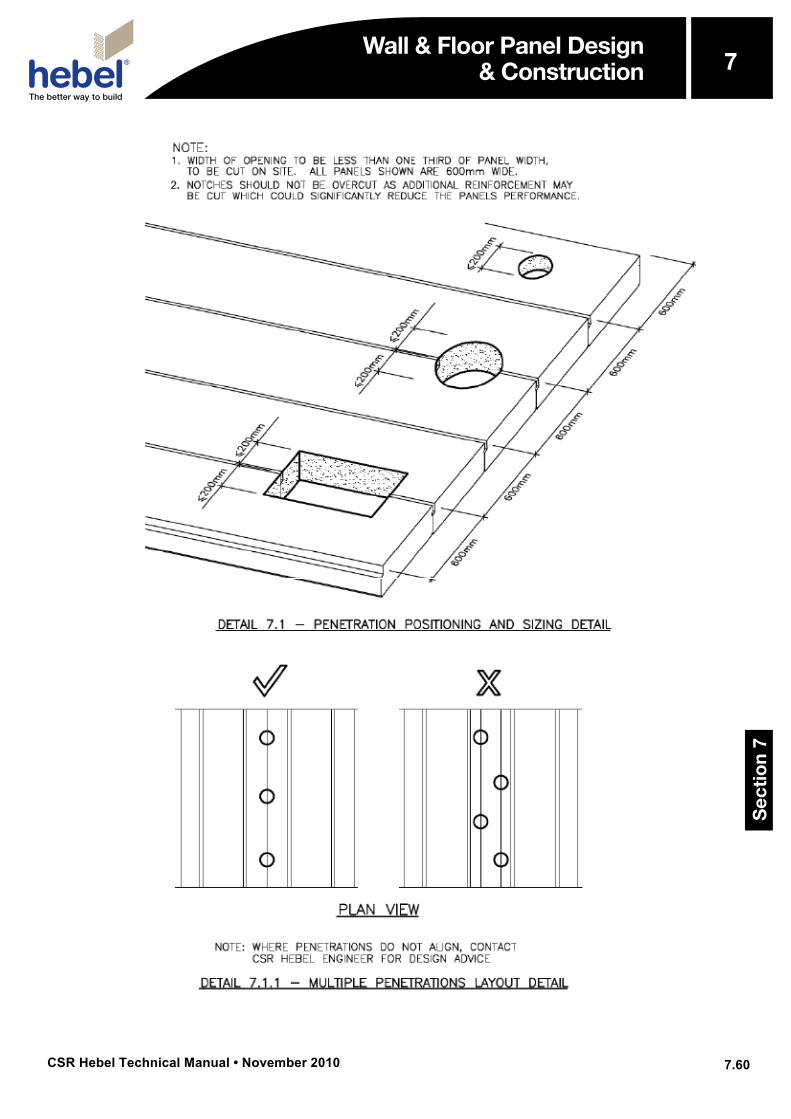
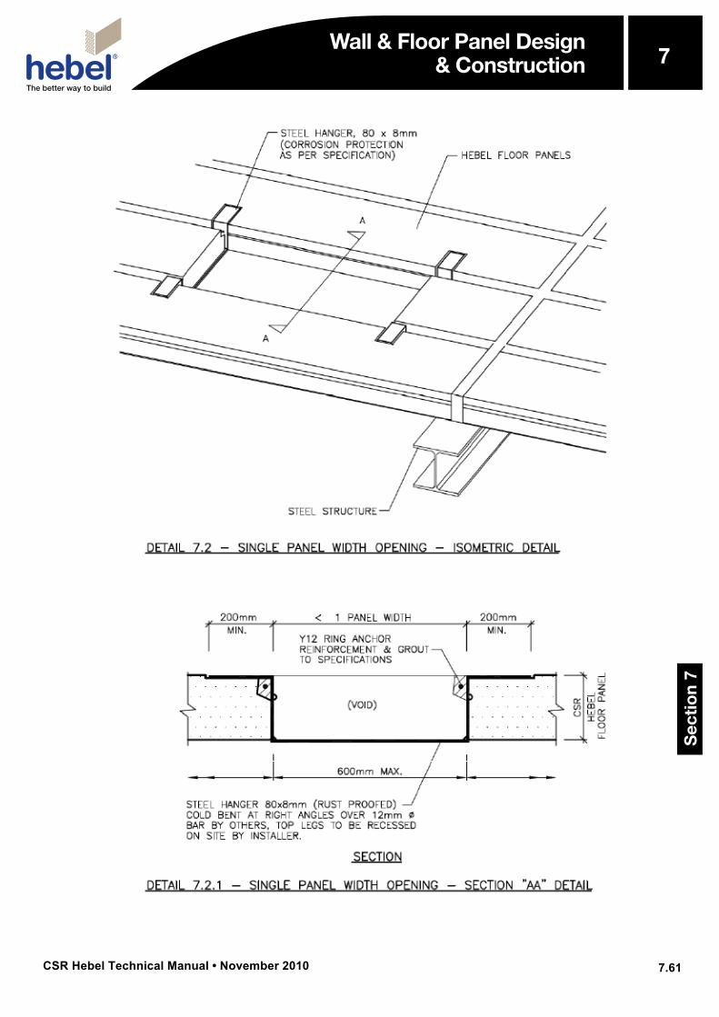
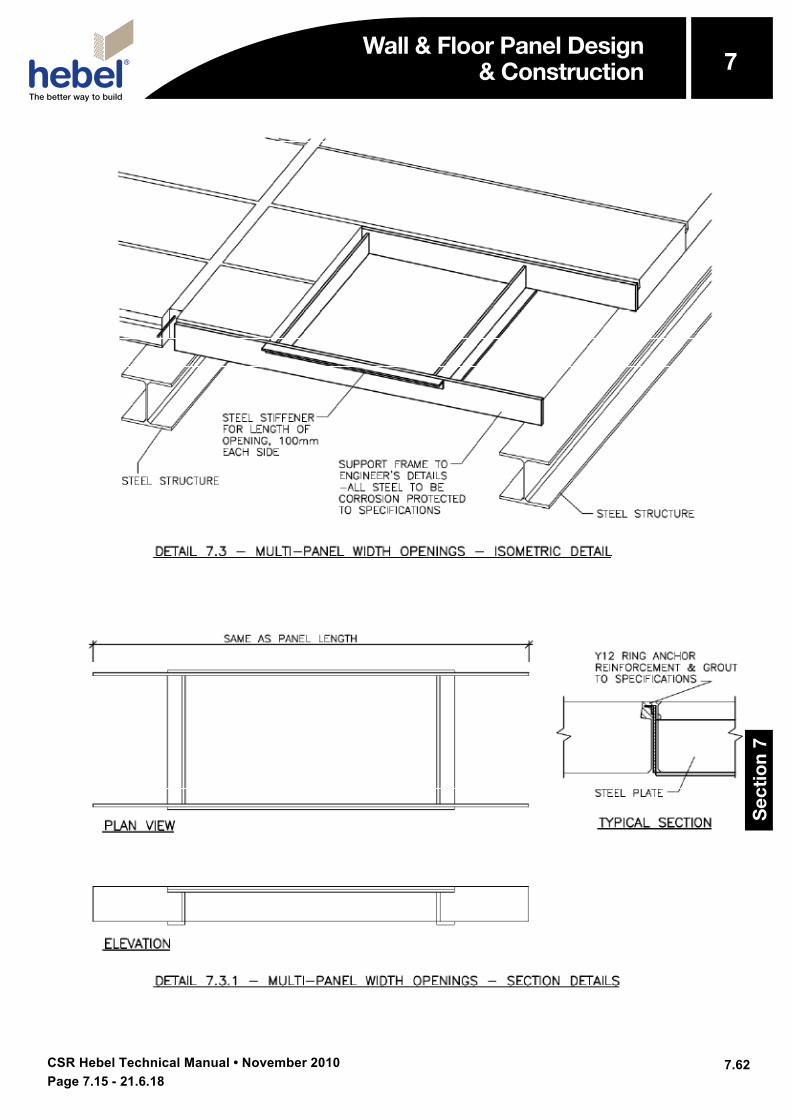
5.3.4 Ring Anchor Reinforcement Positioning and Restraint over Steel Supports - Panel End View 7.59 5.3.5 Ring Anchor Site Panel Notching Detail (PND) 7.60 5.3.6 Ring Anchor Steel Cleat Detail “SCD” Typical 7.60 6.1 General Panel Section Detail-1 7.61 6.2 General Panel Section Detail-2 7.61 7.1 Penetration Positioning and Sizing Detail 7.62 7.1.1 Multiple Penetrations Layout Detail 7.62 7.2 Single Panel Width Opening - Isometric Detail 7.63 7.2.1 Single Panel Width Opening-Section “AA” Detail 7.63 7.3 Multi-Panel Width Openings-Isometric Detail 7.64 7.3.1 Multi-Panel Width Openings- Section Details 7.64
Wall & Floor Panel Design & Construction
Sec
tio
n 7
7
CSR Hebel Technical Manual • November 2010
7
7.51
Wall & Floor Panel Design & Construction
Wall & Floor Panel Design & Construction
Sec
tio
n 7
7
CSR Hebel Technical Manual • November 2010
7
7.52
Wall & Floor Panel Design & Construction Wall & Floor Panel Design
& Construction
Sec
tio
n 7
7
CSR Hebel Technical Manual • November 2010
7
7.53
Wall & Floor Panel Design & Construction
Wall & Floor Panel Design & Construction
Sec
tio
n 7
7
CSR Hebel Technical Manual • November 2010
7
7.54
Wall & Floor Panel Design & Construction Wall & Floor Panel Design
& Construction
Sec
tio
n 7
7
CSR Hebel Technical Manual • November 2010
7
7.55
Wall & Floor Panel Design & Construction Wall & Floor Panel Design
& Construction
Sec
tio
n 7
7
CSR Hebel Technical Manual • November 2010
7
7.56
Wall & Floor Panel Design & Construction
Wall & Floor Panel Design & Construction
Sec
tio
n 7
7
CSR Hebel Technical Manual • November 2010
7
7.57
Wall & Floor Panel Design & Construction Wall & Floor Panel Design
& Construction
Sec
tio
n 7
7
CSR Hebel Technical Manual • November 2010
7
7.58
Wall & Floor Panel Design & Construction Wall & Floor Panel Design
& Construction
Sec
tio
n 7
7
CSR Hebel Technical Manual • November 2010
7
7.59
Wall & Floor Panel Design & Construction Wall & Floor Panel Design
& Construction
Sec
tio
n 7
7
CSR Hebel Technical Manual • November 2010
7
7.60
Wall & Floor Panel Design & Construction
Wall & Floor Panel Design & Construction
Sec
tio
n 7
7
CSR Hebel Technical Manual • November 2010
7
7.61
Wall & Floor Panel Design & Construction Wall & Floor Panel Design
& Construction
Sec
tio
n 7
7
CSR Hebel Technical Manual • November 2010
7
7.62
Wall & Floor Panel Design & Construction Wall & Floor Panel Design
& Construction
Sec
tio
n 7
7
Page 7.15 - 21.6.18