Technical Documentation LEXIUM/VRDM3_manual_V100_BL_EN.… · the machine during production and...
90
Berger Lahr GmbH & Co. KG Breslauer Str. 7 D-77933 Lahr Technical Documentation Motor manual 3-phase stepping motors VRDM 3xx Document: 0098441113309 Edition: V1.00, 02.2006
Transcript of Technical Documentation LEXIUM/VRDM3_manual_V100_BL_EN.… · the machine during production and...

Berger Lahr GmbH & Co. KGBreslauer Str. 7D-77933 Lahr
Technical Documentation
Motor manual
3-phase stepping motors
VRDM 3xxDocument: 0098441113309
Edition: V1.00, 02.2006

-2 3-phase stepping motors
Important information VRDM 3xx
0098
4411
1330
9, V
1.00
, 02.
2006
Important information
The drive systems described here are products for general use that con-form to the state of the art in technology and are designed to prevent any dangers. However, drives and drive controllers that are not specifically designed for safety functions are not approved for applications where the functioning of the drive could endanger persons. The possibility of unexpected or unbraked movements can never be totally excluded wit-hout additional safety equipment. For this reason personnel must never be in the danger zone of the drives unless additional suitable safety equipment prevents any personal danger. This applies to operation of the machine during production and also to all service and maintenance work on drives and the machine. The machine design must ensure per-sonal safety. Suitable measures for prevention of property damage are also required.
See safety section for additional critical instructions.
Not all product variants are available in all countries.Please consult the current catalogue for information on the availability of product variants.
We reserve the right to make changes during the course of technical de-velopments.
All details provided are technical data and not promised characteristics.
In general, product names must be considered to be trademarks of the respective owners, even if not specifically identified as such.

0098
4411
1330
9, V
1.00
, 02.
2006
VRDM 3xx Table of Contents
3-phase stepping motors -3
Table of Contents
Important information. . . . . . . . . . . . . . . . . . . . . . . . . . . . . . . . . -2
Table of Contents . . . . . . . . . . . . . . . . . . . . . . . . . . . . . . . . . . . . -3
Writing conventions and symbols. . . . . . . . . . . . . . . . . . . . . . . -7
1 Introduction
1.1 Overview . . . . . . . . . . . . . . . . . . . . . . . . . . . . . . . . . . . 1-1
1.2 Options, accessories and wiring . . . . . . . . . . . . . . . . . 1-2
1.3 Type code and nameplate . . . . . . . . . . . . . . . . . . . . . . 1-31.3.1 Overview of type code of VRDM 3xx . . . . . . . . . . . 1-31.3.2 Name plate . . . . . . . . . . . . . . . . . . . . . . . . . . . . . . . 1-4
1.4 Literature . . . . . . . . . . . . . . . . . . . . . . . . . . . . . . . . . . . 1-5
1.5 Directives and standards. . . . . . . . . . . . . . . . . . . . . . . 1-5
1.6 Declaration of conformity. . . . . . . . . . . . . . . . . . . . . . . 1-7
2 Safety
2.1 Qualification of personnel . . . . . . . . . . . . . . . . . . . . . . 2-1
2.2 Intended use . . . . . . . . . . . . . . . . . . . . . . . . . . . . . . . . 2-1
2.3 Safety instructions . . . . . . . . . . . . . . . . . . . . . . . . . . . . 2-2
3 Technical Data
3.1 General features . . . . . . . . . . . . . . . . . . . . . . . . . . . . . 3-1
3.2 Ambient conditions . . . . . . . . . . . . . . . . . . . . . . . . . . . 3-2
3.3 Life time. . . . . . . . . . . . . . . . . . . . . . . . . . . . . . . . . . . . 3-2
3.4 IP degree of protection . . . . . . . . . . . . . . . . . . . . . . . . 3-3
3.5 Motor models. . . . . . . . . . . . . . . . . . . . . . . . . . . . . . . . 3-5
3.6 VRDM 36x . . . . . . . . . . . . . . . . . . . . . . . . . . . . . . . . . . 3-63.6.1 Motor-specific data of VRDM 36x. . . . . . . . . . . . . . 3-63.6.2 Shaft load of VRDM 36x . . . . . . . . . . . . . . . . . . . . . 3-73.6.3 Type code of VRDM 36x . . . . . . . . . . . . . . . . . . . . . 3-83.6.4 Dimensional drawing of VRDM 36x . . . . . . . . . . . 3-103.6.5 Characteristic curves of VRDM 36x . . . . . . . . . . . 3-12
3.7 VRDM 39x . . . . . . . . . . . . . . . . . . . . . . . . . . . . . . . . . 3-153.7.1 Motor-specific data of VRDM 39x. . . . . . . . . . . . . 3-153.7.2 Shaft load of VRDM 39x . . . . . . . . . . . . . . . . . . . . 3-163.7.3 Type code of VRDM 39x . . . . . . . . . . . . . . . . . . . . 3-163.7.4 Dimensional drawing of VRDM 39x . . . . . . . . . . . 3-193.7.5 Characteristic curves of VRDM 39x . . . . . . . . . . . 3-21

-4 3-phase stepping motors
Table of Contents VRDM 3xx
0098
4411
1330
9, V
1.00
, 02.
2006
3.8 VRDM 311x . . . . . . . . . . . . . . . . . . . . . . . . . . . . . . . . 3-243.8.1 Motor-specific data of VRDM 311x . . . . . . . . . . . . 3-243.8.2 Shaft load of VRDM 311x . . . . . . . . . . . . . . . . . . . 3-253.8.3 Type code of VRDM 311x . . . . . . . . . . . . . . . . . . . 3-253.8.4 Dimensional drawing of VRDM 311x . . . . . . . . . . . 3-283.8.5 Characteristic curves of VRDM 311x . . . . . . . . . . . 3-30
3.9 Optional holding brake . . . . . . . . . . . . . . . . . . . . . . . . 3-32
3.10 Optional encoder . . . . . . . . . . . . . . . . . . . . . . . . . . . . 3-34
3.11 Optional gearbox . . . . . . . . . . . . . . . . . . . . . . . . . . . . 3-353.11.1 Assignment of motor-gearbox . . . . . . . . . . . . . . . . 3-383.11.2 Dimensional drawings of gearbox . . . . . . . . . . . . . 3-40
4 Installation
4.1 Before installation... . . . . . . . . . . . . . . . . . . . . . . . . . . . 4-2
4.2 Electromagnetic compatibility, EMC . . . . . . . . . . . . . . . 4-3
4.3 Mechanical installation . . . . . . . . . . . . . . . . . . . . . . . . . 4-4
4.4 Electrical installation . . . . . . . . . . . . . . . . . . . . . . . . . . . 4-74.4.1 Calculation of installation space. . . . . . . . . . . . . . . . 4-84.4.2 Motor connection . . . . . . . . . . . . . . . . . . . . . . . . . . . 4-94.4.3 Encoder connection . . . . . . . . . . . . . . . . . . . . . . . . 4-114.4.4 Holding brake connection . . . . . . . . . . . . . . . . . . . 4-12
5 Commissioning
5.1 Preparing for commissioning . . . . . . . . . . . . . . . . . . . . 5-2
5.2 Running commissioning . . . . . . . . . . . . . . . . . . . . . . . . 5-3
6 Diagnostics and troubleshooting
6.1 Mechanical faults . . . . . . . . . . . . . . . . . . . . . . . . . . . . . 6-1
6.2 Electrical faults . . . . . . . . . . . . . . . . . . . . . . . . . . . . . . . 6-1
7 Accessories and spare parts
7.1 Accessories . . . . . . . . . . . . . . . . . . . . . . . . . . . . . . . . . 7-1
7.2 Motor cable. . . . . . . . . . . . . . . . . . . . . . . . . . . . . . . . . . 7-1
8 Service, maintenance and disposal
8.1 Service address . . . . . . . . . . . . . . . . . . . . . . . . . . . . . . 8-1
8.2 Maintenance . . . . . . . . . . . . . . . . . . . . . . . . . . . . . . . . . 8-2

0098
4411
1330
9, V
1.00
, 02.
2006
VRDM 3xx Table of Contents
3-phase stepping motors -5
9 Glossary
9.1 Units and conversion tables . . . . . . . . . . . . . . . . . . . . 9-19.1.1 Length. . . . . . . . . . . . . . . . . . . . . . . . . . . . . . . . . . . 9-19.1.2 Mass . . . . . . . . . . . . . . . . . . . . . . . . . . . . . . . . . . . . 9-19.1.3 Force. . . . . . . . . . . . . . . . . . . . . . . . . . . . . . . . . . . . 9-19.1.4 Power . . . . . . . . . . . . . . . . . . . . . . . . . . . . . . . . . . . 9-19.1.5 Rotation . . . . . . . . . . . . . . . . . . . . . . . . . . . . . . . . . 9-29.1.6 Torque. . . . . . . . . . . . . . . . . . . . . . . . . . . . . . . . . . . 9-29.1.7 Moment of inertia . . . . . . . . . . . . . . . . . . . . . . . . . . 9-29.1.8 Temperature . . . . . . . . . . . . . . . . . . . . . . . . . . . . . . 9-29.1.9 Conductor cross section . . . . . . . . . . . . . . . . . . . . . 9-2
9.2 Terms and Abbreviations. . . . . . . . . . . . . . . . . . . . . . . 9-3
10 Index

-6 3-phase stepping motors
Table of Contents VRDM 3xx
0098
4411
1330
9, V
1.00
, 02.
2006

0098
4411
1330
9, V
1.00
, 02.
2006
VRDM 3xx Writing conventions and symbols
3-phase stepping motors -7
Writing conventions and symbols
Work steps If work steps must be carried out in sequence, they are shown as fol-lows:
Special prerequisites for the following work steps
Step 1
Important response to this work step
Step 2
If a response to a work step is specified, this will inform you that the step has been carried out correctly.
Unless otherwise stated, the individual instruction steps must be carried in the given sequence.
Lists Lists can be sorted alphanumerically or by priority. Lists are structured as follows:
• Point 1
• Point 2
– Subpoint to 2
– Subpoint to 2
• Point 3
Making work easier Information on making work easier can be found at this symbol:
This offers supplementary information on making work easier.See the chapter on safety for an explanation of the safety instructions.

-8 3-phase stepping motors
Writing conventions and symbols VRDM 3xx
0098
4411
1330
9, V
1.00
, 02.
2006

0098
4411
1330
9, V
1.00
, 02.
2006
VRDM 3xx Introduction
3-phase stepping motors 1-1
1 Introduction
1.1 Overview
The three-phase stepper motors are extremely robust, maintenance-free drives. They carry out stepper motions which are controlled by a po-sitioning controller.
The three-phase stepper motors can be operated at very high resoluti-ons with appropriate control electronics.
Options such as rotation monitoring and holding brake with robust, low-play planetary gears extend the application options.
Features The three-phase stepper motors are:
• strong the optimised internal geometry of the motor ensures a high power density; i.e. up to 50% more torque compared to conventio-nal stepper motors of comparable size.
• quiet the sinus commutation of the drive amplifier and the special mechanical construction gives a very quiet and virtually resonance-free stepper motor.
• versatile with a flexible modular system and modern type manage-ment a wide variety of motor types can be manufactured and deli-vered in a very short time.
Motor data
Size 60 90 110
Motor type VRDM 36x VRDM 39x VRDM 311x
Nominal torque MN Nm 0.45 - 1.50 2.00 - 6.00 12.00 - 16.50
Holding torque MH Nm 0.51 - 1.70 2.26 - 6.78 13.56 - 18.65
Steps per revolution 1) 200 / 400 / 500 / 1000 / 2000 / 4000 / 5000 / 10000
Step angleα ° 1.8 / 0.9 / 0.72 / 0.36 / 0.18 / 0.09 / 0.072 / 0.036
Motor phase current IN A 0.9 - 5.8 1.75 - 5.8 4.1 - 4.75
Nominal voltage of DC bus UN VDC 24/35, 130, 325 24/35, 130, 325 325
1) depending on the controller

1-2 3-phase stepping motors
Introduction VRDM 3xx
0098
4411
1330
9, V
1.00
, 02.
2006
1.2 Options, accessories and wiring
The motors are optionally available with:
• Encoder
• holding brake
• PLE or PLS gearbox
• angled and rotatable plug connectors
• various degrees of protection
For the options see the technical data in the various motor descriptions.
The following accessories are available:
• controller for holding brake
• Cable
Fully finished motor and sensor system wiring precisely designed for the drive systems ensures that motor and power amplifier are perfectly con-nected.

0098
4411
1330
9, V
1.00
, 02.
2006
VRDM 3xx Introduction
3-phase stepping motors 1-3
1.3 Type code and nameplate
The type code is explained below. Type code for every motor size is shown in full in "Technical Data".
1.3.1 Overview of type code of VRDM 3xx
Example: VRDM 3 9 10 / 50 L H C E O IP41 1 5 DO O OO 2 B B O OOO
Phase count VRDM 3 X X / 50 L H C E O IP41 1 5 DO O OO 2 B B O OOO
Size (flange) VRDM 3 X X / 50 L H C E O IP41 1 5 DO O OO 2 B B O OOO
Length VRDM 3 X X / 50 L H C E O IP41 1 5 DO O OO 2 B B O OOO
Pole pair count VRDM 3 X X / 50 L H C E O IP41 1 5 DO O OO 2 B B B OOO
Rotor VRDM 3 X X / 50 L H C E O IP41 1 5 DO O OO 2 B B O OOO
Maximum voltage VRDM 3 X X / 50 L H C E O IP41 1 5 DO O OO 2 B B B OOO
Connection type (motor/enco-der)
VRDM 3 X X / 50 L H C E O IP41 1 5 DO O OO 2 B B O OOO
Position capture VRDM 3 X X / 50 L H C E O IP41 1 5 DO O OO 2 B B O OOO
holding brake VRDM 3 X X / 50 L H C E O IP41 1 5 DO O OO 2 B B O OOO
Degree of protection VRDM 3 X X / 50 L H C E O IP41 1 5 DO O OO 2 B B O OOO
Gearbox type VRDM 3 X X / 50 L H C E O IP41 1 5 DO O OO 2 B B O OOO
Gear ratio VRDM 3 X X / 50 L H C E O IP41 1 5 DO O OO 2 B B O OOO
Shaft diameter VRDM 3 X X / 50 L H C E O IP41 1 5 DO O OO 2 B B O OOO
Shaft modelMotor VRDM 3 X X / 50 L H C E O IP41 1 5 DO O OO 2 B B O OOO
Centring collar VRDM 3 X X / 50 L H C E O IP41 1 5 DO O OO 2 B B O OOO
Second shaft VRDM 3 X X / 50 L H C E O IP41 1 5 DO O OO 2 B B O OOO
Connection direction motor plug
VRDM 3 X X / 50 L H C E O IP41 1 5 DO O OO 2 B B O OOO
Connection direction encoder plug
VRDM 3 X X / 50 L H C E O IP41 1 5 DO O OO 2 B B O OOO
Wire output VRDM 3 X X / 50 L H C E O IP41 1 5 DO O OO 2 B B O OOO
Wire length VRDM 3 X X / 50 L H C E O IP41 1 5 DO O OO 2 B B O OOO

1-4 3-phase stepping motors
Introduction VRDM 3xx
0098
4411
1330
9, V
1.00
, 02.
2006
1.3.2 Name plate
The name plate shows the most important motor data.
Figure 1.1 Name plate
(1) Motor type, see type code(2) Nominal torque at standstill
phase current at standstillmaximum supply voltagevoltage constant
(3) variable PWMvariable torquemotor for converter operation only
(4) Order number(5) CE mark(6) Serial number(7) manufacturer's name and logo(8) gearbox type and gear ratio(9) holding torque of the holding brake
nominal voltage of the holding brakepower consumption of the holding brake
(10) degree of protection(11) Temperature class (155)(12) cUR mark(13) Date of manufacture(14) Barcode
VRDM3910/50LWC EB
M N PLE 80 5:1l N 2 Arms Brake 6 NmU 230 VAC 24VDCKe 150,0 Vrms/1000rpm 22 W
IP41Insulation class F
VPWM, VT, Inverter-duty Motor DOM 19.10.05
0055526035803 Ser.No. 1540085949
max
4Nm
mad
e in
Ger
man
y by
2
1
3
9
8
7
5
11
6
4
10
13
14
12

0098
4411
1330
9, V
1.00
, 02.
2006
VRDM 3xx Introduction
3-phase stepping motors 1-5
1.4 Literature
• Rummich, Erich: Elektrische Schrittmotoren und Antriebe. ISBN: 3-8169-2458-1, Expert-Verlag, Renningen
• Kreuth, Hans-Peter: Schrittmotoren. ISBN: 3-486-202642-3, Olden-bourg Verlag, München
• Vogel, Johannes: Elektrische Antriebstechnik. ISBN: 3-7785-2649-9, Hüthig Verlag Heidelberg
• Riefenstahl, Ulrich: Elektrische Antriebstechnik - Leitfaden der Elek-trotechnik. ISBN: 3-519-06429-4, B.G. Teubner Stuttgart, Leipzig
1.5 Directives and standards
The EC directives define the minimum requirements - particularly safety requirements - applicable to a product and must be complied with by all manufacturers and dealers marketing the product in the member states of the European Union (EU).
The EC directives describe the main requirements for a product. The technical details are laid down in the harmonized standards, which are published in Germany as the DIN EN standards. If there is not yet any EN standard applicable to a particular product area, existing technical standards and regulations will apply.
CE mark With the declaration of conformity and the CE mark on the product the manufacturer certifies that the product complies with the requirements of all relevant EC directives. The drive systems described here can be used anywhere in the world.
EC Machine Directive The drive systems described here are not machines as defined by the EC Machine Directive (98/37/EEC) but components for installation in machines. They do not have moving parts designed for specific purpo-ses. However, they can be components of a machine or system.
The manufacturer must certify that the complete system conforms to the machine directive with the CE mark.
EC EMC Directive The EC Electromagnetic Compatibility Directives (89/336/EEC) applies to products that cause electromagnetic interference or whose operation may be be adversely affected by electromagnetic interference.
Conformity with the EMC Directive can only be expected of drive sys-tems after correct installation in the machine. The information on ensu-ring electromagnetic compatibility given in the chapter on "Installation" must be followed to ensure that the drive system in the machine or sys-tem is EMC-compatible and that the product can legally be operated.
EC Low-Voltage Directive The EC Low-Voltage Directive (73/23/EEC) lays down safety require-ments for 'electrical apparatus' as protection against the risks that can originate in such devices and can be created in response to external in-fluences.
The drive systems described here comply with the EN 50178 Standard as per the Low-Voltage Directive.
Standards for safe operation of thedrive systems
EN 50178: Fitting power systems with electronic equipment
EN 60034-ff: Rotating electrical machines

1-6 3-phase stepping motors
Introduction VRDM 3xx
0098
4411
1330
9, V
1.00
, 02.
2006
EN 60664: Insulation coordination
UL1004: Motor classification under UL
Standards for terms andmechanical connections
DIN 42021: Stepper motor terms, symbols, units and characteristic cur-ves
DIN 332-1: Centre hole
DIN 6885: Parallel keys, grooves
DIN 6888: Disc springs
EN 50347: Standardised dimensions, centring diameter, hole circle, fa-stening screw

0098
4411
1330
9, V
1.00
, 02.
2006
VRDM 3xx Introduction
3-phase stepping motors 1-7
1.6 Declaration of conformity
EC Declaration of Conformity
Year 2005 BERGER LAHR GmbH & Co.KG
Breslauer Str. 7
D-77933 Lahr
according to EC Directive Low Voltage 73/23/EC, changed by CE Marking Directive 93/68/EC according to EC Directive on Machinery 98/37/EC according to EC Directive EMC 2004/108/EC
We declare that the products listed below meet the requirements of the mentioned EC
Directives with respect to design, construction and version distributed by us. This declaration
becomes invalid with any modification on the products not authorized by us.
Designation: 3 Phase Stepping Motor
Type: VRDM3xxxx/50xxx
Product number: 0x5xx2xxxxxxx
Applied
harmonized
standards,
especially:
EN 60034-1:2005 Temperature class 155 (F)
EN 60034-5:2001 Protection class according product documenation
EN 60664-1:2003 Insulation system
Applied
national standards
and technical
specifications,
especially:
UL 1004
Product documentation
Company stamp:
Date/ Signature: 26 October 2005
Name/ Department: Wolfgang Brandstätter/R & D Drive Systems
1-8 3-phase stepping motors
Introduction VRDM 3xx
0098
4411
1330
9, V
1.00
, 02.
2006

0098
4411
1330
9, V
1.00
, 02.
2006
VRDM 3xx Safety
3-phase stepping motors 2-1
2 Safety
2.1 Qualification of personnel
Commissioning, operation and maintenance must be conducted by trai-ned electrical and controller technicians only.
The technicians must be familiar with the contents of all technical docu-mentation relevant to this product.
The technicians must have sufficient training, knowledge and experi-ence to recognise and avoid dangers.
The technicians must be familiar with the relevant standards, regulations and safety regulations that must be observed during installation, opera-tion and maintenance of the product.
2.2 Intended use
The drive systems described here are products for general use that con-form to the state of the art in technology and are designed to prevent any dangers. However, drives and drive controllers that are not specifically designed for safety functions are not approved for applications where the functioning of the drive could endanger persons. The possibility of unexpected or unbraked movements can never be totally excluded wit-hout additional safety equipment. For this reason personnel must never be in the danger zone of the drives unless additional suitable safety equipment prevents any personal danger. This applies to operation of the machine during production and also to all service and maintenance work on drives and the machine. The machine design must ensure per-sonal safety. Suitable measures for prevention of property damage are also required.
In the system configuration described the drive systems must be used in industrial applications only and must have a fixed connection only.
In all cases the applicable safety regulations and the specified operating conditions, such as environmental conditions and specified technical data, must be observed.
The drive system must not be commissioned and operated until com-pletion of installation in accordance with the EMC regulations and the specifications in this manual.
To prevent personal injury and damage to property damaged drive sys-tems must not be installed or operated.
Changes and modifications of the drive systems are not permitted and if made all no warranty and liability will be accepted.
The drive system must be operated only with the specified wiring and approved accessories. In general, use only original accessories and spare parts.
The drive systems must not be operated in an environment subject to explosion hazard (ex area).

2-2 3-phase stepping motors
Safety VRDM 3xx
0098
4411
1330
9, V
1.00
, 02.
2006
2.3 Safety instructions
$ DANGERElectric shock, fire or explosion
• Only technicians who are familiar with and understand the contents of this manual and the other relevant manuals are authorised to work on and with this drive system.
• Before working on the drive system:
– Switch off power to all terminals.
– Place a sign "DO NOT SWITCH ON" on the switch and lock to prevent its being switched on.
– Allow the DC bus capacitors to discharge (see power amp-lifier manual).
– Check that there is no power.
• Do not short-circuit DC bus or touch unshielded components or screws of the terminals under voltage.
• Install all covers and close the housing doors before applying power.
• The motor generates voltage when the shaft is rotated. Lock the shaft of the motor to prevent rotation before starting work on the drive system.
• AC voltages may jump over unused wires in the motor cable. Isolate unused wires at both ends of the motor cable.
• The system manufacturer is responsible for compliance with all applicable regulations relevant to earthing the drive system. Extend the earth through the motor cable with an additional earth at the motor housing.
Failure to follow these instructions will result in death or se-rious injury.

0098
4411
1330
9, V
1.00
, 02.
2006
VRDM 3xx Technical Data
3-phase stepping motors 3-1
3 Technical Data
The following pages contains information on the VRDM 3xx motor family and an overview of the gearboxes.
3.1 General features
The series VRDM 3xx motors are three-phase stepper motors. They are distinguished by:
• high power density
• integrated thermal winding monitoring in accordance with the EN requirements for "decoupled"
• test voltage in accordance with EN 60034-1 (IEC 60034-1)
• insulation system class 155 (F) in accordance with EN 60034-1 (IEC 60034-1)
• Mechanical vibration A in accordance with EN 60034-14 (IEC 60034-14)
• Shaft eccentricity and axial precision in accordance with EN 50347 (IEC 60072-1)
• colour: black RAL 9005
Maximum press-on force The maximum press-on force is related to the loading ratio of the bea-ring. The use of assembly paste (e.g. Klüberpaste 46 MR 401) on the shaft and drive element simplifies pressing on.
If the output shaft is threaded, we advise you to push the output element onto the output shaft. This prevents any axial force from acting on the bearing.
Alternatively the output shaft may be also shrunk on, clamped or glued.
Note the following:
• The Motor must not be opened by the customer. If it is opened it will be partially demagnetuized with a consequent loss of power.
• In the case of motors with terminal box, the cover can be opened to connect the terminals.
• Radial and axial limit loads must not be applied simultaneously
• The shaft must be supported if components are pressed onto the shaft ends.
• Please note the saftey information.

3-2 3-phase stepping motors
Technical Data VRDM 3xx
0098
4411
1330
9, V
1.00
, 02.
2006
3.2 Ambient conditions
Environmental influences: ambientclimate for transport and storage
The motors must be in a dry, dust-free and vibration-free environment during transport and storage. The storage and transport temperature must remain in the range given below; in case of doubt the storage area must be air-conditioned.
The storage period is primarily determined by the durability of the lubri-cants in the warehouses and should be less than 36 months. Occasional operation of the drive solution is recommended to ensure that it still ope-rates.
3.3 Life time
The life time of the motors when operated correctly is limited primarily by the bearing life.
The following operating conditions can in some cases significantly re-duce the life time:
• Installation altitude above 1000 m over sea level
• Continuous operating temperatures greater than 80°C
• Angular travel less than 100°
• Operation with very high rotary accelerations
• Operation under vibration stress greater than 20 m/s2
• High cycle frequencies
• Allowing sealing rings to run dry
• Wetting of the drive by aggressive media
• Condensation and icing of functional parts
• Exceeding the permissible shaft load
Ambient conditions
ambient operating temperature °C -25 ... +40
Installation height without power reduction m < 1000 above MSL
Transport and storage temperature °C -25 ... +70
Relative humidity % 75 (annual average), 95 (over 30 days, non-condensing)
Mechanical vibration in operation in accordance with EN 60034-14
A
Continuous shocks as per DIN EN 60068-2-29
• Number of shocks per direction 100
• Peak acceleration m/s2 20
Degree of protection as per EN 60034-5
• Total external shaft bushing IP56
• Shaft bushing without shaft sealing ring IP41
Temperature class as per EN 60034-1 155 (F)
Shaft eccentricity and axial precision [as per EN 50 347 (IEC 60072-1)]
Maximum rotary acceleration rad/s2 200000

0098
4411
1330
9, V
1.00
, 02.
2006
VRDM 3xx Technical Data
3-phase stepping motors 3-3
3.4 IP degree of protection
The motors have the following IP degrees of protection as per EN 60034-5:
The motors can also optionally be fitted with a radial shaft seal to place them in protection class IP56. However, this restricts the maximum speed to 3000 1/min. With mounting position IM V3 (drive shaft vertical, shaft end up) only protection class IP41 is guaranteed. The degree of protection of the drive is determined by the weakest component.
Note the following:
• The radial shaft sealing ring is prelubricated.
• Allowing the seals to run dry increases friction and greatly reduces the service life of the sealing rings.
321
Item Degree of protection
1 Motor front PLE gearbox IP 54
PLS gearbox IP 65
Shaft bushing IP 41, IP 56 1)
1) optional with VRDM 39x and VRDM 311x
2 Motor connection Braided wires IP 41
Terminal box, connector IP 56
3 Back of motor 2. Shaft end IP 41
Holding brake, encoder IP 56
3-4 3-phase stepping motors
Technical Data VRDM 3xx
0098
4411
1330
9, V
1.00
, 02.
2006
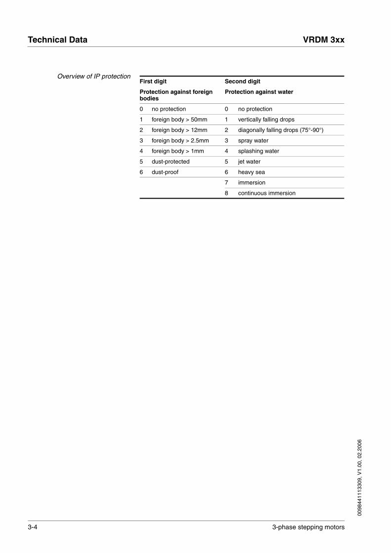
Overview of IP protectionFirst digit Second digit
Protection against foreign bodies
Protection against water
0 no protection 0 no protection
1 foreign body > 50mm 1 vertically falling drops
2 foreign body > 12mm 2 diagonally falling drops (75°-90°)
3 foreign body > 2.5mm 3 spray water
4 foreign body > 1mm 4 splashing water
5 dust-protected 5 jet water
6 dust-proof 6 heavy sea
7 immersion
8 continuous immersion

0098
4411
1330
9, V
1.00
, 02.
2006
VRDM 3xx Technical Data
3-phase stepping motors 3-5
3.5 Motor models
321 654
1 2 3 4 5 6
Motor gear shaft[mm]
centring collar[mm]
Motor type Motor connection Options
Size Length winding
VRDM 36x
3:1
5:1
8:1
D = 6.35 D = 38.1 60 4 H Braided wires 1)
Terminal box 2)
Plug
2. Shaft end 3)
Holding brake 3)
Encoder 4)
6 H ; N
D = 8 D = 38.1 60 8 H ; N ; W
VRDM 39x
3:1
5:1
8:1
D = 9,5
D = 12
D = 60
D = 73
90 7
10
H ; N ; W Braided wires 1)
Terminal box 2)
Plug
2. Shaft end 3)
Holding brake 3)
Encoder 4)D = 14 D = 60
D = 73
90 13 H ; N ; W
VRDM 311x
3:1
5:1
8:1
D = 19 D = 56 110 17 W Terminal box 2)
Plug
2. Shaft end 3)
Holding brake 3)
Encoder 4)
1) Wire outlet at 2nd shaft end to the side only2) Terminal bar inside the motor; sealed with a cable retaining screw; EMC-tested3) only one feature can be selected; either 2nd shaft end or holding brake4) only with motors with connector type (2nd shaft end or holding brake are possible)

3-6 3-phase stepping motors
Technical Data VRDM 3xx
0098
4411
1330
9, V
1.00
, 02.
2006
3.6 VRDM 36x
The stepper motors of the VRDM 36x series are manufactured as the VRDM 364, VRDM 366 and VRDM 368 types. The edge length of the flange is 57.2 mm. The terms and formulas listed in the following tables correspond to DIN 42021 Part 2.
3.6.1 Motor-specific data of VRDM 36x
Motor type VRDM 364 VRDM 366 VRDM 368
Winding H H N H N W
Max. supply voltage Umax VAC 25 25 92 25 92 230
Max. voltage against PE VAC 32 32 125 32 125 250
Nominal voltage of DC bus UN VDC 24 / 35 24 / 35 130 24 / 35 130 325
Nominal torque MN Nm 0.45 0.90 0.90 1.50 1.50 1.50
Holding torque MH Nm 0.51 1.02 1.02 1.70 1.70 1.70
Rotor inertia JR kgcm² 0.1 0.22 0.22 0.38 0.38 0.38
Steps per revolution 1) 200 / 400 / 500 / 1000 / 2000 / 4000 / 5000 / 10000
Step angleα ° 1.8 / 0.9 / 0.72 / 0.36 / 0.18 / 0.09 / 0.072 / 0.036
Systematic angular tolerance ∆αs2) ’ ±6 ±6 ±6 ±6 ±6 ±6
Max. starting frequency fAom kHz 8.5 8.0 8.5 6.0 8.5 8.5
Motor phase current IN Arms 5.2 5.8 1.6 5.8 1.9 0.9
Winding resistance RW Ω 0.42 0.46 3.3 0.7 4.8 25
Rate-of-current rise time constant t ms 2.1 3.3 3.3 4.6 4.6 4.6
Frame m 3) kg 1.3 1.6 1.6 2.0 2.0 2.0
1) depending on the controller2) Measured at 1000 steps/revolution, unit: angular minutes3) Earth of motor type with cable retaining screws or connector

0098
4411
1330
9, V
1.00
, 02.
2006
VRDM 3xx Technical Data
3-phase stepping motors 3-7
3.6.2 Shaft load of VRDM 36x
The following conditions apply:
• speed n = 600 1/min
• ambient temperature = 40°C (ca. 80°C storage temperature)
• 100% Duty Cycle at rated torque
When these conditions apply the maximum forces shown in the table be-low can act on the shaft, but not simultaneously:
X Y
FA1
FA2
FR2FR1
Motor type VRDM 364 VRDM 366 VRDM 368
Max. radial force of 1st shaft end FR11) N 24 24 50
Max. radial force of 2nd shaft end (optional) FR21) N 25 / 40 2) 25 / 40 2) 25 / 40 2)
Max. axial force tension FA1 N 100 100 100
Max. axial force pressure FA2 N 8.4 8.4 8.4
Nominal bearing life L10h3) h 20000 20000 20000
1) Point of attack of radial force: X = Y = 10mm distance from flange2) 1. Value: motors with terminal box, connector or encoder; 2. Value: motors with braided wires3) Operating hours at a failure probability of 10%

3-8 3-phase stepping motors
Technical Data VRDM 3xx
0098
4411
1330
9, V
1.00
, 02.
2006
3.6.3 Type code of VRDM 36x
Example: VRDM 3 6 8 / 50 L H C E O IP41 1 5 DO O OO 2 B B O OOO
Phase count 3
VRDM 3 6 8 / 50 L H C E O IP41 1 5 DO O OO 2 B B O OOO
Size (flange) 6 = 57.2 mm
VRDM 3 8 8 / 50 L H C E O IP41 1 5 DO O OO 2 B B O OOO
Length4 = 42 mm6 = 56 mm8 = 79 mm
VRDM 3 6 8 / 50 L H C E O IP41 1 5 DO O OO 2 B B O OOO
Pole pair count50
VRDM 3 6 8 / 50 L H C E O IP41 1 5 DO O OO 2 B B B OOO
RotorL = laminated rotor plate
VRDM 3 6 8 / 50 L H C E O IP41 1 5 DO O OO 2 B B O OOO
Maximum voltageH = 25 VAC (35 VDC)N = 92 VAC (130 VDC)W = 230 VAC (325 VDC)
VRDM 3 6 8 / 50 L H C E O IP41 1 5 DO O OO 2 B B B OOO
Connection type (motor/enco-der)A = braided wiresB = terminal boxC = connector
VRDM 3 6 8 / 50 L H C E O IP41 1 5 DO O OO 2 B B O OOO
Position captureE = encoder (1000 Inc./rev.)O = without encoder
VRDM 3 6 8 / 50 L H C E O IP41 1 5 DO O OO 2 B B O OOO
holding brakeB = brakeO = without brake
VRDM 3 6 8 / 50 L H C E O IP41 1 5 DO O OO 2 B B O OOO
Degree of protectionIP41
VRDM 3 6 8 / 50 L H C E O IP41 1 5 DO O OO 2 B B O OOO
Gearbox typeO = without gearbox1 = PLE 402 = PLE 60A = PLS 70
VRDM 3 6 8 / 50 L H C E O IP41 1 5 DO O OO 2 B B O OOO
Gear ratioO = without gearbox3 = 3:15 = 5:18 = 8:1
VRDM 3 6 8 / 50 L H C E O IP41 1 5 DO O OO 2 B B O OOO
Shaft diameterD6 = 6.35 mmD8 = 8 mmDO = motor with gearbox
VRDM 3 6 8 / 50 L H C E O IP41 1 5 DO O OO 2 B B O OOO
Shaft modelfrontO = smooth shaft or with gearbox
VRDM 3 6 8 / 50 L H C E O IP41 1 5 DO O OO 2 B B O OOO
Centring collar38 = 38.10 mm00 = motor with gearbox
VRDM 3 6 8 / 50 L H C E O IP41 1 5 DO O OO 2 B B O OOO
Second shaft:O = without2 = with
VRDM 3 6 8 / 50 L H C E O IP41 1 5 DO O OO 2 B B O OOO

0098
4411
1330
9, V
1.00
, 02.
2006
VRDM 3xx Technical Data
3-phase stepping motors 3-9
Connection direction motor plugO = without, L = left, R = rightB = rear, F = front, S = straight
VRDM 3 6 8 / 50 L H C E O IP41 1 5 DO O OO 2 B B O OOO
Connection direction encoder plugO = without, L = left, R = rightB = rear, F = front, S = straight
VRDM 3 6 8 / 50 L H C E O IP41 1 5 DO O OO 2 B B O OOO
Wire outputO = withoutS = sideB = rear
VRDM 3 6 8 / 50 L H C E O IP41 1 5 DO O OO 2 B B O OOO
Wire lengthOOO = noneXXX = XXX mm (max. 400)
VRDM 3 6 8 / 50 L H C E O IP41 1 5 DO O OO 2 B B O OOO
Example: VRDM 3 6 8 / 50 L H C E O IP41 1 5 DO O OO 2 B B O OOO

3-10 3-phase stepping motors
Technical Data VRDM 3xx
0098
4411
1330
9, V
1.00
, 02.
2006
3.6.4 Dimensional drawing of VRDM 36x
The following applies for the dimensional drawings:
(1) motor with holding brake
Figure 3.1 Dimensional drawing of VRDM 36x in braided wire type
Figure 3.2 Dimensional drawing of VRDM 36x in terminal type
L D
VRDM 364 42 6.35
VRDM 366 56 6.35
VRDM 368 79 8
7,7
22
20
Ø D
-0,
013
L ±0,5
5
21
Ø 3
8,1
±0,
025
1,6
Ø 8
±0,
013
0
47,2
57,2
Ø 5
,2
R5
21,5
5˚
L ±0,5
Ø38
,1 ±
0,02
5
5
1,6
21 L ±0,5 37 20
M20 x 1,5
Ø9 - Ø13
Ø8
-0,0
130
Ø51
4137
47,2
57,2Ø
5,2
R5
Ø D
-0,
013
1

0098
4411
1330
9, V
1.00
, 02.
2006
VRDM 3xx Technical Data
3-phase stepping motors 3-11
Figure 3.3 Dimensional drawing of VRDM 36x in connector type withoutencoder
Figure 3.4 Dimensional drawing of VRDM 36x in connector type with enco-der
21,5
5˚
L ±0,5
Ø38
,1 ±
0,02
5
1,6
5
21 37 20L ±0,5
Ø 8
-0,
013
0
47,2
57,2
Ø 5
,2
R5
41
Ø 5
1
37
Ø D
-0,
013
1
5˚
21,5
L ±0,5
47,2
57,2
Ø5,
1
R5
2021
Ø 3
8,1
±0,
025
L ±0,5 37
1,6
5
Ø8
-0,0
130
41
Ø51
37
Ø D
-0,
013
1

3-12 3-phase stepping motors
Technical Data VRDM 3xx
0098
4411
1330
9, V
1.00
, 02.
2006
3.6.5 Characteristic curves of VRDM 36x
3.6.5.1 Characteristic curves of VRDM 364
Measurement of characteristic curves with 1000 steps/revolution, nomi-nal voltage UN and phase current IN
(1) Pull-out torque (2) Pull-in torque(3) Maximum load inertia
VRDM 364 / 50L H
1
J [kg cm²]
0
2
3
4
M [Nm]
n [1/min]
0,6
0,45
0,3
0,15
0
2
3
0,1 1 10 100fs [Hz]
35 VDC
1
24 VDC

0098
4411
1330
9, V
1.00
, 02.
2006
VRDM 3xx Technical Data
3-phase stepping motors 3-13
3.6.5.2 Characteristic curves of VRDM 366
Measurement of characteristic curves with 1000 steps/revolution, nomi-nal voltage UN and phase current IN
(1) Pull-out torque (2) Pull-in torque(3) Maximum load inertia
VRDM 366 / 50L H VRDM 366 / 50L N
1
J [kg cm²]
0
2
3
4
M [Nm]
n [1/min]
1,2
0,9
0,6
0,3
0
2
3
0,1 1 10 100fs [Hz]
35 VDC
1
24 VDC
1
[kg cm²]
0
2
3
4
M [Nm]
n [1/min]
1,2
0,9
0,6
0,3
0
2
3
0,1 1 10 100fs [Hz]
1

3-14 3-phase stepping motors
Technical Data VRDM 3xx
0098
4411
1330
9, V
1.00
, 02.
2006
3.6.5.3 Characteristic curves of VRDM 368
Measurement of characteristic curves with 1000 steps/revolution, nomi-nal voltage UN and phase current IN
(1) Pull-out torque (2) Pull-in torque(3) Maximum load inertia
VRDM 368 / 50L H VRDM 368 / 50L N + W
2
J [kg cm²]
0
4
6
8
M [Nm]
n [1/min]
1,6
1,2
0,8
0,4
0
2
3
0,1 1 10 100fs [Hz]
1
35 VDC
24 VDC
2
J [kg cm²]
0
4
6
8
M [Nm]
n [1/min]
1,6
1,2
0,8
0,4
0
2
3
0,1 1 10 100fs [Hz]
1

0098
4411
1330
9, V
1.00
, 02.
2006
VRDM 3xx Technical Data
3-phase stepping motors 3-15
3.7 VRDM 39x
The stepper motors of the VRDM 39x series are manufactured as the VRDM 397, VRDM 3910 and VRDM 3913 types. The edge length of the flange is 85 mm. The terms and formulas listed in the following tables correspond to DIN 42021 Part 2.
3.7.1 Motor-specific data of VRDM 39x
Motor type VRDM 397 VRDM 3910 VRDM 3913
winding H N W H N W H N W
Max. supply voltage Umax VAC 25 92 230 25 92 230 25 92 230
Max. voltage against PE VAC 32 125 250 32 125 250 32 125 250
Nominal voltage of DC bus UN VDC 24 / 35 130 325 24 / 35 130 325 24 / 35 130 325
Nominal torque MN Nm 1.7 2 2 3.7 4 4 5 6 6
Holding torque MH Nm 1.92 2.26 2.26 4.18 4.52 4.52 5.65 6.78 6.78
Rotor inertia JR kgcm² 1.1 1.1 1.1 2.2 2.2 2.2 3.3 3.3 3.3
Steps per revolution 1) 200 / 400 / 500 / 1000 / 2000 / 4000 / 5000 / 10000
Step angleα ° 1.8 / 0.9 / 0.72 / 0.36 / 0.18 / 0.09 / 0.072 / 0.036
Systematic angular tolerance ∆αs2) ’ ±6 ±6 ±6 ±6 ±6 ±6 ±6 ±6 ±6
Max. starting frequency fAom kHz 4.6 5.3 5.3 4.8 5.3 5.3 4.5 5.3 5.3
Motor phase current IN Arms 5.8 4.4 1.75 5.8 5 2 5.8 5 2.25
Winding resistance RW Ω 0.35 1 6.5 0.55 1.2 5.8 0.63 1.3 6.5
Rate-of-current rise time constant t ms ~7 ~7 ~7 ~9 ~9 ~9 ~10 ~10 ~10
Frame m 3) kg 2.1 2.1 2.1 3.2 3.2 3.2 4.3 4.3 4.3
1) depending on the controller2) Measured at 1000 steps/revolution, unit: angular minutes3) Earth of motor type with cable retaining screws or connector

3-16 3-phase stepping motors
Technical Data VRDM 3xx
0098
4411
1330
9, V
1.00
, 02.
2006
3.7.2 Shaft load of VRDM 39x
The following conditions apply:
• speed n = 600 1/min
• ambient temperature = 40°C (ca. 80°C storage temperature)
• 100% Duty Cycle at rated torque
When these conditions apply the maximum forces shown in the table be-low can act on the shaft, but not simultaneously:
3.7.3 Type code of VRDM 39x
X Y
FA1
FA2
FR2FR1
Motor type VRDM 397 VRDM 3910 VRDM 3913
Max. radial force of 1st shaft end FR11) N 100 100 110
Max. radial force of 2nd shaft end (optional) FR21) N 50 / 75 2) 50 / 75 2) 50 / 75 2)
Max. axial force tension FA1 N 175 175 175
Max. axial force pressure FA2 N 30 30 30
Nominal bearing life L10h3) h 20000 20000 20000
1) Point of attack of radial force: X = Y = 15mm distance from flange2) 1. Value: motors with terminal box, connector or encoder; 2. Value: motors with braided wires3) Operating hours at a failure probability of 10%

0098
4411
1330
9, V
1.00
, 02.
2006
VRDM 3xx Technical Data
3-phase stepping motors 3-17
Example: VRDM 3 9 10 / 50 L H C E O IP41 3 5 DO O OO 2 B B O OOO
Phase count3
VRDM 3 9 10 / 50 L H C E O IP41 3 5 DO O OO 2 B B O OOO
Size (flange) 9 = 85 mm
VRDM 3 9 10 / 50 L H C E O IP41 3 5 DO O OO 2 B B O OOO
Motor length7 = 68 mm10 = 98 mm13 = 128 mm
VRDM 3 9 10 / 50 L H C E O IP41 3 5 DO O OO 2 B B O OOO
Pole pair count 50
VRDM 3 9 10 / 50 L H C E O IP41 3 5 DO O OO 2 B B B OOO
RotorL = laminated rotor plate
VRDM 3 9 10 / 50 L H C E O IP41 3 5 DO O OO 2 B B O OOO
Maximum voltageH = 25 VAC (35 VDC)N = 92 VAC (130 VDC)W = 230 VAC (325 VDC)
VRDM 3 9 10 / 50 L H C E O IP41 3 5 DO O OO 2 B B B OOO
Connection type (motor/encoder)A = braided wiresB = terminal boxC = connector
VRDM 3 9 10 / 50 L H C E O IP41 3 5 DO O OO 2 B B O OOO
Position captureE = encoder (1000 Inc./rev.)O = without encoder
VRDM 3 9 10 / 50 L H C E O IP41 3 5 DO O OO 2 B B O OOO
holding brakeB = brakeO = without brake
VRDM 3 9 10 / 50 L H C E O IP41 3 5 DO O OO 2 B B O OOO
Degree of protectionIP41IP56
VRDM 3 9 10 / 50 L H C E O IP41 3 5 DO O OO 2 B B O OOO
Gearbox typeO = without gearbox 3 = PLE 80B = PLS 90
VRDM 3 9 10 / 50 L H C E O IP41 3 5 DO O OO 2 B B O OOO
Gear ratioO = without gearbox3 = 3:15 = 5:18 = 8:1
VRDM 3 9 10 / 50 L H C E O IP41 3 5 DO O OO 2 B B O OOO
Shaft diameterD9 = 9.5 mmD2 = 12 mmD4 = 14 mmDO = motor with gearbox
VRDM 3 9 10 / 50 L H C E O IP41 3 5 DO O OO 2 B B O OOO
Shaft modelfrontO = smooth shaft or with gearboxK = disc spring, DIN 6888
VRDM 3 9 10 / 50 L H C E O IP41 3 5 DO O OO 2 B B O OOO
Centring collar60 = 60 mm73 = 73 mm00 = motor with gearbox
VRDM 3 9 10 / 50 L H C E O IP41 3 5 DO O OO 2 B B O OOO
Second shaftO = without2 = with
VRDM 3 9 10 / 50 L H C E O IP41 3 5 DO O OO 2 B B O OOO

3-18 3-phase stepping motors
Technical Data VRDM 3xx
0098
4411
1330
9, V
1.00
, 02.
2006
Connection direction motor plugO = without, L = left, R = rightB = rear, F = front, S = straight
VRDM 3 9 10 / 50 L H C E O IP41 3 5 DO O OO 2 B B O OOO
Connection direction encoder plugO = without, L = left, R = rightB = rear, F = front, S = straight
VRDM 3 9 10 / 50 L H C E O IP41 3 5 DO O OO 2 B B O OOO
Wire outputO = withoutS = sideB = rear
VRDM 3 9 10 / 50 L H C E O IP41 3 5 DO O OO 2 B B O OOO
Wire lengthOOO = noneXXX = XXX mm (max. 400)
VRDM 3 9 10 / 50 L H C E O IP41 3 5 DO O OO 2 B B O OOO
Example: VRDM 3 9 10 / 50 L H C E O IP41 3 5 DO O OO 2 B B O OOO

0098
4411
1330
9, V
1.00
, 02.
2006
VRDM 3xx Technical Data
3-phase stepping motors 3-19
3.7.4 Dimensional drawing of VRDM 39x
The following applies for the dimensional drawings:
(1) motor with holding brake
Figure 3.5 Dimensional drawing of VRDM 39x in braided wire type
Figure 3.6 Dimensional drawing of VRDM 39x in terminal type
L D N
VRDM 397 67.5 9.5 12 60 73
VRDM 3910 97.5 9.5 12 60 73
VRDM 3913 127.5 14 14 60 73
6,5
12 ±0,5
34
70
85
Ø6,
5
R8,2
DIN 6888 Ø9,5:3 x 5 Ø12:4 x 6,5 Ø14:5 x 6,5
Ø D
h6
L -0,8 30 ±1,5
10
30+0,6
Ø N
h8
2Ø
14
h6
l -0,8+0,6
22
12
43 46,5
70
85Ø
6,5
R8,2
+0,630 ±1,530
10
2
L -0,8 43
Ø14
h6
DIN 6888 Ø9,5:3 x 5
Ø12:4 x 6,5 Ø14:5 x 6,5
M20 x 1,5Ø9 - Ø13
Ø D
h6
Ø N
h8 ±0,5
1

3-20 3-phase stepping motors
Technical Data VRDM 3xx
0098
4411
1330
9, V
1.00
, 02.
2006
Figure 3.7 Dimensional drawing of VRDM 39x in connector type withoutencoder
Figure 3.8 Dimensional drawing of VRDM 39x in connector type with enco-der
2212 ±0,5
L -0,8+0,6
30˚
30 ±1,5
2
43L -0,8
10
30+0,6
Ø 1
4 h6
70
85
Ø6,
5
R8,2
46,543
DIN 6888 Ø9,5: 3 x 5 Ø12: 4 x 6,5 Ø14: 5 x 6,5
Ø D
h6
Ø N
h8
1
L -0,8+0,6
2212 ±0,5
30˚70
85
Ø6,
5
R8,2
46,543
L -0,8 30 ±1,543+0,6
10
2
30
Ø14
h6
DIN 6888 Ø9,5: 3 x 5 Ø12: 4 x 6,5 Ø14: 5 x 6,5
Ø D
h6
Ø N
h8
1

0098
4411
1330
9, V
1.00
, 02.
2006
VRDM 3xx Technical Data
3-phase stepping motors 3-21
3.7.5 Characteristic curves of VRDM 39x
3.7.5.1 Characteristic curves of VRDM 397
Measurement of characteristic curves with 1000 steps/revolution, nomi-nal voltage UN and phase current IN
(1) Pull-out torque (2) Pull-in torque(3) Maximum load inertia
VRDM 397 / 50L H VRDM 397 / 50L N+ W
kg cm²]
0
10
20
30
M [Nm]
n [1/min]
2
1,5
1
0,5
0
2
3
0,1 1 10 100fs [Hz]
35 VDC
1
24 VDC
J [kg cm²]
0
10
20
30
M [Nm]
n [1/min]
2
1,5
1
0,5
0
2
3
0,1 1 10 100fs [Hz]
1

3-22 3-phase stepping motors
Technical Data VRDM 3xx
0098
4411
1330
9, V
1.00
, 02.
2006
3.7.5.2 Characteristic curves of VRDM 3910
Measurement of characteristic curves with 1000 steps/revolution, nomi-nal voltage UN and phase current IN
(1) Pull-out torque (2) Pull-in torque(3) Maximum load inertia
VRDM 3910 / 50L H VRDM 3910 / 50L N + W
[kg cm²]
0
10
20
30
M [Nm]
n [1/min]
4
3
2
1
0
2
3
0,1 1 10 100fs [Hz]
1
35 VDC
24 VDC
J [kg cm²]
0
10
20
30
M [Nm]
n [1/min]
4
3
2
1
0
2
3
0,1 1 10 100fs [Hz]
1
0098
4411
1330
9, V
1.00
, 02.
2006
VRDM 3xx Technical Data
3-phase stepping motors 3-23
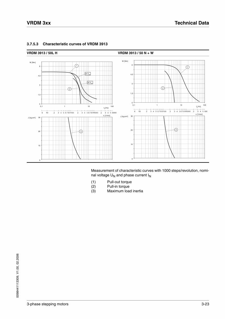
3.7.5.3 Characteristic curves of VRDM 3913
Measurement of characteristic curves with 1000 steps/revolution, nomi-nal voltage UN and phase current IN
(1) Pull-out torque (2) Pull-in torque(3) Maximum load inertia
VRDM 3913 / 50L H VRDM 3913 / 50 N + W
J [kg cm²]
0
10
20
30
M [Nm]
n [1/min]
6
4,5
3
1,5
0
2
3
0,1 1 10 100fs [Hz]
1
35 VDC
24 VDC
J [kg cm²]
0
10
20
30
M [Nm]
n [1/min]
6
4,5
3
1,5
0
2
3
0,1 1 10 100fs [Hz]
1

3-24 3-phase stepping motors
Technical Data VRDM 3xx
0098
4411
1330
9, V
1.00
, 02.
2006
3.8 VRDM 311x
The stepper motors of the VRDM 311x series are manufactured as the VRDM 31117 and VRDM 31122 types. The edge length of the flange is 110 mm. The terms and formulas listed in the following tables corres-pond to DIN 42021 Part 2.
3.8.1 Motor-specific data of VRDM 311x
Motor type VRDM 31117 VRDM 31122
winding W W
Max. supply voltage Umax VAC 230 230
Max. voltage against PE VAC 250 250
Nominal voltage of DC bus UN VDC 325 325
Nominal torque MN Nm 12 16.5
Holding torque MH Nm 13.5 19.7
Rotor inertia JR kgcm² 10.5 16
Steps per revolution 1) 200 / 400 / 500 / 1000 / 2000 / 4000 / 5000 / 10000
Step angleα ° 1.8 / 0.9 / 0.72 / 0.36 / 0.18 / 0.09 / 0.072 / 0.036
Systematic angular tolerance ∆αs2) ’ ±6 ±6
Max. starting frequency fAom kHz 4.7 4.7
Motor phase current IN Arms 4.1 4.75
Winding resistance RW Ω 1.8 1.9
Rate-of-current rise time constant t ms ~22 ~22
Frame m 3) kg 8.2 11.2
1) depending on the controller2) Measured at 1000 steps/revolution, unit: angular minutes3) Earth of motor type with cable retaining screws or connector

0098
4411
1330
9, V
1.00
, 02.
2006
VRDM 3xx Technical Data
3-phase stepping motors 3-25
3.8.2 Shaft load of VRDM 311x
The following conditions apply:
• speed n = 600 1/min
• ambient temperature = 40°C (ca. 80°C storage temperature)
• 100% Duty Cycle at rated torque
When these conditions apply the maximum forces shown in the table be-low can act on the shaft, but not simultaneously:
3.8.3 Type code of VRDM 311x
X Y
FA1
FA2
FR2FR1
Motor type VRDM 31117 VRDM 31122
Max. radial force of 1st shaft end FR11) N 300 300
Max. radial force of 2nd shaft end (optional) FR21) N 150 150
Max. axial force tension FA1 N 330 330
Max. axial force pressure FA2 N 60 60
Nominal bearing life L10h2) h 20000 20000
1) Point of attack of radial force: X = Y = 20mm distance from flange2) Operating hours at a failure probability of 10%

3-26 3-phase stepping motors
Technical Data VRDM 3xx
0098
4411
1330
9, V
1.00
, 02.
2006
Example: VRDM 3 11 17 / 50 L W C E O IP41 4 5 DO O OO 2 B B O OOO
Phase count 3
VRDM 3 11 17 / 50 L W C E O IP41 4 5 DO O OO 2 B B O OOO
Size (flange) 11 = 110 mm
VRDM 3 11 17 / 50 L W C E O IP41 4 5 DO O OO 2 B B O OOO
Length17 = 180 mm22 = 228 mm
VRDM 3 11 17 / 50 L W C E O IP41 4 5 DO O OO 2 B B O OOO
Pole pair count 50
VRDM 3 11 17 / 50 L W C E O IP41 4 5 DO O OO 2 B B B OOO
RotorL = laminated rotor plate
VRDM 3 11 17 / 50 L W C E O IP41 4 5 DO O OO 2 B B O OOO
Maximum voltageW = 230 VAC (325 VDC)
VRDM 3 11 17 / 50 L W C E O IP41 4 5 DO O OO 2 B B B OOO
Connection type (motor/encoder)B = terminal boxC = connector
VRDM 3 11 17 / 50 L W C E O IP41 4 5 DO O OO 2 B B O OOO
Position captureE = encoder (1000 Inc./rev.)O = without encoder
VRDM 3 11 17 / 50 L W C E O IP41 4 5 DO O OO 2 B B O OOO
holding brakeB = brakeO = without brake
VRDM 3 11 17 / 50 L W C E O IP41 4 5 DO O OO 2 B B O OOO
Degree of protectionIP41IP56
VRDM 3 11 17 / 50 L W C E O IP41 4 5 DO O OO 2 B B O OOO
Gearbox typeO = without gearbox4 = PLE 120C = PLS 115
VRDM 3 11 17 / 50 L W C E O IP41 4 5 DO O OO 2 B B O OOO
Gear ratioO = without gearbox3 = 3:15 = 5:18 = 8:1
VRDM 3 11 17 / 50 L W C E O IP41 4 5 DO O OO 2 B B O OOO
Shaft diameterD9 = 19 mmDO = motor with gearbox
VRDM 3 11 17 / 50 L W C E O IP41 4 5 DO O OO 2 B B O OOO
Shaft modelfrontO = smooth shaft or gearboxK = parallel key, DIN 6885
VRDM 3 11 17 / 50 L W C E O IP41 4 5 DO O OO 2 B B O OOO
Centring collar56 = 56 mm00 = motor with gearbox
VRDM 3 11 17 / 50 L W C E O IP41 4 5 DO O OO 2 B B O OOO
Second shaftO = without2 = with
VRDM 3 11 17 / 50 L W C E O IP41 4 5 DO O OO 2 B B O OOO
Connection direction motor plugO = without, L = left, R = rightB = rear, F = front, S = straight
VRDM 3 11 17 / 50 L W C E O IP41 4 5 DO O OO 2 B B O OOO

0098
4411
1330
9, V
1.00
, 02.
2006
VRDM 3xx Technical Data
3-phase stepping motors 3-27
Connection direction encoder plugO = without, L = left, R = rightB = rear, F = front, S = straight
VRDM 3 11 17 / 50 L W C E O IP41 4 5 DO O OO 2 B B O OOO
Wire outputO = without
VRDM 3 11 17 / 50 L W C E O IP41 4 5 DO O OO 2 B B O OOO
Wire lengthOOO = noneXXX = XXX mm (max. 400)
VRDM 3 11 17 / 50 L W C E O IP41 4 5 DO O OO 2 B B O OOO
Example: VRDM 3 11 17 / 50 L W C E O IP41 4 5 DO O OO 2 B B O OOO

3-28 3-phase stepping motors
Technical Data VRDM 3xx
0098
4411
1330
9, V
1.00
, 02.
2006
3.8.4 Dimensional drawing of VRDM 311x
The following applies for the dimensional drawings:
(1) motor with holding brake
Figure 3.9 Dimensional drawing of VRDM 311x in terminal type
L
VRDM 31117 180
VRDM 31122 228
25
R10,5
4 25
3
1440 L ±1 40 ±1,5
Ø19
j6Ø
56 h
7
M 20 x 1,5
Ø9 - Ø13
DIN 6885A 6 x 6 x 25
Ø19
h7
89110
Ø9
52,7L ±1
Ø10
3
1

0098
4411
1330
9, V
1.00
, 02.
2006
VRDM 3xx Technical Data
3-phase stepping motors 3-29
Figure 3.10 Dimensional drawing of VRDM 311x in connector type withoutencoder
Figure 3.11 Dimensional drawing of VRDM 311x in connector type with enco-der
254 25
3
4014
L ±1 40 ±1,50
Ø19
j6Ø
56 h
7
DIN 6885A 6 x 6 x 25
Ø19
h7
89110
Ø9
R10,5
52,7L ±1
Ø10
330˚
1
3
1440 L ±1 40 ±1,5
Ø19
j6Ø
56 h
7
DIN 6885A 6 x 6 x 25
Ø19
h7
89110
Ø9
R10,5
52,7L ±1
Ø10
3
30˚
524
1

3-30 3-phase stepping motors
Technical Data VRDM 3xx
0098
4411
1330
9, V
1.00
, 02.
2006
3.8.5 Characteristic curves of VRDM 311x
3.8.5.1 Characteristic curves of VRDM 31117
Measurement of characteristic curves with 1000 steps/revolution, nomi-nal voltage UN and phase current IN
(1) Pull-out torque (2) Pull-in torque(3) Maximum load inertia
VRDM 31117 / 50L W
1
20
J [kg cm²]
0
40
60
80
M [Nm]
n [1/min]
12
9
6
3
0
2
3
0,1 1 10 100fs [Hz]

0098
4411
1330
9, V
1.00
, 02.
2006
VRDM 3xx Technical Data
3-phase stepping motors 3-31
3.8.5.2 Characteristic curves of VRDM 31122
Measurement of characteristic curves with 1000 steps/revolution, nomi-nal voltage UN and phase current IN
(1) Pull-out torque (2) Pull-in torque(3) Maximum load inertia
VRDM 31122 / 50L W
20
J [kg cm²]
0
40
60
80
M [Nm]
n [1/min]
16
12
6
4
0
2
3
0,1 1 10 100fs [Hz]
1

3-32 3-phase stepping motors
Technical Data VRDM 3xx
0098
4411
1330
9, V
1.00
, 02.
2006
3.9 Optional holding brake
The holding brake is an electromagnetic spring-pressure brake. It holds the motor axis after the motor current is switched off, including after po-wer failure and EMERGENCY STOP. A holding brake is required parti-cularly for torque loads caused by weight forces, such as occur with vertical axes in handling technology.
The control is described in Chapter 4.4.4 “Holding brake connection“.
The connections are safely isolated from the motor winding.
Technical Data
Maximum brake power The permissible brake power for the drive is measured with the formula:
Where:
Q = permissible friction per braking [J],
J = mass moment of inertia [kgcm2],
n = speed of rotation,
M2 = nominal torque of brake,
Mdec = deceleration torque.
Holding brake for motor type VRDM 36x VRDM 39x VRDM 311x
Nominal voltage V 24 24 24
Holding torque Nm 1 6 16
Electrical pick-up power W 8 22 28
Moment of inertia kgcm² 0.015 0.23 0.65
Permissible friction per braking Q 1) J 6*106 8*106 13*106
Make time (release brake) ms 60 30 50
Break time (apply brake) ms 14 18 20
Mass kg ca. 0.5 ca. 1.5 ca. 3
1) The values are applicable for 1...10 brake applications per hour
@ WARNINGViolations and system damage by falling loads during start-up.
When the brake is released on stepping motor drives with external forces (vertical axes), the load may fall if the friction is low.
• Restrict the load in these applications to a maximum of 25% of the static holding torque.
Failure to follow these instructions can result in death, se-rious injury or equipment damage.
Q = J n M*
2
182,4 M*2
dec

0098
4411
1330
9, V
1.00
, 02.
2006
VRDM 3xx Technical Data
3-phase stepping motors 3-33
The holding brake is manufactured by Chr. Mayr GmbH + Co.KG. The "ROBA-Stop" and "ROBA-Stop-M" series holding brakes are used. For the documentation see http://www.mayr.de.
Make and break time The switching times are based on the following release circuit:
24 VDC ZPD 24V
ZPD 24V
M

3-34 3-phase stepping motors
Technical Data VRDM 3xx
0098
4411
1330
9, V
1.00
, 02.
2006
3.10 Optional encoder
Three-phase stepper motors can be fitted with an optional encoder. This measuring system reports the actual position if the power controller is fit-ted with rotary speed monitoring electronics. A temperature sensor is in-tegrated. The connections are safely isolated from the motor winding.
The rotation monitoring compares the setpoint and actual position of the motor and reports an error if the difference exceeds a specified limit (tra-cking error limit). For example, this enables detection of mechanical overload of the motor.
An encoder can only be used with motors with connector. A second shaft end or a holding brake can also be used.
Technical Data
Pulse diagram
Figure 3.12 Signal curve with motor rotating clockwise.
Temperature monitoring
Figure 3.13 Temperature monitoring
Resolution Pulses/rev. 1000
Indexplus Pulses/rev. 1
Output RS 422
Signals A; B; I
Pulse shape Rectangular
Supply voltage V 5 ± 5%
Max. power consumption A 0.125 (VRDM 36x)0.15 (VRDM 39x and 311x)
Temperature sensor °C 100...105 (VRDM 39x and 311x)
90°
A
B
A
I
I
B
t
T_MOT
ENC_0V
PTC
ENC+5V

0098
4411
1330
9, V
1.00
, 02.
2006
VRDM 3xx Technical Data
3-phase stepping motors 3-35
3.11 Optional gearbox
The stepper motors can also be supplied with attached PLE or PLS ge-arboxes with gear ratios 3:1, 5:1 or 8:1.
The following table shows the preferred gearboxes for the motors.
For more information on the layout of motor and gearbox see page 3-38.
If you have any special requirements in addition to the standard range, please contact our technical support.
PLE gearbox Economical precision planetary gearbox The PLE planetary gearbox se-ries is the economy alternative to the PLS planetary gearbox series. They have been developed for applications that do not require extremely low torsional play.
• low torsional play
• high output torques
• patented PCS® (precision connection)
• High efficiency (96%, depending on ratio)
• 22 ratios i=3,...,512
• low noise
• high quality (ISO 9001)
• any desired mounting position
• simple motor attachment
• lubricated for life
PLS gearbox High-quality low-play planetary gearbox Customer requirements are met by innovative solutions in the products. The PLS series represents
Motor type Gearbox types
VRDM 36x PLE 40 PLE 60 PLS 70
VRDM 39x PLE 80 PLS 90
VRDM 311x PLE 120 PLS 115

3-36 3-phase stepping motors
Technical Data VRDM 3xx
0098
4411
1330
9, V
1.00
, 02.
2006
absolute precision and can be found in almost all aspects of mechanical engineering.
• extremely low torsional play (<3’)
• high output torques
• patented NIEC® as option (precision connection)
• patented PCS® (precision connection)
• high efficiency (98%, depending on number of ratios)
• honed gear teeth
• 14 ratios i=3,...,100
• low noise (<65dBA)
• high quality (ISO 9001)
• any desired mounting position
• simple motor attachment
• lubricated for life
Technical data of PLE gearboxPLE gearbox general
Gear ratios 1
Life time 1)
1) Life time with an output shaft speed of 100 1/min and T = 30°C
[h] 10000
Efficiency at full load [%] 96
Case material aluminium
Surface black anodised
Shaft material C 45
Bearings roller bearing
Operating temperature 2)
2) measured at the housing surface
[°C] -25 to +90, shortly +120
Degree of protection 3)
3) at mounting position IM V3 (drive shaft vertical, shaft end up) only protection class IP 41 is guaranteed
IP 54
Lubrication life lubrication
Size of PLE 40 60 80 120 160
Max. radial force 1) 2) [N] 200 500 950 2000 6000
Max. axial force 1) [N] 200 600 1200 2800 8000
Torsional play [arcmin] <24 <16 <9 <8 <6
Max. drive speed 1/min 18000 13000 7000 6500 6500
received drive speed 1/min 4500 4000 4000 3500 3000
Torsion rigidity Nm/arcmin 1.0 2.3 6 12 38
Weight [kg] 0.35 0.9 2.1 6.0 18
1) the details are based on min. 20000 h life time with an output shaft speed of 100 1/min and application factor K=100 min and S1-operating mode for electric machines and T=30°C2) based on the centre of the driven shaft and 50% duty cycle

0098
4411
1330
9, V
1.00
, 02.
2006
VRDM 3xx Technical Data
3-phase stepping motors 3-37
Technical data of PLS gearboxPLS gearbox general
Gear ratios 1
Life time 1)
1) Life time with an output shaft speed of 100 1/min and T = 30°C
[h] 20000
Efficiency at full load [%] 98
Case material aluminium
Surface black anodised
Shaft material C 45
Bearings tapered roller bearings
Operating temperature 2)
2) measured at the housing surface
[°C] -25 to +100, shortly +124
Degree of protection 3)
3) at mounting position IM V3 (drive shaft vertical, shaft end up) only protection class IP 41 is guaranteed
IP 65
Lubrication Life lubrication
Size of PLS 70 90 115 142
Max. radial force 1) 2) [N] 3300 4300 4800 9000
Max. axial force 1) [N] 4700 6400 8000 15000
Torsional play [arcmin] <3 <3 <3 <3
Max. drive speed 1/min 14000 10000 8500 6500
received drive speed 1/min 5000 4500 4000 3000
Torsion rigidity Nm/arcmin 6 9 20 44
Weight [kg] 3.0 4.3 9.0 15.4
1) the details are based on min. 20000 h life time with an output shaft speed of 100 1/min and application factor K=100 min and S1-operating mode for electric machines and T=30°C2) based on the centre of the driven shaft and 50% duty cycle

3-38 3-phase stepping motors
Technical Data VRDM 3xx
0098
4411
1330
9, V
1.00
, 02.
2006
3.11.1 Assignment of motor-gearbox
The stepper motors can be combined with the standard gearboxes for your application. The following tables show the motor and gearbox com-binations.
Tables In the following tables the highlighted value indicate a limitation of the torque by gearbox or motor. Uneconomical combinations are indicated with x; the gearbox is overdimensioned or underdimensioned. The ge-arbox output side is described with index 2 (e.g. Mmax2).
Md2 gearbox output torque (continuous torque)
Mmax2 max. output torque (theoretical value, calculated from max. motor torque MN * gear ratio)
VRDM 36x
@ CAUTIONThe gearbox can be destroyed by overload.
Exceeding the allowable torques will cause accelerated wear, shaft breakage or blocking.
• Do not exceed the peak gearbox torque in any operating sta-tus.
• Limit the motor torque if there is a danger of destruction of the gearbox by peak torques.
• Limit the torque in short-time operation (e.g. in an EMER-GENCY STOP situation) to twice the continuous gearbox out-put torque Md2
Failure to follow these instructions can result in injury or equipment damage.
Motor gear 3:1 3:1 5:1 5:1 8:1 8:1
MNNm
Md2Nm
Mmax2Nm
Md2Nm
Mmax2Nm
Md2Nm
Mmax2Nm
0.45 VRDM 364 PLE 40 4.5 1.35 6 2.25 5 3.6
0.9 VRDM 366 PLE 40 4.5 2.7 6 4.5 5 7.2
1.5 VRDM 368 PLE 40 4.5 4.5 6 7.5 5 12
0.45 VRDM 364 PLE 60 12 1.35 16 2.25 15 3.6
0.9 VRDM 366 PLE 60 12 2.7 16 4.5 15 7.2
1.5 VRDM 368 PLE 60 12 4.5 16 7.5 15 12
0.45 VRDM 364 PLS 70 30 1.35 50 2.25 37 3.6
0.9 VRDM 366 PLS 70 30 2.7 50 4.5 37 7.2
1.5 VRDM 368 PLS 70 30 4.5 50 7.5 37 12

0098
4411
1330
9, V
1.00
, 02.
2006
VRDM 3xx Technical Data
3-phase stepping motors 3-39
VRDM 39x
VRDM 311x
Motor gear 3:1 3:1 5:1 5:1 8:1 8:1
MNNm
Md2Nm
Mmax2Nm
Md2Nm
Mmax2Nm
Md2Nm
Mmax2Nm
2 VRDM 397 PLE 80 40 6 50 10 50 16
4 VRDM 3910 PLE 80 40 12 50 20 50 32
6 VRDM 3913 PLE 80 40 18 50 30 50 48
2 VRDM 397 PLS 90 75 6 110 10 62 16
4 VRDM 3910 PLS 90 75 12 110 20 62 32
6 VRDM 3913 PLS 90 75 18 110 30 62 48
Motor gear 3:1 3:1 5:1 5:1 8:1 8:1
MNNm
Md2Nm
Mmax2Nm
Md2Nm
Mmax2Nm
Md2Nm
Mmax2Nm
12 VRDM 31117 PLE 120 80 36 110 60 120 96
17.5 VRDM 31122 PLE 120 80 52.5 110 87.5 120 140
17.5 VRDM 31122 PLE 160 x x x x 450 140
12 VRDM 31117 PLS 115 150 36 210 60 148 96
17.5 VRDM 31122 PLS 115 150 52.2 210 87.5 148 140

3-40 3-phase stepping motors
Technical Data VRDM 3xx
0098
4411
1330
9, V
1.00
, 02.
2006
3.11.2 Dimensional drawings of gearbox
Dimensional drawing of PLE
Figure 3.14 Dimensional drawing of PLE gearbox
D3
D4
D5
D6
L1 L2
L3
L4L5L11L12
L13
L8
Q2
D1
D2
H1
B1Q
1
Q2
Q1 = D6Z
Size 40 60 80 120 160
Combination possible with VRDM 36x VRDM 36x VRDM 39x VRDM 311x VRDM 311x
Flange hole circle D1 34 52 70 100 145
Screw-in thread D2 M4 x 6 M5 x 8 M6 x 10 M10 x 16 M12 x 20
Shaft diameter D3 10 14 20 25 40
Shaft stub D4 12 17 25 35 55
Centring D5 26 40 60 80 130
Case diameter D6 40 60 80 115 160
Adapter flange cross section Q2 60 60 85 115 140
Centre hole 1) Z M3 x 9 M5 x 12 M6 x 16 M10 x 22 M16 x 36
Parallel key height 2) H1 11.2 16 22.5 28 43
Parallel key width 2) B1 3 5 6 8 12
Parallel key length 2) L1 18 25 28 40 65
Distance from shaft end L2 2.5 2.5 4 5 8
Shaft length to collar L3 23 30 36 50 80
Output shaft length L4 26 35 40 55 87
Case length L5 39 47 60.5 74 104
Output centring collar L8 2 3 3 4 5
Intermediate flange length L11 9.4 8.2 12 25.5 -
Adapter flange length L12 15 16 21.2 21.8 64.5
Total length L13 89.4 106.2 133.7 176.3 255.5
1) Centre hole DIN 332, page 2, form DS 2) Parallel key DIN 6885 T1

0098
4411
1330
9, V
1.00
, 02.
2006
VRDM 3xx Technical Data
3-phase stepping motors 3-41
Dimensional drawing of PLS
Figure 3.15 Dimensional drawing of PLS gearbox
D1
D2
D3
D4
D5
L1
L2
L6
L9L10
L3
L12
L11
D12 D
6
D6
D12
D11
Size 70 90 115
Combination possible with VRDM 36x VRDM 39x VRDM 311x
Flange hole circle D1 75 100 130
Screw-in hole D2 5.5 6.5 8.5
Shaft diameter D3 19 22 32
Shaft stub D4 40 50 55
Centring D5 60 80 110
Gearbox cross section D6 70 90 115
Cut-out D11 64 87 115
Motor flange cross section D12 70 90 115
Shaft length to collar L1 28 36 58
Output shaft length L2 32 41.5 64.5
Case length L3 62.5 69 77.5
Output centring collar L6 3 3 4
Flange thickness L9 7 8 14
Cut-out width L10 23 30 34
Motor flange length L11 29.5 40 46
Total length L12 124 150.5 188

3-42 3-phase stepping motors
Technical Data VRDM 3xx
0098
4411
1330
9, V
1.00
, 02.
2006

0098
4411
1330
9, V
1.00
, 02.
2006
VRDM 3xx Installation
3-phase stepping motors 4-1
4 Installation
$ DANGERElectric shock, fire or explosion
• Only technicians who are familiar with and understand the contents of this manual and the other relevant manuals are authorised to work on and with this drive system.
• Before working on the drive system:
– Switch off power to all terminals.
– Place a sign "DO NOT SWITCH ON" on the switch and lock to prevent its being switched on.
– Allow the DC bus capacitors to discharge (see power amp-lifier manual).
– Check that there is no power.
• Do not short-circuit DC bus or touch unshielded components or screws of the terminals under voltage.
• Install all covers and close the housing doors before applying power.
• The motor generates voltage when the shaft is rotated. Lock the shaft of the motor to prevent rotation before starting work on the drive system.
• AC voltages may jump over unused wires in the motor cable. Isolate unused wires at both ends of the motor cable.
• The system manufacturer is responsible for compliance with all applicable regulations relevant to earthing the drive system. Extend the earth through the motor cable with an additional earth at the motor housing.
Failure to follow these instructions will result in death or se-rious injury.
@ WARNINGStrong electromagnetic fields may cause injury and interfe-rence.
Motors can generate strong localised electrical and magnetic fields. This can cause interference in sensitive devices.
• Keep persons with implants such as pacemakers away from the motor.
• Do not place any sensitive devices close to the motor.
Failure to follow these instructions can result in death, se-rious injury or equipment damage.

4-2 3-phase stepping motors
Installation VRDM 3xx
0098
4411
1330
9, V
1.00
, 02.
2006
4.1 Before installation...
• Read this manual carefully, particularly the chapter on safety and follow all safety instructions. Familiarise yourself with the power controller manual also. This will minimise the accident risk and pre-vent damage to the drive and to your system.
• Before assembly obtain all required tools, instruments, testing aids and equipment.
• Check the nameplate to ensure that the motor is actually suitable for the intended application.
• Make sure that the required ambient conditions for operation will be maintained.
• Make sure that the attachment for the motor flange is stable, clean, free of chips and does not oscillate or vibrate. Check that the sys-tem side conforms with all dimensions and tolerances.
@ WARNINGDanger of injury and damage to system components by un-braked motor.
In case of power failure and faults that cause the power amplifier to switch off, the motor will no longer be actively braked and will run on to a mechanical stop, possibly at high speed.Overload or faults can cause danger by failure of the holding brake.Incorrect use of the holding brake results in accelerated wear and failure.
• Do not use the internal brake as a service brake.
• If necessary, use a damped mechanical stop or a service brake.
• Check the function of the brake.
• In addition, secure the danger area to prevent entry.
• The brake function must be checked again after frequent EMERGENCY STOP braking operations.
Failure to follow these instructions can result in death, se-rious injury or equipment damage.
$ DANGERElectric shock from foreign bodies or damage.
Conductive foreign bodies in the product or serious damage can cause accidental energisation.
• Do not use damaged products.
• Prevent foreign bodies such as chips, screws or wire clippings from entering the product.
• Do not use products that contain foreign bodies.
Failure to follow these instructions will result in death or se-rious injury.

0098
4411
1330
9, V
1.00
, 02.
2006
VRDM 3xx Installation
3-phase stepping motors 4-3
4.2 Electromagnetic compatibility, EMC
Fully finished motor and sensor system connections in many different lengths are available for the drive solutions. Contact your dealer.
EMC requirement:Run motor cablealone
When planning the cabling make sure that the motor cable is laid sepa-rately. It must never by laid in a conduit together with power, control or sensor lines or fastened parallel with cable ties.
EMC requirement:motor and motorsensor cable
Motor leads and motor sensor cables are especially critical signal lines. Use the cables recommended by your local representative. They must be tested for EMC safety and must be suitable for trailing cables.
The motor cable and the motor sensor cable on the drive system must be laid out over a wide area with low resistance on the unit, the switch cabinet output and on the motor.
Lay out motor and motor sensor cable without interruption (do not install switch components) from the motor and sensor to the unit.If a line has to be interrupted, shielded connections and metal casing must be used to prevent interference.
Lay the motor cable at least 20 cm from the signal cable.If the distance is less than this, the motor cable and signal cables must be separated by grounded screening plates.
For long lines equipotential bonding conductors with a suitable cross section must be used
EMC requirement:Mains and motorconnection
Great care is required when connecting the mains power and the motor to the power controller, because the danger of uncontrolled overcoup-ling is greatest here.
Lay mains and motor cable well apart( (> 25 cm).
Keep motor cable as short as possible.
Keep unshielded braided wires of the motor cable (e.g. U,V,W) on the device and motor as short as possible.
This is the only way to prevent the formation of active and passive an-tennas.
EMC requirement:Earth band Connect the motor to earth with an earth band > 8mm2 to ensure correct function without interference.
@ WARNINGInterference with signals and devices may cause injury
Distorted signals can cause unexpected device responses.
• Install the wiring in accordance with the EMC requirements.
• Check compliance with the EMC requirements, particularly in an environment subject to strong interference.
Failure to follow these instructions can result in death, se-rious injury or equipment damage.

4-4 3-phase stepping motors
Installation VRDM 3xx
0098
4411
1330
9, V
1.00
, 02.
2006
fully fabricated Motor and sensorsystem wiring
Use only the fully fabricated and tested connection lines that we supply for the motor connection and to connect the sensor system. They are op-timally designed for these drive solutions.
Place the sleeve of the motor wiring on the motor plug connector and tighten the screw cap. Proceed in the same way with the sensor system connection line. Connect the motor wiring and the sensor system wiring with the power controller as specified by the circuit diagram of the power controller. If your motor is fitted with a holding brake, please follow the in-structions on 4.4.4 “Holding brake connection“.
PE conductor connection For safety reasons a redundant PE conductor connection is recommen-ded.
4.3 Mechanical installation
@ CAUTIONFailure of the drive by mechanical damage.
If the maximum allowable forces on the shaft are exceeded, this will result in accelerated bearing wear or shaft breakage.
• Do not exceed the maximum allowable axial and radial forces.
• Protect the shaft against impact.
• Do not exceed the maximum allowable axial force even when pressing on output components.
Failure to follow these instructions can result in injury or equipment damage.
@ CAUTIONThe gearbox can be destroyed by overload.
Exceeding the allowable torques will cause accelerated wear, shaft breakage or blocking.
• Do not exceed the peak gearbox torque in any operating sta-tus.
• Limit the motor torque if there is a danger of destruction of the gearbox by peak torques.
• Limit the torque in short-time operation (e.g. in an EMER-GENCY STOP situation) to twice the continuous gearbox out-put torque Md2
Failure to follow these instructions can result in injury or equipment damage.

0098
4411
1330
9, V
1.00
, 02.
2006
VRDM 3xx Installation
3-phase stepping motors 4-5
Mounting position The motor can be mounted in any position; according to EN 60034-7 the following mounting positions are defined and approved:
• IM B5 drive shaft horizontal
• IM V1 drive shaft vertical, shaft end down
• IM V3 drive shaft vertical, shaft end up
Mounting When attaching the motor to the fastening flange, make sure that the motor is carefully aligned and has an even contact. There must not be any tension. The flange area of the machine must be sufficiently rigid and able to resist the dynamic reaction by the drive. The same applies for the coupling components or loads that are mounted on the shaft.
@ CAUTIONHot surfaces can cause burns and damage to system compo-nents!
The drive temperature can exceed 100°C (212°F) in some conditi-ons.
• Avoid contact with the hot drive.
• Do not place combustible or heat-sensitive components in immediate vicinity.
• Follow the actions described for heat dissipation.
• Check the temperature of the drive during the test run.
Failure to follow these instructions can result in injury or equipment damage.
@ WARNINGUnexpected motion and destruction of the drive may cause in-jury.
If the environmental conditions are other than those approved, fo-reign material from the environment may enter the drive and cause unexpected reactions.
• Check the environmental conditions.
• If the seals run dry occasionally, make sure that there are no liquids on the end of the shaft. (For example in the IM V3 installation position).
• Protect the shaft seals and cable glands from the spray of a pressure cleaner.
Failure to follow these instructions can result in death, se-rious injury or equipment damage.

4-6 3-phase stepping motors
Installation VRDM 3xx
0098
4411
1330
9, V
1.00
, 02.
2006
Attaching output components Attach output components such as pulleys, clutch etc. with suitable equipment and tools. The motors are fitted with a sliding bearing seat. The maximum effective axial and radial forces on the shaft must not ex-ceed the values specified in "Technical Data, shaft load".
The shaft must be supported if necessary. If the output component is not installed correctly, e.g. pressing on a pinion wheel, the position capture sensor or the bearings may be damaged. Both motor and output com-ponent must be precisely aligned both axially and radially.
If this is not observed, it will run roughly, the bearings or the encoder will be damaged or the rotating components will be damaged. Follow the in-stallation directions of the manufacturer of the output components.

0098
4411
1330
9, V
1.00
, 02.
2006
VRDM 3xx Installation
3-phase stepping motors 4-7
4.4 Electrical installation
The motors are not designed for direct connection to mains power; they must be operated with a suitable power amplifier only.
@ CAUTIONOverheating the plug may cause fire.
The power plug connector may overheat and fuse contacts by ar-cing if the plug is not correctly connected and the cap is not tightly screwed in place.
• Make sure that plug is correctly connected and the plug cap is tight.
Failure to follow these instructions can result in injury or equipment damage.
@ WARNINGDanger of injury and damage to system components by loss of degree of protection
Foreign bodies, deposits or humidity can cause unexpected device responses.
• Prevent any foreign bodies from entering the terminal device.
• Check that seals and cable entries are correctly seated.
Failure to follow these instructions can result in death, se-rious injury or equipment damage.

4-8 3-phase stepping motors
Installation VRDM 3xx
0098
4411
1330
9, V
1.00
, 02.
2006
4.4.1 Calculation of installation space
Principle diagram
Table 4.1 Connector data
Table 4.2 Cable data
General rule The following applies as a general rule for calculation of the plug inser-tion space Rmin:
• stationary wiring: R = 7.5 * d
• trailing cables (moving): R = 7.5 * d
With the allowable temperatures a distinction is made between statio-nary and moving:
• stationary wiring: -40°C to +85°C
• trailing cables (moving): -20°C to +85°C
Rmin
LM∅d
LM
Rmin
LS
LR
LC
LS
LR
LC
∅D
∅D
∅d
Dimensions Motor plug Sensor system plug
D [mm] 28 26
LS [mm] 79 54
LR [mm] 115 80
LC [mm] 95 65
LM [mm] 34 24
Dimensions Motor cable Encoder cables
d [mm] 10.5 (±0.2) 8.8 (±0.2)

0098
4411
1330
9, V
1.00
, 02.
2006
VRDM 3xx Installation
3-phase stepping motors 4-9
4.4.2 Motor connection
• Protective conductor and shield must be connected to the motor and the device.
• To connect the cables in the terminal box only unscrew the four screws of the terminal box, do not remove the brake.
• The outer terminal is an EMC terminal
• Motors of the wire type must be connected to the front flange with PE.
• Two connections (e. g. U and V) can be reversed to change the direction of rotation of the motor shaft.
Cable data
Table 4.3 Cable data for motor connection
Wiring diagram for motor withbraided wires
The braided wires of the same colours must be connected.
Cable data
Cross section [mm2] 4*1.5
Permissible voltage [V] 800
Terminal Description Motor wire colour (IEC 757)
U Motor lead black and yellow (BK and YE)
V Motor lead white and blue (WH and BU)
W Motor lead orange and red (OR and RD)
W1
W2W3
U V
W
YE WH
BU
RDOR
BK

4-10 3-phase stepping motors
Installation VRDM 3xx
0098
4411
1330
9, V
1.00
, 02.
2006
Wiring diagram of motor withterminal box (symbolic)
Wiring diagram for motor withconnector
Figure 4.1 Connector, view of motor side to the contact pins
Pin Terminal Description Strand colour (IEC 757)
1 U Motor lead brown (BR)
2 V Motor lead blue (BU)
3 W Motor lead black (BK)
PE Protective conductor green/yellow (GN/YE)
SHLD Shield
Starting torque of motor terminals [Nm] 0.6
Starting torque for housing screws [Nm] 0.6
U(1)
W(3)
V(2)
SHLD
PE
1
2 3
Pin Terminal Description
1 U Motor lead
2 V Motor lead
3 W Motor lead
4 PE Protective conductor

0098
4411
1330
9, V
1.00
, 02.
2006
VRDM 3xx Installation
3-phase stepping motors 4-11
4.4.3 Encoder connection
The shield must be connected to the motor and the device.
Cable data
Table 4.4 Cable data for encoder connection
Wiring diagram of encoder
Cable data
Cross section [mm2] 5*2*0.25mm2 and 1*2*0.5mm2
19 8
7
612
115
43
2
10
Pin Designation Description
1 ENC_A Encoder signal channel A
2 ENC_A Encoder signal channel A, inverted
3 ENC_B Encoder signal channel B
4 ENC_B Encoder signal channel B, inverted
5 ENC_I Encoder signal channel I
6 ENC_I Encoder signal channel I, inverted
7 ENC_0V Reference potential to ENC+5V
8 ENC+5V 5VDC power supply for encoder
9 ENC_0V_SENSE Reference potential to ENC+5V_SENSE
10 ENC+5V_SENSE SENSE line to ENC+5V
11 T_MOT Temperature sensor
12 not assigned

4-12 3-phase stepping motors
Installation VRDM 3xx
0098
4411
1330
9, V
1.00
, 02.
2006
4.4.4 Holding brake connection
Control logic For a motor with a holding brake an appropriate control logic is required. The control logic releases and closes the holding brake.
Holding brake controller During heat build-up of the brake to 80°C the holding torque can be re-duced 50% from the rated value. If the heat build-up is excessive a hol-ding brake controller with voltage reduction is recommended. A voltage reduction to a maximum of 50% after ca. 100ms is therefore possible. When using a holding brake controller the brake must be connected with a shielded line.
Wiring diagram of holding brake
The connector is a component of the scope of supply.Connector identification: Hirschmann Type G4 A 5M
@ WARNINGWear or high temperature will cause loss of braking power.
Incorrect use of the holding brake causes accelerated wear and loss of braking power. Heat reduces the holding torque.
• Do not use the brake as a service brake.
• At operating temperatures over 80°C (176°F) do not exceed a maximum of 50% of the specified holding torque when using the brake.
Failure to follow these instructions can result in death, se-rious injury or equipment damage.

0098
4411
1330
9, V
1.00
, 02.
2006
VRDM 3xx Commissioning
3-phase stepping motors 5-1
5 Commissioning
$ DANGERElectric shock, fire or explosion
• Only technicians who are familiar with and understand the contents of this manual and the other relevant manuals are authorised to work on and with this drive system.
• Before working on the drive system:
– Switch off power to all terminals.
– Place a sign "DO NOT SWITCH ON" on the switch and lock to prevent its being switched on.
– Allow the DC bus capacitors to discharge (see power amp-lifier manual).
– Check that there is no power.
• Do not short-circuit DC bus or touch unshielded components or screws of the terminals under voltage.
• Install all covers and close the housing doors before applying power.
• The motor generates voltage when the shaft is rotated. Lock the shaft of the motor to prevent rotation before starting work on the drive system.
• AC voltages may jump over unused wires in the motor cable. Isolate unused wires at both ends of the motor cable.
• The system manufacturer is responsible for compliance with all applicable regulations relevant to earthing the drive system. Extend the earth through the motor cable with an additional earth at the motor housing.
Failure to follow these instructions will result in death or se-rious injury.

5-2 3-phase stepping motors
Commissioning VRDM 3xx
0098
4411
1330
9, V
1.00
, 02.
2006
5.1 Preparing for commissioning
Before commissioning check
the correct mechanical installation: take particular note of correctly installed screws at the flange and tension-free alignment of the motor.
the correctly conducted electrical installation: in particular check the PE conductor connections and earth connections. Make sure that all connections on the motor and to the power controller are cor-rectly made and connected and that cable fasteners are tight.
the correct isolation of unused reserve wires: unused lines must be correctly isolated at both ends, because induction currents may also flow in unused wires in drive systems.
the guards to prevent contact: the appropriate guards must be installed to prevent contact with electrical and mechanical or moving parts.
the environmental and operation conditions: make sure that the specified ambient conditions are maintained and that the drive solu-tion matches the operating conditions as specified on the name-plate.
the output components: check that the output components, which may be already installed, are balanced and precisely aligned.
the parallel key at the shaft end of the motor: If you have a motor with a parallel key groove and parallel key, the parallel key must not be inserted when commissioning without output component or it must be appropriately secured.
the function of the holding brake: check that the holding torque of the brake as specified in the data sheet is reached. Make sure that the holding brake is released after applying the brake voltage.

0098
4411
1330
9, V
1.00
, 02.
2006
VRDM 3xx Commissioning
3-phase stepping motors 5-3
5.2 Running commissioning
@ WARNINGRotating parts may cause injury and damage to the system.
Rotating parts may cause injuries and may catch clothing or hair. Loose parts or parts that are unbalanced may be thrown clear.
• After installation check all rotating parts (parallel keys, clutch, ..).
• Use a guard as protection against rotating parts.
Failure to follow these instructions can result in death, se-rious injury or equipment damage.
@ WARNINGUnexpected motion may cause injury and damage to the sys-tem
When the drive is operated for the first time there is a high risk of unexpected motion because of possible wiring faults or unsuitable parameters.
• If possible, run the first test movement without coupled loads.
• Make sure that a functioning button for EMERGENCY STOP is within reach.
• Also anticipate a movement in the incorrect direction or oscilla-tion of the drive.
• Make sure that the system is free and ready for the motion before starting the function.
Failure to follow these instructions can result in death, se-rious injury or equipment damage.
@ WARNINGDanger of injury from falling parts.
The motor may move as a result of the reaction torque, tip and fall.
• Fasten the motor securely to prevent it from breaking loose during strong acceleration.
Failure to follow these instructions can result in death, se-rious injury or equipment damage.

5-4 3-phase stepping motors
Commissioning VRDM 3xx
0098
4411
1330
9, V
1.00
, 02.
2006
@ WARNINGDanger of injury and damage to system components by un-braked motor.
In case of power failure and faults that cause the power amplifier to switch off, the motor will no longer be actively braked and will run on to a mechanical stop, possibly at high speed.Overload or faults can cause danger by failure of the holding brake.Incorrect use of the holding brake results in accelerated wear and failure.
• Do not use the internal brake as a service brake.
• If necessary, use a damped mechanical stop or a service brake.
• Check the function of the brake.
• In addition, secure the danger area to prevent entry.
• The brake function must be checked again after frequent EMERGENCY STOP braking operations.
Failure to follow these instructions can result in death, se-rious injury or equipment damage.
@ CAUTIONHot surfaces can cause burns and damage to system compo-nents!
The drive temperature can exceed 100°C (212°F) in some conditi-ons.
• Avoid contact with the hot drive.
• Do not place combustible or heat-sensitive components in immediate vicinity.
• Follow the actions described for heat dissipation.
• Check the temperature of the drive during the test run.
Failure to follow these instructions can result in injury or equipment damage.

0098
4411
1330
9, V
1.00
, 02.
2006
VRDM 3xx Diagnostics and troubleshooting
3-phase stepping motors 6-1
6 Diagnostics and troubleshooting
6.1 Mechanical faults
6.2 Electrical faults
Error Cause Troubleshooting
excessive heat overload
brake not open
excessive dirt
reduce load
check brake controller
clean motor
whistling or knocking noise bearing or gearbox faulty contact service
grinding noise rotating output component is grinding align output component
radial oscillation orientation of output component faulty
unbalance of an output component
shaft bent
resonance with coupling components
resonance with fastening
align output component
balance output component
contact service
change coupling type
check stiffness of motor fixing
axial oscillation output component incorrectly aligned
output component impacts
resonance in fastening
align output component
check output component
check stiffness of motor fastening
encoder does not operate or only operates sporadically
Encoder with axially displaced motor shaft may be damaged (max. axial load excee-ded)
Make sure that the axial load is not excee-ded or the shaft is returned to the original axial position
Error Cause Troubleshooting
motor does not run or runs hea-vily
Overload
error in power controller
connection line fault or not connected, phase/interturn fault
Reduce load
check power controller
check connection lines
excessive heat overcurrent check motor phase current, use current reduction
heat build-up at connection ter-minals
plug loosened or not tightened tighten plug

6-2 3-phase stepping motors
Diagnostics and troubleshooting VRDM 3xx
0098
4411
1330
9, V
1.00
, 02.
2006

0098
4411
1330
9, V
1.00
, 02.
2006
VRDM 3xx Accessories and spare parts
3-phase stepping motors 7-1
7 Accessories and spare parts
7.1 Accessories
7.2 Motor cable
Description Order number
Holding brake control HBC VW3M3103
Description Order number
Motor cable sized for steppermotor 4x1,5 shielded;The cable has an 6-pin round plug on the motor side; other cable end = open; length=3m
VW3S5101R30
Motor cable sized for steppermotor 4x1,5 shielded;The cable has an 6-pin round plug on the motor side; other cable end = open; length=5m
VW3S5101R50
Motor cable sized for steppermotor 4x1,5 shielded;The cable has an 6-pin round plug on the motor side; other cable end = open; length=10m
VW3S5101R100
Motor cable sized for steppermotor 4x1,5 shielded;The cable has an 6-pin round plug on the motor side; other cable end = open; length=15m
VW3S5101R150
Motor cable sized for steppermotor 4x1,5 shielded;The cable has an 6-pin round plug on the motor side; other cable end = open; length=20m
VW3S5101R200
Motor cable sized for steppermotor 4x1,5 shielded;both cable end = open; length=3m VW3S5102R30
Motor cable sized for steppermotor 4x1,5 shielded;both cable end = open; length=5m VW3S5102R50
Motor cable sized for steppermotor 4x1,5 shielded;both cable end = open; length=10m VW3S5102R100
Motor cable sized for steppermotor 4x1,5 shielded;both cable end = open; length=15m VW3S5102R150
Motor cable sized for steppermotor 4x1,5 shielded;both cable end = open; length=20m VW3S5102R200

7-2 3-phase stepping motors
Accessories and spare parts VRDM 3xx
0098
4411
1330
9, V
1.00
, 02.
2006

0098
4411
1330
9, V
1.00
, 02.
2006
VRDM 3xx Service, maintenance and disposal
3-phase stepping motors 8-1
8 Service, maintenance and disposal
You cannot carry out repairs yourself. The repair should only be carried out by a certified customer service organisation. No warranty or liability is accepted for repairs made by the customer.
8.1 Service address
If you cannot resolve the fault yourself please contact your appointed sa-les partner. Have the following details available:
• Type, identification number and serial number of the product (type plate)
• Type of fault (possibly with fault number)
• Previous and concurrent conditions
• Your own ideas regarding the cause of the fault
Include this information if you return the product for inspection or repair.
$ DANGERElectric shock, fire or explosion
• Only technicians who are familiar with and understand the contents of this manual and the other relevant manuals are authorised to work on and with this drive system.
• Before working on the drive system:
– Switch off power to all terminals.
– Place a sign "DO NOT SWITCH ON" on the switch and lock to prevent its being switched on.
– Allow the DC bus capacitors to discharge (see power amp-lifier manual).
– Check that there is no power.
• Do not short-circuit DC bus or touch unshielded components or screws of the terminals under voltage.
• Install all covers and close the housing doors before applying power.
• The motor generates voltage when the shaft is rotated. Lock the shaft of the motor to prevent rotation before starting work on the drive system.
• AC voltages may jump over unused wires in the motor cable. Isolate unused wires at both ends of the motor cable.
• The system manufacturer is responsible for compliance with all applicable regulations relevant to earthing the drive system. Extend the earth through the motor cable with an additional earth at the motor housing.
Failure to follow these instructions will result in death or se-rious injury.

8-2 3-phase stepping motors
Service, maintenance and disposal VRDM 3xx
0098
4411
1330
9, V
1.00
, 02.
2006
If you have any questions please contact your local dealer. Your dealer will be happy to give you the name of a customer service outlet in your area.
http://www.berger-lahr.com
8.2 Maintenance
Before all work on the drive system consult the chapters on Installation and Commissioning to see what precautions and processes must be observed.
The motor itself is maintenance-free. However, we recommend carrying out the following maintenance procedures at regular intervals:
Connections and fastening Check all connection lines and plug connectors regularly for damage. Replace damaged lines immediately.
Check that all drive components are firmly seated
Tighten all mechanical and electrical threaded connections. Check the screw caps on the connection lines.
Cleaning and care Clean dust and dirt off the motor, otherwise the heat dissipation of the motor will be less effective. Insufficient heat dissipation to the ambient air may increase the temperature in the bearings excessively and adver-sely affect the bearing lubricant. In addition, the temperature monitor may stop the drive unit even though all other conditions are within limits.
Motors with shaft sealing rings (degree of protection IP56) are not sui-table for cleaning with a high-pressure cleaner. The high pressure may force water into the motor.
When using solvents or cleaning agents, make sure that the motor and encoder line, cable bush seals, O-rings and motor paint are not dama-ged.
Occasional lubrication of the sealing rings extends their life time.
Bearing replacement The bearings are not designed to be replaced by the customer, because this procedure partially demagnetises the motor and it loses power.
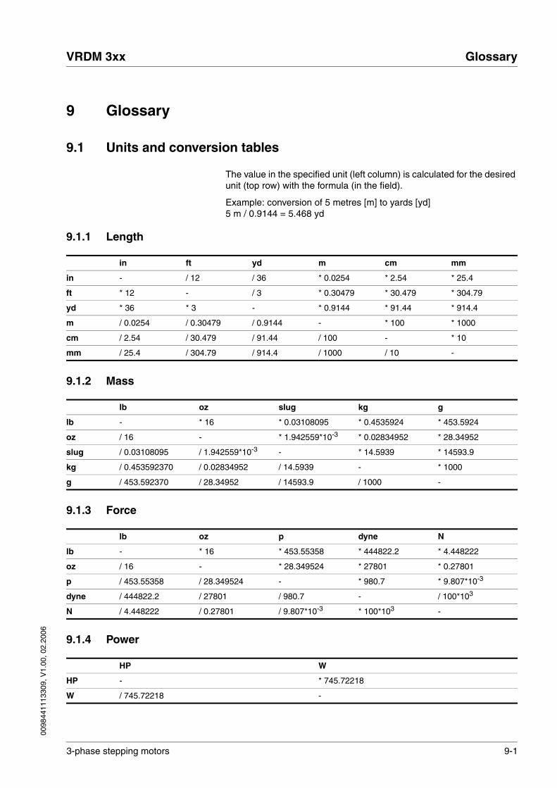
0098
4411
1330
9, V
1.00
, 02.
2006
VRDM 3xx Glossary
3-phase stepping motors 9-1
9 Glossary
9.1 Units and conversion tables
The value in the specified unit (left column) is calculated for the desired unit (top row) with the formula (in the field).
Example: conversion of 5 metres [m] to yards [yd]5 m / 0.9144 = 5.468 yd
9.1.1 Length
9.1.2 Mass
9.1.3 Force
9.1.4 Power
in ft yd m cm mm
in - / 12 / 36 * 0.0254 * 2.54 * 25.4
ft * 12 - / 3 * 0.30479 * 30.479 * 304.79
yd * 36 * 3 - * 0.9144 * 91.44 * 914.4
m / 0.0254 / 0.30479 / 0.9144 - * 100 * 1000
cm / 2.54 / 30.479 / 91.44 / 100 - * 10
mm / 25.4 / 304.79 / 914.4 / 1000 / 10 -
lb oz slug kg g
lb - * 16 * 0.03108095 * 0.4535924 * 453.5924
oz / 16 - * 1.942559*10-3 * 0.02834952 * 28.34952
slug / 0.03108095 / 1.942559*10-3 - * 14.5939 * 14593.9
kg / 0.453592370 / 0.02834952 / 14.5939 - * 1000
g / 453.592370 / 28.34952 / 14593.9 / 1000 -
lb oz p dyne N
lb - * 16 * 453.55358 * 444822.2 * 4.448222
oz / 16 - * 28.349524 * 27801 * 0.27801
p / 453.55358 / 28.349524 - * 980.7 * 9.807*10-3
dyne / 444822.2 / 27801 / 980.7 - / 100*103
N / 4.448222 / 0.27801 / 9.807*10-3 * 100*103 -
HP W
HP - * 745.72218
W / 745.72218 -

9-2 3-phase stepping motors
Glossary VRDM 3xx
0098
4411
1330
9, V
1.00
, 02.
2006
9.1.5 Rotation
9.1.6 Torque
9.1.7 Moment of inertia
9.1.8 Temperature
9.1.9 Conductor cross section
1/min (RPM) rad/s deg./s
1/min (RPM) - * π / 30 * 6
rad/s * 30 / π - * 57.295
deg./s / 6 / 57.295 -
lb·in lb·ft oz·in Nm kp·m kp·cm dyne·cm
lb·in - / 12 * 16 * 0.112985 * 0.011521 * 1.1521 * 1.129*106
lb·ft * 12 - * 192 * 1.355822 * 0.138255 * 13.8255 * 13.558*106
oz·in / 16 / 192 - * 7.0616*10-3 * 720.07*10-6 * 72.007*10-3 * 70615.5
Nm / 0.112985 / 1.355822 / 7.0616*10-3 - * 0.101972 * 10.1972 * 10*106
kp·m / 0.011521 / 0.138255 / 720.07*10-6 / 0.101972 - * 100 * 98.066*106
kp·cm / 1.1521 / 13.8255 / 72.007*10-3 / 10.1972 / 100 - * 0.9806*106
dyne·cm / 1.129*106 / 13.558*106 / 70615.5 / 10*106 / 98.066*106 / 0.9806*106 -
lb·in2 lb·ft2 kg·m2 kg·cm2 kp·cm·s2 oz·in2
lb·in2 - / 144 / 3417.16 / 0.341716 / 335.109 * 16
lb·ft2 * 144 - * 0.04214 * 421.4 * 0.429711 * 2304
kg·m2 * 3417.16 / 0.04214 - * 10*103 * 10.1972 * 54674
kg·cm2 * 0.341716 / 421.4 / 10*103 - / 980.665 * 5.46
kp·cm·s2 * 335.109 / 0.429711 / 10.1972 * 980.665 - * 5361.74
oz·in2 / 16 / 2304 / 54674 / 5.46 / 5361.74 -
°F °C K
°F - (°F - 32) * 5/9 (°F - 32) * 5/9 + 273.15
°C °C * 9/5 + 32 - °C + 273
K (K - 273.15) * 9/5 + 32 K - 273.15 -
AWG 1 2 3 4 5 6 7 8 9 10 11 12 13
mm2 42.4 33.6 26.7 21.2 16.8 13.3 10.5 8.4 6.6 5.3 4.2 3.3 2.6
AWG 14 15 16 17 18 19 20 21 22 23 24 25 26
mm2 2.1 1.7 1.3 1.0 0.82 0.65 0.52 0.41 0.33 0.26 0.20 0.16 0.13

0098
4411
1330
9, V
1.00
, 02.
2006
VRDM 3xx Glossary
3-phase stepping motors 9-3
9.2 Terms and Abbreviations
Axial forces Tension or compression forces acting longitudinally on the shaft
Centring collar centric protrusion on the motor flange to ensure precise assembly.
EMC Electromagnetic compatibility
Encoder Sensor for recording the angular position of a rotating element. The en-coder is mounted on the motor and signals the angular position of the ro-tor.
Holding brake brake that only prevents the motor from rotating without power after it has stopped (e.g. a vertikal-axis lowering). It must not be used as a ser-vice brake for braking motion.
Length length of motor without optional equipment (such as brake or gearbox)
NIEC® patented process that increases the volume in the gearbox during heat build-and thus reduces the pressure on the shaft sealing ring. For high-speed applications at high torques or high temperature cycles.
PCS® patented process for maximum precision when connecting the motor shaft to the pinion.
Protection class The protection class is a standardised specification for electrical equip-ment that describes the protection against the ingress of foreign bodies and water (for example, IP20).
PTC resistance with positive temperature coefficient. Resistance value is in-creased as the temperature rises.
Radial forces forces that act radially on the shaft
Shaft sealing ring a special sealing ring between the fixed flange and the rotating shaft; it increases the protection class of the motor flange. Regular lubrication of the shaft sealing ring is essential and the allowable maximum speed of the motor shaft must not be exceeded.
Size defined by the flange size in the type code

9-4 3-phase stepping motors
Glossary VRDM 3xx
0098
4411
1330
9, V
1.00
, 02.
2006

0098
4411
1330
9, V
1.00
, 02.
2006
VRDM 3xx Index
3-phase stepping motors 10-1
10 Index
AAbbreviations 9-3Accessories 7-1Accessories and spare parts 7-1Attaching output components 4-6
BBefore installation... 4-2
CCable data
encoder connection 4-11motor connection 4-9
care of the motor 8-2CE mark 1-5Characteristic curves
VRDM 31117 3-30VRDM 31122 3-31VRDM 364 3-12VRDM 366 3-13VRDM 368 3-14VRDM 3910 3-22VRDM 3913 3-23VRDM 397 3-21
Cleaning the motor 8-2Commissioning 5-1
preparation 5-2running 5-3
Connector installation space 4-8
DDiagnostics 6-1Dimensional drawing
PLE gearbox 3-40PLS gearbox 3-41VRDM 311x 3-28VRDM 36x 3-10VRDM 39x 3-19
Disposal 8-1
EEMC 4-3
motor and sensor cables 4-3EMC requirement
Earth band 4-3Mains and motor connection 4-3Run motor cable alone 4-3
Encoderpulse diagram 3-34technical data 3-32, 3-34temperature monitoring 3-34

10-2 3-phase stepping motors
Index VRDM 3xx
0098
4411
1330
9, V
1.00
, 02.
2006
wiring diagram 4-11Encoder connection
cable data 4-11Environmental influences 3-2
GGearbox
technical data 3-35Glossary 9-1
HHolding brake
technical data 3-32wiring diagram 4-12
IInstallation
mechanical 4-4Intended use 2-1Introduction 1-1IP degree of protection 3-3
LLife time 3-2
MMaintenance 8-1maximum press-on force 3-1Mechanical installation 4-4Motor connection
cable data 4-9Motor models 3-5Motor with braided wires
wiring diagram 4-9Motor with connector
wiring diagram 4-10Motor with terminal box
wiring diagram 4-10Motor-specific data
VRDM 311x 3-24VRDM 36x 3-6VRDM 39x 3-15
Mounting 4-5Mounting position of motor 4-5
NName plate 1-4
PPLE gearbox 3-35
dimensional drawing 3-40technical data 3-36
PLS gearbox 3-35

0098
4411
1330
9, V
1.00
, 02.
2006
VRDM 3xx Index
3-phase stepping motors 10-3
dimensional drawing 3-41technical data 3-37
press-on force 3-1Pulse diagram (encoder) 3-34
SService 8-1Service address 8-1Shaft load
VRDM 311x 3-25VRDM 36x 3-7VRDM 39x 3-16
TTechnical data 3-1
PLE gearbox 3-36PLS gearbox 3-37
technical dataencoder 3-32, 3-34gearbox 3-35holding brake 3-32
Temperature monitoring (encoder) 3-34Terms 9-3Troubleshooting 6-1Type code
VRDM 311x 3-25VRDM 36x 3-8VRDM 39x 3-16VRDM 3x overview 1-3
UUnits and conversion tables 9-1
WWiring diagram
encoder 4-11holding brake 4-12motor with braided wires 4-9motor with connector 4-10motor with terminal box 4-10

10-4 3-phase stepping motors
Index VRDM 3xx
0098
4411
1330
9, V
1.00
, 02.
2006