Technical Information Product and Systems · PDF fileDouble-V Expansion Joint For use with...
5
Preventing Cracks in Veneer and Conventional Plaster System Advances in construction technology have produced improved building materials, labor-saving techniques, construction efficiencies and commensurate economies. While lightweight materials and new construction methods, such as flat plate concrete design, enable buildings to be constructed faster and taller than ever before, they also present new problems. Perhaps the most elusive of these is partition cracking. Causes of Cracking Cracking occurs in plaster surfaces when the forces exerted on them exceed the tensile, compressive or shear strength of the material. Those forces can come from a variety of sources, such as: • Shrinkage during drying • Humidity expansion or contraction • Thermal expansion or contraction • Changes in pressure • Impacts to partitions • Structural movement of supporting elements produced by: (a) foundation settlement (b) seismic force (c) wind loads (d) volume changes in supporting materials (e) gravitational loads; dead and live Crack Control Mechanisms United States Gypsum Company has studied the various forces that cause cracking and has developed materials and techniques to control the effect of those forces on gypsum partitions and ceilings. Control mechanisms fall into two categories: control joints and perimeter relief. The mechanism selected depends upon how the force affects the partition or ceiling assembly. If the force affects the plane of the partition or ceiling membrane, a control joint is required. If the force affects the structure supporting or abutting the partition or ceiling assembly, perimeter relief is required. Stresses Affecting the Plane Basically, there are two kinds of factors that affect the plane of a partition or ceiling assembly. The first and most common is expansion and contraction of the surfacing materials due to variations in temperature or humidity. This includes shrinkage after installation as the assembly dries and stretching or contracting due to variations in weather. The second factor affecting the plane is applied stresses on the assembly from wind loading on building exteriors, slamming doors, pressure changes or sudden blows on interior partitions, and deflection of ceilings due to loads on the floor above. To control the effects of each of these factors, the use of control joints is recommended. The control joints are placed in the face of the partition or membrane. Common Conditions for Control Joints There are four principal conditions under which control joints are required: 1. Where partitions or ceilings of dissimilar construction meet and remain in the same plane, e.g., junction of a masonry wall and a veneer plaster partition (see fig. 1). 2. Where wings of “L”, “U” and “T” shaped ceilings are joined, control joint to run with structural members (see fig. 2). 3. Where expansion or control joints occur in the base wall construction and/or building structure (see fig. 3). Product and Systems Technology Fig. 1 control joint at junction of veneer plaster partition and masonry wall. IMPERIAL gypsum base Fig. 2 control joint in "L" shaped ceiling. reflected ceiling plan Fig. 3 control joint over structural expansion joint. PM17 Technical Information
Transcript of Technical Information Product and Systems · PDF fileDouble-V Expansion Joint For use with...

Preventing Cracks in Veneer and Conventional Plaster System
Advancesinconstructiontechnologyhaveproducedimprovedbuildingmaterials,labor-savingtechniques, constructionefficienciesandcommensurateeconomies.Whilelightweightmaterialsandnewconstruction methods,suchasflatplateconcretedesign,enablebuildingstobeconstructedfasterandtallerthanever before,theyalsopresentnewproblems.Perhapsthemostelusiveoftheseispartitioncracking.
Causes of Cracking Crackingoccursinplastersurfaceswhentheforcesexertedonthemexceedthetensile,compressiveorshear strengthofthematerial.Thoseforcescancomefromavarietyofsources,suchas:
• Shrinkageduringdrying • Humidityexpansionorcontraction • Thermalexpansionorcontraction • Changesinpressure • Impactstopartitions • Structuralmovementofsupportingelementsproducedby: (a) foundationsettlement (b) seismicforce (c) windloads (d) volumechangesinsupportingmaterials (e) gravitationalloads;deadandlive
Crack Control Mechanisms UnitedStatesGypsumCompanyhasstudiedthevariousforcesthatcausecrackingandhasdevelopedmaterials andtechniquestocontroltheeffectofthoseforcesongypsumpartitionsandceilings.
Controlmechanismsfallintotwocategories:controljointsandperimeterrelief.Themechanismselected dependsuponhowtheforceaffectsthepartitionorceilingassembly.Iftheforceaffectstheplaneofthe partitionorceilingmembrane,acontroljointisrequired.Iftheforceaffectsthestructuresupportingorabutting thepartitionorceilingassembly,perimeterreliefisrequired.
Stresses Affecting the Plane Basically,therearetwokindsoffactorsthataffecttheplaneofapartitionorceilingassembly.Thefirstand mostcommonisexpansionandcontractionofthesurfacingmaterialsduetovariationsintemperatureor humidity.Thisincludesshrinkageafterinstallationastheassemblydriesandstretchingorcontractingdueto variationsinweather.
Thesecondfactoraffectingtheplaneisappliedstressesontheassemblyfromwindloadingonbuilding exteriors,slammingdoors,pressurechangesorsuddenblowsoninteriorpartitions,anddeflectionofceilings duetoloadsonthefloorabove.
Tocontroltheeffectsofeachofthesefactors,theuseofcontroljointsisrecommended.Thecontroljointsare placedinthefaceofthepartitionormembrane.
Common Conditions for Control Joints Therearefourprincipalconditionsunderwhichcontroljointsarerequired:
1.Wherepartitionsorceilingsofdissimilarconstructionmeetandremaininthesameplane,e.g.,junctionofa masonrywallandaveneerplasterpartition(seefig.1). 2.Wherewingsof“L”,“U”and“T”shapedceilingsarejoined,controljointtorunwithstructuralmembers (seefig.2).
3.Whereexpansionorcontroljointsoccurinthebasewallconstructionand/orbuildingstructure(seefig.3).
Product and Systems Technology
Fig. 1control joint at junction of veneer
plaster partition and masonry wall.
IMPERIAL gypsum base
Fig. 2control joint in "L" shaped ceiling.
reflectedceiling plan
Fig. 3control joint over structural expansion joint.
PM17
TechnicalInformation

4.Wherepartitionsorceilingsspanlongdistances,controljointsmustbeplacedatappropriateintervals:
• Partitions—30ft.maximum
• Interiorceilings(withperimeterrelief)—50ft.maximumineitherdirection
• Interiorceilings(withoutperimeterrelief)—30ft.maximumineitherdirection
• Exteriorwall/ceilingwithportlandcementplaster—10ft.maximumineitherdirection
Placement of Control Joints Controljointsareusedtorelieveexpansion,contractionorflexuralstressesacrosslargeceilingandwall expanses.Effectivecontroljointpositionsareasfollows:
• Fromdoorheader(cornersofdoorframes)toceiling
• Fromfloortoceilinginlongpartitionsandwallfurringruns(full-heightdooropeningsprovideexpansion controlinlargepartitions)
• Fromwalltowallinlargeceilingareas
Types of Control Joints USGhasdevelopedseveraltypesofcontroljointsforuseinveneerplaster,conventionalplasterandexteriorstucco construction.Thetypesofcontroljointandtheirrecommendedusesareidentifiedbelow.
Sheetrock® Zinc Control Joint No. 093 Forinteriorusewithveneerplasterfinish(seefig.4,5).Mayalsobe usedforexteriorsoffitapplications.
Theno.093controljointisconstructedwith3/32"groundstoaccommodateboth1-and2-coatveneeron ImperIal®veneerbasecoat.
Separationbetweenpanelsmustbe1/4"min.,1/2"max.Flangeisdesignedforstapleattachmenttopanel surface.Requiresplastering.Plastictapethatprotects1/4"groovemustberemovedwhenplasteringiscompleted.
Sheetrock® Control Joint No. 50, 75, 100 Forinteriorusewithconventionalplasterassemblies (seefig.6,7).Mayalsobeusedwithexteriorstucco.
Controljointsizesreflectvariousgrounds:no.50,1/2";no.75,3/4";no.100,1"(forexteriorstucco). Flangesareperforatedforwireattachmenttometallathortemporarystapleattachmenttogypsumlath.Inall casesflangesofthecontroljointmustbepositivelyattachedtoframingmembers.Controljointno.100may alsobeback-mountedbehindImperIal®gypsumbaseforusewithradiantheatceiling.
Separationbetweenpanelsmustbe1/4"min.,1/2"max.Plastictapethatprotects1/4"groovemustbe removedwhenplasteringiscompleted.
Fig. 5control joints in face of plaster partition accommodate
lateral expansion or contraction up to 1/4".
steel studSHEETROCK sealant
SHEETROCK control joint no. 093
SHEETROCK control joint no. 093
IMPERIAL gypsum base
IMPERIAL or DIAMONDveneer plaster
IMPERIAL gypsum base
ROCKLATHgypsum base
gypsum plaster
SHEETROCK control joint no. 50
SHEETROCK sealant
Fig. 7SHEETROCK control joint no. 50 in metal-stud and plaster partition.
Fig. 4control joint no.093.
1/4" 3/4"
1/2", 3/4", 1"
Fig. 6SHEETROCK control joint.

Double-V Expansion Joint Forusewithconventionalplasterassembliesorexteriorstucco(seefig.8). Availableingalvanizedsteelorzincwith1/2"or3/4"grounds.Flangesareexpandedmetalforpositivekeying ofplaster.Separationbetweenpanelsmustbe1/4"to1/2".
Casing Bead #66 Forusewithconventionalplasterassemblies(seefig.9).Availablewithgalvanizedshortflange andgalvanizedorzincexpandedflange.Provides3/8",1/2",5/8",3/4",7/8",1"and1-1/4"grounds
Verticalcontroljointsareconstructedbyintentionallyseparatingbeads1/4".Jointopeningshouldbesealed withSheetrock®acousticalsealant(seefig.10).
Casingbeadsplacedafewinchesabovefloor,separatingwallmembranefromalternatematerialbackingbase boards,alsoprovideprotectionfromfloordeflection(seefig.11).
Control Joint Installation Guidelines 1.Applicationofcontroljointrequiresbreakinpanelsurfaceofapproximately1/2".
2.Floorandceilingframingshouldbeinterruptedwitha1/2"gapatcontroljointsinthestructure.
3.Separatesupportsmustbeprovidedforeachcontroljointflange.
4.Adequatesealorsafinginsulationmustbeprovidedbehindcontroljointwhereversoundand/orfireratings areprimeconsiderations.
5.Whereverticalandhorizontalcontroljointsintersect,verticaljointmustbecontinuousandhorizontaljoints abutit.Applysealantatallsplices,intersectionsandterminals.
Fire-Rated Control Joints Fireandsoundcontrolprotectionmustbeprovidedbehindcontroljointstomaintainfirerating.Protectivebarrier maybelayersof5/8"ImperIalgyspumbase,FIrecode®core,or3"ThermafiberSAFBInsulation(seefig.12).
Fire-rated Control Joints (Warnock Hersey International-495-PSV-0824, 0824A)
1/2" or 3/4"
43/8"
Fig. 8double-V expansion joint.
1/4"
1/2", 5/8", 3/4"
31/8"
1/4"
1/4", 3/8", 1/2", 3/4", 7/8"
31/8"
Fig. 9no. 66 square edge
casing beads (expanded or short flange).
ROCKLATHgypsum base
gypsum plaster
casing bead control joint
SHEETROCK sealant
Fig. 10casing bead control joint in metal-stud and plaster partition. Fig. 11
1/2" max. control joint (both sides)
Two-hour rated steel stud partitions
5/8"
17/8" 31/8"
2 layers IMPERIAL gypsum base
47STC SA-860302
2 layers IMPERIAL gypsum base
1/2" max. control joint (both sides)
5/8"
17/8" 31/8"
IMPERIAL gypsum base
One-hour rated steel stud partition
2 layers IMPERIAL gypsum base
Fig. 12
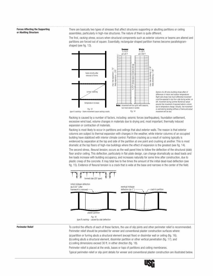
Forces Affecting the Supporting Therearebasicallytwotypesofstressesthataffectstructuressupportingorabuttingpartitionsorceilingor Abutting Structure assemblies,particularlyinhigh-risestructures.Thenatureofthemisquitedifferent.
Thefirst,racking stress,occurswhenstructuralcomponentssuchasexteriorcolumnsorbeamsarealteredand partitionsareforcedoutofsquare.Essentially,rectangular-shapedpartitionframesbecomeparallelogram- shaped(seefig.13).
Rackingiscausedbyanumberoffactors,including:seismicforces(earthquakes),foundationsettlement, excessivewindload,volumechangesinmaterialsduetodryingand,mostimportant,thermallyinduced expansionorcontractionofmaterials.
Rackingismostlikelytooccurinpartitionsandceilingsthatabutexteriorwalls.Thereasonisthatexterior columnsaresubjecttothermalexpansionwithchangesintheweather,whileinteriorcolumnsofanoccupied buildinghavestabilizedwithinteriorclimatecontrol.Partitioncrackingasaresultofrackingtypicallyis evidencedbyseparationatthetopandsideofthepartitionatonepointandcrushingatanother.Thisismost dramaticatthetopfloorsofhigh-risebuildingswheretheeffectofexpansionisthegreatest(seefig.14).
Thesecondstress,flexural tension,occursasthewallpaneltriestofollowthedeflectionofthestructural(slab) floorand/orceiling.Thisdeflection,particularlyinflat-platedesign,canchangedramaticallyasdeadloadsand liveloadsincreasewithbuildingoccupancy,andincreasesnaturallyforsometimeafterconstruction,dueto plasticcreepoftheconcrete.Itmaytotaltwotofivetimestheamountoftheinitialdead-loaddeflection(see fig.15).Evidenceofflexuraltensionisacrackthatiswideatthebaseandnarrowsinthecenterofthefield.
Perimeter Relief Tocontroltheeffectsofeachofthesefactors,theuseofslipjointsandotherperimeterreliefisrecommended. Perimeterreliefshouldbeprovidedforveneerandconventionalplasterconstructionsurfaceswhere:
(a)partitionorfurringabutsastructuralelement(exceptfloor)ordissimilarwallorceiling(fig.16); (b)ceilingabutsastructuralelement,dissimilarpartitionorotherverticalpenetration(fig.17);and (c)ceilingdimensionsexceed30ft.ineitherdirection(fig.18).
Perimeterreliefisplacedattheends,basesortopsofpartitionsandceilingmembranes.
Typicalperimeter-relieforslip-jointdetailsforveneerandconventionalplasterconstructionareillustratedbelow.
Fig. 13type A cracking – frame movement cause racking cracks.
frame shortly afterremoval of forms
temperature increase
corner cracking
WinterSummer T=110˚F∆T=35˚F
T=-25˚F∆T=100˚F
T=75
˚F (t
empe
ratu
re in
side b
uild
ing)
max
. fre
e exp
ansio
n =
.75"
likely
expa
nsio
n =
.375
"
max
. fre
e sho
rteni
ng =
2.1
6"lik
ely sh
orten
ing
= 1.
00"
Note: movement will be cyclic with seasons, but most severe in winter.
Fig. 14
Section of a 30-story building shows effect of differences in indoor and outdoor temperatures. Right side shows how much differential movement could be expected in top floor-slab during winter; on left, movement during summer.Numerical values assume free movement of exposed exterior column due to temperature change. Actually, free movement is restricted by bending stiffness of frame and actual movement will be less.
Fig. 15type B cracking – caused by slab deflection
formed slab (20' span)
initial midspan deflection(∆=0.33" ) after framework is removed
eventual midspan deflection (∆=1" ) crack in partition
plaster partition

TrademarksThe following trademarks used herein are owned by United States Gypsum Company: Firecode, imperial, Sheetrock, USG, USG in stylized letters. Unimast is a trademark of Worthington Industries.
NoteProducts described here may not be available in all geographic markets. Consult your U.S. Gypsum Company sales office or representative for information.
NoticeWe shall not be liable for incidental and consequential damages, directly or indirectly sustained, nor for any loss caused by application of these goods not in accordance with current printed instructions or for other than the intended use. Our liability is expressly limited to replacement of defective goods. Any claim shall be deemed waived unless made in writing to us within thirty (30) days from date it was or reasonably should have been discovered.
Safety First! Follow good safety and industrial hygiene practices during handling and installing products and systems. Take necessary precautions and wear the appropriate personal protective equipment as needed. Read material safety data sheets and related literature on products before specification and/or installation.
Manufactured byUnited States Gypsum Company550 West Adams StreetChicago, IL 60661
800 USG.4YOU (874-4968)usg.com
PM17/rev.10-10 © 2010, United States Gypsum Company. Printed in U.S.A.
Theprincipleofleavingtherunnertrackfreeofpermanentattachmenttothepartitionatceilings(fig.19)and havingthestudattachedtothestructuralwallorcolumnbutnotpermanentlyattachedtothepartition(fig.20) canbeappliedtoveneerplasterassembliesaswelltorelievethestresspointatpartitionintersectionswith structuralceilingsandwallsorcolumns.
Whereasuspendedorfurredveneerorplasterceilingmeetsanexteriororstructuralwallwhichissubject tomovement,thesupportsfortheceilingassemblyshouldbelocatedwithin6in.oftheabuttingsurfaces, butneitherthemainrunnernorfurringchannelsshouldbeallowedtocomeintocontactwiththewall(fig.21). Alsothejunctionoftheceilingmembranewiththewallfacingshouldallowforsomemovementwithouta build-upofstress.
Wherefurringonanexteriorstructuralwallmeetsanotherexteriorstructuralwall,aminimum1/4"clearance shouldbeleftbetweentheacousticaltrimandtheintersectingwallorcolumn.
Wherepartitionsareconstructedacrossthejunctionoftwofloorslabswithexpansionjointsbetween,partition panelbaseattachmentmustbemadetoonlyoneoftheslabs,allowingtheotherpartitionfacingtofloatfree (fig.22).
Fig. 16 perimeter relief at junction of partition and structural wall.
relief
structure
Fig. 17 perimeter relief of ceiling at structural column penetration.
relief
ceiling
structuralcolumn
Fig. 18 perimeter relief of large ceiling surface.
relief control joint
more than 30'(less than 50' )
IMPERIAL gypsum base
Fig. 19perimeter relief of partition at structural ceiling.
runner
type S screw
metal trim
steel stud
SHEETROCK sealant
11/2" min.
IMPERIAL gypsum base
Fig. 20perimeter relief of partition at structural wall or column.
metal trim
type S screw SHEETROCK sealant
column or structural wall
Fig. 21perimeter relief of suspended ceiling at exterior wall.
IMPERIAL gypsum base
metal trim
flexible dust membrane
metal furring channels
Fig. 22construction of partition across
junction of two floor slabs
attached angle
free floating angle
expansion joint