Technical Features - ARGO-HYTOS€¦ · Subect to change GP3L80161en11/2015 Page 1.argo-hytos.com...
4
Subject to change · GP3L_8016_1en_11/2015 Page 1 www.argo-hytos.com Gear Pump – Lightline Version Technical Features Nominal Size Parameters Symbol Unit Displacement [cm 3 ] 20 22 26 33 39 46 50 52 55 63 71 Actual displacement V g [in 3 ] 1.22 1.34 1.59 2.01 2.38 2.81 3.05 3.17 3.36 3.84 4.33 Rotation speed nominal n n [min -1 ] 1500 minimum n min [min -1 ] 600 500 400 maximum n max [min -1 ] 3500 3000 2800 2500 Pressure at inlet* minimum p 1min [bar] -0,3 (-4.4 PSI) maximum p 1max [bar] 0,5 (7.3 PSI) Pressure at outlet** max. continuous p 2n [bar] 250 230 220 200 180 [PSI] 3626 3336 3191 2901 2611 maximum p 2max [bar] 265 250 240 230 200 [PSI] 3844 3626 3481 3336 2901 peak p 3 [bar] 280 270 260 250 220 [PSI] 4061 3916 3771 3626 3191 Weight m [kg] [lbs] Technical Data 1) *Inlet pressure in the reversible design can be up to p 1 = p 2n -70 bar max. External drainage must be used in case of the reversible design. 2) **Outlet pressure in the reversible design is 10% lower than shown in the table (depending on operating conditions). 3) p 2n maximum continuous pressure - maximum working pressure, at which the pump can be operated without time limitation. 4) p 2max maximum pressure - maximum pressure permissible for a short time, max. 20 s. 5) p 3 peak pressure - short-time pressure (fractions of a second) arising in case of a sudden change of the operating mode; any excess of this pressure during operation is impermissible. Gear Pump / Size GF3 - 20 ...71 ccm Volumetric efficiency % 89 ÷ 96 Mechanical efficiency % 85 Fluid temperature range (NBR) °C (°F) -20...80 (-4...176) Fluid temperature range (FPM) °C (°F) -20...120 (-4...248) Viscosity range mm 2 /s (SUS) 20 ...80 (97 ...390), 1200 (5849) for cold start Hydraulic fluid Hydraulic oils of power classes (HL, HLP) to DIN 51524 Max. degree of fluid contamination for p 2 ≤ 200 bar Class 21/18/15 acc. to ISO 4406 Max. degree of fluid contamination for p 2 ≥ 200 bar Class 20/17/14 acc. to ISO 4406 › Operating pressure 250 bar, Peak pressure 280 bar › Cost effective design for circuits with a lower operating pressure › High quality aluminum alloys pump with axial play compensation › Service life for 1800 operation hours › Volumetric efficiency up to 96% › International standard flanges acc.to SAE, ISO, DIN, GOST GP3L Displacement up to 71 cm 3 (4.30 inch 3 ) • p max 280 bar (4060 PSI) • Speed from 400 to 3500 RPM Symbol R, L B
Transcript of Technical Features - ARGO-HYTOS€¦ · Subect to change GP3L80161en11/2015 Page 1.argo-hytos.com...

Subject to change · GP3L_8016_1en_11/2015
Page 1 www.argo-hytos.com
Gear Pump – Lightline Version
Technical Features
Nominal Size Parameters SymbolUnit Displacement
[cm3] 20 22 26 33 39 46 50 52 55 63 71
Actual displacement Vg [in3] 1.22 1.34 1.59 2.01 2.38 2.81 3.05 3.17 3.36 3.84 4.33
Rotation speed
nominal nn [min-1] 1500
minimum nmin [min-1] 600 500 400
maximum nmax [min-1] 3500 3000 2800 2500
Pressure at inlet*
minimum p1min [bar] -0,3 (-4.4 PSI)
maximum p1max [bar] 0,5 (7.3 PSI)
Pressure at outlet**
max. continuous p2n
[bar] 250 230 220 200 180
[PSI] 3626 3336 3191 2901 2611
maximum p2max
[bar] 265 250 240 230 200
[PSI] 3844 3626 3481 3336 2901
peak p3
[bar] 280 270 260 250 220
[PSI] 4061 3916 3771 3626 3191
Weight m[kg]
[lbs]
Technical Data
1) *Inlet pressure in the reversible design can be up to p1 = p2n-70 bar max. External drainage must be used in case of the reversible design.2) **Outlet pressure in the reversible design is 10% lower than shown in the table (depending on operating conditions).3) p2n maximum continuous pressure - maximum working pressure, at which the pump can be operated without time limitation.4) p2max maximum pressure - maximum pressure permissible for a short time, max. 20 s.5) p3 peak pressure - short-time pressure (fractions of a second) arising in case of a sudden change of the operating mode; any excess of this pressure during operation is impermissible.
Gear Pump / Size GF3 - 20 ...71 ccm
Volumetric efficiency % 89 ÷ 96
Mechanical efficiency % 85
Fluid temperature range (NBR) °C (°F) -20...80 (-4...176)
Fluid temperature range (FPM) °C (°F) -20...120 (-4...248)
Viscosity range mm2/s (SUS) 20 ...80 (97 ...390), 1200 (5849) for cold start
Hydraulic fluid Hydraulic oils of power classes (HL, HLP) to DIN 51524
Max. degree of fluid contamination for p2 ≤ 200 bar Class 21/18/15 acc. to ISO 4406
Max. degree of fluid contamination for p2 ≥ 200 bar Class 20/17/14 acc. to ISO 4406
› Operating pressure 250 bar, Peak pressure 280 bar › Cost effective design for circuits with a lower operating pressure › High quality aluminum alloys pump with axial play compensation › Service life for 1800 operation hours › Volumetric efficiency up to 96% › International standard flanges acc.to SAE, ISO, DIN, GOST
GP3L Displacement up to 71 cm3 (4.30 inch3) • pmax 280 bar (4060 PSI) • Speed from 400 to 3500 RPM
Symbol R, L B

Subject to change · GP3L_8016_1en_11/2015
Page 2www.argo-hytos.com
Direction of rotation, reversible design
Ordering Code
Determine direction of rotation by looking at the drive shaft.The pump can be used only in the specified direction of rotation.
The pumps B codes (Bi-directional) have an external drainagewith an orifice located in the cover or the flange.
CLOCKWISE “R“ COUNTER-CLOCKWISE “L“ REVERSIBLE “B“
INLET OUTLET INLET
INLET
OUTLET
OUTLET
INLET
G3/8
465052556371
- --
LRB
RLRNSC
SRC
MIMJMLMMMPGCGDGEGFUDUEUHUIUJ
HIHJHKHLABACADAE
KCKDKEKFSISJSKSL
Gear pump serie 3
Displacement
Ports orientation
Direction of rotation Counter clockwiseClockwiseBi-directional
Flange design
Shaft Type
SealsN NBRV FPM (Viton)
H HNBR
Inlet / Outlet ports
Combination of Flanges and Shafts
Flange Design RL RN SC
Shaft Type
CL
CM
DN
DP
VO
VP
-
2022263339
S R C
Port orientation
GP3 L
Lightline
CLCMDNDPVOVP
No designation004
Shaft sealstandard
without shaft seal
Subject to change · GP3L_8016_1en_11/2015
Page 3 www.argo-hytos.com
118,5 (4.67)98,5 (3.88)
4x
11(0
.43)
21,8
(0.8
6)
5 (0.20)
50,8
(2.0
) f8
25 (0.98)
21,8
(0.8
6)
148
(5.8
3)12
8 (5
.04)
42,2
(1.6
6)
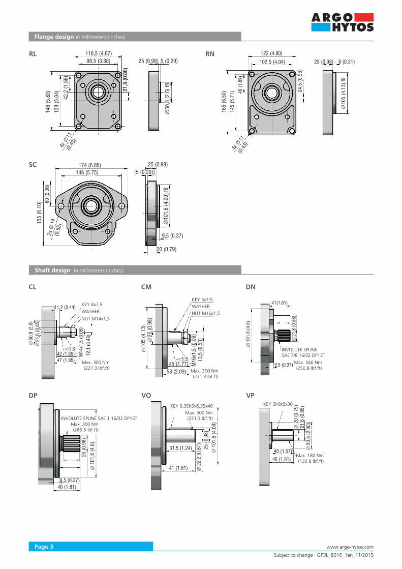
RL
Flange design in millimeters (inches)
174 (6.85)146 (5.75)
2x14
(0.5
5)
10(4
.) f
81,
600
25 (0.98)
155
(6.1
0) 60 (2
.36)
[5 20 ](0. )
9 3,5 (0. 7)
2 (0. )0 79
SC
122 (4.80)
102,5 (4.04)
24,5
(0.9
6)
4x
11(0.
43)
105
(4.1
3) f8
25 (0.98)
165
(6.5
0)14
5 (5
.71) 48
(1.8
9)
8 (0.31)RN
Shaft design in millimeters (inches)
11,2 (0.44)
50,8
(2.0
)21
,6 (0
.85)
42 (1.65)47 (1.85)
1:8
M14
x1,5
(0.0
6)12
,1 (0
.48)
105
(4.1
3)
1:5 13,5
(0.5
3)
25 (0
.98)
45 (1.77)53 (2.09)
M16
x1,5
(0.0
6)
41(1.61)
101,
6 (4
.0)
21,8
(0.8
6)
9,5 (0.37)
CL CM DN
Max. 300 Nm (221.3 lbf.ft)
INVOLUTE SPLINESAE 7/8 16/32 DP13T
9,5 (0.37)
101,
6 (4
.0)
46 (1.81)
25 (0
.98)
DP
WASHER
KEY 4x7,5
NUT M14x1,5
KEY 5x7,5WASHERNUT M16x1,5
INVOLUTE SPLINE SAE 1 16/32 DP15T
Max. 300 Nm (221.3 lbf.ft)
Max. 340 Nm (250.8 lbf.ft)
Max. 360 Nm (265.5 lbf.ft)
101,
6 (4
.00)
31,5 (1.24)
22,2
(0.8
7)
41 (1.61)
25 (0
.98)
20 (0
.79)
46 (1.81)
21,6
(0.8
5)50
,8 (2
.00)
40 (1.57)
VO VP
Max. 300 Nm (221.3 lbf.ft)
KEY 6,35h9x6,35x40 KEY 5h9x5x36
Max. 180 Nm (132.8 lbf.ft)

Subject to change · GP3L_8016_1en_11/2015
Page 4www.argo-hytos.com
Ports design in millimeters (inches)
GPP Pumps - basic design in millimeters (inches)
Q
AB
25 (0.98)
47 (1.85)
25 (0.98) 5 (0.20)
21,8
(0.8
6)
50,8
(2.0
)
146
(5.7
5)
GP3L-*R-RLCL-SG*G*-N
Displacement[cm3(in3)/rev] A B Displacement
[cm3(in3)/rev] A B
20 (1.22) 63 (2.48) 128 (5.04) 50 (3.05) 77 (3.03) 156 (6.14)
22 (1.34) 64 (2.52) 130 (5.12) 52 (3.17) 78 (3.07) 158 (6.22)
26 (1.59) 65 (2.56) 133(5.24) 55 (3.36) 79 (3.11) 160 (6.30)
33 (2.01) 68 (2.68) 139 (5.47) 63 (3.84) 83 (3.27) 168 (6.61)
39 (2.38) 72 (2.83) 146 (5.75) 71 (4.33) 86 (3.39) 175 (6.89)
46 (2.81) 75 (2.95) 152 (5.98)
BSPP pipe thread according to 228-1
UNF thread according to SAE
Flanged fittings according to DIN 8901/8902
Displacement[cm3(in3)]
Inlet Code
Dimension Outlet Code
Dimension
A B C D A B C D
20 - 22 (1.22 - 1.34)including GD G 3/4 16 (0.63) 39 (1.54)
1 (0.04)
GD G 3/4 16 (0.63) 39 (1.54)
1 (0.04)
26 - 39 (1.59 - 2.38)including GE G 1
18 (0.71)45 (1.77)
46 - 63 (2.81 - 3.84)including GF G 1 1/4 57 (2.24) GE G 1 18 (0.71) 45 (1.77)
71 (4.33) GH G 1 1/2 24 (1.46) 60 (3.66) GF G 1 1/4
Displacement[cm3(in3)]
Inlet Code
Dimension Outlet Code
Dimension
A B C D A B C D
20 - 33 (1.22 - 2.01)including UH 1-5/16-12UNF
23 (0.91)
49(1.93) 1
(0.04)
UE 1-1/16-12UNF 19(0.75)
41(1.61) 1
(0.04)39 - 52 (2.38 - 3.17)including UI 1-5/8-12UNF 2B
55 - 71 (3.36 - 4.33)including UJ 1-7/8-12UNF UH 1-5/16-12UNF
Displacement[cm3(in3)]
Inlet Code
Dimension Outlet Code
Dimension
E F G H E F G H
ALL HK 25 (0.98) M8 16 (0.63) 55 (2.17) HJ 18 (0.71) M8 55 (2.17)
Flanged fittings according to SAE, UNC thread
Displacement[cm3(in3)]
Inlet Code
Dimension Outlet Code
Dimension
E F G H I E F G H I
20 - 52(1.22 - 3.17)including
AC 25,4 (1.00) 3/8-16-UNC
22(0.87)
52,4 (2.06)
26,2 (1.03) AB 19
(0.75)
3/8-16-UNC 22 (0.87)
47,6 (1.87)
22,2 (0.87)
55 - 71(3.36 - 4.33)including
AD 30,5 (1.20) 7/16-14-UNC 58,7
(2.31)30,2 (1.19) AC 25,4
(1.00)52,4 (2.06)
26,2 (1.03)

![Gear Pump Content - argo-hytos.com€¦ · Gear Pump – Lightline Version Technical Features Nominal Size Parameters Symbol Unit Displacement [cm3] 0,19 0,26 0,38 0,50 0,65 0,75](https://static.fdocuments.us/doc/165x107/60090533cb17293a5f0866c8/gear-pump-content-argo-hytoscom-gear-pump-a-lightline-version-technical-features.jpg)