
TECHNICAL DATA STANDARD CYLINDERS + ¤ ^ … · B68138 211 330 553 845 1319 2242 3629 5890 9047...
25
2 TECHNICAL DATA STANDARD CYLINDERS COMPRESSED AIR CONSUMPTION THE METHOD OF CALCULATION (Compressed Air Consumption) Qn=(Aa+Ab)x L x P + 0.101 0.101 x n x 10 -6 Qn : Compressed air consumption (l/min) Aa : piston area of A (mm 2 ) Ab : piston area of B (mm 2 ) L : Stroke of cylinder (mm) P : Air pressure (MPa) n : Cycle of operation (cycle/min) m 3 /s l/s cm 3 /s m 3 /h m 3 /min l/h l/min ft 3 /min gallon gallon (scfm) min UK min USA m 3 /s 1 10 -3 10 6 3.6x10 6 60 3.6x10 6 60x10 3 2.12x10 3 13.2x10 3 15.85x10 3 l/s 10 -3 1 10 3 3.6 60x10 -3 3.6x10 3 60 2.12 13.2 15.85 cm 3 /s 10 -6 10 -3 1 3.6x10 -3 60x10 -6 3.6 60x10 -3 2.12x10 -3 13.2x10 -3 15.85x10 -3 m 3 /h 0.28x10 -3 0.28 0.28x10 3 1 16.67x10 -3 10 3 16.67 0.59 3.67 4.4 m 3 /min 16.67x10 -3 16.67 16.67x10 3 60 1 60x10 3 10 3 35.31 219.97 264.17 l/h 0.28x10 -6 0.28x10 -3 0.28 10 -3 16.67x10 -6 1 16.67x10 -3 0.35x10 -3 3.67x10 -3 4.4x10 -3 l/min 16.67x10 -6 16.67x10 -3 16.67 60x10 -3 10 -3 60 1 35.31x10 -3 219.97x10 -3 264x10 -3 ft 3 /min(scfm) 0.47x10 -3 0.47 0.47x10 3 1.699 28.32x10 -3 1.699x10 3 28.32 1 6.23 7.48 gallon min UK 75.79x10 -6 75.77x10 -3 75.77 0.273 4.55x10 -3 0.273x10 3 4.55 0.16 1 1.2 gallon min USA 63.09x10 -6 63.09x10 -3 63.09 0.227 3.79x10 -3 0.227x10 3 3.79 0.13 0.83 1 FLOW RATE CONVERSION CHART • The table is for a complete cycle with 100mm stroke in one minute. • 100 mm Unit : l / min A B Bore(mm) 12 16 20 25 32 40 50 63 80 100 125 150 200 Rod(mm) 6 6 8 10 12 16 20 20 25 25 35 40 50 Area(mm 2 ) A 113 201 314 491 804 1257 1963 3117 5027 7854 12271 17671 31416 B 85 173 264 412 691 1056 1649 2803 4536 7363 11309 16415 29452 0.1 0.040 0.075 0.116 0.181 0.299 0.462 0.722 1.183 1.912 3.042 4.714 6.814 12.168 0.2 0.059 0.112 0.173 0.271 0.448 0.693 1.083 1.775 2.867 4.563 7.071 10.221 18.252 0.3 0.079 0.150 0.231 0.361 0.598 0.924 1.444 2.367 3.823 6.084 9.428 13.628 24.336 0.4 0.099 0.187 0.289 0.451 0.747 1.156 1.805 2.959 4.779 7.605 11.785 17.035 30.420 0.5 0.119 0.224 0.347 0.542 0.897 1.387 2.167 3.550 5.734 9.126 14.142 20.441 36.502 0.6 0.138 0.262 0.405 0.632 1.046 1.618 2.528 4.142 6.690 10.647 16.499 23.848 42.586 0.7 0.158 0.299 0.463 0.722 1.196 1.849 2.889 4.734 7.646 12.168 18.856 27.255 48.670 0.8 0.178 0.336 0.520 0.812 1.345 2.080 3.250 5.325 8.602 13.689 21.213 30.662 54.754 0.9 0.198 0.374 0.578 0.903 1.495 2.311 3.611 5.917 9.557 15.209 23.570 34.069 60.838 1.0 0.218 0.411 0.636 0.993 1.644 2.542 3.972 6.509 10.513 16.927 25.927 37.476 66.922 Operating Pressure(MPa) TECHNICAL DATA STANDARD CYLINDERS CYLINDERS THEORETIC FORCE 1 F = P x A - f F : (N) P : (MPa) A : (mm 2 ) f : (N) F : Cylinders' force (N) P : Air pressure (MPa) A : Piston area (mm 2 ) f : Friction drag (N) THE METHOD OF CALCULATION (Cylinders' Force) Unit : N Pa kPa MPa bar mbar kgf/cm 2 cmH 2 O mmH 2 O mmHg p.s.i Pa 1 10 -3 10 -6 10 -5 10 -2 10.2x10 -6 10.2x10 -3 101.97x10 -3 7.5x10 -3 0.15x10 kPa 10 3 1 10 -3 10 -2 10 10.2x10 -3 10.2 101.97 7.5 0.15 MPa 10 6 10 3 1 10 10 4 10.2 10.2x10 3 101.97x10 3 7.5x10 3 0.15x10 bar 10 5 10 2 10 -1 1 10 3 1.02 1.02x10 3 10.2x10 3 750.06 14.5 mbar 10 2 10 -1 10 -4 10 -3 1 1.02x10 -3 1.02 10.2 0.75 14.5x10 kgf/cm 2 98066.5 98.07 98.07x10 -3 0.98 980.67 1 1000 10000 735.56 14.22 cmH 2 O 98.0665 98.07x10 -3 98.07x10 -6 0.98x10 -3 0.98 10 -3 1 10 0.74 14.22x10 mmH 2 O 9.80665 9.807x10 -3 9.807x10 -6 98.07x10 -6 98.07x10 -3 10 -4 0.1 1 73.56x10 -3 1.42x10 mmHg 133.32 133.32x10 -3 133.32x10 -6 1.33x10 -3 1.33 1.36x10 -3 1.36 13.6 1 19.34x10 p.s.i 6894.76 6.89 6.89x10 -3 68.95x10 -3 68.95 70.31x10 -3 70.31 703.07 51.71 1 PRESSURE CONVERSION CHART A B Bore(mm) 12 16 20 25 32 40 50 63 80 100 125 150 200 Rod(mm) 6 6 8 10 12 16 20 20 25 25 35 40 50 Area(mm) A 113 201 314 491 804 1257 1963 3117 5027 7854 12271 17671 31400 B 85 173 264 412 691 1056 1649 2803 4536 7363 11309 16415 29437 0.1 A 11 20 31 49 80 126 196 312 502 785 1227 1767 3140 B 85 17 26 41 69 106 165 280 453 736 1131 1642 2944 0.2 A 23 40 63 98 161 251 393 623 1005 1571 2454 3534 6280 B 17 35 53 82 138 211 330 561 907 1473 2262 3283 5888 0.3 A 34 60 94 147 241 377 589 935 1508 2356 3681 5301 9420 B 25 52 79 124 207 317 495 841 1361 2209 3393 4925 8832 0.4 A 45 80 126 196 322 503 785 1247 2011 3142 4908 7068 12560 B 34 69 106 165 276 422 660 1121 1814 2945 4524 6566 11776 0.5 A 57 101 157 245 402 629 982 1559 2514 3927 6135 8836 15700 B 42 87 132 206 346 528 825 1402 2268 3682 5655 8208 14720 0.6 A 68 121 189 294 482 754 1178 1870 3016 4712 7363 10603 18840 B 51 104 158 247 415 634 989 1682 2722 4418 6785 9849 17664 0.7 A 79 141 220 343 563 880 1374 2182 3519 5498 8589 12370 21980 B 59 121 185 289 484 739 1154 1962 3175 5154 7916 11491 20608 0.8 A 90 161 251 393 643 1006 1570 2494 4022 6283 9816 14137 25120 B 68 138 211 330 553 845 1319 2242 3629 5890 9047 13132 23552 0.9 A 102 181 283 442 724 1131 1767 2805 4524 7069 11043 15904 28260 B 76 155 238 371 622 950 1484 2523 4082 6627 10178 14774 26496 1.0 A 113 201 314 491 804 1257 1963 3117 5027 7854 12271 17671 31400 B 85 173 264 412 691 1056 1649 2803 4536 7363 11309 16415 29440 Operating Pressure(MPa)
-
Upload
hoangkhanh -
Category
Documents
-
view
232 -
download
0
Transcript of TECHNICAL DATA STANDARD CYLINDERS + ¤ ^ … · B68138 211 330 553 845 1319 2242 3629 5890 9047...

2
TECHNICAL DATA STANDARD CYLINDERS
COMPRESSED AIR CONSUMPTION
THE METHOD OF CALCULATION (Compressed Air Consumption)
Qn=(Aa+Ab)x L x P + 0.1010.101
x n x 10 -6
Qn : Compressed air consumption (l/min)Aa : piston area of A (mm2)Ab : piston area of B (mm2)
L : Stroke of cylinder (mm)P : Air pressure (MPa)n : Cycle of operation (cycle/min)
m3/s l/s cm3/s m3/h m3/min l/h l/min ft3/min gallon gallon(scfm) min UK min USA
m3/s 1 10-3 106 3.6x10⁶ 60 3.6x10⁶ 60x103 2.12x10³ 13.2x10³ 15.85x10³
l/s 10-3 1 103 3.6 60x10-3 3.6x10³ 60 2.12 13.2 15.85
cm3/s 10-6 10-3 1 3.6x10⁻³ 60x10-6 3.6 60x10-3 2.12x10⁻³ 13.2x10⁻³ 15.85x10⁻³
m3/h 0.28x10⁻³ 0.28 0.28x10³ 1 16.67x10⁻³ 103 16.67 0.59 3.67 4.4
m3/min 16.67x10⁻³ 16.67 16.67x10³ 60 1 60x103 103 35.31 219.97 264.17
l/h 0.28x10⁻⁶ 0.28x10⁻³ 0.28 10-3 16.67x10⁻⁶ 1 16.67x10⁻³ 0.35x10⁻³ 3.67x10⁻³ 4.4x10⁻³
l/min 16.67x10⁻⁶ 16.67x10⁻³ 16.67 60x10-3 10-3 60 1 35.31x10⁻³ 219.97x10⁻³ 264x10-3
ft3/min(scfm) 0.47x10⁻³ 0.47 0.47x10³ 1.699 28.32x10⁻³ 1.699x10³ 28.32 1 6.23 7.48
gallon min UK 75.79x10⁻⁶ 75.77x10⁻³ 75.77 0.273 4.55x10⁻³ 0.273x10³ 4.55 0.16 1 1.2
gallon min USA 63.09x10⁻⁶ 63.09x10⁻³ 63.09 0.227 3.79x10⁻³ 0.227x10³ 3.79 0.13 0.83 1
FLOW RATE CONVERSION CHART
• The table is for a complete cycle with 100mm stroke in one minute.• 100 mm
Unit : l / minA B
Bore(mm) 12 16 20 25 32 40 50 63 80 100 125 150 200Rod(mm) 6 6 8 10 12 16 20 20 25 25 35 40 50
Area(mm2)A 113 201 314 491 804 1257 1963 3117 5027 7854 12271 17671 31416
B 85 173 264 412 691 1056 1649 2803 4536 7363 11309 16415 29452
0.1 0.040 0.075 0.116 0.181 0.299 0.462 0.722 1.183 1.912 3.042 4.714 6.814 12.168
0.2 0.059 0.112 0.173 0.271 0.448 0.693 1.083 1.775 2.867 4.563 7.071 10.221 18.252
0.3 0.079 0.150 0.231 0.361 0.598 0.924 1.444 2.367 3.823 6.084 9.428 13.628 24.336
0.4 0.099 0.187 0.289 0.451 0.747 1.156 1.805 2.959 4.779 7.605 11.785 17.035 30.420
0.5 0.119 0.224 0.347 0.542 0.897 1.387 2.167 3.550 5.734 9.126 14.142 20.441 36.502
0.6 0.138 0.262 0.405 0.632 1.046 1.618 2.528 4.142 6.690 10.647 16.499 23.848 42.586
0.7 0.158 0.299 0.463 0.722 1.196 1.849 2.889 4.734 7.646 12.168 18.856 27.255 48.670
0.8 0.178 0.336 0.520 0.812 1.345 2.080 3.250 5.325 8.602 13.689 21.213 30.662 54.754
0.9 0.198 0.374 0.578 0.903 1.495 2.311 3.611 5.917 9.557 15.209 23.570 34.069 60.838
1.0 0.218 0.411 0.636 0.993 1.644 2.542 3.972 6.509 10.513 16.927 25.927 37.476 66.922
Op
era
ting
Pre
ssu
re(M
Pa)
TECHNICAL DATA STANDARD CYLINDERS
CYLINDERS THEORETIC FORCE
1
F = P x A - f F : (N)
P : (MPa)
A : (mm2)
f : (N)
F : Cylinders' force (N)
P : Air pressure (MPa)
A : Piston area (mm2)
f : Friction drag (N)
THE METHOD OF CALCULATION (Cylinders' Force)
Unit : N
Pa kPa MPa bar mbar kgf/cm2 cmH2O mmH
2O mmHg p.s.i
Pa 1 10-3 10-6 10-5 10-2 10.2x10⁻⁶ 10.2x10⁻³ 101.97x10⁻³ 7.5x10⁻³ 0.15x10
kPa 103 1 10-3 10-2 10 10.2x10⁻³ 10.2 101.97 7.5 0.15
MPa 106 103 1 10 104 10.2 10.2x10³ 101.97x10³ 7.5x10³ 0.15x10
bar 105 102 10-1 1 103 1.02 1.02x10³ 10.2x10³ 750.06 14.5
mbar 102 10-1 10-4 10-3 1 1.02x10⁻³ 1.02 10.2 0.75 14.5x10
kgf/cm2 98066.5 98.07 98.07x10⁻³ 0.98 980.67 1 1000 10000 735.56 14.22
cmH2O 98.0665 98.07x10⁻³ 98.07x10⁻⁶ 0.98x10⁻³ 0.98 10-3 1 10 0.74 14.22x10
mmH2O 9.80665 9.807x10⁻³ 9.807x10⁻⁶ 98.07x10⁻⁶ 98.07x10⁻³ 10-4 0.1 1 73.56x10⁻³ 1.42x10
mmHg 133.32 133.32x10⁻³ 133.32x10⁻⁶ 1.33x10⁻³ 1.33 1.36x10⁻³ 1.36 13.6 1 19.34x10
p.s.i 6894.76 6.89 6.89x10⁻³ 68.95x10⁻³ 68.95 70.31x10⁻³ 70.31 703.07 51.71 1
PRESSURE CONVERSION CHART
A B
Bore(mm) 12 16 20 25 32 40 50 63 80 100 125 150 200Rod(mm) 6 6 8 10 12 16 20 20 25 25 35 40 50
Area(mm)A 113 201 314 491 804 1257 1963 3117 5027 7854 12271 17671 31400
B 85 173 264 412 691 1056 1649 2803 4536 7363 11309 16415 29437
0.1A 11 20 31 49 80 126 196 312 502 785 1227 1767 3140
B 8 5 17 26 41 69 106 165 280 453 736 1131 1642 2944
0.2A 2 3 40 63 98 161 251 393 623 1005 1571 2454 3534 6280
B 17 35 53 82 138 211 330 561 907 1473 2262 3283 5888
0.3A 34 60 94 147 241 377 589 935 1508 2356 3681 5301 9420
B 25 52 79 124 207 317 495 841 1361 2209 3393 4925 8832
0.4A 45 80 126 196 322 503 785 1247 2011 3142 4908 7068 12560
B 34 69 106 165 276 422 660 1121 1814 2945 4524 6566 11776
0.5A 57 101 157 245 402 629 982 1559 2514 3927 6135 8836 15700
B 42 87 132 206 346 528 825 1402 2268 3682 5655 8208 14720
0.6A 68 121 189 294 482 754 1178 1870 3016 4712 7363 10603 18840
B 51 104 158 247 415 634 989 1682 2722 4418 6785 9849 17664
0.7A 79 141 220 343 563 880 1374 2182 3519 5498 8589 12370 21980
B 59 121 185 289 484 739 1154 1962 3175 5154 7916 11491 20608
0.8A 90 161 251 393 643 1006 1570 2494 4022 6283 9816 14137 25120
B 68 138 211 330 553 845 1319 2242 3629 5890 9047 13132 23552
0.9A 102 181 283 442 724 1131 1767 2805 4524 7069 11043 15904 28260
B 76 155 238 371 622 950 1484 2523 4082 6627 10178 14774 26496
1.0A 113 201 314 491 804 1257 1963 3117 5027 7854 12271 17671 31400
B 85 173 264 412 691 1056 1649 2803 4536 7363 11309 16415 29440
Op
era
ting
Pre
ssu
re(M
Pa)

A series 4
A A series air cylinder
A / AP - Type
A A series air cylinder
A series air cylinder
3 A series
/ Limits Switch125 Y-JOINT / Y
øMM
KH+STROKE( )K
LL+STROKE( )
YPJ+STROKE( )YWFAM
VF
ZJ+STROKE( )
h
KK
øB
RR
E
2-EE4-DDDepth B B
A-Type AP-Type
Bore AM BB DD E EE H K KK LL øMM PJ RR Y ZJ h øB WF VFø40 24 8 M6X1 50 PT1/4'' 29 32 M12x1.25 93 16 58 37 17.5 118 8 29 25 8
ø50 32 8 M6x1 62 PT1/4'' 29 32 M16x1.5 93 22/20 58 47 17.5 118 12 35 25 10
ø63 32 9 M8x1.25 76 PT3/8'' 29 32 M16x1.5 93 22/20 58 56 17.5 118 12 35 25 11
ø80 40 11 M10x1.5 94 PT3/8'' 32 38 M20x1.5 108 25 65 70 21.5 143 16 42 35 14
ø100 40 11 M10x1.5 114 PT1/2'' 32 38 M20x1.5 108 25 65 84 21.5 143 16 42 35 14
ø125 54 14 M12x1.75 143 PT1/2'' 56 50 M27x2.0 156 30 91 110 32 201 16 55 45 18
CW
EW
A
CF
CC
CW
CA
øD
øCD
KK
CT
ER
110
R27
ø25
ø5
0
M27x262
50
Bore A CA CT CW D ER KKCC CD CF EWY Y Y Y
ø40 25 60 44 12 24 R12 M12x1.25 20 ø14 ø24 20
ø50 33 60 44 12 27 R14 M16x1.5 18 ø14 ø28 20
ø63 33 60 44 12 27 R14 M16x1.5 18 ø14 ø28 20
ø80 41 85 64 16 36 R19 M20x1.5 28 ø20 ø36 32
ø100 41 85 64 16 36 R19 M20x1.5 28 ø20 ø36 32
Unit mm
Unit mmAY TypeY-JOINT / Y
A:
• A
• AP
•
Features :• A Series air cylinder used aluminum casting,
lightly weight, short length and easy installation.
• AP Type used aluminum profile tube.
• Special order also request.
Specification
Bore size 40 mm 50 mm 63 mm 80 mm 100 mm 125 mmAdjustable cushion stroke 20 mm 20 mm 20 mm 20 mm 38 mm 38 mmPort size 1/4" PT 1/4" PT 3/8" PT 3/8" PT 1/2" PT 1/2" PTAction Double acting typeFluid AirPressure range bar 1-9 kgf/cm2
Proof range bar 14 kgf/cm2
Temperature range -5˚C~70˚CCushion type Air cushion adjustable both side
A - A 100 x 125 - CA
54321
1. / Model code:A A typeAP AP Type
2. / Style Code :- Standard type
A - Proximity Switch TypeA1- +1 Magnet+Limits Switch 1 setA2- +2 Magnet+Limits Switch 2 set
3. / Bore Size(mm)
4. / Stroke Length(mm)
5. / Mounting Styles : FA, FB, CA, CB, LB, TA, TB, TC / Mounting Styles
Order Code
FA FB CA CB
LB TC TB TA
A
Se
ries

A series 6
A A series air cylinder
FA / FB - Type
A
Se
ries
A A series air cylinder
LA / LB - Type
5 A series
TF
UF
R EF
XF+STROKE( )
ZB+STROKE( )
W
F
4-FB
TF
UF
R EF
4-FB
ZF+STROKE( )
Bore EF F FB R TF UF W XF ZB ZFø40 52 10 ø 7 36 70 92 16 103 118 128
ø50 63 10 ø 9 47 86 102 16 103 118 128
ø63 76 12 ø 9 56 98 116 13 105 118 130
ø80 95 16 ø12 70 119 144 19 124 143 159
ø100 111 16 ø12 84 138 164 19 124 143 159
ø125 140 20 ø16 90 180 210 29 176 201 217
Unit mm
FA
FB
Bore E LH SB SS ST SU SY TS US XW XS ZSø40 50 25 ø12 73 8 14 22 70 91 108 35 130
ø50 62 31 ø12 73 9 14 24 83 104 108 35 132
ø63 76 38 ø12 76 9 14 26 95 116 111 35 137
ø80 94 47 ø14 82 12 18 33 121 146 130 48 163
ø100 114 57 ø14 82 14 18 37 140 165 130 48 167
SYTS
US
E
LH
ST
ZS+STROKE( )
XW+STROKE( )
XS SS+STROKE( )
SY SU SU4-SB
Bore AB AE AH AU AO AT TR SA UA XA ZAø40 ø12 55 30 24.5 12.5 3.2 36 142 57 142.5 155
ø50 ø12 67 36 28.5 12 3.2 47 150 68 146.5 158.5
ø63 ø12 79 41 31 13 3.2 56 155 80 149 162
ø80 ø14 98 50 30 16 4 70 168 97 173 189
ø100 ø14 114 57 30 16 4 85 168 112 173 189
ø125 ø16 162 71 46 14 5 90 248 140 247 261
TR
UA
AE
AH
AT
4-øABAUAO
SA+STROKE( )
AOAU
XA+STROKE( )
ZA+STROKE( )
Unit mm
Unit mm
LA
LB

A series 8
A A series air cylinder
TA / TC / TB - Type
A
Se
ries
A A series air cylinder
CA / CB - Type
7 A series
TM TLTL
UM
TD TM
XV+1/2 STROKE( )
R
TM
TL
UM
TMTL
TD
R
TM
TL
UM
TMTL
TD
R
XN
ZJ+STROKE( )
ZJ+STROKE( )
ZJ+STROKE( )
XP+STROKE( )
BD
BD
BD
Bore BD TD TL TM R UM ZJ XV XN XPø40 25 ø25 25 59 1.5 109 118 72 69.5 73.5
ø50 25 ø25 25 71 1.5 121 118 72 69.5 73.5
ø63 30 ø25 25 86 1.5 136 118 72 72 71
ø80 30 ø25 25 106 1.5 156 143 89 88 90
ø100 35 ø25 25 132 1.5 182 143 89 90.5 87.5
ø125 40 ø25 25 175 2 225 201 123 115 131
Unit mm
TA
TC
TB
XD+STROKE( )
ZC+STROKE( )
LT
MR
øCD
EW
Bore øCD EW T L MR XD ZCø40 ø14 20 10 20 14 148 162
ø50 ø14 20 10 25 15 153 168
ø63 ø14 20 12 28 17 158 175
ø80 ø20 32 14 31 23 188 211
ø100 ø20 32 14 31 23 188 211
ø125 ø25 70 16 30 26 247 273
Bore øCD EW T L MR XD ZC UBø40 ø14 20 10 12 16 140 153 44
ø50 ø14 20 10 12 16 140 153 52
ø63 ø14 20 12 13 18 143 155 52
ø80 ø20 32 14 21 25 178 198 64
ø100 ø20 32 14 21 25 178 198 64
ø125 ø25 70 16 30 26 247 270 130
XD+STROKE( )
ZC+STROKE( )
L
T
EW
UB
øCD
MR
Unit mm
Unit mm
CA
CB
U series 10
UU series air cylinder
U
Se
ries
A A series air cylinder
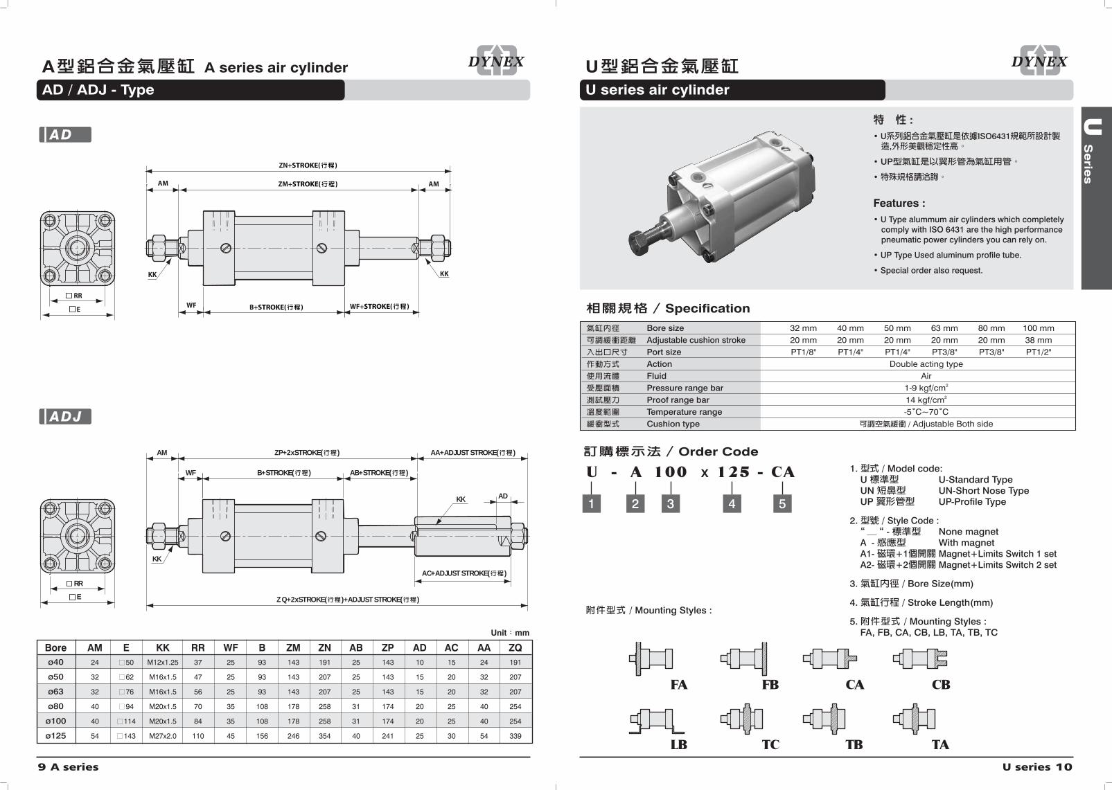
AD / ADJ - Type
9 A series
:• U ISO6431
,
• UP
•
Features :• U Type alummum air cylinders which completely
comply with ISO 6431 are the high performancepneumatic power cylinders you can rely on.
• UP Type Used aluminum profile tube.
• Special order also request.
Specification
Bore size 32 mm 40 mm 50 mm 63 mm 80 mm 100 mmAdjustable cushion stroke 20 mm 20 mm 20 mm 20 mm 20 mm 38 mmPort size PT1/8" PT1/4" PT1/4" PT3/8" PT3/8" PT1/2"Action Double acting typeFluid AirPressure range bar 1-9 kgf/cm2
Proof range bar 14 kgf/cm2
Temperature range -5˚C~70˚CCushion type / Adjustable Both side
/ Mounting Styles :
1. / Model code:U U-Standard TypeUN UN-Short Nose TypeUP UP-Profile Type
2. / Style Code :- None magnet
A - With magnet A1- +1 Magnet+Limits Switch 1 setA2- +2 Magnet+Limits Switch 2 set
3. / Bore Size(mm)
4. / Stroke Length(mm)
5. / Mounting Styles : FA, FB, CA, CB, LB, TA, TB, TC
U - A 100 x 125 - CA
54321
Order Code
FA FB CA CB
LB TC TB TA
WF+STROKE( )WFRR
E
AM ZM+STROKE( ) AM
ZN+STROKE( )
KK KK
B+STROKE( )
RR
E
B+STROKE( )WF AB+STROKE( )
AM ZP+2xSTROKE( ) AA+ADJUST STROKE( )
Z Q+2xSTROKE( )+ADJUST STROKE( )
AC+ADJUST STROKE( )
ADKK
KK
Bore AM E KK RR WF B ZM ZN AB ZP AD AC AA ZQø40 24 50 M12x1.25 37 25 93 143 191 25 143 10 15 24 191
ø50 32 62 M16x1.5 47 25 93 143 207 25 143 15 20 32 207
ø63 32 76 M16x1.5 56 25 93 143 207 25 143 15 20 32 207
ø80 40 94 M20x1.5 70 35 108 178 258 31 174 20 25 40 254
ø100 40 114 M20x1.5 84 35 108 178 258 31 174 20 25 40 254
ø125 54 143 M27x2.0 110 45 156 246 354 40 241 25 30 54 339
Unit mm
AD
ADJ

U series 12
U U series air cylinder
U-LB - Type
U
Se
ries
UU series air cylinder
11 U series
TR
UA
AH
AT
SA+STROKE( )
AL AO
XA+STROKE( )
4-øAB
/ Limits Switch
Unit mm
CE
PL
LE
øD
CM
ER
øCK
CL
CL
KK
Bore AL AO AT UA TR øAB AH SA XAø32 24 10 3.2 47 32 7 32 142 144
ø40 28 12 3.2 53 36 9 36 161 163
ø50 32 13 3.5 65 45 9 45 170 175
ø63 32 13 3.5 75 50 9 50 185 190
ø80 40 16 4 95 63 12 63 210 215
ø100 40 16 4 115 75 14 71 220 230
Bore CK CE CL CM LE ER PL øD KKø32 10 40 3/4" 10 20 12 10 18 M10x1.25
ø40 12 48 7/8" 12 24 14 12 22 M12x1.25
ø50 16 64 5/4" 16 32 19 14 26 M16x1.5
ø63 16 64 5/4" 16 32 19 14 26 M16x1.5
ø80 20 80 3/2" 20 40 25 16 32 M20x1.5
ø100 20 80 3/2" 20 40 25 16 32 M20x1.5
Unit mm
Y
U-LB
KVD K VVA
H+STROKE( )
PJ+STROKE( )YPWH
ZJ+STROKE( )
H+STROKE( )
PJ+STROKE( )
ZE+STROKE( )
AM
øB
øMM
øB
T
KK 2-EETE
E
TE
E
KU8-RT
T
VEKU
øMM
8-RT K
AM
WE YP
øB
KK
VAK
øB
2-EE
Bore AM øMM KK KU øB VD K EE E Tø32 22 ø12 M10x1.25 10 ø28 16 26.5 PT1/8'' 47 8
ø40 24 ø16 M12x1.25 14 ø32 20 32 PT1/4'' 53 8
ø50 32 ø20 M16x1.5 17 ø38 25 32 PT1/4'' 65 12
ø63 32 ø20 M16x1.5 17 ø38 25 37 PT3/8'' 75 12
ø80 40 ø25 M20x1.5 22 ø42 33 40 PT3/8'' 95 16
ø100 40 ø25 M20x1.5 22 ø42 38 45 PT1/2'' 115 16
Bore VA YP TE PT WH H PJ ZJ VE WE ZEø32 5 19 32.5 M6x1 26 41 56 120 10 20 114
ø40 5 21 37.5 M6x1 30 41 63 135 10 20 125
ø50 6 21 46.5 M8x1.25 37 42 64 143 12 24 130
ø63 6 24 56.5 M8x1.25 37 48 74 159 12 24 146
ø80 6 25 72 M10x1.5 46 48 78 174 16 29 157
ø100 6 30 89 M10x1.5 51 48 78 189 16 29 167
Unit mm
U/UP
UN/UNP

U series 14
U U series air cylinder
CA / CB - Type
U
Se
ries
U U series air cylinder
FA / FB - Type
13 U series
EW
L
T
MR
øCD
XD+STROKE( )
L
T
XD+STROKE( )
E
TE
E
TE
EW
UB
MR
øCD
ÅÅ
Bore E TE EW L T øCD MR UB XDø32 47 32.5 26 12 10 10 10 45 142
ø40 53 37.5 28 15 10 12 12 52 160
ø50 65 46.5 32 15 12 12 12 60 170
ø63 75 56.5 40 19 12 16 16 70 190
ø80 95 72 50 22 14 16 16 90 210
ø100 115 89 60 27 14 20 20 110 230
CA
CB
Bore UF TF EF R øFB WF MA ZFø32 78 64 47 32 7 16 10 130
ø40 90 72 53 36 9 20 10 145
ø50 110 90 65 45 9 25 12 155
ø63 120 100 75 50 9 25 12 171
ø80 154 126 95 63 12 30 16 190
ø100 178 150 115 75 14 35 16 205
WF MA
UF
TF
R UF
MA
ZF+ZF+STROKE( )
TF
UF
R EF
4-øFB
4-øFB
Unit mm Unit mm
FA
FB

U series 16
U U series air cylinder
UD / UDJ - Type
U
Se
ries
U U series air cylinder
TA / TC / TB - Type
15 U series
AMAM ZM+STROKE( )
ZN+STROKE( )
WH BB+STROKE( ) WH+STROKE( )
KK KK
WH BB+STROKE( ) AB+STROKE( )
AM ZP+2xSTROKE( )
TE
E
TE
E
AA+ADJUST STROKE( )
AD
EC+ADJUST STROKE( )
KK
ZQ+2xSTROKE( )+ADJUST STROKE( )
KK
Bore AM BB E KK TE ZM ZN AB AA ZQ ZP AD AC WH ø32 22 94 47 M10x1.25 32.5 146 190 21 22 185 141 10 13 26
ø40 24 105 53 M12x1.25 37.5 143 191 25 24 191 143 10 15 30
ø50 32 106 65 M16x1.25 46.5 143 207 32 32 207 143 15 20 37
ø63 32 122 75 M16x1.25 56.5 143 207 32 32 207 143 15 20 37
ø80 40 128 95 M20x1.5 72 178 258 41 40 254 174 20 25 46
ø100 40 138 115 M20x1.5 89 178 258 46 40 254 174 20 25 51
UD
UDJTM TLTL
UM
TD TM
R
TM
UM
TMTL TL
TD
R
TM
UM
TMTL TL
TD
R
XV+1/2 STROKE( )
BD
BD
BD
XN
ZJ+STROKE( )
ZJ+STROKE( )
ZJ+STROKE( )
XP+STROKE( )
Bore BD TD TL TM R UM XN XP ZJ XVø32 20 ø12 12 50 1.5 74 62.5 103.5 120 73
ø40 25 ø25 25 59 1.5 109 74.5 115.5 135 82.5
ø50 25 ø25 25 71 1.5 121 81.5 123.5 143 90
ø63 30 ø25 25 86 1.5 136 89 137 159 97.5
ø80 30 ø25 25 106 1.5 156 101 149 174 110
ø100 35 ø25 25 132 1.5 182 113.5 161.5 189 120
Unit mm Unit mm
TA
TC
TB
M series 18
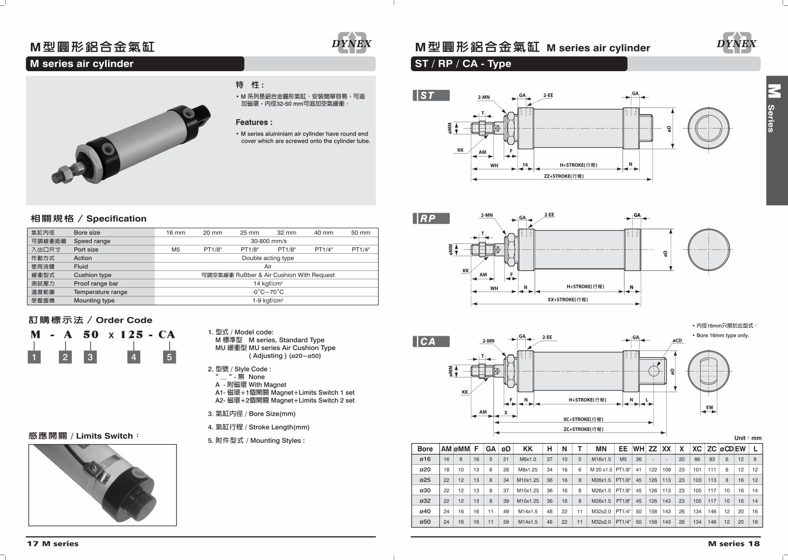
M M series air cylinder
ST / RP / CA - Type
M
Se
ries
MM series air cylinder
17 M series
Bore AM ø M M F GA øD KK H N T MN EE WH ZZ XX X XC ZC ø CD EW Lø16 16 6 16 5 21 M6x1.0 37 10 5 M16x1.5 M5 36 - - 20 86 93 6 12 9
ø20 18 10 13 8 28 M8x1.25 34 16 6 M 20 x1.5 PT1/8'' 41 122 109 23 101 111 8 12 12
ø25 22 12 13 8 34 M10x1.25 36 16 8 M26x1.5 PT1/8'' 45 126 113 23 103 113 8 16 12
ø30 22 12 13 8 37 M10x1.25 36 16 8 M26x1.5 PT1/8'' 45 126 113 23 105 117 10 16 14
ø32 22 12 13 8 39 M10x1.25 36 16 8 M26x1.5 PT1/8'' 45 126 143 23 105 117 10 16 14
ø40 24 16 16 11 49 M14x1.5 48 22 11 M32x2.0 PT1/4'' 50 158 143 26 134 146 12 20 16
ø50 24 16 16 11 59 M14x1.5 48 22 11 M32x2.0 PT1/4'' 50 158 143 26 134 146 12 20 16
• 16mm
• Bore 16mm type only.
AM F
WH 16 H+STROKE( ) N
ZZ+STROKE( )
øDøD
øD
øM
M
GAGA 2-EE
KK
T
2-MN
KK
T
2-MNGA 2-EE GA
AM X
F N H+STROKE( ) N L
XC+STROKE( )
ZC+STROKE( )
EW
øCD
H+STROKE( )
øMM
øMM
WH
KKAM
N
F
T
GA2-EE
NN
GAGA
XX+STROKE( )
2-MN
Unit mm
ST
RP
CA
M series air cylinder
:• M
32-50 mm
Features :• M series aluininiam air cylinder have round end
cover which are screwed onto the cylinder tube.
Specification
Bore size 16 mm 20 mm 25 mm 32 mm 40 mm 50 mmSpeed range 30-800 mm/sPort size M5 PT1/8" PT1/8" PT1/8" PT1/4" PT1/4" Action Double acting typeFluid AirCushion type RuBber & Air Cushion With RequestProof range bar 14 kgf/cm2
Temperature range -0˚C~70˚CMounting type 1-9 kgf/cm2
1. / Model code:M M series, Standard TypeMU MU series Air Cushion Type
( Adjusting ) (ø20~ø50)
2. / Style Code :- None
A - With Magnet A1- +1 Magnet+Limits Switch 1 setA2- +2 Magnet+Limits Switch 2 set
3. / Bore Size(mm)
4. / Stroke Length(mm)
5. / Mounting Styles :
M - A 50 x 125 - CA
54321
Order Code
/ Limits Switch

M series 20
M M series air cylinder
MD / MDJ - Type
M
Se
ries
M M series air cylinder
FA / LB - Type
19 M series
Bore AM øMM F HE AA KK H AD AC MN EE WH AB WEø16 16 6 16 51 16 M6x1.0 37 8 13 M16x1.5 M5 36 36 36
ø20 18 10 13 66 18 M8x1.25 34 10 15 M20x1.5 PT1/8'' 41 41 41
ø25 22 12 13 68 22 M10x1.25 36 12 17 M26x1.5 PT1/8'' 45 45 45
ø30 22 12 13 68 22 M10x1.25 36 12 17 M26x1.5 PT1/8'' 45 45 45
ø32 22 12 13 68 22 M10x1.25 36 12 17 M26x1.5 PT1/8'' 45 45 45
ø40 24 16 16 92 24 M14x1.5 48 15 20 M32x2.0 PT1/4'' 50 50 50
ø50 24 16 16 92 24 M14x1.5 48 15 20 M32x2.0 PT1/4'' 50 50 50
H+STROKE( )
HE+STROKE( )WHWH WE+STROKE( )
AM
øM
M
2-KK
2-MN
FF
AM
2-EE2-EE
HE+STROKE( )
H+STROKE( )
øM
M
AM
WHWH
2-MN2-MN
KKKKFF
2-EE2-EE
AB+STROKE( )+ADJUST STROKE( )
C+ADJUST STROKE( )
AA+ADJUST STROKE( )
AD
Unit mm
MD
MDJ
Bore NH US TR øAB AO AU AT SA ZAø20 28 55 40 7 8 20 3 106 122
ø25 28 55 40 7 8 20 3 108 124
ø30 28 55 40 7 8 20 3 108 124
ø40 30 75 55 7 12 23 3 138 162
Y I
TF
UFU
R
2-øFB
F
W XF+STROKE( )
ZB+STROKE( )
TF
UF
RUR
4-øFB
W
ZB+STROKE( )
XF+STROKE( )
F
TR
US
NH
ø AB
AT
AUAO
SA+STROKE( )
^A+STROKE( )
CE
A
øE1
KK
CL
CM
LE øCK
ER
ACE
øE1
KKLE
CM
ØCK
ER
Bore F UR UF TF R øFB W XF ZBø20 3 42 75 60 - 7 20 82 102
ø25 3 42 75 60 - 7 20 84 104
ø30 3 42 75 60 - 7 20 84 104
ø40 4.5 52 82 66 36 7 21.5 113 134
Bore A E1 CE KK ER LE øCK CM CLø20 16 20 36 M8x1.25 12 14 9 9 18
ø25 18 20 38 M10x1.25 12 14 9 9 18
ø30 18 20 38 M10x1.25 12 14 9 9 18
ø40 22 25 45 M14x1.5 14 15 12 10 22
Unit mm
Unit mm
Unit mm
LB
FA

MR series 22
MR MR series block cylinder
MR / MRF - Type
MR
S
erie
s
MRMR series block cylinder
21 MR series
LXL
B NA3
H
AM
NB
S+STROKE( )
ZZ+STROKE( )
øN
D
øM
M
2-EEKK
øP øZ
Q
ØD
Y
NA3
H
AM
NB
S+STROKE( )
ZZ+STROKE( )
øN
D
øM
M
2-EE
KK
FX
F
4-FF
øD
Bore B KK L LX H Q øZ øP øND NAø20 30.5 M8x1.25 33 21 28 6 9.5 5.5 20 29
ø25 36.3 M10x1.25 39 25 32 7 11 6.5 26 29
ø32 42.3 M10x1.25 47 30 32 9 14 8.5 26 29
ø40 52.3 M14x1.25 58.5 38 34 11 17 10.5 32 38
Bore EE Y FF ZZ S NB øD FX F AM øMMø20 PT1/8'' 12 M5x0.8 DP8 107 79 16 28 22 30.4 18 10
ø25 PT1/8'' 12 M6x1.0 DP10 113 81 16 34 26 36.4 22 12
ø32 PT1/8'' 12 M6x1.0 DP10 113 81 16 38 30 42.4 22 12
ø40 PT1/8'' 15 M8x1.5 DP13 142 108 22 49 36 52.4 24 16
Unit mm
MR
MRF
:•
•
•
•
Features :• Space saving configuration.
• Improved installation accuracy and strength.
• Directly mounted style without using brackets.
• With air cushion.
Specification
Bore size 20 mm 25 mm 32 mm 40 mmSpeed range 30-800 mm/sPort size PT1/8" PT1/8" PT1/8" PT1/8"Action Double acting typeFluid AirPressure range bar 1-9 kgf/cm2
Proof range bar 13.5 kgf/cm2
Temperature range 0˚C -70˚CCushion type Rubber Type (Air cushion option)
Order Code
MRF-Type
MR- A 32 x 125
4321
1. / Model Code: MR, MRF Type
2. Style Code :: None Magnet
A : With MagnetA1 : 1 With 1 Proximity Switch A2 : 2 With 2 Proximity Switch
3. / Bore Size(mm)
4. / Stroke Length(mm)
MR-Type
SR series 24
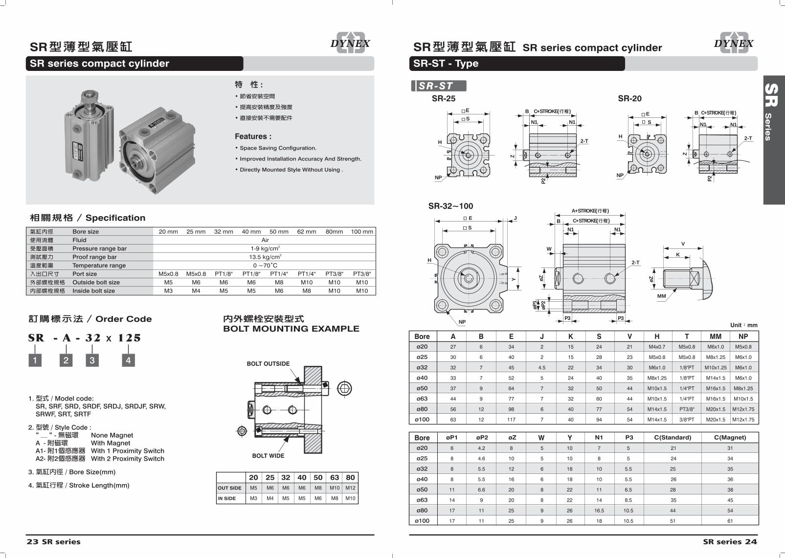
SR SR series compact cylinder
SR-ST - Type
SR
S
erie
s
SRSR series compact cylinder
23 SR series
Bore A B E J K S V H T MM NPø20 27 6 34 2 15 24 21 M4x0.7 M5x0.8 M6x1.0 M5x0.8
ø25 30 6 40 2 15 28 23 M5x0.8 M5x0.8 M8x1.25 M6x1.0
ø32 32 7 45 4.5 22 34 30 M6x1.0 1/8"PT M10x1.25 M6x1.0
ø40 33 7 52 5 24 40 35 M8x1.25 1/8"PT M14x1.5 M6x1.0
ø50 37 9 64 7 32 50 44 M10x1.5 1/4"PT M16x1.5 M8x1.25
ø63 44 9 77 7 32 60 44 M10x1.5 1/4"PT M16x1.5 M10x1.5
ø80 56 12 98 6 40 77 54 M14x1.5 PT3/8'' M20x1.5 M12x1.75
ø100 63 12 117 7 40 94 54 M14x1.5 3/8"PT M20x1.5 M12x1.75
S
E J
H
Y
N1 N1
øZ
P3 P3
øP
2
øP
1
2-T
MM
øZ
K
V
B
W
NP
S
E
P2
B
Z
N1N1
2-TH
NP
SR-25
SR-32~100
P2
SR-20
S
E B
Z
N1 N1
2-TH
NP
C+STROKE( )
A+STROKE( )
C+STROKE( ) C+STROKE( )
Bore øP1 øP2 øZ W Y N1 P3 C(Standard) C(Magnet)
ø20 6 4.2 8 5 10 7 5 21 31
ø25 8 4.6 10 5 10 8 5 24 34
ø32 8 5.5 12 6 18 10 5.5 25 35
ø40 8 5.5 16 6 18 10 5.5 26 36
ø50 11 6.6 20 8 22 11 6.5 28 38
ø63 14 9 20 8 22 14 8.5 35 45
ø80 17 11 25 9 26 16.5 10.5 44 54
ø100 17 11 25 9 26 18 10.5 51 61
Unit mm
SR-ST
1. / Model code:SR, SRF, SRD, SRDF, SRDJ, SRDJF, SRW,SRWF, SRT, SRTF
2. / Style Code :- None Magnet
A - With Magnet A1- 1 With 1 Proximity SwitchA2- 2 With 2 Proximity Switch
3. / Bore Size(mm)
4. / Stroke Length(mm)
:•
•
•
Features :• Space Saving Configuration.
• Improved Installation Accuracy And Strength.
• Directly Mounted Style Without Using .
BOLT MOUNTING EXAMPLE
Specification
Order Code
Bore size 20 mm 25 mm 32 mm 40 mm 50 mm 62 mm 80mm 100 mmFluid AirPressure range bar 1-9 kg/cm2
Proof range bar 13.5 kg/cm2
Temperature range 0 ~70˚CPort size M5x0.8 M5x0.8 PT1/8" PT1/8" PT1/4" PT1/4" PT3/8" PT3/8"Outside bolt size M5 M6 M6 M6 M8 M10 M10 M10Inside bolt size M3 M4 M5 M5 M6 M8 M10 M10
SR - A - 32 x 125
4321
20 25 32 40 50 63 80OUT SIDE M5 M6 M6 M6 M8 M10 M12
IN SIDE M3 M4 M5 M5 M6 M8 M10
BOLT OUTSIDE
BOLT WIDE

SR series 26
SR SR series compact cylinder
SRDJ / SRDJF - Type
SR
S
erie
s
SR SR series compact cylinder
SKD / SRDF - Type
25 SR series
Unit mm
NPNPNP
S
E JJJ
YYY
Ø Z
ØØ
NPNPNP
SSS
EEE JJJ
YYY Ø Z
ØØØ Z
C+STROKE( )VV
KK
MMAB+ADJUST STROKE( )
AC+2 STROKE( )+ADJUST STROKE( )
AF+STROKE( )+ADJUST STROKE( )
C+STROKE( )
AZ+ADJUST STROKE( )
AB+ADJUST STROKE( )
AF+ADJUST STROKE( )BBB
AH+2xSTROKE( )+ADJUST STROKE( )
AZ+ADJUST STROKE( )
Bore AB B E J K S V Y øZ MM NP C(Standard) C(Magnet)ø20 15 6 34 2 15 24 21 10 8 M6x1.0 M5x0.8 21 31
ø25 15 6 40 2 15 28 23 10 10 M8x1.25 M6x1.0 24 34
ø32 22 7 45 4.5 22 34 30 18 12 M10x1.25 M6x1.0 25 35
ø40 24 7 52 5 24 40 35 18 16 M14x1.5 M6x1.0 26 36
ø50 32 9 64 7 32 50 44 22 20 M16x1.5 M8x1.25 28 38
ø63 32 9 77 7 32 60 44 22 20 M16x1.5 M10x1.5 35 45
ø80 40 12 98 6 40 77 54 26 25 M20x1.5 M12x1.75 44 54
ø100 40 12 117 7 40 94 54 26 25 M20x1.5 M12x1.75 51 61
SRDJ
SRDJF
S
E J
H
Y
C+STROKE( )
øZ
ø Z
P3 P3ø
P2
øP
1
2-T
B
W
NP
B+STROKE( )
B1+2xSTROKE( )
S
E J
Y
NP
C+STROKE( )V
K
V+STROKE( )
K
MM
2-T
MM
V1+2xSTROKE( )
Unit mm
Bore B E J K S V H T MM NPø20 6 34 2 15 24 21 M4x0.7 M5x0.8 M6x1.0 M5x0.8
ø25 6 40 2 15 28 23 M5x0.8 M5x0.8 M8x1.25 M6x1.0
ø32 7 45 4.5 22 34 30 M6x1.0 1/8"PT M10x1.25 M6x1.0
ø40 7 52 5 24 40 35 M8x1.25 1/8"PT M14x1.5 M6x1.0
ø50 9 64 7 32 50 44 M10x1.5 1/4"PT M16x1.5 M8x1.25
ø63 9 77 7 32 60 44 M10x1.5 1/4"PT M16x1.5 M10x1.5
ø80 12 98 6 40 77 54 M14x1.5 PT3/8'' M20x1.5 M12x1.75
ø100 12 117 7 40 94 54 M14x1.5 3/8"PT M20x1.5 M12x1.75
Bore W Y P3 øZ øP1 øP2 C(Standard) C(Magnet)ø20 5 10 5 8 6 4.2 21 31
ø25 5 10 5 10 8 4.6 24 34
ø32 6 18 5.5 12 8 5.5 25 35
ø40 6 18 5.5 16 8 5.5 26 36
ø50 8 22 6.5 20 11 6.6 28 38
ø63 8 22 8.5 20 14 9 35 45
ø80 9 26 10.5 25 17 11 44 54
ø100 9 26 10.5 25 17 11 51 61
SKD
SRDF

SRT series 28
SRTSRT type compact cylinder
SR
W/S
RT
Se
ries
SRWSRW type compact cylinder
27 SRW series
Bore øZ H MM NP T C(Standard) C(Mangnet)ø20 8 M4x0.7 M6x1.0 M5x0.8 M5x0.8 21 31
ø25 10 M5x0.8 M8x1.25 M6x1.0 M5x0.8 24 34
ø32 12 M6x1.0 M10x1.25 M6x1.0 PT1/8'' 25 35
ø40 16 M8x1.25 M14x1.5 M6x1.0 PT1/8'' 26 36
ø50 20 M10x1.5 M16x1.5 M8x1.25 PT1/4'' 28 38
ø63 20 M10x1.5 M16x1.5 M10x1.5 PT1/4'' 35 45
ø80 25 M14x1.5 M20x1.5 M12x1.75 PT3/8'' 44 54
ø100 25 M14x1.5 M20x1.5 M12x1.75 PT3/8'' 51 61
Bore E S B J N1 K V øP1 øP2 P3 Yø20 34 24 6 2 7 15 21 6 4.2 5 10
ø25 40 28 6 2 8 15 23 8 4.6 5 10
ø32 45 34 7 4.5 10 22 30 8 5.5 5.5 18
ø40 52 40 7 5 10 24 35 8 5.5 5.5 18
ø50 64 50 9 7 11 32 44 11 6.6 6.5 22
ø63 77 60 9 7 14 32 44 14 9 8.5 22
ø80 98 77 12 6 16.5 40 54 17 11 10.5 26
ø100 117 94 12 7 18 40 54 17 11 10.5 26
SE J
H
Y
N1 N1
Ø Z
P3
øP
2
øP
1
B
NP
SE J
Y
N1 N1
C+STROKE 1( )
P3
ØP2
ØP1
NP
C+STROKE 2( )
MM
Ø Z
K
A3+STROKE 1( )
4-NP 2-NP
4-NP 2-NP
4-T
4-T
V
Unit mm
STROKE 2 STROKE 1
1. / Model code:SRT type, SRTF type
2. / Style Code :- Standard type
A - Magnet Proximity type
3. / Bore Size(mm)
4. / Stroke 1 Length(mm)
5. / Stroke 2 Length(mm)
SRT - A 32 x 25 - 25
54321
Order Code
SRT
SRTF
SE J
H
Y
N1 N1
Ø Z
P3
ØP
2
ØP
1
B
NP
SE J
Y
N1 N1
C+STROKE 1( )
P3
Ø P2
Ø P1
NP
C+STROKE 2( )
MM
Ø Z
K
A1+STROKE 1( ) A1+STROKE 2( )
C+STROKE 1( ) C+STROKE 2( )
A1+STROKE 1( ) A1+STROKE 2( )
4-NP 2-NP
4-NP 2-NP
4-T
4-T
STROKE 1 STROKE 2
1. / Model code:SRW type, SRWF type
2. / Style Code :- Standard type
A - Magnet Proximity type
3. / Bore Size(mm)
4. / Stroke 1 Length(mm)
5. / Stroke 2 Length(mm)
Unit mm
Bore E S H B Y A øP1 øP2 øP3 N1 øZø20 34 24 M4x0.7 6 10 27 6 4.2 5 7 8
ø25 40 28 M5x0.8 6 10 30 8 4.6 5 8 10
ø32 45 34 M6x1.0 7 18 32 8 5.5 5.5 10 12
ø40 52 40 M8x1.25 7 18 33 8 5.5 5.5 10 16
ø50 64 50 M10x1.5 9 22 37 11 6.6 6.5 11 20
ø63 77 60 M10x1.5 9 22 44 14 9 8.5 14 20
ø80 98 77 M14x1.5 12 26 56 17 11 10.5 16.5 25
ø100 117 94 M14x1.5 12 26 63 17 11 10.5 18 25
Bore K MM NP T C(Standard) C(Magnet)ø20 15 M6x1.0 M5x0.8 M5x0.8 21 31
ø25 15 M8x1.25 M6x1.0 M5x0.8 24 34
ø32 22 M10x1.25 M6x1.0 PT1/8'' 25 35
ø40 24 M14x1.5 M6x1.0 PT1/8'' 26 36
ø50 32 M16x1.5 M8x1.25 PT1/4'' 28 38
ø63 32 M16x1.5 M10x1.5 PT1/4'' 35 45
ø80 40 M20x1.5 M12x1.75 PT3/8'' 44 54
ø100 40 M20x1.5 M12x1.75 PT3/8'' 51 61
SRW - A 32 x 25 - 25
54321
Order Code
SRW
SRWF

BG series 30
BG BG series air cylinder
FA / FB-Type
BG
S
erie
s
BGBG series air cylinder
29 BG series
FD
FU
FF
TE
FX FR
4-øFB
F
AM
KK
FU
FF
TE
FX FR
F
ZF+STROKE( )
4-øFB
Bore F FX FR TE FF øFB KK AM FD ZF FUø150 22 180 135 134 220 18 M36x2.0 56 31 211 286
ø160 25 180 115 140 230 18 M36x2.0 72 60 276 275
ø180 25 205 162 165 242 20 M36x2.0 56 35 240 285
ø200 25 225 180 175 280 20 M36x2.0 72 75 285 320
ø250 30 290 226 220 330 25 M42x2.0 60 45 290 385
FA
FB
H+STROKE( )
TE
E
AM
KK
øB
øMM
2-EE
PJ+STROKE( )
AP+STROKE( )
WH
øB
VA
8-RT
Bore E TE RT øB øMM AM KK WH H PJ VA EEø150 172 134 M16x1.5 60 40 56 M36x2.0 53 62 136 10 PT3/4''
ø160 180 140 M16x1.5 65 40 72 M36x2.0 85 74 166 0 PT3/4''
ø180 210 165 M20x1.5 80 45 56 M36x2.0 60 65 155 0 PT3/4''
ø200 220 175 M20x1.5 76 45 72 M36x2.0 100 70 160 0 PT3/4''
ø250 282 220 M20x1.5 155 50 60 M42x2.0 75 75 185 0 PT3/4''
Unit mm Unit mm
SpecificationBore size 150mm 160mm 180mm 200mm 250mmOperating pressure 2~8 Kgf/cm2
Proof range bar 10 Kgf/cm2
Action 30~500mm/secFluid AirTemperature range 0˚C~70˚C
1. / Model code: BG Type
2. / Style Code :- Standard type
A - Magnet Proximity Type
3. / Bore Size(mm)
4. / Stroke Length(mm)
5. / Mounting Styles :
BG - 100 x 125 - CA
54321
Order Code
:• BG
• 150, 160, 200 180, 250
•
•
Features :• BG Series is bigger size standard cylinder.
• Bore150, 160, 200 use aluminum castcover,Bore180, 250 use FC-20 cast cover.
• Easy Installation and good appearance.
• Special order and accessory please contact us.

A series 32
GMGM series air cylinder
GM
S
erie
s
BG BG series air cylinder
CA / CB-type
31 A series
:• ø20, ø25, ø30, ø40
• -20˚C~80˚C
• 15bar
• 10bar
•
• 25~500mm
Features :• Guide Cylinder suitable for Non-
Rotation, for heavy load carriersof various size at a fixposition,and for stacking manywork carriers.
• Bore Size: ø20, ø25, ø30, ø40.
• Stroke Range: 25-500mm.
• Special Order also Request.
J
K 2-Q
HG
S
øMøM
2-U
W
X
P
T+STROKE( )
L+STROKE( )
N
D
ABC
3-E
4-F
Bore A B C D G H S J K Lø20 24 50 68 18 13 38 70 30 10 120
ø25 24 56 72 24 13 38 74 36 10 122
ø30 24 56 72 24 13 38 74 36 10 122
ø40 26 66 84 26 16 50 86 42 12 155
Bore E F Q U W øM T N X Pø20 M6 M6x1.0 M6 PT1/8'' 10 10 65 26 12 30
ø25 M6 M6x1.0 M6 PT1/8'' 10 10 65 32 12 38
ø30 M6 M6x1.0 M6 PT1/8'' 10 10 65 32 12 38
ø40 M8 M8x1.25 M8 PT1/4'' 10 12 80 38 18 50
Unit mm
Bore E TE EW UB øCD T L XDø150 172 134 40 80 25 23 37 249
ø160 180 140 90 170 30 25 35 311
ø180 210 165 40 95 30 20 65 305
ø200 220 175 40 90 30 25 38 323
ø250 282 220 56 107 40 30 65 355
XD+STROKE( )
L
E
TE
E
TE
øCD
øCD
MR
E WT
XD+STROKE( )
L
EW
UB
MR
T
Unit mm
CA
CB

GU series 34
GUGU series guide cylinder
GU
S
erie
s
GUGU series guide cylinder
33 GU series
F
G
CE
W
H
A D B
N Q
S
T1
L+STROKE( )
P+STROKE( )
T2
øU
4-K
4-J
3-M
Bore K L M N P Q S T1 T2 øUø63 M8x1.25 178 M8 37 110 59 120 19 19 ø16
ø80 ø13 199 M10 46 126 75 148 25 25 ø20
ø100 ø13 241 M10 51 131 75 168 25 25 ø20
ø125 M10x1.5 224 M10 46 125 71 208 21 21 ø25
Bore A B C D E F G H I J Wø63 45 99 145 116 165 55 76 63 45 ø9 45
ø80 100 122 175 150 200 60 100 90 60 ø13 60
ø100 120 142 190 170 220 80 120 100 70 ø13 70
ø125 150 175 230 200 260 100 140 100 75 ø17 75
Unit mm
1. / Model code: GM,GU Type
2. / Style Code :- Standard type
A - Magnet Proximity Type
3. / Bore Size(mm)
4. / Stroke Length(mm)
GU - 40 x 50
4321
Order Code
GU63~125
:•
•
• -20˚C~80˚C
• 15 bar
• 10 bar
•
• ø32, ø40, ø50, ø63, ø80,ø100, ø125.
• 25~500mm
Features :• Guide Cylinder suitable for Non-
Rotation, for heavy load carriers ofvarious size at a fix position,and forstacking many work carriers.
• Bore Size: ø32, ø40, ø50, ø63, ø80,ø100, ø125.
• Stroke Range: 25-500mm.
• Special Order also Request.
P+STROKE( )T1
RRB
øU
QN
D A
W
H
S
G
øE
øC
F
HH
4-K
3-M
L+STROKE( )
T2
NS
Bore M N P Q S T1 T2 øC øE øU Kø32 M6 24 90 50 110 9 18 8.5 14 12 M6x1.0
ø40 M6 28 100 54 105 13 20 8.5 14 12 M6x1.0
ø50 M8 34 110 63.5 122 19 25.5 8.5 14 16 M8x1.25
Bore A B D F H G RR W NS HH Lø32 32 64 105 9 50 50 60 32 47 9 136
ø40 32 85 100 9 50 54 60 32 60 12 153
ø50 45 99 119 9 63.5 63.5 70 45 68 16 165
Unit mm
:• U
Features :• U Type

GSR series 36
GSRGSR type compact guide cylinder
GS
R
Se
ries
GSRGSR type compact guide cylinder
35 GSR series
B A
Ø D
CEF
G
H
K N+STROKE( )
P Q RR+STROKE( )4-SS
T T
W
X
U
AB
BC
CD M
DE
2-PT
8-MP
øFG
HF
øOP
2-KP
4-AM
4-DA
Bore BC U DA HF øFG X KP TT PT MP øOP SS W AMø32 104 40.5 M8x1.25 9 14 32 M10x1.5 47 PT1/8'' M8x1.25 8.5 M6x1.0 35 M6x1.0
ø40 104 49 M8x1.25 9 14 40 M10x1.5 55 PT1/8'' M8x1.25 8.5 M6x1.0 38 M8x1.25
ø50 132 64 M8x1.25 11 18 48 M12x1.75 70 PT1/4'' M10x1.5 11 M6x1.0 50 M8x1.25
ø63 140 78 M8x1.25 11 18 60 M12x1.75 82 PT1/4'' M10x1.5 11 M6x1.0 55 M8x1.25
Bore A B C øD E F G H K N M P Q RR CD DE ABø32 122 92 47 20 56 58 12 21 55 5 120 17 5 35 40 22 30
ø40 128 98 54 20 64 64 13 21 58 5 126 17 5 36 40 32 32
ø50 160 123 66 25 80 80 17 26 70 5 154 17 5 38 44 44 44
ø63 170 136 80 25 88 92 20 30 75 5 166 17 5 45 46 58 46
Unit mm
Specification
Order Code
Bore size 20 mm 25 mm 32 mm 40 mm 50 mm 63 mmOperating pressure 2~8 Kgf/cm2
Port size M5 M5 RC1/8" RC1/8" RC1/4" RC1/4"Fluid AirProof range bar 10 kgf/cm2
Temperature range -0˚C~70˚CMounting type 30~500mm/sec
GSR - 50 x 100 - 2
4321
1. / Model code: GSR Type
2. / Style Code :- Standard type
A1- 1 With 1 Proximity SwitchA2- 2 With 2 Proximity Switch
3. / Bore Size(mm)
4. / Stroke Length(mm)
/Dimensional TableUnit mm
Bore ( mm ) / Bore of Cylinderø20, ø25, ø32 10, 20, 30, 40, 50, 75, 100,
ø40, ø50, ø63 10, 20, 30, 40, 50, 75, 100, 125, 150
:•
•
•
•
Features :• The Cylinder and the Guide are
designed as compact makesthe air cylinder working moresmoothly and high-strengthand high-stiffness.
• All sensor type.
• The body and plate arereserved many holes andthreads for mounting.It issuitable for various mountingrequirement.
• Special order also request.

ASC series 38
ASCAir swing clamp cylinder
AS
C
Se
ries
ASCAir swing clamp cylinder
37 ASC series
SpecificationBore of cylinder ø25 mm ø32 mm ø40 mm ø50 mm ø63 mm
Piston rod diameter ø14 mm ø16 mm ø16 mm ø20 mm ø20 mm
Swing stroke 9 mm 11 mm 11 mm 13 mm 13 mm
/ Clamping stroke std/extension 13 mm 15 / 30 mm 15 / 30 mm 17 / 34 mm 17 / 34 mm
/ Pressure area pull/push 3.37 / 4.91 cm2 6.03 / 8.04 cm2 10.56 / 12.57 cm2 16.49 / 19.63 cm2 28.03 / 31.17 cm2
Theoretical clamping force 6kg/cm2 20 36 63 99 168Fluid / Filtered air
Max operation pressure 10 Kg/cm2
Operation pressure range 1-7 Kg/cm2
Rotating direction R L / Turn right R or turn left L
Rotating angle 90 0˚, 45˚, 60˚ / Standard angle 90˚, Optional angle 0˚, 45˚, 60˚
Acting type / Double acting
Sw
ing
Str
oke
Cla
mpi
ng s
trok
e
Order Code
Single Side Swing Clamp
ASC - MF 25 S R x 90 - E
32 4 5 61
1. / Model code:: Blank:Line type
MF: MF:Manifold with flow controlMS: MS: Magnetic typeFA: FA: Flange typeTB: TB: Threaded body
2. / Bore Size(mm): ø25, ø32, ø40, ø50, ø63
3. / Clamping arm type:S: Single side armD: Double side arm
4. / Rotating DirectionR Turn rightL Turn leftN: 0˚ 0˚ No swing
5. / Rotating Angle: 90:90˚,45:45˚,60:60˚
6. / Stroke extension Line type
:• MC
•
• A.B
• 1.5
•
Features :• The product is ideal for mass production on a special
purpose machine and jig on machining center. It willgreatly upgrade production efficiency.
• When the air cylinder actuate, and the piston movesdownward, the clamping arm will swing to a rated angle!Then it lowers until the workpiece is clamped securely.
• To avoid too fast motion a flow control valve is suggestedto connect to the air inlet ports (A, B) on the swing clampcylinder. Do not clamp workpiece while the clamp isswinging to avoid damaging on the cylinder barrel andinternal parts.
• When increasing length of clamping arm is required, besure do not exceed 1.5 times of the ariginal length.
• The cylinder body is manufactured from aluminum allog.Surface is hard membrane treated for maximumsmoothness on inside surface and long service life.
Clamping Port
Unclamping Port
A
B
Single side swing clamp Double side swing clamp
Model ST:Swing/clamping A1 A2 A3 B C D1 D2 E1 E2ASC-25 22 : 9 / 13 89 105.9 - 65 23 15.9 - M6 x1.0 -
ASC-32 26 : 11 / 15 108 128 127 7828 19 19 M8 x1.25 ø8
41 : 11 / 30 138 158 157 93
ASC-40 26 : 11 / 15 108 128 127 7828 19 19 M8 x1.25 ø8
41 : 11 / 30 138 158 157 93
ASC-50 30 : 13 / 17 124 150.4 146.2 9028 25.4 22.2 M10 x1.5 ø8
47 : 13 / 34 158 184.4 180.2 107
ASC-63 30 : 13 / 17 124 150.4 146.2 9028 25.4 22.2 M10 x1.5 ø8
47 : 13 / 34 158 184.4 180.2 107
Unit mm
Model F G1 G2 H øI J K L M N1 N2 N3ASC-25 6 35 - - ø35 38 30 ø4.6 M5 x0.8 8 16.5 39.5
ASC-32 8 50 140 9 ø46 50 40 ø5.6 G1/8 11.5 1945
60
ASC-40 8 55 140 9 ø55 60 48 ø6.8 G1/8 14 1945
60
ASC-50 10 60 160 10 ø65 70 57 ø6.8 G1/8 17 2154
71
ASC-63 10 70 160 10 ø78 83 67 ø9 G1/8 20 2154
71

HSC series 40
HSCHydraulic Swing Clamp Cylinder
HS
C
Se
ries
HSCHydraulic Swing Clamp Cylinder
39 HSC series
SpecificationBore of cylinder ø25 mm ø32 mm ø40 mm ø50 mm ø63 mm
Piston rod diameter ø18 mm ø20 mm ø22.4 mm ø28 mm ø35 mm
Swing stroke 9 mm 11 mm 11 mm 13 mm 13 mm
/ Clamping stroke std/extension 13 mm 15 / 30 mm 15 / 30 mm 17 / 34 mm 17 / 34 mm
/ Pressure area pull/push 2.37 / 4.91 cm2 4.9 / 8.04 cm2 8.63 / 12.57 cm2 13.47 / 19.63 cm2 21.55 / 31.17 cm2
Theoretical clamping force 30kg/cm2 71 147 259 404 647Fluid / Filtered hydraulic oil
Max operation pressure 100 Kg/cm2
Operation pressure range 5-70 Kg/cm2
Rotating direction R L / Turn right R or turn left L
Rotating angle 90 0˚, 45˚, 60˚ / Standard angle 90˚, Optional angle 0˚, 45˚, 60˚
Acting type / Double acting
Order Code
HSC - MF 25 S R x 90 - E
32 4 5 61
1. / Model code:: Blank:Line type
MF: MF:Manifold with flow controlM: M: Manifold typeFA: FA: Flange typeFAM: FAM: Flange with manifoldTB: TB: Threaded body
2. / Bore Size(mm): ø25, ø32, ø40, ø50, ø63
3. / Clamping arm type:S: Single side armD: Double side arm
4. / Rotating DirectionR Turn rightL Turn leftN: 0˚ 0˚ No swing
5. / Rotating Angle: 90:90˚,45:45˚,60:60˚
6. / Stroke extension Line type
:• MC
•
• ,
• 1.5
•
Features :• The product is ideal for mass production on a special
purpose machine and jig on machining center. It willgreatly upgrade production efficiency.
• When the hydraulic cylinder actuate, and the piston movesdownward, the clamping arm will swing to a rated angle.Then it lowers until the workpiece is clamped securely.
• To avoid too fast motion a flow control valve is suggestedto connect to the hydraulic swing clamp cylinder. Do notclamp workpiece while the calmp is swinging to avoiddamaging on the cylinder barrel and internal parts.
• When increasing length of clamping arm is required, besure do not exceed 1.5 times of the original length.
• The cylinder body is manufactured from structural carbonsteel. Surface is specially treated for maximumsmoothness on inside surface and long service life.
Clamping Port
Unclamping Port
A
B
Single side swing clamp Double side swing clamp
Model ST:Swing/clamping A1 A2 A3 B C D1 D2 D2 E1 E2 E3HSC-25 22 : 9 / 13 101 124 120 76 27 15 27 19 M10 x1.5 ø8 M14 x1.5
HSC-32 26 : 11 / 15 115 140 137.2 8530 17 31 22.2 M10 x1.5 ø8 M16 x1.5
41 : 11 / 30 145 170 167.2 100
HSC-40 26 : 11 / 15 120 148 142.2 9030 18 31 22.2 M10 x1.5 ø10 M18 x1.5
41 : 11 / 30 50 178 172.2 105
HSC-50 30 : 13 / 17 134 166 159.4 10034 20 37 25.4 M12 x1.75 ø12 M20 x1.5
47 : 13 / 34 168 200 193.4 117
HSC-63 30 : 13 / 17 139 175 170.8 10534 23 48 31.8 M16 x2.0 ø15 M26 x1.5
47 : 13 / 34 158 184.4 180.2 107
Unit mm
Model F G1 G2 H øI J K L M N1 N2 N3HSC-25 10 50 140 9 ø46 52 40 ø6.8 PT1/8" 8 17 46
HSC-32 10 55 160 10 ø50 56 44 ø6.8 PT1/8" 10 1952
67
HSC-40 10 60 160 10 ø54 63 48 ø9 PT1/8" 12 1957
72
HSC-50 12 65 180 12 ø66 72 57 ø9 PT1/4" 15 21.563.5
80.5
HSC-63 15 75 200 15 ø80 88 70 ø11 PT1/4" 17 2268
85
Sw
ing
Str
oke
Cla
mpi
ng s
trok
e
Single Side Swing Clamp

HH series high pressure hydraulic cylinder
41 HU series HU series 42
H H series high pressure hydraulic cylinder
HU / H - Type
HU
S
erie
s
ZZ+STROKE( ) HGFE
P+STROKE( )D
KK+STROKE( )
8-N
B
øAøC
S
R
2-PT
Bore A B C D E F G H N Pø32 16 M14x1.5 30 25 21 10 32 25 M8x1.25 138
ø40 20 M16x1.6 35 32 22 11 36 26 M10x1.5 155
ø50 25 M20x1.7 40 40 24 11 42 34 M10x1.5 171
ø63 30 M27x2.0 45 40 32 11 42 34 M12x1.75 184
ø80 40 M36x2.0 55 50 29 15 46 40 M16x1.5 200
ø100 50 M45x2.0 65 50 40 15 50 40 M18x1.5 230
ø125 60 M55x2.0 75 60 45 20 58 48 M22x1.5 250
ø150 70 M65x2.0 90 70 50 20 58 48 M26x1.5 276
Bore R S KK ZZ PT CC AA DD EE PPø32 50 37 148 50 PT1/4'' - - - - -
ø40 65 45 160 60 PT1/4'' 35 22 30 30 163
ø50 75 52 178 60 PT3/8'' 45 30 35 32 179
ø63 90 63 188 65 PT3/8'' 50 35 45 39 191
ø80 110 80 216 65 PT1/2'' 60 45 60 38 204
ø100 135 102 230 74 PT1/2'' 70 55 75 45 224
ø125 165 122 - 74 PT3/4'' 90 70 65 49 249
ø150 195 148 - 90 PT3/4'' - - - - -
Unit mm
H
1. / Model code:H H series Standard TypeHU HU series Air Cushion TypeHA HA series Air Switch Type
2. / Style Code : A1- 1 With one SwitchA2- 2 With two Switch
3. / Bore Size(mm)
4. / Stroke Length(mm)
5. / Mounting Styles : ST, FA, CA, TC
/Specification
Series code H HU HA
Mounting type ST, FA, CA, TC ST, FA, CA, TC ST, FA, CA, TC,
Bore diameters(mm) ø32, ø40, ø50, ø63, ø70, ø40, ø50, ø63, ø70, ø80 ø32, ø40, ø50, ø63, ø80, ø100, ø125, ø150, ø100, ø125, ø150 ø80,ø100
Cylinder body material SS41 SUS304Operating pressure 21MPa Max. pressure 21MPa Test pressure 21MPa Starting pressure 0.3MPa Velocity range 8~100mm Operating temperature 10˚C ~+70˚CCushioning device None Available CushionRecommended fluid ISO VG32~VG68 Hydraulic-fluid
:•
Features :• Special order also request.
H - A 100 x 125
54321
Order Code

P+STROKE( )D
E1SU
V
WY
øX1
F1
D
E
V
U
Y W
S
øX1
P1+STROKE( )
F F1
HTB series 44
HTBHTB series hydraulic compact cylinder
HT
B
Se
ries
HUHU series air cylinder
43 HU series
Series code HTB HTM
Mounting typeSD SW SD SW
Other mounting method are available upon request. Contact Howon for info.
Bore diameters(mm)ø20, ø25, ø32, ø40 ø20, ø25, ø32 ø32, ø40, ø50ø50, ø63, ø80 ø50, ø63, ø80 ø63, ø80
Cylinder body material SS41 SUS304Operating pressure 14MPa(142.8kg/cm2)Max. pressure 16MPa(163.2kg/cm2)Test pressure 21MPa(214.1kg/cm2)Starting pressure 0.3MPa(3.1kg/cm2)Velocity range 8~100 mm/secOperating temperature -10˚C ~+70˚C
Cushioning device ( )None(Available upon request. Contact Howon for info.)
Recommended fluid( )
Mineral Base Hydraulic Fluid (Consult Howon when other fluid is required)
HTB - SD x 32 x 20 N
54321
HTM-SQ 32x20 N( Pmax : 70 Kg/cm2 )
H standard type
HU cushion type
1. / Series :HTB Standard typeHTM Proximity Switch Type
5. / Mounting type :SD SD Single end rod typeSW SW Double end rod type
3. / Bore of Cylinder :ø20, ø25, ø32, ø40, ø50, ø63, ø80
4. / Stand stroke :
Please refer to the stroke specification
5. / Rod end type :N Female thread NW Male thread W
Order Code
Specification
Unit mm
FA
FB
Bore D E E1 F F1 P1 P S U V X1 W Yø40 30 30 30 11 11 166 163 45 98 118 11 46 69
ø50 35 32 30 11 13 184 179 52 115 145 11 58 85
ø63 45 39 35 11 15 199 191 63 132 165 14 65 98
ø80 60 38 35 15 18 218 204 80 155 190 18 87 118
ø100 75 45 40 15 20 250 224 102 190 230 18 109 150
ø125 65 49 44 20 25 275 249 122 224 272 22 130 175
Bore D E E1 F F1 P1 P S U V X1 W Yø40 32 22 22 11 11 166 155 45 95 118 11 46 69
ø50 40 24 22 11 13 184 171 52 115 145 11 58 85
ø63 40 32 28 11 15 199 184 63 132 165 14 65 98
ø80 50 29 26 15 18 218 200 80 155 190 18 87 118
ø100 50 40 35 15 20 250 230 102 190 230 18 109 150
ø125 60 45 40 20 25 275 250 122 224 272 22 130 175
ø150 70 50 40 20 30 306 276 148 270 320 25 155 210

Bore A AL AN AW B BB C CL D SW E F H K M N W WLø20 51 71 - - 43 - 8 6 12 10 42 30 5.5 5.6 9 M8x1.25x12D M10x1.25
ø25 53 75 - - 45 - 8 6 14 12 48 36 5.5 5.6 9 M8x1.5x15D M12x1.25
ø32 64 89 89 139 54 69 10 7 20 17 62 47 6.5 6.8 11 M12x1.75x15D M16x1.5
ø40 65 95 90 150 55 70 10 7 25 22 70 52 9 9 14 M16x2.0x20D M22x1.5
ø50 71 106 97 167 60 75 11 8 30 27 80 58 11 11 18 M20x2.5x25D M26x1.5
ø63 80 120 108 188 67 82 13 10 35 32 94 69 13 13 20 M27x3.0x35D M30x1.5
ø80 95 140 127 217 78 93 17 14 45 41 114 86 15 15 22 M30x3.5x35D M39x1.5
ML P1 P2 P3 R PT20 23 10 - 5 1/8''
22 23 12 - 5 1/8''
25 28 14 13 10 1/4''
30 28 15 14 10 1/4''
35 29.5 18 16 10 1/4''
40 31 20 20 10 3/8''
45 33 27 27 15 3/8''
Unit mm
A series 46
HY-P40 / P60 Hydraulic package power unit
HY-P
40
Se
ries
HTB SN.SDHTB series hydraulic thn-type cylinder SD.SW
45 A series
:•
(HYDRAULIC POWER UNIT)
• 40 & 60
•
• ISO VG32-VG68
•
Features :• Hydraulic packahe power unic
used the basc. Hydraulic cycle tostanded forcustom order.
• P40 pack is 40 liter tack, P60 packis 60 liter tack.
• Hydraulic oil: ISO VG32-VG68.
• Special order also request.
(HP) PumpMagnet Accessory Suoke Length Suoke Length Pump
A1 1HP 1-150 kg/cm2 2.8 l /min
A2 1HP 1-100 kg/cm2 4.2 l/min
A3 1HP 1-75 kg/cm2 5.6 l/min
A4 1HP 1-35 kg/cm2 11.2 l/min
A5 2HP 1-200 kg/cm2 4.2 l/min
A6 2HP 1-150 kg/cm2 5.6 l/min
A7 2HP 1-75 kg/cm2 11.2 l/min
A8 ( )
Easy to install and good performance.
Order Code
HY - P40 x A5 x B1 C1
1 2 3 4
1. Bore Size
2. (1-1)Suoke Length(1-1)
3. (1-2)A-Magnet Accessory
4. (3-1)B-Magnet Accessory
• 60˚C
1-1 Magnet Accessory
ø20.ø25 : (5,10)(15,20)(25,30) ø20.ø25 The length ''B''of cylinder body is the same of the storke : (5,10)(15,20)(25,30)
SD-N
SW-N-T
SD-W
SW-W
SD-N
SD-WSD-N

A series 48
HY-P40 / P60 Hydraulic package power unit
HY-P40 / P60 Hydraulic package power unit
47 A series
M
1
10
3
4
98
7
6
5
2
11
M
10
4
98
7
65
11
1
12
3
2
NO. / Change of sand / Extend
1 SOLENOID VALVE WE-3C6-02
2 CHECK VALVE CV-03
3 RELIEF VALVE MRV-02
4 MOTOR
5 SUCTION FILTER MF-03
6 TANK-40L
7 FLUIT LEVEL LS-3"
8 BREATHER AB1163
9 GEAR PUMP HGP-2A
10 PRESSURE GAUGE LA-250
11 OIL COOLER
12 SOLENOID VALVE WE-2B2
4 .C4 (
NO. / Change of sand / Extend
1 SOLENOID VALVE WE-3C6-02
2 CHECK VALVE CV-03
3 RELIEF VALVE MRV-02
4 MOTOR
5 SUCTION FILTER MF-03
6 TANK-40L
7 FLUIT LEVEL LS-3"
8 BREATHER AB1163
9 GEAR PUMP HGP-2A
10 PRESSURE GAUGE LA-250
11 SUCTION FILTER
3.C3 (
47 HY-P40 series
M
1
10
3
4
98
7
6
5
211
M
1
10
3
4
98
7
6
5
2
NO. / Change of sand / Extend
1 SOLENOID VALVE WE-3C6-02
2 CHECK VALVE CV-03
3 RELIEF VALVE MRV-02
4 MOTOR
5 SUCTION FILTER MF-03
6 TANK-40L
7 FLUIT LEVEL LS-3"
8 BREATHER AB1163
9 GEAR PUMP HGP-2A
10 PRESSURE GAUGE LA-250
2-1 Magnet Accessory
Magnet AccessorySuoke Length install Pump
B1 AC380V, 3 ø, 50/60 Hz AC220V, 1ø
B2 AC220V, 3 ø, 50/60 Hz AC110V, 1ø
B3 AC380V, 3 ø, 50/60 Hz DC24V
B4 AC220V, 3 ø, 50/60 Hz DC24V
B5 ( ) Easy to install and good performance.
1 .C1 (
NO. / Change of sand / Extend
1 SOLENOID VALVE WE-3C6-02
2 CHECK VALVE CV-03
3 RELIEF VALVE MRV-02
4 MOTOR
5 SUCTION FILTER MF-03
6 TANK-40L
7 FLUIT LEVEL LS-3"
8 BREATHER AB1163
9 GEAR PUMP HGP-2A
10 PRESSURE GAUGE LA-250
11 OIL COOLER
2 .C2 (
3-1.

A series 50
C TPCE / C TPCHA-Type / AP-Type
TPA / TPC
TPA / TPC TPH / TPM
AIR CYLINDER
49 A series series 50
:C
Features :Special high rigid C-type structure suitable for light to heavyload operation. Can be with Auto-feeder or rotary tableequipment, photo-electric safety protector Auto-feederrejecter, cushioning device etc. Also can be modifiedaccording to customer's requirement.
:
Features :Special high rigid C-type structure suitable for light to heavyload operation. Can be with Auto-feeder or rotary tableequipment, photo-electric safety protector Auto-feederrejecter, cushioning device etc. Also can be modifiedaccording to customer's requirement.
:
Features :Special high rigid C-type structure suitable for light to heavyload operation. Can be with Auto-feeder or rotary tableequipment, photo-electric safety protector Auto-feederrejecter, cushioning device etc. Also can be modifiedaccording to customer's requirement.
:TPCH
Features :TPCH series can quickly approching to work piece thenslow down and press up and quickly return back after finishthe job. slid-way jig-protection design extend the fig life andavoid traditional short jaw-depth and any machine demageor accident in operation.
MODEL TPA-200 TPA-300 TPA-500 TPA-800 TPA-1000 TPA-1500kg 200 300 500 800 1000 1500
mm ø63x75 ø80x100 ø100x100 ø125x100 ø125x100 ø180x100
200mm 200mm 200mm 320mm 320mm 320mm
160mm 160mm 160mm 180mm 180mm 180mm
25 25 25 25 25 25
AC 110/220 110/220 110/220 110/220 110/220 110/220
mm 180x200 180x200 180x200 250x250 250x250 250x250
MODEL TPC-1 TPC-2 TPC-3 TPC-5 TPC-10 TPC-15tons 1 2 3 5 10 15
mm ø50x150 ø63x150 ø63x150 ø80x200 ø100x200 ø125x250
m/min 6.3 4.0 4.0 2.5 2.2 2.0
m/min 12.7 8.1 8.1 6.2 5.3 4.8
HP/ P 2 / 4 2 / 4 2 / 4 3 / 4 5 / 4 5 / 4
mm 270 270 270 270 325 325
mm 255x380 295x400 295x400 335x485 335x485 450x550
MODEL TPCE-15 TPCE-20 TPCE-30 TPCE-50 TPCE-60 TPCE-100tons 15 20 30 50 60 80
mm 200 200 200 200 200 200
m/min 14 14 14 11.6 11.6 11.6
m/min 1.9 1.9 1.3 0.9 0.7 0.6
m/min 5.2 5.2 7.3 5.7 3.9 2.7
HP/ P 5 / 4 7.5 / 4 7.5 / 4 10 / 4 10 / 4 15 / 4
mm 400 400 400 400 400 400
mm 580x500 580x500 650x550 680x600 680x600 680x600
MODEL TPCH-15 TPCH-20 TPCH-30 TPCH-50 TPCH-60 TPCH-100tons 15 20 30 50 60 100
mm 400 400 400 400 400 400
m/min 14 14 14 11.6 11.6 11.6
m/min 1.9 1.9 1.3 0.9 0.7 0.6
m/min 5.2 5.2 7.3 5.7 3.9 2.7
HP / P 5 / 4 7.5 / 4 7.5 / 4 10 / 4 10 / 4 15 / 4
mm 550 550 550 550 550 550
mm 580x500 580x500 650x550 680x600 680x600 680x600
MODEL TPB-5 TPB-10 TPB-15 TPB-20 TPB-30 TPB-50 TPB-80 TPB-100tons 5 10 15 20 30 50 80 100
mm 300 300 300 300 350 350 400 400
m/min 5.2 4.5 3.1 2.1 5.8 4.6 3.7 4.0
m/min 2.5 2.2 1.4 1.1 1.0 0.4 0.3 0.2
m/min 4.8 4.6 2.7 2.3 7.4 1.0 6.9 7.1
HP 3 5 5 5 7.5 10 15 20
mm 360 360 390 390 470 500 580 580
mm 270x380 270x380 340x450 340x450 350x500 450x600 550x750 550x750
TPS-5 TPS-10 TPS-15 TPS-20 TPS-30 TPS-50 TPS-80 TPS-1005 10 15 20 30 50 80 100
300 300 300 300 350 350 400 400
5.2 4.5 3.1 2.1 5.8 4.6 3.7 4.0
2.5 2.2 1.4 1.1 1.0 0.4 0.3 0.2
4.8 4.6 2.7 2.3 7.4 1.0 6.9 7.1
3 5 5 5 7.5 10 15 20
360 360 390 390 470 550 580 580
270x380 270x380 340x450 340x450 350x500 450x600 550x750 550x750
MODEL TPH-5 TPH-10 TPH-15 TPH-20 TPH-30 TPH-50 TPH-60 TPH-80 TPH-100tons 5 10 15 20 30 50 60 80 100
mm 300 300 300 300 350 350 350 400 400
˚C 400 400 400 400 400 400 400 400 400
m/min 2.5 2.2 1.4 1.1 1.0 0.4 0.4 0.3 0.2
m/min 4.8 4.6 2.7 2.3 7.4 1.0 8.1 6.9 7.1
HP 3 5 5 5 7.5 10 10 15 20
mm 360 360 390 390 470 500 500 580 580
mm 270x380 270x380 340x450 340x450 350x500 450x600 450x600 550x750 550x750
TPM-10 TPM-20 TPM-30 TPM-50 TPM-100 TPM-200 TPM-300 TPM-400 TPM-50010 20 30 50 100 200 300 400 500
450 450 450 450 500 500 500 600 600
223 220 19 193 76 76 71 66 58
18 11 11 6.6 5 3.3 2.3 2.0 1.6
226 191 190 183 105 105 58 50 42
5 / 4 5 / 4 7.5 / 6 10 / 6 10 / 6 15 / 6 20 / 6 25 / 6 30 / 6
660 660 660 660 800 800 800 1000 1000
770x560 820x630 980x700 1020x720 1030x730 1240x820 1260x830 1500x900 1600x1000


![SELECTIONOFCABLEGLANDS · 2020. 10. 5. · Code A[NPT] Code A[ISO] LNPT(ISO) C CH1 CH2 E GI ødrange GE øerange Weight[Kg] PMA1B710 1/2" PMA20B710 M20x1.5 18(16) 67 26 28 31 1GI1](https://static.fdocuments.us/doc/165x107/60b0a5f7e15ec915e36c8ca9/selectionofcableglands-2020-10-5-code-anpt-code-aiso-lnptiso-c-ch1-ch2.jpg)


![PARTS LIST - Billigkoste · 17 107417418 1 POWER CORD KIT VCTF 1.25MM 3C JP PSE [8] ... 6 302000490 1 Filterelement PET-fleece M-klasse ... 9 11985 1 Sugeslange Ø36 pr. meter ...](https://static.fdocuments.us/doc/165x107/5b9f4ece09d3f2fc778d41d0/parts-list-billigkoste-17-107417418-1-power-cord-kit-vctf-125mm-3c-jp-pse.jpg)


