Technical Data Manual - Viessmann · Technical Data Manual VITODENS r 222-F 5683 719 - 09 12/2016...
36
Technical Data Manual VITODENS r 222-F 5683 719 - 09 12/2016 Model Nos. and pricing: see Price List For Natural Gas and Liquid Propane Gas Gas-fired floor-mounted condensing DHW combi-boiler 12 to 125 MBH (3.5 to 37 kW) Product may not be exactly as shown Vitodens 222-F B2TA Series 19 and 35 Gas-fired floor-mounted condensing DHW combi-boiler with modulating MatriX cylinder burner and DHW stainless steel tank. For room air independent operation or room air dependent operation. H
-
Upload
trinhduong -
Category
Documents
-
view
225 -
download
0
Transcript of Technical Data Manual - Viessmann · Technical Data Manual VITODENS r 222-F 5683 719 - 09 12/2016...
Technical Data Manual
VITODENSr 222-F
5683 719 - 09 12/2016
Model Nos. and pricing: see Price List
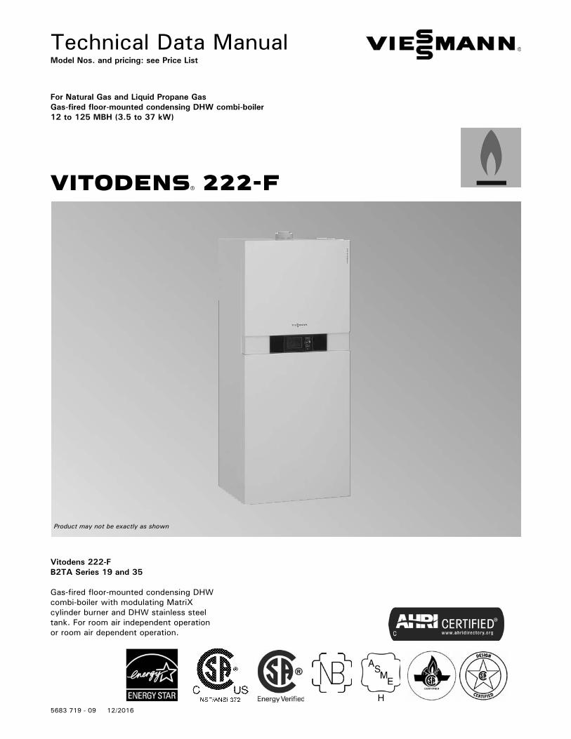
For Natural Gas and Liquid Propane Gas Gas-fired floor-mounted condensing DHW combi-boiler12 to 125 MBH (3.5 to 37 kW)
Product may not be exactly as shown
Vitodens 222-FB2TA Series 19 and 35
Gas-fired floor-mounted condensing DHW combi-boiler with modulating MatriX cylinder burner and DHW stainless steel tank. For room air independent operation or room air dependent operation.
H

Vitodens 222-F, B2TA 19 and 35 Technical Data
5683 7
19 -
09
2
Product Information
Vitodens 222-F
2
Delivered conditionGas condensing boiler with Inox-Radial heat exchanger, modulating MatriX gas burner for natural gas and LPG cylinder, expansion vessel, 3-speed high efficiency circulation pump and integral stainless steel DHW primary storage tank. Fully piped plumbed and wired.White epoxy-coated casing. Preset for operation with natural gas. The conversion to LPG is made at the gas valve (a conversion kit is not required) and control unit.
Accessories required (order separately)Installation on finished walls■ Connection set (for upward connection) for installation on finished walls■ Connection set (for connection to the left or right) for installation on finished walls
The Vitodens 222-F storage combi-boiler combines the benefits of the Vitodens 222-F with the high DHW convenience of a separate DHW tank. With the MatriX gas burner and the stainless steel Inox-Radialheat exchanger, the Vitodens 222-F offers top technology for many years of energy efficiency and high heating and DHW convenience. The Lambda Pro Control combustion controller and the 3-speed high efficiency circulation pump, ensure permanently high efficiency, reliable operation and low power consumption.The Vitodens 222-F is equipped with integral sensor technology that enables operation without minimum flow rate. The integral stainless steel 26.5 USG (100 L) primary storage tank offers the same DHW convenience as a separate DHW cylinder approximately twice the size.
Recommended applications■ Installation in single or semi-detached homes and apartments.■ New build (e.g. pre-fabricated houses and housing association projects): installation in utility rooms and attics.■ Modernisation: Replacement of system boilers, floorstanding atmospheric gas boilers and oil/gas boilers with DHW cylinders below.
Benefits at a glance■ Viessmann made SA240 316Ti stainless steel Inox- Radial heat exchanger constructed to CSA B51 and ASME Section IV■ Viessmann made stainless steel MatriX cylinder burner with Lambda Pro combustion management system for continuous efficiency and low emissions■ 2 models with input ranges from 12 to 125 MBH■ Viessmann made SA240 316Ti stainless steel DHW storage tank 26.5 USG (100 L)■ Zero side clearance requirement■ Pre-installed pressure / temperature relief valves■ Fully enclosed heating expansion tank and circulation pump■ Exceeds Energy Star® Efficiency Requirements■ Built-in 3-speed DHW / space heating pump with diverter valve■ Suitable for altitude levels up to 10,000 ft. (3,050 m)■ Wide modulation ratio up to 6.5:1■ Multiple venting options with vent length up to 180 ft. (55 m)■ 10-minute peak flow of 60 USG (227 L)*■ Continuous DHW draw of 3.3 GPM* * Based on a temperature rise of 70ºF (39ºC) 50ºF to 120ºF (10ºC to 49ºC) (model B2TA-35 only)
■ Fast heat-up with Storage Tank Loading System■ Innovative DHW Storage Tank Loading System comprised of plate heat exchanger, DHW loading pump and storage tank■ Certified to CSA Low Lead Content Certification Program; including US Safe Drinking Water Act, NSF/ANSI 372 as well as other applicable US State requirements
Innovative Storage Tank Loading System (STLS)Advanced Storage Tank Loading System technology in the Vitodens 222-F ensures a reliable and efficient DHW supply equivalent to that of a larger tank. The STLS utilizes an external plate heat exchanger and DHW loading pump for extremely fast heat-up capable of delivering a 10 minute peak flow of 60 gallons or continuous DHW draw of 3.3 GPM*.

Vitodens 222-F, B2TA 19 and 35 Technical Data
3
5683 7
19 -
09
Product Information
3
Cross-Section
Product may not be exactly as shown
The flue gas temperature is only approximately 9-27º F (5-15º C) above boiler return temperature (see chart below).
Vitodens 222-F, series B2TA 19 and 35A Stainless steel Inox-Radial heat exchanger for high operational reliability, a long service life and high heating output in the smallest spaceB Modulating MatriX cylinder gas burner for extremely clean combustionC Integral diaphragm expansion tankD Digital boiler control unitE Integral, 3-speed high efficiency circulation pumpF Stainless steel DHW primary storage tank.
Vitodens 222-F boiler efficiency dependent on system heating water return temperatures and load conditions

Vitodens 222-F, B2TA 19 and 35 Technical Data
5683 7
19 -
09
4
Technical DataTechnical Data
4
Boiler Model No. 222-F B2TA 19 35
Natural Gas / Liquid Propane GasCSA input
CSA output/DOE *1heating capacity
Net AHRI rating *2
MBHkW
MBHkW
MBHkW
12-673.5-20
10.9-613.2-18
5315.5
19-1255.5-37
17.4-1145.1-33
9929
Heat exchanger surface area ft.2m2
10.891.01
10.891.01
Min. gas supply pressureNatural gasLiquid propane gas
“w.c.“w.c.
410
410
Max. gas supply pressure *3Natural gasLiquid propane gas
“w.c.“w.c.
1414
1414
A.F.U.E. % 93.3 93.3
Weight lbskg
282128
282128
Boiler water content USGL
0.873.27
0.873.27
Boiler max. flow rate *4 GPML/h
6.21400
6.21400
Expansion tank *5(for heating system side)Precharge pressureCapacity
psigUSG
L
123.2 12
123.2 12
Max. operating pressureat 210ºF (99ºC)
psigbar
453
453
Boiler water temperature- Adjustable high limit (AHL) range space heating (steady state) - Fixed high limit (FHL)
ºFºC
ºF (ºC)
68 to 16520 to 74210 (99)
68 to 16520 to 74210 (99)
Boiler connectionsBoiler heating supply and return Pressure relief valve Drain valve
Boiler supply/return for indirect-fired DHW storage tank (field supplied)Gas valve connection
NPTM”NPTF”(male
thread)
NPT”
NPTF”
¾”¾”¾”
¾”
¾”
¾”¾”¾”
¾”
¾”
*1 Output based on 140ºF (60ºC), 120ºF (49ºC) system supply/return temperature.
*2 Net AHRI rating based on piping and pick-up allowance of 1.15.
*3 If the gas supply pressure exceeds the maximum gas supply pressure value, a separate gas pressure regulator must be installed upstream of the heating system.
*4 See “Waterside Flow” starting on page 8 in this manual.*5 Determine the required size of the expansion tank to be installed in the heating system. If the integral expansion tank is insufficient, install a suitably sized expansion tank on site.
Vitodens 222-F, B2TA 19 and 35 Technical Data
5
5683 7
19 -
09
Technical Data
5
Technical Data
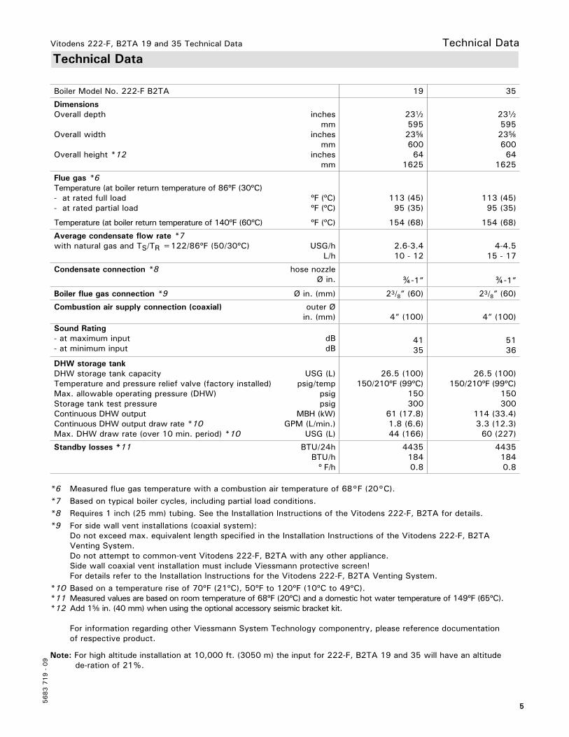
Boiler Model No. 222-F B2TA 19 35
DimensionsOverall depth
Overall width
Overall height *12
inchesmm
inchesmm
inchesmm
23b59523f60064
1625
23b59523f60064
1625
Flue gas *6Temperature (at boiler return temperature of 86ºF (30ºC)- at rated full load- at rated partial load
Temperature (at boiler return temperature of 140ºF (60ºC)
ºF (ºC)ºF (ºC)
ºF (ºC)
113 (45)95 (35)
154 (68)
113 (45)95 (35)
154 (68)
Average condensate flow rate *7with natural gas and TS/TR =122/86ºF (50/30ºC) USG/h
L/h2.6-3.410 - 12
4-4.515 - 17
Condensate connection *8 hose nozzle Ø in. ¾-1” ¾-1”
Boiler flue gas connection *9 Ø in. (mm) 23/8” (60) 23/8” (60)
Combustion air supply connection (coaxial) outer Ø in. (mm) 4” (100) 4” (100)
Sound Rating- at maximum input- at minimum input
dBdB
4135
5136
DHW storage tankDHW storage tank capacityTemperature and pressure relief valve (factory installed)Max. allowable operating pressure (DHW)Storage tank test pressureContinuous DHW outputContinuous DHW output draw rate *10Max. DHW draw rate (over 10 min. period) *10
USG (L)psig/temp
psigpsig
MBH (kW)GPM (L/min.)
USG (L)
26.5 (100)150/210ºF (99ºC)
150300
61 (17.8)1.8 (6.6)44 (166)
26.5 (100)150/210ºF (99ºC)
150300
114 (33.4)3.3 (12.3)
60 (227)
Standby losses *11 BTU/24hBTU/h
º F/h
44351840.8
44351840.8
*6 Measured flue gas temperature with a combustion air temperature of 68°F (20°C).*7 Based on typical boiler cycles, including partial load conditions.*8 Requires 1 inch (25 mm) tubing. See the Installation Instructions of the Vitodens 222-F, B2TA for details.*9 For side wall vent installations (coaxial system): Do not exceed max. equivalent length specified in the Installation Instructions of the Vitodens 222-F, B2TA Venting System. Do not attempt to common-vent Vitodens 222-F, B2TA with any other appliance. Side wall coaxial vent installation must include Viessmann protective screen! For details refer to the Installation Instructions for the Vitodens 222-F, B2TA Venting System.*10 Based on a temperature rise of 70ºF (21ºC), 50ºF to 120ºF (10ºC to 49ºC).*11 Measured values are based on room temperature of 68ºF (20ºC) and a domestic hot water temperature of 149ºF (65ºC).*12 Add 1f in. (40 mm) when using the optional accessory seismic bracket kit.
For information regarding other Viessmann System Technology componentry, please reference documentation of respective product.
Note: For high altitude installation at 10,000 ft. (3050 m) the input for 222-F, B2TA 19 and 35 will have an altitude de-ration of 21%.
Vitodens 222-F, B2TA 19 and 35 Technical Data
5683 7
19 -
09
6
Dimensional Information
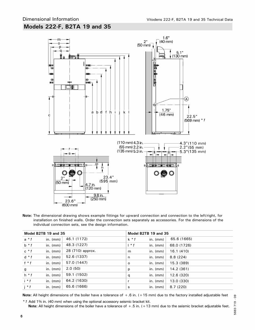
Models 222-F, B2TA 19 and 35
6
Note: The dimensional drawing shows example fittings for upward connection and connection to the left/right, for installation on finished walls. Order the connection sets separately as accessories. For the dimensions of the individual connection sets, see the design information.
Legend A Condensate Drain (side)
Model B2TB 19 and 35 Model B2TB 19 and 35
a *1 in. (mm) 46.1 (1172) k *1 in. (mm) 65.6 (1665)
b *1 in. (mm) 48.3 (1227) l *1 in. (mm) 68.0 (1726)
c *1 in. (mm) 28 (710) approx. m in. (mm) 16.1 (410)
d *1 in. (mm) 52.6 (1337) n in. (mm) 8.8 (224)
f *1 in. (mm) 57.0 (1447) o in. (mm) 15.3 (389)
g in. (mm) 2.0 (50) p in. (mm) 14.2 (361)
h *1 in. (mm) 59.1 (1502) q in. (mm) 12.6 (320)
i *1 in. (mm) 64.2 (1630) r in. (mm) 13.0 (330)
j *1 in. (mm) 65.6 (1666) s in. (mm) 8.7 (220)
Note: All height dimensions of the boiler have a tolerance of +.6 in. (+15 mm) due to the factory installed adjustable feet
*1 Add 1f in. (40 mm) when using the optional accessory seismic bracket kit. Note: All height dimensions of the boiler have a tolerance of +.5 in. (+13 mm) due to the seismic bracket adjustable feet.
*1
Vitodens 222-F, B2TA 19 and 35 Technical Data
7
5683 7
19 -
09
Minimum Clearances
7
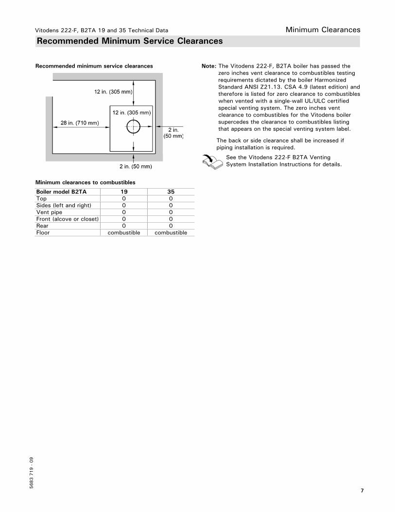
Recommended Minimum Service Clearances
Note: The Vitodens 222-F, B2TA boiler has passed the zero inches vent clearance to combustibles testing requirements dictated by the boiler Harmonized Standard ANSI Z21.13. CSA 4.9 (latest edition) and therefore is listed for zero clearance to combustibles when vented with a single-wall UL/ULC certified special venting system. The zero inches vent clearance to combustibles for the Vitodens boiler supercedes the clearance to combustibles listing that appears on the special venting system label.
The back or side clearance shall be increased if piping installation is required.
See the Vitodens 222-F B2TA Venting System Installation Instructions for details.
Boiler model B2TA 19 35Top 0 0Sides (left and right) 0 0Vent pipe 0 0Front (alcove or closet) 0 0Rear 0 0Floor combustible combustible
Minimum clearances to combustibles
Recommended minimum service clearances

Vitodens 222-F, B2TA 19 and 35 Technical Data
5683 7
19 -
09
8
Waterside FlowWaterside Flow (primary circuit)
Sup
ply
head
pre
ssur
e (w
ater
)
Flow rate
The Vitodens 222-F, B2TA is designed for closed loop, forced circulation hot water heating systems only. Use standard friction loss method for pipe sizing. Observe boiler maximum and minimum flow rate limitations. If system flow rate exceeds boiler maximum flow rate (as stated above), falls below the minimum flow rate or if system flow rate is unknown, Viessmann strongly recommends the installation of a low-loss header. An alternative method may be used, such as primary secondary piping using closely spaced tees.
A low-loss header offers additional benefits not provided by a pair of closely spaced tees. Viessmann therefore strongly recommends and prefers the use of a low-loss header over closely spaced tees. See pages 32 and 33 for low-loss header information. Once the low-loss header is connected, the built-in low-loss header logic of the Vitodens 222-F boiler ensures the required t across the system through the sensory communication between the low-loss header and the boiler.
Pressure drop (primary circuit) for Vitodens 222-F, B2TA 19 and 35
Model B2TA 19 1 boilerOutput (NG/LPG) MBH 61t for NG/LPG20ºF (11ºC) rise GPM (L/h) 6.1 (1385) 25ºF (14ºC) rise GPM (L/h) 4.9 (1113)30ºF (17ºC) rise GPM (L/h) 4.0 (909)35ºF (19.5ºC) rise GPM (L/h) 3.5 (795)40ºF (22ºC) rise GPM (L/h) 3.1 (704)
Model B2TA 35 1 boilerOutput (NG/LPG) MBH 114t for NG/LPG20ºF (11ºC) rise GPM (L/h) 11.4 (2589) 25ºF (14ºC) rise GPM (L/h) 9.1 (2067) 30ºF (17ºC) rise GPM (L/h) 7.6 (1726) 35ºF (19.5ºC) rise GPM (L/h) 6.5 (1476)40ºF (22ºC) rise GPM (L/h) 5.7 (1295)
Boiler maximum flow rate 6.2 GPM (1400 L/h)
Boiler maximum flow rate 6.2 GPM (1400 L/h)

Vitodens 222-F, B2TA 19 and 35 Technical Data
9
5683 7
19 -
09
Pump InformationHeating Circuit
Viessmann offers a variety of Grundfos heating circuit/boiler pumps which meet typical Vitodens system installation requirements (see “Heating circuit pump field supplied)”. See tables below for recommended pumps. Refer to the graphs on page 10 and 11 for the proper waterside boiler friction loss calculations. The following pumps have been selected based on boiler heat exchanger head loss and boiler piping to a low-loss header.
IMPORTANTPump selection must be based on accurate system flow and pressure drop calculations (includes DHW sizing).
Model B2TA 19 B2TA 35Flow rate20ºF (11ºC) t GPM (L/h) 6.1 (1385) --
25ºF (14ºC) t GPM (L/h) 4.9 (1113) --30ºF (17ºC) t GPM (L/h) 4.0 (909) --35ºF (19.5ºC) t GPM (L/h) 3.5 (795) 6.5 (1476)40ºF (22ºC) t GPM (L/h) 3.1 (704) 5.7 (1295)Flow limitation GPM (L/h) 4.4 (1200) 6.2 (1400)
Low-Loss Header Application
Sizing of Low-Loss Header in a Residential Single-Boiler Application
*1 For system t < 20ºF (11ºC) use low-loss header sizes for t 20ºF (11ºC).*2 Low-Loss temperature sensor - optional equipment for use in single-boiler applications.
BoilerModel
No. ofBoilers
Boiler Max. Flow RateGPM (L/h)
Typical System Flow Rates Viessmann Low-lossTemp.Sensor Required*2
t *1 °F(°C)
20(11.0)
25(13.9)
30(16.8)
35(16.1)
40(13.4)
B2TA 19
1 5.3(1200)
System Flow RateLLH RequiredLLH Model
GPM(L/h)
6.1(1385)
Optional80/60
4.9(1108)
Optional80/60
4.1(924)
Optional80/60
3.5(792)
Optional80/60
3.1(693)
Optional80/60
Yes
B2TA 35
1 6.2(1400)
System Flow RateLLH RequiredLLH Model
GPM(L/h)
11.4(2589)
Yes80/60
9.1(2071)
Yes80/60
7.6(1726)
Yes80/60
6.5(1480)
Optional80/60
5.7(1295)
Optional80/60
Yes
Note: The Vitodens 222-F comes equipped with a factory preset integrated boiler pump.

Vitodens 222-F, B2TA 19 and 35 Technical Data
5683 7
19 -
09
10
Low-Loss Header InformationHeating Circuit Pumps
Pump Model Grundfos UPS15-78
Rated voltage VAC 115Rated current A max. 1.15
A min. 0.8Capacitor F 8
Power consumption W max. 130W min. 80
Grundfos UPS15-78 three speed heating circuit/DHW circuit pump for Vitodens 222-F, B2TA boilers (in the factory setting, the pump speed is preset to ‘speed three’)
Speed One
Speed Three
Speed Two
Flow Q (gpm)
Ft o
f H
ead
Performance chart courtesy of Grundfos
Grundfos UPS15-78 residual head pressureResidual head of built-in three speed pump used with Vitodens 222-F, B2TA
Flow Q (gpm)
Ft o
f H
ead

Vitodens 222-F, B2TA 19 and 35 Technical Data
11
5683 7
19 -
09
DHW Production
Domestic Hot Water Production
A diaphragm expansion tank is integrated into the Vitodens 222-F, with a capacity of 3.2 USG (12 L) and a pre-charge pressure of 12 psig.Determine the required size of the expansion tank to be installed in the heating system. If the integral expansion tank is insufficient, install a suitably sized expansion tank on site.
IMPORTANTThe Vitodens 222-F storage combi-boiler combines the benefits of the Vitodens 200-W with high DHW convenience of a separate integral stainless steel DHW storage tank.
The Vitodens 222-F uses an integrated 26.5 USG (100 L) DHW storage tank and a DHW production pump.
Domestic Hot Water Recirculation
DHW recirculation lines increase the level of comfort and convenience of the domestic hot water supply and reduce water consumption.These advantages directly derive from the immediate availability of domestic hot water at all draw points.
Poor insulation of the DHW recirculation line, however, can result in considerable heat loss. Viessmann therefore recommends that effective insulation be provided and used for DHW recirculation lines of 23 ft. (7 m) in length or longer.
Vitodens 222-F, B2TA 19 and 35 Technical Data
5683 7
19 -
09
12
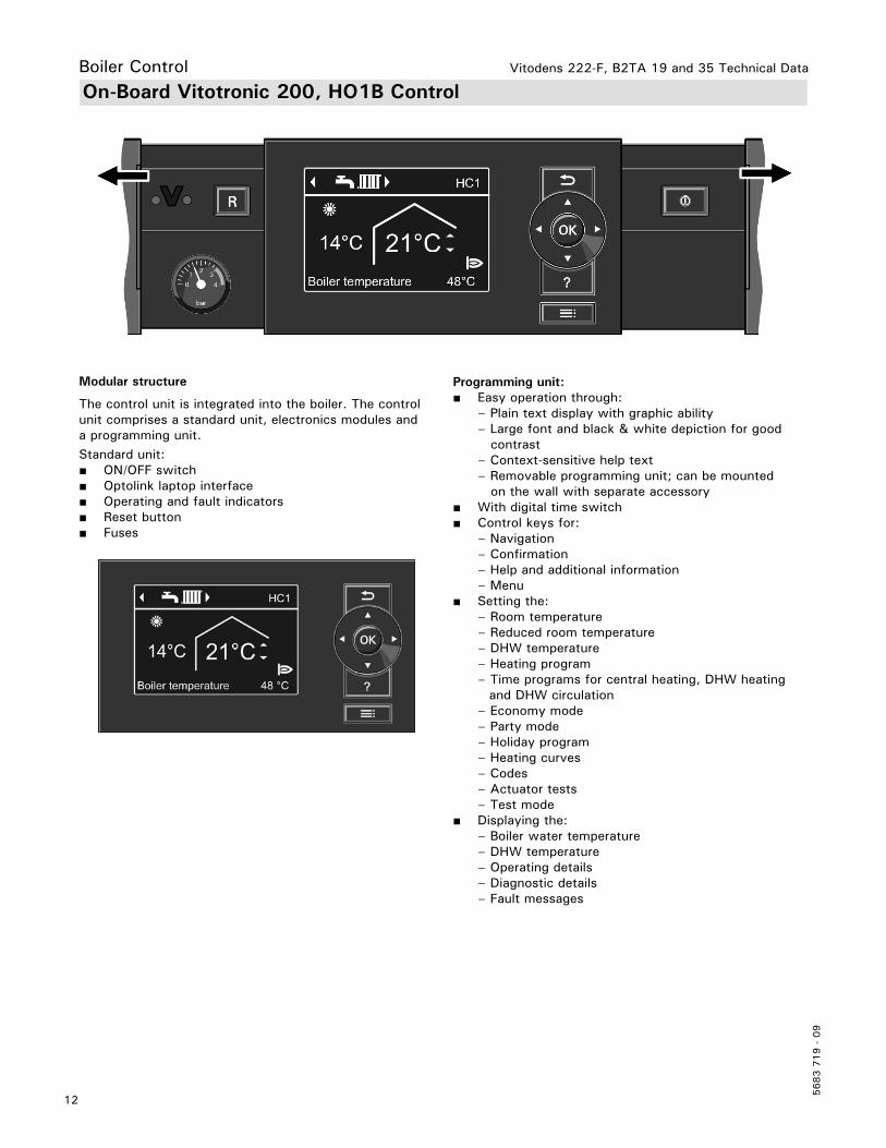
Boiler ControlOn-Board Vitotronic 200, HO1B Control
Modular structure
The control unit is integrated into the boiler. The control unit comprises a standard unit, electronics modules and a programming unit.Standard unit:■ ON/OFF switch■ Optolink laptop interface■ Operating and fault indicators■ Reset button■ Fuses
Programming unit:■ Easy operation through: – Plain text display with graphic ability – Large font and black & white depiction for good contrast – Context-sensitive help text – Removable programming unit; can be mounted on the wall with separate accessory■ With digital time switch■ Control keys for: – Navigation – Confirmation – Help and additional information – Menu■ Setting the: – Room temperature – Reduced room temperature – DHW temperature – Heating program – Time programs for central heating, DHW heating and DHW circulation – Economy mode – Party mode – Holiday program – Heating curves – Codes – Actuator tests – Test mode■ Displaying the: – Boiler water temperature – DHW temperature – Operating details – Diagnostic details – Fault messages
Vitodens 222-F, B2TA 19 and 35 Technical Data
13
5683 7
19 -
09
Frost protection■ The frost protection function will be started when the outside temperature drops below approx. 34°F (1°C). With the frost protection function, the heating circuit pump will be switched ON and the boiler water is maintained at a lower temperature of approx. 68°F (20°C). The DHW tank will be heated to approx. 68°F (20°C).■ The frost protection function will be stopped when the outside temperature rises above approx. 37°F (3°C) (default settings).
Summer OperationHeating program “w”The burner is only activated upon a call for domestic hot water from the DHW storage tank (controlled by DHW tank temperature sensor).
Design and FunctionBoiler Control
Control CharacteristicsPI characteristics with modulating output. Time SwitchDigital time switch.■ Individual and 7-day program■ Automatic daylight savings time changeover■ Automatic function for DHW heating and DHW recirculation pump■ Time, day and standard switching times for space heating, DHW heating and the DHW circulation pump are factory-set■ Switching times are individually programmable, i.e. up to four switching periods per day Shortest switching interval: 10 minutes Power backup: 14 days.
Functions
■ Weather-compensated control of the boiler water and/or supply temperature■ Control of one heating circuit without mixer and two heating circuits with mixer■ Demand-dependent heating circuit pump and burner off control
■ Adjustment of a variable heating limit■ Anti-seizing pump protection■ Integral diagnostic system■ Maintenance display■ DHW temperature control with priority■ Auxiliary function for DHW heating (short-term heating to a higher temperature)■ 0-10V External signal input
Setting the Operating ProgramsThe heating system frost protection (see frost protection function) applies to all heating programs.You can select the following heating programs with the program keys:■ Heating and DHW■ DHW only■ Standby modeExternal heating program changeover.

Vitodens 222-F, B2TA 19 and 35 Technical Data
5683 7
19 -
09
14
Boiler ControlDesign and Functions (continued)
Heating Curve Adjustment (slope and shift)The control unit regulates the boiler water temperature (= supply temperature of heating circuit without mixing valve) and the supply temperature of the heating circuit with mixing valve (in conjunction with the accessory kit for a heating circuit with mixing valve) according to the outdoor temperature. The boiler water temperature is automatically raised by 0 to 72 F / 0 to 40 K higher than the currently required set supply temperature (in the factory default setting the differential temperature is 14.4 F / 8 K). See Service Instructions for coding address “9F” in coding level 2.The supply temperature that is required to achieve a given room temperature depends on the heating system and the thermal insulation of the building that is being heated. The adjustment of the two heating curves is used to match the boiler water temperature and the supply temperature to these conditions. The boiler water temperature is limited upwards by the fixed high limit and the temperature set for the electronic high limit.The supply temperature cannot rise above the boiler water temperature.
Technical Data
Rated supply voltage: 120 VACRated frequency: 60 HzRated current: 12 AMax. ambient temp.- at operation: 32 to 104ºF (0 to 40ºC) Installation in living spaces or boiler rooms (standard ambient conditions)- when storing or transporting: -4 to +158ºF (-20 to +70ºC)Max. operating temp.setting (space heating): Models B2TA 19 & 35 165ºF (74ºC)
DHW production:Models B2TA 19 & 35 165ºF (74ºC)
Setting fixed high limit: 210ºF (99ºC) (not adjustable)Adjustment range of DHW tank set-pointtemperature: 50 to 154ºF (10 to 68ºC)
Heating curve settings- Heating curve slope: 0.2 to 3.5- Heating curve shift: -12 to +33ºC -13 to 40 K
Legend
A Low temperature heating system, e.g. radiant floor heating
B Medium temperature heating system, e.g. cast iron radiation, staple-up radiant floor heating
C High temperature heating system, e.g. fintube radiation, fan coils
Boi
ler
wat
er o
r su
pply
te
mpe
ratu
re
Room set-point temperature
Outdoor temperature

Vitodens 222-F, B2TA 19 and 35 Technical Data
15
5683 7
19 -
09
Design and Functions (continued)
Boiler Temperature Sensor The boiler temperature sensor is connected at the control unit for weather-responsive operation and is built into the boiler.
Specification sensor type: Viessmann NTC 10K ohms at 77ºF (25ºC)
Max. ambient temp.- at operation: 32 to 266ºF (0 to 130ºC)- when storing or transporting: - 4 to+158ºF (-20 to+70ºC)
Outdoor Temperature Sensor
Sensor location:- North or northwest wall of building- 6.6 to 8.2 ft. (2 to 2.5 m) above ground or in case of a multi-storey building approximately halfway up the second floor
Electrical connection:- 2-wire cable, max. cable length 115 ft. (35 m) with a wire size of min. AWG 16 copper- Cable to the outdoor sensor must not be laid near line voltage wiring (120/240V)
DHW Tank Temperature Sensor
- integrated DHW temperature sensor
Accessories
Immersion Temperature SensorTo capture the low loss temperature
SpecificationLead length fully wired: 12 ft. (3.75 m),
Permissable ambient temp.- during operation: 32 to 194°F (0 to 90°C)- when storing or transporting: - 4 to+158°F (-20 to+70°C)
Max. ambient temperature during transport, storage and operation: -40 to 194ºF (-40 to 90ºC)
Vitodens 222-F, B2TA 19 and 35 Technical Data
5683 7
19 -
09
16
AccessoriesVitotronic Control Accessories
Mixing Valve Actuator Kit
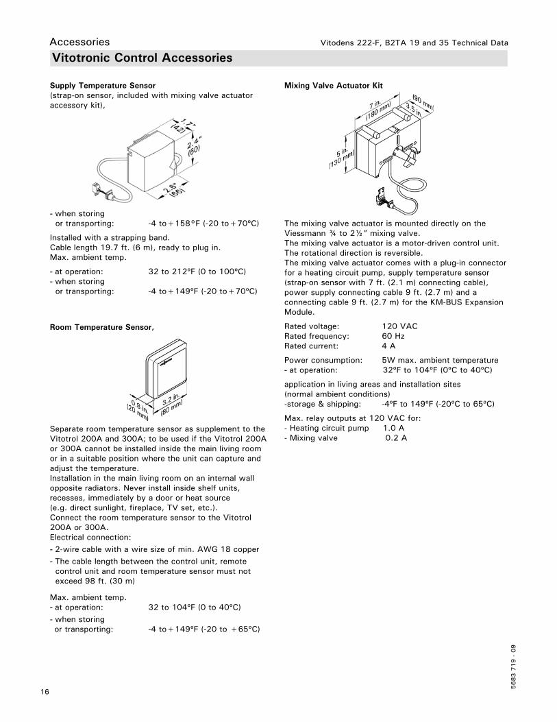
The mixing valve actuator is mounted directly on the Viessmann ¾ to 2½” mixing valve.The mixing valve actuator is a motor-driven control unit. The rotational direction is reversible.The mixing valve actuator comes with a plug-in connector for a heating circuit pump, supply temperature sensor (strap-on sensor with 7 ft. (2.1 m) connecting cable), power supply connecting cable 9 ft. (2.7 m) and a connecting cable 9 ft. (2.7 m) for the KM-BUS Expansion Module.
Rated voltage: 120 VACRated frequency: 60 HzRated current: 4 A
Power consumption: 5W max. ambient temperature - at operation: 32ºF to 104ºF (0ºC to 40ºC)
application in living areas and installation sites (normal ambient conditions)-storage & shipping: -4ºF to 149ºF (-20ºC to 65ºC)
Max. relay outputs at 120 VAC for:- Heating circuit pump 1.0 A- Mixing valve 0.2 A
Room Temperature Sensor,
Separate room temperature sensor as supplement to the Vitotrol 200A and 300A; to be used if the Vitotrol 200A or 300A cannot be installed inside the main living room or in a suitable position where the unit can capture and adjust the temperature.Installation in the main living room on an internal wall opposite radiators. Never install inside shelf units, recesses, immediately by a door or heat source (e.g. direct sunlight, fireplace, TV set, etc.).Connect the room temperature sensor to the Vitotrol 200A or 300A.Electrical connection:- 2-wire cable with a wire size of min. AWG 18 copper - The cable length between the control unit, remote control unit and room temperature sensor must not exceed 98 ft. (30 m)
Max. ambient temp.- at operation: 32 to 104ºF (0 to 40ºC)- when storing or transporting: -4 to+149ºF (-20 to +65ºC)
Supply Temperature Sensor(strap-on sensor, included with mixing valve actuator accessory kit),
- when storing or transporting: -4 to+158°F (-20 to+70ºC)
Installed with a strapping band.Cable length 19.7 ft. (6 m), ready to plug in.Max. ambient temp.
- at operation: 32 to 212ºF (0 to 100ºC)- when storing or transporting: -4 to+149ºF (-20 to+70ºC)

Vitodens 222-F, B2TA 19 and 35 Technical Data
17
5683 7
19 -
09
Mixing Valve Extension Module
Rated voltage: 120 VACRated frequency: 60 HzRated current: 4 (2) APower consumption: 4 WMax. ambient temp.- at operation: 32 to 104ºF (0 to 40ºC)- when storing or transporting: -4 to+149ºF (-20 to+65ºC)Relay output for heating circuit pump: 4 (2) A, 120 VAC
Actuator torque: 3 Nm
Time of 90º: 2 minutes
AccessoriesVitotronic Control Accessories (continued)
LON Communication ModuleElectronic PCB for data exchange with the Vitotronic 200-H, Vitocom 200 and for connecting to a higher level building management system. LON Connecting Cable (for data exchange between control units)Cable length 23 ft. (7 m), fully wired
LON Terminal End ResistorTo terminate the LON BUS at the first and the last control unit.
KM BUS Expansion ModuleTo connect 2 to 9 devices (mixing valve actuator, Vitotrol, input module, etc.) to the single KM BUS connection of the boiler.
SpecificationLead length 10 ft. (3.0 m), fully wired
Permissable ambient temp.- during operation 32 to 104°F (0 to 40°C)
- during storage and transport: - 4 to+149°F (-20 to+65°C)

Vitodens 222-F, B2TA 19 and 35 Technical Data
5683 7
19 -
09
18
Vitotrol 300A
One Vitotrol 300A can be used for every heating circuit in a heating system. The Vitotrol 300A can regulate up to three heating circuits. Up to two remote controls may be connected to the control unit.
KM BUS ParticipantThe Vitotrol 300A remote control regulates the required set room temperature for one heating circuit in standard and reduced mode, the heating program and the switching times for central heating, DHW heating and the DHW circulation pump.
Displaying:- Room temperature- Outside temperature- Heating program- Operating condition- Solar yield as graphic display
Settings:- Set room temperatures for standard mode (day temperature) and reduced mode (night temperature) via the standard display- Heating program, switching times for heating circuits, DHW heating and DHW circulation pump plus further settings via plain text menu on the display- Party and economy mode can be enabled via the menu- Only for heating circuit with mixer: Fitted room temperature sensor for room temperature hook-up
Note: For room temperature hook-up, the Vitotrol 300A must be installed in the main living room (lead room).
RS function:Installation in the main living room on an internal wall opposite radiators. Never install inside shelving units, in recesses, or immediately by a door or heat source (e.g. direct sunlight, fireplace, TV set, etc.). The fitted room temperature sensor captures the actual room temperature and effects any necessary correction of the flow temperature.
WS function:Installation anywhere in the building.Connection:- 2-core lead, length max. 164 ft. (50 m) (even if connecting several remote control units)- Never route this lead immediately next to 120/208/460V cables- LV plug as standard delivery must be installed in the main living room (lead room).
Specification:Power supply via KM BUSPower consumption: 0.2 WProtection class: IIIMax. ambient temp.- at operation: 32 to 104ºF (0 to 40ºC)- when storing or transporting: -4 to+149ºF (-20 to+65ºC)
Set room temp. range 37 to 99ºF (3 to 37ºC)
The set room temperature for reduced mode is adjusted at the control unit.
Vitotronic Control Accessories (continued)
Accessories

Vitodens 222-F, B2TA 19 and 35 Technical Data
19
5683 7
19 -
09
AccessoriesAccessories for Vitodens 222-F
Low-Loss Header
When used in conjunction with the Vitodens 222-F boiler, the low-loss header acts as hydraulic break, decoupling boiler and system circuits from each other. It is recommended to use the low-loss header in applications in which the total system flow rate exceeds the maximum (or minimum) boiler flow rate. For maximum boiler flow rates, starting on page 10 of this manual.
Viessmann strongly recommends the use of a low-loss header in cases where the system head and flow rates are unknown.
The temperature sensor connection [TS] typically located at the top of the low-loss header ensures low return temperatures to the Vitodens 222-F boiler at all times, increasing operational efficiency. In addition, the low-loss header helps eliminate air and debris [D] from the heating system. See illustrations for design and principle of operation.
The low-loss header is available in the following sizes. Select the size based on the maximum system flow rate of your application.
Fuel Conversion Label Kit (NG>LPG)(included in boiler technical literature set)The Vitodens 222-F, B2TA boiler comes factory set for operation with natural gas. All B2TA models can be field converted to operate with liquid propane gas (as well as back to natural gas as required). The kit includes instructions and labels for field conversion.
Use only a Viessmann supplied temperature sensor. Do not use any other manufacturer’s temperature sensor.
LegendAB Air BleedBR Boiler ReturnBS Boiler SupplyBY Bypass (with laminar flow)D Debris and/or airDV Drain ValveSC Sensor CableSR System ReturnSS System SupplyTS Viessmann Temperature SensorSW Sensor Well
IMPORTANT
Low-loss header design (Type 80/50 or 120/80)
Vitodens 222-F, B2TA 19 and 35 Technical Data
5683 7
19 -
09
20
Accessories
Accessories for Vitodens 222-F
Low-Loss Header (continued)
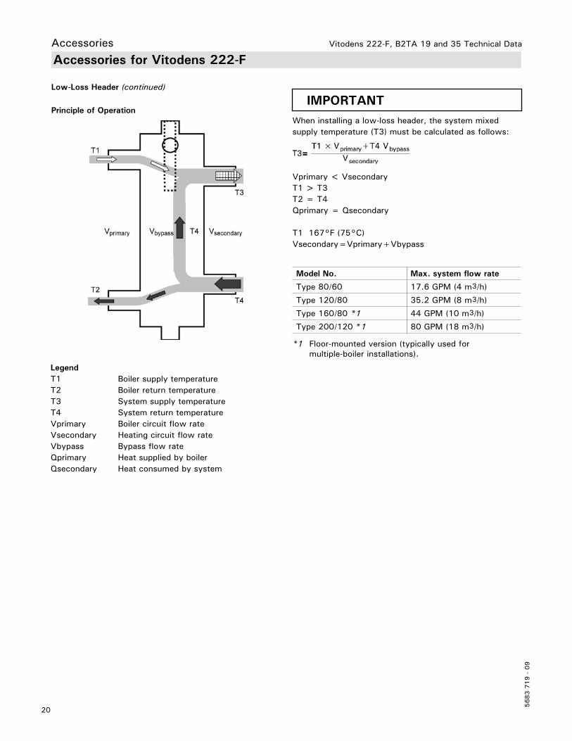
When installing a low-loss header, the system mixed supply temperature (T3) must be calculated as follows:
Vprimary < VsecondaryT1 > T3T2 = T4Qprimary = Qsecondary
T1 167°F (75°C)Vsecondary=Vprimary+Vbypass
IMPORTANT
Model No. Max. system flow rate
Type 80/60 17.6 GPM (4 m3/h)
Type 120/80 35.2 GPM (8 m3/h)
Type 160/80 *1 44 GPM (10 m3/h)
Type 200/120 *1 80 GPM (18 m3/h)
*1 Floor-mounted version (typically used for multiple-boiler installations).
Principle of Operation
LegendT1 Boiler supply temperatureT2 Boiler return temperatureT3 System supply temperatureT4 System return temperatureVprimary Boiler circuit flow rateVsecondary Heating circuit flow rateVbypass Bypass flow rateQprimary Heat supplied by boilerQsecondary Heat consumed by system

Vitodens 222-F, B2TA 19 and 35 Technical Data
21
5683 7
19 -
06
AccessoriesAccessories for Vitodens 222-F
Parts for Top Connection0302 Connecting pipe, DHW/heating0303 Support bracket with pipe clips0304 Pipe clip (each)0307 Connector retaining clip (Set of 2) *10308 Pipe insulation, 19x9x740 mm0310 Gas ball valve, ¾” brass0311 Sediment faucet, ¾” NPT0313 Tee, ¾” brass0318 Security clips *1 *2
Other Parts (not illustrated)0301 Flex pipe (NG/LP), full-length*30305 O-Ring, 18x3 mm for supply/return0306 Gasket, 17x24x2 mm for gas connection pipe*30309 Accessory pack for coaxial venting fasteners0312 Outdoor temperature sensor, NTC0314 Air bleed key0326 Parts List for Installation Set, top0350 Temperature gauge, 2” 30-250ºF*40351 LLH temperature sensor, immersion NTC (if used)
Parts for Left/Right Side Connection0302 Connecting pipe 90º, DHW short0303 Connecting pipe 90º, DHW long0304 Connecting pipe 90º, heating short0305 Connecting pipe 90º, heating long0306 Support bracket with pipe clips0307 Pipe clip (each)0310 Connector retaining clip (Set of 2)*10311 Pipe insulation, 19x9x740 mm0313 Gas ball valve, ¾” brass0314 Sediment faucet, ¾” NPT0316 Tee, ¾” brass0318 Security clips *1 *2
Other Parts (not illustrated)0301 Flex pipe (NG/LP), full-length*30308 O-Ring, 18x3 mm for supply/return0309 Gasket, 17x24x2 mm for gas connection pipe*30312 Accessory pack for coaxial venting fasteners0315 Outdoor temperature sensor, NTC0317 Air bleed key0325 Parts List for Installation Set, left/right0350 Temperature gauge, 2” 30-250ºF*30351 LLH temperature sensor, immersion NTC (if used)
*1 Please ensure security clip (0318) is always installed on connector retaining clip (0310) of the domestic water piping.*2 Shipped affixed to rear of boiler *3 The NG/LPG flex pipe (0301) and It’s gasket (0309) ship preinstalled on the Vitodens 222-F boiler.*4 Install anywhere in the supply piping near the boiler.
Vitodens 222-F, B2TA 19 and 35 Technical Data
5683 7
19 -
09
22
Standard Equipment/Management SystemStandard Equipment
Combustion Management System
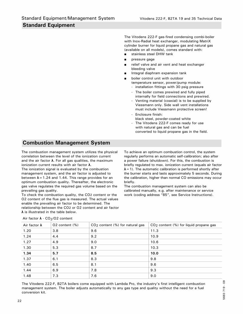
The Vitodens 222-F gas-fired condensing combi-boiler with Inox-Radial heat exchanger, modulating MatriX cylinder burner for liquid propane gas and natural gas (available on all models), comes standard with:■ stainless steel DHW tank ■ pressure gage ■ relief valve and air vent and heat exchanger bleeding valve■ Integral diaphram expansion tank■ boiler control unit with outdoor temperature sensor, power/pump module: - installation fittings with 30 psig pressure - The boiler comes prewired and fully piped internally for field connections and prewired. - Venting material (coaxial) is to be supplied by Viessmann only. Side wall vent installations must include Viessmann protective screen! - Enclosure finish: black steel, powder-coated white - The Vitodens 222-F comes ready for use with natural gas and can be fuel converted to liquid propane gas in the field.
The combustion management system utilizes the physical correlation between the level of the ionization current and the air factor λ. For all gas qualities, the maximum ionization current results with air factor λ.The ionization signal is evaluated by the combustion management system, and the air factor is adjusted to between λ=1.24 and 1.44. This range provides for an optimum combustion quality. Thereafter, the electronic gas valve regulates the required gas volume based on the prevailing gas quality.To check the combustion quality, the CO2 content or the O2 content of the flue gas is measured. The actual values enable the prevailing air factor to be determined. The relationship between the CO2 or O2 content and air factor λ is illustrated in the table below.
To achieve an optimum combustion control, the system regularly performs an automatic self-calibration; also after a power failure (shutdown). For this, the combustion is briefly regulated to max. ionization current (equals air factor λ=1). The automatic calibration is performed shortly after the burner starts and lasts approximately 5 seconds. During the calibration, higher than normal CO emissions may occur briefly.The combustion management system can also be calibrated manually, e.g. after maintenance or service work (coding address “85”, see Service Instructions).
The Vitodens 222-F, B2TA boilers come equipped with Lambda Pro, the industry’s first intelligent combustion management system. The boiler adjusts automatically to any gas type and quality without the need for a fuel conversion kit.
Air factor λ - CO2/O2 content
Air factor λ O2 content (%) CO2 content (%) for natural gas CO2 content (%) for liquid propane gas
1.20 3.8 9.6 11.3
1.24 4.4 9.2 10.9
1.27 4.9 9.0 10.6
1.30 5.3 8.7 10.3
1.34 5.7 8.5 10.0
1.37 6.1 8.3 9.8
1.40 6.5 8.1 9.6
1.44 6.9 7.8 9.3
1.48 7.3 7.6 9.0

Vitodens 222-F, B2TA 19 and 35 Technical Data
23
5683 7
19 -
09
Installation
Installation Examples
Please note that in the following piping layout examples all pumps external to the boiler are field supplied.
IMPORTANT
The examples on the following pages depict possible piping layouts of the Vitodens 222-F boiler equipped with Viessmann System Technology.
Please note that the following examples are simplified conceptual drawings only!Piping and necessary componentry must be field verified. A low water cut-off (LWCO) must be installed where required by local codes.Proper installation and functionality in the field is the responsibility of the heating contractor.
Hydraulic Connection
System designViessmann condensing boilers can generally be installed in any pumped hot water heating system (closed system).The circulation pump is an integral part of the appliance.Minimum system pressure 14 psi.The boiler water temperature is limited to 165ºF (74ºC).To minimise distribution losses, we recommend that you size the heat distribution system to a max. supply temperature of 158ºF (70ºC).
For apartments with less than 860 ft2 (80 m2) living space or for low energy houses with low heat demand we recommend, due to the immediate capturing of the room-influencing factors, the utilisation of the Vitodens with a constant temperature control unit in conjunction with the Vitotrol 100.To reduce burner cycling in low energy houses with a correspondingly low heat demand, we recommend the use of a low loss header.

Vitodens 222-F, B2TA 19 and 35 Technical Data
5683 7
19 -
09
Installation ExamplesSystem Layout 1
Vitodens 222-F, B2TA with a direct-connected heating circuit with integrated DHW production
Installation of ...■ radiator heating circuit (high-temp. circuit)■ DHW production
... with the following flow conditions:The flow rate of the heating circuit is less than the maximum possible water flow rate of the Vitodens 222-F B2TA boiler (see page 28 for maximum water flow rate of boiler).
The use of a low-loss header is strongly recommended if the maximum water flow rate in the application concerned exceeds the values shown in the applicable table on page 28, or if the system flow rates are unknown.The low-loss header is available as accessory part.
See following pages for installation examples with a low-loss header.
24
LegendA Vitodens 222-F B2TA boiler with Vitotronic 200, HO1B outdoor reset controlB Outdoor temperature sensor !C Vitotrol remote (optional)D Heating circuitE Boiler pump 20 F DHW circulating pump sAG DHW storage tank H Integral expansion tankI DCW inletJ DHW outletK Temperature and pressure relief valve outlet L Pressure relief valve outlet
Vitodens 222-F, B2TA 19 and 35 Technical Data
25
5683 7
19 -
09
Installation ExamplesSystem Layout 2
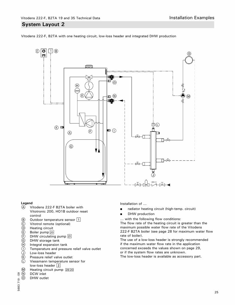
Vitodens 222-F, B2TA with one heating circuit, low-loss header and integrated DHW production
Installation of ...■ radiator heating circuit (high-temp. circuit)■ DHW production... with the following flow conditions:The flow rate of the heating circuit is greater than the maximum possible water flow rate of the Vitodens 222-F B2TA boiler (see page 28 for maximum water flow rate of boiler).The use of a low-loss header is strongly recommended if the maximum water flow rate in the application concerned exceeds the values shown on page 29, or if the system flow rates are unknown.The low-loss header is available as accessory part.
LegendA Vitodens 222-F B2TA boiler with Vitotronic 200, HO1B outdoor reset controlB Outdoor temperature sensor !C Vitotrol remote (optional)D Heating circuitE Boiler pump 20
F DHW circulating pump sAG DHW storage tank H Integral expansion tankI Temperature and pressure relief valve outlet J Low-loss headerK Pressure relief valve outletL Viessmann temperature sensor for low-loss header ?M Heating circuit pump 28/20 N DCW inletO DHW outlet
Vitodens 222-F, B2TA 19 and 35 Technical Data
5683 7
19 -
09
Installation ExamplesSystem Layout 3
26
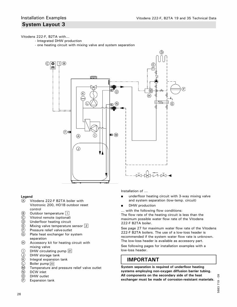
Vitodens 222-F, B2TA with... - Integrated DHW production - one heating circuit with mixing valve and system separation
Installation of ...■ underfloor heating circuit with 3-way mixing valve and system separation (low-temp. circuit)■ DHW production... with the following flow conditions:The flow rate of the heating circuit is less than the maximum possible water flow rate of the Vitodens 222-F B2TA boiler.See page 27 for maximum water flow rate of the Vitodens 222-F B2TA boilers. The use of a low-loss header is recommended if the system water flow rate is unknown. The low-loss header is available as accessory part. See following pages for installation examples with a low-loss header.
System separation is required of underfloor heating systems employing non-oxygen diffusion barrier tubing.All components on the secondary side of the heat exchanger must be made of corrosion-resistant materials.
IMPORTANT
LegendA Vitodens 222-F B2TA boiler with Vitotronic 200, HO1B outdoor reset controlB Outdoor temperature !C Vitotrol remote (optional)D Underfloor heating circuitE Mixing valve temperature sensor ?F Pressure relief valve outlet G Plate heat exchanger for system separationH Accessory kit for heating circuit with mixing valveI DHW circulating pump sAJ DHW storage tankK Integral expansion tankL Boiler pump 20
M Temperature and pressure relief valve outlet N DCW inlet O DHW outletP Expansion tank

Vitodens 222-F, B2TA 19 and 35 Technical Data
27
5683 7
19 -
09
System Layout 4
Vitodens 222-F, B2TA with... - Integrated DHW production - one direct-connected heating circuit - one heating circuit with a mixing valve
Installation of different heating circuits...■ radiator heating circuit (high-temp. circuit)■ under floor heating circuit with 3-way mixing valve (low-temp. circuit)■ DHW production... with the following flow conditions:1. The water flow rate (output) of the radiator heating circuit is at least 30% greater than that of the under floor heating circuit.
2. The total flow rate of the two heating circuits is less than the maximum possible water flow rate of the Vitodens 222-F B2TA boiler (see page 27 for max. water flow rate). The use of a low-loss header is strongly recommended if the maximum water flow rate in the application concerned exceeds the values shown on page 27, or if the system flow rates are unknown. The low-loss header is available as accessory part.
The 3-way mixing valve, built-in to achieve the low-temperature level of the under floor heating circuit, is controlled by an accessory kit for a heating circuit with mixing valve.
Installation Examples
LegendA Vitodens 222-F B2TA boiler with Vitotronic 200, HO1B outdoor reset controlB Outdoor temperature sensor !C Vitotrol remote (optional)D Under floor heating circuitE Radiator heating circuitF Heating circuit pump 28/20
G Mixing valve temperature sensor ?H Accessory kit for heating circuit with mixing valveI Domestic hot water storage tankJ Integral expansion tankK Temperature and pressure relief valve outlet L Pressure relief valve outletM DHW circulating pump sAN Boiler pump 20
O Low-loss headerP Low-loss header sensor ?Q DCW inlet R DHW outlet
Vitodens 222-F, B2TA 19 and 35 Technical Data
5683 7
19 -
09
Installation ExamplesSystem Layout 5
28
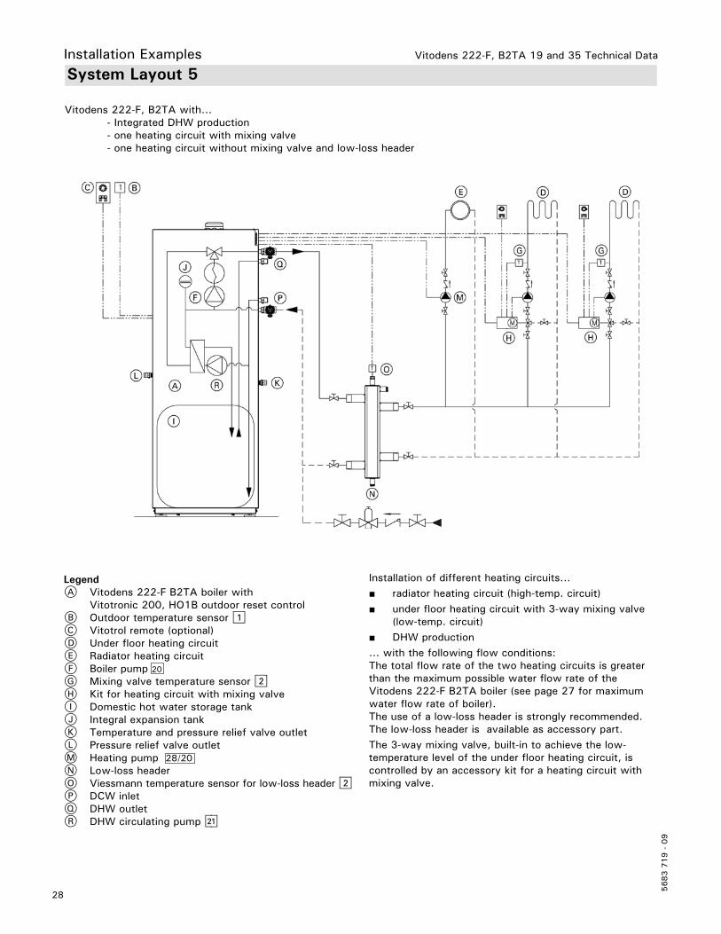
Vitodens 222-F, B2TA with... - Integrated DHW production - one heating circuit with mixing valve - one heating circuit without mixing valve and low-loss header
Installation of different heating circuits...■ radiator heating circuit (high-temp. circuit)■ under floor heating circuit with 3-way mixing valve (low-temp. circuit)■ DHW production... with the following flow conditions:The total flow rate of the two heating circuits is greater than the maximum possible water flow rate of the Vitodens 222-F B2TA boiler (see page 27 for maximum water flow rate of boiler).The use of a low-loss header is strongly recommended. The low-loss header is available as accessory part. The 3-way mixing valve, built-in to achieve the low-temperature level of the under floor heating circuit, is controlled by an accessory kit for a heating circuit with mixing valve.
LegendA Vitodens 222-F B2TA boiler with Vitotronic 200, HO1B outdoor reset controlB Outdoor temperature sensor !C Vitotrol remote (optional)D Under floor heating circuitE Radiator heating circuitF Boiler pump 20
G Mixing valve temperature sensor ?H Kit for heating circuit with mixing valveI Domestic hot water storage tankJ Integral expansion tankK Temperature and pressure relief valve outlet L Pressure relief valve outletM Heating pump 28/20
N Low-loss headerO Viessmann temperature sensor for low-loss header ? P DCW inletQ DHW outletR DHW circulating pump sA
Vitodens 222-F, B2TA 19 and 35 Technical Data
29
5683 7
19 -
09
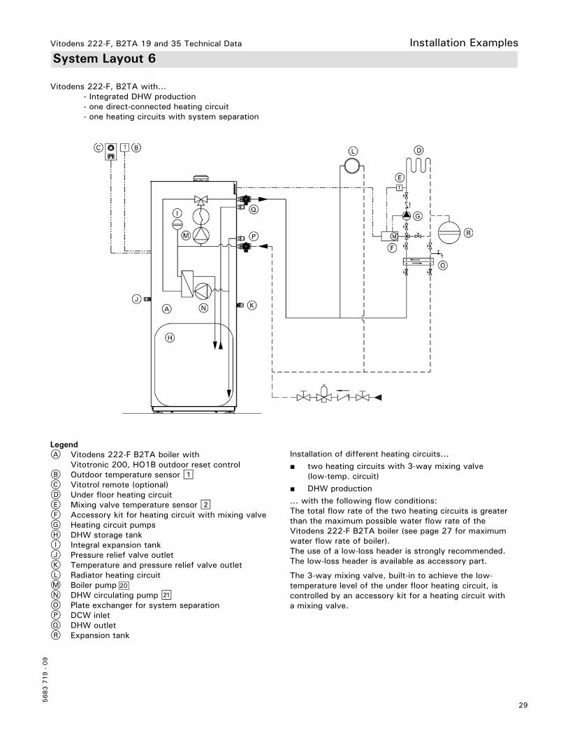
Installation ExamplesSystem Layout 6
Vitodens 222-F, B2TA with... - Integrated DHW production - one direct-connected heating circuit - one heating circuits with system separation
Installation of different heating circuits...■ two heating circuits with 3-way mixing valve (low-temp. circuit)■ DHW production... with the following flow conditions:The total flow rate of the two heating circuits is greater than the maximum possible water flow rate of the Vitodens 222-F B2TA boiler (see page 27 for maximum water flow rate of boiler).The use of a low-loss header is strongly recommended. The low-loss header is available as accessory part.
The 3-way mixing valve, built-in to achieve the low-temperature level of the under floor heating circuit, is controlled by an accessory kit for a heating circuit with a mixing valve.
LegendA Vitodens 222-F B2TA boiler with Vitotronic 200, HO1B outdoor reset controlB Outdoor temperature sensor !C Vitotrol remote (optional)D Under floor heating circuitE Mixing valve temperature sensor ?F Accessory kit for heating circuit with mixing valveG Heating circuit pumpsH DHW storage tankI Integral expansion tankJ Pressure relief valve outletK Temperature and pressure relief valve outlet L Radiator heating circuitM Boiler pump 20
N DHW circulating pump sAO Plate exchanger for system separationP DCW inlet Q DHW outletR Expansion tank

Vitodens 222-F, B2TA 19 and 35 Technical Data
5683 7
19 -
09
Installation ExamplesSystem Layout 7
30
Vitodens 222-F, B2TA with... - one direct-connected heating circuit - three heating circuit with mixing valve and integrated DHW production
Installation of different heating circuits...■ radiator heating circuit (high-temp. circuit)■ under floor heating circuit with 3-way mixing valve (low-temp. circuit)■ DHW production... with the following flow conditions:The total flow rate of the two heating circuits is less than the maximum possible water flow rate of the Vitodens 222-F B2TA boiler (see page 27 for maximum water flow rate of boiler).The use of a low-loss header is strongly recommended if the maximum water flow rate in the application concerned exceeds the max. boiler flow rate, or if the system flow rates are unknown. The low-loss header is available as accessory part.
LegendA Vitodens 222-F B2TA boiler with Vitotronic 200, HO1B outdoor reset controlB Outdoor temperature sensor !C Vitotrol remote (optional)D Under floor heating circuitE Radiator heating circuit F Heating circuit pump 28/20
G Mixing valve temperature sensor ? H Accessory kit for heating circuit with mixing valveI DHW storage tankJ Integral expansion tankK Temperature and pressure relief valve outlet L Pressure relief valve outletM Boiler pump 20
N DHW circulating pump sAO Low-loss header P Low-loss header sensor ?Q DCW inletR DHW outletS Vitotronic 200-H HK1B

Vitodens 222-F, B2TA 19 and 35 Technical Data
31
5683 7
19 -
09
Installation ExamplesAlternative Connection
The following piping diagram reflects the connection for the DHW system to boiler.
LegendA BoilerB Outdoor temperature sensor !C Vitotrol remote (optional)D DHW storage tankE Boiler pump 20
F DHW circulating pump sAG Expansion tank H Diverting valveI Boiler heat exchangerJ DHW heat exchangerK Water softenerL Boiler supplyM Boiler returnN Temperature and pressure relief valve outletO Pressure relief valve outlet P DCW inletQ DHW outletR DHW usersS DHW recirculation pumpT Flow check valveU Integral expansion tank
Vitodens 222-F, B2TA 19 and 35 Technical Data
5683 7
19 -
09
Wiring Diagram
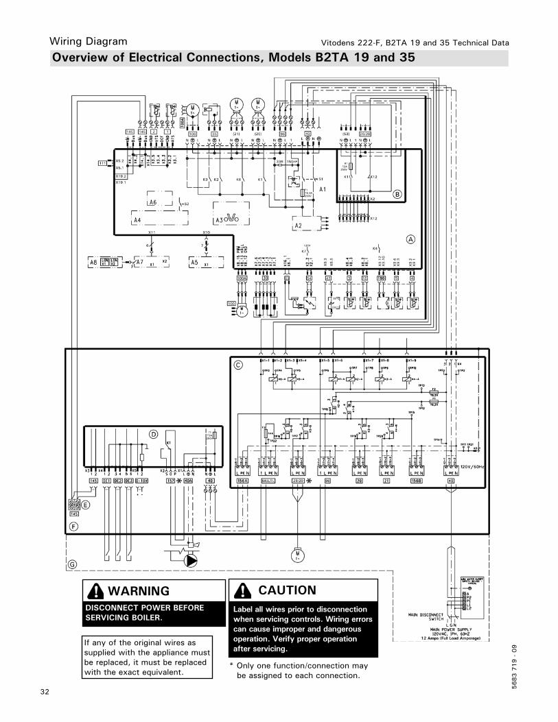
Overview of Electrical Connections, Models B2TA 19 and 35
32
WARNINGDISCONNECT POWER BEFORE SERVICING BOILER.
CAUTIONLabel all wires prior to disconnection when servicing controls. Wiring errors can cause improper and dangerous operation. Verify proper operation after servicing.
If any of the original wires as supplied with the appliance must be replaced, it must be replaced with the exact equivalent.
* Only one function/connection may be assigned to each connection.
Vitodens 222-F, B2TA 19 and 35 Technical Data
33
5683 7
19 -
09
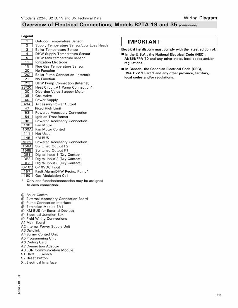
Overview of Electrical Connections, Models B2TA 19 and 35 (continued)
Wiring Diagram
A Boiler ControlB External Accessory Connection BoardC Pump Connection InterfaceD Extension Module EA1E KM-BUS for External DevicesF Electrical Junction BoxG Field Wiring ConnectionsA1 Main BoardA2 Internal Power Supply UnitA3 OptolinkA4 Burner Control UnitA5 Programming UnitA6 Coding CardA7 Connection AdaptorA8 LON Communication ModuleS1 ON/OFF SwitchS2 Reset ButtonX.. Electrical Interface
Legend 1 Outdoor Temperature Sensor 2 Supply Temperature Sensor/Low Loss Header 3 Boiler Temperature Sensor 4 DHW Supply Temperature Sensor 5 DHW tank temperature sensor 11 Ionization Electrode 15 Flue Gas Temperature Sensor 20 No Function [20] Boiler Pump Connection (Internal) 21 No Function [21] DHW Pump Connection (Internal)28/20 Heat Circuit A1 Pump Connection* 30 Diverting Valve Stepper Motor 35 Gas Valve 40 Power Supply 40A Accessory Power Output 47 Fixed High Limit [53] Powered Accessory Connection 54 Ignition Transformer 96 Powered Accessory Connection 100 Fan Motor 100A Fan Motor Control 111 Not Used 145 KM BUS Multi Powered Accessory Connection 156A Switched Output F2 156B Switched Output F1 DE1 Digital Input 1 (Dry Contact) DE2 Digital Input 2 (Dry Contact) DE3 Digital Input 3 (Dry Contact) 0-10V 0-10VDC Input 157 Fault Alarm/DHW Recirc. Pump* 190 Gas Modulation Coil* Only one function/connection may be assigned to each connection.
IMPORTANTElectrical installations must comply with the latest edition of:
In the U.S.A., the National Electrical Code (NEC), ANSI/NFPA 70 and any other state, local codes and/or
regulations.
In Canada, the Canadian Electrical Code (CEC), CSA C22.1 Part 1 and any other province, territory,
local codes and/or regulations.

Vitodens 222-F, B2TA 19 and 35 Technical Data
5683 7
19 -
09
34
System Design
System Design Considerations
IN THE COMMONWEALTH OF MASSACHUSETTS... - this product shall be installed by a licensed plumber or gas fitter. - the flexible connector (if used) cannot exceed 36”.- any level type shutoff used must be of tee handle type.
Boiler locationAs a direct vent appliance, the Vitodens 222-F can be installed for room air independent operation (sealed combustion) regardless of size and ventilation method of the room in which it is located.The Vitodens 222-F can be installed, for example, in the main living area of a house, in non-ventilated utility rooms, cupboards, closets and alcoves with no clearance required from combustible materials, as well as in attics with a direct outlet for the flue gas/fresh air system. Follow all local and national codes.
Flue gas systemViessmann PPS (Polypropylene) concentric flue gas/fresh air systems for room air independent operation (sealed combustion) and side wall venting are tested to ANSI Z21.13 - CSA 4.9 - 2000 standards and are certified together with the Vitodens 222-F boiler as a constructional unit.The Vitodens 222-F boiler may also be vented vertically, using an AL29-4C® special stainless steel, single-wall, room air dependent venting system (UL listed for category IV).For a more detailed description of the direct vent and single-wall vent system, please refer to the Vitodens 222-F Venting System Installation Instructions.
Flue gas temperature protectionFlue pipes used for the Vitodens 222-F are suitable for max. flue gas temperatures of up to 230°F (110°C).No flue gas temperature protection is required as the maximum permissible flue gas temperature is not exceeded in any operating condition or in the event of malfunctioning.
Low water cut-offA low water cut-off may be required by local codes. If the boiler is installed above the radiation level, a low water cut-off device of approved type must be installed in all instances. An approved type low water cut-off device must be provided by the heating contractor. Do not install an isolation valve between the boiler and the low water cut-off.
Water connectionsVitodens 222-F boilers can be used in any fully pumped hot water heating system.Minimum system pressure is14 psig.Chemical corrosion protection productsCorrosion does not typically occur in sealed heating systems which have been correctly installed and are correctly operated.Many manufacturers of plastic pipes recommend the use of chemical additives. In this case, only those commercially available corrosion protection products approved for boilers with domestic hot water heating via single-wall heat exchangers (instantaneous plate heat exchangers or DHW tanks) must be used.
Water qualityTreatment for boiler feed water should be considered in areas of known problems, such as where a high mineral content and hardness exist. In areas where freezing might occur, an antifreeze may be added to the system water to protect the system. Please adhere to the specifications given by the antifreeze manufacturer. Do not use automotive silicate based antifreeze. Please observe that an antifreeze/water mixture may require a backflow preventer within the automatic water feed and influence components such as diaphragm expansion tanks, radiation, etc. Maximum antifreeze content is 50% for the Vitodens 222-F boiler. Do not use antifreeze other than specifically made for hot water heating systems. System also may contain components which might be negatively affected by antifreeze. Check total system frequently when filled with antifreeze. Advise system operator/ultimate owner that system is filled with a glycol mix. The heating contractor must provide a MSDS (Material Safety Data Sheet) for the antifreeze used to the system operator/ultimate owner.
Total permissible hardness of the fill and top-up water
Total heating output Specific heating volume
MBH <5 USG per 3412 BTU 5 USG per 3412 BTU to<13 USG per 3412 BTU
13 USG per 3412 BTU
170 300 ppm 17.5 gpg 200 ppm 11.7 gpg 2 ppm 0.11 gpg
>170 to 682 200 ppm 11.7 gpg 150 ppm 8.8 gpg 2 ppm 0.11 gpg
>682 to 170 150 ppm 8.8 gpg 2 ppm 0.11 gpg 2 ppm 0.11 gpg
>2050 2 ppm 0.11 gpg 2 ppm 0.11 gpg 2 ppm 0.11 gpg
ppm - parts per milliongpg - grains per gallon

Vitodens 222-F, B2TA 19 and 35 Technical Data
35
5683 7
19 -
09
System DesignSystem Design Considerations (continued)
Oxygen diffusion barrier underfloor tubingThe boiler warranty does not cover leaks resulting from corrosion caused by the use of underfloor plastic tubing without an oxygen diffusion barrier. Such systems must have the non-oxygen diffusion barrier tubing separated from the boiler with a heat exchanger. Viessmann recommends the use of underfloor plastic tubing with an oxygen diffusion barrier.
WarrantyOur warranty does not cover damages resulting from the following:- installation or service by unqualified and unlicensed personnel.- attempting to perform any repair work on the boiler other than that mentioned in the boiler literature.- tampering with or attempting, without Viessmann permission, to readjust the factory settings of the; -combination gas valve -combustion air opening of the burner blower - leaks resulting from corrosion caused by the use of underfloor plastic tubing without an oxygen diffusion barrier. For detailed warranty information, please read warranty sheet supplied with product.
System layout■ The max. boiler water temperature for space heating and DHW production is 165°F (74°C) for models B2TA 19 and 35. To minimize distribution losses, Viessmann recommends that the heating and domestic hot water systems be based on a maximum boiler supply temperature of 158°F (70°C).
■ Due to the low return temperatures required for gas condensing, no mixing valves should be used in the heating circuit whenever possible. If mixing valves are required, e.g. for multi-circuit systems or underfloor heating systems, only 3-way mixing valves must be used. Do not use 4-way mixing valves with condensing boilers.
Underfloor heating systemsFor underfloor heating systems Viessmann recommends the use of plastic tubing with an oxygen diffusion barrier in order to prevent the diffusion of oxygen through tubing. If plastic tubing without an oxygen diffusion barrier is used in underfloor heating systems, Viessmann recommends that such systems be separated from the boiler with a heat exchanger.Underfloor heating systems and heating circuits containing a very large volume of water must be connected to the boiler via a 3-way mixing valve; please refer to the applicable installation example in this manual.
Vitodens 222-F, B2TA 19 to 80 Technical Data
5683 7
19 -
09
Tec
hnic
al in
form
atio
n su
bjec
t to
cha
nge
witho
ut n
otic
e.Pr
inte
d on
env
ironm
enta
lly f
riend
ly
(rec
ycle
d an
d re
cycl
able
) pa
per.