Technical Committee on Piping Systems (HEA-PIP)
48
Technical Committee on Piping Systems (HEA-PIP) M E M O R A N D U M DATE: July 31, 2012 TO: Principal and Alternate Members of the Technical Committee on Piping Systems (HEA-PIP) FROM: Jon Hart, Associate Fire Protection Engineer/NFPA Staff Liaison SUBJECT: AGENDA PACKAGE– NFPA 99 First Draft Meeting (A2014) ________________________________________________________________________ Enclosed is the agenda for the NFPA 99 First Draft meeting of the Technical Committee on Piping Systems, which will be held on Wednesday, August 22, and Thursday, August 23, 2012 at the Sheraton Suites San Diego at Symphony Hall. Please review the attached comments in advance, and if you have alternate suggestions, please come prepared with proposed language and respective substantiation. If you have any questions prior to the meeting, please do not hesitate to contact me at: Phone: (617) 984-7470 Email: [email protected] For administrative questions, please contact Elena Carroll at (617) 984-7952. I look forward to working with everyone.
-
Upload
vuongxuyen -
Category
Documents
-
view
227 -
download
1
Transcript of Technical Committee on Piping Systems (HEA-PIP)
Technical Committee on Piping Systems (HEA-PIP)
M E M O R A N D U M
DATE: July 31, 2012 TO: Principal and Alternate Members of the Technical Committee on Piping Systems
(HEA-PIP) FROM: Jon Hart, Associate Fire Protection Engineer/NFPA Staff Liaison SUBJECT: AGENDA PACKAGE– NFPA 99 First Draft Meeting (A2014) ________________________________________________________________________
Enclosed is the agenda for the NFPA 99 First Draft meeting of the Technical Committee on
Piping Systems, which will be held on Wednesday, August 22, and Thursday, August 23,
2012 at the Sheraton Suites San Diego at Symphony Hall. Please review the attached
comments in advance, and if you have alternate suggestions, please come prepared with
proposed language and respective substantiation.
If you have any questions prior to the meeting, please do not hesitate to contact me at:
Phone: (617) 984-7470 Email: [email protected]
For administrative questions, please contact Elena Carroll at (617) 984-7952.
I look forward to working with everyone.

Technical Committee on Piping Systems
(HEA-PIP) NFPA 99 First Draft Meeting (Annual 2014)
Wednesday, August 22, 2012 + Thursday, August 23, 2012 Sheraton Suites San Diego at Symphony Hall
701 A Street, San Diego, California 92101
AGENDA
Wednesday, August 22, 2012 + Thursday, August 23, 2012
1. Call to Order – 8:00 am (8/22)
2. Introductions and Attendance
3. Chairman Comments
4. Approval of Previous Meeting Minutes
5. Staff Liaison Presentation on NFPA’s new Revision Process and A2014 Cycle
6. Review of Correlating Committee Minutes
7. Task Group Reports • Definitions • New/Existing Facility Requirements • Category 3 and 4
8. Preparation of the First Draft
• Review Public Input • Create First Revisions
9. New Business
10. Discuss dates for the TC Second Draft Meeting
11. Adjournment – (8/23)
Technical Committee on Piping Systems
(HEA-PIP) NFPA 99 First Draft Meeting (Annual 2014)
Wednesday, August 22, 2012 + Thursday, August 23, 2012 Sheraton Suites San Diego at Symphony Hall
701 A Street, San Diego, California 92101
Special Notice on Meeting Procedures from Staff Liaison and Chair: It is expected that all committee members have read the Public Input prior to the meeting and that the members come with proposed actions ready. It is not helpful or a good use of time when TC members are reading the public input for the first time during the meeting. All discussion must start with a motion. The workflow of the meeting will be to start by moving quickly through public input that is easiest and put the tougher ones to the side. The tougher ones will then be categorized and assigned to task groups who will work together Wednesday afternoon and possibly evening if needed. The TC will then reconvene Thursday morning and resolve those tougher public inputs.
Technical Committee on Piping Systems
(HEA-PIP) NFPA 99 First Draft Meeting (Annual 2014)
Wednesday, August 22, 2012 + Thursday, August 23, 2012 Sheraton Suites San Diego at Symphony Hall
701 A Street, San Diego, California 92101 Key Dates for the Annual 2014 Revision Cycle
Public Input Closing Date June 22, 2012 Final Date for First Draft Meeting August 31, 2012 Ballots Mailed to TC before October 12, 2012 Ballots Returned By November 2, 2011 Correlating Committee First Draft Meeting December 11, 2012 Final First Draft Posted February 22, 2013 Public Comment Closing Date May 3, 2013 Final Date for Second Draft Meeting July 12, 2013 Correlating Committee Second Draft Meeting by November 8, 2013 Final Second Draft Posted January 3, 2014 Closing Date for Notice of Intent to Make a Motion (NITMAM) February 7, 2014 Issuance of Consent Document (No NITMAMs) May 9, 2014 NFPA Annual Meeting (Las Vegas) June 2014 Issuance of Document with NITMAM August 12-14, 2014
Technical Committee deadlines are in bold.
Technical Committee on Piping Systems
(HEA-PIP) NFPA 99 First Draft Meeting (Annual 2014)
Wednesday, August 22, 2012 + Thursday, August 23, 2012 Sheraton Suites San Diego at Symphony Hall
701 A Street, San Diego, California 92101
Staff Liaison Notice Note from the Staff Liaison Dear Technical Committee Members: We are very pleased that you will be participating in the processing of the 2015 Edition of NFPA 99, Health Care Facilities Code. Development of this document would not be possible without the participation of volunteers like you. Meeting Preparation Committee members are strongly encouraged to review the published comments prior to the meeting and to be prepared to act on each item. Handout materials should be submitted to the chair and staff liaison at least seven days prior to the meeting. Only one posting of the Public Input will be made; it will be arranged in section/order and will be pre-numbered. This will be posted to the NFPA 99 Document Information page (www.nfpa.org/99) under the “Next Edition” tab. If you have trouble accessing the website please contact Elena Carroll at [email protected].
Mandatory Materials: • Last edition of the standard • Meeting agenda • Public Input • Committee Officers' Guide (Chairs) • Roberts’ Rules of Order (Chairs; An abbreviated version may be found in the
Committee Officer’s Guide) Optional Materials:
• NFPA Annual Directory • NFPA Manual of Style
Technical Committee on Piping Systems
(HEA-PIP) NFPA 99 First Draft Meeting (Annual 2014)
Wednesday, August 22, 2012 + Thursday, August 23, 2012 Sheraton Suites San Diego at Symphony Hall
701 A Street, San Diego, California 92101 Regulations and Guiding Documents All committee members are expected to behave in accordance with the Guide for the Conduct of Participants in the NFPA Codes and Standards Development Process. All actions during and following the committee meetings will be governed in accordance with the NFPA Regulations Governing Committee Projects. Failure to comply with these regulations could result in challenges to the standards-making process. A successful challenge on procedural grounds could prevent or delay publication of the document. The style of the document must comply with the Manual of Style for NFPA Technical Committee Documents.
07/12/2012
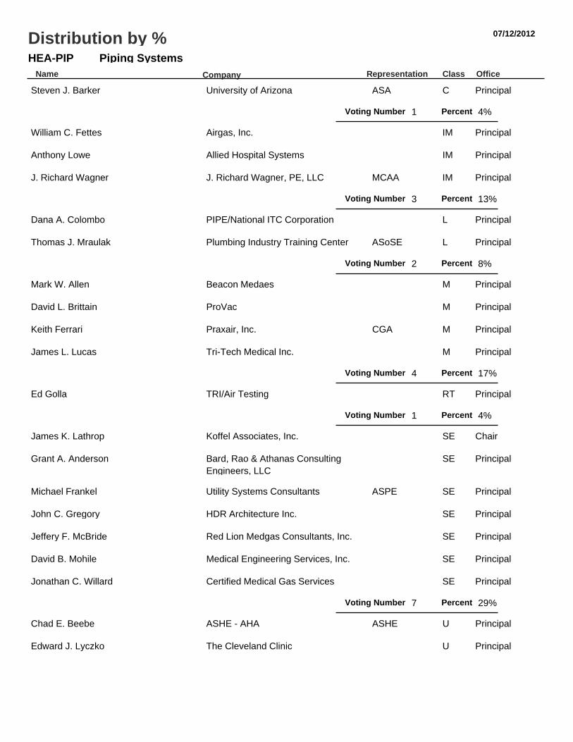
Piping SystemsHEA-PIPName Representation Class Office
Distribution by %
Company
Steven J. Barker University of Arizona ASA C Principal
1Voting Number Percent 4%
William C. Fettes Airgas, Inc. IM Principal
Anthony Lowe Allied Hospital Systems IM Principal
J. Richard Wagner J. Richard Wagner, PE, LLC MCAA IM Principal
3Voting Number Percent 13%
Dana A. Colombo PIPE/National ITC Corporation L Principal
Thomas J. Mraulak Plumbing Industry Training Center ASoSE L Principal
2Voting Number Percent 8%
Mark W. Allen Beacon Medaes M Principal
David L. Brittain ProVac M Principal
Keith Ferrari Praxair, Inc. CGA M Principal
James L. Lucas Tri-Tech Medical Inc. M Principal
4Voting Number Percent 17%
Ed Golla TRI/Air Testing RT Principal
1Voting Number Percent 4%
James K. Lathrop Koffel Associates, Inc. SE Chair
Grant A. Anderson Bard, Rao & Athanas ConsultingEngineers, LLC
SE Principal
Michael Frankel Utility Systems Consultants ASPE SE Principal
John C. Gregory HDR Architecture Inc. SE Principal
Jeffery F. McBride Red Lion Medgas Consultants, Inc. SE Principal
David B. Mohile Medical Engineering Services, Inc. SE Principal
Jonathan C. Willard Certified Medical Gas Services SE Principal
7Voting Number Percent 29%
Chad E. Beebe ASHE - AHA ASHE U Principal
Edward J. Lyczko The Cleveland Clinic U Principal

Piping SystemsHEA-PIPName Representation Class Office
Distribution by %
Company
Donald R. McIlroy Providence Health System U Principal
Ronald M. Smidt Carolinas HealthCare System NFPA/HCS U Principal
Russell C. Thomason US Army Corps of Engineers U Principal
Wayne T. Wozniak American Dental Association ADA U Principal
6Voting Number Percent 25%
24Total Voting Number

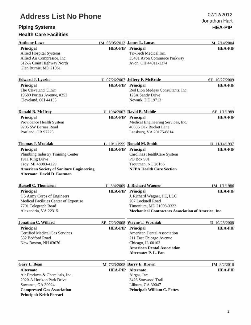
Address List No PhonePiping Systems HEA-PIP
Health Care Facilities
Jonathan Hart07/12/2012
HEA-PIP
James K. Lathrop
ChairKoffel Associates, Inc.81 Pennsylvania AvenueNiantic, CT 06357
SE 03/05/2012HEA-PIP
Mark W. Allen
PrincipalBeacon Medaes1800 Overview DriveRock hill, SC 29730-7463Alternate: Mark T. Franklin
M 1/1/1986
HEA-PIP
Grant A. Anderson
PrincipalBard, Rao & Athanas Consulting Engineers, LLC9 Stagecoach RoadBoxford, MA 01921
SE 7/14/2004HEA-PIP
Steven J. Barker
PrincipalUniversity of ArizonaCOM/Department of Anesthesiology1501 North Campbell AvenuePO Box 245114Tucson, AZ 85724-5114American Society of AnesthesiologistsAlternate: Robert G. Loeb
C 8/9/2011
HEA-PIP
Chad E. Beebe
PrincipalASHE - AHAPO Box 5756Lacey, WA 98509-5756American Society for Healthcare Engineering
U 10/20/2010HEA-PIP
David L. Brittain
PrincipalProVac8012 Glendevan Street, NWMassillon, OH 44646-9017
M 1/1/1988
HEA-PIP
Dana A. Colombo
PrincipalPIPE/National ITC Corporation2540 Severn AvenueMetairie, LA 70002Alternate: Michael T. Massey
L 03/05/2012HEA-PIP
Keith Ferrari
PrincipalPraxair, Inc.3101-124 Stonybrook DriveRaleigh, NC 27604Compressed Gas AssociationAlternate: Gary L. Bean
M 1/16/2003
HEA-PIP
William C. Fettes
PrincipalAirgas, Inc.11523 Knox StreetOverland Park, KS 66210Alternate: Barry E. Brown
IM 7/23/2008HEA-PIP
Michael Frankel
PrincipalUtility Systems Consultants10860 Royal Caribbean CircleBoynton Beach, FL 33437-4219American Society of Plumbing Engineers
SE 7/1/1995
HEA-PIP
Ed Golla
PrincipalTRI/Air Testing1607 North Cuernavaca Drive, Suite 500Austin, TX 78733-1600
RT 4/3/2003HEA-PIP
John C. Gregory
PrincipalHDR Architecture Inc.3200 East Camelback Road, Suite 250Phoenix, AZ 85018
SE 3/1/2011
1
Address List No PhonePiping Systems HEA-PIP
Health Care Facilities
Jonathan Hart07/12/2012
HEA-PIP
Anthony Lowe
PrincipalAllied Hospital SystemsAllied Air Compressor, Inc.512-A Crain Highway NorthGlen Burnie, MD 21061
IM 03/05/2012HEA-PIP
James L. Lucas
PrincipalTri-Tech Medical Inc.35401 Avon Commerce ParkwayAvon, OH 44011-1374
M 7/14/2004
HEA-PIP
Edward J. Lyczko
PrincipalThe Cleveland Clinic19680 Puritas Avenue, #252Cleveland, OH 44135
U 07/26/2007HEA-PIP
Jeffery F. McBride
PrincipalRed Lion Medgas Consultants, Inc.123A Sandy DriveNewark, DE 19713
SE 10/27/2009
HEA-PIP
Donald R. McIlroy
PrincipalProvidence Health System9205 SW Barnes RoadPortland, OR 97225
U 10/4/2007HEA-PIP
David B. Mohile
PrincipalMedical Engineering Services, Inc.40836 Oak Bucket LaneLeesburg, VA 20175-8814
SE 1/1/1989
HEA-PIP
Thomas J. Mraulak
PrincipalPlumbing Industry Training Center1911 Ring DriveTroy, MI 48083-4229American Society of Sanitary EngineeringAlternate: David D. Eastman
L 10/1/1999HEA-PIP
Ronald M. Smidt
PrincipalCarolinas HealthCare SystemPO Box 901Troutman, NC 28166NFPA Health Care Section
U 11/14/1997
HEA-PIP
Russell C. Thomason
PrincipalUS Army Corps of EngineersMedical Facilities Center of Expertise7701 Telegraph RoadAlexandria, VA 22315
U 3/4/2009HEA-PIP
J. Richard Wagner
PrincipalJ. Richard Wagner, PE, LLC207 Locknell RoadTimonium, MD 21093-3323Mechanical Contractors Association of America, Inc.
IM 1/1/1986
HEA-PIP
Jonathan C. Willard
PrincipalCertified Medical Gas Services532 Bedford RoadNew Boston, NH 03070
SE 7/23/2008HEA-PIP
Wayne T. Wozniak
PrincipalAmerican Dental Association211 East Chicago AvenueChicago, IL 60103American Dental AssociationAlternate: P. L. Fan
U 10/28/2008
HEA-PIP
Gary L. Bean
AlternateAir Products & Chemicals, Inc.2920-A Horizon Park DriveSuwanee, GA 30024Compressed Gas AssociationPrincipal: Keith Ferrari
M 7/23/2008HEA-PIP
Barry E. Brown
AlternateAirgas, Inc.3426 Starwood TrailLilburn, GA 30047Principal: William C. Fettes
IM 8/2/2010
2

Address List No PhonePiping Systems HEA-PIP
Health Care Facilities
Jonathan Hart07/12/2012
HEA-PIP
David D. Eastman
AlternateMetro Detroit Plumbing Industry Training Center1911 Ring DriveTroy, MI 48083American Society of Sanitary EngineeringPrincipal: Thomas J. Mraulak
L 7/20/2000HEA-PIP
P. L. Fan
Alternate2829 Plaza VerdeSanta Fe, NM 87507American Dental AssociationPrincipal: Wayne T. Wozniak
U 1/1/1994
HEA-PIP
Mark T. Franklin
AlternateSherman Engineering Company3679 Old Easton RoadDoylestown, PA 18902Principal: Mark W. Allen
M 03/05/2012HEA-PIP
Robert G. Loeb
AlternateUniversity of ArizonaDepartment of Anesthesiology1501 North Campbell Ave., Room 5301PO Box 245114Tucson, AZ 85724-5114American Society of AnesthesiologistsPrincipal: Steven J. Barker
C 8/9/2011
HEA-PIP
Michael T. Massey
AlternatePIPE/National ITC Corporation501 Shatto Place, Suite 200Los Angeles, CA 90020-1713Principal: Dana A. Colombo
L 4/17/2002HEA-PIP
Jonathan Hart
Staff LiaisonNational Fire Protection Association1 Batterymarch ParkQuincy, MA 02169-7471
3/1/2012
3
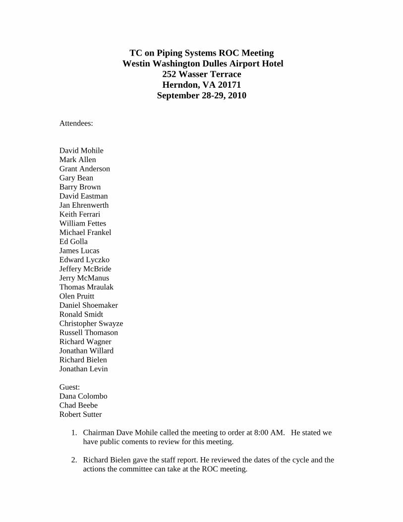
TC on Piping Systems ROC Meeting
Westin Washington Dulles Airport Hotel
252 Wasser Terrace
Herndon, VA 20171
September 28-29, 2010
Attendees:
David Mohile
Mark Allen
Grant Anderson
Gary Bean
Barry Brown
David Eastman
Jan Ehrenwerth
Keith Ferrari
William Fettes
Michael Frankel
Ed Golla
James Lucas
Edward Lyczko
Jeffery McBride
Jerry McManus
Thomas Mraulak
Olen Pruitt
Daniel Shoemaker
Ronald Smidt
Christopher Swayze
Russell Thomason
Richard Wagner
Jonathan Willard
Richard Bielen
Jonathan Levin
Guest:
Dana Colombo
Chad Beebe
Robert Sutter
1. Chairman Dave Mohile called the meeting to order at 8:00 AM. He stated we
have public coments to review for this meeting.
2. Richard Bielen gave the staff report. He reviewed the dates of the cycle and the
actions the committee can take at the ROC meeting.
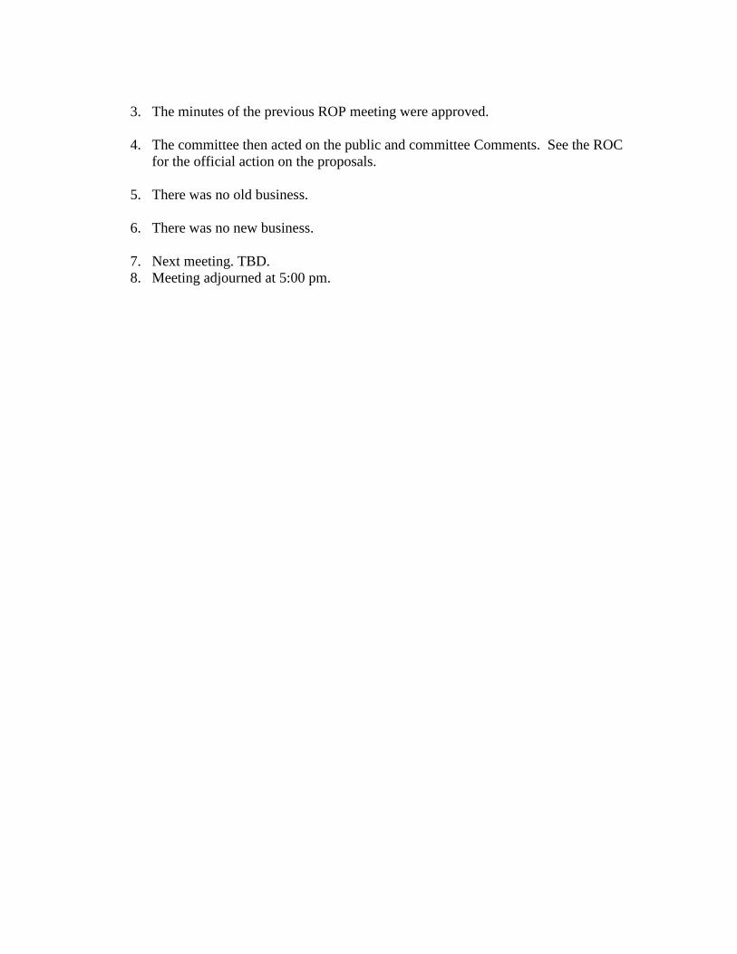
3. The minutes of the previous ROP meeting were approved.
4. The committee then acted on the public and committee Comments. See the ROC
for the official action on the proposals.
5. There was no old business.
6. There was no new business.
7. Next meeting. TBD.
8. Meeting adjourned at 5:00 pm.

Report on Proposals – June 2014 NFPA 99_______________________________________________________________________________________________99- Log #322a HEA-PIP
_______________________________________________________________________________________________William E. Koffel, Koffel Associates, Inc.
Utilize a common chapter format for all chapters that use the risk assessment approach containedin Chapter 4. While it might be desirable to have Category 1 as the .1 Section of each Chapter this may not be practical.Therefore, an alternative approach would be to have the .1 Section address Applicability, the .2 Section address otherissues such as Nature of Hazards, the .3 Section be Category 1, the .4 Section be Category 2, the .5 Section beCategory 3.Within each chapter it would also be good to follow a similar format for the categories addressed. For example,
sprinkler requirements are found in 7.3.1.2.1.7 for EF's but in 7.3.1.2.3.9 (within Environmental Requirements) for TR's.A common format for each chapter would make the document more user friendly. A common format
within each chapter would make it easier to determine the differences between the requirements for different categoriesof each system.
_______________________________________________________________________________________________99- Log #26 HEA-PIP
_______________________________________________________________________________________________
Keith Ferrari, PraxairRevise text to read as follows:
An assembly of equipment, such as storage containers, pressure regulators, pressure reliefdevies, vaporizers, manifolds, and interconnecting piping, that terminates at the source valve of oxygen or 1452 kg(3200-lb) of nitrous oxide including unconnected reserves on the site. (PIP)
Specific definitions for Bulk Oxygen and Bulk Nitrous are in 3.3.19.1 & 3.3.19.2.
_______________________________________________________________________________________________99- Log #235 HEA-PIP
_______________________________________________________________________________________________Mark T. Franklin, Sherman Engineering Company
Revise to read:For the purposes of this code, instrument air is air intended for the powering of medical devices
unrelated to human respiration(e.g., surgical tools, ceiling arms). Medical air and instrument air are distinct systems formutually exclusive applications. Instrument air is a medical support gas that falls. Instrument air similar to Nitrogen gasare medical support gases used for the same purpose and may be connected together on the same piping system andnot considered as a cross-connection but both or either used shall fall under the general requirements for medicalgases. (PIP) When a Nitrogen system are connected to an operating instrument air system, the outlets shall be labeledaccordingly. i.e., Nitrogen/instrument air. Either IA or N2 outlets may be used.
The N2 or IA gas used for this application is appropriate using either or a mixture of both. To allow thehospital community to incorporate the two into one "support gas" will allow existing hospitals a way to switch to a lowercost gas without any detrimental effect to the patient.
1Printed on 7/31/2012

Report on Proposals – June 2014 NFPA 99_______________________________________________________________________________________________99- Log #258 HEA-PIP
_______________________________________________________________________________________________Mark Jelinske, Cator, Ruma, and Associates
Revise text to read: 3.3.84 Instrument Air. For the purposes of this code, instrument air is air intended for the powering of medical devices
unrelated to human respiration (e.g., surgical tools, ceiling arms). Medical Instrument air is a medical support gas thatfalls under the general requirements for medical gases. Medical air and instrument air are distinct systems for mutuallyexclusive applications. Instrument air is a medical support gas that falls under the general requirements for medicalgases. (PIP)
This Public Input simplifies the definition of Instrument Air, since the definition of the umbrella term,Medical Support Gas includes the proper uses of Instrument Air. This simplification reduces any confusion and conflict.This Public Input is associated with Public Inputs defining Medical Support Gas and Nonmedical Compressed Air.
These Public Inputs work well together to clarify that there are two separate systems of non-respired gas systems usedin healthcare. One, (Medical Support Gas, which includes Instrument Air) is a system used directly in patient care,where the gas is in intimate contact with patients in an invasive setting, or has the potential to contaminate sterileproduct.The other non-respired gas (Nonmedical Compressed Air) is a system used to support equipment in a healthcare
facility, and can be used for raising or lowering booms, surgical tables, sterilizer doors, cart wash leveling ramps, etc. aswell as regular facility maintenance.
Instrument Air requires brazed pipe with alarms, zone valve boxes, testing, and a redundant source capable of verydry, very clean gas. Not all “medical support applications” require this level of system. The distinction should be madebased on whether or not the gas is in direct contact with patients in an invasive setting. These coordinated proposalsmake that distinction.Instrument Air has much higher level of cleanliness than Medical Air (IA filtered to 98 percent efficiency at 0.01 micron,
MA allows for 98 percent efficiency at 1 micron; IA required to be free of hydrocarbon vapors, MA allows for 25 ppm ofgaseous hydrocarbons; IA dew point -40 °F, MA dew point of +32°F, MA). It is ironic that NFPA 99 currently prohibits therelatively dirty Medical Air system from providing mechanical function to an equipment boom, while at the same timeprevents the much cleaner Instrument Air system from being used for respiration.As the linking tool is not working for me, this is related to Public Inputs 394, 396, 397, and 398
2Printed on 7/31/2012
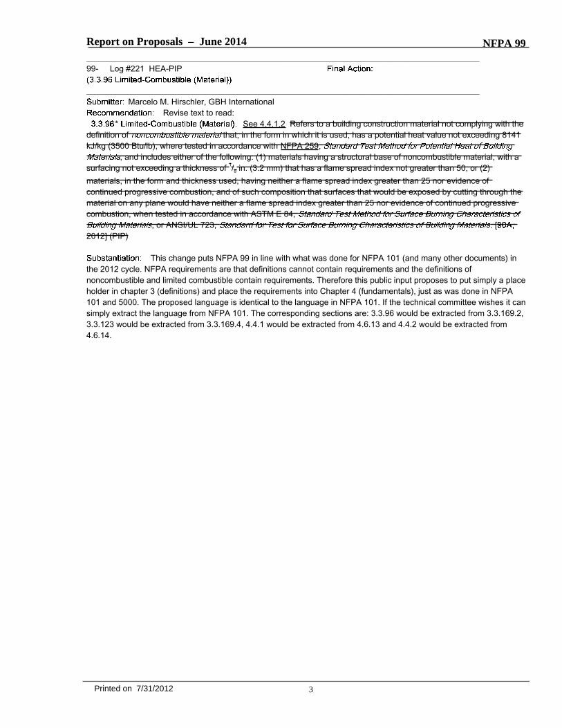
Report on Proposals – June 2014 NFPA 99_______________________________________________________________________________________________99- Log #221 HEA-PIP
_______________________________________________________________________________________________Marcelo M. Hirschler, GBH International
Revise text to read:* See 4.4.1.2 Refers to a building construction material not complying with the
definition of that, in the form in which it is used, has a potential heat value not exceeding 8141kJ/kg (3500 Btu/lb), where tested in accordance with NFPA 259,
, and includes either of the following: (1) materials having a structural base of noncombustible material, with asurfacing not exceeding a thickness of 1/8 in. (3.2 mm) that has a flame spread index not greater than 50; or (2)materials, in the form and thickness used, having neither a flame spread index greater than 25 nor evidence ofcontinued progressive combustion, and of such composition that surfaces that would be exposed by cutting through thematerial on any plane would have neither a flame spread index greater than 25 nor evidence of continued progressivecombustion, when tested in accordance with ASTM E 84,
, or ANSI/UL 723, . [2012] (PIP)
This change puts NFPA 99 in line with what was done for NFPA 101 (and many other documents) inthe 2012 cycle. NFPA requirements are that definitions cannot contain requirements and the definitions ofnoncombustible and limited combustible contain requirements. Therefore this public input proposes to put simply a placeholder in chapter 3 (definitions) and place the requirements into Chapter 4 (fundamentals), just as was done in NFPA101 and 5000. The proposed language is identical to the language in NFPA 101. If the technical committee wishes it cansimply extract the language from NFPA 101. The corresponding sections are: 3.3.96 would be extracted from 3.3.169.2,3.3.123 would be extracted from 3.3.169.4, 4.4.1 would be extracted from 4.6.13 and 4.4.2 would be extracted from4.6.14.
3Printed on 7/31/2012
Report on Proposals – June 2014 NFPA 99_______________________________________________________________________________________________99- Log #259 HEA-PIP
_______________________________________________________________________________________________Mark Jelinske, Cator, Ruma, and Associates
Revise text to read: 3.3.109 Medical Support Gas. Nitrogen or instrument air, Carbon Dioxide, or Instrument Air used for any medical
support purpose (e.g., to remove excess moisture from instruments before further processing, or to operatemedical–surgical tools, air-driven booms, pendants, or similar applications) and, if appropriate to the procedures, used inlaboratories and are not where the gas has the possibility of patient contact in an invasive procedure, or where the gashas the potential to contaminate sterile items. Medical support gas may be used, but it's use is not mandatory, inlaboratories and for non-patient contact applications in direct support of medical procedures (e.g. equipment booms,pendants, patient surgical tables). Medical support gasses shall not be respired as part of any treatment. MedicalSupport Gas shall not be used for general facility needs. Medical support gas falls under the general requirements formedical gases. (PIP)
This adds Carbon Dioxide to the list of Medical Support Gasses. This has been used for years withoutdirection from NFPA 99. The Standard of Care has been to treat it like Nitrogen. This formalizes that practice.This Public Input is associated with Public Inputs defining Instrument Air and Non Medical Compressed Air. These
Public Inputs work well together to clarify that there are two separate systems of non-respired gas systems used inhealthcare. One, (Medical Support Gas) is a system used directly in patient care, where the gas is in intimate contactwith patients in an invasive setting, or has the potential to contaminate sterile product. This includes gasses used todrive tools where the exhaust is very near to an open surgical site, provide an inert gas field around a surgical site, useddirectly to dry body tissue, for insufflation, or to force dry medical devices.The other is a system used to support the medical equipment in a healthcare facility, and can be used for raising or
lowering booms, surgical tables, sterilizer doors, cart wash leveling ramps, etc. This equipment can all be considered“any medical support applications”, but the system of gasses involved only provide a mechanical function, not requiringintimate exposure with human beings in an invasive environment.Any Medical Support Gas requires brazed pipe with alarms, zone valve boxes, testing, and a redundant source
capable of very dry, very clean gas. Not all “medical support applications” require this level of system. The distinctionshould be made based on whether or not the gas is in direct contact with patients in an invasive setting. Thesecoordinated proposals make that distinction.This Public Input ALLOWS for a Medical Support Gas to be used in a limited applications directly supporting the
medical program, but does not REQUIRE this system where the redundancy, alarms, etc of this system are not needed.This Public input clarifies that a Medical Support Gas can not be used for general facility use.As the linking tool is not working for me, this is related to Public inputs 395, 396, 397, and 398
_______________________________________________________________________________________________99- Log #326 HEA-PIP
_______________________________________________________________________________________________Keith Ferrari, Praxair, Inc.
Revise title to read:Gas and Medical Gas, Support Gas and Medical-Surgical Vacuum Systems
With the inclusion of Chapter 8 Plumbing Systems and Chapter 9 HVAC that include non medical gasand non medical - surgical vacuum systems, we need to match the chapter 5 title with the chapter 5 scope. This changewould include changes to 5.1, 5.2 and 5.3 section titles also.
4Printed on 7/31/2012
Report on Proposals – June 2014 NFPA 99_______________________________________________________________________________________________99- Log #323 HEA-PIP
_______________________________________________________________________________________________Keith Ferrari, Praxair, Inc.
Revise text to read:5.1.1.3 Wherever the term medical–surgical vacuum occurs, the provisions shall apply to systems for piped
medical–surgical patient vacuum and piped waste anesthetic gas disposal (WAGD). Wherever the name of a specificvacuum service occurs, the provision shall apply only to that vacuum service.
The origional text does not make sense. How do you differentiate medical-surgical vacuum systemfrom medical - surgical vacuum system ? The intent is clear, but every time we use the word medical-surgical vacuumsystem and do not intend for the WAGD to be included on the item, based on this code section it would include WAGD.We need to have a term that means both Patient vacuum system and waste anesthetic gas disposal, then when wehave code items only for patient vacuum systems or WAGD, it is clear.
_______________________________________________________________________________________________99- Log #351 HEA-PIP
_______________________________________________________________________________________________Rachael Stephenson, Flower Mound, TX
Revise text to read:5.1.1.3 Wherever the term medical–surgical vacuum occurs system occurs, the provisions shall apply to systems for
piped medical–surgical vacuum and piped waste anesthetic gas disposal (WAGD). Wherever the name of a specificvacuum service occurs, the provision shall apply only to that vacuum service.
It is not possible to distinguish when the term "medical-surgical vacuum" is intended to include WAGDbecause the same term is used for vacuum only and vacuum with WAGD. It appears that the when the term"medical-surgical vacuum system" is used it refers to both vacuum and WAGD throughout section 5.
_______________________________________________________________________________________________99- Log #113 HEA-PIP
_______________________________________________________________________________________________Keith Ferrari, Praxair, Inc.
Revise to read: (1) Manifolds for gas cylinders without reserve supply (see 5.1.3.5.10)
Editorial - no need for wording since with reserve was removed in 2012.
_______________________________________________________________________________________________99- Log #105 HEA-PIP
_______________________________________________________________________________________________Keith Ferrari, Praxair, Inc.
Revise to read: (2) Manifolds for gas cylinders with reserve supply(3) Manifolds for cryogenic liquid containers (see 5.1.3.5.12)
Manifolds for gas cylinders with reserve supply was removed in the 2012. (Editorial)
5Printed on 7/31/2012

Report on Proposals – June 2014 NFPA 99_______________________________________________________________________________________________99- Log #114 HEA-PIP
_______________________________________________________________________________________________Keith Ferrari, Praxair, Inc.
Revise to read: (1) Manifolds for gas cylinders without reserve supply (see 5.1.3.5.10)
Editorial - no need for wording since with reserve was removed in 2012.
_______________________________________________________________________________________________99- Log #104 HEA-PIP
_______________________________________________________________________________________________Keith Ferrari, Praxair, Inc.
Revise to read: (2) Manifolds for gas cylinders with reserve supply(3) Manifolds for cryogenic liquid containers (see 5.1.3.5.12)
This section should have been removed from the list when the entire section on Manifolds for gascylinders with reserve supply was deleted in the 2012 edition. (Editorial).
_______________________________________________________________________________________________99- Log #106 HEA-PIP
_______________________________________________________________________________________________Keith Ferrari, Praxair, Inc.
Delete the following:5.1.3.3.1.5 Locations shall be chosen to allow access by delivery vehicles and management of cylinders (e.g.,
proximity to loading docks, access to elevators, and passage of cylinders through public areas).Relocate section to 5.1.3.3.2.
This section fits better under Design and Construction list of requirements. (Editorial).
_______________________________________________________________________________________________99- Log #107 HEA-PIP
_______________________________________________________________________________________________Keith Ferrari, Praxair, Inc.
Revise to read:Cylinders in use and in storage shall be prevented from reaching temperatures in excess of 54°C 52°C
(130°F125°F).125 degress is the recommended high storage temp for cylinders. (CGA). Also, this will be harmonized
with sections: 5.1.3.3.1.8, 9.3.7.7, 9.3.7.8 and A.5.1.14 which all reference 125 drgrees. (Editorial).
6Printed on 7/31/2012

Report on Proposals – June 2014 NFPA 99_______________________________________________________________________________________________99- Log #140 HEA-PIP
_______________________________________________________________________________________________Jim Lucas, Tri-Tech Medical Inc.
Revise to read:5.1.3.3.1.8 Central supply systems for nitrous oxide and carbon dioxide using cylinders or portable containers shall be
prevented from reaching temperatures lower than the recommendations of the central supply system's manufacturer,but shall never be lower than -29°C -7°C (-20°F) or greater than 51.6°C (125°F).
Temperature vs flow data was not provided when this change was adopted in the 2012 edition ofNFPA 99. To date, temperature vs flow data is not available. This changewill increase patient safety by lowering thelikelihood of a gas supply issue.
_______________________________________________________________________________________________99- Log #108 HEA-PIP
_______________________________________________________________________________________________Keith Ferrari, Praxair, Inc.
Add a new section to read:(11) They shall allow access by delivery vehicles and management of cylinders (e.g., proximity to loading docks,
access to elevators, and passage of cylinders through public areas).Relocate 5.1.3.3.1.5 to this section (Editorial).
_______________________________________________________________________________________________99- Log #226 HEA-PIP
_______________________________________________________________________________________________Marcelo M. Hirschler, GBH International
Revise to read:If indoors, they shall be constructed and use interior finishes of noncombustible or limited-combustible materials such
that all walls, floors, ceilings, and doors are of a minimum 1-hour fire resistance rating, when tested in accordance withASTM E119, Standard Test Methods for Fire Tests of Building Construction and Materials.
This public input is basically editorial, but it is necessary to ensure that no alternate tests are used todetermine the fire resistance rating. It is possible to use various non standard tests and get fire resistance ratings butthen the safety desired by the code would not necessarily be achieved.
_______________________________________________________________________________________________99- Log #102 HEA-PIP
_______________________________________________________________________________________________Keith Ferrari, Praxair, Inc.
Revise to read:(A) Outdoor locations surrounded by impermeable walls shall, except fire barrier walls, shall have protected
ventilation openings located at the base of each wall to allow free circulation of air within the enclosure.(C) The fire barrier wall shall not have openings orpenetrations, except conduit orpiping shall be permitted provided
that the penetration is protectedwith a firestop system in accordance with the building code.Fire walls can not have "open" penetrations per the NFPA 55, 2010 edition section 8.7.2.1.1.1 This will
harmonize with the Compressed GAs and Cryogenic Fluids Code.
7Printed on 7/31/2012

Report on Proposals – June 2014 NFPA 99_______________________________________________________________________________________________99- Log #116 HEA-PIP
_______________________________________________________________________________________________Keith Ferrari, Praxair, Inc.
Add a new section to read:
Medical Gases in the form of cylinders, containers and Bulk Vessels come with a Certificate ofAnalysis for the gases delivered. The gases then run through a network of components (Manifolds, vaporizers, pigtails,...) with no on-line monitoring of the purity of these gases. Periodic gas sampling should/could be done at a sample port,similair to the medical air system (medical gas manufactured on site) to check that the gases being delivered to thepatients from the central supply meets the medical air quality needed for patient care.
_______________________________________________________________________________________________99- Log #154 HEA-PIP
_______________________________________________________________________________________________Mark W. Allen, Beacon Medaes
Add a new section to read:5.1.3.5.7 Auxiliary inlets. All source systems shall be provided with an auxiliary inlet / outlet connection point of the
same size as the main line which shall be located immediately on the patient side of the source valve.5.1.3.5.7.1 The connection consists of a tee, valve and a removable plug or cap.5.1.3.5.7.2 The auxiliary connection valve shall be normally closed and secured.5.1.3.5.7.3 On oxygen systems furnished with an emergency oxygen supply connection (EOSC), the EOSC shall be
considered to fulfill this requirement.The addition of an auxiliary connection would simplify: 1. source changeouts 2. major source service 3.
connection of an emergency supply in event of source failure.
_______________________________________________________________________________________________99- Log #115 HEA-PIP
_______________________________________________________________________________________________Keith Ferrari, Praxair, Inc.
Revise to read:5.1.3.5.10* Manifolds for Gas Cylinders Without Reserve Supply .
editorial - no need for wording since with reserve was removed in 2012.
_______________________________________________________________________________________________99- Log #4 HEA-PIP
_______________________________________________________________________________________________Jonathan C. Willard, Certified Medical Gas Services
Revise 5.1.3.5.13 to read as follows:Emergency Temporary Oxygen Supply Connection (EOSC) (TOSC)And all other references to Emergency Oxygen Supply Connection and EOSC should be replaced with the terminology
above.There is a common misconception that the EOSC can be utilized for Emergency Preparedness and is
a viable way to feed the health care facility in the event of an unplanned loss of the oxygen supply system. In reality bulkgas suppliers are not able to provide a temporary oxygen supply trailer as quickly as would be needed for this type ofevent. There usually needs to be another interim measure for dealing with the loss of oxygen (i.e. high pressurecylinders back feeding critical care areas). Most bulk suppliers will not guarantee they will be able to respond quickly inan emergency event. This nomenclature leads facility managers to assume that the EOSC is the best option for dealingwith an emergency situation, but in fact it is not.
8Printed on 7/31/2012
Report on Proposals – June 2014 NFPA 99_______________________________________________________________________________________________99- Log #56 HEA-PIP
_______________________________________________________________________________________________J. Richard Wagner, J. Richard Wagner, PE, LLC
Revise text to read as follows:5.1.3.5.14 In-Building Emergency Reserves (IBERs)5.1.3.5.14.1 In-building emergency reserves (IBERs) shall not be ......... ..5.1.3.5.14.2 When a reserve an IBER is provided inside the building as a substitute for the EOSC .. .. .. ... .. ... .... .. .. .
.5.1.3.5.14.3 In-building emergency reserves (IBERs) shall consist of ........... .......... .5.1.3.5.14.4 In-building emergency reserves (IBERs) shall include a ............ ..... .... .... .5.1.3.5.14.5 In-building emergency reserves (IBERs) shall have a ...... ............. ..... ..... . .
To add IBER in Chapter 5. The term IBER is used in Chapter 14 to indicate in-building emergencyreserve, similar to EOSC for emergency oxygen supply connection in Chapters 5 and 14.
_______________________________________________________________________________________________99- Log #92 HEA-PIP
_______________________________________________________________________________________________Robert M. Sutter, B&R Compliance Associates
Revise to read:In-building emergency reserves shall have a local signal that visibly indicates the operating status of the
equipment and an alarm at all master alarms when or just before the reserve begins to serve the system.I recently had a customer whose facility was cited by their state authority for not having their in building
emergency reserve system alarm at the Master Alarm panels. Their in building emergency reserve system is not asystem that automaticly feeds the system. It is a system that is manualy operated when the gas emergency plan isactivated. For automaticly operating in building emergency reserves the low line pressure alarm should be adequatenotice for operation of the system.
_______________________________________________________________________________________________99- Log #156 HEA-PIP
_______________________________________________________________________________________________Mark W. Allen, Beacon Medaes
Add new sections to read:5.1.3.5.15 Oxygen Concentrator Sources.5.1.3.5.15.1 Oxygen concentrator systems used as sources shall comply to ISO 10083 "Oxygen concentrator supply
systems for use with medical gas pipeline systems"Central oxygen concentrator sources are still rare in U.S. healthcare but are increasingly common
internationally. It is appropriate that the standard give some guidance for a safe installation. At this time I do not believeit appropriate for NFPA to attempt to write a standard, so I propose to reference the most widely used internationalstandard.
9Printed on 7/31/2012

Report on Proposals – June 2014 NFPA 99_______________________________________________________________________________________________99- Log #94 HEA-PIP
_______________________________________________________________________________________________James Bell, Intermountain Health Care
Revise text to read:(2) It shall Cylinders shall meet the requirements of medical air USP.(3) Medical air supplied from compressors using ambient source air shall be tested at initial installation and quarterly to
meet the specifications of USP medical air ( CGA grade N)(4) It shall have no detectable liquid hydrocarbons.Renumber remainder of section
USP medical air is / or has been typically accepted as CGA grade N. The limiting CO2 is 500ppm forCGA grade N (USP medical air). The local ambient air supply globally is increasing. The average CO2 level issomewhere around 350 ppm. There are days in the large cities where the ambient level is over 600ppm. I was unable tofind the history behind why 500 ppm was chosen. The USP / FDA / and CGA are all involved as are the DOT and NFPA.I would suggest that if we leave the limit at 500 ppm CO2 we will start to see failure to meet the standard. It would beexpensive to add air treatment packages and monitoring to compressor systems to meet the 500ppm CO2. Analternative would be to include a definition of medical air from compressors using ambient air and have the limits listedin a table. Also note that 5.1.3.6.3.14 does not agree with 5.1.3.6.1 as there is no requirement to monitor for CO2, nitricoxide, nitrogen dioxide, sulfer dioxide, etc...only CO, and dewpoint.
_______________________________________________________________________________________________99- Log #37 HEA-PIP
_______________________________________________________________________________________________Mike Lemanek, Certech
Revise to read:5.1.3.6.2* Uses of Medical Air. Medical air sources shall be connected to the medical air distribution system only and
shall be used only for air in the application of human respiration and, calibration of medical devices for respiratoryapplication and cleaning of endoscopes.
Instrument air is often not available, and if available it is at an unacceptably high pressure.Compressed air is not clean enough.
_______________________________________________________________________________________________99- Log #110 HEA-PIP
_______________________________________________________________________________________________Keith Ferrari, Praxair, Inc.
Add a new section to read:Medical Air compressor systems shall preclude the condensation of water vapor in the piping
distribution system by the air drying equipment.Relocated 5.1.3.6.3.3 to this section. (editorial).
_______________________________________________________________________________________________99- Log #109 HEA-PIP
_______________________________________________________________________________________________Keith Ferrari, Praxair, Inc.
Delete the following:5.1.3.6.3.3 Air Drying Equipment. Medical air compressor systems shall preclude the condensation of water vapor in
the piping distribution system by the selection of the air drying equipment.Relocate to 5.1.3.6.3.7 (editorial)
10Printed on 7/31/2012
Report on Proposals – June 2014 NFPA 99_______________________________________________________________________________________________99- Log #111 HEA-PIP
_______________________________________________________________________________________________Keith Ferrari, Praxair, Inc.
Delete the following text:5.1.3.6.3.9* Medical Air Local Alarm. A local alarm complying with 5.1.9.5 shall be provided for the medical air
compressor source.Relocate 5.1.3.6.3.9 (and annex) to 5.1.3.6.3.13 Operating Alarms and Local Signals. (Editorial).
_______________________________________________________________________________________________99- Log #117 HEA-PIP
_______________________________________________________________________________________________Keith Ferrari, Praxair, Inc.
Revise to read: (F) Compressor intake piping shall be permitted to be made of materials and use a jointing technique as permitted
under 5.1.10.2 and 5.1.10.3.I believe this was a error on the original print (2012 edition). There was no referenced jointing
technique as listed in 5.1.3.6.3.12. 5.1.10.3 references the joining technique needed fo rthis section.
_______________________________________________________________________________________________99- Log #112 HEA-PIP
_______________________________________________________________________________________________Keith Ferrari, Praxair, Inc.
Revise to read:Medical air systems shall be monitored for conditions that can affect air quality during use or in the event of failure,
based on the type of compressor(s) used in the system.A local alarm complying with 5.1.9.5 shall be provided for the medical air compressor source.
Relocated 5.1.3.6.3.9 to this section. (Editorial).
_______________________________________________________________________________________________99- Log #122 HEA-PIP
_______________________________________________________________________________________________Keith Ferrari, Praxair, Inc.
Delete the following text:5.1.3.7.4 Vacuum Local Alarm. A local alarm complying with 5.1.9.5 shall be provided for the vacuum source.
This section is redundant with 5.1.3.7.8.
_______________________________________________________________________________________________99- Log #123 HEA-PIP
_______________________________________________________________________________________________Keith Ferrari, Praxair, Inc.
Add a new section to read:Vacuum exhaust piping shall be permitted to be madeof materials and use a jointing technique as permitted
under5.1.10.2 and 5.1.10.32012 Log CP2 99-219 inadvertantly took out the exhaust piping section. the NFPA 99, 2012 does not
have a section for exahust piping materials or joining techniques (The NFPA 99, 2005 edition section " 5.1.3.6.7.4 Theexhaust shall be piped of materials approved for medical–surgical vacuum piping under 5.1.10.2."
11Printed on 7/31/2012
Report on Proposals – June 2014 NFPA 99_______________________________________________________________________________________________99- Log #124 HEA-PIP
_______________________________________________________________________________________________Keith Ferrari, Praxair, Inc.
Revise text to read: (2) At least 37.05 5 m (10 25 ft) from any door, window, air intake, or other openings in buildings or places of public
assemblyThe FGI 2.1-8.4.4.2 2010 edition requires 25 ft for exhausts from windows, doors, air intakes ,.. Teh
Medical AIr intake was corrected in 2012 edition, but the vacuum exhaust was not.
_______________________________________________________________________________________________99- Log #331 HEA-PIP
_______________________________________________________________________________________________Anthony Lowe, Allied Air Compressor, Inc.
Add a new section to read:5.1.3.7.7.6 The exhaust shall be piped of materials approved for medical-surgical vacuum piping under 5.1.10.2.
Would clarify the type of materials to be used for vacuum exhaust. Under the current code there is nodefined material to be used on vacuum exhaust piping.This section was removed from the current edition. Since the code has a defined vacuum exhaust section the material
used should be shown.
_______________________________________________________________________________________________99- Log #125 HEA-PIP
_______________________________________________________________________________________________Keith Ferrari, Praxair, Inc.
Delete the following text:5.1.3.8.3 WAGD Connections to Vacuum Piping. If WAGD is joined to vacuum piping, it shall be connected at a
minimum distance of 1.5 m (5 ft) from any vacuum inlet.Relocate to 5.1.5.16 (editorial)
_______________________________________________________________________________________________99- Log #142 HEA-PIP
_______________________________________________________________________________________________Jim Lucas, Tri-Tech Medical Inc.
Revise to read:Valve Types. New or replacement shutoff valves shall be as follows:
(1) They shall be of the quarter turn, full ported, ball type.(2) They shall be of brass or bronze construction.(3) They shall have extensions for brazing.(4) They shall have a handle indicating open or closed.(5) They shall consist of three pieces permitting permit in-line serviceability without cutting or brazing.
Inclusion of the word "ball" restricts/limits technology. There are other types of valve designs that canmeet all five of the requirements for medical valves but are currently denies to the market.Inclusion of the phrase "consists of three pieces" restricts/limits technology. There are other types of valve designs that
can meet all five of the requirements for medical valves but are currently denies to the market.
12Printed on 7/31/2012
Report on Proposals – June 2014 NFPA 99_______________________________________________________________________________________________99- Log #141 HEA-PIP
_______________________________________________________________________________________________Jim Lucas, Tri-Tech Medical Inc.
Revise to read: 5.1.4.3.2 Valves for vacuum or WAGD service shall be permitted to be ball per 5.1.4.3 or butterfly type and shall not
be required to be cleaned for oxygen service.Inclusion of the word "ball" restricts/limits technology. There are other types of valve designs that can
meet all five of the requirements for medical valves but are currently denied to the market.
_______________________________________________________________________________________________99- Log #127 HEA-PIP
_______________________________________________________________________________________________Keith Ferrari, Praxair, Inc.
Revise to read:The source valve shall be located in the immediate vicinity of the source equipment, except as allowed by
5.1.3.4.Editorial.
_______________________________________________________________________________________________99- Log #128 HEA-PIP
_______________________________________________________________________________________________Keith Ferrari, Praxair, Inc.
Revise to read: A shutoff valve shall be provided in the main supply line inside of the building(s) being served, except where one or
more of the following conditions exist:When there are multiple free standing buildings being served by one central supply source, there will
be more then one main valve.
_______________________________________________________________________________________________99- Log #35 HEA-PIP
_______________________________________________________________________________________________Mike Lemanek, Certech
Add a new subsection to read:(4) The zone valve shall be placed to allow someone to to shut off the flow of gas without being directly exposed to the
fire and any products of combustion.This language is from the code handbook. The current lanquage and exhibit 5.22(a) leaves a person
exposed to products of combustion.
13Printed on 7/31/2012
Report on Proposals – June 2014 NFPA 99_______________________________________________________________________________________________99- Log #257 HEA-PIP
_______________________________________________________________________________________________Mark Jelinske, Cator, Ruma, and Associates
Revise text to read: A zone valve shall be located immediately outside each vital life-support area, critical care area, and anesthetizing
location of moderate sedation, deep sedation, or general anesthesia, in location in each medical gas or vacuum line, orboth, and located so as to be readily accessible in an emergency.
The proposed deleted phrase is in conflict with the definition of an Anesthetizing Location in 3.3.9.There is no such thing as an anesthetizing location of moderate or deep sedation. An anesthetizing location is bydefinition limited to general anesthesia.
_______________________________________________________________________________________________99- Log #239 HEA-PIP
_______________________________________________________________________________________________Mark T. Franklin, Sherman Engineering Company
Valves for Future Connections shall be included as part of the piping design of all medical gas andinstalled in the riser line to be used for future changes and additions to the piping systems. The valve size shall be thesame as the riser and shall be replaced with a new valve in the event the first valve is used during any piping change.
Medical gas piping changes are inevitable in every hospital or medical care facility. The cost ofshutting down the medical gas is expensive and increases risk becoming dangerous to patients. The medical gasindustry has been brilliant in developing a means of performing live tie-ins to complete the necessary changes such as"Smart Tap" and others. By including future valves as mandatory in the design code, and having facilities use thesevalves will reduce this risk and maintain the integrity of our medical gas piping.
_______________________________________________________________________________________________99- Log #129 HEA-PIP
_______________________________________________________________________________________________Keith Ferrari, Praxair, Inc.
Add a new section to read:Station outlets/inlets shall be installed where they arevisible and accessible at all times.Station Outlets/Inletsshall not be installed behind normallyopen or normally closed doors or otherwise hiddenfrom plain
view.Recently there have been hospitals "Temporarly" building rooms with in rooms where walls are going
up over existing walls taht have medical gas outlets/inlets on them. The temporary installations are lasting for months,sometimes yrs. This seems to be a less expensive way of using an area without having to demo the area and performshutdowns.
_______________________________________________________________________________________________99- Log #126 HEA-PIP
_______________________________________________________________________________________________Keith Ferrari, Praxair, Inc.
Add a new subsection to read:(5) If joined to the vacuum piping, it shall be connected at a minimum distance of 1.5 m (5 ft) from any vacuum inlet.
Relocated 5.1.3.8.3 (Editorial)
14Printed on 7/31/2012
Report on Proposals – June 2014 NFPA 99_______________________________________________________________________________________________99- Log #155 HEA-PIP
_______________________________________________________________________________________________Mark W. Allen, Beacon Medaes
Revise to read:5.1.6.8 Station outlets installed in Manufactured assemblies connected to the pipeline by brazing shall have station
outlets/inlets that comply with 5.1.5 in all respects.More clear wording. Not all manufactured assemblies contain outlets.
_______________________________________________________________________________________________99- Log #353 HEA-PIP
_______________________________________________________________________________________________Rachael Stephenson, Flower Mound, TX
Add a new section to read:5.1.6.10 For manufactured assemblies employing flexible hose or tubing, the manufacturer shall provide
documentation of the recommended inspection and preventative maintenance including frequency of such activities.Flexible hose may wear or be damaged overtime. The manufacturer should specify the minimum
frequency of inspections for this component. This is equivalent to the requirements in the international standard BS ENISO 11197:2009.
_______________________________________________________________________________________________99- Log #130 HEA-PIP
_______________________________________________________________________________________________Keith Ferrari, Praxair, Inc.
Delete the following text:5.1.8.1.7 The rated accuracy of indicators used for testing shall be 1 percent (full scale) or better at the point of
reading.Relocate to 5.1.12 This has nothing to do with the pipeline indicators and more to do with testing
equipment in 5.1.12.
_______________________________________________________________________________________________99- Log #328 HEA-PIP
_______________________________________________________________________________________________Keith Ferrari, Praxair, Inc.
Throughout the documentEmergency Electrical System should be changed to Essential Electrical Systems (EES) or Emergency Prower Supply
(EPS)whichever is applicable.Specifically: 5.1.9.1, 5.1.9.4.1, 7.3.1.2.1.5, 7.3.1.2.3.8, 14.2.5.1.6, 14.2.5.4.3, chapter 1 and annexes.
The term Emergency Electrical System is used in chapters outside of chapter 6 where EES and EPSare very clearing defined (Essential Electrical Systems (EES) and Emergency Power Supply (EPS)), but not emergencyelectrical systems is not a defined system anywhere in the book. I believe in some chapters (outside of chapter 6) whereemergency electrical system is used, the intent of the chapter was for an essentail electrical system or an emergencypower supply. It is confusing when you read a chapter, outside of chapter 6, that requires an emergency electricalsystem, when the intent was an essential electrical system or emergency power supply.This should be an editorial change.
15Printed on 7/31/2012
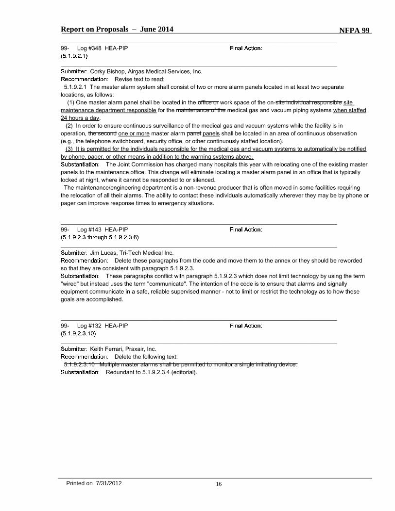
Report on Proposals – June 2014 NFPA 99_______________________________________________________________________________________________99- Log #348 HEA-PIP
_______________________________________________________________________________________________Corky Bishop, Airgas Medical Services, Inc.
Revise text to read: 5.1.9.2.1 The master alarm system shall consist of two or more alarm panels located in at least two separate
locations, as follows:(1) One master alarm panel shall be located in the office or work space of the on-site individual responsible site
maintenance department responsible for the maintenance of the medical gas and vacuum piping systems when staffed24 hours a day.
(2) In order to ensure continuous surveillance of the medical gas and vacuum systems while the facility is inoperation, the second one or more master alarm panel panels shall be located in an area of continuous observation(e.g., the telephone switchboard, security office, or other continuously staffed location).
(3) It is permitted for the individuals responsible for the medical gas and vacuum systems to automatically be notifiedby phone, pager, or other means in addition to the warning systems above.
The Joint Commission has charged many hospitals this year with relocating one of the existing masterpanels to the maintenance office. This change will eliminate locating a master alarm panel in an office that is typicallylocked at night, where it cannot be responded to or silenced.The maintenance/engineering department is a non-revenue producer that is often moved in some facilities requiring
the relocation of all their alarms. The ability to contact these individuals automatically wherever they may be by phone orpager can improve response times to emergency situations.
_______________________________________________________________________________________________99- Log #143 HEA-PIP
_______________________________________________________________________________________________Jim Lucas, Tri-Tech Medical Inc.
Delete these paragraphs from the code and move them to the annex or they should be rewordedso that they are consistent with paragraph 5.1.9.2.3.
These paragraphs conflict with paragraph 5.1.9.2.3 which does not limit technology by using the term"wired" but instead uses the term "communicate". The intention of the code is to ensure that alarms and signallyequipment communicate in a safe, reliable supervised manner - not to limit or restrict the technology as to how thesegoals are accomplished.
_______________________________________________________________________________________________99- Log #132 HEA-PIP
_______________________________________________________________________________________________Keith Ferrari, Praxair, Inc.
Delete the following text:5.1.9.2.3.10 Multiple master alarms shall be permitted to monitor a single initiating device.
Redundant to 5.1.9.2.3.4 (editorial).
16Printed on 7/31/2012
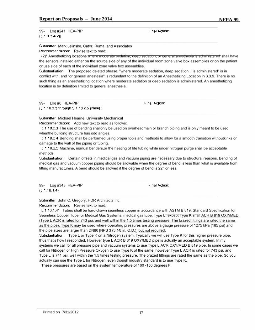
Report on Proposals – June 2014 NFPA 99_______________________________________________________________________________________________99- Log #241 HEA-PIP
_______________________________________________________________________________________________Mark Jelinske, Cator, Ruma, and Associates
Revise text to read:(2)* Anesthetizing locations where moderate sedation, deep sedation, or general anesthesia is administered shall have
the sensors installed either on the source side of any of the individual room zone valve box assemblies or on the patientor use side of each of the individual zone valve box assemblies.
The proposed deleted phrase, "where moderate sedation, deep sedation... is administered" is inconflict with, and "or general anestesia" is redundant to the definition of an Anesthetizing Location in 3.3.9. There is nosuch thing as an anesthetizing location where moderate sedation or deep sedation is administered. An anesthetizinglocation is by definition limited to general anesthesia.
_______________________________________________________________________________________________99- Log #6 HEA-PIP
_______________________________________________________________________________________________Michael Hearne, University Mechanical
Add new text to read as follows:The use of bending shallonly be used on overheadmain or branch piping and is only meant to be used
whenthe building structure has odd angles.Bending shall be performed using proper tools and methods to allow for a smooth transition withoutkinks or
damage to the wall of the piping or tubing.Machine, manual benders,or the heating of hte tubing while under nitrogen purge shall be acceptable
methods.Certain offsets in medical gas and vacuum piping are necessary due to structural reasons. Bending of
medical gas and vacuum copper piping should be allowable when the degree of bend is less than what is available fromfitting manufacturers. A bend should be allowed if the degree of bend is 22° or less.
_______________________________________________________________________________________________99- Log #343 HEA-PIP
_______________________________________________________________________________________________John C. Gregory, HDR Architects Inc.
Revise text to read:5.1.10.1.4* Tubes shall be hard-drawn seamless copper in accordance with ASTM B 819, Standard Specification for
Seamless Copper Tube for Medical Gas Systems, medical gas tube, Type L, except Type K shall ACR B 819 OXY/MED(Type L ACR is rated for 743 psi, and well within the 1.5 times testing pressure. The brazed fittings are rated the sameas the pipe). Type K may be used where operating pressures are above a gauge pressure of 1275 kPa (185 psi) andthe pipe sizes are larger than DN80 [NPS 3 (3 1⁄8 in. O.D.)] but not required.
Type L or Type K on a Nitrogen system. Typically we will use Type K for this higher pressure pipe,thus that's how I responded. However type L ACR B 819 OXY/MED pipe is actually an acceptable system. In mysystems we call for all pressure pipe and vacuum systems to use Type L ACR OXY/MED B 819 pipe. In some cases wecall for Nitrogen or High Pressure Oxygen to use Type K of the same, however Type L ACR is rated for 743 psi, andType L is 741 psi, well within the 1.5 times testing pressure. The brazed fittings are rated the same as the pipe. So youactually can use the Type L for Nitrogen, even though industry standard is to use Type K.These pressures are based on the system temperature of 100 -150 degrees F.
17Printed on 7/31/2012
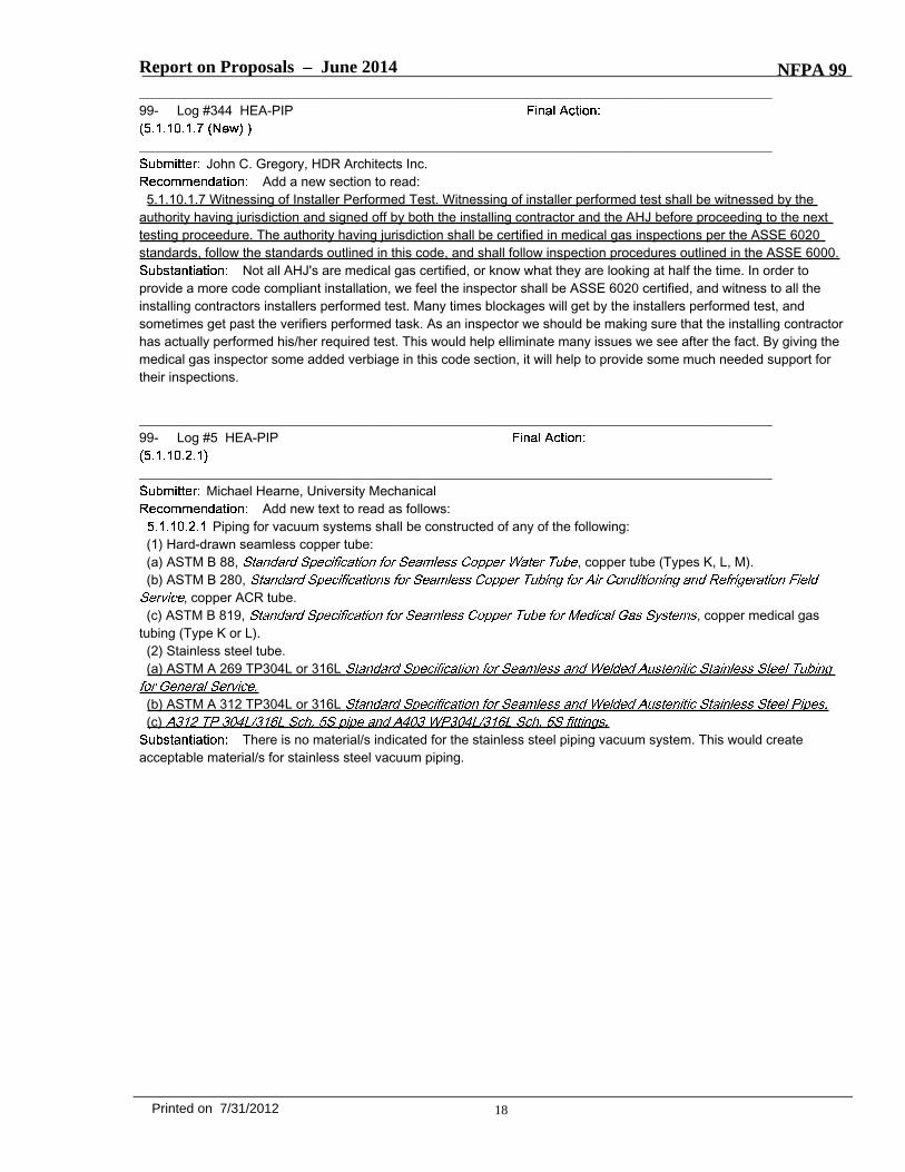
Report on Proposals – June 2014 NFPA 99_______________________________________________________________________________________________99- Log #344 HEA-PIP
_______________________________________________________________________________________________John C. Gregory, HDR Architects Inc.
Add a new section to read:5.1.10.1.7 Witnessing of Installer Performed Test. Witnessing of installer performed test shall be witnessed by the
authority having jurisdiction and signed off by both the installing contractor and the AHJ before proceeding to the nexttesting proceedure. The authority having jurisdiction shall be certified in medical gas inspections per the ASSE 6020standards, follow the standards outlined in this code, and shall follow inspection procedures outlined in the ASSE 6000.
Not all AHJ's are medical gas certified, or know what they are looking at half the time. In order toprovide a more code compliant installation, we feel the inspector shall be ASSE 6020 certified, and witness to all theinstalling contractors installers performed test. Many times blockages will get by the installers performed test, andsometimes get past the verifiers performed task. As an inspector we should be making sure that the installing contractorhas actually performed his/her required test. This would help elliminate many issues we see after the fact. By giving themedical gas inspector some added verbiage in this code section, it will help to provide some much needed support fortheir inspections.
_______________________________________________________________________________________________99- Log #5 HEA-PIP
_______________________________________________________________________________________________Michael Hearne, University Mechanical
Add new text to read as follows:Piping for vacuum systems shall be constructed of any of the following:
(1) Hard-drawn seamless copper tube:(a) ASTM B 88, , copper tube (Types K, L, M).(b) ASTM B 280,
, copper ACR tube.(c) ASTM B 819, , copper medical gas
tubing (Type K or L).(2) Stainless steel tube.(a) ASTM A 269 TP304L or 316L
(b) ASTM A 312 TP304L or 316L(c)
There is no material/s indicated for the stainless steel piping vacuum system. This would createacceptable material/s for stainless steel vacuum piping.
18Printed on 7/31/2012

Report on Proposals – June 2014 NFPA 99_______________________________________________________________________________________________99- Log #7 HEA-PIP
_______________________________________________________________________________________________Michael Hearne, University Mechanical
Add new text to read as follows:
Tube ends shall be cut square using a sharp tubing cutter to avoid deforming the tube.The cutting wheels on tubing cutters shall be free from grease, oil, or other lubricant not suitable for
oxygen service.The cut ends of the tube shall be deburred with a sharp, clean deburring tool, taking care to prevent chips
from entering the tube.When required, exterior deburring (manual filing) of piping for proper insertion into fittings shall be
performed by inserting a clean white, lint-free cloth or line-size cap into the pipe paying close attention to sealing off asmuch area as possible. When the beveling process is completed, the cloth or cap shall be removed carefully so as tokeep any filing materials from entering the cleaned pipe end. A clean white, lint-free cloth will then be saturated with aTri-Sodium Phosphate (TSP) solution and the end wiped clean after which close inspection shall be made to ensure nodebris is present.
When piping is cut from random lengths provided by the manufacturer, ends shall be sealed after cuttingto prevent debris or other contaminants from entering the pipe. No nitrogen purge for either resultant lengths of pipe isrequired.
There are no procedures for the outside of the piping/tubing when cutting. When a tubing cutter isused, especially on large diameter pipe, the cutter forms a ridge that must be reduced or eliminated in order for properinsertion into fittings as the tolerances do not allow the ridge to properly seat into the bottom of the fitting/s. NewSections 5.1.10.4.2.4 and 5.1.10.4.2.5 will create a procedure to rectify that.
_______________________________________________________________________________________________99- Log #8 HEA-PIP
_______________________________________________________________________________________________Michael Hearne, University Mechanical
Revise text to read as follows:During and after installation brazing, openings in the piping system shall be kept sealed, other than the
purge gas openings, to maintain a nitrogen atmosphere within the piping to prevent debris or other contaminants fromentering the system.
The word 'installation' does not technically describe prefabrication procedures and prefabrication is notpart of the installation. (It's somewhat of a middle ground.) Therefore, the word "installation" should change to brazing asthis is a part of both the prefabrication and installation of medical gas and vacuum systems. Also, it has been locallyinterpreted that the phrase "to maintain a nitrogen atmosphere" means that the piping is recharged with nitrogen underpressure. It is not. This should rectify both issues.
_______________________________________________________________________________________________99- Log #9 HEA-PIP
_______________________________________________________________________________________________Michael Hearne, University Mechanical
Revise text to read as follows:After the joint has cooled, the purge discharge opening shall be sealed to prevent contamination of the
inside of the tube and maintain a non-pressurized nitrogen atmosphere within the piping system.Locally, "maintain a nitrogen atmosphere" has been interpreted to mean a nitrogen pressure charge. A
pressurized nitrogen charge is not the intent.
19Printed on 7/31/2012

Report on Proposals – June 2014 NFPA 99_______________________________________________________________________________________________99- Log #133 HEA-PIP
_______________________________________________________________________________________________Keith Ferrari, Praxair, Inc.
Revise text to read:(1) They shall be limited to connections for pressure and vacuum indicators, alarm devices, gas specific demand check
valves, and source equipment on the source side of the source valve.2012 edition required oxygen check valves to have brazed extensions. The only check valve taht can
be thread on the pipeline is the gas specific demand check valve for sensors.
_______________________________________________________________________________________________99- Log #23 HEA-PIP
_______________________________________________________________________________________________
Robert Sewell, Plumbers & Steamfitters Local 159Add text to read as follows:
The installation of medical gas equipment such as but not limited to medical gas compressors, air dryers, vacuumpumps, headwalls, columns, ceiling columns, ceiling hung pendents, movable tract systems, and so forth, shall beinstalled by qualified, competent, technicians who meet the requirements of ASSE 6010 Professional QualificationStandard for Medical Gas Systems Installers.
In Contra Costa County, these items are being installed by persons who are not trained in thehandling, installation and inspection of this equipment. To prevent equipment from being installed that may becontaminated, I believe that any and all persons who install medical gas equipment must meet the requirements ofASSE 6010.
_______________________________________________________________________________________________99- Log #352 HEA-PIP
_______________________________________________________________________________________________Rachael Stephenson, Flower Mound, TX
Add new text to read:5.1.10.11.6.1 Hose and flexible connectors, both metallic and nonmetallic, shall be no longer than necessary and
shall not penetrate or be concealed in walls, floors, ceilings, or partitions.Where flexible hose is used as part of a manufactured assembly, it shall be permitted to penetrate or be concealed in
walls, floors, ceilings, or partitions and shall be as follows:(1) Shall be connected to building pipeline no farther than 10 feet from the manufacturer assembly(2) Meet the requirements of 5.1.6.10(3) Accessible by removal of a panel, door, or cover
This is a clarification for application of this requirement to manufactured assemblies. Allowingconnection of flexible hose from manufactured assemblies within the walls or ceiling allows manufactured assemblies tobe maintained rather than fully removed for flexible hose servicing.
20Printed on 7/31/2012
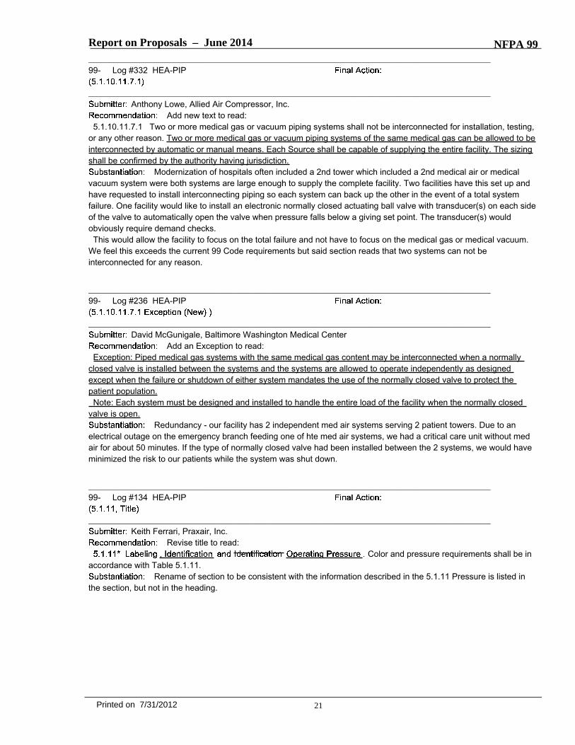
Report on Proposals – June 2014 NFPA 99_______________________________________________________________________________________________99- Log #332 HEA-PIP
_______________________________________________________________________________________________Anthony Lowe, Allied Air Compressor, Inc.
Add new text to read:5.1.10.11.7.1 Two or more medical gas or vacuum piping systems shall not be interconnected for installation, testing,
or any other reason. Two or more medical gas or vacuum piping systems of the same medical gas can be allowed to beinterconnected by automatic or manual means. Each Source shall be capable of supplying the entire facility. The sizingshall be confirmed by the authority having jurisdiction.
Modernization of hospitals often included a 2nd tower which included a 2nd medical air or medicalvacuum system were both systems are large enough to supply the complete facility. Two facilities have this set up andhave requested to install interconnecting piping so each system can back up the other in the event of a total systemfailure. One facility would like to install an electronic normally closed actuating ball valve with transducer(s) on each sideof the valve to automatically open the valve when pressure falls below a giving set point. The transducer(s) wouldobviously require demand checks.This would allow the facility to focus on the total failure and not have to focus on the medical gas or medical vacuum.
We feel this exceeds the current 99 Code requirements but said section reads that two systems can not beinterconnected for any reason.
_______________________________________________________________________________________________99- Log #236 HEA-PIP
_______________________________________________________________________________________________David McGunigale, Baltimore Washington Medical Center
Add an Exception to read:Exception: Piped medical gas systems with the same medical gas content may be interconnected when a normally
closed valve is installed between the systems and the systems are allowed to operate independently as designedexcept when the failure or shutdown of either system mandates the use of the normally closed valve to protect thepatient population.Note: Each system must be designed and installed to handle the entire load of the facility when the normally closed
valve is open.Redundancy - our facility has 2 independent med air systems serving 2 patient towers. Due to an
electrical outage on the emergency branch feeding one of hte med air systems, we had a critical care unit without medair for about 50 minutes. If the type of normally closed valve had been installed between the 2 systems, we would haveminimized the risk to our patients while the system was shut down.
_______________________________________________________________________________________________99- Log #134 HEA-PIP
_______________________________________________________________________________________________Keith Ferrari, Praxair, Inc.
Revise title to read:Color and pressure requirements shall be in
accordance with Table 5.1.11.Rename of section to be consistent with the information described in the 5.1.11 Pressure is listed in
the section, but not in the heading.
21Printed on 7/31/2012
Report on Proposals – June 2014 NFPA 99_______________________________________________________________________________________________99- Log #135 HEA-PIP
_______________________________________________________________________________________________Keith Ferrari, Praxair, Inc.
Add a new section to read:The zone valve(s) shall be labeled in substance as follows:Zone Valve for the (gas/vacuum name) Serving (name of the area/ rooms served by the particular valve)
Zone valves are the only valve not listed in thsi section on labeling.
_______________________________________________________________________________________________99- Log #30 HEA-PIP
_______________________________________________________________________________________________
Jim Lucas, Tri-Tech Medical Inc.Add new text to read as follows:
Sleep labs are being built with outlets downstream of flow control devices using standard labeling (i.e.,Oxygen).
_______________________________________________________________________________________________99- Log #136 HEA-PIP
_______________________________________________________________________________________________Keith Ferrari, Praxair, Inc.
Revise to read as follows:Labeling of alarm panels shall comply with the requirements of 5.1.9.1(6) and (7) for each
indicator, indicating the conditionmonitored and for its area of surveillance.Replaced reference of 5.1.9.1(6) and (7) with section wording for clarity.
_______________________________________________________________________________________________99- Log #131 HEA-PIP
_______________________________________________________________________________________________Keith Ferrari, Praxair, Inc.
Add a new section to read:The rated accuracy of indicators used fro testing shall be 1 percent (full scale) or better at the point of reading.
Relocated 5.1.8.1.7 (Editorial).
22Printed on 7/31/2012

Report on Proposals – June 2014 NFPA 99_______________________________________________________________________________________________99- Log #345 HEA-PIP
_______________________________________________________________________________________________John C. Gregory, HDR Architects Inc.
Revise text to read:5.1.12.2.1.1 The tests required by 5.1.12.2 shall be performed and documented by the installer prior, and witnessed
by an ASSE 6020 certified inspector prior to the tests listed in 5.1.12.3.NFPA identifies the certification levels for the installing contractor, the verifier and the maintenance
worker for the medical gas systems, but the medical gas inspector certified to the ASSE 6020 standards is notmentioned anywhere. I believe their should be some description either under the AHJ description or it's own whichidentifies what they shall perform and how.
_______________________________________________________________________________________________99- Log #358 HEA-PIP
_______________________________________________________________________________________________George L. Scott, Scott Associates LLC
Revise text to read:5.1.12.3.7.1 A minimum of 1000 L (35 ft3) of gas shall be filtered through a clean, white 0.45 micron filter at a
minimum flow rate of 100 Nl/min (3.5 SCFM).By allowing flow rates greater than 100 L/min the total amount of particulate matter deposited on the
filter element can increase, possibly exceeding the permissible level in 5.1.12.3.7.3. Same erroneous result can occurby allowing the total volume of gas to exceed 1,000 L. As the flow increases, the gas velocity increases and theaerosolized particulate matter in the piping system can increase, thus depositing more particulate matter on the filterelement.Two tests performed on the same outlet using different rates of flow (1 at 100 L/min and 1 at >100L/min) could produce
different results, perhaps causing the higher flow rate to exceed the total allowable particulate matter per unit of volume- 1mg/M3.
_______________________________________________________________________________________________99- Log #34 HEA-PIP
_______________________________________________________________________________________________Mike Lemanek, Certech
Delete the following text:5.1.12.3.8.1 These tests shall be performed with oil-free, dry nitrogen NF or the system gas.5.1.12.3.8.2 The outlet most remote from the source shall be tested for total non-methane hydrocarbons and
compared to the source gas.5.1.12.3.8.3 If the system gas is used as the source gas, it shall be tested at the source equipment.5.1.12.3.8.4 The difference between the two tests shall in no case exceed 5 ppm of total non-methane hydrocarbons.5.1.12.3.8.5 The difference between the two tests shall in no case exceed 5 ppm halogenated hydrocarbons.
Eliminate expensive and time consuming test.
23Printed on 7/31/2012

Report on Proposals – June 2014 NFPA 99_______________________________________________________________________________________________99- Log #359 HEA-PIP
_______________________________________________________________________________________________George L. Scott, Scott Associates LLC
Add new text to read:Odor. All positive pressure gas outlets, except nitrous oxide, shall be tested for odor. No appreciable odor shall be
discernible. At an outlet flow of approximately 10 SLPM, deflect a portion of the gas stream toward the nose and sniff.Do not direct the outlet gas stream toward the face.
Odor is presently not required during the verification process, but is seen too frequently when tubingplugs are brazed into the piping system during installation, causing an offensive odor. Gas odor is at times missedresulting in costly opening of walls, etc. and sometimes causing delayed clinical unit openings to remove the pipingsections involved. Occasionally the problem is not noted until patient use, resulting in costly clinical unit(s) unplannedshutdowns.The odor test should be performed with source gas, because the source gas itself is occasionally the cause of the
odor. The new section methodology is similar to the USP test required on some medical gases.Although odor can be subjective between individuals, a “discernible odor” would be caught by the vast majority of
verifiers.Perhaps a clarification in the Appendix would be helpful explaining the difference between breathing the gas under test
and just sniffing it for odor.
24Printed on 7/31/2012
Report on Proposals – June 2014 NFPA 99_______________________________________________________________________________________________99- Log #27 HEA-PIP
_______________________________________________________________________________________________
Keith Ferrari, PraxairRevise text to read as follows:
(a) Purity - Percent Concentration(b) Permanent Particulates & Contaminants(c) Odor & Moisture
There is a continual need for human diligence in the establishment and maintenance of safe practicesfor respiratory therapy. It is essential for personnel having responsibility for respiratory therapy to establish and enforceappropriate safety programs.The supply of gas that comes from the manufacturer or distributor should be accompanied with a Certificate of
Analysis. Additional impurities can enter the pipeline over time from wear and tear on the pipeline, temperature changesthat affect the pipeline, moisture buildup, maintenance work on the pipeline and components, etc. The purity of the gasdoes not end at the supply source. The pipeline network runs throughout the facility. There are numerous articleswritten about pipeline contamination (i.e. ECRI).1. ECRI recommend random testing of selected outlets for purity and contaminant testing.
1. Routinely inspect and maintain medical gas and vacuum systems. Schedules and procedures are described in ourIMP Procedure in 23 (1-2).
2. Use filters on medical gas outlets only as a temporary measure to protect patients and devices against particles,bacteria, or liquid water found in the system. Develop a schedule of filter inspection and replacement and a plan tocorrect the source of contamination in a medical gas system as soon as possible. Note that filters will not remove watervapor or other gases, which can damage some medical devices. Water found in the system is a serious problemrequiring immediate action to eliminate its cause and limit the extent and impact of the contamination.
Eichhhorn JH, Bancroft ML, Laasbert LH, du Moulin GC, Saubermann AJ.
Medical gases and water were sampled and tested for purity prior to the opening of a 176-bed addition to a 450-bedgeneral hospital.Contamination was found. In delivered oxygen, compressed air, and nitrous oxide, this consisted of a volatile
hydrocarbon at an initial concentration of 10 parts per million and a dust of fine gray particulate matter. In water fromnew taps bacterial contamination with as many 400,000 organisms per 100 ml was present. All these contaminantswere considered potential hazards to patient safety. Studies were done to help delineate the nature and origin of thesecontaminants. Each contaminant was eventually largely eliminated by purging the respective pipeline systems withcontinuous flows. Planners, builders, and responsible medical personnel must be aware of the potential such hazards ina new hospital building.
The failure of anesthetic equipment as a result of maintenance is extremely rare. The ingress of water into theflowmeters of an anesthetic machine from the piped medical air supply is reported and is possibly unique. The pipedmedical air supply was open to the atmosphere during maintenance. Water condensed in the gas pipeline and this wasnot noticed during subsequent testing. Water was seen leaking from the orthopacdic air tools used for surgery but wasassumed to be from the autoclaving process. Later the same day, when medical air from the piped source was used aspart of the gas mixture for a general anesthetic, water was seen filling the barrel of the flowmeter air control valve. Thiscould have had far-reaching and dangerous consequences for the patient, which were fortunately averted.(Published Online August 16, 2006)
Journal of Clinical Monitoring and Computing Volume 11, Number 1, 73-76, DOI: 10.1007/BF01627427APSF Newsletter
Dr. Moss, of Verona, NY, has been very active with and is a consultant to the New Jersey State Society ofAnesthesiologists. He is an APSR Director and also Chairman of the APSF Subcommittee on Medical Gas and Vacuum
25Printed on 7/31/2012
Report on Proposals – June 2014 NFPA 99Systems.
26Printed on 7/31/2012

Report on Proposals – June 2014 NFPA 99_______________________________________________________________________________________________99- Log #157 HEA-PIP
_______________________________________________________________________________________________Mark W. Allen, Beacon Medaes
Revise and add new sections to read:5.1.13.1* Nature of Hazards Support Gas System. Support Gases.5.1.13.1 Applicability5.1.13.1.1 Support gases are any gases which are used primarily for powering equipment used in patient care
procedures (typical support gases are nitrogen and instrument air). Support gas applications require delivery atpressures, cleanliness or purities specific to their intended function(s) (e.g. to operate medical–surgical tools). Supportgases shall be permitted to be piped into areas intended for any medical support purpose and, if appropriate to theprocedures, to be piped into laboratories.5.1.13.1.2 Support gases sources are permitted to be used for many general utility uses (e.g. to remove excess
moisture from instruments before further processing, or to operate gas-driven booms, boom brakes, pendants, or similarapplications). Requirements for general utility systems will be found in Chapter 9).5.1.13.1.3 Support gas systems shall not convey oxidizing gases other than air or gases intended for patient or staff
respiration.5.1.13.2 Nature of Hazards5.1.13.2.1 Design, installation and operation of support gas systems shall consider all hazards involved with any
pressurized gas except those associated with oxidizing gases and hazards associated with the elevated pressurestypical of these systems.5.1.13.2 Sources5.1.13.2.1 Support gases may be supplied from the same sources as patient care gases. Where this is done, they
shall be treated as the patient care gas and not as a support gas (refer to 5.1.1 to 5.1.12 and 5.1.14).5.1.13.2.2 Sources for support gases delivered from cylinders shall comply with 5.1.3.3 through 5.1.3.5.10.
Requirements for support gas sources shall be in accordance with the following:
(1) Paragraphs 5.1.3.1 through 5.1.3.5 for nitrogen(2) Paragraph 5.1.3.9 for instrument air
5.1.13.2.3 Sources for support gases delivered from containers shall comply with 5.1.3.3 through 5.1.3.5.11 except5.1.3.5.10.5.1.13.2.4 Sources for support gases delivered from bulk sources shall comply with 5.1.3.3 through 5.1.3.5.11 except
5.1.3.5.10.5.1.13.2.5* Instrument Air Supply Systems.5.1.13.2.5.1 Quality of Instrument Air. The quality of instrument air shall be as follows:(1) Compliant with instrument air section in ANSI/ISA S-7.0.01, Quality Standard for Instrument Air(2) Filtered to 0.01 micron(3) Free of liquids (e.g., water, hydrocarbons, solvents)(4) Free of hydrocarbon vapors(5) Dry to a dew point of −40°C (−40°F)5.1.13.2.5.2 Instrument air supply systems shall be located per 5.1.3.3 as follows:(1) Indoors, in a dedicated mechanical equipment area that is adequately ventilated and with any required utilities(2) In a room ventilated per 5.1.3.3.3.2(3) For air-cooled equipment, in a room designed to maintain the ambient temperature range as recommended by the
equipment manufacturer5.1.13.2.5.3 Instrument Air Sources shall provide air with the following characteristics:(1) a guage pressure not less than a 1380 kPa (200 psi) at the compressor.(2) meeting the definition of instrument air in 5.1.13.2.5.1.5.1.13.2.5.4 Instrument air sources shall be of any of the following formats:(1) at least two compressors(2) one compressor and a standby header complying with 5.1.3.5.8.5.1.13.2.5.5 Instrument air sources shall include the components specified in 5.1.3.6.3.2 (Components), 5.1.3.6.3.5
(Aftercoolers), 5.1.3.6.3.6 (Receivers), 5.1.3.6.3.7 (except (1)) (Dryers).5.1.13.2.5.6 Instrument air compressors shall be permitted to be of any type capable of not less than a gauge
27Printed on 7/31/2012
Report on Proposals – June 2014 NFPA 99pressure of 1380 kPa (200 psi) output pressure and of providing air meeting the definition of instrument air in5.1.13.2.5.1.5.1.13.2.5.7 Instrument Air Standby Headers. Where instrument air systems are provided with a standby header, the
header shall meet the following requirements:(1) It shall comply with 5.1.3.5.9, except that the number of attached cylinders shall be sufficient for 1 hour normal
operation.(2) It shall use connectors as for medical air in CGAV-1, Compressed Gas Association Standard for Compressed Gas
Cylinder Valve Outlet and Inlet Connections (ANSI B57.1).(3) It shall enter the system upstream (source side) of the final line filters. (See Figure A.5.1.3.9.)(4) It shall automatically serve the system in the event of a failure of the compressor.5.1.13.2.5.8* Intake Air. Intake air for instrument air compressors shall be permitted to be drawn from the outside, from
ducted air, or from the equipment location.5.1.13.2.5.9 Instrument Air Filters. Instrument air sources shall be provided with filtration sized for 100 percent of the
system peak calculated demand at design conditions and with the following elements and characteristics:(1) activated carbon filters located upstream (source side) of the final line filters.(2) line filters located upstream (source side) of the final line regulators and downstream of the carbon filters rated for a
minimum of 98 percent efficiency at 0.01 micron.(3) equipped with a continuous visual indicator showing the status of the line filter element life.(4) constructed of materials deemed suitable by the manufacturer.(5) filters combining the functions in (1) to (4) in a single unit shall be permitted to be used.5.1.13.2.5.10 Instrument Air Accessories. Accessories used for instrument air sources shall comply with the following
subparagraphs:(1) 5.1.3.6.3.5 for aftercoolers(2) 5.1.3.6.3.6 for air receivers(3) 5.1.3.6.3.7 for air dryers(4) 5.1.3.5.9 for air regulators5.1.13.2.5.11 Instrument Air Piping Arrangement and Redundancies. Instrument air sources shall comply with
5.1.3.6.3.10, except for the following:(1) Systems employing a standby header shall be permitted to have simplex aftercoolers and dryers.(2) Systems employing a standby header shall not require a three-valve receiver bypass.(3) Standby headers, where provided, shall be isolated from the compressor by a check valve to prevent backflow
through the compressor.5.1.13.2.5.12 Instrument Air Monitoring and Alarms. Instrument air sources shall include the following alarms:(1) Local alarm that activates when or just before the backup compressor (if provided) activates, indicating that the lag
compressor is in operation and that must be manually reset(2) Local alarm and alarms at all master alarm panels that activate when the dew point at system pressure exceeds
−30°C (−22°F), indicating high dew point5.1.3.9.10.2 For sources with standby headers, the following additional conditions shall activate a local alarm at the
compressor site, a local signal at the header location, and alarms at all master alarm panels:(1) Alarm that activates when or just before the reserve begins to supply the system, indicating reserve in use(2) Alarm that activates when or just before the reserve falls below an average hour’s supply, indicating reserve low5.1.13.2.5.13 Electrical Power and Control. Power and control for instrument air sources shall have the following
characteristics:(1) Each compressor motor shall be provided with electrical components including, but not limited to, the following:
(a) Dedicated disconnect switch installed in the electrical circuit ahead of each motor starter(b) Motor starting device(c) Overload protection(d) Where compressor systems having two or more compressors employ a control transformer or other voltage
control power device, installation of at least two such devices(e) Control circuits arranged in such a manner that the shutdown of one compressor does not interrupt the operation
of another compressor(f) Automatic restart function such that the compressor(s) will restart after power interruption without manual
intervention.(2) Electrical installation and wiring shall conform to the requirements of NFPA 70, National Electrical Code.(3) Emergency electrical service for the compressors shall conform to the requirements of the essential electrical
system as described in Chapter 6.(4) When multiple compressors are used, an additional compressor(s) shall automatically activate when the
28Printed on 7/31/2012

Report on Proposals – June 2014 NFPA 99compressor(s) in operation is incapable of maintaining the requiredpressure.(5) When multiple compressors are used, automatic or manual alternation of compressors shall allow division of
operating time. If automatic alternation of compressors is not provided, the facility staff shall arrange a schedule formanual alternation.Delete 5.1.3.9.
This reorganization advances the original intent of creating a separate set of requirements for supportgases to recognize their lees critical nature. It also attempts to identify them more clearly and to separate them fromutility systems (Chapter 9).
_______________________________________________________________________________________________99- Log #159 HEA-PIP
_______________________________________________________________________________________________Mark W. Allen, Beacon Medaes
Revise to read: 5.1.13.4.1 Requirements for nitrogen support gas outlets shall be in accordance with 5.1.5.1, 5.1.5.2, 5.1.5.4 through
5.1.5.8, 5.1.5.11, and 5.1.5.13 through 5.1.5.15.These requirements are not unique for nitrogen.
_______________________________________________________________________________________________99- Log #158 HEA-PIP
_______________________________________________________________________________________________Mark W. Allen, Beacon Medaes
Revise to read:5.1.13.8 Distribution.
Requirements for support gas piping distribution shall be in accordance with 5.1.10.1, 5.1.10.3, 5.1.10.4, 5.1.10.4.1through 5.1.10.4.6, 5.1.10.93.8, 5.1.10.9(1), 5.1.10.9(2), 4.3.13 through 5.1.10.9(3), and 5.1.10.11.
_______________________________________________________________________________________________99- Log #279 HEA-PIP
_______________________________________________________________________________________________David A. Dagenais, Wentworth-Douglas Hospital
Revise text to read:(1) Training and certification Training program through the health care facility by which such persons are employed to
work with specific equipment as installed in that facilityThese systems have been maintanined for several years by trained individuals within the healthcare
origination. to use the term certification required the hospital to become a certifying body and well beyond a welldeveloped training program.
29Printed on 7/31/2012

Report on Proposals – June 2014 NFPA 99_______________________________________________________________________________________________99- Log #330 HEA-PIP
_______________________________________________________________________________________________Anthony Lowe, Allied Air Compressor, Inc.
Delete the following text:(3) Credentialing to the requirements of ASSE 6030, Professional Qualification Standard for Medical Gas Systems
VerifiersThe ASSE 6030 Standard does not include knowledge of manufactured equipment. If the ASSE 6030
can perform maintenance so can the ASSE 6005, ASSE 6010, ASSE 6020, ASSE 6050.Just because a person has knowledge with medical gas systems does not constitute knowledge of the actual
equipment to perform routine maintenance.The current standard allows ALL ASSE 6030 credentialed person(s) to perform maintenance. Maintenance performed
by untrained person(s) can be detrimental to the performance of the equipment being serviced.
_______________________________________________________________________________________________99- Log #95 HEA-PIP
_______________________________________________________________________________________________James Bell, Intermountain Health Care
Revise text to read:(i) Air purity, medical air supplied from compressors shall be verified to meet 5.1.3.6.1 by quarterly sampling using an
AIHA or equivalent testing service unless continuous monitoring with alarms is installed.There is no requirment to test the medical air from compressors to meet 5.1.3.6.1 and it is not clear
what (i) air purity means. OSHA standards and US Navy standards for breathing air require bi annual sampling of the airprovided by compressorsI would sugest that medical air should be held to a higher or equal standard as occupationalbreathing air. See 14.2.8.6.1*
_______________________________________________________________________________________________99- Log #160 HEA-PIP
_______________________________________________________________________________________________Mark W. Allen, Beacon Medaes
Delete as shown:5.1.15* Category 1 Maintenance. Facilities shall have a routine maintenance program for their piped medical gas and
vacuum systems.This section is redundant to 5.1.14.
30Printed on 7/31/2012
Report on Proposals – June 2014 NFPA 99_______________________________________________________________________________________________99- Log #28 HEA-PIP
_______________________________________________________________________________________________
Keith Ferrari, PraxairRevise text to read as follows:
Level 2 systems shall comply with 5.1.3.4, except as follows:(1) Manifolds for Cryogenic Liquid Containers shall be permitted to have a primary supply and reserve supply.(2) The facility staff shall develop their emergency plan to deal with the loss of medical gases.
The increased usage of micro bulks and mini bulks, supplies between 5000 cu ft and 20, 000 cu ft ofgas, in the healthcare industry have caused confusion as to their proper installation. Most installers will follow 5.1.3.4.12for Manifolds for Cryogenic Liquid Containers, but some installations are being designed to 5.1.3.4.13 Bulk CryogenicLiquid Systems because the word Bulk is used in the term "Micro Bulk".By NFPA 99 -section 3.3.19.2 oxygen definition, a supply of oxygen more than 20, 000 cu ft is considered a bulk
supply. The supply of gas 20, 000 cu ft or less is not a bulk supply and should be installed in accordance with5.1.3.4.12. This may not be practical in the case of a micro bulk. In accordance with 5.1.3.4.12, there needs to be twoequal headers. This means that the facility either will have to install two micro bulks and a reserve or have enoughsupply of gas (cylinders or containers) on the secondary side to equal the primary supply. By adding another microbulk, this additional supply would in most cases increase the total supply to over 20,000 Cu ft thus requiring theinstallation to follow NFPA 55 code.Most of the micro or mini bulk installation are supplying level II facilities (clinics, same days under general anesthesia,
emergency care,...). In the NFPA 99 Level II sections 5.2.3.5, 5.2.3.6, & 5.2.3.7, there are exceptions for the Medical AirSupply Systems, Medical Surgical Vacuum Systems and WAGD central supply systems. I believe that Cryogenic LiquidContainers can be designed with a Primary supply and reserve supply for level II facilities without lowering patient safetystandards. The facility will still need to develop an emergency plan that addresses the loss of medical gases.
_______________________________________________________________________________________________99- Log #324 HEA-PIP
_______________________________________________________________________________________________Keith Ferrari, Praxair, Inc.
Renumber all of section 5.3.7 to 8.3.7.Gas-Powered Systems are not part of the scope of Chapter 5. The Gas-powered sytems in Chapter 5
catagory 3 are plumbing systems. Chapter 5 includes medical gases, support gases, medical -surgical vacuum. Chapter8 scope includes plumbing systems (non medical gas). The entire section should be moved to Chapter 8 and the TC forchapter 8 needs to review these sections.
_______________________________________________________________________________________________99- Log #325 HEA-PIP
_______________________________________________________________________________________________Keith Ferrari, Praxair, Inc.
Renumber all of section 5.3.8 to 8.3.8.Vacuum and Scavenging Systems are not part of the scope of Chapter 5. The Vacuum and
Scavenging sytems in Chapter 5 catagory 3 are plumbing systems. Chapter 5 includes medical gases, support gases,medical -surgical vacuum. Chapter 8 scope includes plumbing systems (non medical - surgical vacuum). The entiresection should be moved to Chapter 8 and the TC for chapter 8 needs to review these sections. As with my submittal onGas Powered Systems, this section needs to either move to Chapter 8 or be defined as a Medical-Surgical VacuumSystem Cat. 3 and defined with specific details. NFPA 99, 2012 seems to include wet, dry and other types of vacuumsystems in Cat 3 vacuum. Also, the term "scavenging" as used in this section seems to conflict with Chapter 9 use of theterm "scavenging" systems.
31Printed on 7/31/2012
Report on Proposals – June 2014 NFPA 99_______________________________________________________________________________________________99- Log #138 HEA-PIP
_______________________________________________________________________________________________Keith Ferrari, Praxair, Inc.
Revise table as follows:
INSERT Table A.5.1.9.2 HERE
Updated table (editorial).
_______________________________________________________________________________________________99- Log #36 HEA-PIP
_______________________________________________________________________________________________Mike Lemanek, Certech
Revise text to read:A.5.1.14.1.4 Other examples of prohibited use of medical–surgical vacuum would be scope cleaning, decontamination,
and laser plume.Trying to enforce this prohibition during verification is futile.
32Printed on 7/31/2012

Table A.5.1.9.2 Requirements for Category 1 Master Alarms for Gas and Vacuum Systems
Alarm Condition
Manifold for Gas
Cylinders Without Reserve
(5.1.3.5.10) Manifold for Cryogenic Liquid
Cylinders with Reserve (5.1.3.5.11)
Cryogenic Bulk with Cryogenic Reserve
(5.1.3.5.12)
Cryogenic Bulk with Cylinder Reserve
(5.1.3.5.12)
Medical Air Proportioning
System (5.1.3.6.3.15)
Medical Air Compressors
(5.1.3.6)
Instrument Air Compressors
(5.1.3.9)
Medical– Surgical Vacuum Pumps
(5.1.3.7)
WAGD Producers (5.1.3.78)
Nitrogen main line pressure high
5.1.9.2.4(7) 5.1.9.2.4(7) 5.1.9.2.4(7) 5.1.9.2.4(7)
Nitrogen main line pressure low
5.1.9.2.4(7) 5.1.9.2.4(7) 5.1.9.2.4(7) 5.1.9.2.4(7)
Nitrogen changeover to secondary supply
5.1.3.5.10.6 5.1.9.2.4(1)
5.1.3.5.11.9 (1) 5.1.9.2.4(1)
Nitrogen main supply less than 1 day (low contents)
5.1.9.2.4(2) 5.1.3.5.12.4(1) 5.1.9.2.4(2)5.1.3.5.12.4(1)
Nitrogen reserve in use
5.1.3.5.11.9(3) 5.1.9.2.4(3) 5.1.9.2.4(3) 5.1.3.5.12.4(2) 5.1.9.2.4(3)5.1.3.5.12.4(2)
Nitrogen reserve supply less than 1 day (low contents)
5.1.3.5.11.9(4) 5.1.9.2.4(5) 5.1.3.5.12.4(3) 5.1.9.2.4(5)5.1.3.5.12.4(3)
Nitrogen reserve pressure low (not functional)
5.1.9.2.4(6) 5.1.3.5.12.4(4)
Carbon dioxide main line pressure high
5.1.9.2.4(7) 5.1.9.2.4(7) 5.1.9.2.4(7) 5.1.9.2.4(7)
Carbon dioxide main line pressure low
5.1.9.2.4(7) 5.1.9.2.4(7) 5.1.9.2.4(7) 5.1.9.2.4(7)
Carbon dioxide changeover to secondary supply
5.1.3.5.10.6 5.1.9.2.4(1)
5.1.3.5.11.9(1) 5.1.9.2.4(1)
Carbon Dioxide main supply less than 1 day (low contents)
5.1.9.2.4(2)5.1.3.5.12.4(1) 5.1.9.2.4(2)5.1.3.5.12.4(1)
Carbon Dioxide reserve in use
5.1.3.5.11.9(3) 5.1.9.2.4(3) 5.1.9.2.4(3)5.1.3.5.12.4(2) 5.1.9.2.4(3)5.1.3.5.12.4(2)
Carbon Dioxide reserve supply less than 1 day (low contents)
5.1.3.5.11.9(4) 5.1.9.2.4(5)5.1.3.5.12.4(3) 5.1.9.2.4(5)5.1.3.5.12.4(3)
Carbon Dioxide reserve pressure low (not functional)
5.1.9.2.4(6)5.1.3.5.12.4(3)
Medical air main line pressure high
5.1.9.2.4(7)
5.1.9.2.4(7)
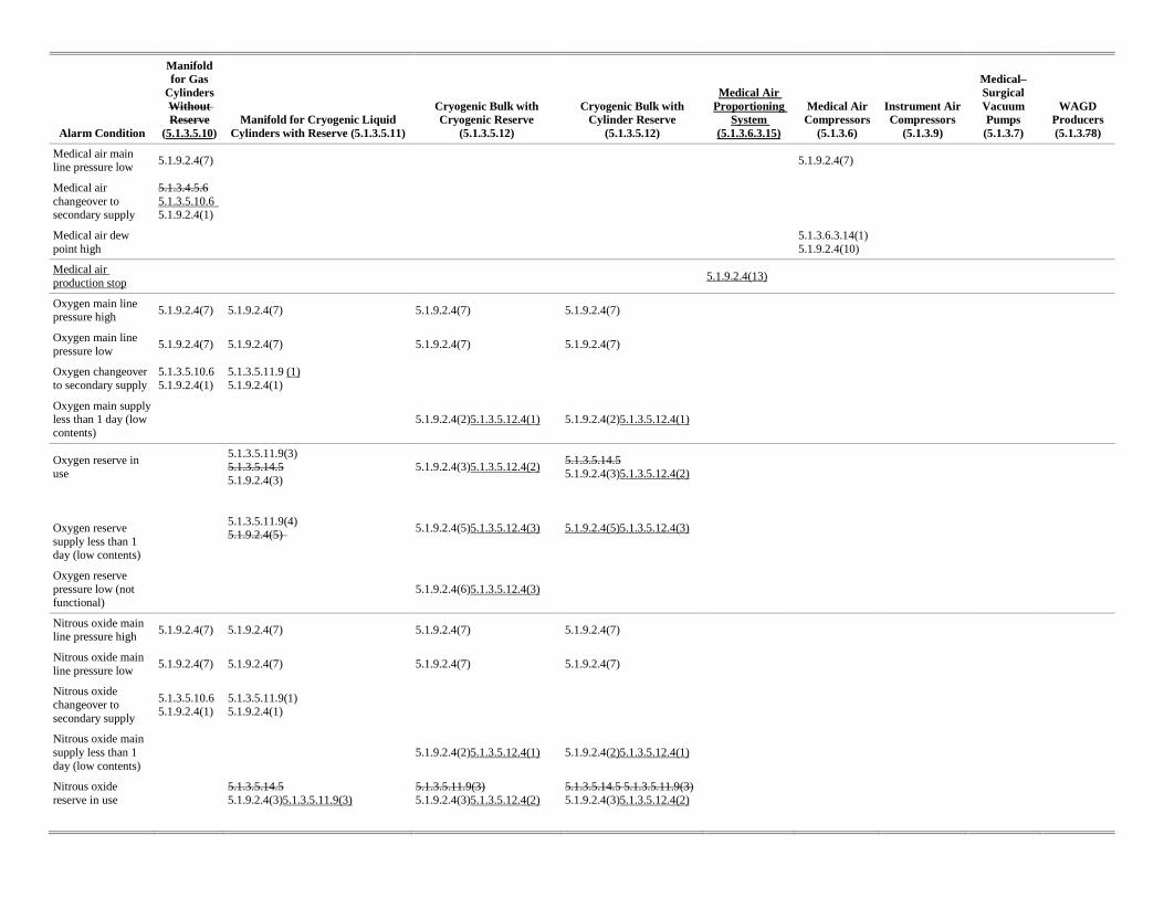
Alarm Condition
Manifold for Gas
Cylinders Without Reserve
(5.1.3.5.10) Manifold for Cryogenic Liquid
Cylinders with Reserve (5.1.3.5.11)
Cryogenic Bulk with Cryogenic Reserve
(5.1.3.5.12)
Cryogenic Bulk with Cylinder Reserve
(5.1.3.5.12)
Medical Air Proportioning
System (5.1.3.6.3.15)
Medical Air Compressors
(5.1.3.6)
Instrument Air Compressors
(5.1.3.9)
Medical– Surgical Vacuum Pumps
(5.1.3.7)
WAGD Producers (5.1.3.78)
Medical air main line pressure low
5.1.9.2.4(7)
5.1.9.2.4(7)
Medical air changeover to secondary supply
5.1.3.4.5.6 5.1.3.5.10.6 5.1.9.2.4(1)
Medical air dew point high
5.1.3.6.3.14(1) 5.1.9.2.4(10)
Medical air production stop
5.1.9.2.4(13)
Oxygen main line pressure high
5.1.9.2.4(7) 5.1.9.2.4(7) 5.1.9.2.4(7) 5.1.9.2.4(7)
Oxygen main line pressure low
5.1.9.2.4(7) 5.1.9.2.4(7) 5.1.9.2.4(7) 5.1.9.2.4(7)
Oxygen changeover to secondary supply
5.1.3.5.10.6 5.1.9.2.4(1)
5.1.3.5.11.9 (1) 5.1.9.2.4(1)
Oxygen main supply less than 1 day (low contents)
5.1.9.2.4(2)5.1.3.5.12.4(1) 5.1.9.2.4(2)5.1.3.5.12.4(1)
Oxygen reserve in use
5.1.3.5.11.9(3) 5.1.3.5.14.5 5.1.9.2.4(3)
5.1.9.2.4(3)5.1.3.5.12.4(2) 5.1.3.5.14.5 5.1.9.2.4(3)5.1.3.5.12.4(2)
Oxygen reserve supply less than 1 day (low contents)
5.1.3.5.11.9(4) 5.1.9.2.4(5)
5.1.9.2.4(5)5.1.3.5.12.4(3) 5.1.9.2.4(5)5.1.3.5.12.4(3)
Oxygen reserve pressure low (not functional)
5.1.9.2.4(6)5.1.3.5.12.4(3)
Nitrous oxide main line pressure high
5.1.9.2.4(7) 5.1.9.2.4(7) 5.1.9.2.4(7) 5.1.9.2.4(7)
Nitrous oxide main line pressure low
5.1.9.2.4(7) 5.1.9.2.4(7) 5.1.9.2.4(7) 5.1.9.2.4(7)
Nitrous oxide changeover to secondary supply
5.1.3.5.10.6 5.1.9.2.4(1)
5.1.3.5.11.9(1) 5.1.9.2.4(1)
Nitrous oxide main supply less than 1 day (low contents)
5.1.9.2.4(2)5.1.3.5.12.4(1) 5.1.9.2.4(2)5.1.3.5.12.4(1)
Nitrous oxide reserve in use
5.1.3.5.14.5 5.1.9.2.4(3)5.1.3.5.11.9(3)
5.1.3.5.11.9(3) 5.1.9.2.4(3)5.1.3.5.12.4(2)
5.1.3.5.14.5 5.1.3.5.11.9(3) 5.1.9.2.4(3)5.1.3.5.12.4(2)
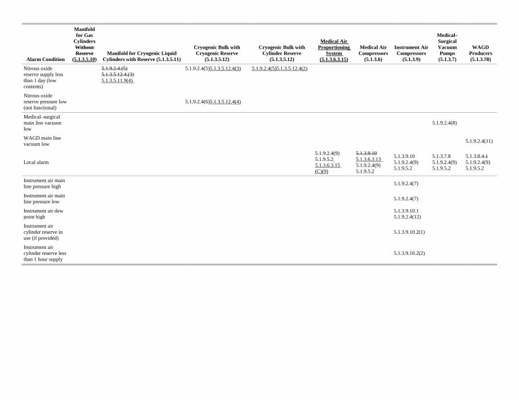
Alarm Condition
Manifold for Gas
Cylinders Without Reserve
(5.1.3.5.10) Manifold for Cryogenic Liquid
Cylinders with Reserve (5.1.3.5.11)
Cryogenic Bulk with Cryogenic Reserve
(5.1.3.5.12)
Cryogenic Bulk with Cylinder Reserve
(5.1.3.5.12)
Medical Air Proportioning
System (5.1.3.6.3.15)
Medical Air Compressors
(5.1.3.6)
Instrument Air Compressors
(5.1.3.9)
Medical– Surgical Vacuum Pumps
(5.1.3.7)
WAGD Producers (5.1.3.78)
Nitrous oxide reserve supply less than 1 day (low contents)
5.1.9.2.4.(5) 5.1.3.5.12.4.(3) 5.1.3.5.11.9(4)
5.1.9.2.4(5)5.1.3.5.12.4(3) 5.1.9.2.4(5)5.1.3.5.12.4(2)
Nitrous oxide reserve pressure low (not functional)
5.1.9.2.4(6)5.1.3.5.12.4(4)
Medical–surgical main line vacuum low
5.1.9.2.4(8)
WAGD main line vacuum low
5.1.9.2.4(11)
Local alarm
5.1.9.2.4(9) 5.1.9.5.2 5.1.3.6.3.15 (C)(9)
5.1.3.9.10 5.1.3.6.3.13 5.1.9.2.4(9) 5.1.9.5.2
5.1.3.9.10 5.1.9.2.4(9) 5.1.9.5.2
5.1.3.7.8 5.1.9.2.4(9) 5.1.9.5.2
5.1.3.8.4.1 5.1.9.2.4(9) 5.1.9.5.2
Instrument air main line pressure high
5.1.9.2.4(7)
Instrument air main line pressure low
5.1.9.2.4(7)
Instrument air dew point high
5.1.3.9.10.1 5.1.9.2.4(12)
Instrument air cylinder reserve in use (if provided)
5.1.3.9.10.2(1)
Instrument air cylinder reserve less than 1 hour supply
5.1.3.9.10.2(2)