Networked PIP Series Reference Manual… · Networked PIP Series Reference Manual PIP - LITE PIP -...
16
PRELIMINARY Networked PIP Series Reference Manual PIP - LITE PIP - USP4-CN PIP - BLU Network Programmable Input Processors with HiQnet™, TCP/IQ™, SmartAmp™Features, Load Supervision for Crown PIP2™-Compatible Amplifiers, PIP-BLU™, and CobraNet™ Connectivity (USP4-CN only) Obtaining Other Language Versions: To obtain information in another language about the use of this product, please contact your local Crown Distributor. If you need assistance locating your local distributor, please contact Crown at 574-294-8000. This manual does not include all of the details of design, production, or variations of the equipment. Nor does it cover every possible situation which may arise during installation, operation or maintenance. If special assistance is needed beyond the scope of this manual, or the software online help, please contact the Crown Technical Support Group. The information provided in this manual was deemed accurate as of the publication date. However, updates to this information may have occurred. To obtain the latest version of this manual, please visit the Crown website at www.crownaudio.com. Trademark Notice: Crown, Crown Audio, Amcron, Com-Tech, Macro-Tech, IQ and IQ System are registered trademarks of Crown International. TCP/IQ, SmartAmp, IQ2, PIP, PIP-BLU and PIP2 are trademarks of Crown International. HiQnet is a trademark of Harman International Industries, Inc. Other trademarks are the property of their respective owners. Some models may be exported under the name Amcron ® . ©2012 by Harman International. 1718 W. Mishawaka Rd., Elkhart, Indiana 46517-9439 U.S.A. Telephone: 574-294-8000. 5014379 02/12
Transcript of Networked PIP Series Reference Manual… · Networked PIP Series Reference Manual PIP - LITE PIP -...
PRELIMINARY
Networked PIP Series Reference Manual
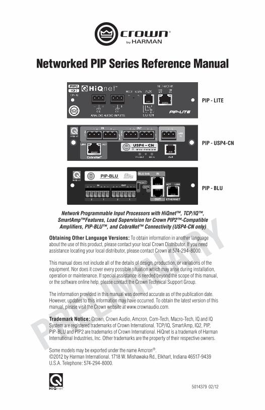
PIP - LITE
PIP - USP4-CN
PIP - BLU
Network Programmable Input Processors with HiQnet™, TCP/IQ™, SmartAmp™Features, Load Supervision for Crown PIP2™-Compatible Amplifiers, PIP-BLU™, and CobraNet™ Connectivity (USP4-CN only)
Obtaining Other Language Versions: To obtain information in another language about the use of this product, please contact your local Crown Distributor. If you need assistance locating your local distributor, please contact Crown at 574-294-8000.
This manual does not include all of the details of design, production, or variations of the equipment. Nor does it cover every possible situation which may arise during installation, operation or maintenance. If special assistance is needed beyond the scope of this manual, or the software online help, please contact the Crown Technical Support Group.
The information provided in this manual was deemed accurate as of the publication date. However, updates to this information may have occurred. To obtain the latest version of this manual, please visit the Crown website at www.crownaudio.com.
Trademark Notice: Crown, Crown Audio, Amcron, Com-Tech, Macro-Tech, IQ and IQ System are registered trademarks of Crown International. TCP/IQ, SmartAmp, IQ2, PIP, PIP-BLU and PIP2 are trademarks of Crown International. HiQnet is a trademark of Harman International Industries, Inc. Other trademarks are the property of their respective owners.
Some models may be exported under the name Amcron®. ©2012 by Harman International. 1718 W. Mishawaka Rd., Elkhart, Indiana 46517-9439 U.S.A. Telephone: 574-294-8000.
5014379 02/12

Networked PIP Series
Reference Manualpage 2
Crown Technical Support1718 W. Mishawaka Rd., Elkhart, Indiana 46517-9439 U.S.A.
Phone: 800-342-6939 (North America, Puerto Rico and Virgin Islands) or 574-294-8200Fax: 574-294-8301 Internet: http://www.crownaudio.com
WATCH FOR THESE SYMBOLS. The exclamation point triangle is used to alert the user to important operating or maintenance instructions.
The lightning bolt triangle is used to alert the user to the risk of electric shock.
This product complies with CISPR22 Emissions standard, EN55103-1 Emissions standard, and EN55103-2 Immunity standard.
WARNINGTO REDUCE THE RISK OF ELECTRIC SHOCK, DO NOT EXPOSE THIS EQUIPMENT TO RAIN OR MOISTURE!
FCC COMPLIANCE NOTICE
This device complies with part 15 of the FCC rules. Operation is subject to the following two conditions: (1) This device may not cause harmful interference, and (2) this device must accept any interference received, including interference that may cause undesired operation.
CAUTION: Changes or modifications not expressly approved by the party responsible for complicance could void the user’s authority to operate the euqipment.
NOTE: This equipment has been tested and found to comply with the limits for a Class B digital device, pursuant to part 15 of the FCC Rules. These limits are designed to provide reasonable protection against harmful interference in a residential installation. This equipment generates, uses, and can radiate radio frequency energy and, if not installed and used in accordance with the instruction manual, may cause harmful interference to radio communications. However, there is no guarantee that interference will not occur in a particular installation. If this equipment does cause harmful interference to radio or television reception, which can be determined by turning the equipment off and on, the user is encouraged to try to correct the interference by one or more of the following measures:
• Reorient or relocate the receiving antenna. • Increase the separation between the equipment and receiver. • Connect the equipment into an outlet on a circuit different from that to which the receiver is connected. • Consult the dealer or an experienced radio/TV technician for help.

Networked PIP Series
Reference Manual page 3
DECLARATION of CONFORMITY
Harman International 1718 W. Mishawaka Rd. Elkhart, IN 46517 U.S.A.
Susan Whitfield [email protected]
FOR COMPLIANCE QUESTIONS ONLY:
European Representative’s Name and Address: David Budge 10 Harvest Close Yateley GU46 6YS United Kingdom
Equipment Type: Control System Components Family Name: PIP Model Name: PIP-Lite, PIP-USP4-CN, PIP-BLU
EMC Standards:
EN 55103-1:2009 EMC Compatibility – Product Family Standard for Audio, Video, Audio-Visual and Entertainment Lighting Control Apparatus for Professional Use, Part 1: Emissions
EN 55103-1:2009 Magnetic Field Emissions-Annex A @ 10 cm and 20 cm
EN 61000-3-2:2006 Limits for Harmonic Current Emissions (equipment input current less than or equal to 16A
EN 61000-3-3:2008 Limitation of Voltage Fluctuations and Flicker in Low-Voltage Supply systems Rated Current less than or equal to 16A
EN 55022:2010 Limits and Methods of Measurement of Radio Disturbance Characteristics of ITE: Radiated & Conducted, Class B Limits
EN 55103-2:2009 EMC Compatibility – Product Family Standard for Audio, Video, Audio-Visual and Entertainment Lighting Control Apparatus for Professional Use, Part 2: Immunity
EN 61000-4-2:2008 Ed 2.0 EMC Compatibility – Product Family Standard for Audio, Video, Audio-Visual and Entertainment Lighting Control Apparatus for Professional Use, Part 2: Immunity
EN 61000-4-3:2010 Ed 3.2 Radiated, Radio-Frequency, Electromagnetic Immunity (Environment E2, criteria A)
EN 61000-4-4:2007 Radiated, Radio-Frequency, EMC Immunity (Environment E2, Criteria A)
EN 61000-4-5:2006 Surge Immunity (Criteria B)
EN 61000-4-6:2006 Immunity to Conducted Disturbances Induced by Radio-Frequency Fields (Criteria A)
EN 61000-4-11:2004 Voltage Dips, Short Interruptions and Voltage Variation
Safety Standards:
IEC 60065:2001 Ed 7 +A1:2005 Safety Requirements – Audio, Video, and Similar Electronic Apparatus
CAN/CSA 60065-03 incl. A1 Safety Requirements – Audio, Video, and Similar Electronic Apparatus
UL Std No. 60065-2007 Safety Requirements – Audio, Video, and Similar Electronic Apparatus
I certify that the product identified above conforms to the requirements of the EMC Council Directive 2004/108/EC and the Low Voltage Directive 2006/95/EC.
Signed
Terry DavenportTitle: Director of Manufacturing
Date of Issue: February 1, 2012
Networked PIP Series
Reference Manualpage 4
Quick Install ProcedureThis procedure is provided for those who would like to install the PIP card in the shortest time possible and are already familiar with Harman Pro System Architect and HiQnet. A more complete installation procedure is outlined in the installation section.
Note: The PIP-BLU module is only available preinstalled from the factory.
Prepare the amplifier:1. Turn down the level controls of the amplifier and turn off the amplifier.
2. Unplug the power cord from the AC mains.
3. Remove the existing PIP or cover from the amplifier back panel (two screws).
4. On the PIP-USP4-CN and PIP-BLU, make sure that the input sensitivity switches located inside the amplifier are in the 26dB mode (middle) position for both, channel 1 and 2.
Install the PIP module into the amplifier:5. Carefully ground yourself to the chassis of the amplifier before installing the PIP card. It is a
good idea to maintain ground contact between yourself and the amplifier while inserting the module into the amplifier in the next step.
6. Position the PIP module so the ribbon cable connectors located along the back edge on the underside of the module can be clearly seen. Attach the ribbon cables from the amplifier to the ribbon-cable connectors. For PIP-Lite, the 20 pin cable (A) should go to the connector closest to the corner (J2A) and the 18 pin cable (B) should go to the other connector. For PIP-USP4-CN, make sure to install the supplied ferrite core to the 18 pin cable (B) before connecting. The 20 pin cable (A) should go to the connector further inside and away from the corner (AJ9), and the 18 pin cable should connect to the one closest to the corner (BJ5).
Important: Be careful when attaching the ribbon cable to the connector. Applying pressure to an improperly seated connector could cause the keying tabs, which ensure proper pin alignment, to break. Connecting the ribbon cables with improper pin alignment will likely result in damage to the PIP.
7. With both cables firmly attached, turn the PIP back to an upright position. Verify that the cables run untwisted between the amplifier and the PIP. Insert the PIP into the amplifier while taking care not to crimp, pinch or stretch the ribbon cables.
8. Tighten the two PIP mounting screws until it is secured to the amplifier back panel, making sure the supplied star-washers contact the PIP panel for a good ground connection.
9. Make sure the amplifier is left in Dual mode – Bridging is done via software (USP4-CN only)
Install the wiring:10. Connect the PIP to the Ethernet network used for control. Each PIP must connect to its own port
on a 100 Megabit Ethernet Switch with a standard straight CAT5 network cable. A 10 Megabit connection will work with the PIP-Lite but is not recommended for systems with a high number of components. A 10 Megabit connection will not work with the PIP-USP4-CN or PIP-BLU.
11. Connect the amplifier back to the AC mains and reset the back panel input attenuators to the proper levels. For the USP4-CN and PIP-BLU the input attenuators should be set to wide open, no attentuation for all the features to function properly.
Networked PIP Series
Reference Manual page 5
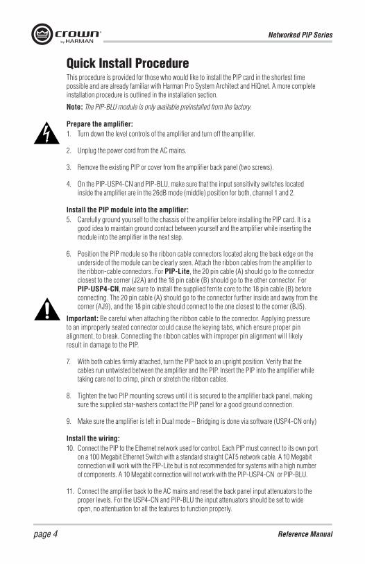
Controls, Indicators and ConnectorsPIP-Lite
A. Balanced Audio Input Connectors 3-pin removable barrier-strip connectors, one per channel.
B. Preset Indicator Signals the number of the current preset, if active, by flashing a series of flashes equal to the current preset number. The indicator will also flash twice a second when receiving an locate command.
C. Reset/Preset Switch Used to change presets, restore settings to factory default or restore all the presets to the factory defaults. During operations of the switch, the Data indicator flashes as an aid to the user.
D. Data Indicator Flashes when the PIP-Lite receives a valid command that is addressed to the PIP-Lite. The indicator will also flash twice a second when receiving an locate command.
E. AUX Connector AUX input, AUX output, and Listen Bus/Foldback.
F. Network Connector The network connector is a standard RJ-45 connector that allows the PIP-Lite to connect to an Ethernet network. Connection is made using a standard Category 5 or better cable to a network switch port. For compliance with emission regulations, the supplied ferrite core must be placed on the CAT5 cable, with the cable making two passes through the core as shown in the figure below. The Link Activity LED indicates data activity on the network line. The 100 MB LED indicates that the data is at 100 Megabits.
G. Mounting Holes
PIP-Lite Controls, Indicators and Connectors (Note: Actual Product Artwork May Vary Slightly)
Networked PIP Series
Reference Manualpage 6
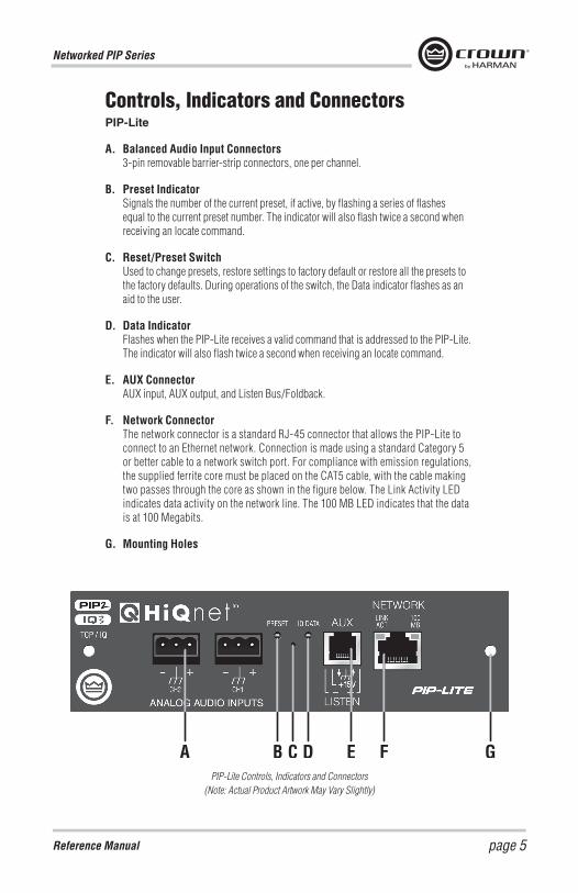
A B C
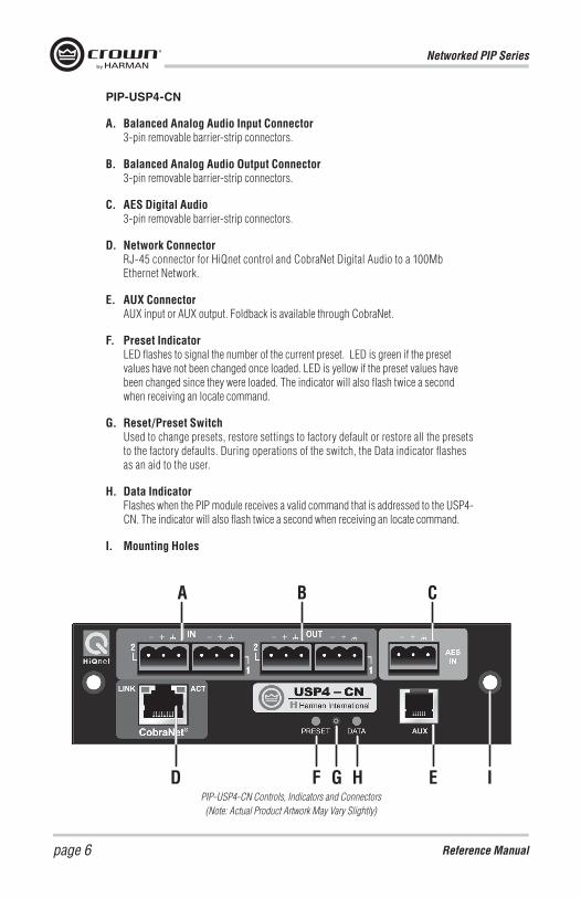
D F G H E IPIP-USP4-CN Controls, Indicators and Connectors (Note: Actual Product Artwork May Vary Slightly)
PIP-USP4-CN
A. Balanced Analog Audio Input Connector 3-pin removable barrier-strip connectors.
B. Balanced Analog Audio Output Connector 3-pin removable barrier-strip connectors.
C. AES Digital Audio 3-pin removable barrier-strip connectors.
D. Network Connector RJ-45 connector for HiQnet control and CobraNet Digital Audio to a 100Mb Ethernet Network.
E. AUX Connector AUX input or AUX output. Foldback is available through CobraNet.
F. Preset Indicator LED flashes to signal the number of the current preset. LED is green if the preset values have not been changed once loaded. LED is yellow if the preset values have been changed since they were loaded. The indicator will also flash twice a second when receiving an locate command.
G. Reset/Preset Switch Used to change presets, restore settings to factory default or restore all the presets to the factory defaults. During operations of the switch, the Data indicator flashes as an aid to the user.
H. Data Indicator Flashes when the PIP module receives a valid command that is addressed to the USP4-CN. The indicator will also flash twice a second when receiving an locate command.
I. Mounting Holes
Networked PIP Series
Reference Manual page 7
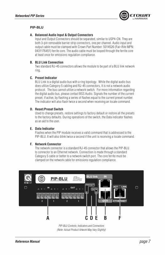
PIP-BLU
A. Balanced Audio Input & Output Connectors Input and Output Connectors should be separated, similar to USP4-CN. They are both 3-pin removable barrier strip connectors, one per channel. Audio input and output cable must be clamped with Crown Part Number: 5014526 (Fair-Rite MPN: 0431176451) ferrite core. The audio cable must be looped through the ferrite core at least once for emissions regulation compliance.
B. BLU Link Connection Two standard RJ-45 connectors allows the module to be part of a BLU link network ring.
C. Preset Indicator BLU Link is a digital audio bus with a ring topology. While the digital audio bus does utilize Category 5 cabling and RJ-45 connectors, it is not a network audio protocol. The bus cannot utilize a network switch. For more information regarding the digital audio bus, please contact BSS Audio. Signals the number of the current preset, if active, by flashing a series of flashes equal to the current preset number. The indicator will also flash twice a second when receiving an locate command.
D. Reset/Preset Switch Used to change presets, restore settings to factory default or restore all the presets to the factory defaults. During operations of the switch, the Data indicator flashes as an aid to the user.
E. Data Indicator Flashes when the PIP module receives a valid command that is addressed to the PIP-BLU. It will also blink twice a second if the unit is receiving a locate command.
F. Network Connector The network connector is a standard RJ-45 connector that allows the PIP-BLU to connector to an Ethernet network. Connection is made through a standard Category 5 cable or better to a network switch port. The core ferrite must be clamped on the network cable for emissions regulation compliance.
PIP-BLUBLU link IN
OUT ETHERNET
ACT LINKPRESET
DATAOUTIN
PIP-BLU Controls, Indicators and Connectors (Note: Actual Product Artwork May Vary Slightly)
Networked PIP Series
Reference Manualpage 8
InstallationBefore beginning, please carefully note:
CAUTION: STATIC ELECTRICITY MAY DAMAGE THE UNIT. Use caution when handling the unit. Carefully ground yourself BEFORE touching the unit. Avoided unnecessary touching the components or solder pads on the circuit board. It is best to handle the unit by its front panel only.
Prepare the PIP The PIP comes ready to install in the amplifier. This unit does not require setting the “IQ address” as the older current loop, Crown bus, units did. Each PIP (as well as all network components) comes preprogrammed with a unique network (MAC) address. The HiQnet address is then set (automatically or manually) via SystemArchitect control software (TCP/IP network address).
Prepare the Amplifier Turn down the amplifier level controls (full counterclockwise) and turn off the amplifier.
Disconnect the amplifier’s power cord.
Remove the existing PIP module from the amplifier back panel (two screws).
Install the PIP into the Amplifier. Carefully ground yourself to the chassis of the amplifier before installing the PIP, it is a good idea to maintain ground contact between yourself and the amplifier while inserting the module into the amplifier.
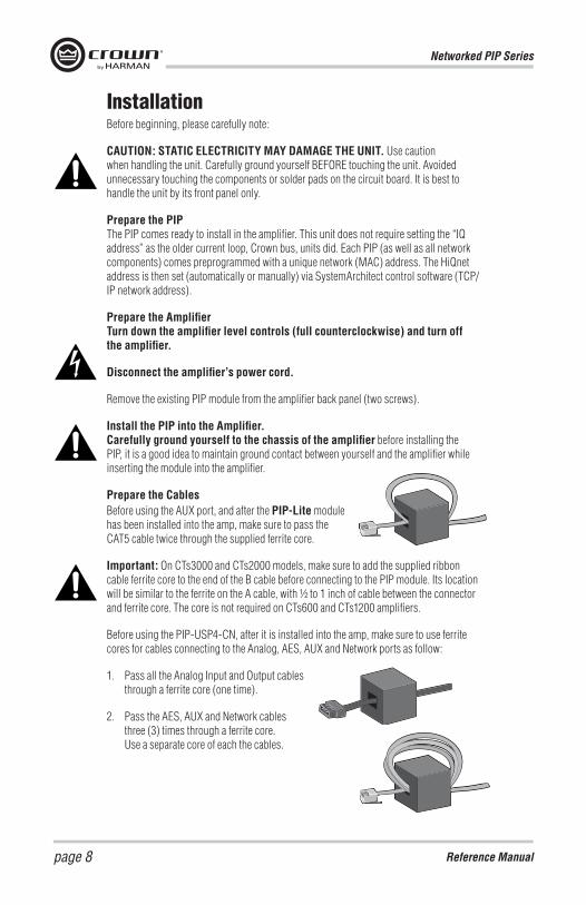
Prepare the CablesBefore using the AUX port, and after the PIP-Lite module has been installed into the amp, make sure to pass the CAT5 cable twice through the supplied ferrite core.
Important: On CTs3000 and CTs2000 models, make sure to add the supplied ribbon cable ferrite core to the end of the B cable before connecting to the PIP module. Its location will be similar to the ferrite on the A cable, with ½ to 1 inch of cable between the connector and ferrite core. The core is not required on CTs600 and CTs1200 amplifiers.
Before using the PIP-USP4-CN, after it is installed into the amp, make sure to use ferrite cores for cables connecting to the Analog, AES, AUX and Network ports as follow:
1. Pass all the Analog Input and Output cables through a ferrite core (one time).
2. Pass the AES, AUX and Network cables three (3) times through a ferrite core. Use a separate core of each the cables.
Networked PIP Series
Reference Manual page 9
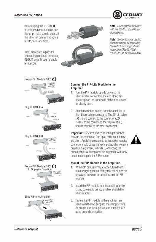
Slide PIP Into Amplifier
BACK PANELOF PIP
AMPLIFIER
Rotate PIP Module 180o
Plug In CABLE A
Plug In CABLE B
Rotate PIP Module 180o
In Opposite Direction
Connect the PIP-Lite Module to the Amplifier1. Turn the PIP module upside down so the
ribbon cable connectors located along the back edge on the underside of the module can be clearly seen.
2. Attach the ribbon cables from the amplifier to the ribbon-cable connectors. The 20-pin cable (A) should connect to the connector (J2A) closest to the corner and the 18 pin cable (B) should connect to the other connector.
Important: Be careful when attaching the ribbon cable to the connector. Don’t pull cables out if they are short. Applying pressure to an improperly seated connector could cause the keying tabs, which ensure proper pin alignment, to break. Connecting the ribbon cables with improper pin alignment will likely result in damage to the PIP module.
Mount the PIP Module in the Amplifier1. With both cables firmly attached, turn the PIP
to an upright position. Verify that the cables run untwisted between the amplifier and the PIP module.
2. Insert the PIP module into the amplifier while taking care not to crimp, pinch or stretch the ribbon cables.
3. Fasten the PIP module to the amplifier rear panel with the two supplied mounting screws. Be sure to use the supplied star-washers for a good ground connection.
Before using the PIP-BLU, after it has been installed into the amp, make sure to pass all the Ethernet cables through a ferrite core (one time).
Also, make sure to pass the connecting cables to the analog IN/OUT once through a single ferrite core.
Note: All ethernet cables used with the PIP-BLU should be of shielded type.
Note: The ferrite cores needed can be obtained by contacting Crown technical support and requesting CPN:5014526 (FAIR-RITE MPN: 0431176451).
Networked PIP Series
Reference Manualpage 10
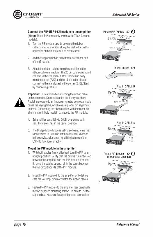
Connect the PIP-USP4-CN module to the amplifier(Note: These PIP cards only works with CTs 2-Channel models).1. Turn the PIP module upside down so the ribbon
cable connectors located along the back edge on the underside of the module can be clearly seen.
2. Add the supplied ribbon cable ferrite core to the end of the (B) cable.
3. Attach the ribbon cables from the amplifier to the ribbon-cable connectors. The 20 pin cable (A) should connect to the connector further inside and away from the corner (AJ9) and the 18 pin cable should connect to the one closest to the corner (BJ5). Start by connecting cable B.
Important: Be careful when attaching the ribbon cable to the connector. Don’t pull cables out if they are short. Applying pressure to an improperly seated connector could cause the keying tabs, which ensure proper pin alignment, to break. Connecting the ribbon cables with improper pin alignment will likely result in damage to the PIP module.
4. Set amplifier sensitivity to 26dB, by placing both sensitivity switches in the center position.
5. The Bridge-Mono Mode is set via software, leave the Mode switch in Dual and set the attenuator knobs to full clockwise, wide open, for all the features of the USP4 to function correctly.
Mount the PIP module in the amplifier1. With both cables firmly attached, turn the PIP to an
upright position. Verify that the cables run untwisted between the amplifier and the PIP module. For best fit, bend the cables up and roll in the cores between the two circuit boards of the PIP module.
2. Insert the PIP module into the amplifier while taking care not to crimp, pinch or stretch the ribbon cables.
3. Fasten the PIP module to the amplifier rear panel with the two supplied mounting screws. Be sure to use the supplied star-washers for a good ground connection.
Networked PIP Series
Reference Manual page 11
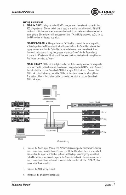
Wiring Instructions1. PIP-Lite ONLY: Using a standard CAT5 cable, connect the network connector to a
100 Mb port on an Ethenet switch that is used to form the control network. If the PIP module is not to be connected to a control network, it can be temporaily connected to a computer’s Ethernet port with a crossover cable (TX and RX pairs switched) to set up the PIP module for desired operation.
PIP-USP4-CN ONLY: Using a standard CAT5 cable, connect the network port to a 100Mb port on the Ethernet switch that is used to form the CobraNet network. We highly recommend that the CobraNet be a standalone or separate-network LAN. If network redundancy is required, please reference Crown’s Audio Redundancy document. HiQnet control is also available over the CobraNet network using Harman Pro System Architect software.
PIP-BLU ONLY: BLU-Link is a digital audio bus that can only be used on a separate network. The BLU-Link bus audio bus is wired using standard CAT5e cable. Connect the output of the London Soundweb BLU to the input BLU-Link port. Connect the BLU-Link output to the next amplifier BLU-Link input and repeat for all amplifiers. The last amplifier in the chain must be connected back to the London Soundweb BLU-Link input.
2. Connect the Audio Input Wiring. The PIP module is equipped with removable barrier block connectors for each channel’s input. The USP4-CN allows the use of standard balanced audio inputs to act either as CobraNet backup, an emergency override of CobraNet audio, or as an audio input to the CobraNet network. The removable barrier block connectors allows both audio channels to be inserted into the USP4-CN, then routed via software control.
3. Connect the AUX wiring if used.
4. Reconnect the amplifier’s power cord.
Computer
Laptop
100Mb Switch
PIP-USP4-CN
PIP-USP4-CN
PIP-Lite
PIP-Lite
PIP-Lite
PIP-Lite
London Blu-80
PIP-USP4-CN
Network Wiring
Networked PIP Series
Reference Manualpage 12
Advanced Features and OptionsUsing the AUX ConnectorThe AUX connector offers a means to tap some of the fl exibility of the Harman Pro System Architect. It can be used to enable peripherals, send a signal to another system component, and send a line-level audio signal of the amplifier’s output.
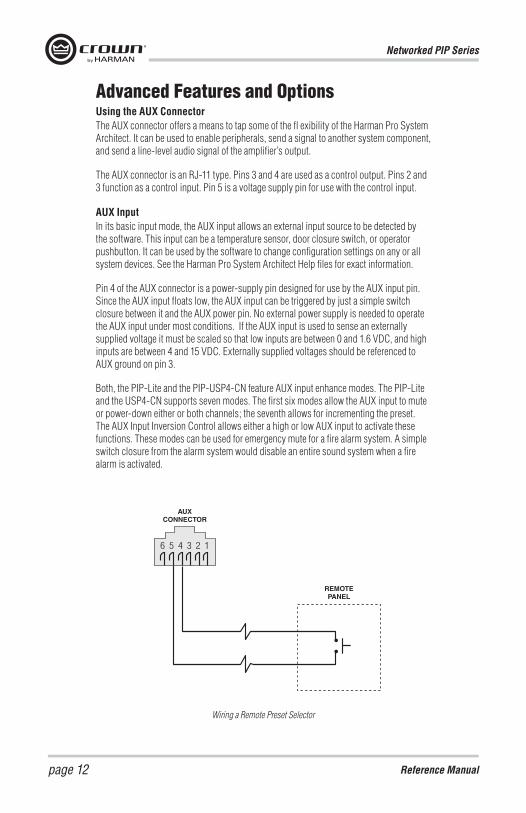
The AUX connector is an RJ-11 type. Pins 3 and 4 are used as a control output. Pins 2 and 3 function as a control input. Pin 5 is a voltage supply pin for use with the control input.
AUX InputIn its basic input mode, the AUX input allows an external input source to be detected by the software. This input can be a temperature sensor, door closure switch, or operator pushbutton. It can be used by the software to change configuration settings on any or all system devices. See the Harman Pro System Architect Help files for exact information.
Pin 4 of the AUX connector is a power-supply pin designed for use by the AUX input pin. Since the AUX input floats low, the AUX input can be triggered by just a simple switch closure between it and the AUX power pin. No external power supply is needed to operate the AUX input under most conditions. If the AUX input is used to sense an externally supplied voltage it must be scaled so that low inputs are between 0 and 1.6 VDC, and high inputs are between 4 and 15 VDC. Externally supplied voltages should be referenced to AUX ground on pin 3.
Both, the PIP-Lite and the PIP-USP4-CN feature AUX input enhance modes. The PIP-Lite and the USP4-CN supports seven modes. The first six modes allow the AUX input to mute or power-down either or both channels; the seventh allows for incrementing the preset. The AUX Input Inversion Control allows either a high or low AUX input to activate these functions. These modes can be used for emergency mute for a fire alarm system. A simple switch closure from the alarm system would disable an entire sound system when a fire alarm is activated.
Wiring a Remote Preset Selector
Networked PIP Series
Reference Manual page 13
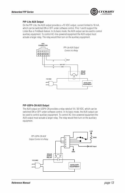
PIP-Lite AUX OutputOn the PIP-LIte, the AUX output provides a +15 VDC output, current limited to 10 mA, which can be switched ON or OFF under software control. Pins 1 and 6 support the Listen Bus or Foldback feature. In its basic mode, the AUX output can be used to control auxiliary equipment. To control AC-line-powered equipment the AUX output must actuate a larger relay. The relay would then turn on the auxiliary equipment.
PIP-USP4-CN AUX OutputThe AUX output on USP4-CN provides a relay rated at 1A / 30 VDC, which can be switched ON or OFF under software control. In its basic mode, the AUX output can be used to control auxiliary equipment. To control AC-line-powered equipment the AUX output must actuate a larger relay. The relay would then turn on the auxiliary equipment.
PIP-Lite AUX Output Control of a Relay
1 2 3 4 5 6
3.3V
AUX Input
255Ω
GND
PIP-USP4-CN AUX Output Control of a Relay

Networked PIP Series
Reference Manualpage 14
SUMMARY OF WARRANTY Crown International, 1718 West Mishawaka Road, Elkhart, Indiana 46517-4095 U.S.A. warrants to you, the ORIGINAL PUR-CHASER and ANY SUB SEQUENT OWNER of each NEW Crown product, for a period of five (5) years from the date of purchase by the original purchaser (the “warranty period”) that the new Crown product is free of defects in materials and workmanship. We further warrant the new Crown product regardless of the reason for failure, except as excluded in this Warranty.
Warranty is only valid within the country in which the product was purchased.
ITEMS EXCLUDED FROM THIS CROWN WARRANTY This Crown Warranty is in effect only for failure of a new Crown product which occurred within the Warranty Period. It does not cover any product which has been damaged because of any inten tional misuse, accident, negligence, or loss which is cov-ered under any of your insurance contracts. This Crown Warranty also does not extend to the new Crown product if the serial number has been defaced, altered, or removed.
WHAT THE WARRANTOR WILL DO We will remedy any defect, regardless of the rea son for failure (except as excluded), by repair, replacement, or refund. We may not elect refund unless you agree, or unless we are unable to pro vide replacement, and repair is not practical or cannot be timely made. If a refund is elected, then you must make the defective or malfunctioning product available to us free and clear of all liens or other encumbrances. The refund will be equal to the actual purchase price, not including inter est, insurance, closing costs, and other finance charges less a reasonable depreciation on the product from the date of original purchase. War ranty work can only be performed at our autho rized service centers or at the factory. Warranty work for some products can only be performed at our factory. We will remedy the defect and ship the product from the service center or our factory within a reasonable time after receipt of the defec tive product at our authorized service center or our factory. All expenses in remedying the defect, including surface shipping costs in the United States, will be borne by us. (You must bear the expense of shipping the product between any for eign country and the port of entry in the United States including the return shipment, and all taxes, duties, and other customs fees for such for eign shipments.)
HOW TO OBTAIN WARRANTY SERVICE You must notify us of your need for warranty ser vice within the warranty period. All components must be shipped in a factory pack, which, if needed, may be obtained from us free of charge. Corrective action will be taken within a reason able time of the date of receipt of the defective product by us or our authorized service center. If the repairs made by us or our authorized service center are not satisfactory, notify us or our autho rized service center immediately.
DISCLAIMER OF CONSEQUENTIAL AND INCIDENTAL DAMAGES YOU ARE NOT ENTITLED TO RECOVER FROM US ANY INCIDENTAL DAMAGES RESULTING FROM ANY DEFECT IN THE NEW CROWN PRODUCT. THIS INCLUDES ANY DAMAGE TO ANOTHER PRODUCT OR PRODUCTS RESULT ING FROM SUCH A DEFECT. SOME STATES DO NOT ALLOW THE EXCLUSION OR LIMITATIONS OF INCIDENTAL OR CONSEQUENTIAL DAM AGES, SO THE ABOVE LIMITATION OR EXCLU SION MAY NOT APPLY TO YOU.
WARRANTY ALTERATIONS No person has the authority to enlarge, amend, or modify this Crown Warranty. This Crown War ranty is not extended by the length of time which you are deprived of the use of the new Crown product. Repairs and replacement parts provided under the terms of this Crown Warranty shall carry only the unexpired portion of this Crown Warranty.
DESIGN CHANGES We reserve the right to change the design of any product from time to time without notice and with no obligation to make corresponding changes in products previously manufactured.
LEGAL REMEDIES OF PURCHASER THIS CROWN WARRANTY GIVES YOU SPECIFIC LEGAL RIGHTS, YOU MAY ALSO HAVE OTHER RIGHTS WHICH VARY FROM STATE TO STATE. No action to enforce this Crown Warranty shall be commenced after expiration of the warranty period.
THIS STATEMENT OF WARRANTY SUPERSEDES ANY OTHERS CONTAINED IN THIS MANUAL FOR CROWN PRODUCTS. 2/12.
Warranty — UNITED STATES & CANADA

Networked PIP Series
Reference Manual page 15
SUMMARY OF WARRANTY Crown International, 1718 West Mishawaka Road, Elkhart, Indiana 46517-4095 U.S.A. warrants to you, the ORIGINAL PUR-CHASER and ANY SUB SEQUENT OWNER of each NEW Crown1 product, for a period of five (5) years from the date of pur chase by the original purchaser (the “warranty period”) that the new Crown product is free of defects in materials and workmanship, and we further warrant the new Crown product regardless of the reason for failure, except as excluded in this Warranty.
Warranty is only valid within the country in which the product is purchased.
Note: If your unit bears the name “Amcron,” please substitute it for the name “Crown” in this warranty.
ITEMS EXCLUDED FROM THIS CROWN WARRANTY This Crown Warranty is in effect only for failure of a new Crown product which occurred within the Warranty Period. It does not cover any product which has been damaged because of any inten tional misuse, accident, negligence, or loss which is covered under any of your insurance contracts. This Crown Warranty also does not extend to the new Crown product if the serial number has been defaced, altered, or removed.
WHAT THE WARRANTOR WILL DO We will remedy any defect, regardless of the rea son for failure (except as excluded), by repair, replacement, or refund. We may not elect refund unless you agree, or unless we are unable to pro vide replacement, and repair is not practical or cannot be timely made. If a refund is elected, then you must make the defective or malfunctioning product available to us free and clear of all liens or other encumbrances. The refund will be equal to the actual purchase price, not including inter est, insurance, closing costs, and other finance charges less a reasonable depreciation on the product from the date of original purchase. War ranty work can only be performed at our autho rized service centers. We will remedy the defect and ship the product from the service center within a reasonable time after receipt of the defec tive product at our authorized service center.
HOW TO OBTAIN WARRANTY SERVICE You must notify your local Crown importer of your need for warranty service within the warranty period. All components must be shipped in the original box. Corrective action will be taken within a reasonable time of the date of receipt of the defective product by our authorized service center. If the repairs made by our authorized service cen ter are not satisfactory, notify our authorized ser vice center immediately.
DISCLAIMER OF CONSEQUENTIAL AND INCIDENTAL DAMAGES YOU ARE NOT ENTITLED TO RECOVER FROM US ANY INCIDENTAL DAMAGES RESULTING FROM ANY DEFECT IN THE NEW CROWN PRODUCT. THIS INCLUDES ANY DAMAGE TO ANOTHER PRODUCT OR PRODUCTS RESULTING FROM SUCH A DEFECT.
WARRANTY ALTERATIONS No person has the authority to enlarge, amend, or modify this Crown Warranty. This Crown Warranty is not extended by the length of time which you are deprived of the use of the new Crown product. Repairs and replacement parts provided under the terms of this Crown Warranty shall carry only the unexpired portion of this Crown Warranty.
DESIGN CHANGES We reserve the right to change the design of any product from time to time without notice and with no obligation to make cor-responding changes in products previously manufactured.
LEGAL REMEDIES OF PURCHASER No action to enforce this Crown Warranty shall be commenced after expiration of the warranty period.
THIS STATEMENT OF WARRANTY SUPERSEDES ANY OTHERS CONTAINED IN THIS MANUAL FOR CROWN PRODUCTS. 2/12.
Warranty — WORLDWIDE EXCEPT USA & CANADA