
Technical Committee on Ovens and Furnaces€¦ · Richard J. Martin Secretary Martin Thermal...
218
Technical Committee on Ovens and Furnaces Date: November 4, 2016 To: Technical Committee on Ovens and Furnaces From: Eric Nette, Staff Liaison/Engineer Re: Agenda Package – NFPA 86 A2018 First Draft Meeting – November 29-December 1, 2016 Enclosed is the agenda package for the November 29-December 1, 2016 meeting for the NFPA 86 First Draft Meeting. Please ensure that you have reviewed the public input and the other agenda items in advance to prepare for discussion. The agenda and public input will be posted on the document information pages (www.nfpa.org/86). Some items to have available during the meeting include: Agenda package with public input A copy of NFPA 86 (visit the NFPA 86 Document information pages for your free committee copy) Any previous copies of the technical committees standard A laptop Optional items that are sometimes useful include: Review of NFPA’s Process, www.nfpa.org/regs If you have any questions or comments, please feel free to reach me at (617) 984-7434 or by e-mail at [email protected]. I look forward to our meeting to begin the revision cycle!
Transcript of Technical Committee on Ovens and Furnaces€¦ · Richard J. Martin Secretary Martin Thermal...

Technical Committee on Ovens and Furnaces
Date: November 4, 2016 To: Technical Committee on Ovens and Furnaces From: Eric Nette, Staff Liaison/Engineer Re: Agenda Package – NFPA 86 A2018 First Draft Meeting – November 29-December 1, 2016
Enclosed is the agenda package for the November 29-December 1, 2016 meeting for the NFPA 86 First Draft Meeting. Please ensure that you have reviewed the public input and the other agenda items in advance to prepare for discussion. The agenda and public input will be posted on the document information pages (www.nfpa.org/86). Some items to have available during the meeting include:
Agenda package with public input
A copy of NFPA 86 (visit the NFPA 86 Document information pages for your free committee copy)
Any previous copies of the technical committees standard
A laptop
Optional items that are sometimes useful include:
Review of NFPA’s Process, www.nfpa.org/regs If you have any questions or comments, please feel free to reach me at (617) 984-7434 or by e-mail at [email protected]. I look forward to our meeting to begin the revision cycle!

NFPA 86 A2018 First Draft Meeting November 29-December 1, 2016
DoubleTree by Hilton-Universal http://nfpa.adobeconnect.com/nette/
8:00 a.m. to 5:00 p.m. (Eastern Time Zone)
1. Meeting opening, introduction and attendance
2. Approval of Second Draft Meeting Minutes of October 2-3, 2013 (Attachment A.
October 2-3, 2013 Meeting Minutes). 3. Chair's remarks, Franklin Switzer
4. Staff Liaison update:
a. A2018 Schedule (Attachment B. A2018 Revision Cycle)
b. Committee Membership Update (Attachment C. FLU-AAA Membership)
c. Standards Process Review (Attachment D. NFPA Process – Quick Reference
Guide)
5. Old/New Business –Order of Consideration/Schedule for Task Group Work and Public
Inputs
a. Public Input for NFPA 86 (Attachment E. NFPA 86 - A2018 Public Input)
i. Public Inputs will be grouped according to Attachment F. – A2018
Public Input Groups so that each topic is discussed fully at one time. If
you would like any of these Public Inputs to be taken out of their
bundles, please review the package before the meeting and request they
be assessed separately at that time.
6. Other business
7. Date/Location of Next Meeting. (Second Draft Meeting between June 1, 2017 and
November 8, 2017)
8. Adjournment (December 1)
Attachments:
A. October 2-3, 2013 Meeting Minutes
B. A2018 – Revision Cycle
C. OVE-AAA Committee Membership
D. NFPA Process – Quick Reference Guide
E. NFPA 86 - A2018 Public Input
F. A2018 Public Input Groups

Attachment A:
October 2-3, 2013 Meeting
Minutes
Minutes “Second Draft Meeting”
NFPA 86 Technical Committee on Ovens & Furnaces Liberty Mutual Group Training Center – Weston, Massachusetts
2-3 October 2013
1. Attendees: Rich Gallagher, Rick Martin, Ted Jablkowski, Guy Colonna, Geoff Raifsnider, Kevin
Carlisle, Scott Musser, Frank Kaczmarczyk, Pete Willse, Mike Polagye, Dan Curry, Bob Daley,
Keith Hancock, Joel Liggins, Bryan Baesel, Franklin Switzer, Bruce Mickelson, Mark Stender, Jak
Kozma, John Dauer, Grant Tiefenbruck, Al Underys, Gary Andress, Tom George, Elliott Davis,
Richard Huggins, John Higginbotham, John Pendergraff, Ted Lemoff.
2. Phone/Web Attendees: Erik Christiansen, Bill Rucki
3. Chair Introduction:
a. On Wednesday morning, Rich Gallagher called the meeting to order.
b. Interim Staff Liaison – Welcome Guy Colonna, Division Manager of Industrial & Chemical
Fire Protection Division, replacing Derek Duval
c. The TC members introduced themselves.
d. Chair Rich Gallagher asked the group to take a moment of silence to remember Clem
Schultz, alternate member of the TC in the last cycle.
e. Chair thanked retired TC Member Gary Keil for his contributions.
f. The TC thanked Mike Polagye in advance of his anticipated retirement, to be effective
before the next cycle of meetings.
g. New Principal Members: Richard Huggins, Joel Liggins, Geoff Raifsnider, Jason
Sroczynski
h. New Alternate Members: Amy Brown, Elliott Davis, Scott Johnston, Robert Wilson
i. Forty-seven percent of Principal TC members do not have alternates. Consider getting
an alternate!
j. Old Buzzard Awards: Ray Ostrowski 47 years on the 86 TC; Bill Sheppard 33 years; Al
Underys 25 years; Pete Willse 25 years.
k. Franklin Switzer is Chair of NFPA 56 Standard for Cleaning and Purging of Pipes and has
called for input from NFPA 86 TC to provide “best practices”. Welcome Guest Ted
Lemoff who will also be participating on the NFPA 56 Task Group.
l. Larry Danner is task group chair of NFPA 2 Hydrogen Technologies for addressing
hydrogen usage across other documents, such as Ovens & Furnaces.
m. The minutes from the 1st Draft meeting were approved by the TC.
n. NFPA Code Fund: Two projects being considered.
i. Explosion Relief (Chapter 5), proposed in conjunction with NFPA 68. Project
Plan with Vendors on-board.
ii. Steam Extinguishing (Annex F), Black Liquor Recovery Boilers, Baking Ovens,
Sulfur NFPA 655 (+ other documents).

4. Staff Liaison Introduction:
a. Guy Colonna discussed the working guidelines for NFPA technical committees and how
committee members can interact with the NFPA 86 TC website.
b. See Calendar posted on website (www.nfpa.org/86) for NFPA imposed deadlines.
c. The letter ballot will be distributed about 1 month after the 2nd Draft meeting.
d. The Standards Council introduced a slight alteration to the rules on NITMAMs.
NITMAMs must be submitted on Public Comments only.
i. NITMAMs may not be submitted on Public Inputs if there was no Public
Comments.
ii. The Standards Council will only “certify” the motion if it is addressed to a Public
Comment.
iii. The submitter must attend the Annual Meeting.
e. NFPA 86 is in the “Annual 2014” cycle. The next Edition will be 2015, with effective date
of May or August 2014.
i. If no NITMAMs are submitted, the Standards Council votes on the document in
May.
ii. If amending motions are presented to the General Assembly, the Standards
Council vote occurs in August.
iii. The effective date is 21 days after the issuance date, which is the date that the
Standards Council votes on the approval of the document.
iv. The 21 day period is allotted to allow for an “Appeal” of the Standards Council’s
issuance of the document.
f. Current makeup of TC: 1 Enforcer, 6 Insurance, 1 Installer/Maintainer, 10
Manufacturer, 6 Special Expert, 6 User; Total = 30
g. The intent of the new format was to help the TC spend more time on issues that actually
change the document.
i. NFPA determined that too much time was spent on rejected proposals that
generated a lot of dialog but never ended up changing the document.
5. Presentation by Former 86 Staff Liaison Ted Lemoff.
a. New book will be available in January – “Fuel and Combustion Systems Safety”, by
former 86 TC Principal member John Puskar.
b. NFPA 86 Chapter 9 discusses the need for fixed or portable fire protection systems in
the oven.
i. IFC is used or adopted in 42 states (i.e., at least one city within that state)
1. Requires internal fire protection inside Class A and B ovens.
ii. NFPA 1 is adopted statewide in 19 states.
iii. TC members may want to participate in the IFC code-making process if they
believe the basis for the IFC requirement is not sufficiently substantiated.
6. Work Conducted on First Day (Wednesday):
a. The Technical Committee resolved approximately 44 Public and Committee Comment
items, and generated approximately 36 Second Revisions.
7. Work Conducted on Second Day (Thursday):
a. The Technical Committee resolved approximately 23 Public and Committee Comment
items, and generated approximately 22 Second Revisions.
8. Chair Closing Statement
a. The Technical Committee expresses its sincere appreciation and gratitude to Liberty
Mutual Group, and especially to Gary Andress for his outstanding hospitality over the
course of this meeting.
b. A very big thank you to Guy Colonna for his exceptional service to the committee.
c. On Thursday afternoon, Rich Gallagher thanked the Technical Committee for their hard
work and adjourned the meeting.
Respectfully submitted,
Rick Martin Secretary, NFPA 86 Technical Committee

Attachment B:
A2018 Revision Cycle

NFPA 86 Revision Cycle KEY DATES Annual 2018
NFPA 86 A2018 [OVE-AAA]
Important Dates For the Cycle:
Public Input Closing June 29, 2016 (DONE)
Posting of First Draft March 1, 2017
Public Comment Closing May 10, 2017
Posting of Second Draft January 24, 2018
Notice of Intent to Make Motion (NITMAM) February 21, 2018
Issuance of Consent Standard April 29, 2018 (published bit later)
NFPA Annual Meeting with CAMs June 4-7, 2018
Issuance of Standard – with CAMs August 14, 2018 (published bit later)

Attachment C:
OVE-AAA Committee
Membership

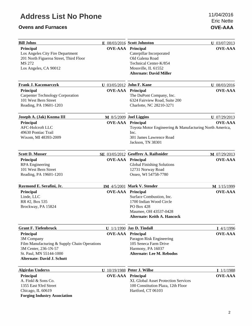
Address List No PhoneOvens and Furnaces OVE-AAA
Eric Nette11/04/2016
OVE-AAA
Franklin R. Switzer, Jr.
ChairS-afe, Inc.85 Denison Parkway E #201Corning, NY 14830-2726
SE 4/17/2002OVE-AAA
Richard J. Martin
SecretaryMartin Thermal Engineering, Inc.PO Box 2234Hawthorne, CA 90251-2234
SE 7/20/2000
OVE-AAA
Gary S. Andress
PrincipalLiberty Mutual Insurance CompanyProperty Risk Engineering20 Riverside RoadMS: 03BNWeston, MA 02493
I 1/1/1992OVE-AAA
Bryan R. Baesel
PrincipalHoneywell/Eclipse/CEC Combustion Safety, Inc.11699 Brookpark RoadCleveland, OH 44130Alternate: Douglas M. Perry
M 1/16/2003
OVE-AAA
Kevin J. Carlisle
PrincipalKarl Dungs, Inc.3890 Pheasant Ridge Drive, NEBlaine, MN 55449Industrial Heating Equipment AssociationAlternate: Elliott Davis
M 4/14/2005OVE-AAA
Erik W. Christiansen
PrincipalExponent, Inc.5401 McConnell AvenueLos Angeles, CA 90066-7027Alternate: Delmar R. “Trey” Morrison III
SE 9/30/2004
OVE-AAA
John Dauer
PrincipalSCC, Inc.1250 Lunt AvenueElk Grove Village, IL 60007-5618Alternate: Peter S. Pinto
M 1/16/2003OVE-AAA
Richard A. Gallagher
PrincipalZurich Services Corporation5124 New Kent RoadWilmington, DE 19808-2706Alternate: Glen R. Mortensen
I 1/1/1990
OVE-AAA
Thomas B. George
PrincipalTokio Marine Management, Inc.800 East Colorado BoulevardPasadena, CA 91101Alternate: Ariel F. Nunez
I 4/14/2005OVE-AAA
John E. Higginbotham
PrincipalAlcoa, Inc.GRP Engineering, Tennessee Operations300 North Hall Road - S029Alcoa, TN 37701Alternate: Mark Aaron Altoonian
U 4/3/2003
OVE-AAA
E. Richard Huggins
PrincipalTechnical Standards & Safety Authority (TSSA)3300 Bloor Street WestCentre Tower, 14th FloorToronto, ON M8X 2X4 Canada
E 07/29/2013OVE-AAA
Ted Jablkowski
PrincipalFives North American Combustion, Inc.287 Boston Post RoadPO Box 160East Lyme, CT 06333Alternate: William M. Rucki
M 7/22/1999
OVE-AAA
Kai-Eric Jensen
PrincipalJensen Industries, Inc.2111 Thompson RoadFenton, MI 48430
M 7/17/1998
1
Address List No PhoneOvens and Furnaces OVE-AAA
Eric Nette11/04/2016
OVE-AAA
Bill Johns
PrincipalLos Angeles City Fire Department201 North Figueroa Street, Third FloorMS 272Los Angeles, CA 90012
E 08/03/2016OVE-AAA
Scott Johnston
PrincipalCaterpillar IncorporatedOld Galena RoadTechnical Center-K/854Mossville, IL 61552Alternate: David Miller
U 03/07/2013
OVE-AAA
Frank J. Kaczmarczyk
PrincipalCarpenter Technology Corporation101 West Bern StreetReading, PA 19601-1203
U 03/05/2012OVE-AAA
John F. Kane
PrincipalThe DuPont Company, Inc.6324 Fairview Road, Suite 200Charlotte, NC 28210-3271
U 08/03/2016
OVE-AAA
Joseph A. (Jak) Kozma III
PrincipalAFC-Holcroft LLC49630 Pontiac TrailWixom, MI 48393-2009
M 8/5/2009OVE-AAA
Joel Liggins
PrincipalToyota Motor Engineering & Manufacturing North America,Inc.301 James Lawrence RoadJackson, TN 38301
U 07/29/2013
OVE-AAA
Scott D. Musser
PrincipalRPA Engineering101 West Bern StreetReading, PA 19601-1203
SE 03/05/2012OVE-AAA
Geoffrey A. Raifsnider
PrincipalGlobal Finishing Solutions12731 Norway RoadOsseo, WI 54758-7780
M 07/29/2013
OVE-AAA
Raymond E. Serafini, Jr.
PrincipalLinde, LLCRR #2, Box 535Brockway, PA 15824
IM 4/5/2001OVE-AAA
Mark V. Stender
PrincipalSurface Combustion, Inc.1700 Indian Wood CirclePO Box 428Maumee, OH 43537-0428Alternate: Keith A. Hancock
M 1/15/1999
OVE-AAA
Grant F. Tiefenbruck
Principal3M CompanyFilm Manufacturing & Supply Chain Operations3M Center, 236-1N-57St. Paul, MN 55144-1000Alternate: David J. Schutt
U 1/1/1990OVE-AAA
Jay D. Tindall
PrincipalParagon Risk Engineering105 Seneca Farm DriveHarmony, PA 16037Alternate: Lee M. Rebodos
I 4/1/1996
OVE-AAA
Algirdas Underys
PrincipalA. Finkl & Sons Co.1355 East 93rd StreetChicago, IL 60619Forging Industry Association
U 10/19/1988OVE-AAA
Peter J. Willse
PrincipalXL Global Asset Protection Services100 Constitution Plaza, 12th FloorHartford, CT 06103
I 1/1/1988
2

Address List No PhoneOvens and Furnaces OVE-AAA
Eric Nette11/04/2016
OVE-AAA
Amy Brown
Voting AlternateFM Global1151 Boston-Providence TurnpikePO Box 9102Norwood, MA 02062-9102
I 03/07/2013OVE-AAA
Robert J. Wilson
Voting AlternateSolar Manufacturing Inc.1983 Clearview RoadSouderton, PA 18964
M 03/07/2013
OVE-AAA
Mark Aaron Altoonian
AlternateAlcoa2300 N. Wright RoadAlcoa, TN 37701Principal: John E. Higginbotham
U 10/28/2014OVE-AAA
Elliott Davis
AlternateSelas Heat Technology Company LLC11012 Aurora-Hudson RoadStreetsboro, OH 44241-1629Industrial Heating Equipment AssociationPrincipal: Kevin J. Carlisle
M 07/29/2013
OVE-AAA
Keith A. Hancock
AlternateSurface Combustion, Inc.1700 Indian Wood CirclePO Box 428Maumee, OH 43537-0428Principal: Mark V. Stender
M 8/9/2011OVE-AAA
David Miller
AlternateCaterpillar Inc.100 Tractor Drive, Dock MLBuilding MM2East Peoria, IL 61614Principal: Scott Johnston
U 12/08/2015
OVE-AAA
Delmar R. “Trey” Morrison III
AlternateExponent, Inc.4580 Weaver Parkway, Suite 100Warrenville, IL 60555-3864Principal: Erik W. Christiansen
SE 8/2/2010OVE-AAA
Glen R. Mortensen
AlternateZurich Services CorporationRisk Engineering21337 West Crescent DriveMundelein, IL 60060-3399Principal: Richard A. Gallagher
I 1/1/1990
OVE-AAA
Ariel F. Nunez
AlternateTokio Marine & Nichido Fire1737 Avenida ReginaSan Marcos, CA 92069-4210Principal: Thomas B. George
I 08/11/2014OVE-AAA
Douglas M. Perry
AlternateMaxon/Honeywell Company201 East 18th StreetMuncie, IN 47302Principal: Bryan R. Baesel
M 08/09/2012
OVE-AAA
Peter S. Pinto
AlternateSCC, Inc.1250 Lunt AvenueElk Grove Village, IL 60007-5618Principal: John Dauer
M 8/5/2009OVE-AAA
Lee M. Rebodos
AlternateParagon Risk Engineering1417 Doubletree TrailFlower Mound, TX 75028Principal: Jay D. Tindall
I 4/3/2003
3

Address List No PhoneOvens and Furnaces OVE-AAA
Eric Nette11/04/2016
OVE-AAA
William M. Rucki
AlternateFives North American Combustion, Inc.4455 East 71st StreetCleveland, OH 44105Principal: Ted Jablkowski
M 08/09/2012OVE-AAA
David J. Schutt
Alternate3M CompanyDesign and Engineering Solutions3M Center, Building 275-06W-25St. Paul, MN 55144-1000Principal: Grant F. Tiefenbruck
U 08/11/2014
OVE-AAA
Eric Nette
Staff LiaisonNational Fire Protection Association1 Batterymarch ParkQuincy, MA 02169-7471
04/16/2014
4

Attachment D:
NFPA Process – Quick
Reference Guide

New Process – Quick Reference Guide For additional information on the Regulations visit: www.nfpa.org/Regs
There are only three actions a TC can take at the First Draft (ROP)
meeting: 1. Resolve a Public Input (no change to the document) 2. Create a First Revision (change to the document) 3. Create Committee Input
Resolve Public Input (no change to the document)
TC must provide a response (Committee Statement/CS) to ALL Public Input (proposal).
CS for not doing what is suggested
Sample Motion: “I make a motion to resolve PI#_ with the following committee statement__.” Approval by meeting vote (simple majority). Not subject to Ballot.
Create a First Revision (change to the document)
TC must create a First Revision (FR) for each change they wish to make to the document, either using Public Input for the basis of the change or not using a Public Input for the basis. One or more Public Input can be considered for the FR.
All Public Input requires a response
TC can use a Public Input for basis i. Sample Motion: “I make a motion to revise section __ using PI#_ as the
basis for change.” Approval by meeting vote (simple majority) and final approval through ballot.
TC develops revision without a Public Input for basis i. Sample Motion: “I make a motion to revise section __ as follows___.”
Approval by meeting vote (simple majority) and final approval through ballot.
First Revisions require a committee statement
Committee Input
TC may create a Committee Input (CI). This replaces the old system “rejected” Committee Proposals. CIs will get printed in the report but will not be balloted or shown as a change in the draft. CIs are used to solicit public comments and/or as a placeholder for the comment stage.
i. Sample Motion: “I make a motion to create a CI with a proposed revision to section__ as follows___.” Approval by meeting vote (simple majority). Not subject to ballot.
Requires a committee statement to explain the intent of making a CI.

Comparison to Previous Process:
PREVIOUS ACTIONS CURRENT PROCESS ACTIONS SAMPLE MOTION
Accept or any variation of Accept
(APA, APR, APP) on a public
proposal
1) Committee generates a First
Revision and Substantiation (CS)
for change
2) Committee provides response (CS)
to each PI that is associated with the
revision
1) “I make a motion to revise section __ using PI#_ as the basis for change.”
2) “ I make a motion to resolve PIs#_ through ## with the following statement__”
Rejected Public Proposal Committee provides response (CS)
to PI
“I make a motion to resolve
PI#_ with the following
committee statement__.”
Accepted Committee Proposal Committee generates a First Revision
and Substantiation (CS) for change
“I make a motion to revise
section __ as follows___.”
Committee generates a
statement for reason for change.
Rejected Committee Proposal Committee generates a Committee
Input (CI) and reason (CS) for
proposed change
“I make a motion to create a CI
with a proposed revision to
section__ as follows___.”
Committee generates a
statement for reason for CI.
Notes:
1) All meeting actions require a favorable vote of a simple majority of the members present. 2) All First Revisions will be contained in the ballot and will require a 2/3 affirmative vote to
confirm the meeting action. 3) Only the First Revisions will be balloted. PIs and CIs will be contained in the report but will
not be balloted. 4) Comments may be submitted on all PIs, FRs and CIs

Term Comparison between Current and Old:
CURRENT TERM OLD TERM
Input Stage ROP Stage
Public Input (PI) Proposal
First Draft Meeting ROP Meeting
Committee Input Committee Proposal that Fail
Ballot
Committee Statement
(CS) Committee Statement
First Revision (FR) Committee Proposal or Accepted
Public Proposal
First Draft Report ROP
First Draft ROP Draft
Comment Stage ROC Stage
Public Comment Public Comment
Second Draft Meeting ROC Meeting
Committee Comment Committee Comment that Fail
Ballot
Committee Action Committee Action
Second Revision Committee Comment or Accepted
Public Comment
Second Draft Report ROC
Second Draft ROC Draft
Note: The highlighted terms are the ones that will be most applicable at the First Draft Meeting.

Attachment E:
NFPA 86 – A2018 Public
Input
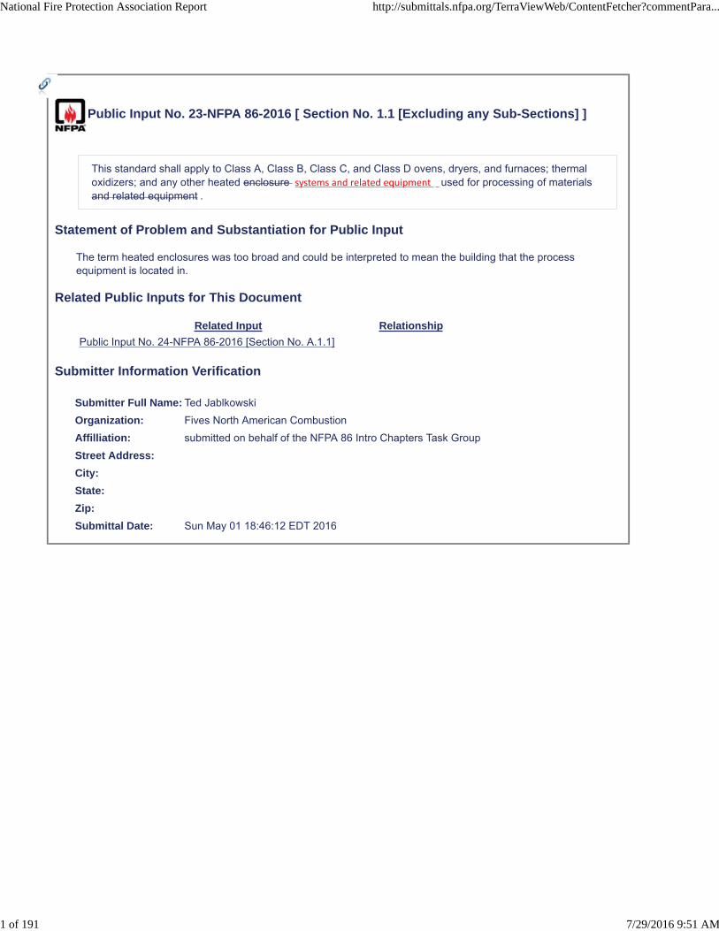
Public Input No. 23-NFPA 86-2016 [ Section No. 1.1 [Excluding any Sub-Sections] ]
This standard shall apply to Class A, Class B, Class C, and Class D ovens, dryers, and furnaces; thermaloxidizers; and any other heated enclosure systems and related equipment used for processing of materialsand related equipment .
Statement of Problem and Substantiation for Public Input
The term heated enclosures was too broad and could be interpreted to mean the building that the process equipment is located in.
Related Public Inputs for This Document
Related Input Relationship
Public Input No. 24-NFPA 86-2016 [Section No. A.1.1]
Submitter Information Verification
Submitter Full Name: Ted Jablkowski
Organization: Fives North American Combustion
Affilliation: submitted on behalf of the NFPA 86 Intro Chapters Task Group
Street Address:
City:
State:
Zip:
Submittal Date: Sun May 01 18:46:12 EDT 2016
National Fire Protection Association Report http://submittals.nfpa.org/TerraViewWeb/ContentFetcher?commentPara...
1 of 191 7/29/2016 9:51 AM
Public Input No. 47-NFPA 86-2016 [ Section No. 1.4.1 ]
1.4.1
Unless otherwise specified, the provisions of this standard shall not apply to facilities, equipment,structures, or installations that existed or were approved for construction or installation prior to the effectivedate of the standard. Where specified, the provisions of this standard shall be retroactive.
Statement of Problem and Substantiation for Public Input
Nowhere in NFPA 86 does the standard specify when the provisions of the standard are retroactive.
Submitter Information Verification
Submitter Full Name: Kevin Carlisle
Organization: Industrial Heating Equipment Association
Affilliation: Industrial Heating Equipment Association
Street Address:
City:
State:
Zip:
Submittal Date: Fri Jun 03 14:39:39 EDT 2016
National Fire Protection Association Report http://submittals.nfpa.org/TerraViewWeb/ContentFetcher?commentPara...
2 of 191 7/29/2016 9:51 AM

Public Input No. 48-NFPA 86-2016 [ Section No. 1.4.2 ]
1.4.2
In those cases where the authority having jurisdiction determines that the existing situation presents anunacceptable degree of risk, the authority having jurisdiction shall be permitted to apply retroactively anyportions of this standard deemed appropriate.
A.1.4.2 A modification that does not alter the logical, mechanical, electrical, or pneumatic function orsystem capacity are considered maintenance, and thus retroactivity is not intended to apply. It might notbe technical feasible to upgrade all elements of the oven to most recent edition of NFPA. Suchdetermination is made by the AHJ. In addition, “permit to use” is site specific. If the oven is moved do adifferent location that is a place within the same building/site, it would be the decision of the AHJ whetheror not to apply retroactivity in 1.4, but in general, the same building would normally be the samesite/location. When equipment is moved to a new site/location, a new permit would be required, thus,retroactivity in 1.4 would normally apply.
Statement of Problem and Substantiation for Public Input
We recommend that the committee provide some guidance to address the ambiguity of this requirement.
Submitter Information Verification
Submitter Full Name: Kevin Carlisle
Organization: Industrial Heating Equipment Association
Affilliation: Industrial Heating Equipment Association
Street Address:
City:
State:
Zip:
Submittal Date: Fri Jun 03 14:43:27 EDT 2016
National Fire Protection Association Report http://submittals.nfpa.org/TerraViewWeb/ContentFetcher?commentPara...
3 of 191 7/29/2016 9:51 AM
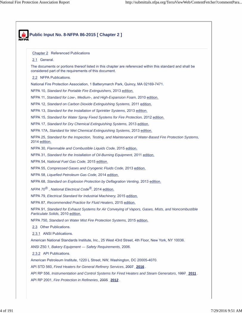
Public Input No. 8-NFPA 86-2015 [ Chapter 2 ]
Chapter 2 Referenced Publications
2.1 General.
The documents or portions thereof listed in this chapter are referenced within this standard and shall beconsidered part of the requirements of this document.
2.2 NFPA Publications.
National Fire Protection Association, 1 Batterymarch Park, Quincy, MA 02169-7471.
NFPA 10, Standard for Portable Fire Extinguishers, 2013 edition.
NFPA 11, Standard for Low-, Medium-, and High-Expansion Foam, 2010 edition.
NFPA 12, Standard on Carbon Dioxide Extinguishing Systems, 2011 edition.
NFPA 13, Standard for the Installation of Sprinkler Systems, 2013 edition.
NFPA 15, Standard for Water Spray Fixed Systems for Fire Protection, 2012 edition.
NFPA 17, Standard for Dry Chemical Extinguishing Systems, 2013 edition.
NFPA 17A, Standard for Wet Chemical Extinguishing Systems, 2013 edition.
NFPA 25, Standard for the Inspection, Testing, and Maintenance of Water-Based Fire Protection Systems,2014 edition.
NFPA 30, Flammable and Combustible Liquids Code, 2015 edition.
NFPA 31, Standard for the Installation of Oil-Burning Equipment, 2011 edition.
NFPA 54, National Fuel Gas Code, 2015 edition.
NFPA 55, Compressed Gases and Cryogenic Fluids Code, 2013 edition.
NFPA 58, Liquefied Petroleum Gas Code, 2014 edition.
NFPA 68, Standard on Explosion Protection by Deflagration Venting, 2013 edition.
NFPA 70® , National Electrical Code®, 2014 edition.
NFPA 79, Electrical Standard for Industrial Machinery, 2015 edition.
NFPA 87, Recommended Practice for Fluid Heaters, 2015 edition.
NFPA 91, Standard for Exhaust Systems for Air Conveying of Vapors, Gases, Mists, and NoncombustibleParticulate Solids, 2010 edition.
NFPA 750, Standard on Water Mist Fire Protection Systems, 2015 edition.
2.3 Other Publications.
2.3.1 ANSI Publications.
American National Standards Institute, Inc., 25 West 43rd Street, 4th Floor, New York, NY 10036.
ANSI Z50.1, Bakery Equipment — Safety Requirements, 2006.
2.3.2 API Publications.
American Petroleum Institute, 1220 L Street, NW, Washington, DC 20005-4070.
API STD 560, Fired Heaters for General Refinery Services, 2007 2016 .
API RP 556, Instrumentation and Control Systems for Fired Heaters and Steam Generators, 1997 2011 .
API RP 2001, Fire Protection in Refineries, 2005 2012 .
National Fire Protection Association Report http://submittals.nfpa.org/TerraViewWeb/ContentFetcher?commentPara...
4 of 191 7/29/2016 9:51 AM
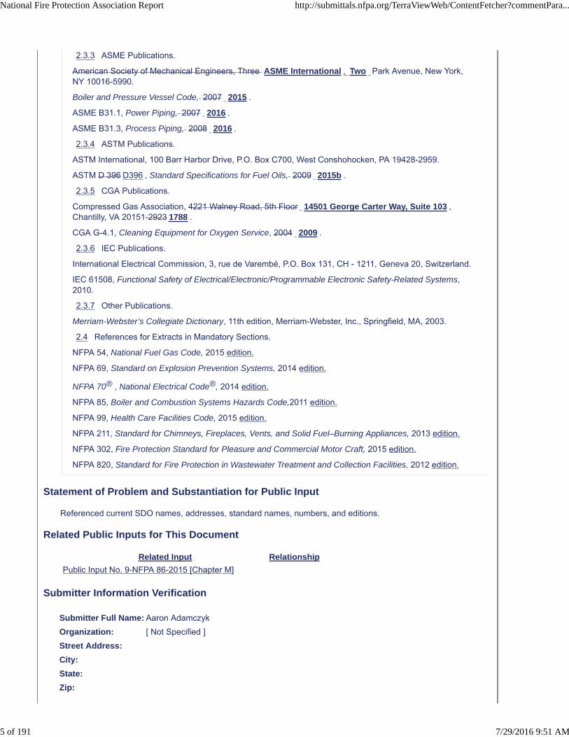
2.3.3 ASME Publications.
American Society of Mechanical Engineers, Three ASME International , Two Park Avenue, New York,NY 10016-5990.
Boiler and Pressure Vessel Code, 2007 2015 .
ASME B31.1, Power Piping, 2007 2016 .
ASME B31.3, Process Piping, 2008 2016 .
2.3.4 ASTM Publications.
ASTM International, 100 Barr Harbor Drive, P.O. Box C700, West Conshohocken, PA 19428-2959.
ASTM D 396 D396 , Standard Specifications for Fuel Oils, 2009 2015b .
2.3.5 CGA Publications.
Compressed Gas Association, 4221 Walney Road, 5th Floor 14501 George Carter Way, Suite 103 ,Chantilly, VA 20151-2923 1788 .
CGA G-4.1, Cleaning Equipment for Oxygen Service, 2004 2009 .
2.3.6 IEC Publications.
International Electrical Commission, 3, rue de Varembé, P.O. Box 131, CH - 1211, Geneva 20, Switzerland.
IEC 61508, Functional Safety of Electrical/Electronic/Programmable Electronic Safety-Related Systems,2010.
2.3.7 Other Publications.
Merriam-Webster’s Collegiate Dictionary, 11th edition, Merriam-Webster, Inc., Springfield, MA, 2003.
2.4 References for Extracts in Mandatory Sections.
NFPA 54, National Fuel Gas Code, 2015 edition.
NFPA 69, Standard on Explosion Prevention Systems, 2014 edition.
NFPA 70® , National Electrical Code®, 2014 edition.
NFPA 85, Boiler and Combustion Systems Hazards Code,2011 edition.
NFPA 99, Health Care Facilities Code, 2015 edition.
NFPA 211, Standard for Chimneys, Fireplaces, Vents, and Solid Fuel–Burning Appliances, 2013 edition.
NFPA 302, Fire Protection Standard for Pleasure and Commercial Motor Craft, 2015 edition.
NFPA 820, Standard for Fire Protection in Wastewater Treatment and Collection Facilities, 2012 edition.
Statement of Problem and Substantiation for Public Input
Referenced current SDO names, addresses, standard names, numbers, and editions.
Related Public Inputs for This Document
Related Input Relationship
Public Input No. 9-NFPA 86-2015 [Chapter M]
Submitter Information Verification
Submitter Full Name: Aaron Adamczyk
Organization: [ Not Specified ]
Street Address:
City:
State:
Zip:
National Fire Protection Association Report http://submittals.nfpa.org/TerraViewWeb/ContentFetcher?commentPara...
5 of 191 7/29/2016 9:51 AM

Submittal Date: Tue Jul 21 16:03:08 EDT 2015
National Fire Protection Association Report http://submittals.nfpa.org/TerraViewWeb/ContentFetcher?commentPara...
6 of 191 7/29/2016 9:51 AM

Public Input No. 71-NFPA 86-2016 [ New Section after 3.3 ]
Definition of Chambers: (a) Heating Chamber, (b) Combustion Chamber, (c) Work Chamber
A lot of the terms within the 3.3.33 definitions refer to combustion chambers and work chambers withoutdefining the terms. This gets more muddled in 8.5.1.1 as well as 8.5.1.2(B) and 8.5.1.8(1) calls out'heating chambers' without a full definition of the term.
Statement of Problem and Substantiation for Public Input
Definition of Chambers: (a) Heating Chamber, (b) Combustion Chamber, (c) Work ChamberA lot of the terms within the 3.3.33 definitions refer to combustion chambers and work chambers without defining the terms. This gets more muddled in 8.5.1.1 as well as 8.5.1.2(B) and 8.5.1.8(1) calls out 'heating chambers' without a full definition of the term.
Submitter Information Verification
Submitter Full Name: Robert Davis
Organization: Alcoa
Street Address:
City:
State:
Zip:
Submittal Date: Thu Jun 09 13:45:15 EDT 2016
National Fire Protection Association Report http://submittals.nfpa.org/TerraViewWeb/ContentFetcher?commentPara...
7 of 191 7/29/2016 9:51 AM

Public Input No. 75-NFPA 86-2016 [ New Section after 3.3.10 ]
TITLE OF NEW CONTENT
3.3.x Cooling systems .
3.3.x.1 Closed cooling systems . A cooling system that does not utilize unrestricted sight drain(s)observable by the operator(s).
3.3.x.2 Open cooling systems. A cooling system that utilizes unrestricted sight drain(s) observableby the operator(s).
Statement of Problem and Substantiation for Public Input
Since “closed loop” and “open loop” are used in multiple places in the standard (i.e. Chapters 5, 13, and 14), “closed loop” and “open loop” should be defined.
Submitter Information Verification
Submitter Full Name: Ted Jablkowski
Organization: Fives North American Combustion
Affilliation: Submitted on behalf of the NFPA 86 Intro Chapters Task Group
Street Address:
City:
State:
Zip:
Submittal Date: Thu Jun 09 16:09:24 EDT 2016
National Fire Protection Association Report http://submittals.nfpa.org/TerraViewWeb/ContentFetcher?commentPara...
8 of 191 7/29/2016 9:51 AM
Public Input No. 50-NFPA 86-2016 [ New Section after 3.3.15 ]
Design pressure: The maximum pressure of a gas piping system or gas train is that can becontinuously sustained, contained or controlled.
Statement of Problem and Substantiation for Public Input
The proposal standardizes on pressure rating terms and uses the ASME B31.3 terms in the same way.
Submitter Information Verification
Submitter Full Name: Kevin Carlisle
Organization: Industrial Heating Equipment Association
Affilliation: Industrial Heating Equipment Association
Street Address:
City:
State:
Zip:
Submittal Date: Fri Jun 03 14:50:18 EDT 2016
National Fire Protection Association Report http://submittals.nfpa.org/TerraViewWeb/ContentFetcher?commentPara...
9 of 191 7/29/2016 9:51 AM

Public Input No. 68-NFPA 86-2016 [ New Section after 3.3.16 ]
Equipment . Also known as an oven, furnace, or dryer .
Associated equipment; Parts of an oven, furnace, or dryer specially designed for executing a task,such as a tool, blower, valve, switch, machine, device, component.
Auxiliary equipment : looking to committee members to define this
Statement of Problem and Substantiation for Public Input
The term equipment, Associated equipment and Auxiliary Equipment are used. We suggest a review of the standard and define the terms.
The term “Equipment” is used many places with different meanings
The term means oven or dryer in these para.• 6.2.4.1• 1.1.7(2)• 1.3.1• 1.4.1• 3.2.2• 3.3.6• 3.3.26• 3.3.27.3• 3.3.27.4• 3.3.36.4 Safety Interlock.• 3.3.49.2.1 Afterburner (Direct Thermal Oxidizer).• 3.3.51.2 Continuous Pilot.• 3.3.54.1 Line Pressure Regulator.• 3.3.63* Safety Device.• 3.3.75 Vacuum Pumping System.• 3.3.78.3 Equipment Isolation Valve.• 3.3.82 Water-Cooling System for Vacuum Furnaces.• 4.1.1 Approvals, Plans, and Specifications.• 4.1.1.1 Aprovals, Plans, and Specifications.• 4.1.3.3 Safety Labeling.• 5.1.3.1 Location in Regard to Stock, Processes, and Personnel• 5.1.3.6• 5.1.4.5
The term means “device or components” in • 1.1• 3.2.3• 3.2.4• 3.3.46 Operator• 5.1.1.1*Location• 5.2.1
The term means “device or components” in • 1.1• 3.2.3• 3.2.4
National Fire Protection Association Report http://submittals.nfpa.org/TerraViewWeb/ContentFetcher?commentPara...
10 of 191 7/29/2016 9:51 AM

• 5.5.3 control equipment
Meaning if the term is not known in these paragraphs• 1.4.1• 5.2.3*• 5.2.6• 5.2.6.1*• 5.5 Mountings and Auxiliary Equipment
Auxiliary equipment Term is used in• 5.5.4• 8.18.1.3
Associated equipment Term is used in• 3.3.46 • 11.6.1.5• 11.7.5
Submitter Information Verification
Submitter Full Name: Kevin Carlisle
Organization: Industrial Heating Equipment Association
Affilliation: Industrial Heating Equipment Association
Street Address:
City:
State:
Zip:
Submittal Date: Fri Jun 03 15:46:06 EDT 2016
National Fire Protection Association Report http://submittals.nfpa.org/TerraViewWeb/ContentFetcher?commentPara...
11 of 191 7/29/2016 9:51 AM

Public Input No. 169-NFPA 86-2016 [ Section No. 3.3.16 ]
3.3.16* Explosion-Resistant (Radiant Tube).
A radiant tube or radiant tube heat recovery system that does not fail catastrophically when subjected tothe maximum deflagration pressure caused by the ignition of an accumulation of a stoichiometric mixture ofthe selected fuel(s) and air.
ELIMINATE THIS SECTION
Statement of Problem and Substantiation for Public Input
The current NFPA 86-2015 Standard for Ovens and Furnaces implies that metallic radiant tubes are safer than other high temperature materials of construction such as ceramics and composites. Alternative non-metallic materials currently in industrial radiant tube service include mullites, sialons, silicon nitrides, siliconized silicon carbides and silicon / silicon carbide composites. The standard excludes and/or favorably treats metallic radiant tubes in terms of relaxed requirements for:• Pre-ignition Purging Sections 8.5.1.2, A.8.5.1.2, 8.5.1.5 & 8.5.1.6• Safety Shut-Off Valves Section 8.8.2.1• Flame Supervision Section 8.10.2
This special treatment for metallic radiant tubes ignores several decades of industry experience where deflagration / explosion has not proved to be a significant risk factor for non-metallic materials, or at minimum the incident losses are no different than metallic tubes used in equivalent service.
In actual operation most metallic radiant tubes used in carburizing, carbonitriding and higher temperature processing periodically experience open-crack, thru-wall hole and/or perforation failures due to material creep distortion, carburization corrosion/embrittlement and/or weld stress fracture. Any risks posed by “open” metallic tube failures are no different than those of non-metallic tubes, regardless of whether combustible gases flow into the furnace chamber or, vice versa, into the radiant tube.
For the processes cited above metallic failures generally occur every three to five years (sometimes sooner) mandating radiant tube replacement to maintain the integrity of the process atmosphere and quality of production. While ceramic and composite tubes available to the industrial furnace users do not experience the progressive failure modes of metallic tubes, they are more susceptible to mechanical impact and less tolerable of thermo-mechanical stress. Failure of non-metallic radiant tubes has the same effect on the furnace atmosphere and production quality, also mandating their replacement.
When radiant metallic tube applications are optimally designed (so that the surface temperatures are uniform and not excessive for the specific alloy employed), they are just as likely, if not more likely, to fail catastrophically compared with ceramic and composite tubes under the same service conditions in carburizing, carbonitriding and higher temperature atmospheres.
Furthermore, consideration of radiant tube durability should not be based on new material properties, but rather on radiant tubes that are at or near the end of their useful service lives. It is at this point that a tube failure-related incident is most likely to occur.
To be logically consistent both metallic and non-metallic radiant tubes used at elevated temperatures (e.g. above 1550°F) must be treated the same. For example, if flame supervision is required for non-metallic radiant tubes, then it should be required for metallic radiant tubes as well. An alternative approach might be to require that metallic tubes are removed from use before they are projected to fail (based on a documented analysis of service life in the specific application). In practice it is rare that adequate information is available to base such projections with certainty, therefore we do not envision that this risk avoidance tactic can be reliably adopted by industry.
On the other hand, if metallic radiant tubes are proven to operate in service with little or no deterioration at lower temperatures (e.g. below 1550°F), a specific reliability analysis might support the conclusion that catastrophic
National Fire Protection Association Report http://submittals.nfpa.org/TerraViewWeb/ContentFetcher?commentPara...
12 of 191 7/29/2016 9:51 AM

failure is improbable in that application.
The testing prescribed in Section A.6.2.10.7 to validate the explosion-resistance of non-metallic materials ignores the failure modes of metallic tubes in carburizing, carbonitriding and higher temperature processing. Normative service failures (open-cracks, thru-wall holes and/or perforations) result in metallic radiant tubes incapable of supporting any pressurization whatsoever. Furthermore, the exclusion of metallic materials from these validity protocols per Section 6.2.10.6 ignores the design pressure ratings of radiant tubes (as a function of wall thickness, alloy strength and weld integrity). Also longer-term metallic tube wall deterioration due to spalling and embrittlement (which inevitably occurs in high temperature service) is not considered.
Related Public Inputs for This Document
Related Input Relationship
Public Input No. 170-NFPA 86-2016 [Sections 8.5.1.5, 8.5.1.6]
Public Input No. 172-NFPA 86-2016 [Section No. 8.8.2.1]
Public Input No. 173-NFPA 86-2016 [Section No. 8.10.2]
Public Input No. 174-NFPA 86-2016 [Section No. A.3.3.16]
Public Input No. 175-NFPA 86-2016 [Section No. A.6.2.10.7]
Public Input No. 176-NFPA 86-2016 [Section No. A.8.5.1.2]
Public Input No. 171-NFPA 86-2016 [Sections 6.2.10.6, 6.2.10.7]
Submitter Information Verification
Submitter Full Name: Curt Colopy
Organization: INEX Incorporated
Street Address:
City:
State:
Zip:
Submittal Date: Wed Jun 29 15:47:11 EDT 2016
National Fire Protection Association Report http://submittals.nfpa.org/TerraViewWeb/ContentFetcher?commentPara...
13 of 191 7/29/2016 9:51 AM

Public Input No. 55-NFPA 86-2016 [ New Section after 3.3.34 ]
Inlet gas pressure : gas pressure measured at the equipment isolation valve.
Statement of Problem and Substantiation for Public Input
Term is used in proposal for overpressure protection and it is suggested that this term replace SUPPLY PRESSURE through the standard except in A.13.5.5, where this should supply pressure regulator should be gas appliance (equipment) regulator.
Submitter Information Verification
Submitter Full Name: Kevin Carlisle
Organization: Industrial Heating Equipment Association
Affilliation: Industrial Heating Equipment Association
Street Address:
City:
State:
Zip:
Submittal Date: Fri Jun 03 15:07:36 EDT 2016
National Fire Protection Association Report http://submittals.nfpa.org/TerraViewWeb/ContentFetcher?commentPara...
14 of 191 7/29/2016 9:51 AM

Public Input No. 142-NFPA 86-2016 [ New Section after 3.3.35 ]
3.3.36 Impulse Pipe
A pipe or tube used to connect an instrument to a point in the system at which a process variable is to bemeasured.
Statement of Problem and Substantiation for Public Input
Adding definition to a term that is currently used in annex material and will be used in proposed mandatory language (new 7.4.4.1).
Related Public Inputs for This Document
Related Input Relationship
Public Input No. 140-NFPA 86-2016 [New Section after 7.4.4]
Public Input No. 141-NFPA 86-2016 [New Section after A.7.3.8]
Submitter Information Verification
Submitter Full Name: Geoffrey Raifsnider
Organization: Global Finishing Solutions
Street Address:
City:
State:
Zip:
Submittal Date: Tue Jun 28 08:23:32 EDT 2016
National Fire Protection Association Report http://submittals.nfpa.org/TerraViewWeb/ContentFetcher?commentPara...
15 of 191 7/29/2016 9:51 AM

Public Input No. 165-NFPA 86-2016 [ New Section after 3.3.35 ]
TITLE OF NEW CONTENT
3.3.3x Impulse Pipe. A pipe or tube used to connect an instrument to a point in the system at which aprocess variable is to be measured.
Statement of Problem and Substantiation for Public Input
PI to propose requirements for impulse lines used for safety devices.
Submitter Information Verification
Submitter Full Name: Ted Jablkowski
Organization: Fives North American Combustion
Affilliation: Submitted on behalf of the NFPA 86 Intro Chapters Task Group
Street Address:
City:
State:
Zip:
Submittal Date: Tue Jun 28 15:04:49 EDT 2016
National Fire Protection Association Report http://submittals.nfpa.org/TerraViewWeb/ContentFetcher?commentPara...
16 of 191 7/29/2016 9:51 AM

Public Input No. 95-NFPA 86-2016 [ Section No. 3.3.36.3 ]
3.3.36.3 Proved Low-Fire Start Ignition Interlock.
A burner start interlock in which a control sequence ensures that a high–low or modulated burner is at areduced specified firing rate for reliable ignition before the burner can be ignited.
Statement of Problem and Substantiation for Public Input
The defined term 3.3.36.3 Proved Low-Fire Start Interlock is not used in the Standard. This public input recommends that the term be changed and used in the mandatory text.
Submitter Information Verification
Submitter Full Name: Ted Jablkowski
Organization: Fives North American Combustion
Affilliation: Submitted on behalf of the NFPA 86 Intro Chapters Task Group
Street Address:
City:
State:
Zip:
Submittal Date: Fri Jun 10 13:19:42 EDT 2016
National Fire Protection Association Report http://submittals.nfpa.org/TerraViewWeb/ContentFetcher?commentPara...
17 of 191 7/29/2016 9:51 AM

Public Input No. 79-NFPA 86-2016 [ Section No. 3.3.40.1 ]
3.3.40.1 Air–Fuel Gas Mixer.
A mixer that combines air and fuel gas in the proper specific proportions for use in combustion.
Statement of Problem and Substantiation for Public Input
Existing text implies a flammable mixture, but mixers could also make mixtures for fuel equivalency that are not in the flammable range.
Submitter Information Verification
Submitter Full Name: Ted Jablkowski
Organization: Fives North American Combustion
Affilliation: Submitted on behalf of the NFPA 86 Intro Chapters Task Group
Street Address:
City:
State:
Zip:
Submittal Date: Thu Jun 09 16:23:49 EDT 2016
National Fire Protection Association Report http://submittals.nfpa.org/TerraViewWeb/ContentFetcher?commentPara...
18 of 191 7/29/2016 9:51 AM

Public Input No. 81-NFPA 86-2016 [ Section No. 3.3.41 ]
3.3.41 Mixing Blower.
A motor-driven blower to supply air–fuel gas mixtures for combustion through one or more fuel burners ornozzles on a single-zone industrial heating appliance or on each control zone of a multizone installation.Mixing machines operated at 10 in. w.c. (2.49 kPa) or less static pressure are considered mixing blowers.
Statement of Problem and Substantiation for Public Input
This creates confusion in proposal for 6.2.9.2(B) and its annex. Deleting it here and adding it under requirements in 6.2.9.3 provides clarity.
Submitter Information Verification
Submitter Full Name: Ted Jablkowski
Organization: Fives North American Combustion
Affilliation: Submitted on behalf of the NFPA 86 Intro Chapters Task Group
Street Address:
City:
State:
Zip:
Submittal Date: Thu Jun 09 16:28:00 EDT 2016
National Fire Protection Association Report http://submittals.nfpa.org/TerraViewWeb/ContentFetcher?commentPara...
19 of 191 7/29/2016 9:51 AM
Public Input No. 51-NFPA 86-2016 [ New Section after 3.3.61 ]
Rated pressure The maximum internal and external pressures that the materials, devices, orcomponents are designed to contain or control.
Statement of Problem and Substantiation for Public Input
This term is part of a proposal to the overpressure protection requirements
Submitter Information Verification
Submitter Full Name: Kevin Carlisle
Organization: Industrial Heating Equipment Association
Affilliation: Industrial Heating Equipment Association
Street Address:
City:
State:
Zip:
Submittal Date: Fri Jun 03 14:53:22 EDT 2016
National Fire Protection Association Report http://submittals.nfpa.org/TerraViewWeb/ContentFetcher?commentPara...
20 of 191 7/29/2016 9:51 AM

Public Input No. 41-NFPA 86-2016 [ New Section after 3.3.65 ]
Safety service: a device used to perform a safety function and is either listed and labeled to the properstandard or has special performance features that give it significantly better reliability for the serviceintended compared to devices intended for general purpose service.
Statement of Problem and Substantiation for Public Input
The term safety service is used, but not defined. Since this is a critical feature about a device, I suggest we define it.
Submitter Information Verification
Submitter Full Name: Kevin Carlisle
Organization: Karl Dungs Inc
Street Address:
City:
State:
Zip:
Submittal Date: Fri Jun 03 13:12:28 EDT 2016
National Fire Protection Association Report http://submittals.nfpa.org/TerraViewWeb/ContentFetcher?commentPara...
21 of 191 7/29/2016 9:51 AM

Public Input No. 45-NFPA 86-2016 [ New Section after 3.3.65 ]
Combustion Safety Service An application related to safety for an oven which uses combustion andrequirements for hazards are addressed in a device standard.
Statement of Problem and Substantiation for Public Input
The term combustion safety service is used, but not defined. Since this is a critical feature about a device, I suggest we define it. Used in 8.2.1.
Submitter Information Verification
Submitter Full Name: Kevin Carlisle
Organization: Industrial Heating Equipment Association
Affilliation: Industrial Heating Equipment Association
Street Address:
City:
State:
Zip:
Submittal Date: Fri Jun 03 14:23:54 EDT 2016
National Fire Protection Association Report http://submittals.nfpa.org/TerraViewWeb/ContentFetcher?commentPara...
22 of 191 7/29/2016 9:51 AM
Public Input No. 80-NFPA 86-2016 [ New Section after 3.3.65 ]
TITLE OF NEW CONTENT
3.x.x Safety Blowout . A device or combination of devices that quench a flame, relieve pressure andprovide a means for automatic shut-off of the air-gas mixture flow in the event of a flashback in air-fuel gasmixture piping.
Statement of Problem and Substantiation for Public Input
New definition, used in 6.2.9.3(E).
Submitter Information Verification
Submitter Full Name: Ted Jablkowski
Organization: Fives North American Combustion
Affilliation: Submitted on behalf of the NFPA 86 Intro Chapters Task Group
Street Address:
City:
State:
Zip:
Submittal Date: Thu Jun 09 16:25:51 EDT 2016
National Fire Protection Association Report http://submittals.nfpa.org/TerraViewWeb/ContentFetcher?commentPara...
23 of 191 7/29/2016 9:51 AM

Public Input No. 42-NFPA 86-2016 [ New Section after 3.3.78.3 ]
Token (minimal) Relief valve: a reduced port, relief valve, intended to vent a small volume of gaspressure when the gas train is in a “no-flow” (shutdown) state. The excessive pressure condition is anincreased pressure between the regulator and the downstream safety shutoff valve, usually caused by toohigh of lock-up pressure or due to an increase of temperature. These devices do not act as an OPD under acontinuous demand condition and do not act as an OPD when an upstream regulator fails
Statement of Problem and Substantiation for Public Input
NPFA 86 uses the term, so it would be good to define it.
Submitter Information Verification
Submitter Full Name: Kevin Carlisle
Organization: Industrial Heating Equipment Association
Affilliation: Industrial Heating Equipment Association
Street Address:
City:
State:
Zip:
Submittal Date: Fri Jun 03 14:13:32 EDT 2016
National Fire Protection Association Report http://submittals.nfpa.org/TerraViewWeb/ContentFetcher?commentPara...
24 of 191 7/29/2016 9:51 AM
Public Input No. 49-NFPA 86-2016 [ New Section after 3.3.81 ]
Maximum Working Pressure. The maximum pressure of a pressure vessel that can becontinuously sustained, contained or controlled
Statement of Problem and Substantiation for Public Input
The proposal standardizes on pressure rating terms and uses the ASME B31.3 terms in the same way.
Submitter Information Verification
Submitter Full Name: Kevin Carlisle
Organization: Industrial Heating Equipment Association
Affilliation: Industrial Heating Equipment Association
Street Address:
City:
State:
Zip:
Submittal Date: Fri Jun 03 14:48:07 EDT 2016
National Fire Protection Association Report http://submittals.nfpa.org/TerraViewWeb/ContentFetcher?commentPara...
25 of 191 7/29/2016 9:51 AM

Public Input No. 143-NFPA 86-2016 [ New Section after 3.3.82 ]
TITLE OF NEW CONTENT
Flame Curtain is lacking a definition in NFPA 86. If a Flame Curtain is a burner, then it requires (2) SSOV’sper 8.8.2.
Insert a definition as follows and renumber subsequent definitions:
3.3.83 Flame Curtain. A Flame Curtain is a type of line burner mounted outside of a furnace door and usedto provide an ignition source for flammable gasses exiting the furnace through the door when opened or toreduce the ingress of air into a furnace to minimize process upsets.
Statement of Problem and Substantiation for Public Input
Flame Curtain is lacking a definition in NFPA 86. If a Flame Curtain is a burner, then it requires (2) SSOV’s per 8.8.2.
Related Public Inputs for This Document
Related Input Relationship
Public Input No. 144-NFPA 86-2016 [Section No. 13.5.11.3]
Public Input No. 145-NFPA 86-2016 [Section No. A.13.5.11.3]
Public Input No. 146-NFPA 86-2016 [New Section after A.13.5.11.3]
Submitter Information Verification
Submitter Full Name: Joseph Kozma III
Organization: AFC-Holcroft LLC
Street Address:
City:
State:
Zip:
Submittal Date: Tue Jun 28 12:00:22 EDT 2016
National Fire Protection Association Report http://submittals.nfpa.org/TerraViewWeb/ContentFetcher?commentPara...
26 of 191 7/29/2016 9:51 AM
Public Input No. 76-NFPA 86-2016 [ Section No. 5.2.10 ]
5.2.10*
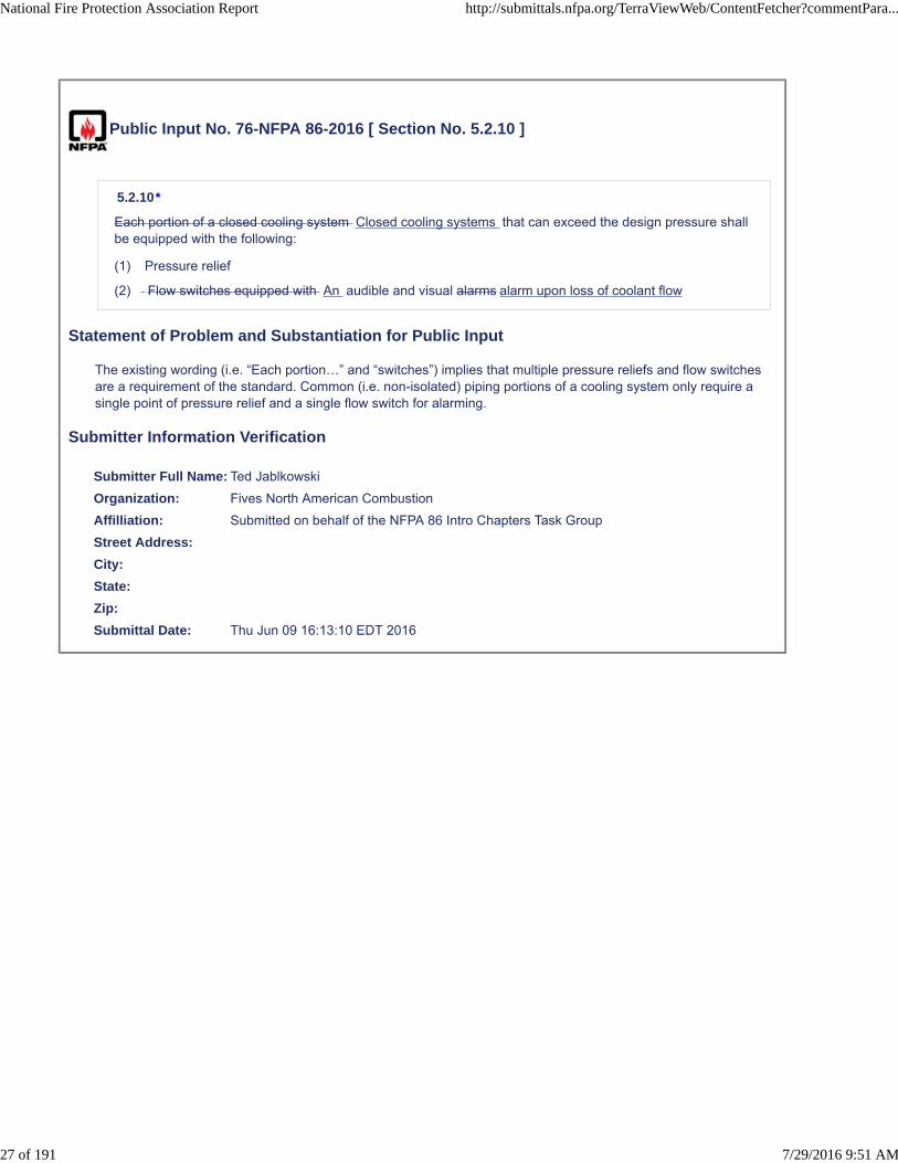
Each portion of a closed cooling system Closed cooling systems that can exceed the design pressure shallbe equipped with the following:
(1) Pressure relief
(2) Flow switches equipped with An audible and visual alarms alarm upon loss of coolant flow
Statement of Problem and Substantiation for Public Input
The existing wording (i.e. “Each portion…” and “switches”) implies that multiple pressure reliefs and flow switches are a requirement of the standard. Common (i.e. non-isolated) piping portions of a cooling system only require a single point of pressure relief and a single flow switch for alarming.
Submitter Information Verification
Submitter Full Name: Ted Jablkowski
Organization: Fives North American Combustion
Affilliation: Submitted on behalf of the NFPA 86 Intro Chapters Task Group
Street Address:
City:
State:
Zip:
Submittal Date: Thu Jun 09 16:13:10 EDT 2016
National Fire Protection Association Report http://submittals.nfpa.org/TerraViewWeb/ContentFetcher?commentPara...
27 of 191 7/29/2016 9:51 AM

Public Input No. 77-NFPA 86-2016 [ Section No. 5.2.11 ]
5.2.11
Open cooling systems utilizing unrestricted sight drains observable by the operator shall not requirepressure relief or loss of flow switches alarming .
Statement of Problem and Substantiation for Public Input
1. Since “open cooling systems” has been defined, no further clarification is required (i.e. “utilizing unrestricted ….”).2. The addition of “pressure relief or” in paragraph 5.2.11 clarifies that for pressure relief is not required for open cooling systems. 3. Paragraph 5.2.11 is more an exception to paragraph 5.2.10 than an actual requirement.
Submitter Information Verification
Submitter Full Name: Ted Jablkowski
Organization: Fives North American Combustion
Affilliation: Submitted on behalf of the NFPA 86 Intro Chapters Task Group
Street Address:
City:
State:
Zip:
Submittal Date: Thu Jun 09 16:15:25 EDT 2016
National Fire Protection Association Report http://submittals.nfpa.org/TerraViewWeb/ContentFetcher?commentPara...
28 of 191 7/29/2016 9:51 AM
Public Input No. 78-NFPA 86-2016 [ Section No. 5.2.12 ]
5.2.12
Where a cooling system is critical to continued safe operation of a furnace, the :
(1) The cooling system shall continue to operate after a safety shutdown or power failure.
(2) The furnace manufacturer’s operating instructions shall state, in effect, that the cooling system iscritical for safe operation.
Statement of Problem and Substantiation for Public Input
It is the responsibility of the furnace manufacturer to inform the end user that the cooling system (typically the water supply) is critical to the safe operation of the furnace.
Submitter Information Verification
Submitter Full Name: Ted Jablkowski
Organization: Fives North American Combustion
Affilliation: Submitted on behalf of the NFPA 86 Intro Chapters Task Group
Street Address:
City:
State:
Zip:
Submittal Date: Thu Jun 09 16:19:01 EDT 2016
National Fire Protection Association Report http://submittals.nfpa.org/TerraViewWeb/ContentFetcher?commentPara...
29 of 191 7/29/2016 9:51 AM
Public Input No. 115-NFPA 86-2016 [ Section No. 5.2.14 ]
5.2.14
Furnace hydraulic systems shall utilize either fire-resistant fluids or flammable hydraulic fluids whereapproved and where failure of hydraulic system components cannot result in a fire hazard.
Statement of Problem and Substantiation for Public Input
Adding the word clarifies the provision and makes it easier to read.
Submitter Information Verification
Submitter Full Name: Jim Muir
Organization: Building Safety Division, Clark County, Washington
Affilliation: NFPA's Building Code Development Committee (BCDC)
Street Address:
City:
State:
Zip:
Submittal Date: Thu Jun 16 17:52:46 EDT 2016
National Fire Protection Association Report http://submittals.nfpa.org/TerraViewWeb/ContentFetcher?commentPara...
30 of 191 7/29/2016 9:51 AM
Public Input No. 103-NFPA 86-2016 [ Section No. 5.3.1 ]
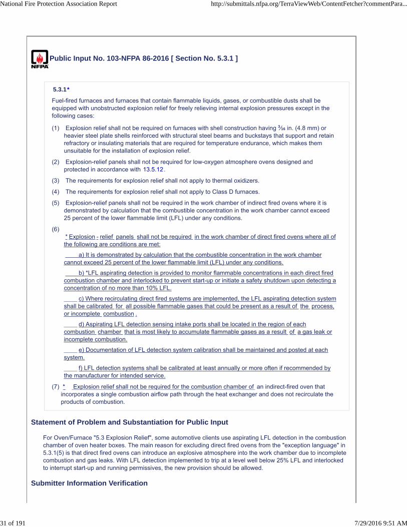
5.3.1*
Fuel-fired furnaces and furnaces that contain flammable liquids, gases, or combustible dusts shall beequipped with unobstructed explosion relief for freely relieving internal explosion pressures except in thefollowing cases:
(1) Explosion relief shall not be required on furnaces with shell construction having 3⁄16 in. (4.8 mm) orheavier steel plate shells reinforced with structural steel beams and buckstays that support and retainrefractory or insulating materials that are required for temperature endurance, which makes themunsuitable for the installation of explosion relief.
(2) Explosion-relief panels shall not be required for low-oxygen atmosphere ovens designed andprotected in accordance with 13.5.12.
(3) The requirements for explosion relief shall not apply to thermal oxidizers.
(4) The requirements for explosion relief shall not apply to Class D furnaces.
(5) Explosion-relief panels shall not be required in the work chamber of indirect fired ovens where it isdemonstrated by calculation that the combustible concentration in the work chamber cannot exceed25 percent of the lower flammable limit (LFL) under any conditions.
(6)* Explosion - relief panels shall not be required in the work chamber of direct fired ovens where all ofthe following are conditions are met:
a) It is demonstrated by calculation that the combustible concentration in the work chambercannot exceed 25 percent of the lower flammable limit (LFL) under any conditions.
b) *LFL aspirating detection is provided to monitor flammable concentrations in each direct firedcombustion chamber and interlocked to prevent start-up or initiate a safety shutdown upon detecting aconcentration of no more than 10% LFL.
c) Where recirculating direct fired systems are implemented, the LFL aspirating detection systemshall be calibrated for all possible flammable gases that could be present as a result of the process,or incomplete combustion .
d) Aspirating LFL detection sensing intake ports shall be located in the region of eachcombustion chamber that is most likely to accumulate flammable gases as a result of a gas leak orincomplete combustion.
e) Documentation of LFL detection system calibration shall be maintained and posted at eachsystem.
f) LFL detection systems shall be calibrated at least annually or more often if recommended bythe manufacturer for intended service.
(7)
Statement of Problem and Substantiation for Public Input
For Oven/Furnace "5.3 Explosion Relief", some automotive clients use aspirating LFL detection in the combustion chamber of oven heater boxes. The main reason for excluding direct fired ovens from the "exception language" in 5.3.1(5) is that direct fired ovens can introduce an explosive atmosphere into the work chamber due to incomplete combustion and gas leaks. With LFL detection implemented to trip at a level well below 25% LFL and interlocked to interrupt start-up and running permissives, the new provision should be allowed.
Submitter Information Verification
* Explosion relief shall not be required for the combustion chamber of an indirect-fired oven thatincorporates a single combustion airflow path through the heat exchanger and does not recirculate theproducts of combustion.
National Fire Protection Association Report http://submittals.nfpa.org/TerraViewWeb/ContentFetcher?commentPara...
31 of 191 7/29/2016 9:51 AM
Submitter Full Name: Ted Jablkowski
Organization: Fives North American Combustion
Affilliation: Submitted on behalf of the NFPA 86 Intro Chapters Task Group
Street Address:
City:
State:
Zip:
Submittal Date: Fri Jun 10 13:47:12 EDT 2016
National Fire Protection Association Report http://submittals.nfpa.org/TerraViewWeb/ContentFetcher?commentPara...
32 of 191 7/29/2016 9:51 AM
Public Input No. 13-NFPA 86-2015 [ Section No. 5.3.1 ]
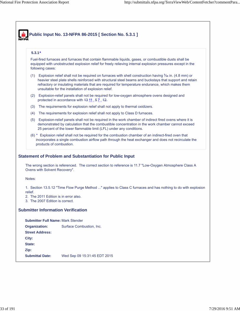
5.3.1*
Fuel-fired furnaces and furnaces that contain flammable liquids, gases, or combustible dusts shall beequipped with unobstructed explosion relief for freely relieving internal explosion pressures except in thefollowing cases:
(1) Explosion relief shall not be required on furnaces with shell construction having 3⁄16 in. (4.8 mm) orheavier steel plate shells reinforced with structural steel beams and buckstays that support and retainrefractory or insulating materials that are required for temperature endurance, which makes themunsuitable for the installation of explosion relief.
(2) Explosion-relief panels shall not be required for low-oxygen atmosphere ovens designed andprotected in accordance with 13 11 . 5 7 . 12.
(3) The requirements for explosion relief shall not apply to thermal oxidizers.
(4) The requirements for explosion relief shall not apply to Class D furnaces.
(5) Explosion-relief panels shall not be required in the work chamber of indirect fired ovens where it isdemonstrated by calculation that the combustible concentration in the work chamber cannot exceed25 percent of the lower flammable limit (LFL) under any conditions.
(6)
Statement of Problem and Substantiation for Public Input
The wrong section is referenced. The correct section to reference is 11.7 "Low-Oxygen Atmosphere Class A Ovens with Solvent Recovery".
Notes:
1. Section 13.5.12 "Time Flow Purge Method ..." applies to Class C furnaces and has nothing to do with explosion relief.2. The 2011 Edition is in error also.3. The 2007 Edition is correct.
Submitter Information Verification
Submitter Full Name: Mark Stender
Organization: Surface Combustion, Inc.
Street Address:
City:
State:
Zip:
Submittal Date: Wed Sep 09 15:31:45 EDT 2015
* Explosion relief shall not be required for the combustion chamber of an indirect-fired oven thatincorporates a single combustion airflow path through the heat exchanger and does not recirculate theproducts of combustion.
National Fire Protection Association Report http://submittals.nfpa.org/TerraViewWeb/ContentFetcher?commentPara...
33 of 191 7/29/2016 9:51 AM
Public Input No. 65-NFPA 86-2016 [ Section No. 5.3.1 ]
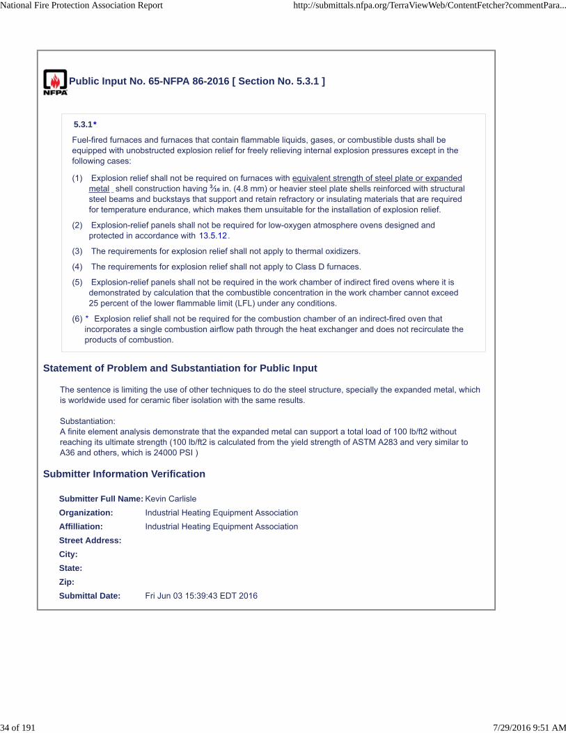
5.3.1*
Fuel-fired furnaces and furnaces that contain flammable liquids, gases, or combustible dusts shall beequipped with unobstructed explosion relief for freely relieving internal explosion pressures except in thefollowing cases:
(1) Explosion relief shall not be required on furnaces with equivalent strength of steel plate or expandedmetal shell construction having 3⁄16 in. (4.8 mm) or heavier steel plate shells reinforced with structuralsteel beams and buckstays that support and retain refractory or insulating materials that are requiredfor temperature endurance, which makes them unsuitable for the installation of explosion relief.
(2) Explosion-relief panels shall not be required for low-oxygen atmosphere ovens designed andprotected in accordance with 13.5.12.
(3) The requirements for explosion relief shall not apply to thermal oxidizers.
(4) The requirements for explosion relief shall not apply to Class D furnaces.
(5) Explosion-relief panels shall not be required in the work chamber of indirect fired ovens where it isdemonstrated by calculation that the combustible concentration in the work chamber cannot exceed25 percent of the lower flammable limit (LFL) under any conditions.
(6)
Statement of Problem and Substantiation for Public Input
The sentence is limiting the use of other techniques to do the steel structure, specially the expanded metal, which is worldwide used for ceramic fiber isolation with the same results.
Substantiation:A finite element analysis demonstrate that the expanded metal can support a total load of 100 lb/ft2 without reaching its ultimate strength (100 lb/ft2 is calculated from the yield strength of ASTM A283 and very similar to A36 and others, which is 24000 PSI )
Submitter Information Verification
Submitter Full Name: Kevin Carlisle
Organization: Industrial Heating Equipment Association
Affilliation: Industrial Heating Equipment Association
Street Address:
City:
State:
Zip:
Submittal Date: Fri Jun 03 15:39:43 EDT 2016
* Explosion relief shall not be required for the combustion chamber of an indirect-fired oven thatincorporates a single combustion airflow path through the heat exchanger and does not recirculate theproducts of combustion.
National Fire Protection Association Report http://submittals.nfpa.org/TerraViewWeb/ContentFetcher?commentPara...
34 of 191 7/29/2016 9:51 AM

Public Input No. 152-NFPA 86-2016 [ Section No. 6.2.2.4 ]
6.2.2.4*
Where primary or secondary combustion air is provided mechanically, combustion airflow or pressure shallbe proven and interlocked with the safety shutoff valves so that fuel gas cannot be admitted prior toestablishment of combustion air and so that the gas is shut off in the event of combustion air failure. (See8.5.1.2 and 8.7.4)
Statement of Problem and Substantiation for Public Input
Reference needed as part of related PI.
Submitter Information Verification
Submitter Full Name: Ted Jablkowski
Organization: Fives North American Combustion
Affilliation: Submitted on behalf of the NFPA 86 Intro Chapters Task Group
Street Address:
City:
State:
Zip:
Submittal Date: Tue Jun 28 14:26:25 EDT 2016
National Fire Protection Association Report http://submittals.nfpa.org/TerraViewWeb/ContentFetcher?commentPara...
35 of 191 7/29/2016 9:51 AM

Public Input No. 112-NFPA 86-2016 [ Sections 6.2.3, 6.2.4 ]
Sections 6.2.3, 6.2.4
New definitions
Gas piping system ; All gas confining pipe, tubing, valves, and fittings from the point of deliveryto the outlet of the equipment isolation valve (see NPFA 54).
Fuel gas train ; All gas confining pipe, tubing, valves, devices, controls, and fittings from outletof the equipment isolation valve up to the burner.
6.2.3 Fuel Gas Supply Piping System .
6.2.3.1*
An emergency shutoff valve shall be provided that meets the following requirements:
(1) It shall be remotely located away from the furnace so that fire or explosion at a furnace does notprevent access to the valve.
(2) It shall be readily accessible.
(3) It shall have permanently affixed visual indication of the valve position.
(4) A removable handle shall be permitted provided all the following requirements are satisfied:
(5) The valve position shall be clearly indicated whether the handle is attached or detached.
(6) The valve handle shall be tethered to the gas main no more than 3 ft (1 m) from the valve in amanner that does not cause personnel safety issues and that allows trouble-free reattachment ofthe handle and operation of the valve without untethering the handle.
(7) It shall be able to be operated from full open to full close and return without the use of tools.
6.2.3.2
Installation of LP-Gas storage and handling systems shall comply with NFPA 58, Liquefied Petroleum GasCode.
6.2.3.3
Piping from the point of delivery to the equipment isolation valve The gas piping system shall comply withNFPA 54, National Fuel Gas Code. (See 6.2.4.2.)
6.2.3.4
An equipment isolation valve shall be provided.
6.2.4 Equipment Fuel Gas Piping.
Fuel gas piping system shall be sized to provide flow rates and pressure to maintain a stable
pressure to the fuel gas train
National Fire Protection Association Report http://submittals.nfpa.org/TerraViewWeb/ContentFetcher?commentPara...
36 of 191 7/29/2016 9:51 AM

6.2.4.1 Equipment Isolation Valves Valve .
Equipment An equipment isolation valves valve shall meet the following requirements:
(1) They It shall be provided for each piece of equipment.
(2) They shall Itshall have permanently affixed visual indication of the valve position.
(3) They It shall be quarter-turn valves with stops.
(4) Wrenches or handles shall remain affixed to valves the valve and shall be oriented with respect to thevalve port to indicate the following:
(5) An open valve when the handle is parallel to the pipe
(6) A closed valve when the handle is perpendicular to the pipe
(7) They It shall be readily accessible.
(8) Valves A valve with removable wrenches shall not allow the wrench handle to be installedperpendicular to the fuel gas line when the valve is open.
(9) They It shall be able to be operated from full open to full close and return without the use of tools.
6.2. 5 Equipment Fuel Gas Train
6.2. 4.2* Materials, Sizing, Piping and Fittings.
(A)
Fuel gas piping materials Gas confining pipe, tubing, and fittings on a fuel gas train shall be in accordancewith NFPA 54, National Fuel Gas Code.
(B)
Fuel The fuel gas piping train shall be sized to provide flow rates and pressure to maintain a stable flameover the burner operating range.
Add Annex
A.6.2.4.2 NPFA 54 contains specific requirements for the type of suitable materials for thefuel gas piping system, which are also desirable for NPFA 86 applications. However, thereare some conflicts when referencing NFPA 54.
(1) The term “fuel gas piping system” is all piping that is upstream of the equipment isolation valve. NPFA54 defines “piping system” as “ All pipe, tubing, valves, and fittings from the point of delivery to theoutlets of the appliance shutoff valve” (aka equipment isolation valve). All piping that is downstream ofthe equipment isolation valve is part of the “fuel gas train”, which is part of the oven and is notconsidered “fuel gas piping”.
(1) The NFPA 54 reference is circuitous; NPFA 86 references a standard, whose scope does not coverand should not be applied to a fuel gas train of the oven. Thus, unintentional conflicts can occur. Forexample, NPFA 54 (2015), 5.6 “Acceptable Piping Materials and Joining Methods” required thatnon-ferrous flanged (i.e. aluminum flanged connections) comply with ANSI/ASME B16.24, CastCopper Alloy Pipe Flanges and Flanged Fittings: Classes 150, 300, 600. 900, 1500, and 2500 (seeNFPA 54, paragraph 5.6.10.1.3). This standard only permits flat face flanges.
The intent of referencing NPFA 54 in this paragraph is to have the material requirementsand fittings for gas piping systems in NFPA 54 also apply to the fuel gas train pipingmaterials and fittings. This paragraph does should not be applied to the joining methods ofthe gas train of the oven. For example, it should not be used to require that aluminumbodied valves have flange connections to ANSI/ASME B16.24. Aluminum bodied valvesare typically raise face in accordance with ASME B16.5 as permitted in ASME B31.3Appendix L (see para. L304).
Statement of Problem and Substantiation for Public Input
Standard needs to better define where the gas piping system is and the gas train is. Sizing of the gas piping system is per NPFA 54. Sizing of the gas train covered by per NPFA 86. Also, A gas piping system is a part of NPFA 54. Fuel gas trains should use materials and fittings that are specified in NFPA 54, but a gas train is not a
National Fire Protection Association Report http://submittals.nfpa.org/TerraViewWeb/ContentFetcher?commentPara...
37 of 191 7/29/2016 9:51 AM

gas piping system, and there are certain engineering practices are required for a fuel gas train that are not permitted in NFPA 54. The proposal clearly separate when NPFA 54 is applied and where not.
There is only a requirement for one equipment isolation valve.
Submitter Information Verification
Submitter Full Name: Kevin Carlisle
Organization: industrial Heating Equipment Association
Affilliation: industrial Heating Equipment Association
Street Address:
City:
State:
Zip:
Submittal Date: Fri Jun 10 16:09:53 EDT 2016
National Fire Protection Association Report http://submittals.nfpa.org/TerraViewWeb/ContentFetcher?commentPara...
38 of 191 7/29/2016 9:51 AM

Public Input No. 37-NFPA 86-2016 [ Section No. 6.2.6 ]
6.2.6 Pressure Regulators, Pressure Relief Valves, and Pressure Switches.
6.2.6.1
A fuel gas appliance (equipment) pressure regulator shall be furnished wherever the plant supply inletgas pressure exceeds the burner operating manifold pressure or design parameters or wherever the plantsupply pressure is subject to fluctuations, unless otherwise permitted by 6.2.6.2.
6.2.6.2
An automatic flow control valve shall be permitted to meet the requirement of 6.2.6.1, provided it cancompensate for the full range of expected source pressure variations.
6.2.6.3*
Regulators, Fuel gas appliance (equipment) pressure regulators, ratio regulators, zero governors , reliefvalves, and switches employing a non-metallic, atmospheric diaphragm shall be vented to an approvedlocation, and the following criteria also shall be met:
(1) Heavier-than-air flammable gases shall be vented outside the building to a location where the gas isdiluted below its LFL before coming in contact with sources of ignition or re-entering the building.
(2) Vents shall be designed to prevent the entry of water and insects without restricting the flow capacityof the vent.
6.2.6.4*
Fuel gas regulators, ratio regulators, and zero governors shall not be required to be vented to an approvedlocation in the following situations:
(1) Where backloaded from combustion air lines, air–gas mixture lines, or combustion chambers,provided that gas leakage through the backload connection does not create a hazard
(2) Where a listed pressure regulator–vent limiter combination is used
(3) Where a regulator system is listed for use without vent piping
(4) A pressure regulator incorporating a leak limiting system, which prevents or restricts the escape ofgas into a space large enough and with sufficient natural ventilation so that the escaping gas does notpresent a hazard
6.2.6.5*
A pressure switch shall not be required to be vented if it employs a vent limiter rated for the serviceintended.
6.2.6.6
Fuel gas appliance (equipment) pressure regulators, ratio regulators and zero governors shall not bebackloaded from oxygen or oxygen-enriched air lines.
6.2.6.7
Vent lines from multiple furnaces shall not be manifolded together.
6.2.6.8
Vents from systems operating at different pressure control levels shall not be manifolded together.
6.2.6.9
Vents from systems served from different pressure-reducing stations shall not be manifolded together.
6.2.6.10
Vents from systems using different fuel sources shall not be manifolded together.
National Fire Protection Association Report http://submittals.nfpa.org/TerraViewWeb/ContentFetcher?commentPara...
39 of 191 7/29/2016 9:51 AM
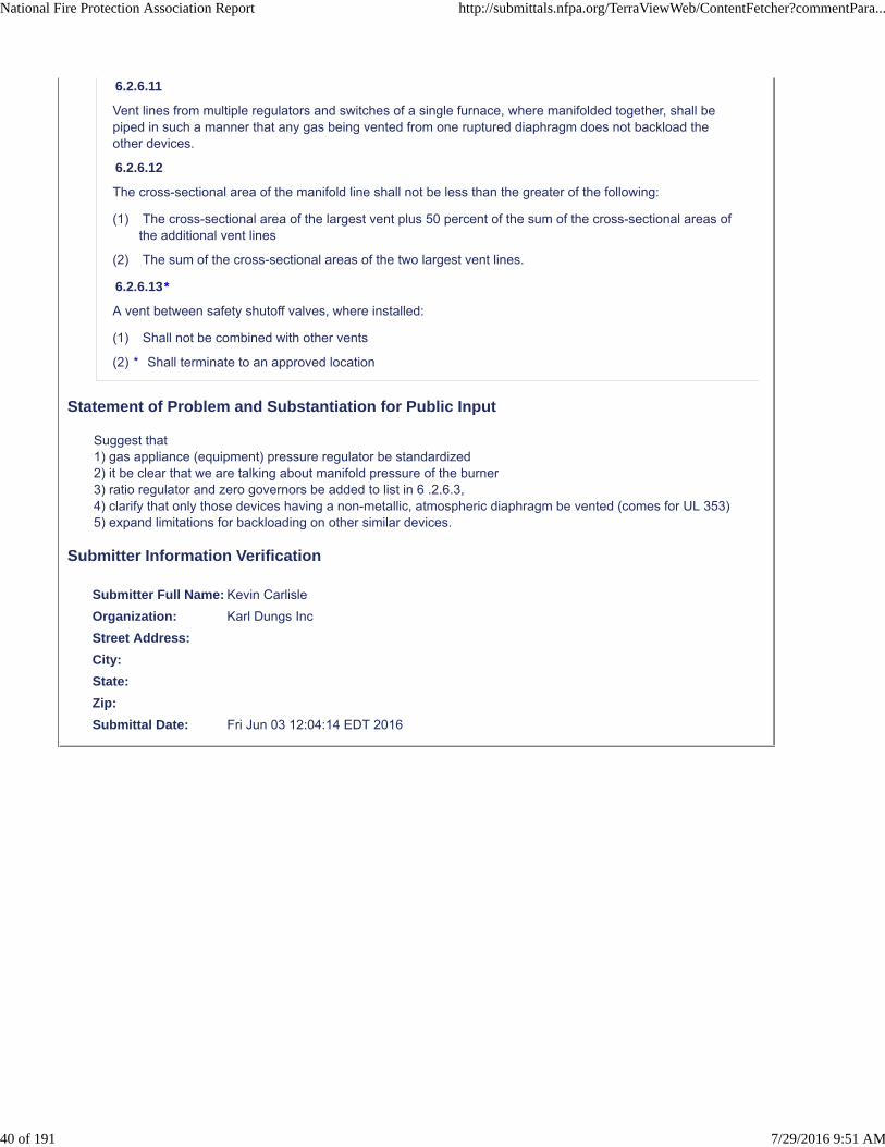
6.2.6.11
Vent lines from multiple regulators and switches of a single furnace, where manifolded together, shall bepiped in such a manner that any gas being vented from one ruptured diaphragm does not backload theother devices.
6.2.6.12
The cross-sectional area of the manifold line shall not be less than the greater of the following:
(1) The cross-sectional area of the largest vent plus 50 percent of the sum of the cross-sectional areas ofthe additional vent lines
(2) The sum of the cross-sectional areas of the two largest vent lines.
6.2.6.13*
A vent between safety shutoff valves, where installed:
(1) Shall not be combined with other vents
(2)
Statement of Problem and Substantiation for Public Input
Suggest that 1) gas appliance (equipment) pressure regulator be standardized 2) it be clear that we are talking about manifold pressure of the burner3) ratio regulator and zero governors be added to list in 6 .2.6.3,4) clarify that only those devices having a non-metallic, atmospheric diaphragm be vented (comes for UL 353)5) expand limitations for backloading on other similar devices.
Submitter Information Verification
Submitter Full Name: Kevin Carlisle
Organization: Karl Dungs Inc
Street Address:
City:
State:
Zip:
Submittal Date: Fri Jun 03 12:04:14 EDT 2016
* Shall terminate to an approved location
National Fire Protection Association Report http://submittals.nfpa.org/TerraViewWeb/ContentFetcher?commentPara...
40 of 191 7/29/2016 9:51 AM

Public Input No. 59-NFPA 86-2016 [ New Section after 6.2.7 ]
6.2.x Safety Shutoff valves : Safety shutoff valves shall be in accordance with section 8.
Statement of Problem and Substantiation for Public Input
This part of larger proposal to separate the requirements of the gas piping system from the fuel gas train requirements.
Submitter Information Verification
Submitter Full Name: Kevin Carlisle
Organization: Industrial Heating Equipment Association
Affilliation: Industrial Heating Equipment Association
Street Address:
City:
State:
Zip:
Submittal Date: Fri Jun 03 15:17:15 EDT 2016
National Fire Protection Association Report http://submittals.nfpa.org/TerraViewWeb/ContentFetcher?commentPara...
41 of 191 7/29/2016 9:51 AM

Public Input No. 64-NFPA 86-2016 [ Section No. 6.2.7 ]
Add definition:
Overpressure Protection Device: A pressure limiting or relieving device that prevents thedownstream pressure from exceeding a setpoint due to a failure of an upstream pressureregulator(s) under a continuous demand/flow condition.
6.2.7 Overpressure Protection.
6.2.7.1 .1 When Required, Location, OPD devices, and Detection of Activation
Overpressure protection shall be provided in either of the following cases:
(1) When the supply inlet gas pressure exceeds both 14 kPa (2 psi) and the rated pressurerating of any downstream component
(2) When the failure of a single upstream line regulator or service pressure regulator results in a supplyan inlet gas pressure exceeding the rated pressure rating of any downstream component, asapplicable in 6.2.7.4.
6.2.7.1. 2
Overpressure protection shall be provided by any one of the following:
(1) A series regulator in combination with a line regulator or service pressure regulator
(2) A monitoring regulator installed in combination with a line regulator or service pressure regulator
(3) A full-capacity pressure relief valve and vent line installed according to 6.2.7.2
(4) An overpressure cutoff device, such as a slam-shut valve or a high-pressure switch in combinationwith an adequately rated shutoff valve
6.2.7.1. 3* When an overpressure protection device is installed on a fuel gas train, there shall be anactive or passive means by which the activation of the overpressure protection device is detectable.
A.6.2.7.1.3* Example of an active means is an alarm or light notification. Exampleof a passive device would be a manual reset.
National Fire Protection Association Report http://submittals.nfpa.org/TerraViewWeb/ContentFetcher?commentPara...
42 of 191 7/29/2016 9:51 AM

6.2.7.2 R elief valves and lines
6.2.7.2.1* When a relief valve is used to comply with 6.2.7.1 , the relief valve shall be afull-capacity relief type
.
and have an atmospheric vent line sized to fully relieve the required volume of gas such that thepressure to the downstream components is maintained at or below the limits specified in 6.2.7.4.
6.2.7.
4 2.2 The relieving flow rate of the relief valve and its atmospheric vent line shall be based onnominal inlet pressures to and the Cv factor of the nearest upstream line pressure regulator withan allowance for any pressure drop between the relief valve and the regulator.
A.6.2.7.2.1. Token relief valves and internal token relief valves shall not be permitted to be usedas the only overpressure protection devices.
6.2.7.4* Setpoint of the Overpressure Protection Device.
The overpressure protection device shall set to provide a maximum downstream pressure as follows:
(1) When the rated pressure of any component is less than 83 kPa (12 psi), the set point of theoverpressure protection device shall not exceed 150 percent of the rated pressure of the lowest ratedcomponent.
(2) When the rated pressure of any component is equal to or greater than 83 kPa (12 psi) but less than414 kPa (60 psi), the set point of the overpressure protection device shall not exceed 41 kPa (6 psi)above the rated pressure of the lowest rated component.
(3) When the rated pressure of any component is equal to or greater than 414 kPa (60 psi), the set pointof the overpressure protection device shall not exceed 110 percent of the rated pressure of the lowestrated component.
A.6.2.7.4 The pressure limits in this section are consistent with 49 CFR Part 192.201,Required Capacity of Pressure Relieving and Limiting Stations
Statement of Problem and Substantiation for Public Input
Proposal attempt so simplify the requirements by using defined terms, limiting the failure of the line pressure regulator, which is in the gas piping system, and by providing relief valve and line requirements.Additional, the current language has not requirement for the max OPD Setpoint.
Submitter Information Verification
Submitter Full Name: Kevin Carlisle
Organization: Industrial Heating Equipment Association
Affilliation: Industrial Heating Equipment Association
Street Address:
City:
State:
Zip:
Submittal Date: Fri Jun 03 15:30:38 EDT 2016
National Fire Protection Association Report http://submittals.nfpa.org/TerraViewWeb/ContentFetcher?commentPara...
43 of 191 7/29/2016 9:51 AM

Public Input No. 90-NFPA 86-2016 [ Section No. 6.2.7.2 ]
6.2.7.2
Overpressure protection shall be provided by any one of the following:
(1) A series regulator in combination with a line regulator or service pressure regulator
(2) A monitoring regulator installed in combination with a line regulator or service pressure regulator
(3) * A full-capacity pressure relief valve
(4) An overpressure cutoff device, such as a slam-shut valve or a high-pressure switch in combinationwith an adequately rated shutoff valve*
Statement of Problem and Substantiation for Public Input
Add annex * to (3). Renumbered A.6.2.7.2 (3) adds information explaining the differences between full-capacity relief valves and token relief valves.
Submitter Information Verification
Submitter Full Name: Ted Jablkowski
Organization: Fives North American Combustion
Affilliation: Submitted on behalf of the NFPA 86 Intro Chapters Task Group
Street Address:
City:
State:
Zip:
Submittal Date: Thu Jun 09 16:50:49 EDT 2016
National Fire Protection Association Report http://submittals.nfpa.org/TerraViewWeb/ContentFetcher?commentPara...
44 of 191 7/29/2016 9:51 AM

Public Input No. 91-NFPA 86-2016 [ Section No. 6.2.7.3 ]
6.2.7.3 *
When a relief valve is used to comply with 6.2.7.1 , the relief valve shall be a full-capacity relief type.
Statement of Problem and Substantiation for Public Input
Deleted paragraph 6.2.7.3 is repeats the same information in paragraph 6.2.7.2 (3).
Submitter Information Verification
Submitter Full Name: Ted Jablkowski
Organization: Fives North American Combustion
Affilliation: Submitted on behalf of the NFPA 86 Intro Chapters Task Group
Street Address:
City:
State:
Zip:
Submittal Date: Thu Jun 09 16:53:47 EDT 2016
National Fire Protection Association Report http://submittals.nfpa.org/TerraViewWeb/ContentFetcher?commentPara...
45 of 191 7/29/2016 9:51 AM

Public Input No. 92-NFPA 86-2016 [ Section No. 6.2.7.4 ]
6.2.7.4
Token relief valves and internal token relief valves shall not be permitted to be used as the onlyoverpressure protection devices.
Statement of Problem and Substantiation for Public Input
Deleted paragraph 6.2.7.4 is not necessary, the requirement in paragraph 6.2.7.2 (3) already prohibits the use of “token” pressure relief valves.
Submitter Information Verification
Submitter Full Name: Ted Jablkowski
Organization: Fives North American Combustion
Affilliation: Submitted on behalf of the NFPA 86 Intro Chapters Task Group
Street Address:
City:
State:
Zip:
Submittal Date: Thu Jun 09 16:55:18 EDT 2016
National Fire Protection Association Report http://submittals.nfpa.org/TerraViewWeb/ContentFetcher?commentPara...
46 of 191 7/29/2016 9:51 AM

Public Input No. 54-NFPA 86-2016 [ Section No. 6.2.9.2 ]
6.2.9.2 Proportional Mixing.
(A)
Piping shall be designed to provide a uniform mixture flow of pressure and velocity needed for stable burneroperation.
(B)
Valves or other obstructions shall not be installed between a proportional mixer and burners, unlessotherwise permitted by 6.2.9.2(C).
(C)
Fixed orifices shall be permitted for purposes of balancing.
(D)
Any field-adjustable device built into a proportional mixer (e.g., gas orifice, air orifice, ratio valve) shallincorporate a device to prevent unintentional changes in the setting.
(E)
Where a mixing blower is used, safety shutoff valves shall be installed in the fuel gas supply and shallinterrupt the fuel gas supply automatically when the mixing blower is not in operation or in the event of afuel gas supply failure.
(F)
Mixing blowers shall not be used with fuel gases containing more than 10 percent free hydrogen (H2).
(G)
Mixing blowers having a static delivery discharge pressure of more than 10 in. w.c. (2.49 kPa) shall beconsidered mixing machines.
Statement of Problem and Substantiation for Public Input
Discharge is better term to use in this case
Submitter Information Verification
Submitter Full Name: Kevin Carlisle
Organization: Karl Dungs Inc
Street Address:
City:
State:
Zip:
Submittal Date: Fri Jun 03 15:03:50 EDT 2016
National Fire Protection Association Report http://submittals.nfpa.org/TerraViewWeb/ContentFetcher?commentPara...
47 of 191 7/29/2016 9:51 AM

Public Input No. 82-NFPA 86-2016 [ Section No. 6.2.9.2(B) ]
(B)
Valves or other obstructions shall not be installed between a an air jet mixer, gas jet mixer, proportionalmixer or a mixing blower and burners, unless otherwise permitted by 6.2.9.2(C).
Statement of Problem and Substantiation for Public Input
Clarifies specific defined mixer types; these were not previously used except in Chap 3.
Submitter Information Verification
Submitter Full Name: Ted Jablkowski
Organization: Fives North American Combustion
Affilliation: Submitted on behalf of the NFPA 86 Intro Chapters Task Group
Street Address:
City:
State:
Zip:
Submittal Date: Thu Jun 09 16:30:13 EDT 2016
National Fire Protection Association Report http://submittals.nfpa.org/TerraViewWeb/ContentFetcher?commentPara...
48 of 191 7/29/2016 9:51 AM

Public Input No. 83-NFPA 86-2016 [ Section No. 6.2.9.3(A) ]
(A)*
Automatic fire checks shall be provided in piping systems that distribute flammable air–fuel gas mixturesfrom a mixing machine at a pressure greater than 10 in . w.c. (2.49 kPa) .
Statement of Problem and Substantiation for Public Input
Adds back the requirement only for pressure >10"wc with proposal to remove it from the definition.
Submitter Information Verification
Submitter Full Name: Ted Jablkowski
Organization: Fives North American Combustion
Affilliation: Submitted on behalf of the NFPA 86 Intro Chapters Task Group
Street Address:
City:
State:
Zip:
Submittal Date: Thu Jun 09 16:32:38 EDT 2016
National Fire Protection Association Report http://submittals.nfpa.org/TerraViewWeb/ContentFetcher?commentPara...
49 of 191 7/29/2016 9:51 AM

Public Input No. 84-NFPA 86-2016 [ Section No. 6.2.9.3(E) ]
(E)*
A backfire arrester with a A safety blowout device shall be installed in accordance with the manufacturer'sinstructions near the outlet of each mixing machine that produces a flammable air–fuel gas mixture at apressure greater than 10 in . w.c. (2.49 kPa) .
Statement of Problem and Substantiation for Public Input
Proposed safety blowout definition eliminates the need for the deleted text. Adds back the requirement only for pressure >10"wc with the proposal to remove it from definition.
Submitter Information Verification
Submitter Full Name: Ted Jablkowski
Organization: Fives North American Combustion
Affilliation: Submitted on behalf of the NFPA 86 Intro Chapters Task Group
Street Address:
City:
State:
Zip:
Submittal Date: Thu Jun 09 16:34:47 EDT 2016
National Fire Protection Association Report http://submittals.nfpa.org/TerraViewWeb/ContentFetcher?commentPara...
50 of 191 7/29/2016 9:51 AM

Public Input No. 85-NFPA 86-2016 [ Section No. 6.2.9.3(F) ]
(F)
Where a mixing machine is used, safety shutoff valves shall be installed in the fuel gas supply and shallinterrupt the fuel gas supply automatically when the mixing machine is not in operation or in the event of anair or fuel gas supply failure.
Statement of Problem and Substantiation for Public Input
(F) is redundant to 8.14.
Submitter Information Verification
Submitter Full Name: Ted Jablkowski
Organization: Fives North American Combustion
Affilliation: Submitted on behalf of the NFPA 86 Intro Chapters Task Group
Street Address:
City:
State:
Zip:
Submittal Date: Thu Jun 09 16:37:35 EDT 2016
National Fire Protection Association Report http://submittals.nfpa.org/TerraViewWeb/ContentFetcher?commentPara...
51 of 191 7/29/2016 9:51 AM

Public Input No. 171-NFPA 86-2016 [ Sections 6.2.10.6, 6.2.10.7 ]
Sections 6.2.10.6, 6.2.10.7
6.2.10.6
Radiant tube heating systems using metallic tubes open at one or both ends shall not require explosionresistance validation.
ELIMINATE THIS SECTION
6.2.10.7 *
A manufacturer's claim of explosion-resistant radiant tube heating systems using nonmetallic tubes ormetallic tubes sealed in at both ends shall be validated.
ELIMINATE THIS SECTION
Statement of Problem and Substantiation for Public Input
The current NFPA 86-2015 Standard for Ovens and Furnaces implies that metallic radiant tubes are safer than other high temperature materials of construction such as ceramics and composites. Alternative non-metallic materials currently in industrial radiant tube service include mullites, sialons, silicon nitrides, siliconized silicon carbides and silicon / silicon carbide composites.
The standard excludes and/or favorably treats metallic radiant tubes in terms of relaxed requirements for:• Pre-ignition Purging Sections 8.5.1.2, A.8.5.1.2, 8.5.1.5 & 8.5.1.6• Safety Shut-Off Valves Section 8.8.2.1• Flame Supervision Section 8.10.2
This special treatment for metallic radiant tubes ignores several decades of industry experience where deflagration / explosion has not proved to be a significant risk factor for non-metallic materials, or at minimum the incident losses are no different than metallic tubes used in equivalent service.
In actual operation most metallic radiant tubes used in carburizing, carbonitriding and higher temperature processing periodically experience open-crack, thru-wall hole and/or perforation failures due to material creep distortion, carburization corrosion/embrittlement and/or weld stress fracture. Any risks posed by “open” metallic tube failures are no different than those of non-metallic tubes, regardless of whether combustible gases flow into the furnace chamber or, vice versa, into the radiant tube.
For the processes cited above metallic failures generally occur every three to five years (sometimes sooner) mandating radiant tube replacement to maintain the integrity of the process atmosphere and quality of production. While ceramic and composite tubes available to the industrial furnace users do not experience the progressive failure modes of metallic tubes, they are more susceptible to mechanical impact and less tolerable of thermo-mechanical stress. Failure of non-metallic radiant tubes has the same effect on the furnace atmosphere and production quality, also mandating their replacement.
When radiant metallic tube applications are optimally designed (so that the surface temperatures are uniform and not excessive for the specific alloy employed), they are just as likely, if not more likely, to fail catastrophically compared with ceramic and composite tubes under the same service conditions in carburizing, carbonitriding and higher temperature atmospheres.
Furthermore, consideration of radiant tube durability should not be based on new material properties, but rather on radiant tubes that are at or near the end of their useful service lives. It is at this point that a tube failure-related incident is most likely to occur.
To be logically consistent both metallic and non-metallic radiant tubes used at elevated temperatures (e.g. above 1550°F) must be treated the same. For example, if flame supervision is required for non-metallic radiant tubes, then it should be required for metallic radiant tubes as well. An alternative approach might be to require that
National Fire Protection Association Report http://submittals.nfpa.org/TerraViewWeb/ContentFetcher?commentPara...
52 of 191 7/29/2016 9:51 AM
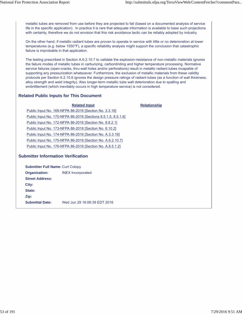
metallic tubes are removed from use before they are projected to fail (based on a documented analysis of service life in the specific application). In practice it is rare that adequate information is available to base such projections with certainty, therefore we do not envision that this risk avoidance tactic can be reliably adopted by industry.
On the other hand, if metallic radiant tubes are proven to operate in service with little or no deterioration at lower temperatures (e.g. below 1550°F), a specific reliability analysis might support the conclusion that catastrophic failure is improbable in that application.
The testing prescribed in Section A.6.2.10.7 to validate the explosion-resistance of non-metallic materials ignores the failure modes of metallic tubes in carburizing, carbonitriding and higher temperature processing. Normative service failures (open-cracks, thru-wall holes and/or perforations) result in metallic radiant tubes incapable of supporting any pressurization whatsoever. Furthermore, the exclusion of metallic materials from these validity protocols per Section 6.2.10.6 ignores the design pressure ratings of radiant tubes (as a function of wall thickness, alloy strength and weld integrity). Also longer-term metallic tube wall deterioration due to spalling and embrittlement (which inevitably occurs in high temperature service) is not considered.
Related Public Inputs for This Document
Related Input Relationship
Public Input No. 169-NFPA 86-2016 [Section No. 3.3.16]
Public Input No. 170-NFPA 86-2016 [Sections 8.5.1.5, 8.5.1.6]
Public Input No. 172-NFPA 86-2016 [Section No. 8.8.2.1]
Public Input No. 173-NFPA 86-2016 [Section No. 8.10.2]
Public Input No. 174-NFPA 86-2016 [Section No. A.3.3.16]
Public Input No. 175-NFPA 86-2016 [Section No. A.6.2.10.7]
Public Input No. 176-NFPA 86-2016 [Section No. A.8.5.1.2]
Submitter Information Verification
Submitter Full Name: Curt Colopy
Organization: INEX Incorporated
Street Address:
City:
State:
Zip:
Submittal Date: Wed Jun 29 16:06:39 EDT 2016
National Fire Protection Association Report http://submittals.nfpa.org/TerraViewWeb/ContentFetcher?commentPara...
53 of 191 7/29/2016 9:51 AM
Public Input No. 30-NFPA 86-2016 [ New Section after 6.2.11.2 ]
6.2.11.3 (new)
Handheld igniters shall not use high voltage to generate electric sparks.
Accompanying Annex material:
A.6.2.12.4 Fixed igniters that utilize high voltage to generate electric sparks have been proven safe invast numbers of systems. However, handheld sparking igniters utilizing high voltage transformers (especially homemade igniters not constructed with suitable electrical insulation and safety guards) pose asevere electrocution hazard and should not be used to light gas-fired burners in ovens or furnaces.Sparking igniters that rely on piezoelectric energy to generate a spark are not intended to be precluded bythis prescriptive requirement.
Statement of Problem and Substantiation for Public Input
Fixed igniters that utilize high voltage to generate electric sparks have been proven safe in vast numbers of systems. However, handheld sparking igniters utilizing high voltage transformers (especially homemade igniters not constructed with suitable electrical insulation and safety guards) pose a severe electrocution hazard and should not be used to light gas-fired burners in ovens or furnaces. Sparking igniters that rely on piezoelectric energy to generate a spark are not intended to be precluded by this prescriptive requirement.
Submitter Information Verification
Submitter Full Name: Richard Martin
Organization: Martin Thermal Engineering Inc
Street Address:
City:
State:
Zip:
Submittal Date: Mon May 16 14:17:52 EDT 2016
National Fire Protection Association Report http://submittals.nfpa.org/TerraViewWeb/ContentFetcher?commentPara...
54 of 191 7/29/2016 9:51 AM

Public Input No. 106-NFPA 86-2016 [ Section No. 6.2.11.3 ]
6.2.11.3
Pilot burners shall be considered burners, and all provisions of Section 6.2 shall apply.
Add Annex
Nothing in this standard prohibits having the pilot and main burner use the same equipment regulator.
Statement of Problem and Substantiation for Public Input
Having one regulator control the pressure to the pilot fuel gas train and main burner fuel gas train is not a safety issue. having the annex clarify this would be helpful since the drawing shows the pilot take off upstream of the main gas pressure regulator.
Submitter Information Verification
Submitter Full Name: Kevin Carlisle
Organization: Karl Dungs Inc
Street Address:
City:
State:
Zip:
Submittal Date: Fri Jun 10 14:36:35 EDT 2016
National Fire Protection Association Report http://submittals.nfpa.org/TerraViewWeb/ContentFetcher?commentPara...
55 of 191 7/29/2016 9:51 AM
Public Input No. 140-NFPA 86-2016 [ New Section after 7.4.4 ]
7.4.4.1* Where an impulse pipe is used to connect a safety device the impulse pipe shall beinspected for leaks or blockages at least annually.
Statement of Problem and Substantiation for Public Input
Changes the suggestion to inspect the impulse line found in current annex material to a requirement to test the functionality of the impulse line. The proposed change also establishes a time frequency that is consistent with the current frequency required for the safety device it is connected to.
Related Public Inputs for This Document
Related Input Relationship
Public Input No. 141-NFPA 86-2016 [New Section after A.7.3.8]
Public Input No. 142-NFPA 86-2016 [New Section after 3.3.35]
Submitter Information Verification
Submitter Full Name: Geoffrey Raifsnider
Organization: Global Finishing Solutions
Street Address:
City:
State:
Zip:
Submittal Date: Tue Jun 28 08:13:06 EDT 2016
National Fire Protection Association Report http://submittals.nfpa.org/TerraViewWeb/ContentFetcher?commentPara...
56 of 191 7/29/2016 9:51 AM

Public Input No. 166-NFPA 86-2016 [ New Section after 7.4.4 ]
TITLE OF NEW CONTENT
7.4.4.1* Where an impulse pipe is used to connect a safety device the impulse pipe shall be inspected forleaks or blockages at least annually.
Statement of Problem and Substantiation for Public Input
Changes the suggestion to inspect the impulse line to a requirement to test the functionality of the impulse line and establishes a time frequency that is consistent with the current frequency required for the safety device it is connected to.
Submitter Information Verification
Submitter Full Name: Ted Jablkowski
Organization: Fives North American Combustion
Affilliation: Submitted on behalf of the NFPA 86 Intro Chapters Task Group
Street Address:
City:
State:
Zip:
Submittal Date: Tue Jun 28 15:07:57 EDT 2016
National Fire Protection Association Report http://submittals.nfpa.org/TerraViewWeb/ContentFetcher?commentPara...
57 of 191 7/29/2016 9:51 AM

Public Input No. 36-NFPA 86-2016 [ New Section after 7.4.9 ]
7.4.10 * The setpoint of pressure relief valve, where installed, shall be verified at least annually.Add annex
A.7.4.10 It’s not practical to test in the field the full relieving capacity of a relief valve in combination of itsvent line. Recommended checks in the field could include
(1) Verify it's in good mechanical condition;
(2) Verify the sizing for the service in which it is employed;
(3) Verify it has been p roperly installed and protected from dirt, liquids, or other conditions that mightprevent proper operation;
(4) That the point of termination of the vent line is goose-necked and is not clogged (check screen).
Statement of Problem and Substantiation for Public Input
Recommend NPFA 86 have some guidance on how relief valves can be inspected in the field since there provide a layer of safety to the gas train.
Submitter Information Verification
Submitter Full Name: Kevin Carlisle
Organization: Industrial Heating Equipment Association
Affilliation: Industrial Heating Equipment Association
Street Address:
City:
State:
Zip:
Submittal Date: Fri Jun 03 11:39:07 EDT 2016
National Fire Protection Association Report http://submittals.nfpa.org/TerraViewWeb/ContentFetcher?commentPara...
58 of 191 7/29/2016 9:51 AM

Public Input No. 70-NFPA 86-2016 [ Section No. 7.4.9 ]
7.4.9*
Valve seat leakage testing of safety shutoff valves, vent valves, and valve proving systems shall beperformed in accordance with the manufacturer's instructions.
7.4.9.1
Testing frequency shall be at least annually.
7.4.9.2
The installation of a valve proving system or a valve with proof of closure shall not replace the requirementfor seat leakage testing in 7.4.9.1.
Statement of Problem and Substantiation for Public Input
vent valves need to be tested, too.
Submitter Information Verification
Submitter Full Name: Kevin Carlisle
Organization: Industrial Heating Equipment Association
Affilliation: Industrial Heating Equipment Association
Street Address:
City:
State:
Zip:
Submittal Date: Thu Jun 09 09:42:56 EDT 2016
National Fire Protection Association Report http://submittals.nfpa.org/TerraViewWeb/ContentFetcher?commentPara...
59 of 191 7/29/2016 9:51 AM
Public Input No. 22-NFPA 86-2016 [ Section No. 7.4.10 ]
7.4.10 Replacement of Safety Shutoff Valve Replacement for open-close cycling applications .
7.4.10.1
Safety shutoff valves that are used to comply with 8. 5 8 .1. 8 (4) 6 and are not proved closed shall bereplaced before they exceed their maximum allowable number of lifetime open–closed cycles.
7.4.10.2 *
The number of safety shutoff valve cycles shall be determined by one of the following ways:
(1) Counting of actual safety shutoff valve open-closed close cycles
(2) Estimated time to reach 90 percent of lifetime total cycles based on normal cycling rates
Statement of Problem and Substantiation for Public Input
The requirements in 7.4.10.1 were not clear in terms of referring to 8.5.1.8 (4). See related PI for 8.8.1.6.
Related Public Inputs for This Document
Related Input Relationship
Public Input No. 20-NFPA 86-2016 [Section No. 8.8.1.6]
Submitter Information Verification
Submitter Full Name: Ted Jablkowski
Organization: Fives North American Combustion
Affilliation: submitted on behalf of the NFPA 86 Intro Chapters Task Group
Street Address:
City:
State:
Zip:
Submittal Date: Sun May 01 18:38:23 EDT 2016
National Fire Protection Association Report http://submittals.nfpa.org/TerraViewWeb/ContentFetcher?commentPara...
60 of 191 7/29/2016 9:51 AM

Public Input No. 88-NFPA 86-2016 [ Section No. 7.4.10 ]
7.4.10 Safety Shutoff Valve Replacement.
7.4.10.1
Safety shutoff valves that are used to comply with 8.5.1.8 (4) and are not proved closed shall be replacedbefore they exceed their maximum allowable number of lifetime open–closed cycles.
7.4.10.2*
The number of safety shutoff valve cycles shall be determined by one of the following ways:
(1) Counting of actual safety shutoff valve open-closed cycles
(2) Estimated time to reach 90 percent of lifetime total cycles based on normal cycling rates
7.4.10.3* When seat leakage of a safety shutoff valve or isolation is excessive, it shall be replaced.
Statement of Problem and Substantiation for Public Input
To provide guidance on what action needs to be done if the valve leaks too much
Submitter Information Verification
Submitter Full Name: Kevin Carlisle
Organization: Karl Dungs Inc
Street Address:
City:
State:
Zip:
Submittal Date: Thu Jun 09 16:46:51 EDT 2016
National Fire Protection Association Report http://submittals.nfpa.org/TerraViewWeb/ContentFetcher?commentPara...
61 of 191 7/29/2016 9:51 AM

Public Input No. 107-NFPA 86-2016 [ Section No. 7.4.10.1 ]
7.4.10.1
Safety shutoff valves that are used to comply with 8.5 8 .1.8 (4) 6 and are not proved closed shall bereplaced before they exceed their maximum allowable number of lifetime open–closed cycles.
Statement of Problem and Substantiation for Public Input
This PI is related to that for 8.8.1.6.
Submitter Information Verification
Submitter Full Name: Ted Jablkowski
Organization: Fives North American Combustion
Affilliation: Submitted on behalf of the NFPA 86 Intro Chapters Task Group
Street Address:
City:
State:
Zip:
Submittal Date: Fri Jun 10 15:07:45 EDT 2016
National Fire Protection Association Report http://submittals.nfpa.org/TerraViewWeb/ContentFetcher?commentPara...
62 of 191 7/29/2016 9:51 AM

Public Input No. 164-NFPA 86-2016 [ Section No. 7.4.10.1 ]
7.4.10.1
Safety shutoff valves that are used to comply with 8.5.1.8 (4) and are not proved closed shall be replacedbefore they exceed their maximum allowable number of lifetime open–closed cycles.When acceptable tothe manufacturer, when a VPS completes a valve proving sequence on two SSOV’s in series over a periodof two burner on-off cycles, such safety shutoff valves shall be replaced when the VPS detects a valvefault.
Statement of Problem and Substantiation for Public Input
Due do the fast cycling demand on a high cycle application, the VPS sequence can be performed on one of the SSOV’s before the next burner start. The burner is then permitted to cycle on, then off. And then thereafter the VPS performs a VPS sequence on the other SSOV. The level of functional testing due to the VPS in combination with 2 SSOV’s in series provides enough safety to permit valves to remain in service until an actual fault is detected.
Submitter Information Verification
Submitter Full Name: Kevin Carlisle
Organization: Karl Dungs Inc
Street Address:
City:
State:
Zip:
Submittal Date: Tue Jun 28 15:02:50 EDT 2016
National Fire Protection Association Report http://submittals.nfpa.org/TerraViewWeb/ContentFetcher?commentPara...
63 of 191 7/29/2016 9:51 AM

Public Input No. 43-NFPA 86-2016 [ Section No. 8.2.6 ]
8.2.6
Safety devices shall be installed, used, and maintained in accordance with the manufacturer's instructions.
Statement of Problem and Substantiation for Public Input
8.2.6 is redundant as these requirements are already in 8.2.3 and 7.4.1.
Submitter Information Verification
Submitter Full Name: Kevin Carlisle
Organization: Karl Dungs Inc
Street Address:
City:
State:
Zip:
Submittal Date: Fri Jun 03 14:16:32 EDT 2016
National Fire Protection Association Report http://submittals.nfpa.org/TerraViewWeb/ContentFetcher?commentPara...
64 of 191 7/29/2016 9:51 AM
Public Input No. 101-NFPA 86-2016 [ New Section after 8.2.9 ]
TITLE OF NEW CONTENT
8.2.9.1* If the mushroom-type emergency fuel stop is wired to the inputs of a safety PLC per 8.4 then theemergency fuel stop shall use redundant contacts to redundant safety inputs per the manufacturer’s safetymanual for implementing an emergency stop to SIL 3/PL e.
8.2.9.2* Ancillary furnace functions not related to fuel e.g., pumps, blowers, atmospheric gas controller,hydraulics, motion, quench tank controls shall be evaluated using the appropriate standards for theirinherent hazard and the appropriate action shall be taken to mitigate that hazard when the emergency fuelstop is activated.
Statement of Problem and Substantiation for Public Input
Complementary to PI for 8.2.9. Some furnaces include complex control of motion, hydraulics, and special atmospheres that can’t be immediately depowered without creating additional hazards when the fuel stop button is depressed.
Submitter Information Verification
Submitter Full Name: Ted Jablkowski
Organization: Fives North American Combustion
Affilliation: Submitted on behalf of the NFPA 86 Intro Chapters Task Group
Street Address:
City:
State:
Zip:
Submittal Date: Fri Jun 10 13:42:24 EDT 2016
National Fire Protection Association Report http://submittals.nfpa.org/TerraViewWeb/ContentFetcher?commentPara...
65 of 191 7/29/2016 9:51 AM
Public Input No. 100-NFPA 86-2016 [ Section No. 8.2.9 ]
8.2.9*
At least one manual emergency switch shall be provided to initiate a safety shutdown fuel stop .
Statement of Problem and Substantiation for Public Input
Some furnaces include complex control of motion, hydraulics, and special atmospheres that can’t be immediately depowered without creating additional hazards when the fuel stop button is depressed.
Submitter Information Verification
Submitter Full Name: Ted Jablkowski
Organization: Fives North American Combustion
Affilliation: Submitted on behalf of the NFPA 86 Intro Chapters Task Group
Street Address:
City:
State:
Zip:
Submittal Date: Fri Jun 10 13:40:22 EDT 2016
National Fire Protection Association Report http://submittals.nfpa.org/TerraViewWeb/ContentFetcher?commentPara...
66 of 191 7/29/2016 9:51 AM

Public Input No. 99-NFPA 86-2016 [ New Section after 8.3.1.4 ]
TITLE OF NEW CONTENT
8.3.2* Each safety interlock shall be wired so that a single fault occurring outside of the controlenclosure (short, open wire condition, etc.) cannot interfere with or disable more than one safetyinterlock.
Statement of Problem and Substantiation for Public Input
Safety circuit wiring should minimize the risk of fault accumulation or common mode failures.
Submitter Information Verification
Submitter Full Name: Ted Jablkowski
Organization: Fives North American Combustion
Affilliation: Submitted on behalf of the NFPA 86 Intro Chapters Task Group
Street Address:
City:
State:
Zip:
Submittal Date: Fri Jun 10 13:37:01 EDT 2016
National Fire Protection Association Report http://submittals.nfpa.org/TerraViewWeb/ContentFetcher?commentPara...
67 of 191 7/29/2016 9:51 AM
Public Input No. 61-NFPA 86-2016 [ Section No. 8.4.2 ]
8.4.2*
Where PLCs are used for combustion safety service (e.g used as a combustion safeguard) and are notlisted for combustion safety service or as combustion safeguard, the PLC and its associated input andoutput (I/O) used to perform safety functions shall be as follows:
(1) Third-party certified to IEC 61508, Functional Safety of Electrical/Electronic/Programmable ElectronicSafety-Related Systems, safety integrity level (SIL) 2 or greater
(2) Applied to achieve at least an SIL 2 capability per the manufacturer's safety manual
8.4. x Where PLCs are used for safety functions to handle the atmosphere within the oven (e.g. safetyventilation, purge-in/purge-out, etc), the PLC and its associated input and output (I/O) used to performsafety functions shall be as follows:
(1) Comply with IEC 61508, Functional Safety of Electrical/Electronic/Programmable Electronic Safety-Related Systems , safety integrity level (SIL) 1 or greater, and
( 2 ) Applied to achieve at least an SIL 1 capability per the manufacturer’s safety manual
(3) The configuration of the program logic uploaded by the designer is according to IEC 61508 for SIL 1or greater
8 .4.2. 1 Software.
(A)
Access to the PLC and its logic shall be restricted to authorized personnel.
(B)
Software shall be documented as follows:
(1) Labeled to identify elements or a group of elements containing safety software
(2) Labeled to describe the function of each element containing safety software
(C)
A listing of the program with documentation shall be available.
Statement of Problem and Substantiation for Public Input
It’s not clear when 8.4.2 applies to PLC’s (e.g. see 13.5.11.11.1 (3) ), which are used for safety functions that have nothing to do with the combustion process. E.g. purge in and purge out. The whole section of 8.4 speaks to the combustion process.
Submitter Information Verification
Submitter Full Name: Kevin Carlisle
Organization: Industrial Heating Equipment Association
Affilliation: Industrial Heating Equipment Association
Street Address:
City:
State:
Zip:
Submittal Date: Fri Jun 03 15:19:28 EDT 2016
National Fire Protection Association Report http://submittals.nfpa.org/TerraViewWeb/ContentFetcher?commentPara...
68 of 191 7/29/2016 9:51 AM

Public Input No. 168-NFPA 86-2016 [ Section No. 8.4.2 [Excluding any Sub-Sections] ]
Where PLCs are not listed for combustion safety service or as combustion safeguard, the PLC and itsassociated input and output (I/O) used to perform safety functions shall be as follows:
(1) Third-party certified to IEC 61508, Functional Safety of Electrical/Electronic/Programmable ElectronicSafety-Related Systems, safety integrity level (SIL) 2 or greater
(2) Applied to achieve at least an SIL 2 capability per the manufacturer's safety manual.
(3) The program logic is third-party certified according to IEC 61508-3 and 61508-1 for SIL 2 or greater. A ny trip of an interlock (e.g. flame detector, air or gas switch, valve switch, e xcess temperature limitinterlock, 1400°F (760°C) bypass interlock, etc) shall lead to safety shutdown of the burner.
Add the following Annex
The PLC should provide the following operations, in proper sequence, the start-up and shut-downof the burner using at least the following timings, responses, and features:
a) Pilot or main burner flame establishing period or both.
b) Safety shutdown within the flame-failure response time in the event of flame failure.
c) Lockout feature such that a restart can be accomplished only by a manual reset at the control.
Considerations in regards to the potential drift of safety related timings should be made when thePLC is subject to 85% of rated voltage for AC or 80% of rated voltage for DC voltage incombination with the lowest and highest rated ambient temperature.
ANSI Z21.20-2014_CAN_CSA-C22.2 No. 60730-2-5, the standard to which flame safeguard arelisted, has specific requirements for timings, sequencing, and actions upon first and second faults. There are details regarding required actions upon first and second faults for systems with andwithout self-checking feature. These actions are also defined in IEC 60730-1. See H27.1.3.102 forsystems without self-checking and H27.1.3.103 for systems with self-checking feature. Theseactions upon first and second faults should be mimicked in the PLC.
Statement of Problem and Substantiation for Public Input
The level of safety of a PLC when used as an alternative to a listed and labeled flame safeguard should be equivalent, and this also includes the software.
Submitter Information Verification
Submitter Full Name: Kevin Carlisle
Organization: Karl Dungs Inc
Street Address:
City:
State:
Zip:
Submittal Date: Tue Jun 28 15:34:56 EDT 2016
National Fire Protection Association Report http://submittals.nfpa.org/TerraViewWeb/ContentFetcher?commentPara...
69 of 191 7/29/2016 9:51 AM

Public Input No. 38-NFPA 86-2016 [ Section No. 8.4.2 [Excluding any Sub-Sections] ]
Where PLCs are not listed for combustion safety service or as combustion safeguard, the PLC and itsassociated input and output (I/O) used to perform safety functions shall be as follows:
(1) Third-party certified to IEC 61508, Functional Safety of Electrical/Electronic/Programmable ElectronicSafety-Related Systems, safety integrity level (SIL) 2 3 or greater
(2) Applied to achieve at least an SIL 2 3 capability per the manufacturer's safety manual
(3) The configuration of the program logic uploaded by the designer is according to IEC 61508 for SIL 3or greater
Statement of Problem and Substantiation for Public Input
In the 2015 edition SIL 2 was selected as the minimum level because it was not know at that time what the SIL level was for existing flame safeguards. Since then, flame safeguard manufactures have determined that the level of safety in listed flame safeguards is SIL 3. Thus, the 2018 edition should bring the SIL level to the equivalent level that listed flame safeguards have.
Here are some differences between SIL2 vs SIL 3 requirements.SIL 3 has two microprocessor. SIL 2 has 1 processor.SIL 3, developer needs continued education, SIL 2, only recommended. In SIL 3, every line of the software code needs some kind of review. E.g. 2 people, or 1 writing and other reviewing. Also, you can do branch checking, which is in SIL 2, too, but with SIL 3, all possible values need to be considered, not just a few random ones or some % of all possible numbers. If possible values are 1-100, SIL 3 has to check all values. SIL 2 needs only to check for example, 1, 5, 8, 99 and, 86.SIL 3 has 1oo2 and 2oo3. SIL 2 only has one processer, so there is no option for this. For SIL, the application matters. For example SIL 3 needed for a school to protect life, SIL 2 needed to protect the building, SIL 1 needed if explosion occurs, and relief door opens, and no one is ever by relief door. But NPFA 86 does not differentiate the application.
Submitter Information Verification
Submitter Full Name: Kevin Carlisle
Organization: Industrial Heating Equipment Association
Affilliation: Industrial Heating Equipment Association
Street Address:
City:
State:
Zip:
Submittal Date: Fri Jun 03 12:18:39 EDT 2016
National Fire Protection Association Report http://submittals.nfpa.org/TerraViewWeb/ContentFetcher?commentPara...
70 of 191 7/29/2016 9:51 AM
Public Input No. 62-NFPA 86-2016 [ Section No. 8.4.4(B) ]
(B)
Safety PLCs shall notimplement replace the function of the following devices :
(1) Manual emergency switches
(2) Continuous vapor concentration high-limit controllers
Statement of Problem and Substantiation for Public Input
What is meaning of implement? Does it mean that the PLC cannot implement the logic or cannot it not implement the switch. Can I integrate into the PLC the push button E-Stop. Can PLC do the logic? The 2010 edition said PLC cannot implement logic and devices. Proposal attempt to make this more clear
Submitter Information Verification
Submitter Full Name: Kevin Carlisle
Organization: Industrial Heating Equipment Association
Affilliation: Industrial Heating Equipment Association
Street Address:
City:
State:
Zip:
Submittal Date: Fri Jun 03 15:21:26 EDT 2016
National Fire Protection Association Report http://submittals.nfpa.org/TerraViewWeb/ContentFetcher?commentPara...
71 of 191 7/29/2016 9:51 AM

Public Input No. 138-NFPA 86-2016 [ Section No. 8.5.1 ]
8.5.1 Pre-ignition (Prepurge, Purging Cycle).
8.5.1.1*
Prior to each furnace heating system startup, provision shall be made for the removal of all flammablevapors and gases that have entered the heating chambers during the shutdown period.
8.5.1.2*
A timed pre-ignition purge shall be provided.
(A)
At least foursystem volumes of fresh air or inert gas shall be introduced during the purging cycle.
(B)
The system volume shall include the heating chambers and all other passages that handle the recirculationand exhaust of products of combustion.
(C)
To begin the timed pre-ignition purge interval, all of the following conditions shall be satisfied:
(1)
(2)
(3) At least one safety shutoff valve is proved closed between all main burners and the fuel supply forovens with total capacity over 400,000 Btu/hr
(D)
The minimum required pre-ignition airflow shall be proved and maintained throughout the timed pre-ignitionpurge interval.
(E)
Failure to maintain the minimum required pre-ignition purge airflow shall stop the pre-ignition purge andreset the purge timer.
8.5.1.3
Pre-ignition purge shall be completed in 60 minutes or less unless otherwise permitted in 8.5.1.4
8.5.1.4
Pre-ignition purge shall be permitted to exceed 60 minutes where it is demonstrated flammable vapor andgas concentrations within the volume described in 8.5.1.2(B) will not exceed 25% of LFL.
8.5.1.5
Once pre-ignition purge is complete and the preignition airflow rate is no longer proven, burners shall beignited and proven in 30 minutes or less unless otherwise permitted in 8.5.1.6.
8.5.1.6
Once pre-ignition purge is complete and the preignition airflow rate is no longer proven, it shall bepermitted for burners to be ignited and proven in more than 30 minutes where it is demonstratedflammable vapor and gas concentrations within the volume described in 8.5.1.2(B) will not exceed 25% ofLFL.
8.5.1.3 [renumber 8.5.1.7]
A furnace heating system, either alone or as part of multiple furnaces feeding into one fume incinerator,shall not be purged into an operating incinerator unless otherwise permitted by 8.5.1.4.
* The minimum required pre-ignition airflow is proved.
* At least one safety shutoff valve is proved closed between all pilot burners and the fuel supply forovens with total pilot capacity over 400,000 Btu/hr.
National Fire Protection Association Report http://submittals.nfpa.org/TerraViewWeb/ContentFetcher?commentPara...
72 of 191 7/29/2016 9:51 AM

8.5.1.4 [renumber 8.5.1.8]
A furnace heating system shall be permitted to be purged into an operating incinerator if it can bedemonstrated that the flammable vapor concentration entering the fume incinerator cannot exceed50 percent of the LFL.
8.5.1.5 [renumber 8.5.1.9]
Pre-ignition purging of radiant tube–type heating systems shall be provided, unless otherwise permitted by8.5.1.6.
8.5.1.6 [renumber 8.5.1.10]
Pre-ignition purging of radiant tube–type heating systems shall not be required where the systems arearranged and designed such that either of the following conditions is satisfied:
(1) The tubes are of metal construction and open at one or both ends. If heat recovery systems are used,they shall be of explosion-resistant construction.
(2) The entire radiant tube heating system, including any associated heat recovery system, is ofexplosion-resistant construction.
8.5.1.7 [renumber 8.5.1.11]
Prior to the re-ignition of a burner after a burner shutdown or flame failure, a pre-ignition purge shall beaccomplished.
CAUTION: Repeated ignition attempts can result in a combustible concentration greater than 25 percent ofthe LFL. Liquid fuels can accumulate, causing additional fire hazards.
8.5.1.8* [renumber 8.5.1.12*]
Repeating the pre-ignition purge shall not be required where any one of the following conditions is satisfied:
(1) The heating chamber temperature is proved to be above 1400°F (760°C).
(2) For a multiburner fuel-fired system not proved to be above 1400°F (760°C), all of the followingconditions are satisfied:
(3)
(4) The burner(s) remaining in operation shall provide ignition without explosion of any unintendedrelease of fuel through other burners that are not in operation.
(5)
(6) All of the following conditions are satisfied (does not apply to fuel oil systems):
(7) The number of safety shutoff valves required to close in 8.8.1.3 and 8.8.2.1 will closebetween the burner system and the fuel gas supply when that burner system is off.
(8) Safety shutoff valve seat leak testing is performed on at least a semiannual basis.
(9) The burner system uses natural gas, butane, or propane fuel gas.
(10)
(11) The minimum airflow used in the LFL calculation in 8.5.1.8 (4)(d) is proved and maintainedduring the period the burner(s) are off.
Statement of Problem and Substantiation for Public Input
To establish requirements for duration of the pre-ignition purge interval and requirements for the time between
* At least one burner remains operating in the common combustion chamber of the burner tobe re-ignited.
* For fuel gas–fired burner systems and assuming that all safety shutoff valves fail in the full openposition, it can be demonstrated that the combustible concentration in the heating chamber and allother passages that handle the recirculation and exhaust of products of combustion cannot exceed25 percent of the LFL.
* It can be demonstrated based on the leakage rate, that the combustible concentration in theheating chamber and all other passages that handle the recirculation and exhaust of products ofcombustion cannot exceed 25 percent of the LFL.
National Fire Protection Association Report http://submittals.nfpa.org/TerraViewWeb/ContentFetcher?commentPara...
73 of 191 7/29/2016 9:51 AM

completion of the pre-ignition purge interval and the ignition of burners.
Submitter Information Verification
Submitter Full Name: Richard Gallagher
Organization: Zurich Services Corporation
Street Address:
City:
State:
Zip:
Submittal Date: Fri Jun 24 10:47:38 EDT 2016
National Fire Protection Association Report http://submittals.nfpa.org/TerraViewWeb/ContentFetcher?commentPara...
74 of 191 7/29/2016 9:51 AM
Public Input No. 34-NFPA 86-2016 [ New Section after 8.5.1.2 ]
< no title required >
Add New Paragraph after 8.5.1.2:
8.5.1.3* For gas-fired heating systems equipped with Flue Gas Recirculation (FGR) for pollution control,an analysis shall be performed to evaluate the necessity for additional purge duration (beyond thatcomputed in 8.5.1.2A) to ensure that a “fail-open” condition of the FGR damper does not lead to anaccumulation of fuel gas in the explosive range inside the combustion chamber.
8.5.1.3.1 Incorporation of Proof-of-Closure on the FGR damper and into the purge safety logic shall bepermitted in lieu of the requirement in 8.5.1.3.
Add New Annex material for new 8.5.1.3:
A.8.5.1.3 When a burner is equipped with FGR, the safety control logic normally attempts to drive the FGRdamper closed before initiation of the pre-purge timer. However, FGR dampers are rarely equipped withProof-of-Closure switches, and the possibility exists that the FGR damper could fail to close when instructedto do so. Such a situation would allow the re-introduction of unburned fuel (left over from a prior ignition trial)back into the combustion chamber. This consequence of this situation is that the “purge gas” (which isnominally understood to be fresh air) that is introduced prior to a second or third igntion attempt, is in factan “indeterminate gas mixture” that may be in the explosive range. The requirement at 8.5.1.3 is intended toensure that this hazard is addressed when the purge timing is established by the manufacturer,installer/commissioner, or user. The analysis may be conducted experimentally, with a tracer gas (preferablynon-flammable) being introduced to simulate fuel gas and a gas analyzer to determine the purge durationthat will effectively dilute the purge mixture to 25% of LFL or lower. The analysis may also be performed viaa Computational Fluid Dynamics (CFD) model. If neither is possible, the analysis should be performed usinga "Perfectly Stirred Reactor" conceptual model for the combustion chamber, which is more conservative thana "Plug Flow Model".
Statement of Problem and Substantiation for Public Input
Failure of an FGR damper to close prior to the commencement of the pre-ignition purge cycle could introduce an indeterminate gas (quite possibly a flammable mixture of fuel gas and air) into the combustion chamber instead of fresh air. Any system that is equipped with FGR for pollution control should be analyzed to account for the possibility of the FGR damper's failure to close and to account for that possibility through extending the purge time to ensure that the worst case scenario will not create an explosive mixture in the combustion chamber on a subject ignition trial. Extending the purge time should not be required if the FGR damper can be proved closed and interlocked with the commencement of the purge cycle.
Submitter Information Verification
Submitter Full Name: Richard Martin
Organization: Martin Thermal Engineering Inc
Street Address:
City:
State:
Zip:
Submittal Date: Thu Jun 02 10:53:40 EDT 2016
National Fire Protection Association Report http://submittals.nfpa.org/TerraViewWeb/ContentFetcher?commentPara...
75 of 191 7/29/2016 9:51 AM
Public Input No. 153-NFPA 86-2016 [ New Section after 8.5.1.2(E) ]
TITLE OF NEW CONTENT
8.5.1.2*
(F) Air pressure switches shall not be used to prove airflow where valves downstream of the pressureswitch can be closed to the point of reducing airflow below the minimum required.
Statement of Problem and Substantiation for Public Input
PI provides another method of implementing an air flow interlock which is based on the burner system's defined pressure drop versus air flow.
Submitter Information Verification
Submitter Full Name: Ted Jablkowski
Organization: Fives North American Combustion
Affilliation: Submitted on behalf of the NFPA 86 Intro Chapters Task Group
Street Address:
City:
State:
Zip:
Submittal Date: Tue Jun 28 14:28:34 EDT 2016
National Fire Protection Association Report http://submittals.nfpa.org/TerraViewWeb/ContentFetcher?commentPara...
76 of 191 7/29/2016 9:51 AM
Public Input No. 170-NFPA 86-2016 [ Sections 8.5.1.5, 8.5.1.6 ]
Sections 8.5.1.5, 8.5.1.6
8.5.1.5
Pre-ignition purging of radiant tube–type heating systems shall be provided, unless otherwise permitted by8.5.1.6 . ELIMINATE THIS SECTION
8.5.1.6
Pre-ignition purging of radiant tube–type heating systems shall not be required where the systems arearranged and designed such that either of the following conditions is satisfied: The tubes are of metalconstruction and open at one or both ends . If heat recovery systems are used, they shall be of explosion-resistant construction.
The entire radiant tube heating system, including any associated heat recovery system, is of explosion-resistant construction.
Statement of Problem and Substantiation for Public Input
The current NFPA 86-2015 Standard for Ovens and Furnaces implies that metallic radiant tubes are safer than other high temperature materials of construction such as ceramics and composites. Alternative non-metallic materials currently in industrial radiant tube service include mullites, sialons, silicon nitrides, siliconized silicon carbides and silicon / silicon carbide composites.
The standard excludes and/or favorably treats metallic radiant tubes in terms of relaxed requirements for:• Pre-ignition Purging Sections 8.5.1.2, A.8.5.1.2, 8.5.1.5 & 8.5.1.6• Safety Shut-Off Valves Section 8.8.2.1• Flame Supervision Section 8.10.2
This special treatment for metallic radiant tubes ignores several decades of industry experience where deflagration / explosion has not proved to be a significant risk factor for non-metallic materials, or at minimum the incident losses are no different than metallic tubes used in equivalent service.
In actual operation most metallic radiant tubes used in carburizing, carbonitriding and higher temperature processing periodically experience open-crack, thru-wall hole and/or perforation failures due to material creep distortion, carburization corrosion/embrittlement and/or weld stress fracture. Any risks posed by “open” metallic tube failures are no different than those of non-metallic tubes, regardless of whether combustible gases flow into the furnace chamber or, vice versa, into the radiant tube.
For the processes cited above metallic failures generally occur every three to five years (sometimes sooner) mandating radiant tube replacement to maintain the integrity of the process atmosphere and quality of production. While ceramic and composite tubes available to the industrial furnace users do not experience the progressive failure modes of metallic tubes, they are more susceptible to mechanical impact and less tolerable of thermo-mechanical stress. Failure of non-metallic radiant tubes has the same effect on the furnace atmosphere and production quality, also mandating their replacement.
When radiant metallic tube applications are optimally designed (so that the surface temperatures are uniform and not excessive for the specific alloy employed), they are just as likely, if not more likely, to fail catastrophically compared with ceramic and composite tubes under the same service conditions in carburizing, carbonitriding and higher temperature atmospheres.
Furthermore, consideration of radiant tube durability should not be based on new material properties, but rather on radiant tubes that are at or near the end of their useful service lives. It is at this point that a tube failure-related incident is most likely to occur.
To be logically consistent both metallic and non-metallic radiant tubes used at elevated temperatures (e.g. above
National Fire Protection Association Report http://submittals.nfpa.org/TerraViewWeb/ContentFetcher?commentPara...
77 of 191 7/29/2016 9:51 AM

1550°F) must be treated the same. For example, if flame supervision is required for non-metallic radiant tubes, then it should be required for metallic radiant tubes as well. An alternative approach might be to require that metallic tubes are removed from use before they are projected to fail (based on a documented analysis of service life in the specific application). In practice it is rare that adequate information is available to base such projections with certainty, therefore we do not envision that this risk avoidance tactic can be reliably adopted by industry.
On the other hand, if metallic radiant tubes are proven to operate in service with little or no deterioration at lower temperatures (e.g. below 1550°F), a specific reliability analysis might support the conclusion that catastrophic failure is improbable in that application.
The testing prescribed in Section A.6.2.10.7 to validate the explosion-resistance of non-metallic materials ignores the failure modes of metallic tubes in carburizing, carbonitriding and higher temperature processing. Normative service failures (open-cracks, thru-wall holes and/or perforations) result in metallic radiant tubes incapable of supporting any pressurization whatsoever. Furthermore, the exclusion of metallic materials from these validity protocols per Section 6.2.10.6 ignores the design pressure ratings of radiant tubes (as a function of wall thickness, alloy strength and weld integrity). Also longer-term metallic tube wall deterioration due to spalling and embrittlement (which inevitably occurs in high temperature service) is not considered.
Related Public Inputs for This Document
Related Input Relationship
Public Input No. 172-NFPA 86-2016 [Section No. 8.8.2.1]
Public Input No. 173-NFPA 86-2016 [Section No. 8.10.2]
Public Input No. 174-NFPA 86-2016 [Section No. A.3.3.16]
Public Input No. 175-NFPA 86-2016 [Section No. A.6.2.10.7]
Public Input No. 176-NFPA 86-2016 [Section No. A.8.5.1.2]
Public Input No. 169-NFPA 86-2016 [Section No. 3.3.16]
Public Input No. 171-NFPA 86-2016 [Sections 6.2.10.6, 6.2.10.7]
Submitter Information Verification
Submitter Full Name: Curt Colopy
Organization: INEX Incorporated
Street Address:
City:
State:
Zip:
Submittal Date: Wed Jun 29 15:59:49 EDT 2016
National Fire Protection Association Report http://submittals.nfpa.org/TerraViewWeb/ContentFetcher?commentPara...
78 of 191 7/29/2016 9:51 AM

Public Input No. 93-NFPA 86-2016 [ Section No. 8.5.1.8 ]
8.5.1.8*
Repeating the pre-ignition purge shall not be required where any one of the following conditions is satisfied:
(1) The heating chamber temperature is proved to be above 1400°F (760°C).
(2) For a multiburner fuel-fired system not proved to be above 1400°F (760°C), all of the followingconditions are satisfied:
(3)
(4) The burner(s) remaining in operation shall provide ignition without explosion of any unintendedrelease of fuel through other burners that are not in operation.
(5)
(6) All of the following conditions are satisfied (does not apply to fuel oil systems):
(7) The number of safety shutoff valves required to close in 8.8.1.3 and 8.8.2.1 will closebetween the burner system and the fuel gas supply when that burner system is off.
(8) Safety shutoff valve seat leak testing is performed on at least a semiannual basis.
(a) The burner system uses natural gas, butane, or propane fuel gas.
(b)
(c) The minimum airflow used in the LFL calculation in 8.5.1.8 (4)(d) is proved and maintained duringthe period the burner(s) are off.
(d) If no gas filter is installed on the individual burner, u pstream of the s afety shutoff valve(s), valveseat leak testing is performed on at least a semiannual basis.
Statement of Problem and Substantiation for Public Input
The need to perform semiannual leak testing was due to the concern of debris building up on the valve disc. However, this risk greatly reduced with a gas filter mounted upstream, and therefore, annual leak testing is sufficient.
Submitter Information Verification
Submitter Full Name: Kevin Carlisle
Organization: Karl Dungs Inc
Street Address:
City:
State:
Zip:
Submittal Date: Fri Jun 10 09:43:41 EDT 2016
* At least one burner remains operating in the common combustion chamber of the burner tobe re-ignited.
* For fuel gas–fired burner systems and assuming that all safety shutoff valves fail in the full openposition, it can be demonstrated that the combustible concentration in the heating chamber and allother passages that handle the recirculation and exhaust of products of combustion cannot exceed25 percent of the LFL.
* It can be demonstrated based on the leakage rate, that the combustible concentration in theheating chamber and all other passages that handle the recirculation and exhaust of products ofcombustion cannot exceed 25 percent of the LFL.
National Fire Protection Association Report http://submittals.nfpa.org/TerraViewWeb/ContentFetcher?commentPara...
79 of 191 7/29/2016 9:51 AM

Public Input No. 96-NFPA 86-2016 [ Section No. 8.5.3 ]
8.5.3 Ignition of Main Burners — Fuel Gas or Oil.
Where a reduced specified firing rate is required for ignition of the burner , an interlock or by theequipment, a Proved Ignition Interlock shall be provided to prove that the control valve has moved to thedesign Ignition position prior to each attempt at ignition.
Statement of Problem and Substantiation for Public Input
The defined term 3.3.36.3 Proved Low-Fire Start Interlock is not used in the Standard. This input recommends that the term be changed and used in the mandatory text. Add Annex to identify various means to provide the interlock.
Submitter Information Verification
Submitter Full Name: Ted Jablkowski
Organization: Fives North American Combustion
Affilliation: Submitted on behalf of the NFPA 86 Intro Chapters Task Group
Street Address:
City:
State:
Zip:
Submittal Date: Fri Jun 10 13:23:30 EDT 2016
National Fire Protection Association Report http://submittals.nfpa.org/TerraViewWeb/ContentFetcher?commentPara...
80 of 191 7/29/2016 9:51 AM

Public Input No. 154-NFPA 86-2016 [ Section No. 8.7.4 ]
8.7.4*
Combustion air minimum pressure or flow shall be interlocked into theburner the burner managementsystem . by any of the following methods:
(1) A low pressure switch that senses and monitors the combustion air source pressure
(2) A differential pressure switch that senses the differential pressure across a fixed orifice in thecombustion air system
(3) An airflow switch
Statement of Problem and Substantiation for Public Input
fixed typos.
Submitter Information Verification
Submitter Full Name: Ted Jablkowski
Organization: Fives North American Combustion
Affilliation: Submitted on behalf of the NFPA 86 Intro Chapters Task Group
Street Address:
City:
State:
Zip:
Submittal Date: Tue Jun 28 14:31:03 EDT 2016
National Fire Protection Association Report http://submittals.nfpa.org/TerraViewWeb/ContentFetcher?commentPara...
81 of 191 7/29/2016 9:51 AM

Public Input No. 25-NFPA 86-2016 [ Section No. 8.7.6 ]
8.7.6
In any combustion system where the combustion air supply can be diverted to an alternate flow path otherthan to a burner (e.g., to a regenerative burner system’s exhaust path), that burner’s associatedcombustion air flow path valve(s) shall be proved open, and its alternate air flow airflow path valve(s) shallbe proved closed, before that burner’s fuel safety shutoff valve(s) are energized.
Statement of Problem and Substantiation for Public Input
The use of term “airflow” and “air flow” should be used consistently throughout the Standard.
Related Public Inputs for This Document
Related Input Relationship
Public Input No. 26-NFPA 86-2016 [Section No. 11.6.1.10]
Submitter Information Verification
Submitter Full Name: Ted Jablkowski
Organization: Fives North American Combustion
Affilliation: submitted on behalf of the NFPA 86 Intro Chapters Task Group
Street Address:
City:
State:
Zip:
Submittal Date: Sun May 01 18:53:33 EDT 2016
National Fire Protection Association Report http://submittals.nfpa.org/TerraViewWeb/ContentFetcher?commentPara...
82 of 191 7/29/2016 9:51 AM

Public Input No. 20-NFPA 86-2016 [ Section No. 8.8.1.6 ]
8.8.1.6 *
Safety shutoff valves operated open-close more than 10 cycles per hour shall be permitted
where all of following requirements are met: shall not be open-close cycled at a rate that
exceedsexceed that specified by its manufacturer
(1) The safety shutoff valves have a published designed open-close cycle rate .
(2) The control logic does not result in exceeding the published open-close cycle rate of the safetyshutoff valves.
(3) The safety shutoff valves have a published designed lifetime number of cycles and/or timeinterval.
(4) The safety shutoff valves are replaced prior to exceeding the lesser of the published designedlifetime number of cycles and/or time interval unless equipped with a proof of closure switchincorporating change of state logic in the burner management system.
(5) The valves are tested in accordance with the manufacturer’s requirements for high cycle ratevalves.
A.8.8.1.6 The open-close safety shutoff valve cycle limit of 10 cycles per hour is intended todifferentiate safety shutoff valve requirements for high cycling operation (e.g. pulse firing) fromtraditional operation, where safety shutoff valves cycle only a few times per day.
Further, the 10 cycles per hour threshold is based on:
The certification of safety shutoff valves to UL429 and/or ANSI Z21.21 / CSA 6.5 whichrequires demonstration that a safety shutoff valve is still fully functional and able to pass leaktesting leak tight after a testing interval of 100,000 cycles and
The minimum required safety shutoff valve leak tightness testing interval of at least once peryear required by this Standard.
Additionally, 100,000 cycles per year divided by 8,760 hours per year equals 11.4 cycles perhour which is greater than and the basis for the 10 cycles per hour threshold.
The requirements of 8.8.1.6 apply to all safety shutoff valve including three position safety shutoffvalves and those rated for concurrent modulating service.
Statement of Problem and Substantiation for Public Input
The existing requirement in 7.4.10 is not clear in terms of its reference to 8.5.1.8 (4). A PI to revise 7.4.10 will also be submitted. Annex material is added for additional information.
Related Public Inputs for This Document
Related Input Relationship
Public Input No. 22-NFPA 86-2016 [Section No. 7.4.10]
Submitter Information Verification
Submitter Full Name: Ted Jablkowski
Organization: Fives North American Combustion
Affilliation: submitted on behalf of the NFPA 86 Intro Chapters Task Group
Street Address:
National Fire Protection Association Report http://submittals.nfpa.org/TerraViewWeb/ContentFetcher?commentPara...
83 of 191 7/29/2016 9:51 AM

City:
State:
Zip:
Submittal Date: Sun May 01 18:24:38 EDT 2016
National Fire Protection Association Report http://submittals.nfpa.org/TerraViewWeb/ContentFetcher?commentPara...
84 of 191 7/29/2016 9:51 AM

Public Input No. 53-NFPA 86-2016 [ Section No. 8.8.1.9 ]
8.8.1.9
Valves shall not be subjected to supply gas pressures in excess of the manufacturer's ratings ratedpressure .
Statement of Problem and Substantiation for Public Input
rated pressure is now a defined term, and is the proper usage here. Also remove supply pressures and change to gas pressure. The pressure could come from the backside of the gas valve.
Submitter Information Verification
Submitter Full Name: Kevin Carlisle
Organization: Industrial Heating Equipment Association
Affilliation: Industrial Heating Equipment Association
Street Address:
City:
State:
Zip:
Submittal Date: Fri Jun 03 14:59:14 EDT 2016
National Fire Protection Association Report http://submittals.nfpa.org/TerraViewWeb/ContentFetcher?commentPara...
85 of 191 7/29/2016 9:51 AM

Public Input No. 172-NFPA 86-2016 [ Section No. 8.8.2.1 ]
8.8.2.1
Each main and pilot fuel gas burner system shall be separately equipped with either of the following:
(1) Two safety shutoff valves piped in series
(2) For radiant tube–fired burner systems only, a single safety shutoff valve where either of the followingconditions is satisfied:
(3) The tubes are of metal construction and open at one or both ends. If heat recovery systems areused, they shall be of explosion-resistant construction.
(4) The entire radiant tube heating system, including any associated heat recovery system, is ofexplosion-resistant construction.
is required.
Statement of Problem and Substantiation for Public Input
The current NFPA 86-2015 Standard for Ovens and Furnaces implies that metallic radiant tubes are safer than other high temperature materials of construction such as ceramics and composites. Alternative non-metallic materials currently in industrial radiant tube service include mullites, sialons, silicon nitrides, siliconized silicon carbides and silicon / silicon carbide composites.
The standard excludes and/or favorably treats metallic radiant tubes in terms of relaxed requirements for:• Pre-ignition Purging Sections 8.5.1.2, A.8.5.1.2, 8.5.1.5 & 8.5.1.6• Safety Shut-Off Valves Section 8.8.2.1• Flame Supervision Section 8.10.2
This special treatment for metallic radiant tubes ignores several decades of industry experience where deflagration / explosion has not proved to be a significant risk factor for non-metallic materials, or at minimum the incident losses are no different than metallic tubes used in equivalent service.
In actual operation most metallic radiant tubes used in carburizing, carbonitriding and higher temperature processing periodically experience open-crack, thru-wall hole and/or perforation failures due to material creep distortion, carburization corrosion/embrittlement and/or weld stress fracture. Any risks posed by “open” metallic tube failures are no different than those of non-metallic tubes, regardless of whether combustible gases flow into the furnace chamber or, vice versa, into the radiant tube.
For the processes cited above metallic failures generally occur every three to five years (sometimes sooner) mandating radiant tube replacement to maintain the integrity of the process atmosphere and quality of production. While ceramic and composite tubes available to the industrial furnace users do not experience the progressive failure modes of metallic tubes, they are more susceptible to mechanical impact and less tolerable of thermo-mechanical stress. Failure of non-metallic radiant tubes has the same effect on the furnace atmosphere and production quality, also mandating their replacement.
When radiant metallic tube applications are optimally designed (so that the surface temperatures are uniform and not excessive for the specific alloy employed), they are just as likely, if not more likely, to fail catastrophically compared with ceramic and composite tubes under the same service conditions in carburizing, carbonitriding and higher temperature atmospheres.
Furthermore, consideration of radiant tube durability should not be based on new material properties, but rather on radiant tubes that are at or near the end of their useful service lives. It is at this point that a tube failure-related incident is most likely to occur.
To be logically consistent both metallic and non-metallic radiant tubes used at elevated temperatures (e.g. above
National Fire Protection Association Report http://submittals.nfpa.org/TerraViewWeb/ContentFetcher?commentPara...
86 of 191 7/29/2016 9:51 AM
1550°F) must be treated the same. For example, if flame supervision is required for non-metallic radiant tubes, then it should be required for metallic radiant tubes as well. An alternative approach might be to require that metallic tubes are removed from use before they are projected to fail (based on a documented analysis of service life in the specific application). In practice it is rare that adequate information is available to base such projections with certainty, therefore we do not envision that this risk avoidance tactic can be reliably adopted by industry.
On the other hand, if metallic radiant tubes are proven to operate in service with little or no deterioration at lower temperatures (e.g. below 1550°F), a specific reliability analysis might support the conclusion that catastrophic failure is improbable in that application.
The testing prescribed in Section A.6.2.10.7 to validate the explosion-resistance of non-metallic materials ignores the failure modes of metallic tubes in carburizing, carbonitriding and higher temperature processing. Normative service failures (open-cracks, thru-wall holes and/or perforations) result in metallic radiant tubes incapable of supporting any pressurization whatsoever. Furthermore, the exclusion of metallic materials from these validity protocols per Section 6.2.10.6 ignores the design pressure ratings of radiant tubes (as a function of wall thickness, alloy strength and weld integrity). Also longer-term metallic tube wall deterioration due to spalling and embrittlement (which inevitably occurs in high temperature service) is not considered.
Related Public Inputs for This Document
Related Input Relationship
Public Input No. 173-NFPA 86-2016 [Section No. 8.10.2]
Public Input No. 174-NFPA 86-2016 [Section No. A.3.3.16]
Public Input No. 175-NFPA 86-2016 [Section No. A.6.2.10.7]
Public Input No. 176-NFPA 86-2016 [Section No. A.8.5.1.2]
Public Input No. 169-NFPA 86-2016 [Section No. 3.3.16]
Public Input No. 170-NFPA 86-2016 [Sections 8.5.1.5, 8.5.1.6]
Public Input No. 171-NFPA 86-2016 [Sections 6.2.10.6, 6.2.10.7]
Submitter Information Verification
Submitter Full Name: Curt Colopy
Organization: INEX Incorporated
Street Address:
City:
State:
Zip:
Submittal Date: Wed Jun 29 16:11:35 EDT 2016
National Fire Protection Association Report http://submittals.nfpa.org/TerraViewWeb/ContentFetcher?commentPara...
87 of 191 7/29/2016 9:51 AM

Public Input No. 173-NFPA 86-2016 [ Section No. 8.10.2 ]
8.10.2
The following shall not require a supervised flame:
(1) Burner flames for radiant tube–type heating systems where a means of ignition is provided and thesystems are arranged and designed such that either of the following conditions is satisfied:Thetubes are of metal high temperature construction and open at one or both ends. If heat recoverysystems are used, they shall be of explosion-resistant high temperature construction.
(2) The entire radiant tube heating system, including any associated heat recovery system, is ofexplosion-resistant construction.
(3) Burner flames at burners interlocked with a 1400°F (760°C) bypass interlock that prevents burneroperation when the temperature in the zone where the burner is located is less than 1400°F (760°C).
Statement of Problem and Substantiation for Public Input
The current NFPA 86-2015 Standard for Ovens and Furnaces implies that metallic radiant tubes are safer than other high temperature materials of construction such as ceramics and composites. Alternative non-metallic materials currently in industrial radiant tube service include mullites, sialons, silicon nitrides, siliconized silicon carbides and silicon / silicon carbide composites.
The standard excludes and/or favorably treats metallic radiant tubes in terms of relaxed requirements for:• Pre-ignition Purging Sections 8.5.1.2, A.8.5.1.2, 8.5.1.5 & 8.5.1.6• Safety Shut-Off Valves Section 8.8.2.1• Flame Supervision Section 8.10.2
This special treatment for metallic radiant tubes ignores several decades of industry experience where deflagration / explosion has not proved to be a significant risk factor for non-metallic materials, or at minimum the incident losses are no different than metallic tubes used in equivalent service.
In actual operation most metallic radiant tubes used in carburizing, carbonitriding and higher temperature processing periodically experience open-crack, thru-wall hole and/or perforation failures due to material creep distortion, carburization corrosion/embrittlement and/or weld stress fracture. Any risks posed by “open” metallic tube failures are no different than those of non-metallic tubes, regardless of whether combustible gases flow into the furnace chamber or, vice versa, into the radiant tube.
For the processes cited above metallic failures generally occur every three to five years (sometimes sooner) mandating radiant tube replacement to maintain the integrity of the process atmosphere and quality of production. While ceramic and composite tubes available to the industrial furnace users do not experience the progressive failure modes of metallic tubes, they are more susceptible to mechanical impact and less tolerable of thermo-mechanical stress. Failure of non-metallic radiant tubes has the same effect on the furnace atmosphere and production quality, also mandating their replacement.
When radiant metallic tube applications are optimally designed (so that the surface temperatures are uniform and not excessive for the specific alloy employed), they are just as likely, if not more likely, to fail catastrophically compared with ceramic and composite tubes under the same service conditions in carburizing, carbonitriding and higher temperature atmospheres.
Furthermore, consideration of radiant tube durability should not be based on new material properties, but rather on radiant tubes that are at or near the end of their useful service lives. It is at this point that a tube failure-related incident is most likely to occur.
To be logically consistent both metallic and non-metallic radiant tubes used at elevated temperatures (e.g. above 1550°F) must be treated the same. For example, if flame supervision is required for non-metallic radiant tubes, then it should be required for metallic radiant tubes as well. An alternative approach might be to require that
National Fire Protection Association Report http://submittals.nfpa.org/TerraViewWeb/ContentFetcher?commentPara...
88 of 191 7/29/2016 9:51 AM

metallic tubes are removed from use before they are projected to fail (based on a documented analysis of service life in the specific application). In practice it is rare that adequate information is available to base such projections with certainty, therefore we do not envision that this risk avoidance tactic can be reliably adopted by industry.
On the other hand, if metallic radiant tubes are proven to operate in service with little or no deterioration at lower temperatures (e.g. below 1550°F), a specific reliability analysis might support the conclusion that catastrophic failure is improbable in that application.
The testing prescribed in Section A.6.2.10.7 to validate the explosion-resistance of non-metallic materials ignores the failure modes of metallic tubes in carburizing, carbonitriding and higher temperature processing. Normative service failures (open-cracks, thru-wall holes and/or perforations) result in metallic radiant tubes incapable of supporting any pressurization whatsoever. Furthermore, the exclusion of metallic materials from these validity protocols per Section 6.2.10.6 ignores the design pressure ratings of radiant tubes (as a function of wall thickness, alloy strength and weld integrity). Also longer-term metallic tube wall deterioration due to spalling and embrittlement (which inevitably occurs in high temperature service) is not considered.
Related Public Inputs for This Document
Related Input Relationship
Public Input No. 174-NFPA 86-2016 [Section No. A.3.3.16]
Public Input No. 175-NFPA 86-2016 [Section No. A.6.2.10.7]
Public Input No. 176-NFPA 86-2016 [Section No. A.8.5.1.2]
Public Input No. 169-NFPA 86-2016 [Section No. 3.3.16]
Public Input No. 170-NFPA 86-2016 [Sections 8.5.1.5, 8.5.1.6]
Public Input No. 171-NFPA 86-2016 [Sections 6.2.10.6, 6.2.10.7]
Public Input No. 172-NFPA 86-2016 [Section No. 8.8.2.1]
Submitter Information Verification
Submitter Full Name: Curt Colopy
Organization: INEX Incorporated
Street Address:
City:
State:
Zip:
Submittal Date: Wed Jun 29 16:15:33 EDT 2016
National Fire Protection Association Report http://submittals.nfpa.org/TerraViewWeb/ContentFetcher?commentPara...
89 of 191 7/29/2016 9:51 AM

Public Input No. 147-NFPA 86-2016 [ Section No. 8.10.6 ]
8.10.6*
Line burners A line burner , pipe burners burner , and radiant burners, where installed adjacent to oneanother or connected with flame-propagating devices, shall be considered to be a single burner and shallor radiant burner with flames propagating 3’ or longer shall have at least one flame detector installed toonly sense the main burner flame at the end of the assembly farthest from the source of ignition.
8.10.6.1 A line burner, pipe burner, or radiant burner with a pilot shall have one flame detector installed tosense pilot burner flame at the source of ignition.
Statement of Problem and Substantiation for Public Input
Additional information is desired to define the circumstance when 2 flame detectors are required. The 3' length requirement referenced is from Canadian B149.3 clause 5.6.12.
Submitter Information Verification
Submitter Full Name: Ted Jablkowski
Organization: Fives North American Combustion
Affilliation: Submitted on behalf of the NFPA 86 Intro Chapters Task group
Street Address:
City:
State:
Zip:
Submittal Date: Tue Jun 28 14:06:00 EDT 2016
National Fire Protection Association Report http://submittals.nfpa.org/TerraViewWeb/ContentFetcher?commentPara...
90 of 191 7/29/2016 9:51 AM

Public Input No. 63-NFPA 86-2016 [ Section No. 8.10.6 ]
8.10.6*
Line burners A line burner , pipe burners burner , and radiant burners, where installed adjacent to oneanother or connected with flame-propagating devices, shall be considered to be a single burner and shallor radiant burner with flames propagating 3’ or longer shall have at least one flame detector installed tosense main burner flame at the end of the assembly farthest from the source of ignition.
Statement of Problem and Substantiation for Public Input
Adjacent is relative. Unburned fuel in the firing chamber or direct-fired heating duct is a primary combustion system hazard. Lineburners and such that operate without fully propagated flames can produce significant amounts of unburned fuel. Lack of flame development across the entire lineburner length may be caused by uneven process air flow distribution through the burner, burner damage, or debris accumulation.
Previous wording is subject to interpretation and does not exclude very short line burner lengths that have low risk for flame propagation failure.
Submitter Information Verification
Submitter Full Name: Kevin Carlisle
Organization: Industrial Heating Equipment Association
Affilliation: Industrial Heating Equipment Association
Street Address:
City:
State:
Zip:
Submittal Date: Fri Jun 03 15:23:12 EDT 2016
National Fire Protection Association Report http://submittals.nfpa.org/TerraViewWeb/ContentFetcher?commentPara...
91 of 191 7/29/2016 9:51 AM

Public Input No. 14-NFPA 86-2015 [ Section No. 9.3.3 ]
9.3.3
Where sprinklers are selected for the protection of ovens, furnaces, or related equipment, the use ofclosed-head sprinkler sprinkler systems shall be prohibited, and only deluge sprinkler systems shall beused where the following conditions exist:
(1) In equipment where temperatures can exceed 625°F (329°C)
(2) Where flash fire conditions can occur
Statement of Problem and Substantiation for Public Input
The word sprinkler should be used verses head. NFPA 13 does not define what a head is.
Submitter Information Verification
Submitter Full Name: PETER SCHWAB
Organization: WAYNE AUTOMATIC FIRE SPRINKLER
Street Address:
City:
State:
Zip:
Submittal Date: Tue Oct 20 09:45:31 EDT 2015
National Fire Protection Association Report http://submittals.nfpa.org/TerraViewWeb/ContentFetcher?commentPara...
92 of 191 7/29/2016 9:51 AM
Public Input No. 149-NFPA 86-2016 [ New Section after 10.6.1 ]
10.6.2* Purging
Equipment shall not be purged into a running thermal oxidizer unless one of the following condi ons is met:
(1) It shall be demonstrated that the flammable vapor concentra on entering the fume incinerator cannot exceed 50
percent of the LFL under all an cipated normal and abnormal opera ng condi ons.
(2) Where it is not permi ed to discharge the air mixture being purged directly to atmosphere, the source equipment,
connec ng ductwork and thermal oxidizers used to oxidize the purge discharge shall have be have explosion
preven on and protec on systems designed and installed in accordance with the requirements of NFPA 69.
Statement of Problem and Substantiation for Public Input
Currently the introductory chapters only preclude purging ovens and furnaces into running incinerators (as referenced in 8.5.1.3 and 8.5.1.4). However, Thermal oxidizers may process fumes that are sourced from equipment other than ovens and furnaces.
Restricting concentrations to a maximum of 50% LFL, regardless of flammable gas/vapor source, the likelihood of the mixture being ignited and flashing back into the source equipment is reduced.
Alternatively NFPA 69, which requires redundant methods of explosion prevention and protection, may provide an effective approach for processes where the equipment exhaust is toxic and must be oxidized at all times (discharge to atmosphere is not acceptable).
Related Public Inputs for This Document
Related Input Relationship
Public Input No. 155-NFPA 86-2016 [New Section after A.10.6.1]
Submitter Information Verification
Submitter Full Name: Thomas George
Organization: Tokio Marine Management, Inc.
Street Address:
City:
State:
Zip:
Submittal Date: Tue Jun 28 14:15:43 EDT 2016
National Fire Protection Association Report http://submittals.nfpa.org/TerraViewWeb/ContentFetcher?commentPara...
93 of 191 7/29/2016 9:51 AM

Public Input No. 26-NFPA 86-2016 [ Section No. 11.6.1.10 ]
11.6.1.10 *
Safety ventilation shall be proved by one of the following:
(1) A dedicated exhaust fan proved in accordance with Section 8.6
(2) The presence of at least the required fresh air flow airflow into the system proven in accordance with11.6.1.11
(3) The presence of at least the required exhaust flow out of the system proven in accordance with11.6.1.11
(4) A continuous vapor concentration high- limit controller in accordance with 11.6.10
Statement of Problem and Substantiation for Public Input
The use of term “airflow” and “air flow” should be used consistently throughout the Standard.
Related Public Inputs for This Document
Related Input Relationship
Public Input No. 25-NFPA 86-2016 [Section No. 8.7.6] Same comment.
Public Input No. 27-NFPA 86-2016 [Section No. 11.6.1.11]
Public Input No. 29-NFPA 86-2016 [Section No. A.11.6.1.10]
Submitter Information Verification
Submitter Full Name: Ted Jablkowski
Organization: Fives North American Combustion
Affilliation: submitted on behalf of the NFPA 86 Intro Chapters Task Group
Street Address:
City:
State:
Zip:
Submittal Date: Sun May 01 18:55:17 EDT 2016
National Fire Protection Association Report http://submittals.nfpa.org/TerraViewWeb/ContentFetcher?commentPara...
94 of 191 7/29/2016 9:51 AM

Public Input No. 27-NFPA 86-2016 [ Section No. 11.6.1.11 ]
11.6.1.11
Safety ventilation shall be arranged to meet the following design characteristics:
(1) The reduction of air flow airflow below the minimum required by11.6.1 shall activate the ventilationsafety devices provided in accordance with Section 8.6.
(2) The physical arrangement of dampers, fans, ducts, chambers, and passages shall ensure that a short-circuited airflow cannot occur without activating the ventilation safety devices provided in accordancewith Section 8.6.
Statement of Problem and Substantiation for Public Input
The use of term “airflow” and “air flow” should be used consistently throughout the Standard.
Related Public Inputs for This Document
Related Input Relationship
Public Input No. 26-NFPA 86-2016 [Section No. 11.6.1.10] same comment.
Public Input No. 28-NFPA 86-2016 [Section No. 11.6.8.5]
Submitter Information Verification
Submitter Full Name: Ted Jablkowski
Organization: Fives North American Combustion
Affilliation: submitted on behalf of the NFPA 86 Intro Chapters Task Group
Street Address:
City:
State:
Zip:
Submittal Date: Sun May 01 18:56:52 EDT 2016
National Fire Protection Association Report http://submittals.nfpa.org/TerraViewWeb/ContentFetcher?commentPara...
95 of 191 7/29/2016 9:51 AM

Public Input No. 28-NFPA 86-2016 [ Section No. 11.6.8.5 ]
11.6.8.5 *
The required minimum rate of exhaust air flow airflow , at standard atmosphere and temperature, shall bedetermined by multiplying the cubic feet of diluted mixture at 25 percent LFL per gallon of solventevaporated in the process by the maximum allowable gallons per minute of solvent entering the processoven, as follows:
[11.6.8.5]
Statement of Problem and Substantiation for Public Input
The use of term “airflow” and “air flow” should be used consistently throughout the Standard.
Related Public Inputs for This Document
Related Input Relationship
Public Input No. 27-NFPA 86-2016 [Section No. 11.6.1.11] Same comment.
Submitter Information Verification
Submitter Full Name: Ted Jablkowski
Organization: Fives North American Combustion
Affilliation: submitted on behalf of the NFPA 86 Intro Chapters Task Group
Street Address:
City:
State:
Zip:
Submittal Date: Sun May 01 18:58:34 EDT 2016
National Fire Protection Association Report http://submittals.nfpa.org/TerraViewWeb/ContentFetcher?commentPara...
96 of 191 7/29/2016 9:51 AM

Public Input No. 162-NFPA 86-2016 [ Section No. 11.6.9.3 ]
11.6.9.3 * Methods for Determining Solvent Safety Ventilation Rate.
In batch process ovens, the rate of safety ventilation air shall be either calculated proven using11.6.9.3(A) or estimated using 11.6.9.3(B).
(A) Method for Calculating Proving Ventilation Rate.
The minimum safety ventilation rate shall be one of the following:
440 scfm of air per gal (3.29 standard m 3 /min of air per L) of solvent
Other
Where o ther than 440 scfm (3.29 standard m 3 /min)
whereventilation is provided,
with exhaustthe following safety ventilation equipment and controls shall be provided:
(1) Exhaust fans and other devices designed to prevent average concentration in the oven fromexceeding 25 percent of the LFL
(2) A continuous vapor concentration high limit controller meeting one both of the following criteria:
(3) The controller is arranged to alarm and shut down the oven heating system if the vaporconcentration exceeds 50 percent of the LFL .
(4) The controller is arranged to operate additional exhaust fans at a predetermined vaporconcentration not exceeding 50 percent of the LFL.
The amount of ventilation air in standard cubic feet (standard cubic meters) that is rendered barelyflammable by the vapor generated in gallons per hour (liters per hour) of solvent in use is determined,and the determined value then is multiplied by an empirical factor of 10 and divided by60 minutes/hour to obtain the safety ventilation in standard cubic feet per minute (standard cubicmeters per minute).
(a)
(B) Method for Estimating Rate of Ventilation.
Batch ovens shall have a minimum safety ventilation rate either of that given in 11.6.9.3(A) or as follows:
(1) The safety ventilation rate of batch ovens shall be designed and maintained to provide 440 scfm of air
per gal (3.29 standard m3/min of air per L) of flammable volatiles in each batch.
(2)
CAUTION: Caution shall be used where applying this method to products of low mass that can heat upquickly (such as paper or textiles) or materials coated with very highly volatile solvents. Either condition canproduce too high a peak evaporation rate for this method to be used.
Statement of Problem and Substantiation for Public Input
Method A as currently written is not a calculation method and is written in a confusing manner.
(A)(1) is a duplication of the estimation method B.
* Where the solvent used requires a volume of air greater than 2640 standard ft3 to dilute vapor from
1 gal of solvent to the LFL (19.75 standard m3/L), safety ventilation shall be adjusted in proportion to
the ratio of the actual volume of air necessary to render 2640 ft3/gal (19.75 m3/L) barely explosive.
National Fire Protection Association Report http://submittals.nfpa.org/TerraViewWeb/ContentFetcher?commentPara...
97 of 191 7/29/2016 9:51 AM

(A)(2) is meaningless as a standalone requirement. It references the 25% LFL limit requirement but provides no direction as to whether that is achieved through empirical testing, LFL monitoring, or other controls. If empirical testing, additional language is needed to explain the evaporation concentration curve from flash off to finish during the heating cycle and how to conservatively determine the required airflow on this basis. However, that is beyond the scope and intent of the current edition of NFPA 86.
(A)(2) and (A)(3) make sense when tied together, as one requires ventilation and control devices and the other specifies what actions must take place when LFL concentrations exceed design limits or 50% LFL.
Submitter Information Verification
Submitter Full Name: Thomas George
Organization: Tokio Marine Management, Inc.
Street Address:
City:
State:
Zip:
Submittal Date: Tue Jun 28 14:57:58 EDT 2016
National Fire Protection Association Report http://submittals.nfpa.org/TerraViewWeb/ContentFetcher?commentPara...
98 of 191 7/29/2016 9:51 AM

Public Input No. 72-NFPA 86-2016 [ Section No. 11.7.10 ]
11.7.10 Inert Gas Introduction and Starting the Production Line.
The following procedures shall be accomplished for inert gas introduction and starting the production line:
(1) Verifying that all personnel are out of the oven enclosure, all guards are in place, and all doors areclosed
(2) Verifying that the volume of inert gas is in storage and that the inert gas supply and solvent recoverysystems are operational and ready to start production
(3) Verifying that the solvent recovery system interfaced with the oven is operational and prepared toreceive solvent-laden gas prior to starting production
(4) Starting the recirculation fans in the oven enclosure prior to introduction of inert gas to ensure thateffective oxygen purging occurs once inert gas enters the enclosure
(5)
(6) Heating the recirculating oven gas to the required operating temperature
Statement of Problem and Substantiation for Public Input
The introduction of inert gas outline did not specify if the pre-ignition purge cycle was required along with attaining the design LOC minus three percent.
Submitter Information Verification
Submitter Full Name: Robert Davis
Organization: Alcoa
Street Address:
City:
State:
Zip:
Submittal Date: Thu Jun 09 14:12:37 EDT 2016
* Purging the oven enclosure with inert gas until the gas until the requirements of 8.5.1 are satisfiedas well as the enclosure oxygen concentration is three percentage points below the limiting oxidantconcentration (LOC) that is able to support combustion of the solvents used
National Fire Protection Association Report http://submittals.nfpa.org/TerraViewWeb/ContentFetcher?commentPara...
99 of 191 7/29/2016 9:51 AM
Public Input No. 117-NFPA 86-2016 [ Section No. 13.5.5.1(F) ]
(F)
Where inert gases are used as safety purge media, the minimum volume stored shall be the amountrequired to purge all connected special atmosphere furnaces with at least five furnace volume changeswherever the flammable atmospheres are being used.
Statement of Problem and Substantiation for Public Input
This is redundant material, this requirement already covered in paragraph 13.5.5.1(D)(1).
Submitter Information Verification
Submitter Full Name: Mark Stender
Organization: Surface Combustion, Inc.
Street Address:
City:
State:
Zip:
Submittal Date: Tue Jun 21 13:46:56 EDT 2016
National Fire Protection Association Report http://submittals.nfpa.org/TerraViewWeb/ContentFetcher?commentPara...
100 of 191 7/29/2016 9:51 AM

Public Input No. 118-NFPA 86-2016 [ Section No. 13.5.7.2 ]
13.5.7.2
TheWhen furnace chamber door operation or workload quenching causes atmosphere contractions, the flowrates used shall restore positive internal pressure
without infiltration of air during atmosphere contractions when furnace chamber doors close or workloadsare quenchedbefore any air infiltration can reach an hazardous explosive level .
Statement of Problem and Substantiation for Public Input
During workload cycling (e.g. movement into and out of the furnace and quenching) air infiltration occurs. Flow rates should safely limit this air infiltration until positive pressure is restored.
Submitter Information Verification
Submitter Full Name: Mark Stender
Organization: Surface Combustion, Inc.
Street Address:
City:
State:
Zip:
Submittal Date: Tue Jun 21 13:51:49 EDT 2016
National Fire Protection Association Report http://submittals.nfpa.org/TerraViewWeb/ContentFetcher?commentPara...
101 of 191 7/29/2016 9:51 AM
Public Input No. 119-NFPA 86-2016 [ Section No. 13.5.8 [Excluding any Sub-Sections] ]
Synthetic atmosphere flow control units shall have the additional capabilities specified in 13.5.8.1 through13.5.8. 11 12 .
Statement of Problem and Substantiation for Public Input
Corrects editorial error (i.e. all of the following sections/paragraphs apply).
Submitter Information Verification
Submitter Full Name: Mark Stender
Organization: Surface Combustion, Inc.
Street Address:
City:
State:
Zip:
Submittal Date: Tue Jun 21 13:56:09 EDT 2016
National Fire Protection Association Report http://submittals.nfpa.org/TerraViewWeb/ContentFetcher?commentPara...
102 of 191 7/29/2016 9:51 AM

Public Input No. 120-NFPA 86-2016 [ New Section after 13.5.11.1(F) ]
(G)* Where a furnace uses an atmosphere oil seal, means shall be provided so that furnacepressure is maintained below the static head pressure of the seal oil.
Statement of Problem and Substantiation for Public Input
1. In the 2015 edition paragraph 13.5.11.7.8(C) is the only place that lists requirements for “oil seals”. This paragraph is specific to burn-in requirements for Type VIII and IX furnaces only.2. The above public comment moves the requirement to the “general” where it would apply to any atmosphere oil seal that is used by a Class C furnace and for any type of introduction of atmosphere (i.e. burn-in or purge-in).
Submitter Information Verification
Submitter Full Name: Mark Stender
Organization: Surface Combustion, Inc.
Street Address:
City:
State:
Zip:
Submittal Date: Tue Jun 21 14:00:19 EDT 2016
National Fire Protection Association Report http://submittals.nfpa.org/TerraViewWeb/ContentFetcher?commentPara...
103 of 191 7/29/2016 9:51 AM

Public Input No. 122-NFPA 86-2016 [ Section No. 13.5.11.2(B) ]
(B)*
Burn-off pilots that are exposed to inert purge gas or special atmosphere gas under either normal oremergency conditions shall be of a type that will remain in service to ignite flammable effluent gases.
Statement of Problem and Substantiation for Public Input
This requirement should apply to door and open end burn-off pilots as well as effluent burn-off pilots.
Submitter Information Verification
Submitter Full Name: Mark Stender
Organization: Surface Combustion, Inc.
Street Address:
City:
State:
Zip:
Submittal Date: Tue Jun 21 14:14:00 EDT 2016
National Fire Protection Association Report http://submittals.nfpa.org/TerraViewWeb/ContentFetcher?commentPara...
104 of 191 7/29/2016 9:51 AM

Public Input No. 144-NFPA 86-2016 [ Section No. 13.5.11.3 ]
13.5.11.3 * Flame Curtains.
Where a flame curtain is used, the following features shall be provided and in service:
(1) One or more flame curtain pilots shall be positioned to reliably ignite the flame curtain.
(2) * At least one flame curtain pilot at a flame curtain shall have flame supervision interlocked to preventthe opening of a closed door served and interlocked to prevent operation of the flame curtain at thedoor served.
(3) At least one safety shutoff valve upstream of all flame curtains on a furnace shall be interlocked toclose upon the following conditions:
(4) Low fuel gas pressure on the flame curtain fuel gas supply
(5) High fuel gas pressure on the flame curtain fuel gas supply where a high gas pressure issuewould create a safety concern
(6) For flame curtains equipped with flame supervision independent of the flame curtain pilotflame supervision, it is permissible to bypass the SSOV interlocks in (3)(a) and (3)(b) oncethe door served is open provided that flame curtain flame is sensed by the flame curtainflame supervision system.
(7) An automatic control valve shall be provided ahead of each flame curtain arranged to open when thedoor served is not closed.
(8) When the safety shutoff valve in item 13.5.11.3 (3) is closed, any doors served by that safety shutoffvalve shall be interlocked so they cannot open.
(9)
Statement of Problem and Substantiation for Public Input
AFC-Holcroft has encountered instances wherein a flame curtain pilot flame is unexpectedly extinguished (due to air drafts, poor adjustment, etc.) when the furnace door is open with flammable atmosphere gas present. The loss of pilot flame has resulted in the flame curtain gas SSOV closing via the interlock prescribed in NFPA 86 2015 13.5.11.3(2), thereby extinguishing the flame curtain flame. In some of these instances involving batch integral quench furnaces, an explosion has occurred due to the build-up of an explosive atmosphere in the vestibule. AFC-Holcroft believes it is of utmost importance to maintain a reliable ignition source to combust the flammable atmosphere gasses. Therefore AFC-Holcroft proposes to allow the interlocks in 13.5.11.2 and 13.11.5.3 to be bypassed if the flame curtain is equipped with a flame supervision system independent of the flame screen pilot flame supervision system and provided that the flame curtain flame is sensed by its independent flame supervision system.
With the changes promulgated by AFC-Holcroft, the flame curtain SSOV will remain open after initiating the door open sequence regardless of the status of low and high gas pressure interlocks or loss of flame curtain pilot flame provided that the flame curtain flame supervision detects flame present. Should an abnormal flame curtain gas pressure condition occur, the flame curtain flame supervision will be active to shut off the flame curtain SSOV should the flame curtain flame be extinguished.
Related Public Inputs for This Document
Related Input Relationship
Public Input No. 143-NFPA 86-2016 [New Section after 3.3.82]
Public Input No. 145-NFPA 86-2016 [Section No. A.13.5.11.3]
Public Input No. 146-NFPA 86-2016 [New Section after A.13.5.11.3]
* A manual means of overriding the door interlock in 13.5.11.3 (5) shall be provided.
National Fire Protection Association Report http://submittals.nfpa.org/TerraViewWeb/ContentFetcher?commentPara...
105 of 191 7/29/2016 9:51 AM

Submitter Information Verification
Submitter Full Name: Joseph Kozma III
Organization: AFC-Holcroft LLC
Street Address:
City:
State:
Zip:
Submittal Date: Tue Jun 28 12:58:06 EDT 2016
National Fire Protection Association Report http://submittals.nfpa.org/TerraViewWeb/ContentFetcher?commentPara...
106 of 191 7/29/2016 9:51 AM

Public Input No. 123-NFPA 86-2016 [ Section No. 13.5.11.4 ]
13.5.11.4 Flammable Special Atmosphere Introduction.
Flammable special atmospheres shall be introduced into a furnace using one of the following methods:
(1) Purge-in
(2) Burn With the exception of Type VIII furnaces, burn -in
Statement of Problem and Substantiation for Public Input
The exception of “burn-in” should listed here, the reader of the standard should not have to read to paragraph 13.5.11.7 to find the exception.
Submitter Information Verification
Submitter Full Name: Mark Stender
Organization: Surface Combustion, Inc.
Street Address:
City:
State:
Zip:
Submittal Date: Tue Jun 21 14:17:02 EDT 2016
National Fire Protection Association Report http://submittals.nfpa.org/TerraViewWeb/ContentFetcher?commentPara...
107 of 191 7/29/2016 9:51 AM
Public Input No. 124-NFPA 86-2016 [ Section No. 13.5.11.5 ]
13.5.11.5 Flammable Special Atmosphere Removal.
Flammable special atmospheres shall be removed from a furnace using one of the following methods:
(1) Purge-out
Burn-out
(2) With the exception of Type VIII furnaces, burn-out
Statement of Problem and Substantiation for Public Input
The exception of “burn-out” should listed here, the reader of the standard should not have to read to paragraph 13.5.11.9 to find the exception.
Submitter Information Verification
Submitter Full Name: Mark Stender
Organization: Surface Combustion, Inc.
Street Address:
City:
State:
Zip:
Submittal Date: Tue Jun 21 14:19:41 EDT 2016
National Fire Protection Association Report http://submittals.nfpa.org/TerraViewWeb/ContentFetcher?commentPara...
108 of 191 7/29/2016 9:51 AM

Public Input No. 125-NFPA 86-2016 [ Section No. 13.5.11.7.8 ]
13.5.11.7.8 Special Requirements for Type VIII and IX Furnaces.
(A)
Circulating base fans, where provided, shall be turned on.
(B) *
The cover shall be sealed to the furnace base before flammable or indeterminate special atmospheres areintroduced.
(C) *
Where a furnace uses an oil seal between a cover and a base, means shall be provided so that furnacepressure is maintained below the static head pressure of the seal oil.
Statement of Problem and Substantiation for Public Input
1. Existing paragraph 13.5.11.7.9 prohibits using burn-in for Type VIII furnaces, so any special requirements of Type VIII is a moot point.2. As for Type IX furnaces, the Table 13.5.10.3 states that the furnace may or may not have a cover therefore references to covers is inappropriate.
Submitter Information Verification
Submitter Full Name: Mark Stender
Organization: Surface Combustion, Inc.
Street Address:
City:
State:
Zip:
Submittal Date: Tue Jun 21 14:40:32 EDT 2016
National Fire Protection Association Report http://submittals.nfpa.org/TerraViewWeb/ContentFetcher?commentPara...
109 of 191 7/29/2016 9:51 AM

Public Input No. 127-NFPA 86-2016 [ Section No. 13.5.11.7.9 ]
13.5.11.7.9 1
For Type VIII furnaces, atmosphere introduction shall be by purge-in, and atmosphere removal shall be bypurge-out; burn-in and burn-out procedures shall not be used.
Statement of Problem and Substantiation for Public Input
1. Paragraph 13.5.11.7 only pertains to “Burn-in Requirements”, therefore any requirements for atmosphere removal is misplaced.2. Locating to the beginning of the paragraph makes for a more “natural” flow of text for the reader of the standard.3. Subsequent paragraphs need to be renumbered.
Submitter Information Verification
Submitter Full Name: Mark Stender
Organization: Surface Combustion, Inc.
Street Address:
City:
State:
Zip:
Submittal Date: Tue Jun 21 15:05:41 EDT 2016
National Fire Protection Association Report http://submittals.nfpa.org/TerraViewWeb/ContentFetcher?commentPara...
110 of 191 7/29/2016 9:51 AM
Public Input No. 128-NFPA 86-2016 [ New Section after 13.5.11.7.10 ]
13.5.11.7.10
Flammable special atmosphere gases shall not be introduced unless the following conditions exist:
(1) Burn-off pilots at open ends, doors, and effluent lines are ignited.
(2)* All required quench fluid levels are at the correct level.
(3) Operation of flame curtains (where provided) is verified.
Statement of Problem and Substantiation for Public Input
1. Adds introduction of atmosphere requirements for “burn-in”, similar to those required for purge-in (paragraph 13.5.11.6.11).2. Annex material will have to be re-referenced.
Submitter Information Verification
Submitter Full Name: Mark Stender
Organization: Surface Combustion, Inc.
Street Address:
City:
State:
Zip:
Submittal Date: Tue Jun 21 15:17:06 EDT 2016
National Fire Protection Association Report http://submittals.nfpa.org/TerraViewWeb/ContentFetcher?commentPara...
111 of 191 7/29/2016 9:51 AM
Public Input No. 129-NFPA 86-2016 [ Section No. 13.5.11.9.1 ]
13.5.11.9.1 For Type VIII furnaces, burn-out procedures shall not be used.
13.5.11.9.2
Written burn-out instructions shall be provided for each furnace.
(A)*
Burn-out effectiveness shall not be compromised by taking any action that deviates from the writtenoperating instructions for burn-out.
(B)*
Inner and outer furnace doors, where provided, shall be placed in the appropriate position as directed in theoperating instructions during each stage of the burn-out procedure.
Statement of Problem and Substantiation for Public Input
1. Locates existing paragraph 13.5.11.7.9 requirement of purge-out only for Type VIII furnaces to correct paragraph (i.e. 13.5.11.9).2. Locating at the beginning of the paragraph is a “natural” flow of text for the reader of the standard.3. Subsequent paragraphs need to be renumbered.
Submitter Information Verification
Submitter Full Name: Mark Stender
Organization: Surface Combustion, Inc.
Street Address:
City:
State:
Zip:
Submittal Date: Tue Jun 21 15:54:32 EDT 2016
National Fire Protection Association Report http://submittals.nfpa.org/TerraViewWeb/ContentFetcher?commentPara...
112 of 191 7/29/2016 9:51 AM

Public Input No. 130-NFPA 86-2016 [ Section No. 13.5.13.6.3 ]
13.5.13.6.3 External Air-Cooled Heat Heat Exchanger.
If the air-cooled heat exchanger is installed in a rooftop location, it shall be installed in a curbed or dikedarea and drained to an approved location outside the building.
Statement of Problem and Substantiation for Public Input
Any oil heat exchanger installed on rooftops should be curbed or diked.
Submitter Information Verification
Submitter Full Name: Mark Stender
Organization: Surface Combustion, Inc.
Street Address:
City:
State:
Zip:
Submittal Date: Tue Jun 21 16:01:52 EDT 2016
National Fire Protection Association Report http://submittals.nfpa.org/TerraViewWeb/ContentFetcher?commentPara...
113 of 191 7/29/2016 9:51 AM
Public Input No. 131-NFPA 86-2016 [ Section No. 13.5.13.7.3 ]
13.5.13.7.3
The quench tank shall be equipped with a low-level device that is arranged to sound an alarm to shallactuate a visual and audible alarm, prevent the start of quenching and that shuts off the heating medium incase of a low-level condition.
Statement of Problem and Substantiation for Public Input
Requires both visual and audible indication of the alarm (was just audible).
Submitter Information Verification
Submitter Full Name: Mark Stender
Organization: Surface Combustion, Inc.
Street Address:
City:
State:
Zip:
Submittal Date: Tue Jun 21 16:29:39 EDT 2016
National Fire Protection Association Report http://submittals.nfpa.org/TerraViewWeb/ContentFetcher?commentPara...
114 of 191 7/29/2016 9:51 AM

Public Input No. 132-NFPA 86-2016 [ New Section after 13.5.13.7.5 ]
13.5.13.7.6 An excess temperature limit interlock shall be provided on heated quench tanks.
(A) It shall be independent of the quench tank’s temperature controller.
(B) It’s setting shall be not less than 50F° (28C°) below the flash point of the oil and a quench oiltemperature greater than this setting shall:
(1) Actuate a visual and audible alarm.
(2) Shut down heating of the quench oil.
Statement of Problem and Substantiation for Public Input
1. Places excess temperature limit interlock into “protective” paragraph where it belongs (versus "design").2. Requires same temperature setting of the excess temperature limit interlock that is required for “open” quench tanks (i.e. 13.5.14.3.2(E)).
Submitter Information Verification
Submitter Full Name: Mark Stender
Organization: Surface Combustion, Inc.
Street Address:
City:
State:
Zip:
Submittal Date: Wed Jun 22 08:08:19 EDT 2016
National Fire Protection Association Report http://submittals.nfpa.org/TerraViewWeb/ContentFetcher?commentPara...
115 of 191 7/29/2016 9:51 AM
Public Input No. 133-NFPA 86-2016 [ New Section after 13.5.13.7.5 ]
13.5.13.7.7 Quenching shall not start if the work to be quenched will raise the quenchanttemperature greater than 50F° (28C°) below the flash point of the oil.
Statement of Problem and Substantiation for Public Input
Requires a “safe” starting temperature for quench oil. Quenching should be prohibited iff a workload to be quenched will raise the temperature of the quench oil to an "unsafe" temperature.
Submitter Information Verification
Submitter Full Name: Mark Stender
Organization: Surface Combustion, Inc.
Street Address:
City:
State:
Zip:
Submittal Date: Wed Jun 22 08:14:32 EDT 2016
National Fire Protection Association Report http://submittals.nfpa.org/TerraViewWeb/ContentFetcher?commentPara...
116 of 191 7/29/2016 9:51 AM

Public Input No. 134-NFPA 86-2016 [ Section No. 13.5.13.8 ]
13.5.13.8 Quench Tank Heating Controls and Design .
13.5.13.8.1 Fuel-Fired Immersion Heaters.
(A)
Burner control
Shall be equipped with a temperature controller that maintains the quench medium at the intendedtemperature.
13.5.13.8.2 Heating control systems shall be interlocked with the quench medium agitationsystem, the recirculating system, or both to prevent localized overheating of the quench medium.
(B)
The immersion
13.5.13.8.3 Fuel-fired immersion tubes shall be installed so that the entire tube within the quench tankis covered with quench medium at all times.
(C)
A quench medium level control and excess temperature supervision shall be interlocked to shut offfuel-fired immersion heating when low quench level or overtemperature is detected.
Electric
13.5.13.8.
2 Electric Immersion Heaters.
(A)
4 Electric immersion heaters shall be of sheath-type construction
.
(B)
Heaters
and shall be installed so that the hot sheath is fully submerged in the quench medium at all times.
(C)
The quench medium shall be supervised by both of the following:
(1) Temperature controller that maintains the quench medium at the intended temperature
(2) Quench medium level control and excess temperature supervision that are interlocked to shut off theelectric immersion heating when low quench level or overtemperature is detected
(D)
The electrical heating system shall be interlocked with the quench medium agitation system to preventlocalized overheating of the quench medium.
Statement of Problem and Substantiation for Public Input
1. Adds temperature controller requirement for fuel-fired heaters (same as electrical heater requirement).2. Adds “recirculating system” language for electrically heated systems (same as fuel-fired heater requirement). 3. Minimizes repetitious text (e.g. The “temperature controller” for heating system requirement should be located in a single place).4. Separate "public input" will propose moving “protective” feature requirements to the paragraph above (13.5.13.7), this section deals with control and design requirements only.
National Fire Protection Association Report http://submittals.nfpa.org/TerraViewWeb/ContentFetcher?commentPara...
117 of 191 7/29/2016 9:51 AM

Submitter Information Verification
Submitter Full Name: Mark Stender
Organization: Surface Combustion, Inc.
Street Address:
City:
State:
Zip:
Submittal Date: Wed Jun 22 08:29:41 EDT 2016
National Fire Protection Association Report http://submittals.nfpa.org/TerraViewWeb/ContentFetcher?commentPara...
118 of 191 7/29/2016 9:51 AM
Public Input No. 135-NFPA 86-2016 [ Section No. 13.5.14.3.3 ]
13.5.14.3.3 Low Oil Level Sensor.
A low oil level sensor shall be provided to sound an actuate a visual and audible alarm in the event thatthe oil level is below the prescribed limits where any of the following conditions exist:
(1) The liquid surface area exceeds 10 ft2 (1 m2).
(2) Incoming or outgoing work is handled by a conveyor.
(3) The tank is equipped with a heating system.
Statement of Problem and Substantiation for Public Input
Requires both visual and audible indication of the alarm (was just audible).
Submitter Information Verification
Submitter Full Name: Mark Stender
Organization: Surface Combustion, Inc.
Street Address:
City:
State:
Zip:
Submittal Date: Wed Jun 22 08:52:18 EDT 2016
National Fire Protection Association Report http://submittals.nfpa.org/TerraViewWeb/ContentFetcher?commentPara...
119 of 191 7/29/2016 9:51 AM

Public Input No. 24-NFPA 86-2016 [ Section No. A.1.1 ]
A.1.1
The use of the term “heated systems” is intended to apply all guidance contained within this standard to the extent
that it is applicable to the safe design, opera on, and maintenance of heat u liza on equipment as addressed within
the provisions of the standard. Explosions and fires in fuel-fired and electric heat utilization equipmentconstitute a loss potential in life, property, and production. This standard is a compilation of guidelines,rules, and methods applicable to the safe operation of this type of equipment.
Conditions and regulations that are not covered in this standard — such as toxic vapors, hazardousmaterials, noise levels, heat stress, and local, state, and federal regulations (EPA and OSHA) — should beconsidered in the design and operation of furnaces.
Most failures can be traced to human error. The most significant failures include inadequate training ofoperators, lack of proper maintenance, and improper application of equipment. Users and designers mustutilize engineering skill to bring together that proper combination of controls and training necessary for thesafe operation of equipment. This standard classifies furnaces as follows:
(1) Class A ovens and furnaces are heat utilization equipment operating at approximately atmosphericpressure wherein there is a potential explosion or fire hazard that could be occasioned by the presenceof flammable volatiles or combustible materials processed or heated in the furnace. Such flammablevolatiles or combustible materials can originate from any of the following:
(2) Paints, powders, inks, and adhesives from finishing processes, such as dipped, coated,sprayed, and impregnated materials
(3) Substrate material
(4) Wood, paper, and plastic pallets, spacers, or packaging materials
(5) Polymerization or other molecular rearrangements
Potentially flammable materials, such as quench oil, water-borne finishes, cooling oil, and cookingoils, that present a hazard are ventilated according to Class A standards.
(6) Class B ovens and furnaces are heat utilization equipment operating at approximately atmosphericpressure wherein no flammable volatiles or combustible materials are being heated.
(7) Class C ovens and furnaces are those in which there is a potential hazard due to a flammable or otherspecial atmosphere being used for treatment of material in process. This type of furnace can use anytype of heating system and includes a special atmosphere supply system(s). Also included in theClass C classification are integral quench furnaces and molten salt bath furnaces.
(8) Class D furnaces are vacuum furnaces that operate at temperatures that exceed ambient to over5000°F (2760°C) and at pressures from vacuum to several atmospheres during heating using any typeof heating system. These furnaces can include the use of special processing atmospheres. During gasquenching, these furnaces can operate at pressures from below atmospheric to over a gauge pressureof 100 psi (690 kPa).
Statement of Problem and Substantiation for Public Input
Supporting revision for PI for clause 1.1
Related Public Inputs for This Document
Related Input Relationship
Public Input No. 23-NFPA 86-2016 [Section No. 1.1 [Excluding any Sub-Sections]]
Submitter Information Verification
National Fire Protection Association Report http://submittals.nfpa.org/TerraViewWeb/ContentFetcher?commentPara...
120 of 191 7/29/2016 9:51 AM

Submitter Full Name: Ted Jablkowski
Organization: Fives North American Combustion
Affilliation: submitted on behalf of the NFPA 86 Intro Chapters Task Group
Street Address:
City:
State:
Zip:
Submittal Date: Sun May 01 18:49:45 EDT 2016
National Fire Protection Association Report http://submittals.nfpa.org/TerraViewWeb/ContentFetcher?commentPara...
121 of 191 7/29/2016 9:51 AM

Public Input No. 174-NFPA 86-2016 [ Section No. A.3.3.16 ]
A.3.3.16 Explosion-Resistant (Radiant Tube).
The radiant tube or the radiant tube heat recovery system can experience bulging and distortion but shouldnot fail catastrophically. ELIMINATE THIS SECTION
Statement of Problem and Substantiation for Public Input
The current NFPA 86-2015 Standard for Ovens and Furnaces implies that metallic radiant tubes are safer than other high temperature materials of construction such as ceramics and composites. Alternative non-metallic materials currently in industrial radiant tube service include mullites, sialons, silicon nitrides, siliconized silicon carbides and silicon / silicon carbide composites.
The standard excludes and/or favorably treats metallic radiant tubes in terms of relaxed requirements for:• Pre-ignition Purging Sections 8.5.1.2, A.8.5.1.2, 8.5.1.5 & 8.5.1.6• Safety Shut-Off Valves Section 8.8.2.1• Flame Supervision Section 8.10.2
This special treatment for metallic radiant tubes ignores several decades of industry experience where deflagration / explosion has not proved to be a significant risk factor for non-metallic materials, or at minimum the incident losses are no different than metallic tubes used in equivalent service.
In actual operation most metallic radiant tubes used in carburizing, carbonitriding and higher temperature processing periodically experience open-crack, thru-wall hole and/or perforation failures due to material creep distortion, carburization corrosion/embrittlement and/or weld stress fracture. Any risks posed by “open” metallic tube failures are no different than those of non-metallic tubes, regardless of whether combustible gases flow into the furnace chamber or, vice versa, into the radiant tube.
For the processes cited above metallic failures generally occur every three to five years (sometimes sooner) mandating radiant tube replacement to maintain the integrity of the process atmosphere and quality of production. While ceramic and composite tubes available to the industrial furnace users do not experience the progressive failure modes of metallic tubes, they are more susceptible to mechanical impact and less tolerable of thermo-mechanical stress. Failure of non-metallic radiant tubes has the same effect on the furnace atmosphere and production quality, also mandating their replacement.
\When radiant metallic tube applications are optimally designed (so that the surface temperatures are uniform and not excessive for the specific alloy employed), they are just as likely, if not more likely, to fail catastrophically compared with ceramic and composite tubes under the same service conditions in carburizing, carbonitriding and higher temperature atmospheres.
Furthermore, consideration of radiant tube durability should not be based on new material properties, but rather on radiant tubes that are at or near the end of their useful service lives. It is at this point that a tube failure-related incident is most likely to occur.
To be logically consistent both metallic and non-metallic radiant tubes used at elevated temperatures (e.g. above 1550°F) must be treated the same. For example, if flame supervision is required for non-metallic radiant tubes, then it should be required for metallic radiant tubes as well. An alternative approach might be to require that metallic tubes are removed from use before they are projected to fail (based on a documented analysis of service life in the specific application). In practice it is rare that adequate information is available to base such projections with certainty, therefore we do not envision that this risk avoidance tactic can be reliably adopted by industry.
On the other hand, if metallic radiant tubes are proven to operate in service with little or no deterioration at lower temperatures (e.g. below 1550°F), a specific reliability analysis might support the conclusion that catastrophic failure is improbable in that application.
The testing prescribed in Section A.6.2.10.7 to validate the explosion-resistance of non-metallic materials ignores
National Fire Protection Association Report http://submittals.nfpa.org/TerraViewWeb/ContentFetcher?commentPara...
122 of 191 7/29/2016 9:51 AM

the failure modes of metallic tubes in carburizing, carbonitriding and higher temperature processing. Normative service failures (open-cracks, thru-wall holes and/or perforations) result in metallic radiant tubes incapable of supporting any pressurization whatsoever. Furthermore, the exclusion of metallic materials from these validity protocols per Section 6.2.10.6 ignores the design pressure ratings of radiant tubes (as a function of wall thickness, alloy strength and weld integrity). Also longer-term metallic tube wall deterioration due to spalling and embrittlement (which inevitably occurs in high temperature service) is not considered.
Related Public Inputs for This Document
Related Input Relationship
Public Input No. 169-NFPA 86-2016 [Section No. 3.3.16]
Public Input No. 170-NFPA 86-2016 [Sections 8.5.1.5, 8.5.1.6]
Public Input No. 171-NFPA 86-2016 [Sections 6.2.10.6, 6.2.10.7]
Public Input No. 172-NFPA 86-2016 [Section No. 8.8.2.1]
Public Input No. 173-NFPA 86-2016 [Section No. 8.10.2]
Public Input No. 175-NFPA 86-2016 [Section No. A.6.2.10.7]
Public Input No. 176-NFPA 86-2016 [Section No. A.8.5.1.2]
Submitter Information Verification
Submitter Full Name: Curt Colopy
Organization: INEX Incorporated
Street Address:
City:
State:
Zip:
Submittal Date: Wed Jun 29 16:22:32 EDT 2016
National Fire Protection Association Report http://submittals.nfpa.org/TerraViewWeb/ContentFetcher?commentPara...
123 of 191 7/29/2016 9:51 AM

Public Input No. 163-NFPA 86-2016 [ New Section after A.5.1.1.4 ]
TITLE OF NEW CONTENT
A.5.1.3.2 Reference NFPA 5000 Building Construction & safety Code and NFPA 101 Life safety Code forinformation on clearance to combustibles
Statement of Problem and Substantiation for Public Input
Annex directs the reader to relevant NFPA documents regarding clearance to combustibles.
Submitter Information Verification
Submitter Full Name: Ted Jablkowski
Organization: Fives North American Combustion
Affilliation: Submitted on behalf of the NFPA 86 Intro Chapters Task Group
Street Address:
City:
State:
Zip:
Submittal Date: Tue Jun 28 15:00:03 EDT 2016
National Fire Protection Association Report http://submittals.nfpa.org/TerraViewWeb/ContentFetcher?commentPara...
124 of 191 7/29/2016 9:51 AM

Public Input No. 104-NFPA 86-2016 [ Section No. A.5.3.1(6) ]
A.5.3.1(6) For reliable operation, the LFL detection sensing location(s) should be located in the region ofthe combustion chamber most likely to accumulate flammable gases as a result of a gas leak orincomplete combustion. This should be determined by a qualified engineer as numerous factors need tobe taken into account (properties of gases, source, expected airflows, etc.). In some cases, it may benecessary to provide multiple ports in a single combustion chamber to reliably monitor potential flammablegas accumulations.
In addition, the detection sensing system should be selected to detect all potential explosive gases thatcould be developed as a result of the process and burner systems. This may require multiple sensingsystems as LFL calibration for different gases may not be the same. Alternatively, the calibration should besuch that no potential flammable gaas could exceed a concentration of 10% LFL without tripping thesensor (with the side effect that some gases may trip the sensor at much lower LFL percentageconcentrations).
A.5.3.1(7)
Because the combustion air has only one path from the combustion blower through the supervisedpowered exhaust, there is no buildup of products of combustion in the heat exchanger. The minimumexhaust rate for the heat exchanger should be determined using 11.6.6.1, which states 183 scfm (5.18
standard m3/min) per 1,000,000 Btu/hr (293.1 kW) burner rating. Refer to Figure A.5.3.1(6 7 ).
Figure A.5.3.1(6 7 ) Example of a Non-Recirculating, Indirect-Fired Oven.
Statement of Problem and Substantiation for Public Input
Annex materail related to public input for new 5.3.1 (6).
Submitter Information Verification
Submitter Full Name: Ted Jablkowski
Organization: Fives North American Combustion
Affilliation: Submitted on behalf of the NFPA 86 Intro Chapters Task Group
Street Address:
City:
State:
Zip:
Submittal Date: Fri Jun 10 13:51:01 EDT 2016
National Fire Protection Association Report http://submittals.nfpa.org/TerraViewWeb/ContentFetcher?commentPara...
125 of 191 7/29/2016 9:51 AM

Public Input No. 52-NFPA 86-2016 [ Section No. A.6.2.6.4 ]
A.6.2.6.4
See NFPA 54, National Fuel Gas Code, for exception to vent requirements.
Vent limiters are used to limit the escape of gas into the ambient atmosphere if a vented device (e.g.,regulator, zero governor, pressure switch) requiring access to the atmosphere for operation has an internalcomponent failure. When a vent limiter is used, there might not be a need to vent the device to an approvedlocation. Following are some general guidelines and principles on the use of vented devices incorporatingvent limiters:
(1) The listing requirements for vent limiters are covered in ANSI Z21.18/CSA 6.3, Standard for GasAppliance Pressure Regulators, for regulators and in ANSI/UL 353, Standard for Limit Controls, forpressure switches and limit controls. ANSI Z21.18/CSA 6.3 requires a maximum allowable leakage
rate of 2.5 ft3/hr (0.071 m3/hr) for natural gas and 1.0 ft3/hr (0.028 m3/hr) for LP-Gas at the device's
maximum rated pressure. ANSI/UL 353 allows 1.0 ft3/hr (0.028 m3/hr) for natural gas and 1.53 ft3/hr
(0.043 m3/hr) for LP-Gas at the device's maximum rated pressure. Since a vent limiter may be ratedless than the device.itself. or it may de-rate the device to a lower pressure rating, a combination listeddevice–vent limiter should be used.
(2) Where a vent limiter is used, there should be adequate airflow through the room or enclosure in whichthe equipment is installed. In reality, conditions can be less ideal, and care should be exercised for thefollowing reasons:
(3) The relative density of the gas influences its ability to disperse in air. The higher the relativedensity, the more difficult it is for the gas to disperse (e.g., propane disperses more slowly thannatural gas).
(4) Airflow patterns through a room or enclosure, especially in the vicinity of the gas leak, affect theability of the air to dilute that gas. The greater the local air movement, the greater the ease withwhich the gas is able to disperse.
(5) The vent limiter may not prevent the formation of a localized flammable air–gas concentrationfor the preceding reasons.
(6) Table A.6.2.6.4 shows various gases and their equivalent allowable leakage rates through a ventlimiting device as per ANSI Z21.18/CSA 6.3, Standard for Gas Appliance Pressure Regulator. Theleakage rates are based on the maximum rated pressure rating for the device.
Table A.6.2.6.4 Allowable Leakage Rates of Various Gases
Gas Type s.g. (based on air = 1.0) Leakage Rate (ft 3 /hr)
Natural gas 0.65 2.5
Propane 1.50 1.0
Butane 1.95 0.8
Statement of Problem and Substantiation for Public Input
rated pressure is now defined and is the proper usage here.
Submitter Information Verification
Submitter Full Name: Kevin Carlisle
Organization: Industrial Heating Equipment Association
Affilliation: Industrial Heating Equipment Association
National Fire Protection Association Report http://submittals.nfpa.org/TerraViewWeb/ContentFetcher?commentPara...
126 of 191 7/29/2016 9:51 AM

Street Address:
City:
State:
Zip:
Submittal Date: Fri Jun 03 14:58:05 EDT 2016
National Fire Protection Association Report http://submittals.nfpa.org/TerraViewWeb/ContentFetcher?commentPara...
127 of 191 7/29/2016 9:51 AM
Public Input No. 89-NFPA 86-2016 [ Section No. A.6.2.7.3 ]
A.6.2.7.2 ( 3 )
Upon upstream pressure regulation failure, a full-capacity pressure relief valve (versus token relief valves)will limit the downstream pressure. Token relief valves only provide minimum pressure relief in caseswhere ambient temperatures increase the pressure inside the gas piping, which can occur during shutdownperiods, or relieves small increases of pressure due to high lockup pressures that occur during a shutdown.
Statement of Problem and Substantiation for Public Input
Renumbered A.6.2.7.2 (3) adds information explaining the differences between full-capacity relief valves and token relief valves.
Submitter Information Verification
Submitter Full Name: Ted Jablkowski
Organization: Fives North American Combustion
Affilliation: Submitted on behalf of the NFPA 86 Intro Chapters Task Group
Street Address:
City:
State:
Zip:
Submittal Date: Thu Jun 09 16:47:34 EDT 2016
National Fire Protection Association Report http://submittals.nfpa.org/TerraViewWeb/ContentFetcher?commentPara...
128 of 191 7/29/2016 9:51 AM

Public Input No. 86-NFPA 86-2016 [ Section No. A.6.2.9.1 ]
A.6.2.9.1
In the design, fabrication, and utilization of mixture piping, it should be recognized that the air–fuel gasmixture might be in the flammable range. Even with mixers that operate at or below 10"wc (2.49 kPa),there may be certain site conditions where it is advisable to install firechecks and safety blowouts. Consideration should be given to the volume, length, and location of the premix pipe. The user shouldconsider the possibility of a backfire and subsequent rise in pressure and temperature in the mixture pipingand connected systems. Some guidance for pressure calculations may be obtained from NFPA 68Standard on Explosion Protection by Deflagration Venting.
Statement of Problem and Substantiation for Public Input
Revised annex adds additional information for the user on the use of firechecks and safety blowouts.
Submitter Information Verification
Submitter Full Name: Ted Jablkowski
Organization: Fives North American Combustion
Affilliation: Submitted on behalf of the NFPA 86 Intro Chapters Task Group
Street Address:
City:
State:
Zip:
Submittal Date: Thu Jun 09 16:39:51 EDT 2016
National Fire Protection Association Report http://submittals.nfpa.org/TerraViewWeb/ContentFetcher?commentPara...
129 of 191 7/29/2016 9:51 AM
Public Input No. 87-NFPA 86-2016 [ Section No. A.6.2.9.3(E) ]
A.6.2.9.3(E)
Acceptable safety blowouts are available from some manufacturers of air–fuel mixing machines. Theyincorporate all the following components and design features:
(1) Flame arrester
(2) Blowout disk
(3) Provision for automatically shutting off the supply of air–gas mixture to the burners in the event of aflashback passing through an automatic fire check
Statement of Problem and Substantiation for Public Input
Proposed safety blowout definition and annex eliminates the need for this annex.
Submitter Information Verification
Submitter Full Name: Ted Jablkowski
Organization: Fives North American Combustion
Affilliation: Submitted on behalf of the NFPA 86 Intro Chapters Task Group
Street Address:
City:
State:
Zip:
Submittal Date: Thu Jun 09 16:43:49 EDT 2016
National Fire Protection Association Report http://submittals.nfpa.org/TerraViewWeb/ContentFetcher?commentPara...
130 of 191 7/29/2016 9:51 AM
Public Input No. 175-NFPA 86-2016 [ Section No. A.6.2.10.7 ]
A.6.2.10.7
Testing of radiant tubes should include subjecting them to thermal cycling typical for the furnace applicationand then verifying their ability to withstand overpressure developed by a fuel–air explosion. Overpressuretesting can be done in one of two ways:
(1) Statically pressurizing the tube until it fails, then comparing this pressure to the maximum pressure(from literature) that can be developed in a contained deflagration of an optimum fuel–air mixture.
(2) Partially blocking the open end of the tube to simulate a heat exchanger, then filling the tube with awell-mixed stoichiometric fuel–air mixture (10 volumes of air to 1 volume of fuel for natural gas). Themixture is ignited at the closed end of the tube, and the pressure that develops is measured andcompared to the maximum pressure (from literature) that can be developed in a containeddeflagration of an optimum fuel–air mixture.
ELIMINATE THIS SECTION
Statement of Problem and Substantiation for Public Input
The current NFPA 86-2015 Standard for Ovens and Furnaces implies that metallic radiant tubes are safer than other high temperature materials of construction such as ceramics and composites. Alternative non-metallic materials currently in industrial radiant tube service include mullites, sialons, silicon nitrides, siliconized silicon carbides and silicon / silicon carbide composites.
The standard excludes and/or favorably treats metallic radiant tubes in terms of relaxed requirements for:
• Pre-ignition Purging Sections 8.5.1.2, A.8.5.1.2, 8.5.1.5 & 8.5.1.6• Safety Shut-Off Valves Section 8.8.2.1• Flame Supervision Section 8.10.2
This special treatment for metallic radiant tubes ignores several decades of industry experience where deflagration / explosion has not proved to be a significant risk factor for non-metallic materials, or at minimum the incident losses are no different than metallic tubes used in equivalent service.
In actual operation most metallic radiant tubes used in carburizing, carbonitriding and higher temperature processing periodically experience open-crack, thru-wall hole and/or perforation failures due to material creep distortion, carburization corrosion/embrittlement and/or weld stress fracture. Any risks posed by “open” metallic tube failures are no different than those of non-metallic tubes, regardless of whether combustible gases flow into the furnace chamber or, vice versa, into the radiant tube.
For the processes cited above metallic failures generally occur every three to five years (sometimes sooner) mandating radiant tube replacement to maintain the integrity of the process atmosphere and quality of production. While ceramic and composite tubes available to the industrial furnace users do not experience the progressive failure modes of metallic tubes, they are more susceptible to mechanical impact and less tolerable of thermo-mechanical stress. Failure of non-metallic radiant tubes has the same effect on the furnace atmosphere and production quality, also mandating their replacement.
When radiant metallic tube applications are optimally designed (so that the surface temperatures are uniform and not excessive for the specific alloy employed), they are just as likely, if not more likely, to fail catastrophically compared with ceramic and composite tubes under the same service conditions in carburizing, carbonitriding and higher temperature atmospheres.
Furthermore, consideration of radiant tube durability should not be based on new material properties, but rather on radiant tubes that are at or near the end of their useful service lives. It is at this point that a tube failure-related incident is most likely to occur.
National Fire Protection Association Report http://submittals.nfpa.org/TerraViewWeb/ContentFetcher?commentPara...
131 of 191 7/29/2016 9:51 AM
To be logically consistent both metallic and non-metallic radiant tubes used at elevated temperatures (e.g. above 1550°F) must be treated the same. For example, if flame supervision is required for non-metallic radiant tubes, then it should be required for metallic radiant tubes as well. An alternative approach might be to require that metallic tubes are removed from use before they are projected to fail (based on a documented analysis of service life in the specific application). In practice it is rare that adequate information is available to base such projections with certainty, therefore we do not envision that this risk avoidance tactic can be reliably adopted by industry.
On the other hand, if metallic radiant tubes are proven to operate in service with little or no deterioration at lower temperatures (e.g. below 1550°F), a specific reliability analysis might support the conclusion that catastrophic failure is improbable in that application.
The testing prescribed in Section A.6.2.10.7 to validate the explosion-resistance of non-metallic materials ignores the failure modes of metallic tubes in carburizing, carbonitriding and higher temperature processing. Normative service failures (open-cracks, thru-wall holes and/or perforations) result in metallic radiant tubes incapable of supporting any pressurization whatsoever. Furthermore, the exclusion of metallic materials from these validity protocols per Section 6.2.10.6 ignores the design pressure ratings of radiant tubes (as a function of wall thickness, alloy strength and weld integrity). Also longer-term metallic tube wall deterioration due to spalling and embrittlement (which inevitably occurs in high temperature service) is not considered.
Related Public Inputs for This Document
Related Input Relationship
Public Input No. 174-NFPA 86-2016 [Section No. A.3.3.16]
Public Input No. 176-NFPA 86-2016 [Section No. A.8.5.1.2]
Public Input No. 169-NFPA 86-2016 [Section No. 3.3.16]
Public Input No. 170-NFPA 86-2016 [Sections 8.5.1.5, 8.5.1.6]
Public Input No. 171-NFPA 86-2016 [Sections 6.2.10.6, 6.2.10.7]
Public Input No. 172-NFPA 86-2016 [Section No. 8.8.2.1]
Public Input No. 173-NFPA 86-2016 [Section No. 8.10.2]
Submitter Information Verification
Submitter Full Name: Curt Colopy
Organization: INEX Incorporated
Street Address:
City:
State:
Zip:
Submittal Date: Wed Jun 29 16:25:59 EDT 2016
National Fire Protection Association Report http://submittals.nfpa.org/TerraViewWeb/ContentFetcher?commentPara...
132 of 191 7/29/2016 9:51 AM

Public Input No. 40-NFPA 86-2016 [ Section No. A.7.1.3 ]
A.7.1.3
Typically, inspection and leak tests of furnace piping that conveys flammable liquids or flammable gases areperformed at a pressure not less than their normal operating pressure using the test method detailed inNFPA 54 .
Statement of Problem and Substantiation for Public Input
What means inspected and how much leakage is allowed. NPFA 54 has a method to leak test gas piping. I suggest that this method be referenced.
Submitter Information Verification
Submitter Full Name: Kevin Carlisle
Organization: Karl Dungs Inc
Street Address:
City:
State:
Zip:
Submittal Date: Fri Jun 03 12:56:33 EDT 2016
National Fire Protection Association Report http://submittals.nfpa.org/TerraViewWeb/ContentFetcher?commentPara...
133 of 191 7/29/2016 9:51 AM

Public Input No. 141-NFPA 86-2016 [ New Section after A.7.3.8 ]
A.7.4.4.1 The following inspections should be performed:
(1) Ensure that the pressure connection is correct.
(2) Check for entrapped gas in liquid lines, or entrapped liquid in gas lines.
(3) Check for sediment, or other blockage, in the impulse pipe to the transmitter.
(4) Check for leaks.
Statement of Problem and Substantiation for Public Input
Annex material for new 7.4.4.1 to list the inspections that should be performed.
Related Public Inputs for This Document
Related Input Relationship
Public Input No. 140-NFPA 86-2016 [New Section after 7.4.4] Supporting annex material
Public Input No. 142-NFPA 86-2016 [New Section after 3.3.35]
Submitter Information Verification
Submitter Full Name: Geoffrey Raifsnider
Organization: Global Finishing Solutions
Street Address:
City:
State:
Zip:
Submittal Date: Tue Jun 28 08:17:51 EDT 2016
National Fire Protection Association Report http://submittals.nfpa.org/TerraViewWeb/ContentFetcher?commentPara...
134 of 191 7/29/2016 9:51 AM

Public Input No. 167-NFPA 86-2016 [ New Section after A.7.3.8 ]
TITLE OF NEW CONTENT
A.7.4.4.1 The following inspections should be performed:
(1) Ensure that the pressure connection is correct.
(2) Check for entrapped gas in liquid lines, and entrapped liquid in gas lines.
(3) Check for sediment, or other blockage, in the impulse pipe to the transmitter.
(4) Check for leaks.
Statement of Problem and Substantiation for Public Input
Changes the suggestion to inspect the impulse line to a requirement to test the functionality of the impulse line and establishes a time frequency that is consistent with the current frequency required for the safety device it is connected to.
Submitter Information Verification
Submitter Full Name: Ted Jablkowski
Organization: Fives North American Combustion
Affilliation: Submitted on behalf of the NFPA 86 Intro Chapters Task Group
Street Address:
City:
State:
Zip:
Submittal Date: Tue Jun 28 15:10:04 EDT 2016
National Fire Protection Association Report http://submittals.nfpa.org/TerraViewWeb/ContentFetcher?commentPara...
135 of 191 7/29/2016 9:51 AM
Public Input No. 10-NFPA 86-2015 [ Section No. A.7.4.9 ]
National Fire Protection Association Report http://submittals.nfpa.org/TerraViewWeb/ContentFetcher?commentPara...
136 of 191 7/29/2016 9:51 AM

A.7.4.9
National Fire Protection Association Report http://submittals.nfpa.org/TerraViewWeb/ContentFetcher?commentPara...
137 of 191 7/29/2016 9:51 AM

The following is an example of a leak test procedure for safety shutoff valves on direct gas-fired ovens witha self-piloted burner and intermittent pilot. With the oven burner(s) shut off, the main shutoff valve open,and the manual shutoff valve closed, the procedures are as follows:
(1) Place the tube in test connection 1, immersed just below the surface of a container of water.
(2) Open the test connection valve. If bubbles appear, the valve is leaking, and the manufacturer'sinstructions should be referenced for corrective action. Energize the auxiliary power supply to safetyshutoff valve No. 1 and open that valve.
(3) Place the tube in test connection 2, immersed just below the surface of a container of water.
(4) Open the test connection valve. If bubbles appear, the valve is leaking. Reference the manufacturer'sinstructions for corrective action.
This procedure is predicated on the piping diagram shown in Figure A.7.4.9(a) and the wiring diagramshown in Figure A.7.4.9(b).
Figure A.7.4.9(a) Example of a Gas Piping Diagram for Leak Test.
Figure A.7.4.9(b) Example of a Wiring Diagram for Leak Test.
It is recognized that safety shutoff valves are not entirely leak free. Because valve seats can deteriorateover time, they require periodic leak testing. Many variables are associated with the valve seat leak testingprocess, including gas piping and valve size, gas pressure and specific gravity, size of the burner chamber,length of downtime, and the many leakage rates published by recognized laboratories and otherorganizations.
Leakage rates are published for new valves and vary by manufacturer and the individual listings to whichthe manufacturer subscribes. It is not expected that valves in service can be held to these publishedleakage rates, but rather that the leakage rates are comparable over a series of tests over time. Anysignificant deviation from the comparable leakage rates over time will indicate to the user that successiveleakage tests can indicate unsafe conditions. These conditions should then be addressed by the user in atimely manner.
The location of the manual shutoff valve downstream of the safety shutoff valve affects the volumedownstream of the safety shutoff valve and is an important factor in determining when to start countingbubbles during a safety shutoff valve seat leakage test. The greater the volume downstream of the safetyshutoff valve, the longer it will take to fully charge the trapped volume in the pipe between the safety shutoffvalve and the manual shutoff valve. This trapped volume needs to be fully charged before starting the leaktest.
Care should be exercised when performing the safety shutoff valve seat leakage test, because flammablegases will be released into the local environment at some indeterminate pressure. Particular attentionshould be paid to lubricated plug valves used as manual shutoff valves to ensure that they have beenproperly serviced prior to the valve seat leakage test.
National Fire Protection Association Report http://submittals.nfpa.org/TerraViewWeb/ContentFetcher?commentPara...
138 of 191 7/29/2016 9:51 AM

The publications listed in Annex M include examples, although not all inclusive, of acceptable leakage ratemethodologies that the user can employ.
Figure A.7.4.9(a) through Figure A.7.4.9(c) show examples of gas piping and wiring diagrams for leaktesting.
Example. The following example is predicated on the piping diagram shown in Figure A.7.4.9(a) and thewiring diagram shown in Figure A.7.4.9(b) .
With the oven burner(s) shut off, the equipment isolation valve open, and the manual shutoff valve locateddownstream of the second safety shutoff valve closed, the procedures are as follows:
(1) Connect the tube to leak test valve No. 1.
(2) Bleed trapped gas by opening leak test valve No. 1.
(3) Immerse the tube in water as shown in Figure A.7.4.9(c). If bubbles appear, the valve is leaking.Reference the manufacturer's instructions for corrective action. Examples of acceptable leakage ratesare given in Table A.7.4.9(a).
(4) Apply auxiliary power to safety shutoff valve No. 1. Close leak test valve No. 1. Connect the tube toleak test valve No. 2 and immerse it in water as shown in Figure A.7.4.9(c) .
(5) Open leak test valve No. 2. If bubbles appear, the valve is leaking. Reference the manufacturer'sinstructions for corrective action. Examples of acceptable leakage rates are given in Table A.7.4.9(a).
Figure A.7.4.9(c) Leak Test for a Safety Shutoff Valve.
Table A.7.4.9(a) Acceptable Maximum Acceptable Leakage Rates for New Production Valves
NPTNominal
Size
(in.)
DNNominal
Size(mm)
UL 429, ANSI Z21.21/CSA 6.5 FM 7400 E
ft 3 /hrmL/hrcc/hr
mL/mincc/min
Bubbles/
minft 3 /hr
mL/hrcc/hr
mL/mincc/min
Bubbles/
minft 3 /hr
mL/hrcc/hr
0.38 10 0.0083 235 3.92 26 0.014 400 6.7 44 0.0014 40
0.50 15 0.0083 235 3.92 26 0.014 400 6.7 44 0.0014 40
0.75 20 0.0083 235 3.92 26 0.014 400 6.7 44 0.0014 40
1.00 25 0.0083 235 3.92 26 0.014 400 6.7 44 0.0014 40
1.25 32 0.0083 235 3.92 26 0.014 400 6.7 44 0.0021 60
1.50 40 0.0124 353 5.88 39 0.014 400 6.7 44 0.0021 60
2.00 50 0.0166 470 7.83 52 0.014 400 6.7 44 0.0021 60
2.50 65 0.0207 588 9.79 65 0.014 400 6.7 44 0.0021 60
3.00 80 0.0249 705 11.75 78 0.014 400 6.7 44 0.0035 100
4.00 100 0.0332 940 15.67 104 0.014 400 6.7 44 0.0035 100
6.00 150 0.0498 1,410 23.50 157 0.014 400 6.7 44 0.0053 150
8.00 200 0.0664 1,880 31.33 209 0.014 400 6.7 44 0.0053 150
[A.7.4.9]
National Fire Protection Association Report http://submittals.nfpa.org/TerraViewWeb/ContentFetcher?commentPara...
139 of 191 7/29/2016 9:51 AM

where:
L = leakage rate (cm3/hr)
|∆p| = absolute value of initial test pressure (mbar) — final test pressure (mbar)
Vtest = total volume of the test (cm3)
Patm = atmospheric pressure (atmospheres)
Ttest = test time (seconds)
Conversion factors
1 in. water col. = 2.44 mbar
1 psi = 27.7 in. water col.
1 atmosphere = 14.7 psi
This test method can be done by tapping into the following ports and performing the test method in TableA.7.4.9(b).
Table A.7.4.9(b) Test Methods.
Test Port Location Test Method
A test port between both safetyshutoff valves
Pressure decay on V 2
Pressure rise on V 1
A test port downstream of bothsafety shutoff valves
Pressure rise on V 1 and V 2 (requires manual shutoff valve downstream
both safety shutoff valves and that it be leak tightness tested).
A test port upstream of bothvalves
Pressure decay on V 1 and V 2 (requires a leak tightness test on the
upstream, manual isolation valve)
Statement of Problem and Substantiation for Public Input
Current title does not clarify the proper usage of the data within the table.
Submitter Information Verification
Submitter Full Name: FRANKLIN SWITZER
Organization: S AFE INC
Street Address:
City:
State:
Zip:
Submittal Date: Sun Aug 23 20:58:06 EDT 2015
National Fire Protection Association Report http://submittals.nfpa.org/TerraViewWeb/ContentFetcher?commentPara...
140 of 191 7/29/2016 9:51 AM

Public Input No. 66-NFPA 86-2016 [ Section No. A.7.4.9 ]
National Fire Protection Association Report http://submittals.nfpa.org/TerraViewWeb/ContentFetcher?commentPara...
141 of 191 7/29/2016 9:51 AM

A.7.4.9
National Fire Protection Association Report http://submittals.nfpa.org/TerraViewWeb/ContentFetcher?commentPara...
142 of 191 7/29/2016 9:51 AM

The following is an example of a leak test procedure for safety shutoff valves on direct gas-fired ovens witha self-piloted burner and intermittent pilot. With the oven burner(s) shut off, the main shutoff valve open,and the manual shutoff valve closed, the procedures are as follows:
(1) Place the tube in test connection 1, immersed just below the surface of a container of water.
(2) Open the test connection valve. If bubbles appear, the valve is leaking, and the manufacturer'sinstructions should be referenced for corrective action. Energize the auxiliary power supply to safetyshutoff valve No. 1 and open that valve.
(3) Place the tube in test connection 2, immersed just below the surface of a container of water.
(4) Open the test connection valve. If bubbles appear, the valve is leaking. Reference the manufacturer'sinstructions for corrective action.
This procedure is predicated on the piping diagram shown in Figure A.7.4.9(a) and the wiring diagramshown in Figure A.7.4.9(b).
Figure A.7.4.9(a) Example of a Gas Piping Diagram for Leak Test.
Figure A.7.4.9(b) Example of a Wiring Diagram for Leak Test.
It is recognized that safety shutoff valves are not entirely leak free. Because valve seats can deteriorateover time, they require periodic leak testing. Many variables are associated with the valve seat leak testingprocess, including gas piping and valve size, gas pressure and specific gravity, size of the burner chamber,length of downtime, and the many leakage rates published by recognized laboratories and otherorganizations.
Leakage rates are published for new valves and vary by manufacturer and the individual listings to whichthe manufacturer subscribes. It is not expected that valves in service can be held to these publishedleakage rates, but rather that the leakage rates are comparable over a series of tests over time. Anysignificant deviation from the comparable leakage rates over time will indicate to the user that successiveleakage tests can indicate unsafe conditions. These conditions should then be addressed by the user in atimely manner.
The location of the manual shutoff valve downstream of the safety shutoff valve affects the volumedownstream of the safety shutoff valve and is an important factor in determining when to start countingbubbles during a safety shutoff valve seat leakage test. The greater the volume downstream of the safetyshutoff valve, the longer it will take to fully charge the trapped volume in the pipe between the safety shutoffvalve and the manual shutoff valve. This trapped volume needs to be fully charged before starting the leaktest.
Care should be exercised when performing the safety shutoff valve seat leakage test, because flammablegases will be released into the local environment at some indeterminate pressure. Particular attentionshould be paid to lubricated plug valves used as manual shutoff valves to ensure that they have beenproperly serviced prior to the valve seat leakage test.
National Fire Protection Association Report http://submittals.nfpa.org/TerraViewWeb/ContentFetcher?commentPara...
143 of 191 7/29/2016 9:51 AM

The publications listed in Annex M include examples, although not all inclusive, of acceptable leakage ratemethodologies that the user can employ.
Figure A.7.4.9(a) through Figure A.7.4.9(c) show examples of gas piping and wiring diagrams for leaktesting.
Example. The following example is predicated on the piping diagram shown in Figure A.7.4.9(a) and thewiring diagram shown in Figure A.7.4.9(b) .
With the oven burner(s) shut off, the equipment isolation valve open, and the manual shutoff valve locateddownstream of the second safety shutoff valve closed, the procedures are as follows:
(1) Connect the tube to leak test valve No. 1.
(2) Bleed trapped gas by opening leak test valve No. 1.
(3) Immerse the tube in water as shown in Figure A.7.4.9(c). If bubbles appear, the valve is leaking.Reference the manufacturer's instructions for corrective action. Examples of acceptable leakage ratesare given in Table A.7.4.9(a).
(4) Apply auxiliary power to safety shutoff valve No. 1. Close leak test valve No. 1. Connect the tube toleak test valve No. 2 and immerse it in water as shown in Figure A.7.4.9(c) .
(5) Open leak test valve No. 2. If bubbles appear, the valve is leaking. Reference the manufacturer'sinstructions for corrective action. Examples of acceptable leakage rates are given in Table A.7.4.9(a).
Figure A.7.4.9(c) Leak Test for a Safety Shutoff Valve.
Table A.7.4.9(a) Acceptable Leakage Rates
NPTNominal
Size
(in.)
DNNominal
Size(mm)
UL 429, ANSI Z21.21/CSA 6.5 FM 7400 EN 1
ft3/hrmL/hrcc/hr
mL/mincc/min
Bubbles/
minft3/hr
mL/hrcc/hr
mL/mincc/min
Bubbles/
minft3/hr
mL/hrcc/hr
mLcc
0.38 10 0.0083 235 3.92 26 0.014 400 6.7 44 0.0014 40 0.6
0.50 15 0.0083 235 3.92 26 0.014 400 6.7 44 0.0014 40 0.6
0.75 20 0.0083 235 3.92 26 0.014 400 6.7 44 0.0014 40 0.6
1.00 25 0.0083 235 3.92 26 0.014 400 6.7 44 0.0014 40 0.6
1.25 32 0.0083 235 3.92 26 0.014 400 6.7 44 0.0021 60 1.0
1.50 40 0.0124 353 5.88 39 0.014 400 6.7 44 0.0021 60 1.0
2.00 50 0.0166 470 7.83 52 0.014 400 6.7 44 0.0021 60 1.0
2.50 65 0.0207 588 9.79 65 0.014 400 6.7 44 0.0021 60 1.0
3.00 80 0.0249 705 11.75 78 0.014 400 6.7 44 0.0035 100 1.6
4.00 100 0.0332 940 15.67 104 0.014 400 6.7 44 0.0035 100 1.6
6.00 150 0.0498 1,410 23.50 157 0.014 400 6.7 44 0.0053 150 2.5
8.00 200 0.0664 1,880 31.33 209 0.014 400 6.7 44 0.0053 150 2.5
[A.7.4.9]
National Fire Protection Association Report http://submittals.nfpa.org/TerraViewWeb/ContentFetcher?commentPara...
144 of 191 7/29/2016 9:51 AM
where:
L = leakage rate (cm3/hr)
|∆p| = absolute value of initial test pressure (mbar) — final test pressure (mbar)
Vtest = total volume of the test (cm3)
Patm = atmospheric pressure (atmospheres)
Ttest = test time (seconds)
Conversion factors
1 in. water col. = 2.44 mbar
1 psi = 27.7 in. water col.
1 atmosphere = 14.7 psi
This test method can be done by tapping into the following ports and performing the test method in TableA.7.4.9(b).
Table A.7.4.9(b) Test Methods.
Test Port Location Test Method
A test port between both safetyshutoff valves
Pressure decay on V2
Pressure rise on V1
A test port downstream of bothsafety shutoff valves
Pressure rise on V1 and V2 (requires manual shutoff valve downstream
both safety shutoff valves and that it be leak tightness tested).
A test port upstream of bothvalves
Pressure decay on V1 and V2 (requires a leak tightness test on the
upstream, manual isolation valve)
Other methods for leak testing Safety Shutoff Valves
(1) Another means to leak test Safety Shutoff Valves using bubble tightness testing without energizing anyof the safety shutoff valves is to have a leak test valve #1 upstream of V1, a leak test valve #2 betweenV1 and V2, and leak test valve #3 downstream V2. Then proceed as follows:
Leak Testing of V1
Prep
Ready a tube that connects to leak test valve No. 2 (see figure FIGURE A.7.4.9(c). for tubedimensions)
Ready a glass of water as shown in Figure A.7.4.9(c).
Test method
O pen leak test valve No 2, and bleed any trapped gas.
Immerse the tube on leak test valve No. 2 into water as shown in Figure A.7.4.9(c).
If bubbles appear, the valve is leaking. Reference the manufacturer’s instructions for correctiveaction. Examples of acceptable leakage rates are given in Table A.7.4.9(a).
Leak Testing of V2
Prep
Ready a tube of sufficient length that will connect leak test valve #1 to leak test valve #2 withoutcrimping.
Ready another tube that connects to leak test valve No. 3 (see figure FIGURE A.7.4.9(c) for tubedimensions)
Ready a glass of water as shown in Figure A.7.4.9(c).
Test method
Ready a tube of sufficient length that will connect leak test valve #1 to leak test valve #2 withoutcrimping.
National Fire Protection Association Report http://submittals.nfpa.org/TerraViewWeb/ContentFetcher?commentPara...
145 of 191 7/29/2016 9:51 AM
Ready another tube that connects to leak test valve No. 3 (see figure FIGURE A.7.4.9(c) for tubedimensions)
O pen leak test valve No 2, and bleed any trapped gas.
Close manual shutoff valve downstream V2.
Connect tube to leak test valve No. 2.
Open leak test valve No. 1, and immediately connect the tube on leak test valve No. 2 to leak testvalve No. 1. This will change the volume between V1 and V2 with gas pressure.
Immerse the tube on leak test valve No. 3 into water as shown in Figure A.7.4.9(c).
If bubbles appear, the valve is leaking. Reference the manufacturer’s instructions for correctiveaction. Examples of acceptable leakage rates are given in Table A.7.4.9(a).
(1) A combination of pressure decay and bubble tightness testing described above can be done to leaktest safety shutoff valves. Depending on the fuel gas train arraignment, leak test valves and pressureport available, and availability of manual valves on the fuel gas train, a pressure decay test on valve #2followed by a bubble tightness testing on valve #1 might be desirable.
Statement of Problem and Substantiation for Public Input
Proposal is to add another means to leak test valves in the field
Submitter Information Verification
Submitter Full Name: Kevin Carlisle
Organization: Industrial Heating Equipment Association
Affilliation: Industrial Heating Equipment Association
Street Address:
City:
State:
Zip:
Submittal Date: Fri Jun 03 15:41:14 EDT 2016
National Fire Protection Association Report http://submittals.nfpa.org/TerraViewWeb/ContentFetcher?commentPara...
146 of 191 7/29/2016 9:51 AM

Public Input No. 67-NFPA 86-2016 [ Section No. A.8.2.3 ]
A.8.2.3
Consideration should be given to the effects of radiant heat on the safety devices. Radiant heat can causesafety devices to be exposed to temperatures greater than their ratings. Adequate insulation, heat shields,ventilation, or other measures should be used in cases where radiant heat causes safety devices to reachtemperatures above their ratings.
A safety device should be replaced if exposed to a conditions (e.g. pressure, temp, corrosive gases, etc)outside of manufacturer’s specifications.
Statement of Problem and Substantiation for Public Input
This annex draws attention to protecting the safety devices from conditions outside their ratings. However, we should also recommend that actions to be taken if by change devices are exposed to conditions outside their ratings. E.g. too high of pressure cannot also permanently damage safety devices, and if this occurs, the devices might not properly operate.
Submitter Information Verification
Submitter Full Name: Kevin Carlisle
Organization: Industrial Heating Equipment Association
Affilliation: Industrial Heating Equipment Association
Street Address:
City:
State:
Zip:
Submittal Date: Fri Jun 03 15:44:04 EDT 2016
National Fire Protection Association Report http://submittals.nfpa.org/TerraViewWeb/ContentFetcher?commentPara...
147 of 191 7/29/2016 9:51 AM
Public Input No. 102-NFPA 86-2016 [ New Section after A.8.2.9 ]
TITLE OF NEW CONTENT
A.8.2.9.1 This clause permits the mushroom-style switch to act as a hard-wired fuel stop by directlyde-energizing the safety shut-off valves or it can be used as in input to a safety PLC when morecomplicated stop sequences are required. If the safety PLC is used to sequence the stop then dualcontacts are required to dual safety inputs per the manufacturer’s safety manual to ensure control reliability. If the single mushroom-style fuel stop eliminates all hazards associated with the furnace/machine then themushroom style button can display the yellow ring at its base and it can be labeled an Emergency Stop perNFPA 79.
A.8.2.9.2 Some furnaces include complex control of motion, hydraulics, and special atmospheres thatcan’t be immediately depowered without creating additional hazards when the fuel stop button isdepressed. For that reason, the fuel stop button can be wired to a safety PLC so that a shutdown sequenceis initiated to bring the furnace and ancillary equipment to a safe state. This controlled stop is consistentwith a Category 1 or 2 stop function defined in NFPA 79.
It is the designer’s responsibility to analyze each of the ancillary function’s hazards against the appropriatestandards to ensure the entire furnace/machine is brought to a safe state when commanded to do so.
Statement of Problem and Substantiation for Public Input
Some furnaces include complex control of motion, hydraulics, and special atmospheres that can’t be immediately depowered without creating additional hazards when the fuel stop button is depressed.
Submitter Information Verification
Submitter Full Name: Ted Jablkowski
Organization: Fives North American Combustion
Affilliation: Submitted on behalf of the NFPA 86 Intro Chapters Task Group
Street Address:
City:
State:
Zip:
Submittal Date: Fri Jun 10 13:45:12 EDT 2016
National Fire Protection Association Report http://submittals.nfpa.org/TerraViewWeb/ContentFetcher?commentPara...
148 of 191 7/29/2016 9:51 AM

Public Input No. 98-NFPA 86-2016 [ New Section after A.8.3 ]
TITLE OF NEW CONTENT
A.8.3.2 Safety circuit wiring should minimize the risk of fault accumulation or common modefailures.In the simple example below, if each device’s wires run back to the control enclosure aspairs, triples, quads, etc., then a shorting fault on that circuit only eliminates that device from thesafety circuit.Should any number of those devices be daisy chained and returned to the enclosure asa single pair and a shorting fault occurs all of the devices are removed from service.
In more advanced systems using sophisticated safety devices, the fault shown in the example maybe detectable and in that case as long as the system returns to a safe state when the fault isdetected, this wiring method may be acceptable.
Figure 8.3.2 – Examples of wiring methods
Additional Proposed Changes
File Name Description Approved
NFPA_86_-_Wiring_method_PI_-_rev3_tj160610.docx
Please extract the Figure from the document attached for this PI.
Statement of Problem and Substantiation for Public Input
Safety circuit wiring should minimize the risk of fault accumulation or common mode failures.
Submitter Information Verification
Submitter Full Name: Ted Jablkowski
Organization: Fives North American Combustion
National Fire Protection Association Report http://submittals.nfpa.org/TerraViewWeb/ContentFetcher?commentPara...
149 of 191 7/29/2016 9:51 AM
Affilliation: Submitted on behalf of the NFPA 86 Intro Chapters Task Group
Street Address:
City:
State:
Zip:
Submittal Date: Fri Jun 10 13:33:20 EDT 2016
National Fire Protection Association Report http://submittals.nfpa.org/TerraViewWeb/ContentFetcher?commentPara...
150 of 191 7/29/2016 9:51 AM

8.3.2* Each safety interlock shall be wired so that a single fault occurring outside of the control
enclosure (short, open wire condition, etc.) cannot interfere with or disable more than one safety
interlock.
A.8.3.2 Safety circuit wiring should minimize the risk of fault accumulation or common mode failures. In
the simple example below, if each device’s wires run back to the control enclosure as pairs,
triples, quads, etc., then a shorting fault on that circuit only eliminates that device from the
safety circuit. Should any number of those devices be daisy chained and returned to the
enclosure as a single pair and a shorting fault occurs all of the devices are removed from service.
In more advanced systems using sophisticated safety devices, the fault shown in the example
may be detectable and in that case as long as the system returns to a safe state when the fault is
detected, this wiring method may be acceptable.
ControlEnclosure
SafetySwitch
SafetySwitch
Fault
ControlEnclosure
SafetySwitch
SafetySwitch
Fault
1 fault – 2 interlocks1 fault – 1 interlock
Unacceptable wiring ofSafety interlocks
Preferred wiring ofSafety interlocks
Figure 8.3.2 – Examples of wiring methods
Note: Change devices to interlocks

Public Input No. 73-NFPA 86-2016 [ Section No. A.8.4 ]
A.8.4
The Programmable Logic Controller ( PLC) approach to combustion interlocks–multiburner a BurnerManagement System (BMS) is as follows:
(1) Interlocks relating to purge are done via PLC.
(2) The purge timer is implemented in the PLC.
(3) Interlocks relating to combustion air and gas pressure are done via PLC.
(4) Gas valves for pilots and burners directly connected to flame safeguards the PLC must conform tothe requirements of 8.8.2.
(5) Operation of pilot and burner gas valves must be confirmed by the PLC.
(6) A PLC can be set up as intermittent, interrupted, or constant pilot operation. With an appropriateflame safeguard, it would be possible to provide an interrupted pilot with one flame sensor and oneflame safeguard The PLC must perform the safe start check.
(7) The PLC performs the trial of ignition per 8.5.2.
(8) The PLC must minitor all limits and all permissives and close the safety shutoff valves whenappropriate .
Statement of Problem and Substantiation for Public Input
Section 8.4 of the standard deals with using a PLC as the BMS logic solver yet A.8.4 (4) referenced a combustion safeguard which didn’t belong in the reference. Additional PLC requirements were added to A.8.4 for completeness. Item (6) was reworded for clarity.
Submitter Information Verification
Submitter Full Name: Ted Jablkowski
Organization: Fives North American Combustion
Affilliation: PI submitted on behalf of the NFPA 86 Intro Chapter Task Group.
Street Address:
City:
State:
Zip:
Submittal Date: Thu Jun 09 15:50:24 EDT 2016
National Fire Protection Association Report http://submittals.nfpa.org/TerraViewWeb/ContentFetcher?commentPara...
151 of 191 7/29/2016 9:51 AM

Public Input No. 74-NFPA 86-2016 [ Section No. A.8.4.2 ]
National Fire Protection Association Report http://submittals.nfpa.org/TerraViewWeb/ContentFetcher?commentPara...
152 of 191 7/29/2016 9:51 AM

A.8.4.2
National Fire Protection Association Report http://submittals.nfpa.org/TerraViewWeb/ContentFetcher?commentPara...
153 of 191 7/29/2016 9:51 AM

Compliance with the manufacturer’s safety manual would achieve actions such as, but not limited to, theProgrammable Logic Controller ( PLC) detecting the following:
(1) Failure to execute any program or task containing safety logic
(2) Failure to communicate with any safety I/O
(3) Changes in software set points of safety functions
(4) Failure of outputs related to safety functions
(5) Failure of timing related to safety functions
An SILThe requirements for Safety Integrity Level (SIL) capability in 8.4.2 pertain only to the PLC and its Input /Output (I/O) and not to the implementation of the burner management system. The purpose of the SILcapability requirement is to provide control reliability.
A SIL 3–capable PLC includes third-party certification, the actions above, and partitioning to separatesafety logic from process logic.
The requirements for SIL capability in 8.4.2 pertain only to the PLC and its I/O and not to theimplementation of the burner management system. The purpose of the SIL capability requirement is toprovide control reliability.SIL 3 capable PLCs automate many of the complexities of designing a safety system, namely; The PLCshave separate safe and non-safe program and memory areas and the safe areas can be locked with asignature. The inputs and outputs are monitored for stuck bits and loss of control. The firmware,application code, and timing is continually checked for faults. The outputs are internally redundant toensure they will open even with a hardware failure. By contrast, SIL 2 capable PLCs require that many ofthese functions be implemented by the application code developer.
Codes have traditionally relied on independent third party companies to test and approve safety devicessuitable for use in the specific application. In the USA, there are companies like FM and UL that developdesign standards and test safety equipment to those standards to ensure the device will operate properlywhen properly applied. Safety shutoff valves, scanners, combustion safeguards and pressure switchesare some of the items that need to be approved for their intended service. Combustion systems havebecome far more complex requiring greater computing power and greater flexibility so the industry hasturned to programmable logic controllers (PLCs) to address the increased complexity. Using a PLC as theburner management system (BMS) makes the PLC a safety device. Just like every other safetycomponent, the PLC must be held to a minimum standard to ensure that it performs predictably andreliably and that its failure modes are well understood.
When assessing a PLC’s ability to perform safety functions, the internationally recognized standard is IEC61508 (Functional Safety of Electrical/Electronic Programmable Electronic Safety-Related Systems.) is adetailed quantitative guideline for designing and testing electronic safety systems. By following thedirectives in this standard, a piece of equipment can be certified by an independent body as capable ofmeeting a safety integrity level (SIL).
The goal of IEC 61508 is to quantify the probability that the safety device will fail in an unsafe fashionwhen commanded to act. The term used is Probability of Failure on Demand (PFD). The data requiredand the circuit and software expertise to get to the PFD can be quite overwhelming but once calculatedthey are categorized as follows.
SafetyIntegrity
Level(SIL)
Probability of Failureon Demand (PFD)
Risk ReductionFactor (1/PFD)
Safety Availability
(1 – PFD)
4 > 0.00001 to < 0.0001 > 10,000 to < 100,000 > 99.99 to < 99.999
3 > 0.0001 to < 0.001 > 1,000 to < 10,000 > 99.9 to < 99.99
2 > 0.001 to < 0.01 > 100 to <1,000 > 99 to < 99.9
1 > 0.01 to < 0.1 < 10 to < 100 > 90 to < 99
One can quickly see that the SIL number is a power of 10 change in PFD. The PFD for SIL 1 states thatthe probability of an unsafe failure in any year is 1% to 10% and SIL 3 has the probability of an unsafe
National Fire Protection Association Report http://submittals.nfpa.org/TerraViewWeb/ContentFetcher?commentPara...
154 of 191 7/29/2016 9:51 AM
failure in a given year of 0.1% to 0.01%. Stated otherwise, SIL 1 indicates there is the probability of anunsafe failure every 10 to 100 years and a SIL 3 system will have a probability of an unsafe failure, whendemanded, once every 1,000 years to 10,000 years.
When the PLC, sensor, or final element is certified to SIL 2 it carries the language, SIL 2 capable. Thisis done because the device in question is capable of performing at that level only when themanufacturer’s safety manual has been followed and the installation is correct per the manufacturer’ssafety manual.
Stipulating that the PLC and its associated I/O shall be SIL 2 capable is only setting the floor forperformance and helping to ensure that the hardware selected is suitable for use as a safety device –nothing else is implied.
Confusion may occur when individuals assume that since the hardware has been certified to IEC 61508and it is SIL capable, that this infers that the “system” must now be designed according to IEC 61511 orANSI/ISA-84.00.01 (Functional Safety: Safety Instrumented Systems for the Process Industry Sector)and that is not the intent. IEC 61511 is a performance-based standard that offers advice and guidanceto quantify, analyze, and subsequently mitigate risks associated with hazards in Safety InstrumentedSystems (SIS). When following IEC 61511, each safety function like flame failure, emergency stop, highgas pressure etc., is analyzed. A systematic approach is taken to determine the severity of the failure ofthat safety function and then the appropriate SIL is assigned to that safety function. Once assigned, theappropriate sensors, logic solvers and final elements are chosen so that three or more of them workingtogether can achieve the required SIL. Placing a sensor in series with a logic solver in series with a finalelement lowers the SIL and increases the PFD because their individual unsafe failures are cumulative,so it is possible to start with all SIL 2 capable components and end up with a SIL 1 safety function due tothe cumulative failures of the individual devices. Offered here is an extremely brief and simple overviewof an SIS, however, its proper application is extremely complicated requiring expertise to do correctly.The NFPA 87 requirements do not specify or imply that a Safety Instrumented System must beimplemented, nor that a safety function meet a specified SIL target.
An extremely effective risk-reducing technique is the use of layers of protection. Analyzing the layers iscalled layer-of-protection-analysis (LOPA). This technique applies safeties that are independent of othersafeties and therefore can’t fall victim to common mode errors or failures. As an example, picture astorage tank being filled by a pump that is controlled by a level sensor. It is important to contain theliquid but also not over-pressurize the tank. A layer of protection could be a pressure relief valvebecause that is independent of the pump control and the level sensor. Another layer could be a dikearound the tank in case the pressure relief valve relieves or the tank fails. Again, the dike is completelyindependent of the other safeties and shouldn’t suffer failures that may attack the other safeties. Common mode failures can be insidious. Think about this example of independent safeties and thenthink about a massive earth quake and tsunami hitting the dike, tanks, and controls all destroyed by acommon mode disturbance (e.g. Fukushima). This technique can be effective in providing independentlayers of protection that can reduce the risk by a factor of 10 - or an entire SIL. Modern combustionsystems take advantage of layers of protection, thus reducing the SIL of each individual safety function. Examples are; Burner flows are set-up with mechanical locking devices to stay within the burner’s stableoperating range, gas pressures are monitored for variances, combustion air pressure is monitored, andthe flame is scanned.
ISA prepared IEC 61511 calculations and scenarios on boiler systems and didn’t identify any functionsabove SIL 2, with the majority being SIL 1 or less.
Statement of Problem and Substantiation for Public Input
The proposed revision to A.8.4.2 adds expanded information on the related subject matter so as to help the user understand more about the intent of the safety PLC requirements in the mandatory text.
Submitter Information Verification
Submitter Full Name: Ted Jablkowski
Organization: Fives North American Combustion
Affilliation: Submitted on behalf of the NFPA 86 Intro Chapters Task Group
Street Address:
National Fire Protection Association Report http://submittals.nfpa.org/TerraViewWeb/ContentFetcher?commentPara...
155 of 191 7/29/2016 9:51 AM

City:
State:
Zip:
Submittal Date: Thu Jun 09 15:57:18 EDT 2016
National Fire Protection Association Report http://submittals.nfpa.org/TerraViewWeb/ContentFetcher?commentPara...
156 of 191 7/29/2016 9:51 AM
Public Input No. 176-NFPA 86-2016 [ Section No. A.8.5.1.2 ]
A.8.5.1.2
Equipment that is not explosion resistant, has no combustion air blower or exhaust blower, and relies on anatural draft to meet the purge requirements of this 8.5.1.2, should address the following conditions toensure conformance:
(1) The natural draft flow rate can be affected by furnace doors, covers, and dampers. If the purge rateand timing depend on the setting of these devices, they should be interlocked to meet the requirementsin 8.5.1.2(C) (1), 8.5.1.2(D), and 8.5.1.2(E).
(2) The proof of minimum required purge flow should handle cases in which the natural draft flow rate canbe affected by differences in pressure between the heating chamber and the inside or outside of thebuilding.
(3) The specific gravity of the fuel must be considered in the design of the furnace purge path. Forexample, there should be no collection areas at the bottom of the heating chamber with a heavier-than-air fuel gas.
(4) If the purge flow rate is not known or is not directly proved, then the purge time to be set in the timershould be determined by measurement. The party commissioning the burner system is responsible forthis measurement and the documentation. The measurement should be conducted at the time whenthe furnace is at normal ambient temperature and is at its lowest purge flow rate. Confirmingcalculations and measurement data should be available for review in accordance with Chapter 7. Combustible gas analyzers and oxygen analyzers should be used to measure the time from the end ofunburned gas release for the trial-for-ignition period until the combustible concentration of the systemvolume is below 25 percent LFL. The test should be repeated immediately for a second release of gasand time delay to ensure that the measurement is still below 25 percent LFL. If it is not, then the purgetime must be increased, with repeated purge and trial-for-ignition sequences, until there is nosuccessive buildup of the combustible concentration.
Statement of Problem and Substantiation for Public Input
The current NFPA 86-2015 Standard for Ovens and Furnaces implies that metallic radiant tubes are safer than other high temperature materials of construction such as ceramics and composites. Alternative non-metallic materials currently in industrial radiant tube service include mullites, sialons, silicon nitrides, siliconized silicon carbides and silicon / silicon carbide composites.
The standard excludes and/or favorably treats metallic radiant tubes in terms of relaxed requirements for:• Pre-ignition Purging Sections 8.5.1.2, A.8.5.1.2, 8.5.1.5 & 8.5.1.6• Safety Shut-Off Valves Section 8.8.2.1• Flame Supervision Section 8.10.2
This special treatment for metallic radiant tubes ignores several decades of industry experience where deflagration / explosion has not proved to be a significant risk factor for non-metallic materials, or at minimum the incident losses are no different than metallic tubes used in equivalent service.
In actual operation most metallic radiant tubes used in carburizing, carbonitriding and higher temperature processing periodically experience open-crack, thru-wall hole and/or perforation failures due to material creep distortion, carburization corrosion/embrittlement and/or weld stress fracture. Any risks posed by “open” metallic tube failures are no different than those of non-metallic tubes, regardless of whether combustible gases flow into the furnace chamber or, vice versa, into the radiant tube.
For the processes cited above metallic failures generally occur every three to five years (sometimes sooner) mandating radiant tube replacement to maintain the integrity of the process atmosphere and quality of production. While ceramic and composite tubes available to the industrial furnace users do not experience the progressive failure modes of metallic tubes, they are more susceptible to mechanical impact and less tolerable of thermo-mechanical stress. Failure of non-metallic radiant tubes has the same effect on the furnace atmosphere and
National Fire Protection Association Report http://submittals.nfpa.org/TerraViewWeb/ContentFetcher?commentPara...
157 of 191 7/29/2016 9:51 AM
production quality, also mandating their replacement.
When radiant metallic tube applications are optimally designed (so that the surface temperatures are uniform and not excessive for the specific alloy employed), they are just as likely, if not more likely, to fail catastrophically compared with ceramic and composite tubes under the same service conditions in carburizing, carbonitriding and higher temperature atmospheres.
Furthermore, consideration of radiant tube durability should not be based on new material properties, but rather on radiant tubes that are at or near the end of their useful service lives. It is at this point that a tube failure-related incident is most likely to occur.
To be logically consistent both metallic and non-metallic radiant tubes used at elevated temperatures (e.g. above 1550°F) must be treated the same. For example, if flame supervision is required for non-metallic radiant tubes, then it should be required for metallic radiant tubes as well. An alternative approach might be to require that metallic tubes are removed from use before they are projected to fail (based on a documented analysis of service life in the specific application). In practice it is rare that adequate information is available to base such projections with certainty, therefore we do not envision that this risk avoidance tactic can be reliably adopted by industry.
On the other hand, if metallic radiant tubes are proven to operate in service with little or no deterioration at lower temperatures (e.g. below 1550°F), a specific reliability analysis might support the conclusion that catastrophic failure is improbable in that application.
The testing prescribed in Section A.6.2.10.7 to validate the explosion-resistance of non-metallic materials ignores the failure modes of metallic tubes in carburizing, carbonitriding and higher temperature processing. Normative service failures (open-cracks, thru-wall holes and/or perforations) result in metallic radiant tubes incapable of supporting any pressurization whatsoever. Furthermore, the exclusion of metallic materials from these validity protocols per Section 6.2.10.6 ignores the design pressure ratings of radiant tubes (as a function of wall thickness, alloy strength and weld integrity). Also longer-term metallic tube wall deterioration due to spalling and embrittlement (which inevitably occurs in high temperature service) is not considered.
Related Public Inputs for This Document
Related Input Relationship
Public Input No. 174-NFPA 86-2016 [Section No. A.3.3.16]
Public Input No. 169-NFPA 86-2016 [Section No. 3.3.16]
Public Input No. 170-NFPA 86-2016 [Sections 8.5.1.5, 8.5.1.6]
Public Input No. 171-NFPA 86-2016 [Sections 6.2.10.6, 6.2.10.7]
Public Input No. 172-NFPA 86-2016 [Section No. 8.8.2.1]
Public Input No. 173-NFPA 86-2016 [Section No. 8.10.2]
Public Input No. 175-NFPA 86-2016 [Section No. A.6.2.10.7]
Submitter Information Verification
Submitter Full Name: Curt Colopy
Organization: INEX Incorporated
Street Address:
City:
State:
Zip:
Submittal Date: Wed Jun 29 16:30:39 EDT 2016
National Fire Protection Association Report http://submittals.nfpa.org/TerraViewWeb/ContentFetcher?commentPara...
158 of 191 7/29/2016 9:51 AM

Public Input No. 156-NFPA 86-2016 [ New Section after A.8.5.1.2(C)(2) ]
TITLE OF NEW CONTENT
A.8.5.1.2 (D) A pre-ignition airflow interlock can be provided by a variety of devices. Most commonly, afixed orifice plate is used to generate a differential pressure at the desired (calculated) pre-ignition airflowrate. A differential pressure switch, used in conjunction with the fixed orifice, provides the electricalpermissive to verify the presence of air movement at the required flow rate.
Similarly, a differential pressure switch can be used as an airflow interlock by monitoring the differentialpressure across a burner, either in single or multi-burner systems. Single burner applications would includepackage burner assemblies. Burners provide a fixed airflow rate at a known pressure, therefore, a burnercan be utilized as the flow element. Burner manufacturer’s literature will typically provide the pressure-flowdata for each specific burner size available. Valves which can restrict airflow below the minimum requiredpre-ignition airflow rate shall not be installed downstream of the pressure switch location. Refer to FigureA.8.7.4. If the furnace internal pressure is operated above atmospheric pressure, the reference connectionon the pressure switch should be connected to the furnace heating chamber in lieu of an atmosphericpressure reference.
A vane or paddle type flow switch is another example of a device that can be used to provide the requiredpre-ignition airflow interlock. When utilizing a vane flow switch, the purge time should be calculated basedon the minimum airflow for the particular vane size being used. Manufacturer’s literature will typicallyspecify the airflow range for each size vane available.
Statement of Problem and Substantiation for Public Input
Annex material adds guidance for various methods to implement an air flow interlock.
Submitter Information Verification
Submitter Full Name: Ted Jablkowski
Organization: Fives North American Combustion
Affilliation: Submitted on behalf of the NFPA 86 Intro Chapters Task Group
Street Address:
City:
State:
Zip:
Submittal Date: Tue Jun 28 14:33:31 EDT 2016
National Fire Protection Association Report http://submittals.nfpa.org/TerraViewWeb/ContentFetcher?commentPara...
159 of 191 7/29/2016 9:51 AM
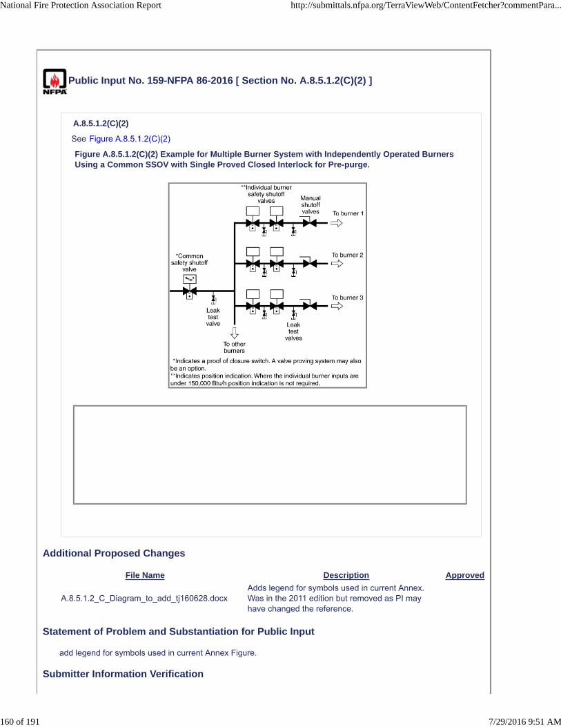
Public Input No. 159-NFPA 86-2016 [ Section No. A.8.5.1.2(C)(2) ]
A.8.5.1.2(C)(2)
See Figure A.8.5.1.2(C)(2)
Figure A.8.5.1.2(C)(2) Example for Multiple Burner System with Independently Operated BurnersUsing a Common SSOV with Single Proved Closed Interlock for Pre-purge.
Additional Proposed Changes
File Name Description Approved
A.8.5.1.2_C_Diagram_to_add_tj160628.docxAdds legend for symbols used in current Annex. Was in the 2011 edition but removed as PI may have changed the reference.
Statement of Problem and Substantiation for Public Input
add legend for symbols used in current Annex Figure.
Submitter Information Verification
National Fire Protection Association Report http://submittals.nfpa.org/TerraViewWeb/ContentFetcher?commentPara...
160 of 191 7/29/2016 9:51 AM
Submitter Full Name: Ted Jablkowski
Organization: Fives North American Combustion
Affilliation: Submitted on behalf of the NFPA 86 Intro Chapters Task Group
Street Address:
City:
State:
Zip:
Submittal Date: Tue Jun 28 14:50:40 EDT 2016
National Fire Protection Association Report http://submittals.nfpa.org/TerraViewWeb/ContentFetcher?commentPara...
161 of 191 7/29/2016 9:51 AM
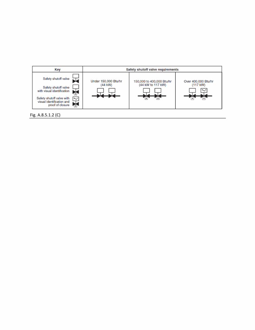
Fig. A.8.5.1.2 (C)

Public Input No. 136-NFPA 86-2016 [ New Section after A.8.5.1.8(4)(d) ]
A.8.5.1.8(4)(e)
A.8.5.1.8(4)(e) A system which has a constant airflow through a fixed orifice with no valve downstream of itis considered to have proven airflow as long as the source of air is proven on the main header.
Additional Proposed Changes
File Name Description Approved
NFPA_proposal_for_section_A.8.5.1.8_4_e_.PDF
Statement of Problem and Substantiation for Public Input
In some applications, the airflow is so low that it is impractical to prove at each individual burner. However, if the airflow is proven at the main header and then flows through a fixed orifice, this meets the intent of NFPA 86.
Submitter Information Verification
Submitter Full Name: Steven Mickey
Organization: WS Thermal Process Technology Inc.
Street Address:
City:
State:
Zip:
Submittal Date: Thu Jun 23 10:33:08 EDT 2016
National Fire Protection Association Report http://submittals.nfpa.org/TerraViewWeb/ContentFetcher?commentPara...
162 of 191 7/29/2016 9:51 AM


Public Input No. 137-NFPA 86-2016 [ Section No. A.8.5.1.8(4)(d) ]
National Fire Protection Association Report http://submittals.nfpa.org/TerraViewWeb/ContentFetcher?commentPara...
163 of 191 7/29/2016 9:51 AM

A.8.5.1.8(4)(d)
National Fire Protection Association Report http://submittals.nfpa.org/TerraViewWeb/ContentFetcher?commentPara...
164 of 191 7/29/2016 9:51 AM

In accordance with 8.5.1.8 (4)(c), fuels other than natural gas, butane, or propane might require additionalconsideration. These additional considerations would be addressed using Section 1.5. The concern withother fuel gases is the variability of fuel gas content being delivered over time. Specific examples includelandfill gas and bio gas.
The following sample calculation illustrating the use of 8.5.1.8 (4)(d) is provided to demonstrate a methodof determining the 25percent LFL requirement.
The sample calculation is based upon the following assumptions:
(1) The fuel is methane gas.
(2) All burners are turned off for control purposes. All safety shutoff valves are de-energized.
(3) At each burner, two safety shutoff valves are closed, or a single shutoff valve is proven closed.
(4) All safety shutoff valves are tested for seat leakage at least semiannually.
(5) Safety shutoff valve seat leakage is assumed to be 1 scfh (0.0283 m3/hr @ 21°C).
The following thoughts are offered regarding the selection of the 1 scfh (0.0283 m3/hr @ 21°C) safetyshutoff valve seat leakage rate.
Limited data reviewed by the committee indicate that valve seat leakage rates over 1 scfh (0.0283 m3/hr @21°C) are not anticipated unless the safety shutoff valve seats are exposed to extremely unusual conditionssuch as corrosives in the fuel gas or furnace heat allowed to back up the fuel line and burn the safetyshutoff valve seat. The former condition is the basis for limiting the use of 8.5.1.8 (4) to furnaces usingnatural gas, butane, or propane fuel gases. The latter condition occurred in a case where a fuel line wasinappropriately opened by maintenance staff while the furnace was in operation. The furnace was promptlyshut down, and the safety shutoff valves were replaced.
Under operating conditions expected by this standard, it is anticipated that debris from internal fuel gas lineoxidation (rust), pipe thread shavings not removed before fuel line assembly, or similar exposures cansubject one safety shutoff valve to seat damage that can lead to seat leakage of one safety shutoff valve;however, it is not expected that both safety shutoff valves would experience similar seat leakage. The
selected safety shutoff valve seat leakage rate of 1 scfh (0.0283 m3/hr @ 21°C) is considered conservative.
Overall, this sample calculation is based upon the following conservative conditions:
(1) Using a safety shutoff valve seat leakage rate of 1 scfh (0.0283 m3/hr @ 21°C)
(2) Providing two safety shutoff valves for each fuel path
(3) Closing two valves or using proof of closure if closing one valve
(4) Assuming safety shutoff valve leakage at each burner fuel path
(5) Using a design limit of 25 percent of LFL
(6) Including the effects of elevated furnace temperature on the LFL
(7) Assuming no fuel exits the furnace
The effects of temperature on fuel gas LFL were obtained from Bureau of Mines Bulletin 680, “Investigationof Fire and Explosion Accidents in the Chemical, Mining, and Fuel-Related Industries — A Manual.” Figure34 in that bulletin, “Temperature effect on lower limits of flammability of 10 normal paraffins in air atatmospheric pressure,” shows temperature (°C) versus combustibles (volume percent) and includes curvesfor methane, butane, and propane. It also includes a formula for computing LFL at elevated temperature.That formula, based on Bureau of Mines Bulletin 627, “Flammability Characteristics of Combustible Gasesand Vapors,” is as follows:
[A.8.5.1.8(4)d
where:
LT = LFL at the desired elevated temperature, T (°C)
L 25 = LFL at 25°C
T = Desired elevated temperature (°C)
National Fire Protection Association Report http://submittals.nfpa.org/TerraViewWeb/ContentFetcher?commentPara...
165 of 191 7/29/2016 9:51 AM

Sample Problem — U. S. Customary Units
Objective. Calculate the amount of time that all burners can be turned off before the furnace atmospherewill reach 25percent LFL.
Assumptions. Furnace contains no combustibles when the burners are turned off. Furnace is under positivepressure with no air infiltration.
Given the following information:
Furnace type: Batch
Furnace size: 8 ft wide × 6 ft deep × 8 ft tall
Number of burners: 5
Burner design rate: 0.8 MM Btu/hr
Burner design excess air: 10.0%
Burner design air capacity: 8800 scfh
Burner air minimum design flow: 100 scfh
Maximum leak rate each flow path*: 1 scfh
Number of burner flow paths**: 5
Furnace temperature: 900°F (482°C)
Oxygen in furnace atmosphere: 18%
Fuel: Methane
*The flow path is across one set of closed safety shutoff valves.
**The number of flow paths is the number of sets of safety shutoff valves that are closed that can leak intothe furnace enclosure.
Step 1. Determine LFL at 900°F using the formula from above:
Step 2. Determine the furnace volume:
Step 3. Determine the methane leak rate into the furnace with all burners off:
Step 4. Determine the airflow into the furnace with all burners off:
Step 5. Determine the percent volume methane to air through all burners:
Step 6. Determine the percent LFL resulting from the methane flow through all burner fuel paths at 900°F:
[NOTE TO EDITOR: Make the following two corrections to the following formula. (1) Change 3.5%to 3.6% to match the calculated percent in Step 1 above. (2) Change the answer from 28.57% to27.78%.]
National Fire Protection Association Report http://submittals.nfpa.org/TerraViewWeb/ContentFetcher?commentPara...
166 of 191 7/29/2016 9:51 AM

Step 7. Determine the time in minutes to reach 25percent LFL with all burners off:
Conclusions. Where the value of percentLFL 900°F exceeds 25 percent, the burner safety shutoff valves
can remain closed and burners be reignited without a repurge within a period of time not exceeding t FCE
25%LFL. After t FCE 25%LFL is exceeded, a repurge of the furnace is required.
Where the value of percentLFL 900°F equals or is less than 25 percent, burners can be reignited at any
time as long as the airflow rate Q AIR is proven and interlocked in the burner management system such
that loss of this proven airflow rate will require a repurge of the furnace before burner reignition is permitted.
Sample Problem — SI Units
Objective. Calculate the amount of time that all burners can be turned off before the furnace atmospherewill reach 25percent LFL.
Assumptions. Furnace contains no combustibles when the burners are turned off. Furnace is under positivepressure with no air infiltration.
Given the following information:
Furnace type: Batch
Furnace size: 2.438 m wide × 1.828 m deep × 2.428 m tall
Number of burners: 5
Burner design rate: 234.2 kW
Burner design excess air: 10.0 percent
Burner design air capacity: 249.2 m3/hr @ 21°C
Burner air minimum design flow: 2.83 m3/hr @ 21°C
Maximum leak rate each flow path*: 0.0283 m3/hr @ 21°C
Number of burner flow paths**: 5
Furnace temperature: 482°C (900°F)
Oxygen in furnace atmosphere: 18 percent
Fuel: Methane
*The flow path is across one set of closed safety shutoff valves.
**The number of flow paths is the number of sets of safety shutoff valves that are closed that can leak intothe furnace enclosure.
Step 1. Determine LFL at 482°C using the formula from above:
Step 2. Determine the furnace volume:
Step 3. Determine the methane leak rate into the furnace with all burners off:
National Fire Protection Association Report http://submittals.nfpa.org/TerraViewWeb/ContentFetcher?commentPara...
167 of 191 7/29/2016 9:51 AM

Step 4. Determine the airflow into the furnace with all burners off:
Step 5. Determine the percent volume methane to air through all burners:
Step 6. Determine the percent LFL resulting from the methane flow through all burner fuel paths at 482°C:
[NOTE TO EDITOR: Make the following two corrections to the following formula. (1) Change 3.5%to 3.6% to match the calculated percent in Step 1 above. (2) Change the answer from 28.57% to27.78%.]
Step 7. Determine the time in minutes to reach 25 percent LFL with all burners off:
Conclusions. Where the value of percentLFL 482°C exceeds 25 percent, the burner safety shutoff valves
can remain closed and burners be reignited without a repurge within a period of time not exceeding t FCE
25%LFL. After t FCE 25%LFL is exceeded, a repurge of the furnace is required.
Where the value of percentLFL 482°C equals or is less than 25 percent, burners can be reignited at any
time as long as the airflow rate Q AIR is proven and interlocked in the burner management system such
that loss of this proven airflow rate will require a repurge of the furnace before burner reignition is permitted.
Statement of Problem and Substantiation for Public Input
In the sample problems (both U.S. Customary Units and SI units), remove the given information "Oxygen in furnace atmosphere: 10 percent" as this information is not a factor in the sample problem. Also, make corrections in Step 6 of the sample problem calculations for both the U.S. Customary Units and SI units.
Submitter Information Verification
Submitter Full Name: Richard Gallagher
Organization: Zurich Services Corporation
Street Address:
City:
State:
Zip:
Submittal Date: Fri Jun 24 07:51:01 EDT 2016
National Fire Protection Association Report http://submittals.nfpa.org/TerraViewWeb/ContentFetcher?commentPara...
168 of 191 7/29/2016 9:51 AM
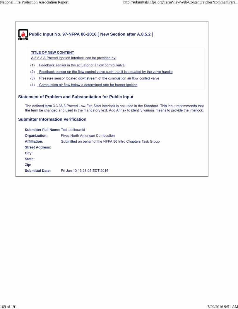
Public Input No. 97-NFPA 86-2016 [ New Section after A.8.5.2 ]
TITLE OF NEW CONTENT
A.8.5.3 A Proved Ignition Interlock can be provided by:
(1) Feedback sensor in the actuator of a flow control valve
(2) Feedback sensor on the flow control valve such that it is actuated by the valve handle
(3) Pressure sensor located downstream of the combustion air flow control valve
(4) Combustion air flow below a determined rate for burner ignition
Statement of Problem and Substantiation for Public Input
The defined term 3.3.36.3 Proved Low-Fire Start Interlock is not used in the Standard. This input recommends that the term be changed and used in the mandatory text. Add Annex to identify various means to provide the interlock.
Submitter Information Verification
Submitter Full Name: Ted Jablkowski
Organization: Fives North American Combustion
Affilliation: Submitted on behalf of the NFPA 86 Intro Chapters Task Group
Street Address:
City:
State:
Zip:
Submittal Date: Fri Jun 10 13:28:05 EDT 2016
National Fire Protection Association Report http://submittals.nfpa.org/TerraViewWeb/ContentFetcher?commentPara...
169 of 191 7/29/2016 9:51 AM

Public Input No. 157-NFPA 86-2016 [ Section No. A.8.7.4 ]
A.8.7.4
In industrial combustion applications with modulating flow control valves downstream of the combustion airblower, it is most common to interlock the constant combustion air source pressure on single andmultiburner systems to meet the requirements of 8.7.2 and 8.7.4.
Because the combustion airflow is proved during each purge cycle along with the combustion air sourcepressure, the most common convention is to prove the combustion air source pressure during burneroperation following purge. In a multiburner system, the proof of combustion airflow during purge proves thatany manual valves in the combustion air system are in an adequately open position. These manual airvalves are provided for maintenance and combustion airflow balancing among burners in a temperaturecontrol zone. In combustion air supply systems that use either an inlet damper or a speed control, thecombustion air pressure can fall below reliably repeatable levels with listed pressure switch interlocks at lowfire. For these systems, the proof of minimum airflow can be a more reliable interlock.
A pressure switch on the inlet (suction) side of an induced draft (ID) fan can be used to prove that theminimum required suction pressure is available.
For combustion systems that use high pressure gas/air to induce (inspirate) air locally at each burner, it isimpractical to monitor and prove the availability of combustion air.
For combustion systems that use natural (stack) draft to induce air into the burners or combustion chamber,it is impractical to monitor and prove the availability of combustion air.
*Pressure Interlock for 8.7.4 compliance
**Flow Interlock for 8.5.1.2 compliance
*Pressure Interlock for 8.7.4 compliance
**Pressure Interlock per zone for 8.5.1.2 compliance (no downstream valves). This system utilizes theburner(s) as the flow element.
FIGURE A.8.7.4 Examples of Air Proving Devices used in Multiple Burner Systems (fuel piping notshown for clarity)
Additional Proposed Changes
File Name Description Approved
Task_Group_Proposal_-_air_proving_devices_Rev_1_tj160628.docx
add diagrams to proposed Annex.
Statement of Problem and Substantiation for Public Input
Annex materials adds implementation examples.
Submitter Information Verification
Submitter Full Name: Ted Jablkowski
Organization: Fives North American Combustion
Affilliation: Submitted on behalf of the NFPA 86 Intro Chapters Task Group
Street Address:
City:
State:
National Fire Protection Association Report http://submittals.nfpa.org/TerraViewWeb/ContentFetcher?commentPara...
170 of 191 7/29/2016 9:51 AM

Zip:
Submittal Date: Tue Jun 28 14:36:05 EDT 2016
National Fire Protection Association Report http://submittals.nfpa.org/TerraViewWeb/ContentFetcher?commentPara...
171 of 191 7/29/2016 9:51 AM

Submitted on behalf of the NFPA 86 Intro Chapters Task Group
PROPOSED MODIFIED TEXT
6.2.2.4* Where primary or secondary combustion air is provided mechanically, combustion airflow or pressure shall be proven and interlocked with the safety shutoff valves so that fuel gas cannot be admitted prior to establishment of combustion air and so that the gas is shut off in the event of combustion air failure. (See 8.5.1.2 and 8.7.4) PI 152
8.5.1.2* A timed pre‐ignition purge shall be provided. (A) At least four system volumes of fresh air or inert gas shall be introduced during the purging cycle. (B) The system volume shall include the heating chambers and all other passages that handle the recirculation and exhaust of products of combustion. (C) To begin the timed pre‐ignition purge interval, all of the following conditions shall be satisfied: (1)*The minimum required pre‐ignition airflow is proved. (2)*At least one safety shutoff valve is proved closed between all pilot burners and the fuel supply for ovens with total pilot capacity over 400,000 Btu/hr. (3) At least one safety shutoff valve is proved closed between all main burners and the fuel supply for ovens with total capacity over 400,000 Btu/hr (D)* The minimum required pre‐ignition airflow shall be proved and maintained throughout the timed pre‐ignition purge interval. (E) Failure to maintain the minimum required pre‐ignition purge airflow shall stop the pre‐ignition purge and reset the purge timer. (F) Air pressure switches shall not be used to prove airflow where valves downstream of the pressure switch can be closed to the point of reducing airflow below the minimum required. PI 153 8.6 Ventilation Safety Devices. 8.6.1* Where a fan is essential for purge or safety ventilation of an oven or allied equipment, fan operation shall be proved and interlocked into the burner management system. 8.6.1.1 Electrical interlocks and flow switches shall be arranged in the safety control circuit so that loss of ventilation or airflow shuts down the heating system of the affected section, or, if necessary, loss of ventilation shall shut down the entire heating system as well as the conveyor. 8.6.1.2 Air pressure switches shall not be used to prove airflow where dampers downstream of the pressure switch can be closed to the point of reducing airflow below the minimum required. 8.6.1.3 Air suction switches shall not be used to prove airflow where dampers upstream of the pressure switch can be closed to the point of reducing airflow below the minimum required. 8.6.1.4 Switches used to prove airflow on systems where the air is contaminated with any substance that might condense or otherwise create a deposit shall be selected and installed to prevent interference with the performance of the switch. 8.6.2 Dampers capable of being adjusted to a position that can result in an airflow below the minimum required shall be equipped with one of the following features arranged to prevent oven operation when airflow is below the minimum required: (1) Mechanical stops (2) Cut‐away dampers (3) Limit switches interlocked into the safety circuitry

8.7.4* Combustion air minimum pressure or flow shall be interlocked into the burner management system. by any of the following methods: (1) A low pressure switch that senses and monitors the combustion air source pressure (2) A differential pressure switch that senses the differential pressure across a fixed orifice in the combustion air system (3) An airflow switch PI 154 A.8.5.1.2 (D) A pre‐ignition airflow interlock can be provided by a variety of devices. Most commonly, a fixed orifice plate is used to generate a differential pressure at the desired (calculated) pre‐ignition airflow rate. A differential pressure switch, used in conjunction with the fixed orifice, provides the electrical permissive to verify the presence of air movement at the required flow rate. Similarly, a differential pressure switch can be used as an airflow interlock by monitoring the differential pressure across a burner, either in single or multi‐burner systems. Single burner applications would include package burner assemblies. Burners provide a fixed airflow rate at a known pressure, therefore, a burner can be utilized as the flow element. Burner manufacturer’s literature will typically provide the pressure‐flow data for each specific burner size available. Valves which can restrict airflow below the minimum required pre‐ignition airflow rate shall not be installed downstream of the pressure switch location. Refer to Figure A.8.7.4. If the furnace internal pressure is operated above atmospheric pressure, the reference connection on the pressure switch should be connected to the furnace heating chamber in lieu of an atmospheric pressure reference. A vane or paddle type flow switch is another example of a device that can be used to provide the required pre‐ignition airflow interlock. When utilizing a vane flow switch, the purge time should be calculated based on the minimum airflow for the particular vane size being used. Manufacturer’s literature will typically specify the airflow range for each size vane available. PI 156 A.8.7.4 In industrial combustion applications with modulating flow control valves downstream of the combustion air blower, it is most common to interlock the constant combustion air source pressure on single and multiburner systems to meet the requirements of 8.7.2 and 8.7.4.
Because the combustion airflow is proved during each purge cycle along with the combustion air source pressure, the most common convention is to prove the combustion air source pressure during burner operation following purge. In a multiburner system, the proof of combustion airflow during purge proves that any manual valves in the combustion air system are in an adequately open position. These manual air valves are provided for maintenance and combustion airflow balancing among burners in a temperature control zone. In combustion air supply systems that use either an inlet damper or a speed control, the combustion air pressure can fall below reliably repeatable levels with listed pressure switch interlocks at low fire. For these systems, the proof of minimum airflow can be a more reliable interlock.
A pressure switch on the inlet (suction) side of an induced draft (ID) fan can be used to prove that the minimum required suction pressure is available.
For combustion systems that use high pressure gas/air to induce (inspirate) air locally at each burner, it is impractical to monitor and prove the availability of combustion air.
For combustion systems that use natural (stack) draft to induce air into the burners or combustion chamber, it is impractical to monitor and prove the availability of combustion air.

*Pressure Interlock for 8.7.4 compliance
**Flow Interlock for 8.5.1.2 compliance

*Pressure Interlock for 8.7.4 compliance
**Pressure Interlock per zone for 8.5.1.2 compliance (no downstream valves). This system
utilizes the burner(s) as the flow element.
FIGURE A.8.7.4 Examples of Air Proving Devices used in Multiple Burner Systems (fuel piping not
shown for clarity)
PI

Public Input No. 161-NFPA 86-2016 [ New Section after A.8.8.2.2 ]
TITLE OF NEW CONTENT
Fig. A.8.8.2.3 One example of a leak testing arrangement. Please note, there are other acceptable pipingarrangements. For example, the pilot take-off can also be downstream of the main pressure regulator.
Additional Proposed Changes
File Name Description Approved
A.8.8.2.3_Diagram_to_add_tj160628.docx add figure.
Statement of Problem and Substantiation for Public Input
This PI adds back a useful Figure that was lost between the 2011 and 2015 editions.
Submitter Information Verification
Submitter Full Name: Ted Jablkowski
Organization: Fives North American Combustion
Affilliation: Submitted on behalf of the NFPA 86 Intro Chapters Task Group
Street Address:
City:
State:
Zip:
Submittal Date: Tue Jun 28 14:55:18 EDT 2016
National Fire Protection Association Report http://submittals.nfpa.org/TerraViewWeb/ContentFetcher?commentPara...
172 of 191 7/29/2016 9:51 AM

8.8.2.3* Means for testing all fuel gas safety shutoff valves for valve seat leakage shall be installed.
Fig. A.8.8.2.3 One example of a leak testing arrangement. Please note, there are other acceptable piping arrangements. For example, the pilot take‐off can also be downstream of the main pressure regulator.

Public Input No. 105-NFPA 86-2016 [ New Section after A.8.10.5(3) ]
TITLE OF NEW CONTENT
A.8.10.5 (1) Where independent flame sensors are used for detecting pilot and main flames, ensurethe pilot and the main flame are each sensed independently. Due to the difficulty of sensing the pilot andmain flames independently with (2) UV scanners, sensing the pilot by a flame rod and the main flame by aUV scanner is acceptable.
Statement of Problem and Substantiation for Public Input
Annex is intended to help the use understand what to be cautious of when employing 2 flame detectors.1) NFPA85 requires (2) sensors, one for pilot and the other for main, if the pilot is continuous. 2) Because of the difficulty of sensing the pilot and main flames independently with (2) UV scanners, other parts of the world (Australia as an example), require the pilot to be supervised by a flame rod and the main flame by a UV scanner.
Submitter Information Verification
Submitter Full Name: Ted Jablkowski
Organization: Fives North American Combustion
Affilliation: Submitted on behalf of the NFPA 86 Intro Chapters Task Group
Street Address:
City:
State:
Zip:
Submittal Date: Fri Jun 10 13:54:46 EDT 2016
National Fire Protection Association Report http://submittals.nfpa.org/TerraViewWeb/ContentFetcher?commentPara...
173 of 191 7/29/2016 9:51 AM
Public Input No. 150-NFPA 86-2016 [ New Section after A.8.10.5(3) ]
TITLE OF NEW CONTENT
Type your content here ...
A.8.10.5 (1) Where independent flame sensors are used for detecting pilot and main flames, ensurethe pilot and the main flame are each sensed independently. Due to the difficulty of sensing the pilot andmain flames independently with (2) UV scanners, sensing the pilot by a flame rod and the main flame by aUV scanner is acceptable.
Statement of Problem and Substantiation for Public Input
Annex provides a caution and a suggested implementation method when seeking to independently monitor the pilot and main flames.
Submitter Information Verification
Submitter Full Name: Ted Jablkowski
Organization: Fives North American Combustion
Affilliation: Submitted on behalf of the NFPA 86 Intro Chapters Task Group
Street Address:
City:
State:
Zip:
Submittal Date: Tue Jun 28 14:19:19 EDT 2016
National Fire Protection Association Report http://submittals.nfpa.org/TerraViewWeb/ContentFetcher?commentPara...
174 of 191 7/29/2016 9:51 AM

Public Input No. 151-NFPA 86-2016 [ Section No. A.8.10.6 ]
A.8.10.6
A line burner, pipe burner, or radiant burner with flames propagating 3’ or shorter are only required to haveone flame sensor for pilot and main flame detection. A line burner, pipe burner, or radiant burner withflames propagating 3’ or longer are required to have two flame sensors, one for pilot and one to sensemain burner flame at the end of the assembly farthest from the source of ignition.
Two examples of burner arrangements considered to be a single burner with one flame safeguard installedat the end of the assembly are shown in Figure A.8.10.6(a) and Figure A.8.10.6(b).
Figure A.8.10.6(a) Example of a Combustion Safeguard Supervising a Pilot for a Continuous LineBurner During Light-Off and the Main Flame Alone During Firing.
Figure A.8.10.6(b) Example of a Combustion Safeguard Supervising a Group of Radiant CupBurners Having Reliable Flame-Propagation Characteristics from One to the Other by Means ofFlame-Propagation Devices.
Statement of Problem and Substantiation for Public Input
Annex to help identify requirements when trying to independently monitor the pilot and main flame.
Submitter Information Verification
Submitter Full Name: Ted Jablkowski
Organization: Fives North American Combustion
Affilliation: Submitted on behalf of the NFPA 86 Intro Chapters Task Group
Street Address:
City:
State:
Zip:
Submittal Date: Tue Jun 28 14:22:59 EDT 2016
National Fire Protection Association Report http://submittals.nfpa.org/TerraViewWeb/ContentFetcher?commentPara...
175 of 191 7/29/2016 9:51 AM
Public Input No. 158-NFPA 86-2016 [ Section No. A.9.1 ]
A.9.1
This standard addresses the protection needs of ovens, furnaces, and related equipment. Fire protectionneeds external to this equipment are beyond the scope of this standard.Fixed fire protection for theequipment can consist of sprinklers, water spray,
carbon dioxide, foam, dry chemical, water mist, or steam extinguishing systems. The extent of protectionrequired depends upon
Determination and extent of required fixed protectiond epends upon:
(1) the construction and arrangement of the oven, furnace, or related equipment
as well as
(1)
(2) the materials being processed.
Fixed
(1)
(2) fixed protection should extend as far as necessary in the enclosure and ductwork if combustiblematerial is processed or combustible buildup is likely to occur.
If the
(1) This includes the potential for solvent condensation in ductwork as well as particle build-up.
(2) if the fixtures or racks are combustible or are subject to loading with excess combustible finishingmaterials, or if an appreciable amount of combustible drippings from finishing materials accumulates inthe oven or ductwork
, protection should also be provided
(1) .
Fixed fire protection for the equipment can consist of sprinklers, water spray, carbon dioxide, foam, drychemical, water mist, or steam extinguishing systems .
Steam inerting systems can be used to protect ovens where steam flooding is the only means available.Otherwise, the use of steam in ovens is not recommended.
Hydrogen and other flammable gas fires are not normally extinguished until the supply of gas has beenshut off because of the danger of re-ignition or explosion. Personnel should be cautioned that hydrogenflames are invisible and do not radiate heat. In the event of fire, large quantities of water should be sprayedon adjacent equipment to cool the equipment and prevent its involvement in the fire. Combination fog andsolid stream nozzles should be used to allow the widest adaptability in fire control.
Small flammable gas fires can be extinguished by dry chemical extinguishers or with carbon dioxide,nitrogen, or steam. Re-ignition can occur if a metal surface adjacent to the flame is not cooled with water orby other means.
Dip tanks and drain boards included in oven enclosures should be protected by an automatic firesuppression system if flammable or combustible liquids are involved. NFPA 34 provides guidance for thedesign of fire suppression systems for dip tanks and drain boards.
Statement of Problem and Substantiation for Public Input
The existing language, while accurate, does not clearly identify the conditions that result in a need for installation of fixed fire protection within an oven enclosure and associated ductwork.
National Fire Protection Association Report http://submittals.nfpa.org/TerraViewWeb/ContentFetcher?commentPara...
176 of 191 7/29/2016 9:51 AM

The intent is made clearer by rephrasing the first paragraph as an explanation of how to determine when protection is required, and then listing the conditions.
Submitter Information Verification
Submitter Full Name: Thomas George
Organization: Tokio Marine Management, Inc.
Street Address:
City:
State:
Zip:
Submittal Date: Tue Jun 28 14:45:47 EDT 2016
National Fire Protection Association Report http://submittals.nfpa.org/TerraViewWeb/ContentFetcher?commentPara...
177 of 191 7/29/2016 9:51 AM

Public Input No. 155-NFPA 86-2016 [ New Section after A.10.6.1 ]
A.10.6.2
The introductory chapters only preclude purging ovens and furnaces into running incinerators (asreferenced in 8.5.1.3 and 8.5.1.4). However, Thermal oxidizers may process fumes that are sourced fromequipment other than ovens and furnaces.
Restricting concentrations to a maximum of 50% LFL, regardless of flammable gas/vapor source, thelikelihood of the mixture being ignited and flashing back into the source equipment is reduced.
Alternatively NFPA 69, which requires redundant methods of explosion prevention and protection, mayprovide an effective approach for processes where the equipment exhaust is toxic and must be oxidized atall times (discharge to atmosphere is not acceptable).
Statement of Problem and Substantiation for Public Input
Explanatory material for new paragraph, submitted as separate PI
Related Public Inputs for This Document
Related Input Relationship
Public Input No. 149-NFPA 86-2016 [New Sectionafter 10.6.1]
Referenced paragraph for submitted new annexmaterial
Submitter Information Verification
Submitter Full Name: Thomas George
Organization: Tokio Marine Management, Inc.
Street Address:
City:
State:
Zip:
Submittal Date: Tue Jun 28 14:33:16 EDT 2016
National Fire Protection Association Report http://submittals.nfpa.org/TerraViewWeb/ContentFetcher?commentPara...
178 of 191 7/29/2016 9:51 AM
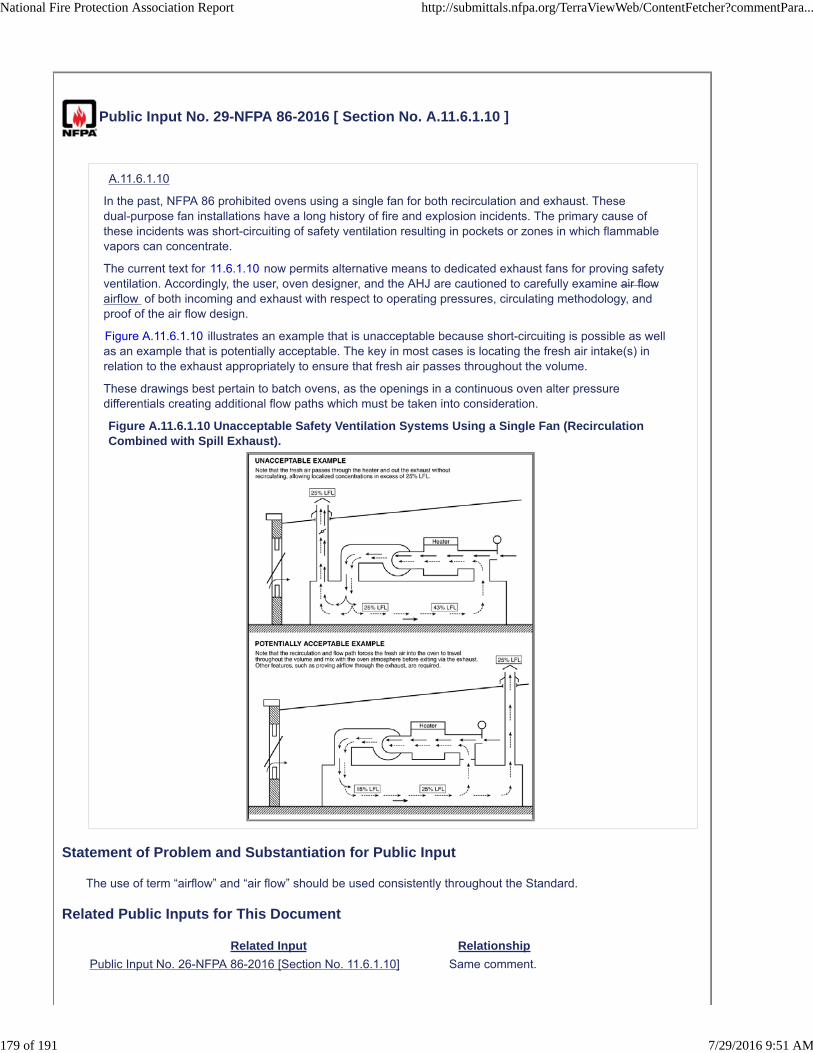
Public Input No. 29-NFPA 86-2016 [ Section No. A.11.6.1.10 ]
A.11.6.1.10
In the past, NFPA 86 prohibited ovens using a single fan for both recirculation and exhaust. Thesedual-purpose fan installations have a long history of fire and explosion incidents. The primary cause ofthese incidents was short-circuiting of safety ventilation resulting in pockets or zones in which flammablevapors can concentrate.
The current text for 11.6.1.10 now permits alternative means to dedicated exhaust fans for proving safetyventilation. Accordingly, the user, oven designer, and the AHJ are cautioned to carefully examine air flowairflow of both incoming and exhaust with respect to operating pressures, circulating methodology, andproof of the air flow design.
Figure A.11.6.1.10 illustrates an example that is unacceptable because short-circuiting is possible as wellas an example that is potentially acceptable. The key in most cases is locating the fresh air intake(s) inrelation to the exhaust appropriately to ensure that fresh air passes throughout the volume.
These drawings best pertain to batch ovens, as the openings in a continuous oven alter pressuredifferentials creating additional flow paths which must be taken into consideration.
Figure A.11.6.1.10 Unacceptable Safety Ventilation Systems Using a Single Fan (RecirculationCombined with Spill Exhaust).
Statement of Problem and Substantiation for Public Input
The use of term “airflow” and “air flow” should be used consistently throughout the Standard.
Related Public Inputs for This Document
Related Input Relationship
Public Input No. 26-NFPA 86-2016 [Section No. 11.6.1.10] Same comment.
National Fire Protection Association Report http://submittals.nfpa.org/TerraViewWeb/ContentFetcher?commentPara...
179 of 191 7/29/2016 9:51 AM
Submitter Information Verification
Submitter Full Name: Ted Jablkowski
Organization: Fives North American Combustion
Affilliation: submitted on behalf of the NFPA 86 Intro Chapters Task Group
Street Address:
City:
State:
Zip:
Submittal Date: Sun May 01 19:00:18 EDT 2016
National Fire Protection Association Report http://submittals.nfpa.org/TerraViewWeb/ContentFetcher?commentPara...
180 of 191 7/29/2016 9:51 AM

Public Input No. 94-NFPA 86-2016 [ Section No. A.13.5.5 ]
A.13.5.5
Vaporizers used for safety purging to convert cryogenic liquids to the gas state should be ambient air heattransfer units so that flow from such vaporizers is unaffected by the loss of power.
The use of powered vaporizers is permitted where one of the following conditions is satisfied:
(1) The vaporizer has reserve heating capacity to continue vaporizing at least five furnace volumes at therequired purge flow rate immediately following power interruption.
(2) Reserve ambient vaporizers are provided that are piped to the source of supply so that they areunaffected by a freeze-up or flow stoppage of gas from the powered vaporizer. The reserve vaporizersshould be capable of evaporating at least five furnace volumes at the required purge flow rate.
(3) Purge gas is available from an alternative source that is capable of supplying five volume changesafter interruption of the flow of the atmosphere gas to the furnace.
Vaporizers should be rated by the industrial gas supplier or the owner to vaporize at 150 percent of thehighest purge gas demand for all connected equipment. Winter temperature extremes for the locale shouldbe taken into consideration by the agency responsible for rating the vaporizers.
The industrial gas supplier should be informed of additions to the plant that materially increase the inert gasconsumption rate so that vaporizer and storage capacity can be resized for the revised requirements.
A temperature indicator should be installed in the vaporizer outlet piping for use in evaluating itsevaporation performance at any time.
A device should be installed that prevents the flow rate of gas from exceeding the vaporizer capacity andthereby threatening the integrity of downstream equipment or control devices due to exposure to cryogenicfluids. A break in the downstream pipeline or failure (opening) of the supply service or line pressureregulator could cause excessive flow. Exceeding the capacity of an atmospheric vaporizer leads to agradual decrease in gas temperature that can be remedied by decreasing the demand on the vaporizer.
In atmospheric vaporizers, in lieu of the flow-limiting device, a visual and audible alarm should indicate tooperators in the vicinity of the furnace that the temperature of the vaporizer outlet gas has fallen below aminimum level, indicating a potential to exceed vaporizer capacity.
Statement of Problem and Substantiation for Public Input
Supply pressure regulator is not defined.
Submitter Information Verification
Submitter Full Name: Kevin Carlisle
Organization: Karl Dungs Inc
Street Address:
City:
State:
Zip:
Submittal Date: Fri Jun 10 12:53:46 EDT 2016
National Fire Protection Association Report http://submittals.nfpa.org/TerraViewWeb/ContentFetcher?commentPara...
181 of 191 7/29/2016 9:51 AM

Public Input No. 121-NFPA 86-2016 [ New Section after A.13.5.11.1(F) ]
A.13.5.11.1(G) The means to maintain furnace pressure below the static head pressure of theseal oil include the use of bubblers or manometers on vent lines. Other means may be possible.Also see A.13.5.11.1(D).
Statement of Problem and Substantiation for Public Input
1. In the 2015 edition paragraph 13.5.11.7.8(C) is the only place that lists requirements for “oil seals”. This paragraph is specific to burn-in requirements for Type VIII and IX furnaces only.2. The above public comment moves the requirement to the “general” where it would apply to any atmosphere oil seal that is used by a Class C furnace and any type of atmosphere introduction method (i.e. burn-in or purge-in).
Submitter Information Verification
Submitter Full Name: Mark Stender
Organization: Surface Combustion, Inc.
Street Address:
City:
State:
Zip:
Submittal Date: Tue Jun 21 14:09:49 EDT 2016
National Fire Protection Association Report http://submittals.nfpa.org/TerraViewWeb/ContentFetcher?commentPara...
182 of 191 7/29/2016 9:51 AM

Public Input No. 146-NFPA 86-2016 [ New Section after A.13.5.11.3 ]
TITLE OF NEW CONTENT
A.13.5.11.3(2) It is recognized that maintaining a reliable source of ignition is critical to avoidexplosion at an open door from which flammable atmosphere gas is flowing. Once a door begins toopen or is full open, the flame curtain pilot flame supervision and flame curtain low and high gasinterlocks may be ignored provided that flame curtain flame is sensed by an independent flamesupervision system.
Statement of Problem and Substantiation for Public Input
AFC-Holcroft has encountered instances wherein a flame curtain pilot flame is unexpectedly extinguished (due to air drafts, poor adjustment, etc.) when the furnace door is open with flammable atmosphere gas present. The loss of pilot flame has resulted in the flame curtain gas SSOV closing via the interlock prescribed in NFPA 86 2015 13.5.11.3(2), thereby extinguishing the flame curtain flame. In some of these instances involving batch integral quench furnaces, an explosion has occurred due to the build-up of an explosive atmosphere in the vestibule. AFC-Holcroft believes it is of utmost importance to maintain a reliable ignition source to combust the flammable atmosphere gasses. Therefore AFC-Holcroft proposes to allow the interlocks in 13.5.11.2 and 13.11.5.3 to be bypassed if the flame curtain is equipped with a flame supervision system independent of the flame screen pilot flame supervision system and provided that the flame curtain flame is sensed by its independent flame supervision system.
With the changes promulgated by AFC-Holcroft, the flame curtain SSOV will remain open after initiating the door open sequence regardless of the status of low and high gas pressure interlocks or loss of flame curtain pilot flame provided that the flame curtain flame supervision detects flame present. Should an abnormal flame curtain gas pressure condition occur, the flame curtain flame supervision will be active to shut off the flame curtain SSOV should the flame curtain flame be extinguished.
Related Public Inputs for This Document
Related Input Relationship
Public Input No. 144-NFPA 86-2016 [Section No. 13.5.11.3] Primary
Public Input No. 145-NFPA 86-2016 [Section No. A.13.5.11.3] Secondary
Public Input No. 143-NFPA 86-2016 [New Section after 3.3.82]
Submitter Information Verification
Submitter Full Name: Joseph Kozma III
Organization: AFC-Holcroft LLC
Street Address:
City:
State:
Zip:
Submittal Date: Tue Jun 28 13:25:29 EDT 2016
National Fire Protection Association Report http://submittals.nfpa.org/TerraViewWeb/ContentFetcher?commentPara...
183 of 191 7/29/2016 9:51 AM

Public Input No. 145-NFPA 86-2016 [ Section No. A.13.5.11.3 ]
A.13.5.11.3
Regarding items (2) and (5), once a door begins to open, it is intended that the door will be permitted toopen completely. The interlock is only intended to prevent a closed door from opening. Flame curtainsare often used to minimize the ingress of air into a furnace through an open furnace door toprevent process upset and not for the purpose of providing the ignition source for flammableatmosphere exiting from the door
Statement of Problem and Substantiation for Public Input
The statement added to the A.13.5.11.3 Annex provides additional guidance on the use of flame curtains.
Related Public Inputs for This Document
Related Input Relationship
Public Input No. 144-NFPA 86-2016 [Section No. 13.5.11.3]
Public Input No. 143-NFPA 86-2016 [New Section after 3.3.82]
Public Input No. 146-NFPA 86-2016 [New Section after A.13.5.11.3]
Submitter Information Verification
Submitter Full Name: Joseph Kozma III
Organization: AFC-Holcroft LLC
Street Address:
City:
State:
Zip:
Submittal Date: Tue Jun 28 13:18:45 EDT 2016
National Fire Protection Association Report http://submittals.nfpa.org/TerraViewWeb/ContentFetcher?commentPara...
184 of 191 7/29/2016 9:51 AM

Public Input No. 126-NFPA 86-2016 [ Sections A.13.5.11.7.8(B), A.13.5.11.7.8(C) ]
Sections A.13.5.11.7.8(B), A.13.5.11.7.8(C)
A.13.5.11.7.8(B)
The retort or inner cover of a Type VIII furnace and the cover of a Type IX furnace will be sealed to thebase. Sand seals, oil seals, or rubber seals can be used.
A.13.5.11.7.8(C)
The means to maintain furnace pressure below the static head pressure of the seal oil include the use ofbubblers or manometers on vent lines. Other means may be possible. Also see A.13.5.11.1(E) .
Statement of Problem and Substantiation for Public Input
1. Existing paragraph 13.5.11.7.9 prohibits using burn-in for Type VIII furnaces, so any special requirements of Type VIII is a moot point.2. As for Type IX furnaces, the Table 13.5.10.3 states that the furnace may or may not have a cover therefore references to covers is inappropriate.
Submitter Information Verification
Submitter Full Name: Mark Stender
Organization: Surface Combustion, Inc.
Street Address:
City:
State:
Zip:
Submittal Date: Tue Jun 21 14:43:02 EDT 2016
National Fire Protection Association Report http://submittals.nfpa.org/TerraViewWeb/ContentFetcher?commentPara...
185 of 191 7/29/2016 9:51 AM

Public Input No. 9-NFPA 86-2015 [ Chapter M ]
Annex M Informational References
M.1 Referenced Publications.
The documents or portions thereof listed in this annex are referenced within the informational sections ofthis standard and are not part of the requirements of this document unless also listed in Chapter 2 for otherreasons.
M.1.1 NFPA Publications.
National Fire Protection Association, 1 Batterymarch Park, Quincy, MA 02169-7471.
NFPA 30, Flammable and Combustible Liquids Code, 2015 edition.
NFPA 31, Standard for the Installation of Oil-Burning Equipment, 2011 edition.
NFPA 33, Standard for Spray Application Using Flammable or Combustible Materials, 2011 edition.
NFPA 34, Standard for Dipping, Coating, and Printing Processes Using Flammable or Combustible Liquids,2011 edition.
NFPA 49, Hazardous Chemicals Data, 1994 edition.
NFPA 54, National Fuel Gas Code, 2015 edition.
NFPA 55, Compressed Gases and Cryogenic Fluids Code, 2013 edition.
NFPA 56, Standard for Fire and Explosion Prevention During Cleaning and Purging of Flammable GasPiping Systems, 2014 edition.
NFPA 58, Liquefied Petroleum Gas Code, 2014 edition.
NFPA 68, Standard on Explosion Protection by Deflagration Venting, 2013 edition.
NFPA 69, Standard on Explosion Prevention Systems, 2014 edition.
NFPA 70 ®, National Electrical Code ®, 2014 edition.
NFPA 85, Boiler and Combustion Systems Hazard Code, 2011 edition.
NFPA 86, Standard for Ovens and Furnaces, 1999 edition.
NFPA 86D, Standard for Industrial Furnaces Using Vacuums as an Atmosphere, 1999 edition.
NFPA 91, Standard for Exhaust Systems for Air Conveying of Vapors, Gases, Mists, and NoncombustibleParticulate Solids, 2010 edition.
NFPA 325, Fire-Hazard Properties of Flammable Liquids, Gases and Volatile Solids, 1960 edition.
NFPA 497, Recommended Practice for the Classification of Flammable Liquids, Gases, or Vapors and ofHazardous (Classified) Locations for Electrical Installations in Chemical Process Areas, 2012 edition.
NFPA 499, Recommended Practice for the Classification of Combustible Dusts and of Hazardous(Classified) Locations for Electrical Installations in Chemical Process Areas, 2013 edition.
Fire Protection Guide to Hazardous Materials, 2001 2008 edition.
M.1.2 Other Publications.
National Fire Protection Association Report http://submittals.nfpa.org/TerraViewWeb/ContentFetcher?commentPara...
186 of 191 7/29/2016 9:51 AM
M.1.2.1 ANSI Publications.
American National Standards Institute, Inc., 25 West 43rd Street, 4th Floor, New York, NY 10036.
ANSI A14.3, Safety Requirements for Fixed Ladders, 2008.
ANSI B16.1, Cast Iron Pipe Flanges and Flanged Fittings , 2005.
ANSI B16.5, Pipe Flanges and Flanged Fittings , 2009.
ANSI B16.22, Wrought Copper and Copper Alloy Solder Joint Pressure Fittings , 2001.
ANSI B16.23 , Cast Copper Alloy Solder Joint Drainage Fittings — DWV , 2002.
ANSI B16.24, Cast Copper Alloy Pipe Flanges and Flanged Fittings Class 150, 300, 400, 600, 900, 1500,and 2500 , 2001.
ANSI Z21.18/CSA 6.3, Standard for Gas Appliance Pressure Regulators, 2005 2007, revised 2012 .
ANSI Z21.21/CSA 6.5, Automatic Valves for Gas Appliances, 2005 2012 .
ANSI Z117.1, Safety Requirements for Confined Spaces, 2009.
ANSI/ISA 84.00.01, Application of Safety Instrumented Systems for the Process Industries, 2004.
M.1.2.2 API Publications.
American Petroleum Institute, 1220 L Street, N.W., Washington, DC 20005-4070.
API 510, Pressure Vessel Inspection Code: In-Service Inspection, Rating, Repair, and Alteration, 20062014 .
API STD 520 P1, Sizing, Selection, and Installation of Pressure-Relieving Devices in Refineries, Part 1:Sizing and Selection, 2008 2014 .
API RP API STD 520 P2, Sizing, Selection, and Installation of Pressure-Relieving Devices in Refineries,Part 2: Installation, 2003 2015 .
API 570, Piping Inspection Code: Inspection, Repair, Alteration, and Rerating of In-Service Piping Systems,2006 2009 .
M.1.2.3 ASME Publications.
American Society of Mechanical Engineers ASME International , Two Park Avenue, New York, NY10016-5990.
ASME Boiler and Pressure Vessel Code, Section VIII, Division 1, 2007. 2015 .
ASME B16.1, Grey Iron Pipe Flanges and Flanged Fittings Classes 25, 125, and 250 , 2015 .
ASME B16.5, Pipe Flanges and Flanged Fittings NPS 1/2 Through NPS 24 Metric/Inch Standard ,2013 .
ASME B16.22, Wrought Copper and Copper Alloy Solder Joint Pressure Fittings , 2013 .
ASME B16.23 , Cast Copper Alloy Solder Joint Drainage Fittings : DWV , 2011 .
ASME B16.24, Cast Copper Alloy Pipe Flanges and Flanged Fittings Class 150, 300, 400, 600, 900,1500, and 2500 , 2011 .
M.1.2.4 ASTM Publications.
ASTM International, 100 Barr Harbor Drive, P.O. Box C700, West Conshohocken, PA 19428–2959.
ASTM E 681 E681 , Standard Test Method for Concentration Limits of Flammability of Chemicals (Vaporsand Gases), 2009, reapproved 2015 .
M.1.2.5 AVS Publications.
American Vacuum Society, 125 Maiden Lane, 15th Floor, New York, NY 10038.
“Graphic Symbols in Vacuum Technology,”J. Vac. Sci. Technol., Vol. 4, No. 3 (1967), pp. 139–142.
Glossary of Terms Used in Vacuum Technology, New York: Pergamon Press, 1958.
National Fire Protection Association Report http://submittals.nfpa.org/TerraViewWeb/ContentFetcher?commentPara...
187 of 191 7/29/2016 9:51 AM

M.1.2.6 CGA Publications.
Compressed Gas Association, 4221 Walney Road, 5th Floor 14501 George Carter Way , Suite 103 ,Chantilly, VA 20151-2923 1788 .
CGA G-2, Anhydrous Ammonia, 1995.
CGA G-2.1/ANSI K61.1, Safety Requirements for the Storage and Handling of Anhydrous Ammonia, 19992014 .
CGA G-4.1, Cleaning Equipment for Oxygen Service, 2004 2009 .
CGA G-4.4, Industrial Practices for Gaseous Oxygen Transmission Pipeline and Distribution PipingSystems System , 2003 2012 .
CGA G-5, Hydrogen, 2005 2011 .
CGA G-6, Carbon Dioxide, 2006 2009 .
CGA G-6.1, Standard for Low Pressure Carbon for Insulated Liquid Carbon Dioxide Systems atConsumer Sites, 2005 2013 .
CGA P-1, Safe Handling of Compressed Gases in Containers, 2008 2012 .
M.1.2.7 CSA America Publications.
Canadian Standards Association, 8501 East Pleasant Valley Road, Cleveland, OH 44131–5575.
CSA B149.6, Code for Digester Gas and Landfill Gas Installations, 2011.
M.1.2.8 EN Publications.
European Committee for Standardization, 36, rue de Stassart CEN-CENELEC ManagementCentre, Avenue Marnix 17 , B-1050 1000 , Brussels, Belgium.
BS EN 161, Automatic Shut-off Valves for Gas Burners and Gas Appliances, 2007 2011, Amendment3, 2013 .
BS EN 1643, Safety and Control Devices for Gas Burners and Gas Burning Appliances - ValveProving Systems for Automatic Shut-off Valves for Gas Burners and Gas Appliances, 2000 2014 .
M.1.2.9 FM Publications.
FM Global, 1301 Atwood 270 Central Avenue , P.O. Box 7500, Johnston, RI 02919-4923 .
FM Approval 7400, Approval Standard for Liquid and Gas Safety Shutoff Valves, 1998.
FM Global Property Loss Prevention Data Sheet 6-13, “Waste Fuel Fired Boilers,” updated May 2007.
FM Global Property Loss Prevention Data Sheet 6-17, “Rotary Kilns and Dryers,” updated January 2008.
M.1.2.10 IEC Publications.
International Electrical Commission, 3 rue de Varembé, P.O. Box 131, CH - 1211, Geneva 20, Switzerland.
IEC 61511, Functional Safety: Safety Instruments Systems for the Process Industry Sector, 2004.
M.1.2.11 JIC Publications.
Joint Industrial Council, 7901 West Park Drive, McLean, VA 22101.
Hydraulic Standards for Industrial Equipment.
M.1.2.12 NEMA Publications.
National Electrical Manufacturers Association, 1300 North 17th Street, Suite 1847, Rosslyn, VA 22209.
TR 27, Commercial, Institutional and Industrial Dry-Type Transformers , 1976.
M.1.2.13 NIOSH Publications.
National Institute for Occupational Safety and Health, 1600 Clifton Road, Atlanta, GA 30333.
NIOSH Pocket Guide to Chemical Hazards, 2005 2015 .
National Fire Protection Association Report http://submittals.nfpa.org/TerraViewWeb/ContentFetcher?commentPara...
188 of 191 7/29/2016 9:51 AM

M.1.2. 14 13 PCI Publications.
The Powder Coating Institute, 2170 Buckthorne Place, Suite 250, The Woodlands, TX 77380 5040 OldTaylor Mill Road, PMB 13, Taylor Mill, KY 41015 .
Recommended Procedure No. 9, “Volatile Content.”
M.1.2. 15 14 UL Publications.
Underwriters Laboratories Inc., 333 Pfingsten Road, Northbrook, IL 60062-2096.
Bulletin of Research No. 43, “The Lower Limit of Flammability and the Autogenous Ignition Temperature ofCertain Common Solvent Vapors Encountered in Ovens,” January 1950.
ANSI/ UL 353, Standard for Limit Controls, 1994, revised 2011.
UL 429, Standard for Electrically Operated Valves for Gas Appliances, 2006 2013 .
M.1.2. 16 15 U.S. Government Publications.
U.S. Government Printing Government Publishing Office, 732 North Capitol Street, NW, Washington,DC 20402 20401-0001 .
Title 29, Code of Federal Regulations, Parts 1910.24 through 1910.29.
Title 29, Code of Federal Regulations, Part 1910.146, “Permit-Required Confined Spaces.”
U.S. Bureau of Mines Bulletin 503, “Limits of Flammability of Gases and Vapors,” by H. F. Coward and G.W. Jones, 1952.
U.S. Bureau of Mines Bulletin 627, “Flammability Characteristics of Combustible Gases and Vapors,” by M.G. Zabetakis, U.S. Department of the Interior, 1965.
U.S. Bureau of Mines Bulletin 680, “Investigation of Fire and Explosion Accidents in the Chemical, Mining,and Fuel-Related Industries — A Manual,” by J. M. Kuchta, U.S. Department of the Interior, 1985.
M.1.2. 17 16 Other Publications.
Hampel, C. A. (ed.), Rare Metals Handbook, New York: Reinhold Publishing Corp., 1961.
Hodgman, C. D. (ed.), Handbook of Chemistry and Physics, Cleveland, OH: Chemical Rubber Publishing,1959.
Honig, R. E., “Vapour Pressure of Elements,” RCA Review, June 1957, pp. 195–204.
Lewis, B., and G. von Elbe, Combustion, Flames and Explosions of Gases, New York: Academic Press,1951.
Stull, D. R., and G. C. Sinke (ed.), Thermodynamic Properties of the Elements, Washington, DC: AmericanChemical Society, 1956.
M.2 Informational References.
The following documents or portions thereof are listed here as informational resources only. They are not apart of the requirements of this document.
M.2.1 NFPA Publications.
National Fire Protection Association. 1 Batterymarch Park, Quincy, MA 02169–7471.
NFPA 87, Recommended Practice for Fluid Heaters, 2015 edition.
M.2.2 ASME Publications.
American Society of Mechanical Engineers ASME International , Two Park Avenue, New York, NY10016-5990.
ASME B31.3, Process Piping, 2008 2016 .
M.3 References for Extracts in Informational Sections. (Reserved)
Statement of Problem and Substantiation for Public Input
Referenced current SDO names, addresses, standard names, numbers, and editions.Removed NEMA Publications because the technical report has been rescinded.
National Fire Protection Association Report http://submittals.nfpa.org/TerraViewWeb/ContentFetcher?commentPara...
189 of 191 7/29/2016 9:51 AM

Related Public Inputs for This Document
Related Input Relationship
Public Input No. 8-NFPA 86-2015[Chapter 2]
Referenced current SDO names, addresse, standard names,numbers, and editions.
Submitter Information Verification
Submitter Full Name: Aaron Adamczyk
Organization: [ Not Specified ]
Street Address:
City:
State:
Zip:
Submittal Date: Tue Jul 21 16:13:10 EDT 2015
National Fire Protection Association Report http://submittals.nfpa.org/TerraViewWeb/ContentFetcher?commentPara...
190 of 191 7/29/2016 9:51 AM

Public Input No. 139-NFPA 86-2016 [ Section No. M.1.2.15 ]
M.1.2.15 UL Publications.
Underwriters Laboratories Inc., 333 Pfingsten Road, Northbrook, IL 60062-2096.
Bulletin of Research No. 43, “The Lower Limit of Flammability and the Autogenous Ignition Temperature ofCertain Common Solvent Vapors Encountered in Ovens,” January 1950.
ANSI/UL 353, Standard for Limit Controls, 1994, revised 2011.
UL 429, Standard for Electrically Operated Valves for Gas Appliances, 2006, revised 2013 .
Statement of Problem and Substantiation for Public Input
This proposal updates the referenced UL Standards to the current edition.
Submitter Information Verification
Submitter Full Name: Ronald Farr
Organization: UL LLC
Street Address:
City:
State:
Zip:
Submittal Date: Mon Jun 27 16:40:59 EDT 2016
National Fire Protection Association Report http://submittals.nfpa.org/TerraViewWeb/ContentFetcher?commentPara...
191 of 191 7/29/2016 9:51 AM

Attachment F:
A2018 Public Input Groups


![2234 McConnell Grace[1] OK](https://static.fdocuments.us/doc/165x107/577cdd8e1a28ab9e78ad4741/2234-mcconnell-grace1-ok.jpg)
![Asian Architecture [ARC 2213/2234] PROJECT 1: CASE STUDY](https://static.fdocuments.us/doc/165x107/55c58117bb61ebd95d8b484d/asian-architecture-arc-22132234-project-1-case-study.jpg)
