Document No. 6706-02-2234
89
Transcript of Document No. 6706-02-2234
MAIN ROADS Western Australia Routine Visual Inspection Guidelines Page 2 of 89 Doc: No. 6706-02-2234 - Issue Date 06/05/2013
This information is owned and controlled by the Senior Engineer Structures. The Bridge Condition Manager is a delegated custodian. All comments and requests for changes are to be submitted to the delegated custodian.
Document No. 6706-02-2234 REVISION STATUS
Page No.
Revision No.
Revision Date
Revision Description Approved By Signature
All 1 21/12/10 Clarification of L1 inspection requirements. Inspection for fire damage.
R F Scanlon
All 2 06/05/13 Changed waterways to waterways, vegetation and debris. Inclusion of vegetation clearance envelope around bridges.
A Lim
All controlled copies shall be marked accordingly
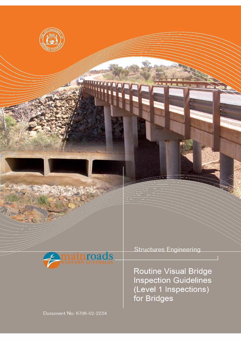
ROUTINE VISUAL BRIDGE INSPECTION GUIDELINES (Level 1 Inspections)
FOR BRIDGES
AUTHORISATION
As head of Structures Engineering of Main Roads Western Australia, I authorise the issue and use of this document.
R F SCANLON SENIOR ENGINEER STRUCTURES Date: 31/07/2009
MAIN ROADS Western Australia Routine Visual Inspection Guidelines Page 3 of 89 Doc: No. 6706-02-2234 - Issue Date 06/05/2013
TABLE OF CONTENTS 1.0 INTRODUCTION ......................................................................................................... 4 2.0 PURPOSE ................................................................................................................... 4 3.0 OTHER REFERENCES ............................................................................................... 4 4.0 ROUTINE VISUAL BRIDGE INSPECTION PROCEDURE ......................................... 5 5.0 ROUTINE VISUAL BRIDGE INSPECTION FORMS ................................................... 8 6.0 COMMON MATERIAL DEFECTS .............................................................................. 12
APPENDIX A: BRIDGE COMPONENT DEFINITIONS ……………………………………… 15 APPENDIX B: TIMBER AND NON-TIMBER BRIDGE ROUTINE VISUAL INSPECTION REPORT (Level 1 Inspection) EXAMPLE …………………. 25 APPENDIX C: PRECAST BOX UNIT BRIDGE ROUTINE VISUAL INSPECTION REPORT (Level 1 Inspection) EXAMPLE ………………………………….. 31 APPENDIX D: PHOTOGRAPHS AND SKETCHES OF SOME COMMON BRIDGE
DEFECTS ……………………………………………………………………….. 40
MAIN ROADS Western Australia Routine Visual Inspection Guidelines Page 4 of 89 Doc: No. 6706-02-2234 - Issue Date 06/05/2013
1.0 INTRODUCTION
This document is one of a set of documents, which together, detail the management of bridge inspections. The routine visual inspection of bridges is one of a number of inspection types that are undertaken. Routine visual bridge inspections are carried out on an annual cycle and are the responsibility of the bridge owner. They are visual in nature. They are intended to check on the overall safety and performance of the structure and the identification of any major accident damage or incident and any obvious failure of structural components. They are also important in ensuring routine annual maintenance works are being carried out. Documentation requirements generally entail completion of a pro-forma with comments on most aspects of the bridge’s condition and includes photographs of distress and defects. Data is generally qualitative in nature. Routine inspections should be carried out by the bridge owner following flood events, bush fires or other natural phenomena to ensure the bridge is safe for its intended service level and function. This triggered inspection may serve as the scheduled (annual) inspection.
2.0 PURPOSE
This document is intended to assist the Bridge Inspector when carrying out Routine Visual Inspections on all bridges by providing the following:
An explanation of terminology used in the Routine Visual Bridge Inspection report forms;
Guidance on preparation needed prior to bridge inspection field trips; and
Guidance on what aspects need to be considered in inspecting the components of the bridge to enable a consistent approach in bridge inspection and reporting.
3.0 OTHER REFERENCES
Other references relevant to this document are:
Procedure for the Management of Bridge Inspections, document 3912/01/03, for a description of the management process for the inspection, investigation and subsequent recording of maintenance or management requirements for bridges and associated structures.
Procedure for the Management of Bridge Data & Information, document 3912/01/04, for the process to be followed in the storage and maintenance of bridge data and information used for the management of the structures asset.
Refer to the Structures Inspection and Information Management Policy, document 6706-01-202 for definitions and requirements about bridge inspection types, extent of bridge inspections and general inspection data requirements.
For typical bridge types and more details on bridge components refer to the Detailed Visual Bridge Inspection Guidelines for Timber Bridges (Level 2 Inspections), document 6706-02-2231 and the Detailed Visual Bridge Inspection Guidelines for Concrete and Steel Bridges (Level 2 Inspections), document 6706-02-2233.
For additional detail about types of concrete and steel component deterioration refer to the Detailed Visual Bridge Inspection Guidelines for Concrete and Steel Bridges (Level 2 Inspections), document 6706-02-2233.
MAIN ROADS Western Australia Routine Visual Inspection Guidelines Page 5 of 89 Doc: No. 6706-02-2234 - Issue Date 06/05/2013
4.0 ROUTINE VISUAL BRIDGE INSPECTION PROCEDURE
Routine visual bridge inspections are intended to check on the overall safety and performance of the structure and the identification of any major accident damage or incident and any obvious failure of structural components. Focus should be on obvious and potentially critical defects (e.g. displaced bearing plate, jammed fingerplates, something actually broken etc.). The annual inspection process is essentially visual in nature and serves as an intermediate check between detailed inspections. They provide an opportunity for the early identification of structural issues. Such issues, when detected, must be clearly identified with comments including the location and extent of the defect. They must be noted and photographed as they may be the first indications of underlying problems. Where the condition of some components is not clear during the routine visual inspection, a further detailed inspection (Level 2 and/or 3) may be necessary to confirm the status and identify any problems. The need for additional inspections must be noted in the visual inspection report. Decommissioned bridges shall still be inspected annually but focus is on safety and ensuring the bridge remains closed to all traffic rather than structural issues. 4.1 Extent of Inspections
The scope of a routine visual inspection includes:
inspection of the road surface, guardrails/barriers, road drainage, waterways, vegetation and debris, footpaths, expansion joints and deck joints, bearings, superstructure and substructure for all timber and non-timber bridges;
inspection of the road surface, guardrails/barriers, road drainage, waterways, vegetation and debris, walls and aprons, and box units for the specific superstructure bridge type of precast box units;
particular close inspection to ascertain the effectiveness and condition of previous repairs;
recommendation of a detailed inspection if it is warranted by observed distress or unusual behaviour of the bridge; and
identification of routine maintenance requirements. Components that are not accessible without specialist equipment (e.g. underbridge inspection unit) are to be checked from as close as practicable using binoculars.
Components that need not be inspected as part of routine visual inspections include:
the inside of box type superstructures (e.g. box girders);
areas behind abutments that are inaccessible; and
piles and foundations below ground or water level. These components may be inspected as part of Level 2 or Level 3 inspections. 4.2 Preparation for Visual Site Inspections
Prior to commencing visual site inspections, it is recommended that the Inspector collates relevant documentation for their needs. Documentation could include a copy of the previous inspections (Level 1 and 2 if available); bridge hard data from the Integrated Road
MAIN ROADS Western Australia Routine Visual Inspection Guidelines Page 6 of 89 Doc: No. 6706-02-2234 - Issue Date 06/05/2013
Information System (IRIS) such as bridge number, road name etc. that are unlikely to change but can be easily verified on site; the appropriate routine visual inspection report forms; bridge location information and a copy of these guidelines. Visual observation involves using the eye to detect defects or signs of defects in the bridge components. Some basic equipment will also prove useful in the completion of the routine visual inspection. The following is a list of equipment recommended for routine visual inspections:
personal protective equipment (PPE) including a high visibility vest, safety boots and waterproof boots;
first aid kit;
signage for traffic management purposes as required;
torch;
binoculars;
tools such as hammer(s), a long thin screwdriver, spirit level, shovel, small axe and a long stiff wire probe;
tape measure;
crack gauge;
camera with flash;
red-and-white hazard tape;
GPS unit; and
chalk and permanent marker pens. 4.3 Operational Safety
All inspection procedures and operations must comply with the relevant rules and regulations of the Occupational Safety and Health Act 1984 and appropriate Main Roads Western Australia (MRWA) operational safety guidelines and documents. Where inspections are to be carried out on bridges located over or under the assets of other Authorities, the relevant regulations and Codes of Practice relating to work on or close to their assets must be adhered to, and where necessary, referred to in the procedures developed for the inspection. This is particularly important when inspecting bridges over electrified railways. 4.4 Routine Visual Site Inspections
A systematic and organised approach is required when undertaking bridge inspections. The procedures adopted should be efficient, effective, thorough and repeatable and cover all aspects of the structure and potential safety issues. The report must be clear, concise, complete and accurate. Reference should be made to Section 6 for appropriate terminology to be adopted for the various bridge component defects and material defect types. Refer to Appendix A for the terminology to be adopted for the various bridge components. All inspection report descriptions should be made consistent with this terminology. The location of bridge components is based upon the direction of the road:
The direction of Straight Line Kilometre (SLK) for each road can be found within the relevant MRWA Region Structures Location Map Book. These can be found in www.mainroads.wa.gov.au selecting “Building Roads”, “Standards and Technical”, then
MAIN ROADS Western Australia Routine Visual Inspection Guidelines Page 7 of 89 Doc: No. 6706-02-2234 - Issue Date 06/05/2013
“Structures Engineering”, “Asset Management” and refer to the required Region’s map book.
Abutments are numbered in the direction of increasing SLK.
Piers and Barrels are numbered along the bridge in ascending order from Abutment 1 to Abutment 2.
Piles, Columns, Beams, Stringers and Barrel Units are numbered across the bridge in ascending order from left to right when facing the direction of increasing SLK.
Pedestrian bridges spanning a road are treated slightly differently. Abutment 1 is located on the left hand side of the road when facing the direction of increasing SLK. All other references are then consistently taken once this first abutment has been located. Previous inspections, current bridge location books (showing the direction of the road) and/or drawings are the best source of information to ascertain which is abutment 1 for the bridge but verification should also be made on site if painted on the bridge itself. 4.5 Photographic Records
It is not mandatory to take general photographs of each bridge when undertaking a routine visual inspection. However, to ensure appropriate identity it is recommended to always take a photograph of the general view of the road from abutment 1 as well as the left-hand side view of the bridge. It is vital that any bridge component showing signs of structural distress that has either not been previously recorded or has altered since the last inspection is photographed. Issues identified in the routine visual inspection report must be supplemented with a clear photograph and/or sketch of the specific concern.
MAIN ROADS Western Australia Routine Visual Inspection Guidelines Page 8 of 89 Doc: No. 6706-02-2234 - Issue Date 06/05/2013
5.0 ROUTINE VISUAL BRIDGE INSPECTION FORMS
Timber and Non-Timber Bridges
The Routine Visual Bridge Inspection Report for timber and non-timber bridges is compiled on a standard form. Inspection items include:
road surface; guardrails/barriers;
road drainage; waterways, vegetation and debris;
footpaths; expansion joints and deck joints;
bearings; superstructure; and
substructure. The blank template is available on Main Roads Western Australia’s (MRWA’s) internet site www.mainroads.wa.gov.au selecting “Building Roads”, “Standards and Technical”, then “Structures Engineering”, “Asset Management” and refer to the “Timber and Non-Timber Bridge Routine Visual Inspection Report - Level 1 Inspection Form” Word document. An example of a completed Timber and Non-Timber Bridge Routine Visual Inspection Report is given in Appendix B. Precast Box Unit Bridges
The Routine Visual Bridge Inspection Report for the specific superstructure bridge type of precast box units is also compiled on a standard form. Inspection items include:
road surface; guardrails/barriers;
road drainage; waterways, vegetation and debris;
walls and aprons; and precast box units. The blank template is available on Main Roads Western Australia’s (MRWA’s) internet site www.mainroads.wa.gov.au selecting “Building Roads”, “Standards and Technical”, then “Structures Engineering”, “Asset Management” and refer to the “Precast Box Unit Bridge Routine Visual Inspection Report - Level 1 Inspection Form” Word document. An example of a completed Precast Box Unit Bridge Routine Visual Inspection Report is given in Appendix C. The routine visual inspection forms have standardised headings. The headings are explained in the following sections with general information on what to look for. Refer to Appendices B and C for actual examples. The bridge components referenced in the routine visual inspection forms are defined in Appendix A. 5.1 General Information
Certain general information heads the routine visual inspection forms. Most of this data does not change over time and can be entered from IRIS, drawings or previous inspections prior to the site visit. The following information is required:
Bridge Number
Crossing Name
Road Name
Road Number
SLK: The Straight Line Kilometre (SLK) distance defines the location of a point on a road to reference items on or adjacent to the road. SLK is a distance measure (to 2
MAIN ROADS Western Australia Routine Visual Inspection Guidelines Page 9 of 89 Doc: No. 6706-02-2234 - Issue Date 06/05/2013
decimal places) that maintains an historical reference of road points as road realignments introduce changes to the true distance measure
Local Authority
Responsibility Area: The MRWA Region responsible for the management of the bridge
Latitude: The Latitude Coordinate is to be taken in decimal degrees (to 5 decimal places) and must be noted as a minus number (i.e. -32.78472) measured from Abutment 1, LHS. Coordinates must be measured using Global Positioning System (GPS) equipment set to the GDA 94 datum
Longitude: The Longitude Coordinate is to be taken in decimal degrees (to 5 decimal places)
Inspected By
Inspection Date 5.2 Road Surface
The condition of the road surface includes identifying any missing, damaged or obscured signs and delineators as well as material defects, surface defects, settlement, depressions, joint transitions and kerb issues on the road surface and on any footpaths; and shoulder erosion. Identification of defects or changes to the road surface is important as it is usually a good indicator of underlying structural issues. 5.3 Guardrails/Barriers
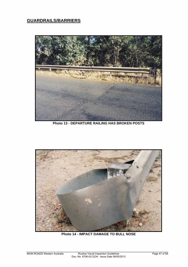
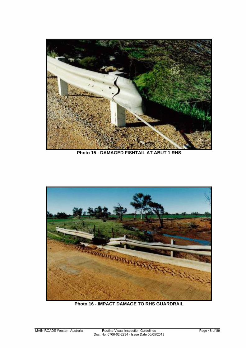
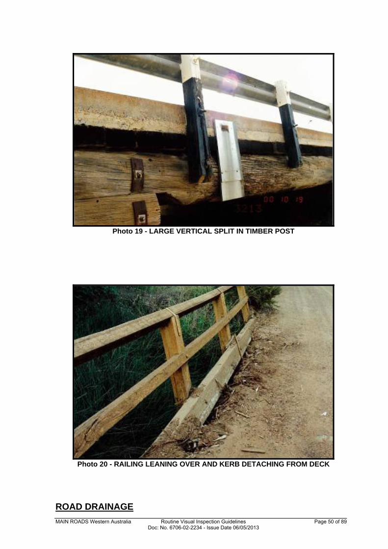
The condition of the guardrails/barriers includes identifying any accident damage, loose connections, barrier misalignment and material defects. If the guardrails/barriers have dropped this may indicate that there has been a settlement of the piles or of the embankment or a component of the bridge has failed. 5.4 Road Drainage
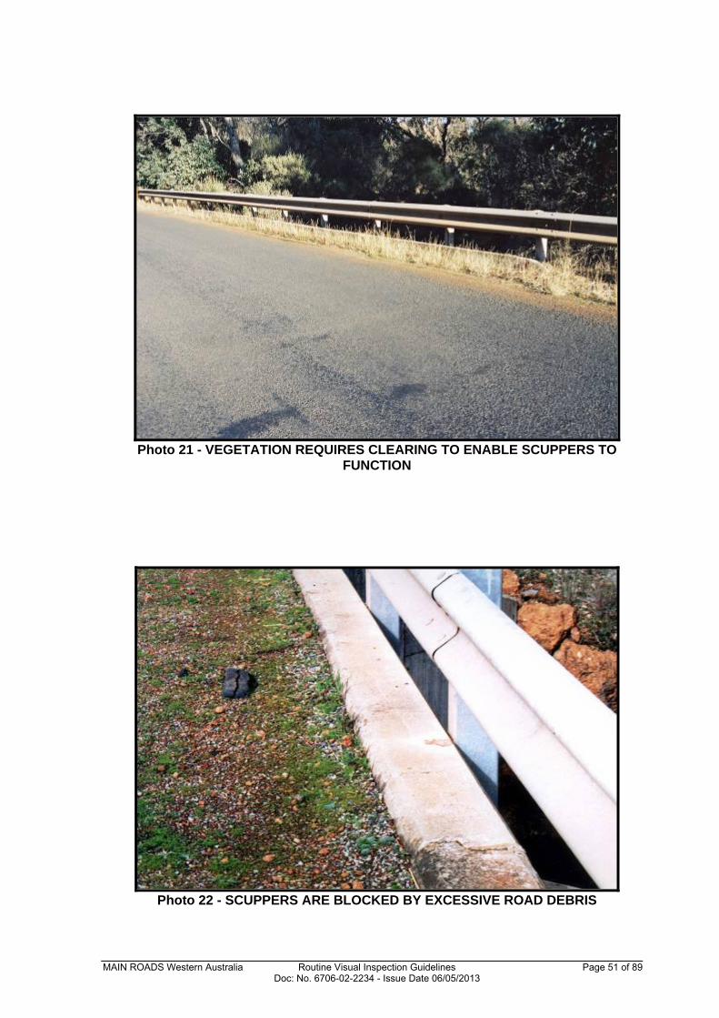
The condition of the scuppers, drains, gully traps and any erosion is identified and recorded. Any gravel or vegetation build-up against the kerb should be noted as possible blockages to effective deck drainage. Check if there is any evidence of ponding on the bridge deck. 5.5 Waterways, Vegetation and Debris
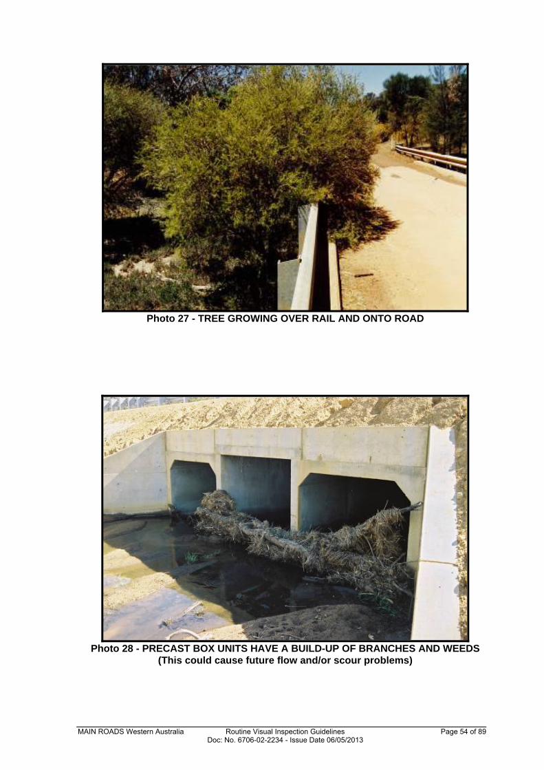
The condition of the waterways and vegetation control area includes noting any potentially damaging vegetation (vegetation may be a fire hazard or a blockage to flow conditions), debris and pruning requirements. Embankment erosion, scour, silt build-up, blocked openings, undermining and any damage to guide-banks, revetment mattresses and rock protection should also be noted. Record any evidence of overtopping. Vegetation Clearance Envelopes for bridges are outlined in MRWA Drawing No. 1230-1666, available on MRWA’s internet site www.mainroads.wa.gov.au selecting “Building Roads”, “Standards and Technical”, then “Structures Engineering”, “Asset Management” and refer to the “Vegetation Clearance Envelopes” document. Vegetation clearance is important with respect to fire hazard reduction, improved access for inspections, reduced maintenance such as debris removal, reduced risk of tree limbs falling, embankment stability and visual amenity particularly within urban areas. In some situations, the removal of vegetation as detailed need not be completed if it is considered and documented that there is little fire risk and/or that it would be detrimental from an aesthetic perspective.
MAIN ROADS Western Australia Routine Visual Inspection Guidelines Page 10 of 89 Doc: No. 6706-02-2234 - Issue Date 06/05/2013
Timber and Non-Timber Bridges Only
5.6 Footpaths
Where present, the condition of the footpath and the condition and effectiveness of the drainage, the evenness of the surface, surface condition and railing is to be inspected. 5.7 Expansion Joints and Deck Joints
The condition of the expansion joints and deck joints includes identifying loose and/or damaged fixings, damaged or missing seals, damage to the deck itself or joint nosing, obstructions in the joint, full closure of any bridge expansion joints and any difference in level across a joint. 5.8 Bearings
The condition of the bearings includes identifying displacement, damage, distortion and alignment of the bearings or the bearing components, seating problems, bearing pads, corrosion or seized bearings. It may not be possible to get a good visual inspection of all bearings but general misalignment and excessive rotation should be evident. 5.9 Superstructure
The superstructure of timber and non-timber bridges can be of many varied forms and consist of a range of different material types. Sites should be actively searched for any signs of fire in the vicinity of the bridge. There are, however, some specific items that should be reported during a routine visual inspection including:
material defects or damage to beams, stringers, slabs, fasteners, cross-bracing and coatings;
impact damage;
distortion of components;
excessive movement or vibration under moving traffic loads;
dampness through the deck or on structural components;
the condition and functioning of air release holes; and
deterioration due to rot or insect attack (e.g. termites) to timber structural components.
5.10 Substructure
Similarly, the substructure of timber and non-timber bridges can be of many varied forms and consist of a range of different material types. Sites should be actively searched for any signs of fire in the vicinity of the bridge. Again there are some specific items that should be observed during a routine visual inspection including:
material defects or damage to piles, footings, walls and capbeams;
movement of abutment or wing walls;
any sign of instability or deflected shape;
water wash and abrasion damage;
the condition of and functioning of weepholes; and
MAIN ROADS Western Australia Routine Visual Inspection Guidelines Page 11 of 89 Doc: No. 6706-02-2234 - Issue Date 06/05/2013
deterioration due to rot or insect attack (e.g. termites) to timber structural components.
Precast Box Unit Bridges Only
5.11 Walls and Aprons
Comments are required for headwalls (LHS, RHS), wing walls (Abutment 1 LHS, RHS; Abutment 2 LHS, RHS) and aprons where these structural components are present. Exception reporting is required for defects such as material defects, impact damage, cracking, spalling, honeycombing, corrosion, coating defects, undermining and settlement/movement. 5.12 Precast Box Units
Comments are required for each barrel, link slab and base slab making up this specific superstructure bridge type. Note that each barrel will be made up of a series of connecting units and all units within that barrel should be inspected, where possible, with any defects encountered documented including detail of what unit number the comments refer to. Exception reporting is required for defects such as material defects, impact damage, cracking, spalling, honeycombing, corrosion, coating defects, undermining and settlement/movement.
MAIN ROADS Western Australia Routine Visual Inspection Guidelines Page 12 of 89 Doc: No. 6706-02-2234 - Issue Date 06/05/2013
6.0 COMMON MATERIAL DEFECTS
This section describes the typical defects that can be found in the various materials used to construct bridges in Western Australia. Only the key items are outlined with full details available in the Detailed Visual Bridge Inspection Guidelines for Concrete and Steel Bridges (Level 2 Inspections), document 6706-02-2233 and in the Detailed Visual Bridge Inspection Guidelines for Timber Bridges (Level 2 Inspections), document 6706-02-2231 as appropriate. Refer to Appendix D for photographs and sketches of some common bridge defects. (Note: the photographs and sketches are provided as a complete set for general information but are not necessarily information that should be recorded for a Level 1 inspection.) 6.1 Timber
Timber is susceptible to significant deterioration but is a material that, combined with appropriate inspection and routine maintenance, can be preserved for a very long life. Rot/Decay – The fungi responsible for the rot of timber can only grow and attack the timber fibres in the presence of both moisture and oxygen. Where there is too little of one or the other, the rot cannot sustain itself. Thus, for dry timber, where the internal moisture content is low, rot will generally not occur. Insect Attack – Timber is required to be protected from termite attack. For timber components in saline river estuaries there is also danger from a variety of marine borers and again, timber protection is essential. Any activity of such insects shall be noted on the inspection form with the requirement for appropriate treatment. Fire Damage – Large section round timbers, as used in bridge construction, have good resistance to fire and, except during a severe bush fire, usually survive quite successfully. The strength of a timber structural component during a fire depends on many factors and to obtain the strength of structural components from these considerations is a complex analytical problem. However, research has shown it is reasonably conservative to assume that the strength of charred sound timber is 80% of the value that it had before the burning commenced. 6.2 Concrete
Concrete is used in structures as mass concrete or normally it is combined with steel reinforcement or with prestressing steel. Defects in concrete are often related to the lack of durability resulting from the composition of the concrete, poor placement practices, poor quality control, insufficient curing or the aggressive environment in which it is placed. Cracking – It is recognised that in reinforced concrete, cracks will form in tension zones. These fine structural cracks are considered harmless but as reinforcement is further stressed the initial cracks open up and progressively spread to longer and wider cracks. Further cracking can result in blocks forming and at this stage a detailed inspection is required. Cracks should be photographed to enable historical recording of crack propagation and growth. Common crack locations in concrete are given in Appendix D, Sketch 1. Spalling – A spall is a fragment of concrete detached from the structure between fracture surfaces. Spalling is a continuation of the corrosion process and represents a serious defect in the concrete, in that the reinforcement is heavily corroded. Delamination – Delamination is defined as a discontinuity in the surface concrete which is substantially separated but not completely detached from the adjoining concrete. Visibly it may appear as a solid surface but can be identified by the hollow sound when tapping with a
MAIN ROADS Western Australia Routine Visual Inspection Guidelines Page 13 of 89 Doc: No. 6706-02-2234 - Issue Date 06/05/2013
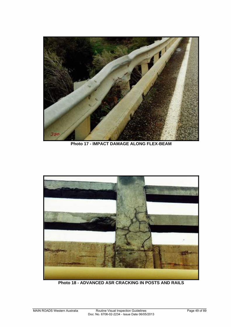
light hammer. Delamination generally begins with the corrosion of reinforcement and subsequent cracking of the concrete parallel to the exterior surface. Patching or Other Repairs – The condition of the repair or patch will indicate whether the underlying problem has been solved or if it has been merely covered up and is actively continuing under the repair. Cracking, delamination, rust stains or spalling around the patch indicates the problem still exists and further investigations and repairs are needed. Alkali Aggregate Reactivity – AAR or Alkali Silica Reaction (ASR) is the phenomenon where some aggregates react adversely with the alkalis in cement to produce a highly expansive alkali-silica gel. Three factors must be present: reactive silica in the aggregate; significant alkalinity; and moisture. The expansion of the gel under moist conditions leads to cracking and deterioration of the concrete. AAR can be difficult to recognise and identify. Typical adverse features of AAR in concrete structures include cracking expansion and consequent misalignment of components, spalling of fragments of surface concrete and the presence of gel in fractures. It is advisable to undertake testing (Level 3 Inspection) to conclusively diagnose AAR. A photograph can be found in Appendix D, Photo 18. Corrosion of Reinforcement – The concrete alkalinity protects the reinforcement from corrosion but when moisture, air and/or chloride ions above a certain concentration penetrate through the concrete to the reinforcement, this protection breaks down and corrosion commences. In the initial stages, corrosion may appear as rust stains on the concrete surface. In the advanced stages, the surface concrete cracks, delaminates and spalls exposing heavily corroded reinforcement. Spalling and delamination are indications of advanced corrosion. In prestressed concrete structures, any indication of corroding prestressing steel is very serious as the failure of the strand or wire may lead to a non-ductile or catastrophic failure of the component. Fire Damage – Due to its low thermal conductivity, concrete is often used for fireproofing of steel structures. However, concrete itself may be damaged by fire. Concrete exposed to up to 100oC is normally considered as healthy. Parts of a concrete structure exposed to temperatures above approximately 300oC (dependent on water/cement ratio) turn pink. Hotter temperatures turn the concrete light grey and then yellow-brown over about 1,000oC. One rule of thumb to remember is that all pink coloured concrete is damaged and should be removed and replaced. The reinforcement or prestressing in the concrete may also be affected by fire. Yield stress and ductility can both be reduced by fire. 6.3 Steel
Steel as a structural material when not encased in concrete has defects related to poor quality control, loosening of connections or the aggressive environment in which it is placed. Corrosion – Corrosion, or rusting, will only occur if the steel is not protected or if the protective coating wears or breaks off. Corrosion on carbon steel is initially fine grained, but as rusting progresses it becomes flaky and delaminates, exposing a pitted surface. The process continues with progressive loss of section. Permanent Deformations – Steel component permanent deformations can take the form of buckling, kinking, warping or waviness, or any combination of these. Permanent bending deformation may occur in the direction of the applied loads whereas permanent buckling deformation may occur in a direction perpendicular to the applied load. Cracking – Cracks represent a linear fracture in the steel and are generally caused by fatigue and can, under certain conditions, lead to brittle fracture. Brittle fracture is a complete material disintegration through the component. This usually occurs without prior warning or
MAIN ROADS Western Australia Routine Visual Inspection Guidelines Page 14 of 89 Doc: No. 6706-02-2234 - Issue Date 06/05/2013
plastic deformation. Cracks in steel should never be treated lightly and all details must be recorded with recommendation for urgent further investigations. The most common locations for crack initiation are at weld joints and other connections (refer also Appendix D, Sketches 2a and 2b). These are the most susceptible points and should be checked if accessible. Loose Connections – Loose connections are pertinent to both bolted and riveted connections and may be caused by corrosion of the connector plates or fasteners themselves, excessive vibration, overstressing, cracking, or failure of individual components. Loose connections may not always be detectable by a visual inspection but the indications such as corrosion and deformation should be investigated. Fire Damage – All materials are weakened with increasing temperature and steel is no exception. On many occasions fire affected steelwork shows little or no distortion resulting in considerable uncertainty regarding re-useability. If the fire subsides before the steel component fails, the deformation will generally recover. Permanent deformation occurs when part of the component has been strained beyond its elastic limit. The cooling phase causes shortening in the steel component and dimensions should be rechecked. 6.4 Masonry
Masonry is made of stones or bricks bonded together by mortar. Although not a common construction material for Western Australian bridges, masonry has been used in abutments, piers and wing walls. Defects in masonry are mostly related to the breakdown of its components over time. A similar size crack in masonry and concrete is not indicative of equivalent concerns for structural stability and strength, with masonry having greater ability to withstand larger cracks and without underlying reinforcement to protect. This distinction should be considered when recording defects in masonry. Cracking – Cracks develop in masonry as a result of non-uniform settlement, thermal restraint and overloading. Cracks develop either at the interface between the mortar and stone, following a zigzag pattern or propagate through the joint and stone in a straight line. Splitting, Spalling and Disintegration – These effects are caused by either the actions of weathering and abrasion; or by the actions of acids, sulphates or chlorides. Loss of Mortar and Stones – Loss of mortar is the result of destructive action of water wash, plant growth or softening by water containing dissolved sulphates or chlorides. Once the mortar has disintegrated it may lead to loss of stones. 6.5 Coating Systems
Coating defects are not necessarily serious but they are indicative of potential weaknesses and eventual loss of protection to the coated surface. It is rare for a protective coating system to outlast the life of the bridge and therefore it should be thoroughly inspected and asset managed accordingly. Defects include loss of coating adhesion, incompatibility of successive coats, subsurface rusting, mechanical damage and inadequate coating on sharp edges, welds and ‘shadow areas’.
MAIN ROADS Western Australia Routine Visual Inspection Guidelines Page 15 of 89 Doc: No. 6706-02-2234 - Issue Date 06/05/2013
APPENDIX A
BRIDGE COMPONENT DEFINITIONS
MAIN ROADS Western Australia Routine Visual Inspection Guidelines Page 16 of 89 Doc: No. 6706-02-2234 - Issue Date 06/05/2013
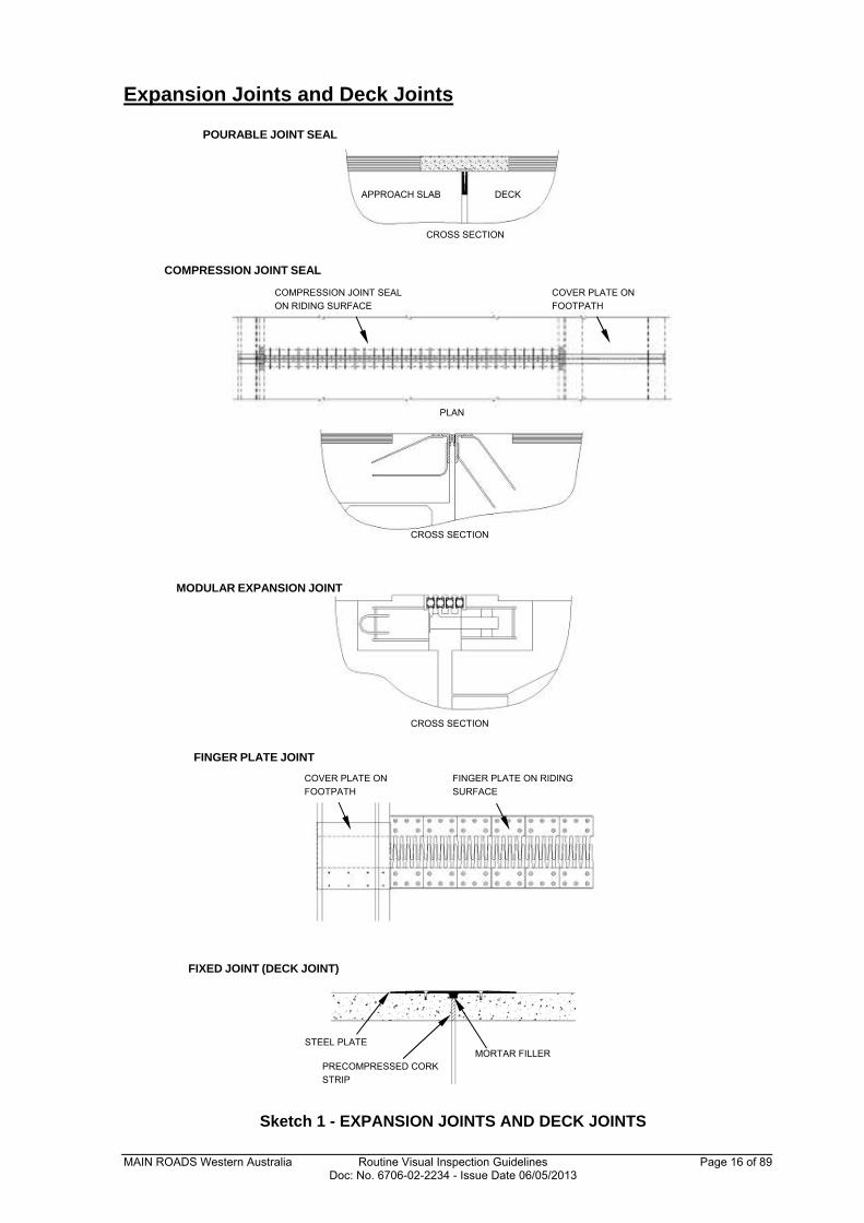
Expansion Joints and Deck Joints
Sketch 1 - EXPANSION JOINTS AND DECK JOINTS
APPROACH SLAB DECK
COMPRESSION JOINT SEAL
ON RIDING SURFACE COVER PLATE ON
FOOTPATH
PLAN
CROSS SECTION
CROSS SECTION
FINGER PLATE ON RIDING
SURFACE COVER PLATE ON
FOOTPATH
POURABLE JOINT SEAL
COMPRESSION JOINT SEAL
MODULAR EXPANSION JOINT
FINGER PLATE JOINT
CROSS SECTION
FIXED JOINT (DECK JOINT)
STEEL PLATE
PRECOMPRESSED CORK
STRIP
MORTAR FILLER
MAIN ROADS Western Australia Routine Visual Inspection Guidelines Page 17 of 89 Doc: No. 6706-02-2234 - Issue Date 06/05/2013
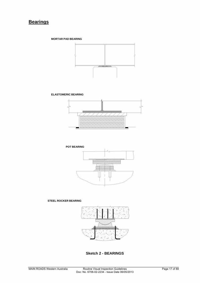
Bearings
Sketch 2 - BEARINGS
MORTAR PAD BEARING
ELASTOMERIC BEARING
POT BEARING
STEEL ROCKER BEARING
MAIN ROADS Western Australia Routine Visual Inspection Guidelines Page 18 of 89 Doc: No. 6706-02-2234 - Issue Date 06/05/2013
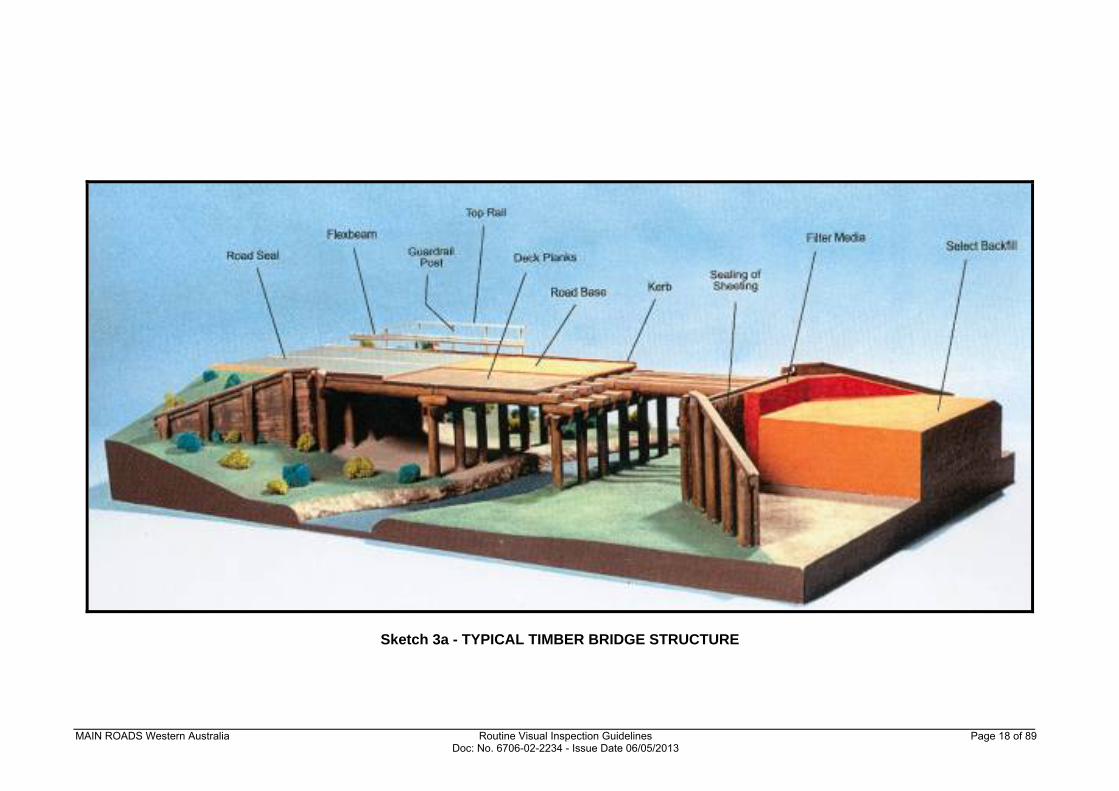
Sketch 3a - TYPICAL TIMBER BRIDGE STRUCTURE
MAIN ROADS Western Australia Routine Visual Inspection Guidelines Page 19 of 89 Doc: No. 6706-02-2234 - Issue Date 06/05/2013
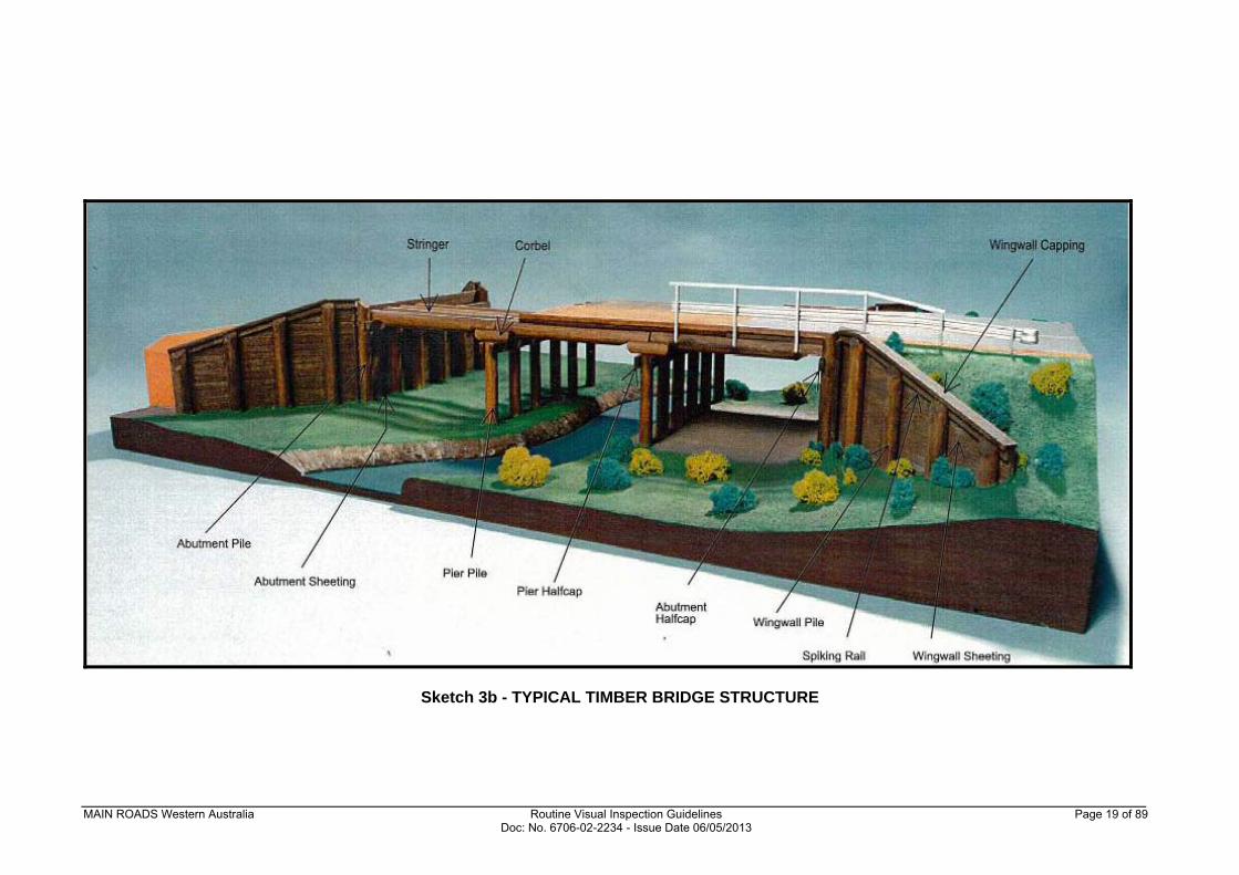
Sketch 3b - TYPICAL TIMBER BRIDGE STRUCTURE
MAIN ROADS Western Australia Routine Visual Inspection Guidelines Page 20 of 89 Doc: No. 6706-02-2234 - Issue Date 06/05/2013
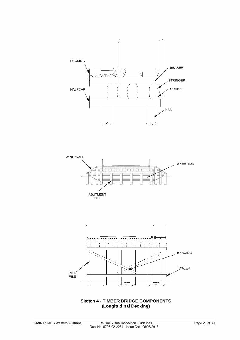
Sketch 4 - TIMBER BRIDGE COMPONENTS (Longitudinal Decking)
HALFCAP CORBEL
STRINGER
PILE
BEARER
DECKING
SHEETING
WING WALL
ABUTMENT
PILE
PIER
PILE
BRACING
WALER
MAIN ROADS Western Australia Routine Visual Inspection Guidelines Page 21 of 89 Doc: No. 6706-02-2234 - Issue Date 06/05/2013
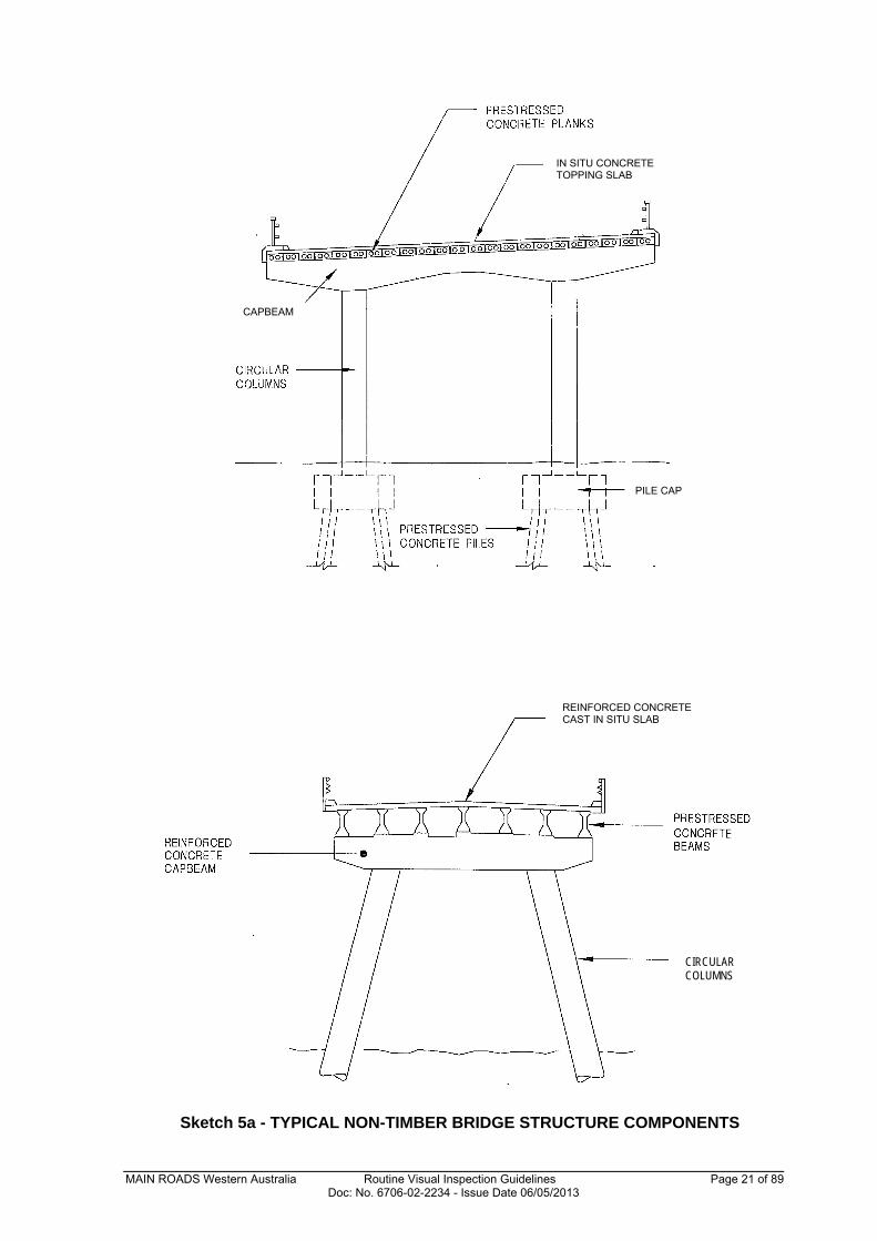
Sketch 5a - TYPICAL NON-TIMBER BRIDGE STRUCTURE COMPONENTS
CIRCULAR COLUMNS
IN SITU CONCRETE TOPPING SLAB
CAPBEAM
PILE CAP
REINFORCED CONCRETE CAST IN SITU SLAB
MAIN ROADS Western Australia Routine Visual Inspection Guidelines Page 22 of 89 Doc: No. 6706-02-2234 - Issue Date 06/05/2013
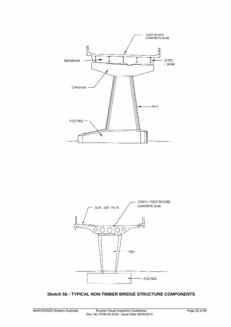
Sketch 5b - TYPICAL NON-TIMBER BRIDGE STRUCTURE COMPONENTS
DIAPHRAGM
CAST IN SITU CONCRETE SLAB
CONCRETE SLAB
MAIN ROADS Western Australia Routine Visual Inspection Guidelines Page 23 of 89 Doc: No. 6706-02-2234 - Issue Date 06/05/2013
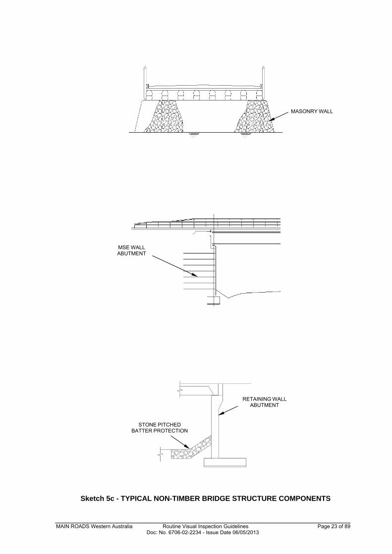
Sketch 5c - TYPICAL NON-TIMBER BRIDGE STRUCTURE COMPONENTS
MASONRY WALL
MSE WALL
ABUTMENT
RETAINING WALL
ABUTMENT
STONE PITCHED
BATTER PROTECTION
MAIN ROADS Western Australia Routine Visual Inspection Guidelines Page 24 of 89 Doc: No. 6706-02-2234 - Issue Date 06/05/2013
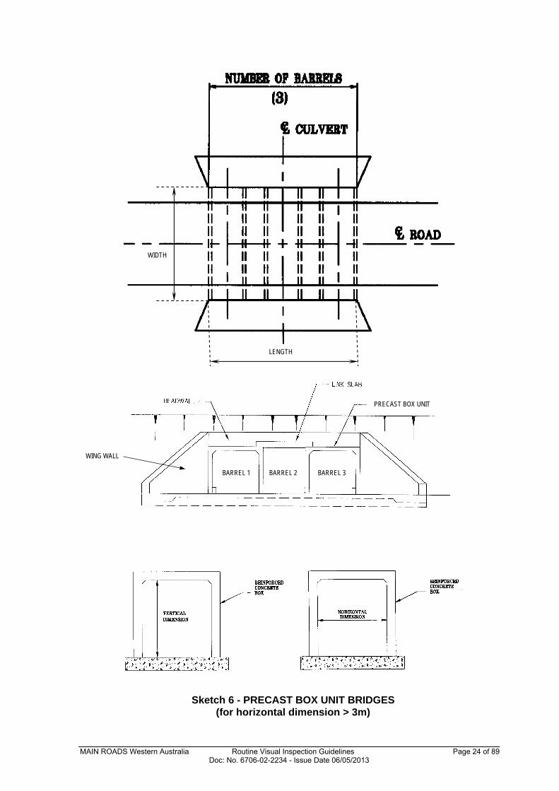
Sketch 6 - PRECAST BOX UNIT BRIDGES (for horizontal dimension > 3m)
PRECAST BOX UNIT
LENGTH
WIDTH
WING WALL
BARREL 1 BARREL 2
BARREL 3
MAIN ROADS Western Australia Routine Visual Inspection Guidelines Page 25 of 89 Doc: No. 6706-02-2234 - Issue Date 06/05/2013
APPENDIX B
TIMBER AND NON-TIMBER BRIDGE ROUTINE VISUAL INSPECTION REPORT (Level 1 Inspection)
EXAMPLE
TIMBER AND NON-TIMBER BRIDGE ROUTINE VISUAL
INSPECTION REPORT (Level 1 Inspection)
MAIN ROADS Western Australia Routine Visual Inspection Guidelines Page 26 of 89 Doc: No. 6706-02-2234 - Issue Date 06/05/2013
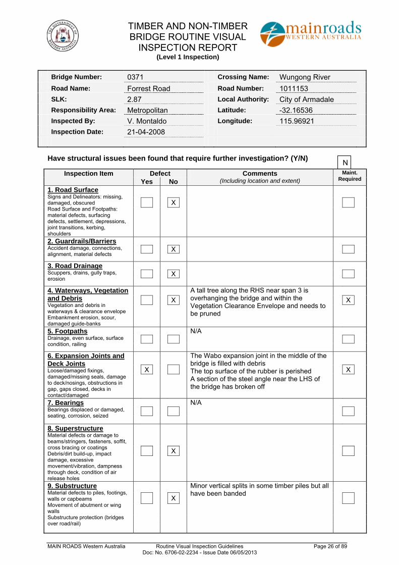
Bridge Number: 0371 Crossing Name: Wungong River Road Name: Forrest Road Road Number: 1011153 SLK: 2.87 Local Authority: City of Armadale Responsibility Area: Metropolitan Latitude: -32.16536 Inspected By: V. Montaldo Longitude: 115.96921 Inspection Date: 21-04-2008
Have structural issues been found that require further investigation? (Y/N)
Inspection Item Defect Comments (Including location and extent)
Maint. Required Yes No
1. Road Surface Signs and Delineators: missing, damaged, obscured Road Surface and Footpaths: material defects, surfacing defects, settlement, depressions, joint transitions, kerbing, shoulders
X
2. Guardrails/Barriers Accident damage, connections, alignment, material defects
X
3. Road Drainage Scuppers, drains, gully traps, erosion
X
4. Waterways, Vegetation and Debris Vegetation and debris in waterways & clearance envelope Embankment erosion, scour, damaged guide-banks
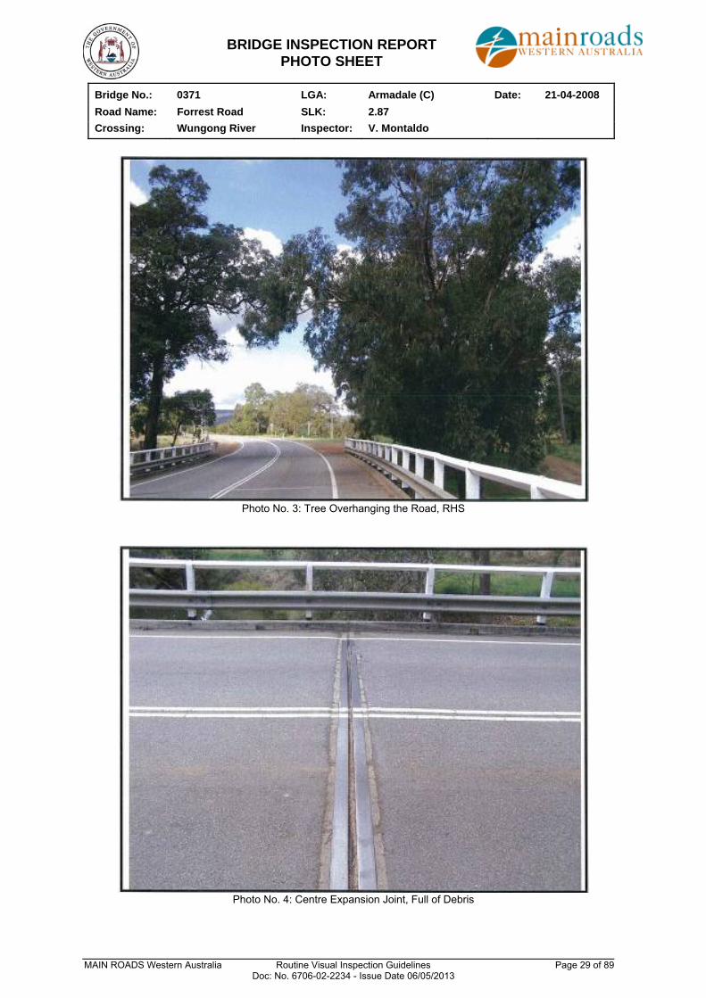
A tall tree along the RHS near span 3 is overhanging the bridge and within the Vegetation Clearance Envelope and needs to be pruned
X X
5. Footpaths Drainage, even surface, surface condition, railing
N/A
6. Expansion Joints and Deck Joints Loose/damaged fixings, damaged/missing seals, damage to deck/nosings, obstructions in gap, gaps closed, decks in contact/damaged
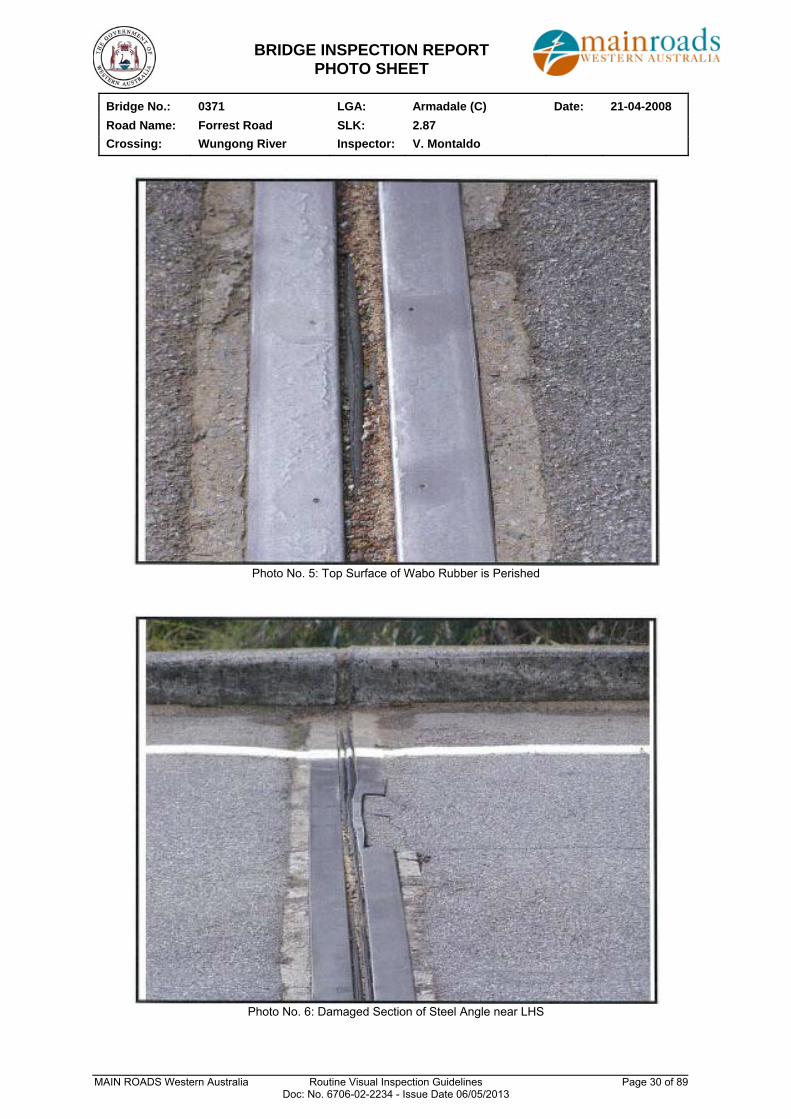
The Wabo expansion joint in the middle of the bridge is filled with debris The top surface of the rubber is perished A section of the steel angle near the LHS of the bridge has broken off
X X
7. Bearings Bearings displaced or damaged, seating, corrosion, seized
N/A
8. Superstructure Material defects or damage to beams/stringers, fasteners, soffit, cross bracing or coatings Debris/dirt build-up, impact damage, excessive movement/vibration, dampness through deck, condition of air release holes
X
9. Substructure Material defects to piles, footings, walls or capbeams Movement of abutment or wing walls Substructure protection (bridges over road/rail)
Minor vertical splits in some timber piles but all have been banded
X
N
TIMBER AND NON-TIMBER BRIDGE ROUTINE VISUAL
INSPECTION REPORT (Level 1 Inspection)
MAIN ROADS Western Australia Routine Visual Inspection Guidelines Page 27 of 89 Doc: No. 6706-02-2234 - Issue Date 06/05/2013
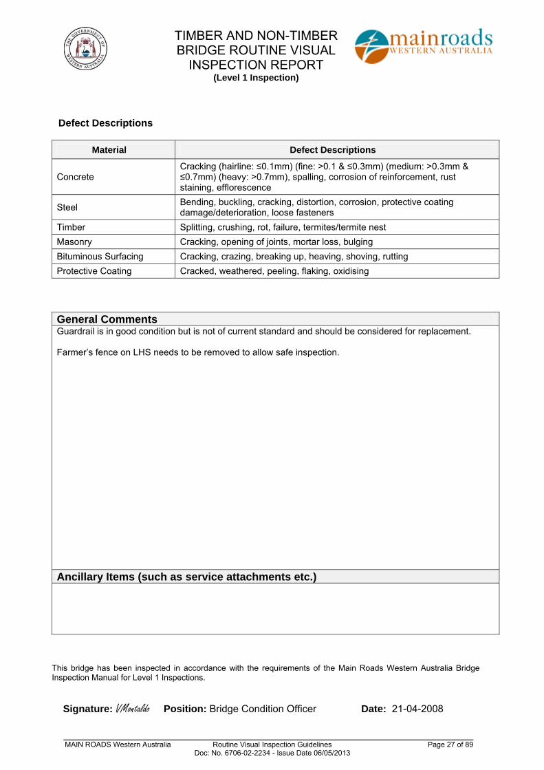
Defect Descriptions
Material Defect Descriptions
Concrete Cracking (hairline: ≤0.1mm) (fine: >0.1 & ≤0.3mm) (medium: >0.3mm & ≤0.7mm) (heavy: >0.7mm), spalling, corrosion of reinforcement, rust staining, efflorescence
Steel Bending, buckling, cracking, distortion, corrosion, protective coating damage/deterioration, loose fasteners
Timber Splitting, crushing, rot, failure, termites/termite nest
Masonry Cracking, opening of joints, mortar loss, bulging
Bituminous Surfacing Cracking, crazing, breaking up, heaving, shoving, rutting
Protective Coating Cracked, weathered, peeling, flaking, oxidising
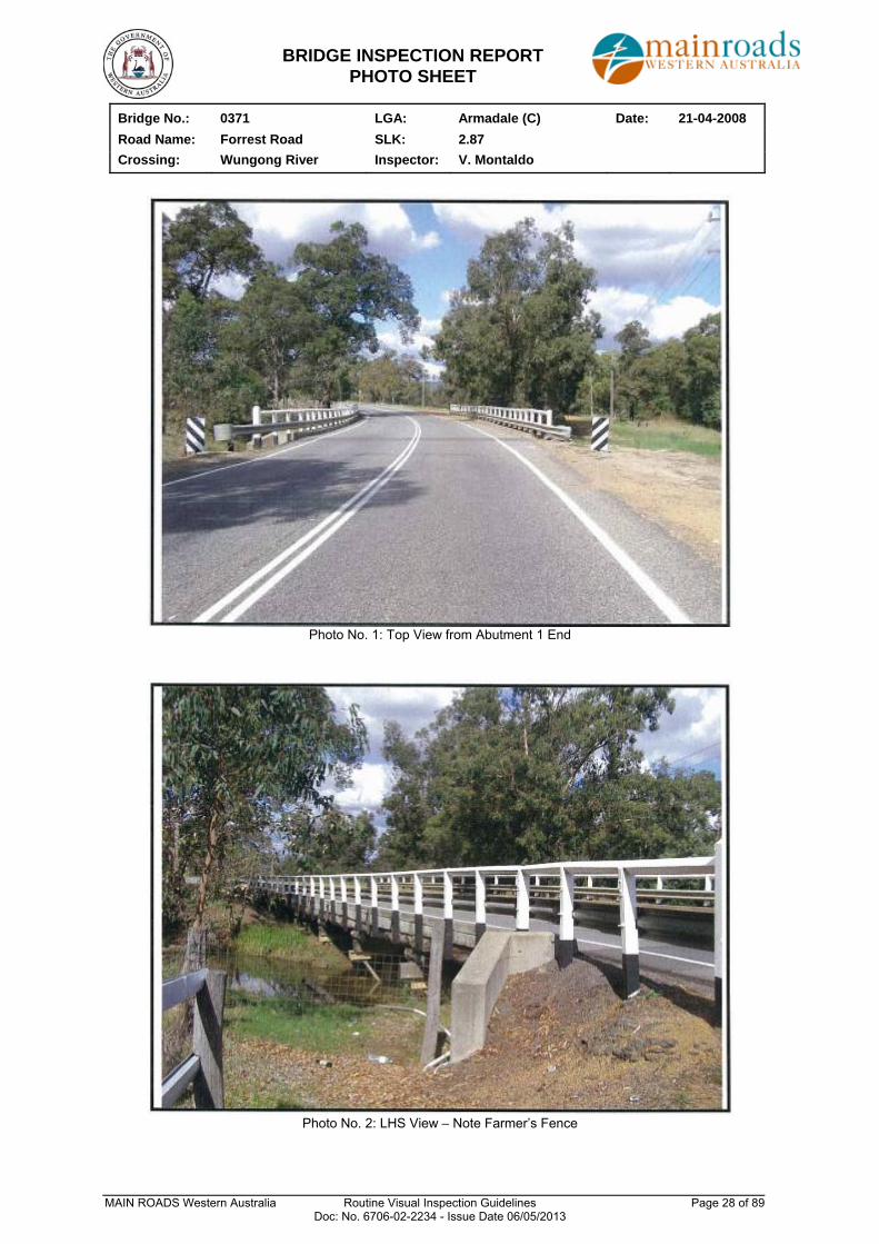
General Comments Guardrail is in good condition but is not of current standard and should be considered for replacement. Farmer’s fence on LHS needs to be removed to allow safe inspection.
Ancillary Items (such as service attachments etc.)
This bridge has been inspected in accordance with the requirements of the Main Roads Western Australia Bridge Inspection Manual for Level 1 Inspections.
Signature: VMontaldo Position: Bridge Condition Officer Date: 21-04-2008
BRIDGE INSPECTION REPORT PHOTO SHEET
Bridge No.: 0371 LGA: Armadale (C) Date: 21-04-2008
Road Name: Forrest Road SLK: 2.87
Crossing: Wungong River Inspector: V. Montaldo
MAIN ROADS Western Australia Routine Visual Inspection Guidelines Page 28 of 89 Doc: No. 6706-02-2234 - Issue Date 06/05/2013
Photo No. 1: Top View from Abutment 1 End
Photo No. 2: LHS View – Note Farmer’s Fence
BRIDGE INSPECTION REPORT PHOTO SHEET
Bridge No.: 0371 LGA: Armadale (C) Date: 21-04-2008
Road Name: Forrest Road SLK: 2.87
Crossing: Wungong River Inspector: V. Montaldo
MAIN ROADS Western Australia Routine Visual Inspection Guidelines Page 29 of 89 Doc: No. 6706-02-2234 - Issue Date 06/05/2013
Photo No. 3: Tree Overhanging the Road, RHS
Photo No. 4: Centre Expansion Joint, Full of Debris
BRIDGE INSPECTION REPORT PHOTO SHEET
Bridge No.: 0371 LGA: Armadale (C) Date: 21-04-2008
Road Name: Forrest Road SLK: 2.87
Crossing: Wungong River Inspector: V. Montaldo
MAIN ROADS Western Australia Routine Visual Inspection Guidelines Page 30 of 89 Doc: No. 6706-02-2234 - Issue Date 06/05/2013
Photo No. 5: Top Surface of Wabo Rubber is Perished
Photo No. 6: Damaged Section of Steel Angle near LHS
MAIN ROADS Western Australia Routine Visual Inspection Guidelines Page 31 of 89 Doc: No. 6706-02-2234 - Issue Date 06/05/2013
APPENDIX C
PRECAST BOX UNIT BRIDGE ROUTINE VISUAL INSPECTION REPORT (Level 1 Inspection)
EXAMPLE
PRECAST BOX UNIT BRIDGE ROUTINE VISUAL
INSPECTION REPORT (Level 1 Inspection)
MAIN ROADS Western Australia Routine Visual Inspection Guidelines Page 32 of 89 Doc: No. 6706-02-2234 - Issue Date 06/05/2013
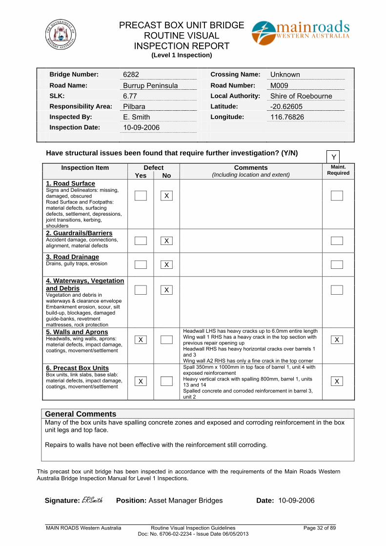
Bridge Number: 6282 Crossing Name: Unknown Road Name: Burrup Peninsula Road Number: M009 SLK: 6.77 Local Authority: Shire of Roebourne Responsibility Area: Pilbara Latitude: -20.62605 Inspected By: E. Smith Longitude: 116.76826 Inspection Date: 10-09-2006
Have structural issues been found that require further investigation? (Y/N)
Inspection Item Defect Comments (Including location and extent)
Maint. Required Yes No
1. Road Surface Signs and Delineators: missing, damaged, obscured Road Surface and Footpaths: material defects, surfacing defects, settlement, depressions, joint transitions, kerbing, shoulders
X
2. Guardrails/Barriers Accident damage, connections, alignment, material defects
X
3. Road Drainage Drains, gully traps, erosion
X
4. Waterways, Vegetation and Debris Vegetation and debris in waterways & clearance envelope Embankment erosion, scour, silt build-up, blockages, damaged guide-banks, revetment mattresses, rock protection
X
5. Walls and Aprons Headwalls, wing walls, aprons: material defects, impact damage, coatings, movement/settlement
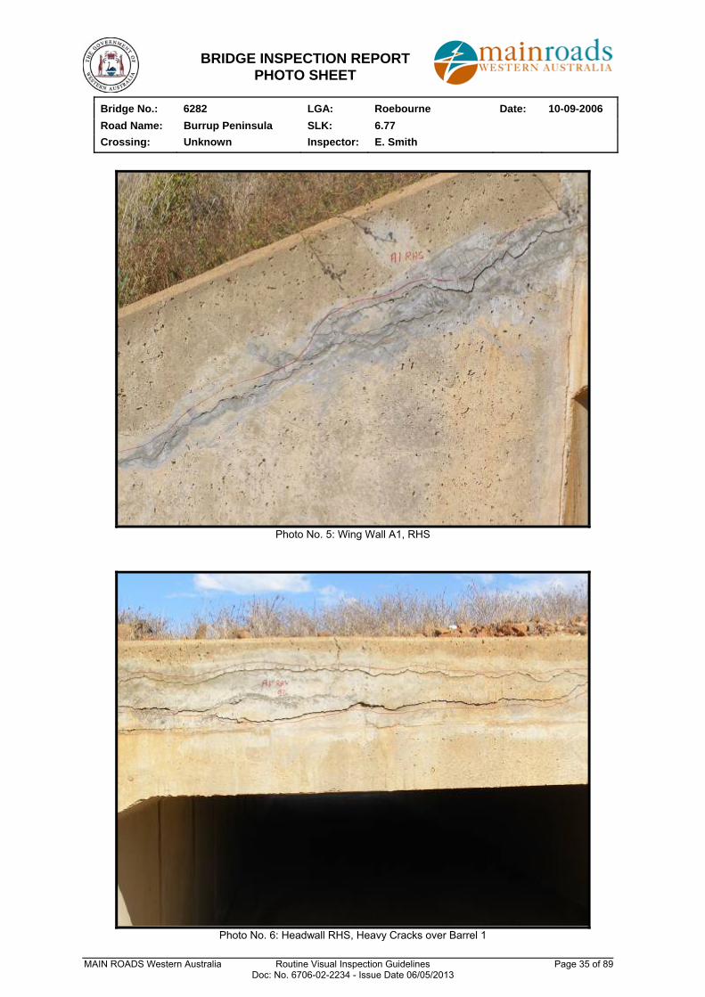
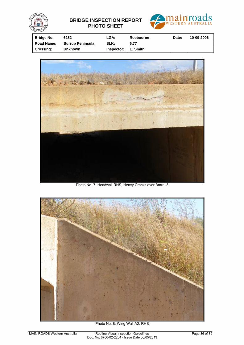
Headwall LHS has heavy cracks up to 6.0mm entire length Wing wall 1 RHS has a heavy crack in the top section with previous repair opening up Headwall RHS has heavy horizontal cracks over barrels 1 and 3 Wing wall A2 RHS has only a fine crack in the top corner
X X
6. Precast Box Units Box units, link slabs, base slab: material defects, impact damage, coatings, movement/settlement
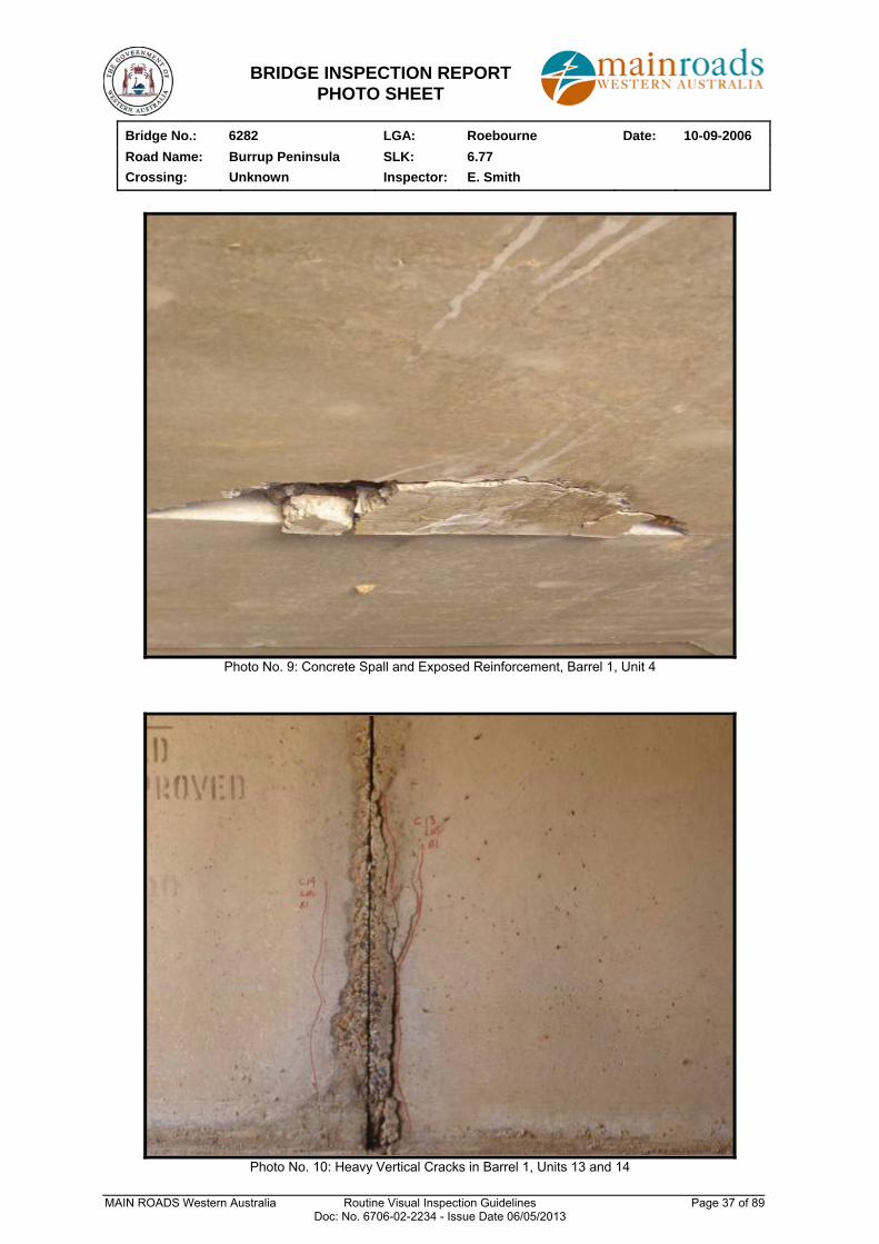
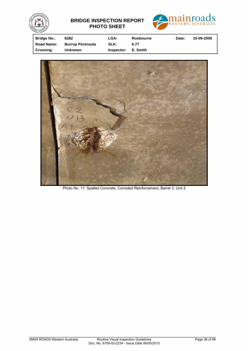
Spall 350mm x 1000mm in top face of barrel 1, unit 4 with exposed reinforcement Heavy vertical crack with spalling 800mm, barrel 1, units 13 and 14 Spalled concrete and corroded reinforcement in barrel 3, unit 2
X X
General Comments Many of the box units have spalling concrete zones and exposed and corroding reinforcement in the box unit legs and top face. Repairs to walls have not been effective with the reinforcement still corroding.
This precast box unit bridge has been inspected in accordance with the requirements of the Main Roads Western Australia Bridge Inspection Manual for Level 1 Inspections.
Signature: ERSmith Position: Asset Manager Bridges Date: 10-09-2006
Y
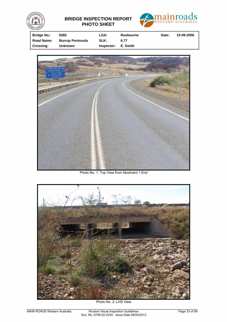
BRIDGE INSPECTION REPORT PHOTO SHEET
Bridge No.: 6282 LGA: Roebourne Date: 10-09-2006
Road Name: Burrup Peninsula SLK: 6.77
Crossing: Unknown Inspector: E. Smith
MAIN ROADS Western Australia Routine Visual Inspection Guidelines Page 33 of 89 Doc: No. 6706-02-2234 - Issue Date 06/05/2013
Photo No. 1: Top View from Abutment 1 End
Photo No. 2: LHS View
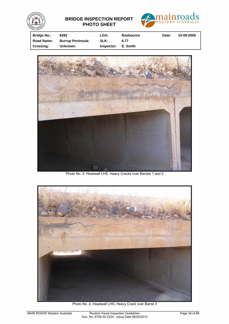
BRIDGE INSPECTION REPORT PHOTO SHEET
Bridge No.: 6282 LGA: Roebourne Date: 10-09-2006
Road Name: Burrup Peninsula SLK: 6.77
Crossing: Unknown Inspector: E. Smith
MAIN ROADS Western Australia Routine Visual Inspection Guidelines Page 34 of 89 Doc: No. 6706-02-2234 - Issue Date 06/05/2013
Photo No. 3: Headwall LHS, Heavy Cracks over Barrels 1 and 2
Photo No. 4: Headwall LHS, Heavy Crack over Barrel 3
BRIDGE INSPECTION REPORT PHOTO SHEET
Bridge No.: 6282 LGA: Roebourne Date: 10-09-2006
Road Name: Burrup Peninsula SLK: 6.77
Crossing: Unknown Inspector: E. Smith
MAIN ROADS Western Australia Routine Visual Inspection Guidelines Page 35 of 89 Doc: No. 6706-02-2234 - Issue Date 06/05/2013
Photo No. 5: Wing Wall A1, RHS
Photo No. 6: Headwall RHS, Heavy Cracks over Barrel 1
BRIDGE INSPECTION REPORT PHOTO SHEET
Bridge No.: 6282 LGA: Roebourne Date: 10-09-2006
Road Name: Burrup Peninsula SLK: 6.77
Crossing: Unknown Inspector: E. Smith
MAIN ROADS Western Australia Routine Visual Inspection Guidelines Page 36 of 89 Doc: No. 6706-02-2234 - Issue Date 06/05/2013
Photo No. 7: Headwall RHS, Heavy Cracks over Barrel 3
Photo No. 8: Wing Wall A2, RHS
BRIDGE INSPECTION REPORT PHOTO SHEET
Bridge No.: 6282 LGA: Roebourne Date: 10-09-2006
Road Name: Burrup Peninsula SLK: 6.77
Crossing: Unknown Inspector: E. Smith
MAIN ROADS Western Australia Routine Visual Inspection Guidelines Page 37 of 89 Doc: No. 6706-02-2234 - Issue Date 06/05/2013
Photo No. 9: Concrete Spall and Exposed Reinforcement, Barrel 1, Unit 4
Photo No. 10: Heavy Vertical Cracks in Barrel 1, Units 13 and 14
BRIDGE INSPECTION REPORT PHOTO SHEET
Bridge No.: 6282 LGA: Roebourne Date: 10-09-2006
Road Name: Burrup Peninsula SLK: 6.77
Crossing: Unknown Inspector: E. Smith
MAIN ROADS Western Australia Routine Visual Inspection Guidelines Page 38 of 89 Doc: No. 6706-02-2234 - Issue Date 06/05/2013
Photo No. 11: Spalled Concrete, Corroded Reinforcement, Barrel 3, Unit 2
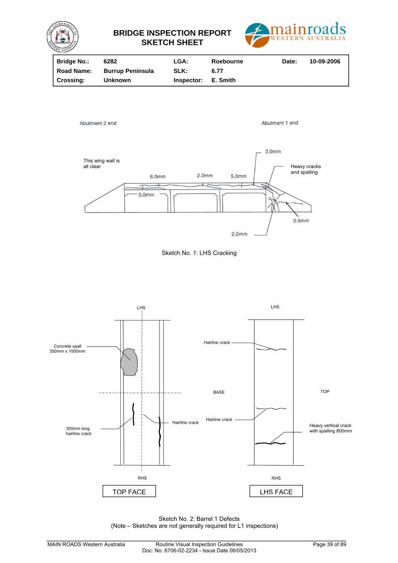
BRIDGE INSPECTION REPORT SKETCH SHEET
Bridge No.: 6282 LGA: Roebourne Date: 10-09-2006
Road Name: Burrup Peninsula SLK: 6.77
Crossing: Unknown Inspector: E. Smith
MAIN ROADS Western Australia Routine Visual Inspection Guidelines Page 39 of 89 Doc: No. 6706-02-2234 - Issue Date 06/05/2013
Sketch No. 1: LHS Cracking
RHS
LHS
300mm long hairline crack
Hairline crack
Concrete spall 350mm x 1000mm
RHS
LHS
Hairline crackMajor vertical crack with spalling 800mm
TOPBASE
Hairline crack
Sketch No. 2: Barrel 1 Defects (Note – Sketches are not generally required for L1 inspections)
TOP FACE LHS FACE
This wing wall is all clear
Heavy vertical crack with spalling 800mm
Heavy cracks and spalling
MAIN ROADS Western Australia Routine Visual Inspection Guidelines Page 40 of 89 Doc: No. 6706-02-2234 - Issue Date 06/05/2013
APPENDIX D
PHOTOGRAPHS AND SKETCHES OF SOME COMMON BRIDGE DEFECTS
Note: the photographs and sketches are provided as a complete set for general information but are not necessarily information that should be recorded for a Level 1 inspection.
MAIN ROADS Western Australia Routine Visual Inspection Guidelines Page 41 of 89 Doc: No. 6706-02-2234 - Issue Date 06/05/2013
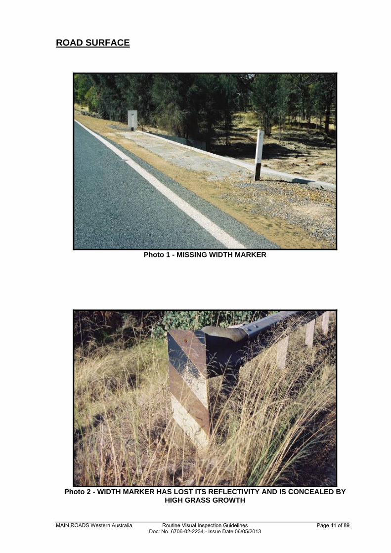
ROAD SURFACE
Photo 1 - MISSING WIDTH MARKER
Photo 2 - WIDTH MARKER HAS LOST ITS REFLECTIVITY AND IS CONCEALED BY
HIGH GRASS GROWTH
MAIN ROADS Western Australia Routine Visual Inspection Guidelines Page 42 of 89 Doc: No. 6706-02-2234 - Issue Date 06/05/2013
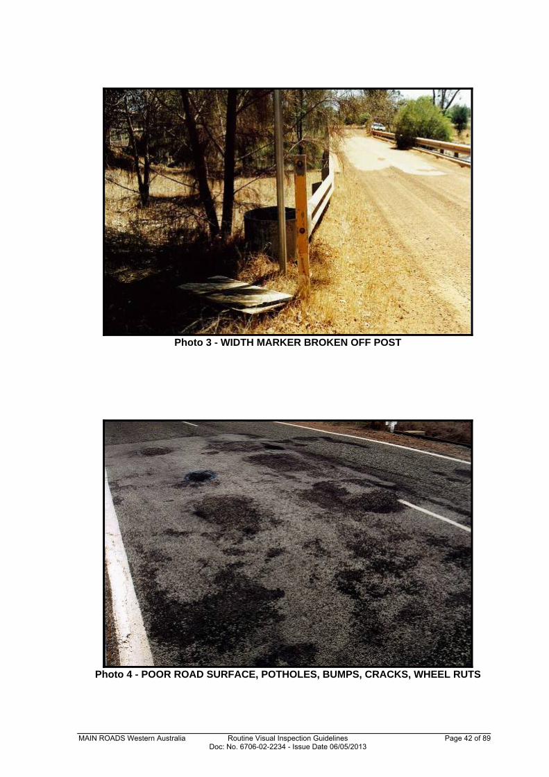
Photo 3 - WIDTH MARKER BROKEN OFF POST
Photo 4 - POOR ROAD SURFACE, POTHOLES, BUMPS, CRACKS, WHEEL RUTS
MAIN ROADS Western Australia Routine Visual Inspection Guidelines Page 43 of 89 Doc: No. 6706-02-2234 - Issue Date 06/05/2013
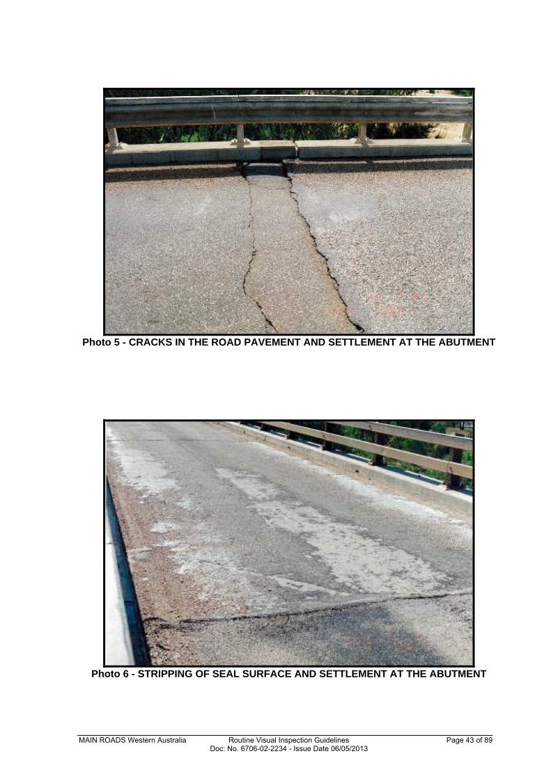
Photo 5 - CRACKS IN THE ROAD PAVEMENT AND SETTLEMENT AT THE ABUTMENT
Photo 6 - STRIPPING OF SEAL SURFACE AND SETTLEMENT AT THE ABUTMENT
MAIN ROADS Western Australia Routine Visual Inspection Guidelines Page 44 of 89 Doc: No. 6706-02-2234 - Issue Date 06/05/2013
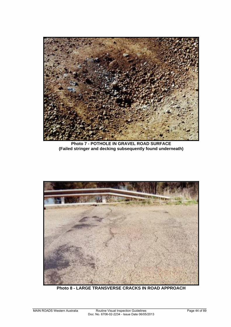
Photo 7 - POTHOLE IN GRAVEL ROAD SURFACE
(Failed stringer and decking subsequently found underneath)
Photo 8 - LARGE TRANSVERSE CRACKS IN ROAD APPROACH
MAIN ROADS Western Australia Routine Visual Inspection Guidelines Page 45 of 89 Doc: No. 6706-02-2234 - Issue Date 06/05/2013
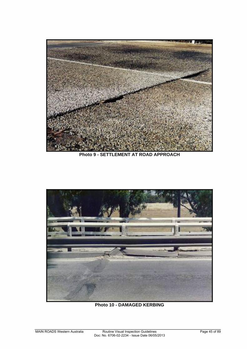
Photo 9 - SETTLEMENT AT ROAD APPROACH
Photo 10 - DAMAGED KERBING
MAIN ROADS Western Australia Routine Visual Inspection Guidelines Page 46 of 89 Doc: No. 6706-02-2234 - Issue Date 06/05/2013
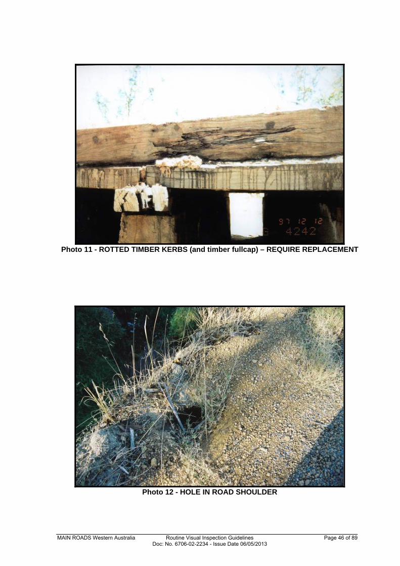
Photo 11 - ROTTED TIMBER KERBS (and timber fullcap) – REQUIRE REPLACEMENT
Photo 12 - HOLE IN ROAD SHOULDER
MAIN ROADS Western Australia Routine Visual Inspection Guidelines Page 47 of 89 Doc: No. 6706-02-2234 - Issue Date 06/05/2013
GUARDRAILS/BARRIERS
Photo 13 - DEPARTURE RAILING HAS BROKEN POSTS
Photo 14 - IMPACT DAMAGE TO BULL NOSE
MAIN ROADS Western Australia Routine Visual Inspection Guidelines Page 48 of 89 Doc: No. 6706-02-2234 - Issue Date 06/05/2013
Photo 15 - DAMAGED FISHTAIL AT ABUT 1 RHS
Photo 16 - IMPACT DAMAGE TO RHS GUARDRAIL
MAIN ROADS Western Australia Routine Visual Inspection Guidelines Page 49 of 89 Doc: No. 6706-02-2234 - Issue Date 06/05/2013
Photo 17 - IMPACT DAMAGE ALONG FLEX-BEAM
Photo 18 - ADVANCED ASR CRACKING IN POSTS AND RAILS
MAIN ROADS Western Australia Routine Visual Inspection Guidelines Page 50 of 89 Doc: No. 6706-02-2234 - Issue Date 06/05/2013
Photo 19 - LARGE VERTICAL SPLIT IN TIMBER POST
Photo 20 - RAILING LEANING OVER AND KERB DETACHING FROM DECK
ROAD DRAINAGE
MAIN ROADS Western Australia Routine Visual Inspection Guidelines Page 51 of 89 Doc: No. 6706-02-2234 - Issue Date 06/05/2013
Photo 21 - VEGETATION REQUIRES CLEARING TO ENABLE SCUPPERS TO
FUNCTION
Photo 22 - SCUPPERS ARE BLOCKED BY EXCESSIVE ROAD DEBRIS
MAIN ROADS Western Australia Routine Visual Inspection Guidelines Page 52 of 89 Doc: No. 6706-02-2234 - Issue Date 06/05/2013
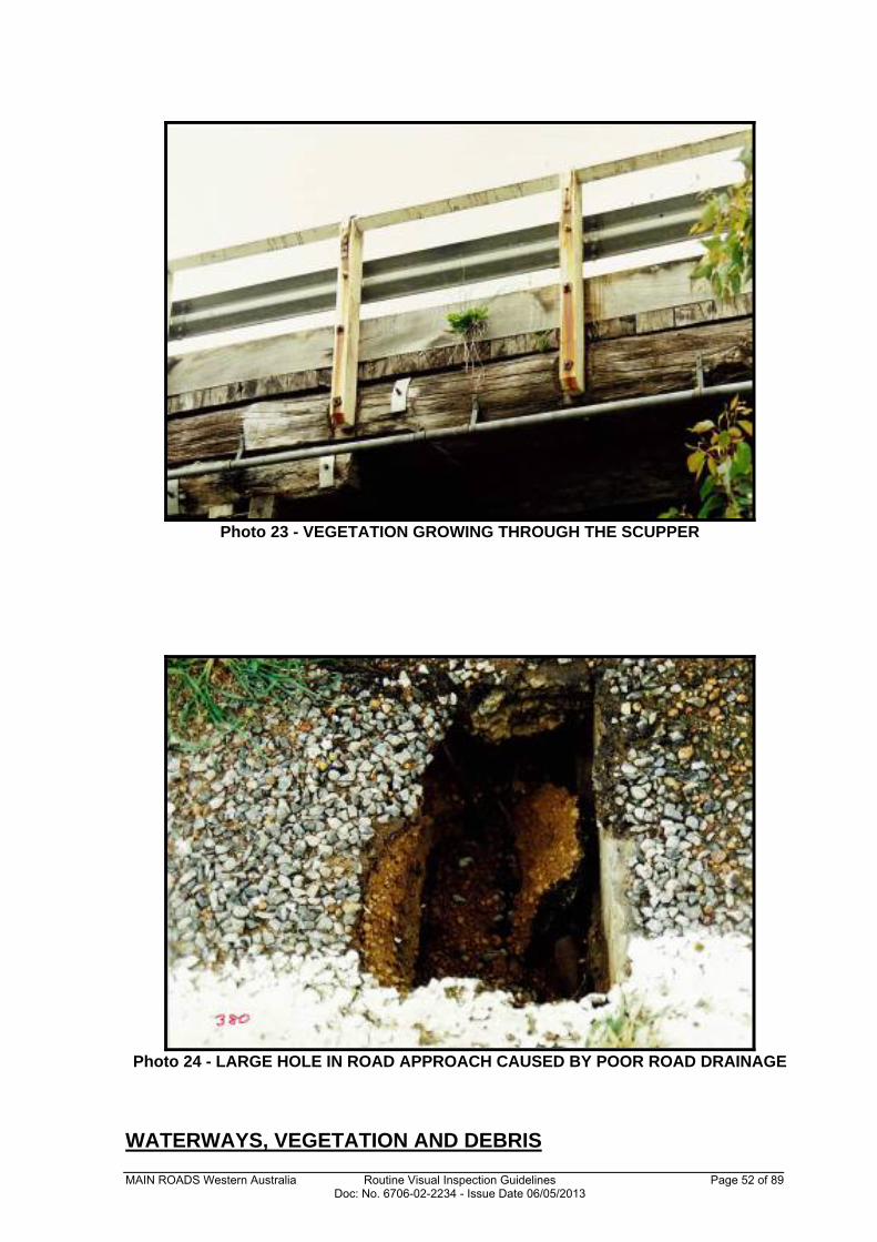
Photo 23 - VEGETATION GROWING THROUGH THE SCUPPER
Photo 24 - LARGE HOLE IN ROAD APPROACH CAUSED BY POOR ROAD DRAINAGE
WATERWAYS, VEGETATION AND DEBRIS

MAIN ROADS Western Australia Routine Visual Inspection Guidelines Page 53 of 89 Doc: No. 6706-02-2234 - Issue Date 06/05/2013
Photo 25 - BRIDGE OPENING IS BLOCKED BY HEAVY VEGETATION
Photo 26 - EXCESSIVE VEGETATION GROWTH ALONG ROAD SHOULDER
(Potential Fire Hazard)
MAIN ROADS Western Australia Routine Visual Inspection Guidelines Page 54 of 89 Doc: No. 6706-02-2234 - Issue Date 06/05/2013
Photo 27 - TREE GROWING OVER RAIL AND ONTO ROAD
Photo 28 - PRECAST BOX UNITS HAVE A BUILD-UP OF BRANCHES AND WEEDS
(This could cause future flow and/or scour problems)
MAIN ROADS Western Australia Routine Visual Inspection Guidelines Page 55 of 89 Doc: No. 6706-02-2234 - Issue Date 06/05/2013
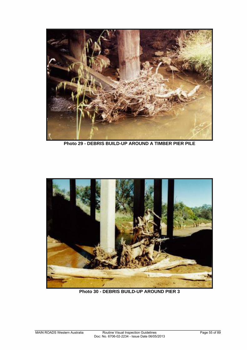
Photo 29 - DEBRIS BUILD-UP AROUND A TIMBER PIER PILE
Photo 30 - DEBRIS BUILD-UP AROUND PIER 3
MAIN ROADS Western Australia Routine Visual Inspection Guidelines Page 56 of 89 Doc: No. 6706-02-2234 - Issue Date 06/05/2013
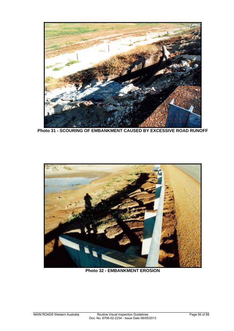
Photo 31 - SCOURING OF EMBANKMENT CAUSED BY EXCESSIVE ROAD RUNOFF
Photo 32 - EMBANKMENT EROSION
MAIN ROADS Western Australia Routine Visual Inspection Guidelines Page 57 of 89 Doc: No. 6706-02-2234 - Issue Date 06/05/2013
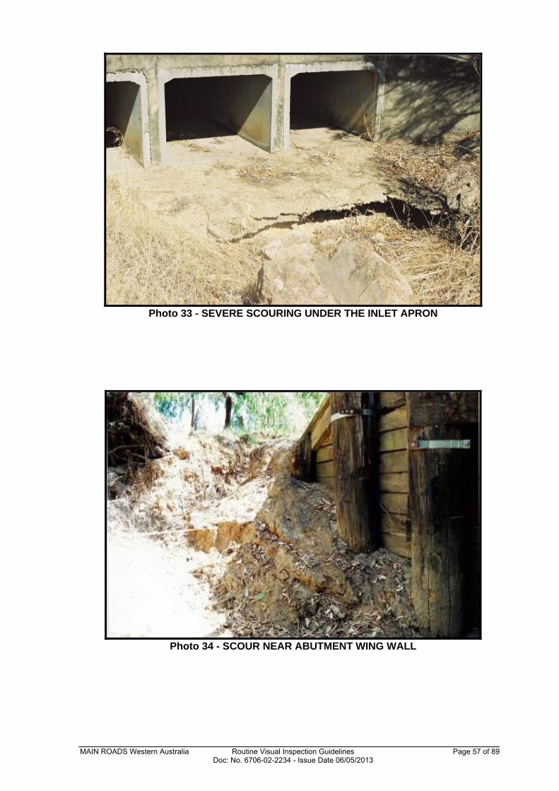
Photo 33 - SEVERE SCOURING UNDER THE INLET APRON
Photo 34 - SCOUR NEAR ABUTMENT WING WALL
MAIN ROADS Western Australia Routine Visual Inspection Guidelines Page 58 of 89 Doc: No. 6706-02-2234 - Issue Date 06/05/2013
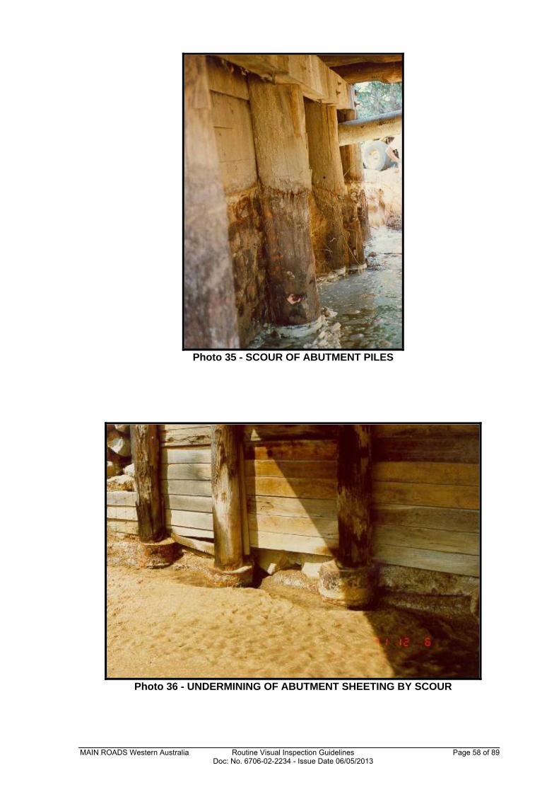
Photo 35 - SCOUR OF ABUTMENT PILES
Photo 36 - UNDERMINING OF ABUTMENT SHEETING BY SCOUR
MAIN ROADS Western Australia Routine Visual Inspection Guidelines Page 59 of 89 Doc: No. 6706-02-2234 - Issue Date 06/05/2013
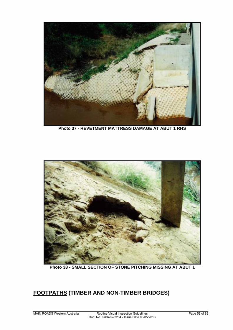
Photo 37 - REVETMENT MATTRESS DAMAGE AT ABUT 1 RHS
Photo 38 - SMALL SECTION OF STONE PITCHING MISSING AT ABUT 1
FOOTPATHS (TIMBER AND NON-TIMBER BRIDGES)
MAIN ROADS Western Australia Routine Visual Inspection Guidelines Page 60 of 89 Doc: No. 6706-02-2234 - Issue Date 06/05/2013
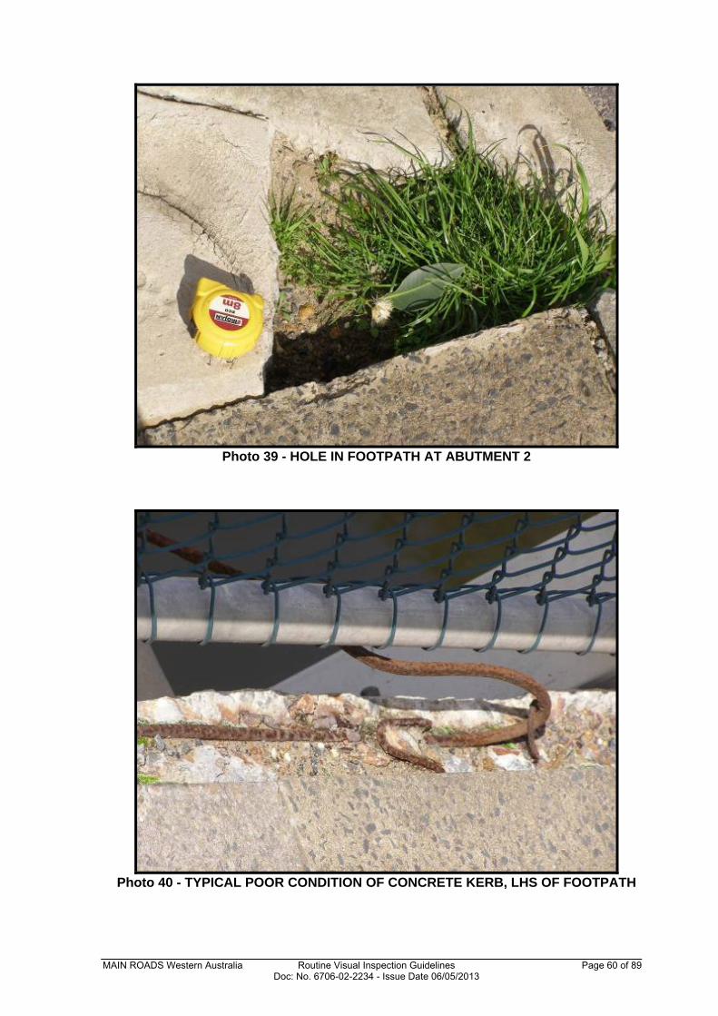
Photo 39 - HOLE IN FOOTPATH AT ABUTMENT 2
Photo 40 - TYPICAL POOR CONDITION OF CONCRETE KERB, LHS OF FOOTPATH
MAIN ROADS Western Australia Routine Visual Inspection Guidelines Page 61 of 89 Doc: No. 6706-02-2234 - Issue Date 06/05/2013
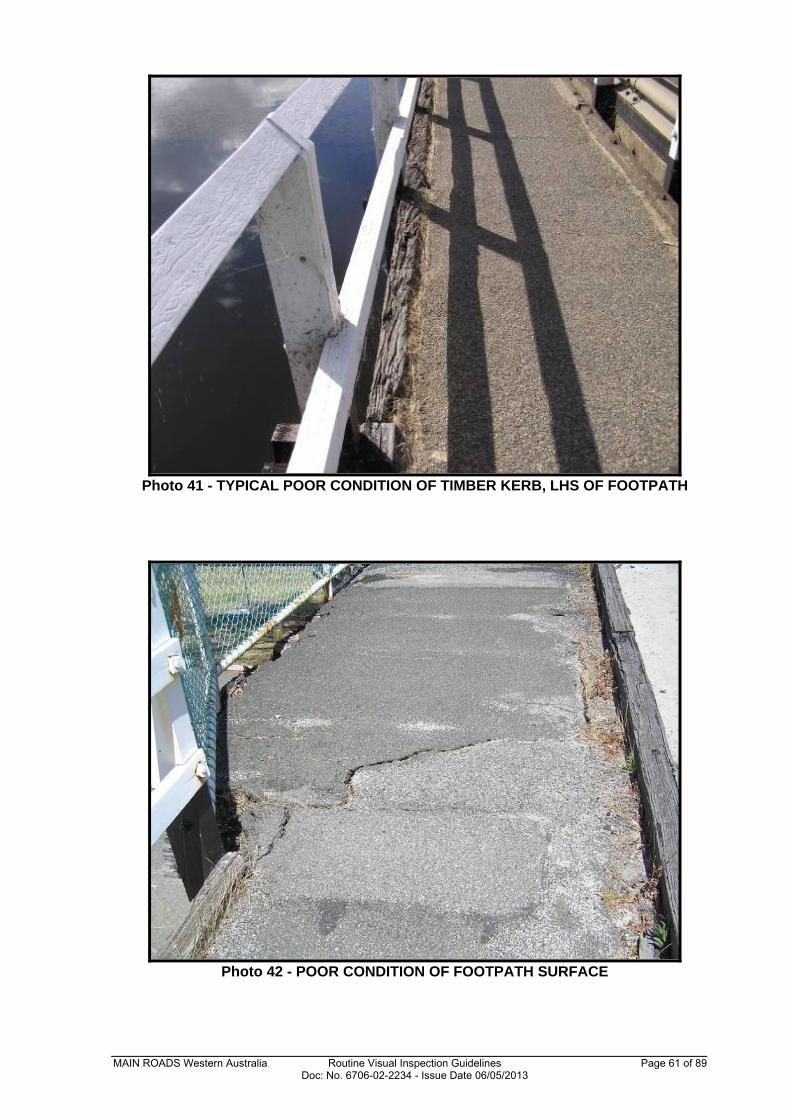
Photo 41 - TYPICAL POOR CONDITION OF TIMBER KERB, LHS OF FOOTPATH
Photo 42 - POOR CONDITION OF FOOTPATH SURFACE
MAIN ROADS Western Australia Routine Visual Inspection Guidelines Page 62 of 89 Doc: No. 6706-02-2234 - Issue Date 06/05/2013
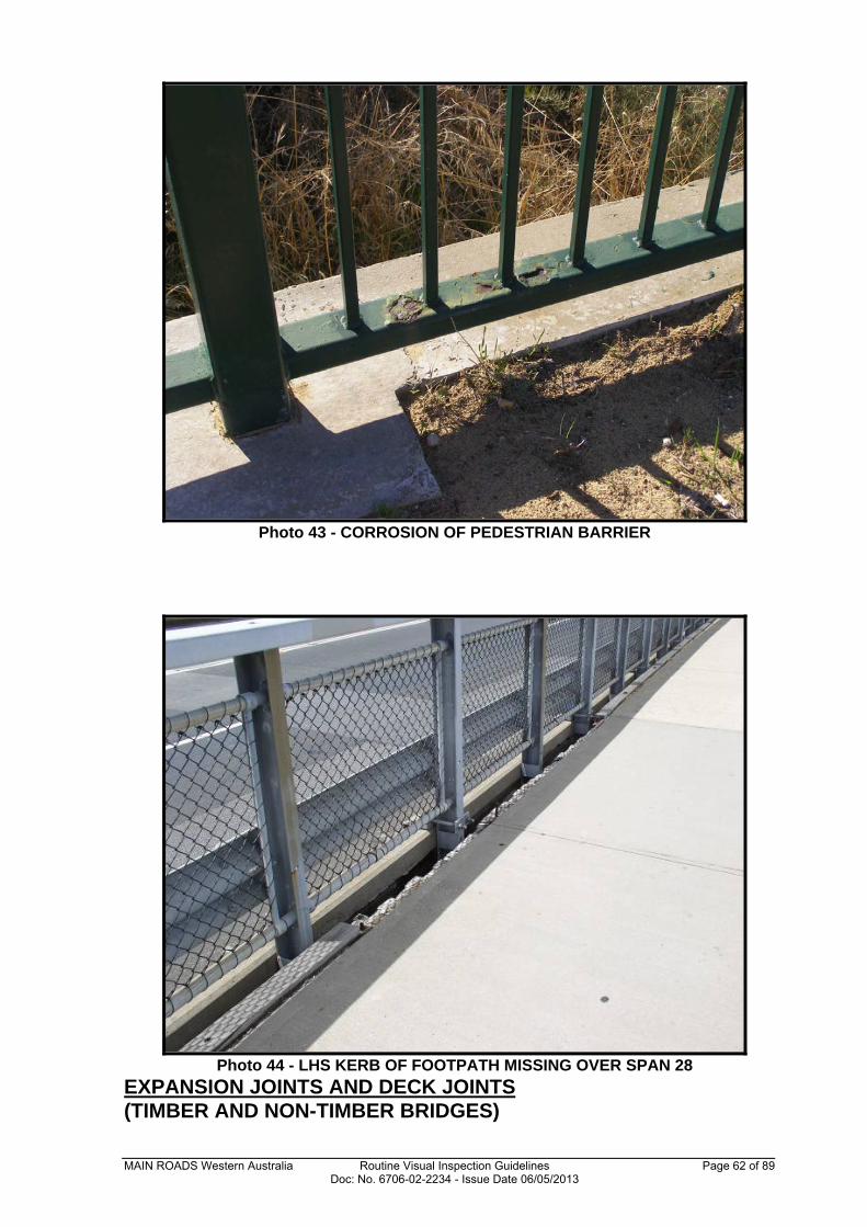
Photo 43 - CORROSION OF PEDESTRIAN BARRIER
Photo 44 - LHS KERB OF FOOTPATH MISSING OVER SPAN 28
EXPANSION JOINTS AND DECK JOINTS (TIMBER AND NON-TIMBER BRIDGES)
MAIN ROADS Western Australia Routine Visual Inspection Guidelines Page 63 of 89 Doc: No. 6706-02-2234 - Issue Date 06/05/2013
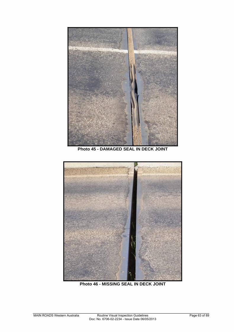
Photo 45 - DAMAGED SEAL IN DECK JOINT
Photo 46 - MISSING SEAL IN DECK JOINT
MAIN ROADS Western Australia Routine Visual Inspection Guidelines Page 64 of 89 Doc: No. 6706-02-2234 - Issue Date 06/05/2013
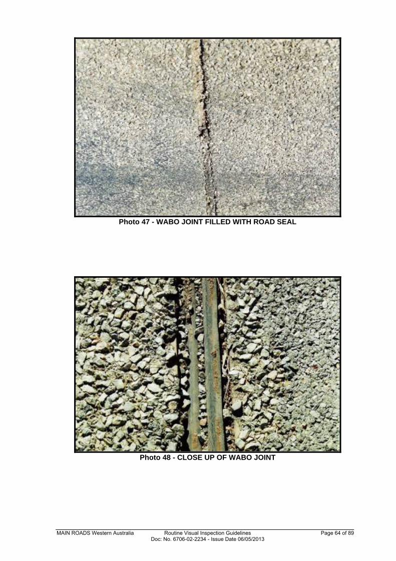
Photo 47 - WABO JOINT FILLED WITH ROAD SEAL
Photo 48 - CLOSE UP OF WABO JOINT
MAIN ROADS Western Australia Routine Visual Inspection Guidelines Page 65 of 89 Doc: No. 6706-02-2234 - Issue Date 06/05/2013
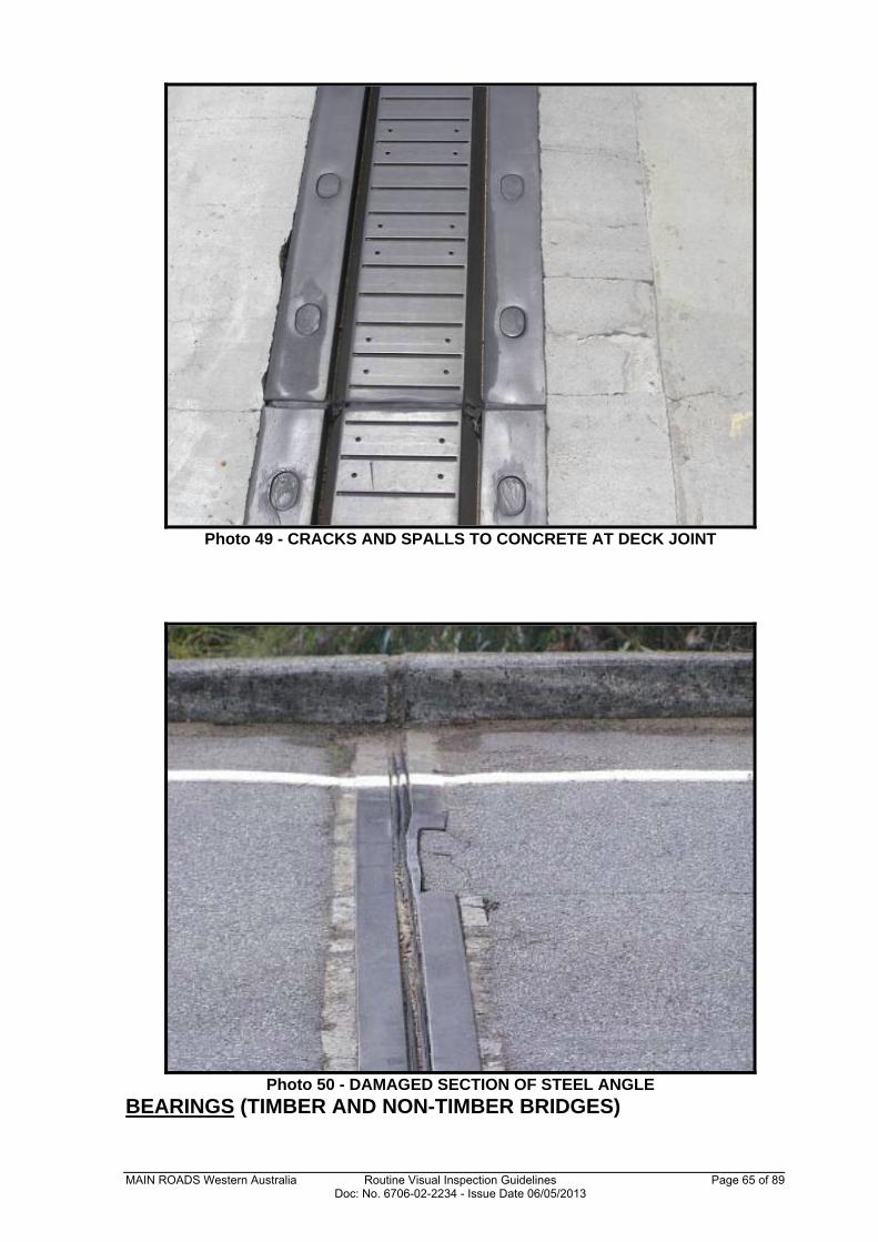
Photo 49 - CRACKS AND SPALLS TO CONCRETE AT DECK JOINT
Photo 50 - DAMAGED SECTION OF STEEL ANGLE
BEARINGS (TIMBER AND NON-TIMBER BRIDGES)
MAIN ROADS Western Australia Routine Visual Inspection Guidelines Page 66 of 89 Doc: No. 6706-02-2234 - Issue Date 06/05/2013
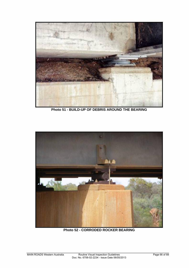
Photo 51 - BUILD-UP OF DEBRIS AROUND THE BEARING
Photo 52 - CORRODED ROCKER BEARING
MAIN ROADS Western Australia Routine Visual Inspection Guidelines Page 67 of 89 Doc: No. 6706-02-2234 - Issue Date 06/05/2013
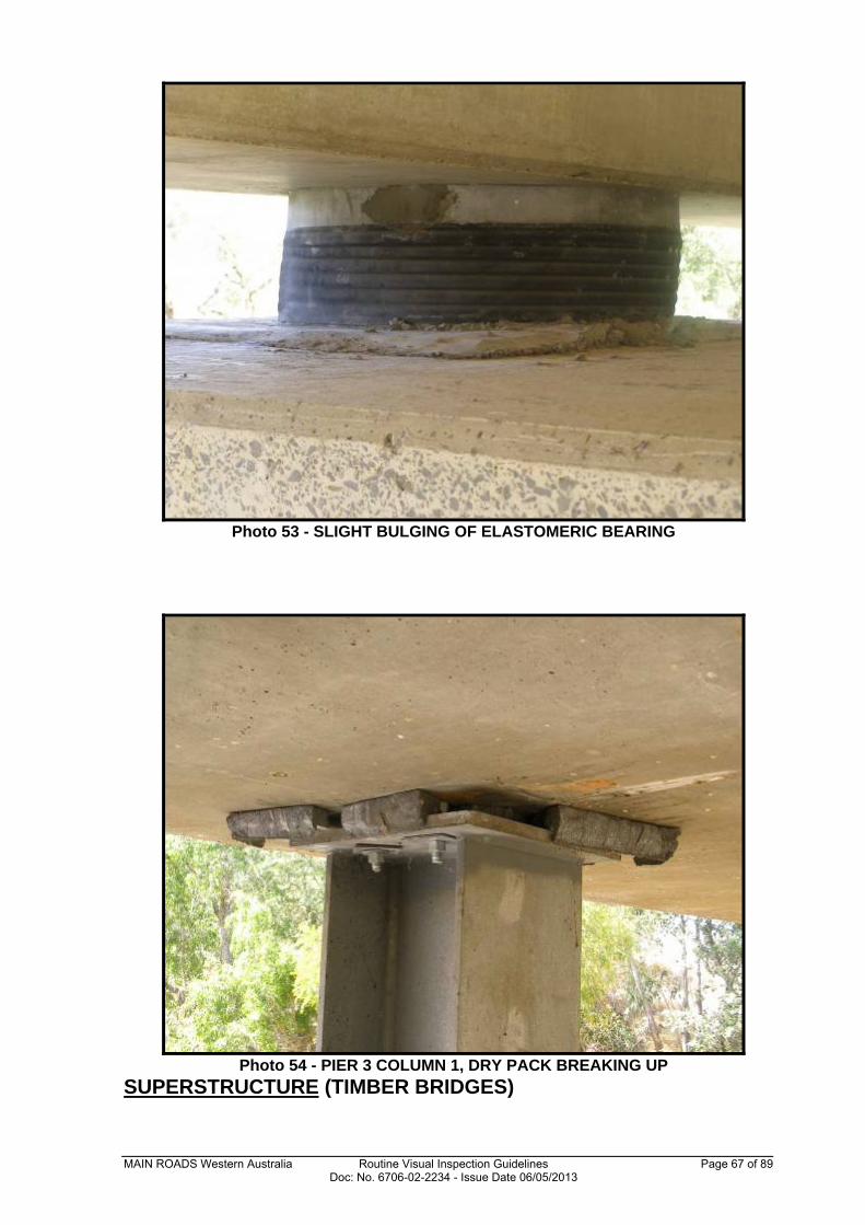
Photo 53 - SLIGHT BULGING OF ELASTOMERIC BEARING
Photo 54 - PIER 3 COLUMN 1, DRY PACK BREAKING UP
SUPERSTRUCTURE (TIMBER BRIDGES)
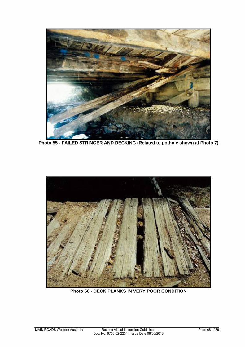
MAIN ROADS Western Australia Routine Visual Inspection Guidelines Page 68 of 89 Doc: No. 6706-02-2234 - Issue Date 06/05/2013
Photo 55 - FAILED STRINGER AND DECKING (Related to pothole shown at Photo 7)
Photo 56 - DECK PLANKS IN VERY POOR CONDITION
MAIN ROADS Western Australia Routine Visual Inspection Guidelines Page 69 of 89 Doc: No. 6706-02-2234 - Issue Date 06/05/2013
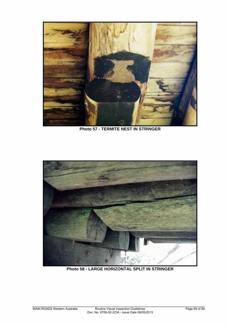
Photo 57 - TERMITE NEST IN STRINGER
Photo 58 - LARGE HORIZONTAL SPLIT IN STRINGER
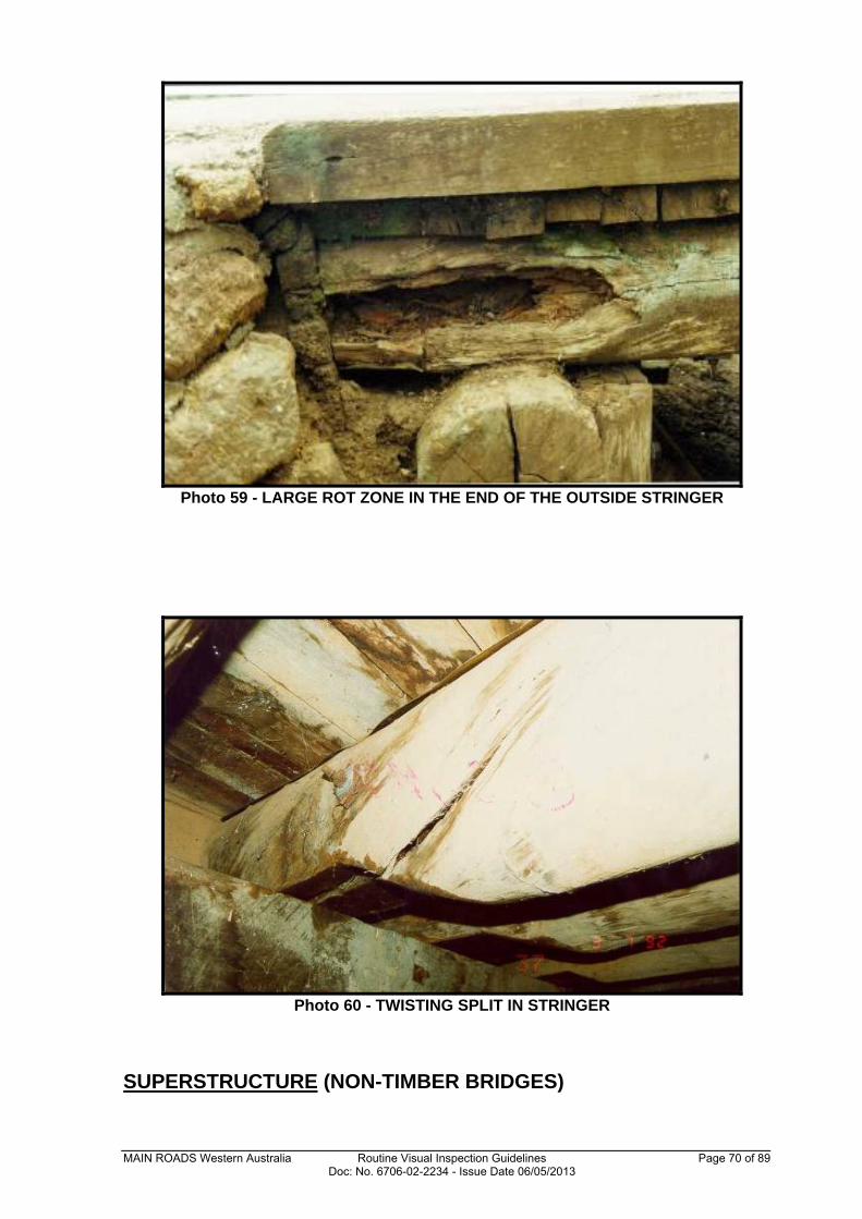
MAIN ROADS Western Australia Routine Visual Inspection Guidelines Page 70 of 89 Doc: No. 6706-02-2234 - Issue Date 06/05/2013
Photo 59 - LARGE ROT ZONE IN THE END OF THE OUTSIDE STRINGER
Photo 60 - TWISTING SPLIT IN STRINGER
SUPERSTRUCTURE (NON-TIMBER BRIDGES)
MAIN ROADS Western Australia Routine Visual Inspection Guidelines Page 71 of 89 Doc: No. 6706-02-2234 - Issue Date 06/05/2013
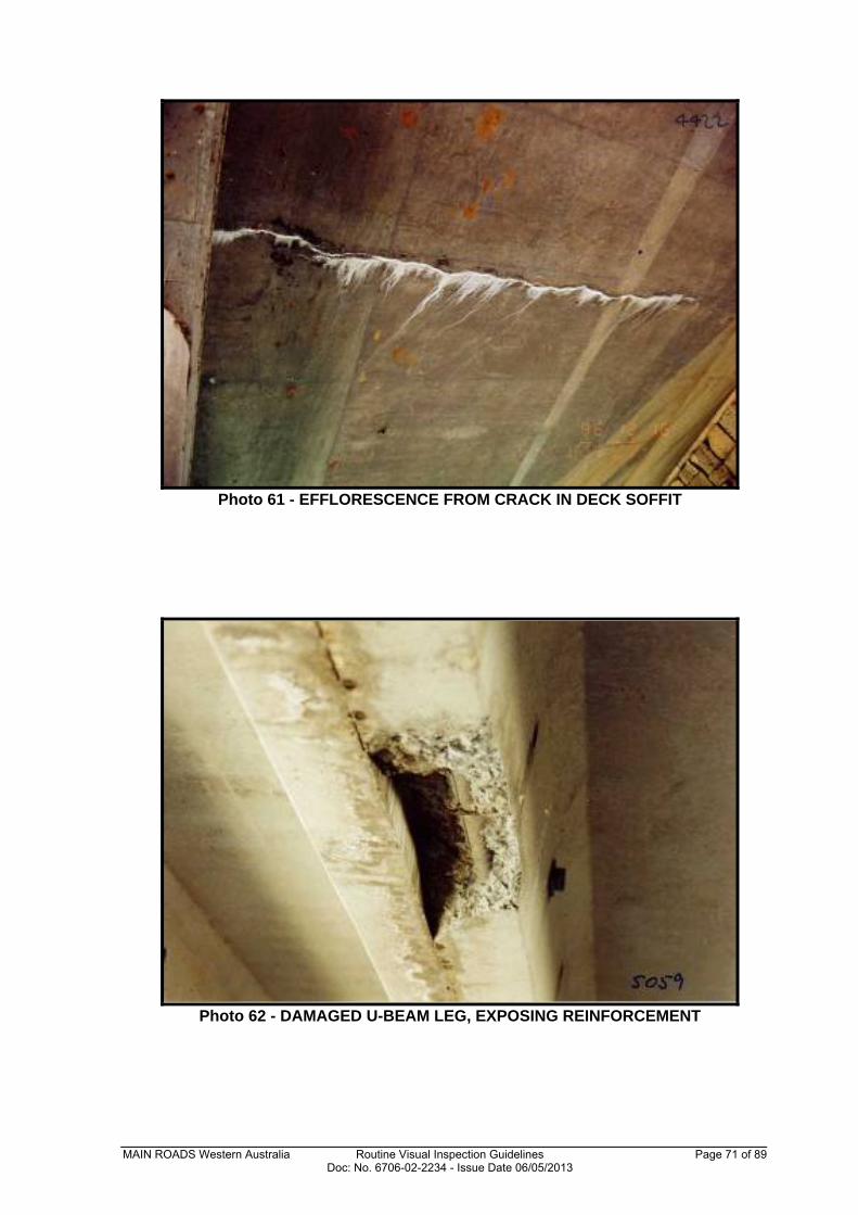
Photo 61 - EFFLORESCENCE FROM CRACK IN DECK SOFFIT
Photo 62 - DAMAGED U-BEAM LEG, EXPOSING REINFORCEMENT
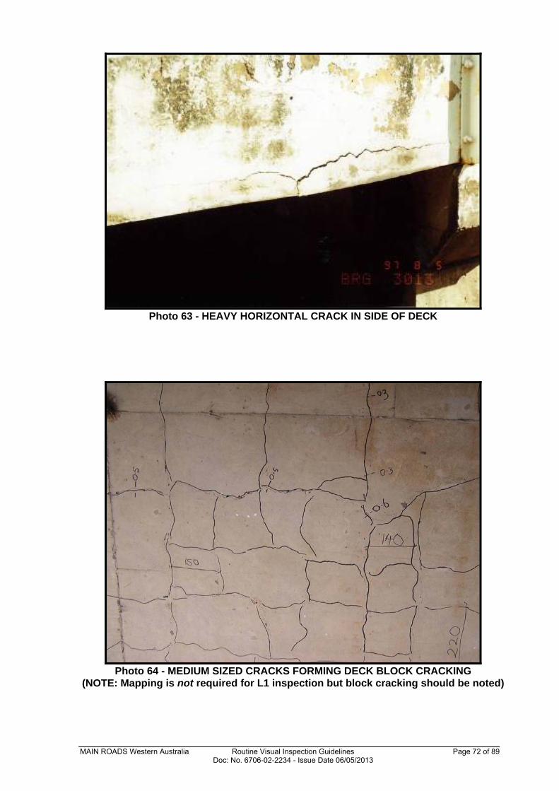
MAIN ROADS Western Australia Routine Visual Inspection Guidelines Page 72 of 89 Doc: No. 6706-02-2234 - Issue Date 06/05/2013
Photo 63 - HEAVY HORIZONTAL CRACK IN SIDE OF DECK
Photo 64 - MEDIUM SIZED CRACKS FORMING DECK BLOCK CRACKING
(NOTE: Mapping is not required for L1 inspection but block cracking should be noted)
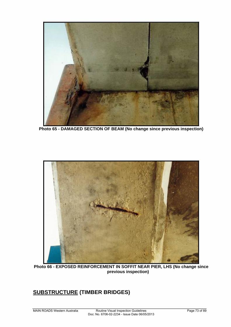
MAIN ROADS Western Australia Routine Visual Inspection Guidelines Page 73 of 89 Doc: No. 6706-02-2234 - Issue Date 06/05/2013
Photo 65 - DAMAGED SECTION OF BEAM (No change since previous inspection)
Photo 66 - EXPOSED REINFORCEMENT IN SOFFIT NEAR PIER, LHS (No change since
previous inspection)
SUBSTRUCTURE (TIMBER BRIDGES)
MAIN ROADS Western Australia Routine Visual Inspection Guidelines Page 74 of 89 Doc: No. 6706-02-2234 - Issue Date 06/05/2013
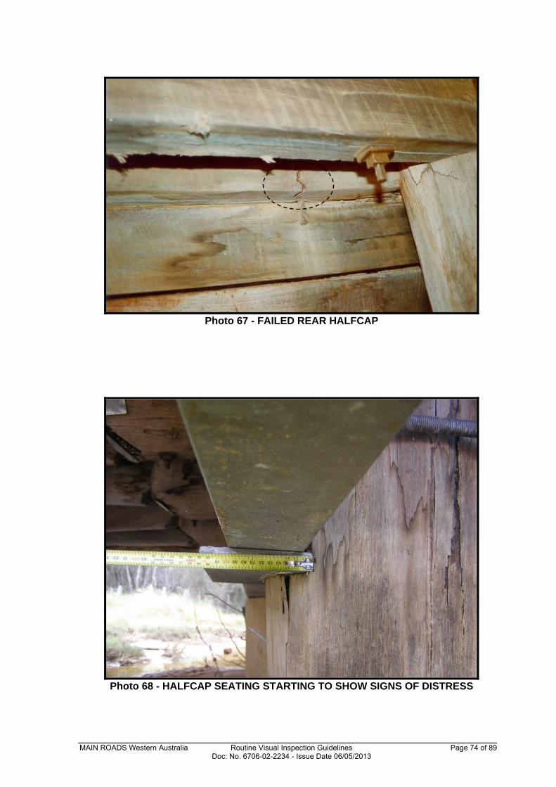
Photo 67 - FAILED REAR HALFCAP
Photo 68 - HALFCAP SEATING STARTING TO SHOW SIGNS OF DISTRESS
MAIN ROADS Western Australia Routine Visual Inspection Guidelines Page 75 of 89 Doc: No. 6706-02-2234 - Issue Date 06/05/2013
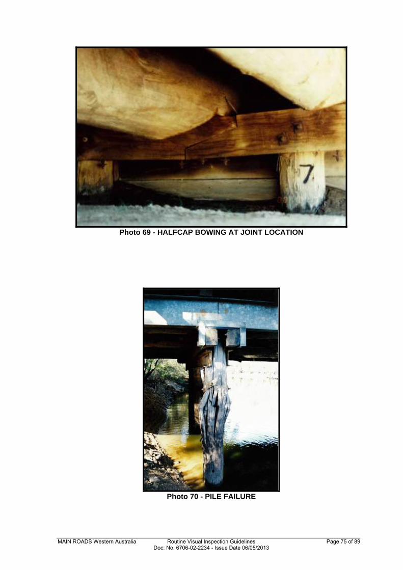
Photo 69 - HALFCAP BOWING AT JOINT LOCATION
Photo 70 - PILE FAILURE
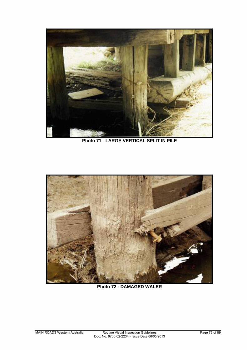
MAIN ROADS Western Australia Routine Visual Inspection Guidelines Page 76 of 89 Doc: No. 6706-02-2234 - Issue Date 06/05/2013
Photo 71 - LARGE VERTICAL SPLIT IN PILE
Photo 72 - DAMAGED WALER
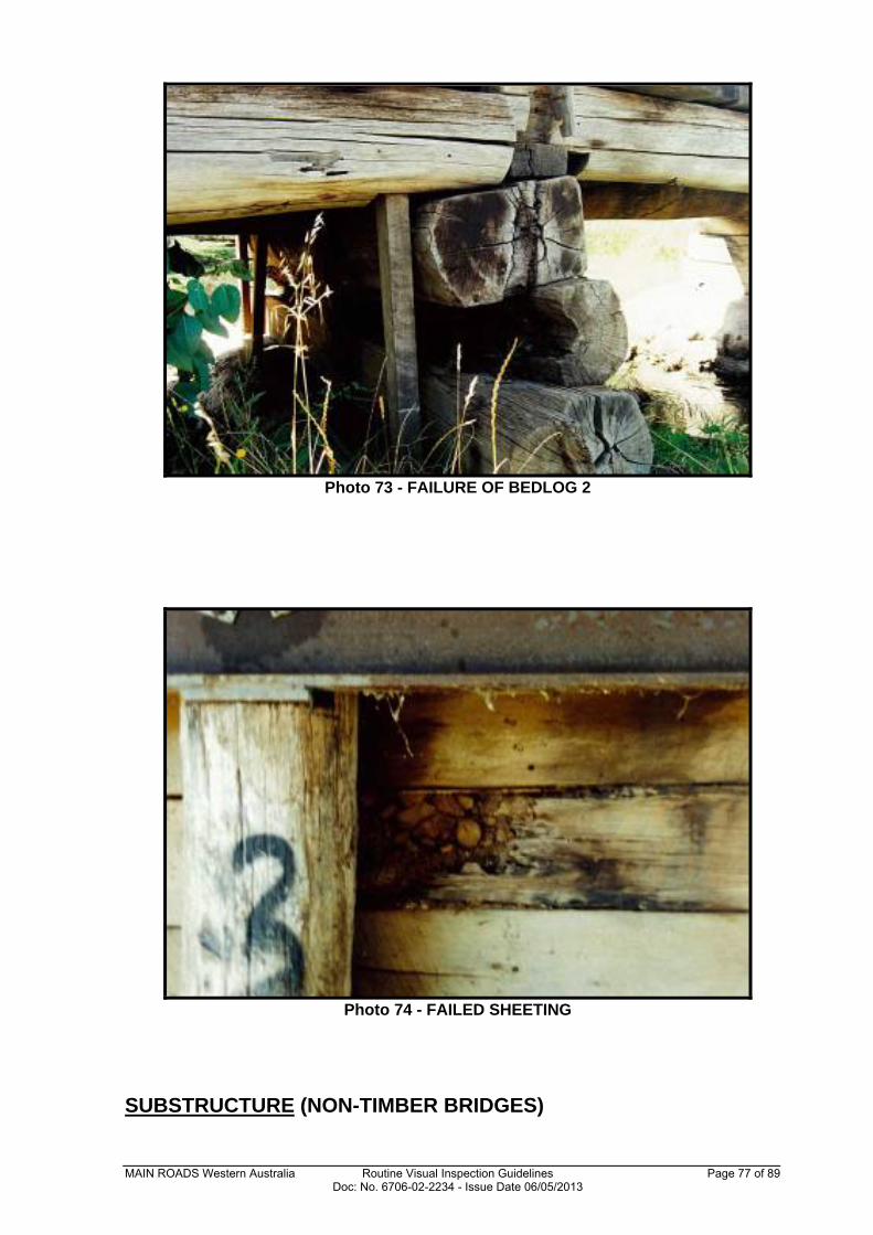
MAIN ROADS Western Australia Routine Visual Inspection Guidelines Page 77 of 89 Doc: No. 6706-02-2234 - Issue Date 06/05/2013
Photo 73 - FAILURE OF BEDLOG 2
Photo 74 - FAILED SHEETING
SUBSTRUCTURE (NON-TIMBER BRIDGES)
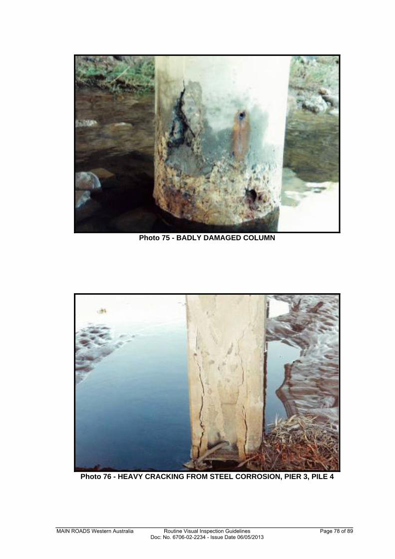
MAIN ROADS Western Australia Routine Visual Inspection Guidelines Page 78 of 89 Doc: No. 6706-02-2234 - Issue Date 06/05/2013
Photo 75 - BADLY DAMAGED COLUMN
Photo 76 - HEAVY CRACKING FROM STEEL CORROSION, PIER 3, PILE 4
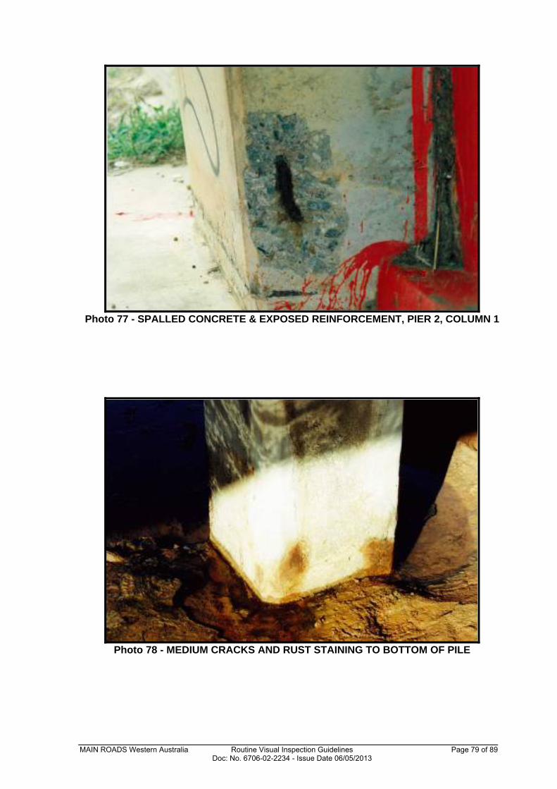
MAIN ROADS Western Australia Routine Visual Inspection Guidelines Page 79 of 89 Doc: No. 6706-02-2234 - Issue Date 06/05/2013
Photo 77 - SPALLED CONCRETE & EXPOSED REINFORCEMENT, PIER 2, COLUMN 1
Photo 78 - MEDIUM CRACKS AND RUST STAINING TO BOTTOM OF PILE
MAIN ROADS Western Australia Routine Visual Inspection Guidelines Page 80 of 89 Doc: No. 6706-02-2234 - Issue Date 06/05/2013
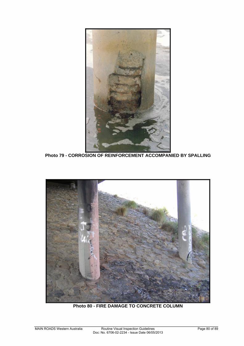
Photo 79 - CORROSION OF REINFORCEMENT ACCOMPANIED BY SPALLING
Photo 80 - FIRE DAMAGE TO CONCRETE COLUMN
MAIN ROADS Western Australia Routine Visual Inspection Guidelines Page 81 of 89 Doc: No. 6706-02-2234 - Issue Date 06/05/2013
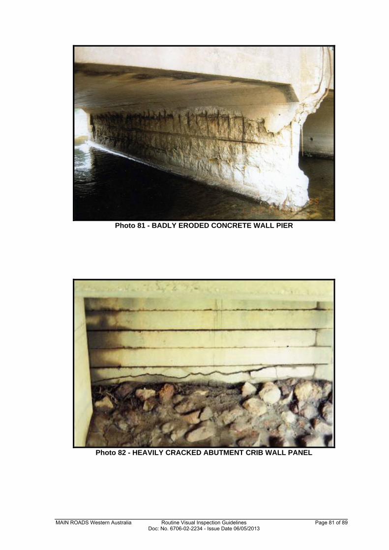
Photo 81 - BADLY ERODED CONCRETE WALL PIER
Photo 82 - HEAVILY CRACKED ABUTMENT CRIB WALL PANEL
MAIN ROADS Western Australia Routine Visual Inspection Guidelines Page 82 of 89 Doc: No. 6706-02-2234 - Issue Date 06/05/2013
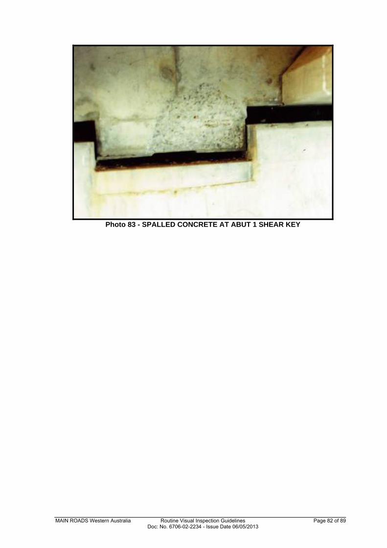
Photo 83 - SPALLED CONCRETE AT ABUT 1 SHEAR KEY
MAIN ROADS Western Australia Routine Visual Inspection Guidelines Page 83 of 89 Doc: No. 6706-02-2234 - Issue Date 06/05/2013
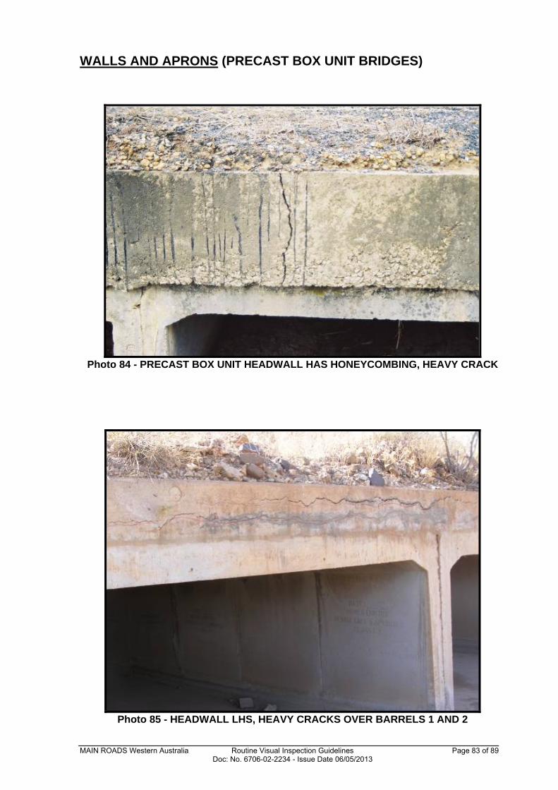
WALLS AND APRONS (PRECAST BOX UNIT BRIDGES)
Photo 84 - PRECAST BOX UNIT HEADWALL HAS HONEYCOMBING, HEAVY CRACK
Photo 85 - HEADWALL LHS, HEAVY CRACKS OVER BARRELS 1 AND 2
MAIN ROADS Western Australia Routine Visual Inspection Guidelines Page 84 of 89 Doc: No. 6706-02-2234 - Issue Date 06/05/2013
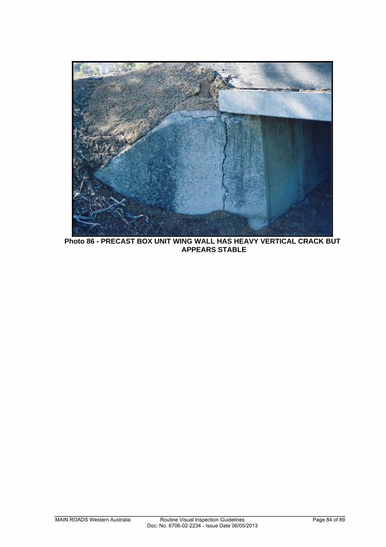
Photo 86 - PRECAST BOX UNIT WING WALL HAS HEAVY VERTICAL CRACK BUT
APPEARS STABLE
MAIN ROADS Western Australia Routine Visual Inspection Guidelines Page 85 of 89 Doc: No. 6706-02-2234 - Issue Date 06/05/2013
PRECAST BOX UNITS (PRECAST BOX UNIT BRIDGES)
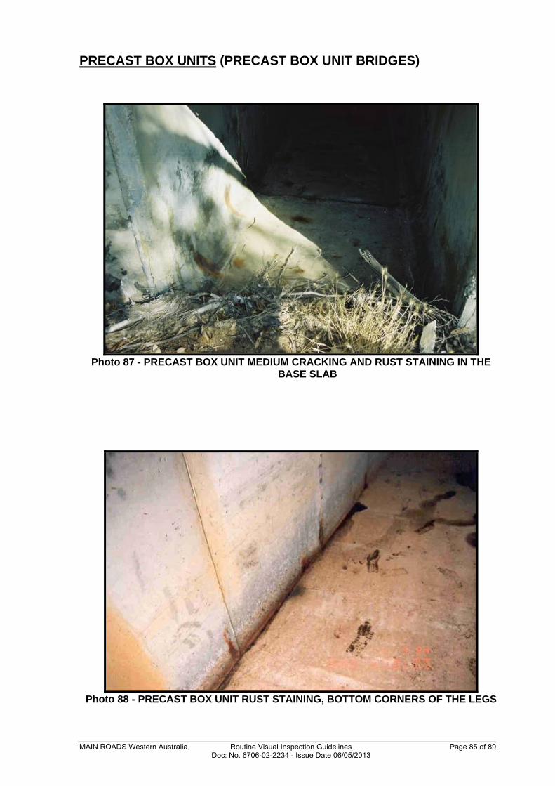
Photo 87 - PRECAST BOX UNIT MEDIUM CRACKING AND RUST STAINING IN THE
BASE SLAB
Photo 88 - PRECAST BOX UNIT RUST STAINING, BOTTOM CORNERS OF THE LEGS
MAIN ROADS Western Australia Routine Visual Inspection Guidelines Page 86 of 89 Doc: No. 6706-02-2234 - Issue Date 06/05/2013
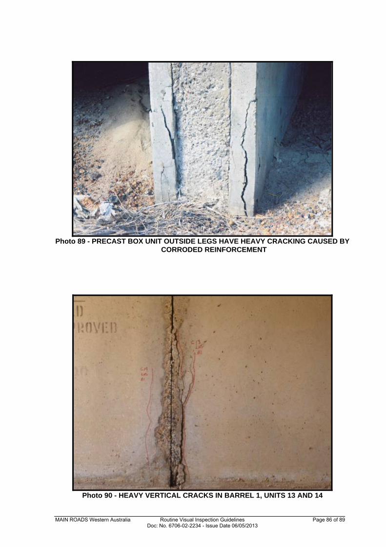
Photo 89 - PRECAST BOX UNIT OUTSIDE LEGS HAVE HEAVY CRACKING CAUSED BY
CORRODED REINFORCEMENT
Photo 90 - HEAVY VERTICAL CRACKS IN BARREL 1, UNITS 13 AND 14
MAIN ROADS Western Australia Routine Visual Inspection Guidelines Page 87 of 89 Doc: No. 6706-02-2234 - Issue Date 06/05/2013
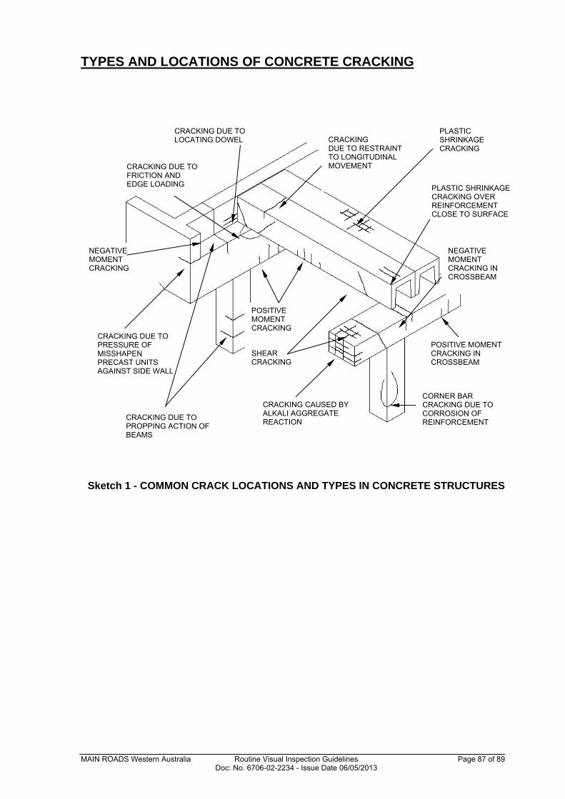
TYPES AND LOCATIONS OF CONCRETE CRACKING
Sketch 1 - COMMON CRACK LOCATIONS AND TYPES IN CONCRETE STRUCTURES
PLASTIC SHRINKAGE CRACKING
PLASTIC SHRINKAGE CRACKING OVER REINFORCEMENT CLOSE TO SURFACE
NEGATIVE MOMENT CRACKING IN CROSSBEAM
POSITIVE MOMENT CRACKING IN CROSSBEAM
CORNER BAR CRACKING DUE TO CORROSION OF REINFORCEMENT
CRACKING DUE TO LOCATING DOWEL CRACKING
DUE TO RESTRAINT TO LONGITUDINAL MOVEMENT
POSITIVE MOMENT CRACKING
SHEAR CRACKING
CRACKING DUE TO PRESSURE OF MISSHAPEN PRECAST UNITS AGAINST SIDE WALL
CRACKING DUE TO PROPPING ACTION OF BEAMS
CRACKING CAUSED BY ALKALI AGGREGATE REACTION
NEGATIVE MOMENT CRACKING
CRACKING DUE TO FRICTION AND EDGE LOADING
MAIN ROADS Western Australia Routine Visual Inspection Guidelines Page 88 of 89 Doc: No. 6706-02-2234 - Issue Date 06/05/2013
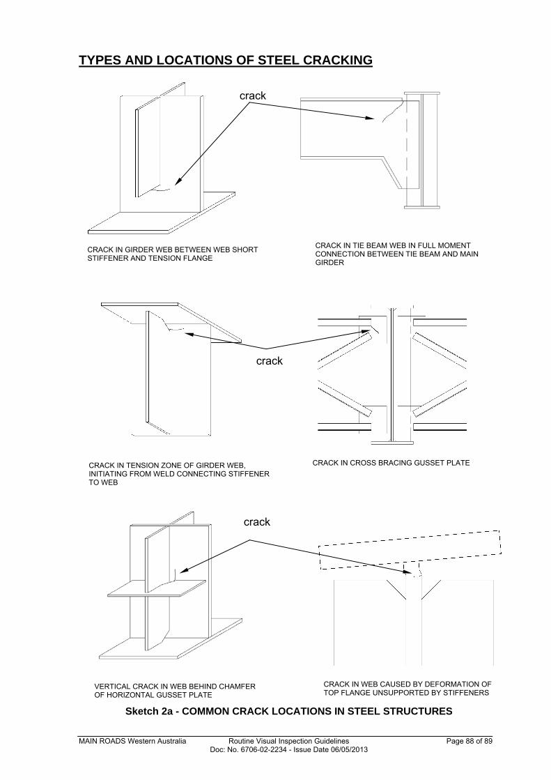
TYPES AND LOCATIONS OF STEEL CRACKING
Sketch 2a - COMMON CRACK LOCATIONS IN STEEL STRUCTURES
crack
CRACK IN GIRDER WEB BETWEEN WEB SHORT STIFFENER AND TENSION FLANGE
CRACK IN TIE BEAM WEB IN FULL MOMENT CONNECTION BETWEEN TIE BEAM AND MAIN GIRDER
CRACK IN TENSION ZONE OF GIRDER WEB, INITIATING FROM WELD CONNECTING STIFFENER TO WEB
CRACK IN CROSS BRACING GUSSET PLATE
crack
VERTICAL CRACK IN WEB BEHIND CHAMFER OF HORIZONTAL GUSSET PLATE
CRACK IN WEB CAUSED BY DEFORMATION OF TOP FLANGE UNSUPPORTED BY STIFFENERS
crack
MAIN ROADS Western Australia Routine Visual Inspection Guidelines Page 89 of 89 Doc: No. 6706-02-2234 - Issue Date 06/05/2013
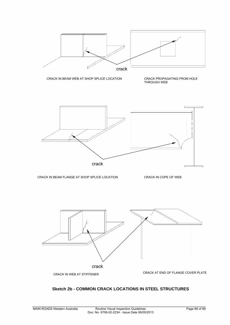
Sketch 2b - COMMON CRACK LOCATIONS IN STEEL STRUCTURES
CRACK IN BEAM WEB AT SHOP SPLICE LOCATION CRACK PROPAGATING FROM HOLE THROUGH WEB
crack
CRACK IN BEAM FLANGE AT SHOP SPLICE LOCATION CRACK IN COPE OF WEB
crack
CRACK IN WEB AT STIFFENER CRACK AT END OF FLANGE COVER PLATE
crack


![Morphological Patterns of Primary Nonendocrine Human Pancreas Carcinoma'cancerres.aacrjournals.org/content/canres/35/8/2234.full.pdf · [CANCER RESEARCH 35, 2234-2248, August 1975]](https://static.fdocuments.us/doc/165x107/5cca616988c993b16c8b83aa/morphological-patterns-of-primary-nonendocrine-human-pancreas-carcinoma-cancer.jpg)