Technical catalogue | July 2016 MNS R Low Voltage ... · PDF fileMNS R Low Voltage Switchgear...
56
MNS R Low Voltage Switchgear System Guide Technical catalogue | July 2016
Transcript of Technical catalogue | July 2016 MNS R Low Voltage ... · PDF fileMNS R Low Voltage Switchgear...

MNS R Low Voltage SwitchgearSystem Guide
Technical catalogue | July 2016

2 | 1TTB900011D0203 | ABB Catalogue
MNS is a registered trademark.
Other trademarks and trade names reside with their respective owners.
Technical descriptions relate to MNS R.
ABB declines all liability for any errors that may appear in this document. In no event shall ABB be liable for direct, indirect, special, incidental, or
consequential damages of any nature or kind arising from use of this document, nor shall ABB be liable for incidental or consequential damages arising
from use of any software or hardware described in this document.
It is forbidden to reproduce or copy this document or parts thereof without ABB’s written permission. Furthermore, the contents of this document may
not be disclosed to third parties or be used for unauthorized purposes. The software described in this document is furnished under a license and may
only be used, copied or disclosed in accordance with the terms of such license.
All rights reserved.
Copyright 2016 © ABB
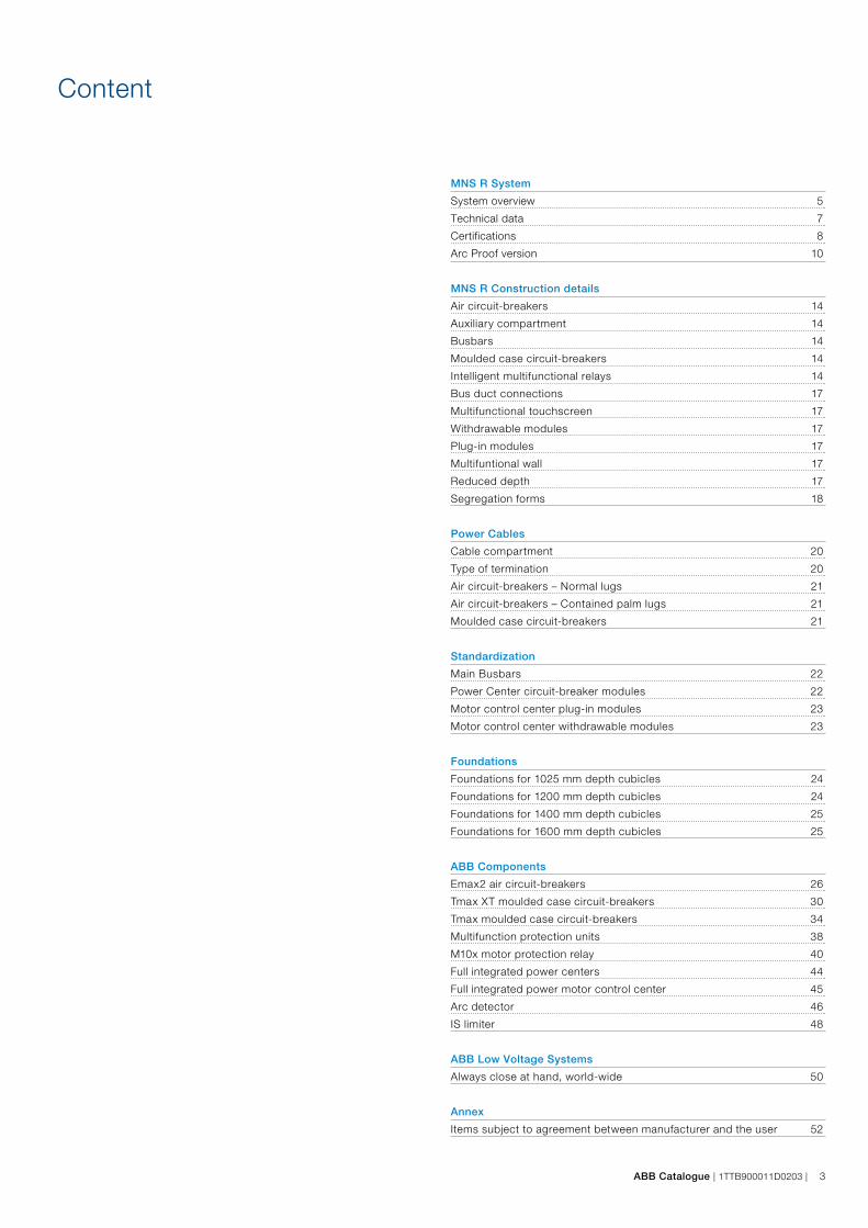
ABB Catalogue | 1TTB900011D0203 | 3
Content
MNS R System
System overview 5
Technical data 7
Certifications 8
Arc Proof version 10
MNS R Construction details
Air circuit-breakers 14
Auxiliary compartment 14
Busbars 14
Moulded case circuit-breakers 14
Intelligent multifunctional relays 14
Bus duct connections 17
Multifunctional touchscreen 17
Withdrawable modules 17
Plug-in modules 17
Multifuntional wall 17
Reduced depth 17
Segregation forms 18
Power Cables
Cable compartment 20
Type of termination 20
Air circuit-breakers – Normal lugs 21
Air circuit-breakers – Contained palm lugs 21
Moulded case circuit-breakers 21
Standardization
Main Busbars 22
Power Center circuit-breaker modules 22
Motor control center plug-in modules 23
Motor control center withdrawable modules 23
Foundations
Foundations for 1025 mm depth cubicles 24
Foundations for 1200 mm depth cubicles 24
Foundations for 1400 mm depth cubicles 25
Foundations for 1600 mm depth cubicles 25
ABB Components
Emax2 air circuit-breakers 26
Tmax XT moulded case circuit-breakers 30
Tmax moulded case circuit-breakers 34
Multifunction protection units 38
M10x motor protection relay 40
Full integrated power centers 44
Full integrated power motor control center 45
Arc detector 46
IS limiter 48
ABB Low Voltage Systems
Always close at hand, world-wide 50
Annex
Items subject to agreement between manufacturer and the user 52

4 | 1TTB900011D0203 | ABB Catalogue
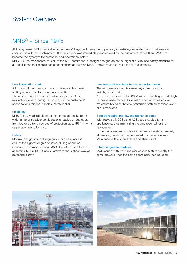
ABB Catalogue | 1TTB900011D0203 | 5
System Overview
MNS® – Since 1975 ABB engineered MNS, the first modular Low Voltage Switchgear, forty years ago. Featuring separated functional areas in conjunction with arc containment, the switchgear was immediately appreciated by the customers. Since then, MNS has become the synonym for personnel and operational safety. MNS R is the rear access version of the MNS family and is designed to guarantee the highest quality and safety standard for all installations that require cable connections at the rear. MNS R provides added value for ABB customers.
Low Installation costA low footprint and easy access to power cables make setting up and installation fast and effective.The rear covers of the power cable compartments are available in several configurations to suit the customers' specifications (hinges, handles, safety locks).
FlexibilityMNS R is fully adaptable to customer needs thanks to the wide range of possible configurations: cables or bus ducts from top or bottom, degrees of protection up to IP54, internal segregation up to form 4b.
SafetyModular design, internal segregation and easy access ensure the highest degree of safety during operation, inspection and maintenance. MNS R is internal arc tested according to IEC 61641 and guarantees the highest level of personnel safety.
Low footprint and high technical performanceThe multilevel air circuit-breaker layout reduces the switchgear footprint.Air circuit-breakers up to 6300A without derating provide high technical performance. Different busbar locations ensuremaximum flexibility, thereby optimizing both switchgear layout and dimensions.
Speedy repairs and low maintenance costsWithdrawable MCCBs and ACBs are available for all applications, thus minimizing the time required for their replacement.Since the power and control cables are so easily accessed, all servicing work can be performed in an effective way. Maintenance takes much less time than usual.
Interchangeable modulesMCC panels with front and rear access feature exactly the same drawers, thus the same spare parts can be used.

6 | 1TTB900011D0203 | ABB Catalogue
System Overview
MNS R main low voltage distribution switchgear with rear access was designed for use in large electrical installations such as those in petrochemical plants, steel works, rolling mills, power stations, oil rigs, ships, etc.The service conditions in these plants are often extremely severe: the high currents involved and effective short-circuit levels require high performance switchgear.
In addition, safe conditions for the personnel, service continuity, easy inspection, maintenance, construction and installation must also be guaranteed. Simply installed extensions and compact overall dimensions are a must. MNS R Power Center switchgear fully complies with all these requirements. But that's not all. Since it integrates perfectly into all the latest generation ABB apparatus, compliance with all market requirements is guaranteed.
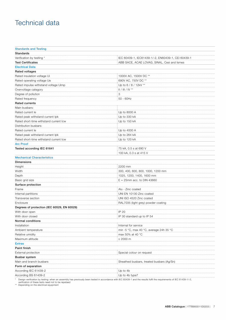
ABB Catalogue | 1TTB900011D0203 | 7
Technical data
Standards and Testing
Standards
Verification by testing * IEC 60439-1, IEC61439-1/-2, EN60439-1, CEI 60439-1
Test Certificates ABB SACE, ACAE LOVAG, SINAL, Cesi and Ismes
Electrical Data
Rated voltages
Rated insulation voltage Ui 1000V AC, 1500V DC **
Rated operating voltage Ue 690V AC, 750V DC **
Rated impulse withstand voltage Uimp Up to 6 / 8 / 12kV **
Overvoltage category II / III / IV **
Degree of pollution 3
Rated frequency 50 - 60Hz
Rated currents
Main busbars:
Rated current Ie Up to 8000 A
Rated peak withstand current Ipk Up to 330 kA
Rated short-time withstand current Icw Up to 150 kA
Distribution busbars:
Rated current Ie Up to 4000 A
Rated peak withstand current Ipk Up to 264 kA
Rated short-time withstand current Icw Up to 120 kA
Arc Proof
Tested according IEC 61641 75 kA, 0.5 s at 690 V
100 kA, 0.3 s at 415 V
Mechanical Characteristics
Dimensions
Height 2200 mm
Width 300, 400, 600, 800, 1000, 1200 mm
Depth 1025, 1200, 1400, 1600 mm
Basic grid size E = 25mm acc. to DIN 43660
Surface protection
Frame Alu - Zinc coated
Internal partitions UNI EN 10130 Zinc coated
Transverse section UNI ISO 4520 Zinc coated
Enclosure RAL7035 (light grey) powder coating
Degrees of protection (IEC 60529, EN 60529)
With door open IP 20
With door closed IP 30 standard up to IP 54
Normal conditions
Installation Internal for service
Ambient temperature min -5 °C, max 40 °C, average 24h 35 °C
Relative umidity max 50% at 40 °C
Maximum altitude ≤ 2000 m
Extras
Paint finish
External protection Special colour on request
Busbar system
Main and branch busbars Sheathed busbars, treated busbars (Ag/Sn)
Form of separation
According IEC 61439-2 Up to 4b
According BS 61439-2 Up to 4b type7* Design verification by testing: when an assembly has previously been tested in accordance with IEC 60439-1 and the results fulfil the requirements of IEC 61439-1/-2, verification of these tests need not to be repetaed** Depending on the electrical equipment
8 | 1TTB900011D0203 | ABB Catalogue
IEC Standards
IEC 61439The new IEC 61439 standard replaces 60439 and applies to enclosures for which the rated voltage is under 1000 V AC (at frequencies not exceeding 1000 Hz) or 1500 V DC. The standard defines design-verified assemblies and completely eliminates categories TTA and PTTA. In order to conform to the standard, type tests have been replaced by design verification, which can be carried out by means of the following three equivalent and alternative methods: testing, calculation/measurement or application of design rules.The following parts are mentioned but are not of equal importance. There is a formal hierarchy. None of the parts can be used individually:– IEC 61439-1: General rules – IEC 61439-2: Power switchgear and controlgear assemblies – IEC 61439-3: Distribution boards– IEC 61439-4: Assemblies for construction sites – IEC 61439-5: Assemblies for power distribution – IEC 61439-6: Busbar trunking systems.
The new IEC 61439 standard includes the following significant technical changes with respect to the last edition of IEC 60439.
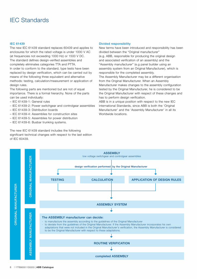
Divided responsibilityNew terms have been introduced and responsibility has been divided between the “Original manufacturer” (e.g. ABB, responsible for producing the original design and associated verification of an assembly) and the “Assembly manufacturer” (e.g panel builder using an assembly system from an Original Manufacturer), which is responsible for the completed assembly.The Assembly Manufacturer may be a different organisation from the Original Manufacturer. When an Assembly Manufacturer makes changes to the assembly configuration tested by the Original Manufacturer, he is considered to be the Original Manufacturer with respect of these changes and has to perform design verification. ABB is in a unique position with respect to the new IEC international Standards, since ABB is both the ‘Original Manufacturer’ and the ‘Assembly Manufacturer’ in all its Worldwide locations.
completed ASSEMBLY
OR
IGIN
AL
MA
NU
FAC
TU
RE
R
OR
IGIN
AL
MA
NU
FAC
TU
RE
RA
SS
EM
BLY
MA
NU
FAC
TU
RE
R
ASSEMBLYlow voltage switchgear and controlgear assemblies
TESTING CALCULATION APPLICATION OF DESIGN RULES
design verification performed by the Original Manufacturer
ASSEMBLY SYSTEM
The ASSEMBLY manufacturer can decide:- to manufacture the assembly according to the guidelines of the Original Manufacturer- to deviate from the guidelines of the Original Manufacturer. If the Assembly Manufacturer incorporates his own adaptations that were not included in the Original Manufacturer's verification, the Assembly Manufacturer is considered to be the Original Manufacturer with respect to these adaptations.
ROUTINE VERIFICATION

ABB Catalogue | 1TTB900011D0203 | 9
Design verification instead of TTA and PTTA categoriesDesign verification replaces type tests, thus discrimination between type-tested assemblies (TTA) and partially type- tested assemblies (PTTA) has been eliminated. New types of verificationsThree different but equivalent types of requirement verifications have been introduced: Verification by testing (test made on a sample of an assembly or on parts of assemblies to ascertain whether the design meets the appropriate requirements. This method is equivalent to the currently implemented type tests).
Verification by calculation/measurement (calculations are applied to a sample of an assembly or to parts of assemblies to ascertain whether the design meets the appropriate requirements). Verification by application of design rules (specified rules for verifying the design of an assembly).The appropriate verification method must be selected according to annex D, which explains the available verification options for each characteristic to be verified, as shown in the table below:
Characteristic to be verified Verification options available
Verification by testing Verification by calculation Verification by design rules
10,2 Strength of material and parts Yes No No
10,3 Degree of protection of enclosures Yes No Yes
10,4 Clearances and creepage distances Yes Yes Yes
10.5.2 Effective continuity between parts and PE Yes No No
10.5.3 Effectiveness of the assembly for external faults Yes Yes Yes
10,6 Incorporation of apparatus No No Yes
10,7 Internal electrical circuits and connections No No Yes
10,8 Terminals for external conductors No No Yes
10.9.2 Power frequency withstand voltage Yes No No
10.9.3 Impulse withstand voltage Yes No Yes
10.10 Temperature rise limits Yes Yes Yes
10,11 Short-circuit withstand strength Yes Yes Yes
10,12 EMC Yes No Yes
10,13 Mechanical operation Yes No No* Tests conducted according to standard 60439 with results that fulfil the requirements of the new IEC 61439 standard need not be repeated. Only the additional verification introduced by the new standard need be tested.
Technical changesVerification of mechanical operation– The number of mechanical operating cycles for main
contacts and any other parts has been increased to 200
Verification of temperature rise– The test methods to verify temperature rise limits have
been extended and adapted– Derivation is allowed for similar modules, with clearly listed
limitations– Verification by calculation is limited to assemblies up to
630A for single compartments and up to 1600A for multiple compartments
Rated diversity factor – The rated diversity factor is described more clearly, with
each circuit requiring a defined rating
Clearance verification– Clearance verification by design may be applied using a
50% ‘safety factor’
Neutral cross section– The neutral cross section has been increased to at least
50% of the phase cross section. This is also valid for dimensioning PEN conductors.
Items subject to agreement between the Assembly Manufacturer and user– Items subject to agreement between the Assembly
Manufacturer and user have been revised and extended
10 | 1TTB900011D0203 | ABB Catalogue
Type Tested according IEC 61439
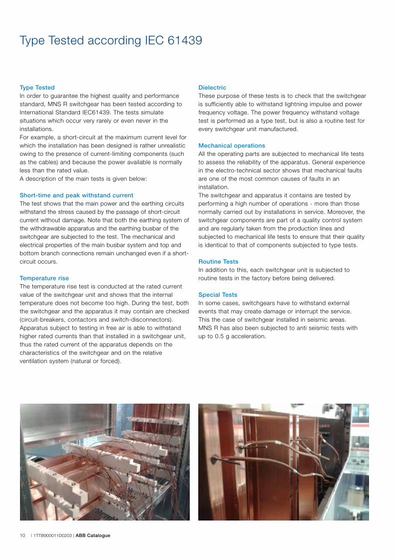
Type TestedIn order to guarantee the highest quality and performance standard, MNS R switchgear has been tested according to International Standard IEC61439. The tests simulate situations which occur very rarely or even never in the installations. For example, a short-circuit at the maximum current level for which the installation has been designed is rather unrealistic owing to the presence of current-limiting components (such as the cables) and because the power available is normally less than the rated value.A description of the main tests is given below:
Short-time and peak withstand current The test shows that the main power and the earthing circuits withstand the stress caused by the passage of short-circuit current without damage. Note that both the earthing system of the withdrawable apparatus and the earthing busbar of the switchgear are subjected to the test. The mechanical and electrical properties of the main busbar system and top and bottom branch connections remain unchanged even if a short-circuit occurs.
Temperature riseThe temperature rise test is conducted at the rated current value of the switchgear unit and shows that the internal temperature does not become too high. During the test, both the switchgear and the apparatus it may contain are checked (circuit-breakers, contactors and switch-disconnectors). Apparatus subject to testing in free air is able to withstand higher rated currents than that installed in a switchgear unit, thus the rated current of the apparatus depends on the characteristics of the switchgear and on the relative ventilation system (natural or forced).
DielectricThese purpose of these tests is to check that the switchgear is sufficiently able to withstand lightning impulse and power frequency voltage. The power frequency withstand voltage test is performed as a type test, but is also a routine test for every switchgear unit manufactured.
Mechanical operationsAll the operating parts are subjected to mechanical life tests to assess the reliability of the apparatus. General experience in the electro-technical sector shows that mechanical faults are one of the most common causes of faults in an installation. The switchgear and apparatus it contains are tested by performing a high number of operations - more than those normally carried out by installations in service. Moreover, the switchgear components are part of a quality control system and are regularly taken from the production lines and subjected to mechanical life tests to ensure that their quality is identical to that of components subjected to type tests.
Routine Tests In addition to this, each switchgear unit is subjected to routine tests in the factory before being delivered.
Special Tests In some cases, switchgears have to withstand external events that may create damage or interrupt the service. This the case of switchgear installed in seismic areas.MNS R has also been subjected to anti seismic tests with up to 0.5 g acceleration.
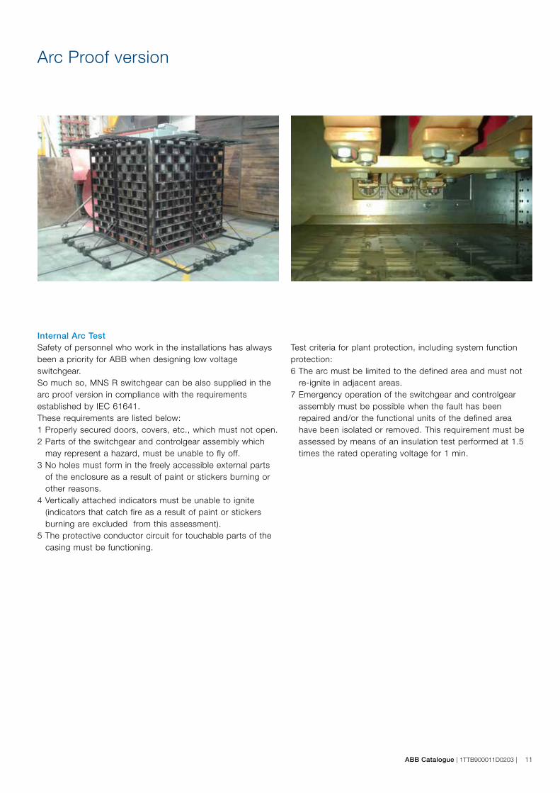
ABB Catalogue | 1TTB900011D0203 | 11
Internal Arc TestSafety of personnel who work in the installations has always been a priority for ABB when designing low voltage switchgear.So much so, MNS R switchgear can be also supplied in the arc proof version in compliance with the requirements established by IEC 61641.These requirements are listed below:1 Properly secured doors, covers, etc., which must not open.2 Parts of the switchgear and controlgear assembly which
may represent a hazard, must be unable to fly off.3 No holes must form in the freely accessible external parts
of the enclosure as a result of paint or stickers burning or other reasons.
4 Vertically attached indicators must be unable to ignite (indicators that catch fire as a result of paint or stickers burning are excluded from this assessment).
5 The protective conductor circuit for touchable parts of the casing must be functioning.
Arc Proof version
Test criteria for plant protection, including system function protection: 6 The arc must be limited to the defined area and must not
re-ignite in adjacent areas.7 Emergency operation of the switchgear and controlgear
assembly must be possible when the fault has been repaired and/or the functional units of the defined area have been isolated or removed. This requirement must be assessed by means of an insulation test performed at 1.5 times the rated operating voltage for 1 min.
12 | 1TTB900011D0203 | ABB Catalogue
MNS R Construction details
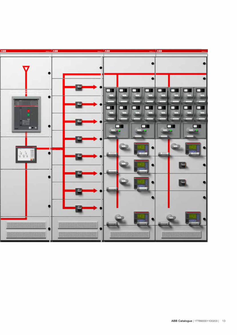
ABB Catalogue | 1TTB900011D0203 | 13
14 | 1TTB900011D0203 | ABB Catalogue
MNS R Construction details
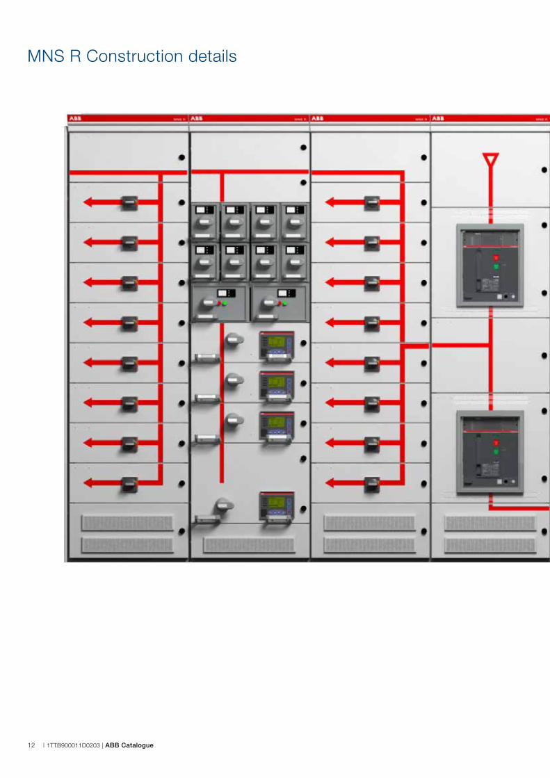
Busbars
Thanks to the new multilevel design, the new MNS R busbars can now provide top performance up to 8000A on the main busbars and 4000A on the distribution busbars. Both the main busbars and distribution busbars can be completely segregated. Each MNS R panel can be fitted with three busbar systems at the same time (top-center- bottom) each segregated from the others. The new design also reduces downtime during maintenance work to modify the switchgear layout or install a spare feeder, since all the interconnections are made without holes in the busbars.Special surface treatments are available on request, so tin-plated, silver-plated or sheathed busbars can be supplied.
Moulded case circuit-breakers
Every moulded case circuit-breaker has a dedicated compartment segregated from the other breakers and with space to install all the auxiliary instrumentation for the feeder. To comply with customer requirements, molded case circuit-breakers are available in the fixed, plug-in and withdrawable versions.
Intelligent multifunctional relays
To integrate motor feeders into the process supervision system that controls production in modern plants, the motor feeders can be equipped with dedicated multifunctional protection relays for protection, metering and dialogue using the most common industrial protocols like Modbus or Profibus.
Air circuit-breakers
Make sure that all the air circuit-breakers are in the vertical mounted withdrawable version to ensure maximum accessibility and reduce downtime during maintenance work. Owing to the unique design of MNS R switchgear, two air circuit-breakers can always be stacked in a single panel. This design ensures the most efficient layout and a reduced footprint. Whatever the size of the breakers and whether power is fed from the top or bottom, is always possible to install two incoming feeders, bus tie and bus riser in only two cubicles.
Auxiliary compartment
All cubicles have a dedicated auxiliary compartment where all the auxiliary equipment can be installed while maintaining segregation for the power components. In the case of stacked air circuit-breakers, the size of the compartment still allows indirect relays and multifunctional protection units to be installed. ABB offers a wide range of external multifunctional protection relays for transformers, generators and line feeders. The units can be equipped with native communication protocols like IEC61850 to integrate the low voltage feeder into the electrical control system of the installation.
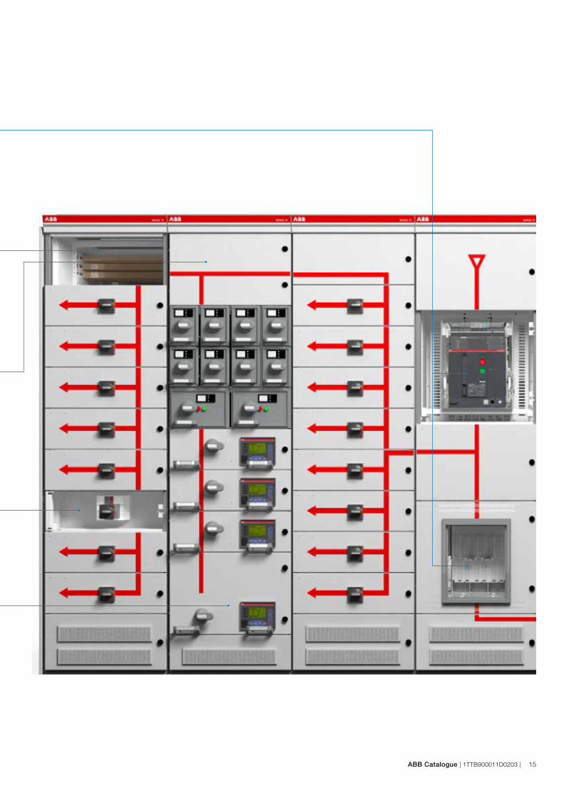
ABB Catalogue | 1TTB900011D0203 | 15

16 | 1TTB900011D0203 | ABB Catalogue
MNS R Construction details

ABB Catalogue | 1TTB900011D0203 | 17
Multifunctional touchscreen
All the switchgears can be controlled from a single location using the ABB touchscreen. You can operate on the breakers, read all the parameters, check the status of the breakers and read all the measurements by just a few "touches".ABB touchscreens also allow you to remote all the information so as to keep everything under control without having to be in front of the switchgear.
Bus duct connections
Rear power cable connection is the main characteristic of MNS R. It guarantees maximun safety and allows switchgear with reduced width to be created. If high rated current is used, a bus duct is often installed instead of the traditional cables. This is a common application for power centers and MNS R has been designed in order to be connected directly to the power bus duct either from the bottom or top. The switchgear busbars are made of copper but can also be connected straight onto an aluminum Bus duct.
Reduced depth
With a standard depth of only 1200 mm that can be reduced to 1025 depending on the switchgear layout, MNS R always guarantees the minimum footprint.
Withdrawable modules
The withdrawable technique has proved to be the appropriate solution in industrial applications where high accessibility is a must, especially for motor feeders. Modules can be easily exchanged under operational conditions thus assuring maximum flexibility. MNS modules are operated with the multifunction operating handle. This handle also activates the electrical and mechanical module and the module door interlocks. No further tools or unlocking devices are necessary to withdraw a module, thus replacing a module takes less than a minute. Replacement as well as retrofitting of modules can be performed under live conditions, should plant operating procedures allow.
Plug-in modules
Plug In modules can also be quickly removed without disassembling any parts. The module includes the power parts and also the auxiliary instrumentation, thus reducing downtime while plug-in modules are replaced to the minimum.
Multifunction Wall
The multifunction wall (MFW) with embedded distribution busbars is a unique MNS platform design for motor control center cubicles. It forms a complete barrier between the main busbars and the equipment compartment. The distribution busbars are fully phase-segregated and insulated. This design makes it virtually impossible for an arc to pass between the distribution busbar phases or between the main busbars and equipment compartment. The insulation material is CFC- and halogen-free. It is also flame-retardant and self-extinguishing. Contact openings are finger proof (IP 2X) so that personnel safety is guaranteed even when modules are removed. Thanks to use of MNS-specific power contact housings, full single phase segregation is assured prior to connection of the power contacts to the distribution busbars.
d
c
a b
18 | 1TTB900011D0203 | ABB Catalogue
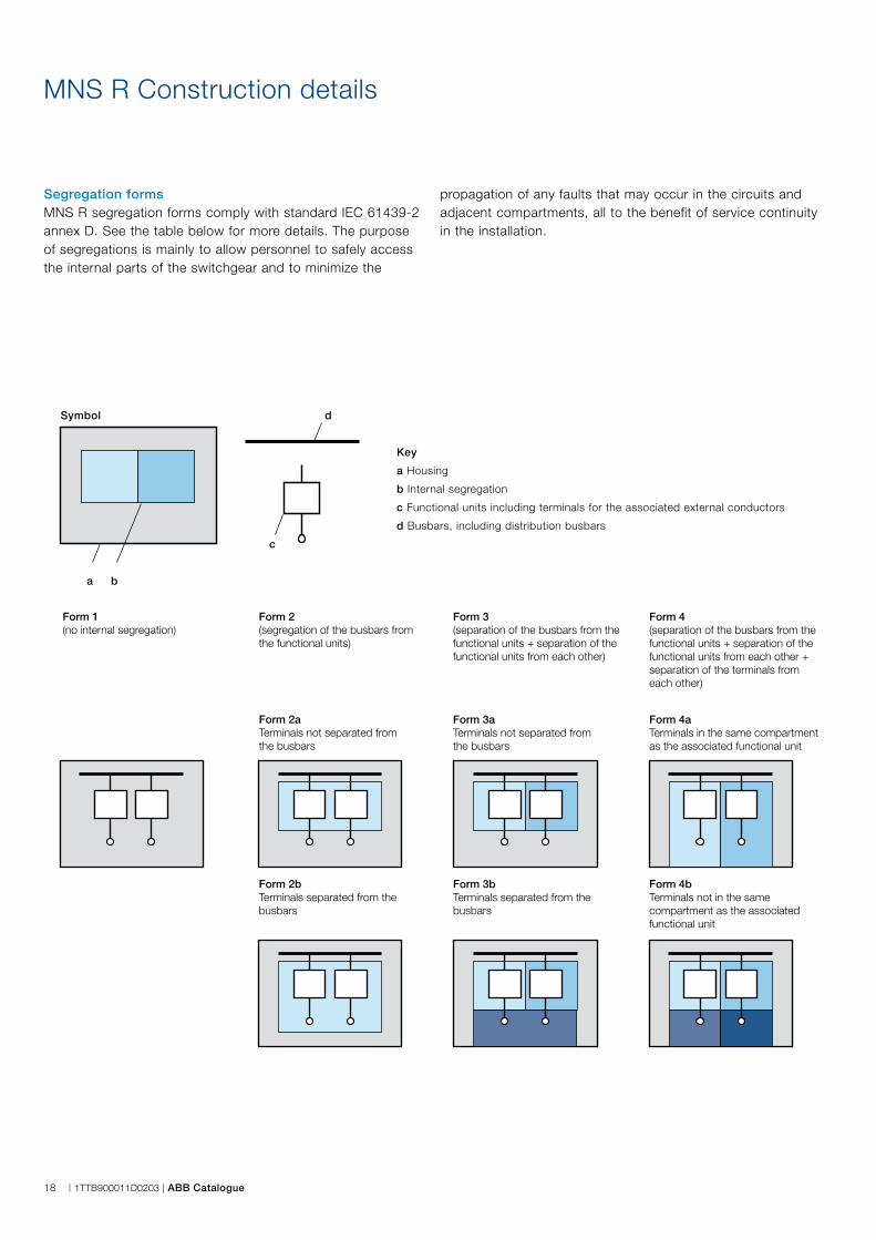
Segregation formsMNS R segregation forms comply with standard IEC 61439-2 annex D. See the table below for more details. The purpose of segregations is mainly to allow personnel to safely access the internal parts of the switchgear and to minimize the
MNS R Construction details
propagation of any faults that may occur in the circuits and adjacent compartments, all to the benefit of service continuity in the installation.
Key
a Housing
b Internal segregation
c Functional units including terminals for the associated external conductors
d Busbars, including distribution busbars
Symbol
Form 1 (no internal segregation)
Form 2 (segregation of the busbars from the functional units)
Form 2a Terminals not separated from the busbars
Form 2b Terminals separated from the busbars
Form 3 (separation of the busbars from the functional units + separation of the functional units from each other)
Form 3a Terminals not separated from the busbars
Form 3bTerminals separated from the busbars
Form 4 (separation of the busbars from the functional units + separation of the functional units from each other + separation of the terminals from each other)
Form 4a Terminals in the same compartment as the associated functional unit
Form 4b Terminals not in the same compartment as the associated functional unit
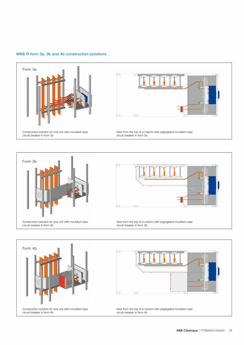
ABB Catalogue | 1TTB900011D0203 | 19
MNS R form 3a, 3b and 4b construction solutions
Form 3a
Form 3b
Form 4b
Construction solution for one unit with moulded-case circuit-breaker in form 3a
View from the top of a column with segregated moulded-casecircuit-breaker in form 3a
Construction solution for one unit with moulded-casecircuit-breaker in form 3b
View from the top of a column with segregated moulded-casecircuit-breaker in form 3b
Construction solution for one unit with moulded-casecircuit-breaker in form 4b
View from the top of a column with segregated moulded-casecircuit-breaker in form 4b
20 | 1TTB900011D0203 | ABB Catalogue
Power Cables
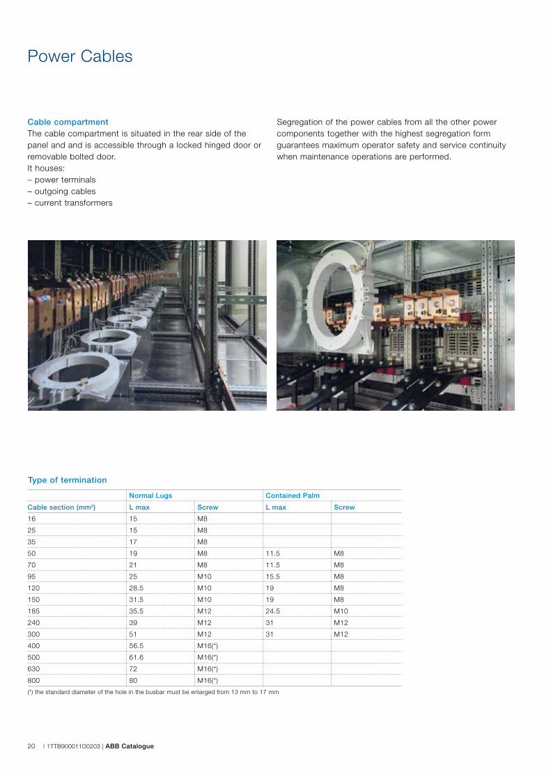
Cable compartmentThe cable compartment is situated in the rear side of the panel and and is accessible through a locked hinged door or removable bolted door.It houses:– power terminals– outgoing cables– current transformers
Type of termination
Segregation of the power cables from all the other power components together with the highest segregation form guarantees maximum operator safety and service continuity when maintenance operations are performed.
Normal Lugs Contained Palm
Cable section (mm2) L max Screw L max Screw
16 15 M8
25 15 M8
35 17 M8
50 19 M8 11.5 M8
70 21 M8 11.5 M8
95 25 M10 15.5 M8
120 28.5 M10 19 M8
150 31.5 M10 19 M8
185 35.5 M12 24.5 M10
240 39 M12 31 M12
300 51 M12 31 M12
400 56.5 M16(*)
500 61.6 M16(*)
630 72 M16(*)
800 80 M16(*)
(*) the standard diameter of the hole in the busbar must be enlarged from 13 mm to 17 mm

ABB Catalogue | 1TTB900011D0203 | 21
Air Circuit-breakers - Normal lugs
Maximum number of cables per phase
Cable section (mm2) E1.2 E2.2 E4.2 E6.2
95 4 14 14 14
120 4 8 8 8
150 4 8 8 8
185 4 8 8 8
240 4 8 8 8
300 4 4 4 4
400 - 4 4 4
500 - 4 2 4
630 - 2 2 4
800 - 2 2 2
Moulded Case Circuit-breakers
Maximum number of cables per phase
Cable section (mm2) E1.2 E2.2 E4.2 E6.2
95 4 14 14 14
120 4 14 14 14
150 4 14 14 14
185 4 14 14 14
240 4 8 8 8
300 4 8 8 8
Breaker Copper section Cable lugs 1 cable x phase 2 cables x phase 3 cables x phase 4 cables x phase
XT1 15x5Normal 25 mm2 25 mm2
Contained palm 50 mm2 50 mm2
XT2 15x5Normal 25 mm2 25 mm2
Contained palm 50 mm2 50 mm2
XT3 20x5Normal 70 mm2 70 mm2
Contained palm 150 mm2 150 mm2
XT4 20x5Normal 70 mm2 70 mm2
Contained palm 150 mm2 150 mm2
T5 400A 25x8Normal 185 mm2 150 mm2
Contained palm 240 mm2 185 mm2
T5 630A 40x8Normal
240 mm2 185 mm2
Contained palm
T6 630 / 800 40x10Normal
240 mm2 240 mm2
Contained palm
T7 (*)Normal
240 mm2 240 mm2 240 mm2 (**) 240 mm2 (**)Contained palm
(*) T7/X1 800/1000A - Copper section 1 Cu 50x10xF / 1 x N(*) T7/X1 1250/1600A - Copper section 2 Cu 50x10xF / 1 x N(**) Only for T7/X1 1250/1600A (to be checked case by case depending on depth/width)
Air Circuit-breakers - Contained palm lugs
22 | 1TTB900011D0203 | ABB Catalogue
Standardization
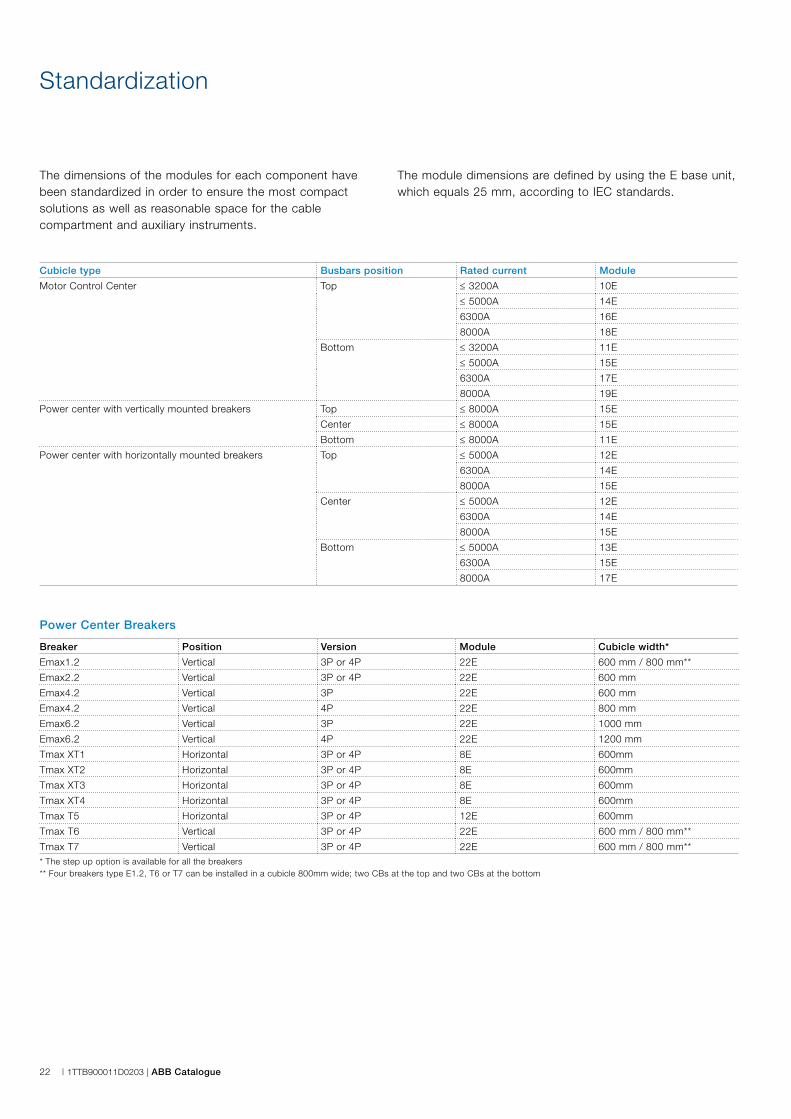
The dimensions of the modules for each component have been standardized in order to ensure the most compact solutions as well as reasonable space for the cable compartment and auxiliary instruments.
Breaker Position Version Module Cubicle width*
Emax1.2 Vertical 3P or 4P 22E 600 mm / 800 mm**
Emax2.2 Vertical 3P or 4P 22E 600 mm
Emax4.2 Vertical 3P 22E 600 mm
Emax4.2 Vertical 4P 22E 800 mm
Emax6.2 Vertical 3P 22E 1000 mm
Emax6.2 Vertical 4P 22E 1200 mm
Tmax XT1 Horizontal 3P or 4P 8E 600mm
Tmax XT2 Horizontal 3P or 4P 8E 600mm
Tmax XT3 Horizontal 3P or 4P 8E 600mm
Tmax XT4 Horizontal 3P or 4P 8E 600mm
Tmax T5 Horizontal 3P or 4P 12E 600mm
Tmax T6 Vertical 3P or 4P 22E 600 mm / 800 mm**
Tmax T7 Vertical 3P or 4P 22E 600 mm / 800 mm*** The step up option is available for all the breakers** Four breakers type E1.2, T6 or T7 can be installed in a cubicle 800mm wide; two CBs at the top and two CBs at the bottom
Power Center Breakers
Cubicle type Busbars position Rated current Module
Motor Control Center Top ≤ 3200A 10E
≤ 5000A 14E
6300A 16E
8000A 18E
Bottom ≤ 3200A 11E
≤ 5000A 15E
6300A 17E
8000A 19E
Power center with vertically mounted breakers Top ≤ 8000A 15E
Center ≤ 8000A 15E
Bottom ≤ 8000A 11E
Power center with horizontally mounted breakers Top ≤ 5000A 12E
6300A 14E
8000A 15E
Center ≤ 5000A 12E
6300A 14E
8000A 15E
Bottom ≤ 5000A 13E
6300A 15E
8000A 17E
The module dimensions are defined by using the E base unit, which equals 25 mm, according to IEC standards.

ABB Catalogue | 1TTB900011D0203 | 23
Breaker Application Version Minimum module Cubicle width*
XT1 Energy distribution 3P or 4P 6E 600 mm
XT2 Energy distribution 3P or 4P 6E 600 mm
XT3 Energy distribution 3P 6E 600 mm
XT3 Energy distribution 4P 8E 600 mm
XT4 Energy distribution 3P 6E 600 mm
XT4 Energy distribution 4P 8E 600 mm
T4 Energy distribution 3P or 4P 8E 600 mm
T5 (400A) Energy distribution 3P 8E 600 mm
T5 (400A) Energy distribution 4P 16E 600 mm
T5 (630A) Energy distribution 3P 16E 600 mm
T5 (630A) Energy distribution 4P 24E 600 mm
T6 (630A) Energy distribution 3P 16E 600 mm
T6 (630A) Energy distribution 4P 24E 600 mm* 600 mm is the only width available for MNS R MCC cubicles
Motor Control Center Plug in modules
Motor Control Center Withdrawable Modules
Drawer size* Peformance** Application Maximum power Cubicle width***
8E/4 400V / 50kA / Type 2 DOL 11kW 600 mm
8E/2 400V / 50kA / Type 2 DOL 30kW 600 mm
6E 400V / 50kA / Type 2 DOL 22kW 600 mm
8E 400V / 50kA / Type 2 DOL 45kW 600 mm
12E 400V / 50kA / Type 2 DOL 75kW 600 mm
16E 400V / 50kA / Type 2 DOL 132kW 600 mm
20E 400V / 50kA / Type 2 DOL 160kW 600 mm
24E 400V / 50kA / Type 2 DOL 200kW 600 mm
16E 400V / 50kA / Type 2 VSD 7.5kW 600 mm
24E 400V / 50kA / Type 2 VSD 45kW 600 mm* Drawer with circuit breakers as main protection device and without auxiliary instrumentation like protection relays** Please consult ABB if different performance values are required*** 600 mm is the only width available for MNS R MCC cubicles
24 | 1TTB900011D0203 | ABB Catalogue
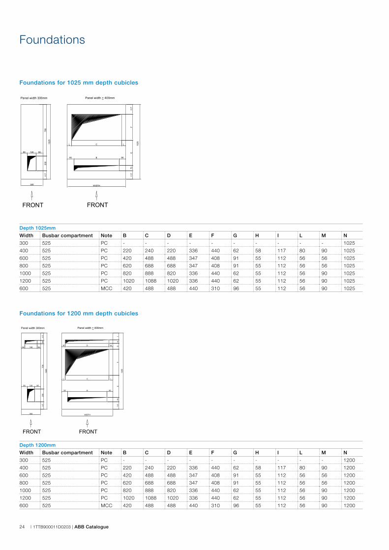
Foundations
Foundations for 1025 mm depth cubicles
Foundations for 1200 mm depth cubicles
Depth 1025mm
Width Busbar compartment Note B C D E F G H I L M N
300 525 PC - - - - - - - - - - 1025
400 525 PC 220 240 220 336 440 62 58 117 80 90 1025
600 525 PC 420 488 488 347 408 91 55 112 56 56 1025
800 525 PC 620 688 688 347 408 91 55 112 56 56 1025
1000 525 PC 820 888 820 336 440 62 55 112 56 90 1025
1200 525 PC 1020 1088 1020 336 440 62 55 112 56 90 1025
600 525 MCC 420 488 488 440 310 96 55 112 56 90 1025
Depth 1200mm
Width Busbar compartment Note B C D E F G H I L M N
300 525 PC - - - - - - - - - - 1200
400 525 PC 220 240 220 336 440 62 58 117 80 90 1200
600 525 PC 420 488 488 347 408 91 55 112 56 56 1200
800 525 PC 620 688 688 347 408 91 55 112 56 56 1200
1000 525 PC 820 888 820 336 440 62 55 112 56 90 1200
1200 525 PC 1020 1088 1020 336 440 62 55 112 56 90 1200
600 525 MCC 420 488 488 440 310 96 55 112 56 90 1200
300
1025
120 9090
117
200
708
WIDTH
1025
L C
90 B
117
F
L
117
70
90
E
Panel width 300mm Panel width > 400mm
FRONT FRONT
300
1200
120 9090
117
200
117
58
56 188 56
708
WIDTH
1200
L C
90 B
M D
IH
GF
L
117
70
90
E
M
Panel width 300mm Panel width > 400mm
FRONT FRONT
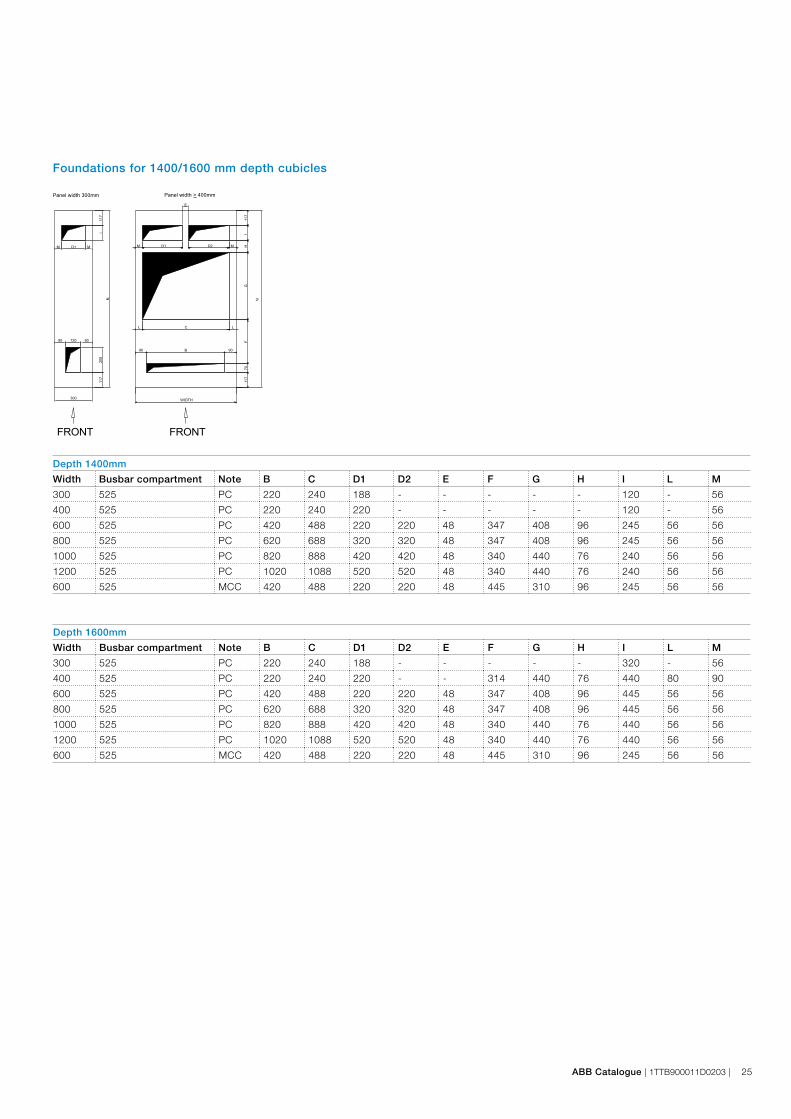
ABB Catalogue | 1TTB900011D0203 | 25
Depth 1400mm
Width Busbar compartment Note B C D1 D2 E F G H I L M
300 525 PC 220 240 188 - - - - - 120 - 56
400 525 PC 220 240 220 - - - - - 120 - 56
600 525 PC 420 488 220 220 48 347 408 96 245 56 56
800 525 PC 620 688 320 320 48 347 408 96 245 56 56
1000 525 PC 820 888 420 420 48 340 440 76 240 56 56
1200 525 PC 1020 1088 520 520 48 340 440 76 240 56 56
600 525 MCC 420 488 220 220 48 445 310 96 245 56 56
Depth 1600mm
Width Busbar compartment Note B C D1 D2 E F G H I L M
300 525 PC 220 240 188 - - - - - 320 - 56
400 525 PC 220 240 220 - - 314 440 76 440 80 90
600 525 PC 420 488 220 220 48 347 408 96 445 56 56
800 525 PC 620 688 320 320 48 347 408 96 445 56 56
1000 525 PC 820 888 420 420 48 340 440 76 440 56 56
1200 525 PC 1020 1088 520 520 48 340 440 76 440 56 56
600 525 MCC 420 488 220 220 48 445 310 96 245 56 56
Foundations for 1400/1600 mm depth cubicles
300
N
120 9090
117
200
117
I
M D1 M70
WIDTH
B
C
FG
HI
117
D1 D2
9090
L
M M11
7
L
E
N
Panel width 300mm Panel width > 400mm
FRONT FRONT
26 | 1TTB900011D0203 | ABB Catalogue
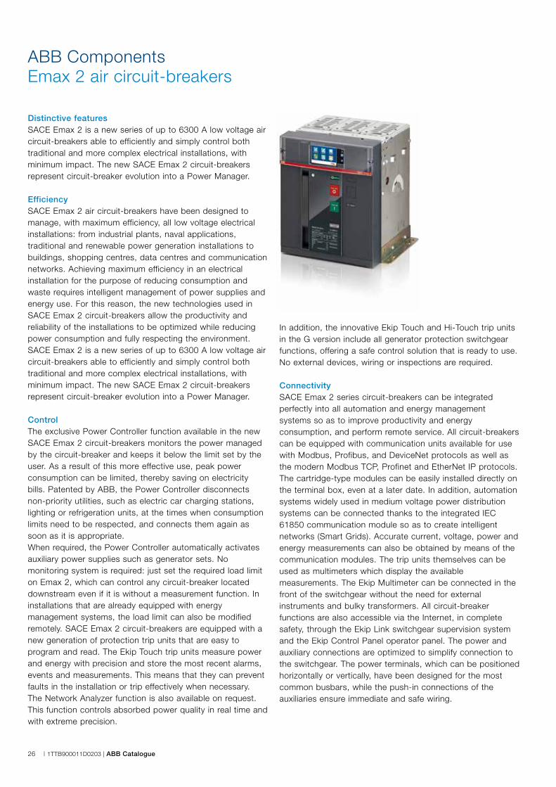
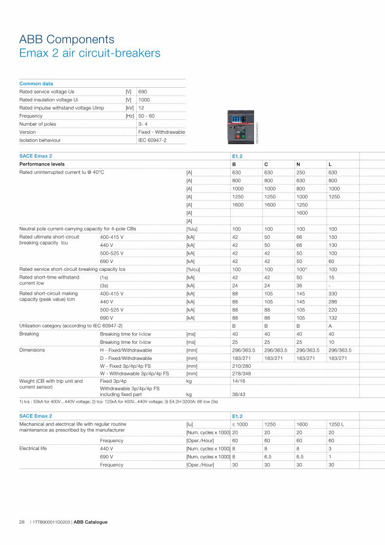
ABB ComponentsEmax 2 air circuit-breakers
Distinctive featuresSACE Emax 2 is a new series of up to 6300 A low voltage air circuit-breakers able to efficiently and simply control both traditional and more complex electrical installations, with minimum impact. The new SACE Emax 2 circuit-breakers represent circuit-breaker evolution into a Power Manager.
EfficiencySACE Emax 2 air circuit-breakers have been designed to manage, with maximum efficiency, all low voltage electrical installations: from industrial plants, naval applications, traditional and renewable power generation installations to buildings, shopping centres, data centres and communication networks. Achieving maximum efficiency in an electrical installation for the purpose of reducing consumption and waste requires intelligent management of power supplies and energy use. For this reason, the new technologies used in SACE Emax 2 circuit-breakers allow the productivity and reliability of the installations to be optimized while reducing power consumption and fully respecting the environment. SACE Emax 2 is a new series of up to 6300 A low voltage air circuit-breakers able to efficiently and simply control both traditional and more complex electrical installations, with minimum impact. The new SACE Emax 2 circuit-breakers represent circuit-breaker evolution into a Power Manager.
ControlThe exclusive Power Controller function available in the new SACE Emax 2 circuit-breakers monitors the power managed by the circuit-breaker and keeps it below the limit set by the user. As a result of this more effective use, peak power consumption can be limited, thereby saving on electricity bills. Patented by ABB, the Power Controller disconnects non-priority utilities, such as electric car charging stations, lighting or refrigeration units, at the times when consumption limits need to be respected, and connects them again as soon as it is appropriate.When required, the Power Controller automatically activates auxiliary power supplies such as generator sets. No monitoring system is required: just set the required load limit on Emax 2, which can control any circuit-breaker located downstream even if it is without a measurement function. In installations that are already equipped with energy management systems, the load limit can also be modified remotely. SACE Emax 2 circuit-breakers are equipped with a new generation of protection trip units that are easy to program and read. The Ekip Touch trip units measure power and energy with precision and store the most recent alarms, events and measurements. This means that they can prevent faults in the installation or trip effectively when necessary. The Network Analyzer function is also available on request. This function controls absorbed power quality in real time and with extreme precision.
In addition, the innovative Ekip Touch and Hi-Touch trip units in the G version include all generator protection switchgear functions, offering a safe control solution that is ready to use. No external devices, wiring or inspections are required.
ConnectivitySACE Emax 2 series circuit-breakers can be integrated perfectly into all automation and energy management systems so as to improve productivity and energy consumption, and perform remote service. All circuit-breakers can be equipped with communication units available for use with Modbus, Profibus, and DeviceNet protocols as well as the modern Modbus TCP, Profinet and EtherNet IP protocols. The cartridge-type modules can be easily installed directly on the terminal box, even at a later date. In addition, automation systems widely used in medium voltage power distribution systems can be connected thanks to the integrated IEC 61850 communication module so as to create intelligent networks (Smart Grids). Accurate current, voltage, power and energy measurements can also be obtained by means of the communication modules. The trip units themselves can be used as multimeters which display the available measurements. The Ekip Multimeter can be connected in the front of the switchgear without the need for external instruments and bulky transformers. All circuit-breaker functions are also accessible via the Internet, in complete safety, through the Ekip Link switchgear supervision system and the Ekip Control Panel operator panel. The power and auxiliary connections are optimized to simplify connection to the switchgear. The power terminals, which can be positioned horizontally or vertically, have been designed for the most common busbars, while the push-in connections of the auxiliaries ensure immediate and safe wiring.
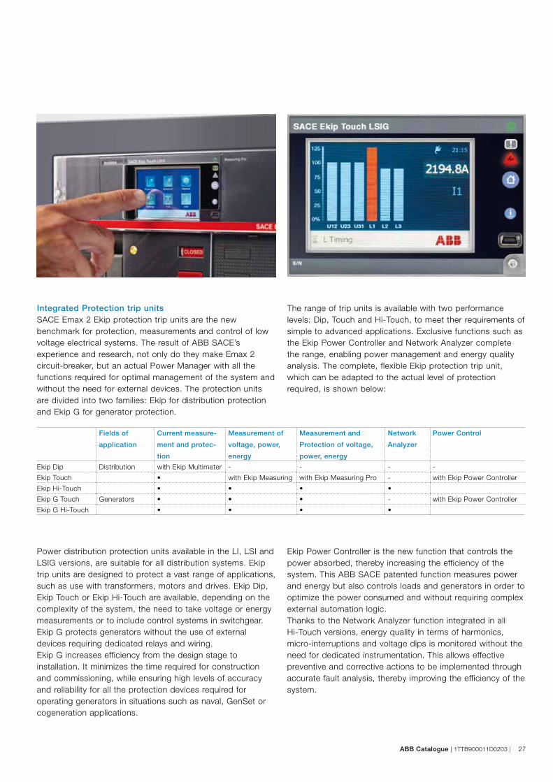
ABB Catalogue | 1TTB900011D0203 | 27
Power distribution protection units available in the LI, LSI and LSIG versions, are suitable for all distribution systems. Ekip trip units are designed to protect a vast range of applications, such as use with transformers, motors and drives. Ekip Dip, Ekip Touch or Ekip Hi-Touch are available, depending on the complexity of the system, the need to take voltage or energy measurements or to include control systems in switchgear.Ekip G protects generators without the use of external devices requiring dedicated relays and wiring. Ekip G increases efficiency from the design stage to installation. It minimizes the time required for construction and commissioning, while ensuring high levels of accuracy and reliability for all the protection devices required for operating generators in situations such as naval, GenSet or cogeneration applications.
Integrated Protection trip unitsSACE Emax 2 Ekip protection trip units are the new benchmark for protection, measurements and control of low voltage electrical systems. The result of ABB SACE’s experience and research, not only do they make Emax 2 circuit-breaker, but an actual Power Manager with all the functions required for optimal management of the system and without the need for external devices. The protection units are divided into two families: Ekip for distribution protection and Ekip G for generator protection.
The range of trip units is available with two performance levels: Dip, Touch and Hi-Touch, to meet ther requirements of simple to advanced applications. Exclusive functions such as the Ekip Power Controller and Network Analyzer complete the range, enabling power management and energy quality analysis. The complete, flexible Ekip protection trip unit, which can be adapted to the actual level of protection required, is shown below:
Ekip Power Controller is the new function that controls the power absorbed, thereby increasing the efficiency of the system. This ABB SACE patented function measures power and energy but also controls loads and generators in order to optimize the power consumed and without requiring complex external automation logic.Thanks to the Network Analyzer function integrated in all Hi-Touch versions, energy quality in terms of harmonics, micro-interruptions and voltage dips is monitored without the need for dedicated instrumentation. This allows effective preventive and corrective actions to be implemented through accurate fault analysis, thereby improving the efficiency of the system.
Fields of
application
Current measure-
ment and protec-
tion
Measurement of
voltage, power,
energy
Measurement and
Protection of voltage,
power, energy
Network
Analyzer
Power Control
Ekip Dip Distribution with Ekip Multimeter - - - -
Ekip Touch • with Ekip Measuring with Ekip Measuring Pro - with Ekip Power Controller
Ekip Hi-Touch • • • •
Ekip G Touch Generators • • • - with Ekip Power Controller
Ekip G Hi-Touch • • • •
1SD
C20
0424
F001
28 | 1TTB900011D0203 | ABB Catalogue
ABB ComponentsEmax 2 air circuit-breakers
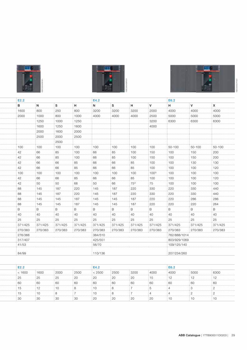
SACE Emax 2 E1.2 E2.2 E4.2 E6.2
Performance levels B C N L B N S H N S H V H V X
Rated uninterrupted current Iu @ 40°C [A] 630 630 250 630 1600 800 250 800 3200 3200 3200 2000 4000 4000 4000
[A] 800 800 630 800 2000 1000 800 1000 4000 4000 4000 2500 5000 5000 5000
[A] 1000 1000 800 1000 1250 1000 1250 3200 6300 6300 6300
[A] 1250 1250 1000 1250 1600 1250 1600 4000
[A] 1600 1600 1250 2000 1600 2000
[A] 1600 2500 2000 2500
[A] 2500
Neutral pole current-carrying capacity for 4-pole CBs [%Iu] 100 100 100 100 100 100 100 100 100 100 100 100 50-100 50-100 50-100
Rated ultimate short-circuit breaking capacity Icu
400-415 V [kA] 42 50 66 150 42 66 85 100 66 85 100 150 100 150 200
440 V [kA] 42 50 66 130 42 66 85 100 66 85 100 150 100 150 200
500-525 V [kA] 42 42 50 100 42 66 66 85 66 66 85 100 100 130 130
690 V [kA] 42 42 50 60 42 66 66 85 66 66 85 100 100 100 120
Rated service short-circuit breaking capacity Ics [%Icu] 100 100 1001) 100 100 100 100 100 100 100 100 1002) 100 100 100
Rated short-time withstand current Icw
(1s) [kA] 42 42 50 15 42 66 66 85 66 66 85 100 100 100 120
(3s) [kA] 24 24 36 - 42 50 50 66 50 66 753) 75 100 100 100
Rated short-circuit making capacity (peak value) Icm
400-415 V [kA] 88 105 145 330 88 145 187 220 145 187 220 330 220 330 440
440 V [kA] 88 105 145 286 88 145 187 220 145 187 220 330 220 330 440
500-525 V [kA] 88 88 105 220 88 145 145 187 145 145 187 220 220 286 286
690 V [kA] 88 88 105 132 88 145 145 187 145 145 187 220 220 220 264
Utilization category (according to IEC 60947-2) B B B A B B B B B B B B B B B
Breaking Breaking time for I<Icw [ms] 40 40 40 40 40 40 40 40 40 40 40 40 40 40 40
Breaking time for I>Icw [ms] 25 25 25 10 25 25 25 25 25 25 25 25 25 25 25
Dimensions H - Fixed/Withdrawable [mm] 296/363.5 296/363.5 296/363.5 296/363.5 371/425 371/425 371/425 371/425 371/425 371/425 371/425 371/425 371/425 371/425 371/425
D - Fixed/Withdrawable [mm] 183/271 183/271 183/271 183/271 270/383 270/383 270/383 270/383 270/383 270/383 270/383 270/383 270/383 270/383 270/383
W - Fixed 3p/4p/4p FS [mm] 210/280 276/366 384/510 762/888/1014
W - Withdrawable 3p/4p/4p FS [mm] 278/348 317/407 425/551 803/929/1069
Weight (CB with trip unit and current sensor)
Fixed 3p/4p kg 14/16 41/53 56/70 109/125/140
Withdrawable 3p/4p/4p FS including fixed part kg 38/43 84/99 110/136 207/234/260
1) Ics : 50kA for 400V…440V voltage; 2) Ics: 125kA for 400V...440V voltage; 3) E4.2H 3200A: 66 Icw (3s)
Common data
Rated service voltage Ue [V] 690
Rated insulation voltage Ui [V] 1000
Rated impulse withstand voltage Uimp [kV] 12
Frequency [Hz] 50 - 60
Number of poles 3- 4
Version Fixed - Withdrawable
Isolation behaviour IEC 60947-2
SACE Emax 2 E1.2 E2.2 E4.2 E6.2
Mechanical and electrical life with regular routine maintenance as prescribed by the manufacturer
[Iu] ≤ 1000 1250 1600 1250 L < 1600 1600 2000 2500 < 2500 2500 3200 4000 4000 5000 6300
[Num. cycles x 1000] 20 20 20 20 25 25 25 20 20 20 20 15 12 12 12
Frequency [Oper./Hour] 60 60 60 60 60 60 60 60 60 60 60 60 60 60 60
Electrical life 440 V [Num. cycles x 1000] 8 8 8 3 15 12 10 8 10 8 7 5 4 3 2
690 V [Num. cycles x 1000] 8 6.5 6.5 1 15 10 8 7 10 8 7 4 4 2 2
Frequency [Oper./Hour] 30 30 30 30 30 30 30 30 20 20 20 20 10 10 10
1SD
C20
0425
F001
1SD
C20
0426
F001
1SD
C20
0427
F001
ABB Catalogue | 1TTB900011D0203 | 29
SACE Emax 2 E1.2 E2.2 E4.2 E6.2
Performance levels B C N L B N S H N S H V H V X
Rated uninterrupted current Iu @ 40°C [A] 630 630 250 630 1600 800 250 800 3200 3200 3200 2000 4000 4000 4000
[A] 800 800 630 800 2000 1000 800 1000 4000 4000 4000 2500 5000 5000 5000
[A] 1000 1000 800 1000 1250 1000 1250 3200 6300 6300 6300
[A] 1250 1250 1000 1250 1600 1250 1600 4000
[A] 1600 1600 1250 2000 1600 2000
[A] 1600 2500 2000 2500
[A] 2500
Neutral pole current-carrying capacity for 4-pole CBs [%Iu] 100 100 100 100 100 100 100 100 100 100 100 100 50-100 50-100 50-100
Rated ultimate short-circuit breaking capacity Icu
400-415 V [kA] 42 50 66 150 42 66 85 100 66 85 100 150 100 150 200
440 V [kA] 42 50 66 130 42 66 85 100 66 85 100 150 100 150 200
500-525 V [kA] 42 42 50 100 42 66 66 85 66 66 85 100 100 130 130
690 V [kA] 42 42 50 60 42 66 66 85 66 66 85 100 100 100 120
Rated service short-circuit breaking capacity Ics [%Icu] 100 100 1001) 100 100 100 100 100 100 100 100 1002) 100 100 100
Rated short-time withstand current Icw
(1s) [kA] 42 42 50 15 42 66 66 85 66 66 85 100 100 100 120
(3s) [kA] 24 24 36 - 42 50 50 66 50 66 753) 75 100 100 100
Rated short-circuit making capacity (peak value) Icm
400-415 V [kA] 88 105 145 330 88 145 187 220 145 187 220 330 220 330 440
440 V [kA] 88 105 145 286 88 145 187 220 145 187 220 330 220 330 440
500-525 V [kA] 88 88 105 220 88 145 145 187 145 145 187 220 220 286 286
690 V [kA] 88 88 105 132 88 145 145 187 145 145 187 220 220 220 264
Utilization category (according to IEC 60947-2) B B B A B B B B B B B B B B B
Breaking Breaking time for I<Icw [ms] 40 40 40 40 40 40 40 40 40 40 40 40 40 40 40
Breaking time for I>Icw [ms] 25 25 25 10 25 25 25 25 25 25 25 25 25 25 25
Dimensions H - Fixed/Withdrawable [mm] 296/363.5 296/363.5 296/363.5 296/363.5 371/425 371/425 371/425 371/425 371/425 371/425 371/425 371/425 371/425 371/425 371/425
D - Fixed/Withdrawable [mm] 183/271 183/271 183/271 183/271 270/383 270/383 270/383 270/383 270/383 270/383 270/383 270/383 270/383 270/383 270/383
W - Fixed 3p/4p/4p FS [mm] 210/280 276/366 384/510 762/888/1014
W - Withdrawable 3p/4p/4p FS [mm] 278/348 317/407 425/551 803/929/1069
Weight (CB with trip unit and current sensor)
Fixed 3p/4p kg 14/16 41/53 56/70 109/125/140
Withdrawable 3p/4p/4p FS including fixed part kg 38/43 84/99 110/136 207/234/260
1) Ics : 50kA for 400V…440V voltage; 2) Ics: 125kA for 400V...440V voltage; 3) E4.2H 3200A: 66 Icw (3s)
SACE Emax 2 E1.2 E2.2 E4.2 E6.2
Mechanical and electrical life with regular routine maintenance as prescribed by the manufacturer
[Iu] ≤ 1000 1250 1600 1250 L < 1600 1600 2000 2500 < 2500 2500 3200 4000 4000 5000 6300
[Num. cycles x 1000] 20 20 20 20 25 25 25 20 20 20 20 15 12 12 12
Frequency [Oper./Hour] 60 60 60 60 60 60 60 60 60 60 60 60 60 60 60
Electrical life 440 V [Num. cycles x 1000] 8 8 8 3 15 12 10 8 10 8 7 5 4 3 2
690 V [Num. cycles x 1000] 8 6.5 6.5 1 15 10 8 7 10 8 7 4 4 2 2
Frequency [Oper./Hour] 30 30 30 30 30 30 30 30 20 20 20 20 10 10 10

30 | 1TTB900011D0203 | ABB Catalogue
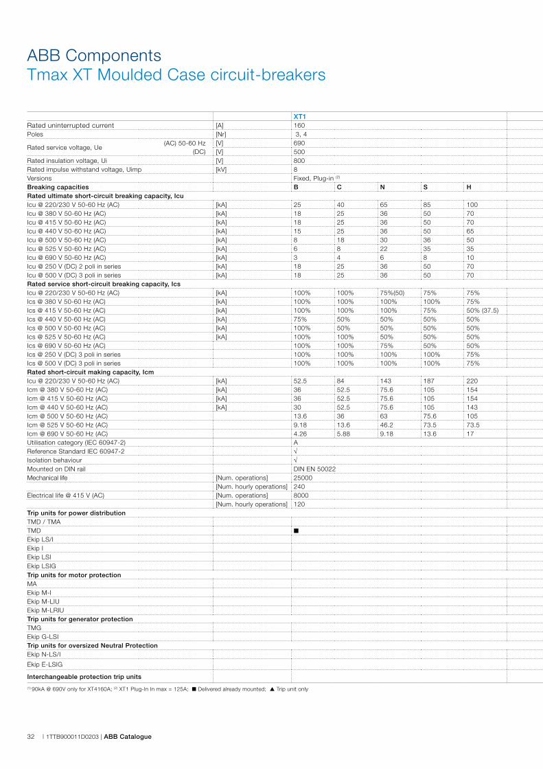
ABB ComponentsTmax XT Moulded Case circuit-breakers
OverviewThe new SACE Tmax XT moulded case circuit-breakers can be installed everywhere since they are made to comply successfully with all plant engineering requirements, both standard and technologically advanced, thanks to their extraordinarily comprehensive range. A complete offer up to 250A for distribution, motor protection, generator protection, oversized neutrals, as switch-disconnectors and for all other needs. A new range of thermomagnetic and electronic protection trip units, interchangeable down to the smallest frames. To say nothing of the new and wide variety of dedicated accessories available, even for special applications.The choice is up to you: XT1 and XT3 for building standard installations with ABB SACE’s unrivalled reliability and safety, or XT2 and XT4 for building technologically advanced installations with top-of-the-market performance. New SACE Tmax XT: simply extraordinary, whatever your choice.
Trip UnitsThe trip units are interchangeable and guarantee absolutetripping reliability and precision. Besides the continuousgreen LED, which indicates that the protection trip unit is operating correctly, all Ekip trip units have a LED that signals when the protection functions have tripped.To allow Ekip units to communicate and exchange information with the other devices, simply insert the Ekip Com module inside the circuit-breaker, leaving the space inside the electric panel free.
All Ekip trip units can be fitted with a vast range ofdedicated accessories. The main ones are:– Ekip Display, to be applied to the front of the electronic trip unit for improved information setting and
reading;– Ekip LED Meter, to be installed on the front of the trip unit
so as to simplify current readings;– Ekip TT, the new trip test unit;– Ekip T&P, the extraordinary testing and programming unit.Lastly, earth fault protection G is now available on the 160A frame for the first time.
AccessoriesWhen it comes to accessories, ease of installation is the first important innovation: coils and auxiliary contacts no longer need screws for their installation. With the new rapid system, simply apply slight pressure to the circuit-breaker slot where the accessory is to be inserted.Another innovation concerns the new auxiliary contacts whose signals depend on the position in which they are installed inside the circuit-breaker.The new motor operators are available with direct operating mechanism for the new XT1-XT3 and stored energy operating mechanism for XT2 and XT4.Apart from simple installation and compact dimensions, the new motor operators require low power values on inrush and during service. The new residual current releases for XT2-XT4 are not only available for the fixed version, but also for the plug-in and withdrawable versions.
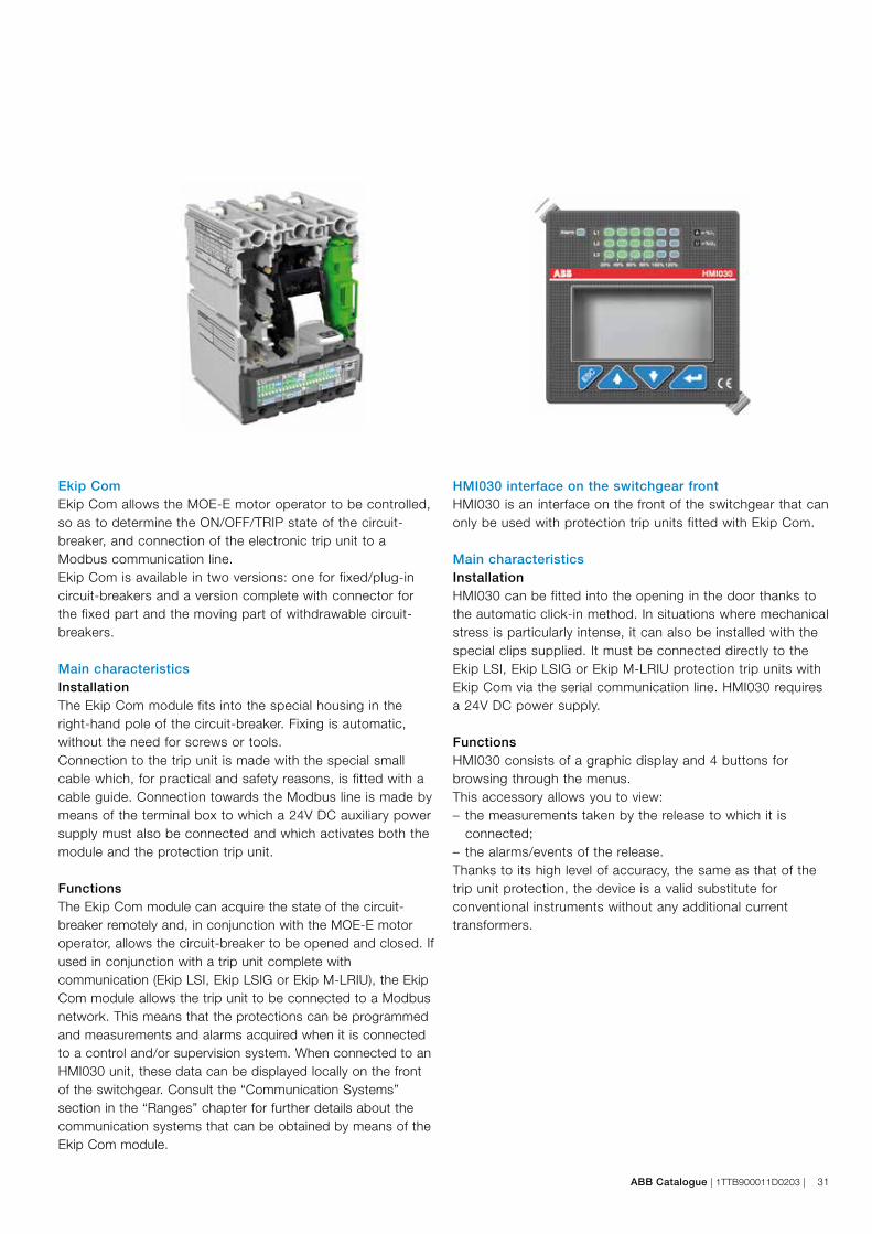
ABB Catalogue | 1TTB900011D0203 | 31
Ekip ComEkip Com allows the MOE-E motor operator to be controlled, so as to determine the ON/OFF/TRIP state of the circuit-breaker, and connection of the electronic trip unit to a Modbus communication line. Ekip Com is available in two versions: one for fixed/plug-in circuit-breakers and a version complete with connector for the fixed part and the moving part of withdrawable circuit-breakers.
Main characteristicsInstallationThe Ekip Com module fits into the special housing in the right-hand pole of the circuit-breaker. Fixing is automatic, without the need for screws or tools.Connection to the trip unit is made with the special small cable which, for practical and safety reasons, is fitted with a cable guide. Connection towards the Modbus line is made by means of the terminal box to which a 24V DC auxiliary power supply must also be connected and which activates both the module and the protection trip unit.
FunctionsThe Ekip Com module can acquire the state of the circuit-breaker remotely and, in conjunction with the MOE-E motor operator, allows the circuit-breaker to be opened and closed. If used in conjunction with a trip unit complete with communication (Ekip LSI, Ekip LSIG or Ekip M-LRIU), the Ekip Com module allows the trip unit to be connected to a Modbus network. This means that the protections can be programmed and measurements and alarms acquired when it is connected to a control and/or supervision system. When connected to an HMI030 unit, these data can be displayed locally on the front of the switchgear. Consult the “Communication Systems” section in the “Ranges” chapter for further details about the communication systems that can be obtained by means of the Ekip Com module.
HMI030 interface on the switchgear frontHMI030 is an interface on the front of the switchgear that can only be used with protection trip units fitted with Ekip Com.
Main characteristicsInstallationHMI030 can be fitted into the opening in the door thanks to the automatic click-in method. In situations where mechanical stress is particularly intense, it can also be installed with the special clips supplied. It must be connected directly to the Ekip LSI, Ekip LSIG or Ekip M-LRIU protection trip units with Ekip Com via the serial communication line. HMI030 requires a 24V DC power supply.
FunctionsHMI030 consists of a graphic display and 4 buttons for browsing through the menus.This accessory allows you to view:– the measurements taken by the release to which it is
connected;– the alarms/events of the release.Thanks to its high level of accuracy, the same as that of the trip unit protection, the device is a valid substitute for conventional instruments without any additional current transformers.
32 | 1TTB900011D0203 | ABB Catalogue
XT1 XT2 XT3 XT4Rated uninterrupted current [A] 160 160 250 160/250Poles [Nr] 3, 4 3, 4 3, 4 3, 4
Rated service voltage, Ue (AC) 50-60 Hz [V] 690 690 690 690
(DC) [V] 500 500 500 500Rated insulation voltage, Ui [V] 800 1000 800 1000Rated impulse withstand voltage, Uimp [kV] 8 8 8 8Versions Fixed, Plug-in (2) Fixed, Withdrawable, Plug-in Fixed, Plug-in Fixed, Withdrawable, Plug-inBreaking capacities B C N S H N S H L V N S N S H L VRated ultimate short-circuit breaking capacity, IcuIcu @ 220/230 V 50-60 Hz (AC) [kA] 25 40 65 85 100 65 85 100 150 200 50 85 65 85 100 150 200Icu @ 380 V 50-60 Hz (AC) [kA] 18 25 36 50 70 36 50 70 120 150 36 50 36 50 70 120 150Icu @ 415 V 50-60 Hz (AC) [kA] 18 25 36 50 70 36 50 70 120 150 36 50 36 50 70 120 150Icu @ 440 V 50-60 Hz (AC) [kA] 15 25 36 50 65 36 50 65 100 150 25 40 36 50 65 100 150Icu @ 500 V 50-60 Hz (AC) [kA] 8 18 30 36 50 30 36 50 60 70 20 30 30 36 50 60 70Icu @ 525 V 50-60 Hz (AC) [kA] 6 8 22 35 35 20 25 30 36 50 13 20 20 25 45 50 50Icu @ 690 V 50-60 Hz (AC) [kA] 3 4 6 8 10 10 12 15 18 20 5 6 10 12 15 20 25 (90) (1)
Icu @ 250 V (DC) 2 poli in series [kA] 18 25 36 50 70 36 50 70 85 100 36 50 36 50 70 85 100Icu @ 500 V (DC) 3 poli in series [kA] 18 25 36 50 70 36 50 70 85 100 36 50 36 50 70 85 100Rated service short-circuit breaking capacity, IcsIcu @ 220/230 V 50-60 Hz (AC) [kA] 100% 100% 75%(50) 75% 75% 100% 100% 100% 100% 100% 75% 50% 100% 100% 100% 100% 100%Ics @ 380 V 50-60 Hz (AC) [kA] 100% 100% 100% 100% 75% 100% 100% 100% 100% 100% 75% 50% (27) 100% 100% 100% 100% 100%Ics @ 415 V 50-60 Hz (AC) [kA] 100% 100% 100% 75% 50% (37.5) 100% 100% 100% 100% 100% 75% 50% (27) 100% 100% 100% 100% 100%Ics @ 440 V 50-60 Hz (AC) [kA] 75% 50% 50% 50% 50% 100% 100% 100% 100% 100% 75% 50% 100% 100% 100% 100% 100%Ics @ 500 V 50-60 Hz (AC) [kA] 100% 50% 50% 50% 50% 100% 100% 100% 100% 100% 75% 50% 100% 100% 100% 100% 100%Ics @ 525 V 50-60 Hz (AC) [kA] 100% 100% 50% 50% 50% 100% 100% 100% 100% 100% 75% 50% 100% 100% 100% 100% 100%Ics @ 690 V 50-60 Hz (AC) 100% 100% 75% 50% 50% 100% 100% 100% 100% 75% 75% 50% 100% 100% 100% 100% 75% (20)Ics @ 250 V (DC) 3 poli in series 100% 100% 100% 100% 75% 100% 100% 100% 100% 100% 100% 75% 100% 100% 100% 100% 100%Ics @ 500 V (DC) 3 poli in series 100% 100% 100% 100% 75% 100% 100% 100% 100% 100% 100% 75% 100% 100% 100% 100% 100%Rated short-circuit making capacity, IcmIcu @ 220/230 V 50-60 Hz (AC) [kA] 52.5 84 143 187 220 143 187 220 330 440 105 187 143 187 220 330 440Icm @ 380 V 50-60 Hz (AC) [kA] 36 52.5 75.6 105 154 75.6 105 154 264 440 75.6 105 75.6 105 154 264 330Icm @ 415 V 50-60 Hz (AC) [kA] 36 52.5 75.6 105 154 75.6 105 154 264 330 75.6 105 75.6 105 154 264 330Icm @ 440 V 50-60 Hz (AC) [kA] 30 52.5 75.6 105 143 75.6 105 143 220 330 52.5 84 75.6 105 143 220 330Icm @ 500 V 50-60 Hz (AC) 13.6 36 63 75.6 105 63 75.6 105 132 154 40 63 63 75.6 105 132 154Icm @ 525 V 50-60 Hz (AC) 9.18 13.6 46.2 73.5 73.5 40 52.5 63 75.6 105 26 40 40 52.5 94.5 105 110Icm @ 690 V 50-60 Hz (AC) 4.26 5.88 9.18 13.6 17 17 24 30 36 40 8.5 13.6 17 24 30 40 52.5Utilisation category (IEC 60947-2) A A A AReference Standard IEC 60947-2 √ √ √ √Isolation behaviour √ √ √ √Mounted on DIN rail DIN EN 50022 DIN EN 50022 DIN EN 50022 DIN EN 50022Mechanical life [Num. operations] 25000 25000 25000 25000
[Num. hourly operations] 240 240 240 240Electrical life @ 415 V (AC) [Num. operations] 8000 8000 8000 8000
[Num. hourly operations] 120 120 120 120Trip units for power distributionTMD / TMA ■ ■
TMD ■ ■
Ekip LS/I ■ ■
Ekip I ■ ■
Ekip LSI ■ ■
Ekip LSIG ■ ■
Trip units for motor protectionMA ■ ■ ■
Ekip M-I ■
Ekip M-LIU ▲ ▲
Ekip M-LRIU ▲ ▲
Trip units for generator protectionTMG ■ ■
Ekip G-LSI ▲ ▲
Trip units for oversized Neutral ProtectionEkip N-LS/I ▲ ▲
Ekip E-LSIG ■
Interchangeable protection trip units √ √
(1) 90kA @ 690V only for XT4160A; (2) XT1 Plug-In In max = 125A; ■ Delivered already mounted; ▲ Trip unit only
ABB ComponentsTmax XT Moulded Case circuit-breakers

ABB Catalogue | 1TTB900011D0203 | 33
XT1 XT2 XT3 XT4Rated uninterrupted current [A] 160 160 250 160/250Poles [Nr] 3, 4 3, 4 3, 4 3, 4
Rated service voltage, Ue (AC) 50-60 Hz [V] 690 690 690 690
(DC) [V] 500 500 500 500Rated insulation voltage, Ui [V] 800 1000 800 1000Rated impulse withstand voltage, Uimp [kV] 8 8 8 8Versions Fixed, Plug-in (2) Fixed, Withdrawable, Plug-in Fixed, Plug-in Fixed, Withdrawable, Plug-inBreaking capacities B C N S H N S H L V N S N S H L VRated ultimate short-circuit breaking capacity, IcuIcu @ 220/230 V 50-60 Hz (AC) [kA] 25 40 65 85 100 65 85 100 150 200 50 85 65 85 100 150 200Icu @ 380 V 50-60 Hz (AC) [kA] 18 25 36 50 70 36 50 70 120 150 36 50 36 50 70 120 150Icu @ 415 V 50-60 Hz (AC) [kA] 18 25 36 50 70 36 50 70 120 150 36 50 36 50 70 120 150Icu @ 440 V 50-60 Hz (AC) [kA] 15 25 36 50 65 36 50 65 100 150 25 40 36 50 65 100 150Icu @ 500 V 50-60 Hz (AC) [kA] 8 18 30 36 50 30 36 50 60 70 20 30 30 36 50 60 70Icu @ 525 V 50-60 Hz (AC) [kA] 6 8 22 35 35 20 25 30 36 50 13 20 20 25 45 50 50Icu @ 690 V 50-60 Hz (AC) [kA] 3 4 6 8 10 10 12 15 18 20 5 6 10 12 15 20 25 (90) (1)
Icu @ 250 V (DC) 2 poli in series [kA] 18 25 36 50 70 36 50 70 85 100 36 50 36 50 70 85 100Icu @ 500 V (DC) 3 poli in series [kA] 18 25 36 50 70 36 50 70 85 100 36 50 36 50 70 85 100Rated service short-circuit breaking capacity, IcsIcu @ 220/230 V 50-60 Hz (AC) [kA] 100% 100% 75%(50) 75% 75% 100% 100% 100% 100% 100% 75% 50% 100% 100% 100% 100% 100%Ics @ 380 V 50-60 Hz (AC) [kA] 100% 100% 100% 100% 75% 100% 100% 100% 100% 100% 75% 50% (27) 100% 100% 100% 100% 100%Ics @ 415 V 50-60 Hz (AC) [kA] 100% 100% 100% 75% 50% (37.5) 100% 100% 100% 100% 100% 75% 50% (27) 100% 100% 100% 100% 100%Ics @ 440 V 50-60 Hz (AC) [kA] 75% 50% 50% 50% 50% 100% 100% 100% 100% 100% 75% 50% 100% 100% 100% 100% 100%Ics @ 500 V 50-60 Hz (AC) [kA] 100% 50% 50% 50% 50% 100% 100% 100% 100% 100% 75% 50% 100% 100% 100% 100% 100%Ics @ 525 V 50-60 Hz (AC) [kA] 100% 100% 50% 50% 50% 100% 100% 100% 100% 100% 75% 50% 100% 100% 100% 100% 100%Ics @ 690 V 50-60 Hz (AC) 100% 100% 75% 50% 50% 100% 100% 100% 100% 75% 75% 50% 100% 100% 100% 100% 75% (20)Ics @ 250 V (DC) 3 poli in series 100% 100% 100% 100% 75% 100% 100% 100% 100% 100% 100% 75% 100% 100% 100% 100% 100%Ics @ 500 V (DC) 3 poli in series 100% 100% 100% 100% 75% 100% 100% 100% 100% 100% 100% 75% 100% 100% 100% 100% 100%Rated short-circuit making capacity, IcmIcu @ 220/230 V 50-60 Hz (AC) [kA] 52.5 84 143 187 220 143 187 220 330 440 105 187 143 187 220 330 440Icm @ 380 V 50-60 Hz (AC) [kA] 36 52.5 75.6 105 154 75.6 105 154 264 440 75.6 105 75.6 105 154 264 330Icm @ 415 V 50-60 Hz (AC) [kA] 36 52.5 75.6 105 154 75.6 105 154 264 330 75.6 105 75.6 105 154 264 330Icm @ 440 V 50-60 Hz (AC) [kA] 30 52.5 75.6 105 143 75.6 105 143 220 330 52.5 84 75.6 105 143 220 330Icm @ 500 V 50-60 Hz (AC) 13.6 36 63 75.6 105 63 75.6 105 132 154 40 63 63 75.6 105 132 154Icm @ 525 V 50-60 Hz (AC) 9.18 13.6 46.2 73.5 73.5 40 52.5 63 75.6 105 26 40 40 52.5 94.5 105 110Icm @ 690 V 50-60 Hz (AC) 4.26 5.88 9.18 13.6 17 17 24 30 36 40 8.5 13.6 17 24 30 40 52.5Utilisation category (IEC 60947-2) A A A AReference Standard IEC 60947-2 √ √ √ √Isolation behaviour √ √ √ √Mounted on DIN rail DIN EN 50022 DIN EN 50022 DIN EN 50022 DIN EN 50022Mechanical life [Num. operations] 25000 25000 25000 25000
[Num. hourly operations] 240 240 240 240Electrical life @ 415 V (AC) [Num. operations] 8000 8000 8000 8000
[Num. hourly operations] 120 120 120 120Trip units for power distributionTMD / TMA ■ ■
TMD ■ ■
Ekip LS/I ■ ■
Ekip I ■ ■
Ekip LSI ■ ■
Ekip LSIG ■ ■
Trip units for motor protectionMA ■ ■ ■
Ekip M-I ■
Ekip M-LIU ▲ ▲
Ekip M-LRIU ▲ ▲
Trip units for generator protectionTMG ■ ■
Ekip G-LSI ▲ ▲
Trip units for oversized Neutral ProtectionEkip N-LS/I ▲ ▲
Ekip E-LSIG ■
Interchangeable protection trip units √ √
(1) 90kA @ 690V only for XT4160A; (2) XT1 Plug-In In max = 125A; ■ Delivered already mounted; ▲ Trip unit only
34 | 1TTB900011D0203 | ABB Catalogue
ABB ComponentsTmax Moulded Case circuit-breakers
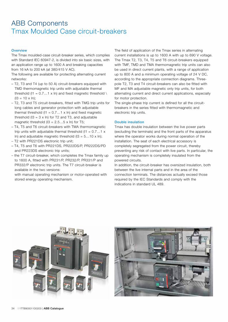
OverviewThe Tmax moulded-case circuit-breaker series, which complies with Standard IEC 60947-2, is divided into six basic sizes, with an application range up to 1600 A and breaking capacities from 16 kA to 200 kA (at 380/415 V AC).The following are available for protecting alternating current networks:– T2, T3 and T4 (up to 50 A) circuit-breakers equipped with
TMD thermomagnetic trip units with adjustable thermal threshold (I1 = 0.7…1 x In) and fixed magnetic threshold \ (I3 = 10 x In);
– T2, T3 and T5 circuit-breakers, fitted with TMG trip units for long cables and generator protection with adjustable thermal threshold (I1 = 0.7…1 x In) and fixed magnetic threshold (I3 = 3 x In) for T2 and T3, and adjustable magnetic threshold (I3 = 2.5…5 x In) for T5;
– T4, T5 and T6 circuit-breakers with TMA thermomagnetic trip units with adjustable thermal threshold (I1 = 0.7…1 x In) and adjustable magnetic threshold (I3 = 5…10 x In);
– T2 with PR221DS electronic trip unit;– T4, T5 and T6 with PR221DS, PR222DS/P, PR222DS/PD
and PR223DS electronic trip units;– the T7 circuit-breaker, which completes the Tmax family up
to 1600 A, fitted with PR231/P, PR232/P, PR331/P and PR332/P electronic trip units. The T7 circuit-breaker is available in the two versions:
with manual operating mechanism or motor-operated with stored energy operating mechanism.
The field of application of the Tmax series in alternating current installations is up to 1600 A with up to 690 V voltage. The Tmax T2, T3, T4, T5 and T6 circuit-breakers equipped with TMF, TMD and TMA thermomagnetic trip units can also be used in direct current plants, with a range of application up to 800 A and a minimum operating voltage of 24 V DC, according to the appropriate connection diagrams. Three-pole T2, T3 and T4 circuit-breakers can also be fitted with MF and MA adjustable magnetic only trip units, for both alternating current and direct current applications, especially for motor protection.The single-phase trip current is defined for all the circuit-breakers in the series fitted with thermomagnetic and electronic trip units.
Double insulationTmax has double insulation between the live power parts (excluding the terminals) and the front parts of the apparatus where the operator works during normal operation of the installation. The seat of each electrical accessory is completely segregated from the power circuit, thereby preventing any risk of contact with live parts. In particular, the operating mechanism is completely insulated from the powered circuits.In addition, the circuit-breaker has oversized insulation, both between the live internal parts and in the area of the connection terminals. The distances actually exceed those required by the IEC Standards and comply with the indications in standard UL 489.
ABB Catalogue | 1TTB900011D0203 | 35
Positive operationThe operating lever always indicates the precise position of the moving contacts of the circuit-breaker, thereby guaranteeing safe and reliable signals, in accordance with standards IEC 60073 and IEC 60417-2. (I = Closed; O = Open; yellow-green line = Open due to protection trip).The circuit-breaker operating mechanism features free release regardless of the pressure on the lever and the speed of operation. Protection tripping automatically opens the moving contacts: to close them again, the operating mechanism must be reset by pushing the operating lever from the intermediate position to the lowest open position.
Isolation behaviorIn the open position, the circuit-breaker guarantees circuit compliance with Standard IEC 60947-2. The oversized insulation distances ensure that there are no leakage currents and dielectric resistance to any overvoltages between input and output.
Versions and typesAll Tmax circuit-breakers are available in fixed versions, T2, T3, T4 and T5 in the plug-in version and T4, T5, T6 and T7 also in the withdrawable version.All the circuit-breakers can be operated in the manual mode using the operating lever or the rotary handle (direct or transmitted), and electrically operated. Different solutions are available:– Solenoid operator for T2 and T3– Stored energy motor operator for T4, T5 and T6– T7 with stored energy operating mechanism, gear motor for
automatic loading of the closing springs and shunt opening and closing releases.
Thermomagnetic trip unitsTmax T2, T3, T4, T5 and T6 circuit-breakers can be fitted with thermomagnetic trip units and are used for protecting alternating and direct current networks with 1.6 A to 800 A operating range. They achieve protection against overload with a thermal device (with adjustable threshold for T2, T3, T4, T5 and T6) created using the bimetal technique, and protection against short-circuit with a magnetic device (with fixed threshold for T2 and T3 and T4 up to 50 A and adjustable threshold for T4, T5 and T6).
The four-pole circuit-breakers are always supplied with the neutral protected by the trip unit and with protection of the neutral at 100% of the phase setting for settings up to 100 A. For higher settings, protection of the neutral is at 50% of the phase setting unless protection of the neutral at 100% of the phase setting is required.Furthermore, TMG thermomagnetic trip units with low magnetic trip threshold are available for Tmax T2, T3 and T5. For T2 and T3 the trip unit has an adjustable thermal threshold (I1 = 0.7…1 x In) and fixed magnetic threshold (I3 = 3 x In), whereas for T5 the trip unit has an adjustable thermal threshold (I1 = 0.7…1 x In) and adjustable magnetic threshold (I3 = 2.5… 5 x In). The thermomagnetic trip units can be used to protect long cables and for generator protection, both in direct current and in alternating current installations.
Electronic trip unitsTmax T2, T4, T5, T6 and T7 circuit-breakers, for use in alternating current, can be equipped with overcurrent releases featuring electronic technology. In this case the protection functions obtained guarantee high reliability, tripping precision, insensitivity to temperature and to electromagnetic components in conformity with the pertinent standards.The power required for correct operation is supplied directly by the current sensors of the release, while tripping is always guaranteed, even under single-phase load conditions and in correspondence to the minimum setting. For Tmax T2, T4, T5 and T6, the protection trip unit consists of:– 3 or 4 current sensors (current transformers)– external current sensors (e.g. for the external neutral), when
available– a trip unit– a trip coil (for T2 housed in the right slot, for T4, T5 and T6
integrated into the electronic trip unit).For Tmax T7, the protection trip unit consists of:– 3 or 4 current sensors (Rogowsky coils and current
transformers)– external current sensors (e.g. for the external neutral)– interchangeable rating plug– a trip unit– a trip coil housed in the body of the circuit-breaker. The current sensors supply the electronic trip unit with the
energy required for correct operation of both the trip unit and the signal that detects the current.

36 | 1TTB900011D0203 | ABB Catalogue
ABB ComponentsTmax Moulded Case circuit-breakers
Tmax T2 Tmax T3 Tmax T4 Tmax T5 Tmax T6 Tmax T7
Rated uninterrupted current [A] 160 250 250/320 400/630 630/800/1000 800/1000/1250/1600Poles [No.] 3/4 3/4 3/4 3/4 3/4 3/4Rated service voltage, Ue (AC) 50-60 Hz [V] 690 690 690 690 690 690
(DC) [V] 500 500 750 750 750 –Rated insulation voltage, Ui [V] 800 800 1000 1000 1000 1000Rated impulse withstand voltage, Uimp [kV] 8 8 8 8 8 8Versions Fixed, Plug-in Fixed, Plug-in Fixed, Withdrawable, Plug-in Fixed, Withdrawable, Plug-in Fixed, Withdrawable Fixed, WithdrawableBreaking capacities N S H L N S N S H L V N S H L V N S H L S H L V(6)
Rated ultimate short-circuit breaking capacity, Icu(AC) 50-60 Hz 220/230 V [kA] 65 85 100 120 50 85 70 85 100 200 200 70 85 100 200 200 70 85 100 200 85 100 200 200(AC) 50-60 Hz 380/400/415 V [kA] 36 50 70 85 36 50 36 50 70 120 200 36 50 70 120 200 36 50 70 100 50 70 120 150(AC) 50-60 Hz 440 V [kA] 30 45 55 75 25 40 30 40 65 100 180 30 40 65 100 180 30 45 50 80 50 65 100 130(AC) 50-60 Hz 500 V [kA] 25 30 36 50 20 30 25 30 50 85 150 25 30 50 85 150 25 35 50 65 40 50 85 100(AC) 50-60 Hz 690 V [kA] 6 7 8 10 5 8 20 25 40 70 80 20 25 40 70 80 20 22 25 30 30 42 50 60(DC) 250 V - 2 poles in series [kA] 36 50 70 85 36 50 36 50 70 100 150 36 50 70 100 150 36 50 70 100 – – – –(DC) 250 V - 3 poles in series [kA] 40 55 85 100 40 55 – – – – – – – – – – – – – – – – – –(DC) 500 V - 2 poles in series [kA] – – – – – – 25 36 50 70 100 25 36 50 70 100 20 35 50 65 – – – –(DC) 500 V - 3 poles in series [kA] 36 50 70 85 36 50 – – – – – – – – – – – – – – – – – –(DC) 750 V - 3 poles in series [kA] – – – – – – 16 25 36 50 70 16 25 36 50 70 16 20 36 50 – – – –Rated service short-circuit breaking capacity, Ics(AC) 50-60 Hz 220/230 V [%Icu] 100% 100% 100% 100% 75% 50% 100% 100% 100% 100% 100% 100% 100% 100% 100% 100% 100% 100% 100% 75% 100% 100% 100% 100%
(AC) 50-60 Hz 380/400/415 V [%Icu] 100% 100% 100%75% (70 kA)
75%50% (27kA)
100% 100% 100% 100% 100% 100% 100% 100% 100% 100% 100% 100% 100% 75% 100% 100% 100% 100%
(AC) 50-60 Hz 440 V [%Icu] 100% 100% 100% 75% 75% 50% 100% 100% 100% 100% 100% 100% 100% 100% 100% 100% 100% 100% 100% 75% 100% 100% 100% 100%(AC) 50-60 Hz 500 V [%Icu] 100% 100% 100% 75% 75% 50% 100% 100% 100% 100% 100% 100% 100% 100% 100%(1) 100%(2) 100% 100% 100% 75% 100% 100% 75% 100%(AC) 50-60 Hz 690 V [%Icu] 100% 100% 100% 75% 75% 50% 100% 100% 100% 100% 100% 100% 100% 100%(1) 100%(2) 100%(2) 75% 75% 75% 75% 100% 75% 75% 75%Rated short-circuit making capacity, Icm(AC) 50-60 Hz 220/230 V [kA] 143 187 220 264 105 187 154 187 220 440 660 154 187 220 440 660 154 187 220 440 187 220 440 440(AC) 50-60 Hz 380/400/415 V [kA] 75.6 105 154 187 75.6 105 75.6 105 154 264 440 75.6 105 154 264 440 75.6 105 154 220 105 154 264 330(AC) 50-60 Hz 440 V [kA] 63 94.5 121 165 52.5 84 63 84 143 220 396 63 84 143 220 396 63 94.5 105 176 105 143 220 286(AC) 50-60 Hz 500 V [kA] 52.5 63 75.6 105 40 63 52.5 63 105 187 330 52.5 63 105 187 330 52.5 73.5 105 143 84 105 187 220(AC) 50-60 Hz 690 V [kA] 9.2 11.9 13.6 17 7.7 13.6 40 52.5 84 154 176 40 52.5 84 154 176 40 46 52.5 63 63 88.2 105 132
Utilisation category (IEC 60947-2) A A A B (400 A)(3) - A (630 A) B (630A - 800A)(5) - A (1000A) B(7)
Reference Standard IEC 60947-2 √ √ √ √ √ √Isolation behaviour √ √ √ √ √ √Mounted on DIN rail DIN EN 50022 DIN EN 50022 - - - -Mechanical life [Num. operations] 25000 25000 20000 20000 20000 10000
[Num. Hourly operations] 240 240 240 120 120 60Electrical life @ 415 V (AC)
[Num. operations] 8000 8000 8000 (250 A) - 6000 (320 A) 7000 (400 A) - 5000 (630 A)7000 (630A) - 5000 (800A) - 4000 (1000A)
2000 (S, H, L versions) / 3000 (V version)
[Num. Hourly operations] 120 120 120 60 60 60Trip units for power distributionTMD / TMA ■ ■ ■ ■ ■ (4) up to 800APR221DS ■ ■ ■ ■
PR222DS ■ ■ ■
PR223DS ■ ■ ■
PR231/P ■
PR232/P ■
PR331/P ■
PR332/P ■
Trip units for motor protectionMF/MA ■ ■ ■ ■ ■
PR221DS-I ■ ■ ■ ■
PR221MP ■
PR222MP ■ ■ ■
Trip units for generator protectionTMG ■ ■
PR221GP ■
Electronic trip units for zone selectivityPR223EF ■ ■ ■
PR332/P ■(1) 75% for T5 630; (2) 50% for T5 630; (3) Icw = 5 kA; (4) W not available for T6 1000 A; (5) Icw = 7.6 kA (630 A) - 10 kA (800 A); (6) Only for T7 800/1000/1250 A; (7) Icw = 20 kA (Versions S,H,L) - 15 kA (Version V); Note: The nominal current of T2 – T3 – T5 630 in the P/W version is derated by 10%.
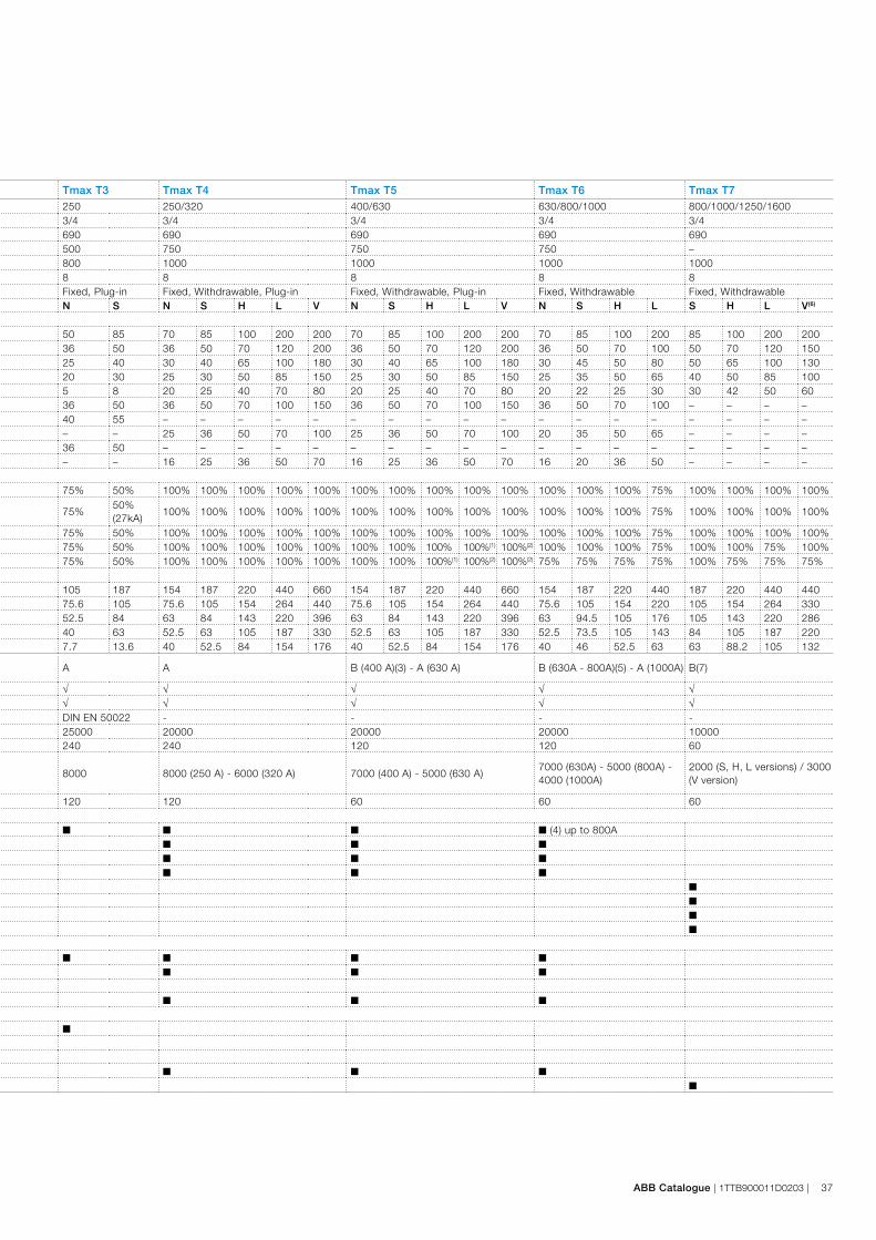
ABB Catalogue | 1TTB900011D0203 | 37
Tmax T2 Tmax T3 Tmax T4 Tmax T5 Tmax T6 Tmax T7
Rated uninterrupted current [A] 160 250 250/320 400/630 630/800/1000 800/1000/1250/1600Poles [No.] 3/4 3/4 3/4 3/4 3/4 3/4Rated service voltage, Ue (AC) 50-60 Hz [V] 690 690 690 690 690 690
(DC) [V] 500 500 750 750 750 –Rated insulation voltage, Ui [V] 800 800 1000 1000 1000 1000Rated impulse withstand voltage, Uimp [kV] 8 8 8 8 8 8Versions Fixed, Plug-in Fixed, Plug-in Fixed, Withdrawable, Plug-in Fixed, Withdrawable, Plug-in Fixed, Withdrawable Fixed, WithdrawableBreaking capacities N S H L N S N S H L V N S H L V N S H L S H L V(6)
Rated ultimate short-circuit breaking capacity, Icu(AC) 50-60 Hz 220/230 V [kA] 65 85 100 120 50 85 70 85 100 200 200 70 85 100 200 200 70 85 100 200 85 100 200 200(AC) 50-60 Hz 380/400/415 V [kA] 36 50 70 85 36 50 36 50 70 120 200 36 50 70 120 200 36 50 70 100 50 70 120 150(AC) 50-60 Hz 440 V [kA] 30 45 55 75 25 40 30 40 65 100 180 30 40 65 100 180 30 45 50 80 50 65 100 130(AC) 50-60 Hz 500 V [kA] 25 30 36 50 20 30 25 30 50 85 150 25 30 50 85 150 25 35 50 65 40 50 85 100(AC) 50-60 Hz 690 V [kA] 6 7 8 10 5 8 20 25 40 70 80 20 25 40 70 80 20 22 25 30 30 42 50 60(DC) 250 V - 2 poles in series [kA] 36 50 70 85 36 50 36 50 70 100 150 36 50 70 100 150 36 50 70 100 – – – –(DC) 250 V - 3 poles in series [kA] 40 55 85 100 40 55 – – – – – – – – – – – – – – – – – –(DC) 500 V - 2 poles in series [kA] – – – – – – 25 36 50 70 100 25 36 50 70 100 20 35 50 65 – – – –(DC) 500 V - 3 poles in series [kA] 36 50 70 85 36 50 – – – – – – – – – – – – – – – – – –(DC) 750 V - 3 poles in series [kA] – – – – – – 16 25 36 50 70 16 25 36 50 70 16 20 36 50 – – – –Rated service short-circuit breaking capacity, Ics(AC) 50-60 Hz 220/230 V [%Icu] 100% 100% 100% 100% 75% 50% 100% 100% 100% 100% 100% 100% 100% 100% 100% 100% 100% 100% 100% 75% 100% 100% 100% 100%
(AC) 50-60 Hz 380/400/415 V [%Icu] 100% 100% 100%75% (70 kA)
75%50% (27kA)
100% 100% 100% 100% 100% 100% 100% 100% 100% 100% 100% 100% 100% 75% 100% 100% 100% 100%
(AC) 50-60 Hz 440 V [%Icu] 100% 100% 100% 75% 75% 50% 100% 100% 100% 100% 100% 100% 100% 100% 100% 100% 100% 100% 100% 75% 100% 100% 100% 100%(AC) 50-60 Hz 500 V [%Icu] 100% 100% 100% 75% 75% 50% 100% 100% 100% 100% 100% 100% 100% 100% 100%(1) 100%(2) 100% 100% 100% 75% 100% 100% 75% 100%(AC) 50-60 Hz 690 V [%Icu] 100% 100% 100% 75% 75% 50% 100% 100% 100% 100% 100% 100% 100% 100%(1) 100%(2) 100%(2) 75% 75% 75% 75% 100% 75% 75% 75%Rated short-circuit making capacity, Icm(AC) 50-60 Hz 220/230 V [kA] 143 187 220 264 105 187 154 187 220 440 660 154 187 220 440 660 154 187 220 440 187 220 440 440(AC) 50-60 Hz 380/400/415 V [kA] 75.6 105 154 187 75.6 105 75.6 105 154 264 440 75.6 105 154 264 440 75.6 105 154 220 105 154 264 330(AC) 50-60 Hz 440 V [kA] 63 94.5 121 165 52.5 84 63 84 143 220 396 63 84 143 220 396 63 94.5 105 176 105 143 220 286(AC) 50-60 Hz 500 V [kA] 52.5 63 75.6 105 40 63 52.5 63 105 187 330 52.5 63 105 187 330 52.5 73.5 105 143 84 105 187 220(AC) 50-60 Hz 690 V [kA] 9.2 11.9 13.6 17 7.7 13.6 40 52.5 84 154 176 40 52.5 84 154 176 40 46 52.5 63 63 88.2 105 132
Utilisation category (IEC 60947-2) A A A B (400 A)(3) - A (630 A) B (630A - 800A)(5) - A (1000A) B(7)
Reference Standard IEC 60947-2 √ √ √ √ √ √Isolation behaviour √ √ √ √ √ √Mounted on DIN rail DIN EN 50022 DIN EN 50022 - - - -Mechanical life [Num. operations] 25000 25000 20000 20000 20000 10000
[Num. Hourly operations] 240 240 240 120 120 60Electrical life @ 415 V (AC)
[Num. operations] 8000 8000 8000 (250 A) - 6000 (320 A) 7000 (400 A) - 5000 (630 A)7000 (630A) - 5000 (800A) - 4000 (1000A)
2000 (S, H, L versions) / 3000 (V version)
[Num. Hourly operations] 120 120 120 60 60 60Trip units for power distributionTMD / TMA ■ ■ ■ ■ ■ (4) up to 800APR221DS ■ ■ ■ ■
PR222DS ■ ■ ■
PR223DS ■ ■ ■
PR231/P ■
PR232/P ■
PR331/P ■
PR332/P ■
Trip units for motor protectionMF/MA ■ ■ ■ ■ ■
PR221DS-I ■ ■ ■ ■
PR221MP ■
PR222MP ■ ■ ■
Trip units for generator protectionTMG ■ ■
PR221GP ■
Electronic trip units for zone selectivityPR223EF ■ ■ ■
PR332/P ■(1) 75% for T5 630; (2) 50% for T5 630; (3) Icw = 5 kA; (4) W not available for T6 1000 A; (5) Icw = 7.6 kA (630 A) - 10 kA (800 A); (6) Only for T7 800/1000/1250 A; (7) Icw = 20 kA (Versions S,H,L) - 15 kA (Version V); Note: The nominal current of T2 – T3 – T5 630 in the P/W version is derated by 10%.
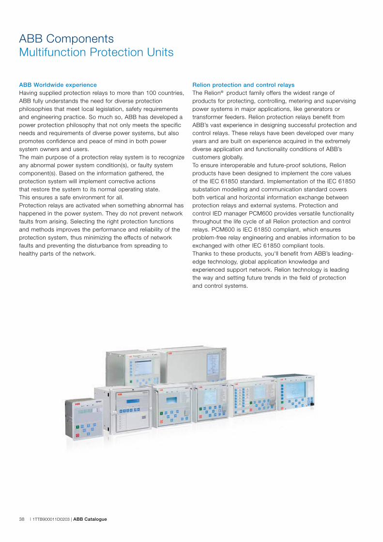
38 | 1TTB900011D0203 | ABB Catalogue
ABB ComponentsMultifunction Protection Units
ABB Worldwide experienceHaving supplied protection relays to more than 100 countries, ABB fully understands the need for diverse protection philosophies that meet local legislation, safety requirements and engineering practice. So much so, ABB has developed a power protection philosophy that not only meets the specific needs and requirements of diverse power systems, but also promotes confidence and peace of mind in both power system owners and users.The main purpose of a protection relay system is to recognize any abnormal power system condition(s), or faulty system component(s). Based on the information gathered, the protection system will implement corrective actions that restore the system to its normal operating state. This ensures a safe environment for all.Protection relays are activated when something abnormal has happened in the power system. They do not prevent network faults from arising. Selecting the right protection functions and methods improves the performance and reliability of the protection system, thus minimizing the effects of network faults and preventing the disturbance from spreading to healthy parts of the network.
Relion protection and control relaysThe Relion® product family offers the widest range of products for protecting, controlling, metering and supervising power systems in major applications, like generators or transformer feeders. Relion protection relays benefit from ABB’s vast experience in designing successful protection and control relays. These relays have been developed over many years and are built on experience acquired in the extremely diverse application and functionality conditions of ABB’s customers globally.To ensure interoperable and future-proof solutions, Relion products have been designed to implement the core values of the IEC 61850 standard. Implementation of the IEC 61850 substation modelling and communication standard covers both vertical and horizontal information exchange between protection relays and external systems. Protection and control IED manager PCM600 provides versatile functionality throughout the life cycle of all Relion protection and control relays. PCM600 is IEC 61850 compliant, which ensures problem-free relay engineering and enables information to be exchanged with other IEC 61850 compliant tools. Thanks to these products, you'll benefit from ABB’s leading-edge technology, global application knowledge and experienced support network. Relion technology is leading the way and setting future trends in the field of protection and control systems.
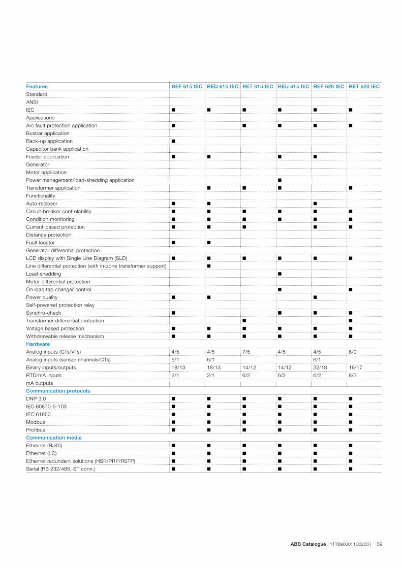
ABB Catalogue | 1TTB900011D0203 | 39
Features REF 615 IEC RED 615 IEC RET 615 IEC REU 615 IEC REF 620 IEC RET 620 IEC
Standard
ANSI
IEC ■ ■ ■ ■ ■ ■
Applications
Arc fault protection application ■ ■ ■ ■ ■
Busbar application
Back-up application ■
Capacitor bank application
Feeder application ■ ■ ■ ■
Generator
Motor application
Power management/load-shedding application ■
Transformer application ■ ■ ■ ■
Functionality
Auto-recloser ■ ■ ■
Circuit-breaker controlability ■ ■ ■ ■ ■ ■
Condition monitoring ■ ■ ■ ■ ■ ■
Current-based protection ■ ■ ■ ■ ■
Distance protection
Fault locator ■ ■
Generator differential protection
LCD display with Single Line Diagram (SLD) ■ ■ ■ ■ ■ ■
Line differential protection (with in-zone transformer support) ■
Load-shedding ■
Motor differential protection
On load tap changer control ■ ■
Power quality ■ ■ ■
Self-powered protection relay
Synchro-check ■ ■ ■ ■
Transformer differential protection ■ ■
Voltage based protection ■ ■ ■ ■ ■ ■
Withdrawable release mechanism ■ ■ ■ ■ ■ ■
Hardware
Analog inputs (CTs/VTs) 4/5 4/5 7/5 4/5 4/5 8/9
Analog inputs (sensor channels/CTs) 6/1 6/1 6/1
Binary inputs/outputs 18/13 18/13 14/12 14/12 32/18 16/17
RTD/mA inputs 2/1 2/1 6/2 6/2 6/2 8/3
mA outputs
Communication protocols
DNP 3.0 ■ ■ ■ ■ ■ ■
IEC 60870-5-103 ■ ■ ■ ■ ■ ■
IEC 61850 ■ ■ ■ ■ ■ ■
Modbus ■ ■ ■ ■ ■ ■
Profibus ■ ■ ■ ■ ■ ■
Communication media
Ethernet (RJ45) ■ ■ ■ ■ ■ ■
Ethernet (LC) ■ ■ ■ ■ ■ ■
Ethernet redundant solutions (HSR/PRP/RSTP) ■ ■ ■ ■ ■ ■
Serial (RS 232/485, ST conn.) ■ ■ ■ ■ ■ ■
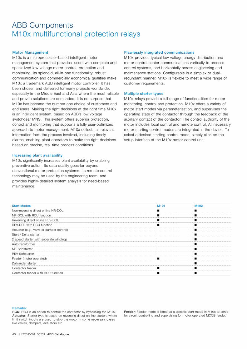
40 | 1TTB900011D0203 | ABB Catalogue
ABB ComponentsM10x multifunctional protection relays
Motor ManagementM10x is a microprocessor-based intelligent motor management system that provides users with complete and specialized low voltage motor control, protection and monitoring. Its splendid, all-in-one functionality, robust communication and commercially economical qualities make M10x a trademark ABB intelligent motor controller. It has been chosen and delivered for many projects worldwide, especially in the Middle East and Asia where the most reliable and proven solutions are demanded. It is no surprise that M10x has become the number one choice of customers and end users. Making the right decisions at the right time M10x is an intelligent system, based on ABB’s low voltage switchgear MNS. This system offers superior protection, control and monitoring that supports a fully user-optimized approach to motor management. M10x collects all relevant information from the process involved, including timely alarms, enabling plant operators to make the right decisions based on precise, real-time process conditions. Increasing plant availabilityM10x significantly increases plant availability by enabling preventive action. Its data quality goes far beyond conventional motor protection systems. Its remote control technology may be used by the engineering team, and provides highly-detailed system analysis for need-based maintenance.
Flawlessly integrated communicationsM10x provides typical low voltage energy distribution and motor control center communications vertically to process control systems, and horizontally across engineering and maintenance stations. Configurable in a simplex or dual-redundant manner, M10x is flexible to meet a wide range of customer requirements.
Multiple starter typesM10x relays provide a full range of functionalities for motor monitoring, control and protection. M10x offers a variety of motor start modes via parameterization, and supervises the operating state of the contactor through the feedback of the auxiliary contact of the contactor. The control authority of the motor includes local control and remote control. All necessary motor starting control modes are integrated in the device. To select a desired starting control mode, simply click on the setup interface of the M10x motor control unit.
Remarks: RCU: RCU is an option to control the contactor by bypassing the M10x.Actuator: Starter type is based on reversing direct on line starters where limit switch inputs are used to stop the motor in some necessary cases like valves, dampers, actuators etc.
Feeder: Feeder mode is listed as a specific start mode in M10x to serve for circuit controlling and supervising for motor operated MCCB feeder.
Start Modes M101 M102
Non-reversing direct online NR-DOL ■ ■
NR-DOL with RCU function ■ ■
Reversing direct online REV-DOL ■ ■
REV-DOL with RCU function ■ ■
Actuator (e.g., valve or damper control) ■
Start / Delta starter ■
2 speed starter with separate windings ■
Autotransformer ■
NR-Softstarter ■
REV-Softstarter ■
Feeder (motor operated) ■ ■
Dahlander starter ■
Contactor feeder ■ ■
Contactor feeder with RCU function ■ ■
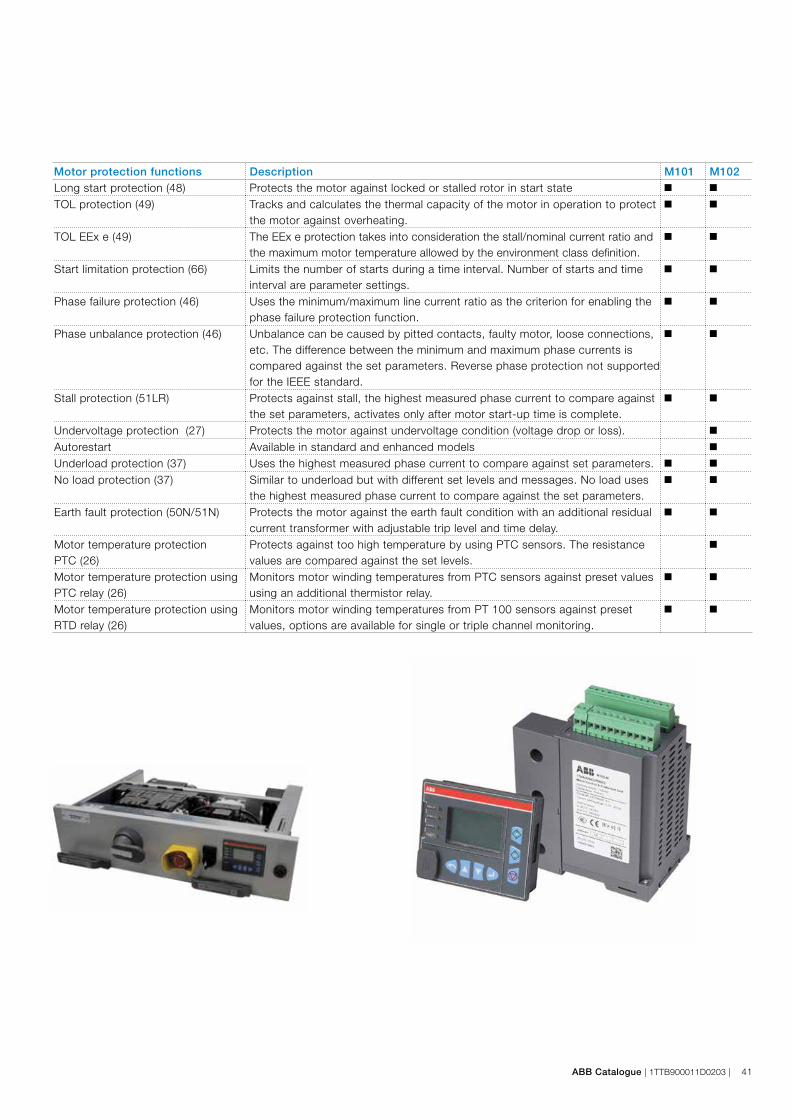
ABB Catalogue | 1TTB900011D0203 | 41
Motor protection functions Description M101 M102Long start protection (48) Protects the motor against locked or stalled rotor in start state ■ ■
TOL protection (49) Tracks and calculates the thermal capacity of the motor in operation to protect the motor against overheating.
■ ■
TOL EEx e (49) The EEx e protection takes into consideration the stall/nominal current ratio and the maximum motor temperature allowed by the environment class definition.
■ ■
Start limitation protection (66) Limits the number of starts during a time interval. Number of starts and time interval are parameter settings.
■ ■
Phase failure protection (46) Uses the minimum/maximum line current ratio as the criterion for enabling the phase failure protection function.
■ ■
Phase unbalance protection (46) Unbalance can be caused by pitted contacts, faulty motor, loose connections, etc. The difference between the minimum and maximum phase currents is compared against the set parameters. Reverse phase protection not supported for the IEEE standard.
■ ■
Stall protection (51LR) Protects against stall, the highest measured phase current to compare against the set parameters, activates only after motor start-up time is complete.
■ ■
Undervoltage protection (27) Protects the motor against undervoltage condition (voltage drop or loss). ■
Autorestart Available in standard and enhanced models ■
Underload protection (37) Uses the highest measured phase current to compare against set parameters. ■ ■
No load protection (37) Similar to underload but with different set levels and messages. No load uses the highest measured phase current to compare against the set parameters.
■ ■
Earth fault protection (50N/51N) Protects the motor against the earth fault condition with an additional residual current transformer with adjustable trip level and time delay.
■ ■
Motor temperature protection PTC (26)
Protects against too high temperature by using PTC sensors. The resistance values are compared against the set levels.
■
Motor temperature protection using PTC relay (26)
Monitors motor winding temperatures from PTC sensors against preset values using an additional thermistor relay.
■ ■
Motor temperature protection using RTD relay (26)
Monitors motor winding temperatures from PT 100 sensors against preset values, options are available for single or triple channel monitoring.
■ ■
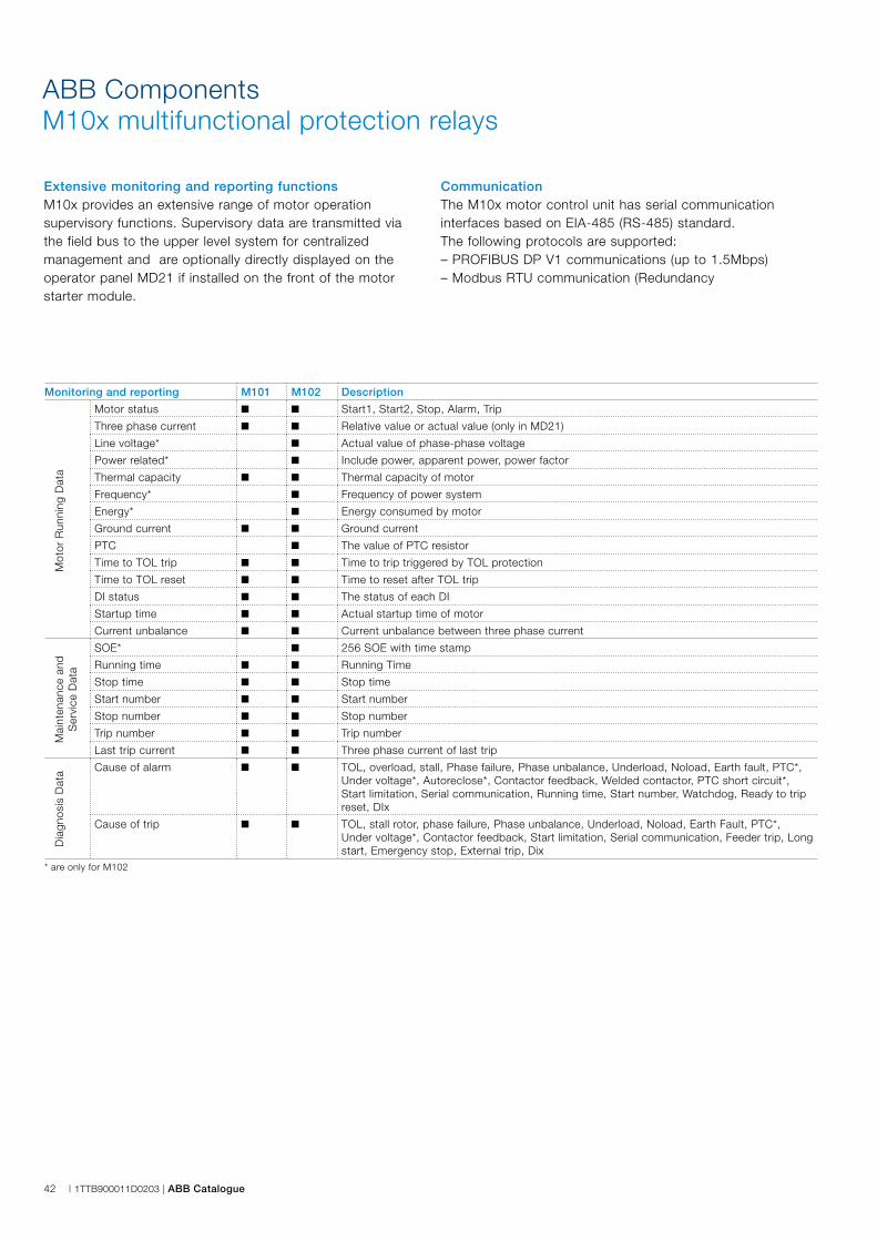
42 | 1TTB900011D0203 | ABB Catalogue
ABB ComponentsM10x multifunctional protection relays
Extensive monitoring and reporting functionsM10x provides an extensive range of motor operation supervisory functions. Supervisory data are transmitted via the field bus to the upper level system for centralized management and are optionally directly displayed on the operator panel MD21 if installed on the front of the motor starter module.
CommunicationThe M10x motor control unit has serial communication interfaces based on EIA-485 (RS-485) standard.The following protocols are supported:– PROFIBUS DP V1 communications (up to 1.5Mbps)– Modbus RTU communication (Redundancy
Monitoring and reporting M101 M102 Description
Motor status ■ ■ Start1, Start2, Stop, Alarm, Trip
Three phase current ■ ■ Relative value or actual value (only in MD21)
Line voltage* ■ Actual value of phase-phase voltage
Power related* ■ Include power, apparent power, power factor
Thermal capacity ■ ■ Thermal capacity of motor
Frequency* ■ Frequency of power system
Energy* ■ Energy consumed by motor
Ground current ■ ■ Ground current
PTC ■ The value of PTC resistor
Time to TOL trip ■ ■ Time to trip triggered by TOL protection
Time to TOL reset ■ ■ Time to reset after TOL trip
DI status ■ ■ The status of each DI
Startup time ■ ■ Actual startup time of motor
Current unbalance ■ ■ Current unbalance between three phase current
SOE* ■ 256 SOE with time stamp
Running time ■ ■ Running Time
Stop time ■ ■ Stop time
Start number ■ ■ Start number
Stop number ■ ■ Stop number
Trip number ■ ■ Trip number
Last trip current ■ ■ Three phase current of last trip
Cause of alarm ■ ■ TOL, overload, stall, Phase failure, Phase unbalance, Underload, Noload, Earth fault, PTC*, Under voltage*, Autoreclose*, Contactor feedback, Welded contactor, PTC short circuit*, Start limitation, Serial communication, Running time, Start number, Watchdog, Ready to trip reset, DIx
Cause of trip ■ ■ TOL, stall rotor, phase failure, Phase unbalance, Underload, Noload, Earth Fault, PTC*, Under voltage*, Contactor feedback, Start limitation, Serial communication, Feeder trip, Long start, Emergency stop, External trip, Dix
* are only for M102
Mot
or R
unni
ng D
ata
Mai
nten
ance
and
S
ervi
ce D
ata
Dia
gnos
is D
ata
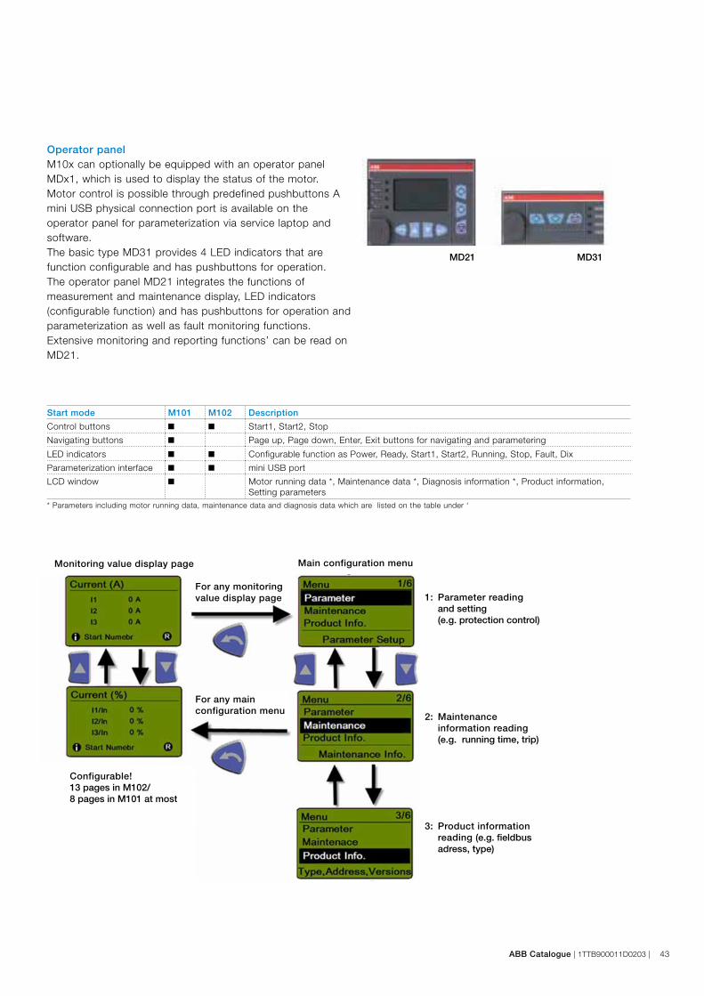
1: Parameter reading and setting (e.g. protection control)
2: Maintenance information reading (e.g. running time, trip)
3: Product information reading (e.g. fieldbus
adress, type)
Monitoring value display page Main configuration menu
For any monitoring value display page
For any main configuration menu
Configurable!13 pages in M102/8 pages in M101 at most
MD21 MD31
ABB Catalogue | 1TTB900011D0203 | 43
Start mode M101 M102 Description
Control buttons ■ ■ Start1, Start2, Stop
Navigating buttons ■ Page up, Page down, Enter, Exit buttons for navigating and parametering
LED indicators ■ ■ Configurable function as Power, Ready, Start1, Start2, Running, Stop, Fault, Dix
Parameterization interface ■ ■ mini USB port
LCD window ■ Motor running data *, Maintenance data *, Diagnosis information *, Product information, Setting parameters
* Parameters including motor running data, maintenance data and diagnosis data which are listed on the table under ‘
Operator panelM10x can optionally be equipped with an operator panel MDx1, which is used to display the status of the motor. Motor control is possible through predefined pushbuttons A mini USB physical connection port is available on the operator panel for parameterization via service laptop and software.The basic type MD31 provides 4 LED indicators that are function configurable and has pushbuttons for operation.The operator panel MD21 integrates the functions of measurement and maintenance display, LED indicators (configurable function) and has pushbuttons for operation and parameterization as well as fault monitoring functions.Extensive monitoring and reporting functions’ can be read on MD21.
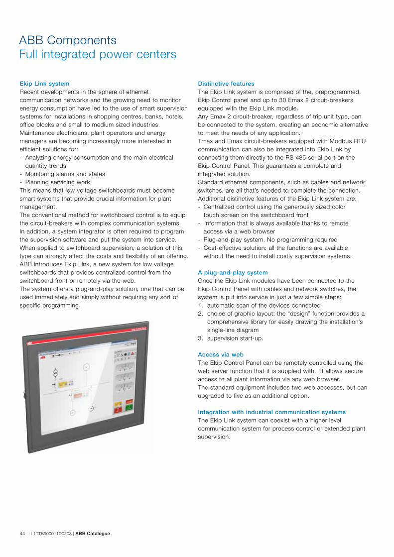
44 | 1TTB900011D0203 | ABB Catalogue
ABB ComponentsFull integrated power centers
Ekip Link systemRecent developments in the sphere of ethernet communication networks and the growing need to monitor energy consumption have led to the use of smart supervisionsystems for installations in shopping centres, banks, hotels,office blocks and small to medium sized industries.Maintenance electricians, plant operators and energy managers are becoming increasingly more interested inefficient solutions for:- Analyzing energy consumption and the main electrical
quantity trends- Monitoring alarms and states- Planning servicing work.This means that low voltage switchboards must becomesmart systems that provide crucial information for plantmanagement.The conventional method for switchboard control is to equipthe circuit-breakers with complex communication systems.In addition, a system integrator is often required to programthe supervision software and put the system into service.When applied to switchboard supervision, a solution of thistype can strongly affect the costs and flexibility of an offering.ABB introduces Ekip Link, a new system for low voltage switchboards that provides centralized control from the switchboard front or remotely via the web.The system offers a plug-and-play solution, one that can beused immediately and simply without requiring any sort ofspecific programming.
Distinctive featuresThe Ekip Link system is comprised of the, preprogrammed, Ekip Control panel and up to 30 Emax 2 circuit-breakers equipped with the Ekip Link module.Any Emax 2 circuit-breaker, regardless of trip unit type, can be connected to the system, creating an economic alternative to meet the needs of any application.Tmax and Emax circuit-breakers equipped with Modbus RTU communication can also be integrated into Ekip Link by connecting them directly to the RS 485 serial port on the Ekip Control Panel. This guarantees a complete and integrated solution.Standard ethernet components, such as cables and network switches, are all that’s needed to complete the connection.Additional distinctive features of the Ekip Link system are:- Centralized control using the generously sized color
touch screen on the switchboard front- Information that is always available thanks to remote
access via a web browser- Plug-and-play system. No programming required- Cost-effective solution: all the functions are available
without the need to install costly supervision systems.
A plug-and-play systemOnce the Ekip Link modules have been connected to the Ekip Control Panel with cables and network switches, the system is put into service in just a few simple steps:1. automatic scan of the devices connected2. choice of graphic layout: the “design” function provides a
comprehensive library for easily drawing the installation’s single-line diagram
3. supervision start-up.
Access via webThe Ekip Control Panel can be remotely controlled using the web server function that it is supplied with. It allows secure access to all plant information via any web browser. The standard equipment includes two web accesses, but can upgraded to five as an additional option.
Integration with industrial communication systemsThe Ekip Link system can coexist with a higher level communication system for process control or extended plant supervision.
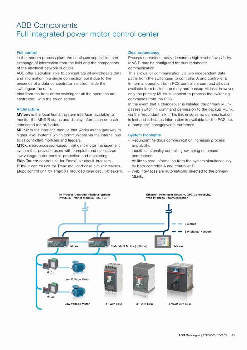
ABB Catalogue | 1TTB900011D0203 | 45
M10x
Full controlIn the modern process plant the continues supervision and exchange of information from the field and the components of the electrical network is crucial.ABB offer a solution able to concentrate all switchgears data and information in a single connection point due to the presence of a data concentrator installed inside the switchgear the data.Also from the front of the switchgear all the operation are centralized with the touch screen.
ArchitectureMView: is the local human system interface available to monitor the MNS R status and display information on each connected motor/feeder.MLink: is the interface module that works as the gateway to higher level systems which communicate via the internal bus to all controlled modules and feeders.M10x: microprocessor-based intelligent motor management system that provides users with complete and specialized low voltage motor control, protection and monitoring.Ekip Touch: control unit for Emax2 air circuit-breakers.PR223: control unit for Tmax moulded case circuit-breakers.Ekip: control unit for Tmax XT moulded case circuit-breakers.
Dual redundancyProcess operations today demand a high level of availability.MNS R may be configured for dual redundant communication.This allows for communication via two independent data paths from the switchgear to controller A and controller B.In normal operation both PCS controllers can read all data available from both the primary and backup MLinks, however,only the primary MLink is enabled to process the switching commands from the PCS.In the event that a changeover is initiated the primary MLinkpasses switching command permission to the backup MLink,via the ‘redundant link’. This link ensures no communication is lost and full status information is available for the PCS, i.e. a ‘bumpless’ changeover is performed.
System highlights- Redundant fieldbus communication increases process
availability.- Inbuilt functionality controlling switching command
permissions.- Ability to read information from the system simultaneously
by both controller A and controller B.- Web interfaces are automatically directed to the primary
MLink.
ABB ComponentsFull integrated power motor control center
Emax2 with EkipXT with EkipXT with Ekip
Low Voltage Motor
Low Voltage Motor
M10x
MLink Redundant MLink (optional) MView
Switchgear Network
Fieldbus
To Process Controller Fieldbus optionsProfibus, Profinet Modbus RTU, TCP
Ethernet Switchgear Network, OPC Connectivity.Web Interface Parameterisation
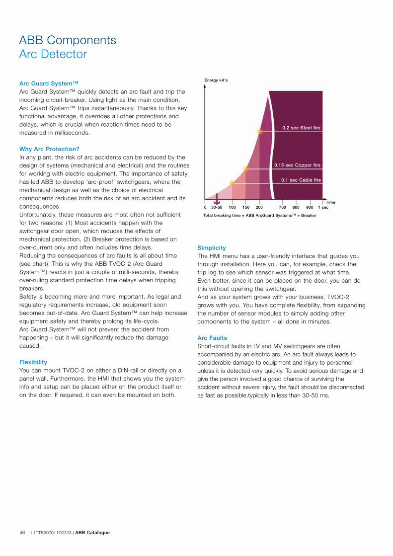
46 | 1TTB900011D0203 | ABB Catalogue
ABB ComponentsArc Detector
Arc Guard System™Arc Guard System™ quickly detects an arc fault and trip the incoming circuit-breaker. Using light as the main condition, Arc Guard System™ trips instantaneously. Thanks to this key functional advantage, it overrides all other protections and delays, which is crucial when reaction times need to be measured in milliseconds.
Why Arc Protection?In any plant, the risk of arc accidents can be reduced by the design of systems (mechanical and electrical) and the routines for working with electric equipment. The importance of safety has led ABB to develop ‘arc-proof’ switchgears, where the mechanical design as well as the choice of electrical components reduces both the risk of an arc accident and its consequences.Unfortunately, these measures are most often not sufficient for two reasons; (1) Most accidents happen with the switchgear door open, which reduces the effects of mechanical protection, (2) Breaker protection is based on over-current only and often includes time delays.Reducing the consequences of arc faults is all about time (see chart). This is why the ABB TVOC-2 (Arc Guard System™) reacts in just a couple of milli-seconds, thereby over-ruling standard protection time delays when tripping breakers. Safety is becoming more and more important. As legal and regulatory requirements increase, old equipment soon becomes out-of-date. Arc Guard System™ can help increase equipment safety and thereby prolong its life-cycle. Arc Guard System™ will not prevent the accident from happening – but it will significantly reduce the damage caused.
FlexibilityYou can mount TVOC-2 on either a DIN-rail or directly on a panel wall. Furthermore, the HMI that shows you the system info and setup can be placed either on the product itself or on the door. If required, it can even be mounted on both.
SimplicityThe HMI menu has a user-friendly interface that guides youthrough installation. Here you can, for example, check thetrip log to see which sensor was triggered at what time. Even better, since it can be placed on the door, you can do this without opening the switchgear.And as your system grows with your business, TVOC-2 grows with you. You have complete flexibility, from expandingthe number of sensor modules to simply adding other components to the system – all done in minutes.
Arc FaultsShort-circuit faults in LV and MV switchgears are often accompanied by an electric arc. An arc fault always leads to considerable damage to equipment and injury to personnel unless it is detected very quickly. To avoid serious damage and give the person involved a good chance of surviving the accident without severe injury, the fault should be disconnected as fast as possible,typically in less than 30-50 ms.
Time
Energy kA's
0 30-50 100 150 200 700 800 900 1 sec
Total breaking time = ABB ArcGuard Systems™ + Breaker
0.2 sec Steel fire
0.15 sec Copper fire
0.1 sec Cable fire
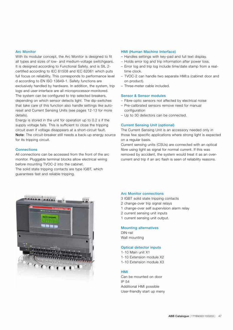
ABB Catalogue | 1TTB900011D0203 | 47
Arc MonitorWith its modular concept, the Arc Monitor is designed to fit all types and sizes of low- and medium-voltage switchgears.It is designed according to Functional Safety, and is SIL 2-certified according to IEC 61508 and IEC 62061 which puts full focus on reliability. This corresponds to performance leveld according to EN ISO 13849-1. Safety functions are exclusively handled by hardware. In addition, the system, trip logs and user-interface are all microprocessor-monitored.The system can be configured to trip selected breakers, depending on which sensor detects light. The dip-switches that take care of this function also handle settings like auto-reset and Current Sensing Units (see pages 12-13 for more details).Energy is stored in the unit for operation up to 0.2 s if the supply voltage fails. This is sufficient to close the tripping circuit even if voltage disappears at a short-circuit fault.Note: The circuit-breaker still needs a back-up energy source for its tripping circuit.
ConnectionsAll connections can be accessed from the front of the arc monitor. Pluggable terminal blocks allow electrical wiring before mounting TVOC-2 into the cabinet.The solid state tripping contacts are type IGBT, which guarantees fast and reliable tripping.
HMI (Human Machine Interface)– Handles settings with key-pad and full text display.– Holds error log and trip information after power loss.– Error log and trip log include time/date stamp from a real-
time clock.– TVOC-2 can handle two separate HMI:s (cabinet door and
on product).– Three-meter cable included.
Sensor & Sensor modules– Fibre-optic sensors not affected by electrical noise– Pre-calibrated sensors remove need for manual
configuration– Up to 30 detectors can be connected.
Current Sensing Unit (optional)The Current Sensing Unit is an accessory needed only in those few specific applications where strong light is expected on a regular basis.Current sensing units (CSUs) are connected with an optical fibre using light as signal for normal current. If this was removed by accident, the system would treat it as an over-current and trip if an arc flash is seen of reliability reasons.
Arc Monitor connections3 IGBT solid state tripping contacts2 change-over trip signal relays1 change-over self supervision alarm relay2 current sensing unit inputs1 current sensing unit output.
Mounting alternativesDIN-railWall mounting
Optical detector inputs1-10 Main unit X11-10 Extension module X21-10 Extension module X3
HMICan be mounted on doorIP 54Additional HMI possibleUser-friendly start up meny
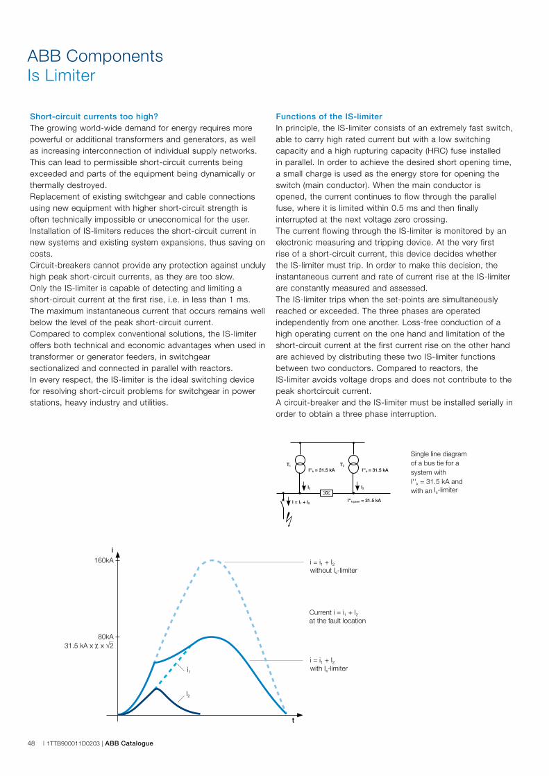
I''k = 31.5 kAT2
I2
I''k = 31.5 kAT1
I2
I = I1 + I2I''k perm = 31.5 kA
48 | 1TTB900011D0203 | ABB Catalogue
ABB ComponentsIs Limiter
Short-circuit currents too high?The growing world-wide demand for energy requires more powerful or additional transformers and generators, as well as increasing interconnection of individual supply networks.This can lead to permissible short-circuit currents being exceeded and parts of the equipment being dynamically or thermally destroyed.Replacement of existing switchgear and cable connections using new equipment with higher short-circuit strength is often technically impossible or uneconomical for the user. Installation of IS-limiters reduces the short-circuit current in new systems and existing system expansions, thus saving on costs.Circuit-breakers cannot provide any protection against undulyhigh peak short-circuit currents, as they are too slow. Only the IS-limiter is capable of detecting and limiting a short-circuit current at the first rise, i.e. in less than 1 ms. The maximum instantaneous current that occurs remains well below the level of the peak short-circuit current.Compared to complex conventional solutions, the IS-limiter offers both technical and economic advantages when used in transformer or generator feeders, in switchgearsectionalized and connected in parallel with reactors.In every respect, the IS-limiter is the ideal switching devicefor resolving short-circuit problems for switchgear in powerstations, heavy industry and utilities.
Functions of the IS-limiterIn principle, the IS-limiter consists of an extremely fast switch,able to carry high rated current but with a low switchingcapacity and a high rupturing capacity (HRC) fuse installedin parallel. In order to achieve the desired short opening time,a small charge is used as the energy store for opening theswitch (main conductor). When the main conductor is opened, the current continues to flow through the parallel fuse, where it is limited within 0.5 ms and then finally interrupted at the next voltage zero crossing.The current flowing through the IS-limiter is monitored by anelectronic measuring and tripping device. At the very firstrise of a short-circuit current, this device decides whetherthe IS-limiter must trip. In order to make this decision, the instantaneous current and rate of current rise at the IS-limiter are constantly measured and assessed. The IS-limiter trips when the set-points are simultaneously reached or exceeded. The three phases are operated independently from one another. Loss-free conduction of a high operating current on the one hand and limitation of the short-circuit current at the first current rise on the other hand are achieved by distributing these two IS-limiter functions between two conductors. Compared to reactors, the IS-limiter avoids voltage drops and does not contribute to the peak shortcircuit current.A circuit-breaker and the IS-limiter must be installed serially in order to obtain a three phase interruption.
t
i
160kA
80kA31.5 kA x χ x √2
i = i1 + I2with Is-limiter
i = i1 + I2without Is-limiter
Current i = i1 + I2at the fault location
i1
I2
Single line diagramof a bus tie for a system with I''k = 31.5 kA and with an Is-limiter
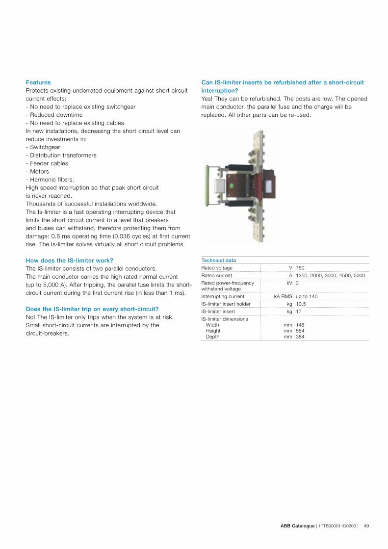
ABB Catalogue | 1TTB900011D0203 | 49
Technical data
Rated voltage V 750
Rated current A 1250, 2000, 3000, 4500, 5000
Rated power-frequency withstand voltage
kV 3
Interrupting current kA RMS up to 140
IS-limiter insert holder kg 10.5
IS-limiter insert kg 17
IS-limiter dimensions Width Height Depth
mm mm mm
148 554 384
FeaturesProtects existing underrated equipment against short circuit current effects:- No need to replace existing switchgear- Reduced downtime- No need to replace existing cables.In new installations, decreasing the short circuit level can reduce investments in:- Switchgear- Distribution transformers- Feeder cables- Motors- Harmonic filters.High speed interruption so that peak short circuitis never reached. Thousands of successful installations worldwide.The Is-limiter is a fast operating interrupting device thatlimits the short circuit current to a level that breakersand buses can withstand, therefore protecting them fromdamage: 0.6 ms operating time (0.036 cycles) at first current rise. The Is-limiter solves virtually all short circuit problems.
How does the IS-limiter work?The IS-limiter consists of two parallel conductors.The main conductor carries the high rated normal current (up to 5,000 A). After tripping, the parallel fuse limits the short-circuit current during the first current rise (in less than 1 ms).
Does the IS-limiter trip on every short-circuit?No! The IS-limiter only trips when the system is at risk.Small short-circuit currents are interrupted by the circuit-breakers.
Can IS-limiter inserts be refurbished after a short-circuit interruption?Yes! They can be refurbished. The costs are low. The opened main conductor, the parallel fuse and the charge will be replaced. All other parts can be re-used.
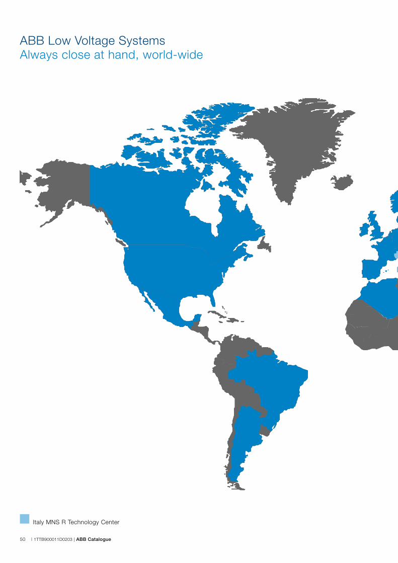
50 | 1TTB900011D0203 | ABB Catalogue
ABB Low Voltage SystemsAlways close at hand, world-wide
Italy MNS R Technology Center

ABB Catalogue | 1TTB900011D0203 | 51
ABB Low Voltage SystemsAlways close at hand, world-wide

52 | 1TTB900011D0203 | ABB Catalogue
Items subject to agreement between manufacturer and user
Extract from IEC 61439 series
The following details are intended as a checklist for the specification of low voltage switchgear.
Annex
User-defined functions and characteristics Reference clause (IEC 61439 series)
Electrical system
Earthing system 5.5, 8.4.3.2.3, 8.6.2, 10.5, 11.4
Rated voltage Un (Volts) 3.8.8.1, 5.2.1, 8.5.3
Overvoltage category 5.2.4, 8.5.3, 9.1, Annex G
Unusual voltage transients, voltage stress, temporary overvoltages 9.1
Rated frequency fn (Hz) 3.8.11, 5.4, 8.5.3, 10.10.2.3, 10.11.5.4
Additional on-site testing requirements: wiring, operational performance and function 11.10
Short circuit withstand capability
Prospective short circuit current at supply terminals Icp (kA) 3.8.6
Prospective short circuit current in the neutral 10.11.5.3.5
Prospective short circuit current in the protective circuit 10.11.5.6
SCPD in the incoming functional unit 9.3.2
Co-ordination of short-circuit protective devices 9.3.4
including external short-circuit protective device details
Data associated with loads likely to contribute to the shortcircuit current 9.3.2
Protection of persons against electric shock in accordance with IEC 60364-4-41
Type of protection against electric shock - Basic protection (protection against direct contact) 8.4.2
NOTE: This type of protection is intended to protect against electric shock due to direct contact
within the assembly during normal service conditions.
Type of protection against electric shock - Fault protection (protection against indirect contact) 8.4.3
NOTE: These types of protection are intended to protect against the consequences of a fault
within the assembly.
Installation environment
Location type 3.5, 8.1.4, 8.2
Protection against ingress of solid foreign bodies and ingress of liquid 8.2.2, 8.2.3
External mechanical impact (IK) 8.2.1, 10.2.6
NOTE: IEC 61439-1 does not nominate specific IK codes.
Resistance to UV radiation (applies for outdoor assemblies only unless specified otherwise) 10.2.4
Resistance to corrosion 10.2.2
Ambient air temperature – lower limit 7.1.1
Ambient air temperature – upper limit 7.1.1
Ambient air temperature – daily average maximum 7.1.1
Maximum relative humidity 7.1.2
Pollution degree 7.1.3
Altitude 7.1.4
EMC environment 9.4, 10.12, Annex J
Special service conditions (e.g. vibration, exceptional condensation, heavy pollution, corrosive 7.2, 8.5.4, 9.3.3, Table 7
environment, strong electric or magnetic fields, fungus, small creatures, explosion hazards,
heavy vibration and shocks, earthquakes)
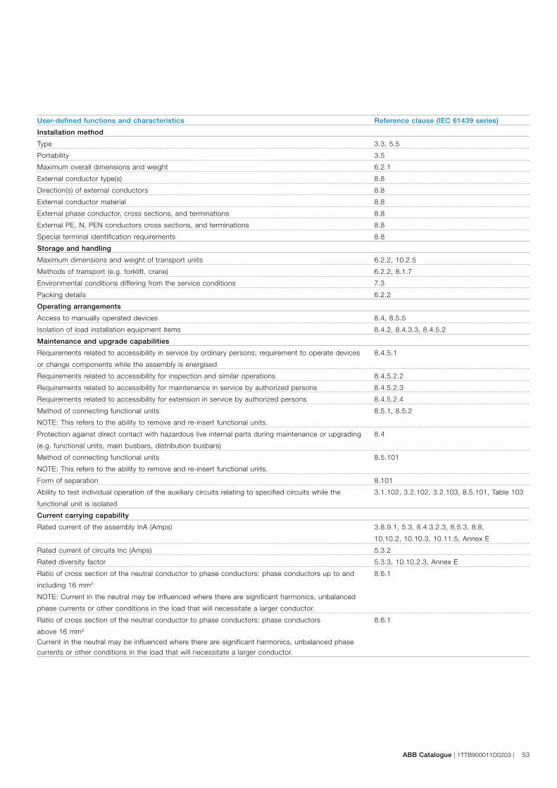
ABB Catalogue | 1TTB900011D0203 | 53
User-defined functions and characteristics Reference clause (IEC 61439 series)
Installation method
Type 3.3, 5.5
Portability 3.5
Maximum overall dimensions and weight 6.2.1
External conductor type(s) 8.8
Direction(s) of external conductors 8.8
External conductor material 8.8
External phase conductor, cross sections, and terminations 8.8
External PE, N, PEN conductors cross sections, and terminations 8.8
Special terminal identification requirements 8.8
Storage and handling
Maximum dimensions and weight of transport units 6.2.2, 10.2.5
Methods of transport (e.g. forklift, crane) 6.2.2, 8.1.7
Environmental conditions differing from the service conditions 7.3
Packing details 6.2.2
Operating arrangements
Access to manually operated devices 8.4, 8.5.5
Isolation of load installation equipment items 8.4.2, 8.4.3.3, 8.4.5.2
Maintenance and upgrade capabilities
Requirements related to accessibility in service by ordinary persons; requirement to operate devices 8.4.5.1
or change components while the assembly is energised
Requirements related to accessibility for inspection and similar operations 8.4.5.2.2
Requirements related to accessibility for maintenance in service by authorized persons 8.4.5.2.3
Requirements related to accessibility for extension in service by authorized persons 8.4.5.2.4
Method of connecting functional units 8.5.1, 8.5.2
NOTE: This refers to the ability to remove and re-insert functional units.
Protection against direct contact with hazardous live internal parts during maintenance or upgrading 8.4
(e.g. functional units, main busbars, distribution busbars)
Method of connecting functional units 8.5.101
NOTE: This refers to the ability to remove and re-insert functional units.
Form of separation 8.101
Ability to test individual operation of the auxiliary circuits relating to specified circuits while the 3.1.102, 3.2.102, 3.2.103, 8.5.101, Table 103
functional unit is isolated
Current carrying capability
Rated current of the assembly InA (Amps) 3.8.9.1, 5.3, 8.4.3.2.3, 8.5.3, 8.8,
10.10.2, 10.10.3, 10.11.5, Annex E
Rated current of circuits Inc (Amps) 5.3.2
Rated diversity factor 5.3.3, 10.10.2.3, Annex E
Ratio of cross section of the neutral conductor to phase conductors: phase conductors up to and 8.6.1
including 16 mm2
NOTE: Current in the neutral may be influenced where there are significant harmonics, unbalanced
phase currents or other conditions in the load that will necessitate a larger conductor.
Ratio of cross section of the neutral conductor to phase conductors: phase conductors 8.6.1
above 16 mm2
Current in the neutral may be influenced where there are significant harmonics, unbalanced phase currents or other conditions in the load that will necessitate a larger conductor.

54 | 1TTB900011D0203 | ABB Catalogue

ABB SACEA division of ABB S.p.A.Low Voltage SystemsFrazione Cà de Bolli26817 S. Martino in Strada (LO) - ItalyTel.: +39 0371 453 1Fax: +39 0371 453251-453265
1TT
B90
0011
D02
03 -
201
6.07
Contact us
Note:We reserve the right to make technical changes or modify the contents of this document without prior notice. With regard to purchase orders, the agreed particulars shall prevail. ABB declines all liability for potential errors or possible lack of information in this document.
We reserve all rights to this document and the subject matter and illustrations contained herein. Any reproduction, disclosure to third parties or utilization of its contents – in whole or in parts – is forbidden without prior written consent from ABB.
Copyright© 2016 ABB All rights reserved