Technical Annex 2I: Controls - gov.uk · 1.2.2. Subject to paragraphs 1.3 and 1.4 in this Technical...
30
Technical Annex 2I: Controls Output Specification May 2020
Transcript of Technical Annex 2I: Controls - gov.uk · 1.2.2. Subject to paragraphs 1.3 and 1.4 in this Technical...

Technical Annex 2I: Controls Output Specification
May 2020

2
Contents Table of figures 3
Summary 4
Review Date 4
Who is this publication for? 4
Document Updates 4
1. Introduction 5
1.1. Overview 5
1.2. Refurbishment 5
2. General Philosophy and Strategy 7
2.1. General Requirements 7
2.2. Site-wide Strategy 11
2.3. Building Management Systems 12
2.4. Zoning 13
2.4.3. Sub-Metering Requirements 13
3. Mechanical Services Controls 15
3.1. Heating System Controls 15
3.2. Ventilation System Controls 18
3.3. Mechanical cooling systems 21
3.4. Frost protection 21
3.5. Gas Services Controls 21
3.6. Electrical Services Controls 22
4. Handover Requirements 24
4.1. Overview 24
4.2. Soak Testing 24
4.3. Documentation 25
4.4. Commissioning and Building Performance Evaluation 26
4.5. Documentation 27
4.6. Demonstration and Training 28
5. Summary of Reference Standards 29

3
Table of figures Table 1 Summary of Requirements for Control and Monitoring ....................................... 11
Table 2 Summary of heating emitter controls at room level ............................................. 17
Table 3 Summary of ventilation controls at room level..................................................... 20
4
Summary This document is one of a number of Technical Annexes which form part of the Generic Design Brief (GDB).
Review Date The next planned review date for this document is November 2020.
Who is this publication for? This document is for technical professionals involved in the design and construction of school premises, to use as part of the Employer’s Requirements of the DfE Construction Framework. It may also be used as the basis of similar documentation for other procurement routes using the Output Specification.
Document Updates • Version 9: May 2020 – Amendments to gas service and electrical service
controls. • Version 8: May 2019 – Revised to incorporate end user feedback, evidence
collected and updates to applicable standards. • Version 7: November 2017 - Issues as OS 2017. • Versions 1-6: July 2016 – November 2017 - Includes initial working towards OS
2017.
5
1. Introduction
1.1. Overview 1.1.1. This document is one of a number of Technical Annexes which form part of the
Generic Design Brief (GDB). It details the design and installation requirements for controls and relevant associated systems within schools. This Annex should act as a minimum specification for compliance with the Employer’s Requirements. It should be read in conjunction with Section 2.13 of the GDB as well as the School-Specific Brief (SSB), including the School-Specific Schedule of Accommodation (SoA), Area Data Sheets (ADS) and, where relevant, the Refurbishment Scope of Works (RSoW). Requirements for lighting controls can be found in Annex 2E: ‘Daylight and Electric Lighting’. The definitions in paragraph 1.3 of the GDB apply to this Technical Annex and all other parts of the OS.
1.1.2. The information exchange required at each stage of the procurement process is
detailed in the Employer’s Requirements Deliverables.
1.1.3. The requirements in this Technical Annex are in respect of Buildings, FF&E and ICT Infrastructure and shall apply to all parts of the Works in any New Buildings, as well as to any Building Elements or Building Services provided in Refurbished Building(s) which are designated Renewed or Replaced in the RSoW.
1.1.4. Where the requirements refer to an area, space or Suite of Spaces, this shall apply
to all spaces in any New Building(s) or Remodelled Area. Any area or space within New Buildings or Remodelled Area shall conform to all relevant requirements in this Technical Annex.
1.2. Refurbishment 1.2.1. As described in the GDB, any work required to Refurbished Buildings shall be as
defined in the RSoW, under the headings of architectural elements (including FF&E) and M&E elements including ICT infrastructure. The work will be categorised as Renewed, Replaced, Repaired, Retained or have ‘no work’:
a) any Renewed controls shall be designed to satisfy the relevant outputs of the
GDB as well as this Technical Annex (and by the code in the ADS where relevant)
b) any Replaced controls shall satisfy the relevant outputs of the GDB as well as
this Technical Annex (and by the code in the ADS where relevant), as far as possible within the constraints of the location, the adjacent elements and the sub-structure
6
c) any Repaired controls shall comply with the specifications in any projectspecific
drawing issued as part of the School-Specific Brief, and the overall performance after repair shall be at least as good as that of the existing provision
d) any Retained controls shall be left as existing, with minimal work required unless
needed in order to complete other Works that form part of the project, and the overall performance shall be no worse than the existing performance
e) any element requiring ‘no work’ shall be left as existing.
1.2.2. Subject to paragraphs 1.3 and 1.4 in this Technical Annex and Section 1.5 in the
GDB, in respect of work to Refurbished Buildings, the required level of compliance with this Technical Annex is set out in the RSoW.
1.2.3. Generally, the requirements in this Technical Annex, refer to all parts of the Works
except any building elements or services that are designated Repaired, Retained or ‘no work’ in the RSoW, or spaces designated ‘Untouched’ in the School-Specific SoA.

7
2. General Philosophy and Strategy
2.1. General Requirements 2.1.1. The following section outlines the general philosophy and strategy for the controls
and relevant associated systems.
2.1.2. The purpose and requirements of the controls systems is as follows: a) Occupant comfort – to maintain the environmental internal conditions that are
appropriate to the activity within the space.
b) Energy and carbon emissions – to reduce energy consumption and carbon emissions through efficient use of installed Building Services systems.
c) Space flexibility – to ensure the environmental conditions of the internal spaces
are flexible where required.
d) Safe operation – to ensure the Building Services systems are safe to operate and maintain.
e) Information – to inform the end users about the environmental conditions that
affect their thermal comfort. This also extends to informing the end users about energy consumption and carbon emissions.
2.1.3. The Contractor shall ensure that:
a) The Building Services control systems in schools are fit for purpose and
appropriate to the proposed application
b) Building Services control systems are as simple as possible and complex inter-connected control systems are avoided
c) The control of the Building Services systems is operable within the affected
space and local to the end users
d) The controls and monitoring arrangements meet the requirements listed in Table 1, which provides a summary of the expectations for Primary and Secondary Schools. Partial School Projects will need to be integrated with the controls and monitoring systems and any site-wide controls and monitoring strategies, e.g., BMS systems and alarm systems, of the existing School, as far as possible, and shall meet the relevant parts of the Table for any New and Refurbished Buildings

8
System Requirement
Heating circuits – Weather compensation
• Centralised control from boiler control panel either optimiser or time clock control with automatic daylight-saving correction (BST/GMT changeover)
• Boiler control should be weather compensated as well as based on spaces served e.g. if all AHU’s or thermostats indicate no heat required then heating boiler and pumps should turn off
Heating circuits – Zoning
• To allow operation of rooms out of normal core hours without heating the whole building
• As a minimum the zones listed in paragraph 2.4.1. • Any key rooms that are used outside normal core hours e.g.
nursery, community facilities or admin offices will be identified in the SSB and shall be zoned separately
Heating, ventilation and domestic hot water – central time and temperature control
Central time and temperature control to suit building occupation pattern • Control panel, located in the boiler house, with local override
to enable out of hours additional usage positioned within the reception office/FM office
• Ensure centralised control of all Building Services to the level of master control i.e. on and off times which are capable of being set and overridden by a non-expert
Plant run time extension • Manual operation of plant extension switch All alarms to be monitored during extension period
Centralised ventilation system
• Trend logging and indication from a central point (BMS) of all supply temperatures, return temperatures, CO2, hours run with monthly automatic data upload to iSERV
• Filter status indication • Control and monitoring of night purge ventilation and free
cooling Local/room-based ventilation system
• Manually openable windows, teacher-controlled window actuators or demand control based on CO2 level
• Local control with display of classroom temperature and CO2 levels and trend logging where demand control is provided.
• Monthly automatic data upload to iSERV • Filter status indication • Control and monitoring of night purge ventilation and free
cooling • All associated central plant (boiler, pumps etc.) enabled for
core hours only from central control, depending on zoning

9
• Mechanical ventilation enabled centrally where more than 10 classrooms
• Dust and fume extract systems for: D&T equipment, 3D printers, laser cutters, photocopiers – local stand-alone control
• Kitchen ventilation and extract systems – local stand-alone control interlocked with gas supplies (where provided)
Temperature monitoring
• External air temperature • Internal temperatures of each heating zone via the BMS and
monthly automatic data upload to iSERV Domestic hot water flow and return via BMS
• Heating flow and return via BMS • Incoming mains water, main cold-water storage tank and any
Cat 5 cold water break tanks via BMS Local control of temperature – classrooms, practical spaces
• Override of centrally set temperature by +/-2 °C to provide local comfort adjustment through TRV or thermostat. TRV’s shall be lockable and set to allow occupant control up to 20 °C or the normal maintained temperature for the space
Boilers • Minimum 2 boilers • Fully modulating burners • Automatic lead/lag sequence control • Boiler fault • Boiler house fire safety circuit operated
Emergency Shut off
• Shut off at point of entry to Building for main incoming gas/water/electricity/oil supplies
Pumps • Duty and standby with auto changeover rotation for heating, sewage
• Each pump to have hand/auto/off local control for heating, hws, boosted cws, sewage
• Indication of pump failure at BMS/boiler panel/locally Pressurisation sets
• Pressurisation set fault • System high/low pressure alarm
Sub-metering • Meters for: o gas to boilers o gas to kitchen o water supply – at building entry, at each cold-water
storage tank or Cat 5 break tank o main electrical intake o kitchen general power o external lighting/power o HVAC control panel for centralised mechanical ventilation
systems o server room general power

10
o plant room general power o each floor general power o each floor lighting o any low or zero carbon energy sources except biomass.
• Trend comparison between each day/week for all meters • Local display on the sub-meter with centralised recording,
monitoring and trend logging, with sampling at a minimum of every 15mins
• Automatic monthly data upload from all sub meters to iSERV Fire strategy • Fully addressable centralised alarm panel located in reception
• Interlocks as part of fire safety strategy: door hold-open devices/kitchen ventilation/gas solenoid valve
• Break glass units or smoke or heat detectors • Fire shutter activation • Smoke clearance system • Sprinkler system interlink
Emergency lighting
• Local testing facility via key switch/self-testing or centralised testing
External lighting • Local photocell or time clock
Lighting • Manual local switching to each room or presence/daylight control. See Annex 2E: ‘Daylight and electric lighting’
BMS • Provided for all schools with system heating loads in excess of 100kW and a floor area in excess of 500m2. Graphics to be provided for each major plant item; menu driven for selection; monitoring and control of all major plant items; global and individual control and adjustment of operating times/temperatures for each operating zone; monitoring and reporting of fault/trip conditions and critical alarms
• Boilers/heating schematic; ventilation schematic; domestic hot and cold-water schematic; gas schematic; electrical schematic, sub-metering and energy graphic. All graphics to show live values and allow historical review of energy usage for the previous 2-week period as a minimum. Automatic uploading of sub-metering, zone temperature and CO2 data monthly to iSERV/K2n or similar system to allow data analysis with feedback to School staff for monitoring and benchmarking purposes and to assist with the formal BPE reviews at 6- and 12-months following handover
• Web enabled to allow remote access to all data • Option to provide a BMS head end or access information via a
user interface display on the boiler house control panel

11
Lifts • Stand-alone local control
Automatic doors/gates
• Stand-alone local control unless a site-wide door access control system is specified as a result of the security risk assessment and included in the SSB
Access controls • Stand-alone local control unless a site-wide door access control system is specified as a result of the security risk assessment and included in the SSB
Domestic hot water
• Local control point of use or centralised system with local TMV's
Cooling • Passive cooling with the exception of server rooms • Local control of DX/AC units where fitted in server rooms
Blinds • Local manual or electric control
Local emergency knock off of gas/electricity
• Local gas knock-off buttons at entrances/exits to kitchen • Emergency gas/electricity knock-off in science, design and
technology. See section 3.5 ‘Gas Services Controls’ and section 3.6 ‘Electrical Services Controls’
Local extract in toilets and chemical store
• Local stand-alone control
Security: intruder alarms, panic alarms
• See Annex 2G: ‘Electrical services, communications, fire and security systems’
Disabled toilet alarms
• Stand-alone system
Table 1 Summary of Requirements for Control and Monitoring
2.2. Site-wide Strategy 2.2.1. The Contractor shall consider the Site as a whole when assessing the controls
strategy. Simplicity and ease of use should prevail when designing the site-wide strategy.
2.2.2. The Contractor shall ensure that the site-wide controls strategy takes into account
the occupied periods of the various zones and offers an energy efficient solution.
2.2.3. The Contractor shall ensure that all control systems allow for optimum start up and shut off.
12
2.2.4. The Contractor shall ensure that the control systems for relevant plant items are interlinked with the fire alarm interface in accordance with the fire strategy to shut down plant in the event of fire as required.
2.2.5. The following sections detail Building Services that may be controlled on/at a local
level. There are some systems that are not appropriate for local control and shall be controlled and planned on a site-wide or building-wide scale to have a coordinated strategy. The Contractor shall ensure that the following systems are controlled on a site-wide or buildingwide scale:
a) Fire detection and alarms
b) External lighting
c) Security
d) Access control: where there are existing site-wide access control systems on
the Site, refurbishment work and block replacement shall integrate with the existing systems, where it is safe to do so. Where this is not feasible the Contractor shall notify the Employer.
2.3. Building Management Systems 2.3.1. A Building Management System (BMS) shall be provided for all schools with system
heating loads in excess of 100kW and a floor area in excess of 500m2 (or extended Buildings which reach this figure).
2.3.2. Graphics shall be provided for each major plant item, menu driven for selection;
monitoring and control of all major plant items; global and individual control and adjustment of operating times/ temperatures for each operating zone; monitoring and reporting of fault/trip conditions and critical alarms.
2.3.3. Lighting controls and fire and security systems shall be independent of the BMS.
2.3.4. On smaller projects where BMS is not involved, controls shall be simple stand-
alone controllers or Programmable Logic Controllers (PLC). Web based monitoring of systems is an alternative for BMS for local monitoring.
2.3.5. The use of BMS should only be used in preference to a simpler system in a small
building where it can be demonstrated that the BMS will provide greater benefit to outweigh the drawbacks of the BMS being a more complex system to operate and maintain.

13
2.3.6. On very small installations, a domestic-type control system or the boiler manufacturer’s own controls may be sufficient, so long as the School is given the additional facility to select a holiday period with frost protection.
2.4. Zoning 2.4.1. The Contractor shall:
a) ensure that the School is zoned appropriately to ensure that:
i. spaces are flexible in use ii. spaces can be used in isolation out of hours where required iii. services can be controlled to account for differing weather/solar gain
characteristics
b) as a minimum, ensure that the heating and cooling is zoned so that the following are provided with separate zones:
i. sports facilities, including change areas and toilets ii. main hall, including any catering facilities, and toilets and connecting
corridors iii. any other spaces as identified in the SSB e.g. Nursery, Community and
before and after school clubs iv. each floor/level of the Building except in Buildings under 500m2
2.4.2. If centralised mechanical ventilation is used, the Contractor shall ensure that the
same zones are provided as that for heating or cooling. However, the zones for mechanical ventilation may not be provided through separate systems but can be met through dampers and other controls methods.
2.4.3. Sub-Metering Requirements
2.4.3.1. The Contractor shall ensure that:
a) sub-meters shall include but not be limited to:
i. gas to boilers ii. gas to kitchen iii. water supply (at building entry, at each cold-water storage tank or
Category 5 break tank) iv. main electrical intake v. kitchen general power vi. external lighting/power vii. HVAC control panel for centralised mechanical ventilation systems

14
viii. server room general power ix. plant room general power x. each floor general power xi. each floor lighting xii. any low or zero carbon energy sources except biomass
b) all data collected from the sub-meters shall be logged, recorded and analysed
in line with the requirements set out in Annex 2H: ‘Energy’.
c) automatic meters shall be installed complete with interface units for connection to the BMS to allow for automatic meter reading and data collection and automatic monthly uploading of data to iSERV (via k2n or similar approved system).

15
3. Mechanical Services Controls
3.1. Heating System Controls 3.1.1. The Contractor shall ensure that the heating system/s are adequately controllable
to give good thermal comfort while maximising energy efficiency and minimising carbon emissions.
3.1.2. The control options for switching on and off include manual, time switch, optimisers
and programmable controllers. A compensator, used to regulate the operating temperature of a heating system in response to the outside air temperature, shall be used for variable temperature circuits.
3.1.3. The Contractor shall ensure that the following requirements are met:
a) Room thermostats are positioned appropriately, out of draughts and direct sunlight and at an appropriate height in the room and that the space is suitably zoned to be controlled by room thermostats.
b) Weather compensated heating and centralised control from the boiler control
panel is provided as either optimiser or time clock control with automatic daylight-saving correction (BST/GMT changeover).
c) Control override is provided to enable out-of-hours use.
d) The particular thermal comfort needs of pupils with complex disabilities or SEND
are taken into consideration when designing the heating system. See Building Bulletin 101: ‘Guidelines on ventilation, thermal comfort and indoor air quality in schools’ (BB101) for further guidance.
e) Space heating control is provided using air and immersion sensors to operate
principal items of plant, control valves and pump/fan motors or their drives.
f) Weather compensation control, optimum start control, frost protection and condensation protection are provided; this will require space temperature, outside air temperature, and flow and return temperature sensors.
g) The heating system is responsive enough to changes in use in the spaces
served.
h) The operational hours of the different zones of the School are taken into account when designing the heating system and predicting energy use, since it is likely that some or all areas will be used for after-school activities.
16
3.1.4. Table 2 details the heating control on a room level, it does not include building-wide
control. The Contractor shall consider the heating controls on a building or site- wide scale for central plant.

Heating Emitter
Automatic Manual Manual and Automatic
On / Off
Modulating System Control
Control Options
Natural Convectors and Radiators
X - - - X Variable Temperature
Wall mounted temperature detector measures the room air temperature and sends the signal to the control valves which reduce flow through the emitter/s.
Thermostatic Radiator Valve/s (TRVs) are used to reduce the flow to the emitter/radiator. TRV’s shall be lockable and set to allow occupant control up to 200C or the normal maintained temperature for the space.
Warm Air X - - - X Constant Temperature
Wall mounted temperature detector measures the room air temperature and sends the signal to the control valves which reduce flow through the emitter/coil in the terminal unit.
Duct mounted or return air temperature detector measures the room air temperature and sends the signal to the control valves which reduce flow through the emitter/coil in the terminal unit.
Radiant Heaters
X - - X - Constant Temperature
Wall mounted, thermostat detects the room air temperature and sends the signal to turn the panel on/off.
Underfloor X - - - X Variable
Temperature Wall mounted thermostat detects the room air temperature and sends the signal to turn the underfloor heating on/off.
Forced Convection - Fan Convector
X - - - X Constant Temperature
Wall mounted thermostat detects the room air temperature and send the signal to turn the fan convector on/off.
Integral thermostat detects the room air temperature and send the signal to turn the fan convector on/off.
Table 2 Summary of heating emitter controls at room level

3.2. Ventilation System Controls 3.2.1. The Contractor shall provide control, trend logging, indication and monitoring of the
following for the ventilation systems.
a) Supply temperatures and return temperatures
b) CO2 concentration
c) Filter status
d) Electrical energy consumed for centralised ventilation systems only
e) Night purge ventilation and free cooling (where applicable)
f) Fault detection.
3.2.2. The Contractor shall ensure that air quality detectors are provided (usually CO2 sensors), training shall be provided to ensure that staff understand the implications of the detected levels and the appropriate action to take.
3.2.3. Reference should be made to Annex 2F: ‘Mechanical Services and Public Health
Engineering’ for the specific ventilation control requirements for:
a) catering kitchens
b) food technology rooms
c) science laboratories
d) design and technology (D&T) workshops and practical spaces, where dust and fume extract systems are provided for D&T equipment, 3D printers and laser cutters
e) photocopiers, where an extract system is provided
3.2.4. In all cases above, local stand-alone control shall be provided.
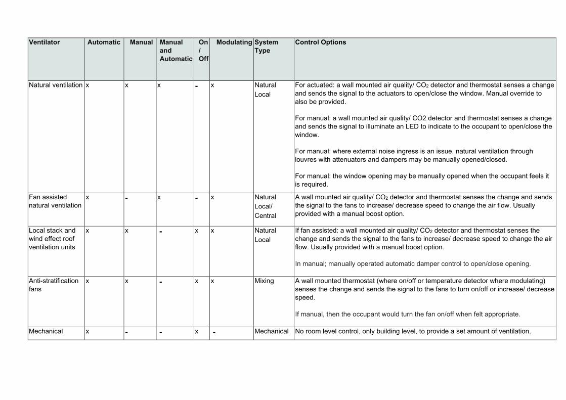
Ventilator Automatic Manual Manual and Automatic
On / Off
Modulating System Type
Control Options
Natural ventilation x x x - x Natural Local
For actuated: a wall mounted air quality/ CO2 detector and thermostat senses a change and sends the signal to the actuators to open/close the window. Manual override to also be provided.
For manual: a wall mounted air quality/ CO2 detector and thermostat senses a change and sends the signal to illuminate an LED to indicate to the occupant to open/close the window.
For manual: where external noise ingress is an issue, natural ventilation through louvres with attenuators and dampers may be manually opened/closed.
For manual: the window opening may be manually opened when the occupant feels it is required.
Fan assisted natural ventilation
x - x - x Natural Local/ Central
A wall mounted air quality/ CO2 detector and thermostat senses the change and sends the signal to the fans to increase/ decrease speed to change the air flow. Usually provided with a manual boost option.
Local stack and wind effect roof ventilation units
x x - x x Natural Local
If fan assisted: a wall mounted air quality/ CO2 detector and thermostat senses the change and sends the signal to the fans to increase/ decrease speed to change the air flow. Usually provided with a manual boost option. In manual; manually operated automatic damper control to open/close opening.
Anti-stratification fans
x x - x x Mixing A wall mounted thermostat (where on/off or temperature detector where modulating) senses the change and sends the signal to the fans to turn on/off or increase/ decrease speed. If manual, then the occupant would turn the fan on/off when felt appropriate.
Mechanical x - - x - Mechanical No room level control, only building level, to provide a set amount of ventilation.

20
Ventilator Automatic Manual Manual and Automatic
On / Off
Modulating System Type
Control Options
General local extract ventilation
x x - x - Local/ Central Mechanical
Presence detector or manual switch for fan, usually connected to the electric lighting e.g. in WCs. Local only for WCs/changing rooms.
Specialist local extract ventilation
x x - x - Local Mechanical
Occupant manually switches on fan when activity is commencing e.g. fume cupboards. Extract fan may be automatically linked to other systems or to a time schedule. Make-up air may need to be interlocked with extract system to avoid pressure issues.
Table 3 Summary of ventilation controls at room level

3.3. Mechanical cooling systems 3.3.1. Mechanical cooling should not be necessary in the majority of schools. The
exception is in the server room for peak lopping in summertime conditions where a local controller will be provided. If multi-room comfort cooling is provided each room shall be monitored via a central BMS only.
3.4. Frost protection 3.4.1. The Contractor shall allow for 2-stage frost protection on all pumped systems as
follows.
a) for all pumped systems, the initial stage of frost protection shall be to enable the pumps in the event that the internal temperature of the Building drops to 5°C. This temperature shall be adjustable on the control system
b) in the event that the temperature drops to below 2°C (this temperature shall be
adjustable on the control system), the second stage of frost protection shall commence, and the boiler plant and plate heat exchangers shall enable to circulate LTHW around the system.
3.5. Gas Services Controls 3.5.1. The Contractor shall ensure that:
a) where a flammable gas detection system is installed within a plant room for
boiler control the system can detect any gas leaks and set off an alarm locally (lamp and sounder) and communicate an alarm to both the fire alarm panel and the BMS where installed
b) the flammable gas detection system complies with IGEM UP/2, that a fail-safe
gas solenoid valve on the gas main is provided and that in the event of a gas leak being detected this valve will close
c) emergency push buttons are provided on all exits of plant room/s which when
pressed close the gas valve and this condition is communicated to the BMS where one is used
d) in the event of a fire alarm, the gas valve in the plant room will close and that a
time delay (adjustable) is included so that during fire alarm testing the boilers are not shut down
22
e) emergency push buttons are provided in any Basic Teaching space or kitchen (as defined in Annex 1A and 1B) using gas, including in any science laboratories or science studios. In Basic Teaching spaces the push buttons should be located by the teacher’s desk and in prep rooms by the exit. When pressed the gas valve shall close and a local reset shall be provided
f) any Basic Teaching space or kitchen using gas is fitted with a gas
isolation/pressure proving system where required by IGEM UP/11, and that gas proving valves are fitted to each branch serving a science lab/ prep area
g) any Basic Teaching space or kitchen using gas is fitted with gas safety
interlocks IGEM UP11, IGEM UP19 and BB101. h) all supplies to practical areas and to practical equipment are designed in
accordance with BS4163 ‘Health and Safety for design and technology in educational and similar establishments. Code of practice’.
3.6. Electrical Services Controls 3.6.1. The contractor shall ensure that the following requirements are met in all secondary
school light and heavy practical spaces (as defined in Annex 1A and 1B).
a) Electrical services are fitted with sufficient local master controls to control services in lessons and for cutting off supplies in an emergency.
b) All supplies to practical equipment are designed in accordance with BS4163
‘Health and safety for design and technology in educational and similar establishments. Code of practice’.
3.6.2. Any electrical equipment used by pupils shall be fitted with a local master electrical
shut-off for the teacher to cut off supplies in an emergency. This shut-off shall:
a) be easily accessible by the teacher
b) be provided with a key control, which can be used by the teacher to turn supplies back on (reset) as required
c) turn off power to all equipment in the room, including low voltage supplies
d) not control:
• other services (such as heating, ventilation, or lighting; the teacher’s PC,
or the projector; fridges/freezers, cleaners sockets)

23
• critical circuits specifically installed to remove hazards (e.g. fume
cupboards and fume extractor fans, alarm circuits)
3.6.3. As well as the shut-off for the teacher, there shall also be emergency electrical stop buttons positioned around the room local to any power supplies used for practical work. These shall be provided in each separate student work area and shall only control one work area. The stop buttons should be of mushroom-headed design and clearly identifiable. They should be approximately 1.5m off the floor and in accessible positions. In accordance with BS4163, emergency stop switches (which could be the normal ‘off’ switch) should be provided at all fixed machines, where a risk assessment shows that it is required; these should be easily actuated by the user. An emergency stop switch should only control the power to the machine to which it is fixed, and not to other machines in the work area.
3.6.4. Emergency stops are also required in preparation areas which are for technician use only. These areas shall not be affected by the emergency system of any other area.

24
4. Handover Requirements
4.1. Overview 4.1.1. The detailed requirement for handover is set out in the Employer’s Requirements
Deliverables. The following section outlines the handover requirements in relation to the control systems. A 7-day period of ‘soak testing’ shall follow on from the successful commissioning and testing activities.
4.2. Soak Testing 4.2.1. The Contractor, prior to Completion, shall carry out a soak test of all the controls in
their normal/auto operation mode, as if the building were occupied and in use. This shall be programmed to occur after completion of all setting to work, commissioning and testing of the mechanical and electrical services and is to prove their reliability and correct calibrations over a continuous period of 7 days. Practical Completion will not be granted until a successful soak test as described here has been achieved. It is not necessary to install additional dummy loads into rooms to prove system performance at the maximum design. All control systems shall be fully energised and placed in their normal/auto operation mode with all normal occupied time settings applying to:
a) control systems
b) energy metering and monitoring systems
4.2.2. The soak test shall meet the following requirements:
a) the test shall be included in the programme for the Works and shall continue
until seven continuous days of plant operation have occurred without fault or failure of any component / function
b) the Contractor shall monitor all functions (plant operating times/starts per
hour/energy and water use) which shall be trend logged using the microprocessor controls equipment where installed
c) each type of space served by the plant and equipment shall be monitored using
data loggers (supplied by the Mechanical or Electrical Contractor) or the BMS system to verify the performance
d) any specified noise performance surveys shall be carried out during this period

25
e) all data and monitoring results shall be provided to the Employer in Excel spreadsheet format (disc and hard copy) along with details of any faults arising and corrective action taken
f) should the soak test fail for any reason, then the results shall be null, and void
and the test period shall re-commence upon rectification of the problem/failure
g) all costs associated with the soak test, such as test equipment, attendance and supervision, shall be at the Contractor’s expense. Any costs incurred as a result of or a consequence of having to restart the soak test shall be at the Contractor’s expense
h) the soak test results shall be included in the Health and Safety File.
4.3. Documentation 4.3.1. The Contractor shall:
a) include within the operation and maintenance manuals a detailed description of
the controls systems and operating instructions
b) ensure that all testing and commissioning certificates are submitted prior to practical completion and that the certificates include the test equipment identity and certificates of calibration
c) ensure that a hard copy and an electronic copy of the testing and commissioning
certificates of the controls systems are submitted with each copy of the Operating and Maintenance Manuals and ‘As Installed’ drawings
d) ensure that the controls documentation includes the optimum settings for all
controls systems as well as product description, date of purchase, performance characteristics, application (suitability for use), method of operation and control, and cleaning and maintenance requirements
e) submit ‘As Installed’ drawings and information for the Operating and
Maintenance Manual and Building Log Book relating to the controls system which include all controls cabling, the cable origin, circuit designation, route, conductor material and insulation type and colour, number of cores per cable, number of cables in ducts, on tray or ladder and location of control panels, equipment and repeater panels

26
f) ensure that a hard copy and an electronic copy of the cable schedules relating to the controls system are submitted with each copy of the Operating and Maintenance Manual
4.3.2. The Contractor shall provide a Building User Guide which includes a userfriendly
description of all controls and an overview of the control’s philosophy. It shall include a short-illustrated guide for the room user for each type of space e.g. classroom, hall, practical space, describing how to control the ventilation, lighting and heating that can be handed to the user of the space. The Building User Guide shall be provided in hard copy and electronic format
4.4. Commissioning and Building Performance Evaluation 4.4.1. The Contractor shall:
a) ensure that the controls systems are fully commissioned throughout prior to
handover, and ensure that the whole building system commissioning is undertaken such that the Building Services controls systems that interact with each other are commissioned at the same time
b) ensure that the Building Services control systems are commissioned in
accordance with CIBSE Commissioning Code C: Automatic controls (refer to Annex 2F: Mechanical Services and Public Health Engineering’ for details of seasonal commissioning required)
c) provide a commissioning programme prior to construction allowing for 2 weeks’
notice prior to witness testing
d) ensure that inspection and testing are undertaken in line with BS 7671 ‘Requirements for electrical installations. IET Wiring Regulations’
e) commission the controls system in accordance with BSRIA AG 9/2001
‘Standard specifications for BMS’
f) carry out Building Performance Evaluation and Seasonal Commissioning in accordance with Section 2.14.6 of the GDB
g) carry out performance testing/proving during the 12-month defects period.
4.4.2. The Contractor shall conduct seasonal commissioning of the control systems
during the 12 months after handover (during the defects liability period) and fine tune control settings. The Contractor shall also run, monitor and maintain the systems for a minimum period of 1 week before handover. During this period, the

27
Contractor shall undertake the required demonstration of the system and controls in line with the requirements set out in the Employer’s Requirements Deliverables.
4.5. Documentation 4.5.1. The Contractor shall:
a) include within the operation and maintenance manuals a detailed description of
the controls systems and operating instructions
b) ensure that all testing and commissioning certificates are submitted prior to practical completion and that the certificates include the test equipment identity and certificates of calibration
c) ensure that a hard copy and an electronic copy of the testing and commissioning
certificates of the controls systems are submitted with each copy of the Operating and Maintenance Manuals and ‘As Installed’ drawings
d) ensure that the controls documentation includes the optimum settings for all
controls systems as well as product description, date of purchase, performance characteristics, application (suitability for use), method of operation and control, and cleaning and maintenance requirements
e) submit ‘As Installed’ drawings and information for the Operating and
Maintenance Manual and Building Log Book relating to the controls system which include all controls cabling, the cable origin, circuit designation, route, conductor material and insulation type and colour, number of cores per cable, number of cables in ducts, on tray or ladder and location of control panels, equipment and repeater panels
f) ensure that a hard copy and an electronic copy of the cable schedules relating
to the controls system are submitted with each copy of the Operating and Maintenance Manual.
4.5.2. The Contractor shall provide a Building User Guide which includes a user-friendly
description of all controls and an overview of the control’s philosophy. It shall include a short-illustrated guide for the room user for each type of space e.g. classroom, hall, practical space, describing how to control the ventilation, lighting and heating that can be handed to the user of the space. The Building User Guide shall be provided in hard copy and electronic format.

28
4.6. Demonstration and Training 4.6.1. The detailed requirement for training and familiarisation is set out in Employer’s
Requirements Deliverables.
4.6.2. The Contractor shall provide dedicated training to the Employer’s and School’s nominated representatives.
4.6.3. In the event that a facilities management team has not been appointed prior to
Practical Completion, the Employer shall be responsible for selecting an appropriate representative for the training procedure. The Employer shall then be responsible for ensuring that the training is passed on accordingly.
29
5. Summary of Reference Standards 5.1. In addition to the guidance in the DfE’s Building Bulletins, the requirements in the
GDB, and the requirements that are set out within this document, the Contractor shall ensure that the design and installation of the controls and relevant associated systems within schools shall be compliant with the following standards (or updated documents where relevant).
1. Approved Documents of the Building Regulations
2. CIBSE Commissioning Code C: ‘Automatic controls’
3. All relevant CIBSE Guides
4. BS 7671 ‘Requirements for electrical installations. IET Wiring Regulations’ 5. BSRIA AG 9/2001 ‘Standard specifications for BMS’

30
© Crown copyright May 2020
This publication (not including logos) is licensed under the terms of the Open Government Licence v3.0 except where otherwise stated. Where we have identified any third party copyright information you will need to obtain permission from the copyright holders concerned.
To view this licence: visit www.nationalarchives.gov.uk/doc/open-government-licence/version/3 email [email protected] write to Information Policy Team, The National Archives, Kew, London, TW9 4DU
About this publication: enquiries www.education.gov.uk/contactus download www.gov.uk/government/publications
Reference: DfE-00079-2020
Follow us on Twitter: @educationgovuk
Like us on Facebook: facebook.com/educationgovuk