Annex 1 Technical Report - UKSpill 1 Technical Report.pdf · 2.15 Marflex Centrifugal Pump...
21
Page 1 of 21 Annex 1 Technical Report Side Collector Sweeping Arm Systems (LSC-4 C/3500) Disclaimer Any specifications and/or graphic material must not be understood as a commercial endorsement by the Agency of any given piece of equipment and/or manufacturer/supplier. If there is a contradiction between this Report and the manufacturers’ manuals, the manufacturers’ manuals take precedence.
Transcript of Annex 1 Technical Report - UKSpill 1 Technical Report.pdf · 2.15 Marflex Centrifugal Pump...

Page 1 of 21
Annex 1
Technical Report
Side Collector Sweeping Arm Systems (LSC-4 C/3500)
Disclaimer
Any specifications and/or graphic material must not be understood as a commercial
endorsement by the Agency of any given piece of equipment and/or
manufacturer/supplier.
If there is a contradiction between this Report and the manufacturers’ manuals, the
manufacturers’ manuals take precedence.

Annex 1 - Technical Report
Page 2 of 21
Table of Contents
1. Background 3
1.1 Sale of sweeping arms 3
2. Description of the Lamor side Collector Sweeping Arm System (LSC-4
C/3500)
5
2.1 Side Collector Cassette LSC-4 C/3500 15.6m 6
2.2 Hydraulic Hose 1/2” x 15m, Tema 5000 7
2.3 Oil Transfer PDAS Pump GT A 115 8
2.4 Hydraulic Hose Set for GT A 115 9
2.5 Oil Transfer Hose Set for GT A 115 10
2.6 Fitting Frame and Jib Fitting Bar 10
2.7 Spreading Jib 1030 11
2.8 Air Filled Guiding Boom SWB 15,60 m 12
2.9 Air blower HAB 200 13
2.10 Flat Rack Container 20 ft. 14
2.11 Hydraulic Power Pack LPP 109 D 15
2.12 Fassi Crane 130 AFM.23 16
2.13 Flat Rack Container 10 ft. 17
2.14 Weir Skimmer Module for Side Collector Cassette LSC-4 C/3500 18
2.15 Marflex Centrifugal Pump MSP150-63 18
2.16 Oil Hose 6” with Camlocks 20
2.17 Skimmer Ancillaries - Spares for the Skimming System 20
3. List of equipment 21
3.1 Lamor Corporation A.B., Baltic Sea, Skagen Depot, Flexible Sweeping Arm 21
3.2 Lamor Corporation A.B., Baltic Sea, Copenhagen Depot, Flexible Sweeping Arm 22

Annex 1 - Technical Report
Page 3 of 21
1. Background
Since 2004, one of key tasks for the Agency is to make available additional at-sea oil
recovery resources to assist Member States responding to large scale incidents such as the
Erika (1999, France) and Prestige (2002, Spain). The service network of stand-by oil spill
response vessels has been built up and maintained through annual procurement
procedures starting in 2005. Since 2006 and following the award of contracts to
companies, the associated vessels have entered into the operational (stand by) phase of
the contracts, ready to provide assistance to a requesting Member State.
The main concept of the service, provided through the Agency, is to ensure the availability
of commercial vessels (for example bunker and product tankers) to carry out at-sea oil
recovery services following a request for assistance from a coastal State. Following a such
request, the vessel ceases its normal commercial activities and is transformed rapidly into
a fully operational spill response vessel. The service is maintained by the Agency through
Vessel Availability Contracts (VACs) with companies whilst, in the event of a request for
assistance from a coastal State, an Incident Response Contract (IRC) is signed between
the Member State and the Contractor.
All vessels are equipped with state of the art oil recovery equipment capable of achieving
high recovery rates.
1.1 Sale of sweeping arms
The Contract for the Baltic Sea Area signed in 2005 expires at the end of 2011. Oil
pollution response equipment covered by this contract will be transferred to a new
contractor and will continue to serve its purpose within the new contract.
However, in the course of the Vessel Network development, the Agency’s approach to the
equipment arrangement on board contracted vessels has changed and currently the Baltic
Sea area is the only one where the LAMOR Side Collector Sweeping Arm System is used on
board EMSA contracted vessels.
As the LAMOR system is not compatible with the equipment arrangements on board other
EMSA contracted vessels, the Agency decided to put it up for sale.
The LAMOR Side Collector Sweeping Arm System was purchased in 2006 within the
framework of the Vessel Availability Contract for the Baltic Sea area.
The equipment is in a very good condition. It has never been used to recover oil but it has
been deployed only few times per year for the purpose of drills and exercises.
It has undergone regular maintenance according to the manufacturer’s specification. The
maintenance has been closely monitored by EMSA.
The completeness of the each equipment set has been ensured by the equipment inventory
and labelling system applied by EMSA.
There are two identical sets of sweeping arms available. They are located in two Lamor oil
pollution response equipment storage facilities, one in Skagen and another one in
Copenhagen, Denmark.
Potential buyers will be invited by EMSA to visit the storage facilities to inspect the
equipment in week 40 (3-7 October), 2011.

Annex 1 - Technical Report
Page 4 of 21
This document contains a list of components of the Lamor Side Collector Sweeping Arm
System LSC-4 C/3500 and a technical description of each component.
The description and technical specifications are based on information provided by the
equipment manufacturer.
2. Description of the Lamor Side Collector Sweeping Arm system (LSC-4
C/3500)
The two available Lamor sweeping arms systems are identical and they include the same
components. The systems were produced by Lamor Corporation Ab with some components
provided by other manufacturers.
The Lamor Side Collector Sweeping Arm System (LSC-4 C/3500) is a flexible type system
supplied with an outrigger (spreading jib) and inflatable sweeping boom, an integrated
brush conveyor belt skimmer, an integrated positive displacement Archimedes screw
(PDAS) pump and with pre-installed hot water current radial system to facilitate pumping
of high viscosity oil and a fitting arrangement to connect the system to the vessel side.
The system was purchased in 2006. Additionally, in 2008 the system was equipped with
an exchangeable weir skimmer module with the high capacity centrifugal (MSP) pump.
Manufacturer:
Lamor Corporation Ab
Mestarintie 25
FIN-06150 PORVOO
FINLAND
Tel: +358 (0)20 7650 100, +358 19 5767 400
Fax: +358 (0)207 650 129, +358 19 5767 450
Email: [email protected] Website: www.lamor.fi
Function: Collecting of oil from the water surface
Year of purchase: 2006
Length: 15.60 m inflatable sweeping boom
Type of skimmer: brush conveyor belt/weir skimmer
Skimmer pumps: Archimedes screw (PDAS) /Centrifugal pump
Operational manual: Available (Manufacturer documentation)
The system collects oils of all types and viscosity, including emulsions, tar balls and
extremely viscous oils. It can operate in adverse weather and sea conditions without losing
performance. Performance improves as oil viscosity increases. The LSC can be deployed
and operated by a small crew very quickly. Simple and intuitive operation requires very
little specialised training.

Annex 1 - Technical Report
Page 5 of 21
Fig.1 Lamor Side Collector Sweeping Arm System in operation
2.1 Side Collector Cassette LSC-4 C/3500 15.6m
The Side Collector is an “oil slick processing system”. Surface water and oil are deflected
into the recovery channel by natural current or by the vessels’ forward motion. The flow of
water carries oil and oily debris into the Brush Conveyor, where these contaminants are
efficiently separated and removed from the flow. The system “filters” and lifts oil and debris
from the water, which passes through. Recovered oil and debris which ride up the
conveyor, are combed and squeezed from the bristles, and fall into the delivery trough.
Recovered oil and debris flow by gravity into holding tanks or into a collection sump, which
is offloaded by a pump.
Fig.2 Side Collector Cassette lifted Fig.3 Rigging of the cassette

Annex 1 - Technical Report
Page 6 of 21
Fig.4 Cassette installed
The Brush Conveyor installed in the Side Cassette consists of parallel brush chains, carried
on a hydraulically driven sprocket system (similar to a motorcycle). The brush conveyor is
supported and protected within an alloy frame. The brush cleaning mechanism is a comb-
like device mounted at the upper end of the brush conveyor. During operation, the cleaner
is positioned below the top axle of the conveyor, allowing recovered oil and debris to drop
directly into the discharge trough.
Fig.5 Brush Conveyors
Annex 1 - Technical Report
Page 7 of 21
2.2 Hydraulic Hose 1/2” x 15m, Tema 5000
Hydraulic Hose 1/2” x 15m, Tema 5000 provides power to the brush conveyor.
The hoses are manufactured in a durable material for long service and supplied with
reliable Tema connectors for secure linkages.
Table 1. Technical Specifications - Hydraulic Hose 1/2”
Length 15 m
Size ½ inch
Weight 0.18 kg/m
Outer diameter 13.5 mm
Burst pressure 900 bar
Test pressure 540 bar
Working pressure 225 bar
Hose construction tube oil resistant synthetic rubber
Reinforcement two high tensile steel wire braids
Cover abrasion and weather resistant synthetic rubber
Temperature range -40 °C to + 100 °C (+120 °C max)
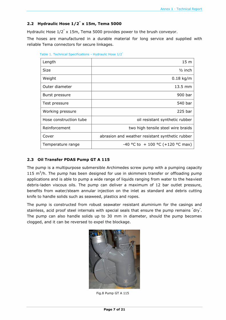
2.3 Oil Transfer PDAS Pump GT A 115
The pump is a multipurpose submersible Archimedes screw pump with a pumping capacity
115 m3/h. The pump has been designed for use in skimmers transfer or offloading pump
applications and is able to pump a wide range of liquids ranging from water to the heaviest
debris-laden viscous oils. The pump can deliver a maximum of 12 bar outlet pressure,
benefits from water/steam annular injection on the inlet as standard and debris cutting
knife to handle solids such as seaweed, plastics and ropes.
The pump is constructed from robust seawater resistant aluminium for the casings and
stainless, acid proof steel internals with special seals that ensure the pump remains “dry”.
The pump can also handle solids up to 30 mm in diameter, should the pump becomes
clogged, and it can be reversed to expel the blockage.
Fig.8 Pump GT A 115

Annex 1 - Technical Report
Page 8 of 21
Table 2. Technical Specifications - Oil Transfer PDAS Pump GT A 115
Performance
Max nominal capacity at 650 RPM 94 m³/h / 414 USGPM
Max. peak capacity at 800 RPM 115 m³/h / 506 USGPM
Max. pressure 12 bar / 180 PSI
Max. operating temperature 110 °C / 230 °F
Debris handling Cutting knife on inlet / Protection grid
Viscosity range 1 - > 3 million cSt
Hydraulic System
Hydraulic motor Danfoss OMTS 200
Hydraulic couplings pressure 3/4” TEMA or Aeroquip male
Hydraulic couplings return 1” TEMA or Aeroquip male
Hydraulic couplings drain line 3/8” TEMA or Aeroquip male
Hydraulic flow 650 RPM 160 l/min max
Hydraulic flow 800 RPM 160 l/min max
Hydraulic pressure 210 bar max
Size and Weight
Height without inlet grid 570 mm
Height with inlet grid 598 mm
Length 500 mm
Width 300 mm
Minimum manhole diameter 520 mm
Weight 71 kg / 156 lbs
2.4 Hydraulic Hose Set for GT A 115
Components included in one set:
Hydraulic Hose 1” x 15 m Q/R Tema 10000 - 1 pc.
Hydraulic Hose 3/4” x 15 m Q/R Tema 7500 - 1 pc.
Hydraulic Hose 3/8” x 15 m DRAIN ISO75242 - 1 pc.

Annex 1 - Technical Report
Page 9 of 21
2.5 Oil Transfer Hose Set for GT A 115
Components included in one set:
Lay Flat Hose 5” x 10 m, Camlock - 2 pcs.
Fig.9 Set of hydraulic and oil hoses on a reel
2.6 Fitting Frame and Jib Fitting Bar
The Side Collector Cassette is rigged to the vessel’s hull on the fitting frame.
Fitting frame for the Side Collector Cassette is connected to flush mounted supporting
arrangement welded on the deck or on the side of the vessel. The lower end of the frame
can be connected to an ear welded close to the water line on the vessel side, if so
required. A C-connector heading 45 degrees ahead and a rubber sealing plate against the
vessel side are typically assembled on this connector. The size of the frame is to be
tailored for each vessel separately.
Fig.6 Fitting Frame Fig.7 Fitting Frame rigged to side of vessel

Annex 1 - Technical Report
Page 10 of 21
The Jib fitting Bar connects the end of the Spreading Jib to the vessel hull.
Fig.10 Jib Fitting Bar
2.7 Spreading Jib 1030
The aluminium jib supports the outer end of the oil boom. The inner end is bolted to the
bulwark of the vessel by the universal joint, which allows the jib to move with the boom in
waves and when rigging out the boom. A truncated cone-shaped buoy (other shapes
optional) is bolted to the outer end of the jib.
Fig.11 & 12 Spreading Jib
Table 3. Technical Specifications - Spreading Jib 1030
Length 10290 mm
Wight 70 kg
Material thickness 5 mm
Jib arm diameter 300 mm
Jib arm shape square

Annex 1 - Technical Report
Page 11 of 21
2.8 Air Filled Guiding Boom SWB 15,60 m
The skimming booms should be fitted on both sides of the vessel. The height of the boom
decreases from the boat end to the outer end, so that close to the side the height is
sufficient to allow for boat rolling and heave, while the outer end the boom height is lower.
The inner end of the boom is fastened to the aft port by an aluminium section. The outer
end is similarly fasted in the buoy at the end of the jib. The booms are fitted with
necessary strengthening parts, weights and supporting lines. The booms are made of
reinforced PVC canvas and filled with float material.
Fig.13 Guiding boom
Table 4. Technical Specifications - Air Filled Guiding Boom SWB 15.60 m
Length 15600 (approx.) mm
Width 100 mm
Height 1200 mm
Weight Approx. 80 kg
The sweeping boom is stored on a hydraulically operated winder which is attached to the
side collector cartridge. The jib arm float is connected to the side sweep boom before
deploying the jib to the water.
The winder stores the boom required for the sweeping operation. The boom is released
when the hydraulic winder is operated from the power pack.

Annex 1 - Technical Report
Page 12 of 21
Fig.14 Boom winder
2.9 Air blower HAB 200
Fig.15 Air blower with air and hydraulic hoses
The Hydraulic Air blower HAB 200 is used for inflating the Lamor Inflatable Booms. The air
blower consists of a hydraulic motor and air blower installed in a portable aluminium
frame. The unit is supplied with hydraulic quick release TEMA couplings. The internals of
the Lamor HAB 200 are protected by a suction filter. The Lamor HAB 200 has a set
discharge pressure so the oil boom cannot be damaged during the inflation operation.
Additionally the HAB 200 can be configured to provide suction for deflation of ILB boom.
The Lamor HAB 200 can be powered by one of the family of Lamor hydraulic power packs
or using vessel hydraulics.
Hydraulic couplings are: 1/2” TEMA 5011/21, Aeroquip 3/8” DRAIN ISO75242.
Annex 1 - Technical Report
Page 13 of 21
Components and accessories included:
HAB 200 air blower
filling nozzle & T-key
air hose 3” Camlock L-10 m with Y-junction (2”/ 3” / 2” Camlocks)
2 x air hose 2” Camlock L-5 m to be connected to the Y-junction
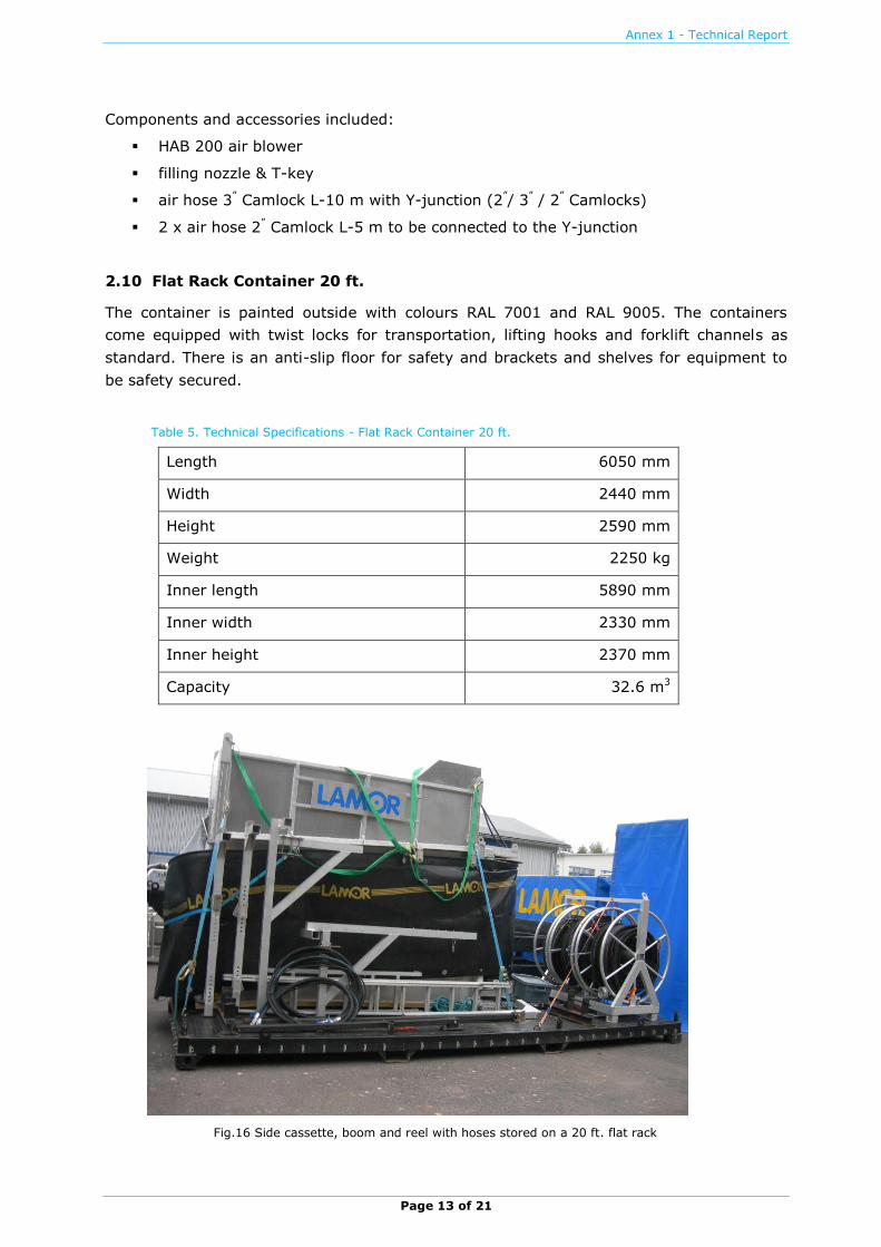
2.10 Flat Rack Container 20 ft.
The container is painted outside with colours RAL 7001 and RAL 9005. The containers
come equipped with twist locks for transportation, lifting hooks and forklift channels as
standard. There is an anti-slip floor for safety and brackets and shelves for equipment to
be safety secured.
Table 5. Technical Specifications - Flat Rack Container 20 ft.
Length 6050 mm
Width 2440 mm
Height 2590 mm
Weight 2250 kg
Inner length 5890 mm
Inner width 2330 mm
Inner height 2370 mm
Capacity 32.6 m3
Fig.16 Side cassette, boom and reel with hoses stored on a 20 ft. flat rack
Annex 1 - Technical Report
Page 14 of 21
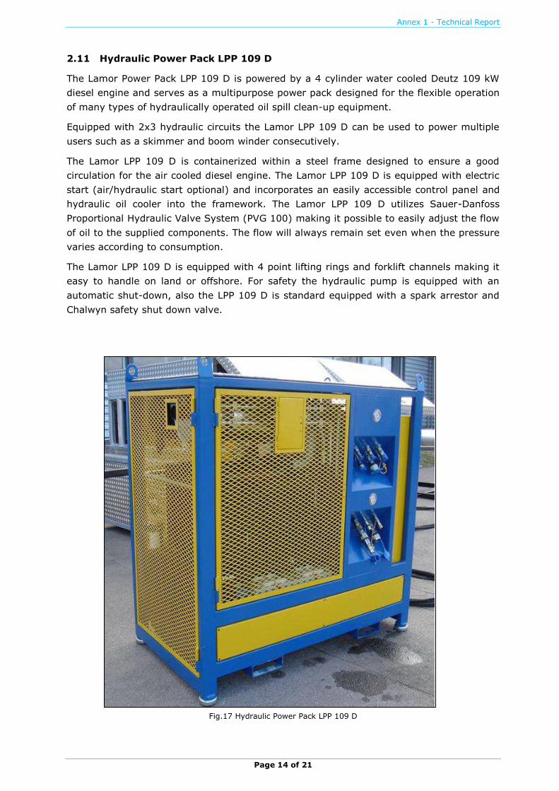
2.11 Hydraulic Power Pack LPP 109 D
The Lamor Power Pack LPP 109 D is powered by a 4 cylinder water cooled Deutz 109 kW
diesel engine and serves as a multipurpose power pack designed for the flexible operation
of many types of hydraulically operated oil spill clean-up equipment.
Equipped with 2x3 hydraulic circuits the Lamor LPP 109 D can be used to power multiple
users such as a skimmer and boom winder consecutively.
The Lamor LPP 109 D is containerized within a steel frame designed to ensure a good
circulation for the air cooled diesel engine. The Lamor LPP 109 D is equipped with electric
start (air/hydraulic start optional) and incorporates an easily accessible control panel and
hydraulic oil cooler into the framework. The Lamor LPP 109 D utilizes Sauer-Danfoss
Proportional Hydraulic Valve System (PVG 100) making it possible to easily adjust the flow
of oil to the supplied components. The flow will always remain set even when the pressure
varies according to consumption.
The Lamor LPP 109 D is equipped with 4 point lifting rings and forklift channels making it
easy to handle on land or offshore. For safety the hydraulic pump is equipped with an
automatic shut-down, also the LPP 109 D is standard equipped with a spark arrestor and
Chalwyn safety shut down valve.
Fig.17 Hydraulic Power Pack LPP 109 D

Annex 1 - Technical Report
Page 15 of 21
Table 6. Technical Specifications - Hydraulic Power Pack LPP 109 D
Length 2300 mm
Width 1400 mm
Height 1500 mm
Weight 2200 kg
Hydraulic circuits 3 pcs
Hydraulic flow 360 l/min
Hydraulic pressure 210 bar
Power 109 kW
Oil tank capacity 350 l
Fuel tank capacity 220 l
2.12 Fassi Crane 130 AFM.23
Manufacturer:
FASSI GRU SPA
via Roma, 110
24021 Albino, Bergamo, ITALY
Tel: +39 035 776400
Fax: +39 035 755020
Email: [email protected]
The hydraulic crane can be used for lifting oil spill recovery equipment and other items.
The weight is compensated by battery, hydraulic oil tank, fuel tank and other marine
equipment to guarantee boat stability and horizontal swing. The safety valve of the crane
automatically halts lifting if the load exceeds crane’s capacity.
Fig.18 Fassi crane in operation
Annex 1 - Technical Report
Page 16 of 21
Table 7. Technical Specifications - Fassi Crane 130 AFM.23
Lifting capacity 11.9 tm
Standard reach 10.40 m
Hydraulic extension 5.70 m
Rotation 3900
Rotation torque 21.50 kNm
Working pressure 28.50 MPa
Pump capacity 40 l/min
Oil tank capacity 90 l
Crane weight 1910 kg
Crane length 2400 mm
Crane width 830 mm
Crane height 2205 mm
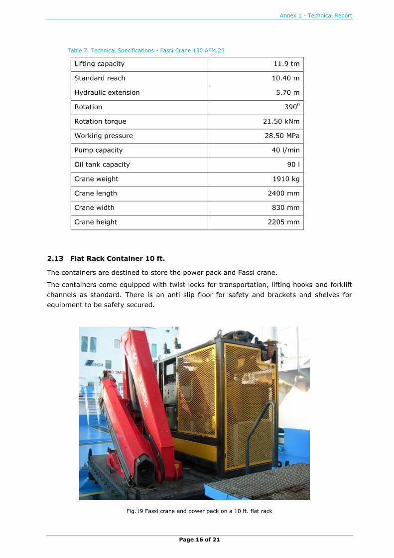
2.13 Flat Rack Container 10 ft.
The containers are destined to store the power pack and Fassi crane.
The containers come equipped with twist locks for transportation, lifting hooks and forklift
channels as standard. There is an anti-slip floor for safety and brackets and shelves for
equipment to be safety secured.
Fig.19 Fassi crane and power pack on a 10 ft. flat rack

Annex 1 - Technical Report
Page 17 of 21
Table 8. Technical Specifications - Flat Rack Container 10 ft.
Length 2990 mm
Width 2435 mm
Height 2518 mm (with equipment)
Weight Empty 1020 kg
Equipment Weight 3240 kg
Total Weight (Container+ Equipment) 4260 kg
2.14 Weir Skimmer Module for Side Collector Cassette LSC-4 C/3500
The Lamor Weir Skimmer module is adjustable weir skimmer offering a high recovery
capacity. The module is supplied with a powerful hydraulically driven MSP 150-63 pump.
The LWS module is powered from the Lamor LPP power pack using the Lamor LCP remote
control panel.
Fig.20 Weir Skimmer Module
2.15 Marflex Centrifugal Pump MSP150-63
Manufacturer:
Marflex B.V.
Postal Address: Louis Pasteurstraat 12
3261 LZ Oud-Beijerland
The Netherlands
Phone: +31 186 89 02 00
Fax: +31 186 89 02 49
E-mail: [email protected] Website: www.marflex.com

Annex 1 - Technical Report
Page 18 of 21
The Marflex pump type MSP-150-63 is a submersible hydraulically driven portable
centrifugal pump. The pump was purchased in 2008.
Fig.21 Marflex pump type MSP-150-63
Table 9. Technical Specifications - Marflex Centrifugal Pump MSP150-63
Fig. 22 MSP-150 Performance Diagram at Various Hydraulic Pressures
Maximum Pressure 320 bar
Maximum Return Pressure 6 bar
Maximum oil flow 130 l/min
Outer Diameter 490 mm
Height 610 mm
Weight excluding hoses 83 kg
Materials Housing – Aluminium
Seals – Nitrile
Annex 1 - Technical Report
Page 19 of 21
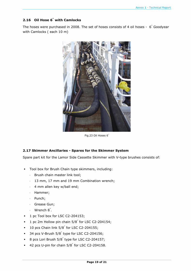
2.16 Oil Hose 6” with Camlocks
The hoses were purchased in 2008. The set of hoses consists of 4 oil hoses - 6” Goodyear
with Camlocks ( each 10 m)
Fig.23 Oil Hoses 6”
2.17 Skimmer Ancillaries - Spares for the Skimmer System
Spare part kit for the Lamor Side Cassette Skimmer with V-type brushes consists of:
Tool box for Brush Chain type skimmers, including:
Brush chain master link tool;
13 mm, 17 mm and 19 mm Combination wrench;
4 mm allen key w/ball end;
Hammer;
Punch;
Grease Gun;
Wrench 8”.
1 pc Tool box for LSC C2-204153;
1 pc 2m Hollow pin chain 5/8” for LSC C2-204154;
10 pcs Chain link 5/8” for LSC C2-204155;
34 pcs V-Brush 5/8” type for LSC C2-204156;
8 pcs Lori Brush 5/8” type for LSC C2-204157;
42 pcs U-pin for chain 5/8” for LSC C2-204158.

Page 20 of 21
3. LIST OF EQUIPMENT
3.1 Lamor Corporation A.B., Baltic Sea, Skagen Depot, Flexible Sweeping Arm System
N° SUB-CATEGORY A SUB-CATEGORY B SER. N°
DESCRIPTION
LABEL N°* UNIT DAY OF RECEIPT
1 SWEEPING ARM CASSETTE 01 OIL COLLECTOR CASSETTE FOR LSC-4C/3500 15.6m. AACM36090
1 Item 23/05/2006
SWEEPING ARM CASSETTE 02 OIL COLLECTOR CASSETTE FOR LSC-4C/3500 15.6m. AACM360902
Item 23/05/2006
2 HYDRAULIC HOSE SECTION 01 HYD. HOSE 1/2”×15m. TEMA 5000 AACM22360
1 Item 23/05/2006
HYDRAULIC HOSE SECTION 02 HYD. HOSE 1/2”×15m. TEMA 5000 AACM223602
Item 23/05/2006
3 PUMP PUMP 01 OIL TRANSFER PDAS GT A 115 AACM28320
1 Item 23/05/2006
PUMP PUMP 02 OIL TRANSFER PDAS GT A 115 AACM283202
Item 23/05/2006
4 HYDRAULIC HOSE SECTION 03 HYD. HOSE SET FOR GT A 115 AACM22360
3 SET 23/05/2006
HYDRAULIC HOSE SECTION 04 HYD. HOSE SET FOR GT A 115 AACM223604
SET 23/05/2006
5 OIL HOSE SET 01 5” OROFLEX OIL TRANSFER HOSES AACM26380
1 SET 23/05/2006
OIL HOSE SET 02 5” OROFLEX OIL TRANSFER HOSES AACM263802
SET 23/05/2006
6 SWEEPING ARM FRAME 01 JIB FITTING BAR AND FITTING FRAME AACM36220
1 Item 23/05/2006
SWEEPING ARM FRAME 02 JIB FITTING BAR AND FITTING FRAME AACM362202
Item 23/05/2006
7 SWEEPING ARM FRAME 03 JIB 1030 AACM36220
3 Item 23/05/2006
SWEEPING ARM FRAME 04 JIB 1030 AACM362204
Item 23/05/2006
8 SWEEPING ARM BOOM 01 SEMI-AUTO. SWEEPING BOOM 15.6 m. ARRANG. AACM36050
1 Item 23/05/2006
SWEEPING ARM BOOM 02 SEMI-AUTO. SWEEPING BOOM 15.6 m. ARRANG. AACM360502
Item 23/05/2006
9 AIR BLOWER SWA AIR BLOWER 01 AIR BLOWER FOR SWEEPING ARM BOOM AACA032901 Item 23/05/2006
10 STORAGE FLAT RACK 01 FLAT RACK 20 ft. CONTAINER FOR SW. ARM AACM35200
1 Item 23/05/2006
STORAGE FLAT RACK 02 FLAT RACK 20 ft. CONTAINER FOR SW. ARM AACM352002
Item 23/05/2006
11
POWER PACK FRAME 01 HYD. PW-PK LPP 109 D WITH INTEG. CONTROL PANEL, 5 VALVES
AACM272201
Item 23/05/2006
POWER PACK FRAME 02 HYD. PW-PK LPP 109 D WITH INTEGRATE CONTROL PANEL, 5 VALVES
AACM272202
Item 23/05/2006
POWER PACK MOTOR 01 DEUTZ 109 kW DIESEL ENGINE AACM272801
Item 23/05/2006
POWER PACK MOTOR 02 DEUTZ 109 kW DIESEL ENGINE AACM272802
Item 23/05/2006
12 CRANE CRANE 01 FASSI CRANE 130AFM.23 AACM13150
1 Item 23/05/2006
CRANE CRANE 02 FASSI CRANE 130AFM.23 AACM131502
Item 23/05/2006
13 STORAGE FLAT RACK 03 FLAT RACK CONTAINER 10 ft. FOR SW. ARM AACM35200
3 Item 23/05/2006
STORAGE FLAT RACK 04 FLAT RACK CONTAINER 10 ft. FOR SW. ARM AACM352004
Item 23/05/2006
14 SKIMMER MODULE WEIR 01 WEIR SKIMMER MODULE FOR CASSETTE AACM31440
1 SET 25/09/2008
SKIMMER MODULE WEIR 02 WEIR SKIMMER MODULE FOR CASSETTE AACM314402
SET 25/09/2008
15 PUMP PUMP 03 MARFLEX MSP150-63 CENT/PUMP AACM28320
3 Item 25/09/2008
PUMP PUMP 04 MARFLEX MSP150-63 CENT/PUMP AACM283204
Item 25/09/2008
16
OIL HOSES SECTION 03 OIL HOSE 6” GOODYEAR WITH CAMLOCKS (10 m) AACM263603
SET 25/09/2008
OIL HOSES SECTION 04 OIL HOSE 6” GOODYEAR WITH CAMLOCKS (10 m) AACM263604
SET 25/09/2008
OIL HOSES SECTION 05 OIL HOSE 6” GOODYEAR WITH CAMLOCKS (10 m) AACM263605
SET 25/09/2008
OIL HOSES SECTION 06 OIL HOSE 6” GOODYEAR WITH CAMLOCKS (10 m) AACM263606
SET 25/09/2008
17 ANCILIARIES SPARE PARTS 02 SPARE PART KIT FOR SKIMMER AACI343102
SET 23/05/2006 *EMSA ID Code

Annex 1 - Technical Report
Page 21 of 21
3.2 Lamor Corporation A.B., Baltic Sea, Copenhagen Depot, Flexible Sweeping Arm System
N° SUB-CATEGORY A SUB-CATEGORY B SER. N°
DESCRIPTION
LABEL N°* UNIT DAY OF RECEIPT
1 SWEEPING ARM CASSETTE 01 OIL COLLECTOR CASSETTE FOR LSC-4C/3500 15.6m. AABM360901 Item 23/05/2006
SWEEPING ARM CASSETTE 02 OIL COLLECTOR CASSETTE FOR LSC-4C/3500 15.6m. AABM360902 Item 23/05/2006
2 HYDRAULIC HOSE SECTION 01 HYD. HOSE 1/2”×15m. TEMA 5000 AABM223601 Item 23/05/2006
HYDRAULIC HOSE SECTION 02 HYD. HOSE 1/2”×15m. TEMA 5000 AABM223602 Item 23/05/2006
3 PUMP PUMP 01 OIL TRANSFER PDAS GT A 115 AABM283201 Item 23/05/2006
PUMP PUMP 02 OIL TRANSFER PDAS GT A 115 AABM283202 Item 23/05/2006
4 HYDRAULIC HOSE SECTION 03 HYD. HOSE SET FOR GT A 115 AABM223603 SET 23/05/2006
HYDRAULIC HOSE SECTION 04 HYD. HOSE SET FOR GT A 115 AABM223604 SET 23/05/2006
5 OIL HOSE SET 01 5” OROFLEX OIL TRANSFER HOSES AABM263601 SET 23/05/2006
OIL HOSE SET 02 5” OROFLEX OIL TRANSFER HOSES AABM263602 SET 23/05/2006
6 SWEEPING ARM FRAME 01 JIB FITTING BAR AND FITTING FRAME AABM362201 Item 23/05/2006
SWEEPING ARM FRAME 02 JIB FITTING BAR AND FITTING FRAME AABM362202 Item 23/05/2006
7 SWEEPING ARM FRAME 03 JIB 1030 AABM362203 Item 23/05/2006
SWEEPING ARM FRAME 04 JIB 1030 AABM362204 Item 23/05/2006
8 SWEEPING ARM BOOM 01 SEMI-AUTO. SWEEPING BOOM 15.6 m. ARRANG. AABM360501 Item 23/05/2006
SWEEPING ARM BOOM 02 SEMI-AUTO. SWEEPING BOOM 15.6 m. ARRANG. AABM360502 Item 23/05/2006
9 AIR BLOWER SWA AIR BLOWER 01 AIR BLOWER FOR SWEEPING ARM BOOM AABM032901 Item 23/05/2006
10 STORAGE FLAT RACK 01 FLAT RACK 20 ft. CONTAINER FOR SW. ARM AABM352001 Item 23/05/2006
STORAGE FLAT RACK 02 FLAT RACK 20 ft. CONTAINER FOR SW. ARM AABM352002 Item 23/05/2006
11
POWER PACK FRAME 01 HYD. PW-PK LPP 109 D WITH INTEG. CONTROL PANEL, 5 VALVES
AABM272201 Item 23/05/2006
POWER PACK FRAME 02 HYD. PW-PK LPP 109 D WITH INTEGRATE CONTROL PANEL, 5 VALVES
AABM272202 Item 23/05/2006
POWER PACK MOTOR 01 DEUTZ 109 kW DIESEL ENGINE AABM272801 Item 23/05/2006
POWER PACK MOTOR 02 DEUTZ 109 kW DIESEL ENGINE AABM272802 Item 23/05/2006
12 CRANE CRANE 01 FASSI CRANE 130AFM.23 AABM131501 Item 23/05/2006
CRANE CRANE 02 FASSI CRANE 130AFM.23 AABM131502 Item 23/05/2006
13 STORAGE FLAT RACK 03 FLAT RACK CONTAINER 10 ft. FOR SW. ARM AABM352003 Item 23/05/2006
STORAGE FLAT RACK 04 FLAT RACK CONTAINER 10 ft. FOR SW. ARM AABM352004 Item 23/05/2006
14 SKIMMER MODULE WEIR 01 WEIR SKIMMER MODULE FOR CASSETTE AABM314401 SET 25/09/2008
SKIMMER MODULE WEIR 02 WEIR SKIMMER MODULE FOR CASSETTE AABM314402 SET 25/09/2008
15 PUMP PUMP 03 MARFLEX MSP150-63 CENT/PUMP AABM283203 Item 25/09/2008
PUMP PUMP 04 MARFLEX MSP150-63 CENT/PUMP AABM283204 Item 25/09/2008
16
OIL HOSES SECTION 03 OIL HOSE 6” GOODYEAR WITH CAMLOCKS (10 m) AABM263603 SET 25/09/2008
OIL HOSES SECTION 04 OIL HOSE 6” GOODYEAR WITH CAMLOCKS (10 m) AABM263604 SET 25/09/2008
OIL HOSES SECTION 05 OIL HOSE 6” GOODYEAR WITH CAMLOCKS (10 m) AABM263605 SET 25/09/2008
OIL HOSES SECTION 06 OIL HOSE 6” GOODYEAR WITH CAMLOCKS (10 m) AABM263606 SET 25/09/2008
17 ANCILIARIES SPARE PARTS 02 SPARE PART KIT FOR SKIMMER AABI343102
SET 23/05/2006 *EMSA ID Code