TECHNICA ATA PECIFICATIONS
38
TECHNICAL DATA & SPECIFICATIONS Revision #2 August 2021
Transcript of TECHNICA ATA PECIFICATIONS

TECHNICAL DATA & SPECIFICATIONS
Revision #2 August 2021

1www.LayfieldEnvironmental.com
800.840.2884 Canada [email protected] United States +01.780.453.6731 International
TABLE OF CONTENTS
1 Product Overview............................................................................................ 3 2 Product Specifications.................................................................................. 5. 3 Material Properties.......................................................................................... 6
A. Index Properties................................................................................. 7 Tensile Strength
Tear Strength
Standard Puncture Test
B. Performance Properties.................................................................... 8 Barrier Properties | Chemical Resistance
Solvent Vapor Permeability
Methane Permeability
Water Vapor Permeability
Puncture Resistance
Large Scale Puncture Test
Flexibility
Multi-axial Stress-Strain Test
Improved Surface Friction Properties
Low Temperature Behavior.
Potable Water Certifications
C. Endurance Properties....................................................................... 13 Weathering Resistance.
Resistance to Brine Solutions
Effect of Solar Irradiance.
4 Comparative Physical Properties...................................................................... 17 5 Discussion on Prefabricated Panels versus Field Fabrication.............. 18
6 Geomembrane Thickness.................................................................................. 19 7 Warranty ................................................................................................................... 20 8 Major Applications....................................................................................... 21
Oil & Gas Mining
Water and Waste Water
9 Installation Specifications........................................................................ 26 Floating Cover
10 Repair and Maintenance......................................................................... 30
11 Typical Drawings.......................................................................................... 31
12 References...................................................................................................... 36
Section Page


3www.LayfieldEnvironmental.com
800.840.2884 Canada [email protected] United States +01.780.453.6731 International
“Enviro Liner® 6000 is a specialized fortified polyolefin alloy that is designed for extended life in most geomembrane applications. Fortified geomembranes are manufactured with special prime grade resins that are stabilized with advanced UV stabilizers and antioxidant additives. This provides the geomembrane with superior physical, mechanical, and endurance properties.”
Enviro Liner® 6000 is fortified with the latest in Ultra Violet/Anti Oxidant (UV/AO) stabilization packages that provides exceptional UV resistance. It is designed for long term exposed applications and very good chemical resistance. It is an excellent product choice for applications such as landfill caps, secondary containment of hydrocarbons, frac produced water, tailings dams, and waste water containment. Enviro Liner® 6000 series is manufactured by Layfield in North America and is available in thicknesses of 20, 30, 40, 50, 60 and 80 mils (0.5, 0.75, 1.0, 1.25, 1.5, 2.0 mm).
Every step in the production of an Enviro Liner® 6000 geomembrane is completed to our ISO 9000 quality management system. The Enviro Liner® 6000 series has been tested for various key performance properties and the results of these tests have been documented in this booklet. Both standard and extended warranties are available on approved applications for our Enviro Liner® 6000 series in thicknesses of 30, 40, 50, 60 and 80 mil (0.75, 1.0, 1.25, 1.5, 2.0 mm).
Key performance advantages of Enviro Liner® 6000 include superior UV resistance, multiaxial properties, flexibility and chemical resistance. Enviro Liner® 6000 is NSF 61 certified allowing it to be used in drinking
water applications. It also complies with the Australia water standard AS/NZS 4020 and is fish grade approved. Enviro Liner® 6000 is an excellent choice as a high performance geomembrane barrier in a variety of markets and applications. These include water & wastewater treatment, mining, oil & gas, waste management, agriculture, aquaculture and commercial vapor management. Enviro Liner® 6000 can be used in both primary and secondary geomembrane containment applications and for floating covers.
SECTION 1
PRODUCT OVERVIEW
Figure 2. Layfield’s Line 9, a wide width geomembrane manufacturing line.
Figure 1. Layfield’s headquarters and manufacturing facility in Vancouver, Canada.


5www.LayfieldEnvironmental.com
800.840.2884 Canada [email protected] United States +01.780.453.6731 International
SECTION 2
PRODUCT SPECIFICATIONS
Table 1. Enviro Liner 6000 Specifications
Inde
x
Performance Properties ASTM EL 6030 EL 6040 EL 6050 EL 6060 EL 6080
Thickness D 519930 mils
0.75 mm40 mils1.0 mm
50 mils1.25 mm
60 mils1.5 mm
80 mils 2.0 mm
Strength at Break (min. avg) D 66693 141 ppi
25 N/mm180 ppi
31.5 N/mm220 ppi
38.5 N/mm255 ppi
44.5 N/mm304 ppi
53 N/mm
Elongation at Break (min. avg)Gauge Length - 2”(50mm)
D 6693 800% 800% 800% 800% 800%
Trapezoidal Tear Resistance(typical)
D 75163 lbs280 N
90 lbs400 N
108 lbs480 N
132 lbs590 N
176 lbs780 N
Puncture Resistance(min. avg)
D 483353 lbs236 N
67 lbs298 N
75 lbs333 N
90 lbs400 N
112 lbs500 N
Perf
orm
ance
Hydrostatic Burst Strength D 751828 kPa120 psi
1148 kPa166 psi
1482 kPa215 psi
1863 kPa270 psi
Axi-Symmetric Break Strain1 D 5617 50% 50% 80% 80% 50%
Critical Cone Height 1
(Large Scale Puncture Test)D 5514
2.0 inches50 mm
2.0 inches50 mm
2.0 inches50 mm
2.0 inches50 mm
Dynamic Puncture Test306 psi
2117 kPa560 psi
3881 kPa
Ozone Resistance100 pphm @ 40οC, 168 hrs.
D 1149No Cracks Observed
FlexibilityCycles Without Cracking5
D 6182 8000
Stress Crack Under Constant Load D 5397 > 1000 hrs
Solvent Vapour Permeability1,3 D 814Fuel C (Toluene/Octane) < 4 grams/m2.hr
Diesel Fuel < 0.4 grams/m2.hr
Methane Permeability1,4 D 1434 2.40 x 10⁻⁵ m3/m2.day, atm
Water Vapor Transmission1,2 F 1249 3 x 10-13 cm/sec
Endu
ranc
e
Oxidative Induction Time (OIT) D 3895 > 200 mins
High Pressure Oxidative Induction Time (HPOIT) D 5885 > 2000 mins
Oven Aging at 85οC1 % OIT retained after 90 days% HPOIT retained after 90 days
D 5721D 3895/D5885
>70%>90%
Brine Resistance @ 90οC1
% HPOIT retainedD 1693
1000 hrs>90%
UV Resistance1
% HPOIT retained after 1600 HoursGRI GM13/17 >80%
UV Resistance Strength Retained (Black)1,2
D 432940,000 hrs
>90%
Coefficient of Liner Thermal Expansion1,3 D 6961.4 x 10-4 m/m/ °C7.8 x 10-5 ft/ft/ °F
Notes: 1 Performance Properties once per formulation (as tested values) | 2 Tested on 30 mil | 3 Tested on 40 mil | 4Tested on 60 mil. | 5 Measured on 30 mil thickness.

6www.LayfieldEnvironmental.com
800.840.2884 Canada [email protected] www.EnviroLiner.com800.377.8404 United States01.780.453.6731 International
Definitions for Material Properties
Index Properties
Index properties characterizes a geomembrane in its manufactured state. These properties are tested to ensure quality control during manufacturing of a geomembrane. Index properties define a geomembrane’s characteristics and physical properties. Examples of index properties include:
• Thickness • Density • Tensile Strength at break • Elongation at break• Trapeziodal tear• Puncture resistance
Performance Properties
These are the properties that are tested to simulate important field conditions. They provide a more accurate indication of how a geomembrane will perform in the field. Examples of performance properties include:
• Hydrostatic Burst Strength• Axi- Symmetric Strain• Large Scale Puncture Test• Dynamic Puncture test• Barrier Properties/ Chemical Resistance• Geomembrane Flexibility• Multi-Axial Stress Strain Test• Improved Surface Friction Properties• Potable Water Certifications
Endurance Properties
These are the properties that are tested to establish the long-term aging performance of a geomembrane. These properties provide an indication of longevity. Examples of endurance properties include:
• Weathering Resistance• High Pressure Oxidative Induction Test• Brine Resistance Testing
SECTION 3
MATERIAL PROPERTIES
Figure 3. Layfield Testing Lab, Vancouver, Canada

7www.LayfieldEnvironmental.com
800.840.2884 Canada [email protected] United States +01.780.453.6731 International
SECTION 3 A
INDEX PROPERTIES
Tensile Strength
The Enviro Liner® 6000 formulation yielded higher tensile strength compared to HDPE without compromising the flexibility of the geomembrane. The improved formulation increased the tensile strength by almost 15% compared to our Enviro Liner® 4000 series which is manufactured in accordance with GRI GM 17. Enviro Liner® 6000 consistently yields higher tensile strengths compared to equivalent thickness of standard HDPE and LLDPE geomembranes. The 30 mil (0.75 mm) Enviro Liner® 6030 yields a tensile strength of 141 ppi (25 N/mm).
Tear Strength
Tear strength is an important property of geomembranes. Small scale tear tests taken from the film industry such as ASTM D1004 do not model field tearing conditions. In order to more closely model field conditions Enviro Liner® materials are tested using the trapezoidal tear test which is part of the ASTM D751 test methods.
The major difference between the two tests is the length of test specimen exposed to tear propagation across the specimen as shown in the figures below. For both ASTM D1004 and ASTM D751 the specimen is held between the grips of a tensiometer and pulled to see the resistance of material to tear propagation. In the trapezoidal tear test a small slit is made on the one of the edges as shown in the picture below.
The specimen is placed between the jaws so that narrow side of the trapezoid forms a straight line with the edge of the clamp and the angled sides of trapezoid are lined up with the clamp. Since the ASTM D751 uses a wider specimen it provides a more accurate estimate of field behavior.
Standard Puncture Test (ASTM D4833)
Standard puncture tests such as ASTM D4833 show increased puncture resistance as the tensile strength of the material increases. This test involves pushing an 8 mm diameter metal rod through a 45 mm diameter geomembrane. Figure 5 shows the metal rod and specimen mounting area on the test equipment. The ASTM D4833 is regarded as a quality control test rather than a performance test. This test does not simulate actual conditions of a geomembrane in service. Large scale puncture testing was developed to better simulate field conditions.
Figure 4b. Trapezoidal Tear Test on Enviro Liner® 6040
Figure 4a. Schematic of Trapezoidal tear specimen (ASTM D751)
Figure 5. Standard Puncture Test Equipment

8www.LayfieldEnvironmental.com
800.840.2884 Canada [email protected] www.EnviroLiner.com800.377.8404 United States01.780.453.6731 International
SECTION 3 B
PERFORMANCE PROPERTIES
Barrier Properties/Chemical Resistance
Enviro Liner® 6000 materials are resistant to a wide range of chemicals. Enviro Liner® 6000 is resistant to most inorganic chemicals and a large number of organic chemicals. The hydrocarbon resistance of Enviro Liner® 6000 is very good and hence is suitable for a large number of oilfield applications where oil resistance is important. Enviro Liner® 6000 can be used for crude oil, drilling sumps, frac/produced water, and produced sand storage as well as ecology pits and secondary containment. Another important application is containment of brine solution in large ponds for storage of natural gas. Layfield has performed extensive brine testing at accelerated conditions to determine performance of the material to saturated salt solutions at elevated temperatures.
Enviro Liner® 6000 is suitable for secondary containment of combustible liquids and primary containment of mine tailings, potable and waste water applications. Please refer to Section 8 for a complete list of major applications.
In several occasions we encounter unique, proprietary, or mixed chemicals that need to be contained with geomembranes. With only a few hundred chemical tests available for reference and many thousands of chemicals in use there will inevitably be chemicals for which we will not have geomembrane compatibility test data. To address this issue, Layfield has developed a test container that can be shipped to the client’s location pre-loaded with a variety of geomembrane samples. The client pours their liquid chemical into the container and exposes the geomembrane samples for 7 to 30 days (depending on the application). After chemical exposure the chemical is drained and the container and geomembrane samples are cleaned. The cleaned container is returned to Layfield for evaluation and testing. Layfield will then report on the compatibility of the geomembrane. Ask your Layfield representative for more details of this testing.
Solvent Vapor Permeability
Solvent Vapor Permeability is a measure of the rate at which chemicals diffuse through the geomembrane over a period of time. In critical containment applications this is a key property. Enviro Liner® is tested against common industry chemicals to substantiate its use as a secondary containment liner. The tests were designed to measure the solvent vapor permeability and the ASTM D814 method was used as a procedural guide.
Methane Permeability
Layfield tested methane permeability in accordance with ASTM D1434, (Procedure V). The permeability of polymers to gases is mainly a function of sheet density and the molecular structure of the polymer. Our Enviro Liner® shows excellent resistance against methane and shows lower values when compared to geomembrane products like High Density Polyethylene (HDPE) 40 mil (1.0 mm), Poly Vinyl Chloride (PVC) 30 mil (0.75 mm) and Linear Low Density Polyethylene (LLDPE) 40 mil (1.0 mm) . Values for HDPE 40 mil (1.0 mm), PVC 30 mil (0.75 mm) and LLDPE 40 mil (1.0 mm) were extracted
Table 2. Solvent Vapor Permeability Rates for Enviro Liner®
Chemical EL6030 in grams/m2hr
EL6040 in grams/m2hr
ASTM Fuel C ≤ 10 ≤ 10
ASTM IRM 902 ≤ 10 ≤ 10
Ethanol ≤ 10 ≤ 10
Methanol ≤ 10 ≤ 10
Vapo
r Tra
nsm
issi
onm
l/(m
2.da
y)
PVC (30mil)(0.75mm)
LLDPE (40mil)(1mm)
HDPE (40mil)(1mm)
EL6030 (30mil)(0.75 mm)
0
200
400
600
800
1000900
690
300
211
Graph 1. Methane Permeability Rates for Various geomembranes

9www.LayfieldEnvironmental.com
800.840.2884 Canada [email protected] United States +01.780.453.6731 International
SECTION 3 B
PERFORMANCE PROPERTIES
Water Vapor Permeability
Water vapor permeability with geomembranes operates in a completely different manner than water permeability in clay liners. The movement of water in clay is actually as a liquid between the particles of clay while the movement of water vapor in a geomembrane is actually molecule-by-molecule between the molecules of the plastic. This makes comparison between the two systems difficult. We are often asked if our geomembrane meets the requirements of 1 x 10⁻⁷ cm/sec which is the speed of movement of water through a clay. Our Enviro Liner® 6000 material was tested using ASTM F1249, which is a standard test method for “Water Vapor Transmission Rate through Plastic Film and Sheeting”. This test determines the rate of water vapor transmission through flexible barrier materials. Our Enviro Liner® 6000 yielded a permeation rate of 3x10-13 cm/sec which is over one million times lower than a typical clay liner at 1x10⁻⁷ cm/sec, and about a ten thousand times lower than a geosynthetic clay liners at 1x10⁻⁹ cm/sec.
Puncture Resistance
Large Scale Puncture Test
There are two large scale puncture performance tests that have been performed on Enviro Liner®. These are the Truncated Cone Puncture and the Dynamic Puncture tests.
The Truncated Cone Puncture (ASTM D5514) test simulates the relative puncture resistance of a geomembrane when subjected to gradually increasing loads over a relatively large area of the specimen. The test equipment is a pressure vessel that is designed to deliver a hydrostatic pressure of up to 100 psi (690 kPa). The truncated cones are designed to simulate rocks in the field and are tapered to a 45 degree angle on top to give a sharp edge. The hydrostatic pressure is increased in the vessel until geomembrane rupture is observed.
A modification of this test is to determine the Critical Cone Height (CCH) of a geomembrane. The CCH is a height of cone above the subgrade where an increase in pressure will not puncture the geomembrane. Typically a geomembrane would be able to resist puncture from a rock of a similar size up to 100 psi (690 kPa, about 230 ft, or 70 m of water volume). In our recent tests the CCH was found to be low for stiffer material like HDPE, with values around 35 mm/1.37” .The more flexible Enviro Liner® showed higher CCH values around 50 mm (2“). Previous studies on geomembranes using large scale testing have suggested that stiffer materials tend to fail at smaller cone heights. In previous studies HDPE demonstrated cone heights as low as 10 mm/0.4”. A technical report on the truncated cone testing is now available. Please contact Layfield for a copy.
The second large scale puncture test is the Dynamic Puncture Test. This test was developed by an engineering firm specializing in Heap Leach Mining and is used to validate geomembranes for use in Heap Leach projects.
The Dynamic Puncture test measures the resistance of a geomembrane to fill materials at very high confining loads. Layfield has worked closely with an industry accredited geosynthetics laboratory to measure puncture resistance of Enviro Liner® 6040 (1.0 mm) and 6060 (1.5mm) at 306 PSI (2,117 kPa), 460 PSI (3,176 kPa), and 560 PSI (3,881 kPa). We also measured Enviro Liner® 6040 (1.00mm) with a 200 g/m2 geotextile. This test is very relevant to the simulation of load conditions in heap leach mining applications. A steel pressure vessel with an inside dimension of 305 mm x 305 mm and a height of 153 mm and capable of applying vertical pressures of up to 4,000 kPa was used for testing. A subgrade material was placed in the lower half of the test cell at a specified dry density and moisture content to simulate the field conditions. The
Figure 6. Truncated cones used for testing on subgrade

10www.LayfieldEnvironmental.com
800.840.2884 Canada [email protected] www.EnviroLiner.com800.377.8404 United States01.780.453.6731 International
SECTION 3 B
PERFORMANCE PROPERTIES
Flexibility
The flexibility of geomembranes is important for installation and handling in the field. To date geomembrane flexibility has been a subjective term as different people have different perceptions on material flexibility. One material may appear to be more flexible than another based on handling. As a geomembrane manufacturer and fabricator, the challenge for us was to measure the point where a material fatigues upon exposure to constant flexing. Results from this test would compare material flexibility with other materials commonly used as geomembranes. One way of doing this was to determine the fatigue behavior in geomembrane materials when exposed to cyclic loading. Plastics, as well as other materials, subjected to cyclic loading, will fail at stress levels well below their tensile or compressive strengths. To determine geomembrane flexibility, Layfield researched available test standards that measured material flexibility; we found ASTM D6182 test that we could use to closely simulate the cyclic loading in a geomembrane. ASTM D6182 is “Standard Test Method for Flexibility and Adhesion of Finish on Leather”. In this test a specimen is flexed and an endpoint is determined by rating the degree of damage after a fixed number of flexes. The specimens are subjected to flexing at 100 cycles per minute.
Applications where flexibility is desirable in a geomembrane:
• Interim and permanent Landfill Cap
• Floating Covers
• Tanks and Pond Liners
• Baffle walls in municipal clear wells
• Geomembranes exposed to a high
• Degree of soil deformation
• Prefabricated Products
• Flexible Membrane Liners
• Floating Covers
• Baffle Curtains
geomembrane specimen was placed on this prepared soil and then covered with an overliner (select fill) material. The select fill for the overliner material was taken from an actual heap leach project and is representative of this type of application. The pressure was applied in increments of 70 kPa per minute until a pressure of 3881 kPa was reached. It was then held constant for 48 hours. A visual inspection was done after removal of the geomembrane sample. The sample was then placed in a vacuum box to observe punctures.
Material Thickness(mils/mm)
# of Flex Cycles before material
deterioration
Enviro Liner® 6030(Polyolefin Alloy)
30 / 0.75 8,000
Reinforced Polypropylene (TPO) 36 / 0.91 4,000
High Density Polyethylene (HDPE) 60 / 1.50 3,000
Chlorosulfonated Polyethylene (CSPE)
36 / 0.91 2,500
Reinforced Polyethylene (RPE) 20 / 0.5 2,000
Table 3. Flex cycles for various geomembranes before material deterioration
Figure 7. Specimens mounted and tested on the flexibility test equipment

11www.LayfieldEnvironmental.com
800.840.2884 Canada [email protected] United States +01.780.453.6731 International
SECTION 3 B
PERFORMANCE PROPERTIES
Multi-axial Stress-Strain Test
This test measures the out of plane response of a geomembrane to a force that is applied perpendicular to the initial plane of geomembrane sample. Test results showed a substantially improved strain values for our Enviro Liner® 6000. This property is desirable in landfill cap applications where large concentration of gases can develop against the liner and push it upwards. In 2007, Layfield installed an interim landfill cap utilizing Enviro Liner® 6030 geomembrane to prevent infiltration and the runoff entering the landfill which would potentially increase the amount of leachate that has to be treated before disposal. Subsidence and settlement of waste can occur as the waste decomposes over the period of time leaving the liner to withstand the out-of-plane deformations beneath the cover. Figure 8b. shows Enviro Liner® 6030 exposed to full landfill gas swells. (Simpson et al, 2009)
Improved Surface Friction Properties
Surface friction properties of a liner material can be improved during manufacturing by using a process called texturing. Enviro Liner® can be textured on one or both sides to improve the interface friction properties. A smooth geomembrane with lower interface friction will have poor interaction with the soil cover and increases the concern of slope stability. When installing geomembranes on steep side slopes, the geomembrane should prevent sloughing of backfill material off of the slopes. Layfield tested our textured liner at an accredited geosynthetics laboratory to determine the interface friction angles between the soil and geomembrane. The data clearly shows that surface texturing can significantly improve the interface shear between the geomembrane and soil. Another advantage of having a textured surface is having a safe work environment. Smooth liners can get slippery due to precipitation, frost and ice build-up. Smooth geomembranes when wet act like a slide and can cause serious injury and can drastically reduce the output in such environments. Using a textured surface can increase installation safety in certain applications.
Textured Enviro Liner® 6000
Interface ASTM Friction Angle
Clay D 5321 30 degrees
Sand 30 degrees
Non Woven Geotextile
28 degrees
Table 4. Interface friction properties of textured Enviro Liner 6000 to soils & geotextile
Figure 8a. Multi-Axial Strain Tester Figure 8b. Inflated Enviro Liner® 6030 Cap
Figure 9. Textured Enviro Liner® 6140

12www.LayfieldEnvironmental.com
800.840.2884 Canada [email protected] www.EnviroLiner.com800.377.8404 United States01.780.453.6731 International
Low Temperature Behavior
Enviro Liner® 6000 retains its flexibility at low temperatures and does not become stiff even at temperatures as low as -40°C/-40°F. This feature is particularly important as it enables the geomembrane to be installed during extreme weather conditions. The practical handling temperature for our Enviro Liner® 6000 is -25°C/-13°F which means we can install Enviro Liner® 6000 in extreme environments. For more information on low temperature behavior, please refer our cold temperature handling guide which is available on our website.
Potable Water Certifications
Enviro Liner® 6000 has been tested and certified by NSF International (NSF) under their standard NSF 61 Drinking Water System Components. NSF International tests Layfield geomembranes annually to maintain their certification. Each year a sample of geomembrane is sent for testing. The testing includes a water extraction test where the geomembrane is soaked in water and then the water is analyzed for trace chemicals. Our Enviro Liner® 6000 regularly passes the extraction test with all 173 chemicals being below the detection limit or at most a few close to the detection limit.
Enviro Liner® 6000 was also tested by the Australian Water Quality Centre in accordance with AS/NZS 4020:2005 standard for contact with drinking water. The AS/NZS 4020:2005 standard requires that the product not affect the taste or appearance of water; not support the growth of microorganisms; and not release cytotoxic or mutagenic compounds or metals when immersed in, or exposed to, test water in accordance with extraction procedures as outlined for each of the tests.
SECTION 3 B
PERFORMANCE PROPERTIES
Figure 10. Enviro Liner® 6040 defined sump floating cover for a potable water reservoir in Australia

13www.LayfieldEnvironmental.com
800.840.2884 Canada [email protected] United States +01.780.453.6731 International
SECTION 3 C
ENDURANCE PROPERTIES
Weathering Resistance
Enviro Liner® 6000 geomembranes have an advanced UV stabilization package in their formulation. In 2009 we presented a research paper titled “Long-Term Weathering Stability and Warranty Implications for Thin Film Geomembranes”. (Mills et al, 2009). This paper describes our testing methodology and compares our EnviroLiner® with HDPE 60 mil under similar test conditions. This extended long-term UV test tested a sample of our 0.75 mm (30 mil) black polyolefin material and a 1.5mm (60 mil) HDPE material out to 30,000 hours. The exposure for these samples was 10 hours of UV light at 60°C followed by a 2-hour condensation cycle at 50°C. UVB bulbs were used with an irradiance of 0.80 W/m2/nm (at 313 nm). Recent laboratory studies on the degradation of exposed polyethylene geomembranes in Texas weather conditions have shown significant improvements in the service life of geomembrane liners that contain high loading of anti-oxidants (Islam, 2011). Layfield in the past has carried out similar tests and reported the advantages of fortifying a geomembrane.
In our study, our Enviro Liner® 6000 fortified geomembrane showed excellent resistance to UV weathering after 30,000 hours. The results showed that our Enviro Liner® 6000 series retained almost 90% of strength after 30,000 hours of UV exposure.
In order to ensure that our Enviro Liner® 6000 geomembranes maintain their high UV resistance we test every production lot for UV stabilizer and antioxidant levels. The level of antioxidants is determined using the test method ASTM D3895 for Oxidative Induction Time of Polyolefins (OIT). Standard geomembranes have an OIT value of 100 minutes while the minimum for Enviro Liner® 6000 geomembranes is double that at 200 minutes. UV stabilizers use a slightly different test method ASTM D5885 which is High Pressure Oxidative Induction Time of Polyolefins (HPOIT). This test uses lower temperatures but higher pressures to target the performance of UV additives. Standard geomembranes have an HPOIT value of 400 minutes. Our Enviro Liner® 6000 has a minimum HPOIT value of 2,000 minutes. For this reason, polymer scientists describe Enviro Liner® 6000 as a fortified geomembrane (Schiers, 2009).
In M
inut
es
Enviro Liner® 6000 Forti�ed Polyole�n
Technology
Enviro Liner® 4000 Exceeds GRI/GM 17
LLDPE and HDPEmanufactured toGRI/GM 13 & 17
O�shore LLDPEand HDPE
0
500
1000
1500
2000
2500
30002500
700
400
100
Figure 11. Exposed Landfill cap 3,000,000 ft2 / 280,000 m2 Enviro Liner 6030 (30 mil)
Graph 2. Accelerated Weathering Results
Graph 3. High Pressure Oxidative Induction Time (HPOIT)

14www.LayfieldEnvironmental.com
800.840.2884 Canada [email protected] www.EnviroLiner.com800.377.8404 United States01.780.453.6731 International
Resistance to Brine Solution
There are a number of developing geomembrane applications where hot salt water needs to be contained over the long term. One application is hydraulic fracturing (fracking) where the flow back water that comes up from underground is high in saline concentration. Brine can include reservoir water, injected water, and chemicals added during the production and treatment process. Brine containment may also be needed to contain highly saline “produced water” or “formation water” extracted along with oil and gas during exploration and production. A second brine containment application is the bypass water from reverse osmosis (RO) water treatment systems. Both of these applications create high salt content water which needs to be stored. Salt water storage applications become more critical when the salt water needs to be stored for an extended period of time. Determining long term performance requires accelerated test methods.
HP
OIT
(min
utes
)
Immersion Hours
0
500
1000
1500
2000
2500
300090ºC/194ºF Stressed
105ºC/221ºF Unstressed
500 1000 1500 2000 2500
To investigate these hot salt water containments we used two test methods. One of these methods used stressed specimens at a single temperature while the other method used unstressed specimens at multiple temperatures. The stressed specimen method immerses the samples in a hot salt solution in a bent strip arrangement. After immersion the bent strips are removed and the antioxidant levels are measured with the HPOIT test. For the unstressed condition, the specimens were cut with a die and immersed as is in the hot salt solution.
In both the stressed and unstressed test, a salt solution with the following composition was used:
100 g/L NaCl Sodium Chloride62 g/L NaHCO3 Sodium Bicarbonate50 g/L NaCO3 Sodium Carbonate
The samples in this test were placed in stressed condition in a hot brine solution with samples taken after 150 hours, 300 hours, 600 hours, 1200 hours, and 2400 hours of immersion time (the actual time may vary but these are the targeted immersion times). At the end of each of these immersion periods the samples were visually inspected to see if any cracking had occurred. Then the samples were sent for antioxidant testing. After 2400 hours of immersion time the Enviro Liner® 6000 material maintained an HPOIT test result of greater than 1000 minutes. In the stressed specimen test the Enviro Liner® 6040 material started with a typical high value of HPOIT. After an initial loss of antioxidant the HPOIT slowed significantly. After 2400 hours of immersion in a stressed state, the material retained over 1000 minutes of HPOIT.
The unstressed specimen test did not show the same antioxidant loss but did show some small tensile strength changes over 1000 hours of immersion. The tensile changes were not clear enough to establish a trend. Other physical measurements of the unstressed specimens did not show any significant changes. This testing indicates that Enviro Liner® 6000 will retain antioxidant stability which will result in long term UV and chemical resistance. Please request a full technical report on this testing from your Layfield Representative.
SECTION 3C
ENDURANCE PROPERTIES
Graph 4. Salt Solution Immersion Test Results for Enviro Liner® 6040
15www.LayfieldEnvironmental.com
800.840.2884 Canada [email protected] United States +01.780.453.6731 International
Effects of Solar Irradiance
Exposure to solar radiation has been shown to increase the surface temperature of black colored geomembranes resulting in thermal expansion of the material. Liner materials that show higher coefficient of liner thermal expansion are prone to dimensional change during service. Geomembranes with light colors have lower surface temperatures when they are exposed to sunlight. Previous research shows how the geomembrane surface temperature between white and black can be very significant over a period of time.
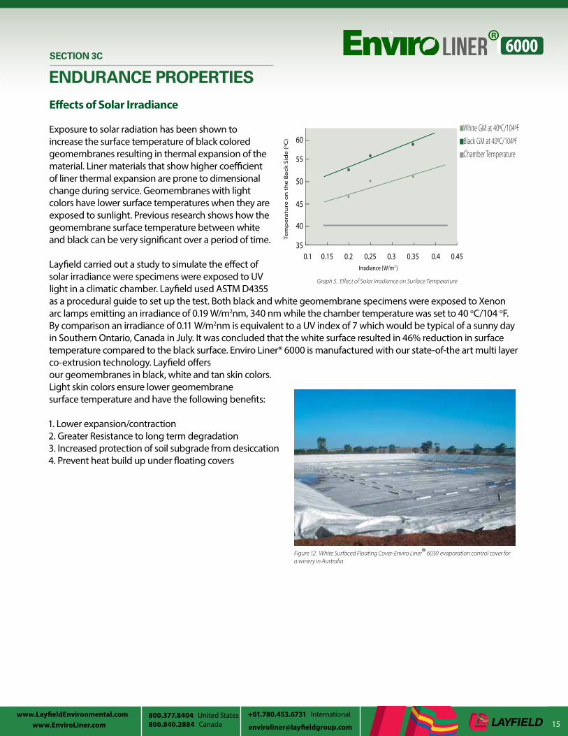
Layfield carried out a study to simulate the effect of solar irradiance were specimens were exposed to UV light in a climatic chamber. Layfield used ASTM D4355 as a procedural guide to set up the test. Both black and white geomembrane specimens were exposed to Xenon arc lamps emitting an irradiance of 0.19 W/m2nm, 340 nm while the chamber temperature was set to 40 oC/104 oF. By comparison an irradiance of 0.11 W/m2nm is equivalent to a UV index of 7 which would be typical of a sunny day in Southern Ontario, Canada in July. It was concluded that the white surface resulted in 46% reduction in surface temperature compared to the black surface. Enviro Liner® 6000 is manufactured with our state-of-the art multi layer co-extrusion technology. Layfield offers our geomembranes in black, white and tan skin colors. Light skin colors ensure lower geomembrane surface temperature and have the following benefits:
1. Lower expansion/contraction2. Greater Resistance to long term degradation3. Increased protection of soil subgrade from desiccation4. Prevent heat build up under floating covers
SECTION 3C
ENDURANCE PROPERTIES
White GM at 40ºC/104ºFBlack GM at 40ºC/104ºFChamber Temperature
Irradiance (W/m )2
35
40
45
50
55
60
Tem
pe
ratu
re o
n t
he
Ba
ck S
ide
(ºC
)
0.1 0.15 0.2 0.25 0.3 0.35 0.4 0.45
Figure 12. White Surfaced Floating Cover-Enviro Liner® 6030 evaporation control cover for a winery in Australia
Graph 5. Effect of Solar Irradiance on Surface Temperature

17www.LayfieldEnvironmental.com
800.840.2884 Canada [email protected] United States +01.780.453.6731 International
SECTION 4
COMPARATIVE PHYSICAL PROPERTIES
Table 5. Comparative Physical Properties of Geomembranes
Properties ASTM EL6020 LLDPE 201 EL6030 LLDPE 301 HDPE 302 EL6040 LLDPE 401 HDPE 402 EL6060 HDPE 6060
Thickness (Nominal)
D 519920 mils
0.50 mm20 mils
0.50 mm30 mils
0.75 mm30 mils
0.75 mm30 mils
0.75 mm40 mils1.0 mm
40 mils1.0 mm
40 mils1.0 mm
60 mils1.5 mm
60 mils1.5 mm
Tensile Strength at Break
D 669395 ppi16.5 N/
mm
71 ppi13 N/mm
141 ppi25 N/mm
114 ppi20 N/mm
114 ppi20 N/mm
180 ppi31.50 N/
mm
152 ppi27 N/mm
152 ppi27 N/mm
255 ppi44.5N/
mm
228 ppi40 N/mm
Elongation D 638 1000% 800% 1000% 800% 700% 1000% 800% 700% 1000% 700%
Critical Cone Height
D 5514 N/A2.0 in
50 mmN/A N/A
2.0 in50 mm
N/A N/A2.0 in
50 mm1.4 in
35 mm
UV ResistanceStrength Retained @ 30,000 hrs
D 4329 N/A N/A 90% N/A N/A 90% N/A N/A 90% N/A
Axi-Symmetric Break Resistance Strain
D 5617 50% 30% 50% 30% N/A 80% 30% N/A 80% N/A
High Pressure Oxidative Induction Time
D 5885 2000 min 400 min 2000 min 400 min 400 min 2000 min 400 min 400 min 2000 min 400 min
OxidativeInduction Time
D 3895 N/A N/A 200 min N/A N/A 200 min N/A N/A 200 min N/A
Stress Crack Under Constant Load
D 5397> 1000
hrsN/A
> 1000 hrs
N/A 300 hrs> 1000
hrsN/A 300 hrs
> 1000 hrs
300 hrs
Flexibility, Number of Cycles
D 6182 N/A N/A 8000 N/A N/A N/A N/A N/A N/A 3000
Certifications (Potable Water)
NSF 61AS/NZ 4020
N/ANSF 61AS/NZ 4020
N/A N/ANSF 61AS/NZ 4020
N/A N/ANSF 61 AS/NZ 4020
N/A
Fish SafeDaphniaMagna
LC50Yes N/A Yes N/A N/A Yes N/A N/A Yes N/A
Notes:1 In accordance with GRI GM 17 specification; Test Method, Test Properties for LLDPE Smooth and Textured Geomembrane.2 In accordance with GRI GM 13 specification; Test Method, Test Properties for HDPE Smooth and Textured Geomembrane.

18www.LayfieldEnvironmental.com
800.840.2884 Canada [email protected] www.EnviroLiner.com800.377.8404 United States01.780.453.6731 International
SECTION 5
PREFABRICATED GEOMEMBRANESPrefabricated geomembrane liners are usually made of flexible liner materials that are thermally welded together to form large geomembrane panels that can be deployed very quickly in the field. On prefabricated panels all of the seams are manufactured in a controlled environment. Installation of prefabricated panels reduces the number of field seams and significantly improves overall efficiency and economics.
Field assembled geomembranes are typically stiffer and are not designed to be prefabricated in a factory environment. Field assembled geomembranes are designed to be assembled in the field and are subject to the variability of the weather.
Our Enviro Liner® 6000 series has been formulated to overcome flexibility issues related with field fabricated geomembranes such as HDPE. HDPE’s very crystalline structure makes it stiffer and produces lower elongation at yield compared to Enviro Liner® 6000, which is flexible with exceptional elongation behavior. For the same reason we do not fabricate HDPE into large panels as it is too stiff to fold and roll. Even in the field, HDPE liners have to be laid smooth on the ground with no creases; backfilling over the creases may cause permanent deformation in those areas with significant loss in strength leading to geomembrane failure. Prefabricated panels also minimize field welding increasing quality control and reducing dependance on weather elements. Prefabricated panels are welded in a controlled environment compared to seam fabrication in field, ensuring high seam integrity.
Another important benefit of using prefabricated liners is described in the figures below. Figure 13a. shows panel layout using roll stock material assembled in field. Figure 13b. involves prefabricated panels made from more flexible materials like Enviro Liner® 6000. In this example, the containment area is approximately 350’ (106.7 m) wide x 500’ (152.4 m) long x 10’ (3 m) deep with a 4 (horizontal) to 1 (vertical) slope.
The following observations and conclusions can be derived from these two typical panel layouts in Figure 13a & b:
• Prefabricated geomembranes require fewer panels: approximately eight Enviro Liner® 6030x (30 mil) (0.75 mm)panels versus approximately sixty-five HDPE (60mil) (1.5 mm) panels
• Prefabricated panels require approximately 80% less field seams: approximately 1550 linear feet/475 linear meters of onsite seams for Enviro Liner 6030x (30 mil)(0.75 mm) versus approximately 8000 linear feet/2438.4 linear meters of onsite seams for HDPE (60 mil) (1.5 mm)
Other considerations of prefabricated panels:• Prefabricated panels are manufactured in a controlled environment• Less dependency on weather elements during construction• Shorter on-site time• Panels can be prefabricated between 20,000 ft2 /1,860m2 to 100,000 ft2/9,290m2
• Smaller jobs can be supplied in one prefabricated panel
Figure 13a. Schematic showing layout of panels for field assembled liners
Figure 13b. Schematic showing layout of panels for shop fabricated liners
Figure14. 7000 lbs (3200 ks) one-piece prefabricated Enviro Liner ®6030

19www.LayfieldEnvironmental.com
800.840.2884 Canada [email protected] United States +01.780.453.6731 International
SECTION 6
GEOMEMBRANES THICKNESS
At Layfield we strongly believe that the thickness of materials should be a function of the containment design taking into consideration site specific conditions. There are a number of thickness standards that are often quoted. One of the most quoted standards is the USEPA RCRA Subtitle D for landfills*. That document requires a minimum material thickness of 30 mil (0.75mm) for the base liners of landfills. The Natural Resources Conservation Service (NRCS) has Conservation Practice Standard 521A that requires a minimum thickness of 40 mil (1.00 mm) for waste water and 30 mil (0.75 mm) for clear water ponds (unsupported materials). In the 6th edition of Designing with Geosynthetics (Table 5.13) Robert Koerner ties thickness to survivability in the designations: Low 25 mil (0.63mm), Medium 30 mil (0.75mm), High 35 mil (0.88mm), and Very High 40 mil (1.0 mm). Therefore, the actual standard for the thickness of geomembranes is clearly between 30 mil (0.75mm) and 40 mil (1.0 mm).
One important aspect to consider is that thickness is not a key property of a geomembrane. The performance properties of a geomembrane need to be examined against the requirements of the project. For example Enviro Liner® 6000 has better UV resistance than other materials twice its thickness. Selecting the thinner material in this case can help you retain UV resistance while adding other properties such as flexibility and the increased speed of installation of a prefabricated liner. With a number of commodity grade liner materials, 60 mil (1.50 mm) and 80 mil (2.00 mm) thick products actually have worse yield, elongation and critical cone height puncture properties compared to more flexible 30 mil (0.75 mil) and 40 mil (1.00 mm) Enviro Liner ® 6000 products.
* The full document name is: Code of Federal Regulations, Title 40, Chapter 1, Subchapter 1, §258.40, Subpart D of Resource Conservation and Recovery Act.
Figure 15. Multi Layer co -extrusion

20www.LayfieldEnvironmental.com
800.840.2884 Canada [email protected] www.EnviroLiner.com800.377.8404 United States01.780.453.6731 International
SECTION 7
WARRANTY
Ultra Violet Weathering Warranty
Enviro Liner® 6000 geomembranes have been specially formulated for outstanding UV resistance. Layfield has developed a proprietary UV stabilization package for the Enviro Liner® 6000 series which allows a 30 mil (0.75 mm) Enviro Liner® 6030 to resist degradation as well as a 60 mil (1.5 mm) geomembrane stabilized with carbon black alone. This is a major advancement in flexible membrane liner technology as it allows the more flexible and durable Enviro Liner® formulation to be considered in exposed applications where a thicker material, such as HDPE 60 or 80 mil (1.5 & 2.0 mm), may have needed to be specified in the past. An extended exposed service life weathering warranty of up to 25 years on approved appplications is available for the Enviro Liner® 6000 series in a 40 mil (1.0 mm), 60 mil (1.5 mm) and 80 mil (2.0 mm) thickness. Our warranty is backed by natural and accelerated weathering tests. For further details please ask your Layfield representative for the technical paper “Long Term Weathering Stability and Warranty Implications for Thin Film Geomembranes”
Warranty Terms
1. Enviro Liner® 6000 will be free from manufacturing defects and, if properly installed and maintained, shall withstand normal weathering for the term of the warranty.
2. The warranty does not cover any damage to the liner, or defects in the liner, resulting from conditions beyond the reasonable control of Layfield, including misuse, abuse, fire, acts of God, abnormal weather conditions of all types, improper installation or maintenance, excessive stress from any source, improper handling during transportation, unloading, storage or installation, floating debris, damage due to machinery, damage from exposure to chemicals harmful to the liner, foreign objects or animals. In addition, the maximum temperature of the effluent is not to exceed 40° C and the pH of the effluent is to be maintained between 5 and 9. In water treatment applications including reverse osmosis the Langelier Saturation Index must not be negative (below 0.0).
3. A failure of a geomembrane is considered to be a breach (holes or cracks) or if the tensile strength falls below a level of 50% of the original specification.
4. As a condition of the warranty, the liner will be installed following Layfield recommended procedures.
5. A claim for breach of warranty needs to be presented to Layfield in writing within 30 days of the discovery of the possible defect. Layfield with then have the opportunity to inspect and determine the cause of the possible defect and take appropriate steps to repair or replace the Liner if a defect exists.
*For the complete warranty terms and conditions please contact your nearest Layfield representative.
Table 6. Enviro Liner® 6000 Weathering Warranties
Materials Standard Weathering Warranty
Extended Weathering Warranty (on approved applications)
Enviro Liner® 6000 Black40, 50, 60, 80 mil
10 years 25 years
Enviro Liner® 6000 White40, 50, 60, 80 mil
10 years 20 years

21www.LayfieldEnvironmental.com
800.840.2884 Canada [email protected] United States +01.780.453.6731 International
SECTION 8
APPLICATIONS
Figure 16. Double Lined secondary containment system lined with Enviro Liner® 6030
Figure 17. Heap Leaching Pads and Ponds
Figure 18. Enviro Liner® 6040 Floating cover and liner for a potable water reservoir
Major Applications
Exposed Applications: 25 year weathering warrantyavailable on approved applications
Oil and Gas • Frac/ Flowback Water• Brine/ Produced Water• Oilfield Pit Liners • Tank liners• Remediation liners and covers• Secondary containment of hydrocarbons and chemicals• Evaporation floating covers
Mining• Heap leach pads and ponds• Tailings ponds• Raincoat covers• Dam face waterproofing• Remediation liners and covers
Water and Wastewater• Potable water• Municipal utilities• Waste water treatment ponds• Sewage Lagoons• Manure Lagoons• Industrial waste water• Stormwater Management Ponds• Aquaculture• Decorative Ponds• Irrigation Canal Liners
Solid Waste Containment• Hazardous Waste• Landfill caps ( temporary and permanent)• Landfill liners• Soil remediation liners• Sludge dewatering
Floating Covers• Algae control• Evaporation control• Prevent waterfowl from landing• Insulated covers• Odor control• Biogas covers
Recreational • Decorative Ponds• Golf Course Ponds• Surf Park Facilities

22www.LayfieldEnvironmental.com
800.840.2884 Canada [email protected] www.EnviroLiner.com800.377.8404 United States01.780.453.6731 International
SECTION 8
APPLICATIONS
Oil and Gas
Enviro Liner® 6000 is used extensively in the Oil & Gas sector for environmental containment. The product’s excellent chemical resistance, long term UV stability, mechanical strengths and flexibility make it an ideal choice in multiple upstream, midstream and downstream applications. In upstream applications Enviro Liner® 6000’s ability to withstand brine and produced water makes it well suited for reserve pits and frac tank liners. It is also commonly used in a multitude of secondary containment applications from hydrocarbons, crude oil, gas liquids, and condensates. A quickly emerging application in warmer and windier climates is as a floating cover for evaporation control for water and fluids used for hydraulic fracturing.
For water storage and waste water treatment applications, Enviro Liner® 6000 provides excellent UV resistance and high levels of anti-oxidant protection, which makes it a very good choice for exposed applications such as brine ponds. The product’s ability to be prefabricated in a custom large size factory panels allows it to be mobilized for fast turnarounds, helping reduce construction costs. In midstream transportation applications, Enviro Liner® 6000 is commonly used for secondary containment applications for temporary storage and transfer facilities for crude oil, liquid bitumen, diluents and many other industry chemicals. It is also an excellent choice for brine water storage ponds. In downstream applications Enviro Liner® 6000 is commonly specified for secondary containment of liquid hydrocarbons for petro chemical facilities, refineries and above ground bulk storage.
Figure 19. Enviro Liner® 6040 lining a Brine Storage Pond in Ontario, Canada
Figure 20. Enviro Liner ®6030 Frac Tank Liner , West Texas.
Figure 21. Enviro Liner® Frac Fluid Evaporation control cover, Texas.
Figure 22. Secondary containment system in Alberta ,Canada

23www.LayfieldEnvironmental.com
800.840.2884 Canada [email protected] United States +01.780.453.6731 International
SECTION 8
APPLICATIONS
Mining Applications
Heap Leaching
A geomembrane is a vital component for heap leach pad construction in mining applications. The geomembrane system contains the heap leaching fluids which allows the target mineral to be recovered through a chemical extraction process. The geomembrane also ensures that the environment is protected by preventing the release of the heap leaching chemicals. When selecting a geomembrane for heap leach pad construction it is important to consider both the mechanical and chemical properties of the material. We have discussed chemical resistance of Enviro Liner® 6000 in detail in previous sections of this booklet. In this section, we emphasize the importance of puncture resistance and interface friction properties of Enviro Liner® 6000 in the challenging application of heap leaching.
Dynamic Puncture Tests and its relevance to Heap Leach Applications
A typical heap leaching process involves placing the geomembrane on a prepared subgrade and then placing a select fill material (in this example called the “over liner” material) on top of the liner for protection. Once the over liner layer is in place the ore is placed on the heap leach pad to the required operating height.
The gradation for the over liner material used in this example is shown in Table 7 and is a combination of soil fines and crushed rock. The over liner material is screened from crushed materials on site and contains ≤ 5% of soil fines to encourage drainage of the heap leach chemicals. The select fill (over liner) material in this test was from an actual heap leach project. The over liner material is designed to protect the geomembrane from the pressure of the heap leach ore which in a heap leach pad can reach up to 100 meters (300’) high. Evaluating whether a geomembrane will be able to withstand these types of ore pressures is done with the Dynamic Puncture test.
The Dynamic Puncture test replicates the high pressures in a heap leach pad using a steel vessel and a hydraulic press. The steel pressure vessel has an inside dimension of 305 mm x 305 mm and a height of 153 mm and is capable of applying vertical pressures of up to 4,000 kPa (580 psi - shown in Figure 22) . Pressure is typically applied in increments of 70 kPa every minute up to a pressure of 3881 kPa (equivalent to 200 m of ore). The pressure was then held constant for 48 hours. Enviro Liner® 6000 performed very well in this Dynamic Puncture Test and the results are shown in Table 8.
Sieve Size % Passing
Metric English Soil Liner Over Liner
75 mm 3 “ 100 100
38 mm 1.5” 75-100 100
25 mm 1” 65-100 84
13 mm 1/2” 55-95 46
4.75 mm # 4 45-85 19
0.45 mm # 40 25-65 12
0.075 mm # 200 15-50 3
Table 7. Soil Liners and Over Liner Gradation
Figure 23. Mining schematic showing placement of geomembrane

24www.LayfieldEnvironmental.com
800.840.2884 Canada [email protected] www.EnviroLiner.com800.377.8404 United States01.780.453.6731 International
Interface Friction Test and its relevance to Heap Leach Applications
Another important aspect of heap leach construction is the stability of the heap leach pads. This requires that the friction angle between the over liner and the geomembrane is clearly understood. Since most interface friction tests with geosynthetics are done at low normal stresses, the values are not always appropriate to heap leaching applications. Once again using a lab specializing in heap leach studies the Layfield Enviro Liner ® 6000 was tested for interface friction values at high normal stresses with two soil types. The two soil types used in this testing were the select fill material (over liner) that was used in the Dynamic Puncture test and a fill material representative of the prepared subgrade of the heap leach pad (called the soil liner material). The soil liner material has a high fines content while the over liner material has a very low fines content. Soil gradations for both materials are shown. Below is the table showing the results of friction angle testing for the smooth and textured Enviro Liner® 6000.
Friction Angles with “Over Liner”
Horizontal Displacement Enviro Liner® 6060(60mil) (1.5 mm)
Enviro Liner® 6160(60 mil)(1.5 mm)
Enviro Liner® 6040 (40 mil) (1.00 mm)
Enviro Liner® 6140(40 mil) (1.00 mm)
2.5 cm displacement 24.5 degrees 24.8 degree 23.7 degree 23.3 degree
7.0 cm displacement 23.9 degrees 26.8 degree 20.0 degree 24.4 degree
Friction Angles with “Soil Liner”
Horizontal Displacement Enviro Liner® 6160(60mil) (1.5 mm)
Enviro Liner® 6140(40 mil) (1.00 mm)
2.5 cm displacement 21.1 degree 22.5 degree
7.0 cm displacement 19.1 degree 21.6 degree
SECTION 8
APPLICATIONS
Table 8. Results of Dynamic Puncture Test
Table 9. Friction Angles with Over Liner
Table 10. Friction Angles with Soil Liner
Material
Ore Height/Equivalent Loads
120 m (393’)2117 kPa(306 PSI)
180 m (590’) 3176 kPA (460 PSI)
220m(721’)3881 kPA (560PSI)
Enviro Liner® 6040 (40 mil) (1.00 mm)
No perforations, minor yelding Minor Perforations Not Tested
Enviro Liner®6040 (40 mil) (1.00 mm) and 6 oz/yd geotextile
Not tested most likely will pass Tested , Passed no perforations or yeilding
Not tested will likely pass due to protection geotextile
Enviro Liner ®6060 (60 mil) (1.5 mm)
No Perforations No Perforations No Perforations
Test Conditions:
Normal Loads: 100 kPa (2000 PSF), 200 kPa (4000 PSF), 400 kPa (8000 PSF) and 800 kPa (16,000 PSF)
Asperity Height of the Geomembrane: 12 mils, 0.012” (0.305 mm)
Soil Gradation: Soil Liner and Over Liner

25www.LayfieldEnvironmental.com
800.840.2884 Canada [email protected] United States +01.780.453.6731 International
SECTION 8
APPLICATIONS
Water and Waste Water Applications
Enviro Liner® 6000 is a potable water grade geomembrane that is certified to the National Sanitation Foundation Standard 61 (NSF 61) and the Australian water standard AS/NZ 4020 for compatibility with drinking water. Enviro Liner® 6000 has excellent long-term resistance to chlorines and other disinfectants (in typical concentrations for potable water) and is commonly specified in potable water applications. In wastewater applications, Enviro Liner® 6000 can contain many variants of waste water from municipal sewage to agricultural manure and commercial waste water. Enviro Liner® 6000 is heavily fortified with advanced stabilizers and a proprietary UV inhibitor / antioxidant additive package that makes it very suitable for exposed long-term floating cover applications. In drinking water applications, Enviro Liner® 6000 can help protect the water from contamination from external sources.
Enviro Liner® 6000 can also be used to fabricate evaporation control covers in a number of agricultural and industrial applications. In wastewater applications, Enviro Liner® 6000 floating covers help prevent odors, collect biogas, and prevent the build-up of algae. Enviro Liner® 6000 has a High Pressure Oxidative Induction Time (HPOIT) level of more than 2,000 minutes which allow us to offer a longer term extended UV weathering warranties on approved applications. Enviro Liner® 6000 can also be placed with the white side exposed to
help reduce the surface temperature of the geomembrane which results in lower expansion/contraction cycles and prevents heat build-up under floating covers.
Enviro Liner® 6000 has high multi axial stress strain values. This property is desirable for biogas collection covers or other applications where large concentrations of gases can develop against the liner and push it upwards. Another important property of Enviro Liner® 6000 is its flexibility. Enviro Liner® 6000 can be thermally welded together to fabricate very large panels, thus reducing the number of field seams in large municipal water and wastewaterprojects.
Figure 25. Reclaimed water storage reservoir floating cover fabricated with Enviro Liner® 6060, Corona California
Figure 24. Enviro Liner® 6030 evaporation control cover for a winery in Australia

26www.LayfieldEnvironmental.com
800.840.2884 Canada [email protected] www.EnviroLiner.com800.377.8404 United States01.780.453.6731 International
SECTION 9
INSTALLATION SPECIFICATIONS
Subgrade Preparation
1. Ensure subgrade is compacted and surface finished to not impair installed geomembrane.
2. Subgrade to provide firm, unyielding surface with no sharp changes or abrupt breaks in grade.
3. A smooth drum rolled surface is preferable.
4. Ensure surfaces to be lined are smooth, free of foreign and organic material, sharp objects, or debris of any kind.
5. If a suitable sub-grade is not available then a cushion layer of 100 mm (4 inches) of clean sand LP8 non woven geotextile shall be placed prior to liner placement.
6. Excavate anchor trench to line, grade, and width indicated on drawings, prior to liner placement. Provide slightly rounded corners in the trench to avoid sharp bends in the geomembrane.
7. Prepare mechanical attachments according to ASTM D6497 Standard Guide for Mechanical Attachment of Geomembrane to Penetrations or Structures.
8. All concrete surfaces to which the liner will attach shall have “smooth trowel” finish. All the corners should have radius to a minimum 25mm (1 inch) as per the drawing.
9. Compaction at pipe penetrations and areas of mechanical attachment will be inspected carefully as these are areas where differential settlement can occur.
10. A certificate of subgrade acceptance will be prepared by the liner installation contractor prior to liner installation.
Geomembrane Installation
1. Installation of the geomembrane shall be performed in a logical sequence.
2. Place panels according to the drawings, the panel layout, and the label on each panel.
3. Sufficient thermal slack shall be incorporated during placement to ensure that harmful stresses do not occur in service.
Figure 26. Approved subgrade for an oilsands project in Northern, Alberta

27www.LayfieldEnvironmental.com
800.840.2884 Canada [email protected] United States +01.780.453.6731 International
SECTION 9
INSTALLATION SPECIFICATIONS
4. Weather Conditions at Time of Installation:• Site welding may proceed at any temperature providing a suitable qualification weld can be prepared at
site conditions using the operator, equipment, and materials intended for the project.• Installation of geomembrane in winds above 20 km/h (12 mph) can proceed only if the installer can
demonstrate that the liner will not be at risk of damage.• Do not install the geomembrane during precipitation or in the presence of excessive moisture.• Do not install in weather conditions that may be detrimental to the function of the geomembrane.
5. Ensure personnel working on geomembrane do not use damaging footwear.
6. Protect completed panels from damage; handle carefully to avoid damaging the liner.
7. Equipment and methods used to unroll liner panels should not damage the prepared subgrade.
8. Ballast used to prevent uplift by wind must not damage the geomembrane. A continuous load is recommended along the edges of panels to eliminate the risk of wind uplift.
9. Qualification Seams:• A qualification seam will be run prior to any field seams.• A qualification seam is made with separate
pieces of geomembrane using the same material and
• equipment that will be used for production welding.
• Machine conditions, and operator used for welding must be the same as those used for the qualification weld.
• Qualification seam must be tested in shear and peel, and meet the specified requirements for the material as stated in the materials section.
• A qualification seam must be rerun whenever the operator is changed, the equipment adjusted, or at least every 4 hours.
10. Field Seams:• Field seams will be sampled for testing in a way
that does not compromise the installed liner• One sample to be tested for every 150 m (500 ft) of field seam.• Test samples are to be removed from the ends of seams, from the anchor trench, or other location that
does not introduce a defect into the liner• Samples to be approximately 100 mm (4 inches) long to permit testing of one shear and two peel
specimens (ASTM D6392).• Test samples immediately after seaming.• Record date, location and pass/fail description.• A written record will be maintained for all field seam tests.• All completed field seams will be 100% non-destructively tested using an air lance test (ASTM D4437
method 7.2).
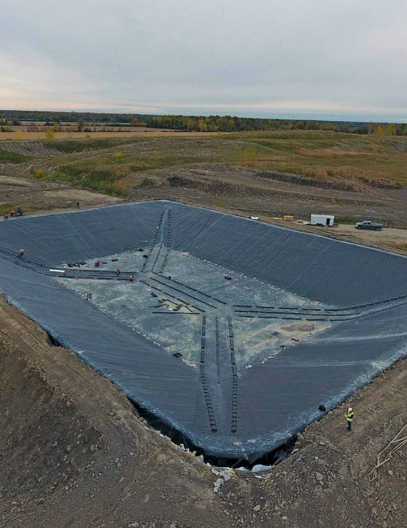
Figure 27. Installation of double lined secondary containment system lined with Enviro Liner® 6030

28www.LayfieldEnvironmental.com
800.840.2884 Canada [email protected] www.EnviroLiner.com800.377.8404 United States01.780.453.6731 International
Enviro Liner® 6000 series REVOC® Floating Cover Specification Summary
Product Description
REVOC® Defined Sump Covers are manufactured using our fortified Enviro Liner® 6000. These covers use floats and weights to create rainwater collection sumps in the cover and to accommodate changes in water level. The REVOC® Defined Sump system is ideal for larger floating cover applications. A defined sump system can be fairly simple, or can be exceptionally complex depending on site conditions. REVOC® Defined Sump Covers are used for all floating cover applications including potable water storage, odor control, evaporation control and contamination/dilution protection. A REVOC® defined sump cover is the most versatile cover system and can be used in any floating cover application especially large ponds, or ponds with an irregular shape. Layfield’s REVOC® Defined Sump Cover design,
installation techniques, and inspection/maintenance protocols fully meet the requirements of local regulations, such as the AWWA M25 Lining and Floating Cover Guidelines and AWWA California-Nevada Reservoir Floating Cover Guidelines. Layfield designs, installs, and maintains all types of floating covers.
Installation
All REVOC® Defined Sump Covers made with Enviro Liner® 6000 must be installed by a Layfield crew operating under a clearly defined contract. Much of the installation of a REVOC® Defined Sump Cover is accomplished by skilled technicians in the field. The layout and fitting of a defined sump cover system requires significant field skill and experience. REVOC® Defined Sump Covers are almost always installed in a dry pond. After the pond liner is complete and inspected the cover panels are placed and welded to fit into the containment. The layout and installation of sumps is done on site according to the final cover geometry. Our skilled installers locate where each sump should be on the cover and then attach the floats and weights around the sump as required. Final installation of fittings such as hatches, walkways, steps, vents, sumps, and pumps complete the cover installation.
Maintenance
Floating Covers, including pumps and auxiliary equipment, should be inspected at least once per year for damage, stress, or any other detrimental condition. Layfield provides complete floating cover maintenance services including cleaning, repairs, and disinfection of potable water covers.
SECTION 9
INSTALLATION SPECIFICATIONS
Figure 28. Floating cover being inflated during inspection

29www.LayfieldEnvironmental.com
800.840.2884 Canada [email protected] United States +01.780.453.6731 International

30www.LayfieldEnvironmental.com
800.840.2884 Canada [email protected] www.EnviroLiner.com800.377.8404 United States01.780.453.6731 International
Enviro Liner® Welding Gun:
The Enviro Liner® Welding Gun is a portable welder designed to make permanent repairs to Enviro Liner® products, including Enviro Liner® 6000. The Enviro Liner® Welding Gun is a low cost, manually operated, extrusion welder for small repairs in thermoplastic geomembranes. The Enviro Liner® Welding Gun will repair all Enviro Liner® brand geomembranes. The Enviro Liner® Welding Gun will also repair other polyolefin materials if compatible welding sticks are available.
Following items are required to perform a repair with this welding gun:• The Welding Gun itself• Power source (grounded)• Welding Sticks (compatible with the geomembrane)• Enviro Liner® welding tape (for tacking weld• Repair material (left over materials from site or order new
material)
Maintenance
1. Inspect seams and non-seam areas for defects, holes, blisters, undispersed raw materials.2. Identify any sign of foreign matter contamination.3. Repair all through-thickness defects.4. Defective Seams: Cap strip or replace.5. Small Holes: Repair by extrusion welding using a bead of extruded material over hole. Patch if hole is larger
than 6 mm (1/4 inch).6. Tears: Patch and seal round sharp ends of tears on slope or stressed area prior to patching.7. Repair blisters, large cuts and undispersed raw materials with patch.8. Secure Patches by Extrusion Welding (Enviro Liner® Welding Gun) or Hot Air Welding:
• Extrusion Welding• Clean area to be patched.• Tack patch in place with hot air welding or with double sided tape.• Prepare patch area by roughening with a wire brush.• Extrude all the way around patch.• More than one extrusion bead can be laid side-by-side on Enviro Liner® 6000 materials. A maximum of three
extrusion beads can be laid side-by side on Enviro Liner® 6000• Hot Air Welding
• Hand hot air welding is permitted for patching Enviro Liner® 6000• Clean area to be patched.• Hand weld the patch with a hot air gun and suitable roller.
9. Patches: Round or oval, of same geomembrane. Extend minimum 75 mm (3 inches)10. Beyond the edge of the defect.11. Verification of Repairs: All repairs to be non-destructively tested using:
• Air Lance Test, ASTM D4437 Method 7.2• Vacuum Box Test ASTM D5641
12. Redo failed repairs and re-test.13. Keep records of all repairs and the test results.
SECTION 10
REPAIR AND MAINTENANCE
Figure 29. Enviro Liner Welding Gun

31www.LayfieldEnvironmental.com
800.840.2884 Canada [email protected] United States +01.780.453.6731 International
SECTION 11
TYPICAL DRAWINGS
Anchor Trench
Pipe Flange

32www.LayfieldEnvironmental.com
800.840.2884 Canada [email protected] www.EnviroLiner.com800.377.8404 United States01.780.453.6731 International
SECTION 11
TYPICAL DRAWINGS
Pipe Boot
Piling Support
33www.LayfieldEnvironmental.com
800.840.2884 Canada [email protected] United States +01.780.453.6731 International
SECTION 11
TYPICAL DRAWINGS
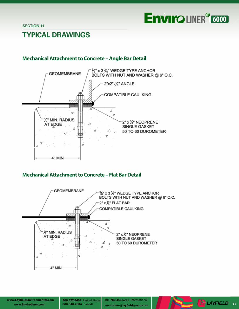
Mechanical Attachment to Concrete – Angle Bar Detail
Mechanical Attachment to Concrete – Flat Bar Detail

34www.LayfieldEnvironmental.com
800.840.2884 Canada [email protected] www.EnviroLiner.com800.377.8404 United States01.780.453.6731 International
SECTION 11
TYPICAL DRAWINGS
Thermoformed Boot
Vent Detail

35www.LayfieldEnvironmental.com
800.840.2884 Canada [email protected] United States +01.780.453.6731 International
SECTION 11
TYPICAL DRAWINGS
Pipe Penetration on Slope
36www.LayfieldEnvironmental.com
800.840.2884 Canada [email protected] www.EnviroLiner.com800.377.8404 United States01.780.453.6731 International
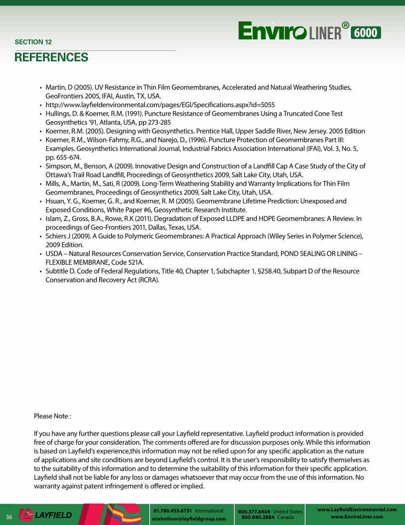
• Martin, D (2005). UV Resistance in Thin Film Geomembranes, Accelerated and Natural Weathering Studies, GeoFrontiers 2005, IFAI, Austin, TX, USA.
• http://www.layfieldenvironmental.com/pages/EGI/Specifications.aspx?id=5055• Hullings, D. & Koerner, R.M. (1991). Puncture Resistance of Geomembranes Using a Truncated Cone Test
Geosynthetics ‘91, Atlanta, USA, pp 273-285 • Koerner, R.M. (2005). Designing with Geosynthetics. Prentice Hall, Upper Saddle River, New Jersey. 2005 Edition• Koerner, R.M., Wilson-Fahmy, R.G., and Narejo, D., (1996). Puncture Protection of Geomembranes Part III:
Examples. Geosynthetics International Journal, Industrial Fabrics Association International (IFAI), Vol. 3, No. 5, pp. 655-674.
• Simpson, M., Benson, A (2009). Innovative Design and Construction of a Landfill Cap A Case Study of the City of Ottawa’s Trail Road Landfill, Proceedings of Geosynthetics 2009, Salt Lake City, Utah, USA.
• Mills, A., Martin, M., Sati, R (2009). Long-Term Weathering Stability and Warranty Implications for Thin Film Geomembranes, Proceedings of Geosynthetics 2009, Salt Lake City, Utah, USA.
• Hsuan, Y. G., Koerner, G. R., and Koerner, R. M (2005). Geomembrane Lifetime Prediction: Unexposed and Exposed Conditions, White Paper #6, Geosynthetic Research Institute.
• Islam, Z., Gross, B.A., Rowe, R.K (2011). Degradation of Exposed LLDPE and HDPE Geomembranes: A Review. In proceedings of Geo-Frontiers 2011, Dallas, Texas, USA.
• Schiers J (2009). A Guide to Polymeric Geomembranes: A Practical Approach (Wiley Series in Polymer Science), 2009 Edition.
• USDA – Natural Resources Conservation Service, Conservation Practice Standard, POND SEALING OR LINING – FLEXIBLE MEMBRANE, Code 521A.
• Subtitle D. Code of Federal Regulations, Title 40, Chapter 1, Subchapter 1, §258.40, Subpart D of the Resource Conservation and Recovery Act (RCRA).
SECTION 12
REFERENCES
Please Note :
If you have any further questions please call your Layfield representative. Layfield product information is provided free of charge for your consideration. The comments offered are for discussion purposes only. While this information is based on Layfield’s experience,this information may not be relied upon for any specific application as the nature of applications and site conditions are beyond Layfield’s control. It is the user’s responsibility to satisfy themselves as to the suitability of this information and to determine the suitability of this information for their specific application. Layfield shall not be liable for any loss or damages whatsoever that may occur from the use of this information. No warranty against patent infringement is offered or implied.

www.LayfieldContainment.com 800.377.8404
www.EnviroLiner.com
United States of America 800.840.2884 Canada
+1 780.453.6731 International