TCX500 Tire Changer Family Operation Manual, Form 5290-T · PDF fileContents • ii TCX500...
48
OPERATION INSTRUCTIONS Form 5290-T, 08-09a Supersedes Form 5290-T, 08-09 TCX500 Tire Changer Family ©Copyright 2005-2009 Hunter Engineering Company
-
Upload
truongphuc -
Category
Documents
-
view
227 -
download
0
Transcript of TCX500 Tire Changer Family Operation Manual, Form 5290-T · PDF fileContents • ii TCX500...

OPERATION INSTRUCTIONS Form 5290-T, 08-09a Supersedes Form 5290-T, 08-09
TCX500 Tire Changer Family
©Copyright 2005-2009 Hunter Engineering Company

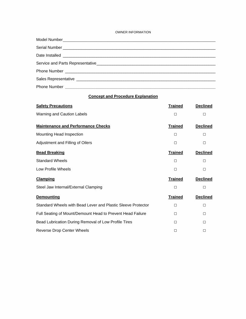
OWNER INFORMATION
Model Number____________________________________________________________________
Serial Number ____________________________________________________________________
Date Installed ____________________________________________________________________
Service and Parts Representative_____________________________________________________
Phone Number ___________________________________________________________________
Sales Representative ______________________________________________________________
Phone Number ___________________________________________________________________
Concept and Procedure Explanation
Safety Precautions Trained Declined
Warning and Caution Labels □ □
Maintenance and Performance Checks Trained Declined
Mounting Head Inspection □ □
Adjustment and Filling of Oilers □ □
Bead Breaking Trained Declined
Standard Wheels □ □
Low Profile Wheels □ □
Clamping Trained Declined
Steel Jaw Internal/External Clamping □ □
Demounting Trained Declined
Standard Wheels with Bead Lever and Plastic Sleeve Protector □ □
Full Seating of Mount/Demount Head to Prevent Head Failure □ □
Bead Lubrication During Removal of Low Profile Tires □ □
Reverse Drop Center Wheels □ □

Mounting Trained Declined
Standard Wheels □ □
Mounting of Stiff, Low Profile Tires □ □
Reverse Drop Center Wheels □ □
Proper Bead Lubrication for Mounting Protection □ □
Inflation Trained Declined
Safety Precautions □ □
Lubrication and Removal of Valve Core □ □
Bead Sealing and Seating □ □
Individuals and Date Trained
___________________________________ ___________________________________
___________________________________ ___________________________________
___________________________________ ___________________________________
___________________________________ ___________________________________
___________________________________ ___________________________________
___________________________________ ___________________________________
Contents
CONTENTS ........................................................................................................... I 1. GETTING STARTED....................................................................................... 1
1.1 Introduction............................................................................................................. 1 1.2 For Your Safety ...................................................................................................... 1
Hazard Definitions.................................................................................................. 1 IMPORTANT SAFETY INSTRUCTIONS............................................................... 2
1.3 Control Pedal Configurations ................................................................................. 4 1.4 Wheel Rotation Pedal............................................................................................. 4 1.5 Tire Bead Breaker Shovel Pedal ............................................................................ 5 1.6 Wheel Clamping Pedal........................................................................................... 5 1.7 Air Inflation Pedal ................................................................................................... 5 1.8 Inflator and Pressure Limiter .................................................................................. 6 1.9 Mount / Demount Head .......................................................................................... 6 1.10 Equipment Components....................................................................................... 7
TCX505, TCX515, TCX535 Series (mid 2009 and later), Tire Changer Components........................................................................................................... 7 TCX500 Series (2005 to mid 2009), Tire Changer Components .......................... 8
2. BASIC PROCEDURES ................................................................................... 9 2.1 Bead Breaking........................................................................................................ 9 2.2 Placing Wheel on Tire Changer ........................................................................... 10
Clamping the Wheel from Inside of Rim - Steel Rims ......................................... 10 Clamping the Wheel from Outside of Rim - Alloy Rims....................................... 10
2.3 Demounting Standard Tire from Rim ................................................................... 11 2.4 Mounting Standard Tire to Rim ............................................................................ 13
Mount a standard tire to rim:................................................................................ 13 Precautionary Notes ............................................................................................ 14
2.5 Tire Inflation.......................................................................................................... 14 2.6 Removal of Wheel from Tire Changer.................................................................. 15 2.7 Clamping Jaw Extensions AR46 (p/n RP11-8-11400276)................................... 15
3. ADVANCED PROCEDURES........................................................................ 17 3.1 Advanced Bead Breaking Procedures ................................................................. 17
Bead Breaking “AH” Wheels (e.g. BMW M3, M5, Some Porsches, Range Rover, Lancia, etc.) ......................................................................................................... 17
Bead Breaking “AH” Wheels as follows: ....................................................... 17 3.2 Advanced Demounting Procedures ..................................................................... 18
Demounting Tire from Rim Using the Bead Lever Tool without the Plastic Sleeve Protector............................................................................................................... 18
Demounting Upper Bead............................................................................... 18 Demounting Lower Bead............................................................................... 19
“HM” Bead Lever and Sleeve Protector, RP6-2663 ............................................ 19 Benefits.......................................................................................................... 19 Use of “HM” Bead Lever................................................................................ 19
3.3 Advanced Mounting Procedures .......................................................................... 20 3.4 Mount/Demount Head Assembly ......................................................................... 20
Checking Mount/Demount Head Calibration ....................................................... 21 For Steel Heads ............................................................................................ 21 Set Position of Steel Mount/Demount Head on Hex Shaft............................ 21 For Plastic Heads .......................................................................................... 22 Set Position of Plastic Mount/Demount Head on Hex Shaft ......................... 22
TCX500 Tire Changer Family Operation Manual Contents • i

Contents • ii TCX500 Tire Changer Family Operation Manual
Adjust the Offset of Lock Mechanism – Steel and Plastic Heads ................. 23 4. TCX515 OPERATIONAL SUPPLEMENT..................................................... 25
BP Arm Operation................................................................................................ 25 4.1 General Information.............................................................................................. 25 4.2 Part Identification.................................................................................................. 25 4.3 Operation.............................................................................................................. 26
Clamping the Wheel............................................................................................. 26 Demounting.......................................................................................................... 27 Removing Tire from Rim...................................................................................... 28 Mounting .............................................................................................................. 28 Using the Bead Press Head Hook to Lift the Tire................................................ 30
5. TCX535 OPERATIONAL SUPPLEMENT..................................................... 31 Bead Press System Operation ............................................................................ 31
5.1 General Information.............................................................................................. 31 5.2 Part Identification.................................................................................................. 31 5.3 Operation.............................................................................................................. 32
Clamping the Wheel............................................................................................. 32 Demounting.......................................................................................................... 32 Breaking the Inner Bead ...................................................................................... 33 Mounting .............................................................................................................. 33 Run Flat Wheels .................................................................................................. 33
Bead Breaking ............................................................................................... 33 Clamping the Wheel ...................................................................................... 34 Second Roller Attachment............................................................................. 34 Demounting the Outer Bead.......................................................................... 34 Demounting the Inner Bead .......................................................................... 35 Operations and Inspections Prior to Mounting.............................................. 35 Mounting the Inner Bead ............................................................................... 35 Mounting the Outer Bead .............................................................................. 36 Sensor Inspection/Replacement ................................................................... 36
6. MAINTENANCE............................................................................................ 37 6.1 Maintenance Schedule......................................................................................... 37 6.2 Maintenance and Replacement Parts .................................................................. 38
7. GLOSSARY.................................................................................................. 39 7.1 Rim Diagram......................................................................................................... 39 7.2 Illustrations of Various Rim Designs .................................................................... 40

1. Getting Started
1.1 Introduction This manual provides operation instructions and information required to maintain the TCX500 tire changer family. An advanced operation section has been provided in “Advanced Procedures,” page 17.
“References”
This manual assumes that you are already familiar with the basics of tire identification and service. The first section provides the basic information to operate the TCX500 tire changer family. The following sections contain detailed information about equipment, procedures, and maintenance. “Italics” are used to refer to specific parts of this manual that provide additional information or explanation. For example, Refer to “Equipment Components,” page 7. These references should be read for additional information to the instructions being presented.
The owner of the tire changer is solely responsible for enforcing safety procedures and arranging technical training. The tire changer is to be operated only by a qualified trained technician. Maintaining records of personnel trained is solely the responsibility of the owner or management.
The TCX500 tire changer family is intended for mounting, demounting, and inflating most tires with an approximate dimension of 40 inches in diameter and 15 inches in width.
1.2 For Your Safety
Hazard Definitions Watch for these symbols:
CAUTION: Hazards or unsafe practices, which could result in minor personal injury, product, or property damage.
WARNING: Hazards or unsafe practices, which could result in severe personal injury or death.
DANGER: Immediate hazards, which will result in severe personal injury or death.
TCX500 Tire Changer Family Operation Manual Getting Started • 1
These symbols identify situations that could be detrimental to your safety and/or cause equipment damage.
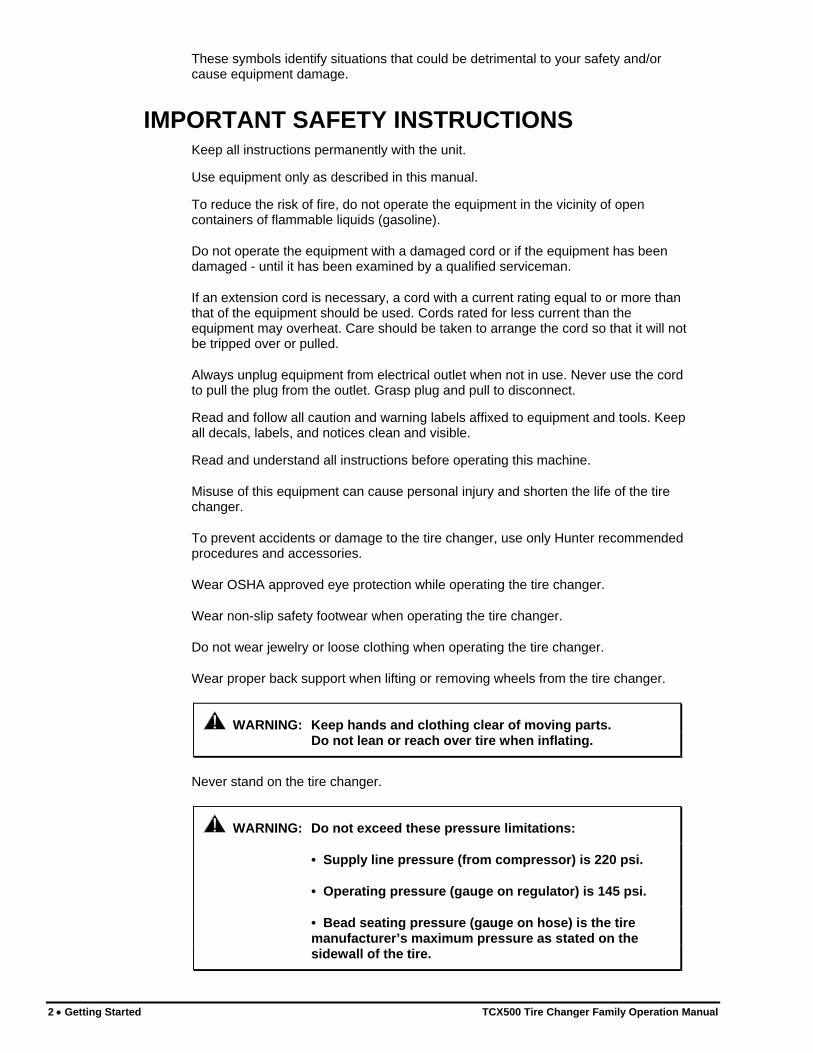
IMPORTANT SAFETY INSTRUCTIONS Keep all instructions permanently with the unit.
Use equipment only as described in this manual.
To reduce the risk of fire, do not operate the equipment in the vicinity of open containers of flammable liquids (gasoline).
Do not operate the equipment with a damaged cord or if the equipment has been damaged - until it has been examined by a qualified serviceman.
If an extension cord is necessary, a cord with a current rating equal to or more than that of the equipment should be used. Cords rated for less current than the equipment may overheat. Care should be taken to arrange the cord so that it will not be tripped over or pulled.
Always unplug equipment from electrical outlet when not in use. Never use the cord to pull the plug from the outlet. Grasp plug and pull to disconnect.
Read and follow all caution and warning labels affixed to equipment and tools. Keep all decals, labels, and notices clean and visible.
Read and understand all instructions before operating this machine.
Misuse of this equipment can cause personal injury and shorten the life of the tire changer.
To prevent accidents or damage to the tire changer, use only Hunter recommended procedures and accessories.
Wear OSHA approved eye protection while operating the tire changer.
Wear non-slip safety footwear when operating the tire changer.
Do not wear jewelry or loose clothing when operating the tire changer.
Wear proper back support when lifting or removing wheels from the tire changer.
WARNING: Keep hands and clothing clear of moving parts. Do not lean or reach over tire when inflating.
Never stand on the tire changer.
WARNING: Do not exceed these pressure limitations:
• Supply line pressure (from compressor) is 220 psi.
• Operating pressure (gauge on regulator) is 145 psi.
• Bead seating pressure (gauge on hose) is the tire manufacturer’s maximum pressure as stated on the sidewall of the tire.
2 • Getting Started TCX500 Tire Changer Family Operation Manual

Mixing tire and rim sizes may affect steering, handling, and the braking of the vehicle.
Keep hands and clothing clear of moving parts.
DANGER: Activate air inflation jets only when sealing bead.
Bleed air pressure from system before disconnecting supply line or other pneumatic components. Air is stored in a reservoir for operation of inflation jets.
WARNING: Only activate the air inflation jets if the rim securing device is locked in place and the tire is properly clamped (when possible).
WARNING: Never mount a tire to a rim that is not the same diameter (e.g., 16 1/2 inch tire mounting on a 16 inch rim).
Do not operate the tire changer with worn, rubber or plastic parts.
Wheels equipped with low tire pressure sensors or special tire and rim designs may require certain procedures. Consult manufacturer’s service manuals.
Service and maintain machine regularly as outlined in this Manual. For further information contact:
Hunter Engineering Company 11250 Hunter Drive Bridgeton, Missouri 63044 800-448-6848 314-731-3020
Internet address: www.hunter.com
TCX500 Tire Changer Family Operation Manual Getting Started • 3

1.3 Control Pedal Configurations Control pedals on the TCX500 tire changer family are configured differently depending on the time period they were manufactured.
There are two control pedal configurations:
• Models built from mid 2009 and later (TCX505, TCX515 and TCX535)
CLAMP SHOVEL ROTATION
• Models built from 2005 to mid 2009 (TCX500, BP and BPS)
ROTATION CLAMP SHOVEL
Throughout this manual, control pedals are referred to by the associated symbol.
ROTATION SHOVELCLAMP
1.4 Wheel Rotation Pedal
Step down on the rotation pedal to rotate the wheel clockwise.
Release the pedal to stop rotation. Depressing the pedal halfway rotates the wheel at slow speed. Depressing the pedal all the way rotates the wheel at fast speed.
Lift up on the pedal to rotate the wheel counterclockwise. Release the pedal to stop rotation.
4 • Getting Started TCX500 Tire Changer Family Operation Manual

1.5 Tire Bead Breaker Shovel Pedal
WARNING: Keep arms and legs from between the bead breaker arm and the side of the housing.
Step down on the bead breaker shovel pedal to close bead
breaker arm and break bead.
Release the pedal to allow the bead breaker arm to open.
1.6 Wheel Clamping Pedal
The wheel clamping pedal has three positions (modes of operation): up
(expand), neutral (stop), and down (retract).
With the clamps in the fully retracted position or clamped against the outside of a rim, step down fully on the pedal to expand the wheel clamps (clamps move outward). The clamps continue to expand until contacting the rim or until fully expanded.
While the clamps are expanding, partially stepping down on the pedal will stop the clamps. The pedal can also be placed in the stopped position with the clamps in the fully expanded position. From this stopped position, additional partial steps on the pedal will incrementally retract clamps.
With the clamps in the fully expanded position or clamped against the inside of a rim, step down partially on the pedal to retract the wheel clamps (clamps move inward). To completely retract the clamps, step down fully on the pedal and the clamps will move completely inward.
Change the position of pedal by briefly stepping down and then releasing.
1.7 Air Inflation Pedal On the left side of the base, the air inflation pedal operates the two-stage air inflation system. Refer to illustrations on page 8 and 7. The pedal controls the air going to the inflation hose and the air inflation jets.
WARNING: Do not lean or reach over tire when inflating.
CAUTION: Keep hands clear of wheel during sealing and seating of beads.
When operating air inflator, stand to the left side of the base. Do not stand in front of the tire changer while operating the air inflator.
Step down partially on the pedal to inflate tires through inflation hose.
Step down completely on the pedal to activate the air inflator jets to seal tire beads.
TCX500 Tire Changer Family Operation Manual Getting Started • 5

1.8 Inflator and Pressure Limiter As a safety device, the pressure limiter prevents the operator from using excessive air pressure.
Bead seating pressure should never exceed the tire manufacturer’s maximum bead seating pressure as stated on the sidewall of the tire.
If tires being mounted require more than the tire manufacturer’s maximum bead seating pressure, the wheel should be removed from the tire changer, placed in an inflation cage, and inflated per manufacturer’s instructions.
1.9 Mount / Demount Head The mount/demount head is suspended from the column above the turntable.
The head has a mounting and demounting lip that is designed to install or remove the bead of tire as the wheel is rotated clockwise.
MOUNTING LIP The
mounting lip is on the left side of the
head.
DEMOUNTING LIP The
demounting lip is on the right
side of the head.
STEEL MOUNT HEAD
PLASTIC MOUNT HEAD
The bead of tire is placed on top of mounting lip during mounting.
The bead of tire is placed on top of demounting lip during demounting.
6 • Getting Started TCX500 Tire Changer Family Operation Manual

1.10 Equipment Components
TCX505, TCX515, TCX535 Series (mid 2009 and later), Tire Changer Components
HEAD POSITION LOCK
MOUNT/DEMOUNT HEAD
INFLATION HOSE
PRESSURE GUAGE
AIR RELEASE BUTTON
CLAMP AND AIR JET (4 PLACES)
MOUNTING PASTE
BEAD BREAKERARM AND SHOVEL
WHEEL ROTATION
PEDAL
WHEEL CLAMPING
PEDAL
TIRE BEAD BREAKING
SHOVEL PEDAL
OILER/REGULATOR
TURNTABLE
AIR INFLATION PEDAL
SHOVEL BLADE POSITION
ADJUSTMENT PIN
PRESSURE RELIEF VALVE COLUMN STOP
SCREW
TCX500 Tire Changer Family Operation Manual Getting Started • 7

8 • Getting Started TCX500 Tire Changer Family Operation Manual
TCX500 Series (2005 to mid 2009), Tire Changer Components
HEAD POSITION LOCK
MOUNT/DEMOUNT HEAD
INFLATION HOSE
PRESSURE GUAGE
AIR RELEASE BUTTON
CLAMP AND AIR JET (4 PLACES)
MOUNTING PASTE
BEAD BREAKERARM AND SHOVEL
TIRE BEAD BREAKING
SHOVEL PEDAL
WHEEL ROTATION
PEDAL
WHEEL CLAMPING
PEDAL
OILER/REGULATOR
TURNTABLE
AIR INFLATION PEDAL
SHOVEL BLADE POSITION
ADJUSTMENT PIN
PRESSURE RELIEF VALVE COLUMN STOP
SCREW

2. Basic Procedures
2.1 Bead Breaking
WARNING: All air pressure inside the tire must be removed before proceeding. Never attempt to break the bead until all air is removed from the tire. Failure to remove all air from tire may result in injury to operator, or damage to equipment, tire, or wheel.
Remove valve stem core to deflate tire completely. Remove all weights from the rim to protect the rim and extend life of the mount/demount head.
Swing the bead-beaker arm out and position the wheel against the side of the tire changer, between the bead-breaker arm and the housing.
Swing the bead-breaker arm toward the tire and position the shovel blade on the sidewall of the tire. Locate the blade close, but not contacting, the edge of the rim.
Step down on the bead-breaker shovel pedal .
The bead-breaker arm will be pulled toward the tire changer to break the bead.
Release the pedal to disengage the bead-breaker arm and then swing the arm to the open position. If the bead has not completely loosened, rotate the wheel and repeat the bead breaking procedure at a different area on the tire.
Turn the wheel and break the opposite bead using the same procedure.
TCX500 Tire Changer Family Operation Manual Basic Procedures • 9

The shovel blade has two-position adjustment. The second position is for wheels 10” wide and larger, but also may be used to break the beads of extreme low profile tires.
For additional information on bead breaking on special wheels, refer to “Advanced Bead Breaking Procedures,” page 17.
2.2 Placing Wheel on Tire Changer Identify and recognize special wheel combinations such as Reverse Drop Center (needs inverted on changer), AH, “Run-Flat” Extended Mobility Tires, and standard tires with pressure sensors.
Clamping the Wheel from Inside of Rim - Steel Rims Identify the inner locations on the rim where the clamps will come in contact.
Position the clamps in the fully retracted position (clamps completely in).
Place the wheel centered onto the turntable.
Step down on the clamping pedal to expand the clamps to the rim.
NOTE: Avoid clamping inside rim of alloy wheels. Steel jaws may damage the finish of inside rim surface during use.
Verify that the wheel has been properly clamped and centered.
Clamping the Wheel from Outside of Rim - Alloy Rims
Place the clamping pedal in the stopped position by partially stepping down
on the pedal with the clamps expanding or in the fully expanded position.
From this stopped position, use additional partial steps on the clamping pedal to incrementally retract the clamps. Set the clamps to the mark on the turntable that corresponds to the size of rim to be clamped (12”- 14” - 16”).
Place the wheel onto the turntable.
10 • Basic Procedures TCX500 Tire Changer Family Operation Manual
Continue to incrementally retract the clamps until all four clamps contact the rim.
Step down once only on the clamping pedal to fully retract the clamps to the
rim.
NOTE: Always verify that all four clamps are on the rim before applying pressure to prevent possible failure.
Plastic jaw covers may be used to help maintain rim protection when clamping externally. Plastic jaw covers may be replaced periodically when worn by ordering kit RP11-8-11400085 which contains 2 sets of plastic covers.
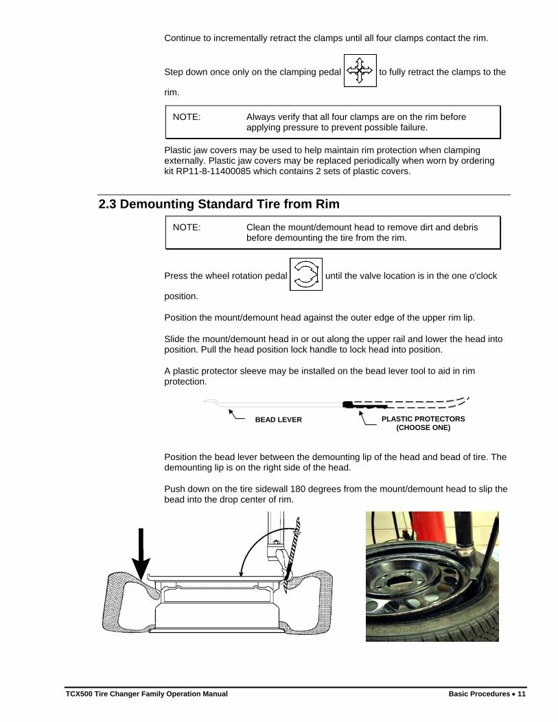
2.3 Demounting Standard Tire from Rim
NOTE: Clean the mount/demount head to remove dirt and debris before demounting the tire from the rim.
Press the wheel rotation pedal until the valve location is in the one o'clock
position.
Position the mount/demount head against the outer edge of the upper rim lip.
Slide the mount/demount head in or out along the upper rail and lower the head into position. Pull the head position lock handle to lock head into position.
A plastic protector sleeve may be installed on the bead lever tool to aid in rim protection.
PLASTIC PROTECTORS (CHOOSE ONE)
BEAD LEVER
Position the bead lever between the demounting lip of the head and bead of tire. The demounting lip is on the right side of the head.
Push down on the tire sidewall 180 degrees from the mount/demount head to slip the bead into the drop center of rim.
TCX500 Tire Changer Family Operation Manual Basic Procedures • 11
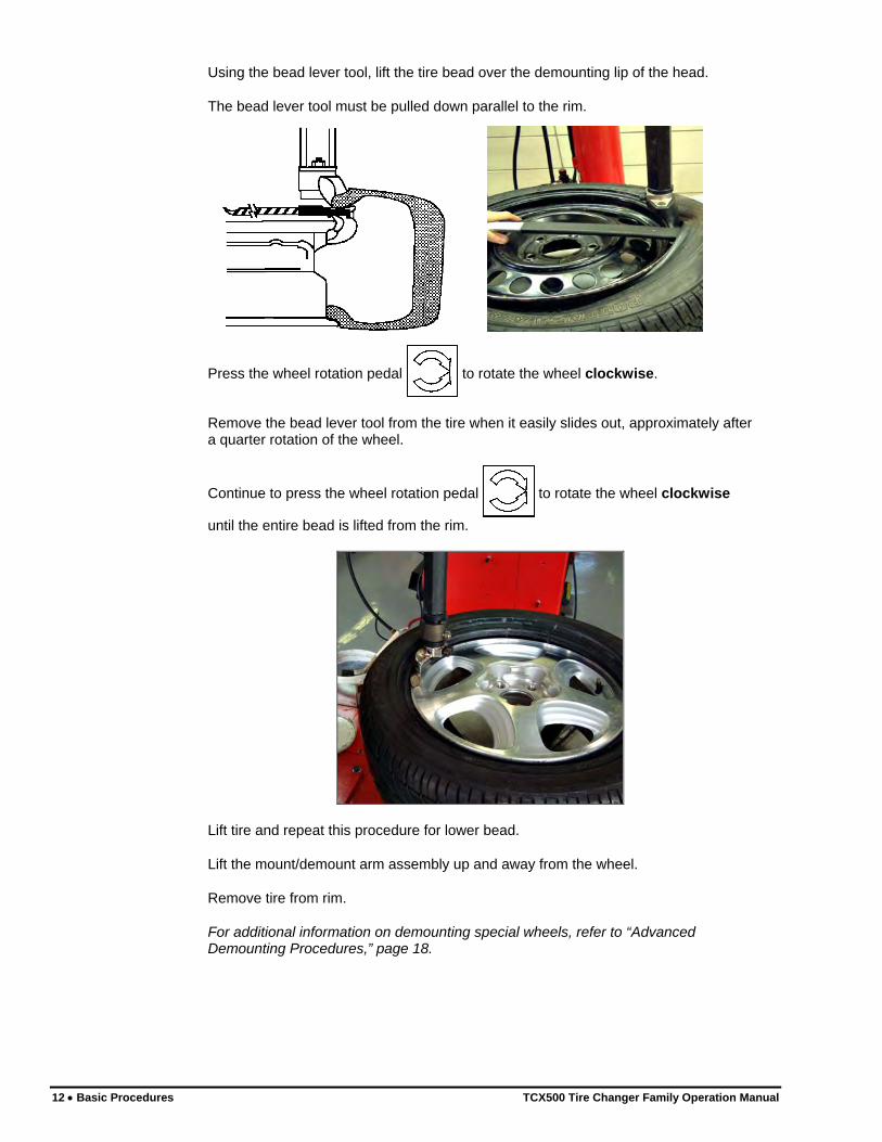
Using the bead lever tool, lift the tire bead over the demounting lip of the head.
The bead lever tool must be pulled down parallel to the rim.
Press the wheel rotation pedal to rotate the wheel clockwise.
Remove the bead lever tool from the tire when it easily slides out, approximately after a quarter rotation of the wheel.
Continue to press the wheel rotation pedal to rotate the wheel clockwise
until the entire bead is lifted from the rim.
Lift tire and repeat this procedure for lower bead.
Lift the mount/demount arm assembly up and away from the wheel.
Remove tire from rim.
For additional information on demounting special wheels, refer to “Advanced Demounting Procedures,” page 18.
12 • Basic Procedures TCX500 Tire Changer Family Operation Manual

2.4 Mounting Standard Tire to Rim Always use this “checklist” as a guide when mounting tires to ensure proper service.
There are four basic steps when mounting a tire to a rim:
• Position the bead on top of the mounting lip of the mount/demount head.
• Position the bead under the demounting lip of the mount/demount head.
• Lock the tire to the rim in the mounting position.
• Slip the bead into the drop center.
These four basic steps to mounting do not necessarily follow the same sequence, however all four steps need to be performed to mount a tire to a rim.
Mount a standard tire to rim: Lubricate inside and outside of both beads of the tire to be mounted with supplied mounting paste.
Position tire on top of the rim and tilt tire forward.
Position mount/demount head through the opening of the tire and on the outer edge of the rim lip.
Position edge of tire bead on top of the mounting lip of the head. The mounting lip is on the left side of the head.
Push edge of tire bead under the demounting lip of the head, while keeping the other edge of tire bead above the mounting lip.
Twist tire clockwise by hand to lock the tire into the mounting position.
Push down on tire at about the 6 o’clock position to slip the bead into drop center.
LOWER BEAD
UPPER BEAD
Press the wheel rotation pedal to rotate the wheel clockwise until the tire
bead drops over the lip of the rim. Repeat procedure on upper bead of tire. Slip the bead completely into the drop center of the rim, during mounting of the upper bead.
For additional information on special wheels, refer to “Advanced Mounting Procedures,” page 20.
TCX500 Tire Changer Family Operation Manual Basic Procedures • 13

Precautionary Notes When basic procedures are NOT followed, sharp angled wheel flanges increase potential damage to tires during mounting. Be sure the tire bead is placed on top of the mounting head. If the tire is incorrectly pushed onto the rim by the side of the mounting head, it may become “trapped” and increases mounting stress to the tire bead.
BEAD CORRECTLY PLACED ON TOP OF MOUNTING HEAD
TIRE IS INCORRECTLY PUSHED ON BY MOUNTING HEAD
Insufficient lubrication and failure to place tire into drop center during mounting may also cause the polymer mount/demount head to fail prematurely.
2.5 Tire Inflation Verify that the wheel has been properly clamped and centered.
WARNING: Never attempt to inflate a tire that is clamped from the outside. If possible, re-clamp the wheel from the inside before inflating.
Verify that both upper and lower tire beads and rim bead seat have been properly lubricated with an approved mounting paste.
Remove valve stem core if not already done.
Connect inflation hose to valve stem.
Pull up on the tire lightly to reduce the gap between upper bead and the rim.
WARNING: Do not stand over tire during inflation.
Step down completely on the air inflation pedal (pedal on the left side of the base) to release a high-pressure air blast through jets on the clamps to assist in seating the beads of the tire.
NOTE: To increase the effectiveness of the inflation jets, always liberally lubricate beads and raise the lower bead while activating inflation jets.
14 • Basic Procedures TCX500 Tire Changer Family Operation Manual
Step down partially on the pedal to inflate tire and seal beads with inflation hose. Frequently stop to check bead seating pressure on gauge.
WARNING: Do not exceed tire manufacturer’s maximum pressure as stated on the sidewall of the tire when seating beads.
Reinstall valve stem core into the valve stem after beads have been seated, and then inflate tire to vehicle manufacturer recommended pressure.
If tire is over-inflated, air may be removed from the tire by pressing the brass manual air release button located below the air pressure gauge.
Disconnect inflation hose from valve stem.
2.6 Removal of Wheel from Tire Changer
Lift the clamping pedal to release the rim from the clamping device.
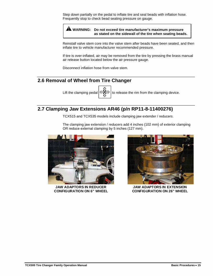
2.7 Clamping Jaw Extensions AR46 (p/n RP11-8-11400276) TCX515 and TCX535 models include clamping jaw extender / reducers.
The clamping jaw extension / reducers add 4 inches (102 mm) of exterior clamping OR reduce external clamping by 5 inches (127 mm).
JAW ADAPTORS IN REDUCER CONFIGURATION ON 6” WHEEL
JAW ADAPTORS IN EXTENSION CONFIGURATION ON 26” WHEEL
TCX500 Tire Changer Family Operation Manual Basic Procedures • 15

16 • Basic Procedures TCX500 Tire Changer Family Operation Manual
The jaw adaptors may be configured for either extension or reduction by removing the two nuts and screws from the adaptor as shown below, rotating the adaptor plate 180°, and re-securing.
REMOVE NUTS AND
SCREWS
ROTATE ADAPTOR
PLATE
JAW ADAPTORS IN REDUCER CONFIGURATION
JAW ADAPTORS IN EXTENSION CONFIGURATION

3. Advanced Procedures
The capabilities of the TCX500 tire changer family allow the user to utilize numerous advanced procedures on a variety of rims and tires. For the operator to take advantage of these features, this section explains in detail what additional steps can be taken.
3.1 Advanced Bead Breaking Procedures
Bead Breaking “AH” Wheels (e.g. BMW M3, M5, Some Porsches, Range Rover, Lancia, etc.)
“AH” (Asymmetrical Humps), “Bead Locking System” wheels may be identified by looking on the back of a rim for “AH” in the rim size designation casting (e.g. 8X17-AH).
“AH” wheels are designed so that the lowest point of the safety hump is located at the valve stem or 180 degrees out. These two points are where it is easiest to break the bead from the bead seat.
AREA BETWEEN THE BEADSEAT AND THE SAFETY
HUMP CHANGES TOPREVENT TIRE SLIPPAGE ON
RIM
Bead Breaking “AH” Wheels as follows: Swing the bead breaker arm out and away from the housing.
Position the wheel against the side of the tire changer between the bead breaker arm and the housing.
TCX500 Tire Changer Family Operation Manual Advanced Procedures • 17

Rotate the wheel so that the valve stem is in line with or 180 degrees from the blade.
Swing the bead breaker arm toward the tire and position the blade one to two inches from the edge of the rim on the sidewall of the tire.
Step down on the bead-breaker shovel pedal
The bead breaker arm will be pulled toward the tire changer to break the bead.
Release the pedal to disengage the bead breaker arm and then swing the arm to the open position.
If the bead has not been completely broken, rotate the wheel 180 degrees and repeat the bead breaking procedure.
Turn the wheel and break the opposite bead using the same procedure.
3.2 Advanced Demounting Procedures
NOTE: It is important on large, low profile tires to always lubricate the tire bead, wheel drop center, and bead seat to prevent possible tire damage during demount.
Demounting Tire from Rim Using the Bead Lever Tool without the Plastic Sleeve Protector
Sometimes the sidewall of the tire is so stiff that use of the bead lever tool with the plastic sleeve protector is not possible. The technician needs every bit of clearance to be able to pry the bead of the tire up and over the mount/demount head.
Demounting Upper Bead Position mount/demount head onto the outer edge of the upper rim lip.
Position bead breaker tool without plastic sleeve protector between demounting lip of the head and the bead of the tire. The demounting lip is on the right side of the head.
Using the bead lever tool, pry the tire bead over the demounting lip of the head.
Position the bead lever tool parallel to the rim.
Lift slightly on the wheel rotation pedal to rotate the wheel
counterclockwise approximately 1/2 inch, to fully unfold the bead onto the mount/demount head.
Slide the bead lever tool out from between the mount/demount head and the tire.
Step down on the wheel rotation pedal to rotate wheel clockwise until the
entire bead is lifted from the rim.
18 • Advanced Procedures TCX500 Tire Changer Family Operation Manual

Demounting Lower Bead Pull the tire up and tilt to place rear of lower bead in drop center behind mount/demount head.
Lubricate tire bead lever tool and then insert it over the demounting lip of the head and under the lower bead of the tire.
Pull the lower bead up and over the demounting lip of the head.
Push the bead lever half-way through tire and rim. Grasp inside of bead lever with one hand and grasp outside of bead lever at the base with the other hand. Firmly pull bead lever straight up.
Step down on the wheel rotation pedal to rotate wheel clockwise until the
entire bead is lifted from the rim.
“HM” Bead Lever and Sleeve Protector, RP6-2663
Benefits The “HM” (Half Moon) high performance bead lever and plastic bead lever sleeve protector can be used to demount low profile tires. With it’s curved, narrow design and rounded smooth finish (nickel chromed), it has several benefits.
1. Easier to reach the inside of wide wheels to access the bottom bead.
2. Easily allows an arc motion pull on tire when working over wide wheels.
3. The tools clears raised center alloy rims (e.g.; Porsche/Speed-Line when held parallel to the face of the rim during demounting).
4. When lubricated, allows for extremely slippery movement inside the tire. There are no ribs on the lever to “dent” the bead during tough demount of stiff sidewall tires. Eliminates air leaks after inflation due to bead damage.
5. Bubbled end will not poke sidewalls.
6. After insertion, allows retraction until end stops at bead to automatically minimize the amount of bead lever inside tire during demount. Reduces labor required to pull back tough tires.
7. When pulling tire up, eliminates the possibility of puncturing the sidewall casing of tire due to over extension.
Use of “HM” Bead Lever When demounting the tire, the wheel may be rotated counterclockwise to roll the bead up onto the front lip of the mount/demount head before rotating clockwise to begin demounting. The tire when rotating, automatically pulls the head down to the rim lip (preventing premature head failure) and usually rolls the bead into the drop center without the need for the Bead Depressor Tail or additional pry bars and helpers.
TCX500 Tire Changer Family Operation Manual Advanced Procedures • 19
3.3 Advanced Mounting Procedures Always use this “checklist” as a guide when mounting tires to ensure proper service.
There are four basic steps when mounting a tire to a rim:
• Position the bead on top of the rear lip of mount/demount head.
• Position the bead under the front lip of the mount/demount head.
• Lock the tire to the rim in the mounting position.
• Slip the bead into the drop center.
These four basic steps to mounting do not necessarily follow the same sequence, however all four steps need to be performed to properly mount a tire to a rim.
3.4 Mount/Demount Head Assembly There are plastic and steel mount/demount head assemblies available for the TCX500 tire changer family. Both use standard procedures for mounting and demounting.
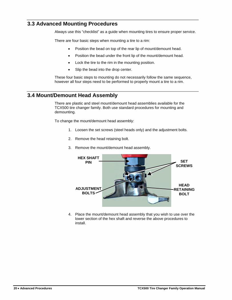
To change the mount/demount head assembly:
1. Loosen the set screws (steel heads only) and the adjustment bolts.
2. Remove the head retaining bolt.
3. Remove the mount/demount head assembly.
HEX SHAFT PIN
ADJUSTMENT BOLTS
HEAD RETAINING
BOLT
SET SCREWS
4. Place the mount/demount head assembly that you wish to use over the lower section of the hex shaft and reverse the above procedures to install.
20 • Advanced Procedures TCX500 Tire Changer Family Operation Manual
Checking Mount/Demount Head Calibration
For Steel Heads Calibration will require the use of a 14-17 inch bare rim.
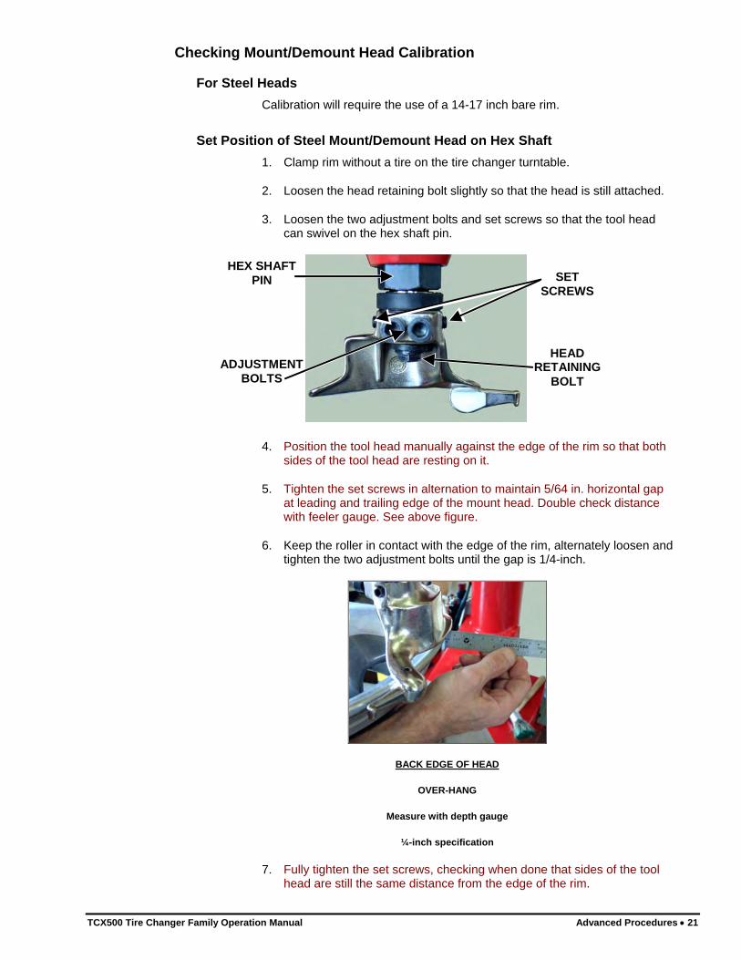
Set Position of Steel Mount/Demount Head on Hex Shaft 1. Clamp rim without a tire on the tire changer turntable.
2. Loosen the head retaining bolt slightly so that the head is still attached.
3. Loosen the two adjustment bolts and set screws so that the tool head can swivel on the hex shaft pin.
HEX SHAFT PIN
ADJUSTMENT BOLTS
HEAD RETAINING
BOLT
SET SCREWS
4. Position the tool head manually against the edge of the rim so that both sides of the tool head are resting on it.
5. Tighten the set screws in alternation to maintain 5/64 in. horizontal gap at leading and trailing edge of the mount head. Double check distance with feeler gauge. See above figure.
6. Keep the roller in contact with the edge of the rim, alternately loosen and tighten the two adjustment bolts until the gap is 1/4-inch.
BACK EDGE OF HEAD
OVER-HANG
Measure with depth gauge
¼-inch specification
7. Fully tighten the set screws, checking when done that sides of the tool head are still the same distance from the edge of the rim.
TCX500 Tire Changer Family Operation Manual Advanced Procedures • 21

22 • Advanced Procedures TCX500 Tire Changer Family Operation Manual
8. When the correct position has been achieved, tighten the adjustment bolts alternately to lock it in position.
9. Tighten the head retaining bolt.
Figure below is a summary of the desired end result.
5/64” 5/64”
1/4”
5/64”
14-17” DIA. RIM WITHOUT A TIRE EXTERNALLY
CLAMPED
For Plastic Heads Calibration will require the use of a 14-17 inch bare rim. Figure below is a summary of the desired end result.
Set Position of Plastic Mount/Demount Head on Hex Shaft 1. Clamp a 14-17” rim without a tire on the tire changer turntable.
2. Loosen the head retaining bolt slightly so that the head is still attached.
HEX SHAFT PIN
ADJUSTMENT BOLTS
HEAD RETAINING
BOLT
3. Position the tool head manually against the edge of the rim.
4. Keep the roller in contact with the edge of the rim, alternately loosen and tighten the two hex bolts until there is no gap.
5. When the correct position has been achieved, tighten the hex bolts alternately to lock it in position.
6. Tighten the head retaining bolt.
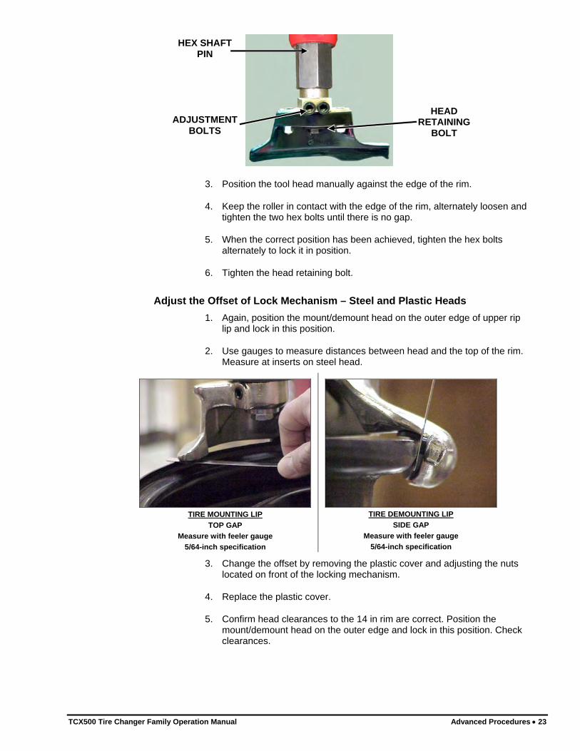
Adjust the Offset of Lock Mechanism – Steel and Plastic Heads 1. Again, position the mount/demount head on the outer edge of upper rip
lip and lock in this position.
2. Use gauges to measure distances between head and the top of the rim. Measure at inserts on steel head.
TIRE MOUNTING LIP
TOP GAP Measure with feeler gauge
5/64-inch specification
TIRE DEMOUNTING LIP
SIDE GAP Measure with feeler gauge
5/64-inch specification
3. Change the offset by removing the plastic cover and adjusting the nuts located on front of the locking mechanism.
4. Replace the plastic cover.
5. Confirm head clearances to the 14 in rim are correct. Position the mount/demount head on the outer edge and lock in this position. Check clearances.
TCX500 Tire Changer Family Operation Manual Advanced Procedures • 23

24 • Advanced Procedures TCX500 Tire Changer Family Operation Manual

4. TCX515 Operational Supplement
BP Arm Operation
4.1 General Information This chapter contains information for the correct use of the optional BP Bead Press Arm.
The BP Bead Press Arm has been designed as an accessory to help the operator mount the tire on the rim, or to demount the tire from the rim.
4.2 Part Identification
1
2
3 45 6
78*
9*
The functional parts of the BP Bead Press Arm are:
1. Articulated Arm 6. Lube Roller Lock Pin
2. Bead Press Head w/hook 7. Bead Press Roller
3. Control Switch 8. * Optional Lube Roller
4. Adjustment Clamp 9. * Optional Clamp
5. Air Cylinder
TCX500 Tire Changer Family Operation Manual TCX515 Operational Supplement • 25
4.3 Operation The BP Bead Press Arm has been designed to facilitate the operations of wheel locking and mounting/demounting the tire on or from the rim. These operations, especially with low-profile, very wide tires, or very hard beads can be very difficult.
Clamping the Wheel Break the beads of the tire following the instructions in Section 2.1, Bead Breaking, page 9.
If you plan to clamp the wheel from the inside, follow the instructions in Section 2.2, Clamping the Wheel from Inside of Rim - Steel Rims, page 10.
If you plan to clamp the wheel from the outside, the BPS can help with this operation. Follow these steps:
1. Release the turntable, bringing the tire changer operating arm and the BP Bead Press Arm to a non-working position.
2. Select the turntable opening so that the jaws touch the tire near the rim when putting the wheel on the turntable. Put the assembly onto the tire changer.
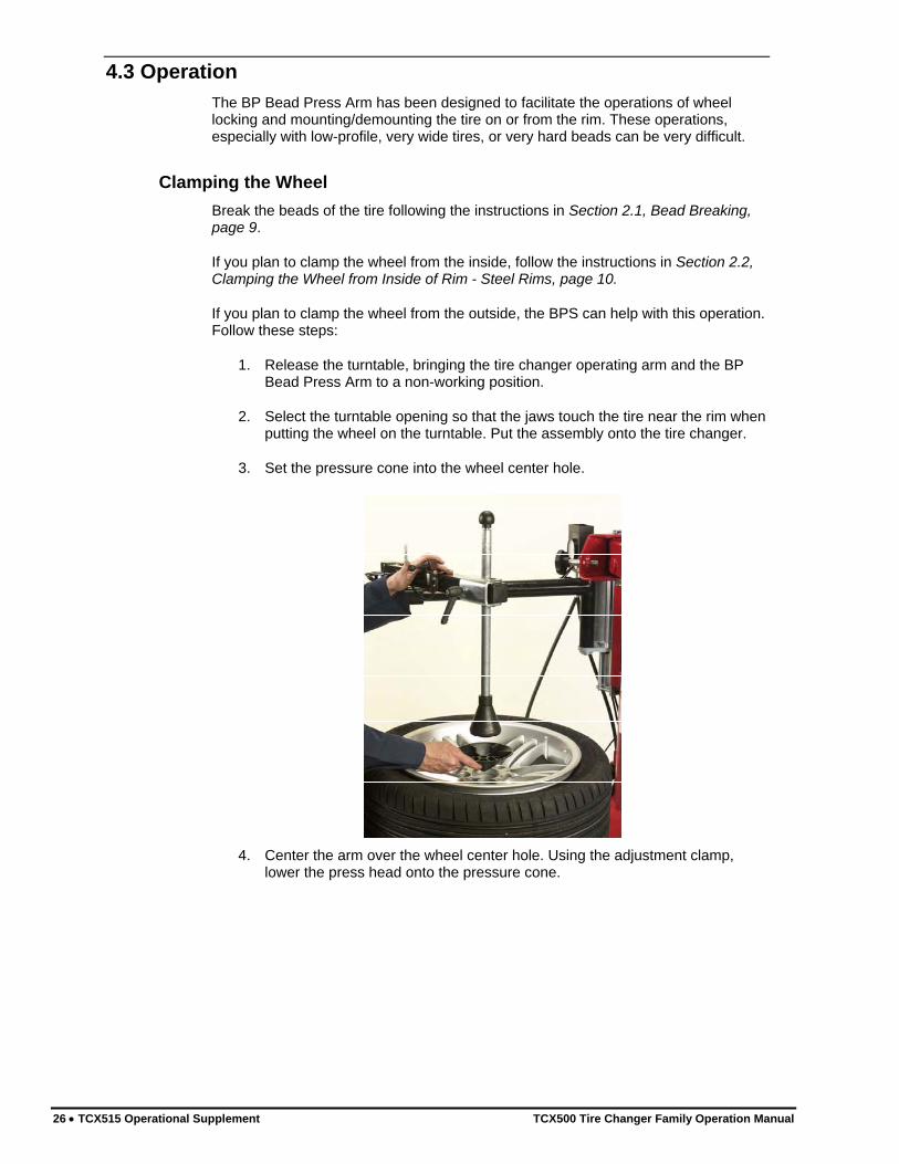
3. Set the pressure cone into the wheel center hole.
4. Center the arm over the wheel center hole. Using the adjustment clamp, lower the press head onto the pressure cone.
26 • TCX515 Operational Supplement TCX500 Tire Changer Family Operation Manual

5. Using the control switch, lower the BP arm until the cone presses against the wheel, and forces it down approximately ¼ – ½ inch.
6. Close the clamps on the wheel. Using the control switch, raise the BP arm until the cone is above the wheel far enough to be removed. Bring the arm back to its non-working position.
Demounting If the outer bead of the tire has “re-seated”, or needs additional lubrication, the bead loosening procedure can be repeated with the BP Bead Press Arm rather than the side shovel. Follow these steps:
1. If equipped, install the lube roller onto the bead press head. Bring the BP arm to its work position.
2. Drop the lube roller lock pin into place.
3. Move the control switch downwards until the lube roller presses on the tire and the bead moves approximately 1 inch away from the rim. The guide rollers should be touching the rim.
4. Push the top bead into the drop center. Lubricate the bead and the rim thoroughly to facilitate the subsequent demounting stages.
5. When the operation has been completed, lift the lube roller lock pin, remove the lube roller, move the BP Bead Press Arm away from the turntable, and begin the demounting operations.
TCX500 Tire Changer Family Operation Manual TCX515 Operational Supplement • 27

Removing Tire from Rim The BP Bead Press Arm can be used when removing the tire from the rim.
1. Position the mount/demount head on the tire and rim.
2. Insert bead lever.
Note: The BP Arm can also be used to create a gap for the bead lever.
3. Position the BP Bead Press Arm head approximately 180° from the mount/demount head.
4. Lower the BP Bead Press Arm head so the bead is pressed downward toward the center of the rim.
5. Using the bead lever, pull the bead up and onto the mount/demount head.
6. Raise the BP arm up and out of the way.
7. Rotate clockwise to complete the demounting procedure.
Mounting Follow these steps:
1. Position the BP Arm head near the mount/demount head. Lower it until the inner bead is level with the drop center.
28 • TCX515 Operational Supplement TCX500 Tire Changer Family Operation Manual

2. Rotate clockwise. The BP Bead Press Arm head will revolve with the tire and keep the bead in the drop center. The second bead will thus be mounted on the rim without any effort or danger to the operator and without damaging the tire.
3. Use the optional bead clamp to assist mounting when ever more difficult tires are being serviced. The optional clamp may be used either;
A. Leading the press head as a traction point
B. Following the press head as a bead guide.
TCX500 Tire Changer Family Operation Manual TCX515 Operational Supplement • 29

30 • TCX515 Operational Supplement TCX500 Tire Changer Family Operation Manual
Using the Bead Press Head Hook to Lift the Tire Use the hook on the bead press head to help lift the tire during demount.
With upper bead demounted, use the bead lever and position the bead press head hook under the upper bead on the opposite side of the tire.
Raise the bead press head hook.
Use lever to hook lower bead and pull over rim.
Remove the bead press head hook from the upper bead and complete removal of the lower bead.

5. TCX535 Operational Supplement
Bead Press System Operation
5.1 General Information This chapter contains information for the correct use of the optional Bead Press System (BPS).
The BPS has been designed as an accessory to help the operator mount the tire on the rim, or to demount the tire from the rim.
5.2 Part Identification
The functional parts of the BPS are:
1. Articulated Arm 6. Tire Lifting Disc
2. Rim presser cone 7. Sliding locking lever
3. Control Lever 8. Rotating locking pin
4. Bead presser roller 9. Arm end of travel pin
5. Arm releasing lever
TCX500 Tire Changer Family Operation Manual TCX535 Operational Supplement • 31

5.3 Operation The BPS has been designed to facilitate the operations of wheel locking and mounting/demounting the tire on or from the rim. These operations, especially with low-profile, very wide tires, or very hard beads can be very difficult.
Clamping the Wheel Break the beads of the tire following the instructions in Section 2.1, Bead Breaking, page 9.
If you plan to clamp the wheel from the inside, follow the instructions in Section 2.2, Clamping the Wheel from Inside of Rim - Steel Rims, page 10.
If you plan to clamp the wheel from the outside, the BPS can help with this operation. Follow these steps:
1. Release the turntable, bringing the tire changer operating arm and the BPS to a non-working position.
2. Select the turntable opening so that the jaws touch the tire near the rim, when putting the wheel on the turntable.
3. Insert the rim pressure cone on the arm and push it upwards making sure the bayonet lock slips into place.
4. Set the arm in work position, it will automatically lock in line with the turntable.
5. Lower lever until the cone, as it presses against the wheel, forces it down a couple of centimeters. (The bead presser must be positioned so as not to touch the tire).
6. Close the clamps on the wheel. Raise the lever until the cone is above the wheel far enough to be removed. Remove the bead pressing cone and bring the arm back to its non-working position.
Demounting If the outer bead of the tire has “re-seated”, the bead loosening procedure can be repeated with the BPS rather than the side shovel. Follow these steps:
1. Pull the roller locking knob towards the outside so that the roller is free to turn on its axis. (For all other operations done with the BPS, this knob must be inserted to prevent the roller from turning).
2. Bring the arm to its work position. Press the lever so that the roller can slide on the arm and position near the edge of the rim. Release the lever.
3. Move the control lever downwards until the roller presses on the tire until the bead moves a few millimeters away from the rim, then rotate the turntable clockwise. The swivel arm will turn with the tire until it comes against the end travel stop. At this point the roller will begin to loosen the top bead on the tire. (When the top bead has been pushed into the drop center, the operator can lubricate the bead and the rim thoroughly to facilitate the subsequent demounting stages).
4. When the operation has been completed, lift off the roller, move the BPS away from the turntable, and begin the demounting operations.
32 • TCX535 Operational Supplement TCX500 Tire Changer Family Operation Manual

Breaking the Inner Bead If the inner bead has re-seated, use the tire lifting disc to loosen it. Follow these steps:
1. Mount the tire lifting disc on to the lower arm holder and lock it in place with the pin.
2. Position the tire lifting disc under the tire, making sure that it is near the edge of the rim.
3. Position the bead lever in the hole on the tire lifting disc arm and hold it to keep the tire lifting disc pressed against the tire.
4. Rotate the turntable clockwise simultaneously raising the tire lifting disc up, with the control lever until the bead-loosening procedure is completed. (Thoroughly lubricate the inner bead before removing it).
Mounting Follow these steps:
1. Clamp the rim on the tabletop and mount the outer bead as described in Chapter 2, Basic Procedures, page 9.
2. Position the roller near the mount/demount head. Lower it until the inner bead is level with the center well. If the tire bead fails to “rise” on the mount/demount head, using the bead lever can facilitate the operation.
3. As the turntable turns the roller will revolve with the tire and keep the bead in the well. The second bead will thus be mounted on the rim without any effort or danger to the operator and without damaging the tire.
Run Flat Wheels With the second roller arm, the BPS can correctly work on Run Flat wheels.
WARNING: The majority of Run Flat wheels are equipped with an internal sensor so that the pressure can be measured. Before proceeding with any operation on the wheel, check the vehicle instruction manual for the type of sensor used and its position on the rim.
WARNING: Before proceeding with any operation on the wheel, make sure that all contact points between the tire changer and rim (mount/demount head, bead lifting lever, tire lifting disc, wheel clamps) are equipped with their relative plastic guards.
Bead Breaking If the wheel does not have an internal sensor, the bead can be loosened in the “conventional” way as described in Section 2.1, Bead Breaking, page 9.
If it does have an internal sensor, the procedure will depend on the type and position of the actual sensor itself, i.e. “conventional” bead breaking on both beads or on the inner bead alone. In all cases, proceed with the utmost care. Never press the shovel near the pressure sensor.
TCX500 Tire Changer Family Operation Manual TCX535 Operational Supplement • 33

Clamping the Wheel Alloy wheels should be clamped on the tabletop from the outside only, as described in Section 2.2, Placing Wheel on Tire Changer, page 10.
Second Roller Attachment The second roller attachment must only be mounted on the BPS at the time it is actually used and taken off the BPS at the end of the operation. This prevents it from hampering the other operating phases or from being a potential source of danger through crushing.
1. Insert the second roller attachment into its housing on the arm of the BPS.
2. Lock in place with the pin.
Demounting the Outer Bead 1. Move the toolhead to the work position. If the wheel has a sensor, turn the
table top until this sensor is lined up with the toolhead.
2. Move the arm of the BPS to the work position.
3. Move the bead presser roller out to the tire and to the right of the toolhead.
4. Operate the BPS control lever in order to press on the tire and create sufficient space to correctly position the toolhead and subsequently insert the bead lifting lever.
5. Lock the toolhead in place and insert the bead lifting lever.
6. Operate the BPS control lever and lift the arm, then turn it and move the bead presser roller opposite the toolhead.
7. Operate the BPS control lever to lower the arm and put pressure on the tire until the bead is in the drop center of the rim. This prevents the bead from being excessively taut and allows it to rise more easily on the toolhead.
8. Lift the arm of the BPS and swing it outwards to free the work surface, then turn the table top to allow the outer bead to slip out.
Note: If the tire flank is so rigid that the bead is unable to position in the drop center, the operation can be facilitated by using the second BPS roller. Mount the second roller on the BPS, positioning it to the left of the BPS roller, half way between the BPS roller and the toolhead.
34 • TCX535 Operational Supplement TCX500 Tire Changer Family Operation Manual

Demounting the Inner Bead 1. If the wheel has a sensor, rotate the table top until it lines up with the
toolhead.
2. Position the tire lifting disc under the inner bead, then, using the BPS control lever, lift the bead until it is in the middle of the drop center. Take care not to damage the sensor when doing this.
3. Insert the bead lifting lever on the toolhead until it has picked up the inner bead. Raise the bead lifting lever until the inner bead rises on to the toolhead.
4. Turn the table top clockwise until the tire has been completely removed.
Operations and Inspections Prior to Mounting 1. Check the tire and rim for any defects.
2. If the wheel has an internal sensor, make sure that it is not defective and/or damaged. If damage is discovered, replace the sensor (refer to vehicle’s maintenance manual).
Mounting the Inner Bead 1. Clamp the rim on to the table top from the outside only.
2. Move the tool arm to the work position and clamp the toolhead on to the rim.
3. Thoroughly lubricate the rim and tire beads.
4. If the wheel has an internal sensor, position it on the right hand side of the toolhead.
5. Position the tire so that the inner bead (lower one) is under the toolhead.
6. Turn the table top clockwise. Keep the tire pressed against the rim so that the inner bead “slips” into the drop center.
TCX500 Tire Changer Family Operation Manual TCX535 Operational Supplement • 35

36 • TCX535 Operational Supplement TCX500 Tire Changer Family Operation Manual
Mounting the Outer Bead 1. If the wheel has an internal sensor, position it directly across from the
toolhead.
2. Mount the second roller arm on the BPS.
3. Position both rollers as shown below.
4. Lower the arms until the outer bead is in the drop center and under the hooked section of the toolhead.
5. Turn the table top clockwise, the BPS roller will turn along with the tire, allowing the outer bead to slip into the rim, while the second roller will remain at a standstill in its position, preventing the bead from slipping out again.
Sensor Inspection/Replacement If the wheel has an internal sensor, the BPS used with the second roller will allow you to inspect and replace the actual sensor itself without having to remove the tire from the rim.
NOTE: Only work on the sensor after having consulted the operation and maintenance manuals of the vehicle and sensor itself.
Proceed in the following way:
1. Break the bead as described in Section 4.3, Breaking the Inner Bead, page 33.
2. Clamp the rim on the table top and position the sensor at 6:00.
3. Move the arm of the BPS to the work position with the roller at 5:00.
4. Mount the BPS second roller and position it at 7:00.
5. Using the BPS control lever, slowly lower the rollers until you have enough space to check or replace the sensor. Take the utmost care to prevent the bead from touching the sensor during this operation.
6. After having terminated the operations, slowly lift the rollers until the bead has passed over the sensors.

6. Maintenance
6.1 Maintenance Schedule Proper care and maintenance are necessary to ensure that the TCX500 tire changer family operates properly. Proper care will also ensure that rims and tires are not damaged during the mount/demount process.
Maintenance Schedule Perform the Following Maintenance
Daily Drain condensation from pressure regulator reservoir by pressing in on the fitting located on the bottom of the regulator.
Check for worn or damaged rubber and nylon components that should be replaced to prevent damage from occurring. Replace worn parts as needed (tool supports, rubber pads, lever protector sleeve and mount/demount head).
Clean all areas that contact rims or tires to prevent possible scratching to rim.
Weekly Clean tire changer with shop towels or a vacuum cleaner. Do not clean with or use compressed air, which can blast dirt between moving parts.
Do not use cleaning solvents to clean pressure regulator/oiler.
Periodically
Refill the pressure regulator/oiler using only Hunter Lubri-Oil, 148-133-2, as needed. Petroleum-based oils should never be used in the oiler and may void all warranties.
Adjust the oiler to release one drop of oil every three rotations of the clamping table by adjusting the screw on top.
Check for loose bolts and tighten per specifications.
TCX500 Tire Changer Family Operation Manual Maintenance • 37

38 • Maintenance TCX500 Tire Changer Family Operation Manual
6.2 Maintenance and Replacement Parts
NAME NUMBER
Safety Goggles 179-15-2
Brush RP6-1506
Mounting Paste RP6-3784
Polymer Mount/Demount Head RP11-3314813
Hand Held Bead Lever - straight RP11-3009516
“HM” Bead Lever - curved RP6-2663
Bead Lever Protector Sleeve (HM) RP6-0326
Bead Lever Protector Sleeve (Std) (4) RP11-8-11400098
Jaw Protection Kit (2 sets - 8 covers) RP11-8-11400085
Steel Head Inserts (10 sets - 20 covers)
RP11-8-11400096
Clamping Jaw Extensions AR46 (4) RP11-8-11400276

7. Glossary
7.1 Rim Diagram
OUTBOARDFLANGE
POSITIVE OFFSET
CENTERLINE
OUTBOARDSAFETY HUMP
DROP CENTERINBOARDSAFETY HUMP
REAR SPACING
RIM WIDTH
OUTBOARDBEAD SEAT
INBOARDBEAD SEAT
INBOARDFLANGE
RIM CENTERLINE
NEGATIVE OFFSET
RIM
DIA
MET
ER
BO
LT C
IRC
LED
IAM
ETER
CEN
TER
BO
RE
MO
UN
TIN
G P
AD
DIA
MET
ER
TCX500 Tire Changer Family Operation Manual Glossary • 39

40 • Glossary TCX500 Tire Changer Family Operation Manual
7.2 Illustrations of Various Rim Designs
REVERSE DROP CENTER
LONG DROP CENTER
CONICAL
CYLINDRICAL
OUTBOARD
OUTBOARD
INBOARD
INBOARD
NO DROP CENTER
OUTBOARD
INBOARD
RIM MUST BE INVERTED. POSITION INBOARD RIM
ON TOP WHEN MOUNTING/DEMOUNTING.
MULTIPLE STROKES REQUIRED FOR REMOVAL OF
LOWER BEAD
RIM DISASSEMBLY REQUIRED -
DO NOT USE ON TCX500


HUNTER RESEARCH AND TRAINING CENTER
HUNTER . . . dedicated to service excellence through professional training HUNTER TRAINING - Hunter operates the most advanced, up-to-date Training Center in the industry today.
The courses have been designed to meet the needs of new and experienced technicians who want to increase their mechanical and diagnostic capabilities. The low student-teacher ratio (average 7 to 1) and the emphasis on “hands-on” training (80% time in shop) create an excellent learning environment.
Highlights of the Hunter Training Center include: An instruction staff with over 100 years of shop, field, and teaching
experience. Fully-equipped service bays. Classrooms equipped with modern teaching aids. The most up-to-date wheel alignment, balancing service and brake
equipment on the market today.
Align 1 (Basic Alignment Theory and Practice) 3 day / 24 hrs Students will learn basic wheel alignment service through classroom and hands-on practice. Pre-alignment services, wheel alignment angle theory and wheel alignment equipment operation are the focus of this course. Basic wheel alignment adjustments will be demonstrated and students will practice on vehicles in a shop environment.
Align 2 (Advanced theory / Aftermarket Adjustment) 2-day / 16 hrs Modified vehicle wheel alignment is the focus of this course. Students learn how to use alignment angles to achieve vehicle handling performance in conjunction with ride height kits and modified tire/wheel packages. Aftermarket alignment adjustment kits are discussed and demonstrated.
Align 3 (Advanced Diagnostics and OE Procedures) 2-day / 16 hrs This class focuses on using advanced diagnostic angles and measurements to determine damaged suspension and steering components. Techniques used in finding damaged parts are reinforced with classroom scenarios and hands-on labs designed to both challenge and further embed these much needed skills.
Performance Tire (Basic and Advanced Tire Changing) 1-day 8 hrs Students will learn basic terminology and theory related to servicing tires and wheels. Students learn the proper techniques for changing tires on tulip clamp and table top tire changer designs. This course covers the proper tire changing techniques for low profile tires, run flat designs, and tire/wheel assemblies using TPMS.
GSP9700 Certification 2-days / 16 hrs This course combines the Rolling Smooth course with a certification program for Hunter Engineering’s GSP9700 Road Force Measurement system. Students use hands-on practice with the GSP9700 to gain a proficiency level acceptable to be deemed certified.
Rolling Smooth (Basic & Advanced vibration theory) 1-day / 8 hrs This course offers a study of vehicle vibration specific to wheel speed. The student will learn basic vibration terminology and vibration theory, Shop activities include the measurement of Road Force Variation, wheel runout and balance. Additional diagnostic tools are discussed.
HDT Alignment 1 (Fundamental Alignment) 3-day / 24 hrs Classroom and shop practice is used to teach the basic elements of Class 8 truck wheel alignment. Students will learn the proper method to measure and correct the required basic alignment angles using state of the art equipment. Trailer alignment is included.
HDT Alignment 2 (Advanced Alignment) 2-day / 16hrs The student will understand the cause and affect of basic alignment angles relative to ride quality, performance and tire life. Classroom and shop practice are used to learn the proper use of diagnostic alignment angles. Additional adjustment techniques and alignment system operation are explored in both the classroom and lab environment. Busses and RVs are discussed.
Hunter University’s eLearning courses are designed for all student levels and can be used as an integral supplement to instructor-led training courses. In-depth information, detailed graphics, video and modular segments assist the participant in expanding their knowledge base at a self-determined level. Go to www.hunter.com and click on TRAINING.
For further information about other classes offered or to schedule into a class, simply call the Hunter Research and Training Center at 1-800-448-6848.