RC150EX/RC200EX Rim Clamp Tire Changer - Automotive Equipment
32
RC150EX/RC200EX Rim Clamp ® Tire Changer For servicing motorcycle and ATV tire/wheel assemblies as well as automotive and most light truck tire/wheel assemblies 1601 J. P. Hennessy Drive, LaVergne, TN USA 37086-3565 615/641-7533 800/688-6359 Manual Part No.: 8184670 01 HENNESSY INDUSTRIES INC. Manufacturer of AMMCO ® , COATS ® and BADA ® Automotive Service Equipment and Tools. Revision: 09/06 ® Installation Instructions Operating Instructions Safety Instructions Maintenance Instructions READ these instructions before placing unit in service KEEP these and other materials delivered with the unit in a binder near the machine for ease of reference by supervisors and operators. See Operating Instructions on page 4.
Transcript of RC150EX/RC200EX Rim Clamp Tire Changer - Automotive Equipment

RC150EX/RC200EXRim Clamp® Tire ChangerFor servicing motorcycle and ATV tire/wheel assemblies aswell as automotive and most light truck tire/wheel assemblies
1601 J. P. Hennessy Drive, LaVergne, TN USA 37086-3565 615/641-7533 800/688-6359 Manual Part No.: 8184670 01HENNESSY INDUSTRIES INC. Manufacturer of AMMCO®, COATS® and BADA® Automotive Service Equipment and Tools. Revision: 09/06
®
IInnssttaallllaattiioonn IInnssttrruuccttiioonnssOOppeerraattiinngg IInnssttrruuccttiioonnss
SSaaffeettyy IInnssttrruuccttiioonnssMMaaiinntteennaannccee IInnssttrruuccttiioonnss
READ these instructions before placing unit inservice KEEP these and other materials deliveredwith the unit in a binder near the machine forease of reference by supervisors and operators.
SSeeee��OOppeerraattiinnggIInnssttrruuccttiioonnss
oonn ppaaggee 44..

ii • Important: Always read and follow the operating instructions.
Important: Always read and follow the operating instructions. • iii
SSaaffeettyy IInnssttrruuccttiioonnssOwner’s Responsibility
To maintain machine and user safety, the responsibil-ity of the owner is to read and follow these instruc-tions:
• Follow all installation instructions.
• Make sure installation conforms to all applicableLocal, State, and Federal Codes, Rules, andRegulations; such as State and Federal OSHARegulations and Electrical Codes.
• Carefully check the unit for correct initial function.
• Read and follow the safety instructions. Keep themreadily available for machine operators.
• Make certain all operators are properly trained,know how to safely and correctly operate the unit,and are properly supervised.
• Allow unit operation only with all parts in place andoperating safely.
• Carefully inspect the unit on a regular basis andperform all maintenance as required.
• Service and maintain the unit only with authorizedor approved replacement parts.
• Keep all instructions permanently with the unit andall decals/labels/notices on the unit clean and visi-ble.
• Do not override safety features.
Operator Protective EquipmentPersonal protective equipment helps make tire serv-
icing safer. However, equipment does not take theplace of safe operating practices. Always wear durablework clothing during tire service activity. Loose fittingclothing should be avoided. Tight fitting leather glovesare recommended to protect operator’s hands whenhandling worn tires and wheels. Sturdy leather workshoes with steel toes and oil resistant soles should beused by tire service personnel to help prevent injury intypical shop activities. Eye protection is essential dur-ing tire service activity. Safety glasses with sideshields, goggles, or face shields are acceptable. Backbelts provide support during lifting activities and arealso helpful in providing operator protection.Consideration should also be given to the use of hear-ing protection if tire service activity is performed in anenclosed area, or if noise levels are high.
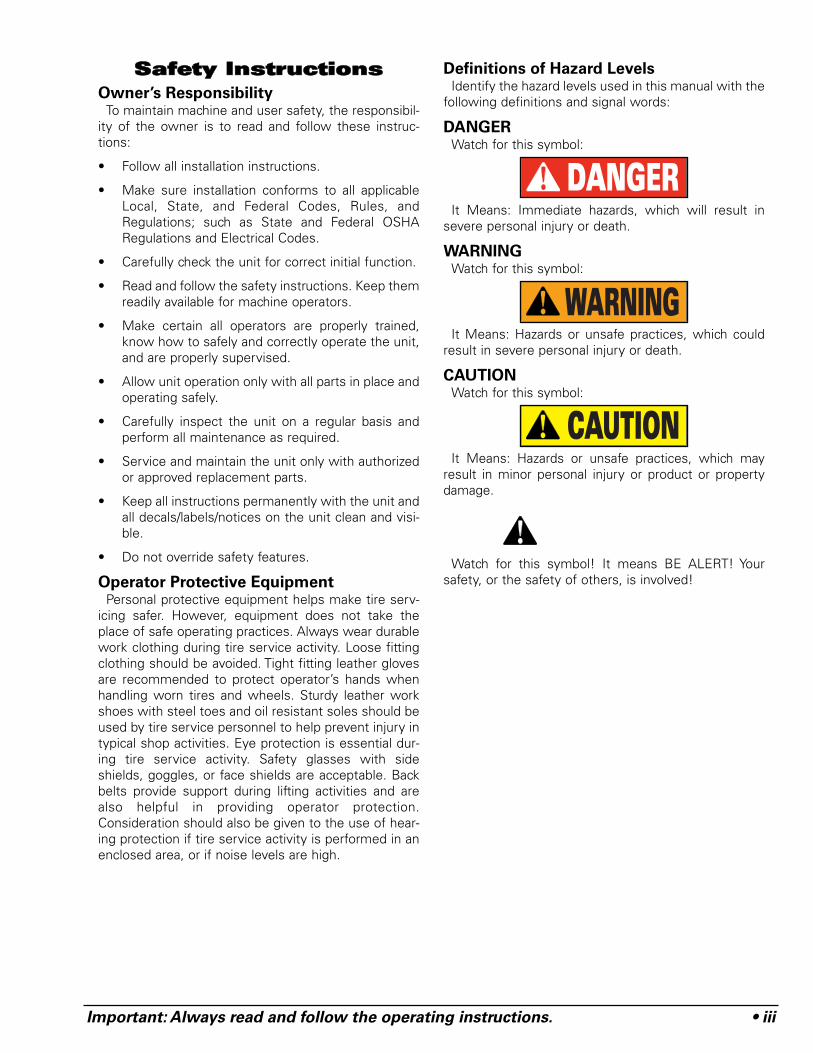
Definitions of Hazard LevelsIdentify the hazard levels used in this manual with the
following definitions and signal words:
DANGERWatch for this symbol:
It Means: Immediate hazards, which will result insevere personal injury or death.
WARNINGWatch for this symbol:
It Means: Hazards or unsafe practices, which couldresult in severe personal injury or death.
CAUTIONWatch for this symbol:
It Means: Hazards or unsafe practices, which mayresult in minor personal injury or product or propertydamage.
Watch for this symbol! It means BE ALERT! Yoursafety, or the safety of others, is involved!
CAUTION
WARNING
DANGER
iv • Important: Always read and follow the operating instructions.
Safety Notices and Decals
Failure to follow danger, warning, and cau-
tion instructions may lead to serious per-
sonal injury or death to operator or
bystander or damage to property. Do not
operate this machine until you read and
understand all the dangers, warnings and
cautions in this manual. For additional
copies of either, or further information, con-
tact:
Hennessy Industries, Inc.1601 J.P. Hennessy Drive
LaVergne, TN 37086-3565(615) 641-7533 or (800) 688-6359
www.ammcoats.com
For additional information contact:
Rubber Manufacturers Association
1400 K Street N. W.Washington, DC 20005
(202) 682-4800
Tire Guides, Inc.
The Tire Information Center1101-6 South Rogers CircleBoca Raton, FL 33487-2795
(561) 997-9229www.tireguides.com
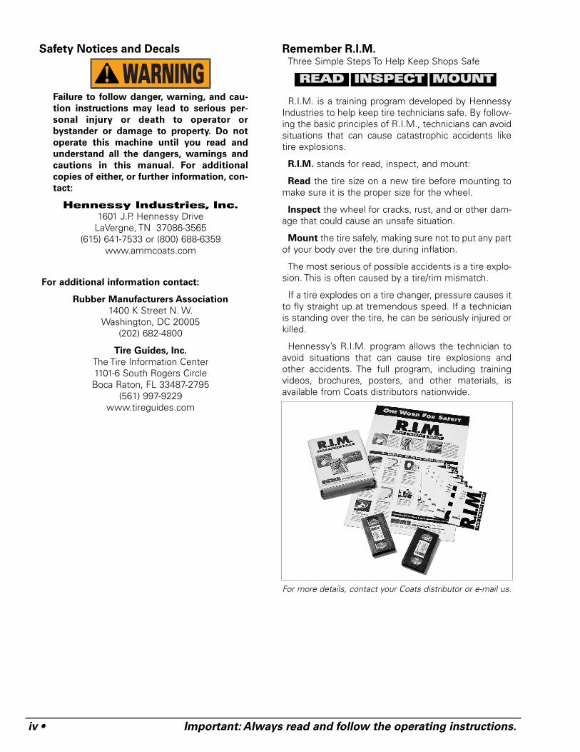
Remember R.I.M.Three Simple Steps To Help Keep Shops Safe
R.I.M. is a training program developed by HennessyIndustries to help keep tire technicians safe. By follow-ing the basic principles of R.I.M., technicians can avoidsituations that can cause catastrophic accidents liketire explosions.
R.I.M. stands for read, inspect, and mount:
Read the tire size on a new tire before mounting tomake sure it is the proper size for the wheel.
Inspect the wheel for cracks, rust, and or other dam-age that could cause an unsafe situation.
Mount the tire safely, making sure not to put any partof your body over the tire during inflation.
The most serious of possible accidents is a tire explo-sion. This is often caused by a tire/rim mismatch.
If a tire explodes on a tire changer, pressure causes itto fly straight up at tremendous speed. If a technicianis standing over the tire, he can be seriously injured orkilled.
Hennessy’s R.I.M. program allows the technician toavoid situations that can cause tire explosions andother accidents. The full program, including trainingvideos, brochures, posters, and other materials, isavailable from Coats distributors nationwide.
For more details, contact your Coats distributor or e-mail us.
WARNING RREEAADD IINNSSPPEECCTT MMOOUUNNTT
Important: Always read and follow the operating instructions. • 1
TTaabbllee ooff CCoonntteennttssSSaaffeettyy IInnssttrruuccttiioonnss .. .. .. .. .. .. .. .. .. .. .. .. .. .. .. .. .. .. .. ..iiiiii
Owner’s Responsibility . . . . . . . . . . . . . . . . . . . . . .iiiOperator Protective Equipment . . . . . . . . . . . . . . . .iiiDefinitions of Hazard Levels . . . . . . . . . . . . . . . . . .iiiSafety Notices and Decals . . . . . . . . . . . . . . . . . . .ivRemember R.I.M. . . . . . . . . . . . . . . . . . . . . . . . . . .iv
PPrriinncciippaall OOppeerraattiinngg PPaarrttss .. .. .. .. .. .. .. .. .. .. .. .. .. ..22 -- 33
Know Your Unit . . . . . . . . . . . . . . . . . . . . . . . . . . .2-3
OOppeerraattiinngg IInnssttrruuccttiioonnss .. .. .. .. .. .. .. .. .. .. .. .. .. .. ..44 -- 1122
Bead Loosening And Demounting . . . . . . . . . . .4 - 6Mounting . . . . . . . . . . . . . . . . . . . . . . . . . . . . . .7 - 8Special Instructions For DemountingExtemely Wide Motorcycle Tires (RC200) . . . . .8 - 9Special Instructions For MountingExtremely Wide Motorcycle Tires (RC200) . . . . . .10Special Instructions For DemountingExtra Wide ATV Type Wheels/Tires DownTo 8-inch Diameter Using Automatic Clamps . . . .11Mounting ATV Type Wheels/Tires DownTo 8-inch Diameter . . . . . . . . . . . . . . . . . . . . . . . . .11Demounting Small 6-inch To 8-inch DiameterWheels/Tires . . . . . . . . . . . . . . . . . . . . . . . . . . . . .12Mounting Small 6-inch To 8-inch DiameterWheels/Tires . . . . . . . . . . . . . . . . . . . . . . . . . . . . .12
IInnffllaattiioonn .. .. .. .. .. .. .. .. .. .. .. .. .. .. .. .. .. .. .. .. .. .. .. .. .. ..1133 -- 1155
Bead Sealing . . . . . . . . . . . . . . . . . . . . . . . . . . . . .14Bead Seating . . . . . . . . . . . . . . . . . . . . . . . . . . . . .14Inflation . . . . . . . . . . . . . . . . . . . . . . . . . . . . . . . . .15
SSttaaggeess ooff IInnffllaattiioonn oonn aa CCoonnvveennttiioonnaall TTiirree
aanndd RRiimm .. .. .. .. .. .. .. .. .. .. .. .. .. .. .. .. .. .. .. .. .. .. .. .. .. .. .. .. .. ..1166
MMiissmmaattcchheedd TTiirreess aanndd WWhheeeellss .. .. .. .. .. .. .. .. .. .. ..1177
PPeerrffoorrmmaannccee,, CCuussttoomm,, aanndd AAlluummiinnuumm
WWhheeeellss .. .. .. .. .. .. .. .. .. .. .. .. .. .. .. .. .. .. .. .. .. .. .. .. .. .. .. .. .. ..2211
Performance Tires & Wheels • Demounting .18 - 20Performance Tires & Wheels • Mounting . . . . . . .21
CCuussttoomm aanndd SSppeecciiaall WWhheeeellss .. .. .. .. .. .. .. .. .. .. .. .. ..2222
MMaaiinntteennaannccee IInnssttrruuccttiioonnss .. .. .. .. .. .. .. .. .. .. ..2233 -- 2255
Mount/Demount Tool Head Adjustment . . . . . . . .23Separator/Lubricator Maintenance . . . . . . . . . . . . .24Pressure Limiter Maintenance . . . . . . . . . . . .24 - 25Robotic Arm Maintenance . . . . . . . . . . . . . . . . . . .25
IInnssttaallllaattiioonn IInnssttrruuccttiioonnss .. .. .. .. .. .. .. .. .. .. .. .. ..2255 -- 2266
Location . . . . . . . . . . . . . . . . . . . . . . . . . . . . . . . . .25Workspace Requirements . . . . . . . . . . . . . . . . . . .25Air Source . . . . . . . . . . . . . . . . . . . . . . . . . . . . . . .25Electrical Source . . . . . . . . . . . . . . . . . . . . . . .25 - 26Floor Mounting . . . . . . . . . . . . . . . . . . . . . . . . . . .26
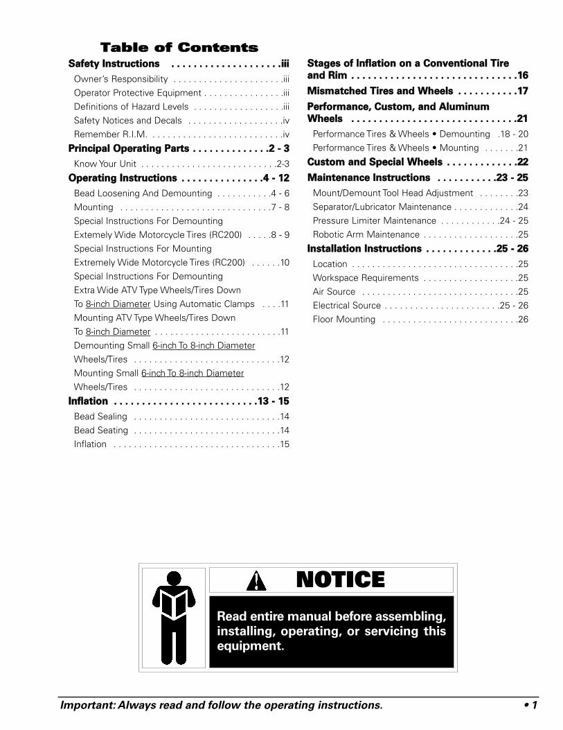
NOTICERead entire manual before assembling,installing, operating, or servicing thisequipment.
2 • Important: Always read and follow the operating instructions.
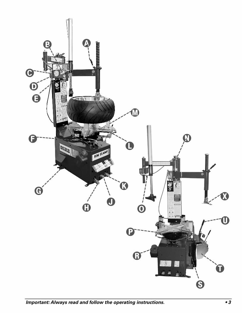
PPrriinncciippaall OOppeerraattiinngg PPaarrttssKnow Your Unit
Compare this illustration with the unit before placing it into service. Maximum performance and safety will beobtained only when all persons using the unit are fully trained in its parts and operation. Each user should learnthe function and location, of all controls.
Prevent accidents and injuries by ensuring the unit is properly installed, operated and maintained.
Do It Now!
Now is a good timeto fill out the Owner’sRegistry Card.
�Vertical Slide Locking Handle — Locks andunlocks vertical slide and sets correct verticalposition to maintain head/wheel clearance.
�Swing Arm Adjustment Knob — Adjusts swingarm/vertical slide assembly for proper horizontalpositioning of duckhead®.
�Release Valve — Allows the manual release ofair pressure from tire when clip-on chuck isattached to tire valve.
�Air Inflation Gauge — Registers tire pressurewhen clip-on chuck is attached to tire valve stemand inflation pedal is released.
�Tower — Support for horizontal swing arm, alsoair storage tank.
�Oil Check Dipstick — For transmission oil level.
�Inflation Pedal — Three-position pedal thatallows inflation of tires through air hose and clip-on chuck.
Clamp Control Pedal — Three-position pedalthat opens and closes rim clamps.
Bead Loosener Control Pedal — Controls oper-ation of bead loosener shoe.
�Tabletop Rotation Pedal — Three-position pedalthat controls rotation of tabletop.
�Tabletop — Rotating chuck for tire changing.
Three Position Motorcycle Clamps — Holdswheel to tabletop for tire changing.
�Pressure Safety Valve — The high pressuresafety valve is set to exhaust at line pressuresabove 185 PSI.
�Robotic Arm Control Valve — Controls VerticalMovement of Robotic Arm Cylinder. (RC200Only)
�Bead Sealing Nozzles (In Slides) — Expandstire sidewall to bead seat area of rim to seal tireto rim and allow inflation. (RC200 Only)
�Lube Bottle — Dispenser for rubber lubricant.
�Bead Lifting Tool — Used to lift and position tirebead correctly on duckhead®.
�Adjustable Bead Loosener Shoe — Pivotingshoe for loosening tire beads.
�Bead Roller Tool — Used to apply pressureagainst sidewall of tire.
�Motorcycle DuckHead® — Mounts anddemounts tire from wheel.
✓
Important: Always read and follow the operating instructions. • 3
�
�
�
� �
�
��
�
�
�
�
�
�
�
�
�
4 • Important: Always read and follow the operating instructions.
OOppeerraattiinngg IInnssttrruuccttiioonnssThe unit must be properly operated and properly
maintained to help avoid accidents that could damagethe unit and injure the operator or bystanders. This sec-tion of the Operating Instructions manual review basicoperations and use of controls. These instructionsshould be reviewed with all employees before they areallowed to work with the machine. Keep these instruc-tions near the machine for easy reference.
Bead Loosening And Demounting
This machine may operate differently from
machines you have previously operated.
Practice with a regular steel wheel and tire
combination to familiarize yourself with the
machine's operation and function to help
prevent damage to rim finishes.
Remember to remove all weights from both sides ofthe wheel. Weights left on back side of wheel maycause the wheel to be clamped un-level. This mayresult in the combination mount/demount head con-tacting the rim causing scratches. On alloy wheels,always rotate the wheel one turn after setting the headto insure proper wheel chucking.
Note: Always review nicks and scratches with own-ers of expensive wheel and tire combinations prior toservicing.
Important: Review the performance wheel sectionof this manual prior to servicing performancetire/wheel combinations.
1. Deflate tire completely by removing the valve corefrom the valve stem (Figure 1).
Figure 1 - Remove Valve Core to Deflate Tire
Note: Loosening the beads on a fully inflated tire isunsafe and causes excess movement and frictionagainst the bumper pads and excessive wear on piv-ots. Deflate the tire completely to prolong the life ofyour machine.
ATV Note: It may be necessary on ATV wheels toleave 3-6 PSI in some of these wheels to facilitatebead loosening. Even after loosening one bead; it may
be necessary to reinflate to 5 PSI to loosen the oppo-site bead.
Note: Always loosen the bead on the narrow side ofthe wheel's drop center first (motorcycle wheels maynot have a narrow or long side, and some ATV wheelsmay may bolt together). See Figure 4 for more infor-mation on the drop center.
Remember: The clamps on the table top may extendbeyond the table top itself. To avoid damaging theclamps, move them to their full inward position beforepositioning a tire for bead loosening.
Note: Use extra care in positioning the bead loosenershoe on larger wheels/tires, and on alloy wheels. Makesure the shoe rests next to but not on the rim, and noton the tire sidewall.
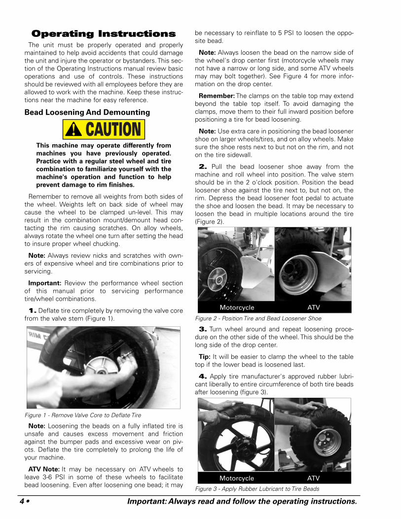
2. Pull the bead loosener shoe away from themachine and roll wheel into position. The valve stemshould be in the 2 o'clock position. Position the beadloosener shoe against the tire next to, but not on, therim. Depress the bead loosener foot pedal to actuatethe shoe and loosen the bead. It may be necessary toloosen the bead in multiple locations around the tire(Figure 2).
Figure 2 - Position Tire and Bead Loosener Shoe
3. Turn wheel around and repeat loosening proce-dure on the other side of the wheel. This should be thelong side of the drop center.
Tip: It will be easier to clamp the wheel to the tabletop if the lower bead is loosened last.
4. Apply tire manufacturer's approved rubber lubri-cant liberally to entire circumference of both tire beadsafter loosening (figure 3).
Figure 3 - Apply Rubber Lubricant to Tire Beads
CAUTION
Motorcycle ATV
Motorcycle ATV
Important: Always read and follow the operating instructions. • 5
5a. Prior to placing the wheel on the table top toclamp, observe the style and strength of the wheeland adjust the clamp pressure as necessary using thepressure regulator and gauge. Thin spun aluminumrims sometimes used on ATV and motorcycle aresometimes delicate and a reduced air pressure shouldbe considered verses cast aluminum and steel wheelsthat can support more clamping force.
5b. Next, observe the rim size from the tire, ie. 15,16, 17, etc. Using the clamp pedal, place the clampvalve in the JOG IN position for prelocating the clampsto the rim diameter. Accomplish this by moving thepedal from the UP position to the 1/2-DOWN location.Then JOG the pedal DOWN allowing the clamps tomove inward until the pointer on the clamps align withthe rim diameter on the table top decal. It may be nec-essary to relocate the clamps on the clamp carriers.Each clamp should be in the same position before pre-locating the clamps.
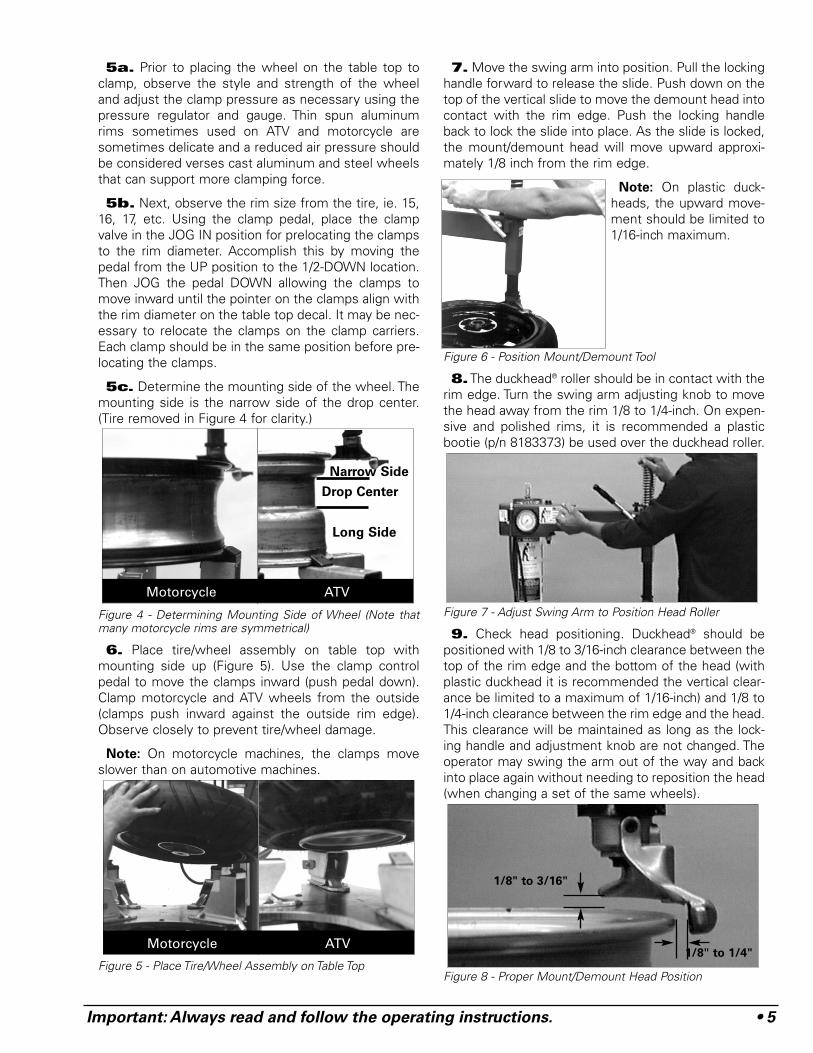
5c. Determine the mounting side of the wheel. Themounting side is the narrow side of the drop center.(Tire removed in Figure 4 for clarity.)
Figure 4 - Determining Mounting Side of Wheel (Note thatmany motorcycle rims are symmetrical)
6. Place tire/wheel assembly on table top withmounting side up (Figure 5). Use the clamp controlpedal to move the clamps inward (push pedal down).Clamp motorcycle and ATV wheels from the outside(clamps push inward against the outside rim edge).Observe closely to prevent tire/wheel damage.
Note: On motorcycle machines, the clamps moveslower than on automotive machines.
Figure 5 - Place Tire/Wheel Assembly on Table Top
7. Move the swing arm into position. Pull the lockinghandle forward to release the slide. Push down on thetop of the vertical slide to move the demount head intocontact with the rim edge. Push the locking handleback to lock the slide into place. As the slide is locked,the mount/demount head will move upward approxi-mately 1/8 inch from the rim edge.
Note: On plastic duck-heads, the upward move-ment should be limited to1/16-inch maximum.
Figure 6 - Position Mount/Demount Tool
8.The duckhead® roller should be in contact with therim edge. Turn the swing arm adjusting knob to movethe head away from the rim 1/8 to 1/4-inch. On expen-sive and polished rims, it is recommended a plasticbootie (p/n 8183373) be used over the duckhead roller.
Figure 7 - Adjust Swing Arm to Position Head Roller
9. Check head positioning. Duckhead® should bepositioned with 1/8 to 3/16-inch clearance between thetop of the rim edge and the bottom of the head (withplastic duckhead it is recommended the vertical clear-ance be limited to a maximum of 1/16-inch) and 1/8 to1/4-inch clearance between the rim edge and the head.This clearance will be maintained as long as the lock-ing handle and adjustment knob are not changed. Theoperator may swing the arm out of the way and backinto place again without needing to reposition the head(when changing a set of the same wheels).
Figure 8 - Proper Mount/Demount Head Position
Motorcycle ATV
Narrow Side
Long Side
Drop Center
Motorcycle ATV1/8" to 1/4"
1/8" to 3/16"
6 • Important: Always read and follow the operating instructions.
Important: The vertical tool clearance may changewith machine use and should be inspected often.Failure to maintain the proper clearance may result infinish/painted/plated damage to the wheel rim.
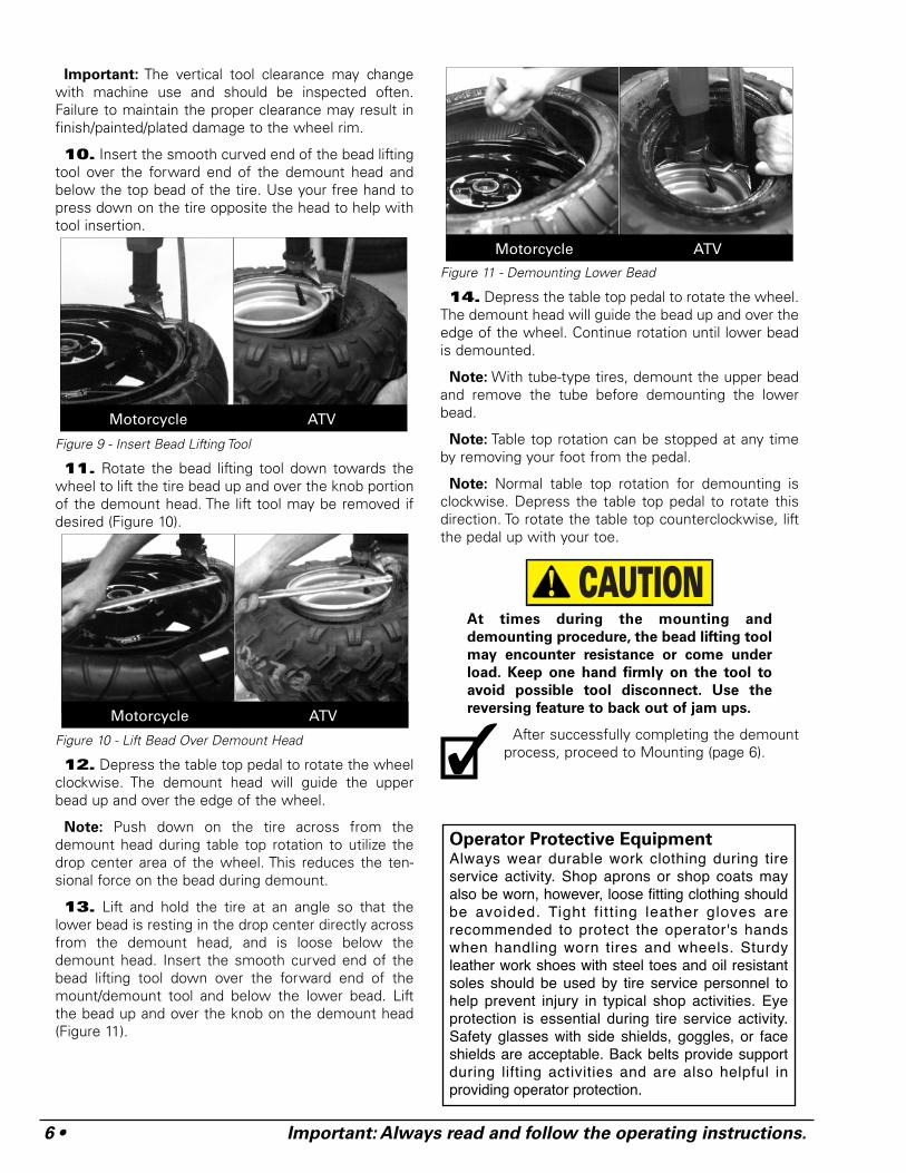
10. Insert the smooth curved end of the bead liftingtool over the forward end of the demount head andbelow the top bead of the tire. Use your free hand topress down on the tire opposite the head to help withtool insertion.
Figure 9 - Insert Bead Lifting Tool
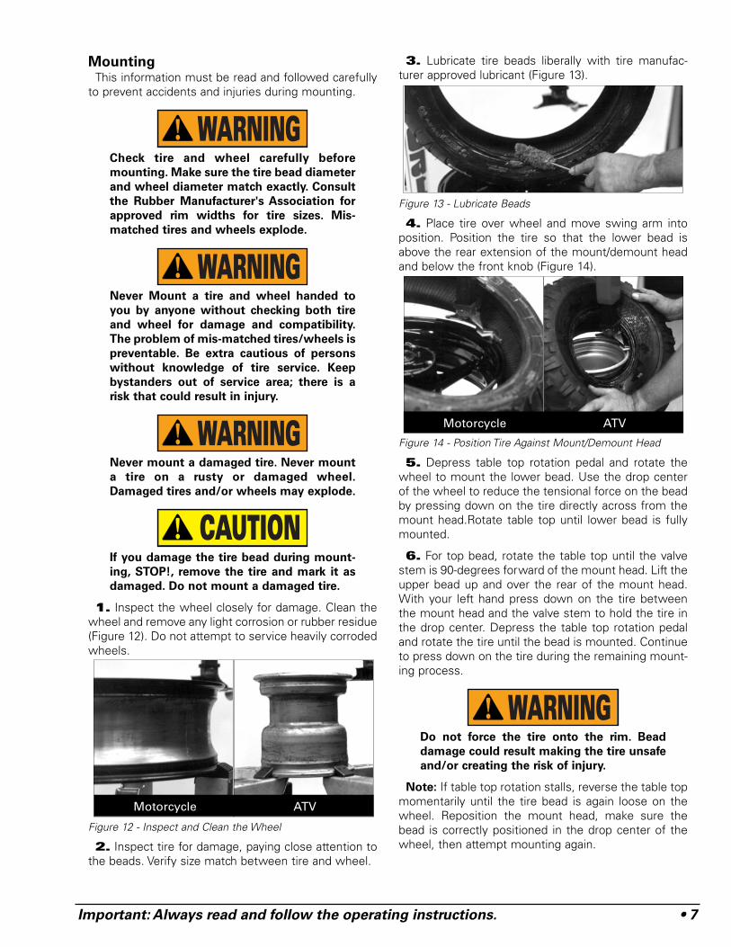
11. Rotate the bead lifting tool down towards thewheel to lift the tire bead up and over the knob portionof the demount head. The lift tool may be removed ifdesired (Figure 10).
Figure 10 - Lift Bead Over Demount Head
12. Depress the table top pedal to rotate the wheelclockwise. The demount head will guide the upperbead up and over the edge of the wheel.
Note: Push down on the tire across from thedemount head during table top rotation to utilize thedrop center area of the wheel. This reduces the ten-sional force on the bead during demount.
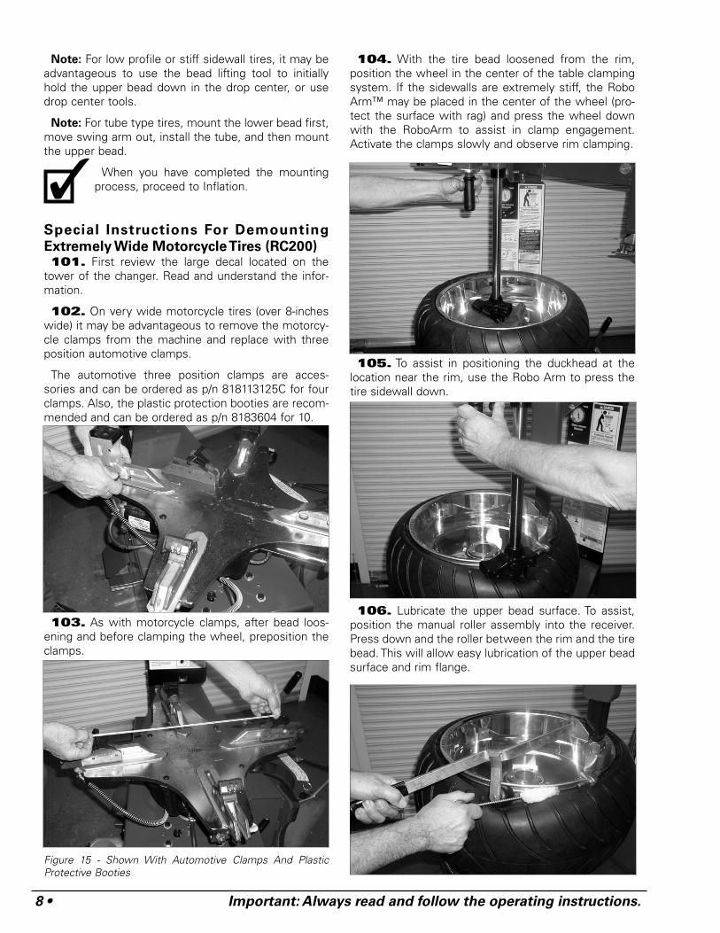
13. Lift and hold the tire at an angle so that thelower bead is resting in the drop center directly acrossfrom the demount head, and is loose below thedemount head. Insert the smooth curved end of thebead lifting tool down over the forward end of themount/demount tool and below the lower bead. Liftthe bead up and over the knob on the demount head(Figure 11).
Figure 11 - Demounting Lower Bead
14. Depress the table top pedal to rotate the wheel.The demount head will guide the bead up and over theedge of the wheel. Continue rotation until lower beadis demounted.
Note: With tube-type tires, demount the upper beadand remove the tube before demounting the lowerbead.
Note: Table top rotation can be stopped at any timeby removing your foot from the pedal.
Note: Normal table top rotation for demounting isclockwise. Depress the table top pedal to rotate thisdirection. To rotate the table top counterclockwise, liftthe pedal up with your toe.
At times during the mounting and
demounting procedure, the bead lifting tool
may encounter resistance or come under
load. Keep one hand firmly on the tool to
avoid possible tool disconnect. Use the
reversing feature to back out of jam ups.
After successfully completing the demountprocess, proceed to Mounting (page 6).
CAUTION
Motorcycle ATV
Motorcycle ATV
✓Operator Protective EquipmentAlways wear durable work clothing during tireservice activity. Shop aprons or shop coats mayalso be worn, however, loose fitting clothing shouldbe avoided. Tight f i t t ing leather gloves arerecommended to protect the operator's handswhen handling worn tires and wheels. Sturdyleather work shoes with steel toes and oil resistantsoles should be used by tire service personnel tohelp prevent injury in typical shop activities. Eyeprotection is essential during tire service activity.Safety glasses with side shields, goggles, or faceshields are acceptable. Back belts provide supportduring lifting activities and are also helpful inproviding operator protection.
Motorcycle ATV
Important: Always read and follow the operating instructions. • 7
MountingThis information must be read and followed carefully
to prevent accidents and injuries during mounting.
Check tire and wheel carefully before
mounting. Make sure the tire bead diameter
and wheel diameter match exactly. Consult
the Rubber Manufacturer's Association for
approved rim widths for tire sizes. Mis-
matched tires and wheels explode.
Never Mount a tire and wheel handed to
you by anyone without checking both tire
and wheel for damage and compatibility.
The problem of mis-matched tires/wheels is
preventable. Be extra cautious of persons
without knowledge of tire service. Keep
bystanders out of service area; there is a
risk that could result in injury.
Never mount a damaged tire. Never mount
a tire on a rusty or damaged wheel.
Damaged tires and/or wheels may explode.
If you damage the tire bead during mount-
ing, STOP!, remove the tire and mark it as
damaged. Do not mount a damaged tire.
1. Inspect the wheel closely for damage. Clean thewheel and remove any light corrosion or rubber residue(Figure 12). Do not attempt to service heavily corrodedwheels.
Figure 12 - Inspect and Clean the Wheel
2. Inspect tire for damage, paying close attention tothe beads. Verify size match between tire and wheel.
3. Lubricate tire beads liberally with tire manufac-turer approved lubricant (Figure 13).
Figure 13 - Lubricate Beads
4. Place tire over wheel and move swing arm intoposition. Position the tire so that the lower bead isabove the rear extension of the mount/demount headand below the front knob (Figure 14).
Figure 14 - Position Tire Against Mount/Demount Head
5. Depress table top rotation pedal and rotate thewheel to mount the lower bead. Use the drop centerof the wheel to reduce the tensional force on the beadby pressing down on the tire directly across from themount head.Rotate table top until lower bead is fullymounted.
6. For top bead, rotate the table top until the valvestem is 90-degrees forward of the mount head. Lift theupper bead up and over the rear of the mount head.With your left hand press down on the tire betweenthe mount head and the valve stem to hold the tire inthe drop center. Depress the table top rotation pedaland rotate the tire until the bead is mounted. Continueto press down on the tire during the remaining mount-ing process.
Do not force the tire onto the rim. Bead
damage could result making the tire unsafe
and/or creating the risk of injury.
Note: If table top rotation stalls, reverse the table topmomentarily until the tire bead is again loose on thewheel. Reposition the mount head, make sure thebead is correctly positioned in the drop center of thewheel, then attempt mounting again.
WARNING
CAUTION
WARNING
WARNING
WARNING
Motorcycle ATV
Motorcycle ATV
8 • Important: Always read and follow the operating instructions.
Note: For low profile or stiff sidewall tires, it may beadvantageous to use the bead lifting tool to initiallyhold the upper bead down in the drop center, or usedrop center tools.
Note: For tube type tires, mount the lower bead first,move swing arm out, install the tube, and then mountthe upper bead.
When you have completed the mountingprocess, proceed to Inflation.
Special Instructions For Demounting
Extremely Wide Motorcycle Tires (RC200)101. First review the large decal located on the
tower of the changer. Read and understand the infor-mation.
102. On very wide motorcycle tires (over 8-incheswide) it may be advantageous to remove the motorcy-cle clamps from the machine and replace with threeposition automotive clamps.
The automotive three position clamps are acces-sories and can be ordered as p/n 818113125C for fourclamps. Also, the plastic protection booties are recom-mended and can be ordered as p/n 8183604 for 10.
103. As with motorcycle clamps, after bead loos-ening and before clamping the wheel, preposition theclamps.
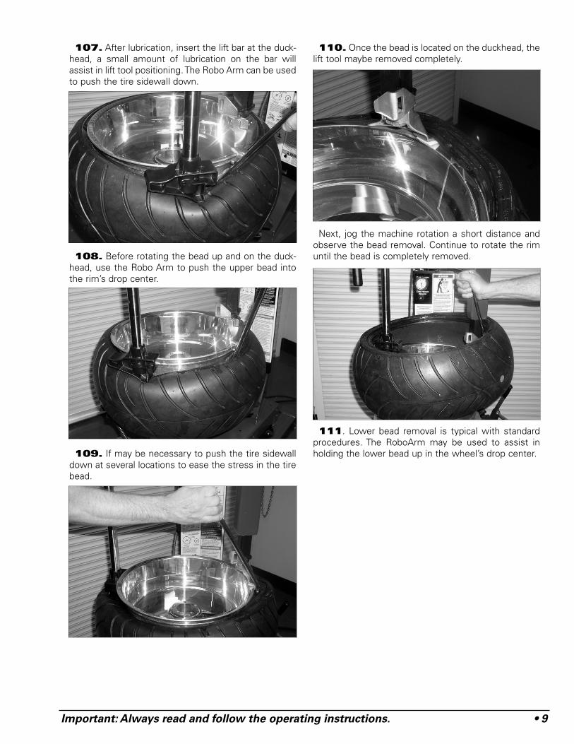
Figure 15 - Shown With Automotive Clamps And PlasticProtective Booties
104. With the tire bead loosened from the rim,position the wheel in the center of the table clampingsystem. If the sidewalls are extremely stiff, the RoboArm™ may be placed in the center of the wheel (pro-tect the surface with rag) and press the wheel downwith the RoboArm to assist in clamp engagement.Activate the clamps slowly and observe rim clamping.
105. To assist in positioning the duckhead at thelocation near the rim, use the Robo Arm to press thetire sidewall down.
106. Lubricate the upper bead surface. To assist,position the manual roller assembly into the receiver.Press down and the roller between the rim and the tirebead. This will allow easy lubrication of the upper beadsurface and rim flange.
✓
Important: Always read and follow the operating instructions. • 9
107. After lubrication, insert the lift bar at the duck-head, a small amount of lubrication on the bar willassist in lift tool positioning. The Robo Arm can be usedto push the tire sidewall down.
108. Before rotating the bead up and on the duck-head, use the Robo Arm to push the upper bead intothe rim’s drop center.
109. If may be necessary to push the tire sidewalldown at several locations to ease the stress in the tirebead.
110. Once the bead is located on the duckhead, thelift tool maybe removed completely.
Next, jog the machine rotation a short distance andobserve the bead removal. Continue to rotate the rimuntil the bead is completely removed.
111. Lower bead removal is typical with standardprocedures. The RoboArm may be used to assist inholding the lower bead up in the wheel’s drop center.
10 • Important: Always read and follow the operating instructions.
Special Instructions For Mounting
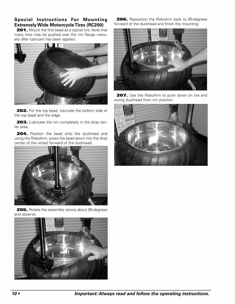
Extremely Wide Motorcycle Tires (RC200)201. Mount the first bead as a typical tire. Note that
many tires may be pushed over the rim flange manu-ally after lubricant has been applied.
202. For the top bead, lubricate the bottom side ofthe top bead and the edge.
203. Lubricate the rim completely in the drop cen-ter area.
204. Position the bead onto the duckhead andusing the RoboArm, press the bead down into the dropcenter of the wheel forward of the duckhead.
205. Rotate the assembly slowly about 90-degreesand observe.
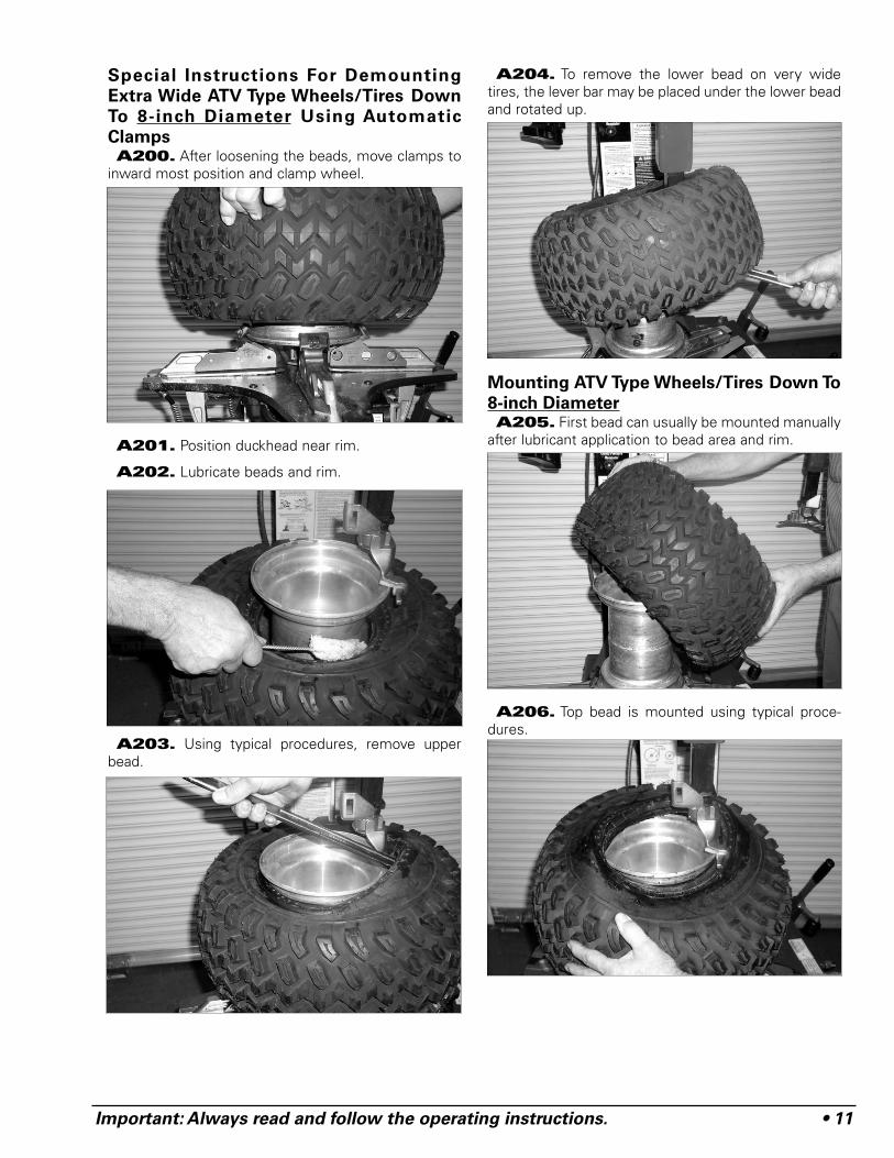
206. Reposition the RoboArm back to 90-degreesforward of the duckhead and finish the mounting.
207. Use the RoboArm to push down on tire andswing duckhead from rim position.
Important: Always read and follow the operating instructions. • 11
Special Instructions For Demounting
Extra Wide ATV Type Wheels/Tires Down
To 8-inch Diameter Using Automatic
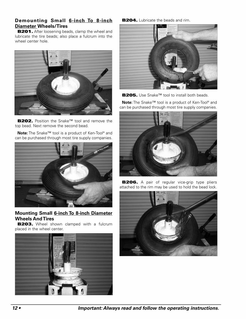
ClampsA200. After loosening the beads, move clamps to
inward most position and clamp wheel.
A201. Position duckhead near rim.
A202. Lubricate beads and rim.
A203. Using typical procedures, remove upperbead.
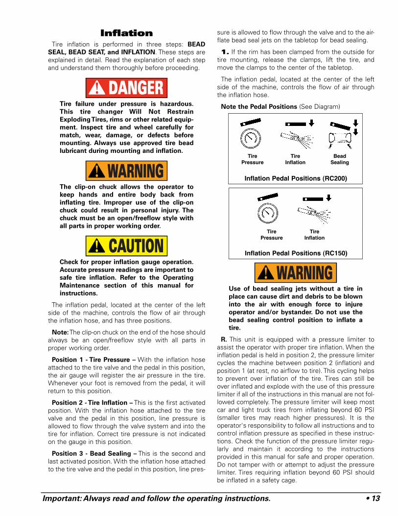
A204. To remove the lower bead on very widetires, the lever bar may be placed under the lower beadand rotated up.
Mounting ATV Type Wheels/Tires Down To
8-inch DiameterA205. First bead can usually be mounted manually
after lubricant application to bead area and rim.
A206. Top bead is mounted using typical proce-dures.
12 • Important: Always read and follow the operating instructions.
Demounting Small 6-inch To 8-inch
Diameter Wheels/TiresB201. After loosening beads, clamp the wheel and
lubricate the tire beads; also place a fulcrum into thewheel center hole.
B202. Position the Snake™ tool and remove thetop bead. Next remove the second bead.
Note: The Snake™ tool is a product of Ken-Tool® andcan be purchased through most tire supply companies.
Mounting Small 6-inch To 8-inch Diameter
Wheels And TiresB203. Wheel shown clamped with a fulcrum
placed in the wheel center.
B204. Lubricate the beads and rim.
B205. Use Snake™ tool to install both beads.
Note: The Snake™ tool is a product of Ken-Tool® andcan be purchased through most tire supply companies.
B206. A pair of regular vice-grip type pliersattached to the rim may be used to hold the bead lock.
Important: Always read and follow the operating instructions. • 13
IInnffllaattiioonnTire inflation is performed in three steps: BEAD
SEAL, BEAD SEAT, and INFLATION. These steps areexplained in detail. Read the explanation of each stepand understand them thoroughly before proceeding.
Tire failure under pressure is hazardous.
This tire changer Will Not Restrain
Exploding Tires, rims or other related equip-
ment. Inspect tire and wheel carefully for
match, wear, damage, or defects before
mounting. Always use approved tire bead
lubricant during mounting and inflation.
The clip-on chuck allows the operator to
keep hands and entire body back from
inflating tire. Improper use of the clip-on
chuck could result in personal injury. The
chuck must be an open/freeflow style with
all parts in proper working order.
Check for proper inflation gauge operation.
Accurate pressure readings are important to
safe tire inflation. Refer to the Operating
Maintenance section of this manual for
instructions.
The inflation pedal, located at the center of the leftside of the machine, controls the flow of air throughthe inflation hose, and has three positions.
Note:The clip-on chuck on the end of the hose shouldalways be an open/freeflow style with all parts inproper working order.
Position 1 - Tire Pressure – With the inflation hoseattached to the tire valve and the pedal in this position,the air gauge will register the air pressure in the tire.Whenever your foot is removed from the pedal, it willreturn to this position.
Position 2 - Tire Inflation – This is the first activatedposition. With the inflation hose attached to the tirevalve and the pedal in this position, line pressure isallowed to flow through the valve system and into thetire for inflation. Correct tire pressure is not indicatedon the gauge in this position.
Position 3 - Bead Sealing – This is the second andlast activated position. With the inflation hose attachedto the tire valve and the pedal in this position, line pres-
sure is allowed to flow through the valve and to the air-flate bead seal jets on the tabletop for bead sealing.
1. If the rim has been clamped from the outside fortire mounting, release the clamps, lift the tire, andmove the clamps to the center of the tabletop.
The inflation pedal, located at the center of the leftside of the machine, controls the flow of air throughthe inflation hose.
Note the Pedal Positions (See Diagram)
Use of bead sealing jets without a tire in
place can cause dirt and debris to be blown
into the air with enough force to injure
operator and/or bystander. Do not use the
bead sealing control position to inflate a
tire.
R. This unit is equipped with a pressure limiter toassist the operator with proper tire inflation. When theinflation pedal is held in position 2, the pressure limitercycles the machine between position 2 (inflation) andposition 1 (at rest, no airflow to tire). This cycling helpsto prevent over inflation of the tire. Tires can still beover inflated and explode with the use of this pressurelimiter if all of the instructions in this manual are not fol-lowed completely. The pressure limiter will keep mostcar and light truck tires from inflating beyond 60 PSI(smaller tires may reach higher pressures). It is theoperator's responsibility to follow all instructions and tocontrol inflation pressure as specified in these instruc-tions. Check the function of the pressure limiter regu-larly and maintain it according to the instructionsprovided in this manual for safe and proper operation.Do not tamper with or attempt to adjust the pressurelimiter. Tires requiring inflation beyond 60 PSI shouldbe inflated in a safety cage.
WARNINGCAUTION
WARNING
DANGER
TireInflation
Inflation Pedal Positions (RC200)
BeadSealing
TirePressure
TireInflation
Inflation Pedal Positions (RC150)
TirePressure
14 • Important: Always read and follow the operating instructions.
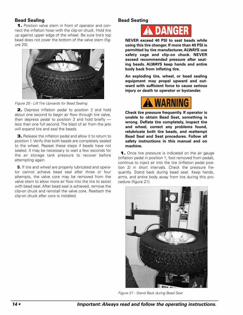
Bead Sealing1. Position valve stem in front of operator and con-
nect the inflation hose with the clip-on chuck. Hold tireup against upper edge of the wheel. Be sure tire’s topbead does not cover the bottom of the valve stem (fig-ure 20).
Figure 20 - Lift Tire Upwards for Bead Sealing
2. Depress inflation pedal to position 2 and holdabout one second to begin air flow through tire valve,then depress pedal to position 3 and hold briefly —less than one full second. The blast of air from the jetswill expand tire and seal the beads.
3. Release the inflation pedal and allow it to return toposition 1. Verify that both beads are completely sealedto the wheel. Repeat these steps if beads have notsealed. It may be necessary to wait a few seconds forthe air storage tank pressure to recover beforeattempting again.
S. If tire and wheel are properly lubricated and opera-tor cannot achieve bead seal after three or fourattempts, the valve core may be removed from thevalve stem to allow more air flow into the tire to assistwith bead seal. After bead seal is achieved, remove theclip-on chuck and reinstall the valve core. Reattach theclip-on chuck after core is installed.
Bead Seating
NEVER exceed 40 PSI to seat beads while
using this tire changer. If more than 40 PSI is
permitted by tire manufacturer, ALWAYS use
safety cage and clip-on chuck. NEVER
exceed recommended pressure after seat-
ing beads. ALWAYS keep hands and entire
body back from inflating tire.
An exploding tire, wheel, or bead sealing
equipment may propel upward and out-
ward with sufficient force to cause serious
injury or death to operator or bystander.
Check tire pressure frequently. If operator is
unable to obtain Bead Seat, something is
wrong. Deflate tire completely, inspect tire
and wheel, correct any problems found,
relubricate both tire beads, and reattempt
Bead Seal and Seat procedures. Follow all
safety instructions in this manual and on
machine.
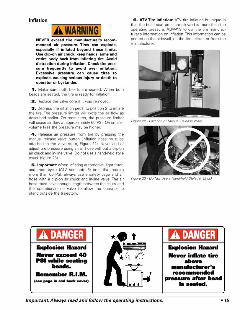
1. Once tire pressure is indicated on the air gauge(inflation pedal in position 1; foot removed from pedal),continue to inject air into the tire (inflation pedal posi-tion 2) in short intervals. Check the pressure fre-quently. Stand back during bead seat. Keep hands,arms, and entire body away from tire during this pro-cedure (figure 21).
Figure 21 - Stand Back during Bead Seat
WARNING
DANGER
Important: Always read and follow the operating instructions. • 15
Inflation
NEVER exceed tire manufacturer's recom-
mended air pressure. Tires can explode,
especially if inflated beyond these limits.
Use clip-on air chuck, keep hands, arms and
entire body back from inflating tire. Avoid
distraction during inflation. Check tire pres-
sure frequently to avoid over inflation.
Excessive pressure can cause tires to
explode, causing serious injury or death to
operator or bystander.
1. Make sure both beads are seated. When bothbeads are seated, the tire is ready for inflation.
2. Replace the valve core if it was removed.
3. Depress the inflation pedal to position 2 to inflatethe tire. The pressure limiter will cycle the air flow asdescribed earlier. On most tires, the pressure limiterwill cease air flow at approximately 60 PSI. On smallervolume tires the pressure may be higher.
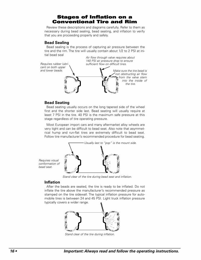
4. Release air pressure from tire by pressing themanual release valve button (inflation hose must beattached to the valve stem, Figure 22). Never add oradjust tire pressure using an air hose without a clip-onair chuck and in-line valve. Do not use a hand-held stylechuck (figure 23).
5. Important: When inflating automotive, light truck,and motorcycle (ATV see note 6) tires that requiremore than 60 PSI, always use a safety cage and airhose with a clip-on air chuck and in-line valve. The airhose must have enough length between the chuck andthe operation/in-line valve to allow the operator tostand outside the trajectory.
6. ATV Tire Inflation: ATV tire inflation is unique inthat the bead seat pressure allowed is more than theoperating pressure. ALWAYS follow the tire manufac-turer’s information on inflation. This information can beprinted on the sidewall, on the tire sticker, or from themanufacturer.
Figure 22 - Location of Manual Release Valve
Figure 23 - Do Not Use a Hand-held Style Air Chuck
WARNING
EExxpplloossiioonn HHaazzaarrddNNeevveerr iinnffllaattee ttiirree
aabboovveemmaannuuffaaccttuurreerr''ssrreeccoommmmeennddeedd
pprreessssuurree aafftteerr bbeeaaddiiss sseeaatteedd..
DANGEREExxpplloossiioonn HHaazzaarrddNNeevveerr eexxcceeeedd 4400PPSSII wwhhiillee sseeaattiinngg
bbeeaaddss..RReemmeemmbbeerr RR..II..MM..
((sseeee ppaaggee iivv aanndd bbaacckk ccoovveerr))
DANGER
16 • Important: Always read and follow the operating instructions.
SSttaaggeess ooff IInnffllaattiioonn oonn aaCCoonnvveennttiioonnaall TTiirree aanndd RRiimm
Review these descriptions and diagrams carefully. Refer to them asnecessary during bead sealing, bead seating, and inflation to verifythat you are proceeding properly and safely.
Bead SealingBead sealing is the process of capturing air pressure between the
tire and the rim. The tire will usually contain about 1/2 to 2 PSI at ini-tial bead seal
Bead SeatingBead seating usually occurs on the long tapered side of the wheel
first and the shorter side last. Bead seating will usually require atleast 7 PSI in the tire. 40 PSI is the maximum safe pressure at thisstage regardless of tire operating pressure.
Most European import cars and many aftermarket alloy wheels arevery tight and can be difficult to bead seat. Also note that asymmet-rical hump and run-flat tires are extremely difficult to bead seat.Follow tire manufacturer’s recommended procedure for bead seating.
InflationAfter the beads are seated, the tire is ready to be inflated. Do not
inflate the tire above the manufacturer’s recommended pressure asstamped on the tire sidewall. The typical inflation pressure for auto-mobile tires is between 24 and 45 PSI. Light truck inflation pressuretypically covers a wider range.
Air flow through valve requires about140 PSI air pressure drop to ensuresufficient flow on difficult tires.
Usually last to “pop” is the mount side.
Requires visualconformation ofbead seat.
Stand clear of the tire during bead seat and inflation.
Stand clear of the tire during inflation.
Requires rubber lubri-cant on both upperand lower beads. Make sure the tire bead is
not obstructing air flowfrom the valve stem
into the inside ofthe tire.
Important: Always read and follow the operating instructions. • 17
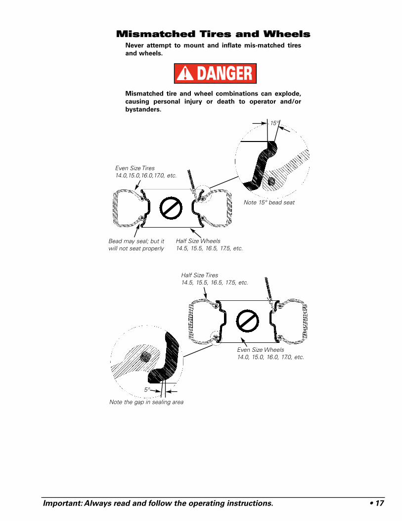
MMiissmmaattcchheedd TTiirreess aanndd WWhheeeellssNever attempt to mount and inflate mis-matched tires
and wheels.
Mismatched tire and wheel combinations can explode,
causing personal injury or death to operator and/or
bystanders.
DANGER
Even Size Tires14.0,15.0,16.0,17.0, etc.
Half Size Tires14.5, 15.5, 16.5, 17.5, etc.
Even Size Wheels14.0, 15.0, 16.0, 17.0, etc.
15°
5°
Note the gap in sealing area
Note 15° bead seat
Bead may seal; but itwill not seat properly
Half Size Wheels14.5, 15.5, 16.5, 17.5, etc.
18 • Important: Always read and follow the operating instructions.
PPeerrffoorrmmaannccee,, CCuussttoomm,,aanndd AAlluummiinnuumm
AAuuttoommoottiivvee && LLiigghhttTTrruucckk WWhheeeellss
To avoid personal injury or finish damage to
components only tire technicians with expe-
rience and training on custom wheels
should attempt to service expensive custom
alloy or aluminum wheels, high-perform-
ance low-profile tires and EMT/run-flat tires.
Many tires/wheels have pressure sensor
devices that are manufactured by different
companies, there are no standards on type
or mounting; therefore, follow the instruc-
tions that apply to the sensor being serviced.
For further information on these devices,
contact the individual sensor manufacturer.
Pre-Operation Notes:
• Ensure all weights have been removed.• Assistance will be required on wide and large diam-
eter wheels.• Clamp wheel from the outside.• Use ample lubricant for mounting and demounting• Always review wheel nicks and/or scratches with
the owner before servicing.
Performance Tires & Wheels • DemountingFollow these instructions for performance type tires
and wheels, including run-flat tires and their associatedwheels, and asymmetrical hump wheels.
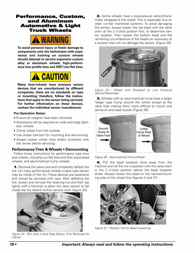
1. Remove the valve core and completely deflate thetire. On many performance wheels a valve type sensormay be inside of the rim. These devices are expensiveand should be serviced with care. After deflating thetire, loosen and remove the retaining nut and then taplightly with a hammer to allow the valve sensor to fallinside the tire before further service work (figure 24).
Figure 24 - Rim with a Valve Type Sensor (Tire Removed forClarity)
2. Some wheels have a low-pressure sensor/trans-mitter strapped to the wheel. This is especially true onolder run-flat tire/wheel systems. To avoid damagingthe sensor, always loosen the top bead with the valvestem at the 2 o’clock position first, to determine sen-sor location. Then loosen the bottom bead and theremaining circumference of the beads as necessary ata location that will not damage the sensor. (Figure 25).
Figure 25 - Wheel with Strapped on Low PressureSensor/Transmitter
3. Wheels with an asymmetrical hump have a larger"ledge" type hump around the wheel except at thevalve hole making them more difficult to mount anddemount and bead loosen (Figure 26).
Figure 26 - Asymmetrical Hump Wheel
4. Pull the bead loosener shoe away from themachine and roll the tire in position with the valve stemin the 2 o’clock position (above the bead loosenershoe). Always loosen the bead on the narrow/mount-ing side of the wheel first (figures 2 and 27).
Figure 27 - Position Tire for Bead Loosening
CAUTION
WARNING
SmoothHump At
Valve Hole
LedgeHump Restof Wheel
Valve Stem
Senso
r
Valve Stem
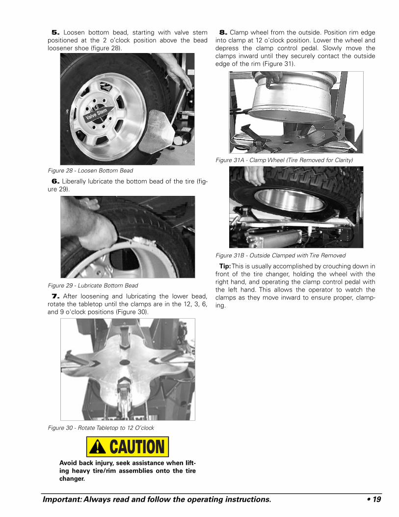
5. Loosen bottom bead, starting with valve stempositioned at the 2 o’clock position above the beadloosener shoe (figure 28).
Figure 28 - Loosen Bottom Bead
6. Liberally lubricate the bottom bead of the tire (fig-ure 29).
Figure 29 - Lubricate Bottom Bead
7. After loosening and lubricating the lower bead,rotate the tabletop until the clamps are in the 12, 3, 6,and 9 o'clock positions (Figure 30).
Figure 30 - Rotate Tabletop to 12 O’clock
Avoid back injury, seek assistance when lift-
ing heavy tire/rim assemblies onto the tire
changer.
8. Clamp wheel from the outside. Position rim edgeinto clamp at 12 o'clock position. Lower the wheel anddepress the clamp control pedal. Slowly move theclamps inward until they securely contact the outsideedge of the rim (Figure 31).
Figure 31A - Clamp Wheel (Tire Removed for Clarity)
Figure 31B - Outside Clamped with Tire Removed
Tip:This is usually accomplished by crouching down infront of the tire changer, holding the wheel with theright hand, and operating the clamp control pedal withthe left hand. This allows the operator to watch theclamps as they move inward to ensure proper, clamp-ing.
CAUTION
Important: Always read and follow the operating instructions. • 19
Valve Stem
20 • Important: Always read and follow the operating instructions.
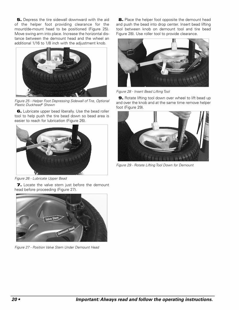
5. Depress the tire sidewall downward with the aidof the helper foot providing clearance for themount/de-mount head to be positioned (Figure 25).Move swing arm into place. Increase the horizontal dis-tance between the demount head and the wheel anadditional 1/16 to 1/8 inch with the adjustment knob.
Figure 25 - Helper Foot Depressing Sidewall of Tire, OptionalPlastic Duckhead® Shown
6. Lubricate upper bead liberally. Use the bead rollertool to help push the tire bead down so bead area iseasier to reach for lubrication (Figure 26).
Figure 26 - Lubricate Upper Bead
7. Locate the valve stem just before the demounthead before proceeding (Figure 27).
Figure 27 - Position Valve Stem Under Demount Head
8. Place the helper foot opposite the demount headand push the bead into drop center. Insert bead liftingtool between knob on demount tool and tire beadFigure 28). Use roller tool to provide clearance.
Figure 28 - Insert Bead Lifting Tool
9. Rotate lifting tool down over wheel to lift bead upand over the knob and at the same time remove helperfoot (Figure 29).
Figure 29 - Rotate Lifting Tool Down for Demount
Demount Head
Valve Stem
Important: Always read and follow the operating instructions. • 21
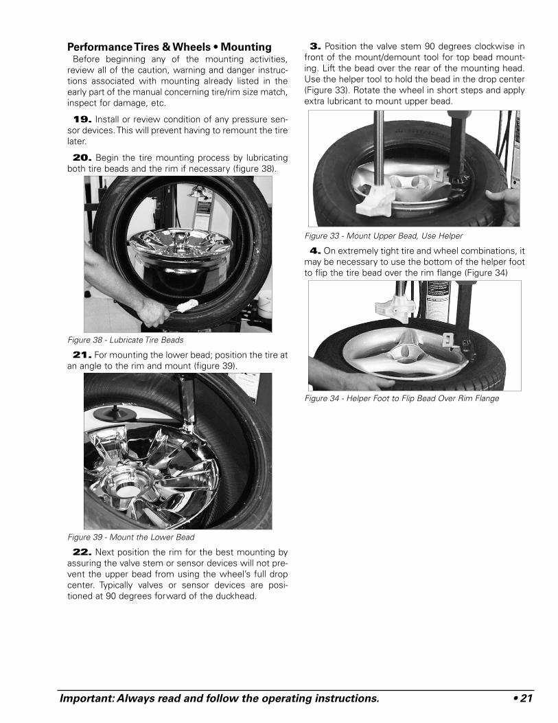
Performance Tires & Wheels • MountingBefore beginning any of the mounting activities,
review all of the caution, warning and danger instruc-tions associated with mounting already listed in theearly part of the manual concerning tire/rim size match,inspect for damage, etc.
19. Install or review condition of any pressure sen-sor devices. This will prevent having to remount the tirelater.
20. Begin the tire mounting process by lubricatingboth tire beads and the rim if necessary (figure 38).
Figure 38 - Lubricate Tire Beads
21. For mounting the lower bead; position the tire atan angle to the rim and mount (figure 39).
Figure 39 - Mount the Lower Bead
22. Next position the rim for the best mounting byassuring the valve stem or sensor devices will not pre-vent the upper bead from using the wheel’s full dropcenter. Typically valves or sensor devices are posi-tioned at 90 degrees forward of the duckhead.
3. Position the valve stem 90 degrees clockwise infront of the mount/demount tool for top bead mount-ing. Lift the bead over the rear of the mounting head.Use the helper tool to hold the bead in the drop center(Figure 33). Rotate the wheel in short steps and applyextra lubricant to mount upper bead.
Figure 33 - Mount Upper Bead, Use Helper
4. On extremely tight tire and wheel combinations, itmay be necessary to use the bottom of the helper footto flip the tire bead over the rim flange (Figure 34)
Figure 34 - Helper Foot to Flip Bead Over Rim Flange
22 • Important: Always read and follow the operating instructions.
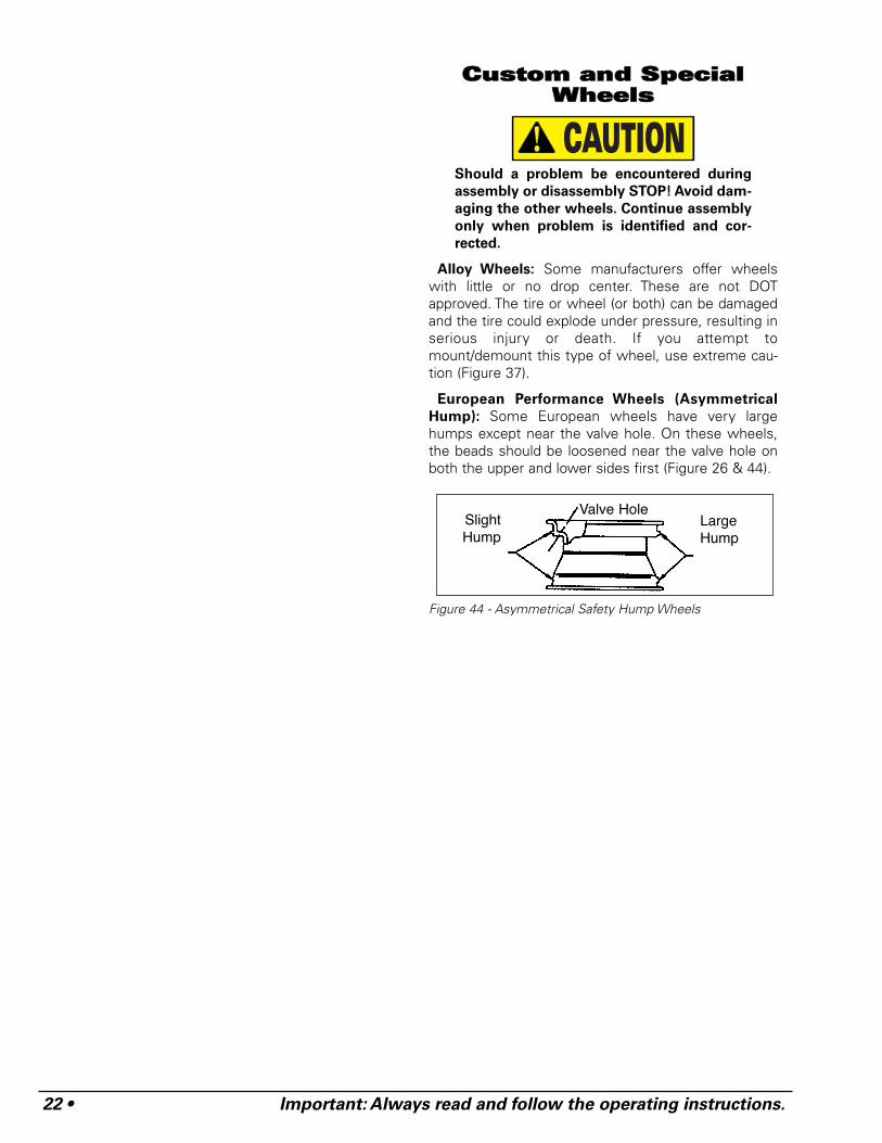
CCuussttoomm aanndd SSppeecciiaallWWhheeeellss
Should a problem be encountered during
assembly or disassembly STOP! Avoid dam-
aging the other wheels. Continue assembly
only when problem is identified and cor-
rected.
Alloy Wheels: Some manufacturers offer wheelswith little or no drop center. These are not DOTapproved. The tire or wheel (or both) can be damagedand the tire could explode under pressure, resulting inserious injury or death. If you attempt tomount/demount this type of wheel, use extreme cau-tion (Figure 37).
European Performance Wheels (Asymmetrical
Hump): Some European wheels have very largehumps except near the valve hole. On these wheels,the beads should be loosened near the valve hole onboth the upper and lower sides first (Figure 26 & 44).
Figure 44 - Asymmetrical Safety Hump Wheels
CAUTION
SlightHump
LargeHump
Valve Hole
Important: Always read and follow the operating instructions. • 23
MMaaiinntteennaanncceeIInnssttrruuccttiioonnss
Read and follow all the maintenance instructions pro-vided in this manual to keep the machine in good oper-ating condition. Refer to the other materials receivedwith the unit and to the service bulletins from the man-ufacturer for additional instructions on proper mainte-nance and service. Regular inspections and propermaintenance are essential to preventing accidents andinjuries.
Before making any inspection, adjustment,
or repair, disconnect the power source and
block out all moving parts to prevent injury.
Keep the machine and the immediate work
area clean. Do not use compressed air to
remove dirt and debris from the machine.
Foreign material may be propelled into the
air and into operator or bystander causing
personal injury.
Wear protective clothing, equipment and
eye protection when making any adjust-
ments or repairs to the machine.
A. The vertical slide should be cleaned with a vaporiz-ing solvent and then lubricated with chassis greaseonce a month.
B. Check the adjustment of the duckhead once amonth.
C. The transmission in this machine is a sealed unitpacked with grease and should need no normal main-tenance.
D. The tabletop, clamps, steel duckhead, and otherworking surfaces should be cleaned with a vaporizingsolvent every month.
E. The clamps should be inspected and metal chipsand dirt removed from the serrations with a wire brushonce a month.
F. Check the tire pressure gauge function daily, andcheck the accuracy monthly. Use a pressurized tire anda high quality stick-type pressure gauge. If necessary,adjust the dial of the machine gauge. If the gauge isdefective, replace it immediately (part number107985). Contact COATS at (615) 641-7533. Checkfunction of the pressure limiter weekly. Always rein-stall the lens after adjusting the gauge.
G. Make sure all fasteners are securely tightened.
H. Make certain that all guards and covers are inplace.
I. Check for worn, damaged or missing parts includinggrips and protective covers. Replace them beforeallowing the unit to be used.
J. On a daily basis, inspect the unit and check to becertain that all systems are operating normally.Detailed inspection and testing procedures are speci-fied for various components at regular intervals. Set upa chart and assign responsibility for these items.
Replace any damaged or missing safety
decals.They are available from COATS, (800)
688-6359.
Important: These instructions will help you servicethe unit. Instructions are for a person with somemechanical ability and training. No attempt has beenmade to describe all basic steps. For example, how toloosen or tighten fasteners. Also basic proceduressuch as cycling systems and checking operation of theequipment are not fully described since they areknown to anyone who does mechanical and servicework. Do not attempt to perform work beyond yourability or at which you have no experience. If you needassistance, call an authorized service center or contactCOATS directly, (800) 688-6359.
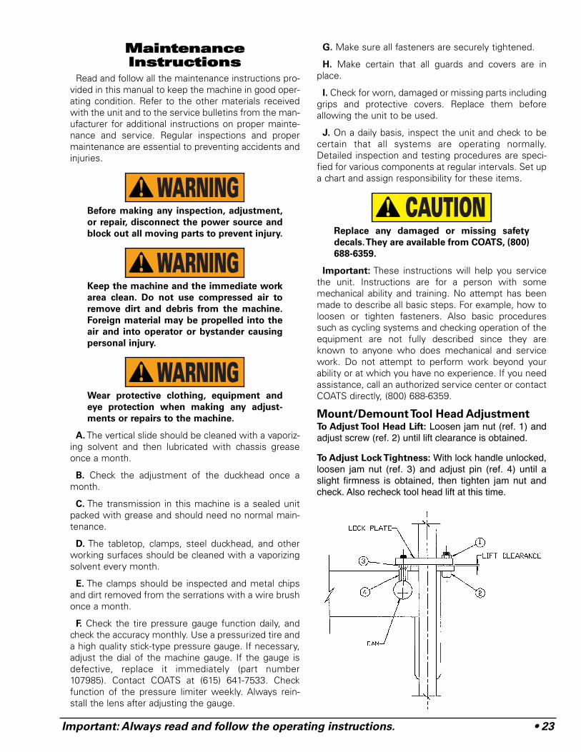
Mount/Demount Tool Head AdjustmentTo Adjust Tool Head Lift: Loosen jam nut (ref. 1) andadjust screw (ref. 2) until lift clearance is obtained.
To Adjust Lock Tightness: With lock handle unlocked,loosen jam nut (ref. 3) and adjust pin (ref. 4) until aslight firmness is obtained, then tighten jam nut andcheck. Also recheck tool head lift at this time.
CAUTION
WARNING
WARNING
WARNING
24 • Important: Always read and follow the operating instructions.
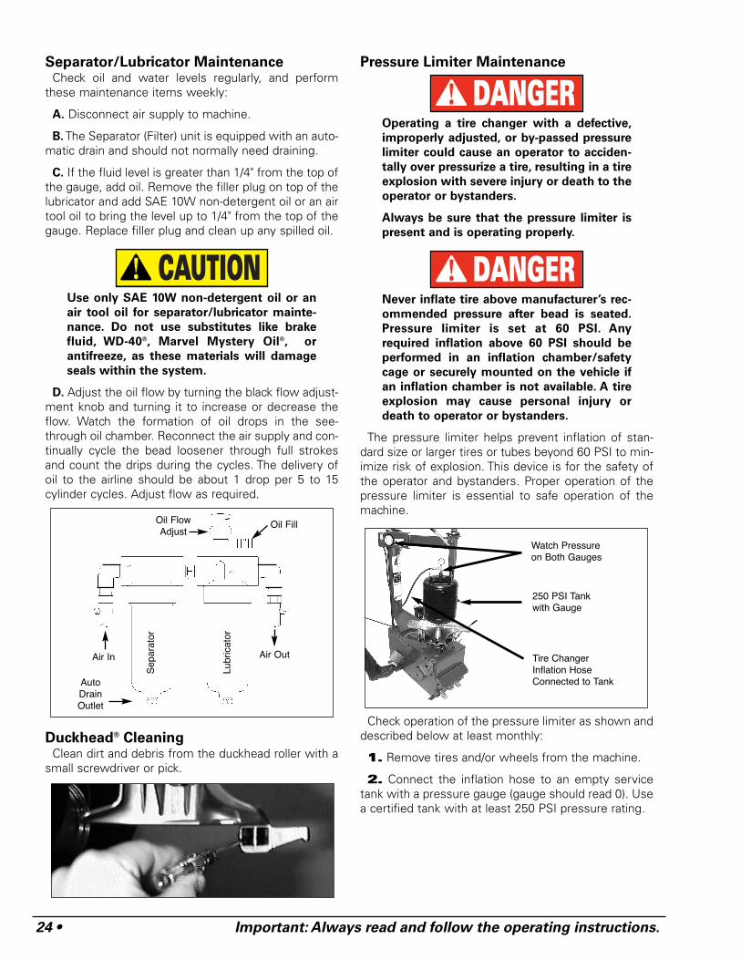
Separator/Lubricator MaintenanceCheck oil and water levels regularly, and perform
these maintenance items weekly:
A. Disconnect air supply to machine.
B. The Separator (Filter) unit is equipped with an auto-matic drain and should not normally need draining.
C. If the fluid level is greater than 1/4" from the top ofthe gauge, add oil. Remove the filler plug on top of thelubricator and add SAE 10W non-detergent oil or an airtool oil to bring the level up to 1/4" from the top of thegauge. Replace filler plug and clean up any spilled oil.
Use only SAE 10W non-detergent oil or an
air tool oil for separator/lubricator mainte-
nance. Do not use substitutes like brake
fluid, WD-40®, Marvel Mystery Oil®, or
antifreeze, as these materials will damage
seals within the system.
D. Adjust the oil flow by turning the black flow adjust-ment knob and turning it to increase or decrease theflow. Watch the formation of oil drops in the see-through oil chamber. Reconnect the air supply and con-tinually cycle the bead loosener through full strokesand count the drips during the cycles. The delivery ofoil to the airline should be about 1 drop per 5 to 15cylinder cycles. Adjust flow as required.
Duckhead® CleaningClean dirt and debris from the duckhead roller with a
small screwdriver or pick.
Pressure Limiter Maintenance
Operating a tire changer with a defective,
improperly adjusted, or by-passed pressure
limiter could cause an operator to acciden-
tally over pressurize a tire, resulting in a tire
explosion with severe injury or death to the
operator or bystanders.
Always be sure that the pressure limiter is
present and is operating properly.
Never inflate tire above manufacturer’s rec-
ommended pressure after bead is seated.
Pressure limiter is set at 60 PSI. Any
required inflation above 60 PSI should be
performed in an inflation chamber/safety
cage or securely mounted on the vehicle if
an inflation chamber is not available. A tire
explosion may cause personal injury or
death to operator or bystanders.
The pressure limiter helps prevent inflation of stan-dard size or larger tires or tubes beyond 60 PSI to min-imize risk of explosion. This device is for the safety ofthe operator and bystanders. Proper operation of thepressure limiter is essential to safe operation of themachine.
Check operation of the pressure limiter as shown anddescribed below at least monthly:
1. Remove tires and/or wheels from the machine.
2. Connect the inflation hose to an empty servicetank with a pressure gauge (gauge should read 0). Usea certified tank with at least 250 PSI pressure rating.
DANGER
DANGER
CAUTION
Auto DrainOutlet
Air In Air Out
Oil FillOil FlowAdjust
Lubr
icat
or
Sep
arat
or
250 PSI Tankwith Gauge
Watch Pressureon Both Gauges
Tire ChangerInflation HoseConnected to Tank
Important: Always read and follow the operating instructions. • 25
3. Depress inflation pedal to position 1 to start air-flow through the hose and into the tank. Maintain asteady pressure for constant flow.
4. Watch the rising pressure on the tank gauge andthe gauge on the machine. Machine gauge shouldcycle between check and inflation pressures whiletank gauge climbs steadily. As tank pressure reaches60 PSI, the pressure limiter should stop the airflowautomatically. Both gauges should read 60 PSI ± 5 PSI.
5. Release inflation pedal. Check manual releasevalve function by pressing the button and releasingpressure from the tank until it reaches 50 PSI.Disconnect inflation hose, and release air inside tank.
6. Replace pressure limiter if it fails to cycle properlyduring inflation, if it fails to shut air supply off at 60 PSI,or if it malfunctions in any other way. Do not operatemachine with a faulty pressure limiter.
Robotic Arm MaintenanceA. Grease the robotic arm to maintain smooth rotation.Grease fittings have been provided at the pivot joints.
B. Check bolt torque periodically at pivot joints. ProperTorque is 200 ft. lbs.
IInnssttaallllaattiioonn IInnssttrruuccttiioonnss
Proper unit installation is necessary for safe
use and efficient operation. Proper installa-
tion also helps protect the unit from dam-
age and makes service easier. Always place
safety poster and instructions near the unit.
LocationSelect a location using the drawings below. The area
should provide the operator with enough space to usethe equipment in a safe manner. The area selectedshould be well lit, easy to clean and should be awayfrom oil, grease, brake lathe chips, etc. Avoid areaswhere bystanders and customers may be present.
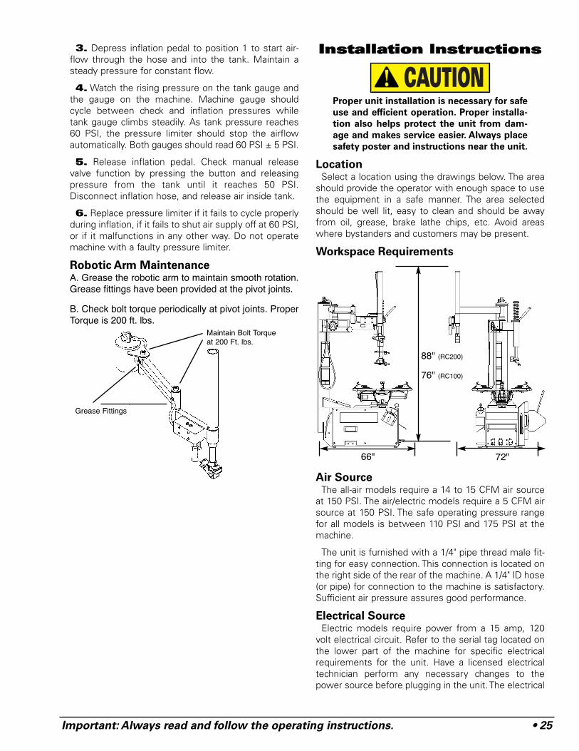
Workspace Requirements
Air SourceThe all-air models require a 14 to 15 CFM air source
at 150 PSI. The air/electric models require a 5 CFM airsource at 150 PSI. The safe operating pressure rangefor all models is between 110 PSI and 175 PSI at themachine.
The unit is furnished with a 1/4" pipe thread male fit-ting for easy connection. This connection is located onthe right side of the rear of the machine. A 1/4" ID hose(or pipe) for connection to the machine is satisfactory.Sufficient air pressure assures good performance.
Electrical SourceElectric models require power from a 15 amp, 120
volt electrical circuit. Refer to the serial tag located onthe lower part of the machine for specific electricalrequirements for the unit. Have a licensed electricaltechnician perform any necessary changes to thepower source before plugging in the unit. The electrical
CAUTION
Maintain Bolt Torqueat 200 Ft. lbs.
Grease Fittings
88" (RC200)
76" (RC100)
66" 72"
26 • Important: Always read and follow the operating instructions.
source must have a solid connection (less than 1 ohm)between ground and building ground.
Floor MountingThe machine should be securely bolted to the floor
with suitable anchors using the hole at each corner ofthe machine base.

Important: Always read and follow the operating instructions. • 27
NNootteess
818???? 00 12/04 © Copyright 2004 Hennessy Industries and COATS All Rights Reserved Printed in USA
FAILURE TO READ AND FOLLOW ALL WARN-
INGS AND INSTRUCTIONS IN THIS MANUAL
CAN LEAD TO SERIOUS PERSONAL INJURY OR
DEATH TO OPERATOR OR BYSTANDER.
THE OWNER IS RESPONSIBLE FOR MAINTAIN-ING THE OPERATION INSTRUCTIONS ANDDECALS FOR OPERATOR REFERENCE. FORADDITIONAL COPIES, CONTACT THE COATS®
COMPANY, 1601 J.P. HENNESSY DRIVE,LAVERGNE, TENNESSEE, 37086 - (800) 688-6359.
TIRE FAILURE UNDER PRESSURE IS HAZ-
ARDOUS! This tire changer Will Not Restrain
Exploding Tires, rims or other related equipment.
TIRES CAN EXPLODE, ESPECIALLY IF INFLATED
BEYOND SPECIFIED LIMITS. DO NOT EXCEED
TIRE MANUFACTURERS RECOMMENDED AIR
PRESSURE.
AN EXPLODING TIRE, RIM, OR BEAD SEATING
EQUIPMENT MAY PROPEL UPWARD AND OUT-
WARD WITH SUFFICIENT ENERGY TO CAUSE
SERIOUS INJURY OR DEATH TO OPERATOR
AND/OR BYSTANDERS.
DANGER
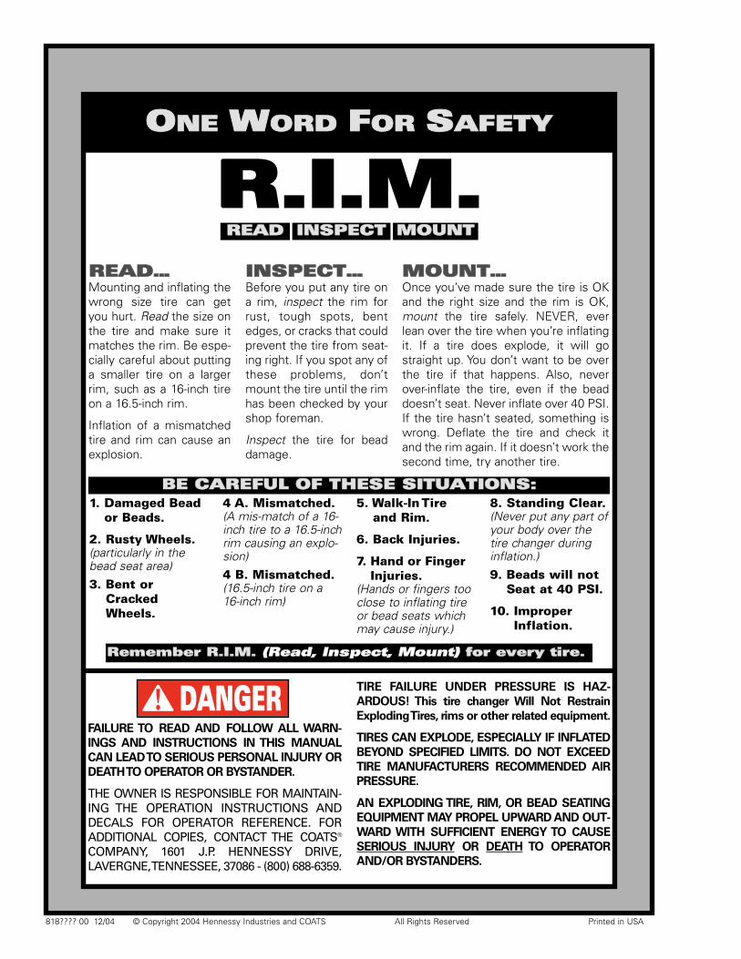
RREEAADD……Mounting and inflating thewrong size tire can getyou hurt. Read the size onthe tire and make sure itmatches the rim. Be espe-cially careful about puttinga smaller tire on a largerrim, such as a 16-inch tireon a 16.5-inch rim.
Inflation of a mismatchedtire and rim can cause anexplosion.
IINNSSPPEECCTT……Before you put any tire ona rim, inspect the rim forrust, tough spots, bentedges, or cracks that couldprevent the tire from seat-ing right. If you spot any ofthese problems, don’tmount the tire until the rimhas been checked by yourshop foreman.
Inspect the tire for beaddamage.
MMOOUUNNTT……Once you’ve made sure the tire is OKand the right size and the rim is OK,mount the tire safely. NEVER, everlean over the tire when you’re inflatingit. If a tire does explode, it will gostraight up. You don’t want to be overthe tire if that happens. Also, neverover-inflate the tire, even if the beaddoesn’t seat. Never inflate over 40 PSI.If the tire hasn’t seated, something iswrong. Deflate the tire and check itand the rim again. If it doesn’t work thesecond time, try another tire.
1. Damaged Beador Beads.
2. Rusty Wheels.(particularly in thebead seat area)3. Bent or
CrackedWheels.
4 A. Mismatched.(A mis-match of a 16-inch tire to a 16.5-inchrim causing an explo-sion)4 B. Mismatched.(16.5-inch tire on a16-inch rim)
5. Walk-In Tireand Rim.
6. Back Injuries.
7. Hand or FingerInjuries.
(Hands or fingers tooclose to inflating tireor bead seats whichmay cause injury.)
8. Standing Clear.(Never put any part ofyour body over thetire changer duringinflation.)9. Beads will not
Seat at 40 PSI.
10. ImproperInflation.
RReemmeemmbbeerr RR..II..MM.. ((RReeaadd,, IInnssppeecctt,, MMoouunntt)) ffoorr eevveerryy ttiirree..
BBEE CCAARREEFFUULL OOFF TTHHEESSEE SSIITTUUAATTIIOONNSS::
OONNEE WWOORRDD FFOORR SSAAFFEETTYY
RR..II..MM..RREEAADD IINNSSPPEECCTT MMOOUUNNTT