Rim Clamp Tire Changers - Equiptoolequiptool.com/attachment/90658-85607260 04 BaseLine TC Ops.pdfof...
30
READ these instructions before placing unit in service. KEEP these and other materials delivered with the unit in a binder near the machine for ease of reference by supervisors and operators. Safety Instructions Operation Instructions Maintenance Instructions Set-up Instructions See RIM Safety page iii ÌOperating Instructions on page 2. Rim Clamp ® Tire Changers For servicing single piece automotive and most light truck tire/wheel assemblies. Manual Part No.: 85607260 04 Revision: 4/13 Model 200 Shown
Transcript of Rim Clamp Tire Changers - Equiptoolequiptool.com/attachment/90658-85607260 04 BaseLine TC Ops.pdfof...
READ these instructions before placing unit in service. KEEP these and other materials delivered with the unit in a binder near the machine for ease of reference by supervisors and operators.
Safety InstructionsOperation Instructions
Maintenance InstructionsSet-up Instructions
SeeRIM Safety page iii
Operating Instructions
on page 2.
Rim Clamp® Tire ChangersFor servicing single piece automotive and most light truck tire/wheel assemblies.
Manual Part No.: 85607260 04 Revision: 4/13
Model 200 Shown
ii • Important: Always read and follow operating instructions.
Safety InstructionsOwner’s Responsibility
To maintain machine and user safety, the responsibility of the owner is to read and follow these instructions:
• Follow all installation instructions.
• Make sure installation conforms to all applicable Local, State, and Federal Codes, Rules, and Regula-tions; such as State and Federal OSHA Regulations and Electrical Codes.
• Carefully check the unit for correct initial function.
• Read and follow the safety instructions. Keep them readily available for machine operators.
• Make certain all operators are properly trained, know how to safely and correctly operate the unit, and are properly supervised.
• Allow unit operation only with all parts in place and operating safely.
• Carefully inspect the unit on a regular basis and perform all maintenance as required.
• Service and maintain the unit only with authorized or approved replacement parts.
• Keep all instructions permanently with the unit and all decals/labels/notices on the unit clean and visible.
• Do not override safety features.
Operator Protective EquipmentPersonal protective equipment helps make tire ser-
vicing safer. However, equipment does not take the place of safe operating practices. Always wear durable work clothing during tire service activity. Loose fitting clothing should be avoided. Tight fitting leather gloves are recommended to protect operator’s hands when handling worn tires and wheels. Sturdy leather work shoes with steel toes and oil resistant soles should be used by tire service personnel to help prevent injury in typical shop activities. Eye protection is essential during tire service activity. Safety glasses with side shields, goggles, or face shields are acceptable. Back belts provide support during lifting activities and are also helpful in providing operator protection. Consideration should also be given to the use of hearing protection if tire service activity is performed in an enclosed area, or if noise levels are high.
Definitions of Hazard LevelsIdentify the hazard levels used in this manual with the
following definitions and signal words:
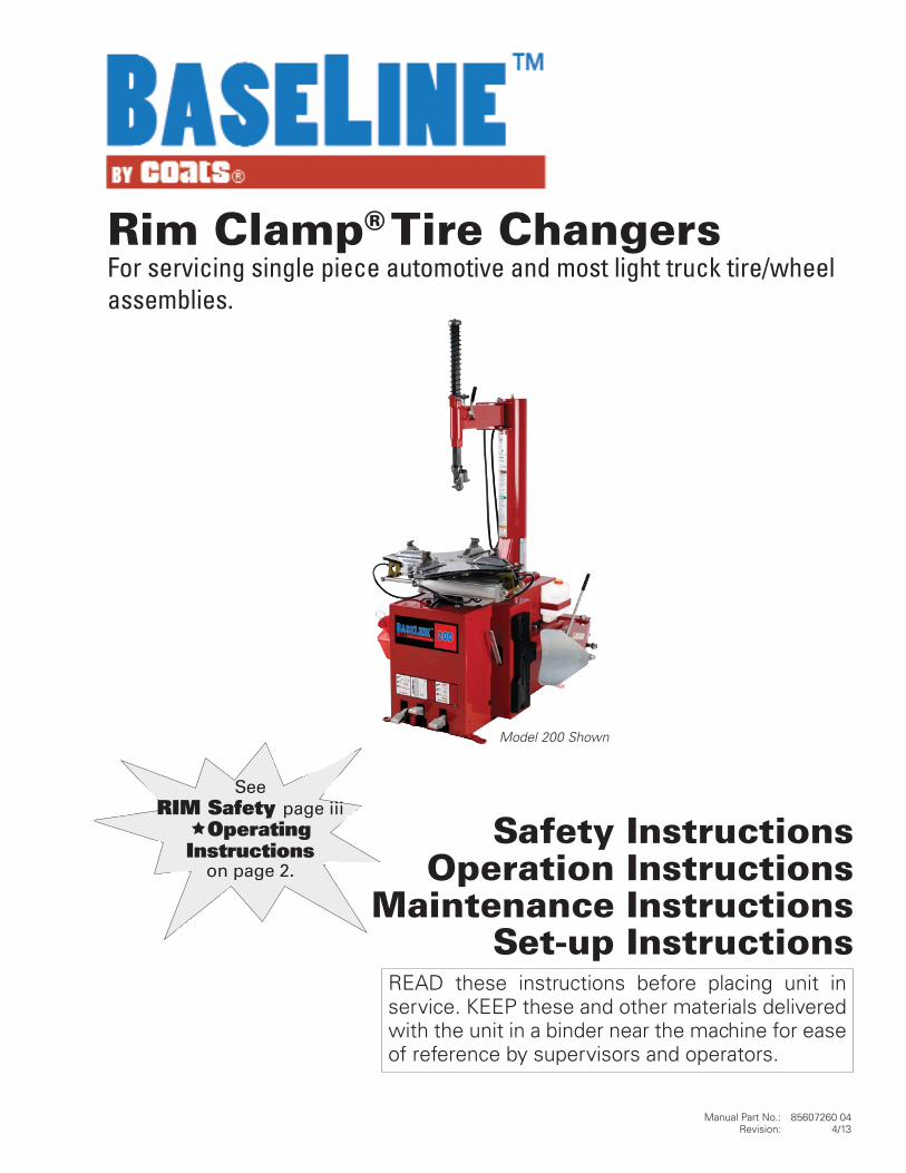
DANGERWatch for this symbol:
DANGERIt Means: Immediate hazards, which will result in
severe personal injury or death.
WARNINGWatch for this symbol:
WARNINGIt Means: Hazards or unsafe practices, which could
result in severe personal injury or death.
CAUTIONWatch for this symbol:
CAUTIONIt Means: Hazards or unsafe practices, which may
result in minor personal injury or product or property damage.
Watch for this symbol! It means BE ALERT! Your safety, or the safety of others, is involved!

Important: Always read and follow operating instructions. • iii
Safety Notices and Decals
WARNINGFailure to follow danger, warning, and caution instructions may lead to serious personal injury or death to operator or bystander or damage to property. Do not operate this machine until you read and understand all the dangers, warnings and cautions in this manual. For additional copies of either, or further information, contact:
Hennessy Industries, Inc.1601 JP Hennessy DriveLaVergne, TN 37086-3565(615) 641-7533 or (800) 688-6359www.ammcoats.com
For additional information contact:
Rubber Manufacturers Association1400 K Street N. W., Suite 900Washington, DC 20005(202) 682-4800www.rma.org
Tire Guides, Inc.The Tire Information Center1101-6 South Rogers CircleBoca Raton, FL 33487-2795(561) 997-9229www.tireguides.com
Remember R.I.M.Three Simple Steps To Help Keep Shops Safe
R.I.M. is a training program developed by Hennessy Industries to help keep tire technicians safe. By follow-ing the basic principles of R.I.M., technicians can avoid situations that can cause catastrophic accidents like tire explosions.
R.I.M. stands for read, inspect, and mount:
Read the tire size on a new tire before mounting to make sure it is the proper size for the wheel.
Inspect the wheel for cracks, rust, and or other dam-age that could cause an unsafe situation.
Mount the tire safely, making sure not to put any part of your body over the tire during inflation.
The most serious of possible accidents is a tire explo-sion. This is often caused by a tire/rim mismatch.
If a tire explodes on a tire changer, pressure causes it to fly straight up at tremendous speed. If a technician is standing over the tire, he can be seriously injured or killed.
Hennessy’s R.I.M. program allows the technician to avoid situations that can cause tire explosions and other accidents. The full program, including training videos, brochures, posters, and other materials, is available from Coats distributors nationwide.
For more details, contact your Coats distributor or e-mail us.
READ INSPECT MOUNT
iv • Important: Always read and follow operating instructions.
Read entire manual before assembling, installing, operating, or servicing this equipment.
NOTICE
Table of ContentsSafety Instructions .................................................. iii
Owner’s Responsibility .............................................ii
Operator Protective Equipment ................................ii
Definitions of H azard Levels .....................................ii
Safety Notices and Decals ...................................... iii
Remember R.I.M. .................................................... iii
Principle Operating Parts ......................................... 1
Know Your Unit ........................................................ 1
Operating Instructions ........................................ 2 - 7
Bead Loosening and Demounting ...................... 2 - 5
Mounting ............................................................ 6 - 7
Inflation .............................................................. 8 - 11
Bead Sealing ............................................................ 9
Bead Seating ..........................................................10
Inflation...................................................................11
Stages of Inflation on a Conventional Tireand Rim ................................................................... 12
Bead Sealing .......................................................... 12
Bead Seating ......................................................... 12
Inflation.................................................................. 12
Mismatched Tires and Wheels ............................... 13
Tube Type Tires ........................................................ 14
Mounting ............................................................... 14
Demounting........................................................... 14
Maintenance Instructions ............................... 15 - 17
Mount/Demount Tool Cleaning .............................. 16
Mount/Demount Tool Adjustment ......................... 16
Pressure Limiter Maintenance ........................16 - 17
Oil Injector Maintenance ........................................17
Installation Instructions .................................. 18 - 19
Location ................................................................. 18
Workspace Requirements ..................................... 18
Tower Installation ............................................18 - 19
Air Source .............................................................. 19
Electrical Source .................................................... 19
Floor Mounting ...................................................... 19
Operating Instructions(with Robo-Assist™) ....................................... 20 - 17
Bead Loosening and Demounting ......................... 20
Mounting ............................................................... 23
Robo-Assist™ Maintenance .................................. 24
Critical Safety Instructions ...................... Back Cover
Important: Always read and follow operating instructions. • 1
Principal Operating PartsDo It Now!Now is a good time to fill out the Owner’s
Registry Card.
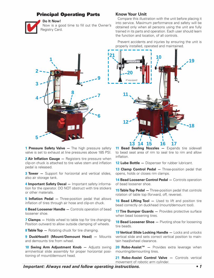
Know Your UnitCompare this illustration with the unit before placing it
into service. Maximum performance and safety will be obtained only when all persons using the unit are fully trained in its parts and operation. Each user should learn the function and location, of all controls.
Prevent accidents and injuries by ensuring the unit is properly installed, operated and maintained.
✔
1 Pressure Safety Valve — The high pressure safety valve is set to exhaust at line pressures above 185 PSI.
2 Air Inflation Gauge — Registers tire pressure when clip-on chuck is attached to tire valve stem and inflation pedal is released.
3 Tower — Support for horizontal and vertical slides, also air storage tank.
4 Important Safety Decal — Important safety informa-tion for the operator. DO NOT obstruct with tire stickers or other materials.
5 Inflation Pedal — Three-position pedal that allows inflation of tires through air hose and clip-on chuck.
6 Bead Loosener Handle — Controls operation of bead loosener shoe.
7 Clamps — Holds wheel to table top for tire changing. Position outward to allow outside clamping of wheels.
8 Table Top — Rotating chuck for tire changing.
9 DuckHead® (Mount/Demount Head) — Mounts and demounts tire from wheel.
10 Swing Arm Adjustment Knob — Adjusts swing arm/vertical slide assembly for proper horizontal posi-tioning of mount/demount head.
11 Bead Sealing Nozzles — Expands tire sidewall to bead seat area of rim to seal tire to rim and allow inflation.
12 Lube Bottle — Dispenser for rubber lubricant.
13 Clamp Control Pedal — Three-position pedal that opens, holds or closes rim clamps.
14 Bead Loosener Control Pedal — Controls operation of bead loosener shoe.
15 Table Top Pedal — Three-position pedal that controls rotation of table top (forward, off, reverse).
16 Bead Lifting Tool — Used to lift and position tire bead correctly on duckhead (mount/demount tool).
17 Tire Bumper Guards — Provides protective surface when bead loosening tires.
18 Bead Loosener Shoe — Pivoting shoe for loosening tire beads.
19 Vertical Slide Locking Handle — Locks and unlocks vertical slide and sets correct vertical position to main-tain head/wheel clearance.
20 Robo-Assist™ — Provides extra leverage when mounting/demounting tires.
21 Robo-Assist Control Valve — Controls vertical movement of robotic arm cylinder.
1
2
3
4
5
6
78
9
10
11
12
13 14 15 16 17
18
19
20(If equipped)
21

2 • Important: Always read and follow operating instructions.
Operating InstructionsThis unit must be properly operated and properly
maintained to help avoid accidents that could damage the unit and injure the operator or bystanders. This section of the Operating Instructions manual review basic operations and use of controls. These instructions should be reviewed with all employees before they are allowed to work with the machine. Keep these instruc-tions near the machine for easy reference.
Bead Loosening and Demounting
CAUTIONThis machine may operate differently from machines you have previously operated. Practice with a regular steel wheel and tire combination to familiarize yourself with the machine’s operation and function.
A. Remember to remove all weights from both sides of the wheel. Weights left on backside of wheel may cause the wheel to be clamped unleveled. This may result in the combination mount/demount head contacting the rim causing scratches. On alloy wheels, always rotate the wheel one turn after set-ting the Duckhead to insure proper wheel chucking.
B. Always review with the owner any nicks and scratches on expensive wheel and tire combina-tions prior to servicing.
CAUTIONLoosening the beads on a partially or fully inflated tire is unsafe and causes excess movement and friction against the bumper pads and excessive wear on pivots. Deflate the tire completely to prolong the life of your machine.
1. Deflate the tire completely by removing the valve core from the valve stem (figure 1). Be cautious and do not smoke as a flammable gas could have been introduced into the tire at some time.
Figure 1 - Remove Valve Core to Deflate Tire
CAUTIONTires are always installed and removed from the rim’s narrow side.
D. Always loosen the bead on the narrow side of the wheel’s drop center first (tire removed in figure 2 for clarity).
Figure 2 - Determine Narrow Side of Wheel
E. The clamps on the table top may extend beyond the table top itself. To avoid damaging the clamps, move them to their full inward position before positioning a tire for bead loosening.
F. Use extra care in positioning the bead loosener shoe on larger wheels/tires, and on alloy wheels. Make sure the shoe rests next to but not on the rim, and not on the tire sidewall.
2. Pull the bead loosener shoe away from the machine and roll wheel into position. The valve stem should be in the 2 o’clock position to accommodate a possible asymmetric safety hump type rim. Position the bead loosener shoe against the tire next to, but not on, the rim. Press the bead loosener foot pedal to actuate the shoe and loosen the bead. It may be necessary to loosen the bead in multiple locations around the tire (figure 3).
Narrow Side
Drop Center
Long Side
Important: Always read and follow operating instructions. • 3
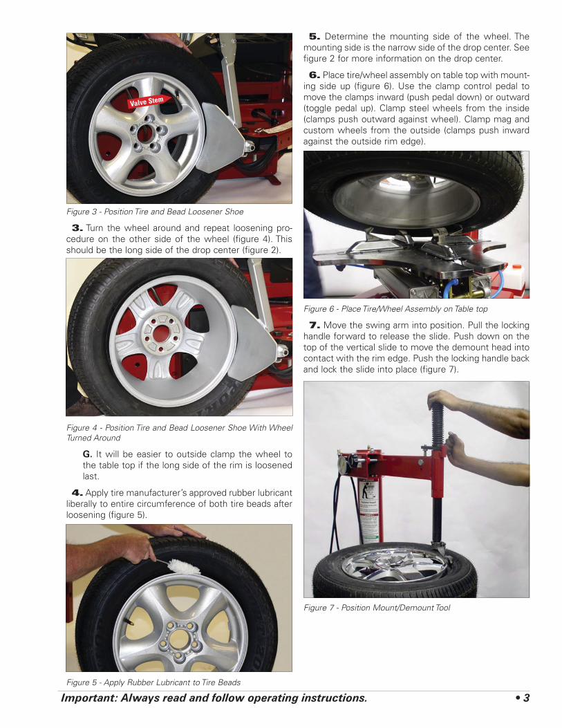
Figure 3 - Position Tire and Bead Loosener Shoe
3. Turn the wheel around and repeat loosening pro-cedure on the other side of the wheel (figure 4). This should be the long side of the drop center (figure 2).
Figure 4 - Position Tire and Bead Loosener Shoe With Wheel Turned Around
G. It will be easier to outside clamp the wheel to the table top if the long side of the rim is loosened last.
4. Apply tire manufacturer’s approved rubber lubricant liberally to entire circumference of both tire beads after loosening (figure 5).
Figure 5 - Apply Rubber Lubricant to Tire Beads
5. Determine the mounting side of the wheel. The mounting side is the narrow side of the drop center. See figure 2 for more information on the drop center.
6. Place tire/wheel assembly on table top with mount-ing side up (figure 6). Use the clamp control pedal to move the clamps inward (push pedal down) or outward (toggle pedal up). Clamp steel wheels from the inside (clamps push outward against wheel). Clamp mag and custom wheels from the outside (clamps push inward against the outside rim edge).
Figure 6 - Place Tire/Wheel Assembly on Table top
7. Move the swing arm into position. Pull the locking handle forward to release the slide. Push down on the top of the vertical slide to move the demount head into contact with the rim edge. Push the locking handle back and lock the slide into place (figure 7).
Figure 7 - Position Mount/Demount Tool
Valve Stem
4 • Important: Always read and follow operating instructions.
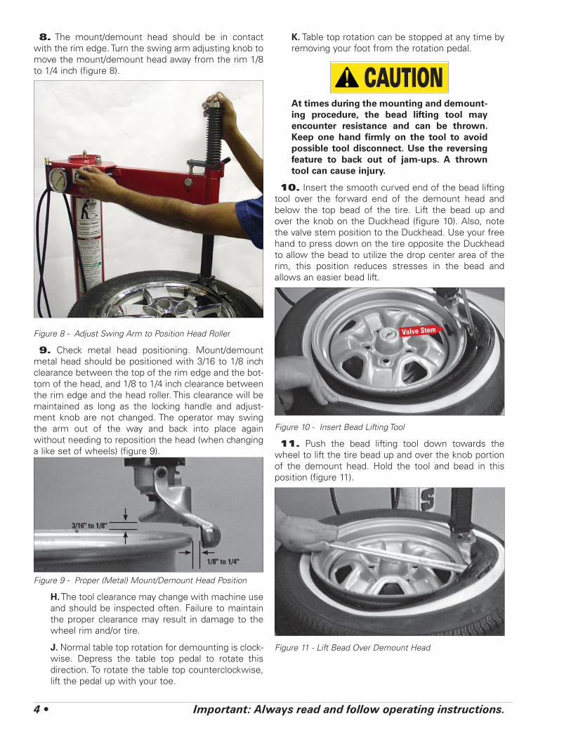
8. The mount/demount head should be in contact with the rim edge. Turn the swing arm adjusting knob to move the mount/demount head away from the rim 1/8 to 1/4 inch (figure 8).
Figure 8 - Adjust Swing Arm to Position Head Roller
9. Check metal head positioning. Mount/demount metal head should be positioned with 3/16 to 1/8 inch clearance between the top of the rim edge and the bot-tom of the head, and 1/8 to 1/4 inch clearance between the rim edge and the head roller. This clearance will be maintained as long as the locking handle and adjust-ment knob are not changed. The operator may swing the arm out of the way and back into place again without needing to reposition the head (when changing a like set of wheels) (figure 9).
Figure 9 - Proper (Metal) Mount/Demount Head Position
H. The tool clearance may change with machine use and should be inspected often. Failure to maintain the proper clearance may result in damage to the wheel rim and/or tire.
J. Normal table top rotation for demounting is clock-wise. Depress the table top pedal to rotate this direction. To rotate the table top counterclockwise, lift the pedal up with your toe.
K. Table top rotation can be stopped at any time by removing your foot from the rotation pedal.
CAUTIONAt times during the mounting and demount-ing procedure, the bead lifting tool may encounter resistance and can be thrown. Keep one hand firmly on the tool to avoid possible tool disconnect. Use the reversing feature to back out of jam-ups. A thrown tool can cause injury.
10. Insert the smooth curved end of the bead lifting tool over the forward end of the demount head and below the top bead of the tire. Lift the bead up and over the knob on the Duckhead (figure 10). Also, note the valve stem position to the Duckhead. Use your free hand to press down on the tire opposite the Duckhead to allow the bead to utilize the drop center area of the rim, this position reduces stresses in the bead and allows an easier bead lift.
Figure 10 - Insert Bead Lifting Tool
11. Push the bead lifting tool down towards the wheel to lift the tire bead up and over the knob portion of the demount head. Hold the tool and bead in this position (figure 11).
Figure 11 - Lift Bead Over Demount Head
3/16" to 1/8"
1/8" to 1/4"
Valve Stem

Important: Always read and follow operating instructions. • 5
12. Depress the table top pedal to rotate the wheel. The Duckhead will guide the tire bead up and over the edge of the wheel. Continue rotation until the upper bead is demounted.
L. Push down on the tire across from the demount head during table top rotation to utilize the drop center area of the wheel. This reduces the tensional force on the top or first bead during demount (figure 10).
Figure 12 - Demounting Lower Bead
13. Lift and hold the tire at an angle so that the lower bead is resting in the drop center directly across from the demount head, and is loose below the demount head (figure 12). Insert the smooth curved end of the bead lifting tool down over the forward end of the mount/demount tool and below the lower bead. Lift the bead up and over the knob on the demount head (figure 13).
Figure 13 - Guide Lower Bead Over Tool Head
14. Depress the table top pedal to rotate the wheel. The demount head will guide the bead up and over the edge of the wheel. Continue rotation until lower bead is demounted.
M. With tube-type tires, demount the upper bead and remove the tube before demounting the lower bead.
After successfully completing the demount process, proceed to Mounting (page 6).✔
6 • Important: Always read and follow operating instructions.
MountingThis information must be read and followed carefully
to prevent accidents and injuries during mounting.
DANGERAttempts to force a bead seat on mis-matched tires and wheels can cause the tire to violently explode, causing serious personal injury or death to operator and/or bystanders.
WARNINGCheck tire and wheel carefully before mount-ing. Make sure the tire bead diameter and wheel diameter match exactly. Consult the Tire Guide and/or Rubber Manufacturer’s Association for approved rim widths for tire sizes.
WARNINGNever mount a damaged tire. Never mount a tire on a rusty or damaged wheel. Damaged tires and/or wheels may explode.
CAUTIONWhen in doubt do not mount.
CAUTIONNever mount a tire and wheel handed to you by anyone without checking both tire and wheel for damage and to be certain the sizes match. Do not let untrained persons operate tire changer and keep bystanders out of service area.
CAUTIONForcing the tire onto the rim can cause bead damage. If you damage the tire bead during mounting, STOP!, remove tire and mark it as damaged. Do not mount a damaged tire.
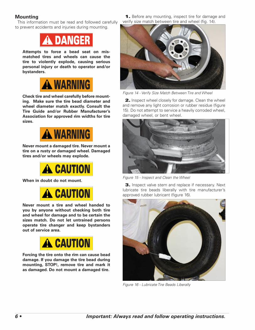
1. Before any mounting, inspect tire for damage and verify size match between tire and wheel (fig. 14).
Figure 14 - Verify Size Match Between Tire and Wheel
2. Inspect wheel closely for damage. Clean the wheel and remove any light corrosion or rubber residue (figure 15). Do not attempt to service a heavily corroded wheel, damaged wheel, or bent wheel.
Figure 15 - Inspect and Clean the Wheel
3. Inspect valve stem and replace if necessary. Next lubricate tire beads liberally with tire manufacturer’s approved rubber lubricant (figure 16).
Figure 16 - Lubricate Tire Beads Liberally
Important: Always read and follow operating instructions. • 7
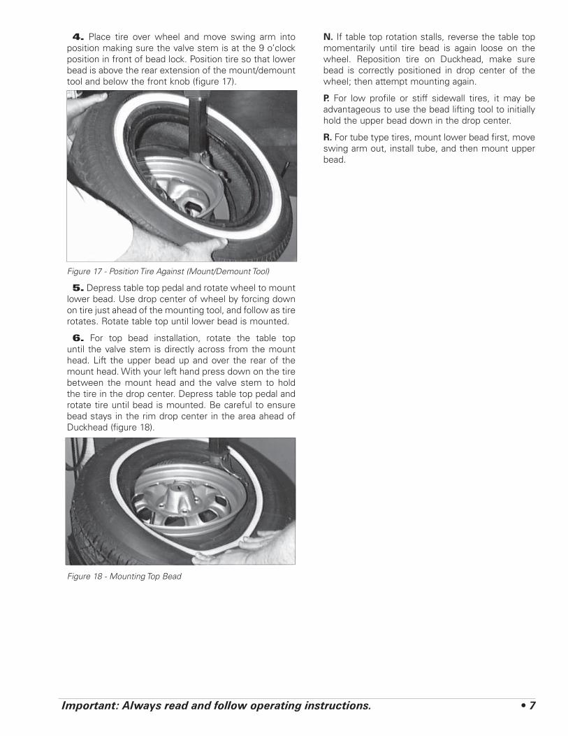
4. Place tire over wheel and move swing arm into position making sure the valve stem is at the 9 o’clock position in front of bead lock. Position tire so that lower bead is above the rear extension of the mount/demount tool and below the front knob (figure 17).
Figure 17 - Position Tire Against (Mount/Demount Tool)
5. Depress table top pedal and rotate wheel to mount lower bead. Use drop center of wheel by forcing down on tire just ahead of the mounting tool, and follow as tire rotates. Rotate table top until lower bead is mounted.
6. For top bead installation, rotate the table top until the valve stem is directly across from the mount head. Lift the upper bead up and over the rear of the mount head. With your left hand press down on the tire between the mount head and the valve stem to hold the tire in the drop center. Depress table top pedal and rotate tire until bead is mounted. Be careful to ensure bead stays in the rim drop center in the area ahead of Duckhead (figure 18).
Figure 18 - Mounting Top Bead
N. If table top rotation stalls, reverse the table top momentarily until tire bead is again loose on the wheel. Reposition tire on Duckhead, make sure bead is correctly positioned in drop center of the wheel; then attempt mounting again.
P. For low profile or stiff sidewall tires, it may be advantageous to use the bead lifting tool to initially hold the upper bead down in the drop center.
R. For tube type tires, mount lower bead first, move swing arm out, install tube, and then mount upper bead.
8 • Important: Always read and follow operating instructions.
Infl ationTire inflation is performed in three steps: BEAD SEAL,
BEAD SEAT, and INFLATION. These steps are explained in detail on page 12. Read the explanation of each step and understand them thoroughly before proceeding.
DANGERTire failure under pressure is hazardous. This tire changer Will Not Restrain Explod-ing Tires, rims or other related equipment. Inspect tire and wheel carefully for match, wear, damage, or defects before mounting. Always use approved tire bead lubricant during mounting and inflation.
CAUTIONThe clip-on chuck allows the operator to keep hands and entire body back from inflat-ing tire. The chuck must be an open/freeflow style with all parts in proper working order.
CAUTIONCheck for proper inflation gauge operation. Accurate pressure readings are important to safe tire inflation. Refer to the Operat-ing Maintenance section of this manual for instructions.
CAUTIONIf the rim has been clamped from the outside for tire mounting, release the clamps, lift the tire, and move the clamps to the center of the table top.
CAUTIONIf the wheel/tire has a diameter larger than 14-inches and is difficult to bead seal, the clamps should be moved to the center of the table top for the bead seal operation.
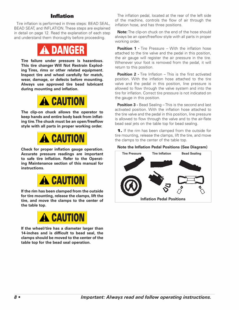
The inflation pedal, located at the rear of the left side of the machine, controls the flow of air through the inflation hose, and has three positions.
Note: The clip-on chuck on the end of the hose should always be an open/freeflow style with all parts in proper working order.
Position 1 - Tire Pressure – With the inflation hose attached to the tire valve and the pedal in this position, the air gauge will register the air pressure in the tire. Whenever your foot is removed from the pedal, it will return to this position.
Position 2 - Tire Inflation – This is the first activated position. With the inflation hose attached to the tire valve and the pedal in this position, line pressure is allowed to flow through the valve system and into the tire for inflation. Correct tire pressure is not indicated on the gauge in this position.
Position 3 - Bead Sealing – This is the second and last activated position. With the inflation hose attached to the tire valve and the pedal in this position, line pressure is allowed to flow through the valve and to the air-flate bead seal jets on the table top for bead sealing.
1. If the rim has been clamped from the outside for tire mounting, release the clamps, lift the tire, and move the clamps to the center of the table top.
Note the Inflation Pedal Positions (See Diagram)
Tire Pressure Tire Inflation Bead Sealing
Inflation Pedal Positions

Important: Always read and follow operating instructions. • 9
CAUTIONUse of bead sealing jets without a tire in place can cause dirt and debris to be blown into the air with enough force to injure operator and/or bystander. Do not use the bead sealing control position to inflate a tire.
S. This unit is equipped with a pressure limiter to assist the operator with proper tire inflation. When the inflation pedal is held in position 2, the pressure limiter cycles the machine between position 2 (infla-tion) and position 1 (at rest, no airflow to tire). This cycling helps to prevent over inflation of the tire. Tires can still be over inflated and explode with the use of this pressure limiter if all of the instructions in this manual are not followed completely. The pressure limiter will keep most car and light truck tires from inflating beyond 60 PSI (smaller tires may reach higher pressures). It is the operator’s responsibility to follow all instructions and to control inflation pressure as specified in these instructions. Check the function of the pressure limiter regularly and maintain it according to the instructions pro-vided in this manual for safe and proper operation. Do not tamper with or attempt to adjust the pres-sure limiter. Tires requiring inflation beyond 60 PSI should be inflated in a safety cage.
Bead Sealing1. Remove the valve core from the valve stem to
allow more air flow into the tire to assist with bead seal.
2. Position valve stem in front of operator and con-nect the inflation hose with the clip-on chuck. Hold tire up against upper edge of the wheel. Be sure tire’s top bead does not cover the bottom of the valve stem (figure 19).
Figure 19 - Lift Tire Upwards for Bead Sealing
3. Depress inflation pedal to position 2 and hold about one second to begin air flow through tire valve, then depress pedal to position 3 and hold briefly — less than one full second. The blast of air from the jets will expand tire and seal the beads.
4. Release the inflation pedal and allow it to return to position 1. Verify that both beads are completely sealed to the wheel. Repeat these steps if beads have not sealed. It may be necessary to wait a few seconds for the air storage tank pressure to recover before attempt-ing again.
5. After bead seal is achieved, remove the clip-on chuck and reinstall the valve core. Reattach the clip-on chuck after core is installed.
10 • Important: Always read and follow operating instructions.
Bead Seating
DANGERNEVER exceed 40 PSI to seat beads while using this tire changer. If more than 40 PSI is permitted by tire manufacturer, ALWAYS use safety cage and clip-on chuck. NEVER exceed recommended pressure after seating beads. ALWAYS keep hands and entire body back from inflating tire.
An exploding tire, wheel, or bead sealing equipment may propel upward and outward with sufficient force to cause serious injury or death to operator or bystander.
WARNINGCheck tire pressure frequently. If operator is unable to obtain Bead Seat, something is wrong. Deflate tire completely, inspect tire and wheel, correct any problems found, relu-bricate both tire beads, and reattempt Bead Seal and Seat procedures. Follow all safety instructions in this manual and on machine.
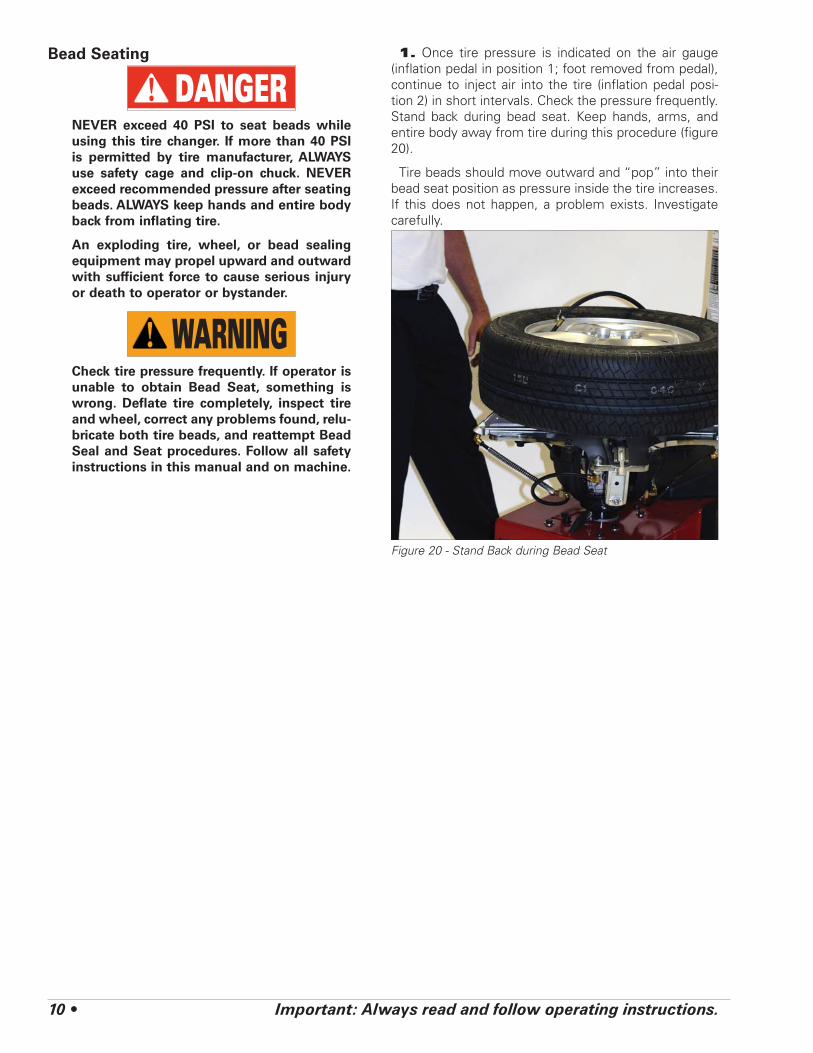
1. Once tire pressure is indicated on the air gauge (inflation pedal in position 1; foot removed from pedal), continue to inject air into the tire (inflation pedal posi-tion 2) in short intervals. Check the pressure frequently. Stand back during bead seat. Keep hands, arms, and entire body away from tire during this procedure (figure 20).
Tire beads should move outward and “pop” into their bead seat position as pressure inside the tire increases. If this does not happen, a problem exists. Investigate carefully.
Figure 20 - Stand Back during Bead Seat

Important: Always read and follow operating instructions. • 11
Inflation
WARNINGNEVER exceed tire manufacturer’s recom-mended air pressure. Tires can explode, especially if inflated beyond these limits. Use clip-on air chuck, keep hands, arms and entire body back from inflating tire. Avoid distraction during inflation. Check tire pressure frequently to avoid over infla-tion. Excessive pressure can cause tires to explode, causing serious injury or death to operator or bystander.
1. Make sure both beads are seated. When both beads are seated, the tire is ready for inflation.
2. Replace the valve core if it was removed.
3. Depress the inflation pedal to position 2 to inflate the tire. The pressure limiter will cycle the air flow as described earlier. On most tires, the pressure limiter will cease air flow at approximately 60 PSI. On smaller volume tires the pressure may be higher.
4. Important: When inflating tires that require more than 60 PSI, always use a safety cage and air hose with a clip-on air chuck and in-line valve. The air hose must have enough length between the chuck and the opera-tion/in-line valve to allow the operator to stand outside the trajectory.
U. If you change tires defined as truck tires, they must be inflated per OSHA instructions.
Figure 21 - Do Not Use a Hand-held Style Air Chuck
Explosion HazardNever exceed 40 PSI while seating
beads.Remember R.I.M.
(see page iv and back cover)
Explosion HazardNever infl ate tire
above manufacturer’s recommended
pressure after bead is seated.
DANGERDANGER
12 • Important: Always read and follow operating instructions.
Stages of Infl ation on aConventional Tire and Rim
Review these descriptions and diagrams carefully. Refer to them as necessary during bead sealing, bead seating, and inflation to verify that you are proceeding properly and safely.
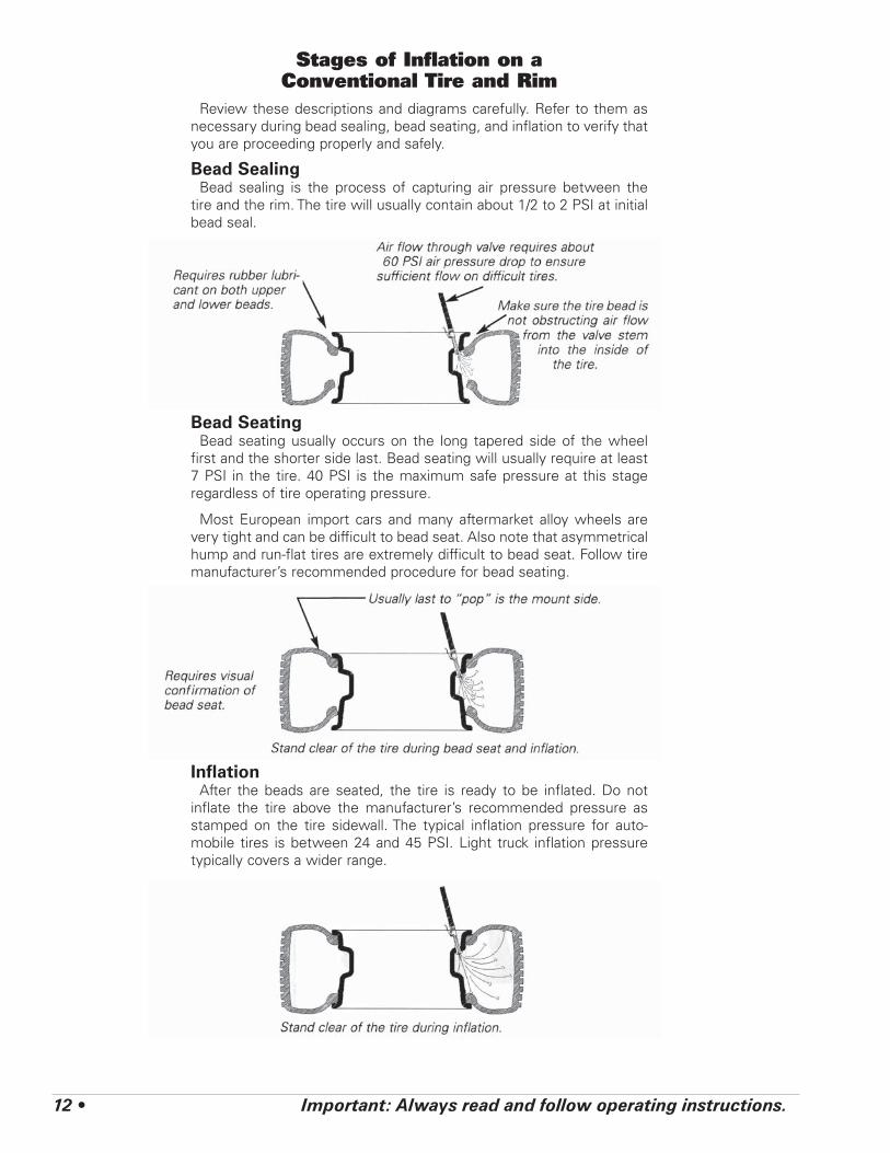
Bead SealingBead sealing is the process of capturing air pressure between the
tire and the rim. The tire will usually contain about 1/2 to 2 PSI at initial bead seal.
Bead SeatingBead seating usually occurs on the long tapered side of the wheel
first and the shorter side last. Bead seating will usually require at least 7 PSI in the tire. 40 PSI is the maximum safe pressure at this stage regardless of tire operating pressure.
Most European import cars and many aftermarket alloy wheels are very tight and can be difficult to bead seat. Also note that asymmetrical hump and run-flat tires are extremely difficult to bead seat. Follow tire manufacturer’s recommended procedure for bead seating.
InflationAfter the beads are seated, the tire is ready to be inflated. Do not
inflate the tire above the manufacturer’s recommended pressure as stamped on the tire sidewall. The typical inflation pressure for auto-mobile tires is between 24 and 45 PSI. Light truck inflation pressure typically covers a wider range.
Important: Always read and follow operating instructions. • 13
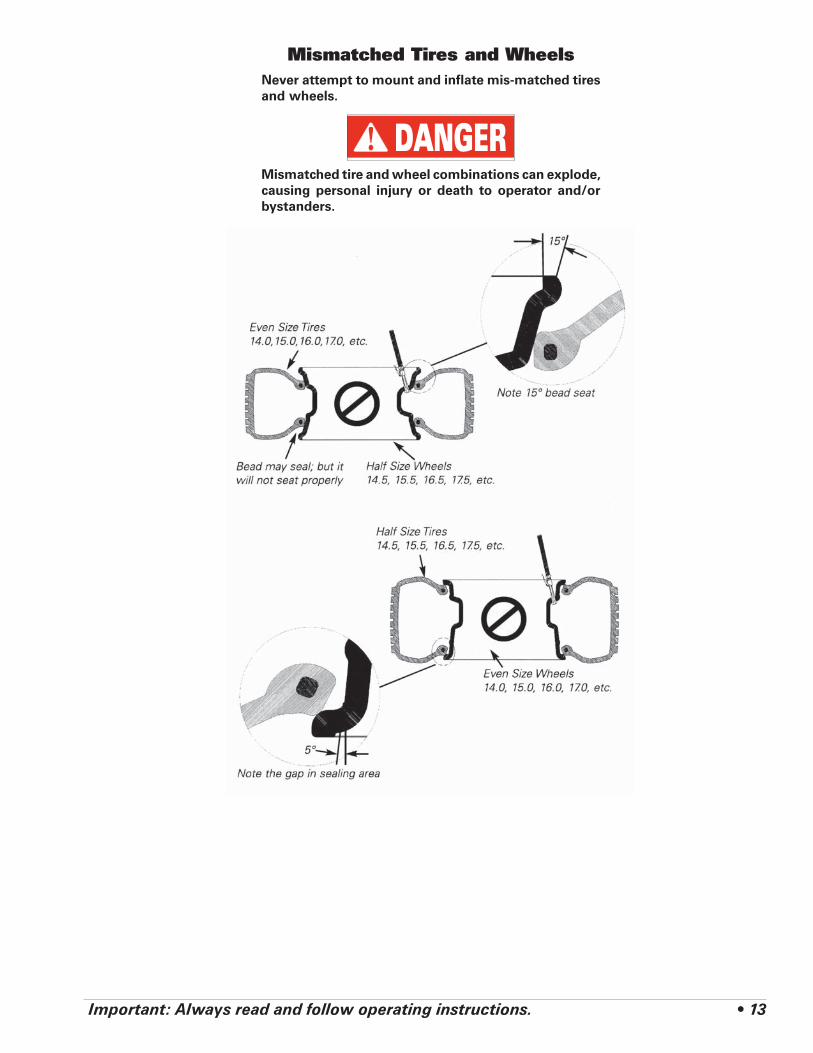
Mismatched Tires and WheelsNever attempt to mount and inflate mis-matched tires and wheels.
DANGERMismatched tire and wheel combinations can explode, causing personal injury or death to operator and/or bystanders.
14 • Important: Always read and follow operating instructions.
Tube Type TiresMounting1. Avoid pinching or forcing the tube.
2. Apply rubber lubricant to the beads of the tire.
3. Mount the bottom bead.
4. Round out the tube with a small amount of air.
5. Apply rubber lubricant to the tube.
6. Insert the tube into the tire.
7. Mount the top bead.
Demounting1. After tire beads are loosened, lubricate the beads
and rim liberally.
2. Position demount head and bead lifting tool as described in steps 7 through 10 on pages 3 and 4. Depress table top pedal and rotate only a short distance at a time. This allows you to stop the process should the tube get pinched.
3. After upper bead is demounted, remove tube and demount lower bead.
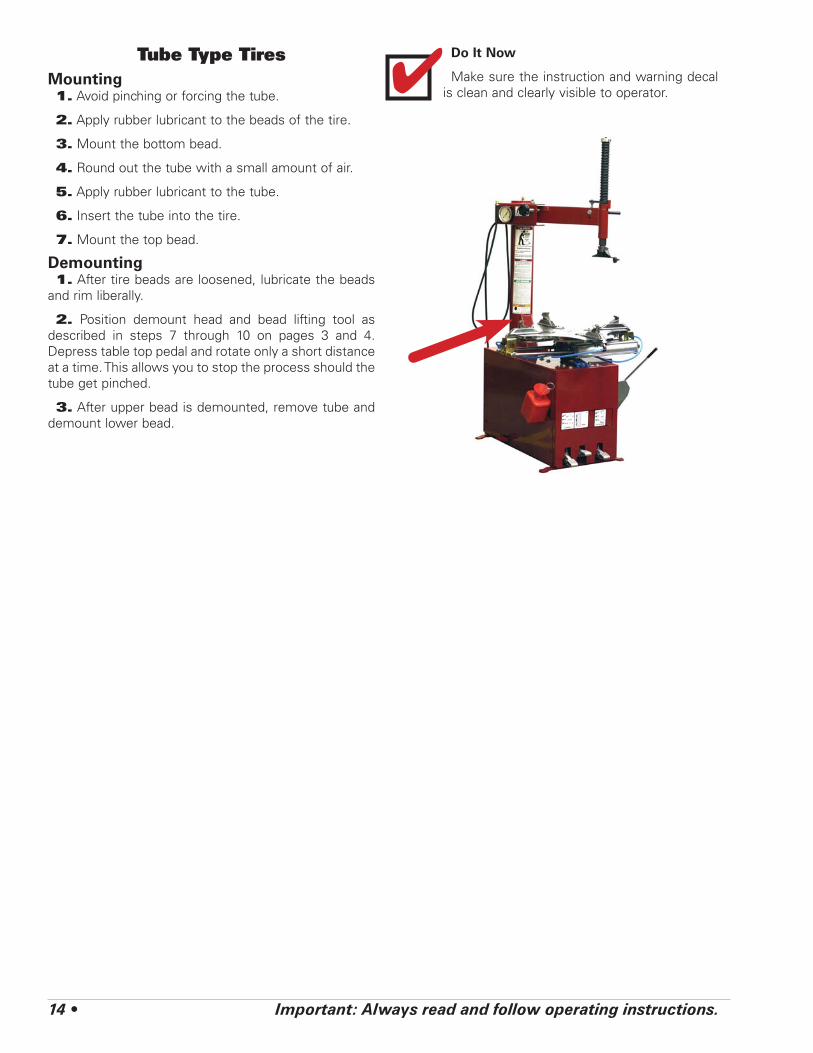
Do It Now
Make sure the instruction and warning decal is clean and clearly visible to operator.✔

Important: Always read and follow operating instructions. • 15
Maintenance InstructionsRead and follow all the maintenance instructions pro-
vided in this manual to keep the machine in good oper-ating condition. Refer to the other materials received with the unit and to the service bulletins from the manufacturer for additional instructions on proper main-tenance and service. Regular inspections and proper maintenance are essential to preventing accidents and injuries.
WARNINGAlways DISCONNECT ELECTRICAL POWER and block out all moving parts before mak-ing any inspection, adjustment, or repair to the machine. This prevents electrical shock or accidental movement of the systems operated by the electrical power.
WARNINGAlways DISCONNECT AIR SUPPLY before servicing machine. This prevents accidental movement of systems operated by com-pressed air which may result in personal injury. BLEED AIR SYSTEM by actuating all the valves.
WARNINGKeep the machine and the immediate work area clean. Do not use compressed air to remove dirt and debris from the machine. Foreign material may be propelled into the air and into operator or bystander causing personal injury.
WARNINGWear protective clothing, equipment and eye protection when making any adjust-ments or repairs to the machine.
CAUTIONReplace any damaged or missing safety decals. They are available from COATS, (800) 688-6359.
Important: These instructions will help you service the unit. Instructions are for a person with some mechanical ability and training. No attempt has been made to describe all basic steps. For example, how to loosen or tighten fasteners. Also basic procedures such as cycling systems and checking operation of the equip-ment are not fully described since they are known to anyone who does mechanical and service work. Do not attempt to perform work beyond your ability or at which you have no experience. If you need assistance, call an authorized service center.
A. The vertical slide should be cleaned with a vapor-izing solvent and then lubricated with chassis grease once a month.
B. Check the adjustment of the Duckhead® (mount /demount tool) once a month.
C. Check the fluid level in the table top transmission once every 3 months. If fluid shows on dipstick, level is satisfactory. If no fluid shows, add an SAE 80 gear lubricant until fluid shows on dipstick.
D. The table top, clamps, steel Duckhead (mount /demount tool), and other working surfaces should be cleaned with a vaporizing solvent every month.
E. The clamps should be inspected and metal chips and dirt from the serrations with a wire brush every month.
F. Check the tire pressure gauge function daily, and check the accuracy monthly. Use a pressurized tire and a high quality stick-type pressure gauge. If necessary, adjust the dial of the machine gauge. If the gauge is defective, replace it immediately (part number 8107985). Check function of the pressure limiter weekly. Always reinstall the lens after adjusting the gauge.
G. Make sure all fasteners are securely tightened.
H. Make certain that all guards and covers are in place.
I. Check for worn, damaged or missing parts including grips and protective covers. Replace them before allow-ing the unit to be used.
J. On a daily basis, inspect the unit and check to be certain that all systems are operating normally. Detailed inspection and testing procedures are specified for vari-ous components at regular intervals. Set up a chart and assign responsibility for these items.

16 • Important: Always read and follow operating instructions.
Mount/Demount Tool CleaningClean dirt and debris from the mount/demount tool
(duckhead) roller with small screw driver or pick.
Figure 22 - Clean Mount/demount Tool Using Small Screw-driver
Mount/Demount Tool AdjustmentTo Adjust Lock TightnessWith lock handle unlocked, loosen jam nut (ref. 1) and
adjust pin (ref. 2) until a slight firmness is obtained, then tighten jam nut and check. Also recheck tool head lift at this time.
Pressure Limiter Maintenance
DANGEROperating a tire changer with a defective, improperly adjusted, or by-passed pressure limiter could cause an operator to acciden-tally over pressurize a tire, resulting in a tire explosion with severe injury or death to the operator or bystanders.
Always be sure that the pressure limiter is present and is operating properly.
DANGERNever inflate tire above manufacturer’s rec-ommended pressure after bead is seated. Pressure limiter is set at 60 PSI. Any required inflation above 60 PSI should be performed in an inflation chamber/safety cage or securely mounted on the vehicle if an infla-tion chamber is not available. A tire explo-sion may cause personal injury or death to operator or bystanders.
The pressure limiter helps prevent inflation of standard size or larger tires or tubes beyond 60 PSI to minimize risk of explosion. This device is for the safety of the operator and bystanders. Proper operation of the pres-sure limiter is essential to safe operation of the machine.
Check operation of the pressure limiter as shown and described below at least monthly:
1. Remove tires and/or wheels from the machine.
2. Connect the inflation hose to an empty service tank with a pressure gauge (gauge should read 0). Use a certified tank with at least 250 PSI pressure rating.
3. Depress inflation pedal to position 1 to start airflow through the hose and into the tank. Maintain a steady pressure for constant flow.

Important: Always read and follow operating instructions. • 17
4. Watch the rising pressure on the tank gauge and the gauge on the machine. Machine gauge should cycle between check and inflation pressures while tank gauge climbs steadily. As tank pressure reaches 60 PSI, the pressure limiter should stop the airflow automati-cally. Both gauges should read 60 PSI ± 5 PSI.
5. Replace pressure limiter if it fails to cycle properly during inflation, if it fails to shut air supply off at 60 PSI, or if it malfunctions in any other way. Do not operate machine with a faulty pressure limiter.
Oil Injector MaintenanceThe oil injector typically require annual service. The
oil level in the oil reservoir tank should be checked regularly.
Add oil to oil reservoir tank when fluid level is a quarter full or below. Remove cap from the oil reservoir tank and add Chevron Regal® R & O 32 oil to full line (air tool oil is an acceptable substitute). Replace cap and clean up any spilled oil.
Important: An air lock will form if the hose between the reservoir and injector is ever empty of oil. In this case, after filling the reservoir tank, the line must be bled of air at the injector connection as follows:
1. Disconnect all power sources, both air and electric-ity inputs. Allow any stored air in the reservoir to escape by depressing the inflate pedal.
2. Remove the side panel and locate the oil injector.
3. Prime the oil injector. Loosen bleeder plug until oil drips from screw and all air is relieved from the oil line hose. Retighten the bleeder screw.
4. Reconnect air/electric sources and cycle the clamp control pedal a few times checking for oil and air leaks.
5. Test the machine for full function before returning the machine to operation.
6. Monitor oil consumption to ensure oil is being used in system.
Watch Pressure on Both Gauges
250 PSI Tank with Gauge
Tire Changer Infl ation Hose Connected to Tank
18 • Important: Always read and follow operating instructions.
Installation Instructions
CAUTIONProper unit installation is necessary for safe use and efficient operation. Proper installa-tion also helps protect the unit from dam-age and makes service easier. Always place safety poster and instructions near the unit.
LocationSelect a location using the drawings below. The area
should provide the operator with enough space to use the equipment in a safe manner. The area selected should be well lit, easy to clean and should be away from oil, grease, brake lathe chips, etc. Avoid areas where bystanders and customers may be present.
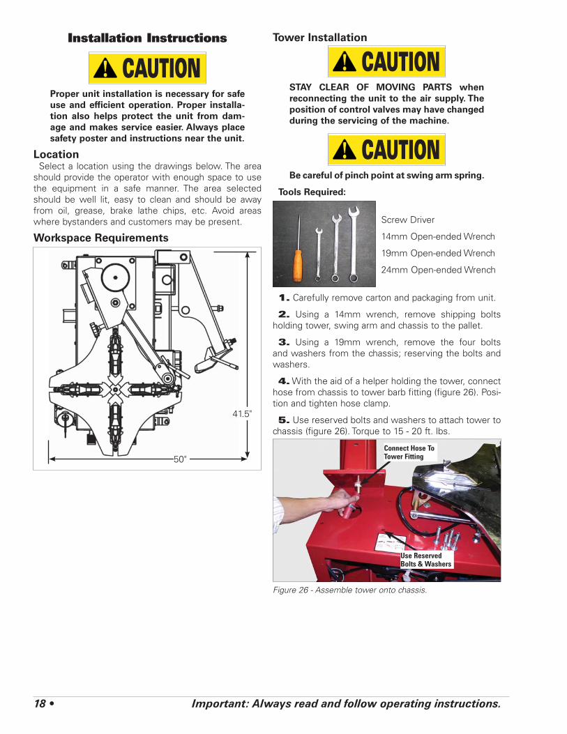
Workspace Requirements
Tower Installation
CAUTIONSTAY CLEAR OF MOVING PARTS when reconnecting the unit to the air supply. The position of control valves may have changed during the servicing of the machine.
CAUTIONBe careful of pinch point at swing arm spring.
Tools Required:
Screw Driver
14mm Open-ended Wrench
19mm Open-ended Wrench
24mm Open-ended Wrench
1. Carefully remove carton and packaging from unit.
2. Using a 14mm wrench, remove shipping bolts holding tower, swing arm and chassis to the pallet.
3. Using a 19mm wrench, remove the four bolts and washers from the chassis; reserving the bolts and washers.
4. With the aid of a helper holding the tower, connect hose from chassis to tower barb fitting (figure 26). Posi-tion and tighten hose clamp.
5. Use reserved bolts and washers to attach tower to chassis (figure 26). Torque to 15 - 20 ft. lbs.
Figure 26 - Assemble tower onto chassis.
50"
41.5"
Use Reserved Bolts & Washers
Connect Hose To Tower Fitting
Important: Always read and follow operating instructions. • 19
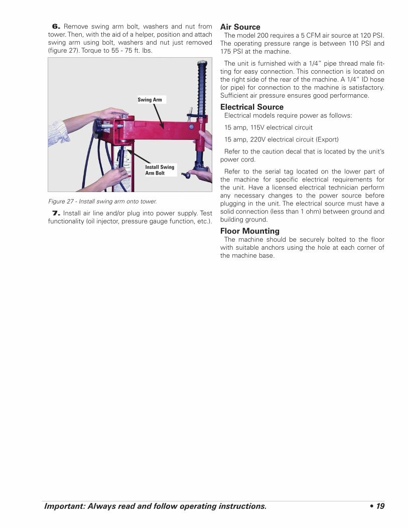
6. Remove swing arm bolt, washers and nut from tower. Then, with the aid of a helper, position and attach swing arm using bolt, washers and nut just removed (figure 27). Torque to 55 - 75 ft. lbs.
Figure 27 - Install swing arm onto tower.
7. Install air line and/or plug into power supply. Test functionality (oil injector, pressure gauge function, etc.).
Air SourceThe model 200 requires a 5 CFM air source at 120 PSI.
The operating pressure range is between 110 PSI and 175 PSI at the machine.
The unit is furnished with a 1/4” pipe thread male fit-ting for easy connection. This connection is located on the right side of the rear of the machine. A 1/4” ID hose (or pipe) for connection to the machine is satisfactory. Sufficient air pressure ensures good performance.
Electrical SourceElectrical models require power as follows:
15 amp, 115V electrical circuit
15 amp, 220V electrical circuit (Export)
Refer to the caution decal that is located by the unit’s power cord.
Refer to the serial tag located on the lower part of the machine for specific electrical requirements for the unit. Have a licensed electrical technician perform any necessary changes to the power source before plugging in the unit. The electrical source must have a solid connection (less than 1 ohm) between ground and building ground.
Floor MountingThe machine should be securely bolted to the floor
with suitable anchors using the hole at each corner of the machine base.
Install Swing Arm Bolt
Swing Arm
20 • Important: Always read and follow operating instructions.
Operating Instructions (with Robo-Assist™)
This unit must be properly operated and properly maintained to help avoid accidents that could damage the unit and injure the operator or bystanders. This section of the Operating Instructions manual review basic operations and use of controls. These instructions should be reviewed with all employees before they are allowed to work with the machine. Keep these instruc-tions near the machine for easy reference.
Bead Loosening and Demounting
CAUTIONThis machine may operate differently from machines you have previously operated. Practice with a regular steel wheel and tire combination to familiarize yourself with the machine’s operation and function.
A. Remember to remove all weights from both sides of the wheel. Weights left on backside of wheel may cause the wheel to be clamped unleveled. This may result in the combination mount/demount head contacting the rim causing scratches. On alloy wheels, always rotate the wheel one turn after set-ting the Duckhead to insure proper wheel chucking.
B. Always review with the owner any nicks and scratches on expensive wheel and tire combina-tions prior to servicing.
CAUTIONLoosening the beads on a partially or fully inflated tire is unsafe and causes excess movement and friction against the bumper pads and excessive wear on pivots. Deflate the tire completely to prolong the life of your machine.
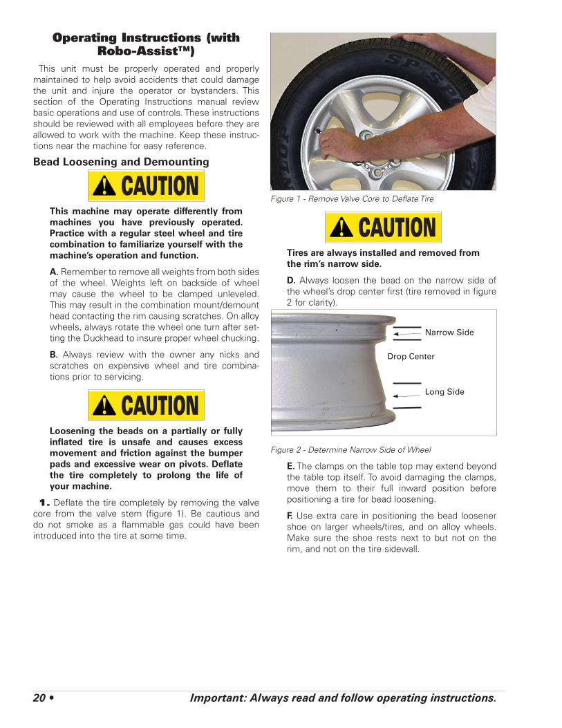
1. Deflate the tire completely by removing the valve core from the valve stem (figure 1). Be cautious and do not smoke as a flammable gas could have been introduced into the tire at some time.
Figure 1 - Remove Valve Core to Deflate Tire
CAUTIONTires are always installed and removed from the rim’s narrow side.
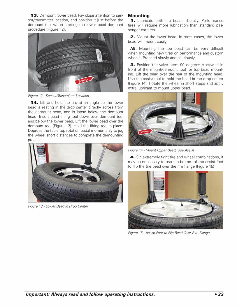
D. Always loosen the bead on the narrow side of the wheel’s drop center first (tire removed in figure 2 for clarity).
Figure 2 - Determine Narrow Side of Wheel
E. The clamps on the table top may extend beyond the table top itself. To avoid damaging the clamps, move them to their full inward position before positioning a tire for bead loosening.
F. Use extra care in positioning the bead loosener shoe on larger wheels/tires, and on alloy wheels. Make sure the shoe rests next to but not on the rim, and not on the tire sidewall.
Narrow Side
Drop Center
Long Side

Important: Always read and follow operating instructions. • 21
2. Pull the bead loosener shoe away from the machine and roll wheel into position. The valve stem should be in the 2 o’clock position to accommodate a possible asymmetric safety hump type rim. Position the bead loosener shoe against the tire next to, but not on, the rim. Press the bead loosener foot pedal to actuate the shoe and loosen the bead. It may be necessary to loosen the bead in multiple locations around the tire (figure 3).
Figure 3 - Position Tire and Bead Loosener Shoe
3. Turn the wheel around and repeat loosening pro-cedure on the other side of the wheel (figure 4). This should be the long side of the drop center (figure 2).
Figure 4 - Position Tire and Bead Loosener Shoe With Wheel Turned Around
G. It will be easier to outside clamp the wheel to the table top if the long side of the rim is loosened last.
4. Apply tire manufacturer’s approved rubber lubricant liberally to entire circumference of both tire beads after loosening (figure 5).
Figure 5 - Apply Rubber Lubricant to Tire Beads
5. Determine the mounting side of the wheel. The mounting side is the narrow side of the drop center. See figure 2 for more information on the drop center.
6. Place tire/wheel assembly on table top with mount-ing side up (figure 6). Use the clamp control pedal to move the clamps inward (push pedal down) or outward (toggle pedal up). Clamp steel wheels from the inside (clamps push outward against wheel). Clamp mag and custom wheels from the outside (clamps push inward against the outside rim edge).
Figure 6 - Place Tire/Wheel Assembly on Table top
Valve Stem

22 • Important: Always read and follow operating instructions.
7. Depress the tire sidewall downward with the aid of the assist foot providing clearance for the mount/demount head to be positioned (figure 7). Move swing arm into place. Increase the horizontal distance between the demount head and the wheel an additional 1/16 to 1/8 inch with the adjustment knob.
Figure 7 - Assist Foot Depressing Sidewall of Tire
8. Lubricate upper bead liberally (Figure 8).
Figure 8 - Lubricate Upper Bead
9. Locate the valve stem just before the demount head before proceeding (Figure 9).
Figure 9 - Position Valve Stem Under Demount Head
10. Place the assist foot opposite the demount head and push the bead into drop center. Insert bead lifting tool between knob on demount tool and tire bead (Figure 10).
Figure 10 - Insert Bead Lifting Tool
11. Rotate lifting tool down over wheel to lift bead up and over the knob and at the same time remove assist foot.
12. Hold lifting tool in place, depress the table top rotation pedal momentarily to jog the wheel a short distance. Check the wheel and tire to verify that opera-tion is not causing damage. The lifting tool can usually be removed after jogging the wheel a short distance (Figure 11). Continue to jog the wheel to allow the tire sidewall to flex as it crosses the rim edge. Continue short rotations until top bead is completely demounted.
Figure 11 - Holding Lifting Tool in Place and Rotate WheelValve Stem
Demount Head
Important: Always read and follow operating instructions. • 23
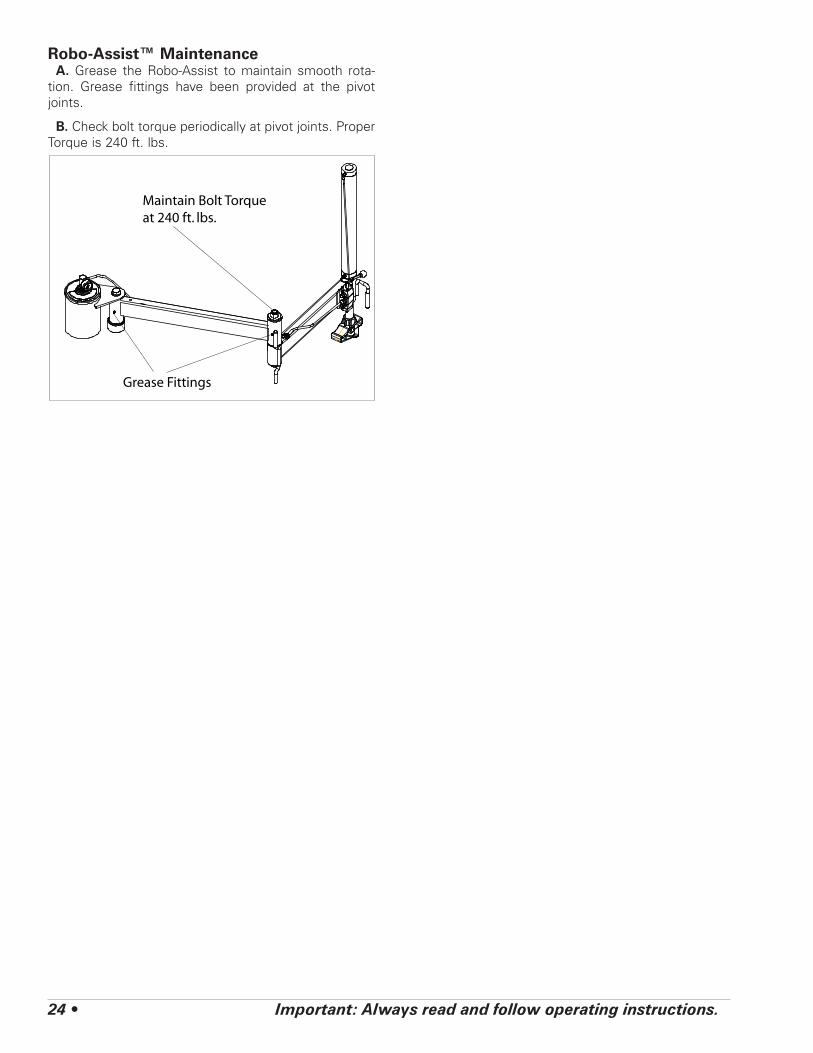
13. Demount lower bead. Pay close attention to sen-sor/transmitter location, and position it just before the demount tool when starting the lower bead demount procedure (Figure 12).
Figure 12 - Sensor/Transmitter Location
14. Lift and hold the tire at an angle so the lower bead is resting in the drop center directly across from the demount head, and is loose below the demount head. Insert bead lifting tool down over demount tool and below the lower bead. Lift the lower bead over the demount tool (Figure 13). Hold the lifting tool in place. Depress the table top rotation pedal momentarily to jog the wheel short distances to complete the demounting process.
Figure 13 - Lower Bead in Drop Center
Mounting1. Lubricate both tire beads liberally. Performance
tires will require more lubrication than standard pas-senger car tires.
2. Mount the lower bead. In most cases, the lower bead will mount easily.
AE: Mounting the top bead can be very difficult when mounting new tires on performance and custom wheels. Proceed slowly and cautiously.
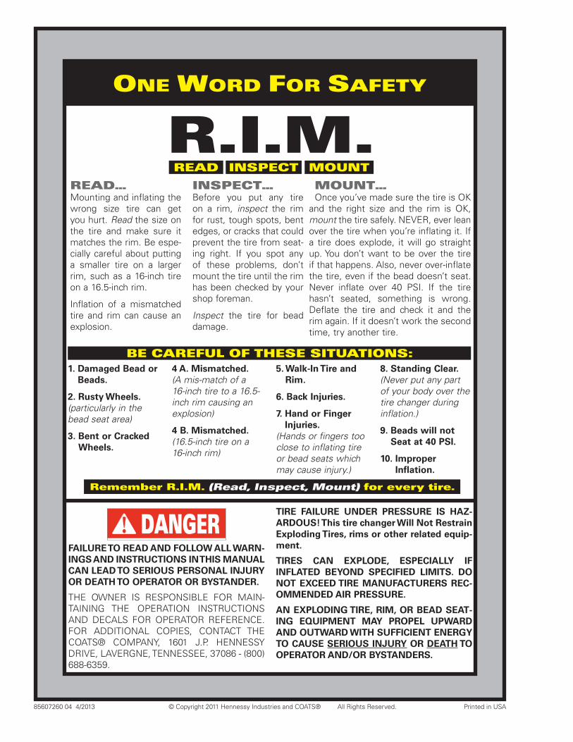
3. Position the valve stem 90 degrees clockwise in front of the mount/demount tool for top bead mount-ing. Lift the bead over the rear of the mounting head. Use the assist tool to hold the bead in the drop center (Figure 14). Rotate the wheel in short steps and apply extra lubricant to mount upper bead.
Figure 14 - Mount Upper Bead, Use Assist
4. On extremely tight tire and wheel combinations, it may be necessary to use the bottom of the assist foot to flip the tire bead over the rim flange (Figure 15)
Figure 15 - Assist Foot to Flip Bead Over Rim Flange
Sensor
Valve
24 • Important: Always read and follow operating instructions.
Robo-Assist™ MaintenanceA. Grease the Robo-Assist to maintain smooth rota-
tion. Grease fittings have been provided at the pivot joints.
B. Check bolt torque periodically at pivot joints. Proper Torque is 240 ft. lbs.
Maintain Bolt Torqueat 240 ft. lbs.
Grease Fittings

Important: Always read and follow operating instructions. • 25
NOTES
85607260 04 4/2013 © Copyright 2011 Hennessy Industries and COATS® All Rights Reserved. Printed in USA
ONE WORD FOR SAFETY
READ INSPECT MOUNT
BE CAREFUL OF THESE SITUATIONS: 1. Damaged Bead or
Beads.
2. Rusty Wheels.(particularly in the bead seat area)
3. Bent or Cracked Wheels.
4 A. Mismatched.(A mis-match of a 16-inch tire to a 16.5-inch rim causing an explosion)
4 B. Mismatched.(16.5-inch tire on a 16-inch rim)
5. Walk-In Tire and Rim.
6. Back Injuries.
7. Hand or Finger Injuries.
(Hands or fingers too close to inflating tire or bead seats which may cause injury.)
8. Standing Clear.(Never put any part of your body over the tire changer during inflation.)
9. Beads will not Seat at 40 PSI.
10. Improper Inflation.
READ…Mounting and inflating the wrong size tire can get you hurt. Read the size on the tire and make sure it matches the rim. Be espe-cially careful about putting a smaller tire on a larger rim, such as a 16-inch tire on a 16.5-inch rim.
Inflation of a mismatched tire and rim can cause an explosion.
INSPECT…Before you put any tire on a rim, inspect the rim for rust, tough spots, bent edges, or cracks that could prevent the tire from seat-ing right. If you spot any of these problems, don’t mount the tire until the rim has been checked by your shop foreman.
Inspect the tire for bead damage.
MOUNT…Once you’ve made sure the tire is OK
and the right size and the rim is OK, mount the tire safely. NEVER, ever lean over the tire when you’re inflating it. If a tire does explode, it will go straight up. You don’t want to be over the tire if that happens. Also, never over-inflate the tire, even if the bead doesn’t seat. Never inflate over 40 PSI. If the tire hasn’t seated, something is wrong. Deflate the tire and check it and the rim again. If it doesn’t work the second time, try another tire.
R.I.M.
DANGER
FAILURE TO READ AND FOLLOW ALL WARN-INGS AND INSTRUCTIONS IN THIS MANUAL CAN LEAD TO SERIOUS PERSONAL INJURY OR DEATH TO OPERATOR OR BYSTANDER.
THE OWNER IS RESPONSIBLE FOR MAIN-TAINING THE OPERATION INSTRUCTIONS AND DECALS FOR OPERATOR REFERENCE. FOR ADDITIONAL COPIES, CONTACT THE COATS® COMPANY, 1601 J.P. HENNESSY DRIVE, LAVERGNE, TENNESSEE, 37086 - (800) 688-6359.
TIRE FAILURE UNDER PRESSURE IS HAZ-ARDOUS! This tire changer Will Not Restrain Exploding Tires, rims or other related equip-ment.
TIRES CAN EXPLODE, ESPECIALLY IF INFLATED BEYOND SPECIFIED LIMITS. DO NOT EXCEED TIRE MANUFACTURERS REC-OMMENDED AIR PRESSURE.
AN EXPLODING TIRE, RIM, OR BEAD SEAT-ING EQUIPMENT MAY PROPEL UPWARD AND OUTWARD WITH SUFFICIENT ENERGY TO CAUSE SERIOUS INJURY OR DEATH TO OPERATOR AND/OR BYSTANDERS.
Remember R.I.M. (Read, Inspect, Mount) for every tire.