TCP/IP Tutorial and Technical Overview - Higher Intellect
738
TCP/IP Tutorial and Technical Overview Martin W. Murhammer, Orcun Atakan, Stefan Bretz, Larry R. Pugh, Kazunari Suzuki, David H. Wood International Technical Support Organization http://www.redbooks.ibm.com GG24-3376-05
Transcript of TCP/IP Tutorial and Technical Overview - Higher Intellect

ÉÂÔ
TCP/IP Tutorial and Technical Overview
Martin W. Murhammer, Orcun Atakan, Stefan Bretz,Larry R. Pugh, Kazunari Suzuki, David H. Wood
International Technical Support Organization
http://www.redbooks.ibm.com
GG24-3376-05


International Technical Support Organization
TCP/IP Tutorial and Technical Overview
October 1998
GG24-3376-05
ÉÂÔ

Take Note!
Before using this information and the product it supports, be sure to read the general information in Appendix A, “SpecialNotices” on page 673.
Sixth Edition (October 1998)
This edition applies to Transmission Control Protocol/Internet Protocol (TCP/IP) in general and selected IBM and OEMimplementations thereof.
Comments may be addressed to:IBM Corporation, International Technical Support OrganizationDept. HZ8 Building 678P.O. Box 12195Research Triangle Park, NC 27709-2195
When you send information to IBM, you grant IBM a non-exclusive right to use or distribute the information in any way it believesappropriate without incurring any obligation to you.
Copyright International Business Machines Corporation 1989, 1998. All rights reserved.Note to U.S. Government Users — Documentation related to restricted rights — Use, duplication or disclosure is subject torestrictions set forth in GSA ADP Schedule Contract with IBM Corp.

Contents
Preface . . . . . . . . . . . . . . . . . . . . . . . . . . . . . . . . . . . . . . . . . xiiiThe Team That Wrote This Redbook . . . . . . . . . . . . . . . . . . . . . . . . xiiiComments Welcome . . . . . . . . . . . . . . . . . . . . . . . . . . . . . . . . . . xv
Part 1. Architecture and Core Protocols . . . . . . . . . . . . . . . . . . . . . . . . . . . . . 1
Chapter 1. Introduction to TCP/IP - History, Architecture and Standards . 31.1 Internet History - Where It All Came From . . . . . . . . . . . . . . . . . . . 3
1.1.1 Internetworks . . . . . . . . . . . . . . . . . . . . . . . . . . . . . . . . . . 41.1.2 The Internet . . . . . . . . . . . . . . . . . . . . . . . . . . . . . . . . . . 41.1.3 ARPANET . . . . . . . . . . . . . . . . . . . . . . . . . . . . . . . . . . . 51.1.4 NSFNET . . . . . . . . . . . . . . . . . . . . . . . . . . . . . . . . . . . . 51.1.5 Commercial Use of the Internet . . . . . . . . . . . . . . . . . . . . . . . 71.1.6 Information Superhighway . . . . . . . . . . . . . . . . . . . . . . . . . . 81.1.7 Internet2 . . . . . . . . . . . . . . . . . . . . . . . . . . . . . . . . . . . . 91.1.8 The Open Systems Interconnect (OSI) Model . . . . . . . . . . . . . . . 9
1.2 TCP/IP Architectural Model - What It Is All About . . . . . . . . . . . . . . 111.2.1 Internetworking . . . . . . . . . . . . . . . . . . . . . . . . . . . . . . . . 111.2.2 The TCP/IP Protocol Stack . . . . . . . . . . . . . . . . . . . . . . . . . 121.2.3 TCP/IP Applications . . . . . . . . . . . . . . . . . . . . . . . . . . . . . 141.2.4 Bridges, Routers and Gateways . . . . . . . . . . . . . . . . . . . . . . 15
1.3 Finding Standards for TCP/IP and the Internet . . . . . . . . . . . . . . . . 171.3.1 Request For Comments (RFC) . . . . . . . . . . . . . . . . . . . . . . 181.3.2 Internet Standards . . . . . . . . . . . . . . . . . . . . . . . . . . . . . . 191.3.3 Major Internet Protocols . . . . . . . . . . . . . . . . . . . . . . . . . . 20
1.4 Future of the Internet . . . . . . . . . . . . . . . . . . . . . . . . . . . . . . . 211.5 IBM and the Internet . . . . . . . . . . . . . . . . . . . . . . . . . . . . . . . 22
1.5.1 The Network Computing Framework . . . . . . . . . . . . . . . . . . . 22
Chapter 2. Internetworking and Transport Layer Protocols . . . . . . . . . 272.1 Internet Protocol (IP) . . . . . . . . . . . . . . . . . . . . . . . . . . . . . . . 27
2.1.1 IP Addressing . . . . . . . . . . . . . . . . . . . . . . . . . . . . . . . . 272.1.2 IP Subnets . . . . . . . . . . . . . . . . . . . . . . . . . . . . . . . . . . 302.1.3 IP Routing . . . . . . . . . . . . . . . . . . . . . . . . . . . . . . . . . . 352.1.4 Methods of Delivery - Unicast, Broadcast, Multicast and Anycast . . 392.1.5 The IP Address Exhaustion Problem . . . . . . . . . . . . . . . . . . . 422.1.6 Intranets (Private IP Addresses) . . . . . . . . . . . . . . . . . . . . . . 442.1.7 Classless Inter-Domain Routing (CIDR) . . . . . . . . . . . . . . . . . 452.1.8 IP Datagram . . . . . . . . . . . . . . . . . . . . . . . . . . . . . . . . . 48
2.2 Internet Control Message Protocol (ICMP) . . . . . . . . . . . . . . . . . . 582.2.1 ICMP Messages . . . . . . . . . . . . . . . . . . . . . . . . . . . . . . . 592.2.2 ICMP Applications . . . . . . . . . . . . . . . . . . . . . . . . . . . . . . 66
2.3 Internet Group Management Protocol (IGMP) . . . . . . . . . . . . . . . . . 672.4 Address Resolution Protocol (ARP) . . . . . . . . . . . . . . . . . . . . . . 68
2.4.1 ARP Overview . . . . . . . . . . . . . . . . . . . . . . . . . . . . . . . . 682.4.2 ARP Detailed Concept . . . . . . . . . . . . . . . . . . . . . . . . . . . 682.4.3 ARP and Subnets . . . . . . . . . . . . . . . . . . . . . . . . . . . . . . 712.4.4 Proxy-ARP or Transparent Subnetting . . . . . . . . . . . . . . . . . . 71
2.5 Reverse Address Resolution Protocol (RARP) . . . . . . . . . . . . . . . . 72
Copyright IBM Corp. 1989, 1998 iii

2.5.1 RARP Concept . . . . . . . . . . . . . . . . . . . . . . . . . . . . . . . . 722.6 Ports and Sockets . . . . . . . . . . . . . . . . . . . . . . . . . . . . . . . . 73
2.6.1 Ports . . . . . . . . . . . . . . . . . . . . . . . . . . . . . . . . . . . . . . 732.6.2 Sockets . . . . . . . . . . . . . . . . . . . . . . . . . . . . . . . . . . . . 74
2.7 User Datagram Protocol (UDP) . . . . . . . . . . . . . . . . . . . . . . . . . 752.7.1 UDP Datagram Format . . . . . . . . . . . . . . . . . . . . . . . . . . . 762.7.2 UDP Application Programming Interface . . . . . . . . . . . . . . . . . 77
2.8 Transmission Control Protocol (TCP) . . . . . . . . . . . . . . . . . . . . . 782.8.1 TCP Concept . . . . . . . . . . . . . . . . . . . . . . . . . . . . . . . . . 782.8.2 TCP Application Programming Interface . . . . . . . . . . . . . . . . . 882.8.3 TCP Congestion Control Algorithms . . . . . . . . . . . . . . . . . . . 88
2.9 References . . . . . . . . . . . . . . . . . . . . . . . . . . . . . . . . . . . . . 93
Chapter 3. Routing Protocols . . . . . . . . . . . . . . . . . . . . . . . . . . . 953.1 Basic IP Routing . . . . . . . . . . . . . . . . . . . . . . . . . . . . . . . . . 95
3.1.1 Routing Processes . . . . . . . . . . . . . . . . . . . . . . . . . . . . . 973.1.2 Autonomous Systems . . . . . . . . . . . . . . . . . . . . . . . . . . . . 97
3.2 Routing Algorithms . . . . . . . . . . . . . . . . . . . . . . . . . . . . . . . . 983.2.1 Static Routing . . . . . . . . . . . . . . . . . . . . . . . . . . . . . . . . 983.2.2 Distance Vector Routing . . . . . . . . . . . . . . . . . . . . . . . . . . 993.2.3 Link State Routing . . . . . . . . . . . . . . . . . . . . . . . . . . . . . 104
3.3 Interior Gateway Protocols (IGP) . . . . . . . . . . . . . . . . . . . . . . . 1063.3.1 Routing Information Protocol (RIP) . . . . . . . . . . . . . . . . . . . 1063.3.2 Routing Information Protocol Version 2 (RIP-2) . . . . . . . . . . . . 1083.3.3 RIPng for IPv6 . . . . . . . . . . . . . . . . . . . . . . . . . . . . . . . 1103.3.4 Open Shortest Path First (OSPF) . . . . . . . . . . . . . . . . . . . . 112
3.4 Exterior Routing Protocols . . . . . . . . . . . . . . . . . . . . . . . . . . . 1343.4.1 Exterior Gateway Protocol (EGP) . . . . . . . . . . . . . . . . . . . . 1343.4.2 Border Gateway Protocol (BGP-4) . . . . . . . . . . . . . . . . . . . 135
3.5 References . . . . . . . . . . . . . . . . . . . . . . . . . . . . . . . . . . . . 147
Chapter 4. Application Protocols . . . . . . . . . . . . . . . . . . . . . . . . 1494.1 Characteristics of Applications . . . . . . . . . . . . . . . . . . . . . . . . 149
4.1.1 Client/Server Model . . . . . . . . . . . . . . . . . . . . . . . . . . . . 1494.2 Domain Name System (DNS) . . . . . . . . . . . . . . . . . . . . . . . . . 150
4.2.1 The Hierarchical Namespace . . . . . . . . . . . . . . . . . . . . . . 1514.2.2 Fully Qualified Domain Names (FQDNs) . . . . . . . . . . . . . . . . 1514.2.3 Generic Domains . . . . . . . . . . . . . . . . . . . . . . . . . . . . . 1524.2.4 Country Domains . . . . . . . . . . . . . . . . . . . . . . . . . . . . . 1524.2.5 Mapping Domain Names to IP Addresses . . . . . . . . . . . . . . . 1534.2.6 Mapping IP Addresses to Domain Names — Pointer Queries . . . . 1534.2.7 The Distributed Name Space . . . . . . . . . . . . . . . . . . . . . . 1534.2.8 Domain Name Resolution . . . . . . . . . . . . . . . . . . . . . . . . 1544.2.9 Domain Name System Resource Records . . . . . . . . . . . . . . . 1574.2.10 Domain Name System Messages . . . . . . . . . . . . . . . . . . . 1594.2.11 A Simple Scenario . . . . . . . . . . . . . . . . . . . . . . . . . . . . 1634.2.12 Extended Scenario . . . . . . . . . . . . . . . . . . . . . . . . . . . . 1654.2.13 Transport . . . . . . . . . . . . . . . . . . . . . . . . . . . . . . . . . 1654.2.14 DNS Applications . . . . . . . . . . . . . . . . . . . . . . . . . . . . . 1664.2.15 References . . . . . . . . . . . . . . . . . . . . . . . . . . . . . . . . 167
4.3 TELNET . . . . . . . . . . . . . . . . . . . . . . . . . . . . . . . . . . . . . 1674.3.1 TELNET Operation . . . . . . . . . . . . . . . . . . . . . . . . . . . . 1674.3.2 Terminal Emulation (Telnet 3270) . . . . . . . . . . . . . . . . . . . . 1724.3.3 TN3270 Enhancements (TN3270E) . . . . . . . . . . . . . . . . . . . 173
iv TCP/IP Tutorial and Technical Overview

4.3.4 References . . . . . . . . . . . . . . . . . . . . . . . . . . . . . . . . . 1754.4 File Transfer Protocol (FTP) . . . . . . . . . . . . . . . . . . . . . . . . . . 175
4.4.1 Overview of FTP . . . . . . . . . . . . . . . . . . . . . . . . . . . . . . 1754.4.2 FTP Operations . . . . . . . . . . . . . . . . . . . . . . . . . . . . . . 1764.4.3 Reply Codes . . . . . . . . . . . . . . . . . . . . . . . . . . . . . . . . 1784.4.4 FTP Scenario . . . . . . . . . . . . . . . . . . . . . . . . . . . . . . . 1794.4.5 A Sample FTP Session . . . . . . . . . . . . . . . . . . . . . . . . . . 1794.4.6 Anonymous FTP . . . . . . . . . . . . . . . . . . . . . . . . . . . . . . 1804.4.7 Remote Job Entry Using FTP . . . . . . . . . . . . . . . . . . . . . . 180
4.5 Trivial File Transfer Protocol (TFTP) . . . . . . . . . . . . . . . . . . . . . 1804.5.1 TFTP Usage . . . . . . . . . . . . . . . . . . . . . . . . . . . . . . . . 1814.5.2 Protocol Description . . . . . . . . . . . . . . . . . . . . . . . . . . . . 1814.5.3 TFTP Multicast Option . . . . . . . . . . . . . . . . . . . . . . . . . . 1824.5.4 Security Issue . . . . . . . . . . . . . . . . . . . . . . . . . . . . . . . 183
4.6 Remote Execution Command Protocol (REXEC and RSH) . . . . . . . . 1834.6.1 Principle of Operation . . . . . . . . . . . . . . . . . . . . . . . . . . . 183
4.7 Simple Mail Transfer Protocol (SMTP) . . . . . . . . . . . . . . . . . . . . 1844.7.1 How SMTP Works . . . . . . . . . . . . . . . . . . . . . . . . . . . . . 1864.7.2 SMTP and the Domain Name System . . . . . . . . . . . . . . . . . 1914.7.3 References . . . . . . . . . . . . . . . . . . . . . . . . . . . . . . . . . 193
4.8 Multipurpose Internet Mail Extensions (MIME) . . . . . . . . . . . . . . . 1934.8.1 How MIME Works . . . . . . . . . . . . . . . . . . . . . . . . . . . . . 1964.8.2 The Content-Type Field . . . . . . . . . . . . . . . . . . . . . . . . . . 1964.8.3 The Content-Transfer-Encoding Field . . . . . . . . . . . . . . . . . . 2024.8.4 Using Non-ASCII Characters in Message Headers . . . . . . . . . . 2064.8.5 References . . . . . . . . . . . . . . . . . . . . . . . . . . . . . . . . . 207
4.9 Post Office Protocol (POP) . . . . . . . . . . . . . . . . . . . . . . . . . . 2084.9.1 POP3 Commands and Responses . . . . . . . . . . . . . . . . . . . 2084.9.2 References . . . . . . . . . . . . . . . . . . . . . . . . . . . . . . . . . 209
4.10 Internet Message Access Protocol Version 4 (IMAP4) . . . . . . . . . . 2094.10.1 IMAP4 Underlying Electronic Mail Models . . . . . . . . . . . . . . 2104.10.2 IMAP4 Commands and Responses . . . . . . . . . . . . . . . . . . 2104.10.3 Message Numbers . . . . . . . . . . . . . . . . . . . . . . . . . . . . 2114.10.4 IMAP4 States . . . . . . . . . . . . . . . . . . . . . . . . . . . . . . . 2124.10.5 Client Commands . . . . . . . . . . . . . . . . . . . . . . . . . . . . 2134.10.6 References . . . . . . . . . . . . . . . . . . . . . . . . . . . . . . . . 214
4.11 Network Management . . . . . . . . . . . . . . . . . . . . . . . . . . . . . 2144.11.1 Standards . . . . . . . . . . . . . . . . . . . . . . . . . . . . . . . . . 2154.11.2 Bootstrap Protocol (BOOTP) . . . . . . . . . . . . . . . . . . . . . . 2154.11.3 Structure and Identification of Management Information (SMI) . . . 2154.11.4 Management Information Base (MIB) . . . . . . . . . . . . . . . . . 2164.11.5 Simple Network Management Protocol (SNMP) . . . . . . . . . . . 2204.11.6 Simple Network Management Protocol Version 2 (SNMPv2) . . . 2224.11.7 MIB for SNMPv2 . . . . . . . . . . . . . . . . . . . . . . . . . . . . . 2254.11.8 Single Authentication and Privacy Protocol . . . . . . . . . . . . . . 2264.11.9 The New Administrative Model . . . . . . . . . . . . . . . . . . . . . 2274.11.10 Simple Network Management Protocol Version 3 (SNMPv3) . . . 2284.11.11 References . . . . . . . . . . . . . . . . . . . . . . . . . . . . . . . 229
4.12 Remote Printing (LPR and LPD) . . . . . . . . . . . . . . . . . . . . . . 2304.13 Network File System (NFS) . . . . . . . . . . . . . . . . . . . . . . . . . 230
4.13.1 NFS Concept . . . . . . . . . . . . . . . . . . . . . . . . . . . . . . . 2304.13.2 WebNFS . . . . . . . . . . . . . . . . . . . . . . . . . . . . . . . . . . 2344.13.3 References . . . . . . . . . . . . . . . . . . . . . . . . . . . . . . . . 235
4.14 X Window System . . . . . . . . . . . . . . . . . . . . . . . . . . . . . . . 235
Contents v
4.14.1 Functional Concept . . . . . . . . . . . . . . . . . . . . . . . . . . . 2364.14.2 Protocol . . . . . . . . . . . . . . . . . . . . . . . . . . . . . . . . . . 239
4.15 Finger Protocol . . . . . . . . . . . . . . . . . . . . . . . . . . . . . . . . . 2404.16 NETSTAT . . . . . . . . . . . . . . . . . . . . . . . . . . . . . . . . . . . . 2404.17 Network Information System (NIS) . . . . . . . . . . . . . . . . . . . . . 2414.18 NetBIOS over TCP/IP . . . . . . . . . . . . . . . . . . . . . . . . . . . . . 241
4.18.1 NetBIOS over TCP/IP in IBM OS/2 Warp 4 . . . . . . . . . . . . . 2444.18.2 NetBIOS over TCP/IP in Microsoft Windows Systems . . . . . . . 2454.18.3 NetBIOS Name Server (NBNS) Implementations . . . . . . . . . . 247
4.19 Application Programming Interfaces (APIs) . . . . . . . . . . . . . . . . 2484.19.1 The Socket API . . . . . . . . . . . . . . . . . . . . . . . . . . . . . . 2484.19.2 Remote Procedure Call (RPC) . . . . . . . . . . . . . . . . . . . . . 2524.19.3 Windows Sockets Version 2 (Winsock V2.0) . . . . . . . . . . . . . 2564.19.4 SNMP Distributed Programming Interface (SNMP DPI) . . . . . . . 2574.19.5 FTP API . . . . . . . . . . . . . . . . . . . . . . . . . . . . . . . . . . 2594.19.6 CICS Socket Interface . . . . . . . . . . . . . . . . . . . . . . . . . . 2604.19.7 IMS Socket Interface . . . . . . . . . . . . . . . . . . . . . . . . . . 2604.19.8 Sockets Extended . . . . . . . . . . . . . . . . . . . . . . . . . . . . 2604.19.9 REXX Sockets . . . . . . . . . . . . . . . . . . . . . . . . . . . . . . 260
Part 2. Special Purpose Protocols and New Technologies . . . . . . . . . . . . . . . 261
Chapter 5. TCP/IP Security Overview . . . . . . . . . . . . . . . . . . . . . 2635.1 Security Exposures and Solutions . . . . . . . . . . . . . . . . . . . . . . 263
5.1.1 Common Attacks Against Security . . . . . . . . . . . . . . . . . . . 2635.1.2 Solutions to Network Security Problems . . . . . . . . . . . . . . . . 2645.1.3 Implementations of Security Solutions . . . . . . . . . . . . . . . . . 2655.1.4 Network Security Policy . . . . . . . . . . . . . . . . . . . . . . . . . . 266
5.2 A Short Introduction to Cryptography . . . . . . . . . . . . . . . . . . . . . 2675.2.1 Terminology . . . . . . . . . . . . . . . . . . . . . . . . . . . . . . . . 2675.2.2 Symmetric or Secret-Key Algorithms . . . . . . . . . . . . . . . . . . 2685.2.3 Asymmetric or Public-Key Algorithms . . . . . . . . . . . . . . . . . . 2705.2.4 Hash Functions . . . . . . . . . . . . . . . . . . . . . . . . . . . . . . 2735.2.5 Digital Certificates and Certification Authorities . . . . . . . . . . . . 2785.2.6 Random-Number Generators . . . . . . . . . . . . . . . . . . . . . . 2795.2.7 Export/Import Restrictions on Cryptography . . . . . . . . . . . . . . 279
5.3 Firewalls . . . . . . . . . . . . . . . . . . . . . . . . . . . . . . . . . . . . . 2805.3.1 Firewall Concept . . . . . . . . . . . . . . . . . . . . . . . . . . . . . . 2815.3.2 Components of A Firewall System . . . . . . . . . . . . . . . . . . . 2825.3.3 Packet-Filtering Router . . . . . . . . . . . . . . . . . . . . . . . . . . 2825.3.4 Application Level Gateway (Proxy) . . . . . . . . . . . . . . . . . . . 2845.3.5 Circuit Level Gateway . . . . . . . . . . . . . . . . . . . . . . . . . . . 2885.3.6 Firewall Examples . . . . . . . . . . . . . . . . . . . . . . . . . . . . . 289
5.4 Network Address Translation (NAT) . . . . . . . . . . . . . . . . . . . . . 2935.4.1 NAT Concept . . . . . . . . . . . . . . . . . . . . . . . . . . . . . . . . 2935.4.2 Translation Mechanism . . . . . . . . . . . . . . . . . . . . . . . . . . 2945.4.3 NAT Limitations . . . . . . . . . . . . . . . . . . . . . . . . . . . . . . 296
5.5 The IP Security Architecture (IPSec) . . . . . . . . . . . . . . . . . . . . . 2975.5.1 Concepts . . . . . . . . . . . . . . . . . . . . . . . . . . . . . . . . . . 2975.5.2 Authentication Header (AH) . . . . . . . . . . . . . . . . . . . . . . . 2995.5.3 Encapsulating Security Payload (ESP) . . . . . . . . . . . . . . . . . 3035.5.4 Combining IPSec Protocols . . . . . . . . . . . . . . . . . . . . . . . 3075.5.5 The Internet Key Exchange Protocol (IKE) . . . . . . . . . . . . . . . 312
vi TCP/IP Tutorial and Technical Overview

5.5.6 References . . . . . . . . . . . . . . . . . . . . . . . . . . . . . . . . . 3255.6 SOCKS . . . . . . . . . . . . . . . . . . . . . . . . . . . . . . . . . . . . . . 326
5.6.1 SOCKS Version 5 (SOCKSv5) . . . . . . . . . . . . . . . . . . . . . . 3275.7 Secure Sockets Layer (SSL) . . . . . . . . . . . . . . . . . . . . . . . . . 331
5.7.1 SSL Overview . . . . . . . . . . . . . . . . . . . . . . . . . . . . . . . 3315.7.2 SSL Protocol . . . . . . . . . . . . . . . . . . . . . . . . . . . . . . . . 333
5.8 Transport Layer Security (TLS) . . . . . . . . . . . . . . . . . . . . . . . . 3375.9 Secure Multipurpose Internet Mail Extension (S-MIME) . . . . . . . . . . 3375.10 Virtual Private Networks (VPN) Overview . . . . . . . . . . . . . . . . . 337
5.10.1 VPN Introduction and Benefits . . . . . . . . . . . . . . . . . . . . . 3385.11 Kerberos Authentication and Authorization System . . . . . . . . . . . . 339
5.11.1 Assumptions . . . . . . . . . . . . . . . . . . . . . . . . . . . . . . . 3395.11.2 Naming . . . . . . . . . . . . . . . . . . . . . . . . . . . . . . . . . . 3405.11.3 Kerberos Authentication Process . . . . . . . . . . . . . . . . . . . 3405.11.4 Kerberos Database Management . . . . . . . . . . . . . . . . . . . 3435.11.5 Kerberos Authorization Model . . . . . . . . . . . . . . . . . . . . . 3445.11.6 Kerberos Version 5 Enhancements . . . . . . . . . . . . . . . . . . 344
5.12 Remote Access Authentication Protocols . . . . . . . . . . . . . . . . . 3455.13 Layer 2 Tunneling Protocol (L2TP) . . . . . . . . . . . . . . . . . . . . . 347
5.13.1 Terminology . . . . . . . . . . . . . . . . . . . . . . . . . . . . . . . . 3475.13.2 Protocol Overview . . . . . . . . . . . . . . . . . . . . . . . . . . . . 3485.13.3 L2TP Security Issues . . . . . . . . . . . . . . . . . . . . . . . . . . 350
5.14 Secure Electronic Transactions (SET) . . . . . . . . . . . . . . . . . . . 3505.14.1 SET Roles . . . . . . . . . . . . . . . . . . . . . . . . . . . . . . . . . 3515.14.2 SET Transactions . . . . . . . . . . . . . . . . . . . . . . . . . . . . 3515.14.3 The SET Certificate Scheme . . . . . . . . . . . . . . . . . . . . . . 353
5.15 References . . . . . . . . . . . . . . . . . . . . . . . . . . . . . . . . . . . 355
Chapter 6. IP Version 6 . . . . . . . . . . . . . . . . . . . . . . . . . . . . . . 3576.1 IPv6 Overview . . . . . . . . . . . . . . . . . . . . . . . . . . . . . . . . . . 3586.2 The IPv6 Header Format . . . . . . . . . . . . . . . . . . . . . . . . . . . . 358
6.2.1 Packet Sizes . . . . . . . . . . . . . . . . . . . . . . . . . . . . . . . . 3616.2.2 Extension Headers . . . . . . . . . . . . . . . . . . . . . . . . . . . . 3616.2.3 IPv6 Addressing . . . . . . . . . . . . . . . . . . . . . . . . . . . . . . 3676.2.4 Priority . . . . . . . . . . . . . . . . . . . . . . . . . . . . . . . . . . . . 3716.2.5 Flow Labels . . . . . . . . . . . . . . . . . . . . . . . . . . . . . . . . . 372
6.3 Internet Control Message Protocol Version 6 (ICMPv6) . . . . . . . . . . 3726.3.1 Neighbor Discovery . . . . . . . . . . . . . . . . . . . . . . . . . . . . 3736.3.2 Stateless Address Autoconfiguration . . . . . . . . . . . . . . . . . . 3826.3.3 Multicast Listener Discovery (MLD) . . . . . . . . . . . . . . . . . . . 383
6.4 DNS in IPv6 . . . . . . . . . . . . . . . . . . . . . . . . . . . . . . . . . . . 3866.4.1 Format of IPv6 Resource Records . . . . . . . . . . . . . . . . . . . 386
6.5 DHCP in IPv6 . . . . . . . . . . . . . . . . . . . . . . . . . . . . . . . . . . 3886.5.1 Differences between DHCPv6 and DHCPv4 . . . . . . . . . . . . . . 3896.5.2 DHCPv6 Messages . . . . . . . . . . . . . . . . . . . . . . . . . . . . 389
6.6 Mobility Support in IPv6 . . . . . . . . . . . . . . . . . . . . . . . . . . . . 3906.7 Internet Transition - Migrating from IPv4 to IPv6 . . . . . . . . . . . . . . 390
6.7.1 Dual IP Stack Implementation - The IPv6/IPv4 Node . . . . . . . . . 3916.7.2 Tunneling . . . . . . . . . . . . . . . . . . . . . . . . . . . . . . . . . . 3926.7.3 Header Translation . . . . . . . . . . . . . . . . . . . . . . . . . . . . 3976.7.4 Interoperability Summary . . . . . . . . . . . . . . . . . . . . . . . . . 397
6.8 The Drive Towards IPv6 . . . . . . . . . . . . . . . . . . . . . . . . . . . . 3986.9 References . . . . . . . . . . . . . . . . . . . . . . . . . . . . . . . . . . . . 398
Contents vii

Chapter 7. Dynamic IP, Mobile IP and Network Computers . . . . . . . . 4017.1 Bootstrap Protocol (BOOTP) . . . . . . . . . . . . . . . . . . . . . . . . . 401
7.1.1 BOOTP Forwarding . . . . . . . . . . . . . . . . . . . . . . . . . . . . 4057.1.2 BOOTP Considerations . . . . . . . . . . . . . . . . . . . . . . . . . . 405
7.2 Dynamic Host Configuration Protocol (DHCP) . . . . . . . . . . . . . . . 4067.2.1 The DHCP Message Format . . . . . . . . . . . . . . . . . . . . . . . 4067.2.2 DHCP Message Types . . . . . . . . . . . . . . . . . . . . . . . . . . 4087.2.3 Allocating a New Network Address . . . . . . . . . . . . . . . . . . . 4097.2.4 DHCP Lease Renewal Process . . . . . . . . . . . . . . . . . . . . . 4117.2.5 Reusing a Previously Allocated Network Address . . . . . . . . . . . 4127.2.6 Configuration Parameters Repository . . . . . . . . . . . . . . . . . . 4137.2.7 DHCP Considerations . . . . . . . . . . . . . . . . . . . . . . . . . . . 4137.2.8 BOOTP and DHCP Interoperability . . . . . . . . . . . . . . . . . . . 413
7.3 Dynamic Domain Name System . . . . . . . . . . . . . . . . . . . . . . . 4147.3.1 The UPDATE DNS Message Format . . . . . . . . . . . . . . . . . . 4157.3.2 IBM's Implementation of DDNS . . . . . . . . . . . . . . . . . . . . . 4177.3.3 Proxy A Record Update (ProxyArec) . . . . . . . . . . . . . . . . . . 424
7.4 Mobile IP . . . . . . . . . . . . . . . . . . . . . . . . . . . . . . . . . . . . . 4267.4.1 Mobile IP Overview . . . . . . . . . . . . . . . . . . . . . . . . . . . . 4267.4.2 Mobile IP Operation . . . . . . . . . . . . . . . . . . . . . . . . . . . . 4277.4.3 Mobility Agent Advertisement Extensions . . . . . . . . . . . . . . . 4287.4.4 Mobile IP Registration Process . . . . . . . . . . . . . . . . . . . . . 4307.4.5 Tunneling . . . . . . . . . . . . . . . . . . . . . . . . . . . . . . . . . . 4327.4.6 Broadcast Datagrams . . . . . . . . . . . . . . . . . . . . . . . . . . . 4327.4.7 Move Detection . . . . . . . . . . . . . . . . . . . . . . . . . . . . . . 4337.4.8 ARP Considerations . . . . . . . . . . . . . . . . . . . . . . . . . . . . 4337.4.9 Mobile IP Security Considerations . . . . . . . . . . . . . . . . . . . . 434
7.5 IP Masquerading . . . . . . . . . . . . . . . . . . . . . . . . . . . . . . . . 4347.6 The Network Computer . . . . . . . . . . . . . . . . . . . . . . . . . . . . . 4347.7 References . . . . . . . . . . . . . . . . . . . . . . . . . . . . . . . . . . . . 436
Chapter 8. Internet Protocols and Applications . . . . . . . . . . . . . . . 4378.1 The World Wide Web (WWW) . . . . . . . . . . . . . . . . . . . . . . . . 437
8.1.1 Web Browsers . . . . . . . . . . . . . . . . . . . . . . . . . . . . . . . 4378.1.2 Web Servers . . . . . . . . . . . . . . . . . . . . . . . . . . . . . . . . 4398.1.3 Web Server Application Technologies . . . . . . . . . . . . . . . . . 439
8.2 Hypertext Transfer Protocol (HTTP) . . . . . . . . . . . . . . . . . . . . . 4408.2.1 Overview of HTTP . . . . . . . . . . . . . . . . . . . . . . . . . . . . . 4408.2.2 HTTP Operation . . . . . . . . . . . . . . . . . . . . . . . . . . . . . . 441
8.3 Hypertext Markup Language (HTML) . . . . . . . . . . . . . . . . . . . . . 4488.4 The Extensible Markup Language (XML) . . . . . . . . . . . . . . . . . . 4488.5 Java . . . . . . . . . . . . . . . . . . . . . . . . . . . . . . . . . . . . . . . . 449
8.5.1 Java Components Overview . . . . . . . . . . . . . . . . . . . . . . . 4498.5.2 JavaScript . . . . . . . . . . . . . . . . . . . . . . . . . . . . . . . . . 4518.5.3 Java in the World Wide Web . . . . . . . . . . . . . . . . . . . . . . . 4518.5.4 Java Security . . . . . . . . . . . . . . . . . . . . . . . . . . . . . . . . 4518.5.5 Distributed Objects . . . . . . . . . . . . . . . . . . . . . . . . . . . . 453
8.6 Accessing Legacy Applications from the Web . . . . . . . . . . . . . . . 4558.6.1 Business Requirements . . . . . . . . . . . . . . . . . . . . . . . . . . 4558.6.2 Technical Issues . . . . . . . . . . . . . . . . . . . . . . . . . . . . . . 4568.6.3 Security Issues . . . . . . . . . . . . . . . . . . . . . . . . . . . . . . . 4568.6.4 IBM e-business Solutions . . . . . . . . . . . . . . . . . . . . . . . . . 457
8.7 Network News Transfer Protocol (NNTP) . . . . . . . . . . . . . . . . . . 4608.8 Gopher . . . . . . . . . . . . . . . . . . . . . . . . . . . . . . . . . . . . . . 460
viii TCP/IP Tutorial and Technical Overview

8.9 Internet2 . . . . . . . . . . . . . . . . . . . . . . . . . . . . . . . . . . . . . 4628.9.1 Mission . . . . . . . . . . . . . . . . . . . . . . . . . . . . . . . . . . . 4628.9.2 Project Description . . . . . . . . . . . . . . . . . . . . . . . . . . . . 4638.9.3 Internet2 and NGI . . . . . . . . . . . . . . . . . . . . . . . . . . . . . 465
8.10 References . . . . . . . . . . . . . . . . . . . . . . . . . . . . . . . . . . . 465
Chapter 9. Multicast and Multimedia . . . . . . . . . . . . . . . . . . . . . . 4679.1 Multicasting . . . . . . . . . . . . . . . . . . . . . . . . . . . . . . . . . . . 4679.2 Internet Group Management Protocol (IGMP) . . . . . . . . . . . . . . . . 469
9.2.1 IGMP Messages . . . . . . . . . . . . . . . . . . . . . . . . . . . . . . 4699.2.2 IGMP Operation . . . . . . . . . . . . . . . . . . . . . . . . . . . . . . 470
9.3 Multicast Routing Protocols . . . . . . . . . . . . . . . . . . . . . . . . . . 4729.3.1 Distance Vector Multicast Routing Protocol (DVMRP) . . . . . . . . 4729.3.2 Multicast OSPF (MOSPF) . . . . . . . . . . . . . . . . . . . . . . . . 4779.3.3 Protocol Independent Multicast (PIM) . . . . . . . . . . . . . . . . . . 478
9.4 The Multicast Backbone . . . . . . . . . . . . . . . . . . . . . . . . . . . . 4829.4.1 MBONE Routing . . . . . . . . . . . . . . . . . . . . . . . . . . . . . . 4829.4.2 MBONE Applications . . . . . . . . . . . . . . . . . . . . . . . . . . . 484
9.5 The Real-Time Protocols RTP and RTCP . . . . . . . . . . . . . . . . . . 4859.5.1 The Real-Time Transport Protocol (RTP) . . . . . . . . . . . . . . . 4859.5.2 The Real-Time Control Protocol . . . . . . . . . . . . . . . . . . . . . 4899.5.3 RTP Translators and Mixers . . . . . . . . . . . . . . . . . . . . . . . 4959.5.4 Real-Time Applications . . . . . . . . . . . . . . . . . . . . . . . . . . 496
9.6 Voice over IP . . . . . . . . . . . . . . . . . . . . . . . . . . . . . . . . . . 4989.6.1 ITU-T Recommendation H.323 . . . . . . . . . . . . . . . . . . . . . 4999.6.2 Voice Compression (G.723.1 and G.729) . . . . . . . . . . . . . . . 5019.6.3 The VoIP Protocol Stack . . . . . . . . . . . . . . . . . . . . . . . . . 502
9.7 References . . . . . . . . . . . . . . . . . . . . . . . . . . . . . . . . . . . . 504
Chapter 10. Quality of Service . . . . . . . . . . . . . . . . . . . . . . . . . . 50510.1 Why QoS? . . . . . . . . . . . . . . . . . . . . . . . . . . . . . . . . . . . 50510.2 Integrated Services . . . . . . . . . . . . . . . . . . . . . . . . . . . . . . 506
10.2.1 Service Classes . . . . . . . . . . . . . . . . . . . . . . . . . . . . . 50810.2.2 The Reservation Protocol (RSVP) . . . . . . . . . . . . . . . . . . . 51110.2.3 The Future of Integrated Services . . . . . . . . . . . . . . . . . . . 522
10.3 Differentiated Services . . . . . . . . . . . . . . . . . . . . . . . . . . . . 52310.3.1 Differentiated Services Architecture . . . . . . . . . . . . . . . . . . 52410.3.2 Using RSVP with Differentiated Services . . . . . . . . . . . . . . . 53010.3.3 Configuration and Administration of DS Components with LDAP . 53210.3.4 Using Differentiated Services with IPSec . . . . . . . . . . . . . . . 53310.3.5 Internet Drafts on Differentiated Services . . . . . . . . . . . . . . . 534
10.4 References . . . . . . . . . . . . . . . . . . . . . . . . . . . . . . . . . . . 534
Chapter 11. Availability, Scalability and Load Balancing . . . . . . . . . 53511.1 Virtual Router Redundancy Protocol (VRRP) . . . . . . . . . . . . . . . 536
11.1.1 Introduction . . . . . . . . . . . . . . . . . . . . . . . . . . . . . . . . 53611.1.2 VRRP Definitions . . . . . . . . . . . . . . . . . . . . . . . . . . . . . 53711.1.3 VRRP Overview . . . . . . . . . . . . . . . . . . . . . . . . . . . . . 53811.1.4 Sample Configuration . . . . . . . . . . . . . . . . . . . . . . . . . . 53911.1.5 VRRP Packet Format . . . . . . . . . . . . . . . . . . . . . . . . . . 540
11.2 Round-Robin DNS . . . . . . . . . . . . . . . . . . . . . . . . . . . . . . . 54211.3 IBM eNetwork Dispatcher . . . . . . . . . . . . . . . . . . . . . . . . . . 543
11.3.1 eNetwork Dispatcher Components . . . . . . . . . . . . . . . . . . . 54311.3.2 Load Balancing with Weights . . . . . . . . . . . . . . . . . . . . . . 546
Contents ix
11.3.3 High Availability . . . . . . . . . . . . . . . . . . . . . . . . . . . . . 54711.3.4 Server Affinity . . . . . . . . . . . . . . . . . . . . . . . . . . . . . . . 54911.3.5 Rules-Based Balancing . . . . . . . . . . . . . . . . . . . . . . . . . 54911.3.6 Wide Area Network Dispatcher . . . . . . . . . . . . . . . . . . . . . 54911.3.7 Combining ISS and Dispatcher . . . . . . . . . . . . . . . . . . . . . 55011.3.8 Advisors and Custom Advisors . . . . . . . . . . . . . . . . . . . . . 55111.3.9 SNMP Support . . . . . . . . . . . . . . . . . . . . . . . . . . . . . . 55211.3.10 Co-Location Option . . . . . . . . . . . . . . . . . . . . . . . . . . . 55211.3.11 ISP Configuration . . . . . . . . . . . . . . . . . . . . . . . . . . . . 55311.3.12 OS/390 Parallel Sysplex Support . . . . . . . . . . . . . . . . . . . 554
11.4 Alternative Solutions to Load Balancing . . . . . . . . . . . . . . . . . . 55611.4.1 Network Address Translation . . . . . . . . . . . . . . . . . . . . . . 55611.4.2 Encapsulation . . . . . . . . . . . . . . . . . . . . . . . . . . . . . . . 55811.4.3 HTTP Redirection . . . . . . . . . . . . . . . . . . . . . . . . . . . . 558
11.5 TCP/IP for OS/390 Using Workload Manager (WLM) . . . . . . . . . . 55811.5.1 Related Terminology and Products . . . . . . . . . . . . . . . . . . 55811.5.2 Overview of WLM . . . . . . . . . . . . . . . . . . . . . . . . . . . . 559
11.6 OSPF Equal-Cost Multipath . . . . . . . . . . . . . . . . . . . . . . . . . 56011.7 OS/390 VIPA Connection Recovery . . . . . . . . . . . . . . . . . . . . 561
Chapter 12. Directory Protocols and Distributed Computing . . . . . . . 56312.1 Introduction to the Distributed Computing Environment (DCE) . . . . . 563
12.1.1 DCE Directory Service . . . . . . . . . . . . . . . . . . . . . . . . . . 56412.1.2 DCE Security Service . . . . . . . . . . . . . . . . . . . . . . . . . . 56612.1.3 DCE Threads . . . . . . . . . . . . . . . . . . . . . . . . . . . . . . . 57012.1.4 DCE Remote Procedure Call . . . . . . . . . . . . . . . . . . . . . . 57112.1.5 Distributed Time Service . . . . . . . . . . . . . . . . . . . . . . . . 57212.1.6 Distributed File Service (DFS) . . . . . . . . . . . . . . . . . . . . . 57312.1.7 References . . . . . . . . . . . . . . . . . . . . . . . . . . . . . . . . 575
12.2 The Andrew File System (AFS) . . . . . . . . . . . . . . . . . . . . . . . 57512.3 Lightweight Directory Access Protocol (LDAP) . . . . . . . . . . . . . . 577
12.3.1 LDAP - Lightweight Access to X.500 . . . . . . . . . . . . . . . . . 57712.3.2 The LDAP Directory Server . . . . . . . . . . . . . . . . . . . . . . . 57912.3.3 Overview of LDAP Architecture . . . . . . . . . . . . . . . . . . . . 58012.3.4 LDAP Models . . . . . . . . . . . . . . . . . . . . . . . . . . . . . . . 58112.3.5 LDAP Security . . . . . . . . . . . . . . . . . . . . . . . . . . . . . . 58612.3.6 LDAP URLs . . . . . . . . . . . . . . . . . . . . . . . . . . . . . . . . 58812.3.7 LDAP and DCE . . . . . . . . . . . . . . . . . . . . . . . . . . . . . . 58912.3.8 The Directory-Enabled Networks Initiative (DEN) . . . . . . . . . . 59012.3.9 References . . . . . . . . . . . . . . . . . . . . . . . . . . . . . . . . 591
Part 3. Connection Protocols and Platform Implementations . . . . . . . . . . . . . 593
Chapter 13. Connection Protocols . . . . . . . . . . . . . . . . . . . . . . . 59513.1 Ethernet and IEEE 802.x Local Area Networks (LANs) . . . . . . . . . 59513.2 Fiber Distributed Data Interface (FDDI) . . . . . . . . . . . . . . . . . . . 59713.3 Asynchronous Transfer Mode (ATM) . . . . . . . . . . . . . . . . . . . . 598
13.3.1 Address Resolution (ATMARP and InATMARP) . . . . . . . . . . . 59813.3.2 Classical IP over ATM . . . . . . . . . . . . . . . . . . . . . . . . . . 60113.3.3 ATM LAN Emulation . . . . . . . . . . . . . . . . . . . . . . . . . . . 60613.3.4 Classical IP over ATM versus LAN Emulation . . . . . . . . . . . . 608
13.4 Data Link Switching: Switch-to-Switch Protocol . . . . . . . . . . . . . . 60913.4.1 Introduction . . . . . . . . . . . . . . . . . . . . . . . . . . . . . . . . 609
x TCP/IP Tutorial and Technical Overview

13.4.2 Functional Description . . . . . . . . . . . . . . . . . . . . . . . . . . 60913.5 Serial Line IP (SLIP) . . . . . . . . . . . . . . . . . . . . . . . . . . . . . 61113.6 Point-to-Point Protocol (PPP) . . . . . . . . . . . . . . . . . . . . . . . . 611
13.6.1 Point-to-Point Encapsulation . . . . . . . . . . . . . . . . . . . . . . 61213.7 Integrated Services Digital Network (ISDN) . . . . . . . . . . . . . . . . 61313.8 TCP/IP and X.25 . . . . . . . . . . . . . . . . . . . . . . . . . . . . . . . . 61413.9 Frame Relay . . . . . . . . . . . . . . . . . . . . . . . . . . . . . . . . . . 616
13.9.1 Frame Format . . . . . . . . . . . . . . . . . . . . . . . . . . . . . . 61613.9.2 Interconnect Issues . . . . . . . . . . . . . . . . . . . . . . . . . . . 61713.9.3 Data Link Layer Parameter Negotiation . . . . . . . . . . . . . . . . 61713.9.4 IP over Frame Relay . . . . . . . . . . . . . . . . . . . . . . . . . . . 618
13.10 PPP over SONET and SDH Circuits . . . . . . . . . . . . . . . . . . . 61813.10.1 Physical Layer . . . . . . . . . . . . . . . . . . . . . . . . . . . . . 619
13.11 Multiprotocol Label Switching (MPLS) . . . . . . . . . . . . . . . . . . . 61913.11.1 Forwarding Methods . . . . . . . . . . . . . . . . . . . . . . . . . . 62013.11.2 MPLS Usefulness . . . . . . . . . . . . . . . . . . . . . . . . . . . . 620
13.12 Enterprise Extender . . . . . . . . . . . . . . . . . . . . . . . . . . . . . 62113.12.1 Performance and Recovery . . . . . . . . . . . . . . . . . . . . . . 621
13.13 Multiprotocol Transport Network (MPTN) . . . . . . . . . . . . . . . . . 62213.13.1 Requirements for Mixed-Protocol Networking . . . . . . . . . . . . 62213.13.2 MPTN Architecture . . . . . . . . . . . . . . . . . . . . . . . . . . . 62213.13.3 MPTN Methodology . . . . . . . . . . . . . . . . . . . . . . . . . . 62313.13.4 MPTN Major Components . . . . . . . . . . . . . . . . . . . . . . . 623
13.14 Multi-Path Channel+ (MPC+) . . . . . . . . . . . . . . . . . . . . . . . . 62513.15 S/390 Open Systems Adapter 2 . . . . . . . . . . . . . . . . . . . . . . 626
13.15.1 OSA-2 Modes . . . . . . . . . . . . . . . . . . . . . . . . . . . . . . 62613.15.2 S/390 Unit Addresses Correlate with OSA-2 LAN Port Numbers 62713.15.3 Open Systems Adapter/Support Facility (OSA/SF) . . . . . . . . . 628
13.16 Multiprotocol over ATM (MPOA) . . . . . . . . . . . . . . . . . . . . . . 62813.16.1 Benefits of MPOA . . . . . . . . . . . . . . . . . . . . . . . . . . . . 62913.16.2 MPOA Logical Components . . . . . . . . . . . . . . . . . . . . . . 62913.16.3 MPOA Functional Components . . . . . . . . . . . . . . . . . . . . 63013.16.4 MPOA Operation . . . . . . . . . . . . . . . . . . . . . . . . . . . . 631
13.17 Private Network-to-Network Interface (PNNI) . . . . . . . . . . . . . . . 63213.17.1 PNNI Overview . . . . . . . . . . . . . . . . . . . . . . . . . . . . . 63313.17.2 PNNI Routing . . . . . . . . . . . . . . . . . . . . . . . . . . . . . . 63313.17.3 PNNI Signalling . . . . . . . . . . . . . . . . . . . . . . . . . . . . . 636
13.18 References . . . . . . . . . . . . . . . . . . . . . . . . . . . . . . . . . . 636
Chapter 14. Platform Implementations . . . . . . . . . . . . . . . . . . . . . 63914.1 Software Operating System Implementations . . . . . . . . . . . . . . . 639
14.1.1 IBM OS/390 V2R6 . . . . . . . . . . . . . . . . . . . . . . . . . . . . 63914.1.2 IBM TCP/IP V2R4 for VM . . . . . . . . . . . . . . . . . . . . . . . . 64414.1.3 IBM OS/400 V4R3 . . . . . . . . . . . . . . . . . . . . . . . . . . . . 64614.1.4 IBM AIX 4.3 . . . . . . . . . . . . . . . . . . . . . . . . . . . . . . . . 65014.1.5 IBM TCP/IP 4.1 for OS/2 . . . . . . . . . . . . . . . . . . . . . . . . 65314.1.6 Functional Comparisons . . . . . . . . . . . . . . . . . . . . . . . . . 655
14.2 IBM Hardware Platform Implementations . . . . . . . . . . . . . . . . . . 66014.2.1 The IBM Nways Router Family . . . . . . . . . . . . . . . . . . . . . 66114.2.2 The IBM Multiprotocol Switch Hub Family . . . . . . . . . . . . . . 66314.2.3 The IBM Workgroup Hubs and Workgroup Switches . . . . . . . . 66514.2.4 The IBM High Performance Controllers . . . . . . . . . . . . . . . . 66814.2.5 The IBM Nways Wide Area Switches . . . . . . . . . . . . . . . . . 66914.2.6 Functional Comparisons . . . . . . . . . . . . . . . . . . . . . . . . . 669
Contents xi

Appendix A. Special Notices . . . . . . . . . . . . . . . . . . . . . . . . . . . 673
Appendix B. Related Publications . . . . . . . . . . . . . . . . . . . . . . . 677B.1 International Technical Support Organization Publications . . . . . . . . 677B.2 Redbooks on CD-ROMs . . . . . . . . . . . . . . . . . . . . . . . . . . . . 678B.3 Other Publications . . . . . . . . . . . . . . . . . . . . . . . . . . . . . . . 678
How to Get ITSO Redbooks . . . . . . . . . . . . . . . . . . . . . . . . . . . . 681How IBM Employees Can Get ITSO Redbooks . . . . . . . . . . . . . . . . . 681How Customers Can Get ITSO Redbooks . . . . . . . . . . . . . . . . . . . . 682IBM Redbook Order Form . . . . . . . . . . . . . . . . . . . . . . . . . . . . . . 683
List of Abbreviations . . . . . . . . . . . . . . . . . . . . . . . . . . . . . . . . 685
Index . . . . . . . . . . . . . . . . . . . . . . . . . . . . . . . . . . . . . . . . . . 691
ITSO Redbook Evaluation . . . . . . . . . . . . . . . . . . . . . . . . . . . . . 693
xii TCP/IP Tutorial and Technical Overview

Preface
This redbook provides an introduction as well as a reference to the TransmissionControl Protocol/Internet Protocol (TCP/IP) suite of protocols and applications,which provide the foundation and framework for many computer networks, amongthem the world's largest, the Internet. This redbook explains the basics of TCP/IPand also includes an overview of the latest developments in the world of TCP/IPand the Internet. Special areas of interest are security (IPSec, VPN, certificate andkey management, etc.), Java, IP mobility and address management, multicasting,priority and bandwidth reservation, IPv6, directory protocols and, last but not least,the latest hardware and software developments.
To provide a comprehensive presentation of the topics, this book is structured asfollows:
� Part 1 describes the history, architecture and standards of TCP/IP and alsoincludes the core network, transport, routing and application protocols of theTCP/IP suite.
� Part 2 introduces new architectures and special purpose protocols, such as IPVersion 6, IP security, quality of service, load balancing and Internet protocols.
� Part 3 discusses network connections and platform implementations of TCP/IP.
It has always been the purpose of this redbook to provide an introduction andoverview that is valuable to the TCP/IP novice to find the bearings in the world ofheterogeneous connectivity. For the benefit of readers who are new to TCP/IP, thisbasic information has been included with this edition in Part 1.
It is the main intention of the authors of this edition, however, to provide in-depthinformation on the most current protocols, technologies and implementations ofTCP/IP available today and which are actually used and deployed throughout theInternet as well as in private TCP/IP networks. This material has been compiled asboth an overview as well as a technical reference for advanced TCP/IP users andexperts in this area who want to broaden their scope of knowledge.
The Team That Wrote This RedbookThis redbook was produced by a team of specialists from around the world workingat the International Technical Support Organization, Raleigh Center. The leader ofthis project was Martin W. Murhammer.
Martin W. Murhammer is a Senior I/T Availability Professional at the InternationalTechnical Support Organization Raleigh Center. Before joining the ITSO in 1996,he was a Systems Engineer in the Systems Service Center at IBM Austria. He has13 years of experience in the personal computing environment including such areasas heterogeneous connectivity, server design, system recovery, and Internetsolutions. He is an IBM Certified OS/2 Engineer and a Certified LAN ServerEngineer and has previously coauthored nine redbooks during projects at the ITSORaleigh and Austin Centers.
Orcun Atakan is an Internet Specialist at the Information Systems TechnicalSupport help desk in IBM Turkey, where he has been working for three years. His
Copyright IBM Corp. 1989, 1998 xiii

areas of expertise is IP security, Internet, Java, Firewalls and the IBM eNetworkrange of products.
Stefan Bretz is a Support Specialist at IBM Network Service Software in Germany.He has two years of experience in the MVS TCP/IP field with a focus on FTP andSockets. His areas of expertise include IP multicasting, RTP and RSVP. He holdsa Bachelor's Degree in Computer Engineering from the Berufsakademie (Universityof Applied Studies) in Mannheim.
Larry R. Pugh has worked for IBM for 25 years. His career at IBM includes jobsas a Systems Programmer, Systems Engineer, and Telecommunications Analyst.He has worked in networking for the past 20 years. In his early networking careerhe assisted IBM customers with configuring and implementing SNA networks. Tenyears ago he joined IBM Education, where he is currently working as anInstructor/Developer. He developed and taught SNA courses before he switched toTCP/IP courses and lab configurations for TCP/IP networks six years ago. Larrygraduated from Grambling State University in Grambling, La., in 1973 with a degreein Applied Mathematics and Computer Science.
Kazunari Suzuki is an Advisory I/T Specialist working for the Network DesignSupport Office at IBM Japan. He has five years of experience supporting IBMnetworking hardware products, focusing on TCP/IP and SNA connectivity. Hisareas of expertise also include MVS and DB2.
David H. Wood is a Senior Software Specialist with IBM UK. He has 10 yearsexperience in networking software. His current areas of expertise include OS/2,LAN/WARP Server, WorkSpace On-Demand, Network Computers, Dynamic IP,NetWare, DCE and Windows NT.
Thanks to the following people for their invaluable contributions to this project:
Karl Wozabal, Marco Pistoia, Harry J. Dutton, Linda Robinson, GailChristensen, Kathryn CasamentoInternational Technical Support Organization, Raleigh Center
Fant SteeleInternational Technical Support Organization, Rochester Center
Uwe ZimmermannInternational Technical Support Organization, Austin Center
Edward Britton, Alfred Christensen, Charlotte Davis, Ed Ellesson, ChrisGage, Pratik Gupta, Brian K. Haberman, Ricardo Haragutchi, Lap Huynh, DavidJacobson, Charles Kunzinger, Acee Lindem, Calvin Stacy Powers, LauraRademacher, Catherine M. Rossi, Bill Stephenson, Glenn Stump, John TavsIBM Research Triangle Park
Christopher MetzIBM New York
Brian Carpenter, Member of the IAB and Co-Chair of the IETF WorkingGroup for Differentiated ServicesIBM United Kingdom
xiv TCP/IP Tutorial and Technical Overview
Pete Russell, Lynda LinneyIBM United Kingdom
Nagatsugu Yamanouchi, Yuhji Mori, Tatsuji Namatsu, Kohji YokoeAtsushi Itoh, Atsuhiko Iwamura, Kunihiko TejimaIBM Japan
Scott S. GassInternational Network Services
Thanks to the authors and contributors of previous editions of this redbook:
Peter Frick, Gerard Bourbigot, Frank VandewieleAuthors of first edition
Peter Frick, Lesia Antonowytsch Cox, Ricardo HaragutchiAuthors of second edition
Philippe Beaupied, Frederic DebuloisAuthors of third edition
Philippe Beaupied, Francis LiAuthors of fourth edition
Eamon Murphy, Matthias Enders, Steve HayesAuthors of fifth edition
Antonius Bekker, Paul D. Bosco, Bob Botts, Edward Britton, AlfredChristensen, Niels Christiansen, Jim Curran, Pete Haverlock, BarryNusbaum, Richard Ryniker, Bruce Wilder;TCP/IP Development Team, Raleigh;International Technical Support Organization Rochester Center;Telecommunications Education Center, Raleigh;Contributors to previous editions
Comments WelcomeYour comments are important to us!
We want our redbooks to be as helpful as possible. Please send us yourcomments about this or other redbooks in one of the following ways:
� Fax the evaluation form found in “ITSO Redbook Evaluation” on page 693 tothe fax number shown on the form.
� Use the electronic evaluation form found on the Redbooks Web sites:
For Internet users http://www.redbooks.ibm.com/
For IBM Intranet users http://w3.itso.ibm.com/
� Send us a note at the following address:
Preface xv

xvi TCP/IP Tutorial and Technical Overview

Part 1. Architecture and Core Protocols
Copyright IBM Corp. 1989, 1998 1

2 TCP/IP Tutorial and Technical Overview

Chapter 1. Introduction to TCP/IP - History, Architecture andStandards
Today, the Internet, World Wide Web, and Information Super Highway are familiarterms to millions of people all over the world. Transmission ControlProtocol/Internet Protocol (TCP/IP) is the protocol suite developed for the Internet.In this chapter we describe how the Internet was formed, how it developed and howit is likely to develop in the future. We also look at the basic properties of TCP/IP.
1.1 Internet History - Where It All Came FromNetworks have become a fundamental, if not the most important, part of today'sinformation systems. They form the backbone for information sharing inenterprises, governmental and scientific groups. That information can take severalforms. It can be notes and documents, data to be processed by another computer,files sent to colleagues, and even more exotic forms of data.
Most of these networks were installed in the late 60s and 70s, when networkdesign was the "state of the art" topic of computer research and sophisticatedimplementers. It resulted in multiple networking models such as packet-switchingtechnology, collision-detection local area networks, hierarchical enterprise networks,and many other excellent technologies.
From the early 70s on, another aspect of networking became important: protocollayering, which allows applications to communicate with each other. A completerange of architectural models were proposed and implemented by various researchteams and computer manufacturers.
The result of all this great know-how is that today any group of users can find aphysical network and an architectural model suitable for their specific needs. Thisranges from cheap asynchronous lines with no other error recovery than abit-per-bit parity function, through full-function wide area networks (public or private)with reliable protocols such as public packet-switching networks or private SNAnetworks, to high-speed but limited-distance local area networks.
The down side of this exploding information sharing is the rather painful situationwhen one group of users wants to extend its information system to another groupof users who happen to have a different network technology and different networkprotocols. As a result, even if they could agree on a type of network technology tophysically interconnect the two locations, their applications (such as mailingsystems) still would not be able to communicate with each other because of thedifferent protocols.
This situation was recognized rather early (beginning of the 70s) by a group ofresearchers in the U.S. who came up with a new principle: internetworking. Otherofficial organizations became involved in this area of interconnecting networks, suchas ITU-T (formerly CCITT) and ISO. All were trying to define a set of protocols,layered in a well-defined suite, so that applications would be able to talk to otherapplications, regardless of the underlying network technology and the operatingsystems where those applications run.
Copyright IBM Corp. 1989, 1998 3

1.1.1 InternetworksThose original designers, funded by the Defense Advanced Research ProjectsAgency (DARPA), of the ARPANET protocol suite introduced fundamental conceptssuch as layering and virtualizing in the world of networking, well before ISO eventook an interest in networking.
The official organization of those researchers was the ARPANET Network WorkingGroup, which had its last general meeting in October 1971. DARPA continued itsresearch for an internetworking protocol suite, from the early NCP (Network ControlProgram) host-to-host protocol to the TCP/IP protocol suite, which took its currentform around 1978. At that time, DARPA was well known for its pioneering ofpacket-switching over radio networks and satellite channels. The first realimplementations of the Internet were found around 1980 when DARPA startedconverting the machines of its research network (ARPANET) to use the newTCP/IP protocols. In 1983, the transition was completed and DARPA demandedthat all computers willing to connect to its ARPANET use TCP/IP.
DARPA also contracted Bolt, Beranek, and Newman (BBN) to develop animplementation of the TCP/IP protocols for Berkeley UNIX on the VAX and fundedthe University of California at Berkeley to distribute that code free of charge withtheir UNIX operating system. The first release of the Berkeley Software Distributionto include the TCP/IP protocol set was made available in 1983 (4.2BSD). Fromthat point on, TCP/IP spread rapidly among universities and research centers andhas become the standard communications subsystem for all UNIX connectivity.The second release (4.3BSD) was distributed in 1986, with updates in 1988(4.3BSD Tahoe) and 1990 (4.3BSD Reno). 4.4BSD was released in 1993. Due tofunding constraints, 4.4BSD was the last release of the BSD by the ComputerSystems Research Group of the University of California at Berkeley.
As TCP/IP internetworking spread rapidly, new wide area networks were created inthe U.S. and connected to ARPANET. In turn, other networks in the rest of theworld, not necessarily based on the TCP/IP protocols, were added to the set ofinterconnected networks. The result is what is described as The Internet. Someexamples of the different networks that have played key roles in this developmentare described in the next sections.
1.1.2 The InternetWhat exactly is the Internet? First, the word internet (also internetwork) is simply acontraction of the phrase interconnected network. However, when written with acapital “I” the Internet refers to a worldwide set of interconnected networks, so theInternet is an internet, but the reverse does not apply. The Internet is sometimescalled the connected Internet.
The Internet consists of the following groups of networks (see the following sectionsfor more information on some of these):
� Backbones: large networks that exist primarily to interconnect other networks.Currently the backbones are NSFNET in the US, EBONE in Europe, and largecommercial backbones.
� Regional networks connecting, for example, universities and colleges.
� Commercial networks providing access to the backbones to subscribers, andnetworks owned by commercial organizations for internal use that also haveconnections to the Internet.
4 TCP/IP Tutorial and Technical Overview

� Local networks, such as campus-wide university networks.
In many cases, particularly for commercial, military and government networks,traffic between these networks and the rest of the Internet is restricted (see also5.3, “Firewalls” on page 280).
1.1.3 ARPANETSometimes referred to as the “grand-daddy of packet networks,” the ARPANET wasbuilt by DARPA (which was called ARPA at that time) in the late 60s toaccommodate research equipment on packet-switching technology and to allowresource sharing for the Department of Defense's contractors. The networkinterconnected research centers, some military bases and government locations. Itsoon became popular with researchers for collaboration through electronic mail andother services. It was developed into a research utility run by the DefenseCommunications Agency (DCA) by the end of 1975 and split in 1983 into MILNETfor interconnection of military sites and ARPANET for interconnection of researchsites. This formed the beginning of the “capital I” Internet.
In 1974, the ARPANET was based on 56 Kbps leased lines that interconnectedpacket-switching nodes (PSN) scattered across the continental U.S. and westernEurope. These were minicomputers running a protocol known as 1822 (after thenumber of a report describing it) and dedicated to the packet-switching task. EachPSN had at least two connections to other PSNs (to allow alternate routing in caseof circuit failure) and up to 22 ports for user computer (host) connections. These1822 systems offered reliable, flow-controlled delivery of a packet to a destinationnode. This is the reason why the original NCP protocol was a rather simpleprotocol. It was replaced by the TCP/IP protocols, which do not assume reliabilityof the underlying network hardware and can be used on other-than-1822 networks.This 1822 protocol did not become an industry standard, so DARPA decided laterto replace the 1822 packet switching technology with the CCITT X.25 standard.
Data traffic rapidly exceeded the capacity of the 56 Kbps lines that made up thenetwork, which were no longer able to support the necessary throughput. Todaythe ARPANET has been replaced by new technologies in its role of backbone onthe research side of the connected Internet (see NSFNET later in this chapter),whereas MILNET continues to form the backbone of the military side.
1.1.4 NSFNETNSFNET, the National Science Foundation Network, is a three-level internetwork inthe United States consisting of:
� The backbone: a network that connects separately administered and operatedmid-level networks and NSF-funded supercomputer centers. The backbonealso has transcontinental links to other networks such as EBONE, theEuropean IP backbone network.
� Mid-level networks: of three kinds (regional, discipline-based andsupercomputer consortium networks).
� Campus networks: whether academic or commercial, connected to themid-level networks.
First BackboneOriginally established by the National Science Foundation (NSF) as acommunications network for researchers and scientists to access theNSF supercomputers, the first NSFNET backbone used six DEC
Chapter 1. Introduction to TCP/IP - History, Architecture and Standards 5

LSI/11 microcomputers as packet switches, interconnected by 56Kbps leased lines. A primary interconnection between the NSFNETbackbone and the ARPANET existed at Carnegie Mellon, whichallowed routing of datagrams between users connected to each ofthose networks.
Second BackboneThe need for a new backbone appeared in 1987, when the first onebecame overloaded within a few months (estimated growth at thattime was 100% per year). The NSF and MERIT, Inc., a computernetwork consortium of eight state-supported universities in Michigan,agreed to develop and manage a new, higher-speed backbone withgreater transmission and switching capacities. To manage it theydefined the Information Services (IS) which is comprised of anInformation Center and a Technical Support Group. The InformationCenter is responsible for information dissemination, informationresource management and electronic communication. The TechnicalSupport Group provides support directly to the field. The purpose ofthis is to provide an integrated information system witheasy-to-use-and-manage interfaces accessible from any point in thenetwork supported by a full set of training services.
Merit and NSF conducted this project in partnership with IBM andMCI. IBM provided the software, packet-switching andnetwork-management equipment, while MCI provided thelong-distance transport facilities. Installed in 1988, the new networkinitially used 448 Kbps leased circuits to interconnect 13 nodalswitching systems (NSS) supplied by IBM. Each NSS was composedof nine IBM RISC systems (running an IBM version of 4.3BSD UNIX)loosely coupled via two IBM Token-Ring Networks (for redundancy).One Integrated Digital Network Exchange (IDNX) supplied by IBM wasinstalled at each of the 13 locations, to provide:
� Dynamic alternate routing� Dynamic bandwidth allocation
Third BackboneIn 1989, the NSFNET backbone circuits topology was reconfiguredafter traffic measurements and the speed of the leased linesincreased to T1 (1.544 Mbps) using primarily fiber optics.
Due to the constantly increasing need for improved packet switchingand transmission capacities, three NSSs were added to the backboneand the link speed was upgraded. The migration of the NSFNETbackbone from T1 to T3 (45Mbps) was completed in late 1992. Thesubsequent migration to gigabit levels has already started and willcontinue through the late 1990s.
In April 1995 the US government discontinued its funding of NSFNET. This was inpart a reaction to growing commercial use of the network. About the same time,NSFNET gradually migrated the main backbone traffic in the U.S. to commercialnetwork service providers, and NSFNET reverted to being a network for theresearch community. The main backbone network is now run in cooperation withMCI and is known as the vBNS (very high speed Backbone Network Service).
6 TCP/IP Tutorial and Technical Overview
NSFNET has played a key role in the development of the Internet. However, manyother networks have also played their part and/or also make up a part of theInternet today.
1.1.5 Commercial Use of the InternetIn recent years the Internet has grown in size and range at a greater rate thananyone could have predicted. A number of key factors have influenced this growth.Some of the most significant milestones have been the free distribution of Gopherin 1991, the first posting, also in 1991, of the specification for hypertext and, in1993, the release of Mosaic, the first graphics-based browser. Today the vastmajority of the hosts now connected to the Internet are of a commercial nature.This is an area of potential and actual conflict with the initial aims of the Internet,which were to foster open communications between academic and researchinstitutions. However, the continued growth in commercial use of the Internet isinevitable so it will be helpful to explain how this evolution is taking place.
One important initiative to consider is that of the Acceptable Use Policy (AUP). Thefirst of these policies was introduced in 1992 and applies to the use of NSFNET. Acopy of this can be obtained at nic.merit.edu/nsfnet/acceptable.use.policy. At theheart of this AUP is a commitment "to support open research and education".Under "Unacceptable Uses" is a prohibition of "use for for-profit activities", unlesscovered by the General Principle or as a specifically acceptable use. However, inspite of this apparently restrictive stance the NSFNET was increasingly used for abroad range of activities, including many of a commercial nature, before reverting toits original objectives in 1995.
The provision of an AUP is now commonplace among Internet Service Providers,although the AUP has generally evolved to be more suitable for commercial use.Some networks still provide services free of any AUP.
Let us now focus on the Internet service providers who have been most active inintroducing commercial uses to the Internet. Two worth mentioning are PSINet andUUNET, which began in the late 80s to offer Internet access to both businessesand individuals. The California-based CERFnet provided services free of any AUP.An organization to interconnect PSINet, UUNET and CERFnet was formed soonafter, called the Commercial Internet Exchange (CIX), based on the understandingthat the traffic of any member of one network may flow without restriction over thenetworks of the other members. As of July 1997, CIX had grown to more than 146members from all over the world connecting member internets. At about the sametime that CIX was formed, a non-profit company, Advance Network and Services(ANS), was formed by IBM, MCI and Merit, Inc. to operate T1 (subsequently T3)backbone connections for NSFNET. This group was active in increasing thecommercial presence on the Internet.
ANS formed a commercially oriented subsidiary called ANS CO+RE to providelinkage between commercial customers and the research and education domains.ANS CO+RE provides access to NSFNET as well as being linked to CIX. In 1995ANS was acquired by America Online.
In 1995, as the NSFNET was reverting to its previous academic role, thearchitecture of the Internet changed from having a single dominant backbone in theU.S. to having a number of commercially operated backbones. In order for thedifferent backbones to be able to exchange data, the NSF set up four Network
Chapter 1. Introduction to TCP/IP - History, Architecture and Standards 7

Access Points (NAPs) to serve as data interchange points between the backboneservice providers.
Another type of interchange is the Metropolitan Area Ethernet (MAE). SeveralMAEs have been set up by Metropolian Fiber Systems (MFS), who also have theirown backbone network. NAPs and MAEs are also referred to as public exchangepoints (IXPs). Internet Service Providers (ISPs) typically will have connections to anumber of IXPs for performance and backup.
Similar to CIX in the United States, European Internet providers formed the RIPE(Réseaux IP Européens) organization to ensure technical and administrativecoordination. RIPE was formed in 1989 to provide a uniform IP service to usersthroughout Europe. Currently, more than 1000 organizations participate in RIPE,and close to 6 million hosts (as of February 1998) could be reached viaRIPE-coordinated networks.
Today, the largest Internet backbones run at OC3 (155 Mbps) or OC12 (622 Mbps).By late 1998 OC12 should be the standard speed for major backbones.
1.1.6 Information SuperhighwayOne recent and important initiative was the creation of the U.S. Advisory Councilon the National Information Infrastructure (NIIAC) headed by U.S. Vice President AlGore (who has been credited with coining the phrase “information superhighway”).The Advisory Council, which was made up of representatives from many areas ofindustry, government, entertainment and education, met for a period of two yearsfrom 1994-6. At the end of their term, they concluded their work with the publishingof two major reports:
� Kickstart Initiative: Connecting America's Communities to the InformationSuperhighway
� A Nation of Opportunity: Realizing the Promise of the InformationSuperhighway
Among the findings in these reports are the goal that every person in the U.S.should have access to the Internet by the year 2005, with all schools and librariesbeing connected by the year 2000.
Although the reports do not specify direct government funding for expansion of theInternet, preferring "commercial and competitive initiatives" to be the driving force, itdoes give a responsibility to all levels of government to ensure fair access andremove regulatory obstacles. Both reports may be found at:
http://www.benton.org/contents.html
From a more international perspective, the Group of Seven (G7) ministers met inBrussels in February 1995 to discuss the emerging Global Information Infrastructure(GII). The conference was attended by science, technology and economicministers of Canada, the United Kingdom, France, Japan, Germany, Italy and theUnited States, and focused on technological, cultural and economic issuesregarding the development of an international infrastructure.
Both the NIIAC and the GII described above were important initiatives whichincreased acceptance, and encouraged further growth, of the Internet.
8 TCP/IP Tutorial and Technical Overview

The most recent and substantive government affirmation for the Internet came, in1996, in the form of the Next Generation Internet initiative. This was launched bythe Clinton administration with the goals of:
� Connecting universities and national labs with networks that are 100-1000times faster than today's (as of October 1996) Internet.
� Promote expermentation with the next generation of networking technologies.
� Demonstrate new applications that meet important national goals and missions.
The initiative included funding of $100 million for 1998.
1.1.7 Internet2The success of the Internet and the subsequent frequent congestion of theNSFNET and its commercial replacement led to some frustration among theresearch community who had previously enjoyed exclusive use of the Internet.The university community, therefore, together with government and industrypartners, and encouraged by the funding component of the NGI, have formed theInternet2 project.
Internet2 has the following principle objectives:
� To create a high bandwidth, leading-edge network capability for the researchcommunity in the U.S.
� To enable a new generation of applications and communication technologies tofully exploit the capabilities of broadband networks.
� To rapidly transfer newly developed technologies to all levels of education andto the broader Internet community, both in the U.S. and abroad.
For further information, please refer to 8.9, “Internet2” on page 462.
1.1.8 The Open Systems Interconnect (OSI) ModelAround the same time that DARPA was researching for an internetworking protocolsuite in response to the requirement for the establishment of networking standards,which eventually led to TCP/IP and the Internet (see 1.1, “Internet History - WhereIt All Came From” on page 3), an alternative standards approach was being led bythe CCITT (Comité Consultatif International Telephonique et Telegraphique, orConsultative Committee on International Telephony and Telegraphy), and the ISO(International Organization for Standardization ). The CCITT has since become theITU-T (International Telecommunications Union - TelecommunicationStandardization Sector).
This effort resulted in the OSI (Open Systems Interconnect) Reference Model (ISO7498), which defined a seven-layer model of data communication with physicaltransport at the lower layer and application protocols at the upper layers. Thismodel, shown in Figure 1 on page 10, is widely accepted as a basis for theunderstanding of how a network protocol stack should operate and as a referencetool for comparing network stack implementations.
Chapter 1. Introduction to TCP/IP - History, Architecture and Standards 9

Application
Presentation
Session
Transport
Network
Data Link
Physical
Application
Presentation
Session
Transport
Network
Data Link
Physical
3376A\3376F1D5
Figure 1. The OSI Reference Model
The OSI Reference Model has seven layers; each layer provides a set of functionsto the layer above and, in turn, relies on the functions provided by the layer below.Although messages can only pass vertically through the stack from layer to layer,from a logical point of view, each layer communicates directly with its peer layer onother nodes.
The seven layers are:
ApplicationNetwork applications such as terminal emulation and file transfer
PresentationFormatting of data and encryption
SessionEstablishment and maintenance of sessions
TransportProvision of reliable and unreliable end-to-end delivery
NetworkPacket delivery, including routing
Data LinkFraming of units of information and error checking
PhysicalTransmission of bits on the physical hardware
The two standards processes approach standardization from two differentperspectives. The OSI approach started from a clean slate and defined standards,adhering tightly to their own model, using a formal committee process withoutrequiring implementations. The Internet uses a less formal engineering approach,where anybody can propose and comment on RFCs, and implementations arerequired to verify feasibility. The OSI protocols developed slowly, and becauserunning the full protocol stack is resource intensive, they have not been widelydeployed, especially in the desktop and small computer market. In the meantime,TCP/IP and the Internet were developing rapidly and being put into use.
10 TCP/IP Tutorial and Technical Overview

1.1.8.1 X.500: The Directory Service StandardThe OSI protocols did, however, address issues important in large distributedsystems that were developing in an ad hoc manner in the desktop and Internetmarketplace. One such important area was directory services. The CCITT createdthe X.500 standard in 1988, which became ISO 9594, Data CommunicationsNetwork Directory, Recommendations X.500-X.521 in 1990, though it is stillcommonly referred to as X.500.
X.500 organizes directory entries in a hierarchical name space capable ofsupporting large amounts of information. It also defines powerful searchcapabilities to make retrieving information easier. Because of its functionality andscalability, X.500 is often used together with add-on modules for interoperationbetween incompatible directory services. X.500 specifies that communicationbetween the directory client and the directory server uses the Directory AccessProtocol (DAP). For further information on X.500 and directories, please seeChapter 12, “Directory Protocols and Distributed Computing” on page 563.
1.2 TCP/IP Architectural Model - What It Is All AboutThe TCP/IP protocol suite is named for two of its most important protocols:Transmission Control Protocol (TCP) and Internet Protocol (IP). Another name forit is the Internet Protocol Suite, and this is the phrase used in official Internetstandards documents. The more common term TCP/IP is used to refer to theentire protocol suite in this book.
1.2.1 InternetworkingThe first design goal of TCP/IP was to build an interconnection of networks thatprovided universal communication services: an internetwork, or internet. Eachphysical network has its own technology-dependent communication interface, in theform of a programming interface that provides basic communication functions(primitives). Communication services are provided by software that runs betweenthe physical network and the user applications and that provides a commoninterface for these applications, independent of the underlying physical network.The architecture of the physical networks is hidden from the user.
The second aim is to interconnect different physical networks to form what appearsto the the user to be one large network. Such a set of interconnected networks iscalled an internetwork or an internet.
To be able to interconnect two networks, we need a computer that is attached toboth networks and that can forward packets from one network to the other; such amachine is called a router. The term IP router is also used because the routingfunction is part of the IP layer of the TCP/IP protocol suite (see 1.2.2, “The TCP/IPProtocol Stack” on page 12).
Figure 2 on page 12 shows two examples of internets.
Chapter 1. Introduction to TCP/IP - History, Architecture and Standards 11

Two networks interconnected by a router equals Internet A
Router
R
OneVirtual
Network
Network 1 Network 2
Router
R Network 3Network 1 Network 2
Router
R
Multiple networks interconnected by routers(also seen as 1 virtual network, an Internet)
3376a\3376F1D1
Figure 2. Internet Examples. Two interconnected sets of networks, each seen as onelogical network.
The basic properties of a router are:
� From the network standpoint, a router is a normal host.
� From the user standpoint, routers are invisible. The user sees only one largeinternetwork.
To be able to identify a host on the internetwork, each host is assigned an address,the IP address. When a host has multiple network adapters (interfaces), eachinterface has a unique IP address. The IP address consists of two parts:
IP address = <network number><host number>
The network number part of the IP address is assigned by a central authority and isunique throughout the Internet. The authority for assigning the host number part ofthe IP address resides with the organization that controls the network identified bythe network number. The addressing scheme is described in detail in 2.1.1, “IPAddressing” on page 27.
1.2.2 The TCP/IP Protocol StackThe TCP/IP protocol suite has evolved over a period of some 30 years. Like mostnetworking software, TCP/IP is modelled in layers. This layered representationleads to the term protocol stack, which is synonymous with protocol suite. It can beused for positioning (but not for comparing functionally) the TCP/IP protocol suiteagainst others, such as SNA and the Open System Interconnection (OSI) model(see Figure 1 on page 10). Functional comparisons cannot easily be extractedfrom this, as there are basic differences in the layered models used by the differentprotocol suites.
The Internet protocols are modeled in four layers:
12 TCP/IP Tutorial and Technical Overview

Applications
Transport
Internetwork
Network Interfaceand
Hardware
Applications
TCP/UDP
ICMP
IPARP/RARP
Network Interfaceand Hardware
.......
.......
.......
.......
3376a\3376F1D2
Figure 3. The TCP/IP Protocol Stack. Each layer represents a “package” of functions.
Application LayerThe application layer is provided by the program that uses TCP/IP forcommunication. An application is a user process cooperating with anotherprocess on the same or a different host. Examples of applications are Telnet,FTP, SMTP, and Gopher. The interface between the application andtransport layers is defined by port numbers and sockets, which is described inmore detail in 2.6, “Ports and Sockets” on page 73.
Transport LayerThe transport layer provides the end-to-end data transfer. Multipleapplications can be supported simultaneously. The transport layer isresponsible for providing a reliable exchange of information. The maintransport layer protocol is TCP which is discussed in more detail in 2.8,“Transmission Control Protocol (TCP)” on page 78.
Another transport layer protocol is User Datagram Protocol (UDP, discussedin 2.7, “User Datagram Protocol (UDP)” on page 75), which provides aconnectionless service in comparison to TCP, which provides aconnection-oriented service. That means that applications using UDP as thetransport protocol have to provide their own end-to-end flow control. Usually,UDP is used by applications that need a fast transport mechanism.
Internetwork LayerThe internetwork layer, also called the internet layer or the network layer,provides the “virtual network” image of an internet (that is, this layer shieldsthe higher levels from the physical network architecture below it). InternetProtocol (IP) is the most important protocol in this layer. It is a connectionlessprotocol that doesn't assume reliability from the lower layers. IP does notprovide reliability, flow control or error recovery. These functions must beprovided at a higher level.
Part of communicating messages between computers is a routing functionthat ensures that messages will be correctly delivered to their destination. IPprovides this routing function. IP is discussed in detail in 2.1, “InternetProtocol (IP)” on page 27. A message unit in an IP network is called an IPdatagram. This is the basic unit of information transmitted across TCP/IPnetworks. Other internetwork layer protocols are IP, ICMP, IGMP, ARP andRARP.
Chapter 1. Introduction to TCP/IP - History, Architecture and Standards 13

Network Interface LayerThe network interface layer, also called the link layer or the data-link layer, isthe interface to the actual network hardware. This interface may or may notprovide reliable delivery, and may be packet or stream oriented. In fact,TCP/IP does not specify any protocol here, but can use almost any networkinterface available, which illustrates the flexibility of the IP layer. Examplesare IEEE 802.2, X.25 (which is reliable in itself), ATM, FDDI and even SNA.Possible physical networks and interfaces that IBM TCP/IP products canconnect to are discussed in Chapter 13, “Connection Protocols” on page 595.
Note that the RFCs actually do not describe or standardize any network layerprotocols per se; they only standardize ways of accessing those protocolsfrom the internetwork layer.
The actual interactions between the layers are shown by the arrows in Figure 3 onpage 13. A more detailed “layering model” is shown in Figure 4.
Applications
Transport
Internetwork
Network Interfaceand Hardware
3376a\3376F1D3
SMTP, Telnet, FTP, Gopher...
TCP UDP
IPICMP
ARP RARP
Ethernet, Token-Ring, FDDI, X.25, Wireless, Async, ATM, SNA...
Figure 4. Detailed Architectural Model
1.2.3 TCP/IP ApplicationsThe highest-level protocols within the TCP/IP protocol stack are applicationprotocols. They communicate with applications on other internet hosts and are theuser-visible interface to the TCP/IP protocol suite.
All application protocols have some characteristics in common:
� They can be user-written applications or applications standardized and shippedwith the TCP/IP product. Indeed, the TCP/IP protocol suite includes applicationprotocols such as:
– TELNET for interactive terminal access to remote internet hosts.
– FTP (file transfer protocol) for high-speed disk-to-disk file transfers.
– SMTP (simple mail transfer protocol) as an internet mailing system.
These are some of the most widely implemented application protocols, butmany others exist. Each particular TCP/IP implementation will include a lesseror greater set of application protocols.
� They use either UDP or TCP as a transport mechanism. Remember that UDPis unreliable and offers no flow-control, so in this case the application has toprovide its own error recovery and flow-control routines. It is often easier tobuild applications on top of TCP, a reliable, connection-oriented protocol. Most
14 TCP/IP Tutorial and Technical Overview

application protocols will use TCP, but there are applications built on UDP toprovide better performance through reduced protocol overhead.
� Most of them use the client/server model of interaction.
1.2.3.1 The Client/Server ModelTCP is a peer-to-peer, connection-oriented protocol. There are no master/slaverelations. The applications, however, use a client/server model for communications.
A server is an application that offers a service to internet users; a client is arequester of a service. An application consists of both a server and a client part,which can run on the same or on different systems.
Users usually invoke the client part of the application, which builds a request for aparticular service and sends it to the server part of the application using TCP/IP asa transport vehicle.
The server is a program that receives a request, performs the required service andsends back the results in a reply. A server can usually deal with multiple requests(multiple clients) at the same time.
ClientA
TCP/IP
ClientB
TCP/IP
Server
TCP/IP
.....
Internet Network
3376a\3376F1D4
Figure 5. The Client/Server Model of Applications
Some servers wait for requests at a well-known port so that their clients know towhich IP socket they must direct their requests. The client uses an arbitrary portfor its communication. Clients that wish to communicate with a server that does notuse a well-known port must have another mechanism for learning to which portthey must address their requests. This mechanism might employ a registrationservice such as Portmap, which uses a well-known port.
For detailed information on TCP/IP application protocols, please refer to Chapter 4,“Application Protocols” on page 149.
1.2.4 Bridges, Routers and GatewaysForming an internetwork by interconnecting multiple networks is done by routers. Itis important to distinguish between a router, a bridge and a gateway.
Bridge Interconnects LAN segments at the network interface layer level andforwards frames between them. A bridge performs the function of aMAC relay, and is independent of any higher layer protocol (including
Chapter 1. Introduction to TCP/IP - History, Architecture and Standards 15

the Logical Link protocol). It provides MAC layer protocol conversion, ifrequired. Examples of bridges are:
� A PC running the IBM Token-Ring Network Bridge program� The IBM 8229 LAN bridge
A bridge can be said to be transparent to IP. That is, when an IP hostsends an IP datagram to another host on a network connected by abridge, it sends the datagram directly to the host and the datagram“crosses” the bridge without the sending IP host being aware of it.
Router Interconnects networks at the internetwork layer level and routespackets between them. The router must understand the addressingstructure associated with the networking protocols it supports and takedecisions on whether, or how, to forward packets. Routers are able toselect the best transmission paths and optimal packet sizes. The basicrouting function is implemented in the IP layer of the TCP/IP protocolstack, so any host or workstation running TCP/IP over more than oneinterface could, in theory and also with most of today's TCP/IPimplementations, forward IP datagrams. However, dedicated routersprovide much more sophisticated routing than the minimum functionsimplemented by IP.
Because IP provides this basic routing function, the term “IP router,” isoften used. Other, older, terms for router are “IP gateway,” “Internetgateway” and “gateway.” The term gateway is now normally used forconnections at a higher layer than the internetwork layer.
A router can be said to be visible to IP. That is, when a host sends anIP datagram to another host on a network connected by a router, itsends the datagram to the router and not directly to the target host.
Gateway Interconnects networks at higher layers than bridges or routers. Agateway usually supports address mapping from one network toanother, and may also provide transformation of the data between theenvironments to support end-to-end application connectivity. Gatewaystypically limit the interconnectivity of two networks to a subset of theapplication protocols supported on either one. For example, a VM hostrunning TCP/IP may be used as an SMTP/RSCS mail gateway.
Note: The term “gateway,” when used in this sense, is not synonymouswith “IP gateway.”
A gateway can be said to be opaque to IP. That is, a host cannot sendan IP datagram through a gateway; it can only send it to a gateway.The higher-level protocol information carried by the datagrams is thenpassed on by the gateway using whatever networking architecture isused on the other side of the gateway.
Closely related to routers and gateways is the concept of a firewall or firewallgateway, which is used to restrict access from the Internet to a network or a groupof networks controlled by an organization for security reasons. See 5.3, “Firewalls”on page 280 for more information on firewalls.
16 TCP/IP Tutorial and Technical Overview

1.3 Finding Standards for TCP/IP and the InternetTCP/IP has been popular with developers and users alike because of its inherentopenness and perpetual renewal. The same holds true for the Internet as an opencommunications network. On the other hand, this openness could easily turn into asword with two edges if it were not controlled in some way. Although there is nooverall governing body to issue directives and regulations for the Internet — controlis mostly based on mutual cooperation — the Internet Society (ISOC) serves as thestandardizing body for the Internet community. It is organized and managed by theInternet Architecture Board (IAB).
The IAB itself relies on the Internet Engineering Task Force (IETF) for issuing newstandards, and on the Internet Assigned Numbers Authority (IANA) for coordinatingvalues shared among multiple protocols. The RFC Editor is responsible forreviewing and publishing new standards documents.
The IETF itself is governed by the Internet Engineering Steering Group (IESG) andis further organized in the form of Areas and Working Groups where newspecifications are discussed and new standards are propsoed.
The Internet Standards Process, described in RFC2026 — The Internet StandardsProcess - Revision 3, is concerned with all protocols, procedures, and conventionsthat are used in or by the Internet, whether or not they are part of the TCP/IPprotocol suite.
The overall goals of the Internet Standards Process are:
� Technical excellence
� Prior implementation and testing
� Clear, concise, and easily understood documentation
� Openness and fairness
� Timeliness
The process of standardization is summarized below:
� In order to have a new specification approved as a standard, applicants have tosubmit that specification to the IESG where it will be discussed and reviewedfor technical merit and feasibility and also published as an Internet draftdocument. This should take no shorter than two weeks and no longer than sixmonths.
� Once the IESG reaches a positive conclusion, it issues a last-call notification toallow the specification to be reviewed by the whole Internet community.
� After the final approval by the IESG, an Internet draft is recommended to theInternet Engineering Taskforce (IETF), another subsidiary of the IAB, forinclusion into the standards track and for publication as a Request forComment (RFC; see 1.3.1, “Request For Comments (RFC)” on page 18).
� Once published as an RFC, a contribution may advance in status as describedin 1.3.2, “Internet Standards” on page 19. It may also be revised over time orphased out when better solutions are found.
� If the IESG does not approve of a new specification after, of if a document hasremained unchanged within, six months of submission, it will be removed fromthe Internet drafts directory.
Chapter 1. Introduction to TCP/IP - History, Architecture and Standards 17

1.3.1 Request For Comments (RFC)The Internet protocol suite is still evolving through the mechanism of Request ForComments (RFC). New protocols (mostly application protocols) are being designedand implemented by researchers, and are brought to the attention of the Internetcommunity in the form of an Internet draft (ID).1 The largest source of IDs is theInternet Engineering Task Force (IETF) which is a subsidiary of the IAB. However,anyone may submit a memo proposed as an ID to the RFC Editor. There are a setof rules which RFC/ID authors must follow in order for an RFC to be accepted.These rules are themselves described in an RFC (RFC 2223) which also indicateshow to submit a proposal for an RFC.
Once an RFC has been published, all revisions and replacements are published asnew RFCs. A new RFC which revises or replaces an existing RFC is said to“update” or to “obsolete” that RFC. The existing RFC is said to be “updated by” or“obsoleted by” the new one. For example RFC 1542, which describes the BOOTPprotocol, is a “second edition,” being a revision of RFC 1532 and an amendment toRFC 951. RFC 1542 is therefore labelled like this: “Obsoletes RFC 1532; UpdatesRFC 951.” Consequently, there is never any confusion over whether two people arereferring to different versions of an RFC, since there is never more than one currentversion.
Some RFCs are described as information documents while others describeInternet protocols. The Internet Architecture Board (IAB) maintains a list of theRFCs that describe the protocol suite. Each of these is assigned a state and astatus.
An Internet protocol can have one of the following states:
StandardThe IAB has established this as an official protocol for the Internet. These areseparated in two groups:
1. IP protocol and above, protocols that apply to the whole Internet.2. Network-specific protocols, generally specifications of how to do IP on
particular types of networks.
Draft standardThe IAB is actively considering this protocol as a possible standard protocol.Substantial and widespread testing and comments are desired. Commentsand test results should be submitted to the IAB. There is a possibility thatchanges will be made in a draft protocol before it becomes a standard.
Proposed standardThese are protocol proposals that may be considered by the IAB forstandardization in the future. Implementations and testing by several groupsare desirable. Revision of the protocol is likely.
ExperimentalA system should not implement an experimental protocol unless it isparticipating in the experiment and has coordinated its use of the protocol withthe developer of the protocol.
1 Some of these protocols, particularly those dated April 1, can be described as impractical at best. For instance, RFC 1149 (dated1990 April 1) describes the transmission of IP datagrams by carrier pigeon and RFC 1437 (dated 1993 April 1) describes thetransmission of people by electronic mail.
18 TCP/IP Tutorial and Technical Overview

InformationalProtocols developed by other standard organizations, or vendors, or that arefor other reasons outside the purview of the IAB may be published as RFCsfor the convenience of the Internet community as informational protocols.Such protocols may in some cases also be recommended for use on theInternet by the IAB.
HistoricThese are protocols that are unlikely to ever become standards in the Interneteither because they have been superseded by later developments or due tolack of interest.
Definitions of protocol status:
RequiredA system must implement the required protocols.
RecommendedA system should implement the recommended protocol.
ElectiveA system may or may not implement an elective protocol. The general notionis that if you are going to do something like this, you must do exactly this.
Limited useThese protocols are for use in limited circumstances. This may be becauseof their experimental state, specialized nature, limited functionality, or historicstate.
Not recommendedThese protocols are not recommended for general use. This may be becauseof their limited functionality, specialized nature, or experimental or historicstate.
1.3.2 Internet StandardsProposed standard, draft standard and standard protocols are described as beingon the Internet Standards Track. When a protocol reaches the standard state it isassigned a standard number (STD). The purpose of STD numbers is to clearlyindicate which RFCs describe Internet standards. STD numbers reference multipleRFCs when the specification of a standard is spread across multiple documents.Unlike RFCs, where the number refers to a specific document, STD numbers donot change when a standard is updated. STD numbers do not, however, haveversion numbers since all updates are made via RFCs and the RFC numbers areunique. Thus to clearly specify which version of a standard one is referring to, thestandard number and all of the RFCs which it includes should be stated. Forinstance, the Domain Name System (DNS) is STD 13 and is described in RFCs1034 and 1035. To reference the standard, a form like“STD-13/RFC1034/RFC1035” should be used.
For some standards track RFCs the status category does not always containenough information to be useful. It is therefore supplemented, notably for routingprotocols by an applicability statement which is given either in STD 1 or in aseparate RFC.
References to the RFCs and to STD numbers will be made throughout this book,since they form the basis of all TCP/IP protocol implementations.
Chapter 1. Introduction to TCP/IP - History, Architecture and Standards 19
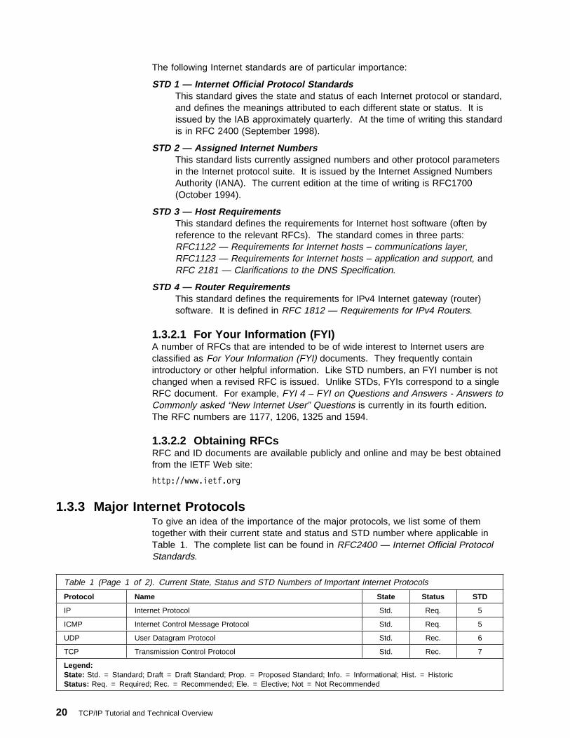
The following Internet standards are of particular importance:
STD 1 — Internet Official Protocol StandardsThis standard gives the state and status of each Internet protocol or standard,and defines the meanings attributed to each different state or status. It isissued by the IAB approximately quarterly. At the time of writing this standardis in RFC 2400 (September 1998).
STD 2 — Assigned Internet NumbersThis standard lists currently assigned numbers and other protocol parametersin the Internet protocol suite. It is issued by the Internet Assigned NumbersAuthority (IANA). The current edition at the time of writing is RFC1700(October 1994).
STD 3 — Host RequirementsThis standard defines the requirements for Internet host software (often byreference to the relevant RFCs). The standard comes in three parts:RFC1122 — Requirements for Internet hosts – communications layer,RFC1123 — Requirements for Internet hosts – application and support, andRFC 2181 — Clarifications to the DNS Specification.
STD 4 — Router RequirementsThis standard defines the requirements for IPv4 Internet gateway (router)software. It is defined in RFC 1812 — Requirements for IPv4 Routers.
1.3.2.1 For Your Information (FYI)A number of RFCs that are intended to be of wide interest to Internet users areclassified as For Your Information (FYI) documents. They frequently containintroductory or other helpful information. Like STD numbers, an FYI number is notchanged when a revised RFC is issued. Unlike STDs, FYIs correspond to a singleRFC document. For example, FYI 4 – FYI on Questions and Answers - Answers toCommonly asked “New Internet User” Questions is currently in its fourth edition.The RFC numbers are 1177, 1206, 1325 and 1594.
1.3.2.2 Obtaining RFCsRFC and ID documents are available publicly and online and may be best obtainedfrom the IETF Web site:
http://www.ietf.org
1.3.3 Major Internet ProtocolsTo give an idea of the importance of the major protocols, we list some of themtogether with their current state and status and STD number where applicable inTable 1. The complete list can be found in RFC2400 — Internet Official ProtocolStandards.
Table 1 (Page 1 of 2). Current State, Status and STD Numbers of Important Internet Protocols
Protocol Name State Status STD
IP Internet Protocol Std. Req. 5
ICMP Internet Control Message Protocol Std. Req. 5
UDP User Datagram Protocol Std. Rec. 6
TCP Transmission Control Protocol Std. Rec. 7
Legend:State: Std. = Standard; Draft = Draft Standard; Prop. = Proposed Standard; Info. = Informational; Hist. = HistoricStatus: Req. = Required; Rec. = Recommended; Ele. = Elective; Not = Not Recommended
20 TCP/IP Tutorial and Technical Overview

Table 1 (Page 2 of 2). Current State, Status and STD Numbers of Important Internet Protocols
Protocol Name State Status STD
TELNET TELNET Protocol Std. Rec. 8
FTP File Transfer Protocol Std. Rec. 9
SMTP Simple Mail Transfer Protocol Std. Rec. 10
MAIL Format of Electronic Mail Messages Std. Rec. 11
DOMAIN Domain Name System Std. Rec. 13
MIME Multipurpose Internet Mail Extensions Draft Ele.
SNMP Simple Network Management Protocol Std. Rec. 15
SMI Structure of Management Information Std. Rec. 16
MIB-II Management Information Base-II Std. Rec. 17
NETBIOS NetBIOS Services Protocol Std. Ele. 19
TFTP Trivial File Transfer Protocol Std. Ele. 33
RIP Routing Information Protocol Hist. Not 34
RIP2 Routing Information Protocol V2 Draft Ele.
ARP Address Resolution Protocol Std. Ele. 37
RARP Reverse Address Resolution Protocol Std. Ele. 38
BGP4 Border Gateway Protocol 3 Draft Ele.
PPP Point-to-Point Protocol Std. Ele. 51
POP3 Post Office Protocol V3 Std. Ele. 53
OSPF2 Open Shortest Path First Protocol V2 Std. Ele. 54
BOOTP Bootstrap Protocol Draft Rec.
DHCP Dynamic Host Configuration Protocol Draft Ele.
IMAPV4 Interactive Mail Access Protocol V4 Prop. Ele.
GOPHER The Internet Gopher Protocol Info.
SUN-NFS Network File System Protocol Info.
IPV6 Internet Protocol Version 6 Prop. Ele.
HTTP-1.1 Hypertext Transfer Protocol 1.1 Prop. Ele.
Legend:State: Std. = Standard; Draft = Draft Standard; Prop. = Proposed Standard; Info. = Informational; Hist. = HistoricStatus: Req. = Required; Rec. = Recommended; Ele. = Elective; Not = Not Recommended
1.4 Future of the InternetTrying to predict the future of the Internet is not an easy task. Few would haveimagined even say, three years ago, the extent to which the Internet has nowbecome a part of everyday life in business, homes and schools. There are anumber of things, however, about which we can be fairly certain.
Bandwidth requirement will continue to increase at massive rates; not only is thenumber of Internet users growing rapidly, but the applications being used arebecoming more advanced and therefore need more bandwidth. This is the reasonwhy the number of core (backbone) service providers has grown from four in 1995to around 48 today (whereas the number of Internet connection providers hasgrown only moderately). However, new technologies such as Dense Wave DivisionMultiplexing (DWDM) will help to get the most bandwidth from currently installedfiber.
Chapter 1. Introduction to TCP/IP - History, Architecture and Standards 21

Today it is possible to hear radio stations from almost any part of the globe via theInternet. Today this is at around AM quality. Soon FM-quality radio andvideo-on-demand will be driving the bandwidth requirement.
Many businesses have already completed an experimental period of Internetaccess and are moving towards using the Internet for serious business use bothintra- and inter-company. This has been made possible by the rapid advances inTCP/IP security technologies made in only the last one to two years. In the not toodistant future, the availability of private, secure high bandwidth networking fromInternet providers may well make many companies question the feasibility of theircurrent in-house wide area networks.
Today we already have Voice over IP technology. As this technology matures weare almost certain to see a sharing of bandwidth between voice and data acrossthe Internet. This raises some interesting questions for phone companies. Thecost to a user of an Internet connection between New York and Japan is the sameas a connection within New York - not so a phone connection. This, and the factthat the Internet is deregulated, will raise many interesting questions in the years tocome.
1.5 IBM and the InternetTo the casual observer of a decade or so ago, it may have appeared that IBM hadlittle interest in the Internet or TCP/IP. It is true that for a long period of time,certain parts of IBM involved in the development and marketing of SNA networksand protocols did consider TCP/IP to be a competitor. In fact, IBM has beenpractically involved in the development of the Internet for a long time, supplyingsoftware and hardware to NSFNET, for example. More importantly, IBM has longbeen involved in the various organizations, committees and task forces responsiblefor establishing open standards. IBM is currently represented on over 130 IETFWorking Groups, helping to shape the future development of TCP/IP.
In March 1992, IBM introduced the Networking Blueprint (later expanded to becomethe Open Blueprint). The Open Blueprint is a framework, based on open andindustry standards, for creating network solutions without concern for underlyingnetworking components and services. It allows the incorporation of multiplenetwork protocols (including TCP/IP and SNA) into a single network. For details onthe Open Blueprint, please refer to the Open Blueprint homepage at:
http://www.software.ibm.com/openblue
1.5.1 The Network Computing FrameworkToday, Network Computing, the Internet and TCP/IP are at the core of IBM'sstrategy. IBM has developed a model for designing business solutions in thenetwork computing environment - the Network Computing Framework fore-business (NCF). NCF is based on an n-tier distributed environment where anynumber of tiers of application logic and business services are separated intocomponents that communicate with each other across a network. In its most basicform, NCF can be depicted as a "logical" three-tier computing model, meaning thatthere is a logical, but not necessarily physical, separation of processes. This modelis designed to support "thin clients" with high-function Web application andenterprise servers.
A prototypical NCF three-tier architecture consists of:
22 TCP/IP Tutorial and Technical Overview
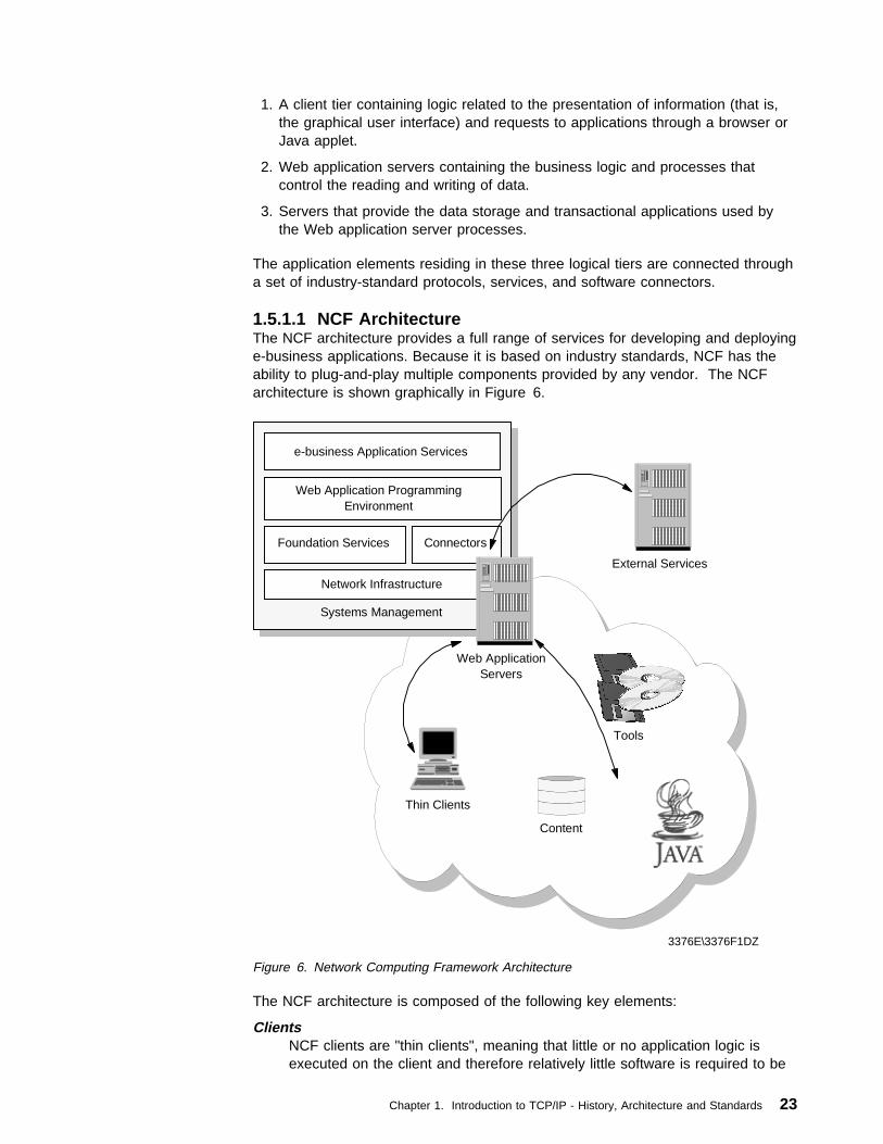
1. A client tier containing logic related to the presentation of information (that is,the graphical user interface) and requests to applications through a browser orJava applet.
2. Web application servers containing the business logic and processes thatcontrol the reading and writing of data.
3. Servers that provide the data storage and transactional applications used bythe Web application server processes.
The application elements residing in these three logical tiers are connected througha set of industry-standard protocols, services, and software connectors.
1.5.1.1 NCF ArchitectureThe NCF architecture provides a full range of services for developing and deployinge-business applications. Because it is based on industry standards, NCF has theability to plug-and-play multiple components provided by any vendor. The NCFarchitecture is shown graphically in Figure 6.
Content
Thin Clients
Tools
External Services
e-business Application Services
Foundation Services Connectors
Systems Management
Network Infrastructure
Web Application ProgrammingEnvironment
Web ApplicationServers
3376E\3376F1DZ
Figure 6. Network Computing Framework Architecture
The NCF architecture is composed of the following key elements:
ClientsNCF clients are "thin clients", meaning that little or no application logic isexecuted on the client and therefore relatively little software is required to be
Chapter 1. Introduction to TCP/IP - History, Architecture and Standards 23
installed on the client. In this model, applications are managed on the serverand dynamically downloaded "on-demand" to requesting clients. As such, theclient portions of new applications should be implemented in HTML, DynamicHTML, XML, and Java applets. NCF supports a broad range of fixed, mobile,and "Tier 0" clients from IBM and other industry leaders, based on industryinitiatives such as the Network Computer Profile, and the Mobile NetworkComputer Reference Specification.
Network infrastructureThe NCF network infrastructure provides a platform for the entire framework.It includes the following services, all based on open standards:
� TCP/IP and network services, such as DHCP, that dynamically assign IPaddresses as devices enter and leave the network.
� Security services based on public key technology that support useridentification and authentication, access control, confidentiality, dataintegrity, and non-repudiation of transactions.
� Directory services that locate users, services, and resources in thenetwork.
� Mobile services that provide access to valuable corporate data to thenomadic computing user.
� Client management services that support the setup, customization, andmanagement of network computers, managed PCs, and in the future Tier0 devices such as smartcards, digital cellphones, etc.
� File and print services that are accessed and managed via a standardWeb browser interface.
Foundation ServicesNCF foundation services provide the core functionality required to developand support the business logic of e-business applications running on the Webapplication server. It includes the following services:
� An HTTP server that coordinates, collects, and assembles Web pagescomposed of static and dynamic content and delivers them to NCFclients.
� Mail and community services that provide e-mail messaging, calendaringand group scheduling, chat, and newsgroup discussions.
� Groupware services that provide a rich shared virtual workspace andsupport the coordination of business workflow processes.
� Database services that integrate the features and functions of anobject-relational database with those of the Web application server.
� Transaction services that extend the Web application server by providinga highly available, robust, expandable and secure transactionalapplication execution environment.
� Messaging services that provide robust, asynchronous communicationand message brokering facilities that support a publish/subscribe model ofcommunication and message transformations.
ConnectorsThe bulk of today's critical data and application (especially transactional)programs reside on and use existing enterprise systems. NCF connectorsallow existing data and application programs to work together with Web
24 TCP/IP Tutorial and Technical Overview

clients and servers, seamlessly linking the strength of the Internet with thestrength of the enterprise. At the core, connectors are software that providelinkage between the NCF Web server programming model environment andsystems, applications, and services that are reached through the use ofapplication specific protocols.
Web Application Programming EnvironmentThe NCF Web application programming environment, based on Java servlets,Enterprise Java services and Enterprise JavaBean components, provides anenvironment for writing dynamic, transactional, secure business applicationson Web application servers. Services are provided that promote separation ofbusiness and presentation logic enabling applications to dynamically adaptand tailor content based on user interests and client device.
e-business Application ServicesNCF e-business application services are building blocks that facilitate thecreation of e-business solutions. They are higher level application-orientedcomponents that conform to the NCF programming model. They build on andextend the underlying NCF infrastructure and foundation services withfunctions required for specific types of applications, for example, e-commerceapplications. As a result, e-business solutions can be developed faster withhigher quality. Examples of NCF e-business application services includepayment services, catalog services, and order management services.
Systems ManagementWithin an enterprise, NCF systems management services provide the corefunctionality that supports end-to-end management across networks, systems,middleware and applications. NCF provides the tools and services thatsupport management of the complete lifecycle of an application frominstallation and configuration, to the monitoring of its operationalcharacteristics such as availability and security, to the controlled update ofchanges. Across multiple enterprises, NCF provides a collaborativemanagement approach for establishing and following procedures to shareinformation and coordinate problem resolution with business partners. Thiscollaborative approach includes policy management, data repository,scheduling and report generation.
Development ToolsNCF provides a broad range of tools to enable creation, deployment andmanagement of e-business applications for Internet, extranet and intranetenvironments. It also supports integrating third-party tools into thedevelopment process. NCF supports the different skill sets involved indeveloping Web applications, providing tools that target specific skill sets, andfacilitates collaboration among members of the development team.
1.5.1.2 API and Protocol SupportThe following table summarizes the standard protocols and APIs supported by eachcomponent of the NCF architecture. While IBM will provide a complete andcompetitive set of products that implement the framework, other implementationscan also work within it. Thus, customers can choose from providers that supportthese open standards. Likewise, solution providers can build their solutions using avariety of software products sourced from different vendors.
Chapter 1. Introduction to TCP/IP - History, Architecture and Standards 25
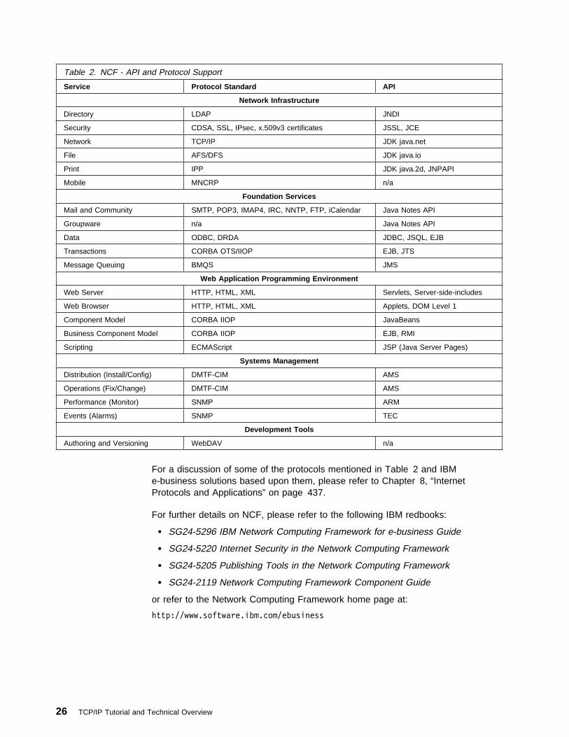
Table 2. NCF - API and Protocol Support
Service Protocol Standard API
Network Infrastructure
Directory LDAP JNDI
Security CDSA, SSL, IPsec, x.509v3 certificates JSSL, JCE
Network TCP/IP JDK java.net
File AFS/DFS JDK java.io
Print IPP JDK java.2d, JNPAPI
Mobile MNCRP n/a
Foundation Services
Mail and Community SMTP, POP3, IMAP4, IRC, NNTP, FTP, iCalendar Java Notes API
Groupware n/a Java Notes API
Data ODBC, DRDA JDBC, JSQL, EJB
Transactions CORBA OTS/IIOP EJB, JTS
Message Queuing BMQS JMS
Web Application Programming Environment
Web Server HTTP, HTML, XML Servlets, Server-side-includes
Web Browser HTTP, HTML, XML Applets, DOM Level 1
Component Model CORBA IIOP JavaBeans
Business Component Model CORBA IIOP EJB, RMI
Scripting ECMAScript JSP (Java Server Pages)
Systems Management
Distribution (Install/Config) DMTF-CIM AMS
Operations (Fix/Change) DMTF-CIM AMS
Performance (Monitor) SNMP ARM
Events (Alarms) SNMP TEC
Development Tools
Authoring and Versioning WebDAV n/a
For a discussion of some of the protocols mentioned in Table 2 and IBMe-business solutions based upon them, please refer to Chapter 8, “InternetProtocols and Applications” on page 437.
For further details on NCF, please refer to the following IBM redbooks:
� SG24-5296 IBM Network Computing Framework for e-business Guide
� SG24-5220 Internet Security in the Network Computing Framework
� SG24-5205 Publishing Tools in the Network Computing Framework
� SG24-2119 Network Computing Framework Component Guide
or refer to the Network Computing Framework home page at:
http://www.software.ibm.com/ebusiness
26 TCP/IP Tutorial and Technical Overview

Chapter 2. Internetworking and Transport Layer Protocols
This chapter provides an overview of the most important and common protocols ofthe TCP/IP internetwork and transport layers, which are the following:
� Internet Protocol (IP)
� Internet Control Message Protocol (ICMP)
� Address Resolution Protocol (ARP)
� Reverse Address Resolution Protocol (RARP)
� User Datagram Protocol (UDP)
� Transmission Control Protocol (TCP)
These protocols perform datagram addressing, routing and delivery, provideconnection-oriented and connectionless services to applications, and resolveinternetwork layer addresses to network interface layer addresses and vice versa.
2.1 Internet Protocol (IP)IP is a standard protocol with STD number 5. That standard also includes ICMP(see 2.2, “Internet Control Message Protocol (ICMP)” on page 58) and IGMP (see9.2, “Internet Group Management Protocol (IGMP)” on page 469). Its status isrequired.
The current IP specification can be found in RFCs 791, 950, 919 and 922, withupdates in RFC 1349.
IP is the protocol that hides the underlying physical network by creating a virtualnetwork view. It is an unreliable, best-effort and connectionless packet deliveryprotocol. Note that best-effort means that the packets sent by IP may be lost, outof order, or even duplicated, but IP will not handle these situations. It is up to thehigher layer protocols to deal with these situations.
One of the reasons for using a connectionless network protocol was to minimizethe dependency on specific computing centers that used hierarchicalconnection-oriented networks. The DoD intended to deploy a network that wouldstill be operational if parts of the country were destroyed. During earthquakes, thishas been proved to be true for the Internet.
2.1.1 IP AddressingIP addresses are represented by a 32-bit unsigned binary value which is usuallyexpressed in a dotted decimal format. For example, 9.167.5.8 is a valid Internetaddress. The numeric form is used by the IP software. The mapping between theIP address and an easier-to-read symbolic name, for example myhost.ibm.com, isdone by the Domain Name System discussed in 4.2, “Domain Name System(DNS)” on page 150. We first look at the numeric form, which is called the IPaddress.
Copyright IBM Corp. 1989, 1998 27

2.1.1.1 The IP AddressThe standards for IP addresses are described in RFC 1166 – Internet Numbers.
To be able to identify a host on the Internet, each host is assigned an address, theIP address, or Internet Address. When the host is attached to more than onenetwork, it is called multi-homed and it has one IP address for each networkinterface. The IP address consists of a pair of numbers:
IP address = <network number><host number>
The network number part of the IP address is centrally administered by the InternetNetwork Information Center (the InterNIC) and is unique throughout the Internet.2
IP addresses are 32-bit numbers usually represented in a dotted decimal form (asthe decimal representation of four 8-bit values concatenated with dots). Forexample, 128.2.7.9 is an IP address with 128.2 being the network number and 7.9being the host number. The rules used to divide an IP address into its network andhost parts are explained below.
The binary format of the IP address 128.2.7.9 is:
1ððððððð ðððððð1ð ððððð111 ðððð1ðð1
IP addresses are used by the IP protocol to uniquely identify a host on the Internet.(Strictly speaking, an IP address identifies an interface that is capable of sendingand receiving IP datagrams, and one system can have multiple such interfaces.However, both hosts and routers must have at least one IP address, so thissimplified definition is acceptable.) IP datagrams (the basic data packetsexchanged between hosts) are transmitted by a physical network attached to thehost and each IP datagram contains a source IP address and a destination IPaddress. To send a datagram to a certain IP destination, the target IP addressmust be translated or mapped to a physical address. This may requiretransmissions on the network to find out the destination's physical network address.(For example, on LANs the Address Resolution Protocol, discussed in 2.4,“Address Resolution Protocol (ARP)” on page 68, is used to translate IP addressesto physical MAC addresses.).
The first bits of the IP address specify how the rest of the address should beseparated into its network and host part.
The terms network address and netID are sometimes used instead of networknumber, but the formal term, used in RFC 1166, is network number. Similarly, theterms host address and hostID are sometimes used instead of host number.
There are five classes of IP addresses. These are shown in Figure 7 on page 29.
2 Prior to 1993, the NIC function was performed by the DDN NIC (nic.ddn.mil). See RFC 1400 for more information about thistransition.
28 TCP/IP Tutorial and Technical Overview

1 2 301 8 6 4 1
110
1110
11110
0
Class B
Class C
Class D
Class E
netID10
Class A
netID
multicast
future use
hostID
netID
hostID
hostID
Figure 7. IP - Assigned Classes of IP Addresses
� Class A addresses use 7 bits for the <network> and 24 bits for the <host>portion of the IP address. That allows for 27-2 (126) networks with 224-2(16777214) hosts each; a total of over 2 billion addresses.
� Class B addresses use 14 bits for the <network> and 16 bits for the <host>portion of the IP address. That allows for 214-2 (16382) networks with 216-2(65534) hosts each; a total of over 1 billion addresses.
� Class C addresses use 21 bits for the <network> and 8 bits for the <host>portion of the IP address. That allows for 221-2 (2097150) networks with 28-2(254) hosts each; a total of over half a billion addresses.
� Class D addresses are reserved for multicasting (a sort of broadcasting, but ina limited area, and only to hosts using the same class D address).
� Class E addresses are reserved for future use.
It is clear that a Class A address will only be assigned to networks with a hugenumber of hosts, and that class C addresses are suitable for networks with a smallnumber of hosts. However, this means that medium-sized networks (those withmore than 254 hosts or where there is an expectation that there may be more than254 hosts in the future) must use Class B addresses. The number of small- tomedium-sized networks has been growing very rapidly in the last few years and itwas feared that, if this growth had been allowed to continue unabated, all of theavailable Class B network addresses would have been used by the mid-1990s.This is termed the IP Address Exhaustion problem. The problem and how it isbeing addressed are discussed in 2.1.5, “The IP Address Exhaustion Problem” onpage 42.
One point to note about the split of an IP address into two parts is that this splitalso splits the responsibility for selecting the IP address into two parts. Thenetwork number is assigned by the InterNIC, and the host number by the authoritywhich controls the network. As we shall see in the next section, the host number
Chapter 2. Internetworking and Transport Layer Protocols 29

can be further subdivided: this division is controlled by the authority which owns thenetwork, and not by the InterNIC.
2.1.1.2 Special IP AddressesAny component of an IP address with a value all bits 0 or all bits 1 has a specialmeaning:
all bits 0Stands for this: this host (IP address with <host address>=0) or this network(IP address with <network address>=0). When a host wants to communicateover a network, but does not yet know the network IP address, it may sendpackets with <network address>=0. Other hosts on the network will interpretthe address as meaning this network. Their reply will contain the fullyqualified network address, which the sender will record for future use.
all bits 1Stands for all: all networks or all hosts. For example, the following means allhosts on network 128.2 (class B address):
128.2.255.255
This is called a directed broadcast address because it contains both a valid<network address> and a broadcast <host address>.
LoopbackThe class A network 127.0.0.0 is defined as the loopback network.Addresses from that network are assigned to interfaces that process datainside the local system and never access a physical network (loopbackinterfaces).
2.1.2 IP SubnetsDue to the explosive growth of the Internet, the principle of assigned IP addressesbecame too inflexible to allow easy changes to local network configurations. Thosechanges might occur when:
� A new type of physical network is installed at a location.� Growth of the number of hosts requires splitting the local network into two or
more separate networks.� Growing distances require splitting a network into smaller networks, with
gateways between them.
To avoid having to request additional IP network addresses in these cases, theconcept of subnets was introduced. The assignment of subnets can be donelocally, as the whole network still appears to be one IP network to the outsideworld.
The host number part of the IP address is subdivided again into a network numberand a host number. This second network is termed a subnetwork or subnet. Themain network now consists of a number of subnets and the IP address isinterpreted as:
<network number><subnet number><host number>
The combination of the subnet number and the host number is often termed thelocal address or the local part. Subnetting is implemented in a way that istransparent to remote networks. A host within a network that has subnets is awareof the subnetting but a host in a different network is not; it still regards the local partof the IP address as a host number.
30 TCP/IP Tutorial and Technical Overview

The division of the local part of the IP address into subnet number and hostnumber parts can be chosen freely by the local administrator; any bits in the localpart can be used to form the subnet. The division is done using a subnet maskwhich is a 32 bit number. Zero bits in the subnet mask indicate bit positionsascribed to the host number, and ones indicate bit positions ascribed to the subnetnumber. The bit positions in the subnet mask belonging to the network number areset to ones but are not used. Subnet masks are usually written in dotted decimalform, like IP addresses.
The special treatment of all bits zero and all bits one applies to each of the threeparts of a subnetted IP address just as it does to both parts of an IP address thathas not been subnetted (see 2.1.1.2, “Special IP Addresses” on page 30). Forexample, a subnetted Class B network, which has a 16-bit local part, could use oneof the following schemes:
� The first byte is the subnet number; the second byte is the host number. Thisgives us 28-2 (254 with the values 0 and 255 being reserved) possible subnets,each having up to 28-2 (254) hosts. The subnet mask is 255.255.255.0.
� The first 12 bits are used for the subnet number and the last four for the hostnumber. This gives us 212-2 (4094) possible subnets but only 24-2 (14) hostsper subnet. The subnet mask is 255.255.255.240.
There are many other possibilities. In fact, the number of subnets and hostsand future requirements should be taken into consideration before defining asubnet. In the above example, for a subnetted Class B network, there are 16bits left for the subnet number and the host number fields. The administratorhas the choice of defining either a larger number of subnets with a smallnumber of hosts in each, or a smaller number of subnets with many hosts.
While the administrator is completely free to assign the subnet part of the localaddress in any legal fashion, the objective is to assign a number of bits to thesubnet number and the remainder to the local address. Therefore, it is normal touse a contiguous block of bits at the beginning of the local address part for thesubnet number because this makes the addresses more readable. (This isparticularly true when the subnet occupies 8 or 16 bits.) With this approach, eitherof the subnet masks above are “good” masks, but masks such as 255.255.252.252and 255.255.255.15 are not. (In fact, hardly any TCP/IP implementation supportsnon-contiguous subnet masks, and their use is commonly discouraged, especiallyin CIDR environments that would become non-functional by choosingnon-conventional subnet masks or network prefixes.)
2.1.2.1 Types of SubnettingThere are two types of subnetting: static and variable length. Variable length is themore flexible of the two. Which type of subnetting is available depends upon therouting protocol being used; native IP routing supports only static subnetting, asdoes the widely used RIP protocol. However, RIP Version 2 supports variablelength subnetting as well. See 3.3.1, “Routing Information Protocol (RIP)” onpage 106 for a description of RIP and RIP2. Chapter 3, “Routing Protocols” onpage 95 discusses routing protocols in detail.
Static Subnetting: Static subnetting means that all subnets in the subnettednetwork use the same subnet mask. This is simple to implement and easy tomaintain, but it implies wasted address space for small networks. For example, anetwork of four hosts that uses a subnet mask of 255.255.255.0 wastes 250 IP
Chapter 2. Internetworking and Transport Layer Protocols 31
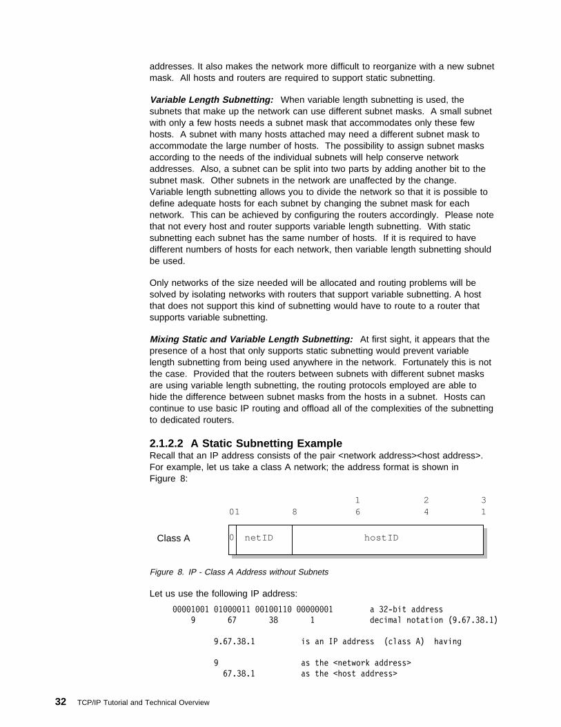
addresses. It also makes the network more difficult to reorganize with a new subnetmask. All hosts and routers are required to support static subnetting.
Variable Length Subnetting: When variable length subnetting is used, thesubnets that make up the network can use different subnet masks. A small subnetwith only a few hosts needs a subnet mask that accommodates only these fewhosts. A subnet with many hosts attached may need a different subnet mask toaccommodate the large number of hosts. The possibility to assign subnet masksaccording to the needs of the individual subnets will help conserve networkaddresses. Also, a subnet can be split into two parts by adding another bit to thesubnet mask. Other subnets in the network are unaffected by the change.Variable length subnetting allows you to divide the network so that it is possible todefine adequate hosts for each subnet by changing the subnet mask for eachnetwork. This can be achieved by configuring the routers accordingly. Please notethat not every host and router supports variable length subnetting. With staticsubnetting each subnet has the same number of hosts. If it is required to havedifferent numbers of hosts for each network, then variable length subnetting shouldbe used.
Only networks of the size needed will be allocated and routing problems will besolved by isolating networks with routers that support variable subnetting. A hostthat does not support this kind of subnetting would have to route to a router thatsupports variable subnetting.
Mixing Static and Variable Length Subnetting: At first sight, it appears that thepresence of a host that only supports static subnetting would prevent variablelength subnetting from being used anywhere in the network. Fortunately this is notthe case. Provided that the routers between subnets with different subnet masksare using variable length subnetting, the routing protocols employed are able tohide the difference between subnet masks from the hosts in a subnet. Hosts cancontinue to use basic IP routing and offload all of the complexities of the subnettingto dedicated routers.
2.1.2.2 A Static Subnetting ExampleRecall that an IP address consists of the pair <network address><host address>.For example, let us take a class A network; the address format is shown inFigure 8:
0Class A netID hostID
1 2 301 8 6 4 1
Figure 8. IP - Class A Address without Subnets
Let us use the following IP address:
ðððð1ðð1 ð1ðððð11 ðð1ðð11ð ððððððð1 a 32-bit address
9 67 38 1 decimal notation (9.67.38.1)
9.67.38.1 is an IP address (class A) having
9 as the <network address>
67.38.1 as the <host address>
32 TCP/IP Tutorial and Technical Overview

Subnets are an extension to this by considering a part of the <host address> to bea subnetwork address. IP addresses are then interpreted as <networkaddress><subnetwork address><host address>.
For example, you may wish to choose the bits from 8 to 25 of a class A IP addressto indicate the subnet addresses, and the bits from 26 to 31 to indicate the actualhost addresses. Figure 9 shows the subnetted address that has thus been derivedfrom the original class A address:
1 2 301 8 6 4 1
Class ASubnet subnet number0
hostIDnetID
Figure 9. IP - Class A Address with Subnet Mask and Subnet Address
We normally use a bit mask, known as the subnet mask, to identify which bits ofthe original host address field should indicate the subnet number. In the aboveexample, the subnet mask is 255.255.255.192 in decimal notation (or 1111111111111111 11111111 11000000 in bit notation). Note that, by convention, the<network address> is masked as well.
For each of these subnet values, only 218-2 addresses (from 1 to 262143) are validbecause of the all bits 0 and all bits 1 number restrictions. This split will thereforegive 262142 subnets each with a maximum of 26-2 or 62 hosts.
You will notice that the value applied to the subnet number takes the value of thefull byte with non-significant bits being set to zero. For example, the hexadecimalvalue 01 in this subnet mask assumes an 8-bit value 01000000 and gives a subnetvalue of 64 and not 1 as it might seem.
Applying this mask to our sample class A address 9.67.38.1 would break theaddress down as follows:
ðððð1ðð1 ð1ðððð11 ðð1ðð11ð ððððððð1 = 9.67.38.1 (class A address)
11111111 11111111 11111111 11------ 255.255.255.192 (subnet mask)
===================================== logical_AND
ðððð1ðð1 ð1ðððð11 ðð1ðð11ð ðð------ = 9.67.38 (subnet base address)
This leaves a host address of:
-------- -------- -------- --ððððð1 = 1 (host address)
IP will recognize all host addresses as being on the local network for which thelogical_AND operation described above produces the same result. This isimportant for routing IP datagrams in subnet environments (see 2.1.3, “IP Routing”on page 35).
Note that the actual subnet number would be:
-------- ð1ðððð11 ðð1ðð11ð ðð------ = 6876ð (subnet number)
You will notice that the subnet number shown above is a relative number. That is,it is the 68760th subnet of network 9 with the given subnet mask. This number
Chapter 2. Internetworking and Transport Layer Protocols 33

bears no resemblance to the actual IP address that this host has been assigned(9.67.38.1) and has no meaning in terms of IP routing.
The division of the original <host address> part into <subnet> and <host> parts canbe chosen freely by the local administrator, except that the values of all zeroes andall ones in the <subnet> field are reserved for special addresses.
Note: Because the range of available IP addresses is decreasing rapidly, manyrouters do support the use of all zeroes and all ones in the <subnet> field,though this is not coherent with the standards.
2.1.2.3 A Variable Length Subnetting ExampleConsider a corporation that was assigned a Class C network 165.214.32.0, and ithas the requirement to split this address range into five separate networks. Therequired number of hosts for each subnet are following:
� 1. Subnet: 50 hosts
� 2. Subnet: 50 hosts
� 3. Subnet: 50 hosts
� 4. Subnet: 30 hosts
� 5. Subnet: 30 hosts
This cannot be achieved by using static subnetting. For this case, the staticsubnetting can only divide the network into four subnets with 64 hosts each or eightsubnet with 32 hosts each. This method would not meet the requirement.
To be able to divide the network into five subnets, multiple masks should bedefined. Using a mask of 255.255.255.192, the network will be divided into foursubnets with 64 hosts each. After that, the last subnet can be further divided intotwo subnets with 32 hosts each by using a mask of 255.255.255.224. There will bethree subnets with 64 hosts each and two subnets with 32 hosts each. This wouldmeet the requirements.
2.1.2.4 Obtaining a Subnet MaskUsually, hosts will store the subnet mask to be used in a configuration file.However, sometimes this cannot be done, as for example in the case of a disklessworkstation. The ICMP protocol includes two messages, address mask requestand address mask reply, that allow hosts to obtain the correct subnet mask from aserver. See 2.2.1.10, “Address Mask Request (17) and Address Mask Reply (18)”on page 65 for more information.
2.1.2.5 Addressing Routers and Multi-homed HostsWhenever a host has a physical connection to multiple networks or subnets, it isdescribed as being multi-homed. All routers are multi-homed since their purpose isto join networks or subnets. A multi-homed host always has different IP addressesassociated with each network adapter, since each adapter is in a different subnet ornetwork.
34 TCP/IP Tutorial and Technical Overview
2.1.3 IP RoutingAn important function of the IP layer is IP routing. It provides the basic mechanismfor routers to interconnect different physical networks. This means that a host canfunction as a normal host and a router simultaneously.
A basic router of this type is referred to as a router with partial routing information,because the router only has information about four kinds of destinations:
� Hosts that are directly attached to one of the physical networks to which therouter is attached
� Hosts or networks for which the router has been given explicit definitions
� Hosts or networks for which the router has received an ICMP redirect message
� A default destination for everything else
The last two items allow a basic router to begin with a very limited amount ofinformation and to increase its information because a more sophisticated router willissue an ICMP redirect message if it receives a datagram and it knows of a betterrouter on the same network for the sender to use. This process is repeated eachtime a basic router of this type is restarted.
Additional protocols are needed to implement a full-function router that canexchange information with other routers in remote network. Such routers areessential except in small networks. The protocols they use are discussed inChapter 3, “Routing Protocols” on page 95.
There are two types of IP routing: direct and indirect.
2.1.3.1 Direct RoutingIf the destination host is attached to a physical network to which the source host isalso attached, an IP datagram can be sent directly, simply by encapsulating the IPdatagram in the physical network frame. This is called direct delivery and isreferred to as direct routing.
2.1.3.2 Indirect RoutingIndirect routing occurs when the destination host is not on a network directlyattached to the source host. The only way to reach the destination is via one ormore IP gateways. (Note that in TCP/IP terminology, the terms gateway and routerare used interchangeably for a system that actually performs the duties of a router.)The address of the first of these gateways (the first hop) is called an indirect routein the context of the IP routing algorithm. The address of the first gateway is theonly information needed by the source host.
In some cases there are multiple subnets defined on the same network. Even ifthe destination host is on the same network with the source host, if the they are ondifferent subnets, then indirect routing is used. Thus, there is a need for a routerthat forwards the traffic between subnets.
Chapter 2. Internetworking and Transport Layer Protocols 35

Host DHost C
Host BHost A
Figure 10. IP - Direct and Indirect Routes. (Host C has a direct route to hosts B and D,and an indirect route to host A via gateway B.)
2.1.3.3 IP Routing TableThe determination of available direct routes is derived from the list of localinterfaces available to IP and is composed by IP automatically at initialization. Alist of networks and associated gateways (indirect routes) needs to be configured tobe used with IP routing if required. Each host keeps the set of mappings betweenthe following:
� Destination IP network address(es)� Route(s) to next gateway(s)
These are stored in a table called the IP routing table. Three types of mappingscan be found in this table:
1. The direct routes, for locally attached networks
2. The indirect routes, for networks reachable via one or more gateways
3. The default route, which contains the (direct or indirect) route to be used incase the destination IP network is not found in the mappings of type 1 and 2above
See the network in Figure 11 on page 37 for an example configuration.
36 TCP/IP Tutorial and Technical Overview

Host DHost C
Host E Host FHost BHost A
128.15
129.7128.10
Figure 11. IP - Routing Table Scenario
The routing table of host D might contain the following (symbolic) entries:
destination router interface
129.7.ð.ð E lanð
128.15.ð.ð D lanð
128.1ð.ð.ð B lanð
default B lanð
127.ð.ð.1 loopback lo
Figure 12. IP - Routing Table Example 1
The routing table of host F might contain the following (symbolic) entries:
destination router interface
129.7.ð.ð F wanð
default E wanð
127.ð.ð.1 loopback lo
Figure 13. IP - Routing Table Example 2
Chapter 2. Internetworking and Transport Layer Protocols 37

2.1.3.4 IP Routing AlgorithmIP uses a unique algorithm to route an IP datagram, called the IP routing algorithm.To send an IP datagram on the network, the general IP routing algorithm has thefollowing form:
no
3376\3376F2OR
yes
send IP datagramon local network
destination IP network address = my IP network address?
send IP datagram to gateway corresponding to the destination IP network address
Figure 14. IP - IP Routing without Subnets
To be able to differentiate between subnets, the IP routing algorithm changes andhas the following form:
no
3376\3376F2OS
yes
send IP datagramon local network
bitwise_AND(my IP address,subnet mask)?
send IP datagram to gateway corresponding to the destination IP (sub)network address
bitwise_AND(destination IP address,subnet mask)
=
Figure 15. IP - IP Routing with Subnets
Some implications of this algorithm are:
� It is a change to the general IP algorithm. Therefore, to be able to operate thisway, the particular gateway must contain the new algorithm. Someimplementations may still use the general algorithm, and will not function withina subnetted network, although they can still communicate with hosts in othernetworks that are subnetted.
� As IP routing is used in all of the hosts (and not just the routers), all of thehosts in the subnet must have:
1. An IP routing algorithm that supports subnetting.2. The same subnet mask (unless subnets are formed within the subnet).
� If the IP implementation on any of the hosts does not support subnetting, thathost will be able to communicate with any host in its own subnet but not withany machine on another subnet within the same network. This is because the
38 TCP/IP Tutorial and Technical Overview

host sees only one IP network and its routing cannot differentiate between anIP datagram directed to a host on the local subnet and a datagram that shouldbe sent via a router to a different subnet.
In case one or more hosts do not support subnetting, an alternative way to achievethe same goal exists in the form of proxy-ARP, which doesn't require any changesto the IP routing algorithm for single-homed hosts, but does require changes onrouters between subnets in the network. This is explained in more detail in 2.4.4,“Proxy-ARP or Transparent Subnetting” on page 71.
The entire IP routing algorithm is illustrated in the figure below, including support ofsubnets:
Bitwise AND dest_IP_addr with local_subnet_mask(s)
Is there a match?
Bitwise AND local interface(s)with local_subnet_mask(s)
Is there an indirect route entry?
Is a default route specified?
NO
Deliver directly usingthe correspondinglocal interface
Deliver indirectlyto the corresponding router's IP address
Deliver indirectlyto the default router'sIP address
Send ICMP error message"network unreachable"
NO
YES
YES
YES
Take destination IP address
NO
Figure 16. IP - Routing Algorithm (with Subnets)
Notes:
1. This is an iterative process. It is applied by every host handling a datagram,except for the host to which the datagram is finally delivered.
2. Routing tables and the routing algorithm are local to any host in an IP network.In order to be able to forward IP datagrams on behalf of other hosts, routersneed to exchange their routing table information with other routers in thenetwork. This is done using special routing protocols, some of which arediscussed in Chapter 3, “Routing Protocols” on page 95.
2.1.4 Methods of Delivery - Unicast, Broadcast, Multicast and AnycastThe majority of IP addresses refer to a single recipient, called unicast addresses.Unicast connections are one-to-one connections. Additionally, there are threespecial types of IP addresses that are used for addressing multiple recipients:broadcast addresses, multicast addresses and anycast addresses. As you see inFigure 17 on page 40, a broadcast serves all, multicast only some and anycastonly one specific availbale host.
Chapter 2. Internetworking and Transport Layer Protocols 39

Unicast
S D
Broadcast
S D
D
D
Anycast
S D
D
DMulticast
S D
D
D
3376\3376F2S1
Figure 17. IP - Packet Delivery Modes
Any protocol that is connectionless can send broadcast, multicast or anycastmessages as well as unicast messages. A protocol that is connection-oriented canonly use unicast addresses because the connection exists between a specific pairof hosts.
2.1.4.1 BroadcastingThere are a number of addresses that are used for IP broadcasting. All use theconvention that all-bits 1 indicates all. Broadcast addresses are never valid assource addresses, only as destination addresses. The different types of broadcastaddresses are listed here:
Limited Broadcast AddressThe address 255.255.255.255 (all bits 1 in all parts of the IP address) is usedon networks that support broadcasting, such as LANs, and it refers to allhosts on the subnet. It does not require the host to know any IP configurationinformation at all. All hosts on the local network will recognize the address,but routers will never forward it.
There is one exception to this rule, called BOOTP forwarding. The BOOTPprotocol uses the limited broadcast address to allow a diskless workstation tocontact a boot server. BOOTP forwarding is a configuration option availableon some routers, including the IBM 2210 Nways Multiprotocol Router and theIBM 2216 Nways Multiaccess Connector to make an exception for UDPdatagrams for ports 67 (used by the BOOTP protocol). Without this facility, aseparate BOOTP server would be required on each subnet. However, this isnot simple forwarding because the router also plays a part in the BOOTPprotocol. See 7.1, “Bootstrap Protocol (BOOTP)” on page 401 for moreinformation about BOOTP forwarding and 2.7, “User Datagram Protocol(UDP)” on page 75 for an explanation of UDP ports.
40 TCP/IP Tutorial and Technical Overview
Network-Directed Broadcast AddressIf the network number is a valid network number, the network is not subnettedand the host number is all ones (for example, 128.2.255.255), then theaddress refers to all hosts on the specified network. Routers should forwardthese broadcast messages unless configured otherwise. This is used in ARPrequests (see 2.4, “Address Resolution Protocol (ARP)” on page 68) onunsubnetted networks.
Subnet-Directed Broadcast AddressIf the network number is a valid network number, the subnet number is a validsubnet number and the host number is all ones, then the address refers to allhosts on the specified subnet. Since the sender's subnet and the targetsubnet may have different subnet mask, the sender must somehow find outthe subnet mask in use at the target. The actual broadcast is performed bythe router that receives the datagram into the subnet.
All-Subnets-Directed Broadcast AddressIf the network number is a valid network number, the network is subnettedand the local part is all ones (for example, 128.2.255.255), then the addressrefers to all hosts on all subnets in the specified network. In principle routersmay propagate broadcasts for all subnets but are not required to do so. Inpractice, they do not; there are few circumstances where such a broadcastwould be desirable, and it can lead to problems, particularly if a host hasbeen incorrectly configured with no subnet mask. Consider the wastedresource involved if a host 9.180.214.114 in the subnetted Class A network 9thought that it was not subnetted and used 9.255.255.255 as a localbroadcast address instead of 9.180.214.255 and all of the routers in thenetwork respected the request to forward the request to all clients.
If routers do respect all-subnets-directed broadcast address, they use analgorithm called reverse path forwarding to prevent the broadcast messagesfrom multiplying out of control. See RFC 922 for more details on thisalgorithm.
2.1.4.2 MulticastingBroadcasting has a major disadvantage; its lack of selectivity. If an IP datagram isbroadcast to a subnet, every host on the subnet will receive it, and have to processit to determine whether the target protocol is active. If it is not, the IP datagram isdiscarded. Multicasting avoids this overhead by using groups of IP addresses.
Each group is represented by a 28-bit number, which is included in a Class Daddress. So multicast group addresses are IP addresses in the range 224.0.0.0 to239.255.255.255. For each multicast address there is a set of zero or more hoststhat are listening to it. This set is called the host group. There is no requirementfor any host to be a member of a group to send to that group. Packets that aresent to a multicast address, are forwared only to the members of the correspondinghost group. So multicast makes it possible to establish a one to some connection.See 9.1, “Multicasting” on page 467 for detailed information about IP multicasting.
2.1.4.3 AnycastingSometimes, the same IP services are provided by different hosts. For example, auser wants to download a file via FTP and the file is available on different FTPservers. But the user doesn't know which connection is the fastest. So it ispossible that the connection to the server from which he or she downloads the fileis slower than the other ones.
Chapter 2. Internetworking and Transport Layer Protocols 41
Hosts that provide the same IP service could serve an anycast address to otherhosts that may require the service. The connection is made to the first host in theanycast address group that responds. This process guarantees that the service isprovided by the host that has the best connection to the receiver.
The anycast service will be part of IPV6. Please see Anycast Address onpage 371 for further details about anycasting.
2.1.5 The IP Address Exhaustion ProblemThe number of networks on the Internet has been approximately doubling annuallyfor a number of years. However, the usage of the Class A, B and C networksdiffers greatly. Nearly all of the new networks assigned in the late 1980s wereClass B, and in 1990 it became apparent that if this trend continued, the last ClassB network number would be assigned during 1994. On the other hand, Class Cnetworks were hardly being used.
The reason for this trend was that most potential users found a Class B network tobe large enough for their anticipated needs, since it accommodates up to 65534hosts, whereas a class C network, with a maximum of 254 hosts, severely restrictsthe potential growth of even a small initial network. Furthermore, most of the classB networks being assigned were small ones. There are relatively few networks thatwould need as many as 65,534 host addresses, but very few for which 254 hostswould be an adequate limit. In summary, although the Class A, Class B and ClassC divisions of the IP address are logical and easy-to-use (because they occur onbyte boundaries), with hindsight they are not the most practical because Class Cnetworks are too small to be useful for most organizations while Class B networksare too large to be densely populated by any but the largest organizations.
In May 1996, there were all of Class A addresses either allocated or assigned, aswell as 61.95 percent of Class B and 36.44 percent of Class C IP networkaddresses. The terms assigned and allocated in this context have the followingmeanings:
AssignedThe number of network numbers in use. The Class C figures are somewhatinaccurate, because the figures do not include many class C networks inEurope, which were allocated to RIPE and subsequently assigned but whichare still recorded as allocated.
AllocatedThis includes all of the assigned networks and additionally, those networksthat have either been reserved by IANA (for example, the 63 class A networksare all reserved by IANA) or have been allocated to regional registries byIANA and will subsequently be assigned by those registries.
Another way to look at these numbers is to examine the proportion of the addressspace that has been used. The figures in the table do not show for example thatthe Class A address space is as big as the rest combined, or that a single Class Anetwork can theoretically have as many hosts as 66,000 Class C networks.
Since 1990, the number of assigned Class B networks has been increasing at amuch lower rate than the total number of assigned networks and the anticipatedexhaustion of the Class B network numbers has not yet occurred. The reason forthis is that the policies of the InterNIC on network number allocation were changedin late 1990 to preserve the existing address space, in particular to avert the
42 TCP/IP Tutorial and Technical Overview
exhaustion of the Class B address space. The new policies can be summarized asfollows.
� The upper half of the Class A address space (network numbers 64 to 127) isreserved indefinitely to allow for the possibility of using it for transition to a newnumbering scheme.
� Class B networks are only assigned to organizations that can clearlydemonstrate a need for them. The same is, of course, true for Class Anetworks. The requirements for Class B networks are that the requestingorganization:
– Has a subnetting plan that documents more than 32 subnets within itsorganizational network
– Has more than 4096 hosts
Any requirements for a Class A network would be handled on an individualcase basis.
� Organizations that do not fulfill the requirements for a Class B network areassigned a consecutively numbered block of Class C network numbers.
� The lower half of the Class C address space (network numbers 192.0.0 through207.255.255) is divided into eight blocks, which are allocated to regionalauthorities as follows:
192.0.0 - 193.255.255 Multi-regional
194.0.0 - 195.255.255 Europe
196.0.0 - 197.255.255 Others
198.0.0 - 199.255.255 North America
200.0.0 - 201.255.255 Central and South America
202.0.0 - 203.255.255 Pacific Rim
204.0.0 - 205.255.255 Others
206.0.0 - 207.255.255 Others
The ranges defined as Others are to be where flexibility outside the constraintsof regional boundaries is required. The range defined as multi-regionalincludes the Class C networks that were assigned before this new scheme wasadopted. The 192 networks were assigned by the InterNIC and the 193networks were previously allocated to RIPE in Europe.
The upper half of the Class C address space (208.0.0 to 223.255.255) remainsunassigned and unallocated.
� Where an organization has a range of class C network numbers, the rangeprovided is assigned as a bit-wise contiguous range of network numbers, andthe number of networks in the range is a power of 2. That is, all IP addressesin the range have a common prefix, and every address with that prefix is withinthe range. For example, a European organization requiring 1500 IP addresseswould be assigned eight Class C network numbers (2048 IP addresses) fromthe number space reserved for European networks (194.0.0 through195.255.255) and the first of these network numbers would be divisible byeight. A range of addresses satisfying these rules would be 194.32.136through 194.32.143, in which case the range would consist of all of the IPaddresses with the 21-bit prefix 194.32.136, or B'110000100010000010001'.
Chapter 2. Internetworking and Transport Layer Protocols 43

The maximum number of network numbers assigned contiguously is 64,corresponding to a prefix of 18 bits. An organization requiring more than 4096addresses but less than 16,384 addresses can request either a Class B or arange of Class C addresses. In general, the number of Class C networksassigned is the minimum required to provide the necessary number of IPaddresses for the organization on the basis of a two-year outlook. However, insome cases, an organization can request multiple networks to be treatedseparately. For example, an organization with 600 hosts would normally beassigned four class C networks. However, if those hosts were distributedacross 10 token-ring LANs with between 50 and 70 hosts per LAN, such anallocation would cause serious problems, since the organization would have tofind 10 subnets within a 10-bit local address range. This would mean at leastsome of the LANs having a subnet mask of 255.255.255.192 which allows only62 hosts per LAN. The intent of the rules is not to force the organization intocomplex subnetting of small networks, and the organization should request 10different Class C numbers, one for each LAN.
The current rules are to be found in RFC 2050 — INTERNET REGISTRY IPALLOCATION GUIDELINES which updates RFC 1466. The reasons for the rulesfor the allocation of Class C network numbers will become apparent in the followingsections. The use of Class C network numbers in this way has averted theexhaustion of the Class B address space, but it is not a permanent term solution tothe overall address space constraints that are fundamental to IP. A long-termsolution is discussed in Chapter 6, “IP Version 6” on page 357.
Today, there are three registries that handle world-wide IP address assignments:
APNIC (Asia-Pacific Network Information Center)Handles IP address allocation for Asia-Pacific. APNIC can be contacted atthe following URL:
http://www.apnic.net
ARIN (American Registry for Internet Numbers )Handles IP address allocation for North and South America, the Caribbean,and sub-Saharan Africa. ARIN can be contacted at the following URL:
http://www.arin.net
RIPE NCC (Reseau IP Europeens)Handles IP address allocation for Europe and surrounding areas. RIPE NCCcan be contacted at the following URL:
http://www.ripe.net
2.1.6 Intranets (Private IP Addresses)Another approach to conservation of the IP address space is described in RFC1918 — Address Allocation for Private Internets. Briefly, it relaxes the rule that IPaddresses are globally unique by reserving part of the address space for networksthat are used exclusively within a single organization and that do not require IPconnectivity to the Internet. There are three ranges of addresses that have beenreserved by IANA for this purpose:
10 A single Class A network
172.16 through 172.31 16 contiguous Class B networks
192.168.0 through 192.168.255 256 contiguous Class C networks
44 TCP/IP Tutorial and Technical Overview

Any organization can use any addresses in these ranges without reference to anyother organization. However, because these addresses are not globally unique,they cannot be referenced by hosts in another organization and they are notdefined to any external routers. Routers in networks not using private addresses,particularly those operated by Internet service providers, are expected to quietlydiscard all routing information regarding these addresses. Routers in anorganization using private addresses are expected to limit all references to privateaddresses to internal links; they should neither advertise routes to privateaddresses to external routers nor forward IP datagrams containing privateaddresses to external routers. Hosts having only a private IP address do not haveIP layer connectivity to the Internet. This may be desirable and may even be areason for using private addressing. All connectivity to external Internet hosts mustbe provided with application gateways (please see 5.3.4, “Application LevelGateway (Proxy)” on page 284).
2.1.7 Classless Inter-Domain Routing (CIDR)It has been mentioned in 2.1.1, “IP Addressing” on page 27 that due to the impactsof growth, the IP address space will near exhaustion very soon if addresses areassigned as they are requested or as they used to be assigned. IPv6 will easilyovercome that problem (see Chapter 6, “IP Version 6” on page 357), but what canbe done until IPv6 will be fully deployed?
One idea was to use a range of Class C addresses instead of a single Class Baddress. The problem there is that each network must be routed separatelybecause standard IP routing understands only class A, B and C network addresses(see 2.1.3, “IP Routing” on page 35).
Within each of these types of network, subnetting can be used to provide bettergranularity of the address space within each network, but there is no way to specifythat multiple Class C networks are actually related (see 2.1.2, “IP Subnets” onpage 30). The result of this is termed the routing table explosion problem: AClass B network of 3000 hosts requires one routing table entry at each backbonerouter, whereas the same network, if addressed as a range of Class C networks,would require 16 entries.
The solution to this problem is a scheme called Classless Inter-Domain Routing(CIDR). CIDR is described in RFCs 1518 to 1520.
CIDR does not route according to the class of the network number (hence the termclassless) but solely according to the high order bits of the IP address, which aretermed the IP prefix. Each CIDR routing table entry contains a 32-bit IP addressand a 32-bit network mask, which together give the length and value of the IPprefix. This can be represented as <IP_address network_mask>. For example, toaddress a block of eight Class C addresses with one single routing table entry, thefollowing representation would suffice: <192.32.136.0 255.255.248.0>. Thiswould, from a backbone point of view, refer to the Class C network range from192.32.136.0 to 192.32.143.0 as one single network because of the identical IPprefix, as illustrated in Figure 18 on page 46:
Chapter 2. Internetworking and Transport Layer Protocols 45

11ðððððð ðð1ððððð 1ððð1ððð ðððððððð = 192.32.136.ð (class C address)
11111111 11111111 11111--- -------- 255.255.248.ð (network mask)
===================================== logical_AND
11ðððððð ðð1ððððð 1ððð1--- -------- = 192.32.136 (IP prefix)
11ðððððð ðð1ððððð 1ððð1111 ðððððððð = 192.32.143.ð (class C address)
11111111 11111111 11111--- -------- 255.255.248.ð (network mask)
===================================== logical_AND
11ðððððð ðð1ððððð 1ððð1--- -------- = 192.32.136 (same IP prefix)
Figure 18. Classless Inter-Domain Routing - IP Supernetting Example
This process of combining multiple networks into a single entry is referred to assupernetting because routing is based on network masks that are shorter than thenatural network mask of an IP address, in contrast to subnetting (see 2.1.2, “IPSubnets” on page 30) where the subnet masks are longer than the natural networkmask.
The current Internet address allocation policies and the assumptions on whichthose policies were based, are described in RFC 1518 — An Architecture for IPAddress Allocation with CIDR. They can be summarized as follows:
� IP address assignment reflects the physical topology of the network and not theorganizational topology; wherever organizational and administrative boundariesdo not match the network topology, they should not be used for the assignmentof IP addresses.
� In general, network topology will closely follow continental and nationalboundaries and therefore IP addresses should be assigned on this basis.
� There will be a relatively small set of networks that carry a large amount oftraffic between routing domains and which will be interconnected in anon-hierarchical way and that will cross national boundaries. These arereferred to as transit routing domains (TRDs). Each TRD will have a unique IPprefix. TRDs will not be organized in a hierarchical way where there is noappropriate hierarchy. However, wherever a TRD is wholly within a continentalboundary, its IP prefix should be an extension of the continental IP prefix.
� There will be many organizations that have attachments to other organizationsthat are for the private use of those two organizations and that do not carrytraffic intended for other domains (transit traffic). Such private connections donot have a significant effect on the routing topology and can be ignored.
� The great majority of routing domains will be single-homed. That is, they willbe attached to a single TRD. They should be assigned addresses that beginwith that TRD's IP prefix. All of the addresses for all single-homed domainsattached to a TRD can therefore be aggregated into a single routing table entryfor all domains outside that TRD.
Note: This implies that if an organization changes its Internet service provider,it should change all of its IP addresses. This is not the current practice,but the widespread implementation of CIDR is likely to make it muchmore common.
� There are a number of address assignment schemes that can be used formulti-homed domains. These include:
46 TCP/IP Tutorial and Technical Overview

– The use of a single IP prefix for the domain. External routers must have anentry for the organization that lies partly or wholly outside the normalhierarchy. Where a domain is multi-homed but all of the attached TRDsthemselves are topologically nearby, it would be appropriate for thedomain's IP prefix to include those bits common to all of the attachedTRDs. For example, if all of the TRDs were wholly within the UnitedStates, an IP prefix implying an exclusively North American domain wouldbe appropriate.
– The use of one IP prefix for each attached TRD, with hosts in the domainhaving IP addresses containing the IP prefix of the most appropriate TRD.The organization appears to be a set of routing domains.
– Assigning an IP prefix from one of the attached TRDs. This TRD becomesa default TRD for the domain but other domains can explicitly route by oneof the alternative TRDs.
– The use of IP prefixes to refer to sets of multi-homed domains having theTRD attachments. For example, there may be an IP prefix to refer tosingle-homed domains attached to network A, one to refer to single-homeddomains attached to network B and one to refer to dual-homed domainsattached to networks A and B.
� Each of these has various advantages, disadvantages and side effects. Forexample, the first approach tends to result in inbound traffic entering the targetdomain closer to the sending host than the second approach, and therefore alarger proportion of the network costs are incurred by the receivingorganization.
Because multi-homed domains can vary greatly in character and none of theabove schemes is suitable for all such domains, there is no single policy that isbest and RFC 1518 does not specify any rules for choosing between them.
2.1.7.1 CIDR ImplementationThe implementation of CIDR in the Internet is primarily based on Border GatewayProtocol Version 4 (see 3.4.2, “Border Gateway Protocol (BGP-4)” on page 135).The implementation strategy, described in RFC 1520 — Exchanging RoutingInformation Across Provider Boundaries in the CIDR Environment involves a stagedprocess through the routing hierarchy beginning with backbone routers. Networkservice providers are divided into four types:
Type 1Those that cannot employ any default inter-domain routing.
Type 2Those that use default inter-domain routing but require explicit routes for asubstantial proportion of the assigned IP network numbers.
Type 3Those that use default inter-domain routing and supplement it with a smallnumber of explicit routes.
Type 4Those that perform all inter-domain routing using only default routes.
The CIDR implementation involves an implementation beginning with the Type 1network providers, then the Type 2 and finally the Type 3 ones. CIDR has alreadybeen widely deployed in the backbone and over 9,000 class-based routes havebeen replaced by approximately 2,000 CIDR-based routes.
Chapter 2. Internetworking and Transport Layer Protocols 47

2.1.8 IP DatagramThe unit of transfer of a data packet in TCP/IP is called an IP datagram. It is madeup of a header containing information for IP and data that is only relevant to thehigher level protocols.
header data
3376\3376F203
base IP datagram...
encapsulated within the physical network's frame
physical network header IP datagram as data
Figure 19. IP - Format of a Base IP Datagram
IP can handle fragmentation and re-assembly of IP datagrams. The maximumlength of an IP datagram is 65,535 bytes (or octets). There is also a requirementfor all TCP/IP hosts to support IP datagrams of size up to 576 bytes withoutfragmentation.
Fragments of a datagram all have a header, basically copied from the originaldatagram, and data following it. They are treated as normal IP datagrams whilebeing transported to their destination. Note, however, that if one of the fragmentsgets lost, the complete datagram is considered lost since IP does not provide anyacknowledgment mechanism, so the remaining fragments will simply be discardedby the destination host.
2.1.8.1 IP Datagram FormatThe IP datagram header is a minimum of 20 bytes long:
48 TCP/IP Tutorial and Technical Overview

VERS
1 1 2 30 4 8 6 9 4 1
HLEN ServiceType
Total Length
ID FLG FragmentOffset
TTL ProtocolHeaderChecksum
Source IP Address
Destination IP Address
IP Options Padding
Data ... ... ...
Figure 20. IP - Format of an IP Datagram Header
Where:
VERSThe version of the IP protocol. The current version is 4. 5 is experimentaland 6 is IPv6 (see 6.2, “The IPv6 Header Format” on page 358).
HLENThe length of the IP header counted in 32-bit quantities. This does notinclude the data field.
Service TypeThe service type is an indication of the quality of service requested for this IPdatagram.
3376\3376F205
precedence TOS MBZ
0 1 2 3 4 5 6 7
Figure 21. IP - Service Type
Where:
PrecedenceIs a measure of the nature and priority of this datagram:
000 Routine
001 Priority
010 Immediate
011 Flash
100 Flash override
Chapter 2. Internetworking and Transport Layer Protocols 49

101 Critical
110 Internetwork control
111 Network control
TOSSpecifies the type of service value:
1000Minimize delay
0100Maximize throughput
0010Maximize reliability
0001Minimize monetary cost
0000Normal service
MBZReserved for future use (must be zero unless participating in an Internetprotocol experiment, which makes use of this bit).
A detailed description of the type of service can be found in the RFC1349 (please also refer to 10.1, “Why QoS?” on page 505 for moredetails).
Total LengthThe total length of the datagram, header and data, specified in bytes.
IdentificationA unique number assigned by the sender to aid in reassembling a fragmenteddatagram. Fragments of a datagram will have the same identification number.
FlagsVarious control flags:
0
0 1 2
DF
MF
Figure 22. IP - Flags
Where:
0 Reserved, must be zero.
DF Don't Fragment: 0 means allow fragmentation, 1 means do not allowfragmentation.
MF More Fragments: 0 means that this is the last fragment of this datagram,1 means that this is not the last fragment.
Fragment OffsetUsed with fragmented datagrams, to aid in reassembly of the full datagram.The value is the number of 64-bit pieces (header bytes are not counted) thatare contained in earlier fragments. In the first (or only) fragment, this value isalways zero.
50 TCP/IP Tutorial and Technical Overview
Time to LiveSpecifies the time (in seconds) this datagram is allowed to travel. Each routerwhere this datagram passes is supposed to subtract from this field itsprocessing time for this datagram. Actually a router is able to process adatagram in less than 1 second; thus it will subtract one from this field, andthe TTL becomes a hop-count metric rather than a time metric. When thevalue reaches zero, it is assumed that this datagram has been traveling in aclosed loop and it is discarded. The initial value should be set by the higherlevel protocol that creates the datagram.
Protocol NumberIndicates the higher level protocol to which IP should deliver the data in thisdatagram. Some important values are:
0 Reserved
1 Internet Control Message Protocol (ICMP)
2 Internet Group Management Protocol (IGMP)
3 Gateway-to-Gateway Protocol (GGP)
4 IP (IP encapsulation)
5 Stream
6 Transmission Control Protocol (TCP)
8 Exterior Gateway Protocol (EGP)
9 Private Interior Routing Protocol
17 User Datagram Protocol (UDP)
41 IP Version 6 (IPv6)
50 Encap Security Payload for IPv6 (ESP)
51 Authentication Header for IPv6 (AH)
89 Open Shortest Path First
The full list can be found in STD 2 — Assigned Internet Numbers.
Header ChecksumIs a checksum on the header only. It does not include the data. Thechecksum is calculated as the 16-bit one's complement of the one'scomplement sum of all 16-bit words in the header. For the purpose of thiscalculation, the checksum field is assumed to be zero. If the headerchecksum does not match the contents, the datagram is discarded because atleast one bit in the header is corrupt, and the datagram may even havearrived at the wrong destination.
Source IP AddressThe 32-bit IP address of the host sending this datagram.
Destination IP AddressThe 32-bit IP address of the destination host for this datagram.
OptionsVariable length. An IP implementation is not required to be capable ofgenerating options in the datagrams it creates, but all IP implementations arerequired to be able to process datagrams containing options. The Optionsfield is variable in length. There may be zero or more options. There are two
Chapter 2. Internetworking and Transport Layer Protocols 51

option formats. The format for each is dependent on the value of the optionnumber found in the first byte.
� A type byte alone.
type
1 byte
Figure 23. IP - A Type Byte
� A type byte, a length byte and one or more option data bytes.
type length option data.../ /
/ /
1 byte length - 2 bytes1 byte
Figure 24. IP - A Type Byte, a Length Byte and One or More Option Data Bytes
The type byte has the same structure in both cases:
3376\3376F209
fc class option number
0 1 2 3 4 5 6 7
Figure 25. IP - The Type Byte Structure
Where:
fc Flag copy indicates whether (1) or not (0) the option field is to be copiedwhen the datagram is fragmented.
classThe option class is a 2-bit unsigned integer:
0 control
1 reserved
2 debugging and measurement
3 reserved
option numberThe option number is a 5-bit unsigned integer.
0 End of option list. It has a class of 0, the fc bit is set to zero, andit has no length byte or data. That is, the option list is terminatedby a X'00' byte. It is only required if the IP header length (whichis a multiple of 4 bytes) does not match the actual length of theoptions.
1 No operation. It has a class of 0, the fc bit is not set and there isno length byte or data. That is, a X'01' byte is a NOP. It may beused to align fields in the datagram.
52 TCP/IP Tutorial and Technical Overview

2 Security. It has a class of 0, the fc bit is set and there is a lengthbyte with a value of 11 and 8 bytes of data). It is used for securityinformation needed by U.S. Department of Defense requirements.
3 Loose source routing. It has a class of 0, the fc bit is set andthere is a variable length data field. This option is discussed inmore detail below.
4 Internet time stamp. It has a class of 2, the fc bit is not set andthere is a variable length data field. The total length may be up to40 bytes. This option is discussed in more detail below.
7 Record route. It has a class of 0, the fc bit is not set and there isa variable length data field. This option is discussed in more detailbelow.
8 Stream ID. It has a class of 0, the fc bit is set and there is alength byte with a value of 4 and one data byte. It is used with theSATNET system.
9 Strict source routing. It has a class of 0, the fc bit is set and thereis a variable length data field. This option is discussed in moredetail below.
lengthCounts the length (in bytes) of the option, including the type and lengthfields.
option dataContains data relevant to the option.
paddingIf an option is used, the datagram is padded with all-zero bytes up to the next32-bit boundary.
dataThe data contained in the datagram is passed to a higher level protocol, asspecified in the protocol field.
2.1.8.2 FragmentationWhen an IP datagram travels from one host to another it can cross differentphysical networks. Physical networks have a maximum frame size, called themaximum transmission unit (MTU), that limits the length of a datagram that can beplaced in one physical frame. Therefore, a scheme has been put in place tofragment long IP datagrams into smaller ones, and to reassemble them at thedestination host. IP requires that each link has an MTU of at least 68 bytes, so ifany network provides a lower value than this, fragmentation and re-assembly mustbe implemented in the network interface layer in a way that is transparent to IP. 68is the sum of the maximum IP header length of 60 bytes and the minimum possiblelength of data in a non-final fragment (8 bytes). IP implementations are notrequired to handle unfragmented datagrams larger than 576 bytes, but mostimplementations will handle larger values, typically slightly more than 8192 bytes orhigher, and rarely less than 1500.
An unfragmented datagram has all-zero fragmentation information. That is, themore fragments flag bit is zero and the fragment offset is zero. Whenfragmentation is to be done, the following steps are performed:
Chapter 2. Internetworking and Transport Layer Protocols 53

� The DF flag bit is checked to see if fragmentation is allowed. If the bit is set,the datagram will be discarded and an error will be returned to the originatorusing ICMP.
� Based on the MTU value, the data field is split into two or more parts. Allnewly created data portions must have a length that is a multiple of 8 bytes,with the exception of the last data portion.
� All data portions are placed in IP datagrams. The header of these datagramsare copies of the original one, with some modifications:
– The more fragments flag bit is set in all fragments except the last.
– The fragment offset field in each is set to the location this data portionoccupied in the original datagram, relative to the beginning of the originalunfragmented datagram. The offset is measured in 8-byte units.
– If options were included in the original datagram, the high order bit of theoption type byte determines whether or not they will be copied to allfragment datagrams or just to the first one. For instance, source routeoptions have to be copied in all fragments and therefore they have this bitset.
– The header length field of the new datagram is set.
– The total length field of the new datagram is set.
– The header checksum field is re-calculated.
� Each of these fragmented datagrams is now forwarded as a normal IPdatagram. IP handles each fragment independently, that is, the fragments cantraverse different routers to the intended destination, and can be subject tofurther fragmentation if they pass through networks that have smaller MTUs.
At the destination host, the data has to be reassembled into one datagram. Theidentification field of the datagram was set by the sending host to a unique number(for the source host, within the limits imposed by the use of a 16-bit number). Asfragmentation doesn't alter this field, incoming fragments at the receiving side canbe identified if this ID field is used together with the source and destination IPaddresses in the datagram.
In order to reassemble the fragments, the receiving host allocates a buffer instorage as soon as the first fragment arrives. A timer routine is then started.When the timer times out and not all of the fragments have been received, thedatagram is discarded. The initial value of this timer is called the IP datagramtime-to-live (TTL) value. It is implementation-dependent, and some implementationsallow it to be configured; for example, IBM AIX Version 4.3 provides an ipfragttloption with a default value of 60 seconds.
When subsequent fragments of the datagram arrive before the timer expires, thedata is simply copied into the buffer storage at the location indicated by thefragment offset field. As soon as all fragments have arrived the complete originalunfragmented datagram is restored, and processing continues just as forunfragmented datagrams.
Note: IP does not provide the reassembly timer. It will treat each and everydatagram, fragmented or not, the same way, that is, as individualmessages. It is up to the higher layer to implement a timeout and to lookafter any missing fragments. The higher layer could be TCP for a
54 TCP/IP Tutorial and Technical Overview

connection-oriented transport network or the application for connectionlesstransport networks based upon UDP and IP.
The netstat command can be used on some TCP/IP hosts to list details offragmentation that is occurring. An example of this is the netstat -i command inTCP/IP for OS/2.
2.1.8.3 IP Datagram Routing OptionsThe IP datagram Options field allows two methods for the originator of an IPdatagram to explicitly provide routing information and one method for an IPdatagram to determine the route that it travels.
Loose Source Routing: The Loose Source Routing option, also called the LooseSource and Record Route (LSRR) option, provides a means for the source of an IPdatagram to supply explicit routing information to be used by the routers inforwarding the datagram to the destination, and to record the route followed.
10000011 length route data/ /
/ /pointer
3376\3376F2OT
Figure 26. IP - Loose Source Routing Option
1000011(Decimal 131) is the value of the option type byte for loose source routing.
lengthContains the length of this option field, including the type and length fields.
pointerPoints to the option data at the next IP address to be processed. It iscounted relative to the beginning of the option, so its minimum value is four.If the pointer is greater than the length of the option, the end of the sourceroute is reached and further routing is to be based on the destination IPaddress (as for datagrams without this option).
route dataIs a series of 32-bit IP addresses.
Whenever a datagram arrives at its destination and the source route is not empty(pointer < length) the receiving host will:
� Take the next IP address in the route data field (the one indicated by thepointer field) and put it in the destination IP address field of the datagram.
� Put the local IP address in the source list at the location pointed to by thepointer field. The IP address for this is the local IP address corresponding tothe network on which the datagram will be forwarded. (Routers are attached tomultiple physical networks and thus have multiple IP addresses.)
� Increment pointer by 4.
� Transmit the datagram to the new destination IP address.
This procedure ensures that the return route is recorded in the route data (inreverse order) so that the final recipient uses this data to construct a loose sourceroute in the reverse direction. This is a loose source route because the forwarding
Chapter 2. Internetworking and Transport Layer Protocols 55
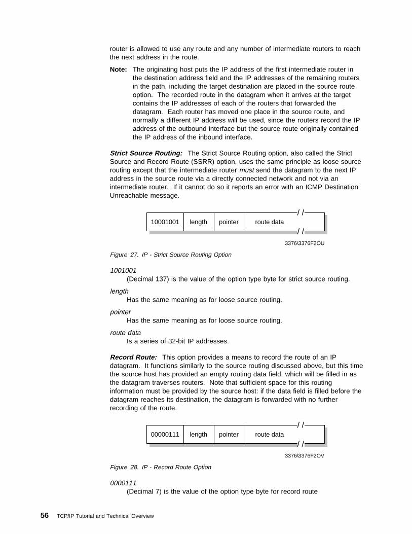
router is allowed to use any route and any number of intermediate routers to reachthe next address in the route.
Note: The originating host puts the IP address of the first intermediate router inthe destination address field and the IP addresses of the remaining routersin the path, including the target destination are placed in the source routeoption. The recorded route in the datagram when it arrives at the targetcontains the IP addresses of each of the routers that forwarded thedatagram. Each router has moved one place in the source route, andnormally a different IP address will be used, since the routers record the IPaddress of the outbound interface but the source route originally containedthe IP address of the inbound interface.
Strict Source Routing: The Strict Source Routing option, also called the StrictSource and Record Route (SSRR) option, uses the same principle as loose sourcerouting except that the intermediate router must send the datagram to the next IPaddress in the source route via a directly connected network and not via anintermediate router. If it cannot do so it reports an error with an ICMP DestinationUnreachable message.
10001001 length route data/ /
/ /pointer
3376\3376F2OU
Figure 27. IP - Strict Source Routing Option
1001001(Decimal 137) is the value of the option type byte for strict source routing.
lengthHas the same meaning as for loose source routing.
pointerHas the same meaning as for loose source routing.
route dataIs a series of 32-bit IP addresses.
Record Route: This option provides a means to record the route of an IPdatagram. It functions similarly to the source routing discussed above, but this timethe source host has provided an empty routing data field, which will be filled in asthe datagram traverses routers. Note that sufficient space for this routinginformation must be provided by the source host: if the data field is filled before thedatagram reaches its destination, the datagram is forwarded with no furtherrecording of the route.
00000111 length route data/ /
/ /pointer
3376\3376F2OV
Figure 28. IP - Record Route Option
0000111(Decimal 7) is the value of the option type byte for record route
56 TCP/IP Tutorial and Technical Overview

length.Has the same meaning as for loose source routing.
pointerHas the same meaning as for loose source routing.
route dataIs a multiple of four bytes in length chosen by the originator of the datagram.
2.1.8.4 Internet Time StampA time stamp is an option forcing some (or all) of the routers on the route to thedestination to put a time stamp in the option data. The time stamps are measuredin seconds and can be used for debugging purposes. They cannot be used forperformance measurement for two reasons:
� They are insufficiently precise because most IP datagrams will be forwarded inless than one second.
� They are insufficiently accurate because IP routers are not required to havesynchronized clocks.
01000100 length oflwpointer
3376\3376F2OW
flag
IP address
timestamp
...
...
0 8 16 24 28
Figure 29. IP - Internet Time Stamp Option
Where:
01000100(Decimal 68) is the value of the option type for the internet time stamp option.
lengthContains the total length of this option, including the type and length fields.
pointerPoints to the next time stamp to be processed (first free time stamp).
oflw (overflow)Is a 4 bit unsigned integer of the number of IP modules that cannot registertime stamps due to a lack of space in the data field.
flag Is a 4-bit value which indicates how time stamps are to be registered. Valuesare:
0 Time stamps only, stored in consecutive 32-bit words.1 Each time stamp is preceded by the IP address of the registering module.2 The IP address fields are pre-specified, and an IP module only registers
when it finds its own address in the list.
Time stampA 32-bit time stamp recorded in milliseconds since midnight UT (GMT).
Chapter 2. Internetworking and Transport Layer Protocols 57

The originating host must compose this option with a large enough data area tohold all the time stamps. If the time stamp area becomes full, no further timestamps are added.
2.2 Internet Control Message Protocol (ICMP)ICMP is a standard protocol with STD number 5. That standard also includes IP(see 2.1, “Internet Protocol (IP)” on page 27) and IGMP (see 9.2, “Internet GroupManagement Protocol (IGMP)” on page 469). Its status is required. It is describedin RFC 792 with updates in RFC 950.
Path MTU Discovery is a draft standard protocol with a status of elective. It isdescribed in RFC 1191.
ICMP Router Discovery is a proposed standard protocol with a status of elective. Itis described in RFC 1256.
When a router or a destination host must inform the source host about errors indatagram processing, it uses the Internet Control Message Protocol (ICMP). ICMPcan be characterized as follows:
� ICMP uses IP as if ICMP were a higher level protocol (that is, ICMP messagesare encapsulated in IP datagrams). However, ICMP is an integral part of IPand must be implemented by every IP module.
� ICMP is used to report some errors, not to make IP reliable. Datagrams maystill be undelivered without any report on their loss. Reliability must beimplemented by the higher level protocols that use IP.
� ICMP can report errors on any IP datagram with the exception of ICMPmessages, to avoid infinite repetitions.
� For fragmented IP datagrams, ICMP messages are only sent about errors onfragment zero. That is, ICMP messages never refer to an IP datagram with anon-zero fragment offset field.
� ICMP messages are never sent in response to datagrams with a destination IPaddress that is a broadcast or a multicast address.
� ICMP messages are never sent in response to a datagram that does not havea source IP address that represents a unique host. That is, the source addresscannot be zero, a loopback address, a broadcast address or a multicastaddress.
� ICMP messages are never sent in response to ICMP error messages. Theycan be sent in response to ICMP query messages (ICMP types 0, 8, 9, 10 and13 through 18).
� RFC 792 states that ICMP messages can be generated to report IP datagramprocessing errors, not must. In practice, routers will almost always generateICMP messages for errors, but for destination hosts, the number of ICMPmessages generated is implementation dependent.
58 TCP/IP Tutorial and Technical Overview
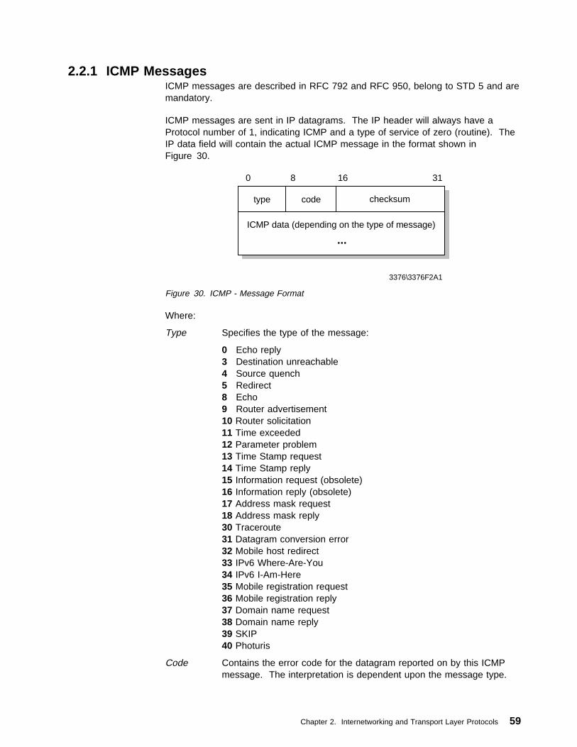
2.2.1 ICMP MessagesICMP messages are described in RFC 792 and RFC 950, belong to STD 5 and aremandatory.
ICMP messages are sent in IP datagrams. The IP header will always have aProtocol number of 1, indicating ICMP and a type of service of zero (routine). TheIP data field will contain the actual ICMP message in the format shown inFigure 30.
type code checksum
3376\3376F2A1
ICMP data (depending on the type of message)
...
0 8 16 31
Figure 30. ICMP - Message Format
Where:
Type Specifies the type of the message:
0 Echo reply3 Destination unreachable4 Source quench5 Redirect8 Echo9 Router advertisement10 Router solicitation11 Time exceeded12 Parameter problem13 Time Stamp request14 Time Stamp reply15 Information request (obsolete)16 Information reply (obsolete)17 Address mask request18 Address mask reply30 Traceroute31 Datagram conversion error32 Mobile host redirect33 IPv6 Where-Are-You34 IPv6 I-Am-Here35 Mobile registration request36 Mobile registration reply37 Domain name request38 Domain name reply39 SKIP40 Photuris
Code Contains the error code for the datagram reported on by this ICMPmessage. The interpretation is dependent upon the message type.
Chapter 2. Internetworking and Transport Layer Protocols 59

Checksum Contains the 16-bit one's complement of the one's complement sumof the ICMP message starting with the ICMP Type field. Forcomputing this checksum, the checksum field is assumed to be zero.This algorithm is the same as that used by IP for the IP header.Compare this with the algorithm used by UDP and TCP (see 2.7,“User Datagram Protocol (UDP)” on page 75 and 2.8, “TransmissionControl Protocol (TCP)” on page 78), which also include a pseudo-IPheader in the checksum.
Data Contains information for this ICMP message. Typically it will contain apart of the original IP message for which this ICMP message wasgenerated. The length of the data can be determined from the lengthof the IP datagram that contains the message less the IP headerlength.
Each of the messages is explained below.
2.2.1.1 Echo (8) and Echo Reply (0)
identifier
3376\3376F2A6
data ...
0 8 16 31
sequence number
Figure 31. ICMP - Echo and Echo Reply
Echo is used to detect if another host is active on the network. The senderinitializes the identifier and sequence number (which is used if multiple echorequests are sent), adds some data to the data field and sends the ICMP echo tothe destination host. The ICMP header code field is zero. The recipient changesthe type to Echo Reply and returns the datagram to the sender. This mechanism isused by the Ping command to determine if a destination host is reachable (see2.2.2.1, “Ping” on page 66).
2.2.1.2 Destination Unreachable (3)
unused (zero)
3376\3376F2A2
IP header + 64 bits of original data of the datagram
0 8 16 31
Figure 32. ICMP - Destination Unreachable
If this message is received from an intermediate router, it means that the routerregards the destination IP address as unreachable.
If this message is received from the destination host, it means that the protocolspecified in the protocol number field of the original datagram is not active, or that
60 TCP/IP Tutorial and Technical Overview

protocol is not active on this host or the specified port is inactive. (See 2.7, “UserDatagram Protocol (UDP)” on page 75 for an introduction to the port concept.)
The ICMP header code field will have one of the following values:
0 Network unreachable1 Host unreachable2 Protocol unreachable3 Port unreachable4 Fragmentation needed but the Do Not Fragment bit was set5 Source route failed6 Destination network unknown7 Destination host unknown8 Source host isolated (obsolete)9 Destination network administratively prohibited10 Destination host administratively prohibited11 Network unreachable for this type of service12 Host unreachable for this type of service13 Communication administratively prohibited by filtering14 Host precedence violation15 Precedence cutoff in effect
If a router implements the Path MTU Discovery protocol, the format of thedestination unreachable message is changed for code 4 to include the MTU of thelink that could not accept the datagram.
unused (zero)
3376\3376F2A3
IP header + 64 bits of original data of the datagram
0 8 16 31
link MTU
Figure 33. ICMP - Fragmentation Required with Link MTU
2.2.1.3 Source Quench (4)
unused (zero)
3376\3376F2A4
IP header + 64 bits of original data of the datagram
0 8 16 31
Figure 34. ICMP - Source Quench
If this message is received from an intermediate router, it means that the routerdoes not have the buffer space needed to queue the datagrams for output to thenext network.
If this message is received from the destination host, it means that the incomingdatagrams are arriving too quickly to be processed.
Chapter 2. Internetworking and Transport Layer Protocols 61

The ICMP header code field is always zero.
2.2.1.4 Redirect (5)
router IP address
3376\3376F2A5
IP header + 64 bits of original data of the datagram
0 8 16 31
Figure 35. ICMP - Redirect
If this message is received from an intermediate router, it means that the hostshould send future datagrams for the network to the router whose IP address isgiven in the ICMP message. This preferred router will always be on the samesubnet as the host that sent the datagram and the router that returned the IPdatagram. The router will forward the datagram to its next hop destination. If therouter IP address matches the source IP address in the original datagram header itindicates a routing loop. This ICMP message will not be sent if the IP datagramcontains a source route.
The ICMP header code field will have one of the following values:
0 Network redirect1 Host redirect2 Network redirect for this type of service3 Host redirect for this type of service
2.2.1.5 Router Advertisement (9) and Router Solicitation (10)ICMP messages 9 and 10 are optional. They are described in RFC 1256 which iselective.
number
3376\3376F2A7
0 8 16 31
TTLentry length
router address 1
preference level 1
/ / / /
router address n
preference level n
Figure 36. ICMP - Router Advertisement
62 TCP/IP Tutorial and Technical Overview

unused (zero)
3376\3376F2A8
0 8 16 31
Figure 37. ICMP - Router Solicitation
Where:
numberThe number of entries in the message.
entry lengthThe length of an entry in 32-bit units. This is 2 (32 bits for the IP address and32 bits for the preference value).
TTL The number of seconds that an entry will be considered valid.
router addressOne of the sender's IP addresses.
preference levelA signed 32-bit level indicating the preference to be assigned to this addresswhen selecting a default router for a subnet. Each router on a subnet isresponsible for advertising its own preference level. Larger values implyhigher preference; smaller values imply lower. The default is zero, which is inthe middle of the possible range. A value of X'80000000' -231 indicates thatthe router should never be used as a default router.
The ICMP header code field is zero for both of these messages.
These two messages are used if a host or a router supports the router discoveryprotocol. The use of multicasting is recommended, but broadcasting may be usedif multicasting is not supported on an interface. Routers periodically advertise theirIP addresses on those subnets where they are configured to do so.Advertisements are made on the all-systems multicast address (224.0.0.1) or thelimited broadcast address (255.255.255.255). The default behavior is to sendadvertisements every 10 minutes with a TTL value of 1800 (30 minutes). Routersalso reply to solicitation messages they receive. They may reply directly to thesoliciting host, or they may wait a short random interval and reply with a multicast.
Hosts can send solicitation messages when they start until they receive a response.Solicitation messages are sent to the all-routers multicast address (224.0.0.2) or thelimited broadcast address (255.255.255.255). Typically, three solicitation messagesare sent at 3-second intervals. Alternatively a host may wait for periodicadvertisements. Each time a host receives an advertisement, it updates its defaultrouter if the new advertisement has one with a higher preference value and setsthe TTL timer for the entry to match the value in the advertisement. When the hostreceives a new advertisement for its current default router, it resets the TTL valueto that in the new advertisement. This also provides a mechanism for routers todeclare themselves unavailable. They send an advertisement with a TTL value ofzero.
Chapter 2. Internetworking and Transport Layer Protocols 63
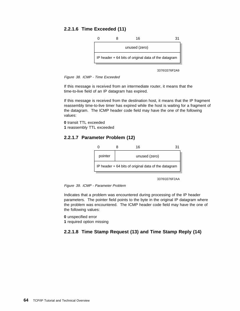
2.2.1.6 Time Exceeded (11)
unused (zero)
3376\3376F2A9
IP header + 64 bits of original data of the datagram
0 8 16 31
Figure 38. ICMP - Time Exceeded
If this message is received from an intermediate router, it means that thetime-to-live field of an IP datagram has expired.
If this message is received from the destination host, it means that the IP fragmentreassembly time-to-live timer has expired while the host is waiting for a fragment ofthe datagram. The ICMP header code field may have the one of the followingvalues:
0 transit TTL exceeded1 reassembly TTL exceeded
2.2.1.7 Parameter Problem (12)
pointer
3376\3376F2AA
IP header + 64 bits of original data of the datagram
0 8 16 31
unused (zero)
Figure 39. ICMP - Parameter Problem
Indicates that a problem was encountered during processing of the IP headerparameters. The pointer field points to the byte in the original IP datagram wherethe problem was encountered. The ICMP header code field may have the one ofthe following values:
0 unspecified error1 required option missing
2.2.1.8 Time Stamp Request (13) and Time Stamp Reply (14)
64 TCP/IP Tutorial and Technical Overview

identifier
3376\3376F2AB
originate timestamp
0 8 16 31
sequence number
receive timestamp
transmit timestamp
Figure 40. ICMP - Time Stamp Request and Time Stamp Reply
These two messages are for performance measurements and for debugging. Theyare not used for clock synchronization.
The sender initializes the identifier and sequence number (which is used if multipletime stamp requests are sent), sets the originate time stamp and sends it to therecipient. The receiving host fills in the receive and transmit time stamps, changesthe type to time stamp reply and returns it to the recipient. The receiver has twotime stamps in case there is a perceptible time difference between the receipt andtransmit times, but in practice, most implementations will perform the two (receiptand reply) in one operation and will set the two time stamps to the same value.Time Stamps are the number of milliseconds elapsed since midnight UT (GMT).
2.2.1.9 Information Request (15) and Information Reply (16)
identifier
0 8 16 31
sequence number
3376\3376F2AC
Figure 41. ICMP - Information Request and Information Reply
An information request is issued by a host to obtain an IP address for an attachednetwork. The sender fills in the request with the destination IP address in the IPheader set to zero (meaning this network) and waits for a reply from a serverauthorized to assign IP addresses to other hosts. The ICMP header code field iszero. The reply will contain IP network addresses in both the source anddestination fields of the IP header. This mechanism is now obsolete (see also 2.5,“Reverse Address Resolution Protocol (RARP)” on page 72).
2.2.1.10 Address Mask Request (17) and Address Mask Reply(18)
Chapter 2. Internetworking and Transport Layer Protocols 65

identifier
3376\3376F2AD
subnet address mask
0 8 16 31
sequence number
Figure 42. ICMP - Address Mask Request and Reply
An address mask request is used by a host to determine the subnet mask in useon an attached network. Most hosts will be configured with their subnet mask(s),but some, such as diskless workstations, must obtain this information from a server.A host uses RARP (see 2.5, “Reverse Address Resolution Protocol (RARP)” onpage 72) to obtain its IP address. To obtain a subnet mask, the host broadcastsan address mask request. Any host on the network that has been configured tosend address mask replies will fill in the subnet mask, convert the packet to anaddress mask reply and return it to the sender. The ICMP header code field iszero.
2.2.2 ICMP ApplicationsThere are two simple and widely used applications that are based on ICMP: Pingand Traceroute. Ping uses the ICMP Echo and Echo Reply messages todetermine whether a host is reachable. Traceroute sends IP datagrams with lowTTL values so that they expire en route to a destination. It uses the resulting ICMPTime Exceeded messages to determine where in the internet the datagramsexpired and pieces together a view of the route to a host. These applications arediscussed in the following sections.
2.2.2.1 PingPing is the simplest of all TCP/IP applications. It sends one or more IP datagramsto a specified destination host requesting a reply and measures the round trip time.The word ping, which is used as a noun and a verb, is taken from the sonaroperation to locate an underwater object. It is also an abbreviation for PacketInterNet Groper.
Traditionally, if you could ping a host, other applications such as Telnet or FTPcould reach that host. With the advent of security measures on the Internet,particularly firewalls (see 5.3, “Firewalls” on page 280), which control access tonetworks by application protocol and/or port number, this is no longer strictly true.Nonetheless, the first test of reachability for a host is still to attempt to ping it.
The syntax that is used in different implementations of ping varies from platform toplatform. The syntax here is for the OS/2 implementation:
ping [-switches] host [size [packets]]
Where:
switchesSwitches to enable various ping options
hostThe destination, either a symbolic name or an IP address
size The size of the data portion of the packet
66 TCP/IP Tutorial and Technical Overview

packetsThe number of packets to send
Ping uses the ICMP Echo and Echo Reply messages, as described in 2.2.1.1,“Echo (8) and Echo Reply (0)” on page 60. Since ICMP is required in everyTCP/IP implementation, hosts do not require a separate server to respond to pings.
Ping is useful for verifying a TCP/IP installation. Consider the following four formsof the command; each requires the operation of an additional part of the TCP/IPinstallation:
ping loopbackVerifies the operation of the base TCP/IP software.
ping my-IP-addressVerifies whether the physical network device can be addressed.
ping a-remote-IP-addressVerifies whether the network can be accessed.
ping a-remote-host-nameVerifies the operation of the name server (or the flat namespace resolver,depending on the installation).
Ping is implemented in all IBM TCP/IP products.
2.2.2.2 TracerouteThe Traceroute program can be useful when used for debugging purposes.Traceroute enables determination of the route that IP datagrams follow from host tohost.
Traceroute is based upon ICMP and UDP. It sends an IP datagram with a TTL of1 to the destination host. The first router to see the datagram will decrement theTTL to 0 and return an ICMP Time Exceeded message as well as discarding thedatagram. In this way, the first router in the path is identified. This process can berepeated with successively larger TTL values in order to identify the series ofrouters in the path to the destination host. Traceroute actually sends UDPdatagrams to the destination host which reference a port number that is outside thenormally used range. This enables Traceroute to determine when the destinationhost has been reached, that is, when an ICMP Port Unreachable message isreceived.
Traceroute is implemented in all IBM TCP/IP products.
2.3 Internet Group Management Protocol (IGMP)IGMP is a standard protocol with STD number 5. That standard also includes IP(see 2.1, “Internet Protocol (IP)” on page 27) and ICMP (see 2.2, “Internet ControlMessage Protocol (ICMP)” on page 58). Its status is recommended. It isdescribed in RFC 1112 with updates in RFC 2236.
Similar to ICMP, the Internet Group Management Protocol (IGMP) is also anintegral part of IP. It serves the purpose of allowing hosts to participate in IPmulticasts and to cancel such participation. IGMP further provides routers with thecapability to check if any hosts on a local subnet are at all interested in a particularmulticast.
Chapter 2. Internetworking and Transport Layer Protocols 67

Please see 9.2, “Internet Group Management Protocol (IGMP)” on page 469 for amore detailed discussion of IGMP.
2.4 Address Resolution Protocol (ARP)The ARP protocol is a network-specific standard protocol. The address resolutionprotocol is responsible for converting the higher level protocol addresses (IPaddresses) to physical network addresses. It is described in RFC 826.
2.4.1 ARP OverviewOn a single physical network, individual hosts are known on the network by theirphysical hardware address. Higher level protocols address destination hosts in theform of a symbolic address (IP address in this case). When such a protocol wantsto send a datagram to destination IP address w.x.y.z, the device driver does notunderstand this address.
Therefore, a module (ARP) is provided that will translate the IP address to thephysical address of the destination host. It uses a lookup table (sometimesreferred to as the ARP cache) to perform this translation.
When the address is not found in the ARP cache, a broadcast is sent out on thenetwork, with a special format called the ARP request. If one of the machines onthe network recognizes its own IP address in the request, it will send an ARP replyback to the requesting host. The reply will contain the physical hardware addressof the host and source route information (if the packet has crossed bridges on itspath). Both this address and the source route information are stored in the ARPcache of the requesting host. All subsequent datagrams to this destination IPaddress can now be translated to a physical address, which is used by the devicedriver to send out the datagram on the network.
An exception to the rule constitutes the Asynchronous Transfer Mode (ATM)technology where ARP cannot be implemented in the physical layer as describedpreviously. Therefore, an ARP server is used with which every host has to registerupon initialization in order to be able to resolve IP addresses to hardwareaddresses (please also see 13.3, “Asynchronous Transfer Mode (ATM)” onpage 598).
ARP was designed to be used on networks that support hardware broadcast. Thismeans, for example, that ARP will not work on an X.25 network.
2.4.2 ARP Detailed ConceptARP is used on IEEE 802 networks as well as on the older DIX Ethernet networksto map IP addresses to physical hardware addresses *see 13.1, “Ethernet andIEEE 802.x Local Area Networks (LANs)” on page 595). To do this, it is closelyrelated to the device driver for that network. In fact, the ARP specifications in RFC826 only describe its functionality, not its implementation. The implementationdepends to a large extent on the device driver for a network type and they areusually coded together in the adapter microcode.
68 TCP/IP Tutorial and Technical Overview

2.4.2.1 ARP Packet GenerationIf an application wishes to send data to a certain IP destination address, the IProuting mechanism first determines the IP address of the next hop of the packet (itcan be the destination host itself, or a router) and the hardware device on which itshould be sent. If it is an IEEE 802.3/4/5 network, the ARP module must beconsulted to map the <protocol type, target protocol address> to a physicaladdress.
The ARP module tries to find the address in this ARP cache. If it finds the matchingpair, it gives the corresponding 48-bit physical address back to the caller (thedevice driver), which then transmits the packet. If it doesn't find the pair in its table,it discards the packet (assumption is that a higher level protocol will retransmit) andgenerates a network broadcast of an ARP request.
ARP
Packet
physical layer header
hardware address space
protocol address space
hardware addressbyte length (n)
protocol addressbyte length (m)
operation code
hardware address of sender
protocol address of sender
hardware address of target
protocol address of target
x bytes
2 bytes
2 bytes
2 bytes
2 bytes
n bytes
m bytes
n bytes
m bytes
3376\3376F2AH
Figure 43. ARP - Request/Reply Packet
Where:
Hardware address spaceSpecifies the type of hardware; examples are Ethernet or Packet Radio Net.
Protocol address spaceSpecifies the type of protocol, same as the EtherType field in the IEEE 802header (IP or ARP).
Hardware address lengthSpecifies the length (in bytes) of the hardware addresses in this packet. ForIEEE 802.3 and IEEE 802.5 this will be 6.
Protocol address lengthSpecifies the length (in bytes) of the protocol addresses in this packet. For IPthis will be 4.
Operation codeSpecifies whether this is an ARP request (1) or reply (2).
Chapter 2. Internetworking and Transport Layer Protocols 69

Source/target hardware addressContains the physical network hardware addresses. For IEEE 802.3 these are48-bit addresses.
Source/target protocol addressContains the protocol addresses. For TCP/IP these are the 32-bit IPaddresses.
For the ARP request packet, the target hardware address is the only undefined fieldin the packet.
2.4.2.2 ARP Packet ReceptionWhen a host receives an ARP packet (either a broadcast request or a point-to-pointreply), the receiving device driver passes the packet to the ARP module whichtreats it as shown in Figure 44.
Yes
No(Discard)
Do I have the specifiedhardware type?
Set flag = falseYes
No(Discard)
Do I speak the specifiedprotocol?
Update the table with the sender hardware addressSet flag = true
YesIs the pair <protocol type, sender protocol address>already in my table?
No
Am I the target protocoladdress?
Yes
No(Discard)
YesIs flag = false?
Add the triplet<protocol type, sender protocol address, sender hardware address>to table
No
Swap source and target addresses in the ARP packetPut my local addresses in the source address fieldsSend back ARP packet as an ARP reply to the requesting host
YesIs the opcode a request?
END
No(Discard)
3376\3376F2AI
Figure 44. ARP - Packet Reception
The requesting host will receive this ARP reply, and will follow the same algorithmto treat it. As a result of this, the triplet <protocol type, protocol address, hardwareaddress> for the desired host will be added to its lookup table (ARP cache). Thenext time a higher level protocol wants to send a packet to that host, the ARPmodule will find the target hardware address and the packet will be sent to thathost.
70 TCP/IP Tutorial and Technical Overview

Note that because the original ARP request was a broadcast on the network, allhosts on that network will have updated the sender's hardware address in theirtable (only if it was already in the table).
2.4.3 ARP and SubnetsThe ARP protocol remains unchanged in the presence of subnets. Remember thateach IP datagram first goes through the IP routing algorithm. This algorithm selectsthe hardware device driver that should send out the packet. Only then, the ARPmodule associated with that device driver is consulted.
2.4.4 Proxy-ARP or Transparent SubnettingProxy-ARP is described in RFC 1027 — Using ARP to Implement TransparentSubnet Gateways, which is in fact a subset of the method proposed in RFC 925 —Multi-LAN Address Resolution. It is another method to construct local subnets,without the need for a modification to the IP routing algorithm, but withmodifications to the routers that interconnect the subnets.
2.4.4.1 Proxy-ARP ConceptConsider one IP network that is divided into subnets and interconnected by routers.We use the “old” IP routing algorithm, which means that no host knows about theexistence of multiple physical networks. Consider hosts A and B which are ondifferent physical networks within the same IP network, and a router R between thetwo subnetworks:
A
R
B
Figure 45. ARP - Hosts Interconnected by a Router
When host A wants to send an IP datagram to host B, it first has to determine thephysical network address of host B through the use of the ARP protocol.
As host A cannot differentiate between the physical networks, its IP routingalgorithm thinks that host B is on the local physical network and sends out abroadcast ARP request. Host B doesn't receive this broadcast, but router R does.Router R understands subnets, that is, it runs the subnet version of the IP routingalgorithm and it will be able to see that the destination of the ARP request (from thetarget protocol address field) is on another physical network. If router R's routingtables specify that the next hop to that other network is through a different physicaldevice, it will reply to the ARP as if it were host B, saying that the network addressof host B is that of the router R itself.
Chapter 2. Internetworking and Transport Layer Protocols 71

Host A receives this ARP reply, puts it in its cache and will send future IP packetsfor host B to the router R. The router will forward such packets to the correctsubnet.
The result is transparent subnetting:
� Normal hosts (such as A and B) don't know about subnetting, so they use the“old” IP routing algorithm.
� The routers between subnets have to:1. Use the subnet IP routing algorithm.2. Use a modified ARP module, which can reply on behalf of other hosts.
IPsubnet routing
and modified ARP
"old" IProuting
A
R
B
Figure 46. ARP - Proxy-ARP Router
2.5 Reverse Address Resolution Protocol (RARP)The RARP protocol is a network-specific standard protocol. It is described in RFC903.
Some network hosts, such as diskless workstations, do not know their own IPaddress when they are booted. To determine their own IP address, they use amechanism similar to ARP, but now the hardware address of the host is the knownparameter, and the IP address the queried parameter. It differs morefundamentally from ARP in the fact that a RARP server must exist on the networkthat maintains that a database of mappings from hardware address to protocoladdress must be pre-configured.
2.5.1 RARP ConceptThe reverse address resolution is performed the same way as the ARP addressresolution. The same packet format (see Figure 43 on page 69) is used as forARP.
An exception is the operation code field that now takes the following values:
3 For the RARP request4 For the RARP reply
72 TCP/IP Tutorial and Technical Overview

And of course, the physical header of the frame will now indicate RARP as thehigher-level protocol (8035 hex) instead of ARP (0806 hex) or IP (0800 hex) in theEtherType field. Some differences arise from the concept of RARP itself:
� ARP only assumes that every host knows the mapping between its ownhardware address and protocol address. RARP requires one or more serverhosts on the network to maintain a database of mappings between hardwareaddresses and protocol addresses so that they will be able to reply to requestsfrom client hosts.
� Due to the size this database can take, part of the server function is usuallyimplemented outside the adapter's microcode, with optionally a small cache inthe microcode. The microcode part is then only responsible for reception andtransmission of the RARP frames, the RARP mapping itself being taken care ofby server software running as a normal process in the host machine.
� The nature of this database also requires some software to create and updatethe database manually.
� In case there are multiple RARP servers on the network, the RARP requesteronly uses the first RARP reply received on its broadcast RARP request, anddiscards the others.
2.6 Ports and SocketsThis section introduces the concepts of port and socket, which are necessary toexactly determine which local process at a given host actually communicates withwhich process at which remote host using which protocol. If this sounds confusing,consider the following:
� An application process is assigned a process identifier number (process ID)which is likely to be different each time that process is started.
� Process IDs differ between operating system platforms, hence they are notuniform.
� A server process can have multiple connections to multiple clients at a time,hence simple connection identifiers would not be unique.
The concept of ports and sockets provides a way to uniformly and uniquely identifyconnections and the programs and hosts that are engaged in them, irrespective ofspecific process IDs.
2.6.1 PortsEach process that wants to communicate with another process identifies itself tothe TCP/IP protocol suite by one or more ports. A port is a 16-bit number, used bythe host-to-host protocol to identify to which higher level protocol or applicationprogram (process) it must deliver incoming messages. There are two types of port:
well-knownWell-known ports belong to standard servers, for example Telnet uses port23. Well-known port numbers range between 1 and 1023 (prior to 1992, therange between 256 and 1023 was used for UNIX-specific servers).Well-known port numbers are typically odd, because early systems using theport concept required an odd/even pair of ports for duplex operations. Mostservers require only a single port. Exceptions are the BOOTP server, whichuses two: 67 and 68 (see 7.1, “Bootstrap Protocol (BOOTP)” on page 401)
Chapter 2. Internetworking and Transport Layer Protocols 73

and the FTP server, which uses two: 20 and 21 (see 4.4, “File TransferProtocol (FTP)” on page 175).
The well-known ports are controlled and assigned by the Internet centralauthority (IANA) and on most systems can only be used by system processesor by programs executed by privileged users. The reason for well-knownports is to allow clients to be able to find servers without configurationinformation. The well-known port numbers are defined in STD 2 — AssignedInternet Numbers.
ephemeralClients do not need well-known port numbers because they initiatecommunication with servers and the port number they are using is containedin the UDP datagrams sent to the server. Each client process is allocated aport number as long as it needs it by the host it is running on. Ephemeralport numbers have values greater than 1023, normally in the range 1024 to65535. A client can use any number allocated to it, as long as thecombination of <transport protocol, IP address, port number> is unique.
Ephemeral ports are not controlled by IANA and on most systems can beused by ordinary user-developed programs.
Confusion due to two different applications trying to use the same port numbers onone host is avoided by writing those applications to request an available port fromTCP/IP. Because this port number is dynamically assigned, it may differ from oneinvocation of an application to the next.
UDP, TCP and ISO TP-4 all use the same port principle (please see Figure 50 onpage 78). To the extent possible, the same port numbers are used for the sameservices on top of UDP, TCP and ISO TP-4.
Note: Normally, a server will use either TCP or UDP, but there are exceptions.For example, domain name servers (see 4.2, “Domain Name System(DNS)” on page 150) use both UDP port 53 and TCP port 53.
2.6.2 SocketsThe socket interface is one of several application programming interfaces (APIs) tothe communication protocols. Designed to be a generic communicationprogramming interface, it was first introduced by the 4.2 BSD UNIX system.Although it has not been standardized, it has become a de facto industry standard.
4.2 BSD allowed two different communication domains: Internet and UNIX. 4.3 BSDhas added the Xerox Network System (XNS) protocols and 4.4 BSD will add anextended interface to support the ISO OSI protocols.
Let us consider the following terminologies:
� A socket is a special type of file handle, which is used by a process to requestnetwork services from the operating system.
� A socket address is the triple:
{protocol, local-address, local-process}
In the TCP/IP suite, for example:
{tcp, 193.44.234.3, 12345}
� A conversation is the communication link between two processes.
74 TCP/IP Tutorial and Technical Overview

� An association is the 5-tuple that completely specifies the two processes thatcomprise a connection:
{protocol, local-address, local-process, foreign-address, foreign-process}
In the TCP/IP suite, the following could be a valid association:
{tcp, 193.44.234.3, 1500, 193.44.234.5, 21}
� A half-association is either:
{protocol, local-address, local-process}
or
{protocol, foreign-address, foreign-process}
which specify each half of a connection.
� The half-association is also called a socket or a transport address. That is, asocket is an endpoint for communication that can be named and addressed ina network.
Two processes communicate via TCP sockets. The socket model provides aprocess with a full-duplex byte stream connection to another process. Theapplication need not concern itself with the management of this stream; thesefacilities are provided by TCP.
TCP uses the same port principle as UDP to provide multiplexing. Like UDP, TCPuses well-known and ephemeral ports. Each side of a TCP connection has asocket that can be identified by the triple <TCP, IP address, port number>. If twoprocesses are communicating over TCP, they have a logical connection that isuniquely identifiable by the two sockets involved, that is by the combination <TCP,local IP address, local port, remote IP address, remote port> (see Figure 50).Server processes are able to manage multiple conversations through a single port.Please refer to 4.19.1, “The Socket API” on page 248 for more information aboutsocket APIs.
2.7 User Datagram Protocol (UDP)UDP is a standard protocol with STD number 6. UDP is described by RFC 768 —User Datagram Protocol. Its status is recommended, but in practice every TCP/IPimplementation that is not used exclusively for routing will include UDP.
UDP is basically an application interface to IP. It adds no reliability, flow-control orerror recovery to IP. It simply serves as a multiplexer/demultiplexer for sending andreceiving datagrams, using ports to direct the datagrams as shown in Figure 47 onpage 76. For a more detailed discussion of ports refer to 2.6, “Ports and Sockets”on page 73.
Chapter 2. Internetworking and Transport Layer Protocols 75

port b
process 2
port z...
UDP - Port De-Multiplexing
IP
process nprocess 1
port a
Figure 47. UDP - Demultiplexing Based on Ports
UDP provides a mechanism for one application to send a datagram to another.The UDP layer can be regarded as being extremely thin and consequently has lowoverheads, but it requires the application to take responsibility for error recoveryand so on.
Applications sending datagrams to a host need to identify a target that is morespecific than the IP address, since datagrams are normally directed to certainprocesses and not to the system as a whole. UDP provides this by using ports.
The port concept is discussed in 2.6, “Ports and Sockets” on page 73.
2.7.1 UDP Datagram FormatEach UDP datagram is sent within a single IP datagram. Although, the IPdatagram may be fragmented during transmission, the receiving IP implementationwill re-assemble it before presenting it to the UDP layer. All IP implementations arerequired to accept datagrams of 576 bytes, which means that, allowing formaximum-size IP header of 60 bytes, a UDP datagram of 516 bytes is acceptableto all implementations. Many implementations will accept larger datagrams, but thisis not guaranteed. The UDP datagram has a 16-byte header that is described inFigure 48.
Destination PortSource Port
Data...
ChecksumLength
3376B\3376F2AM
Figure 48. UDP - Datagram Format
Where:
76 TCP/IP Tutorial and Technical Overview

Source PortIndicates the port of the sending process. It is the port to which replies shouldbe addressed.
Destination PortSpecifies the port of the destination process on the destination host.
LengthIs the length (in bytes) of this user datagram including the header.
ChecksumIs an optional 16-bit one's complement of the one's complement sum of apseudo-IP header, the UDP header and the UDP data. The pseudo-IPheader contains the source and destination IP addresses, the protocol andthe UDP length:
3376B\3376F2AN
3 33 3Source IP address
3 33 3Destination IP address
3 33 3Zero Protocol UDP Length
Figure 49. UDP - Pseudo-IP Header
The pseudo-IP header effectively extends the checksum to include the original(unfragmented) IP datagram.
2.7.2 UDP Application Programming InterfaceThe application interface offered by UDP is described in RFC 768. It provides for:
� The creation of new receive ports.
� The receive operation that returns the data bytes and an indication of sourceport and source IP address.
� The send operation that has as parameters the data, source and destinationports and addresses.
The way this should be implemented is left to the discretion of each vendor.
Be aware that UDP and IP do not provide guaranteed delivery, flow-control or errorrecovery, so these must be provided by the application.
Standard applications using UDP include:
� Trivial File Transfer Protocol (TFTP)� Domain Name System (DNS) name server� Remote Procedure Call (RPC), used by the Network File System (NFS)� Simple Network Management Protocol (SNMP)� Lightweight Directory Access Protocol (LDAP)
Chapter 2. Internetworking and Transport Layer Protocols 77

2.8 Transmission Control Protocol (TCP)TCP is a standard protocol with STD number 7. TCP is described by RFC 793 —Transmission Control Protocol. Its status is recommended, but in practice everyTCP/IP implementation that is not used exclusively for routing will include TCP.
TCP provides considerably more facilities for applications than UDP, notably errorrecovery, flow control and reliability. TCP is a connection-oriented protocol unlikeUDP which is connectionless. Most of the user application protocols, such asTelnet and FTP, use TCP.
The two processes communicate with each other over a TCP connection(InterProcess Communication - IPC), as shown in Figure 50. Please see 2.6,“Ports and Sockets” on page 73 for more details about ports and sockets.
port m
reliableTCP connection
...
TCP
IP
... port n
process 2
...
TCP
IP
...
host A
unreliableIP datagrams
process 1
host B
Figure 50. TCP - Connection between Processes. (Processes 1 and 2 communicate over aTCP connection carried by IP datagrams.)
2.8.1 TCP ConceptAs noted above, the primary purpose of TCP is to provide reliable logical circuit orconnection service between pairs of processes. It does not assume reliability fromthe lower-level protocols (such as IP), so TCP must guarantee this itself.
TCP can be characterized by the following facilities it provides for the applicationsusing it:
Stream Data TransferFrom the application's viewpoint, TCP transfers a contiguous stream of bytesthrough the network. The application does not have to bother with choppingthe data into basic blocks or datagrams. TCP does this by grouping the bytesin TCP segments, which are passed to IP for transmission to the destination.Also, TCP itself decides how to segment the data and it can forward the dataat its own convenience.
78 TCP/IP Tutorial and Technical Overview
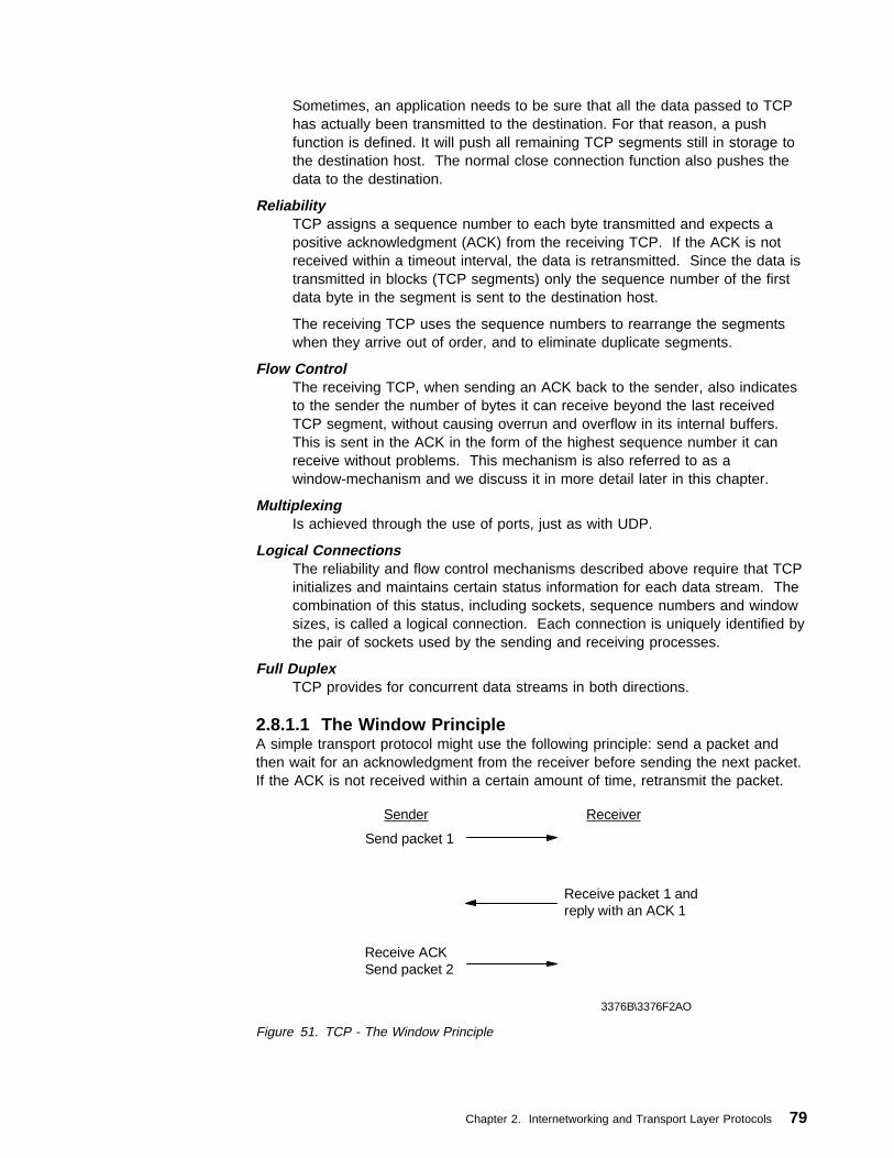
Sometimes, an application needs to be sure that all the data passed to TCPhas actually been transmitted to the destination. For that reason, a pushfunction is defined. It will push all remaining TCP segments still in storage tothe destination host. The normal close connection function also pushes thedata to the destination.
ReliabilityTCP assigns a sequence number to each byte transmitted and expects apositive acknowledgment (ACK) from the receiving TCP. If the ACK is notreceived within a timeout interval, the data is retransmitted. Since the data istransmitted in blocks (TCP segments) only the sequence number of the firstdata byte in the segment is sent to the destination host.
The receiving TCP uses the sequence numbers to rearrange the segmentswhen they arrive out of order, and to eliminate duplicate segments.
Flow ControlThe receiving TCP, when sending an ACK back to the sender, also indicatesto the sender the number of bytes it can receive beyond the last receivedTCP segment, without causing overrun and overflow in its internal buffers.This is sent in the ACK in the form of the highest sequence number it canreceive without problems. This mechanism is also referred to as awindow-mechanism and we discuss it in more detail later in this chapter.
MultiplexingIs achieved through the use of ports, just as with UDP.
Logical ConnectionsThe reliability and flow control mechanisms described above require that TCPinitializes and maintains certain status information for each data stream. Thecombination of this status, including sockets, sequence numbers and windowsizes, is called a logical connection. Each connection is uniquely identified bythe pair of sockets used by the sending and receiving processes.
Full DuplexTCP provides for concurrent data streams in both directions.
2.8.1.1 The Window PrincipleA simple transport protocol might use the following principle: send a packet andthen wait for an acknowledgment from the receiver before sending the next packet.If the ACK is not received within a certain amount of time, retransmit the packet.
Sender Receiver
3376B\3376F2AO
Send packet 1
Receive ACK Send packet 2
Receive packet 1 andreply with an ACK 1
Figure 51. TCP - The Window Principle
Chapter 2. Internetworking and Transport Layer Protocols 79

While this mechanism ensures reliability, it only uses a part of the available networkbandwidth.
Consider now a protocol where the sender groups its packets to be transmitted asin Figure 52 and uses the following rules:
� The sender can send all packets within the window without receiving an ACK,but must start a timeout timer for each of them.
� The receiver must acknowledge each packet received, indicating the sequencenumber of the last well-received packet.
� The sender slides the window on each ACK received.
3376B\3376F2AP
1 2 3 4 5 6 7 8 9 ...
window
packets
Figure 52. TCP - Message Packets
In our example, the sender can transmit packets 1 to 5 without waiting for anyacknowledgment:
Sender Network
3376B\3376F2AQ
Send packet 1
Send packet 2
Send packet 3
Send packet 4
Send packet 5
ACK for packet 1 received ACK 1
Figure 53. TCP - Window Principle
At the moment the sender receives ACK 1 (acknowledgment for packet 1), it canslide its window one packet to the right:
3376B\3376F2AZ
1 2 3 4 5 6 7 8 9 ...
window slides
packets
Figure 54. TCP - Message Packets
At this point, the sender may also transmit packet 6.
80 TCP/IP Tutorial and Technical Overview

Imagine some special cases:
Packet 2 gets lostThe sender will not receive ACK 2, so its window will remain in position 1 (asin Figure 54 on page 80). In fact, since the receiver did not receive packet 2,it will acknowledge packets 3, 4 and 5 with an ACK 1, since packet 1 was thelast one received in sequence. At the sender's side, eventually a timeout willoccur for packet 2 and it will be retransmitted. Note that reception of thispacket by the receiver will generate ACK 5, since it has now successfullyreceived all packets 1 to 5, and the sender's window will slide four positionsupon receiving this ACK 5.
Packet 2 did arrive, but the acknowledgment gets lost:The sender does not receive ACK 2, but will receive ACK 3. ACK 3 is anacknowledgment for all packets up to 3 (including packet 2) and the sendercan now slide its window to packet 4.
This window mechanism ensures:
� Reliable transmission.� Better use of the network bandwidth (better throughput).� Flow-control, since the receiver may delay replying to a packet with an
acknowledgment, knowing its free buffers available and the window-size of thecommunication.
2.8.1.2 The Window Principle Applied to TCPThe above window principle is used in TCP, but with a few differences:
� Since TCP provides a byte-stream connection, sequence numbers areassigned to each byte in the stream. TCP divides this contiguous byte streaminto TCP segments to transmit them. The window principle is used at the bytelevel; that is, the segments sent and ACKs received will carry byte-sequencenumbers and the window size is expressed as a number of bytes, rather than anumber of packets.
� The window size is determined by the receiver when the connection isestablished, and is variable during the data transfer. Each ACK message willinclude the window size that the receiver is ready to deal with at that particulartime.
The sender's data stream can now be seen as follows:
Chapter 2. Internetworking and Transport Layer Protocols 81

3376B\3376F2AR
1 2 3 4 5 6 7 8 9 10 11 12 13 14 15 ...
A B C D
window (size expressed in bytes)
bytes
Figure 55. TCP - Window Principle Applied to TCP
Where:
A Bytes that are transmitted and have been acknowledged.B Bytes that are sent but not yet acknowledged.C Bytes that can be sent without waiting for any acknowledgment.D Bytes that cannot yet be sent.
Remember that TCP will block bytes into segments, and a TCP segment onlycarries the sequence number of the first byte in the segment.
2.8.1.3 TCP Segment FormatThe TCP segment format is shown in Figure 56.
3376B\3376F2AS
Destination PortSource Port
Sequence Number
Acknowledgment Number
Data Offset Reset
URG
ACK
PSH
RST
SYN
FIN
Window
Urgent PointerChecksum
Options
Data Bytes
..|.. Padding
0 1 2 3 4 5 6 7 8 9 0 1 2 3 4 5 6 7 8 9 0 1 2 3 4 5 6 7 8 9 0 1 0 1 2 3
Figure 56. TCP - Segment Format
Where:
Source PortThe 16-bit source port number, used by the receiver to reply.
82 TCP/IP Tutorial and Technical Overview

Destination PortThe 16-bit destination port number.
Sequence NumberThe sequence number of the first data byte in this segment. If the SYNcontrol bit is set, the sequence number is the initial sequence number (n) andthe first data byte is n+1.
Acknowledgment NumberIf the ACK control bit is set, this field contains the value of the next sequencenumber that the receiver is expecting to receive.
Data OffsetThe number of 32-bit words in the TCP header. It indicates where the databegins.
ReservedSix bits reserved for future use; must be zero.
URGIndicates that the urgent pointer field is significant in this segment.
ACKIndicates that the acknowledgment field is significant in this segment.
PSHPush function.
RST Resets the connection.
SYNSynchronizes the sequence numbers.
FIN No more data from sender.
WindowUsed in ACK segments. It specifies the number of data bytes beginning withthe one indicated in the acknowledgment number field which the receiver (=the sender of this segment) is willing to accept.
ChecksumThe 16-bit one's complement of the one's complement sum of all 16-bit wordsin a pseudo-header, the TCP header and the TCP data. While computing thechecksum, the checksum field itself is considered zero.
The pseudo-header is the same as that used by UDP for calculating thechecksum. It is a pseudo-IP-header, only used for the checksum calculation,with the format shown in Figure 57:
3376B\3376F2AT
3 33 3Source IP address
3 33 3Destination IP address
3 33 3Zero Protocol TCP Length
Figure 57. TCP - Pseudo-IP Header
Urgent PointerPoints to the first data octet following the urgent data. Only significant whenthe URG control bit is set.
Chapter 2. Internetworking and Transport Layer Protocols 83
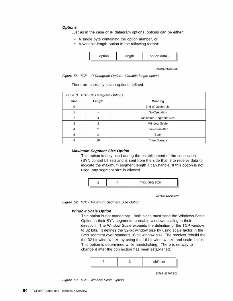
OptionsJust as in the case of IP datagram options, options can be either:
� A single byte containing the option number, or� A variable length option in the following format:
3376B\3376F2AU
3 33 3option length option data...
Figure 58. TCP - IP Datagram Option. Variable length option.
There are currently seven options defined:
Maximum Segment Size OptionThis option is only used during the establishment of the connection(SYN control bit set) and is sent from the side that is to receive data toindicate the maximum segment length it can handle. If this option is notused, any segment size is allowed.
Table 3. TCP - IP Datagram Options
Kind Length Meaning
0 - End of Option List
1 - No-Operation
2 4 Maximum Segment Size
3 3 Window Scale
4 2 Sack-Permitted
5 X Sack
8 10 Time Stamps
3376B\3376F2AV
3 33 32 max. seg size4
Figure 59. TCP - Maximum Segment Size Option
Window Scale OptionThis option is not mandatory. Both sides must send the Windows ScaleOption in their SYN segments to enable windows scaling in theirdirection. The Window Scale expands the definition of the TCP windowto 32 bits. It defines the 32-bit window size by using scale factor in theSYN segment over standard 16-bit window size. The receiver rebuild thethe 32-bit window size by using the 16-bit window size and scale factor.This option is determined while handshaking. There is no way tochange it after the connection has been established.
3
3376B\3376F2X1
3 shift.cnt
Figure 60. TCP - Window Scale Option
84 TCP/IP Tutorial and Technical Overview

SACK-Permitted OptionThis option is set when selective acknowledgment is used in that TCPconnection.
4 2
Figure 61. TCP - Sack-Permitted Option
SACK OptionSelective Acknowledgment (SACK) allows the receiver to inform thesender about all the segments which are received successfully. Thus,the sender will only send the segments that actually got lost. If thenumber of the segments which are lost since the last SACK, is much,the next SACK option contains long data. To reduce this, the SACKoption should be used for the most recent received data.
Length5
Left Edge of 1st Block
Right Edge of 1st Block
- - - - - - -
Left Edge of Nth Block
Right Edge of Nth Block
3376B\3376F2X3
// //
Figure 62. TCP - Sack Option
Time Stamps OptionThe time stamps option sends a time stamp value that indicates thecurrent value of the time stamp clock of the TCP sending the option.Time Stamp Echo Value can only be used if the ACK bit is set in theTCP header.
8
3376B\3376F2X4
10 TS Valve TS Echo Reply
1 1 4 4
Figure 63. TCP - Time Stamps Option
PaddingAll zero bytes used to fill up the TCP header to a total length that is a multipleof 32 bits.
Chapter 2. Internetworking and Transport Layer Protocols 85

2.8.1.4 Acknowledgments and RetransmissionsTCP sends data in variable length segments. Sequence numbers are based on abyte count. Acknowledgments specify the sequence number of the next byte thatthe receiver expects to receive.
Consider that a segment gets lost or corrupted. In this case, the receiver willacknowledge all further well-received segments with an acknowledgment referringto the first byte of the missing packet. The sender will stop transmitting when it hassent all the bytes in the window. Eventually, a timeout will occur and the missingsegment will be retransmitted.
Figure 64 illustrates and example where a window size of 1500 bytes andsegments of 500 bytes are used.
Sender Receiver
3376B\3376F2AW
Segment 1 (seq. 1000)
Receives 1000, sends ACK 1500
Segment 2 (seq. 1500) \\\gets lost
Segment 3 (seq. 2000)
Receives the ACK 1500, which slides window
Segment 4 (seq. 2500)
Receives one of the frames and replies with ACK 1500(receiver is still expecting byte 1500)window size reached,
waiting for ACK
Receives the ACK 1500, which does not slide the window
Timeout for Segment 2 Retransmission
Figure 64. TCP - Acknowledgment and Retransmission Process
A problem now arises, since the sender does know that segment 2 is lost orcorrupted, but doesn't know anything about segments 3 and 4. The sender shouldat least retransmit segment 2, but it could also retransmit segments 3 and 4 (sincethey are within the current window). It is possible that:
1. Segment 3 has been received, and for segment 4 we don't know. It could bereceived, but ACK didn't reach us yet, or it could be lost also.
2. Segment 3 was lost, and we received the ACK 1500 upon the reception ofsegment 4.
Each TCP implementation is free to react to a timeout as the implementers wish. Itcould retransmit only segment 2, but in case 2 above, we will be waiting again untilsegment 3 times out. In this case, we lose all of the throughput advantages of thewindow mechanism. Or TCP might immediately resend all of the segments in thecurrent window.
86 TCP/IP Tutorial and Technical Overview

Whatever the choice, maximal throughput is lost. This is because the ACK does notcontain a second acknowledgment sequence number indicating the actual framereceived.
Variable Timeout Intervals: Each TCP should implement an algorithm to adaptthe timeout values to be used for the round trip time of the segments. To do this,TCP records the time at which a segment was sent, and the time at which the ACKis received. A weighted average is calculated over several of these round trip times,to be used as a timeout value for the next segment(s) to be sent.
This is an important feature, because delays can vary in IP network, depending onmultiple factors, such as the load of an intermediate low-speed network or thesaturation of an intermediate IP gateway.
2.8.1.5 Establishing a TCP ConnectionBefore any data can be transferred, a connection has to be established betweenthe two processes. One of the processes (usually the server) issues a passiveOPEN call, the other an active OPEN call. The passive OPEN call remainsdormant until another process tries to connect to it by an active OPEN.
On the network, three TCP segments are exchanged:
process 1
Active OPENSend SYN, seq=n
process 2
Passive OPEN,waits for active request
Receive SYNSend SYN, seq=m, ACK n+1
Receive SYN+ACKSend ACK m+1
The connection is now established and the two data streams(one in each direction) have been initialized (sequence numbers)
3376B\3376F2AY
Figure 65. TCP - Connection Establishment
This whole process is known as a three-way handshake.
Note that the exchanged TCP segments include the initial sequence numbers fromboth sides, to be used on subsequent data transfers.
Closing the connection is done implicitly by sending a TCP segment with the FINbit (no more data) set. Since the connection is full-duplex (that is, there are twoindependent data streams, one in each direction), the FIN segment only closes thedata transfer in one direction. The other process will now send the remaining data itstill has to transmit and also ends with a TCP segment where the FIN bit is set.The connection is deleted (status information on both sides) once the data streamis closed in both directions.
Chapter 2. Internetworking and Transport Layer Protocols 87

2.8.2 TCP Application Programming InterfaceThe TCP application programming interface is not fully defined. Only some basefunctions it should provide are described in RFC 793 - Transmission ControlProtocol. As is the case with most RFCs in the TCP/IP protocol suite, a greatdegree of freedom is left to the implementers, thereby allowing for optimal(operating system-dependent) implementations, resulting in better efficiency(greater throughput).
The following function calls are described in the RFC:
Open To establish a connection takes several parameters, such as: � Active/passive � Foreign socket� Local port number� Timeout value (optional)
This returns a local connection name, which is used to reference thisparticular connection in all other functions.
Send Causes data in a referenced user buffer to be sent over the connection.Can optionally set the URGENT flag or the PUSH flag.
Receive Copies incoming TCP data to a user buffer.Close Closes the connection; causes a push of all remaining data and a TCP
segment with FIN flag set.Status Is an implementation-dependent call that could return information such
as:� Local and foreign socket� Send and receive window sizes
� Connection state� Local connection name
Abort Causes all pending Send and Receive operations to be aborted, and aRESET to be sent to the foreign TCP.
Full details can be found in RFC 793 - Transmission Control Protocol.
2.8.3 TCP Congestion Control AlgorithmsOne big difference between TCP and UDP is the congestion control algorithm. TheTCP congestion algorithm prevents a sender from overrunning the capacity of thenetwork (for example, slower WAN links). TCP can adapt the sender's rate tonetwork capacity and attempt to avoid potential congestion situations. In order tounderstand the difference between TCP and UDP, understanding basic TCPcongestion control algorithms is very helpful.
Several congestion control enhancements have been added and suggested to TCPover the years. This is still an active and ongoing research area. But modernimplementations of TCP contain four intertwined algorithms as basic Internetstandards:
� Slow start
� Congestion avoidance
� Fast retransmit
� Fast recovery
88 TCP/IP Tutorial and Technical Overview

2.8.3.1 Slow StartOld implementations of TCP would start a connection with the sender injectingmultiple segments into the network, up to the window size advertised by thereceiver. While this is ok when the two hosts are on the same LAN, if there arerouters and slower links between the sender and the receiver, problems can arise.Some intermediate routers could not handle it, packets were dropped,retransmission resulted and performance was degraded.
The algorithm to avoid this is called slow start. It operates by observing that therate at which new packets should be injected into the network is the rate at whichthe acknowledgments are returned by the other end. Slow start adds anotherwindow to the sender's TCP: the congestion window, called cwnd. When a newconnection is established with a host on another network, the congestion window isinitialized to one segment (for example, the segment size announced by the otherend, or the default, typically 536 or 512). Each time an ACK is received, thecongestion window is increased by one segment. The sender can transmit thelower value of the congestion window or the advertised window. The congestionwindow is flow control imposed by the sender, while the advertised window is flowcontrol imposed by the receiver. The former is based on the sender's assessmentof perceived network congestion; the latter is related to the amount of availablebuffer space at the receiver for this connection.
The sender starts by transmitting one segment and waiting for its ACK. When thatACK is received, the congestion window is incremented from one to two, and twosegments can be sent. When each of those two segments is acknowledged, thecongestion window is increased to four. This provides an exponential growth,although it is not exactly exponential because the receiver may delay its ACKs,typically sending one ACK for every two segments that it receives.
At some point the capacity of the IP network (for example, slower WAN links) canbe reached, and an intermediate router will start discarding packets. This tells thesender that its congestion window has gotten too large. Please see Figure 66 onpage 90 for an overview of slow start in action.
Chapter 2. Internetworking and Transport Layer Protocols 89

Sender Receiver
3376a\3376F2KA
Figure 66. TCP Slow Start in Action
2.8.3.2 Congestion AvoidanceThe assumption of the algorithm is that packet loss caused by damage is verysmall (much less than 1%), therefore the loss of a packet signals congestionsomewhere in the network between the source and destination. There are twoindications of packet loss:
1. A timeout occurs.
2. Duplicate ACKs are received.
Congestion avoidance and slow start are independent algorithms with differentobjectives. But when congestion occurs TCP must slow down its transmission rateof packets into the network, and then invoke slow start to get things going again.In practice they are implemented together.
Congestion avoidance and slow start require that two variables be maintained foreach connection:
� A congestion window, cwnd
� A slow start threshold size, ssthresh
The combined algorithm operates as follows:
1. Initialization for a given connection sets cwnd to one segment and ssthresh to65535 bytes.
2. The TCP output routine never sends more than the lower value of cwnd or thereceiver's advertised window.
90 TCP/IP Tutorial and Technical Overview

3. When congestion occurs (time out or duplicate ACK), one-half of the currentwindow size is saved in ssthresh. Additionally, if the congestion is indicated bya timeout, cwnd is set to one segment.
4. When new data is acknowledged by the other end, increase cwnd, but the wayit increases depends on whether TCP is performing slow start or congestionavoidance. If cwnd is less than or equal to ssthresh, TCP is in slow start;otherwise TCP is performing congestion avoidance.
Slow start continues until TCP is halfway to where it was when congestion occurred(since it recorded half of the window size that caused the problem in step 2), andthen congestion avoidance takes over. Slow start has cwnd begin at one segment,and incremented by one segment every time an ACK is received. As mentionedearlier, this opens the window exponentially: send one segment, then two, thenfour, and so on.
Congestion avoidance dictates that cwnd be incremented by segsize*segsize/cwndeach time an ACK is received, where segsize is the segment size and cwnd ismaintained in bytes. This is a linear growth of cwnd, compared to slow start'sexponential growth. The increase in cwnd should be at most one segment eachround-trip time (regardless of how many ACKs are received in that round trip time),whereas slow start increments cwnd by the number of ACKs received in around-trip time. Many implementations incorrectly add a small fraction of thesegment size (typically the segment size divided by 8) during congestionavoidance. This is wrong and should not be emulated in future releases. Pleasesee Figure 67 for an example of TCP slow start and congestion avoidance inaction.
0
5
10
15
20
25
Round Trip Times
CWND
cwnd
ssthresh
3376a\3376F2KB
Figure 67. TCP Slow Start and Congestion Avoidance Behavior in Action
Chapter 2. Internetworking and Transport Layer Protocols 91

2.8.3.3 Fast RetransmitFast retransmit avoids TCP having to wait for a timeout to resend lost segments.
Modifications to the congestion avoidance algorithm were proposed in 1990.Before describing the change, realize that TCP may generate an immediateacknowledgment (a duplicate ACK) when an out-of-order segment is received. Thisduplicate ACK should not be delayed. The purpose of this duplicate ACK is to letthe other end know that a segment was received out of order, and to tell it whatsequence number is expected.
Since TCP does not know whether a duplicate ACK is caused by a lost segment orjust a reordering of segments, it waits for a small number of duplicate ACKs to bereceived. It is assumed that if there is just a reordering of the segments, there willbe only one or two duplicate ACKs before the reordered segment is processed,which will then generate a new ACK. If three or more duplicate ACKs are receivedin a row, it is a strong indication that a segment has been lost. TCP then performsa retransmission of what appears to be the missing segment, without waiting for aretransmission timer to expire. Please see Figure 68 for an overview of TCP fastretransmit in action.
Sender Receiver
packet 1packet 2packet 3 ACK 1
ACK 2
packet 4packet 5packet 6 ACK 2
ACK 2ACK 2
Retransmit Packet 3
ACK 6
3376a\3376F2KC
Figure 68. TCP Fast Retransmit in Action
2.8.3.4 Fast RecoveryAfter fast retransmit sends what appears to be the missing segment, congestionavoidance, but not slow start, is performed. This is the fast recovery algorithm. Itis an improvement that allows high throughput under moderate congestion,especially for large windows.
The reason for not performing slow start in this case is that the receipt of theduplicate ACKs tells TCP more than just a packet has been lost. Since thereceiver can only generate the duplicate ACK when another segment is received,that segment has left the network and is in the receiver's buffer. That is, there is
92 TCP/IP Tutorial and Technical Overview

still data flowing between the two ends, and TCP does not want to reduce the flowabruptly by going into slow start. The fast retransmit and fast recovery algorithmsare usually implemented together as follows.
1. When the third duplicate ACK in a row is received, set ssthresh to one-half thecurrent congestion window, cwnd, but no less than two segments. Retransmitthe missing segment. Set cwnd to ssthresh plus 3 times the segment size.This inflates the congestion window by the number of segments that have leftthe network and the other end has cached (3).
2. Each time another duplicate ACK arrives, increment cwnd by the segment size.This inflates the congestion window for the additional segment that has left thenetwork. Transmit a packet if allowed by the new value of cwnd.
3. When the next ACK arrives that acknowledges new data, set cwnd to ssthresh(the value set in step 1). This ACK should be the acknowledgment of theretransmission from step 1, one round-trip time after the retransmission.Additionally, this ACK should acknowledge all the intermediate segments sentbetween the lost packet and the receipt of the first duplicate ACK. This step iscongestion avoidance, since TCP is down to one-half the rate it was at whenthe packet was lost.
2.9 ReferencesPlease refer to the following RFCs for more information on TCP/IP internetwork andtransport layer protocols:
� RFC 768 — User Datagram Protocol
� RFC 791 — Internet Protocol
� RFC 792 — Internet Control Message Protocol
� RFC 793 — Transmission Control Protocol
� RFC 826 — Ethernet Address Resolution Protocol
� RFC 903 — Reverse Address Resolution Protocol
� RFC 919 — Broadcasting Internet Datagrams
� RFC 922 — Broadcasting Internet datagrams in the presence of subnets
� RFC 950 — Internet Standard Subnetting Procedure
� RFC 1112 — Host extensions for IP multicasting
� RFC 1166 — Internet numbers
� RFC 1191 — Path MTU discovery
� RFC 1256 — ICMP Router Discovery Messages
� RFC 1323 — TCP Extensions for High Performance
� RFC 1466 — Guidelines for Management of IP Address Space
� RFC 1518 — An Architecture for IP Address Allocation with CIDR
� RFC 1519 — Classless Inter-Domain Routing (CIDR): an Address Assignmentand Aggregation Strategy
� RFC 1520 — Exchanging Routing Information Across Provider Boundaries inthe CIDR Environment
Chapter 2. Internetworking and Transport Layer Protocols 93

� RFC 1918 — Address Allocation for Private Internets
� RFC 2001 — TCP Slow Start, Congestion Avoidance, Fast Retransmit, andFast Recovery Algorithms
� RFC 2018 — TCP Selective Acknowledgement Options
� RFC 2050 — INTERNET REGISTRY IP ALLOCATION GUIDELINES
� RFC 2236 — Internet Group Management Protocol, Version 2
94 TCP/IP Tutorial and Technical Overview

Chapter 3. Routing Protocols
One of the basic functions of IP is its ability to form connections between differentphysical networks. This is due to the flexibility of IP to use almost any physicalnetwork below it, and to the IP routing algorithm. A system that does this is termeda router, although the older term IP gateway is also used.
Note: In other sections of the book, we show the position of each protocol in thelayered model of the TCP/IP protocol stack. The routing function is part of theinternetwork layer, but the primary function of a routing protocol is to exchangerouting information with other routers, and in this respect the protocols behavemore like application protocols. Therefore, we do not attempt to represent theposition of these protocols in the protocol stack with a diagram as we do with theother protocols.
3.1 Basic IP RoutingThe fundamental function for routers is present in all IP implementations:
An incoming IP datagram that specifies a destination IP address other than oneof the local host's IP address(es), is treated as a normal outgoing IP datagram.
This outgoing IP datagram is subject to the IP routing algorithm (see 2.1.3.4, “IPRouting Algorithm” on page 38) of the local host, which selects the next hop for thedatagram (the next host to send it to). This new destination can be located on anyof the physical networks to which the intermediate host is attached. If it is aphysical network other than the one on which the host originally received thedatagram, then the net result is that the intermediate host has forwarded the IPdatagram from one physical network to another.
Application
TCP
IP
Interface Y
Host B
Network YNetwork X
Application
TCP
IP
Interface X
Host A
3376\3376FCK1
IP Routing
Interface X Interface Y
Host C Acting as Router
Figure 69. Router Operation of IP
The normal IP routing table contains information about the locally attachednetworks and the IP addresses of other routers located on these networks, plus thenetworks they attach to. It can be extended with information on IP networks that
Copyright IBM Corp. 1989, 1998 95

are farther away, and can also contain a default route, but it still remains a tablewith limited information; that is, it represents only a part of the whole IP networks.That is why this kind of router is called a router with partial routing information.
Some considerations apply to these routers with partial information:
� They do not know about all IP networks.� They allow local sites autonomy in establishing and modifying routes.� A routing entry error in one of the routers can introduce inconsistencies,
thereby making part of the network unreachable.
Some error reporting should be implemented by routers with partial information viathe Internet Control Message Protocol (ICMP) described in 2.2, “Internet ControlMessage Protocol (ICMP)” on page 58. They should be able to report the followingerrors back to the source host:
� Unknown IP destination network by an ICMP Destination Unreachablemessage.
� Redirection of traffic to more suitable routers by sending ICMP Redirectmessages.
� Congestion problems (too many incoming datagrams for the available bufferspace) by an ICMP Source Quench message.
� The Time-to-Live field of an IP datagram has reached zero. This is reportedwith an ICMP Time Exceeded message.
� Also, the following base ICMP operations and messages should be supported: – Parameter problem – Address mask – Time stamp – Information request/reply – Echo request/reply
A more intelligent router is required if:
� The router has to know routes to all possible IP networks, as was the case forthe Internet backbone routers.
� The router has to have dynamic routing tables, which are kept up-to-date withminimal or no manual intervention.
� The router has to be able to advertise local changes to other routers.
These more advanced forms of routers use additional protocols to communicatewith each other. A number of protocols of this kind exist, and descriptions of theimportant ones will be given in the following sections. The reasons for thismultiplicity of different protocols are basically fourfold:
� Using Internet terminology, there is a concept of a group of networks, called anautonomous system (AS) (see AS in 3.1.2, “Autonomous Systems” onpage 97), which is administered as a unit. The AS concept arose because theTCP/IP protocols were developed with the ARPANET already in place.
Routing within an AS and routing outside an AS are treated as different issuesand are addressed by different protocols.
� Over two decades several routing protocols were tested in the Internet. Someof them performed well; others had to be abandoned.
� The emergence of ASs of different sizes called for different routing solutions.For small to medium-sized ASs a group of routing protocols based uponDistance Vector, such as RIP, became very popular. However, such protocols
96 TCP/IP Tutorial and Technical Overview

do not perform well for large interconnected networks. Link State protocols,such as OSPF, are much better suited for such networks.
� To exchange routing information between ASs border gateway protocols weredeveloped.
3.1.1 Routing ProcessesIn TCP/IP software operating systems, routing protocols are often implementedusing one of two daemons:3
routedPronounced “route D.” This is a basic routing daemon for interior routingsupplied with the majority of TCP/IP implementations. It uses the RIPprotocol (see 3.3.1, “Routing Information Protocol (RIP)” on page 106).
gatedPronounced “gate D.” This is a more sophisticated daemon on UNIX-basedsystems for interior and exterior routing. It can employ a number of additionalprotocols such as OSPF (see 3.3.4, “Open Shortest Path First (OSPF)” onpage 112) and BGP (see 3.4.2, “Border Gateway Protocol (BGP-4)” onpage 135).
In TCP/IP hardware implementations, mainly in dedicated router operating systemssuch as the Common Code for IBM routers or Cisco's Internetworking OperatingSystem (IOS), the routing protocols are implemented in the operating system.
For Multicast Roting Protocols such as DVMRP and MOSPF, please see 9.3,“Multicast Routing Protocols” on page 472.
3.1.2 Autonomous SystemsThe dynamic routing protocols can be divided into two groups:
� Interior Gateway Protocols (IGPs)
Examples of these protocols are Open Short Path First (OSPF) and RoutingInformation Protocol (RIP).
� Exterior Gateway Protocols (EGPs):
An example of these routing protocols is Border Gateway Protocol Verson 4(BGP-4).
In this book, the term gateway is frequently used to imply an IP router.
Gateway protocols are referred to as interior or exterior depending on whether theyare used within or between autonomous systems (ASs).
Interior gateway protocols allow routers to exchange routing information within anAS. Exterior gateway protocols allow the exchange of summary reachabilityinformation between separately administered ASs.
3 Daemon, pronounced “demon,” is a UNIX term for a background server process. Usually, daemons have names ending with a d.An analogous concept for MVS is a server running in a separate address space from TCP/IP; for VM it is a separate servicevirtual machine, for OS/2 it is a separate OS/2 process, and so on. Although TCP/IP servers are often implemented differently ondifferent platforms, the routed daemon is implemented like this on each of these platforms.
Chapter 3. Routing Protocols 97

An autonomus system (AS) is defined as a logical portion of larger IP networks thatare administered by a single authority. The AS would normally comprise theinternetwork within an organization, and would be designated as such to allowcommunication over public IP networks with ASs belonging to other organizations.It is mandatory to register an organization's internetwork as an AS in order to usethese public IP services (see Figure 70).
Autonomus System A
IGPs
Autonomus System B
IGPs
Router Router
Autonomus System C
IGPs
Router
EGP
3376\3376FCK2
Router
Router
Router
Router
Router
Router
Router
Router Router
Figure 70. Autonomous Systems
Figure 70 illustrates three interconnected ASs. It shows that IGPs are used withineach AS, and an EGP is used between the three ASs.
3.2 Routing AlgorithmsDynamic routing algorithms allow routers to exchange route or link information, fromwhich the best paths to reach destinations in an internetwork are calculated.
Static routing can also be used to supplement dynamic routing.
3.2.1 Static RoutingStatic routing requires that routes be configured manually for each router, whichconstitutes one major reason why system administrators shy away from thistechnique if they have a choice.
Static routing has the disadvantage that network reachability in this case is notdependent on the existence and state of the network itself. If a destination is down,
98 TCP/IP Tutorial and Technical Overview
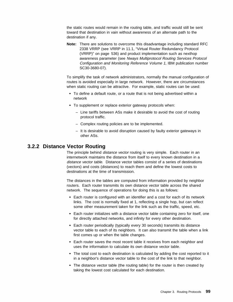
the static routes would remain in the routing table, and traffic would still be senttoward that destination in vain without awareness of an alternate path to thedestination if any.
Note: There are solutions to overcome this disadvantage including standard RFC2338 VRRP (see VRRP in 11.1, “Virtual Router Redundancy Protocol(VRRP)” on page 536) and product implementation such as nexthopawareness parameter (see Nways Multiprotocol Routing Services ProtocolConfiguration and Monitoring Reference Volume 1, IBM publication numberSC30-3680-07).
To simplify the task of network administrators, normally the manual configuration ofroutes is avoided especially in large network. However, there are circumstanceswhen static routing can be attractive. For example, static routes can be used:
� To define a default route, or a route that is not being advertised within anetwork
� To supplement or replace exterior gateway protocols when:
– Line tariffs between ASs make it desirable to avoid the cost of routingprotocol traffic.
– Complex routing policies are to be implemented.
– It is desirable to avoid disruption caused by faulty exterior gateways inother ASs.
3.2.2 Distance Vector RoutingThe principle behind distance vector routing is very simple. Each router in aninternetwork maintains the distance from itself to every known destination in adistance vector table. Distance vector tables consist of a series of destinations(vectors) and costs (distances) to reach them and define the lowest costs todestinations at the time of transmission.
The distances in the tables are computed from information provided by neighborrouters. Each router transmits its own distance vector table across the sharednetwork. The sequence of operations for doing this is as follows:
� Each router is configured with an identifier and a cost for each of its networklinks. The cost is normally fixed at 1, reflecting a single hop, but can reflectsome other measurement taken for the link such as the traffic, speed, etc.
� Each router initializes with a distance vector table containing zero for itself, onefor directly attached networks, and infinity for every other destination.
� Each router periodically (typically every 30 seconds) transmits its distancevector table to each of its neighbors. It can also transmit the table when a linkfirst comes up or when the table changes.
� Each router saves the most recent table it receives from each neighbor anduses the information to calculate its own distance vector table.
� The total cost to each destination is calculated by adding the cost reported to itin a neighbor's distance vector table to the cost of the link to that neighbor.
� The distance vector table (the routing table) for the router is then created bytaking the lowest cost calculated for each destination.
Chapter 3. Routing Protocols 99
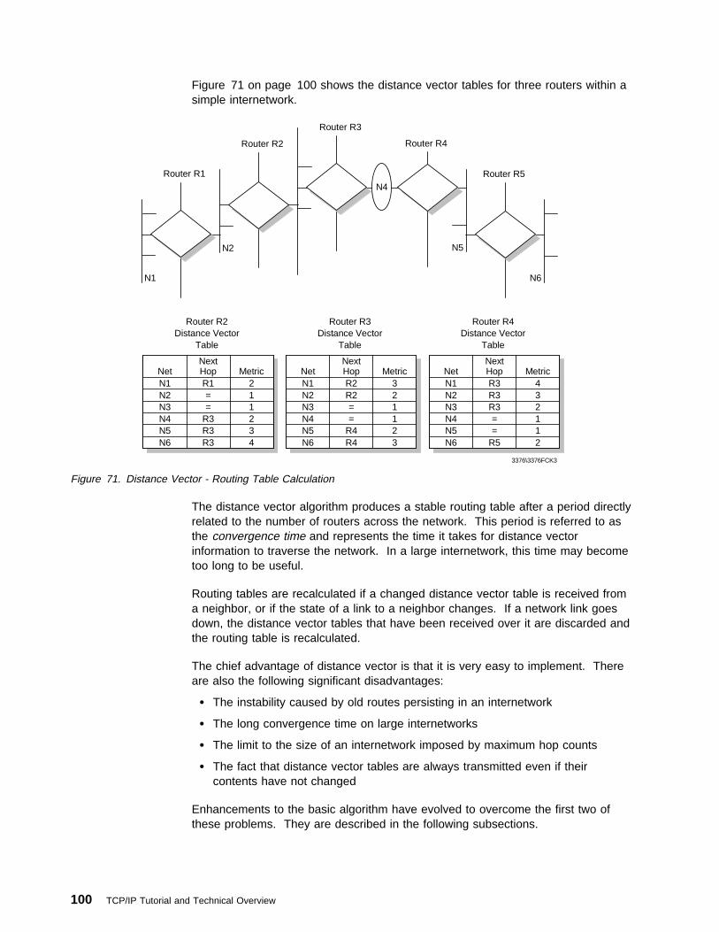
Figure 71 on page 100 shows the distance vector tables for three routers within asimple internetwork.
Router R5
N6
Router R4
N5
Router R3
Router R1
Router R2
N1
N2
N4
Router R2Distance Vector
Table
NetNext Hop Metric
N1 R1 2N2 = 1N3 = 1N4 R3 2N5 R3 3N6 R3 4
Router R3Distance Vector
Table
NetNext Hop Metric
N1 R2 3N2 R2 2N3 = 1N4 = 1N5 R4 2N6 R4 3
Router R4Distance Vector
Table
NetNext Hop Metric
N1 R3 4N2 R3 3N3 R3 2N4 = 1N5 = 1N6 R5 2
3376\3376FCK3
Figure 71. Distance Vector - Routing Table Calculation
The distance vector algorithm produces a stable routing table after a period directlyrelated to the number of routers across the network. This period is referred to asthe convergence time and represents the time it takes for distance vectorinformation to traverse the network. In a large internetwork, this time may becometoo long to be useful.
Routing tables are recalculated if a changed distance vector table is received froma neighbor, or if the state of a link to a neighbor changes. If a network link goesdown, the distance vector tables that have been received over it are discarded andthe routing table is recalculated.
The chief advantage of distance vector is that it is very easy to implement. Thereare also the following significant disadvantages:
� The instability caused by old routes persisting in an internetwork
� The long convergence time on large internetworks
� The limit to the size of an internetwork imposed by maximum hop counts
� The fact that distance vector tables are always transmitted even if theircontents have not changed
Enhancements to the basic algorithm have evolved to overcome the first two ofthese problems. They are described in the following subsections.
100 TCP/IP Tutorial and Technical Overview

3.2.2.1 The Count to Infinity ProblemThe basic distance vector algorithm will always allow a router to correctly calculateits distance vector table.
Using the example shown in Figure 72 you can see one of the problems ofdistance vector protocols known as counting to infinity.
Counting to infinity occurs when a network becomes unreachable, but erroneousroutes to that network persist because of the time for the distance vector tables toconverge.
3376\3376FCK4
A
(1)
B
C
D
(10)
TargetNetwork
(1)
(1)
(1)
(10)
(n) = Network Cost
Figure 72. Counting to Infinity - Example Network
The example network shows four routers interconnected by five network links. Thenetworks all have a cost of 1 except for that from C to D, which has a cost of 10.
Each of the routers A, B, C and D has routes to all networks. If we show only theroutes to the target network, we will see they are as follows:
For D : Directly connected network. Metric 1.
For B : Route via D. Metric 2.
For C : Route via B. Metric 3.
For A : Route via B. Metric 3.
Chapter 3. Routing Protocols 101

If the link from B to D fails, then all routes will be adjusted in time to use the linkfrom C to D. However, the convergence time for this can be considerable.
Distance vector tables begin to change when B notices that the route to D hasbecome unavailable. Figure 73 shows how the routes to the target network willchange, assuming all routers send distance vector table updates at the same time.
D:
B:
C:
A:
Direct
Unreachable
B
B
1
3
3
Direct
C
A
C
1
4
4
4
Direct
C
A
C
1
5
5
5
Direct
C
A
C
1
6
6
6
Direct
C
A
C
1
11
11
11
Direct
C
D
C
1
12
11
12
....
....
Time
3376\3376FCK5
Figure 73. Counting to Infinity
The problem can be seen clearly. B is able to remove the failed route immediatelybecause it times out the link. Other routers, however, have tables that containreferences to this route for many update periods after the link has failed.
1. Initially A and C have a route to D via B.
2. Link from D to B fails.
3. A and C then send updates based on the route to D via B even after the linkhas failed.
4. B then believes it has a route to D via either A or C. But, in reality it does nothave such a route, as the routes are vestiges of the previous route via B, whichhas failed.
5. A and C then see that the route via B has failed, but believe a route exists viaone another.
Slowly the distance vector tables converge, but not until the metrics have countedup, in theory, to infinity. To avoid this happening, practical implementations ofdistance vector have a low value for infinity; for example, RIP uses a maximummetric of 16.
The manner in which the metrics increment to infinity gives rise to the termcounting to infinity. It occurs because A and C are engaged in an extended periodof mutual deception, each claiming to be able to get to the target network D via oneanother.
3.2.2.2 Split HorizonCounting to infinity can easily be prevented if a route to a destination is neverreported back in the distance vector table that is sent to the neighbor from whichthe route was learned. Split horizon is the term used for this technique.
The incorporation of split horizon would modify the sequence of distance vectortable changes to that shown in Figure 74 on page 103. The tables can be seen toconverge considerably faster than before (see Figure 73).
102 TCP/IP Tutorial and Technical Overview

D:
B:
C:
A:
Direct
Unreachable
B
B
1
3
3
Direct
Unreachable
A
C
1
4
4
Direct
Unreachable
D
Unreachable
1
11
Direct
C
D
C
1
12
11
12
3376\3376FCK6
Note: Faster Routing Table Convergence
Time
Figure 74. Split Horizon
3.2.2.3 Split Horizon with Poison ReversePoison reverse is an enhancement to split horizon, whereby routes learned from aneighbor router are reported back to it but with a metric of infinity (that is, networkunreachable).
The use of poison reverse is safer than split horizon alone because it breakserroneous looping routes immediately.
If two routers receive routes pointing at each other, and they are advertised with ametric of infinity, the routes will be eliminated immediately as unreachable. If theroutes are not advertised in this way, they must be eliminated by the timeout thatresults from a route not being reported by a neighbor router for several periods (forexample, six periods for RIP).
Poison reverse does have one disadvantage. It significantly increases the size ofdistance vector tables that must be exchanged between neighbor routers becauseall routes are included in the distance vector tables. While this is generally not aproblem on LANs, it can cause real problems on point-to-point connections in largeinternetworks.
3.2.2.4 Triggered UpdatesSplit horizon with poison reverse will break routing loops involving two routers. It isstill possible, however, for there to be routing loops involving three or more routers.For example, A may believe it has a route through B, B through C, and C throughA. This loop can only be eliminated by the timeout that results from counting toinfinity.
Triggered updates are designed to reduce the convergence time for routing tables,and hence reduce the period during which such erroneous loops are present in aninternetwork.
When a router changes the cost for a route in its distance vector table, it must sendthe modified table immediately to neighbor routers. This simple mechanismensures that topology changes in a network are propagated quickly, rather than ata rate dependent on normal periodic updates.
Chapter 3. Routing Protocols 103
3.2.3 Link State RoutingThe growth in the size of internetworks in recent years has necessitated thereplacement of distance vector routing algorithms with alternatives that address theshortcomings identified in 3.2.2, “Distance Vector Routing” on page 99.
These new protocols have been based on link state or shortest path first (see3.2.3.1, “Shortest-Path First (SPF)” on page 105) algorithms. The best example isthe OSPF Interior Gateway Protocol.
The principle behind link state routing is straightforward, although itsimplementation can be complex:
� Routers are responsible for contacting neighbors and learning their identities.
� Routers construct link state packets which contain lists of network links andtheir associated costs.
� Link state packets are transmitted to all routers in a network.
� All routers therefore have an identical list of links in a network, and canconstruct identical topology maps.
� The maps are used to compute the best routes to all destinations.
Routers contact neighbors by sending hello packets on their network interfaces.Hello packets are sent directly to neighbors on point-to-point links andnon-broadcast networks. On LANs, hello packets are sent to a predefined group ormulticast IP address that can be received by all routers. Neighbors who receivehellos from a router should reply with hello packets that include the identity of thatoriginating router.
Once neighbors have been contacted in this way, link state information can beexchanged.
Link state information is sent in the form of link state packets (LSPs), also knownas link state advertisements. LSPs provide the database from which networktopology maps can be calculated at each router. LSPs are normally sent onlyunder the following specific circumstances:
� When a router discovers a new neighbor
� When a link to a neighbor goes down
� When the cost of a link changes
� Basic refresh packets are sent every 30 minutes
Once a router has generated an LSP it is critical that it is received successfully byall other routers in a network. If this does not happen, routers on the network willcalculate network topology based on incorrect link state information.
Distribution of LSPs would normally be on the basis of each router's routing tables.However, this leads to a chicken and egg situation. Routing tables would rely onLSPs for their creation and LSPs would rely on routing tables for their distribution.A simple scheme called flooding overcomes this, and ensures that LSPs aresuccessfully distributed to all routers in a network.
Flooding requires that a router that receives an LSP transmits it to all neighborsexcept the one from which it was received. All LSPs must be explicitly
104 TCP/IP Tutorial and Technical Overview
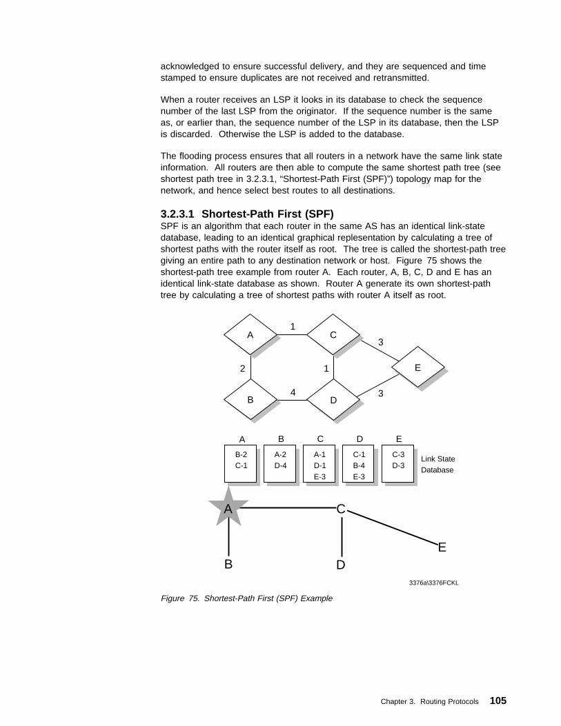
acknowledged to ensure successful delivery, and they are sequenced and timestamped to ensure duplicates are not received and retransmitted.
When a router receives an LSP it looks in its database to check the sequencenumber of the last LSP from the originator. If the sequence number is the sameas, or earlier than, the sequence number of the LSP in its database, then the LSPis discarded. Otherwise the LSP is added to the database.
The flooding process ensures that all routers in a network have the same link stateinformation. All routers are then able to compute the same shortest path tree (seeshortest path tree in 3.2.3.1, “Shortest-Path First (SPF)”) topology map for thenetwork, and hence select best routes to all destinations.
3.2.3.1 Shortest-Path First (SPF)SPF is an algorithm that each router in the same AS has an identical link-statedatabase, leading to an identical graphical replesentation by calculating a tree ofshortest paths with the router itself as root. The tree is called the shortest-path treegiving an entire path to any destination network or host. Figure 75 shows theshortest-path tree example from router A. Each router, A, B, C, D and E has anidentical link-state database as shown. Router A generate its own shortest-pathtree by calculating a tree of shortest paths with router A itself as root.
A
B-2C-1
B
A-2D-4
C
A-1D-1
E-3
D
C-1B-4
E-3
E
C-3D-3
DB
CA
E
E
CA
DB
1
2
34
3
1
3376a\3376FCKL
Link StateDatabase
Figure 75. Shortest-Path First (SPF) Example
Chapter 3. Routing Protocols 105
3.3 Interior Gateway Protocols (IGP)There are many standard and proprietary interior gateway protocols. IBM productssuch as operating systems and routers support only standard IGP protocols (seeChapter 14, “Platform Implementations” on page 639). This section describes thefollowing IGPs:
� Routing Information Protocol (RIP)
� Routing Information Protocol, Version 2 (RIP-2)
� Open Shortest Path Fist (OSPF)
3.3.1 Routing Information Protocol (RIP)RIP is an IAB standard protocol; its status is elective. This means that it is one ofseveral interior gateway protocols available, and it may or may not be implementedon a system. If a system does implement it, however, the implementation shouldbe in line with the RFC 1058.
RIP is based on the Xerox PUP and XNS routing protocols. The RFC was issuedafter many RIP implementations had been completed. For this reason some do notinclude all the enhancements to the basic distance vector routing protocol (such aspoison reverse and triggered updates).
RIP is a distance vector routing protocol suitable for small networks as compared toOSPF (see OSPF in 3.3.4, “Open Shortest Path First (OSPF)” on page 112). Thisis because of the shortcomings of distance vector routing identified in 3.2.2,“Distance Vector Routing” on page 99.
There are two versions of RIP. Version 1 (RIP-1) is a widely deployed protocolwith a number of known limitations. Version 2 (RIP-2) is an enhanced versiondesigned to alleviate the limitations of RIP while being highly compatible with it.The term RIP is used to refer to Version 1, while RIP-2 refers to Version 2.Whenever the reader encounters the term RIP in TCP/IP literature, it is safe toassume that it is referring to Version 1 unless explicitly stated otherwise. We usethis nomenclature in this section except when the two versions are beingcompared, when we use the term RIP-1 to avoid possible confusion.
RIP is very widely used because the code (known as ROUTED) was incorporatedon the Berkeley Software Distribution (BSD) UNIX operating system, and in otherUNIX systems based on it.
3.3.1.1 Protocol DescriptionRIP packets are transmitted onto a network in User Datagram Protocol (UDP)datagrams, which in turn are carried in IP datagrams. RIP sends and receivesdatagrams using UDP port 520. RIP datagrams have a maximum size of 512octets and tables larger than this must be sent in multiple UDP datagrams.
RIP datagrams are normally broadcast onto LANs using the LAN MAC all-stationsbroadcast address and the IP network or subnetwork broadcast address. They arespecifically addressed on point-to-point and multi-access non-broadcast networks,using the destination router IP address.
Routers normally run RIP in active mode; that is, advertising their own distancevector tables and updating them based on advertisements from neighbors. End
106 TCP/IP Tutorial and Technical Overview

nodes, if they run RIP, normally operate in passive (or silent) mode; that is,updating their distance vector tables on the basis of advertisements from neighbors,but not in turn advertising them.
RIP specifies two packet types: request and response.
A request packet is sent by routers to ask neighbors to send part of their distancevector table (if the packet contains destinations), or all their table (if no destinationshave been specified).
A response packet is sent by routers to advertise their distance vector table in thefollowing circumstances:
� Every 30 seconds
� In response to a request packet
� When distance vector tables change (if triggered updates are supported)
Active and passive systems listen for all response packets and update theirdistance vector tables accordingly. A route to a destination, computed from aneighbor's distance vector table, is kept until an alternate is found with lower cost,or it is not re-advertised in six consecutive RIP responses. In this case the route istimed out and deleted.
When RIP is used with IP, the address family identifier is 2 and the address fieldsare 4 octets. To reduce problems of counting to infinity the maximum metric is 16(unreachable) and directly connected networks are defined as having a metric ofone.
The RIP packet format for IP is shown in Figure 76.
Number of Octets
1
1
2
2
2
4
8
4
Command
Version
Reserved
2
Reserved
IP Address
Reserved
Metric
Request = 1Response = 2
3376\3376FCK8
Version = 1
Address FamilyIdentifier for IP
May beRepeated
Figure 76. RIP Message
RIP makes no provision for passing subnet masks with its distance vector tables.A router receiving a RIP response must already have subnet mask information to
Chapter 3. Routing Protocols 107
allow it to interpret the network identifier and host identifier portions of the IPaddress correctly.
In the absence of subnet mask information a router will interpret routes as best as itcan. If it knows an IP network has a specific subnet mask, it will interpret all otherroute information for that network on the basis of that single mask. If it receives apacket with bits set in the field that it regards as the host field, it will interpret it as aroute to a host with a mask of 255.255.255.255.
The above makes it impossible for RIP to be used in an internetwork with variablelength subnet masks.
3.3.2 Routing Information Protocol Version 2 (RIP-2)RIP-2 is a draft standard protocol. Its status is elective. It is described in RFC1723.
RIP-2 extends RIP-1. It is less powerful than other recent IGPs such as OSPF(see 3.3.4, “Open Shortest Path First (OSPF)” on page 112) but it has theadvantages of easy implementation and lower overheads. The intention of RIP-2 isto provide a straightforward replacement for RIP that can be used on small tomedium-sized networks, can be employed in the presence of variable subnetting(see 2.1.2.1, “Types of Subnetting” on page 31) or supernetting (see 2.1.7,“Classless Inter-Domain Routing (CIDR)” on page 45) and importantly, caninteroperate with RIP-1. In fact, the major reason for developing and deployingRIP-2 was the use of CIDR, which cannot be used in conjunction with RIP-1.
RIP-2 takes advantage of the fact that half of the bytes in a RIP-1 message arereserved (must be zero) and that the original RIP-1 specification was well designedwith enhancements in mind, particularly in the use of the version field. One notablearea where this is not the case is in the interpretation of the metric field. RIP-1specifies it as being a value between 0 and 16 stored in a four-byte field. Forcompatibility, RIP-2 preserves this definition, meaning that it agrees with RIP-1 that16 is to be interpreted as infinity, and wastes most of this field.
Note: Neither RIP-1 nor RIP-2 are properly suited for use as an IGP in an ASwhere a value of 16 is too low to be regarded as infinity, because highvalues of infinity exacerbate the counting to infinity problem. The moresophisticated link-state protocol used in OSPF provides a much betterrouting solution when the AS is large enough to have a legitimate hop countclose to 16.
Provided that a RIP-1 implementation obeys the specification in RFC 1058, RIP-2can interoperate with RIP-1. The RIP message format is extended as shown inFigure 77 on page 109.
108 TCP/IP Tutorial and Technical Overview

Number of Octets
1
1
2
2
2
16
2
2
4
4
4
4
Command
Version
Reserved
X'FFFF'
Authentic Type
Authentication Data
2
Reserved
IP Address
Subnet Mask
Next Hop
Metric
Request = 1Response = 2
3376\3376FCKZ
0 = No Authentication2 = Password Data
May be Repeated
Password if Type 2 Selected
Figure 77. RIP-2 Message
The first entry in the message can be an authentication entry, as shown here, or itcan be a route as in a RIP-1 message. If the first entry is an authentication entry,only 24 routes can be included in a message; otherwise the maximum is 25 as inRIP-1.
The fields in a RIP-2 message are the same as for a RIP-1 message except asfollows:
VersionIs 2. This tells RIP-1 routers to ignore the fields designated as “must bezero.” (If the value is 1, RIP-1 routers are required to discard messages withnon-zero values in these fields since the messages originate with a routerclaiming to be RIP-1-compliant but sending non-RIP-1 messages.)
Address FamilyMay be X'FFFF' in the first entry only, indicating that this entry is anauthentication entry.
Authentication TypeDefines how the remaining 16 bytes are to be used. The only defined typesare 0 indicating no authentication and 2 indicating that the field containspassword data.
Authentication DataThe password is 16 bytes, plain text ASCII, left adjusted and padded withASCII NULLs (X'00').
Chapter 3. Routing Protocols 109

Route TagIs a field intended for communicating information about the origin of the routeinformation. It is intended for interoperation between RIP and other routingprotocols. RIP-2 implementations must preserve this tag, but RIP-2 does notfurther specify how it is to be used.
Subnet MaskThe subnet mask associated with the subnet referred to by this entry.
Next HopA recommendation about the next hop that the router should use to senddatagrams to the subnet or host given in this entry.
To ensure safe interoperation with RIP, RFC 1723 specifies the followingrestrictions for RIP-2 routers sending over a network interface where a RIP-1 routermay hear and operate on the RIP messages.
1. Information internal to one network must never be advertised into anothernetwork.
2. Information about a more specific subnet cannot be advertised where RIP-1routers would consider it a host route.
3. Supernet routes (routes with a subnet mask shorter than the natural orunsubnetted network mask) must not be advertised where they could bemisinterpreted by RIP-1 routers.
RIP-2 also supports the use of multicasting (see 9.1, “Multicasting” on page 467)rather than simple broadcasting. This can reduce the load on hosts that are notlistening for RIP-2 messages. This option is configurable for each interface toensure optimum use of RIP-2 facilities when a router connects mixed RIP-1/RIP-2subnets to RIP-2-only subnets. Similarly, the use of authentication in mixedenvironments can be configured to suit local requirements.
RIP-2 is implemented in recent versions of the gated daemon, often termed gatedVersion 3.
3.3.3 RIPng for IPv6RIPng is intended to allow routers to exchange information for computing routesthrough an IPv6-based network and documented in RFC2080 (see IPv6 inChapter 6, “IP Version 6” on page 357).
3.3.3.1 Protocol DescriptionRIPng is a distance vector protocol and similar to RIP-2 in IPv4 (see 3.2.2,“Distance Vector Routing” on page 99). RIPng is a UDP-based protocol and sendsand receives datagrams on UDP port number 521. RIPng should be implementedonly in routers; IPv6 provides other mechanisms for router discovery. Any routerthat uses RIPng is assumed to have interfaces to one or more networks, otherwiseit isn't really a router (see router discovery in 6.3, “Internet Control MessageProtocol Version 6 (ICMPv6)” on page 372). RIPng has the following limitations,just as RIP-2 in IPv4, which are specific to a distance vector protocol.
� Limited number of networks where longest path is 15.
� RIPng depends on counting to infinity. The resolution of the loop would requiremuch more time (see counting to infinity in 3.2.2.1, “The Count to InfinityProblem” on page 101).
110 TCP/IP Tutorial and Technical Overview

� Fixed metric. It is not appropriate for situations where routers need to bechosen based on real-time applications.
The RIPng message format is extended as shown in Figure 78.
Route Table
Entry (RTE)
3376C\3376FCU1
Command
Version
Reserved
1
1
2
20
Request = 1Response = 2
May be Repeated
Figure 78. RIPng Message
The basic blocks of a RIPng message are the following:
CommandIt is the same idea as in RIP-1 and RIP-2 in IPv4 (see Figure 76 onpage 107 and Figure 77 on page 109 also).
Route Table Entry (RTE)It is a different idea from RIP-1 and RIP-2. RIPng provides the ability tospecify the immediate next hop IPv6 address to which packets to adestination specified by an RTE should be forwarded in much the same wayas RIP-1 and RIP-2 (see RTE in Figure 79).
Metric
3376C\3376FCU2
IPv6 Prefix
Route Tag
Prefix Length
16
2
1
1
Between 0 and 128Between 1 and 15Infinity = 16
Number of Octects
Figure 79. RIPng Route Table Entry (RTE)
In RIP-2, each route table entry has a next hop field. Including a next hopfield for each RTE in RIPng would nearly double the size of the RTE.Therefore, in RIPng, the next hop is specified by a special RTE and applies toall of the address RTEs following the next hop RTE until the end of themessage or until another next hop RTE is encountered.
Next Hop Route Table Entry (RTE)The next hop RTE is identified by a value of 0xFF in the metric field of anRTE. The prefix field specifies the IPv6 address of the next hop.
Chapter 3. Routing Protocols 111

Reserved
3376C\3376FCU3
IPv6 Next Hop Address
Reserved
Reserved
16
2
1
1 OxFF
Number of Octects
Figure 80. RIPng Next Hop Route Table Entry (RTE)
3.3.4 Open Shortest Path First (OSPF)The Open Shortest Path First (OSPF) V2 Protocol is an interior gateway protocoldefined in RFC 2328. A report on the use of OSPF V2 is contained in RFC 1246Experience with the OSPF Protocol.
It is an IAB standard protocol; its status is elective. However, RFC 1812Requirements for IPv4 Routers, lists OSPF as the only required dynamic routingprotocol.
OSPF is important because it has a number of features not found in other interiorgateway protocols. Support for these additional features makes OSPF thepreferred choice for new IP internetwork implementations especially in largenetworks. The following features are covered within OSPF:
� Support for type of service (TOS) routing4
� Provides load balancing (see 11.6, “OSPF Equal-Cost Multipath” on page 560)
� Allows site partitioning into subsets by using areas
� Information exchange between routers requires authentication (also in RIP-2,see RIP-2 in 3.3.2, “Routing Information Protocol Version 2 (RIP-2)” onpage 108)
� Support for host-specific routes as well as network-specific routes
� Reduces table maintenance overhead to a minimum by implementing adesignated router
� Allows definition of virtual links to provide support to a non-contiguous area
� Allows the usage of variable length subnet masks(also in RIP-2, see RIP-2 in3.3.2, “Routing Information Protocol Version 2 (RIP-2)” on page 108)
� Will import RIP and EGP routes into its database
4 The use of TOS has been dropped in recent OSPF implementations.
112 TCP/IP Tutorial and Technical Overview
3.3.4.1 OSPF TerminologyOSPF uses specific terminology which must be understood before the protocol canbe described.
Areas: OSPF internetworks are organized into areas. An OSPF area consists ofa number of networks and routers that are logically grouped together. Areas canbe defined on a per location or a per region basis, or they can be based onadministrative boundaries. All OSPF networks consist of at least one area, thebackbone, plus as many additional areas as are demanded by network topologyand other design criteria. Within an OSPF area all routers maintain the sametopology database, exchanging link state information to maintain theirsynchronization. This ensures that all routers calculate the same network map forthe area.
Information about networks outside an area is summarized by an area border or ASboundary routers (see “Intra-Area, Area Border and AS Boundary Routers”) andflooded into the area. Routers within an area have no knowledge of the topology ofnetworks outside the area, only of routes to destinations provided by area bordersand AS boundary routers.
The importance of the area concept is that it limits the size of the topologydatabase that must be held by routers. This has direct impact on the processing tobe carried out by each router, and on the amount of link state information that mustbe flooded into individual networks.
The OSPF Backbone: All OSPF networks must contain at least one area, thebackbone, which is assigned an area identifier of 0.0.0.0. (This is differentdefinition from IP address 0.0.0.0.) The backbone has all the properties of an area,but has the additional responsibility of distributing routing information betweenareas attached to it. Normally an OSPF backbone should be contiguous, that iswith all backbone routers attached one to another. This may not be possiblebecause of network topology, in which case backbone continuity must bemaintained by the use of virtual links (see below). Virtual links are backbonerouter-to-backbone router connections that traverse a non-backbone area.
Routers within the backbone operate identically to other intra-area routers andmaintain full topology databases for the backbone area.
Intra-Area, Area Border and AS Boundary Routers: There are three possibletypes of routers in an OSPF network. Figure 81 on page 114 shows the locationof intra-area, area border and AS boundary routers within an OSPF internetwork.
Chapter 3. Routing Protocols 113

3376\3376FCK7
OSPF Backbone
Area 2 AB
As External Links
Area 1
AB
ASB
As External Links
AB
ASB
Area 4AB
Area 3
IA IA
Area 4
KeyASB ABIA
= AS Boundary Router= Area Border Router= Intra-Area Router
Figure 81. OSPF Network
Intra-Area RoutersRouters that are situated entirely within an OSPF area are called intra-arearouters. All intra-area routers flood router links advertisements into the areato define the links they are attached to. If they are elected designated orbackup-designated routers (see “Designated and Backup Designated Router”on page 116), they also flood network links advertisements to define theidentity of all routers attached to the network. Intra-area routers maintain atopology database for the area in which they are situated.
Area Border RoutersRouters that connect two or more areas are referred to as area borderrouters. Area border routers maintain topology databases for each area towhich they are attached, and exchange link state information with otherrouters in those areas. Area border routers also flood summary link stateadvertisements into each area to inform them of inter-area routes.
AS Boundary RoutersRouters that are situated at the periphery of an OSPF internetwork andexchange reachability information with routers in other ASs using exteriorgateway protocols are called AS boundary routers. Routers that import staticroutes or routes from other IGPs, such as RIP, into an OSPF network arealso AS boundary routers. AS boundary routers are responsible for floodingAS external link state advertisements into all areas within the AS to informthem of external routes.
Virtual Link: A virtual link is part of the backbone. Its endpoints are two areaborder routers that share a common non-backbone area. The link is treated as apoint-to-point link with metrics cost equal to the intra-area metrics between theendpoints of the links. The routing through the virtual link is done using normal
114 TCP/IP Tutorial and Technical Overview

intra-area routing (see Figure 82 on page 115). Virtual endpoints are area borderrouters (ABRs) that share Area 2 as a transit area.
Transit Area: An area through which a virtual route is physically connected. InFigure 82, Area 2 is transit area. In Figure 82, virtual endpoints are ABRs thatshare Area 2 as a transit area.
ABR
Area 0Backbone
3376a\3376FCKM
Area 1
Area 2ABR
Figure 82. OSPF Virtual Link, Transit Area
Stub Area: An area configured to use default routing for inter-AS routing. A stubarea can be configured where there is only a single exit from the area, or whereany exit can be used without preference for routing to destinations outside theautonomous system. By default inter-AS routes are copied to all areas, so the useof stub areas can reduce the storage requirements of routers within those areas forautonomous systems where a lot of inter-AS routes are defined.
Neighbor Routers: Two routers that have interfaces to a common network. Onmultiaccess networks, neighbors are dynamically discovered by the Hello protocol.
Each neighbor is described by a state machine, which describes the conversationbetween this router and its neighbor. A brief outline of the meaning of the statesfollows. See the section immediately following for a definition of the termsadjacency and designated router.
DownInitial state of a neighbor conversation. It indicates that there has been norecent information received from the neighbor.
AttemptA neighbor on a non-broadcast network appears down and an attempt shouldbe made to contact it by sending regular Hello packets.
Chapter 3. Routing Protocols 115
Init A Hello packet has recently been received from the neighbor. However,bidirectional communication has not yet been established with the neighbor.(That is, the router itself did not appear in the neighbor's Hello packet.)
2-wayIn this state, communication between the two routers is bidirectional.Adjacencies can be established, and neighbors in this state or higher areeligible to be elected as (backup) designated routers.
ExStartThe two neighbors are about to create an adjacency.
ExchangeThe two neighbors are telling each other what they have in their topologicaldatabases.
LoadingThe two neighbors are synchronizing their topological databases.
Full The two neighbors are now fully adjacent; their databases are synchronized.
Various events cause a change of state. For example, if a router receives a Hellopacket from a neighbor that is down, the neighbor's state changes to init, and aninactivity timer is started. If the timer fires (that is, no further OSPF packets arereceived before it expires), the neighbor will return to the down state. Refer to RFC2173 for a complete description of the states and information on the events whichcause state changes.
Adjacent Router: Neighbor routers can become adjacent. They are said to beadjacent when they have synchronized their topology databases through theexchange of link state information.
Link state information is exchanged only between adjacent routers, not betweenneighbor routers.
Not all neighbor routers become adjacent. Neighbors on point-to-point links do so,but on multi-access networks adjacencies are only formed between individualrouters and the designated and backup designated routers.
The exchange of link state information between neighbors can create significantamounts of network traffic. Limiting the number of adjacencies on multi-accessnetworks in this way achieves considerable reductions in network traffic.
Designated and Backup Designated Router: All multi-access networks have adesignated and a backup designated router. These routers are electedautomatically for each network once neighbor routers have been discovered by theHello protocol.
The designated router performs two key roles for a network:
� It generates network links advertisements that list the routers attached to amulti-access network.
� It forms adjacencies with all routers on a multi-access network and thereforebecomes the focal point for forwarding of all link state advertisements.
The backup designated router forms the same adjacencies as the designatedrouter. It therefore has the same topology database and is able to assumedesignated router functions should it detect that the designated router has failed.
116 TCP/IP Tutorial and Technical Overview

Physical Network Types: All OSPF areas consist of aggregates of networkslinked by routers. OSPF categorizes networks into the following different types.
Point-to-point NetworkPoint-to-point networks directly link two routers.
Multi-Access NetworkMulti-access networks are those that support the attachment of more than tworouters. They are further subdivided into two types:
� Broadcast
� Non-broadcast
Point-to-Multipoint NetworkPoint-to-multipoint networks describe a special case of multiaccessnon-broadcast where not every router has a direct connection to any otherrouter (also referred to as partial mesh).
Broadcast networks have the capability of directing OSPF packets to all attachedrouters, using an address that is recognized by all of them. An Ethernet LAN andtoken-ring LAN are examples of a broadcast multi-access network.
Non-broadcast networks do not have this capability and all packets must bespecifically addressed to routers on the network. This requires that routers on anon-broadcast network be configured with the addresses of neighbors. Examplesof a non-broadcast multi-access network are the X.25 public data network or aframe relay network
Interface: The connection between a router and one of its attached networks.Each interface has state information associated with it that is obtained from theunderlying lower-level protocols and the OSPF protocol itself. A brief description ofeach state is given here. Please refer to RFC 2173 for more details, and forinformation on the events that will cause an interface to change its state.
DownThe interface is unavailable. This is the initial state of an interface.
LoopbackThe interface is looped back to the router. It cannot be used for regular datatraffic.
WaitingThe router is trying to determine the identity of the designated router or itsbackup.
Point-to-PointThe interface is to a point-to-point network or is a virtual link. The routerforms an adjacency with the router at the other end.
Note: The interfaces do not need IP addresses. Since the remainder of theinternetwork has no practical need to see the routers' interfaces to thepoint-to-point link, just the interfaces to other networks, any IPaddresses for the link would be needed only for communicationbetween the two routers. To conserve the IP address space, therouters can dispense with IP addresses on the link. This has theeffect of making the two routers appear to be one to IP but this has noill effects. Such a link is called an unnumbered link.
Chapter 3. Routing Protocols 117

DR OtherThe interface is on a multiaccess network but this router is neither thedesignated router nor its backup. The router forms adjacencies with thedesignated router and its backup.
BackupThe router is the backup designated router. It will be promoted to designatedrouter if the present designated router fails. The router forms adjacencieswith every other router on the network.
DR The router itself is the designated router. The router forms adjacencies withevery other router on the network. The router must also originate a networklinks advertisement for the network node.
Type of Service (TOS) Metrics: In each type of link state advertisement, differentmetrics can be advertised for each IP Type of Service. A metric for TOS 0 (usedfor OSPF routing protocol packets) must always be specified. Metrics for otherTOS values can be specified; if they are not, these metrics are assumed equal tothe metric specified for TOS 0.5
Link State Database: Also called the directed graph or the topological database.It is created from the link state advertisements generated by the routers in the area.
Note: RFC 2328 uses the term link state database in preference to topologicaldatabase. The former term has the advantage that it describes the contentsof the database, the latter is more descriptive of the purpose of thedatabase, to describe the topology of the area. We have previously usedthe term topological database for this reason, but for the remainder of thissection where we discuss the operation of OSPF in more detail, we refer toit as the link state database.
Shortest-Path Tree: Each router runs the SPF (see SPF in 3.2.3.1,“Shortest-Path First (SPF)” on page 105) algorithm on the link state database toobtain its shortest-path tree. The tree gives the route to any destination network orhost as far as the area boundary. It is used to build the routing table.
Note: Because each router occupies a different place in the area's topology,application of the SPF algorithm gives a different tree for each router, eventhough the database is identical.
Area border routers run multiple copies of the algorithm but build a single routingtable.
Routing table: The routing table contains entries for each destination: network,subnet or host. For each destination, there is information for one or more types ofservice (TOS). For each combination of destination and type of service, there areentries for one or more optimum paths to be used.
Area ID: A 32-bit number identifying a particular area. The backbone has an areaID of zero.
5 The use of TOS has been dropped in recent OSPF implementations.
118 TCP/IP Tutorial and Technical Overview

Router ID: A 32-bit number identifying a particular router. Each router within theAS has a single router ID. One possible implementation is to use the lowestnumbered IP address belonging to a router as its router ID.
Router Priority: An 8-bit unsigned integer, configurable on a per-interface basisindicating this router's priority in the selection of the (backup) designated router. Arouter priority of zero indicates that this router is ineligible to be the designatedrouter.
Link State Advertisements: Link state information is exchanged by adjacentOSPF routers to allow area topology databases to be maintained, and inter-areaand inter-AS routes to be advertised.
Link state information consists of five types of link state advertisement. Togetherthese provide all the information needed to describe an OSPF network and itsexternal environment:
1. Router links
2. Network links
3. Summary links (type 3 and 4)
4. AS External links
Router link advertisementsRouter link advertisements are generated by all OSPF routers and describethe state of the router's interfaces (links) within the area. They are floodedthroughout a single area only.
Network link advertisementsNetwork link advertisements are generated by the designated router on amulti-access network and list the routers connected to the network. They areflooded throughout a single area only.
Summary link advertisementsSummary link advertisements are generated by area border routers. Thereare two types: one describes routes to destinations in other areas; the otherdescirbes routes to AS boundary routers. They are flooded throughout asingle area only.
AS external link advertisementsAS external link advertisements are generated by AS boundary routers anddescribe routes to destinations external to the OSPF network. They areflooded throughout all areas in the OSPF network.
Chapter 3. Routing Protocols 119

Router
Router Links
Advertised by routerDescribes state/cost of routers' links
DR
Network Links
Advertised by designated routerDescribes all routers attached to network
ABR
Summary Links
Advertised by ABRDescribes inter-area and ASBR reachability
Area X Area O ASBR
External Links
Advertised by ASBRDescribes networks outside of OSPF AS
Area X Area O
3376C\3376FCKK
Figure 83. OSPF Link State Advertisements
3.3.4.2 Protocol DescriptionThe OSPF protocol is an implementation of a link state routing protocol, asdescribed in 3.2.3, “Link State Routing” on page 104.
OSPF packets are transmitted directly in IP datagrams. IP datagrams containingOSPF packets can be distinguished by their use of protocol identifier 89 in the IPheader. OSPF packets are not, therefore, contained in TCP or UDP headers.OSPF packets are always sent with IP type of service set to 0, and the IPprecedence field set to internetwork control. This is to aid them in gettingpreference over normal IP traffic. (To see further details on IP protocol identifiers,type of service and precedence, refer to 10.2, “Integrated Services” on page 506.)
OSPF packets are sent to a standard multicast IP address on point-to-point andbroadcast networks. This address is 224.0.0.5, referred to as AllSPFRouters in theRFC. They are sent to specific IP addresses on non-broadcast networks usingneighbor network address information that must be configured for each router. AllOSPF packets share a common header, which is shown in Figure 84 on page 121.This header provides general information such as area identifier and originatingrouter identifier, and also includes a checksum and authentication information. Atype field defines each OSPF packet as one of five possible types:
1. Hello
2. Database description
120 TCP/IP Tutorial and Technical Overview
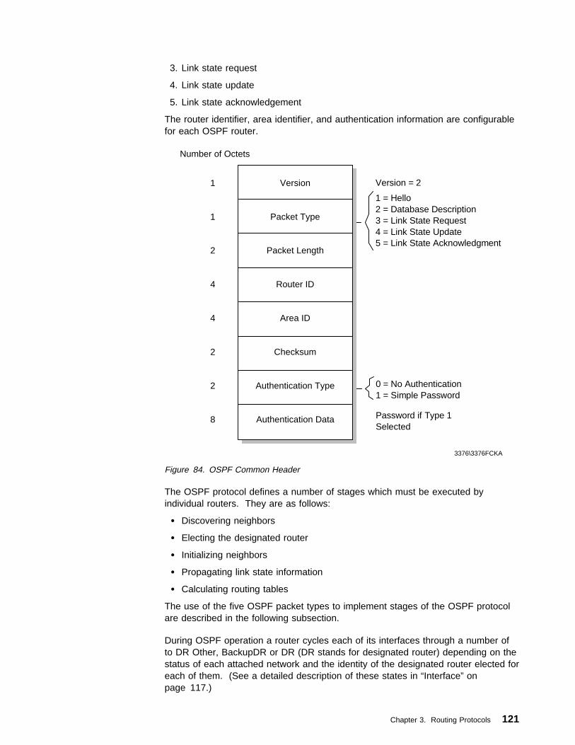
3. Link state request
4. Link state update
5. Link state acknowledgement
The router identifier, area identifier, and authentication information are configurablefor each OSPF router.
0 = No Authentication1 = Simple Password
Number of Octets
1
1
2
4
4
2
2
8
Version
Packet Type
Packet Length
Router ID
Area ID
Checksum
Authentication Type
Authentication Data
1 = Hello2 = Database Description3 = Link State Request4 = Link State Update5 = Link State Acknowledgment
3376\3376FCKA
Version = 2
Password if Type 1Selected
Figure 84. OSPF Common Header
The OSPF protocol defines a number of stages which must be executed byindividual routers. They are as follows:
� Discovering neighbors
� Electing the designated router
� Initializing neighbors
� Propagating link state information
� Calculating routing tables
The use of the five OSPF packet types to implement stages of the OSPF protocolare described in the following subsection.
During OSPF operation a router cycles each of its interfaces through a number ofto DR Other, BackupDR or DR (DR stands for designated router) depending on thestatus of each attached network and the identity of the designated router elected foreach of them. (See a detailed description of these states in “Interface” onpage 117.)
Chapter 3. Routing Protocols 121

At the same time a router cycles each neighbor interface (interaction) through anumber of states as it discovers them and then becomes adjacent. These statesare: Down, Attempt, Init, 2-Way, ExStart, Exchange, Loading and Full. (See adetailed description of these states in “Neighbor Routers” on page 115.)
Discovering Neighbors - The OSPF Hello Protocol: The Hello protocol isresponsible for discovering neighbor routers on a network, and establishing andmaintaining relationships with them. Hello packets are sent out periodically on allrouter interfaces. The format of these is shown in Figure 85.
E = SubareaT = Multiple TOS Metrics Supported
Number of Octets
24
4
2
1
1
4
4
4
4
Common Header
Network Mask
Hello Interval
Router Priority
Router Dead Interval
Designated Router
BackupDesignated Router
Neighbor
3376\3376FCKB
Packet Type = 1
Repeated forEach CurrentValid Neighbor
Reserved E T
Figure 85. OSPF Hello Packet
Hello packets contain the identities of neighbor routers whose hello packets havealready been received over a specific interface. They also contain the networkmask, router priority, designated router identifier and backup designated routeridentifier. The final three parameters are used to elect the designated router onmulti-access networks.
The network mask, router priority, hello interval and router dead interval areconfigurable for each interface on an OSPF router.
A router interface changes state from Down to Point-to-Point (if the network ispoint-to-point), to DR Other (if the router is ineligible to become designated router),or otherwise to Waiting as soon as hello packets are sent over it.
122 TCP/IP Tutorial and Technical Overview
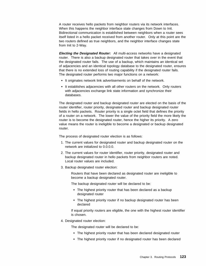
A router receives hello packets from neighbor routers via its network interfaces.When this happens the neighbor interface state changes from Down to Init.Bidirectional communication is established between neighbors when a router seesitself listed in a hello packet received from another router. Only at this point are thetwo routers defined as true neighbors, and the neighbor interface changes statefrom Init to 2-Way.
Electing the Designated Router: All multi-access networks have a designatedrouter. There is also a backup designated router that takes over in the event thatthe designated router fails. The use of a backup, which maintains an identical setof adjacencies and an identical topology database to the designated router, ensuresthat there is no extended loss of routing capability if the designated router fails.The designated router performs two major functions on a network:
� It originates network link advertisements on behalf of the network.
� It establishes adjacencies with all other routers on the network. Only routerswith adjacencies exchange link state information and synchronize theirdatabases.
The designated router and backup designated router are elected on the basis of therouter identifier, router priority, designated router and backup designated routerfields in hello packets. Router priority is a single octet field that defines the priorityof a router on a network. The lower the value of the priority field the more likely therouter is to become the designated router, hence the higher its priority. A zerovalue means the router is ineligible to become a designated or backup designatedrouter.
The process of designated router election is as follows:
1. The current values for designated router and backup designated router on thenetwork are initialized to 0.0.0.0.
2. The current values for router identifier, router priority, designated router andbackup designated router in hello packets from neighbor routers are noted.Local router values are included.
3. Backup designated router election:
Routers that have been declared as designated router are ineligible tobecome a backup designated router.
The backup designated router will be declared to be:
� The highest priority router that has been declared as a backupdesignated router
� The highest priority router if no backup designated router has beendeclared
If equal priority routers are eligible, the one with the highest router identifieris chosen.
4. Designated router election:
The designated router will be declared to be:
� The highest priority router that has been declared designated router
� The highest priority router if no designated router has been declared
Chapter 3. Routing Protocols 123

5. If the router carrying out the above determination is declared the designated orbackup designated router, then the above steps are re-executed. This ensuresthat no router can declare itself both designated and backup designated router.
Once designated and backup designated routers have been elected for a network,they proceed to establish adjacencies with all routers on the network.
Completion of the election process for a network causes the router interface tochange state from Waiting to DR, BackupDR, or DR Other depending on whetherthe router is elected the designated router, the backup designated router or none ofthese.
Establishing Adjacencies - Database Exchange: A router establishesadjacencies with a subset of neighbor routers on a network.
Routers connected by point-to-point networks and virtual links always becomeadjacent. Routers on multi-access networks form adjacencies with the designatedand backup designated routers only.
Link state information flows only between adjacent routers. Before this can happenit is necessary for them to have the same topological database, and to besynchronized. This is achieved in OSPF by a process called database exchange.
Database exchange between two neighbor routers occurs as soon as they attemptto bring up an adjacency. It consists of the exchange of a number of databasedescription packets that define the set of link state information present in thedatabase of each router. The link state information in the database is defined bythe list of link state headers for all link state advertisement in the database. (SeeFigure 90 on page 128 for information on the link state header.)
The format of database description packets is shown in Figure 86.
I = InitM = MoreM/S = '1' for Master
Number of Octets
24
2
1
1
4
20
Common Header
Reserved
Interface MTU
DD Sequence Number
Link State Header
3376\3376FCKC
Packet Type = 2
Repeated forEach LinkState Advertisement
Reserved M MSI
Figure 86. OSPF Database Description Packet
124 TCP/IP Tutorial and Technical Overview

During the database exchange process the routers form a master/slaverelationship, the master being the first to transmit. The master sends databasedescription packets to the slave to describe its database of link state information.Each packet is identified by a sequence number and contains a list of the link stateheaders in the master's database. The slave acknowledges each packet bysequence number and includes its own database of headers in theacknowledgements.
Flags in database description packets indicate whether they are from a master orslave (the M/S bit), the first such packet (the I bit) and if there are more packets tocome (the M bit). Database exchange is complete when a router receives adatabase description packet from its neighbor with the M bit off.
During database exchange each router makes a list of the link state advertisementsfor which the adjacent neighbor has a more up-to-date instance (all advertisementsare sequenced and time stamped). Once the process is complete each routerrequests these more up-to-date instances of advertisements using link staterequests.
The format of link state request packets is shown in Figure 87.
Number of Octets
24
4
4
4
Common Header
Link State Type
Link State ID
Advertising Router
Packet Type = 3
3376\3376FCKD
Repeated forEach LinkState Advertisement
Figure 87. OSPF Link State Request Packet
The database exchange process sequences the neighbor interface state from2-Way through:
� ExStart as the adjacency is created and the master agreed upon
� Exchange as the topology databases are being described
� Loading as the link state requests are being sent and responded to
� And finally to Full when the neighbors are fully adjacent
In this way, the two routers synchronize their topology databases and are able tocalculate identical network maps for their OSPF area.
Link State Propagation: Information about the topology of an OSPF network ispassed from router to router in link state advertisements.
Link state advertisements pass between adjacent routers in the form of link stateupdate packets, the format of which is shown in Figure 88 on page 126.
Chapter 3. Routing Protocols 125

Number of Octets
24
4
Variable
Common Header
No. of Advertisements
Link State Advertisement
Packet Type = 4
3376\3376FCZZ
Repeated for Each Advertisement
Figure 88. OSPF Link State Update Packet
Link state advertisements are of five types: router links, network links, summarylinks (two types) and AS external links as noted earlier in this section.
Link state updates pass as a result of link state requests during databaseexchange, and also in the normal course of events when routers wish to indicate achange of network topology. Individual link state update packets can containmultiple link state advertisements.
It is essential that each OSPF router in an area has the same network topologydatabase, and hence the integrity of link state information must be maintained.
For that reason link state update packets must be passed without loss or corruptionthroughout an area. The process by which this is done is called flooding.
A link state update packet floods one or more link state advertisements one hopfurther away from their originator. To make the flooding procedure reliable eachlink state advertisement must be acknowledged separately. Multipleacknowledgements can be grouped together into a single link stateacknowledgement packet. The format of the link state acknowledgement packet isshown in Figure 89.
Number of Octets
24
20
Common Header
Link State Header
Packet Type = 5
3376\3376FCKE
Repeated forEach AdvertisementAcknowledged
Figure 89. OSPF Link State Acknowledgement Packet
In order to maintain database integrity it is essential that all link stateadvertisements are rigorously checked to ensure validity.
The following checks are applied and the advertisement discarded if:
� The link state checksum is incorrect.
� The link state type is invalid.
� The advertisement's age has reached its maximum.
� The advertisement is older than or the same as one already in the database.
126 TCP/IP Tutorial and Technical Overview

If an advertisement passes the above checks, then an acknowledgement is sentback to the originator. If no acknowledgement is received by the originator, then theoriginal link state update packet is retransmitted after a timer has expired.
Once accepted an advertisement is flooded onward over the router's otherinterfaces until it has been received by all routers within an area.
Advertisements are identified by their link state type, link state ID and theadvertising router. They are further qualified by their link state sequence number,link state age and link state checksum number.
The age of a link state advertisement must be calculated to determine if it shouldbe installed into a router's database. Only a more recent advertisement should beaccepted and installed. Valid link state advertisements are installed into thetopology database of the router. This causes the topology map or graph to berecalculated and the routing table to be updated.
Link state advertisements all have a common 20-byte header. This is shown inFigure 90 on page 128. The four link state advertisement types are shown inFigure 91 on page 130, in Figure 92 on page 132, in Figure 93 on page 132, andin Figure 94 on page 133.
Chapter 3. Routing Protocols 127
Number of Octets
2
1
1
4
4
4
2
2
Link State Age
Link State Type
Link State ID
Advertising Router
Link StateSequence Number
Link State Checksum
Length
3376\3376FCKF
Options
1 = Router Links2 = Network Links3,4 = Summary Links5 = AS External
E
Figure 90. OSPF Link State Header
The fields in the link state advertisement header are:
Link Stage AgeA 16-bit number indicating the time in seconds since the origin of theadvertisement. It is increased as the link state advertisement resides in arouter's database and with each hop it travels as part of the floodingprocedure. When it reaches a maximum value, it ceases to be used fordetermining routing tables and is discarded unless it is still needed fordatabase synchronization. The age is also to determine which of twootherwise identical copies of an advertisement a router should use.
OptionsOne bit that describes optional OSPF capabilitiy. The E-bit indicates anexternal routing capability. It is set unless the advertisement is for a router,network link or summary link in a stub area. The E-bit is used for informationonly and does not affect the routing table.
Link State TypeThe types of the link state advertisement are (see “Link State Advertisements”on page 119):
1. Router links - These describe the states of a router's interfaces.
128 TCP/IP Tutorial and Technical Overview

2. Network links - These describe the routers attached to a network.3. Summary links - These describe inter-area, intra-AS routes. They are
created by area border routers and allow routes to networks within the ASbut outside the area to be described concisely.
4. Summary links - These describe routes to the boundary of the AS (that is,to AS boundary routers). They are created by area border routers. Theyare very similar to type 3.
5. AS external links - These describe routes to networks outside the AS.They are created by AS boundary routers. A default route for the AS canbe described this way.
Link State IDA unique ID for the advertisement that is dependent on the link state type.For types 1 and 4 it is the router ID, for types 3 and 5 it is an IP networknumber, and for type 2 it is the IP address of the designated router.
Advertising RouterThe router ID of the router that originated the link state advertisement. Fortype 1 advertisements, this field is identical to the link state ID. For type 2, itis the router ID of the network's designated router. For types 3 and 4, it is therouter ID of an area border router. For type 5, it is the router ID of an ASboundary router.
LS Sequence NumberUsed to allow detection of old or duplicate link state advertisements.
Link State Sequence ChecksumChecksum of the complete link state advertisement excluding the link stateage field.
Routing Table Calculation: Each router in an OSPF area builds up a topologydatabase of validated link state advertisements and uses them to calculate thenetwork map for the area. From this map the router is able to determine the bestroute for each destination and insert it into its routing table.
Each advertisement contains an age field which is incremented while theadvertisement is held in the database. An advertisement's age is neverincremented past MaxAge. When age reaches MaxAge, it is excluded from routingtable calculation, and re-flooded through the area as a newly originatedadvertisement.
Note: MaxAge is an architecture constant and the maximum age an LSA canattain. The value of MaxAge is set to 1 hour.
Routers build up their routing table from the database of link state advertisementsin the following sequence:
1. The shortest path tree is calculated from router and network linksadvertisements allowing best routes within the area to be determined.
2. Inter-area routes are added by examination of summary link advertisements.
3. AS external routes are added by examination of AS external linkadvertisements.
The topology graph or map constructed from the above process is used to updatethe routing table. The routing table is recalculated each time a new advertisementis received.
Chapter 3. Routing Protocols 129

V = Virtual Link EndpointE = AS Boundary RouterB = Area Border Router
Number of Octets
20
1
1
2
4
4
1
1
2
1
1
2
Link StateHeader
Reserved
Number of Links
Link ID
Link Data
Type
Number of TOS
TOS 0 Metric
TOS
Reserved
Metric
3376\3376FCKF
LS Type = 1
E BVReserved
Repeated for EachLink Reported
Repeated Numberof TOS Times
Figure 91. OSPF Router Links Advertisement
The field in the router link advertisement header are:
V BitWhen set, this router is the endpoint of a virtual link that is using this area asa transit area.
E BitWhen set, the router is an AS boundary router.
B BitWhen set, the router is an area border router.
Number of LinksThe number of links described by this advertisement.
130 TCP/IP Tutorial and Technical Overview

Link IDIdentifies the object that this link connects to. The value depends upon thetype field (see below).
1. Neighboring router's router ID2. IP address of the designated router3. IP network/subnet number. This value depends on what the inter area
route is to:For a stub network it is the IP network/subnet number.For a host it is X'FFFFFFFF'.For the AS-external default route it is X'00000000'.
4. Neighboring router's router ID
Link DataThis value also depends upon the type field (see RFC 2328 for details).
TypeWhat this link connects to.
1. Point-to-point connection to another router2. Connection to a transit network3. Connection to a stub network or to a host
4. Virtual link
Number of TOSThe number of different TOS metrics given for this link in addition to themetric for TOS 0.
TOS 0 MetricThe cost of using this outbound link for TOS 0. All OSPF routing protocolpackets are sent with the IP TOS field set to 0.
TOSFor backward compatibility with previous versions of the OSPF specification.
Note: In RFC 2328 the TOS routing option has been deleted from OSPF.This action was required by the Internet standards process, due tolack of implementation experience with OSPF's TOS routing.However, for backward compatibility the formats of OSPF's variousLSAs remain unchanged, maintaining the ability to specify TOSmetrics in router-LSAs, summary-LSAs, ASBR-summary-LSAs, andAS-external-LSAs (see RFC 2328 for detail).
MetricThe cost of using this outbound router link for traffic of the specified Type ofService.
As an example, suppose the point-to-point link between routers RT1 (IPaddress: 192.1.2.3) and RT6 (IP address: 6.5.4.3) is a satellite link. Toencourage the use of this line for high-bandwidth traffic, the AS administratorcan set an artificially low metric for that TOS. Router RT1 would thenoriginate the following router links advertisement (assuming RT1 is an areaborder router and is not an AS boundary router):
; RT1's router links advertisement
LS age = ð ; always true on origination
LS type = 1 ; indicates router links
Link State ID = 192.1.2.3 ; RT1's Router ID
Advertising Router = 192.1.2.3 ; RT1
Chapter 3. Routing Protocols 131

bit E = ð ; not an AS boundary router
bit B = 1 ; area border router
#links = 1
Link ID = 6.5.4.3 ; neighbor router's Router ID
Link Data = ð.ð.ð.ð ; interface to unnumbered SL
Type = 1 ; connects to router
# other metrics = 1
TOS ð metric = 8
TOS = 2 ; high bandwidth
metric = 1 ; traffic preferred
The format of a network links advertisement (type 2) is shown in Figure 92.
Number of Octets
24
4
4
Link State Header
Network Mask
Attached Router
LS Type = 2
3376\3376FCKH
Repeated for Each Attached Router
Figure 92. OSPF Network Links Advertisement
The fields in the network link advertisement header are:
Network MaskThe IP address mask for the network. For example a CIDR prefix length /20network would have the mask 255.255.240.0 (dotted-decimal) and the mask1111 1111 1111 1111 1110 0000 0000 0000 (binary), (see 2.1.7, “ClasslessInter-Domain Routing (CIDR)” on page 45).
Attached RouterThe router IDs of each of the routers attached to the network that areadjacent to the designated router (including the sending router). The numberof routers in the list is deduced from the length field in the header.
Number of Octets
20
4
1
3
1
3
Link State Header
Network Mask
Reserved
Metric
TOS
Metric
LS Type = 3 or 4
3376\3376FCKI
Repeated for Each TOS
0 for LS Type 4
Figure 93. OSPF Summary Links Advertisement
132 TCP/IP Tutorial and Technical Overview

The fields in the summary link advertisement header are:
Network MaskFor a type 3 link state advertisement, this is the IP address mask for thenetwork. For a type 4 link state advertisement, this is not meaningful andmust be zero.
ReservedAll zero.
MetricThe cost of this route for this type of service in the same units used for TOSmetrics in type 1 advertisements.
TOSZero or more entries for additional types of service. The number of entriescan be determined from the length field in the header.
Repeated for EachTOS
Number of Octets
20
4
1
3
4
4
1
3
4
4
Link State Header
Network Mask
Metric
Forwarding Address
External Route Tag
TOS Metric
Forwarding Address
External Route Tag
3376\3376FCKJ
LS Type = 5
ReservedE
E TOS
Figure 94. OSPF External Links Advertisement
The fields in the external link advertisement header are:
Network MaskThe IP address mask for the network.
Chapter 3. Routing Protocols 133

Bit EThe type of external metric. If set, the type is 2, otherwise it is 1.
1. The metric is directly comparable to OSPF link state metrics2. The metric is considered larger than all OSPF link state metrics
ReservedAll zero.
MetricThe cost of this route. Interpretation depends on the E-bit.
Forwarding AddressThe IP address that data traffic for this type of service intended for theadvertised destination is to be forwarded to. The value 0.0.0.0 indicates thattraffic should be forwarded to the AS boundary router that originated theadvertisement.
External Route TagA 32-bit value attached to the external route by an AS boundary router. Thisis not used by the OSPF itself. It can be used to communicate informationbetween AS boundary routers.
TOSZero or more entries for additional types of service. The number of entriescan be determined from the length field in the header.
3.4 Exterior Routing ProtocolsExterior Routing Protocols or Exterior Gateway Protocols (EGPs) are used toexchange routing information between routers in different autonomous systems.
Note: The term exterior routing protocol has no abbreviation commonly used, sowe shall use the abbreviation EGP as is usual in TCP/IP literature.
Two EGPs are commonly used:
� Exterior Gateway Protocol (see 3.4.1, “Exterior Gateway Protocol (EGP)”)� Border Gateway Protocol (see 3.4.2, “Border Gateway Protocol (BGP-4)” on
page 135)
3.4.1 Exterior Gateway Protocol (EGP)EGP is a historic protocol and described in RFC 904. Interestingly, its status is stilllisted as recommended.
The Exterior Gateway Protocol is a protocol used for exchange of routinginformation between exterior gateways (not belonging to the same autonomoussystem). EGP assumes a single backbone, and therefore only one single pathbetween any two ASs. Therefore, the practical use of EGP today is virtuallyrestricted to someone who wants to build a private Internet. In the real world, EGPis being replaced progressively by BGP.
EGP is based on periodic polling using Hello/I Hear You message exchanges, tomonitor neighbor reachability and poll requests to solicit update responses. EGPrestricts exterior gateways by allowing them to advertise only those destinationnetworks reachable entirely within that gateway's autonomous system. Thus, anexterior gateway using EGP passes along information to its EGP neighbors but
134 TCP/IP Tutorial and Technical Overview
does not advertise reachability information about its EGP neighbors (gateways areneighbors if they exchange routing information) outside the autonomous system.The routing information from inside an AS must be collected by this EGP gateway,usually via an Interior Gateway Protocol (IGP). This is shoen in Figure 70 onpage 98.
3.4.2 Border Gateway Protocol (BGP-4)The Border Gateway Protocol (BGP) is a draft standard protocol. Its status iselective. It is described in RFC 1771.
The Border Gateway Protocol is an exterior gateway protocol used to exchangenetwork reachability information among ASs (see Figure 70 on page 98).
BGP-4 was introduced in the Internet in the loop-free exchange of routinginformation between autonomous systems. Based on Classless Inter-DomainRouting (CIDR), BGP has since evolved to support the aggregation and reductionof routing information.
In essence, CIDR is a strategy designed to address the following problems:
� Exhaustion of Class B address space
� Routing table growth
CIDR eliminates the concept of address classes and provides a method forsummarizing n different routes into single routes. This significantly reduces theamount of routing information that BGP routers must store and exchange. (See2.1.7, “Classless Inter-Domain Routing (CIDR)” on page 45 for details.)
Chapter 3. Routing Protocols 135

AS1
3376\3376FCZD
OSPF/RIP
OSPF/RIP
BGP Speaker
AS2
AS3
OSPF/RIP
BGP Speaker
ASX
ASX
OSPF/RIP
OSPF/RIP
OSPF/RIPBGP Speaker
OSPF/RIP
OSPF/RIP
OSPF/RIP
BGP SpeakerOSPF/RIP
BGP Speaker
OSPF/RIP
OSPF/RIP
OSPF/RIP
Figure 95. BGP Speaker and AS Relationship
Before giving an overview of the BGP protocol, we define some terms used inBGP:
BGP speakerA system running BGP (see Figure 95).
BGP neighborsA pair of BGP speakers exchanging inter-AS routing information. BGPneighbors may be of two types:
Internal A pair of BGP speakers in the same autonomous system. InternalBGP neighbors must present a consistent image of the AS to theirexternal BGP neighbors. This is explained in more detail below.
External A pair of BGP neighbors in different autonomous systems.External BGP neighbors must be connected by a BGP connectionas defined below. This restriction means that in most cases wherean AS has multiple BGP inter-AS connections, it will also requiremultiple BGP speakers.
136 TCP/IP Tutorial and Technical Overview

BGP sessionA TCP session between BGP neighbors that are exchanging routinginformation using BGP. The neighbors monitor the state of the session bysending a keepalive message regularly. (The recommended interval is 30seconds.)6
AS border router (ASBR)A router that has a connection to multiple autonomous systems.
Note: The nomenclature for this type of router is somewhat varied. RFC2328, which describes OSPF, uses the term AS boundary router.RFC 1771 and 1772, which describe BGP, use the terms borderrouter and border gateway. We use the first term consistently whendescribing both OSPF and BGP. BGP defines two types of AS borderrouters, depending on its topological relationship to the BGP speakerthat refers to it.
Internal A next hop router in the same AS as the BGP speaker.
External A next hop router in a different AS from the BGP speaker.
The IP address of a border router is specified as a next hop destination whenBGP advertises an AS path (see below) to one of its external neighbors.Next hop border routers must share a physical connection (see below) withboth the sending and receiving BGP speakers. If a BGP speaker advertisesan external border router as a next hop, that router must have been learnedof from one of that BGP speaker's peers.
AS connectionBGP defines two types of inter-AS connections:
Physical connectionAn AS shares a physical network with another AS, and thisnetwork is connected to at least one border router from each AS.Since these two routers share a network, they can forward packetsto each other without requiring any inter-AS or intra-AS routingprotocols. (That is, they require neither an IGP nor an EGP tocommunicate.)
BGP connectionA BGP connection means that there is a BGP session between apair of BGP speakers, one in each AS. This session is used tocommunicate the routes through the physically connected borderrouters that can be used for specific networks. BGP requires thatthe BGP speakers must be on the same network as the physicallyconnected border routers so that the BGP session is alsoindependent of all inter-AS or intra-AS routing protocols. The BGPspeakers do not need to be border routers, and vice versa.
Note: The term BGP connection can be used to refer to asession between two BGP speakers in the same AS.
Traffic typeBGP categorizes traffic in an AS as one of two types:
6 This keepalive message is implemented in the application layer, and is independent of the keepalive message available in manyTCP implementations.
Chapter 3. Routing Protocols 137
local Local traffic is traffic that either originates in or terminates in thatAS. That is, either the source or the destination IP address is inthe AS.
transit Transit traffic is all non-local traffic.
One of the goals of BGP is to minimize the amount of transit traffic.
AS typeAn AS is categorized as one of three types:
stub A stub AS has a single inter-AS connection to one other AS. Astub AS only carries local traffic.
multihomedA multihomed AS has connections to more than one other AS butrefuses to carry transit traffic.
transit A transit AS has connections to more than one other AS andcarries both and local transit traffic. The AS may impose policyrestrictions on what transit traffic will be carried.
AS numberA 16-bit number uniquely identifying an AS. This is the same AS numberused by EGP.
AS pathA list of all of the AS numbers traversed by a route when exchanging routinginformation. Rather than exchanging simple metric counts, BGPcommunicates entire paths to its neighbors.
Routing policyA set of rules constraining routing to conform to the wishes of the authoritythat administers the AS. Routing policies are not defined in the BGP protocol,but are selected by the AS authority and presented to BGP in the form ofimplementation-specific configuration data. Routing policies can be selectedby the AS authority in whatever way that authority sees fit. For example:
� A multihomed AS can refuse to act as a transit AS. It does this by notadvertising routes to networks other than those directly connected to it.
� A multihomed AS can limit itself to being a transit AS for a restricted setof adjacent ASs. It does this by advertising its routing information to thisset only.
� An AS can select which outbound AS should be used for carrying transittraffic.
An AS can also apply performance-related criteria when selecting outboundpaths:
� An AS can optimize traffic to use short AS paths rather than long ones.
� An AS can select transit routes according to the service quality of theintermediate hops. This service quality information could be obtainedusing mechanisms external to BGP.
It can be seen from the definitions above that a stub AS or a multihomed AS hasthe same topological properties as an AS in the ARPANET architecture. That is, itnever acts as an intermediate AS in an inter-AS route. In the ARPANETarchitecture, EGP was sufficient for such an AS to exchange reachabilityinformation with its neighbors, and this remains true with BGP. Therefore, a stub
138 TCP/IP Tutorial and Technical Overview

AS or a multihomed AS can continue to use EGP (or any other suitable protocol) tooperate with a transit AS. However, RFC 1772 recommends that BGP is usedinstead of EGP for these types of AS because it provides an advantage inbandwidth and performance. Additionally, in a multihomed AS, BGP is more likelyto provide an optimum inter-AS route than EGP, since EGP only addressesreachability and not distance.
3.4.2.1 Path SelectionEach BGP speaker must evaluate different paths to a destination from the borderrouter(s) for an AS connection, select the best one that complies with the routingpolicies in force and then advertise that route to all of its BGP neighbors at that ASconnection.
BGP is a vector-distance protocol but, unlike traditional vector-distance protocolssuch as RIP where there is a single metric, BGP determines a preference order byapplying a function mapping each path to a preference value and selects the pathwith the highest value. The function applied is generated by the BGPimplementation according to configuration information. However, BGP does notkeep a cost metric to any path which is sometimes thought of as a shortcoming, butthere is no mechanism in place for BGP to collect a uniform cost for paths acrossthe multitude of today's service provider networks.
Where there are multiple viable paths to a destination, BGP maintains all of thembut only advertises the one with the highest preference value. This approachallows a quick change to an alternate path should the primary path fail.
3.4.2.2 Routing PoliciesRFC 1772 includes a recommended set of policies for all implementations:
� A BGP implementation should be able to control which routes it announces.The granularity of this control should be at least at the network level for theannounced routes and at the AS level for the recipients. For example, BGPshould allow a policy of announcing a route to a specific network to a specificadjacent AS. Care must be taken when a BGP speaker selects a new routethat cannot be announced to a paticular external peer, while the previouslyselected route was announced to that peer. Specifically, the local system mustexplicitly indicate to the peer that the previous route is now infeasible.
� BGP should allow a weighting policy for paths. Each AS can be assigned aweight and the preferred path to a destination is then the one with the lowestaggregate weight.
� BGP should allow a policy of excluding an AS from all possible paths. This canbe done with a variant of the previous policy; each AS to be excluded is givenan infinite weight and the route selection process refuses to consider paths ofinfinite weight.
Chapter 3. Routing Protocols 139

Routing Updatesfrom BGP Routers
BGP Router
InputPolicy
Routing Updatesto BGP Routers
Routing Table
DecisionProcess
Routesto beUsed
OutputPolicy
3376\3376FCZB
Figure 96. BGP Process and Routing Policies
See Figure 96 regarding the BGP process and routing policies:
1. Routing updates are received from other BGP routers.
2. Input policy engine filters routes and performs attribute manipulation.
3. Decision process decides what routes the BGP router will use.
4. Output policy engine filters routes and performs attribute manipulation forroutes to be advertised.
5. Routing updates are advertised to other BGP routers.
3.4.2.3 AS ConsistencyBGP requires that a transit AS present the same view to every AS using itsservices. If the AS has multiple BGP speakers, they must agree on two aspects oftopology: intra-AS and inter-AS. Since BGP does not deal with intra-AS routing atall, a consistent view of intra-AS topology must be provided by the interior routingprotocol(s) employed in the AS. Naturally, a protocol such as OSPF (see 3.3.4,“Open Shortest Path First (OSPF)” on page 112) that implements synchronizationof router databases lends itself well to this role. Consistency of the externaltopology may be provided by all BGP speakers in the AS having BGP sessionswith each other, but BGP does not require that this method be used, only thatconsistency be maintained.
3.4.2.4 Routing Information ExchangeBGP only advertises routes that it uses itself to its neighbors. That is, BGPconforms to the normal Internet hop-by-hop paradigm, even though it has additionalinformation in the form of AS paths and theoretically could be capable of informinga neighbor of a route it would not use itself.
When two BGP speakers form a BGP session, they begin by exchanging theirentire routing tables. Routing information is exchanged via UPDATE messages(see below for the format of these messages). Since the routing informationcontains the complete AS path to each listed destination in the form of a list of ASnumbers in addition to the usual reachability and next hop information used intraditional vector distance protocols, it can be used to suppress routing loops and toeliminate the counting-to-infinity problem found in RIP. After BGP neighbors haveperformed their initial exchange of their complete routing databases, they onlyexchange updates to that information.
140 TCP/IP Tutorial and Technical Overview

3.4.2.5 Protocol DescriptionBGP runs over a reliable transport layer connection between neighbor routers. BGPrelies on the transport connection for fragmentation, retransmission,acknowledgement and sequencing. It assumes that the transport connection willclose in an orderly fashion, delivering all data, in the event of an error notification.
Practical implementations of BGP use TCP as the transport mechanism.Therefore, BGP protocol data units are contained within TCP packets. Connectionsto the BGP service on a router use TCP port 179.
The BGP protocol comprises four main stages:
� Opening and confirming a BGP connection with a neighbor router
� Maintaining the BGP connection
� Sending reachability information
� Notification of error conditions
Notification
Open
Keep Alive
Update
ASX
BGP
ASY
BGP
3376\3376FCZA
Figure 97. BGP Messages Flow between BGP Speakers
Opening and Confirming a BGP Connection: BGP communication between tworouters commences with the TCP transport protocol connection being established.
Once the connection has been established, each router sends an open message toits neighbor.
The BGP open message, like all BGP messages, consists of a standard headerplus packet-type specific contents. The standard header consists of a 16-octetmaker field, which is set to all ones when the autentication code is 0, the length ofthe total BGP packet, and a type field that specifies the packet to be one of fourpossible types:
1. OPEN7
2. UPDATE 3. NOTIFICATION 4. KEEPALIVE
The format of the BGP header is shown in Figure 98 on page 142.
7 RFC 1771 uses uppercase to name BGP messages, so we do the same in this section.
Chapter 3. Routing Protocols 141

Number of Octets
16
2
1
Marker
Length
Type
Set to '1s'
1 = Open2 = Update3 = Notification4 = Keep Alive
3376\3376FCZ1
Figure 98. BGP Message Header
The open message defines the originating router's AS number, its BGP routeridentifier and the hold time for the connection. If no keepalive, update ornotification messages are received for a period of hold time, the originating routerassumes an error, sends a notification message, and closes the connection.
The open message also provides an optional parameter length and optionalparameters. These fields may be used to authenticate a BGP peer.
The format of the open message is shown in Figure 99.
Number of Octets
19
1
2
2
4
1
12
Common Header
Version
AS Number of Transmitter
Hold Time
BGP Identifier
Optional Parameter Length
Optional Parameters
Type = 1
3376\3376FCZ2
Figure 99. BGP Open Message
An acceptable open message is acknowledged by a keepalive message. Onceneighbor routers have sent keepalive messages in response to opens, they canproceed to exchange further keepalives, notifications and updates.
Maintaining the BGP Connection: BGP messages must be exchangedperiodically between neighbors. If no messages have been received for the periodof the hold timer calculated by using the smaller of its configured hold time and thehold time received in the OPEN message, then an error on the connection isassumed.
BGP uses keepalive messages to maintain the connection between neighbors.Keepalive messages consist of the BGP packet header only, with no data. The
142 TCP/IP Tutorial and Technical Overview
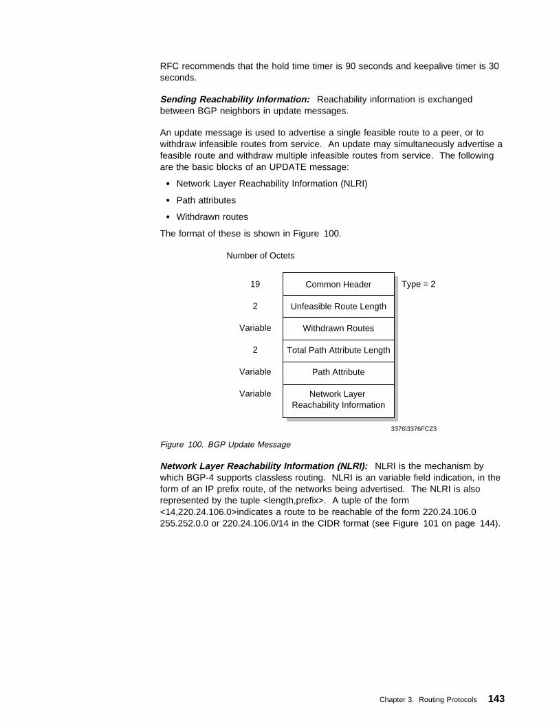
RFC recommends that the hold time timer is 90 seconds and keepalive timer is 30seconds.
Sending Reachability Information: Reachability information is exchangedbetween BGP neighbors in update messages.
An update message is used to advertise a single feasible route to a peer, or towithdraw infeasible routes from service. An update may simultaneously advertise afeasible route and withdraw multiple infeasible routes from service. The followingare the basic blocks of an UPDATE message:
� Network Layer Reachability Information (NLRI)
� Path attributes
� Withdrawn routes
The format of these is shown in Figure 100.
Number of Octets
19
2
Variable
2
Variable
Variable
Common Header
Unfeasible Route Length
Withdrawn Routes
Total Path Attribute Length
Path Attribute
Network Layer Reachability Information
Type = 2
3376\3376FCZ3
Figure 100. BGP Update Message
Network Layer Reachability Information (NLRI): NLRI is the mechanism bywhich BGP-4 supports classless routing. NLRI is an variable field indication, in theform of an IP prefix route, of the networks being advertised. The NLRI is alsorepresented by the tuple <length,prefix>. A tuple of the form<14,220.24.106.0>indicates a route to be reachable of the form 220.24.106.0255.252.0.0 or 220.24.106.0/14 in the CIDR format (see Figure 101 on page 144).
Chapter 3. Routing Protocols 143

AS1
ReachabilityInformation
path 1path 2path 3path4
ReachabilityInformation
path 1path 2path 3path 4
AS2
3376\3376FCZC
OSPF/RIPBGP Speaker
OSPF/RIP
OSPF/RIP
OSPF/RIP
OSPF/RIP
OSPF/RIPBGP Speaker
path1, path 2
path3, path 4
Figure 101. BGP Exchanging NLRI
Path Attributes: Each path attribute consists of a triple set of values: attributeflag, attribute type and attribute value. Three of the attribute flags provideinformation about the status of the attribute types, and may be optional orwell-known, transitive or non-transitive and partial or complete.
Attribute flags must be read in conjunction with their associated attribute types.There are seven attribute types that together define an advertised route:
� Origin, which is a well-known mandatory attribute (type code 1), and definesthe origin of the route as an IGP, an EGP or INCOMPLETE (for example astatic route).
� AS path is a well-known mandatory attribute (type code 2), and defines the ASswhich must be crossed to reach the network being advertised. It is a sequenceof AS numbers a route has traversed to reach a destination. The AS thatoriginates the route adds its own AS number when sending the route to itsexternal BGP peer. Each AS that receives the route and passes it on to otherBGP peer will prepend its own AS number as the last element of the sequence.
� Next hop is a well-known mandatory attribute (type code 3), and defines the IPaddress of the ASBR that is next hop on the path to the listed destnation(s).
� Multi_exit_disc which is an optional non-transitive attribute (type code 4), usedby a BGP speaker's decision process to discriminate among multiple exit pointsto a neighboring autonomous system.
� Local_pref which is a well-known discretionary attribute (type code 5), and usedby a BGP speaker to inform other BGP speakers in its own autonomoussystem of the originating speaker's degree of preference for an advertisedroute.
� Atomic_aggregate, which is a well-known discretionary attribute (type code 6),and used by a BGP speaker to inform other BGP speakers that the local
144 TCP/IP Tutorial and Technical Overview

system selected a less specific route without selecting a more specific routewhich is included in it.
� Aggregator, which is an optional transitive attribute (type code 7), and indicatesthe last AS number that formed the aggregate route, followed by the IP addressof the BGP speaker that formed the aggregate route.
The format of BGP path attributes is shown in Figure 102.
Number of Octets
1
1
1 or 2
Variable
Attribute Type
Attribute Length
Attribute Value
O = OptionalT = TransitiveP = PartialEL = Extended Length
3376\3376FCZ4
ReservedO T P EL
Figure 102. BGP Path Attributes
Withdrawn Routes: An infeasible route length indicates the total length of thewithdrawn routes field in octets. A value of it equaling 0 indicates that no routesare being withdrawn from service, and that the Withdrawn Routes field is notpresent in this update message.
Withdrawn routes is a variable length field. Updates that are not feasible or thatare no longer in service and need to be withdrawn from BGP routing table. Thewithdrawn routes have the same formats as the NLRI. Withdrawn routes are alsorepresented by the tuple <length,prefix>. A tuple of the form<15,220.24.106.0>indicates a route to be withdrawn of the form 220.24.106.0255.254.0.0 or 220.24.106.0/15 in the CIDR format (see Figure 103 on page 146).
Chapter 3. Routing Protocols 145

AS1
ReachabilityInformation
path 2path 3path 4
ReachabilityInformation
path 2path 3path 4
AS2
3376\3376FCZW
OSPF/RIPBGP Speaker
OSPF/RIP
OSPF/RIP
OSPF/RIP
OSPF/RIP
OSPF/RIPBGP Speaker
path1
Trouble
Figure 103. BGP Exchanging Withdraw Routes
Notifying Errors: Notification messages are sent to a neighbor router when errorconditions are detected. The BGP transport connection is closed immediately aftera notification message has been sent.
Notification messages consist of an error code and an error subcode, which furtherqualifies the main error. The format of notification messages is shown inFigure 104.
Number of Octets
19
1
1
Variable
Common Header
Error Code
Error Subcode
Data
Type = 3
3376\3376FCZ5
Figure 104. BGP Notification Message
Error codes that are provided by BGP are as follows:
� Message Header Error
� Open Message Error
� Update Message Error
� Hold Timer Expired
� Finite State Machine Error
� Cease
146 TCP/IP Tutorial and Technical Overview
A data field is included in the notification message to provide additional diagnosticinformation.
3.5 ReferencesFor more information on IP routing protocols, please see the following RFCs:
� RFC 904 — Exterior Gateway Protocol Formal Specification
� RFC 1058 — Routing Information Protocol
� RFC 1245 — OSPF Protocol Analysis
� RFC 1246 — Experience with the OSPF Protocol
� RFC 1721 — RIP Version 2 Protocol Analysis
� RFC 1722 — RIP Version 2 Protocol Applicability Statement
� RFC 1723 — RIP Version 2 – Carrying Additional Information
� RFC 1724 — RIP Version 2 MIB Extension
� RFC 1771 — A Border Gateway Protocol 4 (BGP-4)
� RFC 1772 — Application of the Border Gateway Protocol in the Internet
� RFC 1812 — Requirements for IP Version 4 Routers
� RFC 1850 — OSPF Version 2: Management Information Base
� RFC 2080 — RIPng for IPv6
� RFC 2328 — OSPF Version 2
Chapter 3. Routing Protocols 147

148 TCP/IP Tutorial and Technical Overview

Chapter 4. Application Protocols
The highest level protocols are called application protocols. They communicatewith applications on other hosts and are the user-visible interface to the TCP/IPprotocol suite.
4.1 Characteristics of ApplicationsAll of the higher level protocols have some characteristics in common:
� They can be user-written applications or applications standardized and shippedwith the TCP/IP product. Indeed, the TCP/IP protocol suite includes applicationprotocols such as:
– TELNET for interactive terminal access to remote hosts.
– FTP (file transfer protocol) for high-speed disk-to-disk file transfers.
– SMTP (simple mail transfer protocol) as an Internet mailing system.
These are the most widely implemented application protocols, but a lot ofothers exist. Each particular TCP/IP implementation will include a more or lessrestricted set of application protocols.
� They use either UDP or TCP as a transport mechanism. Remember that UDP(see 2.7, “User Datagram Protocol (UDP)” on page 75) is unreliable and offersno flow-control, so in this case the application has to provide its own errorrecovery and flow-control routines. It is often easier to build applications on topof TCP (see 2.8, “Transmission Control Protocol (TCP)” on page 78), a reliable,connection-oriented protocol. Most application protocols will use TCP, butthere are applications built on UDP to provide better performance throughreduced protocol overhead.
� Most of them use the client/server model of interaction.
4.1.1 Client/Server ModelTCP is a peer-to-peer, connection-oriented protocol. There are no master/slaverelations. The applications, however, use a client/server model for communications.
A server is an application that offers a service to users; a client is a requester of aservice. An application consists of both a server and a client part, which can runon the same or on different systems.
Users usually invoke the client part of the application, which builds a request for aparticular service and sends it to the server part of the application using TCP/IP asa transport vehicle.
The server is a program that receives a request, performs the required service andsends back the results in a reply. A server can usually deal with multiple requests(multiple clients) at the same time.
Copyright IBM Corp. 1989, 1998 149

ClientA
TCP/IP
ClientB
TCP/IP
Server
TCP/IP
.....
Internet Network
3376a\3376F1D4
Figure 105. The Client/Server Model of Applications
Some servers wait for requests at a well-known port (see 2.6, “Ports and Sockets”on page 73) so that their clients know to which IP socket they must direct theirrequests. The client uses an arbitrary port for its communication. Clients that wishto communicate with a server that does not use a well-known port must haveanother mechanism for learning to which port they must address their requests.This mechanism might employ a registration service such as Portmap, which usesa well-known port.
The next sections discuss the most widely used application protocols.
4.2 Domain Name System (DNS)The Domain Name System is a standard protocol with STD number 13. Its statusis recommended. It is described in RFC 1034 and RFC 1035. This sectionexplains the implementation of the Domain Name System, and the implementationof name servers.
The early internet configurations required users to use only numeric IP addresses.Very quickly, this evolved to the use of symbolic host names. For example, insteadof typing TELNET 128.12.7.14 one could type TELNET eduvm9, and eduvm9 is thentranslated in some way to the IP address 128.12.7.14. This introduces the problemof maintaining the mappings between IP addresses and high-level machine namesin a coordinated and centralized way.
Initially, host names to address mappings were maintained by the NetworkInformation Center (NIC) in a single file (HOSTS.TXT), which was fetched by allhosts using FTP. This is called a flat namespace.
Due to the explosive growth in the number of hosts, this mechanism became toocumbersome (consider the work involved in the addition of just one host to theInternet) and was replaced by a new concept: Domain Name System. Hosts cancontinue to use a local flat namespace (the HOSTS.LOCAL file) instead of or inaddition to the Domain Name System, but outside small networks, the DomainName System is practically essential. The Domain Name System allows a programrunning on a host to perform the mapping of a high-level symbolic name to an IPaddress for any other host without the need for every host to have a completedatabase of host names.
150 TCP/IP Tutorial and Technical Overview

4.2.1 The Hierarchical NamespaceConsider the internal structure of a large organization. As the chief executivecannot do everything, the organization will probably be partitioned into divisions,each of them having autonomy within certain limits. Specifically, the executive incharge of a division has authority to make direct decisions, without permission fromhis or her chief executive.
Domain names are formed in a similar way, and will often reflect the hierarchicaldelegation of authority used to assign them. For example, consider the name:
small.itso.raleigh.ibm.com
Here, itso.raleigh.ibm.com is the lowest level domain name, a subdomain ofraleigh.ibm.com, which again is a subdomain of ibm.com, a subdomain of com. Wecan also represent this naming concept by a hierarchical tree (see Figure 106).
(root)
mil
Pentagon DARPA
edu
mit yale
gov
NSF Whitehouse
com
ibm
raleigh
itso
watson
Figure 106. DNS - Hierarchical Namespace
The complete structure is explained in the following sections.
4.2.2 Fully Qualified Domain Names (FQDNs)When using the Domain Name System, it is common to work with only a part of thedomain hierarchy, for example, the ral.ibm.com domain. The Domain NameSystem provides a simple method of minimizing the typing necessary in thiscircumstance. If a domain name ends in a dot (for example,wtscpok.itsc.pok.ibm.com.), it is assumed to be complete. This is termed a fullyqualified domain ame (FQDN) or an absolute domain name. However, if it doesnot end in a dot (for example, wtscpok.itsc), it is incomplete and the DNS resolver(see below) may complete this, for example, by appending a suffix such as.pok.ibm.com to the domain name. The rules for doing this areimplementation-dependent and locally configurable.
Chapter 4. Application Protocols 151

4.2.3 Generic DomainsThe three-character top-level names are called the generic domains or theorganizational domains. Table 4 shows some of the top-level domains of today'sInternet domain namespace.
Since the Internet began in the United States, the organization of the hierarchicalnamespace initially had only U.S. organizations at the top of the hierarchy, and it isstill largely true that the generic part of the namespace contains US organizations.However, only the .gov and .mil domains are restricted to the US.
At the time of writing, the U.S. Department Of Commerce - NationalTelecommunications and Information Administration is looking for a differentorganization for .us domains. As a result of this, it has been decided to change thestatus of the Internet Assigned Numbers Authority (IANA), which will no longer befunded and run by the U.S. Government. A new non-profit organization with aninternational Board of Directors will be funded by domain registries instead. On theother hand, there are some other organizations that have already begun to registernew top-level domains. For current information see the IANA Web site at the URLbelow:
http://www.iana.org
Table 4. DNS - Some Top-Level Internet Domains
Domain Name Meaning
com Commercial organizations
edu Educational institutions
gov Government institutions
int International organizations
mil U.S. Military
net Major network support centers
org Non-profit organizations
country code ISO standard 2-letter identifier for country-specificdomains
4.2.4 Country DomainsThere are also top-level domains named for the each of the ISO 3166 international2-character country codes (from ae for the United Arab Emirates to zw forZimbabwe). These are called the country domains or the geographical domains.Many countries have their own second-level domains underneath which parallel thegeneric top-level domains. For example, in the United Kingdom, the domainsequivalent to the generic domains .com and .edu are .co.uk and .ac.uk (ac is anabbreviation for academic). There is a .us top-level domain, which is organizedgeographically by state (for example, .ny.us refers to the state of New York). SeeRFC 1480 for a detailed description of the .us domain.
152 TCP/IP Tutorial and Technical Overview
4.2.5 Mapping Domain Names to IP AddressesThe mapping of names to addresses consists of independent, cooperative systemscalled name servers. A name server is a server program that holds a master or acopy of a name-to-address mapping database, or otherwise points to a server thatdoes, and that answers requests from the client software, called a name resolver.
Conceptually, all Internet domain servers are arranged in a tree structure thatcorresponds to the naming hierarchy in Figure 106 on page 151. Each leafrepresents a name server that handles names for a single subdomain. Links in theconceptual tree do not indicate physical connections. Instead, they show whichother name server a given server can contact.
4.2.6 Mapping IP Addresses to Domain Names — Pointer QueriesThe Domain Name System provides for a mapping of symbolic names to IPaddresses and vice versa. While it is a simple matter in principle to search thedatabase for an IP address given its symbolic name because of the hierarchicalstructure, the reverse process cannot follow the hierarchy. Therefore, there isanother namespace for the reverse mapping. It is found in the domain in-addr.arpa(arpa because the Internet was originally the ARPAnet).
Because IP addresses are normally written in dotted decimal format, there is onelayer of domains for each hierarchy. However, because domain names have theleast-significant parts of the name first but dotted decimal format has the mostsignificant bytes first, the dotted decimal address is shown in reverse order. Forexample, the domain in the domain name system corresponding to the IP address129.34.139.30 is 30.139.34.129.in-addr.arpa. Given an IP address, the DomainName System can be used to find the matching host name. A domain name queryto find the host names associated with an IP address is called a pointer query.
4.2.7 The Distributed Name SpaceThe Domain Name System uses the concept of a distributed name space.Symbolic names are grouped into zones of authority, or more commonly zones. Ineach of these zones, one or more hosts has the task of maintaining a database ofsymbolic names and IP addresses and providing a server function for clients whowish to translate between symbolic names and IP addresses. These local nameservers are then (through the internetwork on which they are connected) logicallyinterconnected into a hierarchical tree of domains. Each zone contains a part or asubtree of the hierarchical tree and the names within the zone are administeredindependently of names in other zones. Authority over zones is vested in the nameservers.
Normally, the name servers that have authority for a zone will have domain namesbelonging to that zone, but this is not required. Where a domain contains a subtreethat falls in a different zone, the name server(s) with authority over the superiordomain are said to delegate authority to the name server(s) with authority over thesubdomain. Name servers can also delegate authority to themselves; in this case,the domain name space is still divided into zones moving down the domain nametree, but authority for two zones is held by the same server. The division of thedomain name space into zones is accomplished using resource records stored inthe Domain Name System.
Chapter 4. Application Protocols 153

4.2.8 Domain Name ResolutionThe domain name resolution process can be summarized in the following steps:
1. A user program issues a request such as the gethostbyname() sockets call.(This particular call is used to ask for the IP address of a host by passing thehostname.)
2. The resolver formulates a query to the name server. (Full resolvers have alocal name cache to consult first, stub resolvers do not.)
3. The name server checks to see if the answer is in its local authoritativedatabase or cache, and if so, returns it to the client. Otherwise, it will queryother available name server(s), starting down from the root of the DNS tree oras high up the tree as possible.
4. The user program will finally be given a corresponding IP address (or hostname, depending on the query) or an error if the query could not be answered.Normally, the program will not be given a list of all the name servers that havebeen consulted to process the query.
The query/reply messages are transported by either UDP or TCP.
Domain name resolution is a client/server process. The client function (called theresolver or name resolver) is transparent to the user and is called by an applicationto resolve symbolic high-level names into real IP addresses or vice versa. Thename server (also called a domain name server) is a server application providingthe translation between high-level machine names and the IP addresses.
4.2.8.1 Domain Name Full ResolverFigure 107 shows a program called a full resolver, which is a program distinct fromthe user program, which forwards all queries to a name server for processing.Responses are cached by the name server for future use, and often by the nameserver.
FullResolver
userresponse
userquery query
response
Cache
UserProgram
NameServer
Cache
Database
r q
ForeignNameServer
3376a\3376FDO3
Figure 107. DNS - Using a Full Resolver for Domain Name Resolution
154 TCP/IP Tutorial and Technical Overview

4.2.8.2 Domain Name Stub ResolverFigure 108 shows a stub resolver, a routine linked with the user program, whichforwards the queries to a name server for processing. Responses are cached bythe name server but not usually by the resolver although this isimplementation-dependent. On UNIX, the stub resolver is implemented by twolibrary routines: gethostbyname() and gethostbyaddr() for converting host names toIP addresses and vice versa. Other platforms have the same or equivalentroutines. Stub resolvers are much more common than full resolvers.
query
response
Cache
NameServer
Database
r q
ForeignNameServer
3376a\3376FDO9
StubResolver
UserProgram
Figure 108. DNS - Using a Stub Resolver for Domain Name Resolution
4.2.8.3 Domain Name Resolver OperationDomain name queries can be one of two types: recursive or iterative (also termednon-recursive). A flag bit in the domain name query specifies whether the clientdesires a recursive query and a flag bit in the response specifies whether theserver supports recursive queries. The difference between a recursive and aniterative query arises when the server receives a request for which it cannot supplya complete answer by itself. A recursive query requests that the server shouldissue a query itself to determine the requested information and return the completeanswer to the client. An iterative query means that the name server should returnwhat information it has available and also a list of additional servers for the client tocontact to complete the query.
Domain name responses can be one of two types: authoritative andnon-authoritative. A flag bit in the response indicates which type a response is.When a name server receives a query for a domain in a zone over which it hasauthority, it returns all of the requested information in a response with theauthoritative answer flag set. When it receives a query for a domain over which itdoes not have authority, its actions depend upon the setting of the recursiondesired flag in the query.
� If the recursion desired flag is set and the server supports recursive queries, itwill direct its query to another name server. This will either be a name serverwith authority for the domain given in the query, or it will be one of the rootname servers. If the second server does not return an authoritative answer (for
Chapter 4. Application Protocols 155

example, if it has delegated authority to another server), the process isrepeated.
When a server (or a full resolver program) receives a response, it will cache itto improve the performance of repeat queries. The cache entry is stored for amaximum length of time specified by the originator in a 32-bit time-to-live (TTL)field contained in the response. 172,800 seconds (two days) is a typical TTLvalue.
� If the recursion desired flag is not set or the server does not support recursivequeries, it will return whatever information it has in its cache and also a list ofadditional name servers to be contacted for authoritative information.
4.2.8.4 Domain Name Server OperationEach name server has authority for zero or more zones. There are three types ofname servers:
PrimaryA primary name server loads a zone's information from disk, and hasauthority over the zone.
SecondaryA secondary name server has authority for a zone, but obtains its zoneinformation from a primary server using a process called zone transfer. Toremain synchronized, the secondary name servers query the primary on aregular basis (typically every three hours) and re-execute the zone transfer ifthe primary has been updated.
A name server can operate as a primary or a secondary name server for multipledomains, or a primary for some domains and as a secondary for others. A primaryor secondary name server performs all of the functions of a caching only nameserver.
Caching-onlyA name server that does not have authority for any zone is called acaching-only name server. A caching-only name server obtains all of its datafrom primary or secondary name servers as required. It requires at least oneNS record to point to a name server from which it can initially obtaininformation.
When a domain is registered with the root and a separate zone of authorityestablished, the following rules apply:
� The domain must be registered with the root administrator.
� There must be an identified administrator for the domain.
� There must be at least two name servers with authority for the zone that areaccessible from outside and inside the domain to ensure no single point offailure.
It is also recommended that name servers that delegate authority also apply theserules, since the delegating name servers are responsible for the behavior of nameservers under their authority.
156 TCP/IP Tutorial and Technical Overview

4.2.9 Domain Name System Resource RecordsThe Domain Name System's distributed database is composed of resource records(RRs) which are divided into classes for different kinds of networks. We onlydiscuss the Internet class of records. Resource records provide a mappingbetween domain names and network objects. The most common network objectsare the addresses of Internet hosts, but the Domain Name System is designed toaccommodate a wide range of different objects.
The start of a zone, marked by a Start of Authority (SOA) record, is closer to theroot of the tree than the end. A Name Server Record (NS) marks the end of a zonestarted by an SOA record and points to a name server having authority for the nextzone. At the root, there can be no higher name servers to delegate authority.Authority for the zone encompassing the root of the name space is vested in a setof root name servers.8
As a result of this scheme:
� Rather than having a central server for the database, the work that is involvedin maintaining this database is off-loaded to hosts throughout the name space.
� Authority for creating and changing symbolic host names and responsibility formaintaining a database for them is delegated to the organization owning thezone (within the name space) containing those host names.
� From the user's standpoint, there is a single database that deals with theseaddress resolutions. The user may be aware that the database is distributed,but generally need not be concerned about this.
Note: Although domains within the namespace will frequently map in a logicalfashion to networks and subnets within the IP addressing scheme, this isnot a requirement of the Domain Name System. Consider a router betweentwo subnets. It has two IP addresses, one for each network adapter, but itwould not normally have two symbolic names.
The general format of a resource record is:
Name TTL Class Type Rdata
Figure 109. DNS - General Resource Record Format
where:
nameIs the domain name to be defined. The Domain Name System is verygeneral in its rules for the composition of domain names. However, itrecommends a syntax for domain names which will minimize the likelihood ofapplications that use a DNS resolver (that is, nearly all TCP/IP applications)from misinterpreting a domain name. A domain name adhering to thisrecommended syntax will consist of a series of labels consisting ofalphanumeric characters or hyphens, each label having a length of between 1and 63 characters, starting with an alphabetic character. Each pair of labels
8 At the time of writing there were thirteen root servers. The current list is available by anonymous FTP from ftp.rs.internic.net in thefile netinfo/root-servers.txt.
Chapter 4. Application Protocols 157

is separated by a dot (period) in human readable form, but not in the formused within DNS messages. Domain names are not case-sensitive.
ttlIs the time-to-live (TTL) time in seconds that this resource record will be validin a name server cache. This is stored in the DNS as an unsigned 32-bitvalue. 86400 (one day) is a typical value for records pointing to IPaddresses.
classIdentifies the protocol family. The only commonly used value is:
IN The Internet system
typeIdentifies the type of the resource in this resource record.
The different types are described in detail in RFCs 1034, 1035 and 1706.Each type has a name and a value. Commonly used types include:
RdataThe value depends on the type, for example:
A A 32-bit IP address (if the class is IN)
CNAME A domain name
MX A 16-bit preference value (low values being preferred) followed bya domain name
NS A host name
PTR A domain name
Please refer to 7.3, “Dynamic Domain Name System” on page 414 for additionalresource record types.
Type Value MeaningA 1 A host address.CNAME 5 Canonical name of an alias; specifies an alias name for a
host.HINFO 13 The CPU and OS used by the host; this is only a comment
field.MX 15 A mail exchange for the domain; specifies a domain name
for a mailbox. This is used by SMTP (see 4.7.2, “SMTPand the Domain Name System” on page 191 for moreinformation).
NS 2 The authoritative name server for a domain.PTR 12 A pointer to another part of the domain name space.SOA 6 The start of a zone of authority in the domain name space.WKS 11 Well-known services; specifies that certain services (for
instance SMTP) are expected to be always active on thishost.
158 TCP/IP Tutorial and Technical Overview

4.2.10 Domain Name System MessagesAll messages in the Domain Name System protocol use a single format. Thisformat is shown in Figure 110. This frame is sent by the resolver to the nameserver. Only the header and the question section are used to form the query.Replies and/or forwarding of the query use the same frame, but with more sectionsfilled in (the answer/authority/additional sections).
Identification Parameters
3376\3376FDO5
0 8 16 31
QDcount ANcount
NScount ARcount
/ / / /Question Section
/ / / /Answer Section
/ / / /Authority Section
/ / / /Additional Information Section
Figure 110. DNS - DNS Message Format
4.2.10.1 Header FormatThe header section is always present and has a fixed length of 12 bytes. Theother sections are of variable length.
ID A 16-bit identifier assigned by the program. This identifier is copied inthe corresponding reply from the name server and can be used fordifferentiation of responses when multiple queries are outstanding at thesame time.
ParametersA 16-bit value in the following format:
0 1 2 3 4 5 6 7 8 9 10 11 12 13 14 15
Op code AA TC RD RA zero RcodeQR
3376a\3376FDO4
Figure 111. Header Format: Parameters
QR Flag identifying a query (0) or a response(1)
Op code4-bit field specifying the kind of query:
0 standard query (QUERY)
Chapter 4. Application Protocols 159
1 inverse query (IQUERY)2 server status request (STATUS)Other values are reserved for future use
AA Authoritative answer flag. If set in a response, this flag specifiesthat the responding name server is an authority for the domainname sent in the query.
TC Truncation flag. Set if message was longer than permitted on thephysical channel.
RD Recursion desired flag. This bit signals to the name server thatrecursive resolution is asked for. The bit is copied to the response.
RA Recursion available flag. Indicates whether the name serversupports recursive resolution.
zero3 bits reserved for future use. Must be zero.
Rcode4-bit response code. Possible values are:
0 No error.1 Format error. The server was unable to interpret the message.2 Server failure. The message was not processed because of a
problem with the server.3 Name error. The domain name in the query does not exist. This
is only valid if the AA bit is set in the response.4 Not implemented. The requested type of query is not
implemented by name server.5 Refused. The server refuses to respond for policy reasons.Other values are reserved for future use.
QDcount An unsigned 16-bit integer specifying the number of entries in thequestion section.
ANcount An unsigned 16-bit integer specifying the number of RRs in the answersection.
NScount An unsigned 16-bit integer specifying the number of name server RRs inthe authority section.
ARcount An unsigned 16-bit integer specifying the number of RRs in theadditional records section.
4.2.10.2 Question SectionThe next section contains the queries for the name server. It contains QDcount(usually 1) entries, each in the format shown in Figure 112.
160 TCP/IP Tutorial and Technical Overview

3376\3376FDO6
0 8 16 24 31
length label 1. . .
/ / / /
00. . .label n
type class
Figure 112. DNS - Question Format. All of the fields are byte-aligned. The alignment ofthe Type field on a 4-byte boundary is for example purposes and is not required by theformat.
length A single byte giving the length of the next label.
label One element of the domain name characters (for example ibm fromral.ibm.com). The domain name referred to by the question is stored asa series of these variable length labels, each preceded by a 1-bytelength.
00 X'00' indicates the end of the domain name and represents the nulllabel of the root domain.
Type 2 bytes specifying the type of query. It can have any value from theType field in a resource record.
Class 2 bytes specifying the class of the query. For Internet queries, this willbe IN.
For example, the domain name raleigh.ibm.com would be encoded with thefollowing fields:
X'ð7'
"raleigh"
X'ð3'
"ibm"
X'ð3'
"com"
X'ðð'
Thus the entry in the question section for raleigh.ibm.com would require 21 bytes:17 to store the domain name and 2 each for the Qtype and Qclass fields.
4.2.10.3 Answer, Authority and Additional Resource SectionsThese three sections contain a variable number of resource records. The numberis specified in the corresponding field of the header. The resource records are inthe format shown in Figure 113.
Chapter 4. Application Protocols 161

/ / / /
3376\3376FDO8
0 8 16 24 31
length label . . .
/ / / /
00. . .label
type class
TTL
RDlength
Rdata
Figure 113. DNS - Answer Record Entry Format. All of the fields are byte-aligned. Thealignment of the Type field on a 4-byte boundary is for example purposes and is not requiredby the format.
Where the fields before the TTL field have the same meanings as for a questionentry and:
TTL A 32-bit time-to-live value in seconds for the record. This defines howlong it can be regarded as valid.
RDlength A 16-bit length for the Rdata field.
Rdata A variable length string whose interpretation depends on the Type field.
4.2.10.4 Message CompressionIn order to reduce the message size, a compression scheme is used to eliminatethe repetition of domain names in the various RRs. Any duplicate domain name orlist of labels is replaced with a pointer to the previous occurrence. The pointer hasthe form of a 2-byte field:
1 1 offset
� The first 2 bits distinguish the pointer from a normal label, which is restricted toa 63-byte length plus the length byte ahead of it (which has a value of <64).
� The offset field specifies an offset from the start of the message. A zero offsetspecifies the first byte of the ID field in the header.
� If compression is used in an Rdata field of an answer, authority or additionalsection of the message, the preceding RDlength field contains the real lengthafter compression is done.
Please refer to 7.3, “Dynamic Domain Name System” on page 414 for additionalmessage formats.
162 TCP/IP Tutorial and Technical Overview

4.2.11 A Simple ScenarioConsider a stand-alone network (no outside connections), consisting of two physicalnetworks: one has an internet network address 129.112, the other has a networkaddress 194.33.7, interconnected by an IP gateway (VM2).
129.112
MVS3VM9
PC7
3376a\3376FDOA
PC7
VM2 VM2 VM2
194.33.7
Figure 114. DNS - A Simple Configuration. Two networks connected through an IPgateway.
Let us assign the name server function to VM1. Remember that the domainhierarchical tree forms a logical tree, completely independent of the physicalconfiguration. In this simple scenario, there is only one level in the domain tree.Let's give this configuration the domain name test.example.
The zone data for the name server will then be as shown in Figure 115.
Chapter 4. Application Protocols 163

;note: an SOA record has no TTL field
;
$origin test.example. ;note 1
;
@ IN SOA VM1.test.example. ADM.VM1.test.example.
(87ð611 ;serial number for data
18ðð ;secondary refreshes every 3ð mn
3ðð ;secondary reties every 5 mn
6ð48ðð ;data expire after 1 week
864ðð) ;minimum TTL for data is 1 week
;
@ 99999 IN NS VM1.test.example. ;note 2
;
VM1 99999 IN A 129.112.1.1 ;note 3
99999 IN WKS 129.112.1.1 TCP (SMTP ;note 4
FTP
TELNET
NAMESRV)
;
RT1 99999 IN A 129.112.1.2
IN HINFO IBM RT/PC-AIX ;note 5
RT2 99999 IN A 129.112.1.3
IN HINFO IBM RT/PC-AIX
PC1 99999 IN A 129.112.1.11
PC2 99999 IN A 194.33.7.2
PC3 99999 IN A 194.33.7.3
;
;VM2 is an IP gateway and has 2 different IP addresses
;
VM2 99999 IN A 129.112.1.4
99999 IN A 194.33.7.1
99999 IN WKS 129.112.1.4 TCP (SMTP FTP)
IN HINFO IBM-3ð9ð-VM/CMS
;
4.1.112.129.in-addr.arpa. IN PTR VM2 ;note 6
;
;Some mailboxes
;
central 1ð IN MX VM2.test.example. ;note 7 and 8
;
;a second definition for the same mailbox, in case VM2 is down
;
central 2ð IN MX VM1.test.example.
waste 1ð IN MX VM2.test.example.
Figure 115. DNS - Zone Data for the Name Server
Notes:
1 The $origin statement sets the @ variable to the zone name(test.example.). Domain names that do not end with a period are suffixedwith the zone name. Fully qualified domain names (those ending with aperiod) are unaffected by the zone name.
2 Defines the name server for this zone.
3 Defines the Internet address of the name server for this zone.
4 Specifies well-known services for this host. These are expected to alwaysbe available.
5 Gives information about the host.
164 TCP/IP Tutorial and Technical Overview

6 Used for inverse mapping queries (see 4.2.6, “Mapping IP Addresses toDomain Names — Pointer Queries” on page 153).
7 Will allow mail to be addressed to [email protected].
8 See 4.7.2, “SMTP and the Domain Name System” on page 191 for theuse of these definitions.
4.2.12 Extended ScenarioConsider the case where a connection is made to a third network (129.113), whichhas an existing name server with authority for that zone.
129.113
MVS3VM9
PC7
194.33.7
194.33.7
VM2
. . .
. . .3376a\3376FDOB
Figure 116. DNS - Extended Configuration. A third network is connected to the existingconfiguration.
Let us suppose that the domain name of the other network is tt.ibm.com and thatits name server is located in VM9.
All we have to do is add the address of this name server to our own name serverdatabase, and to reference the other network by its own name server. The followingtwo lines are all that is needed to do that:
tt.ibm.com. 99999 IN NS VM9.tt.ibm.com.
VM9.tt.ibm.com. 99999 IN A 129.113.1.9
This simply indicates that VM9 is the authority for the new network, and that allqueries for that network will be directed to that name server.
4.2.13 TransportDomain Name System messages are transmitted either as datagrams (UDP) or viastream connection (TCP).
UDP usage: Server port 53 (decimal).
Messages carried by UDP are restricted to 512 bytes. Longer messages aretruncated and the TC bit is set in the header. Since UDP frames can be lost, aretransmission strategy is required.
TCP usage: Server port 53 (decimal).
In this case, the message is preceded by a 2-byte field indicating the total messageframe length.
STD 3 — Host Requirements requires that:
Chapter 4. Application Protocols 165
� A Domain Name System resolver or server that is sending a non-zone-transferquery must send a UDP query first. If the answer section of the response istruncated and if the requester supports TCP, it should try the query again usingTCP. UDP is preferred over TCP for queries because UDP queries have muchlower overhead, and the use of UDP is essential for a heavily loaded server.Truncation of messages is rarely a problem given the current contents of theDomain Name System database, since typically 15 response records can beaccommodated in the datagram, but this may change as new record types areadded to the Domain Name System.
� TCP must be used for zone transfer activities because the 512-byte limit for aUDP datagram will always be inadequate for a zone transfer.
� Name servers must support both types of transport.
4.2.13.1 Dynamic DNS (DDNS)The Dynamic Domain Name System (DDNS) is a protocol that defines extensionsto the Domain Name System to enable DNS servers to accept requests to add,update and delete entries in the DNS database dynamically. Because DDNS offersa functional superset to existing DNS servers, a DDNS server can serve both staticand dynamic domains at the same time, a welcome feature for migration andoverall DNS design.
DDNS is currently available in a non-secure and a secure flavor, defined in RFC2136 and RFC 2137, respectively. Rather than allowing any host to update itsDNS records, the secure version of DDNS uses public key security and digitalsignatures to authenticate update requests from DDNS hosts. IBM, for instance,has fully implemented secure DDNS on its OS/2 Warp Server, AIX, OS/390 andAS/400 platforms as well as on Windows NT.
Without client authentication, another host could impersonate an unsuspecting hostby remapping the address entry for the unsuspecting host to that of its own. Oncethe remapping occurs, important data, such as logon passwords and mail intendedfor the host would unfortunately be sent to the impersonating host instead.
Please see also 7.3, “Dynamic Domain Name System” on page 414 for moreinformation on how DDNS works together with DHCP to perform seamless updatesof reverse DNS mapping entries and see 6.4, “DNS in IPv6” on page 386 for moreinformation about DNS with IPv6.
4.2.14 DNS ApplicationsThree common utilities for querying name servers are provided with many DNSimplementations:
host Obtains an IP address associated with a host name or a host nameassociated with an IP address.
nslookup Allows you to locate information about network nodes, examine thecontents of a name server database and establish the accessibility ofname servers.
dig Allows you to exercise name servers, gather large volumes of domainname information and execute simple domain name queries. DIGstands for Domain Internet Groper.
166 TCP/IP Tutorial and Technical Overview

4.2.15 ReferencesThe following RFCs define the Domain Name System standard and the informationkept in the system:
� RFC 1032 — Domain Administrator's Guide� RFC 1033 — Domain Administrator Operations Guide� RFC 1034 — Domain Names – Concepts and Facilities� RFC 1035 — Domain Names – Implementation and Specification� RFC 1101 — DNS Encoding of Networks Names and Other Types� RFC 1183 — New DNS RR Definitions� RFC 1480 — The US Domain� RFC 1591 — Domain Name System Structure and Delegation� RFC 1706 — DNS NSAP Resource Records
4.3 TELNETTELNET is a standard protocol with STD number 8. Its status is recommended. Itis described in RFC 854 TELNET Protocol Specifications and RFC 855 TELNETOption Specifications.
The TELNET protocol provides a standardized interface, through which a programon one host (the TELNET client) can access the resources of another host (theTELNET server) as though the client were a local terminal connected to the server.
For example, a user on a workstation on a LAN may connect to a host attached tothe LAN as though the workstation were a terminal attached directly to the host. Ofcourse, TELNET can be used across WANs as well as LANs.
RemoteLogin
Host LocalLogin
LAN
TerminalWorkstation
3376a\3376FDOC
Figure 117. TELNET - Remote Login Using TELNET
Most TELNET implementations do not provide you with graphics capabilities.
4.3.1 TELNET OperationTELNET protocol is based on three ideas:
1. The Network Virtual Terminal (NVT) concept. An NVT is an imaginary devicehaving a basic structure common to a wide range of real terminals. Each hostmaps its own terminal characteristics to those of an NVT, and assumes thatevery other host will do the same.
2. A symmetric view of terminals and processes.
3. Negotiation of terminal options. The principle of negotiated options is used bythe TELNET protocol, because many hosts wish to provide additional services,
Chapter 4. Application Protocols 167

beyond those available with the NVT. Various options may be negotiated.Server and client use a set of conventions to establish the operationalcharacteristics of their TELNET connection via the “DO, DON'T, WILL, WON'T”mechanism discussed later in this chapter.
The two hosts begin by verifying their mutual understanding. Once this initialnegotiation is complete, they are capable of working on the minimum levelimplemented by the NVT. After this minimum understanding is achieved, they cannegotiate additional options to extend the capabilities of the NVT to reflect moreaccurately the capabilities of the real hardware in use. Because of the symmetricmodel used by TELNET, both the host and the client may propose additionaloptions to be used.
Host A
NVT
TELNET
TCP/IP
Operating System
Host B
NVT
TELNET
TCP/IP
Operating System
Negotiations
3376a\3376FDOD
Figure 118. TELNET - The Symmetric TELNET Model
4.3.1.1 Network Virtual TerminalThe NVT has a printer (or display) and a keyboard. The keyboard producesoutgoing data, which is sent over the TELNET connection. The printer receives theincoming data. The basic characteristics of an NVT, unless they are modified bymutually agreed options are:
� The data representation is 7-bit ASCII transmitted in 8-bit bytes.
� The NVT is a half-duplex device operating in a line-buffered mode.
� The NVT provides a local echo function.
All of these can be negotiated by the two hosts. For example, a local echo ispreferred because of the lower network load and superior performance but there isan option for using a remote echo, although no host is required to use it.
168 TCP/IP Tutorial and Technical Overview

Keyboard
A
LocalEcho
AZ
Printer
Terminal (Client)
Input
RemoteEcho
Output
Host (Server)
3376a\3376FDOE
Figure 119. TELNET - Echo Option
An NVT printer has an unspecified carriage width and page length. It can handleprintable ASCII characters (ASCII code 32 to 126) and understands some ASCIIcontrol characters such as:
Command ASCII ActionNULL (NUL) 0 No Operation.Line Feed (LF) 10 Moves the printer to the next print line, keeping the same
horizontal position.Carriage Return(CR)
13 Moves the printer to the left margin.
BELL (BEL) 7 Produces an audible or visible signal.Back Space (BS) 8 Moves the print head one character position toward the left
margin.Horizontal Tab(HT)
9 Moves the printer to the next horizontal tab stop.
Vertical Tab (VT) 11 Moves the printer to the next vertical tab stop.Form Feed (FF) 12 Moves the printer to the top of the next page, keeping the
same horizontal position.
4.3.1.2 TELNET OptionsThere is an extensive set of TELNET options, and the reader should consult STD 1— Official Internet Protocol Standards for the standardization state and status foreach of them. At the time of writing, the following options were defined:
Table 5 (Page 1 of 2). TELNET Options
Num Name State RFC STD
0 Binary Transmission Standard 856 27
1 Echo Standard 857 28
3 Suppress Go Ahead Standard 858 29
5 Status Standard 859 30
6 Timing Mark Standard 860 31
255 Extended-Options-List Standard 861 32
34 Linemode Draft 1184
2 Reconnection Proposed
4 Approx Message Size Negotiation Proposed
Chapter 4. Application Protocols 169

All of the standard options have a status of recommended and the remainder havea status of elective. There is a historic version of the TELNET Environment Optionwhich is not recommended; it is TELNET option 36 and was defined in RFC 1408.
Table 5 (Page 2 of 2). TELNET Options
Num Name State RFC STD
7 Remote Controlled Trans and Echo Proposed 726
8 Output Line Width Proposed
9 Output Page Size Proposed
10 Output Carriage-Return Disposition Proposed 652
11 Output Horizontal Tabstops Proposed 653
12 Output Horizontal Tab Disposition Proposed 654
13 Output Formfeed Disposition Proposed 655
14 Output Vertical Tabstops Proposed 656
15 Output Vertical Tab Disposition Proposed 657
16 Output Linefeed Disposition Proposed 658
17 Extended ASCII Proposed 698
18 Logout Proposed 727
19 Byte Macro Proposed 735
20 Data Entry Terminal Proposed 1043
21 SUPDUP Proposed 736
22 SUPDUP Output Proposed 749
23 Send Location Proposed 779
24 Terminal Type Proposed 1091
25 End of Record Proposed 885
26 TACACS User Identification Proposed 927
27 Output Marking Proposed 933
28 Terminal Location Number Proposed 946
29 TELNET 3270 Regime Proposed 1041
30 X.3 PAD Proposed 1053
31 Negotiate About Window Size Proposed 1073
32 Terminal Speed Proposed 1079
33 Remote Flow Control Proposed 1372
35 X Display Location Proposed 1096
39 TELNET Environment Option Proposed 1572
40 TN3270 Enhancements Proposed 1647
37 TELNET Authentication Option Experimental 1416
41 Telnet XAUTH Experimental
42 Telnet CHARSET Experimental 2066
43 Telnet Remote Serial Port Experimental
44 Telnet Com Port Control Experimental 2217
170 TCP/IP Tutorial and Technical Overview

Full-Screen Capability: Full-screen TELNET is possible provided the client andserver have compatible full-screen capabilities. For example, VM and MVS providea TN3270-capable server. To use this facility, a TELNET client must supportTN3270.
4.3.1.3 TELNET Command StructureThe communication between client and server is handled with internal commands,which are not accessible by users. All internal TELNET commands consist of 2 or3-byte sequences, depending on the command type.
The Interpret As Command (IAC) character is followed by a command code. If thiscommand deals with option negotiation, the command will have a third byte to showthe code for the referenced option.
InterpretasCommand
Command
Code
OptionNegotiated
byte 1 byte 2 byte 3
Sample:
255 253 24
IACWILL
Terminal Type
3376a\3376FDOF
Figure 120. TELNET - Internal TELNET Command Structure. This command proposesnegotiation about terminal type.
Command name Code CommentsSE 240 End of sub-negotiation parameters.NOP 241 No operation.Data Mark 242 The data stream portion of a synch. This should always be
accompanied by a TCP urgent notification.Break 243 NVT character BRK.Go ahead 249 The GA signal.SB 250 Indicates that what follows is sub-negotiation of the option
indicated by the immediately following code.WILL 251 Shows the desire to use, or confirmation that you are now
using, the option indicated by the code immediatelyfollowing.
WON'T 252 Shows the refusal to use, or to continue to use, the optionindicated by the code immediately following.
DO 253 Requests that the other party uses, or confirms that you areexpecting the other party to use, the option indicated by thecode immediately following.
DON'T 254 Demands that the other party stop using, or confirms thatyou are no longer expecting the other party to use, theoption indicated by the code immediately following.
IAC 255 Interpret As Command. Indicates that what follows is aTELNET command, not data.
Chapter 4. Application Protocols 171

4.3.1.4 Option NegotiationUsing internal commands, TELNET in each host is able to negotiate options. Thestarting base of negotiation is the NVT capability: each host to be connected mustagree to this minimum. Every option can be negotiated by the use of the fourcommand codes WILL, WON'T, DO, DON'T described above.
In addition, some options have sub-options: if both parties agree to the option, theyuse the SB and SE commands to manage the sub-negotiation. Here is a simplifiedexample of how option negotiation works.
The terminal types are defined in STD 2 — Assigned Numbers.
Send Reply Meaning
DO transmit binary WILL transmit binary
DO window size WILL window size Can we negotiate windowsize?
SB Window Size 0 80 0 24SE
Specify window size.
DO terminal type WILL terminal type Can we negotiate terminaltype?
SB terminal typeSE
Send me your terminalcharacteristics.
SB terminal typeIBM-3278-2SE
My terminal is a 3278-2.
DO echo WON'T echo
4.3.1.5 TELNET Basic CommandsThe primary goal of the TELNET protocol is the provision of a standard interface forhosts over a network. To allow the connection to start, the TELNET protocoldefines a standard representation for some functions:
IP Interrupt ProcessAO Abort OutputAYT Are You ThereEC Erase CharacterEL Erase LineSYNCH Synchronize
4.3.2 Terminal Emulation (Telnet 3270)Telnet may be used to make a TCP/IP connection to an SNA host. However, telnet3270 is used to provide 3270 telnet emulation (TN3270). The following differencesbetween traditional telnet and 3270 terminal emulation make it necessary foradditional telnet options specifically for TN3270 to be defined:
� 3270 terminal emulation uses block mode rather than line mode.
� 3270 terminal emulation uses the EBCDIC character set rather than the ASCIIcharacter set.
� 3270 terminal emulation uses special key functions such as ATTN andSYSREQ.
172 TCP/IP Tutorial and Technical Overview

The TN3270 connection over telnet is accomplished by the negotiation of thefollowing three different telnet options;
1. Terminal Type
2. Binary Transmission
3. End of Record
A TN3270 server must support these characteristics during initial client/serversession negotiations. Binary transmission and end of record options can be sent inany order during the TN3270 negotiation. Please note that TN3270 does not useany additional option during the TN3270 negotiation; it uses normal telnet options.After a TN3270 connection is established, additional options can be used. Theseoptions are TELNET-REGIME, SUPPRESS-GO-AHEAD, ECHO andTIMING-MARK.
Terminal type option is a string that specifies the terminal type for the host such asIBM 3278-3. The -3 following 3278 indicates the use of an alternate screen sizeother than the standard screen size which is 24x80. Binary transmission telnetoption states that the connection will be other than initial mode which is NVT. If theclient or server want to switch to NVT mode, they should send a command thatdisables binary option. A 3270 data stream consists of a command and relateddata. Since the length of the data associated with the command may vary, everycommand and its related data must be separated with the IAC EOR sequence. Forthis purpose, the EOR telnet option is used during the negotiation.
Other important issues for a TN3270 connection are the correct handling of theATTN and SYSREQ functions. The 3270 ATTN key is used in SNA environmentsto interrupt the current process. The 3270 SYSREQ key is used in SNAenvironments to terminate the session without closing the connection. However,SYSREQ and ATTN commands cannot be sent directly to the TN3270 server overa telnet connection. Most of the TN3270 server implementations convert theBREAK command to an ATTN request to the host via the SNA network. On theclient side, a key or combination of keys are mapped to BREAK for this purpose.For the SYSREQ key, either a telnet Interrupt Process command can be sent or aSYSREQ command can be sent imbedded into a TN3270 data stream. Similarly,on the client side, a key or combination of keys are mapped for SYSREQ.
There are some functions that cannot be handled by traditional TN3270. Some ofthese issues are;
1. TN3270 does not support 328x types of printers.
2. TN3270 cannot handle SNA BIND information.
3. There is no support for the SNA positive/negative reponse process.
4. The 3270 ATTN and SYSREQ keys are not supported by all implementations.
5. TN3270 cannot define telnet sessions into SNA device names.
4.3.3 TN3270 Enhancements (TN3270E)The 3270 structured field allows non-3270 data to be carried in 3270 data.Therefore, it is possible to send graphics, IPDS printer data streams and others.The structured field consists of a structured field command and one or more blocksfollowing the command. However, not every TN3270 client can support all types ofdata. In order for clients to be able to support any of these functions, the supported
Chapter 4. Application Protocols 173

range of data types should be determined when the telnet connection isestablished. This process requires additions to TN3270. To overcome theshortcomings of traditional TN3270, TN3270 extended attributes are defined.Please refer to RFC 2355 for detailed information about TN3270 enhancements(TN3270E).
In order to use the extended attributes of TN3270E, both the client and servershould support TN3270E. If either side does not support TN3270E, traditionalTN3270 can be used. Once both sides have agreed to use TN3270E, they beginto negotiate the subset of TN3270E options. These options are device-type and aset of supported 3270 functions which are:
� Printer data stream type
� Device status information
� The passing of BIND information from server to client
� Positive/negative response exchanges
4.3.3.1 Device-Type NegotiationDevice-type names are NVT ASCII strings and all uppercase. When the TN3270Eserver issues the DEVICE-TYPE SEND command to the client, the server replieswith a device type, a device name or a resource name followed by theDEVICE-TYPE REQUEST command. The device-types are:
Since the 3278 and 3287 are commonly used devices, device-types are restrictedto 3278 and 3287 terminal and printer types to simplify the negotiation. This doesnot mean that other types of devices cannot be used. Simply, the device-typenegotiation determines the generic characteristic of the 3270 device that will beused. More advanced functions of 3270 data stream supported by the client aredetermined by the combination of read partition query and query reply.
The -E suffix indicates the use of extended attributes such as partition, graphics,extended colors and alternate character sets. If the client and the server haveagreed to use extended attributes and negotiated on a device with the -E suffix,IBM-DYNAMIC device or printer, both sides must be able to handle the 3270structured field. The structured field also allows 3270 telnet clients to issue specific3270 data stream to host applications that the client is capable of using.
From the point of TN3270E client, it is not always possible or easy to know devicenames available on the network. The TN3270E server should assign the proper
Table 6. TN3270E Device-Types - Terminals
Terminal Terminal-E Screen Size
IBM-3278-2 IBM-3278-2-E 24 row x 80 col display
IBM-3278-3 IBM-3278-3-E 32 row x 80 col display
IBM-3278-4 IBM-3278-4-E 43 row x 80 col display
IBM-3278-5 IBM-3278-5-E 27 row x 132 col display
IBM-DYNAMIC n/a n/a
Table 7. TN3270E Device-Types - Printers
Printer
IBM-3287-1
174 TCP/IP Tutorial and Technical Overview

device to the client. This is accomplished by using a device pool that is defined onthe TN3270E server. Basically, these device pools contain SNA network devicessuch as terminals and printers. In other words, The TN3270E implementationmaps TN3270 sessions to specific SNA logical unit (LU) names thus effectivelyturning them into SNA devices. The device pool not only defines SNA networkdevices but also provides some other important functions for a TN3270E session.Some of these are:
� It is possible to assign one or more printers to a specific terminal device.
� It is possible to assign a group of devices to a specific organization.
� A pool can be defined that has access to only certain types of applications onthe host.
The TN3270E client can issue CONNECT or ASSOCIATE commands to connect orassociate the sessions to certain types of resources. However, this resource mustnot conflict with the definition on the server and the device-type determined duringthe negotiation.
4.3.4 ReferencesPlease refer to the following RFCs for more information on telnet:
� RFC 854 — TELNET Protocol Specifications
� RFC 855 — TELNET Option Specifications.
� RFC 2355 — TN3270 Enhancements
4.4 File Transfer Protocol (FTP)FTP is a standard protocol with STD Number 9. Its status is recommended. It isdescribed in RFC 959 File Transfer Protocol (FTP) and updated in RFC 2228 FTPSecurity Extensions.
Copying files from one machine to another is one of the most frequently usedoperations. The data transfer between client and server can be in either direction.The client can send a file to the server machine. It can also request a file from thisserver.
To access remote files, the user must identify himself or herself to the server. Atthis point the server is responsible for authenticating the client before it allows thefile transfer.
From an FTP user's point of view, the link is connection-oriented. In other words, itis necessary to have both hosts up and running TCP/IP to establish a file transfer.
4.4.1 Overview of FTPFTP uses TCP as a transport protocol to provide reliable end-to-end connections.The FTP server listens to connections on port 20 and 21. Two connections areused: the first is for login and follows the TELNET protocol and the second is formanaging the data transfer. As it is necessary to log into the remote host, the usermust have a user name and a password to access files and directories. The userwho initiates the connection assumes the client function, while the server function isprovided by the remote host.
Chapter 4. Application Protocols 175

On both sides of the link the FTP application is built with a protocol interpreter (PI),a data transfer process (DTP), and a user interface (see Figure 121 on page 176).
The user interface communicates with the protocol interpreter, which is in charge ofthe control connection. This protocol interpreter has to communicate the necessaryinformation to its own file system.
On the opposite side of the link, the protocol interpreter, besides its function ofresponding to the TELNET protocol, has to initiate the data connection. During thefile transfer, the data management is performed by DTPs. After a user's request iscompleted, the server's PI has to close the control connection.
FileSystem
USER FTPUser
Interface
PIUser
DTPUser
ControlConnection
PIServer
DTPServer
Server SystemClient System
DataConnection
FileSystem
3376a\3376FDOH
Figure 121. FTP - FTP Principle
4.4.2 FTP OperationsWhen using FTP, the user will perform some or all of the following operations:
� Connect to a remote host
� Select a directory
� List files available for transfer
� Define the transfer mode
� Copy files to or from the remote host
� Disconnect from the remote host
4.4.2.1 Connecting to a Remote HostTo execute a file transfer, the user begins by logging into the remote host. This isthe primary method of handling the security. The user must have a user ID andpassword for the remote host, unless using anonymous FTP which is described in4.4.6, “Anonymous FTP” on page 180.
There are four commands that are used:
Open Selects the remote host and initiates the login session
User Identifies the remote user ID
Pass Authenticates the user
176 TCP/IP Tutorial and Technical Overview
Site Sends information to the foreign host that is used to provide servicesspecific to that host
4.4.2.2 Selecting a DirectoryWhen the control link is established, the user can use the cd (change directory)subcommand to select a remote directory to work with. Obviously, the user canonly access directories for which the remote user ID has the appropriateauthorization. The user can select a local directory with the lcd (local changedirectory) command. The syntax of theses commands depends upon the operatingsystem in use.
4.4.2.3 Listing Files Available for TransferThis task is performed using the dir or ls subcommands.
4.4.2.4 Specifying the Transfer ModeTransferring data between dissimilar systems often requires transformations of thedata as part of the transfer process. The user has to decide on two aspects of thedata handling:
� The way the bits will be moved from one place to another
� The different representations of data upon the system's architecture
This is controlled using two subcommands:
Mode Specifies whether the file is to be treated as having a record structure ina byte stream format.
Block Logical record boundaries of the file are preserved.
Stream The file is treated as a byte stream. This is the default, andprovides more efficient transfer but may not produce thedesired results when working with a record-based file system.
Type Specifies the character sets used for the data.
ASCII Indicates that both hosts are ASCII-based, or that if one isASCII-based and the other is EBCDIC-based, thatASCII-EBCDIC translation should be performed.
EBCDIC Indicates that both hosts use an EBCDIC datarepresentation.
Image Indicates that data is to be treated as contiguous bits packedin 8-bit bytes.
Because these subcommands do not cover all possible differences betweensystems, the SITE subcommand is available to issue implementation-dependentcommands.
4.4.2.5 Transferring FilesThe following commands can be used to copy files between FTP clients andservers:
Get Copies a file from the remote host to the local host.
Mget Copies multiple files from the remote to the local host.
Put Copies a file from the local host to the remote host.
Mput Copies multiple files from the local host to the remote host.
Chapter 4. Application Protocols 177
4.4.2.6 Using Passive ModePassive mode reverses the direction of data transfer, so that the FTP server on theremote host selects a port and informs the FTP client program which port to usewhen the client connects to the server on the remote host. Since, passive modeallows the FTP server to create a port for the connection, it will be relatively easy toensure that no dangerous service goes on a given port. This approach makes iteasier to configure filtering rules for firewalls. Therefore, this mode is also referredto as firewall-friendly mode. Please see 5.3.4.2, “An Example: FTP Proxy Server”on page 286 for more detail about FTP proxy server and passive mode.
4.4.2.7 Using Proxy TransferProxy transfer allows the clients that have slow a connection to use a third-partytransfer between two remote servers. A client that is connected to a server opensan FTP connection to another server using that server by issuing the proxy opencommand. For example, client A wants to download a file from server B but theconnection is slow. In this case, client A can first connect to server C and thenissue the proxy open server_B command to log into server B. Client A sends proxyget file_name to transfer the file from server B to server C.
4.4.2.8 Terminating the Transfer SessionThe following commands are used to end an FTP session:
Quit Disconnects from the remote host and terminates FTP. Someimplementations use the BYE subcommand.
Close Disconnects from the remote host but leaves the FTP client running. Anopen command can be issued to work with a new host.
4.4.3 Reply CodesIn order to manage these operations, the client and server conduct a dialog usingthe TELNET convention. The client issues commands, and the server respondswith reply codes. The responses also include comments for the benefit of the user,but the client program uses only the codes.
Reply codes are three digits long, with the first digit being the most significant.
Example: For each user command, shown like this, the FTP server respondswith a message beginning with a 3-digit reply code, shown like this:
FTP foreignhost22ð service ready
USERNAME cmsð1331 user name okay
PASSWORD xyxyx23ð user logged in
TYPE Image2ðð command okay
Table 8. FTP Reply Codes. The second and third digits provide more details about theresponse.
Reply code Description1xx Positive preliminary reply.2xx Positive completion reply.3xx Positive intermediate reply.4xx Transient negative completion reply.5xx Permanent negative completion reply.
178 TCP/IP Tutorial and Technical Overview

4.4.4 FTP ScenarioA LAN user has to transfer a file from a workstation to a system running VM. Thefile has to be transferred from the workstation's disk drive to the minidisk 191owned by CMS user cms01. There is no Resource Access Control Facility (RACF)installed. The symbolic name corresponding to an Internet address ishost01.itsc.raleigh.ibm.com.
FTP Client FTP Server
TCP/IPUSER VM/IS
TCP/IP
foreignhost user IDpassword
: host01: cms01: cmspw
Disk
Ethernet LAN
Disk
Data
3376a\3376FDOI
1) Login to remote host FTPLOGINPASSWORD
host01cms01 cmspw
2) Open a directoryCDPW
cms01 191pw191
3) Define a transfer modeSENDSITESITE FIXrecfm 80
4) Define the file to be transferred
PUT file01.tst file01.tst
5) End of operation QUIT
Figure 122. FTP - FTP Scenario
4.4.5 A Sample FTP SessionFigure 123 on page 180 illustrates an FTP session as seen from an FTP clientprogram:
Chapter 4. Application Protocols 179

à ð[C:\SAMPLES]ftp hostð1.itsc.raleigh.ibm.comConnected to hostð1.itsc.raleigh.ibm.com.
22ð hostð1 FTP server (Version 4.1 Sat Nov 23 12:52:ð9 CST 1991) ready.
Name (rs6ððð2): cmsð1331 Password required for cmsð1.
Password: xxxxxx23ð User cmsð1 logged in.
ftp> put fileð1.tst fileð1.tst2ðð PORT command successful.
15ð Opening data connection for fileð1.tst (1252 bytes).
226 Transfer complete.
local: fileð1.tst remote: fileð1.tst
1285 bytes received in ð.ð62 seconds (2ð Kbytes/s)
ftp> close221 Goodbye.
ftp> quitá ñ
Figure 123. FTP - A Sample FTP Session
4.4.6 Anonymous FTPMany TCP/IP sites implement what is known as anonymous FTP, which means thatthese sites allow public access to some file directories. The remote user onlyneeds to use the login name anonymous and password guest or some othercommon password conventions, for example the user's Internet e-mail ID. Thepassword convention used on a system is explained to the user during the loginprocess.
4.4.7 Remote Job Entry Using FTPThe FTP server on MVS allows sending job control language (JCL) to the internalreader. With this feature a kind of remote job entry (RJE) for TCP/IP can beimplemented. It uses the site filetype=jes subcommand to indicate that the file sentis not really a file but a job. The FTP server on MVS then transfers the job to thejob entry system (JES) for spooling and execution. The individual spool files canbe received with the get subcommand of FTP.
4.5 Trivial File Transfer Protocol (TFTP)The TFTP protocol is a standard protocol with STD number 33. Its status iselective and it is described in RFC 1350 The TFTP Protocol (Revision 2). Updatesto TFTP can be found in the following RFCs: 1785, 2347, 2348, and 2349.
TCP/IP file transfer is a disk-to-disk data transfer, as opposed to, for example, theVM SENDFILE command, a function that is considered in the TCP/IP world as amailing function, where you send out the data to someone's mailbox (reader in thecase of VM).
TFTP is an extremely simple protocol to transfer files. It is implemented on top ofUDP (User Datagram Protocol). The TFTP client initially sends read/write requestvia port 69, then the server and the client determines the port that they will use forthe rest of the connection. TFTP lacks most of the features of FTP (see 4.4, “FileTransfer Protocol (FTP)” on page 175). The only thing it can do is read/write a filefrom/to a server.
180 TCP/IP Tutorial and Technical Overview

Note: TFTP has no provisions for user authentication; in that respect, it is anunsecure protocol.
4.5.1 TFTP UsageThe command TFTP <hostname> takes you to the interactive prompt where youcan enter subcommands, such as the following:
Connect <host>
Specify destination host ID
Mode <ascii/binary>
Specify the type of transfer mode
Get <remote filename> [<local filename>]
Retrieve a file
Put <remote filename> [<local filename>]
Store a file
Verbose
Toggle verbose mode, which displays additional information during filetransfer, on or off
Quit
Exit TFTP
For a full list of these commands, see the user's guide of your particular TFTPimplementation.
4.5.2 Protocol DescriptionAny transfer begins with a request to read or write a file. If the server grants therequest, the connection is opened and the file is sent in blocks of 512 bytes (fixedlength). Blocks of the file are numbered consecutively, starting at 1. Each datapacket must be acknowledged by an acknowledgment packet before the next onecan be sent. Termination of the transfer is assumed on a data packet of less than512 bytes.
Almost all errors will cause termination of the connection (lack of reliability). If apacket gets lost in the network, a timeout will occur, after which a retransmission ofthe last packet (data or acknowledgment) will take place.
There was a serious bug, known as the Sorcerer's Apprentice Syndrome, in RFC783. It may cause excessive retransmission by both sides in some network delayscenarios. It was documented in RFC 1123 and was corrected in RFC 1350.OACK packet was added to the TFTP packets as an extension. This is describedin RFC 2347. For details, please refer to the RFCs.
4.5.2.1 TFTP PacketsThere are six types of packets:
Opcode Operation1 Read Request (RRQ)2 Write Request (WRQ)3 Data (DATA)4 Acknowledgment (ACK)5 Error (ERROR)6 Option Acknowledgment (OACK)
Chapter 4. Application Protocols 181

The TFTP header contains the opcode associated with the packet.
Opcode opt1 0 value1 0 optN 0 valueN 0
/ / / / / / / /
OACK Packet
2 bytes string 1 byte string 1 byte
Opcode 0Filename 0 Mode
RRQ/WRQ Packet
2 bytes
Opcode Block# Data
Data Packet
2 bytes up to 512 bytes of data
2 bytes
Opcode Block#
ACK Packet
2 bytes
2 bytes 2 bytes string 1 byte
Opcode 0Block# ErrMsg
ERROR Packet
/ / / / / / / /
3376a\3376FDOG
Figure 124. TFTP - TFTP Packets
4.5.2.2 Data ModesThree modes of transfer are currently defined in RFC 1350:
NetASCII US-ASCII as defined in USA Standard Code for Information Interchangewith modifications specified in RFC 854 Telnet Protocol Specificationand extended to use the high order bit. That is, it is an 8-bit characterset, unlike US-ASCII, which is 7-bit.
Octet Raw 8-bit bytes, also called binary.
Mail This mode was originally defined in RFC 783 and was declared obsoleteby RFC 1350. It allowed for sending mail to a user rather thantransferring to a file.
The mode used is indicated in the Request for Read/Write packet (RRQ/WRQ).
4.5.3 TFTP Multicast OptionThis option allows multiple clients to get files simultaneously from the server usingthe multicast packets. As an example, when two similar machines are remotelybooted, they can retrieve the same config file simultaneously by adding themulticast option to the TFTP option set. TFTP Multicast Option is described in RFC2090.
Here is the TFTP read request packet, which is modified to include the multicastoption.
182 TCP/IP Tutorial and Technical Overview

Opcode=1
3376B\3376FDOP
Filename Multicost0 0 00Mode\\ \\
\\ \\
Figure 125. TFTP - Read Request Packet with Multicast Option
If the server accepts the multicast, it sends an Option Acknowledgment (OACK)packet to the server including the multicast option. This packet (OACK) consists ofthe multicast address and a flag that specifies whether the client should sendacknowledgments (ACK).
4.5.4 Security IssueSince TFTP does not have any authentication mechanism, the server shouldprotect the host files. Generally, TFTP servers does not allow write access andonly allow read access to public directories. Some server implementations alsohave a host access list.
4.6 Remote Execution Command Protocol (REXEC and RSH)Remote EXEcution Command Daemon (REXECD) is a server that allows executionof the REXEC or Remote Shell Protocol (RSH) command from a remote host overthe TCP/IP network. The client function is performed by the REXEC process.
4.6.1 Principle of OperationREXECD is a server (or daemon). It handles commands issued by foreign hosts,and transfers orders to slave virtual machines for job execution. The daemonperforms automatic login, and user authentication when user ID and password areentered.
The REXEC command is used to define user ID, password, host address, and theprocess to be started on the remote host. On the other hand, RSH does not requireyou to send a username and password; it uses a host access file instead. Bothserver and client are linked over the TCP/IP network. REXEC uses TCP port 512and RSH uses TCP port 514.
Chapter 4. Application Protocols 183

Process
Process
TCP/IP Network
(512)
REXECD
(514)
= Start===== End
Process
= Start===== End
3376a\3376FDOJ
User
REXEC
Local Host
RSH
User/Pin List
Auth.
RSHD
Server
Host Access List
Auth.
Remote Host
Figure 126. REXEC - REXECD Principle
4.7 Simple Mail Transfer Protocol (SMTP)Electronic mail (e-mail) is probably the most widely used TCP/IP application. Thebasic Internet mail protocols provide mail (note) and message exchange betweenTCP/IP hosts; facilities have been added for the transmission of data that cannot berepresented as 7-bit ASCII text.
There are three standard protocols that apply to mail of this kind. Each isrecommended. The term SMTP is frequently used to refer to the combined set ofprotocols, since they are so closely inter-related, but strictly speaking SMTP is justone of the three. Normally, it is evident from the context which of the threeprotocols is being referred to. Whenever some doubt might exist, we refer to theSTD or RFC numbers to avoid ambiguity. The three standards are:
� A standard for exchange of mail between two computers (STD 10/RFC 821),which specifies the protocol used to send mail between TCP/IP hosts. Thisstandard is SMTP itself.
� A standard (STD 11) on the format of the mail messages, contained in twoRFCs. RFC 822 describes the syntax of mail header fields and defines a set ofheader fields and their interpretation. RFC 1049 describes how a set ofdocument types other than plain text ASCII can be used in the mail body (thedocuments themselves are 7-bit ASCII containing imbedded formattinginformation: PostScript, Scribe, SGML, TEX, TROFF and DVI are all listed inthe standard).
The official protocol name for this standard is MAIL.
184 TCP/IP Tutorial and Technical Overview
� A standard for the routing of mail using the Domain Name System, described inRFC 974. The official protocol name for this standard is DNS-MX.
The STD 10/RFC 821 dictates that data sent via SMTP is 7-bit ASCII data, with thehigh-order bit cleared to zero. This is adequate in most instances for thetransmission of English text messages, but is inadequate for non-English text ornon-textual data. There are two approaches to overcoming these limitations:
� Multipurpose Internet Mail Extensions (MIME), defined in RFCs 2045 to 2049,which specifies a mechanism for encoding text and binary data as 7-bit ASCIIwithin the mail envelope defined by RFC 822. MIME is described in 4.8,“Multipurpose Internet Mail Extensions (MIME)” on page 193.
� SMTP Service Extensions, which define a mechanism to extend the capabilitiesof SMTP beyond the limitations imposed by RFC 821. There are three currentRFCs that describe SMTP Service Extensions:
– A standard for a receiver SMTP to inform a sender SMTP which serviceextensions it supports (RFC 1869).
RFC 1869 modifies RFC 821 to allow a client SMTP agent to request thatthe server respond with a list of the service extensions that it supports atthe start of an SMTP session. If the server SMTP does not support RFC1869, it will respond with an error and the client can either terminate thesession or attempt to start a session according to the rules of RFC 821. Ifthe server does support RFC 1869, it can also respond with a list of theservice extensions that it supports. A registry of services is maintained byIANA. The initial list defined in RFC 1869 contains those commands listedin RFC 1123 Requirements for Internet Hosts — Application and Supportas optional for SMTP servers.
Other service extensions are defined via RFCs in the usual manner. Thenext two RFCs define specific extensions:
– A protocol for 8-bit text transmission (RFC 1652) that allows an SMTPserver to indicate that it can accept data consisting of 8-bit bytes. A serverthat reports that this extension is available to a client must leave the highorder bit of bytes received in an SMTP message unchanged if requested todo so by the client.
The MIME and SMTP Service Extension approaches are complementaryrather than competing standards. In particular, RFC 1652 is titled SMTPService Extension for 8-bit-MIMEtransport, since the MIME standard allowsmessages to be declared as consisting of 8-bit data rather than 7-bit data.Such messages cannot be transmitted by SMTP agents that strictlyconform to RFC 821, but can be transmitted when both the client and theserver conform to RFCs 1869 and 1652. Whenever a client SMTPattempts to send 8-bit data to a server that does not support this extension,the client SMTP must either encode the message contents into a 7-bitrepresentation compliant with the MIME standard or return a permanenterror to the user.
This service extension does not permit the sending of arbitrary binary databecause RFC 821 defines the maximum length of a line that an SMTPserver is required to accept as 1000 characters. Non-text data could easilyhave sequences of more than 1000 characters without a <CRLF>sequence.
Chapter 4. Application Protocols 185

Note: The service extension specifically limits the use of non-ASCIIcharacters (those with values above decimal 127) to messagebodies. They are not permitted in RFC 822 message headers.
– A protocol for message size declaration (RFC 1870) that allows a server toinform a client of the maximum size message it can accept. Without thisextension, a client can only be informed that a message has exceeded themaximum size acceptable to the server (either a fixed upper limit or atemporary limit imposed by a lack of available storage space at the server)after transmitting the entire message. When this happens, the serverdiscards the failing message. If both client and server support theMessage Size Declaration extension, the client may declare an estimatedsize of the message to be transferred and the server will return an error ifthe message is too large.
Each of these SMTP Service Extensions is a draft standard protocol and eachhas a status of elective.
4.7.1 How SMTP WorksSMTP (that is, STD 11/RFC 821) is based on end-to-end delivery; an SMTP clientwill contact the destination host's SMTP server directly to deliver the mail. It willkeep the mail item being transmitted until it has been successfully copied to therecipient's SMTP. This is different from the store-and-forward principle that iscommon in many mailing systems, where the mail item may pass through a numberof intermediate hosts in the same network on its way to the destination and wheresuccessful transmission from the sender only indicates that the mail item hasreached the first intermediate hop.
In various implementations, there is a possibility to exchange mail between theTCP/IP SMTP mailing system and the locally used mailing systems. Theseapplications are called mail gateways or mail bridges. Sending mail through a mailgateway can alter the end-to-end delivery specification, since SMTP will onlyguarantee delivery to the mail-gateway host, not to the real destination host, whichis located beyond the TCP/IP network. When a mail gateway is used, the SMTPend-to-end transmission is host-to-gateway, gateway-to-host orgateway-to-gateway; the behavior beyond the gateway is not defined by SMTP.CSNET provides an interesting example of mail gateway service. Started as alow-cost facility to interconnect scientific and corporate research centers, CSNEToperates a mail gateway service that allows subscribers to send and receive mailacross the Internet using only a dial-up modem. The mail gateway polls thesubscribers at regular times, delivers mail that was addressed to them and picks upthe outgoing mail. Although this is not a direct end-to-end delivery, it has proven tobe a very useful system.
Each message has:
� A header, or envelope, the structure of which is strictly defined by RFC 822.
The mail header is terminated by a null line (that is, a line with nothingpreceding the <CRLF> sequence). However, some implementations (forexample VM, which does not support zero-length records in files) may interpretthis differently and accept a blank line as a terminator.
� Contents
186 TCP/IP Tutorial and Technical Overview

Everything after the null (or blank) line is the message body which is asequence of lines containing ASCII characters (that is, characters with a valueless than 128 decimal).
RFC 821 defines a client/server protocol. As usual, the client SMTP is the one thatinitiates the session (that is, the sending SMTP) and the server is the one thatresponds (the receiving SMTP) to the session request. However, since the clientSMTP frequently acts as a server for a user mailing program, it is often simpler torefer to the client as the sender SMTP and to the server as the receiver SMTP.
4.7.1.1 Mail Header FormatThe user normally doesn't have to worry about the message header, since it istaken care of by SMTP itself. A short reference is included below for completeness.
RFC 822 contains a complete lexical analysis of the mail header. The syntax iswritten in a form known as the augmented Backus-Naur Form (BNF). RFC 822contains a description of augmented BNF, and many RFCs that are related to RFC822 use this format. RFC 822 describes how to parse a mail header to a canonicalrepresentation, unfolding continuation lines, deleting insignificant spaces, removingcomments and so on. The syntax is powerful, but relatively difficult to parse. Abasic description is given here, which should be adequate for the reader to interpretthe meaning of simple mail headers that he or she encounters. However, thisdescription is too great a simplification to understand the details workings of RFC822 mailers; for a full description, refer to RFC 822.
Briefly, the header is a list of lines, of the form:
field-name: field-value
Fields begin in column 1. Lines beginning with white space characters (SPACE orTAB) are continuation lines that are unfolded to create a single line for each field inthe canonical representation. Strings enclosed in ASCII quotation marks indicatesingle tokens within which special characters such as the colon are not significant.Many important field values (such as those for the To and From fields) aremailboxes. The most common forms for these are:
The Octopus <[email protected]>
"The Octopus" <[email protected]>
The string The Octopus is intended for human recipients and is the name of themailbox owner. The string [email protected] is the machine-readableaddress of the mailbox. (The angle brackets are used to delimit the address butare not part of it.) One can see that this form of addressing is closely related to theDomain Name System concept. In fact, the client SMTP uses the Domain NameSystem to determine the IP address of the destination mailbox.
Some frequently used fields are:
keyword valueto Primary recipients of the message.cc Secondary (carbon-copy) recipients of the message.from Identity of sender.reply-to The mailbox to which responses are to be sent. This field is added
by the originator.
Chapter 4. Application Protocols 187

return-path Address and route back to the originator. This field is added by thefinal transport system that delivers the mail.
Subject Summary of the message. This is usually provided by the user.
4.7.1.2 Mail ExchangeThe SMTP design is based on the model of communication shown in Figure 127.As a result of a user mail request, the sender SMTP establishes a two-wayconnection with a receiver SMTP. The receiver SMTP can be either the ultimatedestination or an intermediate (mail gateway). The sender SMTP will generatecommands that are replied to by the receiver SMTP.
SendersSMTP
SMTPCommands/Mail
Replies
ReceiversSMTP
User
FileSystem
User
FileSystem
3376a\3376FDOM
Figure 127. SMTP - Model for SMTP
SMTP Mail Transaction Flow: Although mail commands and replies are rigidlydefined, the exchange can easily be followed in Figure 128 on page 189. Allexchanged commands/replies/data are text lines, delimited by a <CRLF>. Allreplies have a numeric code at the beginning of the line.
1. The sender SMTP establishes a TCP connection with the destination SMTPand then waits for the server to send a 220 Service ready message or a 421Service not available message when the destination is temporarily unable toproceed.
2. HELO (HELO is an abbreviation for hello) is sent, to which the receiver willidentify himself or herself by sending back its domain name. The sender-SMTPcan use this to verify if it contacted the right destination SMTP.
If the sender SMTP supports SMTP Service Extensions as defined in RFC1869, it may substitute an EHLO command in place of the HELO command. Areceiver SMTP that does not support service extensions will respond with a 500Syntax error, command unrecognized message. The sender SMTP shouldthen retry with HELO, or if it cannot transmit the message without one or moreservice extensions, it should send a QUIT message.
If a receiver-SMTP supports service extensions, it responds with a multi-line250 OK message, which includes a list of service extensions that it supports.
3. The sender now initiates the start of a mail transaction by sending a MAILcommand to the receiver. This command contains the reverse-path which canbe used to report errors. Note that a path can be more than just the usermailbox@host domain name pair. In addition, it can contain a list of routinghosts. Examples of this are when we pass a mail bridge, or when we provideexplicit routing information in the destination address. If accepted, the receiverreplies with a 250 OK.
4. The second step of the actual mail exchange consists of providing the serverSMTP with the destinations for the message. There can be more than onerecipient.) This is done by sending one or more RCPT TO:<forward-path>
188 TCP/IP Tutorial and Technical Overview

commands. Each of them will receive a reply 250 OK if the destination isknown to the server, or a 550 No such user here if it isn't.
5. When all RCPT commands are sent, the sender issues a DATA command tonotify the receiver that the message contents are following. The server replieswith 354 Start mail input, end with <CRLF>.<CRLF>. Note the endingsequence that the sender should use to terminate the message data.
6. The client now sends the data line by line, ending with the 5-charactersequence <CRLF>.<CRLF> line upon which the receiver acknowledges with a250 OK or an appropriate error message if anything went wrong.
7. We now have several possible actions:
� The sender has no more messages to send. He or she will end theconnection with a QUIT command, which will be answered with a 221Service closing transmission channel reply.
� The sender has no more messages to send, but is ready to receivemessages (if any) from the other side. He or she will issue the TURNcommand. The two SMTPs now switch their role of sender/receiver andthe sender (previously the receiver) can now send messages by startingwith step 3 above.
� The sender has another message to send, and simply goes back to step 3to send a new MAIL command.
Sender (Client) Receiver (Server)
220
220
250
250
354 start mail input, end with
250
establishes connection
. . .
HELO sender-domain
MAIL FROM: reverse-path
RCPT TO: forward"path
DATA
line1line2
lastlineCRLF CRLF
QUIT
server-domain service ready
OKserver-domain
OK
OK
.CRLF CRLF
OK
server closing connection221
3376a\3376FDON
Figure 128. SMTP - Normal SMTP Data Flow. One mail message is delivered to onedestination mailbox.
The SMTP Destination Address (Mailbox Address): Its general form islocal-part@domain-name and can take several forms:
user@host For a direct destination on the same TCP/IP network.
Chapter 4. Application Protocols 189

user%remote-host@gateway-hostFor a user on a non-SMTP destination remote-host, via themail gateway gateway-host.
@host-a,@host-b:user@host-cFor a relayed message. This contains explicit routinginformation. The message will first be delivered to host-a,who will resend (relay) the message to host-b. Host-b willthen forward the message to the real destination host-c.Note that the message is stored on each of the intermediatehosts, so we don't have an end-to-end delivery in this case.
In the above description, only the most important commands were mentioned. All ofthem are commands that must be recognized in each SMTP implementation. Othercommands exist, but most of those are only optional; that is, the RFC standarddoes not require them to be implemented everywhere. However, they implementvery interesting functions such as relaying, forwarding, mailing lists, etc.
For a full list of command verbs, see RFC 821 Simple Mail Transfer Protocol andRFC 1123 Requirements for Internet Hosts — Application and Support. For detailsof SMTP service extensions, see RFC 1869 SMTP Service Extensions, RFC 1652SMTP Service Extension for 8-bit-MIMEtransport and RFC 1870 SMTP ServiceExtension for Message Size Declaration.
Example: In the following scenario, user abc at host vm1.stockholm.ibm.comsends a note to users xyz, opq and rst at host delta.aus.edu. The lines precededby R: are lines sent by the receiver; the S: lines are sent by the sender.
190 TCP/IP Tutorial and Technical Overview
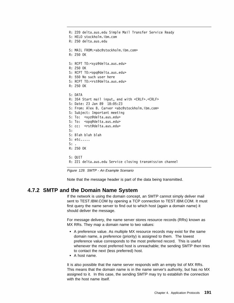
R: 22ð delta.aus.edu Simple Mail Transfer Service Ready
S: HELO stockholm.ibm.com
R: 25ð delta.aus.edu
S: MAIL FROM:<[email protected]>
R: 25ð OK
S: RCPT TO:<[email protected]>
R: 25ð OK
S: RCPT TO:<[email protected]>
R: 55ð No such user here
S: RCPT TO:<[email protected]>
R: 25ð OK
S: DATA
R: 354 Start mail input, end with <CRLF>.<CRLF>
S: Date: 23 Jan 89 18:ð5:23
S: From: Alex B. Carver <[email protected]>
S: Subject: Important meeting
S: To: <[email protected]>
S: To: <[email protected]>
S: cc: <[email protected]>
S:
S: Blah blah blah
S: etc.....
S: .
R: 25ð OK
S: QUIT
R: 221 delta.aus.edu Service closing transmission channel
Figure 129. SMTP - An Example Scenario
Note that the message header is part of the data being transmitted.
4.7.2 SMTP and the Domain Name SystemIf the network is using the domain concept, an SMTP cannot simply deliver mailsent to TEST.IBM.COM by opening a TCP connection to TEST.IBM.COM. It mustfirst query the name server to find out to which host (again a domain name) itshould deliver the message.
For message delivery, the name server stores resource records (RRs) known asMX RRs. They map a domain name to two values:
� A preference value. As multiple MX resource records may exist for the samedomain name, a preference (priority) is assigned to them. The lowestpreference value corresponds to the most preferred record. This is usefulwhenever the most preferred host is unreachable; the sending SMTP then triesto contact the next (less preferred) host.
� A host name.
It is also possible that the name server responds with an empty list of MX RRs.This means that the domain name is in the name server's authority, but has no MXassigned to it. In this case, the sending SMTP may try to establish the connectionwith the host name itself.
Chapter 4. Application Protocols 191

An important recommendation is given in RFC 974. It recommends that afterobtaining the MX records, the sending SMTP should query for Well-Known Services(WKS) records for this host, and should check that the referenced host has SMTPas a WKS-entry.
Note: This is only an option of the protocol but is already widely implemented.
Here is an example of MX resource records:
fsc5.stn.mlv.fr. IN MX ð fsc5.stn.mlv.fr.
IN MX 2 psfred.stn.mlv.fr.
IN MX 4 mvs.stn.mlv.fr.
IN WKS 152.9.25ð.15ð TCP (SMTP)
In the above example, mail for fsc5.stn.mlv.fr should by preference, be delivered tothe host itself, but in case the host is unreachable, the mail might also be deliveredto psfred.stn.mlv.fr or to mvs.stn.mlv.fr (if psfred.stn.mlv.fr is unreachable, too).
4.7.2.1 Addressing Mailboxes on Server SystemsWhen a user employs a server system for all mail functions, the mailbox addressseen by other SMTP users refers exclusively to the mail server system. Forexample if two OS/2 systems are named:
hayes.itso.ral.ibm.com
and
itso18ð.itso.ral.ibm.com
with the first one being used as an UltiMail client and the second as an UltiMailserver, the mailbox address might be:
hayes@itso18ð.itso.ral.ibm.com
This mailbox address would appear in the From: header field of all outgoing mailand in the SMTP commands to remote servers issued by the UltiMail serversystem.
When the user uses a POP server, however, the mailbox address on outbound mailitems contains the workstation's hostname (for example,[email protected]). In this case, the sender should include a Reply-To:field in the mail header to indicate that replies should not be sent to the originatingmailbox. For example, the mail header might look like this:
Date: Fri, 1ð Feb 95 15:38:23
From: [email protected]
To: "Steve Hayes" <[email protected]>
Reply-To: hayes@itso18ð.itso.ral.ibm.com
Subject: Test Reply-To: header field
The receiving mail agent is expected to send replies to the Reply-To: address andnot the From: address.
Using the Domain Name System to Direct Mail: An alternative approach tousing the Reply-To: header field is to use the Domain Name System to direct mailto the correct mailbox. The administrator for the domain name server with authorityfor the domain containing the user's workstation and the name server can add MXresource records to the Domain Name System to direct mail appropriately, asdescribed in 4.7.2, “SMTP and the Domain Name System” on page 191. For
192 TCP/IP Tutorial and Technical Overview

example, the following MX records indicate to client SMTPs that if the SMTP serveron hayes.itso.ral.ibm.com is not available, there is a mail server onitso.180.ral.ibm.com (9.24.104.180) that should be used instead.
itso18ð.itso.ral.ibm.com. IN WKS 9.24.1ð4.18ð TCP (SMTP)
hayes.itso.ral.ibm.com. IN MX ð hayes.itso.ral.ibm.com.
IN MX 1 itso18ð.itso.ral.ibm.com.
4.7.3 ReferencesA detailed description of the SMTP, MAIL and DNS-MX standards can be found inthe following RFCs:
� RFC 821 — Simple Mail Transfer Protocol� RFC 822 — Standard for the format of ARPA Internet text messages� RFC 974 — Mail Routing and the Domain System� RFC 1049 — A Content Type Header Field for Internet messages� RFC 1652 — SMTP Service Extension for 8-bit-MIMEtransport
4.8 Multipurpose Internet Mail Extensions (MIME)MIME is a draft-standard protocol. Its status is elective.
Electronic mail (as described in 4.7, “Simple Mail Transfer Protocol (SMTP)” onpage 184) is probably the most widely used TCP/IP application. However, SMTP(that is, an STD 10/RFC 821-compliant mailing system) is limited to 7-bit ASCII textwith a maximum line length of 1000 characters, which results in a number oflimitations:
� SMTP cannot transmit executable files or other binary objects. There are anumber of ad hoc methods of encapsulating binary items in SMTP mail items,for example:
– Encoding the file as pure hexadecimal
– The UNIX UUencode and UUdecode utilities that are used to encode binarydata in the UUCP mailing system to overcome the same limitations of 7-bittransport
– The Andrew Toolkit representation
None of these can be described as a de facto standard. UUencode is perhapsthe most pervasive due to the pioneering role of UNIX systems in the Internet.
� SMTP cannot transmit text data that includes national language characterssince these are represented by code points with a value of 128 (decimal) orhigher in all character sets based on ASCII.
� SMTP servers may reject mail messages over a certain size. Any given servermay have permanent and/or transient limits on the maximum amount of maildata it can accept from a client at any given time.
� SMTP gateways that translate from ASCII to EBCDIC and vice versa do notuse a consistent set of code page mappings, resulting in translation problems.
� Some SMTP implementations or other mail transport agents (MTAs) in theInternet do not adhere completely to the SMTP standards defined in RFC 821.Common problems include:
– Removal of trailing white space characters (TABs and SPACEs)
Chapter 4. Application Protocols 193
– Padding of all lines in a message to the same length
– Wrapping of lines longer than 76 characters
– Changing of new line sequences between different conventions. (Forinstance <CR> characters may be converted to <CRLF> sequences.)
– Conversion of TAB characters to multiple SPACEs.
MIME is a standard that includes mechanisms to solve these problems in a mannerthat is highly compatible with existing RFC 822 standards. Because mail messagesare frequently forwarded through mail gateways, it is not possible for an SMTPclient to distinguish between a server that manages the destination mailbox andone that acts as a gateway to another network. Since mail that passes through agateway may be tunnelled through further gateways, some or all of which may beusing a different set of messaging protocols, it is not possible in general for asending SMTP to determine the lowest common denominator capability common toall stages of the route to the destination mailbox. For this reason, MIME assumesthe worst: 7-bit ASCII transport, which may not strictly conform to or be compatiblewith RFC 821. It does not define any extensions to RFC 821, but limits itself toextensions within the framework of RFC 822. Thus, a MIME message is one whichcan be routed through any number of networks that are loosely compliant with RFC821 or are capable of transmitting RFC 821 messages.
MIME is a draft-standard protocol with a status of elective. It is described in fiveparts:
� Protocols for including objects other than US ASCII text mail messages withinthe bodies of messages conforming to RFC 822. These are described in RFC2045.
� General structure of the MIME media typing system and defines an initial set ofmedia types. This is described in RFC 2046.
� A protocol for encoding non-US ASCII text in the header fields of mailmessages conforming to RFC 822. This is described in RFC 2047.
� Various IANA registration procedures for MIME-related facilities. This isdescribed in RFC 2048.
� MIME conformance criteria. This is described in RFC 2049.
Although RFC 2045 provides a mechanism suitable for describing non-textual datafrom X.400 messages in a form that is compatible with RFC 822, it does not sayhow X.400 message parts are to be mapped to MIME message parts. Theconversion between X.400 and MIME is defined in RFCs 1494, 2156 and 1496which update the protocols for the conversion between RFC 822 and X.400.
The MIME standard was designed with the following general order of priorities:
1. Compatibility with existing standards such as RFC 822.
There are two areas where compatibility with previous standards is notcomplete.
� RFC 1049 (which is part of STD 11) described a Content-Type: field usedto indicate the type of (ASCII text) data in a message body. PostScript orSGML would allow a user mail agent to process it accordingly. MIMEretains this field, but changes the values that are defined for it. Since thecorrect response for a mail agent on encountering an unknown value in this
194 TCP/IP Tutorial and Technical Overview

field is basically to ignore it, this does not raise any major compatibilityconcerns.
� RFC 934 discussed encapsulation of messages in the context of messageforwarding and defined encapsulation boundaries: lines indicating thebeginning and end of an encapsulated message. MIME retains broadcompatibility with RFC 934, but does not include the quoting mechanismused by RFC 934 for lines in encapsulated messages that could otherwisebe misinterpreted as boundaries.9
The most important compatibility issue is that the standard form of a MIMEmessage is readable with an RFC 821-compliant mail reader. This is, ofcourse, the case. In particular the default encoding for MIME message bodiesis no encoding at all, just like RFC 822.
2. Robustness across existing practice. As noted above, there are many widelydeployed MTAs in the Internet that do not comply with STD 10/RFC 821. Theencoding mechanisms specified in RFC 2045 are designed to alwayscircumvent the most common of these (folding of lines as short as 76characters and corruption of trailing white space characters) by onlytransmitting short lines with no trailing white space characters, and allowingencoding of any data in a mail safe fashion.
Note: MIME does not require mail items to be encoded; the decision is left tothe user and/or the mail program. For binary data transmitted across(7-bit) SMTP, encoding is invariably required, but for data consistingmostly of text, this may not be the case.
The preferred encoding mechanism for mostly text data is such that, ata minimum, it is mail-safe with any compliant SMTP agent on an ASCIIsystem and at maximum is mail-safe with all known gateways andMTAs. The reason why MIME does not require maximum encoding isthat the encoding hampers readability when the mail is transmitted tonon-MIME compliant systems.
3. Ease of extension. RFC 2045 categorizes elements of mail bodies into sevencontent-types, which have subtypes. The content-type/subtype pairs in turnhave parameters that further describe the object concerned. The RFC definesa mechanism for registering new values for these and other MIME fields withthe Internet Assigned Numbers Authority (IANA). This process is itself updatedby RFC 2048.
For the current list of all MIME values, consult STD 2 — Assigned InternetNumbers. The remainder of this chapter describes only the values and typesgiven in RFC 2045.
One consequence of this approach is that, to quote RFC 2045, “some of themechanisms [used in MIME] may seem somewhat strange or even baroque at first.In particular, compatibility was always favored over elegance.”
Because RFC 822 defines the syntax of message headers (and deliberately allowsfor additions to the set of headers it describes) but not the composition of messagebodies, the MIME standard is largely compatible with RFC 822, particularly the RFC
9 The reason for this departure is that MIME allows for deeply nested encapsulation, but encodes text in such a way as to reversiblyspill text lines at or before column 76 to avoid the lines being spilled irreversibly by non-conforming SMTP agents. The RFC 934quoting mechanism can result in lines being lengthened with each level of encapsulation, possibly past column 76.
Chapter 4. Application Protocols 195

2045 part that defines the structure of message bodies and a set of header fieldsthat are used to describe that structure.
MIME can be seen as a high-level protocol; since it works entirely within theboundaries of STD 10 and STD 11, it does not involve the transport layer (or lowerlayers) of the protocol stack at all.
4.8.1 How MIME WorksA MIME-compliant message must contain a header field with the following verbatimtext:
MIME-Version: 1.ð
As is the case with RFC 822 headers, the case of MIME header field names arenever significant but the case of field values may be, depending on the field nameand the context. For the MIME fields described below, the values arecase-insensitive unless stated otherwise.
The general syntax for MIME header fields is the same as that for RFC 822, so thefollowing field is valid since parenthetical phrases are treated as comments andignored.
MIME-Version: 1.ð (this is a comment)
The following five header fields are defined for MIME:
MIME-VersionAs noted above, this must have the value 1.0.
Content-TypeThis describes how the object within the body is to be interpreted. Thedefault value is text/plain; charset=us-ascii, which indicates unformatted 7-bitASCII text data (which is a message body by the RFC 822 definition).
Content-Transfer-EncodingThis describes how the object within the body was encoded so that it could beincluded in the message in a mail-safe form.
Content-DescriptionA plain text description of the object within the body, which is useful when theobject is not readable (for example, audio data).
Content-IDA world-unique value specifying the content of this part of this message.
The first two of these fields are described in more detail in the following sections.
4.8.2 The Content-Type FieldThe body of the message is described with a Content-Type field of the form:
Content-Type: type/subtype ;parameter=value ;parameter=value
The allowable parameters are dependent on the type and subtype. Sometype/subtype pairs have no parameters, some have optional ones, some havemandatory ones and some have both. The subtype parameter cannot be omitted,but the whole field can, in which case the default value is text/plain.
There are seven standard content-types:
196 TCP/IP Tutorial and Technical Overview

textA single subtype is defined:
plain Unformatted text. The character set of the text may be specifiedwith the charset parameter. The following values are permitted:
us-ascii The text consists of ASCII characters in the range 0 to127 (decimal). This is the default (for compatibility with RFC822).
iso-8859-x where x is in the range 1 to 9 for the different parts ofthe ISO-8859 standard. The text consists of ISO characters inthe range 0 to 255 (decimal). All of the ISO-8859 character setsare ASCII-based with national language characters and so on inthe range 128 to 255. Note that, if the text contains nocharacters with values above 127, the character set should bespecified as us-ascii because it can be adequately representedin that character set.
Further subtypes may be added to describe other readable text formats (suchas word processor formats) which contain formatting information for anapplication to enhance the appearance of the text, provided that the correctsoftware is not required to determine the meaning of the text.
multipartThe message body contains multiple objects of independent data types. Ineach case, the body is divided into parts by lines called encapsulationboundaries. The contents of the boundary are defined with a parameter inthe content-type field, for example:
Content-Type: multipart/mixed; boundary="1995ð213ð91ð5517"
The boundary should not appear in any of the parts of the message. It iscase-sensitive and consists of 1-70 characters from a set of 75 which areknown to be very robust through mail gateways, and it may not end in aspace. (The example uses a 16-digit decimal timestamp.) Eachencapsulation boundary consists of the boundary value prefixed by a <CRLF>sequence and two hyphens (for compatibility with RFC 934). The finalboundary that marks the end of the last part also has a suffix of two hyphens.Within each part there is a MIME header, which like ordinary mail headers isterminated by the sequence <CRLF><CRLF> but may be blank. The headerfields define the content of the encapsulated message.
Four subtypes are defined:
mixed The different parts are independent but are to be transmittedtogether. They should be presented to the recipient in the orderthat they appear in the mail message.
parallel This differs from the mixed subtype only in that no order isascribed to the parts and the receiving mail program can, forexample, display all of them in parallel.
alternative The different parts are alternative versions of the same information.They are ordered in increasing faithfulness to the original, and therecipient's mail system should display the best version to the user.
Chapter 4. Application Protocols 197

digest This is a variant on multipart/mixed where the default type/subtypeis message/rfc822 (see below) instead of text/plain. It is used forthe common case where multiple RFC 822 or MIME messages aretransmitted together.
An example of a complex multipart message is shown in Figure 130.
MIME-Version: 1.ð
From: Steve Hayes <[email protected]>
To: Matthias Enders <enders@itso18ð.itso.ral.ibm.com>
Subject: Multipart message
Content-type: multipart/mixed; boundary="1995ð213ð91ð5517"
This section is called the preamble. It is after the header but before the
first boundary. Mail readers which understand multipart messages must
ignore this.
--1995ð213ð91ð5517
The first part. There is no header, so this is text/plain with
charset=us-ascii by default. The immediately preceding <CRLF> is part of
the <CRLF><CRLF> sequence that ends the null header. The one at the end is
part of the next boundary, so this part consists of five lines of text with
four <CRLF>s.
--1995ð213ð91ð5517
Content-type: text/plain; charset=us-ascii
Comments: this header explicitly states the defaults
One line of text this time, but it ends in a line break.
--1995ð213ð91ð5517
Content-Type: multipart/alternative; boundary=_
Comments: An encapsulated multipart message!
Again, this preamble is ignored. The multipart body contains a still image
and a video image encoded in Base64. See4.8.3.5, “Base64 Encoding” on page 2ð4
One feature is that the character "_" which is allowed in multipart
boundaries never occurs in Base64 encoding so we can use a very simple
boundary!
--_
Content-type: text/plain
Figure 130 (Part 1 of 2). MIME - A Complex Multipart Example
198 TCP/IP Tutorial and Technical Overview

This message contains images which cannot be displayed at your terminal.
This is a shame because they're very nice.
--_
Content-type: image/jpeg
Content-transfer-encoding: base64
Comments: This photograph is to be shown if the user's system cannot display
MPEG videos. Only part of the data is shown in this book because
the reader is unlikely to be wearing MIME-compliant spectacles.
Qk1OAAAAAAAAAE4EAABAAAAAQAEAAPAAAAABAAgAAAAAAAAAAAAAAAAAAAAAAAABAAAAAQAAAAAA
AAAAAAAAAAAAAAAAAAAAAAB4VjQSAAAAAAAAgAAAkgAAAJKAAKoAAACqAIAAqpIAAMHBwQDJyckA
/9uqAKpJAAD/SQAAAGðAAFVtAACqbQAA/2ðAAAAkAABVkgAAqiQAAP+SAAAAtgAAVbYAAKq2AAD/
<base64 data continues for another 1365 lines>
--_
Content-type: video/mpeg
Content-transfer-encoding: base64
AAABswoAeBn//+CEAAABsgAAAOgAAAG4AAAAAAAAAQAAT/////wAAAGy//8AAAEBQ/ZlIwwBGWCX
+pqMiJQDjAKywS/1NRrtXcTCLgzVQymqqHAfðsL1sMgMq4SWLCwOTYRdgyAyrhNYsLhhF3DLjAGg
BdwDXBv3yMV8/4tzrp3zsAWIGAJg1IBKTeFFI2IsgutIdfuSaAGCTsBVnWdz8afdMMAMgKgMEkPE
<base64 data continues for another 1839 lines>
--_--
That was the end of the nested multipart message. This is the epilogue.
Like the preamble it is ignored.
--1995ð213ð91ð5517--
And that was the end of the main multipart message. That's all folks!
Figure 130 (Part 2 of 2). MIME - A Complex Multipart Example
messageThe body is an encapsulated message, or part of one. Three subtypes aredefined:
rfc822 The body itself is an encapsulated message with the syntax of anRFC 822 message. It is required that at least one of From:,Subject: or Date: must be present.
Note: rfc822 refers to the syntax of the encapsulated messageenvelopes and does not preclude MIME messages forexample.
partial This type is used to allow fragmentation of large mail items in asimilar way to IP fragmentation. Because SMTP agents mayimpose upper limits on maximum mail sizes, it may be necessaryto send large items as fragments. The intent of themessage/partial mail items is that the fragmentation is transparentto the recipient. The receiving user agent should re-assemble thefragments to create a new message with identical semantics to theoriginal. There are three parameters for the Content-Type: field:
id= A unique identifier common to all parts of the message.
number= The sequence number of this part, with the first partbeing numbered 1.
Chapter 4. Application Protocols 199

total= The total number of parts. This is optional on all but the lastpart. The last part is identified by the fact that it has the samevalue for the number and total parameters.
The original message is always a message according to RFC 822rules. The first part is syntactically equivalent to a message/rfc822message (that is the body itself contains message headers), andthe subsequent parts are syntactically equivalent to text/plainmessages. When re-building the message, the RFC 822 headerfields are taken from the top-level message, not from the enclosedmessage, with the exception of those fields that cannot be copiedfrom the inner message to the outer when fragmentation isperformed (for example, the Content-Type: field).
Note: It is explicitly permitted to fragment a message/partialmessage further. This allows mail gateways to freelyfragment messages in order to ensure that all parts aresmall enough to be transmitted. If this were not the case,the mail agent performing the fragmentation would have toknow the smallest maximum size limit that the mail itemswould encounter en route to the destination.
external-body This type contains a pointer to an object that exists elsewhere.It has the syntax of the message/rfc822 type. The top-levelmessage header defines how the external object is to beaccessed, using the access-type: parameter of the Content-Type:field and a set of additional parameters that are specific to theaccess type. The intent is for the mail reader to be able tosynchronously access the external object using the specifiedaccess type. The following access types are defined:
ftp File Transfer Protocol. The recipient will be expected tosupply the necessary user ID and password. Forsecurity reasons, these are never transmitted with themessage.
tftp Trivial File Transfer Protocol.
anon-ftp Anonymous FTP.
local-file The data is contained in a file accessible directly via therecipient's local file system.
mail-server The data is accessible via a mail server. Unlike theothers, this access is necessarily asynchronous.
When the external object has been received, the desired messageis obtained by appending the object to the message headerencapsulated within the body of the message/external-bodymessage. This encapsulated message header defines how theresulting message is to be interpreted. (It is required to have aContent-ID: and will normally have a Content-Type: field.) Theencapsulated message body is not used (the real message body iselsewhere, after all) and it is therefore termed the phantom body.There is one exception to this: if the access-type is mail-server thephantom body contains the mail server commands necessary toextract the real message body. This is because mail serversyntaxes vary widely so it is much simpler to use the otherwiseredundant phantom body than to codify a syntax for encoding
200 TCP/IP Tutorial and Technical Overview

arbitrary mail server commands as parameters on theContent-Type: field.
imageThe body contains image data requiring a graphical display or some otherdevice such as a printer to display it. Two subtypes are defined initially:
jpeg The image is in JPEG format, JFIF encoding.
gif GIF format.
videoThe body contains moving image data (possibly with synchronized audio)requiring an intelligent terminal or multimedia workstation to display it. Asingle subtype is defined initially:
mpeg MPEG format.
audioThe body contains image data requiring a speaker and sound card (or similarhardware) to display it. A single subtype is defined initially:
basic A lowest common denominator format in the absence of any defacto standards for audio encoding. Specifically, it issingle-channel 8-bit ISDN mu-law encoding at a sample rate of8kHz.
applicationThis type is intended for types that do not fit into other categories, andparticularly for data to be processed by an application program before beingpresented to the user, such as spreadsheet data. It is also intended forapplication programs that are intended to be processed as part of the mailreading process (for example, see the PostScript type below). This type ofusage poses serious security risks unless an implementation ensuresexecutable mail messages are run in a safe or padded cell environment.
Two subtypes are defined initially:
PostScript Adobe Systems PostScript (Level 1 or Level 2).
Security Issues: Although PostScript is often thought of as aformat for printer data, it is a programming language and the useof a PostScript interpreter to process application/PostScript typesposes serious security problems. Any mail reader thatautomatically interprets PostScript programs is equivalent, inprinciple, to one that automatically runs executable programs itreceives. RFC 2045 outlines the issues involved.
octet-stream This subtype indicates general binary data consisting of 8-bitbytes. It is also the subtype that a mail reader should assume onencountering an unknown type or subtype. Any parameters arepermitted, and RFC mentions two: a type= parameter to inform therecipient of the general type of the data and padding= to indicate abit stream encoded in a byte stream. (The padding value is thenumber of trailing zero bits added to pad the stream to a byteboundary.)
Implementations are recommended to offer the user the option ofusing the data as input to a user program or of storing it in a file.(There is no standard for the default name of such a file, although
Chapter 4. Application Protocols 201

RFC 2045 does mention a “Content-Disposition:” field to bedefined in a later RFC.)
Security Issues: RFC strongly recommends against animplementation executing an application/octet-stream partautomatically or using it as input to a program specified in the mailheader. To do so would expose the receiving system to serioussecurity risks and could impact the integrity of any networks thatthe system is connected to.
Obviously, there are many types of data that do not fit into any of the subtypesabove. Co-operating mail programs may, in keeping with the rules of RFC 822,use types and/or subtypes beginning with X- as private values. No other valuesare permitted unless they have first been registered with the Internet AssignedNumbers Authority (IANA). See RFC 2048 for more details. The intention is thatfew, if any, additional types will be needed, but that many subtypes will be added tothe set.
4.8.3 The Content-Transfer-Encoding FieldAs already noted, SMTP agents and mail gateways can severely constrain thecontents of mail messages that can be transmitted safely. The MIME typesdescribed above list a rich set of different types of objects which can be included inmail messages and the majority of these do not fall within these constraints.Therefore, it is necessary to encode data of these types in a fashion that can betransmitted, and to decode them on receipt. RFC 2045 defines two forms ofencoding that are mail safe. The reason for two forms rather than one is that it isnot possible, given the small set of characters known to be mail safe, to devise aform that can both encode text data with minimal impact to the readability of thetext and yet can encode binary data that consists of characters distributed randomlyacross all 256 byte values compactly enough to be practical.
These two encodings are used only for bodies and not for headers. Headerencoding is described in 4.8.4, “Using Non-ASCII Characters in Message Headers”on page 206. The Content-Transfer-Encoding: field defines the encoding used.Although cumbersome, this field name emphasizes that the encoding is a feature ofthe transport process and not an intrinsic property of the object being mailed.Although there are only two encodings defined, this field can take on five values.(As usual, the values are case-insensitive.) Three of the values actually specifythat no encoding has been done; where they differ is that they imply differentreasons why this is the case. This is a subtle but important point. MIME is notrestricted to SMTP as a transport agent, despite the prevalence of (broadly)SMTP-compliant mail systems on the Internet. It therefore allows a mail agent totransmit data that is not mail-safe by the standards of SMTP (that is STD 10/RFC821). If such a mail item reaches a gateway to a more restrictive system, theencoding mechanism specified allows the gateway to decide on an item-by-itembasis whether the body must be encoded to be transmitted safely.
The five encodings are:
� 7-bit (the default if the Content-Transfer-Encoding: header is omitted)
� 8-bit
� Binary
� Quoted-Printable
202 TCP/IP Tutorial and Technical Overview
� Base64
These are described in the sections that follow.
4.8.3.1 7-bit Encoding7-bit encoding means that no encoding has been done and the body consists oflines of ASCII text with a length of no more than 1000 characters. It is thereforeknown to be mail-safe with any mail system that strictly conforms with STD 10/RFC821. This is the default, since these are the restrictions which apply to pre-MIMESTD 11/RFC 822 messages.
Note: 7-bit encoding does not guarantee that the contents are truly mail safe fortwo reasons. First, gateways to EBCDIC networks have a smaller set ofmail-safe characters, and secondly because of the many non-conformingSMTP implementations. The Quoted-Printable encoding is designed toovercome these difficulties for text data.
4.8.3.2 8-bit Encoding8-bit encoding implies that lines are short enough for SMTP transport, but that theremay be non-ASCII characters (that is, octets with the high-order bit set). WhereSMTP agents support the SMTP Service Extension for 8-bit-MIMEtransport,described in RFC 1652, 8-bit encoding is possible. Otherwise, SMTPimplementations should set the high-order bit to zero, so 8-bit encoding is not valid.
4.8.3.3 Binary EncodingBinary encoding indicates that non-ASCII characters may be present and that thelines may be too long for SMTP transport. (That is, there may be sequences of999 or more characters without a CRLF sequence.) There are currently nostandards for the transport of unencoded binary data by mail based on the TCP/IPprotocol stack, so the only case where it is valid to use binary encoding in a MIMEmessage sent on the Internet or other TCP/IP based network is in the header of anexternal-body part (see the message/external-body type above). Binary encodingwould be valid if MIME were used in conjunction with other mail transportmechanisms, or with a hypothetical SMTP Service Extension that did support longlines.
4.8.3.4 Quoted-Printable EncodingThis is the first of the two real encodings and it is intended to leave text files largelyreadable in their encoded form.
� It represents non-mail safe characters by the hexadecimal representation oftheir ASCII characters.
� It introduces reversible (soft) line breaks to keep all lines in the message to alength of 76 characters or less.
Quoted-Printable encoding uses the equal sign as a quote character to indicateboth of these cases. It has five rules which are summarized as follows:
1. Any character except one that is part of a new line sequence (that is, aX'0D0A' sequence on a text file) can be represented by =XX, where XX aretwo uppercase hexadecimal digits. If none of the other rules apply, thecharacter must be represented like this.
2. Any character in the range X'21' to X'7E' except X'3D' (“=”) can berepresented as the ASCII character.
Chapter 4. Application Protocols 203

3. ASCII TAB (X'09') and SPACE (X'20') can be represented as the ASCIIcharacter except when it is the last character on the line.
4. A line break must be represented by a <CRLF> sequence (X'0D0A'). Whenencoding binary data, X'0D0A' is not a line break and should be coded,according to rule 1, as =0D=0A.
5. Encoded lines cannot be longer than 76 characters (excluding the <CRLF>). Ifa line is longer than this, a soft line break must be inserted at or before column75. A soft line break is the sequence =<CRLF> (X'3D0D0A').
This scheme is a compromise between readability, efficiency and robustness.Since rules 1 and 2 use the phrase “may be encoded,” implementations have a fairdegree of latitude on how many characters are quoted. If as few characters arequoted as possible within the scope of the rules, then the encoding will work withwell-behaved ASCII SMTP agents. Adding the following set of ASCII characters tothe list of those to be quoted is adequate for well-behaved EBCDIC gateways:
! " # $ @ [ \ ] ^ y { ¦ } ˜
For total robustness, it is better to quote every character except for the73-character set known to be invariant across all gateways, that is the letters anddigits (A-Z, a-z and 0-9) and the following 11 characters:
' ( ) + , - . / : = ?
Note: This invariant list does not even include the SPACE character. For practicalpurposes, when encoding text files, only a SPACE at the end of a lineshould be quoted. Otherwise readability is severely impacted.
4.8.3.5 Base64 EncodingThis encoding is intended for data that does not consist mainly of text characters.Quoted-Printable replaces each non-text character with a 3-byte sequence which isgrossly inefficient for binary data. Base64 encoding works by treating the inputstream as a bit stream, regrouping the bits into shorter bytes, padding these shortbytes to 8 bits and then translating these bytes to characters that are known to bemail-safe. As noted in the previous section, there are only 73 safe characters, sothe maximum byte length usable is 6 bits which can be represented by 64 uniquecharacters (hence the name Base64). Since the input and output are both bytestreams, the encoding has to be done in groups of 24 bits (that is 3 input bytes and4 output bytes). The process can be seen as follows:
204 TCP/IP Tutorial and Technical Overview

bbbbbbbbbbbbbbbbbbbbbbbb
bbbbbbbb bbbbbbbb bbbbbbbb
bbbbbb bbbbbb bbbbbb bbbbbb
00bbbbbb 00bbbbbb 00bbbbbb 00bbbbbb
0ccccccc 0ccccccc 0ccccccc 0ccccccc
3376a\3376FDOQ
8-bit input byte triplet
group of 24 bits
convert to four 6-bit bytes
pad to 8-bit bytes
translate to mail-safe 7-bit ASCII
Figure 131. MIME - Base64 Encoding. How 3 input bytes are converted to 4 output bytesin the Base64 encoding scheme.
The translate table used is called the Base64 Alphabet.
Figure 132. MIME - The Base64 Alphabet
Base64value
ASCIIchar.
Base64value
ASCIIchar.
Base64value
ASCIIchar.
Base64value
ASCIIchar.
0 A 16 Q 32 g 48 w1 B 17 R 33 h 49 x2 C 18 S 34 i 50 y3 D 19 T 35 j 51 z4 E 20 U 36 k 52 05 F 21 V 37 l 53 16 G 22 W 38 m 54 27 H 23 X 39 n 55 38 I 24 Y 40 o 56 49 J 25 Z 41 p 57 5
10 K 26 a 42 q 58 611 L 27 b 43 r 59 712 M 28 c 44 s 60 813 N 29 d 45 t 61 914 O 30 e 46 u 62 +15 P 31 f 47 v 63 /
One additional character (the = character) is needed for padding. Because theinput is a byte stream that is encoded in 24-bit groups it will be short by zero, 8 or16 bits, as will the output. If the output is of the correct length, no padding isneeded. If the output is 8 bits short, this corresponds to an output quartet of twocomplete bytes, a short byte and a missing byte. The short byte is padded withtwo low-order zero bits. The missing byte is replaced with an = character. If theoutput is 16 bits short, this corresponds to an output quartet of one complete byte,a short byte and two missing bytes. The short byte is padded with 6 low-order zerobits. The two missing bytes are replaced with an = character. If zero characters(that is As) were used, the receiving agent would not be able to tell when decodingthe input stream if trailing X'00' characters in the last or last two positions of theoutput stream were data or padding. With pad characters, the number of “=”s (0, 1or 2) gives the length of the input stream modulo 3 (0, 2 or 1 respectively).
Chapter 4. Application Protocols 205

4.8.3.6 Conversion between EncodingsThe Base64 encoding can be freely translated to and from the binary encodingwithout ambiguity since both treat the data as an octet-stream. This is also true forthe conversion from Quoted-Printable to either of the other two (in the case of theQuoted-Printable to Binary conversion the process can be viewed as involving anintermediate binary encoding) by converting the quoted character sequences totheir 8-bit form, deleting the soft line breaks and replacing hard line breaks with<CRLF> sequences. This is not strictly true of the reverse process sinceQuoted-Printable is actually a record-based system. There is a semantic differencebetween a hard line break and an imbedded =0D=0A sequence. (For examplewhen decoding Quoted-Printable on a EBCDIC record-based system such as VM,hard line breaks map to record boundaries but =0D=0A sequences map toX'0D25' sequences.)
4.8.3.7 Multiple EncodingsMIME does not allow nested encodings. Any Content-Type that recursivelyincludes other Content-Type fields (notably the multipart and message types)cannot use a Content-Transfer-Encoding other than 7-bit, 8-bit or binary. Allencodings must be done at the innermost level. The purpose of this restriction is tosimplify the operation of user mail agents. If nested encodings are not permitted,the structure of the entire message is always visible to the mail agent without theneed to decode the outer layer(s) of the message.
This simplification for user mail agents has a price: complexity for gateways.Because a user agent can specify an encoding of 8-bit or binary, a gateway to anetwork where these encodings are not safe must encode the message beforepassing it to the second network. The obvious solution, to simply encode themessage body and to change the Content-Transfer-Encoding: field, is not allowedfor the multipart or message types since it would violate the restriction describedabove. The gateway must therefore correctly parse the message into itscomponents and re-encode the innermost parts as necessary.
There is one further restriction: messages of type message/partial must alwayshave 7-bit encoding. (8-bit and binary are also disallowed.) The reason for this isthat if a gateway needs to re-encode a message, it requires the entire message todo so, but the parts of the message may not all be available together. (Parts maybe transmitted serially because the gateway is incapable of storing the entiremessage at once or they may even be routed independently via differentgateways.) Therefore message/partial body parts must be mail safe across lowestcommon denominator networks; that is, they must be 7-bit encoded.
4.8.4 Using Non-ASCII Characters in Message HeadersAll of the mechanisms above refer exclusively to bodies and not to headers. Thecontents of message headers must still be coded in US-ASCII. For header fieldsthat include human-readable text, this is not adequate for languages other thanEnglish. A mechanism to include national language characters is defined by thesecond part of MIME (RFC 2047). This mechanism differs from theQuoted-Printable encoding, which would be used in a message body for thefollowing reasons:
� The format of message headers is strictly codified by RFC 822, so theencoding used by MIME for header fields must work within a narrower set ofconstraints than that used for bodies.
206 TCP/IP Tutorial and Technical Overview

� Message relaying programs frequently change message headers, for examplere-ordering header fields, deleting some fields but not others, re-orderingmailboxes within lists or spilling fields at different positions than the originalmessage.
� Some message handling programs do not correctly handle some of the morearcane features of RFC 822 (such as the use of the \ character to quote specialcharacters such as < and >).
The approach used by MIME is to reserve improbable sequences of legal ASCIIcharacters that are not syntactically important in RFC 822 for use with this protocol.Words in header fields that need national characters are replaced by encodedwords which have the form:
=?charset?encoding?word?=
where:
charset The value allowed for the charset parameter used with text/plain MIMEtype, that is: “us-ascii” or “iso-8859-1” through “iso-8859-9.”
encoding B or Q. B is identical to the Base64 encoding used in message bodies.Q is similar to the Quoted-Printable encoding but uses _ to representX'20' (ASCII SPACE).10 Q encoding requires the encoding of _characters and does not allow line breaks. Any printable ASCIIcharacter other than _, = and SPACE may be left unquoted within anencoded word unless it would be syntactically meaningful when theheader field is parsed according to RFC 822.
charset and encoding are both case-insensitive.
word A string of ASCII text characters other than SPACE, which conforms tothe rules of the encoding given.
An encoded word must have no imbedded white space characters (SPACE orTAB), can be up to 75 characters long, and cannot be on a line that is greater than76 characters long (excluding the <CRLF>). These rules ensure that gateways willnot fold encoded words in the middle of the word. Encoded words can generally beused in the human-readable parts of header fields. For example, if a mailbox isspecified in the following form:
The Octopus <[email protected]>
an encoded word could be used in the The Octopus section but not in the addresspart between the < and the>). RFC 2047 specifies precisely where encoded wordscan be used with reference to the syntax of RFC 822.
4.8.5 ReferencesA detailed description of MIME can be found in the following RFCs:
� RFC 2045 – MIME (Multipurpose Internet Mail Extensions) Part One: Format ofInternet Message Bodies
� RFC 2046 – MIME (Multipurpose Internet Mail Extensions) Part Two: MediaTypes
10 The underscore character is not strictly mail-safe, but it is used because the use of any other character to indicate a SPACE wouldseriously hamper readability.
Chapter 4. Application Protocols 207
� RFC 2047 – MIME (Multipurpose Internet Mail Extensions) Part Three:Message Header Extensions for Non-ASCII Text
� RFC 2048 – MIME (Multipurpose Internet Mail Extensions) Part Four:Registration Procedures
� RFC 2049 – MIME (Multipurpose Internet Mail Extensions) Part Five:Conformance Criteria and Examples
� RFC 2156 — MIXER (MIME Internet X.400 Enhanced Relay): Mappingbetween X.400 and RFC 822/MIME
4.9 Post Office Protocol (POP)The Post Office Protocol, Version 3 is a standard protocol with STD number 53. Itsstatus is elective. It is described in RFC 1939. The older Post Office ProtocolVersion 2 is an historic protocol with a status of not recommended.
The Post Office Protocol is an electronic mail protocol with both client(sender/receiver) and server (storage) functions. POP3 supports basic functions(download and delete) for electronic mail retrieval. More advanced functions aresupported by IMAP4 (see 4.10, “Internet Message Access Protocol Version 4(IMAP4)” on page 209).
POP3 clients establish a TCP connection to the server using port 110. When theconnection is established, the POP3 server sends a greeting message to the client.The session then enters the authentication state. The client must send itsidentification to the server while the session is in this state. If the server verifiesthe ID successfully, the session enters the transaction state. In this state, the clientcan access the mailbox. When the client sends the QUIT command, the sessionenters the Update state and the connection is then closed.
4.9.1 POP3 Commands and ResponsesPOP3 commands consist of a keyword and possibly one or more argumentsfollowing the keyword. Keywords are three or four characters long and separatedby one space character from arguments. Each argument must be up to 40characters long.
The server sends a response to the command that was issued by the client. Thisresponse must be up to 512 characters and begin with a status indicator whichshows whether the reply is positive or negative. These indicators are (+OK) or(-ERR). The server must send these indicators in upper case.
Here are the three states for a POP3 session:
Authorization stateIn this state, the client sends identification to the server. This is implementedin two ways. More information on authentication is described in RFC 1734.
1. Using USER and PASS commands.
2. Using APOP command.
Transaction stateIn this state, the client can issue commands for listing, retrieving and deleting.Please note that the deleting action is not taken in this state. The client mustsend the QUIT command and then the server goes to the update state.
208 TCP/IP Tutorial and Technical Overview

Update stateIn this state, the server updates the mailbox according to the commandsreceived from the client in the transaction state and the TCP connection ends.If the connection is broken for any reason before quit command is receivedfrom the client, the server does not enter the update state. Thus, the serverwill not update anything.
Important POP3 Commands
USER name User name for authentication.
PASS password Password for authentication.
STAT To get the number of messages and total size of the messages.
LIST [msg] If a message number is specified, the size of this mail is listed (if itexists). If not, all messages will be listed with the message sizes.
RETR msg This command sends the whole message to the client.
DELE msg This command deletes the specified message.
NOOP The server does not do anything, just sends a positive response.
RSET This command cancels previous delete requests if they exist.
QUIT If entered in the authorization state, it merely ends the TCPconnection. If entered in the transaction state, it first updates themailbox (deletes any messages requested previously) and thenends the TCP connection.
4.9.2 ReferencesA detailed description of the Post Office Protocol can be found in the followingRFCs:
� RFC 937 — Post Office Protocol – Version 2� RFC 1939 — Post Office Protocol – Version 3
4.10 Internet Message Access Protocol Version 4 (IMAP4)The Internet Message Access Protocol, Version 4 is a proposed standard protocol.Its status is elective. It is described in RFC 2060.
IMAP4 is an electronic messaging protocol with both client and server functions.Similar to POP, IMAP4 servers store messages for multiple users to be retrievedupon client requests, but IMAP4 clients have more capabilities in doing so thanPOP clients. IMAP4 allows clients to have multiple remote mailboxes to retrievemessages from and to choose any of those at any time. IMAP4 clients can specifycriteria for downloading messages, such as not to transfer large messages overslow links. Also, IMAP4 always keeps messages on the server and replicatescopies to the clients. Transactions performed by disconnected clients are effectedon server mailboxes by periodic re-synchronization of client and server. Let usdiscuss the underlying electronic mail models of IMAP4 first, to understand theIMAP4 functions clearly. These are described in detail in RFC 1733 DistributedElectronic Mail Models In IMAP4.
Chapter 4. Application Protocols 209

4.10.1 IMAP4 Underlying Electronic Mail ModelsIMAP4 supports all three major electronic mail models. These models are offline,online and disconnected use models.
In the offline model, a client periodically connects to the server and downloads themail messages. Mail messages are deleted on the server. Therefore, mail isprocessed locally on the client. An example of a mail protocol that uses this modelis POP3. Please see 4.9, “Post Office Protocol (POP)” on page 208 for furtherinformation.
In the online model, clients make changes on the server. In other words, mail isprocessed remotely on the server. An example of a mail protocol that uses thismodel is NFS. Please see 4.13, “Network File System (NFS)” on page 230 forfurther information.
The disconnected use model is composite of offline and online models. In thismodel, a client downloads the data and makes changes on it locally, then at a latertime uploads it to server. An example of a mail program which that this model isLotus Notes Mail.
These three models have some advantages and disadvantages. Since IMAP4supports all these models, the client is able to switch to another model. As anexample, if the connection is too slow and there is a large message in the mailbox.An IMAP4 client can retrieve a small part of the message, change that part andthen reconnect to the server and upload that part again.
4.10.2 IMAP4 Commands and ResponsesSimilar to the POP3 (see, 4.9, “Post Office Protocol (POP)” on page 208), IMAP4clients establish a TCP connection to the server using port 143. When theconnection is established, the server sends a greeting message. After that, theclient and the server exchange data interactively. Whenever the client sends acommand, the server sends a completion result response to this command. Theserver can also send data for any other reason. All commands and responses arein the form of lines ending with CRLF.
All client commands begin with a different identifier which is called a tag. Theserver may not respond to the commands in order in which they were received.Let us say a command that has the tag ABC005 is sent and then anothercommand which has tag ABC006 is sent. If it takes less time to process thesecond command, the server responds to the ABC006 command first with a linebeginning with the relevant tag (In this case, ABC006). As this example shows, aunique tag must be used for every command sent. In two cases, the clientcommand is not sent completely. In these cases, the client sends the second partof the command without any tag and the server responds to this command with aline beginning with (+). The client must finish sending the whole command beforesending another command.
All data responses and status responses begin with (*), which are called untaggedresponses. These responses may not be requested by the client. The server cansend data without any request. As an example, if a new mail message arrivesduring the session, the server sends the relevant flag to notify the client. Theserver sends a command completion response to the command that was issued bythe client. This response begins with the same tag of the relevant command and a
210 TCP/IP Tutorial and Technical Overview

status indicator following by the tag, which shows either the operation result ispositive or negative. These indicators are OK, NO or BAD.
4.10.3 Message NumbersThere are two types of method used to identify the messages: the unique identifierand the message sequence number. Here are the some of the attributes. Pleaserefer to RFC 2060 for details.
4.10.3.1 Unique Identifier (UID) Message AttributeEvery message has a 32-bit identifier, which when it is combined with a uniqueidentifier validity value forms a 64-bit value. When a new message is added to themailbox, a higher UID is assigned to that message than those added previously.Unique identifiers do not have to be contiguous. Unique identifiers also persist in toother sessions. In this way, if the clients disconnect, in the next session the clientcan use the same values from the previous session.
Each mailbox has a unique identifier validity value. If it is not possible to use thesame value for the next session, then a new value must be greater than the valuethat was used in the previous session. As an example, if a mailbox is deleted inone session and a new one created with the same name in the next session, sincethe mailbox name is the same, the client may not realize that this is a new mailbox.In this case, the unique identifier validity value should be changed. The uniqueidentifier validity value is sent with the mailbox selection to the client asUIDVALIDITY.
4.10.3.2 Message Sequence Number Message AttributeThe message sequence number shows the relative position of the message in themailbox. It must be in ascending order. The message sequence number is subjectto change during the session or in the next session. If a new message is added,the number of total messages (including the new message) is assigned to thatmessage. The total number of the messages and the message sequence numberof the newest message must always be kept the same, in order to correctly assignthe message sequence number to each new mail message. If a message isremoved permanently, then the message sequence numbers must be recalculatedaccordingly in that session.
4.10.3.3 Flags Message AttributeFlags are used to show the current status of the message. There are two types offlags: permanent and session-only. Here are the current flags at the time of writingthis book. Please refer to RFC 2060 for the latest details.
\seen Message has been read.
\Answered Message has been answered.
\Flagged Message is marked for special attention.
\Deleted Message is deleted for later permanent removal.
\Draft Message has been completed.
\Recent Message has arrived recently and this is the first session after itsarrival. This flag cannot be changed by the client.
Chapter 4. Application Protocols 211

4.10.4 IMAP4 StatesSimilar to POP3 (see, 4.9, “Post Office Protocol (POP)” on page 208), the IMAP4session works in different states. Some commands are valid for certain states andsome of the commands are valid for all states. If the client sends a command thatis not appropriate for that state, the server responds with an error message. Thiserror message may vary. The server might send either BAD or NO depending onthe implementation. Here are the four states for IMAP4.
Non-Authenticated StateIn this state, the client sends identification to the server.
Authenticated StateIn this state, the client must select a mailbox to proceed.
Selected StateIn this state, a mailbox has been selected successfully.
Logout StateIn this state, connection is ended with either the client request or any otherreason.
Flow diagram of an IMAP4 session.
layout and close connection
(1) (2) (3)
(4)
(5) (6)
(7)
initial connection and server greeting
non-authenticated
authenticated
(7)
(7)
selected
3376a\3376FDOO
Figure 133. IMAP4 - Flow Diagram
(1) Connection without pre-authentication (OK greeting)
(2) Pre-authenticated connection (PREAUTH greeting)
(3) Rejected connection (BYE greeting)
(4) Successful LOGIN or AUTHENTICATE command
212 TCP/IP Tutorial and Technical Overview

(5) Successful SELECT or EXAMINE command
(6) CLOSE command, or failed SELECT or EXAMINE command
(7) LOGOUT command, server shutdown, or connection closed
4.10.5 Client CommandsMost of the IMAP4 commands must be used in the corresponding state. Some ofthem can be used in more than one state. The following list shows the commandsand the states in which they are used:
In Any StateThe following commands are valid for this state:
CAPABILITY This command sends a request a list of functions that theserver supports.
NOOP This command does nothing. It can be used to reset the inactivityautologout timer on the server.
LOGOUT This command sends a request to end the connection.
In Non-Authenticated StateAll commands in any state and the following commands are valid for thisstate:
AUTHENTICATE This command requests a special authenticationmechanism with an argument from the server. If the server does notsupport that mechanism, the server sends an error message.
LOGIN This command sends the username and password in plain text.
In Authenticated StateAll commands in Any State and the following commands are valid for thisstate:
SELECT This command selects a mailbox.
EXAMINE This command also selects a mailbox but access to the mailboxwith this command is read-only.
CREATE This command creates a mailbox with a given name. It is notallowed to create INBOX or any other existing mailbox.
DELETE This command permanently removes the mailbox with the givenname.
RENAME This command changes the name of the mailbox.
SUBSCRIBE This command adds the specified mailbox to the subscriptionlist which can be obtained by the LSUB command.
UNSUBSCRIBE This command removes the specified mailbox name from thesubscription list.
LIST This command requests a subset of names from the complete set ofall names available from the server.
LSUB This command requests a subset of names from the subscription list.
STATUS This command requests the status of the given mailbox name. Theserver checks the flags and send the status according to the statusof the flags.
Chapter 4. Application Protocols 213

APPEND This command appends a message text to the given mailbox as anew message.
In Selected StateAll commands in any state, all commands in authenticated state and thefollowing commands are valid for this state:
CHECK This command requests resolution of the state of the selectedmailbox in the memory and the disk.
CLOSE This command permanently removes all messages from the currentlyselected mailbox that were previously marked as deleted and returnsto authenticated state from selected state.
EXPUNGE This command permanently removes all messages from thecurrently selected mailbox that were previously marked as deleted.
SEARCH This command searches the mailbox for the messages that matchgiven searching criteria.
FETCH This command retrieves data associated with a message in theselected mailbox.
STORE This command updates the message with the data which wasretrieved by a FETCH command.
COPY This command copies the specified message to the end of thespecified destination mailbox.
UID This command returns unique identifier instead of messagesequence numbers. This command is used with other commands.
4.10.6 ReferencesA detailed description of the IMAP protocol can be found in the following RFCs:
� RFC 1733 — DISTRIBUTED ELECTRONIC MAIL MODELS IN IMAP4� RFC 2060 — INTERNET MESSAGE ACCESS PROTOCOL - VERSION 4rev1
4.11 Network ManagementWith the growth in size and complexity of the TCP/IP-based internetworks the needfor network management became very important. The current networkmanagement framework for TCP/IP-based internetworks consists of:
1. SMI (RFC 1155) - Describes how managed objects contained in the MIB aredefined. (It is discussed in 4.11.3, “Structure and Identification of ManagementInformation (SMI)” on page 215.)
2. MIB-II (RFC 1213) - Describes the managed objects contained in the MIB. (Itis discussed in 4.11.4, “Management Information Base (MIB)” on page 216.)
3. SNMP (RFC 1157) - Defines the protocol used to manage these objects. (It isdiscussed in 4.11.5, “Simple Network Management Protocol (SNMP)” onpage 220.)
The Internet Architecture Board issued an RFC detailing its recommendation, whichadopted two different approaches:
� In the short term SNMP should be used.
214 TCP/IP Tutorial and Technical Overview

The IAB recommends that all IP and TCP implementations be networkmanageable. At the current time, this implies implementation of the InternetMIB-II (RFC 1213), and at least the recommended management protocol SNMP(RFC 1157).
Note that the historic protocols Simple Gateway Monitoring Protocol (SGMP ,RFC 1028) and MIB-I (RFC-1156) are not recommended for use.
SNMP uses the basic concept of describing and defining management informationcalled Structure and Identification of Management Information (SMI) described inRFC 1155 and Management Information Base (MIB) described in RFC 1156.
4.11.1 StandardsSNMP is an Internet standard protocol. Its status is recommended. Its currentspecification can be found in RFC 1157 Simple Network Management Protocol(SNMP).
MIB-II is an Internet standard protocol. Its status is recommended. Its currentspecification can be found in RFC 1213 Management Information Base for NetworkManagement of TCP/IP-based Internets: MIB-II.
4.11.2 Bootstrap Protocol (BOOTP)The BOOTstrap Protocol (BOOTP) enables a client workstation to initialize with aminimal IP stack and request its IP address, a gateway address and the address ofa name server from a BOOTP server. Once again, a good example of a client thatrequires this service is a diskless workstation. If BOOTP is to be used in yournetwork, then you must make certain that both the server and client are on thesame physical LAN segment. BOOTP can only be used across bridged segmentswhen source-routing bridges are being used, or across subnets if you have a routercapable of BOOTP forwarding, also known as a BOOTP relay agent. This isdiscussed in detail in 7.1, “Bootstrap Protocol (BOOTP)” on page 401
4.11.3 Structure and Identification of Management Information (SMI)The SMI defines the rules for how managed objects are described and howmanagement protocols can access these objects. The description of managedobjects is made using a subset of the ASN.1 (Abstract Syntax Notation 1, ISOstandard 8824), a data description language. The object type definition consists offive fields:
� Object: A textual name, termed the object descriptor, for the object type alongwith its corresponding object identifier defined below.
� Syntax: The abstract syntax for the object type. It can be a choice ofSimpleSyntax (Integer, Octet String, Object Identifier, Null) or anApplicationSyntax (NetworkAddress, Counter, Gauge, TimeTicks, Opaque) orother application-wide types (see RFC 1155 for more details).
� Definition: A textual description of the semantics of the object type.
� Access: One of read-only, read-write, write-only or not-accessible.
� Status: One of mandatory, optional, or obsolete.
As an example, we can have:
Chapter 4. Application Protocols 215

OBJECT
sysDescr { system 1 }
Syntax OCTET STRING
Definition This value should include the full name and version
identification of the system's hardware type, software
operating system, and networking software. It is
mandatory that this contain only printable ASCII
characters.
Access read-only.
Status mandatory.
This example shows the definition of an object contained in the ManagementInformation Base (MIB). Its name is sysDescr and it belongs to the system group(see 4.11.4, “Management Information Base (MIB)”).
A managed object not only has to be described but identified, too. This is doneusing the ASN.1 Object Identifier in the same way as a telephone number,reserving group of numbers to different locations. In the case of TCP/IP-basednetwork management the number allocated was 1.3.6.1.2 and SMI uses it as thebase for defining new objects.
The number 1.3.6.1.2 is obtained by joining groups of numbers with the followingmeaning:
� The first group defines the node administrator:– (1) for ISO– (2) for CCITT– (3) for the joint ISO-CCITT
� The second group for the ISO node administrator defines (3) for use by otherorganizations.
� The third group defines (6) for the use of the U.S. Department of Defense(DoD).
� In the fourth group the DoD has not indicated how it will manage its group sothe Internet community assumed (1) for its own.
� The fifth group was approved by IAB to be:– (1) for the use of OSI directory in the Internet– (2) for objects identification for management purposes– (3) for objects identification for experimental purposes– (4) for objects identification for private use.
In the example the {system 1} beside the object name means that the objectidentifier is 1.3.6.1.2.1.1.1. It is the first object in the first group (system) in theManagement Information Base (MIB).
4.11.4 Management Information Base (MIB)The MIB defines the objects that may be managed for each layer in the TCP/IPprotocol. There are two versions: MIB-I and MIB-II. MIB-I was defined in RFC1156, and is now classified as a historic protocol with a status of notrecommended.
216 TCP/IP Tutorial and Technical Overview

Each managed node supports only those groups that are appropriate. For example,if there is no gateway, the EGP group need not be supported. But if a group isappropriate, all objects in that group must be supported.
The list of managed objects defined has been derived from those elementsconsidered essential. This approach of taking only the essential objects is notrestrictive, since the SMI provides extensibility mechanisms such as definition of anew version of the MIB and definition of private or non-standard objects.
Below are some examples of objects in each group. The complete list is defined inRFC 1213. Please also refer to RFC 2011, RFC 2012 and RFC 2013 for updatedinformation of IP, TCP and UDP.
� System Group
– sysDescr - Full description of the system (version, HW, OS)– sysObjectID - Vendor's object identification– sysUpTime - Time since last re-initialization– sysContact - Name of contact person– sysServices - Services offered by device
� Interfaces Group
– ifIndex - Interface number– ifDescr - Interface description– ifType - Interface type– ifMtu - Size of the largest IP datagram– ifAdminisStatus - Status of the interface– ifLastChange - Time the interface entered in the current status– ifINErrors - Number of inbound packets that contained errors– ifOutDiscards - Number of outbound packets discarded
� Address Translation Group
– atTable - Table of address translation– atEntry - Each entry containing one network address to physical address
equivalence– atPhysAddress - The media-dependent physical address– atNetAddress - The network address corresponding to the
media-dependent physical address
Table 9. Management Information Base II (MIB-II). Group definition.
Group Objects for #
System Basic system information 7
Interfaces Network attachments 23
AT Address translation 3
IP Internet protocol 38
ICMP Internet control message protocol 26
TCP Transmission control protocol 19
UDP User datagram protocol 7
EGP Exterior gateway protocol 18
SNMP SNMP applications entities 30
Legend:#=Number of objects in the group
Chapter 4. Application Protocols 217

� IP Group
– ipForwarding - Indication of whether this entity is an IP gateway– ipInHdrErrors - Number of input datagrams discarded due to errors in their
IP headers– ipInAddrErrors - Number of input datagrams discarded due to errors in their
IP address– ipInUnknownProtos - Number of input datagrams discarded due to
unknown or unsupported protocol– ipReasmOKs - Number of IP datagrams successfully re-assembled
� ICMP Group
– icmpInMsgs - Number of ICMP messages received– icmpInDestUnreachs - Number of ICMP destination-unreachable messages
received– icmpInTimeExcds - Number of ICMP time-exceeded messages received– icmpInSrcQuenchs - Number of ICMP source-quench messages received– icmpOutErrors - Number of ICMP messages not sent due to problems
within ICMP
� TCP Group
– tcpRtoAlgorithm - Algorithm to determine the timeout for retransmittingunacknowledged octets
– tcpMaxConn - Limit on the number of TCP connections the entity cansupport
– tcpActiveOpens - Number of times TCP connections have made a directtransition to the SYN-SENT state from the CLOSED state
– tcpInSegs - Number of segments received, including those received in error– tcpConnRemAddress - The remote IP address for this TCP connection– tcpInErrs - Number of segments discarded due to format error– tcpOutRsts - Number of resets generated
� UDP Group
– udpInDatagrams - Number of UDP datagrams delivered to UDP users– udpNoPorts - Number of received UDP datagrams for which there was no
application at the destination port– udpInErrors - Number of received UDP datagrams that could not be
delivered for reasons other than the lack of an application at the destinationport
– udpOutDatagrams - Number of UDP datagrams sent from this entity
� EGP Group
– egpInMsgs - Number of EGP messages received without error– egpInErrors - Number of EGP messages with errors– egpOutMsgs - Number of locally generated EGP messages– egpNeighAddr - The IP address of this entry's EGP neighbor– egpNeighState - The EGP state of the local system with respect to this
entry's EGP neighbor
This is not the complete MIB definition but it is presented as an example of theobjects defined in each group. These modules currently support IPv4.
To illustrate this, the Interfaces Group contains two top-level objects: the numberof interface attachments on the node (ifNumber) and a table containing informationon those interfaces (ifTable). Each entry (ifEntry) in that table contains the objects
218 TCP/IP Tutorial and Technical Overview

for a particular interface. Among those, the interface type (ifType) is identified in theMIB tree using the ASN.1 notation by 1.3.6.1.2.1.2.2.1.3. and for a token-ringadapter the value of the corresponding variable would be 9, which meansiso88025-tokenRing (see Figure 134).
Object Identifier
ISO(1)
CCITT(2)
Joint-ISO-CCITT (3)
Other intnl organiz. (3)
US Dept. of Defense (6)
IAB(1)
Assumed by IAB RFC 1155
Directory(1)
Mgmt(2)
Experimentl (3)
Private(3)
MIB(1)
System(1)
Interfaces(2)
Address Translation (3)
IP(4)
ifNumber(1)
ifTable(2)
ifEntry(1)
ifIndex(1)
ifDescr(2)
ifType(3)
ifMtu(4)
3376B\3376FDOR
Figure 134. MIB-II - Object Identifier Allocation for TCP/IP-based Network
4.11.4.1 IBM-Specific MIB PartIBM has added the following objects in the MIB-II database:
\ IBM SNMP agent DPI UDP port
DPI_port 1.3.6.1.4.1.2.2.1.1. number 2
\ IBM "ping" round-trip-time table
RTTaddr 1.3.6.1.4.1.2.2.1.3.1. internet 6ð
minRTT 1.3.6.1.4.1.2.2.1.3.2. number 6ð
maxRTT 1.3.6.1.4.1.2.2.1.3.3. number 6ð
aveRTT 1.3.6.1.4.1.2.2.1.3.4. number 6ð
RTTtries 1.3.6.1.4.1.2.2.1.3.5. number 6ð
RTTresponses 1.3.6.1.4.1.2.2.1.3.6. number 6ð
Chapter 4. Application Protocols 219

Where:
� DPI_port returns the port number between the agent and the subagent.
� *RTT* allows an SNMP manager to ping remote hosts. RTT stands for RoundTrip Table.
– RTTaddr: host address– minRTT: minimum round trip time– maxRTT: maximum round trip time– aveRTT: average round trip time– RTTtries: number of pings yet to be performed– RTTresponses: number of responses received
4.11.5 Simple Network Management Protocol (SNMP)The SNMP added the improvement of many years of experience in SGMP andallowed it to work with the objects defined in the MIB with the representationdefined in the SIM.
RFC 1157 defines the Network Management Station (NMS) as the one thatexecutes network management applications (NMA) that monitor and control networkelements (NE) such as hosts, gateways and terminal servers. These networkelements use a management agent (MA) to perform the network managementfunctions requested by the network management stations. The Simple NetworkManagement Protocol (SNMP) is used to communicate management informationbetween the network management stations and the agents in the network elements.
MA
MIB
MA
MIB
MA
MIB
MA
MIB
NMA NMA
NMS - Network Management StationNMA - Network Management ApplicationNE - Network Management StationMA - Management AgentMIB - Management Information Base 3376B\3376FDOS
SNMP SNMP SNMP SNMP
NMS NMS
NE NE NENE
Figure 135. SNMP - Components of the Simple Network Management Protocol
220 TCP/IP Tutorial and Technical Overview

All the management agent functions are only alterations (set) or inspections (get) ofvariables limiting the number of essential management functions to two andavoiding more complex protocols. In the other direction, from NE to NMS, a limitednumber of unsolicited messages (traps) are used to indicate asynchronous events.In the same way, trying to preserve the simplicity, the interchange of informationrequires only an unreliable datagram service and every message is entirely andindependently represented by a single transport datagram. This means also that themechanisms of the SNMP are generally suitable for use with a wide variety oftransport services. The RFC 1157 specifies the exchange of messages via the UDPprotocol, but a wide variety of transport protocols can be used.
The entities residing at management stations and network elements thatcommunicate with one another using the SNMP are termed SNMP applicationentities. The peer processes that implement it are the protocol entities. An SNMPagent with some arbitrary set of SNMP application entities is called an SNMPcommunity, where each one is named by a string of octets that need to be uniqueonly to the agent participating in the community.
A message in the SNMP protocol consists of a version identifier, an SNMPcommunity name and a protocol data unit (PDU). It is mandatory that allimplementations of the SNMP support the five PDUs:
� GetRequest: Retrieve the values of a specific object from the MIB.
� GetNextRequest: Walk through portions of the MIB.
� SetRequest: Alter the values of a specific object from the MIB.
� GetResponse: Response from a GetRequest, a GetNextRequest and aSetRequest.
� Trap: Capability of the network elements to generate events to networkmanagement stations such as agent initialization, agent restart and link failure.There are seven trap types defined in RFC 1157: coldStart, warmStart,linkDown, linkUp, authenticationFailure, egpNeighborLoss andenterpriseSpecific.
The formats of these messages are as follows:
Chapter 4. Application Protocols 221

Version Community Data (PDU) Basic Layout
Request ID Error Status Error Index VarBindList
VarBindVarBind
VarBindVarBind
Version Community Data (PDU)
Enterprise Agent-addr Generic trap Specific trap VarBindList
Basic Layout
Get - Request PDU formatGet - Next - Request PDU
formatSet - Request PDU format
3376B\3376FDOTTrap PDU format
Figure 136. SNMP Message Format - Request, Set and Trap PDU format
4.11.6 Simple Network Management Protocol Version 2 (SNMPv2)The framework of Version 2 of the Simple Network Management Protocol(SNMPv2) was published in April 1993 and consists of 12 RFCs including the first,RFC 1441, which is an introduction. In August 1993 all 12 RFCs became aproposed standard with the status elective.
This framework consists of the following disciplines:
� Structure of Management Information (SMI)
Definition of the OSI ASN.1 subset for creating MIB modules. See RFC 1902for a description.
� Textual conventions
Definition of the initial set of textual conventions available to all MIB modules.See RFC 1903 for a description.
� Protocol operations
Definition of protocol operations with respect to the sending and receiving ofPDUs. See RFC 1905 for a description.
� Transport mappings
Definition of mapping SNMPv2 onto an initial set of transport domains becauseit can be used over a variety of protocol suites. The mapping onto UDP is thepreferred mapping. The RFC also defines OSI, DDP, IPX etc. See RFC 1906for a description.
� Protocol instrumentation
222 TCP/IP Tutorial and Technical Overview
Definition of the MIB for SNMPv2. See RFC 1907 for a description. � Administrative framework
Definition of the administrative infrastructure for SNMPv2, the user-basedsecurity model for SNMPv2 and the community-based SNMPv2. See RFCs1909, 1910 and 1901 for descriptions.
� Conformance statements
Definition of the notation compliance or capability of agents. See RFC 1904 fora description.
The following sections describe the major differences and improvements fromSNMPv1 to SNMPv2.
4.11.6.1 SNMPv2 EntityAn SNMPv2 entity is an actual process that performs network managementoperations by generating and/or responding to SNMPv2 protocol messages byusing the SNMPv2 protocol operations. All possible operations of an entity can berestricted to a subset of all possible operations that belong to a particularadministratively defined party (please refer to 4.11.6.2, “SNMPv2 Party” below). AnSNMPv2 entity could be member of multiple SNMPv2 parties. The following localdatabases are maintained by an SNMPv2 entity:
� One database for all parties known by the SNMPv2 entity which could be:
– Operation realized locally
– Operation realized by proxy interactions with remote parties or devices
– Operation realized by other SNMPv2 entities
� Another database that represents all managed object resources that are knownto that SNMPv2 entity.
� And at least a database that represents an access control policy that definesthe access privileges accorded to known SNMPv2 parties
An SNMPv2 entity can act as an SNMPv2 agent or manager.
4.11.6.2 SNMPv2 PartyAn SNMPv2 party is a conceptual, virtual execution environment whose operationis restricted, for security or other purposes, to an administratively defined subset ofall possible operations of a particular SNMPv2 entity (please refer to 4.11.6.1,“SNMPv2 Entity” above). Architecturally, each SNMPv2 party comprises:
� A single, unique party identity
� A logical network location at which the party executes, characterized by atransport protocol domain and transport addressing information
� A single authentication protocol and associated parameters by which allprotocol messages originated by the party are authenticated as to origin andintegrity
� A single privacy protocol and associated parameters by which all protocolmessages received by the party are protected from disclosure
Chapter 4. Application Protocols 223

4.11.6.3 GetBulkRequestThe GetBulkRequest is defined in RFC 1905 and is thus part of the protocoloperations. A GetBulkRequest is generated and transmitted as a request of anSNMPv2 application. The purpose of the GetBulkRequest is to request thetransfer of a potentially large amount of data, including, but not limited to, theefficient and rapid retrieval of large tables. The GetBulkRequest is more efficientthan the GetNextRequest in case of retrieval of large MIB object tables. Thesyntax of the GetBulkRequest is:
GetBulkRequest [ non-repeaters = N, max-repetitions = M ]
( RequestedObjectName1,
RequestedObjectName2,
RequestedObjectName3 )
Where:
RequestedObjectName1, 2, 3MIB object identifier such as sysUpTime etc. The objects are in alexicographically ordered list. Each object identifier has a binding to atleast one variable. For example, the object identifieripNetToMediaPhysAddress has a variable binding for each IP address inthe ARP table and the content is the associated MAC address.
N Specifies the non-repeaters value, which means that you request onlythe contents of the variable next to the object specified in your requestof the first N objects named between the parentheses. This is the samefunction as provided by the GetNextRequest.
M Specifies the max-repetitions value, which means that you request fromthe remaining (number of requested objects - N) objects the contents ofthe M variables next to your object specified in the request. Similar toan iterated GetNextRequest but transmitted in only one request.
With the GetBulkRequest you can efficiently get the contents of only the nextvariable or the next M variables in only one request.
Assume the following ARP table in a host that runs an SNMPv2 agent:
Interface-Number Network-Address Physical-Address Type
1 1ð.ð.ð.51 ðð:ðð:1ð:ð1:23:45 static
1 9.2.3.4 ðð:ðð:1ð:54:32:1ð dynamic
2 1ð.ð.ð.15 ðð:ðð:1ð:98:76:54 dynamic
An SNMPv2 manager sends the following request to retrieve the sysUpTime andthe complete ARP table:
GetBulkRequest [ non-repeaters = 1, max-repetitions = 2 ]
( sysUpTime,
ipNetToMediaPhysAddress,
ipNetToMediaType )
The SNMPv2 entity acting in an agent role responds with a response PDU:
Response (( sysUpTime.ð = "123456" ),
( ipNetToMediaPhysAddress.1.9.2.3.4 =
"ðððð1ð54321ð" ),
( ipNetToMediaType.1.9.2.3.4 = "dynamic" ),
( ipNetToMediaPhysAddress.1.1ð.ð.ð.51 =
224 TCP/IP Tutorial and Technical Overview

"ðððð1ðð12345" ),
( ipNetToMediaType.1.1ð.ð.ð.51 = "static" ))
The SNMPv2 entity acting in a manager role continues with:
GetBulkRequest [ non-repeaters = 1, max-repetitions = 2 ]
( sysUpTime,
ipNetToMediaPhysAddress.1.1ð.ð.ð.51,
ipNetToMediaType.1.1ð.ð.ð.51 )
The SNMPv2 entity acting in an agent role responds with:
Response (( sysUpTime.ð = "123466" ),
( ipNetToMediaPhysAddress.2.1ð.ð.ð.15 =
"ðððð1ð987654" ),
( ipNetToMediaType.2.1ð.ð.ð.15 =
"dynamic" ),
( ipNetToMediaNetAddress.1.9.2.3.4 =
"9.2.3.4" ),
( ipRoutingDiscards.ð = "2" ))
This response signals the end of the table to the SNMPv2 entity acting in amanager role. With the GetNextRequest you would have needed four requests toretrieve the same information. If you had set the max-repetition value of theGetBulkRequest to three, in this example, you would have needed only onerequest.
4.11.6.4 InformRequestAn InformRequest is generated and transmitted as a request from an application inan SNMPv2 manager entity that wishes to notify another application, acting also inan SNMPv2 manager entity, of information in the MIB view11 of a party local to thesending application. The packet is used as an indicative assertion to the managerof another party about information accessible to the originating party(manager-to-manager communication across party boundaries). The first twovariables in the variable binding list of an InformRequest are sysUpTime.0 andsnmpEventID.i12 respectively. Other variables may follow.
4.11.7 MIB for SNMPv2This MIB defines managed objects that describe the behavior of the SNMPv2entity.
Note: This is not a replacement of the MIB-II.
Following are some object definitions to get an idea of the contents:
sysName OBJECT-TYPE
SYNTAX DisplayString (SIZE (ð..255))
MAX-ACCESS read-write
STATUS current
DESCRIPTION
"An administratively-assigned name for this managed node.
By convention, this is the node's fully-qualified domain
name. If the name is unknown, the value is the zero-length
11 A MIB view is a subset of the set of all instances of all object types defined according to SMI.
12 snmpEventID.i is an SNMPv2 manager-to-manager MIB object that shows the authoritative identification of an event.
Chapter 4. Application Protocols 225

string."
::= { system 5 }
warmStart NOTIFICATION-TYPE
STATUS current
DESCRIPTION
"A warmStart trap signifies that the SNMPv2
entity, acting in an agent role, is reinitializing
itself such that its configuration is unaltered."
::= { snmpTraps 2 }
4.11.8 Single Authentication and Privacy ProtocolThe authentication protocol provides a mechanism by which SNMPv2 managementcommunications, transmitted by a party, can be reliably identified as havingoriginated from that party.
The privacy protocol provides a mechanism by which SNMPv2 managementcommunications transmitted to a party are protected from disclosure.
Principal threats against which the SNMPv2 security protocol provides protectionare:
� Modification of information
� Masquerade
� Message stream modification
� Disclosure
The following security services provide protection against the above threats:
� Data integrity
Provided by the MD5 message digest algorithm. A 128-bit digest is calculatedover the designated portion of a SNMPv2 message and included as part of themessage sent to the recipient.
� Data origin authentication
Provided by prefixing each message with a secret value shared by theoriginator of that message and its intended recipient before digesting.
� Message delay or replay
Provided by including a time stamp value in each message.
� Data confidentiality
Provided by the symmetric privacy protocol which encrypts an appropriateportion of the message according to a secret key known only to the originatorand recipient of the message. This protocol is used in conjunction with thesymmetric encryption algorithm, in the cipher block chaining mode, which ispart of the Data Encryption Standard (DES). The designated portion of anSNMPv2 message is encrypted and included as part of the message sent tothe recipient.
226 TCP/IP Tutorial and Technical Overview

4.11.9 The New Administrative ModelIt is the purpose of the Administrative Model for SNMPv2 to define how theadministrative framework is applied to realize effective network management in avariety of configurations and environments.
The model entails the use of distinct identities for peers that exchange SNMPv2messages. Thus, it represents a departure from the community-basedadministrative model of the original SNMPv1. By unambiguously identifying thesource and intended recipient of each SNMPv2 message, this new strategyimproves upon the historical community scheme both by supporting a moreconvenient access control model and allowing for effective use of asymmetric(public key) security protocols in the future. Please refer to Figure 137 for the newmessage format.
3376B\3376FDOV
IP Header UDP Header
privDst
auth info
dst Party
src Party
con-text
request ID
error status
error index
name value name value
request ID
non repeat
max repts
name value name value
IP datagram
UDP datagram
SnmpPrivMsg
SnmpAuthMsg
SnmpMgmtCom
PDU
Get Bulk Request PDU
//
//
//
//
Figure 137. SNMP Version 2 Message Format
PDU Includes one of the following protocol data units:
� GetNextRequest � GetRequest � Inform � Report � Response � SNMPv2-Trap � SetRequest
The GetBulkRequest has a different PDU format as shown above(please also refer to 4.11.6.3, “GetBulkRequest” on page 224).
Note: The SNMP trap now has the same format as all the otherrequests.
SnmpMgmtCom (SNMP Management Communication)Adds the source party ID (srcParty), the destination party ID (dstParty)and the context to the PDU. The context specifies the SNMPv2 context
Chapter 4. Application Protocols 227

containing the management information referenced by thecommunication.
SnmpAuthMsgThis field is used as authentication information from the authenticationprotocol used by that party. The SnmpAuthMsg is serialized accordingto ASN.1 BER13 and can then be encrypted.
SnmpPrivMsg SNMP Private MessageAn SNMPv2 private message is an SNMPv2 authenticated managementcommunication that is (possibly) protected from disclosure. A privatedestination (privDst) is added to address the destination party.
The message is then encapsulated in a normal UDP/IP datagram and sent to thedestination across the network.
For further information please refer to the above mentioned RFCs.
4.11.10 Simple Network Management Protocol Version 3 (SNMPv3)At the time of writing, the framework of SNMPv3 is not specified entirely. SNMPv3will probably have the same architecture with some more functions andcomponents. Actually, SNMP applications are specified to support SNMPv3.According to the current draft documents, SNMPv3 is an extensible SNMPframework that is added to SNMPv2. SNMPv3 is supposed to support the following;
� A new SNMP message format
� Security for messages
� Access control
Since SNMP has a modular structure, the need of changing a module, most of thetime does not impact the other modules directly. This allows you to define SNMPv3over existing model easily. For example, to add a new SNMP message format, itwill be enough to upgrade message processing model. Furthermore, since it isneeded to support SNMPv1 and SNMPv2 messages as well, it can be achieved toadd the new SNMPv3 message module in to message processing subsystem. Thefollowing figure illustrates this structure.
13 ASN.1 BER specifies the Basic Encoding Rules according to ISO 8825 which are used in OSI Abstract Syntax Notation one.
228 TCP/IP Tutorial and Technical Overview

Message Processing Subsystem
3376B\3376FDOW
SNMPV1
MessageProcessingModel
SNMPV2
MessageProcessingModel
SNMPV3
MessageProcessingModel
Other
MessageProcessingModel
Figure 138. SNMP - Message Processing Subsystem
4.11.11 ReferencesThe following RFCs define the Simple Network Management Protocol and theinformation kept in a system:
� RFC 1052 - IAB Recommendations for the Development of Internet NetworkManagement Standards
� RFC 1085 - ISO Presentation Services on Top of TCP/IP-Based Internets� RFC 1155 - Structure and Identification of Management Information for
TCP/IP-Based Internets� RFC 1157 - A Simple Network Management Protocol (SNMP)� RFC 1213 - Management Information Base for Network Management of
TCP/IP-Based Internets: MIB-II� RFC 1215 - Convention for Defining Traps for Use with the SNMP� RFC 1228 - SNMP-DPI: Simple Network Management Protocol Distributed
Programming Interface� RFC 1239 - Reassignment of Experimental MIBs to Standard MIBs� RFC 1351 - SNMP Administrative Model� RFC 1352 - SNMP Security Protocols� RFC 1441 - Introduction to Version 2 of the Internet-Standard Network
Management Framework� RFC 1592 - Simple Network Management Protocol Distributed Protocol
Interface Version 2.0� RFC 1748 - IEEE 802.5 Token-Ring MIB� RFC 1901 - Introduction to Community-Based SNMPv2� RFC 1902 - Structure of Management Information for Version 2 of the Simple
Network Management Protocol (SNMPv2)� RFC 1903 - Textual Conventions for Version 2 of the Simple Network
Management Protocol (SNMPv2)� RFC 1904 - Conformance Statements for Version 2 of the Simple Network
Management Protocol (SNMPv2)� RFC 1905 - Protocol Operations for Version 2 of the Simple Network
Management Protocol (SNMPv2)� RFC 1906 - Transport Mappings for Version 2 of the Simple Network
Management Protocol (SNMPv2)� RFC 1907 - Management Information Base for Version 2 of the Simple Network
Management Protocol (SNMPv2)
Chapter 4. Application Protocols 229

� RFC 1909 - An Administrative Infrastructure for SNMPv2� RFC 1910 - User-Based Security Model for SNMPv2� RFC 2011 - SNMPv2 Management Information Base for the Internet Protocol
Using SMIv2� RFC 2012 - SNMPv2 Management Information Base for the Transmission
Control Protocol Using SMIv2� RFC 2013 - SNMPv2 Management Information Base
for the User Datagram Protocol Using SMIv2� RFC 2271 - An Architecture for Describing SNMP Management Frameworks� RFC 2273 - SNMPv3 Applications
4.12 Remote Printing (LPR and LPD)The line printer requester (LPR) allows access to printers on other computersrunning the line printer daemon (LPD) as though they were on your computer. Theclients provided (LPR, LPQ, LPRM or LPRMON or LPRPORTD) allow the user tosend files or redirect printer output to a remote host running a remote print server(LPD). Some of these clients can also be used to query the status of a job, as wellas to delete a job. For more information about remote printing, see RFC 1179.
4.13 Network File System (NFS)The SUN Microsystems Network File System (NFS) protocol enables machines toshare file systems across a network. The NFS protocol is designed to be machine-,operating system-, and transport protocol-independent. This is achieved throughimplementation on top of Remote Procedure Call (see 4.19.2, “Remote ProcedureCall (RPC)” on page 252). RPC establishes machine independence by using theExternal Data Representation convention.
SUN-NFS is a proposed standard protocol. Its status is elective. The current NFSspecification can be found in RFC 1813 NFS: NFS Version 3 Protocol Specification.
4.13.1 NFS ConceptNFS allows authorized users to access files located on remote systems as if theywere local. Two protocols serve this purpose:
1. The Mount protocol to specify the remote host and file system to be accessedand where to locate them in the local file hierarchy
2. The NFS protocol to do the actual file I/O to the remote file system
Both the Mount and NFS protocols are RPC applications (caller/server concept)and are transported by both TCP and UDP.
4.13.1.1 Mount ProtocolThe Mount protocol is an RPC application shipped with NFS. It is program number100005. The Mount protocol is transported by both TCP and UDP. Mount is anRPC server program and provides a total of six procedures:
NULL Does nothing. Useful for server response testing.MNT Mount function Returns a file handle pointing to the directory.DUMP Returns the list of all mounted file systems.UMNT Removes a mount list entry.UMNTALL Removes all mount list entries for this client.EXPORT Returns information about the available file systems.
230 TCP/IP Tutorial and Technical Overview

The MOUNT call returns a file handle to the directory. The file handle is avariable-length array of 64 bytes maximum, which will be used subsequently by theclient to access files. File handles are a fundamental part of NFS because eachdirectory and file will be referenced through a handle. Some implementations willencrypt the handles for security reasons. (For example, NFS on VM can optionallyuse the VM encryption programs to provide this.)
The user interface to this RPC application is provided through the MOUNTcommand. The user issues a MOUNT command to locate the remote file system inhis or her own file hierarchy.
For example, consider a VM NFS server. The concept of subdirectories(hierarchical file system) does not exist here; there are only minidisks (to beconsidered as one directory each). Now consider an AIX client. (AIX does have asubdirectory file system.) The client can access the user 191 VM minidisk as itslocal subdirectory /u/vm/first by issuing the MOUNT command:
MOUNT -o options
host:user.191,ro,pass=password,record=type,names=action
/u/vm/first
Where:
options System options such as message size.host The TCP/IP name of the remote host.user VM user ID.191 Minidisk address.pass= Link password that will allow the NFS machine to access the minidisk.record= Specifies what translation processing is to be done on the CMS
records:binary No processing performed.text Code conversion between EBCDIC (server) and ASCII
(client).nl EBCDIC-to-ASCII translation, and new line characters are
interpreted as CMS record boundaries.names= Specifies the handling of a file name:
fold File names supplied by the client are translated touppercase.
mixed File names are used as supplied by the client.If no name translation option is specified, case folding is performedand, in addition, client names that are not valid in CMS will beconverted into valid CMS names.
The result is that the VM minidisk is now seen by the client machine as a localsubdirectory:
Chapter 4. Application Protocols 231

Server Client
RPC program MOUNT
NFS server
user.191 minidisk
mount server-user.191/u/vm/first
RPC API
The VM minidisk is now accessed as the /u/vm/first directory.
root
etc.
local
first . . .
u
vm
3376a\3376FDOK
Figure 139. NFS - Mount Command. The client mounts the VM minidisk user.191 as itslocal directory /u/vm/first.
Obviously, the previous command:
MOUNT -o options host:user.191,ro,pass=password,record=type,names=action
/u/vm/first
has three parts:
1. -o options is the client part. It has to be understood by the NFS client only. Thismeans, it depends on the client host and is documented in the client'sdocumentation.
2. host:user.191,ro,....,names=action is the server part. The syntax depends onthe server's file system. (Obviously, user.191 does not mean anything to anMVS NFS server.) Refer to the documentation of the NFS server to know whatparameters it will accept.
3. /u/vm/first is a client part and is called the mount point, that is, where theremote file system will be hooked on the local file system.
The UMOUNT command removes the remote file system from the local filehierarchy. Following the example abovem the following command will remove the/u/vm/first directory:
UMOUNT /u/vm/first
4.13.1.2 NFS ProtocolNFS is the RPC application program providing file I/O functions to a remote host,once it has been requested through a MOUNT command. It has program number100003 and sometimes uses IP port 2049. As this is not an officially assigned portand several versions of NFS (and mount) already exist, port numbers may change.It is advised to go to Portmap (port number 111) (see “Portmap or Portmapper” onpage 255) to obtain the port numbers for both the Mount and NFS protocols. TheNFS protocol is transported by both TCP and UDP.
The NFS program supports 22 procedures, providing for all basic I/O operationssuch as:
232 TCP/IP Tutorial and Technical Overview

ACCESS Resolves the access rights, according to the set ofpermissions of the file for that user.
LOOKUP Searches for a file in the current directory and if found,returns a file handle pointing to it plus information on thefile's attributes.
READ and WRITE Basic read/write primitives to access the file.RENAME Renames a file.REMOVE Deletes a file.MKDIR and RMDIR Creation/deletion of subdirectories.GET and SET-ATTR Gets or sets file attributes.
Other functions are also provided.
These correspond to most of the file I/O primitives used in the local operatingsystem to access local files. In fact, once the remote directory is mounted, thelocal operating system just has to re-route the file I/O primitives to the remote host.This makes all file I/Os look alike, regardless of whether the file is located locally orremotely. The user can operate his or her normal commands and programs onboth kinds of files; in other words, this NFS protocol is completely transparent tothe user (see Figure 140).
Server Client
NFS application
UDP/IPserverDASD
filel
RPC
ApplicationREAD(filel,block);
operating system
NFS RPC I/O primitives
localDASD
3376aFDOL
Figure 140. NFS - File I/O. Intercepted at the operating system level, thereby making ittransparent to the user.
4.13.1.3 File IntegritySince NFS is a stateless protocol, there is a need to protect the file integrity of theNFS-mounted files. Many implementations have the Lock Manager protocol for thispurpose. Sometimes, multiple processes might open the same file simultaneously.If the file is opened for merely read access, every process will get the most currentdata. If there is more than one processes writing to the file at one time, thechanges made by writers should be coordinated and at the same time the mostaccurate changes should be given to the readers. If some part of the file is cachedon each client's local system, it becomes a more complicated job to synchronizethe writers and readers accordingly. Though they might not occur so frequently,these incidents should be taken into consideration.
Lock Manager Protocol: This protocol allows client and server processes toexclude the other processes when they are writing to the file. When a process locksthe file for exclusive access, no other process can access the file. When a processlocks the file for shared access, the other processes can share the file but cannotinitiate an exclusive access lock. If any other process request conflicts with the
Chapter 4. Application Protocols 233

locking state, either the process waits until the lock is removed or it may return anerror message.
4.13.1.4 NFS File SystemNFS assumes a hierarchical file system (directories). Files are unstructured streamsof uninterpreted bytes; that is, files are seen as a contiguous byte stream, withoutany record-level structure.
This is the kind of file system used by AIX and PC/DOS, so these environments willeasily integrate an NFS client extension in their own local file system. File systemsused in VM and MVS lend themselves less readily to this kind of extension.
With NFS, all file operations are synchronous. This means that the file-operationcall only returns when the server has completed all work for this operation. In caseof a write request, the server will physically write the data to disk and if necessary,update any directory structure, before returning a response to the client. Thisensures file integrity.
NFS also specifies that servers should be stateless. That is, a server does notneed to maintain any extra information about any of its clients in order to functioncorrectly. In case of a server failure, clients only have to retry a request until theserver responds, without having to reiterate a mount operation.
4.13.1.5 Cache File SystemThe Cache File System (CacheFS) provides the ability to cache one file system onanother. CacheFS accomplishes caching by mounting remote directories on thelocal system. Whenever the client needs a mounted file, it first refers to local cache.If the requested file exists, it is accessed locally. Otherwise, the file is retrievedfrom the server using NFS. In case of reading the file sequentially, the future datais retrieved for future access to the cache. This procedure increases the file accessspeed. It depends on the implementation to store the cache on Random AccessMemory (RAM) or disk. If the amount of the data is not too large, it is better to useRAM for much faster access to the cache.
CacheFS periodically checks the cached data for the data accuracy, sweeps outthe inaccurate data from the cache and retrieves the current data from the server tothe cache. CacheFS is proper for the cases in which the files are not changedfrequently. In other circumstances, CacheFS reduces server and network loads andimproves performance for clients on slow links.
4.13.2 WebNFSWebNFS is an enhanced version of the standard NFS. WebNFS allows the clientsto access files over wide area networks (WANs). Since as a transport protocol UDPis fast for local area networks (LANs), many implementations use UDP for thestandard NFS. However, a TCP connection is much more reliable for wide areanetworks. Most of the new NFS implementations support TCP and UDP. WebNFSclients first attempt to use a TCP connection. If it fails or refused, it then uses aUDP connection. WebNFS can easily recover from dropped lines and recover thelost data.
234 TCP/IP Tutorial and Technical Overview
4.13.2.1 Pathname EvaluationThe standard NFS version 3 is designed for LANs. The amount of time for eachLOOKUP requests is not significant. As a result of this, the NFS protocol permitsonly one single pathname request at a time. When we consider a WAN or theInternet, to request the pathname and evaluate the pathname might causesignificant delays. This process is very expensive, especially for files that areseveral directories away. WebNFS can handle retrieving the entire pathname andevaluate it.
4.13.2.2 NFS URLThis scheme allows the NFS clients to go over Internet just like other Internetapplications. The URL scheme is based on the common Internet scheme syntax.The NFS URL is described in RFC 2224. The general form of the NFS URLscheme is the following:
nfs://<host>:<port><url-path>
The port is optional. If it is not specified, the default value is 2049. The WebNFSserver evaluates the path using a multi-component lookup relative to the public filehandle.
4.13.3 ReferencesThe following RFCs provide detailed information on NFS:
� RFC 1813 — NFS Version 3 Protocol Specification
� RFC 2054 — WebNFS Client Specification
� RFC 2055 — WebNFS Server Specification
� RFC 2224 — NFS URL Scheme
4.14 X Window SystemThe X Window System (hereafter referred to as X) is one of the most widely usedgraphical user interface (GUI), or bitmapped-window display systems. It issupported by all major workstation vendors, and is used by a large and growingnumber of users worldwide. The X Window System offers more than just a rawenvironment. It also offers a platform for uniquely incorporated commercialpackages. In addition to writing application software, some industry groups havecreated proprietary software packages and standards for interfaces that leveragethe display capabilities of the X Window System. These packages are thenintegrated into applications to improve the look and feel of them.
The two most significant commercial packages in this area are the Open SoftwareFoundation's MOTIF and UNIX International's Open Look. X was the brainchild ofRobert Scheifler, Jim Gettys, and others at MIT, as part of Project Athena, aresearch project devoted to the examination of very large networks of personalcomputers and workstations. (For an overview of the Project Athena, please referto Project Athena: Supporting Distributed Computing at MIT.) As part of this study,a unifying window system environment extending over all systems was deemednecessary. X was envisioned as this window system, one that could be usedamong the varied heterogeneous computers and networks.
Chapter 4. Application Protocols 235
As Project Athena progressed, X evolved into a portable network-based windowsystem. Much of the early work on X was derived from an existent Stanford windowsystem called W. In fact the name X was simply a play on the previous name W.The MIT X Consortium, founded in 1988, is dedicated to the advancement of the XWindow System and to the promotion of cooperation within the computer industry instandardizing the X Window System interfaces.
Current X releases contain two numbers: the version number indicating majorprotocol or standards revisions, and a release number indicating minor changes. Atthe time of writing, the latest version is X11 Release 6.4, also known as X11R6.4.The latest release of OSF/MOTIF is V2.1.10 (based on X11R5). Major revisions ofX are incompatible, but there is backward compatibility with minor releases withinmajor revision categories.
The aim of X was to allow the user to control all sessions from one screen, withapplications either running in a window, or in separate virtual terminals but with anicon on the primary screen reminding him or her of the existence of that application(the same function as OS/2 Presentation Manager).
The X Window System provides the capability of managing both local and remotewindows. Remote windows are established through TCP/IP, and local windowsthrough the use of BSD sockets. Some of the important features of X11R6.4 is thatit provides access to remote applications over the Internet. Since the internetconnections are relatively slow, there is a need to compress the data and sendaccordingly. For this purpose the Low Bandwidth X (LBX) extension is added in thelatest release. Another issue that comes with the Internet is security. The latest Xwindow release has security function to overcome this problem.
4.14.1 Functional ConceptBasically there are two parts communicating with each other:
1. The application, which gets input from the user, executes code and sendsoutput back to the user. Instead of reading and writing directly to a display, theapplication uses the Xlib programming interface to send and receive datato/from the user's terminal. The application part is also called the X client.
2. The user's terminal, running a display-managing software which receives/sendsdata from/to the application and is called the X server.
236 TCP/IP Tutorial and Technical Overview

Client
X Client Application
Widget Set
Xt Intrinsics
Xlib
X11 Protocol
Transport Layer
Communication:Local via IPCRemote via
TCP/IP
Server
Many-to-ManyClient-to-ServerRelation
X Server
Bit-MappedDisplay
3376A\3376FDOY
Figure 141. Concept of X Window System. Clients and servers communicating together.
Terminology:
� X Server : This is a dedicated program that provides display services on agraphic terminal, on behalf of a user, at the request of the user's X clientprogram. It controls the screen and handles the keyboard and the mouse (orother input devices) for one or more X clients. Equally, it is responsible foroutput to the display, the mapping of colors, the loading of fonts and thekeyboard mapping. Typically X server programs run on high-performancegraphic PCs and workstations, as well as X terminals, which are designed torun only the X server program.
An X Font Service Protocol is available to allow the X servers to delegate thetask of managing fonts to a font server. The X11R6.4 X server supports LBX,security, printing and AddGroup extensions.
� X Client : This is the actual application and is designed to employ a graphicaluser interface to display its output. Typically, many X clients compete for theservice of one X server per display per user. Conflict for services are resolvedby the X Window Manager, a separate entity altogether. Xterm and Xclock aretwo examples of X clients.
Since the X11R6 release, X client uses the MIT-KERBEROS-5 authorizationscheme. Once the connection is established, Xdm initiates the authenticationover Xlib to authorize the client to the server.
� X Window Manager : This is an X client program located on the workstationwhere the X server runs. While windows can be created without a windowmanager in place, a window manager permits windows to be resized, moved,and otherwise modified on demand.
� X Protocol : This runs within the network connection, and allows requests andresponses between client and server. It uses a reliable byte stream connection
Chapter 4. Application Protocols 237
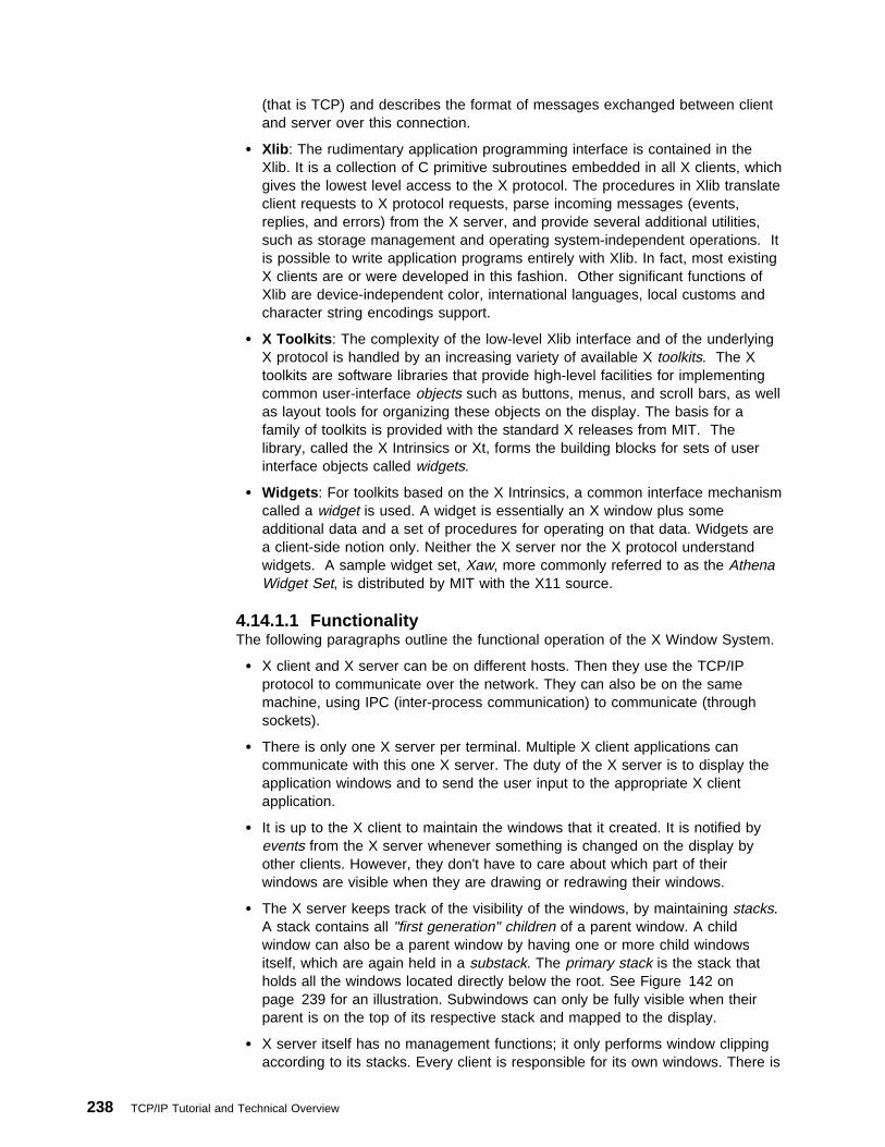
(that is TCP) and describes the format of messages exchanged between clientand server over this connection.
� Xlib : The rudimentary application programming interface is contained in theXlib. It is a collection of C primitive subroutines embedded in all X clients, whichgives the lowest level access to the X protocol. The procedures in Xlib translateclient requests to X protocol requests, parse incoming messages (events,replies, and errors) from the X server, and provide several additional utilities,such as storage management and operating system-independent operations. Itis possible to write application programs entirely with Xlib. In fact, most existingX clients are or were developed in this fashion. Other significant functions ofXlib are device-independent color, international languages, local customs andcharacter string encodings support.
� X Toolkits : The complexity of the low-level Xlib interface and of the underlyingX protocol is handled by an increasing variety of available X toolkits. The Xtoolkits are software libraries that provide high-level facilities for implementingcommon user-interface objects such as buttons, menus, and scroll bars, as wellas layout tools for organizing these objects on the display. The basis for afamily of toolkits is provided with the standard X releases from MIT. Thelibrary, called the X Intrinsics or Xt, forms the building blocks for sets of userinterface objects called widgets.
� Widgets : For toolkits based on the X Intrinsics, a common interface mechanismcalled a widget is used. A widget is essentially an X window plus someadditional data and a set of procedures for operating on that data. Widgets area client-side notion only. Neither the X server nor the X protocol understandwidgets. A sample widget set, Xaw, more commonly referred to as the AthenaWidget Set, is distributed by MIT with the X11 source.
4.14.1.1 FunctionalityThe following paragraphs outline the functional operation of the X Window System.
� X client and X server can be on different hosts. Then they use the TCP/IPprotocol to communicate over the network. They can also be on the samemachine, using IPC (inter-process communication) to communicate (throughsockets).
� There is only one X server per terminal. Multiple X client applications cancommunicate with this one X server. The duty of the X server is to display theapplication windows and to send the user input to the appropriate X clientapplication.
� It is up to the X client to maintain the windows that it created. It is notified byevents from the X server whenever something is changed on the display byother clients. However, they don't have to care about which part of theirwindows are visible when they are drawing or redrawing their windows.
� The X server keeps track of the visibility of the windows, by maintaining stacks.A stack contains all "first generation" children of a parent window. A childwindow can also be a parent window by having one or more child windowsitself, which are again held in a substack. The primary stack is the stack thatholds all the windows located directly below the root. See Figure 142 onpage 239 for an illustration. Subwindows can only be fully visible when theirparent is on the top of its respective stack and mapped to the display.
� X server itself has no management functions; it only performs window clippingaccording to its stacks. Every client is responsible for its own windows. There is
238 TCP/IP Tutorial and Technical Overview
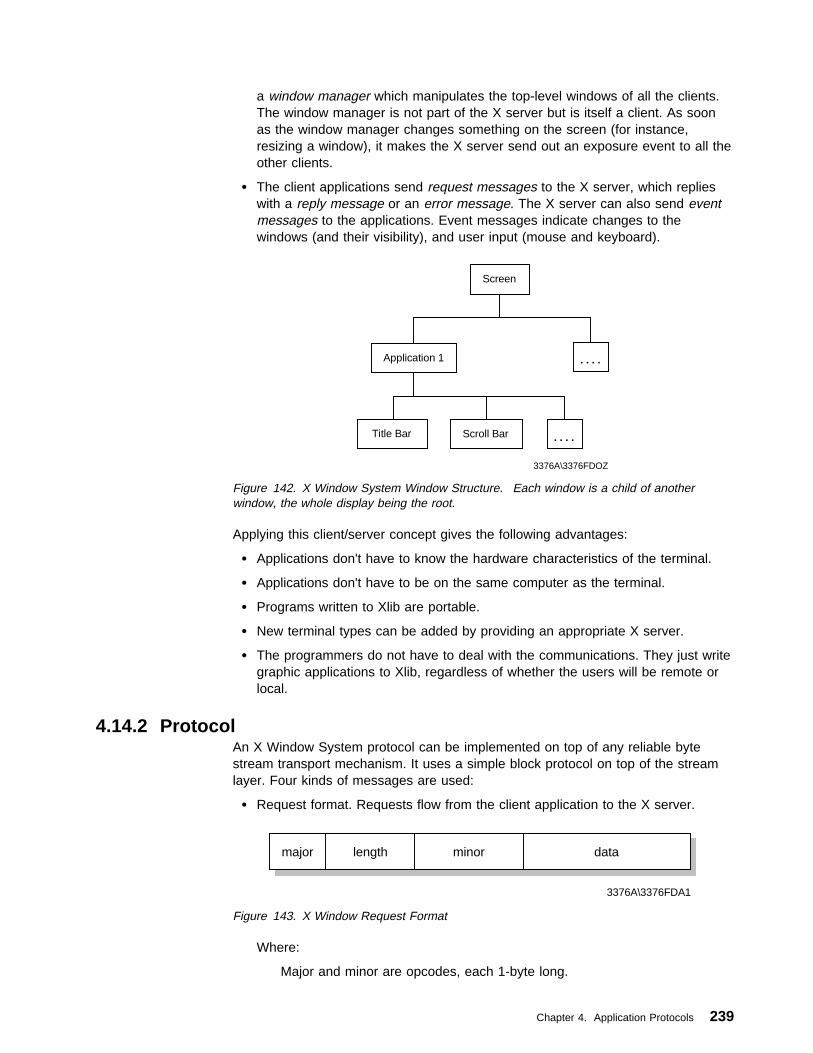
a window manager which manipulates the top-level windows of all the clients.The window manager is not part of the X server but is itself a client. As soonas the window manager changes something on the screen (for instance,resizing a window), it makes the X server send out an exposure event to all theother clients.
� The client applications send request messages to the X server, which replieswith a reply message or an error message. The X server can also send eventmessages to the applications. Event messages indicate changes to thewindows (and their visibility), and user input (mouse and keyboard).
Screen
Application 1
. . . .Title Bar Scroll Bar
. . . .
3376A\3376FDOZ
Figure 142. X Window System Window Structure. Each window is a child of anotherwindow, the whole display being the root.
Applying this client/server concept gives the following advantages:
� Applications don't have to know the hardware characteristics of the terminal.
� Applications don't have to be on the same computer as the terminal.
� Programs written to Xlib are portable.
� New terminal types can be added by providing an appropriate X server.
� The programmers do not have to deal with the communications. They just writegraphic applications to Xlib, regardless of whether the users will be remote orlocal.
4.14.2 ProtocolAn X Window System protocol can be implemented on top of any reliable bytestream transport mechanism. It uses a simple block protocol on top of the streamlayer. Four kinds of messages are used:
� Request format. Requests flow from the client application to the X server.
major length minor data
3376A\3376FDA1
Figure 143. X Window Request Format
Where:
Major and minor are opcodes, each 1-byte long.
Chapter 4. Application Protocols 239
Length is 2-bytes long.Data can be zero or more bytes, depending on the request.
� Reply format: 32-byte block.
� Error format: 32-byte block.
� Event format: 32-byte block.
Reply, error and event messages are sent by the X server to the X clientapplications.
Displays are always numbered from zero. For TCP connections, display number Nis associated with port 5800+N (hex 5800) and port 5900+N. The X server treatsconnections on the 58xx ports as connections with hosts that use the low-orderbyte first format, and the 59xx ports as high-order byte first.
There are more than a hundred different possible requests, each corresponding toan Xlib application call. As this document is not a programmer's guide, we will notdeal with the Xlib functions. RFC 1013 X Window System Protocol, Version 11contains the 1987 alpha update of the X11 protocol. For documentation on thecurrent release X11R6, please contact either MIT or a commercial computer bookspublisher.
4.15 Finger ProtocolFinger is a draft-standard protocol. Its status is elective. The current fingerspecification can be found in RFC 1288 — The Finger User Information Protocol.
The finger command displays information about users of a remote host. Finger is aUNIX command. Its format is:
finger user@host
orfinger @host
The information provided by the finger command about a user depends on theimplementation of the finger server. If a user is not specified, the information willtypically be a list of all users currently logged on to this host.
Connections are established through TCP port 79 (decimal). The client sends anASCII command string, ending with <CRLF>. The server responds with one ormore ASCII strings, until the server closes the connection.
4.16 NETSTATThe NETSTAT command is used to query TCP/IP about the network status of thelocal host. The exact syntax of this command is very implementation-dependent.See the User's Guide or the Command Reference Manual of your implementationfor full details. It is a useful tool for debugging purposes.
In general, NETSTAT will provide information on:
� Active TCP connections at this local host
� State of all TCP/IP servers on this local host and the sockets used by them
240 TCP/IP Tutorial and Technical Overview

� Devices and links used by TCP/IP
� The IP routing tables (gateway tables) in use at this local host
The NETSTAT command is implemented in all IBM software TCP/IP products.
4.17 Network Information System (NIS)The Network Information System (NIS) is not an Internet standard. It wasdeveloped by Sun Microsystems, Inc. It was originally known as the Yellow Pages.
NIS is a distributed database system which allows the sharing of systeminformation in an AIX- or UNIX-based environment. Examples of system informationthat can be shared include the /etc/passwd, /etc/group and /etc/hosts files. NIS hasthe following advantages:
� Provides a consistent user ID and group ID name space across a large numberof systems
� Reduces the time and effort by users in managing their user IDs, group IDsand NFS file system ownerships
� Reduces the time and effort by system administrators in managing user IDs,group IDs and NFS file system ownerships
NIS is built on the SUN-RPC. It employs the client/server model. An NIS domainis a collection of systems consisting of:
NIS master server Maintains maps, or databases, containing the systeminformation such as passwords and host names.
NIS slave server(s) Can be defined to offload the processing from the masterNIS server or when the NIS master server is unavailable.
NIS client(s) Are the remaining systems that are served by the NISservers.
The NIS clients do not maintain NIS maps; they query NIS servers for systeminformation. Any changes to an NIS map is done only to the NIS master server (viaRPC). The master server then propagates the changes to the NIS slave servers.
Note that the speed of a network determines the performance and availability of theNIS maps. When using NIS, the number of slave servers should be tuned in orderto achieve these goals.
4.18 NetBIOS over TCP/IPFor some time, the NetBIOS service has been a dominant mechanism fornetworking of personal computers in a LAN environment. NetBIOS is avendor-independant software interface (API), not a protocol. There is no officialNetBIOS specification, although in practice, the NetBIOS version described in theIBM publication SC30-3587 LAN Technical Reference: 802.2 and NetBIOS APIs isused as reference.
The NetBIOS service has some specific characteristics that limit its use in certainwide area network environments:
Chapter 4. Application Protocols 241

� NetBIOS workstations address each other using NetBIOS names. NetBIOSrelies on the broadcast technique to register and find NetBIOS names on thenetwork.
� NetBIOS uses a flat name space, which bears no relationship to the domainname system.
� NetBIOS generally uses the 802.2 interface, so it is not routable.
One solution to overcome these limitations is found in RFC 1001 — ProtocolStandard for a NetBIOS Service on a TCP/UDP Transport: Concepts and Methodsand RFC 1002 — Protocol Standard for a NetBIOS Service on a TCP/UDPTransport: Detailed Specifications.
As the titles suggest, these RFCs define a method of implementing NetBIOSservices on top of the Transmission Control Protocol (TCP) and User DatagramProtocol (UDP).
RFCs 1001/1002 do not define an encapsulation technique; they define themapping of NetBIOS services to UDP/IP and TCP/IP. For example, once aNetBIOS session has been established, sockets-send commands will be used overa TCP connection to send NetBIOS session data.
From the point of view of a network application, written to the NetBIOS interface,there is no change to the NetBIOS service. An application is unaware of thechange in the underlying protocol.
The NetBIOS service running over TCP and UDP is logically represented inFigure 144.
TELNET FTP SMTP TFTP
TCP UDP
NetBIOSApplications
TCP/NetBIOS
IP and ICMP
3376A\3376FDD1
Figure 144. TCP/IP and NetBIOS
RFC 1001 introduces a number of new concepts to facilitate NetBIOS operation ina TCP/IP environment:
NetBIOS ScopeThe NetBIOS scope is a group of computers across which a NetBIOS nameis known. In a standard NetBIOS configuration, using broadcast techniques,all the computers in this group would be able to contact each other. TheNetBIOS over TCP/IP implementation must provide an alternative method forthis group to communicate with each other, particularly as they may be
242 TCP/IP Tutorial and Technical Overview
spread across subnets. An internet may support multiple, non-intersectingNetBIOS scopes. Each NetBIOS scope has a scope identifier, which is acharacter string in a format compatible with the domain name system.
NetBIOS End NodeComputers using NetBIOS over TCP/IP are known as NetBIOS end nodes.RFC 1001 defines the following three types of end node:
Broadcast (B) nodeUses local broadcast UDP datagrams to establish connections anddistribute datagrams. Because broadcast datagrams cannottypically cross routers, B nodes (as defined in RFC 1001) can onlyestablish communications within a single network segment.
Point-to-Point (P) nodeRelies on a NetBIOS name server (NBNS) to establishconnections with other nodes and on a NetBIOS datagramdistributor (NBDD) for datagram distribution. P nodes neithergenerate, nor listen for, broadcast UDP packets, and use directedunicast packets only.
Mixed (M) nodeA mixed node is a combination of both B and P nodes. It usesboth unicast (to a NBNS) and broadcast packets
A fourth node type, the hybrid (H) node, although not defined in the RFCs, isalso widely implemented:
Hybrid (H) NodeThe hybrid node is also a combination of B and P nodes.However, the H node will always attempt to contact a NetBIOSname server initially, using unicast packets, and will only resort tobroadcast packets in the event that this is unsuccessful. The Hnode has an advantage over the M node in that it limits thegeneration of unwanted broadcast packets.
NetBIOS Name Server (NBNS)The NBNS registers the NetBIOS name/IP address of each P, M or H nodewhen it is initialized. Whenever a node wishes to contact another node bymeans of its NetBIOS name, it uses the NBNS to obtain the corresponding IPaddress for that node. NetBIOS names are combined with their scopeidentifiers and stored in an encoded form (which is a valid domain systemname) in the NBNS.
NetBIOS Datagram Distributor (NBDD)The NBDD extends the NetBIOS datagram distribution service to the internetenvironment. When an end node wishes to broadcast a datagram, the nodesends a unicast datagram, which contains the scope of the broadcast to theNBDD. The NBDD sends a NetBIOS datagram to each end node within thespecified NetBIOS scope, using the services of the NBNS to obtain therelevant IP addresses. (In practice it is likely that the NBNS and NBDD will beimplemented on the same device.)
Chapter 4. Application Protocols 243

4.18.1 NetBIOS over TCP/IP in IBM OS/2 Warp 4IBM OS/2 NetBIOS over TCP/IP can be configured in a B node (default), P node orH node implementation.
For B-node operations the NetBIOS over TCP/IP contains routing extensions, notdefined in the RFCs, that allow communication between networks over IP routersand bridges. The use of these extensions is optional, but if they are not active theNetBIOS over TCP/IP will operate only on the local LAN segment. The followingare the three routing extensions for the IBM NetBIOS over TCP/IP:
Names File Routing ExtensionThis routing extension is implemented through the use of a names file,x:\IBMCOM\RFCNAMES.LST which contains NetBIOS name and IPaddress pairs. This implementation requires an entry in the names filefor every other workstation with which a workstation needs tocommunicate. This file is conceptually similar to the TCP/IP hosts file.
The advantage of using a names file is in the reduction of name querybroadcasts, because before the NetBIOS over TCP/IP programbroadcasts to the network for NetBIOS name to IP address resolution, itsearches this local file.
If an address in the file is given, not as an IP address, but as a hostname string, it is translated to an IP address by the TCP/IPGetHostByName() function by looking it up in the local hosts file or byquerying the Internet domain name server. The host name string musttherefore be in the same form here as it is in the hosts file or on thedomain name server.
Broadcast File Routing ExtensionThis routing extension is implemented through the use of a broadcastfile, x:\IBMCOM\RFCBCST.LST. A TCP/IP is normally limited to asingle subnet unless the broadcast file exists. The broadcast filecontains a list of host names (such as deptsrvr), host IP addresses(such as 9.67.60.80) or subnet broadcast addresses (such asausvm1.austin.ibm.com). The file is read once at startup and each validaddress is added to the set of destination addresses for broadcastpackets. Any host or network accessible by these addresses becomespart of the local NetBIOS broadcast domain; that is, they receive allname lookup and registration packets as well as all broadcast and groupNetBIOS datagrams. These addresses can be on other networks andaccessed through the appropriate router or bridge by the IBM TCP/IPprogram. The remote node is treated as if it were a node on the localnetwork.
Each line of the broadcast file is either an IP address in dotted decimalnotation (for example, 89.0.0.1) or a host name string that occurs ineither the local hosts file used by the IBM TCP/IP program or on anInternet domain name server. If an address is given as a host namestring, it is translated to an IP address by the TCP/IP GetHostByName()function by looking it up in the local hosts file or by querying an Internetdomain name server. The host name string must be in the same formhere as it is in the hosts file or on the domain name server.
A maximum of 32 entries is allowed in the broadcast file.
244 TCP/IP Tutorial and Technical Overview

Domain Name Server (DNS) Routing ExtensionThis routing extension uses a TCP/IP domain name server (DNS) as acentral repository for NetBIOS name and IP address pairs, so that theNetBIOS over TCP/IP clients can obtain the IP address of otherworkstations. This extension requires that the network administratorenters the NetBIOS name (in an encoded format) and the IP address ofevery NetBIOS over TCP/IP workstation into the domain name server.The NetBIOS names must be entered into the DNS in an encodedformat. An encoded format is necessary, because NetBIOS names are16 bytes of any bit pattern and the domain name server accepts alimited character set. The NetBIOS over TCP/IP program encodes theminto the 32-byte, reversible, half-ASCII format that is specified in RFC1001. A MAPNAME utility is available to encode and decode NetBIOSnames. (The MAPNAME utility can also be used to enter encodedNetBIOS name/IP address pairs into the local HOSTS file at theworkstation.)
If B node operation is configured with one or more of the routing extensions, anOS/2 client uses the different methods of resolving NetBIOS names in the followingorder:
1. Look up the local name cache (NetBIOS names that have already beenresolved by any method are stored in this cache)
2. Look up the local names file x:\IBMCOM\RFCNAMES.LST3. Search the domain name server4. Check the x:\MPTN\ETC\HOSTS file5. Use the broadcast file x:\IBMCOM\RFCBCST.LST6. Broadcast to local subnet
The routing extensions to the B node usefully extend the range of NetBIOS clientsin a TCP/IP environment. However, whatever extension is used, a considerableamount of configuration is necessary either at the client, or at the DNS. Also, theextensions have no value in a Dynamic IP environment, when an administrator willnot be able to tell in advance which IP address should be mapped to whichNetBIOS name.
A superior solution is always to use a dedicated NetBIOS name server that mapsNetBIOS names to IP addresses dynamically (see 4.18.3, “NetBIOS Name Server(NBNS) Implementations” on page 247).
4.18.2 NetBIOS over TCP/IP in Microsoft Windows SystemsWhenever Windows NT 4.0, Windows 95, or Windows 98 clients are configured touse the TCP/IP protocol, client-to-server or peer-to-peer file or printer sharing isactually conducted using NetBIOS over TCP/IP.
NetBIOS over TCP/IP in a Windows environment is also based on RFCs1001/1002, with routing extensions.
Windows 95, Windows 98 and Windows NT can use a file called LMHOSTS toperform NetBIOS name to IP address resolution. Under Windows 95 and Windows98, the file should be located in the \WINDOWS subdirectory, while under NT, it islocated in \WINNT\SYSTEM32\DRIVERS\ETC. LMHOSTS performs a similarfunction to the RFCNAMES.LST file on an OS/2 workstation. At its simplest, the
Chapter 4. Application Protocols 245

file contains NetBIOS name and IP address pairs. Additional options are availableto enhance the configuration.
Unlike OS/2 clients, Windows clients do not support the domain name serverrouting extension using names encoded to the RFC 1001/1002 specification.However, Microsoft's Service Pack 3 for Windows NT 4.0 introduces a new way ofNetBIOS name resolution, using non-RFC-encoded names in the DNS. Thistechnique requires the node status request frame (defined in RFC 1001/1002) andcan be implemented on both Windows NT Workstation clients and Windows NTServer.
Note: A fix (APAR IC20646) is available for IBM OS/2 Warp Server to supportnode status request frames, but OS/2 Warp clients do not yet support thisnew technique.
In the DNS domain file, the Windows NT Server computer name, also known asserver name, is appended as a pure ASCII name with an A record that points tothe server's static IP address. In addition, the domain name is included with analias, CNAME, to the server's name. For a domain controller SERVER-A in thedomain DOMAIN-A, the entries in the DNS domain file would look like the followingtwo lines:
SERVER-A IN A 9.53.4.5
DOMAIN-A IN CNAME SERVER-A.
The logon sequence would use the following steps:
1. The Windows NT Workstation client queries the DNS server for hostnameDOMAIN-A.
2. The DNS server returns the information that DOMAIN-A is the alias toSERVER-A. The Windows NT Workstation client receives the IP address ofthe Windows NT Server.
3. Since the Windows NT Workstation client is not sure whether or not the targetIP address is really a NetBIOS node, which has certain NetBIOS namesregistered, it sends a node status request frame to the received IP address(which is the Windows NT Server). This node status request frame passes aresource record name of * (asterisk).
4. The Windows NT Server responds to the node status request by sending acomplete list of NetBIOS names registered in the node.
5. The Windows NT Workstation client now selects the target IP address for thecorrect server name and domain name, then it starts the logon sequencethrough an SMB session.
This technique might be called DNS-Only or Use of non-RFC-encoded namesNetBIOS name resolution, but it actually is a combination of DNS name resolutionand the use of the node status request frame defined in the RFC 1001/1002.
Windows NT, Windows 95, and Windows 98 workstations can also resolveNetBIOS names to IP addresses by using a NetBIOS name server.
246 TCP/IP Tutorial and Technical Overview

4.18.3 NetBIOS Name Server (NBNS) ImplementationsNetBIOS name servers dynamically register NetBIOS-to-IP mappings for P, H andM node workstations as they are initialized and respond to requests for thosemappings. The NBNS is the simplest NetBIOS over IP solution to manage, as itremoves the requirement for manual configuration of files, either on the clientworkstations, or on the DNS.
4.18.3.1 Microsoft Windows Internet Name Service (WINS)Windows Internet Name Service (WINS) is Microsoft's implementation of an NBNS.WINS only supports Microsoft's proprietary clients with its implementation of nativeNetBIOS and NetBIOS over TCP/IP
Each Microsoft client needs to be configured with the IP address of a primary WINSserver, and optionally with the IP address of a secondary WINS server. Whenevera client starts, it will attempt to register its NetBIOS name and IP address with theprimary WINS server. The registration occurs when services or applications arestarted (for example, Workstation or Messenger), and is sent directly to the primaryWINS server. If the name is not already registered to another client, the serverresponds with a message detailing the NetBIOS name that has been registered,and the name time-to-live (TTL). If the client attempts three times to register itsname with the primary server and fails, the client will attempt to register its namewith the secondary server. If the secondary server also fails to respond, the clientwill revert to broadcasting in order to register its name.
The name registrations are made on a temporary basis, and the client isresponsible for maintaining the lease of the registered name. At one-eighth of theTTL, the client will attempt to refresh its name registration with the primary WINSserver. If the client does not receive a response from the server, it will continue toattempt to refresh the registration every two minutes until half the TTL has expired.At this point it will repeat the procedure, but this time using the secondary WINSserver.
With WINS enabled, the client acts as an H node client for name registration. Forresolution, it is H node with a few modifications. The sequence used by a WINSclient for name resolution is:
1. Check to see if it is the local machine name.2. Check the local cache. (Any resolved name is placed in a cache for 10
minutes.)3. Try to use the primary WINS server. (Use the secondary server if the primary
does not answer after three attempts).4. Try a name query broadcast.5. Check the LMHOSTS file. (If the computer is configured to use LMHOSTS).6. Try the HOSTS file.7. Try the DNS.
WINS Limitations: According to RFC 1001/1002, a NetBIOS name server shouldsupport all NetBIOS group names. WINS, however, only keeps a list of IPaddresses for group names ending in 0x1C. IBM OS/2 Warp Server domains, forexample, are registered with a 0x00 suffix and, as such, are not stored by a WINSserver. The WINS NBNS only supports Windows 9x and NT clients.
Chapter 4. Application Protocols 247

4.18.3.2 Network TeleSystems (NTS) Shadow IPserverShadow IPserver is a software system for managing name and addressassignments and desktop configuration information within a TCP/IP network.IPserver includes a robust set of network services offered through standards-basedprotocol interactions, such as:
� DHCP service
� DNS service
� NBNS and NBDD services
The Shadow IPserver NBNS service is an integrated NetBIOS name server anddatagram distributor. The IPserver NBNS service fully implements RFCs 1001 and1002. The NBNS service provides name resolution services similar to thoseprovided by Microsoft WINS, but supports any client configured for P, H or M nodeoperation. Microsoft Windows 9x and Windows NT protocol stacks do not supportdatagram distribution, however. The Shadow IPserver supports up to 16,000names on a single server and is the NBNS recommended by IBM for use in OS/2networks.
For further information on NetBIOS over TCP/IP, please refer to RFC 1001 andRFC 1002. For information on the IBM OS/2 and Microsoft Windowsimplementations, please refer to the IBM redbooks SG24-2009 Network Clients forOS/2 Warp Server and SG24-5280 Beyond DHCP - Work Your TCP/IPInternetwork with Dynamic IP.
4.19 Application Programming Interfaces (APIs)Application programming interfaces allow developers to write applications that canmake use of TCP/IP services. The following sections provide an overview of themost common APIs for TCP/IP applications.
4.19.1 The Socket APIThe socket interface is one of several application programming interfaces (APIs) tothe communication protocols. Designed to be a generic communicationprogramming interface, it was first introduced by the 4.2BSD UNIX system.Although it has not been standardized, it has become a de facto industry standard.
The socket interface is differentiated by the services that are provided toapplications: stream sockets (connection-oriented), datagram sockets(connectionless), and raw sockets (direct access to lower layer protocols) services.Please see 2.6, “Ports and Sockets” on page 73 for more detail about ports andsockets.
A variation of the BSD sockets interface is provided by the Winsock interfacedeveloped by Microsoft and other vendors to support TCP/IP applications onWindows operating systems. Winsock 2.0, the latest version, provides a moregeneralized interface allowing applications to communicate with any availabletransport layer protocol and underlying network services, including, but no longerlimited to, TCP/IP. Please see 4.19.3, “Windows Sockets Version 2 (WinsockV2.0)” on page 256 for more information about Winsock.
248 TCP/IP Tutorial and Technical Overview
4.19.1.1 Basic Socket CallsThe following lists some basic socket interface calls. In the next section we see anexample scenario of using these socket interface calls.
� Initialize a socket.
FORMAT:
int sockfd = socket(int family, int type, int protocol)
Where:
– family stands for addressing family. It can take on values such asAF_UNIX, AF_INET, AF_NS, AF_OS2 and AF_IUCV. Its purpose is tospecify the method of addressing used by the socket.
– type stands for the type of socket interface to be used. It can take onvalues such as SOCK_STREAM, SOCK_DGRAM, SOCK_RAW, andSOCK_SEQPACKET.
– protocol can be UDP, TCP, IP or ICMP.– sockfd is an integer (similar to a file descriptor) returned by the socket call.
� Bind (register) a socket to a port address.
FORMAT:
int bind(int sockfd, struct sockaddr \localaddr, int addrlen)
Where:
– sockfd is the same integer returned by the socket call.– localaddr is the local address returned by the bind call.
Note that after the bind call, we now have values for the first three parametersinside our 5-tuple association:
{protocol, local-address, local-process, foreign-address, foreign-process}
� Indicate readiness to receive connections.
FORMAT:
int listen(int sockfd, int queue-size)
Where:
– sockfd is the same integer returned by the socket call.– queue-size indicates the number of connection requests that can be
queued by the system while the local process has not yet issued the acceptcall.
� Accept a connection.
FORMAT:
int accept(int sockfd, struct sockaddr \foreign-address, int addrlen)
Where:
– sockfd is the same integer returned by the socket call.– foreign-address is the address of the foreign (client) process returned by
the accept call.
Note that this accept call is issued by a server process rather than a clientprocess. If there is a connection request waiting on the queue for this socketconnection, accept takes the first request on the queue and creates anothersocket with the same properties as sockfd; otherwise, accept will block thecaller process until a connection request arrives.
Chapter 4. Application Protocols 249

� Request connection to the server.
FORMAT:
int connect(int sockfd, struct sockaddr \foreign-address, int addrlen)
Where:
– sockfd is the same integer returned by the socket call.– foreign-address is the address of the foreign (server) process returned by
the connect call.
Note that this call is issued by a client process rather than a server process.
� Send and/or receive data.
The read(), readv(sockfd, char *buffer int addrlen), recv(), readfrom(),send(sockfd, msg, len, flags) and write() calls can be used to receive and senddata in an established socket association (or connection).
Note that these calls are similar to the standard read and write file I/O systemcalls.
� Close a socket.
FORMAT:
int close(int sockfd)
Where:
– sockfd is the same integer returned by the socket call.
For more details, please refer to the literature listed in Appendix B, “RelatedPublications” on page 677.
4.19.1.2 An Example ScenarioAs an example, consider the socket system calls for a connection-oriented protocol.
250 TCP/IP Tutorial and Technical Overview
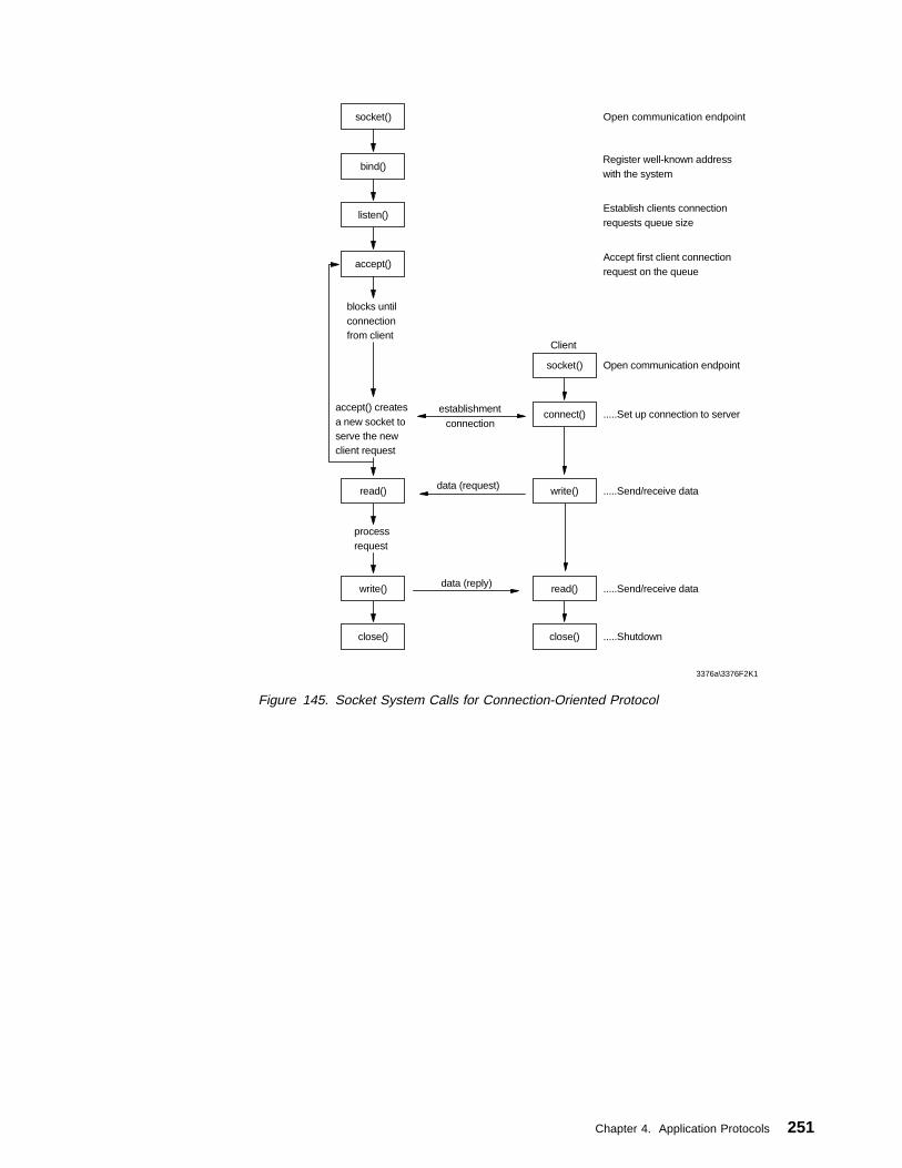
connectionestablishment
data (reply)
connect()
write()
read()
close()
socket()
Client
data (request)
Open communication endpoint
Register well-known addresswith the system
Establish clients connectionrequests queue size
Accept first client connectionrequest on the queue
.....Set up connection to server
.....Send/receive data
.....Shutdown
.....Send/receive data
Open communication endpoint
read()
socket()
bind()
listen()
accept()
write()
close()
accept() createsa new socket toserve the newclient request
blocks untilconnectionfrom client
processrequest
3376a\3376F2K1
Figure 145. Socket System Calls for Connection-Oriented Protocol
Chapter 4. Application Protocols 251

Consider the previous socket system calls in terms of specifying the elements ofthe association:
ProtocolLocal
Address ,Local
ProcessForeign
Address ,ForeignProcess
connection-oriented server socket() bind() listen() accept()
connection-oriented client connect()socket()
connectionless server recvfrom()socket() bind()
connectionless client sendto()socket() bind()
3376a\3376FDK2
Figure 146. Socket System Calls and Association
The socket interface is differentiated by the different services that are provided.Stream, datagram, and raw sockets each define a different service available toapplications.
� Stream socket interface (SOCK_STREAM): It defines a reliableconnection-oriented service (over TCP for example). Data is sent withouterrors or duplication and is received in the same order as it is sent. Flowcontrol is built-in to avoid data overruns. No boundaries are imposed on theexchanged data, which is considered to be a stream of bytes. An example ofan application that uses stream sockets is the File Transfer Program (FTP).
� Datagram socket interface (SOCK_DGRAM): It defines a connectionlessservice (over UDP for example). Datagrams are sent as independent packets.The service provides no guarantees; data can be lost or duplicated, anddatagrams can arrive out of order. No disassembly and reassembly of packetsis performed. An example of an application that uses datagram sockets is theNetwork File System (NFS).
� Raw socket interface (SOCK_RAW): It allows direct access to lower layerprotocols such as IP and ICMP. This interface is often used for testing newprotocol implementations. An example of an application that uses raw socketsis the Ping command.
4.19.2 Remote Procedure Call (RPC)Remote Procedure Call is a standard developed by Sun Microsystems and used bymany vendors of UNIX systems.
RPC is an application programming interface (API) available for developingdistributed applications. It allows programs to call subroutines that are executed ata remote system. The caller program (called client) sends a call message to theserver process, and waits for a reply message. The call message includes theprocedure's parameters and the reply message contains the procedure's results.RPC also provides a standard way of encoding data in a portable fashion betweendifferent systems called External Data Representation (XDR).
252 TCP/IP Tutorial and Technical Overview
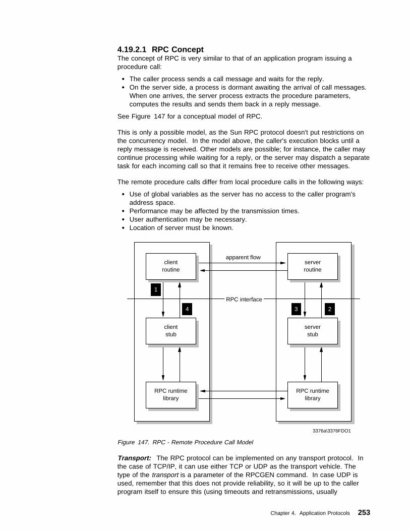
4.19.2.1 RPC ConceptThe concept of RPC is very similar to that of an application program issuing aprocedure call:
� The caller process sends a call message and waits for the reply.� On the server side, a process is dormant awaiting the arrival of call messages.
When one arrives, the server process extracts the procedure parameters,computes the results and sends them back in a reply message.
See Figure 147 for a conceptual model of RPC.
This is only a possible model, as the Sun RPC protocol doesn't put restrictions onthe concurrency model. In the model above, the caller's execution blocks until areply message is received. Other models are possible; for instance, the caller maycontinue processing while waiting for a reply, or the server may dispatch a separatetask for each incoming call so that it remains free to receive other messages.
The remote procedure calls differ from local procedure calls in the following ways:
� Use of global variables as the server has no access to the caller program'saddress space.
� Performance may be affected by the transmission times.� User authentication may be necessary.� Location of server must be known.
serverstub
23
1
4
clientstub
apparent flow
RPC interface
serverroutine
clientroutine
RPC runtimelibrary
RPC runtimelibrary
3376a\3376FDO1
Figure 147. RPC - Remote Procedure Call Model
Transport: The RPC protocol can be implemented on any transport protocol. Inthe case of TCP/IP, it can use either TCP or UDP as the transport vehicle. Thetype of the transport is a parameter of the RPCGEN command. In case UDP isused, remember that this does not provide reliability, so it will be up to the callerprogram itself to ensure this (using timeouts and retransmissions, usually
Chapter 4. Application Protocols 253

implemented in RPC library routines). Note that even with TCP, the caller programstill needs a timeout routine to deal with exceptional situations such as a servercrash.
The call and reply message data is formatted to the XDR standard.
RPC Call Message: The RPC call message consists of several fields:
� Program and procedure numbers
Each call message contains three fields (unsigned integers): that uniquelyidentify the procedure to be executed:
– Remote program number– Remote program version number– Remote procedure number
The remote program number identifies a functional group of procedures, forinstance a file system, which would include individual procedures such as readand write. These individual procedures are identified by a unique procedurenumber within the remote program. As the remote program evolves, a versionnumber is assigned to the different releases.
Each remote program is attached to an internet port. The number of this portcan be freely chosen, except for the reserved well-known-services portnumbers. It is evident that the caller will have to know the port number used bythis remote program.
Assigned program numbers:
00000000 - 1FFFFFFF defined by Sun20000000 - 3FFFFFFF defined by user40000000 - 5FFFFFFF transient (temporary numbers)60000000 - FFFFFFFF reserved
� Authentication fields
Two fields, credentials and verifier, are provided for the authentication of thecaller to the service. It is up to the server to use this information for userauthentication. Also, each implementation is free to choose the varieties ofsupported authentication protocols. Some authentication protocols are:
– Null authentication.– UNIX authentication. The callers of a remote procedure may identify
themselves as they are identified on the UNIX system.– DES authentication. In addition to user ID, a timestamp field is sent to the
server. This timestamp is the current time, enciphered using a key knownto the caller machine and server machine only (based on the secret keyand public key concept of DES).
� Procedure parameters
Data (parameters) passed to the remote procedure.
RPC Reply Message: Several replies exist, depending on the action taken:
� SUCCESS: Procedure results are sent back to the client.� RPC_MISMATCH: Server is running another version of RPC than the caller.� AUTH_ERROR: Caller authentication failed.� PROG_MISMATCH: If program is unavailable or if the version asked for does
not exist or if the procedure is unavailable.
254 TCP/IP Tutorial and Technical Overview

For a detailed description of the call and reply messages, see RFC 1057 RPC:Remote Procedure Call Protocol Specification Version 2, which also contains thetype definitions (typedef) for the messages in XDR language.
Portmap or Portmapper: The Portmap or Portmapper is a server application thatwill map a program number and its version number to the Internet port numberused by the program. Portmap is assigned the reserved (well-known service) portnumber 111.
Portmap only knows about RPC programs on the host it runs on. In order forPortmap to know about the RPC program, every RPC program should register itselfwith the local Portmapper when it starts up.
The RPC client (caller) has to ask the Portmap service on the remote host aboutthe port used by the desired server program.
Normally, the calling application would contact Portmap on the destination host toobtain the correct port number for a particular remote program, and then send thecall message to this particular port. A variation exists when the caller also sendsthe procedure data along to Portmap and then the remote Portmap directly invokesthe procedure.
RPC Client Host RPC Server Host
Call/Reply
Portmap
Register with:{Program No., Version No., Procedure No. and Protocol Used}
1
2
4
Port No.
3
Get Port No. of RPC Server
RPC ClientProgram
RPCServerProgram
3376a\3376FDO2
(iii)
(xyz)(xyz)
Figure 148. RPC - Portmap
RPCGEN: RPCGEN is a tool that generates C code to implement an RPCprotocol. The input to RPCGEN is a file written in a language similar to C, knownas the RPC language. Assuming that an input file named proto.x is used, RPCGENproduces the following output files:
� A header file called proto.h that contains common definitions of constants andmacros
� Client stub source file, protoc.c� Server stub source file, protos.c� XDR routines source file, protox.c
Chapter 4. Application Protocols 255

4.19.3 Windows Sockets Version 2 (Winsock V2.0)Winsock V2.0 is a network programming interface. It is basically a version ofBerkeley Sockets adapted for Microsoft Windows operating systems with morefunctions and enhancements. The previous version of the Winsock API, WindowsSockets V1.1, is widely implemented. Therefore, Winsock V2.0 retains backwardscompatibility with Winsock V1.1 but provides many more functions. One of themost significant aspects of Winsock V2.0 is that it provides a protocol-independenttransport interface supporting various networking capabilities. Besides, WinsockV2.0 also supports the coexistence of multiple protocol stacks. The new functionsof Winsock V2.0 can be summarized as follows:
� Support for multiple protocols� Protocol-independent name resolution� Quality of Service� Protocol-independent multicast and multipoint� Overlapped I/O and event objects
� Socket sharing� Layered service providers
The Winsock V1.1 architecture permits only one Dynamic Link Library (DLL),WINSOCK.DLL or WSOCK32.DLL, on a system at a time, which provides theWinsock API with a way to communicate with an underlying transport protocol.This approach restricts the use of different types of Winsock implementations inconjunction with Winsock V1.1. For systems that have more than one networkinterface, this can become a hindrance. Winsock V2.0 provides a better solution tothis problem. The new Winsock V2.0 architecture allows for simultaneous supportof multiple protocol stacks, interfaces, and service providers. Figure 149 onpage 257 illustrates the Winsock V2.0 structure.
256 TCP/IP Tutorial and Technical Overview

Winsock 1.1Application
(32-bit)
Winsock1.1Application
(16-bit)
WSOCK32.DLL(32-bit)
TransportServiceProvider
Name SpaceServiceProvider
AdditionalService
Providers
Transportand
Name SpaceFunctions
The Winsock 2 DLLWS2_32.DLL
(32-bit)
Winsock 2Application
Winsock 1.1API
Winsock 2API
Winsock 2SPI
Winsock.DLL(16-bit)
3376E\3376FDA3
Figure 149. Winsock V2.0 Architecture
4.19.4 SNMP Distributed Programming Interface (SNMP DPI)SNMP defines a protocol that permits operations on a collection of variables. Thisset of variables (MIB) and a core set of variables have previously been defined.However, the design of the MIB makes provision for extension of this core set.Unfortunately, conventional SNMP agent implementations provide no means for anend user to make new variables available. The SNMP DPI addresses this issue byproviding a light-weight mechanism that permits end users to dynamically add,delete, or replace management variables in the local MIB without requiringrecompilation of the SNMP agent. This is achieved by writing the so-calledsubagent that communicates with the agent via the SNMP DPI. It is described inRFC 1592.
The SNMP DPI allows a process to register the existence of a MIB variable withthe SNMP agent. When requests for the variable are received by the SNMP agent,it will pass the query on to the process acting as a subagent. This subagent thenreturns an appropriate answer to the SNMP agent. The SNMP agent eventuallypackages an SNMP response packet and sends the answer back to the remotenetwork management station that initiated the request. None of the remote networkmanagement stations have any knowledge that the SNMP agent calls on otherprocesses to obtain an answer.
Communication between the SNMP agent and its clients (subagents) takes placeover a stream connection. This is typically a TCP connection, but other
Chapter 4. Application Protocols 257
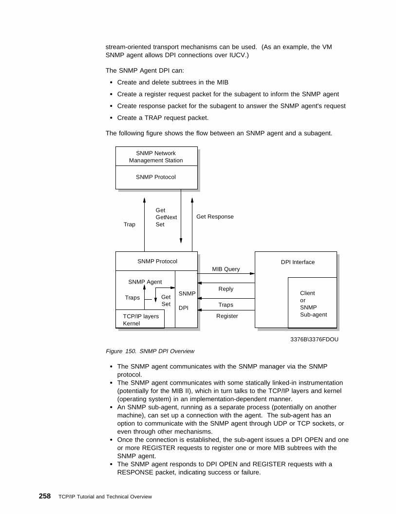
stream-oriented transport mechanisms can be used. (As an example, the VMSNMP agent allows DPI connections over IUCV.)
The SNMP Agent DPI can:
� Create and delete subtrees in the MIB
� Create a register request packet for the subagent to inform the SNMP agent
� Create response packet for the subagent to answer the SNMP agent's request
� Create a TRAP request packet.
The following figure shows the flow between an SNMP agent and a subagent.
SNMP Agent
SNMP
DPI
TCP/IP layers Kernel
SNMP Protocol
Traps Get Set
ClientorSNMP Sub-agent
DPI Interface
SNMP Protocol
SNMP Network Management Station
Trap
Get GetNext Set
Get Response
MIB Query
Reply
Traps
Register
3376B\3376FDOU
Figure 150. SNMP DPI Overview
� The SNMP agent communicates with the SNMP manager via the SNMPprotocol.
� The SNMP agent communicates with some statically linked-in instrumentation(potentially for the MIB II), which in turn talks to the TCP/IP layers and kernel(operating system) in an implementation-dependent manner.
� An SNMP sub-agent, running as a separate process (potentially on anothermachine), can set up a connection with the agent. The sub-agent has anoption to communicate with the SNMP agent through UDP or TCP sockets, oreven through other mechanisms.
� Once the connection is established, the sub-agent issues a DPI OPEN and oneor more REGISTER requests to register one or more MIB subtrees with theSNMP agent.
� The SNMP agent responds to DPI OPEN and REGISTER requests with aRESPONSE packet, indicating success or failure.
258 TCP/IP Tutorial and Technical Overview

� The SNMP agent will decode SNMP packets. If such a packet contains a Getor GetNext request for an object in a subtree registered by a sub-agent, itsends a corresponding DPI packet to the sub-agent. If the request is for aGetBulk, then the agent translates it into multiple DPI GETNEXT packets andsends those to the sub-agent. However, the sub-agent can request (in theREGISTER packet) that a GETBULK be passed to the sub-agent. If therequest is for a Set, then the agent uses a 2-phase commit scheme and sendsthe sub-agent a sequence of SET/COMMIT, SET/UNDO orSET/COMMIT/UNDO DPI packets.
� The SNMP sub-agent sends responses back via a RESPONSE packet.� The SNMP agent then encodes the reply into an SNMP packet and sends it
back to the requesting SNMP manager.� If the sub-agent wants to report an important state change, it sends a DPI
TRAP packet to the SNMP agent which will encode it into an SNMP trappacket and send it to the manager(s).
� If the sub-agent wants to stop operations, it sends a DPI UNREGISTER and aDPI CLOSE packet to the agent. The agent sends a response to anUNREGISTER request.
� There is no RESPONSE to a CLOSE; the agent just closes the DPI connection.A CLOSE implies an UNREGISTER for all registrations that exist for the DPIconnection being CLOSED.
� An agent can send DPI UNREGISTER (if a higher priority registration comes inor for other reasons) to the sub-agent. The sub-agent then responds with aDPI RESPONSE packet.
� An agent can also (for whatever reason) send a DPI CLOSE to indicate it isterminating the DPI connection.
� A sub-agent can send an ARE_YOU_THERE to verify that the connection isstill open. If so, the agent sends a RESPONSE with no error, otherwise, it maysend a RESPONSE with an error.
4.19.5 FTP APIThe file transfer protocol (FTP) API is supplied as part of TCP/IP for OS/2. Itallows applications to have a client interface for file transfer. Applications written tothis interface can communicate with multiple FTP servers at the same time. Itallows up to 256 simultaneous connections and enables third-party proxy transfersbetween pairs of FTP servers. Consecutive third-party transfers are allowedbetween any sequence of pairs of FTP servers. An example of such an applicationis FTPPM.
The FTP API tracks the servers to which an application is currently connected.When a new request for FTP service is requested, the API checks whether aconnection to the server exists and establishes one if it does not exist. If the serverhas dropped the connection since last use, the API re-establishes it.
Note: The FTP API is not re-entrant. In a multithreaded program, the access tothe APIs must be serialized. For example, without serialization, theprogram may fail if it has two threads running concurrently and each threadhas its own connection to a server.
Chapter 4. Application Protocols 259
4.19.6 CICS Socket InterfaceCustomer Information Control System (CICS) is a high-performancetransaction-processing system. It was developed by IBM and has productimplementations in MVS/ESA, MVS, VSE, OS/400, OS/2 and AIX/6000.
CICS is the most widely used Online Transaction Processing (OLTP) system in themarketplace today. It provides a rich set of CICS command level APIs to theapplication transaction programs for data communications (using SNA) anddatabase (using VSAM, IMS or DB2).
Given the need for interoperability among heterogeneous network protocols, thereis a requirement to enhance the CICS data communications interface to includesupport for TCP/IP in addition to SNA. The IBM Sockets Interface for CICS is a firststep towards addressing this requirement.
4.19.7 IMS Socket InterfaceThe IMS socket interface is implemented in TCP/IP for OS/390 V2R5.
The IMS to TCP/IP sockets interface allows you to develop IMS messageprocessing programs that can conduct a conversation with peer programs in otherTCP/IP hosts. The applications can be either client or server applications. The IMSto TCP/IP sockets interface includes socket interfaces for IBM C/370, assemblerlanguage, COBOL, and PL/I languages to use datagram (connectionless) andstream (connection-oriented) sockets. It also provides ASCII-EBCDIC conversionroutines, an ASSIST module that permits the use of conventional IMS calls forTCP/IP communications, and a Listener function to listen for and accept connectionrequests and start the appropriate IMS transaction to service those requests.
4.19.8 Sockets ExtendedThe Sockets Extended information described here is related to the implementationin MVS only.
Sockets Extended provides programmers writing in assembler language, COBOL,or PL/I with an application program interface that may be used to conductpeer-to-peer conversations with other hosts in the TCP/IP networks. You candevelop applications for TSO, batch, CICS, or IMS using this API. The applicationsmay be designed to be reentrant and multithreaded depending upon the applicationrequirements. Typically server applications will be multithreaded while clientapplications might not be.
4.19.9 REXX SocketsREXX sockets allow you to develop REXX applications that communicate over aTCP/IP network. Calls are provided to initialize sockets, exchange data via sockets,perform management activities, and close the sockets.
The REXX Socket APIs are implemented in TCP/IP for MVS and OS/2.
260 TCP/IP Tutorial and Technical Overview

Part 2. Special Purpose Protocols and New Technologies
Copyright IBM Corp. 1989, 1998 261

262 TCP/IP Tutorial and Technical Overview

Chapter 5. TCP/IP Security Overview
This chapter discusses security issues regarding TCP/IP networks and provides anoverview of solutions to resolve security problems before they can occur. The fieldof network security in general and of TCP/IP security in particular is too wide to bedealt with in an all encompassing way in this book, so the focus of this chapter ison the most common security exposures and measures to counteract them.Because many, if not all, security solutions are based on cryptographic algorithms,we also provide a brief overview of this topic for the better understanding ofconcepts presented throughout this chapter.
5.1 Security Exposures and SolutionsThis section gives an overview of some of the most common attacks on computersecurity, and it presents viable solutions to those exposures and lists actualimplementations thereof.
5.1.1 Common Attacks Against SecurityFor thousands of years, people have been guarding the gates to where they storetheir treasures and assets. Failure to do so usually resulted in being robbed,neglected by society or even killed. Though things are usually not as dramaticanymore, they can still become very bad. Modern day I/T managers have realizedthat it is equally important to protect their communications networks againstintruders and saboteurs from both inside and outside. One does not have to beoverly paranoid to find some good reasons as to why this is the case:
� Tapping the wire: to get access to cleartext data and passwords
� Impersonation: to get unauthorized access to data or to create unauthorizede-mails, orders, etc.
� Denial-of-service: to render network resources non-functional
� Replay of messages: to get access to and change information in transit
� Guessing of passwords: to get access to information and services that wouldnormally be denied (dictionary attack)
� Guessing of keys: to get access to encrypted data and passwords (brute-forceattack)
� Viruses: to destroy data
Though these attacks are not exclusively specific to TCP/IP networks, they shouldbe considered potential threats to anyone who is going to base their network onTCP/IP, which is what the majority of enterprises, organizations and smallbusinesses around the world are doing today. Hackers do likewise and hence findeasy prey.
Copyright IBM Corp. 1989, 1998 263

5.1.2 Solutions to Network Security ProblemsWith the same zealousness that intruders search for a way to get into someone'scomputer network, the owners of such networks should, and most likely will, try toprotect themselves. Taking on the exposures mentioned before, here are somesolutions to effectively defend oneself against an attack. It has to be noted that anyof those solutions only solve a single or just a very limited number of securityproblems. Therefore, a combination of several such solutions should be consideredin order to guarantee a certain level of safety and security.
� Encryption: to protect data and passwords
� Authentication and authorization: to prevent improper access
� Integrity checking and message authentication codes: to protect againstimproper alteration of messages
� Non-repudiation: to make sure that an action cannot be denied by the personwho performed it
� Digital signatures and certificates: to ascertain a party's identity
� One-time passwords and two-way random number handshakes: to mutuallyauthenticate parties of a conversation
� Frequent key refresh, strong keys and prevention of deriving future keys: toprotect against breaking of keys (cryptanalysis)
� Address concealment: to protect against denial-of-service attacks
Table 10 matches common problems and security exposures to the solutions listedabove:
Table 10 (Page 1 of 2). Security Exposures and Protections
Problem / Exposure Remedy
How to prevent wire tappers from reading messages? Encrypt messages, typically using a shared secret key.(Secret keys offer a tremendous performance advantage over
public/private keys.)
How to distribute the keys in a secure way? Use a different encryption technique, typically public/privatekeys.
How to prevent keys from becoming stale, and how to protectagainst guessing of future keys by cracking current keys?
Refresh keys frequently and do not derive new keys from oldones (use perfect forward secrecy).
How to prevent retransmission of messages by an impostor(replay attack)?
Use sequence numbers. (Time stamps are usually unreliablefor security purposes.)
How to make sure that a message has not been altered intransit?
Use message digests (hash or one-way functions).
How to make sure that the message digest has not also beencompromised?
Use digital signatures by encrypting the message digest witha secret or private key (origin authentication,
non-repudiation).
How to make sure that the message and signature originatedfrom the desired partner?
Use two-way handshakes involving encrypted randomnumbers (mutual authentication).
How to make sure that handshakes are exchanged with theright partners (man-in-the-middle attack)?
Use digital certificates (binding of public keys to permanentidentities).
How to prevent improper use of services by otherwiseproperly authenticated users?
Use a multi-layer access control model.
How to protect against viruses? Restrict access to outside sources; run anti-virus software onevery server and workstation that has contact to outside data,
and update that software frequently.
264 TCP/IP Tutorial and Technical Overview

Table 10 (Page 2 of 2). Security Exposures and Protections
Problem / Exposure Remedy
How to protect against unwanted or malicious messages(denial-of-service attacks)?
Restrict access to internal network using filters, firewalls,proxies, packet authentication, conceal internal address and
name structure, etc.
In general, keep your network tight towards the outside but also keep a watchfuleye at the inside because most attacks are mounted from inside a corporatenetwork.
5.1.3 Implementations of Security SolutionsThe following protocols and systems are commonly used to provide variousdegrees of security services in a computer network. They are introduced in detaillater in this chapter.
� IP filtering
� Network Address Translation (NAT)
� IP Security Architecture (IPSec)
� SOCKS
� Secure Sockets Layer (SSL)
� Application proxies
� Firewalls
� Kerberos and other authentication systems (AAA servers)
� Secure Electronic Transactions (SET)
Figure 151 illustrates where those security solutions fit within the TCP/IP layers:
CHAP, PAP, MS-CHAP
IPSec (AH, ESP)Packet filteringTunneling protocols
S-MIMEKerberosProxiesSETIPSec (ISAKMP)
Network Interface(Data Link)
IP(Internetwork)
TCP/UDP(Transport)
Applications
SOCKSSSL, TLS
Figure 151. Security Solutions in the TCP/IP Layers
Table 11 on page 266 summarizes the characteristics of some of the securitysolutions mentioned before and compares them to each other. This should help
Chapter 5. TCP/IP Security Overview 265
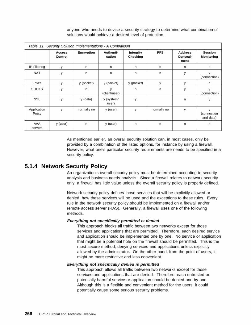
anyone who needs to devise a security strategy to determine what combination ofsolutions would achieve a desired level of protection.
Table 11. Security Solution Implementations - A Comparison
AccessControl
Encryption Authenti-cation
IntegrityChecking
PFS AddressConceal-
ment
SessionMonitoring
IP Filtering y n n n n n n
NAT y n n n n y y(connection)
IPSec y y (packet) y (packet) y (packet) y y n
SOCKS y n y(client/user)
n n y y(connection)
SSL y y (data) y (system/user)
y n y
ApplicationProxy
y normally no y (user) y normally no y y(connectionand data)
AAAservers
y (user) n y (user) n n n n
As mentioned earlier, an overall security solution can, in most cases, only beprovided by a combination of the listed options, for instance by using a firewall.However, what one's particular security requirements are needs to be specified in asecurity policy.
5.1.4 Network Security PolicyAn organization's overall security policy must be determined according to securityanalysis and business needs analysis. Since a firewall relates to network securityonly, a firewall has little value unless the overall security policy is properly defined.
Network security policy defines those services that will be explicitly allowed ordenied, how these services will be used and the exceptions to these rules. Everyrule in the network security policy should be implemented on a firewall and/orremote access server (RAS). Generally, a firewall uses one of the followingmethods.
Everything not specifically permitted is deniedThis approach blocks all traffic between two networks except for thoseservices and applications that are permitted. Therefore, each desired serviceand application should be implemented one by one. No service or applicationthat might be a potential hole on the firewall should be permitted. This is themost secure method, denying services and applications unless explicitlyallowed by the administrator. On the other hand, from the point of users, itmight be more restrictive and less convenient.
Everything not specifically denied is permittedThis approach allows all traffic between two networks except for thoseservices and applications that are denied. Therefore, each untrusted orpotentially harmful service or application should be denied one by one.Although this is a flexible and convenient method for the users, it couldpotentially cause some serious security problems.
266 TCP/IP Tutorial and Technical Overview

Remote access servers should provide authentication of users and should ideallyalso provide for limiting certain users to certain systems and/or networks within thecorporate intranet (authorization). Remote access servers must also determine if auser is considered roaming (can connect from multiple remote locations) orstationary (can connect only from a single remote location), and if the server shoulduse call-back for particular users once they are properly authenticated.
Generally, anonymous access should at best be granted to servers in ademilitarized zone (DMZ, see 5.3.6.4, “Screened Subnet Firewall (DemilitarizedZone)” on page 292). All services within a corporate intranet should require atleast password authentication and appropriate access control. Direct access fromthe outside should always be authenticated and accounted.
5.2 A Short Introduction to CryptographyThe purpose of this chapter is to introduce the terminology and give a briefoverview of the major cryptographic concepts that relate to TCP/IP securityimplementations. The information presented here only scratches the surface.Some issues are left open or not mentioned at all.
5.2.1 TerminologyLet's start with defining some very basic concepts.
CryptographyPut simply, cryptography is the science of keeping your data andcommunications secure. To achieve this goal, techniques such as encryption,decryption and authentication are used. With the recent advances in thisfield, the frontiers of cryptography have become blurred. Every procedureconsisting of transforming data based on methods that are difficult to reversecan be considered cryptography. The key factor to strong cryptography is thedifficulty of reverse engineering. You would be amazed to know that breakingsimple methods such as password-scrambled word processor documents orcompressed archives is a matter of minutes for a hacker using an ordinaryPC. Strong cryptography means that the computational effort needed toretrieve your cleartext messages without knowing the proper procedure makesthe retrieval infeasible. In this context, infeasible means something like this:if all the computers in the world were assigned to the problem, they wouldhave to work tens of thousands of years until the solution was found. Theprocess of retrieval is called cryptanalysis. An attempted cryptanalysis is anattack.
Encryption and Decryption - Cryptographic AlgorithmsEncryption is the transformation of a cleartext message into an unreadableform in order to hide its meaning. The opposite transformation, whichretrieves the original cleartext, is the decryption. The mathematical functionused for encryption and decryption is the cryptographic algorithm or cipher.
The security of a cipher might be based entirely on keeping how it workssecret, in which case it is a restricted cipher. There are many drawbacks torestricted ciphers. It is very difficult to keep in secret an algorithm used bymany people. If it is incorporated in a commercial product, then it is only amatter of time and money to get it reverse engineered. For these reasons,the currently used algorithms are keyed, that is, the encryption and decryptionmakes use of a parameter, the key. The key can be chosen from a set of
Chapter 5. TCP/IP Security Overview 267

possible values, called the keyspace. The keyspace usually is huge, thebigger the better. The security of these algorithms rely entirely on the key,not on their internal secrets. In fact the algorithms themselves are public andare extensively analyzed for possible weaknesses.
Note: As a general rule, be conservative. Do not trust brand new, unknownor unpublished algorithms. The principle of the keyed ciphers isshown in Figure 152.
SecretKey
SecretKeyReport
1. klfjsdf fþp 2. dfdsaþ fpúsdaf3. pfsdþ úfpþsaþf4. fpsdúfpþdsúfþsdfpds 5. þfp6. ds7. dfúpþ8. úþp9. úþp10.
Report
1. klfjsdf fþp 2. dfdsaþ fpúsdaf3. pfsdþ úfpþsaþf4. fpsdúfpþdsúfþsdfpds 5. þfp6. ds7. dfúpþ8. úþp9. úþp10.
Report
1. klfjsdf fþp 2. dfdsaþ fpúsdaf3. pfsdþ úfpþsaþf4. fpsdúfpþdsúfþsdfpds 5. þfp6. ds7. dfúpþ8. úþp9. úþp10.
CleartextEncryption Decryption
Ciphertext OriginalCleartext
Alice BobFigure 152. Keyed Encryption and Decryption
Note: It is common in the cryptographic literature to denote the firstparticipant in a protocol as Alice and the second one as Bob. Theyare the "crypto couple".
Authentication, Integrity, and Non-RepudiationEncryption provides confidentiality to your messages. When communicatingover an untrusted medium, such as the Internet, besides confidentiality, youneed more:
� Authentication - A method for verifying that the sender of a message isreally who he or she claims to be. Any intruder masquerading assomeone else is detected by authentication.
� Integrity checking - A method for verifying that a message has not beenaltered along the communication path. Any tampered message sent byan intruder is detected by integrity check. As a side effect,communication errors are also detected.
� Non-repudiation - The possibility to prove that the sender has really sentthe message. When algorithms providing non-repudiation are used, thesender is not able to later deny the fact that he or she sent the messagein question.
5.2.2 Symmetric or Secret-Key AlgorithmsThe symmetric algorithms are keyed algorithms where the decryption key is thesame as the encryption key. These are the conventional cryptographic algorithmswhere the sender and the receiver must agree on the key before any securedcommunication can take place between them. Figure 152 illustrates a symmetricalgorithm. There are two types of symmetric algorithms: block algorithms, whichoperate on the cleartext in blocks of bits, and stream algorithms, which operate ona single bit (or byte) of cleartext at a time.
268 TCP/IP Tutorial and Technical Overview

Block ciphers are used in several modes. Electronic Codebook Mode (ECB) is thesimplest; each block of cleartext is encrypted independently. Given a block lengthof 64 bits, there are 264 possible input cleartext blocks, each of them correspondingto exactly one out of 264 possible ciphertext blocks. An intruder might construct acodebook with known cleartext-ciphertext pairs and mount an attack. Because ofthis vulnerability, often the Cipher Block Chaining (CBC) mode is used, where theresult of the encryption of the previous block is used in the encryption of the currentblock, thus each ciphertext block is dependent not just on the correspondingplaintext block, but on all previous plaintext blocks.
The algorithms often make use of initialization vectors (IVs). These are variablesindependent of the keys and are good for setting up the initial state of thealgorithms.
A well-known block algorithm is DES, a worldwide standard cipher developed byIBM. DES is an acronym for Data Encryption Standard. DES operates on 64-bitblocks and has a key length of 56 bits, often expressed as a 64-bit number, withevery eighth bit serving as parity bit. From this key 16 subkeys are derived, whichare used in the 16 rounds of the algorithm.
DES produces ciphertexts of the same length as the cleartext and the decryptionalgorithm is exactly the same as the encryption, the only difference being thesubkey schedule. These properties makes it very suitable for hardwareimplementations.
Although DES is aging (its origins dates back to the early '70s), after more then 20years of analysis the algorithm itself is still considered secure. The most practicalattack against it is brute-force: try the decryption with all possible keys and look fora meaningful result. The problem is the key length. Given enough money andtime, a brute-force attack against the 56-bit key might be feasible; that's whyrecently a new mode of DES, called triple-DES or 3DES has gained popularity.With triple-DES, the original DES algorithm is applied in three rounds, with two orthree different keys. This encryption is thought to be unbreakable for a long time,even with the foreseeable technological advances taken into account.
An exportable version of DES is IBM's Commercial Data Masking Facility or CDMF,which uses a 40-bit key.
Another, more recent block algorithm is the International Data Encryption Algorithm(IDEA). This cipher uses 64-bit blocks and 128-bit keys. It was developed in theearly '90s and aimed to replace DES. It is cryptographically strong and faster thanDES. Despite this, there is no widespread commercial acceptance, mainly becauseit is relatively new and not fully analyzed. The most significant use of IDEA is in thefreeware secure e-mail package Pretty Good Privacy (PGP).
An example of a stream algorithm is A5, which is used to encrypt digital cellulartelephony traffic in the GSM standard, widely used in Europe.
The advantage of the symmetric algorithms is their efficiency. They can be easilyimplemented in hardware. A major disadvantage is the difficulty of keymanagement. A secure way of exchanging the keys must exist, which is often veryhard to implement.
Chapter 5. TCP/IP Security Overview 269

5.2.3 Asymmetric or Public-Key AlgorithmsThese algorithms address the major drawback of the symmetric ones, therequirement of the secure key-exchange channel. The idea is that two differentkeys should be used: a public key, which as the name implies, is known toeveryone, and a private key, which is to be kept in tight security by the owner. Theprivate key cannot be determined from the public key. A cleartext encrypted withthe public key can only be decrypted with the corresponding private key, and viceversa. A cleartext encrypted with the private key can only be decrypted with thecorresponding public key. Thus, if someone sends a message encrypted with therecipient's public key, it can be read by the intended recipient only. The process isshown in Figure 153, where Alice sends an encrypted message to Bob.
Bob's Public Key
Bob's Private KeyReport
1. klfjsdf fþp 2. dfdsaþ fpúsdaf3. pfsdþ úfpþsaþf4. fpsdúfpþdsúfþsdfpds 5. þfp6. ds7. dfúpþ8. úþp9. úþp10.
Report
1. klfjsdf fþp 2. dfdsaþ fpúsdaf3. pfsdþ úfpþsaþf4. fpsdúfpþdsúfþsdfpds 5. þfp6. ds7. dfúpþ8. úþp9. úþp10.
Report
1. klfjsdf fþp 2. dfdsaþ fpúsdaf3. pfsdþ úfpþsaþf4. fpsdúfpþdsúfþsdfpds 5. þfp6. ds7. dfúpþ8. úþp9. úþp10.
Alice
Encryption Decryption
Ciphertext
Bob
Cleartext OriginalCleartext
Figure 153. Encryption Using the Recipient's Public Key
As the public key is available to anyone, privacy is assured without the need for asecure key-exchange channel. Parties who wish to communicate retrieve eachother's public key.
5.2.3.1 Authentication and Non-RepudiationAn interesting property of the public-key algorithms is that they can provideauthentication. Use the private key for encryption. Since anyone has access to thecorresponding public key and can decrypt the message, this provides no privacy.However, it authenticates the message. If one can successfully decrypt it with theclaimed sender's public key, then the message has been encrypted with thecorresponding private key, which is known by the real sender only. Thus, thesender's identity is verified. The encryption with the private key is used in digitalsignatures. In Figure 154 on page 271 the principle is shown. Alice encrypts hermessage with her private key ("signs" it), in order to enable Bob to verify theauthenticity of the message.
270 TCP/IP Tutorial and Technical Overview

Alice's Private Key
Alice's Public KeyReport
1. klfjsdf fþp 2. dfdsaþ fpúsdaf3. pfsdþ úfpþsaþf4. fpsdúfpþdsúfþsdfpds 5. þfp6. ds7. dfúpþ8. úþp9. úþp10.
Report
1. klfjsdf fþp 2. dfdsaþ fpúsdaf3. pfsdþ úfpþsaþf4. fpsdúfpþdsúfþsdfpds 5. þfp6. ds7. dfúpþ8. úþp9. úþp10.
Report
1. klfjsdf fþp 2. dfdsaþ fpúsdaf3. pfsdþ úfpþsaþf4. fpsdúfpþdsúfþsdfpds 5. þfp6. ds7. dfúpþ8. úþp9. úþp10.
Alice
Encryption Decryption & Authentication
Ciphertext
Bob
Cleartext OriginalCleartext
Figure 154. Authentication by Encrypting with a Private Key
Going a step forward, encrypting with the private key gives non-repudiation too.The mere existence of such an encrypted message testifies that the originator hasreally sent it, because only he or she could have used the private key to generatethe message. Additionally, if a timestamp is included, then the exact date and timecan also be proven. There are protocols involving trusted third parties that preventthe sender from using phony timestamps.
Note: Inspired by the "stamping" idea, the IPSec architecture makes use ofsequence numbers (instead of timestamps), to achieve replay protection.
5.2.3.2 Examples of Public-Key AlgorithmsAlgorithms based on public keys can be used for a variety of purposes. Twocommon applications are:
1. Encryption (see “RSA Public Key Algorithm” on page 272)2. Generation of shared keys for use with symmetric key algorithms (see
“Diffie-Hellman Key Exchange” on page 273)
The most popular public-key algorithm is the de-facto standard RSA, named afterthe three inventors: Ron Rivest, Adi Shamir and Leonard Adleman. The securityof RSA relies on the difficult problem of factoring large numbers. The public andprivate keys are functions of two very large (200 digits or even more) primenumbers. Given the public key and the ciphertext, an attack would be successful ifit could factor the product of the two primes. RSA has resisted many years ofextensive attacks. As computing power grows, keeping RSA secure is a matter ofincreasing the key length. (As opposed to DES, where the key length is fixed.)
Another public-key algorithm, actually the very first ever invented, is Diffie-Hellman.This is a key-exchange algorithm; that is, it is used for securely establishing ashared secret over an insecure channel. The communicating parties exchangepublic information from which they derive a key. An eavesdropper cannotreconstruct the key from the information that went through the insecure channel.(More precisely, the reconstruction is computationally infeasible.) The security ofDiffie-Hellman relies on the difficulty of calculating discrete logarithms in finite fields.After the shared secret has been established, it can then be used to derive keys foruse with symmetric key algorithms such as DES.
Chapter 5. TCP/IP Security Overview 271
Diffie-Hellman makes possible the secure derivation of a shared secret key, but itdoes not authenticate the parties. For authentication another public-key algorithmmust be used, such as RSA.
Unfortunately, public-key algorithms while providing for easier key management,privacy, authentication and non-repudiation also have some disadvantages. Themost important one is that they are slow and difficult to implement in hardware. Forexample, RSA is 100 to 10000 times slower than DES, depending onimplementation. Because of this, public-key algorithms generally are not used forbulk encryption. Their most important use is key exchange and authentication.Another notable disadvantage is that they are susceptible to certain cryptanalyticattacks to which symmetric algorithms are resistant.
Therefore, a good cryptographic system (cryptosystem) makes use of both worlds.It uses public-key algorithms in the session establishment phase for authenticationand key exchange, then a symmetric one for encrypting the consequent messages.
For the interested reader, below we give more detailed information of the two mostimportant asymmetric algorithms. Both of them involve modular arithmetics. Anarithmetic operation modulo m means that the result of that operation is divided bym and the remainder is taken. For example: 3 * 6 mod 4 = 2, since 3 * 6 = 18 anddividing 18 by 4 gives us 2 as the remainder.
RSA Public Key Algorithm: RSA is used in the ISAKMP/Oakley framework asone of the possible authentication methods. The principle of the RSA algorithm isas follows:
1. Take two large primes, p and q.
2. Find their product n = pq; n is called the modulus.
3. Choose a number, e, less than n and relatively prime to (p-1)(q-1) which meansthat e and (p-1)(q-1) have no common factor other than 1.
4. Find its inverse, d mod (p-1)(q-1) which means that ed = 1 mod (p-1)(q-1).
e and d are called the public and private exponents, respectively. The public key isthe pair (n,e); the private key is d. The factors p and q must be kept secret ordestroyed.
A simplified example of RSA encryption would be the following:
1. Suppose Alice wants to send a private message, m, to Bob. Alice creates theciphertext c by exponentiating:
c = me mod n
where e and n are Bob's public key.
2. Alice sends c to Bob.
3. To decrypt, Bob exponentiates:
m = cd mod n
and recovers the original message; the relationship between e and d ensuresthat Bob correctly recovers m. Since only Bob knows d, only Bob can decryptthe ciphertext.
A simplified example of RSA authentication would be the following:
272 TCP/IP Tutorial and Technical Overview

1. Suppose Alice wants to send a signed message, m, to Bob. Alice creates adigital signature s by exponentiating:
s = md mod n
where d and n belong to Alice's private key.
2. She sends s and m to Bob.
3. To verify the signature, Bob exponentiates and checks if the result, comparesto m:
m = se mod n
where e and n belong to Alice's public key.
Diffie-Hellman Key Exchange: The Diffie-Hellman key exchange is a crucialcomponent of the ISAKMP/Oakley framework. In the earliest phase of a keynegotiation session there is no secure channel in place. The parties derive sharedsecret keys using the Diffie-Hellman algorithm. These keys will be used in the nextsteps of the key negotiation protocol.
The outline of the algorithm is the following:
1. The parties (Alice and Bob) share two public values, a modulus m and aninteger g; m should be a large prime number.
2. Alice generates a large random number a and computes:
X = ga mod m
3. Bob generates a large random number b and computes:
Y = gbmod m
4. Alice sends X to Bob.
5. Bob computes:
K1 = Xb mod m
6. Bob sends Y to Alice.
7. Alice computes:
K2 = Ya mod m
Both K1 and K2 are equal to gab mod m. This is the shared secret key. No one isable to generate this value without knowing a or b. The security of the exchange isbased on the fact that is extremely difficult to inverse the exponentiation performedby the parties. (In other words, to find out discrete logarithms in finite fields of sizem.) Similar to RSA, advances in adversary computing power can be countered bychoosing larger initial values, in this case a larger modulus m.
Please see Chapter 11, “Availability, Scalability and Load Balancing” on page 535for more details on how ISAKMP/Oakley uses Diffie-Hellman exchanges.
5.2.4 Hash FunctionsHash functions (also called message digests) are fundamental to cryptography. Ahash function is a function that takes variable-length input data and produces fixedlength output data (the hash value), which can be regarded as the "fingerprint" ofthe input. That is, if the hashes of two messages match, then we get a highassurance that the messages are the same.
Chapter 5. TCP/IP Security Overview 273

Cryptographically useful hash functions must be one-way, which means that theyshould be easy to compute, but infeasible to reverse. An everyday example of aone-way function is mashing a potato; it is easy to do, but once mashed,reconstructing the original potato is rather difficult. A good hash function should becollision-resistant. It should be hard to find two different inputs that hash to thesame value. As any hash function maps an input set to a smaller output set,theoretically it is possible to find collisions. The point is to provide a unique digital"fingerprint" of the message, that identifies it with high confidence, much like a realfingerprint identifying a person.
A hash function that takes a key as a second input parameter and its outputdepends on both the message and the key is called a Message AuthenticationCode (MAC), as shown in Figure 155.
Report
1. klfjsdf fþp 2. dfdsaþ fpúsdaf3. pfsdþ úfpþsaþf4. fpsdúfpþdsúfþsdfpds 5. þfp6. ds7. dfúpþ8. úþp9. úþp10.
Report
1 .kl f jsdf fþp
2 .dfdsaþ fpúsdaf
3 .pfsdþ úfpþsaþf
4 .fpsdúfpþdsúfþsdfpds
5 .þ fp
6 .d s
7 .d fúpþ
8 .ú þ p
9 .ú þ p
10 .
Message
Message Authentication Code (MAC)
Key
Hash Function
Figure 155. Generating a Message Authentication Code (MAC)
Put simply, if you encrypt a hash, it becomes a MAC. If you add a secret key to amessage, then hash the concatenation, the result is a MAC. Both symmetric andasymmetric algorithms can be used to generate MACs.
Hash functions are primarily used in integrity check and authentication techniques.Let's see how integrity and authentication is assured with hash functions:
� The sender calculates the hash of the message and appends it to themessage.
� The recipient calculates the hash of the received message and then comparesthe result with the transmitted hash.
� If the hashes match, the message was not tampered with.
� In case of MACs where the encryption key (symmetric or asymmetric) shouldhave been used by a trusted sender only, a successful MAC decryptionindicates that the claimed and actual senders are identical. (Unless, of course,your keys have been compromised.)
See Figure 156 on page 275 for an illustration of the procedure. The Message*and MAC* notations reflect the fact that the message might have been altered whilecrossing the untrusted channel.
274 TCP/IP Tutorial and Technical Overview

Report
1. klfjsdf fþp 2. dfdsaþ fpúsdaf3. pfsdþ úfpþsaþf4. fpsdúfpþdsúfþsdfpds 5. þfp6. ds7. dfúpþ8. úþp9. úþp10.
Report
1. klfjsdf fþp 2. dfdsaþ fpúsdaf3. pfsdþ úfpþsaþf4. fpsdúfpþdsúfþsdfpds 5. þfp6. ds7. dfúpþ8. úþp9. úþp10.
Alice Bob
YES
OriginalMAC
Report
1 . kl f jsdf fþp
2 . dfdsaþ fpúsdaf
3 . pfsdþ úfpþsaþf
4 . fpsdúfpþdsúfþsdfpds
5 . þ fp
6 . d s
7 . d fúpþ
8 . ú þ p
9 . ú þ p
10 .
Message*MAC*
Key
Hash Function
Report
1 . kl f jsdf fþp
2 . dfdsaþ fpúsdaf
3 . pfsdþ úfpþsaþf
4 . fpsdúfpþdsúfþsdfpds
5 . þ fp
6 . d s
7 . d fúpþ
8 . ú þ p
9 . ú þ p
10 .
Report
1 .kl f jsdf fþp
2 .dfdsaþ fpúsdaf
3 .pfsdþ úfpþsaþf
4 .fpsdúfpþdsúfþsdfpds
5 .þ fp
6 .d s
7 .d fúpþ
8 .ú þ p
9 .ú þ p
10 .
Untrusted Channel
Match?
Accept Reject
CompareMessage + MAC
NO
Figure 156. Checking Integrity and Authenticity with MAC
One could argue that the same result can be obtained with any kind of encryption,because if an intruder modifies an encrypted message, the decryption will result innonsense, thus tampering can be detected. The answer is that many times onlyintegrity and/or authentication is needed, maybe with encryption on some of thefields of the message. And encryption is very processor-intensive. (Examples arethe personal banking machine networks, where only the PINs are encrypted,however MACs are widely used. Encrypting all the messages in their entiretywould not yield noticeable benefits and performance would dramatically decrease.)
The encryption of a hash with the private key is called a digital signature. It can bethought of as a special MAC. Using digital signatures instead of encrypting thewhole message with the private key leads to considerable performance gains and aremarkable new property. The authentication part can be decoupled from thedocument itself. This property is used for example in the Secure ElectronicTransactions (SET) protocol.
The encryption of a secret key with a public key is called a digital envelope. This isa common technique used to distribute secret keys for symmetric algorithms.
5.2.4.1 Examples of Hash FunctionsThe most widely used hash functions are MD5 and Secure Hash Algorithm 1(SHA-1). MD5 was designed by Ron Rivest (co-inventor of RSA). SHA-1 is largelyinspired from MD5 and was designed by the National Institute of Standards andTechnology (NIST) and the National Security Agency (NSA) for use with the DigitalSignature Standard (DSS). MD5 produces a 128-bit hash, while SHA-1 produces a160-bit hash. Both functions encode the message length in their output. SHA-1 isregarded as more secure, because of the larger hashes it produces.
Chapter 5. TCP/IP Security Overview 275

Note: Neither MD5 nor SHA-1 takes a key as input parameter, hence in theiroriginal implementation they cannot be used for MAC calculation. However,for this purpose it is easy to concatenate a key with the input data andapply the function to the result. In practice, for example in IPSec, oftenmore sophisticated schemes are used.
Keyed MD5 and Keyed SHA-1: Using MD5 and SHA-1 in keyed mode is simple.The shared secret key and the datagram to be protected are both input to the hashalgorithm and the output (the hash value) is placed in the Authentication Data fieldof the AH Header, as it is shown in Figure 157.
MD5
(128)
IP Hdr AH Payload (Pad)
Shared Key(128 bits)
Figure 157. Keyed MD5 Processing
Keyed SHA-1 operates in the same way, the only difference being the larger160-bit hash value.
HMAC-MD5-96 and HMAC-SHA-1-96: A stronger method is the Hashed MessageAuthentication Code (HMAC), proposed by IBM. HMAC itself is not a hashfunction, rather a cryptographically strong way to use a specific hash function forMAC calculation.
Here is how HMAC works, considering MD5 as an example. The base function isapplied twice in succession. In the first round the input to MD5 is the shared secretkey and the datagram. The 128-bit output hash value and the key is input again tothe hash function in the second round. The leftmost 96 bits of the resulting hashvalue are used as the MAC for the datagram. See Figure 158 for an illustration.
MD5Shared Key(128 bits)
(128)
IP Hdr AH Payload (Pad)
MD5
(128) (96)Shared Key(128 bits)
Figure 158. HMAC-MD5-96 Processing
276 TCP/IP Tutorial and Technical Overview

HMAC-SHA-1-96 operates in the same way, except that the intermediary resultsare 160 bits long.
Digital Signature Standard (DSS): As mentioned previously, a hash valueencrypted with the private key is called a digital signature and is illustrated inFigure 159.
Report
1. klfjsdf fþp 2. dfdsaþ fpúsdaf3. pfsdþ úfpþsaþf4. fpsdúfpþdsúfþsdfpds 5. þfp6. ds7. dfúpþ8. úþp9. úþp10.
Report
1 . kl f jsdf fþp
2 . dfdsaþ fpúsdaf
3 . pfsdþ úfpþsaþf
4 . fpsdúfpþdsúfþsdfpds
5 . þ fp
6 . d s
7 . d fúpþ
8 . ú þ p
9 . ú þ p
10 .
Report
1 . kl f jsdf fþp
2 . dfdsaþ fpúsdaf
3 . pfsdþ úfpþsaþf
4 . fpsdúfpþdsúfþsdfpds
5 . þ fp
6 . d s
7 . d fúpþ
8 . ú þ p
9 . ú þ p
10 .
MessageMessage
Digest (Hash)
Digital Signature
Private Key
Hash Function
Encryption
Figure 159. Generating a Digital Signature
One authentication method that can be used with ISAKMP/Oakley is DSS whichwas selected by NIST and NSA to be the digital authentication standard of the U.S.government. The standard describes the Digital Signature Algorithm (DSA) used tosign and verify signatures of message digests produced with SHA-1.
A brief description of DSA is given below:
1. Choose a large prime number, p, usually between 512 and 1024 bits long.
2. Find a prime factor q of (p-1), 160 bits long.
3. Compute:
g=h(p-1)/q mod p
where h is a number less than (p-1) and the following is true:
h(p-1)/q>1
4. Choose another number x, less than q, as the sender's private key.
5. Compute:
y=gx mod p
and use that as the sender's public key. The pair (x,y) is sometimes referred toas the long-term key pair.
6. The sender signs the message as follows:
a. Generate a random number, k, less than q. b. Compute:
r=(gk mod p) mod q
s=(k-1(SHA1(m)+xr)) mod q
The pair (k,r) is sometimes referred to as the per-session key pair, and thesignature is represented by the pair (r,s).
7. The sender sends (m,r,s).
8. The receiver verifies the signature as follows:
Chapter 5. TCP/IP Security Overview 277

a. Compute:
w=s-1 mod q
u1=(SHA1(m)\w) mod q
u2=(rw) mod q
v=((gu1yu2) mod p) mod q
9. If v=r, then the signature is verified.
5.2.5 Digital Certificates and Certification AuthoritiesAs we said before in 5.2.3.1, “Authentication and Non-Repudiation” on page 270,with public-key cryptography, the parties retrieve each other's public key. Thereare security exposures here. An intruder could change some real public keys withhis or her own public key, and then mount a so-called man-in-the-middle attack. Itworks like this. The intruder places himself between Alice and Bob. He can trickBob by sending him one of his own public keys as if it were Alice's. The sameapplies to Alice. She thinks she uses Bob's public key, but the sour reality is thatshe actually uses the intruder's. So the clever intruder can decrypt the confidentialtraffic between the two and remain undetected. For example, a message sent byAlice and encrypted with "Bob's" public key lands at the intruder, who decrypts it,learns its content, then re-encrypts it with Bob's real public key. Bob has no way torealize that Alice is using a phony public key.
An intruder could also use impersonation, claiming to be somebody else, forexample an online shopping mall, fouling innocent shoppers.
The solution to these serious threats is the digital certificate. A digital certificate isa file that binds an identity to the associated public key. This binding is validatedby a trusted third party, the certification authority (CA). A digital certificate is signedwith the private key of the certification authority, so it can be authenticated. It isonly issued after a verification of the applicant. Apart from the public key andidentification, a digital certificate usually contains other information too, such as:
� Date of issue
� Expiry date
� Miscellaneous information from issuing CA (for example, serial number)
Note: There is an international standard in place for digital certificates: the ISOX.509 protocols.
Now the picture looks different. The parties retrieve each other's digital certificateand authenticate it using the public key of the issuing certification authority. Theyhave confidence that the public keys are real, because a trusted third partyvouches for them. The malicious online shopping mall is put out of business.
It easy to imagine that one CA cannot cover all needs. What happens when Bob'scertificate is issued by a CA unknown to Alice? Can she trust that unknownauthority? Well, this is entirely her decision, but to make life easier, CAs can forma hierarchy, often referred to as the trust chain. Each member in the chain has acertificate signed by it superior authority. The higher the CA is in the chain, thetighter security procedures are in place. The root CA is trusted by everyone and itsprivate key is top secret.
278 TCP/IP Tutorial and Technical Overview

Alice can traverse the chain upwards until she finds a CA that she trusts. Thetraversal consists of verifying the subordinate CA's public key and identity using thecertificate issued to it by the superior CA.
When a trusted CA is found up in the chain, Alice is assured that Bob's issuing CAis trustworthy. In fact this is all about delegation of trust. We trust your identitycard if somebody who we trust signs it. And if the signer is unknown to us, we cango upward and see who signs for the signer, etc.
An implementation of this concept can be found in the SET protocol, where themajor credit card brands operate their own CA hierarchies that converge to acommon root. Lotus Notes authentication, as another example, is also based oncertificates, and it can be implemented using hierarchical trust chains. PGP alsouses a similar approach, but its trust chain is based on persons and it is rather adistributed Web than a strict hierarchical tree.
5.2.6 Random-Number GeneratorsAn important component of a cryptosystem is the random-number generator. Manytimes random session keys and random initialization variables (often referred to asinitialization vectors) are generated. For example, DES requires an explicitinitialization vector and Diffie-Hellman relies on picking random numbers whichserve as input for the key derivation.
The quality, that is the randomness of these generators, is more important than youwould think. The ordinary random function provided with most programminglanguage libraries is good enough for games, but not for cryptography. Thoserandom-number generators are rather predictable; if you rely on them, be preparedfor happy cryptanalysts finding interesting correlations in your encrypted output.
The fundamental problem faced by the random-number generators is that thecomputers are ultimately deterministic machines, so real random sequences cannotbe produced. As John von Neumann ironically said: "Anyone who considersarithmetical methods of producing random digits is, of course, in a state of sin".(Quoted by Donald Knuth.) That's why the term pseudorandom generator is moreappropriate.
Cryptographically strong pseudorandom generators must be unpredictable. It mustbe computationally infeasible to determine the next random bit, even with totalknowledge of the generator.
A common practical solution for pseudorandom generators is to use hash functions.This approach provides sufficient randomness and it can be efficiently implemented.Military-grade generators use specialized devices that exploit the inherentrandomness in physical phenomena. An interesting solution can be found in thePGP software. The initial seed of the pseudorandom generator is derived frommeasuring the time elapsed between the keystrokes of the user.
5.2.7 Export/Import Restrictions on CryptographyU.S. export regulations changed in 1996, which put cryptography under the controlof the Commerce Department. It had formerly been treated as a munition. This isa significant step in liberalizing the export of cryptographic products.
Chapter 5. TCP/IP Security Overview 279

According to the new export regulations a license may be granted to export a 56-bitkey encryption algorithm if a company has an approved key recovery plan. Thekey recovery plan must be implemented in 2 years and the license is granted on a6 month basis.
In 1997 IBM was granted the license to export DES as long as it was used similarto other products that have been approved. Recently, the export of triple-DES hasbeen allowed for banking applications.
In September 1998, the White House announced further liberalization of U.S.export restrictions on cryptographic material and key recovery requirements whichcan be sumarized as follows:
� The key recovery requirement for export of 56-bit DES and equivalent productsis eliminated. This includes products that use 1024-bit asymmetric keyexchanges together with 56-bit symmetric key algorithms.
� Export of unlimited strength encryption (for example, 3DES) under licenseexceptions (with or without key recovery) is now broadened to include othersbesides the financial industry for 45 countries. This includes subsidiaries ofU.S firms, insurance, health and medical (excluding biochemical andpharmaceutical manufacturers), and online merchants for the purpose ofsecuring online transactions (excluding distributors of items consideredmunitions).
For the latter, revocerable products will be granted exceptions world wide(excluding terrorist countries) without requiring a review of foreign key recoveryagents.
� Export of recoverable products will be granted to most most commercial firmsfor a broad range of countries in the major commercial markets (excludingitems on the U.S. munitions list).
� Export licenses to end users may be granted on a case-by-case basis.
These regulations are expected to be formally published by the U.S. ExportRegulation Office in November 1998.
In France, according to the law, any product capable of enciphering/decipheringuser data should be granted a license from the French government before beingmarketed. Then customers need to be authorized to use them on a case-by-casebasis. In reality, two major and useful exceptions exist:
1. Routinely, licenses are granted that allow banks to use DES products on aglobal basis (no case-by-case authorization required).
2. Routinely, global licenses are granted that allow anybody to use weakencryption (RC2/RC4 with 40-bit keys).
5.3 FirewallsFirewalls have significant functions in an organization's security policy. Therefore, itis important to understand these functions and apply them to the network properly.This chapter explains the firewall concept, network security, firewall componentsand firewall examples.
280 TCP/IP Tutorial and Technical Overview

5.3.1 Firewall ConceptA firewall is a system (or group of systems) that enforces a security policy betweena secure internal network and an untrusted network such as the Internet. Firewallstend to be seen as a protection between the Internet and a private network. Butgenerally speaking a firewall should be considered as a means to divide the worldinto two or more networks: one or more secure networks and one or morenon-secure networks.
Secure Internal Network
Company B
AAAAAAAAAAAAA
AAAAAA
AAAAAAAA
AAAAAAAA
AAAAAAAA
AAAAAA
AAAAAAAAAAAAAAA
AAAAAAAAAAAAA
AAAAAA
AAAAAAAA
AAAAAAAA
AAAAAAAA
AAAAAA
AAAAAAAAAAAAAAA
AAAAAAAAAAAAAA
AAAAAA
AAAAAAAAAAAAAAAAAAAAAA
AAAAAAAA
AAAAAAAA
AAAA
AAAAAAAAAAAAAA
AAAA
AAAAAAAAAAAAAAAAAAAAAA
AAAAAAAA
AAAAAAAA
AAAA
Firewall
UntrustedNetwork(Internet)
Firewall
Secure Internal Network
Company A
AAAAAAAAAAAAA
AAAAAA
AAAAAAAA
AAAAAAAA
AAAAAAAA
AAAA
AAAAAAAAAAAAAA
AAAAAAAAAAAA
AAAAAAAAAAAAAAAAAAAAAAAAAAAA
AAAAAAAAAAAAAA
AAAA
AAAAAAAA
AAAAAAAA
AAAAAAAA
AAAA
AAAAAAAA
AAAAAAAA
AAAAAAAA
AAAA
AAAAAAAAAAAAAA
AAAA
AAAAAAAA
AAAAAAAA
AAAAAAAA
AAAA
AAAAAAAA
AAAAAAAA
AAAAAAAA
AAAA
3376A\3376F4O2
Figure 160. A Firewall Illustration
A firewall can be a PC, a router, a midrange, a mainframe, a UNIX workstation, ora combination of these that determines which information or services can beaccessed from the outside and who is permitted to use the information and servicesfrom outside. Generally, a firewall is installed at the point where the secure internalnetwork and untrusted external network meet which is also known as a choke point.
In order to understand how a firewall works, consider the network to be a buildingto which access must be controlled. The building has a lobby as the only entrypoint. In this lobby, receptionists welcome visitors, security guards watch visitors,video cameras record visitor actions and badge readers authenticate visitors whoenter the building.
Although these procedures may work well to control access to the building, if anunauthorized person succeeds in entering, there is no way to protect the buildingagainst this intruder's actions. However, if the intruder's movements are monitored,it may be possible to detect any suspicious activity.
Similarly, a firewall is designed to protect the information resources of theorganization by controlling the access between the internal secure network and theuntrusted external network (please see Figure 161 on page 282). However, it isimportant to note that even if the firewall is designed to permit the trusted data topass through, deny the vulnerable services and prevent the internal network fromoutside attacks, a newly created attack may penetrate the firewall at any time. Thenetwork administrator must examine all logs and alarms generated by the firewallon a regular basis. Otherwise, it is not possible to protect the internal network fromoutside attacks.
Chapter 5. TCP/IP Security Overview 281

Production Server
private.organization.com
Client1 Client2
Secure Network
organization.com
Untrusted Network
Internet
3376A\3376F4O8
Figure 161. A Firewall Controls Traffic Between the Secure Network and the Internet
5.3.2 Components of A Firewall SystemAs mentioned previously, a firewall can be a PC, a midrange, a mainframe, a UNIXworkstation, a router, or combination of these. Depending on the requirements, afirewall can consist of one or more of the following functional components:
1. Packet-filtering router
2. Application level gateway (Proxy)
3. Circuit level gateway
Each of these components has different functions and shortcomings. Generally, inorder to build an effective firewall, these components are used together.
5.3.3 Packet-Filtering RouterMost of the time, packet-filtering is accomplished by using a router that can forwardpackets according to filtering rules. When a packet arrives at the packet-filteringrouter, the router extracts certain information from the packet header and makesdecisions according to the filter rules as to whether the packet will pass through orbe discarded (please see Figure 162 on page 283). The following information canbe extracted from the packet header:
� Source IP address
� Destination IP address
� TCP/UDP source port
� TCP/UDP destination port
� ICMP message type
� Encapsulated protocol information (TCP, UDP, ICMP or IP tunnel)
The packet-filtering rules are based on the network security policy (please see5.1.4, “Network Security Policy” on page 266). Therefore, packet-filtering is doneby using these rules as input. When determining the filtering rules, outsider attacks
282 TCP/IP Tutorial and Technical Overview

must be taken into consideration as well as service level restrictions andsource/destination level restrictions.
Trusted Network
Client1 Client2
3376A\3376F4O9
Client1 Client2
Untrusted Network
Packet Filtering Router
Filter
Figure 162. Packet Filtering Router
Service Level FilteringSince most services use well-known TCP/UDP port numbers, it is possible toallow or deny services by using related port information in the filter. Forexample, an FTP server listens for connections on TCP port 20 and 21.Therefore, to permit FTP connections to pass through to a secure network,the router should be configured to permit packets which contain 20 and 21 asthe TCP port in its header. On the other hand, there are some applications,such as NFS, which use RPC and use different ports for each connection.Allowing these kind of services might cause security problems.
Source/Destination Level FilteringThe packet-filtering rules allow a router to permit or deny a packet accordingto the destination or the source information in the packet header. In mostcases, if a service is available, only that particular server is permitted tooutside users. Other packets that have another destination or no destinationinformation in their headers are discarded.
Advanced FilteringAs mentioned previously (please see 5.1.1, “Common Attacks AgainstSecurity” on page 263), there are different types of attacks that threaten theprivacy and network security. Some of them can be discarded by usingadvanced filtering rules such as checking IP options, fragment offset and soon.
Packet-Filtering Limitations: Packet-filtering rules are sometimes very complex.When there are exceptions to existing rules, it becomes much more complex.Although, there are a few testing utilities available, it is still possible to leave someholes in the network security. Packet filters do not provide an absolute protectionfor a network. For some cases, it might be necessary to restrict some set ofinformation (for example, a command) from passing through to the internal secure
Chapter 5. TCP/IP Security Overview 283
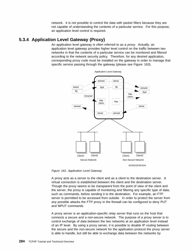
network. It is not possible to control the data with packet filters because they arenot capable of understanding the contents of a particular service. For this purpose,an application level control is required.
5.3.4 Application Level Gateway (Proxy)An application level gateway is often referred to as a proxy. Actually, anapplication level gateway provides higher level control on the traffic between twonetworks in that the contents of a particular service can be monitored and filteredaccording to the network security policy. Therefore, for any desired application,corresponding proxy code must be installed on the gateway in order to manage thatspecific service passing through the gateway (please see Figure 163).
Secure Network
Client1 Client2
3376A\3376F4OA
Non-Secure Network
Client1 Client2
telnetd telnet
ftpd ftp
telnetd
telnetd
ftpd
Application Level Gateway
ftp
telnet
telnetd
httpclient
browserhttp
client
http
telnet
telnet
Figure 163. Application Level Gateway
A proxy acts as a server to the client and as a client to the destination server. Avirtual connection is established between the client and the destination server.Though the proxy seems to be transparent from the point of view of the client andthe server, the proxy is capable of monitoring and filtering any specific type of data,such as commands, before sending it to the destination. For example, an FTPserver is permitted to be accessed from outside. In order to protect the server fromany possible attacks the FTP proxy in the firewall can be configured to deny PUTand MPUT commands.
A proxy server is an application-specific relay server that runs on the host thatconnects a secure and a non-secure network. The purpose of a proxy server is tocontrol exchange of data between the two networks at an application level insteadof an IP level. By using a proxy server, it is possible to disable IP routing betweenthe secure and the non-secure network for the application protocol the proxy serveris able to handle, but still be able to exchange data between the networks by
284 TCP/IP Tutorial and Technical Overview
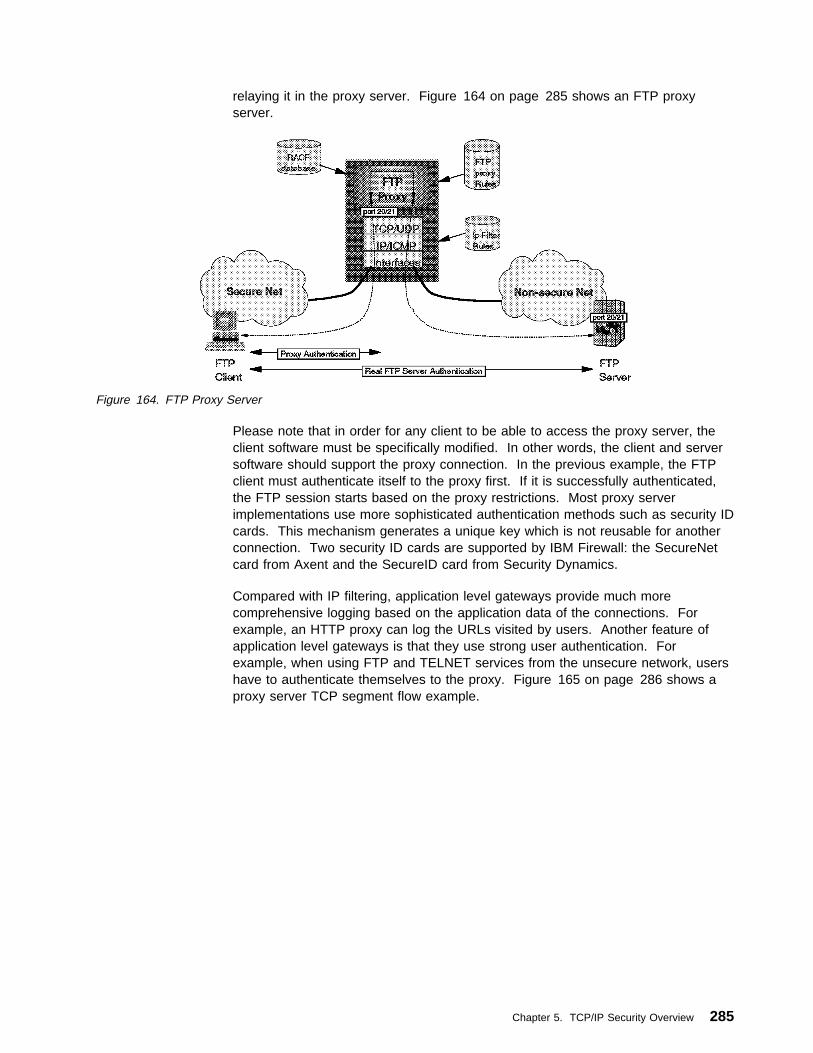
relaying it in the proxy server. Figure 164 on page 285 shows an FTP proxyserver.
Figure 164. FTP Proxy Server
Please note that in order for any client to be able to access the proxy server, theclient software must be specifically modified. In other words, the client and serversoftware should support the proxy connection. In the previous example, the FTPclient must authenticate itself to the proxy first. If it is successfully authenticated,the FTP session starts based on the proxy restrictions. Most proxy serverimplementations use more sophisticated authentication methods such as security IDcards. This mechanism generates a unique key which is not reusable for anotherconnection. Two security ID cards are supported by IBM Firewall: the SecureNetcard from Axent and the SecureID card from Security Dynamics.
Compared with IP filtering, application level gateways provide much morecomprehensive logging based on the application data of the connections. Forexample, an HTTP proxy can log the URLs visited by users. Another feature ofapplication level gateways is that they use strong user authentication. Forexample, when using FTP and TELNET services from the unsecure network, usershave to authenticate themselves to the proxy. Figure 165 on page 286 shows aproxy server TCP segment flow example.
Chapter 5. TCP/IP Security Overview 285

Figure 165. Proxy Server TCP Segment Flow
5.3.4.1 Application Level Gateway LimitationsA disadvantage of application level gateways is that in order to achieve aconnection via a proxy server, the client software should be changed to supportthat proxy service. This can sometimes be achieved by some modifications in userbehavior rather than software modification. For example, to connect to a TELNETserver over a proxy, the user first has to be authenticated by the proxy server thenby the destination TELNET server. This requires two user steps to make aconnection rather than one. However, a modified TELNET client can make theproxy server transparent to the user by specifying the destination host rather thanproxy server in the TELNET command.
5.3.4.2 An Example: FTP Proxy ServerMost of the time, in order to use the FTP proxy server, users must have a validuser ID and password. On UNIX systems, users also should be defined as usersof the UNIX system.
FTP can be used in one of two modes:
1. Normal mode
2. Passive mode
In normal mode, the FTP client first connects to the FTP server port 21 to establisha control connection. When data transfer is required (for example, as the result ofa DIR, GET, or PUT command), the client sends a PORT command to the serverinstructing the server to establish a data connection from the server's data port(port 20) to a specified ephemeral port number on the client host.
286 TCP/IP Tutorial and Technical Overview
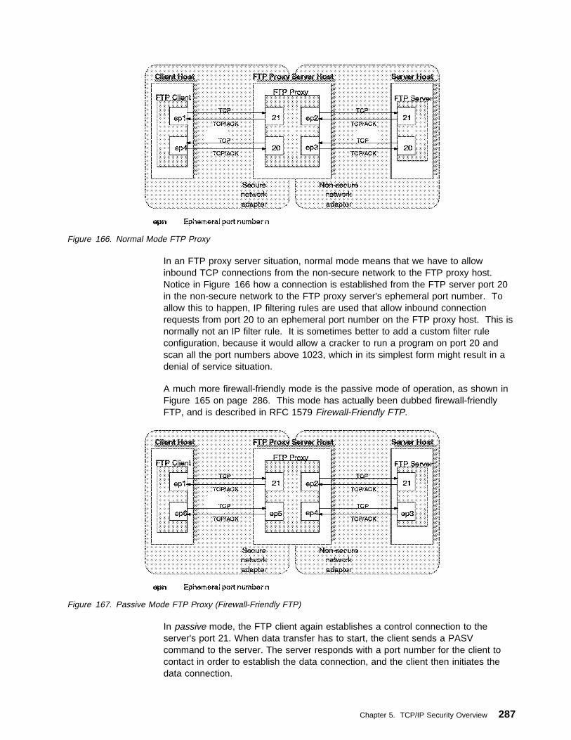
Figure 166. Normal Mode FTP Proxy
In an FTP proxy server situation, normal mode means that we have to allowinbound TCP connections from the non-secure network to the FTP proxy host.Notice in Figure 166 how a connection is established from the FTP server port 20in the non-secure network to the FTP proxy server's ephemeral port number. Toallow this to happen, IP filtering rules are used that allow inbound connectionrequests from port 20 to an ephemeral port number on the FTP proxy host. This isnormally not an IP filter rule. It is sometimes better to add a custom filter ruleconfiguration, because it would allow a cracker to run a program on port 20 andscan all the port numbers above 1023, which in its simplest form might result in adenial of service situation.
A much more firewall-friendly mode is the passive mode of operation, as shown inFigure 165 on page 286. This mode has actually been dubbed firewall-friendlyFTP, and is described in RFC 1579 Firewall-Friendly FTP.
Figure 167. Passive Mode FTP Proxy (Firewall-Friendly FTP)
In passive mode, the FTP client again establishes a control connection to theserver's port 21. When data transfer has to start, the client sends a PASVcommand to the server. The server responds with a port number for the client tocontact in order to establish the data connection, and the client then initiates thedata connection.
Chapter 5. TCP/IP Security Overview 287
In this setup, to establish connections to both port 21 and any ephemeral portnumber in the non-secure network, an ephemeral port number is used on the FTPproxy host. However, adding a rule that allows inbound connections to ephemeralport numbers on the FTP proxy server might cause security problems.
5.3.5 Circuit Level GatewayA circuit level gateway relays TCP and also UDP connections and does not provideany extra packet processing or filtering. A circuit level gateway can be said to be aspecial type of application level gateway. This is because the application levelgateway can be configured to pass all information once the user is authenticated,just as the circuit level gateway (please see Figure 168 on page 289). However,in practice, there are significant differences between them such as:
� Circuit level gateways can handle several TCP/IP applications as well as UDPapplications without any extra modifications on the client side for eachapplication. Thus, this makes circuit level gateways a good choice to satisfyuser requirements.
� Circuit level gateways do not provide packet processing or filtering. Thus, acircuit level gateway is generally referred to as a transparent gateway.
� Application level gateways have a lack of support for UDP.
� Circuit level gateways are often used for outbound connections, whereasapplication level gateways (proxy) are used for both inbound and outboundconnections. Generally, in cases of using both types combined, circuit levelgateways can be used for outbound connections and application level gatewayscan be used for inbound connections to satisfy both security and userrequirements.
A well known example of a circuit level gateway is SOCKS (please refer to 5.6,“SOCKS” on page 326 for more information). Because the data flows over SOCKSare not monitored or filtered, a security problem may arise. To minimize thesecurity problems, trusted services and resources should be used on the outsidenetwork (untrusted network).
288 TCP/IP Tutorial and Technical Overview

Circuit Level Gateway
SOCKSifiedClient Program
UnmodifiedServer Program
SOCKS Server
Secure Network
Client1 Client2
Non-Secure Network
Client1 Client2
3376A\3376F4OB
Figure 168. Circuit Level Gateway
5.3.6 Firewall ExamplesA firewall consists of one or more software elements that run on one or more hosts.The hosts may be general purpose computer systems or specialized such asrouters. There are four important examples to firewalls. These are the following:
1. Packet-Filtering Firewall
2. Dual-Homed Gateway Firewall
3. Screened Host Firewall
4. Screened Subnet Firewall
These firewall examples are commonly used firewall types and are describedbelow.
5.3.6.1 Packet-Filtering FirewallThe packet-filtering firewall is commonly used and an inexpensive firewall type. Inthis type of firewall, there is one router between the external network and internalsecure network (please see Figure 169 on page 290). A packet-filtering routerforwards the traffic between networks using packet-filtering rules to permit or denytraffic (please see 5.3.3, “Packet-Filtering Router” on page 282). A packet-filteringrouter has the same disadvantages of the packet-filtering router. Generally, apacket-filtering router is configured to deny any service if it is not explicitlypermitted. Although this approach prevents some potential attacks, it is still open toattacks which result from improper configurations on filter rules.
Chapter 5. TCP/IP Security Overview 289

Internal DNSInternal Mail Server
Secure Networkorganization.com
Client1 Client2
Router Packet
Filter
Untrusted Network
Internet
3376A\3376F4OI
Figure 169. Packet-Filtering Firewall
Since each host can be directly accessed from the external network, each host inthe internal network should have their own authorization mechanism and need tobe updated regularly in case of any attacks.
5.3.6.2 Dual-Homed Gateway FirewallA dual-homed host has at least two network interfaces and therefore at least two IPaddresses. Since the IP forwarding is not active, all IP traffic between the twointerfaces is broken at the firewall (please see Figure 170 on page 291). Thus,there is no way for a packet to pass the firewall unless the related proxy service orSocks are defined on the firewall. Compared to the packet filtering firewalls,dual-homed gateway firewalls make sure that any attack that comes from unknownservices will be blocked. A dual-homed gateway implements the method in whicheverything not specifically permitted is denied.
290 TCP/IP Tutorial and Technical Overview

Internal DNSInternal Mail Server
Secure Networkprivate.organization.com
Dual-Homed Gateway
ProxyServers
SOCKSServer
PacketFilter
ExternalDNS
Router
Untrusted Network
Internet
3376A\3376F4OJ
Non-Secure Networkorganization.com
Client1 Client2
Figure 170. Dual-Homed Firewall
If an information server (such as a Web or FTP server) is needed to be located togive access to the outside users, it can either be installed inside the protectednetwork or it can be installed between the firewall and the router which is relativelyinsecure. If it is installed beyond the firewall, the firewall must have the relatedproxy services to give access to the information server from inside the securenetwork. If the information server is installed between the firewall and the router,the router should be capable of packet filtering and configured accordingly. Thistype of firewall is called a screened host firewall and discussed in 5.3.6.3,“Screened Host Firewall.”
5.3.6.3 Screened Host FirewallThis type of firewall consists of a packet filtering router and an application levelgateway. The router is configured to forward all traffic to the bastion host(application level gateway) and in some cases also to the information server(please see Figure 171 on page 292). Since the internal network is on the samesubnet as the bastion host, the security policy may allow internal users to accessoutside directly or force them to use proxy services to access the outside network.This can be achieved by configuring the router filter rules so that the router onlyaccepts traffic originating from the bastion host.
Chapter 5. TCP/IP Security Overview 291

Internal DNSInternal Mail Server
Secure Networkorganization.com
Bastion Host Gateway
ProxyServers
SOCKSServer
PacketFilter
ExternalDNS
www
FTP
PublicServer
Client1 Client2
Router Packet
Filter
Untrusted Network
Internet
3376A\3376F4OK
Figure 171. Screened Host Firewall
This configuration allows an information server to be placed between the router andthe bastion host. Again, the security policy determines whether the informationserver will be accessed directly by either outside users or internal users or if it willbe accessed via bastion host. If strong security is needed, both traffic from internalnetwork to the information server and from outside to the information server can gothrough the bastion host.
In this configuration the bastion host can be a standard host or if a more securefirewall system is needed it can be a dual-homed host. In this case, all internaltraffic to the information server and to the outside through the router isautomatically forced to pass the proxy server on the dual-homed host. Since, thebastion host is the only system that can be accessed from the outside, it should notbe permitted to log on to the bastion host. Otherwise an intruder may easily log onthe system and change the configuration to pass the firewall easily.
5.3.6.4 Screened Subnet Firewall (Demilitarized Zone)This type of firewall consists of two packet filtering routers and a bastion host.Screened subnet firewalls provide the highest level security among the firewallexamples (please see Figure 172 on page 293). This is achieved by creating ademilitarized zone (DMZ) between the external network and internal network so thatthe outer router only permits access from the outside to the bastion host (possiblyto the information server) and the inner router only permits access from internalnetwork to the bastion host. Since the outer router only advertises the DMZ to theexternal network, the system on the external network cannot reach internal network.Similarly, the inner router advertises the DMZ to the internal network; the systemsin the internal network cannot reach the Internet directly. This provides strongsecurity in that an intruder has to penetrate three separate systems to reach theinternal network.
292 TCP/IP Tutorial and Technical Overview

Internal DNSInternal Mail Server
Secure Networkprivate.organization.com
Router Packet
Filter
Bastion Host Gateway
ProxyServers
SOCKSServer
PacketFilter
ExternalDNS
www
FTP
PublicServer
DM7
Client1 Client2
Router Packet
Filter
Untrusted Network
Internet
3376A\3376F4OL
Modems
Figure 172. Screened Subnet Firewall
One of the significant benefit of the DMZ is that since the routers force the systemson both external and internal networks to use the bastion host, there is no need forthe bastion host to be a dual-homed host. This provides much faster throughputthan achieved by a dual-homed host. Of course this is more complicated andsome security problems could be caused by improper router configurations.
5.4 Network Address Translation (NAT)This section explains Network Address Translation (NAT). Originally NAT wassuggested as a short-term solution to the problem of IP address depletion. In orderto be assured of any-to-any communication in the Internet, all IP addresses have tobe officially assigned by the Internet Assigned Numbers Authority (IANA). This isbecoming increasingly difficult to achieve, because the number of available addressranges is now severely limited. Also many organizations have in the past usedlocally assigned IP addresses, not expecting to require Internet connectivity.
NAT is defined in RFC 1631.
5.4.1 NAT ConceptThe idea of NAT is based on the fact that only a small part of the hosts in a privatenetwork are communicating outside of that network. If each host is assigned an IPaddress from the official IP address pool only when they need to communicate,then only a small number of official addresses are required.
NAT might be a solution for networks that have private address ranges or illegaladdresses and want to communicate with hosts on the Internet. In fact, most of thetime, this can also be achieved by implementing a firewall. Hence, clients thatcommunicate with the Internet by using a proxy or SOCKS server do not exposetheir addresses to the Internet, so their addresses do not have to be translatedanyway. However, for any reason, when proxy and SOCKS are not available or do
Chapter 5. TCP/IP Security Overview 293

not meet specific requirements, NAT might be used to manage the traffic betweenthe internal and external network without advertising the internal host addresses.
Consider an internal network that is based on the private IP address space, and theusers want to use an application protocol for which there is no application gateway;the only option is to establish IP-level connectivity between hosts in the internalnetwork and hosts on the Internet. Since the routers in the Internet would not knowhow to route IP packets back to a private IP address, there is no point in sendingIP packets with private IP addresses as source IP addresses through a router intothe Internet.
As shown in Figure 173 NAT handles this by taking the IP address of an outgoingpacket and dynamically translates it to an official address. For incoming packets ittranslates the official address to an internal address.
TCP/UDP
IP/ICMP
NAT
Filtering Rules
Based on non-translatedIP addresses (10.x.x.x)
NAT Configuration
RESERVE a.b.2.0 255.255.255.0TRANSLATE 10.0.0.0 255.0.0.0
Non-Secure
src=a.b.1.1 dest=a.b.2.1 src=a.b.1.1 dest=10.0.1.1
10.0.0.0/8a.b.1.0/24
a.b.1.1 10.0.1.1
Filtering
Secure
3376E\3376F4OM
Figure 173. Network Address Translation (NAT)
From the point of two hosts that exchange IP packets with each other, one in thesecure network and one in the non-secure network, NAT looks like a standard IProuter that forwards IP packets between two network interfaces (please seeFigure 174).
Non-Secure
src=a.b.1.1 dest=a.b.2.1
a.b.2.0/24a.b.1.0/24
a.b.1.1 a.b.2.1
Secure
3376E\3376F4ON
Looks like anormal router
Figure 174. NAT Seen from the Non-Secure Network
5.4.2 Translation MechanismFor each outgoing IP packet, the source address is checked by the NATconfiguration rules. If a rule matches the source address, the address is translatedto an official address from the address pool. The predefined address pool containsthe addresses that NAT can use for translation. For each incoming packet thedestination address is checked if it is used by NAT. When this is true the address
294 TCP/IP Tutorial and Technical Overview

is translated to the original unofficial address. Figure 175 on page 295 shows theNAT configuration.
Reserve
Exclude
TranslateN
A
T
To be translated
Pool
3376E\3376F4OO
Map
Secure Network
Exclude
Firewall Non-Secure Network
Figure 175. NAT Configuration
If NAT translates an address for a TCP packet, the checksum is also adjusted. ForFTP packets the task is even more difficult because the packets can containaddresses in the data of the packet. For example, the FTP PORT commandcontains an IP address in ASCII. These addresses should also be translatedcorrectly and checksum updates and even TCP sequence and acknowledgementupdates should be made accordingly.
Note that only TCP and UDP packets are translated by NAT. The ICMP protocol isnot supported by NAT. For example, pinging to the NAT addresses does not work,because ping uses ICMP. (Please see 2.2, “Internet Control Message Protocol(ICMP)” on page 58 for more detail about ICMP and Ping.)
Since the TCP/IP stack that implements NAT looks like a normal IP router, there isa need to create an appropriate IP network design for connecting two or more IPnetworks or subnets through a router. The NAT IP addresses need to come fromseparate networks or subnets, and the addresses need to be unambiguous withrespect to other networks or subnets in the non-secure network. If the non-securenetwork is the Internet, the NAT addresses need to come from a public network orsubnet, in other words, the NAT addresses need to be assigned by IANA.
The non-secure addresses (official addresses) should be reserved in a pool, inorder to use them when needed. If connections are established from the securenetwork, NAT can just pick the next free public address in the NAT pool and assignthat to the requesting secure host. NAT keeps track of which secure IP addressesare mapped to which non-secure IP addresses at any given point in time, so it willbe able to map a response it receives from the non-secure network into thecorresponding secure IP address.
When NAT assigns IP addresses on a demand basis, it needs to know when toreturn the non-secure IP address to the pool of available IP addresses. There is noconnection setup or tear-down at the IP level, so there is nothing in the IP protocolitself that NAT can use to determine when an association between a secure IPaddress and a NAT non-secure IP address is no longer needed. Since TCP is aconnection-oriented protocol it is possible to obtain the connection status
Chapter 5. TCP/IP Security Overview 295
information from TCP header (whether connection is ended or not) whereas, UDPdoes not include such information. Therefore, a timeout value should be configuredthat instructs NAT how long to keep an association in an idle state before returningthe non-secure IP address to the free NAT pool. Generally, the default value forthis parameter is 15 minutes.
Network administrators also need to instruct NAT whether all the secure hosts areallowed to use NAT or not. It can be done by using corresponding configurationcommands. If hosts in the non-secure network need to initiate connections to hostsin the secure network, NAT should be configured in advance as to whichnon-secure NAT address matches which secure IP address. Thus, a staticmapping should be defined to allow connections from non-secure networks to aspecific host in the internal network. The external name server may, for example,have an entry for a mail gateway that runs on a computer in the secure network.The external name server resolves the public host name of the internal mailgateway to a non-secure IP address that is in the internal NAT network, and theremote mail server sends a connection request to this IP address. When thatrequest comes to NAT on the non-secure interface, NAT looks into its mappingrules to see if it has a static mapping between the specified non-secure public IPaddress and a secure IP address. If so, it translates the IP address and forwardsthe IP packet into the secure network to the internal mail gateway.
Please note that the non-secure NAT addresses as statically mapped to secure IPaddresses should not overlap with the addresses specified as belonging to the poolof non-secure addresses NAT can use on a demand basis.
5.4.3 NAT LimitationsNAT works fine for IP addresses in the IP header. Some application protocolsexchange IP address information in the application data part of an IP packet, andNAT will generally not be able to handle translation of IP addresses in theapplication protocol. Currently, most of the implementations handle the FTPprotocol. It should be noted that implementation of NAT for specific applicationsthat have IP information in the application data is more sophisticated than thestandard NAT implementations.
Another important limitation of NAT is that NAT changes some or all of the addressinformation in an IP packet. When end-to-end IPSec authentication is used, apacket whose address has been changed will always fail its integrity check underthe AH protocol, since any change to any bit in the datagram will invalidate theintegrity check value that was generated by the source. Since IPSec protocolsoffer some solutions to the addressing issues that were previously handled by NAT,there is no need for NAT when all hosts that compose a given virtual privatenetwork use globally unique (public) IP addresses. Address hiding can be achievedby IPSec's tunnel mode. If a company uses private addresses within its intranet,IPSec's tunnel mode can keep them from ever appearing in cleartext from in thepublic Internet, which eliminates the need for NAT. (Please see 5.5, “The IPSecurity Architecture (IPSec)” on page 297 and 5.10, “Virtual Private Networks(VPN) Overview” on page 337 for details about IPSec and VPN.)
296 TCP/IP Tutorial and Technical Overview

5.5 The IP Security Architecture (IPSec)This section examines in detail the IPSec framework and its three maincomponents, Authentication Header (AH), Encapsulating Security Payload (ESP),and Internet Key Exchange (IKE). The header formats, the specific cryptographicfeatures and the different modes of application are discussed.
IPSec was designed for interoperability. When correctly implemented, it does notaffect networks and hosts that do not support it. IPSec is independent of thecurrent cryptographic algorithms; it can accommodate new ones as they becomeavailable. It works both with IPv4 and IPv6. Actually IPSec is a mandatorycomponent of IPv6.
IPSec uses state-of-the-art cryptographic algorithms. The specific implementationof an algorithm for use by an IPSec protocol is often called a transform. Forexample, the DES algorithm used in ESP is called the ESP DES-CBC transform.The transforms, as the protocols, are published in RFCs and in Internet drafts.
5.5.1 ConceptsTwo major IPSec concepts should be clarified before entering the details: theSecurity Associations and the tunneling. In fact they are not new; IPSec justmakes use of them. These concepts are described in the following sections.
5.5.1.1 Security AssociationsThe concept of a Security Association (SA) is fundamental to IPSec. An SA is aunidirectional (simplex) logical connection between two IPSec systems, uniquelyidentified by the following triple:
<Security Parameter Index, IP Destination Address, Security Protocol>
The definition of the members is as follows:
Security Parameter Index (SPI)This is a 32-bit value used to identify different SAs with the same destinationaddress and security protocol. The SPI is carried in the header of thesecurity protocol (AH or ESP). The SPI has only local significance, asdefined by the creator of the SA. The SPI values in the range 1 to 255 arereserved by the Internet Assigned Numbers Authority (IANA). The SPI valueof 0 must be used for local implementation-specific purposes only. Generallythe SPI is selected by the destination system during the SA establishment.
IP Destination AddressThis address can be a unicast, broadcast or multicast address. However,currently SA management mechanisms are defined only for unicastaddresses.
Security ProtocolThis can be either AH or ESP.
An SA can be in either of two modes: transport or tunnel, depending on the modeof the protocol in that SA. You can find the explanation of these protocol modeslater in this chapter.
Because SAs are simplex, for bidirectional communication between two IPSecsystems, there must be two SAs defined, one in each direction.
Chapter 5. TCP/IP Security Overview 297

An SA gives security services to the traffic carried by it either by using AH or ESP,but not both. In other words, for a connection that should be protected by both AHand ESP, two SAs must be defined for each direction. In this case, the set of SAsthat define the connection is referred to as an SA bundle. The SAs in the bundledo not have to terminate at the same endpoint. For example, a mobile host coulduse an AH SA between itself and a firewall and a nested ESP SA that extends to ahost behind the firewall.
An IPSec implementation maintains two databases related to SAs:
Security Policy Database (SPD)The Security Policy Database specifies what security services are to beoffered to the IP traffic, depending on factors such as source, destination,whether it is inbound, outbound, etc. It contains an ordered list of policyentries, separate for inbound and/or outbound traffic. These entries mightspecify that some traffic must not go through IPSec processing, some mustbe discarded and the rest must be processed by the IPSec module. Entriesin this database are similar to the firewall rules or packet filters.
Security Association Database (SAD)The Security Association Database contains parameter information abouteach SA, such as AH or ESP algorithms and keys, sequence numbers,protocol mode and SA lifetime. For outbound processing, an SPD entrypoints to an entry in the SAD. That is, the SPD determines which SA is to beused for a given packet. For inbound processing, the SAD is consulted todetermine how the packet must be processed.
Note: The user interface of an IPSec implementation usually hides or presents ina more friendly way these databases and makes the life of the administratoreasier.
5.5.1.2 TunnelingTunneling or encapsulation is a common technique in packet-switched networks. Itconsists of wrapping a packet in a new one. That is, a new header is attached tothe original packet. The entire original packet becomes the payload of the newone, as it is shown in Figure 176.
IP Header PayloadNew IP Header
Original (encapsulated) datagram is thepayload for the new IP header
Figure 176. IP Tunneling
In general tunneling is used to carry traffic of one protocol over a network that doesnot support that protocol directly. For example, NetBIOS or IPX can beencapsulated in IP to carry it over a TCP/IP WAN link. In the case of IPSec, IP istunneled through IP for a slightly different purpose: to provide total protection,including the header of the encapsulated packet. If the encapsulated packet isencrypted, an intruder cannot figure out for example the destination address of thatpacket. (Without tunneling he or she could.) The internal structure of a privatenetwork can be concealed in this way.
298 TCP/IP Tutorial and Technical Overview

Tunneling requires intermediate processing of the original packet on its route. Thedestination specified in the outer header, usually an IPSec firewall or router,retrieves the original packet and sends it to the ultimate destination. Theprocessing overhead is compensated by the extra security.
A notable advantage of IP tunneling is the possibility to exchange packets withprivate IP addresses between two intranets over the public Internet, which requiresglobally unique addresses. Since the encapsulated header is not processed by theInternet routers, only the endpoints of the tunnel (the gateways) have to haveglobally assigned addresses; the hosts in the intranets behind them can beassigned private addresses, for example 10.x.x.x. As globally unique IP addressesare becoming a scarce resource, this interconnection method gains importance.
Note: IPSec tunneling is modeled after RFC 2003 IP Encapsulation within IP. Itwas originally designed for Mobile IP, an architecture that allows a mobilehost to keep its home IP address even if attached to remote or foreignsubnets.
5.5.2 Authentication Header (AH)AH is used to provide integrity and authentication to IP datagrams. Optional replayprotection is also possible. Although its usage is optional, the replay protectionservice must be implemented by any IPSec-compliant system. The mentionedservices are connectionless; that is they work on a per-packet basis.
AH authenticates as much of the IP datagram as possible. Some fields in the IPheader change en-route and their value cannot be predicted by the receiver.These fields are called mutable and are not protected by AH. The mutable IPv4fields are:
� Type of Service (TOS)
� Flags
� Fragment Offset
� Time to Live (TTL)
� Header Checksum
When protection of these fields is required, tunneling should be used. The payloadof the IP packet is considered immutable and is always protected by AH.
AH is identified by protocol number 51, assigned by the IANA. The protocol header(IPv4, IPv6, or Extension) immediately preceding the AH header contains this valuein its Protocol (IPv4) or Next Header (IPv6, Extension) field.
AH processing is applied only to non-fragmented IP packets. However, an IPpacket with AH applied can be fragmented by intermediate routers. In this case thedestination first reassembles the packet and then applies AH processing to it. If anIP packet that appears to be a fragment (offset field is non-zero, or the MoreFragments bit is set) is input to AH processing, it is discarded. This prevents theso-called overlapping fragment attack, which misuses the fragment reassemblyalgorithm in order to create forged packets and force them through a firewall.
Packets that failed authentication are discarded and never delivered to upperlayers. This mode of operation greatly reduces the chances of successful denial of
Chapter 5. TCP/IP Security Overview 299

service attacks, which aim to block the communication of a host or gateway byflooding it with bogus packets.
5.5.2.1 AH Header FormatThe current AH header format is described in the Internet draftdraft-ietf-ipsec-auth-header-07.txt, which contains important modifications comparedto the previous AH specification, RFC 1826. The information in this section isbased on the respective Internet draft.
AH Hdr
IP Hdr Payload
Next Hdr Payld Lgth Reserved
Security Parameter Index (SPI)
Sequence Number
Authentication Data(Integrity Check Value)
(variable size)
32 bits
Figure 177. AH Header Format
In Figure 177 the position of the AH header in the IP packet and the header fieldsare shown. The explanation of the fields are as follows:
Next HeaderThe Next Header is an 8-bit field that identifies the type of the next payloadafter the Authentication Header. The value of this field is chosen from the setof IP protocol numbers defined in the most recent Assigned Numbers RFCfrom the Internet Assigned Numbers Authority (IANA).
Payload LengthThis field is 8 bits long and contains the length of the AH header expressed in32-bit words, minus 2. It does not relate to the actual payload length of the IPpacket as a whole. If default options are used, the value is 4 (three 32-bitfixed words plus three 32-bit words of authentication data minus two).
ReservedThis field is reserved for future use. Its length is 16 bits and it is set to zero.
Security Parameter Index (SPI)This field is 32 bits in length. See Security Parameter Index (SPI) onpage 297 for a definition.
Sequence NumberThis 32-bit field is a monotonically increasing counter which is used for replayprotection. Replay protection is optional; however, this field is mandatory.The sender always includes this field and it is at the discretion of the receiverto process it or not. At the establishment of an SA the sequence number isinitialized to zero. The first packet transmitted using the SA has a sequencenumber of 1. Sequence numbers are not allowed to repeat. Thus themaximum number of IP packets that can be transmitted on any given SA is
300 TCP/IP Tutorial and Technical Overview

232-1. After the highest sequence number is used, a new SA andconsequently a new key is established. Anti-replay is enabled at the senderby default. If upon SA establishment the receiver chooses not to use it, thesender does not concern with the value in this field anymore.
Notes:
1. Typically the anti-replay mechanism is not used with manual keymanagement.
2. The original AH specification in RFC 1826 did not discuss the concept ofsequence numbers. Older IPSec implementations that are based on thatRFC can therefore not provide replay protection.
Authentication DataThis is a variable-length field, also called Integrity Check Value (ICV). TheICV for the packet is calculated with the algorithm selected at the SAinitialization. The authentication data length is an integral multiple of 32 bits.As its name tells, it is used by the receiver to verify the integrity of theincoming packet.
In theory any MAC algorithm can be used to calculate the ICV. Thespecification requires that HMAC-MD5-96 and HMAC-SHA-1-96 must besupported. The old RFC 1826 requires Keyed MD5. In practice KeyedSHA-1 is also used. Implementations usually support two to four algorithms.
When doing the ICV calculation, the mutable fields are considered to be filledwith zero.
5.5.2.2 Ways of Using AHAH can be used in two ways: transport mode and tunnel mode.
AH in Transport Mode: In this mode the original IP datagram is taken and theAH header is inserted right after the IP header, as it is shown in Figure 178. If thedatagram already has IPSec header(s), then the AH header is inserted before anyof those.
IP Hdr PayloadAH Hdr
IP Hdr Payload
Authenticated(except mutable fields)
Original IP datagram
Datagram with AH header in transport mode
Figure 178. Authentication Header in Transport Mode
The transport mode is used by hosts, not by gateways. Gateways are not evenrequired to support transport mode.
The advantage of the transport mode is less processing overhead. Thedisadvantage is that the mutable fields are not authenticated.
Chapter 5. TCP/IP Security Overview 301

AH in Tunnel Mode: With this mode the tunneling concept is applied a new IPdatagram is constructed and the original IP datagram is made the payload of it.Then AH in transport mode is applied to the resulting datagram. See Figure 179on page 302 for an illustration.
IP Hdr Payload Original IP datagram
Datagram with AH header in tunnel mode
NewIP Hdr
Authenticated(except mutable fields in the new IP header)
IP Hdr PayloadAH Hdr
IP Hdr PayloadNewIP Hdr Tunneled datagram
Figure 179. Authentication Header in Tunnel Mode
The tunnel mode is used whenever either end of a security association is agateway. Thus, between two firewalls the tunnel mode is always used.
Although gateways are supposed to support tunnel mode only, often they can alsowork in transport mode. This mode is allowed when the gateway acts as a host,that is in cases when traffic is destined to itself. Examples are SNMP commandsor ICMP echo requests.
In tunnel mode the outer headers' IP addresses does not need to be the same asthe inner headers' addresses. For example two security gateways can operate anAH tunnel which is used to authenticate all traffic between the networks theyconnect together. This is a very typical mode of operation. Hosts are not requiredto support tunnel mode, but often they do.
The advantages of the tunnel mode are total protection of the encapsulated IPdatagram and the possibility of using private addresses. However, there is an extraprocessing overhead associated with this mode.
Note: The original AH specification in RFC 1825 only mentions tunnel mode inpassing, not as a requirement. Because of this, there are IPSecimplementations based on that RFC that do not support AH in tunnel mode.
5.5.2.3 IPv6 ConsiderationsAH is an integral part of IPv6 (see 6.2.2, “Extension Headers” on page 361). In anIPv6 environment, AH is considered an end-to-end payload and it appears afterhop-by-hop, routing, and fragmentation extension headers. The destination optionsextension header(s) could appear either before or after the AH header. Figure 180on page 303 illustrates the positioning of the AH header in transport mode for atypical IPv6 packet. The position of the extension headers marked with * isvariable, if present at all.
302 TCP/IP Tutorial and Technical Overview

Authenticated(except mutable fields)
IP Hdr PayloadAH HdrExt. Hdr(s):hop., dest.*, routing, fragm.
Dest.options*
Figure 180. AH in Transport Mode for IPv6
For a detailed description of AH in IPv6 please refer to the current Internet draft.
5.5.3 Encapsulating Security Payload (ESP)ESP is used to provide integrity check, authentication and encryption to IPdatagrams. Optional replay protection is also possible. These services areconnectionless; they operate on a per-packet basis. The set of desired servicesare selectable upon SA establishment. However, some restrictions apply:
� Integrity check and authentication go together
� Replay protection is selectable only with integrity check and authentication
� Replay protection can be selected only by the receiver
Encryption is selectable independent of the other services. It is highlyrecommended that if encryption is enabled, then integrity check and authenticationbe turned on. If only encryption is used, intruders could forge packets in order tomount cryptanalytic attacks. This is infeasible when integrity check andauthentication are in place.
Although both authentication (with integrity check) and encryption are optional, atleast one of them is always selected. Otherwise it really does not make sense touse ESP at all.
ESP is identified by protocol number 50, assigned by the IANA. The protocolheader (IPv4, IPv6, or Extension) immediately preceding the AH header will containthis value in its Protocol (IPv4) or Next Header (IPv6, Extension) field.
ESP processing is applied only to non-fragmented IP packets. However an IPpacket with ESP applied can be fragmented by intermediate routers. In this casethe destination first reassembles the packet and then applies ESP processing to it.If an IP packet that appears to be a fragment (offset field is non-zero, or the MoreFragments bit is set) is input to ESP processing, it is discarded. This prevents theoverlapping fragment attack mentioned in 5.5.2, “Authentication Header (AH)” onpage 299.
If both encryption and authentication with integrity check are selected, then thereceiver first authenticates the packet and only if this step was successful proceedswith decryption. This mode of operation saves computing resources and reducesthe vulnerability to denial of service attacks.
Chapter 5. TCP/IP Security Overview 303
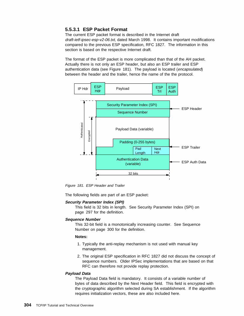
5.5.3.1 ESP Packet FormatThe current ESP packet format is described in the Internet draftdraft-ietf-ipsec-esp-v2-06.txt, dated March 1998. It contains important modificationscompared to the previous ESP specification, RFC 1827. The information in thissection is based on the respective Internet draft.
The format of the ESP packet is more complicated than that of the AH packet.Actually there is not only an ESP header, but also an ESP trailer and ESPauthentication data (see Figure 181). The payload is located (encapsulated)between the header and the trailer, hence the name of the the protocol.
Au t
h en t
icat
e d
Enc
rypt
edESP Hdr
IP Hdr Payload ESP Trl
ESP Auth
32 bits
Payload Data (variable)
Pad Length
Next Hdr
Authentication Data (variable) ESP Auth Data
ESP Trailer
ESP Header
Padding (0-255 bytes)
Security Parameter Index (SPI)
Sequence Number
Figure 181. ESP Header and Trailer
The following fields are part of an ESP packet:
Security Parameter Index (SPI)This field is 32 bits in length. See Security Parameter Index (SPI) onpage 297 for the definition.
Sequence NumberThis 32-bit field is a monotonically increasing counter. See SequenceNumber on page 300 for the definition.
Notes:
1. Typically the anti-replay mechanism is not used with manual keymanagement.
2. The original ESP specification in RFC 1827 did not discuss the concept ofsequence numbers. Older IPSec implementations that are based on thatRFC can therefore not provide replay protection.
Payload DataThe Payload Data field is mandatory. It consists of a variable number ofbytes of data described by the Next Header field. This field is encrypted withthe cryptographic algorithm selected during SA establishment. If the algorithmrequires initialization vectors, these are also included here.
304 TCP/IP Tutorial and Technical Overview

The ESP specification require support for the DES algorithm in CBC mode(DES-CBC transform). Often other encryption algorithms are also supported,such as triple-DES and CDMF in the case of IBM products.
PaddingMost encryption algorithms require that the input data must be an integralnumber of blocks. Also, the resulting ciphertext (including the Padding, PadLength and Next Header fields) must terminate on a 4-byte boundary, so thatNext Header field is right-aligned. That's why this variable length field isincluded. It can be used to hide the length of the original messages too.However, this could adversely impact the effective bandwidth. Padding is anoptional field.
Note: The encryption covers the Payload Data, Padding, Pad Length andNext Header fields.
Pad LengthThis 8-bit field contains the number of the preceding padding bytes. It isalways present, and the value of 0 indicates no padding.
Next HeaderThe Next Header is an 8-bit mandatory field that shows the data type carriedin the payload, for example an upper-level protocol identifier such as TCP.The values are chosen from the set of IP protocol numbers defined by theIANA.
Authentication DataThis field is variable in length and contains the ICV calculated for the ESPpacket from the SPI to the Next Header field inclusive. The AuthenticationData field is optional. It is included only when integrity check andauthentication have been selected at SA initialization time.
The ESP specifications require two authentication algorithms to be supported:HMAC with MD5 and HMAC with SHA-1. Often the simpler keyed versionsare also supported by the IPSec implementations.
Notes:
1. The IP header is not covered by the ICV.
2. The original ESP specification in RFC 1827 discusses the concept ofauthentication within ESP in conjunction with the encryption transform.That is, there is no Authentication Data field and it is left to the encryptiontransforms to eventually provide authentication.
5.5.3.2 Ways of Using ESPLike AH, ESP can be used in two ways: transport mode and tunnel mode.
ESP in Transport Mode: In this mode the original IP datagram is taken and theESP header is inserted right after the IP header, as it is shown in Figure 182 onpage 306. If the datagram already has IPSec header(s), then the ESP header isinserted before any of those. The ESP trailer and the optional authentication dataare appended to the payload.
Chapter 5. TCP/IP Security Overview 305

ESP Hdr
IP Hdr Payload ESP Trl
ESP Auth
IP Hdr Payload
Encrypted
Authenticated
Original IP datagram
Datagram with ESPin transport mode
Figure 182. ESP in Transport Mode
ESP in transport mode provides neither authentication nor encryption for the IPheader. This is a disadvantage, since false packets might be delivered for ESPprocessing. The advantage of transport mode is the lower processing overhead.
As in the case of AH, ESP in transport mode is used by hosts, not gateways.Gateways are not even required to support transport mode.
ESP in Tunnel Mode: As expected, this mode applies the tunneling principle. Anew IP packet is constructed with a new IP header and then ESP in transport modeis applied, as illustrated in Figure 183. Since the original datagram becomes thepayload data for the new ESP packet, its protection is total if both encryption andauthentication are selected. However, the new IP header is still not protected.
IP Hdr Payload Original IP datagram
Payload ESP Trl
ESP Auth
Encrypted
Authenticated
Datagram with ESPin tunnel mode
IP Hdr PayloadNewIP Hdr
NewIP Hdr
IP Hdr
Tunneled datagram
ESP Hdr
Figure 183. ESP in Tunnel Mode
The tunnel mode is used whenever either end of a security association is agateway. Thus, between two firewalls the tunnel mode is always used.
Although gateways are supposed to support tunnel mode only, often they can alsowork in transport mode. This mode is allowed when the gateway acts as a host,that is in cases when traffic is destined to itself. Examples are SNMP commandsor ICMP echo requests.
In tunnel mode the outer headers' IP addresses does not need to be the same asthe inner headers' addresses. For example two security gateways may operate anESP tunnel which is used to secure all traffic between the networks they connecttogether. Hosts are not required to support tunnel mode, but often they do.
306 TCP/IP Tutorial and Technical Overview
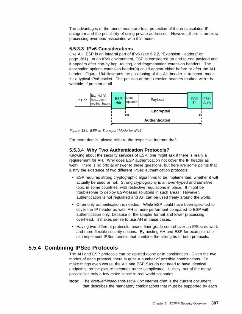
The advantages of the tunnel mode are total protection of the encapsulated IPdatagram and the possibility of using private addresses. However, there is an extraprocessing overhead associated with this mode.
5.5.3.3 IPv6 ConsiderationsLike AH, ESP is an integral part of IPv6 (see 6.2.2, “Extension Headers” onpage 361). In an IPv6 environment, ESP is considered an end-to-end payload andit appears after hop-by-hop, routing, and fragmentation extension headers. Thedestination options extension header(s) could appear either before or after the AHheader. Figure 184 illustrates the positioning of the AH header in transport modefor a typical IPv6 packet. The position of the extension headers marked with * isvariable, if present at all.
IP Hdr PayloadESP Hdr
Ext. Hdr(s):hop., dest.*,routing, fragm.
Dest.options*
ESP Trl
ESP Auth
Authenticated
Encrypted
Figure 184. ESP in Transport Mode for IPv6
For more details, please refer to the respective Internet draft.
5.5.3.4 Why Two Authentication Protocols?Knowing about the security services of ESP, one might ask if there is really arequirement for AH. Why does ESP authentication not cover the IP header aswell? There is no official answer to these questions, but here are some points thatjustify the existence of two different IPSec authentication protocols:
� ESP requires strong cryptographic algorithms to be implemented, whether it willactually be used or not. Strong cryptography is an over-hyped and sensitivetopic in some countries, with restrictive regulations in place. It might betroublesome to deploy ESP-based solutions in such areas. However,authentication is not regulated and AH can be used freely around the world.
� Often only authentication is needed. While ESP could have been specified tocover the IP header as well, AH is more performant compared to ESP withauthentication only, because of the simpler format and lower processingoverhead. It makes sense to use AH in these cases.
� Having two different protocols means finer-grade control over an IPSec networkand more flexible security options. By nesting AH and ESP for example, onecan implement IPSec tunnels that combine the strengths of both protocols.
5.5.4 Combining IPSec ProtocolsThe AH and ESP protocols can be applied alone or in combination. Given the twomodes of each protocol, there is quite a number of possible combinations. Tomake things even worse, the AH and ESP SAs do not need to have identicalendpoints, so the picture becomes rather complicated. Luckily, out of the manypossibilities only a few make sense in real-world scenarios.
Note: The draft-ietf-ipsec-arch-sec-07.txt Internet draft is the current documentthat describes the mandatory combinations that must be supported by each
Chapter 5. TCP/IP Security Overview 307

IPSec implementation. Other combinations may also be supported, but thismight impact interoperability.
We mentioned in 5.5.1.1, “Security Associations” on page 297 that thecombinations of IPSec protocols are realized with SA bundles.
There are two approaches for an SA bundle creation:
� Transport adjacency: Both security protocols are applied in transport mode tothe same IP datagram. This method is practical for only one level ofcombination.
� Iterated (nested) tunneling: The security protocols are applied in tunnel modein sequence. After each application a new IP datagram is created and the nextprotocol is applied to it. This method has no limit in the nesting levels.However, more than three levels are impractical.
These approaches can be combined, for example an IP packet with transportadjacency IPSec headers can be sent through nested tunnels.
When designing a VPN, one should limit the IPSec processing stages applied to acertain packet to a reasonable level. In our view three applications is that limit overwhich further processing has no benefits. Two stages are sufficient for almost allthe cases.
Note that in order to be able to create an SA bundle in which the SAs havedifferent endpoints, at least one level of tunneling must be applied. Transportadjacency does not allow for multiple source/destination addresses, because onlyone IP header is present.
The practical principle of the combined usage is that upon the receipt of a packetwith both protocol headers, the IPSec processing sequence should beauthentication followed by decryption. It is a common sense decision not to botherwith the decryption of packets of uncertain origin.
Following the above principle, the sender first applies ESP and then AH to theoutbound traffic. In fact this sequence is an explicit requirement for transport modeIPSec processing. When using both ESP and AH, a new question arises: shouldESP authentication be turned on? AH authenticates the packet anyway. Theanswer is simple. Turning ESP authentication on makes sense only when the ESPSA extends beyond the AH SA, as in the case of the supplier scenario. In thiscase, not only does it make sense to use ESP authentication, but it is highlyrecommended to do so, to avoid spoofing attacks in the intranet.
As far as the modes are concerned, the usual way is that transport mode is usedbetween the endpoints of a connection and tunnel mode is used between twomachines when at least one of them is a gateway.
Let's take a systematic look on the plausible ways of using the IPSec protocols,from the simplest to the more complicated nested setups.
308 TCP/IP Tutorial and Technical Overview

5.5.4.1 Case 1: End-to-End SecurityAs shown in Figure 185, two hosts are connected through the Internet (or anintranet) without any IPSec gateway between them. They can use ESP, AH orboth. Either transport or tunnel mode can be applied.
H1 H2Internet/intranet
IPSec tunnel
Connection
Figure 185. End-to-End Security
The combinations required to be supported by any IPSec implementation are thefollowing:
Transport Mode 1. AH alone 2. ESP alone
3. AH applied after ESP (transport adjacency)Tunnel Mode
1. AH alone 2. ESP alone
5.5.4.2 Case 2: Basic VPN SupportFigure 186 illustrates the simplest VPN. The gateways G1 and G2 run the IPSecprotocol stack. The hosts in the intranets are not required to support IPSec.
G1 G2Internet/intranet intranetintranet H2H1
Connection IPSec tunnel
Figure 186. Basic VPN Support
In this case the gateways are required to support only tunnel mode, either with AHor ESP.
Combined Tunnels between Gateways: Although the gateways are required tosupport only an AH tunnel or ESP tunnel, often it is desirable to have tunnelsbetween gateways that combine the features of both IPSec protocols.
The IBM IPSec implementations support this type of combined AH-ESP tunnels.The order of the headers is user selectable by setting the tunnel policy.
A combined tunnel between the gateways does not mean that iterated tunnelingtakes place. Since the SA bundle comprising the tunnel have identical endpoints, it
Chapter 5. TCP/IP Security Overview 309

is inefficient to do iterated tunneling. Instead, one IPSec protocol is applied intunnel mode and the other in transport mode, which can be conceptually thought ofas a combined AH-ESP tunnel. An equivalent approach is to IP tunnel the originaldatagram and then apply transport adjacency IPSec processing to it. The result isthat we have an outer IP header followed by the IPSec headers in the order set bythe tunnel policy, then the original IP packet, as it is shown in the figure below.This is the packet format in a combined AH-ESP tunnel between two IBM firewalls.
Note: The ESP authentication data is not present because the IPSecimplementation in the IBM firewall does not support the new specificationsyet.
OuterIP Hdr
Inner IP Hdr
PayloadESP Hdr
ESP Trl
AH Hdr
Figure 187. Combined AH-ESP Tunnel
5.5.4.3 Case 3: End-to-End Security with VPN SupportThis case is a combination of cases 1 and 2 and it does not raise new IPSecrequirements for the machines involved (see Figure 188). The big difference fromcase 2 is that now the hosts are also required to support IPSec.
G1 G2Internet/intranet
intranetintranet H2H1
Connection IPSec tunnels
Figure 188. End-to-End Security with VPN Support
In a typical setup, the gateways use AH in tunnel mode, while the hosts use ESP intransport mode. An enhanced security version could use a combined AH-ESPtunnel between the gateways. In this way the ultimate destination addresses wouldbe encrypted, the whole packet traveling the Internet would be authenticated andthe carried data double encrypted. This is the only case when three stages ofIPSec processing might be useful, however, at a cost; the performance impact isconsiderable.
5.5.4.4 Case 4: Remote AccessThis case, shown in Figure 189 on page 311, applies to the remote hosts that usethe Internet to reach a server in the organization protected by a firewall. Theremote host commonly uses a PPP dial-in connection to an ISP.
310 TCP/IP Tutorial and Technical Overview

G2Internet intranet H2H1
Connection IPSec tunnels
Dial-up segment
Figure 189. Remote Access
Between the remote host H1 and the firewall G2 only tunnel mode is required. Thechoices are the same as in case 2. Between the hosts themselves either tunnelmode or transport mode can be used, with the same choices as in case 1.
A typical setup is to use AH in tunnel mode between H1 and G2 and ESP intransport mode between H1 and H2. Older IPSec implementations that do notsupport AH in tunnel mode cannot implement this.
It is also common to create a combined AH-ESP tunnel between the remote hostH1 and the gateway G2. In this case H1 can access the whole intranet with usingjust one SA bundle, whereas if it were using the setup shown in Figure 189, it onlycould access one host with one SA bundle.
5.5.4.5 Conclusion and an ExampleWhile the combination of the IPSec protocols in theory leads to a large number ofpossibilities, in practice only a few (those presented above) are used. One verycommon combination is AH in tunnel mode protecting ESP traffic in transport mode.Combined AH-ESP tunnels between firewalls are also frequent.
Figure 190 on page 312 shows in detail how the first combination is realized.Consider that host H1 in Figure 188 on page 310 sends an IP packet to host H2.Here is what happens:
1. Host H1 constructs the IP packet and applies ESP transport to it. H1 thensends the datagram to gateway G1, the destination address being H2.
2. Gateway G1 realizes that this packet should be routed to G2. Upon consultingits IPSec databases (SPD and SAD) G1 concludes that AH in tunnel modemust be applied before sending the packet out. It does the requiredencapsulation. Now the IP packet has the address of G2 as its destination, theultimate destination H2 being encapsulated.
3. Gateway G2 receives the AH-tunneled packet. It is destined to itself, so itauthenticates the datagram and strips off the outer header. G2 sees that thepayload is yet another IP packet (that one sent by H1) with destination H2, so itforwards to H2. G2 does not care that this packet has an ESP header.
4. Finally H2 receives the packet. As this is the destination, ESP-transportprocessing is applied and the original payload retrieved.
Chapter 5. TCP/IP Security Overview 311

ESP Hdr
Payload ESP Trl
ESP Auth
IP HdrSrc: H1Dest: H2
Payload
IP HdrSrc: H1Dest: H2
ESP Hdr
Payload ESP Trl
ESP Auth
ESP Hdr
PayloadESP Trl
ESP Auth
Payload
IP HdrSrc: H1Dest: H2
New IP H.Src: G1Dest: G2
IP HdrSrc: H1Dest: H2
IP HdrSrc: H1Dest: H2
AH Hdr
Figure 190. Nesting of IPSec Protocols
5.5.5 The Internet Key Exchange Protocol (IKE)The Internet Key Exchange (IKE) framework, previously referred to asISAKMP/Oakley, supports automated negotiation of Security Associations, andautomated generation and refresh of cryptographic keys. The ability to performthese functions with little or no manual configuration of machines is a criticalelement to any enterprise-scale IPSec deployment.
Before describing the details of the key exchange and update messages, someexplanations are due:
Internet Security Association and Key Management Protocol (ISAKMP)A framework that defines the management of security associations (negotiate,modify, delete) and keys, and it also defines the payloads for exchanging keygeneration and authentication data. ISAKMP itself does not define any keyexchange protocols, and the framework it provides can be applied to securitymechanisms on the network, transport or application layer, and also to itself.
OakleyA key exchange protocol that can be used with the ISAKMP framework toexchange and update keying material for security associations.
Domain of InterpretationDefinition of a set of protocols to be used with the ISAKMP framework for aparticular environment, and a set of common definitions shared with thoseprotocols regarding syntax of SA attributes and payload contents, namespaceof cryptographic transforms, etc. In relation to IPSec, the DOI instantiatesISAKMP for use with IP.
Internet Key Exchange (IKE)A protocol that uses parts of ISAKMP and parts of the Oakley and SKEMEkey exchange protocols to provide management of keys and securityassociations for the IPSec AH and ESP protocols, and for ISAKMP itself.
312 TCP/IP Tutorial and Technical Overview

5.5.5.1 Protocol OverviewISAKMP requires that all information exchanges must be both encrypted andauthenticated so that no one can eavesdrop on the keying material, and the keyingmaterial will be exchanged only among authenticated parties. This is requiredbecause the ISAKMP procedures deal with initializing the keys, so they must becapable of running over links where no security can be assumed to exist. Hence,the ISAKMP protocols use the most complex and processor-intensive operations inthe IPSec protocol suite.
In addition, the ISAKMP methods have been designed with the explicit goals ofproviding protection against several well-known exposures:
� Denial-of-Service: The messages are constructed with unique cookies that canbe used to quickly identify and reject invalid messages without the need toexecute processor-intensive cryptographic operations.
� Man-in-the-Middle: Protection is provided against the common attacks such asdeletion of messages, modification of messages, reflecting messages back tothe sender, replaying of old messages, and redirection of messages tounintended recipients.
� Perfect Forward Secrecy (PFS): Compromise of past keys provides no usefulclues for breaking any other key, whether it occurred before or after thecompromised key. That is, each refreshed key will be derived without anydependence on predecessor keys.
The following authentication methods are defined for IKE:
1. Pre-shared key
2. Digital signatures (DSS and RSA)
3. Public key encryption (RSA and revised RSA)
The robustness of any cryptography-based solution depends much more stronglyon keeping the keys secret than it does on the actual details of the chosencryptographic algorithms. Hence, the IETF IPSec Working Group has prescribed aset of extremely robust Oakley exchange protocols. It uses a 2-phase approach:
Phase 1: This set of negotiations establishes a master secret from which allcryptographic keys will subsequently be derived for protecting the users' data traffic.In the most general case, public key cryptography is used to establish an ISAKMPsecurity association between systems, and to establish the keys that will be used toprotect the ISAKMP messages that will flow in the subsequent Phase 2negotiations. Phase 1 is concerned only with establishing the protection suite forthe ISAKMP messages themselves, but it does not establish any securityassociations or keys for protecting user data.
In Phase 1, the cryptographic operations are the most processor-intensive but needonly be done infrequently, and a single Phase 1 exchange can be used to supportmultiple subsequent Phase 2 exchanges. As a rule of thumb, Phase 1 negotiationsare executed once a day or maybe once a week, while Phase 2 negotiations areexecuted once every few minutes.
Phase 2: Phase 2 exchanges are less complex, since they are used only after thesecurity protection suite negotiated in Phase 1 has been activated. A set ofcommunicating systems negotiate the security associations and keys that will
Chapter 5. TCP/IP Security Overview 313

protect user data exchanges. Phase 2 ISAKMP messages are protected by theISAKMP security association generated in Phase 1. Phase 2 negotiations generallyoccur more frequently than Phase 1. For example, a typical application of a Phase2 negotiation is to refresh the cryptographic keys once every two to three minutes.
Permanent Identifiers: The IKE protocol also offers a solution even when theremote host's IP address is not known in advance. ISAKMP allows a remote hostto identify itself by a permanent identifier, such as a name or an e-mail address.The ISAKMP Phase 1 exchanges will then authenticate the remote host'spermanent identity using public key cryptography:
� Certificates create a binding between the permanent identifier and a public key.Therefore, ISAKMP's certificate-based Phase 1 message exchanges canauthenticate the remote host's permanent identify.
� Since the ISAKMP messages themselves are carried within IP datagrams, theISAKMP partner (for example, a firewall or destination host) can associate theremote host's dynamic IP address with its authenticated permanent identity.
5.5.5.2 Initializing Security Associations with IKEThis section outlines how ISAKMP/Oakley protocols initially establish securityassociations and exchange keys between two systems that wish to communicatesecurely.
In the remainder of this section, the parties involved are named Host-A and Host-B.Host-A will be the initiator of the ISAKMP Phase 1 exchanges, and Host-B will bethe responder. If needed for clarity, subscripts A or B will be used to identify thesource of various fields in the message exchanges.
Phase 1 - Setting Up the ISAKMP Security Associations: The securityassociations that protect the ISAKMP messages themselves are set up during thePhase 1 exchanges. Since we are starting "cold" (no previous keys or SAs havebeen negotiated between Host-A and Host-B), the Phase 1 exchanges will use theISAKMP Identity Protect exchange (also known as Oakley Main Mode). Sixmessages are needed to complete the exchange:
� Messages 1 and 2 negotiate the characteristics of the security associations.Messages 1 and 2 flow in the clear for the initial Phase 1 exchange, and theyare unauthenticated.
� Messages 3 and 4 exchange nonces (random values) and also execute aDiffie-Hellman exchange to establish a master key (SKEYID). Messages 3 and4 flow in the clear for the initial Phase 1 exchange, and they areunauthenticated.
� Messages 5 and 6 exchange the required information for mutuallyauthenticating the parties' identities. The payloads of Messages 5 and 6 areprotected by the encryption algorithm and keying material established withmessages 1 through 4.
The detailed description of the Phase 1 messages and exchanged informationfollows below:
1. IKE Phase 1, Message 1
Since Host-A is the initiating party, it will construct a cleartext ISAKMPmessage (Message 1) and send it to Host-B. The ISAKMP message itself iscarried as the payload of a UDP packet, which in turn is carried as the payloadof a normal IP datagram (see Figure 191 on page 315).
314 TCP/IP Tutorial and Technical Overview

IPHeader
UDPHeader
ISAKMPHeader
SAProposal
#nTransform
(for #n)...
Accept One
Offer AlternativesHost
BHost
A
Proposal#1
Transform(for #1)
Figure 191. Message 1 of an ISAKMP Phase 1 Exchange
The source and destination addresses to be placed in the IP header are thoseof Host-A (initiator) and Host-B (responder), respectively. The UDP header willidentify that the destination port is 500, which has been assigned for use by theISAKMP protocol. The payload of the UDP packet carries the ISAKMPmessage itself.
In Message 1, Host-A, the initiator, proposes a set of one or more protectionsuites for consideration by Host-B, the responder. Hence, the ISAKMPMessage contains at least the following fields in its payload:
ISAKMP HeaderThe ISAKMP Header in Message 1 will indicate an exchange type of MainMode, and will contain a Message ID of 0. Host-A will set the ResponderCookie field to 0, and will fill in a random value of its choice for theInitiator Cookie, denoted as Cookie-A.
Security AssociationThe Security Association field identifies the Domain of Interpretation(DOI). Since the hosts plan to run IPSec protocols between themselves,the DOI is simply IP.
Proposal PayloadHost-A's Proposal Payload will specify the protocol PROTO_ISAKMP andwill set the SPI value to 0.
Note: For ISAKMP Phase 1 messages, the actual SPI field within theProposal Payload is not used to identify the ISAKMP SecurityAssociation. During Phase 1, the ISAKMP SA is identified insteadby the pair of values <Initiator Cookie, Responder Cookie>, bothof which must be non-zero values. Since the Responder Cookiehas not yet been generated by Host-B, the ISAKMP SA is not yetunambiguously identified.
Transform PayloadThe Transform Payload will specify KEY_OAKLEY. For theKEY_OAKLEY transform, Host-A must also specify the relevant attributes:namely, the authentication method to be used, the pseudo-randomfunction to be used, and the encryption algorithm to be used.
Note: Multiple proposals can be included in Message 1.
2. IKE Phase 1, Message 2
In Message 1, Host-A proposed one or more candidate protection suites to beused to protect the ISAKMP exchanges. Host-B uses Message 2 to indicate
Chapter 5. TCP/IP Security Overview 315

which one, if any, it will support. If Host-A proposed just a single option,Host-B merely needs to acknowledge that the proposal is acceptable.
The source and destination addresses to be placed in the IP header are thoseof Host-B (responder) and Host-A (initiator), respectively. The UDP header willidentify that the destination port is 500, which has been assigned for use by theISAKMP protocol. The payload of the UDP packet carries the ISAKMPmessage itself.
The message contents will be as follows:
ISAKMP HeaderThe ISAKMP Header in Message 2 will indicate an exchange type of MainMode, and will contain a Message ID of 0. Host-B will set the ResponderCookie field to a random value, which we will call Cookie-B, and will copyinto the Initiator Cookie field the value that was received in the Cookie-Afield of Message 1. The value pair <Cookie-A, Cookie-B> will serve asthe SPI for the ISAKMP Security Association.
Security AssociationThe Security Association field identifies the Domain of Interpretation(DOI). Since the hosts plan to run IPSec protocols between themselves,the DOI is simply IP.
Proposal PayloadHost-B's Proposal Payload will specify the protocol PROTO_ISAKMP andwill set the SPI value to 0.
Transform PayloadThe Transform Payload will specify KEY_OAKLEY. For theKEY_OAKLEY transform, the attributes that were accepted from theproposal offered by Host-A are copied into the appropriate fields.
At this point, the properties of the ISAKMP Security Association have beenagreed to by Host-A and Host-B. The identity of the ISAKMP SA has been setequal to the pair <Cookie-A, Cookie-B>. However, the identities of the partiesclaiming to be Host-A and Host-B have not yet been authoritatively verified.
3. IKE Phase 1, Message 3
The third message of the Phase 1 ISAKMP exchange begins the exchange ofthe information from which the cryptographic keys will eventually be derived(see Figure 192 on page 317).
Important.
None of the messages themselves carry the actual cryptographic keys.Instead, they carry inputs that will be used by Host-A and Host-B to derivethe keys locally.
The ISAKMP payload will be used to exchange two types of information:
Diffie-Hellman public valueThe Diffie-Hellman public value gx from the initiator. The exponent x inthe public value is the private value that must be kept secret.
NonceThe nonce Ni from the initiator. (Nonce is a fancy name for a value that isconsidered to be random according to some very strict mathematicalguidelines.)
316 TCP/IP Tutorial and Technical Overview

ID If authentication with RSA public key is used, the nonces are encryptedwith the public key of the other party. Likewise are the IDs of either partywhich are then also exchanged at this stage.
If authentication with revised RSA public key is used, the KE and IDpayloads are encrypted with a secret key that is derived from the noncesand the encryption algorithm agreed to in Messages 1 and 2, thusavoiding one CPU-intensive public key operation.
Certificates may optionally be exchanged in either case of public keyauthentication, as well as a hash value thereof.
These values are carried in the Key Exchange, and the Nonce and the IDfields, respectively.
IPHeader
UDPHeader
ISAKMPHeader
HostY
HostX
i, Ngx
r, Ngy
iNgx ID Certificate Signature
Figure 192. Message 3 of an ISAKMP Phase 1 Exchange
4. IKE Phase 1, Message 4
After receiving a Diffie-Hellman public value and a nonce from Host-A, Host-Bwill respond by sending to Host-A its own Diffie-Hellman public value (gy fromthe responder) and its nonce (Nr from the responder).
5. Generating the Keys (Phase 1)
At this point, each host knows the values of the two nonces (Ni and Nr). Eachhost also knows its own private Diffie-Hellman value (x and y) and also knowsits partner's public value (gx or gy). Hence each side can construct thecomposite value gxy. And finally, each side knows the values of the initiatorcookie and the responder cookie.
Given all these bits of information, each side can then independently computeidentical values for the following quantities:
� SKEYID: This collection of bits is sometimes referred to as keying material,since it provides the raw input from which actual cryptographic keys will bederived later in the process. It is obtained by applying the agreed-to keyedpseudorandom function (prf) to the known inputs:
a. For digital signature authentication:
SKEYID = prf(Ni, Nr, gxy)
b. For authentication with public keys:
SKEYID = prf(hash(Ni, Nr), CookieA, CookieB)
Chapter 5. TCP/IP Security Overview 317

c. For authentication with a pre-shared key:
SKEYID = prf(pre-shared key, Ni, Nr)
� Having computed the value SKEYID, each side then proceeds to generatetwo cryptographic keys and some additional keying material:
– SKEYID_d is keying material that will be subsequently used in Phase 2to derive the keys that will be used in non-ISAKMP SAs for protectinguser traffic:
SKEYID_d = prf(SKEYID, gxy, CookieA, CookieB, ð)
– SKEYID_a is the key used for authenticating ISAKMP messages:
SKEYID_a = prf(SKEYID, SKEYID_d, gxy, CookieA, CookieB, 1)
– SKEYID_e is the key used for encrypting ISAKMP exchanges:
SKEYID_e = prf(SKEYID, SKEYID_a, gxy, CookieA, CookieB, 2)
At this point in the protocol, both Host-A and Host-B have derived identicalauthentication and encryption keys that they will use to protect the ISAKMPexchanges. And they have also derived identical keying material from whichthey will derive keys to protect user data during Phase 2 of the ISAKMPnegotiations. However, at this point, the two parties' identities still have notbeen authenticated to one another.
6. IKE Phase 1, Message 5
At this point in the Phase 1 flows, the two hosts will exchange identityinformation with each other to authenticate themselves. As shown inFigure 193, the ISAKMP message will carry an identity payload, a signaturepayload, and an optional certificate payload. Host-A uses Message 5 to sendinformation to Host-B that will allow Host-B to authenticate Host-A.
IPHeader
UDPHeader
ISAKMPHeader
Identity Certificate Signature
Figure 193. Message 5 of an ISAKMP Phase 1 Exchange
When an actual certificate is present in the Certificate Payload field, thereceiver can use the information directly, after verifying that it has been signedwith a valid signature of a trusted certificate authority. If there is no certificatein the message, then it is the responsibility of the receiver to obtain a certificateusing some implementation method. For example, it may send a query to atrusted certificate authority using a protocol such as LDAP, or it may query asecure DNS server, or it may maintain a secure local cache that mapspreviously used certificates to their respective ID values, or it may send anISAKMP Certificate Request message to its peer, who must then immediatelysend its certificate to the requester.
318 TCP/IP Tutorial and Technical Overview

Note: The method for obtaining a certificate is a local option, and is notdefined as part of IKE. In particular, it is a local responsibility of thereceiver to check that the certificate in question is still valid and has notbeen revoked.
There are several points to bear in mind:
� At this stage of the process, all ISAKMP payloads, whether in Phase 1 orPhase 2, are encrypted, using the encryption algorithm (negotiated inMessages 1 and 2) and the keys (derived from the information in Messages3 and 4). The ISAKMP header itself, however, is still transmitted in theclear.
� In Phase 1, IPSec's ESP protocol is not used: that is, there is no ESPheader. The recipient uses the Encryption Bit in the Flags field of theISAKMP header to determine if encryption has been applied to themessage. The pair of values <CookieA, CookieB>, which serve as an SPIfor Phase 1 exchanges, provide a pointer to the correct algorithm and keyto be used to decrypt the message.
� The Digital Signature, if used, is not applied to the ISAKMP message itself.Instead, it is applied to a hash of information that is available to bothHost-A and Host-B.
� The identity carried in the identity payload does not necessarily bear anyrelationship to the source IP address; however, the identity carried in theidentity payload must be the identity to which the certificate, if used,applies.
Host-A (the initiator) will generate the following hash function, and then placethe result in the Signature Payload field:
HASH_I = prf(SKEYID, gx, gy, CookieA, CookieB, SAp, IDA)
If digital signatures were used for authentication, this hash will also be signedby Host-A.
IDA is Host-A's identity information that was transmitted in the identity payloadof this message, and SAp is the entire body of the SA payload that was sent byHost-A in Message 1, including all proposals and all transforms proposed byHost-A. The cookies, public Diffie-Hellman values, and SKEYID were explicitlycarried in Messages 1 through 4, or were derived from their contents.
7. IKE Phase 1, Message 6
After receiving Message 5 from Host-A, Host-B will verify the identity of Host-Aby validating the hash.
If digital signatures were used for authentication, the signature of this hash willbe verified by Host-B.
If this is successful, then Host-B will send Message 6 to Host-A to allow Host-Ato verify the identity of Host-B.
The structure of Message 6 is the same as that of Message 5, with the obviouschanges that the identity payload and the certificate payload now pertain toHost-B.
Chapter 5. TCP/IP Security Overview 319

HASH_R = prf(SKEYID, gy, gx, CookieB, CookieA, SAp, IDB)
Notice that the order in which Diffie-Hellman public values and the cookiesappear has been changed, and the final term now is the Identity Payload thatHost-B has included in Message 6.
If digital signatures were used for authentication, this hash will also be signedby Host-B, which is different from the one previously signed by Host-A.
When Host-A receives Message 6 and verifies the hash or digital signature, thePhase 1 exchanges are then complete. At this point, each participant hasauthenticated itself to its peer. Both have agreed on the characteristics of theISAKMP Security Associations, and both have derived the same set of keys (orkeying material).
8. Miscellaneous Phase 1 Facts
There are several miscellaneous facts worth noting:
a. Regardless of the specific authentication mechanism that is used, there willbe six messages exchanged for Oakley Main Mode. However, the contentof the individual messages will differ, depending on the authenticationmethod.
b. Although Oakley exchanges make use of both encryption andauthentication, they do not use either IPSec's ESP or AH protocol.ISAKMP exchanges are protected with application-layer securitymechanisms, not with network layer security mechanisms.
c. ISAKMP messages are sent using UDP. There is no guaranteed deliveryfor them.
d. The only way to identify that an ISAKMP message is part of a Phase 1 flowrather than a Phase 2 flow is to check the Message ID field in the ISAKMPHeader. For Phase 1 flows, it must be 0, and (although not explicitly statedin the ISAKMP documents) for Phase 2 flows it must be non-zero.
Phase 2 - Setting Up the Protocol Security Associations: After havingcompleted the Phase 1 negotiation process to set up the ISAKMP SecurityAssociations, Host-A's next step is to initiate the Oakley Phase 2 messageexchanges (also known as Oakley Quick Mode) to define the security associationsand keys that will be used to protect IP datagrams exchanged between the pair ofusers. (In the Internet drafts, these are referred to somewhat obtusely as"non-ISAKMP SAs".)
Because the purpose of the Phase 1 negotiations was to agree on how to protectISAKMP messages, all ISAKMP Phase 2 payloads, but not the ISAKMP headeritself, must be encrypted using the algorithm agreed to by the Phase 1 negotiations.
When Oakley Quick Mode is used in Phase 2, authentication is achieved via theuse of several cryptographically based hash functions. The input to the hashfunctions comes partly from Phase 1 information (SKEYID) and partly frominformation exchanged in Phase 2. Phase 2 authentication is based on certificates,but the Phase 2 process itself does not use certificates directly. Instead, it uses theSKEYID_a material from Phase 1, which itself was authenticated via certificates.
Oakley Quick Mode comes in two forms:
320 TCP/IP Tutorial and Technical Overview

� Without a Key Exchange attribute, Quick Mode can be used to refresh thecryptographic keys, but does not provide the property of Perfect ForwardSecrecy (PFS).
� With a Key Exchange attribute, Quick Mode can be used to refresh thecryptographic keys in a way that provides PFS. This is accomplished byincluding an exchange of public Diffie-Hellman values within messages 1 and 2.
Note: PFS apparently is a property that is very much desired by cryptographyexperts, but strangely enough, the specs treat PFS as optional. Theymandate that a system must be capable of handling the Key Exchange fieldwhen it is present in a Quick Mode message, but do not require a system toinclude the field within the message.
The detailed description of the Phase 2 messages and exchanged informationfollows below:
1. IKE Phase 2, Message 1
Message 1 of a Quick Mode Exchange allows Host-A to authenticate itself, toselect a nonce, to propose security association(s) to Host-B, to execute anexchange of public Diffie-Hellman values, and to indicate if it is acting on itsown behalf or as a proxy negotiator for another entity. An overview of theformat of Message 1 is shown in Figure 194.
Note: Inclusion of a key exchange field is optional. However, when PerfectForward Secrecy is desired, it must be present.
HostB
HostA
Hash-2, SA(ESP & AH),
Hash-3
Hash-1, SA(ESP & AH), i, Ngx
r, Ngy
IPHeader
UDPHeader
ISAKMPHeader
KEProp-osal#n
Trans-form
(for #n)
...Prop-osal#1
Trans-form
(for #1)
(Proxy IDs)
(Proxy IDs)
IDsHash SA N
Figure 194. Message 1 of an ISAKMP Phase 2 Quick Mode Exchange
Since we have assumed that Host-A and Host-B are each acting on their ownbehalf, the user identity fields illustrated in Figure 194 will not be present. Themessage will consist of:
ISAKMP HeaderThe ISAKMP Header will indicate an exchange type of Quick Mode, willinclude a non-zero Message-ID chosen by Host-A, will include the initiatorand responder cookie values chosen in Phase 1 (that is, Cookie-A andCookie-B), and will turn on the encryption flag to indicate that thepayloads of the ISAKMP message are encrypted according to thealgorithm and key negotiated during Phase 1.
Chapter 5. TCP/IP Security Overview 321

HashA Hash Payload must immediately follow the ISAKMP header. HASH_1uses the keyed pseudo-random function that was negotiated during thePhase 1 exchanges, and is derived from the following information:
� SKEYID_a was derived from the Phase 1 exchanges.� M-ID is the message ID of this message.� SA is the Security Association payload carried in this message,
including all proposals that were offered.� Nonce is a new value different from the one used in Phase 1.� KE is the public Diffie-Hellman value carried in this message. This
quantity is chosen by Host-A, and is denoted as gqmx. Note that this
is not the same quantity as gx that was used in the Phase 1exchanges.
� IDs, which can identify either the endpoints of the Phase 1 exchangeor endpoints on whose behalf the protocol SA should be negotiated(proxy IDs when IKE is used in client mode). These cansubsequently be different from the IDs used in Phase 1.
Note: The use of KE and ID is optional depending if PFS is desired.
HASH_1 = prf(SKEYID_a, M-ID, SA, Nqmi, KE, IDqmi, IDqmr)
Security AssociationIndicate IP as the Domain of Interpretation.
Proposal, Transform PairsThere can be one or more of these pairs in this message. The firstproposal payload will be numbered 1, will identify an IPSec protocol to beused, and will include an SPI value that is randomly chosen by Host-A foruse with that protocol. The proposal payload will be followed by a singletransform payload that indicates the cryptographic algorithm to be usedwith that protocol. The second proposal payload will be numbered 2, etc.
Nonce PayloadThis contains the nonce Nqmi that was chosen randomly by Host-A.
KE This is the key exchange payload that will carry the public Diffie-Hellmanvalue chosen by Host-A, gqm
x. There is also a field called Group, thatindicates the prime number and generator used in the Diffie-Hellmanexchange.
ID PayloadSpecifies the endpoints for this SA.
2. IKE Phase 2, Message 2
After Host-B receives Message 1 from Host-A and successfully authenticates itusing HASH_1, it constructs a reply, Message 2, to be sent back to Host-A.The Message ID of the reply will be the same one that Host-A used inMessage 1. Host-B will choose new values for the following:
HashThe hash payload now carries the value HASH_2, which is defined as:
HASH_2 = prf(SKEYID_a, Nqmi, M-ID, SA, Nqmr, KE, IDqmi, IDqmr)
322 TCP/IP Tutorial and Technical Overview

Security AssociationThe Security Association payload only describes the single chosenproposal and its associated transforms, not all of the protection suitesoffered by Host-A. Host-B also chooses an SPI value for the selectedprotocol. Host-B's SPI does not depend in any way on the SPI thatHost-A assigned to that protocol when it offered the proposal. That is, itis not necessary that SPIA be the same as SPIB; it is only necessary thatthey each be non-zero and that they each be randomly chosen.
NonceNonce payload now carries Nr, a random value chosen by Host-B.
KE Key exchange payload now carries Host-B's public Diffie-Hellman value,gqm
y.
At this point, Host-A and Host-B have exchanged nonces and publicDiffie-Hellman values. Each one can use this in conjunction with otherinformation to derive a pair of keys, one for each direction of transmission.
3. Generating the Keys (Phase 2)
Using the nonces, public Diffie-Hellman values, SPIs, protocol code pointsexchanged in Messages 1 and 2 of Phase 2, and the SKEYID value fromPhase 1, each host now has enough information to derive two sets of keyingmaterial.
a. When PFS is used:
� For data generated by Host-A and received by Host-B, the keyingmaterial is:
KEYMATAB = prf(SKEYID_d, gqmxy, protocol, SPIB, Nqmi, Nqmr )
� For data generated by Host-B and received by Host-A, the keyingmaterial is:
KEYMATBA = prf(SKEYID_d, gqmxy, protocol, SPIA, Nqmi, Nqmr)
b. When PFS is not used:
� For data generated by Host-A and received by Host-B, the keyingmaterial is:
KEYMATAB = prf(SKEYID_d, protocol, SPIB, Nqmi, Nqmr )
� For data generated by Host-B and received by Host-A, the keyingmaterial is:
KEYMATBA = prf(SKEYID_d, protocol, SPIA, Nqmi, Nqmr)
Note: Depending on the particular case, Host-A may need to derive multiplekeys for the following purposes:
� Generating the integrity check value for transmitted datagrams� Validating the integrity check value of received datagrams
Chapter 5. TCP/IP Security Overview 323
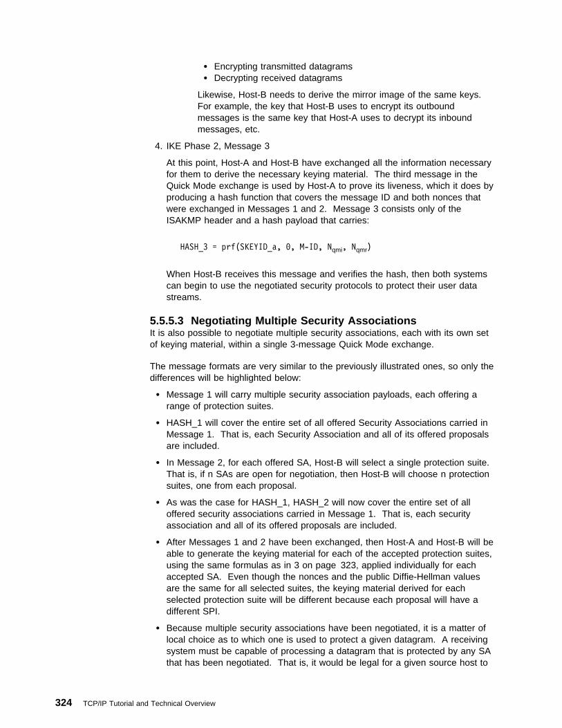
� Encrypting transmitted datagrams� Decrypting received datagrams
Likewise, Host-B needs to derive the mirror image of the same keys.For example, the key that Host-B uses to encrypt its outboundmessages is the same key that Host-A uses to decrypt its inboundmessages, etc.
4. IKE Phase 2, Message 3
At this point, Host-A and Host-B have exchanged all the information necessaryfor them to derive the necessary keying material. The third message in theQuick Mode exchange is used by Host-A to prove its liveness, which it does byproducing a hash function that covers the message ID and both nonces thatwere exchanged in Messages 1 and 2. Message 3 consists only of theISAKMP header and a hash payload that carries:
HASH_3 = prf(SKEYID_a, ð, M-ID, Nqmi, Nqmr)
When Host-B receives this message and verifies the hash, then both systemscan begin to use the negotiated security protocols to protect their user datastreams.
5.5.5.3 Negotiating Multiple Security AssociationsIt is also possible to negotiate multiple security associations, each with its own setof keying material, within a single 3-message Quick Mode exchange.
The message formats are very similar to the previously illustrated ones, so only thedifferences will be highlighted below:
� Message 1 will carry multiple security association payloads, each offering arange of protection suites.
� HASH_1 will cover the entire set of all offered Security Associations carried inMessage 1. That is, each Security Association and all of its offered proposalsare included.
� In Message 2, for each offered SA, Host-B will select a single protection suite.That is, if n SAs are open for negotiation, then Host-B will choose n protectionsuites, one from each proposal.
� As was the case for HASH_1, HASH_2 will now cover the entire set of alloffered security associations carried in Message 1. That is, each securityassociation and all of its offered proposals are included.
� After Messages 1 and 2 have been exchanged, then Host-A and Host-B will beable to generate the keying material for each of the accepted protection suites,using the same formulas as in 3 on page 323, applied individually for eachaccepted SA. Even though the nonces and the public Diffie-Hellman valuesare the same for all selected suites, the keying material derived for eachselected protection suite will be different because each proposal will have adifferent SPI.
� Because multiple security associations have been negotiated, it is a matter oflocal choice as to which one is used to protect a given datagram. A receivingsystem must be capable of processing a datagram that is protected by any SAthat has been negotiated. That is, it would be legal for a given source host to
324 TCP/IP Tutorial and Technical Overview

send two consecutive datagrams to a destination system, where each datagramwas protected by a different SA.
5.5.5.4 Using IKE with Remote AccessThe critical element in the remote access scenario is the use of Oakley to identifythe remote host by name, rather than by its dynamically assigned IP address.Once the remote host's identity has been authenticated and the mapping to itsdynamically assigned IP address has been ascertained, the remainder of theprocesses are the same as we have described for the other scenarios. Forexample, if the corporate intranet is considered to be trusted, then the remote hostneeds to establish a single SA between itself and the firewall. But if the corporateintranet is considered to be untrusted, then it may be necessary for the remote hostto set up two SAs: one between itself and the firewall, and a second between itselfand the destination host.
Recall that a single ISAKMP Phase 1 negotiation can protect several subsequentPhase 2 negotiations. Phase 1 ISAKMP negotiations use computationally intensivepublic key cryptographic operations, while Phase 2 negotiations use the lesscomputationally intensive symmetric key cryptographic operations. Hence, theheavy computational load only occurs in Phase I, which will only be executed oncewhen the dial-up connection is first initiated.
The principal points that pertain to the remote access case are:
� The remote host's dynamically assigned address is the one that is placed in theIP header of all ISAKMP messages.
� The remote host's permanent identifier (such as an e-mail address) is thequantity that is placed in the ID field of the ISAKMP Phase 1 messages.
� The remote host's certificate used in the ISAKMP exchange must be associatedwith the remote host's permanent identifier.
� In traffic-bearing datagrams, the remote host's dynamically assigned IP addresswill be used. This is necessary since the destination IP address that appearsin the datagram's IP header is used in conjunction with the SPI and protocoltype to identify the relevant IPSec security association for processing theinbound datagram.
5.5.6 ReferencesAt the time of writing this book, publication of the following Internet Draft documentshas been approved by the IETF as Proposed Standards but no RFC numbers haveyet been assigned:
Security Architecture for the Internet Protocolhttp://www.ietf.org/internet-drafts/draft-ietf-ipsec-arch-sec-ð7.txt
IP Authentication Header (AH)http://www.ietf.org/internet-drafts/draft-ietf-ipsec-auth-header-ð7.txt
IP Encapsulating Security Payload (ESP)http://www.ietf.org/internet-drafts/draft-ietf-ipsec-esp-v2-ð6.txt
Internet Security Association and Key Management Protocol (ISAKMP)http://www.ietf.org/internet-drafts/draft-ietf-ipsec-isakmp-1ð.txt
Internet Key Exchange (IKE)http://www.ietf.org/internet-drafts/draft-ietf-ipsec-isakmp-oakley-ð8.txt
IPSec Domain of Interpretation for ISAKMPhttp://www.ietf.org/internet-drafts/draft-ietf-ipsec-ipsec-doi-1ð.txt
Chapter 5. TCP/IP Security Overview 325

The Use of HMAC-MD5-96 within ESP and AHhttp://www.ietf.org/internet-drafts/draft-ietf-ipsec-auth-hmac-md5-96-ð3.txt
The Use of HMAC-SHA-1-96 within ESP and AHhttp://www.ietf.org/internet-drafts/draft-ietf-ipsec-auth-hmac-sha196-ð3.txt
The ESP DES-CBC Cipher Algorithm With Explicit IVhttp://www.ietf.org/internet-drafts/draft-ietf-ipsec-ciph-des-expiv-ð2.txt
The NULL Encryption Algorithm and Its Use With IPsechttp://www.ietf.org/internet-drafts/draft-ietf-ipsec-ciph-null-ð1.txt
At the time of writing this book, publication of the following Internet Draft documentshas been approved by the IETF as Informational RFCs but no RFC numbers haveyet been assigned:
Oakley Key Determination Protocolhttp://www.ietf.org/internet-drafts/draft-ietf-ipsec-oakley-ð2.txt
IPSec Working Group to consider Security Document Roadmaphttp://www.ietf.org/internet-drafts/draft-ietf-ipsec-doc-roadmap-ð2.txt
5.6 SOCKSSOCKS is a standard for circuit-level gateways. It does not require the overhead ofa more conventional proxy server where a user has to consciously connect to thefirewall first before requesting the second connection to the destination (please seeFigure 195).
The user starts a client application with the destination server IP address. Insteadof directly starting a session with the destination server, the client initiates a sessionto the SOCKS server on the firewall. The SOCKS server then validates that thesource address and user ID are permitted to establish onward connection into thenonsecure network, and then creates the second session.
Figure 195. SOCKS Server
SOCKS needs to have new versions of the client code (called SOCKSified clients)and a separate set of configuration profiles on the firewall. However, the servermachine does not need modification; indeed it is unaware that the session is beingrelayed by the SOCKS server. Both the client and the SOCKS server need to haveSOCKS code. The SOCKS server acts as an application-level router between theclient and the real application server. SOCKSv4 is for outbound TCP sessionsonly. It is simpler for the private network user, but does not have secure password
326 TCP/IP Tutorial and Technical Overview

delivery so it is not intended for sessions between public network users and privatenetwork applications. SOCKSv5 provides for several authentication methods andcan therefore be used for inbound connections as well, though these should beused with caution. SOCKSv5 also supports UDP-based applications and protocols.
The majority of Web browsers are SOCKSified and you can get SOCKSifiedTCP/IP stacks for most platforms. For additional information, refer to RFC 1928,1929, 1961 and the following URL:
http://www.socks.nec.com
5.6.1 SOCKS Version 5 (SOCKSv5)SOCKS version 5 is a proposed standard protocol with a status of elective. It isdescribed in RFC 1928.
Application-level gateways provide secure connections for some applications suchas TELNET, FTP and SMTP. However, it is not easy to write proxy code for eachnew application. Generally, the proxy service becomes available after some timeeven if the service can be used directly and application level gateways do not allowUDP connections. SOCKSv5 satisfies all these shortcomings and requirementswith a strong authentication mechanism and the hiding of addresses from anon-secure network. Although, supporting UDP might seem to be vulnerable, it canbe configured to pass UDP for particular users and particular applications only.
The SOCKSv5 concept is based on SOCKSv4 with some extensions such as UDPsupport, new and various sophisticated authentication methods and extendedaddressing schemes to cover domain-name and IPv6. SOCKSv5 supports a rangeof authentication methods, including:
1. Username/password authentication
2. One-time password generators
3. Kerberos
4. Remote Authentication Dial-In User Services (RADIUS)
5. Password Authentication Protocol (PAP)
6. IPSEC Authentication method
SOCKSv5 also supports the following encryption standards:
1. DES
2. Triple DES
3. IPSEC
The following tunneling protocols are supported:
1. PPTP
2. L2F
3. L2TP
The following key management systems are supported:
1. SKIP
2. ISAKMP/Oakley
Chapter 5. TCP/IP Security Overview 327
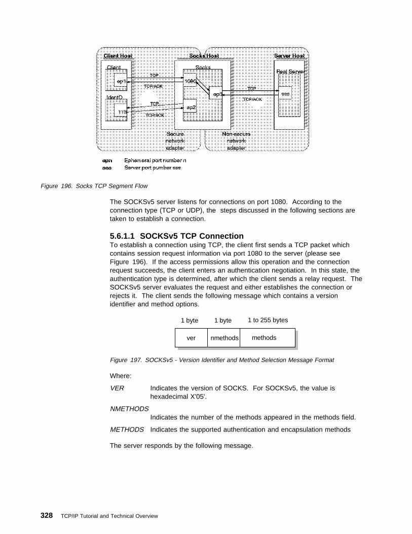
Figure 196. Socks TCP Segment Flow
The SOCKSv5 server listens for connections on port 1080. According to theconnection type (TCP or UDP), the steps discussed in the following sections aretaken to establish a connection.
5.6.1.1 SOCKSv5 TCP ConnectionTo establish a connection using TCP, the client first sends a TCP packet whichcontains session request information via port 1080 to the server (please seeFigure 196). If the access permissions allow this operation and the connectionrequest succeeds, the client enters an authentication negotiation. In this state, theauthentication type is determined, after which the client sends a relay request. TheSOCKSv5 server evaluates the request and either establishes the connection orrejects it. The client sends the following message which contains a versionidentifier and method options.
ver nmethods methods
1 byte 1 to 255 bytes1 byte
Figure 197. SOCKSv5 - Version Identifier and Method Selection Message Format
Where:
VER Indicates the version of SOCKS. For SOCKSv5, the value ishexadecimal X'05'.
NMETHODSIndicates the number of the methods appeared in the methods field.
METHODS Indicates the supported authentication and encapsulation methods
The server responds by the following message.
328 TCP/IP Tutorial and Technical Overview

ver method
1 byte 1 byte
Figure 198. SOCKSv5 - Selected Method Message Format
The hexadecimal values for current standard METHODS are as follows;
X'00' NO AUTHENTICATION REQUIRED
X'01' GSSAPI
X'02' USERNAME/PASSWORD
X'03' to X'7F' IANA ASSIGNED
X'80' to X'FE' RESERVED FOR PRIVATE METHODS
X'FF' NO ACCEPTABLE METHODS
All implementations should support USERNAME/PASSWORD and GSSAPIauthentication methods.
Once authentication is completed successfully, the client sends the request details.If an encapsulation method is negotiated during the method negotiation, theselected encapsulation method must be applied for the following messages. Thedetail request message format issued by the client is as follows:
ver cmd RSV
1 byte X '00'1 byte 1 byte variable 2 bytes
ATYP DST. ADDR DST. Port
3376A\3376F4O5
Figure 199. SOCKSv5 - Detail Request Message Format
Where:
VER Socks protocol version. For SOCKSv5, the value is hexadecimalX'05'.
CMD SOCKS command in octets.
X'01' CONNECT
X'02' BIND
X'03' UDP ASSOCIATE
RSV Reserved for future use.
ATYP Address types in octets.
X'01' IPv4 address
X'03' Domain-name
X'04' IPv6 address
DST.ADDR Desired destination address.
DST.PORT Desired destination port in network octet order.
Chapter 5. TCP/IP Security Overview 329

The server evaluates the request detail message and replies with one or moremessages. Here is the reply message format issued by the server.
ver rep RSV
1 byte X '00'1 byte 1 byte variable 2 bytes
ATYP BND. ADDR BND. Port
3376A\3376F4O6
Figure 200. SOCKSv5 - Server Reply Message Format
Where:
VER Socks protocol version. For SOCKSv5, the value is hexadecimalX'05'.
REP Reply field:
X'00' Succeeded
X'01' General SOCKS server failure
X'02' Connection not allowed by ruleset
X'03' Network unreachable
X'04' Host unreachable
X'05' Connection refused
X'06' TTL expired
X'07' Command not supported
X'08' Address type not supported
X'09' to X'FF' Unassigned
RSV Reserved for future use.
ATYP Address types in octets.
X'01' IPv4 address
X'03' Domain name
X'04' IPv6 address
BND.ADDR Server bound address.
BND.PORT Server bound port in network octet order.
5.6.1.2 SOCKSv5 UDP ConnectionTo be able use a UDP connection over a SOCKS server, the client first issues theUDP ASSOCIATE command to the SOCKSv5 server. The SOCKSv5 server thenassigns a UDP port to which the client sends all UDP datagrams. Each UDPdatagram has a UDP request header. The UDP request header format is asfollows:
330 TCP/IP Tutorial and Technical Overview

RSV frag ATYP
2 bytes 1 byte1 byte variable 2 bytes variable
DST. ADDR DST. Port data
3376A\3376F4O7
Figure 201. SOCKSv5 - UDP Datagram Request Header Format
Where:
RSV Reserved for future use. All bytes are zero.
FRAG Current fragment number.
ATYP Address types in octets.
X'01' IPv4 address
X'03' Domain-name
X'04' IPv6 address
DST.ADDR Desired destination address.
DST.PORT Desired destination port in network octet order.
DATA User data.
The UDP relay server gets the IP address of the client which sends UDPdatagrams to the port specified by DST.PORT. It will then discard any datagramthat comes from another source.
5.7 Secure Sockets Layer (SSL)SSL is a security protocol that was developed by Netscape CommunicationsCorporation, along with RSA Data Security, Inc. The primary goal of the SSLprotocol is to provide a private channel between communicating applications, whichensures privacy of data, authentication of the partners and integrity.
5.7.1 SSL OverviewSSL provides an alternative to the standard TCP/IP socket API that has securityimplemented within it. Hence, in theory it is possible to run any TCP/IP applicationin a secure way without changing the application. In practice, SSL is only widelyimplemented for HTTP connections, but Netscape Communications Corp. hasstated an intention to employ it for other application types, such as NNTP andTelnet, and there are several such implementations freely available on the Internet.IBM, for example, is using SSL to enhance security for TN3270 sessions in its HostOn-Demand and eNetwork Communications Server products.
SSL is composed of two layers:
� At the lower layer, a protocol for transferring data using a variety of predefinedcipher and authentication combinations, called the SSL Record Protocol.Figure 202 on page 332 illustrates this, and contrasts it with a standard HTTPsocket connection. Note that this diagram shows SSL as providing a simplesocket interface, on which other applications can be layered. In reality, currentimplementations have the socket interface embedded within the application anddo not expose an API that other applications can use.
Chapter 5. TCP/IP Security Overview 331

� On the upper layer, a protocol for initial authentication and transfer ofencryption keys, called the SSL Handshake Protocol.
Client Server
socket API socket API
Session
Standard HTTP
socket API socket API
Client Server
socket API socket API
Session
SSL
SSL Record Protocol
3376E\3376F4OS
Figure 202. SSL - Comparison of Standard and SSL Sessions
An SSL session is initiated as follows:
� On the client (browser) the user requests a document with a special URL thatcommences https: instead of http:, either by typing it into the URL input field, orby clicking on a link.
� The client code recognizes the SSL request and establishes a connectionthrough TCP port 443 to the SSL code on the server.
� The client then initiates the SSL handshake phase, using the SSL RecordProtocol as a carrier. At this point there is no encryption or integrity checkingbuilt in to the connection.
The SSL protocol addresses the following security issues:
PrivacyAfter the symmetric key is established in the initial handshake, the messagesare encrypted using this key.
332 TCP/IP Tutorial and Technical Overview

IntegrityMessages contain a message authentication code (MAC) ensuring themessage integrity.
AuthenticationDuring the handshake, the client authenticates the server using anasymmetric or public key. It can also be based on certificates.
SSL requires each message to be encrypted and decrypted and therefore has ahigh performance and resource overhead.
5.7.1.1 Differences between SSL V2.0 and SSL V3.0There is a backward compatibility between SSL V2.0 and SSL V3.0. An SSL V3.0server implementation should be able accept the connection request from an SSLV2.0 client. The main differences between SSL V2.0 and SSL V3.0 are as follows:
� SSL V2.0 does not support client authentication.� SSL V3.0 supports more ciphering types in the CipherSpec.
5.7.2 SSL ProtocolThe SSL protocol is located at the top of the transport layer. SSL is also a layeredprotocol itself. It simply takes the data from the application layer, reformats it andtransmits it to the transport layer. SSL handles a message as follows:
SenderPerforms the following tasks:
� Takes the message from upper layer� Fragments the data to manageable blocks� Optionally compresses the data� Applies a Message Authentication Code (MAC)� Encrypts the data� Transmits the result to the lower layer
ReceiverPerforms the following tasks:
� Takes the data from lower layer � Decrypts� Verifies the data with the negotiated MAC key� Decompresses the data if compression was used� Reassembles the message� Transmits the message to the upper layer
An SSL session works in different states. These states are session and connectionstates. The SSL handshake protocol (please see 5.7.2.2, “SSL HandshakeProtocol” on page 335) coordinates the states of the client and the server. Inaddition, there are read and write states defined to coordinate the encryptionaccording to the change cipher spec messages.
When either party sends a change cipher spec message, it changes the pendingwrite state to current write state. Again, when either party receives a change cipherspec message, it changes the pending read state to the current read state.
The session state includes the following components:
Chapter 5. TCP/IP Security Overview 333

Session identifierAn arbitrary byte sequence chosen by the server to identify an active orresumable session state.
Peer certificateCertificate of the peer. This field is optional; it can be empty.
Compression methodThe compression algorithm.
Cipher specSpecifies data encryption algorithm (such as null, DES) and a MAC algorithm.
Master secret48-byte shared secret between the client and the server.
Is resumableA flag indicating whether the session can be used for new connections.
The connection state includes the following components:
Server and client randomAn arbitrary byte sequence chosen by the client and server for eachconnection.
Server write MAC secretThe secret used for MAC operations by the server.
Client write MAC secretThe secret used for MAC operations by the client.
Server write keyThe cipher key for the server to encrypt the data and the client to decrypt thedata.
Client write keyThe cipher key for the client to encrypt the data and the server to decrypt thedata.
Initialization vectorsInitialization vectors store the encryption information.
Sequence numbersA sequence number indicates the number of the message transmitted sincethe last change cipher spec message. Both the client and the server maintainsequence numbers.
5.7.2.1 Change Cipher Spec ProtocolThe change cipher spec protocol is responsible for sending change cipher specmessages. At any time, the client can request to change current cryptographicparameters such as handshake key exchange. Following the change cipher specnotification, the client sends a handshake key exchange and if available, certificateverify messages, and the server sends a change cipher spec message afterprocessing the key exchange message. After that, the newly agreed keys will beused until the next change cipher spec request. The change cipher spec messageis sent after the hello messages during the negotiation.
334 TCP/IP Tutorial and Technical Overview

5.7.2.2 SSL Handshake ProtocolThe SSL Handshake Protocol allows the client and server to determine the requiredparameters for an SSL connection such as protocol version, cryptographicalgorithms, optional client or server authentication, and public-key encryptionmethods to generate shared secrets. During this process all handshake messagesare forwarded to the SSL Record Layer to be encapsulated into special SSLmessages. Figure 203 illustrates an SSL handshake process.
Client
1Client Hello
3
(Certificate)(Client Key Exchange)(Certificate Verify)Finished
Change Cipher Specs
Server
2
Server Hello(Certificate)(Server Key Exchange)(Certificate Request)Server Hello Done
4 Finished
Change Cipher Specs
5Send Data Send Data
3376E\3376F4OR
Figure 203. SSL - Handshake Process
1. The client sends a connection request with a client hello message. Thismessage includes:
� Desired version number.� Time information (the current time and date in standard UNIX 32-bit
format).� Optionally session-ID. If it is not specified the server will try to resume
previous sessions or return an error message� Cipher suites. (List of the cryptographic options supported by the client.
These are authentication modes, key exchange methods, encryptions andMAC algorithms.)
� Compression methods supported by the client.� A random value.
2. The server evaluates the parameters sent by the client hello message andreturns a server hello message that includes the following parameters whichwere selected by the server to be used for the SSL session:
Chapter 5. TCP/IP Security Overview 335

� Version number� Time information (the current time and date in standard UNIX 32-bit format)
� Session ID � Cipher suite � Compression method� A random value
Following the server hello message the server sends the following messages:
� Server certificate if the server is required to be authenticated� A server key exchange message if there is no certificate available or the
certificate is for signing only� A certificate request if the client is required to be authenticated
Finally, the server sends a server hello done message and begins to wait forthe client response.
3. The client sends the following messages:
� If the server has sent a certificate request, the client must send a certificateor a no certificate message.
� If the server has sent a server key exchange message, the client sends aclient key exchange message based on the public key algorithmdetermined with the hello messages.
� If the client has sent a certificate, the client verifies the server certificateand sends a certificate verify message indicating the result.
The client then sends a finished message indicating the negotiation part iscompleted. The client also sends a change cipher spec message to generateshared secrets. It should be noted that this is not controlled by the handshakeprotocol, the change cipher spec protocol manages this part of the operation.
4. The server sends a finished message indicating the negotiation part iscompleted. The server then sends the change cipher spec message.
5. Finally the session partners separately generate an encryption key, the masterkey from which they derive the keys to use in the encrypted session thatfollows. The Handshake protocol changes the state to the connection state.All data taken from the application layer is transmitted as special messages tothe other party.
There is significant additional overhead in starting up an SSL session comparedwith a normal HTTP connection. The protocol avoids some of this overhead byallowing the client and server to retain session key information and to resume thatsession without negotiating and authenticating a second time.
Following the handshake, both session partners have generated a master key.From that key they generate other session keys, which are used in thesymmetric-key encryption of the session data and in the creation of messagedigests. The first message encrypted in this way is the finished message from theserver. If the client can interpret the finished message, it means:
� Privacy has been achieved, because the message is encrypted using asymmetric-key bulk cipher (such as DES or RC4).
� The message integrity is assured, because it contains a MessageAuthentication Code (MAC), which is a message digest of the message itselfplus material derived from the master key.
� The server has been authenticated, because it was able to derive the masterkey from the pre-master key. As this was sent using the server's public key, it
336 TCP/IP Tutorial and Technical Overview

could only have been decrypted by the server (using its private key). Note thatthis relies on the integrity of the server's public key certificate.
5.7.2.3 SSL Record ProtocolOnce the master key has been determined, the client and server can use it toencrypt application data. The SSL record protocol specifies a format for thesemessages. In general they include a message digest to ensure that they have notbeen altered and the whole message is encrypted using a symmetric cipher.Usually this uses the RC2 or RC4 algorithm, although DES, triple-DES and IDEAare also supported by the specification.
The U.S. National Security Agency (NSA), a department of the United Statesfederal government imposes restrictions on the size of the encryption key that canbe used in software exported outside the U.S. These rules are currently underreview, but the present effect is to limit the key to an effective size of 56 bits. TheRC2 and RC4 algorithms achieve this by using a key in which all but 56 bits are setto a fixed value. International (export) versions of software products have thishobbled security built into them. SSL checks for mismatches between the exportand nonexport versions in the negotiation phase of the handshake. For example, ifa U.S. browser tries to connect with SSL to an export server, they will agree onexport-strength encryption. See 5.2.7, “Export/Import Restrictions on Cryptography”on page 279 for more information on recent changes of U.S. export regulations ofcryptographic material.
5.8 Transport Layer Security (TLS)The Transport Layer Security 1.0 protocol is based on SSL. At the time of writing,the TLS 1.0 protocol is not a standard protocol. (Please refer to current TLS draftdocument for more information about SSL.) There are not significant differencesbetween SSL 3.0 and TLS 1.0. They can interoperate with some modifications onthe message formats.
5.9 Secure Multipurpose Internet Mail Extension (S-MIME)Secure Multipurpose Internet Mail Extension (S-MIME) can be thought of as a veryspecific SSL-like protocol. S-MIME is an application-level security construct, but itsuse is limited to protecting e-mail via encryption and digital signatures. It relies onpublic key technology, and uses X.509 certificates to establish the identities of thecommunicating parties. S-MIME can be implemented in the communicating endsystems; it is not used by intermediate routers or firewalls.
5.10 Virtual Private Networks (VPN) OverviewThe Internet has become a popular, low-cost backbone infrastructure. Its universalreach has led many companies to consider constructing a secure virtual privatenetwork (VPN) over the public Internet. The challenge in designing a VPN fortoday's global business environment will be to exploit the public Internet backbonefor both intra-company and inter-company communication while still providing thesecurity of the traditional private, self-administered corporate network.
In this chapter, we begin by defining a virtual private network (VPN) and explainingthe benefits that customers can achieve from its implementation. After discussing
Chapter 5. TCP/IP Security Overview 337

the security considerations and planning aspects, we then describe the VPNsolutions available in the market today.
5.10.1 VPN Introduction and BenefitsWith the explosive growth of the Internet, companies are beginning to ask: "Howcan we best exploit the Internet for our business?". Initially, companies were usingthe Internet to promote their company's image, products, and services by providingWorld Wide Web access to corporate Web sites. Today, however, the Internetpotential is limitless, and the focus has shifted to e-business, using the global reachof the Internet for easy access to key business applications and data that reside intraditional I/T systems. Companies can now securely and cost-effectively extendthe reach of their applications and data across the world through theimplementation of secure virtual private network (VPN) solutions.
CorporateIntranet Business
Partner/SupplierIntranet
BranchOffice
Intranet
Internet
Remote Access
VPN
VPN
VPN
Figure 204. Virtual Private Networks
A virtual private network (VPN) is an extension of an enterprise's private intranetacross a public network such as the Internet, creating a secure private connection,essentially through a private tunnel. VPNs securely convey information across theInternet connecting remote users, branch offices, and business partners into anextended corporate network, as shown in Figure 204. Internet Service Providers(ISPs) offer cost-effective access to the Internet (via direct lines or local telephonenumbers), enabling companies to eliminate their current, expensive leased lines,long-distance calls, and toll-free telephone numbers.
A 1997 VPN Research Report, by Infonetics Research, Inc., estimates savings from20% to 47% of wide area network (WAN) costs by replacing leased lines to remotesites with VPNs. And, for remote access VPNs, savings can be 60% to 80% ofcorporate remote access dial-up costs. Additionally, Internet access is availableworldwide where other connectivity alternatives may not be available.
The technology to implement these virtual private networks, however, is justbecoming standardized. Some networking vendors today are offeringnon-standards-based VPN solutions that make it difficult for a company toincorporate all its employees and/or business partners/suppliers into an extendedcorporate network. However, VPN solutions based on Internet Engineering Task
338 TCP/IP Tutorial and Technical Overview

Force (IETF) standards will provide support for the full range of VPN scenarios withmore interoperability and expansion capabilities.
The key to maximizing the value of a VPN is the ability for companies to evolvetheir VPNs as their business needs change and to easily upgrade to future TCP/IPtechnology. Vendors who support a broad range of hardware and software VPNproducts provide the flexibility to meet these requirements. VPN solutions todayrun mainly in the IPv4 environment, but it is important that they have the capabilityof being upgraded to IPv6 to remain interoperable with your business partner'sand/or supplier's VPN solutions. Perhaps equally critical is the ability to work with avendor who understands the issues of deploying a VPN. The implementation of asuccessful VPN involves more than technology. The vendor's networkingexperience plays heavily into this equation.
5.11 Kerberos Authentication and Authorization SystemThe Kerberos Network Authentication Service Version 5 is a proposed standardprotocol. It is status is elective and described in RFC 1510.
According to The Enlarged Devil's Dictionary (Ambrose Bierce), Kerberos is “thewatchdog of Hades, whose duty it was to guard the entrance against whom or whatdoes not clearly appear; Kerberos is known to have had three heads.”
The Kerberos Authentication and Authorization System is an encryption-basedsecurity system that provides mutual authentication between the users and theservers in a network environment. The assumed goals for this system are:
� Authentication to prevent fraudulent requests/responses between users andservers that must be confidential and on groups of at least one user and oneservice.
� Authorization can be implemented independently from the authentication byeach service that wants to provide its own authorization system. Theauthorization system can assume that the authentication of a user/client isreliable.
� Permits the implementation of an accounting system that is integrated, secureand reliable, with modular attachment and support for "chargebacks" or billingpurposes.
The Kerberos system is mainly used for authentication purposes, but it alsoprovides the flexibility to add authorization information.
5.11.1 AssumptionsKerberos assumes the following:
� The environment using this security system will include public and privateworkstations that can be located in areas with minimal physical security, acampus network without link encryption that can be composed of dispersedlocal networks connected by backbones or gateways, centrally operatedservers in locked rooms with moderate physical security and centrally operatedservers with considerable physical security.
� Confidential data or high-risk operations such as a bank transaction may not bepart of this environment without additional security, because once you have a
Chapter 5. TCP/IP Security Overview 339

workstation as a terminal you can emulate certain conditions and normal datawill be flowing without any encryption protection.
� One of the cryptosystems used is the Data Encryption Standard (DES), whichhas been developed to be modular and replaceable by the Kerberos designers.
� Kerberos assumes a loosely synchronized clock in the whole system so theworkstation has to have a synchronization tool such as the time serverprovided.
5.11.2 NamingA principal identifier is the name that identifies a client or a service for the Kerberossystem.
In Version 4, the identifier consists of three components:
� The principal name is unique for each client and service assigned by theKerberos Manager.
� The instance name used for distinct authentication is an added label for clientsand services which exist in several forms. For users, an instance can providedifferent identifiers for different privileges. For services, an instance usuallyspecifies the host name of the machine that provides this service.
� The realm name used to allow independently administered Kerberos sites. Theprincipal name and the instance are qualified by the realm to which theybelong, and are unique only within that realm. The realm is commonly thedomain name.
In Version 4, each of the three components has a limit of 39 characters long. Dueto conventions, the period (.) is not an acceptable character.
In Version 5, the identifier consists of two parts only, the realm and the remainder,which is a sequence of however many components are needed to name theprincipal. Both the realm and each component of the remainder are defined asASN.1 (Abstract Syntax Notation One, ISO standard 8824) GeneralStrings. Thisputs few restrictions on the characters available for principal identifiers.
5.11.3 Kerberos Authentication ProcessIn the Kerberos system, a client that wants to contact a server for its service, firsthas to ask for a ticket from a mutually trusted third party, the KerberosAuthentication Server (KAS). This ticket is obtained as a function where one of thecomponents is a private key known only by the service and the KerberosAuthentication Server, so that the service can be confident that the information onthe ticket originates from Kerberos. The client is known to the KAS as a principalname (c). The private key (Kc) is the authentication key known only to the user andthe Kerberos Authentication Server (KAS).
In this chapter, the symbol {X,Y} indicates a message containing information (ordata) X and Y. {X,Y}Kz indicates that a message that contains the data X and Y,has been enciphered using the key Kz.
340 TCP/IP Tutorial and Technical Overview

Client c
KerberosAuthenticationServer (KAS)
KerberosTicketGrantingServer (TGS)
KerberosDatabase
1
Server s
2 3 4
5
3376E\3376F4OT
Figure 205. Kerberos Authentication Scheme
The authentication process consists of exchanging five messages (see Figure 205):
.1/ Client -> KAS
The client sends a message {c, tgs, n}, to the KAS, containing its identity (c), anonce (a timestamp or other means to identify this request), and requests for aticket for use with the ticket-granting server (TGS).
.2/ KAS -> Client
The authentication server looks up the client name (c) and the service name (theticket-granting server, tgs) in the Kerberos database, and obtains an encryption keyfor each (Kc and Ktgs).
Chapter 5. TCP/IP Security Overview 341

The KAS then forms a response to send back to the client. This response containsan initial ticket Tc,tgs, which grants the client access to the requested server (theticket-granting server). Tc,tgs contains Kc,tgs, c, tgs, nonce, lifetime and some otherinformation. The KAS also generates a random encryption key Kc,tgs, called thesession key. It then encrypts this ticket using the encryption key of theticket-granting server (Ktgs). This produces what is called a sealed ticket {Tc,tgs}Ktgs.A message is then formed consisting of the sealed ticket and the TGS session keyKc,tgs.
Note: In Kerberos Version 4, the message is:
{Kc,tgs,n,{Tc,tgs}Ktgs}Kc
While in Kerberos Version 5, the message is of a simpler form:
{Kc,tgs, n}Kc, {Tc,tgs}Ktgs
This simplifies the (unnecessary) double encryption of the ticket.
.3/ Client -> TGS
Upon receiving the message, the client decrypts it using its secret key Kc which isonly known to it and the KAS. It checks to see if the nonce (n) matches thespecific request, and then caches the session key Kc,tgs for future communicationswith the TGS.
The client then sends a message to the TGS. This message contains the initialticket {Tc,tgs}Ktgs, the server name (s), a nonce, and a new authenticator Accontaining a timestamp. Ac is {c, nonce}. The message is:
{Ac}Kc,tgs, {Tc,tgs}Ktgs, s, n
.4/ TGS -> Client
The ticket-granting server (TGS) receives the above message from the client (c),and first deciphers the sealed ticket using its TGS encryption key. (This ticket wasoriginally sealed by the Kerberos authentication server in step 2 using the samekey.) From the deciphered ticket, the TGS obtains the TGS-session-key. It usesthis TGS session key to decipher the sealed authenticator. (Validity is checked bycomparing the client name both in the ticket and in the authenticator, the TGSserver name in the ticket, the network address that must be equal in the ticket, inthe authenticator, and in the received message.) Finally, it checks the current timein the authenticator to make certain the message is recent. This requires that allthe clients and servers maintain their clocks within some prescribed tolerance. TheTGS now looks up the server name from the message in the Kerberos database,and obtains the encryption key (Ks) for the specified service.
The TGS forms a new random session key Kc,s for the benefit of the client (c) andthe server (s), and then creates a new ticket Tc,s containing:
Kc,s, n, nonce, lifetime,
It then assembles and sends a message to the client.
Note: In Kerberos Version 4, the message is:
{Kc,s,n,{Tc,s}Ks}Kc,tgs
While in Kerberos Version 5, the message is of a simpler form:
342 TCP/IP Tutorial and Technical Overview

{Kc,s,n}Kc,tgs, {Tc,s}Ks
This simplifies the (unnecessary) double encryption of the ticket.
.5/ Client -> Server
The client receives this message and deciphers it using the TGS session key thatonly it and the TGS share. From this message it obtains a new session key Kc,sthat it shares with the server(s) and a sealed ticket that it cannot decipher becauseit is enciphered using the server's secret key Ks.
The client builds an authenticator and seals it using the new session key Kc,s. Atlast, it sends a message containing the sealed ticket and the authenticator to theserver (s) to request its service.
The server (s) receives this message and first deciphers the sealed ticket using itsencryption key, which only it and KAS know. It then uses the new session keycontained in the ticket to decipher the authenticator and does the same validationprocess that was described in step .4/.
Once the server has validated a client, an option exists for the client to validate theserver. This prevents an intruder from impersonating the server. The client requiresthen that the server sends back a message containing the timestamp (from theclient's authenticator, with one added to the timestamp value). This message isenciphered using the session key that was passed from the client to the server.
Let us summarize some of the central points in this scheme:
� In order for the workstation to use any end server, a ticket is required. Alltickets, other than the first ticket (also called the initial ticket) are obtained fromthe TGS. The first ticket is special; it is a ticket for the TGS itself and isobtained from the Kerberos authentication server.
� Every ticket is associated with a session key that is assigned every time aticket is allocated.
� Tickets are reusable. Every ticket has a lifetime, typically eight hours. After aticket has expired, you have to identify yourself to Kerberos again, enteringyour login name and password.
� Unlike a ticket, which can be reused, a new authenticator is required every timethe client initiates a new connection with a server. The authenticator carries atimestamp within it, and the authenticator expires a few minutes after it isissued. (This is the reason why clocks must be synchronized between clientsand servers.)
� A server should maintain a history of previous client requests for which thetimestamp in the authenticator is still valid. This way a server can rejectduplicate requests that could arise from a stolen ticket and authenticator.
5.11.4 Kerberos Database ManagementKerberos needs a record for each user and service in its realm and each recordkeeps only the needed information as follows:
� Principal identifier (c,s)� Private key for this principal (Kc,Ks)� Date of expiration for this identity
Chapter 5. TCP/IP Security Overview 343

� Date of the last modification in this record� Identity of the principal who last modified this record (c,s)� Maximum lifetime of tickets to be given to this principal (Lifetime)
� Attributes (unused)� Implementation data (not visible externally)
The private key field is enciphered using a master key so that removing thedatabase will not cause any problem as the master key is not in it.
The entity responsible for managing this database is the Kerberos DatabaseManager (KDBM). There is only one KDBM in a realm, but it is possible to havemore than one Kerberos Key Distribution Server (KKDS), each one having a copyof the Kerberos database. This is done to improve availability and performance sothat the user can choose one in a group of KKDSs to send its request to. TheKKDS performs read-only operations, leaving the actualization to the KDBM, whichcopies the entire database a few times a day. This is done to simplify the operationusing a Kerberos protected protocol. This protocol is basically a mutualauthentication between KDBM and KKDS before a file transfer operation withcheckpoints and checksum.
5.11.5 Kerberos Authorization ModelThe Kerberos Authentication Model permits only the service to verify the identity ofthe requester but it gives no information on whether the requester can use theservice or not. The Kerberos Authorization Model is based on the principle thateach service knows the user so that each one can maintain its own authorizationinformation. However, the Kerberos Authentication System could be extended byinformation and algorithms that could be used for authorization purposes. (This ismade easier in Version 5. Please see the next section.) The Kerberos could thencheck if a user/client is allowed to use a certain service.
Obviously, both the client and the server applications must be able to handle theKerberos authentication process. That is, both the client and the server must bekerberized.
5.11.6 Kerberos Version 5 EnhancementsKerberos Version 5 has a number of enhancements over Version 4. Some of theimportant ones are:
� Use of encryption has been separated into distinct program modules whichallows for supporting multiple encryption systems.
� Network addresses that appear in protocol messages are now tagged with atype and length field. This allows support of multiple network protocols.
� Message encoding is now described using the ASN.1 (Abstract Syntax Notation1) syntax in accordance with ISO standards 8824 and 8825.
� The Kerberos Version 5 ticket has an expanded format to support new features(for example, the inter-realm cooperation).
� As mentioned in 5.11.2, “Naming” on page 340, the principal identifier naminghas changed.
� Inter-realm support has been enhanced.
344 TCP/IP Tutorial and Technical Overview

� Authorization and accounting information can now be encrypted and transmittedinside a ticket in the authorization data field. This facilitates the extension ofthe authentication scheme to include an authorization scheme as well.
� A binding is provided for the Generic Security Service API (GSSAPI) to theKerberos Version 5 implementation.
5.12 Remote Access Authentication ProtocolsRemote dial-in to the corporate intranet and to the Internet has made the remoteaccess server a very vital part of today's internetworking services. More and moremobile users are requiring access not only to central-site resources, but toinformation sources on the Internet. The widespread use of the Internet and thecorporate intranet has fueled the growth of remote access services and devices.There is an increasing demand for simplified connection to corporate networkresources from mobile computing devices such as a notebook computer, or apalmtop device for e-mail access.
The emergence of remote access has caused significant development work in thearea of security. The AAA (triple A) security model has evolved in the industry toaddress the issues of remote access security. Authentication, authorization andaccounting answers the questions who, what, and when respectively. A briefdescription of each of the three As in the AAA security model is listed below:
AuthenticationThis is the action of determining who a user (or entity) is. Authentication cantake many forms. Traditional authentication utilizes a name and a fixedpassword. Most computers work this way, However, fixed passwords havelimitations, mainly in the area of security. Many modern authenticationmechanisms utilize one-time passwords or a challenge-response query.Authentication generally takes place when the user first logs in to a machineor requests a service of it.
AuthorizationThis is the action of determining what a user is allowed to do. Generallyauthentication precedes authorization, but again, this is not required. Anauthorization request may indicate that the user is not authenticated. (wedon't know who they are.) In this case it is up to the authorization agent todetermine if an unauthenticated user is allowed the services in question. Incurrent remote authentication protocols authorization does not merely provideyes or no answers, but it may also customize the service for the particularuser.
AccountingThis is typically the third action after authentication and authorization. Butagain, neither authentication or authorization are required. Accounting is theaction of recording what a user is doing, and/or has done.
In the distributed client/server security database model, a number ofcommunications servers, or clients, authenticate a dial-in user's identity through asingle, central database, or authentication server. The authentication server storesall information about users, their passwords and access privileges. Distributedsecurity provides a central location for authentication data that is more secure thanscattering the user information on different devices throughout a network. A singleauthentication server can support hundreds of communications servers, serving up
Chapter 5. TCP/IP Security Overview 345

to tens of thousand of users. Communications servers can access anauthentication server locally or remotely over WAN connections.
Several remote access vendors and the Internet Engineering Task Force (IETF)have been in the forefront of this remote access security effort, and the meanswhereby such security measures are standardized. Remote Authentication Dial InUser Service (RADIUS) and Terminal Access Controller Access Control System(TACACS) are two such cooperative ventures that have evolved out of the Internetstandardizing body and remote access vendors.
Remote Authentication Dial-In User Service (RADIUS) is a distributed securitysystem developed by Livingston Enterprises. RADIUS was designed based on aprevious recommendation from the IETF's Network Access Server WorkingRequirements Group. An IETF Working Group for RADIUS was formed in January1996 to address the standardization of RADIUS protocol; RADIUS is now anIETF-recognized dial-in security solution (RFC 2058 and RFC 2138).
Similar to RADIUS, Terminal Access Controller Access Control System (TACACS)is an industry standard protocol specification, RFC 1492. Similar to RADIUS,TACACS receives authentication request from a NAS client and forwards the username and password information to a centralized security server. The centralizedserver can either be a TACACS database or an external security database.Extended TACACS (XTACACS) is a version of TACACS with extensions that Ciscoadded to the basic TACACS protocol to support advanced features. TACACS+ isanother Cisco extension that allows a separate access server (the TACACS+server) to provide independent authentication, authorization, and accountingservices.
Although RADIUS and TACACS Authentication Servers can be set up in a varietyof ways, depending upon the security scheme of the network they are serving, thebasic process for authenticating a user is essentially the same. Using a modem, aremote dial-in user connects to a remote access server, (also called the networkaccess server or NAS) with a built-in analog or digital modem. Once the modemconnection is made, the NAS prompts the user for a name and password. TheNAS then creates the so-called authentication request from the supplied datapacket, which consists of information identifying the specific NAS device sendingthe authentication request, the port that is being used for the modem connection,and the user name and password.
For protection against eavesdropping by hackers, the NAS, acting as the RADIUSor TACACS client encrypts the password before it sends it to the authenticationserver. If the primary security server cannot be reached, the security client or NASdevice can route the request to an alternate server. When an authenticationrequest is received, the authentication server validates the request and thendecrypts the data packet to access the user name and password information. If theuser name and password are correct, the server sends an AuthenticationAcknowledgment packet. This acknowledgement packet may include additionalfilters, such as information on the user's network resource requirements andauthorization levels. The security server may, for instance, inform the NAS that auser needs TCP/IP and/or IPX using PPP, or that the user needs SLIP to connectto the network. It may include information on the specific network resource that theuser is allowed to access.
346 TCP/IP Tutorial and Technical Overview

To circumvent snooping on the network, the security server sends an authenticationkey, or signature, identifying itself to the security client. Once the NAS receives thisinformation, it enables the necessary configuration to allow the user the necessaryaccess rights to network services and resources. If at any point in this log-inprocess all necessary authentication conditions are not met, the security databaseserver sends an authentication reject message to the NAS device and the user isdenied access to the network.
5.13 Layer 2 Tunneling Protocol (L2TP)L2TP permits the tunneling of PPP. Any protocol supported by PPP can betunneled. This protocol extends the span of a PPP connection. Instead ofbeginning at the remote host and ending at a local ISP's point of presence (PoP),the virtual PPP link now extends from the remote host all the way back to thecorporate gateway. L2TP tunneling is currently supported over IP/UDP. The latestspecification can be found in the following Internet draft; however, it is expectedthat L2TP will soon be approved as a standard.
http://search.ietf.org/internet-drafts/draft-ietf-pppext-l2tp-11.txt
L2TP is a consensus standard that came from the merging of two earlier tunnelingprotocols: Point-to-Point Tunneling Protocol (PPTP) and Layer 2 Forwarding (L2F;described in RFC 2341). These earlier protocols did not provide as complete asolution as the L2TP protocol; one addresses tunnels created by ISPs and theother addresses tunnels created by remote hosts. L2TP supports both host-createdand ISP-created tunnels.
L2TP adds the ability to create a virtual private network where multiple protocolsand privately addressed IP, IPX, and AT are allowed. In addition, L2TP will giveremote users the ability to connect to a local ISP and tunnel through the internet toa home network, avoiding long distance charges. It will also provide a mechanismon which to solve the multiple box PPP multilink problem. (Calls connecting todifferent physical routers that are destined for the same MP bundle can be tunneledto the same endpoint where MP can be terminated for all links.)
5.13.1 TerminologyBefore describing the protocol, a definition of some L2TP terminology is provided.
L2TP Access Concentrator (LAC)A device attached to one or more public service telephone network (PSTN) orintegrated services digital network (ISDN) lines capable of handling both thePPP operation and L2TP protocol. The LAC implements the media overwhich L2TP operates. L2TP passes the traffic to one or more L2TP servers(LNS).
L2TP Network Server (LNS)An LNS operates on any platform that can be a PPP endstation. The LNShandles the server side of the L2TP protocol. Because L2TP relies only onthe single media over which L2TP tunnels arrive, the LNS can have only asingle LAN or WAN interface, yet is still able to terminate calls arriving fromany PPP interfaces supported by an LAC, such as async, synchronous, ISDN,V.120, etc.
Chapter 5. TCP/IP Security Overview 347

Network Access Servers (NAS)A device providing temporary, on-demand network access to users. Thisaccess is point-to-point using PSTN ir ISDN lines.
Session (Call)L2TP creates a session when an end-to-end PPP connection is attemptedbetween a dial-in user and the LNS, or when an outbound call is initiated.The datagrams for the session are sent over the tunnel between the LAC andthe LNS. The LNS and LAC maintain the state information for each userattached to a LAC.
TunnelA tunnel is defined by an LNS-LAC pair. The tunnel carries PPP datagramsbetween the LAC and the LNS. A single tunnel can multiplex many sessions.A control connection operating over the same tunnel controls theestablishment, release, and maintenance of all sessions and of the tunnelitself.
Attribute Value Pair (AVP)A uniform method of encoding message types and bodies. This methodmaximizes the extensibility while permitting interpretability of L2TP.
5.13.2 Protocol OverviewSince the host and the gateway share the same PPP connection, they can takeadvantage of PPP's ability to transport protocols other than just IP. For example,L2TP tunnels can be used to support remote LAN access as well as remote IPaccess. Figure 206 outlines a basic L2TP configuration:
InternetISP
LNS LAC DialConnection
L2TP Tunnel
PPP Connection
3376\3376F4K1
Figure 206. Layer 2 Tunnel Protocol (L2TP) Scenario
Refering to Figure 206, the following occurs:
1. The remote user initiates a PPP connection.2. The NAS accepts the call.3. The NAS identifies the remote user using an authorization server.4. If the authorization is OK, the NAS/LAC initiates an L2TP tunnel to the desired
LNS at the entry to the enterprise.5. The LNS authenticates the remote user through its authentication server and
accepts the tunnel.6. The LNS confirms acceptance of the call and the L2TP tunnel.7. The NAS logs the acceptance.8. The LNS exchanges PPP negotiation with the remote user.9. End-to-end data is now tunneled between the remote user and the LNS.
L2TP is actually another variation of an IP encapsulation protocol. As shown inFigure 207 on page 349, an L2TP tunnel is created by encapsulating an L2TP
348 TCP/IP Tutorial and Technical Overview

frame inside a UDP packet, which in turn is encapsulated inside an IP packetwhose source and destination addresses define the tunnel's endpoints. Since theouter encapsulating protocol is IP, clearly IPSec protocols can be applied to thiscomposite IP packet, thus protecting the data that flows within the L2TP tunnel.AH, ESP, and ISAKMP/Oakley protocols can all be applied in a straightforwardway.
LAC
L2TPCode
DialConnection
IP UDP
PPP Connection3376\3376F4K2
PPP Data
LNS
L2TP RouterCode Code
PPP Data
L2TP PPP Data
Figure 207. L2TP Packet Changes during Transit
L2TP can operate over UDP/IP and support the following functions:
� Tunneling of single user dial-in clients� Tunneling of small routers, for example a router with a single static route to set
up based on an authenticated user's profile� Incoming calls to an LNS from an LAC� Multiple calls per tunnel� Proxy authentication for PAP and CHAP
� Proxy LCP� LCP restart in the event that proxy LCP is not used at the LAC� Tunnel endpoint authentication� Hidden AVP for transmitting a proxy PAP password� Tunneling using a local rhelm (that is user@rhelm) lookup table� Tunneling using the PPP username lookup in the AAA subsystem (see 5.12,
“Remote Access Authentication Protocols” on page 345)
3376\3376F4K3
IP UDP L2TP PPP Data
Data
L2Net
L2TPCode
IPCode
IP CloudData
L2Net
L2TPCode
IPCode
Figure 208. L2TP Packet Flow through Any IP Cloud
Chapter 5. TCP/IP Security Overview 349

5.13.3 L2TP Security IssuesAlthough L2TP provides cost-effective access, multiprotocol transport, and remoteLAN access, it does not provide cryptographically robust security features. Forexample:
� Authentication is provided only for the identity of tunnel endpoints, but not foreach individual packet that flows inside the tunnel. This can expose the tunnelto man-in-the-middle and spoofing attacks.
� Without per-packet integrity, it is possible to mount denial-of-service attacks bygenerating bogus control messages that can terminate either the L2TP tunnelor the underlying PPP connection.
� L2TP itself provides no facility to encrypt user data traffic. This can lead toembarrassing exposures when data confidentiality is an issue.
� While the payload of the PPP packets can be encrypted, the PPP protocol suitedoes not provide mechanisms for automatic key generation or for automatic keyrefresh. This can lead to someone listening in on the wire to finally break thatkey and gain access to the data being transmitted.
Realizing these shortcomings, the PPP Extensions Working Group of the IETFconsidered how to remedy these shortfalls. Some members proposed to developnew IPSec-like protocols for use with PPP and L2TP. But since this work wouldhave substantially duplicated the more mature work of the IPSec Working Group,the IETF took the position instead to support the use of the existing IPSec protocolsto protect the data that flows through an L2TP tunnel.
The following reference provides additional information on how to use IPSec inconjunction with L2TP:
http://search.ietf.org/internet-drafts/draft-ietf-pppext-l2tp-sec-ð4.txt
In summary, layer 2 tunnel protocols are an excellent way of providingcost-effective remote access. And when used in conjunction with IPSec, they arean excellent technique for providing secure remote access. However, withoutcomplementary use of IPSec, an L2TP tunnel alone does not furnish adequatesecurity.
5.14 Secure Electronic Transactions (SET)SET is the outcome of an agreement by MasterCard International and VisaInternational to cooperate on the creation of a single electronic credit card system.Prior to SET, each organization had proposed its own protocol and each hadreceived support from a number of networking and computing companies. Now,most of the major players are behind the SET specification (for example, IBM,Microsoft, Netscape and GTE).
The following sections describes at a high level the components and processes thatmake up the specification. Please refer to MasterCard and Visa home pages formore information about SET.
350 TCP/IP Tutorial and Technical Overview
5.14.1 SET RolesThe SET specification defines several roles involved in the payment process:
The merchantThis is any seller of goods, services or information.
The acquirerThis is the organization that provides the credit card service and keeps themoney flowing. The most widely known acquirers are MasterCard and Visa.
The issuerThis is the organization that issued the card to the purchaser in the first place.Usually this is a bank or some other financial institution who should knowbetter.
The cardholderThis is the Web surfer, who has been given a credit card by the issuer andnow wants to exercise his or her purchasing power on the Web.
The acquirer payment gatewayThis provides an interface between the merchant and the bankcard networkused by the acquirer and the issuer. It is important to remember that thebankcard network already exists. The acquirer payment gateway provides awell-defined, secure interface to that established network from the Internet.Acquirer payment gateways will be operated on behalf of the acquirers, butthey may be provided by third-party organizations, such as Internet servicesproviders (ISPs).
The certificate authoritySET processing uses public key cryptography, so each element of the systemneed one or more public key certificates. Several layers of CA are describedin the specification. (SET certificates are discussed in 5.14.3, “The SETCertificate Scheme” on page 353.)
5.14.2 SET TransactionsThe SET specification describes a number of transaction flows for purchasing,authentication, payment reversal, etc. Figure 209 on page 352 shows thetransactions involved in a typical online purchase.
Chapter 5. TCP/IP Security Overview 351

PInitReq
PInitRes
PReq
AuthReq
AuthRes
PRes
InqReq
InqRes
CapReq
CapRes
Cardholder Merchant
MasterCardInternational
MasterCard
AcquirerGateway
1
2
3
4
5
3376E\3376F4OU
Figure 209. Typical SET Transaction Sequence
The diagram shows the following transactions (each transaction consists of arequest/response pair):
1. PInitThis initializes the system, including details such as the brand of card beingused and the certificates held by the cardholder. SET does not insist thatcardholders have signing certificates, but it does recommend them. Acardholder certificate binds the credit card account number to the owner of apublic key. If the acquirer receives a request for a given card number signedwith the cardholder's public key, it knows that the request came from the realcardholder. To be precise, it knows that the request came from a computerwhere the cardholder's keyring was installed and available. It could still be athief who had stolen the computer and cracked the keyring password.
2. Purchase OrderThis is the actual request from the cardholder to buy something. The requestmessage is in fact two messages combined, the order instruction (OI), whichis sent in the clear to the merchant and the purchase instruction (PI), whichthe merchant passes on to the acquirer payment gateway. The PI isencrypted in the public key of the acquirer, so the merchant cannot read it.The merchant stores the message for later transmission to the acquirer. ThePI also includes a hash of the OI, so the two messages can only be handledas a pair. Note that the card number is only placed in the PI portion of therequest. This means that the merchant never has access to it, thereby
352 TCP/IP Tutorial and Technical Overview

preventing a fraudulent user from setting up a false store front to collect creditcard information.
The purchase order has a response, which is usually sent (as shown here)after acquirer approval has been granted. However, the merchant cancomplete the transaction with the cardholder before authorization, in whichcase the cardholder would see a message that the request was acceptedpending authorization.
3. AuthorizationIn this request the merchant asks the acquirer, via the acquirer paymentgateway, to authorize the request. The message includes a description of thepurchase and the cost. It also includes the PI from the purchase order thatthe cardholder sent. In this way the acquirer knows that the merchant andthe cardholder both agree on what is being purchased and the amount.
When the acquirer receives the request it uses the existing bank card networkto authorize the request and sends back an appropriate response.
4. InquiryThe cardholder may want to know how his or her request is getting on. TheSET specification provides an inquiry transaction for that purpose.
5. CaptureUp to this point, no money has changed hands. The capture request from themerchant tells the acquirer to transfer the previously authorized amount to itsaccount.
In fact, capture can be incorporated as part of the authorizationrequest/response (see above). However there are situations in which themerchant may want to capture the funds later. For example, most mail orderoperations do not debit the credit card account until the goods have actuallybeen shipped.
There are several other transactions within the SET specification, but the summaryabove shows the principles on which it is based.
5.14.3 The SET Certificate SchemeThe SET specification envisions hundreds of thousands of participants worldwide.Potentially, each of these would have at least one public key certificate. In fact theprotocol calls for an entity to have multiple certificates in some cases. Forexample, the acquirer payment gateways need one for signing messages andanother for encryption purposes.
Key management on such a large scale requires something beyond a simple, flatcertification structure. The organization of certifying authorities proposed for SET isshown in Figure 210 on page 354.
Chapter 5. TCP/IP Security Overview 353

CardholderCACardholder
CACardholderCA
Cardholder
CardholderCACardholder
CAMerchantCA
Merchant
CardholderCACardholder
CAPaymentCA
MasterCard
AcquirerGateway
RootCA
BrandCA
Geo-Political CA(optional)
3376E\3376F4OV
Figure 210. SET Certifying Authorities
At the top of the certificate chain, the root certifying authority is to be kept offlineunder extremely tight arrangements. It will only be accessed when a new creditcard brand joins the SET consortium. At the next level in the hierarchy, the brandlevel CAs are also very secure. They are administered independently by eachcredit card brand.
Under each brand there is some flexibility permitted for different operating policies.It would be possible to set up CAs based on region or country for example. At thebase of the CA hierarchy are the CAs that provide certificates for merchants,cardholders and acquirer payment gateways. The SET specification providesprotocols for merchants and cardholders to request certificates online. It isimportant to have a simple process because SET aims to encourage cardholders tohave their own certificates. It envisions the cardholder surfing to the CA Web site,choosing a Request Certificate option to invoke the certificate request applicationon the browser and then filling in a form to send and receive the certificate request.
Of course, if the system allows certificates to be created easily it must also be ableto revoke them easily, in the event of a theft or other security breach. The SETspecification includes some certificate update and revocation protocols for thispurpose. Although the mechanism for requesting a certificate may be simple, thereis still a need for user education. For example, it is obvious that a cardholdershould notify the credit card company if his or her wallet is stolen, but less obviousthat he or she should also notify them if his or her computer is stolen. However, ifthe computer includes his keyring file containing the private key and certificate, itcould allow the thief to go shopping at the cardholder's expense.
354 TCP/IP Tutorial and Technical Overview
5.15 ReferencesThe following RFCs provide detailed information on the TCP/IP security solutionspresented in this chapter:
� RFC 1492 — An Access Control Protocol, Sometimes Called TACACS
� RFC 1510 — The Kerberos Network Authentication Service (V5)
� RFC 1579 — Firewall-Friendly FTP
� RFC 1631 — The IP Network Address Translator (NAT)
� RFC 1928 — SOCKS Protocol Version 5
� RFC 1929 — Username/Password Authentication for SOCKS V5
� RFC 1961 — GSS-API Authentication Method for SOCKS Version 5
� RFC 2003 — IP Encapsulation within IP
� RFC 2104 — HMAC: Keyed-Hashing for Message Authentication
� RFC 2138 — Remote Authentication Dial In User Service (RADIUS)
� RFC 2313 — PKCS 1: RSA Encryption Version 1-5
� RFC 2314 — PKCS 10: Certification Request Syntax Version 1-5
� RFC 2315 — PKCS 7: Cryptographic Message Syntax Version 1-5
Chapter 5. TCP/IP Security Overview 355

356 TCP/IP Tutorial and Technical Overview

Chapter 6. IP Version 6
The Internet is growing extremely rapidly. The latest Internet Domain Survey,conducted in January 1998, counted over 29.5 million hosts in more than 190countries. The IPv4 addressing scheme, with a 32-bit address field, provides forover 4 billion possible addresses, so it might seem more than adequate to the taskof addressing all of the hosts on the Internet, since there appears to be room for athousand-fold increase before it is completely filled. Unfortunately, this is not thecase, for a number of reasons, including the following:
� The IP address is divided into a network number and a local part which isadministered separately. Although the address space within a network may bevery sparsely filled, as far as the effective IP address space is concerned, if anetwork number has been allocated, then all addresses within that network areunavailable for allocation elsewhere.
� The address space for networks is structured into Class A, B and C networks ofdiffering sizes, and the space within each needs to be considered separately.
� The IP addressing model requires that unique network numbers be assigned toall IP networks whether or not they are actually connected to the Internet.
� It is anticipated that growth of TCP/IP usage into new areas outside thetraditional connected PC will shortly result in a rapid explosion of demand for IPaddresses. For example, widespread use of TCP/IP for interconnectinghand-held devices, electronic point-of-sale terminals or for Web-enabledtelevision receivers, all devices that are now available, will enormously increasethe number of IP hosts.
These factors mean that the address space is much more constrained than oursimple analysis would indicate. This problem is called IP Address Exhaustion.Methods of relieving this problem are already being employed (see Chapter 7,“Dynamic IP, Mobile IP and Network Computers” on page 401) but eventually, thepresent IP address space will be exhausted. The Internet Engineering Task Force(IETF) set up a working group on Address Lifetime Expectations (ALE) with theexpress purpose of providing estimates of when exhaustion of the IP will becomean intractable problem. Their final estimates (reported in the ALE working groupminutes for December 1994) were that the IP address space would be exhaustedat some point between 2005 and 2011. Since then the position may have changedsomewhat in that the use of CIDR (Classless Inter Domain Routing - see 2.1.7,“Classless Inter-Domain Routing (CIDR)” on page 45) and the increased use ofDHCP may have relieved pressure on the address space, but on the other hand,current growth rates are probably exceeding expectation at that time.
Apart from address exhaustion, other restrictions in IPv4 also called for thedefinition of a new IP protocol:
1. Even with the use of CIDR, routing tables, primarily in the IP backbone routers,are growing too large to be manageable.
2. Traffic priority, or class of service, is vaguely defined, scarcely used and not atall enforced in IPv4, but highly desirable for modern real-time applications.
In view of these issues, the IETF established an IPng (IP next generation) workinggroup and published RFC 1752 —The Recommendation for the IP Next Generation
Copyright IBM Corp. 1989, 1998 357

Protocol. Eventually, the specification for Internet Protocol, Version 6 (IPv6) wasproduced in RFC 1883.
6.1 IPv6 OverviewIPv6 offers the following significant features:
� A dramatically larger address space, said to be sufficient for the next 30 years
� Globally unique and hierarchical addressing, based on prefixes rather thanaddress classes, to keep routing tables small and backbone routing efficient
� A mechanism for the autoconfiguration of network interfaces
� Support for encapsulation of itself and other protocols
� Class of service to distinguish types of data
� Improved multicast routing support (in preference to broadcasting)
� Built-in authentication and encryption
� Transition methods to migrate from IPv4
� Compatibility methods to coexist and communicate with IPv4
Note: IPv6 uses the term packet rather than datagram. The meaning is the same,although the formats are different.
IPv6 uses the term node for any system running IPv6, that is, a host or arouter. An IPv6 host is a node that does not forward IPv6 packets that arenot explicitly addressed to it. A router is a node that does forward IPpackets not addressed to it.
6.2 The IPv6 Header FormatThe format of the IPv6 packet header has been simplified from its counterpart inIPv4. The length of the IPv6 header is increased to 40 bytes (from 20 bytes), andcontains two 16-byte addresses (source and destination) preceded by 8 bytes ofcontrol information as shown in Figure 211 on page 359. The IPv4 header (seeFigure 20 on page 49) has two 4-byte addresses preceded by 12 bytes of controlinformation and possibly followed by option data. The reduction of the controlinformation and the elimination of options in the header for most IP packets areintended to optimize the processing time per packet in a router. The infrequentlyused fields that have been removed from the header are moved to optionalextension headers when they are required.
358 TCP/IP Tutorial and Technical Overview

vers
0 4 8 16 24 31
flow labelpriority
payload lengthhoplimit
nextheader
3376\3376F3D1
source IP address
destination IP address
data . . . . . . . . .
Figure 211. IPv6 Header
Vers4-bit Internet Protocol version number: 6.
Priority4-bit priority value. See 6.2.4, “Priority” on page 371.
Flow Label28-bit field. See 6.2.5, “Flow Labels” on page 372 below.
Payload LengthThe length of the packet in bytes (excluding this header) encoded as a16-bit unsigned integer. If length is greater than 64 KB, this field is 0and an option header (Jumbo Payload) gives the true length.
Next HeaderIndicates the type of header immediately following the basic IP header.It may indicate an IP option header or an upper layer protocol. Protocolnumbers used are the same as those used in IPv4 (see the list in 2.1,“Internet Protocol (IP)” on page 27). The next header field is also usedto indicate the presence of extension headers, which provide themechanism for appending optional information to the IPv6 packet. Thefollowing values will appear in IPv6 packets, in addition to thosementioned for IPv4.
41 IPv6 Header45 Interdomain Routing Protocol46 Resource Reservation Protocol58 IPv6 ICMP Packet
The following values are all extension headers:
0 Hop-by-Hop Options Header43 IPv6 Routing Header44 IPv6 Fragment Header50 Encapsulating Security Payload51 IPv6 Authentication Header59 No Next Header60 Destination Options Header
Chapter 6. IP Version 6 359

The different types of extension header are discussed in 6.2.2,“Extension Headers” on page 361.
Hop LimitThis is the IPv4 TTL field but now it is measured in hops and notseconds. It was changed for two reasons:
� IP normally forwards datagrams at faster than one hop per secondand the TTL field is always decremented on each hop, so in practiceit is measured in hops and not seconds.
� Many IP implementations do not expire outstanding datagrams onthe basis of elapsed time.
The packet is discarded once the hop limit is decremented to zero.
Source AddressA 128-bit address. IPv6 addresses are discussed in 6.2.3, “IPv6Addressing” on page 367.
Destination AddressA 128-bit address. IPv6 addresses are discussed in 6.2.3, “IPv6Addressing” on page 367.
A comparison between the IPv4 and IPv6 header formats will show that a numberof IPv4 header fields have no direct equivalents in the IPv6 header.
Type of ServiceType of service issues in IPv6 will be handled using the flow concept,described in 6.2.5, “Flow Labels” on page 372.
Identification, Fragmentation Flags and Fragment OffsetFragmented packets have an extension header rather thanfragmentation information in the IPv6 header. This reduces the size ofthe basic IPv6 header. Since higher level protocols, particularly TCP,tend to avoid fragmentation of datagrams, this reduces the IPv6 headeroverhead for the normal case. As noted below, IPv6 does not fragmentpackets en route to their destinations, only at the source.
Header ChecksumBecause transport protocols implement checksums, and because IPv6includes an optional authentication header that can also be used toensure integrity, IPv6 does not provide checksum monitoring of IPpackets.
Both TCP and UDP include a pseudo IP header in the checksums theyuse, so in these cases, the IP header in IPv4 is being checked twice.
TCP and UDP, and any other protocols using the same checksummechanisms running over IPv6 will continue to use a pseudo IP headeralthough, obviously, the format of the pseudo IPv6 header will bedifferent from the pseudo IPv4 header. ICMP and IGMP and any otherprotocols that do not use a pseudo IP header over IPv4 will use apseudo IPv6 header in their checksums.
OptionsAll optional values associated with IPv6 packets are contained inextension headers ensuring that the basic IP header is always the samesize.
360 TCP/IP Tutorial and Technical Overview

Note
At time of writing an Internet draft exists which proposes a change to the IPv6header format. The draft specifies the replacement of the 4-bit priority field and24-bit flow label with an 8-bit traffic class field followed by a 20-bit flow label.The 8-bit Traffic Class field in the IPv6 header is intended for use by originatingnodes and/or forwarding routers to identify and distinguish between differentclasses or priorities of IPv6 packets. Currently, there are a number ofexperiments underway in the use of the IPv4 Type of Service and/orPrecedence bits to provide various forms of differentiated service for IP packets(see 10.3, “Differentiated Services” on page 523), other than through the use ofexplicit flow setup. The Traffic Class field in the IPv6 header is intended toallow similar functionality to be supported in IPv6.
For the latest information, please refer to the Internet draft at:
http://search.ietf.org/internet-drafts/draft-ietf-ipngwg-ipv6-sp
ec-v2-ð2.txt
6.2.1 Packet SizesAll IPv6 nodes are expected to dynamically determine the maximum transmissionunit (MTU) supported by all links along a path (as described in RFC 1191 — PathMTU Discovery) and source nodes will only send packets that do not exceed thePath MTU. IPv6 routers will therefore not have to fragment packets in the middleof multihop routes and allow much more efficient use of paths that traverse diversephysical transmission media. IPv6 requires that every link supports an MTU of 576bytes or greater.
6.2.2 Extension HeadersEvery IPv6 packet starts with the basic header. In most cases this will be the onlyheader necessary to deliver the packet. Sometimes, however, it is necessary foradditional information to be conveyed along with the packet to the destination or tointermediate systems on route (information that would previously have been carriedin the Options field in an IPv4 datagram). Extension headers are used for thispurpose.
Extension headers are placed immediately after the IPv6 basic packet header andare counted as part of the payload length. Each extension header (with theexception of 59) has its own 8-bit Next Header field as the first byte of the headerthat identifies the type of the following header. This structure allows IPv6 to chainmultiple extension headers together. Figure 212 on page 362 shows an examplepacket with multiple extension headers.
Chapter 6. IP Version 6 361

vers
3376\3376F3D2
0 4 8 16 24 31
flow labelpriority
payload length
source address
destination address
nxt hdr: 0 hop limit
hop-by-hop options
nxt hdr: 43 hdr length
routing information
nxt hdr: 44 hdr length
nxt hdr: 51 reserved fragment offset M
fragment identification
authentication data
nxt hdr: 6 hdr length
TCP header and data
Figure 212. IPv6 Packet Containing Multiple Extension Headers
The length of each header varies, depending on type, but is always a multiple of 8bytes. There are a limited number of IPv6 extension headers, any one of whichmay be present once only in the IPv6 packet (with the exception of the DestinationOptions Header - 60, which may appear more than once). IPv6 nodes thatoriginate packets are required to place extension headers in a specific order(numeric order with exception of 60), although IPv6 nodes that receive packets arenot required to verify that this is the case. The order is important for efficientprocessing at intermediate routers. Routers will generally only be interested in thehop-by-hop options and the routing header. Once the router has read this far, itdoes not need to read further in the packet and can forward immediately. Whenthe Next Header field contains a value other than one for an extension header, thisindicates the end of the IPv6 headers and the start of the higher level protocol data.
IPv6 allows for encapsulation of IPv6 within IPv6 (“tunneling”). This is done with aNext Header value of 41 (IPv6). The encapsulated IPv6 packet may have its ownextension headers. Because the size of a packet is calculated by the originating
362 TCP/IP Tutorial and Technical Overview

node to match the path MTU, IPv6 routers should not add extension headers to apacket but instead should encapsulate the received packet within an IPv6 packet oftheir own making (which may be fragmented if necessary).
With the exception of the Hop-by-Hop header (which must immediately follow the IPheader if present) and sometimes the Destination Options header (see 6.2.2.6,“Destination Options Header” on page 366), extension headers are not processedby any router on the packet's path except the final one.
6.2.2.1 Hop-by-Hop HeaderA Hop-by-Hop header contains options that must be examined by every node thepacket traverses as well as the destination node. It must immediately follow theIPv6 header if present and is identified by the special value 0 in the Next Headerfield of the IPv6 basic header. (This value is not actually a protocol number but aspecial case to identify this unique type of extension header).
Hop-by-hop headers contain variable length options of the following format(commonly known as the Type-Length-Value (TLV) format):
type length value/ /
/ /
Figure 213. IPv6 Type-Length-Value (TLV) Option Format
Type The type of the option. The option types all have a common format:
3376\3376F3D4
xx y zzzzz
0 1 2 3 4 5 6 7
Figure 214. IPv6 Type-Length-Value (TLV) Option Type Format
xx A 2-bit number indicating how an IPv6 node that does notrecognize the option should treat it.
0 Skip the option and continue.
1 Discard the packet quietly.
2 Discard the packet and inform the sender with an ICMPUnrecognized Type message.
3 Discard the packet and inform the sender with an ICMPUnrecognized Type message unless the destination addressis a multicast address.
y If set, this bit indicates that the value of the option may changeen route. If this bit is set, the entire Option Data field is excludedfrom any integrity calculations performed on the packet.
zzzzz The remaining bits define the option:
0 Pad11 PadN194 Jumbo Payload Length
Chapter 6. IP Version 6 363

Length The length of the option value field in bytes.
Value The value of the option. This is dependent on the type.
Hop-by-Hop Header Option Types: You may have noticed that each extensionheader is an integer multiple of 8 bytes long, in order to retain 8-byte alignment forsubsequent headers. This is done, not purely for “neatness,” but becauseprocessing is much more efficient if multibyte values are positioned on naturalboundaries in memory (and today's processors have natural word sizes of 32 or 64bits).
In the same way, individual options are also aligned so that multibyte values arepositioned on their natural boundaries. In many cases, this will result in the optionheaders being longer than otherwise necessary, but still allows nodes to processpackets more quickly. To allow this alignment, two padding options are used inHop-by-Hop headers.
Pad1 A X'00' byte used for padding a single byte. Longer paddingsequences should be done with the PadN option.
PadN An option in the TLV format described above. The length byte gives thenumber of bytes of padding after the minimum two that are required.
The third option type in a Hop-by-Hop header is the Jumbo Payload Length. Thisoption is used to indicate a packet with a payload size in excess of 65,535 bytes(which is the maximum size that can be specified by the 16-bit Payload Length fieldin the IPv6 basic header). When this option is used, the Payload Length in thebasic header must be set to zero and this option carries the total packet size, lessthe 40 byte basic header.
0 8 16 24 31
Jumbo Payload Length
type: 194 opt. len.: 4
Figure 215. Jumbo Payload Length Option
6.2.2.2 Routing HeaderThe path that a packet takes through the network is normally determined by thenetwork itself. Sometimes, however, the source may wish to have more controlover the route taken by the packet. It may wish, for example, for certain data totake a slower, but more secure route than would normally be taken. The routingheader allows a path through the network to be predefined. The routing header isidentified by the value 43 in the preceding Next Header field. It has its next headerfield as the first byte and a single byte routing type as the second. The only typedefined initially is type 0 - Strict/Loose Source Routing, which operates in a similarway to source routing in IPv4 (see 2.1.8.3, “IP Datagram Routing Options” onpage 55).
364 TCP/IP Tutorial and Technical Overview
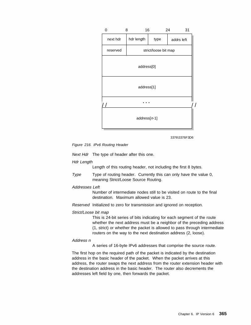
next hdr
3376\3376F3D6
0 8 16 24 31
hdr length
reserved
address[0]
address[1]
strict/loose bit map
. . .
type addrs left
/ / / /
address[n-1]
Figure 216. IPv6 Routing Header
Next Hdr The type of header after this one.
Hdr LengthLength of this routing header, not including the first 8 bytes.
Type Type of routing header. Currently this can only have the value 0,meaning Strict/Loose Source Routing.
Addresses LeftNumber of intermediate nodes still to be visited on route to the finaldestination. Maximum allowed value is 23.
Reserved Initialized to zero for transmission and ignored on reception.
Strict/Loose bit mapThis is 24-bit series of bits indicating for each segment of the routewhether the next address must be a neighbor of the preceding address(1, strict) or whether the packet is allowed to pass through intermediaterouters on the way to the next destination address (2, loose).
Address nA series of 16-byte IPv6 addresses that comprise the source route.
The first hop on the required path of the packet is indicated by the destinationaddress in the basic header of the packet. When the packet arrives at thisaddress, the router swaps the next address from the router extension header withthe destination address in the basic header. The router also decrements theaddresses left field by one, then forwards the packet.
Chapter 6. IP Version 6 365

6.2.2.3 Fragment HeaderAs discussed in 6.2.1, “Packet Sizes” on page 361, the source node determinesthe MTU for a path before sending a packet. If the packet to be sent is larger thanthe MTU, the packet is divided into pieces, each of which is a multiple of 8 bytesand carries a fragment header. The fragment header is identified by the value 44in the preceding Next Header field and has the following format:
nxt hdr
3376\3376F3D7
fragment identification
0 8 16 31
reserved res Mfragment offset
Figure 217. IPv6 Fragment Header
Nxt Hdr The type of next header after this one.
reserved 8-bit reserved field - initialized to zero for transmission and ignored onreception.
Fragment OffsetA 13-bit unsigned integer giving the offset, in 8-byte units, of thefollowing data relative to the start of the original data before it wasfragmented.
Res 2-bit reserved field - initialized to zero for transmission and ignored onreception.
M More flag. If set it indicates that this is not the last fragment.
Fragment IdentificationThis is an unambiguous identifier used to identify fragments of the samedatagram. This is very similar to the IPv4 Identifier field, but it is twiceas wide.
6.2.2.4 Authentication HeaderThe authentication header is used to ensure that a received packet has not beenaltered in transit and that it really came from the claimed sender. Theauthentication header is identified by the value 51 in the preceding Next Headerfield. The format of the authentication header and further details on authenticationcan be found in 5.5.2, “Authentication Header (AH)” on page 299.
6.2.2.5 Encapsulating Security PayloadThe Encapsulated Security Payload (ESP) is a special extension header, in that itcan appear anywhere in a packet between the basic header and the upper layerprotocol. All data following the ESP header is encrypted. For further details,please see 5.5.3, “Encapsulating Security Payload (ESP)” on page 303.
6.2.2.6 Destination Options HeaderThis has the same format as the Hop-by-Hop header, but it is only examined by thedestination node(s). Normally the destination options are only intended for the finaldestination only and the destination options header will be immediately before theupper layer header. However, destination options can also be intended forintermediate nodes, in which case they must precede a routing header. A single
366 TCP/IP Tutorial and Technical Overview
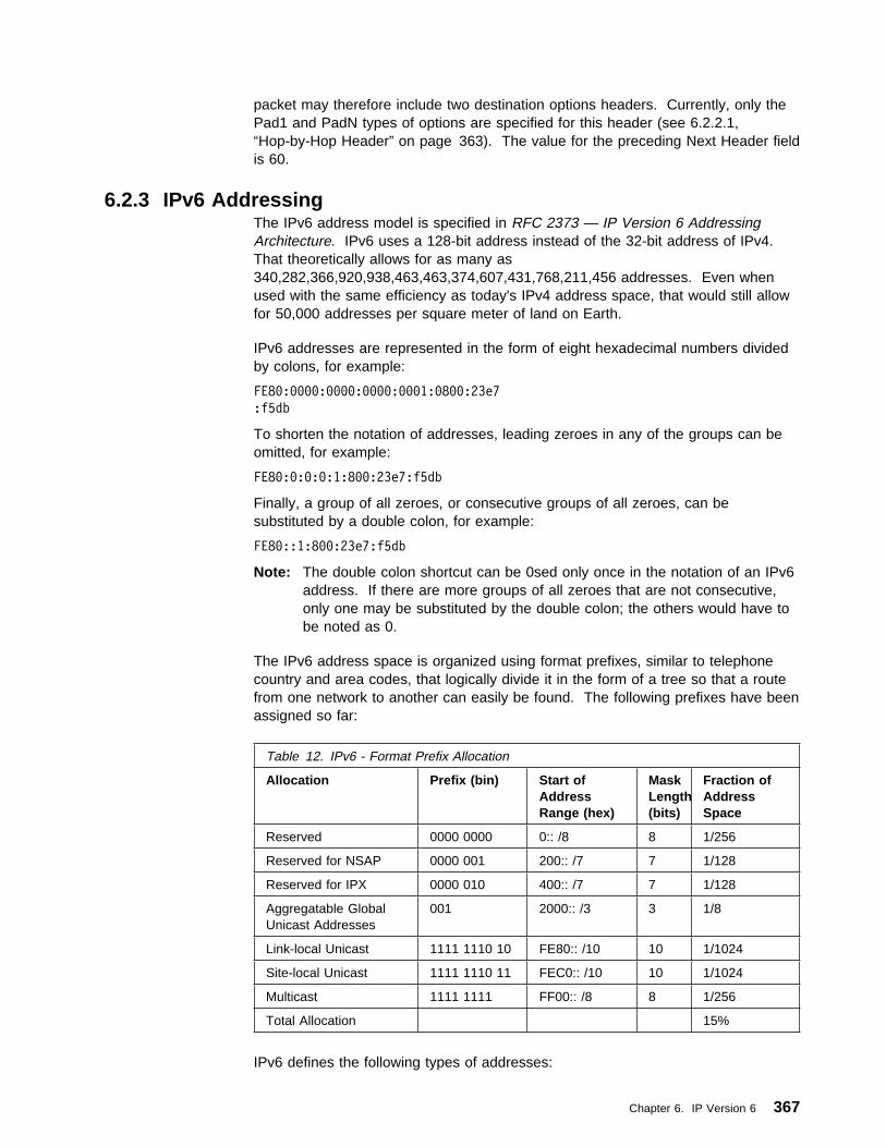
packet may therefore include two destination options headers. Currently, only thePad1 and PadN types of options are specified for this header (see 6.2.2.1,“Hop-by-Hop Header” on page 363). The value for the preceding Next Header fieldis 60.
6.2.3 IPv6 AddressingThe IPv6 address model is specified in RFC 2373 — IP Version 6 AddressingArchitecture. IPv6 uses a 128-bit address instead of the 32-bit address of IPv4.That theoretically allows for as many as340,282,366,920,938,463,463,374,607,431,768,211,456 addresses. Even whenused with the same efficiency as today's IPv4 address space, that would still allowfor 50,000 addresses per square meter of land on Earth.
IPv6 addresses are represented in the form of eight hexadecimal numbers dividedby colons, for example:
FE8ð:ðððð:ðððð:ðððð:ððð1:ð8ðð:23e7
:f5db
To shorten the notation of addresses, leading zeroes in any of the groups can beomitted, for example:
FE8ð:ð:ð:ð:1:8ðð:23e7:f5db
Finally, a group of all zeroes, or consecutive groups of all zeroes, can besubstituted by a double colon, for example:
FE8ð::1:8ðð:23e7:f5db
Note: The double colon shortcut can be 0sed only once in the notation of an IPv6address. If there are more groups of all zeroes that are not consecutive,only one may be substituted by the double colon; the others would have tobe noted as 0.
The IPv6 address space is organized using format prefixes, similar to telephonecountry and area codes, that logically divide it in the form of a tree so that a routefrom one network to another can easily be found. The following prefixes have beenassigned so far:
IPv6 defines the following types of addresses:
Table 12. IPv6 - Format Prefix Allocation
Allocation Prefix (bin) Start ofAddressRange (hex)
MaskLength(bits)
Fraction ofAddressSpace
Reserved 0000 0000 0:: /8 8 1/256
Reserved for NSAP 0000 001 200:: /7 7 1/128
Reserved for IPX 0000 010 400:: /7 7 1/128
Aggregatable GlobalUnicast Addresses
001 2000:: /3 3 1/8
Link-local Unicast 1111 1110 10 FE80:: /10 10 1/1024
Site-local Unicast 1111 1110 11 FEC0:: /10 10 1/1024
Multicast 1111 1111 FF00:: /8 8 1/256
Total Allocation 15%
Chapter 6. IP Version 6 367

Unicast AddressA unicast address is an identifier assigned to a single interface. Packets sentto that address will only be delivered to that interface. Special purposeunicast addresses are defined as follows:
Loopback address (::1) This address is assigned to a virtual interface overwhich a host can send packets only to itself. It is equivalent to theIPv4 loopback address 127.0.0.1.
Unspecified address (::) This address is used as a source address by hostswhile performing autoconfiguration. It is equivalent to the IPv4unspecified address 0.0.0.0.
IPv4-compatible address (::<IPv4_address>) Addresses of this kind areused when IPv6 traffic needs to be tunneled across existing IPv4networks. The endpoint of such tunnels can be either hosts(automatic tunneling) or routers (configured tunneling).IPv4-compatible addresses are formed by placing 96 bits of zero infront of a valid 32-bit IPv4 address. For example, the address1.2.3.4 (hex 01.02.03.04) becomes ::0102:0304
IPv4-mapped address (::FFFF:<IPv4_address>) Addresses of this kind areused when an IPv6 host needs to communicate with an IPv4 host.This requires a dual stack host or router for header translations.For example, if an IPv6 node wishes to send data to host with anIPv4 address of 1.2.3.4, it uses a destination address of::FFFF:0102:0304.
Link-local address Addresses of this kind can be used only on the physicalnetwork that a host's interface is attached to.
Site-local address Addresses of this kind cannot be routed into the Internet.They are the equivalent of IPv4 networks for private use (10.0.0.0,176.16.0.0-176.31.0.0, 192.168.0.0-192.168.255.0).
Global Unicast Address FormatThe Global Unicast address format, as specified in RFC 2374 — An IPv6Aggregatable Global Unicast Address Format is expected to become thepredominant format used for IPv6 nodes connected to the Internet. Theaggregatable address can be split into three sections that relate to thethree-level hierarchy of the Internet, namely:
Public Topology Providers and exchanges that provide public Internet transitservices.
Site Topology Local to an organization that does not provide public transitservice to nodes outside of the site.
Interface Identifiers Identify interfaces on links.
368 TCP/IP Tutorial and Technical Overview

P1 P2 P3
S3
X1
X2
P4S
1S
2S
4S
5S
6
3376\3376F3D9
Figure 218. Global Unicast Address Format - Three-Level Hierarchy
The Global Unicast Address Format is designed for the infrastructure shownin Figure 218. P1, P2 and P3 are long-haul providers. P4 is a smallerprovider that obtains services from P2. Exchanges (X1 and X2), which areanalagous to exchanges in a telephone network, will allocate addresses.Subscribers (S1-S6) have the choice of connecting directly to a provider or toan exchange (in which case they must also subscribe to a provider forlong-haul service). Organizations connecting via an exchange have theflexibility to be able to change their long-haul provider without having tochange their IP addresses.
The format of the aggregatable global unicast address is shown inFigure 219.
FP
3376\3376F3DA
TLAID
RES Interface ID
0 3 16 24 48 64 127
NLAID
SLAID
< Public Topology > < Site Topology >
Figure 219. Global Unicast Address Format
FP Format Prefix (001).
TLA ID Top-Level Aggregation Identifier. These are the top level in therouting hierarchy. Internet top-level routers will need a routing tableentry for every active TLA ID. This will be a maximum of 8,192entries, which compares with around 50,000 entries in today's IPv4top-level routers.
RES Reserved for future use. This will allow growth in the number ofeither TLA IDs or NLA IDs in the future if this becomes necessary.
NLA ID Next-Level Aggregation Identifier. Used by organizations assigneda TLA ID (who may be providers) to create their own addressinghierarchy and to identify sites. The 24-bit NLA ID space allowseach organization to provide service to as many sites as thecurrent total number of networks supported by IPv4.
Chapter 6. IP Version 6 369

SLA ID Site-Level Aggregation Identifier. This field is used by anindividual organization to create its own local addressing hierarchy.The 16-bit field allows for up to 65,535 individual subnets.
Multicast AddressA multicast address is an identifier assigned to a set of interfaces on multiplehosts. Packets sent to that address will be delivered to all interfacescorresponding to that address. (See 9.2, “Internet Group ManagementProtocol (IGMP)” on page 469 for more information on IP multicasting.)There are no broadcast addresses in IPv6, their function being superceded bymulticast addresses. Figure 220 shows the format of an IPv6 multicastaddress:
FP
3376\3376F3DB
ScopeFlags Group ID
0 8 12 16 127
Figure 220. IPv6 Multicast Address Format
FP Format Prefix - 1111 1111.
Flags Set of four flag bits. Only the low order bit currently has anymeaning, as follows:
0000 Permanent address assigned by a numbering authority
0001 Transient address. Addresses of this kind can beestablished by applications as required. When theapplication ends, the address will be released by theapplication and can be reused.
Scope 4-bit value indicating the scope of the multicast. Possible valuesare:
0 Reserved1 Confined to interfaces on the local node (node-local)2 Confined to nodes on the local link (link-local)5 Confined to the local site8 Confined to the organizationE Global scopeF Reserved
Group ID Identifies the multicast group.
For example if the NTP servers group is assigned a permanent multicastaddress, with a group ID of X'101, then:
FF02::101 means all NTP servers on the same link as the sender.
FF05::101 means all NTP servers on the same site as the sender.
Certain special purpose multicast addresses are pre-defined as follows:
FF01::1 All interfaces node-local - Defines all interfaces on the host itself.FF02::1 All nodes link-local - Defines all systems on the local network.FF01::2 All routers node-local - Defines all routers local to the host itself.FF02::2 All routers link-local - Defines all routers on the same link as the
host.
370 TCP/IP Tutorial and Technical Overview
FF05::2 All routers site-local - Defines all routers on the same site as thehost.
FF02::B Mobile agents link-local.FF02::1:2 All DHCP agents link-local.FF05::1:3 All DHCP servers site-local.
A more complete listing of reserved multicast addresses may be found in RFC2375 — IPv6 Multicast Address Assignments
This RFC also defines a special multicast address known as the solicitednode address, which has the format FF02::1:FFxx:xxxx, where xx xxxx istaken from the last 24-bits of a nodes unicast address. For example, thenode with the IPv6 address of 4025::01:800:100F:7B5B belongs to themulticast group FF02::1:FF 0F:7B5B. The solicited node address is used byICMP for neighbour discovery and to detect duplicate addresses. Please see6.3, “Internet Control Message Protocol Version 6 (ICMPv6)” on page 372 forfurther details.
Anycast AddressAn anycast address is a special type of unicast address that is assigned tointerfaces on multiple hosts. Packets sent to such an address will bedelivered to the nearest interface with that address. Routers determine thenearest interface based upon their definition of distance, for example hops incase of RIP or link state in case of OSPF.
Anycast addresses use the same format as unicast addresses and areindistinguishable from them. However, a node that has been assigned ananycast address must be configured to be aware of this fact.
RFC 2373 currently specifies the following restrictions on anycast addresses:
� An anycast address must not be used as the source address of a packet.
� Any anycast address may only be assigned to a router
A special anycast address, the subnet-router address, is predefined. Thisaddress consists of the subnet prefix for a particular subnet followed bytrailing zeroes. This address may be used when a node needs to contact arouter on a particular subnet and it does not matter which router is reached(for example, when a mobile node needs to communicate with one of themobile agents on its “home” subnet),
6.2.4 PriorityThe 4-bit priority field allows applications to specify a certain priority for the trafficthey generate thus introducing the concept of Class of Service.
IPv4-based routers normally treat all traffic equal, whereas IPv6-based routers nowmust act on such prioritized packets in the following way:
1. For priorities 0 to 7, start dropping packets when the network becomescongested (congestion-controlled).
2. For priorities 8 to 15, try to forward packets even when the network isbecoming congested by dropping packets with lower priority(noncongestion-controlled). Real-time applications would opt for this range ofpriority. For a comparison of how priority traffic may be handled in an IPv4network, please see 10.1, “Why QoS?” on page 505.
Chapter 6. IP Version 6 371

6.2.5 Flow LabelsIPv6 introduces the concept of a flow, which is a series of related packets from asource to a destination that requires a particular type of handling by the interveningrouters, for example real-time service. The nature of that handling can either beconveyed by options attached to the datagrams (that is, by using the IPv6Hop-by-Hop options header) or by a separate protocol (such as resourcereservation protocol - see 10.2.2, “The Reservation Protocol (RSVP)” onpage 511). The handling requirement for a particular flow label is known as thestate information; this is cached at the router. When packets with a known flowlabel arrive at the router, the router can efficiently decide how to route and forwardthe packets without having to examine the rest of the header for each packet.
There may be multiple active flows between a source and a destination, as well astraffic that is not associated with any flow. Each flow is distinctly labelled by the24-bit flow label field in the IPv6 packet. See RFC 1883 and RFC 1809 for furtherdetails on the use of the flow label.
6.3 Internet Control Message Protocol Version 6 (ICMPv6)The IP protocol concerns itself with moving data from one node to another.However, in order for IP to perform this task successfully, there are many otherfunctions that need to be carried out: error reporting, route discovery anddiagnostics to name but a few. All these tasks are carried out by the InternetControl Message Protocol (see 2.2, “Internet Control Message Protocol (ICMP)” onpage 58). ICMPv6, in addition, carries out ICMPv6 the tasks of conveyingmulticast group membership information, a function that was previously performedby the IGMP protocol in IPv4 ICMPv6 (see 9.2, “Internet Group ManagementProtocol (IGMP)” on page 469) and address resolution, previously performed byARP (see 2.4, “Address Resolution Protocol (ARP)” on page 68).
ICMPv6 messages, and their use, are specified in RFC 1885 — Internet ControlMessage Protocol (ICMPv6) for the Internet Protocol Version 6 (IPv6) Specificationand RFC 1970 — Neighbor Discovery for IP Version 6 (IPv6). Both RFCs areproposed standards with a status of elective.
Every ICMPv6 message is preceded by an IPv6 header (and possibly some IPextension headers). The ICMPv6 header is identified by a Next Header value of 58in the immediately preceding header.
ICMPv6 messages all have a similar format, shown in Figure 221.
Type
3376\3376F3DC
ChecksumCode
0 8 16 31
Body of ICMP Message
Figure 221. ICMPv6 General Message Format
372 TCP/IP Tutorial and Technical Overview

Type There are two classes of ICMPv6 messages. Error messages have aType from 0 to 127. Informational messages have a Type from 128 to255.
1 Destination Unreachable2 Packet Too Big3 Time (Hop Count) Exceeded4 Parameter Problem128 Echo Request129 Echo Reply130 Group Membership Query131 Group Membership Report132 Group Membership Reduction133 Router Solicitation134 Router Advertisement135 Neighbor Solicitation136 Neighbor Advertisement137 Redirect Message
Code Varies according to message type.
ChecksumUsed to detect data corruption in the ICMPv6 message and parts of theIPv6 header.
Body of MessageVaries according to message type.
For full details of ICMPv6 messages for all Types please refer to RFC 1885 andRFC 1970.
6.3.1 Neighbor DiscoveryNeighbor discovery is an ICMPv6 function that enables a node to neighbordiscovery identify other hosts and routers on its links. The node needs to know ofat least one router, so that it knows where to forward packets if a target node is noton its local link. Neighbor discovery also allows a router to redirect a node to use amore appropriate router if the node has initially made an incorrect choice.
6.3.1.1 Address ResolutionFigure 222 on page 374 shows a simple Ethernet LAN segment with four IPv6workstations.
Chapter 6. IP Version 6 373

IP FE80::0800:5A12:3456MAC 08005A123456
A
IP FE80::0800:5A12:3458MAC 08005A123458
C
IP FE80::0800:5A12:3457MAC 08005A123457
B
IP FE80::0800:5A12:3459MAC 08005A123459
D
3376\3376F3DD
Figure 222. IPv6 Address Resolution
Workstation A needs to send data to workstation B. It knows the IPv6 address ofworkstation B, but it does not know how to send a packet because it does not knowits MAC address. To find this information, it sends a neighbor solicitation message,of the format shown in Figure 223.
6 Flow LabelPri
Payload = 32 Next = 58 Hops = 255
Source Address - FE80::0800:5A12:3456
Destination Address - FF02::1:5A12:3458
Type = 135 Code = 0 Checksum
Reserved = 0
3376\3376F3DE
Target Address - FE80::0800:5A12:3458
IP Header
ICMPMessage
Opt Code=1 Opt Len=1
Source Link Layer Address = 08005A123456
Figure 223. Neighbor Solicitation Message Format
Notice the following important fields in the IP header of this packet:
Next 58 (for the following ICMP message header).
374 TCP/IP Tutorial and Technical Overview

Hops Any solicitation packet that does not have hops set to 255 is discarded;this ensures that the solicitation has not crossed a router.
Destination addressThis address is the solicited node address for the target workstation (aspecial type of multicast - see 371). Every workstation must respond toits own solicited node address but other workstations will simply ignoreit. This is an improvement over ARP in IPv4, which uses broadcastframes that have to be processed by every node on the link.
In the ICMP message itself, notice:
Type 135 (Neighbor Solicitation).
Target addressThis is the known IP address of the target workstation.
Source link layer addressThis is useful to the target workstation and saves it having to initiate aneighbor discovery process of its own when it sends a packet back tothe source workstation.
The response to the neighbor solicitation message is a neighbor advertisement,which has the following format:
6 Flow LabelPri
Payload = 32 Next = 58 Hops = 255
Source Address - FE80::0800:5A12:3458
Destination Address - FE80::0800:5A12:3456
Type = 136 Code = 0 Checksum
Reserved = 0
3376\3376F3DF
Target Address - FE80::0800:5A12:3458
IP Header
ICMPMessage
Opt Code=2 Opt Len=1
Target Link Layer Address = 08005A123458
R S O
Figure 224. Neighbor Advertisement Message
The neighbor advertisement is addressed directly back to Workstation A. TheICMP message option contains the target IP address together with the target's linklayer (MAC) address. Note also the following flags in the advertisement message:
Chapter 6. IP Version 6 375

R Router Flag. This bit is set on if the sender of the advertisement is arouter.
S Solicited Flag. This bit is set on if the advertisement is in response to asolicitation.
O Override Flag. When this bit is set on, the receiving node must updatean existing cached link layer entry in its neighbor cache.
Once Workstation A receives this packet, it commits the information to memory inits neighbor cache, then forwards the data packet that it wanted to send toWorkstation C originally.
Neighbor advertisement messages may also be sent by a node to force updates toneighbor caches if it becomes aware that its link layer address has changed.
6.3.1.2 Router and Prefix Discoveryrouter discovery prefix discovery
Figure 222 on page 374 shows a very simple network example. In a largernetwork, particularly one connected to the Internet, the neighbor discovery processis used to find nodes on the same link in exactly the same way. However, it ismore than likely that a node will need to communicate, not just with other nodes onthe same link, but with nodes on other network segments that may be anywhere inthe world. In this case there are two important pieces of information that a nodeneeds to know:
1. The address of a router that the node can use to reach the rest of the world
2. The Prefix (or prefixes) that define the range of IP addresses on the same linkas the node and which can be reached without going through a router.
Routers use ICMP to convey this information to hosts, by means of routeradvertisements. The format of the router advertisement message is shown inFigure 225 on page 377. The message will generally have one or more attachedoptions; all three possible options are shown in this example:
376 TCP/IP Tutorial and Technical Overview

6 Flow LabelPri
Payload = 64 Next = 58 Hops = 255
Source Address
Destination Address - FF02::1
Type = 134 Code = 0 Checksum
Router Lifetime
3376\3376F3DG
IP Header
Option 2
Reachable Time
M O RsvdHop Limit
Retransmission Timer
Opt Type=1 Opt Len=1
Source Link Address
Opt Type=5 Opt Len=1 Reserved
MTU
Opt Len=4 AL RsvdOpt Type=3 Prefix Len
Valid Lifetime
Preferred Lifetime
Reserved
Prefix
Option 1
Option 3
Figure 225. Router Advertisement Message Format
Notice the following important fields in the IP header of this packet:
Next 58 (for the following ICMP message header).
Hops Any advertisement packet that does not have hops set to 255 isdiscarded. This ensures that the packet has not crossed a router.
Destination addressThis address is the special multicast address defining all systems on thelocal link.
In the ICMP message itself:
Chapter 6. IP Version 6 377

Type 134 (Router Advertisement).
Hop Limit The default value that a node should place in the Hop Count field of itsoutgoing IP packets.
M 1-bit Managed Address Configuration Flag (see 6.3.2, “StatelessAddress Autoconfiguration” on page 382).
O 1-bit Other Stateful Configuration Flag (see 6.3.2, “Stateless AddressAutoconfiguration” on page 382).
Router LifetimeHow long the node should consider this router to be available. If thistime period is exceeded and the node has not received another routeradvertisement message, the node should consider this router to beunavailable.
Reachable TimeThis sets a parameter for all nodes on the local link. It is the time inmilliseconds that the node should assume a neighbor is still reachableafter having received a response to a neighbor solicitation.
Retransmission TimerThis sets the time, in milliseconds, that nodes should allow betweenretransmitting neighbor solicitation messages if no initial response isreceived.
The three possible options in a router advertisement message are:
Option 1 (source link address)Allows a receiving node to respond directly to the router without havingto do a neighbor solicitation.
Option 5 (MTU)Specifies the maximum transmission unit size for the link. For somemedia, such as Ethernet, this value is fixed so this option is notnecessary.
Option 3 (Prefix)Defines the address prefix for the link. Nodes use this information todetermine when they do, and do not, need to use a router. Prefixoptions used for this purpose have the L (link) bit set on. Prefix optionsare also used as part of address configuration, in which case the A bit isset on. Please see 6.3.2, “Stateless Address Autoconfiguration” onpage 382 for further details.
A router constantly sends unsolicited advertisements at a frequency defined in therouter configuration. A node may, however, wish to obtain information about thenearest router without having to wait for the next scheduled advertisement (a newworkstation that has just attached to the network, for example). In this case, thenode can send a router solicitation message. The format of the router solicitationmessage is shown in Figure 226 on page 379:
378 TCP/IP Tutorial and Technical Overview

6 Flow LabelPri
Payload = 16 Next = 58 Hops = 255
Source Address
Destination Address - FF02::2
Type = 133 Code = 0 Checksum
Reserved = 0
3376\3376F3DH
Target Address - FE80::0800:5A12:3458
Opt Type=1 Opt Len=1
Source Link Address
Figure 226. Router Solicitation Message Format
Notice the following important fields in the IP header of this packet:
Next 58 (for the following ICMP message header).
Hops Any advertisement packet that does not have hops set to 255 isdiscarded. This ensures that the packet has not crossed a router.
Destination addressThis address is the special multicast address defining all routers on thelocal link.
In the ICMP message itself:
Type 133 (Router Solicitation)
Option 1 (source link address)Allows the receiving router to respond directly to the node withouthaving to do a neighbor solicitation.
Each router that receives the solicitation message responds with a routeradvertisement sent directly to the node that sent the solicitation (not to the allsystems link-local multicast address).
6.3.1.3 RedirectionThe router advertisement mechanism ensures that a node will always be aware ofone or more routers through which it is able to connect to devices outside of itslocal links. However, in a situation where a node is aware of more than one router,it is likely that the default router selected when sending data will not always be themost suitable router to select for every packet. In this case, ICMPv6 allows forredirection to a more efficient path for a particular destination.
Chapter 6. IP Version 6 379

NodeXRouter A
Router B
NodeY
3376\3376F3DI
Figure 227. Redirection
Consider the simple example shown in Figure 227. Node X is aware of routers Aand B, having received router advertisement messages from both. Node X wishesto send data to Node Y. By a comparison of Node Y's IP address against the locallink prefix, Node X knows that Node Y is not on the local link, and that it musttherefore use a router. Node X selects router A from its list of default routers andforwards the packet. Obviously, this is not the most efficient path to Node Y. Assoon as router A has forwarded the packet to Node Y (via router B), router A sendsa redirect message to Node X. The format of the redirect message (complete withIP header) is shown in Figure 228 on page 381.
380 TCP/IP Tutorial and Technical Overview

6 Flow LabelPri
Payload Length Next = 58 Hops = 255
Source Address (Router A)
Destination Address (Node X)
Type = 137 Code = 0 Checksum
Reserved = 0
3376\3376F3DJ
Target Address (Router B)
Destination Address (Node Y)
Opt Type=1 Opt Len=1
Source Link Address (Router B)
Opt Type=4 Opt Length Reserved = 0
Reserved = 0
IP Header & Data
Figure 228. Redirect Message Format
The fields to note in the message are:
Type 137 (Redirect).
Target AddressThis is address of the router that should be used when trying to reachNode Y.
Destination AddressNode Y's IP address.
Option 2 (target link layer address)Gives link address of router B so that Node X can reach it without aneighbor solicitation.
Option 4 (redirected header)Includes the original packet sent by node X, full IP header and as muchof the data that will fit, such that the total size of the redirect messagedoes not exceed 576 bytes.
Chapter 6. IP Version 6 381

6.3.1.4 Neighbor Unreachability DetectionAn additional responsibility of the neighbor discovery function of ICMPv6 isneighbor unreachability detection (NUD).
A node actively tracks the reachability state of the neighbors to which it is sendingpackets. It may do this in two ways: either by monitoring the upper layer protocolsto see if a connection is making forward progress (for example, TCPacknowledgments are being received), or it may issue specific neighbor solicitationsto check that the path to a target host is still available. When a path to a neighborappears to be failing, then appropriate action is taken to try and recover the link.This may include restarting the address resolution process or deletion of a neighborcache entry so that a new router may be tried in order to find a working path to thetarget.
NUD is used for all paths between nodes, including host-to-host, host-to-router androuter-to-host. NUD may also be used for router-to-router communication, if therouting protocol being used does not already include a similar mechanism. Forfurther information on neighbor unreachability detection, please refer to RFC 1970.
6.3.2 Stateless Address AutoconfigurationAlthough the 128-bit address field of IPv6 solves a number of problems inherent inIPv4, the size of the address itself represents a potential problem to the TCP/IPadministrator. Because of this, IPv6 has been designed with the capability toautomatically assign an address to an interface at initialization time, with theintention that a network can become operational with minimal to no action on thepart of the TCP/IP administrator. IPv6 nodes will generally always useautoconfiguration to obtain their autoconfiguration IPv6 address. This may beachieved using DHCP (see 6.5, “DHCP in IPv6” on page 388), which is known asstateful autoconfiguration, or by stateless autoconfiguration, which is a new featureof IPv6 and relies on ICMPv6.
The stateless autoconfiguration process is defined in RFC 1971 — IPv6 StatelessAddress Autoconfiguration. It consists of the following steps:
1. During system startup, the node begins the autoconfiguration by obtaining aninterface token from the interface hardware, for instance, a 48-bit MAC addresson token-ring or Ethernet networks.
2. The node creates a tentative link-local unicast address. This is done bycombining the well-known link-local prefix (FE80::/10) with the interface token.
3. The node attempts to verify that this tentative address is unique by issuing aneighbor solicitation message with the tentative address as the target. If theaddress is already in use, the node will receive a neighbor advertisement inresponse, in which case the autoconfiguration process stops. (Manualconfiguration of the node is then required.)
4. If no response is received, the node assigns the link-level address to itsinterface. The host then sends one or more router solicitations to theall-routers multicast group. If there are any routers present, they will respondwith a router advertisement. If no router advertisement is received, the nodeshould attempt to use DHCP to obtain an address and configurationinformation. If no DHCP server responds, the node continues using thelink-level address and can communicate with other nodes on the same linkonly.
382 TCP/IP Tutorial and Technical Overview

5. If a router advertisement is received in response to the router solicitation, thenthis message contains several pieces of information that tells the node how toproceed with the autoconfiguration process (see Figure 225 on page 377).
M flag Managed address configuration
If this bit is set, the node should use DHCP to obtain its IP address.
O flag Other stateful configuration.
If this bit is set then the node uses DHCP to obtain otherconfiguration parameters.
Prefix OptionIf the router advertisement has a prefix option with the A bit(autonomous address configuration flag) set on, then the prefix isused for stateless address autoconfiguration.
6. If stateless address configuration is to be used, the prefix is taken from therouter advertisement and added to the interface token to form the globalunicast IP address, which is assigned to the network interface.
7. The working node will continue to receive periodic router advertisements. If theinformation in the advertisement changes, the node must take appropriateaction.
Note that it is possible to use both stateless and stateful configurationsimultaneously. It is quite likely that stateless configuration will be used to obtainthe IP address, but DHCP will then be used to obtain further configurationinformation. However, plug-and-play configuration is possible in both small andlarge networks without the requirement for DHCP servers.
The stateless address configuration process, together with the fact that more thanone address can be allocated to the same interface, also allows for the gracefulrenumbering of all the nodes on a site (for example, if a switch to a new networkprovider necessitates new addressing) without disruption to the network. Forfurther details, please refer to RFC 1971.
6.3.3 Multicast Listener Discovery (MLD)The process used by a router to discover the members of a particular multicastgroup is known as Multicast Listener Discovery (MLD). MLD is a subset of ICMPv6and provides the equivalent function of IGMP for IPv4 (see 9.2, “Internet GroupManagement Protocol (IGMP)” on page 469). This information is then provided bythe router to whichever multicast routing protocol is being used, so that multicastpackets are correctly delivered to all links where there are nodes listening for theappropriate multicast address.
MLD uses ICMPv6 messages of the format shown in Figure 229 on page 384.
Chapter 6. IP Version 6 383

Vers. Flow LabelPri
Payload Length Next = 58 Hops = 1
(Link Local) Source Address
Destination Address
Type Code = 0 Checksum
3376A\3376F3DR
Max. Response Delay Reserved
IP Multicast Address
Figure 229. MLD Message Format
Note the following fields in the IPv6 header of the message:
Next 58 (for the following ICMPv6 message header).
Hops Always set to 1.
Source AddressA link-local source address is used.
In the MLD message itself, notice:
Type There are three types of MLD message:
130 Multicast Listener Query
There are two types of queries:General query
Used to find which multicast addresses are beinglistened for on a link.
Multicast-address-specific queryUsed to find if any nodes are listening for aspecific multicast address on a link.
131 Multicast listener report
Used by a node to report that it is listening to a multicastaddress.
132 Multicast listener done
Used by a node to report that it is ceasing to listen to amulticast address.
Code Set to 0 by sender and ignored by receivers.
Max Response DelayThis sets the maximum allowed delay before a responding report mustbe sent. This parameter is only valid in query messages. Increasing
384 TCP/IP Tutorial and Technical Overview

this parameter can prevent sudden bursts of high traffic if there a lot ofresponders on a network.
Multicast AddressIn a query message, this field is set to zero for a general query, or set tothe specific IPv6 multicast address for a multicast-address-specificquery.
In a response or done message, this field contains the multicast addressbeing listened for.
A router users MLD to learn which multicast addresses are being listened for oneach of its attached links. The router only needs to know that nodes listening for aparticular address are present on a link; it does not need to know the unicastaddress of those listening nodes, or how many listening nodes are present.
A router periodically sends a General Query on each of its links to the all nodeslink-local address (FF02::1). When a node listening for any multicast addressesreceives this query, it sets a delay timer (which may be anything between 0 andmaximum response delay) for each multicast address for which it is listening. Aseach timer expires, the node sends a multicast listener report message containingthe appropriate multicast address. If a node receives another node's report for amulticast address while it has a timer still running for that address, then it stops itstimer and does not send a report for that address. This prevents duplicate reportsbeing sent and, together with the timer mechanism, prevents excess, or burstytraffic being generated.
The router manages a list of, and sets a timer for, each multicast address it isaware of on each of its links. If one of these timers expires without a report beingreceived for that address, the router assumes that no nodes are still listening forthat address, and the address is removed from the list. Whenever a report isreceived, the router resets the timer for that particular address.
When a node has finished listening to a multicast address, if it was the last node ona link to send a report to the router (that is, its timer delay was not interrupted bythe receipt of another node's report), then it sends a multicast listener donemessage to the router. If the node was interrupted by another node before its timerexpired, then it assumes that other nodes are still listening to the multicast addresson the link and therefore does not send a done message.
When a router receives a done message, it sends a multicast-address-specificmessage on the link. If no report is received in response to this message, therouter assumes that there are no nodes still listening to this multicast address andremoves the address from its list.
MLD is not currently specified in an RFC, but is the subject of an Internet draft,Multicast Listener Discovery for IPv6. For further information, please refer to thelatest draft at:
http://www.ietf.org/internet-drafts/draft-ietf-ipngwg-mld-ðð.txt
Chapter 6. IP Version 6 385

6.4 DNS in IPv6With the introduction of 128-bit addresses, IPv6 makes it even more difficult for thenetwork user to be able to identify another network user by means of the IPaddress of his or her network device. The use of the Domain Name Service,therefore, becomes even more of a necessity (please see 4.2, “Domain NameSystem (DNS)” on page 150).
A number of extensions to DNS are specified to support the storage and retrieval ofIPv6 addresses. These are defined in RFC 1886 — DNS Extensions to Support IPVersion 6, which is a proposed standard with elective status. However, there isalso work in progress on useability enhancements to this RFC, described in anInternet draft of the same name.
The following extensions are specified:
� A new resource record type, AAAA, which maps the domain name to the IPv6address
� A new domain, which is used to support address-to-domain name lookups
� A change to the definition of existing queries, so that they will perform correctprocessing on both A and AAAA record types
6.4.1 Format of IPv6 Resource RecordsRFC 1886 defines the format of the AAAA record as similar to an A resourcerecord, but with the 128-bit IPv6 address encoded in the data section, and a Typevalue of 28 (decimal).
A special domain, IP6.INT, is defined for inverse (address-to-host name) lookups(similar to the in-addr.arpa domain used in IPv4). As in IPv4, the address must beentered in reverse order, but hexadecimal digits are used rather than decimalnotation.
For example, the inverse domain name entry for the IPv6 address
2222:ð:1:2:3:4:5678:9abc
is:
c.b.a.9.8.7.6.5.4.ð.ð.ð.3.ð.ð.ð.2.ð.ð.ð.1.ð.ð.ð.ð.ð.ð.ð.2.2.2.2.IP6.INT.
So, if the above address relates to the node ND1.test.com, we might expect to seethe following entries in the name server zone data:
$origin test.com.
ND1 99999 IN AAAA 2222:ð:1:2:3:4:5678:9abc
cba987654ððð3ððð2ððð1ððððððð2222.IP6.INT. IN PTR ND1 .1/
.1/ All characters making up the reversed IPv6 address in this PTR entry shouldbe separated by a period(.). These have been omitted in this example for clarity.
386 TCP/IP Tutorial and Technical Overview

6.4.1.1 Proposed Changes to Resource RecordsThe IPv6 addressing system has been designed to allow for multiple addresses ona single interface and to facilitate address renumbering (for example, whencompany changes one of its service providers). Using the AAAA resource recordformat specified in RFC 1886 would require a major administrative effort in theevent of a renumbering change. The work in progress in the current Internet draftDNS Extensions to Support IP Version 6 proposes changes to the format of theAAAA resource record to simplify network renumbering.
The proposed format of the data section of the AAAA record is as shown inFigure 230
IPv6 address P domain name
3376a\3376F3DK
Figure 230. AAAA Resource Record - Proposed Data Format
IPv6 Address128-bit address (contains only the lower bits of the address)
P Prefix Length (0-128)
Domain NameThe domain name of the prefix
To see how this format works, consider the example shown in Figure 231.
2111 2122
OOCD
OOAB
OOA1
ND1
OOB1
TEST.COM
10005A123456
OOBC
new connection
PROV1 PROV2
TOP1 TOP2
X
3376a\3376F3DL
Figure 231. Prefix Numbering Example
Site X is multihomed to two providers, PROV1 and PROV2. PROV1 gets its transitservices from top-level provider TOP1. PROV2 gets its service from TOP2. TOP1has the top-level aggregate (TLA ID + format prefix) of 2111 (see Figure 219 onpage 369). TOP2 has the TLA of 2222.
Chapter 6. IP Version 6 387

TOP1 has assigned the next-level aggregate (NLA) of 00AB to PROV1. PROV2has been assigned the NLA of 00BC by TOP2.
PROV1 has assigned the subscriber identifier 00A1 to site X. PROV2 hasassigned the subscriber identifier 00B1 to site X.
Node ND1, at site X, which has the interface token of 10005A123456, is thereforeconfigured with the following two IP addresses:
2111:ððAB:ððA1::1ððð:5A12:3456
2222:ððBC:ððB1::1ððð:5A12:3456
Site X is represented by the domain name test.com. Each provider has their owndomain, top1.com, top2.com, prov1.com and prov2.com. In each of these domainsis created an IP6 subdomain that is used to hold prefixes. The node ND1 can nowbe represented by the following entries in the DNS:
ND1.TEST.COM AAAA ::1ððð:5A12:3456 8ð
IP6.TEST.COM
IP6.TEST.COM AAAA ð:ð:ððA1:: 32 IP6.PROV1.COM
IP6.TEST.COM AAAA ð:ð:ððB1:: 32 IP6.PROV2.COM
IP6.PROV1.COM AAAA ð:ððAB:: 16 IP6.TOP1.COM
IP6.PROV2.COM AAAA ð:ððBC:: 16 IP6.TOP2.COM
IP6.TOP1.COM AAAA 2111::
IP6.TOP2.COM AAAA 2222::
This format simplifies the job of the DNS administrator considerably and makesrenumbering changes much easier to implement. Say, for example, site X decidesto stop using links from providers PROV1 and PROV2 and invests in a connectiondirect from the top-level service provider TOP1 (who allocates the next-levelaggregate 00CD to site X). The only change necessary in the DNS would be forthe two IP6.TEST.COM entries to be replaced with a single entry as follows:
IP6.TEST.COM AAAA ð:ððCD:: 16 IP6.TOP1.COM
Note: Note that the proposed AAAA resource record format is currently work inprogress only. Please refer to the latest Internet draft at :
http://www.ietf.org/internet-drafts/draft-ietf-ipngwg-aaaa-ð3.txt
6.5 DHCP in IPv6Although IPv6 introduces stateless address autoconfiguration, DHCP DHCPv6retains its importance as the stateful alternative for those sites that wish to havemore control over their addressing scheme. Used together with statelessautoconfiguration, DHCP provides a means of passing additional configurationoptions to nodes once they have obtained their addresses. (See 7.2, “DynamicHost Configuration Protocol (DHCP)” on page 406 for a detailed description ofDHCP.)
There is currently no RFC covering DHCP in IPv6, although there is work inprogress described in two Internet drafts, Dynamic Host Configuration Protocol for
388 TCP/IP Tutorial and Technical Overview

IPv6 (DHCPv6) and Extensions for the Dynamic Host Configuration Protocol forIPv6.
6.5.1 Differences between DHCPv6 and DHCPv4DHCPv6 has some significant differences to DHCPv4, as it takes advantage ofsome of the inherent enhancements of the IPv6 protocol. Some of the principaldifferences are as follows:
� As soon as a client boots it already has a link-local IP address, which it canuse to communicate with a DHCP server or a relay agent.
� The client uses multicast addresses to contact the server, rather thanbroadcasts.
� IPv6 allows the use of multiple IP addresses per interface and DHCPv6 canprovide more than one address when requested.
� Some DHCP options are now unnecessary. Default routers, for example, arenow obtained by a client using IPv6 neighbor discovery.
� DHCP messages (including address allocations) appear in IPv6 messageextensions, rather than in the IP header as in IPv4.
� There is no requirement for BOOTP compatibility.
� There is a new reconfigure message, which is used by the server to sendconfiguration changes to clients (for example, the reduction in an addresslifetime). Clients must continue to listen for reconfigure messages once theyhave received their initial configuration.
6.5.2 DHCPv6 MessagesThe following DHCPv6 messages are currently defined:
DHCP SolicitThis is an IP multicast message. The DHCP client forwards themessage to FF02::1:2, the well-known multicast address for all DHCPagents (relays and servers). If received by a relay, the relay forwardsthe message to FF05::1:3, the well-known multicast address for allDHCP servers.
DHCP AdvertiseThis is a unicast message sent in response to a DHCP Solicit. A DHCPserver will respond directly to the soliciting client, if on the same link, orvia the relay agent, if the DHCP Solicit was forwarded by a relay. Theadvertise message may contain one or more extensions (DHCPoptions).
DHCP RequestOnce the client has located the DHCP server, the DHCP request(unicast message) is sent to request an address and/or configurationparameters. The request must be forwarded by a relay if the server isnot on the same link as the client. The request may contain extensions(options specified by the client) that may be a subset of all the optionsavailable on the server.
DHCP ReplyAn IP unicast message sent in response to a DHCP request (may besent directly to the client or via a relay). Extensions contain the addressand/or parameters committed to the client.
Chapter 6. IP Version 6 389

DHCP ReleaseAn IP unicast sent by the client to the server, informing of resources thatare being released.
DHCP ReconfigureAn IP unicast or multicast message, sent by the server to one or moreclients, to inform them that there is new configuration informationavailable. The client must respond to this message with a DHCPrequest, to request these new changes from the server.
For further details of DHCPv6, please refer to the latest Internet drafts. Note thatexact numbering of the drafts is subject to change.
http://www.ietf.org/internet-drafts/draft-ietf-dhc-dhcpv6-13.txt
http://www.ietf.org/internet-drafts/draft-ietf-dhc-v6exts-1ð.txt
6.6 Mobility Support in IPv6At time of writing, there is no RFC covering mobility support in IPv6, although thereis work in progress on the subject, described in a current Internet draft,MobilitySupport in IPv6.
Certain enhancements in the IPv6 protocol lend themselves particularly to themobile environment. For example, unlike Mobile IPv4, there is no requirement forrouters to act as “foreign agents” on behalf of the mobile node (see 7.4, “Mobile IP”on page 426), as neighbor discovery and address autoconfiguration allow the nodeto operate away from home without any special support from a local router. Also,most packets sent to a mobile node while it is away from its home location can betunneled by using IPv6 routing (extension) headers, rather than a completeencapsulation, as used in Mobile IPv4, which reduces the overhead of deliveringpackets to mobile nodes.
For further information on mobility support in IPv6, please refer to the latest Internetdraft at:
http://www.ietf.org/internet-drafts/draft-ietf-mobileip-ipv6-ð6.txt
6.7 Internet Transition - Migrating from IPv4 to IPv6If the Internet is to realize the benefits of IPv6, then a period of transition will benecessary when new IPv6 hosts and routers will need to be deployed alongsideexisting IPv4 systems. RFC1933 — Transition Mechanisms for IPv6 Hosts andRouters and RFC2185 — Routing Aspects of IPv6 Transition define a number ofmechanisms to be employed to ensure both compatibility between old and newsystems and a gradual transition that does not impact the functionality of theInternet. These techniques are sometimes collectively termed Simple InternetTransition (SIT). The transition employs the following techniques:
� Dual-stack IP implementations for hosts and routers that must interoperatebetween IPv4 and IPv6.
� Imbedding of IPv4 addresses in IPv6 addresses.
IPv6 hosts will be assigned addresses that are interoperable with IPv4, andIPv4 host addresses will be mapped to IPv6.
� IPv6-over-IPv4 tunneling mechanisms for carrying IPv6 packets across IPv4router networks
390 TCP/IP Tutorial and Technical Overview
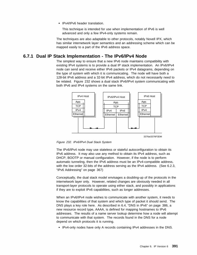
� IPv4/IPv6 header translation.
This technique is intended for use when implementation of IPv6 is welladvanced and only a few IPv4-only systems remain.
The techniques are also adaptable to other protocols, notably Novell IPX, whichhas similar internetwork layer semantics and an addressing scheme which can bemapped easily to a part of the IPv6 address space.
6.7.1 Dual IP Stack Implementation - The IPv6/IPv4 NodeThe simplest way to ensure that a new IPv6 node maintains compatibility withexisting IPv4 systems is to provide a dual IP stack implementation. An IPv6/IPv4node can send and receive either IPv6 packets or IPv4 datagrams, depending onthe type of system with which it is communicating. The node will have both a128-bit IPv6 address and a 32-bit IPv4 address, which do not necessarily need tobe related. Figure 232 shows a dual stack IPv6/IPv4 system communicating withboth IPv6 and IPv4 systems on the same link.
IPv6 Host
App.
TCP
IPv4
Ethernet
IPv6/IPv4 Host
App.
TCP
IPv4
Ethernet
3376a\3376F3DM
IPv4 Host
App.
TCP
IPv4
EthernetIPv6
Ethernet
Figure 232. IPv6/IPv4 Dual Stack System
The IPv6/IPv4 node may use stateless or stateful autoconfiguration to obtain itsIPv6 address. It may also use any method to obtain its IPv4 address, such asDHCP, BOOTP or manual configuration. However, if the node is to performautomatic tunneling, then the IPv6 address must be an IPv4-compatible address,with the low order 32-bits of the address serving as the IPv4 address. (See 6.2.3,“IPv6 Addressing” on page 367)
Conceptually, the dual stack model envisages a doubling-up of the protocols in theinternetwork layer only. However, related changes are obviously needed in alltransport-layer protocols to operate using either stack, and possibly in applicationsif they are to exploit IPv6 capabilities, such as longer addresses.
When an IPv6/IPv4 node wishes to communicate with another system, it needs toknow the capabilities of that system and which type of packet it should send. TheDNS plays a key role here. As described in 6.4, “DNS in IPv6” on page 386, anew resource record type, AAAA, is defined for mapping hostnames to IPv6addresses. The results of a name server lookup determine how a node will attemptto communicate with that system. The records found in the DNS for a nodedepend on which protocols it is running.
� IPv4-only nodes have only A records containing IPv4 addresses in the DNS.
Chapter 6. IP Version 6 391

� IPv6/IPv4 nodes that can interoperate with IPv4-only nodes have AAAArecords containing IPv4-compatible IPv6 addresses and A records containingthe equivalent IPv4 addresses.
� IPv6-only nodes that cannot interoperate with IPv4-only nodes have only AAAArecords containing IPv6 addresses.
Because IPv6/IPv4 nodes make decisions about which protocols to use based onthe information returned by the DNS, the incorporation of AAAA records in the DNSis a prerequisite to interoperability between IPv6 and IPv4 systems. Note thatname servers do not necessarily need to use an IPv6-capable protocol stack, butthey must support the additional record type.
6.7.2 TunnelingWhen IPv6 or IPv6/IPv4 systems are separated from other similar systems, withwhich they wish to communicate, by older IPv4 networks, then IPv6 packets mustbe tunneled through the IPv4 network.
IPv6 packets are tunnelled over IPv4 very simply; the IPv6 packet is encapsulatedin an IPv4 datagram, or in other words, a complete IPv4 header is added to theIPv6 packet. The presence of the IPv6 packet within the IPv4 datagram isindicated by a Protocol value of 41 in the IPv4 header.
There are two kinds of tunneling of IPv6 packets over IPv4 networks: automaticand configured.
6.7.2.1 Automatic TunnelingAutomatic tunneling relies on IPv4-compatible addresses. The decision on when totunnel is made by an IPv6/IPv4 host that has a packet to send across anIPv4-routed network area, and it follows the following rules:
� If the destination is an IPv4 or an IPv4-mapped address, send the packet usingIPv4 because the recipient is not IPv6-capable.
Otherwise:
� If the destination is on the same subnet, send it using IPv6 because therecipient is IPv6-capable.
� If the destination is not on the same subnet but there is at least one defaultrouter on the subnet that is IPv6-capable, or there is a route configured to anIPv6 router for that destination, then send it to that router using IPv6.
Otherwise:
� If the address is an IPv4-compatible address, send the packet using automaticIPv6-over-IPv4 tunneling.
Otherwise:
� The destination is a node with an IPv6-only address that is connected via anIPv4-routed area, which is not also IPv6-routed. Therefore, the destination isunreachable.
Note: The IP address must be IPv4-compatible for tunneling to be used.Automatic tunneling cannot be used to reach IPv6-only addresses because theycannot be addressed using IPv4. Packets from IPv6/IPv4 nodes to IPv4-mappedaddresses are not tunnelled to because they refer to IPv4-only nodes.
392 TCP/IP Tutorial and Technical Overview

The rules listed above emphasize the use of an IPv6 router in preference to atunnel for three reasons:
� There is less overhead because there is no encapsulating IPv4 header.
� IPv6-only features are available.
� The IPv6 routing topology will be used when it is deployed in preference to thepre-existing IPv4 topology.
A node does not need to know whether it is attached to an IPv6-routed or anIPv4-routed area; it will always use an IPv6 router if one is configured on its subnetand will use tunneling if one is not (in which case it can infer that it is attached toan IPv4-routed area).
Automatic tunneling may be either host-to-host, or it may be router-to-host. Asource host will send an IPv6 packet to an IPv6 router if possible, but that routermay not be able to do the same, and will have to perform automatic tunneling tothe destination host itself. Because of the preference for the use of IPv6 routersrather than tunneling, the tunnel will always be as “short” as possible. However,the tunnel will always extend all of the way to the destination host; because IPv6uses the same hop-by-hop routing paradigm, a host cannot determine if the packetwill eventually emerge into an IPv6-complete area before it reaches the destinationhost. In order to use a tunnel that does not extend all of the way to the recipient,configured tunneling must be used.
The mechanism used for automatic tunneling is very simple.
� The encapsulating IPv4 datagram uses the low-order 32 bits of the IPv6 sourceand destination addresses to create the equivalent IPv4 addresses and sets theprotocol number to 41 (IPv6).
� The receiving node's network interface layer identifies the incoming packets (orpackets if the IPv4 datagram was fragmented) as belonging to IPv4 and passesthem upwards to the IPv4 part of the dual IPv6/IPv4 internetwork layer.
� The IPv4 layer then receives the datagram in the normal way, re-assemblingfragments if necessary, notes the protocol number of 41, then removes theIPv4 header and passes the original IPv6 packet “sideways” to the IPv6 part ofthe internetwork layer.
� The IPv6 code then processes the original packet as normal. Since thedestination IPv6 address in the packet is the IPv6 address of the node (anIPv4-compatible address matching the IPv4 address used in the encapsulatingIPv4 datagram) the packet is at its final destination. IPv6 then processes anyextension headers as normal and then passes the packet's remaining payloadto the next protocol listed in the last IPv6 header.
Chapter 6. IP Version 6 393

X Y
3376a\3376F3DN
Ethernet
IPv6/IPv4 Router
(2)
IPv4Network
IPv6/IPv4 RouterIPv6/IPv4 Host
(1)
A
IPv6/IPv4 Host
(3)
B
flow label6 4nextpayload length hops
src: Workstation A(IPv4-compatible)
dst: Workstation B(IPv4-compatible)
payload
nxt:41src: Workstation A (IPv4)dst: Workstation B (IPv4)
flow label6 4nextpayload length hops
src: Workstation A(IPv4-compatible)
dst: Workstation B(IPv4-compatible)
payload
nxt:41src: Workstation A (IPv4)dst: Workstation B (IPv4)
flow label6 4nextpayload length hops
src: Workstation A(IPv4-compatible)
dst: Workstation B(IPv4-compatible)
payload
4
IPv4Header
4
Figure 233. Router-to-Host Automatic Tunneling
Figure 233 shows two IPv6/IPv4 nodes separated by an IPv4 network. Bothworkstations have IPv4-compatible IPv6 addresses. Workstation A sends a packetto workstation B, as follows:
1. Workstation A has received router solicitation messages from an IPv6-capablerouter (X) on its local link. It forwards the packet to this router.
2. Router X adds an IPv4 header to the packet, using IPv4 source and destinationaddresses derived from the IPv4-compatible addresses. The packet is thenforwarded across the IPv4 network, all the way to workstation B. This isrouter-to-host automatic tunneling.
3. The IPv4 datagram is received by the IPv4 stack of workstation B. As theProtocol field shows that the next header is 41 (IPv6), the IPv4 header isstripped from the datagram and the remaining IPv6 packet is then handled bythe IPv6 stack.
394 TCP/IP Tutorial and Technical Overview

X Y
Ethernet
IPv6/IPv4 Router
IPv4Network
IPv6/IPv4 RouterIPv6/IPv4 Host
(2)
A
IPv6/IPv4 Host
(1)
B
nxt:41src: Workstation B (IPv4)dst: Workstation A (IPv4)
flow label6 4nextpayload length hops
src: Workstation B(IPv4-compatible)
dst: Workstation A(IPv4-compatible)
payload
4
nxt:41src: Workstation B (IPv4)dst: Workstation A (IPv4)
flow label6 4nextpayload length hops
src: Workstation B(IPv4-compatible)
dst: Workstation A(IPv4-compatible)
payload
4
3376a\3376F3DN
nxt:41src: Workstation B (IPv4)dst: Workstation A (IPv4)
flow label6 4nextpayload length hops
src: Workstation B(IPv4-compatible)
dst: Workstation A(IPv4-compatible)
payload
4
IPv4Header
Figure 234. Host-to-Host Automatic Tunneling
In Figure 234, workstation B responds as follows:
1. Workstation B has no IPv6-capable router on its local link. It therefore adds anIPv4 header to its own IPv6 frame and forwards the resulting IPv4 datagramdirectly to the IPv4 address of workstation A via the IPv4 network. This ishost-to-host automatic tunneling.
2. The IPv4 datagram is received by the IPv4 stack of workstation A. As theProtocol field shows that the next header is 41 (IPv6), the IPv4 header isstripped from the datagram and the remaining IPv6 packet is then handled bythe IPv6 stack.
6.7.2.2 Configured TunnelingConfigured tunneling is used for host-router or router-router tunneling ofIPv6-over-IPv4. The sending host or the forwarding router is configured so that theroute, as well as having a next hop, also has a tunnel end address (which is alwaysan IPv4-compatible address). The process of encapsulation is the same as forautomatic tunneling except that the IPv4 destination address is not derived from thelow-order 32 bits of the IPv6 destination address, but from the low-order 32 bits ofthe tunnel end. The IPv6 destination and source addresses do not need to beIPv4-compatible addresses in this case.
Chapter 6. IP Version 6 395

When the router at the end of the tunnel receives the IPv4 datagram, it processes itin exactly the same way as a node at the end of an automatic tunnel. When theoriginal IPv6 packet is passed to the IPv6 layer in the router, it recognizes that it isnot the destination, and the router forwards the packet on to the final destination asit would for any other IPv6 packet.
It is, of course, possible that after emerging from the tunnel, the IPv6 packet istunnelled again by another router.
nxt:41src: Router X (IPv4)dst: Router Y (IPv4)
flow label6 4nextpayload length hops
src: Workstation A(not IPv4-compatible)
dst: Workstation B(not IPv4-compatible)
payload
4
X Y
3376a\3376F3DQ
Ethernet
IPv6/IPv4 Router
(2)
IPv4Network
IPv6/IPv4 RouterIPv6 Host
(1)
A
IPv6/IPv4 Host
(3)
B
flow label6 4nextpayload length hops
src: Workstation A(not IPv4-compatible)
dst: Workstation B(not IPv4-compatible)
payload
IPv4Header
(4)
flow label6 4nextpayload length hops
src: Workstation A(not IPv4-compatible)
dst: Workstation B(not IPv4-compatible)
payload
Figure 235. Router-to-Router Configured Tunnel
Figure 235 shows two IPv6-only nodes separated by an IPv4 network. Arouter-to-router tunnel is configured between the two IPv6/IPv4 routers X and Y.
1. Workstation A constructs an IPv6 packet to send to workstation B. It forwardsthe packet to the IPv6 router advertising on its local link (X).
2. Router X receives the packet, but has no direct IPv6 connection to thedestination subnet. However, a tunnel has been configured for this subnet.The router therefore adds an IPv4 header to the packet, with a destinationaddress of the tunnel-end (router Y) and forwards the datagram over the IPv4network.
3. The IPv4 stack of router Y receives the frame. Seeing the Protocol field valueof 41, it removes the IPv4 header, and passes the remaining IPv6 packet to itsIPv6 stack. The IPv6 stack reads the destination IPv6 address, and forwardsthe packet.
396 TCP/IP Tutorial and Technical Overview
4. Workstation B receives the IP6 packet.
6.7.3 Header TranslationInstalling IPv6/IPv4 nodes allows for backward compatibility with existing IPv4systems. However, when migration of networks to IPv6 reaches an advancedstage, it is likely that new systems being installed will be IPv6 only. There willtherefore be a requirement for IPv6-only systems to communicate with theremaining IPv4-only systems. Header translation is required for IPv6-only nodes tointeroperate with IPv4-only nodes. Header translation is performed by IPv6/IPv4routers on the boundaries between IPv6 routed areas and IPv4 routed areas.
The translating router strips the header completely from IPv6 packets and replacesit with an equivalent IPv4 header (or the reverse). In addition to correctly mappingbetween the fields in the two headers, the router must convert source anddestination addresses from IPv4-mapped addresses to real IPv4 addresses (bytaking the low-order 32 bits of the IP address). In the reverse direction, the routeradds the ::FFFF /96 prefix to the IPv4 address to form the IPv4-mapped address.If either the source or the destination IPv6 address is IPv6 only, the header cannotbe translated.
Note that for a site with even just one IPv4 host, every IPv6 node with which itneeds to communicate must have an IPv4-mapped address.
6.7.4 Interoperability SummaryWhether two nodes can interoperate depends upon their capabilities and theiraddresses.
An IPv4 node can communicate with:
� Any IPv4 node on the local link
� Any IPv4 node via an IPv4 router
� Any IPv6 node with IPv4-mapped address via a header translator
An IPv6 node (IPv6-only address) can communicate with:
� Any IPv6 node on the local link
� Any IPv6 node via an IPv6 router on the local link (may require tunnelingthrough IPv4 network from the router)
An IPv6 node (IPv4-mapped address) can communicate with:
� Any IPv6 node on the local link
� Any IPv6 node via an IPv6 router on the local link (may require tunnelingthrough IPv4 network from the router)
� Any IPv4 node via a header translator
An IPv6/IPv4 node (IPv4-compatible address) can communicate with:
� Any IPv4 node on the local link
� Any IPv4 node via an IPv4 router on the local link
� Any IPv6 node on the local link
Chapter 6. IP Version 6 397

� Any IPv6 node via an IPv6 router on the local link (may require tunnelingthrough IPv4 network from the router)
� Any IPv6/IPv4 node (IPv4-compatible address) via host-to-host tunnel
6.8 The Drive Towards IPv6The drivers for the introduction of IPv6 networks are likely to be requirements fornew facilities that require IPv6, or exhaustion of the IPv4 address space. Which ofthese is seen as more important will vary between organizations. For example,commercial organizations with large, long-established internal IPv4 networks areunlikely to be keen to upgrade thousands of working IPv4 hosts and routers, unlessthey have a problem with the address space within their own networks. They will,however, be likely to invest in IPv6 deployment if new business-critical applicationsrequire facilities that are only available on IPv6 or if they require connectivity toother organizations that are using IPv6-only addresses.
Businesses that are implementing IP networks for the first time, however, may beinterested in some of the capabilities of IPv6, such as the addressautoconfiguration. However, anyone thinking of implementing IPv6 today needs tobe aware that the protocol is still, as of today, very much under development. Itmay be said that IPv4 is also still under development, as new RFCs and Internetdrafts are constantly being produced, but for IPv6, certain key protocols, such asDHCP, at time of writing are still at Internet draft stage only. The Internet backbonetoday consists of IPv4 routers and, until such time as the IPv6 protocols have beenwidely used and tested, the owners of these production routers are unlikely to putthem at risk by upgrading them to IPv6.
One off-shoot of the IETF IPng (next generation) project was the development ofthe 6Bone, which is an Internet-wide IPv6 virtual network, layered on top of thephysical IPv4 Internet. The 6Bone consists of many islands supporting IPv6packets, linked by tunnels across the existing IPv4 backbone. The 6Bone is widelyused for testing of IPv6 protocols and products. It is expected that, as confidencegrows in IPv6 and more products with IPv6 capability become available, the 6Bonewill eventually be replaced by a production backbone of ISP and user network IPv6capable routers.
6.9 ReferencesThe following RFCs contain detailed information on IPv6:
� RFC 1752 —The Recommendation for the IP Next Generation Protocol
� RFC 1883 — Internet Protocol, Version 6 (IPv6)
� RFC 1191 — Path MTU Discovery
� RFC 2373 — IP Version 6 Addressing Architecture
� RFC 2374 — An IPv6 Aggregatable Global Unicast Address Format
� RFC 2375 — IPv6 Multicast Address Assignments
� RFC 1885 — Internet Control Message Protocol (ICMPv6) for the InternetProtocol Version 6 (IPv6) Specification
� RFC 1970 — Neighbor Discovery for IP Version 6 (IPv6)
398 TCP/IP Tutorial and Technical Overview

� RFC 1971 — IPv6 Stateless Address Autoconfiguration
� RFC 1886 — DNS Extensions to Support IP Version 6
� RFC 1933 — Transition Mechanisms for IPv6 Hosts and Routers
� RFC 2185 — Routing Aspects of IPv6 Transition
Chapter 6. IP Version 6 399

400 TCP/IP Tutorial and Technical Overview

Chapter 7. Dynamic IP, Mobile IP and Network Computers
There are generally three pieces of information needed by a system in order to beable to communicate on a TCP/IP network: an IP address (to uniquely identify thesystem on the network), a subnet mask (to determine the network and subnet partsof the address) and the address of at least one router (if the system is to be able tocommunicate with other devices outside of its immediate subnet). These threevalues represent the bare minimum of information that must be programmed intoeach and every device that is to participate in the TCP/IP world. Often the numberof necessary parameters will be much higher. With the exponential growth rate ofnetworking today, it is easy to see that manual programming of these values intoevery device that is to attach to the network represents a major administrativeworkload.
The increasingly mobile nature of the workforce also presents problems with regardto configuration of network devices. It is possible to allocate multiple sets ofconfiguration parameters to a device, but this obviously means even more workloadfor the administrator, puts the or she onus on the or she user to ensure that he orshe is using the appropriate configuration for his or her current location, andperhaps most importantly, is wasteful with respect to the number of IP addressesallocated.
This chapter looks at several components of TCP/IP that help automate deviceconfiguration, reduce the number of IP addresses allocated, and/or cope with thedemands of the mobile user.
7.1 Bootstrap Protocol (BOOTP)BOOTP is a draft standard protocol. Its status is recommended. The BOOTPspecifications can be found in RFC 951 — Bootstrap Protocol.
There are also updates to BOOTP, some relating to interoperability with DHCP (see7.2, “Dynamic Host Configuration Protocol (DHCP)” on page 406), described inRFC 1542 — Clarifications and Extensions for the Bootstrap Protocol, whichupdates RFC 951 and RFC 2132 — DHCP Options and BOOTP VendorExtensions. These updates to BOOTP are draft standards with a status of electiveand recommended respectively.
The BOOTP protocol was originally developed as a mechanism to enable disklesshosts to be remotely booted over a network as workstations, routers, terminalconcentrators and so on. It allows a minimum IP protocol stack with noconfiguration information to obtain enough information to begin the process ofdownloading the necessary boot code. BOOTP does not define how thedownloading is done, but this process typically uses TFTP (see also 4.5, “TrivialFile Transfer Protocol (TFTP)” on page 180) as described in RFC 906 — BootstrapLoading Using TFTP. Although still widely for this purpose by diskless hosts,BOOTP is also commonly used solely as a mechanism to deliver configurationinformation to a client that has not been manually configured.
The BOOTP process involves the following steps:
1. The client determines its own hardware address; this is normally in a ROM onthe hardware.
Copyright IBM Corp. 1989, 1998 401

2. A BOOTP client sends its hardware address in a UDP datagram to the server.The full contents of this datagram are shown in Figure 236 on page 403. Ifthe client knows its IP address and/or the address of the server, it should usethem, but in general BOOTP clients have no IP configuration data at all. If theclient does not know its own IP address, it uses 0.0.0.0. If the client does notknow the server's IP address, it uses the limited broadcast address(255.255.255.255). The UDP port number is 67.
3. The server receives the datagram and looks up the hardware address of theclient in its configuration file, which contains the client's IP address. The serverfills in the remaining fields in the UDP datagram and returns it to the clientusing UDP port 68. One of three methods may be used to do this:
� If the client knows its own IP address (it was included in the BOOTPrequest), then the server returns the datagram directly to this address. It islikely that the ARP cache in the server's protocol stack will not know thehardware address matching the IP address. ARP will be used to determineit as normal.
� If the client does not know its own IP address (it was 0.0.0.0 in the BOOTPrequest), then the server must concern itself with its own ARP cache.
� ARP on the server cannot be used to find the hardware address of theclient because the client does not know its IP address and so cannot replyto an ARP request. This is called the “chicken and egg” problem. Thereare two possible solutions:
– If the server has a mechanism for directly updating its own ARP cachewithout using ARP itself, it does so and then sends the datagramdirectly.
– If the server cannot update its own ARP cache, it must send abroadcast reply.
4. When it receives the reply, the BOOTP client will record its own IP address(allowing it to respond to ARP requests) and begin the bootstrap process.
402 TCP/IP Tutorial and Technical Overview
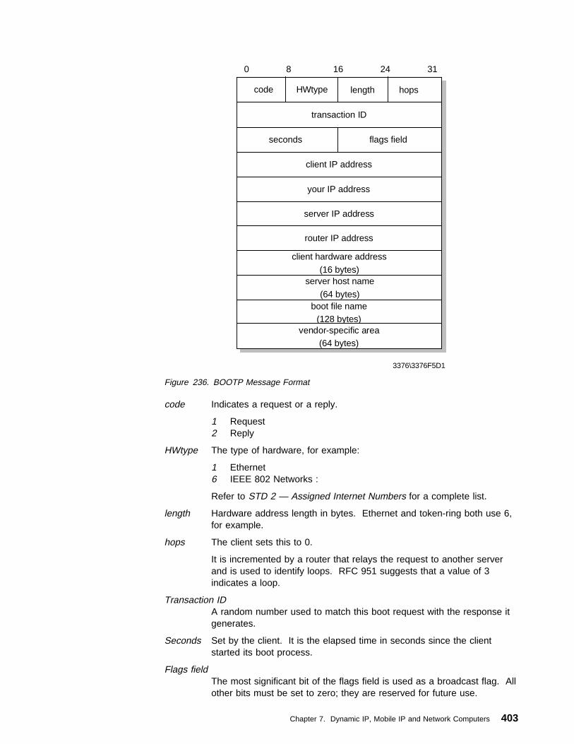
code length
3376\3376F5D1
0 8 16 24 31
HWtype hops
transaction ID
client IP address
your IP address
server IP address
seconds flags field
router IP address
client hardware address
(16 bytes)server host name
(64 bytes)boot file name
(128 bytes)vendor-specific area
(64 bytes)
Figure 236. BOOTP Message Format
code Indicates a request or a reply.
1 Request2 Reply
HWtype The type of hardware, for example:
1 Ethernet6 IEEE 802 Networks :
Refer to STD 2 — Assigned Internet Numbers for a complete list.
length Hardware address length in bytes. Ethernet and token-ring both use 6,for example.
hops The client sets this to 0.
It is incremented by a router that relays the request to another serverand is used to identify loops. RFC 951 suggests that a value of 3indicates a loop.
Transaction IDA random number used to match this boot request with the response itgenerates.
Seconds Set by the client. It is the elapsed time in seconds since the clientstarted its boot process.
Flags fieldThe most significant bit of the flags field is used as a broadcast flag. Allother bits must be set to zero; they are reserved for future use.
Chapter 7. Dynamic IP, Mobile IP and Network Computers 403

Normally, BOOTP servers attempt to deliver BOOTREPLY messagesdirectly to a client using unicast delivery. The destination address in theIP header is set to the BOOTP your IP address and the MAC address isset to the BOOTP client hardware address. If a host is unable toreceive a unicast IP datagram until it knows its IP address, then thisbroadcast bit must be set to indicate to the server that the BOOTREPLYmust be sent as an IP and MAC broadcast. Otherwise this bit must beset to zero.
Client IP addressSet by the client. Either its known IP address, or 0.0.0.0.
Your IP addressSet by the server if the client IP address field was 0.0.0.0.
Server IP addressSet by the server.
Router IP addressThis is the address of a BOOTP relay agent, not a general IP router tobe used by the client. It is set by the forwarding agent when BOOTPforwarding is being used (see 7.1.1, “BOOTP Forwarding” onpage 405).
Client hardware addressSet by the client and used by the server to identify which registeredclient is booting.
Server host nameOptional server host name terminated by X'00'.
Boot file nameThe client either leaves this null or specifies a generic name, such asrouter indicating the type of boot file to be used. The server returns thefully qualified filename of a boot file suitable for the client. The value isterminated by X'00'.
Vendor-specific areaOptional vendor-specific area. It is recommended that clients always fillthe first four bytes with a “magic cookie.” If a vendor-specific magiccookie is not used the client should use 99.130.83.99 followed by anend tag (255) and set the remaining bytes to zero. The vendor-specificarea can also contain BOOTP Vendor extensions. These are optionsthat can be passed to the client at boot time along with its IP address.For example, the client could also receive the address of a defaultrouter, the address of a domain name server and a subnet mask.BOOTP shares the same options as DHCP, with the exception ofseveral DHCP-specific options. Please see RFC 2132 for full details.
Once the BOOTP client has processed the reply, it may proceed with the transferof the boot file and execute the full boot process. See RFC 906 for thespecification of how this is done with TFTP. In the case of a diskless host, the fullboot process will normally replace the minimal IP protocol stack, loaded from ROM,and used by BOOTP and TFTP, with a normal IP protocol stack transferred as partof the boot file and containing the correct customization for the client.
404 TCP/IP Tutorial and Technical Overview
7.1.1 BOOTP ForwardingThe BOOTP client uses the limited broadcast address for BOOTP requests, whichrequires the BOOTP server to be on the same subnet as the client. BOOTPforwarding is a mechanism for routers to forward BOOTP requests across subnets.It is a configuration option available on most routers. The router configured toforward BOOTP requests is known as a BOOTP relay agent.
A router will normally discard any datagrams containing illegal source addresses,such as 0.0.0.0, which is used by a BOOTP client. A router will also generallydiscard datagrams with the limited broadcast destination address. However, aBOOTP relay agent will accept such datagrams from BOOTP clients on port 67.The process carried out by a BOOTP relay agent on receiving a BOOTPREQUESTis as follows:
1. When the BOOTP relay agent receives a BOOTPREQUEST, it first checks thehops field to check the number of hops already completed, in order to decidewhether to forward the request. The threshold for allowable number of hops isnormally configurable.
2. If the relay agent decides to relay the request, it checks the contents of therouter IP address field. If this field is zero, it fills this field with the IP addressof the interface on which the BOOTPREQUEST was received. If this fieldalready has an IP address of another relay agent, it is not touched.
3. The value of the hops field is incremented.
4. The relay agent then forwards the BOOTPREQUEST to one or more BOOTPservers. The address of the BOOTP server(s) is preconfigured at the relayagent. The BOOTPREQUEST is normally forwarded as a unicast frame,although some implementations use broadcast forwarding.
5. When the BOOTP server receives the BOOTPREQUEST with the non-zerorouter IP address field, it sends an IP unicast BOOTREPLY to the BOOTPrelay agent at the address in this field on port 67.
6. When the BOOTP relay agent receives the BOOTREPLY, the HWtype, lengthand client hardware address fields in the message supply sufficient link-layerinformation to return the reply to the client. The relay agent checks thebroadcast flag. If this flag is set, the agent forwards the BOOTPREPLY to theclient as a broadcast. If the broadcast flag is not set, the relay agent sends areply as a unicast to the address specified in your IP address.
When a router is configured as a BOOTP relay agent, the BOOTP forwarding taskis considerably different to the task of switching datagrams between subnetsnormally carried out by a router. Forwarding of BOOTP messages can beconsidered to be receiving BOOTP messages as a final destination, thengenerating new BOOTP messages to be forwarded to another destination.
7.1.2 BOOTP ConsiderationsThe use of BOOTP allows centralized configuration of multiple clients. However, itrequires a static table to be maintained with an IP address preallocated for everyclient that is likely to attach to the BOOTP server, even if the client is seldomactive. This means that there is no relief on the number of IP addresses required.There is a measure of security in an environment utilizing BOOTP, because a clientwill only be allocated an IP address by the server if it has a valid MAC address.
Chapter 7. Dynamic IP, Mobile IP and Network Computers 405

7.2 Dynamic Host Configuration Protocol (DHCP)DHCP is a draft standard protocol. Its status is elective. The current DHCPspecifications can be found in RFC 2131 — Dynamic Host Configuration Protocoland RFC 2132 — DHCP Options and BOOTP Vendor Extensions.
The Dynamic Host Configuration Protocol (DHCP) provides a framework forpassing configuration information to hosts on a TCP/IP network. DHCP is basedon the BOOTP protocol, adding the capability of automatic allocation of reusablenetwork addresses and additional configuration options. For information accordingto BOOTP please refer to 7.1, “Bootstrap Protocol (BOOTP)” on page 401. DHCPmessages use UDP port 67, the BOOTP server's well-known port and UDP port 68,the BOOTP client's well-known port. DHCP participants can interoperate withBOOTP participants. See 7.2.8, “BOOTP and DHCP Interoperability” on page 413for further details.
DHCP consists of two components:
1. A protocol that delivers host-specific configuration parameters from a DHCPserver to a host.
2. A mechanism for the allocation of temporary or permanent network addressesto hosts.
IP requires the setting of many parameters within the protocol implementationsoftware. Because IP can be used on many dissimilar kinds of network hardware,values for those parameters cannot be guessed at or assumed to have correctdefaults. The use of a distributed address allocation scheme based on apolling/defense mechanism, for discovery of network addresses already in use,cannot guarantee unique network addresses because hosts may not always beable to defend their network addresses.
DHCP supports three mechanisms for IP address allocation: address allocation
1. Automatic allocation
DHCP assigns a permanent IP address to the host.
2. Dynamic allocation
DHCP assigns an IP address for a limited period of time. Such a networkaddress is called a lease. This is the only mechanism that allows automaticreuse of addresses that are no longer needed by the host to which it wasassigned.
3. Manual allocation
The host's address is assigned by a network administrator.
7.2.1 The DHCP Message FormatThe format of a DHCP message is shown in Figure 237 on page 407:
406 TCP/IP Tutorial and Technical Overview

code length
3376\3376F5D2
0 8 16 24 31
HWtype hops
transaction ID
client IP address
your IP address
server IP address
seconds flags field
router IP address
client hardware address(16 bytes)
server host name(64 bytes)
boot file name(128 bytes)
options(312 bytes)
Figure 237. DHCP Message Format
code Indicates a request or a reply
1 Request2 Reply
HWtype The type of hardware, for example:
1 Ethernet6 IEEE 802 Networks
Refer to STD 2 — Assigned Internet Numbers for a complete list.
length Hardware address length in bytes. Ethernet and token-ring both use 6,for example.
hops The client sets this to 0. It is incremented by a router that relays therequest to another server and is used to identify loops. RFC 951suggests that a value of 3 indicates a loop.
Transaction IDA random number used to match this boot request with the response itgenerates.
Seconds Set by the client. It is the elapsed time in seconds since the clientstarted its boot process.
Flags fieldThe most significant bit of the flags field is used as a broadcast flag. Allother bits must be set to zero, and are reserved for future use.Normally, DHCP servers attempt to deliver DHCP messages directly to
Chapter 7. Dynamic IP, Mobile IP and Network Computers 407
a client using unicast delivery. The destination address in the IP headeris set to the DHCP your IP address and the MAC address is set to theDHCP client hardware address. If a host is unable to receive a unicastIP datagram until it knows its IP address, then this broadcast bit must beset to indicate to the server that the DHCP reply must be sent as an IPand MAC broadcast. Otherwise this bit must be set to zero.
Client IP addressSet by the client. Either its known IP address, or 0.0.0.0.
Your IP addressSet by the server if the client IP address field was 0.0.0.0.
Server IP addressSet by the server.
Router IP addressThis is the address of a BOOTP relay agent, not a general IP router tobe used by the client. It is set by the forwarding agent when BOOTPforwarding is being used (see 7.1.1, “BOOTP Forwarding” onpage 405).
Client hardware addressSet by the client. DHCP defines a client identifier option that is used forclient identification. If this option is not used the client is identified by itsMAC address.
Server host nameOptional server host name terminated by X'00'.
Boot file nameThe client either leaves this null or specifies a generic name, such asrouter, indicating the type of boot file to be used. In a DHCPDISCOVERrequest this is set to null. The server returns a fully qualified directorypath name in a DHCPOFFER request. The value is terminated byX'00'.
Options The first four bytes of the options field of the DHCP message containthe magic cookie (99.130.83.99). The remainder of the options fieldconsists of tagged parameters that are called options. Please see RFC2132 for details.
7.2.2 DHCP Message TypesDHCP messages fall into one of the following categories:
Message Use
DHCPDISCOVER Broadcast by a client to find available DHCP servers.
DHCPOFFER Response from a server to a DHCPDISCOVER and offeringIP address and other parameters.
DHCPREQUEST Message from a client to servers that does one of thefollowing:
� Requests the parameters offered by one of the serversand declines all other offers
� Verifies a previously allocated address after a system ornetwork change (a reboot for example)
408 TCP/IP Tutorial and Technical Overview
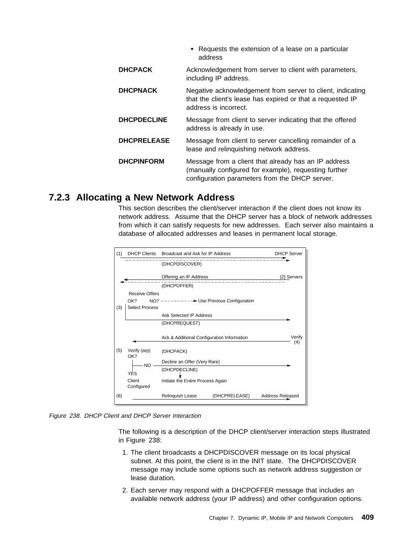
� Requests the extension of a lease on a particularaddress
DHCPACK Acknowledgement from server to client with parameters,including IP address.
DHCPNACK Negative acknowledgement from server to client, indicatingthat the client's lease has expired or that a requested IPaddress is incorrect.
DHCPDECLINE Message from client to server indicating that the offeredaddress is already in use.
DHCPRELEASE Message from client to server cancelling remainder of alease and relinquishing network address.
DHCPINFORM Message from a client that already has an IP address(manually configured for example), requesting furtherconfiguration parameters from the DHCP server.
7.2.3 Allocating a New Network AddressThis section describes the client/server interaction if the client does not know itsnetwork address. Assume that the DHCP server has a block of network addressesfrom which it can satisfy requests for new addresses. Each server also maintains adatabase of allocated addresses and leases in permanent local storage.
DHCP Clients Broadcast and Ask for IP Address DHCP Server
(DHCPDISCOVER)
Offering an IP Address
(DHCPOFFER)
Receive Offers
OK? NO? Use Previous ConfigurationSelect Process
Ask Selected IP Address
(1)
Servers(2)
(3)
(4)
(5)
(DHCPREQUEST)
Ack & Additional Configuration Information
(DHCPACK)
Decline an Offer (Very Rare)
(DHCPDECLINE)
Initiate the Entire Process Again
Verify
Client Configured
Relinquish Lease (DHCPRELEASE) Address Released(6)
Verify (arp)OK?
YES
NO
Figure 238. DHCP Client and DHCP Server Interaction
The following is a description of the DHCP client/server interaction steps illustratedin Figure 238:
1. The client broadcasts a DHCPDISCOVER message on its local physicalsubnet. At this point, the client is in the INIT state. The DHCPDISCOVERmessage may include some options such as network address suggestion orlease duration.
2. Each server may respond with a DHCPOFFER message that includes anavailable network address (your IP address) and other configuration options.
Chapter 7. Dynamic IP, Mobile IP and Network Computers 409

The servers may record the address as offered to the client to prevent thesame address being offered to other clients in the event of furtherDHCPDISCOVER messages being received before the first client hascompleted its configuration.
3. The client receives one or more DHCPOFFER messages from one or moreservers. The client chooses one based on the configuration parameters offeredand broadcasts a DHCPREQUEST message that includes the server identifieroption to indicate which message it has selected and the requested IP addressoption, taken from Your IP Address in the selected offer.
In the event that no offers are received, if the client has knowledge of aprevious network address, the client may reuse that address if its lease is stillvalid, until the lease expires.
4. The servers receive the DHCPREQUEST broadcast from the client. Thoseservers not selected by the DHCPREQUEST message use the message asnotification that the client has declined that server's offer. The server selectedin the DHCPREQUEST message commits the binding for the client topersistent storage and responds with a DHCPACK message containing theconfiguration parameters for the requesting client. The combination of clienthardware and assigned network address constitute a unique identifier for theclient's lease and are used by both the client and server to identify a leasereferred to in any DHCP messages. The Your IP Address field in theDHCPACK messages is filled in with the selected network address.
5. The client receives the DHCPACK message with configuration parameters.The client performs a final check on the parameters, for example with ARP forallocated network address, and notes the duration of the lease and the leaseidentification cookie specified in the DHCPACK message. At this point, theclient is configured.
If the client detects a problem with the parameters in the DHCPACK message(the address is already in use on the network for example), the client sends aDHCPDECLINE message to the server and restarts the configuration process.The client should wait a minimum of ten seconds before restarting theconfiguration process to avoid excessive network traffic in case of looping. Onreceipt of a DHCPDECLINE, the server must mark the offered address asunavailable (and possibly inform the system administrator that there is aconfiguration problem).
If the client receives a DHCPNAK message, the client restarts the configurationprocess.
6. The client may choose to relinquish its lease on a network address by sendinga DHCPRELEASE message to the server. The client identifies the lease to bereleased by including its network address and its hardware address.
Note: Responses from the DHCP server to the DHCP client may be broadcast orunicast, depending on whether the client is able to receive a unicastmessage before the TCP/IP stack is fully configured; this varies betweenimplementations. (See Flags field on page 408.)
410 TCP/IP Tutorial and Technical Overview

7.2.4 DHCP Lease Renewal ProcessThis section describes the interaction between DHCP servers and clients that havealready been configured and the process that ensures lease expiry and renewal.
1. When a server sends the DHCPACK to a client with IP address andconfiguration parameters, it also registers the start of the lease time for thataddress. This lease time is passed to the client as one of the options in theDHCPACK message, together with two timer values, T1 and T2. The client isrightfully entitled to use the given address for the duration of the lease time.On applying the received configuration, the client also starts the timers T1 andT2. At this time the client is in the BOUND state. Times T1 and T2 are optionsconfigurable by the server but T1 must be less than T2, and T2 must be lessthan the lease time. According to RFC 2132, T1 defaults to (0.5 * lease time)and T2 defaults to (0.875 * lease time).
2. When timer T1 expires, the client will send a DHCPREQUEST (unicast) to theserver that offered the address, asking to extend the lease for the givenconfiguration. The client is now in the RENEWING state. The server wouldusually respond with a DHCPACK message indicating the new lease time, andtimers T1 and T2 are reset at the client accordingly. The server also resets itsrecord of the lease time. In normal circumstances, an active client wouldcontinually renew its lease in this way indefinitely, without the lease everexpiring.
3. If no DHCPACK is received until timer T2 expires, the client enters theREBINDING state. It now broadcasts a DHCPREQUEST message to extendits lease. This request can be confirmed by a DHCPACK message from anyDHCP server on the network.
4. If the client does not receive a DHCPACK message after its lease has expired,it has to stop using its current TCP/IP configuration. The client may then returnto the INIT state, issuing a DHCPDISCOVER broadcast to try and obtain anyvalid address.
Figure 239 on page 412 shows the DHCP process and changing client stateduring that process.
Chapter 7. Dynamic IP, Mobile IP and Network Computers 411

AdditionalConfiguration
SELECTING
REQUESTING
BOUND
REBINDING
REBOOTING
DHCPOFFERcollect replies
INIT-REBOOT
select offerDHCPREQUEST
DHCPNACKdiscard offer
DHCPDISCOVER
T2 expiresDHCPREQUEST
DHCPINFORMnotify server,
get parameters
DHCPNACKrestart
DHCPREQUEST
DHCPOFFER,DHCPACK,DHCPNACK
discard
DHCPOFFERdiscard
T1 expiresDHCPREQUEST
DHCPACKrecord lease,
set T1, T2
DHCPACKrecord lease,
set T1, T2
DHCPACKrecord lease,
set T1, T2DHCPACK
record lease,set T1, T2
DHCPACKnot acceptable
DHCPDECLINE
INIT ExternalConfiguration
DHCPACKsupply
parameters
DHCPNACK,Lease expiredhalt network
INIT
BOUND
RENEWING
DHCPNACK,lease expireshalt network
DHCPRELEASEhalt network
Figure 239. DHCP Client State and DHCP Process
7.2.5 Reusing a Previously Allocated Network AddressIf the client remembers and wishes to reuse a previously allocated network addressthen the following steps are carried out:
1. The client broadcasts a DHCPREQUEST message on its local subnet. TheDHCPREQUEST message includes the client's network address.
2. A server with knowledge of the client's configuration parameters responds witha DHCPACK message to the client (provided the lease is still current),renewing the lease at the same time.
If the client's lease has expired, the server with knowledge of the clientresponds with DHCPNACK.
3. The client receives the DHCPACK message with configuration parameters.The client performs a final check on the parameters and notes the duration ofthe lease and the lease identification cookie specified in the DHCPACKmessage. At this point, the client is configured and its T1 and T2 timers arereset.
If the client detects a problem with the parameters in the DHCPACK message,the client sends a DHCPDECLINE message to the server and restarts theconfiguration process by requesting a new network address. If the clientreceives a DHCPNAK message, it cannot reuse its remembered networkaddress. It must instead request a new address by restarting the configurationprocess as described in 7.2.3, “Allocating a New Network Address” onpage 409.
412 TCP/IP Tutorial and Technical Overview

Note: A host should use DHCP to reacquire or verify its IP address and networkparameters whenever the local network parameters have changed, for example atsystem boot time or after a disconnection from the local network, as the localnetwork configuration may change without the host's or user's knowledge. If a clienthas multiple IP interfaces, each of them must be configured by DHCP separately.
For further information please refer to the above-mentioned RFCs.
7.2.6 Configuration Parameters RepositoryDHCP provides persistent storage of network parameters for network clients. ADHCP server stores a key-value entry for each client, the key being some uniqueidentifier, for example an IP subnet number and a unique identifier within thesubnet (normally a hardware address), and the value contains the configurationparameters last allocated to this particular client.
One effect of this is that a DHCP client will tend to always be allocated the same IPaddress by the server, provided the pool of addresses is not over-subscribed andthe previous address has not already been allocated to another client.
7.2.7 DHCP ConsiderationsDHCP dynamic allocation of IP addresses and configuration parameters relievesthe network administrator of great deal of manual configuration work. The ability fora device to be moved from network to network and to automatically obtain validconfiguration parameters for the current network can be of great benefit to mobileusers. Also, because IP addresses are only allocated when clients are actuallyactive, it is possible, by the use of reasonably short lease times and the fact thatmobile clients do not need to be allocated more than one address, to reduce thetotal number of addresses in use in an organization. However, the following shouldbe considered when DHCP is being implemented:
� DHCP is built on UDP, which is, as yet, inherently insecure. In normaloperation, an unauthorized client could connect to a network and obtain a validIP address and configuration. To prevent this, it is possible to preallocate IPaddresses to particular MAC addresses (similar to BOOTP), but this increasesthe administration workload and removes the benefit of recycling of addresses.Unauthorized DHCP servers could also be set up, sending false and potentiallydisruptive information to clients.
� In a DHCP environment where automatic or dynamic address allocation isused, it is generally not possible to predetermine the IP address of a client atany particular point in time. In this case, if static DNS servers are also used,the DNS servers will not likely contain valid host name to IP address mappingsfor the clients. If having client entries in the DNS is important for the network,one may use DHCP to manually assign IP addresses to those clients and thenadminister the client mappings in the DNS accordingly.
7.2.8 BOOTP and DHCP InteroperabilityThe format of DHCP messages is based on the format of BOOTP messages, whichenables BOOTP and DHCP clients to interoperate in certain circumstances. EveryDHCP message contains a DHCP message type (51) option. Any message withoutthis option is assumed to be from a BOOTP client.
Support for BOOTP clients at a DHCP server must be configured by a systemadministrator, if required. The DHCP Server responds to BOOTPREQUEST
Chapter 7. Dynamic IP, Mobile IP and Network Computers 413
messages with BOOTPREPLY, rather than DHCPOFFER. Any DHCP server thatis not configured in this way will discard any BOOTPREQUEST frames sent to it. ADHCP server may offer static addresses, or automatic addresses (from its pool ofunassigned addresses) to a BOOTP client (although not all BOOTPimplementations will understand automatic addresses). If an automatic address isoffered to a BOOTP client, then that address must have an infinite lease time, asthe client will not understand the DHCP lease mechanism.
DHCP messages may be forwarded by routers configured as BOOTP relay agents.
7.3 Dynamic Domain Name SystemThe Domain Name System described in 4.2, “Domain Name System (DNS)” onpage 150 is a static implementation without recommendations with regard tosecurity. In order to take advantage of DHCP, yet still to be able to locate anyspecific host by means of a meaningful label, such as its host name, the followingextensions to DNS are required:
� A method for the host name to address mapping entry for a client in thedomain name server to be updated, once the client has obtained an addressfrom a DHCP server
� A method for the reverse address to hostname mapping to take place once theclient obtains its address
� Updates to the DNS to take effect immediately, without the need forintervention by an administrator
� Updates to the DNS to be authenticated to prevent unauthorized hosts fromaccessing the network and to stop imposters from using an existing host nameand remapping the address entry for the unsuspecting host to that of its own
� A method for primary and secondary DNS servers to quickly forward andreceive changes as entries are being updated dynamically by clients
In short, a secure Dynamic Domain Name System (DDNS) is necessary.
Several RFCs relate to DDNS. These are:
RFC 2065 — DNS Security ExtensionsThe extensions described in this RFC provide for the storage of digitalsignatures and authenticated public keys in secured zones in the DNS.KEY and SIG (signature) resource record types are introduced. Threedistinct services are provided:
� Distribution of keys
� Data origin authentication (by associating digital signatures with theresource records in the DNS)
� Transaction and request authentication
The RFC makes provision for any type of key and security algorithm, butby default assumes the MD5/RSA algorithm (see 5.2, “A ShortIntroduction to Cryptography” on page 267).
RFC 2136 — Dynamic Updates in the Domain Name SystemThis RFC introduces the UPDATE DNS message format, which is usedto add or delete resource records in the DNS. The ability for updates totake effect without the DNS having to be reloaded is also described.
414 TCP/IP Tutorial and Technical Overview
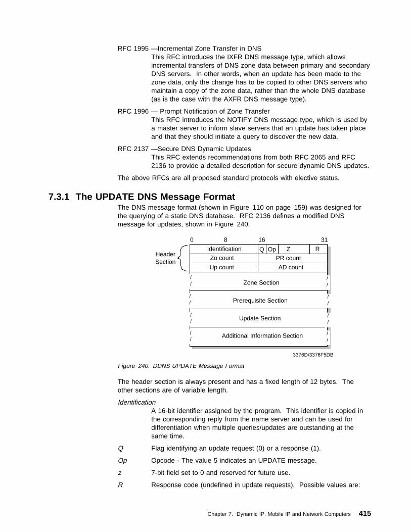
RFC 1995 —Incremental Zone Transfer in DNSThis RFC introduces the IXFR DNS message type, which allowsincremental transfers of DNS zone data between primary and secondaryDNS servers. In other words, when an update has been made to thezone data, only the change has to be copied to other DNS servers whomaintain a copy of the zone data, rather than the whole DNS database(as is the case with the AXFR DNS message type).
RFC 1996 — Prompt Notification of Zone TransferThis RFC introduces the NOTIFY DNS message type, which is used bya master server to inform slave servers that an update has taken placeand that they should initiate a query to discover the new data.
RFC 2137 —Secure DNS Dynamic UpdatesThis RFC extends recommendations from both RFC 2065 and RFC2136 to provide a detailed description for secure dynamic DNS updates.
The above RFCs are all proposed standard protocols with elective status.
7.3.1 The UPDATE DNS Message FormatThe DNS message format (shown in Figure 110 on page 159) was designed forthe querying of a static DNS database. RFC 2136 defines a modified DNSmessage for updates, shown in Figure 240.
3376D\3376F5DB
Identification Q Op Z R
Zo count PR count
Up count AD count
Zone Section
Prerequisite Section
Update Section
Additional Information Section //
//
//
//
//
//
//
//
0 8 16 31
HeaderSection
Figure 240. DDNS UPDATE Message Format
The header section is always present and has a fixed length of 12 bytes. Theother sections are of variable length.
IdentificationA 16-bit identifier assigned by the program. This identifier is copied inthe corresponding reply from the name server and can be used fordifferentiation when multiple queries/updates are outstanding at thesame time.
Q Flag identifying an update request (0) or a response (1).
Op Opcode - The value 5 indicates an UPDATE message.
z 7-bit field set to 0 and reserved for future use.
R Response code (undefined in update requests). Possible values are:
Chapter 7. Dynamic IP, Mobile IP and Network Computers 415

0 No error.
1 Format error. The server was unable to interpret themessage.
2 Server failure. The message was not processed due to aproblem with the server.
3 Name error. A name specified does not exist.
4 Not implemented. The type of message specified in Opcodeis not supported by this server.
5 Refused. The server refuses to perform the UPDATErequested for security or policy reasons.
6 Name error. A name exists when it should not.
7 RRset error. A resource record set exists when it should not.
8 RRset error. A resource record set specified does not exist.
9 Zone Authority error. The server is not authoritative for theZone specified.
10 Zone error. A name specified in the Prerequisite or Updatesections is not in the Zone specified.
ZOcount The number of RRs in the Zone section.
PRcount The number of RRs in the Prerequisite section.
UPcount The number of RRs in the Update section.
ADcount The number of RRs in the Additional Information section.
Zone sectionThis section is used to indicate the zone of the records that are to beupdated. As all records to be updated must belong to the same zone,the zone section has a single entry specifying the zone name, zone type(which must be SOA) and zone class.
Prerequisite sectionThis section contains RRs or RRsets that either must, or must not, exist,depending on the type of update.
Update sectionThis section contains the RRs and/or RRsets that are to be added to, ordeleted from the zone.
Additional information sectionThis section can be used to pass additional RRs that relate to theupdate operation in process.
For further information on the UPDATE message format, please refer to RFC 2136.
Note: The IBM implementation of DDNS uses a different UPDATE messageformat. Please see 7.3.2.5, “IBM DDNS UPDATE Message Format” onpage 424.
416 TCP/IP Tutorial and Technical Overview
7.3.2 IBM's Implementation of DDNSIBM's Dynamic Domain Name System (DDNS) is based on, and is a superset of,the Internet Software Consortium's publicly available implementation of theBerkeley Internet Name Domain (BIND) level 4.9.3 (which did not include anysecurity functions). The IBM implementation supports both static and dynamic DNSdomains. In dynamic domains, only authorized clients can update their own data.RSA public-key digital signature technology is used for client authentication.
Using IBM's DHCP Server, an administrator configures (at the server) hostconfiguration parameters, including IP address, to automate the configuration of IPhosts. The DDNS provides dynamic host name-to-IP address (and IPaddress-to-host name) mapping for dynamic IP clients. Using DDNS, when theclient receives its new address from the DHCP server, it automatically updates its Arecord on the DNS server with the new address. The IBM DHCP serverautomatically updates the PTR record on behalf of the client.
7.3.2.1 DDNS MechanismThe DDNS client program, NSUPDATE, is used to update information in a DDNSserver. Dynamic updates are performed by any of the following:
Network clientA host that has DHCP and DDNS client software and can update its Aand TXT records with the current IP address information
DHCP serverUpdates PTR records with the current host name information for theaddress it has just allocated. In certain circumstances it can alsoperform updates to A records for clients that either cannot, or do not,update the A records themselves (see 7.3.3, “Proxy A Record Update(ProxyArec)” on page 424).
DDNS system administratorA system administrator can make manual changes to all resource recordtypes in the DDNS database, or can use the NSUPDATE commandfrom a command line to make the changes. All changes take effectimmediately.
The interaction between the DDNS client, DDNS server and DHCP server is shownin Figure 241 on page 418:
Chapter 7. Dynamic IP, Mobile IP and Network Computers 417

1. Get IP address 2. Register a RR
hostname to IP address
3. Send renewal request
4. Register PTR RR IP address to hostname
DHCPServer
DHCP/DDNSClient
Return IPaddress orhostname
QueryDNS
99 PTR myhost
myhost A 9.3.1.99DDNSServer
3376\3376F5D5
Figure 241. DDNS-to-DHCP Client Interaction
Note: For ease of explanation, the DHCP and DDNS servers are shown asseparate devices in Figure 241. In practice, it is common for these twoservers to be on the same machine.
1. The DHCP makes the normal exchanges with the DHCP server to obtainconfiguration data (see 7.2.3, “Allocating a New Network Address” onpage 409).
2. The DDNS client then sends an update request, including its newly obtained IPaddress, to the DDNS server for the resource records that are associated withthe client's hostname. The client also sends its public key and signs allresource records with a digital signature. The combination of the key and thesignature verifies that this client is indeed entitled to use the hostname and thatthe information contained in the client's record is valid.
If the client's updates have been successful, the server commits the changes toits database. The client is now reachable by its hostname.
3. The DHCP client sends a lease renewal request message to the DHCP server.This message includes the hostname being used by the client. The DHCPserver updates the PTR record (IP address-to-hostname mapping) for the clienton the DDNS server. An inverse query on the client's IP address to the DDNSserver will now return the client's host name.
7.3.2.2 DDNS SecurityHaving a DHCP and DDNS server in your network allows a client to automaticallyobtain a valid, working configuration from the network and to register its presenceautomatically with the DDNS server. However, this means that withoutauthentication of the DDNS client, an unauthorized host might impersonate anunsuspecting host by copying the hostname of that client. It could then update theDDNS server with its own IP address and could then intercept data (for example,logon passwords) intended for the unsuspecting host.
IBM implements RSA digital signature technology in its DDNS server and clientcode to authenticate the owner of the DNS records and to secure the DNS
418 TCP/IP Tutorial and Technical Overview

database updates. See 5.2, “A Short Introduction to Cryptography” on page 267for more information on RSA digital signature technology. DDNS supports twomodes of securing updates for a dynamic domain, dynamic secured mode anddynamic presecured mode. Both modes protect A records in the database fromunauthorized updates.
Dynamic Secured Mode: When a DDNS client registers its host name for the firsttime, it generates an RSA key pair. A public key is sent to the DDNS server andregistered for that particular host name.
The DDNS client stores the RSA key pair (with the private key encrypted) in aclient key file. When the DDNS client updates the resource records on the DDNSserver, the digital signature is generated by using the private key and is sent to theserver with the update data. On receiving the update request, the DDNS serveruses the client's public key (in the KEY resource record) to:
� Authenticate the owner of the update request to verify that the update requestwas signed with the corresponding private key
� Verify that the data was not changed since it was signed (to verify that no oneintercepted and changed the data on the way to the name server)
In this way, only the owners of the original records, who possess the correct privatekey necessary to generate the correct digital signature, can update resourcerecords that are protected by an existing KEY resource record.
In addition, a DDNS administrator can create and use a zone key for each dynamicdomain. The zone key is the administrator's RSA key pair for a particular domain.This key enables the administrator to create, modify or delete any host's record inthe domain, regardless of who created the records. The private key is used togenerate the signature when the administrator carries out update requests and theserver examines the signature to verify that update requests are from theadministrator. The public key is registered in the domain data file as a KEYresource record for the domain. The private and public keys are stored in theadministrator's key file on the server.
The dynamic secured mode ensures that impersonation of hosts cannot occur in adomain, but it does not prevent any DDNS client with a new hostname fromobtaining a working and valid configuration for the domain. The dynamic secureddomain requires a minimal amount of configuration on the part of the administrator.
Dynamic Presecured Mode: In the presecured dynamic domain, DDNS clientsmust be pre-authorized by a DDNS administrator before they can create their namerecord. The DDNS administrator must preregister hosts and generate RSA keys foreach client. This means that in presecured mode, the KEY resource record for aclient must be already defined in the domain before an update from that client isaccepted. The DDNS administrator must also distribute the correct, correspondingkey information to each host before they create the resource records.
The presecured domain represents the most secure DNS name space available. Inaddition to preventing updates to A and PTR records from unknown orunauthenticated hosts, the DDNS server is able to log attempts at invalid updatesand the administrator can identify MAC addresses of offending clients and can takeappropriate action.
Chapter 7. Dynamic IP, Mobile IP and Network Computers 419
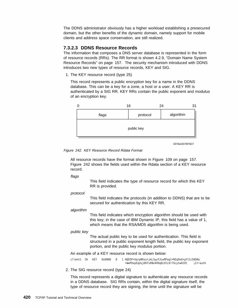
The DDNS administrator obviously has a higher workload establishing a presecureddomain, but the other benefits of the dynamic domain, namely support for mobileclients and address space conservation, are still realized.
7.3.2.3 DDNS Resource RecordsThe information that composes a DNS server database is represented in the formof resource records (RRs). The RR format is shown 4.2.9, “Domain Name SystemResource Records” on page 157. The security mechanism introduced with DDNSintroduces two new types of resource records, KEY and SIG.
1. The KEY resource record (type 25)
This record represents a public encryption key for a name in the DDNSdatabase. This can be a key for a zone, a host or a user. A KEY RR isauthenticated by a SIG RR. KEY RRs contain the public exponent and modulusof an encryption key.
flags
public key
0 123456789101112131415161718192021222324 25262728293031
algorithmprotocol
3376a\3376F5D7
Figure 242. KEY Resource Record Rdata Format
All resource records have the format shown in Figure 109 on page 157.Figure 242 shows the fields used within the Rdata section of a KEY resourcerecord.
flagsThis field indicates the type of resource record for which this KEYRR is provided.
protocolThis field indicates the protocols (in addition to DDNS) that are to besecured for authentication by this KEY RR.
algorithmThis field indicates which encryption algorithm should be used withthis key; in the case of IBM Dynamic IP, this field has a value of 1,which means that the RSA/MD5 algorithm is being used.
public keyThe actual public key to be used for authentication. This field isstructured in a public exponent length field, the public key exponentportion, and the public key modulus portion.
An example of a KEY resource record is shown below:
client1 IN KEY ðxðððð ð 1 AQO3P+UqipNXsuijeL3yyfJLw9PagI+NZg9oXrgYI1cSKOAo
+WwPOxpEqUsjðhFsKNo4Vðq6LH1LKl7XcytwAIð1 ;Cr=auth
2. The SIG resource record (type 24)
This record represents a digital signature to authenticate any resource recordsin a DDNS database. SIG RRs contain, within the digital signature itself, thetype of resource record they are signing, the time until the signature will be
420 TCP/IP Tutorial and Technical Overview

valid, the time when the RR was signed, and the original time to live (TTL)value for the RR being signed.
3376a\3376F5D8
type covered
0 123456789101112131415161718192021222324 25262728293031
labelsalgorithm
original TTL
signature expiration
time signed
signer's name
key footprint
signature
Figure 243. SIG Resource Record Rdata Format
Figure 243 shows the fields used within the Rdata section of a SIG resourcerecord.
type coveredThis field indicates the type of RR covered by this signature.
algorithmThis field indicates which encryption algorithm should be used withthis key; in the case of IBM Dynamic IP, this field has a value of 1,which means that the RSA/MD5 algorithm is being used.
labelsThis field indicates the number of labels (host and domain namestrings separated by dots) in the SIG owner name.
original TTLThe original time to live for the signed resource record is included inorder to avoid caching name servers to decrement this value. Thisvalue is protected by the signature, and it is different from the TTLof the SIG record itself.
signature expirationThe time until which this signature is valid. This value is representedin a number of seconds starting from 1 January 1970, GMT(ignoring leap seconds).
time signedThe time when this signature was actually signed, represented in thesame format as mentioned above.
key footprintThis field determines, depending on the applicable encryptionalgorithm, how to decode the signature.
Chapter 7. Dynamic IP, Mobile IP and Network Computers 421
signer's nameThe fully qualified domain name of the signer generating this SIGRR.
signatureThe actual digital signature that authenticates an RR of the typeindicated in the type covered field.
An example of a SIG resource record is shown below:
466ð IN SIG KEY 1 4 466ð 82ð47ð267 817356268 ðx8dðð client1.test.itsc.austin.ibm.com
ecK2L1zhtyVnNrI24/Viitl41reduDy7TU8dxSCoGoc9zc4IIGEy4E4uVPu
d4fjessH8XS+H2UVjLXhr66y6Gg== ;Cr=auth
To keep data traffic and memory requirements in the DDNS server as small aspossible, public encryption keys and digital signatures are converted to stringsusing a hash function, and they are then represented in so-called base-64 format.
Note: KEY and SIG resource records always use a single line. We have indentedthe examples for illustration purposes only.
7.3.2.4 IBM Implementation in Relation to Current StandardsIBM implemented Dynamic DNS in 1995. This implementation was done by IBMresearch based on an Internet draft being discussed in the IETF at that time. Intheir opinion, the protocol was going to become a standard in a very short time. Itis important to note that the IETF only standardizes protocol on the wire. The keymanagement policies and the integration of DHCP & DDNS are IBM design, whichis what differentiates an integrated product from a pure technology (such as anRFC-proposed standard).
The IETF did not standardize the draft from which IBM research worked. Thatstandard evolved into the current RFC 2137 (Secure Dynamic Updates). Itsresource records in the DNS are almost identical to IBM's implementation.However, the protocol on the wire is different. Also, it deals with the issue ofintegrating dynamic updates into secure DNS resolving (RFC 2065) and describestwo modes of operation, Mode A and Mode B. In Mode A, the client-signed RRsare stored as part of the DNS data, whereas in Mode B, the server signs all therecords. The IBM implementation of DDNS is actually very close to Mode A(although does not yet support the secure resolving described in RFC 2065).
The current version of BIND (8.1.1.) includes DDNS function based on RFC 2136and includes no security for dynamic updates.
There is also another Internet draft that proposes a secure method of dynamicupdates - Secret Key Transaction Signatures for DNS (TSIG). This draft may befound at:
http://www.ietf.org/internet-drafts/draft-ietf-dnsind-tsig-ð5.txt
TSIG uses shared secrets rather than public key cryptography to securecommunication between the name server and a client. It seeks to be a simpleralternative to both RFC 2065 for secure resolving and RFC 2137 for dynamicupdates, in those situations where the client and the server can establish a trustrelationship. This is the mechanism Microsoft will use in Windows NT 5.0.
The following summary describes how IBM's implementation of Dynamic IP isdifferent from the RFCs and also explains the reasons for that:
422 TCP/IP Tutorial and Technical Overview
IBM DDNS versus RFC 2137The logical evolution of IBM's implementation would be to move towardsthe RFC 2137 mechanism. This would not gain IBM any additionalfunctionality but would ensure that IBM's DDNS clients and serverswould maintain compatibility with software from other vendors complyingwith RFC 2137. This would become important if other vendors weredeveloping clients or servers with this capability. At the current time, toour knowledge, no other vendor has a DDNS client or server thatcomplies with RFC 2137, so making this change at this time would notbe of any practical advantage to IBM.
IBM DDNS versus RFC 2136RFC 2136 was not designed for any authentication or expiration ofresource records. It was also not designed for clients updating the DNSrecords. Its main design point was to allow administrators to updatecertain records without having to recycle the DNS. Thus it does not havethe following capabilities that are essential for the IBM integratedproduct:
1. No real security mechanism. It is possible to configure a list of IPaddresses from where update requests to any record in the systemcan originate (per zone). Not only is this mechanism unsecure (thatis, anyone who has update capability can update anyone else'srecord), it is not scalable.
2. No mechanism of expiration. Thus if a DHCP client was allocated anaddress and then moved away from the network, the DHCP server'sIP address lease would expire after a period of time and theaddress would get reused, but the DNS entry would have to bemanually removed.
3. No mechanism to detect out-of order update requests or preventreplay attacks. (No time stamp is associated with the updaterequest.)
IBM DDNS verus T-SigT-Sig accomplishes the goal of providing an authentication mechanismfor updates from clients. But it still does not provide an expirationmechanism. This means that if a client created its A-RR, and movedaway from the network for some period of time. The PTR record createdby the DHCP server could be deleted by it but the A-RR (the hostnameto IP address mapping) would remain in the DNS. This has a securityimplication, because data intended for the old hostname would beforwarded to the new holder of the IP address.
T-Sig also has scalability issues, since the shared secret keys aretheoretically unique between every client-name server pair and must bepredefined in each.
T-Sig does have a time stamp associated with its update requests, butsince these time stamps are not stored with the data updated, it isquestionable how out-of-order update requests or replay attacks couldbe effectively detected/prevented.
Chapter 7. Dynamic IP, Mobile IP and Network Computers 423

7.3.2.5 IBM DDNS UPDATE Message FormatThe IBM implementation of DDNS uses the UPDATE message format shown inFigure 244.
3376D\3376F5DC
Identification Q Op Z R
Zone Authority Section
Delete Section
Addnamenew Section
Addnameexist Section
//
//
//
//
//
//
//
//
Add Section
0 8 16 31
Header
//
//
Figure 244. IBM DDNS UPDATE Message Format
The IBM message has a 32-bit header, which is identical to the first 32 bits of theRFC 2136 format header (see Figure 240 on page 415). However, there are no“count” sections in the header. A response consists of the header only.
The body of an UPDATE message contains one or more of the following sections.Each section consists of a 1-byte type code, followed by a 1-byte count field (inunits of RRs), followed by the RRs themselves.
ZONEAUTHORITYThis contains the SOA RR of the zone that is to be updated. There mayonly be one ZONEAUTHORITY section and it is always the first sectionin the body of the message.
DELETE Used to specify RRs that are to be deleted.
ADDNAMENEWUsed to add an RR with a new name.
ADDNAMEEXISTUsed to update RRs with existing names.
ADD Used for adding records with either new or existing names.
With the exception of the ZONEAUTHORITY section, sections in the body of themessage may appear multiple times and in any order.
7.3.3 Proxy A Record Update (ProxyArec)In a DDNS environment, the client workstation requires DDNS client code to beable to update its A record on the DDNS server. The DHCP Server updates thePTR record at the DDNS server on behalf of the client.
An alternative approach is for the DHCP server to update both the PTR record andthe A record at the DDNS server. This process is known as Proxy A RecordUpdate (ProxyArec) and ProxyArec can be utilized in a situation where clients
424 TCP/IP Tutorial and Technical Overview

support DHCP but do not have DDNS client code. ProxyArec is discussed in theInternet draft Interaction between DHCP and DNS, which may be found at:
http://www.ietf.org/internet-drafts/draft-ietf-dhc-dhcp-dns-ð8.txt
When using ProxyArec, the DDNS server cannot carry out an RSA authenticationcheck on the client for which an update is being made; there is no interactionbetween the client and the DDNS server.
ProxyArec can be used in a situation where:
� Hosts are not mobile, or at least do not move from one domain to another.
� If mobile hosts have to be accommodated, then all the DHCP servers acrosswhich ProxyArec mobile hosts roam must be configured with the same RSApublic/private key pair, otherwise the digital signature verification would fail.
� The client host's DHCP program is capable of sending its fully qualified domainname (FQDN) to the DHCP server, using DHCP options 12 and 15 or 81.
� Hostname hijacking is not a security concern.
The Internet draft specifies the new DHCP option 81 for use with ProxyArec.Option 81 has the following format:
Code Length Flags Rcode1 Rcode2 FQDN
81
3376\3376F5D6
n 00 00 00
Figure 245. DHCP Option 81 Format
FlagsHas the following values:
0 Client wants to retain responsibility for updating A record onDDNS server
1 Client wants DHCP server to update A records
3 DHCP server informs client that server assumesresponsibility for A record updates (even if client wants to beresponsible for update)
The default value is 1.
Rcode1 and Rcode2Used by DHCP server to inform a DHCP client of the response code(s)from DDNS update.
FQDNFully qualified domain name of client.
A DHCP client does not necessarily need to support option 81 in order to takeadvantage of ProxyArec, provided it uses options 12 and/or 15 to pass thehostname to the DHCP server.
Chapter 7. Dynamic IP, Mobile IP and Network Computers 425

7.3.3.1 Using DDNS and ProxyArec TogetherIn a mixed environment with both DDNS clients and clients that support DHCPonly, if the DHCP server is configured for ProxyArec, the DDNS clients must bemanually configured with option 81 and with Flags=0 if you wish the DDNS clientsto carry out their own (secure) updates, otherwise the DHCP server will carry out allA record updates.
7.3.3.2 IBM Implementation of ProxyArecIBM have implemented an enhancement of ProxyArec that introduces a level ofsecurity. The DHCP server can be configured as being in “ProxyArec Protected”mode. In this mode, the DHCP server maintains a record of the MAC address ofthe client for which it created an A record initially. In a subsequent request for anupdate to the A record, the DHCP server checks the MAC address of the clientbefore making the update. This gives some security against hostnameimpersonation.
7.4 Mobile IPIn the DHCP and DDNS environment, DHCP provides a device with a valid IPaddress for the point at which it is attached to the network. DDNS provides amethod of locating that device by its host name, no matter where that devicehappens to be attached to a network and what IP address it has been allocated.An alternative approach to the problem of dealing with mobile devices is provided inRFC 2002 — IP Mobility Support. IP Mobility Support, commonly referred to asMobile IP, is a proposed standard, with a status of elective.
7.4.1 Mobile IP OverviewMobile IP allows a device to maintain the same IP address (its home address)wherever it attaches to the network. (Obviously, a device with an IP addressplugged into the wrong subnet will normally be unreachable.) However, the mobiledevice also has a care-of address, which relates to the subnet where it is currentlylocated. The care-of address is managed by a home agent, which is a device onthe home subnet of the mobile device. Any packet addressed to the IP address ofthe mobile device is intercepted by the home agent and then forwarded on to thecare-of address through a tunnel. Once it arrives at the end of the tunnel, thedatagram is delivered to the mobile device. The mobile node generally uses itshome address as the source address of all datagrams that it sends.
Mobile IP can help resolve address shortage problems and reduce administrativeworkload, because each device that needs to attach to the network at multiplelocations requires a single IP address only.
The following terminology is used in a mobile IP network configuration:
Home AddressThe static IP address allocated to a mobile node. It does notchange no matter where the node attaches to the network.
Home NetworkA subnet with a network prefix matching the home address of themobile node. Datagrams intended for the home address of themobile node will always be routed to this network.
426 TCP/IP Tutorial and Technical Overview
TunnelThe path followed by an encapsulated datagram.
Visited NetworkA network to which the mobile node is connected, other than thenode's home network.
Home AgentA router on the home network of the mobile node that maintainscurrent location information for the node and tunnels datagrams fordelivery to the node when it is away from home.
Foreign AgentA router on a visited network that registers the presence of amobile node and detunnels and forwards datagrams to the nodethat have been tunneled by the mobile node's home agent.
7.4.2 Mobile IP OperationMobility agents (home agents and foreign agents) advertise their presence on thenetwork by means of agent advertisement messages, which are ICMP routeradvertisement messages with extensions (see 7.4.3, “Mobility Agent AdvertisementExtensions” on page 428). A mobile node may also explicitly request one of thesemessages with an agent solicitation message. When a mobile node connects tothe network and receives one of these messages, it is able to determine whether itis on its home network or a foreign network. If the mobile node detects that it is onits home network, it will operate normally, without the use of mobility services. Inaddition, if it has just returned to the home network, having previously been workingelsewhere, it will deregister itself with the home agent. This is done through theexchange of a registration request and registration reply.
f, however, the mobile node detects from an agent advertisement that it hasmoved to a foreign network, then it obtains a care-of address for the foreignnetwork. This address may be obtained from the foreign agent (a foreign agentcare-of address, which is the address of the foreign agent itself), or it may beobtained by some other mechanism such as DHCP (in which case it is known as aco-located care-of address). The use of co-located care-of addresses has theadvantage that the mobile node does not need a foreign agent to be present atevery network that it visits, but it does require that a pool of IP addresses is madeavailable for visiting mobile nodes by the DHCP server.
Note that communication between a mobile node and a foreign agent takes placeat the link layer level. It cannot use the normal IP routing mechanism, because themobile node's IP address does not belong to the subnet in which it is currentlylocated.
Once the mobile node has received its care-of address, it needs to register itselfwith its home agent. This may be done through the foreign agent, which forwardsthe request to the home agent, or directly with the home agent (see 7.4.4, “MobileIP Registration Process” on page 430).
Once the home agent has registered the care-of address for the mobile node in itsnew position, any datagram intended for the home address of the mobile node isintercepted by the home agent and tunneled to the care-of address. The tunnelendpoint may be at a foreign agent if the mobile node has a foreign agent care-of
Chapter 7. Dynamic IP, Mobile IP and Network Computers 427
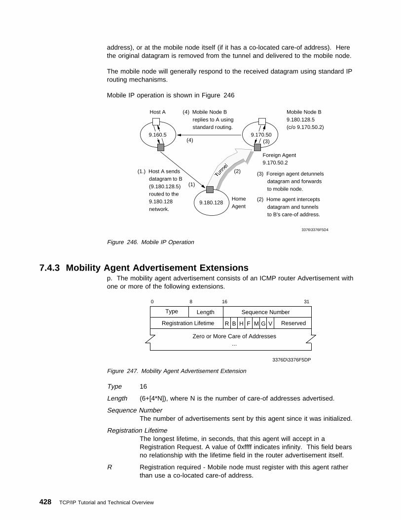
address), or at the mobile node itself (if it has a co-located care-of address). Herethe original datagram is removed from the tunnel and delivered to the mobile node.
The mobile node will generally respond to the received datagram using standard IProuting mechanisms.
Mobile IP operation is shown in Figure 246
(1.) Host A sends datagram to B (9.180.128.5) routed to the 9.180.128 network.
(4) Mobile Node B replies to A using standard routing.
Mobile Node B9.180.128.5(c/o 9.170.50.2)
Foreign Agent9.170.50.2
(3) Foreign agent detunnels datagram and forwards to mobile node.
(2) Home agent intercepts datagram and tunnels to B's care-of address.
(4)
(2)
Host A
9.160.5 9.170.50(3)
9.180.128HomeAgent
(1)
3376\3376F5D4
Figure 246. Mobile IP Operation
7.4.3 Mobility Agent Advertisement Extensionsp. The mobility agent advertisement consists of an ICMP router Advertisement withone or more of the following extensions.
3376D\3376F5DP
Type Length Sequence Number
Registration Lifetime Reserved
Zero or More Care of Addresses...
R B H F M G V
0 8 16 31
Figure 247. Mobility Agent Advertisement Extension
Type 16
Length (6+[4*N]), where N is the number of care-of addresses advertised.
Sequence NumberThe number of advertisements sent by this agent since it was initialized.
Registration LifetimeThe longest lifetime, in seconds, that this agent will accept in aRegistration Request. A value of 0xffff indicates infinity. This field bearsno relationship with the lifetime field in the router advertisement itself.
R Registration required - Mobile node must register with this agent ratherthan use a co-located care-of address.
428 TCP/IP Tutorial and Technical Overview

B Busy - Foreign agent cannot accept additional registrations.
H Home Agent - This agent offers service as a home agent on this link.
F Foreign Agent - This agent offers service as a foreign agent on this link.
M Minimal encapsulation - This agent receives tunneled datagrams thatuse minimal encapsulation.
G GRE encapsulation - This agent receives tunneled datagrams that useGRE encapsulation.
V Van Jacobson header compression - This agent supports use of VanJacobson header compression over the link with any registered mobilenode.
Reserved This area ignored.
Care-of Address(es)The care-of address(es) advertised by this agent. At least one must beincluded if the F bit is set.
Note that a foreign agent may be too busy to service additional mobile nodes atcertain times. However, it must continue to send agent advertisements (with the Bbit set) so that mobile nodes that are already registered will know that the agenthas not failed or that they are still in range of the foreign agent.
3376D\3376F5DQ
0
Op code TC RD RA zero Rcode
8 16 24
Type Length Prefix Length ..
Figure 248. Prefix-Lengths Extension
Type19
LengthThe number of router address entries in the router advertisement portionof the agent advertisement.
Prefix Length(s)The number of leading bits that make up the network prefix for each ofthe router addresses in the router advertisement portion of the agentadvertisement. Each prefix length is a separate byte, in the order thatthe router addresses are listed.
The prefix lengths extension may follow the mobility agent advertisement extension.It is used to indicate the number of bits that should be applied to each routeraddress (in the ICMP router advertisement portion of the message), when networkprefixes are being used for move detection (see 7.4.7, “Move Detection” onpage 433).
Chapter 7. Dynamic IP, Mobile IP and Network Computers 429

7.4.4 Mobile IP Registration ProcessRFC 2002 defines two different procedures for mobile IP registration. The mobilenode may register via a foreign agent, which relays the registration to the mobilenode's home agent, or it may register directly with its home agent. The followingrules are used to determine which of these registration processes is used:
� If the mobile node has obtained its care-of address from a foreign agent, itmust register via that foreign agent.
� If the mobile node is using a co-located care-of address, but has received anagent advertisement from a foreign agent on this subnet, which has the R bit(registration required) set in that advertisement, then it should register via theagent. This mechanism allows for accounting to take place on foreign subnets,even if DHCP and co-located care-of address is the preferred method ofaddress allocation.
� If the mobile node is using a co-located care-of address but has not receivedsuch an advertisement, it must register directly with its home agent.
� If the mobile node returns to its home network, it must (de)register directly withits home agent.
The registration process involves the exchange of registration request andregistration reply messages, which are UDP datagrams. The registration request issent to port 434. The request consists of a UDP header, followed by the fieldsshown in Figure 249:
3376a\3376F5D9
S
0 123456789101112131415161718192021222324 25262728293031
lifetime
home address
home agent
care-of address
DB M G V rsvtype
identification
extensions
Figure 249. Mobile IP - Registration Request
Type 1
S Simultaneous bindings - If this bit is set, the home agent should keepany previous bindings for this node as well as adding the new binding.The home agent will then forward any datagrams for the node tomultiple care-of addresses. This capability is intended particularly forwireless mobile nodes.
B Broadcast datagrams - If this bit is set, the home agent should tunnelany broadcast datagrams on the home network to the mobile node.
430 TCP/IP Tutorial and Technical Overview

D Decapsulation by mobile node - The mobile node is using a co-locatedcare-of address and will, itself, decapsulate the datagrams sent to it.
M Minimal encapsulation should be used for datagrams tunneled to themobile node.
G GRE encapsulation should be used for datagrams tunneled to themobile node.
V Van Jacobson compression should be used over the link between agentand mobile node.
rsv Reserved bits - Sent as zero.
Lifetime The number of seconds remaining before the registration will beconsidered expired. A value of zero indicates a request forderegistration. 0xffff indicates infinity.
Home AddressThe home IP address of the mobile node.
Home AgentThe IP address of the mobile node's home agent.
Care-of AddressThe IP address for the end of the tunnel.
Identification64-bit identification number constructed by the mobile node and used formatching registration requests with replies.
ExtensionsA number of extensions are defined, all relating to authentication of theregistration process. Please see RFC 2002 for full details.
The mobility agent responds to a registration request with a registration reply, witha destination port copied from the source port of the registration request. Theregistration reply is of the format shown in Figure 250:
type code lifetime
3376a\3376F5DA
home address
home agent
identification
extensions
Figure 250. Mobile IP - Registration Reply
Type 3
Code Indicates the result of the registration request.
0 Registration accepted.1 Registration accepted, but simultaneous bindings
unsupported.64-88 Registration denied by foreign agent.
Chapter 7. Dynamic IP, Mobile IP and Network Computers 431

128-136 Registration denied by home agent.
Lifetime The number of seconds remaining before the registration is consideredexpired. (Code field must be 0 or 1.)
Home AddressHome IP address of the mobile node.
Home AgentIP address of the mobile node's home agent.
Identification64-bit identification number used for matching registration requests withreplies.
ExtensionsA number of extensions are defined, all relating to authentication of theregistration process.
For full details of these messages, please refer to RFC 2002.
7.4.5 TunnelingThe home agent examines the destination IP address of all datagrams arriving onthe home network. If the address matches with any of the mobile nodes currentlyregistered as being away from home, then the home agent tunnels (using IP in IPencapsulation) the datagram to the care-of address for that mobile node. It is likelythat the home agent will also be a router on the home network. In this case it islikely that it will receive datagrams addressed for a mobile node that is not currentlyregistered as being away from home. In this case, the home agent assumes thatthe mobile node is at home, and forwards the datagram to the home network.
When a foreign agent receives a datagram sent to its advertised care-of address, itcompares the inner destination address with its list of registered visitors. If it finds amatch, the foreign agent forwards the decapsulated datagram to the appropriatemobile node. If there is no match, the datagram is discarded. (The foreign agentmust not forward such a datagram to the original IP header, otherwise a routingloop will occur.)
If the mobile node is using a co-located care-of address, then the end of the tunnellies at the mobile node itself. The mobile node is responsible for decapsulating thedatagrams received from the home agent.
7.4.6 Broadcast DatagramsIf the home agent receives a broadcast datagram, it should not forward it to mobilenodes unless the mobile node specifically requested forwarding of broadcasts in itsregistration request. In this case, it will forward the datagram in one of the followingmanners:
� If the mobile node has a co-located care-of address, the home agent simplyencapsulates the datagram and tunnels it directly to the care-of address.
� If the mobile node has a foreign agent care-of address, the home agent firstencapsulates the broadcast in a unicast datagram addressed to the homeaddress of the node. It then encapsulates and tunnels this datagram to thecare-of address. In this way the foreign agent, when it decapsulates thedatagram, knows to which of its registered mobile nodes it should forward thebroadcast.
432 TCP/IP Tutorial and Technical Overview

7.4.7 Move DetectionMobile IP is designed not just for mobile users who regularly move from one site toanother and attach their laptops to different subnets each time, but also for trulydynamic mobile users (for example, users of a wireless connection from anaircraft). Two mechanisms are defined that allow the mobile node to detect when ithas moved from one subnet to another. When the mobile node detects that it hasmoved, it must re-register with a care-of address on the new foreign network. Thetwo methods of move detection are as follows:
1. Foreign agents are consistently advertising their presence on the network bymeans of agent advertisements. When the mobile node receives an agentadvertisement from its foreign agent, it starts a timer based on the lifetime fieldin the advertisement. If the mobile node has not received anotheradvertisement from the same foreign agent by the time the lifetime has expired,then the mobile node assumes that it has lost contact with that agent. If in themeantime it has received an advertisement from another foreign agent, it mayimmediately attempt registration with the new agent. If it has not received anyfurther agent advertisements, it should use Agent solicitation to try and locate anew foreign agent with which to register.
2. The mobile node checks whether any newly received agent advertisement is onthe same subnet as its current care-of address. If the network prefix isdifferent, the mobile node assumes that it has moved. On expiry of its currentcare-of address, the mobile node registers with the foreign agent that sent thenew agent advertisement.
7.4.7.1 Returning HomeWhen the mobile node receives an agent advertisement from its own home agent,it knows that it has returned to its home network. Before deregistering with thehome agent, the mobile node must configure its routing table for operation on thehome subnet.
7.4.8 ARP ConsiderationsMobile IP requires two extensions to ARP to cope with the movement of mobilenodes. These are:
Proxy ARPAn ARP reply sent by one node on behalf of another that is eitherunable or unwilling to answer ARP request on its own behalf.
Gratuitous ARPAn ARP packet sent as a local broadcast packet by one node thatcauses all receiving nodes to update an entry in their ARP cache.
When a mobile node is registered as being on a foreign network, its home agentwill use proxy ARP in response to any ARP request seeking the mobile node'sMAC address. The home agent responds to the request giving its own MACaddress.
When a mobile node moves from its home network and registers itself with aforeign network, the home agent does a gratuitous ARP broadcast to update theARP caches of all local nodes on the network. The MAC address used is again theMAC address of the home agent.
Chapter 7. Dynamic IP, Mobile IP and Network Computers 433

When a mobile node returns to its home network, having been previously registeredat a foreign network, gratuitous ARP is again used to update ARP caches of alllocal nodes, this time with the real MAC address of the mobile node.
7.4.9 Mobile IP Security ConsiderationsThe mobile computing environment has many potential vulnerabilities with regard tosecurity, particularly if wireless links are in use, which are particularly exposed toeavesdropping. The tunnel between a home agent and the care-of address of amobile node could also be susceptible to interception, unless a strongauthentication mechanism is implemented as part of the registration process. RFC2002 specifies implementation of keyed MD5 for the authentication protocol andadvocates the use of additional mechanisms (such as encryption) for environmentswhere total privacy is required.
7.5 IP MasqueradingOne way to combat an IP address shortage is to avoid assigning addresses in thefirst place. Yet without an IP address, no system can communicate on a TCP/IPnetwork.
IP masquerading allows you to effectively share one IP address among severaldifferent systems while still providing reliable, full function TCP/IP connections toevery host. This technique can be used to provide Internet service to more thanone computer using a single dial-up connection from an Internet Service Provider(ISP) for example. Or, you may wish to link branch office systems to yourcompany's network without assigning IP addresses from your company's mainaddress pool.
In practice, an IP address is assigned to each host that needs to communicate onthe TCP/IP network, but the addresses are from a private network pool, such as theClass A network 10. A masquerading gateway accepts connection requests fromthese private hosts and translates them into requests originating from the IPaddress of the gateway itself. Responses from the TCP/IP network are then routedby the gateway back to the correct host on the private network. As a result, asingle IP address on a network can effectively serve several different hosts withoutrequiring additional IP address assignments on that same network.
There are currently no RFCs or IETF drafts that cover IP masquerading. However,IP masquerading is implemented in certain routers and is available for severalsoftware platforms.
7.6 The Network ComputerAn alternative approach to solving the problem of a mobile workforce is not to tryand cope with the addressing issues of users' machines being moved around theorganization, but to provide fixed workstations around the organization that allowany user to access their own data and applications from anywhere. This is theprinciple of the network computer.
In general terms, a network computer is usually a microprocessor-based systemwith:
� Local memory (NVRAM)
434 TCP/IP Tutorial and Technical Overview

� No disk (neither hard drive nor diskette)
� Some form of network connection
� Terminal emulation capabilities
� IP-based protocols, such as:
– TCP
– FTP
– Telnet
– NFS
� A Web browser
� A Java Virtual Machine (see 8.5, “Java” on page 449)
In short, a network computer can be thought of as a smart terminal.
All of the software required by a network computer, including the operating system,is stored on a server in the network and downloaded on demand when the networkcomputer is powered on or when the user activates new functions.
The network computer stores only sufficient code in its own local NVRAM (the bootmonitor program) to be able to make a BOOTP or DHCP connection to a server, inorder to be able to download its operating system kernel. Download of theremainder of the operating system is then carried out using TFTP or NFS,depending upon implementation and configuration.
Typically, having powered on a network computer, a user is presented with a logonpanel. On completion of a successful logon, the user is presented with apersonalized desktop with his or her own set of application icons. Selection of anyof those icons causes an application to be downloaded from a server. (Severaldifferent servers may be accessed.)
The network computer relies on TCP/IP protocols for all of its connectivity. As wellas using NFS or TFTP to download applications, the applications themselves, ifthey require communication, will use TCP/IP. SNA emulators, for example, useTN3270 or TN5250 as appropriate.
Although the network computer is not, typically, based on an Intel processor, it isable to access Windows applications on a Windows Terminal Server or CitrixSystems Metaframe, by loading an ICA (independent console architecture) client.In this case, processing of the Windows application is carried out on the NT serveritself and only screen changes are delivered to the client. The network computermay run applications remotely on a UNIX system, in a similar manner, bydownloading an X Window server.
Having all the network computer software stored on a server allows for centralizedmanagement and simplified updates of operating system and application code.
IBM's implementation of the network computer, the IBM Network Station, may bebooted, and managed from, Windows NT, AIX, OS/400, OS/390 and OS/2 servers.For further information on the IBM Network Station, please refer to the followingIBM Redbooks:
SG24-4954 S/390 IBM Network Station - Getting Started
Chapter 7. Dynamic IP, Mobile IP and Network Computers 435
SG24-2153 AS/400 IBM Network Station - Getting Started
SG24-2127 IBM Network Station and the Windows NT Platform
SG24-2016 IBM Network Station - RS/6000 Notebook
You may also refer to the IBM Network Station home page at:
http://www.pc.ibm.com/networkstation/
7.7 ReferencesThe following RFCs contain detailed information on dynamic and mobile IP:
� RFC 951 — Bootstrap Protocol
� RFC 1542 — Clarifications and Extensions for the Bootstrap Protocol
� RFC 2131 — Dynamic Host Configuration Protocol
� RFC 2132 — DHCP Options and BOOTP Vendor Extensions
� RFC 1995 —Incremental Zone Transfer in DNS
� RFC 1996 — Prompt Notification of Zone Transfer
� RFC 2065 — DNS Security Extensions
� RFC 2136 — Dynamic Updates in the Domain Name System
� RFC 2137 —Secure DNS Dynamic Updates
� RFC 2002 — IP Mobility Support
436 TCP/IP Tutorial and Technical Overview

Chapter 8. Internet Protocols and Applications
This chapter introduces some of the protocols and applications that have made thetask of using the Internet both easier and very popular over the past couple ofyears. In fact, World Wide Web traffic, which is mostly HTTP, has outrun FTP asusing the most bandwidth of all protocols across the Internet. Modern computeroperating systems provide Web browser applications by default, some even provideWeb servers, thus making it ever easier for end users and businesses to exploreand exploit the vast capabilities of worldwide networked computing.
8.1 The World Wide Web (WWW)The World Wide Web is a global hypertext system that was initially developed in1989 by Tim Berners Lee at the European Laboratory for Particle Physics, CERN inSwitzerland to facilitate an easy way of sharing and editing research documentsamong a geographically dispersed group of scientists.
In 1993 the Web started to grow rapidly which was mainly due to the NationalCenter for Supercomputing Applications (NCSA) developing a Web browserprogram called Mosaic, an X Windows-based application. This application providedthe first graphical user interface to the Web and made browsing more convenient.
Today there are Web browsers and servers available for nearly all platforms. Youcan get them either from an FTP site for free or buy a licensed copy. The rapidgrowth in popularity of the Web is due to the flexible way people can navigatethrough worldwide resources in the Internet and retrieve them.
The number of Web servers is also increasing rapidly and the traffic over port 80,which is the well-known port for HTTP Web servers, on the NSF backbone has hada phenomenal rate of growth too. The NSFNET, however, was converted back to aprivate research network in 1995; therefore comprehensive statistics of backbonetraffic are not as easily available anymore, if they are at all.
8.1.1 Web BrowsersGenerally, a browser is referred to as an application that provides access to a Webserver. Depending on the implementation, browser capabilities and hencestructures may vary. A Web browser, at a minimum, consists of an HTMLinterpreter and HTTP client which is used to access HTML Web pages. Besidesthis basic requirement, many browsers also support FTP, NNTP, e-mail (POP andSMTP clients), among other features, with an easy-to-manage graphical interface.Figure 251 on page 438 illustrates a basic Web browser structure.
Copyright IBM Corp. 1989, 1998 437

GraphicalUser
Interface
Driver
HTMLInterpreter
OptionalInterpreter
Transport
Layer
HTTPClient
MailClient
FTPClient
Controlleror
Dispatcher
3376E\3376F8O7
Figure 251. Structure of a Web Browser
As with many other Internet facilities, the Web uses a client/server processingmodel. The Web browser is the client component. Examples of Web browsersinclude Mosaic, Netscape Navigator, Microsoft Internet Explorer, or Sun HotJavabrowser. Web browsers are responsible for formatting and displaying information,interacting with the user, and invoking external functions, such as telnet, or externalviewers for data types that Web browsers do not directly support. Web browsershave become the "universal client" for the GUI workstation environment, in muchthe same way that the ability to emulate popular terminals such as the DEC VT100or IBM 3270 allows connectivity and access to character-based applications on awide variety of computers. Web browsers are widely available for all popular GUIworkstation platforms and are inexpensive.
438 TCP/IP Tutorial and Technical Overview

8.1.2 Web ServersWeb servers are responsible for servicing requests for information from Webbrowsers. The information can be a file retrieved from the server's local disk, or itcan be generated by a program called by the server to perform a specificapplication function.
There are a number of public-domain Web servers available for a variety ofplatforms including most UNIX variants, as well as personal computer environmentssuch as OS/2 Warp and Windows NT. Some well-known public domain servers areCERN, NCSA httpd, and Apache servers.
IBM has released the Domino Go Webserver, a scalable, high-performance Webserver that is available on OS/390 as Version 5 (including WebSphere ApplicationServer as described in 8.6.4.2, “IBM Web Application Servers” on page 458).Domino Go Webserver V4.6.2.5 is available on many workstation platforms (AIX,Solaris, HP-UX, OS/2 Warp, Windows NT, and Windows 95). Both versionsprovide state-of-the-art security, site indexing capabilities, advanced server statisticsreporting, PICS support, and relational database connectivity with Net.Data (see8.6.4.1, “IBM Web Connectors” on page 457). Domino Go Webserver is thesuccessor to IBM's well-known Internet Connection Secure Server (ICSS), and it isa Java-enabled Web server that supports the development and running of servlets(see 8.5, “Java” on page 449).
8.1.3 Web Server Application TechnologiesAs mentioned earlier, Web server can serve static (mere HTML pages) or dynamic(generated by a program upon invocation) content. This section discusses somecommonly used technologies used to provide dynamic content and to facilitateinteraction between a Web server and an application server that is not directlyaccessible to a client (Web browser).
8.1.3.1 Common Gateway Interface (CGI)The Common Gateway Interface (CGI) is a means of allowing a Web server toexecute a program that is provided by the Web server administrator, rather thanretrieving a file. CGI programs allow a Web server to generate a dynamicresponse, usually based on the client's input. A number of popular Web serverssupport the CGI, and a variety of programming languages can be used to developprograms that interface with CGI. Unless using PERL, however, CGI programs arenot easily portable across platforms.
8.1.3.2 Server-Specific APIsSome Web servers offer specific APIs that allow developers to create programsthat can be invoked for special purposes upon certain events. Those APIs areusually quite powerful but offer no portability across Web server platforms. Themost popular server-specific APIs are Netscape Server API (NSAPI) and MicrosoftInternet Information Server API (ISAPI).
8.1.3.3 ServletsBased on Java, this technology allows the invocation of a Java program in theserver's memory. This method is usually very portable across platforms and incurslittle processing overhead. See 8.5, “Java” on page 449 for more details.
Chapter 8. Internet Protocols and Applications 439

8.1.3.4 Server-Side Includes (SSI)This is a technology that a Java-enabled Web server (meaning, a Web server witha servlet engine) can use to convert a section of an HTML file into an alternativedynamic portion each time the document is sent to the client's browser. Thisdynamic portion invokes an appropriate servlet and passes to it the parameters itneeds. The replacement is performed at the server and it is completely transparentto the client. Pages that use this technology have the extension .shtml instead of.html (or .htm).
8.1.3.5 Java Server Pages (JSP)This is an easy-to-use solution for generating HTML pages with dynamic content.A JSP file contains combinations of HTML tags, NCSA tags (special tags that werethe first method of implementing server-side includes), <SERVLET> tags, and JSPsyntax. JSP files have the extension .jsp. One of the many advantages of JSP isthat it enables programmers to effectively separate the HTML coding from thebusiness logic in Web pages. JSP can be used to access reusable components,such as servlets, JavaBeans, and Java-based Web applications. JSP alsosupports embedding inline Java code within Web pages.
8.2 Hypertext Transfer Protocol (HTTP)HTTP 1.1 is a proposed standard protocol. Its status is elective. It is described inRFC 2068. The older HTTP 1.0 is an informational protocol and described in RFC1945.
The hypertext transfer protocol is a protocol designed to allow the transfer ofhypertext markup language (HTML) documents (please see 8.3, “Hypertext MarkupLanguage (HTML)” on page 448). HTML is a tag language used to createhypertext documents. Hypertext documents include links to other documents thatcontain additional information about the highlighted term or subject. Suchdocuments may contain other elements apart from text, such as graphic images,audio and video clips, Java applets, and even virtual reality worlds (which aredescribed in VRML, a scripting language for that kind of elements). See 8.3,“Hypertext Markup Language (HTML)” on page 448 for more information on HTML.
8.2.1 Overview of HTTPHTTP is based on request-response activity. A client, running an application calleda browser, establishes a connection with a server and sends a request to theserver in the form of a request method. The server responds with a status line,including the message's protocol version and a success or error code, followed bya message containing server information, entity information and possible bodycontent.
An HTTP transaction is divided into four steps:
1. The browser opens a connection.2. The browser sends a request to the server.3. The server sends a response to the browser.4. The connection is closed.
On the Internet, HTTP communication generally takes place over TCP connections.The default port is TCP 80, but other ports can be used. This does not precludeHTTP from being implemented on top of any other protocol on the Internet, or on
440 TCP/IP Tutorial and Technical Overview
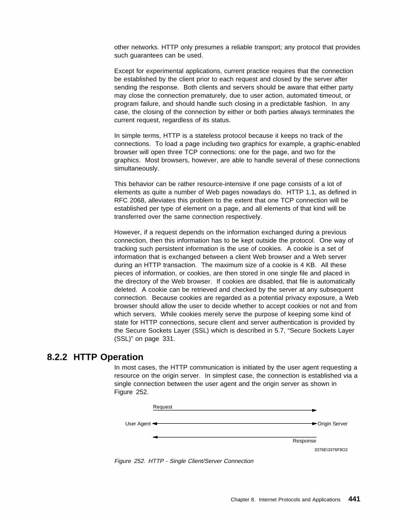
other networks. HTTP only presumes a reliable transport; any protocol that providessuch guarantees can be used.
Except for experimental applications, current practice requires that the connectionbe established by the client prior to each request and closed by the server aftersending the response. Both clients and servers should be aware that either partymay close the connection prematurely, due to user action, automated timeout, orprogram failure, and should handle such closing in a predictable fashion. In anycase, the closing of the connection by either or both parties always terminates thecurrent request, regardless of its status.
In simple terms, HTTP is a stateless protocol because it keeps no track of theconnections. To load a page including two graphics for example, a graphic-enabledbrowser will open three TCP connections: one for the page, and two for thegraphics. Most browsers, however, are able to handle several of these connectionssimultaneously.
This behavior can be rather resource-intensive if one page consists of a lot ofelements as quite a number of Web pages nowadays do. HTTP 1.1, as defined inRFC 2068, alleviates this problem to the extent that one TCP connection will beestablished per type of element on a page, and all elements of that kind will betransferred over the same connection respectively.
However, if a request depends on the information exchanged during a previousconnection, then this information has to be kept outside the protocol. One way oftracking such persistent information is the use of cookies. A cookie is a set ofinformation that is exchanged between a client Web browser and a Web serverduring an HTTP transaction. The maximum size of a cookie is 4 KB. All thesepieces of information, or cookies, are then stored in one single file and placed inthe directory of the Web browser. If cookies are disabled, that file is automaticallydeleted. A cookie can be retrieved and checked by the server at any subsequentconnection. Because cookies are regarded as a potential privacy exposure, a Webbrowser should allow the user to decide whether to accept cookies or not and fromwhich servers. While cookies merely serve the purpose of keeping some kind ofstate for HTTP connections, secure client and server authentication is provided bythe Secure Sockets Layer (SSL) which is described in 5.7, “Secure Sockets Layer(SSL)” on page 331.
8.2.2 HTTP OperationIn most cases, the HTTP communication is initiated by the user agent requesting aresource on the origin server. In simplest case, the connection is established via asingle connection between the user agent and the origin server as shown inFigure 252.
Request
User Agent Origin Server
Response
3376E\3376F8O2
Figure 252. HTTP - Single Client/Server Connection
Chapter 8. Internet Protocols and Applications 441

In some cases, there is no direct connection between the user agent and the originserver. There are one or more intermediaries between the user agent and originserver such as a proxy, gateway, or tunnel. Requests and responses areevaluated by the intermediaries and forwarded to the destination or anotherintermediary in the request-response chain as shown in Figure 253.
Request
User Agent Origin ServerA B C
Response
3376E\3376F8O3
Figure 253. HTTP - Client/Server Connection with Intermediaries Between
As described in 5.3.4, “Application Level Gateway (Proxy)” on page 284, a proxycan handle the content of the data and therefore modify the data accordingly.When a request comes to a proxy, it rewrites all or part of the message andforwards the message to the next destination. A gateway receives the messageand sends the message to the underlying protocols with an appropriate format. Atunnel does not deal with the content of the message, therefore it simply forwardsthe message as it is.
Proxies and gateways in general can handle caching of HTTP messages. This candramatically reduce the response time and IP traffic on the network. Since tunnelscannot understand the message content they cannot store cached data of HTTPmessages. In the previous figure (Figure 253), if one of the intermediaries (A,Band C) employs an internal cache for HTTP messages, the user agent can getresponse from the intermediary if it is previously cached from the origin server inthe response chain. The following figure (Figure 254) illustrates that A has acached copy of an earlier response from the origin server in the response chain.Hence, if the server response for the request is not already cached in the useragent's internal cache, it can directly be obtained from A.
Request
User Agent Origin ServerA B C
Response
3376E\3376F8O4
Figure 254. HTTP - Cached Server Response
Caching is not applicable to all server responses. Caching behavior can bemodified by special requests to determine which server responses can or cannot becached. For this purpose, server responses can be marked as non-cachable,public or private (cannot be cached in a public cache). Cache behavior andcachable responses are discussed in 8.2.2.11, “HTTP Caching” on page 447.
442 TCP/IP Tutorial and Technical Overview

8.2.2.1 Protocol ParametersSome of the HTTP protocol parameters are given below. Please refer to RFC 2068for the full list and details:
HTTP VersionHTTP uses a <major>.<minor> numbering scheme to indicate the versions ofthe protocol. The further connection will be performed according to theprotocol versioning policy. The <major> number is incremented when thereare significant changes in protocol such as changing a message format. The<minor> number is incremented when the changes does not effect themessage format.
The version of HTTP messages is sent by an HTTP-Version field in the firstline of the message. The HTTP-Version field is in the following format.(Please refer to RFC 822 for augmented Backus-Naur Form.)
HTTP-Version = "HTTP" "/" 1\DIGIT "." 1\DIGIT
Uniform Resource Identifiers (URI)Uniform Resource Identifiers are generally refer to as WWW addresses andcombination of Uniform Resource Locators (URL) and Uniform ResourceNames (URN). In fact, URIs are strings that indicate the location and nameof the source on the server. Please see RFC 2068 and 2396 for more detailabout the URI and URL syntax.
HTTP URLThe HTTP URL scheme allows you to locate network resources viaHTTP protocol. It is based on the URI Generic Syntax and described inRFC 2396. The general syntax of a URL scheme is shown below:
HTTP_URL = "http" "//" host [ ":" port ] [ abs_path ]
The port number is optional. If it is not specified, the default value is 80.
8.2.2.2 HTTP MessageHTTP messages consist of the following fields:
Message TypesA HTTP message can be either a client request or a server response. Thefollowing string indicates the HTTP message type:
HTTP-message = Request | Response
Message HeadersHTTP message header field can be one of the following:
� General header � Request header � Response header � Entity header
Message BodyMessage body can be referred to as entity body if there is no transfer codinghas been applied. Message body simply carries the entity body of therelevant request or response.
Message LengthMessage length indicates the length of the message body if it is included.The message length is determined according to the criteria that is describedin RFC 2068 in detail.
Chapter 8. Internet Protocols and Applications 443
General Header FieldsGeneral header fields can apply both request and response messages.Currently defined general header field options are as follows:
� Cache-Control � Connection � Date � Pragma � Transfer-Encoding � Upgrade � Via
8.2.2.3 RequestA request messages from a client to a server includes the method to be applied tothe resource, the identifier of the source, and the protocol version in use. Arequest message field is as follows:
Request = Request-Line
\( general-header | request-header | entity-header )
CRLF
[ message-body ]
Please refer to RFC 2068 for detailed information.
8.2.2.4 ResponseHTTP server returns a response after evaluating the client request. A responsemessage field is as follows:
Request = Request-Line
\( general-header | request-header | entity-header )
CRLF
[ message-body ]
Please refer to RFC 2068 for detailed information.
8.2.2.5 EntityEither the client or server might send Entity in the request message or responsemessage unless otherwise indicated. Entity consists of the following:
� Entity header fields
� Entity body
8.2.2.6 ConnectionsA significant difference between HTTP 1.1 and earlier versions of HTTP is thatHTTP 1.1 uses persistent connection as default. In other words, the servermaintains a persistent connection. In earlier version implementations, a separateTCP connection is established for each URL and clients have to make multiplerequests for images and associated data on the same URL. This approach wascausing congestion and performance problems on the network. Persistent HTTPconnections have a number of advantages.
444 TCP/IP Tutorial and Technical Overview

8.2.2.7 Method DefinitionsCurrently defined methods are as follows:
Safe and Idempotent MethodsMethods considered not to cause side effects are referred to as safe..Idempotent methods are GET, HEAD, PUT and DELETE.
OPTIONSThis method allows the client to determine the options or requirementsassociated with a source or capabilities of a server, without any resourceretrieval.
GETThis method allows the client to retrieve the data which was determined bythe request URI.
HEADThis method allows the client to retrieve metainformation about the entitywhich does not require you to transfer the entity body.
POSTThe post function is determined by the server.
PUT This method is similar to the post method with one important difference whichis the URI in post request identifies the resource that will handle enclosedentity.
DELETEThis methods requests that the server delete the source determined by therequest URI.
TRACETrace method allows the client to see how the message was retrieved at theother side for testing and diagnostic purposes.
8.2.2.8 Status Code DefinitionsThe status code definitions are as follows:
Informational (1xx)Informational status codes indicate a provisional response. Currently definedcodes are as follows:
� 100 Continue� 101 Switching Protocols
Successful (2xx)This class of codes indicates that a particular request was successfullyreceived, understood and accepted. Currently defined codes are as follows:
� 200 OK � 201 Created � 202 Accepted� 203 Non-Authoritative Information� 204 No Content� 205 Reset Content� 206 Partial Content
Redirection (3xx)This class of codes indicates that an action is required from the user agent inorder to complete the request. Currently defined codes are as follows:
Chapter 8. Internet Protocols and Applications 445

� 300 Multiple Choices� 301 Moved Permanently� 302 Moved Temporarily� 303 See Other� 304 Not Modified� 305 Use Proxy
Client Error (4xx)This class of codes indicates client errors. Currently defined codes are asfollows:
� 400 Bad Request � 401 Unauthorized� 402 Payment Required
� 403 Forbidden� 404 Not Found� 405 Method Not Allowed� 406 Not Acceptable� 407 Proxy Authentication Required� 408 Request Timeout
� 409 Conflict � 410 Gone� 411 Length Required� 412 Precondition Failed� 413 Request Entity Too Large� 414 Request-URI Too Long� 415 Unsupported Media Type
Server Error (5xx)This class of codes indicate client errors. Currently defined codes are asfollows:
� 500 Internal Server Error� 501 Not Implemented� 502 Bad Gateway� 503 Service Unavailable� 504 Gateway Timeout� 505 HTTP Version Not Supported
8.2.2.9 Access AuthenticationHTTP provides an authentication mechanism to allow servers to define accesspermissions on resources and clients to use these resources. The authenticationmethod can be one of the following:
Basic Authentication SchemeBasic authentication is based on user IDs and passwords. In thisauthentication scheme, the server will permit the connection if only the userID and password are validated. In basic authentication, user IDs andpasswords are not encrypted. They are encoded in base64 format (see4.8.3.5, “Base64 Encoding” on page 204).
Digest Authentication SchemeDigest authentication scheme is an extension to HTTP and described in RFC2069. In this authentication scheme, the user ID and a digest containing anencrypted form of the password are sent to the server. The server computesa similar digest and grants access to the protected resources if the twodigests are equal. Notice that if the digest authentication is enabled, what is
446 TCP/IP Tutorial and Technical Overview
sent over the network is not simply an encrypted form of the password, whichcould be decrypted if one had the correct key, but is a one-hash value of thepassword, which cannot be decrypted. So digest authentication provides ahigher level of security than the base-64 encoded password. Unfortunately,digest authentication is not yet supported by all browsers.
8.2.2.10 Content NegotiationIn order to find the best handling for different types of data, the correctrepresentation for a particular entity body should be negotiated. Actually, the usermight handle this by himself or herself but this sometimes is not the best way ofrepresentation. There are three types of negotiation:
Server-Driven NegotiationThe representation for a response is determined according to the algorithmslocated at the server.
Agent-Driven NegotiationIf the representation for a response is determined according to the algorithmslocated.
Transparent NegotiationThis is a combination of both server-driven and agent-driven negotiation. It isaccomplished by a cache that includes a list of all available representations.
8.2.2.11 HTTP CachingOne of the most important features of HTTP is caching capability. Since HTTP isdistributed information-based protocol, caching can improve the performancesignificantly. There are number of functions that came with the HTTP 1.1 protocolto use caching efficiently and properly.
In most cases, client requests and server responses can be stored in a cachewithin a reasonable amount of time, to handle the corresponding future requests. Ifthe response is in the cache and accurate, there is no need to request anotherresponse from the server. This approach not only reduces the network bandwidthrequirement but also increases the speed. There is a mechanism that the serverestimates a minimum time in which the response message will be valid. Thatmeans, an expiration time is determined by the server for that particular responsemessage. Therefore, within this time the message can be used without referring tothe server.
Consider that this time is exceeded and there is a need for that response message.The data inside the message might have been changed or not after the expirationdate. To be able to ensure whether the data is changed or not, a validationmechanism is defined as follows:
Expiration MechanismIn order to decide whether the data is fresh or not, an expiration time shouldbe determined. In most cases, the origin server explicitly defines theexpiration time for a particular response message within that message. If thisis the case, the cached data can be used to send from cache for subsequentrequests within the expiration time.
If the origin server did not define any expiration time, there are some methodsto estimate/calculate a reasonable expiration time (such as the Last-Modifiedtime). Since this is not originated from the server, they should be usedcautiously.
Chapter 8. Internet Protocols and Applications 447

Validation MechanismWhen the expiration time is exceeded, there is a possibility that the data isstale. In order to ensure the validation of the response message, the cachehas to check with the origin server (or possibly an intermediate cache with afresh response) whether the response message is still usable. HTTP 1.1provides conditional methods for this purpose.
When an origin server sends a full response, it attaches some sort of validatorto the message. This will then be used as a cache validator by the useragent or the proxy cache. The client (user agent or the proxy cache)generates a conditional request with a cache validator attached to it. Theserver then evaluates the message and responds with a special code(usually, 304 (Not Modified)) and no entity body. Otherwise, the server sendsthe full response (including the entity body). This approach avoids an extraround-trip if the validator does not match and also avoids sending the fullresponse if the validator matches.
Please refer to RFC 2068 for more details about HTTP caching.
8.3 Hypertext Markup Language (HTML)HTML is one of the major attractions of the Web. It has an architected set of tagsthat should be understood by all Web browsers and Web servers, although as newfeatures are added to HTML, they may not be supported by older Web browsers.These tags are device independent. The same document can be sent from apersonal computer, an AIX or UNIX machine, or a mainframe, and the Webbrowser on any client machine can understand the HTML tags and build the datastream to display it on the target device. HTML tags describe basic elements of aWeb document, such as headers, paragraphs, text styles, and lists. There are alsomore sophisticated tags to create tables and to include interactive elements, suchas forms, scripts or Java applets.
Once document writers and programmers have mastered HTML, those skills areapplicable to any operating system on any machine, provided that it has a Webbrowser.
Since HTML supports hypertext, it allows document writers to include links to otherHTML documents. Those documents might be on the same machine as theoriginal, or they might be on a machine on another network on the other side of theworld; such is the power of HTML links.
8.4 The Extensible Markup Language (XML)The Extensible Markup Language (XML) describes a class of data objects calledXML documents which are stored on computers, and partially describes thebehavior of programs that process these objects. XML is an application profile orrestricted form of SGML. The goal of XML is to enable generic SGML to beserved, received, and processed on the Web in the way that is now possible withHTML. XML has been designed for ease of implementation and for interoperabilitywith both SGML and HTML.
448 TCP/IP Tutorial and Technical Overview

8.5 JavaJava is an important new technology in the world of the Internet. In Java summary,it is a simple, robust, object-oriented, platform-independent, multithreaded, dynamicgeneral-purpose programming environment for creating applications for the Internetand intranet.
8.5.1 Java Components OverviewJava itself is a programming language, developed by Sun Microsystems. It isobject-oriented, and was designed to be a close cousin of C and C++, but easier toprogram, more portable and more robust. The authors have done an excellent jobof removing the features in C++ that give programmers sleepless nights, yetretaining good functionality.
The features of Java that are especially important in the Web environment are:
PortabilityJava is a compiled language, but unlike other languages it does not compileinto machine instructions, but into architecture-neutral byte codes. Thismeans that the same program will run on any system that has the Javarun-time environment, regardless of the operating system or hardware type.
Thread SupportJava has multithread support built in to it, making it very effective for dynamicapplications and multimedia.
Memory ManagementJava does not require the programmer to perform any memory allocation; ithandles it automatically. It also does not provide any pointer data types, so itis impossible for a program to attempt to read or write from unallocatedmemory. These are probably the two most pervasive causes of programfailures in conventional languages. Apart from the fact that this makes thelanguage more robust, it also removes a potential security exposure. Afavorite attack technique in conventional languages is to find code errors thatallow sensitive data to be overridden.
Code VerificationIn a more conventional programming language, it is possible for the programto alter execution and data address pointers at run time. In Java this is notallowed; all references are made by name. This means that it is possible toverify in advance whether a program is doing anything you do not want it to.
Java includes the components discussed in the following sections.
8.5.1.1 Java LanguageJava is a programming language developed by Sun Microsystems, which isobject-oriented, distributed, interpreted, architecture-neutral, and portable. Java canbe used to create downloadable program fragments, so-called applets, thataugment the functionality of a Java-capable browser such as HotJava or NetscapeNavigator. To develop applications in Java, a Java Development Kit (JDK) isrequired. To run Java programs, either a Web browser that supports Java, or aJava Run-time Environment (JRE) is required, which is the smallest subset of theJava Development Kit.
Chapter 8. Internet Protocols and Applications 449

8.5.1.2 Java Virtual MachineThe Java Virtual Machine (JVM) is an abstract computer that runs compiled Javaprograms (or precisely, interprets Java byte-code that has been produced by aJava compiler). JVM is virtual because it is generally implemented in software ontop of a real hardware platform and operating system. In this way, it isarchitecture-neutral and platform-independent. All Java programs should becompiled to run in a JVM.
The following diagram describes in simple terms how Java is implemented:
Hardware Platform
Operating System
Java CompilerJava Program Java Bytecode
Java Virtual Machine
Figure 255. Java - Implementation of Java
8.5.1.3 Programs, Applets and ServletsWhen a Java program is started from inside an HTML (Web) page, it is called aJava applet as opposed to a Java program that is executed from the command lineor otherwise on the local system. Applets are downloaded via the Web browserfrom a server and, by definition, are somewhat limited in the way they can useresources of the local system.
Originally, no Java applet was supposed to touch anything locally outside of itsJVM and could only communicate back to the server it was downloaded from. WithJava 1.1, applets can be signed with security keys and certificates and cantherefore be authenticated. Thus, an applet can be authorized to access localresources, such as file systems, and it may communicate with other systems.
In order to spare resources on clients and networks, Java applets can be executedon the server rather than downloaded and started at the client. Such programs arethen referred to as servlets. Though that method requires a significantly morepowerful server, it is highly suitable for environments with medialess systems, suchas network computers (see 7.6, “The Network Computer” on page 434).
8.5.1.4 HotJavaHotJava is the Java-enabled Web browser, developed by Sun Microsystems. Itcomes with fully enabled Java support, which lets you run Java applets.
450 TCP/IP Tutorial and Technical Overview

8.5.1.5 JavaOSJavaOS is a highly compact operating system, developed by JavaSoft, which isdesigned to run Java applications directly on microprocessors in anything frompersonal computers to pagers. JavaOS will run equally well on a networkcomputer, a PDA, a printer, a game machine, or countless other devices thatrequire a very compact OS and the ability to run Java applications.
8.5.1.6 JavaBeansAn initiative called JavaBeans is brewing a similar set of APIs that will make it easyto create Java applications from reusable components. JavaBeans will be used ina wide range of applications, from simple widgets to full-scale, mission-criticalapplications. Many software vendors including IBM have announced plans tosupport it.
8.5.2 JavaScriptJavaScript is an HTML extension and programming language, developed byNetscape, which is a simple object-based language compatible with Java.JavaScript programs are embedded as a source directly in an HTML document.They can control the behavior of forms, buttons and text elements. It is used tocreate dynamic behavior in elements of the Web page. In addition, it can be usedto create forms whose fields have built-in error checking routines.
8.5.3 Java in the World Wide WebJava on its own would be just another, rather interesting, programming language. Itis when it is combined with the HotJava Web browser that it really comes into itsown. HotJava is Sun Microsystems' browser that contains the Java run-timeenvironment combined with conventional Web browser functions. The Java codehas been licensed by several other browser manufacturers, including IBM,Netscape and Microsoft. (Note that Netscape also provides another client-sideexecution language named JavaScript, which despite its name is not directly relatedto Java.)
Special new HTML tags allow you to specify in a document a small Java program,called an applet to be sent to the browser and executed. The HotJava run-timeenvironment provides access to the client machine's facilities, such as graphics,sound and network access. The Java language itself provides class libraries thatallow you to write simple programs that exploit these resources. The end result isgreatly enhanced Web document content, for example animation and dialogs withlocal response times.
8.5.4 Java SecurityJava has a powerful programming language available on browsers for any server touse sounds like a recipe for disaster. Fortunately, the designers were alert to thepotential for security problems when they created Java. It has built-in facilities toprevent an applet from damaging or accessing private parts of the file system,memory or network of a browser machine. The programming language itself is alsodesigned to prevent an unscrupulous programmer from extending its capabilitiesand circumventing the security limitations. The main point of control lies in thecode verification capability that we described above.
1. The compilation step can take place at any time before the applet is requested.It results in a byte-code program, suitable for any Java environment. Note thatat this point there are no restrictions to what the programmer can code. He or
Chapter 8. Internet Protocols and Applications 451
she can use any of the Java object classes or derive his or her own subclassesif he or she wishes.
2. The browser invokes an HTML page containing an applet tag, causing thebyte-code program to be transmitted.
3. The byte-code is checked to ensure that it does not violate any of therestrictions imposed by the browser. Because of the way the language isdesigned there is no way for a programmer to disguise a dangerous action aslegitimate code.
4. Only when the verification has succeeded is the program passed to the Javarun time for execution.
The limitations imposed by the verification step are browser-specific, but theyalways include:
� Writing to files is forbidden.
� Reading from files is heavily restricted.
� Executing operating system commands and invoking dynamic load libraries areforbidden.
� Network access is restricted. Java includes class libraries for retrieving imagedata, defined as URLs. Usually the browser will restrict these to URLs on theapplet host itself (that is, the server from which the applet was originallyloaded).
Java has a well thought-out security structure. Nonetheless, Java should still betreated with suspicion from a security standpoint, for the following reasons:
� The Java process itself may be totally secure, but it relies on the browserconfiguration to provide such things as access controls. It is thereforeimperative that Java is properly integrated into the browser.
� It is important to ensure that there are no situations in which other clientfacilities can inadvertently provide Java with access to restricted resources.
� The Java run-time code is a relatively large set of programs. In any program ofthat complexity, there will certainly be bugs and security holes that an attackercould exploit.
At the time of writing, several flaws had been found in the Java applet securitymechanisms. One example is a weakness against IP address spoofing.Figure 256 on page 453 illustrates the problem. It relies on an attacker machinebeing able to send subverted DNS updates that identify its real IP name as an aliasfor an IP address of a server inside the firewall. The Java applet then specifies aURL on the subverted address, and so gains access to data on the internal server.
452 TCP/IP Tutorial and Technical Overview

bad server advertisestwo IP addresses:1.2.3.4 and 5.6.7.8
good serverIP address: 5.6.7.8
User loads appletfrom compromisedserver.
1.
Applet requests data from5.6.7.8. Security check succeeds because it is analias for the original host.
2.
File retrieved fromreal server (insidefirewall).
3.
Applet sends data back to 1.2.3.4.
4.
3376E\3376F8O5
Figure 256. Java - A Java Security Exposure
This particular problem was fixed very rapidly in Netscape Navigator and SunHotJava, but you can expect many more similar exploits to be discovered, aspeople start to scrutinize Java's defenses. Java has also suffered by association,as a result of some well-publicized security loopholes in Netscape's JavaScriptsupport.
For more information about Java, check out the following URLs:
http://ncc.hursley.ibm.com/javainfo/
http://java.sun.com/
8.5.5 Distributed ObjectsAn application is enabled to use distributed objects by using the Object RequestBroker (ORB). The ORB transparently forwards remote object requests (forexample, a method invocation) to the appropriate server objects, dispatches therequests and returns the results (for example, a method return value).
The Internet Inter-ORB Protocol (IIOP) is a communications protocol based on theCommon Object Request Broker Architecture (CORBA) specifications provided bythe Object Management Group (OMG). Further information about the ObjectManagement Group can be found at the OMG home page at the following URL:
http://www.omg.org/
IIOP is the standard protocol supported by the IBM Network Computing Frameworkfor remote method call support. It allows client communication with BusinessObject Framework objects on a remote server. By using the CORBA/IIOP protocol,a Java applet running in a client machine can communicate with a servlet runningin the Web server and supporting IIOP as well. IIOP is much more efficient thancommunicating over HTTP, since IIOP may reuse a single connection for multiple
Chapter 8. Internet Protocols and Applications 453

requests. That is the reason why the applet and the servlet can exchange methodcalls in both directions, along the same connection.
The IBM Network Computing Framework provides two possibilities to adddistribution to Java and Web-centric applications using the IIOP protocol:
1. A standard IIOP mode, which ensures inter-operability between different ORBsthrough the Internet distributing objects to remote servers. This isaccomplished by passing objects by reference.
2. An enhanced IIOP mode, which ensures that a client can use a local copy of aremote object. This is accomplished by passing objects by value rather than byreference. In this way the overhead of object interactions involving remotemethod invocations is no longer incurred.
The communication between server and client in the CORBA support of IBMWebSphere Application Server can use two connection methods:
1. Direct IIOP connection (independent on the Web server)
2. IIOP over HTTP (through the Web server)
The flow of both methods is described in the following list:
1. The applet is downloaded from a Web server machine to a Java-enabled Webbrowser of a client machine by using a typical HTML page.
2. The applet automatically activates a client ORB within itself.
3. The applet sends an HTTP request to the Web server in order to load and runthe servlet.
4. The servlet will then activate the server ORB inside itself.
5. The client ORB controls IIOP communication with the server.
a. IIOP communication between client and server uses a long-running socketconnection directly from the client to the object server port if WebSphereApplication Server CORBA Support can successfully activate a direct IIOPconnection. This socket is used for the entire period that the client isconnected to the server.
b. IIOP communication between client and server uses short-running socketconnections to the Web server port (usually port 80) if WebSphereApplication Server CORBA Support uses IIOP over HTTP. In this mode, anew connection is used for each IIOP request encoded over HTTP, andthat connection is closed at the end of each reply from the server.
Once the IIOP communication is established, object activations and method callson those objects may occur back and forth using either a direct IIOP connection orIIOP over HTTP, depending on what type of connection has been activated. Noticethat it is the client ORB that decides whether to use a direct IIOP connection orrevert to IIOP over HTTP. The client will use the best quality of service available.It tries to establish a direct IIOP connection first and, if that doesn't work, it usesIIOP over HTTP.
454 TCP/IP Tutorial and Technical Overview

8.6 Accessing Legacy Applications from the WebAbout 70% of corporate data today still resides on legacy systems, most of themmainframes, that are, at best, not directly connected to the World Wide Web. Suchdata in many cases is only accessible using proprietary protocols and applicationsand is embedded in hierarchical processes and system architectures. On the otherhand, it may be desirable, if not a matter of survival, to make this data accessibleto the outside. The area where classic I/T meets the Web is one of the hot spotsof contemporary computer research and application development because it is seento be the key to business computing in the years to come.
8.6.1 Business RequirementsSince the Internet is virtually everywhere and is growing at a phenomenal rate, itoffers consumers and businesses an effective way to communicate directly withsuppliers, vendors, customers and other members of the community and beyond.Many companies today are already using the Web to allow customers to purchaseproducts online. This is expected to grow as security technologies become morewidely implemented and provide both customers and vendors with confidence in asecured environment.
� Access to corporate legacy data from the Web must be provided on-demandand regardless of time and location.
� Web users are opportunistic (they browse and shop at sites that are mostappealing, most attractive, or fast and easy to access), whereas corporateusers are deterministic. (They use the same information, access method anduser interfaces every day.) This different behavior must be accounted for inorder to attract business on the Web.
� Access to corporate legacy data from the Web should be provided withoutchanging existing applications wherever possible.
� Access to corporate data from the Web should be seamless to both the usersand the back-end servers.
There are many possible scenarios for a connection between Web-based clientsand legacy applications. The scenario should be determined according to thebusiness needs and security issues. Figure 257 illustrates a few examples.
Internet
Web Server
Web Client
Firewall LegacyApplication
3376E\3376F8O8
Figure 257. A Web-to-Legacy Scenario
Chapter 8. Internet Protocols and Applications 455

8.6.2 Technical IssuesThere are, of course, also technical requirements to fulfill before a connection canbe established between the Web and legacy back-end systems. The main issuehere is combining the hierarchical structure of legacy systems with the peerstructure of the Web.
� If non-IP protocols are used to access the legacy system, a gateway can beinstalled on the Web server or elsewhere to map the IP traffic from the Web tothe non-IP network.
� Regardless of the network protocol, an application connector has to bedeveloped to translate and/or propagate transaction requests and resultsbetween the Web server or gateway and the back-end legacy system.
� A user interface has to be developed to retrieve input from, and to representthe legacy data to, the Web client.
Some of the technologies that can be used to develop application connectors andWeb user interfaces are Java, JavaScript, CGI and ActiveX.
8.6.3 Security IssuesBecause the data that is at the heart of this discussion is also at the very heart ofan enterprise, security has always been an issue even in times of proprietaryprotocols, in-house access applications and corporate owned and controllednetworks. The more open access to legacy data becomes, the higher the potentialsecurity risks involved in having data stolen, compromised or in any other wayabused.
� A firewall or gateway should be installed between the Web server and theback-end system to protect the data on the internal network.
� An advanced authentication mechanism should be used to deny unauthorizedusers to access and invoke the application connector on the Web server orgateway.
� Running a protocol other than IP between the Web server or gateway and theback-end system can be seen as an additional security advantage. Hackersmay not be able to analyze that other protocol, or they may not be able topenetrate the gateway, or the other protocol is more secure than IP. In anycase, the more effort for a malicious attacker to get to a company's data, thebetter for that company.
Possible configurations resulting from the discussion of technical and securityissues for a Web-to-legacy scenario are illustrated in Figure 258 on page 457.
456 TCP/IP Tutorial and Technical Overview

Case 1: Using Web Browser and Connectors:
Web Client
Browser
TCP/IP, HTTP, SSL
TCP/IP, Proxy
TCP/IP, Socks
Native Protocol
Firewall/Proxy
Legacy Application
Server
HTTP
Native Clientor Gateway
Connector
Web Client
Browser
Client
TCP/IP, Proxy, SSL
TCP/IP, Socks, SSL
TCP/IP, HTTP, SSL
TCP/IP, SSL
Native Protocol
Firewall/Proxy
Legacy Application
ServerHTTPDownload
Gateway
Case 2: Using Download Clients:
3376E\3376F8M1
Web Server
Web Server
ClientCode
Figure 258. Web-to-Legacy Configuration Examples
8.6.4 IBM e-business SolutionsIBM has always been very active in this area because it has both the expertise onthe back-end legacy side as well as the innovative knowledge and technology onthe Web server, application connector and overall security side of this complexequation. IBM has made this the theme of its e-business initiative.
8.6.4.1 IBM Web ConnectorsTo allow seamless access from the Web to legacy applications, IBM offers, amongothers, the following connectors and enablers on many operating system platforms:
Net.DataAllows Web application developers to build macros that embed dynamic SQLstatements into HTML documents to access relational databases.
DB2 ConnectAllows end users to directly access DB2 databases and incorporate thatinformation into business documents and spread sheets.
MQSeries Client for JavaAllows Web application developers to manage transactions from within Javaprograms, thus bringing more flexibility to end users without the requirementof locally installed clients.
Chapter 8. Internet Protocols and Applications 457

MQSeries Internet GatewayAllows translation of Web requests to MQSeries transactions at a Web server.
CICS Internet GatewayAllows access to CICS applications from Web clients and translation between3270 data streams and HTML formats at a Web server.
CICS Gateway for Java and CICS ClientAllows seamless access to CICS applications from within Java programs.
IMS ConnectorsAllow Web access to IMS and DB2 databases via a Web server through IMStransactions.
Lotus Domino Enterprise Integration toolsAllows access from Domino environments to back-end legacy applicationsrunning CICS, MQSeries, DB2 or other relational database systems, and SAPR/3.
eNetwork Host On-DemandAllows host application access from a Web browser by providing a variety ofterminal emulation capabilities (3270, 5250 and VT100/220) implemented asJava applets. Signed applets and SSL security are provided so that bothgateway and direct access configurations are possible for TN3270, TN5250and ASCII telnet access.
DCE Encina Lightweight ClientAllows Web access to DCE and Encina-based applications.
More information on e-business Web connectors from IBM can be found at thefollowing URL:
http://www.software.ibm.com/webservers/connectors
8.6.4.2 IBM Web Application ServersTo develop powerful Web application servers and solutions, IBM offers, amongothers, the following products on a variety of server platforms:
WebSpere Application ServerAn application server environment based on Java servlets and openstandards such as XML, CORBA and JDBC. WebSphere application serverallows the development and object component distribution from simple Webpublishing to enterprise transaction processing. WebSphere applicationserver leverages the power of existing Web servers, such as Lotus DominoGo, Domino, Apache, Netscape Enterprise Server and Microsoft InternetInformation Server.
WebSphere Performance PackProvides enhanced caching, filtering, server monitoring, proxy, scalability andhigh availability functions to Web servers, based on technologies that havesuccessfully handled some of the most heavily loaded Web sites ever, suchas the 1996 and 1998 Olympic Games, the Wimbledon, U.S. Open andFrench Open tennis tournaments, and the Garry Kasparov versus Deep Bluechess match. This solution is also described in 11.3.11, “ISP Configuration”on page 553.
Lotus DominoDomino is a messaging and collaboration, Web application and workflowserver platform. It offers a rich set of server (Notes, HTTP, NNTP, SMTP,
458 TCP/IP Tutorial and Technical Overview

POP, IMAP, LDAP), client and security (SSL, hierarchical certificate-basedauthentication, multi-level access control list authorization) functions and aconsistent user and development interface for corporate applications.
Net.CommerceAllows businesses to create online stores and electronic catalogs to get readyfor doing business over the Web. Net.Commerce is scalable acrossplatforms, it ties into back-end relational database systems, and it provides aninterface to the SET environment for secure credit card transactions.
eNetwork Communications ServerEnable secure access to back-end applications, regardless of platform ornetwork environment, by providing the necessary gateway andcommunications functions between SNA/APPN/HPR, TCP/IP and IPX-basednetworks.
More information on IBM's e-business Web servers can be found at the followingURLs:
http://www.software.ibm.com/webservers
http://www.software.ibm.com/commerce
http://www.software.ibm.com/enetwork
http://www.lotus.com/home.nsf/welcome/domino
8.6.4.3 Security, Management and Application DevelopmentSolutionsTo complete the picture, IBM also offers solutions in the following areas:
SecurityFirewalls, certification authority and public key infrastructure environments,security development toolkits, authentication servers, and more, on variousplatforms, to provide the necessary security components as well as granularityof access control for networks and applications.
ManagementThe Tivoli Enterprise management framework provides cross-platformsolutions for systems and network management. NetObjects Fusion andDomino Designer provide page composition and component assembly, Website authoring and construction, hyperlink management and scripting support.The DSSeries offers LDAP and X.500 directories.
Web Application DevelopmentVisualAge for Java and Lotus Bean Machine provide Web developers withpowerful platforms for creating applets, servlets, Java beans and other objectsand components, and to turn them into highly portable, enterprise strengthapplications. VisualAge is also available for other programming languages,such as C++ and SmallTalk.
More information on e-business security, management and application developmentsolutions from IBM can be found at the following URLs:
http://www.ibm.com/security
http://www.software.ibm.com/enetwork
http://www.tivoli.com
http://www.software.ibm.com/ad
http://www.lotus.com/home.nsf/welcome/domino
Chapter 8. Internet Protocols and Applications 459

8.7 Network News Transfer Protocol (NNTP)One application that is particularly popular on the Internet is Network News, alsoknown as Usenet News. Based on the Network News Transfer Protocol (NNTP),users on the Internet can view and contribute to news groups covering topics suchas science, education, computers, business, politics, recreation, sports, and manymore. News groups are stored on news servers. NNTP is used for bothserver-to-server and client-to-server communication.
Clients use a news agent application, such as the IBM NewsReader/2, to retrievearticles from one or more news groups, and to post articles to one or more newsgroups. For more information about NNTP, see RFC 977.
8.8 GopherIn short, the Internet Gopher is a distributed document search and retrieval system.It combines the best features of browsing through collections of information andfully indexed databases. The protocol and software follow a client/server model andpermit users on a heterogeneous mix of desktop systems to browse, search, andretrieve documents residing on multiple distributed server machines.
The Gopher protocol was developed at the University of Minnesota and is availableunder RFC 1436. Its state is informational.
The reason for developing Gopher was the need for a campus-wide informationsystem which enables anybody to be able to publish documents or informationeven with a small desktop computer. Gopher client software presents users with ahierarchy of items and directories much like a file system. In fact, the Gopherinterface is designed to resemble a file system since a file system is a good modelfor locating documents and services. So if you are connected to a Gopher serveryou get a list of different items, similar to the display of a root directory from a PC.After selecting a menu item for example you get all the items included, similar to asubdirectory and so forth. If you select a file item for example the file isautomatically transmitted and displayed at the client. It is not necessary for the fileto reside on the same Gopher server where you got the information. A Gophermenu can include items from different Gopher servers and the user getsautomatically connected to the server where the selected item points to and so on.The user does not know or care that the items up for selection may reside on manydifferent machines anywhere on the Internet.
A simple example:
You would like to have a look at the menu of your cafeteria.
1. Start your Gopher client and connect to the main Gopher server.
2. Find an item which could include the menu and select it, for example Facilities.
3. The sub-items of Facilities are displayed.
4. One of the items may be Today's Menu which is a file residing on the canteen'sGopher server.
5. If you select it, your Gopher client automatically establishes a connection to theserver pointed to in the item, retrieves and displays the file.
460 TCP/IP Tutorial and Technical Overview

The path to the file could be very complex and Gopher servers around the worldcould be involved.
To implement the above-mentioned hierarchy the Gopher client needs someinformation of the object type in order to display a file or a directory icon forexample. The Gopher type is coded as a single digit at the beginning of each line.Following is a list of known Gopher types included in the RFC:
� 0 - Item is a file.� 1 - Item is a directory.� 2 - Item is a CSO (qi) phone-book server.� 3 - Error.� 4 - Item is a BinHexed Macintosh file.� 5 - Item is a DOS binary archive of some sort.� 6 - Item is a UNIX uuencoded file.� 7 - Item is an Index-Search server.� 8 - Item points to a text-based telnet session.� 9 - Item is a binary file.� T - TN3270 connection.� s - Sound type. Data stream is a mulaw sound.� g - GIF type.� M - Item contains MIME data.� h - html type.� I - Image type.� i - "inline" text type.
The following paragraphs describe the basic functionality of the Gopher protocol.
In essence, the Gopher protocol consists of a client connecting to a server andsending the server a selector (a line of text, which may be empty) via a TCPconnection. The server responds with a block of text terminated with a period on aline by itself, and closes the connection. No state is retained by the server betweentransactions with a client. Let's assume a Gopher server listens to port 70. Theonly configuration information the client software retains is this server's name andport number. (In this example that machine is rawBits.micro.umn.edu and the port70.) In the example below the F character denotes the tab character.
Client: {Opens connection to rawBits.micro.umn.edu at port 7ð}
Server: {Accepts connection but says nothing}
Client: <CR><LF> {Sends an empty line: Meaning "list what you have"}
Server: {Sends a series of lines, each ending with CR LF}
ðAbout internet GopherFStuff:About usFrawBits.micro.umn.eduF7ð
1Around University of MinnesotaFZ,5692,AUMFunderdog.micro.umn.eduF7ð
1Microcomputer News & PricesFPrices/Fpserver.bookstore.umn.eduF7ð
1Courses, Schedules, CalendarsFFevents.ais.umn.eduF912ð
1Student-Staff DirectoriesFFuinfo.ais.umn.eduF7ð
1Departmental PublicationsFStuff:DP:FrawBits.micro.umn.eduF7ð
{.....etc.....}
. {Period on a line by itself}
{Server closes connection}
The first character on each line describes the Gopher type as shown above. Thesucceeding characters up to the tab build the display string to be shown to the userfor making a selection. The characters following the tab, up to the next tab form aselector string that the client software must send to the server to retrieve the
Chapter 8. Internet Protocols and Applications 461
document (or directory listing). In practice, the selector string is often a path nameor other file selector used by the server to locate the item desired. The next twotab delimited fields denote the domain name of the host that has this document (ordirectory), and the port at which to connect. A CR/LF denotes the end of the item.The client may present the above data stream as follows:
About Internet Gopher
Around the University of Minnesota...
Microcomputer News & Prices...
Courses, Schedules, Calendars...
Student-Staff Directories...
Departmental Publications...
In this case, directories are displayed with an ellipsis and files are displayed withoutany. However, depending on the platform the client is written for and the author'staste, item types could be denoted by other text tags or by icons.
In the example, line 1 describes a document the user will see as About InternetGopher. To retrieve this document, the client software must send the retrievalstring: Stuff:About us to rawBits.micro.umn.edu at port 70. If the client does this,the server will respond with the contents of the document, terminated by a periodon a line by itself. As you can see in this example the user does not know or carethat the items up for selection may reside on many different machines anywhere onthe Internet. The connection between server and client only exists while theinformation is transferred. After this the client can connect to a different server inorder to get the contents of a displayed directory.
For further information about the Gopher protocol please refer to the RFC 1436.For a list of frequently asked questions including the anonymous FTP sites forretrieving the Gopher client and server code please get the following file fromanonymous FTP:
ftp://rtfm.mit.edu/pub/usenet/news.answers/gopher-faq.
8.9 Internet2Internet2 has 130 participating universities across the United States. Affiliateorganizations provide the project with valuable input. All participants in the Internet2project are members of the University Corporation for Advanced InternetDevelopment (UCAID).
8.9.1 MissionInternet2 mission is to facilitate and coordinate the development, operation andtechnology transfer of advanced, network-based applications and network servicesto further U.S. leadership in research and higher education and accelerate theavailability of new services and applications on the Internet.
The goals of Internet2 are the following:
� Demonstrate new applications that can dramatically enhance researchers'ability to collaborate and conduct experiments.
� Demonstrate enhanced delivery of education and other services (for instance,health care, environmental monitoring, etc.) by taking advantage of virtualproximity created by an advanced communications infrastructure.
462 TCP/IP Tutorial and Technical Overview

� Support development and adoption of advanced applications by providingmiddleware and development tools.
� Facilitate development, deployment, and operation of an affordablecommunications infrastructure, capable of supporting differentiated Quality ofService (QoS) based on applications requirements of the research andeducation community.
� Promote experimentation with the next generation of communicationstechnologies.
� Coordinate adoption of agreed working standards and common practicesamong participating institutions to ensure end-to-end quality of service andinteroperability.
� Catalyze partnerships with governmental and private sector organizations.
� Encourage transfer of technology from Internet2 to the rest of the Internet.
� Study impact of new infrastructure, services and applications on highereducation and the Internet community in general.
8.9.2 Project DescriptionBuilding on the tremendous success of the last ten years in generalizing andadapting research Internet technology to academic needs, the university communityhas joined together with government and industry partners to accelerate the nextstage of Internet development in academia. The Internet2 project, as it is known, isbringing focus, energy and resources to the development of a new family ofadvanced applications to meet emerging academic requirements in research,teaching and learning. Internet2 addresses major challenges facing the nextgeneration of university networks by:
1. First and most importantly, creating and sustaining a leading edge networkcapability for the national research community. For a number of yearsbeginning in 1987, the network services of NSFnet were unequaled anywherein the world. But the privitization of that network and the frequent congestion ofits commercial replacement have deprived many faculty of the networkcapability needed to support world class research. This unintended result hashad a significant negative impact on the university research community.
2. Second, directing network development efforts to enable a new generation ofapplications to fully exploit the capabilities of broadband networks mediaintegration, interactivity and real-time collaboration to name a few. This work isessential if new priorities within higher education for support of nationalresearch objectives, distance education, lifelong learning, and related effortsare to be fulfilled.
3. Third, integrating the work of Internet2 with ongoing efforts to improveproduction Internet services for all members of the academic community. Amajor goal of the project is to rapidly transfer new network services andapplications to all levels of educational use and to the broader Internetcommunity, both nationally and internationally.
The project will be conducted in phases over the next three to five years, with initialparticipation expected from leading research universities, a number of federalagencies, and many of the leading computer and telecommunications companies.In the initial project phase, end-to-end broadband network services will beestablished among the participating universities. On a parallel basis, teams of
Chapter 8. Internet Protocols and Applications 463

university faculty, researchers, technical staff and industry experts will begindesigning applications. It is expected that within eighteen months, "beta" versions ofa number of applications will be in operation among the Internet2 Projectuniversities.
8.9.2.1 University Participation in Internet2At a meeting in Chicago in October, 1996, representatives of thirty-four universitiesagreed unanimously to endorse the goals of the project, committed their institutionsto finding the resources necessary to participate in the project, and pledged initialfunding to enable planning efforts to proceed without delay. Support for the projectfrom the academic community has grown quickly. To date, over one hundreduniversities have become members of Internet2. Each member university haspledged substantial staff resources and financial support for the duration of theproject.
8.9.2.2 Internet2 PartnershipsSoon after the announcement in October, 1996, the project's central goals wereadopted as part of the White House's Next Generation Internet (NGI) initiative. Inhis State of the Union message on February 4, 1997, President Clinton committedhis Administration to supporting a "second generation of the Internet so that ourleading universities and national laboratories can communicate in speeds 1,000times faster than today." By extending the partnership between academia,government, and industry that created today's commercial Internet, Internet2 willaccelerate the development of next generation Internet technologies and contributeto continued U.S. leadership in this emerging industry.
In most respects, the partnership and funding arrangements for Internet2 willparallel those of previous joint networking efforts of academia and government, ofwhich the NSFnet project is a very successful example. The federal government willparticipate in Internet2 through the NGI initiative and related programs.
Internet2 will also join with corporate leaders to create the advanced networkservices necessary to meet the requirements of broadband, networked applications.Industry partners will work primarily with campus-based and regional universityteams to provide the services and products needed to implement the applicationsdeveloped by the project. Major corporations such as Ameritech, Cisco Systems,Digital Equipment Corporation, IBM, MCI, Sprint and Sun Microsystems havealready pledged their support for Internet2.
Additional support for Internet2 will come from collaboration with non-profitorganizations working in research and educational networking. Affiliateorganizations already committed to the project include: MCNC, National Center forSupercomputing Applications, Northwest Academic Computing Consortium,NYSERNET, OARnet, SURA, PeachNet, Merit, CiCNet, and the State UniversitySystem of Florida. By promoting cooperation among these organizations,government agencies and private industry, Internet2 will effectively leverageresearch funding, accelerate the development of campus networks, and create newstandards and technologies urgently needed for advanced research, and eventually,by all Internet users.
464 TCP/IP Tutorial and Technical Overview

8.9.3 Internet2 and NGIThe Next Generation Internet (NGI) initiative is a multi-agency Federal researchand development program that is developing advanced networking technologies,developing revolutionary applications that require advanced networking, anddemonstrating these capabilities on testbeds that are 100 to 1,000 times fasterend-to-end than today's Internet.
Specific ways in which the Federal NGI initiative and the university-led Internet2work together include:
� The NSF has made more that 70 High-Performance Connections awards toInternet2 universities. These merit-based awards allow universities to connectto NSF's very high-performance Backbone Network Service (vBNS). vBNSconnectivity is a key part of NSF's NGI program.
� Internet2 universities are establishing gigaPoPs (Gigabit per second Points ofPresence) that provide regional connectivity among universities and otherorganizations. Through the gigaPoPs, universities will connect to NGI networksand other advanced Federal networks, including the vBNS, NASA's Researchand Education Network (NREN), DoD's Defense Research and EducationNetwork (DREN), and the Department of Energy's Energy Sciences network(ESnet). The NGI and Internet2 will help ensure that advanced networkingservices are available on interoperable backbone, regional, and local networksthat are competitively provided by multiple vendors.
� Researchers at Internet2 universities are developing a wide range ofapplications that require advanced networking. Many of these applications arefunded by Federal initiatives including the NGI.
For more information on Internet2 see their Web page at:
http://www.internet2.edu
8.10 ReferencesPlease see the following RFCs for more information on Internet protocols andapplications:
� RFC 822 — Standard for the Format of ARPA Internet Text Messages.(Updated by RFC 1123, RFC 1138, RFC 1148, RFC 1327, RFC 2156.)
� RFC 977 — Network News Transfer Protocol
� RFC 1436 — The Internet Gopher Protocol (A Distributed Document Searchand Retrieval Protocol)
� RFC 1945 — Hypertext Transfer Protocol -- HTTP/1.0
� RFC 2068 — Hypertext Transfer Protocol -- HTTP/1.1
� RFC 2069 — An Extension to HTTP: Digest Access Authentication
� RFC 2109 — HTTP State Management Mechanism
� RFC 2396 — Uniform Resource Identifiers (URI): Generic Syntax
Chapter 8. Internet Protocols and Applications 465

466 TCP/IP Tutorial and Technical Overview
Chapter 9. Multicast and Multimedia
In early IP networks, a packet could be sent either to one receiver (unicast) or to allreceivers (broadcast). A single transmission, which could reach a specific group ofreceivers, was not possible. The idea of IP multicasting was developed in 1988 bySteve Deering at Stanford University, promoted by the wish to provide audio andvideo transmissions in real-time from the Internet Engineering Task Forces (IETF)meetings through the Internet. The audio and video data should be transmittedonly to one multicast IP address but should be received by any user that wanted tosee the transmission.
The first multicast multimedia transmission that worked in this case was realized in1992. To synchronize audio and video packets in the transmission the newlydeveloped real-time transport protocol (RTP) was used. The following chapterdescribes how IP multicasting, the Internet Group Management Protocol (IGMP),the multicast routing protocols and RTP work and gives an overview of theapplications that use multicasting.
9.1 MulticastingAs described in 2.1.4, “Methods of Delivery - Unicast, Broadcast, Multicast andAnycast” on page 39, multicast uses Class D IP addresses, which means that theyare in a range from 224.0.0.0 to 239.255.255.255. For each multicast addressthere is a set of zero or more hosts that are listening to it. This set is called thehost group. A host that sends to a group must not be a member of this group.There are two kinds of host groups:
permanentThe IP address is permanently assigned by IANA. The membership of a hostgroup is not permanent; a host can leave or join the group at will. The list ofIP addresses assigned to permanent host groups is included in STD 2 —Assigned Internet Numbers (RFC 1700). Important ones are:
224.0.0.0 Reserved base address224.0.0.1 All systems on this subnet224.0.0.2 All routers on this subnet224.0.0.9 All RIP2 routers
Some other examples used by the OSPF routing protocol(see 3.3.4, “Open Shortest Path First (OSPF)” on page 112)are:
224.0.0.5 All OSPF routers224.0.0.6 OSPF designated routers
An application can also retrieve a permanent host group's IP address from thedomain name system (see 4.2, “Domain Name System (DNS)” on page 150)using the domain mcast.net, or determine the permanent group from anaddress by using a pointer query (see 4.2.6, “Mapping IP Addresses toDomain Names — Pointer Queries” on page 153) in the domain224.in-addr.arpa. A permanent group exists even if it has no members.
transientAny group that is not permanent is transient and is available for dynamicassignment as needed. Transient groups cease to exist when theirmembership drops to zero.
Copyright IBM Corp. 1989, 1998 467

Multicasting on a single physical network that supports the use of multicasting issimple. To join a group, a process running on a host must somehow inform itsnetwork device drivers that it wishes to be a member of the specified group. Thedevice driver software itself must map the multicast IP address to a physicalmulticast address and enable the reception of packets for that address. The devicedriver must also ensure that the receiving process does not receive any spuriousdatagrams by checking the destination address in the IP header before passing it tothe IP layer.
For example, Ethernet supports multicasting if the high-order byte of the 48-byteaddress is X'01' and IANA owns an Ethernet address block, which consists of theaddresses between X'01005E000000' and X'01005EFFFFFF'. The lower half ofthis range has been assigned by IANA for multicast addresses, so on an EthernetLAN there is a range of physical addresses between X'01005E000000' andX'01005E7FFFFF', which is used for IP multicasting. This range has 23 usablebits. The 32-bit multicast IP addresses are mapped to the Ethernet addresses byplacing the low-order 23 bits of the Class D address into the low order 23 bits ofIANA's reserved address block. Figure 259 shows the mapping of a multicastgroup address to an Ethernet multicast address.
Class D Address: 224.11.9.7
Ethernet Multicast Address
NotUsed
0 0 0 0 0 0 0 1 0 0 0 0 0 0 0 0 0 1 0 1 1 1 1 0 0 0 0 0 1 0 1 1 0 0 0 0 1 0 0 1 0 0 0 0 0 1 1 1
1 1 1 0 0 0 0 0 0 0 0 0 1 0 1 1 0 0 0 0 1 0 0 1 0 0 0 0 0 1 1 1
Low Order 23 Bits Mapped
E 0 3 9 70 0 0
0 1 0 0 E 35 0 0 09 7
3376\3376F6SG
Figure 259. Mapping of Class D IP Addresses to IEEE-802.3 Ethernet Addresses
Since the upper five bits of the IP multicast group ID are ignored, this type ofmapping places all 32 different multicast groups into the same Ethernet address.Because of this non-unique mapping, filtering by the device driver is required.There are two other reasons why filtering might still be needed:
� Some LAN adapters are limited to a finite number of concurrent multicastaddresses and if this is exceeded they must receive all multicasts.
� Other LAN adapters tend to filter according to a hash table value rather thanthe whole address, which means that there is a chance that two multicastaddresses with the same hash value might be in use at the same time and thefilter might “leak.”
Despite this requirement for software filtering of multicast packets, multicasting stillcauses much less overhead for hosts that are not interested. In particular, thosehosts that are not in any host group are not listening to any multicast addressesand all multicast messages are filtered by the network interface hardware.
Multicasting is not limited to a single physical network. There are two aspects tomulticasting across physical networks:
468 TCP/IP Tutorial and Technical Overview

� A mechanism for deciding how widespread the multicast is. (Remember that,unlike unicast addresses and broadcast addresses, multicast addresses coverthe entire Internet.)
� A mechanism for deciding whether a multicast datagram needs to be forwardedto a particular network.
The first problem is easily solved: the multicast datagram has a Time To Live (TTL)value like any other datagram, which is decremented with each hop to a newnetwork. When the Time to Live field is decremented to zero, the datagram can gono further. The mechanism for deciding whether a router should forward amulticast datagram is called Internet Group Management Protocol (IGMP) orInternet Group Multicast Protocol. IGMP and multicasting are defined in RFC 1112— Host Extensions for IP Multicasting.
9.2 Internet Group Management Protocol (IGMP)The Internet Group Management Protocol is used by hosts that want to join orleave a multicast host group. Group membership requests are reported from a hostdirectly to the nearest multicast router. The status of IGMP is recommended and itis described in RFC 1112.
IGMP is best regarded as an extension to ICMP and occupies the same place inthe IP protocol stack. In IPv6 (see 6.3, “Internet Control Message Protocol Version6 (ICMPv6)” on page 372) IGMP is integrated into ICMPv6 since all IPv6 hosts willbe required to support multicasting. In IPv4, multicasting support is optional, sounlike IP and ICMP, IGMP is not required.
9.2.1 IGMP MessagesIGMP messages are encapsulated in IP datagrams. The IP header will alwayshave a protocol number of 2 (see RFC 1700 for more information about IP protocolnumbers), indicating IGMP and a Type of Service of zero (routine). The IP datafield will contain the 8-byte IGMP message in the format shown in Figure 260.
vers type checksum
3376\3376F6S1
class D address
0 4 8 16 31
unused
Figure 260. IGMP Message Format
Where:
Vers4-bit IP version. Always 1.
TypeSpecifies a query or a report.
1 Specifies a query sent by a multicast router.2 Specifies a report sent by a host.
Chapter 9. Multicast and Multimedia 469

ChecksumA 16-bit checksum calculated as for ICMP.
Class D AddressThis is zero for a request, and is a valid multicast group address for areport.
9.2.2 IGMP OperationSystems participating in IGMP fall into two types: hosts and multicast routers. Toreceive multicast datagrams a host must join a host group. When a host ismulti-homed, it can join any group on one or more of its interfaces (attachedsubnets). The multicast messages that the host receives from the same group ontwo different subnets may be different. For example 244.0.0.1 is the group for “allhosts on this subnet,” so the messages received on one subnet will always bedifferent for this group from those on another subnet. Multiple processes on asingle host may be listening for messages for a multicast group on a subnet. If thisis the case, the host joins the group once only, and keeps track internally of whichprocesses are interested in that group.
To join a group, the host sends a report on an interface. The report is addressedto the multicast group of interest. Multicast routers on the same subnet receive thereport and set a flag to indicate that at least one host on that subnet is a memberof that group. No host has to join the all hosts group (224.0.0.1) because themembership is automatic. Multicast routers have to listen to all multicast addresses(that is, all groups) in order to detect such reports. The alternatives would be touse broadcasts for reports or to configure hosts with unicast addresses for multicastrouters.
Multicast routers regularly, but infrequently (RFC 1112 mentions one-minuteintervals), send out a query to the all-hosts multicast address. Each host that stillwishes to be a member of one or more groups replies once for each group ofinterest (but never the all hosts group, since membership is automatic). Each replyis sent after a random delay to ensure that IGMP does not cause bursts of trafficon the subnet. Since routers do not care how many hosts are members of a groupand since all hosts that are members of this group can hear each other replying,any host that hears another host claim membership of a group will cancel any replythat it is due to send in order to avoid wasting resources. If no hosts claimmembership of a group within a specified interval, the multicast router decides thatno host is a member of this group.
Since IGMP only performs the communication between the receiving hosts and thelast multicast router in the delivery tree, routing of the packets between multicastrouters must be managed by a multicast routing protocol. There are severalalgorithms for packet routing between multicast routers, which are described indetail in 9.3, “Multicast Routing Protocols” on page 472. Figure 261 on page 471shows that a multicast routing protocol and the group membership protocol work indifferent sections of the multicast delivery tree during a multicast transmission.
470 TCP/IP Tutorial and Technical Overview

R
3376\3376F6S3
Senders
RR
RR R
Multicast Routing Protocol
Group Membership Protocol
Receivers
Delivery Tree
Pruned Branch
Multicast Packet
Figure 261. IP Multicast Routing
The figure shows that multicast packets are transmitted from a sender through adelivery tree to the receivers. If none of the hosts connected directly to a multicastrouter has joined this specific multicast group, no packets are delivered on thebranch which leads to those hosts. The branch is pruned.
When a host or a multicast router receives a multicast datagram, its action isdependent upon the TTL value and the destination IP address.
0 A datagram sent with a TTL value of zero is restricted to the source host.
1 A datagram with a TTL value of one reaches all hosts on the subnet that aremembers of the group. Multicast routers decrement the value to zero, butunlike unicast datagrams, they do not report this with an ICMP TimeExceeded message. Expiration of a multicast datagram is a normaloccurrence.
Chapter 9. Multicast and Multimedia 471

2+ All hosts that are members of the group and all multicast routers receive thedatagram. The action of the routers depends on the multicast group address.
224.0.0.0 - 224.0.0.255This range is intended for single-hop multicasting applications only.Multicast routers will not forward datagrams with destination IPaddresses in this range.
It may seem at first as though a host need not bother reporting itsmembership of a group in this range since multicast routers will notforward datagrams from other subnets. However, the report alsoinforms other hosts on the subnet that the reporting host is a member ofthe group. The only group that is never reported is 224.0.0.1 becauseall hosts know that the group consists of all hosts on that subnet.
otherDatagrams with other values for the destination address are forwardedas normal by the multicast router; it decrements the TTL value by one ateach hop.
This allows a host to locate the nearest server that is listening on amulticast address using what is called an expanding ring search. Thehost sends out a datagram with a TTL value of 1 (same subnet) andwaits for a reply. If none is received, it tries a TTL value of 2, then 3,and so on. Eventually it will find the closest server.
9.3 Multicast Routing ProtocolsThe following standard multicast routing protocols are described in the sectionsbelow:
1. Distance Vector Multicast Routing Protocol (DVMRP)
2. Multicast OSPF (MOSPF)
3. Protocol Independent Multicast (PIM)
9.3.1 Distance Vector Multicast Routing Protocol (DVMRP)DVMRP is a rather old multicast routing protocol originally defined in RFC 1075 in1988. It has since been enhanced to support Reverse Path Multicasting (RPM).DVMRP is an IGP (see IGP in 3.3, “Interior Gateway Protocols (IGP)” onpage 106) in order to build per-source-group multicast delivery trees suitable foruse within an AS (see 3.1.2, “Autonomous Systems” on page 97), but not betweendifferent ASs. DVMRP is not currently developed for use in routing non-multicastdatagrams, so a router that routes both multicast and unicast datagrams must runtwo separate routing processes. DVMRP has the following two advantagescompared with MOSPF (see MOSPF in 9.3.2, “Multicast OSPF (MOSPF)” onpage 477).
1. Tunnel encapsulation
2. Widespread use on the Internet and well-understood
472 TCP/IP Tutorial and Technical Overview

9.3.1.1 DVMRP TerminologyBefore giving a protocol overview of DVMRP, we define some terms used inDVMRP.
Reverse Path Multicasting (RPM)Datagrams follow multicast delivery trees from a source to all members of amulticast group, replicating the packet only at necessary branches in thedelivery tree (see Figure 262).
Multicast DeliveryPath from Source=Sand Group Address=G
3376a\3376F6K6
Members of Group G are present on subnetwork R1. Therefore, link 1-2 is part of the delivery tree.
Router 3 determines there are no members. It sends prune message upstream to Router 1. Link 1-3 is pruned from the delivery tree.
Link 1-2
S
Link 1-3
Join
R1
1
2 3
Figure 262. Reverse Path Multicasting (RPM)
The trees are calculated and updated dynamically to track the membership ofindividual groups. When a datagram arrives at an interface, the reverse pathto the source of the datagram is determined by examining a DVMRP routingtable of known source networks. If the datagram arrives at an interface thatwould be used to transmit datagrams back to the source, then it is forwardedto the appropriate list of downstream interfaces. Otherwise, it is not on theoptimal delivery tree and should be discarded. In this way duplicate packetscan be filtered when loops exist in the network topology. The source-specificdelivery trees are automatically pruned back as group membership changesor leaf routers determine that no group members are present. This keeps thedelivery trees to the minimum branches necessary to reach all of the groupmembers. New sections of the tree can also be added dynamically as newmembers join the multicast group by grafting the new sections onto thedelivery trees.
DVMRP Tunnel EncapsulationBecause not all IP routers support native multicast routing, DVMRP includesdirect support for tunneling IP Multicast datagrams through routers. The IPMulticast datagrams are encapsulated in unicast IP packets and addressed tothe routers that do support native multicast routing. DVMRP treats tunnelinterfaces in an identical manner to physical network interfaces as inFigure 263 on page 474.
Chapter 9. Multicast and Multimedia 473
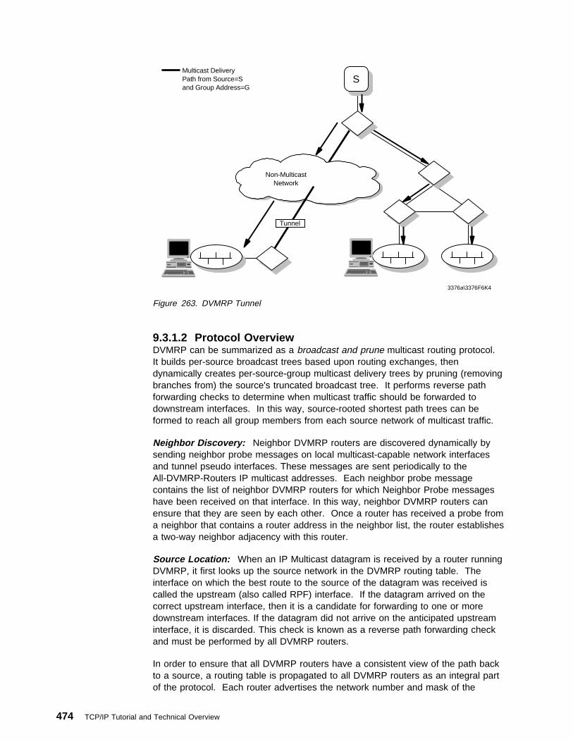
Non-MulticastNetwork
Tunnel
Multicast DeliveryPath from Source=Sand Group Address=G
S
3376a\3376F6K4
Figure 263. DVMRP Tunnel
9.3.1.2 Protocol OverviewDVMRP can be summarized as a broadcast and prune multicast routing protocol.It builds per-source broadcast trees based upon routing exchanges, thendynamically creates per-source-group multicast delivery trees by pruning (removingbranches from) the source's truncated broadcast tree. It performs reverse pathforwarding checks to determine when multicast traffic should be forwarded todownstream interfaces. In this way, source-rooted shortest path trees can beformed to reach all group members from each source network of multicast traffic.
Neighbor Discovery: Neighbor DVMRP routers are discovered dynamically bysending neighbor probe messages on local multicast-capable network interfacesand tunnel pseudo interfaces. These messages are sent periodically to theAll-DVMRP-Routers IP multicast addresses. Each neighbor probe messagecontains the list of neighbor DVMRP routers for which Neighbor Probe messageshave been received on that interface. In this way, neighbor DVMRP routers canensure that they are seen by each other. Once a router has received a probe froma neighbor that contains a router address in the neighbor list, the router establishesa two-way neighbor adjacency with this router.
Source Location: When an IP Multicast datagram is received by a router runningDVMRP, it first looks up the source network in the DVMRP routing table. Theinterface on which the best route to the source of the datagram was received iscalled the upstream (also called RPF) interface. If the datagram arrived on thecorrect upstream interface, then it is a candidate for forwarding to one or moredownstream interfaces. If the datagram did not arrive on the anticipated upstreaminterface, it is discarded. This check is known as a reverse path forwarding checkand must be performed by all DVMRP routers.
In order to ensure that all DVMRP routers have a consistent view of the path backto a source, a routing table is propagated to all DVMRP routers as an integral partof the protocol. Each router advertises the network number and mask of the
474 TCP/IP Tutorial and Technical Overview

interfaces it is directly connected to as well as relaying the routes received fromneighbor routers. DVMRP requires an interface metric to be configured on allphysical and tunnel interfaces. When a route is received, the metric of the interfaceover which the datagram was received must be added to the metric of the routebeing advertised in the route report message. This adjusted metric should be usedwhen comparing metrics to determine the best upstream neighbor.
Dependent Downstream Routers: In addition to providing a consistent view ofsource networks, the exchange of routes in DVMRP provides one other importantfeature. DVMRP uses the route exchange as a mechanism for upstream routers todetermine if any downstream routers depend on them for forwarding from particularsource networks. DVMRP accomplishes this by using a technique called poisonreverse (see 3.2.2.3, “Split Horizon with Poison Reverse” on page 103). If adownstream router selects an upstream router as the best next hop to a particularsource network, this is indicated by echoing back the route on the upstreaminterface with a metric equal to the original metric plus infinity. When the upstreamrouter receives the report and sees a metric that lies between infinity and twiceinfinity, it can then add the downstream router from which it received the report to alist of dependent routers for this source. This list of dependent routers per sourcenetwork built by the poison reverse technique will provide the foundation necessaryto determine when it is appropriate to prune back the IP source specific multicasttrees.
Designated Forwarder: When two or more multicast routers are connected to amulti-access network, it could be possible for duplicate packets to be forwarded onthe network (one copy from each router). DVMRP prevents this possibility byelecting a forwarder for each source as a side effect of its route exchange. Whentwo routers on a multi-access network exchange source networks, each of therouters will know the others metric back to each source network. Therefore, of allthe DVMRP routers on a shared network, the router with the lowest metric to asource network is responsible for forwarding data on to the shared network. If twoor more routers have an equally low metric, the router with the lowest IP addressbecomes the designated forwarder for the network. In this way, DVMRP performsan implicit designated forwarder election for each source network on eachdownstream interface.
9.3.1.3 Building Multicast TreesAs previously mentioned, when an IP multicast datagram arrives, the upstreaminterface is determined by looking up the interface on which the best route to thesource of the datagram was received. If the upstream interface is correct, then aDVMRP router will forward the datagram to a list of downstream interfaces.
Adding Leaf Networks: Initially, the DVMRP router must consider all of theremaining IP multicast capable interfaces (including tunnels) on the router. If thedownstream interface under consideration is a leaf network (has no dependentdownstream neighbors for the source network), then the IGMP local groupdatabase must be consulted. The IGMP local group database is maintained by allIP multicast routers on each physical, multicast-capable network. If the destinationgroup address is listed in the local group database, and the router is the designatedforwarder for the source, then the interface is included in the list of downstreaminterfaces. If there are no group members on the interface, then the interface isremoved from the outgoing interface list.
Chapter 9. Multicast and Multimedia 475
Adding Non-Leaf Networks: Initially, all non-leaf networks should be included inthe downstream interface list when a forwarding cache entry is first being created.This allows all downstream routers to be aware of traffic destined for a particular[source network, group] pair. The downstream routers will then have the option tosend prunes and grafts for this [source network, group] pair as requirementschange from their respective downstream routers and local group members.
9.3.1.4 Pruning Multicast TreesAs mentioned above, routers at the edges with leaf networks will remove their leafinterfaces that have no group members associated with an IP Multicast datagram. Ifa router removes all of its downstream interfaces, it notifies the upstream routerthat it no longer wants traffic destined for a particular [source network, group] pair.This is accomplished by sending a DVMRP prune message upstream to the routerit expects to forward datagrams from a particular source.
Recall that a downstream router will inform an upstream router that it depends onthe upstream router to receive datagrams from particular source networks by usingthe poison reverse technique during the exchange of DVMRP routes. This methodallows the upstream router to build a list of downstream routers on each interfacethat are dependent upon it for datagrams from a particular source network. If theupstream router receives prune messages from each one of the dependentdownstream routers on an interface, then the upstream router can in turn removethis interface from its downstream interface list. If the upstream router is able toremove all of its downstream interfaces in this way, it can then send a DVMRPprune message to its upstream router. This continues until the unnecessarybranches are removed from the delivery tree.
In order to remove old prune state information for [source network, group] pairs thatare no longer active, it is necessary to limit the life of a prune and periodicallyresume the broadcasting procedure. The prune message contains a prune lifetime,indicating the length of time that the prune should remain in effect. When the prunelifetime expires, if the interface is still a non-leaf, the interface is joined back ontothe multicast delivery tree. If unwanted multicast datagrams continue to arrive, theprune mechanism will be reinitiated and the cycle will continue. If all of thedownstream interfaces are removed from a multicast delivery tree causing aDVMRP prune message to be sent upstream, the lifetime of the prune sent must beequal to the minimum of the remaining lifetimes of the received prunes.
9.3.1.5 Grafting Multicast TreesOnce a tree branch has been pruned from a multicast delivery tree, packets fromthe corresponding [source network, group] pair will no longer be forwarded.However, since IP Multicast supports dynamic group membership, hosts may join amulticast group at any time. In this case, DVMRP routers use Grafts to cancel theprunes that are in place from the host back on to the multicast delivery tree. Arouter will send a Graft message to its upstream neighbor if a group join occurs fora group that the router has previously sent a prune. Separate graft messages mustbe sent to the appropriate upstream neighbor for each source network that hasbeen pruned.
Since there would be no way to tell if a Graft message sent upstream was lost orthe source simply quit sending traffic, it is necessary to acknowledge each Graftmessage with a DVMRP Graft Ack message. If an acknowledgment is not receivedwithin a Graft Time-out period, the Graft message should be retransmitted usingbinary exponential back-off between retransmissions. Duplicate Graft Ack
476 TCP/IP Tutorial and Technical Overview

messages should simply be ignored. The purpose of the Graft Ack message is tosimply acknowledge the receipt of a Graft message. It does not imply that anyaction was taken as a result of receiving the Graft message. Therefore, all Graftmessages received from a neighbor with whom a two-way neighbor relationshiphas been formed should be acknowledged whether or not they cause an action onthe receiving router.
9.3.1.6 Current DVMRP Internet DraftsAt the time this book was published, the current Internet draft specifications for thecore components of DVMRP were the following:
Distance Vector Multicast Routing Protocolhttp://www.ietf.org/internet-drafts/draft-ietf-idmr-dvmrp-v3-ð7.txt
9.3.2 Multicast OSPF (MOSPF)MOSPF is the multicast extension that is built on top of OSPF Version 2 (seeOSPF in 3.3.4, “Open Shortest Path First (OSPF)” on page 112) and defined inRFC 1584. MOSPF is not actually a separate multicast routing protocol likeDVMRP. MOSPF The multicast extensions have been implemented to leverage analready existing OSPF topology database to compute source-rooted shortest pathdelivery tree. The following two main MOSPF characteristics are described here tounderstand MOSPF in comparison to OSPF and DVMRP.
1. MOSPF adds a new type of LSA on the top of OSPF.
2. MOSPF does not support tunnel function, whereas DVMRP does.
9.3.2.1 New Type of LSAMOSPF forwards a multicast datagram on the basis of both the datagram's sourceand destination . The OSPF link state database provides a complete description ofthe AS's topology. By adding a new type of LSA (see “Link State Advertisements”on page 119), the group-membership-LSA, the location of all multicast groupmembers is pinpointed in the database. The path of a multicast datagram can thenbe calculated by building a shortest-path tree (SPT) rooted at the datagram'ssource (see 3.2.3.1, “Shortest-Path First (SPF)” on page 105). All branches notcontaining multicast members are pruned from the tree. These prunedshortest-path trees are initially built when the first datagram is received on demand.The results of the shortest path calculation are then cached for use by subsequentdatagrams having the same source and destination.
OSPF allows an AS to be split into areas. However, when this is done completeknowledge of the AS's topology is lost. When forwarding multicasts between areas,only incomplete shortest-path trees can be built. This may lead to someinefficiency in routing. An analogous situation exists when the source of themulticast datagram lies in another autonomous system. In both cases theneighborhood immediately surrounding the source is unknown. In these cases thesource's neighborhood is approximated by OSPF summary link advertisements orby OSPF AS external link advertisements respectively.
Note: For a given multicast datagram, all routers calculate an identicalshortest-path tree. There is a single path between the datagram's sourceand any particular destination group member. This means that, unlikeOSPF's treatment of regular (unicast) IP data traffic, there is no provisionfor equal-cost multipath.
Chapter 9. Multicast and Multimedia 477

9.3.2.2 No Tunnel FunctionRouters running MOSPF can be intermixed with non-multicast OSPF routers. Bothtypes of routers can interoperate when forwarding unicast IP data traffic.Obviously, the forwarding extent of IP multicasts is limited by the number ofMOSPF routers present in the AS. An ability to tunnel (see tunnel in 9.3.1.1,“DVMRP Terminology” on page 473) multicast datagrams through non-multicastrouters is not provided. In MOSPF, just as in the base OSPF protocol, datagrams(multicast or unicast) are routed "as is", they are not further encapsulated ordecapsulated as they transit the AS.
9.3.3 Protocol Independent Multicast (PIM)PIM is new multicast routing protocol developed by the IETF IDMR working group.PIM is independent of any underlying unicast routing protocol like DVMRP (seeDVMRP in 9.3.1, “Distance Vector Multicast Routing Protocol (DVMRP)” onpage 472).
There are two modes defined:
� Dense mode (PIM-DM)
� Sparse mode (PIM-SM), specified in RFC 2362
9.3.3.1 PIM TerminologyHere are some definitions that are necessary to understand the protocol overview.
Reverse Path Forwarding (RPF) / RPF interface / RPF lookupRPF is a multicast forwarding mode where a data packet is accepted forforwarding if it is received on an interface used to reach the source in unicast.The interface passing this check is called the RPF interface. An RPF lookupfor a source returns the RPF interface and the next-hop information, as if aroute lookup is done for the source on a unicast routing table.
Rendezvous Point (RP)RP is the point in network where senders meet receivers. Receivers mustjoin the RP-rooted tree and senders must register their existence with RP.
9.3.3.2 PIM-DM Protocol OverviewPIM-DM is designed for dense multicast regions; group membership is dense, suchas with DVMRP and MOSPF. PIM-DM assumes that when a source startssending, all downstream systems want to receive multicast datagrams. Initially,multicast datagrams are flooded to all areas of the network. If some areas of thenetwork do not have group members, PIM-DM will prune off the forwarding branchby setting up prune state. The prune state has an associated timer, which onexpiration will turn into forward state, allowing data to go down the branchpreviously in prune state (see Figure 264 on page 479).
478 TCP/IP Tutorial and Technical Overview

3376C\3376F6P1V
PruneMessage
A
B C
Source Multicast Tree of Router A
After
Before
Figure 264. PIM-DM Flood and Prune Message Example
The prune state contains source and group address information. When a newmember appears in a pruned area, a router can graft toward the source for thegroup, turning the pruned branch into forward state. The forwarding branches forma tree rooted at the source leading to all members of the group. This tree is calleda source-rooted tree.
9.3.3.3 PIM-DM and DVMRPIn order to understand PIM-DM, comparing it with DVMRP is helpful. PIM-DMdiffers from DVMRP in the following ways:
� PIM-DM forwards out all interfaces until explicit pruning occurs; DVMRP usesthe parent-child relationship, and split-horizon to recognize downstream routers.
� PIM-DM is independent of specific unicast routing technology; DVMRP usesdistance vectors such as RIP (see 3.2.2, “Distance Vector Routing” onpage 99).
� PIM-DM does not support tunnels; DVMRP does (see tunnels in 9.3.1.1,“DVMRP Terminology” on page 473).
9.3.3.4 PIM-SM Protocol OverviewPIM-SM is designed for sparse multicast regions. The basic concept is thatmulticast data is blocked unless a downstream router explicitly asks for it in order tocontrol the amounts of the traffic that traverse the network.
A router receives explicit join/prune messages from those neighboring routers thathave downstream group members. The router then forwards data packetsaddressed to a multicast group, G, only onto those interfaces on which explicit joinshave been received. The basic PIM-SM operation is described below.
Note: All routers mentioned in this document are assumed to be PIM-SM capable,unless otherwise specified.
1. A designated router (DR) sends periodic join/prune messages toward agroup-specific rendezvous point (RP) for each group for which it has activemembers. The DR is responsible for sending triggered join/prune and registermessages toward the RP.
2. Each router along the path toward the RP builds and sends join/prunemessages on toward the RP. Routers with local members join thegroup-specific multicast tree rooted at the RP (see Figure 265 on page 480).
Chapter 9. Multicast and Multimedia 479

3376C\3376F6P2
RP
PIM Join RP-Rooted Tree
Figure 265. PIM-SM Join and RP-Rooted Tree Example
The RP's route entry may include such fields as the source address, the groupaddress, the incoming interface from which packets are accepted, the list ofoutgoing interfaces to which packets are sent, timers, flag bits, etc.
3. The sender's DR initially encapsulates multicast packets in the resistermessage and unicast it to the RP for the group (see Figure 266).
3376C\3376F6P3
S
RP
Multicast Data
PIM Register
Register Message
Figure 266. PIM-SM Resister Message Example
The RP decapsulates each register message and forwards the data packetnatively to downstream routers on the shared RP tree.
4. A router with directly connected members first joins the shared RP tree. Therouter can initiate a source's SPT based on a threshold (see Figure 267 onpage 481).
480 TCP/IP Tutorial and Technical Overview

3376C\3376F6P4
S
RP
Multicast DataPIM Join TowardSource (S)SPT Data
PIM Join - SPT
Figure 267. PIM-SM SPT
5. After the router receives multicast packets from both the source's SPT and RPtree, PIM prune messages are sent upstream towards the RP to prune the RPtree. Now multicast data from the source will only flow over the source's SPTtowards group members (see Figure 268).
3376C\3376F6P5
S
RP
SPT Multicast DataPIM Prune
Figure 268. PIM-SM RP Tree to Source's SPT Switch Example
The recommended policy is to initiate the switch to the SP tree after receiving asignificant number of data packets during a specified time interval from aparticular source. To realize this policy the router can monitor data packetsfrom sources for which it has no source-specific multicast route entry andinitiate such an entry when the data rate exceeds the configured threshold.
9.3.3.5 PIM-DM and PIM-SMIn relation to PIM-DM, PIM-SM differs in two essential ways:
1. There are no periodic joins transmitted, only explicit triggered grafts/prunes inPIM-DM.
2. There is no rendezvous point (RP) in PIM-DM.
Chapter 9. Multicast and Multimedia 481
9.3.3.6 Current PIM Internet DraftsBy the time this book was published, the current Internet draft specifications for thecore components of PIM were the following:
Protocol Independent Multicast Routing in the Internet Protocol Version 6 (IPv6)http://www.ietf.org/internet-drafts/draft-ietf-pim-ipv6-ðð.txt
Protocol Independent Multicast Version 2 Dense Mode Specificationhttp://www.ietf.org/internet-drafts/draft-ietf-pim-v2-dm-ðð.txt
9.4 The Multicast BackboneThe Multicast Backbone (MBONE) was started in March 1992, to provide areal-time audio transmission from the Internet Engineering Task Force (IETF)meeting in San Diego via multicasting on the Internet. At that time, 20 sites werelistening to the audio transmission. Two years later, the IETF meeting in Seattlewas broadcast to 567 hosts in 15 countries on two parallel channels (audio andvideo) on the MBONE. Since then, the MBONE was used for video and audioconferencing, video broadcasts from international technical conferences and NASASpace Shuttle missions.
The multicast backbone is a virtual overlay network that uses the physicalinfrastructure of the existing Internet. Since not many routers in the Internet supportmulticasting the MBONE is layered on top of the existing Internet protocols.
Networks that are connected to the MBONE must comply with special requirementsfor the available bandwidth. For video transmissions, a minimum bandwidth of 128kbps is required. Audio transmissions require a minimum of 9-16 kbps. The IETFmulticast traffic has average transmission rates of 100 to 300 kbps, with spikes upto 500 kbps.
9.4.1 MBONE RoutingThe MBONE consists of many network islands that support IP multicasting. Theseislands are connected by virtual point-to-point links (tunnels) which bridges theareas in the Internet that don't support multicasting. Most routers in todays Internetare unicast routers that normally can't handle multicast packets.
A multicast router (mrouter) that wants to send multicast packets to anothermulticast router through a tunnel hides the multicast packets in normal unicastpackets that can be transmitted through normal Internet routers. The multicastpackets are encapsulated in IP packets with the destination address of the endpointof the tunnel. The receiving mrouter at the end of the tunnel strips off theencapsulating IP header and forwards the enclosed multicast packet. Thistechnique is called tunneling.
482 TCP/IP Tutorial and Technical Overview

MulticastRouter
Tunnel
MulticastIsland
MulticastRouter
MulticastIsland
UnicastRouter
3376\3376F6S4
Figure 269. MBONE Tunnel
Mrouters are either commercial multicast routers or special workstations running amulticast routing daemon (mrouted). The mrouted implementation uses theDistance Vector Multicast Routing Protocol (DVMRP) for the routing of the multicastpackets.
The MBONE tunnels are established with a metric and a threshold. The metricparameter is used for multicast routing. It specifies the routing cost for the tunnelwhich is used in DVMRP to choose the cheapest path for the packets through therouters. The lower the metric the lower the costs for routing the packets through atunnel. Figure 270 on page 484 shows an example for tunnels between MBONEmulticast routers which have different metric values.
Chapter 9. Multicast and Multimedia 483

mrouter1
mrouter4
mrouter3
mrouter2
Tunnel metric=8
Tun
nel m
etric
=1
Tunnel metric=2
Tun
nel m
etric
=2
3376a\3376F6SH
Internet
Figure 270. MBONE Tunnel Metric
If a multicast packet should be sent from mrouter 1 to all other routers, the tunnel1-2 is never used, because the sum of the tunnel metrics 1-3, 3-4, and 4-2(1+2+2=5) is lower than the metric of tunnel 1-2. This means that the cheapestway to send packets from mrouter 1 to mrouter 2 is to send them through routers 3and 4.
The threshold limits the distribution of multicast packets. It specifies the minimumTTL for a multicast packet to be forwarded into an established tunnel. The TTL isdecremented by 1 at each multicast router.
In the future, most routers will support IP multicast directly which will maketunneling dispensable. This makes clear that the MBONE is only a temporary utilitythat will eventually become obsolete when multicasting is supported as standard inall Internet routers.
9.4.2 MBONE ApplicationsThe first multiparty conferencing tools that used the MBONE were developed by theNetwork Research Group at Lawrence Berkeley National Laboratory (LBNL). Thevideoconferencing tool vic in conjunction with the audio tool vat allowsvideoconferences between multiple hosts connected to the MBONE. The tool WB(White Board) provides a shared drawing space that can be used by theparticipants of a videoconference to work on one document commonly.
484 TCP/IP Tutorial and Technical Overview

The following list contains some popular MBONE applications that are availabletoday:
� SDR Session Directory. SDR is used to announce MBONE sessions.
� NV Netvideo. A videoconferencing tool.
� VIC Videoconferencing System.
� IVS Inria Videoconferencing System.
� VAT Visual Audio Tool. An audio conferencing tool.
� RAT Robust Audio Tool. An audio conferencing tool.
� WB Whiteboard.
Most of the MBONE tools use the User Datagram Protocol (UDP) instead of theusual Transport Control Protocol (TCP) because the reliability and flow controlmechanisms of TCP are not practical for real-time broadcasting of multimedia data.The loss of an audio or video packet is acceptable rather than transmission delaysbecause of TCP retransmissions. On top of UDP, most of the MBONE applicationsuse the Real-Time Transport Protocol (RTP) which is described in 9.5, “TheReal-Time Protocols RTP and RTCP.” Mostly, the RTP protocol is implementeddirectly in the MBONE application. It provides mechanisms to transmit multimediadata streams continuously and without delays through the Internet.
9.5 The Real-Time Protocols RTP and RTCPThe Real-Time Transport Protocol (RTP) was developed by the Audio/VideoTransport Working Group from the Internet Engineering Task Force (IETF). It isspecified in RFCs 1889 and 1890. RTP is used in real-time applications such asvideoconferencing, audio broadcasting or Internet telephony, and is usuallyimplemented directly in those applications. Most of the MBONE tools use the RTPprotocol for the delivery of real-time data. Therefore, RTP is mostly used togetherwith UDP. RTP itself is not aware of a connection. It operates overconnection-oriented or connectionless lower layer protocols. Because RTPprovides no reliability mechanisms and does not guarantee delivery the applicationmust decide if packet loss is acceptable or if it needs its own reliability routines.RTP also does not provide functions to ensure timely delivery or provide otherquality-of-service guarantees.
To use real-time services in an application, two protocols must be implemented:
� The Real-Time Transport Protocol (RTP), which is responsible for the transportof real-time data packets.
� The RTP Control Protocol (RTCP), which controls and monitors the RTPsession.
9.5.1 The Real-Time Transport Protocol (RTP)The RTP protocol provides transport mechanisms that allow the synchronization ofmultimedia data streams from different applications.
If a user works with a video tool to provide a video stream and an audio tool toprovide an audio stream on the Internet, RTP marks the packets from the differentapplications with a specific payload type and time stamps so that audio and videodata can be synchronized on the receiving host. Figure 271 on page 486 shows
Chapter 9. Multicast and Multimedia 485

the operation of RTP in a multimedia transmission. Audio and video data areencapsulated in RTP packets and transmitted from the sender to the receiver.
3376\3376F6S5
RTP Stream
Payload RTP UDP IP
A V A V
UDP
IP
Audio(A)
Video(V)
RTP
UDP
IP
Audio(A)
Video(V)
RTP
Figure 271. RTP Operation
Without using RTP, the video and audio data, which eventually doesn't arrive at thesame time at the receiving host because of delays in the network, are displayedunsynchronized. A videoconference doesn't work very well if the audio and videohave different delays.
The header of an RTP packet has the following format:
V
3376\3376F6S2
time stamp
0 8 16 31
sequence numberP X CSRCcount
Mpayload
type
synchronization source (SSRC) identifier
contributing source (CSRC) identifiers
Figure 272. RTP Header Fields
Where:
V2-bit RTP version.
PPadding bit. If this is set, there are one or more additional paddingoctets at the end of the packet that are not part of the payload. Thisfunction is used for some encryption algorithms.
XExtension bit. If this is set, there is exactly one header extension thatfollows the fixed header.
CSRC count4-bit count, that contains the number of the contributing sourceidentifiers that follow the fixed header.
486 TCP/IP Tutorial and Technical Overview

MMarker bit. For special use.
Payload type.7-bit payload type. Specifies the format of the payload in the RTPpacket.
16-bit Sequence numberEach RTP packet gets a sequence number that is used from thereceiver to restore the packet sequence and detect packet loss.
timestampThe timestamp field contains a value that represents the time when thedata in the RTP packet was sampled. The initial value of the timestampis random.
SSRC identifierThe Synchronization Source (SSRC) field is a randomly chosenidentification for the source of a stream of RTP packets, identified by a32-bit number. All packets from a synchronization source contain anunique SSRC identifier so that a receiver can group the packets bysynchronization source for playback. All synchronization sources in anRTP session must have a different SSRC identifier.
CSRC listThe CSRC list contains the contributing sources for the payload in thecurrent packet. This field is used if a mixer (see 9.5.3, “RTP Translatorsand Mixers” on page 495) has combined different streams of RTPpackets with the same payload type (audio) from different senders. Themixer inserts a list of the different SSRC identifiers of the sources thatcontributed to the generation of the new RTP packet into the header ofthis packet. This list makes sure that a receiver that gets a packetwhich was modified by a mixer, still gets all SSRC identifiers of thesenders, because the modified RTP packet contains the SSRC identifierof the mixer.
The main functions of the RTP protocol are:
� Payload type identification
� Sequence numbering
� Time stamping
The payload of an RTP packet can be either an audio or a video format. Thesending application writes the code for the payload type in the RTP header so thatthe receiving application knows which audio or video format must be decoded. Thefollowing payload types are defined today (RFC 1890):
Table 13 (Page 1 of 2). RTP Payload Types
Audio Video
Payload Type Encoding Name Payload Type Encoding Name
0 PCMU 24 HDCC
1 1016 25 CellB
2 G.721 26 JPEG
3 GSM 27 CUSM
Chapter 9. Multicast and Multimedia 487
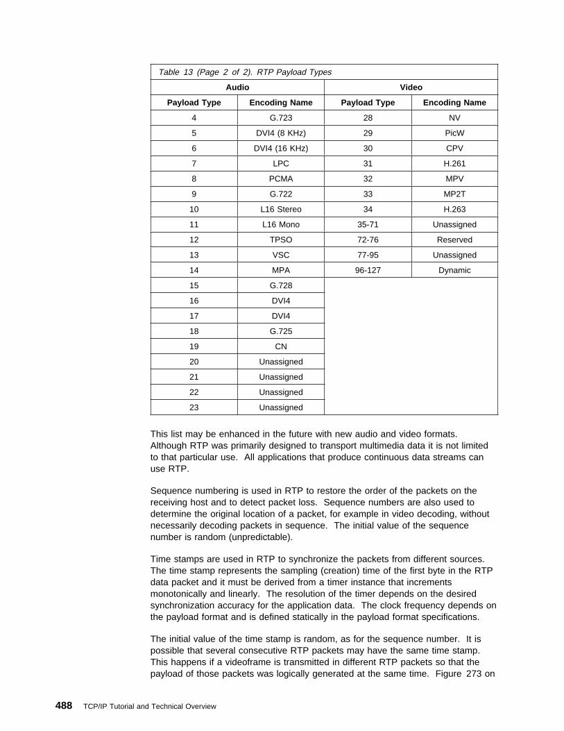
This list may be enhanced in the future with new audio and video formats.Although RTP was primarily designed to transport multimedia data it is not limitedto that particular use. All applications that produce continuous data streams canuse RTP.
Sequence numbering is used in RTP to restore the order of the packets on thereceiving host and to detect packet loss. Sequence numbers are also used todetermine the original location of a packet, for example in video decoding, withoutnecessarily decoding packets in sequence. The initial value of the sequencenumber is random (unpredictable).
Time stamps are used in RTP to synchronize the packets from different sources.The time stamp represents the sampling (creation) time of the first byte in the RTPdata packet and it must be derived from a timer instance that incrementsmonotonically and linearly. The resolution of the timer depends on the desiredsynchronization accuracy for the application data. The clock frequency depends onthe payload format and is defined statically in the payload format specifications.
The initial value of the time stamp is random, as for the sequence number. It ispossible that several consecutive RTP packets may have the same time stamp.This happens if a videoframe is transmitted in different RTP packets so that thepayload of those packets was logically generated at the same time. Figure 273 on
Table 13 (Page 2 of 2). RTP Payload Types
Audio Video
Payload Type Encoding Name Payload Type Encoding Name
4 G.723 28 NV
5 DVI4 (8 KHz) 29 PicW
6 DVI4 (16 KHz) 30 CPV
7 LPC 31 H.261
8 PCMA 32 MPV
9 G.722 33 MP2T
10 L16 Stereo 34 H.263
11 L16 Mono 35-71 Unassigned
12 TPSO 72-76 Reserved
13 VSC 77-95 Unassigned
14 MPA 96-127 Dynamic
15 G.728
16 DVI4
17 DVI4
18 G.725
19 CN
20 Unassigned
21 Unassigned
22 Unassigned
23 Unassigned
488 TCP/IP Tutorial and Technical Overview

page 489 shows an example for the generation of RTP packets in a videoapplication:
Application
Timer
RTP
Sampling Timer100 JPEG Videoframe
99 JPEG Videoframe
98 JPEG Videoframe
97 JPEG Videoframe
Payload TypeSequence No.
Videoframe
UDP
IP
3376\3376F6S8
Figure 273. RTP Packet Generation in a Video Application
9.5.2 The Real-Time Control ProtocolThe RTP protocol itself provides only one message format, the RTP data packet.But many real-time applications need a feedback for the provided packets in orderto guarantee real-time delivery. This function is provided by the Real-Time ControlProtocol (RTCP).
The primary function of RTCP is to provide feedback about the quality of the RTPdata distribution. This is comparable to the flow and congestion control functions ofother transport protocols. Feedback from the receivers is necessary for diagnosingdistribution faults. RTCP produces sender and receiver reports, such as streamstatistics and packet counts. It uses a separate UDP port from the RTP protocol(RTP-port+1). Figure 274 on page 490 shows the cooperation of the RTP and theRTCP protocol.
Chapter 9. Multicast and Multimedia 489

UDP
IP
RTP
Application
Sender
UDP
IP
RTP
Application
UDP
IP
RTP
Application
Receivers
RTP
RTCP
3376\3376F6S9
Figure 274. RTCP and RTP Packet Delivery
Because RTCP packets can have different functions, there are different formatsdefined:
� SR Sender report
� RR Receiver report
� SDES Source description items
� BYE Indicates end of participation
� APP Application-specific functions
9.5.2.1 RTCP Sender ReportAn RTCP sender report will be sent by the sources of an RTP data stream toinform the receivers what they should have received. It is a multicast packet thatreaches all receivers.
The sender report packet can be grouped in three parts. First the header, whichspecifies the RTCP packet type, packet length and the sender identification. Thesecond part contains the sender information and the third part the receiver reportblocks. Most times, the RTCP sender packet contains more than one receiverreport block. They allow the sender to report feedback for received RTP packetsfrom other senders. The following figure shows the format of an RTCP senderreport packet.
490 TCP/IP Tutorial and Technical Overview
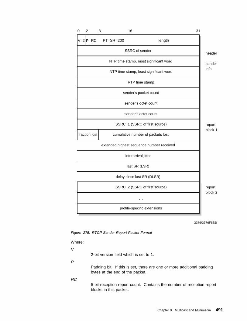
V=2
3376\3376F6SB
SSRC of sender
0 1234567891011121314151617181920212223 2425262728293031
lengthRCP PT=SR=200
NTP time stamp, most significant word
NTP time stamp, least significant word
RTP time stamp
sender's packet count
sender's octet count
sender's octet count
SSRC_1 (SSRC of first source)
cumulative number of packets lostfraction lost
extended highest sequence number received
interarrival jitter
last SR (LSR)
delay since last SR (DLSR)
SSRC_2 (SSRC of first source)
...
profile-specific extensions
header
senderinfo
reportblock 1
reportblock 2
Figure 275. RTCP Sender Report Packet Format
Where:
V2-bit version field which is set to 1.
PPadding bit. If this is set, there are one or more additional paddingbytes at the end of the packet.
RC5-bit reception report count. Contains the number of reception reportblocks in this packet.
Chapter 9. Multicast and Multimedia 491

PT8-bit packet type field. For sender reports the value is 200.
length16-bit packet length in bytes (including any added padding).
SSRC of Sender32-bit field that contains the SSRC identifier of the host sending thispacket.
NTP time stampTwo 32-bit fields containing the absolute time in the Network TimeProtocol (NTP) format. This timer counts the number of seconds sinceJanuary 1, 1900.
RTP timestamp32-bit field that contains the time stamp from the RTP packets accordingto the sender.
sender's packet count32-bit field with the total number of RTP data packets transmitted by thesender since the start of the transmission.
sender's octet count32-bit field with the total number of payload bytes transmitted by thesender since the start of the transmission.
SSRC_n (source identifier):32-bit field that contains the SSRC identifier of another RTP sender fromwhich this sender has received packets. The number of report blockswith different sender SSRCs depends on the number of other sourcesthat were heard by this sender since the last report.
fraction lost8-bit field that represents the fraction of RTP data packets that was lostsince the previous SR or RR packet was sent from the source SSRC_n.
cumulative number of packets lost24-bit field that represents the total number of lost RTP data packetsfrom source SSRC_n.
extended highest sequence number received32-bit field. It contains the highest sequence number that was receivedin an RTP data packet from the source SSRC_n.
interarrival jitter32-bit field that contains the estimated variance of the interarrival timesfrom the appropriate source. If the packets arrive regularly, the jittervalue is zero. If the packets arrive irregularly, the jitter value is high.
last SR timestamp (LSR)32-bit field that contains the middle 32 bits from the 64-bit NTPtimestamp received with the last RTCP sender report packet from thesource SSRC_n.
delay since last SR (DLSR)32-bit field. It contains the delay between receiving the last SR packetfrom the source SSRC_n and the sending of the current exceptionreport block in units of 1/65536 seconds.
492 TCP/IP Tutorial and Technical Overview

9.5.2.2 RTCP Receiver ReportThe RTCP Receiver Report (RR) packet is similar to the sender report packet. Thepacket type field contains the constant 201 and the sender information section(NTP and RTP timestamps/sender's packet and octet counts) is not included in thepacket. The other fields in the receiver report have the same function as in the SRpacket.
V=2
3376\3376F6SB
SSRC of packet sender
0 1234567891011121314151617181920212223 2425262728293031
lengthRCP PT=RR=201
SSRC_1 (SSRC of first source)
cumulative number of packets lostfraction lost
extended highest sequence number received
interarrival jitter
last SR (LSR)
delay since last SR (DLSR)
SSRC_2 (SSRC of second source)
...
profile-specific extensions
header
reportblock 1
reportblock 2
Figure 276. RTCP Receiver Report Packet Format
9.5.2.3 RTCP Source Description PacketA source description packet (SDES) has the packet type 202 and is used from theRTP packet sources to provide more information about themselves. The currentlydefined source description items are:
CNAME Unique name for the sourceNAME The real user name of the sourceEMAIL The e-mail address of the userPHONE Phone number of the userLOC Geographic user locationTOOL User's application or tool nameNOTE Note about the sourcePRIV Private extensions
The SDES packet consists of the basic RTCP header and a series of sourceidentifiers and description items.
Chapter 9. Multicast and Multimedia 493
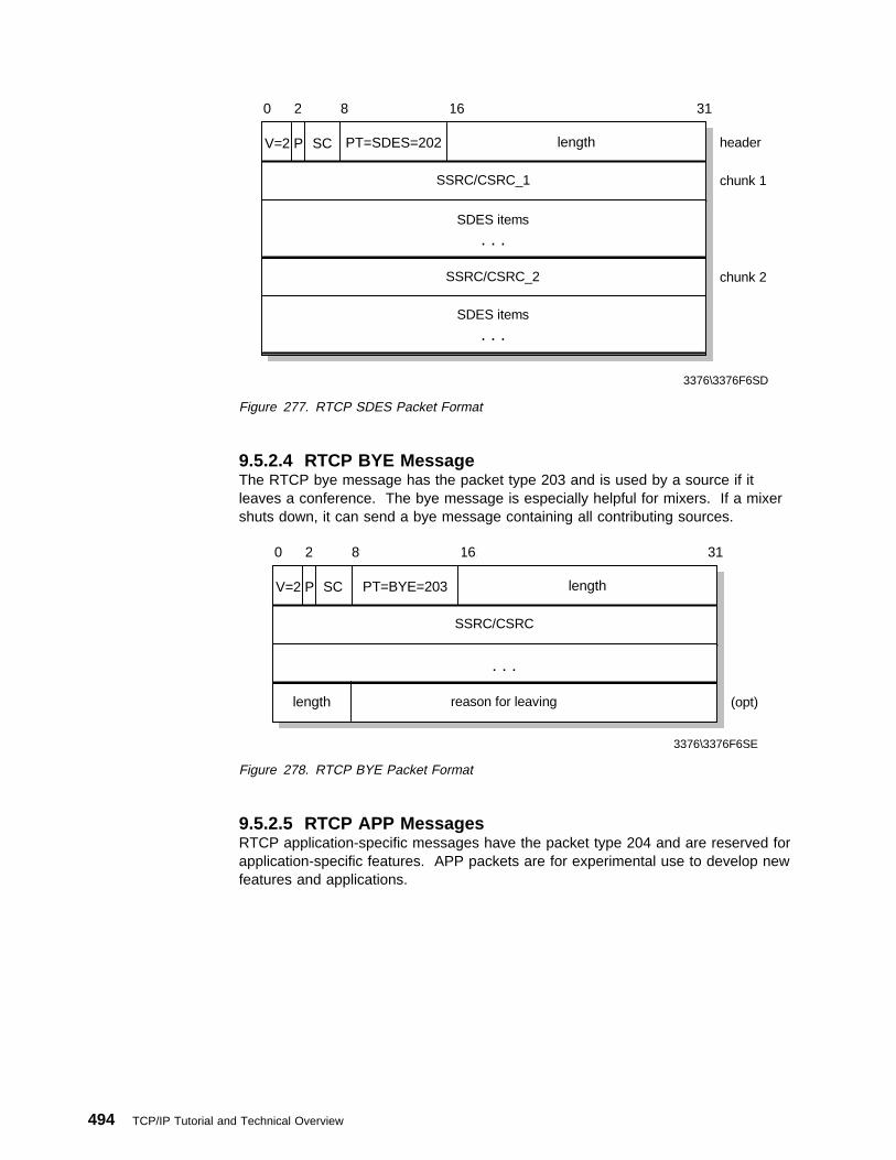
V=2
3376\3376F6SD
SSRC/CSRC_1
0 1234567891011121314151617181920212223 2425262728293031
lengthSCP PT=SDES=202
SDES items
. . .
SSRC/CSRC_2
header
chunk 1
SDES items
. . .
chunk 2
Figure 277. RTCP SDES Packet Format
9.5.2.4 RTCP BYE MessageThe RTCP bye message has the packet type 203 and is used by a source if itleaves a conference. The bye message is especially helpful for mixers. If a mixershuts down, it can send a bye message containing all contributing sources.
V=2
0 1234567891011121314151617181920212223 2425262728293031
lengthP SC PT=BYE=203
SSRC/CSRC
. . .
reason for leaving (opt)
3376\3376F6SE
length
Figure 278. RTCP BYE Packet Format
9.5.2.5 RTCP APP MessagesRTCP application-specific messages have the packet type 204 and are reserved forapplication-specific features. APP packets are for experimental use to develop newfeatures and applications.
494 TCP/IP Tutorial and Technical Overview

V=2
SSRC/CSRC
0 1234567891011121314151617181920212223 2425262728293031
lengthsub-typeP PT=APP=204
name (ASCII)
application-dependent data
3376\3376F6SF
Figure 279. RTCP APP Packet Format
9.5.3 RTP Translators and MixersThe RTP protocol supports the use of translators and mixers to modify the RTPpacket stream. RTP translators are used to change the payload type in an RTPpacket.
For example, three workstations connected to a high-speed network are used for avideoconference and exchange MPEG data with 1.5 Mbps. If another workstationthat is connected only through a 1 Mbps route to the high-speed network wishes toparticipate on the videoconference, the problem appears that this bandwidth isinsufficient for even one video stream. One solution for this problem is that theworkstations change to another video format (maybe h.261 with 256 kbps). Butlower bandwidth reduces the quality of the video.
The idea of RTP translation is that the RTP packets that contain the MPEG datafrom the workstations are converted to another format that needs less bandwidth.This means that the three 1.5 Mbps streams from the workstations are converted tothree 256 kbps streams that can be transmitted through a 1 Mbps route. The threeworkstations connected to the high-speed network can use the high quality MPEGformat for the communication among each other.
Workstation
1.5 Mbps
Workstation
1.5 Mbps
Workstation
1.5 Mbps
Translator
3*256 Kbps
MPEG H.261
Router
100 Mbps
Router
Workstation
1 Mbps
3376\3376F6S6
Figure 280. RTP Translator
The translated RTP packets are forwarded with their synchronization sourceidentifier intact. Only the payload type is changed by the translator. Therefore,receivers of the RTP packets can still identify the different sources even thoughpackets from all the sources pass through the translator and carry the same
Chapter 9. Multicast and Multimedia 495
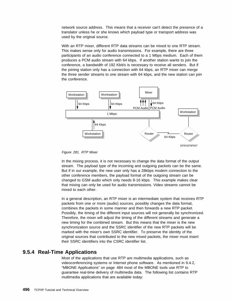
network source address. This means that a receiver can't detect the presence of atranslator unless he or she knows which payload type or transport address wasused by the original source.
With an RTP mixer, different RTP data streams can be mixed to one RTP stream.This makes sense only for audio transmissions. For example, there are threeparticipants of an audio conference connected to a 1 Mbps medium. Each of themproduces a PCM audio stream with 64 kbps. If another station wants to join theconference, a bandwidth of 192 Kbit/s is necessary to receive all senders. But ifthe joining station only has a connection with 64 kbps, an RTP mixer can mergethe three sender streams to one stream with 64 kbps, and the new station can jointhe conference.
Workstation
64 Kbps
Workstation
64 Kbps
Workstation
64 Kbps
Mixer
64 Kbps
PCM Audio PCM Audio
Router
1 Mbps
Router
Workstation
64 Kbps
3376\3376F6S7
Figure 281. RTP Mixer
In the mixing process, it is not necessary to change the data format of the outputstream. The payload type of the incoming and outgoing packets can be the same.But if in our example, the new user only has a 28kbps modem connection to theother conference members, the payload format of the outgoing stream can bechanged to GSM audio which only needs 8-16 kbps. This example makes clearthat mixing can only be used for audio transmissions. Video streams cannot bemixed to each other.
In a general description, an RTP mixer is an intermediate system that receives RTPpackets from one or more (audio) sources, possibly changes the data format,combines the packets in some manner and then forwards a new RTP packet.Possibly, the timing of the different input sources will not generally be synchronized.Therefore, the mixer will adjust the timing of the different streams and generate anew timing for the combined stream. But this means that the mixer is the newsynchronization source and the SSRC identifier of the new RTP packets will bemarked with the mixer's own SSRC identifier. To preserve the identity of theoriginal sources that contributed to the new mixed packets, the mixer must inserttheir SSRC identifiers into the CSRC identifier list.
9.5.4 Real-Time ApplicationsMost of the applications that use RTP are multimedia applications, such asvideoconferencing systems or Internet phone software. As mentioned in 9.4.2,“MBONE Applications” on page 484 most of the MBONE tools use RTP toguarantee real-time delivery of multimedia data. The following list contains RTPmultimedia applications that are available today:
496 TCP/IP Tutorial and Technical Overview
BambaPhoneBambaPhone is a video phone for two-way, real-time communicationover the Internet or any LAN using the TCP/IP protocol. BambaPhoneautomatically negotiates the compression technique appropriate to aconnection bandwidth making videoconferencing possible over dial-up28.8 kbps modem links and LAN-based connections to the Internet or anintranet. BambaPhone code conforms to H.323 multimedia conferencingrecommendations for LANs and the Internet. However, the currentimplementation is not fully compliant with H.323 and will not interoperatewith any other video phones. BambaPhone includes modularcomponents for call setup, multimedia control, and video and audiosupport. The BambaPhone was written to the high-level APIs of thesecomponents.
BambaPhone will automatically detect the systems audio and videocapabilities and adapt itself accordingly. The BambaPhone call controlstarts a session between two users. End-to-end call signaling isachieved through a reliable TCP/IP connection. A call is made using thedestination IP address or host name. BambaPhone will ring when anincoming call arrives and allow the user to see who is calling from the IPaddress. The call will continue to ring until the user answers or thecaller hangs up, exactly as a standard telephone operates.BambaPhone can also be put into automatic answer mode such thatany incoming call is immediately answered and accepted.
BambaPhone is part of the Bamba suite of research technologydemonstrations that includes Web browser plug-ins for audio and videostreaming. Because of the experimental character, BambaPhone hasnot been released as a product. The experimental version ofBambaPhone is available at
http://www.alphaWorks.ibm.com/formula/BambaPhone
Cu-SeeMeCU-SeeMe is an Internet video chat software that supports video, audio,text and whiteboard communications. It uses RTP for real-timetransmissions, but it doesn't use multicasting.
Intel Internet Video PhoneA video phone software that allows one-to-one video and audioconnections through the Internet. The software uses RTP but doesn'tsupport multicast connections.
IP/TVIP/TV is a client/server video application from Precept Software thatsupports different high quality video and audio standards (MPEG, H.261and Video for Windows). With fast network connections it is possible toprovide video and audio in TV quality. IP/TV supports multicasting.
Rendez-VousRendez-Vous is a videoconferencing tool developed by the FrenchNational Institute for Research in Computer Science and Control(INRIA). It supports RTP over multicast or unicast IP and differenthigh-quality audio standards for videoconferences with multipleparticipants.
Chapter 9. Multicast and Multimedia 497

Free PhoneFree Phone is an Internet audio tool that is also developed at INRIA. Itallows audio conferences with multiple participants. Free Phone usesspecial RTP payload types, GSM for example, to reduce the bandwidthfor an Internet phone connection. Furthermore, it includes specialredundancy mechanisms to allow reconstruction of lost packets whichimproves the audio quality especially during high packet loss situations.Free Phone is compatible with some of the MBONE tools like vat andrat.
9.6 Voice over IPThe possibility of running voice over IP networks is extremely attractive because IPtechnology is very low in cost and also that “bandwidth is free” on the Internet.This can reduce dramatically the costs for long distance phone calls. If the Internetcan be used successfully for voice, then a range of interesting applications becomepossible. Some of these applications have been described in 9.5.4, “Real-TimeApplications” on page 496. The disadvantage of these applications is, that they alluse their own protocols and compression algorithms to transport the voice over IPnetworks. Therefore, most of today's Internet telephone programs are incompatibleto each other. Additionally, a PC or a workstation is required to run the voicesoftware.
To provide Voice over IP, or better yet Voice over Internet, to a larger group ofpeople, it is necessary to define a standard for the protocols and the voicecompression algorithms. Furthermore, constitutions are required to use a normalphone for Voice over IP connections instead of a computer.
A standard that realizes this feature is currently being developed by the Voice overIP Forum which consists of members from different telecommunications companies.
The VoIP forum operates as a working group in the International MultimediaTeleconferencing Consortium. They have published the VoIP Forum ServiceInteroperability Implementation Agreement (the VoIP IA), which seeks to complete,and extend existing standards into a specification to provide a complete Internettelephony interoperability protocol. The VoIP forum came into being to define aframework within which existing standards could be used in a way that enabledequipment made by different manufacturers to interoperate. The VoIP IA includesspecifications for Internet telephony client software and the gateways to the publictelephone network.
The basic standard recommended by the VoIP Forum is the InternationalTelecommunication Union (ITU) standard H.323. It is a standard for multimediacommunication over packet networks that references many other standardsincluding definitions for the transport of voice, data and video as well asestablishing standards for audio and video compression and decompression. TheForum Interoperability Implementation Agreement is:
1. A clarification (and interpretation) of the H.323 series of recommendations.
2. A specification as to how H.323 should be used.
3. An extension of H.323 to cover areas (such as Directory Services) that areabsent from the standard.
498 TCP/IP Tutorial and Technical Overview
The key elements of the VoIP IA are:
1. H.323 is used for call establishment and capability negotiation.
2. Call signaling between service elements is performed using ITU-Trecommendation Q.931 (part of H.323). Each service element provides thenecessary conversion from its local endpoint signaling to the H.323/Q.931backbone protocol.
3. Other telephony specific requirements such as the transfer and reproduction ofDTMF data have been added to provide a high level of connectivity with thetraditional telephone infrastructure.
4. Directory services are not covered in the base H.323 recommendation. TheVoIP IA defines dynamic IP address resolution mechanisms via H.323 RAS.
The main goal of the VoIP IA is to help ensure interoperability between equipmentfrom different vendors. In order to achieve this, the VoIP Forum has specified strictconformance requirements. Currently, the VoIP IA includes support for two-partyvoice and similar audio communications over IP networks in a manner similar andcompatible (via gateways) with existing Public Switched Telephone Network (PSTN)telephone calls. However, it is expected that the IA will be extended to includemultipoint communications in the future. Such multipoint function would be addedin such a way that conforming networks were backward-compatible with the existingVoIP IA. Compatibility with existing (non-IP) multipoint circuit mode conferencingstandards is also considered highly desirable.
Whenever possible the VoIP IA uses existing IETF and ITU-T protocols andservices. Interworking between the VoIP connections and the PSTN is providedthrough the use of H.323 gateways.
9.6.1 ITU-T Recommendation H.323H.323 is an ITU-T standard for multimedia videoconferencing on packet-switchednetworks. Its formal title is Visual Telephone Systems and Equipment for LocalArea Networks Which Provide a Non-Guaranteed Quality of Service. Since voice isone part of multimedia the standard covers most of the things you have to do tohandle voice in:
� LANs
� Corporate intranets
� The Internet
H.323 has been developed very rapidly, much more rapidly than has beencustomary in the past. Work commenced in the ITU-T in May 1995 and wascompleted by June of 1996. In January 1998, Version 2 of H.323 with addedfunction will be under development.
The components of an H.323 network are:
� Terminals
� Gateways
� Gatekeepers
� Multipoint Control Units (MCUs). An MCU consists of a Multipoint Controller(MC) and a Multipoint Processor (MP)
Chapter 9. Multicast and Multimedia 499
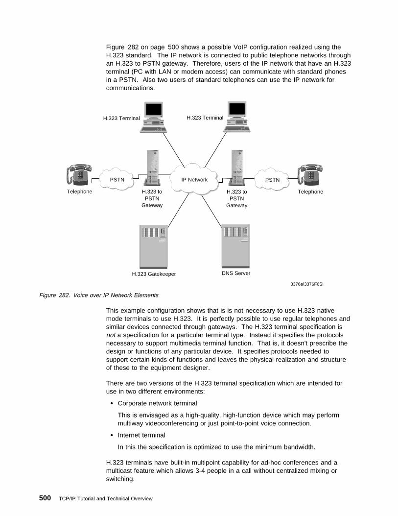
Figure 282 on page 500 shows a possible VoIP configuration realized using theH.323 standard. The IP network is connected to public telephone networks throughan H.323 to PSTN gateway. Therefore, users of the IP network that have an H.323terminal (PC with LAN or modem access) can communicate with standard phonesin a PSTN. Also two users of standard telephones can use the IP network forcommunications.
H.323 toPSTN
Gateway
PSTN
Telephone H.323 toPSTN
Gateway
Telephone
H.323 Gatekeeper DNS Server
H.323 Terminal H.323 Terminal
IP Network PSTN
3376a\3376F6SI
Figure 282. Voice over IP Network Elements
This example configuration shows that is is not necessary to use H.323 nativemode terminals to use H.323. It is perfectly possible to use regular telephones andsimilar devices connected through gateways. The H.323 terminal specification isnot a specification for a particular terminal type. Instead it specifies the protocolsnecessary to support multimedia terminal function. That is, it doesn't prescribe thedesign or functions of any particular device. It specifies protocols needed tosupport certain kinds of functions and leaves the physical realization and structureof these to the equipment designer.
There are two versions of the H.323 terminal specification which are intended foruse in two different environments:
� Corporate network terminal
This is envisaged as a high-quality, high-function device which may performmultiway videoconferencing or just point-to-point voice connection.
� Internet terminal
In this the specification is optimized to use the minimum bandwidth.
H.323 terminals have built-in multipoint capability for ad-hoc conferences and amulticast feature which allows 3-4 people in a call without centralized mixing orswitching.
500 TCP/IP Tutorial and Technical Overview

H.323 gateways provide interoperability between IP-connected H.323 terminals andother audio devices (such as regular telephones), either directly connected to thegateway or connected through a network that is not IP. These could be multimediadevices such as H.320 videoconference terminals or ordinary telephones connectedthrough the public telephone network. The functions performed by the gatewayinclude the mapping of the call signaling protocols, the control protocols and mediamapping (multiplexing, rate matching and audio transcoding).
The H.323 gatekeeper provides the functions of directory server and systemsupervisor. The network of H.323 terminals and gateways under the control of aparticular gatekeeper forms an integrated sub-network within the wider TCP/IPnetwork environment. The gatekeeper's detailed functions are as follows:
� Directory Server (Address Translation) Function
This function translates an H.323 alias address to an IP (transport) addressusing information obtained at terminal registration. This allows the user to havemeaningful, unchanging names with which to refer to other users in the system.These names are arbitrary. You can use addresses similar to those used inTCP/IP e-mail systems. Alternatively you can use “phone number like” namesor another completely different system.
� Supervisory Functions (for example, Call Admission Control)
The gatekeeper can grant or deny permission to make the call. In doing this itcan apply bandwidth limits to manage the network traffic and so preventcongestion occurring. This function is particularly relevant in a LANenvironment.
The gatekeeper also manages gateways and provides necessary addresstranslation between external addresses and IP addresses by which externalresources are known within the H.323 network.
� Call Signaling
The gatekeeper may route calls in order to provide supplementary services orto provide Multipoint Controller functionality for calls with a large number ofparties.
� Call Management
Because the gatekeeper controls network access it is also the logical place toperform call accounting and management.
The Multipoint Controller and Multipoint Processor form the Multipoint Control Unit(MCU). This H.323 component provides conference management, mediaprocessing and the multipoint conference model. The MCU supports mediadistribution for unicast and multicast data.
9.6.2 Voice Compression (G.723.1 and G.729)The ITU recommendations G.723.1, G.729 and G.729A specify the operation ofCodecs in low-quality networking environments similar to that found in the currentpublic Internet.
G.723.1 offers a relatively high degree of compression with an output bit rate ofeither 5.3 or 6.4 kbps. Using a data length in the packet of 20 or 24 bytesthis means that each packet carries 30 ms of the real-time voice signal.
Chapter 9. Multicast and Multimedia 501

The coder typically causes a one-way processing delay of 30 ms, alookahead delay (to the next packet) of 7.5 ms and of course the packetassembly time of 30 ms (because 30 ms of voice is carried in a singlepacket). This imposes a one-way delay at each end of the connection of67.5 ms, that is, 135 ms end-to-end one-way.
G.729 comes in two flavors: G.729 and G.729A. The key difference is in theamount of processing required to implement the algorithm. In both casesthe compressed bit rate is 8 kbps and the amount of real-time voiceencoded is 10 ms. This gives a data packet size of 10 bytes.
The algorithm used is called Conjugate Structured Algebraic Code ExcitedLinear Predictive (CS-ACELP). As input, CS-ACELP takes 80 samples ofstandard or linear PCM (64 kbps Pulse Code Modulation). This algorithmwas designed for implementation by advanced Fixed Point Digital SignalProcessors (DSPs) and is noted for delivering an exceptionally high level ofvoice quality with minimal delay.
In terms of delay both of these protocols are the same, requiring 10 ms forpacket assembly, 10 ms for processing and 5 ms for lookahead. Thismeans a 50 ms end-to-end delay due to the Codecs.
GSM The Group Special Mobile (GSM) audio compression is an algorithmoriginally defined for use with digital mobile telephones. It is a Europeanstandard not one of the ITU set. GSM is an allowed alternative for VoIP. Aframe of 160 samples (each sample consists of 16 bits signed word) isused which is then compressed it into a smaller frame of 260 bits. These260 bits are made up of different variables, each variable requiring adifferent number of bits. The VoIP forum selected the use of the RTP basicpackaging type which enables the packaging of even or odd number ofGSM frames within a single packet of RTP.
G.729 speech frames can be made into packets consuming approximately 9 kbpson a private leased line and 10.6 kbps on a frame relay link, including overhead. Ifsilence suppression is used, the bandwidth required is reduced to an average ofapproximately 4 kbps.
It seems obvious that it is not very efficient to add a TCP/IP header to a packet thathas a data payload of only 10 bytes. Thus G.723.1 is much more efficient in use ofbandwidth than G.729 but G.729 has a significantly lower delays.
9.6.3 The VoIP Protocol StackThe VoIP IA consists of a number of protocols interworking with one another toperform the overall function. These protocols operate in a hierarchical fashion andmay be represented as a stack in the same way as most other communicationssystems are described. The VoIP protocol stack is shown in Figure 283 onpage 503.
502 TCP/IP Tutorial and Technical Overview
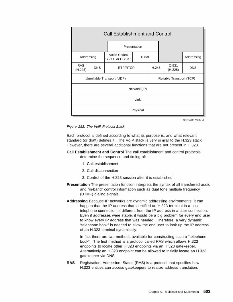
Call Establishment and Control
Presentation
AddressingAudio Codec:
G.711, or G.723.1DTMF Addressing
RAS(H.225)
DNS RTP/RTCP H.245Q.931
(H.225)DNS
Unreliable Transport (UDP) Reliable Transport (TCP)
Network (IP)
Link
Physical
3376a\3376F6SJ
Figure 283. The VoIP Protocol Stack
Each protocol is defined according to what its purpose is, and what relevantstandard (or draft) defines it. The VoIP stack is very similar to the H.323 stack.However, there are several additional functions that are not present in H.323.
Call Establishment and Control The call establishment and control protocolsdetermine the sequence and timing of:
1. Call establishment
2. Call disconnection
3. Control of the H.323 session after it is established
Presentation The presentation function interprets the syntax of all transferred audioand “in-band” control information such as dual tone multiple frequency(DTMF) dialing signals.
Addressing Because IP networks are dynamic addressing environments, it canhappen that the IP address that identified an H.323 terminal in a pasttelephone connection is different from the IP address in a later connection.Even if addresses were stable, it would be a big problem for every end userto know every IP address that was needed. Therefore, a very dynamic“telephone book” is needed to allow the end user to look up the IP addressof an H.323 terminal dynamically.
In fact there are two methods available for constructing such a “telephonebook”. The first method is a protocol called RAS which allows H.323endpoints to locate other H.323 endpoints via an H.323 gatekeeper.Alternatively an H.323 endpoint can be allowed to initially locate an H.323gatekeeper via DNS.
RAS Registration, Admission, Status (RAS) is a protocol that specifies howH.323 entities can access gatekeepers to realize address translation.
Chapter 9. Multicast and Multimedia 503

Audio Codec Audio Coder/Decoder (Codec) are used to convert analog audioto/from digital signals. Please see 9.6.2, “Voice Compression (G.723.1 andG.729)” on page 501 for the audio codecs used in the VoIP specifications.
H.245 In general, H.245 defines a control protocol for multimedia communications.In the VoIP stack H.245 specifies how the channels inside of telephonecalls are established and controlled. It also includes methods for sendingand receiving DTMF dial tones.
H.225.0 H.225.0 is entitled Media Stream Packetisation and Synchronization onNon-Guaranteed Quality of Service LANs.
It defines the method of how audio packets, control packets and DTMF dialinformation are transmitted over IP networks.
Q.931 Q.931 is a signaling protocol that is used to set up, tear down, and controlH.323 communication sessions. The protocol originated as the signalingspecification for ISDN. The way in which it is used in VoIP is defined inH.225.0.
RTP/RTCP RTP/RTCP and the G.723.1 RTP audio packetisation was originallystandardized by the IETF. Please see 9.5, “The Real-Time Protocols RTPand RTCP” on page 485 for a detailed description of the RTP protocol.RTP is a real-time protocol that is used in VoIP control and monitors thepacket delivery. The G.723.1 RTP audio packetisation defines how theG.723.1 audio frames are transmitted in the RTP payload.
On the transport layer, VoIP uses UDP for RAS, DNS and RTP/RTCP and TCP forH.245, Q.931 and sometimes for DNS.
9.7 ReferencesThe following RFCs contain more information on IP multicasting:
� RFC 1075 — Distance Vector Multicast Routing Protocol
� RFC 1112 — Host Extensions for IP Multicasting
� RFC 1584 — Multicast Extensions to OSPF
� RFC 1700 — Assigned Numbers
� RFC 1889 — RTP: A Transport Protocol for Real-Time Applications
� RFC 1890 — RTP Profile for Audio and Videoconferences with Minimal Control
� RFC 2029 — RTP Payload Format of Sun's CellB Video Encoding
� RFC 2032 — RTP Payload Format for H.261 Video Streams
� RFC 2035 — RTP Payload Format for JPEG-Compressed Video
� RFC 2190 — RTP Payload Format for H.263 Video Streams
� RFC 2198 — RTP Payload for Redundant Audio Data
� RFC 2250 — RTP Payload Format for MPEG1/MPEG2 Video
� RFC 2343 — RTP Payload Format for Bundled MPEG
� RFC 2362 — Protocol-Independent Multicast-Sparse Mode (PIM-SM): ProtocolSpecification
504 TCP/IP Tutorial and Technical Overview

Chapter 10. Quality of Service
This chapter discusses the topic of traffic priority, or quality of service, QoS. Itexplains why QoS may be desireable in an intranet as well as in the Internet, and itpresents two approaches to implement QoS in TCP/IP networks:
� Integrated Services
� Differentiated Services
10.1 Why QoS?In the Internet and intranets of today, bandwidth is an important subject. More andmore people are using the Internet for private and business reasons. The amountof data that must be transmitted through the Internet increases exponential. Newapplications such as RealAudio, RealVideo, Internet Phone software andvideoconferencing systems need a lot more bandwidth than the applications thatwere used in the early years of the Internet. Whereas traditional Internetapplications, such as WWW, FTP or telnet, cannot tolerate packet loss but are lesssensitive to variable delays, most real-time applications show just the oppositebehavior, meaning they can compensate for a reasonable amount of packet lossbut are usually very critical towards high variable delays.
This means that without any bandwidth control, the quality of these real-timestreams depends on the bandwidth that is just available. Low bandwidth, or betterunstable bandwidth, causes bad quality in real-time transmissions, for instancedropouts and hangs. Even the quality of a transmission using the real-time protocolRTP depends on the utilization of the underlying IP delivery service.
Therefore, new concepts are necessary to guarantee a specific Quality of Service(QoS) for real-time applications in the Internet. A QoS can be described as a set ofparameters that describe the quality (for example, bandwidth, buffer usage, priority,CPU usage, etc.) of a specific stream of data. The basic IP protocol stack providesonly one QoS which is called best-effort. The packets are transmitted from point topoint without any guarantee for a special bandwidth or minimum time delay. Withthe best-effort traffic model, Internet requests are handled with the first come, firstserve strategy. This means that all requests have the same priority and arehandled one after the other. There is no possibility to make bandwidth reservationsfor specific connections or to raise the priority for special request. Therefore, newstrategies were developed to provide predictable services for the Internet.
Today, there are two main rudiments to bring QoS to the Internet:
� Integrated Services
� Differentiated Services
Integrated Services bring enhancements to the IP Network Model to supportreal-time transmissions and guaranteed bandwidth for specific flows. In this case,we define a flow as a distinguishable stream of related datagrams from a uniquesender to a unique receiver that results from a single user activity and requires thesame QoS.
Copyright IBM Corp. 1989, 1998 505

For example, a flow might consist of one video stream between a given host pair.To establish the video connection in both directions, two flows are necessary.Each application that initiates data flows can specify which QoS are required forthis flow. If the videoconferencing tool needs a minimum bandwidth of 128 kbpsand a minimum packet delay of 100 ms to assure a continuous video display, sucha QoSs can be reserved for this connection.
Differentiated Services mechanism do not use per-flow signaling. Different servicelevels can be allocated to different groups of Internet users, which means that thewhole traffic is split into groups with different QoS parameters. This reduces themaintenance overhead in comparison to Integrated Services. The following sectionsdescribe Integrated Services and Differentiated Services in more detail.
10.2 Integrated ServicesThe Integrated Services (IS) model was defined by an IETF working group to bethe keystone of the planned IS Internet. This Internet architecture model includesthe currently used best-effort service and a new real-time service that providesfunctions to reserve bandwidth on the Internet.
IS was developed to optimize network and resource utilization for new applications,such as real-time multimedia, which requires QoS guarantees. Because of routingdelays and congestion losses, real-time applications do not work very well on thecurrent best-effort Internet. Videoconferencing, video broadcast and audioconferencing software needs a guaranteed bandwidth to provide video and audio inacceptable quality. Integrated Services makes it possible to divide the Internettraffic into the standard best-effort traffic for traditional uses and application dataflows with guaranteed QoS.
To support the Integrated Services model, an Internet router must be able toprovide an appropriate QoS for each flow, in accordance with the service model.The router function that provides different qualities of service is called traffic control.It consists of the following components:
Packet schedulerThe packet scheduler manages the forwarding of different packet streams inhosts and routers, based on their service class, using queue managementand various scheduling algorithms. The packet scheduler must ensure thatthe packet delivery corresponds to the QoS parameter for each flow. Ascheduler can also police or shape the traffic to conform to a certain level ofservice. The packet scheduler must be implemented at the point wherepackets are queued. This is typically the output driver level of an operatingsystem and corresponds to the link layer protocol.
Packet classifierThe packet classifier identifies packets of an IP flow in hosts and routers thatwill receive a certain level of service. To realize effective traffic control, eachincoming packet is mapped by the classifier into a specific class. All packetsthat are classified in the same class get the same treatment from the packetscheduler. The choice of a class is based upon the source and destination IPaddress and port number in the existing packet header or an additionalclassification number which must be added to each packet. A class cancorrespond to a broad category of flows.
506 TCP/IP Tutorial and Technical Overview

For example, all video flows from a videoconferencing with severalparticipants can belong to one service class. But it is also possible that onlyone flow belongs to a specific service class.
Admission controlThe admission control contains the decision algorithm that a router uses todetermine if there are enough routing resources to accept the requested QoSfor a new flow. If there are not enough free routing resources, accepting anew flow would impact earlier guarantees and the new flow must be rejected.If the new flow is accepted, the reservation instance in the router assigns thepacket classifier and the packet scheduler to reserve the requested QoS forthis flow. Admission control is invoked at each router along a reservationpath, to make a local accept/reject decision at the time a host requests areal-time service. The admission control algorithm must be consistent withthe service model.
Please note that admission control is sometimes confused with policy control,which is a packet-by-packet function, processed by the packet scheduler. Itensures that a host does not violate its promised traffic characteristics.Nevertheless, to ensure that QoS guarantees are honored, the admissioncontrol will be concerned with enforcing administrative policies on resourcereservations. Some policies will be used to check the user authentification fora requested reservation. Unauthorized reservation requests can be rejected.Admission control will play an important role in accounting costs for Internetresources in the future.
Figure 284 shows the operation of the Integrated Service model into a host and arouter.
PolicyControl
AdmissionControl
Application RSVPProcess
PolicyControl
AdmissionControl
RoutingProcess
RSVPProcess
RSVP
Data Data
Host Router
3376a\3376F7S1
ClassifierPacket
SchedulerClassifier
PacketScheduler
Figure 284. Integrated Services Model
Integrated Services use the Reservation Protocol (RSVP) for the signalling of thereservation messages. The IS instances communicate via RSVP to create andmaintain flow-specific states in the endpoint hosts and in routers along the path of aflow. Please see 10.2.2, “The Reservation Protocol (RSVP)” on page 511 for adetailed description of the RSVP protocol.
As shown in Figure 284, the application that wants to send data packets in areserved flow, communicates with the reservation instance RSVP. The RSVPprotocol tries to set up a flow reservation with the requested QoS, which will be
Chapter 10. Quality of Service 507

accepted if the application fulfilled the policy restrictions and the routers can handlethe requested QoS. RSVP advises the packet classifier and packet scheduler ineach node to process the packets for this flow adequately. If the application nowdelivers the data packets to the classifier in the first node, which has mapped thisflow into a specific service class complying the requested QoS, the flow isrecognized with the sender IP address and is transmitted to the packet scheduler.The packet scheduler forwards the packets, dependent on their service class, to thenext router or, finally, to the receiving host.
Because RSVP is a simplex protocol, QoS reservations are only made in onedirection, from the sending node to the receiving node. If the application in ourexample wants to cancel the reservation for the data flow, it sends a message tothe reservation instance which frees the reserved QoS resources in all routersalong the path, and the resources can be used for other flows. The ISspecifications are defined in RFC 1633.
10.2.1 Service ClassesThe Integrated Services model uses different classes of service that are defined bythe integrated services IETF working group. Depending on the application, thoseservice classes provide tighter or looser bounds on QoS controls. The current ISmodel includes the Guaranteed Service which is defined in RFC 2212 and theControlled Load Service which is defined in RFC 2211. To understand theseservice classes, some terms need to be explained.
Because the IS model provides per-flow reservations, each flow has assigned aflow descriptor. The flow descriptor defines the traffic and QoS characteristics for aspecific flow of data packets. In the IS specifications, the flow descriptor consist ofa filter specification (filterspec) and a flow specification (flowspec).
Flow Descriptor
FlowspecFilterspec
Tspec Rspec
3376a\3376F7S2
Figure 285. Flow Descriptor
The filterspec is used to identify the packets that belong to a specific flow with thesender IP address and source port. The information from the filterspec is used inthe packet classifier. The flowspec contains a set of parameters that are called theinvocation information. It is possible to assort the invocation information in twogroups:
� Traffic Specification (Tspec)
� Servive Request Specification (Rspec)
508 TCP/IP Tutorial and Technical Overview

The Tspec describes the traffic characteristics of the requested service. In the ISmodel, this Tspec is represented with a token bucket filter. This principle defines adata-flow control mechanism that adds characters (token) in periodical timeintervals into a buffer (bucket) and allows a data packet to leave the sender only ifthere are at least as many tokens in the bucket as the packet length of the datapacket. This strategy allows a precise control of the time interval between two datapackets on the network. The token bucket system is specified by two parameters:the token rate r, which represents the rate at which tokens are placed into thebucket and the bucket capacity b. Both r and b must be positive.
Data Packet Data Flow
r
b
3376a\3376F7S3
Figure 286. Token Bucket Filter
The parameter r specifies the long term data rate and is measured in bytes of IPdatagrams per second. The value of this parameter can range from 1 byte persecond to 40 terabytes per second. The parameter b specifies the burst data rateallowed by the system and is measured in bytes. The value of this parameter canrange from 1 byte to 250 gigabytes. The range of values allowed for theseparameters is intentionally large to be prepared for future network technologies.The network elements are not expected to support the full range of the values.Traffic that passes the token bucket filter must obey the rule that over all timeperiods T, the amount of data sent does not exceed rT+b, where r and b are thetoken bucket parameters.
Two other token bucket parameters are also part of the Tspec. The minimumpoliced unit m and the maximum packet size M. The parameter m specifies theminimum IP datagram size in bytes. Smaller packets are counted against the tokenbucket filter as being of size m. The parameter M specifies the maximum packetsize in bytes that conforms to the Tspec. Network elements must reject a servicerequest if the requested maximum packet size is larger than the MTU size of thelink. Summarizing, the token bucket filter is a policing function that isolates thepackets that conform to the traffic specifications from the ones that do not conform.
The Service Request Specification (Rspec) specifies the Quality of Service theapplication wants to request for a specific flow. This information depends on thetype of service and the needs of the QoS requesting application. It may consist ofa specific bandwidth, a maximum packet delay or a maximum packet loss rate. Inthe IS implementation, the information from Tspec and Rspec is used in the packetscheduler.
Chapter 10. Quality of Service 509

10.2.1.1 Controlled Load ServiceThe Controlled Load Service is intended to support the class of applications thatare highly sensitive to overloaded conditions in the Internet, such as real-timeapplications. These applications are working well on unloaded networks butdegrade quickly under overloaded conditions. If an application uses the ControlledLoad Service, the performance of a specific data flow does not degrade if thenetwork load increases.
The Controlled Load Service offers only one service level which is intentionallyminimal. There are no optional features or capabilities in the specification. Theservice offers only a single function. It approximates best-effort service over lightlyloaded networks. This means that applications that make QoS reservations usingControlled Load Services are provided with service closely equivalent to the serviceprovided to uncontrolled (best-effort) traffic under lightly loaded conditions. In thiscontext, lightly loaded conditions means that a very high percentage of transmittedpackets will be successfully delivered to the destination, and the transit delay for avery high percentage of the delivered packets will not greatly exceed the minimumtransit delay.
Each router in a network that accepts requests for Controlled Load Services mustensure that adequate bandwidth and packet processing resources are available tohandle QoS reservation requests. This can be realized with active admissioncontrol. Before a router accepts a new QoS reservation, represented by the Tspec,it must consider all important resources, such as link bandwidth, router or switchport buffer space and computational capacity of the packet forwarding.
The Controlled Load Service class does not accept or make use of specific targetvalues for control parameters such as bandwidth, delay or loss. Applications thatuse Controlled Load Services must be proof against small amounts of packet lossand packet delays.
QoS reservations using Controlled Load Services need to provide a Tspec thatconsists of the token bucket parameters r and b as well as the minimum policedunit m and the maximum packet size M. An Rspec is not necessary becauseControlled Load Services doesn't provide functions to reserve a fixed bandwidth orguarantee minimum packet delays. Controlled Load Service provides QoS controlonly for traffic that conforms to the Tspec that was provided at setup time. Thismeans that the service guarantees only apply for packets that respect the tokenbucket rule that over all time periods T, the amount of data sent can not exceedrT+b.
Controlled Load Service is designed for applications that can tolerate reasonableamount of packet loss and delay, such as audio and videoconferencing software.
10.2.1.2 Guaranteed ServiceThe Guaranteed Service model provides functions that assure that datagrams willarrive within a guaranteed delivery time. This means that every packet of a flowthat conforms to the traffic specifications will arrive at least at the maximum delaytime that is specified in the flow descriptor. Guaranteed Service is used forapplications that need a guarantee that a datagram will arrive at the receiver notlater than a certain time after it was transmitted by its source.
For example, real-time multimedia applications, such as video and audiobroadcasting systems that use streaming technologies, cannot use datagrams that
510 TCP/IP Tutorial and Technical Overview

arrive after their proper play-back time. Applications that have hard real-timerequirements, such as real-time distribution of financial data (share prices), will alsorequire guaranteed service. Guaranteed Service does not minimize the jitter (thedifference between the minimal and maximal datagram delays), but it controls themaximum queueing delay.
The Guaranteed Service model represents the extreme end of delay control fornetworks. Other service models providing delay control have much weaker delayrestrictions. Therefore, Guaranteed Service is only useful if it is provided by everyrouter along the reservation path.
Guaranteed Service gives applications considerable control over their delay. It isimportant to understand that the delay in an IP network has two parts: a fixedtransmission delay and a variable queueing delay. The fixed delay depends on thechosen path, which is determined not by guaranteed service but by the setupmechanism. All data packets in an IP network have a minimum delay that is limitedby the speed of light and the turnaround time of the data packets in all routers onthe routing path. The queueing delay is determined by Guaranteed Service and itis controlled by two parameters: the token bucket (in particular, the bucket size b)and the bandwidth R that is requested for the reservation. These parameters areused to construct the fluid model for the end-to-end behavior of a flow that usesGuaranteed Services.
The fluid model specifies the service that would be provided by a dedicated linkbetween sender and receiver that provides the bandwidth R. In the fluid model, theflow's service is completely independent from the service for other flows. Thedefinition of guaranteed service relies on the result that the fluid delay of a flowobeying a token bucket (r,b) and being served by a line with bandwidth R isbounded by b/R as long as R is not less than r. Guaranteed Service approximatesthis behavior with the service rate R, where now R is a share of bandwidth throughthe routing path and not the bandwidth of a dedicated line.
In the Guaranteed Service model, Tspec and Rspec are used to set up a flowreservation. The Tspec is represented by the token bucket parameters. TheRspec contains the parameter R that specifies the bandwidth for the flowreservation. The Guaranteed Service model is defined in RFC 2212.
10.2.2 The Reservation Protocol (RSVP)The Integrated Services model uses the Reservation Protocol (RSVP) to set up andcontrol QoS reservations. RSVP is defined in RFC 2205 and has the status of aproposed standard. Because RSVP is an Internet control protocol and not arouting protocol, it requires an existing routing protocol to operate. The RSVPprotocol runs on top of IP and UDP and must be implemented in all routers on thereservation path. The key concepts of RSVP are flows and reservations.
An RSVP reservation applies for a specific flow of data packets on a specific paththrough the routers. As described in 10.1, “Why QoS?” on page 505, a flow isdefined as a distinguishable stream of related datagrams from a unique sender to aunique receiver. If the receiver is a multicast address, a flow can reach multiplereceivers. RSVP provides the same service for unicast and multicast flows. Eachflow is identified from RSVP by its destination IP address and destination port. Allflows have dedicated a flow descriptor which contains the QoS that a specific flowrequires. The RSVP protocol does not understand the contents of the flow
Chapter 10. Quality of Service 511

descriptor. It is carried as an opaque object by RSVP and is delivered to therouter's traffic control functions (packet classifier and scheduler) for processing.
Because RSVP is a simplex protocol, reservations are only done in one direction.For duplex connections, such as video and audio conferences where each senderis also a receiver, it is necessary to set up two RSVP sessions for each station.
The RSVP protocol is receiver-initiated. Using RSVP signalling messages, thesender provides a specific QoS to the receiver which sends an RSVP reservationmessage back with the QoS that should be reserved for the flow from the sender tothe receiver. This behavior considers the different QoS requirements forheterogeneous receivers in large multicast groups. The sender doesn't need toknow the characteristics of all possible receivers to structure the reservations.
To establish a reservation with RSVP the receivers send reservation requests tothe senders depending on their system capabilities. For example, a fastworkstation and a slow PC want to receive a high-quality MPEG video stream with30 frames per second which has a data rate of 1.5 Mbps. The workstation hasenough CPU performance to decode the video stream, but the PC can only decode10 frames per second. If the video server sends the messages to the two receiversthat it can provide the 1.5 Mbps video stream, the workstation can return areservation request for the full 1.5 Mbps. But the PC doesn't need the fullbandwidth for its flow because it cannot decode all frames. So the PC may send areservation request for a flow with 10 frames per second and 500 kbps.
10.2.2.1 RSVP OperationA basic part of a resource reservation is the path. The path is the way of a packetflow through the different routers from the sender to the receiver. All packets thatbelong to a specific flow will use the same path. The path gets determined if asender generates RSVP path messages that travel in the same direction as theflow. Each sender host periodically sends a path message for each data flow itoriginates. The path message contains traffic information that describes the QoSfor a specific flow. Because RSVP doesn't handle routing by itself, it uses theinformation from the routing tables in each router to forward the RSVP messages.
If the path message reaches the first RSVP router, the router stores the IP addressfrom the last hop field in the message, which is the address of the sender. Thenthe router inserts its own IP address into the last hop field, sends the path messageto the next router and the process repeats until the message has reached thereceiver. At the end of this process, each router will know the address from theprevious router and the path can be accessed backwards. Figure 287 onpage 513 shows the process of the path definition.
512 TCP/IP Tutorial and Technical Overview
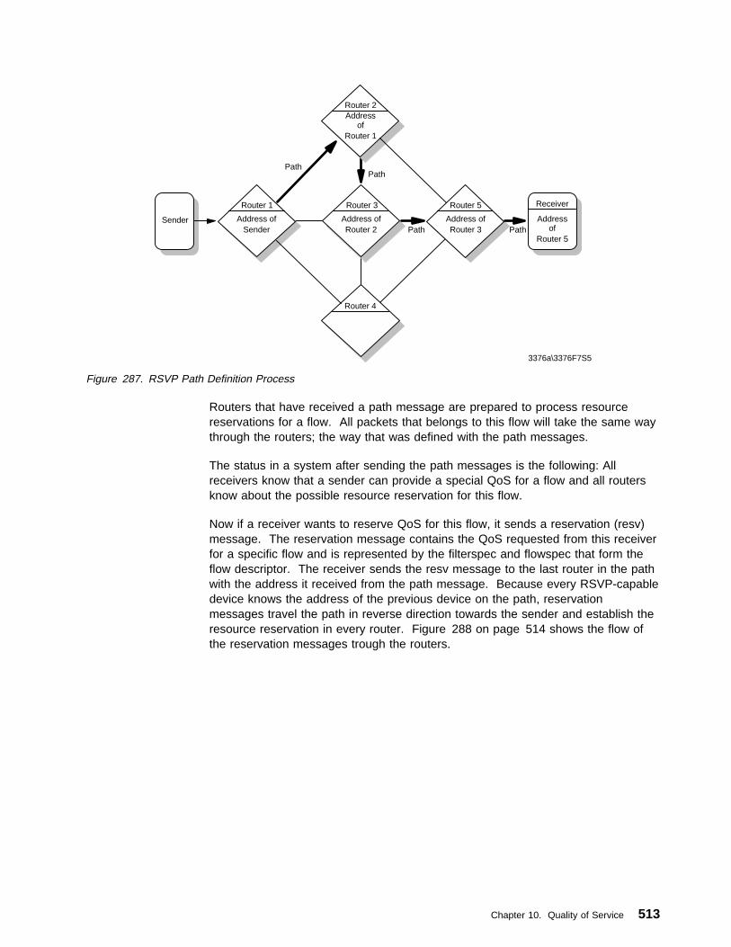
Router 1
Sender
Router 3 Router 5 Receiver
Router 2
Router 4
3376a\3376F7S5
Address of
Router 1
Address ofSender
Address ofRouter 2
Address ofRouter 3
Address of
Router 5
PathPath
Path Path
Figure 287. RSVP Path Definition Process
Routers that have received a path message are prepared to process resourcereservations for a flow. All packets that belongs to this flow will take the same waythrough the routers; the way that was defined with the path messages.
The status in a system after sending the path messages is the following: Allreceivers know that a sender can provide a special QoS for a flow and all routersknow about the possible resource reservation for this flow.
Now if a receiver wants to reserve QoS for this flow, it sends a reservation (resv)message. The reservation message contains the QoS requested from this receiverfor a specific flow and is represented by the filterspec and flowspec that form theflow descriptor. The receiver sends the resv message to the last router in the pathwith the address it received from the path message. Because every RSVP-capabledevice knows the address of the previous device on the path, reservationmessages travel the path in reverse direction towards the sender and establish theresource reservation in every router. Figure 288 on page 514 shows the flow ofthe reservation messages trough the routers.
Chapter 10. Quality of Service 513

Router 1
Sender
Router 3 Router 5
Router 2
Router 4
3376a\3376F7S6
Address of
Router 1
Address ofSender
Address ofRouter 2
Address ofRouter 3
RESV
Receiver
Address of
Router 5
RESV
RESV
RESV
Figure 288. RSVP Resv Messages Flow
At each node, a reservation request initiates two actions:
1. QoS reservation on this link
The RSVP process passes the request to the admission control and policycontrol instance on the node. The admission control checks if the router hasthe necessary resources to establish the new QoS reservation and the policycontrol checks if the application has the authorization to make QoS requests. Ifone of these tests fails, the reservation is rejected and the RSVP processreturns a ResvErr error message to the appropriate receiver. If both checkssucceed, the node uses the filterspec information in the resv message to setthe packet classifier and the flowspec information to set the packet scheduler.After this, the packet classifier will recognize the packets that belong to thisflow and the packet scheduler will obtain the desired QoS defined by theflowspec.
Figure 289 on page 515 shows the reservation process in an RSVP router.
514 TCP/IP Tutorial and Technical Overview

PacketClassifier
PacketScheduler
Determine routeand QoS class
Prioritize and
schedulepacket link
RoutingResources?
PolicyControl
AdmissionControl
RESV Message
Data
ApplicationAuthority?
RESV Message
Flow Descriptor
Flowspec Filterspec
3376a\3376F7S7
Figure 289. RSVP Reservation Process
2. Forwarding of the reservation request
After a successful admission and policy check, a reservation request ispropagated upstream towards the sender. In a multicast environment, areceiver can get data from multiple senders. The set of sender hosts to whicha given reservation request is propagated is called the scope of that request.The reservation request that is forwarded by a node after a successfulreservation can differ from the request that was received from the previous hopdownstream. One possible reason for this is that the traffic control mechanismmay modify the flowspec hop-by-hop. Another, more important reason is thatin a multicast environment, reservations from different downstream branchesbut for the same sender are merged together as they travel across theupstream path. This merging is necessary to conserve resources in therouters.
A successful reservation request propagates upstream along the multicast treeuntil it reaches a point where an existing reservation is equal or greater thanthat being requested. At this point, the arriving request is merged with thereservation in place and need not be forwarded further.
Figure 290 on page 516 shows the reservation merging for a multicast flow.
Chapter 10. Quality of Service 515

R2
RESV
R1
Path
Host
Router
Reserved ResourcesPacket FlowPath MessageReservation Message
S
Path
RESV
RESV
RESV
Reservation Merge
3376a\3376F7S4
Figure 290. RSVP Reservation Merging for Multicast Flows
If the reservation request reaches the sender, the QoS reservation was establishedin every router on the path and the application can start to send packetsdownstream to the receivers. The packet classifier and the packet scheduler ineach router make sure that the packets are forwarded according to the requestedQoS.
This type of reservation is only reasonable if all routers on the path support RSVP.If only one router doesn't support resource reservation, the service cannot beguaranteed for the whole path because of the "best effort" restrictions that apply fornormal routers. A router on the path that doesn't support RSVP would be abottleneck for the flow.
A receiver that originates a reservation request can also request a confirmationmessage that indicates that the request was installed in the network. The receiverincludes a confirmation request in the Resv message and gets a ResvConfmessage if the reservation was established successfully.
RSVP resource reservations maintain soft-state in routers and hosts, which meansthat a reservation is canceled if RSVP doesn't send refresh messages along thepath for an existing reservation. This allows route changes without resulting inprotocol overhead. Path messages must also be resent because the path statefields in the routers will be reset after a time-out period.
Path and reservation states can also be deleted with RSVP teardown messages.There are two types of teardown messages:
� PathTear messages
PathTear messages travel downstream from the point of initiation to allreceivers, deleting the path state as well as all dependent reservation states ineach RSVP-capable device.
� ResvTear messages
ResvTear messages travel upstream from the point of initiation to all senders,deleting reservation states in all routers and hosts.
516 TCP/IP Tutorial and Technical Overview

Teardown request can be initiated by senders, receivers or routers that notice astate timeout. Because of the soft-state principle of RSVP reservations, it is notreally necessary to explicitly tear down an old reservation. Nevertheless, it isrecommended that all end hosts send a teardown request if a consistingreservation is no longer needed.
10.2.2.2 RSVP Reservation StylesUsers of multicast multimedia applications often receive flows from differentsenders. In the reservation process described in 10.2.2.1, “RSVP Operation” onpage 512, a receiver must initiate a separate reservation request for each flow itwants to receive. But RSVP provides a more flexible way to reserve QoS for flowsfrom different senders. A reservation request includes a set of options that arecalled the reservation style. One of these options deals with the treatment ofreservations for different senders within the same session. The receiver canestablish a distinct reservation for each sender or make a single shared reservationfor all packets from the senders in one session.
Another option defines how the senders for a reservation request are selected. It ispossible to specify an explicit list or a wildcard that selects the senders belonging toone session. In an explicit sender-selection reservation, a filterspec must identifyexactly one sender. In a wildcard sender-selection the filterspec is not needed.Figure 291 shows the reservation styles that are defined with this reservationoption:
Sender Selection
DistinctReservation
SharedReservation
Explicit Fixed-Filter(FF) Style
Shared-Explicit(SE)Style
Wildcard (Not Defined) Wildcard-Filter (WF) Style
3376A\3376F7S8
Figure 291. RSVP Reservation Styles
Wildcard-Filter (WF)The Wildcard-Filter style uses the options shared reservation andwildcard sender selection. This reservation style establishes a singlereservation for all senders in a session. Reservations from differentsenders are merged together along the path so that only the biggestreservation request reaches the senders.
A wildcard reservation is forwarded upstream to all sender hosts. If newsenders appear in the session, for example, new members enter avideoconferencing, the reservation is extended to this new senders.
Fixed-Filter (FF)The Fixed-Filter style uses the option's distinct reservations and explicitsender selection. This means that a distinct reservation is created fordata packets from a particular sender. Packets from different sendersthat are in the the same session do not share reservations.
Shared-Explicit (SE)The Shared-Explicit style uses the option's shared reservation andexplicit sender selection. This means that a single reservation coversflows from a specified subset of senders. Therefore a sender list mustbe included into the reservation request from the receiver.
Chapter 10. Quality of Service 517

Reservations established in shared style (WF and SE) are mostly used for multicastapplications. For this type of application, it is unlikely that several data sourcestransmits data simultaneously so that it is not necessary to reserve QoS for eachsender.
For example, in an audio conference that consists of five participants, every stationsends a data stream with 64 kbps. With a Fixed-Filter style reservation, allmembers of the conference must establish four separate 64 kbps reservations forthe flows from the other senders. But in an audio conference most times only oneor two people speak at the same time. Therefore it would be sufficient to reserve abandwidth of 128 kbps for all senders, because most audio conferencing softwareuses silence suppression which means that if a person doesn't speak, no packetsare sent. This can be realized if every receiver makes one shared reservation of128 kbps for all senders.
Using the Shared-Explicit style, all receivers must explicitly identify all other sendersin the conference. With Wildcard-Filter style the reservation counts for everysender that matches the reservation specifications. If, for example the audioconferencing tool sends the data packets to a special TCP/IP port, the receiverscan make a Wildcard-Filter reservation for all packets with this destination port.
10.2.2.3 RSVP Messages FormatBasically an RSVP message consists of a common header, followed by a bodyconsisting of a variable number of objects. The number and the content of theseobjects depends on the message type. The message objects contain theinformation that is necessary to realize resource reservations, for example the flowdescriptor or the reservation style. In most cases, the order of the objects in anRSVP message makes no logical difference. RFC 2205 recommends that an RSVPimplementation should use the object order defined in the RFC but accept theobjects in any permissible order. Figure 292 shows the common header of aRSVP message:
Version
3376\3376F7S9
0 1234567 89101112131415 16 920212223 2425262728293 31
Message Type RSVP ChecksumFlags
Send_TTL (Reserved) RSVP Length
Figure 292. RSVP Common Header
Where:
Version4-bit RSVP protocol number. The current version is 1.
Flags4-bit field that is reserved for flags. No flags are defined yet.
Message Type8-bit field that specifies the message type:
1. Path
2. Resv
518 TCP/IP Tutorial and Technical Overview

3. PathErr
4. ResvErr
5. PathTear
6. ResvTear
7. ResvConf
RSVP Checksum16-bit field. The Checksum can be used by receivers of an RSVPmessage to detect errors in the transmission of this message.
Send_TTL8-bit field, which contains the IP TTL value the message was sent with.
RSVP Length16-bit field that contains the total length of the RSVP message includingthe common header and all objects that follow. The length is counted inbytes.
The RSVP objects that follow the common header consist of a 32-bit header andone or more 32-bit words. Figure 293 shows the RSVP object header:
Length (Bytes)
3376\3376F7SA
0 1234567891011121314151617181920212223 2425262728293031
Class - Number
(Object Contents)
C-Type
Figure 293. RSVP Object Header
Where:
Length16-bit field that contains the object length in bytes. This must be amultiple of 4. The minimum length is 4 bytes.
Class-NumberIdentifies the object class. The following classes are defined:
� Null
The NULL object has a Class-Number of zero. The length of thisobject must be at least 4, but can be any multiple of 4. The NULLobject can appear anywhere in the object sequence of an RSVPmessage. The content is ignored by the receiver.
� Session
The session object contains the IP destination address, the IPprotocol ID and the destination port, to define a specific session forthe other objects that follow. The session object is required in everyRSVP message.
� RSVP_HOP
Chapter 10. Quality of Service 519
The RSVP_HOP object contains the IP address of the node thatsent this message and a logical outgoing interface handle. Fordownstream messages (for example, path messages) theRSVP_HOP object represents a PHOP (previous hop) object and forupstream messages (for example, resv messages) it represents anNHOP (next hop) object.
� Time_Values
The Time_Values object contains the refresh period for path andreservation messages. If these messages are not refreshed withinthe specified time period, the path or reservation state is canceled.
� Style
The style object defines the reservation style and some style-specificinformation that is not in Flowspec or Fiterspec. The style object isrequired in every resv message.
� Flowspec
This object specifies the required QoS in reservation messages.
� Filterspec
The Filterspec object defines which data packets receive the QoSspecified in the Flowspec.
� Sender_Template
This object contains the sender IP address and additionaldemultiplexing information, which is used to identify a sender. TheSender_Template is required in every Path message.
� Sender_Tspec
This object defines the traffic characteristics of a data flow from asender. The Sender_Tspec is required in all path messages.
� Adspec
The adspec object is used to provide advertising information to thetraffic control modules in the RSVP nodes along the path.
� Error_Spec
This object specifies an error in a PathErr, ResvErr, or aconfirmation in a ResvConf message.
� Policy_Data
This object contains information that allows a policy module todecide whether an associated reservation is administrativelypermitted or not. It can be used in Path, Resv, PathErr, or ResvErrmessages.
� Integrity
The integrity object contains cryptographic data to authenticate theoriginating node and to verify the contents of an RSVP message.
� Scope
The Scope object contains an explicit list of sender hosts to whichthe information in the message are sent. The object can appear ina Resv, ResvErr, or ResvTear messages.
520 TCP/IP Tutorial and Technical Overview

� Resv_Confirm
This object contains the IP address of a receiver that requestsconfirmation for its reservation. It can be used in a Resv orResvConf message.
C-TypeThe C-Type specifies the object type within the class number. Differentobject types are used for IPv4 and IPv6.
Object contentsThe object content depend on the object type and has a maximumlength of 65528 bytes.
All RSVP messages are built of a variable number of objects. The recommendedobject order for the most important RSVP messages, the path and the resvmessage are shown in the following. Figure 294 gives an overview about theformat of the RSVP path message. Objects that can appear in a path message butthat are not required are parenthesized.
3376\3376F7SB
0 1234567 89101112131415 16 920212223 2425262728293 31
Common Header
(Integrity)
Session
RSVP_Hop
Time_Values
(Policy_Data))
Sender_Template
Sender_Tspec
(ADSPEC)
Figure 294. RSVP Path Message Format
If the Integrity object is used in the path message, it must immediately follow thecommon header. The order of the other objects may differ in different RSVPimplementations, but the one shown above is recommended by the RFC.
The RSVP Resv messages looks similar to the path message. Figure 295 onpage 522 shows the objects used for reservation messages:
Chapter 10. Quality of Service 521

3376\3376F7S9
0 1234567 89101112131415 16 920212223 2425262728293 31
Common Header
(Integrity)
Session
RSVP_Hop
Time_Values
(Reso_Confirm)
(Scope)
(Policy_Data)
Style
Flow Descriptor List
Figure 295. RSVP Resv Message Format
As in the path message, the Integrity object must follow the common header if it isused. Another restriction applies for the Style object and the following flowdescriptor list. They must occur at the end of the message. The order of the otherobjects follows the recommendation from the RFC.
For a detailed description of the RSVP message structure and the handling of thedifferent reservation styles in reservation messages, please consult RFC 2205.
10.2.3 The Future of Integrated ServicesAt the moment it is not known if the integrated services model will win recognitionin the future Internet. More and more router manufacturers support RSVP in theirrouters. But to provide IS for a larger group of users, many Internet routers shouldsupport RSVP.
An important point that should be monitored by the router manufacturers is thetraffic control overhead in RSVP-capable routers that may decrease the routingperformance. The more data flows are passing a router, the more RSVP sessionsmust be handled by the RSVP daemon inside of the router. Router manufacturersmust make sure that in high traffic situations a router is not blocked with managingRSVP sessions instead of routing data packets and keeping up with routing tableupdates.
Future extensions of the policy control module may implement a priority mechanismthat allows users to send reservation requests with higher priority than others. Ifthe routers on the path run out of routing capacity, the high-priority requests will befavored. This may be coupled with a billing system that charges the user for
522 TCP/IP Tutorial and Technical Overview
high-priority reservation requests. If IS is supported in the Internet, it must beassured that the normal best-effort traffic is still served. It must not happen thatsome routers are blocked with RSVP reservations and can't handle any best-efforttraffic. This may even be an economic policy decision for ISPs to make. Aconceivable scenario is that one half of the routing capacity is used for RSVP flowreservations and the other half for the classic best-effort traffic.
It may be some time, if ever, that RSVP end-to-end services are deployed on theInternet. At the moment, IS is preferably used in corporate intranets to providemultimedia and other real-time data to the end users. For example, if all routers inan intranet support RSVP, a video transmission can be broadcasted, forinformational or educational reasons, to all workstations in a company.
10.3 Differentiated ServicesThe Differentiated Services (DS) concept is currently under development at theIETF DS working group. The DS specifications are defined in some IETF Internetdrafts and there is no RFC available yet. This paragraph gives an overview aboutthe rudiments and ideas to provide service differentiation in the Internet. Becausethe concept is still under development, some of the specifications mentioned in thisbook may be changed in the final definition of differentiated services.
The goal of the DS development is to get a possibility to provide differentiatedclasses of service for Internet traffic, to support various types of applications, andspecific business requirements. DS offers predictable performance (delay, thruput,packet loss, etc.) for a given load at a given time. The difference betweenIntegrated Services, described in 10.2, “Integrated Services” on page 506, andDifferentiated Services is, that DS provides scalable service discrimination in theInternet without the need for per-flow state and signaling at every hop. It is notnecessary to perform a unique QoS reservation for each flow. With DS, theInternet traffic is split into different classes with different QoS requirements.
A central component of DS is the Service Level Agreement (SLA). The SLA is aservice contract between a customer and a service provider that specifies thedetails of the traffic classifying and the corresponding forwarding service acustomer should receive. A customer may be a user organization or another DSdomain. The service provider must assure that the traffic of a customer, with whomit has an SLA, gets the contracted QoS. Therefore the service provider's networkadministration must set up the appropriate service policies and measure thenetwork performance to guarantee the agreed traffic performance.
To distinguish the data packets from different customers in DS-capable networkdevices, the IP packets are modified in a specific field. A small bit-pattern, calledthe DS byte, in each IP packet is used to mark the packets that receive a particularforwarding treatment at each network node. The DS byte uses the space of theTOS octet in the IPv4 IP header 2.1.8.1, “IP Datagram Format” on page 48 and thetraffic class octet in the IPv6 header. All network traffic inside of a domain receivesa service that depends on the traffic class that is specified in the DS byte.
To provide SLA conform services, the following mechanisms must be combined ina network:
� Setting bits in the DS byte (TOS octet) at network edges and administrativeboundaries.
Chapter 10. Quality of Service 523

� Using those bits to determine how packets are treated by the routers inside thenetwork.
� Conditioning the marked packets at network boundaries in accordance with theQoS requirements of each service.
The currently defined DS architecture only provides service differentiation in onedirection and is therefore asymmetric. Development of a complementary symmetricarchitecture is a topic of current research. The following paragraph describes theDS architecture in more detail.
10.3.1 Differentiated Services ArchitectureUnlike Integrated Services, QoS guarantees with Differentiated Services are staticand stay long-term in routers. This means that applications using DS don't need toset up QoS reservations for specific data packets. All traffic that passes DS-capablenetworks can receive a specific QoS. The data packets must be marked with theDS byte which is interpreted by the routers in the network.
10.3.1.1 The Per-Hop BehaviorAs mentioned before, the IETF DS working group has proposed to redefine thestructure of the IPv4 TOS byte and the IPv6 traffic class field and re-label this fieldas the DS byte. The DS byte specifications supersede the IPv4 TOS octetdefinitions of RFC 1349.Figure 296 shows the structure of the newly defined DSbyte.
CU
0 1 2 3 4 5 6 7
DSCP
3376X\3376F7SG
Figure 296. DS Byte
Six bits of the DS field are used as a Differentiated Services CodePoint (DSCP) toselect the traffic class a packet experiences at each node. A two-bit currentlyunused (CU) field is reserved and can be assigned later.
Each DS-capable network device must have information on how packets withdifferent DS bytes should be handled. In the DS specifications this information iscalled the Per-Hop Behavior (PHB). It is a description of the forwarding treatment apacket receives at a given network node. The DSCP value in the DS byte is usedto select the PHB a packet experiences at each node. To provide predictableservices, per-hop behaviors need to be available in all routers in a DifferentiatedServices-capable network. The PHB can be described as a set of parametersinside of a router that can be used to control how packets are scheduled onto anoutput interface. This can be a number of separate queues with settable priorities,parameters for queue lengths or drop algorithms and drop preference weights forpackets.
DS requires routers that support queue scheduling and management to prioritizeoutbound packets and control the queue depth to minimize congestion on thenetwork. The traditional FIFO queuing in common Internet routers provides noservice differentiation and can lead to network performance problems. The packettreatment inside of a router depends on the router's capabilities and its particularconfiguration and it is selected by the DS byte in the IP packet. For example, if a
524 TCP/IP Tutorial and Technical Overview

IP packet reaches a router with eight different queues that all have differentpriorities, the DS byte can be used to select which queue is liable for the routing ofthis packet. The scale reaches from zero, for lowest priority to seven for highestpriority.
Router
Queue 7 (Highest Priority)
Queue 6
Queue 5
Queue 4
Queue 3
Queue 2
Queue 1
Queue 0 (Lowest Priority)
Incoming Traffic
1 5 2
Outgoing Traffic
6 6 7 7 7
3376X\3376F7SD
Figure 297. DS Routing Example
Another example is a router that has a single queue with multiple drop priorities fordata packets. It uses the DS byte to select the drop preference for the packets inthe queue. A value of zero means "it is most likely to drop this packet", and sevenmeans "it is least likely to drop this packet". Another possible constellation are fourqueues with two levels of drop preference in each.
To make sure that the per-hop behaviors in each router are functionally equivalent,certain common PHBs must be defined in future DS specifications to avoid that thesame DS byte value causes different forwarding behaviors in different routers ofone DS domain. This means that in future DS specifications some unique PHBvalues must be defined that represent specific service classes. All routers in oneDS domain must know which service a packet with a specific PHB should receive.The DiffServ Working Group will propose PHBs that should be used to providedifferentiated services. Some of these proposed PHBs will be standardized, othersmay have widespread use and still others may remain experimental.
PHBs will be defined in groups. A PHB group is a a set of one or more PHBs thatcan only be specified and implemented simultaneously, because of queue servicingor queue management policies that apply to all PHBs in one group. A default PHBmust be available in all DS-compliant nodes. It represents the standard best-effortforwarding behavior available in existing routers. When no other agreements are inplace, it is assumed that packets belong to this service level. The IETF workinggroup recommends to use the DSCP value 000000 in the DS byte to define thedefault PHB.
Chapter 10. Quality of Service 525

Another PHB that is proposed for standardization is the Expedited Forwarding (EF)PHB. It is a high priority behavior that is typically used for network control trafficsuch as routing updates. The value 101100 in the DSCP field of the DS byte isrecommended for the EF PHB.
10.3.1.2 Differentiated Services DomainsThe setup of QoS guarantees is not made for specific end-to-end connections butfor well-defined Differentiated Services domains. The IETF working group defines aDifferentiated Services domain as a contiguous portion of the Internet over which aconsistent set of Differentiated Services policies are administered in a coordinatedfashion. It can represent different administrative domains or autonomous systems,different trust regions, different network technologies, such as cell or frame-basedtechniques, hosts and routers. A DS domain consists of boundary components thatare used to connect different DS domains to each other and interior componentsthat are only used inside of the domains. Figure 298 shows the use of boundaryand interior components for two DS domains.
Domain
I
B I
I
B
I
B I
I
B
Domain
3376A\3376F7SE
B = Boundary Component I = Interior Component
Figure 298. DS Domain
A DS domain normally consists of one or more networks under the sameadministration. This can be, for example, a corporate intranet or an InternetService Provider (ISP). The administration of the DS domain is responsible forensuring that adequate resources are provisioned and reserved to support theSLAs offered by the domain. Network administrators must use appropriatemeasurement techniques to monitor if the network resources in a DS domain aresufficient to satisfy all authorized QoS requests.
10.3.1.3 DS Boundary NodesAll data packets that travel from one DS domain to another must pass a boundarynode which can be a router, a host or a firewall. A DS boundary node that handlestraffic leaving a DS domain is called an egress node and a boundary node thathandles traffic entering a DS domain is called an ingress node. Normally, DSboundary nodes act both as ingress node and egress node depending on the trafficdirection. The ingress node must make sure, that the packets entering a domainreceives the same QoS as in the domain the packets traveled before. A DS egressnode performs conditioning functions on traffic that is forwarded to a directlyconnected peering domain. The traffic conditioning is done inside of a boundarynode by a traffic conditioner. It classifies, marks and possibly conditions packets
526 TCP/IP Tutorial and Technical Overview

that enter or leave the DS domain. A traffic conditioner consists of the followingcomponents:
ClassifierA classifier selects packets based on their packet header and forwardsthe packets that match the classifier rules for further processing. TheDS model specifies two types of packet classifiers:
1. Multi-field (MF) classifiers which can classify on the DS byte as wellas on any other IP header field, for example the IP address and theport number like an RSVP classifier.
2. Behavior Aggregate (BA) classifiers which classify only on the bits inthe DS byte.
MeterTraffic meters measure if the forwarding of the packets that are selectedby the classifier correspond to the traffic profile that describes the QoSfor the SLA between customer and service provider. A meter passesstate information to other conditioning functions to trigger a particularaction for each packet which either does or does not comply with therequested QoS requirements.
MarkerDS markers set the DS byte of the incoming IP packets to a particularbit pattern. The PHB is set in the first 6 bits of the DS byte so that themarked packets are forwarded inside of the DS domain accordingly tothe SLA between service provider and customer.
Shaper/DropperPacket shapers and droppers cause conformance to some configuredtraffic properties, for example a token bucket filter as described in10.2.1, “Service Classes” on page 508. They use different methods tobring the stream into compliance with a traffic profile. Shapers delaysome or all of the packets. A shaper usually has a finite-size buffer, andpackets may be discarded if there is not sufficient buffer space to holdthe delayed packets. Droppers discard some or all of the packets. Thisprocess is know as policing the stream. A dropper can be implementedas a special case of a shaper by setting the shaper buffer size to zeropackets.
The traffic conditioner is mainly used in DS boundary components but it can alsobe implemented in an interior component. Figure 299 shows the cooperation of thetraffic conditioner components.
Packets MarkerShaper/DropperClassifier
Meter
3376A\3376F7SH
Figure 299. DS Traffic Conditioner
The traffic conditioner in a boundary component makes sure that packets thattransit the domain are correctly marked to select a PHB from one of the PHB
Chapter 10. Quality of Service 527

groups supported within the domain. This is necessary because different DSdomains can have different groups of PHBs, which means that the same entry inthe DS byte can be interpreted variably in different domains.
For example, in the first domain a packet traverses, all routers have four queueswith different queue priorities (0-3). Packets with a PHB value of three are routedwith the highest priority. But in the next domain the packet travels through, allrouters have eight different queues and all packets with the PHB value of seven arerouted with the highest priority. The packet that was forwarded in the first domainwith high priority has only medium priority in the second domain. This may violatethe SLA contract between customer and service provider. Therefore, the trafficconditioner in the boundary router that connects the two domains, must assure thatthe PHB value is remarked from three to seven if the packet travels from the first tothe second domain. Figure 300 shows an example for the remarking of datapackets that travel trough two different domains.
Interior Router
3
2
1
0
3 3
Boundary Router
7
6
5
4
3
2
1
0
7 7
Classifying Remarking
3 7
Interior Router
7
6
5
4
3
2
1
03
3376X\3376F7SJ
Figure 300. Remarking of Data Packets
If a data packet travels through multiple domains, the DS byte can be remarked atevery boundary component to guarantee the QoS that was contracted in the SLA.The SLA contains the details of the Traffic Conditioning Agreement (TCA) thatspecifies classifier rules and temporal properties of a traffic stream. The TCAcontains information how metering, marking, discarding and shaping of packetsmust be done in the traffic conditioner to fulfill the SLA. The TCA information mustbe available in all boundary components of a DS network to guarantee that packetspassing different DS domains receives the same service in each domain.
10.3.1.4 DS Interior ComponentsThe interior components inside of a DS domain select the forwarding behavior forpackets based on their DS byte. The interior component is usually a router thatcontains a traffic prioritization algorithm. Because the value of the DS byte normallydoesn't change inside of a DS domain, all interior routers must use the same trafficforwarding policies to comply with the QoS agreement. Data packets with differentPHB values in the DS byte receive different QoSs according to the QoS definitionsfor this PHB. Because all interior routers in a domain use the same policyfunctions for incoming traffic, the traffic conditioning inside of an interior node isdone only by a packet classifier. It selects packets based on their PHB value orother IP header fields and forwards the packets to the queue management andscheduling instance of the node. Figure 301 on page 529 shows the trafficconditioning in an interior node.
528 TCP/IP Tutorial and Technical Overview
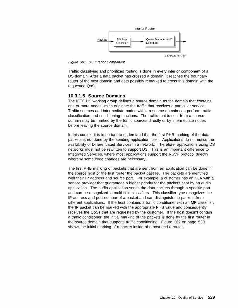
Interior Router
Packets DS ByteClassifier
Queue Management/Scheduler
3376A\3376F7SF
Figure 301. DS Interior Component
Traffic classifying and prioritized routing is done in every interior component of aDS domain. After a data packet has crossed a domain, it reaches the boundaryrouter of the next domain and gets possibly remarked to cross this domain with therequested QoS.
10.3.1.5 Source DomainsThe IETF DS working group defines a source domain as the domain that containsone or more nodes which originate the traffic that receives a particular service.Traffic sources and intermediate nodes within a source domain can perform trafficclassification and conditioning functions. The traffic that is sent from a sourcedomain may be marked by the traffic sources directly or by intermediate nodesbefore leaving the source domain.
In this context it is important to understand that the first PHB marking of the datapackets is not done by the sending application itself. Applications do not notice theavailability of Differentiated Services in a network. Therefore, applications using DSnetworks must not be rewritten to support DS. This is an important difference toIntegrated Services, where most applications support the RSVP protocol directlywhereby some code changes are necessary.
The first PHB marking of packets that are sent from an application can be done inthe source host or the first router the packet passes. The packets are identifiedwith their IP address and source port. For example, a customer has an SLA with aservice provider that guarantees a higher priority for the packets sent by an audioapplication. The audio application sends the data packets through a specific portand can be recognized in multi-field classifiers. This classifier type recognizes theIP address and port number of a packet and can distinguish the packets fromdifferent applications. If the host contains a traffic conditioner with an MF classifier,the IP packet can be marked with the appropriate PHB value and consequentlyreceives the QoSs that are requested by the customer. If the host doesn't containa traffic conditioner, the initial marking of the packets is done by the first router inthe source domain that supports traffic conditioning. Figure 302 on page 530shows the initial marking of a packet inside of a host and a router.
Chapter 10. Quality of Service 529
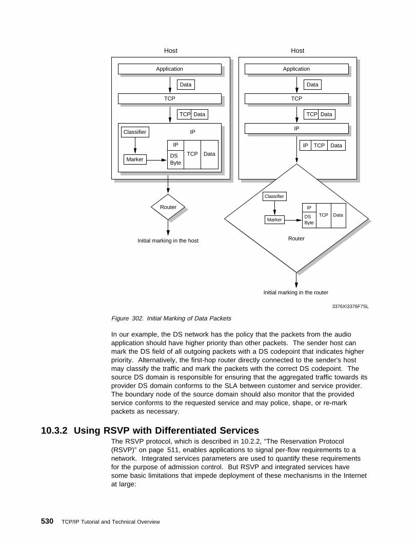
Host
Data
Classifier IP
IP
DSByte
TCP DataMarker
Router
TCP Data
TCP
Application
Host
Data
IP TCP Data
TCP Data
TCP
Application
IP
Router
Classifier
IP
DSByte
TCP DataMarker
Initial marking in the host
Initial marking in the router
3376X\3376F7SL
Figure 302. Initial Marking of Data Packets
In our example, the DS network has the policy that the packets from the audioapplication should have higher priority than other packets. The sender host canmark the DS field of all outgoing packets with a DS codepoint that indicates higherpriority. Alternatively, the first-hop router directly connected to the sender's hostmay classify the traffic and mark the packets with the correct DS codepoint. Thesource DS domain is responsible for ensuring that the aggregated traffic towards itsprovider DS domain conforms to the SLA between customer and service provider.The boundary node of the source domain should also monitor that the providedservice conforms to the requested service and may police, shape, or re-markpackets as necessary.
10.3.2 Using RSVP with Differentiated ServicesThe RSVP protocol, which is described in 10.2.2, “The Reservation Protocol(RSVP)” on page 511, enables applications to signal per-flow requirements to anetwork. Integrated services parameters are used to quantify these requirementsfor the purpose of admission control. But RSVP and integrated services havesome basic limitations that impede deployment of these mechanisms in the Internetat large:
530 TCP/IP Tutorial and Technical Overview

1. The reliance of RSVP on per-flow state and per-flow processing raisesscalability concerns in large networks.
2. Today, only a small number of hosts generate RSVP signaling. Although thisnumber is expected to grow dramatically, many applications may nevergenerate RSVP signaling.
3. Many applications require a form of QoS, but are unable to express theserequirements using the IS model.
These disadvantages can be circumvented if Integrated Services is implementedonly in intranets and it uses Differentiated Services 10.3, “Differentiated Services”on page 523 in the Internet as a backbone. Figure 303 shows an imaginablenetwork structure:
Internet Backbone(DiffServ)
CustomerSite (RSVP)
CustomerSite (RSVP)
R2
R1
R3
R4
3376A\3376F7SI
Figure 303. Using RSVP with Differentiated Services
Two RSVP-capable customer intranets are connected to the DS Internet backbone.The routers R2 and R3 are boundary routers that can condition incoming andoutgoing traffic at the interfaces of the DS network to the IS networks. In ourexample, the boundary routers are not required to run RSVP. They are expectedto implement the policing functions of the DS ingress router. There must be a setof end-to-end services defined in the DS network that allows the mapping of RSVPflow reservations to an appropriate DS service class. The routers in the DSnetwork must provide a set of per-hop behaviors (see 10.3.1.1, “The Per-HopBehavior” on page 524), which provide the service of a true end-to-end connection.It must be possible for RSVP applications to invoke specific end-to-end servicelevels for their traffic flows in the DS network. In this model, the IS intranets arecustomers of the DS Internet.
The edge routers R1 and R4 are special routers that work both in the RSVP/ISregion of the network and the DS region of the network. These routers can bevisualized as split in two halves. One half supports standard RSVP and itinterfaces to the intranets. The other half supports DS and interfaces to the DSInternet. The RSVP half must be at least partially RSVP-capable. The router mustbe able to process PATH and RESV messages but it is not required to supportpacket classification and storing of RSVP states. The DS half of the routerprovides the interface to the Admission Control function for the DS network. If theservice agreement between the IS intranets and the DS Internet is static, theAdmission Control Service can be a simple table which specifies the QoS at each
Chapter 10. Quality of Service 531

service level. If the service agreement is dynamic, Admission Control Servicecommunicates with counterparts within the DS network to make admission controldecisions based on the capacity of the network.
In our model, RSVP signaling is used to provide admission control to specificservice levels in the DS and the IS network. RSVP signaling messages carry an ISQoS description that specifies the type of service that should be provided in the ISregions of the network. At the boundary between the IS network and a DS networkthe edge routers map the requested IS QoS to an appropriate DS service level.After this, the edge router can provide admission control to the DS network byaccepting or rejecting the QoS request based on the capacity available at therequested DS service level. If an RSVP reservation message from the IS networkarrives at an edge router, the RSVP flow descriptor will be mapped to a PHB thatrepresents the corresponding service level in the DS network. The edge routerappends the PHB value to the RSVP reservation message which is carried to thesending host. The sending host then marks all outgoing packets with this PHBvalue. This approach allows end-to-end QoS guarantees for RSVP applications indifferent intranets that use the DS Internet as backbone.
10.3.3 Configuration and Administration of DS Components withLDAP
In a differentiated services network, the service level information must be providedto all network elements to ensure correct administrative control of bandwidth, delayor dropping preferences for a given customer flow. All DS boundary componentsmust have the same policy information for the defined service levels. This makessure that the packets marked with the DS byte receive the same service in all DSdomains. If only one domain in the DS network has different policy information, itcan happen that the data packets passing this domain don't receive the service thatwas contracted in the SLA between customer and service provider.
Network administrators can define different service levels for different customersand provide this information manually to all boundary components. This policyinformation remains statically in the network components until the next manualchange.
But in dynamic network environments it is necessary to enable flexible definitions ofclass-based packet handling behaviors and class-based policy control.Administrative policies can change in a running environment whereby it isnecessary to store the policies in a directory-based repository. The policyinformation from the directory can be distributed across multiple physical servers,but the administration is done for a a single entity by the network administrator.The directory information must be propagated on all network elements, such ashosts, proxies and routers, that use the policy information for traffic conditioning inthe DS network.
In today's heterogeneous environments, it is likely that network devices andadministrative tools are developed by different vendors. Therefore, it is necessaryto use a standardized format to store the administrative policies in the directoryserver function and a standardized mechanism to provide the directory informationto the DS boundary components which act as directory clients. These functions areprovided by the Lightweight Directory Access Protocol (LDAP) which is a commonlyused industry standard for directory accessing (see 12.3, “Lightweight DirectoryAccess Protocol (LDAP)” on page 577). LDAP is a widely deployed and simple
532 TCP/IP Tutorial and Technical Overview

protocol for directory access. Policy rules for different service levels are stored indirectories as LDAP schema and can be downloaded to devices that implement thepolicies, such as hosts, routers, policy servers or proxies. Figure 304 on page 533shows the cooperation of the DS network elements with the LDAP server.
LDAP = Lightweight Directory Access Protocol
Boundary Components
AAAAAAAAAAAAAAAAAAAAAAAAAAAAAAAAAAAAAAAAAAAAAAAAAAAAAAAAAAAAAAAAAAAAAAAAAAAAAAAAAAAAAAAAAAAAAAAAAAAAAAAAAAAAAAAAAAAA
AAAAAAAAAAAAAAAAAAAAAAAAAAAAAAAAAAAAAAAAAAAAAAAAAAAAAAAAAAAAAAAAAAAAAAAAAAAAAAAAAAAAAAAAAAAAAAAAAAAAAAAAAAAAAAAAAAAA
AAAAAAAAAAAAAAAAAAAAAAAAAAAAA
AAAAAAAA
AAAAAA
AAAAAAAAAAAAAAAAAAAA
AAAAAAAAAAAAAAAAAAAAAAAAAAAAAAAAAAAAAAAA
AAAAAAA
AAAAAAA
AAAAAAAAAAAAAAAA
AAAAAAAA
AAAAAAAA
AAAAAAAA
AAAAAAAA
AAAAAAAA
AAAAAAAA
AAAAAAAA
AA
AAAAAAAAAAAAAAAAAAAAAAAAAAAAA
AAAAAAAA
AAAAAAAA
AAAA
AAAAAAAAA
AAAAAAAAAAAAAAAAAAAAAAAA
AAAAAAAAAAAAAAAAAAAAAAAA
AAAAAAAAAAAAAAAAAAAAAAAA
AAAAAAAA
AAAAAAAA
AAAAAAAA
AA
LDAP Client
PolicyDatabase
AAAAAAAAAAAAAAAAAAAAAAAAAAAAAAAAAAAAAAAAAAAAAAAAAAAAAAAAAAAAAAAAAAAAAAAAAAAAAAAAAAAAAAAAAAAAAAAAAAAAAAAAAAAAAAAAAAAA
AAAAAAAAAAAAAAAAAAAAAAAAAAAAAAAAAAAAAAAAAAAAAAAAAAAAAAAAAAAAAAAAAAAAAAAAAAAAAAAAAAAAAAAAAAAAAAAAAAAAAAAAAAAAAAAAAAAA
AAAAAAAAAAAAAAAAAAAAAAAAAAAAA
AAAAAAAA
AAAAAA
AAAAAAAAAAAAAAAAAAAA
AAAAAAAAAAAAAAAAAAAAAAAAAAAAAAAAAAAAAAAA
AAAAAAA
AAAAAAA
AAAAAAAA
AAAAAAAA
AAAAAAAA
AAAAAAAA
AAAAAAAA
AAAAAAAA
AAAAAAAA
AAAAAAAA
AAAAAAAA
AAAAAAAA
AAAAAAAA
AA
AAAAAAAAAAAAAAAAAAAAAAAAAAAA
AAAAAAAA
AAAAAAAA
AAAA
AAAAAAAAA
AAAAAAAAAAAAAAAAAAAAAAAA
AAAAAAAAAAAAAAAAAAAAAAAA
AAAAAAAAAAAAAAAAAAAAAAAA
AAAAAAAA
AAAAAAAA
AAAAAAAA
LDAP Server
Boundary Components
AAAAAAAAAAAAAAAAAAAAAAAAAAAAAAAAAAAAAAAAAAAAAAAAAAAAAAAAAAAAAAAAAAAAAAAAAAAAAAAAAAAAAAAAAAAAAAAAAAAAAAAAAAAAAAAAAAAA
AAAAAAAAAAAAAAAAAAAAAAAAAAAAAAAAAAAAAAAAAAAAAAAAAAAAAAAAAAAAAAAAAAAAAAAAAAAAAAAAAAAAAAAAAAAAAAAAAAAAAAAAAAAAAAAAAAAA
AAAAAAAA
AAAA
AAAAAAAAAAAAAAAAAAAA
AAAAAAAAAAAAAAAAAAAA
AAAAAA
AAAAAA
AAAAAAAAAAAAAAAA
AAAAAAAA
AAAAAAAA
AAAAAAAA
AAAAAAAA
AAAAAAAA
AAAAAAAA
AAAAAAAA
AA
AAAAAAAAAAAAAAAAAAAAAAAAAAAAA
AAAAAAAA
AAAAAAAA
AAAA
AAAAAAAAA
AAAAAAAAAAAAAAAAAAAAAAAA
AAAAAAAAAAAAAAAAAAAAAAAA
AAAAAAAAAAAAAAAAAAAAAAAA
AAAAAAAA
AAAAAAAA
AAAAAAAA
AA
LDAP Client
IPInterior Components
Router
Router
Router
3376X\3376F7SK
Figure 304. Administration of DS Components with LDAP
10.3.4 Using Differentiated Services with IPSecThe IPsec protocol that is described in 5.5, “The IP Security Architecture (IPSec)”on page 297 does not use the DS field in an IP header for its cryptographiccalculations. Therefore, modification of the DS field by a network node has noeffect on IPsec's end-to-end security, because it cannot cause any IPsec integritycheck to fail. This makes it possible to use IPsec-secured packets in DS networks.
IPsec's tunnel mode provides security for the encapsulated IP header's DS field. Atunnel mode IPsec packet contains an outer header that is supplied by the tunnelstart point, and an encapsulated inner header that is supplied by the host that hasoriginally sent the packet.
Chapter 10. Quality of Service 533

Processing of the DS field in the presence of IPSec tunnels would then work asfollows:
1. The node where the IPsec tunnel begins encapsulates the incoming IP packetswith an outer IP header and sets the DS byte of the outer header accordinglyto the SLA in the local DS domain.
2. The secured packet travels through the DS network and intermediate nodesmodify the DS field in the outer IP header as appropriate.
3. If a packet reaches the end of an IPSec tunnel, the outer IP header is strippedoff by the tunnel end node and the packet is forwarded using the informationcontained in the inner (original) IP header.
4. If the DS domain of the original datagram is different from the DS domainwhere the IPSec tunnel ends, the tunnel end node must modify the DS byte ofthe inner header to match the SLA in its domain. The tunnel end node wouldthen effectively act as a DS ingress node.
5. As the packet travels onwards in the DS network on the other side of the IPSectunnel, intermediate nodes use the original IP header to modify the DS byte.
10.3.5 Internet Drafts on Differentiated ServicesThe following Internet drafts were available on Differentiated Services at the time ofwriting:
http://www.ietf.org/internet-drafts/draft-ietf-diffserv-arch-ð1.txt
http://www.ietf.org/internet-drafts/draft-nichols-dsopdef-ðð.txt
http://www.ietf.org/internet-drafts/draft-ietf-diffserv-header-ð2.txt
http://www.ietf.org/internet-drafts/draft-ietf-diffserv-framework-ðð.txt
http://www.ietf.org/internet-drafts/draft-ietf-diffserv-rsvp-ðð.txt
http://www.ietf.org/internet-drafts/draft-ietf-diffserv-phb-ef-ðð.txt
10.4 ReferencesPlease refer to the following RFCs for more information on QoS in the Internet:
� RFC 1349 — Type of Service in the Internet Protocol Suite
� RFC 1633 — Integrated Services in the Internet Architecture: An Overview
� RFC 2205 — Resource Reservation Protocol (RSVP) -- Version 1 FunctionalSpecification
� RFC 2206 — RSVP Management Information Base Using SMIv2
� RFC 2207 — RSVP Extensions for IPSEC Data Flows
� RFC 2208 — Resource Reservation Protocol (RSVP) -- Version 1 ApplicabilityStatement
� RFC 2209 — Resource Reservation Protocol (RSVP) -- Version 1 MessageProcessing Rules
� RFC 2210 — The Use of RSVP with IETF Integrated Services
� RFC 2211 — Specification of the Controlled Load Network Element Service
� RFC 2212 — Specification of Guaranteed Quality of Service
534 TCP/IP Tutorial and Technical Overview

Chapter 11. Availability, Scalability and Load Balancing
The Internet has grown so rapidly over the last few years that many companies arelooking for effective ways of dealing with the ever increasing amount of networktraffic and server load. If this growth is not handled properly, users experienceslow response times or refused connections. Internet sites become unstable oreven fail under critical load conditions, which are sometimes referred to as hotspots. Users are unhappy and often complain. What is needed is a solution thatprovides scalability, load balancing and availability. Before we take a look at somesolutions that provide those desired capabilities, we think it is appropriate to explainthe terms and applicabilities of balancing, scaling and availability:
ScalingRefers to adding more devices to a server or a network, or both, toseamlessly accommodate growth, that is, without interrupting or rebuilding anexisting environment and without adversely affecting existing applications.
BalancingRefers to sharing, or distributing, a load among multiple devices within aserver or network, or both, to facilitate low response times and continuoustraffic flows. Balancing can also be used to better accommodate peak trafficand to forestall the development of bottlenecks.
AvailabilityRefers to providing alternative server or network resources, or both, toseamlessly compensate system or component failures that would otherwisecause down time and/or delay. Depending on the nature of a business, downtime can amount to millions of dollars per minute and become the most costlyproblem to occur in a company's network. It is therefore highly desirable tohave mechanisms in place that avoid down time and delay by providing anautomatic and instant take-over of failing components without disruptingexisting connections.
This chapter describes the following TCP/IP-related scalability, balancing andavailability protocols, applications and techniques:
� Virtual Router Redundancy Protocol (VRRP)
� Round-robin DNS
� IBM eNetwork Dispatcher (also known as Interactive Network Dispatcher orIND)
� NAT-based techniques
� TCP/IP for OS/390 using Workload Manager (WLM)
� OSPF Equal-cost multipath
� OS/390 VIPA connection recovery
The concepts of scaling, balancing and availability can be applied to servers, tonetworks, or both. In the server context, they can be grouped by techniques thatapply those concepts to name resolution, and by techniques that apply them toapplication connections. In the network context, we can distinguish betweentechniques for traffic and techniques for component failure. Some of thosetechniques provide several of these capabilities, which are summarized in the tablebelow:
Copyright IBM Corp. 1989, 1998 535

Table 14. Server: Name Resolution Level
Scalability Balancing Availability
Server - Name Resolution
Round-Robin DNS X X
TCP/IP for OS/390using WorkloadManager (WLM)
X X X
Server - Connection
IND X X X
NAT-BasedTechniques
X X
Network - Traffic and Component Failure
Dynamic RoutingProtocol
X X
VRRP X X
Equal-Cost Multipath X
Network - Component Failure
OS/390 VIPAConnection Recovery
X
11.1 Virtual Router Redundancy Protocol (VRRP)VRRP was issued to the IETF by IBM, Ascend Communications, Microsoft andDigital Equipment Corp. in April 1998 and is documented in RFC number 2338. Itsstatus is proposed standard.
11.1.1 IntroductionThe use of a statically configured default route is quite popular for host IPconfigurations. It minimizes configuration and processing overhead on the end hostand is supported by virtually every IP implementation. This mode of operation islikely where dynamic host configuration protocols such as DHCP (see DHCP in 7.2,“Dynamic Host Configuration Protocol (DHCP)” on page 406) are deployed, whichtypically provide configuration for an end-host IP address and default gateway.However, this creates a single point of failure. Loss of the default router results ina catastrophic event, isolating all end hosts that are unable to detect any alternatepath that may be available.
536 TCP/IP Tutorial and Technical Overview

BackboneNetwork
RouterB
Host
Host
Router
Client
Backup
Server
VRRP
3376C\3376F9KI
RouterA
Figure 305. What Is VRRP? - An Illustration
VRRP is designed to eliminate the single point of failure inherent in the staticdefault routed environment. VRRP specifies an election protocol that dynamicallyassigns responsibility for a virtual router to one of the VRRP routers on a LAN.The VRRP router controlling the IP address(es) associated with a virtual router iscalled the master, and forwards packets sent to these IP addresses. The electionprocess provides dynamic fail-over in the forwarding responsibility should themaster become unavailable. Any of the virtual router's IP addresses on a LAN canthen be used as the default first hop router by end hosts. The advantage gainedfrom using VRRP is a higher availability default path without requiring configurationof dynamic routing or router discovery protocols on every end host (see routerdiscovery protocols in 2.2, “Internet Control Message Protocol (ICMP)” onpage 58).
11.1.2 VRRP DefinitionsBefore giving an overview of VRRP, some terms used in VRRP need to be defined.
VRRP RouterA router running the Virtual Router Redundancy Protocol. It may participatein one or more virtual routers.
Virtual RouterAn abstract object managed by VRRP that acts as a default router for hostson a shared LAN. It consists of a virtual router identifier and a set ofassociated IP address(es) across a common LAN. A VRRP Router may backup one or more virtual routers.
IP Address OwnerThe VRRP router that has the virtual router's IP address(es) as real interfaceaddress(es). This is the router that, when up, will respond to packets
Chapter 11. Availability, Scalability and Load Balancing 537

addressed to one of these IP addresses for ICMP pings, TCP connections,etc.
Primary IP AddressAn IP address selected from the set of real interface addresses. Onepossible selection algorithm is to always select the first address. VRRPadvertisements are always sent using the primary IP address as the source ofthe IP packet.
Virtual Router MasterThe VRRP router that is assuming the responsibility of forwarding packetssent to the IP address(es) associated with the virtual router, and answeringARP requests for these IP addresses. Note that if the IP address owner isavailable, then it will always become the master.
Virtual Router BackupThe set of VRRP routers available to assume forwarding responsibility for avirtual router should the current master fail.
11.1.3 VRRP OverviewVRRP specifies an election protocol to provide the virtual router function describedearlier. All protocol messaging is performed using IP multicast datagrams (seemulticast in 9.1, “Multicasting” on page 467), thus the protocol can operate over avariety of multiaccess LAN technologies supporting IP multicast. Each VRRPvirtual router has a single well-known MAC address allocated to it. The virtualrouter MAC address is used as the source in all periodic VRRP messages sent bythe master router to enable bridge learning in an extended LAN.
A virtual router is defined by its virtual router identifier (VRID) and a set of IPaddresses. A VRRP router can associate a virtual router with its real addresses onan interface, and can also be configured with additional virtual router mappings andpriority for virtual routers it is willing to back up. The mapping between VRID andaddresses must be coordinated among all VRRP routers on a LAN. However,there is no restriction against reusing a VRID with a different address mapping ondifferent LANs.
The scope of each virtual router is restricted to a single LAN. To minimize networktraffic, only the master for each virtual router sends periodic VRRP advertisementmessages. A backup router will not attempt to pre-empt the master unless it hashigher priority. This eliminates service disruption unless a more preferred pathbecomes available. It's also possible to administratively prohibit all pre-emptionattempts. The only exception is that a VRRP router will always become master ofany virtual router associated with addresses it owns. If the master becomesunavailable then the highest priority backup will transition to master after a shortdelay, providing a controlled transition of the virtual router responsibility withminimal service interruption.
The VRRP protocol design provides rapid transition from master to backup tominimize service interruption, and incorporates optimizations that reduce protocolcomplexity while guaranteeing controlled master transition for typical operationalscenarios. The optimizations result in an election protocol with minimal runtimestate requirements, minimal active protocol states, and a single message type andsender. The typical operational scenarios are defined to be two redundant routersand/or distinct path preferences among each router. A side effect when theseassumptions are violated (for example, more than two redundant paths all with
538 TCP/IP Tutorial and Technical Overview

equal preference) is that duplicate packets can be forwarded for a brief periodduring master election. However, the typical scenario assumptions are likely tocover the vast majority of deployments, loss of the master router is infrequent, andthe expected duration in master election convergence is quite small ( << 1 second). Thus the VRRP optimizations represent significant simplifications in the protocoldesign while incurring an insignificant probability of brief network degradation.
11.1.4 Sample ConfigurationThe following figure shows a simple example network with two VRRP routersimplementing one virtual router.
Host-1 Host-2 Host-3 Host-4
RTR-2VRID=1
9.180.20.3
3376\3376F9K2
RTR-1VRID=1 (master)
9.180.20.4
Figure 306. VRRP Simple Configuration Example
The above configuration shows a very simple VRRP scenario. In this configuration,the end hosts install a default route to the IP address of virtual router #1 (IPaddress 9.180.20.3) and both routers run VRRP. The router on the left becomesthe master for virtual router #1 (VRID=1) and the router on the right is the backupfor virtual router #1. If the router on the left should fail, the other router will takeover virtual router #1 and its IP addresses, and provide uninterrupted service forthe hosts. Note that in this example, IP address 9.180.20.4 is not backed up by therouter on the left. IP address 9.180.20.4 is only used by the router on the right asits interface address. In order to back up IP address 9.180.20.4, a second virtualrouter would have to be configured. This is shown in following example.
Chapter 11. Availability, Scalability and Load Balancing 539

Host-1 Host-2 Host-3 Host-4
RTR-1VRID=1 (master)
VRID=2
RTR-2VRID=1
VRID=2 (master)
9.180.20.3
3376\3376F9K3
9.180.20.4
Figure 307. VRRP Simple Load-Splitting Configuration Example
The following figure shows a configuration with two virtual routers with the hostssplitting their traffic between them. This example is expected to be very common inactual practice. In the above configuration, half of the hosts install a default routeto virtual router #1's (IP address 9.180.20.3), and the other half of the hosts installa default route to virtual router #2's (IP address 9.180.20.4). This has the effect ofload balancing the traffic from the hosts through the routers, while also providingfull redundancy.
11.1.5 VRRP Packet FormatThe purpose of the VRRP packet is to communicate to all VRRP routers the priorityand the state of the master router associated with the virtual router ID. VRRPpackets are sent encapsulated in IP packets. They are sent to the IPv4 multicastaddress assigned to VRRP (see multicast in 9.1, “Multicasting” on page 467). TheIP address as assigned by the IANA for VRRP is 224.0.0.18. This is a link localscope multicast address. Routers must not forward a datagram with this destinationaddress regardless of its TTL (see TTL in 2.1, “Internet Protocol (IP)” on page 27).The TTL must be set to 255. A VRRP router receiving a packet with the TTL notequal to 255 must discard the packet.
540 TCP/IP Tutorial and Technical Overview

vers type priority
3376\3376F9K1
advert int
0 4 8 16 24 31
virtual router ID
count IP addrs
checksumauth type
IP address (1)
. . .
IP address (n)
authentication data (1)
authentication data (2)
Figure 308. VRRP Packet Format
The fields of the VRRP header are defined as follows:
VersionThe version field specifies the VRRP protocol version of this packet. (In RFC2338 the version is 2.)
TypeThe type field specifies the type of this VRRP packet. The only packet typedefined in this version of the protocol is 1.
Virtual Router ID (VRID)The virtual router identifier (VRID) field identifies the virtual router this packetis reporting status for.
PriorityThe priority field specifies the sending VRRP router's priority for the virtualrouter. Higher values equal higher priority. The priority value for the VRRProuter that owns the IP address(es) associated with the virtual router must be255. VRRP routers backing up a virtual router must use priority valuesbetween 1-254. The default priority value for VRRP routers backing up avirtual router is 100. The priority value zero (0) has special meaningindicating that the current master has stopped participating in VRRP. This isused to trigger backup routers to quickly transition to master without having towait for the current master to time out.
Count IP AddrsThe number of IP addresses contained in this VRRP advertisement.
Auth TypeThe authentication type field identifies the authentication method beingutilized. Authentication type is unique on a per interface basis. Theauthentication type field is an 8-bit unsigned integer. A packet with unknownauthentication type or that does not match the locally configuredauthentication method must be discarded. The authentication methodscurrently defined are:
� 0 - No Authentication
Chapter 11. Availability, Scalability and Load Balancing 541

� 1 - Simple text password
� 2 - IP Authentication Header
Advertisement Interval (Adver Int)The default is 1 second. This field may be used for troubleshootingmisconfigured routers.
ChecksumIt is used to detect data corruption in the VRRP message.
IP Address(es)One or more IP addresses that are associated with the virtual router.
Authentication DataThe authentication string is currently only utilized for simple textauthentication.
11.2 Round-Robin DNSEarly solutions to address load balancing were often located at the point wherehost names are translated into actual IP addresses: the Domain Name System (seeDNS in 4.2, “Domain Name System (DNS)” on page 150). By rotating through atable of alternate IP addresses for a specific service, some degree of loadbalancing is achieved. This approach is often called round-robin DNS. Theadvantages of this approach are that it is protocol-compliant and transparent bothto the client and the destination host. Also it is performed only once at the start ofthe transaction.
local name server
intermediate name servers
Company name server gives out the
"next" IP address.For example,
9.37.38.2
www.acme.com
9.37.38.2
Servers
9.37.38.29.37.38.1
client
9.37.38.3
Figure 309. Round-Robin DNS
Unfortunately, this approach is sometimes defeated by the fact that intermediatename servers and client software (including some of the most popular browsers)cache the IP address returned by the DNS service, and ignore an expressly
542 TCP/IP Tutorial and Technical Overview
specified time-to-live (TTL) value (see TTL in 2.1, “Internet Protocol (IP)” onpage 27), particularly if the TTL is short or zero. As a result, the balancing functionprovided by the DNS is bypassed, because the client continues to use a cached IPaddress instead of resolving again. Even if a client does not cache the IP address,basic round-robin DNS still has limitations:
� It does not provide the ability to differentiate by port.
� It has no awareness of the availability of the servers.
� It does not take into account the workload on the servers.
11.3 IBM eNetwork DispatchereNetwork Dispatcher, formerly known as Interactive Network Dispatcher (IND), is afundamentally new approach to load balancing. It is described and compared toother solutions in the following sections.
11.3.1 eNetwork Dispatcher ComponentsIBM eNetwork Dispatcher has been developed to address these limitations andprovide customers with advanced functions to meet their site's scaleability andavailability needs. It consists of two components:
Interactive Session Support 14
Can address the above limitations of round-robin DNS while still providing thesame DNS interface as before for the clients. It provides a least-disruptivemigration path for applications that are already deployed using round-robinDNS.
DispatcherProvides an advanced IP level load balancing mechanism that can beinstalled instead of round-robin DNS. Once installed, the Dispatcher remainscompletely invisible to clients, but can deliver superior load balancing,management and availability function.
These two components can be deployed separately or together in variousconfigurations to suit a wide variety of customer application requirements.
11.3.1.1 Interactive Session SupportInteractive Session Support (ISS) is the DNS-based component. It provides aload-monitoring daemon that can be installed on each of the servers that form partof your installation. This group of daemons is referred to as a cell. One of themembers of the cell becomes the "spokesman" for the load-monitoring service.
Standard memory or processor utilization figures can be used to measure load withthe ISS daemon, or alternatively a custom set of criteria can be provided, forexample with an application-aware executable module, or a simple shell script, andtell ISS to use it. This is referred to as a custom metric.
14 Functions such as Interactive Session Support, Dispatcher, Executor, Manager, Advisor, ISS Load Monitor, and Configuratorreferenced with capital letters are not specific products but have been capitalized to indicate a specific eNetwork Dispatcherfunctional component.
Chapter 11. Availability, Scalability and Load Balancing 543

local name server
intermediate name servers
ISS name server decides which IP
address to give to the client, based on
the load on each candidate server
Servers
www.acme.com
9.37.38.29.37.38.1
9.37.38.2
Client
A AA
9.37.38.3
Figure 310. Interactive Session Support
ISS provides an observer interface to enable other applications to use theload-monitoring service. Observers watch the cell and initiate actions based on theload. The observer applications provided in eNetwork Dispatcher are of two kinds:name server observer and dispatcher observer.
1. As shown in Figure 310, the name server observer allows the load monitoringservice to provide an intelligent DNS name resolution service that returns IPaddresses to your clients (in response to a gethostbyname() call) based onfeedback from the ISS daemons running on each server machine, rather thanthe strict rotation of round-robin. Also, if a server is down, its IP address willnot be returned.
2. The dispatcher observer is used in conjunction with the Dispatcher component,and is described later.
ISS can also be configured in ping triangulation mode where the ISS daemonsrespond based on the ping time from each of them to the client. This allows loadbalancing based on network topology
11.3.1.2 The DispatcherThe Dispatcher is an IP-level load balancer. It uses a fundamentally differentapproach to load balancing based on patented technology from IBM's ResearchDivision. Dispatcher does not use DNS in any way, although normal static DNS willstill usually be used in front of the Dispatcher. Once installed and configured, theDispatcher actually becomes the site IP address to which clients send all packets.This externally advertised address is referred to as the cluster address. As manycluster addresses as needed can be defined. Then, the ports that should besupported inside each cluster can be configured, and then the actual servers thatwill provide the service on each of those ports. Optionally, the real IP addresses ofthe servers in the cluster can be concealed from the clients, by filtering them at thegateway router. This object-oriented cluster-port-server structure provides a simple
544 TCP/IP Tutorial and Technical Overview
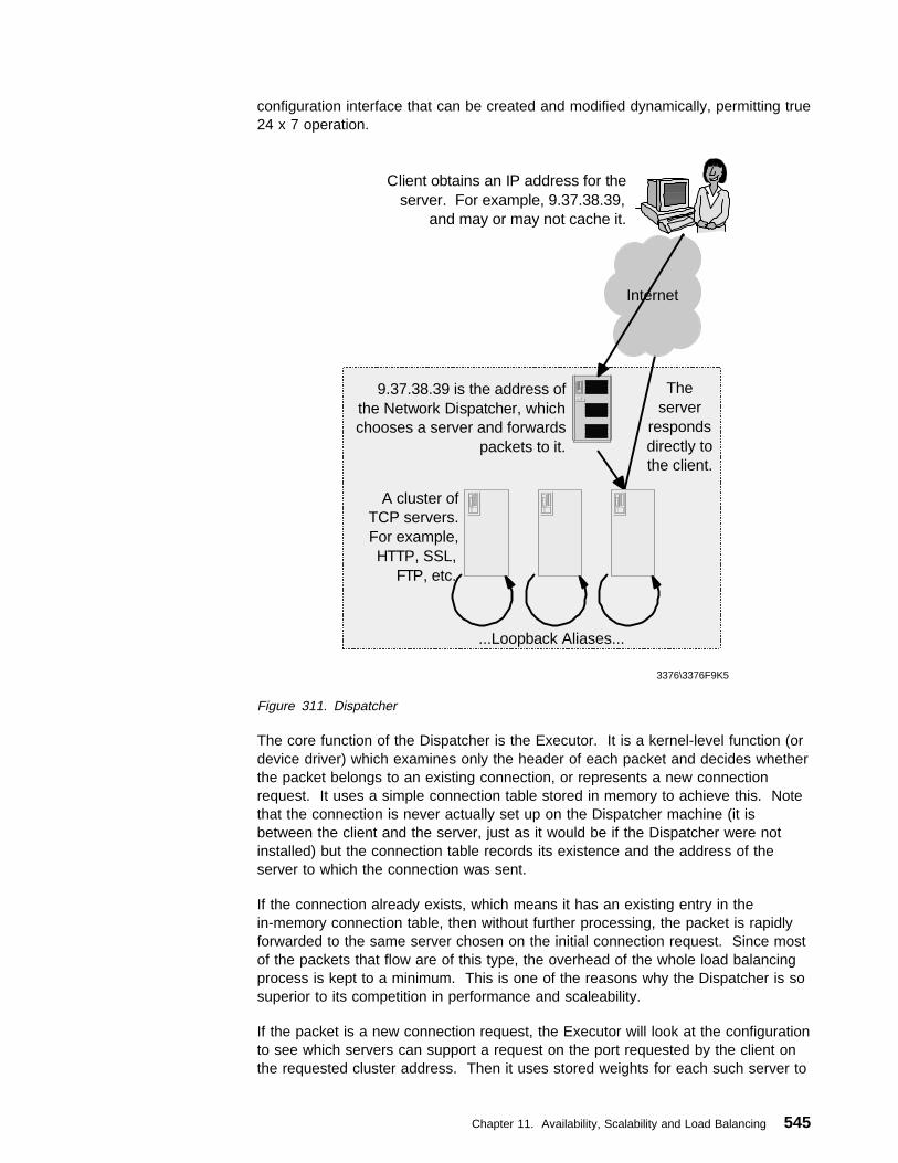
configuration interface that can be created and modified dynamically, permitting true24 x 7 operation.
3376\3376F9K5
A cluster of TCP servers. For example, HTTP, SSL,
FTP, etc.
9.37.38.39 is the address of the Network Dispatcher, which chooses a server and forwards
packets to it.
Client obtains an IP address for the server. For example, 9.37.38.39,
and may or may not cache it.
The server
responds directly to the client.
...Loopback Aliases...
Internet
Figure 311. Dispatcher
The core function of the Dispatcher is the Executor. It is a kernel-level function (ordevice driver) which examines only the header of each packet and decides whetherthe packet belongs to an existing connection, or represents a new connectionrequest. It uses a simple connection table stored in memory to achieve this. Notethat the connection is never actually set up on the Dispatcher machine (it isbetween the client and the server, just as it would be if the Dispatcher were notinstalled) but the connection table records its existence and the address of theserver to which the connection was sent.
If the connection already exists, which means it has an existing entry in thein-memory connection table, then without further processing, the packet is rapidlyforwarded to the same server chosen on the initial connection request. Since mostof the packets that flow are of this type, the overhead of the whole load balancingprocess is kept to a minimum. This is one of the reasons why the Dispatcher is sosuperior to its competition in performance and scaleability.
If the packet is a new connection request, the Executor will look at the configurationto see which servers can support a request on the port requested by the client onthe requested cluster address. Then it uses stored weights for each such server to
Chapter 11. Availability, Scalability and Load Balancing 545

determine the right server to which the connection will be forwarded. An entrymentioning this server is made in the connection table, ensuring that subsequentpackets for this connection are correctly forwarded to the chosen server.
Note that the right server is not always the best server, since it is desirable for alleligible servers to process their share of the load. Even the worst server needs toshoulder some of the burden. If traffic is only ever forwarded to the best server, itcan be guaranteed that it will rapidly cease to be the best. As a result, loadallocation experiences swings that prevent optimal balance from being achieved.Dispatcher's patented algorithm for choosing the right server and its advancedsmoothing techniques achieve optimal balance in the shortest possible time.
The Executor does not modify the client's IP packet when forwarding it. Becausethe Dispatcher is on the same subnet as its clustered servers, it simply forwardsthe packet explicitly to the IP address of the chosen server, just like any ordinary IPpacket. The Dispatcher's TCP/IP stack modifies only the packet's MAC address inthe operating system approved manner and sends the packet to the chosen server.
To allow the TCP/IP stack on that server to accept the unmodified packet from theDispatcher and pass it to the chosen port for normal application processing, the IPaddress of the Dispatcher machine is also installed as a non-advertising alias oneach of the clustered servers. This is achieved by configuring the alias on theloopback adapter.
The server's TCP then establishes the server-to-client half of the connectionaccording to standard TCP semantics, by simply swapping the source and targetaddresses as supplied by the client, rather than determining them from its ownbasic configuration. This means that it replies to the client with the IP address ofthe Dispatcher. As a direct result, the balancing function is invisible both to theclient and the clustered servers. This invisibility means that the Dispatcher is notdependent upon server platforms, provided they implement standard TCP/IPprotocols.
Another key performance and scaleability benefit of the Dispatcher is that theapplication server returns the response to the client's request directly to the clientwithout passing back through the Dispatcher. Indeed there is no need even toreturn using the original physical path; a separate high-bandwidth connection canbe used. In many cases, the volume of outbound server-to-client traffic issubstantially greater than the inbound traffic. For example, Web page HTML andimbedded images sent from the server are typically at least 10 times the size of theclient URLs that request them. This capability was important to address the scalingrequirements of the Web site for the 1998 Nagano Winter Olympic Games.
Because the Dispatcher is a truly generic TCP/IP application, its functions can beapplied not only to HTTP or FTP traffic, but also to other standards-compliant typesof TCP and UDP traffic.
11.3.2 Load Balancing with WeightsThe Dispatcher has a Manager function, which sets the weights that the Executorobeys. The Manager uses four metrics to set these weights:
� Active connection counts for each server on each port. This count is heldinside the Executor.
546 TCP/IP Tutorial and Technical Overview

� New connection counts for each server on each port. This count is held insidethe Executor.
� A check that each server is up-and-running. The Advisor performs thisfunction.
� A check that each server has displaceable capacity which means that it canrealistically process the work. The ISS Load Monitor performs this function.
3376\3376F9K6
Internet
OS
Client
FTPServer20-21
SSLServer
443
HTTPServer
80
Configurator Manager
Advisors
ISSMonitor
Key:C Configuration tableT Connection tableW Weighing values
Manager sets weighing values using:Active connectionsNew connectionsAdvisor metricsISS Monitor input
ISSISS
ISS
ISSISS
ISS
ISSISS
ISS
WTC
Dispatcher Executor
Figure 312. Dispatcher Components
The Advisor is a lightweight client that runs as a part of the Dispatcher but actuallypasses real commands to each application server. It only executes a trivialcommand, but it needs to be more than a ping which will only verify that the TCP/IPprotocol stack is up. If this request is successful, the server is deemed to be up. Ifit fails, the Advisor informs the Manager, and the Manager sets the weight of thatserver to zero, until the server responds again.
If the application server has the ISS Load Monitor daemon installed (with or withouta custom metric), periodic load reports can be passed to the Dispatcher via theDispatcher observer. The results of these reports can be factored into the processof setting the individual server weights for the Dispatcher.
11.3.3 High AvailabilityThe Dispatcher already provides high availability, because one of its basic functionsis to avoid choosing a failed server clustered behind it. The Dispatcher can also beconfigured to eliminate the load balancer itself as a single point of failure, as part ofa comprehensive hardware and software implementation of high availability.
Chapter 11. Availability, Scalability and Load Balancing 547
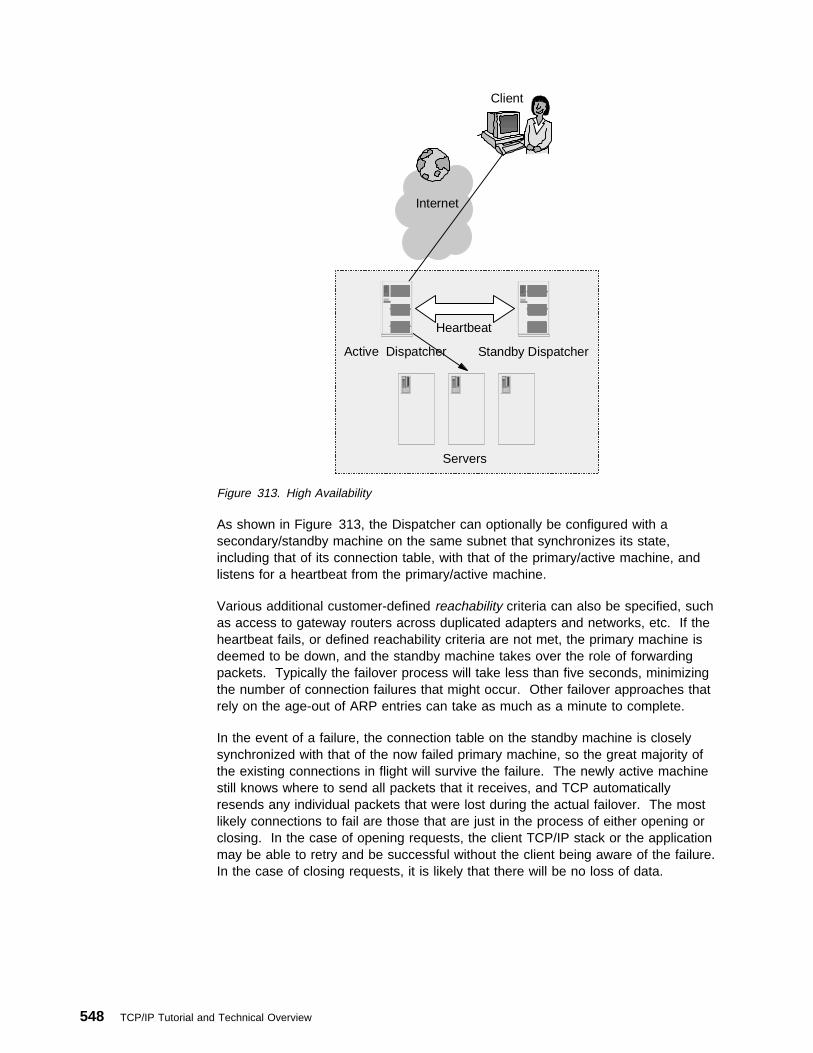
Standby Dispatcher
Servers
Internet
Active Dispatcher
Client
Heartbeat
Figure 313. High Availability
As shown in Figure 313, the Dispatcher can optionally be configured with asecondary/standby machine on the same subnet that synchronizes its state,including that of its connection table, with that of the primary/active machine, andlistens for a heartbeat from the primary/active machine.
Various additional customer-defined reachability criteria can also be specified, suchas access to gateway routers across duplicated adapters and networks, etc. If theheartbeat fails, or defined reachability criteria are not met, the primary machine isdeemed to be down, and the standby machine takes over the role of forwardingpackets. Typically the failover process will take less than five seconds, minimizingthe number of connection failures that might occur. Other failover approaches thatrely on the age-out of ARP entries can take as much as a minute to complete.
In the event of a failure, the connection table on the standby machine is closelysynchronized with that of the now failed primary machine, so the great majority ofthe existing connections in flight will survive the failure. The newly active machinestill knows where to send all packets that it receives, and TCP automaticallyresends any individual packets that were lost during the actual failover. The mostlikely connections to fail are those that are just in the process of either opening orclosing. In the case of opening requests, the client TCP/IP stack or the applicationmay be able to retry and be successful without the client being aware of the failure.In the case of closing requests, it is likely that there will be no loss of data.
548 TCP/IP Tutorial and Technical Overview

11.3.4 Server AffinityThis function is sometimes referred to as the sticky option. It is provided to allowload balancing for those applications which preserve some kind of persistent statein between connections on behalf of clients, without losing the state when the clientreconnects.
When a client originally contacts the site, it is associated with a chosen server inthe normal way. When the sticky option is configured, the difference is that anysubsequent connections sent in by the client will be dispatched to the same serveruntil a configurable time-out value expires. The Dispatcher allows configuration ofthis sticky capability on a per-port basis.
11.3.5 Rules-Based BalancingRules-based balancing introduces the concept of rules and a set of servers amongwhich to load balance if the rule is obeyed. The following rules are available:
� Client IP address
� Client port
� Time of day
� Connections per second for a port
� Active connections for a port
This allows the site to take account of its traffic and the identity of the clients thataccess it when setting up the load balancing policy. A range can be specifiedwhere required, so for example all client IP addresses in a particular subnet can beforwarded to a particular set of servers, or "between the hours of 8 a.m. to 5 p.m.,use this set of ten servers, otherwise use that set of five servers". This provides asimple method of implementing quality of service for individuals, groups of clients ortime-of-day, without imposing unique or proprietary additional semantics orprotocols on the client/server relationship.
11.3.6 Wide Area Network DispatcherPrevious releases of the Dispatcher required that all clustered servers be on thesame subnet as the Dispatcher. With Version 2 of the Dispatcher, there is nodistance limitation to remote servers, either inside a private network or even acrossthe Internet, to provide a site that is geographically distributed over a few miles oracross the globe. Another Dispatcher must be installed at the remote location.
Chapter 11. Availability, Scalability and Load Balancing 549

Internet
A AA
Dispatcher
New York
A AA
Dispatcher
London
A AA
Dispatcher
Tokyo
ClientClient
3376F9\3376F9M1
Figure 314. Wide Area Network Dispatcher
As shown in Figure 314, using this option, a truly distributed wide area network sitecan be configured. Any client data can be forwarded to any of the configuredservers at any location. The choice can be based on server load, or rules, or acombination of the two. The choice of which site should receive the client'spackets first can be achieved in several ways, including the "which site is closest"mode provided by ISS running in ping triangulation mode (see below under ISS andDispatcher together).
The transmission of packets to remote sites is achieved by encapsulating theunmodified client packets at the originating Dispatcher, and then un-encapsulatingthem at the receiving Dispatcher. The server to client data flow goes direct, as itdoes with the local area network Dispatcher, thus keeping the overhead to aminimum.
11.3.7 Combining ISS and DispatcherThe two components of the eNetwork Dispatcher product can be usefully deployedtogether to support a geographically distributed site.
550 TCP/IP Tutorial and Technical Overview

Internet
A AA
Dispatcher
New York
A AA
Dispatcher
London
A AA
Dispatcher
Tokyo
Client
3376F9\3376F9M2
ISSNameServer
Figure 315. ISS and Dispatcher Together
As shown in Figure 315, in response to a standard name resolution request froman application program, the ISS name server returns to the client the IP address ofthe chosen site, based on feedback from the ISS daemons running on theDispatcher machines running at the individual sites. The ISS daemons can beconfigured to return results in one of two ways:
1. Based on system load, which will direct the client to the least loaded site. TheISS daemon can use a custom metric if needed.
2. Based on ping triangulation that will direct the client to the closest site from anetwork topology point of view.
The client then sends its connection request to the selected Dispatcher machine atthe chosen location, which will in turn select the individual server from the cluster atthat site, based on its own set of weights. Note that this configuration can alsoinclude the wide area network Dispatcher support described above.
11.3.8 Advisors and Custom AdvisorsThe Dispatcher supplies standard advisors for HTTP, HTTPS (SSL), FTP, NNTP,SMTP, POP3 and Telnet. A customer may wish to use other standard or privateprotocols with the Dispatcher or to implement specific extensions to the standardadvisors. For this purpose a Custom Advisor facility has been provided, withwell-documented sample source code. Custom advisors must be written in Java atRelease 1.1.2 or higher of the Java Development Kit, which is not provided withDispatcher.
Chapter 11. Availability, Scalability and Load Balancing 551

This powerful extension capability can be coupled with custom code written to runon the application server machine to provide a high degree of synergy between theDispatcher and the applications it balances. One example of this use would be alink between a custom advisor and a Java servlet running inside a Web server.The servlet could be coded to extract in-depth performance data from each serverand return it to the Dispatcher, thus allowing the Dispatcher to benefit from resultsmore precisely tailored to the customer's real application environment.
11.3.9 SNMP SupportA simple network management protocol (SNMP) management information base(MIB) for Dispatcher data is provided. This MIB contains a comprehensive set ofvalues associated with the state and current performance of the Dispatcher. AnSNMP-enabled management tool such as Tivoli TME 10 NetView, or any othersimilarly equipped tool can access this MIB. In addition, SNMP traps are alsogenerated if a clustered server fails or if the Dispatcher itself fails over to itsstandby.
11.3.10 Co-Location OptionIf a company is starting from a small site, but has plans to grow rapidly, it hassome simple options to keep costs down in the early stages of its growth, while stillbenefiting from the high availability and scaleability options of eNetwork Dispatcher,and positioning itself for that growth when it occurs.
Internet
A A
Servers
Co-locatedDispatcher
Client
3376F9\3376F9M3
A
Figure 316. Co-Location Option
552 TCP/IP Tutorial and Technical Overview

As shown in Figure 316, as the site's load increases to the point where it needsmore than one server to handle the traffic, the company can add the Dispatcher toits existing network infrastructure with a minimum of hardware and softwareinvestment by installing the Dispatcher software on one of the machines where theapplication servers reside. It will not have to change its existing networkconfiguration in any way. In the simplest case, all that needs to be done isconfiguring the Dispatcher and either replicating the application server content on toanother server, or sharing it with a shared file system.
The co-location option of the Dispatcher lets a company start quickly with minimumcost and evolve to a stand-alone Dispatcher or to a high-availability configurationwhen the volume of traffic requires it. Even when a dedicated Dispatcher has beendeployed, one can still choose to co-locate a standby Dispatcher with one of theapplication servers.
11.3.11 ISP ConfigurationInternet Service Providers (ISPs) with a large backbone network, or hosting a busysearch engine, can address their scaling and availability requirements by couplingeNetwork Dispatcher in high availability mode with high-capacity caching proxyservers and an enterprise shared file system. These components have beencombined into the IBM WebSphere Performance Pack, as shown in Figure 317 onpage 554.
Chapter 11. Availability, Scalability and Load Balancing 553

Internet
DispatcherHA
A AA
Caching Proxy Servers using a Shared File System
Client
3376F9\3376F9M4
Internet Web Server
Figure 317. IBM WebSphere Performance Pack
An efficiently managed cache can significantly reduce backbone networkcongestion, which provides delivery of faster response times to the clients andbetter customer service, while reducing traffic costs. The additional components inthe IBM WebSphere Performance Pack are IBM Web Traffic Express caching proxyserver and Transarc AFS enterprise shared file system.
11.3.12 OS/390 Parallel Sysplex SupportCompanies with enterprise application servers on the OS/390 parallel sysplex canuse information from OS/390's Workload Manager (WLM) as input to the loadbalancing process of the Dispatcher feature on the IBM 2210 or 2216 Nwaysrouters.
554 TCP/IP Tutorial and Technical Overview
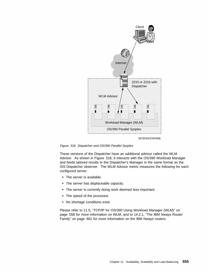
Internet
WLM Advisor
2210 or 2216 with Dispatcher
Client
3376F9\3376F9M5
OS/390 Parallel Sysplex
A AA AA
Workload Manager (WLM)
Figure 318. Dispatcher and OS/390 Parallel Sysplex
These versions of the Dispatcher have an additional advisor called the WLMAdvisor. As shown in Figure 318, it interacts with the OS/390 Workload Managerand feeds tailored results to the Dispatcher's Manager in the same format as theISS Dispatcher observer. The WLM Advisor metric measures the following for eachconfigured server:
� The server is available.
� The server has displaceable capacity.
� The server is currently doing work deemed less important.
� The speed of the processor.
� No shortage conditions exist.
Please refer to 11.5, “TCP/IP for OS/390 Using Workload Manager (WLM)” onpage 558 for more information on WLM, and to 14.2.1, “The IBM Nways RouterFamily” on page 661 for more information on the IBM Nways routers.
Chapter 11. Availability, Scalability and Load Balancing 555

11.4 Alternative Solutions to Load BalancingThere are many vendors currently offering load balancing hardware or softwareproducts. The techniques used vary widely, and have advantages anddisadvantages. What follows is a consideration of some of these alternativeapproaches in comparison to the approach used by IBM eNetwork Dispatcher.
11.4.1 Network Address TranslationNetwork Address Translation (NAT) works by modifying the source and target IPaddresses in the inbound client-to-server packets and restoring the IP address tothe original values in the outbound server-to-client packets. (Please refer to 5.4,“Network Address Translation (NAT)” on page 293 for more details on NAT.)
Note that if NAT is to be transparent to the server, eliminating the need forspecialized agent code on the server, then all packets sent back to the client mustpass back through the load balancer in order to restore the IP addresses originallyused by the client, as shown in Figure 319, in comparison to the previouslydiscussed mode of the Dispatcher. This is a significant overhead which will have avarying impact on the load balancer and the servers whose resources it manages
Client
Internet
Client
Internet
DispatcherNAT
Internet
NAT Dispatcher
3376F9KB
Figure 319. Network Address Translation versus eNetwork Dispatcher - 1
This added overhead and latency can mean network delay, and queuing delay inthe load balancer itself. This in turn drastically limits the potential scaleability ofNAT solutions. To overcome such delays, the capacity of the load balancer mustnot only be sufficient to handle both inbound and outbound packets, but also beable to cope with the disproportionately higher volume of the outbound traffic.
556 TCP/IP Tutorial and Technical Overview

NAT
Internet
Gateway Router
Internet
Gateway Router
Dispatcher
NAT Dispatcher
Figure 320. Network Address Translation versus eNetwork Dispatcher - 2
As shown in Figure 320, NAT offerings sometimes enforce the need to see bothinbound and outbound requests by obliging the NAT device to be installed as abridge (without permitting bridges of any other kind) thus forcing the servers on towhat is essentially a private segment. This can complicate installation since itrequires significant physical change to existing networks. All traffic for thoseservers must pass through the load balancer whether the traffic is to be loadbalanced or not.
Conversely the Dispatcher can be quickly and easily installed without disruption tothe existing network infrastructure. Also the flexibility of configuration offered by theDispatcher allows an asymmetric network to be configured to handle very highbandwidth.
The one advantage of NAT as originally conceived (the ability to forward packets toremote destinations across a wide area network) cannot be usefully deployed sincethe wide area network connection is behind the bridge, and therefore can only bewithin the site's private network, and the same NAT device must still be the onlyexit from the wide area network link. Dispatcher's wide area network support doesnot suffer from this limitation.
To attempt to overcome these limitations, some NAT solutions add to the overheadthat is fundamental to NAT by providing unnecessary add-ons, for example, thecapability to map one port address to another. This is implicitly at odds with thestandards for well-known ports. This is often touted as an advantage forNAT-based solutions, but in fact the so-called advantages of port mapping are ofmarginal value, and the same functionality can be deployed in other ways that aremore standards-compliant.
To check if a server is up, NAT-based load balancing solutions need to sacrifice anactual client request, and so a server outage is typically perceived only as a resultof a timeout of one of these real client requests. Dispatcher's use of specializedadvisors is less disruptive and reacts more quickly to a failure.
Chapter 11. Availability, Scalability and Load Balancing 557
NAT Devices often only map affinity or stickiness based on the client's IP address,and not at the port level. This means that once a client has contacted a server,then all traffic from that client that is intended for other applications is forwarded tothe same server. This drastically restricts configuration flexibility, in many casesrendering the sticky capability unusable in the real world.
11.4.2 EncapsulationOther approaches to load balancing are proxies that encapsulate packets ratherthan modifying them, and then pass them to the server. This approach has somemerit, particularly as, unlike the bridging NAT solutions, it does permit the loadbalancer to forward traffic across a wide area network; indeed this is how theDispatcher's wide area network support works. But other implementations useencapsulation for all traffic, and in turn this requires an agent of the load balancerto be installed on each server. This agent reverses the encapsulation process. Asa result the choice of server platform is by definition restricted to the platforms forwhich the server agent is available. Also, like NAT, it entails further processing ofthe packet, which increases the likelihood that it will not be scaleable to the levelsrequired for major sites.
Dispatcher, on the other hand, does not require any code to be installed on theservers clustered behind it. Indeed it has no knowledge of the hardware oroperating system platform on which the servers are running.
11.4.3 HTTP RedirectionSome load balancing offerings use HTTP redirection. It has the advantage of beingsimple to implement and it is transparent. However, it is restricted to HTTP (Web)traffic only. Redirection forces the client to make two interactions (even though theclient may not be aware that two interactions are occurring) imposes unnecessaryoverhead on the server that does the redirecting, and generates unnecessarynetwork traffic in a world where excessive network traffic is already seen to be thecause of many problems. In addition, if the user bookmarks the site URL returnedby the redirect, then the load balancing function that the customer is trying todeploy is immediately defeated and bypassed by the client. This is in some waysakin to some of the original problems of round-robin DNS.
11.5 TCP/IP for OS/390 Using Workload Manager (WLM)Sysplex, WLM and TCP/IP consist of an entirely new way of implementing anetwork on the OS/390 platform.
11.5.1 Related Terminology and ProductsBefore the overview TCP/IP for OS/390 using Workload Manager (WLM), wedescribe the related terminology.
11.5.1.1 SysplexIn the context of this chapter, we use the term Sysplex to refer to a group of looselycoupled S/390 (MVS) images. For example, a Sysplex could be multiple physicalhosts connected via channels and S/390 Coupling Facility technology. TheseOS/390 hosts in a Sysplex are able to cooperate with each other to share DASD,provide back up capabilities and distribute workload.
See The OS/390 V2R4.0 Parallel Sysplex Overview, GC28-1860, for more details.
558 TCP/IP Tutorial and Technical Overview

11.5.1.2 Work Load Manager (WLM)WLM is a component of OS/390 used for the control of work scheduling, loadbalancing, and performance management. TCP/IP for OS/390 V2R5 uses its owninterface to WLM that provides the DNS (see 4.2, “Domain Name System (DNS)”on page 150) server with information allowing it to load balance. Periodic updatesreceived from WLM tell the server which hosts in the Sysplex have the mostprocessing resources available.
See OS/390 V2R5.0 MVS Planning: Workload Management, GC28-1761, for moredetails.
11.5.1.3 OS/390 eNetwork Communications Server V2R5 IPOS/390 eNetwork Communications Server V2R5 is the communications engine ofOS/390 V2R5. It is composed of TCP/IP, VTAM and AnyNet. Connectionoptimization provides intelligent Sysplex distribution of requests through cooperationbetween WLM and the Domain Name System (DNS) server. For customers thatelect to place a name server in an OS/390 Sysplex, the DNS server can utilizeWLM Sysplex load balancing services to determine the best system to service agiven client request. Note that the best system is evaluated only at connectionsetup time. Once the connection is made, the system being used cannot bechanged without reinitiating the connection.
For a complete list of changes between OS/390 eNetwork Communications ServerV2R5 and previous releases of TCP/IP, see the OS/390 eNetwork CommunicationsServer: IP Planning and Migration Guide V2R5, SC31-8512, for more details.
11.5.2 Overview of WLMWLM provides various workload-related services: performance administration,performance management and workload balancing, for example. OS/390 V2R5 IPtakes advantage of WLM's workload balancing capabilities. WLM is capable ofdynamically assessing resource utilization on all participating hosts within aSysplex.
An IP V2R5 DNS server running on a host in the Sysplex can take advantage ofWLM's knowledge and use it to control how often an address for a particular host inthe Sysplex is returned on a DNS query. When a Sysplex name server queries theWLM for information, it is provided with a weight corresponding to the relativeresource availability of each participating host in the Sysplex. These weights areused by the name server to control the frequency with which an address will bereturned for a given host. If a host in the Sysplex is relatively busy, its address willnot be returned by the server as often as a less busy host's address. As you mighthave guessed, this means that you must use host names when accessing anapplication on the Sysplex. The name server is the only place where addressselection based upon resource availability can occur. If you use an IP addressdirectly, no workload balancing can occur.
Here is a general outline of how WLM and DNS work together in a Sysplex. Referto Figure 321 on page 560 for a schematic diagram.
1. When each application becomes active in the Sysplex, it registers with WLM aswell as interface IP addresses.
2. The Sysplex-enabled name server will query WLM for a list of availableapplications.
Chapter 11. Availability, Scalability and Load Balancing 559

3. Resource records representing the application's information are dynamically(and not permanently) added to the name server's data files.
4. When a request to resolve the name of a dynamically registered applicationsoccurs, the DNS will choose an address to return based upon the weightingfactor provided from WLM.
5. The next request for the same information within the Sysplex will be given thenext address according to the weighting. Depending on the relative resourceutilization of the hosts in the Sysplex, this could be the same address asretrieved in the previous query, it could be a different address for the samehost, or it could be an address for another host in the Sysplex.
6. WLM is queried by the name server every 60 seconds (by default) for a newset of addresses and host weightings.
Sysplex Host
Appl1Appl2activatedAppl3 starting
activated
DNS Server
Appl1 weight addrAppl2 weight addr
4. DNS request 5. DNS responsebased on WLM weighting
3. List of registered groupsand active addresses
2. Query list of active APPLs
1. Registration :
WLM
3376a\3376F9ZA
Figure 321. WLM and Name Server Working Together
11.6 OSPF Equal-Cost MultipathOSPF has a function called equal-cost multipath (see ospf 3.3.4, “Open ShortestPath First (OSPF)” on page 112). With equal-cost multipath, a router potentiallyhas several available next hops towards any given destination.
Actually, it is pretty simple, but the implementation of equal-cost multipath isdifferent depending on the platform such as router. The IBM 2210 implementation isdescribed here as an example.
When OSPF computes an equal-cost multipath routes there is more than one nexthop corresponding to the route, IBM 2210 allows you to use two case of equal-costmulticast function.
A TCP session on the same pathIf most of traffic is forwarded to different hosts in same subnet for example,we want to keep packets associated with a TCP session. Each time a packetis forwarded and there is not a cached route to the destination, a differentnext hop is cached for the destination host. This has the effect of keepingpackets associated with a TCP session on the same path, which is desirable.
560 TCP/IP Tutorial and Technical Overview
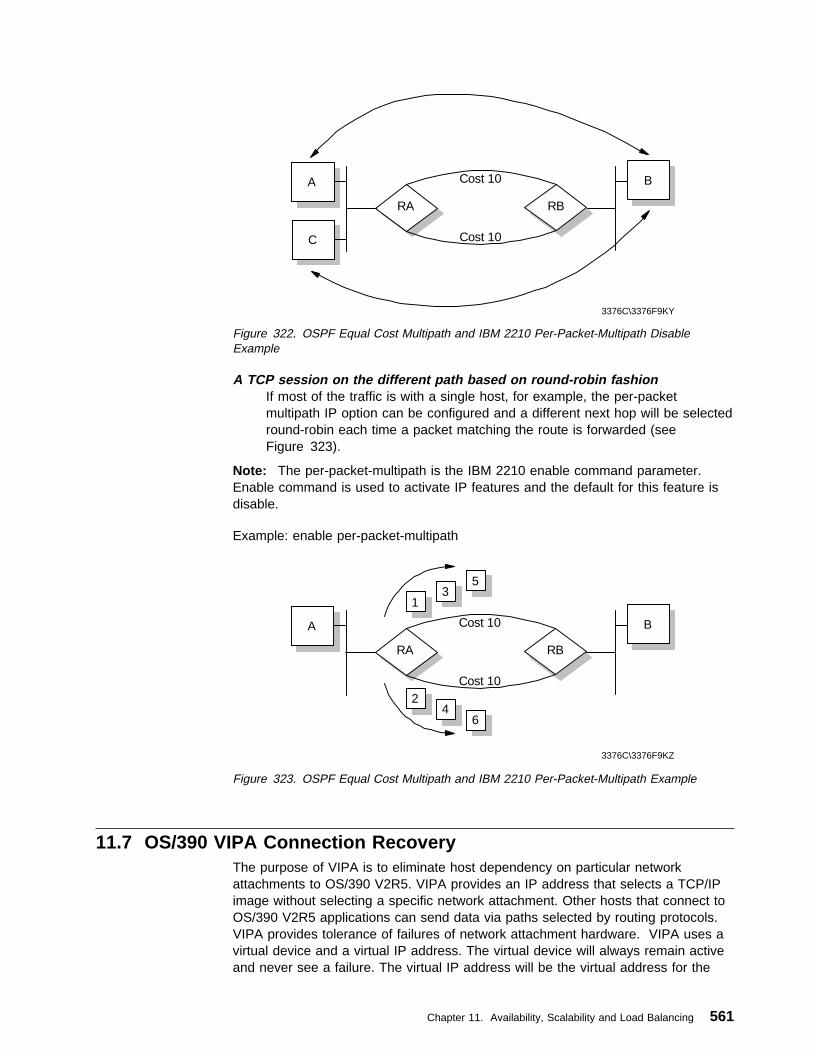
BA
RA RB
Cost 10
Cost 10
3376C\3376F9KY
C
Figure 322. OSPF Equal Cost Multipath and IBM 2210 Per-Packet-Multipath DisableExample
A TCP session on the different path based on round-robin fashionIf most of the traffic is with a single host, for example, the per-packetmultipath IP option can be configured and a different next hop will be selectedround-robin each time a packet matching the route is forwarded (seeFigure 323).
Note: The per-packet-multipath is the IBM 2210 enable command parameter.Enable command is used to activate IP features and the default for this feature isdisable.
Example: enable per-packet-multipath
BA
RA RB
Cost 10
Cost 10
3376C\3376F9KZ
13
5
24
6
Figure 323. OSPF Equal Cost Multipath and IBM 2210 Per-Packet-Multipath Example
11.7 OS/390 VIPA Connection RecoveryThe purpose of VIPA is to eliminate host dependency on particular networkattachments to OS/390 V2R5. VIPA provides an IP address that selects a TCP/IPimage without selecting a specific network attachment. Other hosts that connect toOS/390 V2R5 applications can send data via paths selected by routing protocols.VIPA provides tolerance of failures of network attachment hardware. VIPA uses avirtual device and a virtual IP address. The virtual device will always remain activeand never see a failure. The virtual IP address will be the virtual address for the
Chapter 11. Availability, Scalability and Load Balancing 561

device, with no physical devices associated with it. Failure of a physical interface ishandled by routing traffic to another interface. Similarly outbound traffic can berouted around failing interfaces provided alternate interfaces exist.
562 TCP/IP Tutorial and Technical Overview

Chapter 12. Directory Protocols and Distributed Computing
The TCP/IP protocol suite contains many applications, but these generally take theform of network utilities. Although these are obviously important to a companyusing a network, they are not, in themselves, the reason why a company invests ina network in the first place. The network exists to provide access for users, whomay be both local and remote, to a company's business applications, data andresources, which may be distributed across many servers throughout a building,city, or even the world. Those servers may be running on hardware from manydifferent vendors and on several different operating systems. This chapter looks atmethods of accessing resources and applications in a distributed network.
12.1 Introduction to the Distributed Computing Environment (DCE)Distributed Computing Environment (DCE) is an architecture, a set of openstandard services and associated APIs used to support the development andadministration of distributed applications in a multiplatform, multivendorenvironment.
DCE is the result of work from the Open Systems Foundation (now called the OpenGroup), a collaboration of many hardware vendors, software vendors, customers,and consulting firms. The OSF began in 1988 with the purpose of supporting theresearch, development and delivery of vendor-neutral technology and industrystandards. One such standard developed was DCE. DCE Version 1.0 wasreleased in January 1992.
3376D\3376FBD1
Distributed Applications
Other Services
Global Directory Service
Distributed File Service
DirectoryService
Other Services
TimeService
DCE Threads
Operating System and Transport Services
Remote Procedure Call
Sec
urity
Ser
vice
s
Managem
ent Services
Figure 324. DCE Architectural Components
As shown in Figure 324, DCE includes the following major services:
� Directory Service
� Security Service
� Distributed Time Service
� Distributed File Service
Copyright IBM Corp. 1989, 1998 563
� Threads
� Remote Procedure Call
All the services above have Application Program Interfaces (APIs) that allow theprogrammer to use these functions. These services are described in more detail inthe following pages.
The DCE architecture does not specifically require that TCP/IP should be used forTransport Services, but few other protocols today meet the open and multivendorrequirements of the DCE design goals. In practice, the vast majority, if not all,implementations of DCE are based on TCP/IP networks.
12.1.1 DCE Directory ServiceWhen working in a large, complex network environment, it is important to keeptrack of the locations, names and services (and many other details) of theparticipants and resources in that network. It is also important to be able to accessthis information easily. To enable this, information should be stored in a logical,central location and should have standard interfaces for accessing the information.The DCE Cell Directory Service does exactly this.
The DCE Directory Service has the following major components:
� Cell Directory Service (CDS)
� Global Directory Service (GDS)
� Global Directory Agent (GDA)
� Application Program Interface (API)
12.1.1.1 Cell Directory ServiceThe Cell Directory Service manages a database of information about the resourcesin a group of closely cooperating hosts, which is called a cell. A DCE cell is veryscaleable and may contain many thousands of entities. Typically even fairly largecorporate companies will be organized within a single cell, which may cover severalcountries. The Directory Service database contains a hierarchical set of nameswhich represent a logical view of the machines, applications, users and resourceswithin the cell. These names are usually directory entries within a directory unit.Often, this hierarchical set of names is also called the namespace. Every cellrequires at least one DCE server configured with the Cell Directory Service (adirectory server).
The CDS has two very important characteristics: it can be distributed, and it can bereplicated. Distributed means that the entire database does not have to reside onone physical machine in the cell. The database can logically be partitioned intomultiple sections (called replicas), and each replica can reside on a separatemachine. The first instance of that replica is the master replica, which hasread/write access. The ability of the cell directory to be split into several masterreplicas allows the option of distributing the management responsibility forresources in different parts of the cell. This might be particularly important if thecell covers, say, several countries.
Each master replica can be replicated. That is, a copy of this replica can be madeon a different machine (which is also a directory server). This is called a read-only
564 TCP/IP Tutorial and Technical Overview

replica. Read-only replicas provide both resilience and performance enhancementby allowing a host machine to perform lookups to the nearest available replica.
Replicas are stored in a clearinghouse. A clearinghouse is a collection of directoryreplicas at a particular server. All directory replicas must be part of a clearinghouse(although not necessarily the same one).
The Cell Directory Service makes use of the DCE Security Service. When the CDSinitializes, it must authenticate itself to the DCE Security Service. This prevents afraudulent CDS from participating in the existing cell.
Figure 325 shows the directory structure of the CDS namespace. As you can see,the namespace is organized in a hierarchical manner.
3376D\3376FBD2
cell-profile lan-profile hostname_ch hosts subsysfssec
hostname
self profile cds-clerk cds-server
dce
dfs sec
dfs sec
config
/...
/.:
junction junction
Global Root
Local Root
Figure 325. DCE - CDS Namespace Directory Structure
Not all DCE names are stored directly in the DCE directory service. Resourceentries managed by some services, such as the Security Service (sec) and theDistributed File System (fs), connect into the namespace by means of specializedCDS entries, called junctions. A junction entry contains binding information thatenables a client to connect to a directory server outside of the directory service.
The security namespace is managed by the registry service of the DCE securitycomponent, and the DFS namespace is managed by the Fileset Location Database(FLDB) service of DFS.
12.1.1.2 Global Directory Service and AgentThe Cell Directory Service is responsible for knowing where resources are withinthe cell. However, in a multi-cell network, each cell is part of a larger hierarchicalnamespace, called the Global Directory namespace. The Global Directory Service(GDS) allows us to resolve the location of resources in foreign cells. This is thecase when a company wants to connect their cells together, or to the Internet.
In order to find a resource in another cell, a communication path needs to existbetween the two cells. This communication path can currently be one of two types:
� CCITT X.500 (see 1.1.8.1, “X.500: The Directory Service Standard” onpage 11)
� Internet Domain Name Services (DNS)
Chapter 12. Directory Protocols and Distributed Computing 565

3376D\3376FBD3
GDA
CDS
Cell A Cell B
DNSor
X.500
CDSGDA
Client
Figure 326. DCE - Global Directory Agent
In order for intercell communications to be accomplished, another component, theglobal directory agent, is required. The global directory agent (GDA) is theintermediary between the local cell and the Global Directory Service. InFigure 326, if the CDS does not know the location of a resource, it tells the clientto ask the GDA for assistance. The GDA knows to which global namespace it isconnected and queries the GDS (either DNS or X.500) for the name of the foreigncell directory server with which to communicate. Once in direct communication withthe foreign cell directory server, the network name of the resource requested canbe found. The global directory agent is the component that providescommunications support for either DNS or X.500 environments.
12.1.2 DCE Security ServiceSecurity is always a concern in a networked environment. In a large, distributedenvironment, it is even more crucial to ensure that all participants are valid userswho access only the data with which they are permitted to work. The two primaryconcerns are authentication and authorization. Authentication is the process ofproving or confirming the identity of a user or service. Authorization is the processof checking a user's level of authority when an access attempt is made. Forexample, if a user tries to make a change when read-only access has beengranted, then the update attempt will fail.
The DCE Security Service ensures secure communications and controlled accessto resources in this distributed environment. It is based on the MassachusettsInstitute of Technology's Project Athena, which produced Kerberos. Kerberos is anauthentication service that validates a user or service. The current DCE SecurityService (DCE 1.2.2) is based on Kerberos Version 5.
Since the DCE Security Service must be able to validate users and services, itmust also have a database to hold this information. This is indeed the case. TheDCE Security Service maintains a database of principals, accounts, groups,organizations, policies, properties, and attributes. This database is called theregistry. Figure 327 on page 567 shows a pictorial representation of the registrytree. The registry is actually part of the cell directory namespace, although it isstored on a separate server.
566 TCP/IP Tutorial and Technical Overview

3376D\3376FBD4
organization groups policy replist xattrschema accounts
sec
USER1 USERn...MYGROUP1 MYGROUPn
...
Figure 327. DCE - Registry Directory Structure
The DCE Security Service consists of several components:
Authentication ServiceHandles the process of verifying that principals are correctly identified.This also contains a Ticket Granting Service, which allows theengagement of secure communications.
Privilege ServiceSupplies a user's privilege attributes to enable them to be forwarded toDCE servers.
Registry ServiceMaintains the registry database, which contains accounts, groups,principals, organizations, and policies.
Access Control List FacilityProvides a mechanism to match a principal's access request against theaccess controls for the resource.
Login FacilityProvides the environment for a user to log in and initialize the securityenvironment and credentials.
These services allow for user authentication, secure communication, authorizedaccess to resources, and proper enforcement of security.
The DCE Security Service communicates with the Cell Directory Service toadvertise its existence to the other systems that are part of the cell. The DCESecurity Service also uses the Distributed Time Service to obtain timestamps foruse in many of its processes.
12.1.2.1 Authentication ServiceThe role of the authentication service is to allow principals to positively identifythemselves and participate in a DCE network. Both users and servers authenticatethemselves in a DCE environment, unlike security in most other client/serversystems where only users are authenticated. There are two distinct steps toauthentication. At initial logon time, the Kerberos third-party protocol is used withinDCE to verify the identity of a client requesting to participate in a DSS network.This process results in the client obtaining credentials which form the basis forsetting up secure sessions with DCE servers when the user tries to accessresources.
In DCE Version 1.1, the idea of preauthentication was introduced, which is notpresent in the Kerberos authentication protocols. Preauthentication protects the
Chapter 12. Directory Protocols and Distributed Computing 567
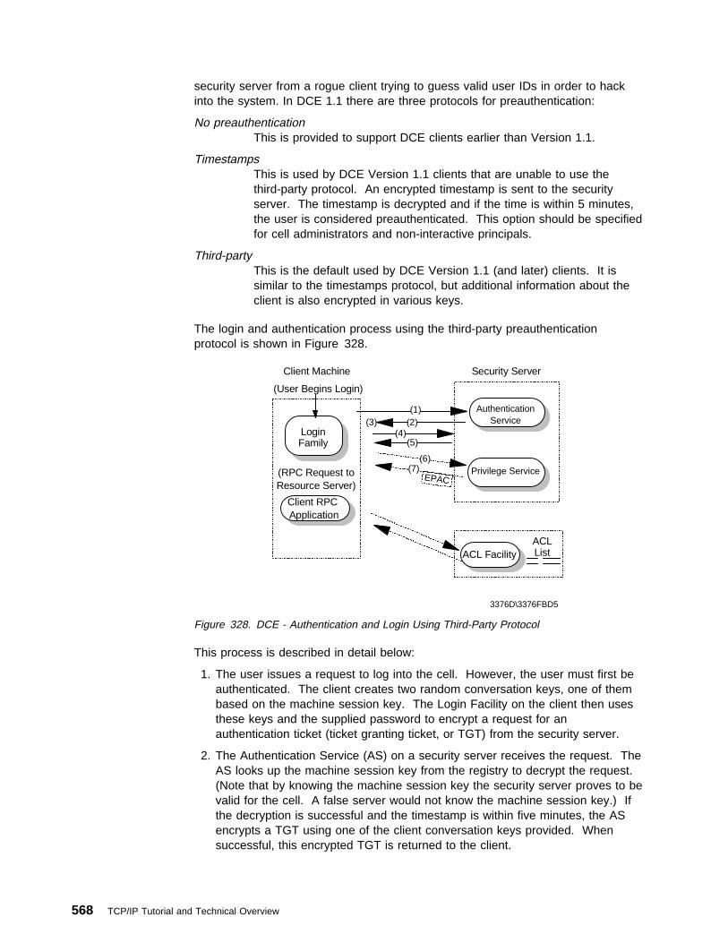
security server from a rogue client trying to guess valid user IDs in order to hackinto the system. In DCE 1.1 there are three protocols for preauthentication:
No preauthenticationThis is provided to support DCE clients earlier than Version 1.1.
TimestampsThis is used by DCE Version 1.1 clients that are unable to use thethird-party protocol. An encrypted timestamp is sent to the securityserver. The timestamp is decrypted and if the time is within 5 minutes,the user is considered preauthenticated. This option should be specifiedfor cell administrators and non-interactive principals.
Third-partyThis is the default used by DCE Version 1.1 (and later) clients. It issimilar to the timestamps protocol, but additional information about theclient is also encrypted in various keys.
The login and authentication process using the third-party preauthenticationprotocol is shown in Figure 328.
3376D\3376FBD5
Client Machine Security Server
(User Begins Login)
(RPC Request toResource Server)
ACL List
Login Family
Client RPC Application
AuthenticationService
Privilege Service
ACL Facility
(1)(2)(3)
(4)(5)
(6)(7)
EPAC
Figure 328. DCE - Authentication and Login Using Third-Party Protocol
This process is described in detail below:
1. The user issues a request to log into the cell. However, the user must first beauthenticated. The client creates two random conversation keys, one of thembased on the machine session key. The Login Facility on the client then usesthese keys and the supplied password to encrypt a request for anauthentication ticket (ticket granting ticket, or TGT) from the security server.
2. The Authentication Service (AS) on a security server receives the request. TheAS looks up the machine session key from the registry to decrypt the request.(Note that by knowing the machine session key the security server proves to bevalid for the cell. A false server would not know the machine session key.) Ifthe decryption is successful and the timestamp is within five minutes, the ASencrypts a TGT using one of the client conversation keys provided. Whensuccessful, this encrypted TGT is returned to the client.
568 TCP/IP Tutorial and Technical Overview

3. The client receives the TGT envelope and decrypts it using one of the clientconversation keys it provided. Also included is a conversation key for the AS.Note that the TGT itself is encrypted with a conversation key of the AS. Thisvalid TGT is proof that the user is now authenticated.
4. Now the user needs its authorization credentials, known as Extended PrivilegeAttribute Certificate (EPAC), from the Privilege Service (PS). Therefore, it mustconstruct a Privilege Ticket Granting Ticket (PTGT) request to retrieve this fromthe PS. To communicate with the PS, the client sends a request to the AS tocontact the PS. This request is encrypted with the conversation key of the AS.
5. The AS receives this request. Using the secret key of the PS, the AS generatesa conversation key for the client to use when contacting the PS. This isreturned to the client and encrypted again with the AS conversation key. Theclient receives the envelope and decrypts it (using the conversation key) anddiscovers the conversation key for the PS. The client can now send a PrivilegeService ticket to the PS.
6. The PS receives the request and decrypts it with its secret key successfully.This proves that the service ticket is legitimate, which also implies that the ASinvolved is also legitimate. From this, the PS knows that the client and the ASare valid. The PS constructs the EPAC, which lists the user's standard andextended registry attributes, including group membership. The PS createsmore conversation keys and sends the EPAC and other information in anencrypted PTGT envelope to the client.
7. The client decrypts the PTGT envelope using the PS conversation key. Also,the client has the conversation key information and an encrypted PTGT (whichthe client cannot decrypt, since it is encrypted using the AS secret key).
8. Now, the client wants to contact an application server. To do so, it sends thePTGT to the AS and requests a service ticket for the application server. TheAS receives the PTGT and decrypts it to obtain the EPAC information. Itencrypts the EPAC information with the secret key of the application server andalso provides a conversation key for the application server. This information isencrypted with the conversation key of the AS (which the client knows) and isreturned to the client.
9. The client decrypts the envelope and discovers the application server's secretconversation key. Using this key, it can now contact the application server. Bycorrectly decrypting the request from the client, the application server is able todetermine that the client has been authenticated and by responding to theclient, the client knows that it was, indeed, the real application server that it hascontacted. The two will then establish a mutually authenticated session.
In addition to the extensive use of secret keys during logon, third-partyauthentication makes use of timestamps to ensure that the conversation isprotected against intruders and eavesdropping. Timestamps make impersonationtechniques, such as record and playback, ineffective. Also, the actual userpassword entered at logon time does not flow to the server as such. Instead, it isused as an encryption key for the initial logon messages which are then decryptedby the security server using its own copy of the password stored in the registrydatabase.
If the security server is not able to authenticate the client for some reason, such asthe entering an invalid password, an error is returned and the logon is terminated.However, if the exchange completes with the client being successfully
Chapter 12. Directory Protocols and Distributed Computing 569

authenticated, the security server returns credentials which are then used by theclient to establish sessions with other DCE servers, such as resource and directoryservers. These credentials contain information in the form of a Privilege TicketGranting Ticket (PTGT) and Extended Privilege Attribute Certificate (EPAC):
EPAC This is a validated list supplied by the security server containing theclient's name, groups the client belongs to, and the extended registryattributes for the authenticated client (if any were defined and associatedwith their account). A client must present its EPAC (acquired duringthird-party authentication) to any server the client wishes to connect to inorder to access its resources.
PTGT A PTGT is a Privilege Ticket Granting Ticket. It contains the EPAC,which has all the relevant information about a user (UUID, groupmembership, ERAs, and so on). The PTGT is what is actually passedfrom a DCE client to a DCE server when it needs to access resources.
Public Key Support: The latest version of DCE (DCE Version 1.2.2) introducesthe option of using public key technology (such as that from RSA or smart cards) tosupport login. Using this technology, the long-term key (or password) for a user (orother DCE object) does not need to be stored at the security server, providingenhanced security in the event of compromise of the security server.Administrators can specify that some principals may use the pre-DCE 1.2mechanisms while others have access to the public key mechanism. DCE 1.2.2retains full interoperability with previous DCE releases. At login, public key usersreceive credentials that allow them to use the current (Kerberos-based) DCEauthentication mechanism. A new pre-authentication protocol is used. The loginclient does not have to determine whether a given user is public key-capable priorto requesting credentials.
12.1.3 DCE ThreadsTraditional applications (written in languages such as C, COBOL, etc.) have manylines of programming code which usually execute in a sequential manner. At anytime, there is one point in the program that is executing. This can be defined assingle threading. A thread is a single unit of execution flow within a process. Betterapplication performance can often be obtained when a program is structured sothat several areas can be executed concurrently. This is called multithreading.The capability of executing multiple threads is also dependent on the operatingsystem.
In a distributed computing environment based on the client/server model, threadsprovide the ability to perform many procedures at the same time. Work cancontinue in another thread while the thread waiting for a specific response isblocked (waiting for response from the network, for example). A server may issueconcurrent procedure call processing. While one server thread is waiting for an I/Ooperation to finish, another server thread can continue working on a differentrequest.
To function well, thread support needs to be integrated into the operating system.If threads are implemented at the application software level instead of within theoperating system, performance of multithreaded applications may seem slow.
The DCE Threads APIs are either user-level (in operating systems that don'tsupport threads, such as Windows 3.x) or kernel threads (such as AIX and OS/2).
570 TCP/IP Tutorial and Technical Overview

They are based on the POSIX 1003.4a Draft 4 standard. Since OS/2 also hasthreads, the programmer can use DCE threads or OS/2 threads.
DCE threads can be mapped onto OS/2 threads through special programmingconstructs. However, in order to write portable applications that can run ondifferent platforms, only DCE threads should be used. In many cases, there is littleperformance difference resulting from this mapping.
12.1.4 DCE Remote Procedure CallThe DCE Remote Procedure Call (RPC) architecture is the foundation ofcommunication between the client and server within the DCE environment.
Note: The DCE RPC is conceptually similar to the ONC RPC (see 4.19.2,“Remote Procedure Call (RPC)” on page 252), but the protocol used on thewire is not compatible.
RPCs provide the ability for an application program's code to be distributed acrossmultiple systems, which can be anywhere in the network.
An application written using DCE RPCs has a client portion, which usually issuesRPC requests, and a server portion, which receives RPC requests, processesthem, and returns the results to the client. RPCs have three main components:
� The Interface Definition Language (IDL) and its associated compiler. From thespecification file, it generates the header file, the client stub and the serverstub. This allows an application to issue a remote procedure call in the samemanner that it would issue a local procedure call.
� The network data representation, which defines the format for passing datasuch as input and output parameters. This ensures that the bit-ordering andplatform-specific data representation can be converted properly once it arrivesat the target system. This process of preparing data for an RPC call is calledmarshalling.
� The run-time library, which shields the application from the details of networkcommunications between client and server nodes.
The application programmer may choose to use multiple threads when making RPCcalls. This is because an RPC is synchronous; that is, when an RPC call is made,the thread that issued the call is blocked from further processing until a response isreceived.
Remote procedure calls can be used to build applications that make use of otherDCE facilities, such as the Cell Directory Service (CDS) and the Security Service.The CDS may be used to find servers or to advertise a server's address for clientaccess. The Security Service might be used to make authenticated RPCs whichenable various levels of data integrity and encryption using the Commercial DataMasking Facility (CDMF), Data Encryption Standard (DES), and other functionssuch as authorization.
Chapter 12. Directory Protocols and Distributed Computing 571
12.1.5 Distributed Time ServiceKeeping the clocks on different hosts synchronized is a difficult task as thehardware clocks do not typically run at the same rates. This presents problems fordistributed applications that depend on the ordering of events that happen duringtheir execution. For example, let's say that a programmer is compiling some codeon a workstation, and some files are also located on a server. If the workstationand the server don't have their time synchronized, it is possible that the compilermay not process a file because the date is older than an existing one on the server.In reality, the file is newer, but the clock on the workstation is slow. As a result, thecompiled code will not reflect the latest source code changes. This problembecomes more acute in a large cell where servers are distributed across multipletime zones.
The DCE Distributed Time Service (DTS) provides standard software mechanismsto synchronize clocks on the different hosts in a distributed environment. It alsoprovides a way of keeping a host's time close to the absolute time. DTS isoptional. It is not a required core service for the DCE cell. However, if DTS is notimplemented, the administrator must use some other means of keeping clockssynchronized for all the systems in the cell.
The Distributed Time Service has several components. They are:
� Local time server
� Global time server
� Courier and backup courier time server
12.1.5.1 Local Time ServerThe local time server is responsible for answering time queries from time clerks onthe LAN. Local time servers also query each other to maintain synchronization onthe LAN. If a time clerk cannot contact the required number of local time servers(as specified by the minservers attribute), it must contact global time serversthrough a CDS lookup.
It is recommended that there are at least three local time servers per LAN. Thisensures that the time on the LAN is synchronized. The task of synchronizationacross multiple LANs in the cell is performed by global and courier time servers.
12.1.5.2 Global Time ServerA global time server (GTS) advertises itself in the Cell Directory Servicenamespace so that all systems can find it easily. A GTS participates in the localLAN in the same way that local time servers do, but it has an additionalresponsibility. It also gives its time to a courier time server, which is located in adifferent LAN.
12.1.5.3 Courier RolesLocal and global time servers can also have a courier role; they can be couriers,backup couriers or non-couriers. The courier behaves similar to other local timeservers, participating in the time synchronization process. However, the courierdoes not look at its own clock. It requests the time from a global time serverlocated in another LAN or in another part of the cell. Because the time is importedfrom another part of the network, this enables many remote LAN segments in allparts of the cell to have a very closely synchronized time value.
572 TCP/IP Tutorial and Technical Overview

The backup courier role provides support in the event that the primary courier forthat LAN is not available. The backup couriers will negotiate to elect a new courierand thus maintain the proper time synchronization with the global time servers.Note that even if a courier time server is not defined, local time servers and clerkswill try to contact a global time server if they cannot contact the minimum numberof servers from the local segment.
The default for time servers is the non-courier role. As long as enough local timeservers can be contacted, they will not contact a global time server.
In a large or distributed network, local time servers, global time servers and couriertime servers make the process of time synchronization function automatically andaccurately.
12.1.6 Distributed File Service (DFS)The Distributed File Service is not really a core component of DCE but anapplication that is integrated with, and uses, the other DCE services. DFS providesglobal file sharing. Access to files located anywhere in interconnected DCE cells istransparent to the user. To the user, it appears as if the files were located on alocal drive. DFS servers and clients may be heterogeneous computers runningdifferent operating systems.
The origin of DFS is Transarc Corporation's implementation of the Andrew FileSystem (AFS) from Carnegie-Mellon University (see 12.2, “The Andrew File System(AFS)” on page 575). DFS conforms to POSIX 1003.1 for file system semanticsand POSIX 1003.6 for access control security. DFS is built onto, and integratedwith, all of the other DCE services and was developed to address identifieddistributed file system needs, such as:
� Location transparency � Uniform naming � Good performance � Security � High availability� File consistency control
� NFS interoperability
DFS follows the client/server model, and it extends the concept of DCE cells byproviding DFS administrative domains, which are an administratively independentcollection of DFS server and client systems within a DCE cell.
There may be many DFS file servers in a cell. Each DFS file server runs the fileexporter service which makes files available to DFS clients. The file exporter is alsoknown as the protocol exporter. DFS clients run the cache manager, anintermediary between applications that request files from DFS servers. The cachemanager translates file requests into RPCs to the file exporter on the file serversystem and stores (caches) file data on disk or in memory to minimize serveraccesses. It also ensures that the client always has an up-to-date copy of a file.
The DFS file server can serve two different types of file systems:
� Local File System (LFS), also known as the Episode File System
� Some other file system, such as the UNIX File System (UFS)
Full DFS functionality is only available with LFS and includes:
Chapter 12. Directory Protocols and Distributed Computing 573

� High performance
� Log-based, fast restarting file sets for quick recovery from failure
� High availability with replication, automatic updates and automatic bypassing offailed file server
� Strong security with integration to the DCE security service providing ACLauthorization control
12.1.6.1 File NamingDFS uses the Cell Directory Service (CDS) name /.:/fs as a junction to itsself-administered namespace (see Figure 325 on page 565). DFS objects of a cell(files and directories) build a file system tree rooted in /.:/fs of every cell.Directories and files can be accessed by users anywhere on the network, using thesame file or directory names, no matter where they are physically located, since allDCE resources are part of a global namespace.
As an example of DFS file naming, to access a particular file from within a cell, auser might use the following name:
/.:/fs/usr/woodd/games/tictactoe.exe
From outside the cell, using GDS (X.500) format, the following name would beused:
/.../C=US/O=IBM/OU=ITSC/fs/usr/woodd/games/tictactoe.exe
or in DNS format:
/.../itsc.ibm.com/usr/woodd/games/tictactoe.exe
12.1.6.2 DFS PerformancePerformance is one of the main goals of DFS, and it achieves it by includingfeatures, such as:
Cache managerFiles requested from the server are stored in cache at the client so thatthe client does not need to send requests for data across the networkevery time the user needs a file. This reduces load on the server filesystems and minimizes network traffic, thereby improving performance.
Multithreaded serversDFS servers make use of DCE threads support to efficiently handlemultiple file requests from clients.
RPC pipesThe RPC pipe facility is extensively used to transport large amounts ofdata efficiently.
ReplicationReplication support allows efficient load-balancing by spreading out therequests for files across multiple servers.
12.1.6.3 File ConsistencyUsing copies of files cached in memory at the client side could potentially causeproblems when the file is being used by multiple clients in different locations. DFSuses a token mechanism to synchronize concurrent file accesses by multiple usersand ensure that each user is always working with the latest version of a file. Thewhole process is transparent to the user.
574 TCP/IP Tutorial and Technical Overview
12.1.6.4 AvailabilityLFS file sets can be replicated on multiple servers for better availability. Every fileset has a single read/write version and multiple read-only replicas. The read/writeversion is the only one that can be modified. Every change in the read/write file setis reflected in the replicated file sets. If there is a crash of a server system housinga replicated file set, the work is not interrupted, and the client is automaticallyswitched to another replica.
12.1.6.5 DFS SecurityDCE security provides DFS with authentication of user identities, verification of userprivileges and authorization control. Using the DCE security's ACL mechanism,DFS provides more flexible and powerful access control than that typically providedby an operating system (UNIX read, write and execute permissions, for example).
12.1.6.6 DFS/NFS InteroperabilityDFS files can be exported to NFS so that NFS clients can access them asunauthenticated users. This requires an NFS/DFS Authenticating Gateway facility,which may not be available in every implementation.
12.1.7 ReferencesFor additional information on DCE, please refer to one of the following IBMredbooks:
Understanding OSF DCE 1.1 for AIX and OS/2, SG24-4616
DCE Cell Design Considerations, SG24-4746
Administering DCE and DFS 2.1 for AIX (and OS/2 Clients), SG24-4714
Security on the Web Using DCE Technology, SG24-4949
For information on the most current release of DCE (Version 1.2.2) view the OpenGroup Web site at :
http://www.opengroup.org
12.2 The Andrew File System (AFS)The Andrew File System (AFS) is a distributed file system used in non-DCEenvironments. DCE DFS was based upon AFS, and the two file systems aresimilar in architecture.
The latest version (AFS 3) has the following attributes:
Single logical shared namespaceEvery AFS user shares the same uniform name space. File names areindependent of both the user's and the file's physical locations. Groupsof client and server machines are known as cells.
Client cachingData is cached on client machines to reduce subsequent data requestsdirected at file servers, which reduces network and server loads.Servers keep track of client caches through callbacks, guaranteeingcache consistency without constant queries to the server to see if thefile has changed.
Chapter 12. Directory Protocols and Distributed Computing 575

RPCs AFS uses its remote procedure call (RPC) reads and writes for efficientdata transfer across the network.
Security Kerberos-based authentication requires that users prove their identitiesbefore accessing network services. Once authenticated, AFS accesscontrol lists (ACLs) give individual users or groups of users varyinglevels of authority to perform operations on the files in a directory.
ReplicationReplication techniques are used for file system reliability. Multiplecopies of applications and data may be replicated on multiple fileservers within a cell. When accessing this information, a client willchoose among the available servers. Replication also reduces the loadon any particular server by placing frequently accessed information onmultiple servers.
Management UtilitiesBackup, reconfiguration and routine maintenance are all done withoutany system down time, files remain available to users during theseoperations. This is done by creating online clones of volumes (subsetsof related files).
AFS commands are RPC-based. Administrative commands can beissued by any authenticated administrator from any client workstation.System databases track file locations, authentication information andaccess control lists. These databases are replicated on multipleservers, and are dynamically updated as information changes.
3376D\3376FBDB
/afs
cern.ch transarc.com alw.nih.gov
common project tools usr www system
zephyr oracle
joe
talks
dce.txt
travel
mlk
user.mlk
user.joe
Figure 329. AFS 3 Name Space
Figure 329 shows an example of an AFS namespace. user.joe is a volume, whichis a group of files managed as a single unit. Any user, situated anywhere in thenetwork, can access Joe's dce.txt file by using the filename:
/afs/transarc.com/usr/joe/talks/dce.txt
Further information on AFS can be found at the Transarc Web site at:
576 TCP/IP Tutorial and Technical Overview

http://www.transarc.com/
12.3 Lightweight Directory Access Protocol (LDAP)The DCE architecture includes its own directory services. However, DCE, althoughwidely implemented is not a practical solution for every company. DCE is an“all-or-nothing” implementation. That is, in order for a company to gain the mostbenefit from its sophisticated security and directory services, every workstationmust have a DCE client installed, every application and data server must be a DCEserver, and the additional security and directory servers which make up the DCEinfrastructure must also be in place. However, every company that has any kind ofnetwork has a requirement for at least some of the type of services provided byDCE.
Many network-based applications exist today that rely on their own directories (ordatabases) containing information describing various users, applications, files andother resources accessible from the network. For example, a company may haveone directory containing information on all users and resources for their file serversand another directory containing information on all users and departments for theire-mail system. Much of the information in the two directories is common, but thetwo are most probably totally incompatible with each other. As the number ofdifferent networks and applications has grown, the number of specialized directoriesof information has also grown, resulting in islands of information that cannot beshared and are difficult to maintain. If all of this information could be maintainedand accessed in a consistent and controlled manner, it would provide a focal pointfor integrating a distributed environment into a consistent and seamless system.
The Lightweight Directory Access Protocol (LDAP) is an open industry standardthat has evolved to meet these needs. LDAP defines a standard method foraccessing and updating information in a directory. LDAP is gaining wideacceptance as the directory access method of the Internet and is therefore alsobecoming strategic within corporate intranets. It is being supported by a growingnumber of software vendors and is being incorporated into a growing number ofapplications.
Further information on LDAP can be found in the IBM Redbook SG24-4986Understanding LDAP.
12.3.1 LDAP - Lightweight Access to X.500The OSI directory standard, X.500 (see 1.1.8.1, “X.500: The Directory ServiceStandard” on page 11), specifies that communication between the directory clientand the directory server uses the Directory Access Protocol (DAP). However, asan application layer protocol, DAP requires the entire OSI protocol stack to operate.Supporting the OSI protocol stack requires more resources than are available inmany small environments. Therefore, an interface to an X.500 directory serverusing a less resource-intensive or lightweight protocol was desired.
LDAP was developed as a lightweight alternative to DAP. LDAP requires thelighter weight and more popular TCP/IP protocol stack rather than the OSI protocolstack. LDAP also simplifies some X.500 operations and omits some esotericfeatures. Two precursors to LDAP appeared as RFCs issued by the IETF, RFC1202 Directory Assistance Service and RFC 1249 DIXIE Protocol Specification.These were both informational RFCs which were not proposed as standards. The
Chapter 12. Directory Protocols and Distributed Computing 577

directory assistance service (DAS) defined a method by which a directory clientcould communicate to a proxy on an OSI-capable host which issued X.500requests on the client's behalf. DIXIE is similar to DAS, but provides a more directtranslation of the DAP. The first version of LDAP was defined in RFC 1487 X.500Lightweight Access, which was replaced by RFC 1777 Lightweight Directory AccessProtocol. LDAP further refines the ideas and protocols of DAS and DIXIE. It ismore implementation-neutral and reduces the complexity of clients to encouragethe deployment of directory-enabled applications. Much of the work on DIXIE andLDAP was carried out at the University of Michigan, which provides referenceimplementations of LDAP and maintains LDAP-related Web pages and mailing lists(see 12.3.9, “References” on page 591).
RFC 1777 defines the LDAP protocol itself. RFC 1777, together with the followingRFCs, defines LDAP Version 2:
� RFC 1778 — The String Representation of Standard Attribute Syntaxes
� RFC 1779 — A String Representation of Distinguished Names
� RFC 1959 — An LDAP URL Format
� RFC 1960 — A String Representation of LDAP Search Filters
LDAP Version 2 has reached the status of draft standard in the IETFstandardization process. Many vendors have implemented products that supportLDAP Version 2. Some vendors are also implementing products that support all orparts of LDAP Version 3.
LDAP Version 3 is defined by RFC 2251 Lightweight Directory Access Protocol(v3), which is a proposed standard. Related RFCs that are new or updated forLDAP Version 3 are:
� RFC 2252 — Lightweight Directory Access Protocol (v3) :Attribute SyntaxDefinitions
� RFC 2253 — Lightweight Directory Access Protocol (v3) :UTF-8 StringRepresentation of Distinguished Names
� RFC 2254 — The String Representation of LDAP Search Filters
� RFC 2255 — The LDAP URL Format
� A Summary of the X.500 (96) User Schema for use with LDAPv3
LDAP defines the communication protocol between the directory client and server,but does not define a programming interface for the client. RFC 1823 — TheLDAP Application Program Interface defines a C language API to access adirectory using LDAP Version 2. This is an informational RFC only, but it hasbecome a de-facto standard. A standardized protocol and the availability of acommon API on different platforms are the major reasons for the wide acceptanceof LDAP. At the time of writing this book, RFC 1823 is in the process of beingupdated to support LDAP Version 3, but a new RFC number has not yet beenassigned. This work in progress is the subject of an Internet draft The C LDAPApplication Program Interface (see 12.3.9, “References” on page 591).
578 TCP/IP Tutorial and Technical Overview

12.3.2 The LDAP Directory ServerLDAP defines a communication protocol. That is, it defines the transport and formatof messages used by a client to access data in an X.500-like directory. LDAP doesnot define the directory service itself. An application client program initiates anLDAP message by calling an LDAP API. But an X.500 directory server does notunderstand LDAP messages. In fact, the LDAP client and X.500 server even usedifferent communication protocols (TCP/IP vs. OSI). The LDAP client actuallycommunicates with a gateway process (also called a proxy or front end) thatforwards requests to the X.500 directory server (see Figure 330). This gateway isknown as an LDAP server. It services requests from the LDAP client. It does thisby becoming a client of the X.500 server. The LDAP server must communicateusing both TCP/IP and OSI.
3376D\3376FBD6
LDAPClient
TCP/IP
Directory
LDAPServer
X.500Server
OSI
Figure 330. LDAP Server Acting as a Gateway to an X.500 Directory Server
As the use of LDAP grew and its benefits became apparent, people who did nothave X.500 servers or the environments to support them wanted to build directoriesthat could be accessed by LDAP clients. This requires that the LDAP server muststore and access the directory itself instead of only acting as a gateway to X.500servers (see Figure 331). This eliminates any need for the OSI protocol stack but,of course, makes the LDAP server much more complicated since it must store andretrieve directory entries. These LDAP servers are often called stand-alone LDAPservers because they do not depend on an X.500 directory server. Since LDAPdoes not support all X.500 capabilities, a stand-alone LDAP server only needs tosupport the capabilities required by LDAP.
3376D\3376FBD7
LDAPClient
TCP/IP
Directory
LDAPServer
Figure 331. Stand-Alone LDAP Server
The concept of the LDAP server being able to provide access to local directoriessupporting the X.500 model, rather than acting only as a gateway to an X.500server is introduced in RFC 2251 (LDAP Version 3). From the client's point ofview, any server that implements the LDAP protocol is an LDAP directory server,whether the server actually implements the directory or is a gateway to an X.500
Chapter 12. Directory Protocols and Distributed Computing 579
server. The directory that is accessed can be called an LDAP directory, whether thedirectory is implemented by a stand-alone LDAP server or by an X.500 server.
12.3.3 Overview of LDAP ArchitectureLDAP defines the content of messages exchanged between an LDAP client and anLDAP server. The messages specify the operations requested by the client (search,modify, delete, and so on), the responses from the server, and the format of datacarried in the messages. LDAP messages are carried over TCP/IP, aconnection-oriented protocol; so there are also operations to establish anddisconnect a session between the client and server.
The general interaction between an LDAP client and an LDAP server takes thefollowing form:
� The client establishes a session with an LDAP server. This is known asbinding to the server. The client specifies the host name or IP address andTCP/IP port number where the LDAP server is listening. The client can providea user name and a password to properly authenticate with the server, or theclient can establish an anonymous session with default access rights. Theclient and server can also establish a session that uses stronger securitymethods such as encryption of data (see 12.3.5, “LDAP Security” onpage 586).
� The client then performs operations on directory data. LDAP offers both readand update capabilities. This allows directory information to be managed aswell as queried. LDAP supports searching the directory for data meetingarbitrary user-specified criteria. Searching is the most common operation inLDAP. A user can specify what part of the directory to search and whatinformation to return. A search filter that uses Boolean conditions specifieswhich directory data matches the search.
� When the client has finished making requests, it closes the session with theserver. This is also known as unbinding.
Because LDAP was originally intended as a lightweight alternative to DAP foraccessing X.500 directories, the LDAP server follows an X.500 model. Thedirectory stores and organizes data structures known as entries. A directory entryusually describes an object such as a person, a printer, a server, and so on. Eachentry has a name called a distinguished name (DN) that uniquely identifies it. TheDN consists of a sequence of parts called relative distinguished names (RDNs),much like a file name consists of a path of directory names in many operatingsystems such as UNIX and OS/2. The entries can be arranged into a hierarchicaltree-like structure based on their distinguished names. This tree of directory entriesis called the directory information tree (DIT).
LDAP defines operations for accessing and modifying directory entries such as:
� Searching for entries meeting user-specified criteria
� Adding an entry
� Deleting an entry
� Modifying an entry
� Modifying the distinguished name or relative distinguished name of an entry(move)
580 TCP/IP Tutorial and Technical Overview
� Comparing an entry
12.3.4 LDAP ModelsLDAP can be better understood by considering the four models upon which it isbased:
InformationDescribes the structure of information stored in an LDAP directory.
Naming Describes how information in an LDAP directory is organized andidentified.
FunctionalDescribes the operations that can be performed on the informationstored in an LDAP directory.
Security Describes how the information in an LDAP directory can be protectedfrom unauthorized access.
The following sections discuss the first three LDAP models. LDAP security iscovered in 12.3.5, “LDAP Security” on page 586.
12.3.4.1 The Information ModelThe basic unit of information stored in the directory is an entry, which represents anobject of interest in the real world such as a person, server or organization. Eachentry contains one or more attributes that describe the entry. Each attribute has atype and one or more values. For example, the directory entry for a person mighthave an attribute called telephoneNumber. The syntax of the telephoneNumberattribute would specify that a telephone number must be a string of numbers thatcan contain spaces and hyphens. The value of the attribute would be the person'stelephone number, such as 919-555-1212. (A person might have multipletelephone numbers, in which case this attribute would have multiple values.)
In addition to defining what data can be stored as the value of an attribute, anattribute syntax also defines how those values behave during searches and otherdirectory operations. The attribute telephoneNumber, for example, has a syntax thatspecifies:
� Lexicographic ordering.
� Case, spaces and dashes are ignored during the comparisons.
� Values must be character strings.
For example, using the correct definitions, the telephone numbers 512-838-6008,512838-6008 and 5128386008 are considered to be the same. A few of thesyntaxes that have been defined for LDAP are listed in the following table.
Table 15 (Page 1 of 2). Common LDAP Attribute Syntaxes
Syntax Description
bin Binary information.
ces Case exact string, also known as a directory string. Case is significantduring comparisons.
cis Case ignore string. Case is not significant during comparisons.
tel Telephone number. The numbers are treated as text, but all blanks anddashes are ignored.
Chapter 12. Directory Protocols and Distributed Computing 581

Table 16 lists some common attributes. Some attributes have alias names thatcan be used wherever the full attribute name is used.
An object class is a general description, sometimes called a template, of an objectas opposed to the description of a particular object. For instance, the object classperson has a surname attribute, whereas the object describing John Smith has asurname attribute with the value Smith. The object classes that a directory servercan store and the attributes they contain are described by schema. Schema definewhich object classes are allowed where in the directory, which attributes they mustcontain, which attributes are optional, and the syntax of each attribute. Forexample, a schema could define a person object class. The person schema mightrequire that a person has a surname attribute that is a character string, specify thata person entry can optionally have a telephoneNumber attribute that is a string ofnumbers with spaces and hyphens, and so on.
Schema-checking ensures that all required attributes for an entry are presentbefore an entry is stored. Schema also define the inheritance and subclassing ofobjects and where in the DIT structure (hierarchy) objects may appear. Table 17lists a few of the common schema (object classes and their required attributes). Inmany cases, an entry can consist of more than one object class:
Though each server can define its own schema, for interoperability it is expectedthat many common schema will be standardized. There are times when newschema will be needed at a particular server or within an organization. In LDAPVersion 3, a server is required to return information about itself, including theschema that it uses. A program can therefore query a server to determine thecontents of the schema.
Table 15 (Page 2 of 2). Common LDAP Attribute Syntaxes
Syntax Description
dn Distinguished name.
Generalized Time Year, month, day, and time represented as a printable string.
Postal Address Postal address with lines separated by "$" characters.
Table 16. Common LDAP Attributes
Attribute, Alias Syntax Description Example
commonName, cn cis Common name of an entry John Smith
surname, sn cis Surname (last name) of aperson
Smith
telephoneNumber tel Telephone number 512-838-6008
Table 17. Object Classes and Required Attributes
Object Class Description Required Attributes
InetOrgPerson Defines entries for a person commonName (cn) surname (sn) objectClass
organizationalUnit Defines entries for organizationalunits
ou objectClass
organization Defines entries for organizations o objectClass
582 TCP/IP Tutorial and Technical Overview
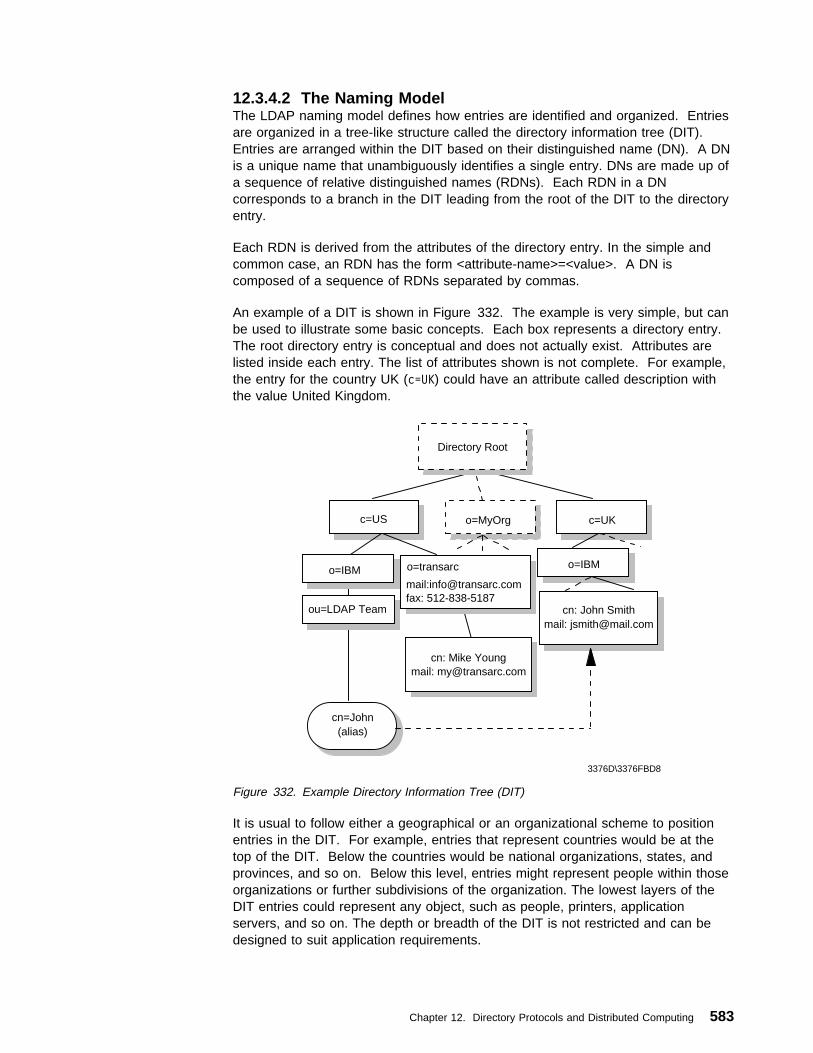
12.3.4.2 The Naming ModelThe LDAP naming model defines how entries are identified and organized. Entriesare organized in a tree-like structure called the directory information tree (DIT).Entries are arranged within the DIT based on their distinguished name (DN). A DNis a unique name that unambiguously identifies a single entry. DNs are made up ofa sequence of relative distinguished names (RDNs). Each RDN in a DNcorresponds to a branch in the DIT leading from the root of the DIT to the directoryentry.
Each RDN is derived from the attributes of the directory entry. In the simple andcommon case, an RDN has the form <attribute-name>=<value>. A DN iscomposed of a sequence of RDNs separated by commas.
An example of a DIT is shown in Figure 332. The example is very simple, but canbe used to illustrate some basic concepts. Each box represents a directory entry.The root directory entry is conceptual and does not actually exist. Attributes arelisted inside each entry. The list of attributes shown is not complete. For example,the entry for the country UK (c=UK) could have an attribute called description withthe value United Kingdom.
3376D\3376FBD8
c=US o=MyOrg c=UK
mail:[email protected]: 512-838-5187
o=transarc
cn=John(alias)
cn: John Smithmail: [email protected]
o=IBM
cn: Mike Youngmail: [email protected]
ou=LDAP Team
o=IBM
Directory Root
Figure 332. Example Directory Information Tree (DIT)
It is usual to follow either a geographical or an organizational scheme to positionentries in the DIT. For example, entries that represent countries would be at thetop of the DIT. Below the countries would be national organizations, states, andprovinces, and so on. Below this level, entries might represent people within thoseorganizations or further subdivisions of the organization. The lowest layers of theDIT entries could represent any object, such as people, printers, applicationservers, and so on. The depth or breadth of the DIT is not restricted and can bedesigned to suit application requirements.
Chapter 12. Directory Protocols and Distributed Computing 583
Entries are named according to their position in the DIT. The directory entry in thelower-right corner of Figure 332 has the DN cn=John Smith,o=IBM,c=DE.
Note: DNs read from leaf to root as opposed to names in a file system directorywhich usually read from root to leaf. DCE directory entries are also namedstarting from the root.
The DN is made up of a sequence of RDNs. Each RDN is constructed from anattribute (or attributes) of the entry it names. For example, the DN cn=JohnSmith,o=IBM,c=DE is constructed by adding the RDN cn=John Smith to the DN ofthe ancestor entry o=IBM,c=DE.
The DIT is described as being tree-like, implying it is not a tree. This is because ofaliases. Aliases allow the tree structure to be circumvented. This can be useful ifan entry belongs to more than one organization or if a commonly used DN is toocomplex. Another common use of aliases is when entries are moved within the DITand you want access to continue to work as before. In Figure 332 on page 583,cn=John,ou=LDAP Team,o=IBM,c=US is an alias for cn=John Smith,o=IBM,c=UK.
DNs in LDAP Version 3 are more restrictive than in LDAP V2. For example, inLDAP V2, semicolons could also be used to separate RDNs. LDAP V3 mustaccept the older syntax, but must not generate DNs that do not conform to thenewer syntax.
As an LDAP directory can be distributed, an individual LDAP server might not storethe entire DIT. A server might store the entries for a particular department and notthe entries for the ancestors of the department. For example, a server might storethe entries for the ITSO department at IBM. The highest node in the DIT stored bythe server would be ou=ITSO,o=IBM,c=US. The server would not store entries forc=US or for o=IBM,c=US. The highest entry stored by a server is called a suffix.Each entry stored by the server ends with this suffix.
A single server can support multiple suffixes. For example, in addition to storinginformation about the ITSO department, the same server could store informationabout the sales department at Transarc. The server would then have the suffixesou=ITSO,o=IBM,c=US and ou=sales,o=Transarc,c=US. Since a server might notstore the entire DIT, servers need to be linked together in some way in order toform a distributed directory that contains the entire DIT. This is accomplished withreferrals. A referral acts as a pointer to an entry on another LDAP server whererequested information is stored. A referral is an entry of objectClass referral. It hasan attribute, ref, whose value is the LDAP URL of the referred entry on anotherLDAP server. See 12.3.6, “LDAP URLs” on page 588, for further information.
The referral is a new feature in LDAP Version 3. Referrals allow a DIT to bepartitioned and distributed across multiple servers. Portions of the DIT can also bereplicated. This can improve performance and availability.
Note: When an application uses LDAP to request directory information from aserver, but the server only has a referral for that information, the LDAP URLfor that information is passed to the client, and it is then the responsibility ofthat client to contact the new server to obtain the information. This is unlikethe standard mechanisms of both DCE and X.500, where a directory server,if it does not contain the requested information locally, will always obtain theinformation from another server and pass it back to the client.
584 TCP/IP Tutorial and Technical Overview

12.3.4.3 The Functional ModelLDAP defines operations for accessing and modifying directory entries. LDAPoperations can be divided into the following three categories:
Query Includes the search and compare operations used to retrieve informationfrom a directory
Update Includes the add, delete, modify, and modify RDN operations used toupdate stored information in a directory. These operations will normallybe carried out by an administrator.
AuthenticationIncludes the bind, unbind, and abandon operations used to connect anddisconnect to and from an LDAP server, establish access rights andprotect information. For further information, please see 12.3.5, “LDAPSecurity” on page 586.
The Search Operation: The most common operation is the search. Thisoperation is very flexible and has some of the most complex options. The searchoperation allows a client to request that an LDAP server search through someportion of the DIT for information meeting user-specified criteria in order to readand list the result(s).
The search can be very general or very specific. The search operation allows thespecification of the starting point within the DIT, how deep within the DIT to search,the attributes an entry must have to be considered a match, and the attributes toreturn for matched entries.
Some example searches expressed informally in English are:
� Find the postal address for cn=John Smith,o=IBM,c=DE.
� Find all the entries that are children of the entry ou=ITSO,o=IBM,c=US.
� Find the e-mail address and phone number of anyone in an organization whoselast name contains the characters “miller” and who also has a fax number.
To perform a search, the following parameters must be specified:
Base A DN that defines the starting point, called the base object, of thesearch. The base object is a node within the DIT.
Scope Specifies how deep within the DIT to search from the base object.There are three choices:
baseObject Only the base object is examined.singleLevel Only the immediate children of the base object are
examined; the base object itself is not examined.wholeSubtree The base object and all of its descendants are
examined.
Search FilterSpecifies the criteria an entry must match to be returned from a search.The search filter is a Boolean combination of attribute value assertions.An attribute value assertion tests the value of an attribute for equality,less than or equal, and so on.
Attributes to ReturnSpecifies which attributes to retrieve from entries that match the searchcriteria. Since an entry may have many attributes, this allows the user
Chapter 12. Directory Protocols and Distributed Computing 585
to only see the attributes they are interested in. Normally, the user isinterested in the value of the attributes. However, it is possible to returnonly the attribute types and not their values.
Alias DereferencingSpecifies if aliases are dereferenced. That is, the actual object ofinterest, pointed to by an alias entry, is examined. Not dereferencingaliases allows the alias entries themselves to be examined.
Limits Searches can be very general, examining large subtrees and causingmany entries to be returned. The user, (or the server), can specify timeand size limits to prevent wayward searching from consuming too manyresources. The size limit restricts the number of entries returned fromthe search. The time limit limits the total time of the search.
12.3.5 LDAP SecuritySecurity is of great importance in the networked world of computers, and this is truefor LDAP as well. When sending data over insecure networks. Internally orexternally, sensitive information may need to be protected during transportation.There is also a need to know who is requesting the information and who is sendingit. This is especially important when it comes to the update operations on adirectory. The term security may be considered to cover the following four aspects:
Authentication Assurance that the opposite party (machine or person) really is whohe/she/it claims to be.
Integrity Assurance that the information that arrives is really the same aswhat was sent.
Confidentiality Protection of information disclosure by means of data encryption tothose who are not intended to receive it.
Authorization Assurance that a party is really allowed to do what it is requestingto do. This is usually checked after user authentication. In LDAPVersion 3, this is currently not part of the protocol specification andis therefore implementation- (or vendor-) specific. Authorization isachieved by assigning access controls, such as read, write, ordelete, for user IDs or common names to the resources beingaccessed. There is an Internet draft that proposes access controlfor LDAP (see 12.3.9, “References” on page 591).
The following sections focus on the first three aspects (since authorization is notcontained in the LDAP Version 3 standard): authentication, integrity andconfidentiality. There are several mechanisms that can be used for this purpose;the most important ones are discussed here. These are:
� No authentication
� Basic authentication
� Simple Authentication and Security Layer (SASL)
The security mechanism to be used in LDAP is negotiated when the connectionbetween the client and the server is established.
586 TCP/IP Tutorial and Technical Overview

12.3.5.1 No AuthenticationNo authentication should only be used when data security is not an issue and whenno special access control permissions are involved. This could be the case, forexample, when your directory is an address book browsable by anybody. Noauthentication is assumed when you leave the password and DN field empty in thebind API call. The LDAP server then automatically assumes an anonymous usersession and grants access with the appropriate access controls defined for this kindof access (not to be confused with the SASL anonymous user as discussed in12.3.5.3, “Simple Authentication and Security Layer (SASL)”).
12.3.5.2 Basic AuthenticationBasic authentication is also used in several other Web-related protocols, such asHTTP. When using basic authentication with LDAP, the client identifies itself to theserver by means of a DN and a password which are sent in the clear over thenetwork (some implementation may use Base64 encoding instead). The serverconsiders the client authenticated if the DN and password sent by the clientmatches the password for that DN stored in the directory. Base64 encoding isdefined in the Multipurpose Internet Mail Extensions (MIME - see 4.8, “MultipurposeInternet Mail Extensions (MIME)” on page 193). Base64 is a relatively simpleencryption, and therefore it is not hard to break once the data has been capturedon the network.
12.3.5.3 Simple Authentication and Security Layer (SASL)SASL is a framework for adding additional authentication mechanisms toconnection-oriented protocols. It has been added to LDAP Version 3 to overcomethe authentication shortcomings of Version 2. SASL was originally devised to addstronger authentication to the IMAP protocol. SASL has since evolved into a moregeneral system for mediating between protocols and authentication systems. It is aproposed Internet standard defined in RFC 2222 Simple Authentication andSecurity Layer (SASL).
In SASL, connection protocols, such as LDAP, IMAP, and so on, are representedby profiles; each profile is considered a protocol extension that allows the protocoland SASL to work together. A complete list of SASL profiles can be obtained fromthe Information Sciences Institute (ISI) (see 12.3.9, “References” on page 591).Among these are IMAP4, SMTP, POP3, and LDAP. Each protocol that intends touse SASL needs to be extended with a command to identify an authenticationmechanism and to carry out an authentication exchange. Optionally, a securitylayer can be negotiated to encrypt the data after authentication and so ensureconfidentiality. LDAP Version 3 includes such a command (ldap_sasl_bind()). Thekey parameters that influence the security method used are:
dn This is the distinguished name of the entry which is to bind. This can bethought of as the user ID in a normal user ID and passwordauthentication.
mechanismThis is the name of the security method that should be used. Validsecurity mechanisms are currently Kerberos Version 4, S/Key, GSSAPI,CRAM-MD5 and EXTERNAL. There is also an ANONYMOUSmechanism available which enables an authentication as useranonymous. In LDAP, the most common mechanism used is SSL (or itssuccessor, TLS), which is provided as an EXTERNAL mechanism.
Chapter 12. Directory Protocols and Distributed Computing 587

credentialsThis contains the arbitrary data that identifies the DN. The format andcontent of the parameter depends on the mechanism chosen. If it is, forexample, the ANONYMOUS mechanism, it can be an arbitrary string oran e-mail address that identifies the user.
SASL provides a high-level framework that lets the involved parties decide on theparticular security mechanism to use. The SASL security mechanism negotiationbetween client and server is done in the clear. Once the client and the server haveagreed on a common mechanism, the connection is secure against modifying theauthentication identities. However, an attacker could try to eavesdrop themechanism negotiation and cause a party to use the least secure mechanism. Inorder to prevent this from happening, clients and servers should be configured touse a minimum security mechanism, provided they support such a configurationoption. As stated earlier, SSL and its successor, TLS, are the mechanismscommonly used in SASL for LDAP. For details on these protocols, please refer to5.7, “Secure Sockets Layer (SSL)” on page 331.
As no data encryption method was specified in LDAP Version 2, some vendors, forexample Netscape and IBM, added their own SSL calls to the LDAP API. Apotential drawback of such an approach is that the API calls might not becompatible among different vendor implementations. The use of SASL, asspecified in LDAP Version 3 should assure compatibility, although it is likely thatvendor products will support only a subset of the possible range of mechanisms(maybe only SSL).
12.3.6 LDAP URLsSince LDAP has become an important protocol on the Internet, a URL format forLDAP resources has been defined. RFC 2255 The LDAP URL Format describesthe format of the LDAP URL. LDAP URLs begin with ldap:// or ldaps:// if the LDAPserver communicates using SSL. LDAP URLs can simply name an LDAP server, orcan specify a complex directory search.
Some examples will help make the format of LDAP URLs clear. The followingrefers to the LDAP server on the host saturn.itso.austin.ibm.com, (using the defaultport 389):
ldap://saturn.itso.austin.ibm.com/
The following retrieves all the attributes for the DN o=Transarc,c=US from the LDAPserver on host saturn.itso.austin.ibm.com. Note that the port 389 is explicitlyspecified here as an example. Since 389 is the default port, it would not have beennecessary to specify it in the URL.
ldap://saturn.itso.austin.ibm.com:389/o=Transarc,c=US
The following retrieves all the attributes for the DNcn=JohnSmith,ou=Austin,o=IBM,c=US. Note that some characters are consideredunsafe in URLs because they can be removed or treated as delimiters by someprograms. Unsafe characters such as space, comma, brackets, and so forthshould be represented by their hexadecimal value preceded by the percent sign.
ldap://saturn.itso.austin.ibm.com/cn=John%2ðSmith,ou=Austin,o=IBM,c=US
In this example, %20 is a space. More information about unsafe characters andURLs in general can be found in RFC 1738 Uniform Resource Locators (URL).
588 TCP/IP Tutorial and Technical Overview

12.3.7 LDAP and DCEDCE has its own cell directory service (CDS - see 12.1.1.1, “Cell Directory Service”on page 564). If applications never access resources outside of their DCE cell,only CDS is required. However, if an application needs to communicate withresources in other DCE cells, the Global Directory Agent (GDA) is required. TheGDA accesses a global (that is, non-CDS) directory where the names of DCE cellscan be registered. This global directory (GDS) can be either a Domain NameSystem (DNS) directory or an X.500 directory. The GDA retrieves the address of aCDS server in the remote cell. The remote CDS can then be contacted to findDCE resources in that cell. Using the GDA enables an organization to link multipleDCE cells together using either a private directory on an intranet or a publicdirectory on the Internet.
In view of LDAP's strong presence in the Internet, two LDAP projects have beensponsored by The Open Group to investigate LDAP integration with DCEtechnology.
12.3.7.1 LDAP Interface for the GDAOne way LDAP is being integrated into DCE is to allow DCE cells to be registeredin LDAP directories. The GDA in a cell that wants to connect to remote cells isconfigured to enable access to the LDAP directory (see Figure 333).
3376D\3376FBD9
LDAPServer
LDAP Interface DNS Interface X.500Interface
DNSServer
X.500Server
Global Directory Agent
Figure 333. LDAP Interface for the GDA
DCE originally supports only X.500 and DNS name syntax for cell names. LDAPand X.500 names both follow the same hierarchical naming model, but their syntaxis slightly different. X.500 names are written in reverse order and use a slash (/)rather than a comma (,) to separated relative distinguished names. When the GDAis configured to use LDAP, it converts cell names in X.500 format to LDAP formatto look them up in an LDAP directory.
12.3.7.2 LDAP Interface for the CDSDCE provides two programming interfaces to the Directory Service; Name ServiceInterface (NSI) and the X/Open Directory Service (XDS). XDS is an X.500compatible interface used to access information in the GDS, and it can also beused to access information in the CDS. However, the use of NSI is much morecommon in DCE applications. The NSI API provides functionality that is specificallytailored for use with DCE client and server programs that use RPC. NSI allowsservers to register their address and the type of RPC interface they support. This
Chapter 12. Directory Protocols and Distributed Computing 589

address/interface information is called an RPC binding and is needed by clients thatwant to contact the server. NSI allows clients to search the CDS for RPC bindinginformation.
NSI was designed to be independent of the directory where the RPC bindings arestored. However, the only supported directory to date has been CDS. NSI will beextended to also support adding and retrieving RPC bindings from an LDAPdirectory. This will allow servers to advertise their RPC binding information in eitherCDS or an LDAP directory. Application programs could use either the NSI or theLDAP API when an LDAP directory is used (see Figure 334).
3376D\3376FBDA
NSI
CDSServer
LDAP API
Application
LDAPServer
Figure 334. LDAP Interface for NSI
An LDAP schema to represent RPC binding information is in the draft stage ofdevelopment within the IETF.
12.3.8 The Directory-Enabled Networks Initiative (DEN)In September 1997, Cisco Systems Inc. and Microsoft Corp. announced theso-called Directory-Enabled Networks Initiative (DEN) as a result of a collaborativework. Many companies, such as IBM, either support this initiative or even activelyparticipate in ad hoc working groups (ADWGs). DEN represents an informationmodel specification for an integrated directory that stores information about people,network devices and applications. The DEN schema defines the object classesand their related attributes for those objects. In such, DEN is a key piece tobuilding intelligent networks, where products from multiple vendors can store andretrieve topology and configuration-related data. Since DEN is a relatively newspecification, products supporting it cannot be expected until about one to twoyears after its first draft was published late in 1997.
Of special interest is that the DEN specification defines LDAP Version 3 as the coreprotocol for accessing DEN information, which makes information available toLDAP-enabled clients and/or network devices.
More information about the DEN initiative can be found on the founders Web sitesor at:
http://murchiso.com/den/
590 TCP/IP Tutorial and Technical Overview

12.3.9 ReferencesPlease refer to the following documents for more information about LDAP.
RFCs
RFC 1487 — X.500 Lightweight Access
RFC 1777 — Lightweight Directory Access Protocol
RFC 1778 — The String Representation of Standard Attribute Syntaxes
RFC 1779 — A String Representation of Distinguished Names
RFC 1959 — An LDAP URL Format
RFC 1960 — A String Representation of LDAP Search Filters
RFC 2251 — Lightweight Directory Access Protocol (v3)
RFC 2252 — Lightweight Directory Access Protocol (v3): Attribute SyntaxDefinitions
RFC 2253 — Lightweight Directory Access Protocol (v3): UTF-8 StringRepresentation of Distinguished Names
RFC 2254 — The String Representation of LDAP Search Filters
RFC 2255 — The LDAP URL Format
RFC 2256 — A Summary of the X.500(96) User Schema for use withLDAPv3
RFC 1823 — The LDAP Application Program Interface
RFC 2222 — Simple Authentication and Security Layer (SASL)
Internet Drafts
The C LDAP Application Program Interface:
http://search.ietf.org/internet-drafts/draft-ietf-ldapext-ldap-c-api-ð1.txt
Access Control Requirements for LDAP:
http://search.ietf.org/internet-drafts/draft-ietf-ldapext-acl-reqts-ð1.txt
Other Resources
SASL Mechanisms:
ftp://ftp.isi.edu/in-notes/iana/assignments/sasl-mechanisms
The Unversity of Michigan was, and still is, an important contributor to thedevelopment of LDAP and can be considered a reliable, neutral sourcefor extensive information.
http://www.umich.edu/˜dirsvcs/ldap/
Chapter 12. Directory Protocols and Distributed Computing 591

592 TCP/IP Tutorial and Technical Overview

Part 3. Connection Protocols and Platform Implementations
Copyright IBM Corp. 1989, 1998 593

594 TCP/IP Tutorial and Technical Overview

Chapter 13. Connection Protocols
This chapter provides an overview of protocols and interfaces that allow TCP/IPtraffic to flow over various kinds of physical networks as well as over logicalmultiprotocol connections.
13.1 Ethernet and IEEE 802.x Local Area Networks (LANs)Two frame formats can be used on the Ethernet coaxial cable:
1. The standard issued in 1978 by Xerox Corporation, Intel Corporation andDigital Equipment Corporation, usually called Ethernet (or DIX Ethernet).
2. The international IEEE 802.3 standard, a more recently defined standard.
The difference between the two standards is in the use of one of the header fields,which contains a protocol-type number for Ethernet and the length of the data inthe frame for IEEE 802.3.
PreambleDestAddr
SourceAddr Type Info FCS
8 bytes 6 bytes 6 bytes 2 bytes 46<=N<=1500 bytes 4 bytes
Ethernet
PreambleDestAddr
SourceAddr Length DSAP FCS
7 bytes 6 bytes 6 bytes 2 bytes variable
SFD
1 byte
IEEE 802.3
Info
1 byte
SSAP
1 byte
Ctrl
1 byte 4 bytes
IEEE 802.2 header
3376\3376F2AE
Figure 335. ARP - Frame Formats for Ethernet and IEEE 802.3
� The type field in Ethernet is used to distinguish between different protocolsrunning on the coaxial cable, and allows their coexistence on the same physicalcable.
� The maximum length of an Ethernet frame is 1526 bytes. This means a datafield length of up to 1500 bytes. The length of the 802.3 data field is alsolimited to 1500 bytes for 10 Mbps networks, but is different for othertransmission speeds.
� In the 802.3 MAC frame, the length of the data field is indicated in the 802.3header. The type of protocol it carries is then indicated in the 802.2 header(higher protocol level, see Figure 335).
� In practice however, both frame formats can coexist on the same physicalcoax. This is done by using protocol type numbers (type field) greater than1500 in the Ethernet frame. However, different device drivers are needed tohandle each of these formats.
Thus, for all practical purposes, the Ethernet physical layer and the IEEE 802.3physical layer are compatible. However, the Ethernet data link layer and the IEEE802.3/802.2 data link layer are incompatible.
Copyright IBM Corp. 1989, 1998 595

The 802.2 Logical Link Control (LLC) layer above IEEE 802.3 uses a conceptknown as link service access point (LSAP) which uses a 3-byte header, whereDSAP and SSAP stand for destination and source service:
DSAP
1 byte
SSAP
1 byte
Ctrl
1 byte
Figure 336. ARP - IEEE 802.2 LSAP Header
Access Point respectively. Numbers for these fields are assigned by an IEEEcommittee.
Due to a growing number of applications using IEEE 802 as lower protocol layers,an extension was made to the IEEE 802.2 protocol in the form of the Sub-NetworkAccess Protocol (SNAP). It is an extension to the LSAP header above, and its useis indicated by the value 170 in both the SSAP and DSAP fields of the LSAP frameabove.
Prot.ID or org.code
3 bytes
Ethertype
2 bytes
Figure 337. ARP - IEEE 802.2 SNAP Header
In the evolution of TCP/IP, three standards were established that describe theencapsulation of IP and ARP frames on these networks:
1. 1984: RFC 894 — Standard for the Transmission of IP Datagrams overEthernet Networks specifies only the use of Ethernet type of networks. Thevalues assigned to the type field are:
2048 (hex 0800) for IP datagrams2054 (hex 0806) for ARP datagrams
2. 1985: RFC 948 — Two Methods for the Transmission of IP Datagrams overIEEE 802.3 Networks specifies two possibilities:
a. The Ethernet compatible method: The frames are sent on a real IEEE802.3 network in the same fashion as on an Ethernet network, that is, usingthe IEEE 802.3 data-length field as the Ethernet type field, thereby violatingthe IEEE 802.3 rules, but compatible with an Ethernet network.
b. IEEE 802.2/802.3 LLC type 1 format: Using 802.2 LSAP header with IPusing the value 6 for the SSAP and DSAP fields.
The RFC indicates clearly that the IEEE 802.2/802.3 method is the preferredmethod. That is, that all future IP implementations on IEEE 802.3 networks aresupposed to use the second method.
3. 1987: RFC 1010 - Assigned Numbers (now obsoleted by RFC 1700 dated1994) notes that as a result of IEEE 802.2 evolution and the need for moreInternet protocol numbers, a new approach was developed based on practicalexperiences exchanged during the August 1986 TCP Vendors Workshop. Itstates in an almost completely overlooked part of this RFC that from now on allIEEE 802.3, 802.4 and 802.5 implementations should use the Sub-Network
596 TCP/IP Tutorial and Technical Overview

Access Protocol (SNAP) form of the IEEE 802.2 LLC: DSAP and SSAP fieldsset to 170 (indicating the use of SNAP) and then SNAP assigned as follows:
� 0 (zero) as organization code. � EtherType field:
2048 (hex 0800) for IP datagrams2054 (hex 0806) for ARP datagrams32821 (hex 8035) for RARP datagramsThese are the same values as used in the Ethernet type field.
4. 1988: RFC 1042 — Standard for the Transmission of IP Datagrams over IEEE802 Networks.
As this new approach (very important for implementations) passed almostunnoticed in a little note of an unrelated RFC, it became quite confusing, andfinally, in February 1988, it was repeated in an RFC on its own: RFC 1042,which obsoletes RFC 948.
The relevant IBM TCP/IP products implement RFC 894 for DIX Ethernet and RFC1700 for IEEE 802.3 networks.
However, in practical situations, there are still TCP/IP implementations that use theolder LSAP method (RFC 948 or 1042). Such implementations will notcommunicate with the more recent implementations (such as IBM's).
Note also that the last method covers not only the IEEE 802.3 networks, but alsothe IEEE 802.4 and 802.5 networks such as the IBM Token-Ring LAN.
13.2 Fiber Distributed Data Interface (FDDI)The FDDI specifications define a family of standards for 100 Mbps fiber optic LANsthat provides the physical layer and media access control sublayer of the data linklayer as defined by the ISO/OSI Model.
IP-FDDI is a draft-standard protocol. Its status is elective. It defines theencapsulating of IP datagrams and ARP requests and replies in FDDI frames.Figure 338 on page 598 shows the related protocol layers.
It is defined in RFC 1188 - A Proposed Standard for the Transmission of IPDatagrams over FDDI Networks for single MAC stations. Operation on dual MACstations will be described in a forthcoming RFC.
RFC 1188 states that all frames are transmitted in standard IEEE 802.2 LLC Type1 Unnumbered Information format, with the DSAP and SSAP fields of the 802.2header set to the assigned global SAP value for SNAP (decimal 170). The 24-bitOrganization Code in the SNAP header is set to zero, and the remaining 16 bitsare the EtherType from Assigned Numbers (see RFC 1700), that is:
� 2048 for IP� 2054 for ARP
The mapping of 32-bit Internet addresses to 48-bit FDDI addresses is done via theARP dynamic discovery procedure. The broadcast Internet addresses (whose<host address> is set to all ones) are mapped to the broadcast FDDI address (allones).
Chapter 13. Connection Protocols 597

IP datagrams are transmitted as series of 8-bit bytes using the usual TCP/IPtransmission order called big-endian or network byte order.
The FDDI MAC specification (ISO 9314-2 - ISO, Fiber Distributed Data Interface -Media Access Control) defines a maximum frame size of 4500 bytes for all framefields. After taking the LLC/SNAP header into account, and to allow futureextensions to the MAC header and frame status fields, the MTU of FDDI networksis set to 4352 bytes.
Please refer to LAN Concepts and Products, SG24-4753 for more details on theFDDI architecture.
IP/ARP
802.2 LLC
FDDI MAC
FDDI PHY
FDDI PMD
FDDI
SMT
MAC =PHY =PMD =SMT =
Medium Access ControlPhysical Layer ProtocolPhysical Layer Medium DependentStation Management
3376E\3376FAL2
Figure 338. IP and ARP over FDDI
13.3 Asynchronous Transfer Mode (ATM)ATM-based networks are of increasing interest for both local and wide areaapplications. There are already some products available to build your physicalATM network. The ATM architecture is new and therefore different from thestandard LAN architectures. For this reason, changes are required so thattraditional LAN products will work in the ATM environment. In the case of TCP/IPthe main change required is in the network interface to provide support for ATM.
There are several approaches already available, two of which are important to thetransport of TCP/IP traffic. They are described in 13.3.2, “Classical IP over ATM”on page 601 and 13.3.3, “ATM LAN Emulation” on page 606. They are alsocompared in 13.3.4, “Classical IP over ATM versus LAN Emulation” on page 608.
13.3.1 Address Resolution (ATMARP and InATMARP)The address resolution in an ATM logical IP subnet is done by the ATM AddressResolution Protocol (ATMARP) based on RFC 826 and the Inverse ATM AddressResolution Protocol (InATMARP) based on RFC 1293 (which is updated in RFC2390). ATMARP is the same protocol as the ARP protocol with extensions neededto support ARP in a unicast server ATM environment. InATMARP is the sameprotocol as the original InARP protocol but applied to ATM networks. Use of theseprotocols differs depending on whether permanent virtual connections (PVCs) orswitched virtual connections (SVCs) are used.
Both ATMARP and InATMARP are defined in RFC 2225 (updating RFC 1577),which is a proposed standard with a state of elective.
598 TCP/IP Tutorial and Technical Overview

The encapsulation of ATMARP and InATMARP requests/replies is described in13.3.2, “Classical IP over ATM” on page 601.
13.3.1.1 InATMARPThe ARP protocol is used to resolve a host's hardware address for a known IPaddress. The InATMARP protocol is used to resolve a host's IP address for aknown hardware address. In a switched environment you first establish a virtualconnection (VC) of either a permanent virtual connection (PVC) or switched virtualconnection (SVC) in order to communicate with another station. Therefore youknow the exact hardware address of the partner by administration but the IPaddress is unknown. InATMARP provides dynamic address resolution. InARPuses the same frame format as the standard ARP but defines two new operationcodes:
� InARP request=8
� InARP reply=9
Please see 2.4.2.1, “ARP Packet Generation” on page 69 for more details.
Basic InATMARP operates essentially the same as ARP with the exception thatInATMARP does not broadcast requests. This is because the hardware address ofthe destination station is already known. A requesting station simply formats arequest by inserting its source hardware and IP address and the known targethardware address. It then zero fills the target protocol address field and sends itdirectly to the target station. For every InATMARP request, the receiving stationformats a reply using the source address from the request as the target address ofthe reply. Both sides update their ARP tables. The hardware type value for ATMis 19 decimal and the EtherType field is set to 0x806, which indicates ARPaccording to RFC 1700.
13.3.1.2 Address Resolution in a PVC EnvironmentIn a PVC environment each station uses the InATMARP protocol to determine theIP addresses of all other connected stations. The resolution is done for thosePVCs that are configured for LLC/SNAP encapsulation. It is the responsibility ofeach IP station supporting PVCs to revalidate ARP table entries as part of theaging process.
13.3.1.3 Address Resolution in an SVC EnvironmentSVCs require support for ATMARP in the non-broadcast environment of ATM. Tomeet this need, a single ATMARP server must be located within the Logical IPSubnetwork (LIS) (see 13.3.2.1, “The Logical IP Subnetwork (LIS)” on page 603).This server has authoritative responsibility for resolving the ATMARP requests of allIP members within the LIS. For an explanation of ATM terms please refer to13.3.2, “Classical IP over ATM” on page 601.
The server itself does not actively establish connections. It depends on the clientsin the LIS to initiate the ATMARP registration procedure. An individual clientconnects to the ATMARP server using a point-to-point VC. The server, upon thecompletion of an ATM call/connection of a new VC specifying LLC/SNAPencapsulation, will transmit an InATMARP request to determine the IP address ofthe client. The InATMARP reply from the client contains the information necessaryfor the ATMARP server to build its ATMARP table cache. This table consists of:
� IP address � ATM address
Chapter 13. Connection Protocols 599

� Timestamp � Associated VC
This information is used to generate replies to the ATMARP requests it receives.
Note: The ATMARP server mechanism requires that each client beadministratively configured with the ATM address of the ATMARP server.
ARP Table Add/Update Algorithm:
� If the ATMARP server receives a new IP address in an InATMARP reply the IPaddress is added to the ATMARP table.
� If the InATMARP IP address duplicates a table entry IP address and theInATMARP ATM address does not match the table entry ATM address andthere is an open VC associated with that table entry, the InATMARPinformation is discarded and no modifications to the table are made.
� When the server receives an ATMARP request over a VC, where the source IPand ATM address match the association already in the ATMARP table and theATM address matches that associated with the VC, the server updates thetimeout on the source ATMARP table entry. For example, if the client issending ATMARP requests to the server over the same VC that it used toregister its ATMARP entry, the server notes that the client is still "alive" andupdates the timeout on the client's ATMARP table entry.
� When the server receives an ARP_REQUEST over a VC, it examines thesource information. If there is no IP address associated with the VC overwhich the ATMARP request was received and if the source IP address is notassociated with any other connection, then the server adds this station to itsATMARP table. This is not the normal way because, as mentioned above, it isthe responsibility of the client to register at the ATMARP server.
ATMARP Table Aging: ATMARP table entries are valid:
� In clients for a maximum time of 15 minutes
� In servers for a minimum time of 20 minutes
Prior to aging an ATMARP table entry, the ATMARP server generates anInARP_REQUEST on any open VC associated with that entry and decides what todo according to the following rules:
� If an InARP_REPLY is received, that table entry is updated and not deleted.
� If there is no open VC associated with the table entry, the entry is deleted.
Therefore, if the client does not maintain an open VC to the server, the client mustrefresh its ATMARP information with the server at least once every 20 minutes.This is done by opening a VC to the server and exchanging the initial InATMARPpackets.
The client handles the table updates according to the following:
� When an ATMARP table entry ages, the ATMARP client invalidates this tableentry.
� If there is no open VC associated with the invalidated entry, that entry isdeleted.
600 TCP/IP Tutorial and Technical Overview
� In the case of an invalidated entry and an open VC, the ATMARP clientrevalidates the entry prior to transmitting any non-address resolution traffic onthat VC. There are two possibilities:
– In the case of a PVC, the client validates the entry by transmitting anInARP_REQUEST and updating the entry on receipt of an InARP_REPLY.
– In the case of an SVC, the client validates the entry by transmitting anARP_REQUEST to the ATMARP server and updating the entry on receiptof an ARP_REPLY.
� If a VC with an associated invalidated ATMARP table entry is closed, that tableentry is removed.
As mentioned above, every ATM IP client that uses SVCs must know its ATMARPserver's ATM address for the particular LIS. This address must be named at everyclient during customization. There is at present no well-known ATMARP serveraddress defined.
13.3.2 Classical IP over ATMThe definitions for implementations of classical IP over Asynchronous TransferMode (ATM) are described in RFC 2225 which is a proposed standard with a statusof elective according to RFC 2400 (STD 1). This RFC considers only theapplication of ATM as a direct replacement for the "wires", local LAN segmentsconnecting IP endstations (members) and routers operating in the classicalLAN-based paradigm. Issues raised by MAC level bridging and LAN emulation arenot covered.
For ATM Forum's method of providing ATM migration please see 13.3.3, “ATM LANEmulation” on page 606.
Initial deployment of ATM provides a LAN segment replacement for:
� Ethernets, token-rings or FDDI networks
� Local area backbones between existing (non-ATM) LANs
� Dedicated circuits of frame relay PVCs between IP routers
This RFC also describes extensions to the ARP protocol (RFC 826) in order towork over ATM. This is discussed separately in 13.3.1, “Address Resolution(ATMARP and InATMARP)” on page 598.
First some ATM basics:
Cells All information (voice, image, video, data , etc.) is transported throughthe network in very short (48 data bytes plus a 5-byte header) blockscalled cells.
Routing Information flow is along paths (called virtual channels) set up as aseries of pointers through the network. The cell header contains anidentifier that links the cell to the correct path that it will take towards itsdestination.
Cells on a particular virtual channel always follow the same path throughthe network and are delivered to the destination in the same order inwhich they were received.
Chapter 13. Connection Protocols 601

Hardware-Based SwitchingATM is designed so that simple hardware-based logic elements may beemployed at each node to perform the switching. On a link of 1 Gbps anew cell arrives and a cell is transmitted every .43 microseconds. Thereis not a lot of time to decide what to do with an arriving packet.
Virtual Connection VCATM provides a virtual connection switched environment. VC setup canbe done on either a permanent virtual connection (PVC) or a dynamicswitched virtual connection (SVC) basis. SVC call management isperformed via implementations of the Q.93B protocol.
End-User InterfaceThe only way for a higher layer protocol to communicate across an ATMnetwork is over the ATM Adaptation Layer (AAL). The function of thislayer is to perform the mapping of protocol data units (PDUs) into theinformation field of the ATM cell and vice versa. There are four differentAAL types defined: AAL1, AAL2, AAL3/4 and AAL5. These AALs offerdifferent services for higher layer protocols. Here are the characteristicsof AAL5, which is used for TCP/IP:
� Message mode and streaming mode � Assured delivery� Non-assured delivery (used by TCP/IP)� Blocking and segmentation of data
� Multipoint operation
AAL5 provides the same functions as a LAN at the Medium AccessControl (MAC) layer. The AAL type is known by the VC endpoints viathe cell setup mechanism and is not carried in the ATM cell header. ForPVCs the AAL type is administratively configured at the endpoints whenthe connection (circuit) is set up. For SVCs, the AAL type iscommunicated along the VC path via Q.93B as part of call setupestablishment and the endpoints use the signaled information forconfiguration. ATM switches generally do not care about the AAL typeof VCs. The AAL5 format specifies a packet format with a maximumsize of 64KB - 1 byte of user data. The primitives, which the higherlayer protocol has to use in order to interface with the AAL layer (at theAAL service access point - SAP), are rigorously defined. When ahigh-layer protocol sends data, that data is processed first by theadaptation layer, then by the ATM layer and then the physical layertakes over to send the data to the ATM network. The cells aretransported by the network and then received on the other side first bythe physical layer, then processed by the ATM layer and then by thereceiving AAL. When all this is complete, the information (data) ispassed to the receiving higher layer protocol. The total functionperformed by the ATM network has been the non-assured transport (itmight have lost some) of information from one side to the other. Lookedat from a traditional data processing viewpoint all the ATM network hasdone is to replace a physical link connection with another kind ofphysical connection. All the higher layer network functions must still beperformed (for example IEEE 802.2).
AddressingAn ATM Forum endpoint address is either encoded as a 20-byte OSINSAP-based address (used for private network addressing, three
602 TCP/IP Tutorial and Technical Overview

formats possible) or is an E.164 Public UNI address (telephone numberstyle address used for public ATM networks).15
Broadcast, MulticastThere are currently no broadcast functions similar to LANs provided.But there is a multicast function available. The ATM term for multicastis point-to-multipoint connection.
13.3.2.1 The Logical IP Subnetwork (LIS)The term LIS was introduced to map the logical IP structure to the ATM network.In the LIS scenario, each separate administrative entity configures its hosts androuters within a closed logical IP subnetwork (same IP network/subnet number andaddress mask). Each LIS operates and communicates independently of other LISson the same ATM network. Hosts that are connected to an ATM networkcommunicate directly to other hosts within the same LIS. This implies that allmembers of a LIS are able to communicate via ATM with all other members in thesame LIS. (VC topology is fully meshed.) Communication to hosts outside of thelocal LIS is provided via an IP router. This router is an ATM endpoint attached tothe ATM network that is configured as a member of one or more LISs. Thisconfiguration may result in a number of separate LISs operating over the sameATM network. Hosts of differing IP subnets must communicate via an intermediateIP router even though it may be possible to open a direct VC between the two IPmembers over the ATM network.
13.3.2.2 Multiprotocol EncapsulationIf you want to use more than one type of network protocol (IP, IPX, etc.)concurrently over a physical network, you need a method of multiplexing thedifferent protocols. This can be done in the case of ATM either by VC-basedmultiplexing or LLC encapsulation. If you choose VC-based multiplexing you haveto have a VC for each different protocol between the two hosts. The LLCencapsulation provides the multiplexing function at the LLC layer and thereforeneeds only one VC. TCP/IP uses, according to RFC 2225 and 1483, the secondmethod because this kind of multiplexing was already defined in RFC 1042 for allother LAN types such as Ethernet, token-ring and FDDI. With this definition IPuses ATM simply as a LAN replacement. All the other benefits ATM has to offer,such as transportation of isochronous traffic etc., are not used. There is an IETFworking group with the mission of improving the IP implementation and to interfacewith the ATM Forum in order to represent the interests of the Internet communityfor future standards.
To be exact, the TCP/IP PDU is encapsulated in an IEEE 802.2 LLC headerfollowed by an IEEE 802.1a SubNetwork Attachment Point (SNAP) header andcarried within the payload field of an AAL5 CPCS-PDU (Common PartConvergence Sublayer). The AAL5 CPCS-PDU format is shown in Figure 339.
15 The ATM Forum is a worldwide organization, aimed at promoting ATM within the industry and the end-user community. Themembership includes more than 500 companies representing all sectors of the communications and computer industries as well asa number of government agencies, research organizations and users.
Chapter 13. Connection Protocols 603

3376E\3376FAL3
0 8 16 31
/ / / /
CCPS-UU CPI
CRC
CPCS-PDU Payload(up to 64 KB-1)
/ / / /Pad (0-47 bytes)
Length
Figure 339. AAL5 CPCS-PDU Format
Where:
CPCS-PDU PayloadThe CPCS-PDU payload is shown in Figure 340.
PadThe Pad field pads out the CDCS-PDU to fit exactly into the the ATMcells.
CPCS-UUThe CPCS-UU (User-to-User identification) field is used to transparentlytransfer CPCS user-to-user information. This field has no function forthe encapsulation and can be set to any value.
CPIThe Common Part Indicator (CPI) field aligns the CPCS-PDU trailer with64 bits.
LengthThe Length field indicates the length, in bytes, of the Payload field. Themaximum value is 65535 which is 64KB - 1.
CRCThe CRC field protects the entire CPCS-PDU except the CRC fielditself.
The payload format for routed IP PDUs is shown in Figure 340.
604 TCP/IP Tutorial and Technical Overview

3376E\3376FAL4
0 8 16 31
/ / / /
OUI cont. PID
LLC
IP PDU(up to 64 KB-9)
OUI
Figure 340. CPCS-PDU Payload Format for IP PDUs
Where:
IP PDUNormal IP datagram starting with the IP header.
LLC3-byte LLC header with the format DSAP-SSAP-Ctrl. For IP data it isset to 0xAA-AA-03 to indicate the presence of a SNAP header. The Ctrlfield always has the value 0x03 specifying Unnumbered InformationCommand PDU.
OUIThe 3-byte Organizationally Unique Identifier (OUI) identifies anorganization which administers the meaning of the following 2-byteProtocol Identifier (PID). To specify an EtherType in PID the OUI has tobe set to 0x00-00-00.
PIDThe Protocol Identifier (PID) field specifies the protocol type of thefollowing PDU. For IP datagrams the assigned EtherType or PID is0x08-00.
The default MTU size for IP members in an ATM network is discussed in RFC 1626and defined to be 9180 bytes. The LLC/SNAP header is 8 bytes; therefore, thedefault ATM AAL5 PDU size is 9188 bytes. The possible values can be betweenzero and 65535. You are allowed to change the MTU size but then all members ofa LIS must be changed as well in order to have the same value. RFC 1755recommends that all implementations should support MTU sizes up to and including64 KB.
The address resolution in an ATM network is defined as an extension of the ARPprotocol and is described in 13.3.1, “Address Resolution (ATMARP andInATMARP)” on page 598.
There is no mapping from IP broadcast or multicast addresses to ATM broadcast ormulticast addresses available. But there are no restrictions for transmitting orreceiving IP datagrams specifying any of the four standard IP broadcast addressforms as described in RFC 1122. Members, upon receiving an IP broadcast or IPsubnet broadcast for their LIS, must process the packet as if addressed to thatstation.
Chapter 13. Connection Protocols 605
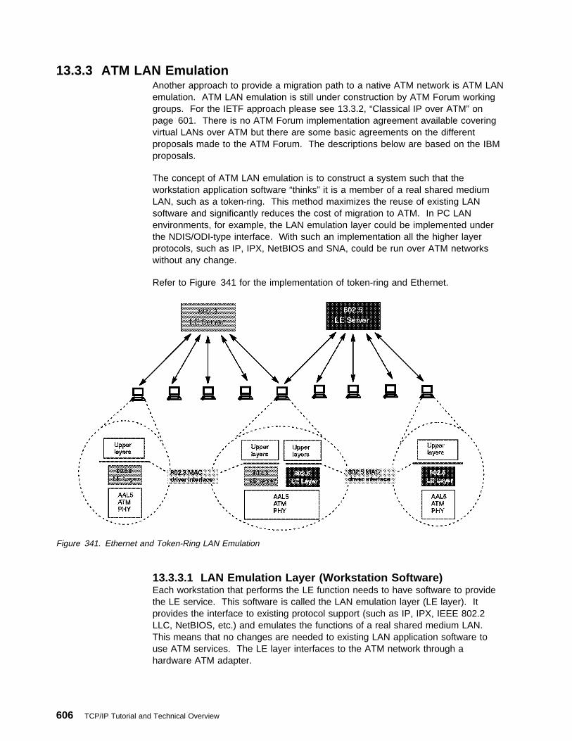
13.3.3 ATM LAN EmulationAnother approach to provide a migration path to a native ATM network is ATM LANemulation. ATM LAN emulation is still under construction by ATM Forum workinggroups. For the IETF approach please see 13.3.2, “Classical IP over ATM” onpage 601. There is no ATM Forum implementation agreement available coveringvirtual LANs over ATM but there are some basic agreements on the differentproposals made to the ATM Forum. The descriptions below are based on the IBMproposals.
The concept of ATM LAN emulation is to construct a system such that theworkstation application software “thinks” it is a member of a real shared mediumLAN, such as a token-ring. This method maximizes the reuse of existing LANsoftware and significantly reduces the cost of migration to ATM. In PC LANenvironments, for example, the LAN emulation layer could be implemented underthe NDIS/ODI-type interface. With such an implementation all the higher layerprotocols, such as IP, IPX, NetBIOS and SNA, could be run over ATM networkswithout any change.
Refer to Figure 341 for the implementation of token-ring and Ethernet.
Figure 341. Ethernet and Token-Ring LAN Emulation
13.3.3.1 LAN Emulation Layer (Workstation Software)Each workstation that performs the LE function needs to have software to providethe LE service. This software is called the LAN emulation layer (LE layer). Itprovides the interface to existing protocol support (such as IP, IPX, IEEE 802.2LLC, NetBIOS, etc.) and emulates the functions of a real shared medium LAN.This means that no changes are needed to existing LAN application software touse ATM services. The LE layer interfaces to the ATM network through ahardware ATM adapter.
606 TCP/IP Tutorial and Technical Overview

The primary function of the LE layer is to transfer encapsulated LAN frames(arriving from higher layers) to their destination either directly (over a direct VC) orthrough the LE server. This is done by using AAL5 services provided by ATM.
Each LE layer has one or more LAN addresses as well as an ATM address.
A separate instance (logical copy or LE client) of the LE layer is needed in eachworkstation for each different LAN or type of LAN to be supported. For example, ifboth token-ring and Ethernet LAN types are to be emulated, then you need two LElayers. In fact they will probably just be different threads within the same copy ofthe same code but they are logically separate LE layers. Separate LE layers wouldalso be used if one workstation needed to be part of two different emulatedtoken-ring LANs. Each separate LE layer needs a different MAC address but canshare the same physical ATM connection (adapter).
13.3.3.2 LAN Emulation ServerThe basic function of the LE server is to provide directory, multicast and addressresolution services to the LE layers in the workstations. It also provides aconnectionless data transfer service to the LE layers in the workstations if needed.
Each emulated LAN must have an LE server. It would be possible to have multipleLE servers sharing the same hardware and code (via multithreading) but the LEservers are logically separate entities. As for the LE layers, an emulated token-ringLAN cannot have members that are emulating an Ethernet LAN. Thus an instanceof an LE server is dedicated to a single type of LAN emulation. The LE server canbe physically internal to the ATM network or provided in an external device, butlogically it is always an external function that simply uses the services provided byATM to do its job.
13.3.3.3 Default VCsA default VC is a connection between an LE layer in a workstation and the LEserver. These connections can be permanent or switched.
All LE control messages are carried between the LE layer and the LE server on thedefault VC. Encapsulated data frames can also be sent on the default VC.
The presence of the LE server and the default VCs is necessary for the LE functionto be performed.
13.3.3.4 Direct VCsDirect VCs are connections between LE layers in the end systems. They arealways switched and set up on demand. If the ATM network does not supportswitched connections then you cannot have direct VCs and all the data must besent through the LE server on default VCs. If there is no direct VC available forany reason then data transfer must take place through the LE server. (There is noother way.)
Direct VCs are set up on request by an LE layer. (The server cannot set them upas there is no third party call setup function in ATM.) The ATM address of adestination LE layer is provided to a requesting LE layer by the LE server. DirectVCs stay in place until one of the partner LE layers decides to end the connection(because there is no more data).
Chapter 13. Connection Protocols 607

13.3.3.5 InitializationDuring initialization the LE layer (workstation) establishes the default VC with theLE server. It also discovers its own ATM address, which is needed if it is to laterset up direct VCs.
13.3.3.6 RegistrationIn this phase the LE layer (workstation) registers its MAC addresses with the LEserver. Other things such as filtering requirements (optional) may be provided.
13.3.3.7 Management and ResolutionThis is the method used by ATM endstations to set up direct VCs with otherendstations (LE layers). This function includes mechanisms for learning the ATMaddress of a target station, mapping the MAC address to an ATM address, storingthe mapping in a table and managing the table.
For the server this function provides the means for supporting the use of direct VCsby endstations. This includes a mechanism for mapping the MAC address of anend system to its ATM address, storing the information and providing it to arequesting endstation.
This structure maintains full LAN function and can support most higher layer LANprotocols. Reliance on the server for data transfer is minimized by using switchedVCs for the transport of most bulk data.
13.3.4 Classical IP over ATM versus LAN EmulationThese two approaches to providing an easier way to migrate to ATM were madewith different goals in mind.
Classical IP over ATM defines an encapsulation and address resolution method.The definitions are made for IP only and not for use with other protocols. So if youhave applications requiring other protocol stacks (such as IPX or SNA) then IP overATM will not provide a complete solution. On the other hand if you only have TCPor UDP-based applications then this might be the better solution, since thisspecialized adaptation of the IP protocol to the ATM architecture is likely to produceless overhead than a more global solution and therefore be more efficient. Anotheradvantage of this implementation is the use of some ATM-specific functions, suchas large MTU sizes, etc.
The major goal of the ATM Forum's approach is to run layer 3 and higher protocolsunchanged over the ATM network. This means that existing protocols, such asTCP/IP, IPX, NetBIOS and SNA for example, and their applications can use thebenefits of the fast ATM network without any changes. The mapping for allprotocols is already defined. The LAN emulation layer provides all the services of aclassic LAN; thus, the upper layer does not know of the existence of ATM. This isboth an advantage and a disadvantage because the knowledge of the underlyingnetwork could be used to provide a more effective implementation.
In the near future both approaches will be used depending on the particularrequirements. Over time, when the mapping of applications to ATM is fully definedand implemented, the scheme of a dedicated ATM implementation may be used.
608 TCP/IP Tutorial and Technical Overview

13.4 Data Link Switching: Switch-to-Switch ProtocolData Link Switching (DLSw) was issued by IBM in March 1993 and is documentedin RFC number 1795. Its state is informational.
13.4.1 IntroductionData Link Switching is a forwarding mechanism for the IBM SNA and IBM NetBIOSprotocols. It does not provide full routing, but instead provides switching at the datalink layer and encapsulation in TCP/IP for transport over the Internet. ThisSwitch-to-Switch Protocol (SSP) is used between IBM 2216 Nways MultiaccessConnector and/or IBM 2210 Nways Multiprotocol Routers. Routers of other vendorscan participate if they comply to the above RFC or without DLSw capability asintermediate routers because the DLSw connection exists only between the twoend routers.
13.4.2 Functional DescriptionDLSw was developed to provide support for SNA and NetBIOS in multiprotocolrouters. Since SNA and NetBIOS are basically connection-oriented protocols, thedata link control procedure that they use on the LAN is IEEE 802.2 Logical LinkControl (LLC) Type 2. DLSw also accommodates SNA protocols over WAN linksvia the SDLC protocol.
IEEE 802.2 LLC Type 2 was designed with the assumption that the network transitdelay would be small and predictable (for example, a local LAN). Therefore LLCuses a fixed timer for detecting lost frames. When bridging is used over wide arealines (especially at lower speeds), the network delay is larger and can vary greatlybased upon congestion. When the delay exceeds the timeout value LLC attemptsto retransmit. If the frame is not actually lost, only delayed, it is possible for theLLC Type 2 procedures to become confused, and as a result, the link is eventuallytaken down.
Given the use of LLC Type 2 services, DLSw addresses the following bridgingproblems:
� DLC timeouts
� DLC acknowledgments over the WAN
� Flow and congestion control
� Broadcast control of search packets
� Source-route bridging hop count limits
NetBIOS also makes extensive use of datagram services that use LLC Type 1. Inthis case, DLSw addresses the last two problems in the above list. The principaldifference between DLSw and bridging is that DLS terminates the data link controlwhereas bridging does not. Figure 342 on page 610 illustrates this differencebased upon two end systems operating with LLC Type 2 services.
Chapter 13. Connection Protocols 609

Figure 342. DLSw Compared to Bridging
In traditional bridging, the data link control is end-to-end. DLSw terminates the LLCType 2 connection at the switch. This means that the LLC Type 2 connections donot cross the wide area network. The DLS multiplexes LLC connections onto a TCPconnection to another DLS. Therefore, the LLC connections at each end are totallyindependent of each other. It is the responsibility of the data link switch to deliverframes that it has received from an LLC connection to the other end. TCP is usedbetween the data link switches to guarantee delivery of frames.
As a result of this design, LLC timeouts are limited to the local LAN. (For examplethey do not traverse the wide area.) Also, the LLC Type 2 acknowledgments (RRs)do not traverse the WAN, thereby reducing traffic across the wide area links. ForSDLC links, polling and poll response occurs locally, not over the WAN. Broadcastof search frames is controlled by the data link switches once the location of a targetsystem is discovered. Finally, the switches can now apply back pressure to the endsystems to provide flow and congestion control.
DLSw uses LAN addressing to set up connections between SNA systems.SDLC-attached devices are defined with MAC addresses to enable them tocommunicate with LAN-attached devices. For NetBIOS systems, DLSw uses theNetBIOS name to forward datagrams and to set up connections for NetBIOSsessions. For circuit establishment, SNA systems send TEST (or in some cases,XID) frames to the null (x'00') SAP. NetBIOS systems have an address resolutionprocedure, based upon the name query and name recognized frames, that is usedto establish an end-to-end circuit.
Since DLSw can be implemented in multiprotocol routers, there may be situationswhere both bridging and switching are enabled. SNA frames can be identified bytheir link SAP. Typical SAP values for SNA are x'04', x'08', and x'0C'. NetBIOSalways uses a link SAP value of x'F0'.
610 TCP/IP Tutorial and Technical Overview

For further details please refer to RFC 1795.
13.5 Serial Line IP (SLIP)The TCP/IP protocol family runs over a variety of network media: IEEE 802.3 and802.5 LANs, X.25 lines, satellite links, and serial lines. Standards for theencapsulation of IP packets have been defined for many of these networks, butthere is no standard for serial lines. SLIP is currently a de facto standard,commonly used for point-to-point serial connections running TCP/IP. Even thoughSLIP is not an Internet standard, it is documented by RFC 1055.
SLIP is just a very simple protocol designed quite a long time ago and is merely apacket framing protocol. It defines a sequence of characters that frame IP packetson a serial line, and nothing more. It does not provide any of the following:
� Addressing: Both computers on a SLIP link need to know each other's IPaddress for routing purposes. SLIP defines only the encapsulation protocol, notany form of handshaking or link control. Links are manually connected andconfigured, including the specification of the IP address.
� Packet type identification: SLIP cannot support multiple protocols across asingle link; thus, only one protocol can be run over a SLIP connection.
� Error detection/correction: SLIP does no form of frame error detection. Thehigher level protocols should detect corrupted packets caused by errors onnoisy lines. (IP header and UDP/TCP checksums should be sufficient.)Because it takes so long to retransmit a packet that was altered, it would beefficient if SLIP could provide some sort of simple error correction mechanismof its own.
� Compression: SLIP provides no mechanism for compressing frequently used IPheader fields. Many applications over slow serial links tend to be single-userinteractive TCP traffic such as TELNET. This frequently involves small packetsizes and therefore a relatively large overhead in TCP and IP headers which donot change much between datagrams, but which can have a noticeablydetrimental effect on interactive response times.
However, many SLIP implementations now use Van Jacobsen HeaderCompression. This is used to reduce the size of the combined IP and TCPheaders from 40 bytes to 8 bytes by recording the states of a set of TCPconnections at each end of the link and replacing the full headers with encodedupdates for the normal case where many of the fields are unchanged or areincremented by small amounts between successive IP datagrams for a session.This compression is described in RFC 1144.
The SLIP protocol is expected to be replaced by the Point-to-Point Protocol (PPP).Please see 13.6, “Point-to-Point Protocol (PPP).”
13.6 Point-to-Point Protocol (PPP)PPP is a network-specific standard protocol with STD number 51. Its status iselective. It is described in RFC 1661 and RFC 1662.
There are a large number of proposed standard protocols, which specify theoperation of PPP over different kinds of point-to-point link. Each has a status of
Chapter 13. Connection Protocols 611

elective. The reader is advised to consult STD 1 — Internet Official ProtocolStandards for a list of PPP-related RFCs which are on the Standards Track.
Point-to-point circuits in the form of asynchronous and synchronous lines have longbeen the mainstay for data communications. In the TCP/IP world, the de factostandard SLIP protocol has served admirably in this area, and is still in widespreaduse for dial-up TCP/IP connections. However, SLIP has a number of drawbacksthat are addressed by the point-to-point protocol.
PPP has three main components:
1. A method for encapsulating datagrams over serial links.
2. A Link Control Protocol (LCP) for establishing, configuring, and testing thedata-link connection.
3. A family of Network Control Protocols (NCPs) for establishing and configuringdifferent network-layer protocols. PPP is designed to allow the simultaneoususe of multiple network-layer protocols.
Before a link is considered to be ready for use by network-layer protocols, aspecific sequence of events must happen. The LCP provides a method ofestablishing, configuring, maintaining and terminating the connection. LCP goesthrough the following phases:
1. Link establishment and configuration negotiation:
In this phase, link control packets are exchanged and link configuration optionsare negotiated. Once options are agreed upon, the link is open, but notnecessarily ready for network-layer protocols to be started.
2. Link quality determination:
This phase is optional. PPP does not specify the policy for determining quality,but does provide low-level tools, such as echo request and reply.
3. Authentication:
This phase is optional. Each end of the link authenticates itself with the remoteend using authentication methods agreed to during phase 1.
4. Network-layer protocol configuration negotiation:
Once LCP has finished the previous phase, network-layer protocols may beseparately configured by the appropriate NCP.
5. Link termination:
LCP may terminate the link at any time. This will usually be done at the requestof a human user, but may happen because of a physical event.
13.6.1 Point-to-Point EncapsulationA summary of the PPP encapsulation is shown below.
Protocol8/16 bits
Information*
Padding*
3376E\3376FAL1
Figure 343. PPP Encapsulation Frame
612 TCP/IP Tutorial and Technical Overview

Protocol Field - The protocol field is one or two octets, and its value identifies thedatagram encapsulated in the Information field of the packet. Up-to-date values ofthe Protocol field are specified in the most recent Assigned Numbers RFC (RFC1700).
Information Field - The Information field is zero or more octets. The Informationfield contains the datagram for the protocol specified in the Protocol field. Themaximum length for the information field, including padding, but not including theProtocol field, is termed the Maximum Receive Unit (MRU), which defaults to 1500octets. By negotiation, other values can be used for the MRU.
Padding - On transmission, the information field may be padded with an arbitrarynumber of octets up to the MRU. It is the responsibility of each protocol todistinguish padding octets from real information.
The IP Control Protocol (IPCP) is the NCP for IP and is responsible for configuring,enabling and disabling the IP protocol on both ends of the point-to-point link. TheIPCP options negotiation sequence is the same as for LCP, thus allowing thepossibility of reusing the code.
One important option used with IPCP is Van Jacobson Header Compression whichis used to reduce the size of the combined IP and TCP headers from 40 bytes toapproximately 4 by recording the states of a set of TCP connections at each end ofthe link and replacing the full headers with encoded updates for the normal casewhere many of the fields are unchanged or are incremented by small amountsbetween successive IP datagrams for a session. This compression is described inRFC 1144.
13.7 Integrated Services Digital Network (ISDN)This section describes how to use the PPP encapsulation over ISDN point-to-pointlinks. PPP over ISDN is documented by RFC 1618. Its status is elective. Sincethe ISDN B-channel is by definition a point-to-point circuit, PPP is well suited foruse over these links.
The ISDN Basic Rate Interface (BRI) usually supports two B-channels with acapacity of 64 kbps each, and a 16 kbps D-channel for control information.B-channels can be used for voice or data or just for data in a combined way.
The ISDN Primary Rate Interface (PRI) may support many concurrent B-channellinks (usually 30) and one 64 Kbps D-channel. The PPP LCP and NCPmechanisms are particularly useful in this situation in reducing or eliminatingmanual configuration, and facilitating ease of communication between diverseimplementations. The ISDN D-channel can also be used for sending PPP packetswhen suitably framed, but is limited in bandwidth and often restricts communicationlinks to a local switch.
PPP treats ISDN channels as bit or octet-oriented synchronous links. These linksmust be full-duplex, but may be either dedicated or circuit-switched. PPP presentsan octet interface to the physical layer. There is no provision for sub-octets to besupplied or accepted. PPP does not impose any restrictions regarding transmissionrate other than that of the particular ISDN channel interface. PPP does not requirethe use of control signals. When available, using such signals can allow greaterfunctionality and performance.
Chapter 13. Connection Protocols 613

The definition of various encodings and scrambling is the responsibility of theDTE/DCE equipment in use. While PPP will operate without regard to theunderlying representation of the bit stream, lack of standards for transmission willhinder interoperability as surely as lack of data link standards. The D-channelinterface requires NRZ encoding. Therefore it is recommended that NRZ be usedover the B-channel interface. This will allow frames to be easily exchangedbetween the B and D channels. However, when configuration of the encoding isallowed, NRZI is recommended as an alternative in order to ensure a minimumones density where required over the clear B-channel. Implementations that want tointeroperate with multiple encodings may choose to detect those encodingsautomatically. Automatic encoding detection is particularly important for primaryrate interfaces, to avoid extensive pre-configuration.
Terminal adapters conforming to V.120 16 can be used as a simple interface toworkstations. The terminal adapter provides async-to-sync conversion. MultipleB-channels can be used in parallel. V.120 is not interoperable with bit-synchronouslinks, since V.120 does not provide octet stuffing to bit stuffing conversion. Despitethe fact that HDLC, LAPB, LAPD, and LAPF are nominally distinguishable, multiplemethods of framing should not be used concurrently on the same ISDN channel.There is no requirement that PPP recognize alternative framing techniques, orswitch between framing techniques without specific configuration. Experience hasshown that the LLC Information Element is not reliably transmitted end to end.Therefore, transmission of the LLC-IE should not be relied upon for framing orencoding determination. No LLC-IE values that pertain to PPP have been assigned.Any other values that are received are not valid for PPP links, and can be ignoredfor PPP service. The LCP recommended sync configuration options apply to ISDNlinks. The standard LCP sync configuration defaults apply to ISDN links. The typicalnetwork connected to the link is likely to have an MRU size of either 1500 or 2048bytes or greater. To avoid fragmentation, the maximum transmission unit (MTU) atthe network layer should not exceed 1500, unless a peer MRU of 2048 or greater isspecifically negotiated.
13.8 TCP/IP and X.25This topic describes the encapsulation of IP over X.25 networks, in accordance withISO/IEC and CCITT standards. IP over X.25 networks is documented by RFC 1356which obsoletes RFC 877. RFC 1356 is a Draft Standard with a status of elective.The substantive change to the IP encapsulation over X.25 is an increase in the IPdatagram MTU size, the X.25 maximum data packet size, the virtual circuitmanagement, and the interoperable encapsulation over X.25 of protocols other thanIP between multiprotocol routers and bridges.
One or more X.25 virtual circuits are opened on demand when datagrams arrive atthe network interface for transmission. Protocol data units (PDUs) are sent as X.25complete packet sequences. That is PDUs begin on X.25 data packet boundariesand the M bit (more data) is used to fragment PDUs that are larger than one X.25data packet in length. In the IP encapsulation the PDU is the IP datagram. The firstoctet in the call user data (CUD) field (the first data octet in the Call Requestpacket) is used for protocol demultiplexing, in accordance with the Subsequent
16 CCITT Recommendations I.465 and V.120, “Data Terminal Equipment Communications over the Telephone Network withProvision for Statistical Multiplexing,” CCITT Blue Book, Volume VIII, Fascicle VIII.1, 1988.
614 TCP/IP Tutorial and Technical Overview

Protocol Identifier (SPI) in ISO/IEC TR 9577. This field contains a one octetNetwork Layer Protocol Identifier (NLPID), which identifies the network layerprotocol encapsulated over the X.25 virtual circuit. For the Internet community, theNLPID has four relevant values:
1. The value hex CC (binary 11001100, decimal 204) is IP.
2. The value hex 81 (binary 10000001, decimal 129) identifies ISO/IEC 8473(CLNP).
3. The value hex 82 (binary 10000010, decimal 130) is used specifically forISO/IEC 9542 (ES-IS). If there is already a circuit open to carry CLNP, then it isnot necessary to open a second circuit to carry ES-IS.
4. The value hex 80 (binary 10000000, decimal 128) identifies the use of the IEEESubnetwork Access Protocol (SNAP) to further encapsulate and identify asingle network-layer protocol. The SNAP-encapsulated protocol is identified byincluding a five-octet SNAP header in the Call Request CUD field immediatelyfollowing the hex 80 octet. SNAP headers are not included in the subsequentX.25 data packets. Only one SNAP-encapsulated protocol can be carried overa virtual circuit opened using this encoding.
The value hex 00 identifies the null encapsulation used to multiplex multiplenetwork layer protocols over the same circuit. The Assigned Numbers RFC (RFC1700) contains one other non-CCITT and non-ISO/IEC value that has been usedfor Internet X.25 encapsulation identification, namely hex C5 (binary 11000101,decimal 197) for Blacker X.25. This value may continue to be used but only by priorpreconfiguration of the sending and receiving X.25 interfaces to support this value.The hex CD (binary 11001101, decimal 205), listed in Assigned Numbers forISO-IP is also used by Blacker and also can only be used by prior preconfigurationof the sending and receiving X.25 interfaces.
Each system must only accept calls for protocols it can process. Every Internetsystem must be able to accept the CC encapsulation for IP datagrams. Systemsthat support NLPIDs other than hex CC (for IP) should allow their use to beconfigured on a per-peer address basis. The Null encapsulation, identified by aNLPID encoding of hex 00, is used in order to multiplex multiple network layerprotocols over one circuit. When the Null encapsulation is used each X.25 completepacket sequence sent on the circuit begins with a one-octet NLPID which identifiesthe network layer protocol data unit contained only in that particular completepacket sequence. Further, if the SNAP NLPID (hex 80) is used, then the NLPIDoctet is immediately followed by the five-octet SNAP header which is thenimmediately followed by the encapsulated PDU. The encapsulated network layerprotocol may differ from one complete packet sequence to the next over the samecircuit.
Use of the single network layer protocol circuits is more efficient in terms ofbandwidth if only a limited number of protocols are supported by a system. It alsoallows each system to determine exactly which protocols are supported by itscommunicating partner. Other advantages include being able to use X.25accounting to detail each protocol and different quality of service or flow controlwindows for different protocols. The Null encapsulation, for multiplexing, is usefulwhen a system for any reason (such as implementation restrictions or network costconsiderations), may only open a limited number of virtual circuits simultaneously.This is the method most likely to be used by a multiprotocol router to avoid using
Chapter 13. Connection Protocols 615

an unreasonable number of virtual circuits. If performing IEEE 802.1d bridgingacross X.25 is required, then the Null encapsulation must be used.
IP datagrams must by default be encapsulated on a virtual circuit opened with theCC CUD. Implementations may also support up to three other possibleencapsulations of IP:
� IP datagrams may be contained in multiplexed data packets on a circuit usingthe Null encapsulation. Such data packets are identified by a NLPID of hex CC.
� IP may be incapsulated within the SNAP encapsulation on a circuit. Thisencapsulation is identified by containing in the 5-octet SNAP header anOrganizationally Unique Identifier (OUI) of hex 00-00-00 and Protocol Identifier(PID) of hex 08-00.
� On a circuit using the Null encapsulation, IP may be contained within the SNAPencapsulation of IP in multiplexed data packets.
13.9 Frame RelayThe frame relay network provides a number of virtual circuits that form the basis forconnections between stations attached to the same frame relay network. Theresulting set of interconnected devices forms a private frame relay group, whichmay be either fully interconnected with a complete mesh of virtual circuits, or onlypartially interconnected. In either case, each virtual circuit is uniquely identified ateach frame relay interface by a data link connection identifier (DLCI). In mostcircumstances, DLCIs have strictly local significance at each frame relay interface.Frame relay is documented in RFC 2427.
13.9.1 Frame FormatAll protocols must encapsulate their packets within a Q.922 Annex A frame{1}.Additionally, frames contain information necessary to identify the protocol carriedwithin the protocol data unit (PDU), thus allowing the receiver to properly processthe incoming packet (refer to Figure 344 on page 617). The format will be asfollows:
The control field is the Q.922 control field. The UI (0x03) value is used unless it isnegotiated otherwise. The use of XID (0xAF or 0xBF) is permitted.
The pad field is used to align the data portion (beyond the encapsulation header) ofthe frame to a two octet boundary. If present, the pad is a single octet and musthave a value of zero.
The Network Level Protocol ID (NLPID) field is administered by ISO and the ITU. Itcontains values for many different protocols including IP, CLNP, and IEEESubnetwork Access Protocol (SNAP). This field tells the receiver whatencapsulation or what protocol follows. Values for this field are defined in ISO/IECTR 9577 {2}. An NLPID value of 0x00 is defined within ISO/IEC TR 9577 as thenull network layer or inactive set. Since it cannot be distinguished from a pad field,and because it has no significance within the context of this encapsulation scheme,an NLPID value of 0x00 is invalid under the frame relay encapsulation.
There is no commonly implemented minimum or maximum frame size for framerelay. A network must, however, support at least a 262-octet maximum. Generally,the maximum will be greater than or equal to 1600 octets, but each frame relay
616 TCP/IP Tutorial and Technical Overview

provider will specify an appropriate value for its network. A frame relay dataterminal equipment (DTE), therefore must allow the maximum acceptable framesize to be configurable.
Flag (7E Hexadecimal)
Q.922 Address*
Control (UI = 0x03)
Pad (When Required) (0x00)
NLPID
Data
Frame Check Sequence
(Two Octets)
Flag (7E Hexadecimal)
3376\3376FALG
..
..
Figure 344. Frame Relay Packet Format
13.9.2 Interconnect IssuesThere are two basic types of data packets that travel within the frame relaynetwork: routed packets and bridged packets. These packets have distinct formatsand therefore, must contain an indicator that the destination can use to correctlyinterpret the contents of the frame. This indicator is embedded within the NLPIDand SNAP header information.
13.9.3 Data Link Layer Parameter NegotiationFrame relay stations may choose to support the Exchange Identification (XID)specified in Appendix III of Q.922 {1}. This XID exchange allows the followingparameters to be negotiated at the initialization of a frame relay circuit: maximumframe size, retransmission timer, and the maximum number of outstandinginformation (I) frames.
If this exchange is not used, these values must be statically configured by mutualagreement of data link connection (DLC) endpoints, or must be defaulted to thevalues specified in Section 5.9 of Q.922 {1}.
There are situations in which a frame relay station may wish to dynamically resolvea protocol address over permanent virtual circuits (PVCs). This may be
Chapter 13. Connection Protocols 617

accomplished using the standard Address Resolution Protocol (ARP) encapsulatedwithin a SNAP-encoded frame relay packet.
Because of the inefficiencies of emulating broadcasting in a frame relayenvironment, a new address resolution variation was developed. It is called InverseARP and describes a method for resolving a protocol address when the hardwareaddress is already known. In a frame relay network, the known hardware addressis the DLCI. Support for Inverse ARP is not required to implement thisspecification, but it has proven useful for frame relay interface autoconfiguration.
Stations must be able to map more than one IP address in the same IP subnet to aparticular DLCI on a frame relay interface. This need arises from applications suchas remote access, where servers must act as ARP proxies for many dial-in clients,each assigned a unique IP address while sharing bandwidth on the same DLC.The dynamic nature of such applications results in frequent address associationchanges with no affect on the DLC's status.
As with any other interface that utilizes ARP, stations may learn the associationsbetween IP addresses and DLCIs by processing unsolicited (gratuitous) ARPrequests that arrive on the DLC. If one station wishes to inform its peer station onthe other end of a frame relay DLC of a new association between an IP addressand that PVC, it should send an unsolicited ARP request with the source IPaddress equal to the destination IP address, and both set to the new IP addressbeing used on the DLC. This allows a station to "announce" new client connectionson a particular DLCI. The receiving station must store the new association, andremove any old existing association, if necessary, from any other DLCI on theinterface.
13.9.4 IP over Frame RelayInternet Protocol (IP) datagrams sent over a frame relay network conform to theencapsulation described previously. Within this context, IP could be encapsulatedin two different ways: NLPID value indicating IP or NLPID value indicating SNAP.
Although both of these encapsulations are supported under the given definitions, itis advantageous to select only one method as the appropriate mechanism forencapsulating IP data. Therefore, IP data should be encapsulated using the NLPIDvalue of 0xcc indicating an IP packet. This option is more efficient because ittransmits 48 fewer bits without the SNAP header and is consistent with theencapsulation of IP in an X.25 network.
13.10 PPP over SONET and SDH CircuitsThis discussion describes the use of the PPP encapsulation over SynchronousOptical Network (SONET) and Synchronous Digital Hierarchy (SDH) links which isdocumented by RFC 1619. Since SONET and SDH are by definition point-to-pointcircuits, PPP is well suited to use over these links. SONET is an octet-synchronousmultiplex scheme that defines a family of standard rates and formats. Despite thename it is not limited to optical links. Electrical specifications have been defined forsingle-mode fiber, multimode fiber, and CATV 75 ohm coaxial cable. Thetransmission rates are integral multiples of 51.840 Mbps, which may be used tocarry T3/E3 bit-synchronous signals. The allowed multiples are currently specifiedas:
618 TCP/IP Tutorial and Technical Overview

Table 18. SONET Speed Hierarchy
Signal Level Bit Rate DS-0s DS-1s DS-3s
STS-1 and OC-1 51.84 Mbps 672 28 1
STS-3 and OC-3 (STM-1) 155.52 Mbps 2,016 84 3
STS-9 and OC-9 466.56 Mbps 6,048 252 9
STS-12 and OC-12 (STM-4) 622.08 Mbps 8,064 336 12
STS-18 and OC-18 933.12 Mbps 12,096 504 18
STS-24 and OC-24 1,244.16 Mbps 16,128 672 24
STS-36 and OC-36 1,866.24 Mbps 24,192 1,008 36
STS-48 and OC-48 (STM-16) 2,488.32 Mbps 32,256 1,344 48
STS-n and OC-n (STM-n/3) n x 51.84 Mbps n x 672 n x 28 n
The CCITT Synchronous Digital Hierarchy defines a subset of SONET transmissionrates beginning at 155.52 Mbps, as shown in the table above.
13.10.1 Physical LayerPPP presents an octet interface to the physical layer. There is no provision forsub-octets to be supplied or accepted. SONET and SDH links are full-duplex bydefinition. The octet stream is mapped into the SONET/SDH Synchronous PayloadEnvelope (SPE) with the octet boundaries aligned with the SPE octet boundaries.No scrambling is needed during insertion into the SPE. The path signal label isintended to indicate the contents of the SPE. The experimental value of 207 (hexCF) is used to indicate PPP. The multiframe indicator is currently unused and mustbe zero.
The basic rate for PPP over SONET/SDH is that of STS-3c/STM-1 at 155.52 Mbps.The available information bandwidth is 149.76 Mbps which is the STS-3c/STM-1SPE with section, line and path overhead removed. This is the same upper layermapping that is used for ATM and FDDI. Lower signal rates must use the VirtualTributary (VT) mechanism of SONET/SDH. This maps existing signals up to T3/E3rates asynchronously into the SPE or uses available clocks for bit-synchronous andbyte-synchronous mapping. Higher signal rates should conform to the SDH STMseries rather than the SONET STS series as equipment becomes available. TheSTM series progresses in powers of 4 instead of 3 and employs fewer steps whichis likely to simplify multiplexing and integration.
13.11 Multiprotocol Label Switching (MPLS)MPLS is documented by an Internet draft. Internet drafts are working documents ofthe IETF. The primary goal of the MPLS working group is to standardize a basetechnology that integrates the label swapping forwarding paradigm with networklayer routing. The initial MPLS effort will be focused on IPv4 and IPv6. However thecore technology will be extendible to multiple network layer protocols. MPLS is notconfined to any specific link layer technology. It can work with any media overwhich network layer packets can be passed between network layer entities.
Chapter 13. Connection Protocols 619

13.11.1 Forwarding MethodsMPLS makes use of a routing approach whereby the normal mode of operation isthat L3 routing (for example, existing IP routing protocols and/or new IP routingprotocols) is used by all nodes to determine the routed path.
13.11.1.1 Peer ModelThis model has the following characteristics:
� Routing information is mapped to labels
� Switch's label-swap tables are updated with the new labels
� Use specialized control protocol to distribute routing to label mappings amongparticipating devices along routed path
� L3 processing replaced with L2 switching at intermediate nodes
� Packets/cells are switched from network ingress to egress
� Forwarding reduced to label lookup, label swap and output port selection
13.11.1.2 Flow-DrivenThis model has the following characteristics:
� Arrival of flow triggers exchange of flow setup messages between adjacentdevices. Cells of a flow are then re-labeled (new VCI) along each segment
� Ingress-to-egress switch path is formed when switch/routers splice togetheradjacent VCs.
Using flow-driven switching individual flows (host/host or appl/appl) are switchedthrough the network. Some but not all flows may be switched.
13.11.1.3 Topology-DrivenThis model has the following characteristics:
� Routing table entries are mapped to labels (VPI/VCI) and distributed amongparticipating devices.
� Ingress-to-egress switch path is established. It carries all traffic with destinationof NET X.
Using topology-driven IP switching all traffic going to a common destination will beswitched. A destination can be a network or collection of networks.
13.11.2 MPLS UsefulnessThe following should be considered when a possible MPLS deployment isdiscussed:
� Growth of the Internet is exceeding the L3 processing capacity of traditionalrouters.
� Enables routing to leverage the price, performance and maturity of layer-2switching.
� ATM switches can be augmented with IP routing.
� MPLS forwarding is independent of current and future enhancements tonetwork layer protocols.
620 TCP/IP Tutorial and Technical Overview

� Works over any layer-2 datalink technology (for example, ATM, frame relay,Ethernet, SONET, etc.)
� More efficient traffic engineering capabilities:
– Use label stacks rather than IP-OVER-IP encapsulation for tunnels
– Explicit routes
� ISP's need to support and deliver special services.
13.12 Enterprise ExtenderThe Enterprise Extender network connection is a simple set of extensions to theexisting open high performance routing (HPR) technology. It performs an efficientintegration of the HPR frames using UDP/IP packets. To the HPR network, the IPbackbone is a logical link. To the IP network, the SNA traffic is UDP datagrams thatare routed without any hardware or software changes to the IP backbone. Unlikegateways there is no protocol transformation and unlike common tunnelingmechanisms the integration is performed at the routing layers without the overheadof additional transport functions. The advanced technology enables efficient use ofthe intranet infrastructure for support of IP-based client accessing SNA-based data(for example, TN2370 emulators or Web browsers using services such as IBM'sHost On-Demand) as well as SNA clients using any of the SNA LU types.
Enterprise Extender seamlessly routes packets through the network protocol“edges” eliminating the need to perform costly protocol translation and thestore-and-forward associated with transport-layer functions. Unlike Data LinkSwitching (DLSw), for example, there are no TCP retransmit buffers and timers andno congestion control logic in the router because it uses connectionless UDP andthe congestion control is provided end system to end system. Because of thesesavings, the “edge” routers have less work to do and can perform the job they dobest which is forwarding packets instead of incurring protocol translation overheadand maintaining many TCP connections. This technology, then, allows the datacenter routers to handle larger networks and larger volumes of network traffic, thusproviding more capacity for the money.
13.12.1 Performance and RecoveryThe Enterprise Extender also provides many of the traffic control features that SNAusers have come to expect. Using Class of Service (COS), SNA applicationsspecify the nature of the services they require from the network (for example,interactive or batch). Included in this specification is the required traffic priority.Most routers support some form of prioritized queuing. In IBM routers this functionis called the Bandwidth Reservation System (BRS). Enterprise Extender exploitsthis existing function by mapping the SNA priority to the UDP port numbers thatrouters can easily use to determine the appropriate priority. Defaults for these portnumbers have been registered with the Internet Assigned Numbers Authority(IANA).
Network failures, even in a network of combined technologies, can be handledsuccessfully. Unlike other technologies such as Data Link Switching, EnterpriseExtender can switch around failures that occur at the edges of the SNA and IPprotocols. Since HPR can switch between routes as required and EnterpriseExtender provides the flexibility for those routes to include an IP backbone,
Chapter 13. Connection Protocols 621

Enterprise Extender makes it possible for SNA networks to use the IP attachmentas alternate and backup routes for the SNA network.
13.13 Multiprotocol Transport Network (MPTN)Multiprotocol transport networking (MPTN), developed by IBM, is an openarchitecture for:
� Mixed-protocol networking: running applications associated with one networkprotocol over different network protocols
� Network concatenation: connection matching applications across networks ofdifferent protocols through gateways
13.13.1 Requirements for Mixed-Protocol NetworkingWith the growth of networking in general and local area networks in particular,many large customer networks have become confederations of individual networksrunning different networking protocols. This heterogeneity has arisen for a numberof reasons. Some of these include:
� Shift of customer interest away from selecting a particular networkingarchitecture in favor of finding solutions to business problems, regardless of thespecific network protocol required
� Inter-enterprise information exchange requirement, for example, directmanufacturing, order placement, or billing systems
� Company mergers requiring interconnection
13.13.2 MPTN ArchitectureNetworking protocols generally provide three types of functions:
� Transport
� Naming and addressing
� Higher level functions
Transport functions are those that provide the basic facility for two partners tocommunicate, either through connections or in a connectionless manner throughdatagrams. Naming and addressing conventions define how entities are known andhow they are to be found. The higher level functions include allocation of theconnections to users and control of their use. Not all networking protocols supporthigher level functions. SNA and OSI do; TCP/IP and NetBIOS do not.
MPTN separates transport functions from higher level functions and from theaddress formats as seen by the users of the protocol. Its goal is to allow any higherlevel protocol using the corresponding address structure to run over any transportfunction. The division of functions between transport and higher level was chosenbecause the transport level is the highest level at which there are commonfunctions that can be reasonably mapped across protocols. At other levels thenumber of services is either too large or too small to provide a practical division.
622 TCP/IP Tutorial and Technical Overview
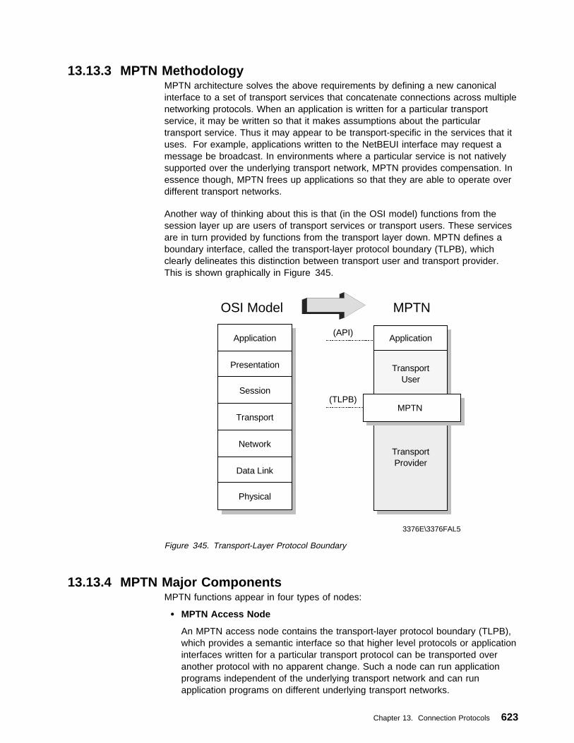
13.13.3 MPTN MethodologyMPTN architecture solves the above requirements by defining a new canonicalinterface to a set of transport services that concatenate connections across multiplenetworking protocols. When an application is written for a particular transportservice, it may be written so that it makes assumptions about the particulartransport service. Thus it may appear to be transport-specific in the services that ituses. For example, applications written to the NetBEUI interface may request amessage be broadcast. In environments where a particular service is not nativelysupported over the underlying transport network, MPTN provides compensation. Inessence though, MPTN frees up applications so that they are able to operate overdifferent transport networks.
Another way of thinking about this is that (in the OSI model) functions from thesession layer up are users of transport services or transport users. These servicesare in turn provided by functions from the transport layer down. MPTN defines aboundary interface, called the transport-layer protocol boundary (TLPB), whichclearly delineates this distinction between transport user and transport provider.This is shown graphically in Figure 345.
(API)
OSI Model
Application
Presentation
Session
Transport
Network
Data Link
Physical
Application
MPTN
TransportUser
TransportProvider
MPTN(TLPB)
3376E\3376FAL5
Figure 345. Transport-Layer Protocol Boundary
13.13.4 MPTN Major ComponentsMPTN functions appear in four types of nodes:
� MPTN Access Node
An MPTN access node contains the transport-layer protocol boundary (TLPB),which provides a semantic interface so that higher level protocols or applicationinterfaces written for a particular transport protocol can be transported overanother protocol with no apparent change. Such a node can run applicationprograms independent of the underlying transport network and can runapplication programs on different underlying transport networks.
Chapter 13. Connection Protocols 623

The applications in the MPTN access node are generally written to an existingapplication programming interface (API). The API uses the functions of thenative communications protocol. When transport-level MPTN functions areaccessed, the API will be converted to access these functions instead of thenative communication protocol, while keeping the same interface to theapplication program. For example, the NetBEUI application interface is writtento use the NetBIOS communications protocol. To use another protocol stackbelow the transport layer, the NetBEUI API must be made to invoke the MPTNfunctions. After this is done, all programs using NetBEUI on this MPTN accessnode can communicate via, for example, SNA, TCP/IP, OSI and otherprotocols, with another NetBEUI application within the MPTN network. All this ispossible without the original application program requiring any change.
� MPTN Address Mapping Server Node
An address mapping server node is an MPTN node with a special function thatprovides a general address mapping service to the address mapping clientcomponent of other MPTN nodes, access or gateway, connected to the sametransport provider network.
� MPTN Multicast Server Node
A multicast server node is an MPTN node with a special function, the multicastserver, which manages multicast and broadcast distribution of datagrams innetworks that do not provide the service as a natural consequence of theirdesign. For example, a NetBIOS transport network is designed to supportmulticast distribution of datagrams while an SNA network is not. The multicastserver operates in cooperation with the address mapping server to provide amulticast service where this capability does not exist within the services offeredby the transport network.
� MPTN Gateway Node
An MPTN gateway connects two transport networks to provide an end-to-endservice over both of them for one or more transport user protocols. There aretwo types of gateways, nonnative-to-nonnative, with respect to the supportedtransport user protocol, and native-to-nonnative, with respect to the supportedtransport user protocol.
In the case of nonnative-to-native one of the transport providers connected tothe gateway node is native to the transport user. This type of gateway allowsaccess to an end node that has no MPTN function. When one side is native,the MPTN protocol (of the nonnative side) terminates in the gateway (refer toFigure 346 on page 625).
624 TCP/IP Tutorial and Technical Overview

NetBIOS Transport
MPTN Access Node
Legend:
Application Program Interface (API)
Transport Layer Protocol Boundary (TLPB)
NetBIOSAppl
SocketsAppl
NetBEUILibrary
SocketsLibrary
TLPB
NetBIOS TCP/IP
MPTN Gateway
NetBIOSLAN
TCP/IPLAN
NetBIOS
NetBEUILibrary
NetBIOSAppl
TCP/IP
SocketsLibrary
SocketsAppl
3376E\3376FAL6
Figure 346. An MPTN Network - Nonnative-to-Native Gateway
13.14 Multi-Path Channel+ (MPC+)The MPC support is a protocol layer that allows multiple read and writesubchannels to be treated as a single transmission group between the host andchannel-attached devices. One level of MPC support, high performance datatransfer (HPDT), also referred to as MPC+, provides more efficient transfer of datathan non-HPDT MPC connections. Multi-Path Channel+ (MPC+) connections allowyou to define a single transmission group (TG) that uses multiple write-direction andread-direction subchannels. Because each subchannel operates in only onedirection, the half-duplex turnaround time that occurs with other channel-to-channelconnections is reduced.
Chapter 13. Connection Protocols 625

If at least one read and one write path is allocated successfully, the MPC+ channelconnection is activated. Additional paths (defined but not online) in an MPC+ groupcan later be dynamically added to the active group using the MVS VARY deviceONLINE command.
For example, if there is a need for an increase in capacity to allow for extra trafficover a channel, additional paths can be added to the active group withoutdisruption. Similarly, paths can be deleted from the active group when no longerneeded using the MVS VARY device OFFLINE command.
13.15 S/390 Open Systems Adapter 2Open Systems Adapter 2 is an integrated hardware feature that has beenimplemented as a channel type on the S/390 Parallel Enterprise Server R2 and R3models. It appears to the application software as a channel-attached control unit.The small size of the package allows the feature to be plugged into an I/O slot in aCEC or I/O expansion cage.
The OSA is defined to the hardware as a new type of S/390 channel. As such, it ishighly integrated into the hardware configuration to take advantage of theavailability characteristics of the 9672 S/390 Parallel Enterprise Server.
The OSA-2 has an Ethernet/Token-Ring (ENTR) feature that has two independentports. The ports can be configured in either non-full duplex or full duplex, as:
� Two Ethernets
� Two token-rings
� One Ethernet and one token-ring
This provides maximum flexibility.
The OSA-2 FDDI feature has one port that supports dual-ring or single-ringattachment, as well as attachment to an optical bypass switch.
The OSA-2 ATM feature has one physical port and two logical ports that provideaccess to Token Ring or Ethernet LANs attached to a high-speed ATM network.Each logical port is configured independently as token-ring or Ethernet and theysupport TCP/IP, or SNA/APPN, or both.
13.15.1 OSA-2 ModesThe OSA-2 can be configured into several mode combinations depending on yourrequirements. There are up to six possible combinations.
� TCP/IP Passthru Mode (Non-Shared Port)
In this mode, an OSA-2 port is capable of transferring TCP/IP LAN traffic toand from just one TCP/IP host or logical partition (refer to Figure 347 onpage 627).
� TCP/IP Passthru Mode (Shared Port)
In this mode, an OSA-2 port is capable of transferring TCP/IP LAN traffic toand from more than one TCP/IP host within multiple logical partitions.
� SNA Mode (Non-Shared Port)
626 TCP/IP Tutorial and Technical Overview

In this mode, an OSA-2 port is capable of transferring SNA LAN traffic to andfrom just one SNA host or logical partition.
� SNA Mode (Shared Port)
In this mode, an OSA-2 port is capable of transferring TCP/IP and SNA LANtraffic to and from more than one TCP/IP and SNA logical partition.
� TCP/IP and SNA Mixed Mode for OSA-2 ATM (Shared Port)
In this mode, one physical ATM port may be configured into two logical ports.Each logical port may then be configured to support TCP/IP, or SNA traffic, orboth. Each logical port is capable of transferring TCP/IP and SNA LAN traffic toand from one or multiple TCP/IP and SNA logical partitions.
SC42
TCP/IP
SC43
TCP/IP
Channel Subsystem
Port 0
OSA-2TCP/IP Passthru
Port 1
Production LAN
AAAAAAAAAAAAAA
AAAAAAAA
AAAAAAAA
AAAAAAAA
AAAAAAAA
AA
AAAAAAAA
AAAAAAAA
AAAAAAAA
AAAAAAAA
AAAAAAAA
AAAAAAAA
AAAAAAAA
AAAAAAAA
AAAAAAAA
AAAA
AAAAAAAAAAAAAAAAAAAAAAAAAAAAAAAAAAAAAA
3376E\3376FAL7
Figure 347. TCP/IP Passthru Mode - (Non-Shared Port)
13.15.2 S/390 Unit Addresses Correlate with OSA-2 LAN Port NumbersOne function of the OSA-2 adapters is to correlate the S/390 devices that areconnected to its channel path with its LAN port or ports through which data will betransferred. Device numbers are assigned to OSA port unit addresses throughdefinitions made using the Hardware Configuration Definition (HCD), provided inMVS/ESA or OS/390.
The OSA port default unit addresses are:
Chapter 13. Connection Protocols 627

� Port 0 00-01
� Port 1 02-03
In LPAR mode these unit addresses are made available within the OSA adapter toevery logical partition. The OSA adapter default mode is TCP/IP Passthru. Thedefault unit addresses and modes can only be changed through the use of theOpen Systems Adapter/Support Facility (OSA/SF) (see 13.15.3, “Open SystemsAdapter/Support Facility (OSA/SF)”).
13.15.2.1 TCP/IP AddressingEach port on an OSA-2 is a LAN channel station (LCS) device through which LANdata passes. As a passthru agent, OSA can transfer data to and from any TCP/IPhost program that is running in any of the logical partitions to which the OSA hasbeen properly defined.
A pair of devices must be defined for each OSA port being used for every logicalpartition that is accessing the OSA. One device is used for reading and the otherfor writing.
13.15.2.2 ATM AddressingLAN clients that use the Asynchronous Transfer Mode to communicate with hostapplications may do so through either TCP/IP or ACF/VTAM on the host.
An OSA-2 ATM has only one physical port, but two logical LAN emulation ports.The OSA-2 ATM must have one pair of device addresses per accessing logicalpartition per port when configured for TCP/IP. The OSA-2 ATM must have onedevice address per accessing logical partition per port when configured for SNA.The OSA-2 ATM can correlate one device address to one or both of its logical portswhen configured for SNA.
13.15.3 Open Systems Adapter/Support Facility (OSA/SF)OSA/SF is an MVS/ESA program product (5655-104) that allows you to customizethe OSA hardware to run in different modes. In some cases OSA/SF is optionaland in others it s required.
OSA/SF for MVS/ESA runs in an MVS address space. It includes software that canbe installed to run on a personal computer that communicates with OSA/SF on thehost and the OSA hardware feature. This tool delivers a simple means to configureand manage the OSA-2 and to download software updates for supportedapplications. OSA/SF is used to implement the TCP/IP, SNA/APPN, or ATMfunction onto the appropriate OSA-2 adapter.
When the S/390 server is running in LPAR (logically partitioned) mode, it ispossible to configure the OSA so that any or all LPARs may share the same LANconnection. This is called port sharing. Port sharing support is provided by OSA/SF.
13.16 Multiprotocol over ATM (MPOA)The objectives of MPOA are to:
� Provide end-to-end layer 3 internetworking connectivity across an ATM network.This is for hosts that are attached either:
– Directly to the ATM network
628 TCP/IP Tutorial and Technical Overview

– Indirectly to the ATM network on a legacy LAN
� Support the distribution of the internetwork layer (for example, an IP subnet)across legacy and ATM-attached devices.
– Removes the port to layer 3 network restriction of routers to enable thebuilding of protocol-based virtual LANs (VLANs).
� Ensure interoperability among the distributed routing components while allowingflexibility in implementations.
� Address how internetwork layer protocols use the services of an ATM network.
Although the name is multiprotocol over ATM, the actual work being done at themoment in the MPOA subworking group is entirely focused on IP.
13.16.1 Benefits of MPOAMPOA represents the transition from LAN emulation to direct exploitation of ATMby the internetwork layer protocols. The advantages are:
� Protocols would see ATM as more than just another link.– Hence we are able to exploit the facilities of ATM.
� Eliminates the need for the overhead of the legacy LAN frame structure.
The MPOA solution has the following benefits over both Classical IP (RFC 1577)and LAN emulation solutions:
� Lower latency by allowing direct connectivity between end systems that can cutacross subnet boundaries. This is achieved by minimizing the need for multiplehops through ATM routers for communication between end systems on differentvirtual LANs.
� Higher aggregate layer 3 forwarding capacity by distributing processingfunctions to the edge of the network.
� Allows mapping of specific flows to specific QOS characteristics.� Allows a layer 3 subnet to be distributed across a physical network.
13.16.2 MPOA Logical ComponentsThe MPOA solution consists of a number of logical components and informationflows between those components. The logical components are of two kinds:
MPOA ServerMPOA servers maintain complete knowledge of the MAC andinternetworking layer topologies for the IASGs they serve. To accomplishthis, they exchange information among themselves and with MPOA clients.
MPOA ClientMPOA clients maintain local caches of mappings (from packet prefix toATM information). These caches are populated by requesting theinformation from the appropriate MPOA server on an as-needed basis.
The layer 3 addresses associated with an MPOA client would representeither the layer 3 address of the client itself, or the layer 3 addressesreachable through the client. (The client has an edge device or router.)
An MPOA client will connect to its MPOA server to register the client's ATMaddress and the layer 3 addresses reachable via the client.
Chapter 13. Connection Protocols 629

13.16.3 MPOA Functional ComponentsFigure 348 shows the mapping between the logical and physical components,which are split between the following layers:
� MPOA Functional Group Layer� LAN Emulation Layer
� Physical Layer
Figure 348. MPOA Functional Components
The MPOA solution will be implemented into various functional groups that include:
Internetwork Address Sub-Group (IASG)A range of internetwork layer addresses (for example, an IPv4 subnet).Hence, if a host operates two internetwork layer protocols, it will be amember of, at least, two IASGs.
Edge Device Functional Group (EDFG)EDFG is the group of functions performed by a device that providesinternetworking level connections between a legacy subnetwork and ATM.
� An EDFG implements layer 3 packet forwarding, but does not executeany routing protocols (executed in the RSFG).
� Two types of EDFG are allowed: simple and smart.– Smart EDFGs request resolution of internetwork addresses (that is,
it will send a query ARP type frame if it doesn't have an entry forthe destination).
– Simple EDFGs will send a frame via a default class to a defaultdestination if no entry exists.
� A coresident proxy LEC function is required.
630 TCP/IP Tutorial and Technical Overview
ATM-Attached Host Functional Group (AHFG)AHFG is the group of functions performed by an ATM-attached host that isparticipating in the MPOA network.
� A coresident proxy LEC function is optional.
Within an IASG, LAN emulation is used as a transport mechanism toeither legacy devices or LAN emulation devices, in which case accessto a LEC is required. If the AHFG will not be communicating with LANEor legacy devices, then a coresident LEC is not required.
IASG Coordination Functional Group (ICFG) 17
ICFG is the group of functions performed to coordinate the distribution of asingle IASG across multiple legacy LAN ports on one or more EDFG and/orATM device. The ICFG tracks the location of the functional components sothat it is able to respond to queries for layer 3 addresses.
Default Forwarder Function Group (DFFG) 17
In the absence of direct client-to-client connectivity, the DFFG providesdefault forwarding for traffic destined either within or outside the IASG.
� Provides internetwork layer multicast forwarding in an IASG; that is, theDFFG acts as the multicast server (MCS) in an MPOA-based MARSimplementation.
� Provides proxy LAN emulation function for AHFGs (that is, for AHFGsthat don't have a LANE client) to enable AHFGs to send/receive trafficwith legacy-attached systems.
Route Server Functional Group (RSFG) 18
RSFG performs internetworking level functions in an MPOA network. Thisincludes:
� Running conventional internetworking routing protocols (for example,OSPF, RIP and BGP)
� Providing address resolution between IASGs, handling requests andbuilding responses
Remote Forwarder Functional Group (RFFG) 18
RFFG is the group of functions performed in association with forwardingtraffic from a source to a destination, where these can be either an IASG oran MPOA client. An RFFG is synonymous with the default router functionof a typical IPv4 subnet.
Note: One or more of these functional groups may coreside in the same physicalentity. MPOA allows arbitrary physical locations of these groups.
13.16.4 MPOA OperationThe MPOA system operates as a set of functional groups that exchangeinformation in order to exhibit the desired behavior. To provide an overview of theMPOA system, the behavior of the components is described in a sequence orderby significant events:
17 ICFG/DFFG functional groups are coresident hence no protocol exists, or needs to be defined between the two.
18 RSFG/RFFG functional groups are coresident hence no protocol exists, or needs to be defined between the two.
Chapter 13. Connection Protocols 631

Configuration:Ensures that all functional groups have the appropriate set of administrativeinformation.
Registration and Discovery:Includes the functional groups informing each other of their existence and ofthe identities of attached devices and EDFGs informing the ICFG of legacydevices.
Destination Resolution:The action of determining the route description given a destinationinternetwork layer address and possibly other information (for example,QOS). This is the part of the MPOA system that allows it to performcut-through (with respect to IASG boundaries).
Data Transfer:To get internetworking layer data from one MPOA client to another.
Intra-IASG Coordination:The function that enables IASGs to be spread across multiple physicalinterfaces.
Routing Protocol Support:Enables the MPOA system to interact with traditional internetworks.
Spanning Tree Support:Enables the MPOA system to interact with existing extended LANs.
Replication Support:Provides for replication of key components for reasons of capacity orresilience.
13.17 Private Network-to-Network Interface (PNNI)In the layered routing model, layer-3 packets are forwarded by routers on ahop-by-hop basis based on the contents of the destination network address. Adynamic routing protocol such as OSPF is used to distribute network topology andreachability information among the routers in the network. In ATM networks asimilar mechanism is required to forward SVC requests through a network ofswitches based on the called or destination ATM address. Likewise a dynamicrouting protocol can be used to distribute ATM network topology and reachabilityinformation among the switches in the network. This will enable ATM switches tocompute an accurate path through the network to the destination.
Due to the unique scaling and QoS features of ATM as well as theconnection-oriented nature of SVCs, the ATM routing protocol must address severalimportant requirements:
� Must be stable and reflect the current topology and capacity of the network.
� Must scale from a network of several switches to one containing hundreds andperhaps thousands.
� Must support efficient and loop-free routing of SVC requests over a path thatwill meet the QoS objectives of the SVC.
� Must support a heterogeneous mix of ATM switches.
� Must be extensible. That is it should be simple to add and enhance newfunction as requirements arise.
632 TCP/IP Tutorial and Technical Overview
The ATM forum is currently working on the Private Network-to-Network InterfaceSpecification Version 1.0 (PNNI Phase I) which is designed to meet the aboverequirements.
The ATM Forum is also examining ways to leverage and exploit the PNNI Phase Iprotocol as a means to support layer-3 internetworking over ATM. Two otherspecifications are under development:
PNNI Augmented Routing (PAR)PAR allows IP routers directly connected to ATM switches to participate inPNNI and use the information gained from PNNI for establishing SVCs withother routers attached to the same ATM network.
Integrated PNNI (I-PNNI)I-PNNI is an extension to PNNI Phase I in which a network of routers andswitches run a single routing protocol that supports both SVC and packetrouting. This single protocol is I-PNNI.
13.17.1 PNNI OverviewThe PNNI protocol is intended for use between ATM switches in a private ATMnetwork. The abbreviation PNNI stands for either Private Network Node Interface orPrivate Network-to-Network Interface and to some degree reflects the duality of itscapability based on its recursive behavior as described below. The PNNI Phase Ispecification defines two distinct protocols:
PNNI Routing ProtocolThis protocol is responsible for distributing topology information betweenswitches in an ATM network. This information is used to compute a paththrough the network for the SVC that will satisfy the requested QoS. Ahierarchy mechanism ensures that this protocol scales well for large ATMnetworks.
PNNI Signalling ProtocolThis protocol defines the signalling flows used to establish point-to-pointand multipoint connections across the ATM network. The protocol is basedon standard ATM UNI signalling (3.1 and 4.0). PNNI signalling employssource routing and a crankback mechanism to route SVC requests aroundfailed network components at call setup.
13.17.2 PNNI RoutingThe PNNI routing protocol is responsible for distributing topology informationbetween switches in an ATM network. The following sections explain how thePNNI routing protocol works.
13.17.2.1 AddressingThe fundamental purpose of PNNI is to compute a route from a source to adestination based on a called ATM address. The called ATM address is aninformation element contained in the SETUP message that is sent over the UNIfrom the device to a switch. Presumably a switch running PNNI Phase I will havein its topology database an entry that will match a portion or prefix of the 20-byteATM address that is contained in the SETUP message. The switch will then beable to compute a path through the network to the destination switch.
Chapter 13. Connection Protocols 633

Figure 349. ATM End System Address
To best understand PNNI routing, it would be helpful to review ATM addressingfrom PNNI's perspective. Addressing and identification of components of the PNNIrouting hierarchy are based on the use of ATM end system addresses. An ATMend system address is 20 bytes long and is shown in Figure 349. PNNI routingworks off of the first 19 bytes of this address or some prefix of this address. The20th byte is the selector field which only has local significance to the endstationand is ignored by PNNI routing. A prefix is the first "p" bits of an ATM address with"p" being a value between 0 and 152. Generally speaking PNNI will advertisereachability to ATM end systems using an address prefix rather than advertise eachunique ATM end system address. This is analogous to routers advertisingreachability to IP subnets rather than to each individual IP host.
Nodes in a peer group have the same prefix address bits in common. This isillustrated in Figure 350.
� At the highest level illustrated, the LGNs that make up the high-order LGN havetheir left x high-order bits the same.
� At the next lower level, the three LGNs shown have their left x+y high-order bitsthe same.
� At the lowest level illustrated, the LGNs have their left x+y+z high-order bits thesame. (At this level, they are real physical switches.)
Figure 350. Addressing Hierarchy
Two identifiers are used in PNNI to define the hierarchy and a nodes placement inthe hierarchy. The first is the peer group identifier. This is a 14-byte value and is
634 TCP/IP Tutorial and Technical Overview
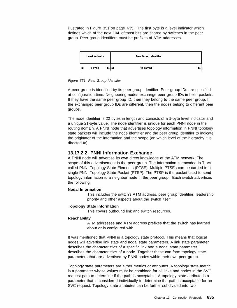
illustrated in Figure 351 on page 635. The first byte is a level indicator whichdefines which of the next 104 leftmost bits are shared by switches in the peergroup. Peer group identifiers must be prefixes of ATM addresses.
Figure 351. Peer Group Identifier
A peer group is identified by its peer group identifier. Peer group IDs are specifiedat configuration time. Neighboring nodes exchange peer group IDs in hello packets.If they have the same peer group ID, then they belong to the same peer group. Ifthe exchanged peer group IDs are different, then the nodes belong to different peergroups.
The node identifier is 22 bytes in length and consists of a 1-byte level indicator anda unique 21-byte value. The node identifier is unique for each PNNI node in therouting domain. A PNNI node that advertises topology information in PNNI topologystate packets will include the node identifier and the peer group identifier to indicatethe originator of the information and the scope (on which level of the hierarchy it isdirected to).
13.17.2.2 PNNI Information ExchangeA PNNI node will advertise its own direct knowledge of the ATM network. Thescope of this advertisement is the peer group. The information is encoded in TLVscalled PNNI Topology State Elements (PTSE). Multiple PTSEs can be carried in asingle PNNI Topology State Packet (PTSP). The PTSP is the packet used to sendtopology information to a neighbor node in the peer group. Each switch advertisesthe following:
Nodal InformationThis includes the switch's ATM address, peer group identifier, leadershippriority and other aspects about the switch itself.
Topology State InformationThis covers outbound link and switch resources.
ReachabilityATM addresses and ATM address prefixes that the switch has learnedabout or is configured with.
It was mentioned that PNNI is a topology state protocol. This means that logicalnodes will advertise link state and nodal state parameters. A link state parameterdescribes the characteristics of a specific link and a nodal state parameterdescribes the characteristics of a node. Together these can form topology stateparameters that are advertised by PNNI nodes within their own peer group.
Topology state parameters are either metrics or attributes. A topology state metricis a parameter whose values must be combined for all links and nodes in the SVCrequest path to determine if the path is acceptable. A topology state attribute is aparameter that is considered individually to determine if a path is acceptable for anSVC request. Topology state attributes can be further subdivided into two
Chapter 13. Connection Protocols 635

categories: performance-related and policy-related. Performance-related attributesmeasure the performance of a particular link or node. Policy-related attributesprovide a measure of conformance level to a specific policy by a node or link in thetopology.
13.17.3 PNNI SignallingPNNI signaling is based on a subset of UNI 4.0 signalling. It does not support someof the UNI Signalling 4.0 signalling features such as proxy signalling, leaf initiatedjoin capability or user-to-user supplementary, but does support new capabilitiessuch as specific QoS parameters, ATM anycast addressing and scoping and ABR.In addition, PNNI signalling differs from UNI 4.0 signalling in that it is symmetric.This makes sense because this is a switch-to-switch signalling protocol rather thanan end user-to-switch protocol.
PNNI signalling utilizes information gathered by PNNI routing. Specifically, it usesthe route calculations derived from reachability, connectivity, and resourceinformation dynamically maintained by PNNI routing. These routes are calculatedas needed from the node's view of the current topology.
The unique capabilities that PNNI signalling defines are designated transit lists andcrankback and alternate routing. DTLs are used to carry hierarchically completesource routes. Crankback and alternate routing allows for an SVC request to bererouted around a failed component as it makes its way to the destination switch.Additionally associated signalling is used for PNNI operation over virtual pathconnections and soft permanent VPCs/VCCs are supported.
13.18 ReferencesThe following RFCs provide detailed information on the connection protocols andarchitectures presented throughout this chapter:
� RFC 826 — Ethernet Address Resolution Protocol
� RFC 894 — Standard for the Transmission of IP Datagrams over EthernetNetworks
� RFC 1042 — Standard for the Transmission of IP Datagrams over IEEE 802Networks
� RFC 1055 — Nonstandard for Transmission of IP Datagrams over Serial Lines:SLIP
� RFC 1144 — Compressing TCP/IP Headers for Low-Speed Serial Links
� RFC 1188 — Proposed Standard for the Transmission of IP Datagrams overFDDI Networks
� RFC 1356 — Multiprotocol Interconnect on X.25 and ISDN in the Packet Mode
� RFC 1483 — Multiprotocol Encapsulation over ATM Adaptation Layer 5
� RFC 1618 — PPP over ISDN
� RFC 1619 — PPP over SONET/SDH
� RFC 1661 — The Point-to-Point Protocol (PPP)
� RFC 1662 — PPP in HDLC-Like Framing
� RFC 1700 — Assigned Numbers
636 TCP/IP Tutorial and Technical Overview

� RFC 1755 — ATM Signaling Support for IP over ATM
� RFC 1795 — Data Link Switching: Switch-to-Switch Protocol AIW DLSw RIG:DLSw Closed Pages, DLSw Standard Version 1
� RFC 2225 — Classical IP and ARP over ATM
� RFC 2390 — Inverse Address Resolution Protocol
� RFC 2400 — Internet Official Protocol Standards
� RFC 2427 — Multiprotocol Interconnect over Frame Relay
Chapter 13. Connection Protocols 637

638 TCP/IP Tutorial and Technical Overview

Chapter 14. Platform Implementations
This chapter presents an overview of the main TCP/IP functions, protocols andapplications that can be found in IBM operating systems and hardware platforms.
14.1 Software Operating System ImplementationsIBM operating systems have been equipped with TCP/IP functionality for the past15 years and have constantly increased and improved their coverage of TCP/IP.The following sections provide an overview of the TCP/IP capabilities of therespective system platforms, followed by a set of tables that offer a comprehensivesummary and cross-platform comparison.
14.1.1 IBM OS/390 V2R6IBM enterprise servers running OS/390, the S/390 flagship operating system,provide customers with the necessary power, scalability, security and availability tohelp them run their mission-critical workloads. IBM will enrich its server platformofferings even further with new releases of OS/390.
14.1.1.1 eNetwork Communications Server for OS/390IBM significantly redesigned the TCP/IP services within the OS/390 Version 2Release 5 eNetwork Communications Server to provide customers with world-classnetworking support for multiple e-business applications. These TCP/IP servicesenabled UNIX, Web serving and traditional applications to benefit from improvedperformance, function and increased connectivity bandwidth with native ATM andFast Ethernet.
Laying the foundation for the next steps in TCP/IP performance, TCP/IP HighSpeed Web Access (HSWA) servers also were integrated into OS/390 V. 2 Rel. 5and provided a robust, high performance Internet Protocol (IP) environment forthose customers with intense Web-serving needs. As announced in May 1998,internal IBM performance tests on a 10-way S/390 G4 Server, with the enhancedTCP/IP HSWA services of OS/390 V. 2 Rel. 5, could handle up to 400 millionInternet hits per day. With the S/390 G5 Server providing more than double thepower of the S/390 G4 Server, OS/390 Release 5's TCP/IP HSWA servers arecapable of handling substantially more than 400 million Internet hits per day.
The OS/390 V.2 Rel. 6 eNetwork Communications Server TCP/IP services leveragethe significant enhancements in the prior release and provide a single, highlyscalable, high-performance IP stack capable of satisfying all customer and TCP/IPcommunications requirements. In addition to providing the same levels ofperformance for intense Web-serving, internal IBM performance tests on a 10-wayS/390 G4 Server comparing MVS TCP/IP Version 3 Release 2 (TCP/IP 3.2 wasintegrated with OS/390 Version 2 Release 4) with the enhanced TCP/IP services ofOS/390 V. 2 Rel. 6 have shown up to 15 times improved performance for a fullrange of applications — whether they be file transfer, telnet, UNIX or any ISVapplication using the TCP/IP sockets interface. Alternative modes of operation,such as offloading TCP/IP workload to the network router, have been madeobsolete with these levels of integrated performance.
Copyright IBM Corp. 1989, 1998 639

14.1.1.2 OS/390 Network Computing ServicesIBM continues to enhance S/390's Web-serving capabilities with each new releaseof OS/390. IBM announced in May 1998 the e-business Series for S/390, ane-business product solution which gives customers scalable and secure e-businesstools focusing on groupware, e-commerce and Web-serving. The latestfunctionality integrated into Release 6 includes WebSphere Application Server forOS/390 and increased performance and security for Web data access with theimproved TCP/IP Services in the eNetwork Communications Server.
WebSphere Application Server for OS/390, a rebranded and enhanced LotusDomino Go Webserver for OS/390, integrated into OS/390 V. 2 Rel. 6. It can helpcustomers build a secure Internet presence. New features in WebSphereApplication Server for OS/390 include automated support of digital certificates andenhanced Java servlet support. The new Java servlet engine, previouslycode-named ServletExpress, helps to improve Java performance. Digital certificatesupport in OS/390 is also enhanced as OS/390 now can act as the local CertificateAuthority to locally issue and manage certificates. The OS/390 Security Server willaccept authenticated digital certificates from WebSphere Application Server forOS/390 and associate the certificate with a user, without requiring a user to enteran ID or password before accessing critical data. Also available in WebSphereApplication Server for OS/390 is enhanced support for Workload Manager, wherebycustomers can dynamically prioritize all Web requests from the Secure SocketsLayer (SSL) to be handled according to business requirements. SSL providesencryption for the transmission of private information over the Internet. WorkloadManager now can manage secure Web requests, as well as non-SSL Webrequests, providing secure systems management and better scalability for bothworkloads.
14.1.1.3 OS/390 Security ServerOS/390 Version 2 Release 6 provides enhancements to many critical e-businesssecurity capabilities. An essential part of these enhancements is contained inOS/390 Security Server, which provides support for digital certificates, ResourceAccess Control Facility (RACF), Lightweight Directory Access Protocol (LDAP)Server, Firewall Technologies and Distributed Computing Environment (DCE)Security Server.
Network security protects data while it is in transit over public backbones and alsodenies access by unauthorized parties to private networks and machines and thedata stored on them. System security uses hardware security facilities, userauthentication and resource access control to help protect a system and its files,programs and data from unauthorized activity. Transaction security works toensure that an electronic transaction takes place securely, privately and isauthenticated. IBM's S/390 platform provides integrated support of these threeforms of security to offer industry-leading security solutions to customers.Together, they help provide the critical levels of network, system and transactionsecurity needed for safe e-business applications.
OS/390 V.2 Rel. 6, together with S/390 hardware and OS/390 Security Server,extends support for OS/390 V.2 e-business security technologies such as digitalcertificates, public key infrastructure, OS/390 Firewall Technologies andcryptography. OS/390 V.2 Rel. 6 also offers enhancements to Web server securitymanagement.
640 TCP/IP Tutorial and Technical Overview

Transaction Security: IBM has enhanced OS/390 V. 2 Rel. 6 to support thesecurity of transactions through WebSphere Application Server, includingenhancements in performance, configuration and flexibility to areas that arenecessary for secure transactions. These include:
Multiple Internet Protocol (IP) address Secure Sockets Layer (SSL) supportThis feature provides SSL support for multiple IP addresses hosted by thesame server and for individual certificates associated with each distinct IPaddress. A single server will sometimes support multiple Universal ResourceLocators (URL) and IP addresses. This support extends the SSL securityprotocols from a single, server-wide certificate to better allow certificates thatare IP-specific.
SSL workload managementThis enhanced support allows OS/390 Workload Manager (WLM) todynamically prioritize SSL requests, improving the overall throughput of thiscritical secure transaction protocol. SSL provides encryption for thetransmission of private data over the Internet. WLM can manage servers forsecure Web requests, as well as non-SSL Web requests, providing betterscalability for business-critical applications.
Lightweight Directory Access Protocol (LDAP) supportThis feature provides centralized access and administration of authenticationinformation, such as user names or passwords, stored in an LDAP directory.A system administrator can now add a user account once and anyLDAP-enabled application such as the Web server will automaticallyrecognize the new user. Also, multiple Web servers can share the sameconfiguration via a new LDAP directive.
Crypto keysize selectionA WebSphere Application Server system administrator can specify maximumand minimum levels of encryption to be used by the server whencommunicating with a requester. Normally the server and requester programsselect the highest level of encryption that is supported by both. Thisenhanced feature allows the server administrator to better control security.
128-bit encryption supportThis function enables export browsers (outside of North America) with 128-bitencryption capability to use this level of encryption when communicating withfinancial institution servers worldwide that also are authorized to use 128-bitencryption.
Digital Certificates and Public Key Infrastructure: One of the fastest growingaspects of e-business security is the use of digital certificates for userauthentication. This entire process of issuing and managing certificates iscommonly referred to as a Public Key Infrastructure. OS/390 Version 2 and theOS/390 Security Server, together with S/390 hardware, provide enhanced supportfor this capability, including:
Digital Certificate AuthenticationWebSphere Application Server can now accept and authenticate digitalcertificates presented by many popular Web browsers. The user can then begiven access to Web server pages and functions.
Accessing OS/390 resourcesBeginning with OS/390 Version 2 Release 4, OS/390 Security Server willaccept authenticated digital certificates from WebSphere Application Serverand associate that certificate with an OS/390 Security Server user, providing
Chapter 14. Platform Implementations 641

authorization based on the user's RACF identity associated with theauthenticated digital certificate.
Mapping a certificate to a user IDA user's digital certificate can be mapped to an OS/390 Security Server RACFuser ID by an administrator or by the user. The latter case, provided byrecent enhancements included in OS/390 V. 2 Rel. 6 Security Server, allowsthe user to self-register a digital certificate to the user's existing SecurityServer RACF user ID directly from a Web browser through a Secure SocketsLayer (SSL) protected Web page.
Issuing digital certificates locallyCompanies may wish to issue their own digital certificates for use within thecompany and act as their own trusted "local" Certificate Authority. WebSphereApplication Server provides a new function, the IBM HTTP Server CertificateAuthority, which can be used to issue and manage locally issued certificates.Digital certificates can be requested by a user, routed for approval, issuedand registered. If the user is using a Netscape browser, the certificate can beautomatically transmitted and installed in the browser's user certificate listover the network.
Working with other Certificate AuthoritiesWebSphere Application Server can process digital certificates from anyCertificate Authority. This might be from specialized Certificate Authorityapplications owned by the customer, or from a third-party digital certificateprovider. In OS/390 V. 2 Rel. 6, WebSphere Application Server can processCertificate Revocation Lists (CRL) "published" by the IBM Registry certificateauthority product. This is a key prerequisite in implementing astandards-based Public Key Infrastructure that can handle the revoking ofcertificates that have expired or been compromised.
Network Security: OS/390 V. 2 Rel. 6 now supports secure, encryptedcommunications across unsecured networks between the OS/390 TN3270 serverand SSL-enabled clients such as Host On-Demand Version 2. Host On-Demanduses Java applet technology to provide host terminal emulation windows within aWeb browser. With the new SSL support in OS/390 TN3270, Host On-Demandcan provide Web browser-based 3270 ("green screen") host terminal emulation withprivacy across the Internet or other unsecured networks.
OS/390 Firewall TechnologiesFirewall Technologies, integrated into OS/390 beginning with Version 2Release 5, builds upon existing S/390 security capabilities to offer customershigher levels of protection for network applications by helping to control useraccess to separate servers inside and outside a secured network.
Delivered by a combination of the eNetwork Communication Server forOS/390 and OS/390 Security Server functions, OS/390 Firewall Technologiesprovides customers with high network security to transact e-business acrossboth secured and unsecured networks.
OS/390 Firewall Technologies also contains a Virtual Private Network (VPN)function which works with the S/390 cryptographic coprocessor to help enabledata to flow securely across a network or between networks.
� The Internet Protocol Security (IPSec) function for VPNs will be upgradedto help provide support for the "transport mode" option of IPSec allowingcustomers to protect data along the entire end-to-end path from client toserver. VPN will continue to support "tunnel mode" for cases when
642 TCP/IP Tutorial and Technical Overview

protection is needed selectively along portions of an end-to-end path,such as between a client and an OS/390 server or between two OS/390systems acting as firewalls. This broadens the VPN support to includemore flexible configurations of servers, clients and gateway (firewall)functions.
� IBM is also enhancing OS/390 Security Server's File Transfer Protocol(FTP) proxy performance by adding multithread support. Performanceimprovements are also being made to other portions of the OS/390Security Server's Firewall Technologies.
System Security/Cryptography: Cryptography is an essential part of e-businessapplications. It is the underlying technology of all security and privacy on theInternet today. S/390 Parallel Enterprise Servers and OS/390 providehardware-based cryptography support.
The cryptographic coprocessor is a hardware-embedded chip that is standard withthe S/390 G4 and G5 Enterprise Servers. OS/390 software exploits thecryptographic coprocessor to provide customers with higher levels of securityprotection than what is available with software cryptography alone. The S/390 G5Server will provide a dual processor chip path that enhances the overall availabilityof cryptographic processing.
IBM also received US government approval to export Triple DES on both the S/390G4 and S/390 G5 servers to banks worldwide, in accordance with US governmentexport laws and regulations. Triple DES, critical for financial institutions, is basedon DES, a reliable standard for network and information security for the past 20years. Triple DES provides customers with exponentially stronger encryptionprotection than standard DES. IBM also increased the cryptographic coprocessorTriple DES performance on S/390 G5 servers by replacing its microcodeimplementation with an all-hardware implementation.
OS/390 V. 2 Rel. 6 also includes enhancements to Integrated CryptographicServices Facility (ICSF) to work in conjunction with the S/390 G5 servercryptographic coprocessor enhancements:
Enhanced ICSF Support for Double-Key MACIBM enhanced S/390 support for the Key-MAC security protocol by allowinguse of a double-length key for message authentication (MAC) processing.This support helps enable enhanced message authentication between senderand receiver. Emerging VISA International and MasterCard protocols inEurope support this important security standard, known as the ANSI X9.19Optional Double-MAC Procedure.
RSA key generationKeys can be generated in the TKE (Trusted Key Element) workstation andtransmitted to the host where they are imported and used by the S/390cryptographic coprocessor. This support, available with ICSF in OS/390 V. 2Rel. 6, conforms to the VISA and MasterCard requirements for RSA keygeneration for SET protocol-based Payment Gateways.
Chapter 14. Platform Implementations 643
14.1.2 IBM TCP/IP V2R4 for VMA TCP/IP built for business IBM TCP/IP for VM, Version 2 Release 4, brings thepower and resources of your System/390 computer to the Internet. Using theTCP/IP for VM TCP/IP protocol suite, you can reach open multivendor networkingenvironments from your VM system. With TCP/IP for VM, VM systems can act aspeers of other central computers in TCP/IP open networks. Applications can beshared transparently across VM, UNIX, VAX, and other environments. VM userscan send messages, transfer files, share printers, and access remote resourcesacross a broad range of systems from multiple vendors.
IBM TCP/IP for VM is the first choice for VM TCP/IP connectivity. Designed tomeet the needs of enterprises with complex networking requirements, TCP/IP forVM applies IBM's experience in the design and development of large systems tothe implementation of TCP/IP on large computers. TCP/IP for VM, Version 2Release 4 offers a wide range of client/server applications, programming interfaces,and connectivity options, plus the data integrity and performance that network usershave come to expect from IBM.
High-speed file transferTCP/IP for VM includes File Transfer Protocol (FTP), CMS shared file system(SFS), and byte file system (BFS) support. FTP clients running either on VMor other systems can access enterprise data residing anywhere in the VMhierarchical file system-BFS, SFS, or on CMS minidisks.
With FTP access capability, TCP/IP for VM lets you continue to use VM SFSor BFS for storing large amounts of enterprise data, while expanding your VMenvironment and moving you toward a TCP/IP future.
Access controlNew configuration statements provide the TCP/IP administrator addedcapabilities regarding the use of TCP/IP services. The eligible administratorcan specify a list of users authorized to use TCP/IP services with the newPERMIT statement, or, the administrator can prevent this usage with a newRESTRICT statement.
Internet servicesTCP/IP for VM provides Internet mail services through a Simple Mail TransferProtocol (SMTP) server. This server receives mail over a TCP/IP networkconnection or from its virtual reader. It sends mail through TCP/IP or RemoteSpooling Communications Subsystem (RSCS) networks, according to themail's destination.
TCP/IP for VM also enables the deployment of VM Web servers currentlyavailable from IBM Business Partners. Utilizing the TCP/IP interfaces, theWeb servers give easy access to VM applications and central computer data,such as mail, calendars, and notelogs of OfficeVision/VM and relational dataof DATABASE 2 (DB2) for VSE & VM (formerly SQL/DS).
Application developmentWith TCP/IP for VM, you get a variety of application programming interfaces(APIs) and services to help you develop new and better applications fornetwork connectivity. You can work with remote procedure call (RPC)libraries and the Network Computing System (NCS) programming interface tobuild distributing applications and allow for distributed processing. With anenhanced sockets library from TCP/IP for VM, you can easily move UNIXapplications to the System/390 computer. TCP/IP for VM also allows you to
644 TCP/IP Tutorial and Technical Overview

invoke high-quality graphics with the Motif/X toolkit and provides bettersecurity with Kerberos client and server services.
Remote printingTCP/IP for VM gives you the added advantage of printing data from your VMsystem on remote printers in your TCP/IP network. With support for lineprinter router (LPR) and line printer daemon (LPD), TCP/IP for VM deliversenterprise-wide network printing support.
Network managementYou can use the Tivoli Enterprise family of products with TCP/IP for VMthrough the Simple Network Management Protocol (SNMP). You can manageTCP/IP for VM with any management product that supports SNMP, includingTivoli Enterprise for AIX and equivalent vendor programs. TCP/IP for VM alsosupports Routing Information Protocol (RIP), which helps automate theadministration of routing tables.
With an optional offload feature, you can reduce central computer processorusage by processing TCP/IP protocols in an attached 3172 InterconnectController Model 3. You can also manage your 3172 controllers through the3172 Simple Network Management Protocol (SNMP) agent support providedby TCP/IP for VM.
Terminal accessA new Telnet session-connection user exit feature lets clients directly connectto VTAM, PVM, VSE, or any other second-level system when the VM/ESA CPDIAL command is specified in the user exit. This exit can be used to controlsystem access based on the client's foreign Internet protocol or local portaddresses, or both.
If you need access to 3270-based applications from UNIX and other systems,you can get it easily with the Telnet TN3270 support provided by TCP/IP forVM. Telnet features include full-screen and ASCII line-mode support.
Expanded capacityIn TCP/IP for VM, Version 2 Release 4, the limit of 2000 sockets per TCP/IPclient has been removed. Now, the only limit to the number of sockets is theamount of available virtual storage. This enhancement enables applications,such as Telnet, to support more than 2000 clients.
Network interfacesTCP/IP for VM provides broad support for local area network (LAN)connectivity, channel attachment interfaces, and wide area network (WAN)support. Supported LAN interfaces include Ethernet, token-ring, PC Network,and Fiber Distributed Data Interface (FDDI). Channel attachment supportincludes channel-to-channel (CTC) 3088 support, Open Systems Adapter,ESCON, HYPERchannel, and Continuously Executing Transfer Interface(CETI). TCP/IP for VM includes SNAlink and X.25 support for WANs.
Reduced cost of computingTCP/IP for VM, Version 2 Release 4, has been recompiled using IBM C forVM/ESA, Version 3 Release 1. This recompilation eliminates the requirementfor the C/370 run-time libraries on VM/ESA, Version 2, systems. It alsosupports the run-time execution environment provided by IBM LanguageEnvironment for MVS and VM.
Chapter 14. Platform Implementations 645

14.1.2.1 TCP/IP in the Latest Release of VM/ESATransmission Control Protocol/Internet Protocol (TCP/IP) support in VM/ESA is nowprovided by the optional TCP/IP Feature for VM/ESA (Function Level 310), whichcontains the functions available in IBM TCP/IP Version 2 Release 4 for VM plus thefollowing enhancements:
NFS Support of Byte File and Shared File Systems (BFS, SFS)In addition to minidisk files, the Network File System (NFS) allows a client toaccess the CMS Byte File (BFS) and Shared File Systems (SFS) as if theywere local to the client. Clients can now access these files using theenhanced MOUNT and MOUNTPW commands.
Expanded CMS/Internet Mail CapabilityThis support lets CMS end users send mail and file objects through a TCP/IPnetwork using enhanced CMS utilities. While a similar capability exists todaythrough separate, TCP/IP-provided utilities, this support incorporates thecapability in existing CMS facilities (EXECUTE, NOTE, PEEK, RDRLIST,RECEIVE, SENDFILE, and TELL).
Line Printer ClientThe current Line Printer Client (LPR) operations have been enhanced to allowthe end user to have print data processed by the RSCS server. Specifically,this enhancement allows users to select either asynchronous printing throughRSCS or the currently supported synchronous delivery. Additional flexibility isprovided with support for the specification of user-defined nicknames.
Configuration of ServersA new server definition methodology provides a way to easily define, orchange the attributes of the set of server virtual machines used by TCP/IP.This implementation focuses on a standard method of server configurationand consolidates that configuration into a single file. The ability to simplify thereplication of TCP/IP servers is further complemented by the ability to addnew application protocols by simply defining them in a CMS NAMES file.
SMTP Performance EnhancementSMTP (Simple Mail Transfer Protocol) performance has been improved byincreasing the throughput of the server. The throughput gains are realized byreducing synchronous minidisk I/O, converting to asynchronous spoolservices, and improved use of data-in-memory techniques. All current SMTPserver functions are still supported with these enhancements. Robustdebugging support through extensive tracing capability is also provided in theserver.
Base ImprovementsMany new functions improve the usability, function, performance andserviceability of TCP/IP in the VM environment. These include multiple logicalhosts, selective trace, performance monitoring, TN3270E printing, multiportTelnet server, and improved server inactivity detection.
14.1.3 IBM OS/400 V4R3This section provides an overview of the capabilities of an AS/400 system inTCP/IP environments as an Internet application platform and as a security server.
646 TCP/IP Tutorial and Technical Overview
14.1.3.1 TCP/IPAn extension to OS/400 called AS/400 TCP/IP Communications Utilities(#5738-TC1) allows AS/400 systems to participate in communications networks thatuse the Transmission Control Protocol/Internet Protocol (TCP/IP). The IBM TCP/IPServer Support/400 product (#5798-RWY) gives clients access to AS/400 databasefiles and folder files via Sun Microsystems' Network File System (NFS), which iscommonly used in TCP/IP environments. The TCP/IP protocol has becomeincreasingly significant as the client/server environment has moved into anetworked environment including both intranets and the Internet.
Standards supported by AS/400 TCP/IP include Dynamic Host ConfigurationProtocol (DHCP) and Domain Name Server (DNS). Dynamic Host ConfigurationProtocol support allows the AS/400 to dynamically assign Internet Protocol (IP)addresses when new hosts are added to the network, such as when a networkstation or PC is turned on in an intranet. Domain Name Server converts the textnames as used in URLs to the 32-bit codes used for network routing. As anexample it converts www.as400.ibm.com to 205.217.130.11. Other functionssupported are TCP/IP dial-in via PPP (Point to Point) and ISDN as well as fullTCP/IP routing. Operations Navigator provides a Windows-like graphical interface tothe TCP/IP configuration function.
The network integration characteristics of TCP/IP have been enhanced through theaddition of Graphical User Interface (GUI) support of all TCP/IP configuration andadministrative tasks.
14.1.3.2 Load BalancingVirtual IP Addressing (VIPA) provides network load balancing and fault tolerancebetween multiple IP interfaces (adapters). Outgoing balancing and incomingbalancing work differently. Outgoing balancing is done through the routingconfiguration. Incoming balancing needs an external router which is capable ofdistributing IP packets to multiple interfaces. The distribution information isprovided to the routers by the RIP protocol. The load balancing using routersenables multiple redundant paths from the server to the network, providinghorizontal bandwidth growth and high availability tolerance for link or router failures.
14.1.3.3 NFSThe AS/400's Integrated File System includes support for the Network File System -a popular protocol used in UNIX-based client/server computing environments. TheNFS Server and NFS Client communicate using Remote Program Calls. The NFSClient is a physical file system that implements the AS/400 Virtual File Systemarchitecture. The NFS Client provides seamless access to remote files for localapplications. The remote files could be on a remote UNIX machine, the AIX IOP, orany machine that is running an NFS Server.
14.1.3.4 InternetThe AS/400 is well equipped to be an Internet server. Many programs (IBM andnon-IBM) are available that allow an AS/400 to be a Web server on the Internet orintranet (a private network built using Internet standards). IBM's Web server for theAS/400 is the Internet Connection Secure Server.
With the AS/400's support for the Internet and the appropriate set of identifiers andpasswords, it is possible to access the Web through the AS/400 to obtaininformation, but as an Internet user, the AS/400 can also be used to develop a
Chapter 14. Platform Implementations 647

program, download that program to your system from a remote site, download theinformation to execute against that program, and execute the program at a localsystem. A user has the option of accessing information in any of the files on theAS/400 and having that information HTML formatted on its way to the user'ssystem. The user can have the AS/400 execute the program and present the outputin HTML format to the Web browser, and can develop an application on the AS/400using CGI/WGS or Net.Data and have that application downloaded to the browser.
Finally, to make this all work, the Internet connection server requires that thesystem administrator grant object access to the user profiles under which the serverruns and then grant permission to the server to serve specific objects. If the serveris on a system with multiple network addresses, it can be configured to servedifferent files based on the IP address that comes in on a request. Multiple serverinstances can also be configured by using either a different IP address or a singleIP address and different ports for each server instance. Internet Connection SecureServer (ICSS) uses Secure Sockets Layer (SSL) defined protocols to provideencryption and other security functions to ICSS.
14.1.3.5 JavaAS/400 has a Java virtual machine residing below the Technology IndependentMachine Interface for fast interpretation and execution. In addition to supportingSun's javac compiler, there is also a direct-execution static compiler, called theJava Transformer, to generate AS/400-dependent machine code. The JavaTransformer is IBM's solution to improve Java runtime performance which replacesthe use of a just-in-time compiler. The static compiler provides AS/400-dependentobject code. The AS/400 Toolbox for Java includes a set of enablers that supportan Internet programming model. Provided is a set of client/server programminginterfaces for use by Java applets and applications plus a set of applets that can beintegrated into HTML documents. Client support required is Java virtual machineand AS/400 Developer Kit for Java.
Since graphical user interfaces cannot be displayed by an AS/400 green screen,AS/400 implements Remote AWT. Java on AS/400 intercepts GUI requests comingfrom a Java program and reroutes the requests to an attached workstation runningits own JVM, which will interpret and display the JAVA.AWT graphical components.Other Java packages are being integrated with OS/400 to improve ease-of-use andperformance. Java objects on AS/400 are full-fledged AS/400 objects that can bepersistent, shared, secure, backed up, and restored, something not available intwo-level-store operating systems.
Also included is a standardized set of Class Libraries (packages) that supportcreating Graphical User Interfaces (GUIs), controlling multimedia data,communicating over networks, and accessing data in stream files and relationaldatabases.
The AS/400 Developer Kit for Java, available with OS/400 V4R2, is a no-cost tooldesigned to produce Java applets and full-scale applications. Included are acollection of development tools, help files, and documentation for Javaprogrammers. The Developer Kit is compliant with Sun's Java 1.1.6 specificationsand provides improved performance either through improved transaction rates orthrough lower CPU utilization on applications that use the database.
The AS/400 Toolbox for Java, available on AS/400 and other Java-compliantplatforms, enables Java applets and applications to access AS/400 data and
648 TCP/IP Tutorial and Technical Overview

resources, by providing a collection of classes that represent AS/400 data andproviding AS/400 client/server program interfaces for Java programs.
The AS/400 Toolbox for Java also includes a set of enablers that support anInternet programming model. Provided is a set of client/server programminginterfaces for use by Java applets and applications.
The AS/400 Toolbox for Java requires that both the TC1 Licensed Program(TCP/IP Connectivity Utilities for AS/400) and the Host Server option of OS/400 tobe installed and configured on the AS/400. Client machines and Web browsersmust contain a Java virtual machine that fully supports Java Version 1.1.2. TheAS/400 Toolbox for Java Classes can access data and resources on V3R2, V3R7,V4R1 and above.
14.1.3.6 FirewallThe AS/400 firewall is implemented using the Integrated PC Server (IPCS) internalto the AS/400 server system. This allows processor separation without requiring anadditional system. Security functions running on the IPCS are separate fromapplications running on the AS/400 processor. The software used by the firewall ison a read-only disk, eliminating the possibility of a virus being introduced andpreventing modification of programs that carry out the communications securityfunctions. Communication between the main processor and the firewall is over aninternal system bus immune from sniffing programs on local area networks. Thefirewall can be disabled by the main processor when it detects tampering,independent of the state of the firewall. Installation of firewall software is the sameas for any other AS/400 software. The administrator is guided through the initialinstallation and configuration. The firewall is administered by a Web browser on theinternal (secure) network. The Secure Sockets Layer (SSL) protocol can be used toprotect the administration session. Authentication of the administrator is done withOS/400 security support.
IBM Firewall for AS/400 (#5769-FW1) is an application gateway firewall usingInternet Protocol (IP) packet filtering to prevent undesirable traffic from reaching theinternal network. The packets may be filtered by source IP address, protocol, portnumber, direction, and network interface. RealAudio is supported through dynamicpacket filtering technology. A proxy server provides Web access to servers on theInternet without revealing the name or address on the browser, and can cache Webpages for better response time. All internal users have a single mail domain withhidden internal e-mail addresses. Various levels of logging are supported, rangingfrom logging all traffic to logging only exceptions.
Network Address Translation (NAT) and filtering activities can be journaled. Theentries will be added each time IP packets are examined, IP addresses aretranslated or rules are updated. The user can choose to start the journal or not.Users have the opportunity to change IP addresses of IP packets going out fromthe network, so the internal address is not known by the external hosts. Thissecures the internal network.
Using the AS/400 SOCKS Client program, AS/400 TCP/IP client programs such asFTP client can communicate with server programs running on systems outside theIBM Firewall for AS/400 program. SOCKS proxy support on the IBM Firewall forAS/400 program is used by the client programs to safely transmit data packets toexternal servers. Funneling these requests through the firewall proxy protects thecustomer's secure internal network from data packets coming from an unsecured
Chapter 14. Platform Implementations 649

network. The AS/400 SOCKS Client program is transparent to TCP/IP clientprograms and works for all client programs written to the sockets interface. TheIBM TCP/IP clients programs, including Telnet and FTP, can be enabled to use aSOCKS proxy. The sockets API also supports TCP/IP multicast.
The IPCS uses Network Address Translation (NAT) to conceal internal networkaddress while allowing direct access from secure clients to the external networkwithout proxies. This simplifies exposing secure hosts, protected by the firewall tothe Internet community without exposing internal network addresses. A virtualprivate network is enabled by the establishment of encrypted connections betweenfirewalls to safeguard data transported through the network. Database tables arecreated from firewall log files, allowing SQL queries to tailor reports on usage oridentify potential attacks. Log files can be deleted when they are no longer needed.
14.1.3.7 Digital Certificate ManagerThe AS/400 is able to serve as a Digital Certificate Manager at V4R2. This meansthat the AS/400 can set up an intranet certificate authority, sign client and servercertificates, distribute client certificates via a Web browser, and provide support forMD5 and SHA-1 hash algorithms. Although the AS/400 can set up a certificateauthority, it cannot act as a certificate authority at this time.
The AS/400 accepts digital certificates for authentication. Both the HTTP and LDAPservers support digital certificates. The certificates are used for identification only. Adigital certificate is associated with a user profile and with a user in a validation list.
14.1.3.8 Cryptographic ProcessorThe Cryptographic Processor (#2620) helps improve the security of an AS/400system by encoding information using cryptographic techniques (ANSI DataEncryption Standard DES). That is, AS/400-resident information is scrambled viaencryption keys (special codes), making it meaningless to anyone except thosewho have the key. This capability is particularly beneficial when AS/400 informationmight be exposed to unauthorized access via a communications network such asthe Internet.
The Security Interface Unit (SIU) (#4754) is an optional device that attaches to thecryptographic processor and allows the user to enter cryptography keys by swipinga personal security card through a reader.
Supported cryptography standards include 40-bit, 56-bit, and 128-bit encryption.Digital certificates are also accepted as a Web server sign-on.
14.1.4 IBM AIX 4.3IBM's award-winning UNIX operating system, AIX 4.3, has been enhanced todeliver even more in scalability, security, connectivity, performance, interoperability,and usability.
AIX 4.3 is an integrated operating environment that supports both existing 32-bitand new 64-bit RS/6000 systems in their full range of scalability while providingimproved software features for both environments. On 64-bit systems, AIX 4.3provides full interoperability and coexistence between 32- and 64-bit applicationswith processes that may run concurrently or cooperatively, sharing access to files,memory, and other system services.
650 TCP/IP Tutorial and Technical Overview

14.1.4.1 Internet and e-business ReadyAIX 4.3 technology enables systems to perform as robust Internet servers. Whilemaintaining binary compatibility, AIX 4.3 offers 64-bit scalability for Web servingthrough increased system capacity via large memories and the mapping of largefiles into memory.
AIX 4.3 helps support the security requirements of Internet servers. It includes thenext generation of Internet Protocol (IPv6) and an Lightweight Directory AccessProtocol (LDAP) compliant directory. The IP security (IPSec) supports unlimitedfilter rules to control network traffic by characteristics such as source anddestination address, interface, type of TCP/IP, subnet mask, specific protocol, andport (FTP, mail, etc.).
14.1.4.2 Features and BenefitsAIX 4.3 offers the following features and benefits:
64-bit support
� Delivers new dimensions in scalability and capacity (32,786threads/process)
� Supports concurrent execution of 32- and 64-bit applications on 64-bithardware
� Implements LP64 (32-bit integers, 64-bit long and pointer types)� Supports up to 16GB real memory on 64-bit hardware
Binary Compatibility
� Helps assure continuing application availability across AIX Version 4releases
Web-based system management
� Allows managing AIX from any Java 1.1- and Abstract Windows Toolkit(AWT) 1.1-enabled browser
� Configuration Assistant automatically launches TaskGuide after base AIXinstallation to help simplify the remaining installation configuration tasks
Java Development Kit (JDK) V1.1.4
� Includes a full range of development tools, such as source and run-timeinterpreters, with Just-In-Time (JIT) 2.01 compiler class compiler,source-level debugger, HTML document generator, runtime libraries forJava multimedia links, and a set of Java class APIs (JDBC, JavaBeans,RMI, and Java security)
� Compiles Java byte code to native machine code at run-time to boostJava performance
� Accommodates multiple Java versions to enhance flexibility in developingJava applications
Internet Protocol Version 6 (IPv6)
� Increases IP addressability, security and integrity through redundantrouting, dynamic rerouting, and tunneling (supports IPv6 to IPv6 tunnelsthrough IPv4)
� Provides IPsec authentication and security for IPv4 and IPv6� Provides Triple DES (3DES) encapsulation (U.S. & Canada only)
Chapter 14. Platform Implementations 651
Internet Protocol Version 4 (IPv4)
� Includes DHCP updates to support classless interdomain routing (CIDR)� Enhances password protection with secure TCP/IP commands (rsh, rcp,
rlogin, telnet, ftp) eNetwork Lightweight Directory� Supports up to 4 million directory entries with sub-second search
response time
Lightweight Directory Access Protocol (LDAP) V1.1.1
� Supports replication of directories across multiple systems� Provides Secure Sockets Layer (SSL) Version 3 for data encryption and
authentication using X.509v3 public-key certificates� Provides Triple DES (3DES) encapsulation (U.S. and Canada only)
HTML-based documentation
� Offers easy access to system documentation via a Web browser,delivered on separate CDs
Print spooler enhancements
� Provide robust network support and increased capacity for up to 1000print jobs
X11R6
� Enhances X Windows functions with thread-safe 64-bit client libraries forgraphics application development
3D Graphics
� OpenGL and graphics APIs are included at no additional charge� Virtual Frame Buffer (VFB) is the enabling software technology for
creating 3D rendering server applications (for example, CATwebNavigator) without a graphics adapter. This environment supports viewing3D graphics on multiple thin client platforms.
Performance analysis/control tools
� Supports more complex statistical analysis for local AIX systemperformance
AutoFS, CacheFS from ONC+ suite
� AutoFS provides network file system mounts automatically� CacheFS provides faster file access when using Network File System
mounts
Direct I/O
� Allows higher bandwidth I/O for performance critical applications
Sendmail 8.8.8
� Notifies senders when mail is delivered successfully
Telnet performance enhancements
� Provide 40% to 60% Telnet performance improvement over prior AIXreleases
652 TCP/IP Tutorial and Technical Overview

Multilingual support
� Enables UCS-based application development via Unicode 2.0� Provides localization support for Thai, Vietnamese, Byelorussian, and
Ukranian
C2 security
� Designed to meet US DoD C2 specifications; formal certification for AIX4.3.1 is in process
� AIX 4.2 is certified for European ITSEC F-C2/E3 specifications; AIX 4.3.1certification is in process
The Open Group
� Maintains conformance to previous UNIX brandings and certifications
UNIX 98
� Implements IEEE POSIX 1003-1996 (.1c) threads including M:N threadsupport
Bonus Pack Version 4.3
� Provides users with options, tools and products including:– Ultimedia Services Version 2.2– LDAP-SSL Version 3 128/40 bit encryption– Lotus Domino Go Webserver 4.6.1– Novell Network Services Version 2.2. with Novell Directory Services– Netscape FastTrack Server 2.0.1– Netscape Navigator 3.0.4– Syntax TotalNET Advanced Server Version 5.2 Evaluation Copy– Netscape Navigator 4.0.4 (browser only)– IP Security triple or 40/56 bit DES– Network Station Manager (NSM) Version 1.2– DCE Client Version 2.1– Adobe Acrobat Version 3.01
Note: Contents may change within each release; products with data encryptionmay be subject to import/export restrictions outside the United States andmay be slightly different in or not offered with the Bonus Pack.
14.1.5 IBM TCP/IP 4.1 for OS/2IBM TCP/IP Version 4.1 for OS/2 and corequisite MPTS Version 5.3 represent asignificant upgrade of the TCP/IP stack and applications previously included inOS/2 Warp. Functional changes include:
Multi-Platform CapabilityTCP/IP Version 4.1 can be installed on:
� OS/2 Warp 4� OS/2 Warp Server� OS/2 Warp Server SMP
Now, all three platforms can use the latest version of TCP/IP.
32-Bit, BSD 4.4-Compliant TCP/IP StackYou may notice substantial performance improvements over the previous16-bit BSD 4.3-compliant stack. Also, INETCFG.EXE is enhanced to allowyou to tune TCP/IP by setting many new protocol parameters.
Chapter 14. Platform Implementations 653

Dynamic IP - DHCP Server Enhancements
� Proxy dynamic DNS update: This allows Dynamic DNS updates to bedone by the DHCP Server on behalf of clients that do not supportDynamic DNS.
� Multiple logical subnets on the same wire: The DHCP server can allocateaddresses for multiple logical subnets on the same physical wire.
� BOOTP server functionality: The DHCP server can act as a BOOTPserver, including giving appropriate information for remote booting ofmachines including the Network Station.
� Server statistics: The DHCP server can provide complete statistics for itsDHCP/BOOTP activity on the network.
Dynamic IP - DDNS Server Enhancements
� Incremental Zone Transfer: The Dynamic DNS server can performIncremental Zone Transfer as defined in IETF RFC 1995.
� Notify: The Dynamic DNS Server can perform Notify function for promptnotification of zone changes as defined in IETF RFC 1996.
� Dynamic Zone Performance Enhancements: This includes the capabilityto separate dynamic and static zone files.
� Time Zone Reconciliation: The DDNS Server can now reconcile timezone time differences between the server and client for dynamic updates.
� Crash Recovery: The DDNS Server can checkpoint files to facilitate crashrecovery.
� Java 1.1 Configuration Programs: New graphical user interfaces (GUIs)allow local and remote configuration of DHCP and DDNS servers. A Java1.1 GUI to manage a DHCP server is also included.
Dynamic IP Client Enhancements
� Detecting a laptop that was relocated while in hibernation mode.� Releasing the DHCP address when shutting down (optional).� Reusing old lease information if a DHCP server cannot be found on the
network (optional).
Remote ConfigurationTCP/IP configuration and Dynamic-IP server configuration (DHCP and DDNS)are written in the Java language. A Java 1.1-capable browser can be used toconfigure a server remotely.
CID Support for all TCP/IP Configuration ParametersAll configuration parameters can now be set during CID (Configuration,Installation and Distribution) installation. Configuration settings that wouldnormally be done through the new Java GUI after installation can now bedone during a local or remote CID installation.
Web-based InstallationInstallation has been enhanced to provide for downloading and installingTCP/IP from the Web. Using the latest Netscape plug-ins, either the guidedor advanced installation paths can be performed.
Virtual Private Network and IP SecurityTCP/IP 4.1 for OS/2 uses the IBM Secure Remote IP Client program, togetherwith the standards-based IP-Security protocol, to configure a virtual privatenetwork (VPN). A VPN provides a secure communications channel from aremote computer across the Internet to an intranet protected by an IBMFirewall Version 3.1 (or subsequent releases).
654 TCP/IP Tutorial and Technical Overview
RSVP Daemon and APIResource Reservation Protocol (RSVP) allows applications to control thebandwidth, data rate, and transmission latency capabilities that are beingimplemented in routers and operating systems. The API and daemon providethis control to OS/2 applications that are written to use it. The library andheader files used to access this API are available in the TCP/IP Version 4.1Programmer's Toolkit in the IBM Developer Connection.
Application Enhancements
� SyslogD: Enhanced to read from the configuration file (syslog.cnf) whichresides in the ETC directory. The configuration file allows the user tospecify different options including the log file size and the number ofbackup log files to maintain.
� RSHD: A command line timeout parameter has been added (like theREXECD timeout parameter). RSHD has also been updated to recordcertain events in the system log when SyslogD is running.
� REXECD: Acquires and validates a client's user ID and password usingthe new TCP/IP configuration. The user ID and password are no longerstored in environment variables. REXECD has also been updated torecord certain events in the system log when SyslogD is running.
� TelnetD: Acquires and validates a client's user ID and password usingthe new TCP/IP configuration. A user ID is now required and thepassword is no longer stored in an environment variable. The telnet shellprogram is also obtained from the configuration and is customizable byuser ID. TelnetD has also been updated to record certain events in thesystem log when SyslogD is running.
� FTPD: Acquires and validates a client's user ID, password, and othercustomized user information from the new TCP/IP configuration. TheTRUSERS file is no longer used.
� LPR, LPRMON, LPQ, LPRM: The print server name and print queuename can now default to names received from a DHCP server (or usevalues entered in the Configuration Notebook, entered as environmentvariables, or entered on the command line with the -s and -p options).
� LPR: Has a -cp command line option (similar to the -cp option for LPDand LPRMON) to convert text files using the specified code page beforesending the files to an LPD server.
� LPRPORTD Performance Enhancements: LPRPORTD now processesprint files faster.
Year-2000 SupportTCP/IP Version 4.1 is year-2000 ready.
14.1.6 Functional ComparisonsThe tables below list the major TCP/IP protocols and applications as they areimplemented and supported by the aforementioned software platforms. To providea better and more comprehensive overview, we have grouped the tables into blocksthat follow in sequence the previous chapters of this book.
Because of their significance in the PC market, from corporate to end user, andbecause of IBM's dedication to provide a comprehensive suite of applications andmiddleware in that area, we have also included the latest versions of the Windowsoperating systems from Microsoft.
Chapter 14. Platform Implementations 655

Table 19 (Page 1 of 2). Operating Systems - Protocol Support
OS/390 MVS VM OS/400 AIX OS/2 WindowsNT 4.0
Windows98
Base Protocols
IP X X X X X X X X
TCP X X X X X X X X
UDP X X X X X X X X
ARP X X X X X X X X
RARP X X X
ICMP X X X X X X X X
PING X X X X X X X X
TRACEROUTE X X X X X X X
IPv6 X8 X
Application Protocols
DNS X X X X X X X C
NSLOOKUP X X X X X X
HOST X X X X
FINGER X9 X C C
FTP X X X X X X X1 C
IMAP X IBM2 IBM2 C
LPR/LPD X X X X X X X
MIME X X X X X X X X
NETSTAT X X X X X X X X
NIS X
ONC-RPC X X X X X IBM7
POP S X X IBM2 IBM2 C
REXEC/RSH X X X S X X C
SMTP X X X X X X IBM2 C
SNMP X X X X X X X X
TALK X X
TELNET X X X X X X C C
TFTP X X X X X X C
TimeD X X X
TN3270 X X S S IBM4 IBM3 IBM4,5 C(IBM)5
TN3270E S S IBM4 IBM3 IBM4,5 C(IBM)5
TN5250 S C C(IBM)5 C(IBM)5
X Windows C C C X OEM
Routing Protocols
Static Routing X X X X X X X X
RIP-1 X X X X X X X6 PassiveOnly
RIP-2 X X X X X X
OSPF X X
Legend:X=Implemented C=Client Implementation only S=Server Implementation n/a=Not ApplicableOEM=requires additional non-IBM software IBM=requires additional IBM software
656 TCP/IP Tutorial and Technical Overview

Table 19 (Page 2 of 2). Operating Systems - Protocol Support
OS/390 MVS VM OS/400 AIX OS/2 WindowsNT 4.0
Windows98
BGP-4 X
CIDR X X X X X
Legend:X=Implemented C=Client Implementation only S=Server Implementation n/a=Not ApplicableOEM=requires additional non-IBM software IBM=requires additional IBM software
Notes:
1. Server function provided by Microsoft Internet Information Server (Windows NTServer) or Personal Web Server (Windows NT Workstation)
2. Server function provided by Lotus Domino, client included in Web browser
3. Server function provided by IBM eNetwork Communications Server, clientincluded in operating system
4. Server function provided by IBM eNetwork Communications Server
5. Client function provided by IBM eNetwork Personal Communications
6. Active RIP provided by Windows NT Server, passive RIP provided by WindowsNT Workstation
7. Function provided by IBM TCP/IP for OS/2 NFS Kit
8. Prototype
9. Via NSLOOKUP
Table 20 (Page 1 of 2). Operating Systems - Special Protocols and Services
OS/390 MVS VM OS/400 AIX OS/2 WindowsNT 4.0
Windows98
Dynamic IP
BOOTP S S S X X S1
BOOTP/DHCPForwarding
X X X X X
DHCP S S S X X X C
DDNS (secureupdate)
X X X C(IBM)26 C(IBM)26
DDNSIncrementalZone Transfer
X X X
ProxyArec X X X
Directory & File Services
DCE IBM2 IBM2 IBM2 C(IBM)2 IBM2 IBM2 IBM2
NFS X X S S X IBM3
AFS Transarc Transarc
LDAP X X IBM4,25 S(IBM)4
NetBIOS Services
Legend:X=Implemented C=Client Implementation only S=Server Implementation n/a=Not ApplicableOEM=requires additional non-IBM software IBM=requires additional IBM software
Chapter 14. Platform Implementations 657

Table 20 (Page 2 of 2). Operating Systems - Special Protocols and Services
OS/390 MVS VM OS/400 AIX OS/2 WindowsNT 4.0
Windows98
NetBIOS overTCP
OEM OEM X X X
NBNS OEM X5
NBDD OEM
Security
IP filtering X X X X X6
Firewall7 X X IBM8 IBM8
SOCKS S X S(IBM)9 C10 S(IBM)9 C
Telnet Proxy X IBM8 IBM8
FTP Proxy X X IBM11 IBM12 IBM11
HTTP Proxy X X IBM11 IBM12 IBM11
NAT X X IBM8 IBM8
SSL X X X X X X
S-MIME X X
IPSec X X X X
Kerberos X X X IBM2 IBM2 IBM2 IBM2
Internet Protocols
HTTP S S(IBM)13 OEM S X S(IBM)14 X15 X15
Java S16 X X17 X17 X18 C
IIOP IBM19 IBM19 IBM19 IBM19
NNTP S(IBM)4 S(IBM)20 S(IBM)20 S(IBM)20 C
Gopher X C C X21 C
Multicasting and Multimedia
IGMP X X X X X X
QoS
RSVP X X X X27 X27
DifferentiatedServices
X X27 X27
Load Balancing
Round robinDNS
X X X
IND C22 IBM23 IBM23
WLM X X
VIPA X X X X24 X24 X24
Legend:X=Implemented C=Client Implementation only S=Server Implementation n/a=Not ApplicableOEM=requires additional non-IBM software IBM=requires additional IBM software
Notes:
1. DHCP server can provide fixed addresses to BOOTP clients
2. Function provided by IBM DCE
3. Function provided by IBM TCP/IP for OS/2 NFS Kit
4. Server function provided by Lotus Domino
658 TCP/IP Tutorial and Technical Overview

5. Using Windows Internet Name Service (WINS)
6. Only on ports and protocols, not on IP addresses
7. Refers to a combined set of security features, including IP filtering, NAT,application proxies, SOCKS, special DNS and mail
8. Function provided by IBM eNetwork Firewall
9. Server function provided by IBM eNetwork Firewall, client included in Webbrowser
10. Socksified TCP/IP stack
11. Function provided by IBM WebTraffic Express or IBM eNetwork Firewall
12. Function provided by IBM WebTraffic Express
13. Server function provided by Lotus Domino or Lotus Domino Go Webserver
14. Server function provided by Lotus Domino or Lotus Domino Go Webserver,client included in operating system
15. Server function provided by Lotus Domino Go Webserver (IBM), or by MicrosoftInternet Information Server (Windows NT Server) or Personal Web Server(Windows NT Server and Windows 98); client included in operating system
16. Servlet support provided by IBM WebSphere Application Server or HostOn-Demand Server
17. Servlet support provided by IBM WebSphere Application Server, client includedin operating system
18. Servlet support provided by IBM WebSphere Application Server or MicrosoftInternet Information Server, client (local JVM) included in Web browser
19. Function provided by IBM WebSphere Application Server
20. Server function provided by Lotus Domino, client included in Web browser
21. Server function provided by Microsoft Internet Information Server (Windows NTServer) or Personal Web Server (Windows NT Workstation)
22. WLM Advisor for eNetwork Dispatcher
23. Function provided by IBM eNetwork Dispatcher
24. Similar concept provided using IP alias addresses
25. Function available through IBM OS/2 LDAP Client Toolkit for C and Java
26. Function provided by IBM Dynamic IP Client for Windows 95 and Windows NT
27. Similar concept provided using Winsock V2.0 APIs
Table 21 (Page 1 of 2). Operating Systems - Connection Support
OS/390 MVS VM OS/400 AIX OS/2 WindowsNT 4.0
Windows98
Token-Ring X X X X X X X X
Ethernet v2 X X X X X X X X
Ethernet 802.3 X X X X X X
Fast Ethernet X X X X X X X
Legend:X=Implemented C=Client Implementation only s=Server Implementation n/a=Not ApplicableOEM=requires additional non-IBM software IBM=requires additional IBM software
Chapter 14. Platform Implementations 659

Table 21 (Page 2 of 2). Operating Systems - Connection Support
OS/390 MVS VM OS/400 AIX OS/2 WindowsNT 4.0
Windows98
FDDI X X X X X X X X
ATM Classic IP X X X X
ATM LANEmulation
X X X X X
X.25 IBM1 IBM1 IBM1 X X IBM2
Frame Relay IBM3 IBM3 IBM3 X X X6
ISDN IBM3 IBM3 IBM3 X X X X X
PPP IBM3 IBM3 IBM3 X X X X X
SLIP IBM3 IBM3 IBM3 X X X X X
Sonet IBM3 IBM3 IBM3 X X
EnterpriseExtender
X IBM4
MPTN X X X IBM4 IBM4 IBM4,5 IBM5
MPC+ X
SNALink X X X IBM2
CTC X X X
Legend:X=Implemented C=Client Implementation only s=Server Implementation n/a=Not ApplicableOEM=requires additional non-IBM software IBM=requires additional IBM software
Notes:
1. Function provided by NCP and NPSI
2. Function provided by IBM TCP/IP for OS/2 Extended Networking Kit
3. Function provided by channel-attached IBM 2216 router
4. Function provided by IBM eNetwork Communications Server
5. Function provided by IBM eNetwork Personal Communications
6. Function provided by IBM RouteXpander/2 in conjunction with IBM WACadapter
14.2 IBM Hardware Platform ImplementationsNetworking hardware from IBM has been used in the TCP/IP world ever since theestablishment of the second NSF backbone (see 1.1.4, “NSFNET” on page 5).Today, IBM routers provide state-of-the-art TCP/IP functionality, and routers,switches and hubs alike provide management capabilities for TCP/IP-basednetworks. The following sections provide an overview of the TCP/IP capabilities ofthe respective system platforms, followed by a set of tables that offer acomprehensive summary and cross-platform comparison.
660 TCP/IP Tutorial and Technical Overview

14.2.1 The IBM Nways Router FamilyIBM offers three different multiprotocol routers:
� IBM 2210 Nways Multiprotocol Router
� IBM Nways Access Utility
� IBM 2216 Nways Multiaccess Connector
� IBM Nways Network Utility
All IBM routers use the following common set of software functions:
� The Nways Multiprotocol Routing Services (Nways MRS) for the 2210
� The Nways Access Integration Services (Nways AIS) for the Access Utility
� The Nways Multiprotocol Access Services (Nways MAS) for the 2216
� The Nways Multiaccess Connector and the Nways Multiprotocol SwitchedServices (Nways MSS) for the 8210, Nways MSS Server and the IBM 8260Nways Multiprotocol Switching Hub MSS Module.
The following is a brief description of routers and their major functions.
14.2.1.1 IBM 2210 Nways Multiprotocol RouterThis router provides an extensive range of connectivity, protocols and pricegranularity to enable you to cost-effectively implement network computing across abroad range of remote locations, branch offices and regional sites.
The most affordable models, the 1S4, 1S8, 1U4, and 1U8, are well-suited to thedemands of small-business networking. They offer one Ethernet port for LANarchitectures and either one serial WAN port or one ISDN BRI port (or allowconcurrent serial WAN with a single ISDN B+D channel).
The midrange models the 12T, 12E, 127, and 128 offer one Ethernet or token-ringLAN port and two serial WAN ports to support medium-sized businesses and largerbranch offices.
Some midrange models also provide a single ISDN BRI port. The mostsophisticated models, the 14T, 24T, 24E, and 24M, double the connectivity andperformance of other 2210 models. They can be configured with up to two LANports and four serial WAN ports to provide connectivity for large branch offices andregional locations. The 2210 most sophisticated models also include one openadapter slot that supports the following adapters: 4- or 8-port Dial Access Adapter,ISDN BRI, ISDN Quad BRI (S/T or U interfaces), ISDN PRI, channelized T1/E1/J1,25 Mbps ATM, or 4- or 8-port WAN concentration.
14.2.1.2 IBM Nways Access UtilityThis is a mid-size router between IBM 2210 and IBM 2216. One of the big featuresof this router is Voice/FAX support.
There are two models:
� Model 40F: 48M flash and No Hard-drive
� Model 40H: Hard-drive and No flash
Both models contain:
Chapter 14. Platform Implementations 661

� System board with four WAN serial ports and one LAN Adapter
� 64 MB (max 128 MB) DRAM
� Four adapter slots -both WAN and LAN adapters available
� Power supply and fans
14.2.1.3 IBM 2216 Nways Multiaccess ConnectorThe IBM 2216 features an Nways Multiaccess Connector and two models of theNetwork Utility. The Network Utility offers scalable capacity by allowing users tocost-effectively add additional network utilities. The Network Dispatcher function inthe Network Utility Transport, the 2216 Multiaccess Connector, the 2210 NwaysMultiprotocol Router, or the 3746 Multiaccess Enclosure can be used to balancethe load among Network Utility TN3270E Servers. The Network Utility includes aNetwork Dispatcher Advisor for TN3270 to maximize the efficiency of multipleNetwork Utility TN3270E Servers.
IBM 2216 Model 400: The IBM 2216 Model 400 is supported by IBM's open,standards-based Multiprotocol Access Services software. The 2216 MultiaccessConnector Model 400 features eight adapter slots for superior scalability facilitatingcost-effective device concentration; high system availability with load-sharinghot-pluggable dual power supplies, individually powered adapter slots, hot-pluggingof adapters, fast boot time, environmental monitoring, and redundant cooling with ahot-pluggable fan tray; superior serviceability built around IBM's on-site servicecombined with easy, front-side access to all critical components, intuitive statusLEDs, and an integrated modem (where homologated); and broad networkconnectivity options:
� LANs - Token-ring, Ethernet, Fast Ethernet and FDDI
� WANs - V.35, EIA-232, X.21, V.36, worldwide ISDN Primary, HSSI, andChannelized T1/J1/E1
� Channel - ESCON and Parallel
� ATM - 155Mbps multimode and 155Mbps single-mode
IBM Network Utility Model: Network Utility models offer:
� Two adapter slots for LANs, ATM, channels, and WANs
� Support for high numbers of user connections
� Customized configurations
� Integrated Network Dispatcher for TCP/IP load balancing
The Network Utility TN3270E Server offers:
� Support for 8,000 TN3270E sessions at a low cost per session while handlingmore than 300 transactions per second
� Code tailored to TN3270 to get you up and running quickly and easily
� Exploitation of the Network Dispatcher Advisor for TN3270 to optimize theefficiency of balancing traffic among multiple TN3270's servers
The Network Utility Transport offers:
� Support for up to 500 DLSw partners and up to 10,000 circuits while handlingmore than 1,500 transactions per second
662 TCP/IP Tutorial and Technical Overview
� Support for over 10,000 LU sessions with APPN DLUR
� A single channel gateway to S/390 servers
� Low-cost and high-capacity (10,000 connections/second) load balancing
� Code tailored to IP and SNA Transport to get you up and running quickly andeasily
14.2.2 The IBM Multiprotocol Switch Hub FamilyIBM offers the following multiprotocol hubs:
� IBM 8210 Multiprotocol Switched Services Server
� IBM 8260 Nways Multiprotocol Switching Hub
� IBM 8265 Nways ATM Switch
� IBM 8274 Nways LAN RouteSwitch
The following is a brief description of the latest multiprotocol switching hubs andtheir major functions.
14.2.2.1 IBM 8210 Multiprotocol Switched Services ServerThe 8210 provides a smooth migration path to ATM by enabling legacy networkingsoftware and hardware to take advantage of high-speed ATM backbones withMultiprotocol Switched Services (MSS).
14.2.2.2 IBM 8260 Nways Multiprotocol Switching HubThe IBM 8260 Nways Multiprotocol Switching Hub delivers flexibility, reliability andmanageability in a single, high-capacity multiprotocol hub. Designed formulti-workgroup and campus backbone applications, the 8260 delivers the functionsyou need to build high-speed ATM networks while you continue to connect existingEthernet, token-ring and FDDI networks.
With more than 70 modules available, the 8260 combines the functions of ashared-media, modular, intelligent hub with LAN and ATM switches in a single unit,providing a smooth migration path from shared-media to high-speed switchednetworks. The 8260 accepts a wide range of Ethernet, token-ring, FDDI, ATM andunique features such as MPEG-2 Video Distribution Modules and can also acceptany module from IBM's mid-range 8250 Multiprotocol Intelligent Hub.
The 8260 eliminates the need for multiple devices, reducing cost and networkcomplexity. With its fault-tolerant features, such as hot-swappability, intelligentpower management and a distributed management system, the 8260 can improveoverall network availability and reduce the cost of operation and ownership.
14.2.2.3 IBM 8265 Nways ATM SwitchIBM 8265 Nways ATM Switch is IBM's next-generation ATM switch offering thefollowing highlights:
� Priority queues per Quality of Service (QoS)
� Early- and partial-packet discard
� Policing per virtual circuit (VC)
� Traffic shaping per virtual path (VP)
� Statistics per VCs
Chapter 14. Platform Implementations 663
� Buffering
� Port-mirroring
Superior ATM Control Point:
� High call setup capacity
� Exclusive PNNI extensions
Port capacities of:
� 56 155-Mbps OC3
� 14 622-Mbps OC12
� WAN interfaces from T1/E1 to OC3 speeds
Support for these existing 8260 ATM features:
� Multiprotocol Switched Services (MSS)
� LAN switching
� WAN interface modules
� Video Distribution Module
� ATM Circuit Emulation Module
High-availability features for mission-critical operations
Compatibility with current 8260 ATM
14.2.2.4 IBM 8274 Nways LAN RouteSwitchThe 8274 is a chassis-based switch available in three sizes: 3-slot, 5-slot and9-slot. In all models, one slot is occupied by the Management Processor Module(MPM), which must be ordered as a feature for all models. Model W33 containsthree slots (one for the MPM and up to two wide switching-module slots); ModelW53 contains five slots (one for the MPM and up to four wide switching-moduleslots); and Model W93 contains nine slots (one for the MPM and up to eight wideswitching-module slots). The wide switching-module slots offer the potential forgreater port density and lower port cost. Two earlier models are available: Model513 with five slots (one for the MPM and four for the switching modules) and Model913 with nine slots (one for the MPM and eight for the switching modules).
The 8274 features an intelligent hardware design that supports high data rates anda sophisticated feature set, yet is priced to serve as a basic network building block.The 8274 provides powerful and complete LAN switching with ATM speed for thedesktop and the backbone. It integrates the most complete, flexible VLANarchitecture on the market today. To build the most comprehensive, scalablenetworking solution, begin with an IBM 8260 Nways Multiprotocol Switching Hub oran IBM 8265 Nways ATM Switch.
Install an IBM Multiprotocol Switched Services (MSS) backbone to work with theLAN Emulation (LANE) clients in your 8274s. Your network can now route localtraffic across ATM for maximum speed and reliability. All 8274 models providepolicy-based VLANs, IP and IPX routing, FDDI trunking, ATM private virtual circuits,ATM LANE, Multiprotocol Encapsulation over ATM, Classical IP over ATM andgraphical network management on a broad set of standard management platforms.
664 TCP/IP Tutorial and Technical Overview

14.2.3 The IBM Workgroup Hubs and Workgroup SwitchesIBM offers the following workgroup hubs and workgroup switches:
Workgroup hubs for fast Ethernet/Ethernet
� IBM Ethernet Desktop Hub (8242) Models 008 and 016
� IBM 8245 10/100 Stackable Ethernet Hub
� IBM 8222 Nways Ethernet Workgroup Hubs
� IBM 8223 Fast Ethernet Workgroup Hub
� IBM 8224 Ethernet Stackable Hub
� IBM 8225 Fast Ethernet Stackable Hub
� IBM 8237 Stackable Ethernet Hub 10BASE-T
� IBM 8276 Nways Ethernet RoutePort
Workgroup hubs for token-ring
� IBM 8239 Token-Ring Stackable Hub
� IBM 8226 Token-Ring RJ-45 Connection Model 100
� IBM 8228 Multistation Access Unit
� IBM 8230 Controlled Access Unit
� IBM 8238 Nways Token-Ring Stackable Hub
Workgroup switches for fast Ethernet/Ethernet
� IBM 8275 Ethernet Desktop Switch Model 113
� IBM 8277 Nways Ethernet RouteSwitch
� IBM 8271 Nways Ethernet LAN Switch
� IBM 8271 Series
� IBM 8273 Nways Ethernet Route Switch
Workgroup switches for token-ring
� IBM 8270 Nways LAN Switch Model 800
� IBM 8272 Nways Token-Ring LAN Switch Models 108 and 216
Workgroup switches for ATM
� IBM 8285 Nways ATM Workgroup Switch
The following is a brief description of the latest IBM workgroup hub and switchproducts and their major functions.
14.2.3.1 IBM Ethernet Desktop Hub (8242) Models 008 and 016The IBM Ethernet Desktop Hub (8242) Models 008 and 016 are high-availability10BASE-T Ethernet Hubs for small business and home networking. These hubshave been designed and tested to be qualified as high-availability hubs and, whencombined with their silent operation, they can be used in any environment. Twomodels support 8 and 16 ports respectively. Both models can be cascaded tosupport larger networks via the MDI (uplink) port.
Chapter 14. Platform Implementations 665
14.2.3.2 IBM 8245 10/100 Stackable Ethernet HubThe IBM 8245 10/100 Ethernet Stackable Hub is a dual-speed (10BASE-T and100BASE-TX), dual-backplane stackable hub. As a Class II repeater, it can be usedto cascade to other hubs through its MDI and MDI-X ports. There are four modelsavailable. Models 012 and 024 are 12- and 24-port manageable slave repeaters.Models 112 and 124 are 12- and 24-port managed master hubs that can manageModels 012 and 024 in a stacked configuration. A maximum of six hubs can be inone stack, providing up to 144 ports.
14.2.3.3 IBM 8237 Stackable Ethernet Hub 10BASE-TIBM 8237 Ethernet Stackable Hub is the simple, reliable, high-performanceEthernet solution with the following highlights:
Model 001:
� 17-port 10BASE-T stackable hub/170 ports per stack
� A full range of migration solutions
� Management using the 8237 Model 002 or Model 003
� Support for redundant port links
� Jabber/excessive collision control featuring automatic partition and reconnection
� Optional Fast Ethernet connectivity
� Comprehensive EtherWatch LED display
� Only one IP address required for each stack
� Intrusion and eavesdropping security with automatic address learning mode
Model 002 has all the features of Model 001 plus:
� SNMP agent that provides in-band and out-of-band management for a full10-unit stack
� EIA 232-C management port
� Easily installed upgrade to RMON management
Model 003 has all the features of Model 002 plus:
� RMON agents (full 9 groups)
� Hub stack
� Maximum 10 hubs per stack (170 ports)
� Hot-swappable design
� 3 backplanes (3 segments per stack)
� Redundant management capability
� Manage Model 001s using Model 002 or Model 003
666 TCP/IP Tutorial and Technical Overview
14.2.3.4 IBM 8239 Token-Ring Stackable HubIBM 8239 Token-Ring Stackable Hub has the following highlights:
� Offers two models allowing you a choice of device and network managementProvides event-driven token-ring fault isolation through token-ring mediamanagement
� Uses RMON and RMON 2 in the Model 001 to provide analysis and trendingfor superior network management, plus beacon recovery and address-to-portmapping
� Allows up to eight hubs in a single stack - all in one place or in a number oflocations
� Integrates with non-8239 token-ring hubs and concentrators using copper orfiber RI/RO connections (Model 001 only)
� Provides 16 ports on each hub, plus a slot for an additional 16 ports when youneed them
� Supports fan-out devices, such as the IBM 8228 or 8226, to allow a port toserve up to eight attaching devices over a single cable
� Works well in a variety of SNMP-based network management products fromIBM and other vendors.
14.2.3.5 IBM 8271 Nways Ethernet LAN Switch Models 524, 612,624 and 712The new IBM 8271 Nways Ethernet LAN Switch Models 524, 612, 624 and 712 arethe latest additions to the popular family of Ethernet switches available from IBM.These new switches, based on ASIC technology, are the most cost-effective meansavailable for extending the benefits of LAN switching to the user's desktop. Anysize business can upgrade its workgroup or campus LANs to relieve existingEthernet LAN congestion. With the integrated Fast Ethernet and optional ATMmodules that provide connections to high-speed backbones, the new switches offeran extremely attractive, cost-effective, scalable enhancement to Ethernet networksof any size.
Model 524 is the most economical way to deliver a full 10 Mbps of bandwidth to theuser's desktop. Each of its 24 Ethernet ports supports one workstation. Models 612and 624 provide 12 and 24 10-Mbps Ethernet ports, respectively. Each of theseports can connect to a dedicated workstation or hub. In addition to the fixed10-Mbps ports, Models 524, 612 and 624 provide one integrated 100BASE-TX port.All of the models provide an additional, optional high-speed port that can be eitherFast Ethernet (100BASE-TX or 100BASE-FX) or 155-Mbps ATM OC3c.
14.2.3.6 IBM 8270 Nways LAN SwitchIBM 8270 Nways LAN Switch is a fully configurable token-ring LAN switch at acompetitive cost and with the following highlights:
� Layer 3 switching
� Multiprotocol support
� Full-duplex (bidirectional) communication
� ATM uplinks
� Three new MSS Universal Feature Cards
Chapter 14. Platform Implementations 667

14.2.3.7 IBM 8272 Nways Token-Ring LAN SwitchIBM 8272 Nways Token-Ring LAN Switch is an evolutionary step to improvedtoken-ring performance and with the following highlights:
� New Multiprotocol Switched Services (MSS) Universal Feature Card (UFC)
� Additional network configuration options for increased flexibility and fewernetwork performance problems
� Automatic configuration to the optimum operating level
� Increased network capacity with minimal disruption to an existing infrastructure
� Source-route switching and internal source-route bridging to maximize thebenefits in source-routing environments
� Adaptive cut-through, token-ring switching at an industry-leading price per port
� Full-duplex
14.2.4 The IBM High Performance ControllersIBM offers two different performance controllers:
� IBM 3745 Communication Controller
� IBM 3746 Nways Multiprotocol Controller Models 900 and 950
The following is a brief description of IBM 3746 Nways Multiprotocol ControllerModels 900 and 950 and their major functions.
14.2.4.1 IBM 3746 Nways Multiprotocol Controller Models 900and 950The IBM 3746 Nways Multiprotocol Controllers are a high-performance solution forsupporting distributed multiprotocol networks. They're designed to provide highconnectivity and high throughput as APPN/HPR and IP routing nodes. Model 950operates in stand-alone mode, without the need for a Network Control Program(NCP), whereas Model 900 attaches to a 3745 Communication Controller, enablingthe transport of SNA subarea traffic as well as supporting all the advancedfunctions of Model 950.
IBM continues to improve the performance of the 3746 and add new functions.Recent additions include new processors for ESCON, LAN and WAN connectivity.Built with improved technology, these processors improve performance by up to 70percent. And by doubling the memory size, connectivity can be increased by asmuch as 100 percent. The addition of the Multiaccess Enclosure (MAE) with itsPowerPC technology and common code support not only increases the breadth ofconnectivity, but also makes available important new functions such as TN3270e,Network Dispatcher, and Enterprise Extender.
The IP function operates without a requirement for Advanced CommunicationsFunctions (ACF)/NCP support. The Network Dispatcher function provides apowerful solution when clustering Web servers. It allows multiple S/390 servers tobe viewed from the network as a single system image and provides load-balancingamong different servers.
Enterprise Extender technology uses HPR to carry SNA applications across an IPbackbone, allowing users to exploit SNA Class of Service (COS) benefits.
668 TCP/IP Tutorial and Technical Overview

14.2.5 The IBM Nways Wide Area SwitchesIBM offers the following wide area switch:
� IBM 2220 Nways BroadBand Switch
The following is a brief description of IBM the 2220 Nways BroadBand Switch andits major functions.
14.2.5.1 IBM 2220 Nways BroadBand SwitchIBM 2220 Nways BroadBand Switch is designed for building cost-effectivemultiservice broadband networks and has the following highlights:
� Optimized bandwidth for cost efficiency using Networking BroadBand Services(NBBS)
� Integration of applications with different quality-of-service requirements (voice,video, data and image) to consolidate networks
� Existing and new wide area link support ranging from low to very high speeds
� Efficient voice server with compression (GSM, ADPCM), echo cancellation andGroup 3 Fax transport
� ATM Bearer Services function for the support of several logical NBBS trunksover one physical ATM interface
� ISDN support for cost-effective connection of remote establishments andtransport of voice, video and data
� Euro-ISDN trunk backup support through the new LIC 563 for more flexibilityand reliability to the NBBS network
� Frame relay over ISDN to establish a backup link for frame relay devicesthrough ISDN
� Flexible PBX interworking in multivendor environments using Q.SIG
� Real-time frame relay support, a complementary solution for the deployment ofvoice Frame Relay Access Devices (FRADs) in small branches
� Non-reserved traffic support including notification of network congestion forframe relay.
� Relay/ATM and networking efficiency
� Multiple Logical Trunk (MLT) function over a single E1/T1/J1/J2 link reducingaccess line requirements
� Mixed multiprotocol capabilities on a single adapter for reduced hardware andconfiguration costs
14.2.6 Functional ComparisonsTable 22 lists the hardware products TCP/IP support for selected connectivityoptions.
Table 22 (Page 1 of 3). IBM Hardware Platforms TCP/IP Support
2210MRS
AccessUtility
2216MAS
NetworkUtility
8210/826XMSS
3746MAE
IP Routing and Management Support
RIP-1 X X X X X X
Chapter 14. Platform Implementations 669

Table 22 (Page 2 of 3). IBM Hardware Platforms TCP/IP Support
2210MRS
AccessUtility
2216MAS
NetworkUtility
8210/826XMSS
3746MAE
RIP-2 X X X X X X
RIPng X X X X
OSPF X X X X X X
BGP-4 X X X X X X
CIDR X X X X X
DVMRP X X X X X X
MOSPF X X X X X X
PIM-DMfor IPv6
X X X X
IPv4 X X X X X X
IPv6 X X X X
SNMP X X X X X X
Multiprotocol Support
PPP X X X X X
TN3270EServer
X X X X1
DLSW X X X X X
DLUR X X X X X
HPR X X X X X X
EnterpriseExtender
X X X X X X
IPX X X X X
AppleTalk 2
X X X X
BanyanVINES
X X X X
DECnetIV/V
X X X X
NetBIOS X X X X X
Availability, Balancing and QoS
IND X X X X X
TN3270ESever
Advisorfor IND
X
DualPower
Support
X2 X3 X
N+1 Fans X2
RSVP X X X X
VRRP X X X X X
Voice over IP Support
Voiceover
FrameRelay
X4 X4
Network Security Features
670 TCP/IP Tutorial and Technical Overview
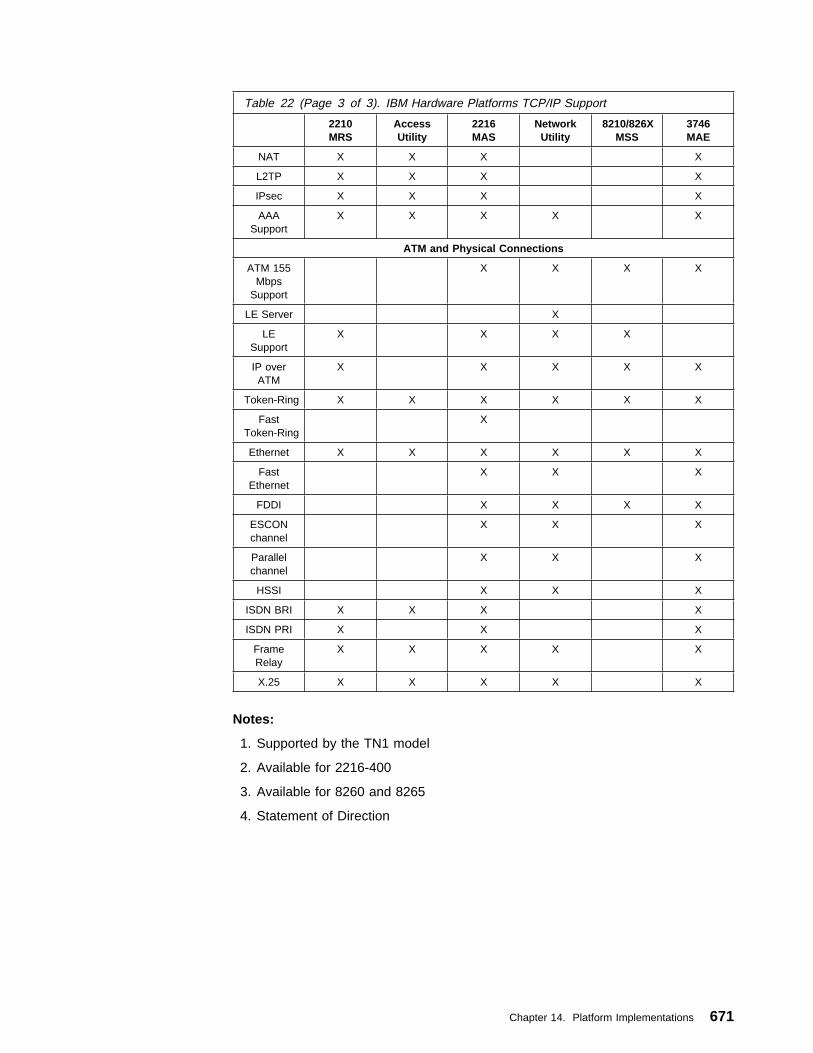
Notes:
1. Supported by the TN1 model
2. Available for 2216-400
3. Available for 8260 and 8265
4. Statement of Direction
Table 22 (Page 3 of 3). IBM Hardware Platforms TCP/IP Support
2210MRS
AccessUtility
2216MAS
NetworkUtility
8210/826XMSS
3746MAE
NAT X X X X
L2TP X X X X
IPsec X X X X
AAASupport
X X X X X
ATM and Physical Connections
ATM 155Mbps
Support
X X X X
LE Server X
LESupport
X X X X
IP overATM
X X X X X
Token-Ring X X X X X X
FastToken-Ring
X
Ethernet X X X X X X
FastEthernet
X X X
FDDI X X X X
ESCONchannel
X X X
Parallelchannel
X X X
HSSI X X X
ISDN BRI X X X X
ISDN PRI X X X
FrameRelay
X X X X X
X.25 X X X X X
Chapter 14. Platform Implementations 671

672 TCP/IP Tutorial and Technical Overview

Appendix A. Special Notices
This publication is intended to discuss TCP/IP. The information in this publicationis not intended as the specification of any programming interfaces that are providedby products mentioned in this book. See the PUBLICATIONS section of the IBMProgramming Announcement for mentioned products for more information aboutwhat publications are considered to be product documentation.
References in this publication to IBM products, programs or services do not implythat IBM intends to make these available in all countries in which IBM operates.Any reference to an IBM product, program, or service is not intended to state orimply that only IBM's product, program, or service may be used. Any functionallyequivalent program that does not infringe any of IBM's intellectual property rightsmay be used instead of the IBM product, program or service.
Information in this book was developed in conjunction with use of the equipmentspecified, and is limited in application to those specific hardware and softwareproducts and levels.
IBM may have patents or pending patent applications covering subject matter inthis document. The furnishing of this document does not give you any license tothese patents. You can send license inquiries, in writing, to the IBM Director ofLicensing, IBM Corporation, North Castle Drive, Armonk, NY 10504-1785.
Licensees of this program who wish to have information about it for the purpose ofenabling: (i) the exchange of information between independently created programsand other programs (including this one) and (ii) the mutual use of the informationwhich has been exchanged, should contact IBM Corporation, Dept. 600A, Mail Drop1329, Somers, NY 10589 USA.
Such information may be available, subject to appropriate terms and conditions,including in some cases, payment of a fee.
The information contained in this document has not been submitted to any formalIBM test and is distributed AS IS. The information about non-IBM ("vendor")products in this manual has been supplied by the vendor and IBM assumes noresponsibility for its accuracy or completeness. The use of this information or theimplementation of any of these techniques is a customer responsibility and dependson the customer's ability to evaluate and integrate them into the customer'soperational environment. While each item may have been reviewed by IBM foraccuracy in a specific situation, there is no guarantee that the same or similarresults will be obtained elsewhere. Customers attempting to adapt thesetechniques to their own environments do so at their own risk.
Any pointers in this publication to external Web sites are provided for convenienceonly and do not in any manner serve as an endorsement of these Web sites.
The following document contains examples of data and reports used in dailybusiness operations. To illustrate them as completely as possible, the examplescontain the names of individuals, companies, brands, and products. All of thesenames are fictitious and any similarity to the names and addresses used by anactual business enterprise is entirely coincidental.
Copyright IBM Corp. 1989, 1998 673
Reference to PTF numbers that have not been released through the normaldistribution process does not imply general availability. The purpose of includingthese reference numbers is to alert IBM customers to specific information relative tothe implementation of the PTF when it becomes available to each customeraccording to the normal IBM PTF distribution process.
The following terms are trademarks of the International Business MachinesCorporation in the United States and/or other countries:
The following terms are trademarks of other companies:
C-bus is a trademark of Corollary, Inc.
Java and HotJava are trademarks of Sun Microsystems, Incorporated.
Microsoft, Windows, Windows NT, and the Windows 95 logo are trademarksor registered trademarks of Microsoft Corporation.
PC Direct is a trademark of Ziff Communications Company and is usedby IBM Corporation under license.
Pentium, MMX, ProShare, LANDesk, and ActionMedia are trademarks orregistered trademarks of Intel Corporation in the U.S. and othercountries.
UNIX is a registered trademark in the United States and othercountries licensed exclusively through X/Open Company Limited.
Other company, product, and service names may be trademarks orservice marks of others.
Full Copyright Statement as requested by recent RFC and Internet draft documentsthat are referred to within this publication:
AIX AIX/6000AnyNet APPNAS/400 Bean MachineC/370 CICSDATABASE 2 DB2DB2 Connect Deep BlueDRDA eNetworkESCON graPHIGSIBM IBM RegistryIMS IPDSMQSeries MVSMVS/ESA Net.DataNetView NwaysOfficeVision/VM On-Demand ServerOpen Blueprint OS/2OS/390 OS/400Parallel Sysplex RACFRS/6000 S/390SP System/390Ultimedia VisualAgeVM/ESA VTAM
674 TCP/IP Tutorial and Technical Overview

Copyright (C) The Internet Society (1998). All Rights Reserved.
This document and translations of it may be copied and furnished toothers, and derivative works that comment on or otherwise explain itor assist in its implementation may be prepared, copied, publishedand distributed, in whole or in part, without restriction of anykind, provided that the above copyright notice and this paragraph areincluded on all such copies and derivative works. However, thisdocument itself may not be modified in any way, such as by removingthe copyright notice or references to the Internet Society or otherInternet organizations, except as needed for the purpose ofdeveloping Internet standards in which case the procedures forcopyrights defined in the Internet Standards process must befollowed, or as required to translate it into languages other thanEnglish.
The limited permissions granted above are perpetual and will not berevoked by the Internet Society or its successors or assigns.
This document and the information contained herein is provided on an"AS IS" basis and THE INTERNET SOCIETY AND THE INTERNET ENGINEERINGTASK FORCE DISCLAIMS ALL WARRANTIES, EXPRESS OR IMPLIED, INCLUDINGBUT NOT LIMITED TO ANY WARRANTY THAT THE USE OF THE INFORMATIONHEREIN WILL NOT INFRINGE ANY RIGHTS OR ANY IMPLIED WARRANTIES OFMERCHANTABILITY OR FITNESS FOR A PARTICULAR PURPOSE.
Appendix A. Special Notices 675

676 TCP/IP Tutorial and Technical Overview

Appendix B. Related Publications
The publications listed in this section are considered particularly suitable for a moredetailed discussion of the topics covered in this redbook.
B.1 International Technical Support Organization PublicationsFor information on ordering these ITSO publications see “How to Get ITSORedbooks” on page 681.
� IBM TCP/IP Version 3 Release 2 for MVS Implementation Guide, SG24-3687
� OS/390 eNetwork Communications Server V2R5 TCP/IP, Volume I, SG24-5227
� OS/390 eNetwork Communications Server V2R5 TCP/IP, Volume II,SG24-5228
� OS/390 eNetwork Communications Server V2R5 TCP/IP, Volume III,SG24-5229
� TCP/IP in a Sysplex, SG24-5235
� OS/390 Security Services and RACF-DCE Interoperation, SG24-4704
� AS/400 TCP/IP Autoconfiguration: DNS and DHCP Support, SG24-5147
� Stay Cool on OS/390: Installing Firewall Technology, SG24-2046
� AS/400 Internet Security: IBM Firewall for AS/400, SG24-2162
� Protect and Survive Using IBM Firewall 3.1 for AIX, SG24-2577
� Guarding the Gates Using the IBM eNetwork Firewall for NT, SG24-5209
� A Comprehensive Guide to Virtual Private Networks, Volume I: IBM Firewall,Server and Client Solutions, SG24-5201
� TCP/IP Implementation in an OS/2 Warp Environment, SG24-4730
� Beyond DHCP -- Work Your TCP/IP Internetwork with Dynamic IP, SG24-5280
� Network Clients for OS/2 Warp Server, SG24-2009
� AIX Version 4.3 Differences Guide, SG24-2014
� Network Computing Framework Component Guide, SG24-2119
� Publishing Tools in the Network Computing Framework, SG24-5205
� IBM Network Computing Framework for e-business Guide, SG24-5296
� Internet Security in the Network Computing Framework, SG24-5220
� Java Network Security, SG24-2109
� Integrating Net.Commerce with Legacy Applications, SG24-4933
� Secure Electronic Transactions: Credit Card Payment on the Web in Theoryand Practice, SG24-4978
� Load-Balancing Internet Servers, SG24-4993
� Understanding OSF DCE 1.1 for AIX and OS/2, SG24-4616
� Administering DCE and DFS 2.1 for AIX (and OS/2 Clients), SG24-4714
� DCE Cell Design Considerations, SG24-4746
Copyright IBM Corp. 1989, 1998 677
� Security on the Web Using DCE Technology, SG24-4949
� Understanding LDAP, SG24-4986
� IBM 2210 Nways Multiprotocol Router Description and Configuration Scenarios- Volume I, SG24-4446
� IBM 2210 and IBM 2216: Description and Configuration Scenarios - Volume II,SG24-4956
� 3746 Nways Controller Models 900 and 950: Multiaccess Enclosure Primer,SG24-5238
� The Technical Side of Being an Internet Service Provider, SG24-2133
� IBM Network Station - RS/6000 Notebook, SG24-2016
� IBM Network Station Guide for Windows NT, SG24-2127
� AS/400 IBM Network Station - Getting Started, SG24-2153
� S/390 IBM Network Station - Getting Started, SG24-4954
� Internetworking over ATM: An Introduction, SG24-4699
� Local Area Network Concepts and Products: Routers and Gateways,SG24-4755
� Open Systems Adapter 2 Implementation Guide, SG24-4770
� MPTN Architecture Tutorial and Product Implementations, SG24-4170
B.2 Redbooks on CD-ROMsRedbooks are also available on CD-ROMs. Order a subscription and receiveupdates 2-4 times a year at significant savings.
CD-ROM Title SubscriptionNumber
Collection KitNumber
System/390 Redbooks Collection SBOF-7201 SK2T-2177Networking and Systems Management Redbooks Collection SBOF-7370 SK2T-6022Transaction Processing and Data Management Redbook SBOF-7240 SK2T-8038Lotus Redbooks Collection SBOF-6899 SK2T-8039Tivoli Redbooks Collection SBOF-6898 SK2T-8044AS/400 Redbooks Collection SBOF-7270 SK2T-2849RS/6000 Redbooks Collection (HTML, BkMgr) SBOF-7230 SK2T-8040RS/6000 Redbooks Collection (PostScript) SBOF-7205 SK2T-8041RS/6000 Redbooks Collection (PDF Format) SBOF-8700 SK2T-8043Application Development Redbooks Collection SBOF-7290 SK2T-8037
B.3 Other PublicationsDocumentation for IBM products is available online and shipped with the products.
These publications are also relevant as further information sources:
� Internetworking with TCP/IP, Volume I, Principles, Protocols and Architecture,third edition, Prentice-Hall, Inc., 1995, by Douglas E. Comer; ISBN0-13-216987-8.
� Internetworking with TCP/IP, Volume II, Design, Implementation, and Internals,Prentice-Hall, Inc., 1991, by Douglas E. Comer and David L. Stevens; ISBN0-13-472242-6.
678 TCP/IP Tutorial and Technical Overview

� Internetworking with TCP/IP, Volume III, Client Server Programming andApplications, Windows Sockets Version, Prentice-Hall, Inc., 1997, by DouglasE. Comer and David L. Stevens; ISBN 0-13-848714-6.
� Applied Cryptography, second edition, John Wiley & Sons, Inc., 1996, by BruceSchneier; ISBN 0-471-11709-9.
� IPng and the TCP/IP Protocols, John Wiley & Sons, Inc., 1996, by Stephen A.Thomas; ISBN 0-471-13088-5.
� Internet Routing Architectures, New Riders Publishing, 1997, by BassamHalabi; ISBN 1-56205-652-2.
� HTML 3.2 & CGI Unleashed, Sams.net Publishing, 1996, by John Decemberand Mark Ginsburg; ISBN 1-57521-177-7.
� TCP/IP Illustrated, Volume I, The Protocols, Addison Wesley, 1994, by W.Richard Stevens; ISBN 0-201-63346-9.
� TCP/IP Illustrated, Volume II, The Implementation, Addison Wesley, 1995, byW. Richard Stevens; ISBN 0-201-63346-9.
� TCP/IP Illustrated, Volume III, TCP for Transactions, HTTP, NNTP, and theUNIX Domain Protocols, Addison Wesley, 1996, by W. Richard Stevens; ISBN0-201-63346-9.
� TCP/IP Network Administration, O'Reilly & Associates, Inc., 1994, by CraigHunt; ISBN 0-937175-82-X.
� DNS and BIND, second edition, O'Reilly & Associates, Inc., 1997, by PaulAlbitz and Cricket Liu; ISBN 1-56592-236-0.
� sendmail, second edition, O'Reilly & Associates, Inc., 1997, by Bryan Costaleswith Eric Allman, ISBN 1-56592-222-0.
� Building Internet Firewalls, O'Reilly & Associates, Inc., 1995, by D. BrentChapman and Elizabeth D. Zwicky; ISBN 1-56592-124-0.
� The Java Handbook, Osborne McGraw-Hill, 1996, by Patrick Naughton; ISBN0-07-882199-1.
� The ABCs of JavaScript, SYBEX, Inc., 1997, by Lee Purcel and Mary JaneMara; ISBN 0-7821-1937-9.
� Communications for Cooperating Systems - OSI, SNA and TCP/IP,Addison-Wesley, Publishing Company, Inc., 1992, by R. J. Cypser; ISBN0-201-50775-7.
� LAN Technical Reference: 802.2 and NetBIOS Application Program Interfaces,SC30-3587
� Request For Comments (RFC) and Internet Drafts (ID)
There are more than 2400 RFCs today. For those readers who want to keepup-to-date with the latest advances and research activities in TCP/IP, theever-increasing number of RFCs and Internet drafts (ID) is the best source ofthis information. RFCs can be viewed or obtained online from the InternetEngineering Taskforce (IETF) Web page using the following URL:http://www.ietf.org.
� IBM Software Glossary
An excellent collection of definitions of commonly used terms for computersoftware and communications which are used in many IBM product publications
Appendix B. Related Publications 679

can be found in this document which is available on the World Wide Web at thefollowing URL: http://www.networking.ibm.com/nsg/nsgmain.htm
Note: This glossary is not available through regular publication services.
680 TCP/IP Tutorial and Technical Overview

How to Get ITSO Redbooks
This section explains how both customers and IBM employees can find out about ITSO redbooks, CD-ROMs,workshops, and residencies. A form for ordering books and CD-ROMs is also provided.
This information was current at the time of publication, but is continually subject to change. The latest informationmay be found at http://www.redbooks.ibm.com/.
How IBM Employees Can Get ITSO Redbooks
Employees may request ITSO deliverables (redbooks, BookManager BOOKs, and CD-ROMs) and information aboutredbooks, workshops, and residencies in the following ways:
� Redbooks Web Site on the World Wide Web
http://w3.itso.ibm.com/
� PUBORDER — to order hardcopies in the United States
� Tools Disks
To get LIST3820s of redbooks, type one of the following commands:
TOOLCAT REDPRINT
TOOLS SENDTO EHONE4 TOOLS2 REDPRINT GET SG24xxxx PACKAGE
TOOLS SENDTO CANVM2 TOOLS REDPRINT GET SG24xxxx PACKAGE (Canadian users only)
To get BookManager BOOKs of redbooks, type the following command:
TOOLCAT REDBOOKS
To get lists of redbooks, type the following command:
TOOLS SENDTO USDIST MKTTOOLS MKTTOOLS GET ITSOCAT TXT
To register for information on workshops, residencies, and redbooks, type the following command:
TOOLS SENDTO WTSCPOK TOOLS ZDISK GET ITSOREGI 1998
� REDBOOKS Category on INEWS
� Online — send orders to: USIB6FPL at IBMMAIL or DKIBMBSH at IBMMAIL
Redpieces
For information so current it is still in the process of being written, look at "Redpieces" on the Redbooks Web Site(http://www.redbooks.ibm.com/redpieces.html). Redpieces are redbooks in progress; not all redbooks becomeredpieces, and sometimes just a few chapters will be published this way. The intent is to get the information outmuch quicker than the formal publishing process allows.
Copyright IBM Corp. 1989, 1998 681

How Customers Can Get ITSO Redbooks
Customers may request ITSO deliverables (redbooks, BookManager BOOKs, and CD-ROMs) and information aboutredbooks, workshops, and residencies in the following ways:
� Online Orders — send orders to:
� Telephone Orders
� Mail Orders — send orders to:
� Fax — send orders to:
� 1-800-IBM-4FAX (United States) or (+1)001-408-256-5422 (Outside USA) — ask for:
� On the World Wide Web
Redpieces
For information so current it is still in the process of being written, look at "Redpieces" on the Redbooks Web Site(http://www.redbooks.ibm.com/redpieces.html). Redpieces are redbooks in progress; not all redbooks becomeredpieces, and sometimes just a few chapters will be published this way. The intent is to get the information outmuch quicker than the formal publishing process allows.
IBMMAIL InternetIn United States: usib6fpl at ibmmail [email protected] Canada: caibmbkz at ibmmail [email protected] North America: dkibmbsh at ibmmail [email protected]
United States (toll free) 1-800-879-2755Canada (toll free) 1-800-IBM-4YOU Outside North America (long distance charges apply)(+45) 4810-1320 - Danish(+45) 4810-1420 - Dutch(+45) 4810-1540 - English(+45) 4810-1670 - Finnish(+45) 4810-1220 - French
(+45) 4810-1020 - German(+45) 4810-1620 - Italian(+45) 4810-1270 - Norwegian(+45) 4810-1120 - Spanish(+45) 4810-1170 - Swedish
IBM PublicationsPublications Customer SupportP.O. Box 29570Raleigh, NC 27626-0570USA
IBM Publications144-4th Avenue, S.W.Calgary, Alberta T2P 3N5Canada
IBM Direct ServicesSortemosevej 21DK-3450 AllerødDenmark
United States (toll free) 1-800-445-9269Canada 1-403-267-4455Outside North America (+45) 48 14 2207 (long distance charge)
Index # 4421 Abstracts of new redbooksIndex # 4422 IBM redbooksIndex # 4420 Redbooks for last six months
Redbooks Web Site http://www.redbooks.ibm.com/IBM Direct Publications Catalog http://www.elink.ibmlink.ibm.com/pbl/pbl
682 TCP/IP Tutorial and Technical Overview

IBM Redbook Order Form
Please send me the following:
Title Order Number Quantity
First name Last name
Company
Address
City Postal code Country
Telephone number Telefax number VAT number
Ø Invoice to customer number
Ø Credit card number
Credit card expiration date Card issued to Signature
We accept American Express, Diners, Eurocard, Master Card, and Visa. Payment by credit card notavailable in all countries. Signature mandatory for credit card payment.
How to Get ITSO Redbooks 683

684 TCP/IP Tutorial and Technical Overview

List of Abbreviations
AAA Authentication, Authorizationand Accounting
AAL ATM Adaptation Layer
AFS Andrews File System
AH Authentication Header
AIX Advanced Interactive ExecutiveOperating System
API Application ProgrammingInterface
APPN Advanced Peer-to-PeerNetworking
ARP Address Resolution Protocol
ARPA Advanced Research ProjectsAgency
AS Autonomous System
ASCII American Standard Code forInformation Interchange
ASN.1 Abstract Syntax Notation 1
AS/400 Application System/400
ATM Asynchronous Transfer Mode
BGP Border Gateway Protocol
BIND Berkeley Internet NameDomain
BNF Backus-Naur Form
BRI Basic Rate Interface
BSD Berkeley Software Distribution
CA Certification Authority
CBC Cipher Block Chaining
CCITT Comité Consultatif InternationalTélégraphique et Téléphonique(now ITU-T)
CDMF Commercial Data MaskingFacility
CERN Conseil Européen pour laRecherche Nucléaire
CGI Common Gateway Interface
CHAP Challenge HandshakeAuthentication Protocol
CICS Customer Information ControlSystem
CIDR Classless Inter-Domain Routing
CIX Commercial Internet Exchange
CLNP Connectionless NetworkProtocol
CORBA Common Object RequestBroker Architecture
COS Class of Service
CPCS Common Part ConvergenceSublayer
CPU Central Processing Unit
CSMA/CD Carrier Sense Multiple Accesswith Collision Detection
DARPA Defense Advanced ResearchProjects Agency
DCE Distributed ComputingEnvironment
DCE Data Circuit-terminatingEquipment
DDN Defense Data Network
DDNS Dynamic Domain NameSystem
DEN Directory-Enabled Networking
DES Digital Encryption Standard
DFS Distributed File Service
DHCP Dynamic Host ConfigurationProtocol
DLC Data Link Control
DLCI Data Link Connection Identifier
DLL Dynamic Link Library
DLSw Data Link Switching
DLUR Dependent LU Requester
DLUS Dependent LU Server
DME Distributed ManagementEnvironment
DMI Desktop Management Interface
DMTF Desktop Management TaskForce
DMZ Demilitarized Zone
DNS Domain Name Server
DOD U.S. Department of Defense
DOI Domain of Interpretation
DOS Disk Operating System
DSA Digital Signature Algorithm
Copyright IBM Corp. 1989, 1998 685

DSAP Destination Service AccessPoint
DSS Digital Signature Standard
DTE Data Terminal Equipment
DTP Data Transfer Process
DVMRP Distance Vector MulticastRouting Protocol
EBCDIC Extended BinaryCommunication DataInterchange Code
EGP Exterior Gateway Protocol
ESCON Enterprise Systems Connection
ESP Encapsulating Security Payload
FDDI Fiber Distributed Data Interface
FQDN Fully Qualified Domain Name
FR Frame Relay
FTP File Transfer Protocol
GGP Gateway-to-Gateway Protocol
GMT Greenwich Mean Time
GSM Group Special Mobile
GUI Graphical User Interface
HDLC High-level Data Link Control
HMAC Hashed MessageAuthentication Code
HPR High Performance Routing
HTML Hypertext Markup Language
HTTP Hypertext Transfer Protocol
IAB Internet Activities Board
IAC Interpret As Command
IANA Internet Assigned NumbersAuthority
IBM International BusinessMachines Corporation
ICMP Internet Control MessageProtocol
ICSS Internet Connection SecureServer
ICV Integrity Check Value
IDEA International Data EncryptionAlgorithm
IDLC Integrated Data Link Control
IDRP Inter-Domain Routing Protocol
IEEE Institute of Electrical andElectronics Engineers
IESG Internet Engineering SteeringGroup
IETF Internet Engineering TaskForce
IGMP Internet Group ManagementProtocol
IGN IBM Global Network
IGP Interior Gateway Protocol
IIOP Internet Inter-ORB Protocol
IKE Internet Key Exchange
IMAP Internet Message AccessProtocol
IMS Information ManagementSystem
IP Internet Protocol
IPC Interprocess Communication
IPSec IP Security Architecture
IPv4 Internet Protocol Version 4
IPv6 Internet Protocol Version 6
IPX Internetwork Packet Exchange
IRFT Internet Research Task Force
ISAKMP Internet Security Associationand Key Management Protocol
ISDN Integrated Services DigitalNetwork
ISO International Organization forStandardization
ISP Internet Service Provider
ITSO International Technical SupportOrganization
ITU-T InternationalTelecommunication Union -TelecommunicationStandardization Sector (wasCCITT)
IV Initialization Vector
JDBC Java Database Connectivity
JDK Java Development Toolkit
JES Job Entry System
JIT Java Just-in-Time Compiler
JMAPI Java Management API
JVM Java Virtual Machine
JPEG Joint Photographic ExpertsGroup
LAC L2TP Access Concentrator
686 TCP/IP Tutorial and Technical Overview

LAN Local Area Network
LAPB Link Access Protocol Balanced
LCP Link Control Protocol
LDAP Lightweight Directory AccessProtocol
LE LAN Emulation (ATM)
LLC Logical Link Layer
LNS L2TP Network Server
LPD Line Printer Daemon
LPR Line Printer Requester
LSAP Link Service Access Point
L2F Layer 2 Forwarding
L2TP Layer 2 Tunneling Protocol
MAC Message Authentication Code
MAC Medium Access Control
MD2 RSA Message Digest 2Algorithm
MD5 RSA Message Digest 5Algorithm
MIB Management Information Base
MILNET Military Network
MIME Multipurpose Internet MailExtensions
MLD Multicast Listener Discovery
MOSPF Multicast Open Shortest PathFirst
MPC Multi-Path Channel
MPEG Moving Pictures Experts Group
MPLS Multiprotocol Label Switching
MPOA Multiprotocol over ATM
MPTN Multiprotocol TransportNetwork
MS-CHAP Microsoft ChallengeHandshake AuthenticationProtocol
MTA Message Transfer Agent
MTU Maximum Transmission Unit
MVS Multiple Virtual StorageOperating System
NAT Network Address Translation
NBDD NetBIOS Datagram Distributor
NBNS NetBIOS Name Server
NCF Network Computing Framework
NCP Network Control Protocol
NCSA National Computer SecurityAssociation
NDIS Network Drivere InterfaceSpecification
NetBIOS Network Basic Input/OutputSystem
NFS Network File System
NIC Network Information Center
NIS Network Information Systems
NIST National Institute of Standardsand Technology
NMS Network Management Station
NNTP Network News TransferProtocol
NRZ Non-Return-to-Zero
NRZI Non-Return-to-Zero Inverted
NSA National Security Agency
NSAP Network Service Access Point
NSF National Science Foundation
NTP Network Time Protocol
NVT Network Virtual Terminal
ODBC Open Database Connectivity
ODI Open Datalink Interface
OEM Original EquipmentManufacturer
ONC Open Network Computing
ORB Object Request Broker
OSA Open Systems Adapter
OSI Open Systems Interconnect
OSF Open Software Foundation
OSPF Open Shortest Path First
OS/2 Operating System/2
OS/390 Operating System for theSystem/390 platform
OS/400 Operating System for theAS/400 platform
PAD PacketAssembler/Disassembler
PAP Password AuthenticationProtocol
PDU Protocol Data Unit
PGP Pretty Good Privacy
PI Protocol Interpreter
PIM Protocol Indepedent Multicast
List of Abbreviations 687
PKCS Public Key Cryptosystem
PKI Public Key Infrastructure
PNNI Private Network-to-NetworkInterface
POP Post Office Protocol
POP Point-of-Presence
PPP Point-to-Point Protocol
PPTP Point-to-Point TunnelingProtocol
PRI Primary Rate Interface
PSDN Packet Switching Data Network
PSTN Public Switched TelephoneNetwork
PVC Permanent Virtual Circuit
QLLC Qualified Logical Link Control
QOS Quality of Service
RACF Resource Access ControlFacility
RADIUS Remote Authentication Dial-InUser Service
RAM Random Access Memory
RARP Reverse Address ResolutionProtocol
RAS Remote Access Service
RC2 RSA Rivest Cipher 2 Algorithm
RC4 RSA Rivest Cipher 4 Algorithm
REXEC Remote Execution CommandProtocol
RFC Request for Comments
RIP Routing Information Protocol
RIPE Réseaux IP Européens
RISC Reduced Instruction-SetComputer
ROM Read-only Memory
RPC Remote Procedure Call
RSH Remote Shell
RSVP Resource Reservation Protocol
RS/6000 IBM RISC System/6000
RTCP Realtime Control Protocol
RTP Realtime Protocol
SA Security Association
SAP Service Access Point
SDH Synchronous Digital Hierarchy
SDLC Synchronous Data Link Control
SET Secure Electronic Transaction
SGML Standard Generalized MarkupLanguage
SHA Secure Hash Algorithm
S-HTTP Secure Hypertext TransferProtocol
SLA Service Level Agreement
SLIP Serial Line Internet Protocol
SMI Structure of ManagementInformation
S-MIME Secure Multipurpose InternetMail Extension
SMTP Simple Mail Transfer Protocol
SNA System Network Architecture
SNAP Subnetwork Access Protocol
SNG Secured Network Gateway(former product name of theIBM eNetwork Firewall)
SNMP Simple Network ManagementProtocol
SOA Start of Authority
SONET Synchronous Optical Network
SOCKS SOCK-et-S (An internal NECdevelopment name thatremained after release)
SPI Security Parameter Index
SSL Secure Sockets Layer
SSAP Source Service Access Point
SSP Switch-to-Switch Protocol
SSRC Synchronization Source
SVC Switched Virtual Circuit
TACACS Terminal Access ControllerAccess Control System
TCP Transmission Control Protocol
TCP/IP Transmission Control Protocol /Internet Protocol
TFTP Trivial File Transfer Protocol
TLPB Transport-Layer ProtocolBoundary
TLS Transport Layer Security
TOS Type of Service
TRD Transit Routing Domain
TTL Time to Live
UDP User Datagram Protocol
688 TCP/IP Tutorial and Technical Overview

UID Unique Identifier
URI Uniform Resource Identifier
URL Uniform Resource Locator
UT Universal Time
VC Virtual Circuit
VM Virtual Machine OperatingSystem
VPN Virtual Private Network
VRML Virtual Reality ModelingLanguage
VRRP Virtual Router RedundancyProtocol
VTAM Virtual TelecommunicationsAccess Method
WAN Wide Area Network
WWW World Wide Web
XDR External Data Representation
XML Extensible Markup Language
X11 X Window System Version 11
X.25 CCITT Packet SwitchingStandard
X.400 CCITT and ISOMessage-handling ServiceStandard
X.500 ITU and ISO Directory ServiceStandard
X.509 ITU and ISO Digital CertificateStandard
3DES Triple Digital EncryptionStandard
List of Abbreviations 689

690 TCP/IP Tutorial and Technical Overview

Index
Numerics2210
See Data Link Switching: Switch-to-Switch Protocol2210 Nways Multiprotocol Router
BOOTP forwarding 40, 4052210/2216 Router 669, 670, 671
Bandwidth Reservation System (BRS) 621Enterprise Extender 621High Performance Routing (HPR) 621
2216See Data Link Switching: Switch-to-Switch Protocol
2216 Nways Multiaccess ConnectorBOOTP forwarding 40, 405
3746 Nways Multiaccess Enclosure6Bone
See IP Version 6 (IPv6)
AA5 algorithm 269AAA security model 345abbreviations 685absolute domain name
See Domain Name System (DNS), fully qualifieddomain name
Abstract Syntax Notation One (ASN.1) 215accounting 345acronyms 685address allocation
See Dynamic Host Configuration Protocol (DHCP)Address Resolution (ATMARP and InATMARP) 598Address Resolution Protocol (ARP)
algorithm 70BOOTP 402cache 68Ethernet 68, 596Frame Relay 618gratuitous ARP 433IEEE 802.2 standard 596IEEE 802.x standards 68IPv6 373Mobile IP 433packet 69, 72proxy ARP 433Proxy-ARP 71reply 68request 68
adjacent router 116AFS
See Andrew File System (AFS)
Agent Solicitation message 427AH
See Authentication Header (AH)AIX 166AIX V4.3 656, 657, 658, 659, 660
CacheFS 652CIDR 652DCE Client 653DHCP 652IP security (IPSec) 651IPv6 651Java 651Lightweight Directory Access Protocol (LDAP) 651Lotus Domino Go Webserver 653Netscape FastTrack Server 653Netscape Navigator 653Network File System 652Network Station Manager (NSM) 653Secure Sockets Layer (SSL) 652Sendmail 8.8.8 652Telnet 652X11R6 652
algorithmblock 268Diffie-Hellman 273Digital Signature 277, 318key-exchange 271link state
See algorithm, shortest path first (SPF)public-key 270, 271, 272RSA 272shortest path first (SPF)
in OSPF 105, 118stream 268symmetric 268, 269TCP congestion control 88vector distance
in BGP 139all-subnets-directed broadcast address 41Andrew File System (AFS) 573
access control list (ACL) 576authentication 576cell 575client cache 575Kerberos 576management utilities 576name space 575remote procedure call (RPC) 576replication 576
Anonymous FTP 180AnyNet
See Multiprotocol Transport Network Architecture(MPTN)
Copyright IBM Corp. 1989, 1998 691

Apache 439, 458API
See application programming interface (API)application level gateway
See firewallapplication programming interface (API)
sockets 74TCP 88UDP 77
application protocols 14architecture
application 13architectural model 11, 12, 14internetwork 13layers 12network interface 14transport 13
area border router 113areas 113arithmetic, modular 272ARP
See Address Resolution Protocol (ARP)ARPANET 5
Network Working Group 4protocol suite 4
ASSee autonomous system (AS)
AS boundary router 113ASN.1
See Abstract Syntax Notation One (ASN.1)Assigned Internet Numbers
See Standard Protocol Numbers (STD), , STD 02Assigned Numbers RFC 300Asynchronous Transfer Mode 598
end system addresses 634Open Systems Adapter 2 626
athentication 285ATM
See Asynchronous Transfer ModeSee ATM LAN EmulationSee CellSee Classical IP over ATMSee LAN Emulation ServerSee Multiprotocol EncapsulationSee Virtual Connection VC
ATM LAN Emulation 606ATM-Attached Host Functional Group (AHFG) 631ATMARP
See Address Resolution (ATMARP and InATMARP)attacks 263audio 440authentication 208, 264, 267, 268, 270, 274, 275, 327,
331, 345, 351, 434, 446, 541, 566, 576, 586, 612,640, 650
IP Control Protocol (IPCP) 613IPCP 613
Authentication Header (AH)Authentication Data 301Authentication Data field 276combinations with ESP 307Flags field 299Fragment Offset 299header checksum 299header format 300HMAC-MD5-96 301HMAC-SHA-1-96 301Integrity Check Value (ICV) 301IP fragment 299IPv6 environment 302Keyed MD5 301mutable fields 299, 301Next Header field 300Payload Length 300replay protection 300Reserved field 300Security Parameter Index (SPI) 300Sequence Number 300Time To Live (TTL) 299transform 297transport mode 301, 308tunnel mode 301, 308Type of Service (TOS) 299
authentication method 315authorization 264, 345, 514, 566, 586
Simple Authentication and Security Layer (SASL)See Lightweight Directory Access Protocol
(LDAP)autoconfiguration
See Internet Control Message Protocol (ICMPv6)autonomous system (AS)
See routing domainautonomous systems (ASs) 97availability 535, 543, 547, 552
Bbackbone 113backup designated router 116, 123Backus-Naur Form (BNF) 187balancing 535, 542, 543, 549, 647Bandwidth Reservation System (BRS) 621base-64 447Berkeley Internet Name Domain (BIND)
See Domain Name System (DNS)See Dynamic Domain Name System (DDNS)
Berkeley Software Distribution 4BGP
See Border Gateway Protocol (BGP)BGP protocol description (BGP) 141BGP-3
See Border Gateway Protocol (BGP), Version 3(BGP-3)
692 TCP/IP Tutorial and Technical Overview

BGP-4See Border Gateway Protocol (BGP), Version 4
(BGP-4)bibliography 677BIND
See Domain Name System (DNS)block algorithm 268BNF 187BOOTP
See Bootstrap Protocol (BOOTP)BOOTP forwarding 215BOOTP relay agent 215BOOTP server 215Bootstrap Protocol (BOOTP) 215, 401
ARP 402BOOTPREQUEST message 405BOOTREPLY message 404DHCP interoperability 413forwarding 40, 405message format 403Network Computer 435OS/2 654TFTP 401
Border Gateway Protocol 135Border Gateway Protocol (BGP) 134
AS path 138BGP connection 137BGP neighbor 136
external 136internal 136
BGP session 137BGP speaker 136external border router 137incremental updates 140internal border router 137keepalive message 137local traffic 138multihomed AS 138path selection 139physical connection 137protocol description 141stub AS 138transit AS 138transit traffic 138Version 1 (BGP-1)Version 2 (BGP-2)Version 3 (BGP-3)Version 4 (BGP-4) 47
bridge 15broadcast
description 40limited broadcast address 40reverse path forwarding algorithm 41
brute-force attack 263, 269BSD UNIX 106
bulk encryption 272
Ccache 543, 573, 575
AIX V4.3 652ARP cache 68HTTP caching 442, 447ICMPv6 neighbor cache 376
care-of address 426CBC 269CDMF 269, 571Cell 601CERN 439certificate 264, 314, 336certificate authority 318, 351, 642, 650certification authority (CA) 278checksum
IGMP message 470IPv6 360TCP datagram 83UDP datagram 77
chicken and egg problem 402CICS
See Customer Information Control System (CICS)CICS Socket Interface 260CIDR
See classless inter-domain routing (CIDR)cipher 267Cipher Block Chaining (CBC) 269cipher, restricted 267ciphertext 271circuit level gateway
See firewallClassical IP over ATM 601, 629classless inter-domain routing (CIDR)
AIX V4.3 652IP prefix 46transit routing domains (TRDs) 46
cleartext 267client-server
client/server model 15, 149CLNP 615, 616codebook 269collision-resistant 274combined tunnel 309Commercial Data Masking Facility (CDMF) 269Common Gateway Interface (CGI) 439Common Object Request Broker Architecture
(CORBA) 453Connections
ATM 598DLSW 609Enterprise Extender 621FDDI 597Frame Relay 616
Index 693

Connections (continued)ISDN 613MPC+ 625MPLS 619MPOA 628MPTN 622OSA-2 626PNNI 632PPP 611SLIP 611SONET 618X.25 614
cookie 441counting to infinity 101, 102crankback and alternate routing 636cryptanalysis 264, 267cryptanalyst 279crypto couple 268cryptographic algorithm 267cryptography 267, 273, 640, 650cryptography, strong 267cryptosystem 272, 279CSNET
mail gateway service 186Customer Information Control System (CICS) 260
Ddaemon 97
gated 97routed 97
DARPA 4See also Defense Advanced Research Projects
Agency (DARPA)Data Encryption Standard (DES) 269, 340Data Link Connection Identifier (DLCI)
See Frame RelayData Link Switching: Switch-to-Switch Protocol 609
IEEE 802.2 LLC Type 2 609NetBIOS 609SDLC 609
database description 124database exchange 124datagram
See Internet Protocol (IP)DCA
See Defense Communication Agency (DCA)DCE
See Distributed Computing Environment (DCE)DDN Network Information Center 28, 150
See also Internet Network Information Center(InterNIC)
DDNS 166decryption 267Default Forwarder Function Group (DFFG) 631
default router 536Defense Advanced Research Projects Agency
(DARPA) 4Defense Communication Agency (DCA) 5Demilitarized Zone (DMZ)
See firewalldenial-of-service attack 263, 264, 300, 313, 350Department of Defense (DoD) 5DES 269, 272, 279, 571, 643, 650
See also Data Encryption Standard (DES)designated router 116, 123destination options extension header 302, 307DHCP
See Dynamic Host Configuration Protocol (DHCP)DHCPv6
See Dynamic Host Configuration Protocol (DHCP)dictionary attack 263Differentiated Services
admission control 532Behavior Aggregate (BA) classifier 527boundary node 530byte, DS 528class of service 523classifier 527, 529Differentiated Services CodePoint (DSCP) 524directory client 532directory information 532directory server 532DS boundary node 526DS byte 523, 527, 528, 532, 534DS domain 523, 526, 528, 532DS marker 527DSCP 524egress node 526Expedited Forwarding (EF) PHB 526ingress node 526, 534interior component 528Internet 531IPsec 533LDAP 532multi-field (MF) classifier 527packet dropper 527packet shaper 527Per-Hop Behavior (PHB) 524PHB 524policing 527policy information 532predictable performance 523QoS 523, 526, 528, 532RSVP 530scalable service discrimination 523security 533Service Level Agreement (SLA) 523SLA 526, 528, 532source domain 529token bucket filter 527
694 TCP/IP Tutorial and Technical Overview

Differentiated Services (continued)TOS octet 523traffic class octet 523traffic conditioner 527, 529Traffic Conditioning Agreement (TCA) 528traffic meter 527traffic prioritization algorithm 528traffic profile 527
Diffie-Hellman 271, 273, 279, 316, 317, 320, 321, 322,323, 324
Diffie-Hellman key exchangeSee IP Security Architecture (IPSec)
dig 166digital certificate 278, 640, 650digital envelope 275digital signature 264, 270, 275, 319, 417Digital Signature Standard 275, 313Digital Signature Standard (DSS)
See IP Security Architecture (IPSec)Directory Access Protocol (DAP) 577disconnected use model 210discrete logarithms 271, 273diskless host 401distance vector routing 99Distributed Computing Environment (DCE) 584
Access Control List Facility 567AIX V4.3 653Application Program Interfaces 564Architectural Components 563authentication 566Authentication Service 567authorization 566Backup Courier Time Server 572cache manager 573CDS namespace 565cell 564, 573, 589Cell Directory Service (CDS) 564, 589Courier Time Server 572DCE architecture 577DFS administrative domains 573Directory Service 563, 577Distributed File Service 563Distributed Time Service 563Episode File System 573Extended Privilege Attribute Certificate (EPAC) 569File Naming 574Fileset Location Database (FLDB) 565Global Directory Agent (GDA) 564, 589Global Directory Service (GDS) 564Global Time Server 572Interface Definition Language (IDL) 571Internet Domain Name Services (DNS) 565Kerberos 566Local File System (LFS) 573Local Time Server 572Login Facility 567
Distributed Computing Environment (DCE) (continued)Master Replica 564NFS interoperability 573OS/390 640Privilege Service 567Privilege Ticket Granting Ticket (PTGT) 569Public Key Support 570Read-only Replica 565registry 566Registry Service 567Remote Procedure Call 564Security Service 563Threads 564Ticket Granting Ticket (TGT) 568Transport Services 564X/Open Directory Service (XDS) 589X.500 565, 589
DIXIE 577DLSW
See Data Link Switching: Switch-to-Switch ProtocolDOI 315, 316Domain Internet Groper 166Domain Name Resolver
See Domain Name System (DNS)Domain Name Server
See Domain Name System (DNS)Domain Name System (DNS) 559, 589
applications 166dig 166host 166nslookup 166
AS/400 647authoritative answer 155Berkeley Internet Name Domain (BIND) 417cache 154, 156, 543country domains 152DDNS extensions 414delegation of authority 153distributed namespace 153example 163fully qualified domain name 151
example 164generic domains 152gethostbyaddr() 155gethostbyname() 155hierarchical namespace 151in-addr.arpa 153IPv6 391IPv6 extensions 386IPv6 inverse lookups 386iterative query 155message compression 162message format 415messages 159
description 159—162name resolver 154
full resolver 154
Index 695

Domain Name System (DNS) (continued)name resolver (continued)
operation 155stub resolver 155
name server 154caching-only 156operation 156primary 156secondary 156
NetBIOS encoded format 245network object 157non-authoritative answer 155non-recursive query 155Pointer Queries 153recursive query 155resource record (RR)
description 157—158format 157, 386, 420
resource record for IPv6 386root name server 157round-robin DNS 542time-to-live (TTL) 156, 158transport 165TTL 543
See also Domain Name System (DNS),time-to-live (TTL)
zone 153zone data 164zone of authority 153zone transfer 156
Domain of Interpretation (DOI) 315, 316Domino Go Webserver 439DSA 277DSS 275, 277Dynamic DNS 166Dynamic Domain Name System (DDNS) 426
A record update 424Berkeley Internet Name Domain (BIND) 417DDNS client 417DHCP option 81 425DHCP server 417digital signature 417DNS extensions 414DNS update message 415Dynamic Presecured Mode 419dynamic secured mode 419IBM DDNS UPDATE message format 424IBM Dynamic IP 420IBM implementation 422incremental zone transfer 654KEY resource record 420KEY resource record format 420MD5 420mechanism 417mixed environment 426notify 654
Dynamic Domain Name System (DDNS) (continued)OS/2 654proxy A record update 424Proxy Dynamic DNS Update 654PTR record update 424public key 420resource record format 420RSA 420RSA public-key 417security 418SIG resource record 420SIG resource record format 421TTL 421
Dynamic Host Configuration Protocol (DHCP) 401,406, 426
See also Dynamic Domain Name System (DDNS)address allocation 406AIX V4.3 652AS/400 647BOOTP forwarding 405BOOTP interoperability 413BOUND state 411client/server interaction 409, 411, 412DHCPACK message 409DHCPDECLINE message 409DHCPDISCOVER message 408DHCPINFORM message 409DHCPNACK message 409DHCPOFFER message 408DHCPRELEASE message 409DHCPREQUEST message 408DHCPv6
DHCP Advertise 389DHCP Reconfigure 390DHCP Release 390DHCP Reply 389DHCP Request 389DHCP Solicit 389
IBM implementation 422ICMPv6 382INIT state 409lease time 411message format 407Message Types 408Network Computer 435option 81 425OS/2 654proxy A record update 424Proxy Dynamic DNS Update 654PTR record update 424REBINDING state 411RENEWING state 411timer 411
dynamic tunnelSee tunnel
696 TCP/IP Tutorial and Technical Overview

Ee-business 338e-mail 184ECB 269Edge Device Functional Group (EDFG) 630EGP
See Exterior Gateway Protocol (EGP)See exterior routing protocol
Electronic Codebook Mode (ECB) 269Electronic Mail 184electronic mail models 210Encapsulating Security Payload (ESP)
authentication 303, 308Authentication Data 305CDMF 305combinations with AH 307DES-CBC transform 305encryption 303, 305ESP authentication data 304ESP header 304ESP trailer 304HMAC-MD5 305HMAC-SHA-1 305integrity check 303Integrity Check Value (ICV) 305IP fragment 303IPv6 environment 307Next Header field 305packet format 304Pad Length 305Padding 305Payload Data 304replay protection 304Security Parameter Index (SPI) 304Sequence Number 304transform 297transport mode 305, 308tunnel mode 305, 308
encapsulation 298encryption 267, 275, 327, 580, 586encryption algorithm 280, 315encryption key 267encryption: 264eNetwork Communications Server 459eNetwork Firewall for AIX
See firewallEnterprise Extender 621Entity
See SNMPv2 Entityephemeral port
See portESP
See Encapsulating Security Payload (ESP)Ethernet
802.2 Logical Link Control (LLC) 596
Ethernet (continued)ARP 68, 596DIX 68, 595DSAP 596frame formats 595header fields 595IEEE 802.3 standard 595, 596IEEE 802.4 standard 596IEEE 802.5 standard 596IEEE 802.x standards 403IPv6 373LSAP 596multicasting 468Open Systems Adapter 2 626protocol-type number 595SNAP 596SSAP 596Sub-Network Access Protocol (SNAP) 596
Extended TACACS 346Extensible Markup Language 448exterior 134Exterior Gateway Protocol (EGP) 134
See also exterior routing protocoldescription 134—135
exterior gateway protocols 97exterior routing protocol 134
See also Border Gateway Protocol (BGP)See also Exterior Gateway Protocol (EGP)protocol descriptions 134
Ffactoring 271FDDI 597File Transfer Protocol (FTP) 175, 546
Anonymous FTP 180end the transfer session 178FTP proxy 643login 176Network Computer 435normal mode 286operations 176OS/2 655passive mode 178, 286proxy 178proxy server 285, 286reply codes 178scenario 179subcommands
cd 177close 178dir 177get 177lcd 177ls 177mode 177open 176
Index 697

File Transfer Protocol (FTP) (continued)subcommands (continued)
pass 176put 177quit 178site 177type 177user 176
VM 644finger 240fingerprint 274firewall 266, 298, 310
application level gateway 291application-level gateway 327athentication 285bastion host 291, 292circuit level gateway 288circuit-level gateway 326demilitarized zone 292DMZ 292dual-homed gateway 290filter rules 282FTP normal mode 286FTP passive mode 286FTP proxy 285, 286HTTP proxy 285IBM Firewall 285inbound connections 288introduction 16logging 285Network Address Translation (NAT) 293non-secure network 281outbound connections 288packet filtering firewall 289packet filtering router 292packet-filtering 282policy 266proxy 284, 288, 290screened host firewall 291screened subnet firewall 292secure network 281security ID cards 285SOCKS 288TELNET proxy 286
firewall for AIXSee firewall
Flags field 299flat namespace 150
geographical domains 152organizational domains 152
flooding 104, 126flow
See Integrated ServicesSee IP Version 6 (IPv6)
For Your Information document (FYI) 20See also Request for Comments (RFC)
foreign agent 427forwarding capacity 629FQDN
See Domain Name System (DNS), fully qualifieddomain name
Fragment Offset 299fragmentation
See Internet Protocol (IP)fragmentation extension header 302, 307Frame Relay
ARP 618Data Link Connection Identifier (DLCI) 616Network Level Protocol ID (NLPID) 616protocol data unit (PDU) 616Subnetwork Access Protocol (SNAP) 616virtual circuit 616
fully qualified domain nameSee Domain Name System (DNS)
FYISee For Your Information document (FYI)
Ggateway 16
See also IP routingSee also proxy-ARPSee also routerSee also Simple Mail Transfer Protocol (SMTP)
gateway address 215Gateway Requirements
See Standard Protocol Numbers (STD), , STD 04GetBulkRequest 224GIF 201Gopher 460Graphical User Interface (GUI) 235gratuitous ARP 433GUI
See Graphical User Interface (GUI)
Hhacker 263, 267hash function 273, 274, 276, 320hash value 273, 276Hashed Message Authentication Code (HMAC) 276header checksum 299hello packets 635Hello Protocol 122
See also Open Shortest Path First Version 2 (OSPF)High Performance Data Transfer (HPDT) 625High Performance Routing (HPR) 621HMAC 276home agent 426hop limit 360
extension headerstype-length-value (TLV) option format 361
698 TCP/IP Tutorial and Technical Overview

hop-by-hop extension header 302, 307host (program) 166Host On-Demand 642Host Requirements
See Standard Protocol Numbers (STD), , STD 03HTML 440, 448, 451hypertext document 440Hypertext Markup Language 440, 448Hypertext Transfer Protocol (HTTP) 440, 546
basic authentication 446caching 442, 447communication 440cookie 441digest authentication 446entity 444IIOP 454message format 443methods 445negotiation 447persistent connection 444privacy exposure 441protocol parameters 443proxy 442proxy server 285redirection 558request 454request message 444response message 444Secure Sockets Layer (SSL) 441status code definitions 445transaction 440Uniform Resource Identifier (URI) 443Uniform Resource Locator (URL) 443Uniform Resource Name (URN) 443Web browser 440
IIAB
See Internet Architecture Board (IAB).IANA
See Internet Assigned Numbers Authority (IANA)IASG Coordination Functional Group (ICFG) 631IBM Dynamic IP
See Dynamic Domain Name System (DDNS)See Dynamic Host Configuration Protocol (DHCP)
IBM eNetwork Dispatcher 535Advisor 547, 551cluster 544Dispatcher 543, 544, 549Executor 545, 547Interactive Session Support 543load balancing 543load-monitoring service 543Manager 546metric 551
IBM eNetwork Dispatcher (continued)metrics 546observer 544performance 546ping triangulation 551remote servers 549rules 549standby machine 548sticky option 549weights 551weights: 546Workload Manager (WLM) 554
IBM firewallSee firewall
IBM Firewall for AS/400See OS/400
IBM Net.Commerce 459IBM Network Computing Framework for e-business
(NCF) 22, 453API support 25clients 23connectors 24development Tools 25e-business application services 25eNetwork Communications Server 459foundation services 24IBM Net.Commerce 459IIOP 453Java 25Lotus Domino 458NCF architecture 23network infrastructure 24protocol support 25systems management 25Web application development 459Web application programming environment 25Web management 459Web security 459WebSpere Application Server 458WebSphere Performance Pack 458
IBM Networking Blueprint 22IBM Nways router
See 2210/2216 RouterIBM Open Blueprint 22IBM tunnel
See tunnelIBM Web Application Servers 458IBM Web Connectors 457IBM WebSphere Application Server 454ICMP
See Internet Control Message Protocol (ICMP)ICMPv6
See Internet Control Message Protocol (ICMPv6)IDEA 269IEEE 802.x standards
See Ethernet
Index 699

IESGSee Internet Engineering Steering Group (IESG)
IETFSee Internet Engineering Task Force (IETF)
IGMPSee Internet Group Management Protocol (IGMP)
IGPSee interior gateway protocolSee interior routing protocol
IIOP 453, 454images 440impersonation 263IMS Socket Interface 260InATMARP
See Address Resolution (ATMARP and InATMARP)InformRequest 225initialization vector 279initialization vector (IV) 269Integrated Services
admission control 507, 532best-effort 505bucket capacity 509Controlled Load Service 508, 510filterspec 508flow 506, 507, 510, 511flow descriptor 508flowspec) 508fluid model 511guaranteed bandwidth 505Guaranteed Service 508, 510maximum packet size 509minimum policed unit 509packet classifier 506, 508packet scheduler 506, 508QoS 505, 508, 532Quality of Service (QoS) 505real-time applications 505real-time service 507real-time transmissions 505reservation 511Reservation Protocol (RSVP) 507resource reservation 507Rspec 508, 509, 510, 511RSVP
See Resource Reservation Protocol (RSVP)RTP
See multicastservice classes 508service rate 511token bucket filter 509, 511token rate 509Tspec 509, 510, 511videoconferencing 506
integrity check 268, 274integrity checking 264
interior gateway protocol (IGP)See interior routing protocol
interior gateway protocols 97interior routing protocol
See Hello ProtocolSee interior gateway protocol (IGP)See Open Shortest Path First Version 2 (OSPF)See Routing Information Protocol (RIP)
International Data Encryption Algorithm (IDEA) 269The Internet 4, 5, 11
See also architectureAcceptable Use Policy (AUP) 7Advance Network and Services (ANS) 7ANS CO+RE 7bridged segments 215Commercial Internet Exchange (CIX) 7Commercial use of 7definition 4Information Superhighway 8source-routing 215
Internet Architecture Board (IAB). 18Internet Assigned Numbers Authority (IANA) 20, 42,
195, 202, 300, 467Internet Connection Secure Server (ICSS) 439Internet Control Message Protocol (ICMP) 58
Address Mask Reply 65Address Mask Request 65Destination Unreachable 60Echo 60Echo Reply 60Information Reply 65Information Request 65message format 59multicasting 63Parameter Problem 64Path MTU Discovery 58Ping 66Redirect 62Router Advertisement 62Router Discovery 58router discovery protocol 63Router Solicitation 62Source Quench 61Time Exceeded 64Time Stamp Reply 64Time Stamp Request 64Traceroute 67
Internet Control Message Protocol (ICMPv6)See also Dynamic Host Configuration Protocol
(DHCP)address resolution 373autoconfiguration 382DHCP server 382message format 372MTU 378multicast group 383
700 TCP/IP Tutorial and Technical Overview

Internet Control Message Protocol (ICMPv6) (continued)Multicast Listener Discovery (MLD) 383multicast listener done message 385multicast listener report 385neighbor advertisement message 375neighbor cache 376neighbor discovery 373neighbor solicitation message 374, 382neighbor unreachability detection (NUD) 382prefix discovery 376redirect message 379router advertisement message 376, 382router discovery 376router solicitation message 378, 382stateful autoconfiguration 382, 388, 391stateless autoconfiguration 382, 388tentative address 382
Internet draft 307Internet Engineering Steering Group (IESG) 17Internet Engineering Task Force (IETF) 18, 339internet gateway 16
See also Internet Protocol (IP)Internet Group Management Protocol (IGMP) 67, 469
See also Internet Control Message Protocol(ICMPv6)
See also multicastchecksum 470message format 469Multicast Listener Discovery (MLD) 383multicast routing 471query 470report 470
Internet Group Multicast ProtocolSee Internet Group Management Protocol (IGMP)
Internet Inter-ORB Protocol 453Internet Key Exchange (IKE)
See ISAKMP/OakleyInternet Message Access Protocol Version 4
(IMAP4) 209Internet Network Information Center (InterNIC) 28Internet Official Protocol Standards
See Standard Protocol Numbers (STD), , STD 01Internet Protocol (IP)
See also Dynamic Host Configuration Protocol(DHCP)
addressSee IP address
care-of address 426datagram 48
See also IP datagramdatagram header 48fragmentation 53gateway
See routerHigh Performance Routing (HPR) 621in the Internetwork Layer 13
Internet Protocol (IP) (continued)internet address
See IP addressIP prefix 46IPng
See IP: the Next Generation (IPng)Loose Source Routing option 55masquerading 434Mobile IP 426Mobile IP operation 428Mobile IP Registration 430MTU 53prefix
See IP prefixprivate IP address 294Record Route option 56router
See routerrouting
See IP routingrouting options 55Strict Source Routing option 56time stamp 57TTL 51tunneling 432Version 6
See IP Version 6 (IPv6)Voice over IP 498
Internet protocol suite 11Internet Security Association and Key Management
Protocol (ISAKMP)See ISAKMP/Oakley
Internet2 462Internet2 mission 462Internet2 partnerships 464internetwork 11Internetwork Address Sub-Group (IASG) 630internetwork layer protocol 629internetworking 3, 11internetworks 4InterNIC
See Internet Network Information Center (InterNIC)InterProcess Communication (IPC)intra-area router 113IP
See Classical IP over ATMSee Internet Protocol (IP)
IP addresscomponents 12exhaustion 42, 357
IP address exhaustion 357IP datagram 48
introduction 13TOS octet 523
IP datagram header 48
Index 701

IP gateway 16See also router
IP masquerading 434IP packet filtering 649IP prefix 46IP router 11
See also routerIP routing
See also exterior routing protocolSee also interior routing protocolbasic router operation 95ICMP error reporting 96
IP Security Architecture (IPSec)AIX V4.3 651Authentication Header (AH)
See Authentication Header (AH)combinations of AH and ESP 307combined tunnel 309concepts 297cryptographic concepts 267differentiated services 533Diffie-Hellman algorithm 273Diffie-Hellman key exchange 273Digital Signature Algorithm 277Encapsulating Security Payload (ESP)
See Encapsulating Security Payload (ESP)encapsulation 298Hashed Message Authentication Code (HMAC) 276HMAC 276integrity check 533Internet Security Association and Key Management
Protocol (ISAKMP)See ISAKMP/Oakley
IPSec module 298iterated tunneling 308modulus 272, 273nested tunneling 308private exponent 272private key 272processing sequence 308public exponent 272public key 272RSA algorithm 272SA bundle 298, 308Security Association (SA) 297Security Association Database (SAD) 298Security Parameter Index (SPI) 297Security Policy Database (SPD) 298sequence numbers 271transform 297transport adjacency 308, 310tunnel mode 533tunneling 298
IP stack 215IP Version 6 (IPv6)
See also Internet Control Message Protocol(ICMPv6)
IP Version 6 (IPv6) (continued)See also IP: the Next Generation (IPng)6Bone 398address space 367AIX V4.3 651anycast address 371automatic tunneling 392configured tunneling 395datagram 358DNC extensions 386Domain Name Service 386dual stack 391extension headers 361
authentication 366destination options 366ESP 366fragment 366hop-by-hop 363routing 364type-length-value (TLV) option format 363
flow 372flow labels 372format prefix 367header checksum 360header translation 397host 358inverse DNS lookups 386IPv4-compatible address 368IPv4-mapped address 368IPv6 addresses 367link-local unicast address 367, 368mobility support 390multicast address 367node 358packet 358
header format 358RIPng 110router 358site-local unicast address 367, 368solicited node multicast address 371traffic class octet 523transition from IPv4 390tunneling 362, 392
automatic 392configured 395
tunneling over IPv4 networks 392VPN 339
IP-FDDI 597IP: the Next Generation (IPng) 398
See also IP Version 6 (IPv6)IP6.INT domain 386IPC
See InterProcess Communication (IPC)IPng
See IP: the Next Generation (IPng)
702 TCP/IP Tutorial and Technical Overview

IPSecSee IP Security Architecture (IPSec)
IPv4See Internet Protocol (IP)
IPv6 339See also IP Version 6 (IPv6)
IPX 298ISAKMP
See ISAKMP/OakleyISAKMP/Oakley
application-layer security 320authentication 272, 320authentication key 318authentication mechanism 313, 320authentication method 315certificate 314, 318, 325certificate authority 318certificate payload 318, 319Certificate Request message 318certificates 320composite value 317cryptographic key 313cryptographic keys 316, 318, 321denial-of-service 313destination port 315Diffie-Hellman 314, 316, 317, 319, 320, 321, 322,
324Diffie-Hellman algorithm 273Digital Signature 319Digital Signature Algorithm 277, 318Digital Signature Standard 313DOI 315, 316Domain of Interpretation (DOI) 315, 316, 322encryption 320encryption algorithm 315Encryption Bit 319Encryption Flag 321encryption key 318exponent 316Flags field 319hash function 320Hash Payload 322, 324identity 317identity payload 318, 319Identity Protect exchange 314Initiator Cookie 315, 316, 317Integrity Check Value (ICV) 323ISAKMP Header 315, 316, 319, 320, 321, 324Key Exchange attribute 321Key Exchange field 317, 321Key Exchange Payload 322, 323KEY_OAKLEY 315, 316keying material 313, 317, 318, 323, 324LDAP 318man-in-the-middle 313master key 314
ISAKMP/Oakley (continued)master secret 313Message 1 314, 321, 324Message 2 315, 322, 324Message 3 316, 324Message 4 317Message 5 318Message 6 319Message ID 315, 316, 322, 324Message ID field 320Message-ID 321nonce 316, 317, 321, 322, 323, 324Nonce field 317Nonce Payload 323Oakley Main Mode 314, 320Oakley Quick Mode 320Perfect Forward Secrecy (PFS) 313, 321permanent identifier 314, 325PFS 313, 321Phase 1 313Phase 2 313pre-shared keys 313private value 316, 317Proposal Payload 315, 316, 322protection suite 324Protection Suites 315PROTO_ISAKMP 315, 316protocol code point 323proxy negotiator 321pseudo-random function 315, 322public key 313, 314public value 316, 317, 319, 320, 321, 322, 323, 324remote access 325remote host 314, 325Responder Cookie 315, 316, 317revised RSA public key authentication 317RSA algorithm 272RSA public key authentication 317RSA public key encryption 313secure DNS server 318secure local cache 318security association 313, 314, 316, 320Security Association field 315, 316Security Association Payload 322, 324Security Payload 323security protection suite 313signature payload 318SKEYID 314, 317, 319, 323SKEYID_a 318, 322SKEYID_d 318SKEYID_e 318SPI 319, 323, 324, 325Transform Payload 315, 316, 322
ISDNB-channel 613Basic Rate Interface (BRI) 613
Index 703

ISDN (continued)D-channel 613Maximum-Transmission-Unit (MTU) 614NRZ encoding 614PPP encapsulation 613Primary Rate Interface (PRI) 613
ISO 3166 152arpa 153
ISO 8859 197ISP 310iterated tunneling 308IV 269
JJava 449
AIX V4.3 651applet 450, 451, 454applets 449AS/400 648byte-code 450, 451compiler 450Development Kit (JDK) 449HotJava 450IIOP 454Java Server Pages (JSP) 440JavaBeans 451JavaOS 451JavaScript 451Network Computer 435, 450Network Computing Framework (NCF) 25OS/2 654OS/390 642programming language 449runtime environment (JRE) 449security 451servlet 440, 450signed applets 450Virtual Machine (JVM) 450
Java Server Pages (JSP) 440JavaScript 451jitter 511JPEG 201
KKAS
See Kerberos Authentication Server (KAS)KDBM
See Kerberos Database Manager (KDBM)Kerberos Authentication Server (KAS) 341Kerberos Database Manager (KDBM) 344Kerberos Key Distribution Server (KKDS) 344Kerberos System 566, 576, 587
assumed goalsaccounting 339authentication 339
Kerberos System (continued)assumed goals (continued)
authorization 339assumptions 339authentication process 340—343authorization model 344database management 343naming 340
instance name 340principal name 340realm name 340
key length 271key management 269, 327, 353key refresh 264key-exchange 270key-exchange algorithm 271keyed algorithm 267keying material 313, 317, 323, 324keyspace 268KKDS
See Kerberos Key Distribution Server (KKDS)
LL2TP
See Layer 2 Tunneling Protocol (L2TP)label swapping forwarding paradigm 619LAN emulation (LANE) 629LAN Emulation Server 607LAN replacement
See Classical IP over ATMLAN segment 215latency 629Layer 2 Forwarding (L2F) 347Layer 2 Tunnel Protocol (L2TP) 347Layer 2 Tunneling Protocol (L2TP)
Access Concentrator 347LAC 347LNS 347NAS 348Network Access Server 348Network Server 347security features 350session 348tunnel 348
layering 4, 14layers 12LDAP 318
See also Lightweight Directory Access Protocol(LDAP)
leaf initiated join capability 636level indicator 635Lightweight Directory Access Protocol (LDAP)
access rights 580AIX V4.3 651authentication 586
704 TCP/IP Tutorial and Technical Overview
Lightweight Directory Access Protocol (LDAP)(continued)
authorization 586binding 580communication protocol 579differentiated services 532directory 579Directory Access Protocol (DAP) 577directory entry 580Directory Information Tree (DIT) 580, 583distinguished name (DN) 580, 583encryption 580, 586functional model 585gateway process 579information model 581Kerberos 587LDAP client 579LDAP server 579, 584, 588Name Service Interface (NSI) 589naming model 583OS/390 640relative distinguished name (RDN) 580, 583schema 582schema-checking 582search 585search filter 580, 585security 586security methods 580Simple Authentication and Security Layer
(SASL) 587syntax 581X/Open Directory Service (XDS) 589X.500 577, 589
link state acknowledgement 126link state advertisement 119link state advertisement (LSA)
See Open Shortest Path First Version 2 (OSPF)link state algorithm
See algorithm, shortest path first (SPF)link state propagation 125link state request 125link state routing 104link state update 125LIS 599logical connection 75Logical IP Subnetwork (LIS) 603long-term key 277Loose Source Routing
See Internet Protocol (IP)Lotus Domino 458Lotus Notes 279LSAP 596
MMA
See Management Agent (MA)See Simple Network Management Protocol (SNMP),
Management Agent (MA)MAC 274, 276mailbox 187man-in-the-middle 313man-in-the-middle attack 278, 350Management
See Version 2 of the Simple Network ManagementProtocol (SNMPv2)
Management Agent (MA)See network management
Management Information BaseSee also network managementIBM-specific part 219MIB-II group definition 217object definition example 216overview 216
Management Information Base (MIB)See network management
manual tunnelSee tunnel
master key 336master secret 313Maximum Transmission Unit (MTU) 53, 598
ICMPv6 378ISDN 614Path MTU Discovery 361
MD5 275, 276, 414, 420, 434message authentication code 264Message Authentication Code (MAC) 274, 336, 643message sequence number (IMAP4) 211MIB
See Management Information BaseSee Management Information Base (MIB)
Microsoft Internet Explorer 438MILNET 5MIME
See Multi-Purpose Internet Mail Extensions (MIME)Mobile IP 299, 426Mobile IP operation 428Mobile IP Registration 430mobility agent advertisement 428modular arithmetic 272Mosaic 437MOTIF 235MOUNT command 231MPEG 201MPLS 619MPOA 629, 630, 631
benefits 629functional components 630logical components 629
Index 705

MPOA (continued)operation 631
MPTNSee Multiprotocol Transport Network Architecture
(MPTN)MPTS Version 5.3
See OS/2MTU
See Maximum Transmission Unit (MTU)multi-homed 28, 34, 46, 47, 470Multi-Path Channel+ (MPC+) 625Multi-Purpose Internet Mail Extensions (MIME)
See also Simple Mail Transfer Protocol (SMTP)Addressing mailboxes 192character sets 207
ISO-8859 197US-ASCII 197
Content Types 196encoded words 207encoding 202
7-bit8-bitBase64Base64 encoding illustrationBinaryconversion betweenMultiple EncodingsNested EncodingsQuoted-Printable Encoding
header fields 196overview 193Registering new MIME field values 195relationship to SMTP 185
multicastSee also Internet Group Management Protocol
(IGMP)addresses 467All hosts group 470building multicast trees 475description 41Designated Router (DR) 479DVMRP 472DVMRP Terminology 473DVMRP Tunnel Encapsulation 473Ethernet 468expanding ring search 472grafting multicast trees 476host group 41, 467ICMP 63MBONE applications 485MBONE tunnels 482MOSPF 477Multicast Backbone (MBONE) 482multicast group 383multicast group address 41Multicast Listener Discovery (MLD) 383
multicast (continued)multicast listener done message 385multicast listener report 385multicast routing 471multicast routing daemon (mrouted) 483PIM 478PIM-DM 478PIM-SM 479pruning multicast trees 476Real-Time Transport Protocol 485Rendezvous Point (RP) 478Reverse Path Forwarding (RPF) 478Reverse Path Multicasting (RPM) 472RSVP 511RTCP 485RTCP bye message 494RTCP receiver report 493RTCP sender report 490RTCP source description packet 493RTP 485RTP Control Protocol 485RTP mixer 496RTP multimedia applications 496RTP packet 486RTP translator 495shortest-path tree (SPT) 477single hop groups 472TTL 469TTL value 471VRRP 540
multicast address resolution server (MARS) 631Multicast Backbone (MBONE)
See multicastmulticast routing protocols
See also multicast refid-multic.PIM Terminology 478
Multiprotocol Encapsulation 603Multiprotocol Label Switching (MPLS) 619Multiprotocol Transport Network Architecture (MPTN)
address mapping server node 624AnyNet 559function compensation 623higher level functions 622MPTN gateway 624multicast server node 624Naming and addressing functions 622transport functions 622transport-layer protocol boundary (TLPB) 623
mutable fields 299MVS
See OS/390
NNAS 346
706 TCP/IP Tutorial and Technical Overview

NATSee Network Address Translation (NAT)
National Institute of Standards and Technology(NIST) 275
National Science Founfation Network (NFSNET) 5National Security Agency (NSA) 275NCSA httpd 439NE
See Simple Network Management Protocol (SNMP),Network Element (NE)
neighbor discoverySee Internet Control Message Protocol (ICMPv6)
neighbor interface state 122neighbor routers 115nested tunneling 308NetBIOS 298
Data Link Switching: Switch-to-Switch Protocol 609datagram distributor (NBDD) 243DNS encoded format 245end node 243name server (NBNS) 243node status request frame 246routing extensions 244scope 242service 242
Netscape Navigator 438, 453NETSTAT 240network access server 346Network Address Translation (NAT) 535, 649
address pool 294AS/400 649FTP packet 295IP network design 295IPSec 296load balancer 556non-secure network 294private IP address 294secure network 294TCP packet 295timeout value 296translation mechanism 294
Network Computer 434, 450Network Element (NE)
See Simple Network Management Protocol (SNMP)Network File System (NFS)
AIX V4.3 652AS/400 647Cache File System 234concept 230file system 234Lock Manager Protocol 233MOUNT command 231
options 231Mount protocol 230Network Computer 435NFS protocol 232
Network File System (NFS) (continued)NFS URL 235Remote Procedure Call 230VM 646
Network Information System (NIS) 241network management
See also Management Information BaseSee also Simple Network Management Protocol
(SNMP)object identifier 219SGMP 215Structure and Identification of Management
Information 215Network Management Application (NMA)
See Simple Network Management Protocol (SNMP)Network Management Station (NMS)
See Simple Network Management Protocol (SNMP)Network News Transfer Protocol 460network object 157Network Service Access Point (NSAP)Network Virtual Terminal (NVT) 167network-directed broadcast address 41news agent 460news groups 460NewsReader/2 460Next Generation Internet (NGI) initiative 465NFS
See Network File System (NFS)NFSNET
See National Science Founfation Network (NFSNET)NIC
See Internet Network Information Center (InterNIC)NIS 241
See also Network Information System (NIS)NIST 275NMA
See Simple Network Management Protocol (SNMP),Network Management Application (NMA)
NMSSee Simple Network Management Protocol (SNMP),
Network Management Station (NMS)NNTP 460nodal information 635node identifier 635non-repudiation 264, 268, 271nonce 316, 317, 321, 322, 323, 324NSA 275NSAP
See Network Service Access Point (NSAP)nslookup 166NVT 167
See also TELNET
Index 707

OOakley
See ISAKMP/OakleyOakley Main Mode 320Oakley Quick Mode 320Object Management Group (OMG) 453Object Request Broker (ORB) 453offline model 210one-time password 264one-way function 274online model 210OPEN
See also Open Systems Adapter/Support Facility(OSA/SF)
active/passive 87, 88Open Look 235Open Shortest Path First (OSPF) 112Open Shortest Path First Version 2 (OSPF)
See also multicastarea ID 118directed graph 118equal-cost multipath 535, 560link-state database 118protocol description 120router ID 119routing table 118shortest-path tree 105, 118shortest-path tree (SPT) 477terminology 113topological database 118TOS metric 118type of service (TOS) metric 118
Open Software Foundation (OSF) 235Open Systems Adapter/Support Facility (OSA/SF) 628OS/2 656, 657, 658, 659, 660
BOOTP server 654BSD 4.3-compliant stack 653DDNS incremental zone transfer 654DDNS notify 654FTP enhancement 655Java 654Proxy Dynamic DNS Update 654Resource Reservation Protocol (RSVP) 655virtual private network (VPN) 654year-2000 655
OS/2 TCP/IP V4.1 IPSec ClientOS/2 Warp 653OS/2 Warp Server 166, 653OS/2 Warp Server SMP 653OS/390 166, 656, 657, 658, 659, 660
AnyNet 559authentication 640certificate authority 642cryptographic coprocessor 643cryptography 640
OS/390 (continued)digital certificate 640Distributed Computing Environment (DCE) Security
Server 640DNS 559eNetwork Communications Server 639eNetwork Communications Server V2R5 559Firewall Technologies 640FTP proxy 643Host On-Demand 642Java 642Lightweight Directory Access Protocol (LDAP)
Server 640MVS TCP/IP Version 3 Release 2 639Network Computing Services 640Open Systems Adapter 2 626public key infrastructure 640Resource Access Control Facility (RACF) 640Secure Sockets Layer (SSL) 640Sysplex 558, 559TCP/IP 559TCP/IP High Speed Web Access (HSWA)
server 639TN3270 server 642VIPA 561virtual device 561virtual IP address 561VTAM 559WebSphere Application Server 640workload balancing 559Workload Manager (WLM) 554, 558, 641
OS/400 656, 657, 658, 659, 660certificate authority 650cryptographic processor 650Domain Name Server (DNS) 647Dynamic Host Configuration Protocol (DHCP) 647IBM Firewall for AS/400 649Internet Connection Secure Server (ICSS) 647Java 648load balancing 647Network Address Translation (NAT) 649Network File System (NFS) 647Secure Sockets Layer (SSL) 648Socks 649VIPA 647
OSFSee Open Software Foundation (OSF)
OSI 215OSI protocol stack 577OSPF
See Open Shortest Path First Version 2 (OSPF)OSPF protocol description 120OSPF terminology 113overlapping fragment attack 299
708 TCP/IP Tutorial and Technical Overview

Ppacket-filtering 282packet-filtering router
See firewallpartial routing information 35, 96Party
See SNMPv2 Partypath aggregationPath MTU Discovery
See Internet Control Message Protocol (ICMP)per-session key 277Perfect Forward Secrecy (PFS) 313, 321performance-related 636PFS 313, 321PGP 269physical layer 630Ping 66point of presence 347Point-to-Point Protocol (PPP) 346
authentication 612IP Control Protocol (IPCP) 613IPCP 613L2TP tunnel 348LCP 612Link Control Protocol (LCP) 612NCP 612Network Control Protocol (NCP) 612Synchronous Digital Hierarchy (SDH) 618Synchronous Optical Network (SONET) 618Synchronous Payload Envelope (SPE) 619Van Jacobson header compression 613
Point-to-Point Tunneling Protocol (PPTP) 347Pointer Queries
See Domain Name System (DNS)policy-related 636port 73
ephemeral 74well-known 73
Portmap 232See also Remote Procedure Call (RPC)
Post Office Protocol 208PostScript 184, 194, 201PPP
See Point-to-Point Protocol (PPP)prefix discovery
See Internet Control Message Protocol (ICMPv6)Pretty Good Privacy (PGP) 269prime factor 277prime number 271principal identifier 340private IP address 299private key 270, 277Private Network-to-Network Interface (PNNI)
integrated PNNI (I-PNNI) 633
Project Athena 235protocol number
in an IPv6 header 359protocol stack 12protocol suite 4protocol virtual LAN (PVLAN) 629proxy 178
See also firewallproxy server 326proxy signalling 636proxy-ARP 433
Concept 71ProxyArec
See also Dynamic Domain Name System (DDNS)ProxyArec 424
pseudo-headerIPv6 360TCP checksum 83UDP checksum 77
pseudo-random function 315pseudorandom generator 279public key 270, 277, 278, 313, 337, 420public key infrastructure 640public-key algorithm 271, 272public-key algorithms 270PVC 599
QQoS
See Differentiated ServicesSee Integrated Services
Quality of ServiceSee Differentiated ServicesSee Integrated Services
RRADIUS 346random function 279random-number generator 279RARP
See Reverse Address Resolution Protocol (RARP)RC2 280RC4 280reachability 635Real-Time Transport Protocol (RTP)
See multicastRealAudio 649Reconfigure, DHCP 390Record Route
See Internet Protocol (IP)refresh keys 321remote access 325remote access server (RAS) 266
Index 709

Remote Authentication Dial In User Service 346remote dial-in 345Remote Exec Daemon (REXECD) 183
principle 184REXEC command 183REXECD 183
Remote Forwarder Functional Group (RFFG) 631remote host 311, 314Remote Printing (LPR/LPD) 230Remote Procedure Call (RPC) 252
See also Network File System (NFS)Call Message 254concept 253Portmap 255Reply Message 254transport 253VM 644
Remote Shell Protocol (RSH) 183replay attack 263replay protection 300Request for Comments (RFC)
See also For Your Information document (FYI)See also Standard Protocol Numbers (STD)referenced in this book
RFC 652 170RFC 653 170RFC 654 170RFC 655 170RFC 656 170RFC 657 170RFC 658 170RFC 698 170RFC 726 170RFC 727 170RFC 735 170RFC 736 170RFC 749 170RFC 768 75, 77, 93RFC 779 170RFC 791 27, 93RFC 792 58, 59, 93RFC 793 78, 88, 93RFC 821 184, 187, 193RFC 822 184, 187, 194, 443, 465RFC 826 68, 93, 598, 601, 636RFC 854 175, 182RFC 855 175RFC 856 169RFC 857 169RFC 858 169RFC 859 169RFC 860 169RFC 861 169RFC 877 614RFC 885 170RFC 894 596, 636RFC 903 72, 93
Request for Comments (RFC) (continued)referenced in this book (continued)
RFC 904 134, 147RFC 906 401, 404RFC 919 27, 93RFC 922 27, 41, 93RFC 925 71RFC 927 170RFC 933 170RFC 934 195RFC 946 170RFC 948 596, 597RFC 950 27, 58, 59, 93RFC 951 18, 401, 403, 436RFC 959 175RFC 974 185, 192RFC 977 465RFC 1001 242RFC 1002 242RFC 1010 596RFC 1013 240RFC 1027 71RFC 1032 167RFC 1033 167RFC 1034 19, 150, 158, 167RFC 1035 19, 150, 158, 167RFC 1041 170RFC 1042 597, 603, 636RFC 1043 170RFC 1049 184, 194RFC 1052 229RFC 1053 170RFC 1055 611, 636RFC 1057 255RFC 1058 106, 147RFC 1073 170RFC 1075 472, 504RFC 1079 170RFC 1085 229RFC 1091 170RFC 1096 170RFC 1101 167RFC 1112 67, 93, 469, 504RFC 1122 20, 605RFC 1123 20, 181, 185, 465RFC 1138 465RFC 1144 611, 613, 636RFC 1148 465RFC 1149 18RFC 1155 229RFC 1157 215, 220, 229RFC 1166 28, 93RFC 1177 20RFC 1179 230RFC 1183 167RFC 1184 169RFC 1188 636
710 TCP/IP Tutorial and Technical Overview

Request for Comments (RFC) (continued)referenced in this book (continued)
RFC 1191 58, 93, 361, 398RFC 1202 577RFC 1206 20RFC 1213 215, 217, 229RFC 1215 229RFC 1228 229RFC 1239 229RFC 1245 147RFC 1246 112, 147RFC 1249 577RFC 1256 58, 62, 93RFC 1288 240RFC 1293 598RFC 1323 93RFC 1325 20RFC 1327 465RFC 1349 27, 50, 524, 534RFC 1350 180, 181, 182RFC 1351 229RFC 1352 229RFC 1356 614, 636RFC 1372 170RFC 1390 597RFC 1400 28RFC 1408 170RFC 1416 170RFC 1436 460, 465RFC 1437 18RFC 1441 222, 229RFC 1466 44, 93RFC 1480 152, 167RFC 1483 603, 636RFC 1487 578, 591RFC 1492 346, 355RFC 1494 194RFC 1496 194RFC 1510 339, 355RFC 1518 45, 46, 93RFC 1519 45, 93RFC 1520 45, 93RFC 1542 18, 401, 436RFC 1572 170RFC 1577 598, 629RFC 1579 287, 355RFC 1584 477, 504RFC 1591 167RFC 1592 229, 257RFC 1594 20RFC 1618 613, 636RFC 1619 618, 636RFC 1631 293, 355RFC 1633 508, 534RFC 1647 170RFC 1652 185RFC 1661 611, 636
Request for Comments (RFC) (continued)referenced in this book (continued)
RFC 1662 611, 636RFC 1700 20, 467, 504, 599, 613, 615, 636RFC 1706 158RFC 1721 147RFC 1722 147RFC 1723 108, 147RFC 1724 147RFC 1733 209RFC 1734 208RFC 1748 229RFC 1752 357, 398RFC 1755 605, 637RFC 1771 135, 137, 141, 147RFC 1772 137, 139, 147RFC 1777 578, 591RFC 1778 578, 591RFC 1779 578, 591RFC 1786 167RFC 1795 609, 637RFC 1812 20, 112, 147RFC 1813 230, 235RFC 1823 578, 591RFC 1825 302RFC 1826 300, 301RFC 1827 304, 305RFC 1850 147RFC 1869 185, 188RFC 1870 186RFC 1883 358, 372, 398RFC 1885 372, 373, 398RFC 1886 386, 387, 399RFC 1889 485, 504RFC 1890 485, 487, 504RFC 1901 223, 229RFC 1902 222, 229RFC 1903 222, 229RFC 1904 223, 229RFC 1905 222, 229RFC 1906 222, 229RFC 1907 223, 229RFC 1909 223, 230RFC 1910 223, 230RFC 1918 44, 94RFC 1928 327, 355RFC 1929 327, 355RFC 1933 390, 399RFC 1939 208RFC 1945 440, 465RFC 1959 578, 591RFC 1960 578, 591RFC 1961 327, 355RFC 1970 372, 373, 382, 398RFC 1971 382, 383, 399RFC 1995 415, 436, 654RFC 1996 415, 436, 654
Index 711

Request for Comments (RFC) (continued)referenced in this book (continued)
RFC 2001 94RFC 2002 426, 430, 431, 432, 434, 436RFC 2003 299, 355RFC 2011 217, 230RFC 2012 217, 230RFC 2013 217, 230RFC 2018 94RFC 2026 17RFC 2029 504RFC 2032 504RFC 2035 504RFC 2045 185, 194RFC 2046 185, 194RFC 2047 185, 194, 206RFC 2048 185, 194, 195, 202RFC 2049 185, 194RFC 2050 44, 94RFC 2054 235RFC 2055 235RFC 2058 346RFC 2060 209RFC 2065 414, 422, 436RFC 2066 170RFC 2068 440, 441, 443, 444, 448, 465RFC 2069 446, 465RFC 2080 110, 147RFC 2090 182RFC 2104 355RFC 2109 465RFC 2131 406, 436RFC 2132 401, 404, 406, 408, 411, 436RFC 2136 166, 414, 422, 423, 436RFC 2137 166, 415, 422, 423, 436RFC 2138 346, 355RFC 2156 194, 465RFC 2173 116RFC 2181 20RFC 2185 390, 399RFC 2190 504RFC 2198 504RFC 2205 511, 518, 522, 534RFC 2206 534RFC 2207 534RFC 2208 534RFC 2209 534RFC 2210 534RFC 2211 508, 534RFC 2212 508, 511, 534RFC 2217 170RFC 2222 587, 591RFC 2223 18RFC 2224 235RFC 2225 598, 601, 603, 637RFC 2228 175RFC 2236 67, 94
Request for Comments (RFC) (continued)referenced in this book (continued)
RFC 2250 504RFC 2251 578, 579, 591RFC 2252 578, 591RFC 2253 578, 591RFC 2254 578, 591RFC 2255 578, 588, 591RFC 2256 591RFC 2271 230RFC 2273 230RFC 2313 355RFC 2314 355RFC 2315 355RFC 2328 112, 118, 131, 137, 147RFC 2338 536, 541RFC 2341 347RFC 2343 504RFC 2347 180, 181RFC 2355 174, 175RFC 2362 478, 504RFC 2373 367, 371, 398RFC 2374 368, 398RFC 2375 371, 398RFC 2390 598, 637RFC 2396 443, 465RFC 2400 20, 601, 637RFC 2427 616, 637
purpose 18state 18
draft standard 18experimental 18historic 19informational 19major protocols 20proposed standard 18standard 18
status 19elective 19limited use 19not recommended 19recommended 19required 19
Réseaux IP Européens (RIPE) 42resource record
See Domain Name System (DNS)Resource Reservation Protocol (RSVP) 372
authorization 514common header 518differentiated services 530distinct reservation 517filterspec 513, 517, 520Fixed-Filter style 517flow 511, 512flow descriptor 513flowspec 513, 520
712 TCP/IP Tutorial and Technical Overview

Resource Reservation Protocol (RSVP) (continued)intranets 531message objects 518multicast address 511OS/2 655path 512path definition 512path message 513PathTear message 516policy control 514QoS 511, 513, 518, 532QoS reservation 514, 516receiver 512reservation 511reservation message 513reservation request 516reservation style 517ResvTear message 516router 512routing table 512sender 512shared reservation 517Shared-Explicit style 517soft-state 516teardown request 517traffic control overhead 522Tspec 520Wildcard-Filter style 517
restricted cipher 267Reverse Address Resolution Protocol (RARP)
operation code field 72packet format 72reply 72request 72
rexecdSee Remote Exec Daemon (REXECD)
REXX Sockets 260RFC
See Request for Comments (RFC) rfc.Internet Standards Track 17RIP
See Routing Information Protocol (RIP)RIP protocol description 106RIP-2 108
See also Routing Information Protocol (RIP), Version2 (RIP-2)
RIP Version 2 (RIP-2) 108RIPE
See Réseaux IP Européens (RIPE)Round-robin DNS 535
See also Domain Name System (DNS)Route Server Functional Group (RSFG) 631ROUTED 106router 11, 16, 215
default router 536external border 137
router (continued)internal border 137router discovery protocol 63RSVP 512, 516soft-state 516virtual router 537, 538
Router DiscoverySee Internet Control Message Protocol (ICMP)See Internet Control Message Protocol (ICMPv6)
router discovery protocolSee Internet Control Message Protocol (ICMP)
router interface state 121routing
See architectureSee IP routing
routing algorithms 98routing domain
See autonomous system (AS)routing extension header 302, 307Routing Information Protocol (RIP) 106
description 110protocol description 106UDP port 520 106Version 1 (RIP-1)Version 2 (RIP-2)
authentication data 109authentication entry 109authentication type 109gated daemon 110next hop 110route tag 110subnet mask 110
Routing Information Protocol Version 2 (RIP-2) 108routing table
OSPF 118RSVP 512
RPCSee Remote Procedure Call (RPC)
RPCGEN 255RR
See Domain Name System (DNS), resource record(RR)
RSA 271, 272, 414, 420RSA algorithm 272RSA encryption standard
See IP Security Architecture (IPSec)RSH
See Remote Shell Protocol (RSH)RSVP
See Resource Reservation Protocol (RSVP)RTP
See multicastRTP Control Protocol (RTCP)
See also multicast refid-multic.RTP payload types 487
Index 713

SSA bundle 298, 309scaling 535secret, shared 272secure DNS server 318Secure Electronic Tranactions (SET) 275
acquirer 351cardholder 351certificate authority 351issuer 351key management 353merchant 351payment gateway 351transactions 351
Secure Hash Algorithm 1 (SHA-1) 275secure local cache 318Secure Sockets Layer (SSL) 331
AIX V4.3 652AS/400 648certificate 336change cipher spec protocol 334compability 333connection state 334generate encryption key 336handshake phase 332Handshake Protocol 332, 335HTTP 441master key 336Message Authentication Code (MAC) 336OS/390 640public key 337Record Layer 335Record Protocol 331, 337security issues 332session 333session state 333states 333symmetric-key 336TCP port 443 332
Security Association Database (SAD) 298security exposures 264security ID cards 285Security Parameter Index (SPI) 297, 300, 304security policy 266Security Policy Database (SPD) 298security services 265security solutions 264, 265sequence numbers 271Serial Line IP (SLIP) 346
addressing: 611implementations 611overview 611Van Jacobson header compression 611
server-side includes 440
server, LDAP 584Service Level Agreement (SLA)
See Differentiated Servicesservlet
See JavaSET 279
See also Secure Electronic Tranactions (SET)SGMP
See Simple Gateway Monitoring Protocol (SGMP)SHA-1 275shared keys 271shared secret 271, 272, 273, 276shortest path first (SPF)
See algorithmSee Open Shortest Path First Version 2 (OSPF)
Simple Gateway Monitoring Protocol (SGMP) 215Simple Internet Transition (SIT) 390Simple Mail Transfer Protocol (SMTP)
See also Multi-Purpose Internet Mail Extensions(MIME)
AIX V4.3 652destination address 189Domain Name System 185, 191
MX Resource Records 192mail exchange protocol 188mail header format 187
MIME extensions 196using non-ASCII characters 206
mailbox 187mailbox address 189National Language Support 185non-textual data 185overview 184scenario 190VM 644
Simple Network Management Protocol (SNMP)See also network managementcommunity name 221components 221MA 220Management Agent (MA) 220message format 222NE 220Network Element (NE) 220Network Management Application (NMA) 220Network Management Station (NMS) 220NMA 220NMS 220protocol data unit 221VM 645
single-homedSIT
See Simple Internet Transition (SIT)SKEYID 317, 323SKEYID_a 318, 322
714 TCP/IP Tutorial and Technical Overview

SKEYID_d 318SKEYID_e 318SLIP
See Serial Line IP (SLIP)SMI
See Structure and Identification of ManagementInformation (SMI)
SMTPSee Simple Mail Transfer Protocol (SMTP)
SMTP Service Extensions 185, 188SNA
See also Data Link Switching: Switch-to-SwitchProtocol
LCP 612Link Control Protocol (LCP) 612NCP 612Network Control Protocol (NCP) 612
SNAlinkVM 645
SNMPSee Simple Network Management Protocol (SNMP)See Version 2 of the Simple Network Management
Protocol (SNMPv2)SNMPv2
See Version 2 of the Simple Network ManagementProtocol (SNMPv2)
SNMPv2 Entity 223SNMPv2 Party 223socket
address 74association 74CICS Socket Interface 260conversation 74datagram type 252definition 74half-association 75IMS Socket Interface 260interface 74raw type 252REXX Sockets 260stream type 252system call 250transport address 75
SOCKSAS/400 649authentication methods 327circuit-level gateway 326encapsulation method 329encryption standards 327firewall 288, 326key management systems 327method options 328request detail message 330SOCKS server 326SOCKSified client 326SOCKSified TCP/IP stack 327
SOCKS (continued)SOCKSv4 326SOCKSv5 327TCP connection 328tunneling protocols 327UDP connection 330UDP port 330UDP relay server 331UDP support 327version identifier 328
source-routing bridges 215SPF
See algorithm, shortest path first (SPF)split horizon 101split horizon with poison reverse 103spoofing attack 350SSL
See Secure Sockets Layer (SSL)Standard Protocol Numbers (STD) 19
See also Request for Comments (RFC)referenced in this book
STD 1 20, 612STD 2 20, 51, 172, 195, 467STD 3 20, 165STD 4 20STD 5 27, 58, 469STD 6 75STD 7 78STD 8 167STD 9 175STD 10 184, 193STD 11 184STD 13 150, 208STD 14 185STD 27 169STD 28 169STD 29 169STD 30 169STD 31 169STD 32 169STD 33 180STD 51 611
static routing 98STD
See Standard Protocol Numbers (STD)stream algorithm 268Strict Source Routing
See Internet Protocol (IP)strong cryptography 267, 307Structure and Identification of Management Information
(SMI)See network management
Sub-Network Access Protocol (SNAP)See Ethernet
subagent 257
Index 715

subnet-directed broadcast address 41Subnets
See ?Subnetwork Access Protocol (SNAP)
See Frame RelaySee X.025
Sun HotJava browser 438, 450, 453supernetting
See classless inter-domain routing (CIDR)SVC 599symmetric algorithm 268, 269symmetric-key 336Synchronous Digital Hierarchy (SDH) 618Synchronous Optical Network (SONET) 618Synchronous Payload Envelope (SPE) 619Sysplex
See OS/390
TTACACS 346TACACS+ 346tapping the wire 263TCP
See Transmission Control Protocol (TCP)TCP/IP for MVS
See OS/390TCP/IP for VM
See VMTCP/IP protocol suite 11TCP/IP Server Support/400
See OS/400TCP/IP Version 4.1 for OS/2
See OS/2TELNET 167
AIX V4.3 652basic commands 172command structure 171full-screen capability 171Network Computer 435Network Virtual Terminal 168Network Virtual Terminal (NVT) 167NVT 167NVT printer 169option negotiation 172principle of operation 167proxy server 286TN3270 server
See OS/390Terminal Access Controller Access Control
System 346TFTP
See Trivial File Transfer Protocol (TFTP)TGS
See Ticket-Granting Server (TGS)
thin clients 23Ticket-Granting Server (TGS) 341time-to-live
See also Domain Name System (DNS)See also IP datagramSee also multicastDDNS 421IP 51IPSec Authentication Header (AH) 299IPv6 hop limit 360NetBIOS name 247RSVP 519VRRP 540
timestamp 271TN3270 173TN3270 server
See TELNETtoken bucket filter
See Integrated ServicesToken-Ring LAN 597Traceroute 67transform 297transit traffic 138Transmission Control Protocol (TCP) 546
acknowledgment 86application programming interface 88characteristics 78checksum 83congestion avoidance 90congestion control algorithm 88connection establishment 87definition 78fast retransmit 92flow control 79full duplex 79half-association 75logical connection 79multiplexing 79push 79reliability 79retransmission 86segment 78, 82
format 82mapped on IP datagrams 87options 84
slow start 89socket 75stream data transfer 78three-way handshake 87variable timeout interval 87window 81
transparent subnettingSee proxy-ARP
transport adjacency 308, 310transport-layer protocol boundary (TLPB)
See Multiprotocol Transport Network Architecture(MPTN)
716 TCP/IP Tutorial and Technical Overview

triggered updates 103triple-DES 269, 280, 643, 651Trivial File Transfer Protocol (TFTP)
BOOTP 401data modes 182NetASCII 182Network Computer 435overview 180packet types 181protocol 181Sorcerer's Apprentice Syndrome 181TFTP RFCs 181
trust chain 278TTL
See Domain Name System (DNS)See IP datagramSee multicastSee time-to-live
tunnel 348tunnel 350tunnel mode 533
tunneling 298, 327, 392, 432, 482two-way random number handshake 264Type of Service (TOS) 299type-length-value (TLV) 363
UUDP
See User Datagram Protocol (UDP)UMOUNT command 232unicast
address 39Uniform Resource Identifier (URI) 443Uniform Resource Locator (URL) 443Uniform Resource Name (URN) 443University Corporation for Advanced Internet
Development (UCAID) 462Usenet News 460User Datagram Protocol (UDP) 75, 546
application programming interface 77checksum 77datagram format 76port 76Traceroute 67
user-to-user supplementary 636
Vvalue, hash 276vector distance
See algorithmVersion 2 of the Simple Network Management Protocol
(SNMPv2) 222video 440
VIPA 535Virtual Connection VC 602virtual private network
OS/2 654OS/390 642
virtual reality 440virtual router 537, 538
See also Virtual Router Redundancy Protocol(VRRP)
Virtual Router Redundancy Protocol (VRRP) 535authentication 541default router 536election protocol 538IP Address Owner 537multicast address 540Primary IP Address 538priority 541TTL 540Virtual Router 537, 538Virtual Router Backup 538Virtual Router Identifier 537Virtual Router Master 538VRRP Router 537
virtualizing 4virus 263VM 656, 657, 658, 659, 660
FTP access capability 644line printer daemon (LPD) 645line printer router (LPR) 645Network File System (NFS) 646remote procedure call (RPC) 644Simple Network Management Protocol (SNMP) 645SMTP server 644TN3270 support 645
Voice over IP 498VPN
See virtual private networkVRML 440VRRP
See Virtual Router Redundancy Protocol (VRRP)
WWeb browser
See World Wide WebWeb server
See World Wide WebWebSpere Application Server 458WebSphere Application Server
See OS/390WebSphere Performance Pack 458well-known port
See portwell-known services 192, 255window
applied to TCP 81
Index 717

window (continued)principle 79—81
Windows 98 656, 657, 658, 659, 660NetBIOS over TCP/IP 245
Windows Internet Name Service 247Windows NT 656, 657, 658, 659, 660
NetBIOS over TCP/IP 245WINS 247Winsock interface 248Workload Manager (WLM) 535
See also OS/390World Wide Web 437
accessing legacy applications 455Apache 439application development 459CERN 439client/server processing model 438Common Gateway Interface (CGI) 439Domino Go Webserver 439eNetwork Communications Server 459FTP client 437Gopher 460HTML interpreter 437HTTP client 437IBM Net.Commerce 459IBM Web Application Servers 458IBM Web Connectors 457Internet Connection Secure Server (ICSS) 439Java 451Java Server Pages (JSP) 440Lotus Domino 458management 459Microsoft Internet Explorer 438Microsoft Internet Information Server API
(ISAPI) 439Mosaic 437NCSA httpd 439Netscape Navigator 438Netscape Server API (NSAPI) 439Network News Transfer Protocol 460NNTP 460NNTP client 437POP client 437security 459server-side includes 440servlet 440SMTP client 437Sun HotJava browser 438, 450Uniform Resource Identifier (URI) 443Uniform Resource Locator (URL) 443Uniform Resource Name (URN) 443Web browser 437, 440, 454Web server 439, 454WebSpere Application Server 458WebSphere Performance Pack 458
WWW 437See also World Wide Web
XX Window 235
AIX V4.3 652concept 236Mosaic 437Network Computer 435protocol 239used TCP ports 240widget 238X Client 237X Protocol 237X Server 237X Toolkit 238X Window Manager 237Xlib 238
X.509 278X.509 certificates 337X.25
Call Request packet 614Call User Data (CUD) 614Network Layer Protocol Identifier (NLPID) 615Organizationally Unique Identifier (OUI) 616Protocol Data Unit (PDU) 614Protocol Identifier (PID) 616Subnetwork Access Protocol (SNAP) 615Subsequent Protocol Identifier (SPI) 615virtual circuits 614
X.500 565, 577, 589XML 448XTACACS 346
Yyear-2000 655
718 TCP/IP Tutorial and Technical Overview

ITSO Redbook Evaluation
TCP/IP Tutorial and Technical OverviewGG24-3376-05
Your feedback is very important to help us maintain the quality of ITSO redbooks. Please complete thisquestionnaire and return it using one of the following methods:
� Use the online evaluation form found at http://www.redbooks.ibm.com� Fax this form to: USA International Access Code 914 432 8264� Send your comments in an Internet note to [email protected]
Which of the following best describes you?__Customer __Business Partner __Solution Developer __IBM employee__None of the above
Please rate your overall satisfaction with this book using the scale:(1 = very good, 2 = good, 3 = average, 4 = poor, 5 = very poor)
Overall Satisfaction ____________
Please answer the following questions:
Was this redbook published in time for your needs? Yes____ No____
If no, please explain:_____________________________________________________________________________________________________
_____________________________________________________________________________________________________
_____________________________________________________________________________________________________
_____________________________________________________________________________________________________
What other redbooks would you like to see published?_____________________________________________________________________________________________________
_____________________________________________________________________________________________________
_____________________________________________________________________________________________________
Comments/Suggestions: (THANK YOU FOR YOUR FEEDBACK!)_____________________________________________________________________________________________________
_____________________________________________________________________________________________________
_____________________________________________________________________________________________________
_____________________________________________________________________________________________________
_____________________________________________________________________________________________________
Copyright IBM Corp. 1989, 1998 719

GG
24-3
376-
05P
rinte
d in
the
U.S
.A.
TCP/IP Tutorial and Technical Overview GG24-3376-05
ÉÂÔ