TCP/IP Ethernet Communications for the Series 90-30 PLC User's ...

TCP/IP and Data CommunicationsAdministration Guide
Sun Microsystems, Inc.2550 Garcia Avenue
Mountain View, CA 94043-1100U.S.A.
Part No: 802-5753August 1997

Copyright 1997 Sun Microsystems, Inc. 901 San Antonio Road, Palo Alto, California 94303-4900 U.S.A. All rights reserved.This product or document is protected by copyright and distributed under licenses restricting its use, copying, distribution, anddecompilation. No part of this product or document may be reproduced in any form by any means without prior written authorization ofSun and its licensors, if any. Third-party software, including font technology, is copyrighted and licensed from Sun suppliers.Parts of the product may be derived from Berkeley BSD systems, licensed from the University of California. UNIX is a registeredtrademark in the U.S. and other countries, exclusively licensed through X/Open Company, Ltd.Sun, Sun Microsystems, the Sun logo, SunSoft, SunDocs, SunExpress, and Solaris are trademarks, registered trademarks, or service marksof Sun Microsystems, Inc. in the U.S. and other countries. All SPARC trademarks are used under license and are trademarks or registeredtrademarks of SPARC International, Inc. in the U.S. and other countries. Products bearing SPARC trademarks are based upon anarchitecture developed by Sun Microsystems, Inc.The OPEN LOOK and SunTM Graphical User Interface was developed by Sun Microsystems, Inc. for its users and licensees. Sunacknowledges the pioneering efforts of Xerox in researching and developing the concept of visual or graphical user interfaces for thecomputer industry. Sun holds a non-exclusive license from Xerox to the Xerox Graphical User Interface, which license also covers Sun’slicensees who implement OPEN LOOK GUIs and otherwise comply with Sun’s written license agreements.
RESTRICTED RIGHTS: Use, duplication, or disclosure by the U.S. Government is subject to restrictions of FAR 52.227–14(g)(2)(6/87) andFAR 52.227–19(6/87), or DFAR 252.227–7015(b)(6/95) and DFAR 227.7202–3(a).DOCUMENTATION IS PROVIDED “AS IS” AND ALL EXPRESS OR IMPLIED CONDITIONS, REPRESENTATIONS AND WARRANTIES,INCLUDING ANY IMPLIED WARRANTY OF MERCHANTABILITY, FITNESS FOR A PARTICULAR PURPOSE ORNON-INFRINGEMENT, ARE DISCLAIMED, EXCEPT TO THE EXTENT THAT SUCH DISCLAIMERS ARE HELD TO BE LEGALLYINVALID.
Copyright 1997 Sun Microsystems, Inc. 901 San Antonio Road, Palo Alto, Californie 94303-4900 Etats-Unis. Tous droits réservés.
Ce produit ou document est protégé par un copyright et distribué avec des licences qui en restreignent l’utilisation, la copie, ladistribution, et la décompilation. Aucune partie de ce produit ou document ne peut être reproduite sous aucune forme, par quelquemoyen que ce soit, sans l’autorisation préalable et écrite de Sun et de ses bailleurs de licence, s’il y en a. Le logiciel détenu par des tiers, etqui comprend la technologie relative aux polices de caractères, est protégé par un copyright et licencié par des fournisseurs de Sun.Des parties de ce produit pourront être dérivées du système Berkeley BSD licenciés par l’Université de Californie. UNIX est une marquedéposée aux Etats-Unis et dans d’autres pays et licenciée exclusivement par X/Open Company, Ltd.Sun, Sun Microsystems, le logo Sun, SunSoft, SunDocs, SunExpress, et Solaris sont des marques de fabrique ou des marques déposées, oumarques de service, de Sun Microsystems, Inc. aux Etats-Unis et dans d’autres pays. Toutes les marques SPARC sont utilisées sous licenceet sont des marques de fabrique ou des marques déposées de SPARC International, Inc. aux Etats-Unis et dans d’autres pays. Les produitsportant les marques SPARC sont basés sur une architecture développée par Sun Microsystems, Inc.L’interface d’utilisation graphique OPEN LOOK et SunTM a été développée par Sun Microsystems, Inc. pour ses utilisateurs et licenciés.Sun reconnaît les efforts de pionniers de Xerox pour la recherche et le développement du concept des interfaces d’utilisation visuelle ougraphique pour l’industrie de l’informatique. Sun détient une licence non exclusive de Xerox sur l’interface d’utilisation graphique Xerox,cette licence couvrant également les licenciés de Sun qui mettent en place l’interface d’utilisation graphique OPEN LOOK et qui en outrese conforment aux licences écrites de Sun.CETTE PUBLICATION EST FOURNIE “EN L’ETAT” ET AUCUNE GARANTIE, EXPRESSE OU IMPLICITE, N’EST ACCORDEE, YCOMPRIS DES GARANTIES CONCERNANT LA VALEUR MARCHANDE, L’APTITUDE DE LA PUBLICATION A REPONDRE A UNEUTILISATION PARTICULIERE, OU LE FAIT QU’ELLE NE SOIT PAS CONTREFAISANTE DE PRODUIT DE TIERS. CE DENI DEGARANTIE NE S’APPLIQUERAIT PAS, DANS LA MESURE OU IL SERAIT TENU JURIDIQUEMENT NUL ET NON AVENU.
PleaseRecycle

Contents
Preface xvii
Part I Setting Up and Administering TCP/IP Networks
1. Overview of Network Administration 3
Responsibilities of the Network Administrator 3
Designing the Network 4
Setting Up the Network 4
Maintaining the Network 4
Expanding the Network 5
What is TCP/IP? 5
Types of Hardware That Make Up a Solaris Network 6
How Network Software Transfers Information 7
Reaching Beyond the Local-Area Network—the Wide-Area Network 10
TCP Large Window Support 10
2. TCP/IP Protocol Suite 15
Introducing the Internet Protocol Suite 15
Protocol Layers and the OSI Model 16
TCP/IP Protocol Architecture Model 17
How the TCP/IP Protocols Handle Data Communications 22
Data Encapsulation and the TCP/IP Protocol Stack 23
Contents iii
Finding Out More About TCP/IP and the Internet 26
Computer Trade Books 26
RFCs and FYIs 26
3. Planning Your Network 29
Designing the Network 29
Factors Involved in Network Planning 30
Setting Up an IP Addressing Scheme 30
Parts of the IP Address 31
Network Classes 32
How IP Addresses Apply to Network Interfaces 35
Naming Entities on Your Network 35
Administering Host Names 36
Selecting a Name Service 36
Registering Your Network 38
InterNIC and InterNIC Registration Services 38
How to Contact the InterNIC 39
Adding Routers 39
Network Topology 39
How Routers Transfer Packets 41
4. Configuring TCP/IP on the Network 43
Before You Configure TCP/IP 44
Determining Host Configuration Modes 44
Machines That Should Run in Local Files Mode 45
Machines That Are Network Clients 46
Mixed Configurations 46
Sample Network 46
TCP/IP Configuration Files 47
/etc/hostname. interface File 48
iv TCP/IP and Data Communications Administration Guide ♦ August 1997
/etc/nodename File 49
/etc/defaultdomain File 49
/etc/defaultrouter File 49
hosts Database 49
netmasks Database 52
H How to Add a Subnet to a Network 55
Network Databases and nsswitch.conf File 56
How Name Services Affect Network Databases 56
nsswitch.conf File — Specifying Which Name Service to Use 58
bootparams Database 60
ethers Database 61
Other Network Databases 62
protocols Database 63
services Database 63
Network Configuration Procedures 64
H How to Configure a Host for Local Files Mode 65
H Setting Up a Network Configuration Server 66
H How to Set Up a Network Configuration Server 66
Configuring Network Clients 67
H How to Configure Hosts for Network Client Mode 67
H How to Specify a Router for the Network Client 68
Configuring Standard TCP/IP Services 69
Overview of the Booting Processes 70
5. Configuring Routers 71
Routing Protocols 71
Routing Information Protocol (RIP) 71
ICMP Router Discovery (RDISC) Protocol 72
Configuring Routers 72
Contents v

Configuring Both Router Network Interfaces 72
H How to Configure a Machine as a Router 73
How a Machine Determinesif it is a Router 73
Automatic Routing Protocol Selection 74
Forcing a Machine to Be a Router 74
Creating a Multihomed Host 75
H How to Create a Multihomed Host 75
Turning On Space-Saving Mode 76
Turning Off ICMP Router Discovery on the Host 76
Turning Off ICMP Router Discovery on the Router 76
6. Troubleshooting TCP/IP 77
General Troubleshooting Methods 77
Running Software Checks 78
ping Command 78
ifconfig Command 80
netstat Command 81
Displaying Per Protocol Statistics 81
Displaying Network Interface Status 83
Displaying Routing Table Status 83
Logging Network Problems 84
Displaying Packet Contents 84
H How to check all packets from your system 85
H How to capture snoop results to a file 86
H How to check packets between server and client 86
Part II Expanding Your Network With PPP
7. Understanding PPP 91
Overview of Solaris PPP 91
Solaris PPP Specifications 91
vi TCP/IP and Data Communications Administration Guide ♦ August 1997

Transmission Facilities Used by PPP 92
Standards Conformance 92
PPP Network Interfaces 93
Extending Your Network With PPP 93
Point-to-Point Communications Links 93
Point-to-Point Configurations Supported by Solaris PPP 94
Multipoint Communications Links 97
Multipoint Configurations Supported by PPP 97
Introducing the PPP Software 99
Link Manager 99
Login Service 100
Configuration File 100
Log File 101
FIFO File 101
UUCP Databases 101
How the Components Work Together 101
Outbound Connections Scenario 101
Inbound Connections Scenario 102
PPP Security 103
8. Preparing Your PPP Configuration 105
Determining Requirements for Your Configuration Type 106
Remote Computer-to-Network Configuration 106
Remote Host-to-Remote Host Configuration 107
Network-to-Network Configuration 108
Dial-in Server With Dynamic Point-to-Point Links 108
Multipoint Dial-in Server 109
Hosts on a Virtual Network 110
Determining IP Addressing for Your PPP Link 110
Contents vii

Specifying IP Addresses 111
Types of Addressing Schemes 111
Routing Considerations 113
Turning Off RIP 113
PPP Hardware Requirements 114
File Space Requirements 114
Checklist for Configuring PPP 114
9. Configuring PPP 117
Overview of the Configuration Process 117
Installing the PPP Software 118
Verifying Installation 118
Sample PPP Configuration 119
Editing the /etc/inet/hosts File 119
H How to Configure the Remote Machine’s hosts Database 120
Multipoint Dial-in Server hosts Database 120
H How to Configure the Dial-In Server’s hosts Database 121
Editing UUCP Databases 121
Updating /etc/uucp/Devices for PPP 122
Updating /etc/uucp/Dialers for PPP 122
Updating /etc/uucp/Systems for PPP 123
Modifying the /etc/passwd File 123
Editing the /etc/asppp.cf Configuration File 124
Parts of Basic Configuration File 124
Configuration File for Multipoint Dial-in Server 127
Editing the Configuration File 129
H How to Edit the asppp.cf Configuration File 129
Adding PPP Security 130
Starting up and Stopping Your New PPP Link 130
viii TCP/IP and Data Communications Administration Guide ♦ August 1997

H How to Manually Start PPP 130
H How to Verify That PPP Is Running 130
H How to Stop PPP 131
10. Troubleshooting PPP 133
Checking Hardware 134
Checking Interface Status 134
Checking Connectivity 135
Checking Interface Activity 135
Checking the Local Routing Tables 135
Checking Permissions 137
Checking Packet Flow 137
Using PPP Diagnostics for Troubleshooting 138
H How to Set Diagnostics for Your Machine 138
Analyzing Diagnostic Output 139
11. Tailoring Your PPP Link 147
Configuring Dynamically Allocated PPP Links 147
Addressing Issues for Dynamically Allocated Links 149
Updating the hosts Database for Dynamic Links 149
H How to Update a Remote Host 149
H How to Update the Dial-in Server 150
Considerations for Other Files 150
Editing asppp.cf for Dynamic Link 150
Configuring a Virtual Network 153
Addressing Issues for Virtual Networks 154
Updating hosts and networks Databases 154
Considerations for Other Files 155
asppp.cf Configuration File for a Virtual Network 155
Editing asppp.cf for PAP/CHAP Security 156
Contents ix

H How to Install PAP/CHAP 157
Configuration Keywords 161
Part III Administering UUCP Communications
12. UUCP Databases and Programs 167
UUCP Hardware Configurations 167
Software Comprising UUCP 168
Daemons 168
Administrative Programs 169
User Programs 169
Introducing the UUCPDatabase Files 170
Configuring UUCP Files 171
/etc/uucp/Systems File 172
System-Name Field 172
Time Field 173
Type Field 174
Speed Field 174
Phone Field 175
Chat-Script Field 175
Hardware Flow Control 178
Setting Parity 178
/etc/uucp/Devices File 178
Type Field 179
Line Field 180
Line2 Field 180
Class Field 180
Dialer-Token-Pairs Field 181
Protocol Definitions in the Devices File 184
/etc/uucp/Dialers File 185
x TCP/IP and Data Communications Administration Guide ♦ August 1997

Hardware Flow Control 188
Setting Parity 189
Other Basic Configuration Files 189
/etc/uucp/Dialcodes File 189
/etc/uucp/Sysfiles File 190
/etc/uucp/Sysname File 191
/etc/uucp/Permissions File 192
Structuring Entries 192
Considerations 192
REQUESTOption 193
SENDFILES Option 193
MYNAMEOption 193
READand WRITEOptions 194
NOREADand NOWRITEOptions 195
CALLBACKOption 195
COMMANDSOption 196
VALIDATE Option 197
MACHINEEntry for OTHER 198
Combining MACHINEand LOGNAME 199
Forwarding 199
/etc/uucp/Poll File 200
/etc/uucp/Config File 200
/etc/uucp/Grades File 200
User-job-grade Field 201
System-job-grade Field 201
Job-size Field 202
Permit-type Field 202
ID-list Field 203
Contents xi

Other UUCP Configuration Files 203
/etc/uucp/Devconfig File 203
/etc/uucp/Limits File 204
remote.unknown File 204
Administrative Files 205
13. Configuring and Maintaining UUCP 207
Adding UUCP Logins 207
Starting UUCP 208
uudemon.poll Shell Script 209
uudemon.hour Shell Script 209
uudemon.admin Shell Script 209
uudemon.cleanup Shell Script 209
Running UUCP Over TCP/IP 210
Activating UUCP in /etc/inetd.conf 210
Tailoring Systems File Entries for TCP/IP 210
Checking /etc/inet/services for UUCP 210
Security, Maintenance, and Troubleshooting 211
Setting Up UUCP Security 211
Regular UUCP Maintenance 211
Troubleshooting UUCP 212
UUCP Error Messages 214
UUCP ASSERT Error Messages 214
UUCP STATUS Error Messages 216
UUCP Numerical Error Messages 218
Part IV Dynamic Host Configuration Protocol
14. Understanding DHCP 223
What is DHCP? 223
The DHCP Client 226
xii TCP/IP and Data Communications Administration Guide ♦ August 1997

Delivering Client Information 226
Supplying Additional Information 227
DHCP Server 228
Server Databases 230
BOOTP Relay Agents 230
Leases 231
15. Moving to DHCP 233
Why Move to DHCP? 233
Advantages of DHCP 234
Migration 235
Subnets 235
Routers 236
16. Administration of DHCP 237
Collecting Information Before Setting Up a DHCP Service 238
Choosing a Data Store for DHCP Data 238
How the Datastore Service is Selected 238
Create Initial DHCP Tables 239
DHCP Tables 239
DHCP Network Tables 239
The dhcptab ConfigurationTable 241
Configure Each Subnet for DHCP 242
How Each Subnet for DHCP is Configured 243
Start the DHCP Service Daemon 243
Lease Time Policy 243
Setting Up a BOOTP Relay Agent 245
Standard DHCP Options 246
Vendor Options 246
Adding Vendor and Site Options 246
Contents xiii

Creating Macro Definitions 247
IP Address Leases 247
Customization Examples 248
Maintenance 251
Enabling the Solaris DHCP Client 251
Increasing Boot Process Suspension Time 252
Designating a Network Interface as Primary 252
Network Topologies That Limit Effective Use of DHCP/BOOTP 253
17. Troubleshooting DHCP 255
Strategies and Tips 256
Using snoop to Monitor Network Traffic 256
H To Use snoop to Monitor Network Traffic 256
Running the DHCP Client in Debug Mode 257
H To Run a Solaris 2 Client in Debug Mode 257
H To Run the DHCP Server in Debug Mode 258
Restarting the DHCP Client 258
H To Restart the DHCP Client 258
H To Restart the DHCP Server 258
H To Restart the DHCP Server After Debugging is Completed 259
Common Problems 259
Where to Get More Help 261
Troubleshooting the DHCP Server 261
When Using Files 262
When Using NIS+ 262
Cannot Use NIS+ as Name Service 264
I/O Error Accessing File Name Service 265
User Has no DES Credentials 266
No Permission to Create Table in Data Store 266
xiv TCP/IP and Data Communications Administration Guide ♦ August 1997

Unable to Determine Name Servers 267
Errors Trying to Set Up DHCP Table 268
No Permission to Access dhcp_network Table 268
Troubleshooting a DHCP Client 269
Client Cannot Communicate With the Server 269
DHCP Configurations Received Are Invalid 269
Isolate the Problem to the Client or Server 270
Client Cannot Reach DHCP Server 271
Some Clients Do Not Boot From DHCP Server in BOOTP CompatabilityMode 276
Diagnose NIS+ Configuration Problems 276
Diagnose Name Service Configuration Problems 278
Macro Change Not Propagated to Client 279
A. PCNFSpro Appendix 281
Troubleshooting 281
Reboot the PC 281
Running in Debug Mode 282
H To Run a Windows Client in Debug Mode 282
Client Fails to Connect With DHCP/BOOTP Server 282
Applications Run Out of Conventional Memory 283
Mounting Home Directories 283
Use of Ping 284
SNC Script 284
DHCP Databases 285
License Upgrade 285
Loss of Hostname and IP Address 286
Distributing Applications 286
Logging In and Out 286
Contents xv

Index 289
xvi TCP/IP and Data Communications Administration Guide ♦ August 1997

Preface
TCP/IP and Data Communications Administration Guide explains how to set up,maintain, and expand a network running the SolarisTM implementation of the TCP/IP protocol suite. The manual
� Defines networking concepts used when working with TCP/IP
� Describes tasks necessary for setting up a new network
� Presents information for maintaining the network
� Explains how to expand the existing network by using routers to create aninternetwork
� Describes how to use Point-to-Point Protocol (PPP) to allow remote machines toconnect to the network
� Explains how to set up communications with remote machines through theUNIX-to-UNIX Copy Program (UUCP)
� Introduces the Dynamic Host Configuration Protocol (DHCP) and describes boththe client and server side of the protocol
Who Should Use This BookTCP/IP and Data Communications Administration Guide contains information fornetwork administrators with a wide range of experience. The text assumes that youare already familiar with the Solaris environment and have administered localmachines and peripheral devices such as modems.
If you are setting up a new network, read TCP/IP and Data CommunicationsAdministration Guide before going on to the other books in the Solaris 2.5 System
Preface xvii
Administrator set. If you are administering or expanding an existing network, referto the specific chapters related to the tasks that you want to perform.
Note - If you need to set up a brand new network at a site that has never had aSolaris or other UNIX-based network, read Chapter 3 before installing the Solarissoftware. This chapter provides important information that supplements theinstallation tasks in Solaris Advanced Installation Guide.
Reading the chapters in sequence is not required, but each chapter assumes that youare familiar with the contents of previous chapter.
Before You Read This BookYou should be familiar with the information contained in the following books beforecontinuing with the TCP/IP and Data Communications Administration Guide:
� Solaris Advanced Installation Guide
� Solaris Advanced User’s Guide
� Mail Administration Guide
� System Administration Guide
How This Book Is OrganizedTCP/IP and Data Communications Administration Guide contains the followingchapters.
Chapter 1 describes the tasks a network administrator is likely to perform andintroduces basic networking concepts.
Chapter 2 introduces the protocols composing the TCP/IP protocol suite.
Chapter 3 presents the issues that you need to consider when designing a newnetwork, such as Internet Protocol (IP) addressing, network topology, and so forth.
Chapter 4 contains procedures for setting up the machines on the new network.
Chapter 5 explains how to expand the network through use of routers.
Chapter 6 explains how to use the tools available for diagnosing and fixing TCP/IP-related problems.
Chapter 7 introduces the PPP data link protocol that enables you to expand anetwork through use of modems and phone lines.
xviii TCP/IP and Data Communications Administration Guide ♦ August 1997

Chapter 8 explains issues that you need to consider when designing a particular PPPconfiguration.
Chapter 9 contains procedures for configuring two basic types of PPP links.
Chapter 10 explains how to diagnose and fix problems related to PPP.
Chapter 11 contains information for setting up more complex PPP links.
Chapter 12 explains how to set up the UUCP database files.
Chapter 13 explains how to start up UUCP and troubleshoot problems on UUCPlinks.
Chapter 14 introduces the Dynamic Host Configuration Protocol, which allows a hostto get an Internet Protocol (IP) address and other Internet configuration parameterswithout any need for preconfiguration by the system administrator.
Chapter 15 describes the differences between DHCP and earlier protocols and how tomigrate from these protocols to DHCP.
Chapter 16 explains how to set up a network running DHCP, determine a lease timepolicy, add BOOTP relay agents, and create macros within some of the databasesused by DHCP.
Chapter 17 describes how to troubleshoot problems you may have while using DHCP.
Appendix A contains troubleshooting techniques that are specific to PCNFSprorunning as the Windows client.
Related BooksAfter you have set up the network, you probably will want to add the networkservices provided by the Solaris operating environment. They are described in thefollowing books that are part of your System Administration Document Set:
� NFS Administration Guide
� Solaris Naming Administration Guide
� Solaris Naming Setup and Configuration Guide
� NIS+ Transition Guide
You can also find invaluable information for managing heterogeneous TCP/IPnetworks in the following books:
� Bart Anderson, Bryan Costales, and Harry Henderson. UNIX Communications.Howard W. Sams & Company, 1987.
� William R. Cheswick and Steven M. Bellovin. Firewalls and Internet Security.Addison Wesley, 1994.
xix

� Craig Hunt. TCP/IP Network Administration. O’ Reilly & Associates, Inc., 1993)
� Ed Krol. The Whole Internet User’s Guide and Catalog. O’ Reilly & Associates,Inc., 1993.
� Tim O’ Reilly and Grace Todino. Managing UUCP and Usenet. O’ Reilly &Associates, Inc., 1992.
� W. Richard Stevens. TCP/IP Illustrated, Volume 1, The Protocols. Addison Wesley,1994.
Ordering Sun DocumentsThe SunDocsSM program provides more than 250 manuals from Sun Microsystems,Inc. If you live in the United States, Canada, Europe, or Japan, you can purchasedocumentation sets or individual manuals using this program.
� For a list of documents and how to order them, see the catalog section ofSunExpressTM Internet site at http://www.sun.com/sunexpress
What Typographic Changes andSymbols MeanTable P–1 describes the type changes and symbols used in this book
TABLE P–1 Typographic Conventions
Typeface orSymbol
Meaning Example
AaBbCc123 The names of commands,files, and directories;on-screen computer output
Edit your .login file.
Use ls -a to list all files.
machine_name% You have mail.
AaBbCc123 What you type, contrastedwith on-screen computeroutput
machine_name% su
Password:
xx TCP/IP and Data Communications Administration Guide ♦ August 1997

TABLE P–1 Typographic Conventions (continued)
Typeface orSymbol
Meaning Example
AaBbCc123 Command-line placeholder:
replace with a real name orvalue
To delete a file, type rm filename.
AaBbCc123 Book titles, new words orterms, or words to beemphasized
Read Chapter 6 in User’s Guide. Theseare called class options.
You must be root to do this.
Shell Prompts in Command ExamplesTable P–2 shows the default system prompt and superuser prompt for the C shell,Bourne shell, and Korn shell.
TABLE P–2 Shell Prompts
Shell Prompt
C shell prompt machine_name%
C shell superuser prompt machine_name#
Bourne shell and Korn shell prompt $
Bourne shell and Korn shell superuser prompt #
xxi

xxii TCP/IP and Data Communications Administration Guide ♦ August 1997

PART I Setting Up and Administering TCP/IPNetworks
Part 1 explains how to set up a network that will run the Solaris implementation ofTCP/IP. The text assumes that you are familiar with UNIX and have someexperience administering local UNIX systems. It does not assume that you are anexperienced network administrator.
� “Responsibilities of the Network Administrator” on page 3
� “Types of Hardware That Make Up a Solaris Network” on page 6
� “Introducing the Internet Protocol Suite” on page 15
� “Designing Your IP Addressing Scheme” on page 34
� “Selecting a Name Service” on page 36
� “Determining Host Configuration Modes” on page 44
� “TCP/IP Configuration Files” on page 47
� “Network Configuration Procedures” on page 64
� “Routing Protocols” on page 71
� “Configuring Routers” on page 72
� “General Troubleshooting Methods” on page 77
� “Running Software Checks” on page 78


CHAPTER 1
Overview of Network Administration
This chapter introduces the role of the network administrator. If you are a newnetwork administrator, the topics covered give you an idea of the tasks you mightperform. The chapter then presents fundamental networking concepts that you needto know as you progress through this book. If you are an experienced networkadministrator, consider skipping this chapter.
� “Designing the Network” on page 4
� “Maintaining the Network” on page 4
� “Expanding the Network” on page 5
� “What is TCP/IP?” on page 5
� “Types of Hardware That Make Up a Solaris Network” on page 6
� “How Information Is Transferred: The Packet” on page 8
� “Who Sends and Receives Information: The Host” on page 8
Responsibilities of the NetworkAdministratorAs a network administrator, your tasks generally fall into four areas:
� Designing and planning the network
� Setting up the network
� Maintaining the network
� Expanding the network
3

Each task area corresponds to a phase in the continuing life cycle of a network. Youmay be responsible for all the phases, or you may ultimately specialize in aparticular area; for example, network maintenance.
Designing the NetworkThe first phase in the life cycle of a network involves creating its design, a task notusually performed by new network administrators. Designing a network involvesmaking decisions about the type of network that best suits the needs of yourorganization. In larger sites this task is performed by a senior network architect: anexperienced network administrator familiar with both network software andhardware.
Chapter 3, describes the factors involved in network design.
Setting Up the NetworkAfter the new network is designed, the second phase of network administrationbegins, which involves setting up and configuring the network. This consists ofinstalling the hardware that makes up the physical part of the network, andconfiguring the files or databases, hosts, routers, and network configuration servers.
The tasks involved in this phase are a major responsibility for networkadministrators. You should expect to perform these tasks unless your organization isvery large, with an adequate network structure already in place.
Chapter 4, contains instructions for the tasks involved in this phase of the networklife cycle.
Maintaining the NetworkThe third phase of network administration consists of ongoing tasks that typicallyconstitute the bulk of your responsibilities. They might include:
� Adding new host machines to the network
� Network security
� Administering network services, such as NFS®, name services, and electronic mail
� Troubleshooting network problems
Chapter 4, explains how to set up new hosts on an existing network. Chapter 6,contains hints for solving network problems. For information on network services,refer to the NFS Administration Guide, the Solaris Naming Administration Guide, theNIS+ Transition Guide, and the Mail Administration Guide. For security-related tasks,refer to the System Administration Guide.
4 TCP/IP and Data Communications Administration Guide ♦ August 1997

Expanding the NetworkThe longer a network is in place and functioning properly, the more yourorganization might want to expand its features and services. Initially, you canincrease network population by adding new hosts and expanding network servicesby providing additional shared software. But eventually, a single network willexpand to the point where it can no longer operate efficiently. That is when it mustenter the fourth phase of the network administration cycle: expansion.
Several options are available for expanding your network:
� Setting up a new network and connecting it to the existing network using amachine functioning as a router, thus creating an internetwork
� Configuring machines in users’ homes or in remote office sites and enabling thesemachines to connect over telephone lines to your network
� Connecting your network to the Internet, thus enabling users on your network toretrieve information from other systems throughout the world
� Configuring UUCP communications, enabling users to exchange files andelectronic mail with remote machines
Chapter 5, contains procedures for setting up an internetwork. , explains how to setup networking connections for nomadic computers. , explains how to use UUCP toexchange information between your machine and other UUCP systems.
What is TCP/IP?A network communications protocol is a set of formal rules that describe how softwareand hardware should interact within a network. For the network to functionproperly, information must be delivered to the intended destination in an intelligibleform. Because different types of networking software and hardware need to interactto perform the network function, designers developed the concept of thecommunications protocol.
The Solaris operating environment includes the software needed for networkoperations for your organization. This networking software implements thecommunications protocol suite, collectively referred to as TCP/IP. TCP/IP isrecognized as a standard by major international standards organizations and is usedthroughout the world. Because it is a set of standards, TCP/IP runs on manydifferent types of computers, making it easy for you to set up a heterogeneousnetwork running the Solaris operating environment.
TCP/IP provides services to many different types of computers, operating systems,and networks. Types of networks range from local area networks, such as Ethernet,FDDI, and Token Ring, to wide-area networks, such as T1 (telephone lines), X.25, andATM.
Overview of Network Administration 5
You can use TCP/IP to construct a network out of a number of local-area networks.You can also use TCP/IP to construct a wide-area network by way of virtually anypoint-to-point digital circuit.
TCP/IP and its protocol family are fully described in Chapter 2.
Types of Hardware That Make Up a SolarisNetworkThe term local-area network (LAN) refers to a single network of computers limited to amoderate geographical range, such as the floor of a building or two adjacentbuildings. A local-area network has both hardware and software components. From ahardware perspective, a basic Solaris LAN consists of two or more computersattached to some form of local-area network media.
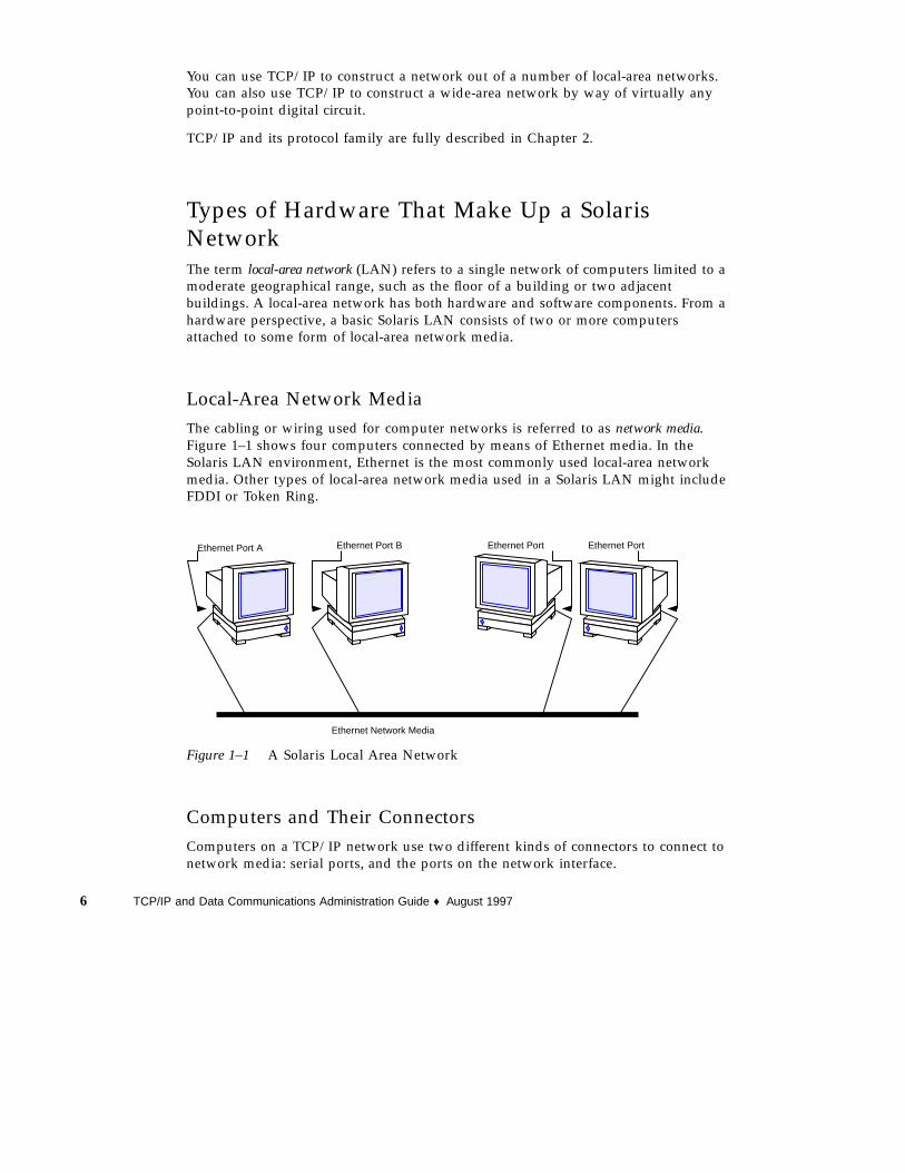
Local-Area Network MediaThe cabling or wiring used for computer networks is referred to as network media.Figure 1–1 shows four computers connected by means of Ethernet media. In theSolaris LAN environment, Ethernet is the most commonly used local-area networkmedia. Other types of local-area network media used in a Solaris LAN might includeFDDI or Token Ring.
Ethernet Port
Ethernet Network Media
Ethernet Port A Ethernet Port B Ethernet Port
Figure 1–1 A Solaris Local Area Network
Computers and Their ConnectorsComputers on a TCP/IP network use two different kinds of connectors to connect tonetwork media: serial ports, and the ports on the network interface.
6 TCP/IP and Data Communications Administration Guide ♦ August 1997

Serial PortsEach computer has at least two serial ports, the connectors that enable you to plug aprinter or modem into the computer. The serial ports may be attached to the CPUboard, or you may have to purchase them. You use these ports when attaching amodem to the system to establish a PPP or UUCP connection. PPP and UUCPactually provide wide-area network services, since they may use telephone lines astheir network media.
Network InterfacesThe hardware in a computer that enables you to connect it to a network is known asa network interface. Many computers come with a preinstalled network interface;others may require you to purchase the network interface separately.
Each LAN media type has its own associated network interface. For example, if youwant to use Ethernet as your network media, you must have an Ethernet interfaceinstalled in each host to be part of the network. The connectors on the board towhich you attach the Ethernet cable are referred to as Ethernet ports. If you plan touse FDDI, each prospective host must have an FDDI network interface, and so on.
This book refers to the default network interface on a host as the primary networkinterface.
Note - Installing network hardware is outside the scope of this guide. Refer toSystem Administration Guide for instructions for configuring serial ports and manualsaccompanying network media for installation instructions.
How Network Software Transfers InformationSetting up network software is an involved task. Therefore, it helps to understandhow the network software you are about to set up will transfer information.
Figure 1–2 shows the basic elements involved in network communication.
Overview of Network Administration 7

Sending Host Receiving Host
Packet
Header
Message
Figure 1–2 How Information Is Transferred on a Network
In this figure, a computer sends a packet over the network media to anothercomputer attached to the same media.
How Information Is Transferred: The PacketThe basic unit of information to be transferred over the network is referred to as apacket. A packet is organized much like a conventional letter.
Each packet has a header, which corresponds to the envelope. The header contains theaddresses of the recipient and the sender, plus information on how to handle thepacket as it travels through each layer of the protocol suite.
The message part of the packet corresponds to the letter itself. Packets can onlycontain a finite number of bytes of data, depending on the network media in use.Therefore, typical communications such as email messages are sometimes split intopacket fragments.
Who Sends and Receives Information: The HostIf you are an experienced Solaris user, you are no doubt familiar with the term“host,” a word often used as a synonym for “computer” or “machine.” From a TCP/IP perspective, only two types of entities exist on a network: routers and hosts.
A router is a machine that forwards packets from one network to another. To do this,the router must have at least two network interfaces. A machine with only onenetwork interface cannot forward packets; it is considered a host. Most of themachines you set up on a network will be hosts.
It is possible for a machine to have more than one network interface but not functionas a router. This type of machine is called a multihomed host. A multihomed host isdirectly connected to multiple networks through its network interfaces. However, itdoes not route packets from one network to another.
When a host initiates communication, it is called a sending host, or the sender. Forexample, a host initiates communications when its user types rlogin or sends anemail message to another user. The host that is the target of the communication is
8 TCP/IP and Data Communications Administration Guide ♦ August 1997

called the receiving host, or recipient. For example, the remote host specified as theargument to rlogin is the recipient of the request to log in.
Each host has three characteristics that help identify it to its peers on the network.These characteristics include:
� Host name
� Internet address, or IP address, the form used in this book
� Hardware address
Host NameThe host name is the name of the local machine, combined with the name of yourorganization. Many organizations let users choose the host names for their machines.Programs such as sendmail and rlogin use host names to specify remotemachines on a network. System Administration Guide contains more informationabout host names.
The host name of the machine also becomes the name of the primary networkinterface. This concept becomes important when you set up the network databases orconfigure routers.
When setting up a network, you must obtain the host names of all machines to beinvolved. You will use this information when setting up network databases, asdescribed in Chapter 4.
IP AddressThe IP address is one of the two types of addresses each machine has on a TCP/IPnetwork that identifies the machine to its peers on the network. This address alsogives peer hosts a notion of where a particular host is located on the network. If youhave installed the Solaris operating environment on a machine on a network, youmay recall specifying the IP address during the installation process. IP addressing isa significant aspect of TCP/IP and is explained fully in “Designing Your IPAddressing Scheme” on page 34.
Hardware AddressEach host on a network has a hardware address, which also identifies it to its peers.This address is physically assigned to the machine’s CPU or network interface by themanufacturer. Each hardware address is unique.
This book uses the term Ethernet address to correspond to the hardware address.Because Ethernet is the most commonly used network media on Solaris-basednetworks, the text assumes that the hardware address of your Solaris host is anEthernet address. If you are using other network media, such as FDDI, refer to thedocumentation that came with your media for hardware addressing information.
Overview of Network Administration 9

Reaching Beyond the Local-Area Network—theWide-Area NetworkAs your network continues to function successfully, users may need to accessinformation available from other companies, institutes of higher learning, and otherorganizations not on your LAN. To obtain this information, they may need tocommunicate over a wide-area network (WAN), a network that covers a potentiallyvast geographic area and uses network media such as leased data or telephone lines,X.25, and ISDN services.
A prime example of a WAN is the Internet, the global public network that is thesuccessor to the WANs for which TCP/IP was originally developed. Other examplesof WANs are enterprise networks, linking the separate offices of a single corporationinto one network spanning an entire country, or perhaps an entire continent. It isentirely possible for your organization to construct its own WAN.
As network administrator, you may have to provide access to WANs to the users onyour local net. Within the TCP/IP and UNIX community, the most commonly usedpublic network has been the Internet. Information about directly connecting to theInternet is outside the scope of this book. You can find many helpful books on thissubject in a computer bookstore.
SecurityConnecting a LAN to a WAN poses some security risks. You must make sure yournetwork is protected from unauthorized use, and control access to data andresources. An overview of security issues is provided in the System AdministrationGuide. Further help can be found in Firewalls and Internet Security by William R.Cheswick and Steven M Bellovin (Addison Wesley, 1994).
You can also become informed by subscribing to [email protected] ,citing subscribe firewalls in the text. If you prefer the shorter version, citefirewalls_digest in the text.
TCP Large Window SupportTCP large windows provides the support described in RFC1323. This support isdesigned to improve performance over large bandwidth or delay networks such asATM or satellite networks by using windows that exceed the normal 65535 limit.
This support expands the amount of data that can be outstanding in a TCP sessionfrom 65,535 bytes to approximately 1 Gigabyte.
TCP large window supports a number of TCP configuration parameters which allowa system administrator to enable the use of enhanced send and receive window sizesand the RFC1323 timestamp option, without having to modify the applications.These changes can be made on a system-wide basis or can be customized for
10 TCP/IP and Data Communications Administration Guide ♦ August 1997

particular hosts or networks. This is especially useful when using standard networkutilities such as ftp and rcp which do not provide facilities to increase the buffersizes they use.
TCP Large Window ParametersThe configuration parameters are associated with the TCP device, /dev/tcp, andmay be inspected or modified using ndd (5). Normally, these parameters would be setin one of the shell scripts executed by init (1M) when the system is booted (seeinit.d (4) for information on how to add a new script).
A list of the available parameters and their meaning are.
tcp_xmit_hiwat Specifies the default value for a connection’s sendbuffer space. The default is 8K.
tcp_recv_hiwat Specifies the default value for a connection’sreceive buffer space; that is, the amount of bufferspace allocated for received data (and thus themaximum possible advertised receive window).The default is 8K.
tcp_wscale_always If this parameter is nonzero, a window scaleoption is always sent when connecting to aremote system. Otherwise, the option will be sentif-and-only-if the user has requested a receivewindow larger than 64K. The default is zero.
Regardless of the value of this parameter, awindow scale option is always included in aconnect acknowledgment if the connectingsystem has used the option.
tcp_tstamp_always If this parameter is nonzero, a timestamp optionis always sent when connecting to a remotesystem. The default is zero.
Regardless of the value of this parameter, atimestamp option is always included in a connectacknowledgment (and all succeeding packets) ifthe connecting system has used the option.
tcp_tstamp_if_wscale If this parameter is nonzero, the timestampoption is sent when connecting to a remotesystem if the user has requested a receivewindow larger than 64K (that is, if a windowscale option with a nonzero scale is being used).The default is zero.
Overview of Network Administration 11

tcp_max_buf Specifies the maximum buffer size a user isallowed to specify with the SO_SNDBUForSO_RCVBUFoptions. Attempts to use largerbuffers fail with EINVAL. The default is 256K. Itis unwise to make this parameter much largerthan the maximum buffer size your applicationsrequire, since that could allow malfunctioning ormalicious applications to consume unreasonableamounts of kernel memory.
tcp_host_param This parameter is a table of IP addresses,networks, and subnetworks, along with defaultvalues for certain TCP parameters to be used onconnections with the specified hosts. The tablecan be displayed with the ndd command asfollows:
example# ndd /dev/tcp tcp_host_paramHash HSP Address Subnet Mask Send Receive TStamp027 fc31eea4 129.154.000.000 255.255.255.000 0000008192 0000008192 0131 fc308244 129.154.152.000 000.000.000.000 0000032000 0000032000 0133 fc30bd64 129.154.152.006 000.000.000.000 0000128000 0000128000 1
Each element in the table specifies either a host, a network (with optional subnetmask), or a subnet, along with the default send buffer space and receive buffer space,and a flag indicating whether timestamps are to be used.
The default values specified in the table are used for both active and passiveconnections (that is, both connect() and listen() ). The most applicable matchfound is used; first the full host address, then the subnet, and finally the network.For subnet recognition to work properly, there must be an entry for that subnet’snetwork which specifies the subnet mask.
The example table above specifies that:
� Connections with host 129.154.152.6 uses send and receive buffer sizes of 128000bytes, and will use timestamps.
� Connections with other hosts on the 129.154.152 subnet uses send and receivebuffer sizes of 32000 bytes.
� Connections with other hosts on the 129.154 network uses send and receive buffersizes of 8192 bytes.
Elements are added to or removed from the table with ndd as follows:
12 TCP/IP and Data Communications Administration Guide ♦ August 1997

ndd -set /dev/tcp tcp_host_param ’<command>’
where <command> is either:
<ipaddr> [ mask <ipmask>] [ sendspace <integer> ][ recvspace <integer> ] [ timestamp { 0 | 1 } ]
or
<ipaddr> delete
For example, the table above was created by:
example# ndd -set /dev/tcp tcp_host_param ’129.154.0.0 mask 255.255.255.0 sendspace 8192 recvspace 8192’
example# ndd -set /dev/tcp tcp_host_param ’129.154.152.0 sendspace 32000 recvspace 32000’
example# ndd -set /dev/tcp tcp_host_param ’129.154.152.6 sendspace 128000 recvspace 128000 timestamp 1’
It could be removed by:
example# ndd -set /dev/tcp tcp_host_param ’129.154.152.6 delete’
example# ndd -set /dev/tcp tcp_host_param ’129.154.152.0 delete’
example# ndd -set /dev/tcp tcp_host_param ’129.154.0.0 delete’
Networks and subnets are specified by leaving the host bits zero. The same syntaxused to add entries can also be used to modify existing entries.
The send and receive space values from the tcp_host_param table will only beused if they are larger than the values set by the user (or obtained fromtcp_xmit_hiwat and tcp_recv_hiwat ). This is so that the user can specify largervalues for improved throughput and not have them erroneously reduced.
Overview of Network Administration 13

If timestamp value in the tcp_host_param table is 1, the timestamp option will besent to the selected host or hosts when a connection is initiated. However, if thevalue is 0, the timestamp option may still be sent, depending on the settings of thetcp_tstamp_always and tcp_tstamp_if_wscale options.
14 TCP/IP and Data Communications Administration Guide ♦ August 1997

CHAPTER 2
TCP/IP Protocol Suite
This chapter introduces the Solaris implementation of the TCP/IP network protocolsuite. The information is particularly geared to network administrators who areunfamiliar with the TCP/IP. (For an introduction to basic network concepts, seeChapter 1.) If you are an experienced TCP/IP network administrator, considermoving on to chapters covering the tasks you want to perform.
� “Protocol Layers and the OSI Model” on page 16
� “TCP/IP Protocol Architecture Model” on page 17
� “Standard TCP/IP Services” on page 20
� “Data Encapsulation and the TCP/IP Protocol Stack” on page 23
Introducing the Internet Protocol SuiteThis section presents an in-depth introduction to the protocols that compose TCP/IP.Although the information is conceptual, you should learn the names of the protocolsand what each does. This is important because TCP/IP books explain tasks with theassumption that you understand the concepts introduced here.
TCP/IP is the commonly used nickname for the set of network protocols composingthe Internet Protocol suite. Many texts use the term “Internet” to describe both theprotocol suite and the global wide-area network. In this book, the “TCP/IP” refersspecifically to the Internet protocol suite; “Internet” refers to the wide-area networkand the bodies that govern it.
To interconnect your TCP/IP network with other networks, you must obtain aunique IP network number. At the time of this writing, IP network numbers areassigned by an organization known as the InterNIC.
15

If hosts on your network are going to participate in the Internet Domain Namesystem (DNS), you must obtain and register a unique domain name. The InterNICalso handles the registration of domain names under certain top-level domains suchas .com (commercial), .edu (education), and .gov (government). Chapter 3, containsmore information about the InterNIC. (For more information on DNS, refer to SolarisNaming Administration Guide.)
Protocol Layers and the OSI ModelMost network protocol suites are structured as a series of layers, sometimes referredto collectively as a protocol stack. Each layer is designed for a specific purpose andexists on both the sending and receiving hosts. Each is designed so that a specificlayer on one machine sends or receives exactly the same object sent or received by itspeer process on another machine. These activities take place independently from whatis going on in layers above or below the layer under consideration. In other words,each layer on a host acts independently of other layers on the same machine, and inconcert with the same layer on other hosts.
OSI Reference ModelMost network protocol suites are viewed as structured in layers. This is a result ofthe Open Systems Interconnect (OSI) Reference Model designed by the InternationalStandards Organization (ISO). The OSI model describes network activities as havinga structure of seven layers, each of which has one or more protocols associated withit. The layers represent data transfer operations common to all types of data transfersamong cooperating networks.
The protocol layers of the OSI Reference Model are traditionally listed from the top(layer 7) to the bottom (layer 1) up, as shown in Table 2–1.
TABLE 2–1 The Open Systems Interconnect Reference Model
Layer No. Layer Name Description
7 Application Consists of standard communication services andapplications that everyone can use.
6 Presentation Ensures that information is delivered to the receivingmachine in a form that it can understand.
5 Session Manages the connections and terminations betweencooperating computers.
4 Transport Manages the transfer of data and assures that receivedand transmitted data are identical.
16 TCP/IP and Data Communications Administration Guide ♦ August 1997

TABLE 2–1 The Open Systems Interconnect Reference Model (continued)
Layer No. Layer Name Description
3 Network Manages data addressing and delivery between networks.
2 Data Link Handles the transfer of data across the network media.
1 Physical Defines the characteristics of the network hardware.
The operations defined by the OSI model are conceptual and not unique to anyparticular network protocol suite. For example, the OSI network protocol suiteimplements all seven layers of the OSI Reference Model. TCP/IP uses some of OSImodel layers and combines others. Other network protocols, such as SNA, add aneighth layer.
TCP/IP Protocol Architecture ModelThe OSI model describes an idealized network communications protocol family.TCP/IP does not correspond to this model directly, as it either combines several OSIlayers into a single layer, or does not use certain layers at all. Table 2–2 shows thelayers of the Solaris implementation of TCP/IP, listed from topmost layer(application) to lowest (physical network).
TABLE 2–2 TCP/IP Protocol Stack
OSI Ref.Layer No.
OSI LayerEquivalent
TCP/IP Layer TCP/IP Protocol Examples
5,6,7 Application,Session,Presentation
Application NFS, NIS+, DNS, telnet , ftp , “r”commands1 , RIP, RDISC, SNMP, others
4 Transport Transport TCP, UDP
3 Network Internet IP, ARP, ICMP
2 Data Link Data Link PPP, IEEE 802.2
1 Physical PhysicalNetwork
Ethernet (IEEE 802.3) Token Ring, RS-232,others
1. “r” commands include rlogin , rsh , and rcp .
TCP/IP Protocol Suite 17

The table shows the TCP/IP protocol layers, their OSI Model equivalents, andexamples of the protocols available at each level of the TCP/IP protocol stack. Eachhost involved in a communication transaction runs its own implementation of theprotocol stack.
Physical Network LayerThe physical network layer specifies the characteristics of the hardware to be usedfor the network. For example, it specifies the physical characteristics of thecommunications media. The physical layer of TCP/IP describes hardware standardssuch as IEEE 802.3, the specification for Ethernet network media, and RS-232, thespecification for standard pin connectors.
Data-Link LayerThe data-link layer identifies the network protocol type of the packet, in this caseTCP/IP. It also provides error control and “framing.” Examples of data-link layerprotocols are Ethernet IEEE 802.2 framing and Point-to-Point Protocol (PPP) framing.
Internet LayerThis layer, also known as the network layer, accepts and delivers packets for thenetwork. It includes the powerful Internet protocol (IP), the ARP protocol, and theICMP protocol.
IP ProtocolThe IP protocol and its associated routing protocols are possibly the most significantof the entire TCP/IP suite. IP is responsible for:
� IP addressing - The IP addressing conventions are part of the IP protocol. (Chapter3, describes IP addressing in complete detail.)
� Host-to-host communications - IP determines the path a packet must take, based onthe receiving host’s IP address.
� Packet formatting - IP assembles packets into units known as IP datagrams.Datagrams are fully described in “Internet Layer” on page 25.
� Fragmentation - If a packet is too large for transmission over the network media, IPon the sending host breaks the packet into smaller fragments. IP on the receivinghost then reconstructs the fragments into the original packet.
18 TCP/IP and Data Communications Administration Guide ♦ August 1997

ARP ProtocolThe Address Resolution Protocol (ARP) conceptually exists between the data linkand Internet layers. ARP assists IP in directing datagrams to the appropriatereceiving host by mapping Ethernet addresses (48 bits long) to known IP addresses(32 bits long).
ICMP ProtocolInternet Control Message Protocol (ICMP) is the protocol responsible for detectingnetwork error conditions and reporting on them. ICMP reports on:
� Dropped packets (when packets are arriving too fast to be processed)
� Connectivity failure (when a destination host can’t be reached)
� Redirection (which tells a sending host to use another router)
Chapter 6, contains more information on the operating system commands that useICMP for error detection.
Transport LayerThe TCP/IP transport layer protocols ensure that packets arrive in sequence andwithout error, by swapping acknowledgments of data reception, and retransmittinglost packets. This type of communication is known as “end-to-end.” Transport layerprotocols at this level are Transmission Control Protocol (TCP) and User DatagramProtocol (UDP).
TCP ProtocolTCP enables applications to communicate with each other as though connected by aphysical circuit. TCP sends data in a form that appears to be transmitted in acharacter-by-character fashion, rather than as discreet packets. This transmissionconsists of a starting point, which opens the connection, the entire transmission inbyte order, and an ending point, which closes the connection.
TCP attaches a header onto the transmitted data. This header contains a largenumber of parameters that help processes on the sending machine connect to peerprocesses on the receiving machine.
TCP confirms that a packet has reached its destination by establishing an end-to-endconnection between sending and receiving hosts. TCP is therefore considered a“reliable, connection-oriented” protocol.
TCP/IP Protocol Suite 19

UDP ProtocolUDP, the other transport layer protocol, provides datagram delivery service. It doesnot provide any means of verifying that connection was ever achieved betweenreceiving and sending hosts. Because UDP eliminates the processes of establishingand verifying connections, applications that send small amounts of data use it ratherthan TCP.
Application LayerThe application layer defines standard Internet services and network applicationsthat anyone can use. These services work with the transport layer to send andreceive data. There are many applications layer protocols, some of which youprobably already use. Some of the protocols include:
� Standard TCP/IP services such as the ftp , tftp , and telnet commands
� UNIX “r” commands, such as rlogin and rsh
� Name services, such as NIS+ and Domain Name System (DNS)
� File services, such as NFS
� Simple Network Management Protocol (SNMP), which enables networkmanagement
� RIP and RDISC routing protocols
Standard TCP/IP Services� FTP and Anonymous FTP - The File Transfer Protocol (FTP) transfers files to and
from a remote network. The protocol includes the ftp command (local machine)and the in.ftpd daemon (remote machine). FTP enables a user to specify thename of the remote host and file transfer command options on the local host’scommand line. The in.ftpd daemon on the remote host then handles therequests from the local host. Unlike rcp , ftp works even when the remotecomputer does not run a UNIX-based operating system. A user must log in to theremote computer to make an ftp connection unless it has been set up to allowanonymous FTP.
You can now obtain a wealth of materials from anonymous FTP servers connected tothe Internet. These servers are set up by universities and other institutions to makecertain software, research papers, and other information available to the publicdomain. When you log in to this type of server, you use the login nameanonymous , hence the term “anonymous FTP servers.”
Using anonymous FTP and setting up anonymous FTP servers is outside the scopeof this manual. However, many trade books, such as The Whole Internet User’sGuide & Catalog, discuss anonymous FTP in detail. Instructions for using FTP toreach standard machines are in System Administration Guide. The ftp (1) man
20 TCP/IP and Data Communications Administration Guide ♦ August 1997
page describes all ftp command options, including those invoked through thecommand interpreter. The ftpd (1M) man page describes the services provided bythe daemon in.ftpd .
� Telnet - The Telnet protocol enables terminals and terminal-oriented processes tocommunicate on a network running TCP/IP. It is implemented as the programtelnet (on local machines) and the daemon in.telnet (on remote machines).Telnet provides a user interface through which two hosts can communicate on acharacter-by-character or line-by-line basis. The application includes a set ofcommands that are fully documented in the telnet (1) man page.
� TFTP - The trivial file transfer protocol (tftp ) provides functions similar to ftp ,but it does not establish ftp ’s interactive connection. As a result, users cannot listthe contents of a directory or change directories. This means that a user mustknow the full name of the file to be copied. The tftp (1) man page describes thetftp command set.
UNIX “r” CommandsThe UNIX “r” commands enable users to issue commands on their local machinesthat are actually carried out on the remote host that they specify. These commandsinclude
� rcp
� rlogin
� rsh
Instructions for using these commands are in Solaris Advanced User’s Guide and inrcp (1), rlogin (1), and rsh (1) man pages.
Name ServicesTwo name services are available from the Solaris implementation of TCP/IP: NIS+and DNS.
� NIS+ - NIS+ provides centralized control over network administration services,such as mapping host names to IP and Ethernet addresses, verifying passwords,and so on. See Solaris Naming Administration Guide for complete details.
� Domain Name System - The Domain Name System (DNS) provides host names tothe IP address service. It also serves as a database for mail administration. For acomplete description of this service, see Solaris Naming Administration Guide. Seealso the in.named (1M) man page.
TCP/IP Protocol Suite 21

File ServicesThe NFS application layer protocol provides file services for the Solaris operatingenvironment. You can find complete information about the NFS service in NFSAdministration Guide.
Network AdministrationThe Simple Network Management Protocol (SNMP) enables you to view the layoutof your network, view status of key machines, and obtain complex network statisticsfrom graphical user interface based software. Many companies offer networkmanagement packages that implement SNMP; SunNet ManagerTM software is anexample.
Routing ProtocolsThe Routing Information Protocol (RIP) and the Router Discovery Protocol (RDISC)are two routing protocols for TCP/IP networks. They are described in Chapter 5.
How the TCP/IP Protocols Handle DataCommunicationsWhen a user issues a command that uses a TCP/IP application layer protocol, achain of events is set in motion. The user’s command or message passes through theTCP/IP protocol stack on the local machine, and then across the network media tothe protocols on the recipient. The protocols at each layer on the sending host addinformation to the original data.
As the user’s command makes its way through the protocol stack, protocols on eachlayer of the sending host also interact with their peers on the receiving host. Figure2–1 shows this interaction.
22 TCP/IP and Data Communications Administration Guide ♦ August 1997

Application Layer
Transport Layer
Internet Layer
Data Link
Physical
Application Layer
Transport Layer
Internet Layer
Data Link
Physical
Sending Host
Peer Processes
Receiving Host
& rlogin host
TCP segment
IP datagram
Frame Frame
IP datagram
TCP segment
Receivesrequest forlogin
Network Media
Network Layer Network Layer Frame Frame
packet
Layer Layer
Figure 2–1 How a Packet Travels Through the TCP/IP Stack
Data Encapsulation and the TCP/IP Protocol StackThe packet is the basic unit of information transferred across a network, consisting,at a minimum, of a header with the sending and receiving hosts’ addresses, and abody with the data to be transferred. As the packet travels through the TCP/IPprotocol stack, the protocols at each layer either add or remove fields from the basicheader. When a protocol on the sending host adds data to the packet header, theprocess is called data encapsulation. Moreover, each layer has a different term for thealtered packet, as shown in Figure 2–1.
This section summarizes the life cycle of a packet from the time the user issues acommand or sends a message to the time it is received by the appropriateapplication on the receiving host.
Application Layer—User Initiates CommunicationThe packet’s history begins when a user on one host sends a message or issues acommand that must access a remote host. The application protocol associated withthe command or message formats the packet so that it can be handled by theappropriate transport layer protocol, TCP or UDP.
Suppose the user issues an rlogin command to log in to the remote host, as shownin Figure 2–1. The rlogin command uses the TCP transport layer protocol. TCPexpects to receive data in the form of a stream of bytes containing the information inthe command. Therefore, rlogin sends this data as a TCP stream.
TCP/IP Protocol Suite 23

Not all application layer protocols use TCP, however. Suppose a user wants to mounta file system on a remote host, thus initiating the NIS+ application layer protocol.NIS+ uses the UDP transport layer protocol. Therefore, the packet containing thecommand must be formatted in a manner that UDP expects. This type of packet isreferred to as a message.
Transport Layer—Data Encapsulation BeginsWhen the data arrives at the transport layer, the protocols at the layer start theprocess of data encapsulation. The end result depends on whether TCP or UDP hashandled the information.
TCP Segmentation
TCP is often called a “connection-oriented” protocol because it ensures the successfuldelivery of data to the receiving host. Figure 2–1 shows how the TCP protocolreceives the stream from the rlogin command. TCP divides the data received fromthe application layer into segments and attaches a header to each segment.
Segment headers contain sender and recipient ports, segment ordering information,and a data field known as a checksum. The TCP protocols on both hosts use thechecksum data to determine whether data has transferred without error.
Establishing a TCP Connection
In addition, TCP uses segments to determine whether the receiving host is ready toreceive the data. When the sending TCP wants to establish connections, it sends asegment called a SYN to the peer TCP protocol running on the receiving host. Thereceiving TCP returns a segment called an ACK to acknowledge the successful receiptof the segment. The sending TCP sends another ACK segment, then proceeds to sendthe data. This exchange of control information is referred to as a three-way handshake.
UDP Packets
UDP is a “connectionless” protocol. Unlike TCP, it does not check to make sure thatdata arrived at the receiving host. Instead, UDP takes the message received from theapplication layer and formats it into UDP packets. UDP attaches a header to eachpacket, which contains the sending and receiving host ports, a field with the lengthof the packet, and a checksum.
The sending UDP process attempts to send the packet to its peer UDP process on thereceiving host. The application layer determines whether the receiving UDP processacknowledges that the packet was received. UDP requires no notification of receipt.UDP does not use the three-way handshake.
24 TCP/IP and Data Communications Administration Guide ♦ August 1997

Internet LayerAs shown in Figure 2–1, both TCP and UDP pass their segments and packets downto the Internet layer, where they are handled by the IP protocol. IP prepares them fordelivery by formatting them into units called IP datagrams. IP then determines theIP addresses for the datagrams, so they can be delivered effectively to the receivinghost.
IP Datagrams
IP attaches an IP header to the segment or packet’s header in addition to theinformation added by TCP or UDP. Information in the IP header includes the IPaddresses of the sending and receiving hosts, datagram length, and datagramsequence order. This information is provided in case the datagram exceeds theallowable byte size for network packets and must be fragmented.
Data-Link Layer—Framing Takes PlaceData-link layer protocols such as PPP format the IP datagram into a frame. Theyattach a third header and a footer to “frame” the datagram. The frame headerincludes a cyclical redundancy check (CRC) field that checks for errors as the frametravels over the network media. Then the data-link layer passes the frame to thephysical layer.
Physical Network Layer—Preparing the Frame forTransmissionThe physical network layer on the sending host receives the frames and converts theIP addresses into the hardware addresses appropriate to the network media. Thephysical network layer then sends the frame out over the network media.
How the Receiving Host Handles the PacketWhen the packet arrives on the receiving host, it travels through the TCP/IP protocolstack in the reverse order from that which it took on the sender. Figure 2–1 illustratesthis path. Moreover, each protocol on the receiving host strips off header informationattached to the packet by its peer on the sending host. Here is what happens.
1. Physical Network Layer receives the packet in its frame form. It computes theCRC of the packet, then sends the frame to the data link layer.
2. Data-Link Layer verifies that the CRC for the frame is correct and strips off theframe header and CRC. Finally, the data link protocol sends the frame to theInternet layer.
TCP/IP Protocol Suite 25

3. Internet Layer reads information in the header to identify the transmission anddetermine if it is a fragment. If the transmission was fragmented, IP reassemblesthe fragments into the original datagram. It then strips off the IP header andpasses the datagram on to transport layer protocols.
4. Transport Layer (TCP and UDP) reads the header to determine which applicationlayer protocol must receive the data. Then TCP or UDP strips off its relatedheader and sends the message or stream up to the receiving application.
5. Application Layer receives the message and performs the operation requested bythe sending host.
Finding Out More About TCP/IP andthe InternetA great deal of information about TCP/IP and the Internet has been published. Ifyou require specific information that is not covered in this text, you probably canfind what you need in the sources cited below.
Computer Trade BooksMany books about TCP/IP and the Internet are available from your local library orcomputer bookstore. Three highly recommended books are
� Craig Hunt. TCP/IP Network Administration - This book contains some theory andmuch practical information for managing a heterogeneous TCP/IP network.
� W. Richard Stevens. TCP/IP Illustrated, Volume I - This book is an in-depthexplanation of the TCP/IP protocols. It is ideal for network administratorsrequiring a technical background in TCP/IP and for network programmers.
� Ed Krol. The Whole Internet User’s Guide & Catalog - This book is ideal for anyoneinterested in using the many tools available for retrieving information over theInternet.
RFCs and FYIsSince 1969, developers working on the Internet protocol suite have described theirprotocols and related subjects in documents known as Requests for Comments(RFCs). Many RFCs are specifications for particular TCP/IP protocols and describestandards with which software implementing the protocols must comply. Other RFCsdiscuss the Internet, its topology, and its governing bodies. Still other RFCs explainhow to manage TCP/IP applications, such as DNS.
26 TCP/IP and Data Communications Administration Guide ♦ August 1997
All RFCs must be approved by the Internet Architecture Board (IAB) before they areplaced in the public domain. Typically, the information in RFCs is geared todevelopers and other highly technical readers, though this isn‘t always the case.
In recent years, For Your Information (FYI) documents have appeared as a subset ofthe RFCs. The FYIs contain information that does not deal with Internet standards;rather, they contain Internet information of a more general nature. For example, FYIdocuments include a bibliography listing introductory TCP/IP books and papers, anexhaustive compendium of Internet-related software tools, and a glossary of Internetand general networking terms.
You’ll find references to relevant RFCs throughout this guide and other books in theSolaris 2.6 System Administrator set.
How to Obtain RFCsThe InterNIC Directory and Database Service maintains the repository of RFCs. Ifyou have a connection to the Internet, you can retrieve online RFCs as follows:
� Through ftp , by sending your requests to the InterNIC directory and databaseserver ds.internic.net . Your request should have the format:
rfc/rfc. rfcnum.txt or rfc/rfc. rfcnum.ps
where rfcnum represents the number of the RFC you want. For example, if youwanted to retrieve RFC 1540 in PostScript® format, you would requestrfc/rfc.1540.ps .
� Through electronic mail, by emailing [email protected] . This is anautomatic server that expects the body of your request message to have the format:
document-by-name rfc rfcnum or document-by-name rfc rfcnum.ps
� Through a World Wide Web browser, by specifying the URLhttp://ds.internic.net/ds/dspg1intdoc.html . The home page ishttp://ds.internic.net
If you need an online index of RFCs, send electronic mail to ds.internic.net with amessage containing the request document-by-name rfc-index .
Note - The InterNIC information above is current as of this writing. However, theInternet is expanding at a fast pace, and the addresses listed might no longer becurrent when you read this manual.
TCP/IP Protocol Suite 27

28 TCP/IP and Data Communications Administration Guide ♦ August 1997

CHAPTER 3
Planning Your Network
This chapter describes the issues you must resolve in order to create your network inan organized, cost-effective manner. After you have resolved these issues, you candevise a plan for your network to follow as you set it up and administer it in thefuture.
� “Designing the Network” on page 29
� “Designing Your IP Addressing Scheme” on page 34
� “Registering Your Network” on page 38
� “Naming Entities on Your Network” on page 35
� “Adding Routers” on page 39
� “Network Topology” on page 39
If you are unfamiliar with TCP/IP fundamentals, refer to Chapter 2.
Designing the NetworkThe first phase in the life of a network—designing the network—involves makingdecisions about the type of network that best suits the needs of your organization.Some of the planning decisions you make will involve network hardware; forexample:
� Number of host machines your network can support
� Type of network media to use: Ethernet, token ring, FDDI, and so on
� Network topology; that is, the physical layout and connections of the networkhardware
� Types of hosts the network will support: standalone, diskless, and dataless
29
Based on these factors, you can determine the size of your local-area network.
Note - Planning the network hardware is outside the scope of this manual. Refer tothe manuals that came with your hardware for assistance.
Factors Involved in Network PlanningAfter you have completed your hardware plan, you are ready to begin networkplanning, from the software perspective.
As part of the planning process you must:
1. Obtain a network number and, if applicable, register your network domain withthe InterNIC.
2. Devise an IP addressing scheme for your hosts, after you receive your IP networknumber.
3. Create a list containing the IP addresses and host names of all machines thatmake up your network, which you can use as you build network databases.
4. Determine which name service to use on your network: NIS, NIS+, DNS, or thenetwork databases in the local /etc directory.
5. Establish administrative subdivisions, if appropriate for your network.
6. Determine if your network is large enough to require routers, and, if appropriate,create a network topology that supports them.
7. Set up subnets, if appropriate for your network.
The remainder of Chapter 3, explains how to plan your network with these factors inmind.
Setting Up an IP Addressing SchemeThe number of machines you expect to support will affect several decisions you willneed to make at this stage of setting up a network for your site. Your organizationmay require a small network of several dozen standalone machines located on onefloor of a single building. Alternatively, you may need to set up a network with morethan 1000 hosts in several buildings. This arrangement may require you to furtherdivide your network into subdivisions called subnets. The size of your prospectivenetwork will affect the
� Network class you apply for
� Network number you receive
� IP addressing scheme you use for your network
30 TCP/IP and Data Communications Administration Guide ♦ August 1997

Obtaining a network number and then establishing an IP addressing scheme is oneof the most important tasks of the planning phase of network administration.
Parts of the IP AddressEach network running TCP/IP must have a unique network number, and everymachine on it must have a unique IP address. It is important to understand how IPaddresses are constructed before you register your network and obtain its networknumber.
The IP address is a 32-bit number that uniquely identifies a network interface on amachine. An IP address is typically written in decimal digits, formatted as four 8-bitfields separated by periods. Each 8-bit field represents a byte of the IP address. Thisform of representing the bytes of an IP address is often referred to as thedotted-decimal format.
The bytes of the IP address are further classified into two parts: the network part andthe host part. Figure 3–1 shows the component parts of a typical IP address,129.144.50.56.
129.144. 50. 56
network part host part
Figure 3–1 Parts of an IP Address
Network PartThis part specifies the unique number assigned to your network. It also identifies theclass of network assigned. In Figure 3–1, the network part takes up two bytes of theIP address.
Host PartThis is the part of the IP address that you assign to each host. It uniquely identifiesthis machine on your network. Note that for each host on your network, the networkpart of the address will be the same, but the host part must be different.
Subnet Number (Optional)Local networks with large numbers of hosts are sometimes divided into subnets. Ifyou choose to divide your network into subnets, you need to assign a subnet number
Planning Your Network 31

for the subnet. You can maximize the efficiency of the IP address space by usingsome of the bits from the host number part of the IP address as a network identifier.When used as a network identifier, the specified part of the address becomes thesubnet number. You create a subnet number by using a netmask, which is a bit maskthat selects the network and subnet parts of an IP address. (Refer to “Creating theNetwork Mask” on page 53 for full details.)
Network ClassesThe first step in planning for IP addressing on your network is to determine whichnetwork class is appropriate for your network. After you have done this, you cantake the crucial second step: obtain the network number from the InterNICaddressing authority.
Currently there are three classes of TCP/IP networks. Each class uses the 32-bit IPaddress space differently, providing more or fewer bits for the network part of theaddress. These classes are class A, class B, and class C.
Class A Network NumbersA class A network number uses the first eight bits of the IP address as its “networkpart.” The remaining 24 bits comprise the host part of the IP address, as illustrated inFigure 3–2 below.
Class A Address
Network Part Host Part
0 7-8 15-16 23-24 31bits:
Figure 3–2 Byte Assignment in a Class A Address
The values assigned to the first byte of class A network numbers fall within therange 0–127. Consider the IP address 75.4.10.4. The value 75 in the first byte indicatesthat the host is on a class A network. The remaining bytes, 4.10.4, establish the hostaddress. The InterNIC assigns only the first byte of a class A number. Use of theremaining three bytes is left to the discretion of the owner of the network number.Only 127 class A networks can exist. Each one of these numbers can accommodateup to 16,777,214 hosts.
Class B Network NumbersA class B network number uses 16 bits for the network number and 16 bits for hostnumbers. The first byte of a class B network number is in the range 128–191. In thenumber 129.144.50.56, the first two bytes, 129.144, are assigned by the InterNIC, and
32 TCP/IP and Data Communications Administration Guide ♦ August 1997

comprise the network address. The last two bytes, 50.56, make up the host address,and are assigned at the discretion of the owner of the network number. Figure 3–3graphically illustrates a class B address.
0 7-8 15-16 23-24 31bits:
Class B Address
Network Part Host Part
Figure 3–3 Byte Assignment in a Class B Address
Class B is typically assigned to organizations with many hosts on their networks.
Class C Network NumbersClass C network numbers use 24 bits for the network number and 8 bits for hostnumbers. Class C network numbers are appropriate for networks with fewhosts—the maximum being 254. A class C network number occupies the first threebytes of an IP address. Only the fourth byte is assigned at the discretion of thenetwork owners. Figure 3–4 graphically represents the bytes in a class C address.
0 7-8 15-16 23-24 31bits:
Class C Address
Network Part Host Part
Figure 3–4 Byte Assignment in a Class C Address
The first byte of a class C network number covers the range 192–223. The second andthird each cover the range 1– 255. A typical class C address might be 192.5.2.5. Thefirst three bytes, 192.5.2, form the network number. The final byte in this example, 5,is the host number.
Administering Network NumbersIf your organization has been assigned more than one network number, or usessubnets, appoint a centralized authority within your organization to assign networknumbers. That authority should maintain control of a pool of assigned networknumbers, assigning network, subnet, and host numbers as required. To preventproblems, make sure that duplicate or random network numbers do not exist in yourorganization.
Planning Your Network 33

Designing Your IP Addressing SchemeAfter you have received your network number, you can then plan how you willassign the host parts of the IP address.
Table 3–1 shows the division of the IP address space into network and host addressspaces. For each class, “range” specifies the range of decimal values for the first byteof the network number. “Network address” indicates the number of bytes of the IPaddress that are dedicated to the network part of the address, with each byterepresented by xxx. “Host address” indicates the number of bytes dedicated to thehost part of the address. For example, in a class A network address, the first byte isdedicated to the network, and the last three are dedicated to the host. The opposite istrue for a class C network.
TABLE 3–1 Division of IP Address Space
Class Range Network Address Host Address
A 0–127 xxx xxx.xxx.xxx
B 128–191 xxx.xxx xxx.xxx
C 192–223 xxx.xxx.xxx xxx
The numbers in the first byte of the IP address define whether the network is classA, B, or C and are always assigned by the InterNIC. The remaining three bytes havea range from 0–255. The numbers 0 and 255 are reserved; you can assign thenumbers 1–254 to each byte depending on the network number assigned to you.
Table 3–2 shows which bytes of the IP address are assigned to you and the range ofnumbers within each byte that are available for you to assign to your hosts.
TABLE 3–2 Range of Available Numbers
Network Class Byte 1 Range Byte 2 Range Byte 3 Range Byte 4 Range
A 0–127 1–254 1–254 1–254
B 128–191 Preassigned byInternet
1–254 1–254
C 192–223 Preassigned byInternet
Preassigned byInternet
1–254
34 TCP/IP and Data Communications Administration Guide ♦ August 1997
How IP Addresses Apply to Network InterfacesIn order to connect to the network, a computer must have at least one networkinterface, as explained in “Network Interfaces” on page 7. Each network interfacemust have its own unique IP address. The IP address that you give to a host isassigned to its network interface, sometimes referred to as the primary networkinterface. If you add a second network interface to a machine, it must have its ownunique IP number. Adding a second network interface changes the function of amachine from a host to a router, as explained in Chapter 5. If you add a secondnetwork interface to a host and disable routing, the host is then considered amultihomed host.
Each network interface has a device name, device driver, and associated device file inthe /devices directory. The network interface might have a device name such asle0 or smc0, device names for two commonly used Ethernet interfaces.
Note - This book assumes that your machines have Ethernet network interfaces. Ifyou plan to use different network media, refer to the manuals that came with thenetwork interface for configuration information.
Naming Entities on Your NetworkAfter you have received your assigned network number and given IP addresses toyour hosts, the next task is to assign names to the hosts and determine how you willhandle name services on your network. You will use these names when you initiallyset up your network and, later, for expanding your network through routers or PPP.
The TCP/IP protocols locate a machine on a network by using its IP address.However, humans find it much easier to identify a machine if it has anunderstandable name. Therefore, the TCP/IP protocols (and the Solaris operatingenvironment) require both the IP address and the host name to uniquely identify amachine.
From a TCP/IP perspective, a network is a set of named entities. A host is an entitywith a name. A router is an entity with a name. The network is an entity with aname. A group or department in which the network is installed can also be given aname, as can a division, a region, or a company. In theory, there is virtually no limitto the hierarchy of names that can be used to identify a network and its machines.The term for these named entities is domain.
Planning Your Network 35

Administering Host NamesMany sites let users pick host names for their machines. Servers also require at leastone host name, which is associated with the IP address of its primary networkinterface.
As network administrator, you must ensure that each host name in your domain isunique. In other words, no two machines on your network could both have the name“fred,” although the machine “fred” might have multiple IP addresses.
When planning your network, make a list of IP addresses and their associated hostnames for easy access during the setup process. The list can help you verify that allhost names are unique.
Selecting a Name ServiceThe Solaris operating environment gives you the option of using four types of nameservices: local files, NIS, NIS+, and DNS. Name services maintain critical informationabout the machines on a network, such as the host names, IP addresses, Ethernetaddresses, and the like.
Network DatabasesWhen you install the operating system, you supply the host name and IP address ofyour server, clients, or standalone machine as part of the procedure. The Solarisinstallation program enters this information into a network database called the hostsdatabase. The hosts database is one of a set of network databases that containinformation necessary for TCP/IP operation on your network. These databases areread by the name service you select for your network.
Setting up the network databases is a critical part of network configuration.Therefore, you need to decide which name service to use as part of the networkplanning process. Moreover, the decision to use name services also affects whether ornot you organize your network into an administrative domain. Chapter 4, hasdetailed information on the set of network databases.
Using NIS, NIS+, or DNS for Name ServiceThe NIS, NIS+, or DNS name services maintain network databases on several serverson the network. Solaris Naming Setup and Configuration Guide fully describes thesename services and explains how to set them up. It also explains the “namespace”and “administrative domain” concepts in complete detail. If you are changing nameservices from NIS to NIS+, refer to NIS+ Transition Guide. You should refer to thesemanuals to help you decide whether to use these name services on your network.
36 TCP/IP and Data Communications Administration Guide ♦ August 1997
Using Local Files for Name ServiceIf you do not implement NIS, NIS+, or DNS, the network will use local files toprovide name service. The term “local files” refers to the series of files in the /etcdirectory that the network databases use. The procedures in this book assume youare using local files for your name service, unless otherwise indicated.
Note - If you decide to use local files as the name service for your network, you canset up another name service at a later date.
Domain NamesMany networks organize their hosts and routers into a hierarchy of administrativedomains. If you are going to use NIS, NIS+, or the DNS name services, you mustselect a domain name for your organization that is unique worldwide. To ensure thatyour domain name is unique, you should register it with the InterNIC. This isespecially important if you plan to use DNS.
The domain name structure is hierarchical. A new domain typically is located belowan existing, related domain. For example, the domain name for a subsidiarycompany could be located below the domain of the parent company. If it has noother relationship, an organization can place its domain name directly under one ofthe existing top-level domains.
Examples of top-level domains include:
� .com – Commercial companies (international in scope)
� .edu – Educational institutions (international in scope)
� .gov – U.S. government agencies
� .fr – France
The name that identifies your organization is one that you select, with the provisionthat it is unique.
Administrative SubdivisionsThe question of administrative subdivisions deals with matters of size and control.The more hosts and servers you have in a network, the more complex yourmanagement task. You may wish to handle such situations by setting up additionaladministrative divisions in the form of more additional networks of a particular classor by dividing existing networks into subnets. The decision as to whether to set upadministrative subdivisions for your network hinges on the following factors:
� How large is the network?
A single network of several hundred hosts, all in the same physical location andrequiring the same administrative services, can be handled by a single
Planning Your Network 37

administrative division. On the other hand, a network of fewer machines, dividedinto a number of subnets and physically scattered over an extensive geographicarea, would be likely to benefit from the establishment of several administrativesubdivisions.
� Do users on the network have similar needs?
For example, you may have a network that is confined to a single building andsupports a relatively small number of machines. These machines are dividedamong a number of subnetworks, each supporting groups of users with differentneeds. Such a case could call for an administrative subdivision for each subnet.
Solaris Naming Administration Guide discusses administrative subdivisions indetail.
Registering Your NetworkBefore you assign IP addresses to the machines on your Solaris network, you mustobtain a network number from the InterNIC. Moreover, if you plan to useadministrative domains, you should register them with the InterNIC.
InterNIC and InterNIC Registration ServicesThe InterNIC was created in 1993 to act as a central body where users of the Internetcould go for information, such as
� What the Internet’s policies are
� How to access the Internet, including training services
� What resources are available to Internet users, such as anonymous FTP servers,Usenet user groups, and so on.
The InterNIC also includes the InterNIC Registration Services, the organization withwhich you register your TCP/IP network. The InterNIC Registration Servicesprovide templates for obtaining a network number and for registering your domain.Two points to remember about registration are:
� The InterNIC assigns network numbers.
Note - Do not arbitrarily assign network numbers to your network, even if you donot plan to attach it to other existing TCP/IP networks.
Subnet numbers are not assigned by the InterNIC. Rather, they are composed partlyof the assigned network number and numbers that you define, as explained in“What is Subnetting” on page 52.
38 TCP/IP and Data Communications Administration Guide ♦ August 1997

� You—not InterNIC—determine the domain name for your network and thenregister it with the InterNIC.
How to Contact the InterNICYou can reach the InterNIC Registration Services by:
Write to:
Network SolutionsAttn: InterNIC Registration Services505 Huntmar Park DriveHerndon, Virginia 22070
� Telephone
The phone number is 1-703-742-4777. Phone service is available from 7 a.m. to 7p.m. Eastern Standard Time.
� Electronic mail
Send email regarding network registration to: [email protected]
� Anonymous FTP or Telnet inquiries, through the Gopher and WAIS interfaces.Connect to rs.internic.net . (Anonymous FTP and Telnet are outside thescope of this book; however, books on these subjects are available in computerbookstores.)
Adding RoutersRecall that in TCP/IP, two types of entities exist on a network: hosts and routers. Allnetworks must have hosts, while not all networks require routers. Whether you userouters should depend on the physical topology of the network. This sectionintroduces the concepts of network topology and routing, important when youdecide to add another network to your existing network environment.
Network TopologyNetwork topology describes how networks fit together. Routers are the entities thatconnect networks to each other. From a TCP/IP perspective, a router is any machinethat has two or more network interfaces. However, the machine cannot function as arouter until properly configured, as described in Chapter 5.
Planning Your Network 39
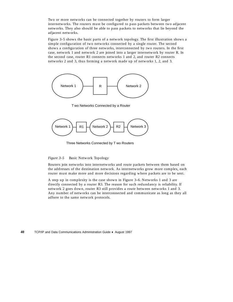
Two or more networks can be connected together by routers to form largerinternetworks. The routers must be configured to pass packets between two adjacentnetworks. They also should be able to pass packets to networks that lie beyond theadjacent networks.
Figure 3–5 shows the basic parts of a network topology. The first illustration shows asimple configuration of two networks connected by a single router. The secondshows a configuration of three networks, interconnected by two routers. In the firstcase, network 1 and network 2 are joined into a larger internetwork by router R. Inthe second case, router R1 connects networks 1 and 2, and router R2 connectsnetworks 2 and 3, thus forming a network made up of networks 1, 2, and 3.
Network 1 Network 2R
Network 1 Network 2 Network 3R1 R2
T wo Networks Connected by a Router
Three Networks Connected by T wo Routers
Figure 3–5 Basic Network Topology
Routers join networks into internetworks and route packets between them based onthe addresses of the destination network. As internetworks grow more complex, eachrouter must make more and more decisions regarding where packets are to be sent.
A step up in complexity is the case shown in Figure 3–6. Networks 1 and 3 aredirectly connected by a router R3. The reason for such redundancy is reliability. Ifnetwork 2 goes down, router R3 still provides a route between networks 1 and 3.Any number of networks can be interconnected and communicate as long as they alladhere to the same network protocols.
40 TCP/IP and Data Communications Administration Guide ♦ August 1997

Network 1 Network 2 Network 3R1 R2
R3
Figure 3–6 Providing an Additional Path Between Networks
How Routers Transfer PacketsRouting decisions on a network are based on the network portion of the IP addressof the recipient that is contained in the packet header. If this address includes thenetwork number of the local network, the packet goes directly to the host with thatIP address. If the network number is not the local network, the packet goes to therouter on the local network.
Routers maintain routing information in routing tables. These tables contain the IPaddress of the hosts and routers on the networks to which the router is connected.The tables also contain pointers to these networks. When a router gets a packet, itconsults its routing table to see if it lists the destination address in the header. If thetable does not contain the destination address, the router forwards the packet toanother router listed in its routing table. Refer to Chapter 5, for detailed informationon routers.
Figure 3–7 shows a network topology with three networks connected by two routers.
Planning Your Network 41

Router R1 Router R2Host A 192.9.200.15
Host B 192.9.202.10
Network 192.9.200 Network 192.9.201 Network 192.9.202
Figure 3–7 Three Interconnected Networks
Router R1 connects networks 192.9.200 and 192.9.201. Router R2 connects networks192.9.201 and 192.9.202. If host A on network 192.9.200 sends a message to host B onnetwork 192.9.202, this is what happens.
1. Host A sends a packet out over network 192.9.200. The packet header contains theIP address of the recipient host B, 192.9.202.10.
2. None of the machines on network 192.9.200 has the IP address 192.9.202.10.Therefore, router R1 accepts the packet.
3. Router R1 examines its routing tables. No machine on network 192.9.201 has theaddress 192.9.202.10. However, the routing tables do list router R2.
4. R1 then selects R2 as the “next hop” router and sends the packet to R2.
5. Because R2 connects network 192.9.201 to 192.9.202, it has routing information forhost B. Router R2 then forwards the packet to network 192.9.202, where it isaccepted by host B.
42 TCP/IP and Data Communications Administration Guide ♦ August 1997

CHAPTER 4
Configuring TCP/IP on the Network
The second phase of network administration involves setting up the network. Thisconsists of assembling the hardware which makes up the physical part of thenetwork, and configuring TCP/IP. This chapter explains how to configure TCP/IP,including:
� Determining the host configuration mode for each machine on your network
� Setting up the subnet mask for your network (optional)
� Configuring TCP/IP on the machines that run in local files mode
� Configuring a network configuration server
� Configuring TCP/IP on machines that run in network client mode
� Editing the network databases, based on the name service you have selected foryour network
� Configuring the name service switch file
� “Before You Configure TCP/IP” on page 44
� “Determining Host Configuration Modes” on page 44
� “TCP/IP Configuration Files” on page 47
� “hosts Database” on page 49
� “Creating the Network Mask” on page 53
� “How Name Services Affect Network Databases” on page 56
� “nsswitch.conf File — Specifying Which Name Service to Use” on page 58
� “Network Configuration Procedures” on page 64
� “Configuring Standard TCP/IP Services” on page 69
43

Before You Configure TCP/IPBefore configuring the TCP/IP software, you should have:
1. Designed the network topology, if you are the network designer. (See “NetworkTopology” on page 39 for details.)
2. Obtained a network number from your Internet addressing authority. (See“Network Classes” on page 32.)
3. Assembled the network hardware according to the topology designed andassured that the hardware is functioning. (See the hardware manuals and“Network Topology” on page 39.)
4. Run any configuration software required by network interfaces and routers, ifapplicable. (See Chapter 3, and Chapter 5, for information on routers. If you havepurchased network interfaces for your machines, refer to the manuals that camewith them for software configuration requirements.)
5. Planned the IP addressing scheme for the network, including subnet addressing,if applicable. (See “Designing Your IP Addressing Scheme” on page 34.)
6. Assigned IP numbers and host names to all machines involved in the network.(See “Designing Your IP Addressing Scheme” on page 34.)
7. Determined which name service your network uses: NIS, NIS+, DNS, or localfiles. (See Solaris Naming Administration Guide.)
8. Selected domain names for your network, if applicable. (See Solaris NamingAdministration Guide.)
9. Installed the operating system on at least one machine on the prospectivenetwork. (See Solaris Advanced Installation Guide.)
Determining Host Configuration ModesOne of your key functions as a network administrator is configuring TCP/IP to runon hosts and routers (if applicable). You can set up these machines to obtainconfiguration information from two sources: files on the local machine or fileslocated on other machines on the network. Configuration information includes:
� Host name of a machine
� IP address of the machine
� Domain name to which the machine belongs
� Default router
� Netmask in use on the machine’s network
44 TCP/IP and Data Communications Administration Guide ♦ August 1997

A machine that obtains TCP/IP configuration information from local files is said tobe operating in local files mode. A machine that obtains TCP/IP configurationinformation from a remote machine is said to be operating in network client mode.
Machines That Should Run in Local Files ModeTo run in local files mode, a machine must have local copies of the TCP/IPconfiguration files. These files are described in “TCP/IP Configuration Files” on page47. The machine should have its own disk, though this is not strictly necessary.
Most servers should run in local file mode. This requirement includes:
� Network configuration servers
� NFS servers
� Name servers supplying NIS, NIS+, or DNS services
� Mail servers
Additionally, routers should run in local files mode.
Machines that exclusively function as print servers do not need to run in local filesmode. Whether individual hosts should run in local files mode depends on the sizeof your network.
If you are running a very small network, the amount of work involved inmaintaining these files on individual hosts is manageable. If your network serveshundreds of hosts, the task becomes difficult, even with the network divided into anumber of administrative subdomains. Thus, for large networks, using local filesmode is usually less efficient. On the other hand, because routers and servers mustbe self-sufficient, they should be configured in local files mode.
Network Configuration ServersNetwork configuration servers are the machines that supply the TCP/IP configurationinformation to hosts configured in network client mode. These servers support threebooting protocols:
� RARP – Reverse Address Resolution Protocol (RARP) maps known Ethernetaddresses (48 bits) to IP addresses (32 bits), the reverse of ARP. When you runRARP on a network configuration server, this enables hosts running in networkclient mode to obtain their IP addresses and TCP/IP configuration files from theserver. The in.rarpd daemon enables RARP services. Refer to thein.rarpd (1M) man page for complete details.
� TFTP – Trivial File Transfer Protocol (TFTP) is an application that transfers filesbetween remote machines. The in.tftpd daemon carries out TFTP services,enabling file transfer between network configuration servers and their networkclients.
Configuring TCP/IP on the Network 45

� bootparams – The bootparams protocol supplies parameters for booting that arerequired by diskless clients. The rpc.bootparamd daemon carries out theseservices.
Network configuration servers can also can function as NFS file servers.
If you are going to configure any hosts as network clients, then you must alsoconfigure at least one machine on your network as a network configuration server. Ifyour network is subnetted, then you must have at least one network configurationserver for each subnet with network clients.
Machines That Are Network ClientsAny host that gets its configuration information from a network configuration serveris said to be “operating” in network client mode. Machines configured as networkclients do not require local copies of the TCP/IP configuration files.
Network client mode greatly simplifies administration of large networks. It minimizesthe number of configuration tasks that must be performed on individual hosts andassures that all machines on the network adhere to the same configuration standards.
You can configure network client mode on all types of computers, from fullystandalone systems to diskless and dataless machines. Although it is possible toconfigure routers and servers in network client mode, local files mode is a betterchoice for these machines. Routers and servers should be as self-sufficient as possible.
Diskless BootingSetting up systems for diskless booting is described in the System AdministrationGuide.
Mixed ConfigurationsDue to the flexibility of the system, configurations are not limited to either anall-local-hosts mode or an all-network-client mode. The configuration of routers andservers typifies this, in that routers and servers should always be configured in localmode. For hosts, you can use any combination of local and network client mode youwant.
Sample NetworkFigure 4–1 shows the hosts of a fictional network with the network number192.9.200. The network includes one network configuration server, the machine
46 TCP/IP and Data Communications Administration Guide ♦ August 1997

sahara . It serves the diskless client ahaggar . Machines tenere and nubian havetheir own disks and run in local files mode. Machine faiyum also has a disk butoperates in network client mode.
Finally, the machine timbuktu is configured as a router. It includes two networkinterfaces, one named timbuktu on network 192.9.200 and one namedtimbuktu-201 on network 192.9.201. Both networks are in the organizationaldomain deserts.worldwide.com . The domain uses local files as its name service.
Most examples in this chapter use the network shown in Figure 4–1 as their basis.
sahara
timbuktu-201
ahaggar 192.9.200.3
tenere 192.9.200.1
nubian 192.9.200.4
faiyum 192.9.200.5
(net. config. server)192.9.200.50
timbuktu 192.9.200.70
192.9.201.10
Network 192.9.200
Network 192. 9
deserts.worldwide.com domain
(diskless client)
(local files mode)
(local files mode)
(network client mode)
Figure 4–1 Hosts in a Sample Network
TCP/IP Configuration FilesEach machine on the network gets its TCP/IP configuration information from thefollowing TCP/IP configuration files and network databases:
� /etc/hostname. interface file
� /etc/nodename file
� /etc/defaultdomain file
Configuring TCP/IP on the Network 47

� /etc/defaultrouter file (optional)
� hosts database
� netmasks database (optional)
The Solaris installation program creates these files as part of the installation process.You can also edit the files manually, as explained in this section. The hosts andnetmasks databases are two of the network databases read by the name servicesavailable on Solaris networks. “Network Databases and nsswitch.conf File” onpage 56 describes the concept of network databases in detail.
/etc/hostname. interface FileThis file defines the network interfaces on the local host. At least one/etc/hostname. interface file should exist on the local machine. The Solarisinstallation program creates this file for you. In the file name, interface is replaced bythe device name of the primary network interface.
The file contains only one entry: the host name or IP address associated with thenetwork interface. For example, suppose smc0 is the primary network interface for amachine called ahaggar . Its /etc/hostname. interface file would have the name/etc/hostname.smc0 ; the file would contain the entry ahaggar .
For Multiple Network InterfacesIf a machine contains more than one network interface, you must create additional/etc/hostname. interface files for the additional network interfaces. You must createthese files with a text editor; the Solaris installation program does not create them foryou.
For example, consider the machine timbuktu shown in Figure 4–1. It has twonetwork interfaces and functions as a router. The primary network interface le0 isconnected to network 192.9.200. Its IP address is 192.9.200.70, and its host name istimbuktu . The Solaris installation program creates the file /etc/hostname.le0for the primary network interface and enters the host name timbuktu in the file.
The second network interface is le1 ; it is connected to network 192.9.201. Althoughthis interface is physically installed on machine timbuktu , it must have a separateIP address. Therefore, you have to manually create the /etc/hostname.le1 file forthis interface; the entry in the file would be the router‘s name, timbuktu-201 .
48 TCP/IP and Data Communications Administration Guide ♦ August 1997

/etc/nodename FileThis file should contain one entry: the host name of the local machine. For example,on machine timbuktu , the file /etc/nodename would contain the entrytimbuktu .
/etc/defaultdomain FileThis file should contain one entry, the fully qualified domain name of theadministrative domain to which the local host’s network belongs. You can supplythis name to the Solaris installation program or edit the file at a later date.
In Figure 4–1, the networks are part of the domain deserts.worldwide , whichwas classified as a .com domain. Therefore, /etc/defaultdomain should containthe entry deserts.worldwide.com . For more information on network domains,refer to the Solaris Naming Administration Guide.
/etc/defaultrouter FileThis file should contain an entry for each router directly connected to the network.The entry should be the name for the network interface that functions as a routerbetween networks.
In Figure 4–1, the network interface le1 connects machine timbuktu with network192.9.201. This interface has the unique name timbuktu-201 . Thus, the machineson network 192.9.200 that are configured in local files mode have the nametimbuktu-201 as the entry in /etc/defaultrouter .
hosts DatabaseThe hosts database contains the IP addresses and host names of machines on yournetwork. If you use the NIS, NIS+, or DNS name services, the hosts database ismaintained in a database designated for host information. For example, on a networkrunning NIS+, the hosts database is maintained in the host table.
If you use local files for name service, the hosts database is maintained in the/etc/inet/hosts file. This file contains the host names and IP addresses of theprimary network interface, other network interfaces attached to the machine, andany other network addresses that the machine must know about.
Note - For compatibility with BSD-based operating systems, the file /etc/hosts isa symbolic link to /etc/inet/hosts .
Configuring TCP/IP on the Network 49

/etc/inet/hosts File FormatThe /etc/inet/hosts file uses this basic syntax: (Refer to the hosts (4) man pagefor complete syntax information.)
IP-address hostname [nicknames] [#comment]
IP-address contains the IP address for each interface that the local host must knowabout.
hostname contains the host name assigned to the machine at setup, plus the hostnames assigned to additional network interfaces that the local host must know about.
[nickname] is an optional field containing a nickname for the host.
[# comment] is an optional field where you can include a comment.
Initial /etc/inet/hosts FileWhen you run the Solaris installation program on a machine, it sets up the initial/etc/inet/hosts file. This file contains the minimum entries that the local hostrequires: its loopback address, its IP address, and its host name.
For example, the Solaris installation program might create the following/etc/inet/hosts file for machine ahaggar shown in Figure 4–1:
EXAMPLE 4–1 /etc/inet/hosts File for Machine ahaggar
127.0.0.1 localhost loghost #loopback address192.9.200.3 ahaggar #host name
Loopback AddressIn Example 4–1, the IP address 127.0.0.1 is the loopback address, the reserved networkinterface used by the local machine to allow interprocess communication so that itsends packets to itself. The ifconfig command uses the loopback address forconfiguration and testing, as explained in “ifconfig Command” on page 80. Everymachine on a TCP/IP network must use the IP address 127.0.0.1 for the local host.
Host NameThe IP address 192.9.200.3 and the name ahaggar are the address and host name ofthe local machine. They are assigned to the machine’s primary network interface.
50 TCP/IP and Data Communications Administration Guide ♦ August 1997

Multiple Network InterfacesSome machines have more than one network interface, either because they arerouters or multihomed hosts. Each additional network interface attached to themachine requires its own IP address and associated name. When you configure arouter or multihomed host, you must manually add this information to the router’s/etc/inet/hosts file. (See Chapter 5, for more information on setting up routersand multihomed hosts.)
Example 4–2 is the /etc/inet/hosts file for machine timbuktu shown in Figure4–1.
EXAMPLE 4–2 /etc/inet/hosts File for Machine timbuktu
127.0.0.1 localhost loghost192.9.200.70 timbuktu #This is the local host name192.9.201.10 timbuktu-201 #Interface to network 192.9.201
With these two interfaces, timbuktu connects networks 192.9.200 and 192.9.201 as arouter.
How Name Services Affect the hosts DatabaseThe NIS, NIS+, and DNS name services maintain host names and addresses on oneor more servers. These servers maintain hosts databases containing information forevery host and router (if applicable) on the servers’ network. Refer to the SolarisNaming Administration Guide for more information about these services.
When Local Files Provide Name ServiceOn a network using local files for name service, machines running in local files modeconsult their individual /etc/inet/hosts files for IP addresses and host names ofother machines on the network. Therefore, their /etc/inet/hosts files mustcontain the:
� Loopback address
� IP address and host name of the local machine (primary network interface)
� IP address and host name of additional network interfaces attached to thismachine, if applicable
� IP addresses and host names of all hosts on the local network
� IP addresses and host names of any routers this machine must know about, ifapplicable
� IP address of any machine your machine wants to refer to by its host name
Configuring TCP/IP on the Network 51

Example 4–3 shows the /etc/inet/hosts file for machine tenere , a machine thatruns in local files mode. Notice that the file contains the IP addresses and host namesfor every machine on the 192.9.200 network. It also contains the IP address andinterface name timbuktu-201 , which connects the 192.9.200 network to the192.9.201 network.
A machine configured as a network client uses the local /etc/inet/hosts file forits loopback address and IP address.
EXAMPLE 4–3 /etc/inet/hosts File for Machine Running in Local Files Mode
# Desert Network - Hosts File
#
# If the NIS is running, this file is only consulted# when booting
#
127.0.0.1 localhost
#
192.9.200.1 tenere This is my machine
192.9.200.50 sahara big #This is the net config server
#
192.9.200.2 libyan libby#This is Tom’s machine
192.9.200.3 ahaggar #This is Bob’s machine
192.9.200.4 nubian #This is Amina’s machine
192.9.200.5 faiyum suz #This is Suzanne’s machine
192.9.200.70 timbuktu tim #This is Kathy’s machine
192.9.201.10 timbuktu-201 #Interface to net 192.9.201 on#timbuktu
Localhost Line
Other Hosts
Host Name Line
Server Line
netmasks DatabaseYou need to edit the netmasks database as part of network configuration only if youhave set up subnetting on your network. The netmasks database consists of a list ofnetworks and their associated subnet masks.
Note - When you create subnets, each new network must be a separate physicalnetwork. You cannot apply subnetting to a single physical network.
What is SubnettingSubnetting is a method for getting the most out of the limited 32-bit IP addressingspace and reducing the size of the routing tables in a large internetwork. With anyaddress class, subnetting provides a means of allocating a part of the host addressspace to network addresses, which lets you have more networks. The part of the hostaddress space allocated to new network addresses is known as the subnet number.
52 TCP/IP and Data Communications Administration Guide ♦ August 1997

In addition to making more efficient use of the IP address space, subnetting hasseveral administrative benefits. Routing can become very complicated as the numberof networks grows. A small organization, for example, might give each local networka class C number. As the organization grows, administering a number of differentnetwork numbers could become complicated. A better idea is to allocate a few classB network numbers to each major division in an organization. For instance, youcould allocate one to Engineering, one to Operations, and so on. Then, you coulddivide each class B network into additional networks, using the additional networknumbers gained by subnetting. This can also reduce the amount of routinginformation that must be communicated among routers.
Creating the Network MaskAs part of the subnetting process, you need to select a network-wide netmask. Thenetmask determines how many and which bits in the host address space representthe subnet number and how many and which represent the host number. Recall thatthe complete IP address consists of 32 bits. Depending on the address class, as manyas 24 bits and as few as 8 bits can be available for representing the host addressspace. The netmask is specified in the netmasks database.
If you plan to use subnets, you must determine your netmask before you configureTCP/IP. You then need to carry out the procedures in “How to Add a Subnet to aNetwork” on page 55. If you plan to install the operating system as part of networkconfiguration, the Solaris installation program requests the netmask for your network.
As described in “Parts of the IP Address” on page 31, 32-bit IP addresses consist of anetwork part and a host part. The 32 bits are divided into 4 bytes. Each byte isassigned either to the network number or the host number, depending on thenetwork class.
For example, in a class B IP address, the 2 left–hand bytes are assigned to thenetwork number, and the 2 right–hand bytes are assigned to the host number. In theclass B IP address 129.144.41.10, you can assign the 2 right–hand bytes to hosts.
If you are going to implement subnetting, you need to use some of the bits in thebytes assigned to the host number to apply to subnet addresses. For example, a16-bit host address space provides addressing for 65,534 hosts. If you apply the thirdbyte to subnet addresses and the fourth to host addresses, you can address up to 254networks, with up to 254 hosts on each.
The bits in the host address bytes that will be applied to subnet addresses and thoseapplied to host addresses is determined by a subnet mask. Subnet masks are used toselect bits from either byte for use as subnet addresses. Although netmask bits mustbe contiguous, they need not align on byte boundaries.
The netmask can be applied to an IP address using the bitwise logical AND operator.This operation selects out the network number and subnet number positions of theaddress.
Configuring TCP/IP on the Network 53

It is easiest to explain netmasks in terms of their binary representation. You can use acalculator for binary-to-decimal conversion. The following examples show both thedecimal and binary forms of the netmask.
If a netmask 255.255.255.0 is applied to the IP address 129.144.41.101, the result is theIP address of 129.144.41.0.
129.144.41.101 & 255.255.255.0 = 129.144.41.0
In binary form, the operation is:
10000001.10010000.00101001.01100101 (IP address)
ANDed with
11111111.11111111.11111111.00000000 (netmask)
Now the system looks for a network number of 129.144.41 instead of a networknumber of 129.144. If you have a network with the number 129.144.41, that is whatthe system looks for and finds. Since you can assign up to 254 values to the thirdbyte of the IP address space, subnetting lets you create address space for 254networks, where previously there was room for only one.
If you want to provide address space for only two additional networks, you coulduse a subnet mask of:
255.255.192.0
This netmask provides a result of:
11111111.11111111.1100000.00000000
This still leaves 14 bits available for host addresses. Since all 0s and 1s are reserved,at least two bits must be reserved for the host number.
Editing the /etc/inet/netmasks FileIf your network runs NIS or NIS+, the servers for these name services maintainnetmasks databases. For networks that use local files for name service, thisinformation is maintained in the /etc/inet/netmasks file.
Note - For compatibility with BSD-based operating systems, the file/etc/netmasks is a symbolic link to /etc/inet/netmasks .
Example 4–4 shows the /etc/inet/netmasks file for a class B network.
EXAMPLE 4–4 /etc/inet/netmasks File for a Class B Network
## The netmasks file associates Internet Protocol (IP) address# masks with IP network numbers.
(continued)
54 TCP/IP and Data Communications Administration Guide ♦ August 1997

(Continuation)
## network-number netmask## Both the network-number and the netmasks are specified in# ‘‘decimal dot’’ notation, e.g:## 128.32.0.0 255.255.255.0
129.144.0.0 255.255.255.0
If the file does not exist, create it. Use the following syntax:
network-number netmask-number
Refer to the netmasks (4) man page for complete details.
When creating netmask numbers, type the network number assigned by theInterNIC (not the subnet number) and netmask number in /etc/inet/netmasks .Each subnet mask should be on a separate line.
For example:
128.78.0.0 255.255.248.0
You can also type symbolic names for network numbers in the /etc/inet/hostsfile. You can then use these network names instead of the network numbers asparameters to commands.
How to Add a Subnet to a NetworkIf you are changing from a network that does not use subnets to one that issubnetted, perform the following steps:
1. Decide on the new subnet topology, including considerations for routers andlocations of hosts on the subnets.
2. Assign all subnet and host addresses.
3. Modify the /etc/inet/netmasks file, if you are manually configuring TCP/IP, or supply the netmask to the Solaris installation program.
4. Modify the /etc/inet/hosts files on all hosts to reflect the new hostaddresses.
5. Reboot all machines.
Configuring TCP/IP on the Network 55
Network Databases andnsswitch.conf FileThe network databases are files that provide information needed to configure thenetwork. The network databases are:
� hosts
� netmasks
� ethers
� bootparams
� protocols
� services
� networks
As part of the configuration process, you edit the hosts database and the netmasksdatabase, if your network is subnetted. Two network databases, bootparams andethers , are used to configure machines as network clients. The remaining databasesare used by the operating system and seldom require editing.
Although it is not a network database, the nsswitch.conf file needs to beconfigured along with the relevant network databases. nsswitch.conf specifieswhich name service to use for a particular machine: NIS, NIS+, DNS, or local files.
How Name Services Affect Network DatabasesYour network database takes a form that depends on the type of name service youselect for your network. For example, the hosts database contains, at minimum, thehost name and IP address of the local machine and any network interfaces directlyconnected to the local machine. However, the hosts database could contain other IPaddresses and host names, depending on the type of name service on your network.
The network databases are used as follows:
� Networks that use local files for their name service rely on files in the /etc/inetand /etc directories
� NIS+ uses databases called NIS+ tables
� NIS uses databases called NIS maps
� DNS uses records with host information
Note - DNS boot and data files do not correspond directly to the network databases.
Figure 4–2 shows the forms of the hosts database used by these name services:
56 TCP/IP and Data Communications Administration Guide ♦ August 1997
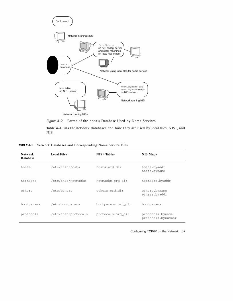
DNS record
Network running DNS
hosts database
Network using local files for name service
/etc/hosts on net. config. server and other machines on local files mode
host.byname and host.byaddr maps on NIS server
host table on NIS+ server
Network running NIS
Network running NIS+
Figure 4–2 Forms of the hosts Database Used by Name Services
Table 4–1 lists the network databases and how they are used by local files, NIS+, andNIS.
TABLE 4–1 Network Databases and Corresponding Name Service Files
NetworkDatabase
Local Files NIS+ Tables NIS Maps
hosts /etc/inet/hosts hosts.ord_dir hosts.byaddrhosts.byname
netmasks /etc/inet/netmasks netmasks.ord_dir netmasks.byaddr
ethers /etc/ethers ethers.ord_dir ethers.bynameethers.byaddr
bootparams /etc/bootparams bootparams.ord_dir bootparams
protocols /etc/inet/protocols protocols.ord_dir protocols.bynameprotocols.bynumber
Configuring TCP/IP on the Network 57

TABLE 4–1 Network Databases and Corresponding Name Service Files (continued)
NetworkDatabase
Local Files NIS+ Tables NIS Maps
services /etc/inet/services services.ord_di r services.byname
networks /etc/inet/networks networks.ord_dir networks.byaddrnetworks.byname
This book discusses network databases as viewed by networks using local files forname services. Information regarding the hosts database is in “hosts Database” onpage 49; information regarding the netmasks database is in “netmasks Database”on page 52. Refer to Solaris Naming Administration Guide for information onnetwork databases correspondences in NIS, DNS, and NIS+.
nsswitch.conf File — Specifying Which NameService to UseThe /etc/nsswitch.conf file defines the search order of the network databases.The Solaris installation program creates a default /etc/nsswitch.conf file for thelocal machine, based on the name service you indicate during the installationprocess. If you selected the “None” option, indicating local files for name service, theresulting nsswitch.conf file resembles Example 4–5.
EXAMPLE 4–5 nsswitch.conf for Networks Using Files for Name Service
# /etc/nsswitch.files:## An example file that could be copied over to /etc/nsswitch.conf;# it does not use any naming service.## "hosts:" and "services:" in this file are used only if the# /etc/netconfig file contains "switch.so" as a# nametoaddr library for "inet" transports.
passwd: filesgroup: fileshosts: filesnetworks: filesprotocols: filesrpc: filesethers: filesnetmasks: files
(continued)
58 TCP/IP and Data Communications Administration Guide ♦ August 1997

(Continuation)
bootparams: filespublickey: files# At present there isn’t a ’files’ backend for netgroup; the# system will figure it out pretty quickly,# and won’t use netgroups at all.netgroup: filesautomount: filesaliases: filesservices: filessendmailvars: files
The nsswitch.conf (4) man page describes the file in detail. Its basic syntax is:
database name-service-to-search
The database field can list one of many types of databases searched by the operatingsystem. For example, it could indicate a database affecting users, such as passwd oraliases , or a network database. The parameter name-service-to-search can have thevalues files , nis , or nis+ for the network databases. (The hosts database canalso have dns as a name service to search.) You can also list more than one nameservice, such as nis+ and files .
In Example 4–5, the only search option indicated is files . Therefore, the localmachine gets security and automounting information, in addition to networkdatabase information, from files located in its /etc and /etc/inet directories.
Changing nsswitch.conf
The /etc directory contains the nsswitch.conf file created by the Solarisinstallation program. It also contains template files for the following name services:
� nsswitch.files
� nsswitch.nis
� nsswitch.nis+
If you want to change from one name service to another, you can copy theappropriate template to nsswitch.conf . You can also selectively edit thensswitch.conf file, and change the default name service to search for individualdatabases.
For example, on a network running NIS, you might have to change thensswitch.conf file on diskless clients. The search path for the bootparams andethers databases must list files as the first option, and nis . Example 4–6 showsthe correct search paths.
Configuring TCP/IP on the Network 59

EXAMPLE 4–6 nsswitch.conf for a Diskless Client on a Network Running NIS
## /etc/nsswitch.conf:#..passwd: files nisgroup: file nis
# consult /etc "files" only if nis is down.hosts: nis [NOTFOUND=return] filesnetworks: nis [NOTFOUND=return] filesprotocols: nis [NOTFOUND=return] filesrpc: nis [NOTFOUND=return] filesethers: files [NOTFOUND=return] nisnetmasks: nis [NOTFOUND=return] filesbootparams: files [NOTFOUND=return] nispublickey: nis netgroup: nis
automount: files nisaliases: files nis
# for efficient getservbyname() avoid nisservices: files nissendmailvars: files
For complete details on the name service switch, refer to Solaris NamingAdministration Guide.
bootparams DatabaseThe bootparams database contains information used by diskless clients andmachines configured to boot in the network client mode. You need to edit it if yournetwork will have network clients. (See “Configuring Network Clients” on page 67for procedures.) The database is built from information entered into the/etc/bootparams file.
The bootparams (4) man page contains complete syntax for this database. Its basicsyntax is
machine-name file-key-server-name:pathname
For each diskless or network client machine, the entry might contain the followinginformation: the name of the client, a list of keys, the names of servers, and pathnames.
The first item of each entry is the name of the client machine. Next is a list of keys,names of servers, and path names, separated by tab characters. All items but the firstare optional. The database can contain a wildcard entry that will be matched by allclients. Here is an example:
60 TCP/IP and Data Communications Administration Guide ♦ August 1997
EXAMPLE 4–7 bootparams Database
myclient root=myserver : /nfsroot/myclient \swap=myserver : /nfsswap//myclient \dump=myserver : /nfsdump/myclient
In this example the term dump=: tells diskless hosts not to look for a dump file.
Wildcard Entry for bootparams
In most cases, you will want to use the wildcard entry when editing thebootparams database to support diskless clients. This entry is:
* root=server:/path dump=:
The asterisk (*) wildcard indicates that this entry applies to all clients not specificallynamed within the bootparams database.
ethers DatabaseThe ethers database is built from information entered into the /etc/ethers file. Itassociates host names to their Ethernet addresses. You need to create an ethersdatabase only if you are running the RARP daemon; that is, if you are configuringnetwork clients or diskless machines.
RARP uses the file to map Ethernet addresses to IP addresses. If you are running theRARP daemon in.rarpd , you need to set up the ethers file and maintain it on allhosts running the daemon to reflect changes to the network.
The ethers (4) man page contains complete syntax information for this database. Itsbasic format is:
Ethernet-address hostname #comment
Ethernet-address is the Ethernet address of the host.
hostname is the official name of the host.
#comment is any kind of note you want to append to an entry in the file.
The equipment manufacturer provides the Ethernet address. If a machine does notdisplay the Ethernet address when you power up, see your hardware manuals forassistance.
When adding entries to the ethers database, make sure that host names correspondto the primary names in the hosts database, not to the nicknames, as shown inExample 4–8.
Configuring TCP/IP on the Network 61
EXAMPLE 4–8 Entries in the ethers Database
8:0:20:1:40:16 fayoum8:0:20:1:40:15 nubian8:0:20:1:40:7 sahara # This is a comment8:0:20:1:40:14 tenere
Other Network DatabasesThe remaining network databases seldom need to be edited.
networks databaseThe networks database associates network names with network numbers, enablingsome applications to use and display names rather than numbers. The networksdatabase is based on information in the /etc/inet/networks file. It contains thenames of all networks to which your network connects via routers.
The Solaris installation program sets up the initial networks database. The onlytime you need to update it is when you add a new network to your existing networktopology.
The networks (4) man page contains full syntax information for/etc/inet/networks . Here is its basic format
network-name network-number nickname(s) # comment
network-name is the official name for the network.
network-number is the number assigned by the InterNIC.
nickname is any other name by which the network is known.
#comment is any kind of note you want to append to an entry in the file.
It is particularly important that you maintain the networks file. The netstatprogram uses the information in this database to produce status tables.
Example 4–9 shows a sample /etc/networks file:
EXAMPLE 4–9 /etc/networks File
#ident "@(#)networks 1.4 92/07/14 SMI" /* SVr4.0 1.1 */## The networks file associates Internet Protocol (IP) networknumbers with network names. The format of this file is:## network-name network-number nicnames . . .
(continued)
62 TCP/IP and Data Communications Administration Guide ♦ August 1997

(Continuation)
# The loopback network is used only for intra-machinecommunication#loopback 127
# Internet networks#arpanet 10 arpa # Historicalucb-ether 46 ucbether## local networks
eng 193.9.0 #engineeringacc 193.9.1 #accountingprog 193.9.2 #programming
protocols DatabaseThe protocols database lists the TCP/IP protocols installed on your system andtheir numbers; the Solaris installation program automatically creates it. It is rarewhen this file requires administrative handling.
The protocols database contains the names of the TCP/IP protocols installed onthe system. Its syntax is completely described in the protocols (4) man page.Example 4–10 shows an example of the /etc/inet/protocols file:
EXAMPLE 4–10 /etc/inet/protocols File
## Internet (IP) protocols#ip 0 IP # internet protocol, pseudo protocol numbericmp 1 ICMP # internet control message protocoltcp 6 TCP # transmission control protocoludp 17 UDP # user datagram protocol
services DatabaseThe services database lists the names of TCP and UDP services and their wellknown port numbers; it is used by programs that call network services. The Solarisinstallation automatically creates the services database; it generally requires noadministrative handling.
The services (4) man page contains complete syntax information. Example 4–11shows an excerpt from a typical /etc/inet/services file:
Configuring TCP/IP on the Network 63

EXAMPLE 4–11 /etc/inet/services File
## Network services#echo 7/udpecho 7/tcpdiscard 9/udp sink nulldiscard 11/tcpdaytime 13/udpdaytime 13/tcpnetstat 15/tcpftp-data 20/tcpftp 21/tcptelnet 23/tcptime 37/tcp timeservertime 37/udp timeservername 42/udp nameserverwhois 43/tcp nickname
Network Configuration ProceduresNetwork software installation takes place along with the installation of the operatingsystem software. At that time, certain IP configuration parameters must be stored inappropriate files so they can be read at boot time.
The procedure is simply a matter of creating or editing the network- configurationfiles. How configuration information is made available to a machine’s kerneldepends on whether these files are stored locally (local files mode) or acquired fromthe network configuration server (network client mode).
Parameters supplied during network configuration are:
� IP address of each network interface on every machine
� Host names of each machine on the network. You can type the host name in alocal file or a name service database.
� NIS, NIS+, or DNS domain name in which the machine resides, if applicable
� Default router addresses. You supply this only if you have a simple networktopology with only one router attached to each network, or your routers don’t runrouting protocols such as the Router Discovery Server Protocol (RDISC) or theRouter Information Protocol (RIP). (See Chapter 5, for more information aboutthese protocols.)
� Subnet mask (required only for networks with subnets)
64 TCP/IP and Data Communications Administration Guide ♦ August 1997

This chapter contains complete information on creating and editing localconfiguration files. See the Solaris Naming Administration Guide for information onworking with name service databases.
How to Configure a Host for Local Files ModeUse this procedure for configuring TCP/IP on a machine that run in local files mode.
1. Become superuser and change to the /etc directory.
2. Type the host name of the machine in the file /etc/nodename .
For example, if the name of the host is tenere , type tenere in the file.
3. Create a file named /etc/hostname. interface for each network interface.
(The Solaris installation program automatically creates this file for the primarynetwork interface.)
Refer to “/etc/hostname. interface File” on page 48 for complete details.
4. Type either the interface IP address or the interface name in each/etc/hostname. interface file.
For example, create a file named hostname.ie1 , and type either the IP addressof the host’s interface or the host’s name.
5. Edit the /etc/inet/hosts file to add:
a. IP addresses that you have assigned to any additional network interfaces inthe local machine, along with the corresponding host name for eachinterface.The Solaris installation program will already have created entries for theprimary network interface and loopback address.
b. IP address or addresses of the file server, if the /usr file system is NFSmounted.
Note - The Solaris installation program creates the default/etc/inet/host s for the local machine. If the file does not exist, create it asshown in “hosts Database” on page 49.
6. Type the host’s fully qualified domain name in the /etc/defaultdomain file.
For example, suppose host tenere was part of the domaindeserts.worldwide.com. Therefore, you would type: deserts.worldwide.comin /etc/defaultdomain . See “/etc/defaultdomain File” on page 49 formore information.
Configuring TCP/IP on the Network 65

7. Type the router’s name in /etc/defaultrouter .
See “/etc/defaultrouter File” on page 49 for information about this file.
8. Type the name of the default router and its IP addresses in /etc/inet/hosts .
Additional routing options are available. Refer to the discussion on routingoptions in “How to Configure Hosts for Network Client Mode” on page 67. Youcan apply these options to a local files mode configuration.
9. If your network is subnetted, type the network number and the netmask in thefile /etc/inet/netmasks .
If you have set up a NIS or NIS+ server, you can type netmask information inthe appropriate database on the server as long as server and clients are on thesame network.
10. Reboot each machine on the network.
Setting Up a Network Configuration ServerIf you plan to configure certain hosts as network clients, you must configure at leastone machine on your network as a network configuration server. (Refer to “NetworkConfiguration Servers” on page 45 for an introduction.)
Setting up a network configuration server involves:
1. Turning on the network configuration daemons:
� in.tftpd
� in.rarpd
� rpc.bootparamd
2. Editing and maintaining the network configuration files on the configurationserver.
“How to Set Up a Network Configuration Server” on page 66 assumes that youhave already set up the network configuration server for local files mode.
How to Set Up a Network Configuration Server1. Become superuser and change to the root directory of the prospective network
configuration server.
2. Turn on the in.tftpd daemon by creating the directory /tftpboot :
# mkdir /tftpboot
This configures the machine as a TFTP, bootparams, and RARP server.
66 TCP/IP and Data Communications Administration Guide ♦ August 1997
3. Create a symbolic link to the directory.
# ln -s /tftpboot/. /tftpboot/tftpboot
4. Enable the tftp line in intetd.conf .
Check that the /etc/inetd.conf entry reads:
tftp dgram udp wait root /usr/sbin/in.tftpd in.tftpd -s /tftpboot
This prevents inettftpd() from retrieving any file other than one located in/tftpboot .
5. Edit the hosts database, and add the host names and IP addresses for everyclient on the network.
6. Edit the ethers database, and create entries for every host on the network torun in network client mode.
7. Edit the bootparams database.
See “bootparams Database” on page 60. Use the wildcard entry or create anentry for every host that run in network client mode.
8. Reboot the server.
Information for setting up diskless clients, install servers, and boot servers can befound in Solaris Advanced Installation Guide.
Configuring Network ClientsNetwork clients receive their configuration information from network configurationservers. Therefore, before you configure a host as a network client you must ensurethat at least one network configuration server is set up for the network.
How to Configure Hosts for Network Client ModeDo the following on each host to be configured in network client mode:
1. Become superuser.
2. Check the directory for the existence of an /etc/nodename file. If one exists,delete it.
Eliminating /etc/nodename causes the system to use the hostconfig programto obtain the host name, domain name, and router addresses from the networkconfiguration server. See “Network Configuration Procedures” on page 64.
Configuring TCP/IP on the Network 67

3. Create the file /etc/hostname. interface, if it does not exist.
Make sure that the file is empty. An empty /etc/hostname. interface file causesthe system to acquire the IP address from the network configuration server.
4. Ensure that the /etc/inet/hosts file contains only the host name and IPaddress of the loopback network interface.
(See “Loopback Address” on page 50.) The file should not contain the IP addressand host name for the local machine (primary network interface).
EXCEPTION: For a diskless client (a machine with an NFS-mounted root filesystem), type the name and IP address of the server that provides the client’s rootfile system (usually, but not always, the network configuration server).
5. Check for the existence of an /etc/defaultdomain file. If one exists, deleteit.
The hostconfig program sets the domain name automatically. If you want tooverride the domain name set by hostconfig , type the substitute domain namein the file /etc/defaultdomain .
6. Ensure that the search paths in the client’s /etc/nsswitch.conf reflects thename service requirements for your network.
How to Specify a Router for the Network Client1. If you have only one router on the network and you want the network
configuration server to specify its name automatically, ensure that the networkclient does not have a /etc/defaultrouter file.
2. To override the name of the default router provided by the networkconfiguration server:
a. Create /etc/defaultrouter on the network client.
b. Type the host name and IP address of the machine you have designated asthe default router.
c. Add the host name and IP address of the designated default router to thenetwork client’s /etc/inet/hosts .
3. If you have multiple routers on the network, create /etc/defaultrouter onthe network client, but leave it empty.
68 TCP/IP and Data Communications Administration Guide ♦ August 1997

Creating /etc/defaultrouter and leaving it empty causes one of the twodynamic routing protocols to run: ICMP Router Discovery protocol (RDISC), orRouting Information Protocol (RIP). The system first runs the program in.rdisc ,which looks for routers that are running the router discovery protocol. If it finds onesuch router, in.rdisc continues to run and keeps track of the routers that arerunning the RDISC protocol.
If the system discovers that routers are not responding to the RDISC protocol, it usesRIP and runs the daemon in.routed to keep track of them.
After Installing a Network ClientAfter you have finished editing the files on each network client machine, do thefollowing on the network configuration server.
1. Add entries for the hosts in the ethers and hosts databases.
2. Add entries for the hosts to the bootparams database.
To simplify matters, you can type a wild card in the bootparams database inplace of individual entries for each host. For an example, see “bootparamsDatabase” on page 60.
3. Reboot the server.
Configuring Standard TCP/IP ServicesServices such as telnet , ftp , and rlogin are started by the inetd daemon, whichruns automatically at boot time. Like the name service ordering specified innsswitch.conf , you can configure TCP/IP services in the file /etc/inetd.confby using the inetd −t flag.
For example, you can use inetd to log the IP addresses of all incoming TCPconnections (remote logins and telnet ). To turn the logging on, kill the runninginetd and type:
# /usr/sbin/inetd -t -s
The t switch turns on TCP connection-tracing in inetd .
Refer to the inetd (1M) and inetd.conf (4) man pages.
See Solaris Naming Administration Guide and Solaris Naming Setup andConfiguration Guide for further information on name services.
Configuring TCP/IP on the Network 69

Overview of the Booting ProcessesThe following information is provided for your reference. It is a brief overview of thenetwork booting processes to help you better visualize what is happening duringconfiguration.
Note - The names of startup scripts might change from one release to another.
1. You start the operating system on a host.
2. The kernel runs /sbin/init , as part of the booting process.
3. /sbin/init runs the /etc/rcS.d/S30rootusr.sh . startup script.
4. The script runs a number of system startup tasks, including establishing theminimum host and network configurations for diskless and dataless operations./etc/rcS.d/S30rootusr.sh also mounts the /usr file system.
a. If the local database files contain the required configuration information (hostname and IP address), the script uses it.
b. If the information is not available in local host configuration files,/etc/rcS.d/S30rootusr.sh uses RARP to acquire the host’s IP address.
5. If the local files contain domain name, host name, and default router address, themachine uses them. If the configuration information is not in local files, then thesystem uses the Bootparams protocol to acquire the host name, domain name, anddefault router address. Note that the required information must be available on anetwork configuration server that is located on the same network as the host. Thisis necessary because no internetwork communications exist at this point.
6. After /etc/rcS/S30rootusr.sh completes its tasks and several other bootprocedures have executed, /etc/rc2.d/S69inet runs. This script executesstartup tasks that must be completed before the name services (NIS, NIS+, orDNS) can start. These tasks include configuring the IP routing and setting thedomain name.
7. At completion of the S69inet tasks, /etc/rc2.d/S71rpc runs. This scriptstarts the NIS, NIS+, or DNS name service.
8. After /etc/rc2.d/S71 runs, /etc/rc2.d/S72inetsvc runs. This script startsup services that depend on the presence of the name services. S72inetsvc alsostarts the daemon inetd , which manages user services such as telnet .
See System Administration Guide for a complete description of the booting process.
70 TCP/IP and Data Communications Administration Guide ♦ August 1997

CHAPTER 5
Configuring Routers
This chapter describes routing protocols and contains procedures specifically forconfiguring routers on TCP/IP networks. A router is any machine that has two ormore network interfaces and forwards packets from one network to another. Twocommon types of routers are computers with additional network interfaces in theircard slots and dedicated routers sold by various manufacturers.
This chapter does not explain the theory of routing. You can find that information in“Network Topology” on page 39; “How Routers Transfer Packets” on page 41explains basic topics regarding routing. Tasks for creating subnets are found in“netmasks Database” on page 52.
� “Routing Protocols” on page 71
� “How to Configure a Machine as a Router” on page 73
� “Creating a Multihomed Host” on page 75
Routing ProtocolsSolaris system software supports two routing protocols: Routing InformationProtocol (RIP) and ICMP Router Discovery (RDISC). RIP and RDISC are bothstandard TCP/IP protocols.
Routing Information Protocol (RIP)RIP is implemented by in.routed , the routing daemon, which automatically startswhen the machine boots. When run on a router with the s option specified,
71

in.routed fills the kernel routing table with a route to every reachable networkand advertises “reachability” through all network interfaces.
When run on a host with the q option specified, in.routed extracts routinginformation but does not advertise reachability. On hosts, routing information can beextracted in two ways:
� Do not specify the S flag (capital “S”: “Space-saving mode”) and in.routedbuilds a full routing table exactly as it does on a router.
� Specify the S flag and in.routed creates a minimal kernel table, containing asingle default route for each available router.
ICMP Router Discovery (RDISC) ProtocolHosts used RDISC to obtain routing information from routers. Thus, when hosts arerunning RDISC, routers must also run another protocol, such as RIP, in order toexchange router information among themselves.
RDISC is implemented by in.rdisc , which should run on both routers and hosts.Normally, when in.rdisc runs on a host, it enters a default route for each routerthat is also running in.rdisc . A host that is running in.rdisc can not discoverrouters that are running only RIP. Furthermore, when routers are running in.rdisc(rather than in.routed ), they can be configured to have a different preference,which causes hosts to select a better router. See the rdisc (1M) man page.
Configuring RoutersTCP/IP’s first requirement for a router is that the machine must have at least twonetwork interfaces installed, as introduced in “Network Interfaces” on page 7. Aslong as one of the network interfaces is not disabled, the router automatically “talks”to the RDISC and RIP protocols. These protocols keep track of routers on thenetwork and advertise the router to the hosts on the network.
After the router is physically installed on the network, configure it to operate in localfiles mode, as described in “How to Configure a Host for Local Files Mode” on page65. This ensures that routers will boot in case the network configuration server isdown. Remember that,unlike a host, a router has at least two interfaces to configure.
Configuring Both Router Network InterfacesBecause a router provides the interface between two or more networks, you mustassign a unique name and IP address to each of the router’s network interface cards.
72 TCP/IP and Data Communications Administration Guide ♦ August 1997

Thus, each router has a host name and IP address associated with its primarynetwork interface, plus at least one more unique name and IP address for eachadditional network interface.
How to Configure a Machine as a RouterBecome superuser on the machine to be configured as a router and do the following:
1. Create an /etc/hostname. interface file or each network interface installed.
For example, create hostname.ie0 and hostname.ie1 . (See“/etc/hostname. interface File” on page 48 for more information.)
2. Type in each file the host name you have selected for that interface.
For example, you could type the name timbuktu in the file hostname.ie0 ,then type the name timbuktu-201 in the file hostname.ie1 . Both interfaceswould be located on the same machine.
3. Type the host name and IP address of each interface into /etc/inet/hosts .
For example:
192.9.200.20 timbuktu #interface for network 192.9.200192.9.201.20 timbuktu-201 #interface for network 192.9.201192.9.200.9 gobi192.9.200.10 mojave192.9.200.110 saltlake192.9.200.12 chilean
The interfaces timbuktu and timbuktu-201 are on the same machine. Noticethat the network address for timbuktu-201 is different from that of timbuktu .That is because the medium for network 192.9.201 is connected to thetimbuktu-201 network interface while the media for network 192.9.200 isconnected to the timbuktu interface.
4. If the router is connected to any subnetted network, edit/etc/inet/netmasks and type the local network number (129.9.0.0, forexample) and associated netmask number (255.255.255.0, for example).
How a Machine Determinesif it is a RouterThe /etc/rc2.d/S69inet startup script, which runs when the machine boots,determines whether a machine is a router or a host. This decision also determineswhether the routing protocols (RIP and RDISC) should run in router mode or hostmode.
Configuring Routers 73

The /etc/rc2.d/S69inet script concludes that a machine is a router if thefollowing two conditions exist:
� More than one /etc/hostname. interface file exists.
� More than one interface was configured “up” by the ifconfig command. (Seethe ifconfig (1M) man page.)
If only one interface is found, the script concludes that the machine is a host. See“Configuring Both Router Network Interfaces” on page 72. An interface that isconfigured by any means other than an /etc/hostname. interface file is not takeninto account.
Automatic Routing Protocol SelectionThe startup script then must determine whether to start up a routing protocol (RIPor RDISC) on the machine or use static routing.
To Select Static Routing on a HostIf the host is a diskless client or network client, add an entry for a router on thenetwork into /etc/defaultrouter . (See “/etc/defaultrouter File” on page49.) A single static default route is then installed in the routing table. Under thiscondition, the host does not run any dynamic routing protocol (such as RIP andRDISC).
To Select Dynamic Routing on a HostTo force a diskless client or network client to select a dynamic routing protocol, its/etc/defaultrouter file should be empty. The type of dynamic routing used isselected according to the following criteria:
� If the /usr/sbin/in.rdisc program exists, the startup script starts in.rdisc .Any router on the network that is running RDISC then responds to any RDISCqueries from the host. If at least one router responds, the host selects RDISC as itsrouting protocol.
� If the network router is not running RDISC or fails to respond to the RDISCqueries, then in.rdisc on the host exits. The host then starts in.routed , whichruns RIP.
Forcing a Machine to Be a RouterYou can force a machine that has only one /etc/hostname .interface file (by defaulta host) to be a router. To do so, create a file named /etc/gateways and leave it
74 TCP/IP and Data Communications Administration Guide ♦ August 1997

empty. This is important if you decide to configure PPP links, as explained in“Routing Considerations” on page 113.
Creating a Multihomed HostBy default, TCP/IP considers any machine with multiple network interfaces to be arouter. However, you can change a router into a multihomed host—a machine withmore than one network interface that does not run routing protocols or forward IPpackets. You typically configure the following types of machines as multihomedhosts:
� NFS servers, particularly large data centers, can be attached to more than onenetwork in order to share files among a large pool of users. These servers don’tneed to maintain routing tables.
� Database servers can have multiple network interfaces for the same reason as NFSservers—to provide resources to a large pool of users.
� Firewall gateways are machines that provide the connection between a company’snetwork and public networks such as the Internet. Administrators set up firewallsas a security measure. When configured as a firewall, the host will not passpackets between the networks attached to it. On the other hand, it can still providestandard TCP/IP services, such as ftp or rlogin , to authorized users.
Since TCP/IP considers any machine with multiple network interfaces to be a router,you need to perform a few operations to turn it into a multihomed host.
How to Create a Multihomed HostBecome superuser on the prospective multihomed host and do the following:
1. Create an /etc/hostname. interface file for each additional network interfaceinstalled in the machine.
2. Type:
% touch /etc/notrouter
This creates an empty file called /etc/notrouter .
3. Reboot the machine.
When the machine reboots, the startup script looks for the presence of the/etc/notrouter file. If the file exists, the startup script does not runin.routed -s or in.rdisc -r , and does not turn on IP forwarding on allinterfaces configured “up” by ifconfig . This happens regardless of whether an/etc/gateways file exists. Thus the machine is now a multihomed host.
Configuring Routers 75

Turning On Space-Saving ModeSpace-saving mode provides the host with a table that contains only the defaultroutes. On a host, in.routed runs with space saving mode turned off by default.
If you do not want the host to have a full routing table (which provides increasedprotection against misconfigured routers), turn space saving mode on. To do so, editthe /etc/rc2.d/S69inet startup script by changing the line:
/usr/sbin/in.routed -q
to
/usr/sbin/in.routed -q -S
Turning Off ICMP Router Discovery on the HostFor reasons involving router reliability, you might not want your hosts to use RDISC.To turn RDISC off, change the name of the host’s /usr/sbin/in.rdisc to someother name, such as /usr/sbin/in.rdisc.saved , and then reboot the host.
Turning Off ICMP Router Discovery on the RouterIf the automatic selection of RIP rather than RDISC by a host is to work reliably, therouters in the network (particularly those running RDISC) must also work reliably.
If your routers are not running RDISC and you install a single Solaris router, bydefault all hosts connected to that router rely on it alone. To have the hosts on thatnetwork use the other routers as well, turn off RDISC on the new router. To do this,change the name of the router’s /usr/bin/in.rdisc file to some other file nameand reboot the router.
76 TCP/IP and Data Communications Administration Guide ♦ August 1997

CHAPTER 6
Troubleshooting TCP/IP
This chapter describes general methods for troubleshooting TCP/IP networks andsome of the tools available for doing so. These tools include ping , ifconfig ,netstat , and route .
� “General Troubleshooting Methods” on page 77
� “Running Software Checks” on page 78
� “ping Command” on page 78
� “ifconfig Command” on page 80
� “netstat Command” on page 81
� “Logging Network Problems” on page 84
� “Displaying Packet Contents” on page 84
General Troubleshooting MethodsOne of the first signs of trouble on the network is a loss of communications by one ormore hosts. If a host refuses to come up at all the first time it is added to the network,the problem might lie in one of the configuration files, or in the network interface. Ifa single host suddenly develops a problem, the network interface might be the cause.If the hosts on a network can communicate with each other but not with othernetworks, the problem could lie with the router, or it could lie in another network.
You can use the ifconfig program to obtain information on network interfaces andnetstat to display routing tables and protocol statistics. Third-party networkdiagnostic programs provide a number of troubleshooting utilities. Refer tothird-party documentation for information.
77

Less obvious are the causes of problems that degrade performance on the network.For example, you can use tools like ping to quantify problems like the loss ofpackets by a host.
Running Software ChecksIf there is trouble on the network, some actions that you can take to diagnose and fixsoftware-related problems include:
1. Using the netstat command to display network information.
2. Checking the hosts database to make sure that the entries are correct and up todate.
3. If you are running RARP, checking the Ethernet addresses in the ethers databaseto make sure that the entries are correct and up to date.
4. Trying to connect by telnet to the local host.
5. Ensuring that the network daemon inetd is running. To do this, log in assuperuser and type:
# ps -ef | grep inetd
Here is an example of output displayed if the inetd daemon is running:
root 57 1 0 Apr 04 ? 3:19 /usr/sbin/inetd -sroot 4218 4198 0 17:57:23 pts/3 0:00 grep inetd
ping CommandUse the ping command to find out whether there is IP connectivity to a particularhost. The basic syntax is:
/usr/sbin/ping host [timeout]
where host is the host name of the machine in question. The optional timeoutargument indicates the time in seconds for ping to keep trying to reach themachine—20 seconds by default. The ping (1M) man page describes additionalsyntaxes and options.
78 TCP/IP and Data Communications Administration Guide ♦ August 1997

When you run ping , the ICMP protocol sends a datagram to the host you specify,asking for a response. (ICMP is the protocol responsible for error handling on aTCP/IP network. See “ICMP Protocol” on page 19 for details.)
Suppose you type:
$ ping elvis
If host elvis is up, this message is displayed:
elvis is alive
indicating that elvis responded to the ICMP request. However, if elvis is downor cannot receive the ICMP packets, you receive the following response from ping :
no answer from elvis
If you suspect that a machine might be losing packets even though it is up, you canuse the s option of ping to try to detect the problem. For example, type:
$ ping -s elvis
ping continually sends packets to elvis until you send an interrupt character or atimeout occurs. The responses on your screen will resemble:
PING elvis: 56 data bytes64 bytes from 129.144.50.21: icmp_seq=0. time=80. ms64 bytes from 129.144.50.21: icmp_seq=1. time=0. ms64 bytes from 129.144.50.21: icmp_seq=2. time=0. ms64 bytes from 129.144.50.21: icmp_seq=3. time=0. ms...----elvis PING Statistics----4 packets transmitted, 4 packets received, 0% packet lossround-trip (ms) min/avg/max = 0/20/80
The packet-loss statistic indicates whether the host has dropped packets.
If ping fails, check the status of the network reported by ifconfig and netstat ,as described in “ifconfig Command” on page 80 and “netstat Command” onpage 81.
Troubleshooting TCP/IP 79
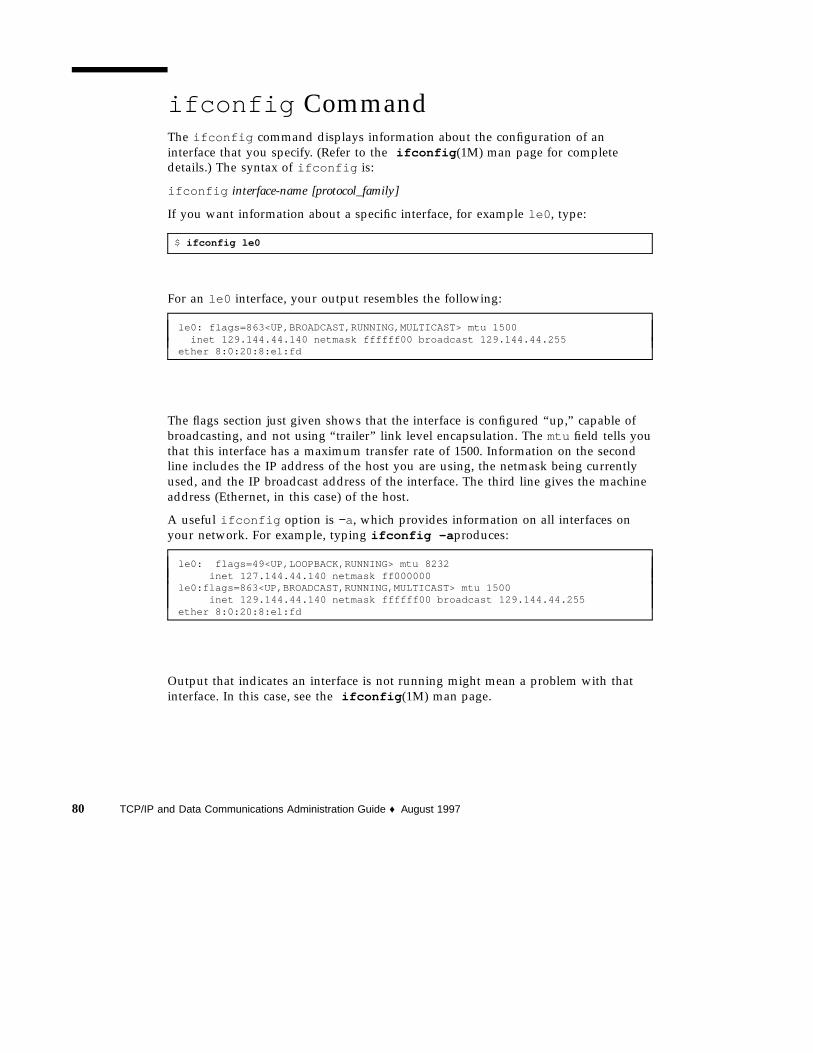
ifconfig CommandThe ifconfig command displays information about the configuration of aninterface that you specify. (Refer to the ifconfig (1M) man page for completedetails.) The syntax of ifconfig is:
ifconfig interface-name [protocol_family]
If you want information about a specific interface, for example le0 , type:
$ ifconfig le0
For an le0 interface, your output resembles the following:
le0: flags=863<UP,BROADCAST,RUNNING,MULTICAST> mtu 1500inet 129.144.44.140 netmask ffffff00 broadcast 129.144.44.255
ether 8:0:20:8:el:fd
The flags section just given shows that the interface is configured “up,” capable ofbroadcasting, and not using “trailer” link level encapsulation. The mtu field tells youthat this interface has a maximum transfer rate of 1500. Information on the secondline includes the IP address of the host you are using, the netmask being currentlyused, and the IP broadcast address of the interface. The third line gives the machineaddress (Ethernet, in this case) of the host.
A useful ifconfig option is −a, which provides information on all interfaces onyour network. For example, typing ifconfig -a produces:
le0: flags=49<UP,LOOPBACK,RUNNING> mtu 8232inet 127.144.44.140 netmask ff000000
le0:flags=863<UP,BROADCAST,RUNNING,MULTICAST> mtu 1500inet 129.144.44.140 netmask ffffff00 broadcast 129.144.44.255
ether 8:0:20:8:el:fd
Output that indicates an interface is not running might mean a problem with thatinterface. In this case, see the ifconfig (1M) man page.
80 TCP/IP and Data Communications Administration Guide ♦ August 1997

netstat CommandThe netstat command generates displays that show network status and protocolstatistics. You can display the status of TCP and UDP endpoints in table format,routing table information, and interface information.
netstat displays various types of network data depending on the command lineoption selected. These displays are the most useful for system administration. Thesyntax for this form is:
netstat [-m] [-n] [-s] [-i | -r] [-f address_family]
The most frequently used options for determining network status are: s , r , and i .See the netstat (1M) man page for a description of the options.
Displaying Per Protocol StatisticsThe netstat -s option displays per protocol statistics for the UDP, TCP, ICMP, andIP protocols. The result resembles the display shown in the example below. (Parts ofthe output have been truncated.) The information can indicate areas where a protocolis having problems. For example, statistical information from ICMP can indicatewhere this protocol has found errors.
UDP
udpInDatagrams = 39228 udpOutDatagrams = 2455udpInErrors = 0
TCP
tcpRtoAlgorithm = 4 tcpMaxConn = -1tcpRtoMax = 60000 tcpPassiveOpens = 2tcpActiveOpens = 4 tcpEstabResets = 1tcpAttemptFails = 3 tcpOutSegs = 315tcpCurrEstab = 1 tcpOutDataBytes = 10547tcpOutDataSegs = 288 tcpRetransBytes = 8376tcpRetransSegs = 29 tcpOutAckDelayed = 23tcpOutAck = 27 tcpOutWinUpdate = 2tcpOutUrg = 2 tcpOutControl = 8tcpOutWinProbe = 0 tcpOutFastRetrans = 1tcpOutRsts = 0tcpInSegs = 563 tcpInAckBytes = 10549tcpInAckSegs = 289 tcpInAckUnsent = 0tcpInDupAck = 27 tcpInInorderBytes = 673tcpInInorderSegs = 254 tcpInInorderBytes = 673tcpInUnorderSegs = 0 tcpInUnorderBytes = 0tcpInDupSegs = 0 tcpInDupBytes = 0tcpInPartDupSegs = 0 tcpInPartDupBytes = 0
(continued)
Troubleshooting TCP/IP 81

(Continuation)
tcpInPastWinSegs = 0 tcpInPastWinBytes = 0tcpInWinProbe = 0 tcpInWinUpdate = 237tcpInClosed = 0 tcpRttNoUpdate = 21tcpRttUpdate = 266 tcpTimRetrans = 26tcpTimRetransDrop = 0 tcpTimKeepalive = 0tcpTimKeepaliveProbe= 0 tcpTimKeepaliveDrop = 0
IP
ipForwarding = 2 ipDefaultTTL = 255ipInReceives = 4518 ipInHdrErrors = 0ipInAddrErrors = 0 ipInCksumErrs = 0ipForwDatagrams = 0 ipForwProhibits = 0ipInUnknownProtos = 0 ipInDiscards = 0ipInDelivers = 4486 ipOutRequests = 2805ipOutDiscards = 5 ipOutNoRoutes = 0ipReasmTimeout = 60 ipReasmReqds = 2ipReasmOKs = 2 ipReasmReqds = 2ipReasmDuplicates = 0 ipReasmFails = 0ipFragOKs = 20 ipReasmPartDups = 0ipFragCreates = 116 ipFragFails = 0tcpInErrs = 0 ipRoutingDiscards = 0udpInCksumErrs = 0 udpNoPorts = 33rawipInOverflows = 0 udpInOverflows = 6
ICMP
icmpInMsgs = 0 icmpInErrors = 0icmpInCksumErrs = 0 icmpInUnknowns = 0icmpInDestUnreachs = 0 icmpInTimeExcds = 0icmpInParmProbs = 0 icmpInSrcQuenchs = 0icmpInRedirects = 0 icmpInBadRedirects = 0icmpInEchos = 0 icmpInEchoReps = 0icmpInTimestamps = 0 icmpInTimestampReps = 0icmpInAddrMasks = 0 icmpInAddrMaskReps = 0icmpInFragNeeded = 0 icmpOutMsgs = 7icmpOutDestUnreachs = 1 icmpOutErrors = 0icmpOutDrops = 5 icmpOutTimeExcds = 0icmpOutParmProbs = 0 icmpOutSrcQuenchs = 6icmpOutRedirects = 0 icmpOutEchos = 0icmpOutEchoReps = 0 icmpOutTimestamps = 0icmpOutTimestampReps= 0 icmpOutAddrMasks = 0icmpOutAddrMaskReps = 0 icmpOutFragNeeded = 0icmpInOverflows = 0
IGMP:
0 messages received0 messages received with too few bytes0 messages received with bad checksum0 membership queries received0 membership queries received with invalid field(s)
(continued)
82 TCP/IP and Data Communications Administration Guide ♦ August 1997

(Continuation)
0 membership reports received0 membership reports received with invalid field(s)0 membership reports received for groups to which we belong0 membership reports sent
Displaying Network Interface StatusThe i option of netstat shows the state of the network interfaces that areconfigured with the machine where you ran the command. Here is a sample displayproduced by netstat -i .
Name Mtu Net/Dest Address Ipkts Ierrs Opkts Oerrs Collis Queuele0 1500 b5-spd-2f-cm tatra 14093893 8492 10174659 1119 2314178 0lo0 8232 loopback localhost 92997622 5442 12451748 0 775125 0
Using this display, you can find out how many packets a machine thinks it hastransmitted and received on each network. For example, the input packet count(Ipkts ) displayed for a server can increase each time a client tries to boot, while theoutput packet count (Opkts ) remains steady. This suggests that the server is seeingthe boot request packets from the client, but does not realize it is supposed torespond to them. This might be caused by an incorrect address in the hosts orethers database.
On the other hand, if the input packet count is steady over time, it means that themachine does not see the packets at all. This suggests a different type of failure,possibly a hardware problem.
Displaying Routing Table StatusThe −r option of netstat displays the IP routing table. Here is a sample displayproduced by netstat -r run on machine tenere .
Routing tablesDestination Gateway Flags Refcnt Use Interfacetemp8milptp elvis UGH 0 0irmcpeb1-ptp0 elvis UGH 0 0route93-ptp0 speed UGH 0 0mtvb9-ptp0 speed UGH 0 0
.mtnside speed UG 1 567ray-net speed UG 0 0
Troubleshooting TCP/IP 83

(Continuation)
mtnside-eng speed UG 0 36mtnside-eng speed UG 0 558mtnside-eng tenere U 33 190248 le0
The first column shows the destination network, the second the router throughwhich packets are forwarded. The U flag indicates that the route is up; the G flagindicates that the route is to a gateway. The H flag indicates that the destination is afully qualified host address, rather than a network.
The Refcnt column shows the number of active uses per route, and the Use columnshows the number of packets sent per route. Finally, the Interface column showsthe network interface that the route uses.
Logging Network ProblemsIf you suspect a routing daemon malfunction, you can log its actions, including allpacket transfers. To create a log file of routing daemon actions, supply a file namewhen you start up the routed daemon. For example:
# /usr/sbin/in.routed /var/routerlog
Caution - On a busy network, this can generate almost continuous output.
Displaying Packet ContentsYou can use snoop to capture network packets and display their contents. Packetscan be displayed as soon as they are received, or saved to a file. When snoop writesto an intermediate file, packet loss under busy trace conditions is unlikely. snoopitself is then used to interpret the file. For information about using the snoopcommand, refer to the snoop (1M) man page.
84 TCP/IP and Data Communications Administration Guide ♦ August 1997

The snoop command must be run by root (#) to capture packets to and from thedefault interface in promiscuous mode. In summary form, only the data pertaining tothe highest-level protocol is displayed. For example, an NFS packet will have onlyNFS information displayed. The underlying RPC, UDP, IP, and Ethernet frameinformation is suppressed but can be displayed if either of the verbose options ischosen.
The snoop capture file format is described in RFC 1761. To access, use your favoriteweb browser with the URL: http://ds.internic.net/rfc/rfc1761.txt .
snoop server client rpc rstatd collects all RPC traffic between a client andserver, and filters it for rstatd .
How to check all packets from your system1. Type netstat -i to find the interfaces attached to the system.
Snoop normally uses the first non-loopback device (le0 ).
2. Become root and type snoop
Use Ctl C to halt the process.
# snoopUsing device /dev/le (promiscuous mode)
maupiti -> atlantic-82 NFS C GETATTR FH=0343atlantic-82 -> maupiti NFS R GETATTR OK
maupiti -> atlantic-82 NFS C GETATTR FH=D360atlantic-82 -> maupiti NFS R GETATTR OK
maupiti -> atlantic-82 NFS C GETATTR FH=1A18atlantic-82 -> maupiti NFS R GETATTR OK
maupiti -> (broadcast) ARP C Who is 129.146.82.36, npmpk17a-82 ?
3. Interpret results
In the example, client maupiti transmits to server atlantic-82 using NFS filehandle 0343. atlantic-82 acknowledges with OK. The conversation continuesuntil maupiti broadcasts an ARP request asking who is 129.146.82.36?
This example demonstrates the format of snoop . The next step is to filter snoopto capture packets to a file.
Interpret the capture file using details described in RFC 1761. To access, use yourfavorite web browser with the URL: http://ds.internic.net/rfc/rfc1761.txt
Troubleshooting TCP/IP 85

How to capture snoop results to a file1. As root, type snoop -o filename. Example:
# snoop -o /tmp/capUsing device /dev/le (promiscuous mode)30 snoop: 30 packets captured
This has captured 30 packets in a file /tmp/cap . The file can be anywhere thereis enough disk space. The number of packets captured is displayed on thecommand line, enabling you to press Ctl-C to abort at any time.
snoop creates a noticeable networking load on the host machine, which can skewthe results. To see reality at work, run snoop from a third system, (see the nextsection).
2. Type snoop -i filename to inspect the file:
# snoop -i /tmp/cap
1 0.00000 frmpk17b-082 -> 224.0.0.2 IP D=224.0.0.2 S=129.146.82.1 LEN=32, ID=02 0.56104 scout -> (broadcast) ARP C Who is 129.146.82.63, grail ?3 0.16742 atlantic-82 -> (broadcast) ARP C Who is 129.146.82.76, honeybea ?4 0.77247 scout -> (broadcast) ARP C Who is 129.146.82.63, grail ?5 0.80532 frmpk17b-082 -> (broadcast) ARP C Who is 129.146.82.92, holmes ?6 0.13462 scout -> (broadcast) ARP C Who is 129.146.82.63, grail ?7 0.94003 scout -> (broadcast) ARP C Who is 129.146.82.63, grail ?8 0.93992 scout -> (broadcast) ARP C Who is 129.146.82.63, grail ?9 0.60887 towel -> (broadcast) ARP C Who is 129.146.82.35, udmpk17b-82 ?10 0.86691 nimpk17a-82 -> 129.146.82.255 RIP R (1 destinations)
Refer to specific protocol documentation for detailed analysis and recommendedparameters for ARP, IP, RIP and so forth. Searching the web is a good place tolook at RFCs.
How to check packets between server and client1. Establish a snoop system off a hub connected to either the client or server.
The third system (the snoop system) sees all the intervening traffic, so the snooptrace reflects reality on the wire.
2. As root, type snoop with options and save to a file.
86 TCP/IP and Data Communications Administration Guide ♦ August 1997

3. Inspect and interpret results.
Look at RFC 1761 for details of the snoop capture file. To access, use your favoriteweb browser with the URL: http://ds.internic.net/rfc/rfc1761.txt
Use snoop frequently and consistently to get a feel for normal system behavior. Forassistance in analyzing packets, look for recent white papers and RFCs, and seek theadvice of an expert in a particular area, such as NFS or YP. For complete details onusing snoop and its options, refer to the snoop (1M) man page.
Troubleshooting TCP/IP 87

88 TCP/IP and Data Communications Administration Guide ♦ August 1997

PART II Expanding Your Network With PPP
Part 2 explains how to set up and administer asynchronous PPP communicationslinks on the network. The text assumes that you are an experienced networkadministrator who is familiar with TCP/IP.
� “PPP Network Interfaces” on page 93
� “Point-to-Point Communications Links” on page 93
� “Multipoint Communications Links” on page 97
� “Determining IP Addressing for Your PPP Link” on page 110
� “Routing Considerations” on page 113
� “Checklist for Configuring PPP” on page 114
� “Installing the PPP Software” on page 118
� “Editing the /etc/asppp.cf Configuration File” on page 124
� “How to Manually Start PPP” on page 130
� “Checking Interface Status” on page 134
� “Checking Connectivity” on page 135
� “Configuring Dynamically Allocated PPP Links” on page 147
� “Configuring a Virtual Network” on page 153
� “Configuration Keywords” on page 161


CHAPTER 7
Understanding PPP
This chapter presents an overview of Solaris PPP, a data-link protocol included in theTCP/IP protocol suite. The text includes product specifications, introductions to themost typical PPP configurations, and definitions of the terms related to PPP.
� “Solaris PPP Specifications” on page 91
� “PPP Network Interfaces” on page 93
� “Point-to-Point Communications Links” on page 93
� “Dial-in Server With Dynamic Point-to-Point Link” on page 96
� “Multipoint Communications Links” on page 97
� “Introducing the PPP Software” on page 99
Overview of Solaris PPPPPP enables you to connect computers and networks at separate physical locationsby using modems and telephone lines. With PPP, users with computers at home or inremote offices can connect to your site’s network. You can also use the combinationof PPP software, a modem, and telephone lines as a router connecting networks indifferent places. PPP offers strategies for configuring these machines and networks,which are introduced in this chapter.
Solaris PPP SpecificationsSolaris PPP is an asynchronous implementation of the standard data-link levelPoint-to-Point Protocol (PPP) included in the TCP/IP protocol suite and provided by
91
a number of router system vendors and terminal concentrators. It includes astandard encapsulation protocol, making datagram transmission transparent tonetwork layer protocols.
The major characteristics of the Solaris PPP protocol are:
� Implements the Internet Point-to-Point Protocol, as defined in RFC 1331
� Provides error detection through CRC
� Supports full duplex transmission
The major functions of the protocol are:
� Interface for IP to forward packets over asynchronous serial lines
� Connection establishment on demand
� Configurable options negotiation
� Connection termination (automatic hang-up)
Transmission Facilities Used by PPPPPP supports interfaces to RS-232-C (V.24) facilities through the CPU serial portsincluded on most machines running the Solaris software. In addition, PPP runs overoptional asynchronous serial ports supplied or supported by many manufacturers ofmachines that run the Solaris software. PPP supports the maximum data rates thatyour machine’s serial ports can achieve. Consult the manufacturer of your computersystem for more details on the speeds supported by your machine’s serial hardware.
Note - Machines of the x86 architecture require UARTs that run above a certainspeed. See the for details.
Standards ConformancePPP, and the routing functions in the Solaris software, use industry-standardconventions for performing their tasks. These conventions support:
� Forwarding of IP datagrams
� Reception of packets for forwarding from any IP-compatible networked system
� Delivery of packets to any IP-compatible networked system on local-area networkmedia, such as Ethernet, Token Ring, and FDDI
� Use of standard routing protocols, enabling users to exchange packets withequipment that supports the PPP protocol from many manufacturers
92 TCP/IP and Data Communications Administration Guide ♦ August 1997

PPP Network InterfacesPPP enables asynchronous devices, such as modems, to become network interfaces.Solaris PPP enables you to configure two types of virtual network interfaces, ipdptp nand ipd n. (The letter n represents the device number you assign to the interface.)
PPP network interfaces are considered virtual network interfaces because they do notinvolve network hardware, as does, for example, an Ethernet interface. Moreover,they are not associated with any particular serial port. The PPP network interfacesreside in the /devices directories along with the physical network interfaces. (Forinformation on physical network interfaces, see “Network Interfaces” on page 7.)
The type of network interface you use depends on the PPP communications link youwant to set up. The ipdptp interface supports point-to-point PPP links; the ipdinterface supports point-to-multipoint links (called “multipoint links”).
Extending Your Network With PPPThis section introduces PPP-related communications concepts used. It also explainsthe most typical PPP configurations that you are likely to set up.
Point-to-Point Communications LinksThe most common use of Solaris PPP is to set up a point-to-point communicationslink. A generic point-to-point communications configuration consists of twoendpoints connected by a communications link. In a generic configuration, anendpoint system could be a computer or terminal, either in an isolated location orphysically connected to a network. The term communications link refers to thehardware and software connecting these endpoint systems. Figure 7–1 illustratesthese concepts.
Understanding PPP 93
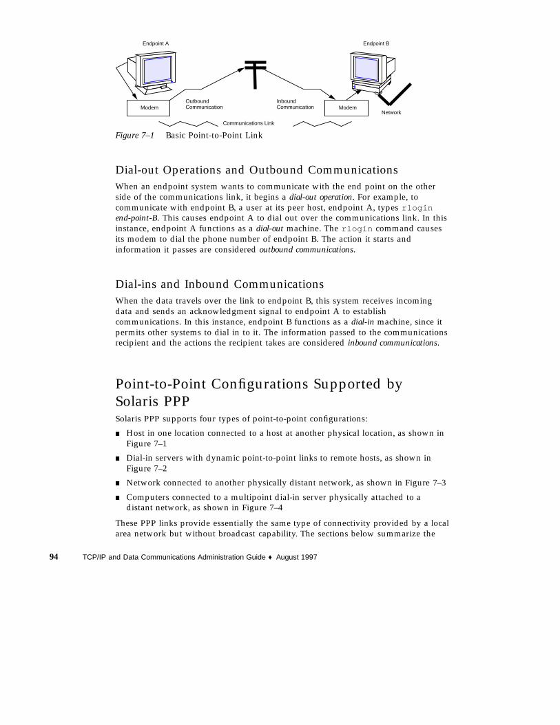
ModemNetwork
Endpoint A Endpoint B
Communications Link
OutboundCommunication
InboundCommunication Modem
Figure 7–1 Basic Point-to-Point Link
Dial-out Operations and Outbound CommunicationsWhen an endpoint system wants to communicate with the end point on the otherside of the communications link, it begins a dial-out operation. For example, tocommunicate with endpoint B, a user at its peer host, endpoint A, types rloginend-point-B. This causes endpoint A to dial out over the communications link. In thisinstance, endpoint A functions as a dial-out machine. The rlogin command causesits modem to dial the phone number of endpoint B. The action it starts andinformation it passes are considered outbound communications.
Dial-ins and Inbound CommunicationsWhen the data travels over the link to endpoint B, this system receives incomingdata and sends an acknowledgment signal to endpoint A to establishcommunications. In this instance, endpoint B functions as a dial-in machine, since itpermits other systems to dial in to it. The information passed to the communicationsrecipient and the actions the recipient takes are considered inbound communications.
Point-to-Point Configurations Supported bySolaris PPPSolaris PPP supports four types of point-to-point configurations:
� Host in one location connected to a host at another physical location, as shown inFigure 7–1
� Dial-in servers with dynamic point-to-point links to remote hosts, as shown inFigure 7–2
� Network connected to another physically distant network, as shown in Figure 7–3
� Computers connected to a multipoint dial-in server physically attached to adistant network, as shown in Figure 7–4
These PPP links provide essentially the same type of connectivity provided by a localarea network but without broadcast capability. The sections below summarize the
94 TCP/IP and Data Communications Administration Guide ♦ August 1997

configuration types; Chapter 8, gives information for setting up each configurationtype.
Two Isolated Hosts Connected by a Point-to-Point LinkPPP enables you to set up a point-to-point link to connect two standalone machinesin separate locations, effectively creating a network consisting solely of these twomachines. This is the simplest point-to-point configuration because it involves onlythe two endpoints. The generic configuration shown in Figure 7–1 also uses thehost-to-host configuration.
Nomadic Machines Connected to a Dial-in ServerIn the past, standard dial-up or temporary connections permitted only ASCIIterminals to connect to a network. With Solaris PPP, an individual machine canbecome part of a physically distant network by configuring it as one endpoint of thePPP link. The advantage of this nomadic connection is particularly apparent if yournetwork includes users who travel frequently or work from home.
Figure 7–2 shows nomadic computers, each with a point-to-point link to an endpointsystem on the network. The endpoint on the network is a dial-in server.
Modem
Modem
Modem
Modem
Dial-in Server
CurrentlyEndpoint A
Endpoint B
Endpoint C
active dynamiclink
Modem
Inactive link
Figure 7–2 Nomadic Computers and Dynamic Link Dial-in Server
Understanding PPP 95

Dial-in Server With Dynamic Point-to-Point LinkThe endpoint machine on the network shown in Figure 7–2 functions as a dial-inserver with dynamic point-to-point links. It is called a dial-in server because remotemachines can dial in to it to reach the network. When the server receives a request todial in from a machine, the server allocates the PPP link to the machine on anas-needed basis.
A dial-in server can communicate with the remote hosts through a dynamicpoint-to-point link or through a multipoint link, as explained in “MultipointCommunications Links” on page 97. The dynamic point-to-point link has theadvantages of point-to-point communications: RIP can run over the link, andbroadcasting is enabled. Perhaps most importantly, more than one machine on thephysical network can function as the dial-in server. This allows you to configurebackup servers, thus enabling redundancy and easier administration. Although themachines in Figure 7–2 can directly communicate with the network endpoint, theycannot directly communicate with each other. They must pass information to eachother through the dial-in server endpoint.
Two Networks Connected by Point-to-Point LinkYou can use PPP to connect two separate networks through a point-to-point link,with one system on each network serving as an endpoint. These endpointscommunicate through modems and phone lines, essentially in the same fashion asshown in Figure 7–1. But in this setup, the endpoints, modems, and PPP softwarebecome routers for their physical networks. Using this type of configuration scheme,you can create an internetwork with wide geographic reach.
Figure 7–3 shows two networks in different locations connected by a point-to-pointlink.
Network A
Network B
Modem
Modem
Endpoint A
Endpoint BPPP Communications Link
(Token Ring)
(Ethernet)
Figure 7–3 Two Networks Connected by a PPP Link
In this example, endpoints A and B, their modems, public telephone lines, and thePPP software act as a router between the networks. These networks may have otherhosts serving as routers between physical networks. Sometimes, the host functioning
96 TCP/IP and Data Communications Administration Guide ♦ August 1997
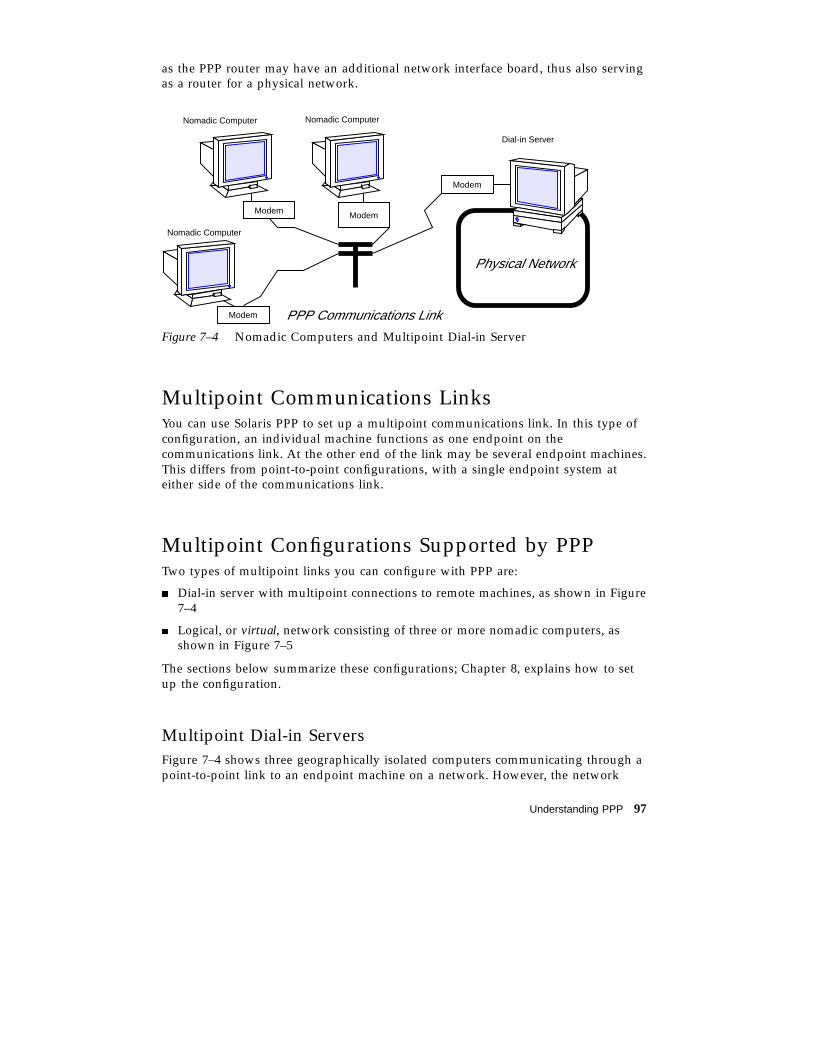
as the PPP router may have an additional network interface board, thus also servingas a router for a physical network.
Modem
Modem PPP Communications Link
Modem Modem
Physical Network
Nomadic Computer
Nomadic Computer Nomadic Computer
Dial-in Server
Figure 7–4 Nomadic Computers and Multipoint Dial-in Server
Multipoint Communications LinksYou can use Solaris PPP to set up a multipoint communications link. In this type ofconfiguration, an individual machine functions as one endpoint on thecommunications link. At the other end of the link may be several endpoint machines.This differs from point-to-point configurations, with a single endpoint system ateither side of the communications link.
Multipoint Configurations Supported by PPPTwo types of multipoint links you can configure with PPP are:
� Dial-in server with multipoint connections to remote machines, as shown in Figure7–4
� Logical, or virtual, network consisting of three or more nomadic computers, asshown in Figure 7–5
The sections below summarize these configurations; Chapter 8, explains how to setup the configuration.
Multipoint Dial-in ServersFigure 7–4 shows three geographically isolated computers communicating through apoint-to-point link to an endpoint machine on a network. However, the network
Understanding PPP 97

endpoint machine can communicate with the nomadic computers through amultipoint link, thus making it a multipoint dial-in server. (You can also set up adial-in server with dynamic point-to-point connections, as explained in “Dial-inServer With Dynamic Point-to-Point Link” on page 96.)
The dial-in server can communicate with all the machines on the other end of itsmultipoint PPP link. Though the machines in Figure 7–4 can directly communicatewith the multipoint dial-in server, they cannot communicate directly with each other.They must pass information to each other through the dial-in server.
Virtual NetworksYou can use PPP to set up a virtual network wherein the modems, PPP software, andtelephone wires become the “virtual” network media. In a physical network, such asEthernet or Token Ring, computers are directly cabled to the network media. In avirtual network, no true network media exist.
Machines become peer hosts on the virtual network when you configure each with amultipoint communications link. Then each host can dial out through its modemover phone lines to reach another endpoint machine. Each computer also functionsas a dial-in machine, permitting its peer hosts on the virtual network to dial in to it.
Figure 7–5 depicts a virtual network consisting of nomadic computers connected toeach other through modems and telephone lines.
Modem Modem Modem Modem
office.1 office.2 office.3 office.4
Telephone Lines
Figure 7–5 Virtual Network of Nomadic Computers
Each machine exists in a different office, perhaps in a different town from othermembers of the virtual network. However, each machine can establishcommunications with its peer hosts over its multipoint communications links.
98 TCP/IP and Data Communications Administration Guide ♦ August 1997

Introducing the PPP SoftwareThe PPP component software includes:
� Link manager (/usr/sbin/aspppd )
� Log in service (/usr/sbin/aspppls )
� Configuration file (/etc/asppp.cf )
� Log file (/var/adm/log/asppp.log )
� FIFO file (/tmp/.asppp.fifo )
After you install the PPP software, you will find the /etc/init.d/asppp file,which is the run-control script for PPP. It is linked to several other files in therun-control directories.
Figure 7–6 shows the software components of PPP and how they interact.
asppplslogin service
aspppdlink manager
asppp.cflink managerconfigurationfile
asppp.loglog file
UUCP Database
/etc/uucp/Dialers
/etc/uucp/Devices
/etc/uucp/Systems
Software createslog file
Network administratorcreates configurationfile and UUCP databasefiles
Figure 7–6 PPP Component Software
Link ManagerThe /usr/sbin/aspppd link manager is a user-level daemon that automates theprocess of connecting to a remote host when PPP service is required. This automatedprocess starts whenever any activity that generates IP traffic takes place (for example,a user logs in to a remote machine, accesses an NFS-mounted file, and so on). If a
Understanding PPP 99

remote host tries to establish a connection, the link manager on the local host willcomplete the connection.
Refer to the aspppd (1M) man page for specific information about the link manager.
Login ServiceThe /usr/sbin/aspppls login service is invoked as a login shell that starts PPPafter you dial up and log in. Its function is similar to the /usr/lib/uucp/uucicocommand described in “Software Comprising UUCP” on page 168. Whenconfiguring a machine as a dial-in server, you must specify aspppls as the loginshell in the /etc/passwd file in the entries for every nomadic computer allowed todial in to the local host.
Configuration FileThe asppp.cf file provides the link manager with information about each remoteendpoint with which the local host will communicate. You define this information ina section of the configuration file called a path. The path section also defines the PPPinterface to be used and, optionally, other attributes determining howcommunications will take place, including security issues. “Parts of BasicConfiguration File” on page 124 explains the sections of the asppp.cf file in detail.Example 7–1 shows an unmodified asppp.cf file.
EXAMPLE 7–1 An Unmodified asppp.cf File
#ident "@(#)asppp.cf 10 93/07/07 SMI"## Copyright (c) 1993 by Sun Microsystems, Inc.## Sample asynchronous PPP /etc/asppp.cf file##
ifconfig ipdptp0 plumb mojave gobi private up
pathinactivity_timeout 120 # Approx. 2 minutesinterface ipdptp0peer_system_name Pgobi # The name this system logs in with when
# it dials this server# *OR* the entry we look up in# /etc/uucp/Systems when we dial out.
100 TCP/IP and Data Communications Administration Guide ♦ August 1997

Log FileThe link manager produces messages and logs them in the log file/var/adm/log/asppp.log . The level of detail reported into the file is controlledby the -d option of aspppd or the debug_level keyword in the configuration file.See “Configuration Keywords” on page 161 and the aspppd (1M) man page formore information.
FIFO FileThe PPP FIFO file /tmp/.asppp.fifo is a named pipe used to communicatebetween aspppd and aspppls . This file must be present in /tmp for the PPP loginservice to connect to the link manager. The /tmp/.asppp.fifo file is created,managed, and deleted by the link manager.
UUCP DatabasesBesides its component software, Solaris PPP uses information in three UUCP files,/etc/uucp/Systems , /etc/uucp/Dialers , and /etc/uucp/Devices , to help itestablish the communications link. You must modify these files to enable a host todial out over the PPP link. Alternatively, you can use the file /etc/uucp/Sysfilesto specify different names for the Systems , Devices , and Dialers files.
Refer to Chapter 12, for full descriptions of these UUCP files.
How the Components Work TogetherThis section describes how the components of PPP function for outbound andinbound connections.
Outbound Connections ScenarioOutbound communications begin when a user on one endpoint host initiates anactivity involving the peer host on the other end of the PPP link. The followingactivities take place when a user types an rcp command to copy a file from a hoston the other side of the link
1. rcp sends the data through the levels of the TCP/IP protocol stack.
2. A virtual network interface (ipd n or ipdptp n) receives the data in the form of IPpackets.
Understanding PPP 101

3. The interface sends the aspppd link manager a connection request that initiatesan outbound connection.
4. The link manager then:
a. Verifies that the connection request corresponds to a configured path in the/etc/asppp.cf configuration file.
b. Consults the UUCP database files (/etc/uucp/Systems ,/etc/uucp/Devices , and /etc/uucp/Dialers ) for specific informationabout the modem and destination system.
c. Places a phone call to the destination host or attaches to the appropriatehardwired serial line.
5. The physical link to the peer host is established.
6. The link manager configures and initiates PPP.
7. The data-link layer is established, and the PPP modules on the peer hosts startcommunicating.
8. The link manager enables IP over the link.
The link manager then monitors the connection until an even, such as an idle timeout, line disconnect, or error condition, occurs. When any of these events occur, thelink manager disconnects from the peer host and returns to the idle state.
Inbound Connections ScenarioThe host initiating the inbound communication logs in, which invokes the/usr/sbin/aspppls login service. Then the following events occur:
1. The login service connects to the link manager through the /tmp/.asppp.fifofile.
2. The login service provides the link manager with information such as the loginname used by the endpoint at the other end of the link.
3. The link manager uses this login name to find a corresponding configured path inthe configuration file.
4. The link manager then configures and initiates PPP.
5. The data-link layer is established, and the PPP modules on the peer hosts startcommunicating.
6. The link manager enables IP over the link.
The link manager then monitors the connection until an event occurs such as an idletime out, line disconnect, or error condition. When any of these events occur, the linkmanager disconnects from the peer and returns to the idle state.
102 TCP/IP and Data Communications Administration Guide ♦ August 1997

PPP SecurityAfter you have completed installing PPP on every machine involved in yourconfiguration, you can add either one or two levels of security for the PPP link.
The first level, Password Authentication Protocol (PAP), is the least secure. Apassword is sent over the circuit “in the clear” until authentication is acknowledgedor the connection terminated.
The second level of security, Challenge-Handshake Authentication Protocol (CHAP),periodically verifies the identity of the peer—the other end of the point-to-point link.A challenge message is sent to the peer by the authenticator—the system starting thelink or challenge. The response is checked against a “secret” not sent over the link,and if the values match, authentication is acknowledged. Otherwise, the link isterminated. The process of adding PPP security is described in “Editing asppp.cffor PAP/CHAP Security” on page 156.
Understanding PPP 103

104 TCP/IP and Data Communications Administration Guide ♦ August 1997

CHAPTER 8
Preparing Your PPP Configuration
Before configuring the PPP software, you need to prepare the hardware and softwareinvolved and gather some information that is needed during the configurationprocess. This chapter explains the tasks you have to perform prior to configuration,such as:
� Determining your network addressing scheme
� Ensuring that your hardware meets the requirements for PPP
� Preparing your software to meet the requirements for PPP
The chapter concludes with a checklist to help you organize this information beforeyou configure your PPP link.
� “Remote Computer-to-Network Configuration” on page 106
� “Remote Host-to-Remote Host Configuration” on page 107
� “Network-to-Network Configuration” on page 108
� “Dial-in Server With Dynamic Point-to-Point Links” on page 108
� “Multipoint Dial-in Server” on page 109
� “Hosts on a Virtual Network” on page 110
� “Determining IP Addressing for Your PPP Link” on page 110
� “Assigning a Network Number to the PPP Link” on page 112
� “Turning Off RIP” on page 113
� “PPP Hardware Requirements” on page 114
105

Determining Requirements for YourConfiguration TypeSolaris PPP supports many configuration options, including:
� Remote computer-to-network over a point-to-point link
� Remote computer-to-remote computer over a point-to-point link
� Network-to-network over a point-to-point link
� Dial-in server-to-multiple remote computers through one or more dynamicpoint-to-point links
� Dial-in server-to-multiple remote computers through a multipoint link
� Multiple remote computers comprising a virtual network, all communicatingthrough multipoint links
These configurations are introduced in “Extending Your Network With PPP” on page93 in Chapter 7.
This section describes the information you need to gather and tasks you have toperform for each configuration type before beginning the configuration process. Readthe section that describes the configuration you want to set up.
Areas you need to consider are:
� Network interface
� Addressing method
� Name service used, if any
� Dial-in as well as dial-out support
� Routing requirements
Remote Computer-to-Network ConfigurationThe remote computer-to-network is the most common asynchronous PPPconfiguration. Use it to configure machines in remote offices or user’s homes thatdial out over a point-to-point PPP link to a dial-in server on a network.
� Network interface – This point-to-point link uses the ipdptp n virtual networkinterface. You need to specify it in the configuration files of all remote machinesthat dial out to a network.
� Addressing method – The configuration file must include the host names or IPaddresses of the machines that communicates over the link. For remote hosts, youshould use existing host names and IP addresses. Refer to “Determining IPAddressing for Your PPP Link” on page 110 for complete details.
106 TCP/IP and Data Communications Administration Guide ♦ August 1997
� Name service – NIS and NIS+ name services are not recommended for remotehosts. These services generate a great deal of network traffic, often at unexpectedtimes. The DNS name service is more efficient for this type of configuration. Youmight want to set up DNS, as described in Solaris Naming Administration Guide,on each remote host. If you don’t use DNS, PPP accesses /etc/inet/hosts fileon the remote machine.
� Dial-in and dial-out support – Remote hosts usually implement dial-outcommunications only. They do not allow other machines to dial in to themdirectly. Therefore, you must update the UUCP files on each to support dial-outcommunications, as explained in “Editing UUCP Databases” on page 121.
� Routing requirements – Because RIP is part of the Solaris TCP/IP protocol stack, itruns by default on remote hosts. Turn off RIP to improve performance, ifnecessary, and instead use static routing. See “To Select Static Routing on a Host”on page 74 and “Turning Off RIP” on page 113 for details.
Remote Host-to-Remote Host ConfigurationUse the host-to-host configuration to establish point-to-point communicationsbetween two remote hosts in different physical locations. This configuration is usefulfor two standalone machines in remote offices that need to exchange information. Nophysical network is involved.
� Network interface – This basic point-to-point link uses the ipdptp n virtual networkinterface. You must specify the interface in the configuration files of bothendpoints.
� Addressing method – The configuration file must include the host names or IPaddresses of the machines that can communicate over the link. Use the existinghost names and the IP addresses assigned to the primary network interface, if theyalready exist. Otherwise, create IP addresses for the endpoints. Refer to“Determining IP Addressing for Your PPP Link” on page 110 for complete details.
� Name service – Because only two peer hosts are involved, you don’t need a truename service. The /etc/inet/hosts files on both peer hosts are used foraddress resolution.
� Dial-in and Dial-out support – Both machines need to perform dial-in and dial-outoperations. You must modify the UUCP databases and /etc/passwd on bothendpoints.
� Routing requirements – Because RIP is part of the Solaris TCP/IP protocol stack, itruns by default on remote hosts. Turn off RIP to improve performance, ifnecessary, and instead use static routing. See “To Select Static Routing on a Host”on page 74 and “Turning Off RIP” on page 113 for details.
Preparing Your PPP Configuration 107

Network-to-Network ConfigurationUse the network-to-network PPP configuration to create an internetwork joining twonetworks in physically separate locations. In this case, modems and PPP softwarefunction as the router connecting the networks.
� Network interface – The point-to-point link uses the ipdptp n virtual networkinterface. You must specify ipdptp n in the configuration files for both endpointmachines joining the two networks.
� Addressing method – The configuration file must include the host names or IPaddresses of the machines that communicate over the link. Two possibleaddressing scenarios exist for this type of configuration; they are explained in“Determining IP Addressing for Your PPP Link” on page 110.
� Name service – NIS and NIS+ name services can function over this type of PPPlink; however, each network should be a separate domain. If you use DNS, bothnetworks can be part of a single domain. Refer to Solaris Naming AdministrationGuide for details. If you use local files for name service, the /etc/inet/hostsfiles on both endpoint machines are used for address resolution. They mustcontain the host names and IP addresses of every host on each network that cancommunicate over the link.
� Dial-in and Dial-out support – Both network endpoint machines need to performdial-in and dial-out operations, so you should update their UUCP and/etc/passwd files.
� Routing requirements – The endpoints in a network-to-network link usually run RIPin order to exchange routing information. Do not disable RIP for thisconfiguration.
Dial-in Server With Dynamic Point-to-Point LinksA dynamic point-to-point link is one of two types of configurations that you can usefor a dial-in server functioning as the network endpoint that remote hosts access. Inthis configuration scheme, the server connects to its remote hosts over a dynamicallyallocated point-to-point link. The dial-in server uses its dynamic links on anas-needed basis to establish communications with the remote hosts it serves.
� Network interface – The dynamic point-to-point link uses the ipdptp* virtualnetwork interface with an asterisk wildcard character. The asterisk enables the linkto be allocated dynamically. You must specify this interface in the configurationfile.
� Addressing method – The configuration file must include the host names or IPaddresses of the machines that communicate over the link. Refer to “DeterminingIP Addressing for Your PPP Link” on page 110 for complete details.
� Name service – Although NIS and NIS+ are not recommended for remote hosts, thedial-in server in a remote host-to-network configuration can be an NIS client onthe network to which it is physically connected. If NIS is on the server’s physical
108 TCP/IP and Data Communications Administration Guide ♦ August 1997

network, make sure that the NIS maps are updated with the host names and IPaddresses of the remote hosts. You can use DNS on the dial-in server and itsremote hosts. For more information regarding DNS and name services in general,refer to Solaris Naming Administration Guide. If you use local files for nameservice, PPP access the /etc/inet/hosts file on the dial-in server for addressresolution.
� Dial-in support – You must update the /etc/passwd file on the dynamicpoint-to-point dial-in server. The dynamic link server does not directly dial out tothe remote hosts.
� Routing requirements – Because RIP is part of the Solaris TCP/IP protocol stack, itruns by default on remote hosts. Turn off RIP to improve performance, ifnecessary, and instead use static routing. See “To Select Static Routing on a Host”on page 74 and “Turning Off RIP” on page 113 for details.
Multipoint Dial-in ServerA multipoint link is one of two types of configurations that you can use for a dial-inserver functioning as the network endpoint that remote machines can access. In thisconfiguration scheme, the dial-in server connects to multiple remote hosts over thesame multipoint link. The remote hosts always connect to the dial-in server over apoint-to-point link, as explained in “Remote Computer-to-Network Configuration”on page 106.
Use this configuration when you want to define a separate network of remote hostsand their dial-in server.
� Network interface – The multipoint link uses the ipd n virtual network interface.You must specify this interface in the configuration file for the dial-in server.
� Addressing method – The configuration file must include the host names or IPaddresses of the machines that communicate over the link. Refer to “DeterminingIP Addressing for Your PPP Link” on page 110 for complete details. You mustcreate a separate network for the machines on the multipoint link. See “Assigninga Network Number to the PPP Link” on page 112 for more information.
� Name service – Although NIS and NIS+ are not recommended for remote hosts, thedial-in server in a remote host-to-network configuration can be an NIS client onthe physical network to which it is connected. If NIS is on the server’s physicalnetwork, make sure that the NIS maps are updated with the host names and IPaddresses of the remote hosts. You can use DNS on the dial-in server and itsremote hosts. For more information regarding DNS and name services in general,refer to Solaris Naming Administration Guide. If you use local files for nameservice, PPP uses the /etc/inet/hosts file on the dial-in server for addressresolution.
� Dial-in and dial-out support – The multipoint dial-in server functions as a networkrouter between its PPP virtual network and the physical network to which it isconnected. It dials out to its remote hosts whenever it receives IP traffic from the
Preparing Your PPP Configuration 109

physical network destined for its PPP network. Therefore, you must configure themultipoint dial-in server for both dial-in and dial-out support, and update itsUUCP and /etc/passwd files.
� Routing requirements – The ipd n interface does not support RIP; there is no need todisable it.
Hosts on a Virtual NetworkUse a virtual network configuration to connect three or more physically separatedcomputers into a virtual network of phone lines, modems, and PPP software.
� Network interface – This type of configuration requires a multipoint link, whichuses the ipd n virtual network interface. This interface connects each endpointsystem with the other endpoints on the virtual network.
� Addressing method – The configuration file must include the host names or IPaddresses of the machines that communicate over the link. Refer to “DeterminingIP Addressing for Your PPP Link” on page 110 for more information. You mustassign a network number to the virtual network. Refer to “Creating a Unique IPAddress and Host Name” on page 112 for complete details.
� Name Service – You can run NIS and NIS+ for the virtual network; however, thiscan affect the performance of the link. DNS is a better alternative. Refer to SolarisNaming Administration Guide for instructions on setting up these name services. Ifyou use files for name service, be sure to update /etc/inet/hosts on eachmachine with the host names and IP addresses of all machines on the virtualnetwork.
� Dial-in and dial-out support – All machines in the virtual network must beconfigured for both dial-in and dial-out operations, so you should update theirUUCP and /etc/passwd files.
� Routing requirements – The ipd n interface does not support RIP; you do not needto disable it.
Determining IP Addressing for YourPPP LinkTo enable communications over the PPP link, the machine at one end of the linkmust know the host name and IP address of the peer host on the other end of thelink. The PPP configurations often require a particular addressing scheme. Thissection explains the addressing schemes and where each should be used.
110 TCP/IP and Data Communications Administration Guide ♦ August 1997

Specifying IP AddressesOn each endpoint machine, you specify addressing information in these places:
� /etc/asppp.cf configuration file
� /etc/inet/hosts file
� NIS+, NIS, or DNS databases, if applicable
When you edit the local machine’s asppp.cf file, you must provide the host namesand, in certain cases, the IP addresses for each endpoint machine to be on the link.For example, you must type either the IP addresses or host names for each endpointas arguments in the ifconfig section in the configuration file:
ifconfig ipdptp0 plumb 192.99.44.01 192.99.44.02 up
See Chapter 9, for information regarding the format of /etc/asppp.cf .
Additionally, to enable communications, you must add the IP address and host nameof the remote endpoints to the hosts database on the local end point by editing/etc/inet/hosts . This process is explained in “Configuring Network Clients” onpage 67.
Types of Addressing SchemesYou have a choice of several addressing schemes for PPP, depending on yourconfiguration type. Before you edit the asppp.cf file and hosts database, youmust decide on the appropriate addressing scheme for your configuration. Theseschemes include:
� Using the same IP addresses for the PPP endpoints as is assigned to their primarynetwork interface in their local /etc/inet/hosts files
� Assigning a unique IP address for each PPP endpoint
� Assigning a new network number for the network created by the PPP link
Using the Same IP Address as the Primary Network InterfaceThis addressing scheme is appropriate for point-to-point links only. In this scheme,you specify the addresses of the primary network interface for each endpoint. (SeeChapter 1, for more information about the primary network interface.) Theseendpoints might be:
� Two standalone machines communicating over the PPP link (if they have existingIP addresses)
� Two network endpoints communicating over the PPP link
� Remote host connecting to a network dial-in server through a point-to-point link
Preparing Your PPP Configuration 111
� Dial-in server connecting to remote hosts through a dynamically allocatedpoint-to-point link
When you edit the /etc/inet/hosts file on a local endpoint, supply the IPaddress of its primary network interface and host name and the IP address of thepeer host on the other end of the link.
Creating a Unique IP Address and Host NameIn this method, you assign a unique host name and IP address to the PPP networkinterface. (You might want to call the interface hostname-ppp .) Use this addressingscheme fo:
� Endpoint machines on a network used as a multipoint dial-in server
� Machines on a virtual network
� Remote host that uses a dedicated IP address for communicating with a dial-inserver over a dynamically allocated PPP link. (Note that this is not a requirementfor the dynamic link configuration.)
� Machine that is also configured as a router for a physical network, such asEthernet or Token Ring
� Machine in a standalone-to-standalone configuration that does not have anexisting IP address. (The PPP interface becomes the primary network interface.)
You must specify the unique address and host name for the PPP network interface inthe asppp.cf configuration file.
To create the new host name and IP address, add it to the /etc/inet/hosts file onthe endpoint machines, as described in “hosts Database” on page 49.
Assigning a Network Number to the PPP LinkYou create a new network number for the PPP configuration when it involves:
� Virtual networks of computers communicating through PPP multipoint links(required)
� A multipoint dial-in server and its remote hosts (required)
� The PPP link between two networks, particularly when one or both of the networkendpoint machines are also routers for a physical network (optional)
(See Chapter 3, for information on network numbers.)
The PPP link becomes a virtual network, since it does not involve any physicalnetwork media. You need to type its network number in the networks database onall endpoint machines, along with the network numbers of the networks being linked.
Example 8–1 shows a sample /etc/inet/networks file for an internetwork withPPP:
112 TCP/IP and Data Communications Administration Guide ♦ August 1997

EXAMPLE 8–1 /etc/inet/networks File for an Internetwork With PPP
kalahari 192.9.253negev 192.9.201nubian-ppp 192.29.15
In the sample file, kalahari and negev are two local area networks, andnubian-ppp is the name of the PPP link.
Routing ConsiderationsThe RIP routing protocol runs on Solaris TCP/IP networks by default. In most cases,you should leave RIP running on point-to-point links. However, if you are havingperformance problems with the link, you might want to disable RIP on thepoint-to-point link.
Note - RIP is not started on multipoint links. Therefore, you must set up staticrouting for the multipoint link. Refer to “To Select Static Routing on a Host” on page74 for instructions.
Turning Off RIPYou can disable RIP on a point-to-point link through the file /etc/gateways . Thisfile does not come with your operating system: you must create it with a text editor.
To turn off RIP, /etc/gateways must have the following entry:
norip ipdptp n
where ipdptp n represents the device name of the point-to-point PPP interface used.
For more information, refer to the in.routed (1M) man page.
Preparing Your PPP Configuration 113
PPP Hardware RequirementsThe basic PPP configuration involves a computer, a modem, and RS-232 telephonelines. However, before you configure, you need to verify whether the hardware youselected can support PPP. This section describes the hardware requirements for PPP.
� Modem requirements – To run PPP, each endpoint machine must have a modem thatsupports at least 9600 bps or faster bidirectional connections. Such a modemimplements the V.32 or V.32bis specification.
� Serial port selection (for dial-in servers only) – You can configure either serial port Aor serial port B on most CPUs for PPP usage. Use the Solaris Serial Port Managerto initialize the ports on the dial-in server. System Administration Guide containsinstructions for selecting the appropriate port. If you have additional serial cardsinstalled, you can also use their serial ports for PPP connections.
� Disk space – You must have 300 Kbytes of free space in /usr to install PPP.
File Space RequirementsYou need sufficient space in the following directories for the PPP software:
� /usr
� /usr/kernel/drv
� /usr/kernel/strmod
� /usr/sbin
PPP occupies approximately 243 Kbytes in /usr and 4 Kbytes in / (root).
Checklist for Configuring PPPUse this checklist to prepare for configuring PPP. It lists the information you need togather and the tasks you need to do before starting the configuration process.
1. Do you have 300 Kbytes of free space available in /usr ? ___________
2. Do you have 4 Kbytes of free space available in / (root)? ___________
3. Do the modems for each endpoint support V.32 or V.32bis or higher?___________
4. Have you used the Serial Port Manager on the dial-in server to designate theserial port for the modem? ___________
114 TCP/IP and Data Communications Administration Guide ♦ August 1997

5. Have you ensured that Solaris PPP is installed on each endpoint machine? (If PPPhasn’t been installed, you can use the pkgadd program or admintool softwaremanager to install it. Refer to Solaris Advanced Installation Guide for instructions.)___________
6. Have you ensured that there are no other versions of PPP running on eachendpoint. (If there are, disable them, as explained in their documentation.)___________
7. Have you determined which IP addresses to use for all computers involved in thePPP link? __________
8. List the host names and IP addresses of these machines here. ______________________ ___________ ___________
9. Write the name and IP address of the dial-in server (if applicable). ___________
10. Write the name of the network interface that you need to use. ___________
Preparing Your PPP Configuration 115

116 TCP/IP and Data Communications Administration Guide ♦ August 1997

CHAPTER 9
Configuring PPP
This chapter contains procedures and information for configuring PPP. The exampleused in the text is for the configuration with both types of PPP links— remote hostsand their multipoint dial-in server. Chapter 11, contains information for setting upother PPP configuration types.
� “Installing the PPP Software” on page 118
� “Sample PPP Configuration” on page 119
� “Editing UUCP Databases” on page 121
� “Modifying the /etc/passwd File” on page 123
� “Parts of Basic Configuration File” on page 124
� “Configuration File for Multipoint Dial-in Server” on page 127
� “Starting up and Stopping Your New PPP Link” on page 130
Overview of the Configuration ProcessYou have completed the preinstallation activities noted in Chapter 8. Now you canbegin PPP configuration.
PPP requires that you:
1. Install the PPP software, if it isn’t already installed.
2. Edit the /etc/inet/hosts files on all machines involved.
3. Edit the UUCP database files for all dial-out machines.
4. Edit the /etc/passwd and /etc/shadow files for the dial-in machine.
5. Edit the /etc/asppp.cf file on each machine on the link.
117

6. Start the link manager aspppd on each machine on a link.
7. Verify that PPP is running successfully.
Although you don’t have to perform Tasks 1–4 in order, you must complete thembefore you can edit the PPP-configuration file.
The sections in this chapter explain the procedures for configuring PPP.
Installing the PPP SoftwareThe PPP software is automatically included when you run the Solaris installationprogram and select the entire distribution. If you did not select the entiredistribution, you need to install PPP as a separate package.
Verifying InstallationBefore proceeding further, you must check that the Solaris version of PPP is installedon all machines to be involved in the PPP link. On each endpoint involved in thelink, type:
# pkginfo | grep ppp
If PPP is installed, the following package names are displayed:
SUNWpppk # Contains kernel modulesSUNWapppu # Contains the link manager and login serviceSUNWappp # Contains configuration files
If PPP is not installed on an endpoint system, install it using either the pkgaddprogram or admintool software manager.
Note - When using pkgadd to install PPP, you must install the packages in the orderlisted in the preceding screen box.
Refer to System Administration Guide for more information about pkgadd andadmintool software manager.
118 TCP/IP and Data Communications Administration Guide ♦ August 1997

Sample PPP ConfigurationThis and the following sections show you how to edit the appropriate files tosupport the most common PPP configuration: remote hosts and their dial-in server.Figure 9–1 illustrates the configuration used as the example for this chapter. Itdepicts three remote machines (nomada, nomadb, nomadc) and their dial-in servernubian , which compose the network 192.41.43. This is a separate network from thelocal area network 192.41.40, to which dial-in server nubian is directly attached.Network 192.41.40 runs NIS as its name service.
The IP number shown for each remote host is the address of its PPP networkinterface. However, the dial-in server has a specially created IP address for the PPPinterface, 192.41.43.10, in addition to the IP address for its primary network interface,192.41.40.45.
Network 192.41.43
Modem
Modem
PPP Communications Link
ModemModem
nomada
nomadb nomadc(Dial-in Server)
NIS Master
192.41.43.2 (PPP)
192.41.43.1 (PPP)
192.41.43.3 (PPP)
192.41.43.10(PPP)
Network 192.41.40
192.41.40.20
192.41.40.45 (primary)
nubian
Figure 9–1 Sample Network of Remote Hosts and Multipoint Dial-in Server
Editing the /etc/inet/hosts FileAfter ensuring that PPP is installed on every machine involved in yourconfiguration, your next task is to edit the /etc/inet/hosts files on each machine.You must add host information to the hosts database for every machine on theother end of the PPP link that the local machine needs to communicate with.
Configuring PPP 119

Note - You must update /etc/inet/hosts regardless of the name service in useon the physical network. This is necessary because PPP starts before the nameservice daemons during the booting process.
How to Configure the Remote Machine’s hostsDatabase1. Become superuser and prepare to edit the /etc/inet/hosts file.
2. Add an entry with the IP address and host name of the PPP network interfacefor the dial-in server on the other end of the link.
In Figure 9–1, nomada must have in its /etc/inet/hosts file an entry with theIP address for dial-in server nubian ’s PPP network interface. This is true also forthe /etc/inet/hosts files for nomadb and nomadc.
3. Add entries with the IP addresses of any machines on the dial-in server‘sphysical network that the remote host can remotely log in to.
The /etc/inet/hosts file on nomadc would look like:
# Internet host table#127.0.0.1 localhost loghost192.41.43.3 nomadc192.41.43.10 nubian-ppp192.41.40.20 nismaster
4. Update the databases on the name server (if the network has one) with the hostnames and IP addresses of the remote hosts.
Multipoint Dial-in Server hosts DatabaseMultipoint dial-in servers must have a unique IP address for the PPP interface,besides the local IP address for the primary network interface. When configuring thehosts database for the dial-in server, you need to perform the following procedure.
120 TCP/IP and Data Communications Administration Guide ♦ August 1997
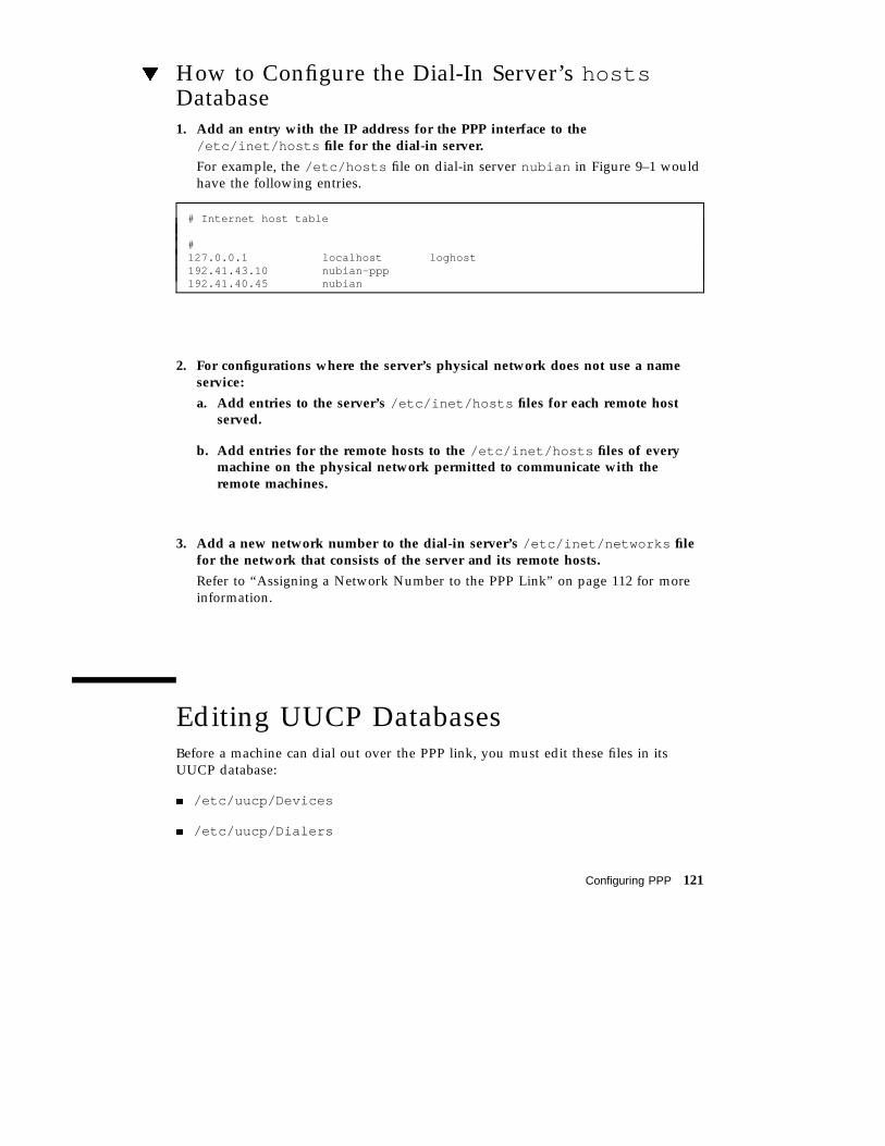
How to Configure the Dial-In Server’s hostsDatabase1. Add an entry with the IP address for the PPP interface to the
/etc/inet/hosts file for the dial-in server.
For example, the /etc/hosts file on dial-in server nubian in Figure 9–1 wouldhave the following entries.
# Internet host table
#127.0.0.1 localhost loghost192.41.43.10 nubian-ppp192.41.40.45 nubian
2. For configurations where the server’s physical network does not use a nameservice:
a. Add entries to the server’s /etc/inet/hosts files for each remote hostserved.
b. Add entries for the remote hosts to the /etc/inet/hosts files of everymachine on the physical network permitted to communicate with theremote machines.
3. Add a new network number to the dial-in server’s /etc/inet/networks filefor the network that consists of the server and its remote hosts.
Refer to “Assigning a Network Number to the PPP Link” on page 112 for moreinformation.
Editing UUCP DatabasesBefore a machine can dial out over the PPP link, you must edit these files in itsUUCP database:
� /etc/uucp/Devices
� /etc/uucp/Dialers
Configuring PPP 121

� /etc/uucp/Systems
You must edit these files for remote hosts serving as PPP dial-out machines.Additionally, you must edit these files on the dial-in server if it is to dial out to theremote hosts (a requirement for multipoint dial-in servers). Chapter 12, describesthese files in detail.
Updating /etc/uucp/Devices for PPPThe /etc/uucp/Devices file must contain entries for every communicationsdevice that a particular host uses or must know about. For example, if a machineuses a US Robotics V.32bis modem as part of the PPP link, you should ensure that/etc/uucp/Devices has an entry similar to the following:
# Use these if you have a USrobotics V.32bis modem on Port B.ACUEC cua/b - 9600 usrv32bis-ecACUEC cua/b - 19200 usrv32bis-ecACUEC cua/b - 38400 usrv32bis-ec
Be sure that the Devices file on each PPP endpoint machine has an entry describingits modem. For more information about /etc/uucp/Devices , refer to“/etc/uucp/Devices File” on page 178.
Updating /etc/uucp/Dialers for PPPThe /etc/uucp/Dialers file must have an entry describing the conversation withthe modem attached to your PPP endpoint machine. Here is a sample entry for a USRobotics V.32bis modem that is part of a PPP link:
usrv32bis-ec =,-, "" \dA\pT&FE1V1X1Q0S2=255S12=255&A1&H1&M5&B2\r\c OK\r\EATDT\T\r\c CONNECT\s14400/ARQ STTY=crtscts
The first parameter in the entry, usrv32bis , corresponds to the last parameter inthe /etc/uucp/Devices file, linking them together. The remainder of the entrydescribes the characters that the modem sends, those that it expects to receive, andso on. Table 12–6 defines the control codes used in the Dialers file.
Be sure that an entry is in the Dialers file for the modem attached to each dial-outendpoint on your link. If you are unsure of the correct conversation for a particularmodem, refer to the System Administration Guide and the operating manual for themodem.
122 TCP/IP and Data Communications Administration Guide ♦ August 1997

Updating /etc/uucp/Systems for PPPThe /etc/uucp/Systems file contains entries for every machine to which the localhost can dial out. Information in an entry might include the remote host’s phonenumber, the line speed, and so on. Here is an example that host nomadb in Figure9–1 might have for its dial-in server:.
nubian-ppp Any ACUEC 38400 5551212 "" P_ZERO ""\r\n\c login:-\r\n\c-login:-\r\n\c-login:-EOT-login: bnomad password: Secret-Password
The first field gives the server’s host name, nubian-ppp , a value used by theasppp.cf file keyword peer_system_name . ACUECand 38400 refer to the deviceand speed, and are used to select an entry from the /etc/uucp/Devices file. Theremaining information includes the phone number of the machine that nomadbwants to dial in to, the login name that nomadb is using to log in, and so on.“/etc/uucp/Systems File” on page 172 fully defines the parameters you need tosupply to the Systems file.
On each remote host in your configuration, you must add an entry for its dial-inserver. You can have additional entries in the /etc/uucp/Systems file for othermachines to which the host can dial out for UUCP communications and for otherPPP dial-in servers.
If the dial-in server also directly dials out to remote hosts, you must add entries toits Systems file describing each of these remote hosts.
Modifying the /etc/passwd FileTo configure a dial-in server, you must also edit the /etc/passwd and/etc/shadow files.
You must add entries to the /etc/passwd file on the dial-in server for each user ona remote host authorized to log in to the server. When a remote host calls the dial-inserver, it reads its UUCP databases and passes the server a user name or user ID forthe host initiating the call. The server then verifies this user information in its/etc/passwd file.
If the user’s password is authenticated, the server then logs the user in to a specialshell for PPP hosts, /usr/sbin/aspppls . The server gets this information from thelogin shell entry in its /etc/passwd file. Using the example in Figure 9–1, dial-inserver nubian might have the following entries in its /etc/passwd file:
Configuring PPP 123

bin:x:2:2::/bin:sys:x:3:3::/bin:
uucp:x:5:5::/usr/lib/uucp:nuucp:x:9:9::/var/spool/uucppublic:/usr/lib/uucp/uuciconews:x:6:6::/var/spool/news:/bin/cshsundiag:x:0:1:System Diagnostic:/usr/diag/sundiag:/usr/diag/sundiag/sundiaglily:x:20:99:Dial-in Operator:/home/nubian/lily:/bin/cshnomada:x:21:99:R. Burton:/:/usr/sbin/asppplsnomadb:x:22:99:T. Sherpa:/:/usr/sbin/asppplsnomadc:x:23:99:S. Scarlett:/:/usr/sbin/aspppls
Refer to System Administration Guide for information about the /etc/passwd file.
Note - In addition to the information in the /etc/passwd file, you update the/etc/shadow file with the passwords for the login names used by each endpointmachine permitted to dial in to the server. For more information, refer to SystemAdministration Guide.
Editing the /etc/asppp.cfConfiguration FileThe /etc/asppp.cf configuration file provides the PPP link manager on oneendpoint machine with information about the machine on the other end of thelink—or the machines on the other end of a multipoint (or dynamic point-to-point)link. When the machine boots, the link manager uses this information to establishand maintain communication with a remote endpoint.
Parts of Basic Configuration FileThe basic asppp.cf configuration file must contain at least two main sections: anifconfig line and at least one path section. It can also contain a defaultssection, which you use when you want to set the default values for an endpoint.(Refer to Chapter 11, for a description of keywords used in the defaults section.)
Example 9–1 shows a basic configuration file such as you would create for a remotehost to establish a point-to-point link with a dial-in server.
124 TCP/IP and Data Communications Administration Guide ♦ August 1997

EXAMPLE 9–1 Basic Configuration File
ifconfig ipdptp0 plumb nomada nubian-ppp uppath
interface ipdptp0peer_system_name nubian-ppp # The name in the /etc/uucp/Systems fileinactivity_timeout 300 # Allow five minutes before timing out
ifconfig Section of the asppp.cf FileThe asppp.cf file must contain an ifconfig section with this syntax:
ifconfig interface-number plumb local-machine remote-machine up
Here is a description of the fields:
� ifconfig – Tells the link manager to run the ifconfig command and beginconfiguring the PPP interface.
� interface-number – Identifies the PPP interface ipdptp n for a point-to-point link oripd n for a multipoint link. (Replace the n with the number of the interface.)
� plumb – Option of ifconfig that enables IP to recognize the interface.
� local-machine – Gives the name of the local endpoint, which can be the local hostname or IP address.
� remote-machine – Gives the name of the remote endpoint, which can be the remotehost name or IP address.
� up – Option of ifconfig that marks the interface just described as “up”.
The link manager first runs the ifconfig command on the local machine toconfigure the ipdptp0 point-to-point interface. The zero in ipdptp0 gives the devicenumber of the interface. The plumb option performs various activities necessary forIP to recognize the ipdptp0 interface. nomada is the name of the local host.nubian-ppp is the name of the dial-in server to which nomada connects throughthe point-to-point link. The ifconfig option up marks the ipdptp0 interface as up.
Note - For more information about ifconfig , see Chapter 10, and theifconfig (1M) man page.
path Section of the asppp.cf FileThe path section of the configuration file tells the link manager the name of theremote endpoint and the name of the interface linking the endpoint machines. At aminimum the path section should contain the following lines:
Configuring PPP 125

pathinterface interface-number
peer_system_name endpoint-name
interface KeywordThis keyword defines the PPP interface (either ipdptp n or ipd n). In Example 9–1,the following information appears in the path section:
interface ipdptp0peer_system_name nubian-ppp
The interface keyword identifies ipdptp0 as the point-to-point interface thatlocal endpoint nomada uses to communicate with the remote endpoint in the mannerdescribed in this path section. It associates the peer_system_name with theinterface.
peer_system_name KeywordOn a dial-out machine such as a remote host, the peer_system_name keywordtakes the host name of the remote endpoint as its argument. This is the name of theremote endpoint given in /etc/uucp/Systems . The name need not be the same asthe host name on the corresponding ifconfig line.
Note - The argument to the peer_system_name keyword for a dial-in server has adifferent value. See “Configuration File for Multipoint Dial-in Server” on page 127for details.
In Example 9–1, peer_system_name identifies dial-in server nubian-ppp as theremote endpoint at the other end of this link. When the link manager reads theasppp.cf file, it then looks for the entry for nubian-ppp in the/etc/uucp/Systems file. (Recall that the Systems file contains information abouthow to set up communications with the remote endpoint, including that machine’stelephone number. Refer to “Updating /etc/uucp/Systems for PPP” on page 123.)
inactivity_timeout KeywordThe inactivity_timeout keyword is optional. It tells the link manager that thelink can remain inactive for the interval designated. When that interval is passed, thelink manager knows to automatically disconnect the link. The default interval is twominutes; you do not have to use inactivity_timeout unless you require adifferent inactivity interval.
126 TCP/IP and Data Communications Administration Guide ♦ August 1997

Additional KeywordsYou can supply other keywords in the asppp.cf file to define how endpointmachines should communicate. Chapter 11, has complete information about thesekeywords.
Configuration File for Multipoint Dial-in ServerThe asppp.cf configuration file for a multipoint dial-in server contains the samebasic sections as that for a point-to-point link: an ifconfig section, at least onepath section, and, if desired, a defaults section.
Example 9–2 shows a configuration file for the dial-in server nubian introduced inFigure 9–1.
EXAMPLE 9–2 Configuration File for a Multipoint Dial-in Server
ifconfig ipd0 plumb nubian-ppp up
pathinterface ipd0peer_system_name tamerlane # The user name this remote
# machine logs in with when it# dials this server
peer_ip_address nomada# nomada is a remote machine that# dials in to this server
# nomadb is another remote machine that dials in to nubian
pathinterface ipd0peer_system_name lawrencepeer_ip_address nomadb
# nomadc is another remote machine that dials in to nubian
pathinterface ipd0peer_system_name azzizpeer_ip_address nomadc
ifconfig Section for Multipoint Dial-in ServerThe ifconfig section for a multipoint dial-in server has a slightly different syntaxthan that for a point-to-point link. This syntax is:
ifconfig ipd n plumb server-name up
Configuring PPP 127

The major difference is that no destination end points are listed as arguments toifconfig . Instead, the link manager picks up this information from the pathsection of the asppp.cf file.
In Example 9–2, the link manager first runs the ifconfig command on the dial-inserver to configure multipoint interface ipd0 . The zero in ipd0 gives the devicenumber of the interface. The option plumb performs various activities necessary forIP to recognize the ipd0 interface. The ifconfig option up marks interface ipd0as up.
Note - You may have to supply a netmask + parameter on the ifconfig line if youuse subnetting.
path Section for Multipoint Dial-in ServerThe path section of the asppp.cf file tells the link manager the name of the remoteendpoint and the name of the interface linking the endpoint machines. However, on amultipoint dial-in server, you can include more than one path section. Additionally,some of the arguments to the keywords are used differently with multipoint links.
pathinterface interface-numberpeer_system_name endpoint-usernamepeer_ip_address endpoint-hostname
You need to define a path section for each nomadic endpoint with which the dial-inserver can establish connections.
interface KeywordFor a multipoint dial-in server, the interface keyword defines the PPP interfaceipd n. You must specify the same PPP interface in the path section for everyendpoint that communicates with the server through this interface.
peer_system_name KeywordThe peer_system_name keyword takes a slightly different argument for a dial-inmachine than a dial-out machine. For a dial-in server, this argument is the loginname used by the remote host when it tries to establish communications with theserver. This user name must already be present in the server’s /etc/passwd file.When the login service reads this name, it verifies the user name in the/etc/passwd and /etc/shadow files enabling communications.
128 TCP/IP and Data Communications Administration Guide ♦ August 1997

In this excerpt from Example 9–2:
pathinterface ipd0peer_system_name scarlettpeer_ip_address nomadc
the argument to peer_system_name is scarlett , indicating that when nomadclogs in to nubian-ppp , it uses the login name scarlett .
peer_ip_address KeywordThe peer_ip_address keyword is required for multipoint links. It takes the hostname or IP address of the remote endpoint as its argument. The example above usesthe host name nomads as the argument to keyword peer_ip_address .
Additional KeywordsYou can supply other keywords in the asppp.cf file to define how endpointmachines should communicate. Refer to Chapter 11, for a complete list of keywords.
Editing the Configuration FileWhen editing asppp.cf :
� Separate keywords in the configuration file by white space (blanks, tabs, and newlines).
� Use a # sign before all character strings meant as comments. All characters placedbetween a # sign and the next new line are considered comments and ignored.
There are no other format requirements for the placement of the keywords in the file.
How to Edit the asppp.cf Configuration File1. Become superuser on one endpoint machine and change to the /etc directory.
2. Edit the generic asppp.cf file to add the information defining the PPP link forthis machine.
3. Save the file, making sure the permissions are set to 600 .
4. Change to the /etc directories on the remaining endpoints and repeat Steps 2and 3.
Configuring PPP 129
Adding PPP SecurityAfter you have completed installing PPP on every machine involved in yourconfiguration, you can add either PAP or CHAP levels of security for the PPP link bymodifying the asppp.cf file. Refer to “Editing asppp.cf for PAP/CHAP Security”on page 156.
Starting up and Stopping Your NewPPP LinkYou can start PPP either automatically, at boot time, or manually from the commandline.
How to Manually Start PPPYou can start PPP manually, although this is not normally required.
1. Become superuser and type:
# /etc/init.d/asppp start
How to Verify That PPP Is Running1. Run the ps command:
# ps -e | grep asppp
The resulting output from grep should list the aspppd daemon, indicating thatPPP is running.
2. If you do get results, verify that you can reach the remote PPP link by typing:
# ping remote-host 300
This version of ping sets a timeout value of 5 minutes (300 seconds). You shouldreceive output similar to remote-host is alive . If you receive a different notice,such as remote-host unreachable , route configuration has failed.
130 TCP/IP and Data Communications Administration Guide ♦ August 1997

3. Check for errors in the configuration process by examining the log file.
# tail /var/adm/log/asppp.log
The asppp.log contains error messages if any errors were encountered duringconfiguration.
See Chapter 10, for information on troubleshooting and problem solving.
How to Stop PPP1. To stop PPP operations on your network, type:
# /etc/init.d/asppp stop
Configuring PPP 131

132 TCP/IP and Data Communications Administration Guide ♦ August 1997

CHAPTER 10
Troubleshooting PPP
This chapter is organized as a series of checks to make after you have configuredPPP on your network. Thereafter, whenever you have trouble communicating overthe PPP link, you can use PPP diagnostics to help troubleshoot problems.
� “Checking Hardware” on page 134
� “Checking Interface Status” on page 134
� “Checking Connectivity” on page 135
� “Checking Interface Activity” on page 135
� “Checking the Local Routing Tables” on page 135
� “Checking Permissions” on page 137
� “Checking Packet Flow” on page 137
� “Using PPP Diagnostics for Troubleshooting” on page 138
In summary, you should do these checks in the following order:
1. Hardware
2. Interface status
3. Connectivity
4. Network interface activity
5. Local routing tables
6. Permissions
7. Packet flow
If PPP passes all the tests, you should be able to use TCP and UDP services such asrlogin , telnet , and ftp over the link. If the link still fails, turn on PPPdiagnostics for assistance in troubleshooting.
The next sections describe these checks in detail.
133

Checking HardwareMake sure that all modem and power cables are tightly seated. If you are havingproblems with PPP, always check the modems, cables, serial card, and phone linesfirst.
Checking Interface StatusAfter PPP is started, you can use ifconfig to monitor the current state of the line,using only the PPP interface name as an argument. Example 10–1 shows sampleoutput from ifconfig for PPP links that are running.
EXAMPLE 10–1 ifconfig Output for Point-to-Point Link
nomadb# ifconfig ipdptp0
ipdptp0: flags=28d1<UP,POINTOPOINT,RUNNING,NOARP,MULTICAST,UNNUMBERED> mtu 1500inet 129.144.111.26 --> 129.144.116.157 netmask ffff0000ether 0:0:0:0:0:0
You receive output similar to that in Example 10–1 for both standard and dynamicpoint-to-point links.
EXAMPLE 10–2 ifconfig Output for Multipoint Link
nubian# ifconfig ipd0
ipd0: flags=c1<UP,RUNNING,NOARP> mtu 1500inet 129.144.201.191 netmask ffffff00ether 0:0:0:0:0:0
If ifconfig does not display UP and RUNNING, you did not configure PPP correctly.For more information on ifconfig , see “ifconfig Command” on page 80 and theifconfig (1M) man page.
134 TCP/IP and Data Communications Administration Guide ♦ August 1997

Checking ConnectivityUse the ping command to verify that the connection is up or can be established. Forexample, consider the following simple round-trip test:
# ping elvis
where elvis is the name of the PPP interface on the remote host. If the resultingdisplay is
elvis is alive
then packets can be sent to and received from elvis . If not, a routing problem existsat some point between the local and remote hosts. For more information on ping ,refer to “ping Command” on page 78 and the ping (1M) man page.
Checking Interface ActivityUse the netstat command as follow, to check that packets are being sent andreceived correctly:
# netstat --i
Refer to “netstat Command” on page 81 and the netstat (1M) man page.
Checking the Local Routing TablesUse the netstat command to display the local routing tables:
# netstat --r
The following is sample output:
Troubleshooting PPP 135

Routing tablesDestination Gateway Flags Refcnt Use Interfacesahara deserted UGH 0 0 ie1karakum labia UGH 0 0 ie1frodo bilbo UGH 1 12897 ipdptp0route7 route7 UGH 0 0 ie0eastgate route71 UGH 0 158 ie0backbone pitstopbb U 1 16087 ie1dresdenpc route1 UG 0 0 ie1loopback localhost U 2 113436 lo0swan-bb pitstop U 406 146044 ie0dallas2 route7 UG 0 0 ie0trainingpc route62 UG 0 0 ie1
Make sure there is a routing table entry for each possible destination network. Inparticular, PPP devices, listed under Interface , should be matched with theappropriate host names listed under Gateway . The Gateway entry should, in turn,be matched with the correct entry under Destination .
Otherwise, if you are using static routing, add the appropriate static routes. If you areusing dynamic routing with in.routed :
1. Verify that in.routed is running by typing:
# ps -e | grep route
If the routing tables still don’t look correct, become superuser and continue withthe next steps.
2. Kill in.routed by typing the process ID you got from ps -e as the argumentto kill . For example, if 1384 was the process ID, you would type:
# kill 1384
3. Flush the routing tables as follows:
# /usr/sbin/route -f
4. Restart in.routed :
# /usr/sbin/in.routed
136 TCP/IP and Data Communications Administration Guide ♦ August 1997

Checking PermissionsIf you attempt to use rsh and receive the message Permission denied , theremote system’s /etc/hosts.equiv or /.rhosts file does not contain the sendingsystem’s host name or does not contain the line +.
Checking Packet FlowCheck the packet flow next. Use the snoop command to observe packets from thenetwork and observe their contents. Example 10–3 shows some sample output fromsnoop .
EXAMPLE 10–3 Sample Output from snoop
# snoop -d ipdptp0Using device ipdptp0 (promiscuous mode)corey -> pacifica7 RLOGIN C port=1019
hugo -> ponc3 RPC R XID=22456455 Successponc3 -> hugo NFS C WRITE FH=1B29 at 32768
commlab3 -> commlab4 TELNET R port=34148commlab4 -> commlab3 IP D=129.144.88.3 S=129.144.88.4 LEN=46, ID=41925commlab3 -> commlab4 TELNET R port=34148commlab4 -> commlab3 ICMP Echo requestcommlab3 -> commlab4 ICMP Echo replycommlab4 -> commlab3 FTP C port=34149commlab4 -> commlab3 FTP C port=34149commlab3 -> commlab4 FTP R port=34149commlab4 -> commlab3 FTP C port=34149
The ipdptp0 device name mentioned in the first line of the outputUsing device ipdptp0 indicates a point-to-point connection.
Note - You need to have the link up and some traffic generated in order to usesnoop to check the line status.
snoop captures packets from the network and displays their contents. It uses boththe network packet filter and streams buffer modules to provide efficient capture ofpackets from the network. Captured packets can be displayed as they are received orsaved to a file for later viewing.
Troubleshooting PPP 137

snoop can display packets in a single-line summary form or in verbose multilineforms. In summary form, only the data pertaining to the highest-level protocol isdisplayed. For example, an NFS packet will have only NFS information displayed.The underlying RPC, UDP, IP, and Ethernet frame information is suppressed but canbe displayed if either of the verbose options is chosen.
For more information about the snoop command, refer to the snoop (1M) man page.
Using PPP Diagnostics forTroubleshootingIf you have problems with a link after successfully establishing modem connections,you can use PPP-level diagnostics for troubleshooting. PPP-level diagnostics reportdetailed information about the activities of a link to help you determine where it isfailing.
To obtain diagnostic information, add the line debug_level 8 to the path sectionof the asppp.cf file. (If you are very knowledgeable about data communications,you might want to use debug level 9, which provides very detailed information.)Here is a sample configuration file that invokes PPP diagnostics.
ifconfig ipdptp0 plumb nomada nubian-ppp uppath
interface ipdptp0peer_system_name nubian-ppp #The name in the /etc/uucp/Systems fileinactivity_timeout 300 #Allow five minutes before timing outdebug_level 8 #Start up PPP diagnostics for this link
For complete details about the aspppd.conf file, refer to “Editing the/etc/asppp.cf Configuration File” on page 124.
How to Set Diagnostics for Your MachineSet diagnostics on the host you want to monitor as follows:
1. Become superuser and change to the /etc directory.
2. Edit the current asppp.cf file and add the following to the path section:debug_level 8 .
3. Save the file, making sure the permissions are set to 600 .
4. Kill the current aspppd daemon and restart it.
138 TCP/IP and Data Communications Administration Guide ♦ August 1997

#kill PID#aspppd
where PID is the process ID for aspppd .
PPP reports diagnostic information in /var/adm/log/asppp.log .
Analyzing Diagnostic OutputWhen a PPP link runs correctly, the asppp.log file includes diagnostic informationin addition to its normal output. This section explains what the diagnostic messagesmean. If your output is different, refer to RFC 1331.
Host and Modem SetupThis section contains messages that occur as the local host sends configurationinformation to the modem, and then as the modem tries to dial the remote host.These initial activities are actually handled by the UUCP daemon. You might think ofthem as the UUCP portion of asynchronous PPP communications. (Refer to Chapter12, for complete details on UUCP.)
The two messages below should always appear at the beginning of the session. Theyindicate that the aspppd daemon has started successfully.
11:53:33 Link manager (1057) started 04/14/9411:53:33 parse_config_file: Successful configuration
The next line indicates that a packet was routed to the ipdptp0 interface on thelocal host. It helps you to determine if a dial-out is occurring correctly. For example,if you tried to ping the remote machine and this message isn’t in asppp.log , thepacket was lost, probably due to a routing problem.
Next, UUCP looks for an entry that matches Ppac7 in a chat script in the/etc/uucp/Systems file. It then reports that it found an entry that had a devicetype ACUTEC. (For more information on the Systems file, refer to“/etc/uucp/Systems File” on page 172.)
Troubleshooting PPP 139

11:53:46 process_ipd_msg: ipdptp0 needs connectionconn(Ppac7)Trying entry from ’/etc/uucp/Systems’ - device type ACUTEC.
UUCP then finds the dialing information for an ACUTEC dialer in the/etc/uucp/Devices file. When it finds the information, it opens the appropriateserial port on the local host and sets it with a speed of 9600. (For more informationon /etc/uucp/Devices , see “/etc/uucp/Devices File” on page 178.)
Device Type ACUTEC wantedTrying device entry ’cua/a’ from ’/etc/uucp/Devices’.processdev: calling setdevcfg(ppp, ACUTEC)fd_mklock: okfixline(8, 9600)gdial(tb9600-ec) calle
UUCP looks for the entry tb9600 in the /etc/uucp/Dialers file and then sendsout these messages.
Trying caller script ’tb9600-ec’ from ’/etc/uucp/Dialers’expect: (‘‘’’)
The host waits a couple of seconds and then sets the registers on the modem. Theinformation shown in the log below is modem-specific. It comes from the/etc/uucp/Dialers file.
got itsendthem (DELAY)APAUSEAPAUSEAPAUSET&D2E1V1X1Q0S2=255S12=255S50=6S58=2^M<NO CR>)
The next lines are the dialog between the modem and the host machine.expect (OK^M) means that the host expects the modem to send an ”okay.” Thewords got it at the end of the second line indicate that the host got the “okay”message from the modem.
140 TCP/IP and Data Communications Administration Guide ♦ August 1997

expect: (OK^M)AAAT&D2E1V1X1Q0S2=255S12=255S50=6S58=2^M^M^JOK^Mgot it
Next, the host sends the string below to the modem, which does the actual dialing.The phone number in the second line is retrieved from the entry for the remote hostin the /etc/uucp/Systems file.
sendthem (ECHO CHECK ONA^JATTDDTT99003300887744^M^M<NO CR>)
The line beginning with expect indicates that the local host expects to get aresponse from the modem at a speed of 9600 bps. The next line indicates that themodem responded.
expect: (CONNECT 9600)^M^JCONNECT 9600got it
This line indicates that hardware flow control has started on the link. The hostobtains flow control information from the /etc/uucp/Dialers file.
STTY crtscts
In the next series of messages, the local host waits for the remote host to send it astandard UNIX login prompt.
getty ret 8expect: (‘‘‘‘)got itsandiest (^J^M)expect: (login:)
The next messages indicate that the local host has received the login prompt from theremote. It then retrieves the appropriate login sequence from the chat script in the/etc/uucp/Systems entry for the remote host. This sequence is Ppong^M, which isrequired for login by the remote host.
Troubleshooting PPP 141
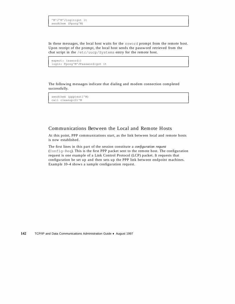
^M^J^M^Jlogin:got itsendthem (Ppong^M)
In these messages, the local host waits for the ssword prompt from the remote host.Upon receipt of the prompt, the local host sends the password retrieved from thechat script in the /etc/uucp/Systems entry for the remote host.
expect: (ssword:)login: Ppong^M^JPassword:got it
The following messages indicate that dialing and modem connection completedsuccessfully.
sendthem (ppptest1^M)call cleanup(0)^M
Communications Between the Local and Remote HostsAt this point, PPP communications start, as the link between local and remote hostsis now established.
The first lines in this part of the session constitute a configuration request(Config-Req ). This is the first PPP packet sent to the remote host. The configurationrequest is one example of a Link Control Protocol (LCP) packet. It requests thatconfiguration be set up and then sets up the PPP link between endpoint machines.Example 10–4 shows a sample configuration request.
142 TCP/IP and Data Communications Administration Guide ♦ August 1997

EXAMPLE 10–4 Configuration Request
11:54:20 004298 ipdptp0 SEND PPP ASYNC 29 Octets LCP Config-ReqID=4c LEN=24 MRU=1500 ACCM=00000000 MAG#=69f4f5b2 ProtFCOMP
AddrCCOMP
Here is a description of the configuration request shown in Example 10–4.
� 11:54:20 – Time stamp field, indicating the time when the packet was sent
� 004298 – Number of the packet
� ipdptp0 – Network interface used� SEND PPP ASYNC– Indicates that the modem is sending asynchronous PPP
� 29 Octets – Amount of data the host sent
� LCP – Packet type to send
� ID=4c – Identifier associated with the packet; it is actually part of the packet
� LEN=24 – Length of the LCP part of the packet
The remaining items are a list of options to be negotiated between hosts.
� MRU=1500– Maximum Receive Unit (MRU), the largest packet size the callinghost can receive from the remote host
� ACCM=00000000 – Asynchronous Character Map (ACCM), the mask sent to theremote host that tells what control characters to escape on transmission
� MAG#=69f4f5b2 – Magic number field; used for loopback detection mechanism
� ProtFCOMP AddrCCOMP– Asks for the remote host to compress certain parts ofthe frame header (protocol field, address field).
The next lines are reporting invalid PPP packets. They come from the remote host,which is sending out UNIX text. This does not indicate a problem with PPP.
11:54:20 004299 ipdptp0 RECEIVE {Invalid ppp packet}PPP ASYNC 7Octets [BAD FCS] {Unrecognized protocol: 1}
11:54:20 004299 ipdptp0 RECEIVE PPP ASYNC 73 Octets [BAD FCS]{Unrecognized protocol: 880a}
In these packets, the local host receives the remote host’s request for configuration,then sends out another configuration request. The packets are identical except fortheir ID fields. The ID field helps to distinguish between the two packets.
Troubleshooting PPP 143

11:54:21 004301 ipdptp0 RECEIVE PPP ASYNC 29 Octets LCP Config-Req ID=35 LEN=24 MRU=1500 ACCM=00000000 MAG#=a8562e5f ProtFCOMPAddrCCOMP
11:54:21 004302 ipdptp0 SEND PPP ASYNC 29 Octets LCP Config-ReqID=4d LEN=24 MRU=1500 ACCM=00000000 MAG#=69f4f5b2 ProtFCOMPAddrCCOMP
In this packet, the local host acknowledges the remote request by sending it aconfiguration acknowledgment (Config-ACK ).
11:54:21 004303 ipdptp0 SEND PPP ASYNC 29 Octets LCP Config-ACKID=35 LEN=24 MRU=1500 ACCM=00000000 MAG#=a8562e5f ProtFCOMPAddrCCOMP
The local host receives a configuration request (Config-Req ) from the remote host.
11:54:21 004304 ipdptp0 RECEIVE PPP ASYNC 29 Octets LCP Config-Req ID=36 LEN=24 MRU=1500 ACCM=00000000 MAG#=a8562e5f ProtFCOMPAddrCCOMP
In these packets, the local host acknowledges the second packet sent by the remotehost and receives the remote host’s acknowledgment.
11:54:21 004305 ipdptp0 SEND PPP ASYNC 29 Octets LCP Config-ACKID=36 LEN=24 MRU=1500 ACCM=00000000 MAG#=a8562e5f ProtFCOMPAddrCCOMP
11:54:21 004306 ipdptp0 RECEIVE PPP ASYNC 29 Octets LCP Config-ACK ID=4d LEN=24 MRU=1500 ACCM=00000000 MAG#=69f4f5b2 ProtFCOMPAddrCCOMP
Here the local host negotiates parameters about IP transmission. LEN=16 gives thepacket size. VJCOMPindicates Van Jacobsen header compression. IPADDR is followedby the calling host’s IP address.
144 TCP/IP and Data Communications Administration Guide ♦ August 1997

11:54:21 004307 ipdptp0 SEND PPP ASYNC 21 Octets IP_NCP Config-Req ID=4e LEN=16 VJCOMP MAXSID=15 Sid-comp-OK IPADDR=192.9.68.70
This packet indicates that the local host has received IP configuration from theremote host, including its IP address.
11:54:22 004308 ipdptp0 RECEIVE PPP ASYNC 21 Octets IP_NCPConfig-Req ID=37 LEN=16 VJCOMP MAXSID=15 Sid-comp-OKIPADDR=192.9.68.71
The local host sends this ACK to the remote host and receives an ACK from theremote host.
11:54:22 004309 ipdptp0 SEND PPP ASYNC 21 Octets IP_NCP Config-ACK ID=37 LEN=16 VJCOMP MAXSID=15 Sid-comp-OK IPADDR=192.9.68.71
11:54:22 004310 ipdptp0 RECEIVE PPP ASYNC 21 Octets IP_NCPConfig-ACK ID=4e LEN=16 VJCOMP MAXSID=15 Sid-comp-OKIPADDR=192.9.68.70
The first message below indicates that IP has started on the link. The next messageindicates that the local host is sending IP traffic over the link.
11:54:22 start_ip: IP up on interface ipdptp0, timeout set for120 seconds
11:54:24 004311 ipdptp0 SEND PPP ASYNC 89 Octets IP_PROTO
In the first message below the local host receives IP traffic from the remote host. Thesubsequent messages indicate that the interface was disconnected because of an idletime-out.
Troubleshooting PPP 145

11:54:25 004312 ipdptp0 RECEIVE PPP ASYNC 89 Octets IP_PROTO11:56:25 process_ipd_msg: interface ipdptp0 has disconnected11:56:25 disconnect: disconnected connection from ipdptp0
The next messages begin the termination sequence. The first message indicates thatthe remote host has sent a packet to terminate the IP layer. The second is the localhost’s acknowledgment of the request to terminate.
11:56:25 004313 ipdptp0 RECEIVE PPP ASYNC 9 Octets IP_NCP Term-REQ ID=38 LEN=4
11:56:25 004314 ipdptp0 SEND PPP ASYNC 9 Octets IP_NCP Term-ACKID=38 LEN=4
The local host receives a request to terminate the LCP layer. The second message isan acknowledgment of the request, causing a graceful shutdown.
11:56:25 004315 ipdptp0 RECEIVE PPP ASYNC 9 Octets LCP Term-REQID=39 LEN=4
11:56:25 004316 ipdptp0 SEND PPP ASYNC 9 Octets LCP Term-ACKID=39 LEN=4
This message indicates that the link has closed.
11:56:29 004317 ipdptp0 PPP DIAG CLOSE
146 TCP/IP and Data Communications Administration Guide ♦ August 1997
CHAPTER 11
Tailoring Your PPP Link
This chapter contains information you need to configure PPP links less commonlyused than the basic links described in Chapter 9. The text includes instructions forconfiguring two types of PPP links: the dial-in server with dynamic point-to-pointlinks and the virtual network, which uses multipoint links. The chapter concludeswith tables listing all available keywords for the asppp.cf configuration file.
� “Addressing Issues for Dynamically Allocated Links” on page 149
� “Editing asppp.cf for Dynamic Link” on page 150
� “Addressing Issues for Virtual Networks” on page 154
� “asppp.cf Configuration File for a Virtual Network” on page 155
� “Editing asppp.cf for PAP/CHAP Security” on page 156
� “Configuration Keywords” on page 161
Configuring Dynamically Allocated PPPLinksA dial-in server with a dynamic point-to-point link gives your site all the advantagesof point-to-point communications. Chapter 7, introduces this configuration type. Itconsists of remote hosts communicating with at least one dial-in server thatdynamically allocates point-to-point links on an as-needed basis. The sampleconfiguration shown in Figure 11–1 is used throughout this section.
147

Modem
Modem
Modem
Modem
mojave
ipdptp0
nomada
nomadb
nomadc
192.41.40.55
Network 40
Modem
Modem
ipdptp1
ipdptp2
(primary interface)
Figure 11–1 Network of Remote Hosts and Dynamic Link Dial-in Servers
Each remote host communicates with the dial-in server using a standardpoint-to-point link. However, unlike the multipoint dial-in server in Figure 9–1,dial-in server mojave connects to a calling host over a dynamic point-to-point link.The server allocates an available link whenever a remote host attempts to establish aconnection.
The idea behind a dynamic link is that the server provides the client with an IPaddress each time a connection is established. When the connection is established,the server allocates an available IP interface to the client. The remote IP address ofthe interface then becomes the client’s IP address for the duration of the connection.When the connection is terminated, the IP interface is returned to the pool ofavailable interfaces, ready to be used for another connection.
You use the same generic procedures for configuring dynamic links as you do for theremote host–to–multipoint dial-in server link, as described in “Overview of theConfiguration Process” on page 117. However, the dynamic point-to-point link hasits own set of issues and requires slightly different modifications to the files involvedin configuration.
148 TCP/IP and Data Communications Administration Guide ♦ August 1997

Addressing Issues for Dynamically AllocatedLinksYou must add host information to the /etc/inet/hosts file for each machine thatuse the dynamically allocated PPP link. The IP addresses for the PPP endpointsshould follow these conventions:
� For the dial-in server, you must use the IP address of the server’s primary networkinterface (for example le0 or smc0) as the address of the dynamic link.
� For a dynamic link, you don’t need to assign an IP address to each remote host (asyou would for a static link), but you do need to assign a remote IP address to eachpoint-to-point IP interface on the server. The number of IP interfaces you can useis equal to the number of modems your server is connected to. For example, if youhave three modems, you need three point-to-point IP interfaces and three IPaddresses
� You must include a dummy IP address for the ifconfig command to workproperly on the client. This address acts as a placeholder for the local IP addressassigned to the client IP interface when PPP is started.
Note - There are no restrictions on the remote IP addresses that can be assigned tothe IP interfaces, but, for clarity, it is probably best to include only IP addressesbelonging to the same subnet.
Updating the hosts Database for Dynamic LinksYou must update the hosts database on all machines involved in the dynamic-linkconfiguration.
How to Update a Remote HostWhen configuring the hosts databases on the remote machines, do the following:
1. Add to the /etc/inet/hosts file the IP address and host name of theprimary network interface for each dial-in server on the other end of the link.
For example, in Figure 11–1, the /etc/inet/hosts file for nomada, nomadb,and nomadc should each include the IP address of the primary network interfaceof the dial-in server mojave .
2. Add the dummy IP address.
This IP address is used only when PPP is started.
The /etc/inet/hosts file on nomadc might look like:
# Internet host table#
Tailoring Your PPP Link 149
(Continuation)
127.0.0.1 localhost loghost192.41.40.55 mojave1.2.3.4 dummy
3. Add to the /etc/inet/hosts file the IP addresses of all machines on thedial-in server‘s physical network that the remote host can remotely log in to.
4. Update the databases on any name server on the physical network with thehost names and IP addresses of the remote hosts.
How to Update the Dial-in ServerYou do not have to add any PPP-specific address to the hosts database for thedial-in server. The dynamically allocated link must use the server’s primary networkinterface. Therefore, when configuring the hosts database for the dial-in server, dothe following:
1. Add entries to the server’s /etc/inet/hosts files for each remote host served.
2. Add to the /etc/inet/hosts files of every machine on the physical networkentries for any remote hosts they are permitted to communicate with.
Considerations for Other FilesThe next steps in the configuration process involve editing the /etc/passwd fileand the /etc/shadow file. Edit these files for the dynamic–link configurations justas you would for the remote host–to–multipoint dial-in server configuration. Refer to“Modifying the /etc/passwd File” on page 123 for information regarding the/etc/passwd and /etc/shadow files.
Editing asppp.cf for Dynamic LinkThe asppp.cf configuration file for a dynamic–link configuration must containinformation about remote hosts and the interfaces to use for the PPP link. After thedial-in server boots, its link manager uses this information to establishcommunications whenever the server is called by a remote endpoint.
150 TCP/IP and Data Communications Administration Guide ♦ August 1997

Remote Host with Dynamic LinkThe asppp.cf configuration file for a remote host is the same as the one describedin “Parts of Basic Configuration File” on page 124, except for the addition of theparameter negotiate_address:
ifconfig ipdptp0 plumb dummy mojave uppath
interface ipdptp0peer_system_name mojave-pppconnectivity_timeout 300negotiate_address on
The negotiate_address parameter indicates whether or not local IP address assignmentis obtained through negotiation and assigned dynamically. If set to on, the IP addresssupplied by the server is used as the client’s local address for the duration of theconnection.
Dial-in Server With Dynamic LinkWhen the dial-in server receives an incoming packet, the link manager reads thepath sections of its configuration file to identify the remote endpoint and determinethe interface to use. The configuration file shown in Example 11–1 does not containan interface keyword. Instead, the link manager uses interface informationestablished in the defaults section.
The asppp.cf configuration file for a dial-in server with dynamically allocated linksmight resemble Example 11–1:
EXAMPLE 11–1 Configuration File for Server With Dynamically Allocated Link
ifconfig ipdptp0 plumb mojave clienta downifconfig ipdptp1 plumb mojave clientb downifconfig ipdptp2 plumb mojave clientc down
# This means grab whatever interface is available (not in use)defaults
interface ipdptp*
# Each path specifies a machine that might dial up / log# in to this server
pathpeer_system_name tamerlane # nomada uses the login name
# tamerlane
(continued)
Tailoring Your PPP Link 151
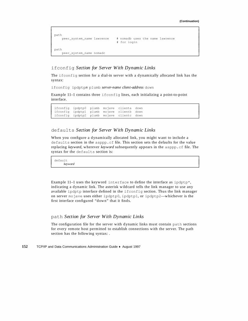
(Continuation)
pathpeer_system_name lawrence # nomadb uses the name lawrence
# for login
pathpeer_system_name nomadc
ifconfig Section for Server With Dynamic Links
The ifconfig section for a dial-in server with a dynamically allocated link has thesyntax:
ifconfig ipdptp n plumb server-name client-address down
Example 11–1 contains three ifconfig lines, each initializing a point-to-pointinterface.
ifconfig ipdptp0 plumb mojave clienta downifconfig ipdptp1 plumb mojave clientb downifconfig ipdptp2 plumb mojave clientc down
defaults Section for Server With Dynamic Links
When you configure a dynamically allocated link, you might want to include adefaults section in the asppp.cf file. This section sets the defaults for the valuereplacing keyword, wherever keyword subsequently appears in the asppp.cf file. Thesyntax for the defaults section is:
defaultkeyword
Example 11–1 uses the keyword interface to define the interface as ipdptp* ,indicating a dynamic link. The asterisk wildcard tells the link manager to use anyavailable ipdptp interface defined in the ifconfig section. Thus the link manageron server mojave uses either ipdptp0 , ipdptp1 , or ipdptp2 —whichever is thefirst interface configured “down” that it finds.
path Section for Server With Dynamic Links
The configuration file for the server with dynamic links must contain path sectionsfor every remote host permitted to establish connections with the server. The pathsection has the following syntax: .
152 TCP/IP and Data Communications Administration Guide ♦ August 1997

pathpeer_system_name endpoint-username
No interface keyword has been defined in the path section because this value isdefined in the defaults section.The peer_system_name keyword has the samemeaning here as it does in the configuration file for the multipoint server. See “pathSection for Multipoint Dial-in Server” on page 128 for more information.
Additional Keywords
You can supply other keywords in the asppp.cf file to define how endpointmachines should communicate, including the use of security keywords as explainedin “Configuration Keywords” on page 161.
Configuring a Virtual NetworkVirtual networks consist of a group of standalone computers, each in an isolatedlocation, that can connect to each other through PPP multipoint links. “VirtualNetworks” on page 98 introduces virtual network concepts. This section explainshow to configure a virtual network.
Modem Modem Modem
nomada nomadb nomadc
Network 192.41.47
192.41.47.15 192.41.47.20 192.41.47.12
Figure 11–2 Sample Virtual Network
The network shown in Figure 11–2 consists of three isolated computers. Eachmember of the network connects to the other members of the network through amultipoint PPP link. Therefore, to create such a network, you (and perhaps othernetwork administrators at the remote location) have to configure a multipoint PPPlink on each participating host.
Tailoring Your PPP Link 153

You use the same generic process for configuring multipoint links as you do forconfiguring a multipoint dial-in server link, as described in “Overview of theConfiguration Process” on page 117. However, the virtual network has its own set ofissues and requires you to configure each host in the network accordingly.
Addressing Issues for Virtual NetworksYou must add host information to the /etc/hosts file for each machine in thevirtual network. When typing the IP addresses used for the PPP endpoints:
� Designate a PPP-specific IP address for its point-to-point link. Note that if themachine was not previously configured in a physical network, you must create anIP address for the PPP link. This address becomes the host’s primary networkinterface.
� Create a network number for the virtual network. See “Assigning a NetworkNumber to the PPP Link” on page 112 for more information.
Updating hosts and networks DatabasesThe first step in the configuration process involves updating the hosts andnetworks databases with information about your virtual network.
/etc/inet/hosts File for the Virtual NetworkThe /etc/inet/hosts file on each machine must contain the addressinginformation for every member of the network that this host has permission to access.For example, each host in the network in Figure 11–2 would have this information:
# Internet host table#127.0.0.1 localhost loghost192.41.47.15 nomada192.41.47.20 nomadb192.41.47.12 nomadc
/etc/inet/networks File for the Virtual NetworkSince the virtual network requires a unique IP address, you must type this address inthe networks database. For example, the network shown in Figure 11–2 has thenumber 192.41.47. Moreover, if the hosts on the network need to communicate withother networks, you should register the network with the InterNIC addressingauthority. See Chapter 4, for information on editing the networks database.
154 TCP/IP and Data Communications Administration Guide ♦ August 1997

Each host on the virtual network must have an entry with the network’s address inthe /etc/inet/networks file. For example, each host on network 192.41.47 mighthave the following in /etc/inet/networks :
# Internet networks## arpanet 10 arpa# ucb-ether 46 ucbether## local networksloopback 127ppp 192.41.47 #remote sales offices
Considerations for Other FilesThe next steps in the configuration process involve editing the UUCP databases, the/etc/passwd file, and the /etc/shadow file. You edit these files for the machinesin the virtual network just as you would for the multipoint dial-in serverconfiguration. Refer to “Editing UUCP Databases” on page 121 for UUCP-relatedinformation and “Modifying the /etc/passwd File” on page 123 for informationregarding the passwd file.
asppp.cf Configuration File for a VirtualNetworkThe configuration file for a local machine on a virtual network must containinformation about all remote hosts on the network that the local host can access.Moreover, each machine on the virtual network must be configured for both dial-inand dial-out functions. After the local machine boots, its link manager reads theasppp.cf file to establish communications.
Example 11–2 shows a configuration file such as you would set up for nomada on avirtual network 192.41.47.
EXAMPLE 11–2 Configuration File for nomada
# /etc/asppp.cf for hosta
ifconfig ipd0 plumb nomada netmask + updefaults
interface ipd0path
peer_ip_address nomadbpeer_system_name lawrence # name machine logs in with
(continued)
Tailoring Your PPP Link 155

(Continuation)
pathpeer_ip_address nomadcpeer_system_name azziz
Example 11–3 shows a configuration file such as you would set up for nomadb onvirtual network 192.41.47.
EXAMPLE 11–3 Configuration File for nomadb
# /etc/asppp.cf for nomadb
ifconfig ipd0 plumb nomadb netmask + updefaults
interface ipd0path
peer_ip_address nomadapeer_system_name tamerlane # name the machine logs in with
pathpeer_ip_address nomadcpeer_system_name azziz
Editing asppp.cf for PAP/CHAPSecurityYou can edit the asppp.cf file to establish security and to specify whether parts ofthe link will respond to Password Authentication Protocol (PAP), orChallenge-Handshake Authentication Protocol (CHAP),as described in “PPPSecurity” on page 103. The asppp.cf file is edited by adding a series of keywords.In this section, authenticator is the system starting the link or challenge, and isfrequently the server. Peer is the other end of the link, and is often the client.
The keywords to be added are require_authentication andwill_do_authentication . The authenticator or server generally requireauthentication and the peer or client generally do authentication.
156 TCP/IP and Data Communications Administration Guide ♦ August 1997

TABLE 11–1 Authenticator Keywords and Associated Strings
require_authentication pap require_authentication chap
pap_peer_id chap_peer_secret
pap_peer_password chap_peer_name
TABLE 11–2 Peer Keywords and Associated Strings
will_do__authentication pap will_do_authentication chap
pap_id chap_secret
pap_password chap_name
How to Install PAP/CHAP1. On the server, become superuser and prepare to edit the /etc/asppp.cf file.
2. Add the require_authentication keyword for each machine on the link touse either CHAP or PAP security.
a. For each pap keyword add an associated pap_peer_id andpap_peer_password string.
b. For each chap keyword add an associated chap_peer_secret andchap_peer_name string.You can state the keywords explicitly, or if you prefer, you can use the defaultfor the path. Refer to Table 11–3 to see what each keyword specifies. Examplescan be found in Example 11–4.
3. On each remote host on the link to use either PAP or CHAP security, add anentry in the remote host’s /etc/asppp.cf file with thewill_do_authentication keyword.
a. For each pap keyword entry add an associated pap_id and pap_passwordstring.
Tailoring Your PPP Link 157

b. For each chap keyword entry add an associated chap_secret andchap_name string.
You can state the keywords explicitly, or if you prefer, you can use the default for thepath. Refer to Table 11–3 to see what each keyword specifies. Examples can be foundstarting with Example 11–4.
Rules for PAP/CHAP Keywords� Either server or client can require authentication or offer to do authentication.
� If PAP and CHAP are both present, the authenticator first tries CHAP. If that fails,the link is terminated. The authenticator will not try PAP.
� The default value for PAP and CHAP authentication keywords is off. The syntaxfor keywords is:
require_authentication off | pap[chap] | chap[pap]
will_do_authentication off | pap[chap] | chap[pap]
� If you fail to specify pap_id and pap_password or pap_peer_id andpap_peer_password keywords and values for the associated path, thecorresponding values are set to the NULL string.
� You must specify chap_name ,chap_secret , chap_peer_secret andchap_peer_name keywords and values for that path.
TABLE 11–3 PAP/CHAP Keyword Definitions
Keywords Value Definition
require_authenticationkeywords1
Specifies whether the peer must authenticate itself. If either pap or chapis present, the peer must participate in authentication or end theconnection. The default value is off.
pap_peer_id peername2 Specifies the name of the peer to be authenticated for the current path.peername string is one or more octets3 . To indicate a zero-length string, donot include the keyword.
pap_peer_password string4 Specifies password for peer in one or more octets. To indicate azero-length string, do not include the keyword.
158 TCP/IP and Data Communications Administration Guide ♦ August 1997

TABLE 11–3 PAP/CHAP Keyword Definitions (continued)
Keywords Value Definition
chap_peer_secret string Specifies the secret used with the challenge value to generate the responsesent by the peer. The format is one or more octets, preferably at least 16.
chap_peer_name peername Specifies the identity of the peer transmitting the packet. The nameshould not be NULL or terminated with CR/LF. The name is receivedfrom the peer in a response packet and consists of one or more octets.
will_do_authenticationkeywords
Specifies whether the system is willing to participate as the authenticatedpeer in the specified authentication process. If both pap and chap arepresent, then the system is willing to participate in either authenticationprotocol. The default value is off.
pap_id peername Specifies the name of the system to be sent to the authenticator in theresponse packet. To indicate a zero-length string, do not include thekeyword.
pap_password string Specifies the password for the system to be sent to the authenticator inthe response packet. To indicate a zero-length string, do not include thekeyword.
chap_secret string Contains the secret that is used with the received challenge value togenerate the response sent to the authenticator. The format is one or moreoctets, preferably at least 16.
chap_name peername Specifies the identity of the system. The name should not end with aNULL or CR/LF. The name is sent to the authenticator in a responsepacket.
1. Keyword alternatives are: off|pap[chap] | chap[pap]2. peername is the name of the system at the other end of the point-to-point link from the authenticator. It takes the form of a string with
the syntax specified in Footnote 4.
3. Octet is the more accurate definition of byte.4. string is a single token without embedded white space. The standard ANSI C \ escape sequence may be used to embed special
characters. Use \s for the space character. Any pound sign at the beginning of the string must be escaped (\#) to avoid interpretationas a comment. A NULL (\0) truncates the string.
PAP/CHAP ExamplesExample 11–4 shows the asppp.cf file for the server mojave with PAP and CHAPauthentication required. The peers are nomada (PAP) and nomadb (CHAP).
Tailoring Your PPP Link 159

EXAMPLE 11–4 Code Example for Server mojave
ifconfig ipdptp0 plumb mojave nomada upifconfig ipdptp1 plumb mojave nomanb up
pathpeer_system_name tamerlanerequire_authentication pap #tells nomada that mojave
#requires pap authenticationpap_peer_id desertpap_peer_password oasis
pathpeer_system_name lawrencerequire_authentication chap #tells nomadb that mojave
#requires chap authenticationchap_peer_name another\sdesertchap_peer_secret secret\soasis\swith\007bell
Example 11–5 sample shows mojave ’s remote host nomada offering to do both PAPand CHAP authentication.
EXAMPLE 11–5 Code Example for Remote Host nomada
ifconfig ipdptp0 plumb tamerlane mojave uppath
interface ipdptp0peer_system_name mojavewill_do_authentication chap pap #nomada tells mojave
#that it will do chap and#pap authentication
pap_id desertpap_password oasischap_name desert\srainchap_secret %$#@7&*(+|‘P’12
Example 11–6 shows mojave ’s remote host nomadb offering to do CHAPauthentication.
EXAMPLE 11–6 Code Example for Remote Host nomadb
ifconfig ipdptp0 plumb nomadb mojave private uppath
interface ipdptp0peer_system_name mojavewill_do_authentication chap #nomadb tells mojave that it
#will do chap authenticationchap_name another\sdesert
(continued)
160 TCP/IP and Data Communications Administration Guide ♦ August 1997

(Continuation)
chap_secret secret\soasis\swith\007bell
Ideally, both CHAP and PAP are included in the configuration file, with the serverrequiring authentication and the remote host willing to do authentication. Howeverthis is reversible so that either side can require authentication. CHAP secrets need tobe delivered by secure means. This generally involves handing them over in person.
Configuration KeywordsThis section describes the configuration keywords available for the asppp.cfconfiguration file and the values you must define for them. Most of these keywordsare optional. The required ones are indicated. For further explanations of thekeywords, refer to RFCs 1331, 1332, 1333, and 1334.
Table 11–4 lists required keywords that must appear in all asppp.cf configurationfiles.
TABLE 11–4 Required Keywords for asppp.cf
Keywords Value Definitions
ifconfig parameters Tells the link manager to run the ifconfig command with the valuessupplied by parameters. See “ifconfig Section of the asppp.cf File” onpage 125, “ifconfig Section for Multipoint Dial-in Server” on page 127,and the ifconfig (1M) man page for more information.
path Specifies the beginning of the token sequences that are grouped together asattributes of this (current) path. The collection of attributes comprising thecurrent path are terminated by the occurrence of a subsequent pathkeyword, defaults keyword, or by the end–of–file character.
Tailoring Your PPP Link 161

TABLE 11–4 Required Keywords for asppp.cf (continued)
Keywords Value Definitions
interface (ipdptp n,ipdptp* , or ipd n)
Specifies either an ipdptp (static point-to-point), ipdptp* (dynamicpoint-to-point), or ipd (multipoint) device for each interface in yournetwork. For ipdptp n and ipd n, this keyword associates the specificinterface defined by n with the current path. n must be a non-negativeinteger. It matches the interface defined in the path section with theinterface stated in the ifconfig section.
For the ipdptp* interface, the * indicates that the interface will match anypoint-to-point interface that is configured as “down.”
peer_system_name hostnamepeer_system_name username
On dial-out machines, specifies the hostname of the remote endpoint that thelocal machine wants to call. This is the same as the system name in the /etc/uucp/Systems file. Associates the remote system name with thecurrent path. This name is used to look up modem- and peer-specificinformation for outbound connections in the /etc/uucp/Systems file.
On dial-in machines, this specifies the username that remote machines usewhen logging in to the dial-in machine. The appropriate path is determinedby matching username with the login name that was used to obtain theconnection.
peer_ip_address hostnamepeer_ip_address ip-address
Specifies the destination host address. It is required only for multipointlinks. This address is associated with the current path. The value is ignoredif the path specifies a point-to-point interface. The address format can bedotted decimal, hexadecimal, or symbolic.
Table 11–5 contains optional keywords for asppp.cf that you can use to furtherdefine your PPP configuration.
TABLE 11–5 Optional Keywords for asppp.cf
Keywords Value Definitions
debug_level 0–9 The integer between 0–9 defines how much debugging information shouldbe written to the log file. The higher the number, the more output isgenerated.
defaults Indicates that all following token sequences up to the next path keyword,or the end-of-file character, set default attributes that affect subsequentlydefined paths.
default_route Tells the link manager to add the path’s peer IP address to the route table asthe default destination when the IP layer corresponding to the current path isfully operational. The route is removed when the IP layer is brought down.
162 TCP/IP and Data Communications Administration Guide ♦ August 1997

TABLE 11–5 Optional Keywords for asppp.cf (continued)
Keywords Value Definitions
inactivity_timeout seconds Specifies the maximum number of seconds that the connection for thecurrent path can remain idle before it is terminated. A zero can be specifiedto indicate no timeout. The default is 120 seconds.
ipcp_async_map hex-number Specifies the asynchronous control-character map for the current path.hex-number indicates the natural (big-endian) form of the four octets thatcomprise the map. The default value is 0x FFFFFFFF.
ipcp_compression (vj or off) Specifies whether IP compression is enabled. The Van Jacobson compressionalgorithm (vj) is the default.
lcp_compression (on or off) Specifies whether PPP address, control, and protocol field compression isenabled. The default is on.
lcp_mru number Specifies the value of the desired maximum receive unit packet size. Thenumber is the size in octets. The default is 1500.
negotiate_address (on oroff)
Indicates whether local IP address assignment is obtained throughnegotiation and assigned dynamically or not. If enabled, the local address isobtained from the remote end of the PPP link. If so obtained, any localaddress other than 0.0.0.0 can be used to initially configure the interface.The default is not to negotiate (off).
peer_ip_address hostnamepeer_ip_address ip-address
Specifies the destination host address. This keyword is optional forpoint-to-point links only. address is associated with the current path. Theaddress format can be dotted decimal, hexadecimal, or symbolic.
version n Specifies that the contents of the configuration file correspond to formatversion n. If this keyword is present, it must be the first keyword in the file.If absent, the version is assumed to be 1. This book contains the definition ofthe version 1 format for the configuration file.
Tailoring Your PPP Link 163

164 TCP/IP and Data Communications Administration Guide ♦ August 1997

PART III Administering UUCP Communications
The UUCP file transfer system enables you to send files and electronic mail from oneUNIX-based system to another. This part explains how to administer the complexUUCP system.
The materials in this part assume that you are a very experienced networkadministrator with some practical knowledge of modem administration andwide-area networks. The text assumes that if you are going to use UUCP over atelephone line, you are familiar with the procedures for adding hardware to yourcomputer, have already connected modems to your machines, and are able to usetip or cu to dial out.
� “Software Comprising UUCP” on page 168
� “Introducing the UUCPDatabase Files” on page 170
� “Running UUCP Over TCP/IP” on page 210
� “UUCP Error Messages” on page 214


CHAPTER 12
UUCP Databases and Programs
This chapter introduces the UUCP programs and daemons. It then provides completeinformation for setting up the UUCP database files as part of UUCP configuration.Chapter 13, explains how to configure UUCP after the databases have been created.
� “UUCP Hardware Configurations” on page 167
� “Software Comprising UUCP” on page 168
� “Introducing the UUCPDatabase Files” on page 170
� “/etc/uucp/Systems File” on page 172
� “/etc/uucp/Devices File” on page 178
� “/etc/uucp/Dialers File” on page 185
� “Other Basic Configuration Files” on page 189
� “/etc/uucp/Permissions File” on page 192
The UNIX-to-UNIX Copy Program (UUCP) enables computers to transfer files andexchange mail with each other. It also enables computers to participate in largenetworks such as Usenet.
The Solaris environment provides the Basic Network Utilities (BNU) version ofUUCP, also known as HoneyDanBer UUCP. The term UUCP denotes the completerange of files and utilities that comprise the system, of which the program uucp isonly a part. The UUCP utilities range from those used to copy files betweencomputers (uucp and uuto ) to those used for remote login and command execution(cu and uux ).
UUCP Hardware ConfigurationsUUCP supports the following hardware configurations:
167

� Direct links – You can create a direct link to another computer by running RS-232cables between serial ports on the two machines. Direct links are useful where twocomputers communicate regularly and are physically close—within 50 feet of eachother. You can use a limited distance–modem to increase this distance somewhat.
� Telephone lines – Using an automatic call unit (ACU), such as a high-speed modem,your machine can communicate with other computers over standard phone lines.The modem dials the telephone number requested by UUCP. The recipientmachine must have a modem capable of answering incoming calls.
� Network – UUCP can also communicate over a network running TCP/IP or otherprotocol family. After your computer has been established as a host on a network,it can contact any other host connected to the network.
This chapter assumes that your UUCP hardware has already been assembled andconfigured. If you need to set up a modem, refer to System Administration Guide andthe manuals that came with the modem for assistance.
Software Comprising UUCPThe UUCP software is automatically included when you run the Solaris installationprogram and select the entire distribution. Alternatively, you can add it usingpkgadd . The UUCP programs can be divided into three categories: daemons,administrative programs, and user programs.
DaemonsThe UUCP system has four daemons: uucico , uuxqt , uusched and in.uucpd .These daemons handle UUCP file transfers and command executions. You can alsorun them manually from the shell, if necessary.
� uucico – Selects the device used for the link, establishes the link to the remotecomputer, performs the required login sequence and permission checks, transfersdata and execute files, logs results, and notifies the user by mail of transfercompletions. uucico acts as the “login shell” for UUCP login accounts. When thelocal uucico daemon calls a remote machine, it communicates directly with theremote uucico daemon during the session.
uucp , uuto , and uux programs execute the uucico daemon after all the requiredfiles have been created, to contact the remote computer. uusched and Uutry allexecute uucico . (See the uucico (1M) man page for details.)
� uuxqt – Executes remote execution requests. It searches the spool directory forexecute files (always named X.file) that have been sent from a remote computer.When an X.file file is found, uuxqt opens it to get the list of data files that are
168 TCP/IP and Data Communications Administration Guide ♦ August 1997

required for the execution. It then checks to see if the required data files areavailable and accessible. If the files are available, uuxqt checks the Permissionsfile to verify that it has permission to execute the requested command. The uuxqtdaemon is executed by the uudemon.hour shell script, which is started by cron .(See the uuxqt (1M) man page for details.)
� uusched – Schedules the queued work in the spool directory. uusched is initiallyrun at boot time by the uudemon.hour shell script, which is started by cron . (Seethe uusched (1M) man page for details.) Before starting the uucico daemon,uusched randomizes the order in which remote computers are called.
� in.uucpd – Supports UUCP connections over networks. The inetd on theremote host invokes in.uucpd whenever a UUCP connection is established.uucpd then prompts for a login name. uucico on the calling host must respondwith a login name. in.uucpd then prompts for a password, unless one is notrequired. (See the in.uucpd (1M) man page for details.)
Administrative ProgramsMost UUCP administrative programs are in /usr/lib/uucp . Most basic databasefiles are in /etc/uucp . The only exception is uulog , which is in /usr/bin . Thehome directory of the uucp login ID is /usr/lib/uucp . When running theadministrative programs through su or login , use the uucp user ID. It owns theprograms and spooled data files.
� uulog – Displays the contents of a specified computer’s log files. Log files arecreated for each remote computer with which your machine communicates. Thelog files record each use of uucp , uuto , and uux . (See the uucp (1C) man page fordetails.)
� uucleanup – Cleans up the spool directory. It is normally executed from theuudemon.cleanup shell script, which is started by cron . (See theuucleanup (1M) man page for details.)
� Uutry – Tests call-processing capabilities and does moderate debugging. Itinvokes the uucico daemon to establish a communication link between yourmachine and the remote computer you specify. (See the Uutry (1M) man page fordetails.)
� uucheck – Checks for the presence of UUCP directories, programs, and supportfiles. It can also check certain parts of the /etc/uucp/Permissions file forobvious syntactic errors. (See the uucheck (1M) man page for details.)
User ProgramsThe UUCP user programs are in /usr/bin . You do not need special permission touse these programs.
UUCP Databases and Programs 169

� cu – Connects your machine to a remote computer so that you can log in to bothat the same time. cu enables you to transfer files or execute commands on eithermachine without dropping the initial link. (See the cu (1C) man page for details.)
� uucp – Lets you copy a file from one machine to another. It creates work files anddata files, queues the job for transfer, and calls the uucico daemon, which in turnattempts to contact the remote computer. (See the uucp (1C) man page for details.)
� uuto – Copies files from the local machine to the public spool directory/var/spool/uucppublic/receive on the remote machine. Unlike uucp ,which lets you copy a file to any accessible directory on the remote machine, uutoplaces the file in an appropriate spool directory and tells the remote user to pick itup with uupick . (See the uuto (1C) man page for details.)
� uupick – Retrieves files in /var/spool/uucppublic/receive when files aretransferred to a computer using uuto . (See the uuto (1C) man page.)
� uux – Creates the work, data, and execute files needed to execute commands on aremote machine. (See the uux (1C) man page for details.)
� uustat – Displays the status of requested transfers (uucp , uuto , or uux ). It alsoprovides a means of controlling queued transfers. (See the uustat (1C) man pagefor details.)
Introducing the UUCPDatabase FilesA major part of UUCP setup is the configuration of the files comprising the UUCPdatabase. These files are in the /etc/uucp directory. You need to edit them to set upUUCP or PPP on your machine. The files include:
� Config – Contains a list of variable parameters. You can manually set theseparameters to configure the network.
� Devconfig – Used to configure network communications.
� Devices – Contains information concerning the location and line speed ofautomatic call unit (modem), direct links, and network devices. It is used by PPPas well as UUCP.
� Dialers – Contains character strings required to negotiate with modems toestablish connections with remote computers. It is used by PPP as well as UUCP.
� Dialcodes – Contains dial-code abbreviations that can be used in the phonenumber field of Systems file entries. Though not required, it can be used by PPPas well as UUCP.
� Grades – Defines job grades, and the permissions associated with each job grade,that users can specify to queue jobs to a remote computer.
170 TCP/IP and Data Communications Administration Guide ♦ August 1997
� Limits – Defines the maximum number of simultaneous uucico s, uuxqt s, anduusched s permitted on your machine.
� Permissions – Defines the level of access granted to remote hosts that attempt totransfer files or execute commands on your machine.
� Poll – Defines machines that are to be polled by your system and when they arepolled.
� Sysfiles – Assigns different or multiple files to be used by uucico and cu asSystems , Devices , and Dialers files.
� Sysname – Enables you to define a unique UUCP name for a machine in additionto its TCP/IP host name.
� Systems – Contains information needed by the uucico daemon, cu , and PPP toestablish a link to a remote computer. This information includes the name of theremote host, the name of the connecting device associated with the remote host,time when the host can be reached, telephone number, login ID, and password.
Several other files can be considered part of the supporting database but are notdirectly involved in establishing a link and transferring files.
Configuring UUCP FilesThe UUCP database consists of the files shown in “Introducing the UUCPDatabaseFiles” on page 170. However, basic UUCP configuration involves only the followingcritical files:
� /etc/uucp/Systems
� /etc/uucp/Devices
� /etc/uucp/Dialers
Because PPP uses some of the UUCP databases, you should understand at least thesecritical database files if you plan to configure PPP. After these databases areconfigured, UUCP administration is fairly straightforward. Typically, you edit theSystems file first, then edit the Devices file. You usually can use the default/etc/uucp/Dialers file, unless you plan to add dialers that aren’t in the defaultfile. In addition, you might also want to use the following files for basic UUCP andPPP configuration:
� /etc/uucp/Sysfiles
� /etc/uucp/Dialcodes
� /etc/uucp/Sysname
Because these files work closely with each other, you should understand the contentsof them all before you change any one of them. A change to an entry in one filemight require a change to a related entry in another file. The remaining files listed in“Introducing the UUCPDatabase Files” on page 170 are not as critically intertwined.
UUCP Databases and Programs 171

Note - PPP uses only the files described in this section. It does not use the otherUUCP database files.
The rest of this chapter explain the UUCP databases in detail.
/etc/uucp/Systems FileThe /etc/uucp/Systems file contains the information needed by the uucicodaemon to establish a communication link to a remote computer. It is the first fileyou need to edit to configure UUCP.
Each entry in the Systems file represents a remote computer with which your hostcommunicates. A particular host can have more than one entry. The additionalentries represent alternative communication paths that are tried in sequential order.In addition, by default UUCP prevents any computer that does not appear in/etc/uucp/Systems from logging in to your host.
Using the Sysfiles file, you can define several files to be used as Systems files.See the description of the Sysfiles file for details.
Each entry in the Systems file has the following format:
System-Name Time Type Speed Phone Chat-Script
Example 12–1 showing the fields of the Systems file.
EXAMPLE 12–1 Fields in /etc/uucp/Systems
System-Name Time Type Speed Phone Chat ScriptArabian Any ACUEC 38400 111222 Login: Puucp ssword:beledi
System-Name FieldThis field contains the node name of the remote computer. On TCP/IP networks, thiscan be the machine’s host name or a name created specifically for UUCPcommunications through the /etc/uucp/Sysname file. See “/etc/uucp/SysnameFile” on page 191. In Example 12–1, the System-Name field contains an entry forremote host arabian .
172 TCP/IP and Data Communications Administration Guide ♦ August 1997

Time FieldThis field specifies the day of week and time of day when the remote computer canbe called. The format of the Time field is:
daytime[;retry]
The day portion can be a list containing some of the following entries:
TABLE 12–1 Day Field
Su Mo Tu We Th Fr Sa For individual days
Wk For any weekday
Any For any day
Never Your host never initiates a call to the remote computer; thecall must be initiated by the remote computer. Your host isthen operating in passive mode.
Example 12–1 shows Any in the Time field, indicating that host arabian can becalled at any time.
The time portion should be a range of times specified in 24-hour notation. (Example:0800-1230 for 8:30 a.m. to 12:30 p.m.) If no time portion is specified, any time ofday is assumed to be allowed for the call.
A time range that spans 0000 is permitted. For example, 0800-0600 means all timesare allowed other than times between 6 a.m. and 8 a.m.
Retry SubfieldThe Retry subfield enables you to specify the minimum time (in minutes) before aretry, following a failed attempt. The default wait is 60 minutes. The subfieldseparator is a semicolon (;). For example, Any;9 is interpreted as call any time, butwait at least 9 minutes before retrying after a failure occurs.
If you do not specify a retry entry, an exponential back-off algorithm is used. Whatthis means is that UUCP starts with a default wait time that grows larger as thenumber of failed attempts increases. For example, suppose the initial retry time is 5minutes. If there is no response, the next retry is 10 minutes later. The next retry is 20minutes later, and so on until the maximum retry time of 23 hours is reached. If retryis specified, that is always the retry time. Otherwise, the back-off algorithm is used.
UUCP Databases and Programs 173

Type FieldThis field contains the device type that should be used to establish thecommunication link to the remote computer. The keyword used in this field ismatched against the first field of Devices file entries as shown in Example 12–2.(Note that the fields listed in the table heading are for the Systems file and do notapply to the Devices file. For a table showing the same correspondences to fields inthe Devices file, see Example 12–6.)
EXAMPLE 12–2 Type Field and /etc/uucp/Devices File
File Name System-Name Time Type Speed Phone Chap-Script
Systems arabian Any ACUEC, g 38400 1112222 ogin: Puucp ssword:beledi
Device ACUEC cua/a - 38400 usrv32bis-ec
You can define the protocol used to contact the system by adding it on to the Typefield. The example above shows how to attach the protocol g to the device typeACUEC. (For information on protocols, see “Protocol Definitions in the Devices File”on page 184.)
Speed FieldThis field (also known as the Class field) specifies the transfer speed of the deviceused in establishing the communication link. It can contain a letter and speed (forexample, C1200, D1200) to differentiate between classes of dialers (refer to “ClassField” on page 180).
Some devices can be used at any speed, so the keyword Any can be used. This fieldmust match the Class field in the associated Devices file entry as shown in Example12–3:
EXAMPLE 12–3 Speed Field and /etc/uucp/Devices File
File Name System-Name Time Type Speed Phone Chap-Script
Systems eagle Any ACU, g D1200 NY3251 ogin: nuucp ssword: Oakgrass
Device ACU tty11 -- D1200 penril
If information is not required for this field, use a dash (- ) as a place holder for thefield.
174 TCP/IP and Data Communications Administration Guide ♦ August 1997

Phone FieldThis field allows you to specify the telephone number (token) of the remotecomputer for automatic dialers (port selectors). The telephone number consists of anoptional alphabetic abbreviation and a numeric part. If an abbreviation is used, itmust be one that is listed in the Dialcodes file, as shown in Example 12–4:
EXAMPLE 12–4 Phone Field Correspondence
File Name System-Name Time Type Speed Phone Chap-Script
Systems nubian Any ACU 2400 NY5551212 ogin: Puucp ssword:Passuan
Dialcodes NY 1-1212
In the System-Name string, an equals sign (=) tells the ACU to wait for a secondarydial tone before dialing the remaining digits. A dash (- ) in the string instructs theACU to pause four seconds before dialing the next digit.
If your computer is connected to a port selector, you can access other computersconnected to that selector. The Systems file entries for these remote machinesshould not have a telephone number in the Phone field. Instead, this field shouldcontain the token to be passed on to the switch. In this way, the port selector knowsthe remote machine with which your host wants to communicate. (This is usuallyjust the system name.) The associated Devices file entry should have a \D at theend of the entry to ensure that this field is not translated using the Dialcodes file.
Chat-Script FieldThis field (also called the Login field) contains a string of characters called a chatscript. The chat script contains the characters the local and remote machines mustpass to each other in their initial conversation. Chat scripts have the format:
expect send [expect send] ....
expect represents the string that the local host expects to get from the remote host toinitiate conversation. send is the string the local host sends after it receives the expectstring from the remote host. A chat script can have more than one expect-sendsequence.
A basic chat script might contain:
� Login prompt that the local host expects to get from the remote machine
� Login name that the local host sends to the remote machine in order to log in
� Password prompt that the local host expects to get from the remote machine
� Password that the local host sends to the remote machine
UUCP Databases and Programs 175

The expect field can be made up of subfields of the form:
expect[-send-expect]...
where -send is sent if the prior expect is not successfully read, and -expect followingthe send is the next expected string.
For example, with strings login--login , the UUCP on the local host expectslogin . If UUCP gets login from the remote machine, it goes to the next field. If itdoes not get login , it sends a carriage return, then looks for login again. If thelocal computer initially does not expect any characters, use the characters "" (NULLstring) in the expect field. All send fields are sent followed by a carriage-return unlessthe send string is terminated with a \c .
Here is an example of a Systems file entry that uses an expect-send string:
sonora Any ACUEC 9600 2223333 "" \r \r ogin:-BREAK-ogin: Puucpx ssword: xyzzy
This example tells UUCP on the local host to send two carriage-returns and wait forogin: (for Login: ). If ogin : is not received, send a BREAK. When you do getogin: send the login name Puucpx . When you get ssword: (for Password: ), sendthe password xyzzy .
Table 12–2 lists some useful escape characters.
TABLE 12–2 Escape Characters Used in Systems File Chat Script
\b Send or expect a backspace character.
\c If at the end of a string, suppress the carriage return that is normally sent.Ignored otherwise.
\d Delay 1–3 seconds before sending more characters.
\E Start echo checking. (From this point on, whenever a character is transmitted, itwaits for the character to be received before doing anything else.)
\e Echo check-off.
\H Ignore one hangup. Use this option for dialback modems.
\K Send a BREAK character.
\M Turn on CLOCALflag.
\m Turn off CLOCALflag.
\n Send or expect a newline character.
176 TCP/IP and Data Communications Administration Guide ♦ August 1997

TABLE 12–2 Escape Characters Used in Systems File Chat Script (continued)
\N Send a NULL character (ASCII NUL).
\p Pause for approximately 1/4 to 1/2 second.
\r Send or expect a carriage return.
\s Send or expect a space character.
\t Send or expect a tab character.
EOT Send an EOT followed by newline twice.
BREAK Send a break character.
\ ddd Send or expect the character represented by the octal digits (ddd).
Enabling Dialback Through the Chat Script
Some companies set up dial-in servers to handle calls from remote computers. Forexample, your company might have a dial-in server with a dialback modem thatemployees can call from their home computers. After the dial-in server identifies theremote machine, it disconnects the link to the remote machine and then calls theremote machine back. The communications link is then reestablished.
You can facilitate dialback by using the \H option in the Systems file chat script atthe place where dialback should occur. Include the \H as part of an expect string atthe place where the dial-in server is expected to hang up.
For example, suppose the chat script that calls a dial-in server contains the followingstring:
INITIATED\Hogin:
The UUCP dialing facility on the local machine expects to get the charactersINITIATED from the dial-in server. After the INITIATED characters have beenmatched, the dialing facility flushes any subsequent characters it receives until thedial-in server hangs up. The local dialing facility then waits until it receives the nextpart of the expect string, the characters ogin: , from the dial-in server. When itreceives the ogin: , the dialing facility then continues through the chat script.
You need not have a string of characters directly preceding or following the \H , asshown in the sample string above.
UUCP Databases and Programs 177

Hardware Flow ControlYou can also use the pseudo-send STTY=value string to set modem characteristics.For instance, STTY=crtscts enables hardware flow control. STTY accepts all sttymodes. See the stty (1) and termio (4) man pages for complete details.
The following example would enable hardware flow control in a Systems file entry:
unix Any ACU 2400 12015551212 "" \r login:-\r-login:-\r-login:nuucp password: xxx "" \ STTY=crtscts
This pseudo-send string can also be used in entries in the Dialers file.
Setting ParityIn some cases, you have to reset the parity because the system that you are callingchecks port parity and drops the line if it is wrong. The expect-send couplet ""P_ZEROsets the high-order bit (parity bit) to 0. For example:
unix Any ACU 2400 12015551212 "" P_ZERO "" \r login:-\r-login:-\r-login:nuucp password: xxx
In the same manner, P_EVENsets parity to even (the default), P_ODDsets odd parity,and P_ONEsets the parity bit to 1.
The parity couplet can be inserted anywhere in the chat script. It applies to allinformation in the chat script following the "" P_ZERO . It can also be used in entriesin the Dialers file.
/etc/uucp/Devices FileThe /etc/uucp/Devices file contains information for all the devices that can beused to establish a link to a remote computer. These devices include ACUs—whichincludes modern, high-speed modems—direct links, and network connections.
Each entry in the Devices file has the following format:
Type Line Line2 Class Dialer-Token-Pairs
178 TCP/IP and Data Communications Administration Guide ♦ August 1997

Here is an entry in /etc/uucp/Devices for a US Robotics V.32bis modem attachedto port A and running at 38,400 bps.
ACUEC cua/a - 38400 usrv32bis-ec
Each field is described below.
Type FieldThis field describes the type of link that the device establishes. It can contain one ofthe keywords described in the sections that follow:
Direct KeywordThe Direct keyword appears mainly in entries for cu connections. This keywordindicates that the link is a direct link to another computer or a port selector. Make aseparate entry for each line that you want to reference through the -l option of cu .
ACUKeywordThe ACUkeyword indicates that the link to a remote computer (whether through cu ,UUCP, or PPP) is made through a modem. This modem can be connected eitherdirectly to your computer or indirectly through a port selector.
Port SelectorThis is a variable that is replaced in the Type field by the name of a port selector.Port selectors are devices attached to a network that prompt for the name of a callingmodem, then grant access. The file /etc/uucp/Dialers contains caller scripts onlyfor the micom and develcon port selectors. You can add your own port selectorentries to the Dialers file. (See “/etc/uucp/Dialers File” on page 185 for moreinformation.)
Sys-NameThis variable is replaced by the name of a machine in the Type field, indicating thatthe link is a direct link to this particular computer. This naming scheme is used toassociate the line in this Devices entry to an entry in /etc/uucp/Systems for thecomputer Sys-Name.
UUCP Databases and Programs 179

Type Field and /etc/uucp/Systems FileExample 12–5 shows a comparison between the fields in /etc/uucp/Devices andfields in /etc/uucp/Systems . The titles of each column apply only to fields in theDevices file.
The keyword used in the Type field of the Devices file is matched against the thirdfield of the Systems file entries, as indicated in Example 12–5. In the Devices file,the Type field has the entry ACUEC, indicating an automatic call unit, in this case aV.32bis modem. This value is matched against the third field in the Systems file,which also contains the entry ACUEC. (See “/etc/uucp/Systems File” on page172 for more information.)
EXAMPLE 12–5 Type Field and /etc/uucp/Systems File Equivalent
File Name Type Line Line2 Class Dialer-Token-Pairs
Devices ACUEC cua/a - 38400 usrv32bis-ec
System nubian Any ACUEC 38400 9998888 ‘‘‘‘ \d\d\r\n\c-ogin-\r\n\c-ogin.......
Line FieldThis field contains the device name of the line (port) associated with the Devicesentry. For instance, if the modem associated with a particular entry were attached tothe /dev/cua/a device (serial port A), the name entered in this field would becua/a . There is an optional modem control flag, M, that can be used in the Line fieldto indicate that the device should be opened without waiting for a carrier. Forexample:
cua/a,M
Line2 FieldThis field is a placeholder. Always use a dash (- ) here. 801 type dialers, which arenot supported in the Solaris environment, use the Line2 field. Non-801 dialers do notnormally use this configuration, but still require a hyphen in this field.
Class FieldThe Class field contains the speed of the device, if the keyword ACUor Direct isused in the Type field. However, it can contain a letter and a speed (for example,C1200, D1200) to differentiate between classes of dialers (Centrex or DimensionPBX).
180 TCP/IP and Data Communications Administration Guide ♦ August 1997

This is necessary because many larger offices can have more than one type oftelephone network: one network might be dedicated to serving only internal officecommunications while another handles the external communications. In such a case,it becomes necessary to distinguish which line(s) should be used for internalcommunications and which should be used for external communications.
The keyword used in the Class field of the Devices file is matched against theSpeed field of Systems file as shown in Example 12–6. Note that the titles of eachcolumn apply only to fields in the Devices file.
EXAMPLE 12–6 Class Field and /etc/uucp/Systems Correspondence
File Name Type Line Line2 Class Dialer-Token-Pairs
Devices ACU cua/a - D2400 hayes
System gobi Any ACUEC D2400 3251 ogin: nuucp ssword: taheya
Some devices can be used at any speed, so the keyword Any can be used in the Classfield. If Any is used, the line matches any speed requested in the Speed field of theSystems file. If this field is Any and the Systems file Speed field is Any , the speeddefaults to 2400 bps.
Dialer-Token-Pairs FieldThe Dialer-Token-Pairs (DTP) field contains the name of a dialer and the token topass it. The DTP field has this syntax:
dialer token [dialer token]
The dialer portion can be the name of a modem, a port monitor, or it can be director uudirect for a direct-link device. You can have any number of dialer-tokenpairs; if not present, it is taken from a related entry in the Systems file. The tokenportion can be supplied immediately following the dialer portion.
The last dialer token pair might not be present, depending on the associated dialer.In most cases, the last pair contains only a dialer portion. The token portion isretrieved from the Phone field of the associated Systems file entry.
A valid entry in the dialer portion can be defined in the Dialers file or can be oneof several special dialer types. These special dialer types are compiled into thesoftware and are therefore available without having entries in the Dialers file.Table 12–3 shows the special dialer types which include:
UUCP Databases and Programs 181

TABLE 12–3 Dialer-Token Pairs
TCP TCP/IP network
TLI Transport Level Interface Network (without STREAMS)
TLIS Transport Level Interface Network (with STREAMS)
See “Protocol Definitions in the Devices File” on page 184 for more information.
Structure of the Dialer-Token-Pairs FieldThe DTP field can be structured four different ways, depending on the deviceassociated with the entry:
� Directly connected modem
If a modem is connected directly to a port on your computer, the DTP field of theassociated Devices file entry has only one pair. This pair would normally be thename of the modem. This name is used to match the particular Devices file entrywith an entry in the Dialers file. Therefore, the Dialer field must match the firstfield of a Dialers file entry as shown in Example 12–7. (The titles of each columnapply only to fields in the Devices file.)
EXAMPLE 12–7 Dialers Field and /etc/uucp/Dialers Correspondence
File Name Type Line Line2 Class Dialer-Token-Pairs
Devices ACU cua/b - 2400 hayes
Dialers hayes =,-, "" \\dA\pTE1V1X1Q0S2=255S12=255\r\c\EATDT\T\r\c CONNECT
Notice that only the dialer portion (hayes ) is present in the DTP field of theDevices file entry. This means that the token to be passed on to the dialer (in thiscase the phone number) is taken from the Phone field of a Systems file entry. (\T isimplied, as described in Example 12–9.)
� Direct link – For a direct link to a particular computer, the DTP field of theassociated entry would contain the keyword direct . This is true for both types ofdirect-link entries, Direct and Sys-Name (refer to “Type Field” on page 179).
� Computers on the same port selector – If a computer with which you want tocommunicate is on the same port selector switch as your computer, your computermust first access the switch. The switch then makes the connection to the othercomputer. This type of entry has only one pair. The dialer portion is used to match
182 TCP/IP and Data Communications Administration Guide ♦ August 1997

a Dialers file entry as shown in Example 12–8. (The titles of each column applyonly to fields in the Devices file.)
EXAMPLE 12–8 Dialers Field and /etc/uucp/Dialers Correspondence
File Name Type Line Line2 Class Dialer-Token-Pairs
Devices develcon cua/a - 1200 develcon
Dialers develcon ,"" "" \pr\ps\c est:\007 \E\D\e \007
As shown, the token portion is left blank. This indicates that it is retrieved from theSystems file. The Systems file entry for this computer contains the token in thePhone field, which is normally reserved for the phone number of the computer.(Refer to “/etc/uucp/Systems File” on page 172.) This type of DTP contains anescape character (\D ), which ensures that the contents of the Phone field notinterpreted as a valid entry in the Dialcodes file.
� Modems connected to port selector – If a high-speed modem is connected to a portselector, your computer must first access the port selector switch. The switchmakes the connection to the modem. This type of entry requires twodialer-token-pairs. The dialer portion of each pair (fifth and seventh fields of entry)is used to match entries in the Dialers file, as shown in Example 12–7. (Noticethat the titles of each column apply only to fields in the Devices file.)
EXAMPLE 12–9 Dialers Field and /etc/uucp/Dialers Correspondence
File Name Type Line Line2 Class Dialer-Token-Pairs
Devices ACU cua/b - 1200 develcon vent ventel
Dialers develcon "" "" \pr\ps\c est:\007 \E\D\e \007
Dialers ventel =&-% t"" \r\p\r\c $ <K\T%\r>\c ONLINE!
In the first pair, develcon is the dialer and vent is the token that is passed to theDevelcon switch to tell it which device (such as Ventel modem) to connect to yourcomputer. This token is unique for each port selector since each switch can be set updifferently. After the Ventel modem has been connected, the second pair is accessed,where Ventel is the dialer and the token is retrieved from the Systems file.
Two escape characters can appear in a DTP field:
� \T – Indicates that the Phone (token) field should be translated using the/etc/uucp/Dialcodes file. This escape character is normally placed in the/etc/uucp/Dialers file for each caller script associated with a modem (Hayes,
UUCP Databases and Programs 183
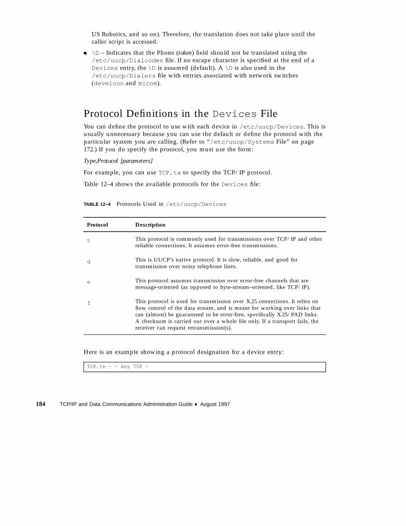
US Robotics, and so on). Therefore, the translation does not take place until thecaller script is accessed.
� \D – Indicates that the Phone (token) field should not be translated using the/etc/uucp/Dialcodes file. If no escape character is specified at the end of aDevices entry, the \D is assumed (default). A \D is also used in the/etc/uucp/Dialers file with entries associated with network switches(develcon and micom).
Protocol Definitions in the Devices FileYou can define the protocol to use with each device in /etc/uucp/Devices . This isusually unnecessary because you can use the default or define the protocol with theparticular system you are calling. (Refer to “/etc/uucp/Systems File” on page172.) If you do specify the protocol, you must use the form:
Type,Protocol [parameters]
For example, you can use TCP,te to specify the TCP/IP protocol.
Table 12–4 shows the available protocols for the Devices file:
TABLE 12–4 Protocols Used in /etc/uucp/Devices
Protocol Description
t This protocol is commonly used for transmissions over TCP/IP and otherreliable connections. It assumes error-free transmissions.
g This is UUCP’s native protocol. It is slow, reliable, and good fortransmission over noisy telephone lines.
e This protocol assumes transmission over error-free channels that aremessage-oriented (as opposed to byte-stream–oriented, like TCP/IP).
f This protocol is used for transmission over X.25 connections. It relies onflow control of the data stream, and is meant for working over links thatcan (almost) be guaranteed to be error-free, specifically X.25/PAD links.A checksum is carried out over a whole file only. If a transport fails, thereceiver can request retransmission(s).
Here is an example showing a protocol designation for a device entry:
TCP,te - - Any TCP -
184 TCP/IP and Data Communications Administration Guide ♦ August 1997

This example indicates that, for device TCP, try to use the t protocol. If the other endrefuses, use the e protocol.
Neither e nor t is appropriate for use over modems. Even if the modem assureserror-free transmission, data can still be dropped between the modem and the CPU.
/etc/uucp/Dialers FileThe /etc/uucp/Dialers file contains dialing instructions for many commonlyused modems. You probably do not need to change or add entries to this file unlessyou plan to use a nonstandard modem or plan to customize your UUCPenvironment. Nevertheless, you should understand what is in the file and how itrelates to the Systems and Devices file.
The text specifies the initial conversation that must take place on a line before it canbe made available for transferring data. This conversation, often referred to as a chatscript, is usually a sequence of ASCII strings that is transmitted and expected, and itis often used to dial a phone number.
As shown in the examples in “/etc/uucp/Devices File” on page 178 the fifth fieldin a Devices file entry is an index into the Dialers file or a special dialer type(TCP, TLI , or TLIS ). The uucico daemon attempts to match the fifth field in theDevices file with the first field of each Dialers file entry. In addition, eachodd-numbered Devices field, starting with the seventh position is used as an indexinto the Dialers file. If the match succeeds, the Dialers entry is interpreted toperform the dialer conversation.
Each entry in the Dialers file has the following format:
dialer substitutions expect-send
Example 12–10 shows the entry for a US Robotics V.32bis modem.
EXAMPLE 12–10 /etc/uucp/Dialers File Entry
Dialer Substitution Expaec-Sendusrv32bis-e =,-, "" dA\pT&FE1V1X1Q0S2=255S12=255&A1&H1&M5&B2&W\r\c OK\r
\EATDT\T\r\c CONNECT\s14400/ARQ STTY=crtscts
The Dialer field matches the fifth and additional odd-numbered fields in the Devicesfile. The Substitutions field is a translate string: the first of each pair of characters is
UUCP Databases and Programs 185

mapped to the second character in the pair. This is usually used to translate = and -into whatever the dialer requires for “wait for dial tone” and “pause.”
The remaining expect-send fields are character strings.
Example 12–11 shows some sample entries in the Dialers file, as distributed whenyou install UUCP as part of the Solaris installation program.
EXAMPLE 12–11 Excerpts From /etc/uucp/Dialers
penril =W-P "" \d > Q\c : \d- > s\p9\c )-W\p\r\ds\p9\c-) y\c : \E\TP > 9\c OK
ventel =&-% "" \r\p\r\c $ <K\T%%\r>\c ONLINE!
vadic =K-K "" \005\p *-\005\p-*\005\p-* D\p BER? \E\T\e \r\c LINE
develcon "" "" \pr\ps\c est:\007
\E\D\e \n\007 micom "" "" \s\c NAME? \D\r\c GO
hayes =,-, "" \dA\pTE1V1X1Q0S2=255S12=255\r\c OK\r \EATDT\T\r\c CONNECT
# Telebit TrailBlazertb1200 =W-, "" \dA\pA\pA\pTE1V1X1Q0S2=255S12=255S50=2\r\c OK\r \EATDT\T\r\c CONNECT\s1200tb2400 =W-, "" \dA\pA\pA\pTE1V1X1Q0S2=255S12=255S50=3\r\c OK\r \EATDT\T\r\c CONNECT\s2400tbfast =W-, "" \dA\pA\pA\pTE1V1X1Q0S2=255S12=255S50=255\r\c OK\r \EATDT\T\r\c CONNECT\sFAST
# USrobotics, Codes, and DSI modems
dsi-ec =,-, "" \dA\pTE1V1X5Q0S2=255S12=255*E1*F3*M1*S1\r\c OK\r \EATDT\T\r\cCONNECT\sEC STTY=crtscts,crtsxoff
dsi-nec =,-, "" \dA\pTE1V1X5Q0S2=255S12=255*E0*F3*M1*S1\r\c OK\r \EATDT\T\r\c CONNECTSTTY=crtscts,crtsxoff
usrv32bis-ec =,-, "" \dA\pT&FE1V1X1Q0S2=255S12=255&A1&H1&M5&B2&W\r\c OK\r \EATDT\T\r\cCONNECT\s14400/ARQ STTY=crtscts,crtsxoff
usrv32-nec =,-, "" \dA\pT&FE1V1X1Q0S2=255S12=255&A0&H1&M0&B0&W\r\c OK\r \EATDT\T\r\cCONNECT STTY=crtscts,crtsxoff
codex-fast =,-, "" \dA\pT&C1&D2*MF0*AA1&R1&S1*DE15*FL3S2=255S7=40S10=40*TT5&W\r\c OK\r\EATDT\T\r\c CONNECT\s38400 STTY=crtscts,crtsxoff
tb9600-ec =W-, "" \dA\pA\pA\pTE1V1X1Q0S2=255S12=255S50=6\r\c OK\r\EATDT\T\r\cCONNECT\s9600 STTY=crtscts,crtsxoff
tb9600-nec =W-, "" \dA\pA\pA\pTE1V1X1Q0S2=255S12=255S50=6S180=0\r\c OK\r \EATDT\T\r\cCONNECT\s9600 STTY=crtscts,crtsxoff
Table 12–5 lists escape characters commonly used in the send strings in the Dialersfile:
186 TCP/IP and Data Communications Administration Guide ♦ August 1997

TABLE 12–5 Backslash Characters for /etc/uucp/Dialers
Character Description
\b Send or expect a backspace character
\c No newline or carriage return
\d Delay (approximately 2 seconds)
\D Phone number or token without Dialcodes translation
\e Disable echo checking
\E Enable echo checking (for slow devices)
\K Insert a Break character
\n Send newline
\nnn Send octal number. Additional escape characters that can be usedare listed in the section “/etc/uucp/Systems File” on page 172.
\N Send or expect a NULL character (ASCII NUL)
\p Pause (approximately 12–14 seconds)
\r Return.
\s Send or expect a space character
\T Phone number or token with Dialcodes translation
Here is a penril entry in the Dialers file:
penril =W-P "" \d > Q\c : \d- > s\p9\c )-W\p\r\ds\p9\c-) y\c : \E\TP > 9\c OK
First, the substitution mechanism for the phone number argument is established, sothat any = is replaced with a W(wait for dial tone) and any - with a P (pause).
The handshake given by the remainder of the line works as listed:
� "" – Wait for nothing. (that is, proceed to the next thing)
� \d – Delay 2 seconds, then send a carriage-return
UUCP Databases and Programs 187
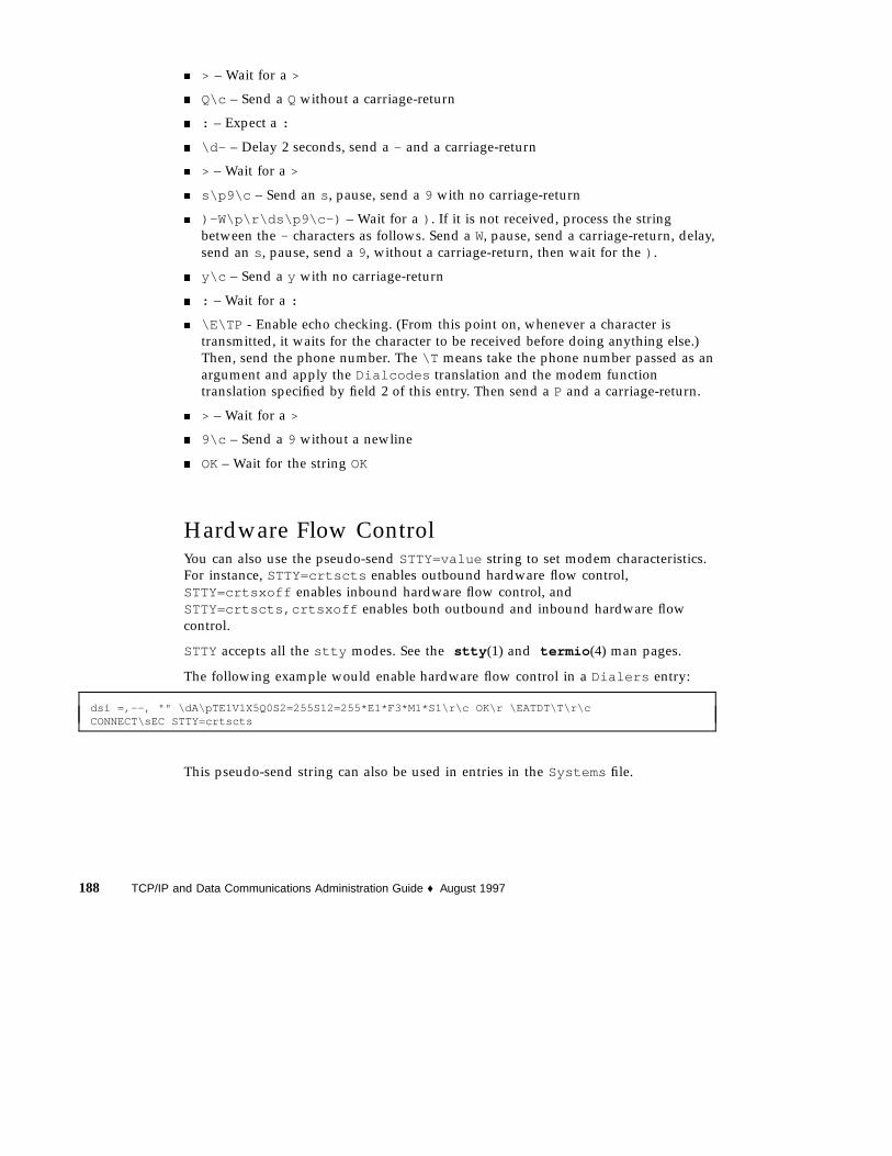
� > – Wait for a >
� Q\c – Send a Q without a carriage-return
� : – Expect a :
� \d- – Delay 2 seconds, send a - and a carriage-return
� > – Wait for a >
� s\p9\c – Send an s , pause, send a 9 with no carriage-return
� )-W\p\r\ds\p9\c-) – Wait for a ) . If it is not received, process the stringbetween the - characters as follows. Send a W, pause, send a carriage-return, delay,send an s , pause, send a 9, without a carriage-return, then wait for the ) .
� y\c – Send a y with no carriage-return
� : – Wait for a :
� \E\TP - Enable echo checking. (From this point on, whenever a character istransmitted, it waits for the character to be received before doing anything else.)Then, send the phone number. The \T means take the phone number passed as anargument and apply the Dialcodes translation and the modem functiontranslation specified by field 2 of this entry. Then send a P and a carriage-return.
� > – Wait for a >
� 9\c – Send a 9 without a newline
� OK– Wait for the string OK
Hardware Flow ControlYou can also use the pseudo-send STTY=value string to set modem characteristics.For instance, STTY=crtscts enables outbound hardware flow control,STTY=crtsxoff enables inbound hardware flow control, andSTTY=crtscts,crtsxoff enables both outbound and inbound hardware flowcontrol.
STTY accepts all the stty modes. See the stty (1) and termio (4) man pages.
The following example would enable hardware flow control in a Dialers entry:
dsi =,--, "" \dA\pTE1V1X5Q0S2=255S12=255*E1*F3*M1*S1\r\c OK\r \EATDT\T\r\cCONNECT\sEC STTY=crtscts
This pseudo-send string can also be used in entries in the Systems file.
188 TCP/IP and Data Communications Administration Guide ♦ August 1997

Setting ParityIn some cases, you have to reset the parity because the system that you are callingchecks port parity and drops the line if it is wrong. The expect-send couplet~~ P_ZEROsets parity to zero:
foo =,-, "" P_ZERO "" \dA\pTE1V1X1Q0S2=255S12=255\r\c OK\r\EATDT\T\r\c CONNECT
In the same manner, P_EVENsets it to even (the default); P_ODDsets it to odd; andP_ONEsets it to one. This pseudo-send string can also be used in entries in theSystems file.
Other Basic Configuration FilesThe files in this section can be used in addition to the Systems , Devices , andDialers file when doing basic UUCP configuration.
/etc/uucp/Dialcodes FileThe /etc/uucp/Dialcodes file enables you to define dial-code abbreviations thatcan be used in the Phone field in the /etc/uucp/Systems file. You can use theDialcodes files to provide additional information about a basic phone number thatis used by several systems at the same site.
Each entry has the format:
abbreviation dial-sequence
where abbreviation represents the abbreviation used in the Phone field of theSystems file and dial-sequence represents the dial sequence passed to the dialer whenthat particular Systems file entry is accessed. Table 12–6 shows the correspondencesbetween the two files.
TABLE 12–6 Correspondences between Dialcodes and Systems Files
Field Names
Dialcodes Abbreviation Dial-Sequence
Systems System-Name Time Type Speed Phone Chat Script
UUCP Databases and Programs 189

Table 12–7 contains sample entries in a Dialcodes file.
TABLE 12–7 Entries in the Dialcode s File
Abbreviation Dial-sequence
NY 1=212
jt 9+847
In the first row, NY is the abbreviation to appear in the Phone field of the Systemsfile. For example, the Systems file might have the entry:
NY5551212
When uucico reads NY in the Systems file, it searches the Dialcodes file for NYand obtains the dialing sequence 1=212 . This is the dialing sequence needed for anyphone call to New York City. It includes the number 1, an equal sign (=) meaningpause and wait for a secondary dial tone, and the area code 212 . uucico sends thisinformation to the dialer, then returns to the Systems file for the remainder of thephone number, 5551212 .
The entry jt 9=847- would work with a Phone field in the Systems file such asjt7867 . When uucico reads the entry containing jt7867 in the Systems file, itsends the sequence 9=847-7867 to the dialer, if the token in the dialer-token pair is\T .
/etc/uucp/Sysfiles FileThe /etc/uucp/Sysfiles file lets you assign different files to be used by uucpand cu as Systems , Devices , and Dialers files. (For more information on cu , seethe cu (1C) man page.) You might want to use Sysfiles for:
� Different Systems files, so that requests for login services can be made todifferent addresses than uucp services.
� Different Dialers files, so that you can assign different handshaking for cu anduucp .
� Multiple Systems , Dialers , and Devices files. The Systems file in particularcan become large, making it more convenient to split it into several smaller files.
The format of the Sysfiles file is:
service= w systems= x:x dialers= y:y devices= z:z
190 TCP/IP and Data Communications Administration Guide ♦ August 1997
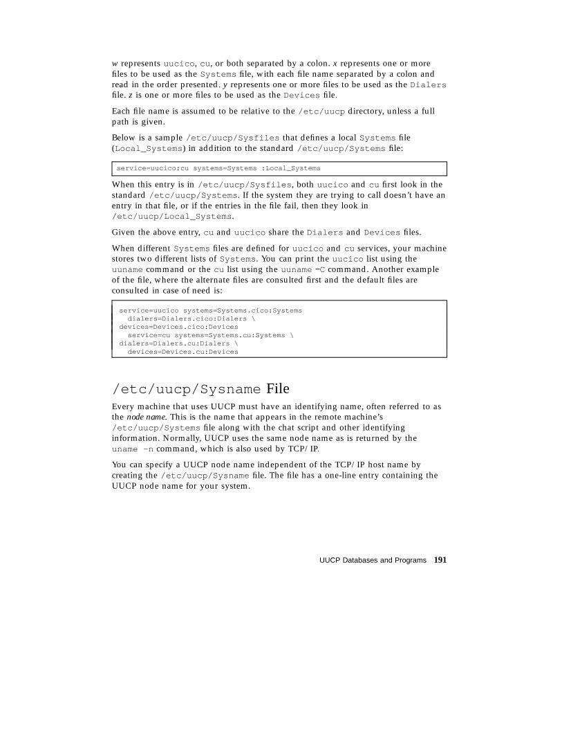
w represents uucico , cu , or both separated by a colon. x represents one or morefiles to be used as the Systems file, with each file name separated by a colon andread in the order presented. y represents one or more files to be used as the Dialersfile. z is one or more files to be used as the Devices file.
Each file name is assumed to be relative to the /etc/uucp directory, unless a fullpath is given.
Below is a sample /etc/uucp/Sysfiles that defines a local Systems file(Local_Systems ) in addition to the standard /etc/uucp/Systems file:
service=uucico:cu systems=Systems :Local_Systems
When this entry is in /etc/uucp/Sysfiles , both uucico and cu first look in thestandard /etc/uucp/Systems . If the system they are trying to call doesn’t have anentry in that file, or if the entries in the file fail, then they look in/etc/uucp/Local_Systems .
Given the above entry, cu and uucico share the Dialers and Devices files.
When different Systems files are defined for uucico and cu services, your machinestores two different lists of Systems . You can print the uucico list using theuuname command or the cu list using the uuname −C command. Another exampleof the file, where the alternate files are consulted first and the default files areconsulted in case of need is:
service=uucico systems=Systems.cico:Systemsdialers=Dialers.cico:Dialers \
devices=Devices.cico:Devicesservice=cu systems=Systems.cu:Systems \
dialers=Dialers.cu:Dialers \devices=Devices.cu:Devices
/etc/uucp/Sysname FileEvery machine that uses UUCP must have an identifying name, often referred to asthe node name. This is the name that appears in the remote machine’s/etc/uucp/Systems file along with the chat script and other identifyinginformation. Normally, UUCP uses the same node name as is returned by theuname -n command, which is also used by TCP/IP.
You can specify a UUCP node name independent of the TCP/IP host name bycreating the /etc/uucp/Sysname file. The file has a one-line entry containing theUUCP node name for your system.
UUCP Databases and Programs 191

/etc/uucp/Permissions FileThe /etc/uucp/Permissions file specifies the permissions that remote computershave with respect to login, file access, and command execution. There are optionsthat restrict the remote computer’s ability to request files and its ability to receivefiles queued by the local machine. Another option is available that specifies thecommands that a remote machine can execute on the local computer.
Structuring EntriesEach entry is a logical line, with physical lines terminated by a backslash (\) toindicate continuation. Entries are made up of options delimited by blank space. Eachoption is a name-value pair in the following format:
name=value
Values can be colon-separated lists. No blank space is allowed within an optionassignment.
Comment lines begin with a pound sign (#), and they occupy the entire line up to anewline character. Blank lines are ignored (even within multiple-line entries).
There types of Permissions file entries are:
� LOGNAME– Specifies the permissions that take effect when a remote computer logsin to (calls) your computer.
Note - When a remote machine calls you, its identity is questionable unless it has aunique login and verifiable password.
� MACHINE– Specifies permissions that take effect when your computer logs in to(calls) a remote computer.
LOGNAMEentries contain a LOGNAME option and MACHINEentries contain aMACHINE option. One entry can contain both options.
ConsiderationsWhen using the Permissions file to restrict the level of access granted to remotecomputers, you should consider the following:
� All login IDs used by remote computers to log in for UUCP communications mustappear in one and only one LOGNAMEentry.
� Any site that is called whose name does not appear in a MACHINEentry, has thefollowing default permissions or restrictions:
192 TCP/IP and Data Communications Administration Guide ♦ August 1997

� Local send and receive requests are executed.� The remote computer can send files to your computer’s
/var/spool/uucppublic directory.� The commands sent by the remote computer for execution on your computer
must be one of the default commands, usually rmail .
REQUESTOptionWhen a remote computer calls your computer and requests to receive a file, thisrequest can be granted or denied. The REQUESToption specifies whether the remotecomputer can request to set up file transfers from your computer. The stringREQUEST=yesspecifies that the remote computer can request to transfer files fromyour computer. The string REQUEST=nospecifies that the remote computer cannotrequest to receive files from your computer. This is the default value; it is used if theREQUESToption is not specified. The REQUESToption can appear in either aLOGNAME(remote computer calls you) entry or a MACHINE(you call remotecomputer) entry.
SENDFILES OptionWhen a remote computer calls your computer and completes its work, it can attemptto take work your computer has queued for it. The SENDFILES option specifieswhether your computer can send the work queued for the remote computer.
The string SENDFILES=yes specifies that your computer can send the work that isqueued for the remote computer as long as itis logged in as one of the names in theLOGNAMEoption. This string is mandatory if you have entered Never in the Timefield of /etc/uucp/Systems . This designation sets up your local machine inpassive mode; it is not allowed to initiate a call to this particular remote computer.(See “/etc/uucp/Systems File” on page 172 for more information.)
The string SENDFILES=call specifies that files queued in your computer are sentonly when your computer calls the remote computer. The call value is the defaultfor the SENDFILES option. This option is only significant in LOGNAMEentries sinceMACHINEentries apply when calls are made out to remote computers. If the option isused with a MACHINEentry, it is ignored.
MYNAMEOptionThis option enables you to designate a unique UUCP node name for your computerin addition to its TCP/IP host name, as returned by the hostname command. Forinstance, if you have unknowingly given your host the same name as that of someother system, you might want to set the MYNAMEoption of the Permissions file. Or
UUCP Databases and Programs 193

if you want your organization to be known as widget but all your modems areconnected to a machine with the host name gadget , you can have an entry ingadget ’s Permissions file that says:
service=uucico systems=Systems.cico:Systemsdialers=Dialers.cico:Dialers \devices=Devices.cico:Devices
service=cu systems=Systems.cu:Systems \dialers=Dialers.cu:Dialers \devices=Devices.cu:Devices
Now the system world can log in to the machine gadget as if it were logging in towidget . In order for machine world to know you also by the aliased name widgetwhen you call it, you can have an entry that says:
MACHINE=world MYNAME=widget
You can also use the MYNAMEoption for testing purposes, since it allows yourmachine to call itself. However, since this option could be used to mask the realidentity of a machine, you should use the VALIDATE option, as described in“VALIDATE Option” on page 197.
READand WRITEOptionsThese options specify the various parts of the file system that uucico can read fromor write to. You can designate READand WRITEoptions with either MACHINEorLOGNAMEentries.
The default for both the READand WRITEoptions is the uucppublic directory, asshown in the following strings:
READ=/var/spool/uucppublic WRITE=/var/spool/uucppublic
The strings READ=/ and WRITE=/ specify permission to access any file that can beaccessed by a local user with Other permissions.
The value of these entries is a colon-separated list of path names. The READoption isfor requesting files, and the WRITEoption is for depositing files. One of the valuesmust be the prefix of any full path name of a file coming in or going out. To grantpermission to deposit files in /usr/news as well as the public directory, use thefollowing values with the WRITEoption:
WRITE=/var/spool/uucppublic:/usr/news
If the READand WRITEoptions are used, all path names must be specified becausethe path names are not added to the default list. For instance, if the /usr/news path
194 TCP/IP and Data Communications Administration Guide ♦ August 1997

name were the only one specified in a WRITEoption, permission to deposit files inthe public directory would be denied.
You should be careful which directories you make accessible for reading and writingby remote systems. For example, the /etc directory contains many critical systemfiles; remote users should not have permission to deposit files in this directory.
NOREADand NOWRITEOptionsThe NOREADand NOWRITEoptions specify exceptions to the READand WRITEoptions or defaults. The entry:
READ=/ NOREAD=/etc WRITE=/var/spool/uucppublic
permits reading any file except those in the /etc directory (and itssubdirectories—remember, these are prefixes). It permits writing only to the default/var/spool/uucppublic directory. NOWRITEworks in the same manner as theNOREADoption. You can use the NOREADand NOWRITEoptions in both LOGNAMEand MACHINEentries.
CALLBACKOptionYou can use the CALLBACKoption in LOGNAMEentries to specify that no transactiontakes place until the calling system is called back. There are two reasons to set upCALLBACK: For security purposes, if you call back a machine, you can be sure it isthe right machine. For accounting purposes, if you are doing long datatransmissions, you can choose the machine that is billed for the longer call.
The string CALLBACK=yes specifies that your computer must call the remotecomputer back before any file transfers can take place.
The default for the CALLBACKoption is CALLBACK=no. If you set CALLBACKto yes ,then the permissions that affect the rest of the conversation must be specified in theMACHINEentry corresponding to the caller. Do not specify these permissions in theLOGNAME, or in the LOGNAMEentry that the remote machine might have set for yourhost.
Note - If two sites have the CALLBACKoption set for each other, a conversationnever gets started.
UUCP Databases and Programs 195

COMMANDSOption
Caution - The COMMANDSoption can compromise the security of your system. Use itwith extreme care.
You can use the COMMANDSoption in MACHINEentries to specify the commands thata remote computer can execute on your machine. The uux program generates remoteexecution requests and queue them to be transferred to the remote computer. Filesand commands are sent to the target computer for remote execution. This is anexception to the rule that MACHINEentries apply only when your system calls out.
Note that COMMANDSis not used in a LOGNAMEentry; COMMANDSin MACHINEentriesdefines command permissions, whether you call the remote system or it calls you.
The string COMMANDS=rmailspecifies the default commands that a remotecomputer can execute on your computer. If a command string is used in a MACHINEentry, the default commands are overridden. For instance, the entry:
MACHINE=owl:raven:hawk:dove COMMANDS=rmail:rnews:lp
overrides the COMMAND default so that the computers named owl , raven , hawk,and dove can now execute rmail , rnews , and lp on your computer.
In addition to the names as specified above, there can be full path names ofcommands. For example:
COMMANDS=rmail:/usr/local/rnews:/usr/local/lp
specifies that command rmail uses the default search path. The default search pathfor UUCP is /bin and /usr/bin . When the remote computer specifies rnews or/usr/local/rnews for the command to be executed, /usr/local/rnews isexecuted regardless of the default path. Likewise, /usr/local/lp is the lpcommand that is executed.
Including the ALL value in the list means that any command from the remotecomputers specified in the entry will be executed. If you use this value, you give theremote computers full access to your machine.
Caution - This allows far more access than normal users have. You should use thisvalue only when both machines are at the same site, are closely connected, and theusers are trusted.
The string:
COMMANDS=/usr/local/rnews:ALL:/usr/local/lp
illustrates two points:
� The ALL value can appear anywhere in the string.
196 TCP/IP and Data Communications Administration Guide ♦ August 1997
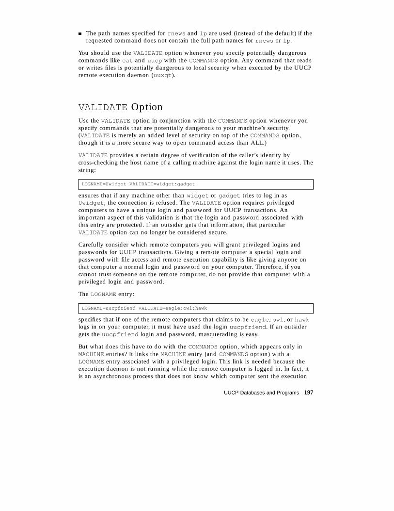
� The path names specified for rnews and lp are used (instead of the default) if therequested command does not contain the full path names for rnews or lp .
You should use the VALIDATE option whenever you specify potentially dangerouscommands like cat and uucp with the COMMANDSoption. Any command that readsor writes files is potentially dangerous to local security when executed by the UUCPremote execution daemon (uuxqt ).
VALIDATE OptionUse the VALIDATE option in conjunction with the COMMANDSoption whenever youspecify commands that are potentially dangerous to your machine’s security.(VALIDATE is merely an added level of security on top of the COMMANDSoption,though it is a more secure way to open command access than ALL.)
VALIDATE provides a certain degree of verification of the caller’s identity bycross-checking the host name of a calling machine against the login name it uses. Thestring:
LOGNAME=Uwidget VALIDATE=widget:gadget
ensures that if any machine other than widget or gadget tries to log in asUwidget , the connection is refused. The VALIDATE option requires privilegedcomputers to have a unique login and password for UUCP transactions. Animportant aspect of this validation is that the login and password associated withthis entry are protected. If an outsider gets that information, that particularVALIDATE option can no longer be considered secure.
Carefully consider which remote computers you will grant privileged logins andpasswords for UUCP transactions. Giving a remote computer a special login andpassword with file access and remote execution capability is like giving anyone onthat computer a normal login and password on your computer. Therefore, if youcannot trust someone on the remote computer, do not provide that computer with aprivileged login and password.
The LOGNAMEentry:
LOGNAME=uucpfriend VALIDATE=eagle:owl:hawk
specifies that if one of the remote computers that claims to be eagle , owl , or hawklogs in on your computer, it must have used the login uucpfriend . If an outsidergets the uucpfriend login and password, masquerading is easy.
But what does this have to do with the COMMANDSoption, which appears only inMACHINEentries? It links the MACHINEentry (and COMMANDSoption) with aLOGNAMEentry associated with a privileged login. This link is needed because theexecution daemon is not running while the remote computer is logged in. In fact, itis an asynchronous process that does not know which computer sent the execution
UUCP Databases and Programs 197
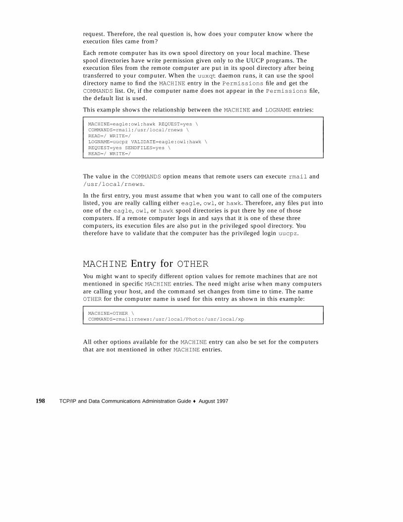
request. Therefore, the real question is, how does your computer know where theexecution files came from?
Each remote computer has its own spool directory on your local machine. Thesespool directories have write permission given only to the UUCP programs. Theexecution files from the remote computer are put in its spool directory after beingtransferred to your computer. When the uuxqt daemon runs, it can use the spooldirectory name to find the MACHINEentry in the Permissions file and get theCOMMANDSlist. Or, if the computer name does not appear in the Permissions file,the default list is used.
This example shows the relationship between the MACHINEand LOGNAMEentries:
MACHINE=eagle:owl:hawk REQUEST=yes \COMMANDS=rmail:/usr/local/rnews \READ=/ WRITE=/LOGNAME=uucpz VALIDATE=eagle:owl:hawk \REQUEST=yes SENDFILES=yes \READ=/ WRITE=/
The value in the COMMANDSoption means that remote users can execute rmail and/usr/local/rnews .
In the first entry, you must assume that when you want to call one of the computerslisted, you are really calling either eagle , owl , or hawk. Therefore, any files put intoone of the eagle , owl , or hawk spool directories is put there by one of thosecomputers. If a remote computer logs in and says that it is one of these threecomputers, its execution files are also put in the privileged spool directory. Youtherefore have to validate that the computer has the privileged login uucpz .
MACHINEEntry for OTHERYou might want to specify different option values for remote machines that are notmentioned in specific MACHINEentries. The need might arise when many computersare calling your host, and the command set changes from time to time. The nameOTHERfor the computer name is used for this entry as shown in this example:
MACHINE=OTHER \COMMANDS=rmail:rnews:/usr/local/Photo:/usr/local/xp
All other options available for the MACHINEentry can also be set for the computersthat are not mentioned in other MACHINEentries.
198 TCP/IP and Data Communications Administration Guide ♦ August 1997

Combining MACHINEand LOGNAMEYou can combine MACHINEand LOGNAMEentries into a single entry where thecommon options are the same. For example, the two entries:
MACHINE=eagle:owl:hawk REQUEST=yes \READ=/ WRITE=/
and:
LOGNAME=uupz REQUEST=yes SENDFILES=yes \READ=/ WRITE=/
share the same REQUEST, READ, and WRITEoptions. You can merge them, as shown:
MACHINE=eagle:owl:hawk REQUEST=yes \logname=uucpz SENDFILES-yes \READ=/ WRITE=/
Combining MACHINEand LOGNAMEentries makes the Permissions file moremanageable and efficient.
ForwardingWhen sending files through a series of machines, the intermediary machines musthave the command uucp among their COMMANDSoptions. That is, if you type thecommand:
% uucp sample.txt oak\!willow\!pine\!/usr/spool/uucppublic
This forwarding operation works only if machine willow permits oak to execute theprogram uucp , and if oak permits your machine to do the same. The machine pine ,being the last machine designated, does not have to permit the command uucp .Machines are not normally set up this way.
UUCP Databases and Programs 199

/etc/uucp/Poll FileThe /etc/uucp/Poll file contains information for polling remote computers. Eachentry in the Poll file contains the name of a remote computer to call, followed by atab character or a space, and finally the hours the computer should be called. Theformat of entries in the Poll file are:
sys-name hour ...
For example, the entry
eagle 0 4 8 12 16 20
provides polling of computer eagle every four hours.
The uudemon.poll script processes the Poll file but does not actually perform thepoll. It merely sets up a polling work file (always named C.file) in the spool directory.The uudemon.poll script starts the scheduler, and the scheduler examines all workfiles in the spool directory.
/etc/uucp/Config FileThe /etc/uucp/Config file enables you to override certain parameters manually.Each entry in the Config file has this format:
parameter=value
See the Config file provided with your system for a complete list of configurableparameter names.
The following Config entry sets the default protocol ordering to Gge and changesthe G protocol defaults to 7 windows and 512-byte packets.
Protocol=G(7,512)ge
/etc/uucp/Grades FileThe /etc/uucp/Grades file contains the definitions for the job grades that can beused to queue jobs to a remote computer. It also contains the permissions for eachjob grade. Each entry in this file represents a definition of an administrator-definedjob grade that lets users queue jobs.
200 TCP/IP and Data Communications Administration Guide ♦ August 1997

Each entry in the Grades file has the following format:
User-job-grade System-job-grade Job-size Permit-type ID-list
Each entry contains fields that are separated by blank space. The last field in theentry is made up of subfields also separated by spaces. If a entry takes up more thanone physical line, then you can use a backslash to continue the entry onto thefollowing line. Comment lines begin with a pound sign (#) and occupy the entireline. Blank lines are always ignored.
User-job-grade FieldThis field contains an administrative-defined user job grade name of up to 64characters.
System-job-grade FieldThis field contains a one-character job grade to which User-job-grade is mapped. Thevalid list of characters is A–Z, a–z, with A having the highest priority and z thelowest.
Relationship Between User and System Job GradesThe user job grade can be bound to more than one system job grade. It is importantto note that the Grades file is searched sequentially for occurrences of a user jobgrade. Therefore, any multiple occurrences of a system job grade should be listedaccording to the restriction on the maximum job size.
While there is no maximum number for the user job grades, the maximum numberof system job grades allowed is 52. The reason is that more than one User-job-gradecan be mapped to a System-job-grade, but each User-job-grade must be on a separateline in the file. Here is an example:
mail N Any User Any netnews N Any User Any
Given this configuration in a Grades file, these two User-job-grade will share thesame System-job-grade. Since the permissions for a Job-grade are associated with aUser-job-grade and not a System-job-grade, two User-job-grades can share the sameSystem-job-grades and have two different sets of permissions.
Default GradeYou can define the binding of a default User-job-grade to a system job grade. Youmust use the keyword default as user job grade in the User-job-grade field of the
UUCP Databases and Programs 201

Grades file and the system job grade that it is bound to. The Restrictions and IDfields should be defined as Any so that any user and any size job can be queued tothis grade. Here is an example:
default a Any User Any
If you do not define the default user job grade, then the built-in default grade Z isused. Because the restriction field default is Any , multiple occurrences of the defaultgrade are not checked.
Job-size FieldThis field specifies the maximum job size that can be entered in the queue. Job-size ismeasured in bytes and can be a list of the options listed in Table 12–8:
TABLE 12–8 Job-size Field
nnnn Integer specifying the maximum job size for this job grade
nK Decimal number representing the number of kilobytes (K is an abbreviation forkilobyte)
nM Decimal number representing the number of megabytes (M is an
abbreviation for megabyte)
AnyKeyword specifying that there is no maximum job size
Here are some examples:
� 5000 represents 5000 bytes
� 10K represents 10 Kbytes
� 2M represents 2 Mbytes
Permit-type FieldThis field contains a keyword that denotes how to interpret the ID list. Table 12–9lists the keywords and their meanings:
202 TCP/IP and Data Communications Administration Guide ♦ August 1997

TABLE 12–9 Permit-type Field
Keyword ID List Contents
User Login names of users permitted to use this job grade
Non-user Login names of users not permitted to use this job grade
Group Group names whose members are permitted to use this group
Non-group Group names whose members are not permitted to use this job grade
ID-list FieldThis field contains a list of login names or group names that are to be permitted ordenied queuing to this job grade. The list of names are separated by blank space andterminated by a newline character. The keyword Any is used to denote that anyoneis permitted to queue to this job grade.
Other UUCP Configuration FilesThis section describes three less-frequently modified files that impact the use ofUUCP facilities.
/etc/uucp/Devconfig FileThe /etc/uucp/Devconfig file enables you to configure devices by service—uucpor cu . Devconfig entries define the STREAMS modules that are used for aparticular device. They have the format:
service= x device= y push= z[:z...]
x can be cu , uucico , or both separated by a colon. y is the name of a network andmust match an entry in the Devices file. z is replaced by the names of STREAMSmodules in the order that they are to be pushed onto the Stream. Different modulesand devices can be defined for cu and uucp services.
The following entries are for a STARLAN network and would most commonly beused in the file:
UUCP Databases and Programs 203

service=cu device=STARLAN push=ntty:tirdwrservice=uucico device=STARLAN push=ntty:tirdwr
This example pushes ntty , then tirdwr .
/etc/uucp/Limits FileThe /etc/uucp/Limits file controls the maximum number of simultaneousuucico s, uuxqt s, and uusched s that are running in the uucp networking. In mostcases, the default values are fine and no changes are needed. If you want to changethem, however, use any text editor.
The format of the Limits file is:
service= x max=y:
x can be uucico , uuxqt or uusched , and y is the limit permitted for that service.The fields can be in any order and in lowercase.
The following entries should most commonly be used in the Limits file:
service=uucico max=5service=uuxqt max=5service=uusched max=2
The example allows five uucico s, five uuxqt s, and two uusched s running on yourmachine.
remote.unknown FileThe other file that affects the use of communication facilities is theremote.unknown file. This file is a binary program that executes when a machinenot found in any of the Systems files starts a conversation. It logs the conversationattempt and drop the connection.
Caution - If you change the permissions of the remote.unknown file so it cannotexecute, your system accepts connections from any system.
This program executes when a machine that is not in any of the Systems starts aconversation. It logs the conversation attempt but fails to make a connection. If youchange the permissions of this file so it cannot execute(chmod 000 remote.unknown ), your system accepts any conversation requests.This is not a trivial change, and you should have very good reasons for doing it.
204 TCP/IP and Data Communications Administration Guide ♦ August 1997

Administrative FilesThe UUCP administrative files are described below. These files are created in spooldirectories to lock devices, hold temporary data, or keep information about remotetransfers or executions.
� Temporary data files (TM) – These data files are created by UUCP processes underthe spool directory /var/spool/uucp/ x when a file is received from anothercomputer. The directory x has the same name as the remote computer that issending the file. The names of the temporary data files have the format:
TM.pid.ddd
where pid is a process ID and ddd is a sequential three-digit number starting at 0.
When the entire file is received, the TM.pid.ddd file is moved to the path namespecified in the C. sysnxxxx file (discussed below) that caused the transmission. Ifprocessing is abnormally terminated, the TM.pid.ddd file can remain in the xdirectory. These files should be automatically removed by uucleanup .
� Lock files (LCK) – Lock files are created in the /var/spool/locks directory foreach device in use. Lock files prevent duplicate conversations and multipleattempts to use the same calling device. Table 12–10 shows the different types ofUUCP lock files.
TABLE 12–10 UUCP Lock Files
File Name Description
LCK..sys sys represents the name of the computer using the file
LCK.dev dev represents the name of a device using the file
LCK.LOG LOG represents a locked UUCP log file
These files can remain in the spool directory if the communications link isunexpectedly dropped (usually on computer crashes). The lock files is ignored(removed) after the parent process is no longer active. The lock file contains theprocess ID of the process that created the lock.
� Work file (C. ) – Work files are created in a spool directory when work (filetransfers or remote command executions) has been queued for a remote computer.The names of work files have the format:
C. sysnxxxx
UUCP Databases and Programs 205
where sys is the name of the remote computer, n is the ASCII characterrepresenting the grade (priority) of the work, and xxxx is the four-digit jobsequence number assigned by UUCP. Work files contain the following information:
� Full path name of the file to be sent or requested� Full path name of the destination or user or file name� User login name� List of options� Name of associated data file in the spool directory; if the uucp −C or uuto −p
option was specified, a dummy name (D.0 ) is used� Mode bits of the source file� Remote user’s login name to be notified upon completion of the transfer
� Data file (D. ) – Data files are created when you specify on the command line tocopy the source file to the spool directory. The names of data files have thefollowing format:
� D. systmxxxxyyy – Where systm is the first five characters in the name of theremote computer, xxxx is a four-digit job sequence number assigned by uucp .The four digit job sequence number can be followed by a subsequence number,yyy that is used when there are several D. files created for a work (C. ) file.
� X. (execute file) - Execute files are created in the spool directory prior to remotecommand executions. The names of execute files have the following format:
X. sysnxxxx
sys is the name of the remote computer. n is the character representing the grade(priority) of the work. xxxx is a four-digit sequence number assigned by UUCP.Execute files contain the following information:
� Requester’s login and computer name� Names of files required for execution� Input to be used as the standard input to the command string� Computer and file name to receive standard output from the command
execution� Command string� Option lines for return status requests
206 TCP/IP and Data Communications Administration Guide ♦ August 1997

CHAPTER 13
Configuring and Maintaining UUCP
This chapter explains how to start up UUCP operations afteryou have modified thedatabase file relevant to your machines. The chapter contains procedures andtroubleshooting information for setting up and maintaining UUCP on machinesrunning the Solaris environment.
� “Adding UUCP Logins” on page 207
� “Running UUCP Over TCP/IP” on page 210
� “Setting Up UUCP Security” on page 211
� “Regular UUCP Maintenance” on page 211
� “UUCP Error Messages” on page 214
Adding UUCP LoginsFor incoming UUCP (uucico ) requests from remote machines to be handledproperly, each machine has to have a login on your system.
Here is a typical entry that you might put into the /etc/passwd file for a remotemachine permitted to access your system with a UUCP connection:
Ugobi:*:5:5:gobi:/var/spool/uucppublic:/usr/lib/uucp/uucico
By convention, the login name of a remote machine is the machine name precededby the uppercase letter U. Note that the name should not exceed eight characters, sothat in some cases you might have to truncate or abbreviate it.
The previous entry shows that a login request by Ugobi is answered by/usr/lib/uucp/uucico . The home directory is /var/spool/uucppublic . Thepassword is obtained from the /etc/shadow file. You must coordinate the
207

password and the login name with the UUCP administrator of the remote machine.The remote administrator must then add an appropriate entry, with login name andunencrypted password, in the remote machine’s Systems file.
Similarly, you must coordinate your machine’s name and password with the UUCPadministrators of all machines that you want to reach through UUCP.
Starting UUCPUUCP comes with four shell scripts that poll remote machines, rescheduletransmissions, and clean up old log files and unsuccessful transmissions. The scriptsare:
� uudemon.poll
� uudemon.hour
� uudemon.admin
� uudemon.cleanup
These shell scripts should execute regularly to keep UUCP running smoothly. Thecrontab file to run the scripts is automatically created in/usr/lib/uucp/uudemon.crontab as part of the Solaris installation process, ifyou select the full installation. Otherwise, it is created when you install the UUCPpackage.
You can also run the UUCP shell scripts manually. The following is the prototypeuudemon.crontab file that you can tailor for a particular machine:
##ident "@(#)uudemon.crontab 1.3 93/02/02 SMI"#48 8,12,16 * * * /usr/libuucp/uudemon.admin45 23 * * * /usr/lib/uucp/uudemon.cleanup0 * * * * /usr/lib/uucp/uudemon.poll11,41 * * * * /usr/lib/uucp/uudemon.hour
To activate the uudemon.crontab file, become superuser and type:
# su uucp# crontab < /usr/lib/uucp/uudemon.crontab
208 TCP/IP and Data Communications Administration Guide ♦ August 1997

uudemon.poll Shell ScriptThe default uudemon.poll shell script reads the /etc/uucp/Poll file once anhour. If any machines in the Poll file are scheduled to be polled, a work file(C. sysnxxxx) is placed in the /var/spool/uucp/ nodename directory, wherenodename represents the UUCP node name of the machine.
The shell script is scheduled to run once an hour, before uudemon.hour , so that thework files are there when uudemon.hour is called.
uudemon.hour Shell ScriptThe default uudemon.hour shell script:
� Calls the uusched program to search the spool directories for work files (C. ) thathave not been processed and schedules these files for transfer to a remote machine.
� Calls the uuxqt daemon to search the spool directories for execute files (X. ) thathave been transferred to your computer and were not processed at the time theywere transferred.
By default, uudemon.hour runs twice an hour. You might want it to run more oftenif you expect high failure rates of calls to remote machines.
uudemon.admin Shell ScriptThe default uudemon.admin shell script does the following:
1. Runs the uustat command with p and q options. The q reports on the status ofwork files (C. ), data files (D. ), and execute files (X. ) that are queued. The p printsprocess information for networking processes listed in the lock files(/var/spool/locks ).
2. Sends resulting status information to the uucp administrative login via mail .
uudemon.cleanup Shell ScriptThe default uudemon.cleanup shell script does the following:
1. Takes log files for individual machines from the /var/uucp/.Log directory,merges them, and places them in the /var/uucp/.Old directory with other oldlog information.
2. Removes work files (C. ) seven days old or older, data files (D. ) Seven days old orolder, and execute files (X. ) two days old or older from the spool files.
3. Returns mail that cannot be delivered to the sender.
4. Mails a summary of the status information gathered during the current day to theUUCP administrative login (uucp ).
Configuring and Maintaining UUCP 209

Running UUCP Over TCP/IPTo run UUCP on a TCP/IP network, you need to make a few modifications, asdescribed in this section.
Activating UUCP in /etc/inetd.confMake sure that the following entry in /etc/inetd.conf is not preceded by acomment mark (#):
uucp stream tcp nowait root /usr/sbin/in.uucpd in.uucpd
Tailoring Systems File Entries for TCP/IPEntries in the /etc/uucp/Systems file should have the following fields:
System-Name Time TCP Port networkname Standard-Login-Chat
A typical entry would look like this:
rochester Any TCP - ur-seneca login: Umachine password: xxx
Notice that the networkname field permits you to specify explicitly the TCP/IP hostname. This is important for some sites. In the example above, the site has the UUCPnode name rochester is different from its TCP/IP host name ur-seneca .Moreover, there could easily be a completely different machine running UUCP thathas the TCP/IP host name of rochester .
The Port field in the Systems file should have the entry -- . This is equivalent tolisting it as uucp . In almost every case, the networkname is the same as the systemname, and the Port field is -- , which says to use the standard uucp port from theservices database. The in.uucpd daemon expects the remote machine to send itslogin and password for authentication, and it prompts for them much as getty andlogin do.
Checking /etc/inet/services for UUCPThe following entry in /etc/inet/services sets up a port for UUCP:
uucp 540/tcp uucpd # uucp daemon
You should not have to change the entry. However, if your machine runs NIS orNIS+ as its name service, you should change the /etc/nsswitch.conf entry for/etc/services to check files first, then check nis or nisplus .
210 TCP/IP and Data Communications Administration Guide ♦ August 1997
Security, Maintenance, andTroubleshootingAfter you have set up UUCP, maintenance is straightforward. This section explainsongoing UUCP tasks with regard to security, maintenance, and troubleshooting.
Setting Up UUCP SecurityThe default /etc/uucp/Permissions file provides the maximum amount ofsecurity for your UUCP links. The default Permissions file contains no entries.
You can set additional parameters for each machine to define:
� Ways it can receive files from your machine
� Directories for which it has read and write permission
� Commands it can use for remote execution
A typical Permissions entry is:
MACHINE=datsun LOGNAME=Udatsun VALIDATE=datsunCOMMANDS=rmail REQUEST=yes SENDFILES=yes
This entry allows files to be sent and received (to and from the “normal” UUCPdirectories, not from anywhere in the system) and causes the UUCP user name to bevalidated at login time.
Regular UUCP MaintenanceUUCP does not require much maintenance. Apart from making sure that thecrontab file is in place, as described in the section “uudemon.poll Shell Script” onpage 209, all you have to worry about is the growth of mail files and the publicdirectory.
Email for UUCPAll email messages generated by the UUCP programs and scripts go to the user IDuucp . If you do not log in frequently as that user, you might not realize that mail isaccumulating (and consuming disk space). To solve this, make an alias in/etc/aliases and redirect that email either to root or to yourself and others
Configuring and Maintaining UUCP 211
responsible for maintaining UUCP. Don’t forget to run the newaliases commandafter modifying the aliases file.
Public DirectoryThe directory /var/spool/uucppublic is the one place in every system to whichUUCP by default is able to copy files. Every user has permission to change to/var/spool/uucppublic and read and write files in it. However, its sticky bit isset, so its mode is 01777. As a result, users cannot remove files that have been copiedto it and that belong to uucp . Only you, as UUCP administrator logged in as root oruucp , can remove files from this directory. To prevent the uncontrolled accumulationof files in this directory, you should make sure to clean it up periodically.
If this is inconvenient for users, encourage them to use uuto and uupick ratherthan removing the sticky bit, which is set for security reasons. (See the uuto (1C)man page for instructions for using uuto and uupick .) You can also restrict themode of the directory to only one group of people. If you do not want to run the riskof someone filling your disk, you can even deny UUCP access to it.
Troubleshooting UUCPThese procedures describe how to solve common UUCP problems.
Checking for Faulty Modems or ACUsYou can check if the modems or other ACUs are not working properly in severalways.
� Run uustat −q. This will give counts and reasons for contact failure.
� Run cu −d −lline , where line is /dev/cua/a . This lets you call over a particularline and print debugging information on the attempt. The line must be defined asdirect in the /etc/uucp/Devices file. (You must add a telephone number tothe end of the command line if the line is connected to an autodialer or the devicemust be set up as direct .)
Checking the /etc/uucp/Systems FileVerify that you have up-to-date information in your Systems file if you are havingtrouble contacting a particular machine. Some things that might be out of date for amachine are its:
� Phone number
� Login ID
212 TCP/IP and Data Communications Administration Guide ♦ August 1997

� Password
Debugging TransmissionsIf you cannot contact a particular machine, you can check out communications tothat machine with Uutry and uucp .
1. To try to make contact, type /usr/lib/uucp/Uutry --r machine and pressReturn.
Replace machine with the host name of the machine you are having problemscontacting. This command:
a. Starts the transfer daemon (uucico ) with debugging. You can get moredebugging information if you are root .
b. Directs the debugging output to /tmp/ machine.
c. Prints the debugging output to your terminal (tail −f ).Press Control-c to end output. You can copy the output from /tmp/ machine ifyou want to save it.
2. If Uutry doesn’t isolate the problem, try to queue a job by typing uucp ---rfile machine\! /dir/file and press Return.
Replace file by the file you want to transfer, machine by the machine you want tocopy to, and /dir/file where the file will be placed on the other machine. The roption queues a job but does not start the transfer.
3. Now use Uutry again.
If you still cannot solve the problem, you might need to call your local supportrepresentative. Save the debugging output; it will help diagnose the problem.
You might also want to decrease or increase the level of debugging provided byUutry through the −x n option, where n indicates the debug level. The defaultdebug level for Uutry is 5.
Debug level 3 provides basic information as to when and how the connection isestablished, but not much information about the transmission itself. Debug level 9,on the other hand, provides exhaustive information about the transmission process.Be aware that debugging occurs at both ends of the transmission. If you intend touse a level higher than 5 on a moderately large text, get in touch with theadministrator of the other site and agree on a time for doing so.
Configuring and Maintaining UUCP 213

Checking Error MessagesUUCP has two types of error messages: ASSERTand STATUS.
When a process is aborted, ASSERTerror messages are recorded in/var/uucp/.Admin/errors . These messages include the file name, sccsid , linenumber, and text. These messages usually result from system problems.
STATUS error messages are stored in the /var/uucp/.Status directory. Thedirectory contains a separate file for each remote machine your computer attempts tocommunicate with. These files contain status information on the attemptedcommunication and whether it was successful.
Checking Basic InformationSeveral commands are available for checking basic networking information:
� uuname – Use this command to list those machines your machine can contact.
� uulog – Use this command to display the contents of the log directories forparticular hosts.
� uucheck −v – Run this command to check for the presence of files and directoriesneeded by uucp . This command also checks the Permissions file and outputsinformation on the permissions you have set up.
UUCP Error MessagesThis section lists the error messages associated with UUCP.
UUCP ASSERT Error MessagesTable 13–1 lists ASSERT error messages.
TABLE 13–1 ASSERT Error Messages
Error Message Description/Action
CAN’T OPEN An open( ) or fopen() failed.
CAN’T WRITE A write( ) , fwrite( ) , fprint( ) , or similar command, failed.
CAN’T READ A read( ) , fgets( ) , or similar command failed.
214 TCP/IP and Data Communications Administration Guide ♦ August 1997

TABLE 13–1 ASSERT Error Messages (continued)
Error Message Description/Action
CAN’T CREATE A creat( ) call failed.
CAN’T ALLOCATE A dynamic allocation failed.
CAN’T LOCK An attempt to make a LCK (lock) file failed. In some cases, this is a fatal error.
CAN’T STAT A stat( ) call failed.
CAN’T CHMOD A chmod() call failed.
CAN’T LINK A link( ) call failed.
CAN’T CHDIR A chdir( ) call failed.
CAN’T UNLINK An unlink( ) call failed.
WRONG ROLE This is an internal logic problem.
CAN’T MOVE TOCORRUPTDIR
An attempt to move some bad C. or X. files to the /var/spool/uucp/.Corruptdirectory failed. The directory is probably missing or has wrong modes or owner.
CAN’T CLOSE A close() or fclose() call failed.
FILE EXISTS The creation of a C. or D. file is attempted, but the file exists. This occurs when thereis a problem with the sequence file access. Usually indicates a software error.
NO uucp SERVICENUMBER
A TCP/IP call is attempted, but there is no entry in /etc/services for UUCP.
BAD UID The user ID is not in the password database. Check name service configuration..
BAD LOGIN_UID Same as previous.
BAD LINE There is a bad line in the Devices file; there are not enough arguments on one ormore lines.
SYSLST OVERFLOW An internal table in gename.c overflowed. A single job attempted to talk to morethan 30 systems.
TOO MANY SAVED CFILES
Same as previous.
Configuring and Maintaining UUCP 215

TABLE 13–1 ASSERT Error Messages (continued)
Error Message Description/Action
RETURN FROMfixline ioctl
An ioctl(2) , which should never fail, failed. There is a system driver problem.
BAD SPEED A bad line speed appears in the Devices or Systems file (Class or Speed field).
BAD OPTION There is a bad line or option in the Permissions file. It must be fixed immediately.
PKCGET READ The remote machine probably hung up. No action need be taken.
PKXSTART The remote machine aborted in a nonrecoverable way. This can usually be ignored.
TOO MANY LOCKS There is an internal problem. Contact your system vendor.
XMV ERROR There is a problem with some file or directory. It is likely the spool directory, since themodes of the destinations were suppose to be checked before this process wasattempted.
CAN’T FORK An attempt to make a fork and exec failed. The current job should not be lost butwill be attempted later (uuxqt ). No action is needed.
UUCP STATUS Error MessagesTable 13–2 is a list of the most common STATUS error messages.
TABLE 13–2 UUCP STATUS Messages
Error Message Description/Action
OK Status is okay.
NO DEVICES AVAILABLE There is currently no device available for the call. Check to see that there is avalid device in the Devices file for the particular system. Check theSystems file for the device to be used to call the system.
WRONG TIME TO CALL A call was placed to the system at a time other than what is specified in theSystems file.
TALKING Self-explanatory.
216 TCP/IP and Data Communications Administration Guide ♦ August 1997

TABLE 13–2 UUCP STATUS Messages (continued)
Error Message Description/Action
LOGIN FAILED The login for the given machine failed. It could be a wrong login orpassword, wrong number, a very slow machine, or failure in getting throughthe Dialer-Token-Pairs script.
CONVERSATION FAILED The conversation failed after successful startup. This usually means that oneside went down, the program aborted, or the line (link) was dropped.
DIAL FAILED The remote machine never answered. It could be a bad dialer or the wrongphone number.
BAD LOGIN/MACHINECOMBINATION
The machine called us with a login/machine name that does not agree withthe Permissions file. This could be an attempt to masquerade!.
DEVICE LOCKED The calling device to be used is currently locked and in use by anotherprocess.
ASSERT ERROR An ASSERTerror occurred. Check the /var/uucp/.Admin/errors file forthe error message and refer to the section “UUCP Error Messages” on page214.
SYSTEM NOT IN SystemsFILE
The system is not in the Systems file.
CAN’T ACCESS DEVICE The device tried does not exist or the modes are wrong. Check theappropriate entries in the Systems and Devices files.
DEVICE FAILED The device could not be opened.
WRONG MACHINE NAME The called machine is reporting a different name than expected.
CALLBACK REQUIRED The called machine requires that it calls your machine.
REMOTE HAS A LCK FILE FORME
The remote machine has a LCK file for your machine. It could be trying tocall your machine. If it has an older version of UUCP, the process that wastalking to your machine might have failed, leaving the LCK file. If it has thenew version of UUCP and is not communicating with your machine, thenthe process that has a LCK file is hung.
REMOTE DOES NOT KNOW METhe remote machine does not have the node name of your machine in itsSystems file.
REMOTE REJECT AFTER LOGINThe login used by your machine to login does not agree with what theremote machine was expecting.
Configuring and Maintaining UUCP 217

TABLE 13–2 UUCP STATUS Messages (continued)
Error Message Description/Action
REMOTE REJECT, UNKNOWNMESSAGE
The remote machine rejected the communication with your machine for anunknown reason. The remote machine might not be running a standardversion of UUCP.
STARTUP FAILED Login succeeded, but initial handshake failed.
CALLER SCRIPT FAILED This is usually the same as DIAL FAILED . However, if it occurs often,suspect the caller script in the Dialers file. Use Uutry to check.
UUCP Numerical Error MessagesTable 13–3 lists the exit code numbers of error status messages produced by the/usr/include/sysexits.h file. Not all are currently used by uucp .
TABLE 13–3 UUCP Error Messages by Number
MessageNumber
Description Meaning
64 Base value for errormessages
Error messages begin at this value.
64 Command Line UsageError
The command was used incorrectly, for example, with the wrong numberof arguments, a bad flag, or a bad syntax.
65 Data Format Error The input data was incorrect in some way. This should only be used foruser’s data and not system files.
66 Cannot Open Input An input file (not a system file) did not exist, or was not readable. Thiscould also include errors like “No message” to a mailer (if it cared tocatch it).
67 Address Unknown The user specified did not exist. This might be used for mail addresses orremote logins.
68 Host Name Unknown The host did not exist. This is used in mail addresses or network requests.
69 Service Unavailable A service is unavailable. This can occur if a support program or file doesnot exist. This message also can be a catchall message when somethingdoesn’t work and you don’t know why.
218 TCP/IP and Data Communications Administration Guide ♦ August 1997

TABLE 13–3 UUCP Error Messages by Number (continued)
MessageNumber
Description Meaning
70 Internal SoftwareError
An internal software error has been detected. This should be limited tonon-operating system related errors if possible.
71 System Error An operating system error has been detected. This is intended to be usedfor conditions like “cannot fork”,“cannot create pipe.” For instance, itincludes getuid returning a user that does not exist in the passwd file.
72 Critical OS FileMissing
Some system file like /etc/passwd or /etc/utmp does not exist,cannot be opened, or has some error such as syntax error.
73 Can’t Create OutputFile
A user specified output file cannot be created.
74 Input/Output Error An error occurred while doing I/O on some file.
75 Temporary Failure.User is invited to retry
Temporary failure, indicating something that is not really an error. Insendmail , this means that a mailer, for example, could not create aconnection, and the request should be reattempted later.
76 Remote Error inProtocol
The remote system returned something that was “not possible” during aprotocol exchange.
77 Permission Denied You do not have sufficient permission to perform the operation. This isnot intended for file system problems, which should use NOINPUTorCANTCREAT, but rather for higher level permissions. For example, kreuses this to restrict students who can send mail to.
78 Configuration Error There is an error in the configuration.
79 Entry Not Found Entry not found.
79 Maximum ListedValue
Highest value for error messages.
Configuring and Maintaining UUCP 219

220 TCP/IP and Data Communications Administration Guide ♦ August 1997

PART IV Dynamic Host Configuration Protocol
The Dynamic Host Configuration Protocol (DHCP) allows a host to get an InternetProtocol (IP) address and other Internet configuration parameters without any needfor preconfiguration by the user. This new protocol improves on the traditionalInternet architecture, where the system administrator must assign or change each IPaddress individually.
DHCP reduces the cost of managing networks by eliminating the need for theadministrator to assign or change addresses again and again.
� “What is DHCP?” on page 223
� “The DHCP Client” on page 226
� “DHCP Server” on page 228
� “BOOTP Relay Agents” on page 230
� “Leases” on page 231
� “Advantages of DHCP” on page 234
� “Migration” on page 235
� “DHCP Tables” on page 239
� “Configure Each Subnet for DHCP” on page 242
� “Lease Time Policy” on page 243
� “Standard DHCP Options” on page 246
� “Vendor Options” on page 246
� “Creating Macro Definitions” on page 247
� “Customization Examples” on page 248
� Chapter 17
� “Strategies and Tips” on page 256
� “Troubleshooting the DHCP Server” on page 261
� “Troubleshooting a DHCP Client” on page 269


CHAPTER 14
Understanding DHCP
This chapter introduces the Dynamic Host Configuration Protocol (DHCP) anddescribes both the client and server sides of the protocol. It discusses BootstrapProtocol (BOOTP) relay agents, which can be used in the operation of DHCP.
� “What is DHCP?” on page 223
� “The DHCP Client” on page 226
� “DHCP Server” on page 228
� “BOOTP Relay Agents” on page 230
� “Leases” on page 231
What is DHCP?DHCP provides a host with an Internet Protocol (IP) address and other Internetconfiguration parameters without any need for preconfiguration by the user. Thisnew protocol improves on the traditional Internet architecture, where the systemadministrator must assign or change each IP address individually. The manualprocess is expensive, difficult, error-prone and time-consuming.
DHCP reduces the cost of managing networks by eliminating the need for theadministrator to assign or change IP addresses again and again. Dynamic IPaddresses are chosen from a pool of unused IP addresses, and are automaticallyassigned to a host for temporary or permanent use. DHCP also reclaims that IPaddress for use by other clients when it is no longer needed or when the time periodfor its use is up.
The packet formats for DHCP and BOOTP are the same, although BOOTP packetsare fixed length and DHCP packets are variable length. The DHCP packet length isnegotiated between the client and the server.
223

The Dynamic Host Configuration working group of the Internet Engineering TaskForce (IETF) has been working for approximately five years on the problemspresented by the current IP address assignment architecture. The IETF is in theprocess of standardizing DHCP. It currently has the status of several Requests ForComment (RFCs), including RFCs 1542, 2131, and 2132.
The Internet has grown so rapidly that users are running out of network addresses tosupport it. In response to this problem, Classless Inter-Domain Routing (CIDR) wasdeveloped. IP addresses had been separated into class A, B, and C for large,medium, and small networks. As the class B IP addresses were depleted, the CIDRdesign came into use. CIDR was based on the idea that an organization should getthe exact number of class C IP addresses it needs, rather than be assigned one class Bnetwork, consisting of 65,536 addresses.
The class C network numbers allocated following the CIDR strategy are not random.They are contiguous and share the same prefixes. This helps alleviate many of theproblems caused by manipulating very large routing tables.
With the CIDR strategy, blocks of IP addresses are allocated to individual ISPs, not toindividual requestors or companies, as was previously the case. So it becomesimportant to renumber easily, in order to change ISPs easily. DHCP makes it easy torenumber networks, and therefore easier to change ISPs.
DHCP is a technology that enables several useful features, including:
� Automatic network configuration, such that after client machines are powered upon a network that supports DHCP, the clients acquire what they need. Forexample, their IP addresses, default routers, subnet masks, the DNS domain, DNSservers, NIS+ domain, NIS+ servers, Timezones, time servers, and all the otherinformation necessary to operate without any need for individual configuration byan administrator.
� Automatic IP address management, including assignment, reclamation,reconfiguration, and renumbering of IP addresses. Since all TCP/IP parameters aremanaged centrally, and the DHCP service manages the assignment and reuse of IPaddresses automatically, minimal administrator involvement is necessary.
� Vastly simplified system administration through the centralized location ofnetwork configuration information. The TCP/IP configuration information can bestored in a central place, instead of being distributed among all the clients in thenetwork. A network can be renumbered simply and quickly, usually in only a fewdays, using relatively short IP address leases.
DHCP can also exploit existing BOOTP relay functionality since DHCP is based onthe BOOTP. This permits network administrators to configure their routers toforward BOOTP/DHCP traffic to remote BOOTP/DHCP servers. Therefore, networkparameter servers are no longer needed on every network segment, as was true ofthe in,rarpd (see in.rarpd (1M)) and bootparams configuration services.
A network administrator can use the command to quickly and easily configureDHCP and BOOTP services on a Solaris 2 server. The command bootstraps theDHCP service and configures local and remote networks. Local networks are those to
224 TCP/IP and Data Communications Administration Guide ♦ August 1997

which the server is directly connected. Remote networks are those to which theserver is not directly connected, but are accessed through BOOTP relay agents.
Serving clients on remote networks requires the configuration of a BOOTP relayagent on the client’s network. BOOTP relay agent functionality is present in manypopular routers and switches. If your router does not support this feature, you canrun the in.dhcpd daemon (see in.dhcpd (1M)) in relay agent mode on any Solaris 2machine on the client’s network capable of running in.dhcpd . This is true formachines running Solaris 2.6 and later releases. Figure 14–1 shows an overview ofDHCP and BOOTP.
DHCP client
DHCP Service Architectural Diagram
DHCP Service Datastore Interface
DHCP client
NIS+
UFS Files
libdhcp.so,datastore switch is /etc/default/dhcp
in.dhcpd
dhtadm
pntadm
dhcpconfig
DHCP client
BOOTP client
BOOTP client
BOOTP relay agent Could be router or Sun OS machine running in.dhcpd.
Remote Network (129.144.8.0)
in.dhcpd.
DHCP Network tables
dhcptab
129_148_5_0 129_144_8_0
Legend: Unicast Broadcast
Figure 14–1 DHCP Architectural Diagram
Understanding DHCP 225

The DHCP ClientThe DHCP protocol has two functions with regard to the client. It delivers sufficientinformation to clients for them to establish an endpoint for network communications,and it supplies other parameters needed by system- and application-level software.
Delivering Client InformationTo perform the first function, the DHCP protocol supplies an IP address valid for thenetwork attached to the client’s hardware interface. The right to use this IP addressis given to the client for a finite period of time, called a lease. This differs from thetraditional static configuration. If the client wants to use the IP address for a periodof time longer than the original lease, it must periodically negotiate a lease extensionwith the server through DHCP. When the client no longer needs the IP address, theuser of the machine can relinquish its lease, returning it to the pool of available IPaddresses. Otherwise, the IP address is reclaimed automatically when its leaseexpires.
The implementation of the client side of the DHCP protocol on Solaris must meetseveral criteria. Bootstrapping a Sun workstation is a complex process because of thenumber and diversity of services that must be configured and invoked. Any DHCPsolution must co-exist with other methods already in use, particularly the ReverseAddress Resolution Protocol (RARP) and static configuration. It must know that thesuperuser can change the address of a network interface after the workstation hasbooted. It must be able to configure multiple interfaces. And it must respond tohuman control and be able to report on the status and provide the statistics of theprotocol.
The Solaris 2 DHCP client meets these criteria by implementing several features.Since leases must be renewed days or weeks after the initial boot, an agentresponsible for DHCP on the client must run as a daemon. This daemon, the DHCPagent or dhcpagent (see dhcpagent (1M)) is responsible for all the interactions ofthe protocol. It sends and receives all the DHCP protocol packets when talking to theserver. The daemon:
� Constructs and sends packets
� Listens for responses from servers
� Caches the configuration information received
� Releases or renews leases
� Configures the interfaces with sufficient information to enable communicationswith the network through the interface
This is where the responsibilities of the agent end. The daemon knows nothing ofany higher-level services that the client might be running.
226 TCP/IP and Data Communications Administration Guide ♦ August 1997

When the agent starts, it assumes nothing about which interfaces are to beconfigured by DHCP. It waits for instructions from some other entity. Theseinstructions are passed to the agent by a control protocol, which also returns statusand other information from the agent to the controller. The controller allows the userto control the behavior of the agent, and implements this control through newfeatures of the ifconfig (1M) command.
The ifconfig command has new command line options specific to DHCP, whichstart or terminate DHCP on an interface. After DHCP is started on an interface, theagent sends packets to and receives them from a server as the protocol dictates.
In the simplest example, the interface is successfully configured by DHCP. The agentnotes the duration of the lease, informs ifconfig that the interface was configured,writes the configuration it received to disk, and goes back to sleep.
At some predetermined future time, usually 50 percent into the lease’s lifetime, theagent reawakens and negotiates an extension to the lease. This renegotiation canoccur an unlimited number of times while the workstation is running. Eventually, thesystem is halted. At that time, ifconfig can tell the agent to relinquish the lease. Ifthe lease is relinquished, the configuration information stored on the disk isremoved, since it is no longer valid.
The agent can keep track of leases on many different interfaces simultaneously. Thereis no requirement that they all be renewed at the same time.
The example above is the simplest one, but circumstances might be morecomplicated. The agent might not receive any responses to its protocol messages. Inthat case, the agent can use a configuration previously stored on disk, as long as thelease associated with the configuration has not expired. If no valid configuration isfound, the agent can continue to retry DHCP using a predefined retransmissionschedule, or it can fail to configure the interface. What it does depends on whetherthe interface was designated as a primary interface. If it was designated as a primaryinterface, the agent continues to retry DHCP. If it was not designated as a primaryinterface, the agent fails the ifconfig command.
In addition, the agent must take into account that human intervention might haveoccurred. If the agent awakens to discover that the IP address and interface status nolonger conform to the DHCP configuration received, then the agent drops theinterface from its active list. No further DHCP operations will occur on it until theagent is again asked to acquire a lease for the interface.
Supplying Additional InformationTo perform its second function, delivering application and system-level information,the Solaris DHCP client uses another program, dhcpinfo (1). Since the agent doesnot know about these services, any configuration information it receives via theDHCP protocol is stored, waiting to be retrieved by dhcpinfo .
Understanding DHCP 227

The dhcpinfo command takes a command line argument with a specified parameter,interrogates the agent as to the value of that parameter, and echoes the result to itsstandard output as a (human readable) text string. However, the chief consumer ofthe dhcpinfo answers is not the user, but the Solaris 2 startup scripts, since theoutput lends itself easily to shell command substitution and output redirection.
Data supplied by DHCP can be host-wide or interface-specific. On a client with asingle DHCP-configurable interface, this distinction is meaningless. But on a hostwith many interfaces, questions of interpretation arise regarding dhcpinfoparameters. For example, the agent could configure two interfaces and find that theNIS+ domain name returned for the two differs. This situation is resolved by dividinginterfaces into two categories: the primary interface and secondary interfaces.
The primary interface is the preferred one for a host-wide configuration. Whendhcpinfo is asked for a value, it consults the primary interface. It does the same inthe case of interface-specific data. The values returned are those that were receivedon the primary interface. For example, if dhcpinfo is asked for the IP address, itechoes the IP address of the primary interface to standard output. An interface isdesignated as primary by command line arguments to ifconfig .
The dhcpinfo command allows other command line options to override this defaultbehavior. One of these options allows an interface name to be explicitly specified. Inthat case, the values returned are those delivered by DHCP for that interface.
Because much of the host-wide data is critically important to successful booting of aSolaris 2 client, the designation of an interface as primary implies that the systemcannot boot unless the agent can configure that interface. The ifconfig commandis instructed by command line arguments to wait indefinitely until dhcpagent hasfinished configuring the primary interface.
DHCP ServerThe DHCP server manages the IP address space of networks directly connected tothat server. To extend this environment into other networks, DHCP servers orBOOTP relay agents must be set up on those networks.
A DHCP server can act as a primary or a secondary server. To be a primary server, itmust have a range of IP addresses for which it is responsible.
Note - The term primary is used differently for the client and the server.
When a DHCP server is added to a network that already has a primary DHCPserver, the new server can be configured to provide primary and secondary service,or secondary service only. If the server is configured for both services, both serverscan perform the duties of a primary server, (they can give out IP addresses) as longas each is primarily responsible for a different IP range. Each server can act as a
228 TCP/IP and Data Communications Administration Guide ♦ August 1997

secondary server for the other, by confirming existing configurations supplied by aprimary server when the primary server is unable to respond to requests forconfirmation. Every primary server automatically acts as a secondary server.
A DHCP server’s range of IP addresses is specified during the installation andconfiguration of the software on the server. As a primary DHCP server, the servercan give out an IP address to a client requesting a new configuration from the rangeof IP addresses for which it is responsible. When a client asks for confirmation of itsexisting configuration, the server responsible for that client’s IP address confirms theconfiguration. Acting as a secondary server, it can confirm configurations that weresupplied by another DHCP server on the network.
To provide secondary service, the DHCP server confirms configurations that weresupplied by another DHCP server on the network. It does this when the primaryserver responsible for those IP addresses cannot respond. After a waiting period, thesecondary server responds in its place.
DHCP servers can be configured as secondary only. If you decide you want toconfigure a DHCP server as a secondary server only, you can do this through thedhcpconfig program, by choosing to configure the server without a range of IPaddresses that it can give out to clients requesting a new configuration. In thisconfiguration, the DHCP servers should be using NIS+ for their data storage.
DHCP service is enabled and configured on the machine on which it is run with thedhcpconfig utility. This utility allows you to set startup options, configure theDHCP service database type and location, and initialize the dhcptab anddhcp_network tables for any locally attached or remote networks.
When dhcpconfig is invoked, it presents a menu offering the option of configuringthe DHCP service, configuring a BOOTP relay agent, removing the DHCPconfiguration or relay service configuration, or exiting. When the administratorselects one of the menu options, he or she is presented with a series of questions tocollect the required information. Then dhcpconfig performs the appropriate stepsto turn on the selected functions.
Multiple DHCP servers on the same network operate much more efficiently if theyshare DHCP databases through NIS+ or NFS. Sharing allows DHCP servers tocommunicate through a common datastore, increasing redundancy and balancingload among cooperating servers.
When a new DHCP client is added to the network, the client broadcasts a messageintended to locate all available DHCP and/or BOOTP servers within reach. AnyDHCP server that receives the message first checks to see if any IP addresses areavailable for assignment. If they are, the server verifies that a potential IP address isnot already in use. If it is not, the server offers the IP address and otherconfiguration information to the client. If the IP address is in use, the server marksthis IP address as unusable, notifies the network administrator of its status, andselects another IP address.
The client selects an IP address offered to it based on its own criteria, and broadcastsa message that identifies its selection.
Understanding DHCP 229

Server DatabasesThe DHCP/BOOTP server uses two types of databases: the dhcptab database andthe dhcp_network databases (see dhcp_network (4).
The dhcptab database contains macros defined using a termcap-like syntax. Thissyntax permits network administrators to define groups of DHCP configurationparameters to be returned to clients. There are currently 77 predefined parameters.
A DHCP/BOOTP server returns hostname, network broadcast address, networksubnet mask, or IP maximum transfer unit (MTU), if this information is requested bya client attached to the same network as the server. This information does not haveto be explicitly configured in the dhcptab . The dhtadm command manages thedhcptab service configuration table.
If there are two servers sharing a distributed dhcptab table, the administrator canconfigure the DHCP parameters in the table so the servers back each other up,provided that they are in the same NIS+ domain. However, each should be primarilyresponsible for a different range of IP addresses. Each network might require aBOOTP relay agent as well, so its clients can reach the server on the other network.
The dhcp_network databases contain client identifier-to-IP address mappings.These databases are named after the network they support. There is onedhcp_network database for each network that offers DHCP/BOOTP services. Thedhcp_network databases are located dynamically by the server and consultedduring runtime. A client request received from a network for which nodhcp_network database exists is ignored.
The dhcp_network database maps a DHCP client’s client identifier to an IP addressand the configuration parameter associated with that IP address. This database islocated by the DHCP server at runtime by generating a dhcp_network databasename by using the IP network address and subnet mask for the network where theDHCP request originated. For example, a dhcp_network database that supports the10.0.0.0 network would be called 10_0_0_0. The dhcp_network databases can existas NIS+ tables or ASCII files. Use the pntadm command to manage thedhcp_network databases.
The in.dhcpd daemon has two run modes, DHCP server (with optional BOOTPcompatibility mode) and BOOTP relay agent mode (see in.dhcpd (1M).
BOOTP Relay AgentsMultiple networks, and the use of netmasks to identify them, complicate thefunctioning of TCP/IP-based networks. For instance, broadcasting using IP cannottake place through the gateways that link networks. So clients on one networkcannot broadcast DHCP or BOOTP requests to servers on other networks. A BOOTP
230 TCP/IP and Data Communications Administration Guide ♦ August 1997

relay agent must direct the initial requests through the gateway to the server, thenreturn the replies from the server to the clients.
If your router doesn’t have a built-in BOOTP relay agent, and you want clients inother networks to have the advantage of the services installed on the DHCP server,you can install BOOTP relay agents on those networks. This allows clients to accessDHCP servers from a network that is not running a DHCP server.
The in.dhcpd daemon can be run as a BOOTP relay agent. If you specify BOOTPrelay agent mode, the option argument specifies a comma-separated list of IPaddresses or the hostnames of DHCP or BOOTP servers to which the relay agentmust forward BOOTP requests. When the daemon is started in this mode, any DHCPdatabases are ignored, and the daemon acts as a BOOTP relay agent.
A BOOTP relay agent listens to UDP port 68, and forwards BOOTP request packetsreceived on this port to the destinations specified on the command line. The relayagent can run on any machine that has knowledge of local routers, so it does nothave to be an Internet gateway machine.
The −r IPaddr | hostname ... option enables the BOOTP relay agent. Theproper entries need to be made to the netmasks database so that the DHCP serverserved by the BOOTP relay agents can identify the subnet mask of the foreignBOOTP/DHCP client’s network.
After you install the BOOTP relay agent, entries must be added to the distributedDHCP databases so the DHCP servers can service clients sending requests throughthe BOOTP relay agent.
The macro option (−M) for PNTADM command is a mechanism that permits thenetwork administrator to select configuration parameters to be returned to clientsusing a particular IP address. It can also be used to deliver a macro withserver-specific information by including this macro definition in all dhcp_networkdatabase entries owned by a specific server.
LeasesThe DHCP/BOOTP server calculates a client’s IP address lease using informationcontained in the dhcptab and dhcp_network databases. The server consults theLeaseTim and LeaseNeg symbols in the dhcptab database, and the Flags andLease fields of the chosen dhcp_network database record.
The server first examines the Flags field for the identified dhcp_network record. Ifthe PERMANENTor BOOTPflag is on, then the client’s lease is considered permanent.
If the PERMANENTflag is not on, then the server checks to see if the client’s lease, asrepresented by the Lease field in the dhcp_network record, has expired. If it hasnot, the server checks to see if the client has requested a new lease. If the LeaseNegsymbol has not been included in the client’s dhcptab parameters, then the client’s
Understanding DHCP 231

requested lease extension is ignored, and the lease is set to be the time remaining asshown in the Lease field.
If the LeaseNeg symbol has been included, the server extends the client’s lease tothe value it requested, provided this requested lease is less than or equal to thecurrent time plus the value of the client’s LeaseTim dhcptab parameter. If theclient’s requested lease is greater than policy allows (the policy is the value ofLeaseTim ), then the client is given a lease equal to the current time, plus the valueof LeaseTim . If LeaseTim is not set, then the default LeaseTim value is one hour.
232 TCP/IP and Data Communications Administration Guide ♦ August 1997
CHAPTER 15
Moving to DHCP
This chapter discusses the differences between DHCP, BOOTP or RARP protocols. Itdescribes the advantages of DHCP and explains how to migrate to DHCP.
� “Why Move to DHCP?” on page 233
� “Advantages of DHCP” on page 234
� “Migration” on page 235
� “Subnets” on page 235
� “Routers” on page 236
Why Move to DHCP?A user who is used to BOOTP or RARP might wonder about the differences andadvantages of DHCP. The main difference between DHCP and the older protocols isthat the older protocols were designed for manual pre-configuration of the hostinformation in a server database, while DHCP allows dynamic allocation of IPaddresses and configurations to newly attached hosts.
In addition, DHCP’s leasing mechanism permits automatic recovery and reallocationof IP addresses. DHCP is a superset of BOOTP, offering greater flexibility. DHCPbuilds on BOOTP using the same protocol packet format and mechanisms withcertain additions. In this way, DHCP can leverage the BOOTP relay agentfunctionality already built into routers, and support BOOTP clients directly.
RARP allows a machine to discover its own IP address, which is one of the protocolparameters typically passed to the client system by DHCP or BOOTP. Thedisadvantage of RARP is that it doesn’t support other parameters, and a serverproviding it can serve only directly attached networks.
233

DHCP and BOOTP traffic can utilize BOOTP relay agent functionality built intocommon routers. This means the network administrator does not have to place aBOOTP service on every network segment.
When administrators try to support manually configured IP addresses, they are facedwith a number of difficulties:
� There is no way to detect reliably whether an IP address is still in use.
� Any time the network topology changes, such as adding a new network IPaddress, the administrator has to add new IP addresses manually.
� Hosts configured on one network and then moved to another are not able tocommunicate without having their configuration manually changed.
Advantages of DHCPDHCP servers offer a number of advantages over earlier methods of getting IPaddresses. Here are the features a DHCP server can offer.
1. Automatic management of IP addresses, including the prevention of duplicate IPaddress problems
2. Allows support for BOOTP clients, so you can easily transition your networksfrom BOOTP to DHCP
3. Allows the administrator to set lease times, even on manually allocated IPaddresses.
4. Allows limiting which MAC addresses are served with dynamic IP addresses
5. Allows the administrator to configure additional DHCP option types, over andabove what is possible with BOOTP
6. Allows the definition of the pool or pools of IP addresses that can be allocateddynamically. A user might have a server that forces the pool to be a whole subnetor network. The server should not force such a pool to consist of contiguous IPaddresses.
7. Allows the association of two or more dynamic IP address pools on separate IPnetworks (or subnets). This is the basic support for secondary networks. It allowsa router to act as a BOOTP relay for an interface which has more than one IPnetwork or subnet IP address.
Here are some features that are not part of the DHCP server itself, but related to theway it is administered.
1. Central administration of multiple servers
2. The ability to make changes while the server is running and leases are beingtracked. For example, you can add or take away IP addresses from a pool, or youcan modify parameters.
234 TCP/IP and Data Communications Administration Guide ♦ August 1997
3. The ability to make global modifications (those that apply to all entries) toparameters, or to make modifications to groups of clients or pools
4. The maintenance of a lease audit trail, such as a log of the leases granted
DHCP supports four strategies for IP address allocation. These are independentfeatures. A particular server can offer any or none of them.
� Manual. The unique client identifier-to-IP address binding has been made by anadministrator. Therefore the DHCP service should not reallocate IP addresses ofthis type to other clients after the lease expires. This type of IP address allocationis useful when the administrator wants a host to maintain the same IP address butstill wants to detect when an IP address is no longer being used. An example is ahost that provides a service located by the IP address, like mail.
� Permanent. The server’s administrator creates a configuration for the server thatincludes only IP addresses, and gives this configuration to clients. After an IPaddress is associated with a MAC address, the association is permanent unless theserver’s administrator intervenes. Allocating permanent IP addresses has thedrawback that such IP addresses cannot be reclaimed automatically.
� Dynamic (through leases with limited duration). The server tracks leases and givesIP addresses to DHCP clients automatically as they become available when leasesexpire. No interaction is needed by the administrator. This is the preferred IPaddress type for non-BOOTP clients.
� BOOTP. Addresses that are reserved for use by BOOTP clients. This allows anadministrator to enter a pool of IP addresses intended only for BOOTP clients.
MigrationSince DHCP is based on BOOTP and the BOOTP packet structure, migrating toDHCP is easy for most sites. Many DHCP servers support both old BOOTP and newDHCP clients.
Since the Solaris 2 DHCP server handles BOOTP queries as well as DHCP queries, aBOOTP client can boot from a DHCP server. If a DHCP client is written to use theanswers from a BOOTP server, a DHCP client can boot from a BOOTP server. TheTCP/IP stack included with Windows 95 does not have this capability.
SubnetsDHCP client messages are sent to remote servers by BOOTP relay agents, which areoften a feature of an IP router. Through the BOOTP relay agent, the DHCP server cantell which subnet a request came from. The BOOTP relay agent records which subnet
Moving to DHCP 235

the message came from in the DHCP message header. Then the DHCP server can useit to determine which network the client is on.
You cannot run a BOOTP server and a DHCP server on the same machine, becausethey both use the same port number. You can use the Solaris 2 DHCP server to serveBOOTP clients by turning on BOOTP compatibility mode.
With the DHCP protocol, a client that already has a leased or permanent IP addresscan get another lease on a temporary basis on another subnet. This is helpful formachines that sometimes must be moved from one location to another. This option isavailable if the server implementation supports such a feature.
RoutersDHCP requires non-volatile storage. This makes the task of DHCP servicecompatible with servers, but incompatible with dedicated routers. There are anumber of server types that can be configured to both relay and serve DHCP,especially all-in-one Internet Gateways designed to be web servers, firewalls, and soforth. But there are no dedicated routers.
The DHCP RFC specifies that DHCP is not intended for use in configuring routers.The reasons are that in maintaining and troubleshooting a router, it is important toknow its exact configuration, rather than leaving that to be established automatically,and that you do not want your router’s operation to depend on the working of yetanother server.
You may be able to configure some types of more general purpose computers orservers to get their IP addresses from DHCP and to act as routers. In addition, thereare remote access servers, which are usually not true routers, which use DHCP to getIP addresses to give to their clients.
236 TCP/IP and Data Communications Administration Guide ♦ August 1997

CHAPTER 16
Administration of DHCP
This chapter describes how to administer DHCP, including setting up a networkrunning DHCP, determining a lease time policy, and adding BOOTP relay agents. Italso talks about the types of databases DHCP uses and how to create macros withincertain databases. It discusses the various options that are implemented in or can beadded to DHCP.
� “Collecting Information Before Setting Up a DHCP Service” on page 238
� “Choosing a Data Store for DHCP Data” on page 238
� “DHCP Network Tables” on page 239
� “The dhcptab ConfigurationTable” on page 241
� “Configure Each Subnet for DHCP” on page 242
� “Lease Time Policy” on page 243
� “Setting Up a BOOTP Relay Agent” on page 245
� “Standard DHCP Options” on page 246
� “Vendor Options” on page 246
� “Creating Macro Definitions” on page 247
� “IP Address Leases” on page 247
� “Customization Examples” on page 248
� “Maintenance” on page 251
� “Enabling the Solaris DHCP Client” on page 251
� “Increasing Boot Process Suspension Time” on page 252
� “Designating a Network Interface as Primary” on page 252
237

Collecting Information Before SettingUp a DHCP ServiceTo set up a network running DHCP, you must first collect information about yourexisting network. This includes information about its topology, such as routers,switches, other networks, and services such as name services, file and print services,and so on.
If you plan to support clients on remote networks (clients on a different networkfrom the networks on which you plan to deploy your DHCP services), you must alsocollect the remote networks’ subnet masks, providing the remote network issubnetted. Be sure your netmasks (see netmasks (4)) table, which will be used byyour DHCP service, has been updated with this information. You must also collectthe IP addresses of the routers on the remote network, or configure clients on theremote network to use router discovery.
After you get all the necessary information, you must decide whether to store datathat will be moved across the network in NIS+ or in files. NIS+ is the preferredstorage for a multiple service environment, or for an enterprise environment. Files isthe preferred storage for a single server, or small environments. After you havecollected this information, run dhcpconfig (1M) and configure your remotenetwork.
Choosing a Data Store for DHCP DataConfiguring DHCP name services involves determining which data store resourcethe DHCP server will use to store its tables and to access host information. Thedhcpconfig script sets the DHCP service in the /etc/default/dhcp file. Theruntime daemon and administrative utilities will use this file to determine whichname service to contact during processing.
How the Datastore Service is SelectedThe dhcpconfig command first determines whether NIS+ or files is currently beingused by the server system. If NIS+ is currently being used by the system, thennisplus is the default value in the Enter data store prompt. Otherwise, filesis the default.
If you choose NIS+ and the server is not running NIS+, a warning message isdisplayed and you are told how to set up NIS+. The dhcpconfig script continues
238 TCP/IP and Data Communications Administration Guide ♦ August 1997

(although it is likely that errors will occur in the next section when creating DHCPtables).
NIS+ should be used if you have an environment with multiple servers, or anenterprise environment. With NIS+, data can be shared among servers. Files can beused if you have only a single server unless you arrange to share data using NFS.
Create Initial DHCP TablesThe dhcpconfig script creates the following empty DHCP tables in the datastoreyou selected as shown in Table 16–1.
TABLE 16–1 Tables Created by the dhcpconfig Script
dhcptab DHCP configuration information table
dhcp_network DHCP client mapping tables, one per network served by the DHCPserver
DHCP TablesDHCP uses two types of databases: network tables and a dhcptab configurationmacros table. These databases are NIS+ tables if you are using NIS+, or files if youare not using NIS+.
DHCP Network TablesA DHCP network table contains information related to IP address allocation. Eachnetwork has a separate network table. The tables, called dhcp_network tables inDHCP, derive their names from the IP address of the network they serve. Forexample, the network table for the network 120.146.5.0 is 120_146_5_0 , withunderscores replacing periods in the IP address notation.
Each subnet in a DHCP network has a dhcp_network table containing entries forthe clients in the subnet. When a client boots and a DHCP server answers its requestfor parameters, information is recorded as a dhcp_network entry for the client.Among other information, the table includes the client’s IP address and a pointerinto the dhcptab table.
Administration of DHCP 239

A network table contains the following specific information:
� IP addresses, both assigned and unassigned
� Client identifier (for assigned records only)
� Lease expiration time
� Flag that indicates the type of lease: dynamic, permanent, manual, unusable orBOOTP only
� Name of the dhcptab configuration macro for each IP address
� IP address of the server that owns the original client IP address
The network table functions as a list of the IP addresses that DHCP servers canassign on a particular network. Each network has its own network table. The keyelement in the network table is the list of IP addresses. All other elements in thetable are significant in relation to the IP address. For example, the client ID identifiesthe client to which a particular IP address is currently assigned. If the IP address isnot currently assigned, then the client ID for that IP address is zero. The expirationtime is also zero. When the IP address is assigned, then the client ID and leaseexpiration time are filled in.
In certain implementations, the client ID becomes the hardware address of the clientmachine, with a prefix that indicates the network type. For example, a client with anEthernet address would have 0102608BA614C1 as its client ID, where 01 indicatesthat the client is an Ethernet network. Other implementations of DHCP may useother identifiers, such as DNS names or property numbers. The important thing isthat the client IDs must be unique within the network.
When an IP address is assigned, the lease expiration time for that IP address is set toa specific date and time, or it is marked “No Expiration.”
The lease flag and the dhcptab configuration macro name are the same, regardlessof whether the IP address is currently assigned to a client. When a client gets aparticular IP address, it also gets the type of lease specified by the lease flag andthe configuration specified by the property name. The lease flag indicates theconditions under which the IP address can be assigned. The pntadm commandmanages the dhcp_network table. Example 16–1 shows an example of pntadmoutput.
EXAMPLE 16–1 Sample Output: pntadm −P 129.146.86.0
Client ID Flags Client IP Server IP Lease Macro CommentExplanation
010800207CBA2C 04 129.146.86.153 129.146.86.181 Zero mrcoffee0108002022519C 00 129.146.86.205 129.146.86.181 7/3/1996 inet1101080011043B65 08 129.146.86.29 129.146.86.181 Zero inet110100A024A9BCEE 08 129.146.86.198 129.146.86.181 7/22/1996 inet110100A024A791DE 00 129.146.86.200 129.146.86.181 8/4/1996 inet110100A02463D6EC 00 129.146.86.199 129.146.86.181 8/1/1996 inet11
240 TCP/IP and Data Communications Administration Guide ♦ August 1997

0100A024636AB7 00 129.146.86.201 129.146.86.181 8/3/1996 inet11010080C72EE4A3 00 129.146.86.206 129.146.86.181 7/5/1996 inet11010020AF4A3B31 0 129.146.86.214 129.146.86.181 Zero hobbs00 00 129.146.86.202 129.146.86.181 Zero inet11
The dhcptab ConfigurationTableThe dhcptab table contains information related to client configuration. The table isorganized as a series of macro definitions that contain all of the information necessaryto configure a network client. A client gets its configuration when it is assigned an IPaddress from the network table. The macro name associated with the IP addresscorresponds to a macro name in the dhcptab table. After a client gets an IP addressfrom the network table, it gets its network configuration from the dhcptab table.
During the initial configuration of the DHCP server, the dhcptab table is createdwith macros for each configured network. Each of these macros contains informationspecific to the network, including subnet mask, network broadcast address, IP packettime to live, maximum datagram size, default router, static routes, DNS domain, NISdomain, DNS servers, and NIS servers, if these are available when the server isconfigured.
You can control how client machines access a network by changing the informationcontained in the macros. For example, changing the name of the macro that aparticular client machine uses changes the network configuration of that machine. Ina different example, changing a single option within a macro changes the reactions ofall the machines that use that macro set. The ability to manage IP addresses is one ofthe major features of DHCP. The dhtadm command manages the dhcptab serverconfiguration table. Example 16–2 shows an example of dhtadm output.
EXAMPLE 16–2 Sample Output: dhtadm −P
Name Type Value
mrcoffee Macro :Subnet=255.255.255.0:Router=129.146.86.1:Broadcst=129.146.86.255: \:BootSrvA=129.146.86.175:BootFile="/export/root/JavaDesktop/kona": \:NISservs=129.146.86.33:NISdmain=sunsoft.eng.sun.com: \:DNSdmain=Eng.Sun.COM: \:DNSserv=129.146.1.151 129.146.1.152 129.144.1.57 129.144.134.19: \:Include=Locale: \:Timeserv=129.144.1.3:LeaseTim=3600:T1Time=1800: \:T2Time=3060:
Locale Macro :UTCoffst=25200:SN_TZ="PST8PDT":
inet11 Macro :Include=Locale:Timeserv=129.146.86.181:LeaseTim=259200: \:DNSdmain=Eng.Sun.COM: \:DNSserv=129.146.1.151 129.146.1.152 129.144.1.57 129.144.134.19:
hobbs Macro :Subnet=255.255.255.0:Router=129.146.86.1:Broadcst=129.146.86.255: \:BootSrvA=129.146.86.32:BootFile="819256D6.PREP":
129.146.89.0 Macro :Subnet=255.255.255.0:Router=129.146.89.1:Broadcst=129.146.89.255: \:NISdmain=sunsoft.eng.sun.com:NISservs=129.146.89.33: \
Administration of DHCP 241

:NetBNms=129.146.171.31:NetBNdT=8:
129.146.88.0 Macro :Subnet=255.255.255.0:Router=129.146.88.1:Broadcst=129.146.88.255: \:NISdmain=sunsoft.eng.sun.com:NISservs=129.146.88.33: \:NetBNms=129.146.171.31:NetBNdT=8:
129.146.87.0 Macro :Subnet=255.255.255.0:Router=129.146.87.1:Broadcst=129.146.87.255: \:NISdmain=sunsoft.eng.sun.com:NISservs=129.146.87.33::NetBNms=129.146.171.31:NetBNdT=8:
129.146.86.0 Macro :Broadcst=129.146.86.255:Subnet=255.255.255.0:MTU=1500: \:Router=129.146.86.1:NISdmain=sunsoft.eng.sun.com: \:NISservs=129.146.86.33:NetBNms=129.146.171.31:NetBNdT=8: \:BootSrvA=129.146.86.32:
129.146.85.0 Macro :Subnet=255.255.255.0:Router=129.146.85.1:Broadcst=129.146.85.255: \:NISdmain=sunsoft.eng.sun.com:NISservs=129.146.85.33: \:NetBNms=129.146.171.31:NetBNdT=8:
129.146.84.0 Macro :Subnet=255.255.255.0:Router=129.146.84.1:Broadcst=129.146.84.255: \:NISdmain=sunsoft.eng.sun.com:NISservs=129.146.84.33: \:NetBNms=129.146.171.31:NetBNdT=8:
129.146.83.0 Macro :Subnet=255.255.255.0:Router=129.146.83.1:Broadcst=129.146.83.255: \:NISdmain=sunsoft.eng.sun.com: \:NISservs=129.146.83.33:NetBNms=129.146.171.31:NetBNdT=8:
129.146.82.0 Macro :Subnet=255.255.255.0:Router=129.146.82.1:Broadcst=129.146.82.255: \:NISdmain=sunsoft.eng.sun.com:NISservs=129.146.82.33: \:NetBNms=129.146.171.31:NetBNdT=8:
129.146.81.0 Macro :Subnet=255.255.255.0:Router=129.146.81.1:Broadcst=129.146.81.255: \:NISdmain=sunsoft.eng.sun.com:NISservs=129.146.81.33: \:NetBNms=129.146.171.31:NetBNdT=8:
SN_TZ Symbol Vendor=SUNW,13,ASCII,1,0
Configure Each Subnet for DHCPThis section discusses using dhcpconfig to configure subnets, based on yourresponses to three questions for each subnet:
� What range of IP addresses do you want to be searched for unused IP addressesto allocate?
� Do you want the DHCP daemon to respond to requests for a specific subnet?
� For each monitored subnet, how many clients do you want to be assigneddynamically-allocated IP addresses?
242 TCP/IP and Data Communications Administration Guide ♦ August 1997

How Each Subnet for DHCP is ConfiguredThe dhcpconfig script creates a table—called the dhcp_network table—for eachsubnet being configured on the server system. The table name is the same as the IPaddress, but with decimal points replaced by underscores. For example, the subnet129.148.5.0 has a dhcp_network table 129_148_5_0 in the name service beingused by DHCP. For NIS+, this is a table in the org_dir object. For files, this is a filein the /var/dhcp directory.
Each client system being managed by DHCP has an entry in the dhcp_networktable (the table corresponding to the subnet on which the client machine is attached).Entries may be permanent, with the IP address permanently assigned to the machine.Or, entries may be dynamic, where the DHCP server assigns an IP address when theclient is first configured and provides a lease, a specified amount of time for whichthe IP address can be used. It is these dynamic clients that this step attempts to setup. Permanent clients can be set up with pntadm after the DHCP environment isfully configured.
Start the DHCP Service DaemonThis section describes three functions performed by the dhcpconfig script:
� Installs the start/stop script for the DHCP daemon processes into the/etc/init.d directory
� Sets up links to this script in the /etc/rc{0,3}.d directories
� Starts the daemon processes
The start/stop script is named dhcp and the links are S34dhcp (to start thedaemons) and K34dhcp (to stop the daemons). This follows standard SVR4procedure for daemon process execution at boot time.
One daemon process, in.dhcpd , is started. The in.dhcpd daemon is the DHCPserver process, which responds to the client DHCP requests and forwards thenetwork configurations, which have been established in the dhcptab table.
Lease Time PolicyDHCP provides a mechanism for dynamically allocating IP addresses. These IPaddresses carry a lease period, which you can set to permanent or temporary. Yoursite policy must include decisions about the number of temporary and permanent IPaddresses, and the lease period of temporary IP addresses.
To reap the most benefit from your DHCP service, it’s best to allow DHCP todynamically manage your IP address assignment for you. With DHCP, the client and
Administration of DHCP 243

the server negotiate a loan of an IP address configuration for a certain time period,known as a lease time. You can set a lease time policy based on server, network,client vendor class, or individual client IP address through the use of the LeaseTimand LeaseNeg symbols in certain macro definitions in your dhcptab .
The LeaseNeg and LeaseTim symbols allow you to set policy for your site.LeaseTim is a relative time, such as 24 hours, or 2 hours, or 10 hours. When a clientis assigned an IP address (or renegotiates a lease on an IP address it is alreadyassigned), the LeaseTim value is added to the absolute time the client received itsDHCP reply. Absolute time is the time now, such as September 27, 1996. TheLeaseTim value plus the absolute current time is stored in the client’sdhcp_network record as an absolute future time when the client’s lease on its IPaddress expires.
The LeaseTim symbol setting defines the maximum lease time interval you allow toclients. Typically, this value should remain relatively small, so that: clients andservers stay in synch; IP addresses that are not being used are reclaimed in the mosttimely fashion; and the renumbering of networks happens more smoothly.
However, the value must be large enough so that if your DHCP server becomesunavailable, your clients continue to function until the machine(s) running the DHCPservice can be repaired. One to 3 days is an optimal LeaseTim policy. Select valuesthat work well in your environment.
The LeaseNeg symbol determines whether or not a client can renegotiate its leasewith the server before the lease expires. If this symbol is present, then the client canrenegotiate its lease. LeaseNeg allows clients to operate on the network withoutlease-related interrupts of existing connections.
Omitting LeaseNeg is useful for environments where you have more machines thanyou have IP addresses, and thus want to enforce a time limit on the use of any IPaddress. Enforcing a time limit on machines in a Computer Science class lab is anexample of this. Like LeaseTim , LeaseNeg can be used in a variety of differentmacros in your dhcptab . See dhcptab (4) and dhcp_network (4) for moreinformation.
Machines that export services such as mail or web pages must retain their IP address.However, you’d still like to be able to detect when the IP address used by this node isno longer being used (perhaps when the machine is retired). You can achieve this bymarking this node’s dhcp_network record as being manually assigned (by you) andby setting the node’s flag field to MANUAL. For example, if the hostname is gandalfand the network is 10.50.0.0, type pntadm − gandalf −f MANUAL 10.50.0.0 .
You can allocate IP addresses with permanent leases. However, you will not be able touse the DHCP service to automatically reclaim these IP addresses for you. Therefore,keep the number of permanent IP addresses to a minimum, manageable number.
The DHCP service uses this field to determine when dhcp_network record entrieshave expired and can be reclaimed. You can alter this value through the e option ofthe pntadm command. Through this command, you can set a client’s lease expiration
244 TCP/IP and Data Communications Administration Guide ♦ August 1997

time to the past, although we recommend that you only set it into the future to avoidadversely affecting the client and the client’s user(s).
Each time the DHCP service allocates a dynamic IP address or renegotiates a leaseon an existing binding, this field in the dhcp_network table is updated.
The lease flag indicates the conditions under which the IP address can be assigned.The flag setting can be a combination of the following:
0 (Dynamic ) The IP address lease has an expiration time. When thelease expires it can be renewed, if that is indicated by thesite policy. If the current client does not renew the lease,then the IP address can be assigned to another client.When the flag is set to 0, the client can request that thelease time be changed.
1 (Permanent ) The IP address lease is assigned permanently, and theclient cannot change the lease time. However, the clientusing the IP address can release it. When it is released, itcan be assigned to another client.
2 (Manual ) The IP address is assigned to a specific client machine. Itcannot be released by the client. As long as the flag is setto 2, the IP address can be reassigned only if anadministrator changes it manually.
4 (Unusable ) The IP address is unusable. You can set the flag to 4 toprevent an IP address from being assigned. The DHCPserver marks an IP address as unusable if it attempts tolocate the IP address and finds that it is already in use.Before it assigns an IP address, the DHCP server normallyping s it to see if it is already in use for some reason. Thissetting is configurable in dhcpconfig .
The flag can also have a combination of settings. For example, if the flag is set to 3, itis a combination of 1 and 2; that is, it is both permanent and manual. The IP addresshas a permanent lease, and was assigned by the administrator.
Setting Up a BOOTP Relay AgentFirst, determine if your router or routers has a built-in relay agent. If the router does,read the documentation to understand how to use the relay agent. If your routerdoes not have a built-in relay agent, choose a Solaris 2.6 machine on the client’s
Administration of DHCP 245
network to act as the relay agent. Install SUNWdhcsr and SUNWdhcsuon themachine. Then run dhcpconfig and select Configure BOOTP relay agent .
Enter the IP addresses or hostnames of the BOOTP/DHCP servers to which youwant to send BOOTP/DHCP requests.
Standard DHCP OptionsThe Solaris 2 DHCP server implements all of the standard DHCP options. Theseoptions contain network information such as:
� Server names
� Router address
� DNS Domain Name
� TCP Time to Live
� Connection options
� Server options
� IP layer options
� Time options
Vendor OptionsVendor options are DHCP options that are defined by the DHCP client softwarevendor. When a client broadcasts a request for a configuration, the client includes itsvendor client class. If this client class matches any client classes in the dhcptabdatabase, then the options specified for that class are sent to the client, along withother configuration options. The Solaris 2 DHCP server can be configured to supportany DHCP client vendor’s options.
Adding Vendor and Site OptionsTo create additional vendor or site options, you must define:
� Vendor class, which is the name used to distinguish clients by vendor. The classname is an ASCII character string. It is not specified when you are defining a siteoption.
246 TCP/IP and Data Communications Administration Guide ♦ August 1997

� Value type, which specifies the type of data contained in this option. Thesupported data types are:
� ASCII text� Octet, an ASCII representation of binary data� IP, the dotted decimal form of an Internet address� Number, an 8-bit, 16-bit, 32-bit, or 64-bit number
� Option Code, which is the DHCP option number you want to assign to the newoptions. Vendor codes can be between 1 and 254; site codes can be between 128and 254.
� Granularity, which specifies how many objects of this value type make up a singleinstance of this option. For example, the static route symbol is a list of routes. Eachroute consists of two IP addresses, so the value type is defined as IP and thegranularity is defined as 2.
� Length, which specifies the minimal granularity permissible in this option. Forexample, a subnet mask can be only one IP address, so the length for the subnetmask option is 1. A value of zero means that a variable number of items, up to 16,is permitted.
Because site options are specific to your site, you can create any meaningful option.In the case of vendor options, however, you can add only options that are meaningfulto a specific client vendor. Some options are predefined, but others must be created.In that case, you may need to create a list of vendor options on the server that areappropriate to the specific vendor. The list typicall is provided by the client vendor.
Creating Macro DefinitionsWhen you create a macro for the dhcptab table, you must specify all of the relevantstandard, vendor, and site options. You do not have to specify all the optionsavailable. How many you specify depends on how your network is configured.
IP Address LeasesIP address leases are assigned as temporary by default. Temporary leases are usefulif users and their machines change subnets frequently, or if systems come in and outof use fairly often.
Each site can specify whether the temporary leases on the site are renewable. Youcan set this site policy in the properties table with the LeaseNeg symbol. If you omit
Administration of DHCP 247
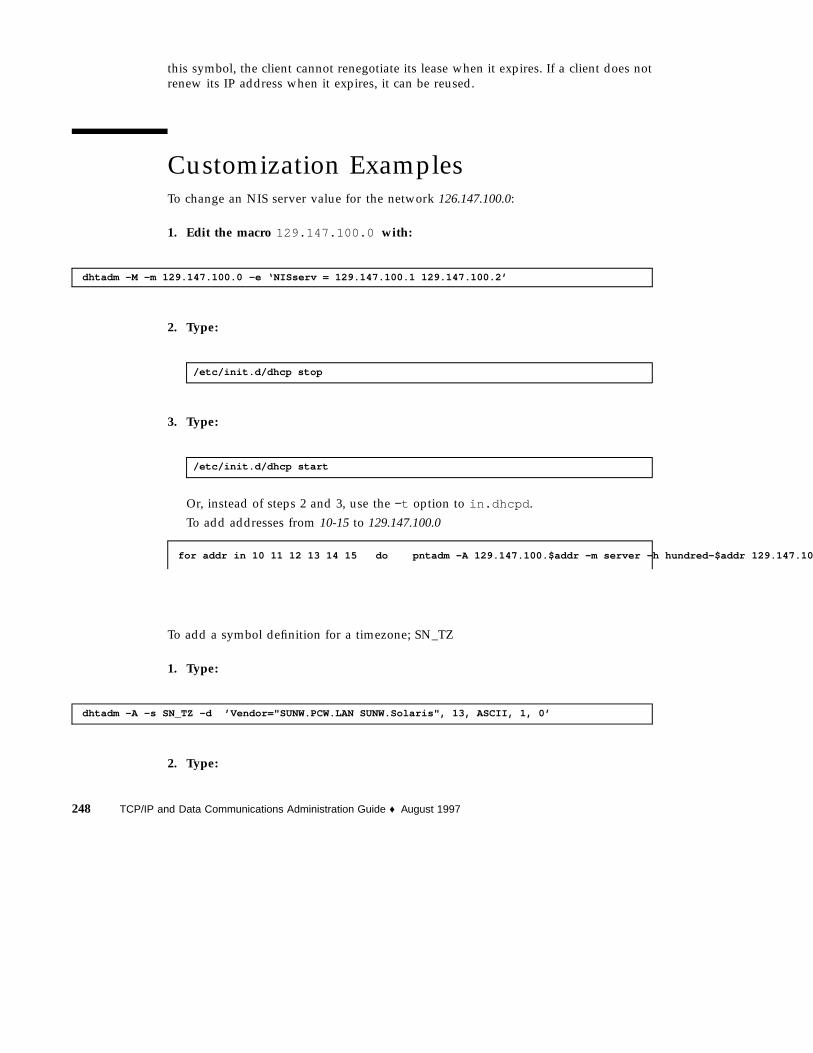
this symbol, the client cannot renegotiate its lease when it expires. If a client does notrenew its IP address when it expires, it can be reused.
Customization ExamplesTo change an NIS server value for the network 126.147.100.0:
1. Edit the macro 129.147.100.0 with:
dhtadm -M -m 129.147.100.0 -e ‘NISserv = 129.147.100.1 129.147.100.2’
2. Type:
/etc/init.d/dhcp stop
3. Type:
/etc/init.d/dhcp start
Or, instead of steps 2 and 3, use the −t option to in.dhcpd .
To add addresses from 10-15 to 129.147.100.0
for addr in 10 11 12 13 14 15 do pntadm -A 129.147.100.$addr -m server -h hundred-$addr 129.147.10
To add a symbol definition for a timezone; SN_TZ
1. Type:
dhtadm -A -s SN_TZ -d ’Vendor="SUNW.PCW.LAN SUNW.Solaris", 13, ASCII, 1, 0’
2. Type:
248 TCP/IP and Data Communications Administration Guide ♦ August 1997

dhtadm -M -m Locale -e ‘:SN_TZ = "EST5EDT4":’
3. Type:
/etc/init.d/dhcp stop
4. Type:
/etc/init.d/dhcp start
or −t option
To delete the Timeserv value from the jurassic macro:
1. Type:
dhtadm -D -m jurassic -e ‘Timeserv=‘
2. Type:
/etc/init.d/dhcp stop
3. Type:
/etc/init.d/dhcp start
or −t option
Always return hostnames to the client of the server jurassic.
1. Type:
dhtadm -M -m jurassic -e ‘Hostname= _NULL_VALUE_’
Administration of DHCP 249

2. Type:
/etc/initd/dhcp stop
3. Type:
/etc/init.d/dhcp start
or −t option
If it is important to maintain the hostname-to-IP address association for a hostnamed canoepoint to an IP address association, mark the canoepoint entry on the pedsnetwork as MANUAL.
1. Type:
pntadm -M canoepoint -f MANUAL peds
or
2. Type:
pntadm -M canoepoint -f 02 peds
In order to mark 129.147.100.87 as BOOTP and permanent:
1. Type:
pntadm -M 129.147.100.87 -f ‘BOOTP + PERMANENT’ 129.147.100.0
or
2. Type:
pntadm -M 129.147.100.87 -f 09 129.147.100.0
250 TCP/IP and Data Communications Administration Guide ♦ August 1997
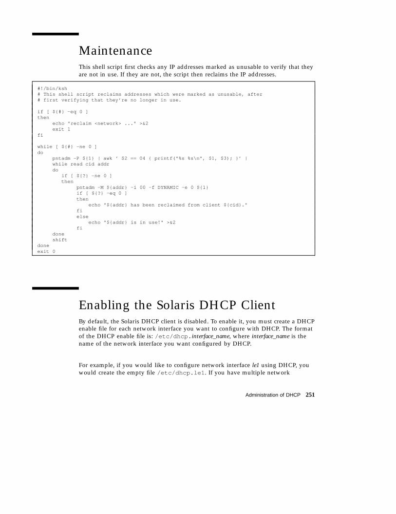
MaintenanceThis shell script first checks any IP addresses marked as unusable to verify that theyare not in use. If they are not, the script then reclaims the IP addresses.
#!/bin/ksh# This shell script reclaims addresses which were marked as unusable, after# first verifying that they’re no longer in use.
if [ ${#} -eq 0 ]then
echo "reclaim <network> ..." >&2exit 1
fi
while [ ${#} -ne 0 ]do
pntadm -P ${1} | awk ’ $2 == 04 { printf("%s %s\n", $1, $3); }’ |while read cid addrdo
if [ ${?} -ne 0 ]then
pntadm -M ${addr} -i 00 -f DYNAMIC -e 0 ${1}if [ ${?} -eq 0 ]then
echo "${addr} has been reclaimed from client ${cid}."fielse
echo "${addr} is in use!" >&2fi
doneshift
doneexit 0
Enabling the Solaris DHCP ClientBy default, the Solaris DHCP client is disabled. To enable it, you must create a DHCPenable file for each network interface you want to configure with DHCP. The formatof the DHCP enable file is: /etc/dhcp. interface_name, where interface_name is thename of the network interface you want configured by DHCP.
For example, if you would like to configure network interface le1 using DHCP, youwould create the empty file /etc/dhcp.le1 . If you have multiple network
Administration of DHCP 251
interfaces that you would like to configure using DHCP, you must create a DHCPenable file for each interface.
Increasing Boot Process SuspensionTimeUsing DHCP to configure an interface may increase the boot time. In particular, if noDHCP server is present to answer the client’s requests, a delay of approximately 30seconds occurs for each interface. If you want your Solaris DHCP client to suspendthe booting process until the network interface is configured (regardless of how longthis takes), edit the network interface’s DHCP enable file(/etc/dhcp. interface_name) and add the phrase wait forever .
If you want your client to suspend its booting process for a shorter period of time,you can specify the number of seconds to wait instead of using the keywordforever . For example, if you want to allow DHCP one hour to configure thenetwork interface before the booting process continues, specify wait 3600 .
Note - Even if the suspend time is exhausted, the Solaris DHCP client will continueasynchronously to configure the network interface until it is successful. To avoid this,you can specify the drop option to the ifconfig (1M) command. For example:ifconfig le0 dhcp drop . This will remove the specified interface (in this case,le0) from the control of the DHCP agent, which should cause the asynchronousaddress allocation attempts to terminate.
Designating a Network Interface asPrimaryMany DHCP configuration parameters are not specific to a network interface.Instead, the parameters specify more general information. Examples of this type ofgeneral parameter are: NIS server, NIS domain, DNS servers, and DNS domain. Ifyour Solaris machine has only a single network interface, there does not need to be adistinction between the general and interface-specific parameters.
However, if your machine has multiple network interfaces (it is multihomed), andDHCP is to configure more than one interface, then it is possible to receive multiplesets of general configuration parameters that may conflict. For example, which DNS
252 TCP/IP and Data Communications Administration Guide ♦ August 1997

parameters should be used? Those received when using DHCP to configure interfacele0 or those received for le1?
The Solaris DHCP client solves this problem by allowing you to specify one networkinterface as the primary network interface. Interface-specific parameters (such assubnet mask) will be retrieved from the DHCP parameters for that specific interface.General parameters are retrieved only from the DHCP information received on theprimary interface.
To designate a network interface as the primary interface, add the keyword primaryto the DHCP enable file for that interface. For example, suppose you want to use qe2as the primary interface. Edit /etc/dhcp.qe2 and add the word primary .
If the keyword primary is not added (no interface has been designated as primary),the Solaris machine receives parameters from the first interface that is configuredsuccessfully.
Network Topologies That LimitEffective Use of DHCP/BOOTPDHCP and BOOTP clients initially have no information about the local IP network,and therefore use the 0.0.0.0 (the default network address) for their IP address. Theclients send their DHCP or BOOTP requests to the 255.255.255.255 IP address(broadcast address) which will be received by all IP devices attached to the local IPnetwork.
DHCP and BOOTP servers determine the client’s IP network attachment based onfollowing factors:
1. Which network hardware interface the DHCP or BOOTP request was received on?
2. Was the DHCP or BOOTP request received from a BOOTP relay agent?
BOOTP relay agents insert the IP address of their network hardware interface thatis attached to the same IP network as the DHCP or BOOTP client. The absence ofthis IP address signals to the server that the client is on a directly-attached IPnetwork. The presence of this IP address indicates that the client is attached to anIP network remote from the server and that the server is to send responses backto the client using the BOOTP relay agent’s IP address.
3. Is the IP network the client is attached to subnetted?
The servers, using the IP address as a key, consults the contents of the netmaskstable (which contains subnet mask information) using either:
� The IP address of the server’s network hardware interface if the client is on adirectly-attached IP network (indicated by an IP address of 0.0.0.0 in thepacket’s relay address field)
Administration of DHCP 253
� The IP address specified if a BOOTP relay agent specified its IP address in theclient’s request
(See netmasks (4) for information on netmasks.)
This procedure for determining the client’s IP network attachment is only effective ifthere is only one IP network present on the network hardware media (for example,Ethernet). DHCP does not work well in IP network environments where, eitherthrough the use of multiple network hardware interfaces or multiple logicalinterfaces, there is more than one IP network sharing the same network hardwaremedia. In this case, a DHCP client’s request appears on all network hardwareinterfaces, making the client "appear" to be attached to all of the IP networkssimultaneously. Since DHCP servers dynamically allocate IP addresses to requestingclients, the server is unable to determine which IP address to allocate to the client.DHCP clients, attempting to validate IP addresses they presently hold, will be seento originate on all the logical IP networks, not just the network the client has beenassigned to.
Such network topologies should be avoided, either though the use of Variable LengthSubnet Masks (VLSM) to preserve the one-to-one mapping of IP network to networkhardware media through more efficient subnetting, or by configuring the DHCP orBOOTP service to serve just one of the logical IP networks. See netmasks (4) foradditional information.
254 TCP/IP and Data Communications Administration Guide ♦ August 1997

CHAPTER 17
Troubleshooting DHCP
This chapter describes how to troubleshoot problems you may encounter while usingDHCP. It includes solutions to problems you may have when installing andconfiguring the first DHCP server. To further help you troubleshoot server problems,this chapter also includes background information about the DHCP serverconfiguration script (dhcpconfig ) - the purpose of various script components andhow the script executes installation procedures. It also describes problems you mayencounter as you add your first and subsequent DHCP clients to the network.
� “Strategies and Tips” on page 256
� “Common Problems” on page 259
� “Where to Get More Help” on page 261
� “Troubleshooting the DHCP Server” on page 261
� “Cannot Use NIS+ as Name Service” on page 264
� “I/O Error Accessing File Name Service” on page 265
� “User Has no DES Credentials” on page 266
� “No Permission to Create Table in Data Store” on page 266
� “Unable to Determine Name Servers” on page 267
� “Errors Trying to Set Up DHCP Table” on page 268
� “No Permission to Access dhcp_network Table” on page 268
� “Troubleshooting a DHCP Client” on page 269
� “Client Cannot Communicate With the Server” on page 269
� “Isolate the Problem to the Client or Server” on page 270
� “Client Cannot Reach DHCP Server” on page 271
� “Look up Error Messages” on page 273
� “Some Clients Do Not Boot From DHCP Server in BOOTP Compatability Mode”on page 276
255

� “Diagnose NIS+ Configuration Problems” on page 276
� “Diagnose Name Service Configuration Problems” on page 278
� “Macro Change Not Propagated to Client” on page 279
Strategies and TipsThe following troubleshooting techniques are helpful in solving problems when youcannot isolate the cause:
� Use the snoop command to monitor network traffic.
� Run the DHCP client in debug mode.
� Run the DHCP server in debug mode.
� Reboot the DHCP client.
� Stop the DHCP server. Then start it again.
This chapter describes these techniques in more detail. It also tells you where to getmore information when you cannot solve a problem using this guide.
Using snoop to Monitor Network TrafficYou can use the snoop command to monitor network traffic.
To Use snoop to Monitor Network Traffic1. Log in to the root account on a Solaris server or BOOTP/DHCP relay agent on
the same subnet as the client.
2. Use the snoop command to trace network traffic. For example:
snoop -o /tmp/output udp port 67 or udp port 68
3. Boot the client and watch the DHCP message exchange between the client andserver(s).
4. Type:
snoop -i /tmp/output -x 0 -v
256 TCP/IP and Data Communications Administration Guide ♦ August 1997

You can limit the scope of snoop by specifying the client’s hardware address. Aversion of snoop that understands the DHCP/BOOTP protocols is available inSolaris version 2.5 and later.
Running the DHCP Client in Debug ModeRunning the DHCP client in debug mode reveals much of the ongoing dialoguebetween the client and the server. Refer to the documentation for the product onwhich you are running the client.
To Run a Solaris 2 Client in Debug ModeDebugging the DHCP client is only possible after it has booted. If DHCP problemsare experienced, you must boot with DHCP disabled. The steps here can beperformed only once after the host has booted, preferably in single-user mode.
1. The DHCP agent can be configured to log details of the packets exchanged withthe server. To do this, the agent must be started with debug mode turned on:
/sbin/dhcpagent -n -d3 &
The -d3 flag turns on debug at leve1 3, and the -n flag says “don’t configure theinterface even if DHCP is successful”.
Note - Level 3 and levels below that return appropriate information for the user.Levels above level 3 are appropriate only for developers or those with even moreexpertise, since they return raw packets of information.
2. Only one instance of dhcpagent can run at a time, so before the agent can bestarted in this manner, any previously invoked agent must be stopped. To dothis, find the agent’s process ID and send it the terminate signal:
kill -TERM process_id_of_dhcpagent
3. After an agent has been started in debug mode, try to configure an interfacemanually by typing:
ifconfig interface_name auto_dhcp
Troubleshooting DHCP 257

The packets that are sent, and any that are received, will be displayed.
Note - During the time that DHCP tries to configure an interface, the interface isunable to send or receive packets. Other network services, such as NIS or NFS,may be adversely affected while the interface is down.
To Run the DHCP Server in Debug Mode♦ Stop and restart the DHCP server in debug mode.
For example:
1. Stop the server using the shutdown script:
/etc/init.d/dhcp stop
2. Restart the server in debug/verbose mode, using the -d and -v flags inaddition to any flags specified in the /etc/init.d/dhcp startup script. Forexample, if the i option is present, type the command in the following format:
/usr/lib/inet/in.dhcpd -i interface_names -d -v
Restarting the DHCP Client
Once you have run the DHCP client in debug mode, you can try rebooting.Rebooting resets the network hardware and software.
To Restart the DHCP Client1. Reboot the client.
To Restart the DHCP Server1. Log in to the DHCP server as root.
258 TCP/IP and Data Communications Administration Guide ♦ August 1997

2. Type:
/etc/init.d/dhcp stop
Wait about 10 seconds.
3. Type:
/etc/init.d/dhcp start
To Restart the DHCP Server After Debugging isCompleted1. Restart the DHCP server daemons.
2. Log in to the DHCP server as root.
3. Type:
/etc/init.d/dhcp stop
Wait about 10 seconds.
4. Type:
/etc/init.d/dhcp start
Common ProblemsThis section describes some of the more common problems you may encounter withDHCP, and what to do about them.
Troubleshooting DHCP 259

Problem
The DHCP client is sending out DHCPDISCOVER or DHCPREQUEST messages, butthe DHCP server is not responding.
Verification: Check the server machine’s console. It may not have any IP addressesleft to allocate.
Solution: Add more IP addresses.
Verification: Check the server machine’s console. If the server is stating that the clientis unrecognized, then the DHCP server’s databases may have been flushed, with theresult that the server fails to recognize the client.
Solution: Remove any DHCP cache file on the client.
1. Interrupt the boot by typing Control −C.
2. Remove the cache by typing:
cd /etc/dhcp; rm interface_name.dhc
3. Restart the initialization process by typing
ifconfig interface_name dhcp release
Verification: Check the server machine’s console. Perhaps support for the client’snetwork has not been added to the DHCP databases.
Solution: Add support for the client’s network, using dhcpconfig .
Verification: The client is on a network separate from that of the DHCP server, and aBOOTP relay agent has not been installed or configured.
Solution: Install and configure a BOOTP relay agent. In addition, you may need toadd an entry to the netmasks (4) database for the remote network.
Problem
The client logs a message that the address is already in use.
Verification: Check whether the address is in use elsewhere. If the client continues tolog the same message, it is likely that the server is not checking the address, or isignoring the client’s message which declines the address. Check to be sure you arenot using the in.dhcpd command with the n option.
260 TCP/IP and Data Communications Administration Guide ♦ August 1997

Solution: Find out whether the server gave out the bad address. Either the server ismalfunctioning, or another user has illicitly used the same address.
Problem
The following error message is displayed:
DHCP renewal on interface_name failed
Verification: The DHCP client was unable to renew a lease on the specified interface.
Solution: Make sure that the DHCP server is still running correctly.
Problem
The following message is displayed:
Address of interface name has changed
Verification: The address or status of the interface is not what the DHCP agentexpects to see. The address was probably altered manually.
Solution: There is no solution. The agent will stop trying to configure the interface.
Where to Get More HelpIf after using these instructions you need further assistance, please call your localSolaris sales or service representative. To ensure that you receive the best possibleservice, have the following information ready before calling for help.
� Exact error message you received (if any)
� Version of the operating system running on the client
� Machine type
� Type of network (Ethernet, Token Ring, FDDI or PPP)
Troubleshooting the DHCP ServerThis section discusses problems you may have with your DHCP server.
Troubleshooting DHCP 261

When Using FilesFollow the instructions below if you have problems while using files as a nameservice.
Problem
You cannot access the /var/dhcp directory; it either does not exist or you do nothave UNIX file permissions to read it.
Verification: Use the following command:
ls -d /var/dhcp
Solution: The DHCP server hasn’t yet been configured. Run dhcpconfig .
When Using NIS+Follow the instructions below if you have problems while using NIS+ as a nameservice.
Problem
The root object does not exist in the NIS+ domain.
Verification: Enter the command:
niscat -o org_dir
Solution: Refer to Solaris NIS+ setup documentation.
Problem
The root account does not have access rights to create a table under the org_dirobject.
Verification: Enter the command:
niscat -o org_dir
Solution: Use the nischmod command to change the permissions on thetable.org_dir.domainname.
262 TCP/IP and Data Communications Administration Guide ♦ August 1997

Problem
The root account does not have access rights to create a table under the org_dirobject. Usually, this means the root account’s principal name is not a member of theowning group for the org_dir object, or no owning group exists.
Verification: Enter this command to find the owning group name: niscat -o org_dir
Solution:
1. Enter nisgrpadm -l group to see the group members.
2. If the current system’s principal name is not in the group, enter:nisgrpadm -a group principalname to add it. Typically, the group is admin.If it is not, edit the dhcpconfig script and change the group to match thegroup name in use.
3. Enter /usr/lib/nis/nisctl -fg to flush the cache for immediate update.
Problem
The domain name is unset.
Verification: Enter the command:
domainname
If the command lists an empty string, no domain name has been set for the domain.
Solution: Use the domainname command to set the proper domain name. Place thedomain name value in the /etc/default domain.
Problem
The NIS_COLD_STARTfile does not exist.
Verification: Enter the following command on the server system:
strings /var/nis/NIS_COLD_START
Solution: Create a NIS+ client. Refer to the Solaris NIS+ QuickStart documentation.
Problem
You choose NIS+ and the site is not running NIS+.
Verification: Log on to the server. Type in the command:
Troubleshooting DHCP 263

ps -ef | grep nis
If NIS+ is running you will see output similar to: /usr/sbin/rpc.nisd -YB .
Solution: Create a NIS+ server:
1. On the client, set up the NIS+ root master server for the domain. For example:
/usr/lib/nis/nisserve -r
2. Populate the NIS+ tables from the local /etc files. For example:
nispopulate -F /etc
3. On the server, verify that NIS+ is running. For example:
/usr/lib/nis/nisstatnisls org_dirniscat hosts. org_dir
Cannot Use NIS+ as Name ServiceOne or more of the following error messages are displayed:
!!! warning !!! trailing dot ignored - use dns domain namesyntax
Error 20 from NIS+; unable to use NIS+ as name service.
These messages mean either that there is no such name in the NIS+ domain, or theNIS+ domain does not exist. Use the information below to find and solve errors inthe configuration of NIS+.
Problem
The domain name for the server system ends with a period.
Verification: Enter the nisdefaults command to determine whether there are twotrailing periods after the domain name.
264 TCP/IP and Data Communications Administration Guide ♦ August 1997
Solution:
1. Edit the /etc/defaultdomain file by removing the trailing period (.) fromthe domain name.
2. Reboot your system, and rerun the dhcpconfig script.
Problem
A host name includes the domain name. For example, setting a host tomyhost.Faxco.COM instead of myhost .
Verification: Enter the nisdefaults command to show a host name with thedomain name included twice.
Solution:
1. If your host name is set incorrectly, enter the sys-unconfig command toremove the configuration settings and halt the system.
2. Reboot the system and supply the correct settings for host name and domainname.
Problem
The root account does not have create access to the org_dir object in the NIS+domain.
Verification: Enter the command:
niscat -o org_dir
Solution: Use the nischmod command to change the permissions on thetable.org_dir.domainname .
I/O Error Accessing File Name ServiceThe following error message is displayed:
File system I/O error number accessing file datastore.
If you receive this error message, look through the list of error messages below,which are returned by the operating system when it tries to open, read, or write afile in /var/dhcp .
Troubleshooting DHCP 265
Problem
The error number is 2 (ENOENT).
Verification: The file or directory does not exist.
Solution: Enter the dhcpconfig command to create it.
Problem
The error number is 13 (EACCES) .
Verification: A UNIX permission error occurred accessing the file or directory.
Solution: Use the su command and change the UNIX permissions.
User Has no DES CredentialsProblem
The following error message is displayed:
The user user does not have DES credentials in the NIS+ nameservice.
Verification: The current system’s root account does not have valid Data EncryptionStandard (DES) credentials in the NIS+ cred table.
Solution: Use the nisaddcred command to add the credentials for the root account.You must enter the UNIX netname and NIS+ principal name on the command line.
The following example shows how to add DES credentials for the system mercury inthe domain Faxco.COM.
nisaddcred -p [email protected] \-P mercury.Faxco.COM. DES Faxco.COM
The command prompts for the root password (which is required to generate anencrypted secret key).
No Permission to Create Table in Data StoreThe following error message is displayed:
You do not have permission to create the tablename table in theservicename data store.
266 TCP/IP and Data Communications Administration Guide ♦ August 1997
If you have a problem creating tables in the data store, check the information below.
Problem
The root account does not have access rights to create a table under the org_dirobject.
Verification: Usually, this means the root account’s principal name is not a memberof the owning group for the org_dir object, or no owning group exists.
Solution:
1. Enter niscat -o org_dir to see the name of the owning group.
2. Enter nisgrpadm -l admin to see the group members.
3. If the current system’s principal name is not in the group, enternisgrpadm -a group principalname to add it.
4. Enter /usr/lib/nis/nisctl -f g to flush the cache for immediate update.
Unable to Determine Name ServersSolutions to problems in finding a name server during configuration of the DHCPserver are listed below.
Problem
The dhcpconfig script could not match server names with IP addresses.
Verification: Find the IP address of the server by using the command getent hostsname.
Solution: Create the entries in the hosts database.
Problem
The dhcpconfig script is using the wrong name service for the server.
Verification: Look at the hosts entry in the /etc/nsswitch.conf file to see whichname service is used to look up IP addresses (xfn , files , nis , nisplus , dns ).
Solution: Change the hosts directive in the /etc/nsswitch.conf file to thecorrect name service. Stop and restart nscd .
Problem
The dhcpconfig script did not check the name service.
Verification: The name service preceding the [NOTFOUND=RETURN]directive in the/etc/nsswitch.conf file is authoritative. If the specified name service does notfind an entry, any name services listed after this directive are not checked.
Troubleshooting DHCP 267

Solution: Remove the [NOTFOUND=RETURN]directive from the/etc/nsswitch.conf file and run the dhcpconfig script again. Stop and restartnscd .
Errors Trying to Set Up DHCP TableOne of the following error messages is displayed:
The user username does not have permission to update the dhcptabtable in the servicename resource.
Error 10 from the Table subsystem accessing dhcptab table,message: NIS+ error while executing nis_modify_entry for[key=SUNW.PCNFS.5.1.1,flag=m],dhcptab.org_dir.island.ocean.: Permission deniedError trying to set up DHCP table, exiting.
Error 10 from the Table subsystem accessing dhcptab table,message: NIS+ error while executing nis_modify_entry for[key=SUNW.PCNFS.5.1.1,flag=m],dhcptab.org_dir.island.ocean.: Object with samename exists Error trying to set up DHCP table, exiting.
If you receive one of these error messages, check the information below for solutionsto problems trying to set up DHCP tables during the configuration of the DHCPserver.
Problem
You do not have access rights to add entries into DHCP tables from NIS+ or theUNIX file system.
Verification: Check permissions and set appropriate access rights for the DHCP table.
Solution: Make sure the administrator is a member of the appropriate administrativegroup and has write access to the NIS+ master server.
No Permission to Access dhcp_network TableThe following error message is displayed:
You do not have permission to create {update} the tablename tablein the servicename data store.
If you receive this message, check the information below regarding a problem. Listedbelow are solutions to problems accessing the dhcp_network table during theconfiguration of the DHCP server.
Problem
268 TCP/IP and Data Communications Administration Guide ♦ August 1997

You do not have access rights to add entries into the dhcp_network table fromNIS+ or the UNIX file system.
Verification: Check permissions and set appropriate access rights for thedhcp_network table.
Solution: Make sure the administrator is a member of the appropriate administrativegroup and has write access to the NIS+ master server.
Troubleshooting a DHCP ClientWhen troubleshooting a DHCP client, you must understand certain issues aboutconfiguring the client and client-server communication. DHCP may fail to configurethe client properly, either because DHCP could not communicate with a server, orbecause, although configuration responses were received, they were incorrect.Problems can also occur later in the life of a DHCP lease if the client cannot renewits IP addresses.
Client Cannot Communicate With the ServerWhen a client and a server cannot communicate with each other, the consequencesdepend on whether or not the client has a configuration cached from an earlierDHCP transaction. If it has, and if the lease is still valid, the client will use thecached data to configure the interface.
However, because the client has received no outside confirmation that thisconfiguration is valid, there is no guarantee that the IP address, router address, andother information are valid. If the interface is connected to a network other than theone on which the configuration was received, one of two things can happen. Eithererrors may appear when other network services are started, or it may be impossibleto communicate with other hosts on the network.
On the other hand, if no cache with an unexpired lease exists, the interface is notconfigured.
DHCP Configurations Received Are InvalidConfigurations can be invalid for two reasons:
1. The client determines by ARP that the IP address offered to it is in use elsewhere.In this case, the client will send a DHCPDECLINE message to the server. If theserver offers more than two bad addresses, dhcpagent fails.
Troubleshooting DHCP 269

2. The client gets offers, but when it tries to confirm them, the server sends aDHCPNAK message instead of a confirmation. If the client receives DHCPNAKmessages more than twice, dhcpagent fails. This indicates a malfunctioningserver.
Isolate the Problem to the Client or ServerPerform the following actions to isolate the problem to either the client or the servermachine.
Problem
The DHCP server machine is not working.
Verification: Log in to another machine on the same subnet as the client, and use theping command to try to reach the server.
Solution: Diagnose the problem on the server machine.
Problem
The DHCP server is not running.
Verification: Log in to the server and enter the command:
ps -ef | grep dhcp
Solution:
1. Stop and restart the DHCP server.
2. Enter the command:
/etc/init.d/dhcp stop
3. Wait about 10 seconds. Then enter the command:
/etc/init.d/dhcp start
Problem
The boot process hangs during DHCP.
270 TCP/IP and Data Communications Administration Guide ♦ August 1997
Verification: The interface is marked primary, but no valid DHCP transaction hasoccurred.
Solution: Interrupt DHCP by typing control-C . The boot continues.
Note - Although booting continues, the host may be incorrectly configured for thenetworks to which it is attached.
Client Cannot Reach DHCP ServerProblem
After configuring the DHCP client software and rebooting the client, you are unableto reach a server on the network from the client. All DHCP network commands failand you see messages that the client is trying to reach the DHCP server and failing.
Typical error messages include:
DHCP or BOOTP server not responding
A request to access nonexistent dhcp_network database:databasename in datastore: datastore.
No more IP addresses for network_address network.
Verification: To pinpoint exactly what the problem is, perform the following actions.
1. Run the client in debug mode.
2. Attempt to configure the interface manually to verify that the hardware isfunctioning.
3. Run the DHCP server in debug mode.
4. Use snoop to trace messages sent between the DHCP server and client.
5. Find out if the problem is on the client or server machines.
6. Look at the error message and choose a solution from the information below.
Run Client in Debug ModeRun the client in debug mode. Refer to the documentation for the product you arerunning.
Troubleshooting DHCP 271
Solaris 2 Client:1. Invoke:
/sbin/dhcpagent -d3
DOS ClientOn a PC-NFS DOS client:
1. Edit the AUTOEXEC.BATfile by replacing SNCLIENT with SNCLIENT /D.
2. Reboot the client.
Configure the Interface ManuallyAfter dhcpagent has been started in debug mode, you can try to configure aninterface manually by typing:
ifconfig interface_name auto_dhcp
Packets that are sent, and any that are received, will be displayed.
Run the Server in Debug Mode1. Log in to the root account on a DHCP server on the same subnet as the client.
2. Kill and restart the DHCP server in debug mode. For example:
/etc/init.d/dhcp stop /usr/lib/inet/in.dhcpd -d -v
Or, if the i option is present, enter the command in the following format:
/usr/lib/inet/in.dhcpd -i interface_names -d -v
272 TCP/IP and Data Communications Administration Guide ♦ August 1997

Use snoop to Monitor Network Traffic1. Log in to the root account on a DHCP server or BOOTP relay agent on the
same subnet as the client.
2. Use the snoop command to trace network traffic. For example:
snoop -o /tmp/output udp port 67 or udp port 68
or
snoop -o /tmp/output udp port bootps or udp port bootpc
plus the per-interface argument, if there is one.
3. Boot the client and watch the network messages on the server.
4. Type:
snoop -i /tmp/output -x 0 -v
to view the packet traces.
Look up Error MessagesLook at the output from running the in.dhcpd command in debug mode and usethe error message or condition you see to find a solution from the information below.
ProblemYou see one of the following error messages:
Datagram received on network device: le0
ICMP ECHO reply to OFFER candidate: ip_address disabling
Verification: Before the DHCP server offers an IP address to a client, it verifies thatthe IP address is not in use by ping ing the IP address. If a client replies, the IPaddress is in use.
Solution: Make sure the IP addresses you configured are not already in use.
Troubleshooting DHCP 273

ProblemYou see the following error message:
No more IP addresses for network_address network
Verification: There are no available IP addresses in the client’s dhcp_network table.
Solution: Use the dhcpconfig command to allocate more IP addresses. If the DHCPdaemon is monitoring multiple subnets, be sure the additional IP addresses are forthe subnet where the client is located.
ProblemThere is a bad client id: id_name in the dhcp_network database.
Verification: The client ID (MAC address) in the dhcp_network table is incorrect.
Solution: If you are using Ethernet, the client ID is 01 followed by the Ethernetaddress. Make sure that all letters in this address are capitalized. A 00 means theaddress has not been assigned.
ProblemYou see the following error message:
Request to access nonexistent dhcp_network database: database_namein datastore: nisplus_datastore.
Verification: The dhcpconfig script did not create a dhcp_network table for asubnet during the configuration of the DHCP server. This can happen if you set upan isolated LAN, such as a server and two clients, as a test network.
Solution: Use the dhcpconfig command to initialize the dhcp_network table andnew IP addresses.
ProblemYou receive the error message:
Client client_id is trying to verify unrecorded address ip_address,ignored.
Verification: There are two possible reasons for getting this message:
1. You can receive this message if your dhcp_network tables have been deleted. Ifyou are using only the Solaris 2 DHCP server, then this is typically the reason.
2. You can receive it if you are not using NIS+ for datastore, so information is notshared. Make sure that the server is sharing data.
274 TCP/IP and Data Communications Administration Guide ♦ August 1997

If you have a group of heterogenous servers, then ignore this message.
Solution: Remove old cache files on the client by typing:
ifconfig interface_name dhcp release
ProblemDHCP is started, but some required network services will not start.
Verification: The DHCP server is not supplying the configurations required.
Solution: Find out why the server does not send the parameters that are required.Configure the server to do so.
ProblemDHCP is started, but certain network services, such as NIS and NIS+, report errorsor hang. The host cannot communicate with other hosts on the network.
Verification: The dhcpagent command was unable to communicate with DHCP(presumably because DHCP was unavailable) and has used cached data.
Solution: Remove the cache. Type:
ifconfig interface_name dhcp release
Since removing the cache does not solve the problem of getting the properconfiguration, the host may have to be configured by hand. At boot time, DHCPshould be disabled by removing the trigger file by typing:
rm /etc/dhcp. interface_name
ProblemThe client boots and works correctly, but the following message appears:
DHCP renewal on interface_name failed
Troubleshooting DHCP 275

Verification: DHCP is working, but dhcpagent cannot contact the server to extendthe lease.
Solution: Find out why the server is not responding now. This could be because therouter value configured in the dhcptab is incorrect or out of date for the clientnetwork.
ProblemMessages about failed DHCP renewals are received. Then the following messageappears on the console:
DHCP lease expired on interface_name: interface is now down
Network services may hang at this point.
Verification: The lease has expired. The client has not been able to extend the leaseafter several attempts.
Solution: Find out why the server is not responding. Reboot the client.
Some Clients Do Not Boot From DHCP Server inBOOTP Compatability ModeProblem
The DHCP daemon is running in BOOTP compatibility mode (−b option).
Verification: BOOTP does not use a lease time. The DHCP server looks for freeaddresses with the BOOTP flag set to allocate the BOOTP clients.
Solution: Allocate BOOTP addresses. Use dhcpconfig to change the daemonoptions.
Diagnose NIS+ Configuration ProblemsUse the information below to fix errors in the configuration of the NIS+ name servicethat prevent the client from accessing a server during boot.
Problem
No name service is configured for the client in the dhcptab table.
Verification: Log in to the server and type the command:
dhtadm -P | grep ip_address
276 TCP/IP and Data Communications Administration Guide ♦ August 1997
Check for entries such as NISdmain , DNSdmain, and NISservs . Make sure theaddresses entered for them are correct. For example:
# dhtadm -P | grep 129.148.3.129.148.3.m:Subnet=255.255.255.0:Router=129.148.3.11:Broadcast=129.148.3.255:NISdmain=’’island.ocean’’:NISservs=129.148.3.3:
Note - The line above actually appears on one line, instead of being broken into two.
Solution: Use dhtadm to change any incorrect addresses.
Problem
You are using NIS+ and the server is not running in NIS+ compatibility mode. NIS+tables do not have read rights for the Nobody category, so NIS clients cannot accessthe information stored there.
Verification: Run the command:
nisls -l org_dir
to show permissions of .r---rmcdrmcdr---
Check whether the Y option is set for the rpc.nisd daemon. For example:
ps -deaf | grep nis
Solution:
1. Log in to the NIS+ server as root.
2. Enter the command:
/usr/lib/nis/nisserver -r -Y -d domainname
Problem
An incorrect default router prevents the client from reaching a server on anothernetwork.
Troubleshooting DHCP 277
Verification: Make sure the router symbol definition in the dhcptab table is actuallya router.
Solution: Use dhtadm to correct the route symbol in the table.
Problem
You are running NIS+ but DNS forwarding is not turned on for NIS clients.
Verification: Use the command:
ps -ef | grep rpc.nisd
A −B option means that NIS is running with DNS forwarding turned on. For example:
/usr/sbin/rpc.nisd -B
Solution: Start the NIS+ server in NIS compatibility mode with DNS forwardingenabled. For example:
/usr/sbin/rpc.nisd -YB
Diagnose Name Service Configuration ProblemsUse the information below to fix errors in the configuration of the NIS name servicesthat prevent the client from accessing a server during boot.
Problem
An incorrect default router prevents the client from reaching a server on anothernetwork.
Verification: Make sure the router symbol definition in the dhcptab table is actuallya router. If there are problems with the default router, make corrections withserver-based tools.
Solution: Use dhtadm to correct the route symbol in the table.
Problem
278 TCP/IP and Data Communications Administration Guide ♦ August 1997

No name service is configured for the client in the dhcptab table. For clients, thename service must be DNS, NIS, or NIS+, and appropriate parameters must beprovided to each client.
Verification: Check the network-specific macro relating to the client’s configuration.
1. Log in to the server and type the command:
dhtadm -P
2. Look for an entry that matches your client’s network.
Solution: Use dhtadm to correct the client’s macro for the name service:
If this is the first client on the network:
1. Use dhtadm to correct the entries.
2. Then type:
/etc/init.d/dhcp stop, /etc/rc3.d/S34dhcp start
on the server and reboot the client.
Note - The server does not dictate the name service choice to the client. Theserver only provides the relevant information. The client chooses its name service.
Macro Change Not Propagated to ClientYou have changed one or more macros for a client with dhtadm , but the changes arenot evident on your machine. For example, you changed the client’s router, but theclient is still using the old router.
Use the information below to solve the problem of changed client macros notshowing up on the DHCP server.
Problem
The DHCP server was not reinitialized to read your changes to the dhcptab table.This must be done every time you change a macro definition.
Solution: Use the rescan option-set with dhcpconfig , or:
Reinitialize the DHCP server:
Troubleshooting DHCP 279

1. Log in to the DHCP server as root.
2. Enter:
/etc/init.d/dhcp stop
3. Restart the DHCP daemon by entering:
/etc/init.d/dhcp start
280 TCP/IP and Data Communications Administration Guide ♦ August 1997
APPENDIX A
PCNFSpro Appendix
TroubleshootingThe following series of troubleshooting techniques are specific to PCNFSpro runningas the Windows client. To get further information about PCNFSpro and the Windowsclient, consult the SolarNet PC-Admin Admininstrator’s Guide.
� “Running in Debug Mode” on page 282
� “Client Fails to Connect With DHCP/BOOTP Server” on page 282
� “SNC Script” on page 284
� “Logging In and Out” on page 286
Reboot the PCThis is a good first step if the PC is unable to connect to a server, or displays errormessages as it contacts the server. Rebooting the machine resets network hardwareand software. If the problem is caused by a temporary license that has expired,rebooting renews the license for 30 minutes.
For the Windows client, delete the file:
c:\pcnfspro\dhcp\ interface.bin
Replace interface with the name of the actual interface in use, for example:c:\pcnfspro\dhcp\pk0.bin .
281

Running in Debug ModeRunning in DHCP debug mode reveals much of the ongoing dialog between theclient and the server. This dialog provides useful clues for solving network problems.
To Run a Windows Client in Debug Mode1. Kill the DHCP server and restart it in debug mode.
2. Enable the Network Event Log in the Services applet of the Configuration tool.
3. Close the Configuration Tool.
4. Start the Network Event Log directly from the program group.
5. Select the Display menu and highlight all priority levels.
6. Choose Save. After you do this, nfswdhcp.exe logs to the Network Event Log.
7. Exit and restart Windows.
Client Fails to Connect With DHCP/BOOTPServerIf you have installed or added a new client, but the machine fails to connect to theserver and displays an error message, check the machine’s cable and adapter. If theadapter has a diagnostic program, run it to identify possible problems.
Start the Configuration application in the PCNFSpro directory. Choose Services andenable the Start Network Event Log. You can also start the Network Event Logdirectly from its icon. After it starts, choose Display and then Configure. Select allpriority levels, down to Debug. Choose Save to save the configuration. NetworkEvent Log entries similar to:
DHCP: Attempting to configure interface using DHCP
indicate that the machine has broadcast for a configuration. Server replies shouldfollow.
Next, kill the in.dhcpd daemon on the server and run the server in diagnosticmode by entering in.dhcp -d .
After receiving output, check that there is a DHCP server or relay agent on themachine’s subnet. While booting the client, run:
snoop udp port 67 or udp port 68
282 TCP/IP and Data Communications Administration Guide ♦ August 1997
on a server on the same subnet as the machine. See if a system responds. Windowsclient snoop output looks like this:
OLD-BROADCAST -> BROADCAST UDP D=67 S=68 LEN=311
glrr -> BROADCAST UDP D=68 S=67 LEN=490
The client name is not shown for the Windows client. The DHCP activity is reflectedby the presence of BROADCAST.
Applications Run Out of Conventional MemoryThe CONFIG.SYS file (by default) does not try to load the Windows client adapterdrivers (packet driver, NDIS, or ODI) into upper memory. This can lead toapplications reporting “not enough conventional memory” or a similar messagewhen they start.
If you are running DOS 5.x or greater, change CONFIG.SYS lines from:
DEVICE=C:\PCNFSPRO\filename
to
DEVICEHIGH=C:\PCNFSPRO\filename
and NFSWAUTO.BATlines that load TSRs from
tsrname
to
LH tsrname
Mounting Home DirectoriesThe software default of mounting home directories on Drive H conflicts with the useof H by the MS-DOS 6.2 DoubleSpace utility. To resolve this conflict, remap the driveused by the DoubleSpace utility (dblspace h: /host =new_drive) or change yoursite login script to mount home directories on a different drive. The site login scriptis /opt/SUNWpcnet/1.5/site/pcnfspro/login.snc .
If you change the site login script, you must also change the HOME environmentvariable to a new drive.
PCNFSpro Appendix 283

Use of PingIf a machine cannot mount a remote file with the net use command, verify that thepathname to the file system you want to access has been entered correctly. Then usethe Ping application.
If a user is copying files to or from a network drive and the process stops before it iscompleted, use the Ping application.
If a machine has been receiving a license and cannot receive a license when it isturned on or rebooted, and instead receives error messages, use the Ping application.
SNC ScriptThe software distributes access to applications and other network services when amachine starts up or when a new user logs on. This interprets the directives in thestore\login.snc file. %SNDRIVE%expands to/opt/SUNWpcnet/1.5/site/pcnfspro , the site SNC script directory for theWindows client. This script is not accessible to users because it is protected by UNIXpermissions.
The directory /opt/SUNWpcnet/1.5/site/pcnfspro contains the default clientscripts (SNC scripts) used at boot, login and logout time to control resources on themachines. The directories are mounted temporarily and then dismounted after thescripts are run. On the Windows client, SNC commands are responsible forestablishing users’ unique relationships to the network.
The Windows client’s Configuration program processes the boot script (by defaultnamed boot.snc ) in the SNC script directory/opt/SUNWpcnet/1.5/site/pcnfspro . The names of the script and the SNCscript directory can be different for each network.
The Windows client’s Configuration program is a comprehensive graphical tool usedto view and change a wide variety of configuration parameters. The program enablesyou to change and customize any Windows client’s default configuration, and tosave the customized configuration. Among the parameters that you control by wayof the Configuration program are TCP/IP, the Local Area Network (LAN) user name,NFS, the printer client, NetBIOS, and SNMP. You can also standardize and controlthe level of configuration that the Windows client’s Configuration program makesavailable to users at your site. See the Configuration program’s on-line help fordetails about using the program.
The site SNC script directory is expanded when you add an INCLUDE directive fora new group login.snc script. It is also expanded when you add an INCLUDEdirective in the store\logout.snc file.
The script directory is used to create a directory with the UNIX login name for eachuser who has an individualized view of applications on the network. Then it is used
284 TCP/IP and Data Communications Administration Guide ♦ August 1997
to create and copy the user-specific login.snc and logout.snc scripts into eachdirectory. The commands are:
cd/opt/SUNWpcnet/1.5/site/pcnfspro
mkdir user1user2 user3 user4 user5user6user7
In this example, all users except user8, user9, user10, and user11 use applications thatthey either do not share with other users or that they share with some, but not allusers.
Three default SNC scripts are provided for each type of client in the SNC scriptdirectory /opt/SUNWpcnet/1.5/site/pcnfspro . They are:
� boot.snc - The site boot script used by the Windows client’s Configurationprogram and Login/Logout application.
� login.snc - The site login script used by the Windows client’s Login/Logoutapplication.
� logout.snc - The site logout script used by the Windows client’s Login/Logoutapplication.
The default site logout.snc script cleans up after the site login.snc script. Youcan copy the site logout.snc script, rename it, and modify it to correspond to yourlogin scripts. You should name all logout scripts logout.snc to parallel the loginscripts. Place the logout scripts in user and group-specific directories you createunder the SNC script directory /opt/SUNWpcnet/1.5/site/pcnfspro .
DHCP DatabasesEach NIS+ domain has one dhcptab table, which defines the configurationparameters to be returned to DHCP (or BOOTP) clients. The/opt/SUNWpcnet/1.5/site/pcnfspro script directory is one of the entries usedin defining user views and distributing applications.
License UpgradeChecking to see that license upgrade files were created requires certain proceduresfor the Windows clients. First run C:\pcnfspro\upgrade . After checking thelicense upgrade file and its contents, rerun the install program. Then:
1. Rename C:\windows\pcnfswin.ini .
2. Run the C:\pcnfspro\binnfswpupg program.
3. Finally, restore the renamed pcnfswin.ini file to its original name ofpcnfswin.ini .
PCNFSpro Appendix 285

After following the other steps to be sure the upgraded license file is present and isoperating correctly, delete the old DHCP configuration files and reboot the machine.Delete the file in the directory C:\pcnfspro\dhcp corresponding to your interface.
Loss of Hostname and IP AddressSimilar procedures must be followed if the machine has lost its original hostnameand IP address. First start the Control Panel application and choose the Networkicon. View the current hostname and IP address, as well as other pertinentinformation. Perform the procedure that creates an entry to the dhcp_table . Thenrun C:\pcnfspro\dhcp and follow the steps above.
Next, copy the upgrade file to the upgrade directory in the installation directory onthe server. Check to see that the snaddpcs script was executed. Then delete oldDHCP configuration files and reboot the screen. Do this by deleting the file in thedirectory C:\pcnfspro\dhcp corresponding to your interface.
Distributing ApplicationsThe software distributes access to applications and other network services when amachine starts up or when a new user logs on. For the Windows client, theseapplications and services are provided to each user by the Login application, whichstarts automatically when Windows is started.
The Windows-based DHCP application initiates DHCP, receives an IP address andrelated network information for the machine, configures the machine’s stack andservices, then begins processing client (SNC) scripts that mount file systems and setsearch paths for shared resources, groups, individual users, and individual machines.
Logging In and OutFor the Windows client, logging into and out of the network is done by clicking onthe Login/Logout application icon and filling in the resulting Windows dialog box.When a user fills in the dialog box with the user name and password, and clicks OKor presses Enter, the Windows client’s site logon.snc script is launched by thefollowing INCLUDEdirective in the client’s site boot script:
INCLUDE %SNDRIVE%\PCNFSPRO\LOGIN.SNC
286 TCP/IP and Data Communications Administration Guide ♦ August 1997

This script mounts directories, sets certain environment variables, and provides otherservices for the user who is already logged in, regardless of which machine theperson is using to log in. It establishes the login procedure that all users in thenetwork follow.
When the Windows client uses the same Windows-based dialog box to log out, theclient’s site logout.snc script is processed. This script undoes what thelogin.snc script did. The Logout application unmounts file systems and printers,and resets the machine’s environment variables to their original, pre-login values.
The Windows client’s Login/Logout application provides detailed information aboutthe user’s network settings, and enables you to change the settings. Among thesettings are version and license numbers, the user name and ID, the group ID, NISand DNS domains, the subnet mask, MAC addresses (which identify an Ethernetcommunications adapter), the time zone, the last drive, and names and IP addressesof available servers.
PCNFSpro Appendix 287

288 TCP/IP and Data Communications Administration Guide ♦ August 1997

Index
Special Characters* wildcard in bootparams database, 61- (dash)
Speed field placeholder, 174, 175, 180= dial-code abbreviation, 175
A-a option of ifconfig command, 80access control, see Permissions file; security,ACK segment, 24ACU keyword of Type field, 179ACU, see Automatic Call Unit (ACU);
modems,Address Resolution Protocol (ARP), 19addresses
Ethernet addressesdescribed, 9ethers database, 57, 61
loopback address, 50retrieving RFCs, 27
administration, see network administration,administrative files (UUCP), 205, 206
cleanup, 209execute files (X.), 169, 206lock files (LCK), 205temporary data files (TM), 205work files (C.), 205, 206
administrative programs (UUCP), 169administrative subdivisions, 37admintool software manager, 118aliases file, 212ALL value in COMMANDS option, 197
anonymous FTP programdescribed, 20InterNIC Registration Services, 39
anonymous login name, 20Any
Grades file keyword, 202, 203Speed field keyword, 174Time field entry, 173
application layerOSI, 16packet life cycle
receiving host, 26sending host, 23
TCP/IP, 20, 22described, 17, 20file services, 22name services, 21network administration, 22routing protocols, 22standard TCP/IP services, 20, 21UNIX “r” commands, 21
ARP (Address Resolution Protocol), 19asppp file
described, 99starting PPP, 130stopping PPP, 131
asppp.cf filedefaults section
dynamic-link dial-in server, 152value definitions, 162
described, 100, 124dynamic-link configuration, 150, 153editing, 129
Index-289

ifconfig sectionbasic configuration, 125dynamic-link dial-in server, 152multipoint dial-in server, 127, 128value definitions, 161
keywordsbasic configuration, 126, 127configuration keyword
definitions, 161, 163dynamic-link dial-in server
configuration, 152, 153multipoint dial-in server
configuration, 128, 129PAP/CHAP authenticator keywords
and associated strings, 157,159
PAP/CHAP keyword definitions, 158,159
PAP/CHAP keyword rules, 158PAP/CHAP peer keywords and
associated strings, 157, 159multipoint dial-in server, 127, 129obtaining diagnostic information, 138PAP/CHAP security, 156, 161parts of basic file, 124, 127path section
basic configuration, 125, 127dynamic-link dial-in server, 152, 153multipoint dial-in server, 128, 129obtaining diagnostic information, 138value definitions, 161
specifying IP addresses or host names, 112virtual network configuration, 155, 156
.asppp.fifo file, 101asppp.log file
described, 101PPP diagnostics
communications between local andremote hosts, 142, 146
host and modem setup, 139, 142obtaining diagnostic information, 138
aspppd PPP link managerdescribed, 100FIFO file, 101killing and restarting, 138verifying if PPP running, 130
aspppls PPP login service, 100, 101ASSERT ERROR message, 217
ASSERT error messages (UUCP), 214, 216asterisk (*) wildcard in bootparams
database, 61authenticator keywords and associated
strings, 157, 159Automatic Call Unit (ACU)
See also modems; outboundcommunications,
Devices file Type field, 179troubleshooting, 212UUCP hardware configuration, 167
Bb escape character
Systems file chat script, 176, 187backslash (escape) characters
Dialers file send strings, 186Systems file chat script, 176
backspace escape character, 176, 187BAD LINE message, 215BAD LOGIN/MACHINE COMBINATION
message, 217BAD LOGIN_UID message, 215BAD OPTION message, 216BAD SPEED message, 216BAD UID message, 215Basic Network Utilities UUCP, see UUCP,binary to decimal conversion, 54BNU UUCP, see UUCP,booting
diskless, 46network configuration server booting
protocols, 45processes, 70
BOOTP IP address allocation, 235BOOTP relay agents, 230bootparams database
corresponding name service files, 57network client mode configuration, 69overview, 60wildcard entry, 61
bootparams protocol, 46Bootstrap Protocol (BOOTP), 223Break escape character, 177
Dialers file, 187Systems file chat script, 176, 177
Index-290 TCP/IP and Data Communications Administration Guide ♦ August 1997

BSD-based operating systems/etc/inet/hosts file link, 49/etc/inet/netmasks file link, 54
buffer limit, exceeding65535 limit, 10
Cc escape character
Systems file chat script, 176, 187C. UUCP work files
cleanup, 209described, 205, 206
cables (network media), 6callback
enabling dialback through chat script, 177Permissions file option, 195
CALLBACK option of Permissions file, 195CALLBACK REQUIRED message, 217CALLER SCRIPT FAILED message, 218CAN’T ACCESS DEVICE message, 217CAN’T ALLOCATE message, 215CAN’T CHDIR message, 215CAN’T CHMOD message, 215CAN’T CLOSE message, 215CAN’T CREATE message, 215CAN’T FORK message, 216CAN’T LINK message, 215CAN’T LOCK message, 215CAN’T MOVE TO CORRUPTDIR
message, 215CAN’T OPEN message, 214CAN’T READ message, 214CAN’T STAT message, 215CAN’T UNLINK message, 215CAN’T WRITE message, 214carriage-return escape characters, 176, 177, 187Challenge-Handshake Authentication Protocol,
see CHAP,CHAP
asppp.cf keywordsauthenticator keywords and
associated strings, 157, 159definitions, 158, 159peer keywords and associated
strings, 157, 159rules, 158
described, 103
editing asppp.cf file, 156, 161examples, 159, 161installing, 157, 158
chap_name keyword, 158, 159chap_peer_name keyword, 157 to 159chap_peer_secret keyword, 157 to 159chap_secret keyword, 158, 159Chat Script field of Systems file, 175, 177
basic script, 175enabling dialback, 177escape characters, 176expect field, 175, 176format, 175
checklist for configuring PPP, 114, 115Class A network numbers
addressing scheme, 34administration, 33described, 32IP address space division, 34range of numbers available, 34
Class B network numbersaddressing scheme, 34administration, 33described, 33IP address space division, 34range of numbers available, 34
Class C network numbersaddressing scheme, 34administration, 33described, 33IP address space division, 34range of numbers available, 34
Class field, Devices file, 180clients, see diskless clients; network client
mode; network client,CLOCAL flag, turning on and off, 176.com domain, 16commands
execute (X.) UUCP files, 169, 206remote execution using UUCP, 193, 196,
198UUCP troubleshooting, 214
COMMANDS option of Permissions file, 196,197, 199
VALIDATE option, 197, 198commands, NIS+
niscat, 262, 265
Index-291

nischmod, 262, 265nisctl, 267nisdefaults, 264
Common Problems, 259communications links, see dynamic link dial-in
server;multipoint links;point-to-point links; PPPlinks,
communications protocols, 5Config file
described, 170, 200format, 200
CONFIG.SYS file, 283configuration files
PPP (asppp.cf)described, 100editing, 124, 129specifying IP addresses or host
names, 112TCP/IP networks
/etc/defaultdomain, 49/etc/defaultrouter, 49/etc/hostname.interface, 48/etc/nodename, 49, 67hosts database, 49, 52netmasks database, 52, 55
configuration request, 142, 143configuring
PPP links, 117, 133adding security, 130checking for errors, 131/etc/asppp.cf file, 124, 129/etc/inet/hosts file, 119, 121/etc/passwd and /etc/shadow
files, 123, 124dynamic links configuration, 147, 153installing PPP software, 118overview, 117, 118sample configuration, 119starting the PPP link, 130, 131stopping PPP, 131UUCP databases, 121, 123, 171, 172virtual network configuration, 153,
156
PPP preparation, 106, 115checklist, 114, 115determining IP addressing, 110, 113determining requirements, 106, 110file space requirements, 114hardware requirements, 114routing considerations, 113tasks, 106
PPP requirements, 106, 110dial-in server with dynamic links, 108file space, 114hardware, 114hosts on a virtual network, 110multipoint dial-in server, 109network-to-network
configuration, 108remote computer-to-network
configuration, 106, 107remote host-to-remote host
configuration, 107routers, 71, 76
network interfaces, 73overview, 72
TCP/IP configuration files, 47, 55/etc/defaultdomain, 49/etc/defaultrouter, 49/etc/hostname.interface, 48/etc/nodename, 49, 67hosts database, 49, 52netmasks database, 52, 55
TCP/IP configuration modes, 44, 47configuration information, 44, 45local files mode, 45, 46, 65, 66mixed configurations, 46network client mode, 46, 67, 68network configuration servers, 45sample network, 47
Index-292 TCP/IP and Data Communications Administration Guide ♦ August 1997

TCP/IP networks, 44, 70booting processes, 70configuration files, 47, 55host configuration modes, 44, 47local files mode, 65, 66network clients, 67, 69network configuration parameters, 64network configuration server
setup, 66, 67network databases, 56, 58, 60nsswitch.conf file, 58, 60prerequisites, 44standard TCP/IP services, 69
UUCPadding logins, 207, 208database files, 121, 123, 171, 172shell scripts, 208, 210TCP/IP networks, 210
configuring PC-Admin serverconfiguring a subnet, 242creating initial tables, 239setting name service, 238
connectivitychecking PPP connection, 135ICMP protocol reports of failures, 19
connectors, 6CONVERSATION FAILED message, 217CRC (cyclical redundancy check) field, 25Creating Macro Definitions, 247crontab file (UUCP), 208cu program
checking modems or ACUs, 212described, 170multiple or different configuration
files, 171, 190printing Systems lists, 191
Customization Examples, 248cyclical redundancy check (CRC) field, 25
Dd escape character
Systems file chat script, 176D escape character
Devices file, 184d escape character
Dialers file, 187-d option of cu program, 212
.D UUCP data filescleanup, 209
daemonsnetwork configuration server booting
protocols, 45turning on network configuration
daemons, 66, 67dash (-)
dial-code abbreviation, 175Line2 field placeholder, 180Speed field placeholder, 174
data (.D) UUCP filescleanup, 209
data communications, 22, 26packet life cycle, 23, 26
data encapsulationdefined, 23TCP/IP protocol stack and, 23, 26
Data Store, 238data-link layer
framing, 25OSI, 17packet life cycle
receiving host, 26sending host, 25
TCP/IP, 17, 18databases, see network databases; UUCP,datagrams
IP header, 25IP protocol formatting, 18packet process, 25UDP protocol functions, 20
day entries for Time field, 173ddd escape character, Systems file chat
script, 177Debug Mode, 257debugging
PPP debug level, 138, 162UUCP transmissions, 213
debug_level keyword, 138, 162decimal to binary conversion, 54default keyword of User-job-grade field, 202defaultdomain file
deleting for network client mode, 68described, 49local files mode configuration, 65
defaultrouter file
Index-293

automatic router protocol selection and, 74described, 49local files mode configuration, 66network client mode configuration, 68specifying router for network client, 68
defaults section of asppp.cf fileserver with dynamic-links, 152value definitions, 162
default_route keyword, 162delay escape character, 176, 187DES Credentials, 266DES credentials, 266designing the network
domain name selection, 37IP addressing scheme, 30, 35naming hosts, 36overview, 4, 29, 30subnetting, 52, 55
Devconfig filedescribed, 170, 203format, 203
DEVICE FAILED message, 217DEVICE LOCKED message, 217device transmission protocols, 184, 185device type for UUCP communication
link, 174Devices file, 178, 185
Class field, 180described, 101, 170, 178Dialer-Token-Pairs field, 181, 184editing for PPP, 122format, 178, 179Line field, 180Line2 field, 180multiple or different files, 190PPP diagnostics, 140protocol definitions, 184, 185Systems file Speed field and, 174Systems file Type field and, 180Type field, 179, 180
DHCP agent, 226DHCP Name Services, 238dhcpconfig script, 239dhcptab database, 230dhcptab table
definition, 239problems creating, 268
dhcp_network databases, 230
diagnostics, see troubleshooting,DIAL FAILED message, 217dial-code abbreviations, 170, 175dial-in servers
connected to nomadic machines, 95/etc/passwd and /etc/shadow
configuration, 123, 124dynamic links
configuring, 147, 153described, 95, 96requirements, 108
multipoint serversaspp.cf configuration file, 127, 129described, 97, 98hosts database configuration, 120, 121requirements, 109
requirements, 114UUCP, 177
dial-ins, 94dial-out operations, 94dialback
CALLBACK option of Permissionsfile, 195
enabling through chat script, 177Dialcodes file
described, 170, 189Dialers file escape characters, 187format, 189sample entries, 190Systems file and, 189, 215
Dialer-Token-Pairs field of Devices file, 181,184
computers on same port selector, 183direct link, 182directly connected modem, 182modems connected to port selector, 183,
184special dialer types, 181
Dialers file, 185, 189code example, 186described, 101, 170, 185Devices file DTP field and, 182, 183editing for PPP, 122escape characters in send strings, 186format, 185hardware flow control, 188multiple or different files, 190
Index-294 TCP/IP and Data Communications Administration Guide ♦ August 1997

parity setting, 189penril entry, 187, 188PPP diagnostics, 140
direct keyword of DTP field, 181Direct keyword of Type field, 179direct link UUCP configuration, 168directories (UUCP)
administration, 169error messages, 214public directory maintenance, 212
disabling, see turning off,disk space requirements for PPP, 114diskless booting, 46diskless clients
bootparams database, 57, 60/etc/inet/hosts file, 68ethers database, 61
Domain Name System (DNS)described, 21domain name registration, 16, 39network databases, 36, 56selecting as name service, 36
domain names/etc/defaultdomain file, 49, 65, 68registration, 16, 39selecting, 37top-level domains, 37
dotted-decimal format, 31dropped or lost packets, 19, 79DTP field, see Dialer-Token-Pairs field of
Devices file,Dynamic Host Configuration Protocol, 223Dynamic IP address allocation, 235dynamic IP address pools, 234dynamic link dial-in server
configuring, 147, 153asppp.cf file, 150, 153/etc/passwd and /etc/shadow
files, 150hosts database, 149, 150IP address issues, 149
described, 95, 96requirements, 108
dynamic routing, 74
EE escape character
Systems file chat script, 176e escape character
Systems file chat script, 176E escape character
Dialers file, 187e escape character
Dialers file, 187e protocol in Devices file, 184e-mail
index of RFCs, 27InterNIC address, 39retrieving RFCs, 27UUCP maintenance, 212
echo checking, 176, 187.edu domain, 16electronic mail, see e-mail,enabling, see turning on,endpoint systems
described, 93dial-ins, 94dial-out operations, 94
enterprise networks, 10EOT escape character, 177equals sign (=) in dial-code abbreviation, 175Error Messages, 273error messages, see messages,errors directory, 214escape characters
Dialers file send strings, 186Systems file chat script, 176
(escape) charactersDialers file send strings, 186Systems file chat script, 176
/etc/aliases file, 212/etc/asppp.cf file
defaults sectiondynamic-link dial-in server, 152, 162
described, 100, 112, 124, 127, 129, 130, 138,150, 153, 155, 156, 161
ifconfig sectionbasic configuration, 125, 127, 128, 152,
161keywords
basic configuration, 126 to 129, 152,153, 157 to 159, 161, 163
Index-295

path sectionbasic configuration, 125, 127 to 129,
138, 152, 153, 161/etc/bootparams file, 60/etc/defaultdomain file
described, 49, 65, 68/etc/defaultrouter file
described, 49, 66, 68, 74/etc/ethers file, 61/etc/gateways file
forcing machine to be a router, 75, 113/etc/hostname.interface file
described, 48, 65, 68, 73, 74/etc/hosts file, 49/etc/inet/hosts file
See also hosts database,format, 50, 51, 55, 65, 68, 73, 111, 112, 119,
121, 149, 150, 154/etc/inet/netmasks file
See also netmasks database,editing, 54, 55, 73
/etc/inet/networks fileSee also networks database,overview, 62, 112, 154
/etc/inet/protocols file, 63/etc/inet/protocols file
See also protocols database,/etc/inet/services file
See also services database,sample, 63, 210
/etc/inetd.conf file, 210/etc/init.d/asppp file
described, 99, 130, 131/etc/init.d directory, 243/etc/netmasks file, 54/etc/nodename file
described, 49, 67/etc/nsswitch.conf file, 58, 60/etc/nsswitch.conf file
changing, 59, 60, 68/etc/passwd file
PPP configuration, 123, 124, 150, 155, 207/etc/rc2.d/s69inet startup script, 73, 74/etc/shadow file
PPP configuration, 123, 124, 150, 155/etc/uucp/Config file
See also UUCP,described, 200
described, 170, 200/etc/uucp/Devconfig file
See also UUCP,described, 170, 203
/etc/uucp/Devices file, 178, 185/etc/uucp/Devices file
See also UUCP,described, 101, 122, 140, 170, 174, 178 to
180, 184, 185, 190Dialer-Token-Pairs field, 181, 184
/etc/uucp/Dialcodes fileSee also UUCP,described, 170, 187, 189, 190, 215
/etc/uucp/Dialers file, 185, 189/etc/uucp/Dialers file
See also UUCP,described, 101, 122, 140, 170, 182, 183, 185
to 190/etc/uucp/Grades file, 200, 203/etc/uucp/Grades file
See also UUCP,described, 170, 200 to 203, 215
/etc/uucp/Limits fileSee also UUCP,described, 171, 204
/etc/uucp/Permissions file, 192, 199/etc/uucp/Permissions file
See also UUCP,uucheck program and, 169, 171, 192 to
199, 211LOGNAME
described, 192, 199MACHINE
default permissions orrestrictions, 192, 198, 199
/etc/uucp/Poll fileSee also UUCP,described, 171, 200
/etc/uucp/Sysfiles fileSee also UUCP,described, 171, 190, 191
/etc/uucp/Sysname file, 171, 191/etc/uucp/Sysname file
See also UUCP,/etc/uucp/Systems file, 172, 178/etc/uucp/Systems file
See also UUCP,
Index-296 TCP/IP and Data Communications Administration Guide ♦ August 1997

described, 101, 123, 139, 170 to 172, 174 to178, 180, 190, 210, 212, 213
Time fieldNever entry, 173, 193
Ethernetaddresses
described, 9ethers database, 57, 61
network media, 6ports, 7
ethers databasechecking entries, 78corresponding name service files, 57network client mode configuration, 69overview, 61
execute (X.) UUCP filescleanup, 209described, 206uuxqt execution, 169
executing, see starting,expect field of Chat Script field, 175, 176
Ff protocol in Devices file, 184FIFO file (PPP), 101FILE EXISTS message, 215file services, 22file space requirements for PPP software, 114File Transfer Protocol, see FTP program,file transfers (UUCP)
daemon, 168permissions, 193, 195troubleshooting, 213work files C., 36, 99, 205, 206
files name servicesetting as default, 238
flow control hardwareDialers file, 188Systems file, 178
flushing local routing tables, 136For Your Information (FYI) documents, 27forwarding operation (UUCP), 199Fr Time field entry, 173fragmented packets, 18framing
data-link layer, 18, 25described, 25
FTP program, 20anonymous FTP program
described, 20described, 20InterNIC Registration Services, 39retrieving RFCs, 27
FYIs, 27
Gg protocol in Devices file, 184gateways file
disabling RIP, 113forcing machine to be a router, 75
.gov domain, 16Grades file, 200, 203
default grade, 202described, 171, 200ID-list field, 202, 203Job-size field, 202keywords, 202, 203, 215Permit-type field, 202System-job-grade field, 201, 202User-job-grade field, 201
Group keyword of Permit-type field, 203
HH escape character, 176handshake, three-way, 24hangup, ignoring, 176hard disk space requirements for PPP, 114hardware
address (Ethernet address), 9flow control
Dialers file, 188Systems file, 178
local area network media, 6network interfaces, 7physical layer (OSI), 17physical network layer (TCP/IP), 17, 18PPP
requirements, 114troubleshooting, 134
serial ports, 7
Index-297

UUCPconfigurations, 167port selector, 179
header of packetsdescribed, 8IP header, 25TCP protocol functions, 19
HoneyDanBer UUCP, see UUCP,host configuration modes (TCP/IP), 44, 47
local files mode, 45, 46mixed configurations, 46network client mode, 46network configuration servers, 45sample network, 47
host-to-host communications, 18hostconfig program, 68hostname.interface file
described, 48local files mode configuration, 65multiple network interfaces, 48network client mode configuration, 68router configuration, 73router determination at startup, 73, 74
hostsbooting processes, 70checking IP connectivity, 78, 79described, 8forcing to become router, 75hardware address, 9host name
administration, 36creating for PPP link, 112described, 9/etc/inet/hosts file, 50
IP addresses, 9, 31multi-homed
creating, 75multihomed
described, 8PPP diagnostics
analyzing communications betweenlocal and remote hosts, 142,146
setup information, 139, 142receiving
defined, 9packet travel through, 25, 26
routing protocol selection, 74
sample network, 47sending
defined, 9packet travel through, 23, 25
TCP/IP configuration modes, 44, 47configuration information, 44, 45local files mode, 45, 46, 65, 66mixed configurations, 46network client mode, 46, 67, 68network configuration servers, 45sample network, 47
turning off RDISC, 76virtual network requirements, 110
hosts database, 49, 52checking entries, 78configuring
dial-in server, 120, 121remote machine, 120
corresponding name service files, 57/etc/inet/hosts file
adding subnets, 55dynamic-link dial-in server, 149, 150editing, 119, 121format, 50host name, 50initial file, 50, 51local files mode configuration, 65loopback address, 50multiple network interfaces, 51network client mode
configuration, 67, 68PPP link addressing information, 111,
112router configuration, 73updating for dynamic links, 149, 150virtual network, 154
name service forms of, 57name services’ affect, 51, 52network client mode configuration, 69
hyphen (-)dial-code abbreviation, 175Line2 field placeholder, 180Speed field placeholder, 174
I-i option
Index-298 TCP/IP and Data Communications Administration Guide ♦ August 1997

netstat command, 83, 135ICMP protocol
described, 19displaying statistics, 81ping command, 79Router Discovery (RDISC) protocol
automatic selection, 74described, 22, 72turning off, 76
ID-list field of Grades file, 202, 203ifconfig command, 80
checking PPP interface status, 134described, 80output, 80syntax, 80
ifconfig section of asppp.cf filebasic configuration, 125multipoint dial-in server, 127, 128server with dynamic-links, 152value definitions, 161
in.rarpd daemon, 45in.rdisc program
described, 72dynamic routing selection and, 74logging actions, 84turning off RDISC, 76
in.routed daemondescribed, 72killing, 136logging actions, 84restarting, 136space-saving mode, 72, 76verifying if running, 136
in.telnet daemon, 21in.tftpd daemon
described, 46turning on, 66
in.uucpd daemon, 169inactivity_timeout keyword, 126, 163inbound communications
callback security, 195dial-ins defined, 94enabling through UUCP chat script, 177overview, 102point-to-point links, 94
PPP requirementsdial-in server with dynamic links, 109multipoint dial-in server, 110network-to-network
configuration, 108remote computer-to-network
configuration, 107remote host-to-remote host
configuration, 107virtual network hosts, 110
index of RFCs, 27inetd daemon
checking if running, 78in.uucpd invoked by, 169services started by, 69
inetd.conf file, 210installing
PAP/CHAP, 157, 158PPP software, 118
interface keywordbasic configuration, 126defined, 162dynamic-link dial-in server
configuration, 153multipoint dial-in server
configuration, 128interfaces, see network interfaces,Internet
described, 10domain name registration, 16security information, 10
Internet Control Message Protocol, see ICMPprotocol,
Internet layer (TCP/IP)ARP protocol, 19described, 17, 18ICMP protocol, 19IP protocol, 18packet life cycle
receiving host, 26sending host, 25
Internet Protocol (IP), 223Internet protocol suite, see TCP/IP protocol
suite,Internet Protocol, see IP protocol,internetworks
defined, 40
Index-299

network-to-network PPPconfiguration, 108
packet transfer by routers, 41, 42redundancy and reliability, 40topology, 39, 41
InterNICcontacting, 39IP network numbers, 15overview, 38, 39Registration Services, 38, 39registration services
domain name registration, 16Registration Services
domain name registration, 39network number assignment, 34, 38
retrieving RFCs, 27IP addresses
allocation, 243applying netmasks, 53, 54described, 9designing an address scheme, 30, 35dotted-decimal format, 31dynamic, 243dynamic link dial-in server issues, 149InterNIC network number assignment, 34,
38IP protocol functions, 18network classes, 32, 34
addressing scheme, 34Class A, 32Class B, 33Class C, 33network number administration, 33
network interfaces and, 35parts, 31, 32
host part, 31network part, 31subnet number, 32
permanent, 243PPP link
creating unique IP address and hostname, 112
network number assignment, 112requirements, 106, 110specifying addresses, 111types of schemes, 111, 113using primary network interface IP
address, 111, 112
PPP requirementsdial-in server with dynamic links, 108multipoint dial-in server, 109network-to-network
configuration, 108remote computer-to-network
configuration, 107remote host-to-remote host
configuration, 107virtual network hosts, 110
range of numbers available, 34subnet issues, 52, 54symbolic names for network numbers, 55virtual network issues, 154
IP datagramsIP header, 25IP protocol formatting, 18packet process, 25UDP protocol functions, 20
IP network numbers, 15IP protocol
checking host connectivity, 78, 79described, 18displaying statistics, 81
IP routing table status, 84ipcp_async_map keyword, 163ipcp_compression keyword, 163ipdn virtual network interface, 93ipdptpn virtual network interface, 93
Jjob grades (UUCP), see Grades file,Job-size field of Grades file, 202
KK escape character
Systems file chat script, 176, 187keywords
Index-300 TCP/IP and Data Communications Administration Guide ♦ August 1997

asppp.cf filebasic configuration, 126, 127configuration keyword
definitions, 161, 163dynamic-link dial-in server
configuration, 152, 153multipoint dial-in server
configuration, 128, 129PAP/CHAP, 156, 159
Devices file Type field, 179, 180Grades file, 202, 203, 215
killingaspppd daemon, 138in.routed daemon, 136
L-l option of cu program, 212LAN, see local-area network (LAN),large window support, 10LCK UUCP lock files, 205lcp_compression keyword, 163lcp_mru keyword, 163Lease, 226lease flag, 245lease time policy, 238leases for IP addresses, 243License Upgrade, 285Limits file
described, 171, 204format, 204
Line field of Devices file, 180Line2 field of Devices file, 180link manager (aspppd)
described, 100FIFO file, 101killing and restarting, 138verifying if PPP running, 130
links, see multipoint links,loading, see starting,local area network (LAN)
boot processes, 70hardware
network interfaces, 7network media, 6serial ports, 7
IP addresses, 31
software transfer of information, 7, 9hosts, 8, 9packets, 8
UUCP configuration, 168WAN access, 10
security issues, 10local files mode
defined, 45host configuration, 65, 66machines requiring, 45, 46network configuration servers, 45
local files name servicedescribed, 37/etc/inet/hosts file
example, 52format, 50initial file, 50, 51requirements, 51
local files mode, 45, 46network databases, 56
lock (LCK) UUCP files, 205logging
displaying UUCP log files, 169in.rdisc program actions, 84in.routed daemon actions, 84PPP log file, 101UUCP log file cleanup, 209
LOGIN FAILED message, 217Login field, see Chat Script field of Systems
file,login service (PPP), 100, 101logins (UUCP)
adding, 207, 208privileged, 197, 198
LOGNAME Permissions filecombining with MACHINE, 199described, 192login IDs for remote computers, 192SENDFILES option, 193VALIDATE option, 197, 198
loopback address, 50lost or dropped packets, 19, 79
MM escape character, 176m escape character, 176
Index-301

MACHINE Permissions filecombining with LOGNAME, 199COMMANDS option, 196, 197default permissions or restrictions, 193described, 192OTHER option, 198
macros, 238maintaining UUCP
adding logins, 207, 208mail, 212public directory, 212regular maintenance, 211, 212shell scripts, 208, 210
Manual IP address allocation, 235media, network, 6, 10message of packets
described, 8displaying contents, 84
messagesPermissions denied, 137PPP diagnostics
communications between local andremote hosts, 142, 146
host and modem setup, 139, 142UUCP
ASSERT error messages, 214, 216checking error messages, 214STATUS error messages, 218, 216
Mo Time field entry, 173modems
direct connection, 182port selector connection, 183, 184PPP diagnostics, 139, 142PPP requirements, 114serial ports, 7setting characteristics, 178, 188UUCP databases
described, 101DTP field of Devices file, 182 to 184editing, 121, 123
UUCP hardware configuration, 168UUCP troubleshooting, 212
multi-homed hostscreating, 75
multihomed hostsdescribed, 8
multiple network interfaces/etc/hostname.interface file, 48
/etc/inet/hosts file, 51router configuration, 73
multiple routers, 69multipoint links
described, 97dial-in servers
aspp.cf configuration file, 127, 129described, 97, 98hosts database configuration, 120, 121requirements, 109
requirements, 109, 110security, 103virtual networks
described, 98interface support, 93network number assignment, 112requirements, 110
MYNAME option of Permissions file, 194
Nn escape character
Systems file chat script, 176N escape character
Systems file chat script, 177, 187n escape character
Dialers file, 187name services
administrative subdivisions, 37database search order specification, 58, 60domain name registration, 16, 39Domain Name System (DNS), 22, 36files corresponding to network
databases, 57, 58hosts database and, 51, 52local files
described, 37local files mode, 45, 46/etc/inet/hosts file, 49, 52
network databases and, 36, 56NIS, 36NIS+, 21, 36nsswitch.conf file templates, 59
Index-302 TCP/IP and Data Communications Administration Guide ♦ August 1997

PPP requirementsdial-in server with dynamic links, 109multipoint dial-in server, 109network-to-network
configuration, 108remote computer-to-network
configuration, 107remote host-to-remote host
configuration, 107virtual network hosts, 110
selecting a service, 36, 38supported services, 36
names/namingdomain names
registration, 16, 39selecting, 37top-level domains, 37
host nameadministration, 36creating for PPP link, 112described, 9/etc/inet/hosts file, 50
naming network entities, 35, 38node name
local host, 49, 68UUCP alias, 171, 194UUCP remote computer, 172, 191
nameservice file, 265negotiate_address keyword, 163netmasks database, 52, 55
adding subnets, 55corresponding name service files, 57/etc/inet/netmasks file
adding subnets, 55editing, 54, 55router configuration, 73
network masksapplying to IP address, 53, 54creating, 53, 54described, 53
subnetting, 52netstat command
checking local routing tables, 135, 136checking PPP interface activity, 135described, 81network interface status display, 83per protocol statistics display, 81routing table status display, 84
running software checks, 78syntax, 81
network administrationhost names, 36network administrator responsibilities
designing the network, 4, 29, 30expanding the network, 5maintaining the network, 4overview, 3, 4setting up the network, 4
network numbers, 33Simple Network Management Protocol
(SNMP), 22network classes, 32, 34
addressing scheme, 34Class A, 32Class B, 33Class C, 33InterNIC network number assignment, 34,
38network number administration, 33range of numbers available, 34
network client modedefined, 45host configuration, 67, 68overview, 46
network clientsafter installing, 69diskless booting, 46ethers database, 61host configuration, 67, 68machines operating as, 46network configuration server for, 45, 66, 67router specification, 68
network configuration serversbooting protocols, 45defined, 45setting up, 66, 67
network databases, 56, 58, 60bootparams
network client mode configuration, 69overview, 60
corresponding name service files, 57, 58DNS boot and data files and, 56
Index-303

etherschecking entries, 78network client mode configuration, 69overview, 61
hostschecking entries, 78configuring, 120, 121name service forms of, 57name services’ affect, 51, 52network client mode configuration, 69overview, 49, 52
name services’ affect, 56, 58netmasks, 52, 55, 57networks
overview, 62PPP link configuration, 112virtual network, 154
nsswitch.conf file and, 56, 58, 60protocols, 63services
overview, 63UUCP port, 210
network interfaceschecking PPP interface
activity, 135status, 134
described, 7displaying configuration information, 80displaying status, 83IP addresses and, 35multiple network interfaces
/etc/hostname.interface file, 48/etc/inet/hosts file, 51
PPP requirementsdial-in server with dynamic links, 108multipoint dial-in server, 109network-to-network
configuration, 108remote computer-to-network
configuration, 106remote host-to-remote host
configuration, 107virtual network hosts, 110
PPP virtual network interfaces, 93primary
defined, 7host name and, 9using IP address for PPP link, 111, 112
router configuration, 73network layer (OSI), 17network media, 6, 10network numbers, see IP address,network planning, 29, 42
adding routers, 39, 42design decisions, 29, 30IP addressing scheme, 30, 35name assignments, 35, 38registering your network, 38, 39software factors, 30
network topology, 39, 41network-to-network PPP configuration
requirements, 108networks database
corresponding name service files, 58overview, 62PPP link configuration, 112virtual network, 154
networks, see local-area network (LAN),Never Time field entry, 173, 193newaliases command, 212newline escape characters, 176, 177, 187NFS service, 22NIS
domain name registration, 16, 39network databases, 36, 56selecting as name service, 36
NIS+default name service, 238described, 21domain name registration, 16, 39network databases, 36, 56problems using, 264selecting as name service, 36
niscat command, 262, 265nischmod command, 262, 265nisctl command, 267nisdefaults command, 264nnn escape character, 187NO DEVICES AVAILABLE message, 216NO UUCP SERVICE NUMBERmessage, 215node name
local host, 49, 67UUCP alias, 171, 194UUCP remote computer, 172, 191
nodename file
Index-304 TCP/IP and Data Communications Administration Guide ♦ August 1997

deleting for network client mode, 67described, 49
nomadic machines connected to dial-inserver, 95
Non-group keyword of Permit-type field, 203Non-user keyword of Permit-type field, 203NOREAD option of Permissions file, 195NOWRITE option of Permissions file, 195nsswitch.conf file, 58, 60
changing, 59, 60examples, 59name service templates, 59network client mode configuration, 68syntax, 59
NUL (ASCII character) escape character, 177,187
null escape character, 177, 187
Ooctal numbers escape character, 177, 187OK message, 216Open Systems Interconnect (OSI) Reference
Model, 16, 17opening, see starting,/opt/SUNWpcnet/etc directory, 267/opt/SUNWpcnet/etc/dhcp_ip directory, 243OTHER option of Permissions file, 198outbound communications
dial-out operations, 94editing UUCP databases, 121, 123overview, 101, 102point-to-point links, 94PPP requirements
dial-in server with dynamic links, 109multipoint dial-in server, 110network-to-network
configuration, 108remote computer-to-network
configuration, 107remote host-to-remote host
configuration, 107virtual network hosts, 110
Pp escape character
Systems file chat script, 177, 187
packetschecking flow, 84, 137, 138data encapsulation, 24described, 8, 23displaying contents, 84dropped or lost, 19, 79fragmentation, 19header
described, 8IP header, 25TCP protocol functions, 19
IP protocol functions, 18life cycle, 23, 26
application layer, 23data-link layer, 25, 26Internet layer, 25physical network layer, 25receiving host process, 25, 26transport layer, 24
message, 8PPP
configuration request, 142, 143diagnostics, 142, 146
transferrouter, 41, 42TCP/IP stack, 23, 26
transfer log, 84UDP, 24
PAPasppp.cf keywords
authenticator keywords andassociated strings, 157, 159
definitions, 158, 159peer keywords and associated
strings, 157, 159rules, 158
described, 103editing asppp.cf file, 156, 161examples, 159, 161installing, 157, 158
pap_id keywordassociated string, 157defined, 159value if not specified, 158
pap_password keywordassociated string, 157defined, 159
Index-305

value if not specified, 158pap_peer_id keyword
associated string, 157defined, 158value if not specified, 158
pap_peer_password keywordassociated string, 157defined, 158value if not specified, 158
parityDialers file, 189Systems file, 178
passive mode, 193passwd file
dynamic link dial-in serverconfiguration, 150
enabling UUCP logins, 207PPP configuration, 123, 124virtual network configuration, 155
Password Authentication Protocol, see PAP,passwords
secret key generation, 266passwords (UUCP), privileged, 197, 198path section of asppp.cf file
basic configuration, 126, 127dynamic-link dial-in server, 153multipoint dial-in server, 128, 129obtaining diagnostic information, 138value definitions, 161
PCNFSpro, 281peer keywords and associated strings, 157, 159peer_ip_address keyword
defined, 162, 163dynamic-link dial-in server
configuration, 153multipoint dial-in server
configuration, 129peer_system_name keyword
basic configuration, 126defined, 162dynamic-link dial-in server
configuration, 153multipoint dial-in server
configuration, 128, 129penril entry in Dialers file, 187, 188per-network tables
definition, 243permissions problems, 268
Permanent IP address allocation, 235Permissions denied message, 137Permissions file, 192, 199
CALLBACK option, 195changing node name, 194COMMANDS option, 196, 197, 199considerations, 192, 193described, 171, 192dialback permissions, 195file transfer permissions, 193, 195format, 192forwarding operation, 199LOGNAME
combining with MACHINE, 199described, 192login IDs for remote computers, 192
MACHINEcombining with LOGNAME, 199default permissions or restrictions, 192described, 192OTHER option, 198
MYNAME option, 194NOREAD option, 195NOWRITE option, 195OTHER option, 198READ option, 194, 195remote execution permissions, 196, 198REQUEST option, 193security set up, 211SENDFILES option, 193structuring entries, 192uucheck program and, 169uuxqt daemon and, 169VALIDATE option, 197, 198WRITE option, 194
Permit-type field of Grades file, 202Phone field of Systems file, 175physical layer (OSI), 17physical network layer (TCP/IP), 18, 25Ping application, 284ping command, 78, 79
checking PPP connection, 135described, 78running, 79syntax, 78verifying if PPP running, 130
PKCGET READ message, 216
Index-306 TCP/IP and Data Communications Administration Guide ♦ August 1997

pkgadd program, 118PKXSTART message, 216planning your network, see network planning,plumb option of ifconfig, 125point-to-multipoint links, see multipoint links,point-to-point links
communications links defined, 93described, 93dial-in server with dynamic link
configuring, 147, 153described, 95, 96requirements, 108
dial-ins and inbound communications, 94dial-out operations and outbound
communications, 94generic configuration, 93, 94nomadic machines connected to dial-in
server, 95requirements, 106, 109security, 103two isolated hosts connected, 95two networks connected, 96, 97
Point-to-Point Protocol, see PPP links,Poll file
described, 171, 200format, 200
polling remote computers (UUCP), 171, 200Port Selector variable in Devices file, 179ports
Devices file entry, 180Ethernet ports, 7serial ports
described, 7PPP transmission facilities, 92selection for PPP, 114
TCP and UDP port numbers, 63UUCP, 210
PPP linkscommunications links defined, 93configuration preparation, 106, 115
checklist, 114, 117determining IP addressing, 110, 113determining requirements, 106, 110file space requirements, 114hardware requirements, 114routing considerations, 113tasks, 106
configuration request packet, 142, 143configurations supported
multipoint, 97, 98point-to-point, 94, 97
configuring, 117, 133, 147, 163adding security, 130asppp.cf keywords, 161, 163checking for errors, 131dynamic links configuration, 147, 153installing PPP software, 118overview, 117, 118/etc/asppp.cf file, 124, 129/etc/inet/hosts file, 119, 121/etc/passwd and /etc/shadow
files, 123, 124sample configuration, 119security, 156, 161starting the PPP link, 130, 131stopping PPP links, 131UUCP databases, 121, 123, 171, 172virtual network configuration, 153,
156diagnostics, 138, 146
analyzing diagnostic output, 139, 146communications between local and
remote hosts, 142, 146described, 138editing asppp.cf file, 138host and modem setup, 139, 142obtaining diagnostic information, 138setting diagnostics for your
machine, 138forcing machine to be a router, 75IP addresses, 110, 113
creating unique address and hostname, 112
network number assignment, 112specifying, 111types of schemes, 111, 113using primary network interface
address, 111, 112multipoint links
described, 97dial-in servers, 97, 98, 109virtual networks, 98, 110
Index-307

point-to-point linksdescribed, 93dial-in server with dynamic link, 95,
96, 108, 147, 153dial-ins and inbound
communications, 94dial-out operations and outbound
communications, 94generic configuration, 93, 94network-to-network, 96, 97, 108nomadic machines connected to
dial-in server, 95remote host-to-remote host, 107two isolated hosts connected, 95
requirements, 106, 110dial-in server with dynamic links, 108file space, 114hardware, 114hosts on a virtual network, 110multipoint dial-in server, 109network-to-network
configuration, 108remote computer-to-network
configuration, 106, 107remote host-to-remote host
configuration, 107run-control script, 99security, 103, 130, 156, 161starting, 130, 131stopping, 131troubleshooting, 134, 146
connectivity, 135diagnostics, 138, 146hardware, 134interface activity, 135interface status, 134local routing tables, 135, 136order for checks, 134packet flow, 84, 137, 138permissions, 137
verifying if running, 130, 131virtual network interface support, 93
PPP protocolconfigurations supported
multipoint, 97, 98point-to-point, 94, 97
overview, 91, 92run-control script, 99
security, 103, 130, 156, 161software components, 99
configuration file, 100FIFO file, 101file space requirements, 114inbound connections scenario, 102installing, 118link manager, 100log file, 101login service, 100outbound connections scenario, 101,
102UUCP databases, 101verifying installation, 118
Solaris configurations supported, 94, 98Solaris specifications, 92standards conformance, 92, 93starting the PPP link, 130, 131stopping, 131transmission facilities supported, 92verifying if running, 130, 131virtual network interfaces, 93
presentation layer (OSI), 16primary network interface
defined, 7host name and, 9using IP address for PPP link, 111, 112
Primary server, 228problem solving, see troubleshooting,protocol definitions in Devices file, 184, 185protocol layers
OSI Reference Model, 16, 17packet life cycle, 23, 26TCP/IP protocol architecture model, 17, 22
application layer, 17, 20, 22data-link layer, 17, 18Internet layer, 17, 18physical network layer, 17, 18transport layer, 17, 19
protocol stacks, see protocol layers,protocol statistics display, 81protocols database
corresponding name service files, 57overview, 63
ps command, 130, 136public directory maintenance (UUCP), 212
Index-308 TCP/IP and Data Communications Administration Guide ♦ August 1997

Q-q option
in.routed daemon, 72, 212queue (UUCP)
administrative files, 205, 206clean-up program, 169job grade definitions, 200, 203scheduling daemon, 169spool directory, 205uusched daemon
described, 169maximum simultaneous
executions, 171, 204
R“r” commands, 21r escape character
Systems file chat script, 177, 187-r option
netstat command, 84, 135, 136, 213RARP protocol
checking Ethernet addresses, 78described, 45Ethernet address mapping, 61RARP server configuration, 66, 67
RDISCautomatic selection, 74described, 22, 72turning off, 76
READ option of Permissions file, 194, 195NOREAD option, 195
receiving hostsdefined, 9packet travel through, 25, 26
redirection of ICMP protocol reports, 19registering
domain names, 16, 39networks, 38, 39
remote computer-to-network PPPconfiguration, 106, 107
REMOTE DOES NOT KNOW MEmessage, 217
remote execution (UUCP)commands, 193, 196, 198daemon, 169work files C., 205, 206
REMOTE HAS A LCK FILE FOR MEmessage, 217
remote host-to-remote host PPPconfiguration, 107
REMOTE REJECT AFTER LOGINmessage, 217
REMOTE REJECT, UNKNOWN MESSAGEmessage, 218
remote.unknown file, 204REQUEST option of Permissions file, 193Requests for Comments (RFCs)
described, 26, 27FYIs, 27obtaining, 27online index, 27paper copies, 27
requirementsPPP, 106, 110
dial-in server with dynamic links, 108file space, 114hardware, 114hosts on a virtual network, 110multipoint dial-in server, 109network-to-network
configuration, 108remote computer-to-network
configuration, 106, 107remote host-to-remote host
configuration, 107, 108require_authentication keyword
associated string, 157defined, 158
Restarting, 258restarting, see starting,retry subfield of Time field, 173return escape character, 187RETURN FROM fixline ioctl message, 216Reverse Address Resolution Protocol, see
RARP protocol,Reverse Address Resoultion Protocol
(RARP), 226RFCs, see Requests for Comments (RFCs),RIP
automatic selection, 74described, 22, 72
Index-309

PPP requirementsdial-in server with dynamic links, 109multipoint dial-in server, 110network-to-network
configuration, 108remote computer-to-network
configuration, 107remote host-to-remote host
configuration, 107virtual network hosts, 110
starting for multipoint links, 113turning off, 113
rlogin commandpacket process, 23
route command, 136Router Discovery (RDISC) protocol, see
RDISC,Routers, 236routers
adding, 39, 42configuring, 71, 76
network interfaces, 73overview, 72
default address, 64defined, 71described, 8determining if a machine is a router, 73, 74dynamic vs. static routing, 74forcing machines as, 75local files mode configuration, 66network client specification, 68network topology, 39, 41packet transfer, 41, 42/etc/defaultrouter file, 49routing protocols
automatic selection, 74described, 22, 71, 72PPP requirements, 107, 110turning off RDISC, 76turning off RIP, 113
Routing Information Protocol, see RIP,routing protocols
automatic selection, 74described, 22, 71, 72
PPP requirementsdial-in server with dynamic links, 109multipoint dial-in server, 110network-to-network
configuration, 108remote computer-to-network
configuration, 107remote host-to-remote host
configuration, 107turning off RIP, 113virtual network hosts, 110
RDISCautomatic selection, 74described, 22, 72turning off, 76
RIPautomatic selection, 74described, 22, 72PPP requirements, 107, 110starting for multipoint links, 113turning off, 113
routing tableschecking local tables, 135, 136described, 41displaying, 77flushing, 136in.routd daemon creation of, 72IP routing table status, 84packet transfer example, 42, 43space-saving mode, 72, 76subnetting and, 52
rpc.bootparamd daemon, 46RS-232 telephone lines
PPP requirement, 114UUCP configuration, 168
running, see starting,
Ss escape character
Systems file chat script, 177, 187-S option of in.routed daemon, 72, 76-s option
ping command, 79, 81s69inet startup script, 73, 74Sa Time field entry, 173scheduling daemon for UUCP, 169
Index-310 TCP/IP and Data Communications Administration Guide ♦ August 1997

scriptschat scripts (UUCP), 175, 177
basic script, 175enabling dialback, 177escape characters, 176expect field, 175, 176format, 175
PPP run-control script, 99shell scripts (UUCP), 208, 210startup scripts, 70, 73, 74
Secondary server, 229security
checking permissions, 137Internet information source, 10PPP, 103, 130UUCP
COMMANDS option of Permissionsfile, 196, 197
setting up, 211sticky bit for public directory files, 212VALIDATE option of Permissions
file, 197, 198WAN access issues, 10
SENDFILES option of Permissions file, 193sending hosts
defined, 9packet travel through, 23, 25
serial portsdescribed, 7PPP transmission facilities, 92selection for PPP, 114
servers table, 239servers, dial-in, see dial-in servers,services database
corresponding name service files, 58overview, 63UUCP port, 210
session layer (OSI), 16shadow file
dynamic link dial-in serverconfiguration, 150
PPP configuration, 123, 124virtual network configuration, 155
shell scripts (UUCP), 208, 210automatic execution, 208running manually, 208uudemon.admin, 209uudemon.cleanup, 209
uudemon.hourdescribed, 209uusched daemon execution by, 169uuxqt daemon execution by, 169
uudemon.poll, 200, 209Simple Network Management Protocol
(SNMP), 22snconfig script
configuring a subnet, 242creating initial tables, 239
SNMP (Simple Network ManagementProtocol), 22
snoop commandchecking packet flow, 84, 137, 138displaying packet contents, 84
software checks (TCP/IP), 78Solaris
LAN hardwarenetwork interfaces, 7network media, 6serial ports, 7
PPPconfigurations supported, 94, 98specifications, 92
UUCP version, 167solarnet script, 243space escape character, 177, 187space-saving mode
in.routed daemon option, 72turning on, 76
Speed fieldDevices file Class field and, 181Systems file, 174
spool (UUCP)administrative files, 205, 206clean-up program, 169directory, 205job grade definitions, 200, 203uusched daemon
described, 169maximum simultaneous
executions, 171, 204standard DHCP options, 246starting
Index-311

bootingdiskless, 46network configuration server booting
protocols, 45processes, 70
enabling dialback through chat script, 177killing and restarting aspppd daemon, 138PPP link, 130, 131restarting in.routed daemon, 136startup scripts, 70, 73, 74turning on
CLOCAL flag, 176echo checking, 176, 187network configuration daemons, 66,
67space-saving mode, 76
UUCP shell scripts, 208, 210STARTUP FAILED message, 218startup scripts, 70, 73, 74static routing, 74statistics
IP routing table status, 84packet transmission (ping), 79per-protocol (netstat), 81PPP interface, 134, 136
.Status directory, 214STATUS error messages (UUCP), 218, 214, 216sticky bit for public directory files, 212stopping
killing and restarting aspppd daemon, 138killing in.routed daemon, 136PPP, 131turning off
CLOCAL flag, 176echo checking, 176, 187RDISC, 76RIP, 113
STREAMSdevice configuration, 203dialer token pairs, 182
STTY flow control, 178, 188Su Time field entry, 173subdivisions, administrative, 37subnet masks, 238Subnets, 235subnetting
adding subnets, 55IP addresses and, 53, 54
local files mode configuration, 66netmasks database, 52, 55
editing /etc/inet/netmasks file, 54, 55network mask creation, 53, 54
network configuration servers, 45network masks
applying to IP address, 53, 54creating, 53, 54described, 53
overview, 52subnet number in IP addresses, 32
subscribing to Internet security information, 10symbolic names for network numbers, 55SYN segment, 24Sys-Name variable of Type field, 179Sysfiles file
described, 171, 190format, 190printing Systems list, 191samples, 191
SYSLST OVERFLOW message, 215Sysname file, 171, 191SYSTEM NOT IN Systems FILE message, 217System-job-grade field of Grades file, 201, 202System-Name field of Systems file, 172Systems file, 172, 178
Chat Script field, 175, 177described, 101, 171, 172Devices file Class field and, 181Devices file Type field and, 180dial-code abbreviations, 170, 175editing for PPP, 123escape characters, 176format, 172hardware flow control, 178multiple or different files, 171, 172, 190parity setting, 178Phone field, 175PPP diagnostics, 139Speed field, 174System-Name field, 172TCP/IP configuration, 210Time field
described, 173Never entry, 173, 193
troubleshooting, 212, 213Type field, 174
Index-312 TCP/IP and Data Communications Administration Guide ♦ August 1997

Tt escape character, 177, 184T escape character
Devices file, 184, 187-t option of inetd daemon, 69tab escape character, 177tables, PC-Admin
dhcptab, 239per-network, 268servers, 239
TALKING message, 216TCP connection-tracing, 69TCP dialer type, 182TCP protocol
described, 19displaying statistics, 81establishing a connection, 24segmentation, 24services in /etc/inet/services file, 63
TCP/IP networksconfiguration files, 47, 55
/etc/defaultdomain, 49/etc/defaultrouter, 49/etc/hostname.interface, 48/etc/nodename, 49, 67hosts database, 49, 52netmasks database, 52, 56
configuring, 44, 70booting processes, 70configuration files, 47, 55host configuration modes, 44, 47local files mode, 65, 66network clients, 67, 69network configuration parameters, 64network configuration server
setup, 66, 67network databases, 56, 58, 60nsswitch.conf file, 58, 60prerequisites, 44standard TCP/IP services, 69
host configuration modes, 44, 47local files mode, 45, 46mixed configurations, 46network client mode, 46network configuration servers, 45sample network, 47
IP network numbers, 15
troubleshooting, 77, 87displaying packet contents, 84general methods, 77, 78ifconfig command, 80logging routing daemon actions, 84netstat command, 81, 84packet loss, 79ping command, 78, 79software checks, 78third-party diagnostic programs, 77
UUCP over, 210TCP/IP protocol suite, 15, 27
data communications, 22, 26data encapsulation, 23, 26
described, 5displaying statistics, 81further information, 26, 27
books, 26FYIs, 27RFCs, 26, 27
OSI Reference Model, 16, 17overview, 15, 16standard services, 69TCP/IP protocol architecture model, 17, 22
application layer, 17, 20, 22data-link layer, 17, 18Internet layer, 17, 18physical network layer, 17, 18transport layer, 17, 19
tcp_host_param, 12tcp_max_buf, 12tcp_recv_hiwat, 11tcp_tstamp_always, 11tcp_tstamp_if_wscale, 11tcp_wscale_always, 11tcp_xmit_hiwat, 11telephone lines
PPP requirement, 114UUCP configuration, 168
telephone numbers in Systems file, 175telnet program, 21Telnet protocol, 21temporary (TM) UUCP data files, 205/tftboot directory creation, 66tftp
network configuration server bootingprotocol, 45
Index-313

program described, 21Th Time field entry, 173The DHCP Client, 226The SNC Script, 284three-way handshake, 24Time field of Systems file, 173, 193TLI dialer type, 182TLI network, 182TLIS dialer type, 182TM UUCP temporary data files, 205/tmp/.asppp.fifo file, 101tokens (dialer token pairs), 181, 184TOO MANY LOCKS message, 216TOO MANY SAVED C FILES message, 215topology, 39, 41transfer speed for UUCP communication
link, 174, 181transferring files, see file transfers (UUCP),Transmission Control Protocol, see TCP
protocol,Transmission Control Protocol/Internet
Protocol, see TCP/IPnetworks,
transport layerdata encapsulation, 24OSI, 16packet life cycle
receiving host, 26sending host, 24
TCP/IPdescribed, 17, 19TCP protocol, 19UDP protocol, 20
Transport Level Interface Network (TLI), 182trivial file transfer protocol, see tftp,troubleshooting
checking PPP links, 134, 146connectivity, 135diagnostics, 138, 146hardware, 134interface activity, 135interface status, 134local routing tables, 135, 136order for checks, 134packet flow, 84, 137, 138packet reception, 135permissions, 137
PPP diagnostics, 138, 146analyzing diagnostic output, 139, 146communications between local and
remote hosts, 142, 146debug level, 138, 162described, 138editing asppp.cf file, 138host and modem setup, 139, 142obtaining diagnostic information, 138setting diagnostics for your
machine, 138TCP/IP networks, 77, 87
displaying packet contents, 84general methods, 77, 78ifconfig command, 80logging routing daemon actions, 84netstat command, 81, 84packet loss, 79ping command, 78, 79software checks, 78third-party diagnostic programs, 77
UUCP, 218, 212ASSERT error messages, 214, 216checking basic information, 214checking error messages, 218, 214checking Systems file, 212commands for troubleshooting, 214debugging transmissions, 213faulty modem or ACU, 212STATUS error messages, 218, 214, 216
Troubleshooting a DHCP Client, 269Troubleshooting the DHCP Server, 261Tu Time field entry, 173turning off
CLOCAL flag, 176echo checking, 176, 187RDISC, 76RIP, 113
turning onCLOCAL flag, 176echo checking, 176, 187enabling dialback through chat script, 177network configuration daemons, 66, 67space-saving mode, 76
Type fieldDevices file, 179, 180Systems file, 174
Index-314 TCP/IP and Data Communications Administration Guide ♦ August 1997

UUDP protocol
described, 20displaying statistics, 81services in /etc/inet/services file, 63UDP packet process, 24
uname -n command, 191UNIX “r” commands, 21UNIX-to-UNIX Copy Program, see UUCP,up option of ifconfig, 125Usenet, 167User Datagram Protocol, see UDP protocol,User keyword of Permit-type field, 203User-job-grade field of Grades file, 201Using snoop, 256/usr/bin/cu program
described, 170, 171, 190, 191, 212/usr/bin/uucp program
uucico execution by, 168 to 170, 199, 213/usr/bin/uulog program, 169, 214/usr/bin/uupick program, 170, 212/usr/bin/uustat program, 170, 212/usr/bin/uuto program
uucico execution by, 168, 170, 212/usr/bin/uux program
uucico execution by, 168, 170/usr/lib/uucp/uucheck program, 169, 214/usr/lib/uucp/uucleanup program, 169/usr/lib/uucp/Uutry program, 169, 213/usr/sbin/aspppd PPP link manager
described, 100, 101, 130, 139/usr/sbin/aspppls PPP login service
described, 100, 101/usr/sbin/in.rdisc program
described, 72, 74, 76, 84/usr/sbin/in.routed daemon
described, 72, 76, 84, 136/usr/sbin/inetd daemon
services started by, 69, 78, 169/usr/sbin/ping command, 78, 79/usr/sbin/ping command
described, 78, 79, 130, 135/usr/sbin/route command, 136uucheck program, 169, 214uucico daemon
adding UUCP logins, 207, 208described, 168
Dialcodes file and, 190maximum simultaneous executions, 171,
204multiple or different configuration
files, 171, 172, 190printing Systems lists, 191Systems file and, 172uusched daemon and, 169Uutry program and, 169
uucleanup program, 169UUCP
administrative files, 205, 207administrative programs, 169callback option, 195configuring
adding UUCP logins, 207, 208running UUCP over TCP/IP, 210
daemonsoverview, 168, 169PPP diagnostics, 139, 142
database files, 170, 204basic configuration files, 171, 172described, 101, 170, 171multiple or different files, 171, 172,
190PPP configuration, 121, 123, 171, 172PPP diagnostics, 140, 142
described, 167directories
administration, 169error messages, 214public directory maintenance, 212
displaying log files, 169file transfers
daemon, 168permissions, 193, 195troubleshooting, 213work files C., 205, 206
forwarding operation, 199hardware configurations, 167log files
cleanup, 209displaying, 169
loginsadding, 207, 208privileges, 197, 198
mail accumulation, 212
Index-315

maintenance, 211, 212node name
alias, 171, 194remote computer, 172, 191
overriding parameters manually, 200passive mode, 193polling remote computers, 171, 200privileged logins and passwords, 197, 198public directory maintenance, 212remote execution
commands, 193, 196, 198daemon, 169work files C., 205, 206
securityCOMMANDS option of Permissions
file, 196, 197setting up, 211sticky bit for public directory files, 212VALIDATE option of Permissions
file, 197, 198shell scripts, 208, 210Solaris version, 167spool
clean-up program, 169job grade definitions, 200, 203scheduling daemon, 169
STREAMS configuration, 203transfer speed, 174, 181troubleshooting, 218, 212
ACU faulty, 212ASSERT error messages, 214, 216checking basic information, 214checking error messages, 218, 214checking Systems file, 212commands for troubleshooting, 214debugging transmissions, 213modem faulty, 212STATUS error messages, 218, 214, 216
user programs, 169, 170“login shell”, 168
uucp programdebugging transmissions, 213described, 170home directory of login ID, 169permissions for forwarding operation, 199uucico execution by, 168
uucppublic directory maintenance, 212uudemon.admin shell script, 209
uudemon.cleanup shell script, 209uudemon.crontab file, 208uudemon.hour shell script
described, 209uusched daemon execution by, 169uuxqt daemon execution by, 169
uudemon.poll shell script, 200, 209uudirect keyword of DTP field, 181uulog program, 169, 214uuname command, 214uupick program
described, 170removing public directory files, 212
uusched daemondescribed, 169maximum simultaneous executions, 171,
204uudemon.hour shell script call, 209
uustat programchecking modems or ACUs, 212described, 170uudemon.admin shell script for, 209
uuto programdescribed, 170removing public directory files, 212uucico execution by, 168
Uutry program, 169, 213uux program
described, 170uucico execution by, 168
uuxqt daemondescribed, 169maximum simultaneous executions, 171,
204uudemon.hour shell script call, 209
V-v option of uucheck program, 214VALIDATE option of Permissions file, 197, 198
COMMANDS option, 196, 197/var/adm/log/asppp.log file
PPP diagnosticsobtaining diagnostic information, 138,
139, 142, 146described, 101
Index-316 TCP/IP and Data Communications Administration Guide ♦ August 1997

/var/spool/uucppublic directorymaintenance, 212
/var/uucp/.Admin/errors directory, 214/var/uucp/.Status directory, 214Vendor options, 246version keyword, 163virtual networks
configuring, 153, 156asppp.cf file, 155, 156hosts database, 154IP address issues, 154networks database, 154/etc/passwd and /etc/shadow
files, 155described, 98interface support, 93network number assignment, 112requirements, 110sample network, 153
WWAN, see wide-area network (WAN),We Time field entry, 173wide-area network (WAN)
examples, 10Internet
described, 10domain name registration, 16security information, 10
LAN access, 10security issues, 10Usenet, 167
wildcards in bootparams database, 61will_do_authentication keyword
associated string, 157defined, 159
Windows client, 281Wk Time field entry, 173work (C.) UUCP files
cleanup, 209described, 205, 206
WRITE option of Permissions file, 194NOWRITE option, 195
WRONG MACHINE NAME message, 217WRONG ROLE message, 215WRONG TIME TO CALL message, 216
XX. UUCP execute files
cleanup, 209described, 206uuxqt execution, 169
XMV ERROR message, 216
Index-317