Targa Systems Division Technical Reference and ... · Targa Systems Division . Technical Reference...
56
Targa Systems Division Technical Reference and Installation Guide Series 4 Ethernet Network Attached Storage GEN2 Data Transfer System Targa Document 32003272-1 Revision Rev 5 Date May 2013 Targa Systems Division L-3 Communications Canada Inc. 2081 Merivale Road Ottawa Ont Canada K2G 1G9 Tel: 613.727.9876 Fax 613.727.1705
Transcript of Targa Systems Division Technical Reference and ... · Targa Systems Division . Technical Reference...

Targa Systems Division
Technical Reference and
Installation Guide
Series 4 Ethernet Network Attached Storage
GEN2 Data Transfer System
Targa Document 32003272-1 Revision Rev 5 Date May 2013
Targa Systems Division L-3 Communications Canada Inc. 2081 Merivale Road Ottawa Ont Canada K2G 1G9 Tel: 613.727.9876 Fax 613.727.1705

Targa Systems Division S4 Ethernet NAS DTS Installation Guide 32003272-1 Rev 5
Revision History Table Release Date
Rev 1 1’st Release October 2011
Rev 2 Corrections Sect 2-2 October 2011
Rev 3 Updates for F/W vs 3.1.3 January 2012 - iSCSI Target Mode added 4.5 DTU Network configuration A.1 FTPSITE – DTU status bits 6 & 7 - DTD Encryption support added Sect 4.7 and Appendix C Rev 4 Section 3.3 – DTD factory shipped format is EXT3 March 2012 Appendix C.4.1 Passphrase File Format – updated Updates associated with F/W vs 3.1.4 Section 4.4 - F/W update default – manual Section 4.7.1 - Security Erase & Sanitize changes Appendix A - DTD Status – partition not valid status bit Rev 5 Figure 1 updated May 2013 Updates associated with F/W vs 3.1.9 and 3.2.0 FTPSITE – Autoextract & MD5 Check file added Appendix F – Netcapture Function added DTD Info – SMART Data display added Unit connector P/N corrected
All rights reserved. The contents of this publication may not be reproduced in any form without the written permission of Targa Systems Div L-3 Communications Canada Inc. The material covered in this manual is for information purposes and is subject to change without notice. L-3 Targa Systems assumes no responsibility for errors appearing in this manual. However, users finding errors in the course of referring to this manual are encouraged to contact the L-3 Targa Systems Sales at (613) 727-9876.
ii

Targa Systems Division S4 Ethernet NAS DTS Installation Guide 32003272-1 Rev 5
Table of Contents 1. Introduction .............................................................................................................. 1
1.1 Scope ................................................................................................................... 1 1.2 Data Transfer System Overview .......................................................................... 1 1.3 Model Numbers .................................................................................................... 2 1.4 DTU Architecture.................................................................................................. 2
2. Specifications ........................................................................................................... 3 2.1 DTU and GSU Ethernet Interface ........................................................................ 3 2.2 Data Transfer Unit ................................................................................................ 3 2.3 Ground Station Unit ............................................................................................. 4 2.4 Data Transfer Device ........................................................................................... 4 2.5 Environmental Conditions .................................................................................... 5
2.5.1 Data Transfer Unit (DTU) and Data Transfer Device (DTD......................... 5 2.5.2 Ground Station Unit (GSU) ........................................................................... 5
2.6 Interconnections ................................................................................................... 6 2.6.1 DTU J2 - Ethernet Connector Pinout .......................................................... 6 2.6.2 DTU J1 - Power & Auxiliary Signal Connector Pinout ................................ 7 2.6.3 DTU and GSU - Auxiliary Input / Output Signal Functions ......................... 7 2.6.4 GSU Connector Pinout ................................................................................ 8 2.6.5 DTD Connector Pinout ................................................................................. 9
2.7 Data Transfer System Reliability Performance ................................................... 9 2.8 Maintainability/Logistics Support .......................................................................10
3. Targa NAS DTU Operations – Overview ..............................................................10 3.1 DTD Use and Handling ......................................................................................10 3.2 Opening the DTD Access Door – DTD protection ............................................10 3.3 DTD NAS Partition File Structures ....................................................................11 3.4 DTD Write Protect ..............................................................................................11 3.5 DTD Data Reliability ...........................................................................................11 3.6 Power Fail ..........................................................................................................12 3.7 Security Erase ....................................................................................................12 3.8 Monitoring DTU Output Messages ....................................................................12 3.9 Dual DTD Data Transfer Unit ............................................................................12
4. Unit Configuration and Network Controls..............................................................13 4.1 User Configuration Utility ...................................................................................13
4.1.1 DTU Configuration Control Panel ..............................................................13 4.1.2 Configuration Utility - Data Updates .........................................................13
4.2 DTU – Reboot Page ...........................................................................................13 4.3 DTU-INFO Page .................................................................................................14 4.4 DTU Configuration Page....................................................................................15 4.5 DTU Network Configuration Page .....................................................................17
4.5.1 DTU Operation Mode .................................................................................18 4.5.2 Network Services ........................................................................................19 4.5.3 Bridged Mode .............................................................................................22
4.6 DTU User Management Page ...........................................................................23 4.7 DTD-INFO Page .................................................................................................24
4.7.1 Setup DTD Page.........................................................................................24 4.7.2 Setup Encryption Partition ..........................................................................27
4.8 DTU Save and Restore ......................................................................................27 5. Warranty & Repair .................................................................................................28 iii

Targa Systems Division S4 Ethernet NAS DTS Installation Guide 32003272-1 Rev 5
Figure 1 DTU Architecture ................................................................................................ 2 Figure 2 Ethernet Quadrax Connector Pin Orientation .................................................... 6 Appendix
A FTP Site Command .......................................................................................... 29 B DTD Sanitize / Secure Erase Algorithms ........................................................ 40 C Encryption Overview & implementation ......................................................... 41 D DHCP Control File “dnsmasq.conf” ................................................................ 47 E DTD MTBF Data ............................................................................................. 48 F Network Data Capture Function ..................................................................... 49 G USB & SATA – DTD Erase / Sanitize ............................................................. 51
iv

Targa Systems Division S4 Ethernet NAS DTS Installation Guide 32003272-1 Rev 5
1. Introduction 1.1 Scope
This document describes the installation and operational features of Targa Series 4 2nd generation Gb Ethernet Network Attached Storage (NAS) Data Transfer System.
1.2 Data Transfer System Overview Targa Systems Series 4 NAS Data Transfer System has three (3) components: DTU - Data Transfer Unit DTD - Data Transfer Device GSU - Ground Support Unit
DTU - Data Transfer Unit Targa System’s Series 4 Ethernet DTU is a rugged, field deployed unit providing dual 10/100/1000 Mbps Ethernet network interconnections as well as the electrical and mechanical infrastructure support for the removable Data Transfer Device. The DTU, based on the ARINC CDU style, (DZUS rail mount) form factor is equipped with an RTCA-DO-160C, Cat Z compliant 28VDC power supply and two rear panel mount, MIL-C-38999 connectors; J1 for +28Vdc power and additional auxiliary control and status signals; J2 for the dual Ethernet ports. The DTU front panel accommodates four (4) DZUS ¼ turn fasteners and the DTD access door. The access door is opened by simply rotating the ¼ turn door latch counter-clockwise. This action releases the door lock mechanism and as the door is opened, an optical sensor is tripped and the DTU executes an orderly power shutdown of the network links, flushing cached data to the DTD and then removing power from the DTD. This is an important feature to meet explosive atmosphere requirements and to avoid data corruption due to operator actions during data write operations. Once the door is open, the DTD is inserted through the front panel aperture and gently pushed into place. When closed, the door is locked by simply rotating the latch clockwise.
DTD - Data Transfer Device The Targa Systems Series 4 SATA Data Transfer Device (DTD) is a rugged removable data storage unit containing a solid state 2.5” FLASH SATA disk enclosed in a machined aluminium case with a high reliability, low insertion/removal force connector. The S4 SATA DTD is designed with a flange on one side to prevent improper insertion into the Data Transfer Unit (DTU) receptacle, or insertion into other Targa Systems Series 4 Data Transfer Units that support SCSI or ATA type Data Transfer Devices. When the DTD is inserted into either a Data Transfer Unit (DTU) or a Ground Support Unit (GSU), an optical sensor is used to detect the presence or absence of a reflective label on the end plate. When reflected light is detected, the DTD is mounted by the DTU / GSU as a read only device.
GSU - Ground Support Unit The Series 4 GSU is a desktop, office grade unit providing 10/100/1000 Mbps Ethernet network interconnections to ground based data preparation/retrieval computer systems as well as electrical and mechanical support for the removable Data Transfer device. The GSU front face is designed with a keyway corresponding to the SATA DTD flange to ensure that only the correct DTD type can be inserted and that the DTD is inserted in the proper orientation. Data can be transferred to/from the DTD when inserted into the GSU using widely supported file transfer protocols such as TFTP, FTP and NFS or using the iSCSI block I/O protocol.
1

Targa Systems Division S4 Ethernet NAS DTS Installation Guide 32003272-1 Rev 5
1.3 Model Numbers
Model Description DTD Support Power Unit Description Encryption Single Dual 28Vdc AC
DTU40SA-50A-2
Flight Unit - Panel Mount
- √ - √ -
DTU40SA-50A-2e √ √ √
DTU40SA-52A-2 - √ √
DTU40SA-52A-2e √ √ √
GSU49/SA-50A-0 Ground Unit - Desktop
- √ - - √
GSU49/SA-50A-0e √ √ - - √
DTD40/SAn-ccc-2 SATA Flash Disk - Data Transfer Device SAn – Flash disk type Capacity where ccc = unformatted capacity in GBytes
1.4 DTU Architecture Series 4 GEN2 DTU System Architecture is shown below:
Figure 1 DTU System Architecture
2

Targa Systems Division S4 Ethernet NAS DTS Installation Guide 32003272-1 Rev 5
2. Specifications 2.1 DTU and GSU Ethernet Interface
Ethernet Compliance dual port auto sensing: 10/100/1000 Mbps Address Protocol IPv4 Transport Protocol TCP, UDP Application Protocol TFTP, FTP, NFS, SMB/CIFS (Samba), iSCSI, DHCP,
HTTP IEEE Physical Address 00:11:1B:xx:xx:xx
OUI for L-3 Targa 00:11:1B
Performance - varies with SATA disk type and test conditions, data transfer rates presented below are nominal. Contact Targa for more detailed performance capabilities
Data Reads 50 MBytes/sec - average data transfer rate FTP Data Writes 30 MBytes/sec - average data transfer rate FTP Startup Time 20 seconds (nominal – for the DTD to be mounted and be
available for user access) 2.2 Data Transfer Unit
Physical Characteristics
Single DTD Dual DTD
Mounting DZUS rail mount per MS25221C
K=8 K=12
Unit Case Size 2.9"h x 5"w x 9.5"d 4.4"h x 5"w x 9.5"d Front Panel 3.0"h x 5.75"w x .3”d 4.5"h x 5.75"w x .3”d Weight 2.3 Kg 3.0 Kg Max Power: 28Vdc 15 w 25 w Inrush Current Nominal 3.5 A for 30msec 4 A for 60msec Cooling Passive, free air convection Outline Drawing www.targasystems.com/s4-2002.htm
Input Power - 28 Vdc See Section 3.6 for details on power fail detection and operations.
RTCA/DO160C Cat Z with 50 msec holdup capability Normal Operation 22 - 29.5 Vdc (18 emergency low)
Ripple 2v rms Interrupt 1 sec (Unit Reset) Surge 50Vdc 50ms / 12vdc 30ms Under voltage 10v 15sec, with unit reset
Abnormal Operation 20 - 32.2 Vdc Surge 80Vdc 100ms / 48Vdc 1sec Under voltage 12v 7sec, with unit reset
Over Voltage: For voltages exceeding 40V and less than 80V, a limiting circuit
is modulated in order to maintain the input voltage to the module within acceptable limits. The over voltage surge protection is limited to 80V for 100ms, for surges exceeding that voltage and duration, damage may occur to the unit.
Over Current 7A fusible resistor
3

Targa Systems Division S4 Ethernet NAS DTS Installation Guide 32003272-1 Rev 5
Ethernet Connector Amphenol TVP00RGQF-21-75S MIL-DTL-38999, wall mount, shell size 21 with four 21-33385-51 Quadrax sockets Material: Electroless nickel finish
Mate Amphenol TV06RGQF21-75P or CTV06RGQF-21-75P
MIL-DTL-38999, straight plug, shell size 21 with four 21-33384-51 Quadrax pin. (C prefix for composite shell) For use with: Tensolite NF24Q100 Netflight cable
Pinout Refer to section 2.6
Power & Aux Connector D38999/20MC35PN MIL-C-38999 Series 3, Rear mount, 22 pin contacts
Mate D38999/26FC35SN Pinout Refer to Section 2.6
2.3 Ground Station Unit Case Size 3.4”h x 9"w x 12"d approx. Weight 3.2 Kg max Input Power 96 - 276 VAC, 50 - 60 Hz @ 25 watts Internal fan 22cfm (60 x 60mm ball bearing) Ethernet Connectors 2 x RJ-45 Pinout Refer to Section 2.6 Aux Connector 1 DB9F Console Port 2 DB9M Monitor Port Pinout Refer to Section 2.6
2.4 Data Transfer Device Case Size 3”w x 4.8”l x 0.9”h Finish Black epoxy paint Weight < 500 g Connector Hypertronics KA17/127BEFD21TAH Pinout Refer to Section 2.6
4

Targa Systems Division S4 Ethernet NAS DTS Installation Guide 32003272-1 Rev 5
2.5 Environmental Conditions 2.5.1 Data Transfer Unit (DTU) and Data Transfer Device (DTD
Temperature Operating -40°C to +71°C MIL-STD-810E, Method 501.3 Storage -55°C to +85°C MIL-STD-810E, Method 502.3 Altitude 50,000 ft MIL-STD-810E, Method 500.3 Humidity 10-100% Condensing RTCA/DO–160D, Sec 6, Cat. B Shock Operating 20g, 9 ms, ½ sine MIL-STD-810E Method 516.4 Crash Hazard 40g, 9 ms, ½ sine - operating MIL-STD-810E Method 516.4 Vibration Dzus Mount PSD 0.04g2/Hz, 5-2000 Hz MIL-STD-810E, Method 514.4, Cat 10 Waterproofness RTCA/DO–160D, Sec. 10, Cat. W Sand & Dust RTCA/DO–160D, Sec. 12, Cat. D Fungus RTCA/DO–160D, Sec. 13, Cat. F Salt Spray RTCA/DO–160D, Sec. 14, Cat. S
2.5.2 Ground Station Unit (GSU) Temperature 10°C to + 50°C Humidity 10 - 85% (non condensing) Altitude -1000 to 10,000 ft
5

Targa Systems Division S4 Ethernet NAS DTS Installation Guide 32003272-1 Rev 5
2.6 Interconnections 2.6.1 DTU J2 - Ethernet Connector Pinout
Each of the four Quadrax sockets (A,B,C,D) has 4 contacts (1,2,3,4) as shown below – for a total of 16 contacts:
For 1000 Base-T (Gb ethernet) For 10/100 Base-T
NOTE: When using the 10/100 Base-T wiring, the NAS unit must first be re-configured to set Link speed to 10/100. The NAS unit default configuration is to negotiate for Gbit ethernet which cannot be done with only 4 wires. Once re-configured a 10/100 cable can be used.
Pin Signal Pin Signal A1 Port1 a+ D1 Port1 c+ A2 Port1 b+ D2 Port1 d+ A3 Port1 a - D3 Port1 c- A4 Port1 b - D4 Port1 d -
B1 Port2 a+ C1 Port2 c+ B2 Port2 b+ C2 Port2 d+ B3 Port2 a - C3 Port2 c - B4 Port2 b - C4 Port2 d -
Pin Signal Pin Signal A1 Port1 Tx+ D1 n/c A2 Port1 Rx+ D2 n/c A3 Port1 Tx- D3 n/c A4 Port1 Rx- D4 n/c
B1 Port2 Tx+ C1 n/c B2 Port2 Rx+ C2 n/c B3 Port2 Tx- C3 n/c B4 Port2 Rx- C4 n/c
J2 Connector with 4 Quadrax
Sockets
Quadrax contact arrangement
6

Targa Systems Division S4 Ethernet NAS DTS Installation Guide 32003272-1 Rev 5
2.6.2 DTU J1 - Power & Auxiliary Signal Connector Pinout
Signal Pin Description
+28 VDC +28 RTN
12 13
Power Supply Input Power Supply Return
COM1 RX COM1 TX Reserved Secure_Erase- BUSY+ UNIT_OK+ Config_Enable- COM2 TX
2 3 4 5 8 9 16 17
RS232 Receive of Console Port RS232 Transmit of Console Port Reserved Input Security Erase Input, LVTTL active low DTU Busy Indicator, LVTTL active high PBIT Passed Indicator, LVTTL active high DTU Configuration Enable, LVTTL active low RS232 Transmit – DTU Monitor Port
CaseGnd 1, 11, 14, 20,21 SignalGnd 6, 7, 10, 15, 18, 19, 22
2.6.3 DTU and GSU - Auxiliary Input / Output Signal Functions
Inputs: (1,3)
Config_Enable- When pulled to signal ground - enables DTU configuration mode. See Section 4.1 - status is determined at power-on. Secure_Erase- When pulled to signal ground activates the DTD Secure
Erase function. See Section 4.4 Outputs (2,3)
BUSY+ Indicates data transfers in process to the DTD UNIT_OK+ Indicates DTU has passed Power-On BIT
Notes: 1. Inputs are internally pulled high (10 Kohm) 2. Outputs are not capable of direct LED drive 3. LVTTL 3.3Vdc Voh min 2.4V @ -4ma
Vol max 0.4V @ 4ma Vil max 0.7v
4. GSU is shipped with a DB-9 config-plug Targa PN 32003425 5. Console Port setup: 115KB 8bit, no parity; 1 stop bit
7

Targa Systems Division S4 Ethernet NAS DTS Installation Guide 32003272-1 Rev 5
2.6.4 GSU Connector Pinout
10/100/1000 Mbps Ethernet - RJ45
Signal Pin Gb Ethernet Signal Description
10/100 Signal Description
BI_DA+ BI_DA - BI_DB+ BI_DC+ BI_DC - BI_DB - BI_DD+ BI_DD -
1 2 3 4 5 6 7 8
Bi-directional pair A+ Bi-directional pair A- Bi-directional pair B+ Bi-directional pair C+ Bi-directional pair C- Bi-directional pair B- Bi-directional pair D+ Bi-directional pair D-
Tx+ Tx- Rx+ - - Rx- - -
Console Port DB9F
Signal Pin Signal Description
Com1 Tx Com1 Rx
Gnd DCD-RTS-CTS
DTR-DSR Com2 Tx
2 3 5
1-7-8 4-6 9
Console Port - RS232 Transmit Console Port - RS232 Receive
Ground RS232 DCD-RTS-CTS Loopback
RS232 DTR-DSR Loopback Com2 – RS232 Transmit
Auxiliary Functions DB9M
Signal Pin Signal Description Config_Enable- Secure_Erase-
Reserved BUSY+
UNIT_OK+ Gnd
1 5 6 8 9
2,3,4,7
Configuration Enable, TTL active low Security Erase Input, TTL active low
Reserved Input DTU Busy Indicator, TTL active high
BIT Passed Indicator, TTL active high Ground
Port 1 Port2
8

Targa Systems Division S4 Ethernet NAS DTS Installation Guide 32003272-1 Rev 5
2.6.5 DTD Connector Pinout
Pin Signal Signal Pin 1 SATA RX+ Gnd 2 3 SATA RX- Gnd 4 5 SATA TX- Gnd 6 7 SATA TX+ Gnd 8 9 Gnd Reserved 10 11 Reserved Reserved 12 13 Gnd Gnd 14 15 DTD Installed (Gnd) +5Vdc 16 17 +5Vdc
2.7 Data Transfer System Reliability Performance
Series 4 - Data Transfer Devices DTD40SAx - ccc – 2 Refer to Appendix E
Series 4 Data Transfer Unit
DTU40SA-50A-2
(Single DTD) DTU40SA-52A-2
(Dual DTD)
Environment MTBF (hrs) MTBF (hrs) GB 35°C 151,676 144,113 GM 35°C 30,335 28,823 AIC 35°C 45,503 43,234 AUC 45°C 13,651 12,970 AIF 35°C 30,335 28,830 AUF 45°C 13,651 12.970 ARW 35°C 15,168 14,411
9

Targa Systems Division S4 Ethernet NAS DTS Installation Guide 32003272-1 Rev 5
2.8 Maintainability/Logistics Support Targa recommends that all of the Series 4 NAS components be designated as LRU with return to Targa Systems for repair. Maintenance activities DTU – none GSU – none DTD – inspect DTD connector for damage or obstructions Unscheduled Service Time to replace DTU estimated @ < 15 minutes Test Equipment a. Industry Standard PC with Ethernet Interface
b. DTU J1 & J2 Test cables & 28Vdc power source BIT Features Basic unit health check performed via Power Up BIT
Tested elements: CPU; Memory and Ethernet controller Keying a. DTU rear connectors are keyed to ensure proper
installation. b. DTD case is keyed to ensure proper installation through
the DTU & GSU faceplate cutouts.
3. Targa NAS DTU Operations – Overview
Targa Systems Ethernet NAS DTU is a dedicated data storage device intended to be connected directly to a network to provide centralized data access and storage via a removable Data Transfer Device containing a SATA FLASH disk . The following is a brief overview of some of the systems operational features.
3.1 DTD Use and Handling
Targa's Ethernet DTU/GSU is equipped with a door sensor to detect door open/close status. Upon detection of a door open event the DTU/GSU will execute the Door Open algorithms as outlined below. To install the DTD, open the DTU/GSU access door and slide the DTD through the faceplate slot until it is fully engaged in the receptacle. To remove the DTD, open the DTU/GSU access door, firmly grip the exposed end of the DTD and pull to extract. Note: The DTD to DTU interconnect is via a low insertion force connector rated
over 100,000 insertion /removal cycles. The user must, however, ensure that no foreign matter is trapped in the DTD connector before insertion into the DTU/GSU to prevent damage to the inter-connecting pins.
3.2 Opening the DTD Access Door – DTD protection
Targa Systems DTU and GSU products are designed to protect against data file corruption if the access door is opened while there is disk activity. The DTU and GSU products are equipped with protective circuitry to detect the DTD access door being open, DTD installed as well as a DTD power on/off control. These features are used to activate the DTD shutdown process for data integrity as well as meeting explosive atmosphere requirements.
10
Targa Systems Division S4 Ethernet NAS DTS Installation Guide 32003272-1 Rev 5
When a Door Open event occurs, the following sequence is performed: - FTP and NFS processes for that DTD are terminated - DTD filesystem is unmounted - Write pending ext4 file system journal to DTD - Turn DTD power Off
When the Door is closed, the following sequence occurs: - DTD is initialized - If a valid file system is detected – the DTD is mounted - If reflective label detected – DTD is mounted Read only
NOTE: Depending upon unit activity, it may take the DTU several seconds to complete all pending data writes to the DTD. Users should wait approximately 3-5 seconds after the door is opened before removing the DTD.
3.3 DTD NAS Partition File Structures
Data is stored on DTD NAS partitions using the ext4 filesystem (extended filesystem version 4) with journaling capabilities. A journaling filesystem keeps a log of filesystem transactions and in the event of a major uncontrolled event, such as a power failure, the journal will be played back during the next disk mount process and any filesystem inconsistencies automatically corrected. This does not mean that data sent to the DTU immediately prior to a power failure cannot be lost, but it does mean that the existing data and file structures will not be corrupted. Due to the overheads associated with the journaling filesystem, Targa recommends that the DTD be periodically reformatted using the DTU Configuration utility.
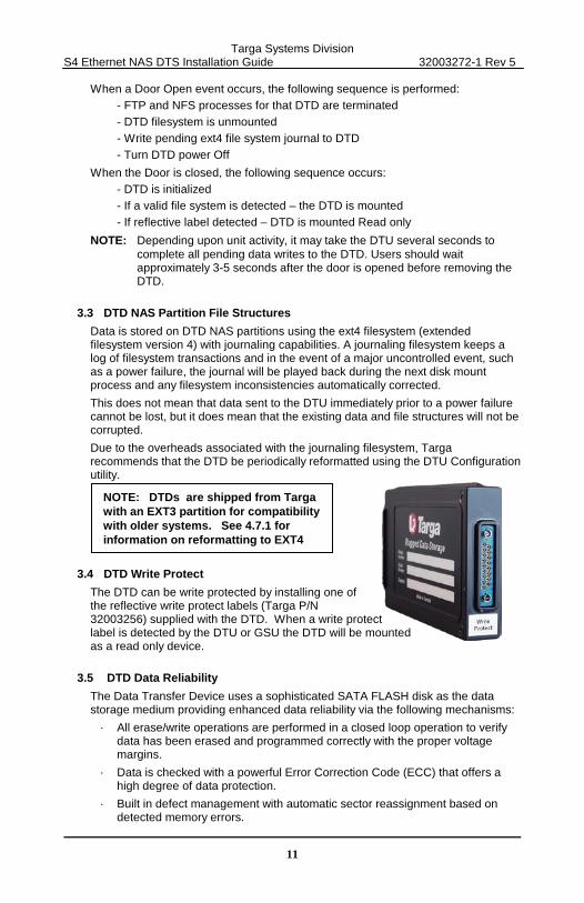
3.4 DTD Write Protect The DTD can be write protected by installing one of the reflective write protect labels (Targa P/N 32003256) supplied with the DTD. When a write protect label is detected by the DTU or GSU the DTD will be mounted as a read only device.
3.5 DTD Data Reliability The Data Transfer Device uses a sophisticated SATA FLASH disk as the data storage medium providing enhanced data reliability via the following mechanisms: · All erase/write operations are performed in a closed loop operation to verify
data has been erased and programmed correctly with the proper voltage margins.
· Data is checked with a powerful Error Correction Code (ECC) that offers a high degree of data protection.
· Built in defect management with automatic sector reassignment based on detected memory errors.
NOTE: DTDs are shipped from Targa with an EXT3 partition for compatibility with older systems. See 4.7.1 for information on reformatting to EXT4
11

Targa Systems Division S4 Ethernet NAS DTS Installation Guide 32003272-1 Rev 5
3.6 Power Fail The DTU’s 28Vdc power supply features a power fail detection circuit along with a 50 millisecond holdup capability to support DTU operations during power interruptions to ensure data integrity. When a Power Fail is detected (< 17Vdc), the following sequence occurs:
Power Fail signal debounced, ignored if < 1ms Ethernet File data transfers are suspended All DTD I/O operations are suspended.
If the input power recovers within the 50msec holdup period, the DTU will resume normal operations. In the event of an extended brown-out; when the input power recovers the DTU will resume operations – as if there had been a door open/close sequence. Any suspended I/O is written to the DTD Network connections are reset DTD(s) remounted
Note: The power fail feature is not supported by the desktop GSU version.
3.7 Security Erase The Targa Series 4 NAS Data Transfer System, supports both a hardware and ethernet commanded means of sanitizing the Data Transfer Device. Hardware: via the Secure_Erase- input Refer to section 4.4 for details Commanded via the FTP Site command dtdsanitize - see appendix A via the HTTP Configuration / setup utility - see section 4.7
Note: Secure Erase will override Write Protect
3.8 Monitoring DTU Output Messages The Targa NAS DTU is equipped with an RS-232 output monitor port (COM2) that can be used to assist users during systems integration, or to provide additional error/warning messages as part of systems operations. Refer to section 4.4 for details on COM2 log Verbosity.
3.9 Dual DTD Data Transfer Unit
The Dual DTD Data Transfer Unit supports two independent removable FLASH disks. If the door is opened to access one disk it does does not interrupt the 2nd disk as long as 2nd disk access door remains closed. NAS mount points are: DTD #1: /dtd/a/part1 (upper door) DTD #2: /dtd/b/part1 (lower door)
12

Targa Systems Division S4 Ethernet NAS DTS Installation Guide 32003272-1 Rev 5
4. Unit Configuration and Network Controls 4.1 User Configuration Utility
The DTU User Configuration Utility can be used to review and setup the Targa DTU operational parameters. To access the DTU / GSU embedded User Configuration Utility:
- Connect the DTU / GSU to the network and from your web browser go the DTU Configuration IP Address http://192.168.2.104
- Login with admin User ID and Password (section 4.6). When logged in the DTU Configuration Control Panel and DTU INFO page will be displayed.
To update DTU / GSU configuration data using this utility - the “Config Enable-“ input must be connected to ground. If not installed current configuration data is displayed, but cannot be changed.
4.1.1 DTU Configuration Control Panel
Select the appropriate DTU page link to access each of the Targa DTU configuration pages. Refer to the individual configuration page in this section for details on page controls and supported features.
4.1.2 Configuration Utility - Data Updates
After changing or adding new DTU configuration data, the revised configuration data must be “Submitted” for the associated DTU configuration data files to be updated. When all of the changes have been made the Targa DTU must then be rebooted for the new configuration data to take effect. Each DTU Configuration page, that provides access to user controlled parameters, will display the “Submit Changes” button:
Submit Changes: Used to submit the data as entered on the page into the
DTU configuration files. When the configuration files have been updated, all DTU subsequent configuration pages will display the following message, until a DTU reboot or power cycle has been performed: The DTU's configuration has changed. A reboot is required for the changes to take effect
To initiate the DTU reboot – select “DTU Reboot” on the DTU Control Panel
Reset Clears the changes as entered on this page and reverts to the current settings.
4.2 DTU – Reboot Page
Click “Yes” to confirm DTU reboot. The DTU will reboot in approximately 30 seconds and will re-display the DTU-info page when the reboot process had completed
13

Targa Systems Division S4 Ethernet NAS DTS Installation Guide 32003272-1 Rev 5
4.3 DTU-INFO Page Displays Basic DTU information: Model#: Targa DTU Model # Serial#: DTU serial number YYMMxxxxxx
YYMM is the DTU date of manufacture xxxxxx is the DTU MAC address
Firmware: DTU firmware version and part
number Config Mode: Must be enabled to update
unit configuration data. See section 2.6.3 System Time: Current time within the DTU
At power up defaults to 00:00:00 January 1, 1970 GMT DTU time can be set via 2 mechanisms
- FTP Site Command “SETTIME” - rdate server - time is requested at power-on (refer to the DTU
Network configuration page for details) Uptime: Length of time that the DTU has been operational.
Uptime can be used to determine if the DTU has experienced a power failure recovery since it was last accessed (ie: if your current directory has changed back to the default mount point due to system reboot)
Load Avg: Measure of average DTU CPU utilization use as a % over time for
the past: 1 min, 5 min, 15 min Load Avg can be used as a reference, during test and integration to determine if there are sufficient resources available to handle more client sessions or file transfers. Note: 1.0 = 100% and loads > 1.0 are normal.
Power State: Status of input power:
Good - input power within range Power-fail - input power is < 17Vdc and DTU is operating in
power-fail protection mode. Refer to Section 3.6 for more details.
DTD State Status of DTU access door as well as DTD #1 [and DTD #2 ]
Door Open Door Closed, DTD Not Present Door Closed, DTD Present Door Closed, DTD Present, Write Protected
14

Targa Systems Division S4 Ethernet NAS DTS Installation Guide 32003272-1 Rev 5
4.4 DTU Configuration Page Displays Targa DTU identification data and provides access to the DTU features configuration parameters. DTU Identification:
Model#: Targa DTU Model #
Serial#: DTU serial number
Firmware: DTU firmware version and part number
DTU Features Erase Input / Erase Algorithm:
The Targa DTU supports a remote sourced Erase input signal used to activate a user specified DTD Security Erase algorithm. Refer to Appendix B for details on the supported Sanitize / Secure Erase algorithms. If the Erase input is disabled, the Erase Algorithm entry is not applicable. Factory default is disabled. Erase Input Signal: (Secure_Erase- refer to 2.6.3 & 3.7) Active low input signal. Signal must transition from Off state (logic high) to On state (logic low) and be logic low for a minimum of 300msec for DTU to activate erase. If the signal is detected as logic low at power up or at door closure the signal is disqualified until it returns to the logic high state (for a minimum 300msec). If the Erase Input feature is disabled the signal is not monitored. Refer to the FTP Site command “dtdsanitize” for details on the ethernet commanded DTD Secure Erase.
Enable Temp Alerts: Enabled Disabled The DTU is equipped with an on-board temperature sensor that can be used to monitor the internal temperature. The temperature monitoring process can also, when enabled, issue an alert at a user specified temperature. Refer to the FTP Site command section for details on how to read unit temperature and detect a temperature alert. Factory default is disabled.
Temperature Alert at: Default: 90ºC Input range: 80ºC to 100ºC Temperature Alert value is used only when Temp Alert is enabled
15

Targa Systems Division S4 Ethernet NAS DTS Installation Guide 32003272-1 Rev 5
Firmware Upgrade The Targa DTU firmware is field upgradeable using a DTD as the transport mechanism. To upgrade DTU firmware:
1. The DTU “Config Enable-” input must be connected to ground. 2. A DTD installed with the new firmware code stored in /dtd/a/part1 as:
targa-firmware.edtu if not modifying unit configuration or targaconf-firmware.edtu restore factory default configuration Note: If both files found: targa-firmware.edtu takes precedence
3. Firmware upgrade process must be enabled and the upgrade initiation mechanism selected. The options are:
Disabled - firmware upgrade process disabled On-boot - at DTU startup, the DTD will be read and if either of the
specified DTU firmware files are present, the DTU firmware will be updated.
Manual - Update process will be initiated upon receipt of the FTP Site “SITE UPDATEFIRM” command at which time, the DTD will be read and if either of the specified DTU firmware files are present, the DTU firmware will be updated
On-boot, Manual – either update processes can be used
Notes: - The firmware update process can take anywhere from 3-5 minutes and MUST BE monitored on the COM2 Log port. During the update process a stream of “….” will be output and a completion message issued. DO NOT POWER OFF UNTIL UPDATE IS COMPLETE. Any Error Conditions encountered during the update process are output on the COM2 Log port.
- Upon completion of the firmware update process the DTU will reboot.
- If the targa-firmware.edtu file is used, then the DTU must be re-booted a 2nd time for the existing configuration files to be transferred into the new operational code space . If this is not done a DTU unconfigured error will be reported in FTP Site “Healthcheck” and DTU functionality may be compromised.
- To install previous firmware versions: Only the manual process will support loading older firmware and only with the targaconf-firmware.edtu file. This ensures synchronization of configuration files to the operational code set.
- F/W 3.1.4 and onward - Factory default is now manual.
COM2 Log Verbosity The Targa DTU provides an RS-232 system monitor port designated COM2. COM2 Log output is: RS-232, 8bit ASCII, no parity, 1 stop bit at 115.2K BAUD Select the messages output level:
Off - no message output Low - Critical messages only Medium - Warnings, Errors and Critical messages High - all messages including debug messages
16

Targa Systems Division S4 Ethernet NAS DTS Installation Guide 32003272-1 Rev 5
4.5 DTU Network Configuration Page This page is used to configure the DTU network address and select the network services that are to be supported.
IP Network Configuration Network Mode:
Normal – Unit functions as a networked device with each ethernet port operating independently.
Bridged – Unit operates as a networked device as well as a bridge joining network segments on Port1 and Port2. (see 4.5.3 below)
IP Address: The unique number that devices use in order to identify and communicate with each other on a computer network utilizing the Internet Protocol standard (IP) Targa’s DTU supports IPv4. If the IP address is changed, a DTU reboot is required before the new IP address takes effect. When the DTU “Config Enable-” jumper is installed the Targa DTU will respond to either:
- DTU Network IP - DTU Configuration
IP 192.168.2.104 (netmask 255.255.255.0)
NOTE: Only one Targa DTU can be on a network segment when “Config Enable” installed, otherwise there will be an IP address conflict at the configuration IP address.
NOTE: In F/W release 3.1.1 ARP flux filtering was enabled to resolve issues associated with connecting both NAS DTU ethernet ports to the same physical network and using IP addresses in the same network range, which resulted in unexpected network operations, due to ordering of the routing table entries in the DTU’s Linux operating system.
ie: transmitted data was directed through one DTU ethernet port. With ARP flux filtering enabled, the DTU will only respond from the specified IP address port.
17

Targa Systems Division S4 Ethernet NAS DTS Installation Guide 32003272-1 Rev 5
Netmask Defines the structure of the IP address as a bitmask to indicate how many bits identify the sub-network, and how many bits specify the host addresses. If the Netmask is changed, a DTU reboot is required before the new Netmask takes effect.
Gateway For those network configurations where the Targa DTU may receive an IP packet address from outside the local subnet, the DTU response packet is sent to the specified gateway address. The gateway address is usually the LAN's border router. If set to 0.0.0.0 packets with an address outside the local subnet are dropped.
MTU Maximum Transmission Unit – packet size
Link Specifies the speed of the Ethernet bus for that port.
Hostname Human-readable unique nick-name, by which the Targa DTU network attached device is known on the network.
4.5.1 DTU Operation Mode
Network Configuration option to place Targa DTU into different modes of operation:
NAS Mode: DTU functions as a Network Attached Storage device, providing access to up to 4 logical partitions on the DTD. Partitions can either be
- NAS partition with EXT4 file system structures or - iSCSI partition supporting block I/O to only the specified
iSCSI partition region on the disk.
iSCSI Target Mode: DTU functions as an iSCSI disk supporting block I/O to the DTD(s) installed in the DTU. Each DTD installed in the Targa S4 DTU will appear as an iSCSI LUN. Client has full control over disk structures.
Note: File transfer protocols are not supported in this mode only the FTP Site commands are supported
Numerous DTU NAS Mode configuration display and setup functions are changed or not supported when in iSCSI Target mode.
To change DTU Operational mode, the changes must be “submitted” and
the DTU “rebooted” before the mode change occurs.
18

Targa Systems Division S4 Ethernet NAS DTS Installation Guide 32003272-1 Rev 5
4.5.2 Network Services FTP Enabled FTP is always enabled.
File Transfer Protocol (FTP) is a reliable, connection-oriented protocol for exchanging files over any network that supports the TCP/IP protocol. There are two computers involved in an FTP transfer: a server and a client. The Targa DTU functions as the FTP server. Refer to RFC 959 File Transfer Protocol . FTP Port: 20 - FTP Data 21 – FTP Control Default Directory: /dtd at FTP login /dtd/a/part1 DTD #1 root directory Max number of Users: Input Range 1, 2, 4, 8, 12, 16, 20, 24
The data transfer bandwidth of the Targa DTU is shared between “active” users. In order to ensure a minimum bandwidth is available to each user, a maximum number of users can be set. Note: Anonymous FTP access is not supported – see User
Management.
FTP Connection timeout: FTP session timeout can be set via the FTP SITE IDLE command SITE IDLE <seconds> Targa DTU default is 900 sec= 15 min
min is 30 sec; max is 7200 sec
NFS Enabled Disabled (Factory default is disabled) Network File System (NFS) is a file system protocol allowing a computer to access files over a network as if they were local disks. The Targa DTU, as the NFS server, exports a disk mount point which is then used by the NFS clients to mount the disk. NFS adopts a stateless model of transaction processing, meaning that the server does not maintain any historical information about any of the dialogues it may be running with remote clients. Targa DTU supports NFS Version 2 and 3 per RFC 1813 NFS Version 4 per RFC 3530
Data Mode Async NAS DTU will cache data permitting NFS Client to maximize throughput. In the event of a power failure, data in cache will be lost.
Sync NFS client will be forced to wait on each write() until the NAS DTU has successfully written the data to disk. This ensures that no data is lost in the event of a power failure.
NFS Port 2049 NFS File Permissions NFS clients file access permission:
User ID per username entry (see User Management) Group ID = gid101
Note: 1. Root privileges are not exported; root users (UID=0 GID=0) are mapped as UID=100 (admin) and GID=101 (writers). 2. However directory “nfsroot” on the 1st DTD, 1’st partition, will be
exported no_root_squash: e.g., /dtd/a/part1/nfsroot 3. Targa does not recommend using NFS under UDP
19

Targa Systems Division S4 Ethernet NAS DTS Installation Guide 32003272-1 Rev 5
SMB Enabled Disabled (Factory default is disabled) Implementation via Samba 3 (file server only) Disk share will support all mounted partitions eg: dtda_part1; dtda_part2 dtdb_part1 if DTD#2 is installed Max # clients = same limit as FTP Workgroup: Windows workgroup name: default = Targa Max 32 characters, no spaces Public Access: When enabled (checked) permits public access and
sets user account to “admin” DHCP DHCP server
Enabled (Factory default is disabled) Dnsmasq is an easy to configure DHCP/BOOTP server. Dnsmasq
supports static and dynamic DHCP leases and BOOTP/TFTP for network booting of diskless machines. Using the client MAC address, the dnsmasq.conf configuration file is used to define the DHCP client IP address as well as specify the associated client boot files. Then using TFTP the client can pull the target file(s) off the DTD installed in the Targa DTU. (Note: Targa DTU TFTP support must be enabled)
Refer to Appendix C for details on the dnsmasq.conf configuration file. TFTP TFTP support is a user configurable parameter
Enabled Disabled (Factory default is disabled) Trivial File Transfer Protocol (TFTP) is a very simple file transfer protocol which is relatively easy to implement in a very small amount of memory, originally developed for booting computers such as routers which did not have any mass storage devices. It is still typically used to transfer small files between hosts on a network or any other thin client that boots from a network host or server. NOTE: For TFTP a full path name must be specified with the filename eg: put file.testsample /dtd/a/part1/testsample TFTP uses UDP (port 69) as its transport protocol, it cannot list directory contents and has no authentication or encryption mechanisms. Under TFTP each file transferred via TFTP constitutes an independent exchange. That transfer is performed in lock-step, with only one packet (either a block of data, or an 'acknowledgement') ever in flight on the network at any time. TFTP Port Port 69
Telnet Enabled (Factory default is enabled) Provides command line interface access to Series 4 NAS DTU Linux operating system. For use by experienced Linux users only.
TCP Port Port 23
20

Targa Systems Division S4 Ethernet NAS DTS Installation Guide 32003272-1 Rev 5
rdate Host
Used to set Targa DTU “UTC” time from a remote host If set non-zero and a valid IP address, the Targa DTU at power-up will issue the TCP/IP command to retrieve the date and time from the specified host on the network and set the local DTU system time. If there is no host response an error message is sent to the console (COM 1). Refer to RFC 868 for details. Targa S4 NAS DTU does not provide a time zone offset from UTC
syslog host
Used to log Targa DTU console status messages to a remote host on the network. If set non-zero and a valid IP address, all Targa DTU log messages as are sent to the specified “syslog” host. SYSLOG protocol and message format per: http://tools.ietf.org/html/rfc5424
21

Targa Systems Division S4 Ethernet NAS DTS Installation Guide 32003272-1 Rev 5
4.5.3 Bridged Mode The DTU in IEEE802.1 “Ethernet Bridge” mode transparently connects the two Ethernet segments on Port 1 and Port 2 together. The DTU, as an ethernet bridge, will distribute ethernet frames coming in on either port, out the second port. This permits the connection of the two Ethernet network segments on Port1 and Port2 without changing the topology of the network. The Targa DTU will continue to function as a network attached storage device processing any IP data packet with the Targa DTU specified IP address, all other packets are forwarded out the second ethernet port.
IP Address & Netmask IP Address and Netmask for the
DTU as a Network Storage device. If either is changed a DTU reboot is required before the change takes effect.
Gateway Addr: For those network configurations where the Targa
DTU may receive an IP packet address from outside the local subnet, the DTU response packet is sent to the gateway address. The gateway address is usually the LAN's border router. If set to 0.0.0.0 packets with an address outside the local subnet are dropped.
Hostname Human-readable unique nick-name, by which the
Targa DTU network attached device is known on the network.
22

Targa Systems Division S4 Ethernet NAS DTS Installation Guide 32003272-1 Rev 5
Default Usernames / Passwords root / targaroot
admin / targa1 user1 / targa1 user2 / targa2 user3 / targa3 user4 / targa4
Note: usernames & passwords are case sensitive
4.6 DTU User Management Page
This page is used to manage user (client) access to the Targa DTU. A list of valid usernames and their file permission status is displayed and control function tabs provided to either edit user data, delete or add a user as outlined below:
User Management Control Functions:
Edit: To change file permissions [Read Write] or [Read Only] To change user password
Delete Deletes username entry Add user Enter new username, user password and file permissions. To update the user data: Select “Update User” or [enter] after “repeat password” entry
Usernames Valid user name: 6 – 32 alphanumeric characters only
Maximum number of users: 8 + admin Note: - admin and root users
cannot be deleted - admin is the only user
with access to the Targa DTU configuration pages.
Passwords Passwords once entered cannot
be displayed Valid Passwords 6 – 32 alpha numeric characters only
UID Numerical user identification - for NFS Only Auto assigned by the DTU when a user is created
WARNING Root user access is for experienced “Linux” users only
23

Targa Systems Division S4 Ethernet NAS DTS Installation Guide 32003272-1 Rev 5
4.7 DTD-INFO Page Displays basic DTD information. Note: DTD#2 information displayed
only for dual DTD units Disk: Disk type S.M.A.R.T Display disk SMART
data Serial Number: Disk serial number Firmware: Disk firmware version Size Disk physical size Write protect: DTD Write protected Partitions: Name, size and type of the
DTD partitions. Setup DTD Used to review, create
and maintain the DTD partition structures. Setup Encryption Used to review, create and maintain an encrypted partition
4.7.1 Setup DTD Page Displays basic DTD information. Note: DTD#2 is displayed for
dual DTD units only
Current Partition table Lists the partitions found on the
DTD, partition size and partition “use” as either a NAS, NAS Encrypted or iSCSI partition.
Reformat Partitions Upon activation a new copy of
the file system structures is written to the DTD for NAS partition(s) checked with “Reformat” in the table .
When completed the DTD Info page screen will be re-displayed.
NOTE: Targa recommends reformatting on a regular basis to reset the journal log file. This replaces the “FSCK” process associated with maintenance of a journaling file system.
All data in the selected NAS partition(s) is lost.
An unformatted DTD reports: Partitions: None found
24

Targa Systems Division S4 Ethernet NAS DTS Installation Guide 32003272-1 Rev 5
EXT3 Compat The “nas” partition is formatted as an ext3 file system for backwards compatibility with GEN1 DTUs. Data transfer rates are reduced by approx 25% for ext3 partitions.
Reset Clears any selected “Reformat” boxes in the current partition table. Create Different Partition Table:
Text input line used to specify up to 4 partitions for the DTD. Each partition description is separated from the next by a comma ','. The partition description is used to specify the partition size and use. The user is to enter a text string, specifying the partition(s) as outlined below and then select the APPLY button to activate. Note: All existing DTD data is lost in this process.
Partition Size There are two methods to specify the partition size, you must use one or the other in the partition input string. Percentage of disk Each partition size, with the exception of the optional
wildcard, must end with a '%' symbol. Absolute size Partition size as an integer number Size designators are: - 'm' or 'M': Megabytes
- 'g' or 'G': Gigabytes eg: 1024m = 1024 MBytes 1024G = 1024 GBytes
An asterisk '*' may be used as a wildcard, resulting in that specified partition size expanding to fill all available space. Only one wildcard is permitted in the partition string. Not requesting a wildcard partition may result in space on the DTD going unallocated. Unallocated space is inaccessible.
If no size designator used default size is in Kilobytes
Partition Use Each DTD partition can be designated for use as either a:
NAS The default use. No special designation is required to allocate a partition for use as a NAS-exported filesystem that is accessible via FTP or NFS. NAS partitions are formatted with an ext4 journaling file system by the Targa DTU.
iSCSI To allocate a partition on a DTD for use as an iSCSI device, prefix the partition description with an 'i'. (lower case only). iSCSI partitions are accessed as a Block I/O device by the remote client. The client is responsible for formatting the iSCSI partition with any associated file system structures.
The DTU will export a list of iSCSI targets as an iSCSI Qualified Name (iqn). The LUN number the same as the DTD partition #.
eg: Iqn.2007-06.com.targasystems.edtu:dtd1 Sample - Partition inputs
* - Create a single partition for NAS use using the whole DTD. i*,2g - Create two partitions - Partition 1 is iSCSI filling all but 2GB of the DTD - Partition 2 is a 2GB NAS partition 2G,2g,i250m,* - Create four partitions - Partitions 1 and 2 are 2GB each and allocated for NAS - Partition 3 is 250MB iSCSI - Partition 4 consumes the rest of the DTD and is NAS use.
25

Targa Systems Division S4 Ethernet NAS DTS Installation Guide 32003272-1 Rev 5
50%,i40% - Create two partitions - Partition 1 is 50% of the DTD size, allocated for NAS - Partition 2 is 40% of the DTD size, allocated for iSCSI - 10% of the DTD will be inaccessible
Note: DTD capacity / Partition Size / Available free space FTP Site dtdinfo - returns details on the DTD including the physical disk
space available FTP Site fsinfo - returns the raw partition size and the available free
space For a single partition DTD: Partition Size = Physical Disk – Partition overhead Total Usable Capacity = Partition Size – ext4 file overhead Available Space = Total Usable – User data file space
Security Erase Upon selection the standard ATA Security Erase command is sent to the disk.
This command is supported by all current SATA disks and will erase contents of disk. Upon completion DTD will report – unknown file system and will have to have partition tables re-established per “reformat partitions” process.
Sanitize Tab – No longer supported
The Sanitize process is intended to be used only for specific security related purposes and not as a means to simply clear the disk. As such the ability to command the disk to be sanitized from the web based utility was removed in version 3.1.4. Disks that support sanitization can be commanded to “sanitize” via the FTP Site “dtdsanitize” command (Appendix A2) or via the H/W Secure Erase input signal process (Sect 4.4).
Post-Sanitize Format - IMPORTANT After a DTD40/SA3 unit has been sanitized, the FLASH array must be low level
formatted in order for the DTD disk to re-build its FLASH control structures. User must use this button to re-format the FLASH array before the disk can be used
Note: After being sanitized the DTD will take approximately 60 seconds to mount until the low-level format has been performed. The low-level format process will take approximately 1 -2 minutes to complete (DTD capacity dependent).
Activation button will only be present for those DTD’s that support the process to restore a sanitized DTD. When completed the DTD Info page screen will be re-displayed. Post-Sanitize process will create a single ext4 partition on the DTD. To install any other partition table arrangement that may be required for your application you must use the DTD Setup process.
26

Targa Systems Division S4 Ethernet NAS DTS Installation Guide 32003272-1 Rev 5
4.7.2 Setup Encryption Partition Note: Encryption is supported only by F/W versions with an “e” suffix . The supported actions are Create Create a LUKS
partition by reallocating an existing NAS partition
Manage Add passphrase to a LUKS key slot or delete existing key slot.
Kill LUKS partition header is overwritten, resulting in an “unknown” partition type until re-allocated or re-formatted.
Refer to Appendix C for an details on the implementation of LUKS encrypted volumes within the Targa S4 DTU. It is imperative that the operator is knowledgable of the concepts and terminology associated with LUKS volumes, data encryption, passphrase and encryption key management as well as the SSH protocol before proceeding.
4.8 DTU Save and Restore This feature can be used to save the current DTU configuration in file “targasave.bin” This can then be restored at a later date, or recalled on a different DTU to ensure common configuration across numerous units. Units should be at the same F/W revision to ensure compatibility. Note: The SSH host keys are not included in this process. The SSH host keys
are unique to each Series 4 DTU. See appendix C.4.2 for discussion on SSH host keys
27

Targa Systems Division S4 Ethernet NAS DTS Installation Guide 32003272-1 Rev 5
5. Warranty & Repair
Targa products are designed, manufactured and tested to the highest industrial standards, however repair may become necessary sometime during the life of the unit. If you believe your Targa product requires repair, please follow these guidelines to ensure prompt, accurate service:
1. Carefully note the symptoms of the problem you are experiencing, along with
the model and serial number of the product. 2. Call Targa Customer Service Support at +1 (613) 727-9876. A technician will
discuss the problem with you. If factory service is necessary, Targa will issue a Return Authorization (R.A.) number and give you instructions for customer prepaid shipment of the goods for repair. Products returned without an R.A. number, or returned C.O.D. will not be accepted by Targa.
3. If the product is covered under Targa's Limited Warranty, there will be no charge for parts or labour.
4. If the product is not covered under Targa's Limited Warranty, there will be a minimum charge for each item returned and a purchase order must accompany any returned goods.
TARGA LIMITED WARRANTY Targa products are warranted for one year from the date of shipment. Targa will repair or replace, for the original purchaser only, any defects in material or workmanship in the system components. No other representations or warranties, expressed or implied have been made by Targa Systems. Targa does not warrant that the system components are merchantable or fit for any particular purpose. Targa Systems is not liable for any loss of profit or for any special, incidental or consequential damages resulting from the failures of its products. The sole liability of Targa Systems is to repair defects in Targa products. This warranty is rendered void if the unit has been changed or modified other than by written instruction from Targa Systems.
28

Targa Systems Division S4 Ethernet NAS DTS Installation Guide 32003272-1 Rev 5
A FTP Site Command This command is used by the DTU to provide additional services and information that are specific to the DTU. The DTU response is a response code followed by an ASCII string that uses comma (0x2c) to separate data fields and CRLF (0x0d0a) to mark the end of the data. Site response codes: 200 successful 400 transient error 500 permanent or command syntax error
A.1 Site Status Command The FTP Site Status Command returns the current status of the DTU and DTD(s) over the FTP Control Port: Command Site Status Returns 6 bytes – for single DTD units 10 bytes - for Dual DTD units Data is ASCII representation of hexadecimals numbers Example 200 0x0000,0x00001110 DTU OK & DTD#1 has 1 partition
Bit 15 ……………………. Bit 0 Status for Word1/Byte2 Word1/Byte1 DTU Status Word2/Byte2 Word2/Byte1 DTD #1 - Status Word3/Byte2 Word3/Byte1 DTD #1 - Partitions Word4/Byte2 Word4/Byte1 DTD #2 - Status
DTD #2 - Partitions For dual DTD units
only Word5/Byte2 Word5/Byte1
Bit DTU Status 0 1 2 3 4 5 6 7
8- 15
DTU over temperature alert (if enabled) – per section 4.4 DTU unconfigured – per section 4.4 Memory test failed - Power Fail Detect, unit preparing for shutdown Reserved for DHCP – invalid file Configuration jumper installed Invalid F/W Checksum - critical error DTU is in iSCSI Mode Reserved
29

Targa Systems Division S4 Ethernet NAS DTS Installation Guide 32003272-1 Rev 5
Note * Transient status bit - cleared after first client read of status
Bit DTD Partition Status – 4 bits / Partition 0 1 2 3
Partition 1 Partition not present Partition not mounted Invalid File System iSCSI partition
4 5 6 7
Partition 2 Partition not present Partition not mounted Invalid File System iSCSI partition
8 9 10 11
Partition 3 Partition not present Partition not mounted Invalid File System iSCSI partition
12 13 14 15
Partition 4 Partition not present Partition not mounted Invalid File System iSCSI partition
Note: DTD partition status bits are not relevant under the following conditions:
Door open DTD is not installed DTD format in progress DTD sanitize in progress DTD wipe in progress DTD mount in process
F/W vs 3.1.4 added DTD Status bit 10 to indicate this state
Bit DTD Status 0 1 2 3 4 5 6 7 8 9 10
11 – 15
DTD Access door open No DTD detected / installed DTD Sanitize in process Reserved (DTD Wipe in process-no longer supported) DTD Remounted – after power fail or door open/close (note *) DTD mount in process DTD Format in process DTD Write Protected Reserved DTD Interface Fault / Door Sensor fault (F/W vs 3.1.4) DTD Partition status not valid (F/W vs 3.1.4) Reserved
30

Targa Systems Division S4 Ethernet NAS DTS Installation Guide 32003272-1 Rev 5
Additional Examples Site Status returns 200 0x0020,0x00001110 DTU in config mode DTD #1 Partition 1 – mounted OK For F/W versions up to 3.1.3 Site Status returns 200 0x0020,0x00001110,0x00010000 DTU in config mode DTD #1 Partition 1 – mounted OK DTD #2 Door Open – partition info – unknown For F/W versions from 3.1.4 onward Site Status returns 200 0x0020,0x00001110,0x04011111 DTU in config mode DTD #1 Partition 1 – mounted OK DTD #2 Door Open – partition info – unknown Site Status returns 200 0x0008,0x00020000 DTU in power fail
DTD #1 No DTD installed, partition info – unknown
31

Targa Systems Division S4 Ethernet NAS DTS Installation Guide 32003272-1 Rev 5
A.1.1 SITE Extended Status Command estatus The FTP “site estatus” command provides extended status information of the DTU and DTD(s) over the FTP Control Port. These additional status bits are provided as an extension to the original “site status” command in order to support mounting an encrypted LUKS partition. Command site estatus
Returns 1 line header and trailer with command status information 1 line DTU information 1 line per DTD (1 line - single door, 2 lines- dual door units) Example: 200-Enhanced Status dtu: 0x0020 dtd1: 0x0000,0x0000,0x0010,0x0001,0x0001 dtd2: 0x0000,0x0001,0x0001,0x0001,0x0001 (only if present) 200-OK
dtu: status word is unchanged from the Site Status command.
Bit DTU Status 0 1 2 3 4 5
6 - 15
DTU over temperature alert (if enabled) – per section 4.4 DTU un configured – per section 4.4 (FW update) Memory test failed – Power Fail Detect, unit preparing for shutdown Reserved for DHCP – invalid file Configuration jumper installed Reserved
dtd1(2): status response is formatted as follows:
<DTD Status>,<Partition 1 status>,…,<Partition 4 status> Where:
<DTD Status> status word is unchanged from site status
Bit DTD Status 0 1 2 3 4 5 6 7 8 9
10 11 – 15
DTD Access door open No DTD detected / installed DTD Sanitize in process DTD Wipe in process DTD Remounted – after power fail or door open/close (note *) DTD mount in process DTD Format in process DTD Write Protected Reserved DTD Interface Fault / Door Sensor fault (F/W vs 3.1.4) DTD Partition status not valid (F/W vs 3.1.4) Reserved
32

Targa Systems Division S4 Ethernet NAS DTS Installation Guide 32003272-1 Rev 5
<partition X status> field for each partition has been extended from the “site status” 4 bits per partition to a 16 bit word per partition. The meaning of the low 4 bits is unchanged
Bit DTD Partition Enhanced Status 0 Partition not present
Same as site status 1 Partition not mounted 2 Invalid Filesystem 3 iSCSI partition 4 Partition is encrypted 5 Partition is encrypted and needs to be unlocked
6 Partition unlock was attempted, but an invalid passphrase was provided
7 Other Encryption-related error 8-15 Reserved
33

Targa Systems Division S4 Ethernet NAS DTS Installation Guide 32003272-1 Rev 5
A.2 FTP Site Action Commands The FTP Site Action Commands initiate the DTU specific operation as follows over the FTP Control Port. The command parameters specified are space separated decimal value, ASCII strings. Autoextract Autoextract enables/disables the DTU function to intercept all FTP
PUT/STORE operations and to automatically extract archived ".tar" archive files. When enabled, archive files are extracted and saved into the current directory. This feature is similar to the SITE EXTRACT in that archive contents are extracted, however the archive file itself is not saved to the DTD; only the component files are saved.
Supported archive formats are .tar, .tar.gz, .tar.bz2 Zip files are not supported due to the file format storing relevant
information at the end of the archive, and thus streaming extract is not possible.
Command site autoextract [on|off]
Returns 211 AUTOEXTRACT is now on.
211 AUTOEXTRACT is now off.
Example site autoextract on stor dataset.tar site autoextract off
dtdsanitize Initiate a disk level secure erase using either a pre-determined or
user selected erase algorithm. After this process the DTD must be low-level reformatted to be useable – see section 4.7.
See Appendix B for details on Sanitize / Secure Erase algorithms Command site dtdsanitize [dtd#] [erasetype ] dtd # = dtd1 or dtd2; default = dtd1 erasetype = erase algorithm # 1 - 5 default = algorithm #1
Returns 200 - OK 400 – see special error response A.2.1 Example site dtdsanitize dtd1 - sanitize DTD1, erase type = 1 site dtdsanitize dtd2 4 - sanitize DTD2, erase type = 4, site dtdsanitize 3 - sanitize DTD1 erase type = 3
dtdwipe This command is no longer supported
34

Targa Systems Division S4 Ethernet NAS DTS Installation Guide 32003272-1 Rev 5
extract Extract and store files contained within the specified “.tar” or “.zip” archive file. Archived files are extracted and saved in the current directory.
Command site extract [ <sp> -n ] <sp> filename [ <sp> dir-name ]
the optional "-n" argument specifies "no overwrite". e.g., if the filename exists already it will not be overwritten by the contents of the archive.
Returns 200 - OK
Example site extract file1 Extract to current directory
site extract file2 dir23 Extract to directory 'dir23' Note: Directory it must exist
healthcheck Initiate DTU Health Check and return DTU status information Command site healthcheck Returns 200 + comma separated status data Example site healthcheck 200 0x0020,237,87456,200,55,Vok DTU status = 0x0020 Runtime = 237 seconds Total Runtime = 87456 seconds Power cycles = 200 Unit Temp = 55C Voltages = Vok
md5sum Compute and return the MD5 checksum for the specified file, or a
list of files. MD5 checksum is a 32-digit hexadecimal number. Command site md5sum [--check] <filename>
Returns 200 md5sum <filename>:<checksum>
Example site md5sum<sp>testfile 200 md5sum testfile. 77cd7158a5d25069b16b81210f708985
--check option reads <file> and verifies the checksums of all checksum/file pairs contained within specified filename. file format: <checksum> <filename>
77cf1221fd299a73100ba000584c5446 test-set/file-0691
DTU Status 2 hex bytes - See A.1 Current runtime 32 bit decimal seconds Total Runtime 32 bit decimal seconds Total number of power cycles 8 bit decimal Unit Temperature °C 8 bit decimal DTU Voltage Check “Vok” or “Vfault”
35

Targa Systems Division S4 Ethernet NAS DTS Installation Guide 32003272-1 Rev 5
108670b6939aff099468db4307b89b00 test-set/file-0159 8e1f3d1da67c9320b4ddad21daa657c2 test-set/dir08/file08 Returns
200 Checksum OK ….if all checksums match If checksums do not match
500-Checksum Failure ** test-set/file-0132: FAILED ** test-set/file-0364: FAILED ** test-set/file-0054: FAILED ** md5sum: WARNING: 3 of 1000
computed checksums did NOT match
500 Checksum Failure End
settime Set DTU Date and Time (seconds since Jan 1, 1970) Admin user only Command site settime [seconds]
seconds integer from Jan 1, 1970 Returns 200 [seconds]
seconds commanded value returned updatefirm Triggers DTU firmware upgrade (see section 4.4) only if - Manual upgrade enabled - a DTD with the specified files is installed
Command site updatefirm Returns 200 - OK 400 – see special error response A.2.1 Example site updatefirm
200 command complete Note: F/W update will take approx 1 min after command
completes . Do not reset or power cycle the DTU until process is completed .
36

Targa Systems Division S4 Ethernet NAS DTS Installation Guide 32003272-1 Rev 5
A.2.1 Special Error responses
Several of the FTP Site Action Commands have complex interactions with the DTU and DTD. In the event of an error, details are available on the COM2 monitor port. For site commands: dtdsanitize updatefirm Error result: 400 signal=0(0) exitcode=non zero Good result: 200 action issued, Command finished OK
The specific error information is output on the COM 2 monitor port
37

Targa Systems Division S4 Ethernet NAS DTS Installation Guide 32003272-1 Rev 5
A.3 FTP Site Information Commands The FTP Site Information Commands returns specific requested information over the FTP Control Port as a string of comma separated ASCII data.
gettime Get DTU Date and Time (seconds since Jan 1, 1970) Command site gettime Returns 200 [seconds]
where [seconds] is an ASCII string
dtuinfo Read DTU Information; DTU Model #, Serial #, F/W Revision, H/W Rev Command site dtuinfo Returns 200 [Model #,Serial #,F/W Rev,HW Rev] H/W Rev = 1 GEN2, no encryption engine 2 GEN2, with encryption engine dtdinfo Read DTD FLASH disk Information: Disk Model #, F/W Rev, Serial#, Capacity (MB) and # of Partitions. Command site dtdinfo [dtd#] dtd # = dtd1 or dtd2; default = dtd1
Returns 200 [Model #, F/W Rev,Serial #,Capacity, Partitions]
Example site dtdinfo
200 A25FB-12GI10,BG06A,110502170, 12286,1
fsinfo Read DTD partition (filesystem) information: File system type, Mount point, Partition size (MB), Free space (MB) Command site fsinfo [dtd# Partition#] dtd # = dtd1 or dtd2; default = dtd1 partition # = max is 4; default = 1
Returns 200 [FS Type,Mount point,Size (MB),Free Space (MB)]
Example site fsinfo - send info on DTD1, Partition 1
i 200 ext4,/dtd/a/part1,12088,11957 FS Type = ext4 Mount Point = /dtd/a/part1 Size = 12,088 MB Free Space = 11,957 MB ii. 200 iscsi,,12088, FS Type = iscsi Mount Point = n/a Size = 12,088 MB Free Space = n/a 38

Targa Systems Division S4 Ethernet NAS DTS Installation Guide 32003272-1 Rev 5
netstats Return network operational statistics: Mode, # FTP users, Port1 status, Port1 Collisions, Port2 status, Port2 Collisions Mode : 0 = Normal ; 1 = Bridged #FTP Users Integer count of current FTP users Port Status bitmap 0x01 = link on 0x02 = full duplex 0x04 = 100 Base-T link 0x08 = 1000 Base-T link Port Collisions Integer count of collisions since last netstat or
unit power cycle
Command site netstats
Returns 200 [Mode, #FTP,Port1 Stat,Port1 Coll, Port2 Stat,Port2 Coll]
Example site netstats
200 0,3,0x0b,0,0x00,0 Mode = Normal FTP Users = 3 Port1 Stat = linked, full duplex, 1000 Base-T Port1 Collisions = 0 Port2 Stat = no link Port2 Collisions = 0 A.4 FTP Site – Additional Supported Commands Help - generates a list of FTP SITE commands Chmod - change the permissions of files Chown - change the owner of files Idle - specifies FTP idle disconnect time Rateget - limit file FTP “get” speed Rateput - limit file FTP “put” speed Sync - synchronize files - flush any buffered write data to disk
39

Targa Systems Division S4 Ethernet NAS DTS Installation Guide 32003272-1 Rev 5
B DTD Sanitize / Secure Erase Algorithms All of the SATA FLASH disks used by Targa Systems in the Data Transfer Device support an embedded capability to “sanitize” or “secure” erase the disks FLASH memory array using a number of pre-defined algorithms. This process can be activated by two mechanisms 1. Hardware triggered via the Secure_Erase - input signal - executes the DTD algorithm specified as per section 4.4
2. Commanded over the ethernet link via the FTP Site dtdsanitize command.
- using the table below select the preferred algorithm number to use with the dtdsanitize command.
The time to execute is dependent on: the selected algorithm, the DTD Type and DTD capacity. Please contact Targa to review your requirements. Note: - in the event of a power fail, the sanitize process will resume when
power is restored - DTU internal buffer memory is also overwritten to clear any residual
disk data.
Algorithm Process
DTD Type # Type SA3
SA3B TBD
TBD
1 Erase only Flash array is erased; √
2 USA-AF AFSSI 5020
Erase; Overwrite random data
√
Not
Sup
porte
d 3 US-Navy NAVSO P-5239-26
Erase; Overwrite random data; Erase;
√
4
NSA 130-2 Erase; Overwrite random; Overwrite random; Erase; Overwrite single byte;
√
5 NSA 9-12 Erase
Write data Erase
√
40

Targa Systems Division S4 Ethernet NAS DTS Installation Guide 32003272-1 Rev 5
C Encryption Overview & implementation C.1 Overview
Targa's Gen2 Series 4 Ethernet DTU (S4eDTU) supports Logical Volume encryption on a per-partition basis. The volume is encrypted using the AES algorithm with a user selected 128/192/256 bit key size in the Cipher Block Chaining (CBC) mode with an S4eDTU generated Encrypted Salt-Sector Initialization Vector (ESSIV). The S4eDTU web based configuration utility is used to manage the logical volume encryption passphrase that is subsequently transformed into an encryption key using a hash algorithm. The processor used by Targa's S4eDTU has a hardware encryption acceleration device that performs the AES encryption, decryption and hashing operations. Refer to DTU model number (sect 1.3) and or F/W version (sect 4.7.2) to confirm encryption is supported. The S4eDTU does not keep a copy of any encryption key or passphrase. In an operational scenario a logical volume passphrase is provided via a secure shell (SSH) command executed from a remote client and this passphrase is used to unlock the volume encryption key. SSH is used to ensure passphrase is not transmitted in the clear over the network. Performance Impact: The additional processing associated with data encryption
does impact the data transfer rates supported by the S4eDTU. The reduction varies depending on the file transfer protocol and MTU size.
On average: Writes reduced by 30-35% Reads reduced by 50%
C.2 Volume Encryption
The Linux Operating system as used within the S4eDTU, provides two different mechanisms to perform device encryption, dm-crypt and Linux Unified Key Setup (LUKS). Targa has chosen to use LUKS exclusively for encrypted volumes due to its industry standard design (based on the TKS1 paper) and multiple Operating System support (FreeOFTE on Microsoft Windows). Partitions encrypted with LUKS contain a header at the beginning of the partition. This allows LUKS the flexibility to do limited user management, where there is the possibility of having more than one passphrases (referred to as key slots) that will allow the user to decrypt the partition and access the data. Since there is a partition header, it is also possible to identify when a logical volume (partition) has been set up with LUKS and to provide feedback to the user when an incorrect passphrase is provided. There is some discussion in the cryptsetup Frequently Asked Questions document about LUKS security. http://code.google.com/p/cryptsetup/wiki/FrequentlyAskedQuestions. The summary of this document is that with low-entropy passwords (i.e., short or non-random) the security is not as good on slower computers, such as the S4eDTU. Since the S4eDTU will be used almost exclusively in situations where automated key-exchange will happen between two computers, this problem can easily be avoided by using passphrases that are 256bytes of pseudo-random binary data. See sect C4.1 for passphrase file format details
41

Targa Systems Division S4 Ethernet NAS DTS Installation Guide 32003272-1 Rev 5
SSH Passphrase Input Command: (see C.4 for SSH syntax details) sudo /targa/bin/targa-send-create-key <dtd> <partition#> < keyfile.b64
C.3 Creating & Managing Encrypted Volumes The S4eDTU supports the creation of up to 4 partitions per DTD. Encrypted partitions will be created by reallocating an existing NAS partition via the DTD Setup partition management support page.
C.3.1 Create Encrypted Partition When directed to reallocate a NAS partitions to an encrypted volume the user is required to select the AES encryption key size (128, 192, 256) and select passphrase source as SSH or HTTP selected file upload (see C..4.1). The passphrase will then be stored in hashed SHA1 form in the partition header and will be used to unlock the AES encryption key that is needed to encrypt/decrypt data on the partition.
For SSH Input, the DTU will loop waiting for the passphrase to transferred via SSH tunnel.
For HTTP file upload, user to specify base64 encoded passphrase file.
Partition #2 reallocated
as a LUKS encrypted partition. Partition is unlocked and contains an EXT4 filesystem
NOTE: Only the ‘admin’ user has access to the Encryption Setup functions.
42

Targa Systems Division S4 Ethernet NAS DTS Installation Guide 32003272-1 Rev 5
C.3.2 Manage Encrypted Partition Each LUKS encrypted volume has 8 key slots (passphrases). The administrative user can either “Enable” a key slot by providing a passphrase or “Disable” by removing the passphrase (kill key slot). There must be at least one active key slot in a LUKS partition. Iteration count is the number of computational iterations a passphrase is put through before it is used to unlock a key slot. If multiple key slots are enabled, the supplied passphrase is processed in key slot sequence, thereby increasing the time required to unlock and mount the partition’s filesystem while searching for a passphrase match.
C.3.3 Kill Encrypted Partition
The LUKS partition header and the first 10 MBytes of the LUKS partition is overwritten, resulting in a “unknown” partition type when the process is completed. The partition must be re-formatted (see 4.7.1) to be reused.
43

Targa Systems Division S4 Ethernet NAS DTS Installation Guide 32003272-1 Rev 5
C.4 Passphrase Exchange “ targa-unlock-volume” A remote entity will have to provide a passphrase(s) to the S4eDTU after each reboot (or door open/close cycle) in order to access the data on an encrypted volume(s). The passphrase is exchanged via SSH (RFC4251 Secure Shell) remote command execution, providing a secure mechanism to supply the passphrase. Until the passphrase is provided, the S4eDTU is unable to access the encrypted partitions. The S4eDTU reports volume status via a FTP SITE command: ESTATUS. This status command includes per-partition status bits that indicate if a partition is encrypted and if the volume is still locked and requires a passphrase to be supplied. This status command also provides status bits indicating error conditions including if a client provided the incorrect passphrase. A volume unlock program will read the key from standard input stream, (thereby avoiding writing the passphrase to a logical file) and as such the machine providing the passphrase would do so, in a *nix environment: sudo /targa/bin/targa-unlock-volume <dtd> <partition#> < keyfile.b64 Where <dtd> - dtd1 or dtd2 <partition#> = 1,2,3 or4 Note: The SSH passphrase commands must be executed as the 'admin' user ssh admin@s4edtu sudo /targa/bin/targa-send-create-key dtd1 1 < keyfile.b64
C.4.1 Passphrase File Format
The passphrase shall be provided in Base-64 encoded (RFC 3548) format in order to facilitate the storage and transfer of binary data.
Special Note: Cryptsetup preparation using iSCSI Target Mode Due to the way that the passphrase manipulation and error checking occurs within the DTU software, if iSCSI target mode is used to prepare the Cryptsetup volumes on a remote machine the passphrase *must* end with a newline character. To ensure this, create the keyfile as follows:
echo "`dd if=/dev/random bs=256 count=1 iflag=fullblock" > keyfile base64 < keyfile > keyfile.b64
This key-generation command could block for a very long time if the generating system lacks sufficient bits in the entropy pool to produce very high quality random numbers (http://en.wikipedia.org/wiki//dev/random). Using the /dev/urandom device or the openssl(1) command are alternative sources for random data, although they will not generate data of the same quality as /dev/random.
C.4.2 Targa S4eDTU Host Identification
As an additional security measure for consideration, SSH Host Keys can by verified in order to ensure that the passphrase providing computer is able to positively verify the identity of the S4eDTU, in order to guarantee that the passphrase is only sent to an authorized target. This concept is supported by the fact that each Targa S4eDTU has a unique, internally generated SSH Host Key that can be confirmed as part of the ssh login (key exchange) process.
Utilization of this identification process is at the sole discretion of the client as the host key exchange is part of the standard ssh login process. It is however important to note that if this process is incorporated into the system initialization process there are instances where the S4eDTU Host Key can change such as if the S4eDTU is reset to factory defaults or physically replaced with another S4eDTU unit.
44

Targa Systems Division S4 Ethernet NAS DTS Installation Guide 32003272-1 Rev 5
C.4.3 SSH User Authentication
By default, ssh uses username/password authentication. It should be made clear that this authentication mechanism is also encrypted. No password is transmitted in the clear. As with the discussion of password entropy in section C.2, it is most important that good quality passwords are chosen.
C.5 Encrypted Volume Mount & Unlock Process C.5.1 Mounting an Encrypted Volume – System Start up
45

Targa Systems Division S4 Ethernet NAS DTS Installation Guide 32003272-1 Rev 5
C.5.2 Encrypted Volume – External Event forced un-mount
46
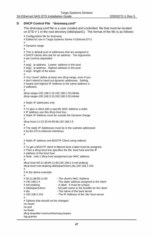
Targa Systems Division S4 Ethernet NAS DTS Installation Guide 32003272-1 Rev 5
D DHCP Control File “dnsmasq.conf” The dnsmasq.conf file is a user created and controlled file that must be located on DTD # 1 in the root directory (/dtd/a/part1). The format of the file is as follows: # Configuration file for dnsmasq # Edited for use in Targa Systems Series 4 Ethernet DTU # # Dynamic range # # This is default pool of addresses that are assigned to # DHCP clients who ask for an address. The arguments # are comma separated: # # arg1: ip address. Lowest address in the pool. # arg2: ip address. Highest address in the pool. # arg3: length of the lease # # You *must* define at least one dhcp-range, even if you # don't intend to hand out dynamic addresses. Setting # lowest and highest IP Address to the same address is # sufficient. # dhcp-range=192.168.2.10,192.168.2.20,infinite dhcp-range=192.168.3.10,192.168.3.20,infinite # Static IP addresses only # # To give a client with a specific MAC address a static # IP address use this dhcp-host line: # Static IP Address must be outside the Dynamic Range # dhcp-host=11:22:33:44:55:66,192.168.2.5 # # The static IP Addresses must be in the subnets addressed # by the DTUs ethernet interfaces # # Static IP address and BOOTP Client using netboot # # To get a BOOTP client to tftp/net boot a label must be assigned. # Then a dhcp-boot line specifies the file, boot host and the IP # address of the boot host. # Note: only 1 dhcp-host assignment per MAC address # dhcp-host=00:11:d8:85:11:83,192.168.2.4,net:seaking dhcp-boot=net:seaking,/dtd/a/part1/kern,dtu,192.168.2.104 # # In the above example: # # 00:11:d8:85:11:83 - The client's MAC Address # 192.168.2.4 - The static address assigned to the client # net:seaking - A label. It must be unique. # /dtd/a/part1/kern - full path name to the bootfile for the client # dtu - The name of the boot server # 192.168.2.104 - The IP Address of the 'dtu' boot server # # Options that should not be changed: no-resolv no-poll no-hosts dhcp-leasefile=/var/run/dnsmasq.leases log-queries
47

Targa Systems Division S4 Ethernet NAS DTS Installation Guide 32003272-1 Rev 5
E DTD MTBF Data
DTD MTBF data based on SATA disk manufacturers reliability data. RAC Reliability toolkit environmental conversion factors were used to convert the computed MTBF to additional environments.
Series 4 - Data Transfer Devices DTD40SA3 - ccc - 2
MTBF (hrs) for Capacity (ccc)
Environment 32GB 64GB 128GB 256GB
GB 35°C 341,263 332,758 316,959 263,527 GM 45°C 68,253 66,552 63,392 52,705 AIC 35°C 102,379 99,827 95,088 79,058 AUC 55°C 30,714 29,948 28,526 23,717 AIF 45°C 68,253 66,552 63,392 52,705 AUF 45°C 30,714 29,948 28,526 23,717 ARW 35°C 34,126 33,276 31,696 26,353
48

Targa Systems Division S4 Ethernet NAS DTS Installation Guide 32003272-1 Rev 5
F Network Data Capture Function With F/W version 3.1.8 and above, the Targa Series 4 NAS DTU has the ability to log network traffic to the removable Data Transfer Device (DTD). This capability uses tcpdump v4.1.1 (www.tcpdump.org) to capture information from the network in a libpcap v1.1.1 format that can be later replayed by tools such as tcpdump or Wireshark (www.wireshark.org). The feature is activated if a special control file “netcapture.cfg” is found on /dtd/a/part1 when mounted (as well as /dtd/b/part1 in a dual DTD system). Traffic can be captured from port1, port2 or both ports simultaneously. Network capture operations are specified within the “netcapture.cfg” file as defined below. The network capture can store data to encrypted volumes, however they must first be unlocked via the standard SSH mechanism before the capture service can begin. High-rate network transfers to/from the DTU while doing network capture will affect overall performance of transfers due to the DTU writing network packet data to the DTD in addition to the "normal" requirements of the network transfer.
“netcapture.cfg” Configuration file The netcapture.cfg file is a simple text file located on partition1 of the DTD where data is to be stored. Configurable parameters are as specified below, where x (=0; 1) specifies the ethernet port. Targa Systems recommends that when initially preparing the netcapture.cfg file you set the DTU COM2 monitor “verbosity” to “high” and then monitor the output during DTU start up. Note: Network data capture will not start if: - DTD door is open - DTD is not installed - netcapture specified target directory are encrypted and not unlocked. - netcapture specified target directory does not exist
netcapture – Basic Activation
ETHx_NC_ENABLE=yes Start netcapture on specified port where x = 0 for port 1; x=1 for port 2 Defaults: Capture All traffic on the wire (in switched ethernet environments this is
often just broadcast traffic and traffic destined to the DTU) Into Directory: Partition #1 of the DTD on which the netcapture
file was found Into Filename: nc-ethX-runY.pcapZ where: X = 0 for port1 X = 1 for port2 Y = 1 to n; Upon DTD re-mount, if file found Y = Y+1, else Y=1 Z = “null” to n; capture file size limited to 1GB, auto increments
49

Targa Systems Division S4 Ethernet NAS DTS Installation Guide 32003272-1 Rev 5
netcapture – control parameters and filter commands
ETHx_NC_BASENAME Change capture file basename (runY.pcapZ is unchanged)
eg: ETH0_NC_BASENAME="netcap-eth0-" ETHx_NC_DEST Specify “destination” directory within DTD where
netcapture was found … can be a different partition or directory to store the capture files
eg: ETH0_NC_DEST= "part2/capture" ETHx_NC_FILTER Filter expression. eg: ETH0_NC_FILTER="multicast and not broadcast"
eg: ETH1_NC_FILTER="host 192.168.3.231 and port ftp" See manpage for pcap-filter that is part of the tcpdump
documentation. ETHx_NC_ARGS Arguments to tcpdump. eg: ETH1_NC_ARGS="-n -C 10 -ttttt" See manpage for tcpdump for all command line options. ETHx_NC_OVERWRITE Overwrites previous "Runs". Capture always to -run1 An example netcapture.cfg file is also available on the DTU under /targa/doc/netcapture.cfg
# Example netcapture.cfg file ETH0_NC_ENABLE=yes ETH0_NC_BASENAME="netcap-eth0-" ETH0_NC_DEST="part1/capture" ETH0_NC_FILTER="multicast and not broadcast" ETH0_NC_OVERWRITE=yes ETH1_NC_ENABLE=yes ETH1_NC_BASENAME="mync-eth1-" ETH1_NC_ARGS="-n -C 10 -ttttt" ETH1_NC_FILTER="host 192.168.3.231 and port ftp"
50

Targa Systems Division S4 Ethernet NAS DTS Installation Guide 32003272-1 Rev 5
G USB & SATA – DTD Erase / Sanitize For applications that use Targa’s Series 4 Data Transfer Units with either a USB or SATA interface, Targa has added this special support page to assist in maintaining the Erase and Sanitization features of the Data Transfer Devices (DTD). Note: 1 This page IS NOT to support applications that use the Ethernet NAS
DTU. For NAS DTU applications use the DTD Info and DTD SETUP pages (Section 4-7 above)
2 The sanitize process can take from 1 – 12 hours to complete depending on the algorithm selected and disk capacity. Do not use this process to clean up the DTD disk.
3 Sanitize is two (2) step process: Sanitize algorithms 2- 7 must be followed by the Restore DTD operation
4 Do not power off DTU until the Sanitize function has completed Page access: http://192.168.2.104/cgi-bin/dtd-erase (config-jumper installed) “feature not supported” Displayed if DTD does not support the feature This page has three specific functions: 1 If the DTD supports a H/W activated erase - Report the current configured algorithm - User can select and save a different algorithm 2 If the DTD supports a S/W activated erase or sanitize - allow the user to activate the selected erase/sanitize process - when completed page will display – DTD not found 3 Restore DTD after a Sanitize has been performed
51

Targa Systems Division L-3 Communications Canada
Blank Page