Tank Gauging System with FOUNDATION - · PDF fileReference Manual 308017EN, Edition 1/Rev. B...
116
Reference Manual 308017EN, Edition 1/Rev. B October 2007 www.rosemount-tg.com Tank Gauging System with FOUNDATION™ Fieldbus
Transcript of Tank Gauging System with FOUNDATION - · PDF fileReference Manual 308017EN, Edition 1/Rev. B...

Reference Manual308017EN, Edition 1/Rev. BOctober 2007
Tank Gauging Systemwith FOUNDATION™ Fieldbus
www.rosemount-tg.com
Product Discontinued


www.rosemount-tg.com
Foundation FieldbusReference Manual
Edition 1/Rev. B

www.rosemount-tg.com
Copyright © October 2007
Rosemount Tank Radar ABThe contents, descriptions and specifications within this manual is subject to change without notice. Rosemount Tank Radar AB accepts no responsibility for any errors that may appear in this manual.
Trademarks
Rosemount, and the Rosemount logotype are registered trademarks of Rosemount Inc.
TankRadar is a registered trademark of Rosemount Tank Radar AB.
HART is a registered trademark of the HART Communication Foundation.
FOUNDATION fieldbus is a registered trademark of the Fieldbus Foundation.
Spare Parts
Any substitution of non-recognized spare parts may jeopardize safety. Repair, e.g. substitution of components etc, may also jeopardize safety and is under no circumstances allowed.
Rosemount Tank Radar AB will not take any responsibility for faults, accidents, etc caused by non-recognized spare parts or any repair which is not made by Rosemount Tank Radar AB.
Specific FCC Requirements (USA only)
Rosemount TankRadar REX generates and uses radio frequency energy. If it is not installed and used properly, that is, in strict accordance with the manufacturer´s instructions, it may violate FCC regulations on radio frequency emission.
Rosemount TankRadar REX has been FCC certified under test conditions which assume a metallic tank. Installation on a non-metallic tank is not certified, and is not allowed.
The FCC certificate for Rosemount TankRadar REX requires that the tank is closed as far as emitted radio energy is concerned. Tanks with open manholes, external-floating-roof tanks without still pipes etc. are not covered by the certificate.

Rosemount TankRadar REXTable of Contents
Reference Manual308017EN, Edition 1/Rev. BOctober 2007
Contents1. INTRODUCTION . . . . . . . . . . . . . . . . . . . . . . . . . . . . . . . . 1-1
1.1 USING THIS MANUAL . . . . . . . . . . . . . . . . . . . . . . . . . . . . . . . . . . . . .1-1
2. SAFETY . . . . . . . . . . . . . . . . . . . . . . . . . . . . . . . . . . . . . 2-1
2.1 INTRINSIC SAFETY . . . . . . . . . . . . . . . . . . . . . . . . . . . . . . . . . . . . . . .2-12.2 EXPLOSION PROOF . . . . . . . . . . . . . . . . . . . . . . . . . . . . . . . . . . . . . .2-22.3 EUROPEAN ATEX DIRECTIVE INFORMATION . . . . . . . . . . . . . . . . .2-32.4 UNDERWRITERS LABORATORY INFORMATION . . . . . . . . . . . . . . .2-8
3. FOUNDATION FIELDBUS TECHNOLOGY ANDFIELDBUS FUNCTION BLOCKS. . . . . . . . . . . . . . . . . . . . . 3-1
3.1 OVERVIEW . . . . . . . . . . . . . . . . . . . . . . . . . . . . . . . . . . . . . . . . . . . . .3-13.2 INTRODUCTION . . . . . . . . . . . . . . . . . . . . . . . . . . . . . . . . . . . . . . . . .3-13.3 BLOCK OPERATION . . . . . . . . . . . . . . . . . . . . . . . . . . . . . . . . . . . . . .3-33.4 NETWORK COMMUNICATION . . . . . . . . . . . . . . . . . . . . . . . . . . . . . .3-5
4. INSTALLATION . . . . . . . . . . . . . . . . . . . . . . . . . . . . . . . . 4-1
4.1 SAFETY MESSAGES . . . . . . . . . . . . . . . . . . . . . . . . . . . . . . . . . . . . . .4-14.2 MECHANICAL INSTALLATION . . . . . . . . . . . . . . . . . . . . . . . . . . . . . .4-24.3 ELECTRICAL INSTALLATION . . . . . . . . . . . . . . . . . . . . . . . . . . . . . . .4-3
TOC-1

Rosemount TankRadar REXTable of Contents
Reference Manual308017EN, Edition 1/Rev. B
October 2007
5. CONFIGURATION. . . . . . . . . . . . . . . . . . . . . . . . . . . . . . . 5-1
5.1 INTRODUCTION . . . . . . . . . . . . . . . . . . . . . . . . . . . . . . . . . . . . . . . . .5-15.2 OVERVIEW . . . . . . . . . . . . . . . . . . . . . . . . . . . . . . . . . . . . . . . . . . . . .5-15.3 ASSIGNING DEVICE TAG AND NODE ADDRESS . . . . . . . . . . . . . . .5-25.4 CONFIGURE GAUGE . . . . . . . . . . . . . . . . . . . . . . . . . . . . . . . . . . . . .5-25.5 FOUNDATION FIELDBUS FUNCTION BLOCKS . . . . . . . . . . . . . . . . . . .5-45.6 CONFIGURE THE AI BLOCK . . . . . . . . . . . . . . . . . . . . . . . . . . . . . . . .5-65.7 CONFIGURE THE DI BLOCK . . . . . . . . . . . . . . . . . . . . . . . . . . . . . . .5-95.8 APPLICATION EXAMPLES . . . . . . . . . . . . . . . . . . . . . . . . . . . . . . . . .5-95.9 CONFIGURATION USING THE TRL/2 PORT . . . . . . . . . . . . . . . . . .5-13
6. OPERATION AND MAINTENANCE . . . . . . . . . . . . . . . . . . . 6-1
6.1 OVERVIEW . . . . . . . . . . . . . . . . . . . . . . . . . . . . . . . . . . . . . . . . . . . . .6-16.2 SAFETY MESSAGES . . . . . . . . . . . . . . . . . . . . . . . . . . . . . . . . . . . . . .6-1
7. SERVICE AND TROUBLESHOOTING. . . . . . . . . . . . . . . . . . 7-1
7.1 OVERVIEW . . . . . . . . . . . . . . . . . . . . . . . . . . . . . . . . . . . . . . . . . . . . .7-17.2 SAFETY MESSAGES . . . . . . . . . . . . . . . . . . . . . . . . . . . . . . . . . . . . . .7-17.3 FIELD UPGRADES . . . . . . . . . . . . . . . . . . . . . . . . . . . . . . . . . . . . . . .7-27.4 TROUBLESHOOTING . . . . . . . . . . . . . . . . . . . . . . . . . . . . . . . . . . . . .7-27.5 RESOURCE BLOCK . . . . . . . . . . . . . . . . . . . . . . . . . . . . . . . . . . . . . .7-37.6 TRANSDUCER BLOCK . . . . . . . . . . . . . . . . . . . . . . . . . . . . . . . . . . . .7-47.7 ANALOG INPUT (AI) FUNCTION BLOCK . . . . . . . . . . . . . . . . . . . . . .7-5
APPENDIX A SPECIFICATIONS
APPENDIX B LEVEL TRANSDUCER BLOCKOVERVIEW ...................................................................................................... B-1PARAMETERS AND DESCRIPTIONS ............................................................ B-2DIAGNOSTICS DEVICE ERRORS ................................................................. B-6SUPPORTED UNITS ....................................................................................... B-8
APPENDIX C REGISTER TRANSDUCER BLOCKOVERVIEW ...................................................................................................... C-1REGISTER ACCESS TRANSDUCER BLOCK PARAMETERS ....................... C-1
TOC-2

Rosemount TankRadar REXTable of Contents
Reference Manual308017EN, Edition 1/Rev. BOctober 2007
APPENDIX D RESOURCE BLOCKOVERVIEW ...................................................................................................... D-1PARAMETERS AND DESCRIPTIONS ............................................................ D-1
APPENDIX E ANALOG-INPUT BLOCKOVERVIEW ...................................................................................................... E-1SIMULATION .................................................................................................... E-4DAMPING ......................................................................................................... E-5SIGNAL CONVERSION ................................................................................... E-6BLOCK ERRORS ............................................................................................. E-7MODES ............................................................................................................. E-7ALARM DETECTION ........................................................................................ E-8ADVANCED FEATURES ................................................................................ E-10CONFIGURE THE AI BLOCK ........................................................................ E-11TROUBLESHOOTING .................................................................................... E-13
APPENDIX F DISCRETE INPUT BLOCKOVERVIEW .......................................................................................................F-1I/O SELECTION .................................................................................................F-2SIMULATION .....................................................................................................F-2FIELD VALUE PROCESSING ...........................................................................F-3ALARM DETECTION .........................................................................................F-3BLOCK ERRORS ..............................................................................................F-3MODES ..............................................................................................................F-3STATUS HANDLING .........................................................................................F-4ACTION ON FAILURE .......................................................................................F-4
APPENDIX G APPROVAL DRAWINGS
APPENDIX H OPERATION WITH DELTA VCOMMISSIONING THE DEVICE .................................................................... H-1CONFIGURE THE PARAMETERS .................................................................. H-2
INDEX . . . . . . . . . . . . . . . . . . . . . . . . . . . . . . . . . . . . . . . . . . . I-1
TOC-3

Rosemount TankRadar REXTable of Contents
Reference Manual308017EN, Edition 1/Rev. B
October 2007
TOC-4

Rosemount Tank Radar REXChapter 1 Introduction
Reference Manual308017EN, Edition 1/Rev. BOctober 2007
1. Introduction
This manual was developed with the assumption that the user will have a basic understanding of FOUNDATION™ fieldbus concept and wiring practices.
1.1 Using This Manual
The sections in this manual provide information on configurating, operating, and maintaining Rosemount TankRadar REX 3900 Radar Gauges with FOUNDATION fieldbus protocol output.
Refer to www.tankradar.com for further information relating to FOUNDATION fieldbus.
The purpose of this manual is to serve as a supplement to the TankRadar REX Installation Manual (Ref.no. 308014E), TankRadar REX Service Manual (Ref.no. 308012E) and TankMaster Winsetup User´s Guide (Ref. no. 303027E).
The sections in this manual are organized as follows:
• Chapter 1. Introduction
• Chapter 2. Safety provides intrinsic safety approval information and European Atex directives.
• Chapter 3. FOUNDATION Fieldbus Technology and Fieldbus Function Blocks describes the basic information about fieldbus and the function blocks that are common to all FOUNDATION field-bus devices.
• Chapter 4. Installation provides mechanical and electrical instal-lation instructions.
• Chapter 5. Configuration provides instruction on configuration and operation of Rosemount TankRadar REX 3900 gauges. Infor-mation on software functions, configuration parameters, and online variables are also included. This section covers information for FOUNDATION fieldbus units only. For additional configuration instructions see the TankRadar REX Installation Manual (Ref. no. 308014E) and TankMaster Winsetup User´s guide (Ref. no. 303027E).
• Chapter 6. Operation and Maintenance contains operation and maintenance techniques for FOUNDATION fieldbus protocol only. For TRL/2 Bus protocol see the TankRadar REX Installation Man-ual (Ref. no. 308014E) and TankRadar REX Service Manual (Ref.no. 308012E).
1-1

Rosemount Tank Radar REXChapter 1 Introduction
Reference Manual308017EN, Edition 1/Rev. B
October 2007
• Chapter 7. Service and Troubleshooting provides troubleshoot-ing techniques for the most common operating problems for FOUN-DATION fieldbus protocol only. For additional gauge related troubleshooting see the TankRadar REX Service Manual (Ref.no. 308012E).
• Appendix A Specifications
• Appendix B Level Transducer Block supplies Level Transducer Block data.
• Appendix C Register Transducer Block contains information relating to the operation of the register transducer block.
• Appendix D Resource Block contains information relating to the operation of the resource block.
• Appendix E Analog-Input Block contains information relating to the operation of the analog-input block.
• Appendix F Discrete Input Block contains information relating to the operation of the discrete input block.
• Appendix G Approval Drawings
• Appendix H Operation with Delta V contains information relating to the operation of Delta V.
1-2

Rosemount Tank Radar REXChapter 2 Safety
Reference Manual308017EN, Edition 1/Rev. BOctober 2007
2. Safety
TankRadar REX equipment is often used in areas where flammable materials are handled and where an explosive atmosphere may be present. To protect both the plant and the personnel, precautions must be taken to ensure that this atmosphere cannot be ignited. These areas are called hazardous areas and equipment within these areas must be explosion protected.
A number of different explosion protection techniques have been developed over the years. Intrinsic safety and explosion proof (or flame proof ) safety are two techniques.
2.1 Intrinsic Safety
Intrinsic safety, IS, is based on the principle of restricting electrical energy available in hazardous-area circuits such that any sparks or hot surfaces, that may occur as a result of electrical faults in components, are unable to cause ignition. Intrinsic safety is the only technique accepted for Zone 0 hazardous areas. It is also safe for personnel and allows equipment to be maintained without the need for a gas-free certificate.
The basic principles of intrinsic safety are:
• All flammable materials are grouped according to the energy needed to ignite them.
• Equipment located in hazardous areas are classified according to the maximum surface temperature that it can produce and this must be safe with the flammable gases that may be present.
• Hazardous areas are classified according to the probability that an explosive atmosphere is present, and this dictates whether or not a particular explosion protection technique may be used.
Note! For trouble shooting and repair work of components in or in connection to intrinsically safe equipment, strict observance of the following rules is necessary:- Disconnect the power supply to the Radar Tank Gauge.- Use a certified battery operated instrument only.- Use Rosemount TankRadar REX original spare parts only. Replacement with non-original spare parts may jeopardize the intrinsic safety.
2-1

Rosemount Tank Radar REXChapter 2 Safety
Reference Manual308017EN, Edition 1/Rev. B
October 2007
2.2 Explosion Proof
Explosion proof enclosures can be used when an explosion can be allowed inside the enclosure as long as it does not spread to the outside. The enclosure must be strong enough to withstand the pressure and must have narrow gaps to allow the pressure to escape without igniting the atmosphere outside of the equipment.
Note! Any substitution to non-recognized parts may impair safety. The explosion-proof (flame-proof ) enclosure of the Gauge Head must not be opened while the unit is powered.
2-2

Rosemount Tank Radar REXChapter 2 Safety
Reference Manual308017EN, Edition 1/Rev. BOctober 2007
2.3 European ATEX Directive Information
2.3.1 Radar Unit
The REX Radar Unit has been certified to comply with Directive 94/9/EC of the European Parliament and the Council as published in the Official Journal of the European Communities No. L 100/1.
Figure 2-1. Approval label ATEX for the 2015 Radar Unit (used in 3900 series radar tank gauges).
The following information is provided as part of the label of the radar unit:
• Name and address of the manufacturer (Rosemount Tank Radar AB).
• CE Conformity Marking:
• Complete model number
• The serial number of the device
• Year of construction
• Marking for explosion protection:
• EEx d IIB T6 (-40°C ≤ Ta ≤ +70°C)
• Baseefa(2001) ATEX certificate number: Baseefa03ATEX0071X
Special Conditions for Safe Use (X):
• The Type TH2015-2019 Radar Units are not to be mounted directly on to a tank.
• For replacement purposes the cover fastening screws are to be of minimum grade A4-80 stainless steel.
• The permanently attached cables are to be suitably terminated and protected against impact.
MA
INLA
BEL
_RA
DAR
UN
IT
2-3

Rosemount Tank Radar REXChapter 2 Safety
Reference Manual308017EN, Edition 1/Rev. B
October 2007
2.3.2 Radar Tank Gauge
The 3900 Radar Tank Gauge (type TH2015-2019 Radar Unit with antenna certified for Zone 0) has been certified to comply with Directive 94/9/EC of the European Parliament and the Council as published in the Official Journal of the European Communities No. L 100/1.
Figure 2-2. Approval label ATEX for the 3900 Series Radar Tank Gauge.
The following information is provided as part of the label of the radar unit:
• Name and address of the manufacturer (Rosemount Tank Radar AB).
• CE Conformity Marking:
• Complete model number
• The serial number of the device
• Year of construction
• Marking for explosion protection:
• EEx d IIB T6 (-40°C ≤ Ta ≤ +70°C)
• Baseefa(2001) ATEX certificate number: Baseefa03ATEX0071X
Special Conditions for Safe Use (X):
• For replacement purposes the cover fastening screws are to be of minimum grade A4-80 stainless steel.
• The permanently attached cables are to be suitably terminated and protected against impact.
MAI
NLA
BE
L_R
TG39
00
2-4

Rosemount Tank Radar REXChapter 2 Safety
Reference Manual308017EN, Edition 1/Rev. BOctober 2007
2.3.3 Transmitter Interface Card (TIC)
Figure 2-3. Approval label for the Transmitter Interface Card (TIC).
The following information is provided as part of the label of the gauge:
• Name and address of the manufacturer (Rosemount Tank Radar AB).
• CE Conformity Marking:
• Year of construction
• Marking for explosion protection:
• [EEx ia] IIC (-40°C ≤ Ta ≤ +85°C)
• Baseefa(2001) ATEX certificate number: Baseefa03ATEX0050U
ATEX
_TIC
_LAB
EL
2-5

Rosemount Tank Radar REXChapter 2 Safety
Reference Manual308017EN, Edition 1/Rev. B
October 2007
2.3.4 Transmitter Multiplexer Card (TMC)
Figure 2-4. Approval label for the Transmitter Multiplexer Card (TMC).
The following information is provided as part of the label of the gauge:
• Name and address of the manufacturer (Rosemount Tank Radar AB).
• CE Conformity Marking:
• Year of construction
• Marking for explosion protection:
• [EEx ia] IIC (-40°C ≤ Ta ≤ +85°C)
• Baseefa(2001) ATEX certificate number: Baseefa03ATEX0050U
ATE
X_T
MC
_LA
BEL
2-6

Rosemount Tank Radar REXChapter 2 Safety
Reference Manual308017EN, Edition 1/Rev. BOctober 2007
2.3.5 Foundation Fieldbus Adapter (FFA)
Figure 2-5. Approval label for the Foundation Fieldbus Adapter board (FFA).
The following information is provided as part of the label of the gauge:
• Name and address of the manufacturer (Rosemount Tank Radar AB).
• CE Conformity Marking:
• Year of construction
• Marking for explosion protection:
• [EEx ia] IIC (-40°C ≤ Ta ≤ +85°C)
• Baseefa(2001) ATEX certificate number: Baseefa04ATEX0119U
ATE
X_F
FA_L
ABE
L.E
PS
2-7

Rosemount Tank Radar REXChapter 2 Safety
Reference Manual308017EN, Edition 1/Rev. B
October 2007
2.3.6 Remote Display Unit 40 (RDU 40)
Figure 2-6. Approval label for the Remote Display Unit RDU40.
The following information is provided as part of the label of the gauge:
• Name and address of the manufacturer (Rosemount Tank Radar AB).
• CE Conformity Marking:
• Year of construction
• Marking for explosion protection:
• EEx ib IIC T4 (-40°C ≤ Ta ≤ +70°C)
• Sira ATEX certificate number: Sira 00 ATEX 2062
2.4 Underwriters Laboratory Information
The System Control drawing 9150072-966 (see Appendix G Approval Drawings) shows specific requirements which have to be fulfilled to secure a safe installation and use of Rosemount Tank Radar REX in an hazardous area. The approval plate on explosion proof enclosures indicates installed options.
Omission may jeopardize safety and Rosemount Tank Radar AB will not take any responsibility if requirements in the drawing are not fulfilled.
ATE
X_R
DU
40_l
abel
.eps
2-8

Rosemount Tank Radar REXChapter 3 FOUNDATION Fieldbus Technology and
Reference Manual308017EN, Edition 1/Rev. BOctober 2007
3. FOUNDATION Fieldbus Technology andFieldbus Function Blocks
3.1 Overview
This section introduces fieldbus systems that are common to all fieldbus devices.
3.2 Introduction
A fieldbus system is a distributed system composed of field devices and control and monitoring equipment integrated into the physical environment of a plant or factory. Fieldbus devices work together to provide I/O and control for automated processes and operations. The FOUNDATION fieldbus provides a framework for describing these systems as a collection of physical devices interconnected by a fieldbus network. One of the ways that the physical devices are used is to perform their portion of the total system operation by implementing one or more function blocks.
3.2.1 Function Blocks
Function blocks within the fieldbus device perform the various functions required for process control. Because each system is different, the mix and configuration of functions are different. Therefore, the FOUNDATION fieldbus has designed a range of function blocks, each addressing a different need.
Function blocks perform process control functions, such as analog input (AI) and analog output (AO) functions as well as proportional-integral-derivative (PID) functions. The standard function blocks provide a common structure for defining function block inputs, outputs, control parameters, events, alarms, and modes, and combining them into a process that can be implemented within a single device or over the fieldbus network. This simplifies the identification of characteristics that are common to function blocks.
The FOUNDATION fieldbus has established the function blocks by defining a small set of parameters used in all function blocks called universal parameters. The FOUNDATION fieldbus has also defined a standard set of function block classes such as: input, output, control, and calculation blocks. Each of these classes also has a small set of parameters established for it. They have also published definitions for transducer blocks commonly used with standard function blocks. Examples include temperature, pressure, level, and flow transducer blocks.
3-1

Rosemount Tank Radar REXChapter 3 FOUNDATION Fieldbus Technology and
Reference Manual308017EN, Edition 1/Rev. B
October 2007
The FOUNDATION specifications and definitions allow vendors to add their own parameters by importing and subclassing specified classes. This approach permits extending function block definitions as new requirements are discovered and as technology advances.
Figure 3-1 illustrates the internal structure of a function block. When execution begins, input parameter values from other blocks are snapped-in by the block. The input snap process ensures that these values do not change during the block execution. New values received for these parameters do not affect the snapped values and will not be used by the function block during the current execution.
Figure 3-1. Function Block Internal Structure
Once the inputs are snapped, the algorithm operates on them, generating outputs as it progresses. Algorithm executions are controlled through the setting of contained parameters. Contained parameters are internal to function blocks and do not appear as normal input and output parameters. However, they may be accessed and modified remotely, as specified by the function block.
Input events may affect the operation of the algorithm. An execution control function regulates the receipt of input events and the generation of output events during execution of the algorithm. Upon completion of the algorithm, the data internal to the block is saved for use in the next execution, and the output data is snapped, releasing it for use by other function blocks.
A block is a tagged logical processing unit. The tag is the name of the block. System management services locate a block by its tag. Thus the service personnel need only know the tag of the block to access or change the appropriate block parameters.
Function blocks are also capable of performing short-term data collection and storage for reviewing their behavior.
Input Events Output Events
Input Parameter Linkages
Output Parameter Linkages
Processing Algorithm
Execution Control
Input Snap
Status
Output Snap
Status
FF_B
LOC
KIN
TER
NAL
STR
UC
TUR
E
3-2

Rosemount Tank Radar REXChapter 3 FOUNDATION Fieldbus Technology and
Reference Manual308017EN, Edition 1/Rev. BOctober 2007
3.2.2 Device Descriptions
Device Descriptions are specified tool definitions that are associated with the function blocks. Device descriptions provide for the definition and description of the function blocks and their parameters.
To promote consistency of definition and understanding, descriptive information, such as data type and length, is maintained in the device description. Device Descriptions are written using an open language called the Device Description Language (DDL). Parameter transfers between function blocks can be easily verified because all parameters are described using the same language. Once written, the device description can be stored on an external medium, such as a CD-ROM or diskette. Users can then read the device description from the external medium. The use of an open language in the device description permits interoperability of function blocks within devices from various vendors. Additionally, human interface devices, such as operator consoles and computers, do not have to be programmed specifically for each type of device on the bus. Instead their displays and interactions with devices are driven from the device descriptions.
Device descriptions may also include a set of processing routines called methods. Methods provide a procedure for accessing and manipulating parameters within a device.
3.3 Block Operation
In addition to function blocks, fieldbus devices contain two other block types to support the function blocks. These are the resource block and the transducer block. The resource block contains the hardware specific characteristics associated with a device. Transducer blocks couple the function blocks to local input/output functions.
3.3.1 Instrument-Specific Function Blocks
Resource Blocks
Resource blocks contain the hardware specific characteristics associated with a device; they have no input or output parameters. The algorithm within a resource block monitors and controls the general operation of the physical device hardware. The execution of this algorithm is dependent on the characteristics of the physical device, as defined by the manufacturer. As a result of this activity, the algorithm may cause the generation of events. There is only one resource block defined for a device. For example, when the mode of a resource block is “out of service,” it impacts all of the other blocks.
3-3

Rosemount Tank Radar REXChapter 3 FOUNDATION Fieldbus Technology and
Reference Manual308017EN, Edition 1/Rev. B
October 2007
Transducer Blocks
Transducer blocks connect function blocks to local input/output functions. They read sensor hardware and write to effector (actuator) hardware. This permits the transducer block to execute as frequently as necessary to obtain good data from sensors and ensure proper writes to the actuator without burdening the function blocks that use the data. The transducer block also isolates the function block from the vendor specific characteristics of the physical I/O.
3.3.2 Alerts
When an alert occurs, execution control sends an event notification and waits a specified period of time for an acknowledgment to be received. This occurs even if the condition that caused the alert no longer exists. If the acknowledgment is not received within the pre-specified time-out period, the event notification is retransmitted. This assures that alert messages are not lost.
Two types of alerts are defined for the block, events and alarms. Events are used to report a status change when a block leaves a particular state, such as when a parameter crosses a threshold. Alarms not only report a status change when a block leaves a particular state, but also report when it returns back to that state.
3-4

Rosemount Tank Radar REXChapter 3 FOUNDATION Fieldbus Technology and
Reference Manual308017EN, Edition 1/Rev. BOctober 2007
3.4 Network communication
Figure 3-2 illustrates a simple fieldbus network consisting of a single segment (link).
Figure 3-2. Simple, Single-Link Fieldbus Network
3.4.1 Link Active Scheduler (LAS)
All links have one and only one Link Active Scheduler (LAS). The LAS operates as the bus arbiter for the link. The LAS does the following:
• recognizes and adds new devices to the link.
• removes non-responsive devices from the link.
• distributes Data Link (DL) and Link Scheduling (LS) time on the link. Data Link Time is a network-wide time periodically distributed by the LAS to synchronize all device clocks on the bus. Link Scheduling time is a link-specific time represented as an offset from Data Link Time. It is used to indicate when the LAS on each link begins and repeats its schedule. It is used by system manage-ment to synchronize function block execution with the data trans-fers scheduled by the LAS.
• polls devices for process loop data at scheduled transmission times.
• distributes a priority-driven token to devices between scheduled transmissions.
Any device on the link may become the LAS, as long as it is capable. The devices that are capable of becoming the LAS are called link master devices. All other devices are referred to as basic devices. When a segment first starts up, or upon failure of the existing LAS, the link master devices on the segment bid to become the LAS. The link master that wins the bid begins operating as the LAS immediately upon completion of the bidding process. Link masters that do not become the LAS act as basic devices. However, the link masters can act as LAS backups by monitoring the link for failure of the LAS and then bidding to become the LAS when a LAS failure is detected.
LAS = Link Active Scheduler
LAS
Basic Devices and/or link master devices
Link Master
Fieldbus Link
FF_N
ETW
OR
KC
OM
MU
NIC
ATI
O
3-5

Rosemount Tank Radar REXChapter 3 FOUNDATION Fieldbus Technology and
Reference Manual308017EN, Edition 1/Rev. B
October 2007
Only one device can communicate at a time. Permission to communicate on the bus is controlled by a centralized token passed between devices by the LAS. Only the device with the token can communicate. The LAS maintains a list of all devices that need access to the bus. This list is called the “Live List.”
Two types of tokens are used by the LAS. A time-critical token, compel data (CD), is sent by the LAS according to a schedule. A non-time critical token, pass token (PT), is sent by the LAS to each device in ascending numerical order according to address.
3.4.2 Device Addressing
Fieldbus uses addresses between 0 and 255. Addresses 0 through 15 are reserved for group addressing and for use by the data link layer. For all Emerson Process Management, Rosemount Division fieldbus devices addresses 20 through 35 are available to the device. If there are two or more devices with the same address, the first device to start will use its programmed address. Each of the other devices will be given one of four temporary addresses between 248 and 251. If a temporary address is not available, the device will be unavailable until a temporary address becomes available.
3.4.3 Scheduled Transfers
Information is transferred between devices over the fieldbus using three different types of reporting.
• Publisher/Subscriber: This type of reporting is used to transfer critical process loop data, such as the process variable. The data producers (publishers) post the data in a buffer that is transmitted to the subscriber (S), when the publisher receives the Compel data. The buffer contains only one copy of the data. New data completely overwrites previous data. Updates to published data are transferred simultaneously to all subscribers in a single broad-cast. Transfers of this type can be scheduled on a precisely peri-odic basis.
• Report Distribution: This type of reporting is used to broadcast and multicast event and trend reports. The destination address may be predefined so that all reports are sent to the same address, or it may be provided separately with each report. Trans-fers of this type are queued. They are delivered to the receivers in the order transmitted, although there may be gaps due to cor-rupted transfers. These transfers are unscheduled and occur in between scheduled transfers at a given priority.
• Client/Server: This type of reporting is used for request/response exchanges between pairs of devices. Like Report Distribution reporting, the transfers are queued, unscheduled, and prioritized. Queued means the messages are sent and received in the order submitted for transmission, according to their priority, without over-writing previous messages. However, unlike Report Distribution,
3-6

Rosemount Tank Radar REXChapter 3 FOUNDATION Fieldbus Technology and
Reference Manual308017EN, Edition 1/Rev. BOctober 2007
these transfers are flow controlled and employ a retransmission procedure to recover from corrupted transfers.
Figure 3-3 diagrams the method of scheduled data transfer. Scheduled data transfers are typically used for the regular cyclic transfer of process loop data between devices on the fieldbus. Scheduled transfers use publisher/subscriber type of reporting for data transfer. The Link Active Scheduler maintains a list of transmit times for all publishers in all devices that need to be cyclically transmitted. When it is time for a device to publish data, the LAS issues a Compel Data (CD) message to the device. Upon receipt of the CD, the device broadcasts or “publishes” the data to all devices on the fieldbus. Any device that is configured to receive the data is called a “subscriber.”
Figure 3-3. Scheduled Data Transfer
Schedule XYZ
CD(X,A)
DT(A)
Device X
AB
P SLAS = Link Active Scheduler
P = PublisherS = Subscriber
CD = Compel DataDT = Data Transfer Packet
LAS
FF_S
CH
ED
ULE
DD
ATA
TRA
NSF
ER
P S P S
AA C D
3-7

Rosemount Tank Radar REXChapter 3 FOUNDATION Fieldbus Technology and
Reference Manual308017EN, Edition 1/Rev. B
October 2007
3.4.4 Unscheduled Transfers
Figure 3-4 diagrams an unscheduled transfer. Unscheduled transfers are used for things like user-initiated changes, including set point changes, mode changes, tuning changes, and upload/download. Unscheduled transfers use either report distribution or client/server type of reporting for transferring data.
All of the devices on the fieldbus are given a chance to send unscheduled messages between transmissions of scheduled data. The LAS grants permission to a device to use the fieldbus by issuing a pass token (PT) message to the device. When the device receives the PT, it is allowed to send messages until it has finished or until the “maximum token hold time” has expired, whichever is the shorter time. The message may be sent to a single destination or to multiple destinations.
Figure 3-4. Unscheduled Data Transfer
ScheduleXYZ
PT(Z)
Device X Device Y Device Z
A C DAB
P S P S P
A
S
LAS = Link Active Scheduler
P = PublisherS = Subscriber
PT = Pass TokenM = Message
LASDT(M)
MM
FF_U
NSC
HED
ULE
DD
ATA
TRA
NS
FER
3-8

Rosemount Tank Radar REXChapter 3 FOUNDATION Fieldbus Technology and
Reference Manual308017EN, Edition 1/Rev. BOctober 2007
3.4.5 Function Block Scheduling
Figure 3-5 shows an example of a link schedule. A single iteration of the link-wide schedule is called the macrocycle. When the system is configured and the function blocks are linked, a master link-wide schedule is created for the LAS. Each device maintains its portion of the link-wide schedule, known as the Function Block Schedule. The Function Block Schedule indicates when the function blocks for the device are to be executed. The scheduled execution time for each function block is represented as an offset from the beginning of the macrocycle start time.
Figure 3-5. Example Link Schedule Showing scheduled and Unsched-uled Communication
To support synchronization of schedules, periodically Link Scheduling (LS) time is distributed. The beginning of the macrocycle represents a common starting time for all Function Block schedules on a link and for the LAS link-wide schedule. This permits function block executions and their corresponding data transfers to be synchronized in time.
Macrocycle Start TimeOffset from
macrocycle start time = 0 for AI Execution
Device 1
Scheduled Communication
Sequence Repeats
Macrocycle
Offset from macrocycle start time = 20 for AI Communication
Unscheduled Communication
Device 2
Offset from macrocycle starttime = 30 for PID Execution
Offset from macrocycle start time = 50 for AO Execution
AI
AI
PID AO PID AO
FF_F
UN
CTI
ON
BLO
CKS
CH
ED
ULI
NG
3-9

Rosemount Tank Radar REXChapter 3 FOUNDATION Fieldbus Technology and
Reference Manual308017EN, Edition 1/Rev. B
October 2007
3-10

Rosemount Tank Radar REXChapter 4 Installation
Reference Manual308017EN, Edition 1/Rev. BOctober 2007
4. Installation
This section contains information on installing the Rosemount TankRadar REX Radar Level Gauge with FOUNDATION fieldbus. For further information of the 3900 refer to TankRadar REX Installation Manual (Ref.no. 308014E). For detailed information about FOUNDATION fieldbus technology and the function blocks used in the TankRadar REX 3900 Radar Level Gauge, refer to the FOUNDATION fieldbus Block manual (00809-0100-4783).
4.1 Safety Messages
Procedures and instructions in this section may require special precautions to ensure the safety of the personnel performing the operations. Information that raises potential safety issues is indicated by a warning symbol ( ). Refer to the following safety messages before performing an operation preceded by this symbol.
4.1.1 Warnings
Explosions can result in death or serious injury.
• Do not remove the gauge covers in explosive environments when the circuit is live.
• Gauge covers must be fully engaged to meet explosionproof requirements.
• Before connecting a configuration tool in an explosive atmo-sphere, make sure the instruments in the loop are installed in accordance with intrinsically safe or nonincendive field wiring practices.
Electrical shock can result in death or serious injury.
• Avoid contact with the leads and terminals. High voltage that may be present on leads can cause electrical shock.
4-1

Rosemount Tank Radar REXChapter 4 Installation
Reference Manual308017EN, Edition 1/Rev. B
October 2007
4.1.2 Node Address
The gauge is shipped at a temporary address to allow a host to automatically assign an address.
4.1.3 FOUNDATION fieldbus function blocks
Resource Block
The Resource block contains diagnostic, hardware, electronics, and mode handling information. There are no linkable inputs or outputs to the Resource Block. For more information on the Resource Block, refer to Appendix D Resource Block.
Transducer Block
The Transducer block allows a user to view the different parameters, errors, and diagnostics in the gauge. It also includes information to configure the gauge for the application it is used in. For more information on the Transducer block, refer to Appendix B Level Transducer Block.
Analog Input (AI) Block
The Analog Input (AI) Function Block processes the measurements from sensors and makes them available to other function blocks. The output value from the AI block is in engineering units and contains a status indicating the quality of the measurement. The AI block is widely used for scaling functionality. For more information on the Analog Input Block, refer to Appendix E Analog-Input Block.
Discrete Input (DI) Block
The Discrete Input (DI) Function Block takes the discrete input data and makes it available to other inout function blocks. The output value from the DI blocks is a value between 0-255 and contains a status indicating the quality of the value. For more information on the Discrete Input Block, see Appendix F Discrete Input Block.
4.2 Mechanical Installation
For mechanical installation of the Rosemount TankRadar REX Radar Level Gauge, refer to the TankRadar REX Installation Manual (Ref.no. 308014E).
4-2
Rosemount Tank Radar REXChapter 4 Installation
Reference Manual308017EN, Edition 1/Rev. BOctober 2007
4.3 Electrical Installation
For further information on electrical installation of the Rosemount TankRadar REX Radar Level Gauge, refer to the TankRadar REX Installation Manual Ref.no. 308014E).
4.3.1 Power Supply
The gauge requires separate power within the range 24-240 V AC or DC 0-60Hz. Tighten the terminal screws to ensure adequate contact.
Fieldbus Voltage limits: 9 to 32 V
Current Draw: 12 mA
For I.S. Applications:
Ui < 30 V
Ii < 300 mA
Pi < 1.3 W
Ci = 0 μF
Li = 0 mH
4.3.2 Fieldbus Connections
For best installation practices use a fieldbus type A cable. Do not run unshielded signal wiring in conduit or open trays with power wiring or near heavy electrical equipment. Do not remove the gauge cover in explosive atmospheres when the circuit is alive. Use ordinary copper wire of sufficient size to ensure that the voltage across the fieldbus terminals does not go below 9 V dc.
Note! Do not apply high voltage (e.g. ac line voltage) to the fieldbus terminals. Abnormally high voltage can damage the unit.
4-3

Rosemount Tank Radar REXChapter 4 Installation
Reference Manual308017EN, Edition 1/Rev. B
October 2007
4.3.3 Non-Intrinsically Safe Wiring
Figure 4-1. Gauge Terminal Block (Non-IS Wiring)
Table 4-1. X11 connections
1 Connect fieldbus wires to terminal 7 and 8 on the X11 terminal. These terminals are marked FB A and FB B. The FB terminals are polarity insensitive.
2 Connect the power wires to terminal 1 and 2 on the X11 terminal. These wires are separate from the fieldbus wires.
Connection Description
1 Power Supply L, L1+
2 Power Supply N, L1-
3 Fieldbus
4 Fieldbus
5 Relay K1A
6 Relay K1B
7 FOUNDATION fieldbus A
8 FOUNDATION fieldbus B
FB B
FB A
X11 EEx e
X11
_FO
UN
DAT
ION
FIE
LDB
US
4-4

Rosemount Tank Radar REXChapter 4 Installation
Reference Manual308017EN, Edition 1/Rev. BOctober 2007
4.3.4 Intrinsically Safe Wiring
Figure 4-2. Gauge Terminal Block (IS Wiring))
Table 4-2. X12 Connections
1 Connect fieldbus wires to terminals 3 and 4 on the X12 terminal. These terminals are marked FB A and FB B terminals. The FB terminals are polarity insensitive.
2 Connect the power wires to terminal X11:1 and X11:2. These wires are separate from the fieldbus wires.
Note! Do not ground out the live signal wiring to the housing when working on a segment. Grounding the communication wires may result in temporary loss of communication with all devices on the segment.
Connection Description
1 Analog Input 1 + / HART
2 Analog Input 1 - / HART
3 FOUNDATION fieldbus A
4 FOUNDATION fieldbus B
5 DAU/RDU40 signal
6 DAU/RDU40 power
7 DAU/RDU40 ground
8 T1 (Temperature sensor)
9 T2 (Temperature sensor)
10 T3 (Temperature sensor)
11 T4 (Temperature sensor)
12 T5 (Temperature sensor)
13 T6 (Temperature sensor)
14 T7 (Temperature sensor)
15 T8 (Temperature sensor)
FB A
FB B
X12 EEx i X11 EEx e
X12_
FOU
ND
ATIO
NFI
ELD
BUS
4-5

Rosemount Tank Radar REXChapter 4 Installation
Reference Manual308017EN, Edition 1/Rev. B
October 2007
l g
4.3.5 Grounding
Signal wiring of the fieldbus segment can not be grounded. Grounding out one of the signal wires will shut down the entire fieldbus segment.
Shield Wire Ground
To protect the fieldbus segment from noise, grounding techniques for shield wire usually require a single grounding point for shield wire to avoid creating a ground loop. The ground point is typically at the power supply.
Figure 4-3. TankRadar REX Radar Gauge Field Wiring
SignaWirin
Power Supply
FOUNDATION fieldbus
Configuration Tool
Terminators
6234 ft (1900 m) max(depending upon cable
characteristics)Integrated Power
Conditionerand Filter
(Trunk)
(Spu
r)
(Spu
r)
(The power supply, filter, first terminator, and configuration tool are typically located in the control room.)
fieldbus Segment
fieldbus devices on segment
*Intrinsically safe installations may allow fewer devices per I.S. barrier due to current limitations.
Configuration with TankMaster(in a fieldbus system hooked up to
the device Sensor Bus Port). FF_
FIE
LD_W
IRIN
G_R
EX
4-6

Rosemount Tank Radar REXChapter 5 Configuration
Reference Manual308017EN, Edition 1/Rev. BOctober 2007
5. Configuration
5.1 Introduction
Figure 5-1 illustrates how the signals are channeled through the gauge.
Figure 5-1. Function Block Diagram for the TankRadar REX 3900 Radar Gauge with FOUNDATION fieldbus.
5.2 Overview
Each FOUNDATION fieldbus configuration tool or host device has a different way of displaying and performing configurations. Some will use Device Descriptions (DD) and DD Methods to make configuration and displaying of data consistent across host platforms. Since there is no requirement that a configuration tool or host support these features, this section will describe how to reconfigure the device manually. Appendix H Operation with Delta V shows the Delta V implementation of these common functions.
It is highly recommended that you limit the number of periodic writes to all static or non-volatile parameters such as HI_HI_LIM, LOW_CUT, SP, TRACK_IN_D, OUT, IO_OPTS, BIAS, STATUS_OPTS, SP_HI_LIM, and so on. Static parameter writes increment the static revision counter, ST_REV, and are written to the device's non-volatile memory. Fieldbus devices have a non-volatile memory write limit. If a static or non-volatile parameter is configured to be written periodically, the device can stop its normal operation after it reaches its limit or fail to accept new values.
FOUNDATION FieldbusCompliantCommunicationsStack
Level Transducer Block
Register Transducer BlockResource Block
physical device information
FF_
FUN
CTI
ON
BLO
CKS
_RE
X
5-1

Rosemount Tank Radar REXChapter 5 Configuration
Reference Manual308017EN, Edition 1/Rev. B
October 2007
This section covers basic operation, software functionality, and basic configuration procedures for the TankRadar REX 3900 Radar Gauge with FOUNDATION fieldbus (Device Revision 1). For detailed information about FOUNDATION fieldbus technology and the function blocks used in the TankRadar REX 3900 Radar Gauge, refer to the FOUNDATION fieldbus Block manual (Ref. no. 00809-0100-4783).
5.3 Assigning Device Tag and Node Address
The TankRadar REX 3900 is shipped with a blank tag and a temporary address (unless specifically ordered with both) to allow a host to automatically assign an address and a tag. If the tag or address need to be changed, use the features of the configuration tool. The tools basically do the following:
1 Change the address to a temporary address (248-251).
2 Change tag to new value.
3 Change address to new address.
When the device is at a temporary address, only the tag and address can be changed or written to. The resource, transducer, and function blocks are all disabled.
5.4 Configure Gauge
The wizard is used to do a standard configuration of the device. For further information refer to the Rosemount TankMaster Winsetup User´s Guide (Ref. no. 303027E) and Appendix C Register Transducer Block. All settings that are made from this method can also be made manually from the DD information, through the parameters listed below.
The following are configured by stepping through the Configure Gauge Wizard:
1 Choice of Antenna Type (ANTENNA_TYPE).
2 Based on antenna type choice, the different antenna related con-figuration parameters will be available for configuration. See Table 5-1 for Tank Connection Length (ANTENNA_TCL), and Antenna Pipe Diameter (ANTENNA_PIPE_DIAMETER).
5-2

Rosemount Tank Radar REXChapter 5 Configuration
Reference Manual308017EN, Edition 1/Rev. BOctober 2007
UP
Ue
Uc
UA
C
P
P
P
L
Table 5-1. Parameters that are configurable for each antenna type
3 Set Tank Height (GEOM_TANK_HIGH). The tank height is defined by the difference between the Upper Reference Point (gauge point) and the Lower Reference Point (zero level).
Figure 5-2. Tank Height
5.4.1 Advanced Gauge Setup
Additional configuration can be made as described in Appendix A Specifications.
ANTENNA_TYPE ANTENNA_TCL ANTENNA_PIPE_DIAM ANTENNA_SIZE GEOM_HOLD_OFF
ser Defined Free rop
configurable factory configured factory configured configurable
ser Defined Lin-ar Pipe
configurable configurable factory configured configurable
ser Defined Mod-onv
configurable configurable factory configured configurable
ser Defined Pipe rray
configurable configurable configurable configurable
one factory configured factory configured factory configured configurable
arabola factory configured factory configured factory configured configurable
ipe factory configured configurable factory configured configurable
ipe Array factory configured configurable configurable configurable
PG factory configured configurable factory configured configurable
Gauge Reference Point
TankHeight (R)
ZeroLevel
FF_C
ON
FIG
UR
ETA
NK
HEI
GH
T_R
EX
5-3
Rosemount Tank Radar REXChapter 5 Configuration
Reference Manual308017EN, Edition 1/Rev. B
October 2007
5.5 FOUNDATION fieldbus Function Blocks
For more information refer to Appendix B Level Transducer Block, Appendix C Register Transducer Block, Appendix D Resource Block, Appendix E Analog-Input Block and Appendix F Discrete Input Block.
5.5.1 Resource Block
The Resource block contains diagnostic, hardware, electronics, and mode handling information. There are no linkable inputs or outputs to the Resource Block.
5.5.2 Level Transducer Block
The Level Transducer block contains gauge information including diagnostics and the ability to configure the radar gauge, set to factory defaults, and restart the gauge.
5.5.3 Register Transducer Block
The Register Transducer Block allows a service engineer to access all database registered in the device.
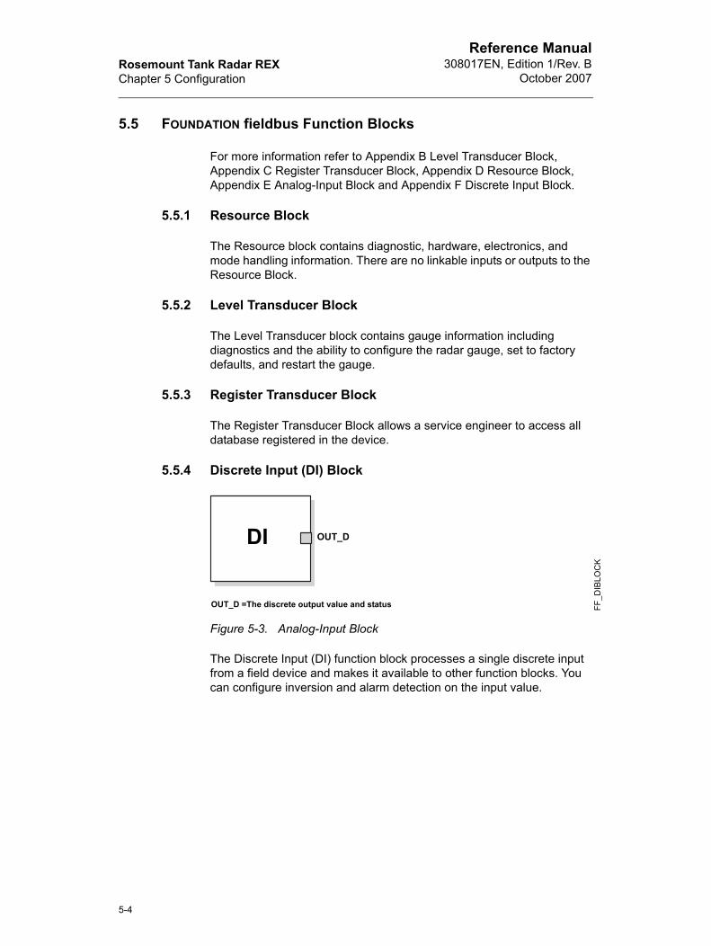
5.5.4 Discrete Input (DI) Block
Figure 5-3. Analog-Input Block
The Discrete Input (DI) function block processes a single discrete input from a field device and makes it available to other function blocks. You can configure inversion and alarm detection on the input value.
OUT_D =The discrete output value and status
AI
FF_D
IBLO
CK
OUT_DDI
5-4

Rosemount Tank Radar REXChapter 5 Configuration
Reference Manual308017EN, Edition 1/Rev. BOctober 2007
5.5.5 AI Block
Figure 5-4. Analog-Input Block
The Analog Input (AI) function block processes field device measurements and makes them available to other function blocks. The output value from the AI block is in engineering units and contains a status indicating the quality of the measurement. The measuring device may have several measurements or derived values available in different channels. Use the channel number to define the variable that the AI block processes and passes on to linked blocks. For further information refer to Appendix E Analog-Input Block.
OUT=The block output value and statusOUT_D=Discrete output that signals a selected alarm condition
OUT_D
OUT
FF_A
IBLO
CK
AI
5-5

Rosemount Tank Radar REXChapter 5 Configuration
Reference Manual308017EN, Edition 1/Rev. B
October 2007
5.6 Configure the AI Block
A minimum of four parameters are required to configure the AI Block. The parameters are described with “Application Examples” on page 5-9.
5.6.1 Channel
Table 5-2. Analog Input channels
5.6.2 L_TYPE
The L_TYPE parameter defines the relationship of the gauge measurement (Level, Distance, Level Rate, Signal Strength, Volume, and Average Temperature) to the desired output of the AI Block. The relationship can be direct or indirect.
Direct
Select direct when the desired output will be the same as the gauge measurement (Level, Distance, Level Rate, and Signal Strength).
Indirect
Select indirect when the desired output is a calculated measurement based on the gauge measurement. The relationship between the gauge measurement and the calculated measurement will be linear.
Indirect Square Root
Select indirect square root when the desired output is an inferred measurement based on the gauge measurement and the relationship between the sensor measurement and the inferred measurement is square root (e.g. level).
Channel Name Channel Number Process Variable
Level 1 CHANNEL_RADAR_LEVEL
Ullage 2 CHANNEL_RADAR_ULLAGE
Level Rate 3 CHANNEL_RADAR_LEVELRATE
Signal Strength 4 CHANNEL_RADAR_SIGNAL_STRENGTH
Volume 5 CHANNEL_RADAR_VOLUME
Average Tem-perature
6 CHANNEL_RADAR_AVG_TEMP
Analog Input 1 9 CHANNEL_RADAR_ANALOG_INP_1
Analog Input 2 10 CHANNEL_RADAR_ANALOG_INP_2
HART Input 1 11 CHANNEL_RADAR_HART_INP_1
HART Input 3 12 CHANNEL_RADAR_HART_INP_2
HART Input 3 13 CHANNEL_RADAR_HART_INP_3
5-6

Rosemount Tank Radar REXChapter 5 Configuration
Reference Manual308017EN, Edition 1/Rev. BOctober 2007
5.6.3 XD_SCALE and OUT_SCALE
The XD_SCALE and OUT_SCALE each include three parameters: 0%, 100%, and engineering units. Set these based on the L_TYPE:
L_TYPE is Direct
When the desired output is the measured variable, set the XD_SCALE to match the OUT_SCALE value.
L_TYPE is Indirect
When an inferred measurement is made based on the sensor measurement, set the XD_SCALE to represent the operating range that the sensor will see in the process. Determine the inferred measurement values that correspond to the XD_SCALE 0 and 100% points and set these for the OUT_SCALE.
L_TYPE is Indirect Square Root
When an inferred measurement is made based on the gauge measurement and the relationship between the inferred measurement and sensor measurement is square root, set the XD_SCALE to represent the operating range that the sensor will see in the process. Determine the inferred measurement values that correspond to the XD_SCALE 0 and 100% points and set these for the OUT_SCALE.
Note! To avoid configuration errors, only select Engineering Units for XD_SCALE that are supported by the device. The supported units are:
5-7

Rosemount Tank Radar REXChapter 5 Configuration
Reference Manual308017EN, Edition 1/Rev. B
October 2007
Length
Table 5-3. Length
Level Rate
Table 5-4. Level Rate
Temperature
Table 5-5. Temperature
Signal Strength
Table 5-6. Signal Strength
Volume
Table 5-7. Volume
Display Description
m meter
ft feet
in inch
mm millimeter
Display Description
ft/s feet per second
m/s meter per second
m/h meter per hour
Display Description
K Kelvin
°C Degree Celsius
°F Degree Fahrenheit
Display Description
mV Millivolt
Display Description
m3 Cubic meter
Gallon US gallon
bbl barrel
ft3 Cubic feet
5-8

Rosemount Tank Radar REXChapter 5 Configuration
Reference Manual308017EN, Edition 1/Rev. BOctober 2007
5.7 Configure the DI Block
Table 5-8. Discrete Input Channels
For an example of configuration of the DI block, see “Discrete Input Block” on page 5-12.
5.8 Application Examples
5.8.1 Radar Level Gauge, Level Value
Situation
A level gauge is measuring the level in a 33ft (10m) high tank.
Figure 5-5. Situation Diagram
Solution
Table 5-9 lists the appropriate configuration settings, and Figure 5-6 illustrates the correct function block configuration.
Channel Name Channel Number Process Variable
Relay Status 1 7 CHANNEL_RADAR_RELAY_STATUS_1
Relay Status 2 8 CHANNEL_RADAR_RELAY_STATUS_2
33 ft(10m)
100%
0%
FF_C
ON
FIG
UR
ATI
ON
EX
AMP
LES
_RE
X
5-9

Rosemount Tank Radar REXChapter 5 Configuration
Reference Manual308017EN, Edition 1/Rev. B
October 2007
Table 5-9. Analog Input Function Block Configuration for a Typical Level Gauge
Figure 5-6. Analog Input Function Block Diagram for a typical Level gauge
5.8.2 Radar Level Gauge, Level value in percent (%)
Situation
The level of a tank is to be measured using the Radar Level gauge mounted on a nozzle on the top of the tank. The maximum level in the tank is 46ft (14m). The level value shall be displayed in percentage of the full span (see Figure 5-7).
Figure 5-7. Situation Diagram
Parameter Configured Values
L_TYPE Direct
XD_SCALE Not Used
OUT_SCALE Not Used
CHANNEL CH1: Level
Level Measurement
To Another Function Block
OUT_D
OUTAI Function Block
33 ft(10m)
100%
0%
FF_C
ON
FIG
UR
ATI
ON
EXA
MP
LES
_RE
X
5-10

Rosemount Tank Radar REXChapter 5 Configuration
Reference Manual308017EN, Edition 1/Rev. BOctober 2007
Solution
Table 5-10 lists the appropriate configuration settings, and Figure 5-8 illustrates the correct function block configuration.
Table 5-10. Analog Input Function Block Configuration for a Level Gauge where level output is scaled between 0-100%
Figure 5-8. Function Block Diagram for a Level Gauge where level out-put is scaled between 0-100%
Parameter Configured Values
L_TYPE Indirect
XD_SCALE 0 to 14 m
OUT_SCALE 0 to 100%
CHANNEL CH1: Level
LevelMeasurement
AI Function
Block
OUT_D
OUT 0 to 100%
5-11

Rosemount Tank Radar REXChapter 5 Configuration
Reference Manual308017EN, Edition 1/Rev. B
October 2007
5.8.3 Discrete Input Block
Situation
An alarm is required to alert when there is a risk for overfilling.
Figure 5-9. Situation Diagram
Solution
In this solution the Relay 1/2 Channel in the Discrete Input function block is used to read the relay state. When the level rises above the alarm level the relay state is changed.
Table 5-11. Discrete Input Function Block Configuration for a Radar Level Gauge using relays
Figure 5-10. Function Block Diagram for a Level Gauge where alarm is output as a relay state
Parameter Configured Values
CHANNEL CH7: Relay 1
CHANNEL CH8: Relay 2
FF_C
ON
FIG
UR
ATI
ON
EXA
MP
LES
_REX
.EPS
HiAlarm
Relay State
DI Function
Block OUT_D Relay State
5-12
Rosemount Tank Radar REXChapter 5 Configuration
Reference Manual308017EN, Edition 1/Rev. BOctober 2007
5.9 Configuration using the TRL/2 port
When using a TankRadar REX 3900 with FOUNDATION fieldbus the configuration of the gauge is done via DeltaV or other Fieldbus Host. With the help of Device descriptors these hosts are able to present, read, and write necessary information and data within the gauge and assist the user to a successful configuration of the gauge.
In some cases, there could be a need for a more advanced service access to the gauge. This is done by using the TankMaster and accessing the data from the TRL/2 Bus Port, which is always readily available. Below are instructions of how to connect this port and how to use it.
5.9.1 Electrical Connection
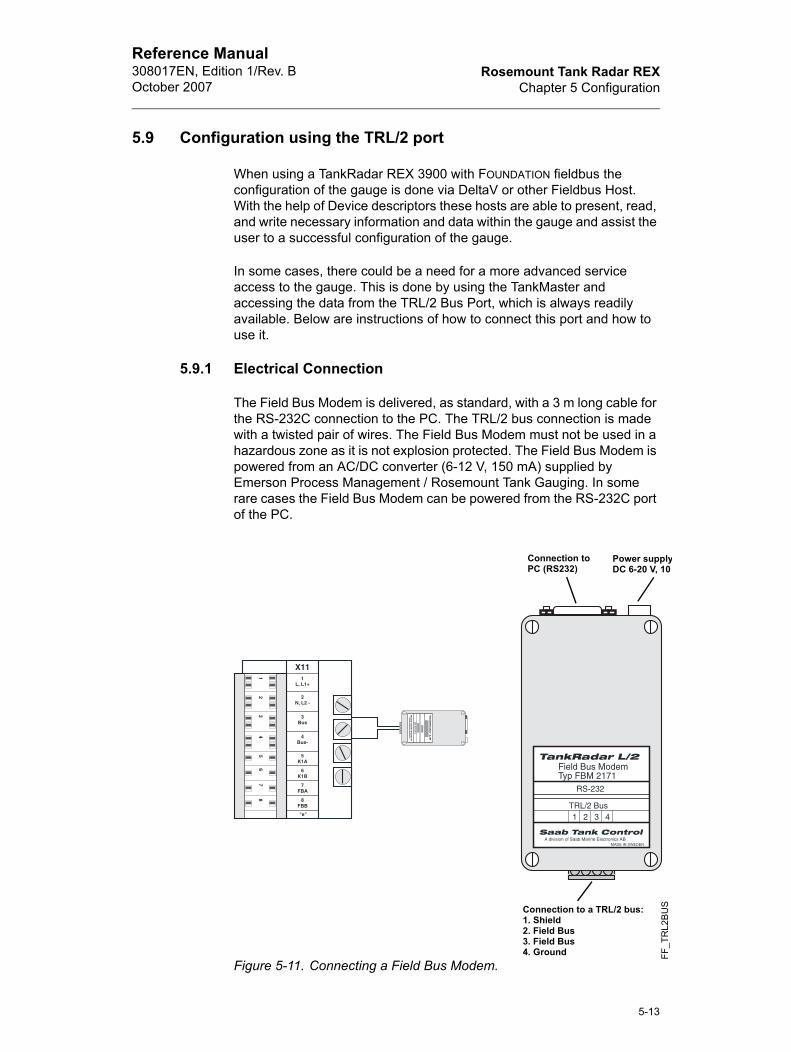
The Field Bus Modem is delivered, as standard, with a 3 m long cable for the RS-232C connection to the PC. The TRL/2 bus connection is made with a twisted pair of wires. The Field Bus Modem must not be used in a hazardous zone as it is not explosion protected. The Field Bus Modem is powered from an AC/DC converter (6-12 V, 150 mA) supplied by Emerson Process Management / Rosemount Tank Gauging. In some rare cases the Field Bus Modem can be powered from the RS-232C port of the PC.
Figure 5-11. Connecting a Field Bus Modem.
Connection to a TRL/2 bus:1. Shield2. Field Bus3. Field Bus4. Ground
Power supplyDC 6-20 V, 10
Connection toPC (RS232)
FF_T
RL2
BU
S
5-13

Rosemount Tank Radar REXChapter 5 Configuration
Reference Manual308017EN, Edition 1/Rev. B
October 2007
5.9.2 Connecting to the TRL/2 Bus
1 Make the electrical connection, as described in Figure 5-11.
2 Start Rosemount TankMaster Winsetup and change protocol to Modbus and modem type to RS-232. Make sure the Modbus protocol is enabled.
3 Search for a new online device by selecting New Device in the Device menu. The default unit has Modbus address 246. See Rosemount Tank-Master Winsetup User’s guide (Ref.no. 303027E) for further instructions of how to install a gauge.
4 Enter the configuration windows as required for the configuration
5 See Rosemount TankMaster Winsetup User’s guide (Ref.no. 303027E) for further instructions of how to configure the gauge.
5-14

Rosemount Tank Radar REXChapter 6 Operation and Maintenance
Reference Manual308017EN, Edition 1/Rev. BOctober 2007
6. Operation and Maintenance
6.1 Overview
This section contains information on operation and maintenance procedures.
Methods and Manual Operation
Each FOUNDATION fieldbus host or configuration tool has different ways of displaying and performing operations. Some hosts will use Device Descriptions (DD) and DD Methods to complete device configuration and will display data consistently across platforms. The DD can be found on www.fieldbus.org. There is no requirement that a host or configuration tool support these features.
The information in this section will describe how to use methods in a general fashion. In addition, if your host or configuration tool does not support methods this section will cover manually configuring the parameters involved with each method operation. For more detailed information on the use of methods, see your host or configuration tool manual.
6.2 Safety Messages
Procedures and instructions in this section may require special precautions to ensure the safety of the personnel performing the operations. Information that raises potential safety issues is indicated by a warning symbol ( ). Refer to the following safety messages before performing an operation preceded by this symbol.
6.2.1 Configure Gauge
Refer to “Configure Gauge” on page 5-2 for further information regarding the configuration of the Radar Gauge.
6-1

Rosemount Tank Radar REXChapter 6 Operation and Maintenance
Reference Manual308017EN, Edition 1/Rev. B
October 2007
6.2.2 Service Method
This method is for service purpose only. If your host does not support methods ENV_DEVICE_MODE it needs to be manually configured.The following options are available:
• FOUNDATION fieldbus: Set the device in normal fieldbus communication mode.
• Restart gauge:Restarts the device, not the fieldbus card.
• Set to factory default:Sets all configured data to factory settings.
6.2.3 Calibration Distance Configuration
See “Configure Gauge” on page 6-1 for further information.
6.2.4 Master Reset Method (Resource Block)
To perform a master reset, run the Master Reset Method. If your system does not support methods, manually configure the Resource Block parameters listed below.
Set the RESTART = Run, Resource, Defaults, or Processor
• Run = nominal state when not restarting (default)
• Resource = not used by device
• Defaults = sets parameters to FOUNDATION fieldbus default values
• Processor = does a warm start of the fieldbus card and the gauge
6.2.5 Write Protection (Resource Block)
Inputs to the security and write lock functions include the hardware security jumper, the hardware and software write lock bits of the FEATURE_SEL parameter, the WRITE_LOCK parameter, and the DEFINE_WRITE_LOCK parameter.
The WRITE_LOCK parameter limits access to modify parameters within the block except to clear the WRITE_LOCK parameter. During this time, the block will function normally updating inputs and outputs and executing algorithms. When the WRITE_LOCK condition is cleared, a WRITE_ALM alert is generated with a priority that corresponds to the WRITE_PRI parameter.
The FEATURE_SEL parameter enables the user to select a hardware or software write lock or no write lock capability. To enable the hardware security function, enable the HW_SEL bit in the FEATURE_SEL parameter. When this bit has been enabled the WRITE_LOCK
6-2

Rosemount Tank Radar REXChapter 6 Operation and Maintenance
Reference Manual308017EN, Edition 1/Rev. BOctober 2007
FS
0
0
0
1
1
parameter becomes read only and will reflect the state of the hardware jumper. In order to enable the software write lock, the SW_SEL bit must be set in the FEATURE_SEL parameter. Once this bit is set, the WRITE_LOCK parameter may be set to LOCKED or NOT LOCKED. Once the WRITE_LOCK parameter is set to LOCKED by either the software or the hardware lock, all user requested writes as determined by the DEFINE_WRITE_LOCK parameter shall be rejected.
The DEFINE_WRITE_LOCK parameter allows the user to configure whether the write lock functions (both software and hardware) will control writing to all blocks, or only to the resource and transducer blocks. Internally updated data such as process variables and error logs will not be restricted by the security jumper.
The following table displays all possible configurations of the WRITE_LOCK parameter.
Table 6-1. WRITE_LOCK parameters
EATURE_SELHW_EL bit
FEATURE_SELSW_SEL bit
SECURITY JUMPER
WRITE_LOCK
WRITE_LOCK Read/Write
(off) 0 (off) NA 1 (unlocked) Read only
(off) 1 (on) NA 1 (unlocked) Read/Write
(off) 1 (on) NA 2 (locked) Read/Write
(on) 0 (off)a
a. The hardware and software write lock select bits are mutually exclusive and the hardware select has the highest priority. When the HW_SEL bit if set to 1 (on), the SW_SEL bit is auto-matically set to 0 (off) and is read only.
0 (unlocked) 1 (unlocked) Read only
(on) 0 (off) 1 (locked) 2 (locked) Read only
6-3

Rosemount Tank Radar REXChapter 6 Operation and Maintenance
Reference Manual308017EN, Edition 1/Rev. B
October 2007
6.2.6 Simulation
For testing purposes, it is possible to manually drive the output of the Analog Input Block to a desired value.
1 Power up the device. If the SIMULATE jumper is in the OFF position, move it to the ON position. If the SIMULATE jumper is already in the ON position, you must still remove the jumper and place it back in the ON position.
Note! As a safety measure, the jumper must be reset every time power is interrupted to the device in order to enable SIMULATE. This prevents a device that is tested on the bench using SIMULATE from getting installed in the process with SIMULATE still active.
2 To change only the OUT_VALUE and not the OUT_STATUS of the AI Block, place the TARGET MODE of the block to MANUAL. Then, change the OUT_VALUE to the desired value.
3 To change both the OUT_VALUE and OUT_STATUS of the AI Block, set the TARGET MODE to AUTO. Set SIMULATE_ENABLE_DISABLE to ACTIVE. Enter the desired SIMULATE_VALUE to change the OUT_VALUE and SIMULATE_STATUS_QUALITY to change the OUT_STATUS.
If errors occur when performing the above steps, be sure that the SIMULATE jumper has been reset after powering up the device.
6.2.7 Block Instantiation
The Rosemount TankRadar REX 3900 supports the use of Function Block Instantiation. When a device supports block instantiation, the user can define the number of blocks and block types to match specific application needs. The number of blocks that can be instantiated is only limited by the amount of memory within the device and the block types that are supported by the device. Instantiation does not apply to standard device blocks like the Resource, Level Transducer, and Register Transducer Block. Block instantiation is done by the host control system or configuration tool, but not all hosts are required to implement this functionality. Please refer to your specific host or configuration tool manual for more information.
Rosemount TankRadar devices are pre-instantiated with function blocks at the factory, the default configuration for the Rosemount TankRadar REX 3900 is listed below.
• 11 Analog Input Blocks
• 2 Discrete Input Blocks
6-4

Rosemount Tank Radar REXChapter 7 Service and Troubleshooting
Reference Manual308017EN, Edition 1/Rev. BOctober 2007
7. Service and Troubleshooting
7.1 Overview
Table 7-1 provides summarized maintenance and troubleshooting suggestions for the most common operating problems. This section contains Rosemount TankRadar REX FOUNDATION fieldbus troubleshooting information only. For troubleshooting information using TankRadar REX TRL/2 bus, see the Rosemount TankRadar REX Service Manual (Ref. no. 308012E).
Follow the procedures described here to verify that gauge hardware and process connections are in good working order. Always deal with the most likely checkpoints first.
7.2 Safety Messages
Procedures and instructions in this section may require special precautions to ensure the safety of the personnel performing the operations. Information that raises potential safety issues is indicated by a warning symbol ( ). Refer to the following safety messages before performing an operation preceded by this symbol.
Explosions can result in death or serious injury.
• Do not remove the gauge covers in explosive environments when the circuit is live.
• Gauge covers must be fully engaged to meet explosion proof requirements.
• Before connecting a communicator in an explosive atmosphere, make sure that the instruments in the loop are installed according to intrinsically safe or nonincendive field wiring practices.
Static electricity can damage sensitive components.
• Observe safe handling precautions for static-sensitive components.
7-1

Rosemount Tank Radar REXChapter 7 Service and Troubleshooting
Reference Manual308017EN, Edition 1/Rev. B
October 2007
FOUCom
Leve
Tem
Volu
No s
Tank
Emp
Con
7.3 Field Upgrades
7.3.1 Labeling
Each radar gauge is labeled individually, so it is imperative that the approval codes on each label match exactly during upgrade. The label on the radar gauge reflects the replacement model code for reordering an assembled unit. The housing labeling only reflects the approvals and communication protocol of the housing.
Figure 7-1. Example of the TankRadar REX label
7.4 Troubleshooting
Symptom Corrective Actions
NDATION fieldbus Card to Transmitter munication Fault
Verify Device Mode setting, should be FOUNDATION fieldbus (Parameter: ENV_DEVICE_MODE)
Restart method from Resource Block
Reboot gauge (Cycle Power)
l Measurement Failure Check Power Supply
Check the gauge configuration (Transducer Block)
Check that the mechanical installation is correct
perature Measurement Failure Check temperature electrical installation
Check configuration (Transducer Block)
Restart the gauge
me Measurement Failure Restart gauge
Check gauge configuration using PC Based configuration tool, TankMaster WinSetup
urface echo Check signal strength
Restart gauge
Signal Clip Warning Restart gauge
ty Tank/ Full Tank Information of tank status
figuration Reg Password Enabled Information, Ready Write Data
/
\
FF_M
AIN
LAB
EL_
RE
X
7-2

Rosemount Tank Radar REXChapter 7 Service and Troubleshooting
Reference Manual308017EN, Edition 1/Rev. BOctober 2007
DB Eratio
SW Erro
Table 7-1. TankRadar REX troubleshooting table
For more information see the Rosemount TankRadar REX Service Manual (Ref.no. 308012E).
7.5 Resource Block
This section describes error conditions found in the Resource block. Read Table 7-2 through Table 7-4 to determine the appropriate corrective action.
7.5.1 Block Errors
Block Error messages
Table 7-2 lists conditions reported in the BLOCK_ERR parameter.
Table 7-2. Resource Block BLOCK_ERR messages
Block Summary Status messages
rror/ Microwave Unit Error/ Configu-n Error/ Other Error
Restart gauge
Call Service Center
Download Application Software
Set database to default load Database default
Error/ Display Error/ Analog Out r
Restart gauge
Call Service Center
Condition Name and Description
Other
Simulate Active: This indicates that the simulation switch is in place. This is not an indication that the I/O blocks are using simulated data
Device Fault State Set
Device Needs Maintenance Soon
Memory Failure: A memory failure has occurred in FLASH, RAM, or EEPROM memory
Lost Static Data: Static data that is stored in non-volatile memory has been lost
Lost NV Data: Non-volatile data that is stored in non-volatile memory has been lost
Device Needs Maintenance Now
Out of Service: The actual mode is out of service
Symptom Corrective Actions
7-3

Rosemount Tank Radar REXChapter 7 Service and Troubleshooting
Reference Manual308017EN, Edition 1/Rev. B
October 2007
Table 7-3. Resource Block SUMMARY_STATUS messages
Resource Block Detailed Status messages
Table 7-4. Resource Block DETAILED_STATUS with recommended action messages
7.6 Transducer Block
This section describes error conditions found in the Sensor Transducer Block.
Transducer Block Error Messages
Table 7-5. Transducer Block BLOCK_ERR messages
Condition Name
Uninitilized
No repair needed
Repairable
Call Service Center
Condition Name Recommended Action
Mfg. Block integrity error 1. Restart processor2. Call service center
Non-Volatile memory integrity error
1. Restart processor2.Call service center
ROM integrity error 1. Restart processor2. Call service center
Condition Name and Description
Other
Out of Service: The actual mode is out of service
Electronics Failure: An electrical component failed
I/O Failure: An I/O failure occurred
Data Integrity Error: Data stored in the device is no longer valid due to a non-vola-tile memory checksum failure, a data verify after write failure, etc.
Algorithm Error: The algorithm used in the transducer block produced an error due to overflow, data reasonableness failure, etc.
7-4

Rosemount Tank Radar REXChapter 7 Service and Troubleshooting
Reference Manual308017EN, Edition 1/Rev. BOctober 2007
Transducer Block XD Error Messages
Table 7-6. Transducer Block XD_ERR messages
7.7 Analog Input (AI) Function Block
This section describes error conditions that are supported by the AI Block. Read Table 7-8 to determine the appropriate corrective action.
AI Block Error Conditions
Table 7-7. AI BLOCK_ERR Conditions
Condition Name and Description
Electronics Failure: An electrical component failed
I/O Failure: An I/O failure occurred
Data Integrity Error: Data stored in the device is no longer valid due to a non-vola-tile memory checksum failure, a data verify after write failure, etc.
Algorithm Error: The algorithm used in the transducer block produced an error due to overflow, data reasonableness failure, etc.
Condition Number Condition Name and Description
0 Other
1 Block Configuration Error: the selected channel carries a measure-ment that is incompatible with the engineering units selected in XD_SCALE, the L_TYPE parameter is not configured, or CHANNEL = zero
3 Simulate Active: Simulation is enabled and the block is using a sim-ulated value in its execution
7 Input Failure/Process Variable has Bad Status: The hardware is bad, or a bad status is being simulated
14 Power Up
15 Out of Service: The actual mode is out of service
7-5

Rosemount Tank Radar REXChapter 7 Service and Troubleshooting
Reference Manual308017EN, Edition 1/Rev. B
October 2007
Bad(Rea“BLOter)
OUTreadsubstRan
Mod
Procalarm
Troubleshooting the AI Block
Symptom Possible Causes Recommended Actions
or no level readingsd the AI CK_ERR” parame-
BLOCK_ERR reads OUT OF SERVICE
1. AI Block target mode target mode set to OOS.2. Resource Block OUT OF SERVICE.
BLOCK_ERR reads CON-FIGURATION ERROR
1. Check CHANEL parameter (See “Channel” on page 6.)2. Check L_TYPE parameter (See “L_TYPE” on page 6.)3. Check XD_SCALE engineering units. (See “XD_SCALE and OUT_SCALE” on page 7.)
BLOCK_ERR reads POWERUP
Download Schedule into block. Refer to host for downloading procedure.
BLOCK_ERR reads BAD INPUT
1. Sensor Transducer Block Out Of Service 2. Resource Block Out of Service
No BLOCK_ERR but readings are not correct. If using Indirect mode, scal-ing could be wrong
1. Check XD_SCALE parameter.2. Check OUT_SCALE parameter. (See “XD_SCALE and OUT_SCALE” on page 7.)
parameter status s UNCERTAIN and tatus reads EngUni-gViolation
Out_ScaleEU_0 and EU_100 settings are incorrect.
See “XD_SCALE and OUT_SCALE” on page 7.
e will not leave OOS Target mode not set Set target mode to something other than OOS.
Configuration error BLOCK_ERR will show the configuration error bit set. The following are parameters that must be set before the block is allowed out of OOS:CHANNEL must be set to a valid value and can-not be left at initial value of 0.XD_SCALE.UNITS_INDX must match the units in the transducer block channel value.L_TYPE must be set to Direct, Indirect, or Indi-rect Square Root and cannot be left at initial value of 0.
Resource block The actual mode of the Resource block is OOS. See Resource Block Diagnostics for corrective action.
Schedule Block is not scheduled and therefore cannot execute to go to Target Mode. Schedule the block to execute.
ess and/or block s will not work
Features FEATURES_SEL does not have Alerts enabled. Enable the Alerts bit.
Notification LIM_NOTIFY is not high enough. Set equal to MAX_NOTIFY.
Status Options STATUS_OPTS has Propagate Fault Forward bit set. This should be cleared to cause an alarm to occur.
7-6

Rosemount Tank Radar REXChapter 7 Service and Troubleshooting
Reference Manual308017EN, Edition 1/Rev. BOctober 2007
Valumak
CanHI_Hor L
Table 7-8. Troubleshooting the AI block
7.7.1 Discrete Input (DI) Function Block
DI Block Error conditions
Table 7-9. DI BLOCK_ERR Conditions
e of output does not e sense
Linearization Type L_TYPE must be set to Direct, Indirect, or Indi-rect Square Root and cannot be left at initial value of 0.
Scaling Scaling parameters are set incorrectly:XD_SCALE.EU0 and EU100 should match that of the transducer block channel value.OUT_SCALE.EU0 and EU100 are not set prop-erly.
not set HI_LIMIT, I_LIMIT, LO_LIMIT,
O_LO_LIMIT Values
Scaling Limit values are outside the OUT_SCALE.EU0 and OUT_SCALE.EU100 values. Change OUT_SCALE or set values within range.
Condition Number Condition Name and Description
3 Simulate Active: Simulate_D is enabled and OUT_D does not reflect actual process conditions
7 Input Failure/Process Variable has Bad Status: The hardware is bad, the configured channel is invalid or a Bad status is being simu-lated
15 Out of Service: The block is not being processed
Symptom Possible Causes Recommended Actions
7-7

Rosemount Tank Radar REXChapter 7 Service and Troubleshooting
Reference Manual308017EN, Edition 1/Rev. B
October 2007
7-8

Rosemount Tank Radar REXAppendix A Specifications
Reference Manual308017EN, Edition 1/Rev. BOctober 2007
Appendix A Specifications
Polarity Sensitive (Yes / No) No
Quiescent Current Draw (mA) 12 mA
CENELEC certified for FISCO (Yes / No) Planned when development is complete.
Class Link Master (LAS)
Number of Available VCRs 20
Data Rate H1 (31,25 kbit/s)
Function Blocks Provided 11 Analog Input blocks, 2 Discrete Input Blocks, 2 Transducer, 1 Resource
Execution Time (ms) 960 ms
Block Class Std
Device Description Provided
Common File Format File Provided
Certification/Registration Status Planned when development is complete
Date for Registered Product (item #11) Planned when development is complete
List and description of all Menus and Meth-ods
Transducer Block Methods:Configure GaugeRestart DeviceSet to factory defaultsResource Function Block Methods:Master Reset
A-1

Rosemount Tank Radar REXAppendix A Specifications
Reference Manual308017EN, Edition 1/Rev. B
October 2007
Diagnostic capability of the transmitters ErrorDatabase (DB)Microwave unitDisplayAnalog outputOther hardwareConfigurationSoftware (SW)
WarningInvalid ATPNo surface echoTank signal clipEmpty tankFull tankSoftware write protectedDatabase (DB)Microwave unitDisplayAnalog outConfigurationSoftware (SW)SW version
FailureFF card to gaugeLevel measurementTemperature measurementVolume measurement
Analog input blocks 1 - 11 LevelUllage (distance)Level rateSignal strengthVolumeAverage temperatureAnalog input 1Analog input 2Hart input 1Hart input 2Hart input 3
Discrete input blocks 1 - 2 Relay status 1Relay status 2
Temp Input Direct to REX
A-2

Rosemount Tank Radar REXAppendix B Level Transducer Block
Reference Manual308017EN, Edition 1/Rev. BOctober 2007
Appendix B Level Transducer Block
Overview
This section contains information on the 3900 Transducer Block (TB). Descriptions of all Transducer Block parameters, errors, and diagnostics are listed. Also, the modes, alarm detection, status handling, application information, and troubleshooting are discussed.
Figure B-1. Transducer Block Diagram
Definition
The transducer block contains the actual measurement data, including a level and distance reading. Channels 1–13 are assigned to these measurements (see Figure B-1). The transducer block includes information about sensor type, engineering units, and all parameters needed to configure the radar gauge.
Channel Definitions
Each input has a channel assigned to it allowing the AI block to link to it. The channels for the Rosemount TankRadar REX are the following:
Channel Name Channel Number Process variable
Level 1 CHANNEL_RADAR_LEVEL
Ullage 2 CHANNEL_RADAR_ULLAGE
Level Rate 3 CHANNEL_RADAR_LEVELRATE
Signal Strength 4 CHANNEL_RADAR_SIGNAL_STRENGTH
Volume 5 CHANNEL_RADAR_VOLUME
DigitalSignal
Conversion
Diagnostics
Line
ariz
atio
n
Tem
pera
ture
C
ompe
nsat
ion
Dam
ping
Uni
ts/R
angi
ng
Channel
FF_T
RAN
SD
UC
ER
BLO
CK
DIA
GR
AM
1
TB
23456
ChannelChannelChannelChannelChannel
Channel 13
B-1

Rosemount Tank Radar REXAppendix B Level Transducer Block
Reference Manual308017EN, Edition 1/Rev. B
October 2007
S
T
S
A
M
B
Table B-1. Channel Assignments
Table B-2. Channel Assignments
Parameters and Descriptions
Average Tempera-ture
6 CHANNEL_RADAR_AVG_TEMP
Analog Input 1 9 CHANNEL_RADAR_ANALOG_INP_1
Analog Input 2 10 CHANNEL_RADAR_ANALOG_INP_2
HART Input 1 11 CHANNEL_RADAR_HART_INP_1
HART Input 3 12 CHANNEL_RADAR_HART_INP_2
HART Input 3 13 CHANNEL_RADAR_HART_INP_3
Channel Name Channel Number Process variable
Relay Status 1, 7 CHANNEL_RADAR_RELAY_STATUS_1
Relay Status 2, 8 CHANNEL_RADAR_RELAY_STATUS_2
Parameter Index Number Description
T_REV 1 The revision level of the static data associated with the function block. The revision value increments each time a static parameter value in the block is changed.
AG_DESC 2 The user description of the intended application of the block.
TRATEGY 3 The strategy field can be used to identify grouping of blocks. This data is not checked or processed by the block.
LERT_KEY 4 The identification number of the plant unit. This infor-mation may be used in the host for sorting alarms, etc.
ODE_BLK 5 The actual, target, permitted, and normal modes of the block.Target: The mode to “go to”Actual: The mode the “block is currently in”Permitted: Allowed modes that target may take onNormal: Most common mode for target
LOCK_ERR 6 This parameter reflects the error status associated with the hardware or software components associated with a block. It is a bit string, so that multiple errors may be shown.
Channel Name Channel Number Process variable
B-2

Rosemount Tank Radar REXAppendix B Level Transducer Block
Reference Manual308017EN, Edition 1/Rev. BOctober 2007
U
B
T
T
X
C
R
R
R
R
R
R
R
RR
R
R
R
R
R
R
R
R
R
R
R
R
R
R
PDATE_EVT 7 This alert is generated by any change to the static data.
LOCK_ALM 8 The block alarm is used for all configuration, hard-ware, connection failure or system problems in the block. The cause of the alert is entered in the subcode field. The fist alert to become active will set the Active status in the Status parameter. As soon as the Unre-ported status is cleared by the alert reporting task, another block alert may be reported without clearing the Active status, if the subcode has changed.
RANSDUCER_DIRECTORY 9 Directory that specifies the number and starting indi-ces of the transducers in the transducer block.
RANSDUCER_TYPE 10 Identifies the transducer.
D_ERROR 11 A transducer block alarm subcode.
OLLECTION_DIRECTORY 12 A directory that specifies the number, starting indices, and DD Item ID’s of the data collections in each trans-ducer within a transducer block.
ADAR_LEVEL_TYPE 13 Not used
ADAR_LEVEL 14 Level
ADAR_LEVEL_RANGE 15 See Table E-4
ADAR_ULLAGE 16 Distance (Ullage)
ADAR_LEVELRATE 17 Level Rate
ADAR_LEVELRATE_RANGE 18 See Table E-5
ADAR_SIGNAL_STRENGTH 19 Signal strength
ADAR_SIGNAL_STRENGTH_ANGE
20 See Table E-7
ADAR_VOLUME 21 Volume
ADAR_VOLUME_RANGE 22 See Table E-8
ADAR_AVG_TEMP 23 Average Temperature
ADAR_TEMP_1 24 Spot temperature 1
ADAR_TEMP_RANGE 25 See Table E-6
ADAR_TEMP_2 26 Spot temperature 2
ADAR_TEMP_3 27 Spot temperature 3
ADAR_TEMP_4 28 Spot temperature 4
ADAR_TEMP_5 29 Spot temperature 5
ADAR_TEMP_6 30 Spot temperature 6
ADAR_RELAY_STATUS_1 31 Relay 1 status
ADAR_RELAY_STATUS_2 32 Relay 2 status
ADAR_ANALOG_INP_1 33 Analog Input 1 value
ADAR_ANALOG_INP_2 34 Analog Input 2 value
Parameter Index Number Description
B-3

Rosemount Tank Radar REXAppendix B Level Transducer Block
Reference Manual308017EN, Edition 1/Rev. B
October 2007
R
R
R
A
A
A
A
G
G
G
G
G
E
E
D
D
D
D
T
T
T
T
T
T
T
T
T
T
T
S
S
S
Table B-3. Level Transducer Block Parameters and Descriptions
ADAR_HART_INP_1 35 Hart Input 1 value
ADAR_HART_INP_2 36 Hart Input 2 value
ADAR_HART_INP_3 37 Hart Input 3 value
NTENNA_TYPE 38 Antenna Type. See Table B-4
NTENNA_TCL 39 TCL (Tank connection Length)
NTENNA_PIPE_DIAM 40 Still Pipe Diameter
NTENNA_SIZE 41 Antenna size
EOM_DIST_OFFSET 42 Distance offset (G)
EOM_TANK_HEIGHT 43 Tank Height (R)
EOM_MIN_LEVEL_OFFSET 44 Minimum distance offset (C)
EOM_HOLD_OFF 45 Hold Off Distance
EOM_CAL_DISTANCE 46 Calibration Distance
NV_PRESENTATION 47 Tank Presentation. See Table B-6
NV_DEVICE_MODE 48 Service mode. See Table B-5
IAGN_DEV_ERR 49 Status
IAGN_VERSION 50 Gauge SW version
IAGN_REVISION 51 P1451 revision
IAGN_DEVICE_ID 52 Device ID for the gauge.
EMP_NUM_SENSORS 53 Num Temp Spots
EMP_SENSOR_TYPE 54 Sensor type
EMP_INSERT_DIST 55 Insertion distance
EMP_EXCL_AVG_CALC 56 Exclude from Avg. Temp. calculation
EMP_POS_1 57 Position sensor 1
EMP_POS_2 58 Position sensor 2
EMP_POS_3 59 Position sensor 3
EMP_POS_4 60 Position sensor 4
EMP_POS_5 61 Position sensor 5
EMP_POS_6 62 Position sensor 6
EMP_SENSOR_RANGE 63 Temp card type
TATS_ATTEMPTS 64
TATS_FAILURES 65
TATS_TIMEOUTS 66
Parameter Index Number Description
B-4

Rosemount Tank Radar REXAppendix B Level Transducer Block
Reference Manual308017EN, Edition 1/Rev. BOctober 2007
Table B-4. Antenna Type
Table B-5. Device Mode
Value ANTENNA_TYPE
1001 User Defined Linear Pipe
1002 User Defined Modconv
1003 User Defined PipeArray
2001 Cone (3920)
3001 Parabola (3930)
3002 Parabola Parant (3930P)
4001 Pipe Modconv (3940)
4501 Pipe Modconv (3945)
5001 PipeArray Fixed 3950A
5002 PipeArray Hatch 3950B
5003 PipeArray Inclined 3950C
6001 LPG 150PSI + Valve
6002 LPG 150PSI
6011 LPG 300PSI + Valve
6012 LPG 300PSI
6021 LPG 600PSI + Valve
6022 LPG 600PSI
Value ENV_DEVICE_MODE
0 FF bus
1 Reserved
2 Restart device
3 Set to factory default data-base
B-5

Rosemount Tank Radar REXAppendix B Level Transducer Block
Reference Manual308017EN, Edition 1/Rev. B
October 2007
Table B-6. Presentation
Diagnostics Device Errors
In addition to the BLOCK_ERR and XD_ERROR parameters, more detailed information on the measurement status can be obtained via DIAGN_DEV_ERR. Table B-7 on page B-7 lists the potential errors and the possible corrective actions for the given values. The corrective actions are in order of increasing system level compromises. The first step should always be to reset the gauge and then if the error persists, try to the steps in Table B-7. Start with the first corrective action and then try the second.
Bit Number Value of ENV_PRESENTATION Description
1 0x00000002 Reserved
2 0x00000004 Bottom echo visible
3 0x00000008 Reserved
4 0x00000010 Reserved
5 0x00000020 Enable double surface
6 0x00000040 Ignore top surface
7 0x00000080 Not used
8 0x00000100 Show negative levels as zero
9 0x00000200 Reserved
10 0x00000400 Not used
11 0x00000800 Not used
12 0x00001000 Invalid level is NOT set if tank is empty or full
13 0x00002000 Not used
14 0x00004000 Not used
15 0x00008000 Not used
16 0x00010000 Not used
17 0x00020000 -
18 0x00040000 Reserved 15
19 0x00080000 Reserved 16
Bit Number Value of DIAGN_DEV_ERR Description Corrective Actions
0 0 No alarm active See Table 7-1
1 0x00000001 Reserved “
2 0x00000002 FF card to gauge comm fault “
B-6

Rosemount Tank Radar REXAppendix B Level Transducer Block
Reference Manual308017EN, Edition 1/Rev. BOctober 2007
Table B-7. Device Errors Diagnostics
‘
Table B-8. Temperature sensor type
3 0x00000004 Level Measurement Failure “
4 0x00000008 *)Temperature Measurement Failure “
5 0x00000010 **)Volume Measurement Failure “
6 0x00000020 Invalid ATP “
7 0x00000040 No surface echo “
8 0x00000080 Tank signal clip warning “
9 0x00000100 Empty Tank “
10 0x00000200 Full Tank “
11 0x00000400 Software Write Protected “
12 0x00000800 DB Error “
13 0x00001000 Microwave unit error “
14 0x00002000 Display error “
15 0x00004000 Analog out error “
16 0x00008000 Other HW error “
17 0x00010000 Configuration error “
18 0x00020000 SW error “
19 0x00040000 DB Warning “
20 0x00080000 Microwave unit Warning “
21 0x00100000 Display Warning “
22 0x00200000 Analog out Warning “
23 0x00400000 Other HW Warning “
24 0x00800000 Configuration Warning “
25 0x01000000 SW Warning “
26 0x02000000 SW Version Warning “
Value TEMP_SENSOR_TYPE Description
0 Reserved
1 Reserved
2 DIN PT 100
3 CU90
Bit Number Value of DIAGN_DEV_ERR Description Corrective Actions
B-7

Rosemount Tank Radar REXAppendix B Level Transducer Block
Reference Manual308017EN, Edition 1/Rev. B
October 2007
Table B-9. Exclude from avg. temp. calculation
Table B-10. Antenna size
Supported Units
Unit codes
Table B-11. Length
Bit Number Value of TEMP_EXCL_AVG_CALC Description
0 0 -
1 0x00000001 Reserved
2 0x00000002 Exclude nbr. 1
3 0x00000004 Exclude nbr. 2
4 0x00000008 Exclude nbr. 3
5 0x00000010 Exclude nbr. 4
6 0x00000020 Exclude nbr. 5
7 0x00000040 Exclude nbr. 6
Value ANTENNA_SIZE
0 Pipe 5 Inch
1 Pipe 6 Inch
2 Pipe 8 Inch
3 Pipe 10 Inch
4 Pipe 12 Inch
Value Display Description
1010 m meter
1018 ft feet
1019 in inch
1013 mm millimeter
B-8

Rosemount Tank Radar REXAppendix B Level Transducer Block
Reference Manual308017EN, Edition 1/Rev. BOctober 2007
Table B-12. Level Rate
Table B-13. Temperature
Table B-14. Signal Strength
Table B-15. Volume
Methods
See “Methods and Manual Operation” on page 6-1.
Value Display Description
1067 ft/s feet per second
1061 m/s meter per second
1063 m/h meter per hour
Value Display Description
1000 K Kelvin
1001 °C Degree Celsius
1002 °F Degree Fahrenheit
Value Display Description
1243 mV Millivolt
Value Display Description
1034 m3 Cubic meter
1048 Gallon US gallon
1051 bbl barrel
1043 ft3 Cubic feet
B-9

Rosemount Tank Radar REXAppendix B Level Transducer Block
Reference Manual308017EN, Edition 1/Rev. B
October 2007
B-10

Rosemount Tank Radar REXAppendix C Register Transducer Block
Reference Manual308017EN, Edition 1/Rev. BOctober 2007
ST_R
TAG_
STRA
ALER
MOD
BLOC
UPDA
Appendix C Register Transducer Block
Overview
The Register Transducer Block allows access to Database registers and Input registers of the Rosemount TankRadar REX gauges. This makes it possible to read a selected set of register directly by accessing the memory location.
The Register Transducer Block is only available with advanced service.
Register Access Transducer Block Parameters
Since this Register Transducer Block allows access to most registers in the gauge, which includes the registers set by the Methods and Configuration screens, in the Level Transducer Block (see Appendix A Specifications) it should be handled with care and ONLY to be changed by trained and certified service personnel, or as guided by Emerson Process Management / Rosemount Tank Gauging support personnel.
Parameter Index Number Description
EV 1 The revision level of the static data associated with the function block. The revision value increments each time a static parameter value in the block is changed.
DESC 2 The user description of the intended application of the block.
TEGY 3 The strategy field can be used to identify grouping of blocks. This data is not checked or processed by the block.
T_KEY 4 The identification number of the plant unit. This information may be used in the host for sorting alarms, etc.
E_BLK 5 The actual, target, permitted, and normal modes of the block.Target: The mode to “go to”Actual: The mode the “block is currently in”Permitted: Allowed modes that target may take onNormal: Most common mode for target
K_ERR 6 This parameter reflects the error status associated with the hard-ware or software components associated with a block. It is a bit string, so that multiple errors may be shown.
TE_EVT 7 This alert is generated by any change to the static data.
C-1

Rosemount Tank Radar REXAppendix C Register Transducer Block
Reference Manual308017EN, Edition 1/Rev. B
October 2007
BLOC
TRAN
TRAN
XD_E
COLL
INP_S
DB_S
INP_R
INP_R
INP_R
INP_R
INP_R
INP_R
INP_R
INP_R
INP_R
INP_R
INP_R
INP_R
INP_R
INP_R
INP_R
INP_R
INP_R
INP_R
INP_R
INP_R
K_ALM 8 The block alarm is used for all configuration, hardware, connection failure or system problems in the block. The cause of the alert is entered in the subcode field. The fist alert to become active will set the Active status in the Status parameter. As soon as the Unre-ported status is cleared by the alert reporting task, another block alert may be reported without clearing the Active status, if the sub-code has changed.
SDUCER_DIRECTORY 9 Directory that specifies the number and starting indices of the transducers in the transducer block.
SDUCER_TYPE 10 Identifies the transducer.100 = Standard pressure with calibration
RROR 11 A transducer block alarm subcode.
ECTION_DIRECTORY 12 A directory that specifies the number, starting indices, and DD Item ID’s of the data collections in each transducer within a transducer block.
EARCH_START_NBR 13 Search start number for input registers
EARCH_START_NBR 14 Search start number for holding registers
EG_1_NAME 16 Name of the register
EG_1_FLOAT 17 If the register contains a float value it shall be displayed here
EG_1_INT_DEC 18 If the register contains a DWORD value and dec is chosen,it shall be displayed here
EG_2_NAME 20 Name of the register
EG_2_FLOAT 21 If the register contains a float value it shall be displayed here
EG_2_INT_DEC 22 If the register contains a DWORD value and dec is chosen,it shall be displayed here
EG_3_NAME 24 Name of the register
EG_3_FLOAT 25 If the register contains a float value it shall be displayed here
EG_3_INT_DEC 26 If the register contains a DWORD value and dec is chosen,it shall be displayed here
EG_4_NAME 28 Name of the register
EG_4_FLOAT 29 If the register contains a float value it shall be displayed here
EG_4_INT_DEC 30 If the register contains a DWORD value and dec is chosen,it shall be displayed here
EG_5_NAME 32 Name of the register
EG_5_FLOAT 33 If the register contains a float value it shall be displayed here
EG_5_INT_DEC 34 If the register contains a DWORD value and dec is chosen,it shall be displayed here
EG_6_NAME 36 Name of the register
EG_6_FLOAT 37 If the register contains a float value it shall be displayed here
EG_6_INT_DEC 38 If the register contains a DWORD value and dec is chosen,it shall be displayed here
EG_7_NAME 40 Name of the register
EG_7_FLOAT 41 If the register contains a float value it shall be displayed here
Parameter Index Number Description
C-2

Rosemount Tank Radar REXAppendix C Register Transducer Block
Reference Manual308017EN, Edition 1/Rev. BOctober 2007
INP_R
INP_R
INP_R
INP_R
INP_R
INP_R
INP_R
INP_R
INP_R
INP_R
DB_R
DB_R
DB_R
DB_R
DB_R
DB_R
DB_R
DB_R
DB_R
DB_R
DB_R
DB_R
DB_R
DB_R
DB_R
DB_R
DB_R
DB_R
DB_R
DB_R
DB_R
EG_7_INT_DEC 42 If the register contains a DWORD value and dec is chosen,it shall be displayed here
EG_8_NAME 44 Name of the register
EG_8_FLOAT 45 If the register contains a float value it shall be displayed here
EG_8_INT_DEC 46 If the register contains a DWORD value and dec is chosen,it shall be displayed here
EG_9_NAME 48 Name of the register
EG_9_FLOAT 49 If the register contains a float value it shall be displayed here
EG_9_INT_DEC 50 If the register contains a DWORD value and dec is chosen,it shall be displayed here
EG_10_NAME 52 Name of the register
EG_10_FLOAT 53 If the register contains a float value it shall be displayed here
EG_10_INT_DEC 54 If the register contains a DWORD value and dec is chosen,it shall be displayed here
EG_1_NAME 57 Name of the register
EG_1_FLOAT 58 If the register contains a float value it shall be displayed here
EG_1_INT_DEC 59 If the register contains a DWORD value and dec is chosen, it shall be displayed here
EG_2_NAME 61 Name of the register
EG_2_FLOAT 62 If the register contains a float value it shall be displayed here
EG_2_INT_DEC 63 If the register contains a DWORD value and dec is chosen, it shall be displayed here
EG_3_NAME 65 Name of the register
EG_3_FLOAT 66 If the register contains a float value it shall be displayed here
EG_3_INT_DEC 67 If the register contains a DWORD value and dec is chosen, it shall be displayed here
EG_4_NAME 69 Name of the register
EG_4_FLOAT 70 If the register contains a float value it shall be displayed here
EG_4_INT_DEC 71 If the register contains a DWORD value and dec is chosen, it shall be displayed here
EG_4_NAME 73 Name of the register
EG_4_FLOAT 74 If the register contains a float value it shall be displayed here
EG_4_INT_DEC 75 If the register contains a DWORD value and dec is chosen, it shall be displayed here
EG_5_NAME 77 Name of the register
EG_5_FLOAT 78 If the register contains a float value it shall be displayed here
EG_5_INT_DEC 79 If the register contains a DWORD value and dec is chosen, it shall be displayed here
EG_6_NAME 81 Name of the register
EG_6_FLOAT 82 If the register contains a float value it shall be displayed here
EG_6_INT_DEC 83 If the register contains a DWORD value and dec is chosen, it shall be displayed here
Parameter Index Number Description
C-3

Rosemount Tank Radar REXAppendix C Register Transducer Block
Reference Manual308017EN, Edition 1/Rev. B
October 2007
DB_R
DB_R
DB_R
DB_R
DB_R
DB_R
DB_R
DB_R
DB_R
DB_R
DB_R
DB_R
INP_S
INP_S
INP_S
DB_S
DB_S
DB_S
Table C-1. Register Access Transducer Block Parameters
EG_7_NAME 85 Name of the register
EG_7_FLOAT 86 If the register contains a float value it shall be displayed here
EG_7_INT_DEC 87 If the register contains a DWORD value and dec is chosen, it shall be displayed here
EG_8_NAME 89 Name of the register
EG_8_FLOAT 90 If the register contains a float value it shall be displayed here
EG_8_INT_DEC 91 If the register contains a DWORD value and dec is chosen, it shall be displayed here
EG_9_NAME 93 Name of the register
EG_9_FLOAT 94 If the register contains a float value it shall be displayed here
EG_9_INT_DEC 95 If the register contains a DWORD value and dec is chosen, it shall be displayed here
EG_10_NAME 97 Name of the register
EG_10_FLOAT 98 If the register contains a float value it shall be displayed here
EG_10_INT_DEC 99 If the register contains a DWORD value and dec is chosen, it shall be displayed here
EARCH_CHOICE 101 Search for register by name or by number.
EARCH_START_GROUP 102 Available when searching by name
EARCH_START_NAME 103 Available when searching by name
EARCH_CHOICE 104 Search for register by name or by number
EARCH_START_GROUP 105 Available when searching by name
EARCH_START_NAME 106 Available when searching by name
Parameter Index Number Description
C-4

Rosemount Tank Radar REXAppendix D Resource Block
Reference Manual308017EN, Edition 1/Rev. BOctober 2007
ACK
ADV
ADV
ADV
ADV
ADV
ALA
ALE
Appendix D Resource Block
Overview
This section contains information on the Rosemount TankRadar REX 3900 Radar Level Transmitter Resource Block. Descriptions of all Resource Block Parameters, errors, and diagnostics are included. Also the modes, alarm detection, status handling, and troubleshooting are discussed.
Definition
The resource block defines the physical resources of the device. The resource block also handles functionality that is common across multiple blocks. The block has no linkable inputs or outputs.
Parameters and Descriptions
The table below lists all of the configurable parameters of the Resource Block, including the descriptions and index numbers for each.
Parameter Index Number Description
_OPTION 38 Selection of whether alarms associated with the function block will be automatically acknowledged.
ISE_ACTIVE 82 Enumerated list of advisory conditions within a device.
ISE_ALM 83 Alarm indicating advisory alarms. These conditions do not have a direct impact on the process or device integrity.
ISE_ENABLE 80 Enabled ADVISE_ALM alarm conditions. Corresponds bit for bit to the ADVISE_ACTIVE. A bit on means that the corre-sponding alarm condition is enabled and will be detected. A bit off means the corresponding alarm condition is disabled and will not be detected.
ISE_MASK 81 Mask of ADVISE_ALM. Corresponds bit of bit to ADVISE_ACTIVE. A bit on means that the condition is masked out from alarming.
ISE_PRI 79 Designates the alarming priority of the ADVISE_ALM
RM_SUM 37 The current alert status, unacknowledged states, unreported states, and disabled states of the alarms associated with the function block.
RT_KEY 04 The identification number of the plant unit.
D-1

Rosemount Tank Radar REXAppendix D Resource Block
Reference Manual308017EN, Edition 1/Rev. B
October 2007
BLO
BLO
CLR
CON
CYC
CYC
DD_
DD_
defin
deta
DEV
DEV
DEV
DIAG
distr
CK_ALM 36 The block alarm is used for all configuration, hardware, con-nection failure or system problems in the block. The cause of the alert is entered in the subcode field. The first alert to become active will set the Active status in the Status parame-ter. As soon as the Unreported status is cleared by the alert reporting task, another block alert may be reported without clearing the Active status, if the subcode has changed.
CK_ERR 06 This parameter reflects the error status associated with the hardware or software components associated with a block. It is a bit string, so that multiple errors may be shown.
_FSAFE 30 Writing a Clear to this parameter will clear the device FAIL_SAFE if the field condition has cleared.
FIRM_TIME 33 The time the resource will wait for confirmation of receipt of a report before trying again. Retry will not happen when CONFIRM_TIME=0.
LE_SEL 20 Used to select the block execution method for this resource. The Rosemount TankRadar REX 3900 supports the follow-ing:Scheduled: Blocks are only executed based on the function block schedule.Block Execution: A block may be executed by linking to another blocks completion.
LE_TYPE 19 Identifies the block execution methods available for this resource.
RESOURCE 09 String identifying the tag of the resource which contains the Device Description for this resource.
REV 13 Revision of the DD associated with the resource - used by an interface device to locate the DD file for the resource.
e_write_lock 60 Allows the operator to select how WRITE_LOCK behaves. The initial value is “lock everything”. If the value is set to “lock only physical device” then the resource and transducer blocks of the device will be locked but changes to function blocks will be allowed.
iled_status 55 Indicates the state of the gauge. See Resource Block detailed status codes.
_REV 12 Manufacturer revision number associated with the resource - used by an interface device to locate the DD file for the resource.
_STRING 43 This is used to load new licensing into the device. The value can be written but will always read back with a value of 0.
_TYPE 11 Manufacturer’s model number associated with the resource - used by interface devices to locate the DD file for the resource.
_OPTION 46 Indicates which diagnostics licensing options are enabled.
ibutor 42 Reserved for use as distributor ID. No FOUNDATION enumera-tions defined at this time.
Parameter Index Number Description
D-2

Rosemount Tank Radar REXAppendix D Resource Block
Reference Manual308017EN, Edition 1/Rev. BOctober 2007
dow
FAIL
FAIL
FAIL
FAIL
FAIL
FAIL
FB_
FEA
FEA
FINA
FRE
FRE
GRA
HAR
hard
ITK_
LIM_
MAI
nload_mode 67 Gives access to the boot block code for over-the-wire down-loads.0 = Uninitialized 1 = Run mode2 = Download mode
_SAFE 28 Condition set by loss of communication to an output block, fault promoted to an output block or physical contact. When FAIL_SAFE condition is set, then output function blocks will perform their FAIL_SAFE actions.
ED_ACTIVE 72 Enumerated list of failure conditions within a device.
ED_ALM 73 Alarm indicating a failure within a device which makes the device non-operational.
ED_ENABLE 70 Enabled FAILED_ALM alarm conditions. Corresponds bit for bit to the FAILED_ACTIVE. A bit on means that the corre-sponding alarm condition is enabled and will be detected. A bit off means the corresponding alarm condition is disabled and will not be detected.
ED_MASK 71 Mask of FAILED_ALM. Corresponds bit of bit to FAILED_ACTIVE. A bit on means that the condition is masked out from alarming.
ED_PRI 69 Designates the alarming priority of the FAILED_ALM.
OPTION 45 Indicates which function block licensing options are enabled.
TURES 17 Used to show supported resource block options. See Error! Reference source not found. The supported features are: SOFT_WRITE_LOCK_SUPPORT, HARD_WRITE_LOCK_SUPPORT, REPORTS, and UNI-CODE
TURES_SEL 18 Used to select resource block options.
L_ASSY_NUM 54 The same final assembly number placed on the neck label.
E_SPACE 24 Percent of memory available for further configuration. Zero in a preconfigured device.
E_TIME 25 Percent of the block processing time that is free to process additional blocks.
NT_DENY 14 Options for controlling access of host computers and local control panels to operating, tuning, and alarm parameters of the block. Not used by device.
D_TYPES 15 The types of hardware available as channel numbers.
ware_rev 52 Hardware revision of the hardware that has the resource block in it.
VER 41 Major revision number of the inter operability test case used in certifying this device as interoperable. The format and range are controlled by the FOUNDATION fieldbus.
NOTIFY 32 Maximum number of unconfirmed alert notify messages allowed.
NT_ACTIVE 77 Enumerated list of maintenance conditions within a device.
Parameter Index Number Description
D-3

Rosemount Tank Radar REXAppendix D Resource Block
Reference Manual308017EN, Edition 1/Rev. B
October 2007
MAI
MAI
MAI
MAI
MAN
MAX
MEM
mes
mes
MIN
MIS
MOD
NV_
outp
RB_
RB_
NT_ALM 78 Alarm indicating the device needs maintenance soon. If the condition is ignored, the device will eventually fail.
NT_ENABLE 75 Enabled MAINT_ALM alarm conditions. Corresponds bit for bit to the MAINT_ACTIVE. A bit on means that the corre-sponding alarm condition is enabled and will be detected. A bit off means the corresponding alarm condition is disabled and will not be detected.
NT_MASK 76 Mask of MAINT_ALM. Corresponds bit of bit to MAINT_ACTIVE. A bit on means that the condition is masked out from alarming.
NT_PRI 74 Designates the alarming priority of the MAINT_ALM
UFAC_ID 10 Manufacturer identification number – used by an interface device to locate the DD file for the resource.
_NOTIFY 31 Maximum number of unconfirmed notify messages possible.
ORY_SIZE 22 Available configuration memory in the empty resource. To be checked before attempting a download.
sage_date 57 Date associated with the MESSAGE_TEXT parameter.
sage_text 58 Used to indicate changes made by the user to the device's installation, configuration,or calibration.
_CYCLE_T 21 Time duration of the shortest cycle interval of which the resource is capable.
C_OPTION 47 Indicates which miscellaneous licensing options are enabled.
E_BLK 05 The actual, target, permitted, and normal modes of the block:Target: The mode to “go to”Actual: The mode the “block is currently in”Permitted: Allowed modes that target may take onNormal: Most common mode for actual
CYCLE_T 23 Minimum time interval specified by the manufacturer for writ-ing copies of NV parameters to non-volatile memory. Zero means it will never be automatically copied. At the end of NV_CYCLE_T, only those parameters which have changed need to be updated in NVRAM.
ut_board_sn 53 Output board serial number.
SFTWR_REV_ALL 51 The string will contains the following fields:Major rev: 1-3 characters, decimal number 0-255Minor rev: 1-3 characters, decimal number 0-255Build rev: 1-5 characters, decimal number 0-255Time of build: 8 characters, xx:xx:xx, military timeDay of week of build: 3 characters, Sun, Mon,...Month of build: 3 characters, Jan, Feb.Day of month of build: 1-2 characters, decimal number 1-31Year of build: 4 characters, decimalBuilder: 7 characters, login name of builder
SFTWR_REV_BUILD 50 Build of software that the resource block was created with.
Parameter Index Number Description
D-4

Rosemount Tank Radar REXAppendix D Resource Block
Reference Manual308017EN, Edition 1/Rev. BOctober 2007
RB_
RB_
REC
RES
RS_
save
save
secu
SEL
SET
SHE
SHE
simu
SIM
ST_
start
SFTWR_REV_MAJOR 48 Major revision of software that the resource block was cre-ated with.
SFTWR_REV_MINOR 49 Minor revision of software that the resource block was cre-ated with.
OMMENDED_ACTION 68 Enumerated list of recommended actions displayed with a device alert.
TART 16 Allows a manual restart to be initiated. Several degrees of restart are possible. They are the following:1 Run – nominal state when not restarting2 Restart resource – not used 3 Restart with defaults – set parameters to default values. See START_WITH_DEFAULTS below for which parameters are set.4 Restart processor – does a warm start of CPU.
STATE 07 State of the function block application state machine.
_config_blocks 62 Number of EEPROM blocks that have been modified since last burn. This value will count down to zero when the config-uration is saved.
_config_now 61 Allows the user to optionally save all non-volatile information immediately.
rity_IO 65 Status of security switch.
F_TEST 59 Instructs resource block to perform self-test. Tests are device specific.
_FSAFE 29 Allows the FAIL_SAFE condition to be manually initiated by selecting Set.
D_RCAS 26 Time duration at which to give up on computer writes to func-tion block RCas locations. Shed from RCas shall never hap-pen when SHED_ROUT = 0
D_ROUT 27 Time duration at which to give up on computer writes to func-tion block ROut locations. Shed from ROut shall never hap-pen when SHED_ROUT = 0
late_IO 64 Status of simulate switch.
ULATE_STATE 66 The state of the simulate switch:0 = Uninitialized1 = Switch off, simulation not allowed2 = Switch on, simulation not allowed (need to cycle jumper/switch)3 = Switch on, simulation allowed
REV 01 The revision level of the static data associated with the func-tion block.
_with_defaults 63 0 = Uninitialized1 = do not power-up with NV defaults2 = power-up with default node address3 = power-up with default pd_tag and node address4 = power-up with default data for the entire communications stack (no application data)
Parameter Index Number Description
D-5

Rosemount Tank Radar REXAppendix D Resource Block
Reference Manual308017EN, Edition 1/Rev. B
October 2007
STR
sum
TAG
TES
UPD
WRI
WRI
WRI
XD_
Table D-1. Configurable parameters of the Resource Block
ATEGY 03 The strategy field can be used to identify grouping of blocks.
mary_status 56 An enumerated value of repair analysis.
_DESC 02 The user description of the intended application of the block.
T_RW 08 Read/write test parameter - used only for conformance test-ing.
ATE_EVT 35 This alert is generated by any change to the static data.
TE_ALM 40 This alert is generated if the write lock parameter is cleared.
TE_LOCK 34 If set, no writes from anywhere are allowed, except to clear WRITE_LOCK. Block inputs will continue to be updated.
TE_PRI 39 Priority of the alarm generated by clearing the write lock.
OPTION 44 Indicates which transducer block licensing options are enabled.
Parameter Index Number Description
D-6

Rosemount Tank Radar REXAppendix E Analog-Input Block
Reference Manual308017EN, Edition 1/Rev. BOctober 2007
P
ACK
ALA
ALA
Appendix E Analog-Input Block
Overview
The Analog Input (AI) function block processes field device measurements and makes them available to other function blocks. The output value from the AI block is in engineering units and contains a status indicating the quality of the measurement. The measuring device may have several measurements or derived values available in different channels. Use the channel number to define the variable that the AI block processes.
Figure E-1. Analog-Input Block
The AI block supports alarming, signal scaling, signal filtering, signal status calculation, mode control, and simulation. In Automatic mode, the block’s output parameter (OUT) reflects the process variable (PV) value and status. In Manual mode, OUT may be set manually. The Manual mode is reflected on the output status. A discrete output (OUT_D) is provided to indicate whether a selected alarm condition is active. Alarm detection is based on the OUT value and user specified alarm limits. Figure E-2 illustrates the internal components of the AI function block, and Table E-1 lists the AI block parameters and their units of measure, descriptions, and index numbers.
arameters Index Number Units Description
_OPTION 23 None Used to set auto acknowledgment of alarms.
RM_HYS 24 Percent The amount the alarm value must return within the alarm limit before the associated active alarm condition clears.
RM_SEL 38 None Used to select the process alarm conditions that will cause the OUT_D parameter to be set.
OUT=The block output value and statusOUT_D=Discrete output that signals a selected alarm condition
OUT_D
OUT
FF_A
IBLO
CK
AI
E-1

Rosemount Tank Radar REXAppendix E Analog-Input Block
Reference Manual308017EN, Edition 1/Rev. B
October 2007
ALA
ALE
BLO
BLO
CHA
FIEL
GRA
HI_A
HI_H
HI_H
HI_H
P
RM_SUM 22 None The summary alarm is used for all process alarms in the block. The cause of the alert is entered in the subcode field. The first alert to become active will set the Active status in the Status parameter. As soon as the Unreported sta-tus is cleared by the alert reporting task, another block alert may be reported without clearing the Active status, if the subcode has changed.
RT_KEY 04 None The identification number of the plant unit. This information may be used in the host for sorting alarms, etc.
CK_ALM 21 None The block alarm is used for all configuration, hardware, connection failure or system problems in the block. The cause of the alert is entered in the subcode field. The first alert to become active will set the Active status in the Status parameter. As soon as the Unreported status is cleared by the alert reporting task, another block alert may be reported without clearing the Active status, if the subcode has changed.
CK_ERR 06 None This parameter reflects the error status associ-ated with the hardware or software components associated with a block. It is a bit string, so that multiple errors may be shown.
NNEL 15 None The CHANNEL value is used to select the mea-surement value. Refer to the appropriate device manual for information about the specific chan-nels available in each device.You must configure the CHANNEL parameter before you can configure the XD_SCALE param-eter.
D_VAL 19 Percent The value and status from the transducer block or from the simulated input when simulation is enabled.
NT_DENY 12 None Options for controlling access of host computers and local control panels to operating, tuning, and alarm parameters of the block. Not used by device.
LM 34 None The HI alarm data, which includes a value of the alarm, a timestamp of occurrence and the state of the alarm.
I_ALM 33 None The HI HI alarm data, which includes a value of the alarm, a timestamp of occurrence and the state of the alarm.
I_LIM 26 EU of PV_SCALE The setting for the alarm limit used to detect the HI HI alarm condition.
I_PRI 25 None The priority of the HI HI alarm.
arameters Index Number Units Description
E-2

Rosemount Tank Radar REXAppendix E Analog-Input Block
Reference Manual308017EN, Edition 1/Rev. BOctober 2007
HI_L
HI_P
IO_O
L_T
LO_
LO_
LO_
LO_
LO_
LO_
LOW
MOD
OUT
OUT
OUT
PV
PV_
SIM
P
IM 28 EU of PV_SCALE The setting for the alarm limit used to detect the HI alarm condition.
RI 27 None The priority of the HI alarm.
PTS 13 None Allows the selection of input/output options used to alter the PV. Low cutoff enabled is the only selectable option.
YPE 16 None Linearization type. Determines whether the field value is used directly (Direct) or is converted lin-early (Indirect).
ALM 35 None The LO alarm data, which includes a value of the alarm, a timestamp of occurrence and the state of the alarm.
LIM 30 EU of PV_SCALE The setting for the alarm limit used to detect the LO alarm condition.
LO_ALM 36 None The LO LO alarm data, which includes a value of the alarm, a timestamp of occurrence and the state of the alarm.
LO_LIM 32 EU of PV_SCALE The setting for the alarm limit used to detect the LO LO alarm condition.
LO_PRI 31 None The priority of the LO LO alarm.
PRI 29 None The priority of the LO alarm.
_CUT 17 % If percentage value of transducer input fails below this, PV = 0.
E_BLK 05 None The actual, target, permitted, and normal modes of the block. Target: The mode to “go to”Actual: The mode the “block is currently in”Permitted: Allowed modes that target may take onNormal: Most common mode for target
08 EU of OUT_SCALE The block output value and status.
_D 37 None Discrete output to indicate a selected alarm con-dition.
_SCALE 11 None The high and low scale values, engineering units code, and number of digits to the right of the dec-imal point associated with OUT.
07 EU of XD_SCALE The process variable used in block execution.
FTIME 18 Seconds The time constant of the first-order PV filter. It is the time required for a 63% change in the IN value.
ULATE 09 None A group of data that contains the current trans-ducer value and status, the simulated transducer value and status, and the enable/disable bit.
arameters Index Number Units Description
E-3

Rosemount Tank Radar REXAppendix E Analog-Input Block
Reference Manual308017EN, Edition 1/Rev. B
October 2007
STR
ST_
TAG
UPD
VAR
VAR
XD_
P
Table E-1. Definitions of Analog Input Function Block System Parameters
Simulation
To support testing, you can either change the mode of the block to manual and adjust the output value, or you can enable simulation through the configuration tool and manually enter a value for the measurement value and its status. In both cases, you must first set the ENABLE jumper on the field device.
Note! All fieldbus instruments have a simulation jumper. As a safety measure, the jumper has to be reset every time there is a power interruption. This measure is to prevent devices that went through simulation in the staging process from being installed with simulation enabled.
With simulation enabled, the actual measurement value has no impact on the OUT value or the status.
ATEGY 03 None The strategy field can be used to identify group-ing of blocks. This data is not checked or pro-cessed by the block.
REV 01 None The revision level of the static data associated with the function block. The revision value will be incremented each time a static parameter value in the block is changed.
_DESC 02 None The user description of the intended application of the block.
ATE_EVT 20 None This alert is generated by any change to the static data.
_INDEX 39 % of OUT Range The average absolute error between the PV and its previous mean value over that evaluation time defined by VAR_SCAN.
_SCAN 40 Seconds The time over which the VAR_INDEX is evalu-ated.
SCALE 10 None The high and low scale values, engineering units code, and number of digits to the right of the dec-imal point associated with the channel input value.
arameters Index Number Units Description
E-4

Rosemount Tank Radar REXAppendix E Analog-Input Block
Reference Manual308017EN, Edition 1/Rev. BOctober 2007
_D
Figure E-2. Analog Input Function Block Schematic
Figure E-3. Analog Input Function Block Timing Diagram
Damping
The filtering feature changes the response time of the device to smooth variations in output readings caused by rapid changes in input. You can adjust the filter time constant (in seconds) using the PV_FTIME parameter. Set the filter time constant to zero to disable the filter feature.
Analog Measurement
AccessAnalogMeas.
CHANNEL
SIMULATE
OUT_SCALEXD_SCALE
FIELD_VAL
L_TYPE
IO_OPTS
PV_FTIME MODE
STATUS_OPTS
HI_HI_LIMHI_LIMLO_LO_LIMLO_LIMALARM_HYS
ALARM_TYPE
OUT
OUTPVConvert Cutoff Filter StatusCalc.
Alarm Detection
NOTES:OUT = block output value and status.OUT_D = discrete output that signals a selected alarm condition.
LOW_CUT
FF_A
IBLO
CK
SC
HE
MA
TIC
PV_FTIME
63% of Change
OUT (mode in man)
OUT (mode in auto)
PV
Time (seconds)
FIELD_VAL
FF_A
IBLO
CK
WIR
ING
DIA
GR
AM
E-5

Rosemount Tank Radar REXAppendix E Analog-Input Block
Reference Manual308017EN, Edition 1/Rev. B
October 2007
Signal Conversion
You can set the signal conversion type with the Linearization Type (L_TYPE) parameter. You can view the converted signal (in percent of XD_SCALE) through the FIELD_VAL parameter.
You can choose from direct or indirect signal conversion with the L_TYPE parameter.
Direct
Direct signal conversion allows the signal to pass through the accessed channel input value (or the simulated value when simulation is enabled).
Indirect
Indirect signal conversion converts the signal linearly to the accessed channel input value (or the simulated value when simulation is enabled) from its specified range (XD_SCALE) to the range and units of the PV and OUT parameters (OUT_SCALE).
Indirect Square Root
Indirect Square Root signal conversion takes the square root of the value computed with the indirect signal conversion and scales it to the range and units of the PV and OUT parameters..
When the converted input value is below the limit specified by the LOW_CUT parameter, and the Low Cutoff I/O option (IO_OPTS) is enabled (True), a value of zero is used for the converted value (PV). This option is useful to eliminate false readings when the differential pressure measurement is close to zero, and it may also be useful with zero-based measurement devices such as flowmeters.
Note! Low Cutoff is the only I/O option supported by the AI block. You can set the I/O option in Manual or Out of Service mode only.
FIELD_VAL 100 Channel Value EU*@0%–( )×EU*@100% EU*@0%–( )
--------------------------------------------------------------------------------------=* XD_SCALE values
PV Channel Value=
PV FIELD_VAL100
--------------------------------⎝ ⎠⎛ ⎞ EU**@100% EU**@0%–( ) EU**@0%+×=
** OUT_SCALE values
PV FIELD_VAL100
--------------------------------⎝ ⎠⎛ ⎞ EU**@100% EU**@0%–( ) EU**@0%+×=
** OUT_SCALE values
E-6

Rosemount Tank Radar REXAppendix E Analog-Input Block
Reference Manual308017EN, Edition 1/Rev. BOctober 2007
Block Errors
Table E-2 lists conditions reported in the BLOCK_ERR parameter.
Table E-2. BLOCK_ERR Conditions
ModesThe AI Function Block supports three modes of operation as defined by the MODE_BLK parameter:
• Manual (Man) The block output (OUT) may be set manually
• Automatic (Auto) OUT reflects the analog input measurement or the simulated value when simulation is enabled.
• Out of Service (O/S) The block is not processed. FIELD_VAL and PV are not updated and the OUT status is set to Bad: Out of Ser-vice. The BLOCK_ERR parameter shows Out of Service. In this mode, you can make changes to all configurable parameters. The target mode of a block may be restricted to one or more of the supported modes.
Condition Number Condition Name and Description
0 Other
1 Block Configuration Error: the selected channel carries a measure-ment that is incompatible with the engineering units selected in XD_SCALE, the L_TYPE parameter is not configured, or CHANNEL = zero.
2 Link Configuration Error
3 Simulate Active: Simulation is enabled and the block is using a sim-ulated value in its execution.
4 Local Override
5 Device Fault State Set
6 Device Needs Maintenance Soon
7 Input Failure/Process Variable has Bad Status: The hardware is bad, or a bad status is being simulated.
8 Output Failure: The output is bad based primarily upon a bad input.
9 Memory Failure
10 Lost Static Data
11 Lost NV Data
12 Readback Check Failed
13 Device Needs Maintenance Now
14 Power Up
15 Out of Service: The actual mode is out of service.
E-7

Rosemount Tank Radar REXAppendix E Analog-Input Block
Reference Manual308017EN, Edition 1/Rev. B
October 2007
Alarm Detection
A block alarm will be generated whenever the BLOCK_ERR has an error bit set. The types of block error for the AI block are defined above.
Process Alarm detection is based on the OUT value. You can configure the alarm limits of the following standard alarms:
• High (HI_LIM)
• High high (HI_HI_LIM)
• Low (LO_LIM)
• Low low (LO_LO_LIM)
In order to avoid alarm chattering when the variable is oscillating around the alarm limit, an alarm hysteresis in percent of the PV span can be set using the ALARM_HYS parameter. The priority of each alarm is set in the following parameters:
• HI_PRI
• HI_HI_PRI
• LO_PRI
• LO_LO_PRI
Alarms are grouped into five levels of priority:
Table E-3. Alarm level priority
Priority Number Priority Description
0 The priority of an alarm condition changes to 0 after the condition that caused the alarm is corrected.
1 An alarm condition with a priority of 1 is recognized by the system, but is not reported to the operator.
2 An alarm condition with a priority of 2 is reported to the operator, but does not require operator attention (such as diagnostics and system alerts).
3-7 Alarm conditions of priority 3 to 7 are advisory alarms of increasing priority.
8-15 Alarm conditions of priority 8 to 15 are critical alarms of increasing pri-ority.
E-8

Rosemount Tank Radar REXAppendix E Analog-Input Block
Reference Manual308017EN, Edition 1/Rev. BOctober 2007
Status Handling
Normally, the status of the PV reflects the status of the measurement value, the operating condition of the I/O card, and any active alarm condition. In Auto mode, OUT reflects the value and status quality of the PV. In Man mode, the OUT status constant limit is set to indicate that the value is a constant and the OUT status is Good.
The Uncertain - EU range violation status is always set, and the PV status is set high- or low-limited if the sensor limits for conversion are exceeded.
In the STATUS_OPTS parameter, you can select from the following options to control the status handling:
BAD if Limited – sets the OUT status quality to Bad when the value is higher or lower than the sensor limits.
Uncertain if Limited – sets the OUT status quality to Uncertain when the value is higher or lower than the sensor limits.
Uncertain if in Manual mode – The status of the Output is set to Uncertain when the mode is set to Manual.
Note! The instrument must be in Manual or Out of Service mode to set the status option.The AI block only supports the BAD if Limited option. Unsupported options are not grayed out; they appear on the screen in the same manner as supported options.
E-9

Rosemount Tank Radar REXAppendix E Analog-Input Block
Reference Manual308017EN, Edition 1/Rev. B
October 2007
Advanced Features
The AI function block provided with Fisher-Rosemount fieldbus devices provides added capability through the addition of the following parameters:
ALARM_TYPE – Allows one or more of the process alarm conditions detected by the AI function block to be used in setting its OUT_D parameter.
OUT_D – Discrete output of the AI function block based on the detection of process alarm condition(s). This parameter may be linked to other function blocks that require a discrete input based on the detected alarm condition.
VAR_SCAN – Time period in seconds over which the variability index (VAR_INDEX) is computed.
VAR_INDEX – Process variability index measured as the integral of average absolute error between PV and its mean value over the previous evaluation period. This index is calculated as a percent of OUT span and is updated at the end of the time period defined by VAR_SCAN.
E-10
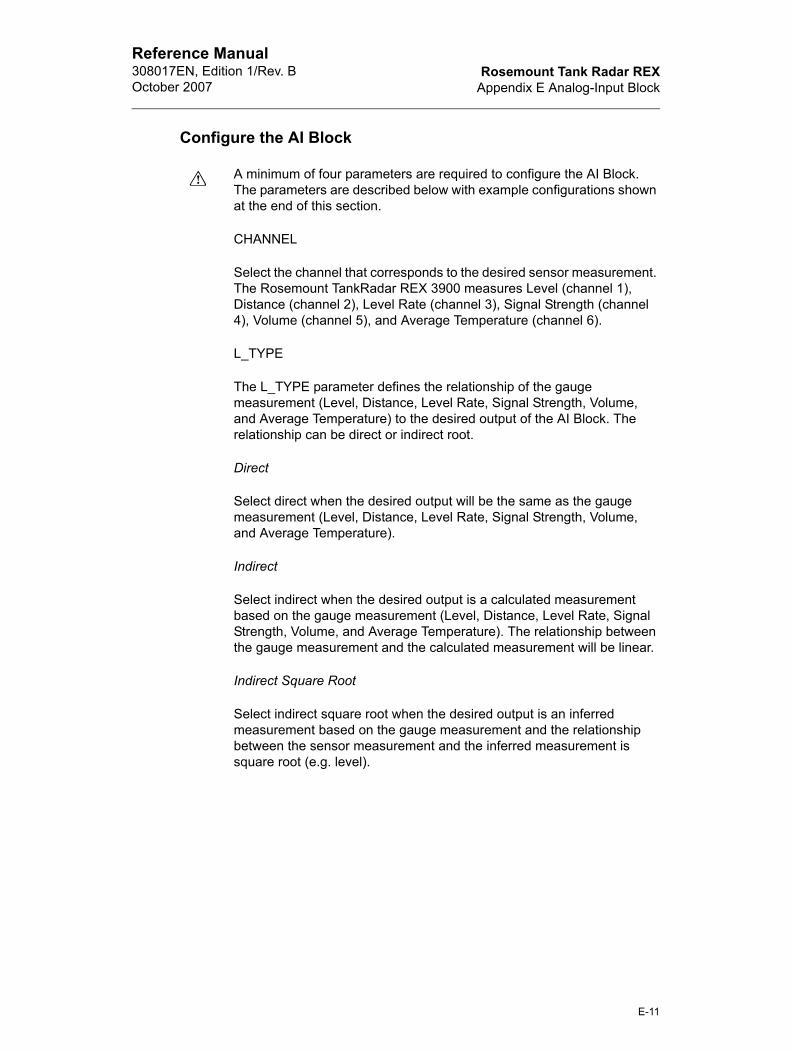
Rosemount Tank Radar REXAppendix E Analog-Input Block
Reference Manual308017EN, Edition 1/Rev. BOctober 2007
Configure the AI Block
A minimum of four parameters are required to configure the AI Block. The parameters are described below with example configurations shown at the end of this section.
CHANNEL
Select the channel that corresponds to the desired sensor measurement. The Rosemount TankRadar REX 3900 measures Level (channel 1), Distance (channel 2), Level Rate (channel 3), Signal Strength (channel 4), Volume (channel 5), and Average Temperature (channel 6).
L_TYPE
The L_TYPE parameter defines the relationship of the gauge measurement (Level, Distance, Level Rate, Signal Strength, Volume, and Average Temperature) to the desired output of the AI Block. The relationship can be direct or indirect root.
Direct
Select direct when the desired output will be the same as the gauge measurement (Level, Distance, Level Rate, Signal Strength, Volume, and Average Temperature).
Indirect
Select indirect when the desired output is a calculated measurement based on the gauge measurement (Level, Distance, Level Rate, Signal Strength, Volume, and Average Temperature). The relationship between the gauge measurement and the calculated measurement will be linear.
Indirect Square Root
Select indirect square root when the desired output is an inferred measurement based on the gauge measurement and the relationship between the sensor measurement and the inferred measurement is square root (e.g. level).
E-11

Rosemount Tank Radar REXAppendix E Analog-Input Block
Reference Manual308017EN, Edition 1/Rev. B
October 2007
XD_SCALE and OUT_SCALE
The XD_SCALE and OUT_SCALE each include three parameters: 0%, 100%, and, engineering units. Set these based on the L_TYPE:
L_TYPE is Direct
When the desired output is the measured variable, set the XD_SCALE to represent the operating range of the process. Set OUT_SCALE to match XD_SCALE.
L_TYPE is Indirect
When an inferred measurement is made based on the sensor measurement, set the XD_SCALE to represent the operating range that the sensor will see in the process. Determine the inferred measurement values that correspond to the XD_SCALE 0 and 100% points and set these for the OUT_SCALE.
L_TYPE is Indirect Square Root
When an inferred measurement is made based on the gauge measurement and the relationship between the inferred measurement and sensor measurement is square root, set the XD_SCALE to represent the operating range that the sensor will see in the process. Determine the inferred measurement values that correspond to the XD_SCALE 0 and 100% points and set these for the OUT_SCALE.
Note! To avoid configuration errors, only select Engineering Units for XD_SCALE and OUT_SCALE that are supported by the device. The supported units are:
Table E-4. Length
Table E-5. Level Rate
Display Description
m meter
ft feet
in inch
mm millimeter
Display Description
Ft/s feet per second
m/s meter per second
m/h meter per hour
E-12

Rosemount Tank Radar REXAppendix E Analog-Input Block
Reference Manual308017EN, Edition 1/Rev. BOctober 2007
Table E-6. Temperature
Table E-7. Signal Strength
Table E-8. Volume
Troubleshooting
Refer to Table 7-8 to troubleshoot any problems that you encounter.
Display Description
K Kelvin
°C Degree Celsius
°F Degree Fahrenheit
Display Description
mV millivolt
Display Description
m3 Cubic meter
Gallon US gallon
bbl barrel
ft3 Cubic feet
E-13

Rosemount Tank Radar REXAppendix E Analog-Input Block
Reference Manual308017EN, Edition 1/Rev. B
October 2007
E-14

Rosemount Tank Radar REXAppendix F Discrete Input Block
Reference Manual308017EN, Edition 1/Rev. BOctober 2007
P
BLO
DISC
FIEL
CHA
Appendix F Discrete Input Block
Overview
Figure F-1. DI Block
The Discrete Input (DI) function block processes a single discrete input from a field device and makes it available to other function blocks. You can configure inversion and alarm detection on the input value.
The Discrete Input function block supports mode control, signal status propagation and simulation.
Normally, the block is used in Automatic (Auto) mode so that the process variable (PV_D) is copied to the output (OUT_D). You can change the mode to Manual (MAN) to disconnect the field signal and substitute a manually-entered value for OUT_D. In this case, PV_D continues to show the value that will become OUT_D when the mode is changed to Auto.
To support testing, you can enable simulation, which allows the measurement value to be manually through the SIMULATE_D parameter. Figure F-2 illustrates the internal components of th DI function block, and Table F-1 lists the definitions of the system parameters.
arameters Units Description
CK_ERR None The summary of activ error conditions associated with the block. The sup-ported block errors in the Discrete Input function block are Simulate active, Input failure/process variable has Bad status, and Out of service. See Sys-tem Support.
_LIM None The state of the discrete inpute that cuases an alarm. Any number from 0 to 255 may be. State 255 specifies that no alarm indication is to be shown.
D_VAL_D None The value and status of the discrete input from a field device.
NNEL None Definies the I/O input used for the field measurement.
OUT_D =The discrete output value and status
AI
FF_D
IBLO
CK
OUT_DDI
F-1

Rosemount Tank Radar REXAppendix F Discrete Input Block
Reference Manual308017EN, Edition 1/Rev. B
October 2007
IO_O
MOD
OUT
PV_
SIM
P
Table F-1. Discrete Input Function Block System Parameters
Figure F-2. Discrete Input Function Block Schematic
I/O Selection
To select the I/O associated with the discrete measurement, configure the value of the CHANNEL attribute.
Simulation
To support testing, you can either change the mode of the block to manual and adjust the output value, or you can enable simulation through the configuration tool and manually enter a value for the measurement value and its status. In both cases, you must first set the ENABLE jumper on the field device.
Note! All fieldbus instruments have an ENABLE jumper. As a safety measure, the jumper has to be reset every time there is a power interruption. This measure is to prevent devices that went through simulation in the staging process from being installed with simulation enabled.
With simulation enabled, the actual measurement value has no impact on the OUT_D value or the status.
PTS None Allows you to select options for I/O value processing. The supported I/O option for the Discrete Input function block is Invert. See System Support.
E None The mode record of the block. Contains the actual, target, permitted, and normal mode. see System Support.
_D None The discrete output value and status.
D None The discrete process variable used in block execution.
ULATE_D None Enables simulation and allow you to enter an input value and status when SIMULATE_IN_D is not connected.
arameters Units Description
FF_D
IBLO
CK
SC
HE
MAT
IC
FIELD_VAL_D
SIMULATE_D MODE
Invert Option
PV_D
Alarm Detection
OUT_D
Discrete Signal
F-2

Rosemount Tank Radar REXAppendix F Discrete Input Block
Reference Manual308017EN, Edition 1/Rev. BOctober 2007
Field Value Processing
You can configure the Invert I/O option (IO_OPTS) to process FIELD_VAL_D. The invert option indicates whether or not the discrete input is logically inverted before it is stored in the process variable (PV_D).
The output of the Invert processor is PV_D. This value goes to the mode switch where it becomes OUT_D when the mode is Auto. OUT_D is also tested for an alarm state. You might choose this option when the field contact is normally closed, so an open contact or a broken wire represents the active state of the condition being sensed.
Note! INVERT is the only I/O mode that the DI block supports. You can set the I/O option in Manual or Out of Service mode only.
Alarm Detection
To select the state that initiates an input alarm, and to set discrete alarm substatus in the output, configure the DISC_LIM attribute. You can enter any value between 0 and 255. A value of 255 disables the alarm.
Block Errors
The following conditions are reported in the BLOCK_ERR attribute:
Simulate Active - Simulate_D is enabled and OUT_D does not reflect actual process conditions
Input Failure/Process Variable has Bad Status - The hardware is bad, the configured channel is invalid or a Bad status is being simulated
Out of Service - The block is not being processed
Modes
Manual (Man) - The output is disconnected from the field.
Automatic (Auto) - The block algorithm determines OUT_D
Out of Service - The block is not processed. The output status is set to Bad: Out of Service. The BLOCK_ERR attribute shows Out of Service.
F-3

Rosemount Tank Radar REXAppendix F Discrete Input Block
Reference Manual308017EN, Edition 1/Rev. B
October 2007
Status Handling
Under normal conditions, a Good: Non-cascade status is passed through to OUT_D. The block also support Status Action on Failure and Block Error indications.
Action on failure
In case of hardware failure, FIELD_VAL_D, PV_D and OUT_D change to a Bad status and the BLOCK_ERR attribute displays Bad PV. When SIMULATE_D is enabled, FIELD_VAL_D, PV_D and OUT_D change to a simulation status. When the block is set to Man mode, OUT_D is set to Good: Non-cascade, Constant status.
F-4

Rosemount Tank Radar REXAppendix G Approval Drawings
Reference Manual308017EN, Edition 1/Rev. BOctober 2007
9150
072-
966_
1
Appendix G Approval Drawings
C:\
PIW
\FF
-RE
X\A
ppro
vals
\9150072-9
66
_I0
4_P
01
_A
3.c
al
- 2004-0
5-2
4C
:\P
IW\F
F-R
EX
\Appro
vals
\9150072-9
66
_I0
4_P
01
_A
3.c
al
- 2004-0
5-2
4C
:\P
IW\F
F-R
EX
\Appro
vals
\9150072-9
66
_I0
4_P
01
_A
3.c
al
- 2004-0
5-2
4
G-1

Rosemount Tank Radar REXAppendix G Approval Drawings
Reference Manual308017EN, Edition 1/Rev. B
October 2007
C:\
PIW
\FF
-RE
X\A
ppro
vals
\9150072-9
66
_I0
4_
P0
2_
A3
.cal
- 2004-0
5-2
4C
:\P
IW\F
F-R
EX
\Appro
vals
\9150072-9
66
_I0
4_
P0
2_
A3
.cal
- 2004-0
5-2
4C
:\P
IW\F
F-R
EX
\Appro
vals
\9150072-9
66
_I0
4_
P0
2_
A3
.cal
- 2004-0
5-2
4
9150
072-
966_
2
G-2

Rosemount Tank Radar REXAppendix H Operation with Delta V
Reference Manual308017EN, Edition 1/Rev. BOctober 2007
Appendix H Operation with Delta V
The Rosemount TankRadar REX Radar Tank Gauge with FOUNDATION fieldbus software is designed to permit remote testing and configuration using the Emerson Process Management DeltaV™ fieldbus configuration tool, or other FOUNDATION fieldbus host.
Note! Device support files for the Rosemount TankRadar REX Radar Tank Gauge with FOUNDATION fieldbus are available on www.fieldbus.org or www.rosemount.com. Correct revision of Device Support Files must be loaded into DeltaV to provide proper functionality.
Commissioning the Device
1 Select DeltaV > Engineering > DeltaV Explorer from the Start menu.
2 Navigate through the file structure to find the gauge you wish to configure, see Figure H-1.
3 The Fieldbus Device Properties window appears, seeFigure H-1.
Figure H-1. Fieldbus device properties
4 Enter a description of the device properties information in the win-dow.
FF_D
ELTA
V_G
ENE
RA
L
H-1

Rosemount Tank Radar REXAppendix H Operation with Delta V
Reference Manual308017EN, Edition 1/Rev. B
October 2007
Configure the Parameters
Figure H-2. Navigating to Configure Gauge
Figure H-3. Configuring the TankRadar REX 3900 Transducer Block (Process Tab)
FF_D
ELT
AV
_MAI
NVI
EWFF
_DE
LTA
V_P
RO
CES
S
H-2

Rosemount Tank Radar REXAppendix H Operation with Delta V
Reference Manual308017EN, Edition 1/Rev. BOctober 2007
Figure H-4. Configuring the TankRadar REX 3900 Transducer Block (Values Tab)
Figure H-5. Configuring the TankRadar REX 3900 Transducer Block (Antenna Tab)
FF_D
ELT
AV_
VALU
ESFF
_DE
LTA
V_A
NTE
NN
A
H-3

Rosemount Tank Radar REXAppendix H Operation with Delta V
Reference Manual308017EN, Edition 1/Rev. B
October 2007
Figure H-6. Configuring the TankRadar REX 3900 Transducer Block (Geometry Tab)
5 Double click the gauge you wish to configure/calibrate.
The function blocks within the gauge appear in the right half of the DeltaV Explorer window, see Figure H-7.
FF_D
ELT
AV
_GE
OM
ETR
Y
H-4

Rosemount Tank Radar REXAppendix H Operation with Delta V
Reference Manual308017EN, Edition 1/Rev. BOctober 2007
FF_D
ELTA
V_B
RO
WS
E
Figure H-7. List of Function Blocks in DeltaV Explorer
6 Double click on the TRANSDUCER400 block icon. The transducer block properties window appears.
7 Select the Mode tab.
8 Select Out of Service (OOS) and deselect Auto in the Target Mode region of the window.
The parameters you change in the properties window remain highlighted (as in Figure H-7) so you can easily track changes.
9 Click the Apply button to apply the changes you made.
The software warns you that the changes you made may upset the process and create a dangerous situation in your plant. Before you select OK, verify that the control loop is in manual control.
The Actual Mode region changes to OOS.
10 A warning window will pop up, click OK to return to the DeltaV Explorer.
H-5

Rosemount Tank Radar REXAppendix H Operation with Delta V
Reference Manual308017EN, Edition 1/Rev. B
October 2007
11 Right click on the TRANSDUCER block icon to access the config-uration parameters menu.
12 Select the parameter you wish to configure, and follow the on-line instructions to complete the configuration.
Note! As you make changes to the configuration parameters, the software warns you that the changes you made may upset the process and create a dangerous situation in your plant. Before you select OK, verify that the control loop is in manual control.
See Appendix A Specifications to change the sensor type and to calibrate the sensors.
13 Repeat Steps 6 through 10 to return the mode of the transducer block to Auto.
H-6

Rosemount TankRadar REXIndex
Reference Manual308014EN, Edition 3October 2007
Index
AAddress . . . . . . . . . . . . . . . . . . . . . . . . . . . . . . . . . . . . . . . . . . . . . . . . . . . . . . . . . . . . . .3-6
Temporary . . . . . . . . . . . . . . . . . . . . . . . . . . . . . . . . . . . . . . . . . . . . . . . . . . . . . . . .3-6Temporary Node . . . . . . . . . . . . . . . . . . . . . . . . . . . . . . . . . . . . . . . . . . . . . . . 4-2, 5-2
AI BlockConfiguration . . . . . . . . . . . . . . . . . . . . . . . . . . . . . . . . . . . . . . . . . . . . . . . . . . . . . .5-5Parameters
ALARM_TYPE ................................................................................................ E-10BLOCK_ERR .................................................................................................... E-7IO_OPTS .......................................................................................................... E-6L_TYPE ............................................................................................................ E-6LOW_CUT ........................................................................................................ E-6OUT_D ............................................................................................................ E-10OUT_SCALE .................................................................................................... E-6PV_FTIME ........................................................................................................ E-5VAR_INDEX ................................................................................................... E-10VAR_SCAN .................................................................................................... E-10XD_SCALE ....................................................................................................... E-6
Status . . . . . . . . . . . . . . . . . . . . . . . . . . . . . . . . . . . . . . . . . . . . . . . . . . . . . . . . . . . E-9ALARM_TYPE
AI Block . . . . . . . . . . . . . . . . . . . . . . . . . . . . . . . . . . . . . . . . . . . . . . . . . . . . . . . . E-10Alerts
Definition . . . . . . . . . . . . . . . . . . . . . . . . . . . . . . . . . . . . . . . . . . . . . . . . . . . . . . . . .3-4Analog Input (AI) Block . . . . . . . . . . . . . . . . . . . . . . . . . . . . . . . . . . . . . . . . . . 4-2, 5-5, E-1
BLOCK_ERR . . . . . . . . . . . . . . . . . . . . . . . . . . . . . . . . . . . . . . . . . . . . . . . . . . 7-5, 7-7Antenna Type . . . . . . . . . . . . . . . . . . . . . . . . . . . . . . . . . . . . . . . . . . . . . . . . . . . . . . . . .5-2
BBlock Configuration
AI Block . . . . . . . . . . . . . . . . . . . . . . . . . . . . . . . . . . . . . . . . . . . . . . . . . . . . . . . . . .5-5Block Instantiation . . . . . . . . . . . . . . . . . . . . . . . . . . . . . . . . . . . . . . . . . . . . . . . . . . . . . .6-4BLOCK_ERR
AI Block . . . . . . . . . . . . . . . . . . . . . . . . . . . . . . . . . . . . . . . . . . . . . . . . . . 7-5, 7-7, E-7Resource Block . . . . . . . . . . . . . . . . . . . . . . . . . . . . . . . . . . . . . . . . . . . . . . . . . . . .7-3
CCalibration Distance . . . . . . . . . . . . . . . . . . . . . . . . . . . . . . . . . . . . . . . . . . . . . . . . . . . .6-2Channel . . . . . . . . . . . . . . . . . . . . . . . . . . . . . . . . . . . . . . . . . . . . . . . . . . . . . . . .B-1, E-11Channel Definitions
Level Transducer Block . . . . . . . . . . . . . . . . . . . . . . . . . . . . . . . . . . . . . . . . . . . . . B-1Commissioning
Delta V . . . . . . . . . . . . . . . . . . . . . . . . . . . . . . . . . . . . . . . . . . . . . . . . . . . . . . . . . . H-1Compel Data (CD)
Definition . . . . . . . . . . . . . . . . . . . . . . . . . . . . . . . . . . . . . . . . . . . . . . . . . . . . . . . . .3-6Configuration
Index-1
Rosemount Tank Radar REXIndex
Reference Manual308014EN, Edition 3
October 2007
Analog Input (AI) Function BlockOUT_SCALE ........................................................................................... 5-7, E-12XD_SCALE .............................................................................................. 5-7, E-12
Antenna Type . . . . . . . . . . . . . . . . . . . . . . . . . . . . . . . . . . . . . . . . . . . . . . . . . . . . . .5-2Calibration Distance . . . . . . . . . . . . . . . . . . . . . . . . . . . . . . . . . . . . . . . . . . . . . . . . .6-2Channel . . . . . . . . . . . . . . . . . . . . . . . . . . . . . . . . . . . . . . . . . . . . . . . . . . . . . . . . E-11Delta V . . . . . . . . . . . . . . . . . . . . . . . . . . . . . . . . . . . . . . . . . . . . . . . . . . . . . . . . . . H-1Direct . . . . . . . . . . . . . . . . . . . . . . . . . . . . . . . . . . . . . . . . . . . . . . . . . . . . . . . 5-7, E-12Indirect . . . . . . . . . . . . . . . . . . . . . . . . . . . . . . . . . . . . . . . . . . . . . . . . . . . . . . 5-7, E-12L_TYPE . . . . . . . . . . . . . . . . . . . . . . . . . . . . . . . . . . . . . . . . . . . . . . . . . . . . . 5-6, E-11
Direct ....................................................................................................... 5-6, E-11Indirect .................................................................................... 5-6, 5-7, E-11, E-12
Tank Height . . . . . . . . . . . . . . . . . . . . . . . . . . . . . . . . . . . . . . . . . . . . . . . . . . . . . . .5-3
DDelta V
Commissioning the Device . . . . . . . . . . . . . . . . . . . . . . . . . . . . . . . . . . . . . . . . . . . H-1Configure the Parameters . . . . . . . . . . . . . . . . . . . . . . . . . . . . . . . . . . . . . . . . . . . H-1Fieldbus Device Properties . . . . . . . . . . . . . . . . . . . . . . . . . . . . . . . . . . . . . . . . . . H-1
Device DescriptionsDefinition . . . . . . . . . . . . . . . . . . . . . . . . . . . . . . . . . . . . . . . . . . . . . . . . . . . . . . . . .3-3
Device Revision . . . . . . . . . . . . . . . . . . . . . . . . . . . . . . . . . . . . . . . . . . . . . . . . . . . . . . .5-2Device Tag . . . . . . . . . . . . . . . . . . . . . . . . . . . . . . . . . . . . . . . . . . . . . . . . . . . . . . . . . . .5-2Diagnostics Device Errors
Level Transducer Block . . . . . . . . . . . . . . . . . . . . . . . . . . . . . . . . . . . . . . . . . . . . . B-6Direct . . . . . . . . . . . . . . . . . . . . . . . . . . . . . . . . . . . . . . . . . . . . . . . . . 5-6, 5-7, E-11, E-12Direct Signal Conversion . . . . . . . . . . . . . . . . . . . . . . . . . . . . . . . . . . . . . . . . . . . . . . . E-6Discrete Input (DI) Block . . . . . . . . . . . . . . . . . . . . . . . . . . . . . . . . . . . . . . . . . 4-2, 5-4, F-1
Action on Failure . . . . . . . . . . . . . . . . . . . . . . . . . . . . . . . . . . . . . . . . . . . . . . . . . . .F-4Alarm Detection . . . . . . . . . . . . . . . . . . . . . . . . . . . . . . . . . . . . . . . . . . . . . . . . . . . .F-3BLOCK_ERR . . . . . . . . . . . . . . . . . . . . . . . . . . . . . . . . . . . . . . . . . . . . . . . . . . . . . .F-3Field Value Processing . . . . . . . . . . . . . . . . . . . . . . . . . . . . . . . . . . . . . . . . . . . . . .F-3Modes . . . . . . . . . . . . . . . . . . . . . . . . . . . . . . . . . . . . . . . . . . . . . . . . . . . . . . . . . . .F-3Status Handling . . . . . . . . . . . . . . . . . . . . . . . . . . . . . . . . . . . . . . . . . . . . . . . . . . . .F-4
Download . . . . . . . . . . . . . . . . . . . . . . . . . . . . . . . . . . . . . . . . . . . . . . . . . . . . . . . . . . . .3-8
EElectrical
Connection . . . . . . . . . . . . . . . . . . . . . . . . . . . . . . . . . . . . . . . . . . . . . . . . . . . . . . .5-13Intrinsically Wiring ..............................................................................................4-5Non-Intrinsically Wiring ......................................................................................4-4
InstallationPower Supply .....................................................................................................4-3
Power Connections . . . . . . . . . . . . . . . . . . . . . . . . . . . . . . . . . . . . . . . . . . . . . . . . .4-3
FField Upgrades . . . . . . . . . . . . . . . . . . . . . . . . . . . . . . . . . . . . . . . . . . . . . . . . . . . . . . . .7-2Fieldbus
Index-2

Rosemount TankRadar REXIndex
Reference Manual308014EN, Edition 3October 2007
Addresses . . . . . . . . . . . . . . . . . . . . . . . . . . . . . . . . . . . . . . . . . . . . . . . . . . . . . . . .3-6Network
Definition ............................................................................................................3-5Segment . . . . . . . . . . . . . . . . . . . . . . . . . . . . . . . . . . . . . . . . . . . . . . . . . . . . . . . . . .3-5
FilteringAI Block . . . . . . . . . . . . . . . . . . . . . . . . . . . . . . . . . . . . . . . . . . . . . . . . . . . . . . . . . E-5
Function BlockDefinition . . . . . . . . . . . . . . . . . . . . . . . . . . . . . . . . . . . . . . . . . . . . . . . . . . . . . . . . .3-1Schedule . . . . . . . . . . . . . . . . . . . . . . . . . . . . . . . . . . . . . . . . . . . . . . . . . . . . . . . . .3-9
GGrounding . . . . . . . . . . . . . . . . . . . . . . . . . . . . . . . . . . . . . . . . . . . . . . . . . . . . . . . . . . . .4-6
II/O selection . . . . . . . . . . . . . . . . . . . . . . . . . . . . . . . . . . . . . . . . . . . . . . . . . . . . . . . . . .F-2Indirect . . . . . . . . . . . . . . . . . . . . . . . . . . . . . . . . . . . . . . . . . . . . . . . . 5-6, 5-7, E-11, E-12Indirect Signal Conversion . . . . . . . . . . . . . . . . . . . . . . . . . . . . . . . . . . . . . . . . . . . . . . E-6Intrinsically Wiring . . . . . . . . . . . . . . . . . . . . . . . . . . . . . . . . . . . . . . . . . . . . . . . . . . . . . .4-5IO_OPTS
AI Block . . . . . . . . . . . . . . . . . . . . . . . . . . . . . . . . . . . . . . . . . . . . . . . . . . . . . . . . . E-6
LL_TYPE . . . . . . . . . . . . . . . . . . . . . . . . . . . . . . . . . . . . . . . . . . . . . . . . . . . . . . . . 5-6, E-11
. . . . . . . . . . . . . . . . . . . . . . . . . . . . . . . . . . . . . . . . . . . . . . . . . . . 5-6, 5-7, E-11, E-12AI Block . . . . . . . . . . . . . . . . . . . . . . . . . . . . . . . . . . . . . . . . . . . . . . . . . . . . . . . . . E-6
LAS . . . . . . . . . . . . . . . . . . . . . . . . . . . . . . . . . . . . . . . . . . . . . . . . . . . . . . . . . . . . . 3-8, 3-9Definition . . . . . . . . . . . . . . . . . . . . . . . . . . . . . . . . . . . . . . . . . . . . . . . . . . . . . . . . .3-5
Level Transducer Block . . . . . . . . . . . . . . . . . . . . . . . . . . . . . . . . . . . . . . . . . . . . . . . . .5-4Channel Definitions . . . . . . . . . . . . . . . . . . . . . . . . . . . . . . . . . . . . . . . . . . . . . . . . B-1Diagnostics Device Errors . . . . . . . . . . . . . . . . . . . . . . . . . . . . . . . . . . . . . . . . . . . B-6Supported Units . . . . . . . . . . . . . . . . . . . . . . . . . . . . . . . . . . . . . . . . . . . . . . . . . . . B-8
Unit Codes ........................................................................................................ B-8Link Active Scheduler (LAS)
Definition . . . . . . . . . . . . . . . . . . . . . . . . . . . . . . . . . . . . . . . . . . . . . . . . . . . . . . . . .3-5Live List
Definition . . . . . . . . . . . . . . . . . . . . . . . . . . . . . . . . . . . . . . . . . . . . . . . . . . . . . . . . .3-6LOW_CUT
AI Block . . . . . . . . . . . . . . . . . . . . . . . . . . . . . . . . . . . . . . . . . . . . . . . . . . . . . . . . . E-6
MMacrocycle . . . . . . . . . . . . . . . . . . . . . . . . . . . . . . . . . . . . . . . . . . . . . . . . . . . . . . . . . . .3-9Manual Operation . . . . . . . . . . . . . . . . . . . . . . . . . . . . . . . . . . . . . . . . . . . . . . . . . . . . . .6-1Master Reset Method
Resource Block . . . . . . . . . . . . . . . . . . . . . . . . . . . . . . . . . . . . . . . . . . . . . . . . . . . .6-2Methods . . . . . . . . . . . . . . . . . . . . . . . . . . . . . . . . . . . . . . . . . . . . . . . . . . . . . . . . . . . . .6-1
Index-3

Rosemount Tank Radar REXIndex
Reference Manual308014EN, Edition 3
October 2007
NNode Address . . . . . . . . . . . . . . . . . . . . . . . . . . . . . . . . . . . . . . . . . . . . . . . . . . . . . 4-2, 5-2Non-Intrinsically Wiring . . . . . . . . . . . . . . . . . . . . . . . . . . . . . . . . . . . . . . . . . . . . . . . . . .4-4
OOperation . . . . . . . . . . . . . . . . . . . . . . . . . . . . . . . . . . . . . . . . . . . . . . . . . . . . . . . . . . . .5-2
Block Instantiation . . . . . . . . . . . . . . . . . . . . . . . . . . . . . . . . . . . . . . . . . . . . . . . . . .6-4Calibration Distance Configuration . . . . . . . . . . . . . . . . . . . . . . . . . . . . . . . . . . . . . .6-2Master Reset Method
Resource Block ..................................................................................................6-2Service Method . . . . . . . . . . . . . . . . . . . . . . . . . . . . . . . . . . . . . . . . . . . . . . . . . . . .6-2Simulation . . . . . . . . . . . . . . . . . . . . . . . . . . . . . . . . . . . . . . . . . . . . . . . . . . . . . . . .6-4Write Protection
Resource Block ..................................................................................................6-2OUT_D
AI Block . . . . . . . . . . . . . . . . . . . . . . . . . . . . . . . . . . . . . . . . . . . . . . . . . . . . . . . . E-10OUT_SCALE . . . . . . . . . . . . . . . . . . . . . . . . . . . . . . . . . . . . . . . . . . . . . . . . . . . . 5-7, E-12
AI Block . . . . . . . . . . . . . . . . . . . . . . . . . . . . . . . . . . . . . . . . . . . . . . . . . . . . . . . . . E-6L_TYPE
Direct ....................................................................................................... 5-7, E-12Indirect ..................................................................................................... 5-7, E-12
PParameter
BLOCK_ERR . . . . . . . . . . . . . . . . . . . . . . . . . . . . . . . . . . . . . . . . . . . . . . 7-3, 7-5, 7-7CHANNEL . . . . . . . . . . . . . . . . . . . . . . . . . . . . . . . . . . . . . . . . . . . . . . . . . . . . . . E-11L_TYPE . . . . . . . . . . . . . . . . . . . . . . . . . . . . . . . . . . . . . . . . . . . . 5-6, 5-7, E-11, E-12OUT_SCALE . . . . . . . . . . . . . . . . . . . . . . . . . . . . . . . . . . . . . . . . . . . . . . . . . 5-7, E-12Resource Block . . . . . . . . . . . . . . . . . . . . . . . . . . . . . . . . . . . . . . . . . . . . . . . . . . . D-1XD_SCALE . . . . . . . . . . . . . . . . . . . . . . . . . . . . . . . . . . . . . . . . . . . . . . . . . . 5-7, E-12
Pass Token (PT) . . . . . . . . . . . . . . . . . . . . . . . . . . . . . . . . . . . . . . . . . . . . . . . . . . . . . . .3-8Definition . . . . . . . . . . . . . . . . . . . . . . . . . . . . . . . . . . . . . . . . . . . . . . . . . . . . . . . . .3-6
Power Connections . . . . . . . . . . . . . . . . . . . . . . . . . . . . . . . . . . . . . . . . . . . . . . . . . . . . .4-3Power Supply . . . . . . . . . . . . . . . . . . . . . . . . . . . . . . . . . . . . . . . . . . . . . . . . . . . . . . . . .4-3Publisher . . . . . . . . . . . . . . . . . . . . . . . . . . . . . . . . . . . . . . . . . . . . . . . . . . . . . . . . . . . . .3-6PV_FTIME
AI Block . . . . . . . . . . . . . . . . . . . . . . . . . . . . . . . . . . . . . . . . . . . . . . . . . . . . . . . . . E-5
RRegister Transducer Block . . . . . . . . . . . . . . . . . . . . . . . . . . . . . . . . . . . . . . . . . . . . . . .5-4Resource Block . . . . . . . . . . . . . . . . . . . . . . . . . . . . . . . . . . . . . . . . . . . . 4-2, 5-4, 7-3, D-1
Block Errors . . . . . . . . . . . . . . . . . . . . . . . . . . . . . . . . . . . . . . . . . . . . . . . . . . . . . . .7-3Definition . . . . . . . . . . . . . . . . . . . . . . . . . . . . . . . . . . . . . . . . . . . . . . . . . . . . . . . . .3-3Detailed Status . . . . . . . . . . . . . . . . . . . . . . . . . . . . . . . . . . . . . . . . . . . . . . . . . . . . .7-3Master Reset Method . . . . . . . . . . . . . . . . . . . . . . . . . . . . . . . . . . . . . . . . . . . . . . . .6-2Parameters . . . . . . . . . . . . . . . . . . . . . . . . . . . . . . . . . . . . . . . . . . . . . . . . . . . . . . . D-1
BLOCK_ERR .....................................................................................................7-3Summary Status . . . . . . . . . . . . . . . . . . . . . . . . . . . . . . . . . . . . . . . . . . . . . . . . . . . .7-3
Index-4

Rosemount TankRadar REXIndex
Reference Manual308014EN, Edition 3October 2007
Write Protection . . . . . . . . . . . . . . . . . . . . . . . . . . . . . . . . . . . . . . . . . . . . . . . . . . . .6-2
SSegment
Definition . . . . . . . . . . . . . . . . . . . . . . . . . . . . . . . . . . . . . . . . . . . . . . . . . . . . . . . . .3-5Sensor Bus Mode
Switching . . . . . . . . . . . . . . . . . . . . . . . . . . . . . . . . . . . . . . . . . . . . . . . . . . . . . . . .5-14Service Method
Operation . . . . . . . . . . . . . . . . . . . . . . . . . . . . . . . . . . . . . . . . . . . . . . . . . . . . . . . . .6-2Signal Conversion
Direct . . . . . . . . . . . . . . . . . . . . . . . . . . . . . . . . . . . . . . . . . . . . . . . . . . . . . . . . . . . E-6Indirect . . . . . . . . . . . . . . . . . . . . . . . . . . . . . . . . . . . . . . . . . . . . . . . . . . . . . . . . . . E-6
Signal WiresGrounding . . . . . . . . . . . . . . . . . . . . . . . . . . . . . . . . . . . . . . . . . . . . . . . . . . . . . . . .4-6
Simulation . . . . . . . . . . . . . . . . . . . . . . . . . . . . . . . . . . . . . . . . . . . . . . . . . . . . . . . . 6-4, E-4Jumper . . . . . . . . . . . . . . . . . . . . . . . . . . . . . . . . . . . . . . . . . . . . . . . . . . . . . . . . . . E-4
StatusAI Block . . . . . . . . . . . . . . . . . . . . . . . . . . . . . . . . . . . . . . . . . . . . . . . . . . . . . . . . . E-9
Subscriber (S) . . . . . . . . . . . . . . . . . . . . . . . . . . . . . . . . . . . . . . . . . . . . . . . . . . . . . . . . .3-6Supported Units . . . . . . . . . . . . . . . . . . . . . . . . . . . . . . . . . . . . . . . . . . . . . . . . . . 5-7, E-12System Management . . . . . . . . . . . . . . . . . . . . . . . . . . . . . . . . . . . . . . . . . . . . . . . . . . .3-2
TTag
Definition . . . . . . . . . . . . . . . . . . . . . . . . . . . . . . . . . . . . . . . . . . . . . . . . . . . . . . . . .3-2Device . . . . . . . . . . . . . . . . . . . . . . . . . . . . . . . . . . . . . . . . . . . . . . . . . . . . . . . . . . .5-2
Tank Height . . . . . . . . . . . . . . . . . . . . . . . . . . . . . . . . . . . . . . . . . . . . . . . . . . . . . . . . . .5-3Transducer Block . . . . . . . . . . . . . . . . . . . . . . . . . . . . . . . . . . . . . . . . . . . . . . . . . . . . . .4-2
Definition . . . . . . . . . . . . . . . . . . . . . . . . . . . . . . . . . . . . . . . . . . . . . . . . . . . . . . . . .3-4Troubleshooting
Field Upgrades . . . . . . . . . . . . . . . . . . . . . . . . . . . . . . . . . . . . . . . . . . . . . . . . . . . . .7-2Resource Block . . . . . . . . . . . . . . . . . . . . . . . . . . . . . . . . . . . . . . . . . . . . . . . . . . . .7-3
UUnit Codes
Level Transducer Block . . . . . . . . . . . . . . . . . . . . . . . . . . . . . . . . . . . . . . . . . . . . . B-8Upload . . . . . . . . . . . . . . . . . . . . . . . . . . . . . . . . . . . . . . . . . . . . . . . . . . . . . . . . . . . . . .3-8
VVAR_INDEX
AI Block . . . . . . . . . . . . . . . . . . . . . . . . . . . . . . . . . . . . . . . . . . . . . . . . . . . . . . . . E-10VAR_SCAN
AI Block . . . . . . . . . . . . . . . . . . . . . . . . . . . . . . . . . . . . . . . . . . . . . . . . . . . . . . . . E-10
WWiring
Grounding . . . . . . . . . . . . . . . . . . . . . . . . . . . . . . . . . . . . . . . . . . . . . . . . . . . . . . . .4-6
Index-5

Rosemount Tank Radar REXIndex
Reference Manual308014EN, Edition 3
October 2007
Intrinsically . . . . . . . . . . . . . . . . . . . . . . . . . . . . . . . . . . . . . . . . . . . . . . . . . . . . . . . .4-5Non-Intrinsically . . . . . . . . . . . . . . . . . . . . . . . . . . . . . . . . . . . . . . . . . . . . . . . . . . . .4-4Power Connections . . . . . . . . . . . . . . . . . . . . . . . . . . . . . . . . . . . . . . . . . . . . . . . . .4-3
Write ProtectionResource Block . . . . . . . . . . . . . . . . . . . . . . . . . . . . . . . . . . . . . . . . . . . . . . . . . . . .6-2
XXD_SCALE . . . . . . . . . . . . . . . . . . . . . . . . . . . . . . . . . . . . . . . . . . . . . . . . . . . . . . 5-7, E-12
AI Block . . . . . . . . . . . . . . . . . . . . . . . . . . . . . . . . . . . . . . . . . . . . . . . . . . . . . . . . . E-6L_TYPE
Direct ....................................................................................................... 5-7, E-12Indirect ..................................................................................................... 5-7, E-12
Index-6


Reference Manual308017EN, Edition 1/Rev. BOctober 2007
Rosemount Tank Gauging local representative:
Copyright © Rosemount Tank Radar AB. Ref. no: 308017EN, Edition 1/Rev. B. October 2007.
Rosemount Tank GaugingBox 130 45SE-402 51 GöteborgSWEDENTel (International): +46 31 337 00 00Fax (International): +46 31 25 30 22E-mail: [email protected]
Emerson Process Management