Tank Gauging System ZYcj^hXdc9i^ EdgXYij · 1-3 Rosemount Tank Radar Rex Chapter 1 System...
154
Service Manual 308012En, Ed.2 May 2013 www.rosemount-tg.com Tank Gauging System
Transcript of Tank Gauging System ZYcj^hXdc9i^ EdgXYij · 1-3 Rosemount Tank Radar Rex Chapter 1 System...

Service Manual308012En, Ed.2May 2013
Tank Gauging System
Product Discontinued
www.rosemount-tg.com

www.rosemount-tg.com
Service manualSecond edition
Copyright © May 2013Rosemount Tank Radar AB

www.rosemount-tg.com
Copyright © May 2013
Rosemount Tank Radar ABThe contents, descriptions and specifications within this manual is subject to change without notice. Rosemount Tank Radar AB accepts no responsibility for any errors that may appear in this manual.
Trademarks
Rosemount, and the Rosemount logotype are trademarks of Rosemount Inc.
TankRadar is a trademark of Rosemount Tank Radar AB.
HART is a trademark of HART Communication Foundation.
Modbus is a trademark of Modicon.
Pentium is a trademark of Intel Corporation.
Windows NT is a trademark of Microsoft Corporation.
Viton is a trademark of Du Pont Performance Elastomers.
Spare Parts
Any substitution of non-recognized spare parts may jeopardize safety. Repair, e.g. substitution of components etc., may also jeopardize safety and is under no circumstances allowed.
Rosemount Tank Radar AB will not take any responsibility for faults, accidents, etc. caused by non-recognized spare parts or any repair which is not made by Rosemount Tank Radar AB.
Specific FCC Requirements (USA only)
Rosemount TankRadar Rex generates and uses radio frequency energy. If it is not installed and used properly, that is, in strict accordance with the manufacturer´s instructions, it may violate FCC regulations on radio frequency emission.
Rosemount TankRadar Rex has been FCC certified under test conditions which assume a metallic tank. Installation on a non-metallic tank is not certified, and is not allowed.
The FCC certificate for Rosemount TankRadar Rex requires that the tank is closed as far as emitted radio energy is concerned. Tanks with open manholes, external-floating-roof tanks without still pipes etc. are not covered by the certificate.
Rosemount TankRadar RexContents
Service Manual308012En, Ed.2May 2013
Contents1. SYSTEM DESCRIPTION . . . . . . . . . . . . . . . . . . . . . . . . . . 1-1
2. SAFETY . . . . . . . . . . . . . . . . . . . . . . . . . . . . . . . . . . . . . 2-1
2.1 INTRINSIC SAFETY . . . . . . . . . . . . . . . . . . . . . . . . . . . . . . . . . . . . . . .2-12.2 EXPLOSION PROOF . . . . . . . . . . . . . . . . . . . . . . . . . . . . . . . . . . . . . .2-2
3. DEVICE DESCRIPTION . . . . . . . . . . . . . . . . . . . . . . . . . . . 3-1
3.1 REX RTG . . . . . . . . . . . . . . . . . . . . . . . . . . . . . . . . . . . . . . . . . . . . . . .3-13.1.1 Overview . . . . . . . . . . . . . . . . . . . . . . . . . . . . . . . . . . . . . .3-13.1.2 Antenna types . . . . . . . . . . . . . . . . . . . . . . . . . . . . . . . . . .3-23.1.3 Measurement principle . . . . . . . . . . . . . . . . . . . . . . . . . . .3-53.1.4 Transmitter Head Electronics . . . . . . . . . . . . . . . . . . . . . .3-73.1.5 Write protection (Metrological Seal) . . . . . . . . . . . . . . . . .3-93.1.6 Internal calculations . . . . . . . . . . . . . . . . . . . . . . . . . . . .3-103.1.7 Inputs and Outputs . . . . . . . . . . . . . . . . . . . . . . . . . . . . . 3-113.1.8 Database Registers . . . . . . . . . . . . . . . . . . . . . . . . . . . .3-133.1.9 Tank Geometry . . . . . . . . . . . . . . . . . . . . . . . . . . . . . . . .3-163.1.10 Software Description . . . . . . . . . . . . . . . . . . . . . . . . . . .3-17
3.2 FIELD COMMUNICATION UNIT (FCU) . . . . . . . . . . . . . . . . . . . . . . .3-183.2.1 Field Bus and Group Bus Communication . . . . . . . . . . .3-193.2.2 Input and Database Registers . . . . . . . . . . . . . . . . . . . .3-193.2.3 Software . . . . . . . . . . . . . . . . . . . . . . . . . . . . . . . . . . . . .3-203.2.4 Redundancy . . . . . . . . . . . . . . . . . . . . . . . . . . . . . . . . . .3-203.2.5 Connection to a PC . . . . . . . . . . . . . . . . . . . . . . . . . . . .3-21
3.3 DATA ACQUISITION UNIT (DAU) . . . . . . . . . . . . . . . . . . . . . . . . . . .3-223.3.1 Overview . . . . . . . . . . . . . . . . . . . . . . . . . . . . . . . . . . . . .3-223.3.2 Data Acquisition Unit (DAU) . . . . . . . . . . . . . . . . . . . . . .3-223.3.3 Electronics . . . . . . . . . . . . . . . . . . . . . . . . . . . . . . . . . . .3-233.3.4 Temperature Measurement . . . . . . . . . . . . . . . . . . . . . .3-243.3.5 RTD Multiplexer . . . . . . . . . . . . . . . . . . . . . . . . . . . . . . .3-253.3.6 DAU Software . . . . . . . . . . . . . . . . . . . . . . . . . . . . . . . . .3-263.3.7 Database Registers . . . . . . . . . . . . . . . . . . . . . . . . . . . .3-273.3.8 Local Display . . . . . . . . . . . . . . . . . . . . . . . . . . . . . . . . .3-273.3.9 Level value pick-up . . . . . . . . . . . . . . . . . . . . . . . . . . . . .3-283.3.10 Automatic test of temperature references . . . . . . . . . . .3-29
3.4 REMOTE DISPLAY UNIT 40 (RDU 40) . . . . . . . . . . . . . . . . . . . . . . .3-29
4. SERVICE. . . . . . . . . . . . . . . . . . . . . . . . . . . . . . . . . . . . . 4-1
TOC-1

Rosemount TankRadar RexContents
Service Manual308012En, Ed.2
May 2013
4.1 REX RTG . . . . . . . . . . . . . . . . . . . . . . . . . . . . . . . . . . . . . . . . . . . . . . .4-14.1.1 How to initiate an echo search . . . . . . . . . . . . . . . . . . . . .4-14.1.2 Viewing and Editing database registers . . . . . . . . . . . . . .4-24.1.3 Loading and Saving a device database . . . . . . . . . . . . . .4-34.1.4 Loading the default database . . . . . . . . . . . . . . . . . . . . . .4-44.1.5 Installing new Transmitter Software . . . . . . . . . . . . . . . . .4-54.1.6 Exchanging the Transmitter Head Electronics . . . . . . . .4-104.1.7 Write protection (Metrological Seal) . . . . . . . . . . . . . . . .4-134.1.8 Temperature measurement . . . . . . . . . . . . . . . . . . . . . .4-154.1.9 Analog inputs . . . . . . . . . . . . . . . . . . . . . . . . . . . . . . . . .4-214.1.10 Analog outputs . . . . . . . . . . . . . . . . . . . . . . . . . . . . . . . .4-244.1.11 HART Input . . . . . . . . . . . . . . . . . . . . . . . . . . . . . . . . . . .4-334.1.12 Relay Output . . . . . . . . . . . . . . . . . . . . . . . . . . . . . . . . . .4-35
4.2 FCU . . . . . . . . . . . . . . . . . . . . . . . . . . . . . . . . . . . . . . . . . . . . . . . . . . .4-414.2.1 Default database loading . . . . . . . . . . . . . . . . . . . . . . . .4-414.2.2 Group and Field Bus Ports . . . . . . . . . . . . . . . . . . . . . . .4-434.2.3 Power Supply . . . . . . . . . . . . . . . . . . . . . . . . . . . . . . . . .4-444.2.4 Fuses . . . . . . . . . . . . . . . . . . . . . . . . . . . . . . . . . . . . . . .4-444.2.5 Write protection and Reset . . . . . . . . . . . . . . . . . . . . . . .4-454.2.6 Electronics . . . . . . . . . . . . . . . . . . . . . . . . . . . . . . . . . . .4-464.2.7 Redundancy (option) . . . . . . . . . . . . . . . . . . . . . . . . . . .4-49
4.3 DAU . . . . . . . . . . . . . . . . . . . . . . . . . . . . . . . . . . . . . . . . . . . . . . . . . .4-544.3.1 Setting the temperature measurement range . . . . . . . . .4-544.3.2 Checking the Resistance Temperature Detectors . . . . .4-564.3.3 Exchanging the External Reference Resistor . . . . . . . . .4-574.3.4 Suppressing error indication... . . . . . . . . . . . . . . . . . . . .4-584.3.5 DAU Reset . . . . . . . . . . . . . . . . . . . . . . . . . . . . . . . . . . .4-584.3.6 Write Protection . . . . . . . . . . . . . . . . . . . . . . . . . . . . . . .4-594.3.7 Default database reload . . . . . . . . . . . . . . . . . . . . . . . . .4-604.3.8 Local Display modes . . . . . . . . . . . . . . . . . . . . . . . . . . .4-614.3.9 Local Display Error codes . . . . . . . . . . . . . . . . . . . . . . . .4-654.3.10 Time-out settings . . . . . . . . . . . . . . . . . . . . . . . . . . . . . .4-66
4.4 FBM . . . . . . . . . . . . . . . . . . . . . . . . . . . . . . . . . . . . . . . . . . . . . . . . . .4-674.4.1 Power Supply . . . . . . . . . . . . . . . . . . . . . . . . . . . . . . . . .4-674.4.2 Operation - front panel . . . . . . . . . . . . . . . . . . . . . . . . . .4-674.4.3 FBM instead of FCU for small systems . . . . . . . . . . . . .4-68
4.5 RDU 40 . . . . . . . . . . . . . . . . . . . . . . . . . . . . . . . . . . . . . . . . . . . . . . . .4-694.5.1 Installation . . . . . . . . . . . . . . . . . . . . . . . . . . . . . . . . . . .4-694.5.2 Two RDU 40 connected to the same Rex . . . . . . . . . . .4-714.5.3 Data items . . . . . . . . . . . . . . . . . . . . . . . . . . . . . . . . . . .4-71
5. CALIBRATION . . . . . . . . . . . . . . . . . . . . . . . . . . . . . . . . . 5-1
5.1 INTRODUCTION . . . . . . . . . . . . . . . . . . . . . . . . . . . . . . . . . . . . . . . . .5-15.2 MANUALLY ADJUSTING THE CALIBRATION DISTANCE . . . . . . . . .5-15.3 USING THE WINSETUP CALIBRATE FUNCTION . . . . . . . . . . . . . . .5-3
TOC-2

Rosemount TankRadar RexContents
Service Manual308012En, Ed.2May 2013
5.3.1 Required information . . . . . . . . . . . . . . . . . . . . . . . . . . . .5-35.3.2 Hand dipping . . . . . . . . . . . . . . . . . . . . . . . . . . . . . . . . . .5-45.3.3 Entering calibration data . . . . . . . . . . . . . . . . . . . . . . . . . .5-5
6. TROUBLESHOOTING . . . . . . . . . . . . . . . . . . . . . . . . . . . . 6-1
7. SPARE PARTS . . . . . . . . . . . . . . . . . . . . . . . . . . . . . . . . 7-1
8. LIST OF DRAWINGS. . . . . . . . . . . . . . . . . . . . . . . . . . . . . 8-1
9. TECHNICAL DATA . . . . . . . . . . . . . . . . . . . . . . . . . . . . . . 9-1
9.1 RTG 3900 . . . . . . . . . . . . . . . . . . . . . . . . . . . . . . . . . . . . . . . . . . . . . . .9-19.2 RTG 3920 . . . . . . . . . . . . . . . . . . . . . . . . . . . . . . . . . . . . . . . . . . . . . . .9-29.3 RTG 3930 . . . . . . . . . . . . . . . . . . . . . . . . . . . . . . . . . . . . . . . . . . . . . . .9-39.4 RTG 3950 . . . . . . . . . . . . . . . . . . . . . . . . . . . . . . . . . . . . . . . . . . . . . . .9-49.5 RTG 3960 . . . . . . . . . . . . . . . . . . . . . . . . . . . . . . . . . . . . . . . . . . . . . . .9-59.6 FCU 2160 . . . . . . . . . . . . . . . . . . . . . . . . . . . . . . . . . . . . . . . . . . . . . . .9-69.7 DAU 2100 . . . . . . . . . . . . . . . . . . . . . . . . . . . . . . . . . . . . . . . . . . . . . . .9-79.8 RDU 40 . . . . . . . . . . . . . . . . . . . . . . . . . . . . . . . . . . . . . . . . . . . . . . . . .9-89.9 FBM 2180 . . . . . . . . . . . . . . . . . . . . . . . . . . . . . . . . . . . . . . . . . . . . . . .9-9
INDEX . . . . . . . . . . . . . . . . . . . . . . . . . . . . . . . . . . . . . . . .INDEX-1
TOC-3

Rosemount TankRadar RexContents
Service Manual308012En, Ed.2
May 2013
TOC-4
Rosemount Tank Radar RexChapter 1 System Description
Service Manual308012En, Ed.2May 2013
1. System Description
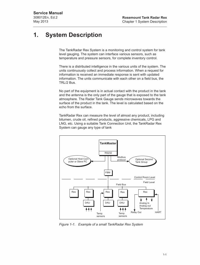
The TankRadar Rex System is a monitoring and control system for tank level gauging. The system can interface various sensors, such as temperature and pressure sensors, for complete inventory control.
There is a distributed intelligence in the various units of the system. The units continuously collect and process information. When a request for information is received an immediate response is sent with updated information. The units communicate with each other on a field bus, the TRL/2 Bus.
No part of the equipment is in actual contact with the product in the tank and the antenna is the only part of the gauge that is exposed to the tank atmosphere. The Radar Tank Gauge sends microwaves towards the surface of the product in the tank. The level is calculated based on the echo from the surface.
TankRadar Rex can measure the level of almost any product, including bitumen, crude oil, refined products, aggressive chemicals, LPG and LNG, etc. Using a suitable Tank Connection Unit, the TankRadar Rex System can gauge any type of tank
Figure 1-1. Example of a small TankRadar Rex System
TankMaster
RS232
Optional Second Tank Group
FBM
Modbus protocol
Field Bus
Control Room Level
Field Level
Analog InAnalog outTemperature
Temp.sensors
Temp.sensors
Rex
Optional Host Com-puter or Slave PC
DAU
Relay Out HART
Rex Rex Rex Rex
DAU DAU
1-1
Rosemount Tank Radar RexChapter 1 System Description
Service Manual308012En, Ed.2
May 2013
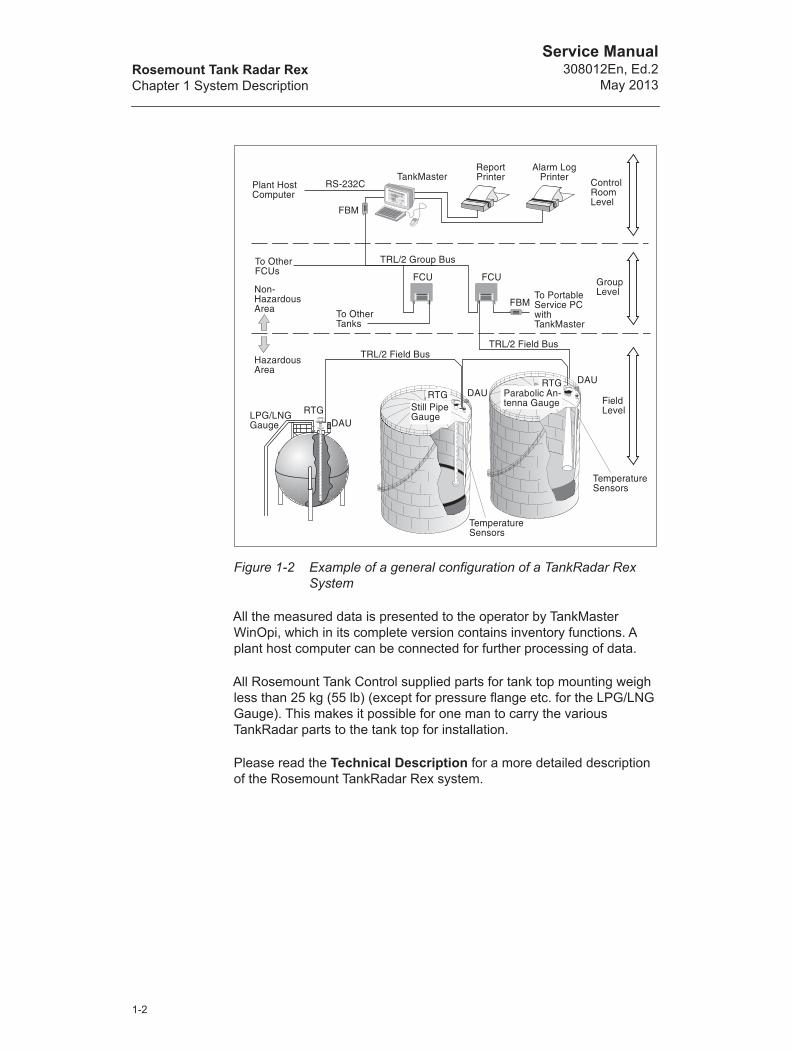
Figure 1-2 Example of a general configuration of a TankRadar Rex System
All the measured data is presented to the operator by TankMaster WinOpi, which in its complete version contains inventory functions. A plant host computer can be connected for further processing of data.
All Rosemount Tank Control supplied parts for tank top mounting weigh less than 25 kg (55 lb) (except for pressure flange etc. for the LPG/LNG Gauge). This makes it possible for one man to carry the various TankRadar parts to the tank top for installation.
Please read the Technical Description for a more detailed description of the Rosemount TankRadar Rex system.
�
�
�
�����
����
��� �����
����
�� ����
��������
�� ����� ���
�� ����� ���
��� ���
��
����!���� ���
��
"�!!��
"�!!����� �����
���#
������������
�$���������
���
�����$���
���
�����������
%��
��% �����
1-2

Rosemount Tank Radar RexChapter 1 System Description
Service Manual308012En, Ed.2May 2013
The basic parts of the TankRadar Rex system are:
• The Radar Tank Gauge, RTG, is an intelligent explosion pro-tected instrument for measuring the level of a product inside a tank. Four different Tank Connection Units can be attached in order to satisfy a variety of different applications.
• The Data Acquisition Unit, DAU, is a local readout/connection unit for use with the TankRadar Rex tank gauging system. The DAU is used for connection of temperature sensors when more inputs/outputs are required than is available in the Rex Gauge.
• The Field Communication Unit, FCU, acts as a gateway and data concentrator between the Group Bus and the Field Bus. Each FCU can have a total of 32 RTGs and 32 DAUs connected to it.
• The Field Bus Modem, FBM, acts as a converter between USB or RS-232C and the TRL/2 Bus. It is used for connecting a PC with TankMaster to the TRL/2 Bus.
• The Remote Display Unit, RDU 40, is a display unit for present-ing calculated and measured data from the Rex gauge such as level, average temperature, volume, signal strength etc.
• The TankMaster is a software package for installation and config-uration of level gauging equipment manufactured by Rosemount. The TankMaster program package provides powerful and easy-to-use tools for installation and configuration of level gauging devices.
1-3

Rosemount Tank Radar RexChapter 1 System Description
Service Manual308012En, Ed.2
May 2013
1-4
Rosemount Tank Radar RexChapter 2 Safety
Service Manual308012En, Ed.2May 2013
2. Safety
TankRadar Rex equipment is often used in areas where flammable materials are handled and where an explosive atmosphere may be present. To protect both the plant and the staff, precautions must be taken to ensure that this atmosphere cannot be ignited. These areas are called hazardous areas and equipment within these areas are explosion protected.
A number of different explosion protection techniques have been developed over the years. Intrinsic safety and explosion proof (or flame proof) safety are two techniques.
2.1 Intrinsic safety
Intrinsic safety, IS, is based on the principle of restricting electrical energy available in hazardous-area circuits such that any sparks or hot surfaces, that may occur as a result of up to two electrical faults in components, are too weak to cause ignition. Intrinsic safety is the only technique accepted for Zone 0 (high risk) hazardous areas. It is also safe for personnel and allows equipment to be maintained without the need for a gas-free certificate.
The basic principles of intrinsic safety are:
• All flammable materials are grouped according to the energy needed to ignite them.
• Equipment located in hazardous areas are classified according to the maximum surface temperature that it can produce and this must be safe with the flammable gases that may be present.
• Hazardous areas are classified according to the probability that an explosive atmosphere is present, and this dictates whether or not a particular explosion protection technique may be used.
2-1
Rosemount Tank Radar RexChapter 2 Safety
Service Manual308012En, Ed.2
May 2013
2.2 Explosion Proof
Explosion proof enclosures can be used when an explosion can be allowed as long as it does not spread outside the enclosure. The enclosure must be strong enough to withstand the pressure and must have narrow gaps to allow the pressure to escape without igniting the atmosphere outside the equipment.
IMPORTANT!
For trouble shooting and repair work of components in or in connection to intrinsically safe equipment, strict observance of the following rules is necessary:
• Disconnect the power supply to the Radar Tank Gauges and Field Communi-cation Units.
• Use a certified battery operated instru-ment only.
• Use Rosemount original spare parts only. Replacement with non-original spare parts may jeopardize the intrinsic safety.
IMPORTANT!
Any substitution to non-recognized parts may impair intrinsic safety.
The explosion-proof (flame-proof) enclosures of the Radar Tank Gauge and the Data Acquisition Unit must not be opened while the units are powered.
2-2

Rosemount Tank Radar RexChapter 3 Device Description
Service Manual308012En, Ed.2May 2013
3. Device Description
3.1 Rex RTG
3.1.1 Overview
The Radar Tank Gauge Rex, RTG Rex, is an autonomous distance measuring device. The distance and level calculations are continuously carried out in the Radar Tank Gauge. Upon request from a master the RTG can send the level information, status and other information on the Field Bus.
All Rex gauges consist of two main parts; the Transmitter Head (TH) and a Tank Connection Unit. A number of different Tank Connection Units (Antennas) can be attached in order to satisfy a variety of different applications.
There are different types of Radar Tank Gauges:
• The Horn Antenna Gauge RTG 3920, for fixed roof installation without still pipe.
• The Parabolic Antenna Gauge RTG 3930, for demanding envi-ronments without still pipe.
• The Still Pipe Gauge RTG 3950, for measuring in still pipes.
• The LPG/LNG Gauge RTG 3960, for liquid gas, LPG and LNG.
All antenna types use the same kind of Transmitter Head Electronics.
3-1
Rosemount Tank Radar RexChapter 3 Device Description
Service Manual308012En, Ed.2
May 2013
3.1.2 Antenna types
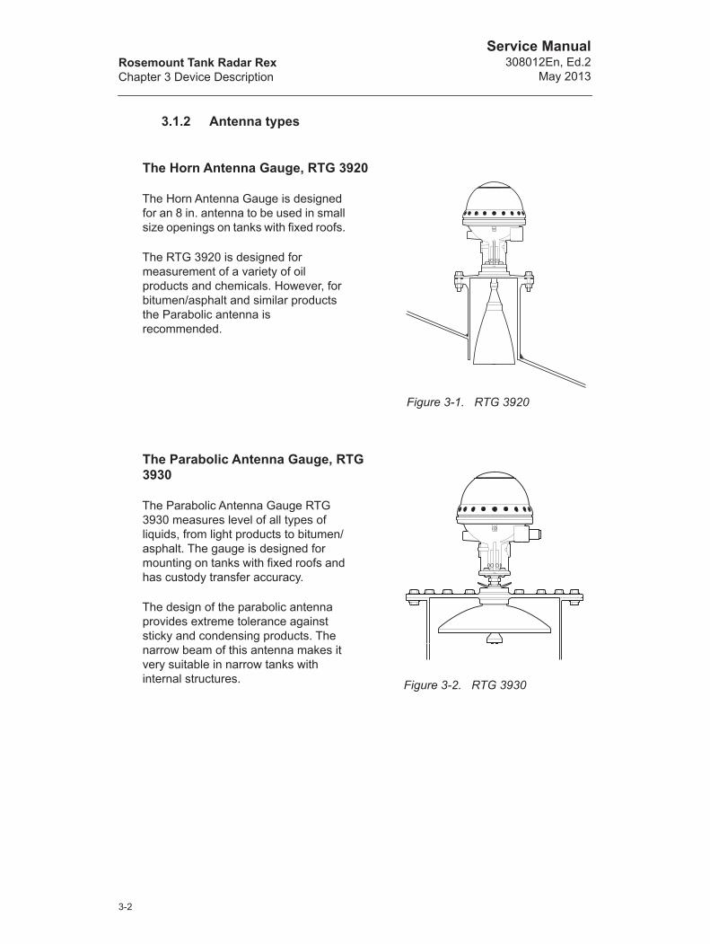
The Horn Antenna Gauge, RTG 3920
The Horn Antenna Gauge is designed for an 8 in. antenna to be used in small size openings on tanks with fixed roofs.
The RTG 3920 is designed for measurement of a variety of oil products and chemicals. However, for bitumen/asphalt and similar products the Parabolic antenna is recommended.
The Parabolic Antenna Gauge, RTG 3930
The Parabolic Antenna Gauge RTG 3930 measures level of all types of liquids, from light products to bitumen/asphalt. The gauge is designed for mounting on tanks with fixed roofs and has custody transfer accuracy.
The design of the parabolic antenna provides extreme tolerance against sticky and condensing products. The narrow beam of this antenna makes it very suitable in narrow tanks with internal structures.
Figure 3-1. RTG 3920
Figure 3-2. RTG 3930
3-2
Rosemount Tank Radar RexChapter 3 Device Description
Service Manual308012En, Ed.2May 2013
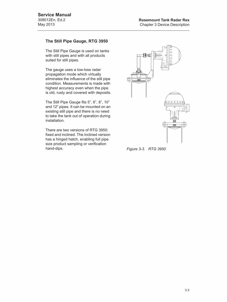
The Still Pipe Gauge, RTG 3950
The Still Pipe Gauge is used on tanks with still pipes and with all products suited for still pipes.
The gauge uses a low-loss radar propagation mode which virtually eliminates the influence of the still pipe condition. Measurements is made with highest accuracy even when the pipe is old, rusty and covered with deposits.
The Still Pipe Gauge fits 5”, 6”, 8”, 10” and 12” pipes. It can be mounted on an existing still pipe and there is no need to take the tank out of operation during installation.
There are two versions of RTG 3950: fixed and inclined. The inclined version has a hinged hatch, enabling full pipe size product sampling or verification hand-dips. Figure 3-3. RTG 3950
3-3
Rosemount Tank Radar RexChapter 3 Device Description
Service Manual308012En, Ed.2
May 2013
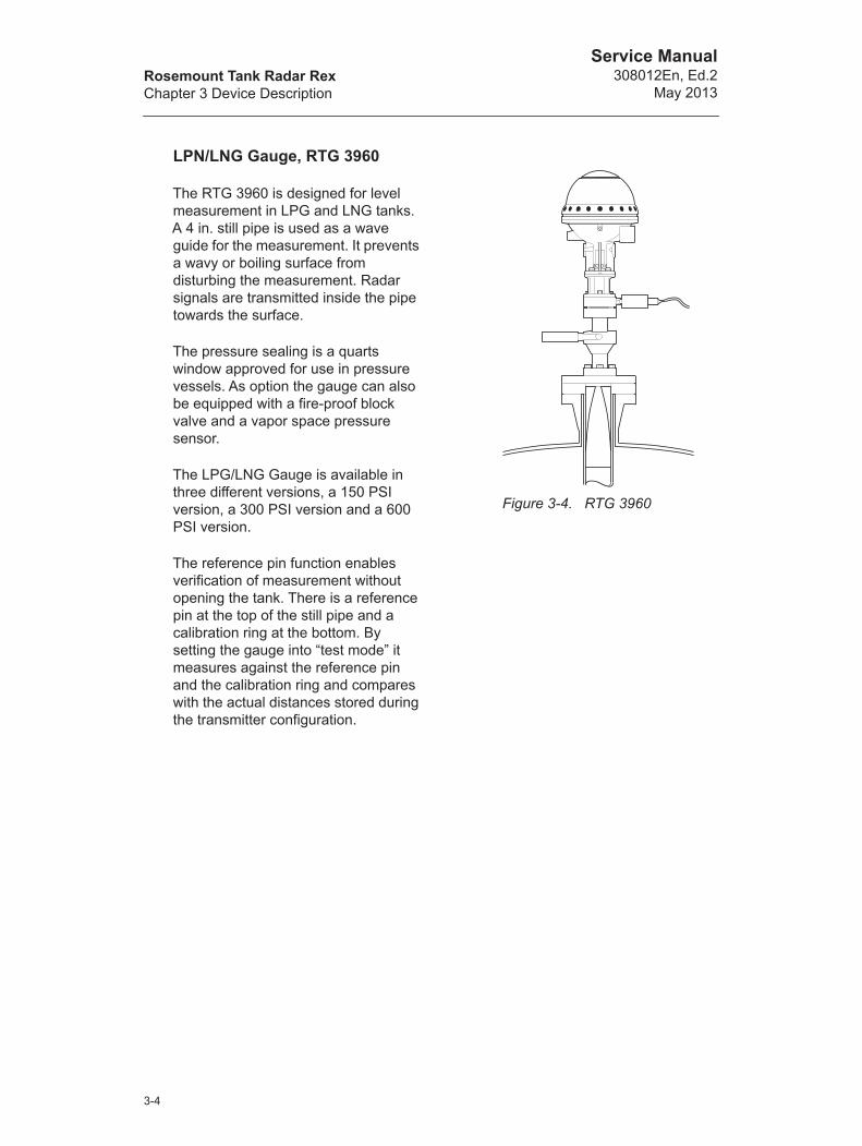
LPN/LNG Gauge, RTG 3960
The RTG 3960 is designed for level measurement in LPG and LNG tanks. A 4 in. still pipe is used as a wave guide for the measurement. It prevents a wavy or boiling surface from disturbing the measurement. Radar signals are transmitted inside the pipe towards the surface.
The pressure sealing is a quarts window approved for use in pressure vessels. As option the gauge can also be equipped with a fire-proof block valve and a vapor space pressure sensor.
The LPG/LNG Gauge is available in three different versions, a 150 PSI version, a 300 PSI version and a 600 PSI version.
The reference pin function enables verification of measurement without opening the tank. There is a reference pin at the top of the still pipe and a calibration ring at the bottom. By setting the gauge into “test mode” it measures against the reference pin and the calibration ring and compares with the actual distances stored during the transmitter configuration.
Figure 3-4. RTG 3960
3-4
Rosemount Tank Radar RexChapter 3 Device Description
Service Manual308012En, Ed.2May 2013
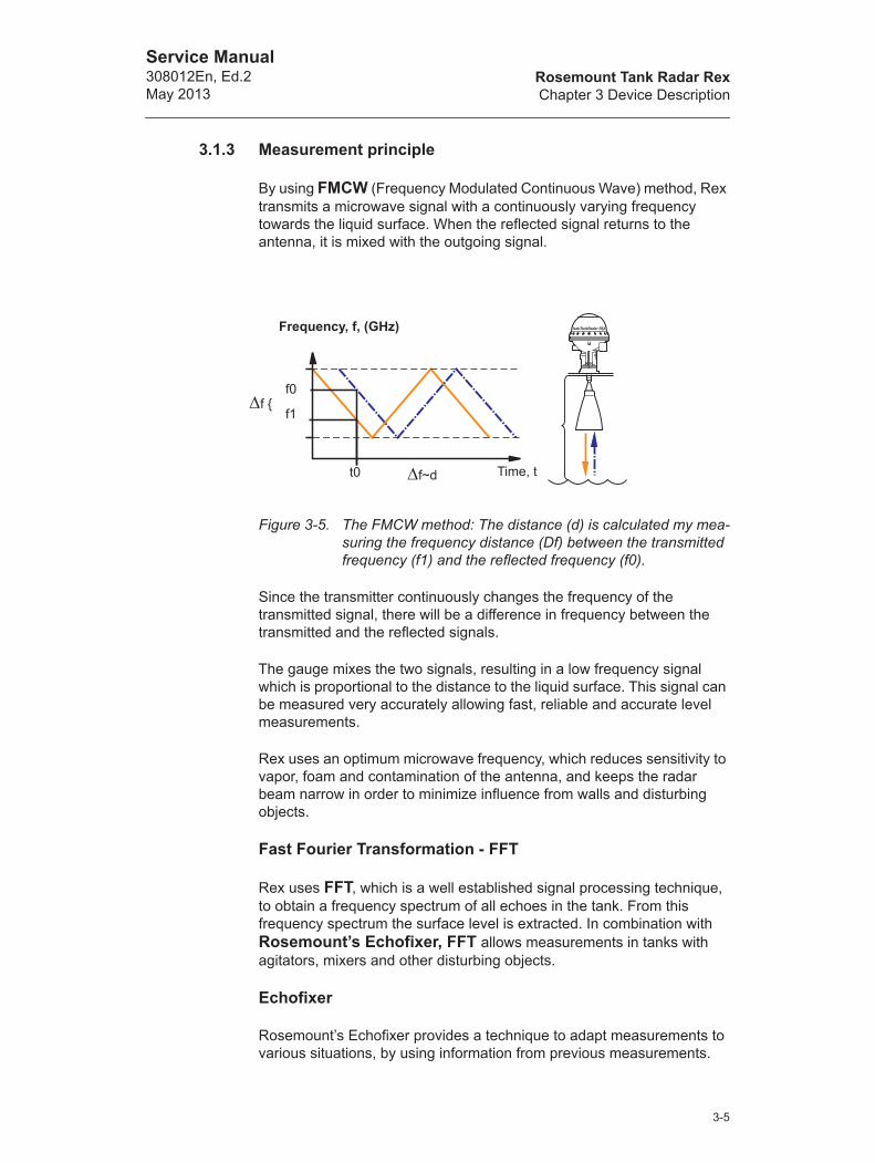
3.1.3 Measurement principle
By using FMCW (Frequency Modulated Continuous Wave) method, Rex transmits a microwave signal with a continuously varying frequency towards the liquid surface. When the reflected signal returns to the antenna, it is mixed with the outgoing signal.
Figure 3-5. The FMCW method: The distance (d) is calculated my mea-suring the frequency distance (Df) between the transmitted frequency (f1) and the reflected frequency (f0).
Since the transmitter continuously changes the frequency of the transmitted signal, there will be a difference in frequency between the transmitted and the reflected signals.
The gauge mixes the two signals, resulting in a low frequency signal which is proportional to the distance to the liquid surface. This signal can be measured very accurately allowing fast, reliable and accurate level measurements.
Rex uses an optimum microwave frequency, which reduces sensitivity to vapor, foam and contamination of the antenna, and keeps the radar beam narrow in order to minimize influence from walls and disturbing objects.
Fast Fourier Transformation - FFT
Rex uses FFT, which is a well established signal processing technique, to obtain a frequency spectrum of all echoes in the tank. From this frequency spectrum the surface level is extracted. In combination with Rosemount’s Echofixer, FFT allows measurements in tanks with agitators, mixers and other disturbing objects.
Echofixer
Rosemount’s Echofixer provides a technique to adapt measurements to various situations, by using information from previous measurements.
Frequency, f, (GHz)
t0 f~d Time, t
f1
f0f {
3-5

Rosemount Tank Radar RexChapter 3 Device Description
Service Manual308012En, Ed.2
May 2013
Fast High Accuracy Signal Technique - FHASTTM
To further improve measurement accuracy, Rex can utilize the benefits of Rosemount’s Fast High Accuracy Signal Technique
Multiple Echo Tracking - METTM
Multiple Echo Tracking is another advanced feature, which provides increased resolution in tanks with disturbing objects. MET facilitates the separation of disturbances from the actual product surface echo.
Figure 3-6. Signal processing schedule
Digital Signal Processor
FFT
Disturbance EchoHandling
FHASTFilter
High Accuracy
Signal Product Level
ProgrammableMemory
DynamicMemory
Real TimeMemory
Multiple EchoTrackingEchofixer
3-6

Rosemount Tank Radar RexChapter 3 Device Description
Service Manual308012En, Ed.2May 2013
3.1.4 Transmitter Head Electronics
The electronics is mounted in an exchangeable unit in the explosion proof Transmitter Head. A high measurement accuracy is achieved by using digital reference circuitry, and by controlling the internal temperature by an internal heater.
The 3900 transmitter head can be used on all types of Rex antennas.
A metrological seal is available to prevent unauthorized changes of database settings.
Note! Some of the electronic cards shown below are optional and may not be installed in your transmitter
.
Figure 3-7. Rex Transmitter Head Electronics
Transmitter Interface Card (TIC)
Analog Processing Card (APC)Field Communication Card (FCC)
Signal Processing Card (SPC)
MotherboardRelay Output Card (ROC)
Temperature Multiplex-ing Card (TMC)
Transformer Rectifier Card (TRC)
3-7
Rosemount Tank Radar RexChapter 3 Device Description
Service Manual308012En, Ed.2
May 2013
Signal Processing Card (SPC)
The SPC is mainly a digital processor card for advanced signal and communication processing as well as handling of auxiliary functions.
Analog Processing Card (APC)
The APC is used for filtering and multiplexing of analog input signals. By keeping the analog circuitry on a separate card a high Signal to Noise Ratio is achieved.
Field Communication Card (FCC)
The FCC handles communication with external devices. There are different versions of the FCC card allowing you to use various types of communication protocols and even emulate other types of gauges.
Relay Output Card (ROC), optional
The Relay Output Card (ROC) contains two relays. It allows controlling external devices such as valves, pumps, heating coils etc.
Transmitter Interface Card (TIC, optional)
The Transmitter Interface Card (TIC) is required for intrinsically safe auxiliary inputs. The TIC includes:
• Two supply barriers and two input/return barriers for 4-20 mA cur-rent loops.
• One supply barrier for a DAU or a local display unit.
• One signal barrier for communication with the DAU or local display unit.
• Signal/supply connection for optional TMC.
Temperature Multiplexer Card (TMC), optional
The Temperature Multiplexer Card (TMC) is an optional add-on board which is mounted on the back of TIC. TMC is used to connect up to 6 temperature sensors. Both spot and average sensors are supported.
3-8
Rosemount Tank Radar RexChapter 3 Device Description
Service Manual308012En, Ed.2May 2013
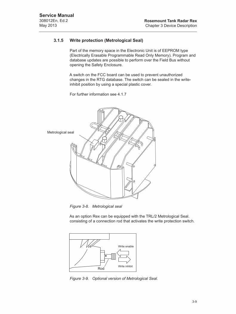
3.1.5 Write protection (Metrological Seal)
Part of the memory space in the Electronic Unit is of EEPROM type (Electrically Erasable Programmable Read Only Memory). Program and database updates are possible to perform over the Field Bus without opening the Safety Enclosure.
A switch on the FCC board can be used to prevent unauthorized changes in the RTG database. The switch can be sealed in the write-inhibit position by using a special plastic cover.
For further information see 4.1.7
Figure 3-8. Metrological seal
As an option Rex can be equipped with the TRL/2 Metrological Seal. consisting of a connection rod that activates the write protection switch.
Figure 3-9. Optional version of Metrological Seal.
Metrological seal
Write enable
Write inhibitRod
3-9
Rosemount Tank Radar RexChapter 3 Device Description
Service Manual308012En, Ed.2
May 2013
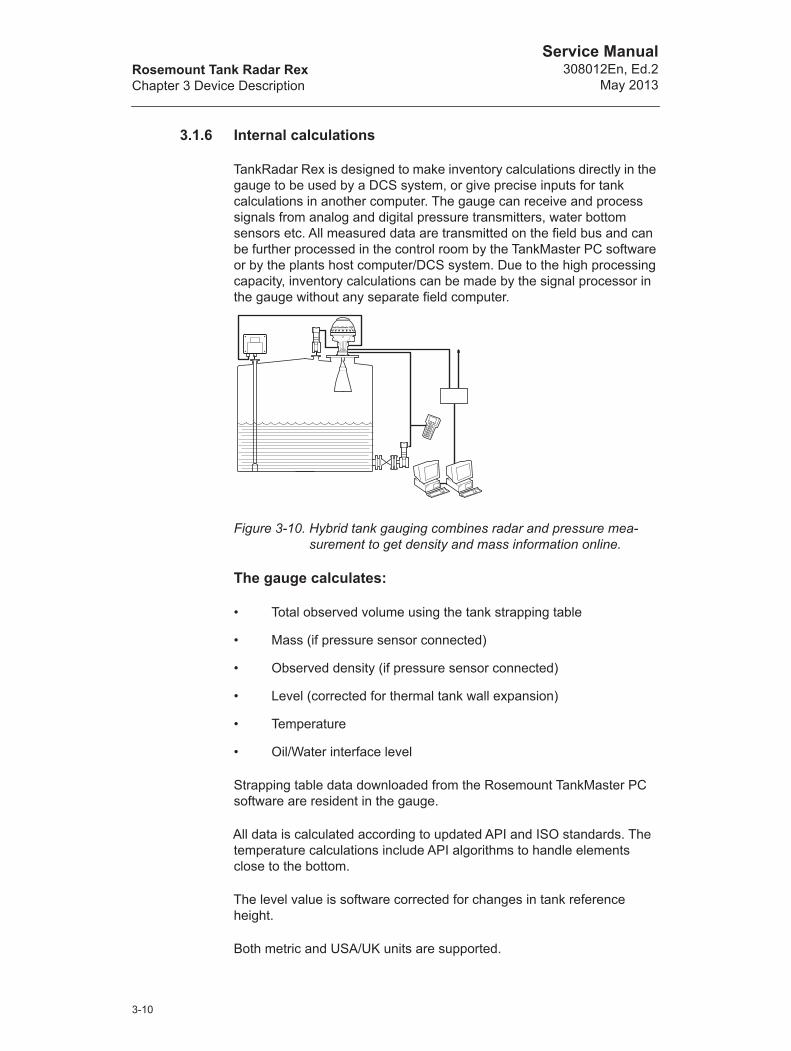
3.1.6 Internal calculations
TankRadar Rex is designed to make inventory calculations directly in the gauge to be used by a DCS system, or give precise inputs for tank calculations in another computer. The gauge can receive and process signals from analog and digital pressure transmitters, water bottom sensors etc. All measured data are transmitted on the field bus and can be further processed in the control room by the TankMaster PC software or by the plants host computer/DCS system. Due to the high processing capacity, inventory calculations can be made by the signal processor in the gauge without any separate field computer.
Figure 3-10. Hybrid tank gauging combines radar and pressure mea-surement to get density and mass information online.
The gauge calculates:
• Total observed volume using the tank strapping table
• Mass (if pressure sensor connected)
• Observed density (if pressure sensor connected)
• Level (corrected for thermal tank wall expansion)
• Temperature
• Oil/Water interface level
Strapping table data downloaded from the Rosemount TankMaster PC software are resident in the gauge.
All data is calculated according to updated API and ISO standards. The temperature calculations include API algorithms to handle elements close to the bottom.
The level value is software corrected for changes in tank reference height.
Both metric and USA/UK units are supported.
3-10
Rosemount Tank Radar RexChapter 3 Device Description
Service Manual308012En, Ed.2May 2013
3.1.7 Inputs and Outputs
Inputs
The gauge has:
• up to 6 temperature inputs directly into the gauge.
• up to 14 temperature inputs to each gauge via separate Data Acquisition Unit.
• two 18 bits high accuracy analog inputs for e.g. pressure transmit-ters or water bottom sensors. The gauge can act as a single HART master using one analog input to interface intrinsically safe digital HART inputs from up to 3 HART based sensors.
Technical Data, Analog inputs
Outputs
The gauge has:
• two relay outputs (non-intrinsically safe) to be used for level, tem-perature or other alarms (250 VAC, 4 A). The relays are approved for overfill safety by TÜV and have function feedback. Operation is selectable as “normally open” or “normally closed”.
• one optional non-intrinsically safe Analog output. The Analog out-put replaces the second Relay output.
Technical Data, Relay outputs
Accuracy ±20 A
Input range 4-20 mA
Update range 0.5 Hz
Low alarm level < 3.8 mA, configurable
High alarm level > 20.7 mA, configurable
Umax from TIC 25.2 V
Imax from TIC 96 mA
Pmax from TIC 0.6 W
Available voltage 13.7 V (at 20 mA)
Contact rating (resis-tive load)
250 V, 4A
Contact life 100 000 op
3-11

Rosemount Tank Radar RexChapter 3 Device Description
Service Manual308012En, Ed.2
May 2013
Technical Data, Analog output
Type Analog 4-20 mA current loop, passive or active output (external or internal loop supply)
Galvanic isolation >1500 V RMS or DC
Range 4-20 mA
Alarm level 3.8 mA, 22 mA, “freeze current”, Binary High or Binary Low; software select-able
Resolution 0.5 mA (0.003%)
Linearity ± 0.01%
Temperature drift ± 50 ppm/C°
Output impedance >10 MW
Voltage compliance 7-30 V
External loop resis-tance
<700 W (passive output with 24 V external supply).<300 W (active output).
3-12
Rosemount Tank Radar RexChapter 3 Device Description
Service Manual308012En, Ed.2May 2013
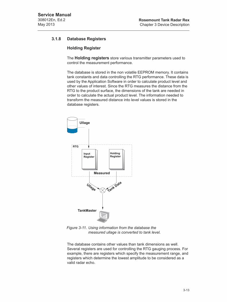
3.1.8 Database Registers
Holding Register
The Holding registers store various transmitter parameters used to control the measurement performance.
The database is stored in the non volatile EEPROM memory. It contains tank constants and data controlling the RTG performance. These data is used by the Application Software in order to calculate product level and other values of interest. Since the RTG measures the distance from the RTG to the product surface, the dimensions of the tank are needed in order to calculate the actual product level. The information needed to transform the measured distance into level values is stored in the database registers.
The database contains other values than tank dimensions as well. Several registers are used for controlling the RTG gauging process. For example, there are registers which specify the measurement range, and registers which determine the lowest amplitude to be considered as a valid radar echo.
Figure 3-11. Using information from the database the measured ullage is converted to tank level.
Input Register
Ullage
Holding Register
Tank DataUllage
Measured
TankMaster
3-13
Rosemount Tank Radar RexChapter 3 Device Description
Service Manual308012En, Ed.2
May 2013
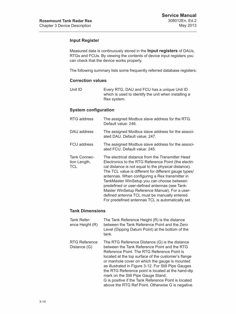
Input Register
Measured data is continuously stored in the Input registers of DAUs, RTGs and FCUs. By viewing the contents of device input registers you can check that the device works properly.
The following summary lists some frequently referred database registers:
Correction values
System configuration
Tank Dimensions
Unit ID Every RTG, DAU and FCU has a unique Unit ID which is used to identify the unit when installing a Rex system.
RTG address The assigned Modbus slave address for the RTG. Default value: 246.
DAU address The assigned Modbus slave address for the associ-ated DAU. Default value: 247.
FCU address The assigned Modbus slave address for the associ-ated FCU. Default value: 245.
Tank Connec-tion Length, TCL
The electrical distance from the Transmitter Head Electronics to the RTG Reference Point (the electri-cal distance is not equal to the physical distance). The TCL value is different for different gauge types/antennas. When configuring a Rex transmitter in TankMaster WinSetup you can choose between predefined or user-defined antennas (see Tank-Master WinSetup Reference Manual). For a user-defined antenna TCL must be manually entered. For predefined antennas TCL is automatically set.
Tank Refer-ence Height (R)
The Tank Reference Height (R) is the distance between the Tank Reference Point and the Zero Level (Dipping Datum Point) at the bottom of the tank.
RTG Reference Distance (G)
The RTG Reference Distance (G) is the distance between the Tank Reference Point and the RTG Reference Point. The RTG Reference Point is located at the top surface of the customer’s flange or manhole cover on which the gauge is mounted as illustrated in Figure 3-12. For Still Pipe Gauges the RTG Reference point is located at the hand-dip mark on the Still Pipe Gauge Stand.G is positive if the Tank Reference Point is located above the RTG Ref Point. Otherwise G is negative.
3-14
Rosemount Tank Radar RexChapter 3 Device Description
Service Manual308012En, Ed.2May 2013
Minimum leveldistance (C)
The Minimum Level Distance (C) is defined as the distance between the Zero Level (Dipping Datum Point) and Minimum Level of the product surface (tank bottom). By specifying a C-distance, the mea-suring range can be extended to the bottom of the tank. If C>0, negative level values will be displayed when the product surface is below the Zero Level. Select the Show negative level values as zero check box if you want levels below the Zero Level to be displayed as Level=0.If you set the C-distance =0, measurements below the Zero Level will not be approved, i.e. the RTG will report an invalid level.
Calibration Dis-tance
Calibration Distance is used for calibration of the RTG.
Hold Off Distance (UFM)
The Hold Off Distance (also referred to as Upper Fil-ter Margin) defines how close to the RTG Reference Point measurements are accepted. Normally this parameter should not be changed. The Hold Off Distance may be increased, if for example, there are disturbing echoes from the tank nozzle.
3-15
Rosemount Tank Radar RexChapter 3 Device Description
Service Manual308012En, Ed.2
May 2013
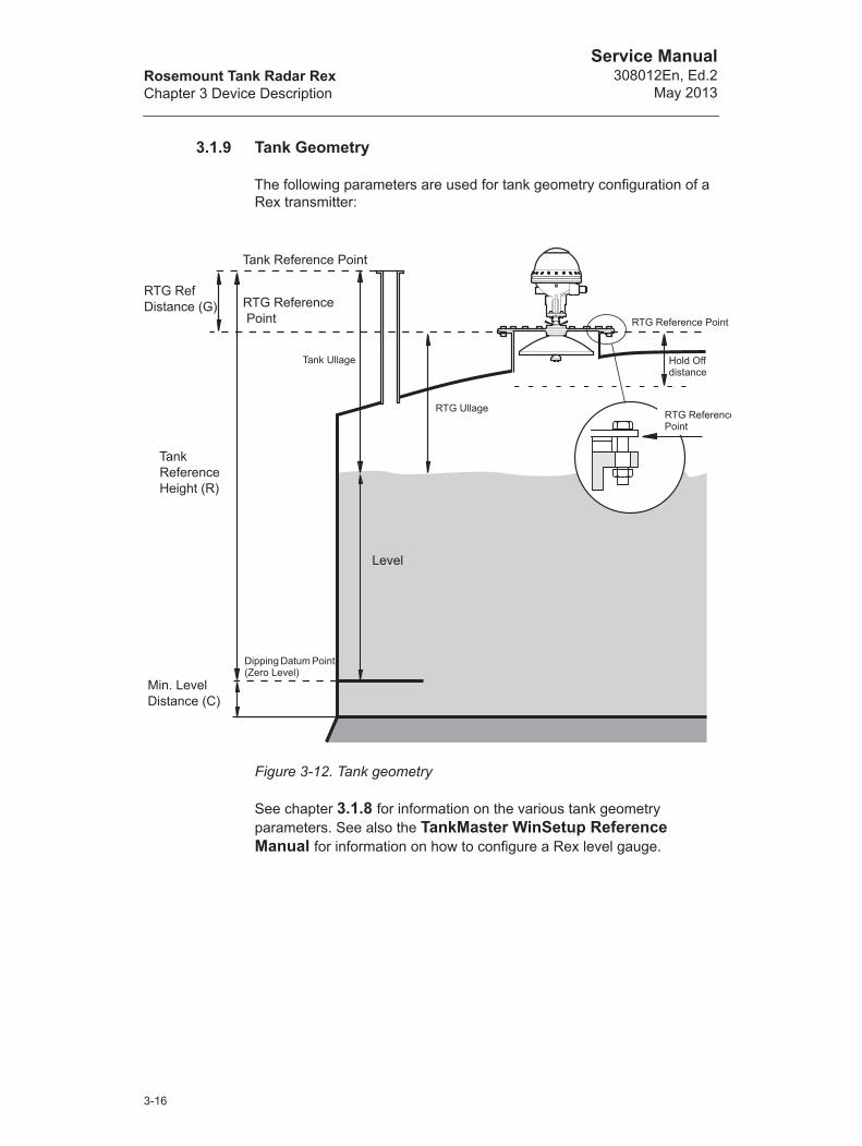
3.1.9 Tank Geometry
The following parameters are used for tank geometry configuration of a Rex transmitter:
Figure 3-12. Tank geometry
See chapter 3.1.8 for information on the various tank geometry parameters. See also the TankMaster WinSetup Reference Manual for information on how to configure a Rex level gauge.
Tank Reference Point
RTG Reference Point RTG Reference Point
RTG Ullage
Tank Ullage
Dipping Datum Point (Zero Level)
Level
Hold Off distance
RTG RefDistance (G)
TankReference Height (R)
Min. LevelDistance (C)
RTG ReferencePoint
3-16

Rosemount Tank Radar RexChapter 3 Device Description
Service Manual308012En, Ed.2May 2013
3.1.10 Software Description
The Rex transmitter contains software which controls measurement, communication etc. Each program can be changed by either replacing an EEPROM or by downloading through the TRL/2 bus. Both programs must be changed simultaneously. The EEPROM contains both the Boot and the Application programs.
The transmitter software performs actions as:
• Internal initialization
• Communication handling
• Implementing measurement features
• Internal checks
For further information, see Chapter 4.1.5.
3-17

Rosemount Tank Radar RexChapter 3 Device Description
Service Manual308012En, Ed.2
May 2013
3.2 Field Communication Unit (FCU)
The Field Communication Unit, FCU acts as a master of communications on the Field Bus and as a slave on the Group Bus. The FCU is an intelligent data concentrator that continuously collects input data from a group of Radar Tank Gauges and Data Acquisition Units and stores it in a buffer memory.
The heart of the FCU is a microprocessor with RAM and EEPROM for data and program storage.
The FCU is delivered in an IP-65 weather protected, wall-mounted box of the same type as for the Data Acquisition Unit. See Figure 3-13.
Figure 3-13. Field Communication Unit FCU 2160
Note! No explosion protection is provided so the Field Communication Unit must be installed in a non-hazardous area.
Cable Outputs
GroundConnection
3-18

Rosemount Tank Radar RexChapter 3 Device Description
Service Manual308012En, Ed.2May 2013
3.2.1 Field Bus and Group Bus Communication
The Field Communication Unit has six communication ports, X1 to X6. The standard configuration is six TCM interface boards with four TRL/2 Field Bus (FB) ports and two TRL/2 Group Bus (GB) ports. As an alternative, the FCM boards at the Group and Field Bus ports can be replaced with FCI boards for RS-485 communication. The FCU communication ports can be configured according to the following table:
The Field Communication Unit has six communication ports for the Field bus and Group bus communication. The Group Bus ports can be used independently of each other. For example, one Group Bus can be connected to a PC with OPI software, and at the same time another Group Bus may be connected to a plant host computer.
There are four Field Bus ports each of which can connect up to eight units. A unit may consist of a Rex gauge, or a Rex gauge connected to a DAU.
If the number of cables to a Field Communication Unit is higher than the capacity of the connectors then standard Junction Boxes (fitted for use in the environment in question) can be used to split the connections.
There is a steel plate to shield the bus ports from the rest of the electronics in the FCU.
3.2.2 Input and Database Registers
The input register is a dynamic register which holds the values that the FCU receives over the TRL/2 bus from connected slave units (RTGs, DAUs). Level, temperature and other measured data is stored in the input register, and are sent to the master on request.
The database contains information on program version, communication protocol values, slave configuration, memory configuration etc. It is divided into one write protected and one unprotected part. See Chapter 4.1.7 on how to remove the write protection.
X1 X2 X3 X4 X5 X6
FB FB FB FB GB GB
FB FB FB GB GB GB
FB FB GB GB GB GB
3-19

Rosemount Tank Radar RexChapter 3 Device Description
Service Manual308012En, Ed.2
May 2013
3.2.3 Software
The FCU software controls the collection of data from the units connected to the Field Bus, and handles the distribution of data to the TankMaster PC on the Group Bus.
The Group Bus Process and the Field Bus Process work as interfaces to the serial communication control, SCC. The EEPROM switch is used by the program to determine if it is allowed to write to the EEPROM. The watch dog has to be gritted at least every tenth second or else a reset is performed. Direct Memory Access (DMA) channels in the FCU microprocessor are used to write to the SCC.
When the Group Bus Process receives a query from the master on the Group Bus, it will translate the query into the MODBUS format if necessary. The query is processed, translated back to the original format and the response is sent back to the master. The processing of the query could be done in the Field Communication Unit or it could request further processing in the slave units (RTGs and DAUs) connected to the Field Communication Unit.
The Field Bus Process scans the slave units as a master. The result of the queries is stored in the standard data registers. It could also get queries from the Group Bus, via the Special Command Process, to be sent out on the Field Bus. The results of those queries are stored in the Special Data Buffer.
3.2.4 Redundancy
In order to reduce the risk of communication failure between the TankMaster and the units connected to the TRL/2 field bus, two FCUs can be connected to run in parallel. If one FCU fails, the other one automatically takes over without any action from the operator. The FCUs are connected with an extra cable allowing them to communicate. The inactive FCU constantly checks if the connected FCU is active. If the active FCU fails, it signals to the backup FCU to take over. Then the backup FCU immediately switches to an active state.
&�!��
'��
&�!��
'��
����(&�!��
)�*
+�,- �*
,����.�!
)�/.�!
Figure 3-14. Group and Field bus communication
3-20

Rosemount Tank Radar RexChapter 3 Device Description
Service Manual308012En, Ed.2May 2013
3.2.5 Connection to a PC
The FCU can be connected to the PC either directly via a TRL/2 Group Bus or via the RS-232C interface.
The RS-232C connection can be made with 3 wires from the PC to the Field Communication Unit. The cross sectional area must be at least 0.25 mm² (AWG 24 or similar). The maximum length of the RS-232C connection is 15 m.
The TRL/2 bus requires a twisted and shielded pair cable with a cross sectional area of min. 0.50 mm² (AWG 20 or similar).
3-21

Rosemount Tank Radar RexChapter 3 Device Description
Service Manual308012En, Ed.2
May 2013
3.3 Data Acquisition Unit (DAU)
3.3.1 Overview
The Data Acquisition Unit, DAU, is a complement to the Radar Tank Gauge.
Figure 3-15. The DAU.
The DAU is equipped with an interface for temperature measurement.
3.3.2 Data Acquisition Unit (DAU)
The DAU is intrinsically safe and is connected to the Radar Tank Gauge on the same tank. It receives its power supply and communicates via the Barrier Unit Card in the Radar Tank Gauge.
Figure 3-16. DAU
Cable inlets
3-22

Rosemount Tank Radar RexChapter 3 Device Description
Service Manual308012En, Ed.2May 2013
3.3.3 Electronics
The DAU's main circuit board is called DMB, DAU Minimum Board.
In Figure 3-17 the block diagram of the DAU is shown.
Figure 3-17. Block diagram of the Data Acquisition Unit.
RTG
(power supply for DAU)
3-23

Rosemount Tank Radar RexChapter 3 Device Description
Service Manual308012En, Ed.2
May 2013
3.3.4 Temperature Measurement
Temperature sensors
Measuring the product temperature is necessary for correct inventory calculations. Up to 14 temperature sensors can be connected to each Data Acquisition Unit. The temperature elements are placed in a tube which is anchored to the bottom of the tank. Either Pt 100 (spot element) or Cu90 (average sensor) temperature sensors can be used. By using the Pt100 spot sensors, a profile of the temperature at various tank levels is obtained, as well as the average temperature of the liquid. The Cu90 sensors measures the average temperature measured from the tank bottom to the product surface.
Reference resistors
There are two reference resistors connected which are used to calibrate the voltage to frequency converter (VCF) feeding the DAU's microprocessor with data from the temperature sensors. The internal 100 W precision reference resistor is connected to channel 0 of the RTD multiplexer. The external reference resistor is connected to channel 15. In some cases there is a third reference resistor connected to the first free temperature sensor input. Using this sensor enables the accuracy to be increased even more.
Database
The DAU's database contains several registers for temperature measurements. Temperature range and sensor type may need to be checked before operation. The ratio between the two reference resistances is measured, and the tolerance of the deviation from the nominal value is also stored in the database.
3-24
Rosemount Tank Radar RexChapter 3 Device Description
Service Manual308012En, Ed.2May 2013
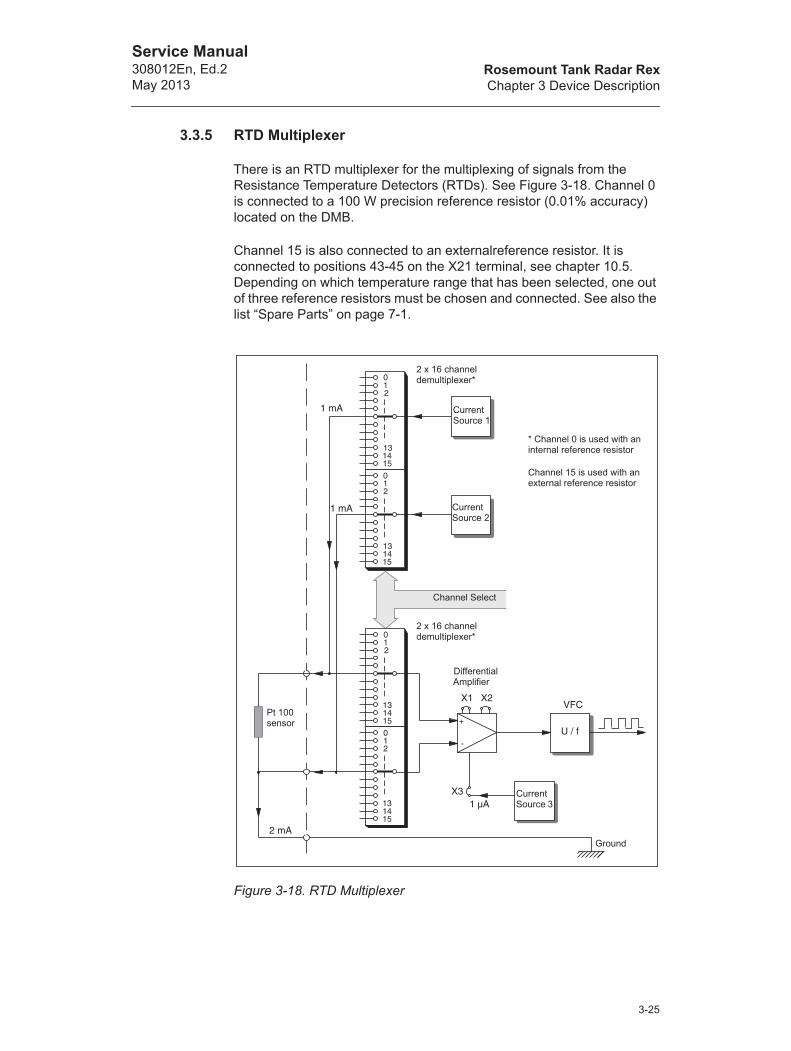
3.3.5 RTD Multiplexer
There is an RTD multiplexer for the multiplexing of signals from the Resistance Temperature Detectors (RTDs). See Figure 3-18. Channel 0 is connected to a 100 W precision reference resistor (0.01% accuracy) located on the DMB.
Channel 15 is also connected to an externalreference resistor. It is connected to positions 43-45 on the X21 terminal, see chapter 10.5. Depending on which temperature range that has been selected, one out of three reference resistors must be chosen and connected. See also the list “Spare Parts” on page 7-1.
Figure 3-18. RTD Multiplexer
2 x 16 channel demultiplexer*
* Channel 0 is used with an internal reference resistor
Channel 15 is used with an external reference resistor
Current Source 1
Current Source 2
Channel Select
2 x 16 channel demultiplexer*
Differential Amplifier
Current Source 3
Ground
Pt 100 sensor
3-25

Rosemount Tank Radar RexChapter 3 Device Description
Service Manual308012En, Ed.2
May 2013
3.3.6 DAU Software
The software in the DAU operates in the context shown in Figure 3-19.
The software is made up of various modules called tasks. The tasks are running with the following priorities:
The TIMER task is running at the highest priority so that the communication cannot interfere with the measuring of a sensor.
The DAU controls the installed hardware based on the information stored in the database, and sends error reports if requested data is not available due to hardware failure.
Figure 3-19. The DAU software handles several processes
Task 1: Timer
Task 2: External communication
Task 3. Internal communication
Task 4: Commands decoding and handling
Task 5: Background tasks
Field Bus
Serial in
Serial out
EEPROM
EEPROMProgramming Switch
Readconfigu-ration
Storeconfiguration
Write enable/inhibit
Display dataLocal display
Relay
Relay status
Controldata
Frequency Inputs
Choose frequency inputs Frequency
Digital Status
Read Status
Status
Current inputs
Current data
Choosecurrent inputs
Temperature Sensors
Temperature
Choosesensor
DAUSoftware
3-26

Rosemount Tank Radar RexChapter 3 Device Description
Service Manual308012En, Ed.2May 2013
3.3.7 Database Registers
The DAU’s database is stored in a nonvolatile memory (it will retain its contents even if the power is turned off), a serial EEPROM. The database is copied to a part of RAM that acts as a Shadow RAM in order to increase performance when accessing the database. The database contains tank specific values like the height of the temperature sensors.
At start up the software determines whether it was a power on or a reset from the Watchdog. At power on it tests the checksum of the program stored in the EPROM, and runs a test of the entire RAM. If any faults are found, these are flagged in status registers. Then the checksum in the database is tested. If it is OK, the data base is loaded into the shadow RAM. If it is not OK, this is indicated in status registers, and a default database is restored in the EEPROM and RAM.
The program will also conduct memory tests during the usual chores. The RAM test is run approximately every 20:th second. The EPROM and EEPROM tests are run at intervals of 80 minutes separated by 40 minutes. It takes two consecutive errors to be detected before the error is signaled to the bus-master.
3.3.8 Local Display
The DAU is equipped with an LCD-display as a Local Readout function. The display shows the level of the associated RTG, values measured by the DAU itself and error codes.
Figure 3-20. DAU LCD-display
��� ��0��!����� *��� ��� �* ��1�
��2 � �3
� ��# 4(3�5 �� 67%5� ��/ � �������� ��/ �3� �9 /���,���� ���:��/��! �������� ��!!
�����������
���2
3-27
Rosemount Tank Radar RexChapter 3 Device Description
Service Manual308012En, Ed.2
May 2013
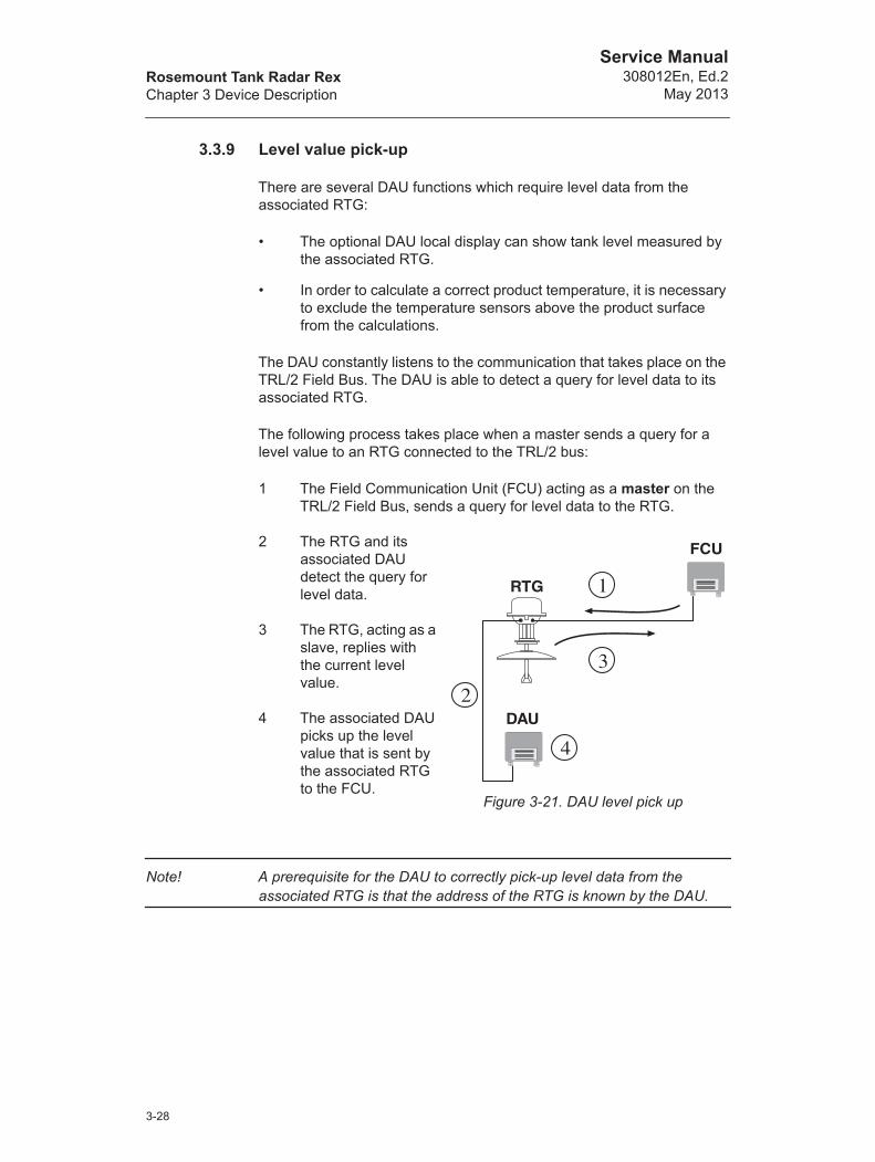
3.3.9 Level value pick-up
There are several DAU functions which require level data from the associated RTG:
• The optional DAU local display can show tank level measured by the associated RTG.
• In order to calculate a correct product temperature, it is necessary to exclude the temperature sensors above the product surface from the calculations.
The DAU constantly listens to the communication that takes place on the TRL/2 Field Bus. The DAU is able to detect a query for level data to its associated RTG.
The following process takes place when a master sends a query for a level value to an RTG connected to the TRL/2 bus:
1 The Field Communication Unit (FCU) acting as a master on the TRL/2 Field Bus, sends a query for level data to the RTG.
2 The RTG and its associated DAU detect the query for level data.
3 The RTG, acting as a slave, replies with the current level value.
4 The associated DAU picks up the level value that is sent by the associated RTG to the FCU.
Note! A prerequisite for the DAU to correctly pick-up level data from the associated RTG is that the address of the RTG is known by the DAU.
Figure 3-21. DAU level pick up
3-28

Rosemount Tank Radar RexChapter 3 Device Description
Service Manual308012En, Ed.2May 2013
3.3.10 Automatic test of temperature references
The reference resistors are automatically tested by calculating the ratio between the temperature references,
This value is put into Input register 10. The ratio is compared with a nominal value which depends on the selected temperature range. The tolerance of the value is set in Database registers 307-310.
3.4 Remote Display Unit 40 (RDU 40)
The RDU 40 is a display unit for use with Rosemount TankRadar Rex and Rosemount TankRadar Pro. The display functions are controlled by the software of the connected TankRadar gauge.
Figure 3-22. RDU 40 can be configured to show various measurement variables such as Level, Temperature, Volume etc.
For installation instructions see section “RDU 40” on page 4-69.
The RDU40 is used for monitoring measured data. To configure a TankRadar Rex gauge use the TankMaster Winsetup configuration software.
Configuration and installation of the RDU40 is described in the Display Unit RDU 40, User’s Guide (Ref. no. 308010EN).
Note! Check that the Rex Software version is 1.D2 or later, and that the RDU 40 Software version is 1.B1 or later.
HirefLoref---------------
6.767Level
m
3-29

Rosemount Tank Radar RexChapter 3 Device Description
Service Manual308012En, Ed.2
May 2013
3-30
Rosemount Tank Radar RexChapter 4 Service
Service Manual308012En, Ed.2May 2013
4. Service
4.1 Rex RTG
4.1.1 How to initiate an echo search
There are several ways that an echo search can be initiated:
• Switch power supply off and on. A search is automatically per-formed.
• Restart the RTG:
1 Select the transmitter icon in the TankMaster WinSetup workspace window.
2 Click the right mouse button and choose the Restart optionor-from the Service menu choose Devices/Restart.
What happens after a power on?
1 An internal check of software version and memory status is done.
2 The communication is enabled.
3 The sweep generation is started. A “dummy” sweep is generated until the sweep is linear (warm-up mode).
4 The level gauging starts with a search through the tank to find the level of the product.
5 When the level is found, the normal gauging procedure starts.
What happens during a search?
A microwave signal is sent towards the product surface with a continuously varying frequency. The reflected signal is mixed with the outgoing signal, resulting in a low-frequency signal which is proportional to the distance to the liquid surface. By using a signal processing technique based on Fast Fourier Transformation (FFT), a frequency spectrum of all echoes in the tank is obtained. From this spectrum the surface level is extracted with high accuracy.
4-1
Rosemount Tank Radar RexChapter 4 Service
Service Manual308012En, Ed.2
May 2013
4.1.2 Viewing and Editing database registers
Measured data is continuously stored in the Input registers of DAUs, RTGs and FCUs. By viewing the contents of device input registers you can check that the device works properly.
The Holding registers store various transmitter parameters used to control the measurement performance.
Most Holding registers can be edited by simply typing a new value in the appropriate Value input field. Some holding registers (marked grey in the Value input column) can be edited in a separate window. In this case you can choose from a list of options or you can change separate data bits.
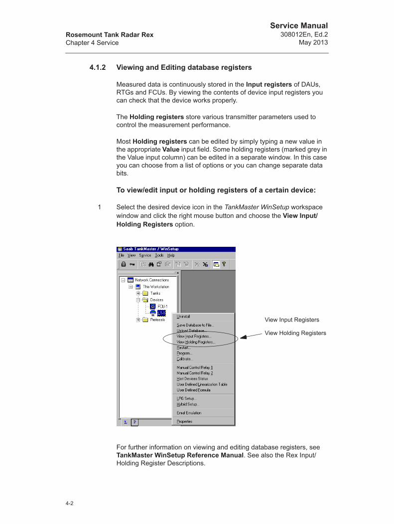
To view/edit input or holding registers of a certain device:
1 Select the desired device icon in the TankMaster WinSetup workspace window and click the right mouse button and choose the View Input/Holding Registers option.
For further information on viewing and editing database registers, see TankMaster WinSetup Reference Manual. See also the Rex Input/Holding Register Descriptions.
View Input Registers
View Holding Registers
4-2

Rosemount Tank Radar RexChapter 4 Service
Service Manual308012En, Ed.2May 2013
4.1.3 Loading and Saving a device database
Each device (RTG, DAU and FCU) is equipped with a database of parameters used by the Application Software to control the performance of the device. TankMaster WinSetup offers the option to load a new database to replace the current one. This can be useful if, for example, you want to try out new database settings and then want to reload the original database.
The Save Database to File function in the TankMaster WinSetup is used to store the registers from FCUs, RTGs and DAUs. The main use of the Save Database to file function is for service purposes. The registers can be stored into files on the hard disk of the PC or to a diskette.
To load/save database registers:
1 Select the desired device icon in the TankMaster WinSetup workspace window and choose the Upload database/Save Database to File option.
For further information on how to loading and saving database registers, see TankMaster WinSetup Reference Manual.
Save Database to file...
Upload Database
4-3
Rosemount Tank Radar RexChapter 4 Service
Service Manual308012En, Ed.2
May 2013
4.1.4 Loading the default database
The Default Database is the original factory setting for the RTG Database.
TankMaster WinSetup offers the option to load the Default Database. This can be useful if, for example, you want to try new database settings and then want to reload the original factory setting, or when the tank conditions have been altered. If error messages appear or other problems occur concerning the Database a troubleshooting is recommended before loading the Default Database.
Note! The device address remains unaltered when the default database is loaded.
To load the default database:1 Select the desired device icon in the TankMaster WinSetup workspace
window.
2 Click the right mouse button and choose the View Holding Register option.
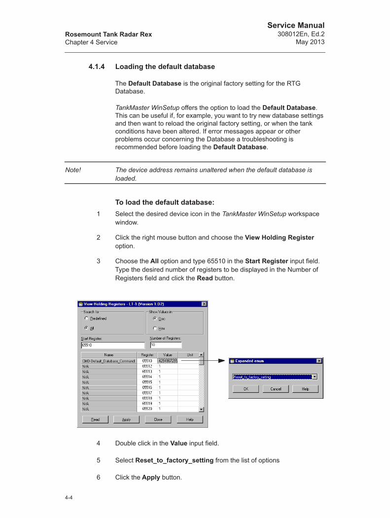
3 Choose the All option and type 65510 in the Start Register input field. Type the desired number of registers to be displayed in the Number of Registers field and click the Read button.
4 Double click in the Value input field.
5 Select Reset_to_factory_setting from the list of options
6 Click the Apply button.
4-4

Rosemount Tank Radar RexChapter 4 Service
Service Manual308012En, Ed.2May 2013
4.1.5 Installing new Transmitter Software
The transmitter software is stored in flash EEPROM. The software consists of boot software and application software. They are both placed in the same EEPROM.
There are two different methods to install new Transmitter Software:
• Downloading
• Changing the EEPROM
To download new Transmitter Software:
1 Select the Devices folder in the Workspace window or a single device in the Devices folder.
2 From the Service menu choose Devices/Program All - or -click the right mouse button and choose the Devices/Program All option. For single devices choose the Program option.
3 Select the desired device to be programmed from the Available Devices pane and click the Move button. Repeat for all devices to be pro-grammed. If a single device was selected in the workspace window, no devices are available in the Available Devices pane. In this case the device appears automatically in the Program these Devices pane.
Use the Remove button if you want to change the list of devices to be programmed.
4-5

Rosemount Tank Radar RexChapter 4 Service
Service Manual308012En, Ed.2
May 2013
4 Click the Browse button and locate the flash program file. Use xxxB.cry file for Boot Software and xxxA.cry file for Application Software. Always start by downloading the Boot Software.
5 Click the Start Programming button.
Response: the Start Device Programming window is opened.
6 Make sure the devices are properly prepared for reprogramming and click the Start Programming button to activate the programming pro-cess.
Response: the programming is started.
Comment: It may take up to 2 minutes to download a flash program.
A maximum of 25 RTGs can be programmed for one FCU. If more RTGs are connected the programming must be performed in two steps. When programming is performed via a FCU only one Group Bus port may be used. The FCU must be restarted prior to the programming of the RTGs.
7 Update the TankMaster installation by copying the Rex *.ini-files for TankMaster that correspond to the new Rex software version to the folder where TankMaster is installed. For example:
The Rex.ini file is copied to the */Saab/Server folder. The other *.ini-files, for example Rex_1E4.ini, are copied to the */Saab/Shared folder.
Note! When new application software has been downloaded, the actual program version does not correspond to the text on the label on top of the EEPROM.
4-6
Rosemount Tank Radar RexChapter 4 Service
Service Manual308012En, Ed.2May 2013
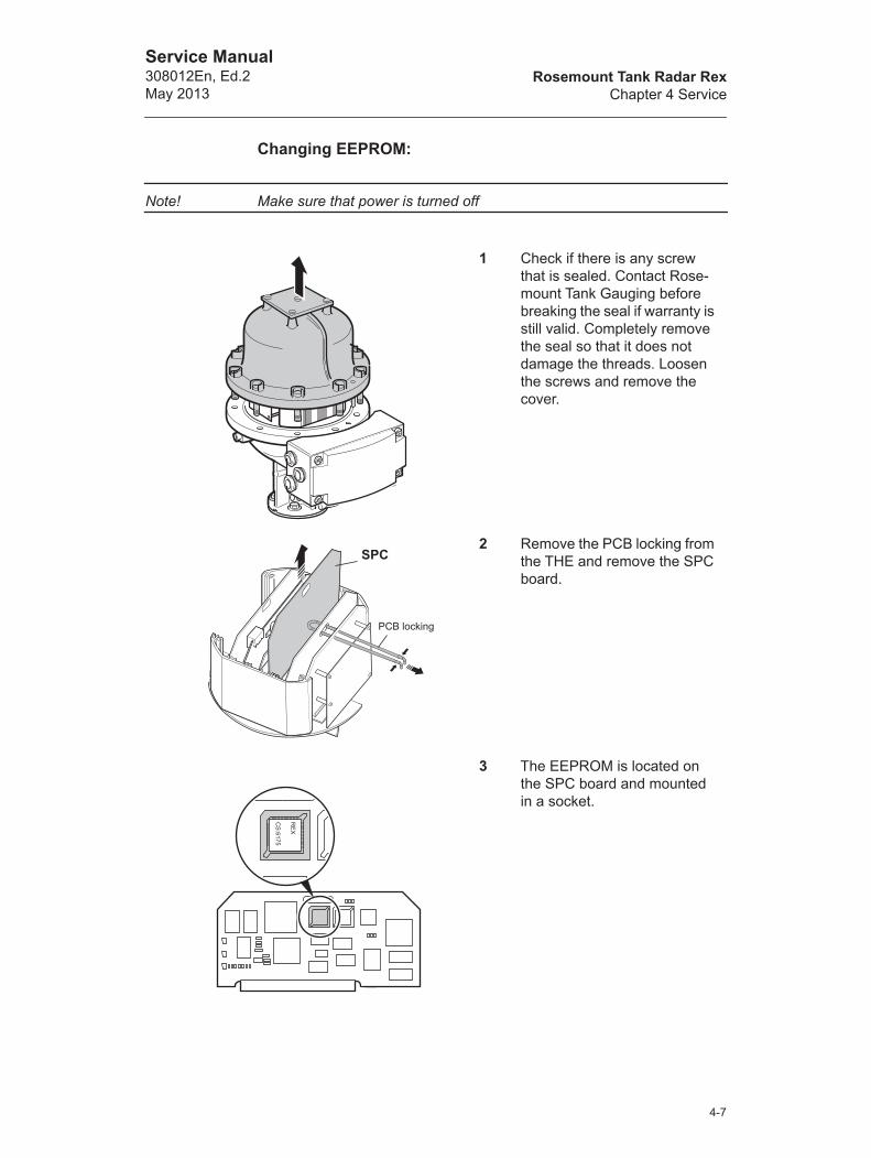
Changing EEPROM:
Note! Make sure that power is turned off
1 Check if there is any screw that is sealed. Contact Rose-mount Tank Gauging before breaking the seal if warranty is still valid. Completely remove the seal so that it does not damage the threads. Loosen the screws and remove the cover.
2 Remove the PCB locking from the THE and remove the SPC board.
3 The EEPROM is located on the SPC board and mounted in a socket.
SPC
PCB locking
RE
X
CS
:6175
4-7

Rosemount Tank Radar RexChapter 4 Service
Service Manual308012En, Ed.2
May 2013
4 Remove the old EEPROM by using the IC Extractor tool. Do not use a screwdriver or simi-lar tools.
5 Place the new EEPROM into the socket. Make sure that the cut off corner is placed in the right position.
Note! Make sure that necessary precautions are taken in order to prevent electrostatic discharge from damaging the EEPROM.
6 Replace the SPC board, PCB locking and cover. Check that contact surfaces on the trans-mitter housing and cover are clean. Tighten the screws. Turn power on.
11
22
Cut off corner
4-8
Rosemount Tank Radar RexChapter 4 Service
Service Manual308012En, Ed.2May 2013
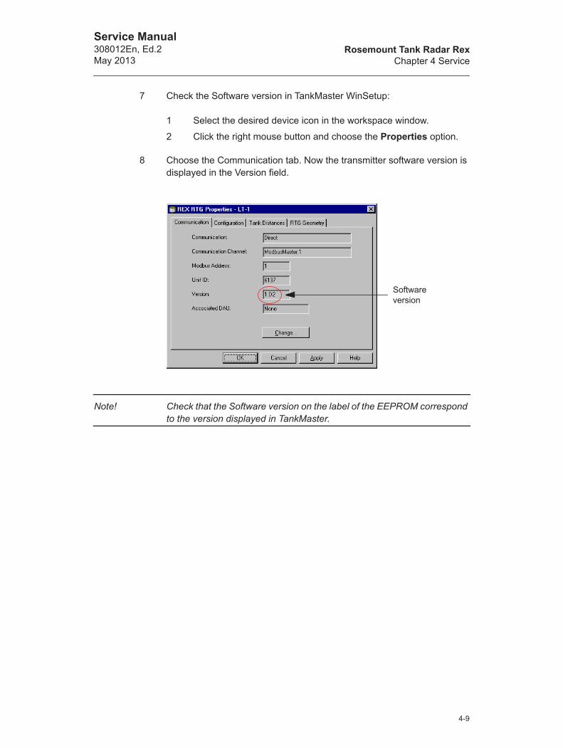
7 Check the Software version in TankMaster WinSetup:
1 Select the desired device icon in the workspace window.
2 Click the right mouse button and choose the Properties option.
8 Choose the Communication tab. Now the transmitter software version is displayed in the Version field.
Note! Check that the Software version on the label of the EEPROM correspond to the version displayed in TankMaster.
Software version
4-9

Rosemount Tank Radar RexChapter 4 Service
Service Manual308012En, Ed.2
May 2013
4.1.6 Exchanging the Transmitter Head Electronics
Note! Make sure that power is turned off
Removing the THE
1 Check if there is any screw that is sealed. Contact Rosemount Tank Gauging before breaking the seal if warranty is still valid. Completely remove the seal so that it does not damage the threads. Loosen the screws and remove the cover.
2 Loosen the two screws which hold the electronic unit.
3 Carefully lift the Electronic Unit. Remove the cable connectors. Han-dle the Electronic Unit carefully. Be especially careful with the PTFE plug at the center of the bottom of the Electronic Unit.
4-10

Rosemount Tank Radar RexChapter 4 Service
Service Manual308012En, Ed.2May 2013
Replacing the THE
1 Connect the cables to the THE. See Figure 4-1 below. Press firmly so that the connectors lock into place.
Figure 4-1. Transmitter Head Electronic connections.
X20
X21
Connections to the ROC board, for further information see 4.1.12.
Mother Board (MB)
Connection to the MB. The 6-pin connector cable shall be connected to the X20 on the MB.
The Analog Output function requires the 2-pin connector cable to be connected to X21 on the MB, for further information see 4.1.10.
Connection to the TIC and TMC board, for further infor-mation see “TIC/TMC Con-figuration” on page 4-16.
4-11
Rosemount Tank Radar RexChapter 4 Service
Service Manual308012En, Ed.2
May 2013
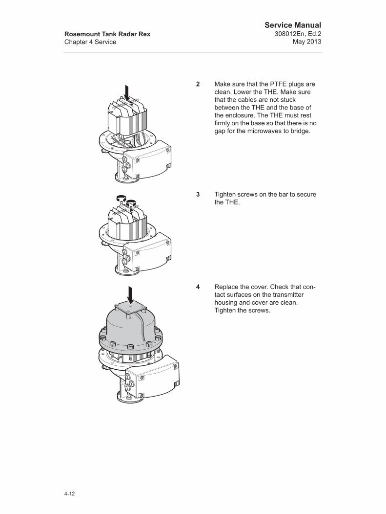
2 Make sure that the PTFE plugs are clean. Lower the THE. Make sure that the cables are not stuck between the THE and the base of the enclosure. The THE must rest firmly on the base so that there is no gap for the microwaves to bridge.
3 Tighten screws on the bar to secure the THE.
4 Replace the cover. Check that con-tact surfaces on the transmitter housing and cover are clean. Tighten the screws.
4-12

Rosemount Tank Radar RexChapter 4 Service
Service Manual308012En, Ed.2May 2013
4.1.7 Write protection (Metrological Seal)
A switch on the FCC board can be used to prevent unauthorized changes in the RTG database. The switch can be sealed in the write-inhibit position by using a special plastic cover.
If there are problems writing to the database EEPROM, then check the setting of the Metrological Seal.
How to write protect the EEPROM
1 Check if there is any screw that is sealed. Contact Rosemount Tank Gauging before breaking the seal if warranty is still valid. Completely remove the seal so that it does not damage the threads. Loosen the screws and remove the cover.
2 Remove the PCB locking from the Transmitter Head and remove the FCC board with the metrological seal.
FCC
PCB locking
4-13

Rosemount Tank Radar RexChapter 4 Service
Service Manual308012En, Ed.2
May 2013
3 Remove the plastic cover and turn the switch to the right.
4 Replace the plastic cover and seal the switch in the write protect posi-tion.
5 Replace the FCC board and the PCB locking. Check that contact surfaces on the trans-mitter housing and cover are clean. Replace the cover and tighten the screws.
Write Enable Protect
4-14

Rosemount Tank Radar RexChapter 4 Service
Service Manual308012En, Ed.2May 2013
4.1.8 Temperature measurement
The Rex transmitter can be connected to 1-3 single spot temperature elements, or to 1-6 multiple spot common return or average elements if the Temperature Multiplexer Card (TMC) is installed.
Max 6 sensors can be connected to the transmitter (sensor number 1 must have the lowest tank position etc.). The sensors must be of the same type (average or spot).
The TMC board must be configured in accordance with the type of sensor that is used, see .
Figure 4-2. Transmitter Interface Card (TIC) and Temperature Multi-plexing Card (TMC)
Temperature Multiplexing Card, TMC
Transmitter Interface Card, TIC
4-15
Rosemount Tank Radar RexChapter 4 Service
Service Manual308012En, Ed.2
May 2013
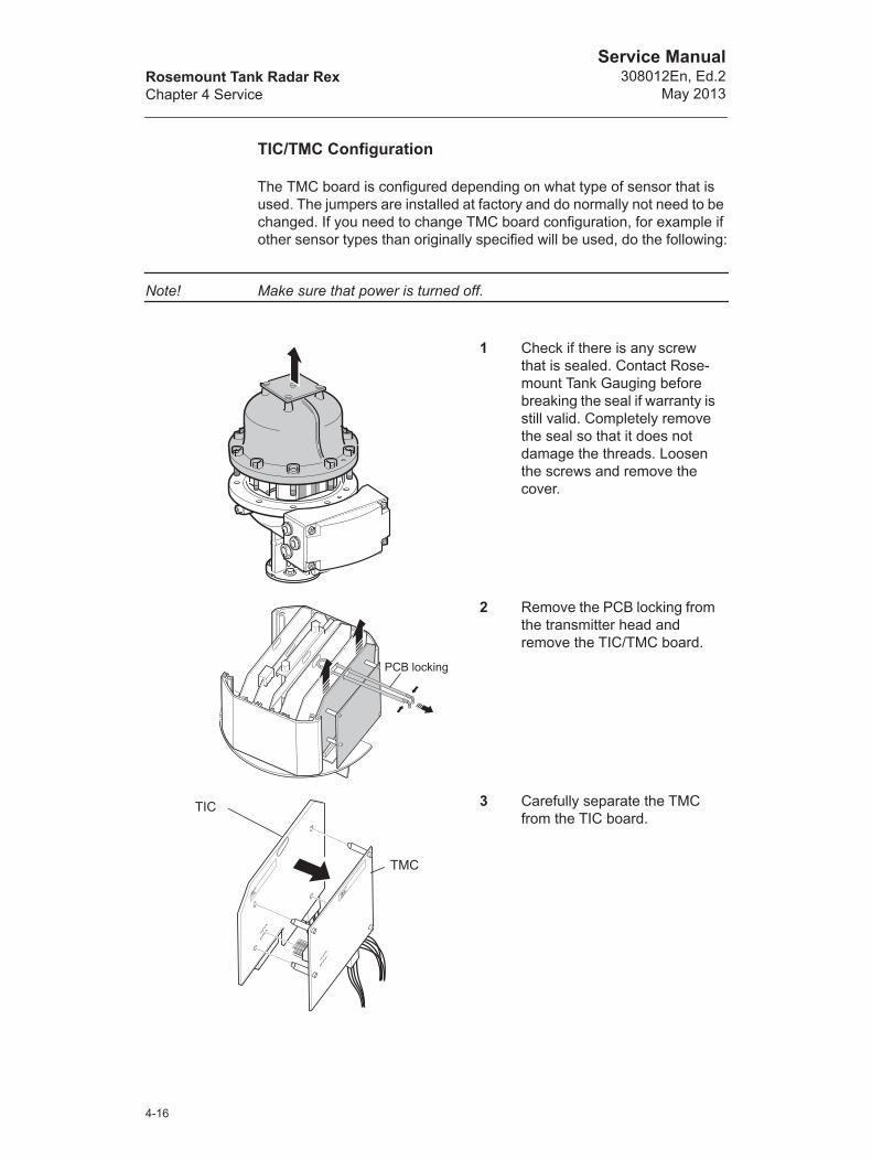
TIC/TMC Configuration
The TMC board is configured depending on what type of sensor that is used. The jumpers are installed at factory and do normally not need to be changed. If you need to change TMC board configuration, for example if other sensor types than originally specified will be used, do the following:
Note! Make sure that power is turned off.
1 Check if there is any screw that is sealed. Contact Rose-mount Tank Gauging before breaking the seal if warranty is still valid. Completely remove the seal so that it does not damage the threads. Loosen the screws and remove the cover.
2 Remove the PCB locking from the transmitter head and remove the TIC/TMC board.
3 Carefully separate the TMC from the TIC board.
PCB locking
TMC
TIC
TMC
TIC
4-16
Rosemount Tank Radar RexChapter 4 Service
Service Manual308012En, Ed.2May 2013
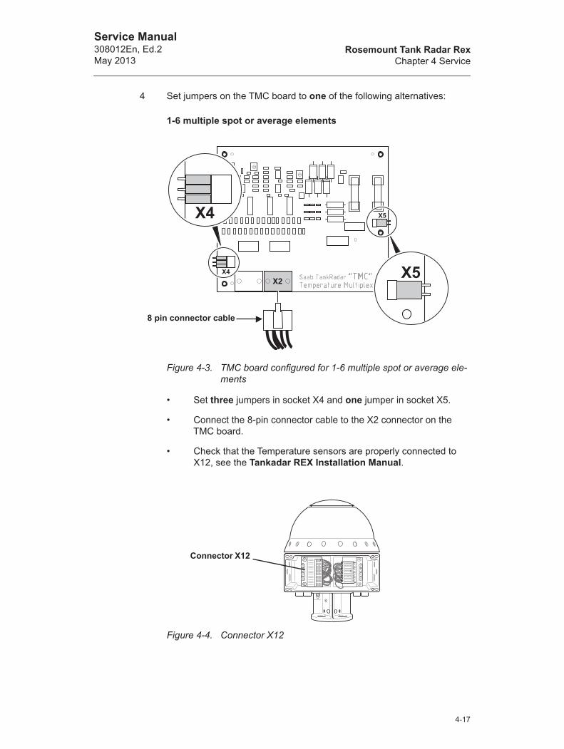
4 Set jumpers on the TMC board to one of the following alternatives:
1-6 multiple spot or average elements
Figure 4-3. TMC board configured for 1-6 multiple spot or average ele-ments
• Set three jumpers in socket X4 and one jumper in socket X5.
• Connect the 8-pin connector cable to the X2 connector on the TMC board.
• Check that the Temperature sensors are properly connected to X12, see the Tankadar REX Installation Manual.
Figure 4-4. Connector X12
8 pin connector cable
Connector X12
4-17

Rosemount Tank Radar RexChapter 4 Service
Service Manual308012En, Ed.2
May 2013
1-3 spot elements
Figure 4-5. TMC board configured for 1-3 spot elements
• No jumpers in socket X4 and X5!
• Connect the 8-pin connector cable to the X3 connector on the TMC board.
• Check that the Temperature sensors are properly connected to X12, see the TankRadar REX Installation Manual.
Figure 4-6. Connector X12
8 pin connector cable
ConnectorX12
4-18

Rosemount Tank Radar RexChapter 4 Service
Service Manual308012En, Ed.2May 2013
5 Make sure the 10-pin connec-tor is connected to socket X2 on the TIC board.
6 Carefully attach the TMC on the back of the TIC.
7 Replace the TIC/TMC board and the PCB locking. Check that contact surfaces on the transmitter housing and cover are clean. Replace the cover and tighten the screws.
TMC
TIC
4-19

Rosemount Tank Radar RexChapter 4 Service
Service Manual308012En, Ed.2
May 2013
Temperature sensor configuration
By using TankMaster WinSetup you can configure the transmitter by specifying sensor type, sensor range and sensor positions. See WinSetup Reference Manual for further information on how to configure the temperature sensors.
Following options are available in TankMaster WinSetup:
• Spot DIN PT100 - for Spot and Multiple Spot sensors.
• Avg. CU90 - for Average Temperature sensors.
• User Defined - The characteristics are specified by a mathemati-cal formula or a linearization table (see WinSetup menu option Service>Devices>User Defined Linearization Table/Formula)
Troubleshooting
If the temperature values are incorrect or are not shown check the following:
• TankMaster WinSetup; click the right mouse button on the Rex icon and choose Properties>Configuration>Temp Input. Check that the Enable/Disable check box is selected. Check the sensor position.
• The Device Error and Device Warning status in Input Register 2.
• The Temperature sensor status in Input Register 27.
• The Temperature sensor status in Input Registers 4460, 4466, 4472 etc. Double click the Status field for detailed information.
• The temperature values in Input Registers 4462, 4468, 4474 etc.
• The Sensor resistance values in Input Registers 4464, 4470, 4476 etc.
• Jumper settings and cable connections, see “TIC/TMC Configura-tion” on page 4-16.
• FCU Slave Database configuration (see WinSetup Reference Manual): check that the right number of temperature sensors are given. Also check that Interval 2 is set to 10.
See chapter 4.3.2 for information on how to check the temperature sensors.
For a general overview of status and configuration check Holding Registers 3300-3542.
4-20
Rosemount Tank Radar RexChapter 4 Service
Service Manual308012En, Ed.2May 2013
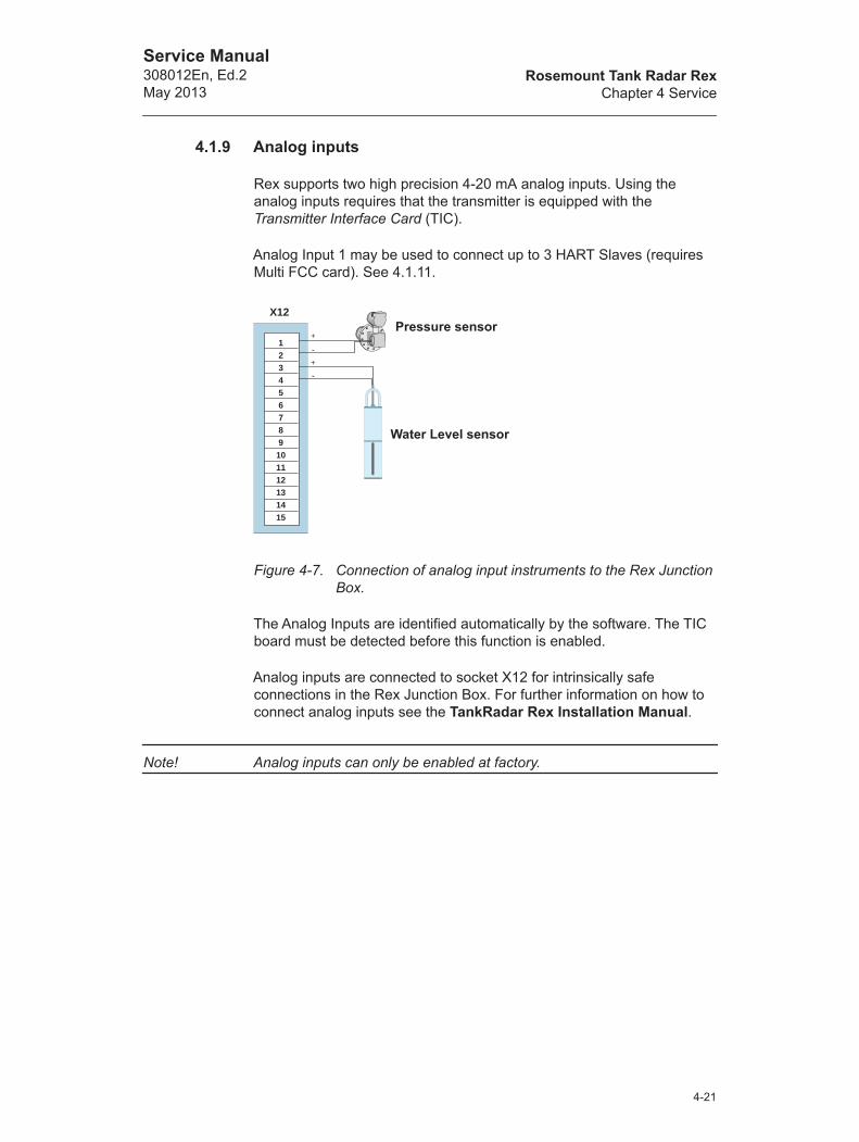
4.1.9 Analog inputs
Rex supports two high precision 4-20 mA analog inputs. Using the analog inputs requires that the transmitter is equipped with the Transmitter Interface Card (TIC).
Analog Input 1 may be used to connect up to 3 HART Slaves (requires Multi FCC card). See 4.1.11.
Figure 4-7. Connection of analog input instruments to the Rex Junction Box.
The Analog Inputs are identified automatically by the software. The TIC board must be detected before this function is enabled.
Analog inputs are connected to socket X12 for intrinsically safe connections in the Rex Junction Box. For further information on how to connect analog inputs see the TankRadar Rex Installation Manual.
Note! Analog inputs can only be enabled at factory.
123456789101112131415
X12Pressure sensor
Water Level sensor
4-21
Rosemount Tank Radar RexChapter 4 Service
Service Manual308012En, Ed.2
May 2013
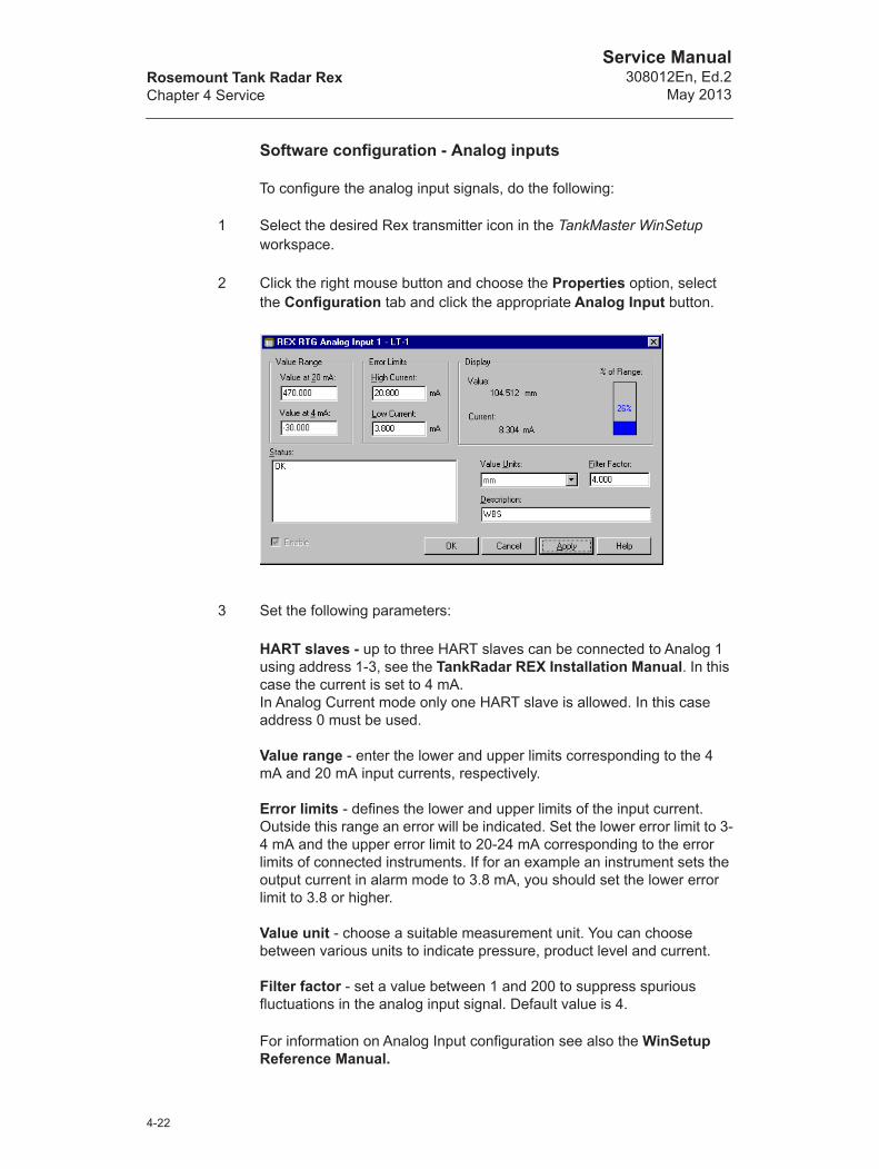
Software configuration - Analog inputs
To configure the analog input signals, do the following:
1 Select the desired Rex transmitter icon in the TankMaster WinSetup workspace.
2 Click the right mouse button and choose the Properties option, select the Configuration tab and click the appropriate Analog Input button.
3 Set the following parameters:
HART slaves - up to three HART slaves can be connected to Analog 1 using address 1-3, see the TankRadar REX Installation Manual. In this case the current is set to 4 mA.In Analog Current mode only one HART slave is allowed. In this case address 0 must be used.
Value range - enter the lower and upper limits corresponding to the 4 mA and 20 mA input currents, respectively.
Error limits - defines the lower and upper limits of the input current. Outside this range an error will be indicated. Set the lower error limit to 3-4 mA and the upper error limit to 20-24 mA corresponding to the error limits of connected instruments. If for an example an instrument sets the output current in alarm mode to 3.8 mA, you should set the lower error limit to 3.8 or higher.
Value unit - choose a suitable measurement unit. You can choose between various units to indicate pressure, product level and current.
Filter factor - set a value between 1 and 200 to suppress spurious fluctuations in the analog input signal. Default value is 4.
For information on Analog Input configuration see also the WinSetup Reference Manual.
4-22
Rosemount Tank Radar RexChapter 4 Service
Service Manual308012En, Ed.2May 2013
Status information
If the input values are incorrect or are not shown in TankMaster check the following:
• Analog Input Configuration, see “Software configuration - Analog inputs” on page 4-22.
• Device Error and Device Warning status in Input register 2.
• Analog Input Status (connection status, calibration mode, above/under limit etc.) and the Analog Input Value in Input registers 4420-4434.
• Analog Input Value Unit, Filter Factor, Lower/Upper range, High/Low current limit, Calibration method etc. in Holding registers 3200-3270.
• FCU configuration: check the number of Analog Inputs in the FCU Slave Database.
4-23
Rosemount Tank Radar RexChapter 4 Service
Service Manual308012En, Ed.2
May 2013
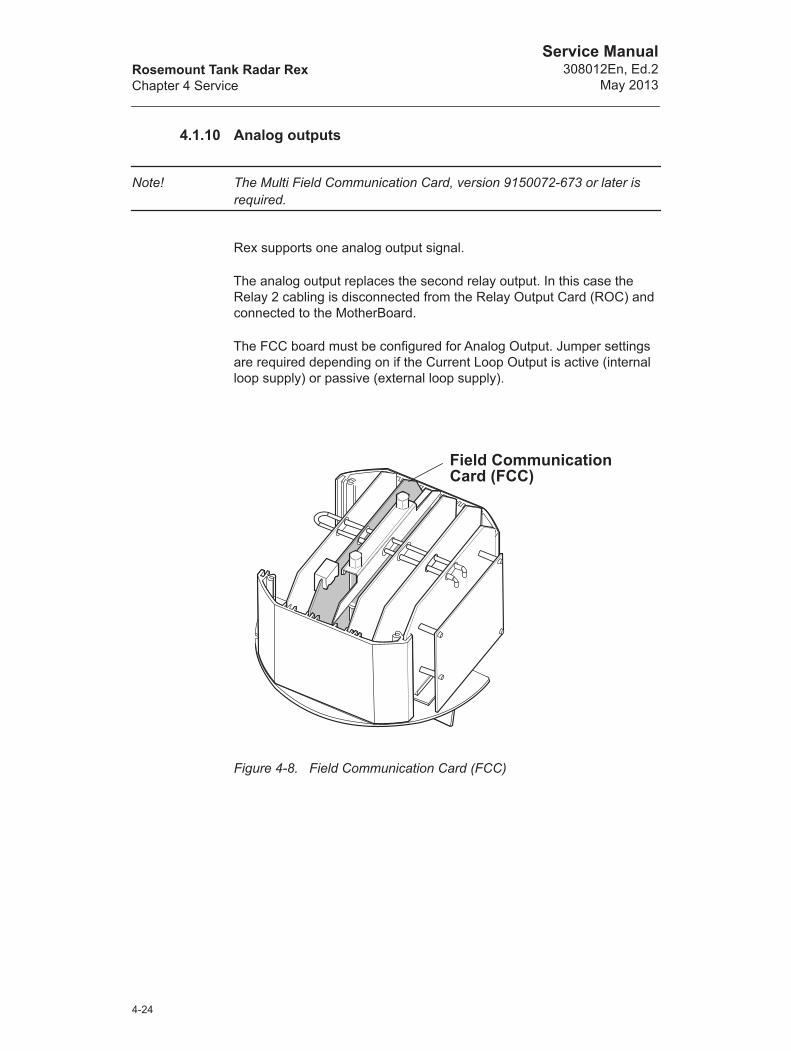
4.1.10 Analog outputs
Note! The Multi Field Communication Card, version 9150072-673 or later is required.
Rex supports one analog output signal.
The analog output replaces the second relay output. In this case the Relay 2 cabling is disconnected from the Relay Output Card (ROC) and connected to the MotherBoard.
The FCC board must be configured for Analog Output. Jumper settings are required depending on if the Current Loop Output is active (internal loop supply) or passive (external loop supply).
Figure 4-8. Field Communication Card (FCC)
Field Communication Card (FCC)
4-24

Rosemount Tank Radar RexChapter 4 Service
Service Manual308012En, Ed.2May 2013
FCC Configuration of Analog Output
In order to use the Analog Output function the cabling must be disconnected from the ROC board and connected to the Mother Board.
Jumper settings on the FCC are needed in order to configure the card for Current Loop Output active (internal loop supply) or passive (external loop supply).
Note! Make sure that power is turned off before opening the cover.
1 Check if there is any screw that is sealed. Contact Rosemount Tank Gauging before breaking the seal if warranty is still valid. Completely remove the seal so that it does not damage the threads. Loosen the screws and remove the cover.
2 Loosen the two screws which hold the Electronic Unit.
4-25
Rosemount Tank Radar RexChapter 4 Service
Service Manual308012En, Ed.2
May 2013
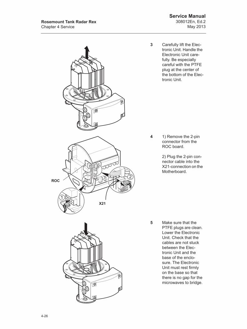
3 Carefully lift the Elec-tronic Unit. Handle the Electronic Unit care-fully. Be especially careful with the PTFE plug at the center of the bottom of the Elec-tronic Unit.
4 1) Remove the 2-pin connector from the ROC board.
2) Plug the 2-pin con-nector cable into the X21-connection on the Motherboard.
5 Make sure that the PTFE plugs are clean. Lower the Electronic Unit. Check that the cables are not stuck between the Elec-tronic Unit and the base of the enclo-sure. The Electronic Unit must rest firmly on the base so that there is no gap for the microwaves to bridge.
1
2
X21
ROC
4-26

Rosemount Tank Radar RexChapter 4 Service
Service Manual308012En, Ed.2May 2013
6 Tighten the two screws which hold the Electronic Unit.
7 Remove the PCB locking from the Elec-tronic Unit and remove the FCC board.
FCC
PCB locking
4-27

Rosemount Tank Radar RexChapter 4 Service
Service Manual308012En, Ed.2
May 2013
8 Check that the Multi FCC card 9150072-673 is used.
Set the jumpers according to Figure 4-9 below for current loop active or passive.
Figure 4-9. Current Loop Output settings.
9 Replace the FCC board and PCB locking. Check that contact surfaces on the transmitter housing and cover are clean. Replace the cover and tighten the screws.
Active
Passive
PCB locking
4-28

Rosemount Tank Radar RexChapter 4 Service
Service Manual308012En, Ed.2May 2013
Software configuration - Analog outputs
You can choose various sources for the Analog Output. The Upper Range value for the analog output signal is 20mA and the Lower Range value is 4 mA.
The following Analog Output sources (measuring variables) are available:
1 Level, Ullage, Level Rate, Amplitude, Volume and Observed density (the Upper and Lower range can be changed in the Range Values input field).
2 RTG AvgLiqTemp, RF Head Temp, DAU AvgLiqTemp, Gas-Pressure, Liquid pressure, Gas Temp, LiquidTemp and Free Water Level (the Upper and Lower range values can be changed in Holding Registers 2144 and 2146).
There are five different alarm modes available, for further information see “Alarm mode settings” on page 4-31.
To configure the Analog Output signal do the following:
1 Select the desired device icon in the WinSetup workspace window.
2 Click the right mouse button, choose the Properties option and select the Configuration tab.
3 Click the Analog Output button.
4-29

Rosemount Tank Radar RexChapter 4 Service
Service Manual308012En, Ed.2
May 2013
4 Choose a measuring variable in the AOut Source list.
Set the Upper and Lower Range for the analog output signal in the Range Values input field. For measuring variables that can not be edited in the Range Value input field, set the Upper and Lower values in Holding Registers 2144 and 2146. For further information on how to edit Holding Registers, see “To view/edit input or holding registers of a certain device:” on page 4-2.
4-30

Rosemount Tank Radar RexChapter 4 Service
Service Manual308012En, Ed.2May 2013
Alarm mode settings
Analog Output current as a function of product level for different alarm mode settings. The shaded area indicates analog output in alarm mode.
Upper
Lower
3.8 mA
22 mA
20 mA
4 mA
20 mA
4 mA
20 mA
4 mA
Level
Analog Output
Analog Output
Analog Output
Time
Time
Time
Time
20 mA
4 mA
Analog Output
Time
20 mA
4 mA
Analog Output
Time
Product level
Alarm modeLow Current
Alarm modeHigh Current
Alarm modeFreeze Current
Alarm modeBinary High
Alarm modeBinary Low
4-31

Rosemount Tank Radar RexChapter 4 Service
Service Manual308012En, Ed.2
May 2013
Following alarm modes are supported in Rex:
The Analog Output goes into alarm when:
• The measurement value goes outside the approved range.
• Measurements are invalid.
• An error is detected in the gauge.
For an overview on the Analog output signal status, see Holding Register 2000-2146. See also WinSetup Reference Manual for further information on how to configure the analog output.
Table 4-1: Alarm Modes
Alarm Mode Current Output
Low Alarm 3.8 mA
High Alarm 22.2 mA
Freeze The current that was output the last valid measurement
Binary Low 20 mA for valid measurements, 4 mA output when in Alarm Mode
Binary High 4 mA for valid measurements, 20 mA output when in Alarm Mode
4-32

Rosemount Tank Radar RexChapter 4 Service
Service Manual308012En, Ed.2May 2013
4.1.11 HART Input
Hart Slaves are connected to Analog input 1. Connection to HART devices requires a Multi Field Communication Card equipped with optional HART modem.
Figure 4-10. Connection of HART slaves.
A maximum of 3 Hart slaves can be connected to the Rex gauge in multidrop configuration.
If only on HART slave is connected, and the short address = 0, current mode is supported.
With three HART slaves connected, short address 1-3 must be used and the slave current is parked at 4 mA.
The 250 resistance is needed for HART-communication only.
123456789101112131415
X12
250
4-33

Rosemount Tank Radar RexChapter 4 Service
Service Manual308012En, Ed.2
May 2013
Software configuration - HART devices
1 Select the desired Rex device icon in the WinSetup workspace window.
2 Click the right mouse button and choose the Properties option.
3 Select the Configuration tab.
4 Click the HART devices button and “configure” the HART slaves. This window is used only to add a description about the connected HART slaves.
For further information on how to configure the HART slaves, see WinSetup Reference Manual.
4-34

Rosemount Tank Radar RexChapter 4 Service
Service Manual308012En, Ed.2May 2013
4.1.12 Relay Output
You can use two relay ports if the optional Relay Output Card (ROC) is installed. Different transmitter variables can be chosen to trigger the relay to change state.
Figure 4-11. Connecting the relay ports.
The relay outputs can be configured as Normally Open (NO) or Normally Closed (NC) depending on the selected connector on the ROC board. There is also a contact used for internal function monitoring.
Figure 4-12. The relays can be configured as Normally Open or Normally Closed.
12345678
X11
Bottom view of Transmitter HeadElectronic Unit
NO=Normally OpenNC=Normally ClosedRelay Output Card
Relay1 NC
Relay2 NC
Relay1 NO
Relay2 NO
4-35
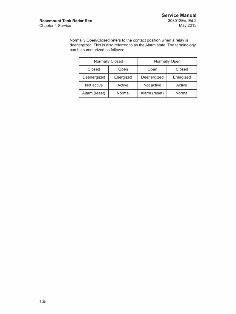
Rosemount Tank Radar RexChapter 4 Service
Service Manual308012En, Ed.2
May 2013
Normally Open/Closed refers to the contact position when a relay is deenergized. This is also referred to as the Alarm state. The terminology can be summarized as follows:
Normally Closed Normally Open
Closed Open Open Closed
Deenergized Energized Deenergized Energized
Not active Active Not active Active
Alarm (reset) Normal Alarm (reset) Normal
4-36

Rosemount Tank Radar RexChapter 4 Service
Service Manual308012En, Ed.2May 2013
Software configuration - Relay Outputs
1 Select the desired device icon in the WinSetup workspace window.
2 Click the right mouse button, choose the Properties option and select the Configuration tab.
3 Click the Relay Output button to configure the Relays.
Response: The Rex RTG Relay Output window opens.
4 Set the following parameters:
Using first/both points To define three relay zones select “Use Both Points”.To define only two relay zones select “Use Only First Point”.
First and second set pointsThe first and second set points define the transitions between Zone 1, 2 and 3. You can set different relay states in each of these zones.
HysteresisWhen the source variable passes a set point, the relay switches from one state to the other. If a hysteresis zone is specified, the relay remains in the new state even if the source signal returns back to a value within the previous zone. How far it will remain in the new state is defined by the value given in the hysteresis input field.
4-37
Rosemount Tank Radar RexChapter 4 Service
Service Manual308012En, Ed.2
May 2013
Relay states.
Select sourceSpecifies the transmitter variable that triggers the switching of the relay.
Switch DelayThis is the time delay until the relay switches into alarm state, i.e. the amount of time it takes for a relay to respond to an alarm. You can use this to prevent the relay from being activated due to temporary variations of the source signal.
Toggle PeriodWhen the relay is in Toggle state it switches between On and Off at a rate defined by the Toggle Period.
Control Mode
Alarm In this state the relay is deenergized.
Normal In this state the relay is energized.
Toggle The relay switches periodically between Normal and Alarm.
Manual The relay can be manually controlled by choosing the Manual Control Relay option from the Service/Devices menu.
Auto The relay state is controlled by the transmitter variable specified in the Select Source field.
Disabled The relay function is turned off.
4-38
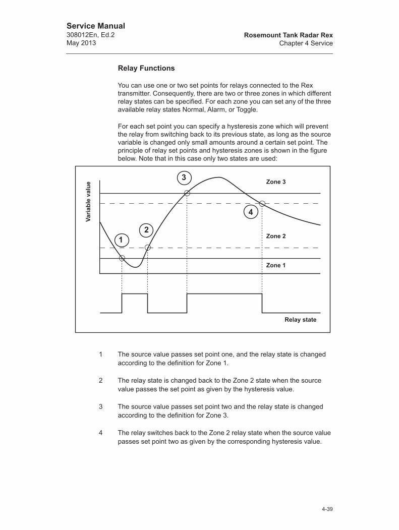
Rosemount Tank Radar RexChapter 4 Service
Service Manual308012En, Ed.2May 2013
Relay Functions
You can use one or two set points for relays connected to the Rex transmitter. Consequently, there are two or three zones in which different relay states can be specified. For each zone you can set any of the three available relay states Normal, Alarm, or Toggle.
For each set point you can specify a hysteresis zone which will prevent the relay from switching back to its previous state, as long as the source variable is changed only small amounts around a certain set point. The principle of relay set points and hysteresis zones is shown in the figure below. Note that in this case only two states are used:
1 The source value passes set point one, and the relay state is changed according to the definition for Zone 1.
2 The relay state is changed back to the Zone 2 state when the source value passes the set point as given by the hysteresis value.
3 The source value passes set point two and the relay state is changed according to the definition for Zone 3.
4 The relay switches back to the Zone 2 relay state when the source value passes set point two as given by the corresponding hysteresis value.
Zone 3
Zone 2
Zone 1
Relay state
Varia
ble
valu
e
2
3
4
1
4-39
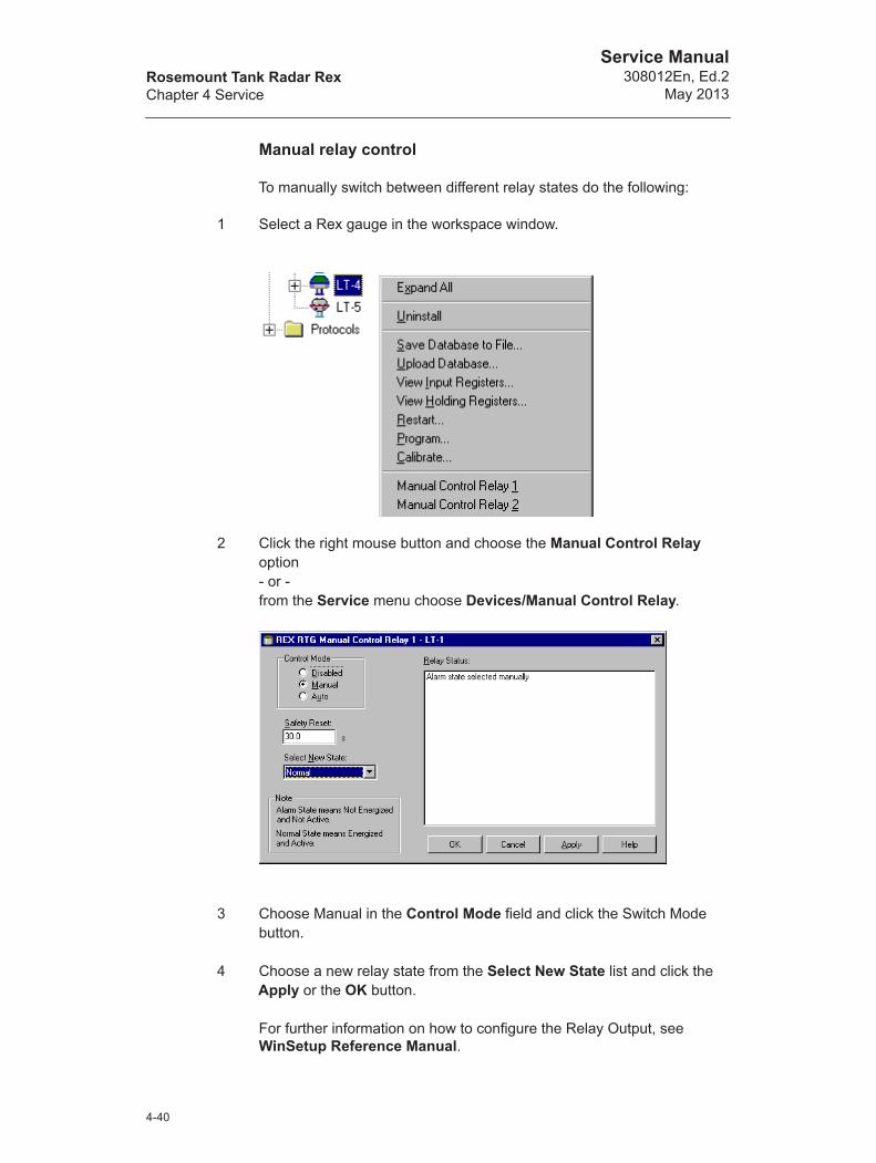
Rosemount Tank Radar RexChapter 4 Service
Service Manual308012En, Ed.2
May 2013
Manual relay control
To manually switch between different relay states do the following:
1 Select a Rex gauge in the workspace window.
2 Click the right mouse button and choose the Manual Control Relay option - or -from the Service menu choose Devices/Manual Control Relay.
3 Choose Manual in the Control Mode field and click the Switch Mode button.
4 Choose a new relay state from the Select New State list and click the Apply or the OK button.
For further information on how to configure the Relay Output, see WinSetup Reference Manual.
4-40
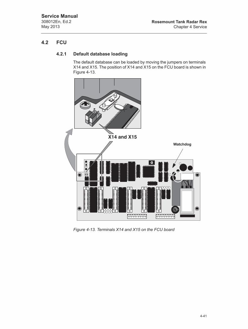
Rosemount Tank Radar RexChapter 4 Service
Service Manual308012En, Ed.2May 2013
4.2 FCU
4.2.1 Default database loading
The default database can be loaded by moving the jumpers on terminals X14 and X15. The position of X14 and X15 on the FCU board is shown in Figure 4-13.
Figure 4-13. Terminals X14 and X15 on the FCU board
Watchdog
4-41
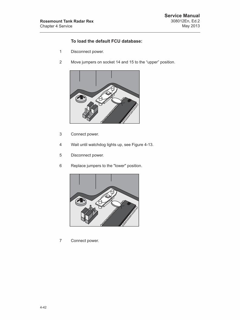
Rosemount Tank Radar RexChapter 4 Service
Service Manual308012En, Ed.2
May 2013
To load the default FCU database:
1 Disconnect power.
2 Move jumpers on socket 14 and 15 to the “upper” position.
3 Connect power.
4 Wait until watchdog lights up, see Figure 4-13.
5 Disconnect power.
6 Replace jumpers to the "lower" position.
7 Connect power.
4-42

Rosemount Tank Radar RexChapter 4 Service
Service Manual308012En, Ed.2May 2013
4.2.2 Group and Field Bus Ports
Inside the FCU box there are two terminals, X10 and X11, which are used for RS-232C Group Bus communication, see Figure 4-14.
Figure 4-14. RS 232 ports
When one of the RS-232C ports is used a special jumper must be connected. Terminal X10: jumper in X5.Terminal X11: jumper in X6.
On X10 (or X11) the terminals 1, 4 and 6 have to be connected, as well as terminals 7 and 8. See the instruction inside the box beside the terminal.
Figure 4-15. Connect a jumper to the X5 or X6 terminalwhen a RS-232 terminal is used.
230 V
1
15 V
X3 X2 X1
X4X5
X6
Jumpers for RS-232C
TRL/2 Bus Interface boards, FCM boards
4-43

Rosemount Tank Radar RexChapter 4 Service
Service Manual308012En, Ed.2
May 2013
4.2.3 Power Supply
Power supply can be selected as either 115 V or 230 V with a switch. See Figure 4-16. If the switch is set to 115 V, the box on the label of the FCU must be marked.
Figure 4-16. Selection of voltage for power supply on FCU.
4.2.4 Fuses
There are two 100 mA fuses inside the FCU box. See Figure 4-17.
Figure 4-17. Location of the two 100 mA fuses inside the FCU box.
NOTE! Do not turn the switch all the way around as it may damage the switch.
Fuses: 2x100 mA
4-44
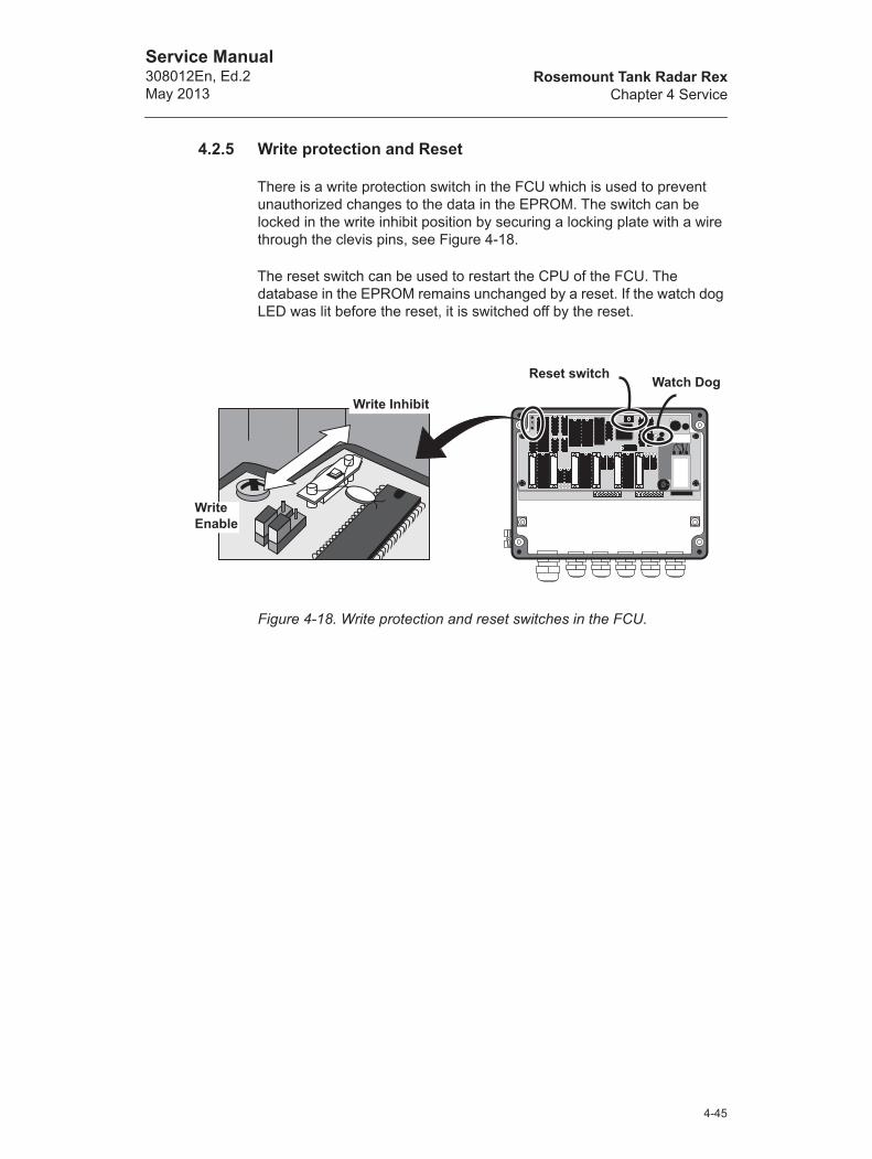
Rosemount Tank Radar RexChapter 4 Service
Service Manual308012En, Ed.2May 2013
4.2.5 Write protection and Reset
There is a write protection switch in the FCU which is used to prevent unauthorized changes to the data in the EPROM. The switch can be locked in the write inhibit position by securing a locking plate with a wire through the clevis pins, see Figure 4-18.
The reset switch can be used to restart the CPU of the FCU. The database in the EPROM remains unchanged by a reset. If the watch dog LED was lit before the reset, it is switched off by the reset.
Figure 4-18. Write protection and reset switches in the FCU.
Write Inhibit
Write Enable
Reset switch Watch Dog
4-45
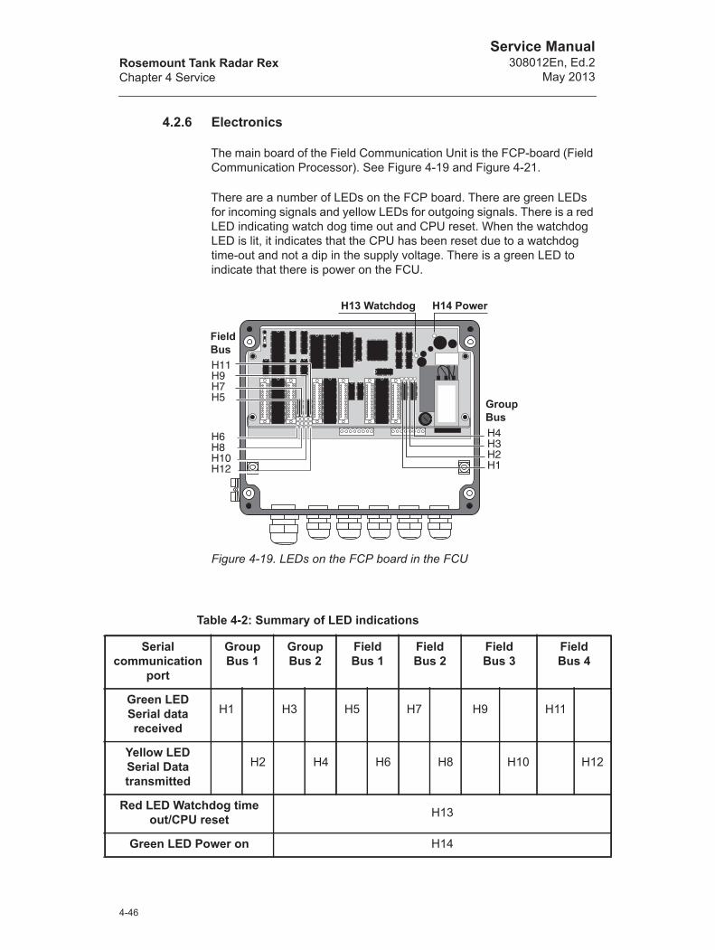
Rosemount Tank Radar RexChapter 4 Service
Service Manual308012En, Ed.2
May 2013
4.2.6 Electronics
The main board of the Field Communication Unit is the FCP-board (Field Communication Processor). See Figure 4-19 and Figure 4-21.
There are a number of LEDs on the FCP board. There are green LEDs for incoming signals and yellow LEDs for outgoing signals. There is a red LED indicating watch dog time out and CPU reset. When the watchdog LED is lit, it indicates that the CPU has been reset due to a watchdog time-out and not a dip in the supply voltage. There is a green LED to indicate that there is power on the FCU.
Figure 4-19. LEDs on the FCP board in the FCU
Table 4-2: Summary of LED indications
Serial communication
port
GroupBus 1
GroupBus 2
FieldBus 1
Field Bus 2
Field Bus 3
Field Bus 4
Green LED Serial data received
H1 H3 H5 H7 H9 H11
Yellow LED Serial Data transmitted
H2 H4 H6 H8 H10 H12
Red LED Watchdog time out/CPU reset H13
Green LED Power on H14
Field Bus
Group Bus
H14 PowerH13 Watchdog
4-46

Rosemount Tank Radar RexChapter 4 Service
Service Manual308012En, Ed.2May 2013
The location of the Field bus and Group bus connections are shown in Figure 4-20.
Figure 4-20. The location of Field and Group bus connections on the FCP board.
The microprocessor of the FCU is the 80C188. It contains a DMA controller (Direct Memory Access) which allows the processor to process other information while the DMA controls data between the RAM memory and the serial ports.
There is RAM (Random Access Memory) of 32 KB for the data buffer. The data buffer is used to store the information from the slave units. The EPROM is used to store the program. When exchanging the EPROM it is strongly recommended that the FCP board is removed from the FCU box for better access of the memory chip.
The EEPROM is used to store database registers and can be remotely reprogrammed (if the write protection switch is in the write enable position).
There are three dual channel Serial Communication Controllers (SCC) that control the six serial communication ports for Group Bus and Field Bus communication.
Field Bus 1
Field Bus 2
Field Bus 3
Field Bus 4 Group B
us 1
Group B
us 2
4-47
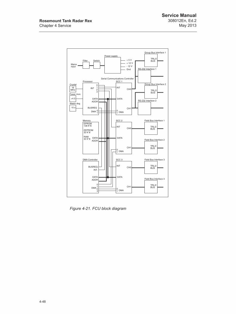
Rosemount Tank Radar RexChapter 4 Service
Service Manual308012En, Ed.2
May 2013
Figure 4-21. FCU block diagram
SCC 1Serial Communications Controller
INT
DATA
DMA01
CH0
CH1
TRL/2 BUS
Group Bus Interface 1
RS-232 Interface 1
TRL/2 BUS
Group Bus Interface 2
RS-232 Interface 2
SCC 2
INT
DATA
DMA01
CH0
CH1
TRL/2 BUS
Field Bus Interface 1
TRL/2 BUS
Field Bus Interface 2
SCC 3
INT
DATA
DMA01
CH0
CH1
TRL/2 BUS
Field Bus Interface 3
TRL/2 BUS
Field Bus Interface 4
Mainsinput
Filter Switch
Power supply
+ 5 V+ 12 V- 12 VGnd
Processor
0123
INT
DATAADDR
BUSREG01
DMA
Power mon.
Watch dog
Crystal16
MHz
>4.5
10 s
MemoryEPROM128 K*8
EEPROM32 K*8
RAM32 K*8 DATA
ADDR
DMA Controller
INT.BUSREQ.
DATAADDR
0123
DMA
4-48
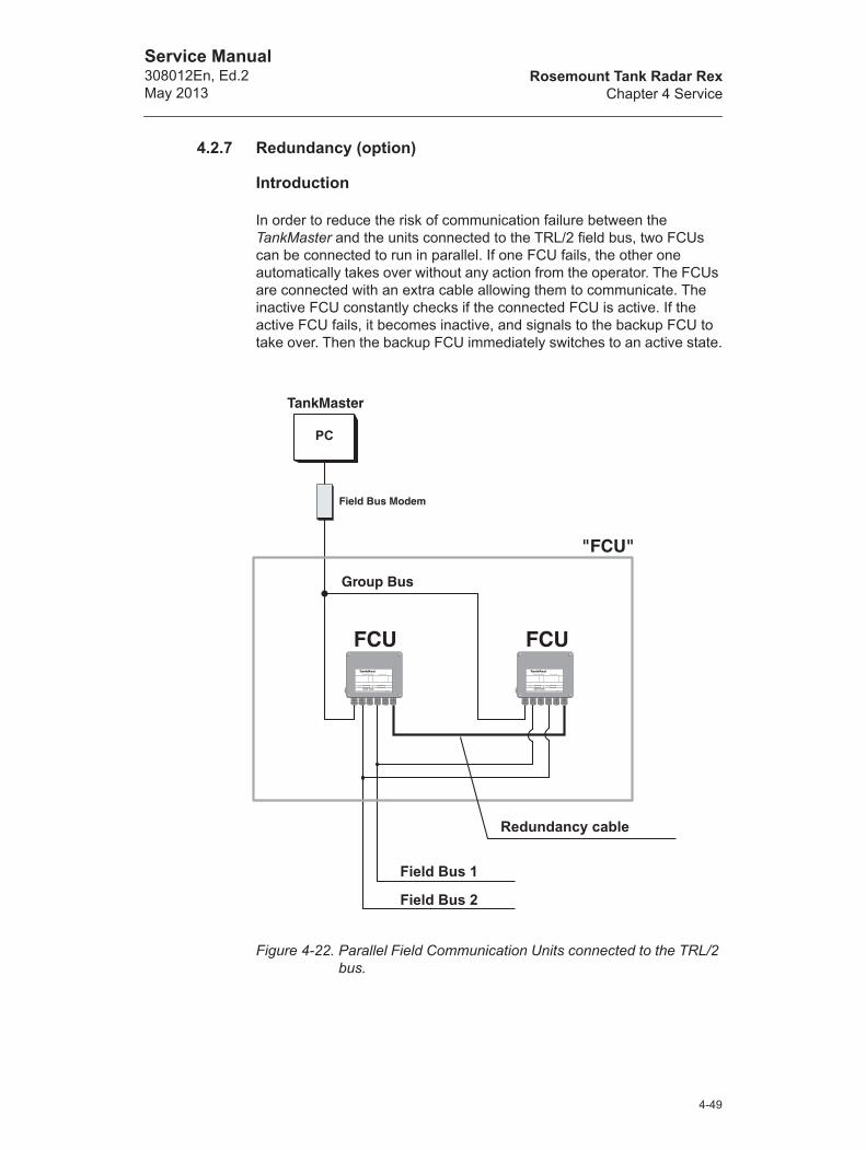
Rosemount Tank Radar RexChapter 4 Service
Service Manual308012En, Ed.2May 2013
4.2.7 Redundancy (option)
Introduction
In order to reduce the risk of communication failure between the TankMaster and the units connected to the TRL/2 field bus, two FCUs can be connected to run in parallel. If one FCU fails, the other one automatically takes over without any action from the operator. The FCUs are connected with an extra cable allowing them to communicate. The inactive FCU constantly checks if the connected FCU is active. If the active FCU fails, it becomes inactive, and signals to the backup FCU to take over. Then the backup FCU immediately switches to an active state.
Figure 4-22. Parallel Field Communication Units connected to the TRL/2 bus.
Redundancy cable
Field Bus 2
Field Bus 1
PC
4-49
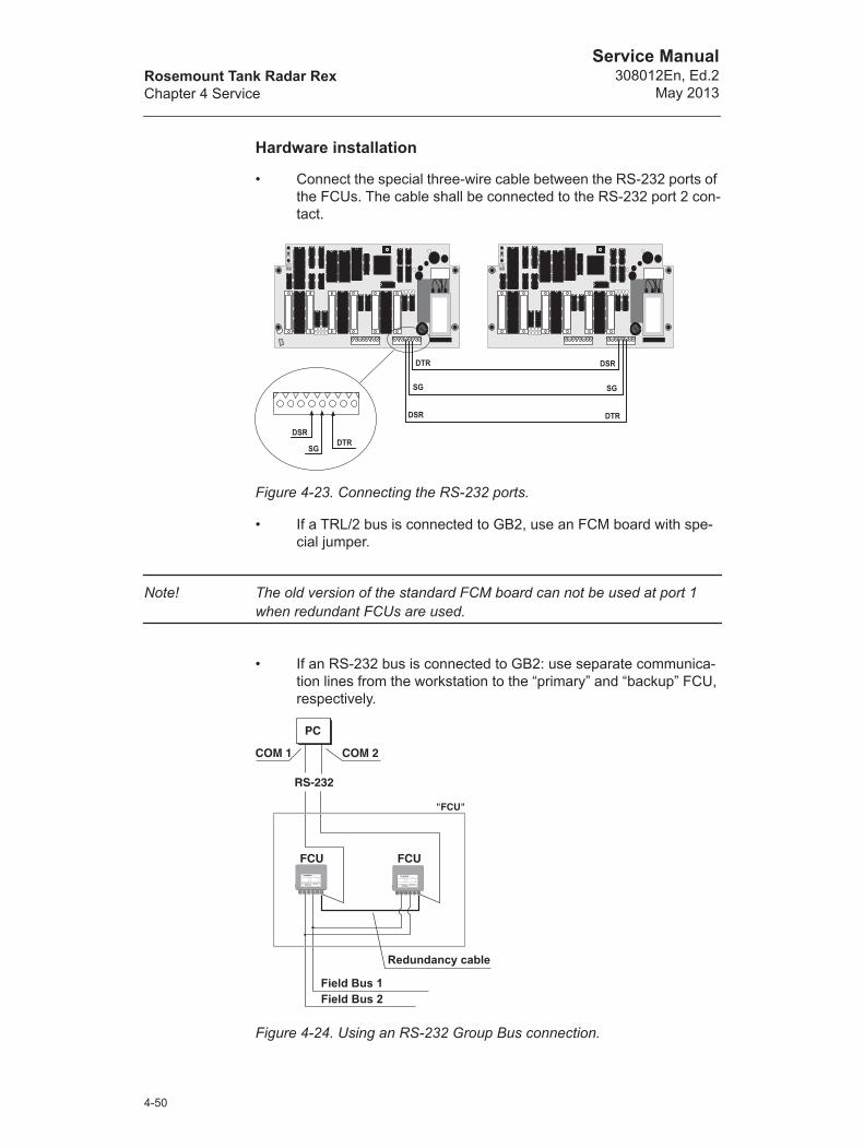
Rosemount Tank Radar RexChapter 4 Service
Service Manual308012En, Ed.2
May 2013
Hardware installation
• Connect the special three-wire cable between the RS-232 ports of the FCUs. The cable shall be connected to the RS-232 port 2 con-tact.
Figure 4-23. Connecting the RS-232 ports.
• If a TRL/2 bus is connected to GB2, use an FCM board with spe-cial jumper.
Note! The old version of the standard FCM board can not be used at port 1 when redundant FCUs are used.
• If an RS-232 bus is connected to GB2: use separate communica-tion lines from the workstation to the “primary” and “backup” FCU, respectively.
Figure 4-24. Using an RS-232 Group Bus connection.
Redundancy cable
Field Bus 1Field Bus 2
4-50
Rosemount Tank Radar RexChapter 4 Service
Service Manual308012En, Ed.2May 2013
Software configuration
Note! For further information on how to configure/install the FCU see TankMaster WinSetup Reference Manual.
1 Power down both FCUs.
2 Power up one of the FCUs.
3 Select the Devices folder in the TankMaster WinSetup workspace win-dow, click the right mouse button and choose the Install New option.
4 Choose device type FCU, specify a name in the Tag input field and click the Next button to continue.
5 Select a communication channel.
6 Set the FCU address:
1 In the FCU Communication window click the Change Address on Device button.
2 Enter the Unit ID and the Modbus Address and click the OK but-ton.
3 In the FCU Communication window click the Verify Communica-tion button to make sure that communication is established.
4 Click the Next button to continue.
7 In the FCU Configuration window choose the Redundant, Primary mode option to set the operation mode.
8 Click the Next button to open the FCU Slave Database window. Config-ure the FCU.
9 Click the Next button to open the Summary window and then the Finish button to finish the FCU installation.
Comment: The standard mode of operation is "normal". There is no difference in operation between the FCU designated "primary" and "backup", respectively. The reason for having different names is only to be able to distinguish between the redundant FCUs.
10 Check that holding register 831=7 (only memory tests).
11 Power down the FCU.
4-51

Rosemount Tank Radar RexChapter 4 Service
Service Manual308012En, Ed.2
May 2013
12 Power up the second FCU.
13 Set the second FCU address. It is important that both FCUs are using the same address.
1 Select the FCU icon in the WinSetup workspace window, click the right mouse button and choose the Properties option.
2 Select the Communication tab and click the Change button.
3 Enter the Unit ID and the Modbus Address and click the OK but-ton.
4 Click the Verify Communication button to make sure that com-munication is established.
5 Click the OK button to continue.
14 Select the Configuration tab and choose the Redundant, Backup mode option to set the operation mode.
15 Check that holding register 831=7.
16 Power down the FCU.
17 Move switch X14 to position 1 on both FCUs.
18 Power up the "primary" FCU first, and then the "backup" FCU.
Comment: Now the "primary" FCU, which was powered up first, becomes active.
19 Check that TankMaster reads data from the active FCU. Select the FCU icon, click the right mouse button and choose the Properties option and check that the Unit ID corresponds to the active FCU.
Position 1
4-52

Rosemount Tank Radar RexChapter 4 Service
Service Manual308012En, Ed.2May 2013
20 Check the diagnostics Input Register (Input Register 30689) to verify that the "primary" FCU is active. This is indicated by status bit 12=0. (If the "backup" FCU is active status bit 12=1).
21 Power down the active FCU.
Comment: The "backup" FCU switches from inactive to active.
22 Make sure that the backup FCU is active. This is indicated by status bit 12=1 (see step 20).
23 Power down both FCUs, and then power up the FCUs again starting with the "primary" FCU as described in step 18.
24 Select the FCU Slave Database tab from the Properties menu, and con-figure the FCU pair like you would configure a single non redundant FCU. Both FCUs will receive the same data. Switch between the FCUs to make sure that the same data was stored in both FCUs.
For further information on FCU Installation Procedure see WinSetup Reference Manual.
4-53

Rosemount Tank Radar RexChapter 4 Service
Service Manual308012En, Ed.2
May 2013
4.3 DAU
4.3.1 Setting the temperature measurement range
Do the following to set the measuring range of the temperature sensors:
1 Connect the reference resistor corresponding to the desired measure-ment range to channel 15.
Figure 4-25. Reference Resistor
2 Set the jumpers X1, X2 and X3 on the DAU's circuit board in the correct positions for the desired measurement range. The jumpers are set according to Table 4-3. See also Figure 4-26. The default setting is from -50°C to 125°C for the Pt 100 sensor.
Figure 4-26. Jumper settings for temperature range -50 to 125°C
The X21 terminal
Connecttemperature sensors
Connect Reference Resistor to terminals 43, 44 and 45.
X1 - OPENX2 - OPEN
X3 - CLOSED
4-54
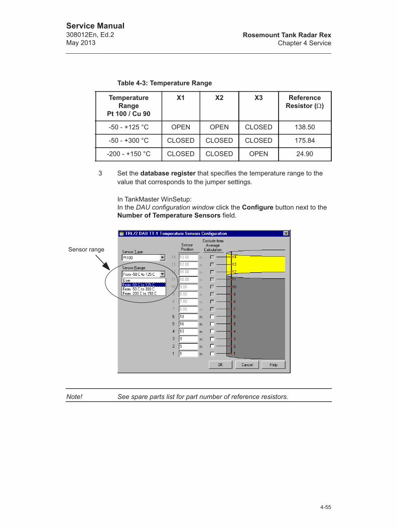
Rosemount Tank Radar RexChapter 4 Service
Service Manual308012En, Ed.2May 2013
3 Set the database register that specifies the temperature range to the value that corresponds to the jumper settings.
In TankMaster WinSetup: In the DAU configuration window click the Configure button next to the Number of Temperature Sensors field.
Note! See spare parts list for part number of reference resistors.
Table 4-3: Temperature Range
Temperature Range
Pt 100 / Cu 90
X1 X2 X3 Reference Resistor ()
-50 - +125 °C OPEN OPEN CLOSED 138.50
-50 - +300 °C CLOSED CLOSED CLOSED 175.84
-200 - +150 °C CLOSED CLOSED OPEN 24.90
Sensor range
4-55
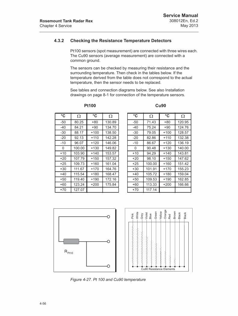
Rosemount Tank Radar RexChapter 4 Service
Service Manual308012En, Ed.2
May 2013
4.3.2 Checking the Resistance Temperature Detectors
Pt100 sensors (spot measurement) are connected with three wires each. The Cu90 sensors (average measurement) are connected with a common ground.
The sensors can be checked by measuring their resistance and the surrounding temperature. Then check in the tables below. If the temperature derived from the table does not correspond to the actual temperature, then the sensor needs to be replaced.
See tables and connection diagrams below. See also Installation drawings on page 8-1 for connection of the temperature sensors.
Figure 4-27. Pt 100 and Cu90 temperature
Pt100
°C °C -50 80.25 +80 130.89-40 84.21 +90 134.70-30 88.17 +100 138.50-20 92.13 +110 142.28-10 96.07 +120 146.060 100.00 +130 149.82
+10 103.90 +140 153.57+20 107.79 +150 157.32+25 109.73 +160 161.04+30 111.67 +170 164.76+40 115.54 +180 168.47+50 119.40 +190 172.16+60 123.24 +200 175.84+70 127.07
Cu90
°C °C -50 71.43 +80 120.95-40 75.24 +90 124.76-30 79.05 +100 128.57-20 82.86 +110 132.38-10 86.67 +120 136.190 90.48 +130 140.00
+10 94.29 +140 143.81+20 98.10 +150 147.62+25 100.00 +160 151.42+30 101.91 +170 155.23+40 105.72 +180 159.04+50 109.53 +190 162.85+60 113.33 +200 166.66+70 117.14
Pin
k
Whi
teG
rey
Viol
etB
lue
Gre
en
Yello
w
Red
Bro
wn
Bla
ck
Bla
ck
Ora
nge
Cu90 Resistance Elements
4-56

Rosemount Tank Radar RexChapter 4 Service
Service Manual308012En, Ed.2May 2013
4.3.3 Exchanging the External Reference Resistor
The external reference resistor must be changed if a different temperature measurement range will be used, see 4.3.1. Also, if the local display shows a reference resistor calibration error, it may be necessary to replace it. The reference resistor is connected to channel 15 of the multiplexer.
The reference resistance values corresponding to different temperature ranges and sensors are given in the table below.
Figure 4-28 illustrates how to connect the external reference resistor to the X21 terminal.
Figure 4-28. Connection of reference resistor
Automatic test of reference resistors
The internal reference resistor is placed on the Motherboard. The ratio between the high and low temperature references is calculated as a test of the reference resistors. This value is compared with a value given for the current temperature range. The ratio is allowed to deviate a certain amount from the nominal value. The tolerated deviation can be viewed in holding registers 307-310.
Resistance () Temperature range (°C)
138.50 -50 - +125
175.84 -50 - 300
24.90 -200 - +150
The X21 terminal
Connecttemperature sensors
Connect Reference Resistor to terminals 43, 44 and 45.
4-57

Rosemount Tank Radar RexChapter 4 Service
Service Manual308012En, Ed.2
May 2013
4.3.4 Suppressing error indication...
... when associated RTG is not present.
Normally a DAU receives queries from the bus master (FCU), and picks up level data from the associated RTG. However, there may be situations when a DAU is installed without bus master and/or RTG. In this case error codes indicating external serial communication error will be shown on the DAU display. These error codes can be suppressed by setting DAU holding register 313 to the appropriate value:
4.3.5 DAU Reset
The DAU can be reset by switching power off and on with an external switch. Another way is to open the box and remove connector X20 on the DMB. When replacing the connector the power-LED will light up for a short period of time during start up. The (optional) display shows the Unit Id during start up.
Figure 4-29. Connection X20
Database value Action
0 Normal operation
1 No bus master present
2 No associated RTG
3 No associated bus master or RTG
X20
4-58

Rosemount Tank Radar RexChapter 4 Service
Service Manual308012En, Ed.2May 2013
4.3.6 Write Protection
There is a write protection switch to prevent unauthorized changes in the EEPROM. The switch can be sealed in the write inhibit position using a wire through the clevis pins. See Figure 4-30.
Figure 4-30. Write protection switch
Write Inhibit
Write Enable
4-59
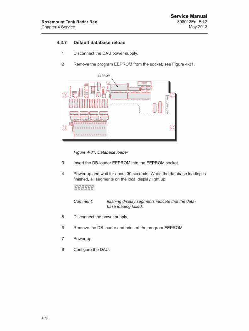
Rosemount Tank Radar RexChapter 4 Service
Service Manual308012En, Ed.2
May 2013
4.3.7 Default database reload
1 Disconnect the DAU power supply.
2 Remove the program EEPROM from the socket, see Figure 4-31.
Figure 4-31. Database loader
3 Insert the DB-loader EEPROM into the EEPROM socket.
4 Power up and wait for about 30 seconds. When the database loading is finished, all segments on the local display light up:
Comment: flashing display segments indicate that the data-base loading failed.
5 Disconnect the power supply.
6 Remove the DB-loader and reinsert the program EEPROM.
7 Power up.
8 Configure the DAU.
EEPROM
4-60
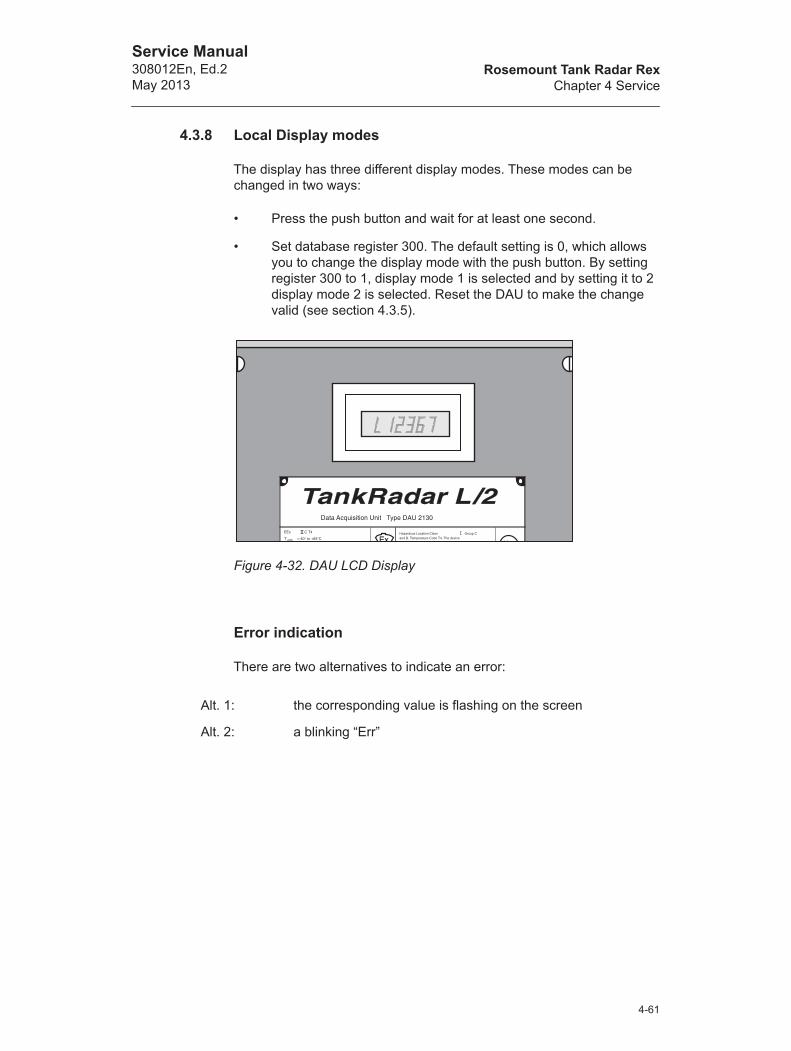
Rosemount Tank Radar RexChapter 4 Service
Service Manual308012En, Ed.2May 2013
4.3.8 Local Display modes
The display has three different display modes. These modes can be changed in two ways:
• Press the push button and wait for at least one second.
• Set database register 300. The default setting is 0, which allows you to change the display mode with the push button. By setting register 300 to 1, display mode 1 is selected and by setting it to 2 display mode 2 is selected. Reset the DAU to make the change valid (see section 4.3.5).
Figure 4-32. DAU LCD Display
Error indication
There are two alternatives to indicate an error:
Alt. 1: the corresponding value is flashing on the screen
Alt. 2: a blinking “Err”
��� ��0��!����� *��� ��� �* ��1�
��2 � �3
� ��# 4(3�5 �� 67%5� ��/ � �������� ��/ �3� �9 /���,���� ���:��/��! �������� ��!!
�����������
���2
4-61

Rosemount Tank Radar RexChapter 4 Service
Service Manual308012En, Ed.2
May 2013
Display mode 0:
The following values are shown. Only the values for which the DAU has been configured, are shown. The sequence is repeated continuously.
Level. L for metric: decimal, colons for feet: inches: inches/17.
Average temperature.
C for Celsius or F for Fahrenheit.
One current input channel.
The specific channel is selected in the database.
Digital input values.
The digital input values are shown high when the connected device is open (not grounding = 1). They are shown low when it is closed (grounding = 0). Each vertical segment corresponds to an input.
Relay outputcontrol.
The lower segment is shown when the relay is in its normal position (inactivated). The upper section is shown when the relay is in its activated position. If the relay feedback does not match relay control this will be shown with a "-" sign like this:
If there is an error:
System sta-tus
See Chapter Troubleshooting for more information.
4-62

Rosemount Tank Radar RexChapter 4 Service
Service Manual308012En, Ed.2May 2013
Display mode 1:
The following sequence is shown when the display is in mode 1.
Level See display mode 0 for explanation.
Temperature sensor 1.
If the sensor is below the surface.
The temperature value of sensor 1.
Temperature sensor 2.
The temperature value of sensor 2.
Pressure sensor 1.
The pressure value of sensor 1.
Pressure sensor 2.
The pressure value of sensor 2.
Digital input values. See display mode 0 for explanation.
Relay output control. See display mode 0 for explanation.
If there is an error:
System status. See Chapter Trou-bleshooting for more information.
4-63
Rosemount Tank Radar RexChapter 4 Service
Service Manual308012En, Ed.2
May 2013
Display mode 2:
This mode locks the display on the value which is on display at the moment. The value is still sampled at its usual rate (approximately every 15 seconds for a temperature sensor).
Press the button and hold it down. Release the button when the value before the desired value is displayed. For example, if temperature value C5 is to be displayed, then release the button when the display is showing the value of temperature C4.
You can set this display mode remotely via database register 300. The default reading is level. If you want to remotely change the display to other variables in display mode 2, please contact Emerson Process Management/Rosemount Tank Gauging for instructions.
4-64

Rosemount Tank Radar RexChapter 4 Service
Service Manual308012En, Ed.2May 2013
4.3.9 Local Display Error codes
The type of errors displayed on the local display can be divided into the following groups.
• System
• External serial communication
• Internal serial communication
• Temperature measuring error
System Errors indicate that there is an error in one of the memory circuits.
External serial communication error means that communication with master or RTG is lost.
Internal serial communication error may indicate that there is an internal bus failure.
Temperature measuring error may indicate that there is a defect temperature sensor or a calibration error.
4-65
Rosemount Tank Radar RexChapter 4 Service
Service Manual308012En, Ed.2
May 2013
4.3.10 Time-out settings
Master communication time-out
The master communication time-out specifies the elapsed time without contact before communication with the master is considered to be lost. This value is stored in database register 188. The default value is set to 20 s.
Note! The database value is given in number of "ticks" 255. One tick is equal to 278 s, and 255 ticks is equal to 71 ms. Thus the value stored in database register 188 must be multiplied with 71 ms in order to obtain the time-out value in number of seconds.
RTG Communication time-out
The RTG communication time-out is stored in database register 249. The default value is set to 60 seconds. This is the value which specifies the time interval without contact before communication with the RTG is considered to be lost.
4-66
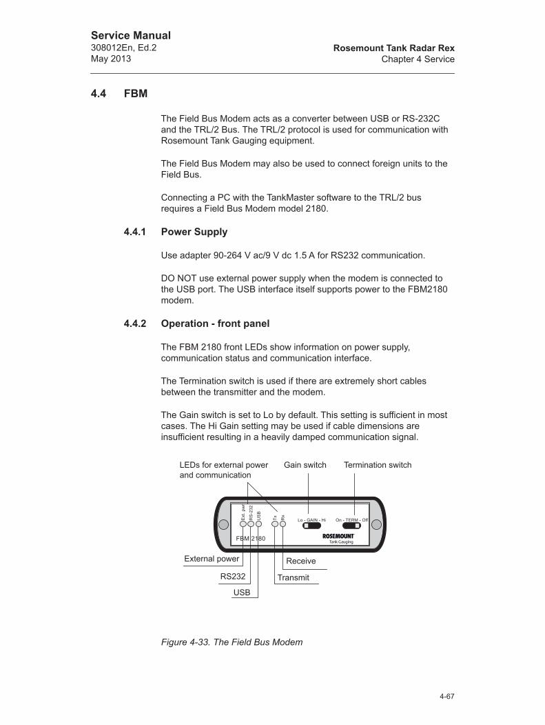
Rosemount Tank Radar RexChapter 4 Service
Service Manual308012En, Ed.2May 2013
4.4 FBM
The Field Bus Modem acts as a converter between USB or RS-232C and the TRL/2 Bus. The TRL/2 protocol is used for communication with Rosemount Tank Gauging equipment.
The Field Bus Modem may also be used to connect foreign units to the Field Bus.
Connecting a PC with the TankMaster software to the TRL/2 bus requires a Field Bus Modem model 2180.
4.4.1 Power Supply
Use adapter 90-264 V ac/9 V dc 1.5 A for RS232 communication.
DO NOT use external power supply when the modem is connected to the USB port. The USB interface itself supports power to the FBM2180 modem.
4.4.2 Operation - front panel
The FBM 2180 front LEDs show information on power supply, communication status and communication interface.
The Termination switch is used if there are extremely short cables between the transmitter and the modem.
The Gain switch is set to Lo by default. This setting is sufficient in most cases. The Hi Gain setting may be used if cable dimensions are insufficient resulting in a heavily damped communication signal.
Figure 4-33. The Field Bus Modem
External power
LEDs for external power and communication
Gain switch Termination switch
RS232
USB
Receive
Transmit
4-67
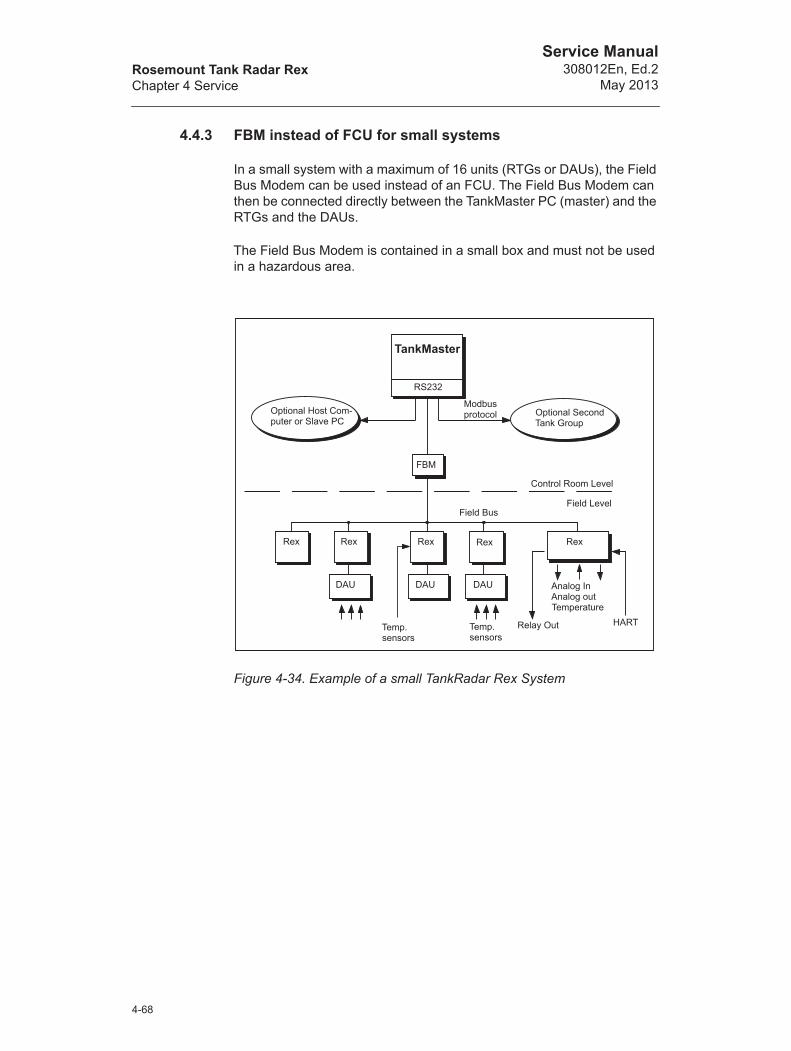
Rosemount Tank Radar RexChapter 4 Service
Service Manual308012En, Ed.2
May 2013
4.4.3 FBM instead of FCU for small systems
In a small system with a maximum of 16 units (RTGs or DAUs), the Field Bus Modem can be used instead of an FCU. The Field Bus Modem can then be connected directly between the TankMaster PC (master) and the RTGs and the DAUs.
The Field Bus Modem is contained in a small box and must not be used in a hazardous area.
Figure 4-34. Example of a small TankRadar Rex System
TankMaster
RS232
Optional Second Tank Group
FBM
Modbus protocol
Field Bus
Control Room Level
Field Level
Analog InAnalog outTemperature
Temp.sensors
Temp.sensors
Rex
Optional Host Com-puter or Slave PC
DAU
Relay Out HART
Rex Rex Rex Rex
DAU DAU
4-68
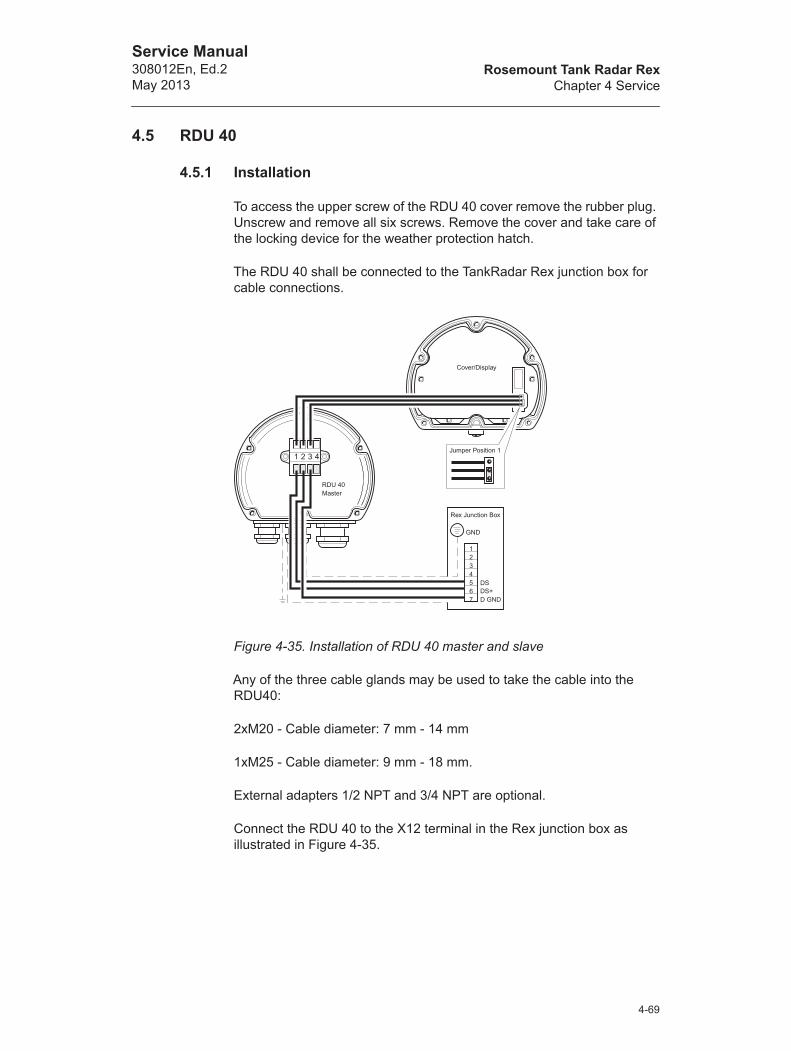
Rosemount Tank Radar RexChapter 4 Service
Service Manual308012En, Ed.2May 2013
4.5 RDU 40
4.5.1 Installation
To access the upper screw of the RDU 40 cover remove the rubber plug. Unscrew and remove all six screws. Remove the cover and take care of the locking device for the weather protection hatch.
The RDU 40 shall be connected to the TankRadar Rex junction box for cable connections.
Figure 4-35. Installation of RDU 40 master and slave
Any of the three cable glands may be used to take the cable into the RDU40:
2xM20 - Cable diameter: 7 mm - 14 mm
1xM25 - Cable diameter: 9 mm - 18 mm.
External adapters 1/2 NPT and 3/4 NPT are optional.
Connect the RDU 40 to the X12 terminal in the Rex junction box as illustrated in Figure 4-35.
4-69

Rosemount Tank Radar RexChapter 4 Service
Service Manual308012En, Ed.2
May 2013
In order to allow proper operation and to fulfil EMC requirements, the cable between the RDU 40 and the Rex junction box should meet the following requirements:
• Shielded cable. Minimum 3 wires. The shield shall be circular con-nected inside the cable gland of the RDU 40 and connected to ground in the Rex junction box.
• All wires must have at least 0.25 mm individual insulation.
• Maximum total length of 100 m, both master and slave included.
• Minimum AWG 20 or 0.5 mm² for each wire.
The RDU 40-chassis shall be grounded locally to the tank. Use minimum 4 mm² or AWG 11 wire. Additional protective ground connection to the power distribution central or the Rex junction box is not recommended except where required according to national code of practice. A ground loop with circulating current may occur.
Note! It is not possible to use an RDU40 and a DAU simultaneously.
If a cable with two shields is used, one shield shall be connected to ground in the Rex junction box and the other shall be circular connected inside the cable gland of the RDU 40.
Check the gasket and put the locking device for the weather protection hatch in position when remounting the RDU-cover. Tighten all six screws firmly.
Mount the RDU 40 with the four M4 screws. Distances between the screws are 60 mm and 68 mm according to the back of the RDU 40.
See the RDU 40 User´s Guide, Ref. no. 308010E, for further information on RDU 40 installation.
Figure 4-36. Back of RDU40.
4-70
Rosemount Tank Radar RexChapter 4 Service
Service Manual308012En, Ed.2May 2013
4.5.2 Two RDU 40 connected to the same Rex
If two RDU 40 are connected to the same Rex, one of them has to be configured as “slave” while the other is “master”. The slave cannot be configured or controlled individually but follows the master. Only the LCD-contrast can be individually controlled on the slave RDU 40.
To make an RDU 40 work as a slave it is necessary to move the jumper at the RDU 40 cover to position 2 (see Figure 4-35).
4.5.3 Data items
24 items are available, dependent of how the Rex gauge is equipped:
• Level
• Ullage
• Level rate
• Signal strength
• Volume
• Average temperature
• Temperature spot 1-6
• Analog input 1-2
• Vapor pressure
• Observed density
• Free water level
• Hart slave 1-3
• Relay 1-2
4-71

Rosemount Tank Radar RexChapter 4 Service
Service Manual308012En, Ed.2
May 2013
4-72
Rosemount Tank Radar RexChapter 5 Calibration
Service Manual308012En, Ed.2May 2013
5. Calibration
5.1 Introduction
Normally a minor adjustment of the Calibration Distance is needed in order to achieve agreement between measured and actual product level. (For TRL/2 transmitters the Tank Connection Length (TCL) is adjusted). A small offset can for example result from deviations between the actual tank height and the value stored in the transmitter database, or from differences between various RTG microwave units and antennas.
The calibration should be performed once at the final commissioning, and does not need to be repeated unless tank conditions are altered.
You can choose to manually adjust the Calibration Distance, or you can use the Calibrate function in WinSetup for automatic adjustment.
5.2 Manually adjusting the Calibration Distance
The Calibration Distance can be manually adjusted in order to compensate for differences between different RTG microwave units and different antennas. For TRL/2 2900 transmitters the corresponding adjustment is done by changing the TCL parameter. (For Rex transmitters the TCL is never adjusted except when non-standard antennas are used).
If there is a deviation between hand dipped and measured levels, you may calculate a new Calibration Distance value according to the formula:
New Calibration Distance = Old Calibration Distance + L
where L = observed level (hand dip) - transmitter level reading.The same formula applies for TRL/2 transmitters if the Calibration Distance is changed to the TCL parameter.
5-1
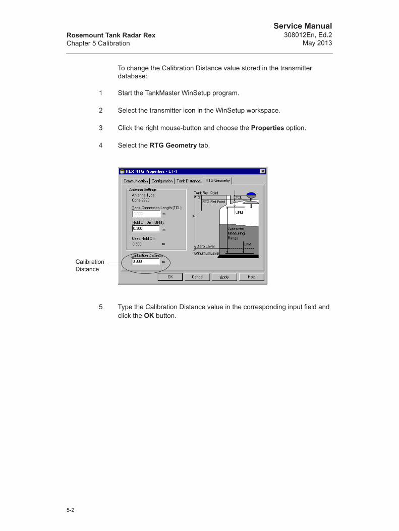
Rosemount Tank Radar RexChapter 5 Calibration
Service Manual308012En, Ed.2
May 2013
To change the Calibration Distance value stored in the transmitter database:
1 Start the TankMaster WinSetup program.
2 Select the transmitter icon in the WinSetup workspace.
3 Click the right mouse-button and choose the Properties option.
4 Select the RTG Geometry tab.
5 Type the Calibration Distance value in the corresponding input field and click the OK button.
Calibration Distance
5-2
Rosemount Tank Radar RexChapter 5 Calibration
Service Manual308012En, Ed.2May 2013
5.3 Using the WinSetup Calibrate function
The Calibration function is a tool to adjust the RTG in order to minimize the offset between actual (hand dipped) product levels and the corresponding values measured by the transmitter. By using the Calibrate function you can optimize measurement performance over the whole measurement range from the top to the bottom of the tank.
The Calibration function calculates a new Calibration Distance based on fitting a straight line to the deviations between hand dipped levels and levels measured by the transmitter.
For the 3950 still pipe gauge the calibration function is specially suitable since a minor adjustment of the Scale Factor is often necessary. The radar propagation velocity is dependent on the inner diameter of the still pipe, and the Scale Factor parameter is used to adjust the transmitter to take this effect into account. Since the average diameter is often difficult to determine accurately a calibration is often needed.
Procedure
The adjustment process includes the following steps:
1 Recording the hand dipped ullage values and the corresponding RTG level values.
2 Entering the hand dipped levels and the RTG level values into WinSetup.
3 Inspect the resulting calibration graph and, if necessary, exclude measurement points which should not be used in the adjustment calculation.
5.3.1 Required information
Make sure that the following information is available when you intend to use the RTG Adjustment function in TankMaster WinSetup:
• A list of hand dipped ullage values.
• A list of RTG level values corresponding to the hand dipped ullage/level values.
5-3
Rosemount Tank Radar RexChapter 5 Calibration
Service Manual308012En, Ed.2
May 2013
5.3.2 Hand dipping
Staff
Only one person should perform the manual ullage measurements in order to guarantee good repeatability between measurements.
Hand dip tape
Use only one tape for the calibration. The tape should be made of steel and calibrated by an approved testing institute. It must also be free from bends and kinks.
The thermal expansion factor and calibration temperature shall also be provided.
Manual dip hatch
A dip hatch should be available close to the level gauge. If the dip hatch is far away from the level gauge, differences in roof movements may result in large errors.
Procedure
Follow these instructions when you make hand dip measurements:
• hand dip until you obtain three consecutive readings within 1 mm
• correct the tape according to the calibration record
• note the hand dipped ullage and the RTG level reading simultane-ously.
Do not calibrate when
• the tank is emptying or filling
• agitators are running
• when there are windy conditions
• when there is foam on the surface.
5-4
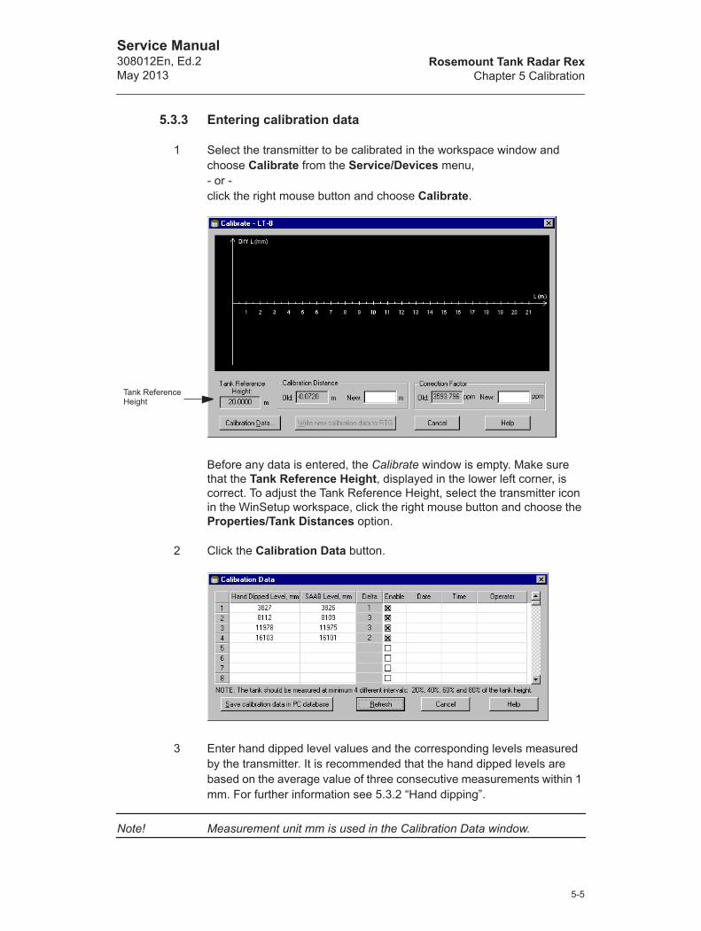
Rosemount Tank Radar RexChapter 5 Calibration
Service Manual308012En, Ed.2May 2013
5.3.3 Entering calibration data
1 Select the transmitter to be calibrated in the workspace window and choose Calibrate from the Service/Devices menu,- or -click the right mouse button and choose Calibrate.
Before any data is entered, the Calibrate window is empty. Make sure that the Tank Reference Height, displayed in the lower left corner, is correct. To adjust the Tank Reference Height, select the transmitter icon in the WinSetup workspace, click the right mouse button and choose the Properties/Tank Distances option.
2 Click the Calibration Data button.
3 Enter hand dipped level values and the corresponding levels measured by the transmitter. It is recommended that the hand dipped levels are based on the average value of three consecutive measurements within 1 mm. For further information see 5.3.2 “Hand dipping”.
Note! Measurement unit mm is used in the Calibration Data window.
Tank Reference Height
5-5
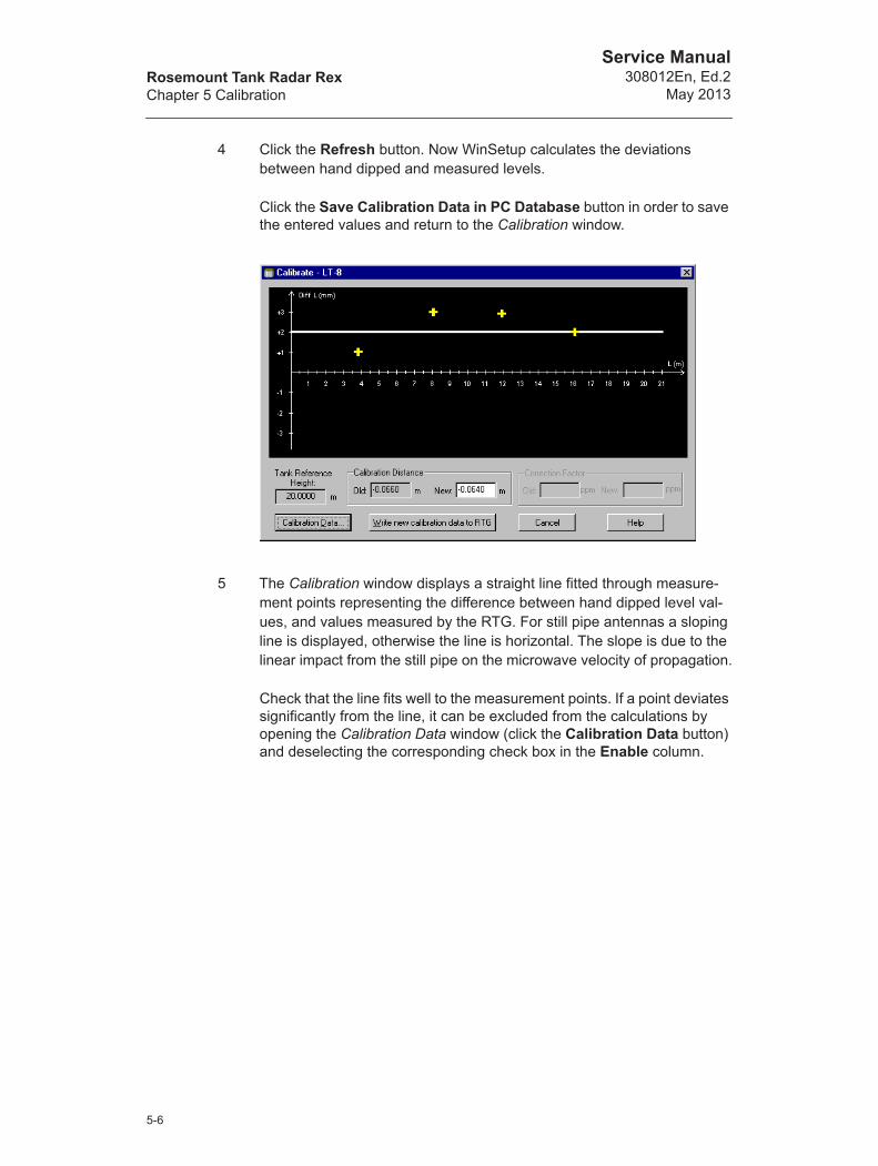
Rosemount Tank Radar RexChapter 5 Calibration
Service Manual308012En, Ed.2
May 2013
4 Click the Refresh button. Now WinSetup calculates the deviations between hand dipped and measured levels.
Click the Save Calibration Data in PC Database button in order to save the entered values and return to the Calibration window.
5 The Calibration window displays a straight line fitted through measure-ment points representing the difference between hand dipped level val-ues, and values measured by the RTG. For still pipe antennas a sloping line is displayed, otherwise the line is horizontal. The slope is due to the linear impact from the still pipe on the microwave velocity of propagation.
Check that the line fits well to the measurement points. If a point deviates significantly from the line, it can be excluded from the calculations by opening the Calibration Data window (click the Calibration Data button) and deselecting the corresponding check box in the Enable column.
5-6

Rosemount Tank Radar RexChapter 5 Calibration
Service Manual308012En, Ed.2May 2013
6 Click the Write new calibration data to RTG button in order to save the current calibration data.
Note! By clicking the Write new calibration data to RTG button, the Rosemount Level values in the Calibration Data window are recalculated and the old Calibration Data is replaced.
Now you can check the calibration result by opening the Calibration window again:
Note that all measured values are adjusted according to the calculated Calibration Distance. In the Calibration Data window you can also see that the level values measured by the transmitter are adjusted. Of course, the hand dipped levels are unaltered.
5-7

Rosemount Tank Radar RexChapter 5 Calibration
Service Manual308012En, Ed.2
May 2013
5-8
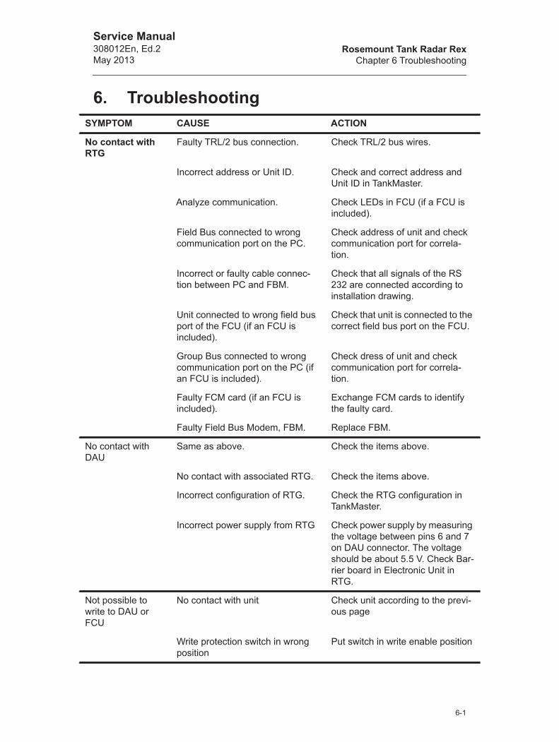
Rosemount Tank Radar RexChapter 6 Troubleshooting
Service Manual308012En, Ed.2May 2013
6. TroubleshootingSYMPTOM CAUSE ACTION
No contact with RTG
Faulty TRL/2 bus connection. Check TRL/2 bus wires.
Incorrect address or Unit ID. Check and correct address and Unit ID in TankMaster.
Analyze communication. Check LEDs in FCU (if a FCU is included).
Field Bus connected to wrong communication port on the PC.
Check address of unit and check communication port for correla-tion.
Incorrect or faulty cable connec-tion between PC and FBM.
Check that all signals of the RS 232 are connected according to installation drawing.
Unit connected to wrong field bus port of the FCU (if an FCU is included).
Check that unit is connected to the correct field bus port on the FCU.
Group Bus connected to wrong communication port on the PC (if an FCU is included).
Check dress of unit and check communication port for correla-tion.
Faulty FCM card (if an FCU is included).
Exchange FCM cards to identify the faulty card.
Faulty Field Bus Modem, FBM. Replace FBM.
No contact with DAU
Same as above. Check the items above.
No contact with associated RTG. Check the items above.
Incorrect configuration of RTG. Check the RTG configuration in TankMaster.
Incorrect power supply from RTG Check power supply by measuring the voltage between pins 6 and 7 on DAU connector. The voltage should be about 5.5 V. Check Bar-rier board in Electronic Unit in RTG.
Not possible to write to DAU or FCU
No contact with unit Check unit according to the previ-ous page
Write protection switch in wrong position
Put switch in write enable position
6-1
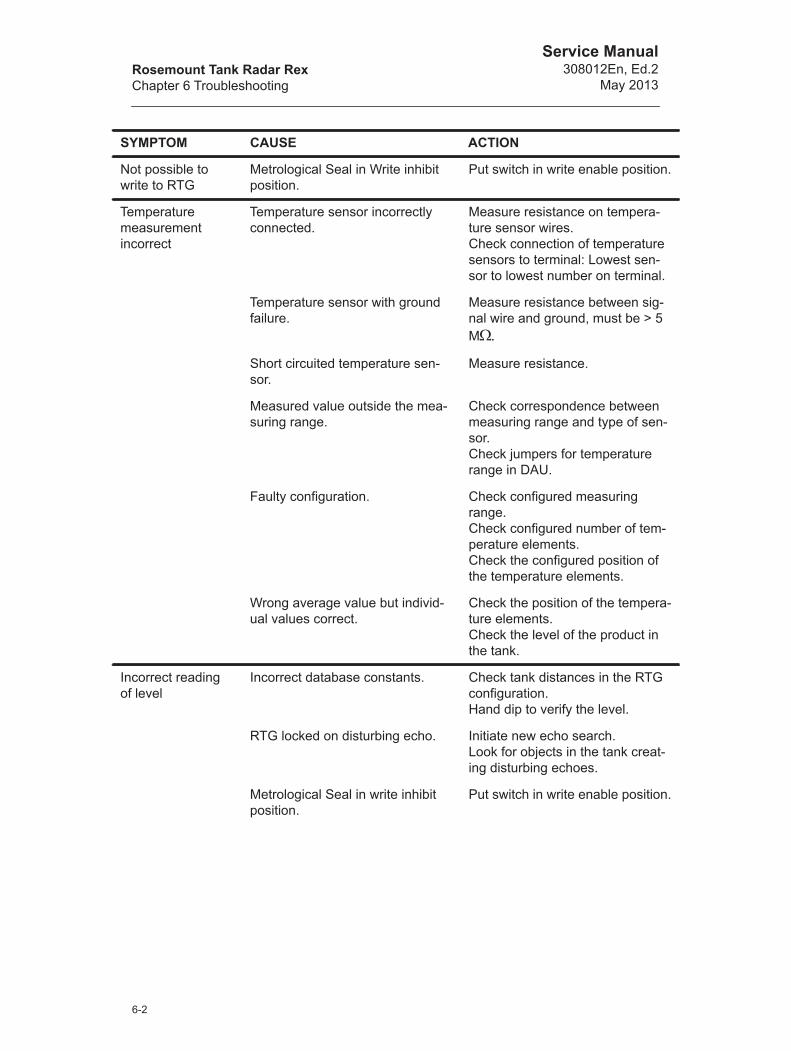
Rosemount Tank Radar RexChapter 6 Troubleshooting
Service Manual308012En, Ed.2
May 2013
Not possible to write to RTG
Metrological Seal in Write inhibit position.
Put switch in write enable position.
Temperature measurementincorrect
Temperature sensor incorrectly connected.
Measure resistance on tempera-ture sensor wires.Check connection of temperature sensors to terminal: Lowest sen-sor to lowest number on terminal.
Temperature sensor with ground failure.
Measure resistance between sig-nal wire and ground, must be > 5 M
Short circuited temperature sen-sor.
Measure resistance.
Measured value outside the mea-suring range.
Check correspondence between measuring range and type of sen-sor.Check jumpers for temperature range in DAU.
Faulty configuration. Check configured measuring range.Check configured number of tem-perature elements.Check the configured position of the temperature elements.
Wrong average value but individ-ual values correct.
Check the position of the tempera-ture elements.Check the level of the product in the tank.
Incorrect reading of level
Incorrect database constants. Check tank distances in the RTG configuration.Hand dip to verify the level.
RTG locked on disturbing echo. Initiate new echo search. Look for objects in the tank creat-ing disturbing echoes.
Metrological Seal in write inhibit position.
Put switch in write enable position.
SYMPTOM CAUSE ACTION
6-2

Rosemount Tank Radar RexChapter 6 Troubleshooting
Service Manual308012En, Ed.2May 2013
Echo amplitude below noise threshold.
Check signal amplitude.Check for foam on product sur-face.Check inclination of RTG, see “Installation Manual”.Clean antenna.Check for waves on product sur-face.
Still Pipe Gauge: Amplitude of approximately 20 000 mV or more.
Disturbing echo may be present. Restart the RTG.Check if level is near empty tank.Check the still pipe (drawings).
Parabolic or Cone Antenna Gauge: Disturbing echo with strength above the noise threshold
Check amplitude of echo. Should be 1000-3000 mV.Restart the RTG.
Varying amplitudes Check that the surface of the prod-uct is calm (no mixer).
Mechanically incorrect installation Check installation drawings and Installation Manual.
Downloading of program to RTG impossible
Faulty communication. Check the communication to the RTG in question.
Wrong file used for programming. Check that correct diskette is used.Check that correct disk drive is used.Check that correct file is used with name TH<date>.cry
ComFail occurs TankMaster configuration incor-rect.
Check configuration.
Power supply to FBM insufficient. Connect external power supply.
Incorrect cables used. Use a single twisted shielded pair of wires.
Field Communication Unit faulty. Check LEDs on the field bus ports and the group bus ports.
Bad connection of cables. Check connection of cables.
Short cables between FBM and PC.
Check termination switch, see 4.4.2.
Cable dimensions are insufficient Check gain switch, see 4.4.2.
No contact with RTG See previous pages.
SYMPTOM CAUSE ACTION
6-3

Rosemount Tank Radar RexChapter 6 Troubleshooting
Service Manual308012En, Ed.2
May 2013
Current input read-ing incorrect
Connected device faulty. Check device.
Power supply faulty. Connect a resistance and check the measured value.Measure current. If there is more than one current input then the power supply is multiplexed. There is no continuous current in that case.
Incorrect correspondence between current and displayed value
Check scaling configuration of inputs.
SYMPTOM CAUSE ACTION
6-4
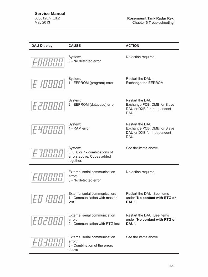
Rosemount Tank Radar RexChapter 6 Troubleshooting
Service Manual308012En, Ed.2May 2013
DAU Display CAUSE ACTION
System:0 - No detected error
No action required
System:1 - EEPROM (program) error
Restart the DAU. Exchange the EEPROM.
System:2 - EEPROM (database) error
Restart the DAU. Exchange PCB: DMB for Slave DAU or DXB for Independent DAU.
System:4 - RAM error
Restart the DAU.Exchange PCB: DMB for Slave DAU or DXB for Independent DAU.
System:3, 5, 6 or 7 - combinations of errors above. Codes added together.
See the items above.
External serial communication error:0 - No detected error
No action required.
External serial communication:1 - Communication with master lost
Restart the DAU. See items under “No contact with RTG or DAU”.
External serial communication error:2 - Communication with RTG lost
Restart the DAU. See items under “No contact with RTG or DAU”.
External serial communication error:3 - Combination of the errors above
See the items above.
6-5

Rosemount Tank Radar RexChapter 6 Troubleshooting
Service Manual308012En, Ed.2
May 2013
Internal serial communication error:0 - No detected error
No action required.
Internal serial communication error:1- Error detected
Restart the DAU. Exchange PCB: DMB for Slave DAU or DXB for Independent DAU.
Internal serial communication error:3 - Internal bus failure.
Restart the DAU. Exchange PCB: DMB for Slave DAU or DXB for Independent DAU.
Temperature measuring error:0 - No detected error
No action required.
Temperature measuring error:1- Error in at least one sensor
Watch display in mode 1 (if dis-play is included) for blinking value of the faulty sensor.
Temperature measuring error:2 - Calibration errorReference signals out of range
Exchange the precision refer-ence resistance. If problem per-sists, then exchange PCB: DMB for Slave DAU or DXB for Inde-pendent DAU.
Temperature measuring error:3 - Average errorNot any functioning non-blocked sensor is within the product.
Check if product level is below the lowest functioning non-blocked sensor. Check that DAU receives a level from the associated RTG.
Current input error (p for pres-sure):0 - No detected error
No action required.
Current input error (p for pres-sure):1- Error in at least one sensor
See items under “Current input reading incorrect”.
DAU Display CAUSE ACTION
6-6

Rosemount Tank Radar RexChapter 6 Troubleshooting
Service Manual308012En, Ed.2May 2013
Current input error (p for pres-sure):2 - Internal calibration error
Exchange PCB: DMB for Slave DAU or DXB for Independent DAU.
Current input error (p for pres-sure):3 - Old value in at least one value.Same cause as 1 above.
See items under “Current input reading incorrect”.
Output error (Independent DAU) Relay feedback does not match relay control.
Exchange relay card, DRM.
DAU Display CAUSE ACTION
6-7

Rosemount Tank Radar RexChapter 6 Troubleshooting
Service Manual308012En, Ed.2
May 2013
6-8

Rosemount Tank Radar RexChapter 7 Spare Parts
Service Manual308012En, Ed.2May 2013
7. Spare PartsRadar Tank Gauge
Data Acquisition Unit, DAU
Field Communication Unit, FCU
Field Bus Modem, FCBM
Fuses
Transmitter Interface Card, TIC 9150072-551
Temperature Multiplexing Card, TMC 9150072-561
Relay Output Card, ROC 9150072-591
DAU - DMB board 9240002-512
Display board 9240002-541
Precision Reference ResistorsHi Reference Adapter 1138.50 for temperature range -50 to 125 °C
9240003-721
Hi Reference Adapter 2175.84 for temperature range -50 to 300 °C
9240003-722
Hi Reference Adapter 324.90 for temperature range -200 to 150 °C
9240003-723
FCU - PC board 9240002-574
FCM board 9240002-701
FBM 2171 9240002-633
FBM cable 6853442-682
FBM DC power supply 6853496-240
Fuse THE (5 pcs.) 0980240-013
Fuse FCU (5 pcs.) 6853472-017
Fuse FBM 6853389-084
7-1

Rosemount Tank Radar RexChapter 7 Spare Parts
Service Manual308012En, Ed.2
May 2013
7-2

Rosemount Tank Radar RexChapter 8 List of Drawings
Service Manual308012En, Ed.2May 2013
8. List of Drawings
Mechanical Installation
Electrical Installation
Horn Antenna Gauge RTG 3920 9150 072-980
Parabolic Antenna Gauge RTG 3930 9150 072-981
Parabolic Antenna Gauge RTG 3930 (P440) 9150 072-982
Welding of T38-W 9240 003-944
Flange Ball T30 9240 003-947
RTG 3935/EES 9150 072-983
Still-pipe Array Antenna RTG 3950 fixed 9150 070-941
Still-pipe Array Antenna RTG 3950 inclined 9150 070-943
LPG/LNG Gauge 3960 9150 072-986
Reference pin to still pipe 9150 072-922
Reflector kit LPG still pipe 9150 071-651
Reflector kit LPG still pipe (Alt. B) 9150 072-924
Reflector kit LPG still pipe (Alt. A) 9150 072-925
Recommended still pipes for Rosemount Radar 9240 003-987
Installation Drawing FBM 2180 sheet 3 DIN-rail 9150 070-972
Installation Drawing FBM 2180 sheet 4 wall mounting 9150 070-972
Dimensional drawing FCU 2160 9240 002-914
Mechanical Installation Sun Shelter 9240 003-930
Dimensional drawing DAU 2100 9240 002-913
RTG (DAU-AIN, Relay) 9150 072-913
RTG (AIN-Temp, Relay) 9150 072-914
RTG/JBi (DAU-AIN, Relay) 9150 072-911
RTG/JBi (AIN-Temp, Relay) 9150 072-912
Power - TRL/2 Bus Connection RTG (W11/X11) 9150 072-930
Relay 1+2 connection RTG (W11/X11) 9150 072-932
Relay 1 connection RTG (W11/X11) 9150 072-933
Analog Output Connection RTG (W11/X11) 9150 072-934
8-1
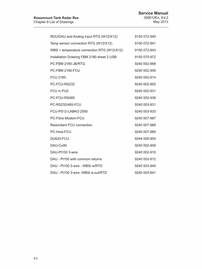
Rosemount Tank Radar RexChapter 8 List of Drawings
Service Manual308012En, Ed.2
May 2013
RDU/DAU and Analog Input RTG (W12/X12) 9150 072-940
Temp sensor connection RTG (W12/X12) 9150 072-941
WBS + temperature connection RTG (W12/X12) 9150 072-943
Installation Drawing FBM 2180 sheet 2 USB 9150 070-972
PC-FBM 2180-JB/RTG 9240 002-968
PC-FBM 2180-FCU 9240 002-959
FCU 2160 9240 002-914
PC-FCU-RS232 9240 002-905
FCU in PU2 9240 002-931
PC-FCU-RS485 9240 002-936
PC-RS232/485-FCU 9240 003-931
FCU-PS12-LABKO 2000 9240 003-933
PC-Fibre Modem-FCU 9240 007-987
Redundant FCU connection 9240 007-988
PC-Host-FCU 9240 007-989
DU620-FCU 9244 000-904
DAU-Cu90 9240 002-909
DAU-Pt100 3-wire 9240 002-910
DAU - Pt100 with common returns 9240 003-912
DAU - Pt100 3-wire - WBSi w/RTD 9240 003-940
DAU - Pt100 3-wire -WBSi w.out/RTD 9240 003-941
8-2
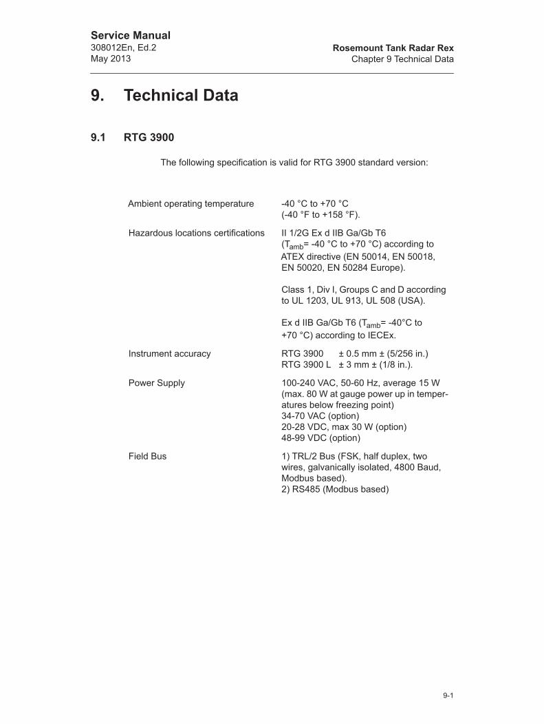
Rosemount Tank Radar RexChapter 9 Technical Data
Service Manual308012En, Ed.2May 2013
9. Technical Data
9.1 RTG 3900
The following specification is valid for RTG 3900 standard version:
Ambient operating temperature -40 °C to +70 °C(-40 °F to +158 °F).
Hazardous locations certifications II 1/2G Ex d IIB Ga/Gb T6 (Tamb= -40 °C to +70 °C) according to ATEX directive (EN 50014, EN 50018, EN 50020, EN 50284 Europe).
Class 1, Div I, Groups C and D according to UL 1203, UL 913, UL 508 (USA).
Ex d IIB Ga/Gb T6 (Tamb= -40°C to +70 °C) according to IECEx.
Instrument accuracy RTG 3900 ± 0.5 mm ± (5/256 in.)RTG 3900 L ± 3 mm ± (1/8 in.).
Power Supply 100-240 VAC, 50-60 Hz, average 15 W (max. 80 W at gauge power up in temper-atures below freezing point)34-70 VAC (option)20-28 VDC, max 30 W (option)48-99 VDC (option)
Field Bus 1) TRL/2 Bus (FSK, half duplex, two wires, galvanically isolated, 4800 Baud, Modbus based).2) RS485 (Modbus based)
9-1

Rosemount Tank Radar RexChapter 9 Technical Data
Service Manual308012En, Ed.2
May 2013
9.2 RTG 3920
Instrument accuracy RTG 3900 ± 0.5 mm ± (5/256 in.)RTG 3900 L ± 3 mm ± (1/8 in.).
Operating temperature in tank
Max. +230 °C (+445 °F)
Ambient temperature -40 °C to +70 °C(-40 °F to +158 °F)
Measuring range 0.8 to 20 m (2.6 to 65 ft) below flangeCan be extended to 0.3 to 30 m(1 to 100 ft) below flange with reduced accuracy.
Pressure -0.2 to 2 bar (-2.9 to 29 psig)
Material exposed to tank atmosphere
Antenna: Acid proof steel type EN 1.4436 (AISI 316)Sealing: PTFEO-ring: FPM (Viton™)
Total weight Approximately 20 kg (44 lbs) excl. flange
Mounting flange 8-in. ANSI B 16.5 150 lbs/DN 200PN 10 DIN 2632/SS2032
9-2

Rosemount Tank Radar RexChapter 9 Technical Data
Service Manual308012En, Ed.2May 2013
9.3 RTG 3930
Instrument accuracy RTG 3900 ± 0.5 mm ± (5/256 in.)RTG 3900 L ± 3 mm ± (1/8 in.).
Operating temperature in tank
Max. +230 °C (+445 °F)
Ambient temperature -40 °C to +70 °C(-40 °F to +158 °F)
Measuring range 0.8 to 40 m (2.6 to 130 ft) below flange
Pressure Clamped: -0.2 to 0.2 bar (-2.9 to 2.9 psig)Welded: -0.2 to 10 bar (-2.9 to 145 psig)
Material exposed to tank atmosphere
Antenna: Acid proof steel type EN 1.4436 (AISI 316)Sealing: PTFEO-ring: FPM (Viton™)
Total weight Appr. 25 kg (55 lbs) excluding flange
Manway size Minimum 20 in.
9-3

Rosemount Tank Radar RexChapter 9 Technical Data
Service Manual308012En, Ed.2
May 2013
9.4 RTG 3950
Instrument accuracy RTG ±0.5 mm + (5/256 in.)RTG 3950 L ±3 mm ± (1/8 in.)
Operating temperature in tank
-40 °C to +120 °C (-40 °F to +248 °F)
Ambient temperature -40 °C to +70 °C(-40 °F to +158 °F)
Measuring range 0.8 to 40 m (2.6 to 130 ft) from antenna end.
Pressure (two versions available)
Fixed version: -0.2 to 2 bar (-2.9 to 29 psig) at 20°CInclined version: 5 to 8 in. pipes, -0.2 to 0.5 bar (-2.9 to 7.2 psig).10 and 12 in. pipes, -0.2 to 0.25 bar (-2.9 to 3.6 psig)
Material exposed to tank atmosphere
Antenna: Polyphenylensulfid (PPS)Sealing: PTFEO-ring: FluorosiliconeFlange: Acid Proof Steel EN 1.4404 (AISI 316L)
Total weight 21.5-32 kg for fixed version and 28.5-41.5 kg for inclined version, depending on dimension
Still-pipe dimensions 5-, 6-, 8-, 10- or 12 in.
9-4
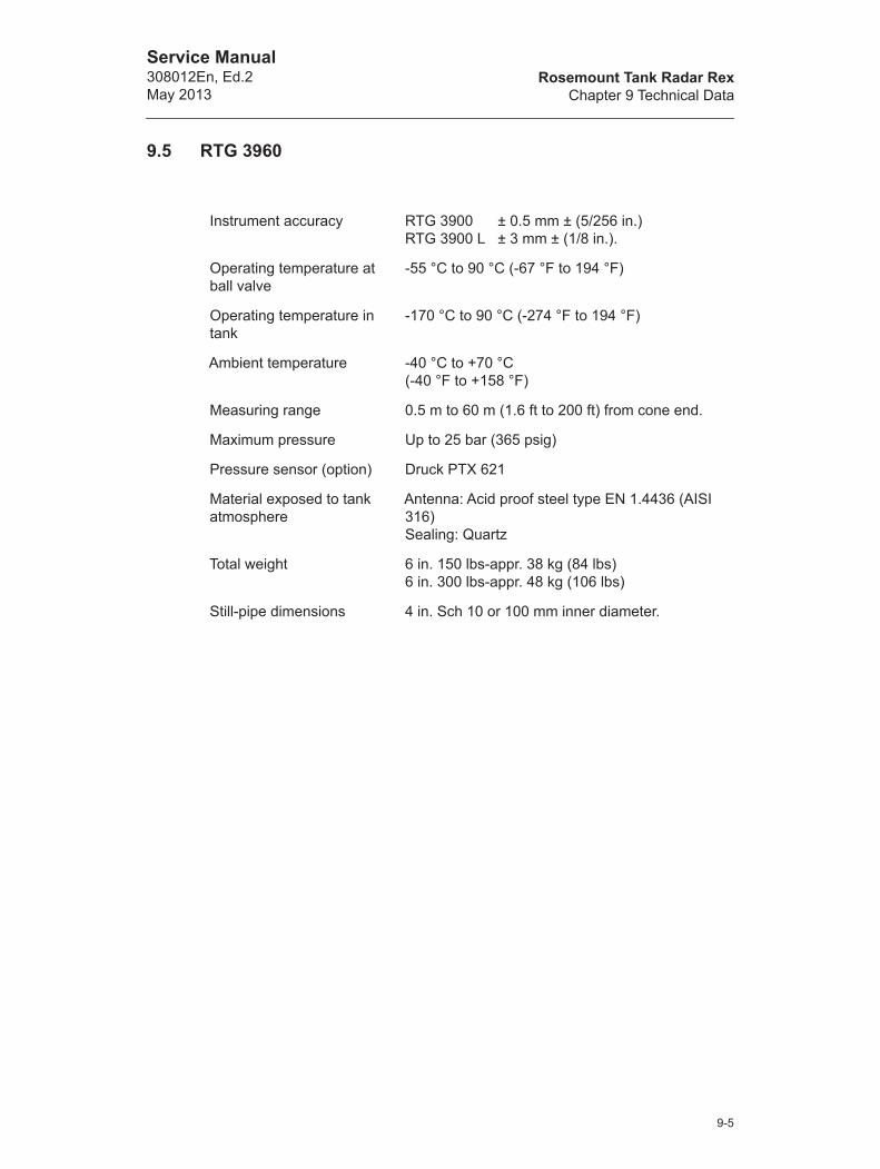
Rosemount Tank Radar RexChapter 9 Technical Data
Service Manual308012En, Ed.2May 2013
9.5 RTG 3960
Instrument accuracy RTG 3900 ± 0.5 mm ± (5/256 in.)RTG 3900 L ± 3 mm ± (1/8 in.).
Operating temperature at ball valve
-55 °C to 90 °C (-67 °F to 194 °F)
Operating temperature in tank
-170 °C to 90 °C (-274 °F to 194 °F)
Ambient temperature -40 °C to +70 °C(-40 °F to +158 °F)
Measuring range 0.5 m to 60 m (1.6 ft to 200 ft) from cone end.
Maximum pressure Up to 25 bar (365 psig)
Pressure sensor (option) Druck PTX 621
Material exposed to tank atmosphere
Antenna: Acid proof steel type EN 1.4436 (AISI 316)Sealing: Quartz
Total weight 6 in. 150 lbs-appr. 38 kg (84 lbs)6 in. 300 lbs-appr. 48 kg (106 lbs)
Still-pipe dimensions 4 in. Sch 10 or 100 mm inner diameter.
9-5

Rosemount Tank Radar RexChapter 9 Technical Data
Service Manual308012En, Ed.2
May 2013
9.6 FCU 2160
Ambient operating temperature -40 °C to +70 °C (-40 °F to +158 °F)
Power Supply 115 or 230 VAC, +10% to -15%, 50-60 Hz, max. 10 W
Group bus interface TRL/2 Bus, RS-232 or RS-485,Modbus based protocol
Field bus interface TRL/2 Bus. Max 8 units on one port
Explosion protection None
Number of tanks per FCU Max 32 (max 8 per field bus is recom-mended)
9-6
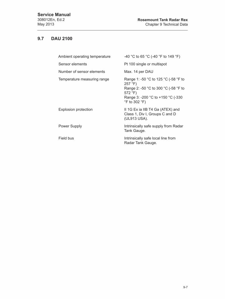
Rosemount Tank Radar RexChapter 9 Technical Data
Service Manual308012En, Ed.2May 2013
9.7 DAU 2100
Ambient operating temperature -40 °C to 65 °C (-40 °F to 149 °F)
Sensor elements Pt 100 single or multispot
Number of sensor elements Max. 14 per DAU
Temperature measuring range Range 1: -50 °C to 125 °C (-58 °F to 257 °F)Range 2: -50 °C to 300 °C (-58 °F to 572 °F)Range 3: -200 °C to +150 °C (-330 °F to 302 °F)
Explosion protection II 1G Ex ia IIB T4 Ga (ATEX) and Class 1, Div I, Groups C and D (UL913 USA).
Power Supply Intrinsically safe supply from Radar Tank Gauge.
Field bus Intrinsically safe local line from Radar Tank Gauge.
9-7

Rosemount Tank Radar RexChapter 9 Technical Data
Service Manual308012En, Ed.2
May 2013
9.8 RDU 40
Ambient temperature -20 °C to +70 °C (-4 °F to +158 °F)
Hazardous locations certifications
II 2 G Ex ib IIC T4 Gb
FM Class I Div I Group A, B, C, D
Max cable length 100 m (328 ft) (total length if two units are con-nected to the same gauge)
Cable requirement 3-wire, shielded instrument cable Min 0.5 mm² (AWG 20)Max 2.5 mm² (AWG 14)Max Ø14 mm (0.55 inch)Min insulation thickness for each wire 0.25 mm (0.00985 inch)
Material housing Die cast aluminium
Dimensions 150 x 120 x 70 mm (6 x 4 x 3 inch)
Weight 1.2 kg (2.6 lbs)
Ingress protection IP 66 & 67
9-8
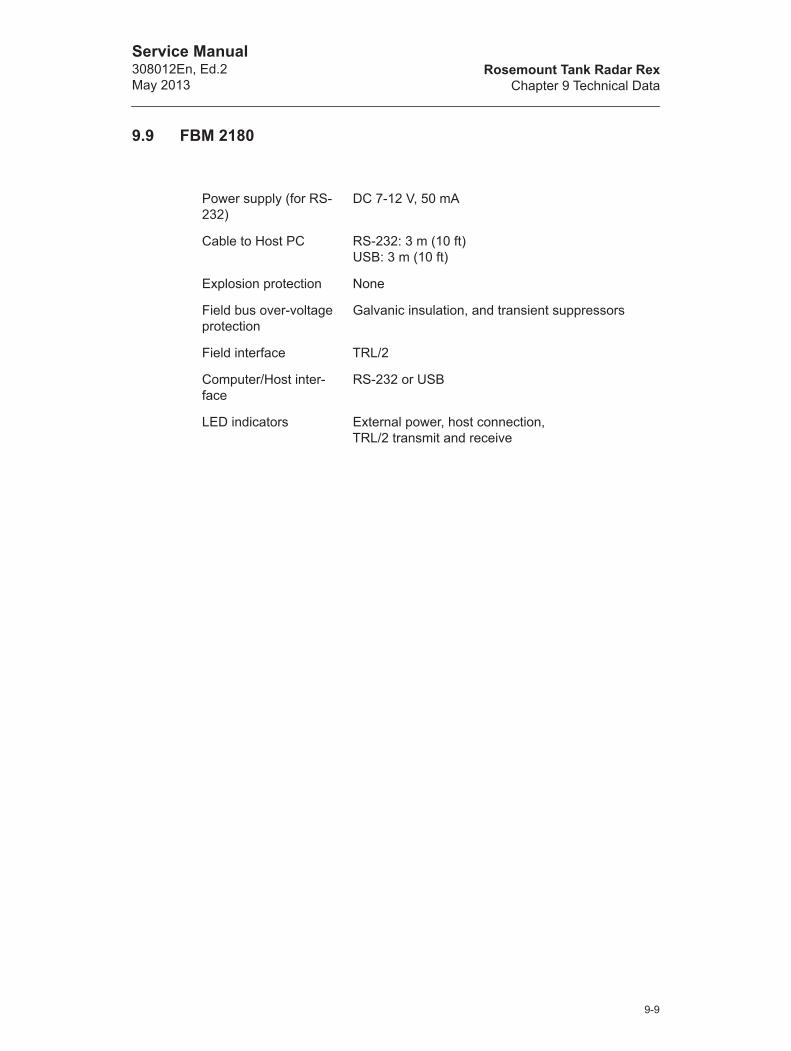
Rosemount Tank Radar RexChapter 9 Technical Data
Service Manual308012En, Ed.2May 2013
9.9 FBM 2180
Power supply (for RS-232)
DC 7-12 V, 50 mA
Cable to Host PC RS-232: 3 m (10 ft)USB: 3 m (10 ft)
Explosion protection None
Field bus over-voltage protection
Galvanic insulation, and transient suppressors
Field interface TRL/2
Computer/Host inter-face
RS-232 or USB
LED indicators External power, host connection,TRL/2 transmit and receive
9-9

Rosemount Tank Radar RexChapter 9 Technical Data
Service Manual308012En, Ed.2
May 2013
9-10
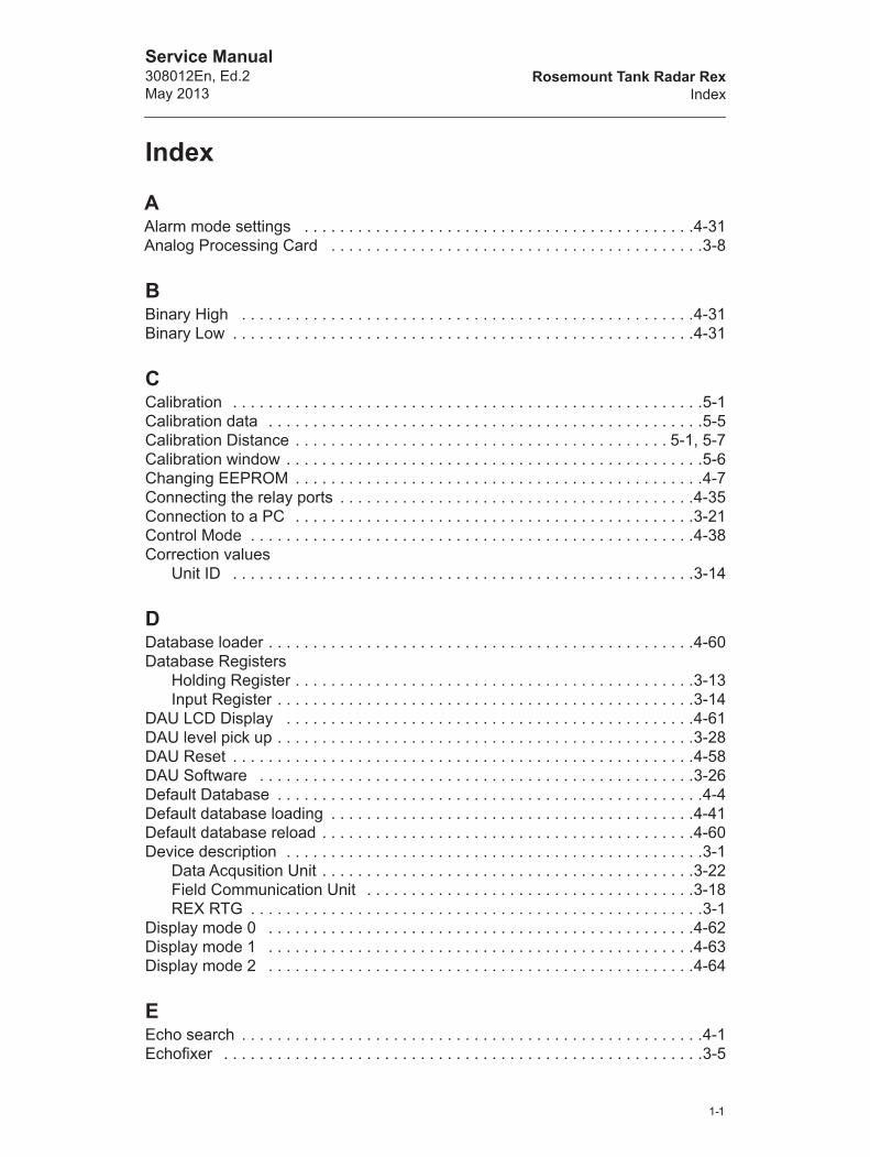
Rosemount Tank Radar RexIndex
Service Manual308012En, Ed.2May 2013
Index
AAlarm mode settings . . . . . . . . . . . . . . . . . . . . . . . . . . . . . . . . . . . . . . . . . . . .4-31Analog Processing Card . . . . . . . . . . . . . . . . . . . . . . . . . . . . . . . . . . . . . . . . . .3-8
BBinary High . . . . . . . . . . . . . . . . . . . . . . . . . . . . . . . . . . . . . . . . . . . . . . . . . . .4-31Binary Low . . . . . . . . . . . . . . . . . . . . . . . . . . . . . . . . . . . . . . . . . . . . . . . . . . . .4-31
CCalibration . . . . . . . . . . . . . . . . . . . . . . . . . . . . . . . . . . . . . . . . . . . . . . . . . . . . .5-1Calibration data . . . . . . . . . . . . . . . . . . . . . . . . . . . . . . . . . . . . . . . . . . . . . . . . .5-5Calibration Distance . . . . . . . . . . . . . . . . . . . . . . . . . . . . . . . . . . . . . . . . . . 5-1, 5-7Calibration window . . . . . . . . . . . . . . . . . . . . . . . . . . . . . . . . . . . . . . . . . . . . . . .5-6Changing EEPROM . . . . . . . . . . . . . . . . . . . . . . . . . . . . . . . . . . . . . . . . . . . . . .4-7Connecting the relay ports . . . . . . . . . . . . . . . . . . . . . . . . . . . . . . . . . . . . . . . .4-35Connection to a PC . . . . . . . . . . . . . . . . . . . . . . . . . . . . . . . . . . . . . . . . . . . . .3-21Control Mode . . . . . . . . . . . . . . . . . . . . . . . . . . . . . . . . . . . . . . . . . . . . . . . . . .4-38Correction values
Unit ID . . . . . . . . . . . . . . . . . . . . . . . . . . . . . . . . . . . . . . . . . . . . . . . . . . . .3-14
DDatabase loader . . . . . . . . . . . . . . . . . . . . . . . . . . . . . . . . . . . . . . . . . . . . . . . .4-60Database Registers
Holding Register . . . . . . . . . . . . . . . . . . . . . . . . . . . . . . . . . . . . . . . . . . . . .3-13Input Register . . . . . . . . . . . . . . . . . . . . . . . . . . . . . . . . . . . . . . . . . . . . . . .3-14
DAU LCD Display . . . . . . . . . . . . . . . . . . . . . . . . . . . . . . . . . . . . . . . . . . . . . .4-61DAU level pick up . . . . . . . . . . . . . . . . . . . . . . . . . . . . . . . . . . . . . . . . . . . . . . .3-28DAU Reset . . . . . . . . . . . . . . . . . . . . . . . . . . . . . . . . . . . . . . . . . . . . . . . . . . . .4-58DAU Software . . . . . . . . . . . . . . . . . . . . . . . . . . . . . . . . . . . . . . . . . . . . . . . . .3-26Default Database . . . . . . . . . . . . . . . . . . . . . . . . . . . . . . . . . . . . . . . . . . . . . . . .4-4Default database loading . . . . . . . . . . . . . . . . . . . . . . . . . . . . . . . . . . . . . . . . .4-41Default database reload . . . . . . . . . . . . . . . . . . . . . . . . . . . . . . . . . . . . . . . . . .4-60Device description . . . . . . . . . . . . . . . . . . . . . . . . . . . . . . . . . . . . . . . . . . . . . . .3-1
Data Acqusition Unit . . . . . . . . . . . . . . . . . . . . . . . . . . . . . . . . . . . . . . . . . .3-22Field Communication Unit . . . . . . . . . . . . . . . . . . . . . . . . . . . . . . . . . . . . .3-18REX RTG . . . . . . . . . . . . . . . . . . . . . . . . . . . . . . . . . . . . . . . . . . . . . . . . . . .3-1
Display mode 0 . . . . . . . . . . . . . . . . . . . . . . . . . . . . . . . . . . . . . . . . . . . . . . . .4-62Display mode 1 . . . . . . . . . . . . . . . . . . . . . . . . . . . . . . . . . . . . . . . . . . . . . . . .4-63Display mode 2 . . . . . . . . . . . . . . . . . . . . . . . . . . . . . . . . . . . . . . . . . . . . . . . .4-64
EEcho search . . . . . . . . . . . . . . . . . . . . . . . . . . . . . . . . . . . . . . . . . . . . . . . . . . . .4-1Echofixer . . . . . . . . . . . . . . . . . . . . . . . . . . . . . . . . . . . . . . . . . . . . . . . . . . . . . .3-5
1-1

Rosemount Tank Radar RexIndex
Service Manual308012En, Ed.2
May 2013
Electronics . . . . . . . . . . . . . . . . . . . . . . . . . . . . . . . . . . . . . . . . . . . . . . . 3-23, 4-46Exchanging the Transmitter Head Electronics . . . . . . . . . . . . . . . . . . . . . . . . .4-10Explosion Proof . . . . . . . . . . . . . . . . . . . . . . . . . . . . . . . . . . . . . . . . . . . . . . . . .2-2External Sensors
Local Display . . . . . . . . . . . . . . . . . . . . . . . . . . . . . . . . . . . . . . . . . . . . . . .3-27External serial communication error . . . . . . . . . . . . . . . . . . . . . . . . . . . . . . . .4-65
FFast High Accuracy Signal Technique . . . . . . . . . . . . . . . . . . . . . . . . . . . . . . . .3-6FBM . . . . . . . . . . . . . . . . . . . . . . . . . . . . . . . . . . . . . . . . . . . . . . . . . . . . . . . . . .1-3
Operation - front panel . . . . . . . . . . . . . . . . . . . . . . . . . . . . . . . . . . . . . . . .4-67Power Supply . . . . . . . . . . . . . . . . . . . . . . . . . . . . . . . . . . . . . . . . . . . . . . .4-67
FCC Configuration for Analog Output . . . . . . . . . . . . . . . . . . . . . . . . . . . . . . .4-25FCI boards . . . . . . . . . . . . . . . . . . . . . . . . . . . . . . . . . . . . . . . . . . . . . . . . . . . .3-19FCU block diagram . . . . . . . . . . . . . . . . . . . . . . . . . . . . . . . . . . . . . . . . . . . . .4-48FCU software . . . . . . . . . . . . . . . . . . . . . . . . . . . . . . . . . . . . . . . . . . . . . . . . . .3-20FFT (Fast Fourier Transformation) . . . . . . . . . . . . . . . . . . . . . . . . . . . . . . . . . . .3-5Field Communication Card . . . . . . . . . . . . . . . . . . . . . . . . . . . . . . . . . . . . . . . .3-8Flammable materials . . . . . . . . . . . . . . . . . . . . . . . . . . . . . . . . . . . . . . . . . . . . .2-1FMCW (Frequency Modulated Continuous Wave) method . . . . . . . . . . . . . . . .3-5Freeze Current . . . . . . . . . . . . . . . . . . . . . . . . . . . . . . . . . . . . . . . . . . . . . . . . .4-31Fuses . . . . . . . . . . . . . . . . . . . . . . . . . . . . . . . . . . . . . . . . . . . . . . . . . . . . . . . .4-44
GGroup and Field Bus Ports . . . . . . . . . . . . . . . . . . . . . . . . . . . . . . . . . . . . . . . .4-43
HHand dip tape . . . . . . . . . . . . . . . . . . . . . . . . . . . . . . . . . . . . . . . . . . . . . . . . . . .5-4Hand dipping . . . . . . . . . . . . . . . . . . . . . . . . . . . . . . . . . . . . . . . . . . . . . . . . . . .5-4Hardware installation . . . . . . . . . . . . . . . . . . . . . . . . . . . . . . . . . . . . . . . . . . . .4-50Hart Input . . . . . . . . . . . . . . . . . . . . . . . . . . . . . . . . . . . . . . . . . . . . . . . . . . . . .4-33Hart Slaves . . . . . . . . . . . . . . . . . . . . . . . . . . . . . . . . . . . . . . . . . . . . . . . . . . .4-33Hazardous areas . . . . . . . . . . . . . . . . . . . . . . . . . . . . . . . . . . . . . . . . . . . . . . . .2-1High Current . . . . . . . . . . . . . . . . . . . . . . . . . . . . . . . . . . . . . . . . . . . . . . . . . . .4-31Horn Antenna Gauge . . . . . . . . . . . . . . . . . . . . . . . . . . . . . . . . . . . . . . . . . 3-1, 3-2Hysteresis . . . . . . . . . . . . . . . . . . . . . . . . . . . . . . . . . . . . . . . . . . . . . . . . . . . .4-37
IInstalling new transmitter software . . . . . . . . . . . . . . . . . . . . . . . . . . . . . . . . . . .4-5Internal calulations . . . . . . . . . . . . . . . . . . . . . . . . . . . . . . . . . . . . . . . . . . . . . .3-10
Gross volume . . . . . . . . . . . . . . . . . . . . . . . . . . . . . . . . . . . . . . . . . . . . . . .3-10Level . . . . . . . . . . . . . . . . . . . . . . . . . . . . . . . . . . . . . . . . . . . . . . . . . . . . . .3-10Mass . . . . . . . . . . . . . . . . . . . . . . . . . . . . . . . . . . . . . . . . . . . . . . . . . . . . . .3-10Observed density . . . . . . . . . . . . . . . . . . . . . . . . . . . . . . . . . . . . . . . . . . . .3-10Oil/Water interface level . . . . . . . . . . . . . . . . . . . . . . . . . . . . . . . . . . . . . . .3-10Temperature . . . . . . . . . . . . . . . . . . . . . . . . . . . . . . . . . . . . . . . . . . . . . . . .3-10
1-2

Rosemount Tank Radar RexIndex
Service Manual308012En, Ed.2May 2013
Internal serial communication error . . . . . . . . . . . . . . . . . . . . . . . . . . . . . . . . .4-65Intrinsic safety . . . . . . . . . . . . . . . . . . . . . . . . . . . . . . . . . . . . . . . . . . . . . . . . . .2-1
JJumper settings . . . . . . . . . . . . . . . . . . . . . . . . . . . . . . . . . . . . . . . . . . . . . . . .4-54
LList of drawings . . . . . . . . . . . . . . . . . . . . . . . . . . . . . . . . . . . . . . . . . . . . . . . . .8-1Loading and Saving a device database . . . . . . . . . . . . . . . . . . . . . . . . . . . . . . .4-3Loading the default database . . . . . . . . . . . . . . . . . . . . . . . . . . . . . . . . . . . . . . .4-4Local Display Error codes . . . . . . . . . . . . . . . . . . . . . . . . . . . . . . . . . . . . . . . .4-65Low Current . . . . . . . . . . . . . . . . . . . . . . . . . . . . . . . . . . . . . . . . . . . . . . . . . . .4-31LPG/LNG Gauge . . . . . . . . . . . . . . . . . . . . . . . . . . . . . . . . . . . . . . . . . . . . . . . .3-1LPN/LNG Gauge . . . . . . . . . . . . . . . . . . . . . . . . . . . . . . . . . . . . . . . . . . . . . . . .3-4
MManual dip hatch . . . . . . . . . . . . . . . . . . . . . . . . . . . . . . . . . . . . . . . . . . . . . . . .5-4Manual relay control . . . . . . . . . . . . . . . . . . . . . . . . . . . . . . . . . . . . . . . . . . . . .4-40Master communication timeout . . . . . . . . . . . . . . . . . . . . . . . . . . . . . . . . . . . .4-66Multiple Echo Tracking . . . . . . . . . . . . . . . . . . . . . . . . . . . . . . . . . . . . . . . . . . . .3-6
PParabolic Antenna Gauge . . . . . . . . . . . . . . . . . . . . . . . . . . . . . . . . . . . . . 3-1, 3-2Power Supply . . . . . . . . . . . . . . . . . . . . . . . . . . . . . . . . . . . . . . . . . . . . . 4-44, 4-67Product level . . . . . . . . . . . . . . . . . . . . . . . . . . . . . . . . . . . . . . . . . . . . . . . . . .4-31Properties/Tank Distances . . . . . . . . . . . . . . . . . . . . . . . . . . . . . . . . . . . . . . . . .5-5
RRDU 40 . . . . . . . . . . . . . . . . . . . . . . . . . . . . . . . . . . . . . . . . . . . . . . . . . . . . . . .1-3Redundancy . . . . . . . . . . . . . . . . . . . . . . . . . . . . . . . . . . . . . . . . . . . . . . 3-20, 4-49Reference resistor . . . . . . . . . . . . . . . . . . . . . . . . . . . . . . . . . . . . . . . . . 3-24, 4-54
Automatic test . . . . . . . . . . . . . . . . . . . . . . . . . . . . . . . . . . . . . . . . . . . . . . .4-57Exchanging . . . . . . . . . . . . . . . . . . . . . . . . . . . . . . . . . . . . . . . . . . . . . . . .4-57
Relay Functions . . . . . . . . . . . . . . . . . . . . . . . . . . . . . . . . . . . . . . . . . . . . . . . .4-39Relay Output . . . . . . . . . . . . . . . . . . . . . . . . . . . . . . . . . . . . . . . . . . . . . . . . . .4-35Relay Output Card . . . . . . . . . . . . . . . . . . . . . . . . . . . . . . . . . . . . . . . . . . . . . . .3-8Relay states . . . . . . . . . . . . . . . . . . . . . . . . . . . . . . . . . . . . . . . . . . . . . . . . . . .4-38Remote Display Unit 40 . . . . . . . . . . . . . . . . . . . . . . . . . . . . . . . . . . . . . . . . . .3-29Removing the THE . . . . . . . . . . . . . . . . . . . . . . . . . . . . . . . . . . . . . . . . . . . . . .4-10Replacing the THE . . . . . . . . . . . . . . . . . . . . . . . . . . . . . . . . . . . . . . . . . . . . . .4-11RTD Multiplexer . . . . . . . . . . . . . . . . . . . . . . . . . . . . . . . . . . . . . . . . . . . . . . . .3-25RTG Communication timeout . . . . . . . . . . . . . . . . . . . . . . . . . . . . . . . . . . . . . .4-66
SSafety . . . . . . . . . . . . . . . . . . . . . . . . . . . . . . . . . . . . . . . . . . . . . . . . . . . . . . . . .2-1
1-3

Rosemount Tank Radar RexIndex
Service Manual308012En, Ed.2
May 2013
Select source . . . . . . . . . . . . . . . . . . . . . . . . . . . . . . . . . . . . . . . . . . . . . . . . . .4-38Service
DAU . . . . . . . . . . . . . . . . . . . . . . . . . . . . . . . . . . . . . . . . . . . . . . . . . . . . . .4-54FBM . . . . . . . . . . . . . . . . . . . . . . . . . . . . . . . . . . . . . . . . . . . . . . . . . . . . . .4-67FCU . . . . . . . . . . . . . . . . . . . . . . . . . . . . . . . . . . . . . . . . . . . . . . . . . . . . . .4-41RDU 40 . . . . . . . . . . . . . . . . . . . . . . . . . . . . . . . . . . . . . . . . . . . . . . . . . . .4-69
Set points . . . . . . . . . . . . . . . . . . . . . . . . . . . . . . . . . . . . . . . . . . . . . . . . . . . . .4-37Setting the temperature measurement range . . . . . . . . . . . . . . . . . . . . . . . . .4-54Signal Processing Card . . . . . . . . . . . . . . . . . . . . . . . . . . . . . . . . . . . . . . . . . . .3-8Signal to Noise Ratio . . . . . . . . . . . . . . . . . . . . . . . . . . . . . . . . . . . . . . . . . . . . .3-8Slave Data Acquisition Unit . . . . . . . . . . . . . . . . . . . . . . . . . . . . . . . . . . . . . . .3-22Software configuration . . . . . . . . . . . . . . . . . . . . . . . . . . . . . . . . . . . . . . . . . . .4-51
Analog inputs . . . . . . . . . . . . . . . . . . . . . . . . . . . . . . . . . . . . . . . . . . . . . . .4-22Analog outputs . . . . . . . . . . . . . . . . . . . . . . . . . . . . . . . . . . . . . . . . . . . . . .4-29Relay Outputs . . . . . . . . . . . . . . . . . . . . . . . . . . . . . . . . . . . . . . . . . . . . . .4-37
Spare parts . . . . . . . . . . . . . . . . . . . . . . . . . . . . . . . . . . . . . . . . . . . . . . . . . . . .7-1Suppressing error indication . . . . . . . . . . . . . . . . . . . . . . . . . . . . . . . . . . . . . .4-58Switch Delay . . . . . . . . . . . . . . . . . . . . . . . . . . . . . . . . . . . . . . . . . . . . . . . . . .4-38System configuration
DAU address . . . . . . . . . . . . . . . . . . . . . . . . . . . . . . . . . . . . . . . . . . . . . . .3-14RTG address . . . . . . . . . . . . . . . . . . . . . . . . . . . . . . . . . . . . . . . . . . . . . . .3-14
System Description . . . . . . . . . . . . . . . . . . . . . . . . . . . . . . . . . . . . . . . . . . . . . .1-1Data Acquisition Unit . . . . . . . . . . . . . . . . . . . . . . . . . . . . . . . . . . . . . . . . . .1-3Field Bus Modem . . . . . . . . . . . . . . . . . . . . . . . . . . . . . . . . . . . . . . . . . . . . .1-3Field Communication Unit . . . . . . . . . . . . . . . . . . . . . . . . . . . . . . . . . . . . . .1-3Radar Tank Gauge . . . . . . . . . . . . . . . . . . . . . . . . . . . . . . . . . . . . . . . . . . . .1-3Remote Display Unit . . . . . . . . . . . . . . . . . . . . . . . . . . . . . . . . . . . . . . . . . .1-3TankMaster . . . . . . . . . . . . . . . . . . . . . . . . . . . . . . . . . . . . . . . . . . . . . . . . . .1-3
System error . . . . . . . . . . . . . . . . . . . . . . . . . . . . . . . . . . . . . . . . . . . . . . . . . .4-65
TTank Connection Unit . . . . . . . . . . . . . . . . . . . . . . . . . . . . . . . . . . . . . . . . . . . . .3-1Tank Dimensions
Calibration Distance . . . . . . . . . . . . . . . . . . . . . . . . . . . . . . . . . . . . . . . . . .3-15Hold Off Distance . . . . . . . . . . . . . . . . . . . . . . . . . . . . . . . . . . . . . . . . . . . .3-15Minimum level distance . . . . . . . . . . . . . . . . . . . . . . . . . . . . . . . . . . . . . . .3-15RTG Reference Distance . . . . . . . . . . . . . . . . . . . . . . . . . . . . . . . . . . . . . .3-14Tank Reference Height . . . . . . . . . . . . . . . . . . . . . . . . . . . . . . . . . . . . . . . .3-14
Tank Reference Height . . . . . . . . . . . . . . . . . . . . . . . . . . . . . . . . . . . . . . . . . . . .5-5TCM interface boards . . . . . . . . . . . . . . . . . . . . . . . . . . . . . . . . . . . . . . . . . . . .3-19Technical Data
Analog inputs . . . . . . . . . . . . . . . . . . . . . . . . . . . . . . . . . . . . . . . . . . . . . . .3-11Analog outputs . . . . . . . . . . . . . . . . . . . . . . . . . . . . . . . . . . . . . . . . . . . . . .3-12DAU 2100 . . . . . . . . . . . . . . . . . . . . . . . . . . . . . . . . . . . . . . . . . . . . . . . . . . .9-7FBM 2180 . . . . . . . . . . . . . . . . . . . . . . . . . . . . . . . . . . . . . . . . . . . . . . . . . . .9-9FCU 2160 . . . . . . . . . . . . . . . . . . . . . . . . . . . . . . . . . . . . . . . . . . . . . . . . . . .9-6Relay outputs . . . . . . . . . . . . . . . . . . . . . . . . . . . . . . . . . . . . . . . . . . . . . . .3-11RTG 3920 . . . . . . . . . . . . . . . . . . . . . . . . . . . . . . . . . . . . . . . . . . . . . . . . . . .9-2
1-4
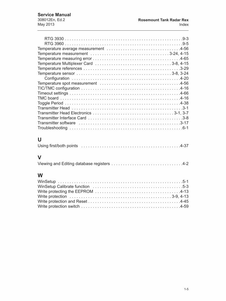
Rosemount Tank Radar RexIndex
Service Manual308012En, Ed.2May 2013
RTG 3930 . . . . . . . . . . . . . . . . . . . . . . . . . . . . . . . . . . . . . . . . . . . . . . . . . . .9-3RTG 3960 . . . . . . . . . . . . . . . . . . . . . . . . . . . . . . . . . . . . . . . . . . . . . . . . . . .9-5
Temperature average measurement . . . . . . . . . . . . . . . . . . . . . . . . . . . . . . . .4-56Temperature measurement . . . . . . . . . . . . . . . . . . . . . . . . . . . . . . . . . . 3-24, 4-15Temperature measuring error . . . . . . . . . . . . . . . . . . . . . . . . . . . . . . . . . . . . . .4-65Temperature Multiplexer Card . . . . . . . . . . . . . . . . . . . . . . . . . . . . . . . . . 3-8, 4-15Temperature references . . . . . . . . . . . . . . . . . . . . . . . . . . . . . . . . . . . . . . . . . .3-29Temperature sensor . . . . . . . . . . . . . . . . . . . . . . . . . . . . . . . . . . . . . . . . . 3-8, 3-24
Configuration . . . . . . . . . . . . . . . . . . . . . . . . . . . . . . . . . . . . . . . . . . . . . . .4-20Temperature spot measurement . . . . . . . . . . . . . . . . . . . . . . . . . . . . . . . . . . .4-56TIC/TMC configuration . . . . . . . . . . . . . . . . . . . . . . . . . . . . . . . . . . . . . . . . . . .4-16Timeout settings . . . . . . . . . . . . . . . . . . . . . . . . . . . . . . . . . . . . . . . . . . . . . . . .4-66TMC board . . . . . . . . . . . . . . . . . . . . . . . . . . . . . . . . . . . . . . . . . . . . . . . . . . . .4-16Toggle Period . . . . . . . . . . . . . . . . . . . . . . . . . . . . . . . . . . . . . . . . . . . . . . . . . .4-38Transmitter Head . . . . . . . . . . . . . . . . . . . . . . . . . . . . . . . . . . . . . . . . . . . . . . . .3-1Transmitter Head Electronics . . . . . . . . . . . . . . . . . . . . . . . . . . . . . . . . . . . 3-1, 3-7Transmitter Interface Card . . . . . . . . . . . . . . . . . . . . . . . . . . . . . . . . . . . . . . . . .3-8Transmitter software . . . . . . . . . . . . . . . . . . . . . . . . . . . . . . . . . . . . . . . . . . . .3-17Troubleshooting . . . . . . . . . . . . . . . . . . . . . . . . . . . . . . . . . . . . . . . . . . . . . . . . .6-1
UUsing first/both points . . . . . . . . . . . . . . . . . . . . . . . . . . . . . . . . . . . . . . . . . . .4-37
VViewing and Editing database registers . . . . . . . . . . . . . . . . . . . . . . . . . . . . . . .4-2
WWinSetup . . . . . . . . . . . . . . . . . . . . . . . . . . . . . . . . . . . . . . . . . . . . . . . . . . . . . .5-1WinSetup Calibrate function . . . . . . . . . . . . . . . . . . . . . . . . . . . . . . . . . . . . . . .5-3Write protecting the EEPROM . . . . . . . . . . . . . . . . . . . . . . . . . . . . . . . . . . . . .4-13Write protection . . . . . . . . . . . . . . . . . . . . . . . . . . . . . . . . . . . . . . . . . . . . 3-9, 4-13Write protection and Reset . . . . . . . . . . . . . . . . . . . . . . . . . . . . . . . . . . . . . . . .4-45Write protection switch . . . . . . . . . . . . . . . . . . . . . . . . . . . . . . . . . . . . . . . . . . .4-59
1-5

Rosemount Tank Radar RexIndex
Service Manual308012En, Ed.2
May 2013
1-6

Service Manual308012En, Ed.2May 2013
Rosemount Tank Gauging local representative:
Copyright © Rosemount Tank Radar AB. Ref. no: 308012En, Ed.2. May 2013.
Rosemount Tank GaugingBox 130 45SE-402 51 GöteborgSWEDENTel (International): +46 31 337 00 00Fax (International): +46 31 25 30 22E-mail: [email protected]
Emerson Process Management