Table of content - Rubber Design · 2017-03-02 · Last revision 08-06-2015 Table of content _____...
14
Last revision 08-06-2015 Table of content _________________ Rubber Shock Mountings 2.1 Shock mounting type RDS-R80 2.2 Shock mounting type RDS-R40 2.3 Shock mounting type RDS-C 2.4 Shock mounting type RDS-X 2.5 Shock mounting type RDS-XM 2.6 Shock mounting type RDS-Y 2.7 Shock mounting type RDS-J 2.8 Maintenance of the RDS-Mountings
Transcript of Table of content - Rubber Design · 2017-03-02 · Last revision 08-06-2015 Table of content _____...
Last revision 08-06-2015
Table of content _________________ Rubber Shock Mountings 2.1 Shock mounting type RDS-R80 2.2 Shock mounting type RDS-R40 2.3 Shock mounting type RDS-C 2.4 Shock mounting type RDS-X 2.5 Shock mounting type RDS-XM 2.6 Shock mounting type RDS-Y 2.7 Shock mounting type RDS-J 2.8 Maintenance of the RDS-Mountings

Last revision 08-06-2015
2.1 Shock mounting type RDS-R80 Rubber Design developed this shock mounting mainly for marine applications. This type of mounting can stand a linear shock deflection up to 80 mm. The RDS mounting is meeting the requirements of all international shock specifications such as BV 043, BV 044, MIL 901, STANAG and MOD. The shock mounting type RDS is in particular suitable for marine applications such as propulsion engines, diesel generator sets and auxiliary equipment where attenuation of low frequencies is required.
The RDS shock mounting is capable to reduce an input shock of 210 G to a transmitted shock of 6 G in a time to maximum velocity of 5 ms. The RDS shock mounting is suitable for a nominal load of 23 kN and a maximum load of 34 kN. resulting in a natural frequency of 4 Hz under maximum load. The RDS shock mounting developed by Rubber Design with a shock deflection of 80 mm gives that extra shock insulation which makes the difference. Where others with the same unloaded mounting height are restricted to 60 mm shock deflection, Rubber Design operates at 80 mm.

Last revision 08-06-2015
Technical data
Static load deflection characteristicvertical deflection
0
20
40
60
80
100
120
140
160
0 20 40 60 80Travel in mm
Forc
e in
kN
RDS 60°
Static load deflection characteristiclateral deflection
0
10
20
30
40
50
60
70
0 10 20 30 40
Travel in mm
Forc
e in
kN
RDS 60°
Static load deflection characteristiclongitudinal deflection
0
4
8
12
16
20
0 4 8 12 16 20 24 28 32 36 40Travel in mm
Forc
e in
kN
RDS 60°
Transfer function RDS-mount
-40,0
-30,0
-20,0
-10,0
0,0
10,0
20,0
30,0
40,0
31,5 63 125 250 500 1000 2000 4000 8000Frequency (Hz)
Lt d
B re
f. 1k
g (1
/3 o
ctav
e ba
nd)
RDS 60°

Last revision 08-06-2015
2.2 Shock mounting type RDS-R40 Based on the principals of our RDS-R80 shock mounting, the RDS-R40 adds to the range of high quality shock absorption solutions for marine applications. The nominal load range of the RDS-R40 is placed below the RDS-R80, complementing the range of high quality anti vibration and shock products for a larger equipment range. Working principals are likewise, providing very low transmitted shock under shock loads due to the linear shock load deflection curve. The RDS-R40 works with a linear shock deflection up to 40 mm.
The combination of high shock deflection capabilities and good sound & vibration isolation features, make this mounting the ideal solution for small medium speed diesel engines of generator sets, large pump sets and other rotary equipment. Like all other RDS shock mountings, the RDS-R40 meets the requirements of all international shock specifications like, for example, BV043, BV044, MIL-STD-901, STANAG, MOD BR3021, etc.
Static load deflection characteristic
0
10
20
30
40
50
0 2 4 6 8 10 12 14 16 18
Travel in mm
Forc
e in
kN RD SMD/45°
RD SMD/50°RD SMD/55°RD SMD/60°

Last revision 08-06-2015
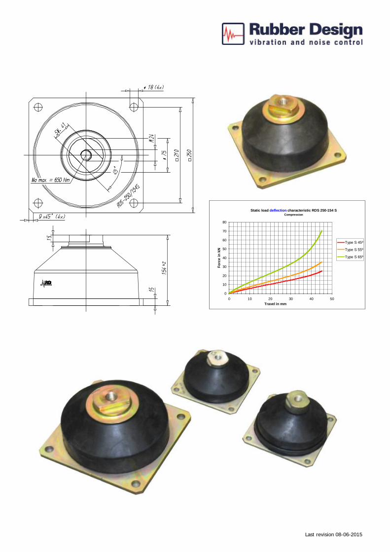
2.3 Shock mounting type RDS-C General / Applications In addition to the existing RDS shock mounting range, the new RDS C-165/95, RDS C-165/126 and RDS C-250/154 provide the ideal solution for equipment protection (up to 1500 kg per mounting) like water makers, pump sets, gensets and hydro-packs, whilst also isolating the vibrations of the resiliently mounted equipment. Features The unique mounting design characteristics allows absorption of large shock displacements whilst ensuring excellent vibration isolation. The RDS C-mountings have a linear stiffness over a wide range varying from compression to extension, which is necessary to maintain the optimum isolation properties. The maximum deflection of the mounting as a result of shock impact is as large as up to 50 mm in all directions. Due to the conical round shape, the RDS-C mountings have identical stiffness characteristics in longitudinal and transverse direction. A special developed natural
rubber compound for high dynamic loads is used which ensures the best results for long lifetime of the shock mountings. The chosen metals provide a solid vulcanisation base, ensuring high quality within the RDS series. Quality control The mountings are individually tested, marked with date of production and identification number before delivery to the customers. The new RDS mountings fulfil the requirements of international shock specifications, such as BV 043, BV 044, MIL 901, STANAG, MOD etc. Dimensions The 165/95 S and H have identical dimensions, but different stiffness’s and characteristics. Likewise, the 165/126 S and H mountings share identical dimensions, but vary in stiffness and characteristics. The 250/154S is only available in ‘S’-execution.
Static load deflection characteristic RDS 165-95SCom pression
0
2
4
6
8
10
0 10 20 30 40 50
Travel in m m
Forc
e in
kN
45º Sh.A55º Sh.A
S tatic lo ad de flec tion cha ra cte ristic R D S 16 5-95 HC om pre s s ion
0
2
4
6
8
10
12
0 1 0 2 0 3 0 4 0 50
Tra v el in m m
Forc
e in
kN
4 0º S h.A4 5º S h.A5 5º S h.A

Last revision 08-06-2015
Technical data
Static load deflection characteristic RDS 165-126HCompress ion
0
2
4
6
8
10
12
14
0 10 20 30 40 50 60
Travel in m m
Forc
e in
kN
40º Sh.A45º Sh.A55º Sh.A65º Sh.A
Static load deflection characteristic RDS 165-126SC om pression
0
1
2
3
4
5
6
0 10 20 30 40 50 60
Travel in mm
Forc
e in
kN 40º Sh.A
Last revision 08-06-2015
Static load deflection characteristic RDS 250-154 SCompression
0
10
20
30
40
50
60
70
80
0 10 20 30 40 50Travel in mm
Forc
e in
kN
Type S 45º
Type S 55º
Type S 65º

Last revision 08-06-2015
2.4 Shock mounting type RDS-X The type X leaf spring mounting was first introduced into the Naval Service some years ago by the MOD to isolate equipment from under water shock and to prevent vibration from equipment transferring to a ship’s structure and thus water. The present range of this type of mounting is between 10 kg to 450 kg. However, the reduction in the size and mass of ancillary equipment resulted in the addition of mass to accommodate the smallest mounting. There was therefore a requirement for a mounting of similar type but which will support smaller masses. This range of mountings was designed specifically for shipboard applications and is particularly suitable to protect marine equipment from shock due to underwater explosions. When loaded within their recommended range, RDS-X Mountings are capable of attenuating large shock inputs. They are also an effective anti-vibration mounting, having a low natural frequency. The RDS-X Mounting is made from stainless steel strip to BS 1449/302 S 25 hard cold rolled. The leaves are ‘U’ shaped and riveted or bolted together at the open ends with face plates and spacer platers to form an elliptical shaped assembly. The space between the inner and outer leaves is filled with an epoxy resin
damping compound, and the whole Mounting is coated with neoprene paint. High-impact nylon bushes and washers, with stainless steel backing washers, are provided for improved noise attenuation and load bearing. There are eight sizes for nominal loads ranging from 10 to 450 kg. Non Magnetic RDS-X Mountings. RDS-X Mountings can be manufactured for non-magnetic applications. Typical applications are for example: heavy machine tools, air compressors, engine suspensions, machine mountings, laboratory equipment, electric motors, radar communications equipment, electronic control equipment, refrigeration compressors, fuel tanks, blowers and fans, pumps etc. Note: Special care must be taken to ensure that the required clearances are provided around the equipment and the RDS-X Mountings. Precautions must also be taken to ensure that cables, pipes and other connecting services do not interfere with the functioning of the mounting, and that these connections will not themselves be damaged by motion of the equipment under shock.
2 inch
Type Nato Stock Number (NSN)
Rating
(kg)
Supported mass range
(kg)
A
(mm)
B
(mm)
C
(mm)
D
(mm)
E
(mm)
F
(mm)
Bolt Weight
(kg) 5717 5340-99-923-5717 10 9 – 18 114 107 203 51 32 23 M8 0.7 5718 5340-99-923-5718 20 18 – 35 114 106 203 51 32 23 M8 0.8 5719 5340-99-923-5719 45 35 – 55 133 124 216 51 32 26 M12 1.0 5720 5340-99-923-5720 70 55 – 90 133 124 216 51 32 26 M12 1.1 5721 5340-99-923-5721 110 90 – 135 133 122 216 51 32 26 M12 1.3
Static load deflection characteristicTension
0
500
1000
1500
2000
2500
3000
3500
4000
0 5 10 15 20 25 30 35 40 45 50Travel in mm
Forc
e in
N
10 kg20 kg45 kg70 kg110 kg
Static load deflection characteristicCompression
0
500
1000
1500
2000
2500
3000
3500
4000
0 5 10 15 20 25 30 35 40 45 50Travel in mm
Forc
e in
kN 10 kg
20 kg45 kg70 kg110 kg

Last revision 08-06-2015
4 inch
Type Nato Stock Number (NSN)
Rating
(kg)
Supported mass range
(kg)
A
(mm)
B
(mm)
C
(mm)
D
(mm)
E
(mm)
F
(mm)
Bolt Weight
(kg) 8429 5340-99-520-8429 180 135 – 250 190 185 297 102 64 43 M20 5.9 8428 5340-99-520-8428 320 250 – 380 190 186 297 102 64 43 M20 6.6 8427 5340-99-520-8427 450 380 – 550 190 184 297 102 64 43 M20 7.3
Static load tension characteristic
0
5
10
15
20
25
30
0 5 10 15 20 25 30 35 40 45 50 55
Travel in mm
Forc
e in
kN
180 kg320 kg450 kg
Static load compression characteristic
0
5
10
15
20
0 5 10 15 20 25 30 35 40 45 50 55 60
Travel in mm
Forc
e in
kN
180 kg320 kg450 kg

Last revision 08-06-2015
Technical details Type 5717 5718 5719 5720 5721 8429 8428 8427 Nominal load 10 20 45 70 110 180 320 450 Transmitted Acceleration V = Vertical m/s2 150 150 150 150 150 150 150 150 Hs = Horizontal Across m/s2 150 150 150 150 150 150 150 150 Hr = Vertical Across m/s2 50 50 50 50 50 50 50 50 Natural frequency and shock natural frequency (Acceleration&Deceleration)
V = Vertical Hz 6.50-8.50 6.50-8.50 7.50-8.50 6.50-8.50 7.00-8.50 9.50-13.00 8.00-9.50 7.50-9.50 Ha = Horizontal Across Hz 4.50-6.25 4.50-6.25 5.00-6.25 4.50-6.25 5.00-6.25 4.75-6.50 5.25-6.00 4.75-6.00 Hr = Vertical Across Hz 3.50-5.00 3.50-5.00 4.25-5.00 4.00-5.00 4.25-5.00 4.00-5.00 4.25-5.00 4.00-5.00 Max. shock deflection V = Vertical mm 60 60 60 60 60 60 60 60 Ha = Horizontal Across mm 40 40 40 40 40 40 40 40 Hr = Vertical Across mm 40 40 40 40 40 40 40 40 Static stiffness V = Vertical kN/m 13 26 44 70 120 350 500 875 Ha = Horizontal Across kN/m 17 35 58 91 149 665 788 1400 Hr = Vertical Across kN/m 7 14 24 39 61 175 219 385 Dynamic stiffness Hr = Vertical Across kN/m 30 58 122 150 261 891 960 1221 Hs = Horizontal Across kN/m 30 58 122 150 261 891 960 1221 Hr = Vertical Across kN/m 9 14 39 57 96 158 271 347 Dynamic factors Hr = Vertical Across 2.3 2.2 2.8 2.1 2.2 2.5 1.9 1.4 Hs = Horizontal Across 1.8 1.7 2.1 1.6 1.8 1.3 1.2 0.9 Hr = Vertical Across 1.3 1.0 1.6 1.5 1.6 0.9 1.2 0.9 Stiffness ratio н Ra = Horizontal Across 1.3 1.3 1.3 1.3 1.90 1.6 1.6 1.6 Rr = Horizontal Roll 0.55 0.55 0.55 0.55 0.55 0.50 0.45 0.45 Support stiffness kN/m 200 450 900 1300 2000 3500 6000 8500 Support strength N 150 300 675 1050 1650 2700 4800 6750

Last revision 08-06-2015
2.5 Shock mounting type RDS-XM The RDS-XM mounting is an all-metal version of the RDS-X mounting, which will maintain its properties over a wider temperature range than the RDS-X mounting. RDS-XM mountings are essentially similar to the RDS-X mountings, utilising the same leaf spring assembly, except that the epoxy resin damping compound has been replaced by stainless steel mesh inserts. Whereas the inclusion of the epoxy resin damping compound rendered the RDS-X mounting temperature sensitive (with optimum isolation efficiency at +15° to +20° C) the mesh inserts will operate over a range of –150° to +400° C with little change to the damping properties. In addition the RDS-XM has a reduction in natural frequency of the system. The RDS-X and RDS-XM are the most space efficient of all shock mountings, having originally been developed for submarines. The
elliptical leaf spring assembly enables the RDS-X and RDS-XM to have at least +/- 60mm of displacement under vertical shock conditions, within their low overall height. In addition, they have +/- 40mm of displacement to provide friction damping. Some mountings, other than leaf springs, are often employed at 45° to the vertical in an effort to equalise the stiffness in all directions. This increases the overall space envelope. The RDS-X mounting is part of the British ‘Admirality’ range of standardised mountings all NATO codified and made to Naval Engineering Standards. The RDS-XM utilises the same leaf springs and is intended to be directly interchangeable with the RDS-X mounting for extreme environmental conditions. The table below gives dimensional details of the range of RDS-XM mountings.
Type Nato Stock
Number (NSN)
Rating
(kg)
Supported mass range
(kg)
A
(mm)
B
(mm)
C
(mm)
D
(mm)
E
(mm)
F
(mm)
Bolt Weight
(kg) Not allocated 10 9 – 18 114 107 203 51 32 23 M8 0.7 Not allocated 20 18 – 35 114 106 203 51 32 23 M8 0.8 Not allocated 45 35 – 55 133 124 216 51 32 26 M12 1.0 Not allocated 70 55 – 90 133 124 216 51 32 26 M12 1.1 Not allocated 110 90 – 135 133 122 297 51 32 26 M12 1.3 Not allocated 180 135 – 250 190 185 297 102 64 43 M20 5.9 Not allocated 320 250 – 380 190 186 297 102 64 43 M20 6.6 Not allocated 450 380 – 550 190 184 297 102 64 43 M20 7.3
Last revision 08-06-2015
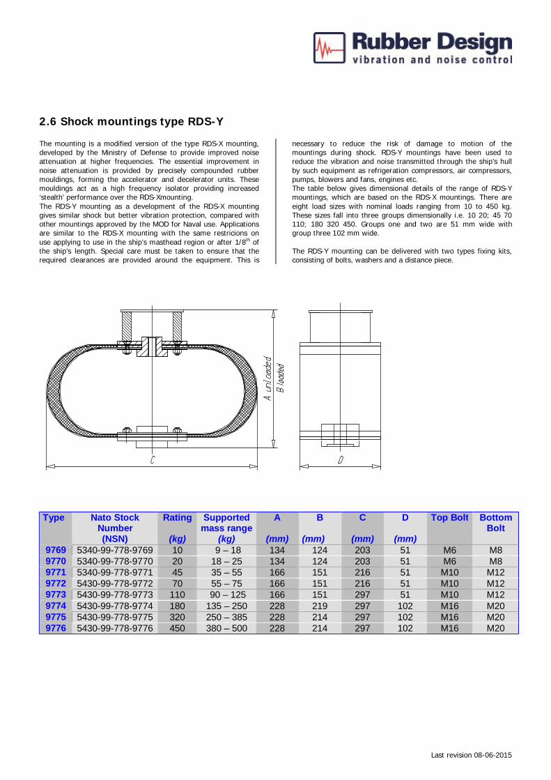
2.6 Shock mountings type RDS-Y The mounting is a modified version of the type RDS-X mounting, developed by the Ministry of Defense to provide improved noise attenuation at higher frequencies. The essential improvement in noise attenuation is provided by precisely compounded rubber mouldings, forming the accelerator and decelerator units. These mouldings act as a high frequency isolator providing increased ‘stealth’ performance over the RDS-Xmounting. The RDS-Y mounting as a development of the RDS-X mounting gives similar shock but better vibration protection, compared with other mountings approved by the MOD for Naval use. Applications are similar to the RDS-X mounting with the same restricions on use applying to use in the ship’s masthead region or after 1/8th of the ship’s length. Special care must be taken to ensure that the required clearances are provided around the equipment. This is
necessary to reduce the risk of damage to motion of the mountings during shock. RDS-Y mountings have been used to reduce the vibration and noise transmitted through the ship’s hull by such equipment as refrigeration compressors, air compressors, pumps, blowers and fans, engines etc. The table below gives dimensional details of the range of RDS-Y mountings, which are based on the RDS-X mountings. There are eight load sizes with nominal loads ranging from 10 to 450 kg. These sizes fall into three groups dimensionally i.e. 10 20; 45 70 110; 180 320 450. Groups one and two are 51 mm wide with group three 102 mm wide. The RDS-Y mounting can be delivered with two types fixing kits, consisting of bolts, washers and a distance piece.
Type Nato Stock
Number (NSN)
Rating
(kg)
Supported mass range
(kg)
A
(mm)
B
(mm)
C
(mm)
D
(mm)
Top Bolt Bottom Bolt
9769 5340-99-778-9769 10 9 – 18 134 124 203 51 M6 M8 9770 5340-99-778-9770 20 18 – 25 134 124 203 51 M6 M8 9771 5340-99-778-9771 45 35 – 55 166 151 216 51 M10 M12 9772 5430-99-778-9772 70 55 – 75 166 151 216 51 M10 M12 9773 5430-99-778-9773 110 90 – 125 166 151 297 51 M10 M12 9774 5430-99-778-9774 180 135 – 250 228 219 297 102 M16 M20 9775 5430-99-778-9775 320 250 – 385 228 214 297 102 M16 M20 9776 5430-99-778-9776 450 380 – 500 228 214 297 102 M16 M20

Last revision 08-06-2015
2.7 Shock mountings type RDS-J Suitable for shock mounting applications, where alignment with either equipment or ships structure need not be maintained after shock, and where vibration protection or isolation is not a requirement. The mounted item may be displaced from its original position by plastic yielding of the mounts as a result of shock. But it may be possible to regain shock protection, as an emergency measure, by forcing the mounts back into their original shape. The J Mount is commonly employed for the shock protection of
robust electrical distribution equipment, including switch and control gear. The J Mount is a curved metal strap designed to yield at a predetermined load in any direction under shock. The mount is self-contained, needing no separate or additional associated devices (i.e. Decelerators). It is cost effective and requires little maintenance because its zinc plated surface protects it against corrosion. The J mount is an effective shock mount, with only minor shortcomings in deflection capabilities.
J Mount ‘A’ and J Deck Mounting J Bulkhead Mounting J mounts ‘A’ Range (metric) NATO Stock Number
Mount Size No.
Mass Range (kg)
A (mm)
B (mm)
C (mm)
D (mm)
E (mm)
F (mm)
5340-99-539-6795 03A 2 - 5 151 2 55 M8 30 95 5340-99-539-6794 02A 5 - 10 152 3 55 M8 30 95 5340-99-539-6793 01A 10 - 20 153 4 55 M10 30 95 5340-99-533-2588 1A 20 - 35 154 5 70 M10 30 95 5340-99-533-2589 2A 35 - 45 154 5 90 M10 30 95 5340-99-533-2590 3A 45 - 60 155 6 85 M12 30 95 5340-99-533-2591 4A 60 - 80 155 6 105 M12 30 95 5340-99-533-2592 5A 80 - 115 157 8 95 M16 30 95 5340-99-533-2593 6A 115 - 180 159 10 85 M20 30 95 J Bulkhead mounts (metric) NATO Stock Number
Mount Size No.
Mass Range (kg)
A (mm)
B (mm)
C (mm)
D (mm)
E (mm)
F (mm)
G (mm)
H (mm)
5340-99-533-2576 1 2 - 5 69 2 55 M10 19 38 6 25 5340-99-533-2577 2 5 - 10 69 3 55 M10 19 38 6 25 5340-99-533-2578 3 10 - 20 76 4 55 M12 21 40 8 25 5340-99-533-2579 4 20 - 35 105 6 70 M16 29 49 15 32 5340-99-533-2580 5 35 - 70 125 8 90 M20 35 67 9 44 5340-99-533-2581 6 70 - 135 159 12 85 M24 44 83 11 57 J Deck mounts (Original Range - metric) NATO Stock Number
Mount Size No.
Mass Range (kg)
A (mm)
B (mm)
C (mm)
D (mm)
E (mm)
F (mm)
5340-99-533-2582 1 20 - 35 116 5 45 M10 19 64 5340-99-533-2583 2 35 - 45 116 5 55 M10 19 64 5340-99-533-2584 3 45 - 60 117 6 55 M12 19 64 5340-99-533-2585 4 60 - 80 117 6 70 M12 19 64 5340-99-533-2586 5 80 - 115 119 8 65 M16 19 64 5340-99-533-2587 6 115 - 180 121 10 65 M20 19 64
Last revision 08-06-2015
2.8 Maintenance of the RDS-Mountings • The life expectancy of the rubber elements will be
approximately 20 years in ideal circumstances. Unfortunately ideal circumstances are not feasible, therefore the (working) life expectancy will be approx. 10 years. The life expectancy of the rubber elements is dependent on the environmental circumstances (weather influences, contaminants, etc).
• A visual inspection of the RDS-Mountings should be carried
out six months after installation and should be repeated every year. For better recognition of damages you can use a blunt pin. The use of a screwdriver is not advisable, because of the damage it can cause to the conical mountings.
• The use of a natural rubber (NR) compound for the rubber
elements means that they are not oil resistant. The occasional occurrence of oil-leaks does not effect the working of the conical mountings, because the oil will only damage the surface of the rubber elements. In case of oil contamination the rubber elements will show some signs of swelling.
• When cleaning the engine or the engine room with a solvent
cleansing agent, it is advisable to cover up the RDS-Mountings. If the cleansing agent still contaminates the rubber elements, they should be cleaned als follows.
• Storage, cleaning and maintenance of the rubber elements
should be done in accordance with DIN 7716. The cleaning of the RDS-Mountings should be done with a normal (household) cleansing agent. It is also advisable to use a glycerine-alcohol mixture (1:10). Do not use a solvent cleansing agent.
• In cases where it is necessary to replace the RDS-Mounting,
we advise return of the RDS-Mounting to Rubber Design BV. • If required, the RDS-mounting can be painted by the
customer, Be aware that only the top- and base plate of the RDS-Mounting can be painted. Do not use paint on the rubber element as the rubber element might be contaminated and therefore be damaged.
• All deliveries are stored for over 20 years in a database
including all relevant data and characteristics.