Table clock and pencil holder - Siemens Global Website · table clock, milled ... drawings, tool...
12
table clock, milled A classical table clock milled from a single block, with an integrated pencil holder for the CNC miller. The workpiece is milled from an aluminum plate in two clamping operations. The border of the clock face is created in the contour editor, and is milled and chamfered with path milling cycles. The clock face itself is created with the position pattern cycle together with centering and drilling cycles, and the pocket milling cycle. The table is swiveled with CYCLE800, the inclined surface and the circular pockets are milled, and then engraved. The milled, aluminum clock case contains an analog quartz movement. This classic gem is ideal as a gift or for standing on one's own desk. All of the information required for production, drawings, tool data and workplans are compiled in the following. www.siemens.com/cnc4you Table clock and pencil holder
Transcript of Table clock and pencil holder - Siemens Global Website · table clock, milled ... drawings, tool...

table clock, milled
A classical table clock milled from a single block, with an integrated pencil
holder for the CNC miller.
The workpiece is milled from an aluminum plate in two clamping operations.
The border of the clock face is created in the contour editor, and is milled
and chamfered with path milling cycles. The clock face itself is created with
the position pattern cycle together with centering and drilling cycles, and the
pocket milling cycle. The table is swiveled with CYCLE800, the inclined
surface and the circular pockets are milled, and then engraved. The milled,
aluminum clock case contains an analog quartz movement. This classic gem
is ideal as a gift or for standing on one's own desk.
All of the information required for production, drawings, tool data and
workplans are compiled in the following.
www.siemens.com/cnc4you
Table clock and pencil holder

2/12
table clock, milled
www.siemens.com/cnc4you
Contents
1. Safety Note 2
2. Preliminary remark 2
3. Workpiece blank and clock movement 3
4. Milling machine and machining plan 3
5. Tools used 4
6. Milling the table clock 5
7. Informationen on the Internet 7
8. Pictures 8
1. Safety Note
Working with machines is always associated with numerous hazards. It is therefore imperative that the legal
and company safety regulations are also observed during the production of the table clock.
2. Preliminary remark
The following description is intended for persons acquainted with CNC machines and who have experience
with or knowledge of SINUMERIK CNCs. All the technical data listed here corresponds to the machines,
tools, materials, machining plans and drawings used to produce the prototype. Because of the widely varying
conditions in other workshops, this data is only of exemplary character for a reproduction. Nevertheless, a
problem-free reproduction should be possible in most cases.
The programs were created and tested using a CNC milling machine equipped with SINUMERIK Operate
V4.5 SP2. It should be possible to easily adapt the program to other SINUMERIK versions (e.g. different
SINUMERIK Operate SW versions). Usually these programs are not downward compatible as new cycles
often require additional parameters not yet available in older versions. These must then be added manually.
A simulation and necessary changes (e.g. zero points) should always be carried out.
You can download all the CAD drawings, programs and machining descriptions for the workpieces free of
charge at www.siemens.com/cnc4you.
The following files and formats are available there:
NC programs ShopMill, drawings PDF

3/12
table clock, milled
www.siemens.com/cnc4you
3. Workpiece blank and clock movement
AlCu4PbMg, Plate ca. 100x100x45
Standard quartz clock movement
Example shop: Conrad Electronic Order-Nr. 463077 - 62, EAN 4016138012675
Copyright: Conrad Electronic
4. Milling machine and machining plan
CNC milling machine DMG MORI DMU50, Siemens 840D sl - SINUMERIK Operate V4.5 SP2
ShopMill machining plans UHR_CLOCK_1SPG.MPF
UHR_CLOCK_2SPG.MPF
Tool list UHR_CLOCK_TMZ.INII
The machining plans are available as download for the software version V4.5 SINUMERIK Operate
SP2.

4/12
table clock, milled
www.siemens.com/cnc4you
5. Tools used
Drilling and milling tools for machining both sides of the parts.
Tools for milling machine
Tool name in the machining plan
Designation
ECK-MK-D40 90° angular face milling head Ø40 mm
CUTTER 20 End mill Ø20 mm
FRAESER 12 End mill Ø12 mm
FRAESER 8 End mill Ø8 mm
CENTERDRILL 12 Center drill Ø12 mm
BOHRER D8.0 Solid carbide twist drill Ø8 mm
KUGELKOPF_ZYL 2 Ball cutter Ø2 mm
CUTTER 16 End mill Ø16 mm
CUTTER 6 End mill r Ø6 mm
BOHRER D5 Solid carbide twist drill Ø5 mm
MFR_D4_G90 Multi mill Ø4 x 90 deg

5/12
table clock, milled
www.siemens.com/cnc4you
6. Milling the table clock
The clock has a one-piece case. The front and rear sides
of the case are machined in two clamping operations. The
zero point lies in the drill hole for the axes of the clock
hands X0-50 Y0-64.
The raw part is clamped. First the workpiece is face milled.
Then the external contour of the clock is milled with the
contour milling cycles, this is followed by the rectangular
pocket, which is the right size to hold the clock movement.
The holes are then drilled, the external contour and the
rectangular pocket are chamfered. The rear can be
engraved as an option. This completes the machining in
the first clamping operation.
The workpiece is reclamped, and the front is machined.
The zero point lies in the center of the Ø8 hole for the clock
hands, and should be redetermined. First the workpiece is
face milled, the step and the incline are milled. The
programmed contour of the clock border is roughed and
then finished. The circular pocket for the clock face is then
milled, the radius of the clock border and the two optional
rectangular pockets are milled (the clock in the illustration
does not have rectangular pockets on the left or right). In
the swiveled position, the circular pockets for the pencil
holders on the inclined surface are milled.
Now only the holes for the hands have to be drilled and the entire external contour of the clock chamfered.
The front or inclined surface can be optionally engraved.
That finishes the processing on the machine. Finally only the quartz movement has to be fitted.

6/12
table clock, milled
www.siemens.com/cnc4you
Work steps at the milling machine (back)
1. Approach the reference point of the machine
2. Read-in the workplan: UHR_CLOCK_1SPG.MPF
3. Read-in the tool list or zero offsets UHR_CLOCK_TMZ.INI
4. Measure tools and enter them in the tool list
5. Insert tools in magazine
6. Clamp the workpiece
7. Set tool zero point, by scraping (center of the borehole -50/-64)
8. Program of zero offsets
9. Perform simulation
10. Start production, process workplan
Work steps at the milling machine (front)
1. Approach the reference point of the machine
2. Read-in the workplan: UHR_CLOCK_2SPG.MPF
3. Read-in the tool list or zero offsets UHR_CLOCK_TMZ.INI
4. Measure tools and enter them in the tool list
5. Insert tools in magazine
6. Clamp the workpiece
7. Set tool zero point, by scraping (center of the borehole -50/-64)
8. Program of zero offsets
9. Perform simulation
10. Start production, process workplan
7/12
table clock, milled
www.siemens.com/cnc4you
7. Informationen on the Internet
Design of the parts, creation of the drawings, development of the machining plans for machining
Moser CNC-Training
Internet: www.moser-cnc-training.de/
and
HANDWERKSKAMMER KARLSRUHE
Friedrichsplatz 4-5
76133 Karlsruhe
Internet: www.hwk-karlsruhe.de
Details of the tool machine and tools to be used
DMG MORI High Speed Cutting precision center
Internet: www.dmgmori.com
Manuals and information from the Siemens AG
Manuals and detailed information about our products, please visit the following websites:
Technical Documentation (https://support.industry.siemens.com/cs/ww/en/view/109476679)
Service&Support Portal (https://support.industry.siemens.com)
SINUMERIK Website (www.siemens.com/sinumerik)

8/12
table clock, milled
www.siemens.com/cnc4you
8. Pictures
Simulation backside

9/12
table clock, milled
www.siemens.com/cnc4you
Graphical view backside
10/12
table clock, milled
www.siemens.com/cnc4you
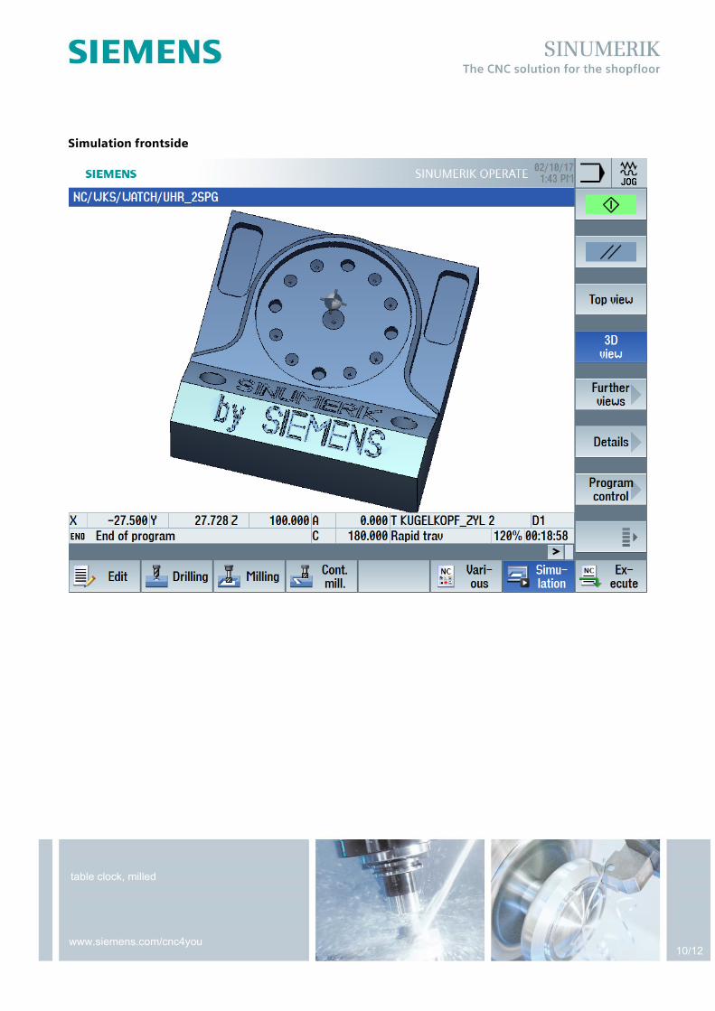
Simulation frontside

11/12
table clock, milled
www.siemens.com/cnc4you
Graphical view frontside

12/12
table clock, milled
www.siemens.com/cnc4you
Picture table clock