Reference Clock-less 1.6Gb/s Clock and Data Recovery ... · Reference Clock-less 1.6Gb/s Clock and...
4
Reference Clock-less 1.6Gb/s Clock and Data Recovery Circuit Using Oversampling Method KANG-JIK KIM, IL-DO JEONG, SEONG-IK CHO, HANG-GEUN JEONG The Department of Electronics Engineering Chonbuk National University 664-14 1GA DUCKJIN-DONG JEONJU JEONBUK SOUTH KOREA Abstract: - This paper presents the design of a clock and data recovery circuit (CDR) without a reference clock. It has a phase and frequency detector (PD and FD), which incorporates a half-rate bang-bang type oversampling PD and a half-rate digital quadricorrelator frequency detector (DQFD) that can achieve low-jitter operation and improve pull-in range. It also has a ring oscillator type voltage controlled oscillator (VCO) and three charge pumps (CP). The VCO consists of four fully differential delay cells with rail-to-rail current bias scheme that can increase the VCO tuning range and tuning linearity. The CDR circuit was designed for fabrication using 0.18um 1P6M CMOS process. The designed circuit consumes 130mW from 1.8V supply voltage according to simulation results. Key-Words: - Clock and data recovery (CDR), Oversampling, Phase detector (PD), Frequency detector (FD), DQFD, Voltage controlled oscillator (VCO), Charge pump (CP), Phase Locked Loops (PLL) 1 Introduction In recent years, data communication system is demanding high-speed and huge transmission capacity as the data transmission speed grows exponentially. In the receiver stage, the most challenging part is the design of the CDR circuit. The CDR circuit generates the clock synchronized with the received data and offers reproduction of digital signal and clock in the receiver stage of chip-to-chip interface as well as the optical communication. Phase and frequency detector (PD and FD) which detect data transition from random NRZ data is a primary block in the CDR circuit[1]. One of the challenges in designing a good CDR circuit is to design the PD and FD that can tolerate missing data transitions in random NRZ data. Hogge PD, Alexander PD and tri-wave PD structures are used for the conventional CDR circuits. A three-state PFD cannot be used in CDR application because the missing transitions cause error pulses[2]. This paper presents a CDR that has a half-rate PD[3] and a half-rate DQFD[4] using oversampling method without a reference clock. This architecture adopts the PLL structure for phase and frequency tracking [5] [6]. 2 Architecture The proposed architecture consists of six parts. PD, FD, CP, LPF, VCO and MUX (multiplexer). Fig. 1 shows the architecture of the proposed CDR circuit. Fig. 1. Architecture of the proposed CDR circuit The outputs of VCO are provided to the PD and FD. The PD generates four different up and down signals to the charge pumps. In the VCO, the delay stage in the ring oscillator structure generates eight different phases. The phase difference between adjacent clocks is 45 degrees. In the PD, input data (1.6Gb/s) is sampled by eight-phase clock (Clk0, Clk0b~Clk3, Clk3b) of VCO and PD outputs (PD1up, PD1dn, Proceedings of the 6th WSEAS Int. Conf. on Electronics, Hardware, Wireless and Optical Communications, Corfu Island, Greece, February 16-19, 2007 193
-
Upload
truongtram -
Category
Documents
-
view
229 -
download
2
Transcript of Reference Clock-less 1.6Gb/s Clock and Data Recovery ... · Reference Clock-less 1.6Gb/s Clock and...
Reference Clock-less 1.6Gb/s Clock and Data Recovery Circuit Using Oversampling Method
KANG-JIK KIM, IL-DO JEONG, SEONG-IK CHO, HANG-GEUN JEONG
The Department of Electronics Engineering Chonbuk National University
664-14 1GA DUCKJIN-DONG JEONJU JEONBUK SOUTH KOREA
Abstract: - This paper presents the design of a clock and data recovery circuit (CDR) without a reference clock. It has a phase and frequency detector (PD and FD), which incorporates a half-rate bang-bang type oversampling PD and a half-rate digital quadricorrelator frequency detector (DQFD) that can achieve low-jitter operation and improve pull-in range. It also has a ring oscillator type voltage controlled oscillator (VCO) and three charge pumps (CP). The VCO consists of four fully differential delay cells with rail-to-rail current bias scheme that can increase the VCO tuning range and tuning linearity. The CDR circuit was designed for fabrication using 0.18um 1P6M CMOS process. The designed circuit consumes 130mW from 1.8V supply voltage according to simulation results. Key-Words: - Clock and data recovery (CDR), Oversampling, Phase detector (PD), Frequency detector (FD), DQFD, Voltage controlled oscillator (VCO), Charge pump (CP), Phase Locked Loops (PLL) 1 Introduction In recent years, data communication system is demanding high-speed and huge transmission capacity as the data transmission speed grows exponentially. In the receiver stage, the most challenging part is the design of the CDR circuit.
The CDR circuit generates the clock synchronized with the received data and offers reproduction of digital signal and clock in the receiver stage of chip-to-chip interface as well as the optical communication. Phase and frequency detector (PD and FD) which detect data transition from random NRZ data is a primary block in the CDR circuit[1]. One of the challenges in designing a good CDR circuit is to design the PD and FD that can tolerate missing data transitions in random NRZ data. Hogge PD, Alexander PD and tri-wave PD structures are used for the conventional CDR circuits. A three-state PFD cannot be used in CDR application because the missing transitions cause error pulses[2]. This paper presents a CDR that has a half-rate PD[3]
and a half-rate DQFD[4] using oversampling method without a reference clock. This architecture adopts the PLL structure for phase and frequency tracking [5] [6].
2 Architecture The proposed architecture consists of six parts. PD,
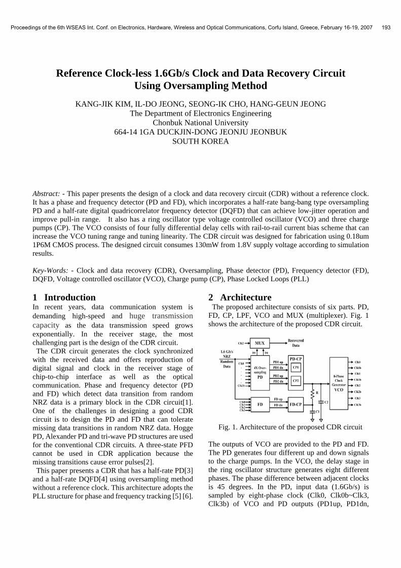
FD, CP, LPF, VCO and MUX (multiplexer). Fig. 1 shows the architecture of the proposed CDR circuit.
Fig. 1. Architecture of the proposed CDR circuit
The outputs of VCO are provided to the PD and FD. The PD generates four different up and down signals to the charge pumps. In the VCO, the delay stage in the ring oscillator structure generates eight different phases. The phase difference between adjacent clocks is 45 degrees. In the PD, input data (1.6Gb/s) is sampled by eight-phase clock (Clk0, Clk0b~Clk3, Clk3b) of VCO and PD outputs (PD1up, PD1dn,
Proceedings of the 6th WSEAS Int. Conf. on Electronics, Hardware, Wireless and Optical Communications, Corfu Island, Greece, February 16-19, 2007 193

PD2up, PD2dn) are transmitted to the PD-CP. In the FD, the input data is sampled by four-phase clock (Clk0, Clk1, Clk2, Clk3) of VCO and FD outputs (FDup, FDdn) are transmitted to the FD-CP. The PD and FD, producing six phase and frequency information, need three CPs for the controlling voltage of the VCO. The PD-CPs generate PDup and PDdn. FD-CP also generates voltage FDup and FDdn. The LPF consists of C1, C2 and R for controlling the VCO. The MUX with Clk2 signal is used to produce the recovered data from D0 and D4. 3 Design of Detailed circuit 3.1 Phase Detector
Fig. 2. The section of 4X oversampling Clock
The PD uses eight clock signals to detect data
transition from two consecutive incoming data. Fig. 2 shows the section of 4X oversampling (0~3b). Eight samplers pick eight sampling points for two successive input data[7]. Through eight XOR gates and 4 MUXs, these samplers provide four output signals that control the two charge pumps (PD-CP1, PD-CP2). The block diagram of a half-rate bang-bang type oversampling PD is shown in Fig. 3.
Fig. 3. Block diagram of an oversampling PD
Fig. 4 shows the operating condition (PD1up) of the
PD generating the up and down signals. The clock signals from VCO can be divided into 0 to 3b section. A data transition of two consecutive input data in the
eight regions of the clock period is used to detect the phase difference between the input data and the clock signal of the VCO. If the CDR is locked, the data transition occurs on the Clk2 and Clk2b signal at the PD. A data transition between 1 and 1b of section causes PD1up signal to generate a phase shifting signal. A data transition between 2 and 2b section causes PD1dn signal to generate a phase shifting signal. PD2up, PD2dn signal of the PD are also generated for a large phase difference.
Fig. 4. Operating condition of PD
3.2 Frequency Detector The half-rate DQFD can be realized by eight D-FFs
(D Flip-Flop), two XOR gates, and combinational logics as shown in Fig. 5.
Fig. 5. Block diagram of the DQFD
Proceedings of the 6th WSEAS Int. Conf. on Electronics, Hardware, Wireless and Optical Communications, Corfu Island, Greece, February 16-19, 2007 194

The truth table for the combinational logic in the proposed DQFD is shown in Table1.
Table 1. Truth table for the combinational logic
In Fig. 5, the clocks Clk0, Clk1, Clk2 and Clk3 are
sampled by input data, each half of clock period can be divided into four states, I, II, III, and IV, as shown in the left of table 1. In the DQFD, four D-FFs triggered by Clk0 will store the sampled values and record the states. All valid state transitions have to rotate counterclockwise and cross the arrow in the left of table 1. The arrow represents the edge of Clk0 to rise.
3.3 Voltage Controlled Oscillator
The VCO consists of three blocks as shown in Fig. 6(a), (b) and (c). In Fig.6(a), the rail-to-rail current bias circuit can increase the tuning range and the tuning linearity of the VCO[8]. The input control voltage of the VCO can operate from GND to VDD, and the frequency of the VCO is from 270MHz to 1.25GHz. The delay cell is shown in Fig. 6(b). The buffer (Differential to single ended amplifier) as shown in Fig. 6(c) can convert the small swing signal to the rail-to-rail signal.
Fig. 6. Block diagram of a VCO
4 Results of Simulation This CDR circuit was designed for 0.18um CMOS
process and included a PRBS (25-1 long) circuit. Fig. 7 shows eight-phase clock (Clk0, Clk0b~Clk3, Clk3b) waveform used for sampling and VCO control the voltage while the CDR achieves the locking.
Fig. 7. Waveform of eight-phase clock
and VCO control voltage during the locking Fig. 8 shows the clock frequency variation with the
VCO control voltage and the VCO tuning range for each process corner (FF, TT, SS).
Fig. 8. VCO tuning range simulation
Fig. 9 shows the recovered data and the jitter on data
eye diagram. It has 800ps gate delay.
Fig. 9. Recovered data and jitter
Proceedings of the 6th WSEAS Int. Conf. on Electronics, Hardware, Wireless and Optical Communications, Corfu Island, Greece, February 16-19, 2007 195

5 Conclusion This proposed 1.6Gb/s CDR circuit was designed
using TSMC 0.18um 1P6M CMOS process and 1.8V supply voltage. It has recovered data without a reference clock and improved the pull-in range by separating the FD from the oversampling PD. The peak-to-peak jitter on the recovered data was 28ps and the total power dissipation was 130mW. The layout area occupied 1x1mm2 . Fig. 10 shows the layout of this CDR circuit.
Fig. 10. Layout
Acknowledgment This research was supported by the IDEC(IC Design
Education Center), IT-SoC(Information Technology -System on Chip) and the second stage of Brain Korea 21. References: [1] Behzard Razavi, Monolithic Phase-Locked Loops and Clock Recovery Circuits, IEEE press, pp33-34, 1996 [2] Behzard Razavi, Desing of Integrated Circuits for Optical Commynications, McGRAW-HILL, 2003 [3] Sung-Sop Lee, Hyung-Wook Jang, and Jin-Ku Kang, 3.125Gbps Reference-less Clock and Data Recovery using 4X Oversampling, Incheon, Korea: Inha University, IEEE, 2005. [4] Rong-Jyi Yang, Shang-Ping Chen, Shen-Iuan Liu, A 3.125-Gb/s Clock and Data Recovery Circuit for the 10-Gbase-LX4 Ethernet, IEEE JOURNAL OF SOLID-STATE CIRCUITS, VOL. 39, NO. 8, AUGUST 2004
[5] Mehrdad Ramezani, C. Andre. T, An Improved Bang-bang Phase Detector for Clock and Data Recovery Applications, Department of Electrical & Computer Engineering, University of Toronto, 2001, IEEE [6] Jafar Savoj and Behzard Razavi, A 10-Gb/s CMOS Clock and Data Recovery Circuit With a Half-Rate Binary Phase/Frequency Detector, IEEE JOURNAL OF SOLID-STATE CIRCUITS, VOL. 38, NO. 1, JANUARY 2003 [7] Rezayee. A, and C. Andre. T. Salama, An Improved Bang-bang Phase Detector for Clock and Data Recovery Applications, Circuits and Systems, 2001. ISCAS’ 01. Proceedings of the 2001 International Symposium on, Volume: 1 Page, 715-718, May,2001. [8] Kuo-Hsing Cheng ,Ch'ing- Wen Lai and Yu-Lung Lo, A CMOS VCO for 1V, 1GHz PLL Applications, 2004 IEEE Asia-Pacific Conference on Advanced System Integrated Circuits(AF'-ASIC2004)/ Aug. 4-5,2004
Proceedings of the 6th WSEAS Int. Conf. on Electronics, Hardware, Wireless and Optical Communications, Corfu Island, Greece, February 16-19, 2007 196