TA101 : Engineering Graphics Review of Lineshome.iitk.ac.in/~adutta/Discussion.pdf · TA101 :...
25
TA101 : Engineering Graphics Review of Lines Dr. Ashish Dutta Professor Dept. of Mechanical Engineering IIT Kanpur Kanpur , INDIA
Transcript of TA101 : Engineering Graphics Review of Lineshome.iitk.ac.in/~adutta/Discussion.pdf · TA101 :...

TA101 : Engineering Graphics
Review of Lines
Dr. Ashish Dutta
Professor
Dept. of Mechanical Engineering
IIT Kanpur
Kanpur , INDIA

Projection of a point in space
A point is behind the frontal plane by ‘d’ units
and below the horizontal plane by ‘h’ units.
HORIZONTAL
FRONTAL
PLANE
HORIZONTAL
PLANE

Line positions
• Line lying on two principal planes of projection will
appear normal / true length (TL) in two views.

• A line lying in one principal plane will appear normal
in one view.

Find normal view of a lineMethod 1 (using auxiliary plane).
1. Determine the desired line of sight.
2. Establish a new projection plane perpendicular to
line of sight.

3. Project all points into the new view.
4. Locate points A and B along the projections in
plane.

Auxiliary plane method

Method 2 : Rotation method
1. Make the line parallel to one of the
Principal planes in any view by rotation.
2. Take projections on the other
view to get normal view of line.view to get normal view of line.
Why does it work?

Slope and Grade of a line
� Relationship of a line to the horizontal plane
• Line in TL (normal view)
• Slope =
• θ is the slope angle of a line.
θtanRun
Rise==
X
Y
• θ is the slope angle of a line.

Bearing
• Bearing of a line can be, measured only in horizontal
view.
• Examples are N60°W, S45°W etc.

Azimuth
Azimuth is measured clockwise from the north arrow
and only uses ‘N’ along with the angle.
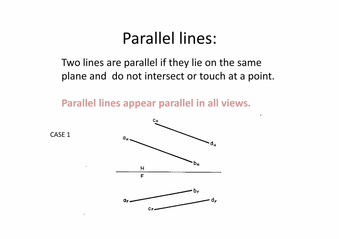
Parallel lines:
Two lines are parallel if they lie on the same
plane and do not intersect or touch at a point.
Parallel lines appear parallel in all views.
CASE 1

Lines that appear normal in H and F planes may
not be parallel: Check for P view
CASE 2

Perpendicular lines:
Two lines are perpendicular if there is a 90o angle
between them if at least one line is in true length
Cases :
A : Perpendicular (both lines in TL)
B: Perpendicular (only one line in TL)
C: Not perpendicularC: Not perpendicular

Shortest distance from a point to a line is a
perpendicular from the point to a line.
• Shortest distance shows true length (TL) when
original line is a point view. ?
• Const.:
Draw a line O-P perpendicular Draw a line O-P perpendicular
to line 1-2 at ‘P’.
Similarly in F view,
Join point ‘O’ and point view of line.

• Point view of line 1-2 is given in F view. Hence
OP is in TL.
• Line OP is parallel to H plane.

Line not in point view• Point view required for line 3-4.
• Construct auxiliary view H/A to get point view of line
3-4
• Point P must lie along a line from ‘O’ parallel to H/A
folding line.
• Hence OP is in TL in• Hence OP is in TL in
view A.

• Once point P is found in H view, drop it to the F view
on line 3-4.

Given line not in true length• The shortest distance is seem as TL when line is
made a point view.
• In view 1 line A B is made TL.
• In view 2 AB is made point view.
• Distances from view H are transferred into view 2.

• View 2 TL of OP connector is made.
• Line OP is returned to other views.
• Line OP in view 1 is made parallel to the 1/2 fold
line to get P, such that OP is in TL in view 2.

Shortest distance from a line to a line
in case one line is in point view • Two lines that are not parallel and do not intersect
(skew lines).
• The shortest connector between two skew lines is
the connector perpendicular to each line.

• Connector shows TL as one line 1-2 is in point view in
F view.
• Hence OP is made TL in F view by constructing
perpendicular to line 3-4.
• OP is found in H view by projecting P on to 3-4 line.
• Run it parallel to H/F fold line.

Distance between Skew lines when
neither are in point view
• A line AB is mode in point view. (TL then point view)
In view 2 the shortest distance OP is added as a TL
connector.
• Connector makes 900 angle to line CD.

• Line AB is first made TL, and then point view.
• CD is carried along from view to view.
• In view 2 the shortest distance is found by
constructing a perpendicular to get point P.
• OP is projected
back.back.

Main Points to rememberNormal Line:
• A line lying in one principal plane will appear
normal in one view.
• A line lying on two principal planes will appear
normal in two views
Shortest distance:
• Shortest distance from a point to a line is a
perpendicular from the point to a line.
• Shortest distance shows true length (TL)
when original line is a point view. ?