T2FD, Terminated & twisted folded dipole - … is a 600-900 ohms folded dipole, terminated with...
3
T2FD, Terminated & twisted folded dipole © OH1AYR Rev: 2.0 About the T2FD antenna type T2FD is a 600-900 ohms folded dipole, terminated with resistor. Feed impedance is coupled with 50/600 ohms voltage balun. It is a wide band antenna with rather low SWR over the full designed frequency range: antenna tuner is seldom needed. Antenna length is not critical: it works also beyond the designed frequency range, with less radiation while transmitting. Free space gain is 3-6 dB below fixed frequency half-wave dipole. Radiation pattern is similar to dipole with the same dimensions. It is a traveling wave antenna, which is rather immune to local noise sources and statics. This is a very quiet RX antenna. T2FD is an ideal construction for wide band reference antennas and for Slow Frequency Hop systems. It is also used as a high-quality receiving antenna, with low power terminator. Commercial T2FD antennas T2FD antenna type is widely used by military, commercial and broadcasting services: Codan C411 Racal 3051-901 Comrod AH51 Barker & Williamson BDW-90 Diamond WD-330 Giovannini 1830/DL-M T2FD proto This proto was built for tests as amateur radio stations HF antenna. This antenna is assembled as inverted-V at 2/8/2 m height. SWR is from 1.1 to 2.4 full range: optional use with antenna tuner. 1.8 MHz operation is possible with tuner: low radiation, however. Antennas full length is 44m for frequencies from 3.5 to 30 MHz. Antenna length is tuned to optimal SWR on 7 MHz, so the SWR is below 2.0 on all amateur bands. See the SWR chart. Proto antennas wire spacing is 450 mm, range 200 to 450 mm. 5/500 mm glass fiber spacers was used between the wires, distance between spacers is about 3m. Spacers were fitted with gable ties. This antenna uses horizontal wires; vertical wires are also usable. 1.5 mm2 PVC insulated stranded equipment wire was used as the antenna wire; suitable wire size ranges from 0.5 to 1.5 mm2. Input power range is up to 50W/CW and up to 100W/SSB with the current 50W terminator. © KORPI control systems http://www.korpi.biz 16.08.2006 Page 1/2 2,0 2,5 3,0 3,5 4,0 4,5 5,0 5,5 6,0 6,5 7,0 7,5 8,0 8,5 9,0 9,5 10,0 10,5 11,0 11,5 12,0 12,5 13,0 13,5 14,0 14,5 15,0 15,5 16,0 16,5 17,0 17,5 18,0 18,5 19,0 19,5 20,0 20,5 21,0 21,5 22,0 22,5 23,0 23,5 24,0 24,5 25,0 25,5 26,0 26,5 27,0 27,5 28,0 28,5 29,0 29,5 30,0 1,0 1,5 2,0 2,5 T2FD SWR MHz SWR
Transcript of T2FD, Terminated & twisted folded dipole - … is a 600-900 ohms folded dipole, terminated with...
T2FD, Terminated & twisted folded dipole
© OH1AYR Rev: 2.0
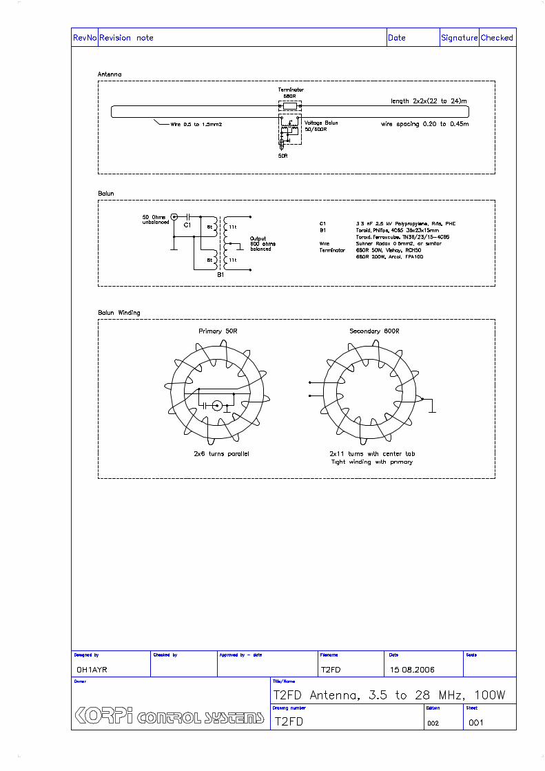
About the T2FD antenna type
T2FD is a 600-900 ohms folded dipole, terminated with resistor.Feed impedance is coupled with 50/600 ohms voltage balun. It is a wide band antenna with rather low SWR over the fulldesigned frequency range: antenna tuner is seldom needed.Antenna length is not critical: it works also beyond the designedfrequency range, with less radiation while transmitting.Free space gain is 3-6 dB below fixed frequency half-wave dipole.Radiation pattern is similar to dipole with the same dimensions.It is a traveling wave antenna, which is rather immune to localnoise sources and statics. This is a very quiet RX antenna.T2FD is an ideal construction for wide band reference antennas andfor Slow Frequency Hop systems. It is also used as a high-qualityreceiving antenna, with low power terminator.
Commercial T2FD antennas
T2FD antenna type is widely used by military, commercial andbroadcasting services:
Codan C411Racal 3051-901Comrod AH51Barker & Williamson BDW-90Diamond WD-330Giovannini 1830/DL-M
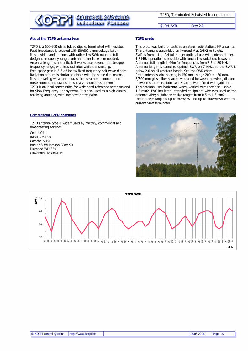
T2FD proto
This proto was built for tests as amateur radio stations HF antenna.This antenna is assembled as inverted-V at 2/8/2 m height. SWR is from 1.1 to 2.4 full range: optional use with antenna tuner.1.8 MHz operation is possible with tuner: low radiation, however.Antennas full length is 44m for frequencies from 3.5 to 30 MHz.Antenna length is tuned to optimal SWR on 7 MHz, so the SWR isbelow 2.0 on all amateur bands. See the SWR chart.Proto antennas wire spacing is 450 mm, range 200 to 450 mm.5/500 mm glass fiber spacers was used between the wires, distancebetween spacers is about 3m. Spacers were fitted with gable ties. This antenna uses horizontal wires; vertical wires are also usable.1.5 mm2 PVC insulated stranded equipment wire was used as theantenna wire; suitable wire size ranges from 0.5 to 1.5 mm2.Input power range is up to 50W/CW and up to 100W/SSB with thecurrent 50W terminator.
© KORPI control systems http://www.korpi.biz 16.08.2006 Page 1/2
2,0
2,5
3,0
3,5
4,0
4,5
5,0
5,5
6,0
6,5
7,0
7,5
8,0
8,5
9,0
9,5
10,0
10,5
11,0
11,5
12,0
12,5
13,0
13,5
14,0
14,5
15,0
15,5
16,0
16,5
17,0
17,5
18,0
18,5
19,0
19,5
20,0
20,5
21,0
21,5
22,0
22,5
23,0
23,5
24,0
24,5
25,0
25,5
26,0
26,5
27,0
27,5
28,0
28,5
29,0
29,5
30,0
1,0
1,5
2,0
2,5
T2FD SWR
MHz
SW
R
T2FD, Terminated & twisted folded dipole
© OH1AYR Rev: 2.0
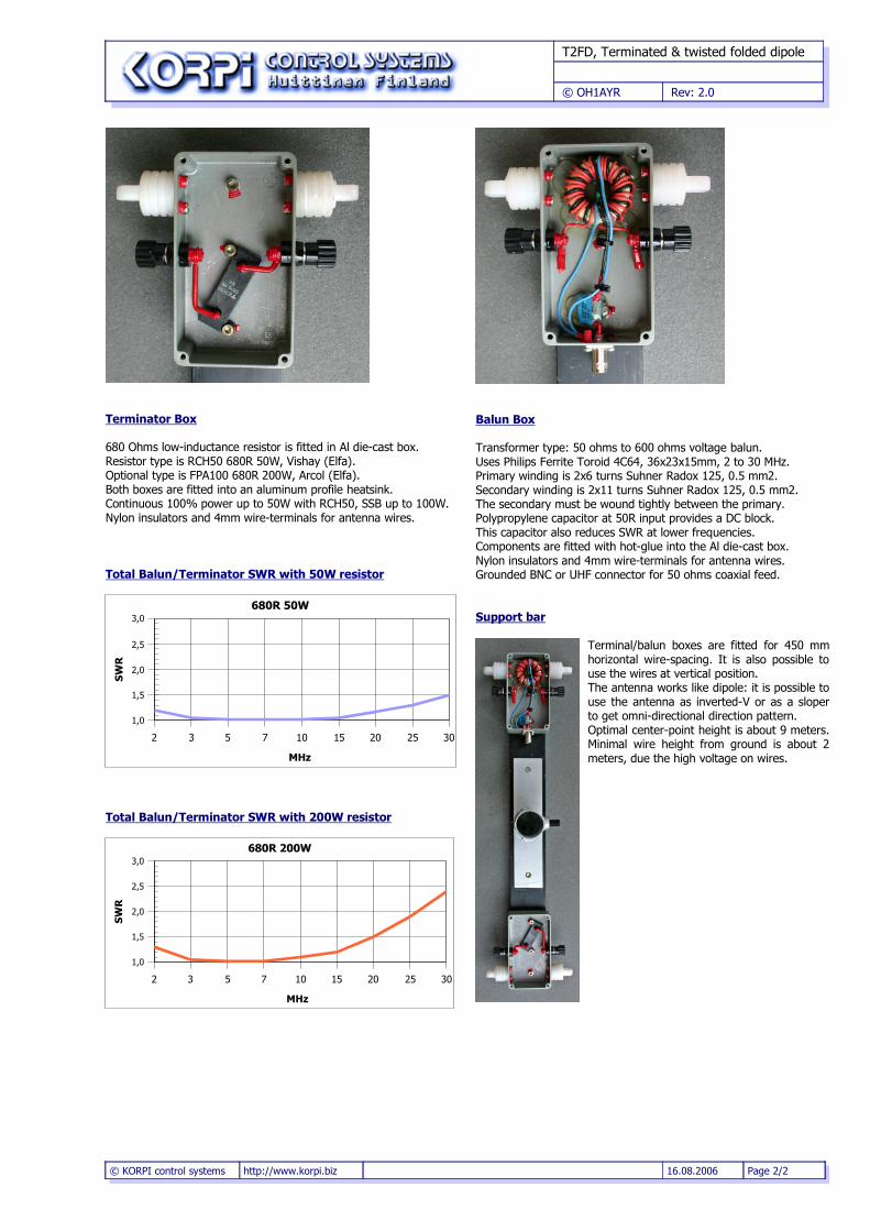
Terminator Box
680 Ohms low-inductance resistor is fitted in Al die-cast box.Resistor type is RCH50 680R 50W, Vishay (Elfa).Optional type is FPA100 680R 200W, Arcol (Elfa).Both boxes are fitted into an aluminum profile heatsink.Continuous 100% power up to 50W with RCH50, SSB up to 100W.Nylon insulators and 4mm wire-terminals for antenna wires.
Total Balun/Terminator SWR with 50W resistor
Total Balun/Terminator SWR with 200W resistor
Balun Box
Transformer type: 50 ohms to 600 ohms voltage balun.Uses Philips Ferrite Toroid 4C64, 36x23x15mm, 2 to 30 MHz.Primary winding is 2x6 turns Suhner Radox 125, 0.5 mm2.Secondary winding is 2x11 turns Suhner Radox 125, 0.5 mm2.The secondary must be wound tightly between the primary.Polypropylene capacitor at 50R input provides a DC block.This capacitor also reduces SWR at lower frequencies.Components are fitted with hot-glue into the Al die-cast box.Nylon insulators and 4mm wire-terminals for antenna wires.Grounded BNC or UHF connector for 50 ohms coaxial feed.
Support bar
Terminal/balun boxes are fitted for 450 mmhorizontal wire-spacing. It is also possible touse the wires at vertical position. The antenna works like dipole: it is possible touse the antenna as inverted-V or as a sloperto get omni-directional direction pattern.Optimal center-point height is about 9 meters.Minimal wire height from ground is about 2meters, due the high voltage on wires.
© KORPI control systems http://www.korpi.biz 16.08.2006 Page 2/2
2 3 5 7 10 15 20 25 30
1,0
1,5
2,0
2,5
3,0680R 50W
MHz
SW
R
2 3 5 7 10 15 20 25 30
1,0
1,5
2,0
2,5
3,0680R 200W
MHz
SWR