t( r iO(),.> GRUMMAN DESIGN, FABRICATION AND TESTING OF … · GRUMMAN DESIGN, FABRICATION AND...
93
CR-114526 r T L-. iO(),.> . IS:: GRUMMAN DESIGN, FABRICATION AND TESTING OF A THERMAL DIODE Final Report Prepared by B. Swerdling R. Kosson OOMM t.1 1.4 La ia _ _ Ln P)R 0 e ti O I f o b3P C, I ( bs O.tSH ID -. j6) ICo I o o eu I h Oo cn1 as IE loc 2 | S Lu0 "" a Approved by M. Tawil, Grumman Aerospace Corp. J. Kirkpatrick, NASA/ARC Contract NAS 2-6493 Prepared for National Aeronautics and Space Administration Ames Research Center Moffett Field, California 94035 By Grumman Aerospace Corporation Bethpage, New York 11714 November 1972 (\A ''\> t( -. ~i' ' _\i6L t. https://ntrs.nasa.gov/search.jsp?R=19730009188 2018-07-10T13:14:53+00:00Z
Transcript of t( r iO(),.> GRUMMAN DESIGN, FABRICATION AND TESTING OF … · GRUMMAN DESIGN, FABRICATION AND...
CR-114526r T L-. iO(),.> . IS::
GRUMMAN
DESIGN, FABRICATION AND TESTING OF
A THERMAL DIODE
Final Report
Prepared by B. SwerdlingR. Kosson
OOMM
t.1
1.4
La ia
_ _
Ln P)R
0 e ti O
I f o b3P
C, I
( bs O.tSH
ID -. j6)
ICo I o o eu
I h
Oo
cn1
asIE loc 2
| S
Lu0 "" a
Approved by M. Tawil, Grumman Aerospace Corp.J. Kirkpatrick, NASA/ARC
Contract NAS 2-6493
Prepared for
National Aeronautics and Space AdministrationAmes Research Center
Moffett Field, California 94035
By
Grumman Aerospace CorporationBethpage, New York 11714
November 1972
(\A ''\>
t( -.~i' ' _\i6L t.
https://ntrs.nasa.gov/search.jsp?R=19730009188 2018-07-10T13:14:53+00:00Z

FOREWORD
This report was prepared by Grumman Aerospace Corporation for
the Ames Research Center of the National Aeronautics and Space Admini-
stration. The work was performed under Contract NAS 2-6493, with
Mr. J. P. Kirkpatrick serving as Technical Monitor.
The work described herein was performed from July 1, 1971 to
November 15, 1972. The work was conducted under the direction of
Mr. M. Tawil as project manager and Mr. B. Swerdling as project
engineer. Contributions were also made by Mr. M. Urkowitz and Dr. R.
Kosson in thermal analysis, and by Mr. J. Fiorello in structural
design.
i
TABLE OF CONTENTS
1. Summary 1
2. Introduction 2
3. Review of Types of Diodes 5
3.1 Non-condensable Gas Blockage 5
3.2 Freezing of the Working Fluid 6
3.3 Liquid Trap for Wick Dryout 8
3.4 Excess Liquid Blockage 14
4. Diode Design and Fabrication 26
4.1 Selection of the ATFE Diode Design 26
4.2 Design of Engineering Model 26
4.3 Diode Fabrication 29
5. Mechanical Tests 34
6. Thermal Performance Tests 37
6.1 Engineering Model Tests Without Saddles 37
6.2 Engineering Model Direct Mode Tests with Saddles 38
6.3 Engineering Model Reverse Mode Tests 41
7. Thermal Tests - Qual. and Flight Diodes 48
7.1 Direct Mode Test Results 49
7.2 Reverse Mode Test Results 49
8. References 55
Appendix A - Tunnel Wick Analysis A-1
Appendix B - Liquid Blockage Diode-Tunnel Wick Equations B-l
Appendix C - Reverse Heat Leakage Calculation C-l
Appendix D - DPCS-1, Charging of ATFE Thermal Diode D-1
Appendix E - DPM-3A, Thermal Performance Test Plan E-l1
ii
LIST OF FIGURES
1 Advanced Thermal Control Flight Experiment 3
2 Non-condensable Gas Diode - Reservoir Size Variation 7
3 Diode Liquid Trap Schematic 9
4 Liquid Trap Diode Heat Pipe Photo 10
5 Liquid Trap Development Diode Temperature Profile -- Direct Mode 11
6 Liquid Trap Diode Reverse Mode Temperature Profile 11
7 Liquid Trap Diode - Ammonia and Methanol Parametrics 12
8 Freon-21 Liquid Trap Diode Parametric 15
9 Liquid Blockage of Vapor Space 16
10 Development Liquid Blockage Diode Ammonia Heat Pipe 17
11 Liquid Blockage Diode Pipe, Feasibility Test Model Direct ModeTemperature Distribution 19
12 Liquid Blockage Diode Pipe Shutoff Mode 20
13 Ammonia Liquid Blockage Diode Parametric Study 23
14 Reservoir Requirements for Thermal Diode Heat Pipes 27
15 Liquid Blockage Diode - Capacity vs. Artery Diameter 28
16 Liquid Blockage Diode - Capacity vs. Condenser Diameter 29
17 Diode Heat Pipe - ATFE 30
18 ATFE Diode Design Drawing 31
19 Diode Engineering Model -- Qnax vs. Tilt 38
20 Diode Attached to Saddles 39
21 Engineering Model Diode .- Thermocouple Layout 39
22 Engineering Model A T vs. Q 40
23 Engineering Model Direct Mode AT vs. Q 41
24 Insulated Diode showing Absorber Plate -a Reverse Mode 42
25 Insulated Diode showing Back Side of Radiator - Reverse Mode 43
iii

LIST OF FIGURES (Cont.)
26 Diode installed in Vacuum Chamber 44
27 Engineering Model {-v Direct to Reverse Mode Transient 46
28 Engineering Model Diode Transition Section 47
29 Direct Mode Test Results Summary 50
30 Reverse Mode Insulation Scheme 51
31 Qualification Model Reverse Mode Transient 52
32 Flight Model Reverse Mode Transient 53
33 Reverse Mode Temperature Distribution, Qual and Flight Models 54
Appendices
A-1 Tunnel Wick
C-1 Transition Section
D-1 Charge Bottle and Diode Evacuation Schematic
D-2 Diode Charging Schematic
D-3 Pinch Off Schemes
E-1 Diode Heat Pipe Thermocouple and Heater Locations
iv

Symbols
A - cross-sectional area
C - viscous loss coefficient
D - diameter
DH - hydraulic diameter
g - gravitational acceleration
g - gravitational constant
h P - pressure drop
Q - heat flux
T - temperature
t - vapor space thickness
A - latent heat
- absolute viscosity
p - density
oa - surface tension
Subscripts
A - artery
C - capillary
L - liquid
GR - thread or groove
V - vapor
W - retainer web
v
dA.
1.0 SUMMARY
This report reviews heat pipe diode types, and describes the design,
fabrication and test of a flight qualified diode for the Advanced Thermal
Control Flight Experiment (ATFE). The review covers the use of non-condensable
gas, freezing, liquid trap, and liquid blockage techniques. Test data and
parametric performance are presented for the liquid trap and liquid blockage
techniques. The liquid blockage technique was selected for the ATFE diode
on the basis of small reservoir size, low reverse mode heat transfer, and
apparent rapid shut-off.
The design, fabrication and test of an engineering model, a qualification
pipe and a flight pipe are described. The diode pipes were made of stainless
steel and had nominal condenser and evaporator diameters of 0.450 inch and
0.375 inch, respectively. The working fluid was ammonia and the capillary
system was a spiral artery tunnel wick. The diodes had a nominal capacity
of 85 watts. Tests were conducted in both direct (heat pipe mode) and
reverse (shutoff) mode and exceeded the specification by a factor of 2.
Mechanical pressure tests were also conducted on each pipe. The report dis-
cusses in detail the fabrication, test procedures and results.
1
2.0 INTRODUCTION
One of the most useful of the recent developments in heat pipe technology
is the capability to vary heat pipe thermal conductance in response to varying
heat rejection requirements and/or changing thermal boundary conditions. Al-
though studies have been made of both passive and active techniques for varying
conductance (generally using noncondensable gases) with the object of minimizing
heat-source temperature variations, many applications exist in which limiting
the heat flow to one direction is of greater importance than minimizing varia-
tions in heat source temperature. Heat pipes designed for such unidirectional
applications are described as thermal diodes since they transfer heat very
efficiently in one direction, but very inefficiently in the other. Since heat
pipes are inherently efficient heat transfer devices, the diode effect is
achieved by interfering with or shutting off the heat pipe operation for heat
transfer in one direction, while permitting normal operation in the other
direction.
Task I of the work performed under this contract consists of a review of
various heat pipe shut-off techniques, including use of noncondensable gas,
liquid flow control, and freezing. The liquid flow control schemes were found
to be most attractive, particularly for applications such as the Advanced
Thermal Control Flight Experiment (ATFE), and are given more emphasis in this
review than the other types. Two types of liquid flow control are considered:
the liquid trap concept which shuts the pipe off by starving the wick, and the
liquid blockage technique, which uses excess liquid to block the vapor space
to achieve shut-off. These types were studied with several working fluids
(ammonia, Freon-21, and methanol), pipe sizes, and wick designs. The studies
led to selection of an ammonia, stainless steel, liquid blockage type of diode
for the ATFE.
Tasks II and III of this contract were concerned with the development
of such a diode for the ATFE. The ATFE (Fig. 1) for the ATS-F satellite con-
sists of solar absorber, a thermal diode (or one-way heat pipe), a simulated
equipment shelf containing a fusible material thermal accumulator, an active
feedback-controlled variable conductance heat pipe, and a space radiator. The
2
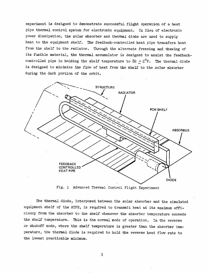
experiment is designed to demonstrate successful flight operation of a heat
pipe thermal control system for electronic equipment. In lieu of electronic
power dissipation, the solar absorber and thermal diode are used to supply
heat to the equipment shelf. The feedback-controlled heat pipe transfers heat
from the shelf to the radiator. Through the alternate freezing and thawing of
its fusible material, the. thermal accumulator is designed to assist the feedback-
controlled pipe in holding the shelf temperature to 82 + 20F. The thermal diode
is designed to minimize the flow of heat from the shelf to the solar absorber
during the dark portion of the orbit.
STRUCTURE
RADIATOR
PCM SHELF!
FEEDBACKCONTROLLEDHEAT PIPE
Fig. 1 Advanced Thermal Control Flight Experiment
ABSORBER
The thermal diode, interposed between the solar absorber and the simulated
equipment shelf of the ATFE, is required to transmit heat at its maximum effi-
ciency from the absorber to the shelf whenever the absorber temperature exceeds
the shelf temperature. This is the normal mode of operation. In the reverse
or shutoff mode, where the shelf temperature is greater than the absorber tem-
perature, the thermal diode is required to hold the reverse heat flow rate to
the lowest practicable minimum.
3
, _
In the normal mode, the diode must transmit a nominal 20 watts from the
solar absorber to the equipment shelf when the maximum temperature of the
absorber saddle is 1050F(3140 K) and the temperature of the shelf saddle is 890 F
(3050 K). During that portion of the orbit when the solar absorber is in the
earth's shadow, the thermal diode must transmit heat from the equipment shelf
to the absorber at a design rate not exceeding 1.4 watts under steady-state
conditions(reverse or shut-off mode). The heat required to shutoff the pipe
has to be minimized. During the orbital phase, the maximum design temperature
of the shelf saddle is 82 + 20 F (301 + 10K), and the minimum temperature of
the absorber saddle is -1800 F (1550 K).
4
3.0 REVIEW OF TYPES OF DIODES
The techniques for interfering with normal heat pipe operation may be
categorized as:
o Noncondensable gas blockage of the vapor space
o Freezing of the working fluid
o Liquid trap to dry out all or part of the wick
o Excess working fluid to block the vapor space
o Mechanical variations
The first four items are of primary interest; the mechanical devices,
being inherently more complex were not considered in this study since one or
more of the others appeared suitable for the various boundary conditions en-
visioned.
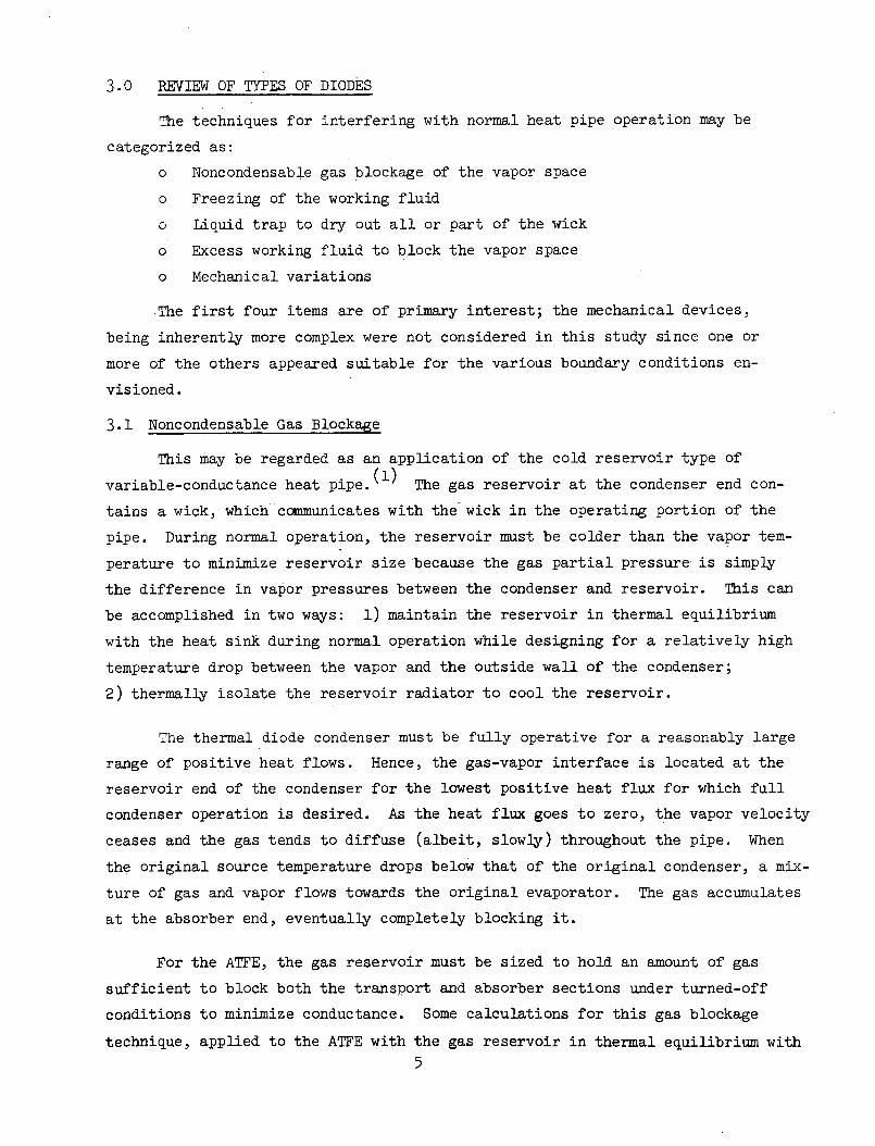
3.1 Noncondensable Gas Blockage
This may be regarded as an application of the cold reservoir type of
variable-conductance heat pipe.(l) The gas reservoir at the condenser end con-
tains a wick, which communicates with the wick in the operating portion of the
pipe. During normal operation, the reservoir must be colder than the vapor tem-
perature to minimize reservoir size because the gas partial pressure is simply
the difference in vapor pressures between the condenser and reservoir. This can
be accomplished in two ways: 1) maintain the reservoir in thermal equilibrium
with the heat sink during normal operation while designing for a relatively high
temperature drop between the vapor and the outside wall of the condenser;
2) thermally isolate the reservoir radiator to cool the reservoir.
The thermal diode condenser must be fully operative for a reasonably large
range of positive heat flows. Hence, the gas-vapor interface is located at the
reservoir end of the condenser for the lowest positive heat flux for which full
condenser operation is desired. As the heat flux goes to zero, the vapor velocity
ceases and the gas tends to diffuse (albeit, slowly) throughout the pipe. When
the original source temperature drops below that of the original condenser, a mix-
ture of gas and vapor flows towards the original evaporator. The gas accumulates
at the absorber end, eventually completely blocking it.
For the ATFE, the gas reservoir must be sized to hold an amount of gas
sufficient to block both the transport and absorber sections under turned-off
conditions to minimize conductance. Some calculations for this gas blockage
technique, applied to the ATFE with the gas reservoir in thermal equilibrium with
5
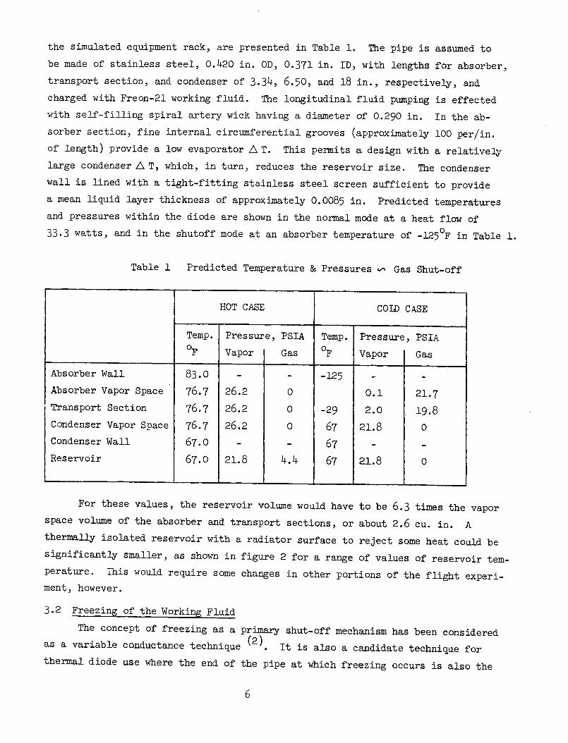
the simulated equipment rack, are presented in Table 1. The pipe is assumed to
be made of stainless steel, 0.420 in. OD, 0.371 in. ID, with lengths for absorber,
transport section, and condenser of 3.34, 6.50, and 18 in., respectively, and
charged with Freon-21 working fluid. The longitudinal fluid pumping is effected
with self-filling spiral artery wick having a diameter of 0.290 in. In the ab-
sorber section, fine internal circumferential grooves (approximately 100 per/in.
of length) provide a low evaporator A T. This permits a design with a relatively
large condenser LA T, which, in turn, reduces the reservoir size. The condenser
wall is lined with a tight-fitting stainless steel screen sufficient to provide
a mean liquid layer thickness of approximately 0.0085 in. Predicted temperatures
and pressures within the diode are shown in the normal mode at a heat flow of
33.3 watts, and in the shutoff mode at an absorber temperature of -1250F in Table 1.
Table 1 Predicted Temperature & Pressures - Gas Shut-off
For these values, the reservoir volume would have
space volume of the absorber and transport sections, or
thermally isolated reservoir with a radiator surface to
significantly smaller, as shown in figure 2 for a. range
to be 6.3 times the vapor
about 2.6 cu. in. A
reject some heat could be
of values of reservoir tem-
perature. This would require some changes in other portions of the flight experi-
ment, however.
3.2 Freezing of the Working Fluid
The concept of freezing as a primary shut-off mechanism has been considered
as a variable conductance technique (2) It is also a candidate technique for
thermal diode use where the end of the pipe at which freezing occurs is also the
6
HOT CASE COLD CASE
Temp. Pressure, PSIA Temp. Pressure, PSIA
_F Vapor Gas F Vapor Gas
Absorber Wall 83.0 - - -125 - -
Absorber Vapor Space 76.7 26.2 0 O.1 21.7
Transport Section 76.7 26.2 O -29 2.0 19.8
Condenser Vapor Space 76.7 26.2 0 67 21.8 0
Condenser Wall 67.0 - - 67 - -
Reservoir 67.0 21.8 4.4 67 21.8 0
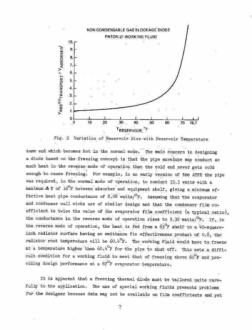
NON:CONDENSABLE GAS BLOCKAGE DIODE
FREON-21 WORKING FLUID10.
LU 9.
0a 8.
7.
+ 6. -i-0 5.
Z 4.
3.
uZ 2.C,
c- 1.
0 10 20 30 40 50 60 70 76.7
TRESERVOIR, OF
Fig. 2 Variation of Reservoir Size with Reservoir Temperature
same end which becomes hot in the normal mode. The main concern in designing
a diode based on the freezing concept is that the pipe envelope may conduct so
much heat in the reverse mode of operation that the cold end never gets cold
enough to cause freezing. For example, in an early version of the ATFE the pipe
was required, in the normal mode of operation, to conduct 33.3 watts with a
maximum A T of 16OF between absorber and equipment shelf, giving a minimum ef-
fective heat pipe conductance of 2.08 watts/OF. Assuming that the evaporator
and condenser wall wicks are of similar design and that the condenser film co-
efficient is twice the value of the evaporator film coefficient (a typical ratio),
the conductance in the reverse mode of operation rises to 3.32 watts/OF. If, in
the reverse mode of operation, the heat is fed from a 630 F shelf to a 40-square-
inch radiator surface having an emittance fin effectiveness product of 0.8, the
radiator root temperature will be 60.40 F. The working fluid would have to freeze
at a temperature higher than 60.4°F for the pipe to shut off. This sets a diffi-
cult condition for a working fluid to meet that of freezing above 60 F and pro-
viding design performance at a 670 F evaporator temperature.
It is apparent that a freezing thermal diode must be tailored quite care-
fully to the application. The use of special working fluids presents problems
for the designer because data may not be available on film coefficients and yet
7
be critically important to the success of the design. Melting considerations
on restart will influence wick design. All portions of the wick should melt
readily, and the slug of frozen condensate should not extend beyond the absorber
section.
3.3 Liquid Trap for Wick Dry-out
This technique is based on the tendency of liquid to accumulate at the
coldest portion of the pipe, except as displaced by surface tension and gravity
forces. The liquid trap is a volume made up of small passages capable of holding
liquid against the action of gravity, placed at the end of the pipe which is hot
during normal pipe operation. The trap is separate from, and does not communicate
with, the wick in the operating portion of the pipe.
In the normal mode of operation, the trap is dry, and the diode operates as
an ordinary heat pipe, with the correct amount of working fluid for the wick design
employed. When the liquid-trap end becomes the cold end of the pipe, condensation
begins to occur on the liquid trap surfaces, as well as on the absorber end internal
surfaces. As liquid accumulates in the trap, the main heat pipe wick becomes
underfilled causing a fairly rapid reduction in transport capacity. The re-
duction in pumping capacity with undercharge can be quite significant with only
a few percent reduction in charge below the 100l fill requirement. For reduction
in transport capacity to the order of 1% or less of the original value, however,
it may be necessary for the main wick to dry out completely, with all the liquid
in the trap.
When the trap end again becomes the warm end, the trap acts as an evaporator
until all the liquid is expelled. The trap volume requirement is based on the
amount of liquid in the main heat pipe wick and would appear to be most attractive
for wicks having a relatively small volume. In contrast with the liquid blockage
technique, it has very little dependence on vapor-space volume. The transient
response on heating of the liquid trap involves the same considerations for boiling
heat transfer as the liquid blockage concept. There is considerable latitude in
the trap design, however, since the trap is not the main evaporator. The transient
response on filling the trap for shut-off will depend on the ratio of trap conden-
sation rate to absorber section condensation rate and on the main wick liquid fill
requirements.
8
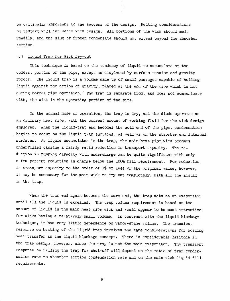
3.3.1 Liquid Trap Feasibility Tests
In order to verify the principle, a liquid trap diode was fabricated and
tested as part of an in-house funded project. A schematic and photo of the pipe
is shown in figures 3 and 4, respectively. Details of the pipe are listed below.
o Pipe Material
o Working Fluid
o Evaporator Length
o Condenser Length
o Transport Length
o Pipe O.D.
o Trap
o Wick
Aluminum
Ammonia
4.0 in.
12.00
17.62 in.
.580 in.
.980 I.D. x 6.5 in.
100 mesh .290 O.D. tunnel spiral artery
The pipe was instrumented with 18 copper-constantan thermocouples as seen in
figure 3. Nichrome ribbon heaters were attached to the evaporator, trap and
condenser sections. Condenser cooling was accomplished by both water and
methanol spray baths.
TC #
-t - ___
l1 51.38
3----- ~33.62 (LENGTH OF ARTERY AND RETAINER) ) '(REF)
1 _2_ 3 4_ 5 6 2 3 4 56 91011121 141516117181
I ___ _ _ __ _
__ 12"HEATER #2 _1 l(CONDENSER)
L .580 DIA
-- A
200 MESH SCREEN(MAT'L: AL ALY)
SECT A-A
Fig. 3 Diode Liquid Trap Schematic
9
RESERVOIR1.00 O.D. x .035 WALL
-1 I
i. .I~~ ~ ~ ~ ~~ ~ _ _q,!
B
Ir_: , ,1 i
i-.,. 13,,___I-1 ,m .

Fig. k Liquid Trap Diode Heat Pipe
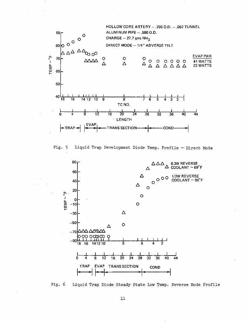
Both direct and reverse mode tests were conducted. Unfortunately, the
heaters on the evaporator and trap were connected in series and were different
resistances. Therefore, at a given current the trap temperature was higher
than the evaporator temperature. This can be noticed in figure 5 where some
direct mode test data is plotted. In an actual application, the trap would
be at the same temperature as the evaporator. The important point to note is
that the direct mode conductance was 6 to 8 watts/ F.
The reverse mode steady state data is shown in Figure 6. Shutoff of the
pipe is evident by the large temperature difference between the condenser and
evaporator. Reversal was obtained in 6 minutes with 60 watts of power applied
to the condenser (20.6 Btu). As stated earlier, the shut off time and associated
heat transport are functions of the condensation rate in the trap as compared
with the condensation in the pipe itself. The data is thus a function of the
external coupling of trap and pipe to the reverse mode heat sink as well as the
specifics of the design itself.
10
90rO
0~00
o O_a6A0
HOLLOW CORE ARTERY - .290 O.D. -. 062 TUNNELALUMINUM PIPE - .580 O.D.CHARGE - 27.7 gms NH3
DIRECT MODE - 1/4" ADVERSE TILT
O O EVAP PWRO 0O- O O O 41 WATTS
A L A A L 22 WATTS60
50 -
A I I I I I I I I I I
"18 16 14 12 10 9I I I I I I I
8 7 6 5 4 3 2 1TC NO.
I I I I I I I I I I
0 4 8 12 16 20 24 28 32 36 40 44LENGTH
TRAP- [ t RA TRANS SECTION - -- COND -
Fig. 5 Liquid Trap Development Diode Temp. Profile - Direct Mode
80r
A
AAA A 8.3W REVERSEA A COOLANT - 69°F
A 1/2W REVERSEO O O COOLANT - 80°F
A 0O
0
o
O
0
o99 00CEDCO -90I I I I III II
18 16 1412 10I I I I I I I I
8 6 4 2
I I I I I I I I I I I I0 4 8 12 16 20 24 28 32 36 40 44
TRAP EVAP TRANS SECTION COND
1- -- -:1 1 - O
Fig. 6 Liquid Trap Diode Steady State Low Temp. Reverse Mode Profile
11
80
70
LL
o
a-
60i-
40-
20-
00
LLUj
-10 -
-30 -
-50 -
-70
-- 1
I

3.3.2 Liquid Trap Parametric Studies
The parametric studies conducted for the liquid trap design are based olu
use of the spiral artery tunnel wick. This wick is self-priming and combines
high capacity with high conductance in the normal operating mode. With this
wick, the transport capacity is a function of tunnel diameter and artery overall
diameter, as well as pipe inside diameter when the artery is large enough to
severely constrict the remaining vapor space. The principal item of interest
is the reservoir volume required to hold all the liquid in the pipe in the re-
verse mode of operation.
The method of analysis for the tunnel wick is presented in Appendix A and
is essentially the same as outlined in Reference 3. The calculations were made
for a pipe similar to an early version of the ATFE diode, with lengths of 3.34"
for the evaporator, 4.62" for the transport section and 18.0" for the condenser.
Charge and transport capacity calculations are based on the mean of evaporator
and condenser temperatures in the normal mode of operation (taken to be 93°F and
83 F, respectively). For the reverse mode, the evaporator was assumed to drop
to -125 F with the condenser held at 830F. The reservoir was assumed to be at
the evaporator temperature of -125 F.
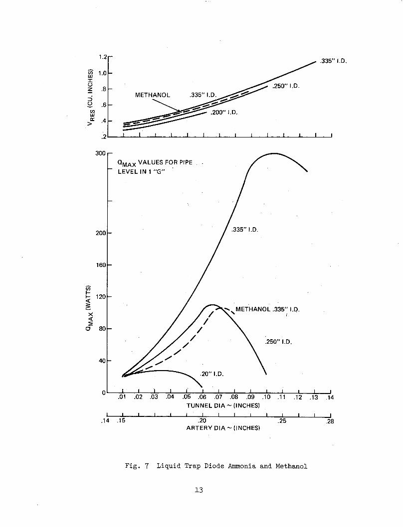
Calculated values of maximum transport capacity and reservoir volume are
shown in Figure 7 using ammonia as working fluid. Results are shown as a function
of artery diameter for three values of pipe inside diameter. In these calcula-
tions the artery consists of a hollow core or tunnel surrounded by a spiral
artery annulus .070" thick.
Results for artery diameters smaller than that corresponding to peak
transport capacity are of most interest. In these cases, liquid pressure drop
is dominant and Qmax depends primarily on tunnel diameter. With artery diameters
larger than those for peak capacity, vapor pressure drop becomes excessive.
causing transport capacity to decrease.
Note that reservoir volume depends primarily on artery diameter. The
small differences with pipe diameter are primarily due to variations in liquid
volume in the webs which connect the artery to the wall. For a transport
12
.335" I.D.
1.0 -
.250" I.D.
METHANOL .335" I.D.
.200" I.D.
I I I I I I I I I I I I I
QMAX VALUES FOR PIPELEVEL IN 1 "G"
.335" I.D.
METHANOL .335" I.D.
.250" I.D.
.20" I.D.
I I I I I I' I I I I I I I I I.01 .02 .03 .04 .05 .06 .07 .08 .09 .10 .11 .12 .13 .14
TUNNEL DIA - (INCHES)
I I I I I I I I I I I I I I I.14 .15 .20 .25 .28
ARTERY DIA - (INCHES)
Fig. 7 Liquid Trap Diode Ammonia and Methanol
13
.8 -
ZjiI
C-z
5t,w
Z:
LU
>r
.6
.4
300 r-
200 _-
160 -
I-
aI
3:O
120 -
80 -
40-
1.2r
I

capacity in the 100 watt range (1500 watt-inches), a reservoir volume of approxi-
mately 0.5 cubic inches is required.
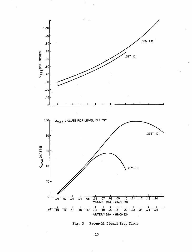
Results with Freon-21 as working fluid are shown in Figure 8. Trends are
similar to those obtained with ammonia, though Qmax values are lower for Freon-21
because of the lower zero "g" liquid figure of merit (surface tension time latent
heat divided by kinematic viscosity). A 100 watt pipe using Freon-21 would require
a liquid trap volume of approximately 0.75 cubic inches, and a pipe diameter of
at least 0.335".
Reverse mode steady state heat conduction values would simply be that due
to solid conduction in the pipe wall augmented somewhat by the dried-out wick.
For the assumed transport length of 4.62" and temperature difference of 208 F, a
stainless steel diode with .020" thick wall should have a conduction heat transfer
below 1 watt, even allowing for some wall thickening for mitered corners. The
transient heat transfer during pipe shut-off is much harder to predict, but should
be proportional to liquid trap volume.
3.4 Excess Liquid Blockage
If a heat pipe is charged with excess fluid, that fluid tends to accumulate
as a slug in the colder portion of the pipe, except where displaced by surface
tension and gravity forces. Because of its low conductivity, the liquid very
effectively limits the heat transfer.
For a thermal diode, the excess liquid would shift naturally from one end
to the other as hot and cold ends were interchanged. Under reverse-mode opera-
tion, the excess liquid must have a volume sufficient to block the vapor space
of the cold end and a large part of the transport section (to minimize conduction
heat transfer). A reservoir would be provided at the other end to contain the
excess liquid under normal-mode conditions. The reservoir size must be a little
larger than the absorber and transport section vapor space volumes, to allow for
changes in liquid density with temperature. For Freon-21 working fluid, the ratio
would be approximately 1.1:1, as compared with approximately 6.3:1 for the gas-
reservoir concept.
1.00 -
.90
.335" I.D..80
'i .70I
z .60z
= .50
c .40
.25" I.D.
.30 _
.20F-
.10-
I I I I I I I I I I I I I I
1001 QMAX VALUES FOR LEVEL IN 1 "G"
80
4-60
aC 40
.335" I.D.
IF
.25" I.D.
201-
1 0i i I I I I I I II I I I II.01 .02 .03 .04 .05 .06 .07 .08 .09 .10 .11 .12 .13 .14
TUNNEL DIA - (INCHES)I I I I I I I I I I I I I I I I
.12 .13 .14 .15 .16 .17 .18 .19 .20 .21 .22 .23 .24 .25 .26
ARTERY DIA - (INCHES)
Fig. 8 Freon-21 Liquid Trap Diode
15
For the transient response in emptying the reservoir for shut-off, the
total amount of heat transported depends on the ratio of reservoir evaporation
rate to the evaporation rate from what is normally considered the condenser
portion of the pipe. In going from the reverse to the normal mode of operation
no startup time is required because evaporation of the excess liquid serves to
carry heat to the equipment shelf in much the same manner as ordinary evaporation.
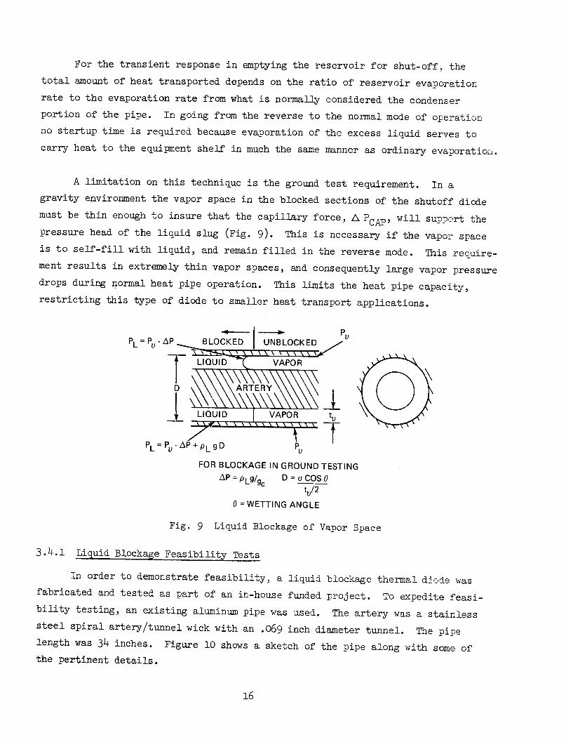
A limitation on this technique is the ground test requirement. In a
gravity environment the vapor space in the blocked sections of the shutoff diode
must be thin enough to insure that the capillary force,A PCAp, will support the
pressure head of the liquid slug (Fig. 9). This is necessary if the vapor space
is to self-fill with liquid, and remain filled in the reverse mode. This require-
ment results in extremely thin vapor spaces, and consequently large vapor pressure
drops during normal heat pipe operation. This limits the heat pipe capacity,
restricting this type of diode to smaller heat transport applications.
.-< I 1 P-
PL = Pu - AP BLOCKED UNBLOCKED
LIQUID ? VAPOR
LIQUID VAPOR tu
PL P AP + PL gD P TFOR BLOCKAGE IN GROUND TESTING
AP = PL9g/g D = a COS 0tu/2
0 = WETTING ANGLE
Fig. 9 Liquid Blockage of Vapor Space
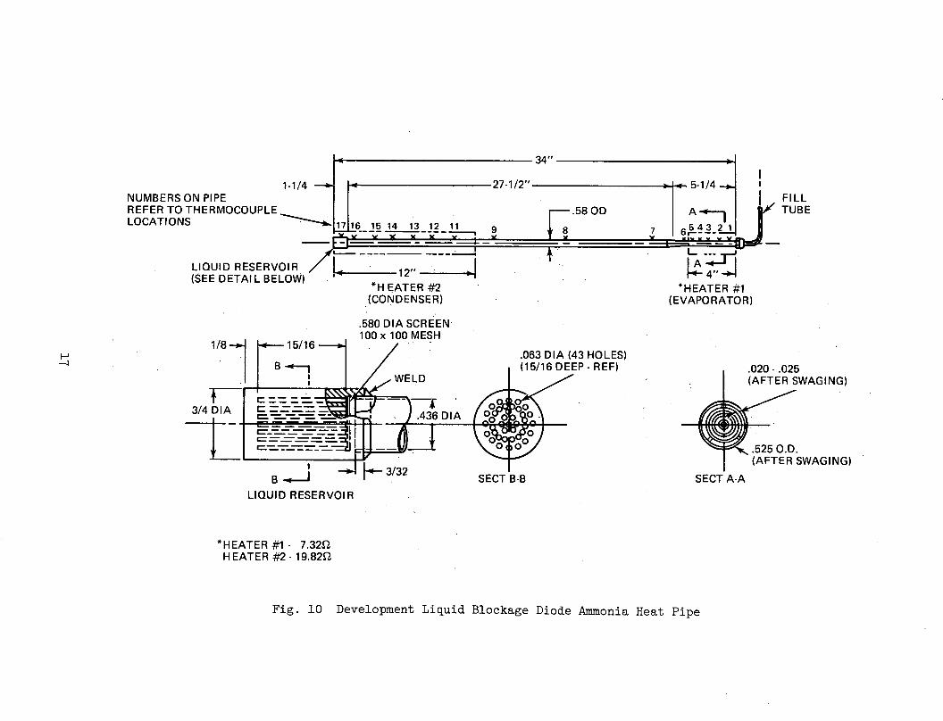
3.4.1 Liquid Blockage Feasibility Tests
In order to demonstrate feasibility, a liquid blockage thermal diode was
fabricated and tested as part of an in-house funded project. To expedite feasi-
bility testing, an existing aluminum pipe was used. The artery was a stainless
steel spiral artery/tunnel wick with an .069 inch diameter tunnel. The pipe
length was 34 inches. Figure 10 shows a sketch of the pipe along with some of
the pertinent details.
Q
I-w
.rd0Idoobf
rd- IO
m
m
-r'4
o
e CaH
m
C)-
w w
II*
zZ,"
LO
(N
az
(D
O
:
0L
LCN
LLO
<
/)L
O r
Ir
<
0(o-
cO~f
w
iLL
-UJ
-Ia.
00
ZI
z a: -O
zC)
n,0UI
O.°
-o>wnw
D L
L
wl I
,
17
The basic pipe had an outside diameter of 0.580 inch, , after the initial
swaging operation required for good retainer contact. A second swaging opera-
tion was performed over 6 inches of the evaporator end of the pipe to reduce the
vapor space to about 0.020 inches. This narrow gap permits self-priming of the
vapor space in the shutoff mode and minimizes the amount of excess fluid required
for blockage. The O.D. in this region was 0.525 inches.
A liquid reservoir was added to the condenser end of the pipe to trap the
excess fluid added to the charge in order to obtain liquid blockage in the
evaporator during the shutoff mode operation. The reservoir was made by drilling
43 - .062 x 1.00 inch holes in an aluminum cylinder. The reservoir was then
welded on the condenser end of the pipe.
The pipe was charged with 28 grams of UHP (ultra high purity, 10 ppm H2 0
max) ammonia. This is equivalent to an 8% artery overcharge at 75°F. Both the
4 inch evaporator and 12 inch condenser were equipped with heaters and cooling
systems in order that both modes of operation could be tested.
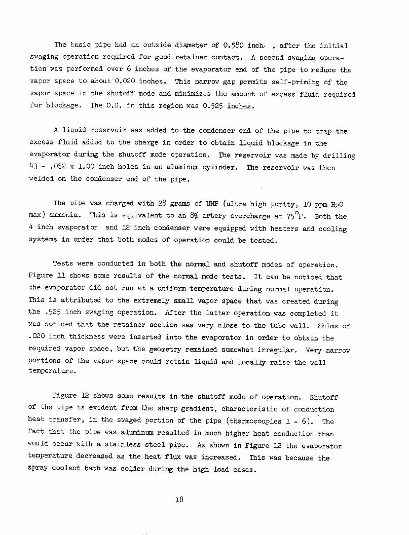
Tests were conducted in both the normal and shutoff modes of operation.
Figure 11 shows some results of the normal mode tests. It can be noticed that
the evaporator did not run at a uniform temperature during normal operation.
This is attributed to the extremely small vapor space that was created during
the .525 inch swaging operation. After the latter operation was completed it
was noticed that the retainer section was very close to the tube wall. Shims of
.020 inch thickness were inserted into the evaporator in order to obtain the
required vapor space, but the geometry remained somewhat irregular. Very narrow
portions of the vapor space could retain liquid and locally raise the wall
temperature.
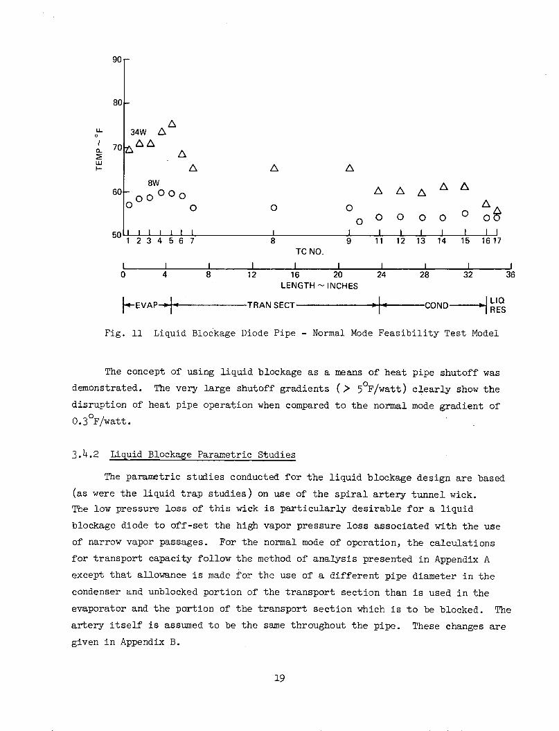
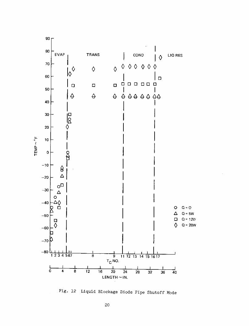
Figure 12 shows some results in the shutoff mode of operation. Shutoff
of the pipe is evident from the sharp gradient, characteristic of conduction
heat transfer, in the swaged portion of the pipe (thermocouples 1 - 6). The
fact that the pipe was aluminum resulted in much higher heat conduction than
would occur with a stainless steel pipe. As shown in Figure 12 the evaporator
temperature decreased as the heat flux was increased. This was because the
spray coolant bath was colder during the high load cases.
90 -
80
ALL 34W A
n 70 A/
ww a
60o A / A A
0 O O O O o 0
50 I I I l I I I I I I I1 2 3 4 5 6 7 8 9 11 12 13 14 15 1617
TC NO.
L I I I I I I I0 4 8 12 16 20 24 28 32 36
LENGTH - INCHES
F-EVAP - TRAN SECT pioo COND RES
Fig. 11 Liquid Blockage Diode Pipe - Normal Mode Feasibility Test Model
The concept of using liquid blockage as a means of heat pipe shutoff was
demonstrated. The very large shutoff gradients (> 50F/watt) clearly show the
disruption of heat pipe operation when compared to the normal mode gradient of
0.3°F/watt.
3.4.2 Liquid Blockage Parametric Studies
The parametric studies conducted for the liquid blockage design are based
(as were the liquid trap studies) on use of the spiral artery tunnel wick.
The low pressure loss of this wick is particularly desirable for a liquid
blockage diode to off-set the high vapor pressure loss associated with the use
of narrow vapor passages. For the normal mode of operation, the calculations
for transport capacity follow the method of analysis presented in Appendix A
except that allowance is made for the use of a different pipe diameter in the
condenser and unblocked portion of the transport section than is used in the
evaporator and the portion of the transport section which is to be blocked. The
artery itself is assumed to be the same throughout the pipe. These changes are
given in Appendix B.
19
c\IAD
oIO
- 4
1
- 0
I
'R- I
_ A
I0O I
IO I
,,,I 1,,
TRANS
OI
[ O
I
IIIIIIIIIII
Il
-1I
O
COND I LIQRES
0000
4 44 44
I o
I
IQ=OQ= 5W
Q = 12W
Q = 20W
1 2 3 4 567 8 9 11 12 13 14 15 1617TC NO.
I I I I I I I I I I I0 4 8 12 16 20 24 28 32 36 40
LENGTH - IN.
Fig. 12 Liquid Blockage Diode Pipe Shutoff Mode
20
90
80
70
60
50
40
30
20
10LLo
a-
0
-10
-20
-30
-40
-50
-60
-70
On-ou
II
7
L
I
I0 0
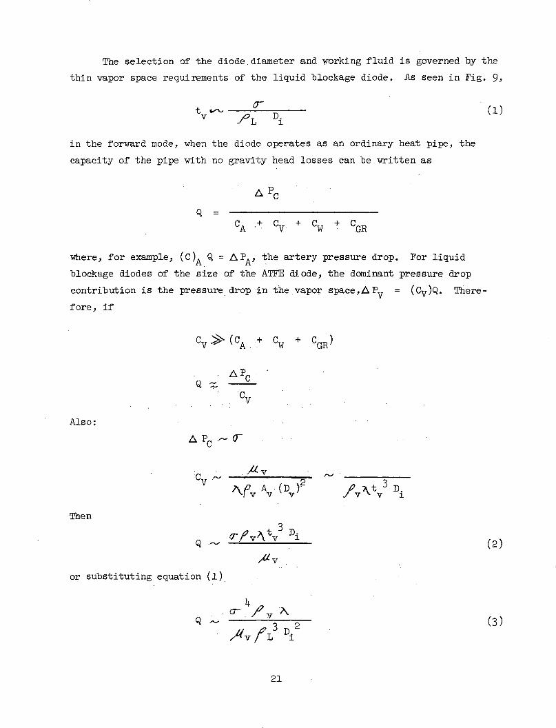
The selection of the diode diameter and working fluid is governed by the
thin vapor space requirements of the liquid blockage diode. As seen in Fig. 9,
t -ow (1)D.
in the forward mode, when the diode operates as an ordinary heat pipe, the
capacity of the pipe with no gravity head losses can be written as
A P
CA +0 C + CGR
where, for example, (C)A Q = APA, the artery pressure drop. For liquid
blockage diodes of the size of the AT FE diode, the dominant pressure drop
contribution is the pressure drop :in the vapor space,APV = (CV)Q. There-
fore, if
Cv (CA+ C + + CGR)
A PCQm
CV
Also:
AP C . 0-
Cv Av 2v
'\.v AV (D ) /v "v 3 Di
Then
Q '. 7 .v tv Di
/AV
or substituting equation (1)
4/
'/v f L Di2
21
(2)
(3)

Equation 2 illustrates the importance (for small values of tv) of the vapor
space thickness on capacity. Equation 3 indicates that the most desirable
fluid would have the largest value of
14 v tI -- 3
/ v L 3
Of the three fluids considered for the ATFE design, ammonia, Freon-21, and
methanol, ammonia has significantly the largest value of I (Table 2) and was
therefore selected as the working fluid.
Table 2 Fluid Comparison
4 8
I r /v ~ ft8 - lb
Fluid Av / L sec7
Ammonia 1.59
Freon-21 0.02
iviethanol 0.06
Equations (1) and (3) also indicate that for a diode for which AP >>
A PART, increasing the internal diameter Di, decreases the vapor space and
the capacity. The optimum diameter for maximum heat transport is therefore
some small value where A Pv approaches in magnitude A PA (recognizing that
for this condition, equations (2) and (3) do not hold).
Calculations of liquid blockage diode performance with ammonia working
fluid are presented in figure 13 for a diode similar to the ATFE with normal
mode lengths of 4.56" for the evaporator, 5.70" for the transport section,
and 18.0" for the condenser.
Reservoir volume requirements and maximum transport capacity are shown
as a function of artery core and overall diameter for evaporator inside diameters
of .25", .30" and .335". The condenser inside diameter was .335" in all cases.
In the transport section, the unblocked portion has the same I.D. as the con-
denser, and the blocked portion (in the reverse mode) has the same I.D. as the
evaporator. The artery consists of a hollow core surrounded by a .070" thick
spiral artery annulus.
22

I.D. CONDENSER = .335"2 GAPS
.020" ST. STEEL WALL
QR EV. 1.5 WATTS= 1.0= 1.24'
K
I I I I
Q = 270@ D1 = .103
*ENTIRE TRANSPORTSECTION BLOCKED
I I I I I
Q= 370@ D1 =.103
550° F
500 F
II
50 F
I.D. EVAP -
-125°F \
METHANOLI.D. EVAP = .30"
INDICATESMIN. D1 FORSELF PRIMING VAPORSPACE AT TEVAP. (REVERSEMODE) = 50°F
"OG" PERFORMANCE"IG" & 0 TILT
I.D. EVAP = .335"
) I I I I I I I I I I0 .16 .18 .20 .22 .24 .26 .28 .30 .32
ARTERY DIAMETER - INCHI I I I I I I I I I0 .02 .04 .06 .08 .10 .12 .14 .16 .18
D1 = CORE DIAMETER -INCH
Fig. 13 NH3 Liquid Blockage Diode Parametric Study
23
.5 r-
.4
z
w
-J0
5tr
UrUwc
.3 -
.2 -
.1
240 r
220 -
200 -
180 -
160 -U,
o
x
140
120
100
80
60
40
20 -
0
^,)a
I%
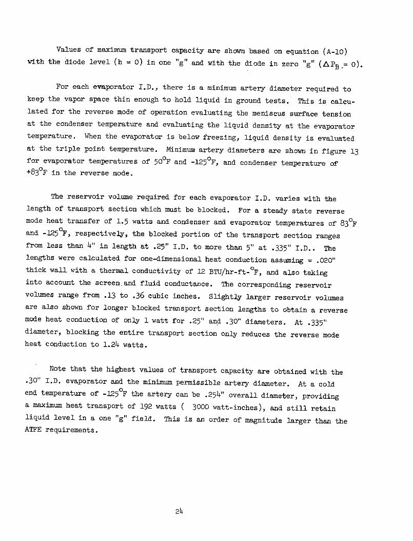
Values of maximum transport capacity are shown based on equation (A-10)
with the diode level (h = 0) in one "g" and with the diode in zero "g" (ZAPB = 0).
For each evaporator I.D., there is a minimum artery diameter required to
keep the vapor space thin enough to hold liquid in ground tests. This is calcu-
lated for the reverse mode of operation evaluating the meniscus surface tension
at the condenser temperature and evaluating the liquid density at the evaporator
temperature. When the evaporator is below freezing, liquid density is evaluated
at the triple point temperature. Minimum artery diameters are shown in figure 13
for evaporator temperatures of 500F and -125°F, and condenser temperature of
+830F in the reverse mode.
The reservoir volume required for each evaporator I.D. varies with the
length of transport section which must be blocked. For a steady state reverse
mode heat transfer of 1.5 watts and condenser and evaporator temperatures of 830 F
and -125 F, respectively, the blocked portion of the transport section ranges
from less than 4" in length at .25" I.D. to more than 5" at .335" I.D.. The
lengths were calculated for one-dimensional heat conduction assuming = .020"
thick wall with a thermal conductivity of 12 BTU/hr-ft- F, and also taking
into account the screen.and fluid conductance. The corresponding reservoir
volumes range from .13 to .36 cubic inches. Slightly larger reservoir volumes
are also shown for longer blocked transport section lengths to obtain a reverse
mode heat conduction of only 1 watt for .25" and .30" diameters. At .335"
diameter, blocking the entire transport section only reduces the reverse mode
heat conduction to 1.24 watts.
Note that the highest values of transport capacity are obtained with the
.30" I.D. evaporator and the minimum permissible artery diameter. At a cold
end temperature of -125 F the artery can be .254" overall diameter, providing
a maximum heat transport of 192 watts ( 3000 watt-inches), and still retain
liquid level in a one "g" field. This is an order of magnitude larger than the
ATFE requirements.
24
Also shown in figure 13 is a single curve of maximum capacity of a
diode with methanol working fluid with a .25" I.D. evaporator. The minimum
artery diameter is .217" to retain liquid in ground test with -125 F evaporator
and the corresponding maximum transport is 33 watts. These results are in line
with the figure of merit values given in Table I. Clearly, methanol is marginal
for the ATFE application. No results are presented for Freon-21 since they were
below the ATFE requirement.
25

4.0 DIODE - DESIGN AND FABRICATION
4.1 Selection of the ATFE Diode Type
The requirements for the ATFE diode made either the liquid trap or
the liquid blockage technique the most suitable for shutting off heat pipe
operation. The temperature at which shutoff is required is 820F, making
impractical a design based on freezing of the working fluid. The relatively
large reservoir volume required for the noncondensable gas blockage technique
was inconsistent with the weight and dimension restrictions placed upon the
flight diode.
After limiting the potential designs to either a liquid trap or an
excess liquid blockage type diode, a parametric study was undertaken to select
the most suitable design. The study was restricted to diode designs utilizing
self-priming, axisymmetric, spiral arteries in order to obtain large film coef-
ficients, in the case of liquid blockage diodes, these designs provide a rela-
tively large vapor cross-sectional area considering the small vapor space
hydraulic radius required to support the blocking liquid slug.
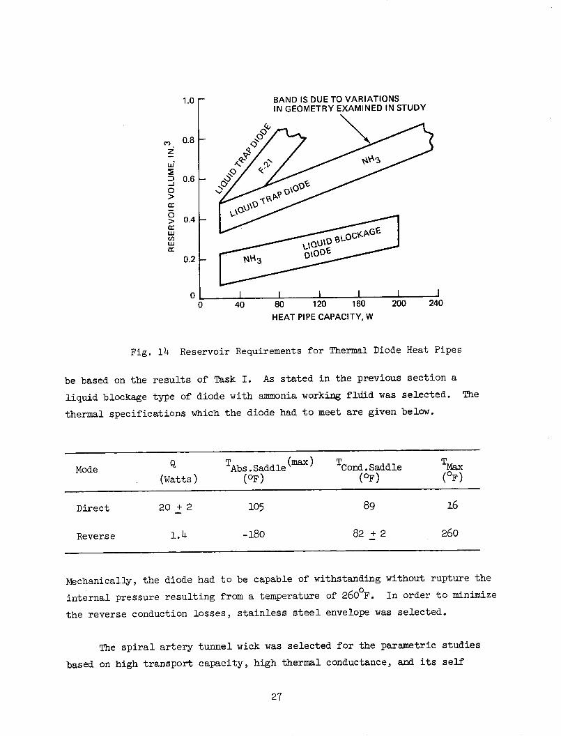
In figure 14, the trends indicated by the parametric study are presented.
Feasibility models of both the liquid trap and liquid blockage pipes were built
and successfully tested as described earlier, thus providing proof-of-principle
of both designs. In the range of capacities less than 200 watts, the liquid
blockage diode required a significantly smaller reservoir volume than a liquid
trap diode of equal capacity. The liquid blockage diode therefore has an ad-
vantage in spacecraft applications, such as ATFE, where weight and size are
important limitations. As previously mentioned, the vapor space restriction
limits liquid blockage diodes to small capacity applications. Since the 200
watt limit far exceeds the 20-watt ATFE minimum requirement, the liquid blockage
design was selected.
4.2 Design of Engineering Model
The objectives of Task II were to design, fabricate and performance
test an engineering model of a thermal diode of a type, configuration, and
capacity suitable for its inclusion as a component of the Advanced Thermal
Control Flight Experiment (ATFE). Satisfaction of the objectives were to
26
I I40 80 120 160
HEAT PIPE CAPACITY, W200 240
Fig. 14 Reservoir Requirements for Thermal Diode Heat Pipes
be based on the results of Task I. As stated in the previous section a
liquid blockage type of diode with ammonia working fldid was selected. The
thermal specifications which the diode had to meet are given below.
Mode T (max) T TMode Q TAbs.Saddle ( ) TCond.Saddle TMax(Watts) (OF) (OF) (°F)
Direct 20 + 2 105 89 16
Reverse 1.4 -180 82 + 2 260
Mechanically, the diode had to be capable of withstanding without rupture the
internal pressure resulting from a temperature of 2600 F. In order to minimize
the reverse conduction losses, stainless steel envelope was selected.
The spiral artery tunnel wick was selected for the parametric studies
based on high transport capacity, high thermal conductance, and its self
27
1.0 r-
0.8 -
0.6 k
0.4 _
C.,
z
w
-J0o
acc:
LUwCd,wena:
0.2 k
00
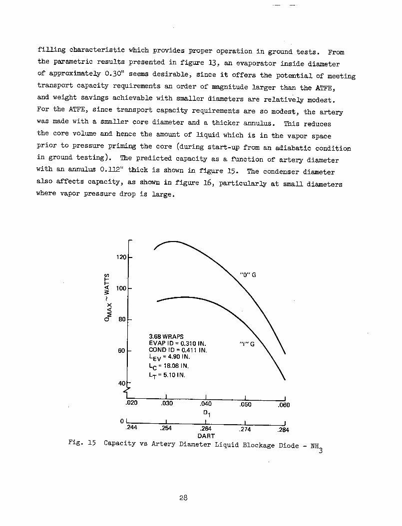
filling characteristic which provides proper operation in ground tests. From
the parametric results presented in figure 13, an evaporator inside diameter
of approximately 0.30" seems desirable, since it offers the potential of meeting
transport capacity requirements an order of magnitude larger than the ATFE,
and weight savings achievable with smaller diameters are relatively modest.
For the ATFE, since transport capacity requirements are so modest, the artery
was made with a smaller core diameter and a thicker annulus. This reduces
the core volume and hence the amount of liquid which is in the vapor space
prior to pressure priming the core (during start-up from an adiabatic condition
in ground testing). The predicted capacity as a function of artery diameter
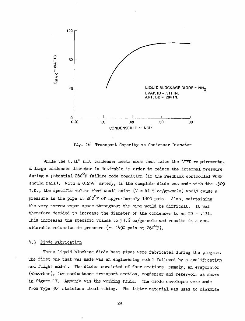
with an annulus 0.112" thick is shown in figure 15. The condenser diameter
also affects capacity, as shown in figure 16, particularly at small diameters
where vapor pressure drop is large.
120
eI
x
E0
001
fE- "0" G
60 _
40
3.68 WRAPSEVAP ID = 0.310 IN.COND ID= 0.411 IN.LEV = 4.90 IN.LC = 18.08 IN.LT = 5.10 IN.
"I" G
Fig. 15 Capa
I I I I I.020 .030 .040 .050 .060
D1
01 1 I I I.244 .254 .264 .274 .284
DARTacity vs Artery Diameter Liquid Blockage Diode - NH3
28
80
120 r
F- 80
Xx
40 - LIQUID BLOCKAGE DIODE -NH3
EVAP. ID =.311 IN.ART. OD = .264 IN.
0 I I I 0.20 .30 .40 .50 .60
CONDENSER ID - INCH
Fig. 16 Transport Capacity vs Condenser Diameter
While the 0.31" I.D. condenser meets more than twice the ATFE requirements,
a large condenser diameter is desirable in order to reduce the internal pressure
during a potential 2600 F failure mode condition (if the feedback controlled VCHP
should fail). With a 0.259" artery, if the complete diode was made with the .309
I.D., the specific volume that would exist (V = 41.5 cc/gm-mole) would cause a
pressure in the pipe at 2600F of approximately 1800 psia. Also, maintaining
the very narrow vapor space throughout the pipe would be difficult. It was
therefore decided to increase the diameter of the condenser to an ID = .411.
This increases the specific volume to 53.6 cc/gm-mole and results in a con-
siderable reduction in pressure (a 1490 psia at 2600F).
4.3 Diode Fabrication
Three liquid blockage diode heat pipes were fabricated during the program.
The first one that was made was an engineering model followed by a qualification
and flight model. The diodes consisted of four sections, namely, an evaporator
(absorber), low conductance transport section, condenser and reservoir as shown
in figure 17. Ammonia was the working fluid. The diode envelopes were made
from Type 304 stainless steel tubing. The latter material was used to minimize
29
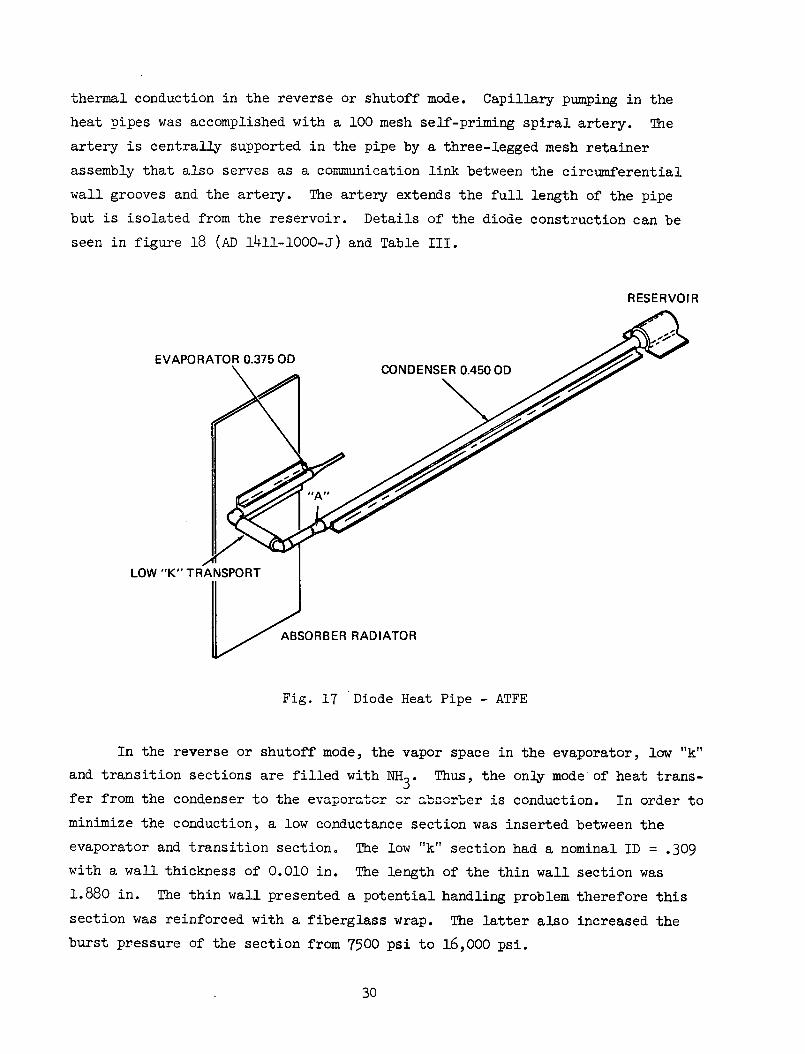
thermal conduction in the reverse or shutoff mode. Capillary pumping in the
heat pipes was accomplished with a 100 mesh self-priming spiral artery. The
artery is centrally supported in the pipe by a three-legged mesh retainer
assembly that also serves as a communication link between the circumferential
wall grooves and the artery. The artery extends the full length of the pipe
but is isolated from the reservoir. Details of the diode construction can be
seen in figure 18 (AD 1411-1000-J) and Table III.
RESERVOIR
EVAPORATOR 0.375 OD .
LOW "K" TRANSPORT
ABSORBER RADIATOR
Fig. 17 Diode Heat Pipe - ATFE
In the reverse or shutoff mode, the vapor space in the evaporator, low "k"
and transition sections are filled with NH3. Thus, the only mode of heat trans-
fer from the condenser to the evaporator or absorber is conduction. In order to
minimize the conduction, a low conductance section was inserted between the
evaporator and transition section. The low "k" section had a nominal ID = .309
with a wall thickness of 0.010 in. The length of the thin wall section was
1.880 in. The thin wall presented a potential handling problem therefore this
section was reinforced with a fiberglass wrap. The latter also increased the
burst pressure of the section from 7500 psi to 16,000 psi.
30

Page intentionally left blank
The reservoirs of the diodes were made by drilling 86 - .063 in. holes
in an aluminum cylinder 1.44 inches long. The reservoir was then encased in
a stainless steel shell (figure 18). Aluminum was used in order to increase
the heat transfer rates during the direct to reverse mode transport.
In order to attach the diode in the ATFE experiment package, the diode
was attached to an aluminum saddle (manufactured by Dynatherm Corp.) and
absorber plate. Initially, the attachment was made by a conductive adhesive
but was later changed to a soft solder attachment. This will be discussed in
more detail in the test section.
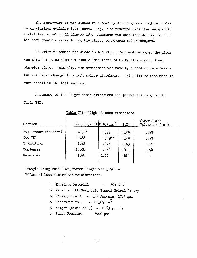
A summary of the flight diode dimensions and parameters is given in
Table III.
Table III- Flight Diodes Dimensions
Section
Evaporator (Absorber)
Low "K"
Transition
Condenser
Reservoir
Length(in.)
4.90*
1.88
1.42
18.08
1.44
O.D.(in.)
.377
.329**
.375
.452
1.00
I.D.
.309
.309
.309
.411
.884
Vapor SpaceThickness (in.)
.025
.025
.025
.074
*Engineering Model Evaporator Length was 3.90 in.
**Tube without fiberglass reinforcement.
o Envelope Material - 304 S.S.
o Wick - 100 Mesh S.S. Tunnel Spiral Artery
o Working Fluid - UHP Ammonia, 17.5 gms
o Reservoir Vol. = 0.369 in3
o Weight (Diode only) = 0.63 pounds
o Burst Pressure 7500 psi
33
5.0 MECHANICAL TESTS
The major mechanical requirement imposed on /the diode design was that
the diode shall not rupture from the pressure resulting from a temperature
of 260°F (Ref. 4). This temperature could occur if there is a failure of the
Feedback Controlled VCHP and the diode absorber plate is absorbing solar radia-
tion. At a temperature of 2600 F, the diode pressure is approximately 1500 psia.
The diode was designed to withstand at least 4 times this pressure. In order
to verify the integrity of the diode design, proof and burst pressure tests
were conducted on the components of the diode. Table IV summarizes the results
of the pressure tests.
The major concern was a handling problem of the 0.010 in. thick low "k"
section. Burst tests were conducted on this section using N2 gas at room tem-
perature. The section began to yield at 7200 psi and burst at 7500 psi. Al-
though the burst was at a higher pressure than required, a fiberglass wrap rein-
forcement was applied to the section. The burst was then increased to approxi-
mately 16,000 psi. It should be noted that the .375"' O.D. tube sections used
in conjunction with the low "k" section did not have circumferential grooves.
However, a .375 O.D. grooved section with a welded charged tube was proofed to
5000 psi with no anomolies.
During the proof pressure test of the engineering model diode, the
reservoir end cap bulged slightly at 3200 psi. A test was later conducted on
an equivalent reservoir with bursting occuring at 7500 psi. In order to
eliminate bulging, the design of the end cap was changed to that shown in
figure 18. The calculated burst of the reservoir was then increased to about
12,000 psi with a corresponding increase in yield. It should be noted that
reservoir burst test was conducted using a typical .450 O.D. condenser tube.
At a pressure of 7500 psi no anomolies were noted on the condenser. No
further tests were therefore made on the condenser sections.
As requested by the NASA Technical Monitor, proof pressure tests were
conducted on the completed flight pipes. Prior to charging the diodes with
their working fluid, they were pressure tested with dry N2 to 3000 psi at a
34

0 0
0 0
0 uL
Ur '
04 ,
O
a)*rl
24 t
0"Lr\ "D
,-
CO
-4
C\J
O
C
0
C) C
)
0 rlI 0
*0
PA
Y-)
CU
F41 o
v
H'J
0
0Cd
LC\ r\
0 HH
o o'd
ow
o oJ
o o
0
Q)
E
4-
H
'co
bD
-rl
H
--H
co
F
p .
4 \n
O
O
\
P-1
q-,0.-*rl
;a)
C
C
OO
O-O
0*,
*H4 h
· ·
O
Pi
U)
U) *,
o
4,U)
U )
bD
Hp4
Cd ,tl
0o
0:-uO
id 'd0
:4 P
i
rd r.d
C
Cd
c c
O
0 0
13 2 o
J'
P
-A
t 0't
Co
Cu C
.-v I
I
35
Q)
00
r4kv
o3PI
4,000 oV
temperature of 2600 F. After charging the pipes with NH and welding of the
pinched off charged tube, the pipes were placed in an oven at 280 - 2850F
for 1 hour. The pressure in the pipe was approximately 2300 psi. After the
test, the diodes were given a dimensional and NH3 leak check. Both flight
pipes were satisfactory.
36
6.0 THERMAL PERFORMANCE TESTS
Thermal performance tests were conducted on the engineering model, quali-
fication and flight diodes. Tests were performed with two different saddle
attachment techniques. The engineering model saddles were bonded to the diode
with Hysol silver-filled epoxy. The qualification model was also tested with
bonded saddles but due to a possible premature high temperature condition,
adhesive bonding was eliminated and the qualification pipe was soldered to the
saddles. The flight, pipe was also soldered. Test results will be presented
for both bonded and soldered configurations.
The thermal requirements that the diode had to meet are given in Table V
below:
Table V - Thermal Requirements (Ref. 3)
Mode QT TAT (0 F)(Watts) Abs-Saddle Cond-Saddle TMaxF)
Max (OF) (OF)
Direct 20 + 2 105 89 16
Reverse 1.4 -180 82 + 2 260
6.1 Engineering Model Tests Without Saddles
The engineering model was tested with and without saddles. The latter
condition was tested in order to determine maximum capacity (QMax) versus tilt.
For this test, a nichrome ribbon heater was attached to the evaporator portion
of the pipe in such a way as to simulate the single-sided heat input from the
saddles. The pipe was instrumented with copper-constantan thermocouples and
mounted in an adjustable test fixture. Condenser cooling was accomplished with
a variable temperature water spray bath impinging on one side.
Power was applied to the evaporator heater in 10-watt increments until
dryout occurred at a condenser temperature of 800 F. Dryout or Qax levels
were obtained at three tilts. Tilts were defined as the vertical distance
between the evaporator and condenser planes. Figure 19 shows the results of
the tests. Extrapolating the data curve to a zero tilt or level conditions
gives a QMax = 85 watts.
37

100 r QMAX. VS. TI LT
E80 t hhE
U)I-~- 60
Xo 40
20 -
0 .4 .8 1.2 1.6TILT - IN.(hEvAp - hCOND)
Fig. 19 Diode Engineering Model Heat Pipe
6.2 Engineering Model Direct Mode Tests With Saddles
Direct mode tests were performed with saddles attached to the evaporator
and condenser portions of the pipe. The saddles were made of aluminum and
were fabricated by Dynatherm Corporation. The condenser saddle was 18.08
inches long and the evaporator saddle was 3.90 inches in length. An absorber
plate approximately 5 x 12 inches was attached to the evaporator saddle. The
pipe was bonded to the saddles with silver filled Hysol epoxy. The pipe with
saddles is shown in figure 20.
The pipe, saddles, reservoir and radiator plate were instrumented with
thermocouples and heater ribbons were attached to the radiator plate. The
thermocouple locations are shown in figure 21. The condenser saddle was
cooled by a water spray bath located below the saddle. The absorber plate
was insulated on both sides to insure minimum heat loss during the direct
mode tests.
38

Fig. 20 Diode Attached to Saddles
RESERVOIR
EVAPORATOR 0.375 OD CONDENSER 0.450 OD 1
LOW "K" TRANSPORT
Q THERMOCOUPLES
LABS SADDLE = 3-90IN-
ABSORBER RADIATOR
Fig. 21 Diode Heat Pipe, Thermocouple Layout - Engineering Model
39
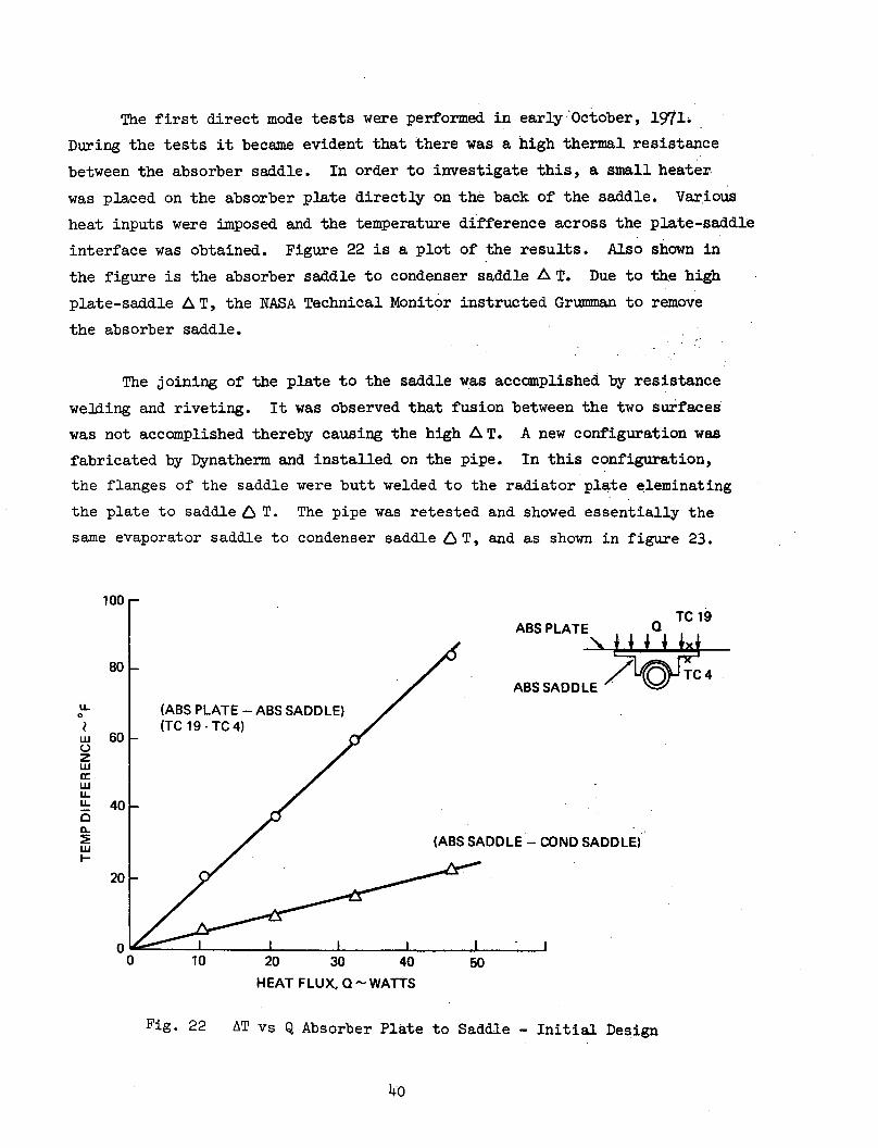
The first direct mode tests were performed in early October, 1971L
During the tests it became evident that there was a high thermal resistance
between the absorber saddle. In order to investigate this, a small heater
was placed on the absorber plate directly on the back of the saddle. Various
heat inputs were imposed and the temperature difference across the plate-saddle
interface was obtained. Figure 22 is a plot of the results. Also shown in
the figure is the absorber saddle to condenser saddle A T. Due to the high
plate-saddle A T, the NASA Technical Monitor instructed Grumman to remove
the absorber saddle.
The joining of the plate to the saddle was accomplished by resistance
welding and riveting. It was observed that fusion between the two surfaces
was not accomplished thereby causing the high A T. A new configuration was
fabricated by Dynatherm and installed on the pipe. In this configuration,
the flanges of the saddle were butt welded to the radiator plate eleminating
the plate to saddle L T. The pipe was retested and showed essentially the
same evaporator saddle to condenser saddle 6 T, and as shown in figure 23.
100
ABS PLATE Q TC19
80ABS SADDLE
u - (ABS PLATE - ABS SADDLE)t ~(TC 19 -TC 4
w 600z
LL 40
EH~~~~~~ / ~(ABS SADDLE- COND SADDLE)
20
00 10 20 30 40 50
HEAT FLUX, Q - WATTS
Fig. 22 AT vs Q Absorber Plate to Saddle - Initial Design
4o
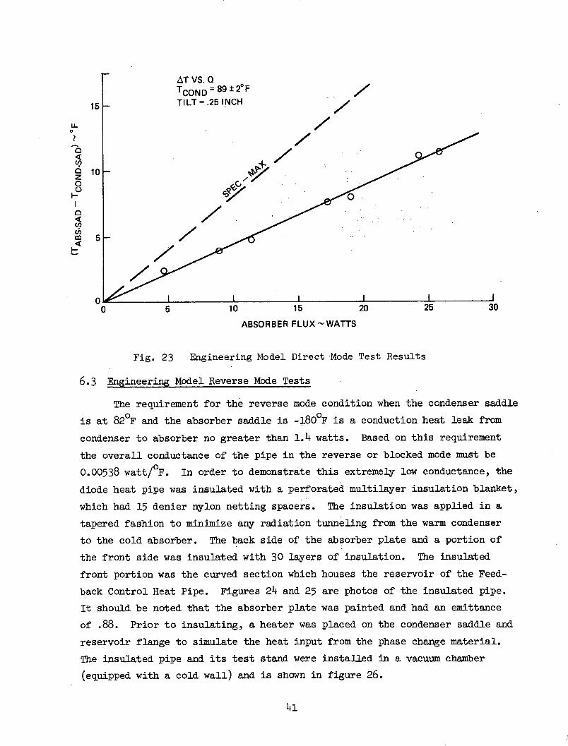
AT VS. QTCOND = 89 +20 FTILT = .25 INCH
/7
L /
Uo0 10
5
00 5 10 15 20 25 30
ABSORBER FLUX -WATTS
Fig. 23 Engineering Model Direct Mode Test Results
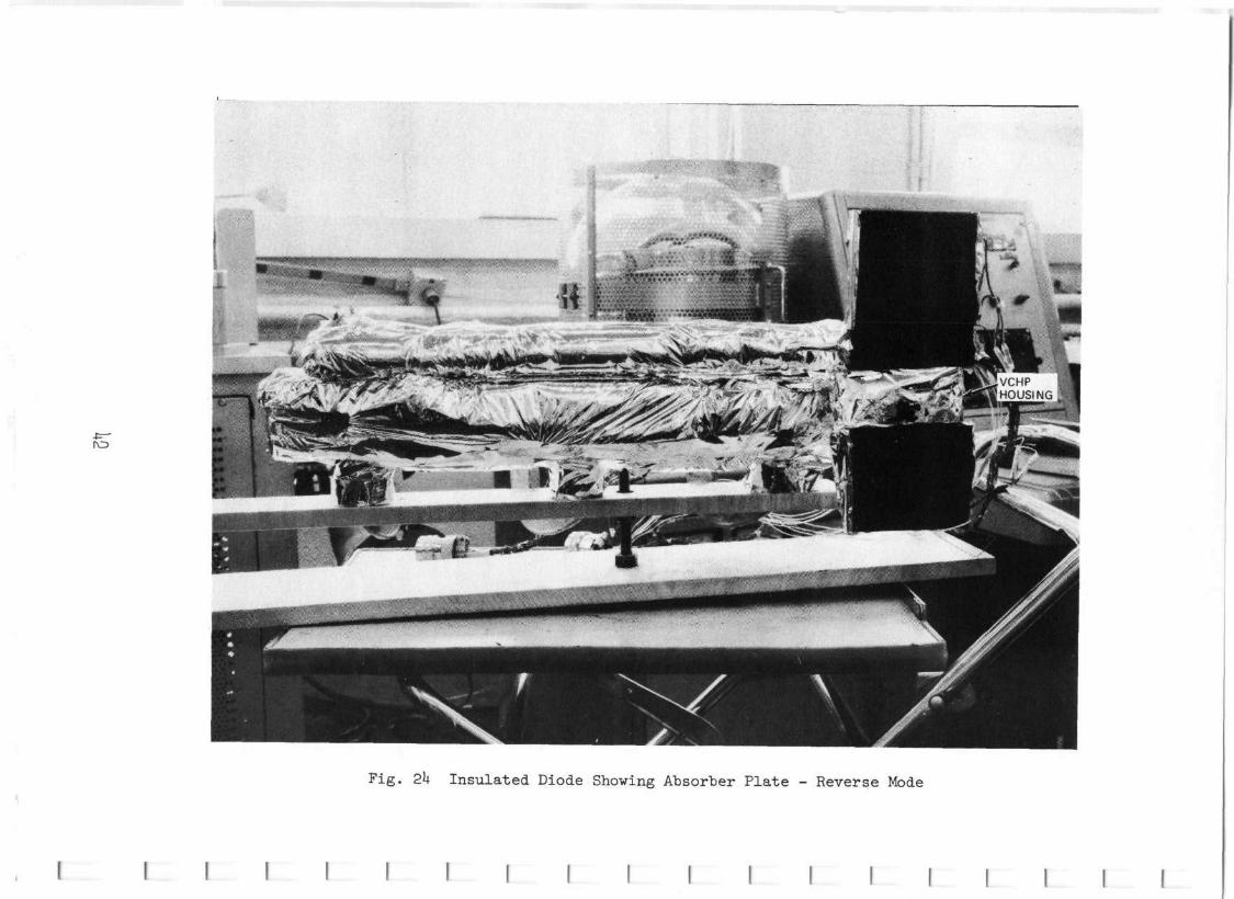
6.3 Engineering Model Reverse Mode Tests
The requirement for the reverse mode condition when the condenser saddle
is at 820 F and the absorber saddle is -180OF is a conduction heat leak from
condenser to absorber no greater than 1.4 watts. Based on this requirement
the overall conductance of the pipe in the reverse or blocked mode must be
0.00538 watt/OF. In order to demonstrate this extremely low conductance, the
diode heat pipe was insulated with a perforated multilayer insulation blanket,
which had 15 denier nylon netting spacers. The insulation was applied in a
tapered fashion to minimize any radiation tunneling from the warm condenser
to the cold absorber. The back side of the absorber plate and a portion of
the front side was insulated with 30 layers of insulation. The insulated
front portion was the curved section which houses the reservoir of the Feed-
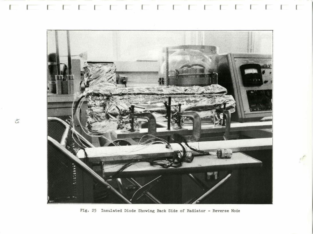
back Control Heat Pipe. Figures 24 and 25 are photos of the insulated pipe.
It should be noted that the absorber plate was painted and had an emittance
of .88. Prior to insulating, a heater was placed on the condenser saddle and
reservoir flange to simulate the heat input from the phase change material.
The insulated pipe and its test stand were installed in a vacuum chamber
(equipped with a cold wall) and is shown in figure 26.
41
ro
Fig. 24 Insulated Diode Showing Absorber Plate - Reverse Mode
I I I I I I I I I I
I I I I
Fig. 25 Insulated Diode Showing Back Side of Radiator - Reverse Mode
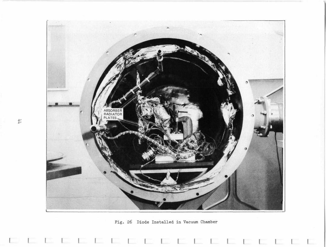
Fig. 26 Diode Installed in Vacuum Chamber
I I • 1
I I I I M W W I I
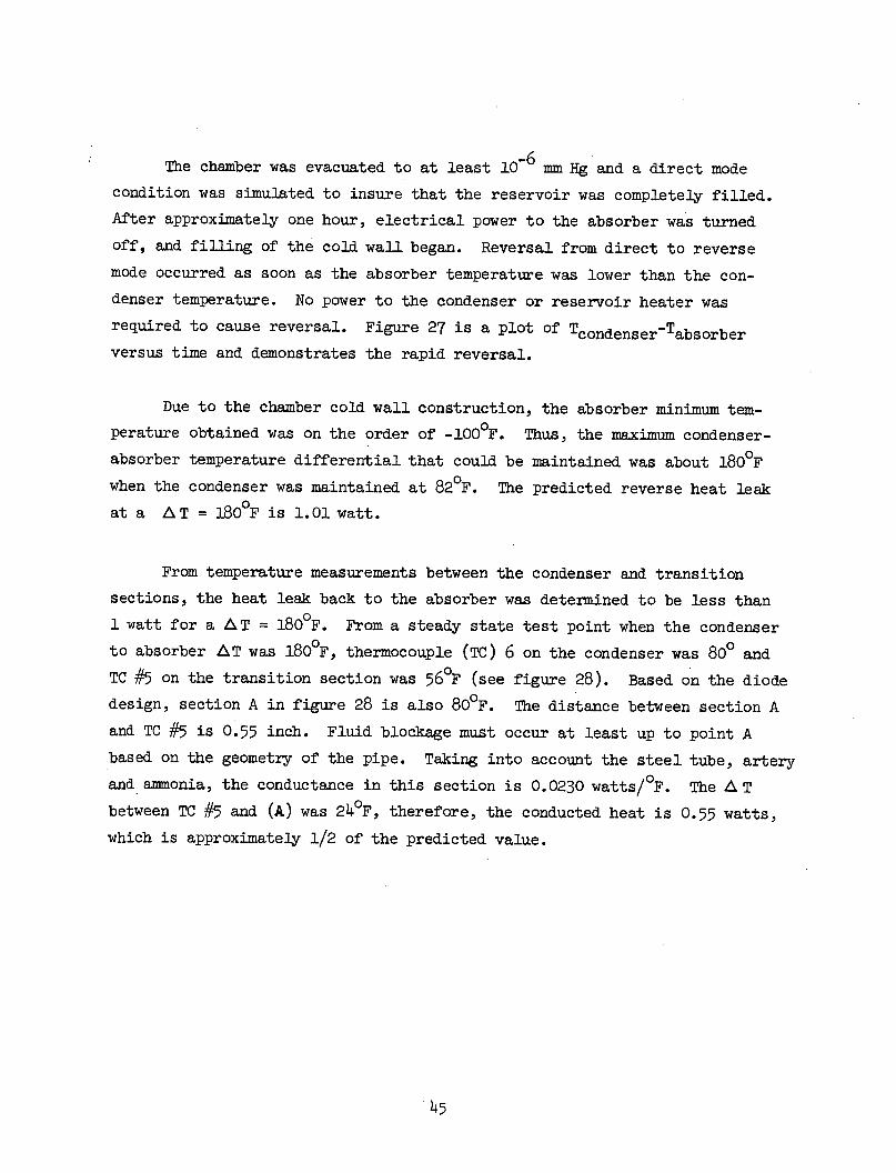
-6The chamber was evacuated to at least 10 6 mm Hg and a direct mode
condition was simulated to insure that the reservoir was completely filled.
After approximately one hour, electrical power to the absorber was turned
off, and filling of the cold wall began. Reversal from direct to reverse
mode occurred as soon as the absorber temperature was lower than the con-
denser temperature. No power to the condenser or reservoir heater was
required to cause reversal. Figure 27 is a plot of Tcondenser-Tabsorber
versus time and demonstrates the rapid reversal.
Due to the chamber cold wall construction, the absorber minimum tem-
perature obtained was on the order of -1000F. Thus, the maximum condenser-
absorber temperature differential that could be maintained was about 1800F
when the condenser was maintained at 820F. The predicted reverse heat leak
at a A T = 1800F is 1.01 watt.
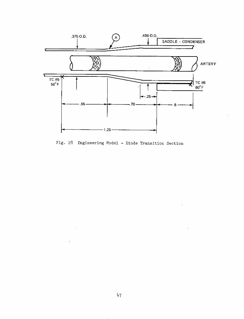
From temperature measurements between the condenser and transition
sections, the heat leak back to the absorber was determined to be less than
1 watt for a A T = 1800 F. From a steady state test point when the condenser
to absorber AT was 1800F, thermocouple (TC) 6 on the condenser was 800 and
TC #5 on the transition section was 560 F (see figure 28). Based on the diode
design, section A in figure 28 is also 800F. The distance between section A
and TC #5 is 0.55 inch. Fluid blockage must occur at least up to point A
based on the geometry of the pipe. Taking into account the steel tube, artery
and ammonia, the conductance in this section is 0.0230 watts/OF. The A T
between TC #5 and (A) was 240F, therefore, the conducted heat is 0.55 watts,
which is approximately 1/2 of the predicted value.
45

20ot
10-
AAT /
C-A /
// REVERSE
MINUTES
10 2010 20
I I j-20 -10 /,/
-10DIRECT
-20
0O
COLD WALL FILL @ 2 MIN.
H
20 40 60 80 100 120 140 160
TIME - MIN.(TIME FROM DIRECT MODE Q = 0 STABI LIZATION)
Fig. 27 Diode Engineering Model Thermal Vacuumto Reverse Mode Transient
1V
Test Direct
46
160
140
120
U-0
I
z0C-,)
I-
60
401
20
d6
0
.375 O.D.
1.450 O.D
I·
A ).
I SADDLE-CONDENSER
ST
-. 25 -'-
1.25
ARTERY
.5
Fig. 28 Engineering Model - Diode Transition Section
47
TC #5560 F 'I TC #6
800 FI
7.0 THERMAL TESTS - QUAL AND FLIGHT DIODES
Based on the results of the ATFE engineering model tests, NASA determined
that more absorber area was required. Grumman was therefore instructed to in-
crease the length of the qualification and flight diode evaporators by 1.0 inch
to 4.90 inches. The increase in pipe length required a minor redesign of the
reservoir, i.e., the diameter of the holes in the reservoir were increased a
few thousands of an inch in order to accommodate more fluid.
In April 1972, tests were conducted on diode #2, the qualification or
prototype model. The diode was attached to the saddles by Hysol epoxy. The
diode was charged with 17.8 grams of ultra high purity ammonia in accordance
with Appendix D. The tests were conducted as per Appendix E and witnessed by
both Grumman and NASA quality control. Thermocouples were attached to the
absorber and condenser saddles, transition section, and reservoir. Thermocouples
were not attached to the pipe directly in the evaporator and condensers. The
reason was that due to the poor conductivity of the steel the portions of the
pipe not attached to the saddles would be at an adiabatic temperature. This
was noticed during the engineering model tests. The instrumentation and heater
locations for the qualification and flight models are shown in Appendix E. The
direct mode test was conducted in a similar manner as the engineering model.
At the specification level of 20 watts input to the absorber, the absorber
condenser saddle temperature difference was 9°F, 7 F below the maximum allowable.
The reverse mode test was conducted in a vacuum chamber at a pressure of
2 x 10-
7 torr. A direct mode condition was setup at ambient temperatures to
insure that the reservoir was filled at which time the cold wall of the chamber
was filled. After approximately 24 hours, the absorber temperature was -145°F
and the condenser temperature 820 F. The reverse heat leak was calculated to be
0.29 watts. For the 217°F temperature difference, the maximum allowable leak
was 1.2 watts. This calculation is shown in Appendix C.
At the conclusion of the thermal tests on Diode #2, Grumman was notified
by the NASA Technical Monitor that a possible premature dryout of the Feedback
Controlled Heat Pipe on the ATFE could occur. If this happened, the diode tem-
perature could reach as high as 2600F. Once the premature dryout was corrected,
the diode would have to operate normally again. This possible condition was not
part of the original specification. The impact was that the Hysol epoxy which
48
bonds the diode to its saddles loses its structural strength at high tempera-
tures and the thermal interface between the diode and its saddles could be
damaged. Grumman was therefore instructed to do the following: (a) eliminate
the Hysol epoxy, (b) ship Diode #3, the original flight pipe, to Dynatherm Corp.
for a solder attachment to the saddles, and designate Diode #3 as the qualifi-
cation unit, and (c) remove the epoxy from Diode #2, the original qualification
pipe, and solder the saddles. Diode #2 would become the flight unit.
After the diode heat pipes were soldered to the saddles, the pipes were
charged with ammonia and pinched off according to Appendix D. Prior to NH3
charging, the diodes were proof pressured with N2 at 3000 psi for one hour at a
temperature of 285 F. After pinch off the diodes were then subjected to a tem-
perature of 2850F for 1 hour. The resulting pressure was 2300 psi. Direct and
reverse mode tests were then performed on both the qualification and flight units
as per Appendix E. In addition, burnout levels in the direct mode were obtained
at the test tilt of 1 inch. Both pipes performed well within its specification.
7.1 Direct Mode Results
The direct mode test results for the Qualification and Flight diode are
shown in figure 29. Also shown for comparison purposes, are the Engineering
Model results and Diode #2 with Hysol attachment saddles. It can be noted that
Flight model had a higher A T than the Qualification model. At 20 watts, the
A T between the absorber and condenser saddles was 2.30 F for the Qualification
unit and 5.5 F for the Flight unit. The difference could be attributed to a
poorer saddle solder attachment noticed on the flight unit.
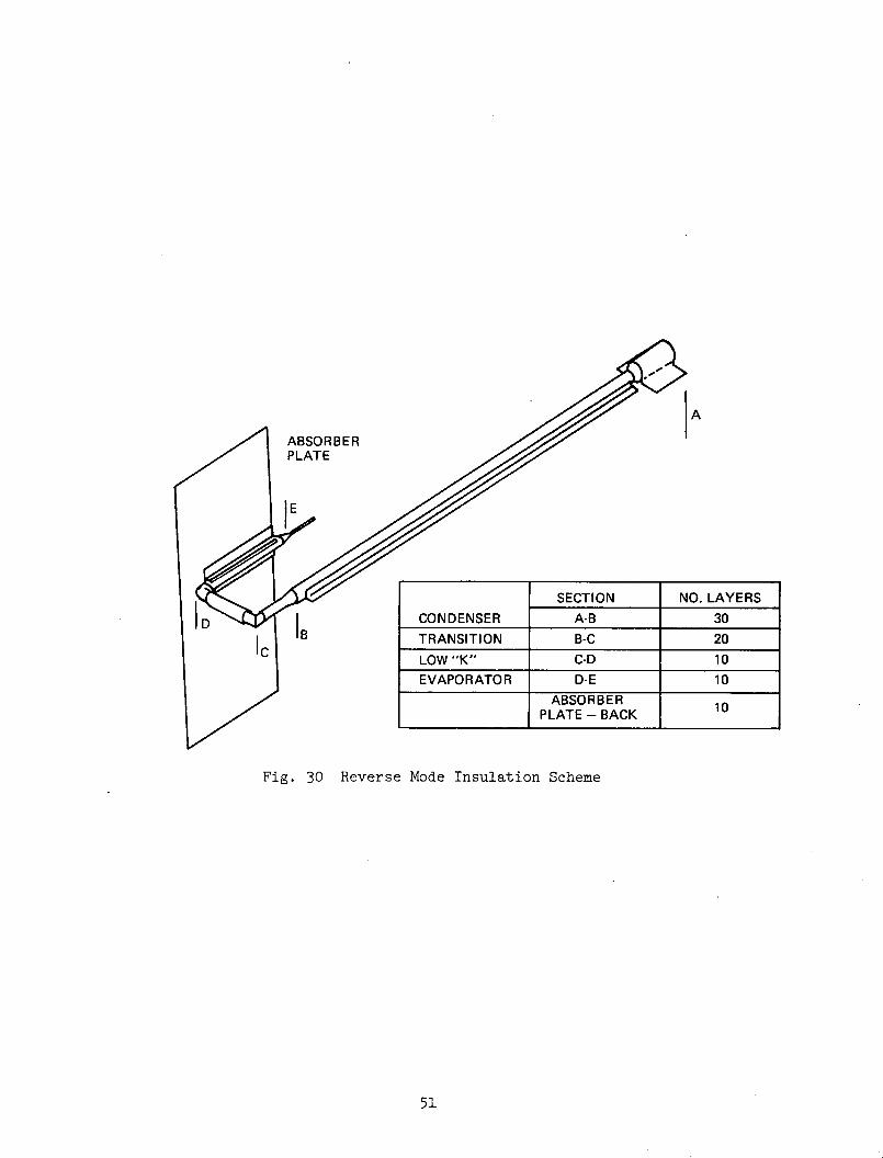
7.2 Reverse Mode Test Results
As indicated earlier, the reverse mode tests were conducted in a thermal
vacuum chamber equipped with a IN2 cold wall. Since the expected heat leakage
in the reverse or shut off mode was so small, the diode had to be insulated in
a special manner in order to minimize radiation tunneling. It was determined
that with temperature difference of 2200 F between the condenser and absorber,
approximately 1 watt of radiation could be transferred from the condenser to
the absorber. Therefore, the pipe was insulated in a tapered fashion with super-
insulation as shown in figure 30. Both pipes were installed in the vacuum chamber
in a level position. The test chamber was evacuated to at least 10 torr at
ambient temperature at which time the evaporator heater was energized to insure
49
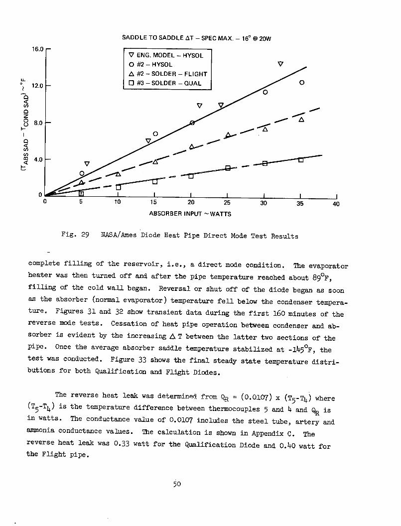
SADDLE TO SADDLE AT - SPEC MAX. - 160 @ 20W
16.016.0 ENG. MODEL - HYSOL
O #2- HYSOL V
A #2 - SOLDER - FLIGHT
12.0 O #3 - SOLDER - QUAL 12.0 -
C3
<n~a V
0 8000--
o 80
0 5 10 15 20 25 30 35 40
ABSORBER INPUT -WATTS
Fig. 29 NASA/Ames Diode Heat Pipe Direct Mode Test Results
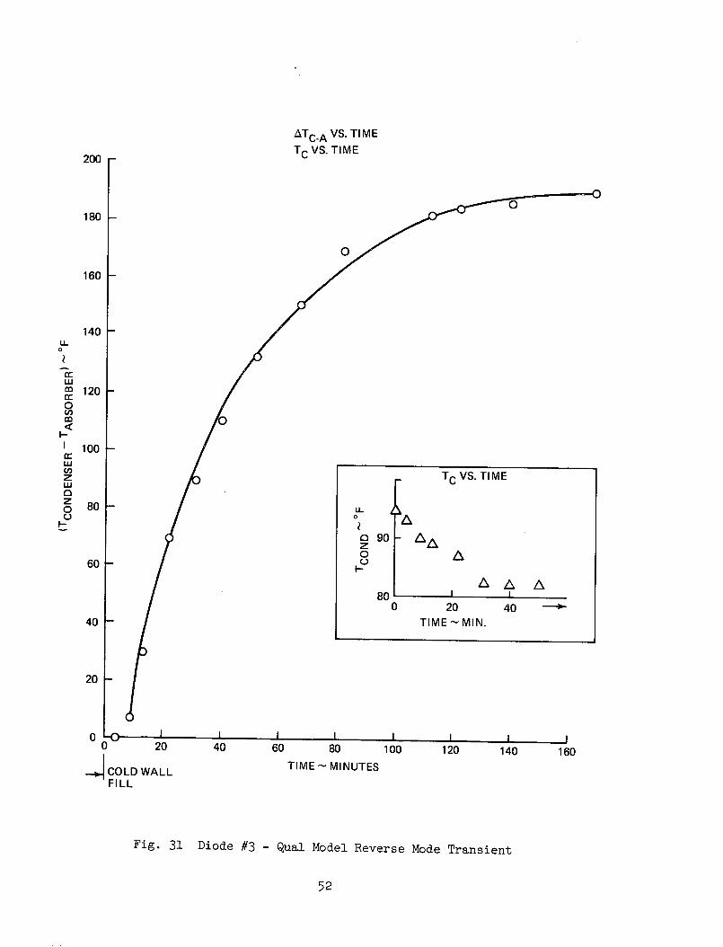
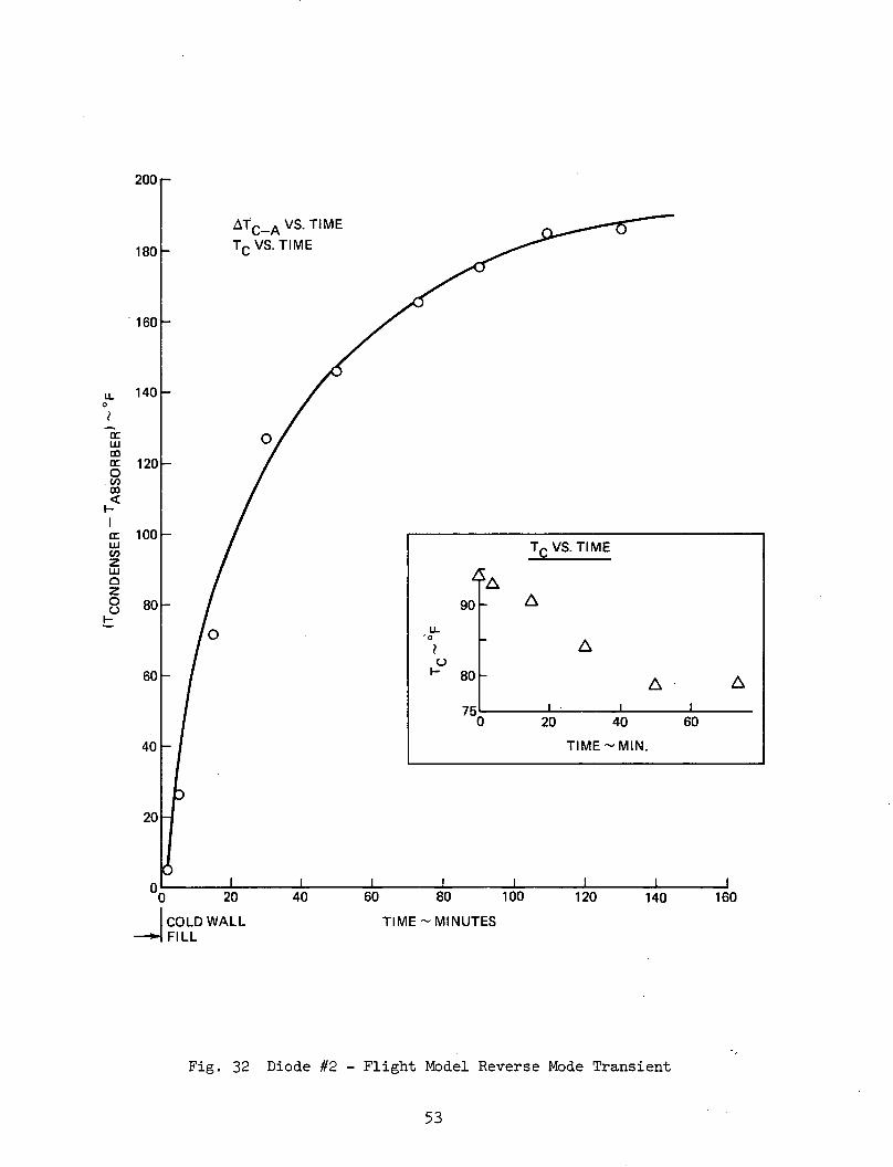
complete filling of the reservoir, i.e., a direct mode condition. The evaporator
heater was then turned off and after the pipe temperature reached about 890F,
filling of the cold wall began. Reversal or shut off of the diode began as soon
as the absorber (normal evaporator) temperature fell below the condenser tempera-
ture. Figures 31 and 32 show transient data during the first 160 minutes of the
reverse mode tests. Cessation of heat pipe operation between condenser and ab-
sorber is evident by the increasing LA T between the latter two sections of the
pipe. Once the average absorber saddle temperature stabilized at -1450F, the
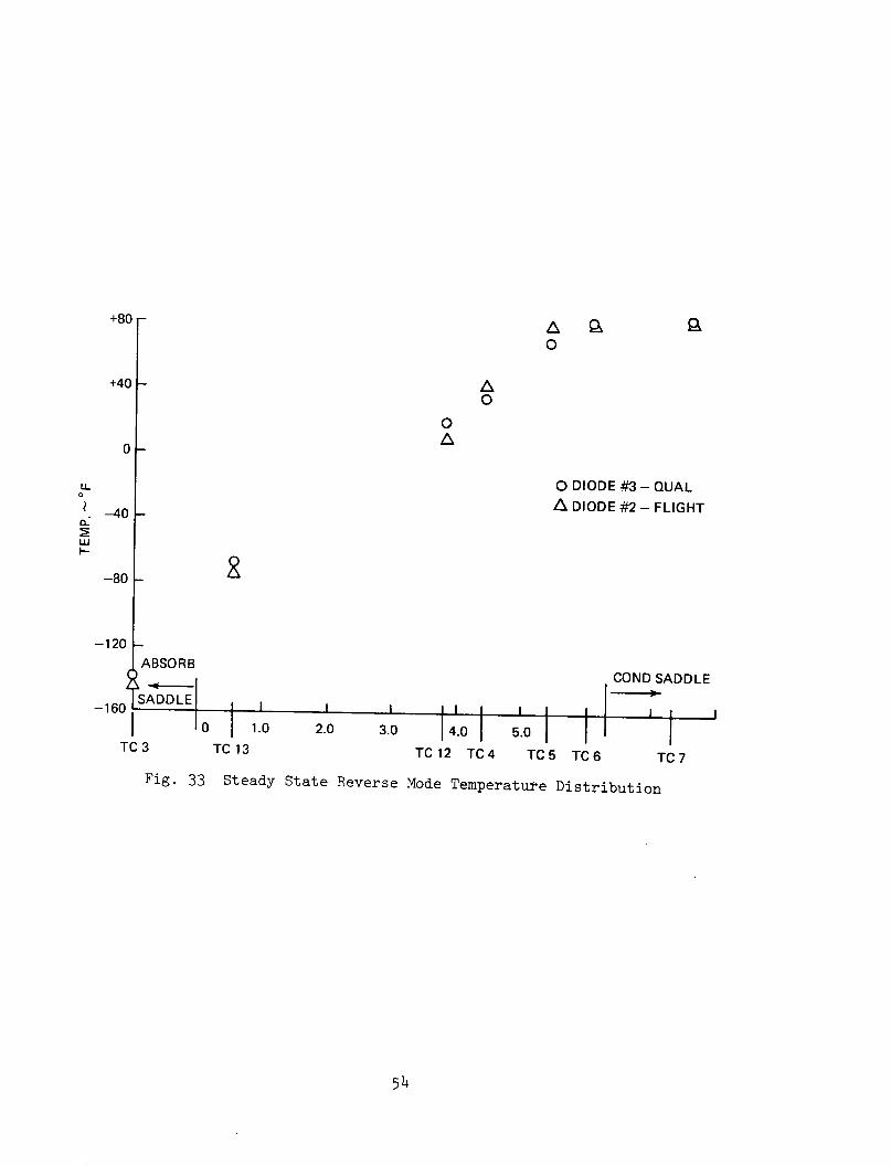
test was conducted. Figure 33 shows the final steady state temperature distri-
butions for both Qualification and Flight Diodes.
The reverse heat leak was determined from QR = (0.0107) x (T5 -T4) where
(T5 -T4 ) is the temperature difference between thermocouples 5 and 4 and QR is
in watts. The conductance value of 0.0107 includes the steel tube, artery and
ammonia conductance values. The calculation is shown in Appendix C. The
reverse heat leak was 0.33 watt for the Qualification Diode and 0.40 watt for
the Flight pipe.
50
A
ABSORBERPLATE
IB
Fig. 30 Reverse Mode Insulation Scheme
51
SECTION NO. LAYERSCONDENSER A-B 30TRANSITION B-C 20
LOW "K" C-D 10EVAPORATOR D-E 10
ABSORBERPLATE- BACK
ATC.A VS. TIMETC VS. TIME
20 40 60 80 100 120 140
4 COLD WALLFILL
TIME - MINUTES
Fig. 31 Diode #3 - Qual Model Reverse Mode Transient
52
200
180 -
160 -
140 -
O
LL
0IJ
Cd
I-
USr,zwozr,)
I-
120
100
80
60 -
40
TC VS. TIME
LL
o g ACO A
A /\80 I l
0 20 40TIME - MIN.
20 k
0 LO00 160
I i I
200
180
160
mAn
ATC-A VS. TIMETC VS. TIME
LL 14U
r0
w 0mh 1200
c 100w TC VS. TIMEzo AL 80- 90 _
-oU-
0-60 - 80 A 8
75I0 20 40 60
40 _ I TIME - MIN.
20
C I I i f I I I I0 20 40 60 80 100 120 140 160
COLD WALL TIME - MINUTESFI LL
Fig. 32 Diode #2 - Flight Model Reverse Mode Transient
53
AZ~
o
OA
O DIODE #3 - QUALA DIODE #2 - FLIGHT
BSORB
ADDLE I I I II I I I
I 0 1.0 2.0 3.0TC 13
COND SADDLE
I I-- I
14.0 5.0TC12 TC4 TC5 TC6 TC 7
Fig. 33 Steady State Reverse Mode Temperature Distribution
54
+80 r
+40
0
U.0o
I±J
-40 -
-80 -
-120 kAl
-160
TC 3
1
8. REFERENCES
(1) F. Edelstein and R. J. Hembach, "Design, Fabrication and Testing
of a Variable Conductance Heat Pipe for Equipment Thermal Control,"
AIAA Paper 71-422, April, 1971.
(2) J. P. Kirkpatrick and B. D. Marcus, "A Variable Conductance Heat Pipe/
Radiator for the Lunar Surface Magnetometer," AIAA Paper 72-271,
April, 1972.
(3) R. Kosson, R. Hembach, F. Edelstein and M. Tawil; "A Tunnel Wick
100,000 Watt-Inch Heat Pipe," AIAA Paper 72-273, April 1972.
(4) "ATFE/Thermal Diode Interface Specification," NASA/Ames PES-ATS-1-A.
(5) Los Alamos Scientific Laboratory, "Theory of Heat Pipes", T. P. Cotter,
LA-3246-MS, Los Alamos, New Mexico, February 23, 1965.
55

APPENDIX A - TUNNEL W-CK--ANAIMYSIS
WEB PIPE OD
WRAP TWO
TUNNEL OD
ROOT-
Fig. A-1 Tunnel Wick
For the spiral artery configuration, the liquid flow path consists
of the condenser grooves, condenser webs, artery evaporator webs, and
evaporator grooves. The liquid pressure drops continuously along this
flow path. In ground tests, the liquid pressure is assumed to equal the
vapor pressure at the lowest point of the condenser, which is taken to
be at the far end of the condenser at the bottom of the pipe. The liquid
pressure then drops with increasing elevation in a gravity or body force
field in addition to viscous losses in the direction of flow. Compressi-
bility effects are negligible for the cases considered.
The equation for the difference in pressure between liquid and vapor
which must be sustained by the meniscus or capillary forces is
Pc = APL + 4Pv + &PB A-1
which , PL and APV refer to viscous losses in the liquid and vapor and
A P B refers to the body force pressure drop.
The circumferential grooves are assumed to have a symmetric trapezoid
cross-section, as shown in Figo~-l. For this shape, the maximum capillary
force is
A-1
SECTION A-A
2 r cos ( +0t)c P = A-2
cMax w
The body force pressure drop is
Ai B /L g- (Di + h) A-3
For laminar flow of a fluid in a smooth passage, the pressure gradient
may be written:
dp - 321m2 A-4dz /gc 2
where m = Q/', neglecting liquid and vapor sensible temperature changes.
For the vapor, the mass flow is assumed to vary linearly with distance
between zero and QA within the evaporator and condenser, hence
= 32V. .1 (IC + LEV) + LTR A-5
gc/'V PAvfv
For the liquid, the pressure drop consists of five terms
APL PL,GR,C + PL,W,C+ LA +
A P + NP A-6PL,W,EV + L,GR,EV
For the condenser grooves, the mass flow is assumed to vary linearly
from zero at the midpoint between webs to Q/(2 nw Nn'GR LC) entering each
side of each web. The effective groove length is then 1/4 the distance
between webs, or ;rDi/4nw.
For the evaporator grooves, the expression is the same except for the
use of LEV in place of LC
. Combining the two terms,
A-2
L,GR - L,GR,C PL,GR,EV
P L, GR =Q GR
32t /L Di.
The webs are assumed to be made of screening with porosity 6 , thick-
ness tw, and nominal pore diameter Dp. The mass flow is Q/nw, the area
6 tw
LC or6tw
LEV, and the path length (Di- DA)/2. Hence the pressure drop
for the condenser and evaporator combined is
A PL,W - L,W,C + L,W,EV
NPL,W 3 2 'UL (Di- DA) (b/8) i A-8CW = LC 2A-8
&Q ._ Cw = c/i LP 2 nw twEDp2 LEV LC
(4)where (b/8), following Cotter, is a factor(generally between 1.2 and 2.5)
accounting for the tortuosity of flow within the screening as compared with
smooth passages.
The artery represents the major viscous loss in most applications,and
is assumed to have parallel flow paths within the screening, the gap regions, and
the tunnel. As with the vapor, the mass flow is assumed to vary linearly
in evaporator and condenser. The pressure drop is then given by
4 PLA -C32 L 2 (LC + LE) + LTRQ 0 A gcfLt ( AG D 2 +2 +C A D)
where subscripts P, G and T refer to the screen, gap regions & tunnel respectively.
Substituting these expressions into equation 1 and rearranging to
solve for QMax corresponding to PcMax gives
cMax -4PAPc, - a B A-10
QMax Cv C + +C + CAv GR A-3
A-3

APPENDIX B
Liquid Blockage Diode - Tunnel Wick Equations
The tunnel wick equations of Appendix A must be modified for the liquid
blockage diode to account for different pipe inside diameters in the condenser,
evaporator, transport section portion which is to be blocked in the reverse mode,
and transport section portion which is left unblocked.
Specifically, Equations A-3, A-5, A-7 and A-8 are replaced by
A PB = gC (Di, + h)i ,EV
AI 'v _ ( 3Z r LcrQ I' -.fV A, ,Ce
L Tt-- L L rp- i -
AVTRU., TO
.EV
-; z Ax __2z~u, / A- \ fist He p&Lz g b t, Cdl·P·~~~ ~~- A61~~~Y~~I :e ~-1/
Chii Ac,. AL 6 @s a9 ri e-;> ·
where subscripts C, TRU, TRB, EV refer to condenser, transport section unblocked,
transport section blocked, and evaporator, respectively.
These quantities are then substituted in equation A-10 to obtain Qi.ax
B-1
(B-1)
ATV L, rp 3
Av, ret PVj rz
( a -Ž)
A , = CGe-
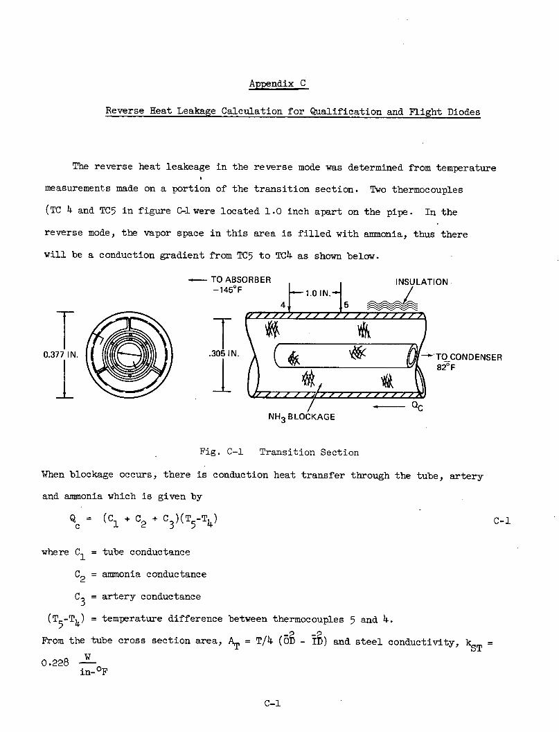
Appendix C
Reverse Heat Leakage Calculation for Qualification and Flight Diodes
The reverse heat leakeage in the reverse mode was determined from temperature
measurements made on a portion of the transition section. Two thermocouples
(TC 4 and TC5 in figure C-l were located 1.0 inch apart on the pipe. In the
reverse mode, the vapor space in this area is filled with ammonia, thus there
will be a conduction gradient from TC5 to TC4 as shown below.
TO ABSORBER INSULATION-145°F 1.0 IN.
0.377 IN. (.305N. TO CONDENSER
-QCNH3 BLOCKAGE
Fig. C-1 Transition Section
When blockage occurs, there is conduction heat transfer through the tube, artery
and ammonia which is given by
Q (C1 + C2 + C3 )(T5-T4) C-
where C1= tube conductance
C2= ammonia conductance
C3 = artery conductance
(T5 -T4) = temperature difference between thermocouples 5 and 4.
From the tube cross section area, AT = T/4 (05 - ID) and steel conductivity, kST =
W0.228 W
in-OF
C-1
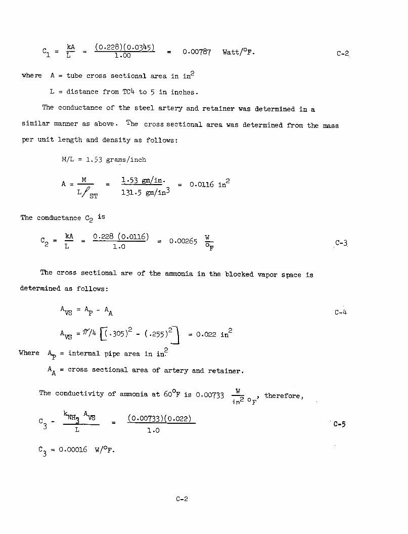
C k- (0.228)(005) = 00787 Watt/OF. C-2
where A = tube cross sectional area in in2
L = distance from TC4 to 5 in inches.
The conductance of the steel artery and retainer was determined in a
similar manner as above. The cross sectional area was determined from the mass
per unit length and density as follows:
M/L = 1.53 grams/inch
A -M 1.53 gm/i = 0.0116 in2
L/ST 131.5 gm/in3
The conductance C2 is
C =kA = 0.228 (0.0116) = 0.00265 W C-32 L 1.0 F
The cross sectional are of the ammonia in the blocked vapor space is
determined as follows:
AVs = Ap - AA C-4
AVs =i/4 U .305) - (.255) = 0.022 in
Where Ap = internal pipe area in in2
AA = cross sectional area of artery and retainer.
The conductivity of ammonia at 600 F is 0.00733 W O therefore,~2 oF
C _ NH3 VS (0.00733)(0.022) C-5
L 1.0
C3 = 0.00016 W/OF.
C-2

The conductance of the ammonia in the artery was neglected. The total conductance
C is just the sum of C1, C2 and C3 which is 0.0107 W/OF. Thus, from (c-1), the
leakage conducted through the diode is
Qc = (0.0107 W/oF) (T5-T4 ) c-6
C-3
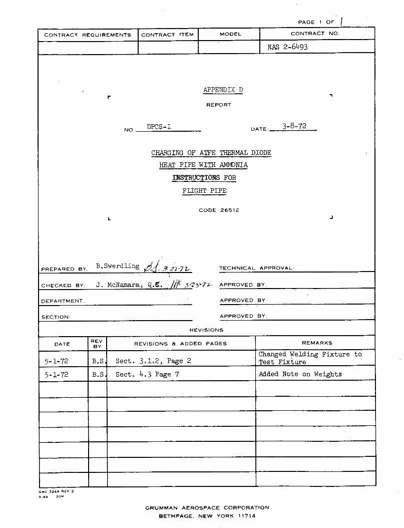
PAGE 1 OF I
CONTRACT REQUIREMENTS CONTRACT ITEM MODEL CONTRACT NO.
NAS 2-6493
APPENDIX D
REPORT
DPCS-1 DATE: 3-8-72
CHARGING OF ATFE THERMAL DIODE
HEAT PIPE WITH AMNDNIA
INSTRUCTIONS FOR
FLIGHT PIPE
CODE 26512
TECHNICAL APPROVAL:
J. McNamara, Q.e... ///A 3-t3o7l.- APPROVED BY:
DEPARTMENT:
SECTION:
APPROVED BY:
APPROVED BY:
REVISIONS
DATE REV REVISIONS & ADDED PAGES REMARKSBY
Changed Welding Fixture to5-1-72 B.S Sect. 3.1.2, Page 2 Test Fixture
5-1-72 B.S. Sect. 4.3 Page 7 Added Note on Weights
_ _GAC 324A REV 2
8.69 20M
GRUMMAN AEROSPACE CORPORATION
BETHPAGE. NEW YORK 11714
r
NO.
L
PREPARED BY.
CHECKED BY:
J
B.Swerdling ' 2;-7L-
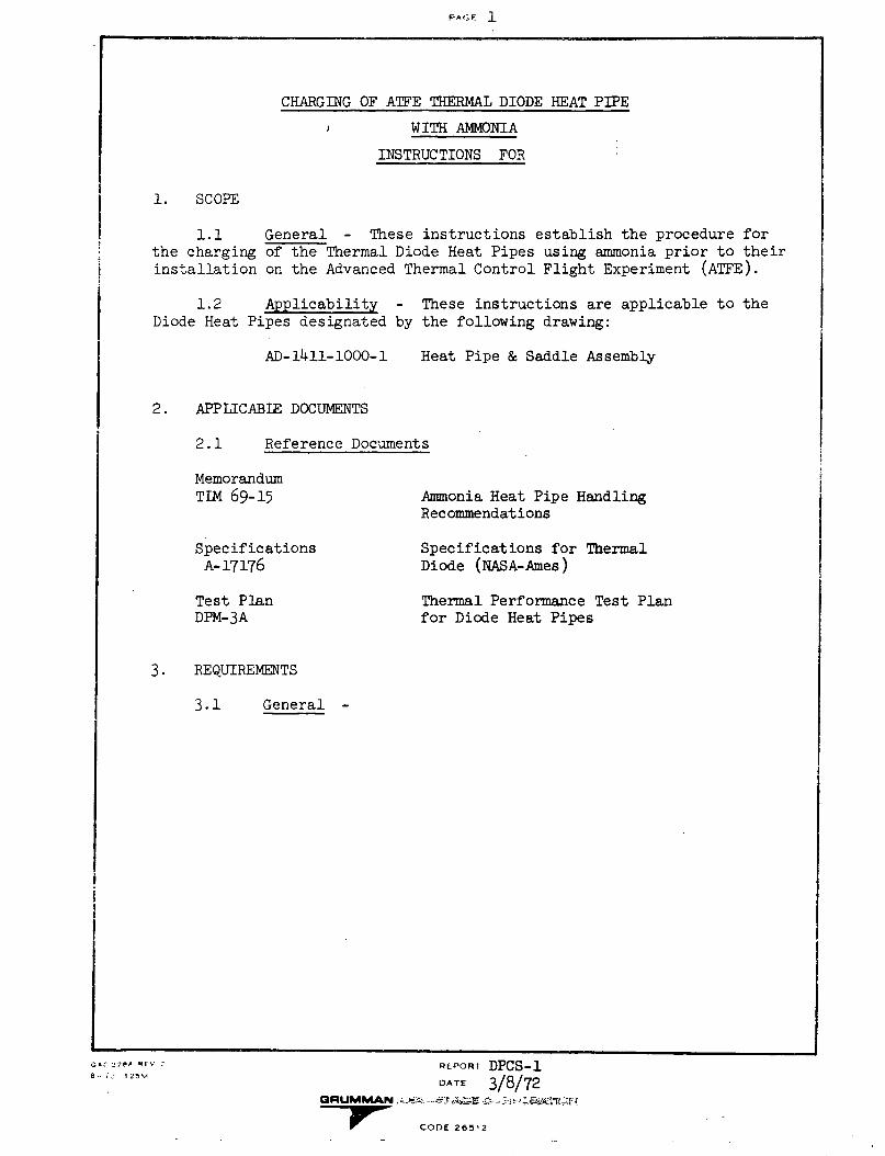
PA¢E 1
CHARGING OF ATFE THERMAL DIODE HEAT PIPE
WITH AMMONIA
INSTRUCTIONS FOR
1. SCOPE
1.1 General - These instructions establish the procedure forthe charging of the Thermal Diode Heat Pipes using ammonia prior to theirinstallation on the Advanced Thermal Control Flight Experiment (ATFE).
1.2 Applicability - These instructions are applicable to theDiode Heat Pipes designated by the following drawing:
AD-1411-10OO-l Heat Pipe & Saddle Assembly
2. APPLICABLE DOCUMENTS
2.1 Reference Documents
MemorandumTIM 69-15 Ammonia Heat Pipe Handling
Recommendations
Specifications Specifications for ThermalA-17176 Diode (NASA-Ames)
Test Plan Thermal Performance Test PlanDPM-3A for Diode Heat Pipes
3. REQUIREMENTS
3.1 General -
REPORT DPCS-1DATE 3/8/72
Pr CODE 26512
GC 3?Pa RPFV 2
8 - J I 25
i
iI
I
4
i
I
I
II
I
L
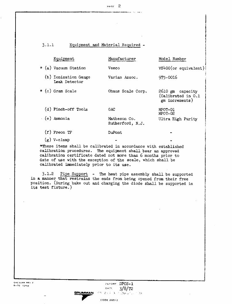
FPAC F 2
Equipment and Material Required -
Manufacturer Model Number
* (a) Vacuum Station
(b) Ionization GaugeLeak Detector
* (c) Gram Scale
(d) Pinch-off Tools
(e) Ammonia
Veeco
Varian Assoc.
Ohaus Scale Corp.
GAC
Matheson Co.Rutherford, N.J.
VS400(or equivalent)
975-0016
2610 gm capacity(Calibrated in 0.1gm increments)
MPOT-01MPOT- 02
Ultra High Purity
(f) Freon TF DuPont
(g) V-clamp
*These items shall be calibrated in accordance with establishedcalibration procedures. The equipment shall bear an approvedcalibration certificate dated not more than 6 months prior todate of use with the exception of the scale, which shall becalibrated immediately prior to its use.
3.1.2 Pipe Supportin a manner that restrainsposition. (During bake outits test fixture..)
- The heat pipe assembly shallthe ends from being opened fromand charging the diode shall be
be supportedtheir freesupported in
,'tPORT DPCS-1D.' 3/8/72
GRUMMAN - : -_.-;?.' " .';
CODE 26512
3.1.1
Equipment
GAC 328A REV 2
8-70 12ŽM
_ .- ----
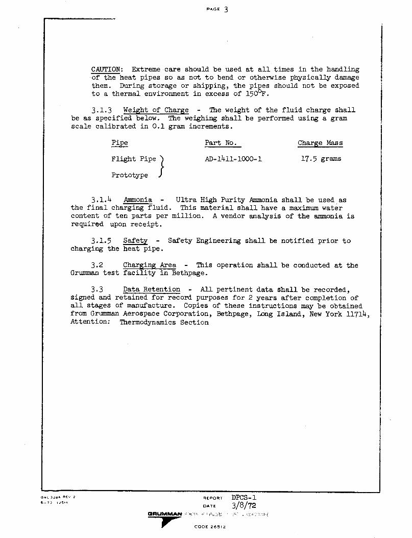
PAGE 3
CAUTION: Extreme care should be used at all times in the handlingof the heat pipes so as not to bend or otherwise physically damagethem. During storage or shipping, the pipes should not be exposedto a thermal environment in excess of 150°F.
3.1.3 Weight of Charge - The weight of the fluid charge shallbe as specified below. The weighing shall be performed using a gramscale calibrated in 0.1 gram increments.
Pipe
Flight Pipe'4
Prototype
Part No.
AD-1411-1000-1
Charge Mass
17.5 grams
3.1.4 Ammonia - Ultra High Purity Ammonia shall be used asthe final charging fluid. This material shall have a maximum watercontent of ten parts per million. A vendor analysis of the ammonia isrequired upon receipt.
3.1.5 Safety - Safety Engineering shall be notified prior tocharging the heat pipe.
3.2 Charging Area - This operation shall be conducted at theGrumman test facility in Bethpage.
3.3 Data Retention - All pertinent data shall be recorded,signed and retained for record purposes for 2 years after completion ofall stages of manufacture. Copies of these instructions may be obtainedfrom Grumman Aerospace Corporation, Bethpage, Long Island, New York 11714,Attention: Thermodynamics Section
REPORT
DATE
GRUMMAN^ .e..-,r :i -CO'
CODE 26512
DPCS-13/8/72
..l . ,; j.~L j .
GAC 328A REV 2
A-- 70 1 25M
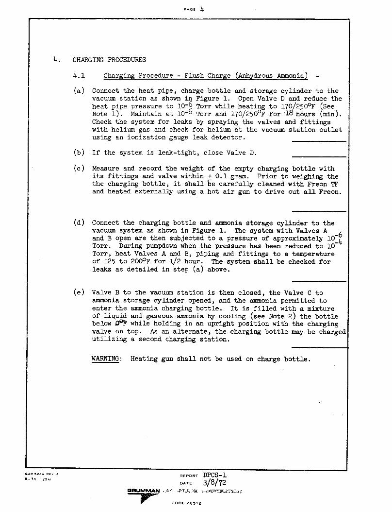
PAGF 4
4. CHARGING PROCEDURES
4.1 Charging Procedure - Flush Charge (Anhydrous Ammonia) -
(a) Connect the heat pipe, charge bottle and storage cylinder to thevacuum station as shown in Figure 1. Open Valve D and reduce theheat pipe pressure to 10-6 Torr while heating to 170/2500 F (SeeNote 1). Maintain at 10-6 Torr and 170/250°F for .18 hours (min).Check the system for leaks by spraying the valves and fittingswith helium gas and check for helium at the vacuum station outletusing an ionization gauge leak detector.
(b) If the system is leak-tight, close Valve D.
(c) Measure and record the weightits fittings and valve withinthe charging bottle, it shalland heated externally using a
of the empty charging bottle with+ 0.1 gram. Prior to weighing thebe carefully cleaned with Freon TFhot air gun to drive out all Freon.
(d) Connect the charging bottle and ammonia storage cylinder to thevacuum system as shown in Figure 1. The system with Valves A 6and B open are then subjected to a pressure of approximately 10-
4Torr. During pumpdown when the pressure has been reduced to 10Torr, heat Valves A and B, piping and fittings to a temperatureof 125 to 2000 F for 1/2 hour. The system shall be checked forleaks as detailed in step (a) above.
(e) Valve B to the vacuum station is then closed, the Valve C toammonia storage cylinder opened, and the ammonia permitted toenter the ammonia charging bottle. It is filled with a mixtureof liquid and gaseous ammonia by cooling (see Note 2) the bottlebelow DQF while holding in an upright position with the chargingvalve on top. As an alternate, the charging bottle may be chargedutilizing a second charging station.
WARNING: Heating gun shall not be used on charge bottle.
REPORT DPCS-1DATE 3/8/72
GRUMIMAN a·- .TC * 26;s 2
-rw0- CODE 26512
GAC 328A -Ev 2
0--70 125M
- ~~-------- -- --- -.
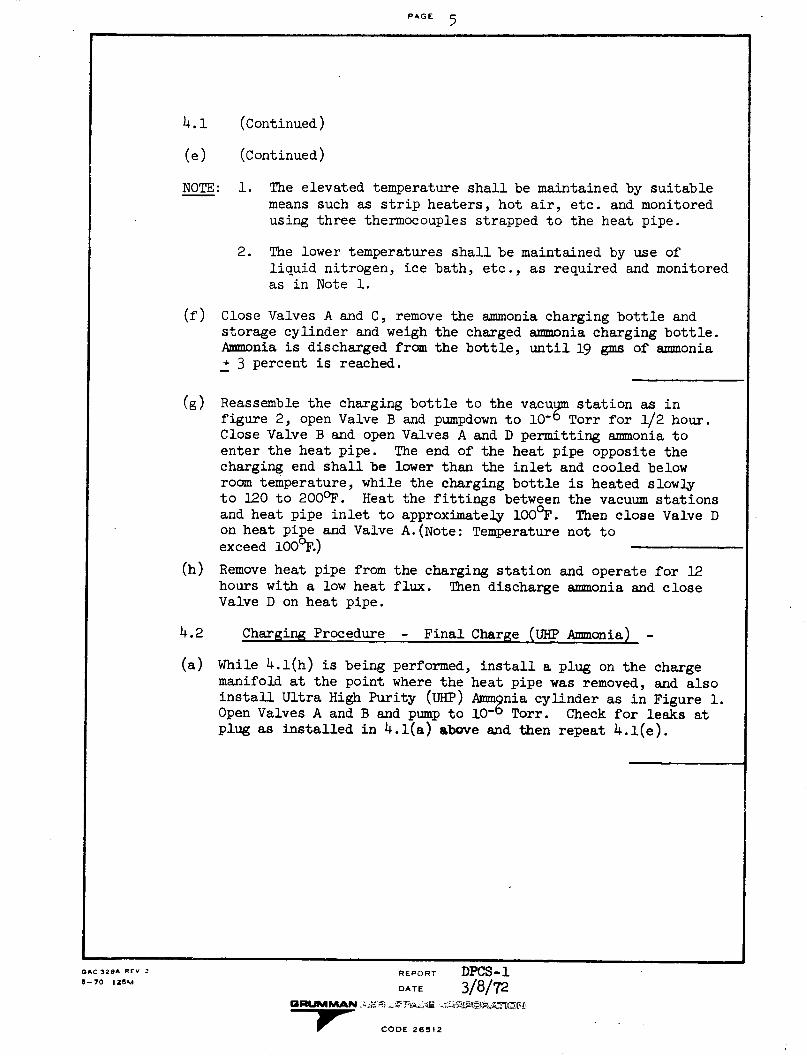
PAGE 5
4.1 (Continued)
(e) (Continued)
NOTE: 1. The elevated temperature shall be maintained by suitablemeans such as strip heaters, hot air, etc. and monitored
using three thermocouples strapped to the heat pipe.
2. The lower temperatures shall be maintained by use of
liquid nitrogen, ice bath, etc., as required and monitoredas in Note 1.
(f) Close Valves A and C, remove the ammonia charging bottle and
storage cylinder and weigh the charged ammonia charging bottle.
Ammonia is discharged from the bottle, until 19 gins of ammonia
+ 3 percent is reached.
(g) Reassemble the charging bottle to the vacuum station as in
figure 2, open Valve B and pumpdown to 1 0 -6 Torr for 1/2 hour.
Close Valve B and open Valves A and D permitting ammonia to
enter the heat pipe. The end of the heat pipe opposite the
charging end shall be lower than the inlet and cooled below
room temperature, while the charging bottle is heated slowly
to 120 to 2000 F. Heat the fittings between the vacuum stations
and heat pipe inlet to approximately 100 0 F. Then close Valve Don heat pipe and Valve A.(Note: Temperature not to
exceed 1000F.)
(h) Remove heat pipe from the charging station and operate for 12
hours with a low heat flux. Then discharge ammonia and close
Valve D on heat pipe.
4.2 Charging Procedure - Final Charge (UHP Ammonia) -
(a) While 4.1(h) is being performed, install a plug on the chargemanifold at the point where the heat pipe was removed, and also
install Ultra High Purity (UHP) Ammpnia cylinder as in Figure 1.Open Valves A and B and pump to 10O Torr. Check for leaks at
plug as installed in 4.1(a) above and then repeat 4.1(e).
GAC328A REV 2 REPORT DPCS-1_-70 1I2M DATE 3/8/72
CODE 26512
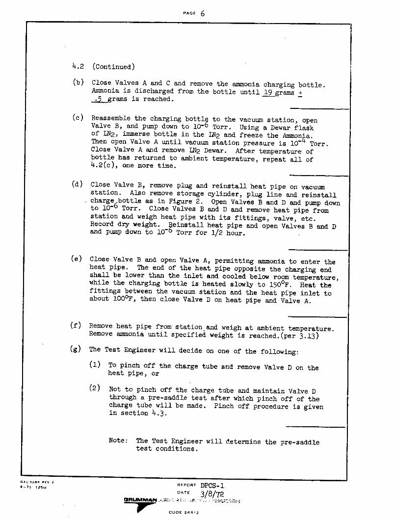
PAGE 6- .~~- .- _----~- . . .
4.2 (Continued)
(b) Close Valves A and C and remove the ammonia charging bottle.Ammonia is discharged from the bottle until 19 grams +·5 grams is reached.
(c) Reassemble the charging bottle to the vacuum station, openValve B, and pump down to 10- Torr. Using a Dewar flaskof LN2, immerse bottle in the IN2 and freeze the Ammon'a.Then open Valve A until vacuum station pressure is 10- Torr.Close Valve A and remove LN2 Dewar. After temperature ofbottle has returned to ambient temperature, repeat all of4.2(c), one more time.
(d) Close Valve B, remove plug and reinstall heat pipe on vacuumstation. Also remove storage cylinder, plug line and reinstallcharge bottle as in Figure 2. Open Valves B and D and pump downto 10-6 Torr. Close Valves B and D and remove heat pipe fromstation and weigh heat pipe with its fittings, valve, etc.Record dry weight. Peinstall heat pipe and open Valves B and Dand pump down to 10O' Torr for 1/2 hour.
(e) Close Valve B and open Valve A, permitting ammonia to enter theheat pipe. The end of the heat pipe opposite the charging endshall be lower than the inlet and cooled below room temperature,while the charging bottle is heated slowly to 150 F. Heat thefittings between the vacuum station and the heat pipe inlet toabout 100°F, then close Valve D on heat pipe and Valve A.
(f) Remove heat pipe from station and weigh at ambient temperature.Remove ammonia until specified weight is reached.(per 3.13)
(g) The Test Engineer will decide on one of the following:
(1) To pinch off the charge tube and remove Valve D on theheat pipe, or
(2) Not to pinch off the charge tube and maintain Valve Dthrough a pre-saddle test after which pinch off of thecharge tube will be made. Pinch off procedure is givenin section 4.3.
Note: The Test Engineer will determine the pre-saddletest conditions.
GAC 328^ REV 2 REPORT DPCS-18-70 125M
DATE 3/8/72PGRUMMJ CODE i
-7w- CODE 26SI2
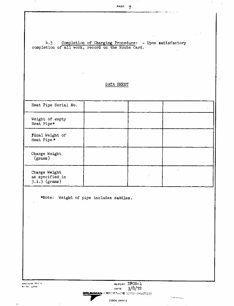
PAGE 7
4.3 Completion of Charging Procedure: - Upon satisfactorycompletion of all work, record on the Route Card.
DATA SHEET
Heat Pipe Serial No.
Weight of emptyHeat Pipe*
Final Weight ofHeat Pipe*
Charge Weight(grams)
Charge Weightas specified in3.1.3 (grams)
*Note: Weight of pipe includes saddles.
GAC 326A REV 2
0-70 2lZMREPORT DPCS-1DATE 3/8/72
EOUMMAN a/L-i-.CODE 2 R 1r
-" CODE 26512
6.
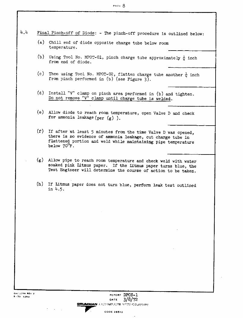
pAr-t 8
4.4 Final Pinch-off of Diode: - The pinch-off procedure is outlined below:
(a) Chill end of diode opposite charge tube below roomtemperature.
(b) Using Tool No. MPOT-O1, pinch charge tube approximately 4 inchfrom end of diode.
(c) Then using Tool No. MPOT-02, flatten charge tube another 4 inchfrom pinch performed in (b) (see Figure 3).
(d) Install "V" clamp on pinch area performed in (b) and tighten.Do not remove "V" clamp until charge tube is welded.
(e) Allow diode to reach room temperature, open Valve D and checkfor ammonia leakage (per (g) ).
(f) If after at least 5 minutes from the time Valve D was opened,there is no evidence of ammonia leakage, cut charge tube inflattened portion and weld while maintaining pipe temperaturebelow 700 F.
(g) Allow pipe to reach room temperature and check weld with watersoaked pink Litmus paper. If the Litmus paper turns blue, theTest Engineer will determine the course of action to be taken.
(h) If Litmus paper does not turn blue, perform leak test outlinedin 4.5.
GACJ 2-A REV 2
8-70 I25MREPORT DPCS-1DATE 3/8/72
CODE 26512
I - - -~~~~~~~~~~~~~
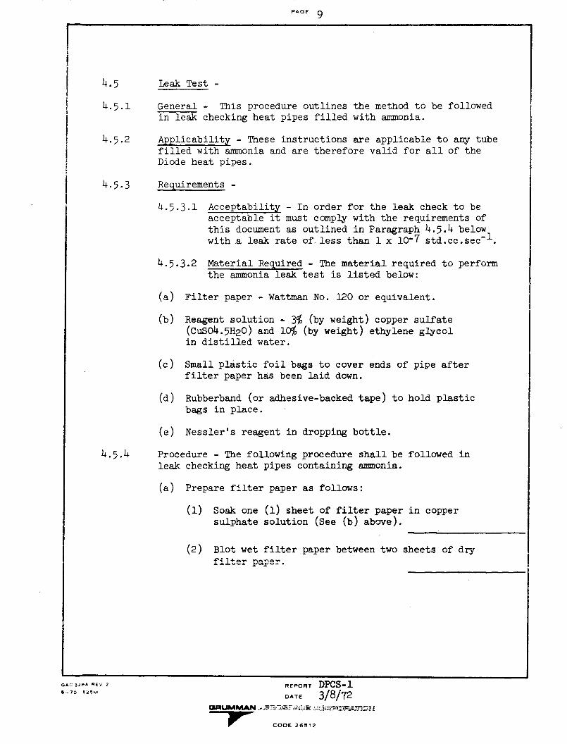
PAGF 9
4.5 Leak Test -
4.5.1 General - This procedure outlines the method to be followedin leak checking heat pipes filled with ammonia.
4.5.2 Applicability - These instructions are applicable to any tubefilled with ammonia and are therefore valid for all of theDiode heat pipes.
4.5.3 Requirements -
4.5.3.1 Acceptability - In order for the leak check to beacceptable it must comply with the requirements ofthis document as outlined in Paragraph 4.5.4 belowwith a leak rate of less than 1 x 10⁻⁷ std.cc.sec
-1.
4.5.3.2 Material Required - The material required to performthe ammonia leak test is listed below:
(a) Filter paper - Wattman No. 120 or equivalent.
(b) Reagent solution - 3% (by weight) copper sulfate(CuSO4.5H20) and 10lO (by weight) ethylene glycolin distilled water.
(c) Small plastic foil bags to cover ends of pipe afterfilter paper has been laid down.
(d) Rubberband (or adhesive-backed tape) to hold plasticbags in place.
(e) Nessler's reagent in dropping bottle.
4.5.4 Procedure - The following procedure shall be followed inleak checking heat pipes containing ammonia.
(a) Prepare filter paper as follows:
(1) Soak one (1) sheet of filter paper in coppersulphate solution (See (b) above).
(2) Blot wet filter paper between two sheets of dryfilter paper.
cAC 32RA REV 2 REPORT DPCS-1~8- 70 (14!5mDATE 3/8/72
GRCUMM OAN DiTi;.OE 2-912i
r CODE 2f912
PA^GE 10
Procedure - (Cont'd.)
(3) Place wet filter paper in airtight container(to prevent evaporation) until ready for use.
(b) Cut filter paper into sheets approximately 1-1/2inches by 2 inches.
(c) Wrap filter paper from (b) above around ends of pipes.
(d) Cover ends of pipe and filter paper with small plasticbag and secure with rubberband or adhesive-backed tape.
(e) Leave ends of pipe covered for at least four hours.This should provide a leak sensitivity of approxi-mately 3.3 x 10⁻⁷ std.cc.sec- 1 .
(f) After at least four hours, remove plastic bag andfilter paper and observe filter paper for darkblue spots. If these spots are visible, a leakrate of - 3.3 x 10⁻⁷ std.cc. sec -1 has beenexceeded.
(g) If no dark blue spots are visible, drop a few dropsof Nessler's reagent on filter paper. If dark brownspots from8the reagent appear, then a leak rate of
3 x 10- std. cc. sec-
was exceeded.
Completion ofin log book.
Test - Upon satisfactory completion of the test, record
QA3S REV 2 EOR PC-AC 328A REV 2
8-70 25MREPORT DPCS-1DA T E 3/8/72
IUIMMA.N . . CODE, -. -26512
1 " CODE 265i2
4.5.4
I
PAGE 11
4.6 Certification or Evidence of Satisfactory Equipment: -After charging is completed, mark each successfully charged Heat Pipe inaccordance with applicable Grumman Quality Control Procedures.
5. INSPECTION REQUIREMENTS
5.1 Inspection:- Compliance with the applicable engineering drawingand with all procedures of Section 4 shall be verified by a Grumman QualityControl representative, who shall witness the charging of each diode.
REPORT DPCS-1DATE 3/8/72
Pr CODE 26512
GAC 328A -FV 2
2- 70 1 23M
I

PAGE 12
I FIGURE 1
VALVE A
CHARGEBOTTLE
GAC 3'2' REV 2
--70 125M
;ALVE B
REPORT DPCS-1
CE 23/8 /72
CODE 26512
DIODE
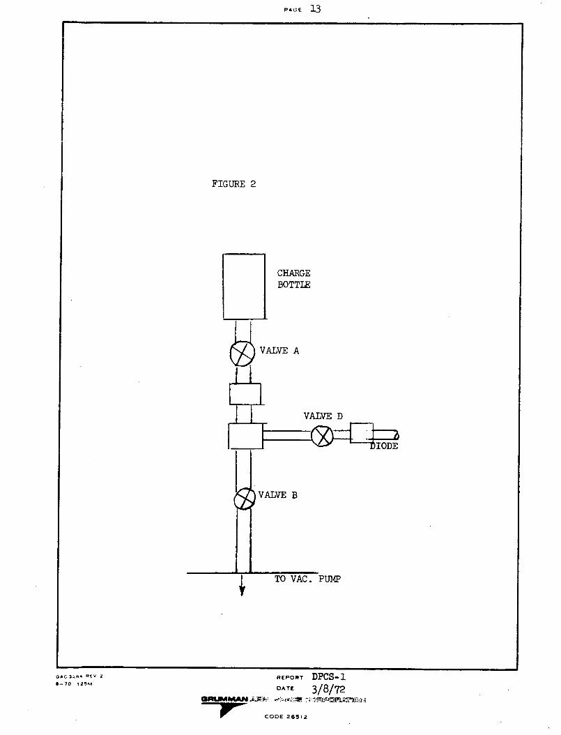
PIC'E 13
FIGURE 2
CHARGEBOTTLE
A
VALVE D
VALVE B
REPORT DPCS-1DATE 3/8/72
ARUMMAN'. .A -;. 9 COE 212
-r CODE 26512
GAC 348A REV 2
-- 70 125M
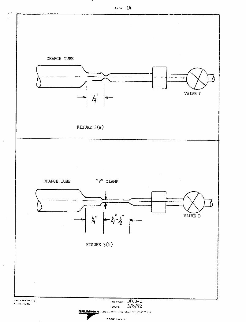
PAGE 14
CHARGE TUBE
VALVE D
FIGURE 3(a)
CHARGE TUBE "V" CLAMP
FIGURE 3(b)
REPORT DPCS-1
DATE 3/8/72
7- CODE 26512
GAC 328A REV 2
--70 125M
I
I
iIi
Ii
i
I
I
I
I
I
i
PAGE 1 OF I
CONTRACT REQUIREMENTS CONTRACT. ITEM MODEL CONTRACT NO.
Par. 4.3, SOW NAS 2-6493
APPENDIX Er -E
REPORT
DPM-3A 3-21-72DATE:
THERMAL PERFORMANCE TEST PLAN AND
PROCEDURE FOR THE ATFE THERMAL
DIODE HEAT PIPE
CODE 26512
PREPARED BY:
CHECKED BY:
B. Swerdlin C-X2-7? TECHNICAL APPROVAL:
J.McNamara, Q.E../C ? APPROVED BY: M.Tawil
APPROVED BY:
APPROVED BY:
REVISIONS
DATE REV.REVISIONS & ADDED PAGES REMARKSBY
5-1-72 B.S 4.2(b) and 4.2(c) - added tolerance
fB.S 4.3(b) omitted "as detailed in Fig. 3
It B.S. 4 .4(e) added tolerance comments
It"_ _ B.SB 4.4(f) changed recording time
"_ B.S to at least every 30 minutes
" B.S. Also changed -1800 F to -145 0 F
"_ B.S Table I - changed QgEV to 1.2_±0.1
and -1800 F to -1450F
GAC 324A REV 2
8.69 20M
GRUMMAN AEROSPACE CORPORATION
BETHPAGE. NEW YORK 11714
NO.
L J
DEPARTMENT: J
SECTION:
... , I/' , I, "

PA -F 1
1.0 SCOPE
1.1 General: - This test plan and procedure define the test procedureand data requirements for the thermal performance testing of the 4TFEThermal Diode Heat Pipes.
1.2 Applicability: - This test plan and procedure is applicable to thePrototype and Flight Diode Heat Pipes defined by Drawing AD-1411 -1000H. TheDiode will be part of the Advanced Thermal Control Flight Experiment on theATS-F Satellite.
1.3 Diode Description: - The Diode to be tested is made from stainlesssteel tubing and has outside diameters of 0.450 inch and 0.375 inch. Theshape of the Diode is a modified "L" shape. The longest dimension is approxi-mately 23 inches. The pipe is charged with Ammonia working fluid and has GFEsaddles attached to the evaporator and condenser.
1.4 Objective: - The objective of this test is to demonstrate com-pliance with the performance of PES-ATS-1-A. The Diode Heat Pipe shall betested under two thermal load conditions as follows:
Condition A: Direct Mode (Level + .250 inch)( - .000 )
Condition B: Reverse Mode (Level + .250 inch)( - .000 )
GAC 328A PEV 2
8--70 125MREPORT DPM-3ADATE
OIULMMAIN I- i:. - : X :; !Ei 25 i_2:,; iO
" CODE 26512
III
Ii
iIII
i
J
I
I
I
PAGE 2
2.0 APPLICABLE DOCUMENTS
2.1 Government Documents
Specifications
PES-ATS-1-A ATFE/Thermal DiodeInterface Specification
2.2 Grumman Documents
Drawing
AD-1411-1000-H Diode Heat PipeLiquid Blockage Configuration
ICD AD-1411-1001-A Interface Control Drawing
3.0 REQUIREMENTS
3.1 General: - The Diode shall be tested in accordance with therequirements specified in Section 4.
3.2 Test Environment: - The Diode shall be tested in two environments.Condition A shall be tested in standard atmospheric conditions and ConditionB shall be tested in a vacuum chamber of at least 10-5 mm of mercury.
3.3 Test Conditions: - The Diode shall be subjected to thermal loadconditions as specified in Table I.
3.4 Acceptance Criteria: - Two conditions shall determine complianceto the test conditions as specified in 3.3. These conditions are:
(a) Temperature Difference (AT): Compliance to the a T require-ment of Condition A of Table I shall be based on averageabsorber saddle temperature to average shelf saddle tempera-ture.
(b) Reverse Heat Flow: Compliance to the Reverse Heat Flowrequirement of Condition B of Table I shall be based onan average rate under steady state conditions. This rateshall be calculated from temperature measurements on thediode.
GAC 32RA RFV 2
8--70 12IMREPORT DPM-3ADATE
*aRUM ",4MAN.,,;.PF ,'ODE 2
71p CODE 26512
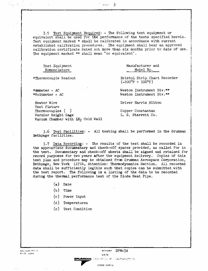
FA;' 3
3.5 Test Equipment Required: - The following test equipment orequivalent shall be used for the performance of the tests specified herein.Test equipment marked * shall be calibrated in accordance with currentestablished calibration procedures. The equipment shall bear an approvedcalibration certificate dated not more than six months prior to date of use.
The equipment marked ** shall mean "or equivalent".
Test EquipmentNomenclature
Manufacturer andModel No.
*Thermocouple Readout
*Ammeter - AC*Voltmeter - AC
Heater WireTest FixtureThermocouples ( )Vernier Height GageVacuum Chamber with LN2 Cold Wall
3.6 Test Facilities: - All 1Bethpage facilities.
Bristol Strip Chart Recorder(-2000 F + 100lF)
Weston Instrument Div.**Weston Instrument Div.**
Driver Harris Ribbon
Copper ConstantanL. S. Starrett Co.
testing shall be performed in the Grumman
3.7 Data Recording: - The results of the test shall be recorded inthe appropriate documentary and check-off spaces provided, as called for inthe text. Documentary and check-off sheets shall be signed and retained forrecord purposes for two years after the equipment delivery. Copies of thistest plan and procedure may be obtained from Grumman Aerospace Corporation,Bethpage, New York 11714, Attention: Thermodynamics Section. All recordeddata shall be sufficiently legible such that copies can be submitted withthe test report. The following is a listing of the data to be recordedduring the thermal performance test of the Diode Heat Pipe.
(a) Date
(b) Time
(c) Power Input
(d)
(e)
Temperatures
Test Condition
RE "ORT DPM-3ADATE
GRUMMtAN - - -tCODE 2 6512
- " CODE 26512
GAC 3.MA Ra 2
8-70 125M
PAGE 4
Prior to recording data, the Diode temperatures shall reach steady state as
achieved not sooner than 10 minutes after a power set point change. Asecond set of readings shall be taken within 5 minutes to establish the rela-tive stability of the Diode. In the event steady state conditions cannot beachieved, recording of data shall be determined by the GAC Test Engineerand Quality Control Engineer.
3.8 Test Summary: - Within five (5) days after completion of the per-formance test, a test summary shall be prepared which will contain testresults as well as test conclusions.
3.9 Test Reports: - Within thirty (30) days after completion of per-formance testing, a test report shall be prepared which will contain thefollowing:
(a) Test Objectives
(b) Test Description
(c) Test Assessment Criteria
(d) Test Results
(e) Conclusions
,c 37- v' 2571ŽIZ~M
RPFP-U- DPM-3ADATE
GRUMMAN -
Pr CODE 265.'
I . -s -- I--
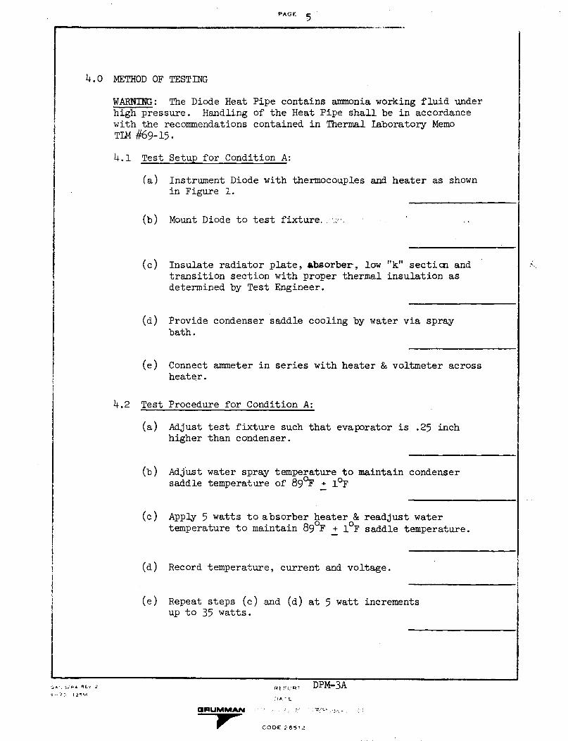
PAGE 5
4.0 METHOD OF TESTING
WARNING: The Diode Heat Pipe contains ammonia working fluid underhigh pressure. Handling of the Heat Pipe shall be in accordancewith the recommendations contained in Thermal laboratory MemoTIM #69-15.
4.1 Test Setup for Condition A:
(a) Instrument Diode with thermocouples and heater as shownin Figure 1.
(b) Mount Diode to test fixture. ..;
(c) Insulate radiator plate, absorber, lowtransition section with proper thermaldetermined by Test Engineer.
"k" section andinsulation as
(d) Provide condenser saddle cooling by water via spraybath.
(e) Connect ammeter in series with heater & voltmeter acrossheater.
4.2 Test Procedure for Condition A:
(a) Adjust test fixture such that evaporator is .25 inchhigher than condenser.
(b) Adjust water spray temperature to maintain condensersaddle temperature of 890 F + 1°F
(c) Apply 5 watts to absorber heater & readjust watertemperature to maintain 890 F + 10 F saddle temperature.
(d) Record temperature, current and voltage.
(e) Repeat steps (c) and (d) at 5 watt incrementsup to 35 watts.
?:9 R DPM-3A.)A. -E
GRUMMAN : - : .- '" ;. -. :
lCODE 26512
N,I
I
iI
I
G*- 32PA REv 2
t ..71 ! } 2
il
II
I
J
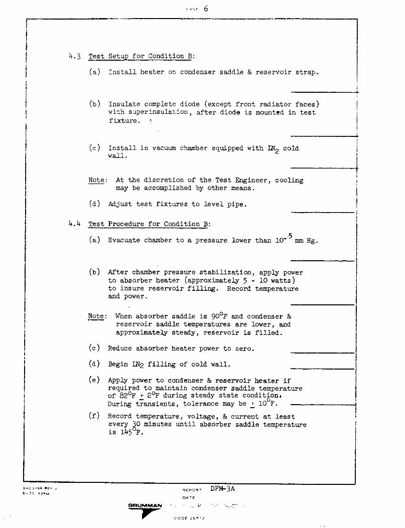
- 6
4.3 Test Setup for Condition B:
(a) Install heater on condenser saddle & reservoir strap.
(b) Insulate complete diode (except front radiator faces)with superinsulation, after diode is mounted in test
fixture.
(c) Install in vacuum chamber equipped with LN2 coldwall.
Note: At the discretion of the Test Engineer, coolingmay be accomplished by other means.
(d) Adjust test fixtures to level pipe.
4.4 Test Procedure for Condition B:
(a) Evacuate chamber to a pressure lower than 10-:5 mm Hg.
(b) After chamber pressure stabilization, apply powerto absorber heater (approximately 5 - 10 watts)to insure reservoir filling. Record temperatureand power.
Note: When absorber saddle is 90°F and condenser &reservoir saddle temperatures are lower, and
approximately steady, reservoir is filled.
(c) Reduce absorber heater power to zero.
(d) Begin IN2 filling of cold wall.
(e) Apply power to condenser & reservoir heater ifrequired to maintain condenser saddle temperatureof 820 F + 20 F during steady state condition,During transients, tolerance may be l10 F.
(f) Record temperature, voltage, & current at leastevery 30 minutes until absorber saddle temperatureis 145 F.
GAC 0A- REV .
d-- 7d 2%kU
GRUMMAN
REO)R DPM-3ADATE
A F
(CO0E i 6i 2
- - |~_
iI
I
I4II
i
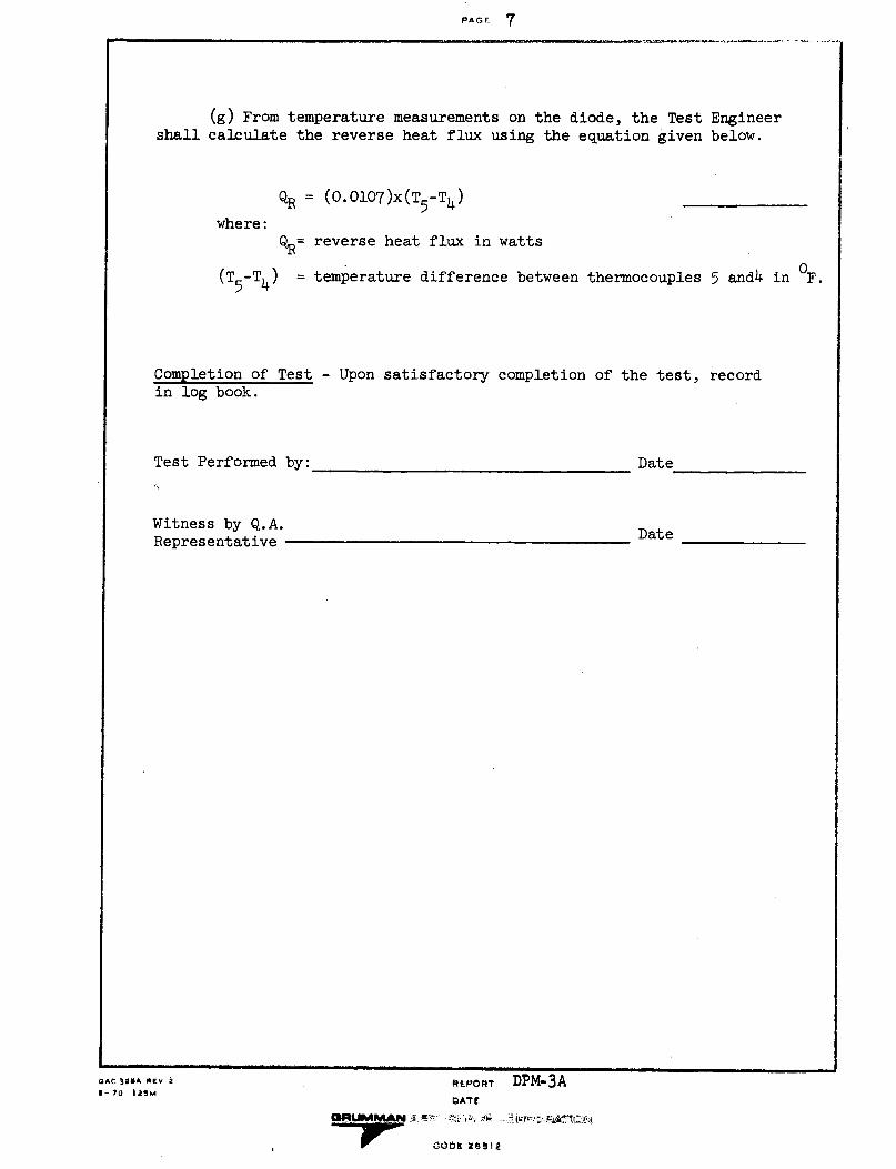
PAEF 7
(g) From temperature measurements on the diode, the Test Engineershall calculate the reverse heat flux using the equation given below.
where:
QR = (0.0107)x(T5 -T4 )
Q%= reverse heat flux in watts
(T5 -T4) = temperature difference between thermocouples 5 and4 in OF.
Completion of Test - Upon satisfactory completion of the test, recordin log book.
Test Performed by: Date
Witness by Q.A.Representative Date
EPuo.T DPM-3AbATE
iAt j0aA *Ev 2
7-70 1i2M

PAGE 8
TABIE I
Test Requirements *
Mode Q(watts)
Direct 20 + 2
TAbs-Saddle(Max)
105°F
TCond-Saddle
89°F
Reverse 1.2 + 0.1 -145°F 82 + 2°F(max)
Shutoff - 5 BTU
*PES-ATS-1-A, ATFE/Thermal1 September 1971
Diode Interface Specification,
REPORT DPM-3ADATE
COBRUMMAN :*- .; ...C- 2, ;r
- - CODE 26512
Condition
A
B
l;BC- 2-.? L'7I 2
e-7O 12;M
t
iIi
II
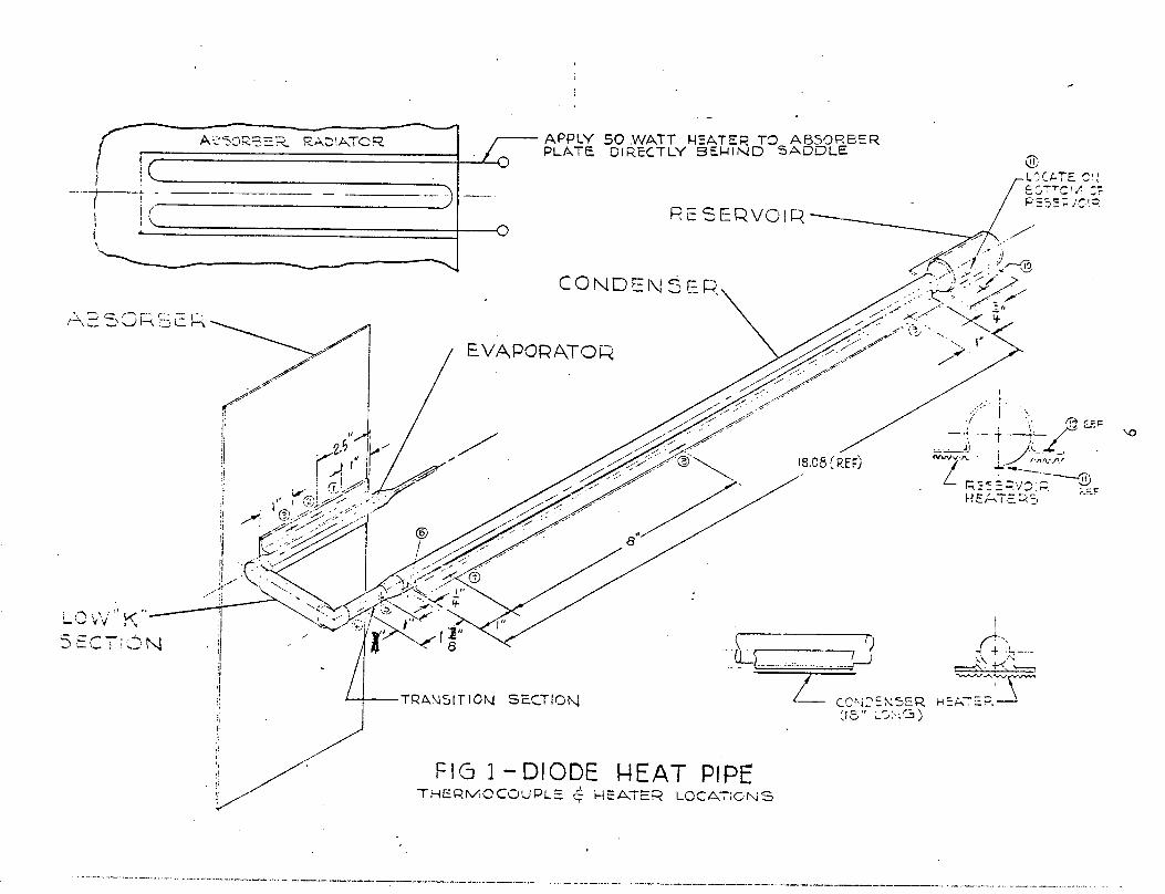
9,11IJ
Ii i
ff. \'
_ I
O
OO_
LIz I
0 Oa0L
i
'x--.
,II .I
.11 ) I . I 1 ! 1
IEcy~
,
ui -i
0)-
L I J
(I)I-
Li
a_ L
u o-J
I4I,,
U
o I
-L L
:p
I7
!i.~~
~
:( 7
, ) >,
-Vf)
.-> I-(1)
() 1i.
.- Ir)
LiJLID0 -
44U)
KZ
tl-I)
C. 4
(I
itiIi
I 01LI--
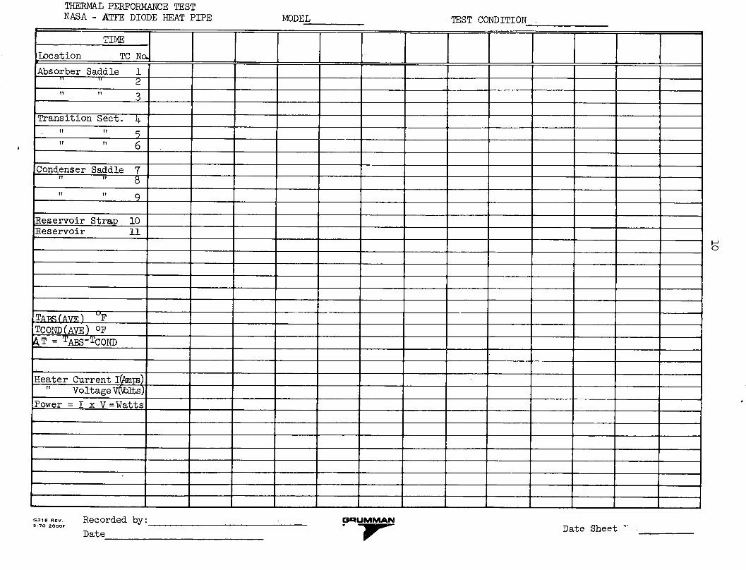
10
m--o
---
a
0 a)
-Pra
00
I
r30
Fi aaa
) 4-P
a)L
w
C
0r · 1I
~-g
o~ ~~4
d. :
: _(
E(
41 1
1 1 E-.4 I
I I
I ol
I I
I p rt I jlm I
I I
E-11 EU
-1d I
4 W-1
I o..
I
-4-a,a,toa,-I',r-
q
IaoIdC1)0a,P
rA
a,
-4-
>0
wo,0
.O,
r0
G