System Sequence Diagrams - rose-hulman.edu · frame Guard Return Values Q2 Life Line. From Use Case...
11
System Sequence Diagrams Curt Clifton Rose-Hulman Institute of Technology Q1
Transcript of System Sequence Diagrams - rose-hulman.edu · frame Guard Return Values Q2 Life Line. From Use Case...

System Sequence DiagramsCurt Clifton
Rose-Hulman Institute of Technology
Q1
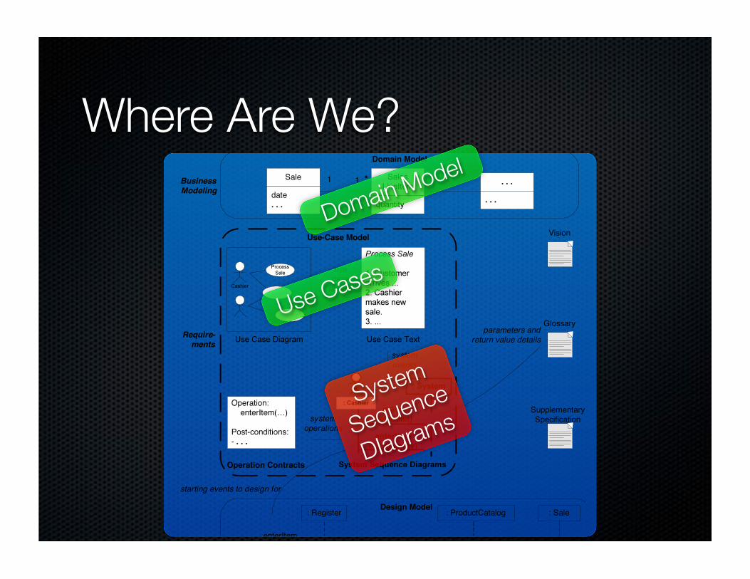
Where Are We?
Use Cases
Domain Model
System
Sequence
DIagrams

System Sequence Diagrams
Illustrate the input and output events related to the
systems under discussion
Show large-scale operations of systems
Starting point for designing collaborating objects

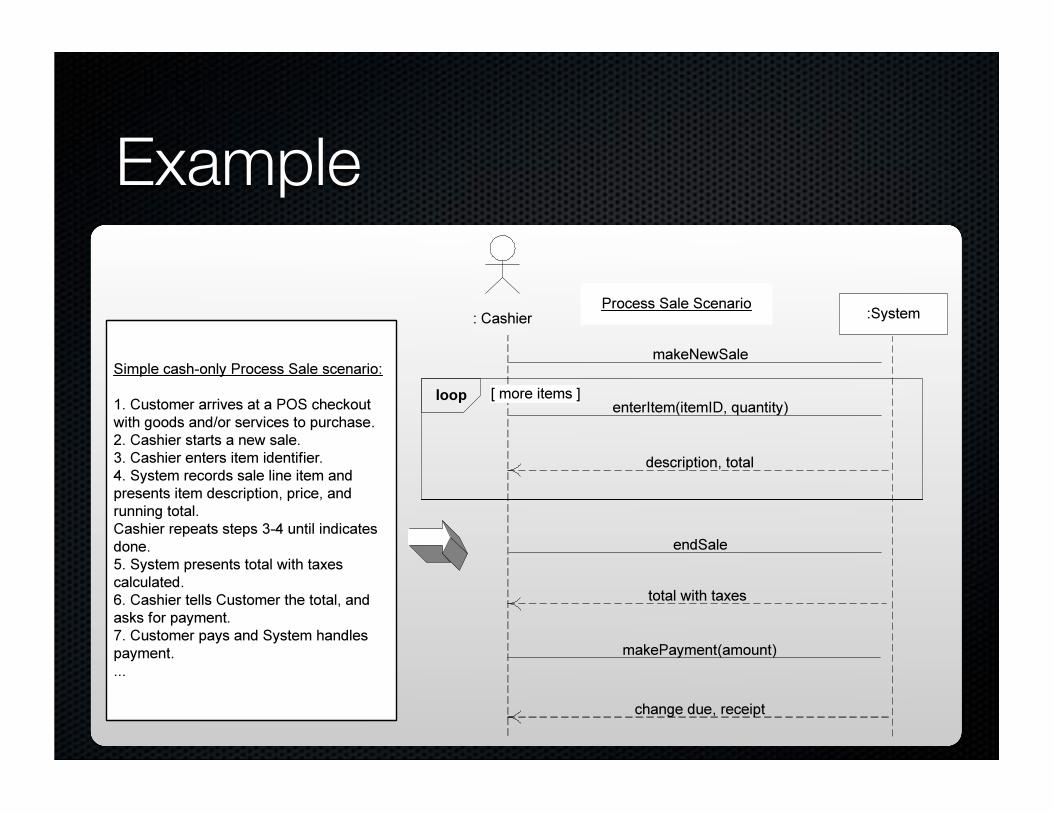
:Cashier :System
makeNewSale
Process Sale Scenario
enterItem(itemID, quantity)
description, total
endSale
total with taxes
loop [ more items ]
SSD NotationExternal Actor
Black Box Object
Message with
Parameters
Interaction
frame
Guard
Return Values
Q2
Life Line

From Use Case to SSD
Use cases describe how external actors will interact
with our system
Actors generate system events requesting some
system operation
For a single scenario of a use case, SSD shows
system events and their order
All systems treated as black boxes;
only show events that cross system boundaries
Also inter-
system events
Q3
Example

Why Draw an SSD?
Software systems react to three things:
External input events (a.k.a., system events)
from actors
Timer events
Faults or exceptions
SSD captures system behavior: a description of what
a system does, not how it does it
Q4,5

SSD Tips
Show one scenario of a use case
Show events as intentions, not physical implementation
E.g., enterItem, not scan
presentCredentials, not enterPassword
Start system event names with verbs
Can model collaborations between systems
Give details in the Glossary
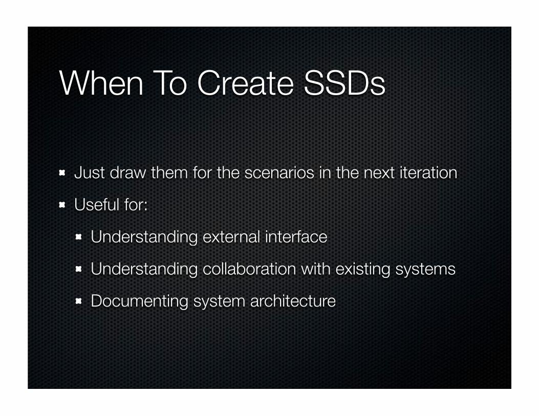
When To Create SSDs
Just draw them for the scenarios in the next iteration
Useful for:
Understanding external interface
Understanding collaboration with existing systems
Documenting system architecture

Key Idea
System Sequence Diagrams are a bridge
From functional Use Cases
To an object-oriented System Model
Providing requirements traceability
http://justinsomnia.org/2007/10/golden-gate-bridge-at-night/

Examples…
Q6,7


![SGX-SSD: A Policy-based Versioning SSD with Intel SGX · Existing Solution: Versioning SSD[BVSSD, Systor12], [Project Almanac, Eurosys19] §Versioning SSD implements versioning system](https://static.fdocuments.us/doc/165x107/60ae19522c0a8f54c27ad581/sgx-ssd-a-policy-based-versioning-ssd-with-intel-sgx-existing-solution-versioning.jpg)