SYSTEM DESCRIPTION AND INSTALLATION MANUAL T · SYSTEM DESCRIPTION AND INSTALLATION MANUAL ......
261
SYSTEM DESCRIPTION AND INSTALLATION MANUAL T 3 CAS/Part No.9005000 Table 4-1: T 3 CAS Computer Unit Interface Description (cont) (Applicable to Part No. 9005000-10000, -10101, -10202, -10204, and -11203) Connector Pin Designation Functional Description RMP-3A Corrective Visual Advisory Discrete Output (NO) The visual advisory discrete outputs are ground/open-type discretes (Note 3) used to operate the annunciator lights on the displays. This output is activated whenever a corrective aural advisory is issued. The output remains active for the duration of the advisory unless cancelled by the cancel discrete at RMP-3D. Only one visual advisory is active at a time. The active state is ground and the inactive state is open. RMP-3B Preventive Visual Advisory Discrete Output (NO) Same as RMP-3A, except this discrete is activated whenever a preventative aural advisory is issued. RMP-3C Traffic Visual Advisory Discrete Output (NO) Same as RMP-3A, except this discrete is active during a traffic advisory. RMP-3D Cancel Discrete Input (NO) This input discrete provides a means of canceling TCAS aural and visual alerts. It should be connected to a cancel button (momentary ground type), if used. Groundprox/Windshear has priority over the cancel button. Open is the inactive state and a momentary ground (less than 50 ohms) produces the active state, canceling any active aural or visual alert. RMP-3E Reserved Discrete Output (Lamp Driver) RMP-3F, 3G 600-Ohm Audio Output: [RMP-3F (HI), RMP-3G (LO)] This is a synthesized voice output supplied by the T 3 CAS computer unit. Its level is programmable up to 80 mW into a 600-ohm audio distribution system. All aural traffic and resolution advisories are annunciated over this output. See RBP-7A for audio level programming. RMP-3H Program Pin Parity Input RMP-3J Program Pin Parity Input RMP-3K Traffic Selection Device Input #1 (Rotate Right) RMP-4A Reserved RMP-4B Reserved RMP-4C Reserved RMP-4D Reserved RMP-4E Reserved RMP-4F Reserved RMP-4G Reserved Pub. No. 8600200-001, Revision 004 34-45-29 4-13 04 Nov 2014 Use or disclosure of information on this page is subject to the restrictions in the proprietary notice of this document.
Transcript of SYSTEM DESCRIPTION AND INSTALLATION MANUAL T · SYSTEM DESCRIPTION AND INSTALLATION MANUAL ......

SYSTEM DESCRIPTION AND INSTALLATION MANUAL
T3CAS/Part No.9005000
Table 4-1: T3CAS Computer Unit Interface Description (cont) (Applicable to Part No. 9005000-10000, -10101, -10202, -10204, and -11203)
Connector Pin
Designation Functional Description
RMP-3A Corrective Visual Advisory Discrete Output (NO) The visual advisory discrete outputs are ground/open-type discretes (Note 3) used to operate the annunciator lights on the displays. This output is activated whenever a corrective aural advisory is issued. The output remains active for the duration of the advisory unless cancelled by the cancel discrete at RMP-3D. Only one visual advisory is active at a time. The active state is ground and the inactive state is open.
RMP-3B Preventive Visual Advisory Discrete Output (NO) Same as RMP-3A, except this discrete is activated whenever a preventative aural advisory is issued.
RMP-3C Traffic Visual Advisory Discrete Output (NO) Same as RMP-3A, except this discrete is active during a traffic advisory.
RMP-3D Cancel Discrete Input (NO) This input discrete provides a means of canceling TCAS aural and visual alerts. It should be connected to a cancel button (momentary ground type), if used. Groundprox/Windshear has priority over the cancel button. Open is the inactive state and a momentary ground (less than 50 ohms) produces the active state, canceling any active aural or visual alert.
RMP-3E Reserved Discrete Output (Lamp Driver) RMP-3F, 3G 600-Ohm Audio Output: [RMP-3F (HI), RMP-3G (LO)]
This is a synthesized voice output supplied by the T3CAS computer unit. Its level is programmable up to 80 mW into a 600-ohm audio distribution system. All aural traffic and resolution advisories are annunciated over this output. See RBP-7A for audio level programming.
RMP-3H Program Pin Parity Input RMP-3J Program Pin Parity Input RMP-3K Traffic Selection Device Input #1 (Rotate Right) RMP-4A Reserved RMP-4B Reserved RMP-4C Reserved RMP-4D Reserved RMP-4E Reserved RMP-4F Reserved RMP-4G Reserved
Pub. No. 8600200-001, Revision 004 34-45-29 4-13
04 Nov 2014 Use or disclosure of information on this page is subject to the restrictions in the proprietary notice of this document.
SYSTEM DESCRIPTION AND INSTALLATION MANUAL
T3CAS/Part No.9005000
Table 4-1: T3CAS Computer Unit Interface Description (cont) (Applicable to Part No. 9005000-10000, -10101, -10202, -10204, and -11203)
Connector Pin
Designation Functional Description
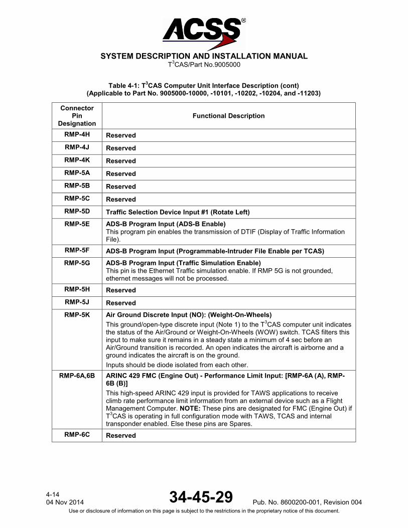
RMP-4H Reserved RMP-4J Reserved RMP-4K Reserved RMP-5A Reserved RMP-5B Reserved RMP-5C Reserved RMP-5D Traffic Selection Device Input #1 (Rotate Left) RMP-5E ADS-B Program Input (ADS-B Enable)
This program pin enables the transmission of DTIF (Display of Traffic Information File).
RMP-5F ADS-B Program Input (Programmable-Intruder File Enable per TCAS) RMP-5G ADS-B Program Input (Traffic Simulation Enable)
This pin is the Ethernet Traffic simulation enable. If RMP 5G is not grounded, ethernet messages will not be processed.
RMP-5H Reserved RMP-5J Reserved RMP-5K Air Ground Discrete Input (NO): (Weight-On-Wheels)
This ground/open-type discrete input (Note 1) to the T3CAS computer unit indicates the status of the Air/Ground or Weight-On-Wheels (WOW) switch. TCAS filters this input to make sure it remains in a steady state a minimum of 4 sec before an Air/Ground transition is recorded. An open indicates the aircraft is airborne and a ground indicates the aircraft is on the ground. Inputs should be diode isolated from each other.
RMP-6A,6B ARINC 429 FMC (Engine Out) - Performance Limit Input: [RMP-6A (A), RMP-6B (B)] This high-speed ARINC 429 input is provided for TAWS applications to receive climb rate performance limit information from an external device such as a Flight Management Computer. NOTE: These pins are designated for FMC (Engine Out) if T3CAS is operating in full configuration mode with TAWS, TCAS and internal transponder enabled. Else these pins are Spares.
RMP-6C Reserved
4-14 04 Nov 2014 34-45-29 Pub. No. 8600200-001, Revision 004
Use or disclosure of information on this page is subject to the restrictions in the proprietary notice of this document.
SYSTEM DESCRIPTION AND INSTALLATION MANUAL
T3CAS/Part No.9005000
Table 4-1: T3CAS Computer Unit Interface Description (cont) (Applicable to Part No. 9005000-10000, -10101, -10202, -10204, and -11203)
Connector Pin
Designation Functional Description
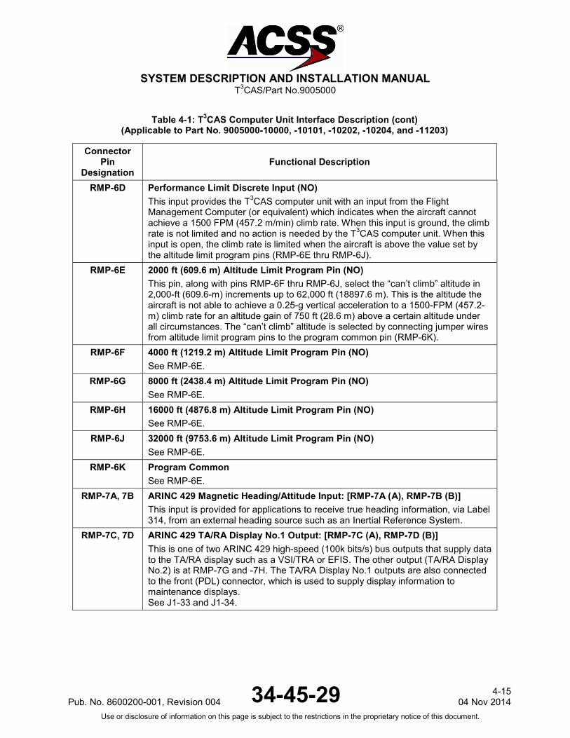
RMP-6D Performance Limit Discrete Input (NO) This input provides the T3CAS computer unit with an input from the Flight Management Computer (or equivalent) which indicates when the aircraft cannot achieve a 1500 FPM (457.2 m/min) climb rate. When this input is ground, the climb rate is not limited and no action is needed by the T3CAS computer unit. When this input is open, the climb rate is limited when the aircraft is above the value set by the altitude limit program pins (RMP-6E thru RMP-6J).
RMP-6E 2000 ft (609.6 m) Altitude Limit Program Pin (NO) This pin, along with pins RMP-6F thru RMP-6J, select the “can’t climb” altitude in 2,000-ft (609.6-m) increments up to 62,000 ft (18897.6 m). This is the altitude the aircraft is not able to achieve a 0.25-g vertical acceleration to a 1500-FPM (457.2-m) climb rate for an altitude gain of 750 ft (28.6 m) above a certain altitude under all circumstances. The “can’t climb” altitude is selected by connecting jumper wires from altitude limit program pins to the program common pin (RMP-6K).
RMP-6F 4000 ft (1219.2 m) Altitude Limit Program Pin (NO) See RMP-6E.
RMP-6G 8000 ft (2438.4 m) Altitude Limit Program Pin (NO) See RMP-6E.
RMP-6H 16000 ft (4876.8 m) Altitude Limit Program Pin (NO) See RMP-6E.
RMP-6J 32000 ft (9753.6 m) Altitude Limit Program Pin (NO) See RMP-6E.
RMP-6K Program Common See RMP-6E.
RMP-7A, 7B ARINC 429 Magnetic Heading/Attitude Input: [RMP-7A (A), RMP-7B (B)] This input is provided for applications to receive true heading information, via Label 314, from an external heading source such as an Inertial Reference System.
RMP-7C, 7D ARINC 429 TA/RA Display No.1 Output: [RMP-7C (A), RMP-7D (B)] This is one of two ARINC 429 high-speed (100k bits/s) bus outputs that supply data to the TA/RA display such as a VSI/TRA or EFIS. The other output (TA/RA Display No.2) is at RMP-7G and -7H. The TA/RA Display No.1 outputs are also connected to the front (PDL) connector, which is used to supply display information to maintenance displays. See J1-33 and J1-34.
Pub. No. 8600200-001, Revision 004 34-45-29 4-15
04 Nov 2014 Use or disclosure of information on this page is subject to the restrictions in the proprietary notice of this document.
SYSTEM DESCRIPTION AND INSTALLATION MANUAL
T3CAS/Part No.9005000
Table 4-1: T3CAS Computer Unit Interface Description (cont) (Applicable to Part No. 9005000-10000, -10101, -10202, -10204, and -11203)
Connector Pin
Designation Functional Description
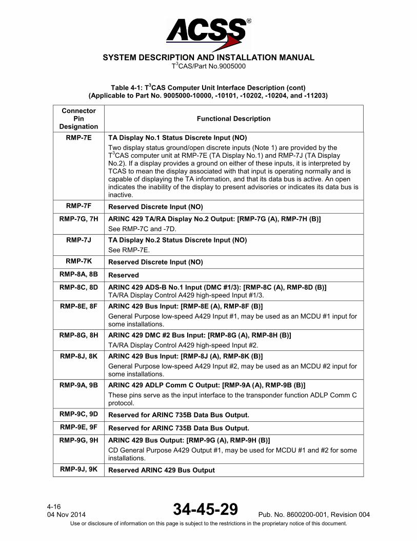
RMP-7E TA Display No.1 Status Discrete Input (NO) Two display status ground/open discrete inputs (Note 1) are provided by the T3CAS computer unit at RMP-7E (TA Display No.1) and RMP-7J (TA Display No.2). If a display provides a ground on either of these inputs, it is interpreted by TCAS to mean the display associated with that input is operating normally and is capable of displaying the TA information, and that its data bus is active. An open indicates the inability of the display to present advisories or indicates its data bus is inactive.
RMP-7F Reserved Discrete Input (NO) RMP-7G, 7H ARINC 429 TA/RA Display No.2 Output: [RMP-7G (A), RMP-7H (B)]
See RMP-7C and -7D. RMP-7J TA Display No.2 Status Discrete Input (NO)
See RMP-7E. RMP-7K Reserved Discrete Input (NO)
RMP-8A, 8B Reserved RMP-8C, 8D ARINC 429 ADS-B No.1 Input (DMC #1/3): [RMP-8C (A), RMP-8D (B)]
TA/RA Display Control A429 high-speed Input #1/3. RMP-8E, 8F ARINC 429 Bus Input: [RMP-8E (A), RMP-8F (B)]
General Purpose low-speed A429 Input #1, may be used as an MCDU #1 input for some installations.
RMP-8G, 8H ARINC 429 DMC #2 Bus Input: [RMP-8G (A), RMP-8H (B)] TA/RA Display Control A429 high-speed Input #2.
RMP-8J, 8K ARINC 429 Bus Input: [RMP-8J (A), RMP-8K (B)] General Purpose low-speed A429 Input #2, may be used as an MCDU #2 input for some installations.
RMP-9A, 9B ARINC 429 ADLP Comm C Output: [RMP-9A (A), RMP-9B (B)] These pins serve as the input interface to the transponder function ADLP Comm C protocol.
RMP-9C, 9D Reserved for ARINC 735B Data Bus Output. RMP-9E, 9F Reserved for ARINC 735B Data Bus Output. RMP-9G, 9H ARINC 429 Bus Output: [RMP-9G (A), RMP-9H (B)]
CD General Purpose A429 Output #1, may be used for MCDU #1 and #2 for some installations.
RMP-9J, 9K Reserved ARINC 429 Bus Output
4-16 04 Nov 2014 34-45-29 Pub. No. 8600200-001, Revision 004
Use or disclosure of information on this page is subject to the restrictions in the proprietary notice of this document.
SYSTEM DESCRIPTION AND INSTALLATION MANUAL
T3CAS/Part No.9005000
Table 4-1: T3CAS Computer Unit Interface Description (cont) (Applicable to Part No. 9005000-10000, -10101, -10202, -10204, and -11203)
Connector Pin
Designation Functional Description
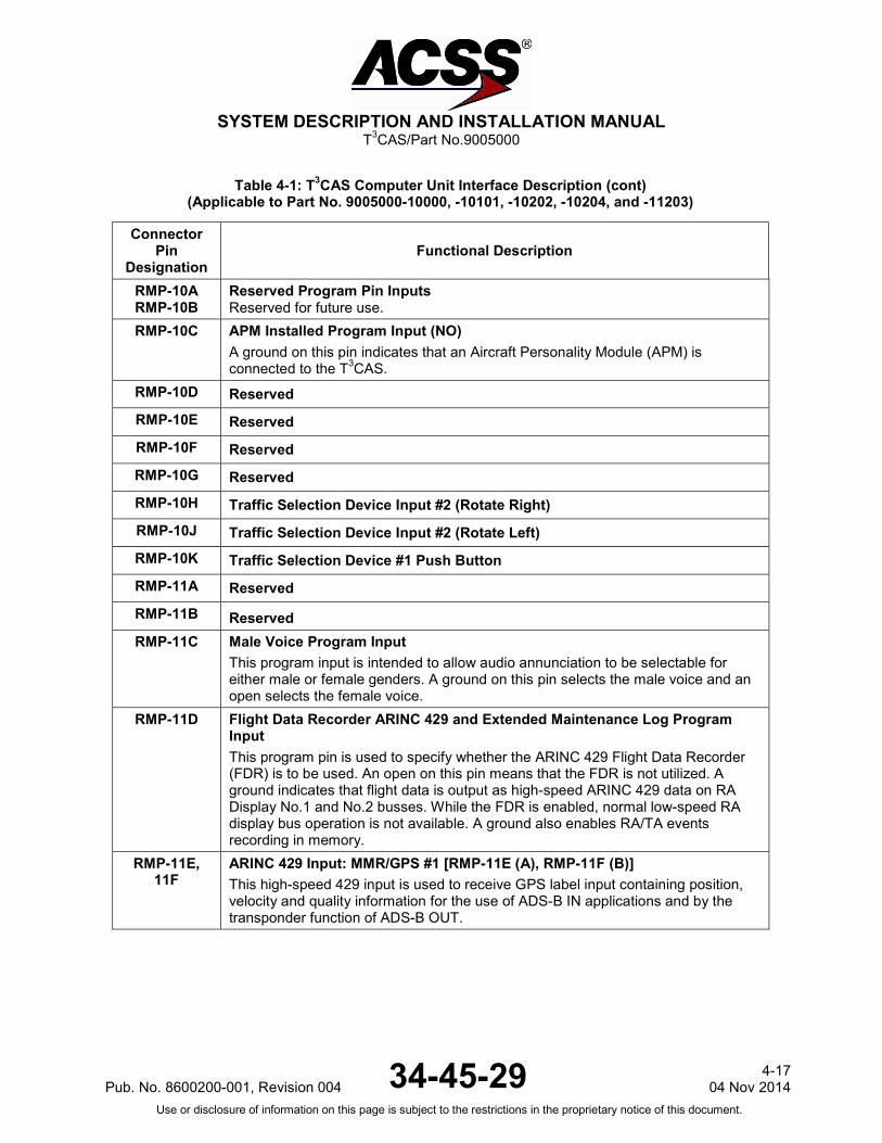
RMP-10A RMP-10B
Reserved Program Pin Inputs Reserved for future use.
RMP-10C APM Installed Program Input (NO) A ground on this pin indicates that an Aircraft Personality Module (APM) is connected to the T3CAS.
RMP-10D Reserved RMP-10E Reserved RMP-10F Reserved RMP-10G Reserved RMP-10H Traffic Selection Device Input #2 (Rotate Right) RMP-10J Traffic Selection Device Input #2 (Rotate Left) RMP-10K Traffic Selection Device #1 Push Button RMP-11A Reserved RMP-11B Reserved RMP-11C Male Voice Program Input
This program input is intended to allow audio annunciation to be selectable for either male or female genders. A ground on this pin selects the male voice and an open selects the female voice.
RMP-11D Flight Data Recorder ARINC 429 and Extended Maintenance Log Program Input This program pin is used to specify whether the ARINC 429 Flight Data Recorder (FDR) is to be used. An open on this pin means that the FDR is not utilized. A ground indicates that flight data is output as high-speed ARINC 429 data on RA Display No.1 and No.2 busses. While the FDR is enabled, normal low-speed RA display bus operation is not available. A ground also enables RA/TA events recording in memory.
RMP-11E, 11F
ARINC 429 Input: MMR/GPS #1 [RMP-11E (A), RMP-11F (B)] This high-speed 429 input is used to receive GPS label input containing position, velocity and quality information for the use of ADS-B IN applications and by the transponder function of ADS-B OUT.
Pub. No. 8600200-001, Revision 004 34-45-29 4-17
04 Nov 2014 Use or disclosure of information on this page is subject to the restrictions in the proprietary notice of this document.

SYSTEM DESCRIPTION AND INSTALLATION MANUAL
T3CAS/Part No.9005000
Table 4-1: T3CAS Computer Unit Interface Description (cont) (Applicable to Part No. 9005000-10000, -10101, -10202, -10204, and -11203)
Connector Pin
Designation Functional Description
RMP-11G, 11H
ARINC 429 Input: FMC #1:EIS [RMP-11G (A), RMP-11H (B)] This high-speed 429 input from the Flight Management Computer (FMC) Electronic Instrument System (EIS) provides position information from the FMC to the T3CAS. NOTE: These pins are designated for FMC #1 if T3CAS is operating in full configuration mode with TAWS, TCAS and internal transponder enabled. Else these pins are Spares.
RMP-11J, 11K
ARINC 429 Input: ADIRU #1/ADR [RMP-11J (A), RMP-11K (B)] This low-speed 429 input from the Air Data/Inertial Reference Unit (ADIRU) #1 provides altitude, airspeed, altitude rate and temperature information to the T3CAS. NOTE: These pins are designated for ADIRU #1 if T3CAS is operating in full configuration mode with TAWS, TCAS and internal transponder enabled. Else these pins are Spares.
RMP-12A Reserved Program Input Reserved for future use.
4-18 04 Nov 2014 34-45-29 Pub. No. 8600200-001, Revision 004
Use or disclosure of information on this page is subject to the restrictions in the proprietary notice of this document.

SYSTEM DESCRIPTION AND INSTALLATION MANUAL
T3CAS/Part No.9005000
Table 4-1: T3CAS Computer Unit Interface Description (cont) (Applicable to Part No. 9005000-10000, -10101, -10202, -10204, and -11203)
Connector Pin
Designation Functional Description
RMP-12B (Continues)
Radio Altimeter Type Select Program Input No.4 (NO) The T3CAS computer unit uses radio altitude to inhibit advisories and aural annunciation when in close proximity to the ground. This analog input No.1, as well as analog input No.2 can accept data as a dc voltage from several types of radio altimeters. Program pin RMP-12B is used, along with program pins RMP-12D, -12E, and -12F, to identify the type of analog radio altimeter installed. For T3CAS CU ARINC 552, Collins BCA, AHV-6, NR-AS-10A, LPIA, APN-232 CARA and metric type radio altimeters can be selected. The program pin inputs use ground/open logic levels. All unassigned program pin combinations are invalid and should not be selected. Pin RMP-6K can be used to supply a ground.
Program Pin RMP-12F RMP-12E RMP-12D RMP-12B Altimeter Type
Open Open Open Open ARINC 552/552A
Open Open Open Ground Collins BCA
Open Open Ground Open Metric Altimeter No.1
Open Open Ground Ground Unassigned
Open Ground Open Open Metric Altimeter No.2
Open Ground Open Ground Unassigned
Open Ground Ground Open Metric Altimeter No.3
Open Ground Ground Ground Unassigned
Ground Open Open Open Metric Altimeter No.4
Ground Open Open Ground Unassigned
Ground Open Ground Open Military AHV6 (Linear)
Ground Open Ground Ground Military AHV6 (Log)
Ground Ground Open Open Military NR-AS-10A (Alternate)
Ground Ground Open Ground Military APN-232 CARA
Ground Ground Ground Open Military LPIA
Ground Ground Ground Ground Military NR-AS-10A (Curve Fit)
The Radio Altitude sources listed are defined by the following:
Pub. No. 8600200-001, Revision 004 34-45-29 4-19
04 Nov 2014 Use or disclosure of information on this page is subject to the restrictions in the proprietary notice of this document.

SYSTEM DESCRIPTION AND INSTALLATION MANUAL
T3CAS/Part No.9005000
Table 4-1: T3CAS Computer Unit Interface Description (cont) (Applicable to Part No. 9005000-10000, -10101, -10202, -10204, and -11203)
Connector Pin
Designation Functional Description
RMP-12B (Continued) ARINC 552/552A
-20 < H < 480 ft: Voltage = [ 0.02 x (H + 20) ] V dc 480 < H < 2500 ft: Voltage = [ 10 x ( 1 + ln((H + 20)/500)) ] V dc Where H = Radio Altitude in ft.
Maximum Voltage output is 26.2 V dc at any height above 2500 ft .
Collins BCA
-20 < H < 500 ft: Voltage = [ 0.02 x (H + 20) ] V dc 500 < H < 2500 ft: Voltage = [ 10.4 + 0.003 x (H - 500) ] V dc
Where H = Radio Altitude in ft.
Maximum Voltage output is 26.2 V dc at any height above 2500 ft.
AHV 6 Linear
0.0 to 25.0 V dc: H = 200V - 20
Where H = Radio Altitude in ft and V = Voltage in V dc.
Radio Altimeter Type Select Program Input No.4 (NO)
AHV 6 Log 0.0 to 10.4 V dc: H = 50V - 20
> 10.4 to 18.09 V dc: H = EXP(0.1479V + 4.7289)
> 18.09 to 25 V dc: H = 695 + EXP(0.2532V + 2.1111)
Where H = Radio Altitude in ft and V = Voltage in V dc.
APN 232
0.0 to 27.0 V dc: H = 200V
Where H = Radio Altitude in ft and V = Voltage in V dc.
4-20 04 Nov 2014 34-45-29 Pub. No. 8600200-001, Revision 004
Use or disclosure of information on this page is subject to the restrictions in the proprietary notice of this document.
SYSTEM DESCRIPTION AND INSTALLATION MANUAL
T3CAS/Part No.9005000
Table 4-1: T3CAS Computer Unit Interface Description (cont) (Applicable to Part No. 9005000-10000, -10101, -10202, -10204, and -11203)
Connector Pin
Designation Functional Description
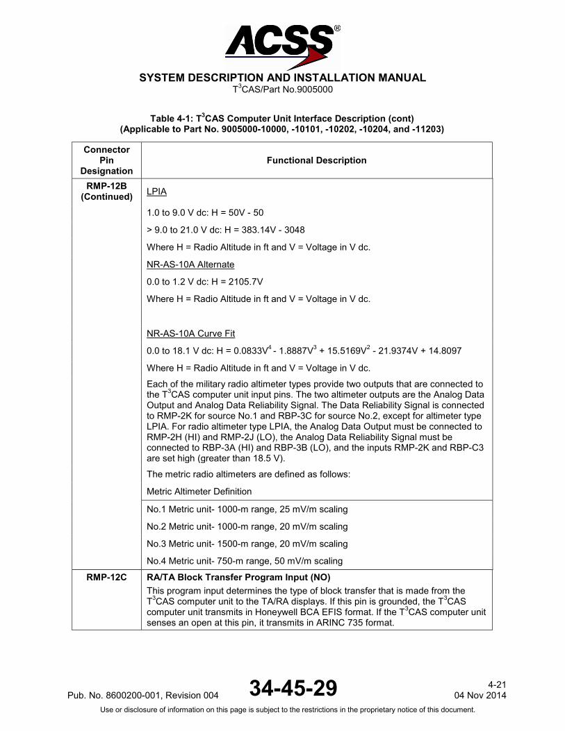
RMP-12B (Continued) LPIA
1.0 to 9.0 V dc: H = 50V - 50
> 9.0 to 21.0 V dc: H = 383.14V - 3048
Where H = Radio Altitude in ft and V = Voltage in V dc.
NR-AS-10A Alternate
0.0 to 1.2 V dc: H = 2105.7V
Where H = Radio Altitude in ft and V = Voltage in V dc.
NR-AS-10A Curve Fit
0.0 to 18.1 V dc: H = 0.0833V4 - 1.8887V3 + 15.5169V2 - 21.9374V + 14.8097
Where H = Radio Altitude in ft and V = Voltage in V dc.
Each of the military radio altimeter types provide two outputs that are connected to the T3CAS computer unit input pins. The two altimeter outputs are the Analog Data Output and Analog Data Reliability Signal. The Data Reliability Signal is connected to RMP-2K for source No.1 and RBP-3C for source No.2, except for altimeter type LPIA. For radio altimeter type LPIA, the Analog Data Output must be connected to RMP-2H (HI) and RMP-2J (LO), the Analog Data Reliability Signal must be connected to RBP-3A (HI) and RBP-3B (LO), and the inputs RMP-2K and RBP-C3 are set high (greater than 18.5 V).
The metric radio altimeters are defined as follows:
Metric Altimeter Definition
No.1 Metric unit- 1000-m range, 25 mV/m scaling
No.2 Metric unit- 1000-m range, 20 mV/m scaling
No.3 Metric unit- 1500-m range, 20 mV/m scaling
No.4 Metric unit- 750-m range, 50 mV/m scaling
RMP-12C
RA/TA Block Transfer Program Input (NO) This program input determines the type of block transfer that is made from the T3CAS computer unit to the TA/RA displays. If this pin is grounded, the T3CAS computer unit transmits in Honeywell BCA EFIS format. If the T3CAS computer unit senses an open at this pin, it transmits in ARINC 735 format.
Pub. No. 8600200-001, Revision 004 34-45-29 4-21
04 Nov 2014 Use or disclosure of information on this page is subject to the restrictions in the proprietary notice of this document.

SYSTEM DESCRIPTION AND INSTALLATION MANUAL
T3CAS/Part No.9005000
Table 4-1: T3CAS Computer Unit Interface Description (cont) (Applicable to Part No. 9005000-10000, -10101, -10202, -10204, and -11203)
Connector Pin
Designation Functional Description
RMP-12D Analog Radio Altimeter Type Select Program Input No.3 (NO) See RMP-12B.
RMP-12E Analog Radio Altimeter Type Select Program Input No.2 (NO) See RMP-12B.
RMP-12F Analog Radio Altimeter Type Select Program Input No.1 (NO) See RMP-12B.
RMP-12G Traffic Generator (Ethernet RX+) The T3CAS computer unit may be configured in some lab installations to receive simulated traffic over an Ethernet connection rather than RF interface. Also serves as the A615A Dataloader Interface.
RMP-12H Traffic Generator (Ethernet RX-) See RMP-12G.
RMP-12J Traffic Generator (Ethernet TX+) The T3CAS computer unit may be configured in some lab installations to transmit simulated traffic over an Ethernet connection rather than RF interface. Also serves as the A615A Dataloader Interface.
RMP-12K Traffic Generator (Ethernet TX-) See RMP-12J.
RMP-13A, 13B
RA Display No.1/ARINC 429 Data Recorder Output: [RMP-13A (A), RMP-13B (B)] These ARINC 429 outputs are configured to output either RA information or for use as an ARINC 429 data recorder function. The output is configured by program pin RMP-11D. When RMP-11D is open (standard configuration), the bus is configured for low-speed (12.5k bits/s) ARINC 429 operation and RA information is output according to the format specified for the RA display bus in ARINC 735. When RMP-11D is grounded, the bus is configured for high-speed (100k bits/s) ARINC 429 operation and the output supplies TA and RA information to a 429 data recorder.
RMP-13C, 13D
RA Display No.2/ARINC 429 Data Recorder Output: [RMP-13C (A), RMP-13D (B)] See RMP-13A.
RMP-13E RA Display No.2 Status Discrete Input (NO) This ground/open discrete input (Note 1) provides the functional status of RA Display No.2. A ground on this pin indicates a valid display. If this discrete is not provided by the RA display, connect to aircraft ground to prevent RA DISPLAY No.2 fail message during self-test.
4-22 04 Nov 2014 34-45-29 Pub. No. 8600200-001, Revision 004
Use or disclosure of information on this page is subject to the restrictions in the proprietary notice of this document.
SYSTEM DESCRIPTION AND INSTALLATION MANUAL
T3CAS/Part No.9005000
Table 4-1: T3CAS Computer Unit Interface Description (cont) (Applicable to Part No. 9005000-10000, -10101, -10202, -10204, and -11203)
Connector Pin
Designation Functional Description
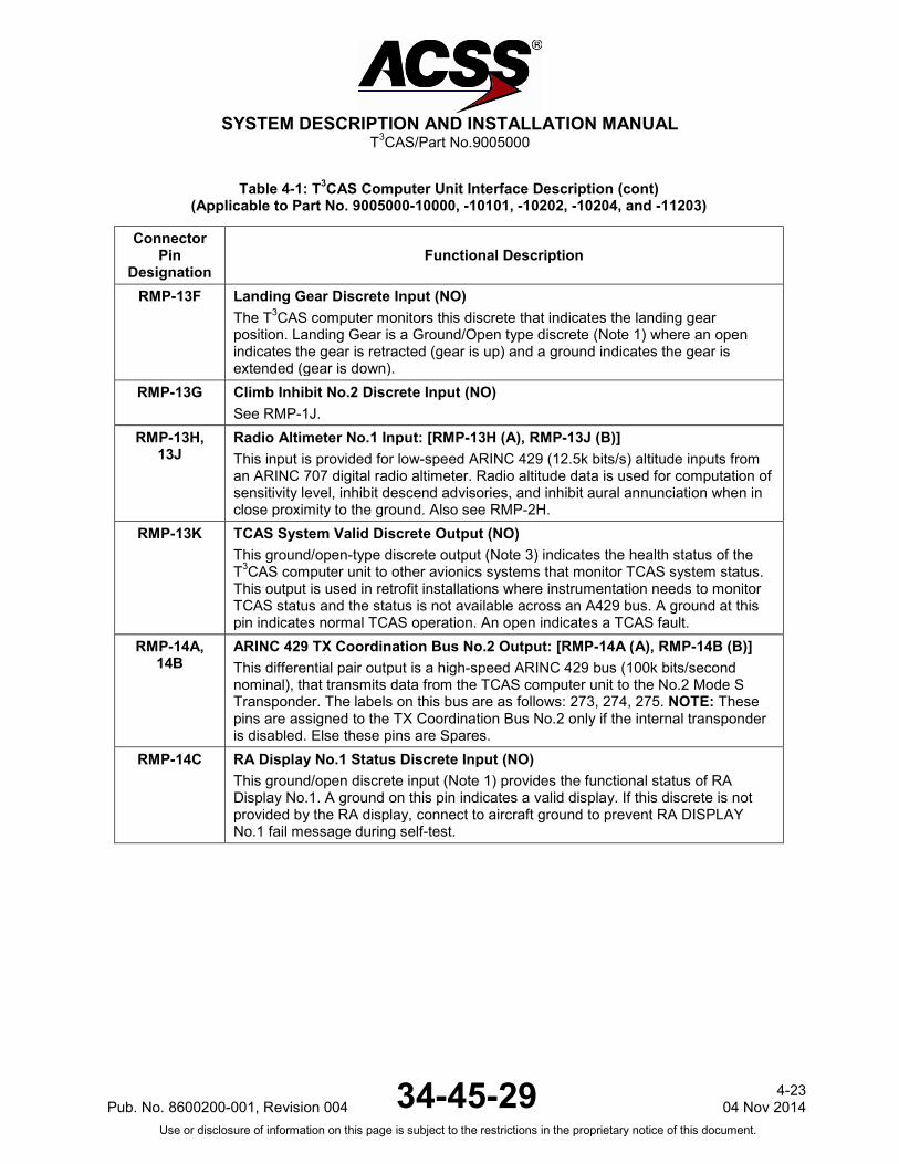
RMP-13F Landing Gear Discrete Input (NO) The T3CAS computer monitors this discrete that indicates the landing gear position. Landing Gear is a Ground/Open type discrete (Note 1) where an open indicates the gear is retracted (gear is up) and a ground indicates the gear is extended (gear is down).
RMP-13G Climb Inhibit No.2 Discrete Input (NO) See RMP-1J.
RMP-13H, 13J
Radio Altimeter No.1 Input: [RMP-13H (A), RMP-13J (B)] This input is provided for low-speed ARINC 429 (12.5k bits/s) altitude inputs from an ARINC 707 digital radio altimeter. Radio altitude data is used for computation of sensitivity level, inhibit descend advisories, and inhibit aural annunciation when in close proximity to the ground. Also see RMP-2H.
RMP-13K TCAS System Valid Discrete Output (NO) This ground/open-type discrete output (Note 3) indicates the health status of the T3CAS computer unit to other avionics systems that monitor TCAS system status. This output is used in retrofit installations where instrumentation needs to monitor TCAS status and the status is not available across an A429 bus. A ground at this pin indicates normal TCAS operation. An open indicates a TCAS fault.
RMP-14A, 14B
ARINC 429 TX Coordination Bus No.2 Output: [RMP-14A (A), RMP-14B (B)] This differential pair output is a high-speed ARINC 429 bus (100k bits/second nominal), that transmits data from the TCAS computer unit to the No.2 Mode S Transponder. The labels on this bus are as follows: 273, 274, 275. NOTE: These pins are assigned to the TX Coordination Bus No.2 only if the internal transponder is disabled. Else these pins are Spares.
RMP-14C RA Display No.1 Status Discrete Input (NO) This ground/open discrete input (Note 1) provides the functional status of RA Display No.1. A ground on this pin indicates a valid display. If this discrete is not provided by the RA display, connect to aircraft ground to prevent RA DISPLAY No.1 fail message during self-test.
Pub. No. 8600200-001, Revision 004 34-45-29 4-23
04 Nov 2014 Use or disclosure of information on this page is subject to the restrictions in the proprietary notice of this document.

SYSTEM DESCRIPTION AND INSTALLATION MANUAL
T3CAS/Part No.9005000
Table 4-1: T3CAS Computer Unit Interface Description (cont) (Applicable to Part No. 9005000-10000, -10101, -10202, -10204, and -11203)
Connector Pin
Designation Functional Description
RMP-14D, 14E
FCU #2: Selected Altitude 701/720 ARINC 429 Bus Input Optional TCAS input for ARINC 429 low-speed Selected Altitude labels 025 or 102. The TCAS must also receive ARINC 429 label 204 Baro Corrected Altitude on the XT coordination bus (either RMP-14F/G or RMP-14H/J) from the selected transponder. Also, the selected transponder must be passing label 204 Corrected Baro Altitude unchanged from the selected transponder’s active ARINC 429 air data source. TCAS cannot differentiate between label 102 Selected Altitude and label 102 GPS Vertical Dilution Of Precision (VDOP) so the system integrator must insure that the correct label 102 is provided to the TCAS. NOTE: These pins are designated for FCU #2 inputs if T3CAS is operating in full configuration mode with TAWS, TCAS and internal transponder enabled. Else these pins are Spares.
RMP-14F, 14G
ARINC 429 XT Coordination No.1 Input: [RMP-14F (A), RMP-14G (B)] This differential pair input is a high-speed ARINC 429 bus (100k bits/second nominal), that receives data from the No.1 Mode S Transponder.
RMP-14H, 14J
ARINC 429 XT Coordination No.2 Input: [RMP-14H (A), RMP-14J (B)] This differential pair input is a high-speed ARINC 429 bus (100k bits/second nominal), that receives data from the No.2 Mode S Transponder. NOTE: These pins are designated for XT Coordination No.2 if T3CAS is operating as TAWS and TCAS only with internal transponder disabled. Else these pins are Spares.
RMP-14K Traffic Selector #1 “Pull” Discrete. RMP-15A,
15B Reserved ARINC 429 Bus Output
RMP-15C, 15D
ARINC 429 Input: MMR/GPS #2 [RMP-15C (A), RMP-15D (B)] This high-speed 429 input is used to receive GPS label input containing position, velocity and quality information for the use of ADS-B IN applications and by the transponder function for ADS-B Out.
RMP-15E Thru
RMP-15H Reserved for TAWS/RWS use.
RMP-15J, 15K
ARINC 429 TX Coordination No.1 Output: [RMP-15J (A), RMP-15K (B)] This differential pair output is a high-speed ARINC 429 bus (100k bits/second nominal), that transmits data from the T3CAS computer unit to the No.1 Mode S Transponder. The labels on this bus are as follows: 273, 274, 275.
T3CAS Computer Unit Right Bottom Plug (RBP)
RBP-1A Thru
RBP-1D Reserved
4-24 04 Nov 2014 34-45-29 Pub. No. 8600200-001, Revision 004
Use or disclosure of information on this page is subject to the restrictions in the proprietary notice of this document.

SYSTEM DESCRIPTION AND INSTALLATION MANUAL
T3CAS/Part No.9005000
Table 4-1: T3CAS Computer Unit Interface Description (cont) (Applicable to Part No. 9005000-10000, -10101, -10202, -10204, and -11203)
Connector Pin
Designation Functional Description
RBP-1E Reserved RBP-1F, G GPS #2 Time Mark Input: [RBP-1F (A), RBP-1G (B)]
These RS422 differential pair inputs are provided to receive the Time Mark signal from an external GPS receiver in order to provide synchronization with other aircraft systems. This signal is also used to remove the latency error from GPS when available.
RBP-1H RA Data Word 270 Bit 18 Discrete Output This discrete output provides RA information to the ARINC 573 flight recorder. The output goes to the “ground” state each time its associated bit within the advisory field of the RA output words changes from a “zero” condition to a “one” condition. The output remains in the “ground” state for as long as the associated RA bit remains non-zero. This output is read by the flight recorder as either a series or shunt output. NOTE: The discrete is pulled up to +28 V dc in the “open” state.
RBP-1J RA Data Word 270 Bit 19 Discrete Output See RBP-1H.
RBP-1K RA Data Word 270 Bit 20 Discrete Output See RBP-1H.
RBP-2A
Program Pin Parity Input
RBP-2B Program Pin Parity Input
RBP-2C THRU
RBP-2G Reserved for TCAS/ADS-B Pin Strobing.
RBP-2H RA Data Word 270 Bit 21 Discrete Output See RBP-1H.
RBP-2J RA Data Word 270 Bit 22 Discrete Output See RBP-1H.
RBP-2K RA Data Word 270 Bit 23 Discrete Output See RBP-1H.
RBP-3A, 3B Radio Altimeter No.2 ARINC 552/Analog Input: [RBP-3A (HI), RBP-3B (LO)] See RMP-2H and -2J.
RBP-3C Radio Altimeter No.2 Valid Discrete Input (PO) See RMP-2H. Valid condition is greater than +18.5 V dc. Invalid is open.
RBP-3D, 3E Radio Altimeter No.2 Input: [RBP-3D (A), RBP-3E (B)] See RMP-13H. Also see RMP-2H.
Pub. No. 8600200-001, Revision 004 34-45-29 4-25
04 Nov 2014 Use or disclosure of information on this page is subject to the restrictions in the proprietary notice of this document.

SYSTEM DESCRIPTION AND INSTALLATION MANUAL
T3CAS/Part No.9005000
Table 4-1: T3CAS Computer Unit Interface Description (cont) (Applicable to Part No. 9005000-10000, -10101, -10202, -10204, and -11203)
Connector Pin
Designation Functional Description
RBP-3F Reserved for TCAS/ADS-B Pin Strobing. RBP-3G TCAS/ADS-B Parity. RBP-3H RA Data Word 270 Bit 24 Discrete Output
See RBP-1H. RBP-3J RA Data Word 270 Bit 25 Discrete Output
See RBP-1H. RBP-3K RA Data Word 270 Bit 26 Discrete Output
See RBP-1H. RBP-4A Magnetic/True Display Discrete Input (NO)
This pin is used to set the display to a magnetic or true orientation. Grounding this pin indicates a true orientation of the CDTI map display; opening this pin indicates a magnetic orientation of the CDTI map display.
RBP-4B Thru
RBP-4D
Reserved Discrete Inputs Reserved for future use.
RBP-4E Reserved Discrete Input Traffic Selector #2 Push Button
RBP-4F Reserved Discrete Input Traffic Selector #2 Pull Button
RBP-4G RA Display Test Inhibit Program Pin This program pin is used to determine if RA discrete monitoring will be inhibited during self-test. If this pin is connected to program common (ground), RA discrete self-test monitoring is inhibited. An open on this pin indicates RA discretes monitoring during self-test.
RBP-4H RA Data Word 270 Bit 27 Discrete Output See RBP-1H.
RBP-4J RA Data Word 270 Bit 28 Discrete Output See RBP-1H.
RBP-4K RA Data Word 270 Bit 29 Discrete Output See RBP-1H.
4-26 04 Nov 2014 34-45-29 Pub. No. 8600200-001, Revision 004
Use or disclosure of information on this page is subject to the restrictions in the proprietary notice of this document.
SYSTEM DESCRIPTION AND INSTALLATION MANUAL
T3CAS/Part No.9005000
Table 4-1: T3CAS Computer Unit Interface Description (cont) (Applicable to Part No. 9005000-10000, -10101, -10202, -10204, and -11203)
Connector Pin
Designation Functional Description
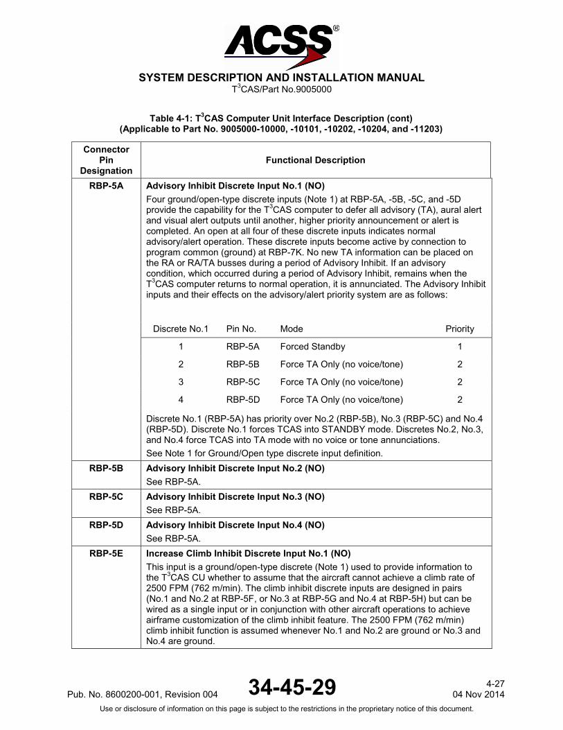
RBP-5A Advisory Inhibit Discrete Input No.1 (NO) Four ground/open-type discrete inputs (Note 1) at RBP-5A, -5B, -5C, and -5D provide the capability for the T3CAS computer to defer all advisory (TA), aural alert and visual alert outputs until another, higher priority announcement or alert is completed. An open at all four of these discrete inputs indicates normal advisory/alert operation. These discrete inputs become active by connection to program common (ground) at RBP-7K. No new TA information can be placed on the RA or RA/TA busses during a period of Advisory Inhibit. If an advisory condition, which occurred during a period of Advisory Inhibit, remains when the T3CAS computer returns to normal operation, it is annunciated. The Advisory Inhibit inputs and their effects on the advisory/alert priority system are as follows:
Discrete No.1 Pin No. Mode Priority
1 RBP-5A Forced Standby 1
2 RBP-5B Force TA Only (no voice/tone) 2
3 RBP-5C Force TA Only (no voice/tone) 2
4 RBP-5D Force TA Only (no voice/tone) 2
Discrete No.1 (RBP-5A) has priority over No.2 (RBP-5B), No.3 (RBP-5C) and No.4 (RBP-5D). Discrete No.1 forces TCAS into STANDBY mode. Discretes No.2, No.3, and No.4 force TCAS into TA mode with no voice or tone annunciations. See Note 1 for Ground/Open type discrete input definition.
RBP-5B Advisory Inhibit Discrete Input No.2 (NO) See RBP-5A.
RBP-5C Advisory Inhibit Discrete Input No.3 (NO) See RBP-5A.
RBP-5D Advisory Inhibit Discrete Input No.4 (NO) See RBP-5A.
RBP-5E Increase Climb Inhibit Discrete Input No.1 (NO) This input is a ground/open-type discrete (Note 1) used to provide information to the T3CAS CU whether to assume that the aircraft cannot achieve a climb rate of 2500 FPM (762 m/min). The climb inhibit discrete inputs are designed in pairs (No.1 and No.2 at RBP-5F, or No.3 at RBP-5G and No.4 at RBP-5H) but can be wired as a single input or in conjunction with other aircraft operations to achieve airframe customization of the climb inhibit feature. The 2500 FPM (762 m/min) climb inhibit function is assumed whenever No.1 and No.2 are ground or No.3 and No.4 are ground.
Pub. No. 8600200-001, Revision 004 34-45-29 4-27
04 Nov 2014 Use or disclosure of information on this page is subject to the restrictions in the proprietary notice of this document.

SYSTEM DESCRIPTION AND INSTALLATION MANUAL
T3CAS/Part No.9005000
Table 4-1: T3CAS Computer Unit Interface Description (cont) (Applicable to Part No. 9005000-10000, -10101, -10202, -10204, and -11203)
Connector Pin
Designation Functional Description
RBP-5F Increase Climb Inhibit Discrete Input No.2 (NO) See RBP-5E.
RBP-5G Increase Climb Inhibit Discrete Input No.3 (NO) See RBP-5E.
RBP-5H Increase Climb Inhibit Discrete Input No.4 (NO) See RBP-5E.
RBP-5J Climb Inhibit Discrete Input No.3 (NO) See RMP-1J.
RBP-5K Climb Inhibit Discrete Input No.4 (NO) See RMP-1J.
RBP-6A Thru
RBP-6D Reserved Discrete Inputs Reserved for future use.
RBP-6E, 6F ARINC 429 TCAS Output to CFDS: [RBP-6E (A), RBP-6F (B)] This differential pair output is a low-speed ARINC 429 bus (12.5k bits/second nominal), that transmits labels 350, 354, 356, 357, 360, 361, 362, 363, 364, 365, 377 to an onboard maintenance computer or a central fault display system.
RBP-6G, 6H ARINC 429 CFDS Input: [RBP-6G (A), RBP-6H (B)] This differential pair input is a low-speed ARINC 429 bus (12.5k bits/second nominal), that receives data from an onboard maintenance computer or a central fault display system. NOTE: These pins are designated for CFDS data if T3CAS is operating in full configuration mode with TAWS, TCAS and internal transponder enabled. If T3CAS is operating as a TAWS and TCAS only configuration with internal transponder disabled, then the CFDS will only provide inputs to TCAS.
RBP-6J Single Mode S Transponder Program Pin Input Ground this pin when the computer is connected to a single mode S transponder.
RBP-6K Single Radio Altimeter Program Pin Input Ground this pin when the computer is connected to a single radio altimeter.
4-28 04 Nov 2014 34-45-29 Pub. No. 8600200-001, Revision 004
Use or disclosure of information on this page is subject to the restrictions in the proprietary notice of this document.

SYSTEM DESCRIPTION AND INSTALLATION MANUAL
T3CAS/Part No.9005000
Table 4-1: T3CAS Computer Unit Interface Description (cont) (Applicable to Part No. 9005000-10000, -10101, -10202, -10204, and -11203)
Connector Pin
Designation Functional Description
RBP-7A Audio Level Program Pin No.1 (NO) Two synthesized voice outputs with programmable output levels are provided by the T3CAS computer unit. The output at RMP-2F and -2G supply high-level (up to 8 W) audio signals to an 8-ohm speaker. The second output at RMP-3F and -3G supply low-level (up to 80 mW) audio signals to a 600-ohm audio distribution system. All aural traffic and resolution advisories can be annunciated over these outputs unless cancelled by a Cancel Discrete (RMP-3D). Listed below are the audio level program pin configurations and the resulting output levels:
Program Pin
RBP-7A (MSB)
RBP-7B
RBP-7C (LSB)
Low-Level Output dBm mW
High-Level Output dBm W
Open Open Open 16 40 6 4
Open Open Ground 13 20 3 2
Open Ground Open 10 10 0 1
Open Ground Ground 7 5 -3 0.5
Ground Open Open 4 2.5 -6 0.25
Ground Open Ground 1 1.25 -9 0.125
Ground Ground Open -2 0.625 -12 0.0625
Ground Ground Ground 19 80 9 8
RBP-7B Audio Level Program Pin No.2 (NO) See RBP-7A.
RBP-7C Audio Level Program Pin No.3 (NO) See RBP-7A.
RBP-7D Audio Tone Enable Program Pin (NO) If this programming pin is connected to program common, (RBP-7K), all voice announcements are delayed by one sec and are preceded by a tone. If pin is left open, no delays or tones occur.
Pub. No. 8600200-001, Revision 004 34-45-29 4-29
04 Nov 2014 Use or disclosure of information on this page is subject to the restrictions in the proprietary notice of this document.

SYSTEM DESCRIPTION AND INSTALLATION MANUAL
T3CAS/Part No.9005000
Table 4-1: T3CAS Computer Unit Interface Description (cont) (Applicable to Part No. 9005000-10000, -10101, -10202, -10204, and -11203)
Connector Pin
Designation Functional Description
RBP-7E Ground Display Mode Program Pin (NO) The T3CAS computer unit monitors this programming pin to select the TCAS ground display mode while the aircraft is on the ground. If the aircraft is on the ground and this pin is connected to program common (RBP-7K), TCAS goes into standby mode. If this pin is left open and the aircraft is on the ground, TCAS displays traffic only. Aural and voice annunciations are inhibited while the aircraft is on the ground. NOTE: TCAS does not display any traffic that it locates on the ground. TCAS
aircraft has WOW and intruder aircraft reports the same altitude or a lower altitude.
RBP-7F Display All Traffic Program Pin (NO) The T3CAS computer unit monitors this program pin to select either the all traffic display mode or the TA/RA only mode. If this pin is open, all traffic is displayed. If this pin is connected to program common (RBP-7K), the TCAS displays only TA/RA type intruders.
RBP-7G Cable Delay Signal Program Pin (NO) The cable delay program pins (RBP-7G, RBP-7H, and RBP-7J) convey to the T3CAS computer unit the amount of delay differential between the top and bottom antenna cables. Pin RBP-7G determines whether a time delay is added to the top or bottom. If this pin is open, the time delay is added to the top. If this pin is ground (connected to program pin RBP-7K), the time delay is added to the bottom. The cable delay logic is given below. Program common for the cable delay program pins is RBP-7K.
RBP-7H (MSB)
RBP-7J (LSB)
Differential Delay Adjustment
Open Open 0-50 nsec No Change
Open Ground 51-150 nsec Add 100 nsec delay
Ground Open 151-250 nsec Add 200 nsec delay
Ground Ground 251-350 nsec Add 300 nsec delay
RBP-7H Cable Delay MSB Program (NO) See RBP-7G.
RBP-7J Cable Delay LSB Program Pin (NO) See RBP-7G.
RBP-7K Program Common This is the ground source for use with program pins.
4-30 04 Nov 2014 34-45-29 Pub. No. 8600200-001, Revision 004
Use or disclosure of information on this page is subject to the restrictions in the proprietary notice of this document.

SYSTEM DESCRIPTION AND INSTALLATION MANUAL
T3CAS/Part No.9005000
Table 4-1: T3CAS Computer Unit Interface Description (cont) (Applicable to Part No. 9005000-10000, -10101, -10202, -10204, and -11203)
Connector Pin
Designation Functional Description
RBP-8A Thru
RBP-8D Reserved Program Pins
RBP-8E Self-Test Test Inhibit Program Pin (NO) This program pin determines if self-test will be inhibited while airborne. If grounded, this pin inhibits self-test while airborne. If open, self-test is enabled while airborne.
RBP-8F TA/RA Display Symbol Maximum 16 Program Pin (NO) The T3CAS computer unit establishes the number of intruder symbols to be displayed on the TA display through the program pins RBP-8F, -8G, -8H, -8J, and -8K. This number can vary between 0 and 31, depending on the programming that is a summation of the selected pins (-8F = 16, -8G = 8, -8H = 4, -8J = 2 and -8K = 1). Connecting one of these pins to program common (RBP-7K) conveys that the associated pin is not selected and that its value is not included in the summation. Leaving the pin open conveys that the associated pin is selected and its value is included in the summation. The encoded number is placed within the RTS data word (label 357) and sent to the display. The display should then limit the intruder symbols to this number. NOTE: Although it is possible to program pin the maximum number of intruder symbols to be displayed to be less than 8, T3CAS will output a minimum of 8 intruder symbols to the display.
RBP-8G TA/RA Display Symbol Maximum 8 Program Pin (NO) See RBP-8F.
RBP-8H TA/RA Display Symbol Maximum 4 Program Pin (NO) See RBP-8F.
RBP-8J TA/RA Display Symbol Maximum 2 Program Pin (NO) See RBP-8F.
RBP-8K TA/RA Display Symbol Maximum 1 Program Pin (NO) See RBP-8F.
RBP-9A Thru
RBP-9K
Reserved Factory Test Pins Leave these pins unconnected for aircraft installations.
RBP-10A Thru
RBP-10K
Reserved Factory Test Pins Leave these pins unconnected for aircraft installations
Pub. No. 8600200-001, Revision 004 34-45-29 4-31
04 Nov 2014 Use or disclosure of information on this page is subject to the restrictions in the proprietary notice of this document.

SYSTEM DESCRIPTION AND INSTALLATION MANUAL
T3CAS/Part No.9005000
Table 4-1: T3CAS Computer Unit Interface Description (cont) (Applicable to Part No. 9005000-10000, -10101, -10202, -10204, and -11203)
Connector Pin
Designation Functional Description
T3CAS Computer Unit Left Top Plug (LTP)
LTP-1
Top Antenna 0-Degree Port J1 on the antenna is color-coded yellow. This antenna port (Note 2) is called the 0-degree port because it produces a transmission pattern in the forward quadrant of the aircraft. J1 is physically located toward the rear of the antenna and to the rear of the aircraft when antenna is properly installed. The T3CAS computer unit checks the built-in dc-to-ground resistance of this antenna port. It must detect approximately 1000 ohms or TCAS fails its antenna test.
LTP-2
Top Antenna 270-Degree Port J2 on the antenna is color-coded black. This antenna port (Note 2) is called the 270-degree port because it produces a transmission pattern in the left-wing quadrant of the aircraft. J2 is physically located toward the right wing of the aircraft when antenna is properly installed. The TCAS function checks the built-in dc-to-ground resistance of this antenna port. It must detect approximately 8000 ohms or it reports antenna test failure.
LTP-3
Top Antenna 180-Degree Port J3 on the antenna is color-coded blue. This antenna port (Note 2) is called the 180-degree port because it produces a transmission pattern in the rear quadrant of the aircraft. J3 is physically located toward the front of the antenna and to the front of the aircraft when antenna is installed properly. The T3CAS computer unit checks the built-in dc-to-ground resistance of this antenna port. It must detect approximately 4000 ohms or it reports antenna test failure.
LTP-4
Top Antenna 90-Degree Port J4 on the antenna is color-coded red. This antenna port (Note 2) is called the 90-degree port because it produces a transmission pattern in the right-wing quadrant of the aircraft. J4 is physically located toward the left wing of the aircraft when antenna is properly installed. The TCAS function checks the built-in dc-to-ground resistance of this antenna port. It must detect approximately 2000 ohms or it reports antenna test failure.
T3CAS Computer Unit Left Middle Plug (LMP)
LMP-1 Bottom Antenna 0-Degree Port J1 on the antenna is color-coded yellow. Same as top antenna 0-degree port (LTP-1). In addition, this port (Note 2) is used as the omnidirectional antenna connection. The TCAS function determines that a bottom omnidirectional antenna is installed if it detects less than 500 ohms (50 ohms typical) to ground on this pin and an open circuit (>13k ohms) at LMP- 2, -3, and -4 or a dc short (<500 ohms) if unused ports are terminated at back of mounting tray.
4-32 04 Nov 2014 34-45-29 Pub. No. 8600200-001, Revision 004
Use or disclosure of information on this page is subject to the restrictions in the proprietary notice of this document.

SYSTEM DESCRIPTION AND INSTALLATION MANUAL
T3CAS/Part No.9005000
Table 4-1: T3CAS Computer Unit Interface Description (cont) (Applicable to Part No. 9005000-10000, -10101, -10202, -10204, and -11203)
Connector Pin
Designation Functional Description
LMP-2 Bottom Antenna 90-Degree Port J2 on the antenna is color-coded black. This antenna port (Note 2) is called the 90-degree port because it produces a transmission pattern in the right-wing quadrant of the aircraft. J2 is physically located toward the left wing of the aircraft when antenna is properly installed. The TCAS function checks the built in dc-to-ground resistance of this antenna port. It must detect approximately 8000 ohms or it reports antenna test failure.
LMP-3 Bottom Antenna 180-Degree Port J3 on the antenna is color-coded blue. Same as top antenna (Note 2) 180-degree port (LTP-3).
LMP-4 Bottom Antenna 270-Degree Port J4 on the antenna is color-coded red. This antenna port (Note 2) is called the 270-degree port because it produces a transmission pattern in the left-wing quadrant of the aircraft. J4 is physically located toward the right wing of the aircraft when properly installed. The TCAS function checks the built in dc-to-ground resistance of this antenna port. It must detect approximately 2000 ohms or it reports antenna test failure.
T3CAS Computer Unit Left Bottom Plug (LBP)
LBP-1 115 V ac Power Input (H) This pin along with the 115 V ac Power Input (C) line (pin LBP-7) provides the 115 V ac power requirements for the T3CAS computer unit. Wiring requirement is a standard #20 AWG. NOTE: The T3CAS computer unit operates with either 115 V ac, 400 Hz, or 28 V dc
input power. If 115 V ac is used, the power should be connected through a 3-A circuit breaker, and the pins for the ±28 V dc input should be left unconnected.
LBP-2 Spare Pin
LBP-3 28 VDC Power Return (-) LBP-4 Spare Pin
LBP-5 Fan 115 V ac Power Output (H) For 115 V ac T3CAS computer installations, this pin along with the Fan 115 V ac Output Power (C) line (pin LBP-9) provides 115 V ac power for an external fan.
LBP-6 Spare Pin
LBP-7 115 V ac Power Input (C) See LBP-1.
LBP-8 Signal Ground Connect to Aircraft Signal Ground.
Pub. No. 8600200-001, Revision 004 34-45-29 4-33
04 Nov 2014 Use or disclosure of information on this page is subject to the restrictions in the proprietary notice of this document.

SYSTEM DESCRIPTION AND INSTALLATION MANUAL
T3CAS/Part No.9005000
Table 4-1: T3CAS Computer Unit Interface Description (cont) (Applicable to Part No. 9005000-10000, -10101, -10202, -10204, and -11203)
Connector Pin
Designation Functional Description
LBP-9 Fan 115 V ac Power Output (C) See LBP-5.
LBP-10 28 VDC Power Input (+) LBP-11 Chassis Ground
Connect to aircraft frame. The T3CAS Chassis and signal ground pins should use the same AWG as the power connections (See LBP-1 and LBP-10).
LBP-12 Mutual Suppression Pulse Bus Input A The T3CAS computer unit joins the mutual suppression bus daisy chained through TCAS and other RF-transmitting equipment onboard the aircraft. The TCAS function receives suppression pulses from other LRUs on this bus, which is used to suppress the TCAS receivers during such transmissions. This prevents the TCAS function from interpreting these transmissions as valid replies from an intruder aircraft. When not suppressed, the TCAS function transmits its own suppression pulses on the same bus in order to suppress the receivers in other L-band systems on the aircraft. The L-Band suppression coax must be RG142, RG400, or equivalent coaxial cable which meets the operational characteristics required by ARINC 735A.
LBP-13 Mutual Suppression Pulse Bus Input B See LBP-12.
The Interface descriptions that follow are for the 53-pin connector J1 mounted on the front panel of the T3CAS computer unit. These descriptions are used to make up the cable that is used to interface between the T3CAS computer unit and an ARINC 615A Ethernet, a RS-232
PC Serial Port, or an ARINC 429 Maintenance Display. J1-1, 2 ARINC 429 PDL Bus Input: [J1-1 (A), J1-2 (B)]
Reserved. J1-3, 4 Spare Pins
J1-5 Output Bus Shields The shields from the output bus (J1-8, 9) should be connected to this pin.
J1-6, 7 A615A Data Loader Ethernet Output [J1-6 (TD+), J1-7 (TD-)] TAWS Ethernet 10 Base-T.
J1-8, 9 ARINC 429 Data Loader/PDL Recorder Bus Output: [J1-8 (A), J1-9 (B)] Reserved.
J1-10 Thru J1-15
Spare Pins
4-34 04 Nov 2014 34-45-29 Pub. No. 8600200-001, Revision 004
Use or disclosure of information on this page is subject to the restrictions in the proprietary notice of this document.

SYSTEM DESCRIPTION AND INSTALLATION MANUAL
T3CAS/Part No.9005000
Table 4-1: T3CAS Computer Unit Interface Description (cont) (Applicable to Part No. 9005000-10000, -10101, -10202, -10204, and -11203)
Connector Pin
Designation Functional Description
J1-16 Input Bus Shields The shields from the input bus (J1-1, 2) should be connected to this pin.
J1-17 Spare Pin
J1-18 PDL Link A Discrete Input Reserved.
J1-19 PDL Link B Common Reserved..
J1-20, 22 115 V ac Power Output: [J1-20 (H), J1-22 (C)] These power output pins provide the 115 V ac operating power for the data loader. The 115 V ac (H) and 115 V ac (C) interconnect wires should be shielded or twisted and shielded with an insulating jacket over the shield. The shield should be connected to chassis ground (J1-21).
J1-21 Chassis Ground Connect 115 V ac power shields to this pin.
J1-23 A615A Dataloader Ethernet Input (RD+) TAWS Ethernet 10-base-T read input
J1-24, Thru J1-27
Spare Pins
J1-28 Output Bus Shields
J1-29 Thru J1-32
Spare Pins
J1-33,34 ARINC 429 TA/RA Display No.1 Output: [J1-33 (A), J1-34 (B)] This bus can be used to connect to a maintenance display. These pins are also connected to the ARINC 600 connector on the rear of the unit (RMP-7C and -7D).
J1-35, J1-36 Spare Pins
J1-37, 38 28 V dc Power Output: [J1-37 (HI), J1-38 (LO)] These pins supply +28 V dc, 30 W nominal power for a portable data loader (PDL). These pins are used only if the PDL operates from +28 V dc.
J1-39 A615A Dataloader Ethernet Input (RD-) TAWS Ethernet 10-base-T read input
J1-40 RS-232 Data Input #1 This input is used by the T3CAS to receive RS- 232 data from a portable maintenance terminal.
Pub. No. 8600200-001, Revision 004 34-45-29 4-35
04 Nov 2014 Use or disclosure of information on this page is subject to the restrictions in the proprietary notice of this document.

SYSTEM DESCRIPTION AND INSTALLATION MANUAL
T3CAS/Part No.9005000
Table 4-1: T3CAS Computer Unit Interface Description (cont) (Applicable to Part No. 9005000-10000, -10101, -10202, -10204, and -11203)
Connector Pin
Designation Functional Description
J1-41 RS-232 Data Output #1 This output is used by the T3CAS function to transmit RS-232 data to a portable maintenance terminal.
J1-42
RS-232 Data Input #2 This input is used by the T3CAS function to receive RS-232 data from a portable maintenance terminal.
J1-43 RS-232 Data Output #2 This output is used by the T3CAS function to transmit RS-232 data to a portable maintenance terminal.
J1-44 RS-232 Data Input #3 This input is used by the T3CAS function to receive RS-232 data from a portable maintenance terminal.
J1-45 RS-232 Data Output #3 This output is used by the T3CAS function to transmit RS-232 data to a portable maintenance terminal.
J1-46 Thru J1-47
Spare Pins
J1-48, J1-49
Logic Common Common lines for the RS-232 Data Input/Output lines. These two pins are tied together in the T3CAS computer unit.
J1-50 Reserved Pin
J1-51 Reserved Data Loader Link No.2 Discrete Input J1-52 Reserved Data Loader Link No.3 Discrete Input J1-53 Reserved Data Loader Link No.4 Discrete Input
4-36 04 Nov 2014 34-45-29 Pub. No. 8600200-001, Revision 004
Use or disclosure of information on this page is subject to the restrictions in the proprietary notice of this document.
SYSTEM DESCRIPTION AND INSTALLATION MANUAL
T3CAS/Part No.9005000
Table 4-1: T3CAS Computer Unit Interface Description (cont) (Applicable to Part No. 9005000-10000, -10101, -10202, -10204, and -11203)
Connector Pin
Designation Functional Description
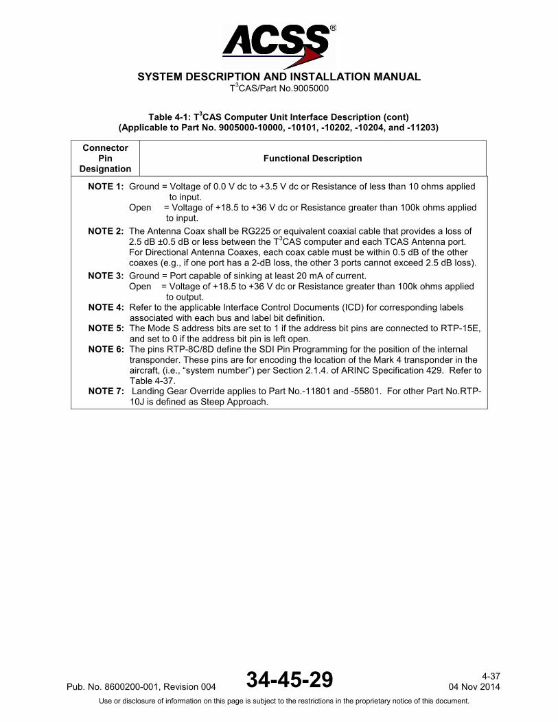
NOTE 1: Ground = Voltage of 0.0 V dc to +3.5 V dc or Resistance of less than 10 ohms applied to input.
Open = Voltage of +18.5 to +36 V dc or Resistance greater than 100k ohms applied to input.
NOTE 2: The Antenna Coax shall be RG225 or equivalent coaxial cable that provides a loss of 2.5 dB ±0.5 dB or less between the T3CAS computer and each TCAS Antenna port. For Directional Antenna Coaxes, each coax cable must be within 0.5 dB of the other coaxes (e.g., if one port has a 2-dB loss, the other 3 ports cannot exceed 2.5 dB loss).
NOTE 3: Ground = Port capable of sinking at least 20 mA of current. Open = Voltage of +18.5 to +36 V dc or Resistance greater than 100k ohms applied
to output. NOTE 4: Refer to the applicable Interface Control Documents (ICD) for corresponding labels
associated with each bus and label bit definition. NOTE 5: The Mode S address bits are set to 1 if the address bit pins are connected to RTP-15E,
and set to 0 if the address bit pin is left open. NOTE 6: The pins RTP-8C/8D define the SDI Pin Programming for the position of the internal
transponder. These pins are for encoding the location of the Mark 4 transponder in the aircraft, (i.e., “system number”) per Section 2.1.4. of ARINC Specification 429. Refer to Table 4-37.
NOTE 7: Landing Gear Override applies to Part No.-11801 and -55801. For other Part No.RTP-10J is defined as Steep Approach.
Pub. No. 8600200-001, Revision 004 34-45-29 4-37
04 Nov 2014 Use or disclosure of information on this page is subject to the restrictions in the proprietary notice of this document.

SYSTEM DESCRIPTION AND INSTALLATION MANUAL
T3CAS/Part No.9005000
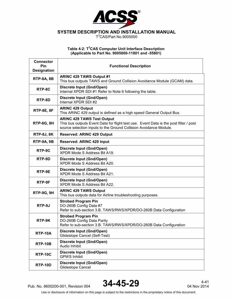
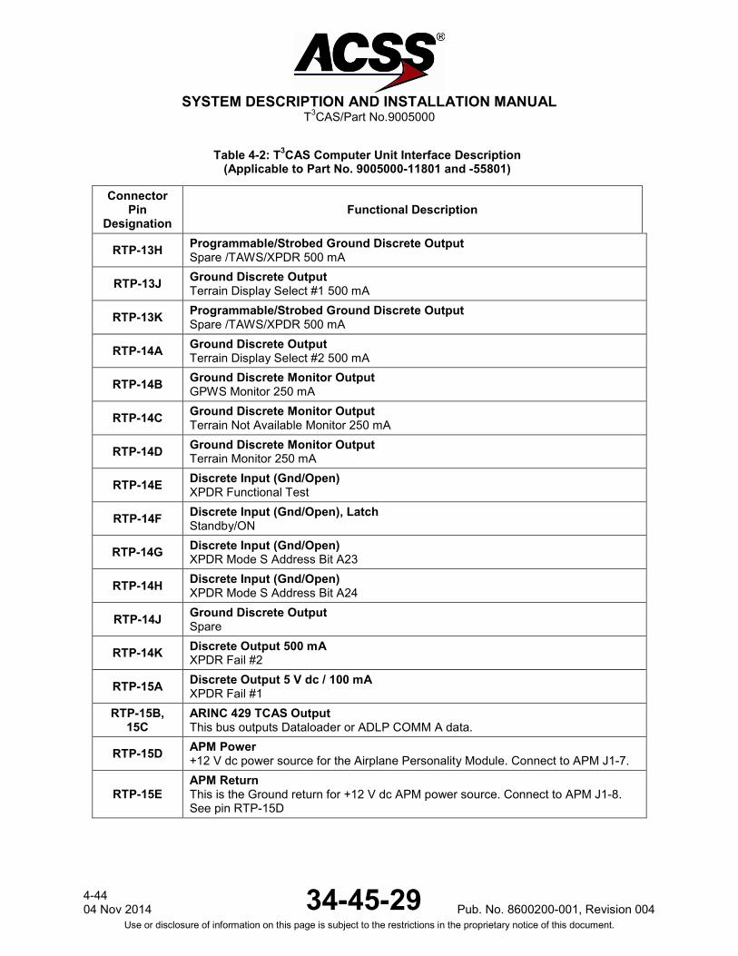
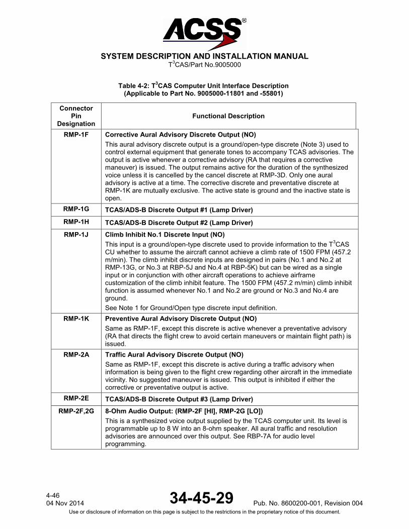
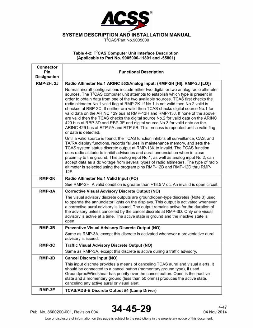
Table 4-2: T3CAS Computer Unit Interface Description (Applicable to Part No. 9005000-11801 and -55801)
Connector Pin
Designation Functional Description
T3CAS Computer Unit Right Top Plug (RTP) RTP-1A, 1B ARINC 453 Terrain Display Output No.1: (RTP-1A [A], RTP-1B [B])
T3CAS output number 1 to the terrain awareness display. RTP-1C, 1D ARINC 429 Input: Spare RTP-1E, 1F ARINC 453 Terrain Display Output No.2: (RTP-1E [A], RTP-1F [B])
T3CAS output number 2 to the terrain awareness display. RTP-1G, 1H ARINC 429 Input: AFMC – EFIS #2 [RTP-1G (A), RTP-1H (B)]
This high-speed 429 input from the Flight Management Computer (FMC) Electronic Flight Instrument System (EFIS) provides position, heading, track angle, speed, etc. information to the T3CAS.
RTP-1J, 1K ARINC 429 Input: ADIRU #2 (Right) / ADR [RTP-1J (A), RTP-1K (B)] This low-speed 429 input from the Air Data/Inertial Reference Unit (ADIRU) #2 provides altitude, airspeed, altitude rate and temperature information to the T3CAS.
RTP-2A, 2B ARINC 429 Input: Spare RTP-2C, 2D ARINC 429 Air Data/Inertial Reference Unit (ADIRU) #2 (Right), Inertial
Reference Part (IRS) Input: [RTP-2C (A), RTP-2D (B)] This high-speed input is provided for applications to receive Inertial Reference System information.
RTP-2E, 2F Instrument Landing System #2 (Right) This low-speed bus inputs all signals associated with the instrument landing system to the T3CAS.
RTP-2G Discrete Input (Gnd/Open) XPDR Mode S Address Bit A1 (MSB). Refer to Note 5 following the table.
RTP-2H Discrete Input (Gnd/Open) XPDR Mode S Address Bit A2.
RTP-2J Discrete Input (Gnd/Open) XPDR Mode S Address Bit A3.
RTP-2K Discrete Input (Gnd/Open) XPDR Mode S Address Bit A4.
RTP-3A, 3B Instrument Landing System #1 (Left) This low-speed bus inputs all signals associated with the instrument landing system to the T3CAS.
RTP-3C, 3D ARINC 429 Input: Spare RTP-3E, 3F ARINC 429 FMC – GENBUS #2 (NAV Modes) Input: [RTP-3E (A), RTP-3F (B)]
This Low-Speed ARINC 429 (12.5k bits/s) input provides aircraft gross weight, selected altitude, position, etc. to T3CAS.
4-38 04 Nov 2014 34-45-29 Pub. No. 8600200-001, Revision 004
Use or disclosure of information on this page is subject to the restrictions in the proprietary notice of this document.

SYSTEM DESCRIPTION AND INSTALLATION MANUAL
T3CAS/Part No.9005000
Table 4-2: T3CAS Computer Unit Interface Description (Applicable to Part No. 9005000-11801 and -55801)
Connector Pin
Designation Functional Description
RTP-3G, 3H EWEU #2 (Slat/Flap Control Computer #2) [RTP-3G (A), RTP-3H (B)] This high-speed bus inputs flap angle and body angle of attack to T3CAS.
RTP-3J, 3K ARINC 429 Input: Spare
RTP-4A, 4B EWEU #1 (Slat/Flap Control Computer #1) [RTP-4A (A), RTP-4B (B)] This high-speed bus inputs flap angle and body angle of attack to T3CAS.
RTP-4C Discrete Input (Gnd/Open) XPDR Mode S Address Bit A5.
RTP-4D, 4E AFMC – ATC/TCAS Control Panel #1 [RTP-4D (A), RTP-4E (B)] This low-speed bus controls the TCAS/ATC interfaces and TCAS display.
RTP-4F Discrete Input (Gnd/Open) XPDR Mode S Address Bit A6.
RTP-4G, 4H ARINC 429 Input: Spare
RTP-4J Discrete Input (Gnd/Open) XPDR Mode S Address Bit A7.
RTP-4K Discrete Input (Gnd/Open) XPDR Mode S Address Bit A8.
RTP-5A, 5B Radio Altimeter #3 (Center) [RTP-5A (A), RTP-5B (B)] See RMP-2H.
RTP-5C Discrete Input (Gnd/Open) XPDR Mode S Address Bit A9.
RTP-5D, 5E AFMC – ATC/TCAS Control Panel #2 [RTP-5D (A), RTP-5E (B)] This low-speed bus controls the TCAS/ATC interfaces and TCAS display.
RTP-5F Discrete Input (Gnd/Open) XPDR Mode S Address Bit A10.
RTP-5G, 5H ARINC 429 Input: Spare RTP-5J Discrete Input (Gnd/Open)
XPDR Mode S Address Bit A11. RTP-5K Strobed Program Pin
TAWS/XPDR #11: Max True Airspeed Refer to sub-section 3.C. TAWS/XPDR Pin Programming
RTP-6A, 6B ARINC 429 Input: Spare RTP-6C Discrete Input (Gnd/Open)
XPDR Mode S Address Bit A12. RTP-6D Strobed Program Pin
TAWS/XPDR #1: Aircraft Type. Refer to Table 4-19: Aircraft Type Configurations
Pub. No. 8600200-001, Revision 004 34-45-29 4-39
04 Nov 2014 Use or disclosure of information on this page is subject to the restrictions in the proprietary notice of this document.

SYSTEM DESCRIPTION AND INSTALLATION MANUAL
T3CAS/Part No.9005000
Table 4-2: T3CAS Computer Unit Interface Description (Applicable to Part No. 9005000-11801 and -55801)
Connector Pin
Designation Functional Description
RTP-6E Discrete Input (Gnd/Open) XPDR Mode S Address Bit A13.
RTP-6F Strobed Program Pin TAWS/XPDR #2: Aircraft Type. Refer to Table 4-19: Aircraft Type Configurations
RTP-6G Strobed Program Pin TAWS/XPDR #3: Lateral Position Priority. Refer to sub-section 3.C. TAWS/XPDR Pin Programming
RTP-6H Discrete Input (Gnd/Open) XPDR Mode S Address Bit A14.
RTP-6J Strobed Program Pin TAWS/XPDR #4: Audio Menu Selection Refer to sub-section 3.C. TAWS/XPDR Pin Programming
RTP-6K Discrete Input (Gnd/Open) XPDR Mode S Address Bit A15.
RTP-7A Strobed Program Pin TAWS/XPDR #5: CRT-LCD Disp Select Refer to sub-section 3.C. TAWS/XPDR Pin Programming
RTP-7B Discrete Input (Gnd/Open) XPDR Mode S Address Bit A16.
RTP-7C Strobed Program Pin TAWS/XPDR #6: Auto (CPA-THD) Deactivation Refer to sub-section 3.C. TAWS/XPDR Pin Programming
RTP-7D Strobed Program Pin TAWS/XPDR #7: Predictive Windshear Present Refer to sub-section 3.C. TAWS/XPDR Pin Programming
RTP-7E Discrete Input (Gnd/Open) XPDR Mode S Address Bit A17.
RTP-7F Strobed Program Pin TAWS/XPDR #8: Spare
RTP-7G Strobed Program Pin TAWS/XPDR #9: Spare
RTP-7H Discrete Input (Gnd/Open) XPDR Mode S Address Bit A18.
RTP-7J Strobed Program Pin TAWS/XPDR #10: Attitude Source Selection Refer to sub-section 3.C. TAWS/XPDR Pin Programming
RTP-7K Strobed Program Pin TAWS/XPDR #12: Cold Temp Comp Refer to sub-section 3.C. TAWS/XPDR Pin Programming
4-40 04 Nov 2014 34-45-29 Pub. No. 8600200-001, Revision 004
Use or disclosure of information on this page is subject to the restrictions in the proprietary notice of this document.
SYSTEM DESCRIPTION AND INSTALLATION MANUAL
T3CAS/Part No.9005000
Table 4-2: T3CAS Computer Unit Interface Description (Applicable to Part No. 9005000-11801 and -55801)
Connector Pin
Designation Functional Description
RTP-8A, 8B ARINC 429 TAWS Output #1 This bus outputs TAWS and Ground Collision Avoidance Module (GCAM) data.
RTP-8C Discrete Input (Gnd/Open) Internal XPDR SDI #1 Refer to Note 6 following the table.
RTP-8D Discrete Input (Gnd/Open) Internal XPDR SDI #2
RTP-8E, 8F ARINC 429 Output This ARINC 429 output is defined as a high speed General Output Bus.
RTP-8G, 8H ARINC 429 TAWS Test Output This bus outputs Event Data for flight test use. Event Data is the post filter / post source selection inputs to the Ground Collision Avoidance Module.
RTP-8J, 8K Reserved: ARINC 429 Output
RTP-9A, 9B Reserved: ARINC 429 Input
RTP-9C Discrete Input (Gnd/Open) XPDR Mode S Address Bit A19.
RTP-9D Discrete Input (Gnd/Open) XPDR Mode S Address Bit A20.
RTP-9E Discrete Input (Gnd/Open) XPDR Mode S Address Bit A21.
RTP-9F Discrete Input (Gnd/Open) XPDR Mode S Address Bit A22.
RTP-9G, 9H ARINC 429 TAWS Output This bus outputs data for Airline troubleshooting purposes.
RTP-9J Strobed Program Pin DO-260B Config Data #7 Refer to sub-section 3.B. TAWS/RWS/XPDR/DO-260B Data Configuration
RTP-9K Strobed Program Pin DO-260B Config Data Parity Refer to sub-section 3.B. TAWS/RWS/XPDR/DO-260B Data Configuration
RTP-10A Discrete Input (Gnd/Open) Glideslope Cancel (Self-Test)
RTP-10B Discrete Input (Gnd/Open) Audio Inhibit
RTP-10C Discrete Input (Gnd/Open) GPWS Inhibit
RTP-10D Discrete Input (Gnd/Open) Glideslope Cancel
Pub. No. 8600200-001, Revision 004 34-45-29 4-41
04 Nov 2014 Use or disclosure of information on this page is subject to the restrictions in the proprietary notice of this document.

SYSTEM DESCRIPTION AND INSTALLATION MANUAL
T3CAS/Part No.9005000
Table 4-2: T3CAS Computer Unit Interface Description (Applicable to Part No. 9005000-11801 and -55801)
Connector Pin
Designation Functional Description
RTP-10E Discrete Input (Gnd/Open) XPDR Air/Ground #1
RTP-10F Discrete Input (Gnd/Open) Terrain Display Select #1
RTP-10G Discrete Input (Gnd/Open) Terrain Display Select #2
RTP-10H Discrete Input (Gnd/Open) Landing Flaps / Landing Flap Override
RTP-10J Discrete Input (Gnd/Open) Steep Approach or Landing Gear Override. Refer to Note 7 following the table.
RTP-10K Discrete Input (Gnd/Open) Audio Momentary Suppress
RTP-11A Strobed Program Pin TAWS/XPDR #13: Spare
RTP-11B Discrete Input (Gnd/Open) WXR Radar #1 On/Off
RTP-11C Strobed Program Pin TAWS/XPDR #14: Eleview Function Refer to sub-section 3.C. TAWS/XPDR Pin Programming
RTP-11D Discrete Input (Gnd/Open) WXR Radar #2 On/Off
RTP-11E Discrete Input (Gnd/Open) Terrain Mode Inhibit
RTP-11F Strobed Program Pin TAWS/XPDR #15: Obstacle Function Refer to sub-section 3.C. TAWS/XPDR Pin Programming
RTP-11G Strobed Program Pin TAWS/XPDR #16: Antenna Modes Refer to sub-section 3.C. TAWS/XPDR Pin Programming
RTP-11H Strobed Program Pin TAWS/XPDR #17: TAWS/XPDR Installed Refer to sub-section 3.C. TAWS/XPDR Pin Programming
RTP-11J Strobed Program Pin TAWS/XPDR #18: Odd Program Pin Parity Refer to sub-section 3.C. TAWS/XPDR Pin Programming
RTP-11K Discrete Input (Gnd/Open) XPDR Air/Ground #2
4-42 04 Nov 2014 34-45-29 Pub. No. 8600200-001, Revision 004
Use or disclosure of information on this page is subject to the restrictions in the proprietary notice of this document.

SYSTEM DESCRIPTION AND INSTALLATION MANUAL
T3CAS/Part No.9005000
Table 4-2: T3CAS Computer Unit Interface Description (Applicable to Part No. 9005000-11801 and -55801)
Connector Pin
Designation Functional Description
RTP-12A Strobed Program Pin DO-260B Config Data #1 Refer to sub-section 3.B. TAWS/RWS/XPDR/DO-260B Data Configuration
RTP-12B Strobed Program Pin DO-260B Config Data #2 Refer to sub-section 3.B. TAWS/RWS/XPDR/DO-260B Data Configuration
RTP-12C Strobed Program Pin DO-260B Config Data #3 Refer to sub-section 3.B. TAWS/RWS/XPDR/DO-260B Data Configuration
RTP-12D Strobed Program Pin DO-260B Config Data #4 Refer to sub-section 3.B. TAWS/RWS/XPDR/DO-260B Data Configuration
RTP-12E Strobed Program Pin DO-260B Config Data #5 Refer to sub-section 3.B. TAWS/RWS/XPDR/DO-260B Data Configuration
RTP-12F Strobed Program Pin DO-260B Config Data #6 Refer to sub-section 3.B. TAWS/RWS/XPDR/DO-260B Data Configuration
RTP-12G 28V/Open Discrete Input: Spare
RTP-12H 28V/Open Discrete Input: Spare
RTP-12J Discrete Input (Gnd/Open), Latch Air Data Source Select
RTP-12K Discrete Input (Gnd/Open) Control Panel Source Select
RTP-13A Discrete Input (Gnd/Open), Latch Extended Squitter Disable
RTP-13B Programmable/Strobed Ground Discrete Output GPWS Caution /TAWS/XPDR Lamp 500 mA
RTP-13C Programmable/Strobed Ground Discrete Output Spare Output /TAWS/XPDR 500 mA
RTP-13D Programmable/Strobed Ground Discrete Output GPWS Warning /TAWS/XPDR Lamp 500 mA
RTP-13E Programmable/Strobed Ground Discrete Output Spare /TAWS/XPDR 500 mA
RTP-13F Programmable/Strobed Ground Discrete Output Spare /TAWS/XPDR 500 mA
RTP-13G Programmable/Strobed Ground Discrete Output Spare /TAWS/XPDR 500 mA
Pub. No. 8600200-001, Revision 004 34-45-29 4-43
04 Nov 2014 Use or disclosure of information on this page is subject to the restrictions in the proprietary notice of this document.
SYSTEM DESCRIPTION AND INSTALLATION MANUAL
T3CAS/Part No.9005000
Table 4-2: T3CAS Computer Unit Interface Description (Applicable to Part No. 9005000-11801 and -55801)
Connector Pin
Designation Functional Description
RTP-13H Programmable/Strobed Ground Discrete Output Spare /TAWS/XPDR 500 mA
RTP-13J Ground Discrete Output Terrain Display Select #1 500 mA
RTP-13K Programmable/Strobed Ground Discrete Output Spare /TAWS/XPDR 500 mA
RTP-14A Ground Discrete Output Terrain Display Select #2 500 mA
RTP-14B Ground Discrete Monitor Output GPWS Monitor 250 mA
RTP-14C Ground Discrete Monitor Output Terrain Not Available Monitor 250 mA
RTP-14D Ground Discrete Monitor Output Terrain Monitor 250 mA
RTP-14E Discrete Input (Gnd/Open) XPDR Functional Test
RTP-14F Discrete Input (Gnd/Open), Latch Standby/ON
RTP-14G Discrete Input (Gnd/Open) XPDR Mode S Address Bit A23
RTP-14H Discrete Input (Gnd/Open) XPDR Mode S Address Bit A24
RTP-14J Ground Discrete Output Spare
RTP-14K Discrete Output 500 mA XPDR Fail #2
RTP-15A Discrete Output 5 V dc / 100 mA XPDR Fail #1
RTP-15B, 15C
ARINC 429 TCAS Output This bus outputs Dataloader or ADLP COMM A data.
RTP-15D APM Power +12 V dc power source for the Airplane Personality Module. Connect to APM J1-7.
RTP-15E APM Return This is the Ground return for +12 V dc APM power source. Connect to APM J1-8. See pin RTP-15D
4-44 04 Nov 2014 34-45-29 Pub. No. 8600200-001, Revision 004
Use or disclosure of information on this page is subject to the restrictions in the proprietary notice of this document.

SYSTEM DESCRIPTION AND INSTALLATION MANUAL
T3CAS/Part No.9005000
Table 4-2: T3CAS Computer Unit Interface Description (Applicable to Part No. 9005000-11801 and -55801)
Connector Pin
Designation Functional Description
RTP-15F
APM Clock This is the APM Clock Output which is used to synchronize serial output to the APM. The Clock output frequency is 2.0 MHz + 1% when the APM is being accessed and is set to a logic 0 (not toggling) when the APM is not being accessed. Connect to APM J1-2.
RTP-15G APM Serial Data Output This is the Serial Data Output from T3CAS to the APM Serial Data Input. APM Enable (RTP-15J) and APM Write Enable (RTP-15K) must be enabled before data can be written to the APM. Connect to APM J1-1.
RTP-15H APM Serial Data Input This is the Serial Data Input to T3CAS from the APM Serial Data Output. APM Enable (RTP-15J) must be enabled before data can be read from the APM. Connect to APM J1-9.
RTP-15J
APM Enable No.1 This pin is used to Enable Read/Write access to the APM. An APM Enable Output logic of 1 disables Read/Write access to the APM and a logic 0 enables APM Read/Write access. Connect to APM J1-3. This pin is used in conjunction with pins RTP-15G (APM serial output) and RTP-15H (APM serial input).
RTP-15K
APM Write Enable No.1 This pin is used to Enable Write access to the APM. An APM Write Enable Output logic of 1 disables Write access to the APM and a logic 0 enables APM Write access. Connect to APM J1-4. This pin is used in conjunction with pin RTP-15G (APM serial output).
T3CAS Computer Unit Right Middle Plug (RMP) RMP-1A PIL_O_AURAL_EXTERNAL_REQ_1 RMP-1B, RMP-1C Discrete Outputs (Standard Ground/Open): Spares
RMP-1D DO_ADSB_FAIL_INDICATOR RMP-1E TA Display Enable Discrete Output (NO)
This output is a ground/open-type discrete used by the weather radar display to place the radar in standby mode. A ground on this pin enables the weather radar display.
Pub. No. 8600200-001, Revision 004 34-45-29 4-45
04 Nov 2014 Use or disclosure of information on this page is subject to the restrictions in the proprietary notice of this document.
SYSTEM DESCRIPTION AND INSTALLATION MANUAL
T3CAS/Part No.9005000
Table 4-2: T3CAS Computer Unit Interface Description (Applicable to Part No. 9005000-11801 and -55801)
Connector Pin
Designation Functional Description
RMP-1F Corrective Aural Advisory Discrete Output (NO) This aural advisory discrete output is a ground/open-type discrete (Note 3) used to control external equipment that generate tones to accompany TCAS advisories. The output is active whenever a corrective advisory (RA that requires a corrective maneuver) is issued. The output remains active for the duration of the synthesized voice unless it is cancelled by the cancel discrete at RMP-3D. Only one aural advisory is active at a time. The corrective discrete and preventative discrete at RMP-1K are mutually exclusive. The active state is ground and the inactive state is open.
RMP-1G TCAS/ADS-B Discrete Output #1 (Lamp Driver) RMP-1H TCAS/ADS-B Discrete Output #2 (Lamp Driver) RMP-1J Climb Inhibit No.1 Discrete Input (NO)
This input is a ground/open-type discrete used to provide information to the T3CAS CU whether to assume the aircraft cannot achieve a climb rate of 1500 FPM (457.2 m/min). The climb inhibit discrete inputs are designed in pairs (No.1 and No.2 at RMP-13G, or No.3 at RBP-5J and No.4 at RBP-5K) but can be wired as a single input or in conjunction with other aircraft operations to achieve airframe customization of the climb inhibit feature. The 1500 FPM (457.2 m/min) climb inhibit function is assumed whenever No.1 and No.2 are ground or No.3 and No.4 are ground. See Note 1 for Ground/Open type discrete input definition.
RMP-1K Preventive Aural Advisory Discrete Output (NO) Same as RMP-1F, except this discrete is active whenever a preventative advisory (RA that directs the flight crew to avoid certain maneuvers or maintain flight path) is issued.
RMP-2A Traffic Aural Advisory Discrete Output (NO) Same as RMP-1F, except this discrete is active during a traffic advisory when information is being given to the flight crew regarding other aircraft in the immediate vicinity. No suggested maneuver is issued. This output is inhibited if either the corrective or preventative output is active.
RMP-2E TCAS/ADS-B Discrete Output #3 (Lamp Driver) RMP-2F,2G 8-Ohm Audio Output: (RMP-2F [HI], RMP-2G [LO])
This is a synthesized voice output supplied by the TCAS computer unit. Its level is programmable up to 8 W into an 8-ohm speaker. All aural traffic and resolution advisories are announced over this output. See RBP-7A for audio level programming.
4-46 04 Nov 2014 34-45-29 Pub. No. 8600200-001, Revision 004
Use or disclosure of information on this page is subject to the restrictions in the proprietary notice of this document.
SYSTEM DESCRIPTION AND INSTALLATION MANUAL
T3CAS/Part No.9005000
Table 4-2: T3CAS Computer Unit Interface Description (Applicable to Part No. 9005000-11801 and -55801)
Connector Pin
Designation Functional Description
RMP-2H, 2J Radio Altimeter No.1 ARINC 552/Analog Input: (RMP-2H [HI], RMP-2J [LO]) Normal aircraft configurations include either two digital or two analog radio altimeter sources. The T3CAS computer unit attempts to establish which type is present in order to obtain data from one of the two available sources. TCAS first checks the radio altimeter No.1 valid flag at RMP-2K. If No.1 is not valid then No.2 valid is checked at RBP-3C. If neither are valid then TCAS checks digital source No.1 for valid data on the ARINC 429 bus at RMP-13H and RMP-13J. If none of the above are valid then the TCAS checks the digital source No.2 for valid data on the ARINC 429 bus at RBP-3D and RBP-3E and digital source No.3 for valid data on the ARINC 429 bus at RTP-5A and RTP-5B. This process is repeated until a valid flag or data is detected. Until a valid source is found, the TCAS function inhibits all surveillance, CAS, and TA/RA display functions, records failures in maintenance memory, and sets the TCAS system status discrete output at RMP-13K to invalid. The TCAS function uses radio altitude to inhibit advisories and aural annunciation when in close proximity to the ground. This analog input No.1, as well as analog input No.2, can accept data as a dc voltage from several types of radio altimeters. The type of radio altimeter is selected using the program pins RMP-12B and RMP-12D thru RMP-12F.
RMP-2K Radio Altimeter No.1 Valid Input (PO) See RMP-2H. A valid condition is greater than +18.5 V dc. An invalid is open circuit.
RMP-3A Corrective Visual Advisory Discrete Output (NO) The visual advisory discrete outputs are ground/open-type discretes (Note 3) used to operate the annunciator lights on the displays. This output is activated whenever a corrective aural advisory is issued. The output remains active for the duration of the advisory unless cancelled by the cancel discrete at RMP-3D. Only one visual advisory is active at a time. The active state is ground and the inactive state is open.
RMP-3B Preventive Visual Advisory Discrete Output (NO) Same as RMP-3A, except this discrete is activated whenever a preventative aural advisory is issued.
RMP-3C Traffic Visual Advisory Discrete Output (NO) Same as RMP-3A, except this discrete is active during a traffic advisory.
RMP-3D Cancel Discrete Input (NO) This input discrete provides a means of canceling TCAS aural and visual alerts. It should be connected to a cancel button (momentary ground type), if used. Groundprox/Windshear has priority over the cancel button. Open is the inactive state and a momentary ground (less than 50 ohms) produces the active state, canceling any active aural or visual alert.
RMP-3E TCAS/ADS-B Discrete Output #4 (Lamp Driver)
Pub. No. 8600200-001, Revision 004 34-45-29 4-47
04 Nov 2014 Use or disclosure of information on this page is subject to the restrictions in the proprietary notice of this document.
SYSTEM DESCRIPTION AND INSTALLATION MANUAL
T3CAS/Part No.9005000
Table 4-2: T3CAS Computer Unit Interface Description (Applicable to Part No. 9005000-11801 and -55801)
Connector Pin
Designation Functional Description
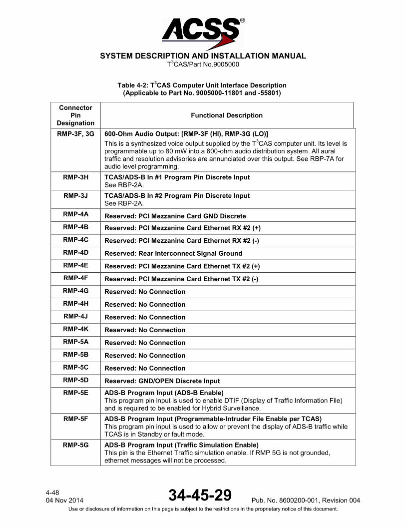
RMP-3F, 3G 600-Ohm Audio Output: [RMP-3F (HI), RMP-3G (LO)] This is a synthesized voice output supplied by the T3CAS computer unit. Its level is programmable up to 80 mW into a 600-ohm audio distribution system. All aural traffic and resolution advisories are annunciated over this output. See RBP-7A for audio level programming.
RMP-3H TCAS/ADS-B In #1 Program Pin Discrete Input See RBP-2A.
RMP-3J TCAS/ADS-B In #2 Program Pin Discrete Input See RBP-2A.
RMP-4A Reserved: PCI Mezzanine Card GND Discrete RMP-4B Reserved: PCI Mezzanine Card Ethernet RX #2 (+) RMP-4C Reserved: PCI Mezzanine Card Ethernet RX #2 (-) RMP-4D Reserved: Rear Interconnect Signal Ground RMP-4E Reserved: PCI Mezzanine Card Ethernet TX #2 (+) RMP-4F Reserved: PCI Mezzanine Card Ethernet TX #2 (-) RMP-4G Reserved: No Connection RMP-4H Reserved: No Connection RMP-4J Reserved: No Connection RMP-4K Reserved: No Connection RMP-5A Reserved: No Connection RMP-5B Reserved: No Connection RMP-5C Reserved: No Connection RMP-5D Reserved: GND/OPEN Discrete Input RMP-5E ADS-B Program Input (ADS-B Enable)
This program pin input is used to enable DTIF (Display of Traffic Information File) and is required to be enabled for Hybrid Surveillance.
RMP-5F ADS-B Program Input (Programmable-Intruder File Enable per TCAS) This program pin input is used to allow or prevent the display of ADS-B traffic while TCAS is in Standby or fault mode.
RMP-5G ADS-B Program Input (Traffic Simulation Enable) This pin is the Ethernet Traffic simulation enable. If RMP 5G is not grounded, ethernet messages will not be processed.
4-48 04 Nov 2014 34-45-29 Pub. No. 8600200-001, Revision 004
Use or disclosure of information on this page is subject to the restrictions in the proprietary notice of this document.

SYSTEM DESCRIPTION AND INSTALLATION MANUAL
T3CAS/Part No.9005000
Table 4-2: T3CAS Computer Unit Interface Description (Applicable to Part No. 9005000-11801 and -55801)
Connector Pin
Designation Functional Description
RMP-5H Reserved: No Connection RMP-5J Reserved: No Connection RMP-5K Air Ground Discrete Input (NO): (Weight-On-Wheels)
This ground/open-type discrete input (Note 1) to the T3CAS computer unit indicates the status of the Air/Ground or Weight-On-Wheels (WOW) switch. TCAS filters this input to make sure it remains in a steady state a minimum of 4 sec before an Air/Ground transition is recorded. An open indicates the aircraft is airborne and a ground indicates the aircraft is on the ground. Inputs should be diode isolated from each other.
RMP-6A, 6B ARINC 429 FMC – GENBUS #1 (NAV Modes) Input: [RMP-6A (A), RMP-6B (B)] This Low-Speed ARINC 429 (12.5k bits/s) input provides aircraft gross weight, selected altitude, position, etc. to T3CAS.
RMP-6C Reserved: No Connection RMP-6D Performance Limit Discrete Input (NO)
This input provides the T3CAS computer unit with an input from the Flight Management Computer (or equivalent) which indicates when the aircraft cannot achieve a 1500 FPM (457.2 m/min) climb rate. When this input is ground, the climb rate is not limited and no action is needed by the T3CAS computer unit. When this input is open, the climb rate is limited when the aircraft is above the value set by the altitude limit program pins (RMP-6E thru RMP-6J).
RMP-6E 2000 ft (609.6 m) Altitude Limit Program Pin (NO) This pin, along with pins RMP-6F thru RMP-6J, select the “can’t climb” altitude in 2,000-ft (609.6-m) increments up to 62,000 ft (18897.6 m). This is the altitude the aircraft is not able to achieve a 0.25-g vertical acceleration to a 1500-FPM (457.2-m) climb rate for an altitude gain of 750 ft (28.6 m) above a certain altitude under all circumstances. The “can’t climb” altitude is selected by connecting jumper wires from altitude limit program pins to the program common pin (RMP-6K).
RMP-6F 4000 ft (1219.2 m) Altitude Limit Program Pin (NO) See RMP-6E.
RMP-6G 8000 ft (2438.4 m) Altitude Limit Program Pin (NO) See RMP-6E.
RMP-6H 16000 ft (4876.8 m) Altitude Limit Program Pin (NO) See RMP-6E.
RMP-6J 32000 ft (9753.6 m) Altitude Limit Program Pin (NO) See RMP-6E.
RMP-6K Program Common See RMP-6E.
Pub. No. 8600200-001, Revision 004 34-45-29 4-49
04 Nov 2014 Use or disclosure of information on this page is subject to the restrictions in the proprietary notice of this document.
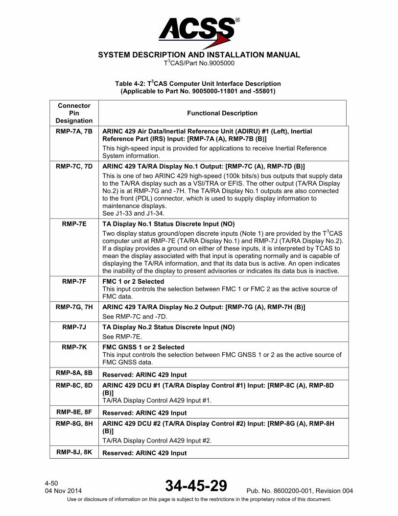
SYSTEM DESCRIPTION AND INSTALLATION MANUAL
T3CAS/Part No.9005000
Table 4-2: T3CAS Computer Unit Interface Description (Applicable to Part No. 9005000-11801 and -55801)
Connector Pin
Designation Functional Description
RMP-7A, 7B ARINC 429 Air Data/Inertial Reference Unit (ADIRU) #1 (Left), Inertial Reference Part (IRS) Input: [RMP-7A (A), RMP-7B (B)] This high-speed input is provided for applications to receive Inertial Reference System information.
RMP-7C, 7D ARINC 429 TA/RA Display No.1 Output: [RMP-7C (A), RMP-7D (B)] This is one of two ARINC 429 high-speed (100k bits/s) bus outputs that supply data to the TA/RA display such as a VSI/TRA or EFIS. The other output (TA/RA Display No.2) is at RMP-7G and -7H. The TA/RA Display No.1 outputs are also connected to the front (PDL) connector, which is used to supply display information to maintenance displays. See J1-33 and J1-34.
RMP-7E TA Display No.1 Status Discrete Input (NO) Two display status ground/open discrete inputs (Note 1) are provided by the T3CAS computer unit at RMP-7E (TA/RA Display No.1) and RMP-7J (TA/RA Display No.2). If a display provides a ground on either of these inputs, it is interpreted by TCAS to mean the display associated with that input is operating normally and is capable of displaying the TA/RA information, and that its data bus is active. An open indicates the inability of the display to present advisories or indicates its data bus is inactive.
RMP-7F FMC 1 or 2 Selected This input controls the selection between FMC 1 or FMC 2 as the active source of FMC data.
RMP-7G, 7H ARINC 429 TA/RA Display No.2 Output: [RMP-7G (A), RMP-7H (B)] See RMP-7C and -7D.
RMP-7J TA Display No.2 Status Discrete Input (NO) See RMP-7E.
RMP-7K FMC GNSS 1 or 2 Selected This input controls the selection between FMC GNSS 1 or 2 as the active source of FMC GNSS data.
RMP-8A, 8B Reserved: ARINC 429 Input RMP-8C, 8D ARINC 429 DCU #1 (TA/RA Display Control #1) Input: [RMP-8C (A), RMP-8D
(B)] TA/RA Display Control A429 Input #1.
RMP-8E, 8F Reserved: ARINC 429 Input RMP-8G, 8H ARINC 429 DCU #2 (TA/RA Display Control #2) Input: [RMP-8G (A), RMP-8H
(B)] TA/RA Display Control A429 Input #2.
RMP-8J, 8K Reserved: ARINC 429 Input
4-50 04 Nov 2014 34-45-29 Pub. No. 8600200-001, Revision 004
Use or disclosure of information on this page is subject to the restrictions in the proprietary notice of this document.

SYSTEM DESCRIPTION AND INSTALLATION MANUAL
T3CAS/Part No.9005000
Table 4-2: T3CAS Computer Unit Interface Description (Applicable to Part No. 9005000-11801 and -55801)
Connector Pin
Designation Functional Description
RMP-9A, 9B ARINC 429 ADLP Comm C Output: [RMP-9A (A), RMP-9B (B)] These pins serve as the input interface to the transponder function ADLP Comm C protocol.
RMP-9C, 9D Reserved for ARINC 735B Data Bus Output. RMP-9E, 9F Reserved for ARINC 735B Data Bus Output. RMP-9G, 9H Reserved: ARINC 429 Bus Output RMP-9J, 9K Reserved: ARINC 429 Bus Output RMP-10A,
10B Reserved Program Pin Inputs Reserved for future use.
RMP-10C APM Installed Program Input (NO) A ground on this pin indicates that an Aircraft Personality Module (APM) is connected to the T3CAS.
RMP-10D Program Pin Input: Spare
RMP-10E User Option A Program Pin RMP-10F Program Pin Input: Spare
RMP-10G Option Parity Program Pin RMP-10H Reserved: GND/OPEN Discrete Input (Momentary)
RMP-10J Reserved: GND/OPEN Discrete Input (Momentary)
RMP-10K Reserved: GND/OPEN Discrete Input (Momentary)
RMP-11A User Option B Program Pin RMP-11B Reserved RMP-11C Male Voice Program Input
This program input is intended to allow audio annunciation to be selectable for either male or female genders. A ground on this pin selects the male voice and an open selects the female voice.
RMP-11D Flight Data Recorder ARINC 429 and Extended Maintenance Log Program Input This program pin is used to specify whether the ARINC 429 Flight Data Recorder (FDR) is to be used. An open on this pin means that the FDR is not utilized. A ground indicates that flight data is output as high-speed ARINC 429 data on RA Display No.1 and No.2 busses. While the FDR is enabled, normal low-speed RA display bus operation is not available. A ground also enables RA/TA events recording in memory.
Pub. No. 8600200-001, Revision 004 34-45-29 4-51
04 Nov 2014 Use or disclosure of information on this page is subject to the restrictions in the proprietary notice of this document.

SYSTEM DESCRIPTION AND INSTALLATION MANUAL
T3CAS/Part No.9005000
Table 4-2: T3CAS Computer Unit Interface Description (Applicable to Part No. 9005000-11801 and -55801)
Connector Pin
Designation Functional Description
RMP-11E, 11F
ARINC 429 Input: MMR/GPS #1 (Left) [RMP-11E (A), RMP-11F (B)] This high-speed 429 input is used to receive GPS label input containing position, velocity and quality information for the use of ADS-B IN applications and by the transponder function of ADS-B OUT.
RMP-11G, 11H
ARINC 429 Input: AFMC – EFIS #1 [RMP-11G (A), RMP-11H (B)] This high-speed 429 input from the Flight Management Computer (FMC) Electronic Flight Instrument System (EFIS) provides position, heading, track angle, speed, etc. information to the T3CAS.
RMP-11J, 11K
ARINC 429 Input: ADIRU #1 (Left) / ADR [RMP-11J (A), RMP-11K (B)] This low-speed 429 input from the Air Data/Inertial Reference Unit (ADIRU) #1 provides altitude, airspeed, altitude rate and temperature information to the T3CAS.
RMP-12A Reserved Program Input Reserved for future use.
4-52 04 Nov 2014 34-45-29 Pub. No. 8600200-001, Revision 004
Use or disclosure of information on this page is subject to the restrictions in the proprietary notice of this document.

SYSTEM DESCRIPTION AND INSTALLATION MANUAL
T3CAS/Part No.9005000
Table 4-2: T3CAS Computer Unit Interface Description (Applicable to Part No. 9005000-11801 and -55801)
Connector Pin
Designation Functional Description
RMP-12B (Continues)
Radio Altimeter Type Select Program Input No.4 (NO) The T3CAS computer unit uses radio altitude to inhibit advisories and aural annunciation when in close proximity to the ground. This analog input No.1, as well as analog input No.2 can accept data as a dc voltage from several types of radio altimeters. Program pin RMP-12B is used, along with program pins RMP-12D, -12E, and -12F, to identify the type of analog radio altimeter installed. For T3CAS CU ARINC 552, Collins BCA, AHV-6, NR-AS-10A, LPIA, APN-232 CARA and metric type radio altimeters can be selected. The program pin inputs use ground/open logic levels. All unassigned program pin combinations are invalid and should not be selected. Pin RMP-6K can be used to supply a ground.
Program Pin RMP-12F RMP-12E RMP-12D RMP-12B Altimeter Type
Open Open Open Open ARINC 552/552A
Open Open Open Ground Collins BCA
Open Open Ground Open Metric Altimeter No.1
Open Open Ground Ground Unassigned
Open Ground Open Open Metric Altimeter No.2
Open Ground Open Ground Unassigned
Open Ground Ground Open Metric Altimeter No.3
Open Ground Ground Ground Unassigned
Ground Open Open Open Metric Altimeter No.4
Ground Open Open Ground Unassigned
Ground Open Ground Open Military AHV6 (Linear)
Ground Open Ground Ground Military AHV6 (Log)
Ground Ground Open Open Military NR-AS-10A (Alternate)
Ground Ground Open Ground Military APN-232 CARA
Ground Ground Ground Open Military LPIA
Ground Ground Ground Ground Military NR-AS-10A (Curve Fit)
The Radio Altitude sources listed are defined by the following: ARINC 552/552A
Pub. No. 8600200-001, Revision 004 34-45-29 4-53
04 Nov 2014 Use or disclosure of information on this page is subject to the restrictions in the proprietary notice of this document.
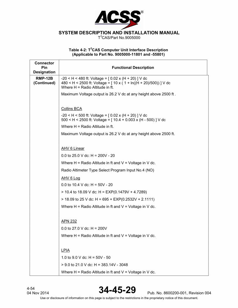
SYSTEM DESCRIPTION AND INSTALLATION MANUAL
T3CAS/Part No.9005000
Table 4-2: T3CAS Computer Unit Interface Description (Applicable to Part No. 9005000-11801 and -55801)
Connector Pin
Designation Functional Description
RMP-12B (Continued)
-20 < H < 480 ft: Voltage = [ 0.02 x (H + 20) ] V dc 480 < H < 2500 ft: Voltage = [ 10 x ( 1 + ln((H + 20)/500)) ] V dc Where H = Radio Altitude in ft.
Maximum Voltage output is 26.2 V dc at any height above 2500 ft .
Collins BCA
-20 < H < 500 ft: Voltage = [ 0.02 x (H + 20) ] V dc 500 < H < 2500 ft: Voltage = [ 10.4 + 0.003 x (H - 500) ] V dc
Where H = Radio Altitude in ft.
Maximum Voltage output is 26.2 V dc at any height above 2500 ft.
AHV 6 Linear
0.0 to 25.0 V dc: H = 200V - 20
Where H = Radio Altitude in ft and V = Voltage in V dc.
Radio Altimeter Type Select Program Input No.4 (NO)
AHV 6 Log 0.0 to 10.4 V dc: H = 50V - 20
> 10.4 to 18.09 V dc: H = EXP(0.1479V + 4.7289)
> 18.09 to 25 V dc: H = 695 + EXP(0.2532V + 2.1111)
Where H = Radio Altitude in ft and V = Voltage in V dc.
APN 232
0.0 to 27.0 V dc: H = 200V
Where H = Radio Altitude in ft and V = Voltage in V dc.
LPIA
1.0 to 9.0 V dc: H = 50V - 50
> 9.0 to 21.0 V dc: H = 383.14V - 3048
Where H = Radio Altitude in ft and V = Voltage in V dc.
4-54 04 Nov 2014 34-45-29 Pub. No. 8600200-001, Revision 004
Use or disclosure of information on this page is subject to the restrictions in the proprietary notice of this document.
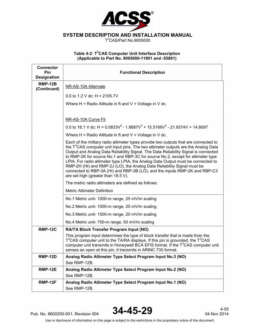
SYSTEM DESCRIPTION AND INSTALLATION MANUAL
T3CAS/Part No.9005000
Table 4-2: T3CAS Computer Unit Interface Description (Applicable to Part No. 9005000-11801 and -55801)
Connector Pin
Designation Functional Description
RMP-12B (Continued) NR-AS-10A Alternate
0.0 to 1.2 V dc: H = 2105.7V
Where H = Radio Altitude in ft and V = Voltage in V dc.
NR-AS-10A Curve Fit
0.0 to 18.1 V dc: H = 0.0833V4 - 1.8887V3 + 15.5169V2 - 21.9374V + 14.8097
Where H = Radio Altitude in ft and V = Voltage in V dc.
Each of the military radio altimeter types provide two outputs that are connected to the T3CAS computer unit input pins. The two altimeter outputs are the Analog Data Output and Analog Data Reliability Signal. The Data Reliability Signal is connected to RMP-2K for source No.1 and RBP-3C for source No.2, except for altimeter type LPIA. For radio altimeter type LPIA, the Analog Data Output must be connected to RMP-2H (HI) and RMP-2J (LO), the Analog Data Reliability Signal must be connected to RBP-3A (HI) and RBP-3B (LO), and the inputs RMP-2K and RBP-C3 are set high (greater than 18.5 V).
The metric radio altimeters are defined as follows:
Metric Altimeter Definition
No.1 Metric unit- 1000-m range, 25 mV/m scaling
No.2 Metric unit- 1000-m range, 20 mV/m scaling
No.3 Metric unit- 1500-m range, 20 mV/m scaling
No.4 Metric unit- 750-m range, 50 mV/m scaling
RMP-12C
RA/TA Block Transfer Program Input (NO) This program input determines the type of block transfer that is made from the T3CAS computer unit to the TA/RA displays. If this pin is grounded, the T3CAS computer unit transmits in Honeywell BCA EFIS format. If the T3CAS computer unit senses an open at this pin, it transmits in ARINC 735 format.
RMP-12D Analog Radio Altimeter Type Select Program Input No.3 (NO) See RMP-12B.
RMP-12E Analog Radio Altimeter Type Select Program Input No.2 (NO) See RMP-12B.
RMP-12F Analog Radio Altimeter Type Select Program Input No.1 (NO) See RMP-12B.
Pub. No. 8600200-001, Revision 004 34-45-29 4-55
04 Nov 2014 Use or disclosure of information on this page is subject to the restrictions in the proprietary notice of this document.

SYSTEM DESCRIPTION AND INSTALLATION MANUAL
T3CAS/Part No.9005000
Table 4-2: T3CAS Computer Unit Interface Description (Applicable to Part No. 9005000-11801 and -55801)
Connector Pin
Designation Functional Description
RMP-12G Traffic Generator (Ethernet RX+) The T3CAS computer unit may be configured in some lab installations to receive simulated traffic over an Ethernet connection rather than RF interface. Also serves as the A615A Dataloader Interface.
RMP-12H Traffic Generator (Ethernet RX-) See RMP-12G.
RMP-12J Traffic Generator (Ethernet TX+) The T3CAS computer unit may be configured in some lab installations to transmit simulated traffic over an Ethernet connection rather than RF interface. Also serves as the A615A Dataloader Interface.
RMP-12K Traffic Generator (Ethernet TX-) See RMP-12J.
RMP-13A, 13B
RA Display No.1/ARINC 429 Data Recorder Output: [RMP-13A (A), RMP-13B (B)] These ARINC 429 outputs are configured to output either RA information or for use as an ARINC 429 data recorder function. The output is configured by program pin RMP-11D. When RMP-11D is open (standard configuration), the bus is configured for low-speed (12.5k bits/s) ARINC 429 operation and RA information is output according to the format specified for the RA display bus in ARINC 735. When RMP-11D is grounded, the bus is configured for high-speed (100k bits/s) ARINC 429 operation and the output supplies TA and RA information to a 429 data recorder.
RMP-13C, 13D
RA Display No.2/ARINC 429 Data Recorder Output: [RMP-13C (A), RMP-13D (B)] See RMP-13A.
RMP-13E RA Display No.2 Status Discrete Input (NO) This ground/open discrete input (Note 1) provides the functional status of RA Display No.2. A ground on this pin indicates a valid display. If this discrete is not provided by the RA display, connect to aircraft ground to prevent RA DISPLAY No.2 fail message during self-test.
RMP-13F Landing Gear Discrete Input (NO) The T3CAS computer monitors this discrete that indicates the landing gear position. Landing Gear is a Ground/Open type discrete (Note 1) where an open indicates the gear is retracted (gear is up) and a ground indicates the gear is extended (gear is down).
RMP-13G Climb Inhibit No.2 Discrete Input (NO) See RMP-1J.
4-56 04 Nov 2014 34-45-29 Pub. No. 8600200-001, Revision 004
Use or disclosure of information on this page is subject to the restrictions in the proprietary notice of this document.

SYSTEM DESCRIPTION AND INSTALLATION MANUAL
T3CAS/Part No.9005000
Table 4-2: T3CAS Computer Unit Interface Description (Applicable to Part No. 9005000-11801 and -55801)
Connector Pin
Designation Functional Description
RMP-13H, 13J
Radio Altimeter No.1 (Left) Input: [RMP-13H (A), RMP-13J (B)] This input is provided for low-speed ARINC 429 (12.5k bits/s) altitude inputs from an ARINC 707 digital radio altimeter. Radio altitude data is used for computation of sensitivity level, inhibit descend advisories, inhibit aural annunciation when in close proximity to the ground and for TAWS reactive modes. See RMP-2H.
RMP-13K TCAS System Valid Discrete Output (NO) This ground/open-type discrete output (Note 3) indicates the health status of the T3CAS computer unit to other avionics systems that monitor TCAS system status. This output is used in retrofit installations where instrumentation needs to monitor TCAS status and the status is not available across an A429 bus. A ground at this pin indicates normal TCAS operation. An open indicates a TCAS fault.
RMP-14A, 14B Reserved: ARINC 429 Bus Output
RMP-14C RA Display No.1 Status Discrete Input (NO) This ground/open discrete input (Note 1) provides the functional status of RA Display No.1. A ground on this pin indicates a valid display. If this discrete is not provided by the RA display, connect to aircraft ground to prevent RA DISPLAY No.1 fail message during self-test.
RMP-14D, 14E Reserved: ARINC 429 Input
RMP-14F, 14G
ARINC 429 XT Coordination No.1 Input: [RMP-14F (A), RMP-14G (B)] This differential pair input is a high-speed ARINC 429 bus (100k bits/second nominal), that receives data from the No.1 Mode S Transponder.
RMP-14K Reserved: GND/OPEN Discrete Input RMP-15A,
15B Reserved: ARINC 429 Output Bus
RMP-15C, 15D
ARINC 429 Input: MMR/GPS #2 (Right) [RMP-15C (A), RMP-15D (B)] This high-speed 429 input is used to receive GPS label input containing position, velocity and quality information for the use of ADS-B IN applications and by the transponder function for ADS-B Out.
RMP-15E Thru
RMP-15H Reserved: TAWS/RWS ARINC 429 Output
RMP-15J, 15K
ARINC 429 TX Coordination No.1 Output: [RMP-15J (A), RMP-15K (B)] This differential pair output is a high-speed ARINC 429 bus (100k bits/second nominal), that transmits data from the T3CAS computer unit to the No.1 Mode S Transponder.
Pub. No. 8600200-001, Revision 004 34-45-29 4-57
04 Nov 2014 Use or disclosure of information on this page is subject to the restrictions in the proprietary notice of this document.

SYSTEM DESCRIPTION AND INSTALLATION MANUAL
T3CAS/Part No.9005000
Table 4-2: T3CAS Computer Unit Interface Description (Applicable to Part No. 9005000-11801 and -55801)
Connector Pin
Designation Functional Description
T3CAS Computer Unit Right Bottom Plug (RBP)
RBP-1A, 1B
Reserved: PCI Mezzanine Card Ethernet #1 RX (+/-)
RBP-1C, 1D
Reserved: PCI Mezzanine Card Ethernet #1 TX (+/-)
RBP-1E Reserved: GND/OPEN Discrete Input RBP-1F, G Reserved: GPS Time Mark A422 Input
RBP-1H RA Data Word 270 Bit 18 Discrete Output This discrete output provides RA information to the ARINC 573 flight recorder. The output goes to the “ground” state each time its associated bit within the advisory field of the RA output words changes from a “zero” condition to a “one” condition. The output remains in the “ground” state for as long as the associated RA bit remains non-zero. This output is read by the flight recorder as either a series or shunt output. NOTE: The discrete is pulled up to +28 V dc in the “open” state.
RBP-1J RA Data Word 270 Bit 19 Discrete Output See RBP-1H.
RBP-1K RA Data Word 270 Bit 20 Discrete Output See RBP-1H.
RBP-2A THRU
RBP-2G
TCAS/ADS-B In #3 thru TCAS/ADS-B In #9 Pin Strobing discrete inputs. See RMP-3H, RMP-3J, RBP-3F, RBP-3G
RBP-2H RA Data Word 270 Bit 21 Discrete Output See RBP-1H.
RBP-2J RA Data Word 270 Bit 22 Discrete Output See RBP-1H.
RBP-2K RA Data Word 270 Bit 23 Discrete Output See RBP-1H.
RBP-3A, 3B Radio Altimeter No.2 ARINC 552/Analog Input: [RBP-3A (HI), RBP-3B (LO)] See RMP-2H and -2J.
RBP-3C Radio Altimeter No.2 Valid Discrete Input (PO) See RMP-2H. Valid condition is greater than +18.5 V dc. Invalid is open.
RBP-3D, 3E Radio Altimeter No.2 (Right) Input: [RBP-3D (A), RBP-3E (B)] See RMP-13H. Also see RMP-2H.
4-58 04 Nov 2014 34-45-29 Pub. No. 8600200-001, Revision 004
Use or disclosure of information on this page is subject to the restrictions in the proprietary notice of this document.
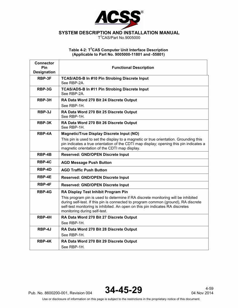
SYSTEM DESCRIPTION AND INSTALLATION MANUAL
T3CAS/Part No.9005000
Table 4-2: T3CAS Computer Unit Interface Description (Applicable to Part No. 9005000-11801 and -55801)
Connector Pin
Designation Functional Description
RBP-3F TCAS/ADS-B In #10 Pin Strobing Discrete Input See RBP-2A.
RBP-3G TCAS/ADS-B In #11 Pin Strobing Discrete Input See RBP-2A.
RBP-3H RA Data Word 270 Bit 24 Discrete Output See RBP-1H.
RBP-3J RA Data Word 270 Bit 25 Discrete Output See RBP-1H.
RBP-3K RA Data Word 270 Bit 26 Discrete Output See RBP-1H.
RBP-4A Magnetic/True Display Discrete Input (NO) This pin is used to set the display to a magnetic or true orientation. Grounding this pin indicates a true orientation of the CDTI map display; opening this pin indicates a magnetic orientation of the CDTI map display.
RBP-4B Reserved: GND/OPEN Discrete Input
RBP-4C AGD Message Push Button RBP-4D AGD Traffic Push Button RBP-4E Reserved: GND/OPEN Discrete Input RBP-4F Reserved: GND/OPEN Discrete Input RBP-4G RA Display Test Inhibit Program Pin
This program pin is used to determine if RA discrete monitoring will be inhibited during self-test. If this pin is connected to program common (ground), RA discrete self-test monitoring is inhibited. An open on this pin indicates RA discretes monitoring during self-test.
RBP-4H RA Data Word 270 Bit 27 Discrete Output See RBP-1H.
RBP-4J RA Data Word 270 Bit 28 Discrete Output See RBP-1H.
RBP-4K RA Data Word 270 Bit 29 Discrete Output See RBP-1H.
Pub. No. 8600200-001, Revision 004 34-45-29 4-59
04 Nov 2014 Use or disclosure of information on this page is subject to the restrictions in the proprietary notice of this document.

SYSTEM DESCRIPTION AND INSTALLATION MANUAL
T3CAS/Part No.9005000
Table 4-2: T3CAS Computer Unit Interface Description (Applicable to Part No. 9005000-11801 and -55801)
Connector Pin
Designation Functional Description
RBP-5A Advisory Inhibit Discrete Input No.1 (NO) Four ground/open-type discrete inputs (Note 1) at RBP-5A, -5B, -5C, and -5D provide the capability for the T3CAS computer to defer all advisory (TA), aural alert and visual alert outputs until another, higher priority announcement or alert is completed. An open at all four of these discrete inputs indicates normal advisory/alert operation. These discrete inputs become active by connection to program common (ground) at RBP-7K. No new TA information can be placed on the RA or RA/TA busses during a period of Advisory Inhibit. If an advisory condition, which occurred during a period of Advisory Inhibit, remains when the T3CAS computer returns to normal operation, it is annunciated. The Advisory Inhibit inputs and their effects on the advisory/alert priority system are as follows:
Discrete No.1 Pin No. Mode Priority
1 RBP-5A Forced Standby 1
2 RBP-5B Force TA Only (no voice/tone) 2
3 RBP-5C Force TA Only (no voice/tone) 2
4 RBP-5D Force TA Only (no voice/tone) 2
Discrete No.1 (RBP-5A) has priority over No.2 (RBP-5B), No.3 (RBP-5C) and No.4 (RBP-5D). Discrete No.1 forces TCAS into STANDBY mode. Discretes No.2, No.3, and No.4 force TCAS into TA mode with no voice or tone annunciations. See Note 1 for Ground/Open type discrete input definition.
RBP-5B Advisory Inhibit Discrete Input No.2 (NO) See RBP-5A.
RBP-5C Advisory Inhibit Discrete Input No.3 (NO) See RBP-5A.
RBP-5D Advisory Inhibit Discrete Input No.4 (NO) See RBP-5A.
RBP-5E Increase Climb Inhibit Discrete Input No.1 (NO) This input is a ground/open-type discrete (Note 1) used to provide information to the T3CAS CU whether to assume that the aircraft cannot achieve a climb rate of 2500 FPM (762 m/min). The climb inhibit discrete inputs are designed in pairs (No.1 and No.2 at RBP-5F, or No.3 at RBP-5G and No.4 at RBP-5H) but can be wired as a single input or in conjunction with other aircraft operations to achieve airframe customization of the climb inhibit feature. The 2500 FPM (762 m/min) climb inhibit function is assumed whenever No.1 and No.2 are ground or No.3 and No.4 are ground.
4-60 04 Nov 2014 34-45-29 Pub. No. 8600200-001, Revision 004
Use or disclosure of information on this page is subject to the restrictions in the proprietary notice of this document.

SYSTEM DESCRIPTION AND INSTALLATION MANUAL
T3CAS/Part No.9005000
Table 4-2: T3CAS Computer Unit Interface Description (Applicable to Part No. 9005000-11801 and -55801)
Connector Pin
Designation Functional Description
RBP-5F Increase Climb Inhibit Discrete Input No.2 (NO) See RBP-5E.
RBP-5G Increase Climb Inhibit Discrete Input No.3 (NO) See RBP-5E.
RBP-5H Increase Climb Inhibit Discrete Input No.4 (NO) See RBP-5E.
RBP-5J Climb Inhibit Discrete Input No.3 (NO) See RMP-1J.
RBP-5K Climb Inhibit Discrete Input No.4 (NO) See RMP-1J.
RBP-6A Reserved: GND/OPEN Discrete Input RBP-6B Data Loader Discrete #2 Ground RBP-6C Reserved: GND/OPEN Discrete Input RBP-6D Data Loader Discrete #4 Ground or Software Part Number Enabled
RBP-6E, 6F ARINC 429 Output Interface to CMC: [RBP-6E (A), RBP-6F (B)] This differential pair output is a low-speed ARINC 429 bus (12.5k bits/second nominal) that transmits data to a Central Maintenance Computer.
RBP-6G, 6H ARINC 429 CMC Input: [RBP-6G (A), RBP-6H (B)] This differential pair input is a low-speed ARINC 429 bus (12.5k bits/second nominal), that receives data from a Centralized Maintenance Computer.
RBP-6J Single Mode S Transponder Program Pin Input Ground this pin when the computer is connected to a single mode S transponder.
RBP-6K Single Radio Altimeter Program Pin Input Ground this pin when the computer is connected to a single radio altimeter.
Pub. No. 8600200-001, Revision 004 34-45-29 4-61
04 Nov 2014 Use or disclosure of information on this page is subject to the restrictions in the proprietary notice of this document.
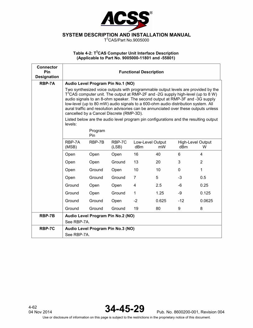
SYSTEM DESCRIPTION AND INSTALLATION MANUAL
T3CAS/Part No.9005000
Table 4-2: T3CAS Computer Unit Interface Description (Applicable to Part No. 9005000-11801 and -55801)
Connector Pin
Designation Functional Description
RBP-7A Audio Level Program Pin No.1 (NO) Two synthesized voice outputs with programmable output levels are provided by the T3CAS computer unit. The output at RMP-2F and -2G supply high-level (up to 8 W) audio signals to an 8-ohm speaker. The second output at RMP-3F and -3G supply low-level (up to 80 mW) audio signals to a 600-ohm audio distribution system. All aural traffic and resolution advisories can be annunciated over these outputs unless cancelled by a Cancel Discrete (RMP-3D). Listed below are the audio level program pin configurations and the resulting output levels:
Program Pin
RBP-7A (MSB)
RBP-7B
RBP-7C (LSB)
Low-Level Output dBm mW
High-Level Output dBm W
Open Open Open 16 40 6 4
Open Open Ground 13 20 3 2
Open Ground Open 10 10 0 1
Open Ground Ground 7 5 -3 0.5
Ground Open Open 4 2.5 -6 0.25
Ground Open Ground 1 1.25 -9 0.125
Ground Ground Open -2 0.625 -12 0.0625
Ground Ground Ground 19 80 9 8
RBP-7B Audio Level Program Pin No.2 (NO) See RBP-7A.
RBP-7C Audio Level Program Pin No.3 (NO) See RBP-7A.
4-62 04 Nov 2014 34-45-29 Pub. No. 8600200-001, Revision 004
Use or disclosure of information on this page is subject to the restrictions in the proprietary notice of this document.

SYSTEM DESCRIPTION AND INSTALLATION MANUAL
T3CAS/Part No.9005000
Table 4-2: T3CAS Computer Unit Interface Description (Applicable to Part No. 9005000-11801 and -55801)
Connector Pin
Designation Functional Description
RBP-7D Audio Tone Enable Program Pin (NO) If this programming pin is connected to program common, (RBP-7K), all voice announcements are delayed by one sec and are preceded by a tone. If pin is left open, no delays or tones occur.
RBP-7E Ground Display Mode Program Pin (NO) The T3CAS computer unit monitors this programming pin to select the TCAS ground display mode while the aircraft is on the ground. If the aircraft is on the ground and this pin is connected to program common (RBP-7K), TCAS goes into standby mode. If this pin is left open and the aircraft is on the ground, TCAS displays traffic only. Aural and voice annunciations are inhibited while the aircraft is on the ground. NOTE: TCAS does not display any traffic that it locates on the ground. TCAS
aircraft has WOW and intruder aircraft reports the same altitude or a lower altitude.
RBP-7F Display All Traffic Program Pin (NO) The T3CAS computer unit monitors this program pin to select either the all traffic display mode or the TA/RA only mode. If this pin is open, all traffic is displayed. If this pin is connected to program common (RBP-7K), the TCAS displays only TA/RA type intruders.
RBP-7G Cable Delay Signal Program Pin (NO) The cable delay program pins (RBP-7G, RBP-7H, and RBP-7J) convey to the T3CAS computer unit the amount of delay differential between the top and bottom antenna cables. Pin RBP-7G determines whether a time delay is added to the top or bottom. If this pin is open, the time delay is added to the top. If this pin is ground (connected to program pin RBP-7K), the time delay is added to the bottom. The cable delay logic is given below. Program common for the cable delay program pins is RBP-7K.
RBP-7H (MSB)
RBP-7J (LSB)
Differential Delay Adjustment
Open Open 0-50 nsec No Change
Open Ground 51-150 nsec Add 100 nsec delay
Ground Open 151-250 nsec Add 200 nsec delay
Ground Ground 251-350 nsec Add 300 nsec delay
RBP-7H Cable Delay MSB Program (NO) See RBP-7G.
RBP-7J Cable Delay LSB Program Pin (NO) See RBP-7G.
Pub. No. 8600200-001, Revision 004 34-45-29 4-63
04 Nov 2014 Use or disclosure of information on this page is subject to the restrictions in the proprietary notice of this document.

SYSTEM DESCRIPTION AND INSTALLATION MANUAL
T3CAS/Part No.9005000
Table 4-2: T3CAS Computer Unit Interface Description (Applicable to Part No. 9005000-11801 and -55801)
Connector Pin
Designation Functional Description
RBP-7K Program Common This is the ground source for use with program pins.
RBP-8A Thru
RBP-8D Reserved: Program Pin Inputs
RBP-8E Self-Test Test Inhibit Program Pin (NO) This program pin determines if self-test will be inhibited while airborne. If grounded, this pin inhibits self-test while airborne. If open, self-test is enabled while airborne.
RBP-8F TA/RA Display Symbol Maximum 16 Program Pin (NO) The T3CAS computer unit establishes the number of intruder symbols to be displayed on the TA display through the program pins RBP-8F, -8G, -8H, -8J, and -8K. This number can vary between 0 and 31, depending on the programming that is a summation of the selected pins (-8F = 16, -8G = 8, -8H = 4, -8J = 2 and -8K = 1). Connecting one of these pins to program common (RBP-7K) conveys that the associated pin is not selected and that its value is not included in the summation. Leaving the pin open conveys that the associated pin is selected and its value is included in the summation. The encoded number is placed within the RTS data word (label 357) and sent to the display. The display should then limit the intruder symbols to this number. NOTE: Although it is possible to program pin the maximum number of intruder symbols to be displayed to be less than 8, T3CAS will output a minimum of 8 intruder symbols to the display.
RBP-8G TA/RA Display Symbol Maximum 8 Program Pin (NO) See RBP-8F.
RBP-8H TA/RA Display Symbol Maximum 4 Program Pin (NO) See RBP-8F.
RBP-8J TA/RA Display Symbol Maximum 2 Program Pin (NO) See RBP-8F.
RBP-8K TA/RA Display Symbol Maximum 1 Program Pin (NO) See RBP-8F.
RBP-9A Thru
RBP-9K
Reserved Factory Test Pins Leave these pins unconnected for aircraft installations.
RBP-10A Thru
RBP-10K
Reserved Factory Test Pins Leave these pins unconnected for aircraft installations
4-64 04 Nov 2014 34-45-29 Pub. No. 8600200-001, Revision 004
Use or disclosure of information on this page is subject to the restrictions in the proprietary notice of this document.
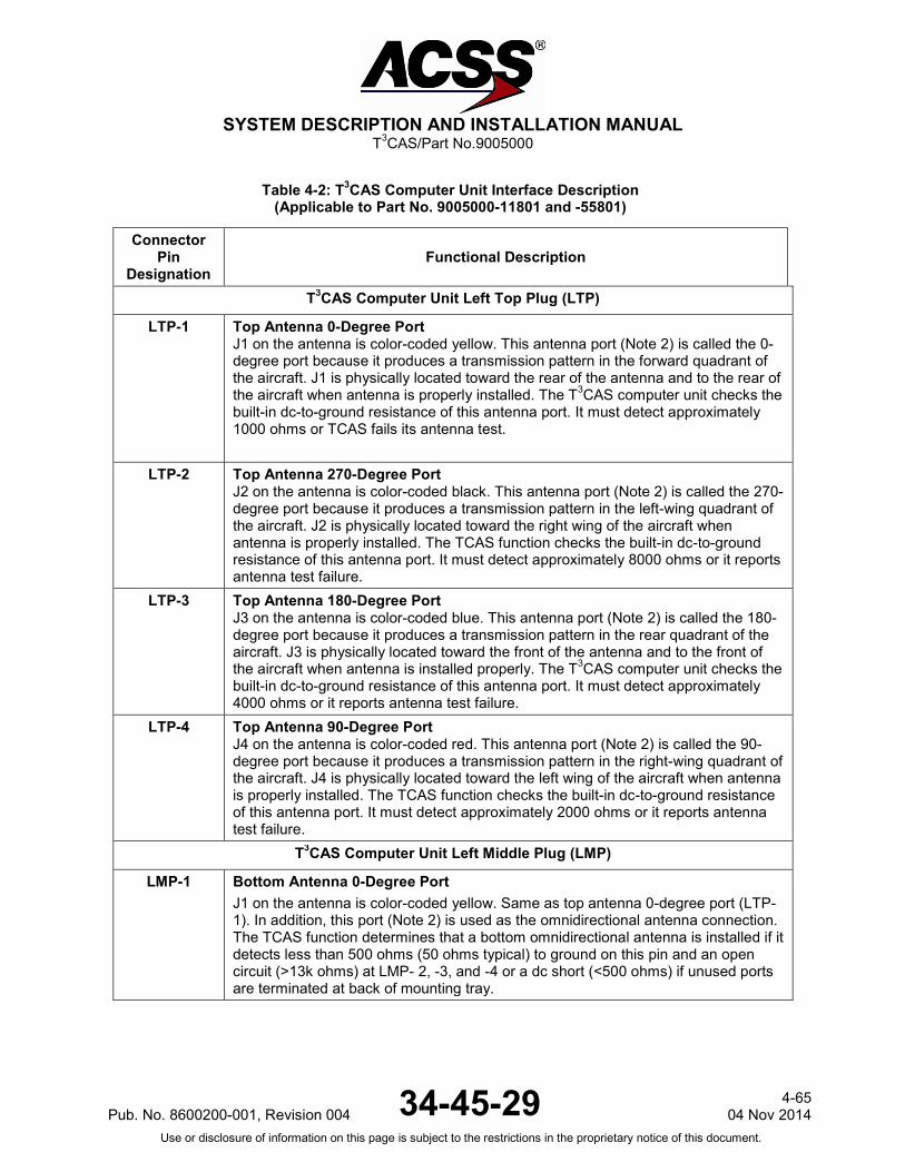
SYSTEM DESCRIPTION AND INSTALLATION MANUAL
T3CAS/Part No.9005000
Table 4-2: T3CAS Computer Unit Interface Description (Applicable to Part No. 9005000-11801 and -55801)
Connector Pin
Designation Functional Description
T3CAS Computer Unit Left Top Plug (LTP)
LTP-1
Top Antenna 0-Degree Port J1 on the antenna is color-coded yellow. This antenna port (Note 2) is called the 0-degree port because it produces a transmission pattern in the forward quadrant of the aircraft. J1 is physically located toward the rear of the antenna and to the rear of the aircraft when antenna is properly installed. The T3CAS computer unit checks the built-in dc-to-ground resistance of this antenna port. It must detect approximately 1000 ohms or TCAS fails its antenna test.
LTP-2
Top Antenna 270-Degree Port J2 on the antenna is color-coded black. This antenna port (Note 2) is called the 270-degree port because it produces a transmission pattern in the left-wing quadrant of the aircraft. J2 is physically located toward the right wing of the aircraft when antenna is properly installed. The TCAS function checks the built-in dc-to-ground resistance of this antenna port. It must detect approximately 8000 ohms or it reports antenna test failure.
LTP-3
Top Antenna 180-Degree Port J3 on the antenna is color-coded blue. This antenna port (Note 2) is called the 180-degree port because it produces a transmission pattern in the rear quadrant of the aircraft. J3 is physically located toward the front of the antenna and to the front of the aircraft when antenna is installed properly. The T3CAS computer unit checks the built-in dc-to-ground resistance of this antenna port. It must detect approximately 4000 ohms or it reports antenna test failure.
LTP-4
Top Antenna 90-Degree Port J4 on the antenna is color-coded red. This antenna port (Note 2) is called the 90-degree port because it produces a transmission pattern in the right-wing quadrant of the aircraft. J4 is physically located toward the left wing of the aircraft when antenna is properly installed. The TCAS function checks the built-in dc-to-ground resistance of this antenna port. It must detect approximately 2000 ohms or it reports antenna test failure.
T3CAS Computer Unit Left Middle Plug (LMP)
LMP-1 Bottom Antenna 0-Degree Port J1 on the antenna is color-coded yellow. Same as top antenna 0-degree port (LTP-1). In addition, this port (Note 2) is used as the omnidirectional antenna connection. The TCAS function determines that a bottom omnidirectional antenna is installed if it detects less than 500 ohms (50 ohms typical) to ground on this pin and an open circuit (>13k ohms) at LMP- 2, -3, and -4 or a dc short (<500 ohms) if unused ports are terminated at back of mounting tray.
Pub. No. 8600200-001, Revision 004 34-45-29 4-65
04 Nov 2014 Use or disclosure of information on this page is subject to the restrictions in the proprietary notice of this document.

SYSTEM DESCRIPTION AND INSTALLATION MANUAL
T3CAS/Part No.9005000
Table 4-2: T3CAS Computer Unit Interface Description (Applicable to Part No. 9005000-11801 and -55801)
Connector Pin
Designation Functional Description
LMP-2 Bottom Antenna 90-Degree Port J2 on the antenna is color-coded black. This antenna port (Note 2) is called the 90-degree port because it produces a transmission pattern in the right-wing quadrant of the aircraft. J2 is physically located toward the left wing of the aircraft when antenna is properly installed. The TCAS function checks the built in dc-to-ground resistance of this antenna port. It must detect approximately 8000 ohms or it reports antenna test failure.
LMP-3 Bottom Antenna 180-Degree Port J3 on the antenna is color-coded blue. Same as top antenna (Note 2) 180-degree port (LTP-3).
LMP-4 Bottom Antenna 270-Degree Port J4 on the antenna is color-coded red. This antenna port (Note 2) is called the 270-degree port because it produces a transmission pattern in the left-wing quadrant of the aircraft. J4 is physically located toward the right wing of the aircraft when properly installed. The TCAS function checks the built in dc-to-ground resistance of this antenna port. It must detect approximately 2000 ohms or it reports antenna test failure.
T3CAS Computer Unit Left Bottom Plug (LBP)
LBP-1 115 V ac Power Input (H) This pin along with the 115 V ac Power Input (C) line (pin LBP-7) provides the 115 V ac power requirements for the T3CAS computer unit. Wiring requirement is a standard #20 AWG. NOTE: The T3CAS computer unit operates with either 115 V ac, 400 Hz, or 28 V dc
input power. If 115 V ac is used, the power should be connected through a 3-A circuit breaker, and the pins for the ±28 V dc input should be left unconnected.
LBP-2 Common Power Supply Spare Pin: No Connection
LBP-3 28 VDC Power Return (-) LBP-4 Common Power Supply Spare Pin: No Connection
LBP-5 Fan 115 V ac Power Output (H) For 115 V ac T3CAS computer installations, this pin along with the Fan 115 V ac Output Power (C) line (pin LBP-9) provides 115 V ac power for an external fan.
LBP-6 Common Power Supply Spare Pin: No Connection
LBP-7 115 V ac Power Input (C) See LBP-1.
LBP-8 Signal Ground Connect to Aircraft Signal Ground.
4-66 04 Nov 2014 34-45-29 Pub. No. 8600200-001, Revision 004
Use or disclosure of information on this page is subject to the restrictions in the proprietary notice of this document.

SYSTEM DESCRIPTION AND INSTALLATION MANUAL
T3CAS/Part No.9005000
Table 4-2: T3CAS Computer Unit Interface Description (Applicable to Part No. 9005000-11801 and -55801)
Connector Pin
Designation Functional Description
LBP-9 Fan 115 V ac Power Output (C) See LBP-5.
LBP-10 28 VDC Power Input (+) LBP-11 Chassis Ground
Connect to aircraft frame. The T3CAS Chassis and signal ground pins should use the same AWG as the power connections (See LBP-1 and LBP-10).
LBP-12 Mutual Suppression Pulse Bus Input A The T3CAS computer unit joins the mutual suppression bus daisy chained through TCAS and other RF-transmitting equipment onboard the aircraft. The TCAS function receives suppression pulses from other LRUs on this bus, which is used to suppress the TCAS receivers during such transmissions. This prevents the TCAS function from interpreting these transmissions as valid replies from an intruder aircraft. When not suppressed, the TCAS function transmits its own suppression pulses on the same bus in order to suppress the receivers in other L-band systems on the aircraft. The L-Band suppression coax must be RG142, RG400, or equivalent coaxial cable which meets the operational characteristics required by ARINC 735A.
LBP-13 Mutual Suppression Pulse Bus Input B See LBP-12.
The Interface descriptions that follow are for the 53-pin connector J1 mounted on the front panel of the T3CAS computer unit. These descriptions are used to make up the cable that is used to interface between the T3CAS computer unit and an ARINC 615A Ethernet, a RS-232
PC Serial Port, or an ARINC 429 Maintenance Display. J1-1, 2 ARINC 429 PDL Bus Input: [J1-1 (A), J1-2 (B)]
Reserved. J1-3, 4 Spare Pins
J1-5 Output Bus Shields The shields from the output bus (J1-8, 9) should be connected to this pin.
J1-6, 7 A615A Data Loader Ethernet Output [J1-6 (TD+), J1-7 (TD-)] TAWS Ethernet 10 Base-T.
J1-8, 9 ARINC 429 Data Loader/PDL Recorder Bus Output: [J1-8 (A), J1-9 (B)] Reserved.
J1-10 Thru J1-15
Spare Pins
Pub. No. 8600200-001, Revision 004 34-45-29 4-67
04 Nov 2014 Use or disclosure of information on this page is subject to the restrictions in the proprietary notice of this document.

SYSTEM DESCRIPTION AND INSTALLATION MANUAL
T3CAS/Part No.9005000
Table 4-2: T3CAS Computer Unit Interface Description (Applicable to Part No. 9005000-11801 and -55801)
Connector Pin
Designation Functional Description
J1-16 Input Bus Shields The shields from the input bus (J1-1, 2) should be connected to this pin.
J1-17 Spare Pin
J1-18 PDL Link A Discrete Input Reserved.
J1-19 PDL Link B Common Reserved..
J1-20, 22 115 V ac Power Output: [J1-20 (H), J1-22 (C)] These power output pins provide the 115 V ac operating power for the data loader. The 115 V ac (H) and 115 V ac (C) interconnect wires should be shielded or twisted and shielded with an insulating jacket over the shield. The shield should be connected to chassis ground (J1-21).
J1-21 Chassis Ground Connect 115 V ac power shields to this pin.
J1-23 A615A Dataloader Ethernet Input (RD+) TAWS Ethernet 10-base-T read input
J1-24, Thru J1-27
Spare Pins
J1-28 Output Bus Shields
J1-29 Thru J1-32
Spare Pins
J1-33,34 ARINC 429 TA/RA Display No.1 Output: [J1-33 (A), J1-34 (B)] This bus can be used to connect to a maintenance display. These pins are also connected to the ARINC 600 connector on the rear of the unit (RMP-7C and -7D).
J1-35, J1-36 Spare Pins
J1-37, 38 28 V dc Power Output: [J1-37 (HI), J1-38 (LO)] These pins supply +28 V dc, 30 W nominal power for a portable data loader (PDL). These pins are used only if the PDL operates from +28 V dc.
J1-39 A615A Dataloader Ethernet Input (RD-) TAWS Ethernet 10-base-T read input
J1-40 RS-232 Data Input #1 This input is used by the T3CAS to receive RS- 232 data from a portable maintenance terminal.
4-68 04 Nov 2014 34-45-29 Pub. No. 8600200-001, Revision 004
Use or disclosure of information on this page is subject to the restrictions in the proprietary notice of this document.
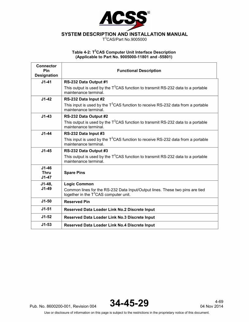
SYSTEM DESCRIPTION AND INSTALLATION MANUAL
T3CAS/Part No.9005000
Table 4-2: T3CAS Computer Unit Interface Description (Applicable to Part No. 9005000-11801 and -55801)
Connector Pin
Designation Functional Description
J1-41 RS-232 Data Output #1 This output is used by the T3CAS function to transmit RS-232 data to a portable maintenance terminal.
J1-42
RS-232 Data Input #2 This input is used by the T3CAS function to receive RS-232 data from a portable maintenance terminal.
J1-43 RS-232 Data Output #2 This output is used by the T3CAS function to transmit RS-232 data to a portable maintenance terminal.
J1-44 RS-232 Data Input #3 This input is used by the T3CAS function to receive RS-232 data from a portable maintenance terminal.
J1-45 RS-232 Data Output #3 This output is used by the T3CAS function to transmit RS-232 data to a portable maintenance terminal.
J1-46 Thru J1-47
Spare Pins
J1-48, J1-49
Logic Common Common lines for the RS-232 Data Input/Output lines. These two pins are tied together in the T3CAS computer unit.
J1-50 Reserved Pin
J1-51 Reserved Data Loader Link No.2 Discrete Input J1-52 Reserved Data Loader Link No.3 Discrete Input J1-53 Reserved Data Loader Link No.4 Discrete Input
Pub. No. 8600200-001, Revision 004 34-45-29 4-69
04 Nov 2014 Use or disclosure of information on this page is subject to the restrictions in the proprietary notice of this document.
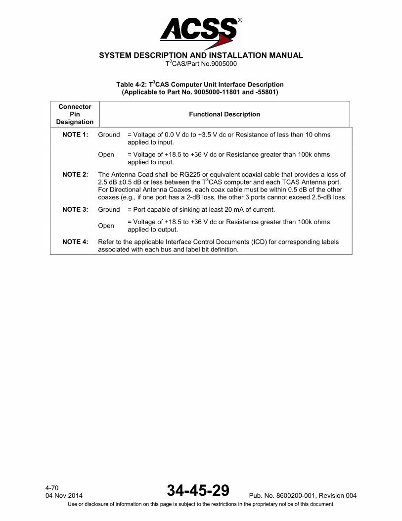
SYSTEM DESCRIPTION AND INSTALLATION MANUAL
T3CAS/Part No.9005000
Table 4-2: T3CAS Computer Unit Interface Description (Applicable to Part No. 9005000-11801 and -55801)
Connector Pin
Designation Functional Description
NOTE 1: Ground = Voltage of 0.0 V dc to +3.5 V dc or Resistance of less than 10 ohms applied to input.
Open = Voltage of +18.5 to +36 V dc or Resistance greater than 100k ohms applied to input.
NOTE 2: The Antenna Coad shall be RG225 or equivalent coaxial cable that provides a loss of 2.5 dB ±0.5 dB or less between the T3CAS computer and each TCAS Antenna port. For Directional Antenna Coaxes, each coax cable must be within 0.5 dB of the other coaxes (e.g., if one port has a 2-dB loss, the other 3 ports cannot exceed 2.5-dB loss.
NOTE 3: Ground = Port capable of sinking at least 20 mA of current.
Open = Voltage of +18.5 to +36 V dc or Resistance greater than 100k ohms applied to output.
NOTE 4: Refer to the applicable Interface Control Documents (ICD) for corresponding labels associated with each bus and label bit definition.
4-70 04 Nov 2014 34-45-29 Pub. No. 8600200-001, Revision 004
Use or disclosure of information on this page is subject to the restrictions in the proprietary notice of this document.

SYSTEM DESCRIPTION AND INSTALLATION MANUAL
T3CAS/Part No.9005000
Table 4-3: Gables Control Panel Interface Descriptions
Connector Pin
Designation Functional Description
J1-1, 2 PANEL AND DISPLAY LIGHTING INPUT: (J1-1 HIGH, J1-2 LOW) 5-V ac, 2.3-A maximum lighting input for front panel and display lighting. Lighting is provided by incandescent lamps.
J1/J2-3, 4
+28 V dc INPUT POWER: (J1/J2-3 HIGH, J1/J2-4 LOW) The control panel is powered from a +28-V dc power bus. Two identical but isolated power supplies provide the power requirements to each individual electronic module that independently control transponder 1 and 2. Maximum current is 2.5 A dc.
J1/J2-5
ANTENNA TRANSFER DISCRETE OUTPUT: (J1/J2-5) This discrete output is used to provide the ability to switch a RF relay for dual transponder installations that have only one set of antennas. These outputs from J1 and J2 are linked to the XPDR 1-2 switch. The output is OPEN (+12 to +35 V dc) when the transponder is in standby (inactive) mode, and GROUND (< +3.5 V dc) when the transponder is in an active operational mode.
J1/J2-6 dc GROUND INPUT: (J1/J2-6) Reference for all discrete inputs/outputs. Tied to aircraft dc ground.
J1/J2-7
STANDBY/ON OUTPUT: (J1/J2-7) These discrete outputs (STANDBY/ON) will mimic the XPDR switch position placing one transponder in Standby and the other in the ON (active) mode. Both transponders will never be in the ON mode simultaneously. This output is GROUND(< +3.5 V dc) when in Standby mode and OPEN (+12 to +35 V dc) when in the ON mode. This output can sink 100 mA maximum. Connect pin to transponder STANDBY/ON Discrete Input.
J1/J2-8 CHASSIS GROUND INPUT: (J1/J2-8) Tied to airframe. Also used to connect ARINC 429 cable shields to the chassis.
J1/J2-9
FUNCTIONAL TEST INPUT: (J1/J2-9) Functional test can also be initiated using this discrete input. When J1/J2-9 is grounded, a functional test similar to pushing the TEST button on the front panel is done.
J1/J2-10
WARNING AND CAUTION OUTPUT: (J1/J2-10) This discrete output provides a low signal to a remote master warning system when the control panel receives a Monitor Lamp fault indication from the active transponder. Otherwise it provides 7 to 30 V dc or a resistance of >100k ohms to ground. This output can sink 20 mA maximum.
Pub. No. 8600200-001, Revision 004 34-45-29 4-71
04 Nov 2014 Use or disclosure of information on this page is subject to the restrictions in the proprietary notice of this document.
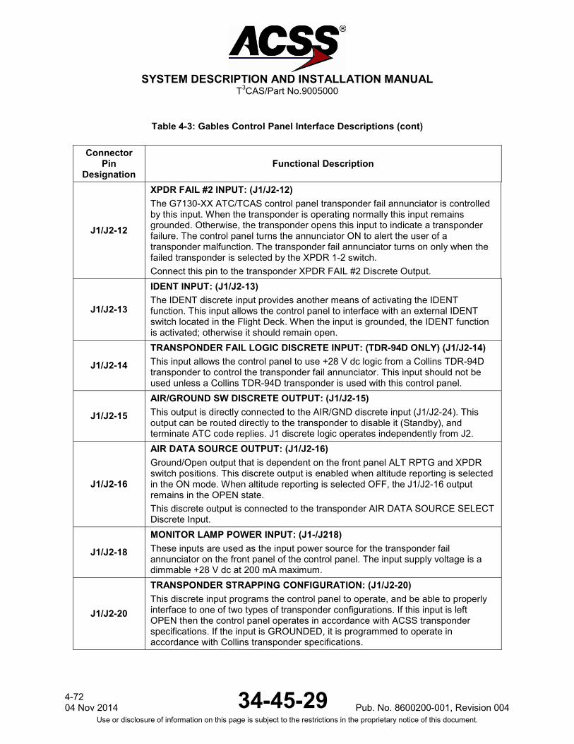
SYSTEM DESCRIPTION AND INSTALLATION MANUAL
T3CAS/Part No.9005000
Table 4-3: Gables Control Panel Interface Descriptions (cont)
Connector Pin
Designation Functional Description
J1/J2-12
XPDR FAIL #2 INPUT: (J1/J2-12) The G7130-XX ATC/TCAS control panel transponder fail annunciator is controlled by this input. When the transponder is operating normally this input remains grounded. Otherwise, the transponder opens this input to indicate a transponder failure. The control panel turns the annunciator ON to alert the user of a transponder malfunction. The transponder fail annunciator turns on only when the failed transponder is selected by the XPDR 1-2 switch. Connect this pin to the transponder XPDR FAIL #2 Discrete Output.
J1/J2-13
IDENT INPUT: (J1/J2-13) The IDENT discrete input provides another means of activating the IDENT function. This input allows the control panel to interface with an external IDENT switch located in the Flight Deck. When the input is grounded, the IDENT function is activated; otherwise it should remain open.
J1/J2-14
TRANSPONDER FAIL LOGIC DISCRETE INPUT: (TDR-94D ONLY) (J1/J2-14) This input allows the control panel to use +28 V dc logic from a Collins TDR-94D transponder to control the transponder fail annunciator. This input should not be used unless a Collins TDR-94D transponder is used with this control panel.
J1/J2-15
AIR/GROUND SW DISCRETE OUTPUT: (J1/J2-15) This output is directly connected to the AIR/GND discrete input (J1/J2-24). This output can be routed directly to the transponder to disable it (Standby), and terminate ATC code replies. J1 discrete logic operates independently from J2.
J1/J2-16
AIR DATA SOURCE OUTPUT: (J1/J2-16) Ground/Open output that is dependent on the front panel ALT RPTG and XPDR switch positions. This discrete output is enabled when altitude reporting is selected in the ON mode. When altitude reporting is selected OFF, the J1/J2-16 output remains in the OPEN state. This discrete output is connected to the transponder AIR DATA SOURCE SELECT Discrete Input.
J1/J2-18
MONITOR LAMP POWER INPUT: (J1-/J218) These inputs are used as the input power source for the transponder fail annunciator on the front panel of the control panel. The input supply voltage is a dimmable +28 V dc at 200 mA maximum.
J1/J2-20
TRANSPONDER STRAPPING CONFIGURATION: (J1/J2-20) This discrete input programs the control panel to operate, and be able to properly interface to one of two types of transponder configurations. If this input is left OPEN then the control panel operates in accordance with ACSS transponder specifications. If the input is GROUNDED, it is programmed to operate in accordance with Collins transponder specifications.
4-72 04 Nov 2014 34-45-29 Pub. No. 8600200-001, Revision 004
Use or disclosure of information on this page is subject to the restrictions in the proprietary notice of this document.
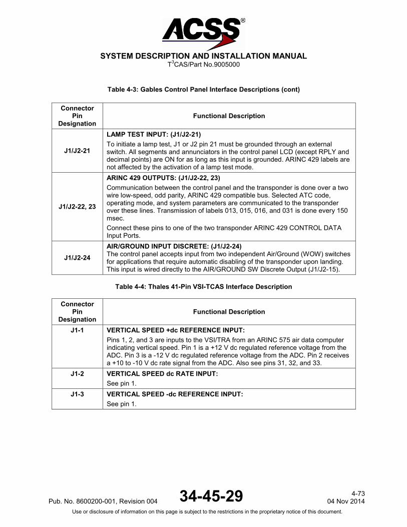
SYSTEM DESCRIPTION AND INSTALLATION MANUAL
T3CAS/Part No.9005000
Table 4-3: Gables Control Panel Interface Descriptions (cont)
Connector Pin
Designation Functional Description
J1/J2-21
LAMP TEST INPUT: (J1/J2-21) To initiate a lamp test, J1 or J2 pin 21 must be grounded through an external switch. All segments and annunciators in the control panel LCD (except RPLY and decimal points) are ON for as long as this input is grounded. ARINC 429 labels are not affected by the activation of a lamp test mode.
J1/J2-22, 23
ARINC 429 OUTPUTS: (J1/J2-22, 23) Communication between the control panel and the transponder is done over a two wire low-speed, odd parity, ARINC 429 compatible bus. Selected ATC code, operating mode, and system parameters are communicated to the transponder over these lines. Transmission of labels 013, 015, 016, and 031 is done every 150 msec. Connect these pins to one of the two transponder ARINC 429 CONTROL DATA Input Ports.
J1/J2-24 AIR/GROUND INPUT DISCRETE: (J1/J2-24) The control panel accepts input from two independent Air/Ground (WOW) switches for applications that require automatic disabling of the transponder upon landing. This input is wired directly to the AIR/GROUND SW Discrete Output (J1/J2-15).
Table 4-4: Thales 41-Pin VSI-TCAS Interface Description
Connector Pin
Designation Functional Description
J1-1 VERTICAL SPEED +dc REFERENCE INPUT: Pins 1, 2, and 3 are inputs to the VSI/TRA from an ARINC 575 air data computer indicating vertical speed. Pin 1 is a +12 V dc regulated reference voltage from the ADC. Pin 3 is a -12 V dc regulated reference voltage from the ADC. Pin 2 receives a +10 to -10 V dc rate signal from the ADC. Also see pins 31, 32, and 33.
J1-2 VERTICAL SPEED dc RATE INPUT: See pin 1.
J1-3 VERTICAL SPEED -dc REFERENCE INPUT: See pin 1.
Pub. No. 8600200-001, Revision 004 34-45-29 4-73
04 Nov 2014 Use or disclosure of information on this page is subject to the restrictions in the proprietary notice of this document.
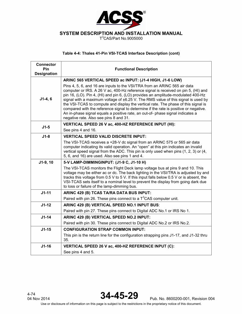
SYSTEM DESCRIPTION AND INSTALLATION MANUAL
T3CAS/Part No.9005000
Table 4-4: Thales 41-Pin VSI-TCAS Interface Description (cont)
Connector Pin
Designation Functional Description
J1-4, 6
ARINC 565 VERTICAL SPEED ac INPUT: (J1-4 HIGH, J1-6 LOW) Pins 4, 5, 6, and 16 are inputs to the VSI/TRA from an ARINC 565 air data computer or IRS. A 26 V ac, 400-Hz reference signal is received on pin 5, (HI) and pin 16, (LO). Pin 4, (HI) and pin 6, (LO) provides an amplitude-modulated 400-Hz signal with a maximum voltage of ±6.25 V. The RMS value of this signal is used by the VSI-TCAS to compute and display the vertical rate. The phase of this signal is compared with the reference signal to determine if the rate is positive or negative. An in-phase signal equals a positive rate, an out-of- phase signal indicates a negative rate. Also see pins 8 and 31.
J1-5 VERTICAL SPEED 26 V ac, 400-HZ REFERENCE INPUT (HI): See pins 4 and 16.
J1-8 VERTICAL SPEED VALID DISCRETE INPUT: The VSI-TCAS receives a +28-V dc signal from an ARINC 575 or 565 air data computer indicating its valid operation. An “open” at this pin indicates an invalid vertical speed signal from the ADC. This pin is only used when pins (1, 2, 3) or (4, 5, 6, and 16) are used. Also see pins 1 and 4.
J1-9, 10 5-V LAMP-DIMMINGINPUT: (J1-9 C, J1-10 H) The VSI-TCAS monitors the Flight Deck lamp voltage bus at pins 9 and 10. This voltage may be either ac or dc. The back lighting in the VSI/TRA is adjusted by and tracks this voltage from 0.5 V to 5 V. If this input falls below 0.5 V or is absent, the VSI-TCAS sets itself to a nominal level to prevent the display from going dark due to loss or failure of the lamp-dimming bus.
J1-11 ARINC 429 (B) TCAS TA/RA DATA BUS INPUT: Paired with pin 26. These pins connect to a T3CAS computer unit.
J1-12 ARINC 429 (B) VERTICAL SPEED NO.1 INPUT BUS: Paired with pin 27. These pins connect to Digital ADC No.1 or IRS No 1.
J1-14 ARINC 429 (B) VERTICAL SPEED NO.2 INPUT: Paired with pin 30. These pins connect to Digital ADC No.2 or IRS No.2.
J1-15 CONFIGURATION STRAP COMMON INPUT: This pin is the return line for the configuration strapping pins J1-17, and J1-32 thru 35.
J1-16 VERTICAL SPEED 26 V ac, 400-HZ REFERENCE INPUT (C): See pins 4 and 5.
4-74 04 Nov 2014 34-45-29 Pub. No. 8600200-001, Revision 004
Use or disclosure of information on this page is subject to the restrictions in the proprietary notice of this document.

SYSTEM DESCRIPTION AND INSTALLATION MANUAL
T3CAS/Part No.9005000
Table 4-4: Thales 41-Pin VSI-TCAS Interface Description (cont)
Connector Pin
Designation Functional Description
J1-17 CONFIGURATION STRAP #3 INPUT (NO): Pin 17 is used in conjunction with pin 35 to select the indicator operating mode as follows: The following applies: O = Open, G = Ground.
Pin 35 17 Indicator Operating Mode
G G Test (shop level) G O VSI only
O G RA VSI only
O O TA/RA VSI
J1-18 SECONDARY VERT SPEED VALIDITY INPUT (+28 V dc): The VSI-TCAS receives a +28-V dc signal from an ARINC 575 or 565 air data computer indicating its valid operation. An “open” at this pin indicates an invalid vertical speed signal from the ADC. This pin is only used when pins (1, 2, 3) or (4, 5, 6, and 16) are used.
J1-19, 20 VERT SPEED BOOTSTRAP ac OUT: (J1-19 [HIGH], J1-20 [LO]) This output repeats the ARINC 565 input signals (26-V 400-Hz reference and signal) available on the primary input when this input has been selected : -26-V 400-Hz reference The voltage available on the output (26-V ac Bootstrap ref. output) is the same as that available on the 26-V ac 400-Hz reference (hot) of the ARINC 565 primary input, the common reference being the cold of the 26-V ac primary ref. input. - Output signal (vertical speed bootstrap ac output) available on two wires (HI and LO).
J1-22 CHASSIS GROUND INPUT: Connected to aircraft frame. Also used to connect ARINC cable shields to the chassis.
J1-23 115-V ac, 400-HZ POWER INPUT (COMMON): See pin 40. Connect to aircraft ac ground.
J1-24, 25 REMOTE LIGHT SENSOR INPUT: (J1-24 LOW, J1-25 HIGH) This input at pins 24 and 25 provides a means of controlling the VSI-TCAS back lighting via a remote light sensor already present in some aircraft (Douglas and Boeing). The VSI-TCAS has its own built-in sensor and therefore a remote light sensor need not be used in all installations. Program the VSI-TCAS for a remote light sensor, as describe under pin 34.
Pub. No. 8600200-001, Revision 004 34-45-29 4-75
04 Nov 2014 Use or disclosure of information on this page is subject to the restrictions in the proprietary notice of this document.

SYSTEM DESCRIPTION AND INSTALLATION MANUAL
T3CAS/Part No.9005000
Table 4-4: Thales 41-Pin VSI-TCAS Interface Description (cont)
Connector Pin
Designation Functional Description
J1-26 ARINC 429 (A) TCAS TA/RA DATA INPUT: Traffic and Resolution Advisory data is supplied to the VSI-TCAS from the T3CAS computer unit via this high-speed ARINC 429 data bus. Paired with pin 11.
J1-27 ARINC 429 (A) VERTICAL SPEED NO.1 INPUT: This is the primary ARINC 429 input bus to the VSI-TCAS. This pin accepts high- or low-speed ARINC 429 vertical speed data (Label 212). Its use is determined by the source select discrete and configuration straps CS0 and CS1 (pins 31, 32, and 33 respectively). Paired with pin 12.
J1-28 CONFIGURATION STRAP #2 INPUT (NO): This is the V/S response time selection. A time constant of 3.8 sec with pin 28 open and of 7.6 sec with pin 28 grounded.
J1-29 TA/RA VALID DISCRETE OUTPUT (NO): This output discrete indicates the ability of the VSI-TCAS to perform as a resolution advisory and/or a traffic advisory display. If the VSI-TCAS fails, this discrete presents an open. Normal operation causes a ground. This discrete is monitored by the T3CAS computer unit.
J1-30 ARINC 429 (A) VERTICAL SPEED NO.2 INPUT: This is the secondary ARINC 429 input bus to the VSI-TCAS. This pin accepts high- or low-speed ARINC 429 vertical speed data (Label 212). Its use is determined by the source select discrete and configuration straps CS0 and CS1 (pins 31, 32 and 33 respectively). Paired with pin 14.
J1-31 (Continues)
SOURCE SELECT DISCRETE INPUT (NO): This discrete input is used in conjunction with configuration straps CS0, CS1 and CS2 to program the VSI-TCAS to accept and use the vertical speed data being supplied. In some installations, this discrete is connected to a switch in the Flight Deck and is used to select between primary and secondary ARINC 429 vertical speed inputs. It is hard-wired to configuration strap common if ac or dc analog vertical speed inputs are used. Cycle power to update to the new configuration. The following applies: O = Open, G = Ground.
4-76 04 Nov 2014 34-45-29 Pub. No. 8600200-001, Revision 004
Use or disclosure of information on this page is subject to the restrictions in the proprietary notice of this document.
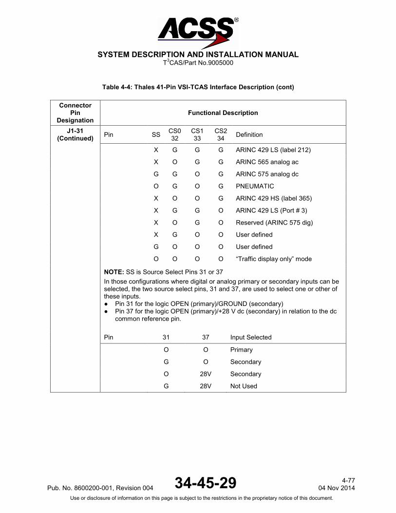
SYSTEM DESCRIPTION AND INSTALLATION MANUAL
T3CAS/Part No.9005000
Table 4-4: Thales 41-Pin VSI-TCAS Interface Description (cont)
Connector Pin
Designation Functional Description
J1-31 (Continued) Pin SS CS0
32 CS1 33
CS2 34 Definition
X G G G ARINC 429 LS (label 212)
X O G G ARINC 565 analog ac
G G O G ARINC 575 analog dc
O G O G PNEUMATIC
X O O G ARINC 429 HS (label 365)
X G G O ARINC 429 LS (Port # 3)
X O G O Reserved (ARINC 575 dig)
X G O O User defined
G O O O User defined
O O O O “Traffic display only” mode
NOTE: SS is Source Select Pins 31 or 37 In those configurations where digital or analog primary or secondary inputs can be selected, the two source select pins, 31 and 37, are used to select one or other of these inputs. ● Pin 31 for the logic OPEN (primary)/GROUND (secondary) ● Pin 37 for the logic OPEN (primary)/+28 V dc (secondary) in relation to the dc
common reference pin.
Pin 31 37 Input Selected
O O Primary
G O Secondary
O 28V Secondary
G 28V Not Used
Pub. No. 8600200-001, Revision 004 34-45-29 4-77
04 Nov 2014 Use or disclosure of information on this page is subject to the restrictions in the proprietary notice of this document.

SYSTEM DESCRIPTION AND INSTALLATION MANUAL
T3CAS/Part No.9005000
Table 4-4: Thales 41-Pin VSI-TCAS Interface Description (cont)
Connector Pin
Designation Functional Description
J1-32 CONFIGURATION STRAP #0 INPUT (NO): See pin 31.
J1-33 CONFIGURATION STRAP #1 INPUT (NO): See pin 31.
J1-34 CONFIGURATION STRAP #2 INPUT (NO): See pin 31.
J1-35 CONFIGURATION STRAP #4 INPUT (NO): See pin 17.
J1-36 SECONDARY ANALOG ac INPUT (LO): ARINC 565 ADC
J1-37 SECONDARY SOURCE SELECT DISCRETE INPUT (NO): See pin 31.
J1-38 VERTICAL SPEED VALID DISCRETE OUTPUT (NO): This validity discrete is representative of the operation of the vertical speed channel. The state of this discrete corresponds to an invalid state (OPEN) if : ● The indicator is not energized ● The indicator is in the initialization phase on power up ● The vertical speed failure warning flag is in view (case of internal or external
failures) ● The self-test/display test pin is activated. Definition of the OPEN state: Impedance in relation to the dc common greater than 100k ohms (open collector with an applicable voltage of +14 V dc to +32 than 100k ohms (open collector with an applicable voltage of +14 V dc to +32 V dc). A valid state is indicated by either: 1) A GROUND state characterized by a voltage of less than 3.5 V dc in relation to
dc commons with a maximum current of 20 mA, when the following types of vertical speed are selected: - Pneumatic input - Digital inputs (per ARINC 429 HS or LS and digital ARINC 575).
or 2) A dc output voltage (+ 28 V dc nominal), the minimum value of which is equal to
VIN - (2 + 200 x I), where VIN is the greater of the primary vertical speed and secondary vertical speed voltages available and I the output current expressed in amps (0.02 A max.). This type of signal is present on the output when the following types of vertical speed are selected: - ac analogue input (ARINC 565) - dc analogue input (ARINC 575).
4-78 04 Nov 2014 34-45-29 Pub. No. 8600200-001, Revision 004
Use or disclosure of information on this page is subject to the restrictions in the proprietary notice of this document.

SYSTEM DESCRIPTION AND INSTALLATION MANUAL
T3CAS/Part No.9005000
Table 4-4: Thales 41-Pin VSI-TCAS Interface Description (cont)
Connector Pin
Designation Functional Description
J1-39 dc GROUND INPUT: To be connected to aircraft dc Ground.
J1-40 115-V ac, 400-HZ POWER INPUT (HI): This pin, along with its return line (pin 23) supplies power to the VSI-TCAS. Connect power through a 1-A circuit breaker.
J1-41 SELF-TEST/DISPLAY TEST: This input functions on an OPEN/GROUND logic (in relation to dc common) and in parallel with the TEST Push button located on the front face of the indicator (for maintenance purposes only). When this input is activated and maintained in the GROUND state, the indicator performs a self-test procedure which results in:
- The display of a representative test pattern within 3 sec. - The transmission of an OPEN (invalid) state on the TCAS Display Status
Discrete Output for the duration of the test.
Table 4-5: ACSS 41-Pin VSI/TRA Interface Descriptions
Connector Pin
Designation Functional Description
J1-1 VERTICAL SPEED +dc REFERENCE INPUT: Pins 1,2, and 3 are inputs to the VSI/TRA from an ARINC 575 air data computer indicating vertical speed. Pin 1 is a +12 V dc regulated reference voltage from the ADC. Pin 3 is a -12 V dc regulated reference voltage from the ADC. Pin 2 receives a +10 to -10 V dc rate signal from the ADC. Also see pins 31, 32, and 33.
J1-2 VERTICAL SPEED dc RATE INPUT: See pin 1.
J1-3 VERTICAL SPEED -dc REFERENCE INPUT: See pin 1..
J1-4, 6 ARINC 565 VERTICAL SPEED ac INPUT: (J1-4 HIGH, J1-6 LOW) Pins 4, 5, 6, and 16 are inputs to the VSI/TRA from an ARINC 565 air data computer or IRS. A 26 V ac, 400-Hz reference signal is received on pin 5, (HI) and pin 16, (LO). Pin 4, (HI) and pin 6, (LO) provides an amplitude-modulated 400-Hz signal with a maximum voltage of ±6.25 volts. The RMS value of this signal is used by the VSI/TRA to compute and display the vertical rate. The phase of this signal is compared with the reference signal to determine if the rate is positive or negative. An in-phase signal equals a positive rate, an out-of- phase signal indicates a negative rate. Also see pins 8, 31, 32.
Pub. No. 8600200-001, Revision 004 34-45-29 4-79
04 Nov 2014 Use or disclosure of information on this page is subject to the restrictions in the proprietary notice of this document.
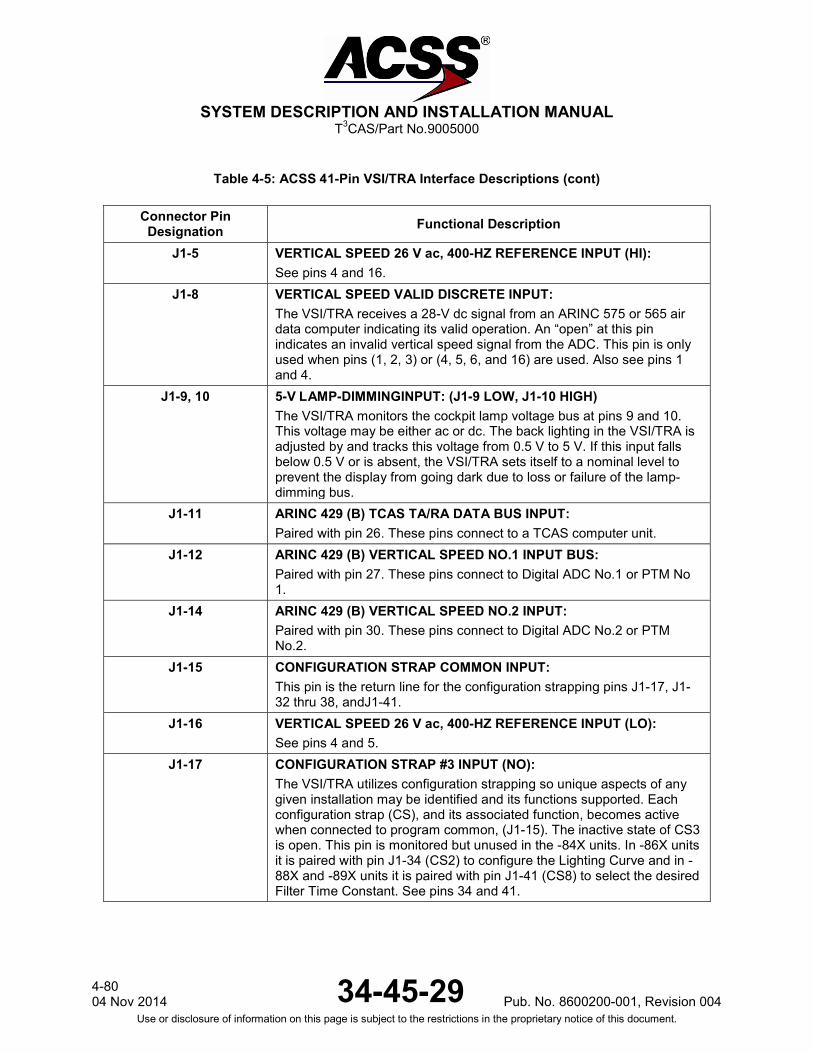
SYSTEM DESCRIPTION AND INSTALLATION MANUAL
T3CAS/Part No.9005000
Table 4-5: ACSS 41-Pin VSI/TRA Interface Descriptions (cont)
Connector Pin Designation Functional Description
J1-5 VERTICAL SPEED 26 V ac, 400-HZ REFERENCE INPUT (HI): See pins 4 and 16.
J1-8 VERTICAL SPEED VALID DISCRETE INPUT: The VSI/TRA receives a 28-V dc signal from an ARINC 575 or 565 air data computer indicating its valid operation. An “open” at this pin indicates an invalid vertical speed signal from the ADC. This pin is only used when pins (1, 2, 3) or (4, 5, 6, and 16) are used. Also see pins 1 and 4.
J1-9, 10 5-V LAMP-DIMMINGINPUT: (J1-9 LOW, J1-10 HIGH) The VSI/TRA monitors the cockpit lamp voltage bus at pins 9 and 10. This voltage may be either ac or dc. The back lighting in the VSI/TRA is adjusted by and tracks this voltage from 0.5 V to 5 V. If this input falls below 0.5 V or is absent, the VSI/TRA sets itself to a nominal level to prevent the display from going dark due to loss or failure of the lamp-dimming bus.
J1-11 ARINC 429 (B) TCAS TA/RA DATA BUS INPUT: Paired with pin 26. These pins connect to a TCAS computer unit.
J1-12 ARINC 429 (B) VERTICAL SPEED NO.1 INPUT BUS: Paired with pin 27. These pins connect to Digital ADC No.1 or PTM No 1.
J1-14 ARINC 429 (B) VERTICAL SPEED NO.2 INPUT: Paired with pin 30. These pins connect to Digital ADC No.2 or PTM No.2.
J1-15 CONFIGURATION STRAP COMMON INPUT: This pin is the return line for the configuration strapping pins J1-17, J1-32 thru 38, andJ1-41.
J1-16 VERTICAL SPEED 26 V ac, 400-HZ REFERENCE INPUT (LO): See pins 4 and 5.
J1-17 CONFIGURATION STRAP #3 INPUT (NO): The VSI/TRA utilizes configuration strapping so unique aspects of any given installation may be identified and its functions supported. Each configuration strap (CS), and its associated function, becomes active when connected to program common, (J1-15). The inactive state of CS3 is open. This pin is monitored but unused in the -84X units. In -86X units it is paired with pin J1-34 (CS2) to configure the Lighting Curve and in -88X and -89X units it is paired with pin J1-41 (CS8) to select the desired Filter Time Constant. See pins 34 and 41.
4-80 04 Nov 2014 34-45-29 Pub. No. 8600200-001, Revision 004
Use or disclosure of information on this page is subject to the restrictions in the proprietary notice of this document.
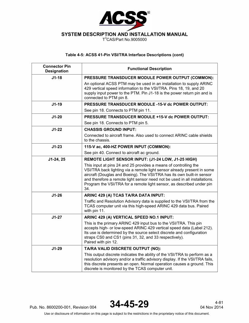
SYSTEM DESCRIPTION AND INSTALLATION MANUAL
T3CAS/Part No.9005000
Table 4-5: ACSS 41-Pin VSI/TRA Interface Descriptions (cont)
Connector Pin Designation Functional Description
J1-18 PRESSURE TRANSDUCER MODULE POWER OUTPUT (COMMON): An optional ACSS PTM may be used in an installation to supply ARINC 429 vertical speed information to the VSI/TRA. Pins 18, 19, and 20 supply input power to the PTM. Pin J1-18 is the power return pin and is connected to PTM pin 8.
J1-19 PRESSURE TRANSDUCER MODULE -15-V dc POWER OUTPUT: See pin 18. Connects to PTM pin 11.
J1-20 PRESSURE TRANSDUCER MODULE +15-V dc POWER OUTPUT: See pin 18. Connects to PTM pin 5.
J1-22 CHASSIS GROUND INPUT: Connected to aircraft frame. Also used to connect ARINC cable shields to the chassis.
J1-23 115-V ac, 400-HZ POWER INPUT (COMMON): See pin 40. Connect to aircraft ac ground.
J1-24, 25 REMOTE LIGHT SENSOR INPUT: (J1-24 LOW, J1-25 HIGH) This input at pins 24 and 25 provides a means of controlling the VSI/TRA back lighting via a remote light sensor already present in some aircraft (Douglas and Boeing). The VSI/TRA has its own built-in sensor and therefore a remote light sensor need not be used in all installations. Program the VSI/TRA for a remote light sensor, as described under pin 34.
J1-26 ARINC 429 (A) TCAS TA/RA DATA INPUT: Traffic and Resolution Advisory data is supplied to the VSI/TRA from the TCAS computer unit via this high-speed ARINC 429 data bus. Paired with pin 11.
J1-27 ARINC 429 (A) VERTICAL SPEED NO.1 INPUT: This is the primary ARINC 429 input bus to the VSI/TRA. This pin accepts high- or low-speed ARINC 429 vertical speed data (Label 212). Its use is determined by the source select discrete and configuration straps CS0 and CS1 (pins 31, 32, and 33 respectively). Paired with pin 12.
J1-29 TA/RA VALID DISCRETE OUTPUT (NO): This output discrete indicates the ability of the VSI/TRA to perform as a resolution advisory and/or a traffic advisory display. If the VSI/TRA fails, this discrete presents an open. Normal operation causes a ground. This discrete is monitored by the TCAS computer unit.
Pub. No. 8600200-001, Revision 004 34-45-29 4-81
04 Nov 2014 Use or disclosure of information on this page is subject to the restrictions in the proprietary notice of this document.

SYSTEM DESCRIPTION AND INSTALLATION MANUAL
T3CAS/Part No.9005000
Table 4-5: ACSS 41-Pin VSI/TRA Interface Descriptions (cont)
Connector Pin Designation Functional Description
J1-30 ARINC 429 (A) VERTICAL SPEED NO.2 INPUT: This is the secondary ARINC 429 input bus to the VSI/TRA. This pin accepts high- or low-speed ARINC 429 vertical speed data (Label 212). Its use is determined by the source select discrete and configuration straps CS0 and CS1 (pins 31, 32 and 33 respectively). Paired with pin 14.
J1-31 SOURCE SELECT DISCRETE INPUT (NO): This discrete input is used in conjunction with configuration straps CS0 and CS1 to program the VSI/TRA to accept and use the vertical speed data being supplied. In some installations, this discrete is connected to a switch in the cockpit and is used to select between primary and secondary ARINC 429 vertical speed inputs. It is hard-wired to configuration strap common if ac or dc analog vertical speed inputs are used. Cycle power to update to the new configuration. The following applies: O = Open, G = Ground.
Pin SS 31
CS0 32
CS1 33 Definition
O O O ARINC 429 HS Primary
G O O ARINC 429 HS Secondary
O G O Pressure Transducer Module (PTM)
G G O ARINC 575 dc
G O G ARINC 565 ac
O G G ARINC 429 LS Primary
G G G ARINC 429 LS Secondary
J1-32 CONFIGURATION STRAP #0 INPUT (NO): See pin 31.
J1-33 CONFIGURATION STRAP #1 INPUT (NO): See pin 31.
4-82 04 Nov 2014 34-45-29 Pub. No. 8600200-001, Revision 004
Use or disclosure of information on this page is subject to the restrictions in the proprietary notice of this document.
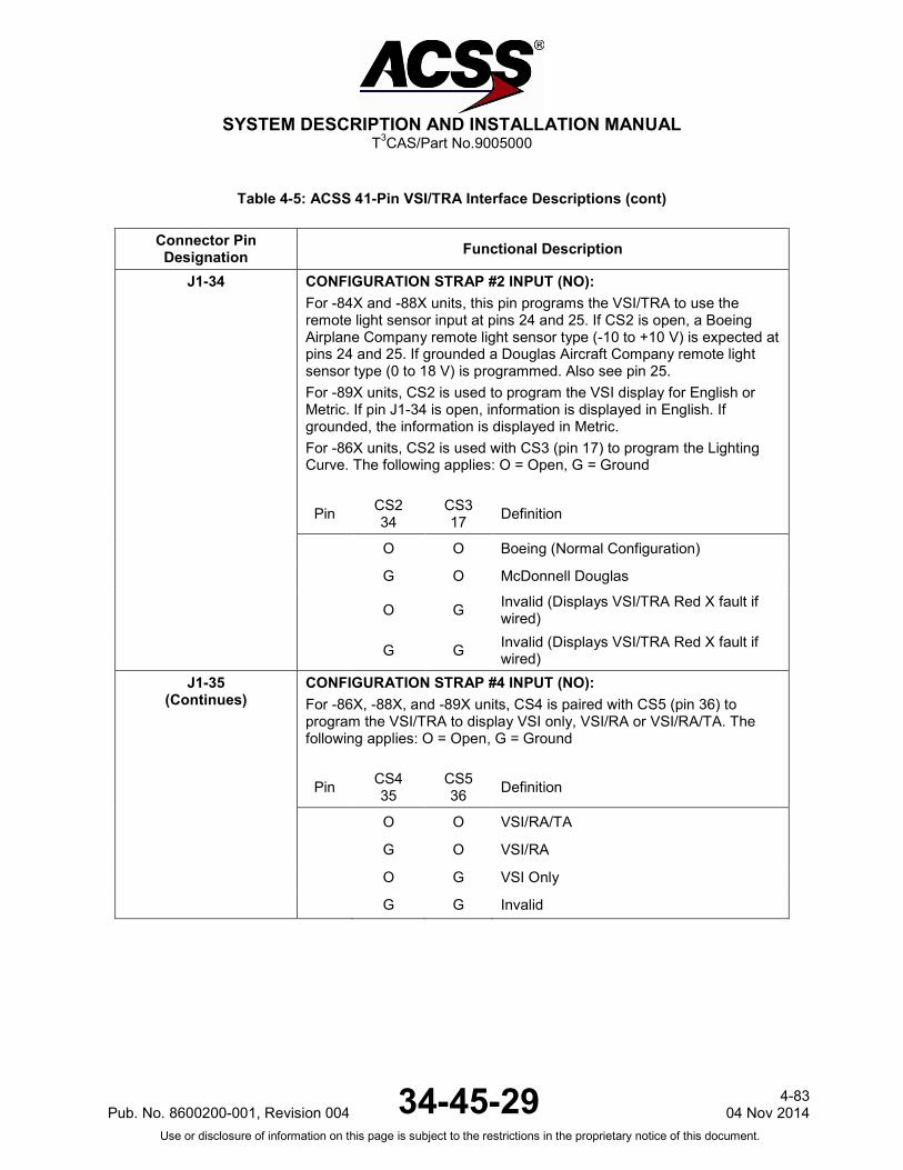
SYSTEM DESCRIPTION AND INSTALLATION MANUAL
T3CAS/Part No.9005000
Table 4-5: ACSS 41-Pin VSI/TRA Interface Descriptions (cont)
Connector Pin Designation Functional Description
J1-34
CONFIGURATION STRAP #2 INPUT (NO): For -84X and -88X units, this pin programs the VSI/TRA to use the remote light sensor input at pins 24 and 25. If CS2 is open, a Boeing Airplane Company remote light sensor type (-10 to +10 V) is expected at pins 24 and 25. If grounded a Douglas Aircraft Company remote light sensor type (0 to 18 V) is programmed. Also see pin 25. For -89X units, CS2 is used to program the VSI display for English or Metric. If pin J1-34 is open, information is displayed in English. If grounded, the information is displayed in Metric. For -86X units, CS2 is used with CS3 (pin 17) to program the Lighting Curve. The following applies: O = Open, G = Ground
Pin CS2 34
CS3 17 Definition
O O Boeing (Normal Configuration)
G O McDonnell Douglas
O G Invalid (Displays VSI/TRA Red X fault if wired)
G G Invalid (Displays VSI/TRA Red X fault if wired)
J1-35 (Continues)
CONFIGURATION STRAP #4 INPUT (NO): For -86X, -88X, and -89X units, CS4 is paired with CS5 (pin 36) to program the VSI/TRA to display VSI only, VSI/RA or VSI/RA/TA. The following applies: O = Open, G = Ground
Pin CS4 35
CS5 36 Definition
O O VSI/RA/TA
G O VSI/RA
O G VSI Only
G G Invalid
Pub. No. 8600200-001, Revision 004 34-45-29 4-83
04 Nov 2014 Use or disclosure of information on this page is subject to the restrictions in the proprietary notice of this document.

SYSTEM DESCRIPTION AND INSTALLATION MANUAL
T3CAS/Part No.9005000
Table 4-5: ACSS 41-Pin VSI/TRA Interface Descriptions (cont)
Connector Pin Designation Functional Description
J1-35 (Continued)
For -84X units, CS4 is paired with CS3 (pin 17) to program the Display Range Format. The following applies: O = Open, G = Ground
Pin CS4 35
CS5 17 Definition
O O 14-NMI Range
G O 6-NMI Range
O G 40-NMI Range
G G 6-NMI Range
J1-36 CONFIGURATION STRAP #5 INPUT (NO): For -86X, -88X, and -89X units, see pin 35. For -84X units, CS5 is paired with CS6 (pin 37) to program the Altitude Band. The following apply: O = Open, G = Ground
Pin CS5 36
CS6 37 Definition
O O Normal -A to +A
G O Above -A to +B
O G Below -B to +A
G G Unrestricted Range
J1-37 CONFIGURATION STRAP #6 INPUT (NO): For -84X units this pin is paired with CS5 to program the altitude band. See pin 36. For -86X, -88X, and -89X units, CS6 is used to program the Traffic Filter. If pin 37 is Open, the VSI/TRA is programmed to NOT display other traffic. If pin 37 is grounded, other traffic is displayed.
J1-38 CONFIGURATION STRAP #7 INPUT (NO): This configuration strap is used during factory test to take the VSI/TRA out of flight mode and into test mode when grounded. This pin must be left unwired, “Open” in all aircraft installations.
J1-39 dc GROUND INPUT: To be connected to aircraft dc Ground.
4-84 04 Nov 2014 34-45-29 Pub. No. 8600200-001, Revision 004
Use or disclosure of information on this page is subject to the restrictions in the proprietary notice of this document.
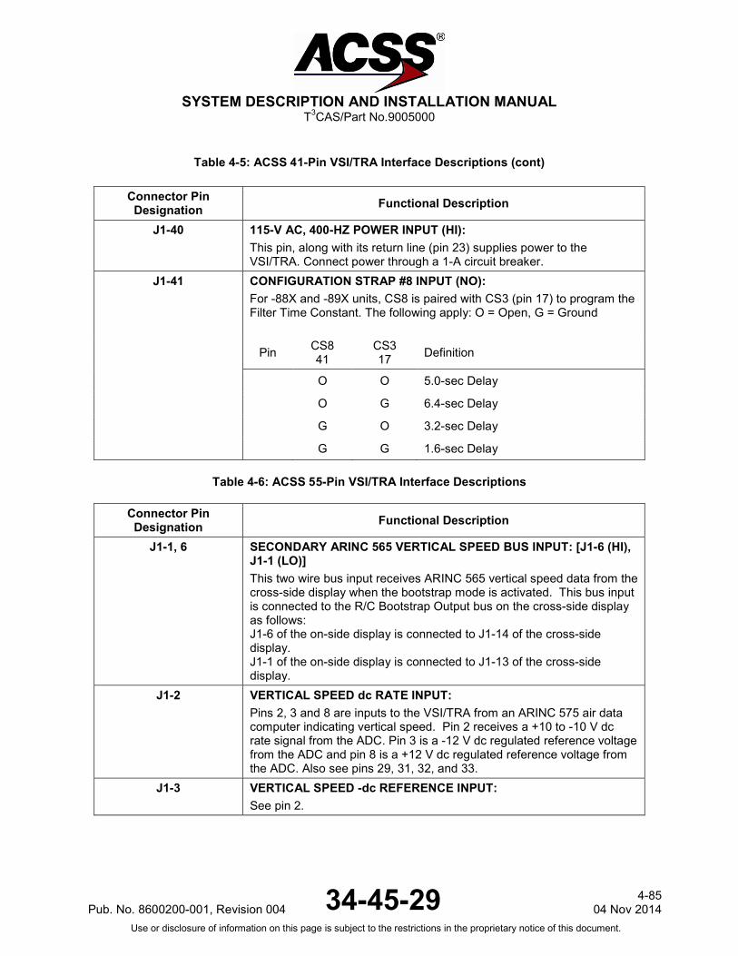
SYSTEM DESCRIPTION AND INSTALLATION MANUAL
T3CAS/Part No.9005000
Table 4-5: ACSS 41-Pin VSI/TRA Interface Descriptions (cont)
Connector Pin Designation Functional Description
J1-40 115-V AC, 400-HZ POWER INPUT (HI): This pin, along with its return line (pin 23) supplies power to the VSI/TRA. Connect power through a 1-A circuit breaker.
J1-41 CONFIGURATION STRAP #8 INPUT (NO): For -88X and -89X units, CS8 is paired with CS3 (pin 17) to program the Filter Time Constant. The following apply: O = Open, G = Ground
Pin CS8 41
CS3 17 Definition
O O 5.0-sec Delay
O G 6.4-sec Delay
G O 3.2-sec Delay
G G 1.6-sec Delay
Table 4-6: ACSS 55-Pin VSI/TRA Interface Descriptions
Connector Pin Designation Functional Description
J1-1, 6 SECONDARY ARINC 565 VERTICAL SPEED BUS INPUT: [J1-6 (HI), J1-1 (LO)] This two wire bus input receives ARINC 565 vertical speed data from the cross-side display when the bootstrap mode is activated. This bus input is connected to the R/C Bootstrap Output bus on the cross-side display as follows: J1-6 of the on-side display is connected to J1-14 of the cross-side display. J1-1 of the on-side display is connected to J1-13 of the cross-side display.
J1-2 VERTICAL SPEED dc RATE INPUT: Pins 2, 3 and 8 are inputs to the VSI/TRA from an ARINC 575 air data computer indicating vertical speed. Pin 2 receives a +10 to -10 V dc rate signal from the ADC. Pin 3 is a -12 V dc regulated reference voltage from the ADC and pin 8 is a +12 V dc regulated reference voltage from the ADC. Also see pins 29, 31, 32, and 33.
J1-3 VERTICAL SPEED -dc REFERENCE INPUT: See pin 2.
Pub. No. 8600200-001, Revision 004 34-45-29 4-85
04 Nov 2014 Use or disclosure of information on this page is subject to the restrictions in the proprietary notice of this document.

SYSTEM DESCRIPTION AND INSTALLATION MANUAL
T3CAS/Part No.9005000
Table 4-6: ACSS 55-Pin VSI/TRA Interface Descriptions (cont)
Connector Pin Designation Functional Description
J1-4 BOOTSTRAP REFERENCE OUTPUT: This output sends the bootstrap ARINC 565 ac reference voltage to the cross-side display. The output is connected to the Secondary 26-V ac Reference Input (pin 7) of the cross-side display.
J1-5 VERTICAL SPEED NO.2 VALID DISCRETE INPUT: This discrete input receives bootstrap ARINC 565 vertical speed valid data from the cross-side display. The input is connected to the Vertical Speed Output (pin 49) of the cross-side display.
J1-7 SECONDARY 26-V ac REFERENCE INPUT: This input receives the bootstrap ARINC 565 ac reference voltage from the cross-side display. The input is connected to the Bootstrap Reference Output (pin 40) of the cross-side display.
J1-8 VERTICAL SPEED +dc REFERENCE INPUT: See pin 2.
J1-9 PRIMARY VERTICAL SPEED 26-V ac, 400-HZ REFERENCE INPUT: See pins 10, 11.
J1-12 VERTICAL SPEED NO.1 VALID DISCRETE INPUT: The VSI/TRA receives a 28-V dc signal from an ARINC 575 or 565 air data computer indicating its valid operation. An “Open” at this pin indicates an invalid vertical speed signal from ADC #1. This pin is only used when pins ( 2, 3, 8) or (9, 10, 11) are used and on the #1 VSI/TRA display. Also see pins 2, 10, and 11.
J1-13,14 R/C BOOTSTRAP OUTPUT: [J1-14 (HI), J1-13 (LO)] This two-wire bus output sends ARINC 565 vertical speed data to the cross-side display when the bootstrap mode is activated. These pins are connected to the ARINC 565 Secondary Vertical Speed Input bus on the cross-side display as follows: J1-14 of the on-side display is connected to J1-6 of the cross-side display. J1-13 of the on-side display is connected to J1-1 of the cross-side display.
J1-15 BOOTSTRAP COMMAND OUTPUT: This pin is connected to the Source Select #2 (SS2) discrete input, pin 29, within the VSI/TRA. The output provides an Open/28 V dc discrete that can be used to annunciate the bootstrap function. This output is normally not used.
4-86 04 Nov 2014 34-45-29 Pub. No. 8600200-001, Revision 004
Use or disclosure of information on this page is subject to the restrictions in the proprietary notice of this document.

SYSTEM DESCRIPTION AND INSTALLATION MANUAL
T3CAS/Part No.9005000
Table 4-6: ACSS 55-Pin VSI/TRA Interface Descriptions (cont)
Connector Pin Designation Functional Description
J1-17 CONFIGURATION STRAP #5 INPUT (NO): For -84X units, CS5 is paired with CS6 (pin 37) to program the altitude band. The following apply: O = Open, G = Ground
Pin CS5 17
CS6 18 Definition
O O Normal -A to +A
G O Above -A to +B
O G Below -B to +A
G G Unrestricted Range
For -86X, -88X and -89X units, CS5 is paired with CS4 (pin 36) to program the Display Format. The following apply: O = Open, G = Ground
Pin CS5 41
CS4 17 Definition
O O VSI/RA/TA
O G VSI/RA
G O VSI Only
G G Invalid
J1-18 CONFIGURATION STRAP #6 INPUT (NO): For -84X units, see pin 17. For -86X, -88X, and -89X units CS6 is used to program the Traffic Filter. If pin 18 is Open, the VSI/TRA is programmed to not display other traffic. If pin 18 is grounded, other traffic will be displayed.
J1-19 CONFIGURATION STRAP #7 INPUT (NO): This configuration strap is used during factory test to take the VSI/TRA out of flight mode and into test mode when grounded. This pin must be left unwired, “Open” in all aircraft installations.
J1-20 CHASSIS GROUND INPUT: Connected to aircraft frame. Also used to connect ARINC cable shields to the chassis.
J1-21 dc GROUND INPUT: To be connected to aircraft dc Ground.
Pub. No. 8600200-001, Revision 004 34-45-29 4-87
04 Nov 2014 Use or disclosure of information on this page is subject to the restrictions in the proprietary notice of this document.
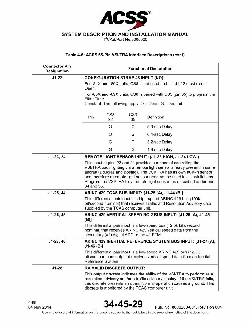
SYSTEM DESCRIPTION AND INSTALLATION MANUAL
T3CAS/Part No.9005000
Table 4-6: ACSS 55-Pin VSI/TRA Interface Descriptions (cont)
Connector Pin Designation Functional Description
J1-22 CONFIGURATION STRAP #8 INPUT (NO): For -84X and -86X units, CS8 is not used and pin J1-22 must remain Open. For -88X and -89X units, CS8 is paired with CS3 (pin 35) to program the Filter Time Constant. The following apply: O = Open, G = Ground
Pin CS8 22
CS3 35 Definition
O O 5.0-sec Delay
O G 6.4-sec Delay
G O 3.2-sec Delay
G G 1.6-sec Delay
J1-23, 24 REMOTE LIGHT SENSOR INPUT: (J1-23 HIGH, J1-24 LOW ) This input at pins 23 and 24 provides a means of controlling the VSI/TRA back lighting via a remote light sensor already present in some aircraft (Douglas and Boeing). The VSI/TRA has its own built-in sensor and therefore a remote light sensor need not be used in all installations. Program the VSI/TRA for a remote light sensor, as described under pin 34 and 35.
J1-25, 44 ARINC 429 TCAS BUS INPUT: [J1-25 (A), J1-44 (B)] This differential pair input is a high-speed ARINC 429 bus (100k bit/second nominal) that receives Traffic and Resolution Advisory data supplied by the TCAS computer unit.
J1-26, 45 ARINC 429 VERTICAL SPEED NO.2 BUS INPUT: [J1-26 (A), J1-45 (B)] This differential pair input is a low-speed bus (12.5k bits/second nominal) that receives ARINC 429 vertical speed data from the secondary (#2) digital ADC or the #2 PTM.
J1-27, 46 ARINC 429 INERTIAL REFERENCE SYSTEM BUS INPUT: [J1-27 (A), J1-46 (B)] This differential pair input is a low-speed ARINC 429 bus (12.5k bits/second nominal) that receives vertical speed data from an Inertial Reference System.
J1-28 RA VALID DISCRETE OUTPUT: This output discrete indicates the ability of the VSI/TRA to perform as a resolution advisory and/or a traffic advisory display. If the VSI/TRA fails, this discrete presents an open. Normal operation causes a ground. This discrete is monitored by the TCAS computer unit.
4-88 04 Nov 2014 34-45-29 Pub. No. 8600200-001, Revision 004
Use or disclosure of information on this page is subject to the restrictions in the proprietary notice of this document.
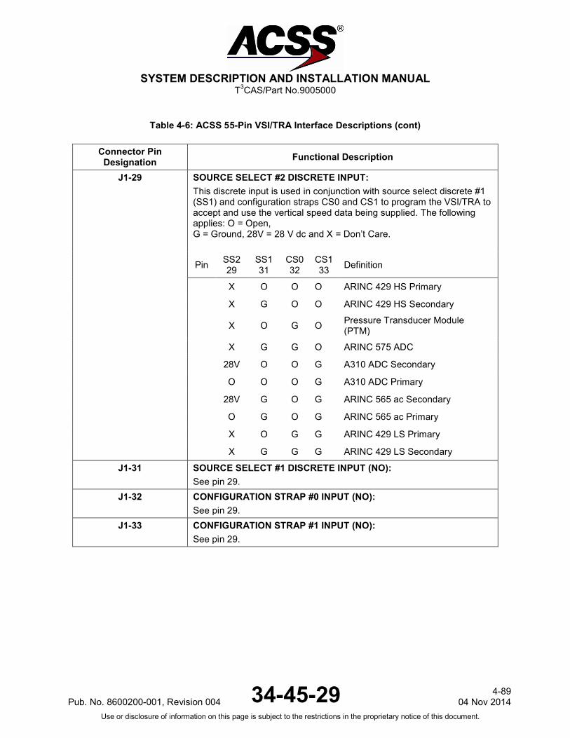
SYSTEM DESCRIPTION AND INSTALLATION MANUAL
T3CAS/Part No.9005000
Table 4-6: ACSS 55-Pin VSI/TRA Interface Descriptions (cont)
Connector Pin Designation Functional Description
J1-29 SOURCE SELECT #2 DISCRETE INPUT: This discrete input is used in conjunction with source select discrete #1 (SS1) and configuration straps CS0 and CS1 to program the VSI/TRA to accept and use the vertical speed data being supplied. The following applies: O = Open, G = Ground, 28V = 28 V dc and X = Don’t Care.
Pin SS2 29
SS1 31
CS0 32
CS1 33 Definition
X O O O ARINC 429 HS Primary
X G O O ARINC 429 HS Secondary
X O G O Pressure Transducer Module (PTM)
X G G O ARINC 575 ADC
28V O O G A310 ADC Secondary
O O O G A310 ADC Primary
28V G O G ARINC 565 ac Secondary
O G O G ARINC 565 ac Primary
X O G G ARINC 429 LS Primary
X G G G ARINC 429 LS Secondary
J1-31 SOURCE SELECT #1 DISCRETE INPUT (NO): See pin 29.
J1-32 CONFIGURATION STRAP #0 INPUT (NO): See pin 29.
J1-33 CONFIGURATION STRAP #1 INPUT (NO): See pin 29.
Pub. No. 8600200-001, Revision 004 34-45-29 4-89
04 Nov 2014 Use or disclosure of information on this page is subject to the restrictions in the proprietary notice of this document.

SYSTEM DESCRIPTION AND INSTALLATION MANUAL
T3CAS/Part No.9005000
Table 4-6: ACSS 55-Pin VSI/TRA Interface Descriptions (cont)
Connector Pin Designation Functional Description
J1-34 J1-34 CONFIGURATION STRAP #2 INPUT (NO): For -84X and -88X units, this pin programs the VSI/TRA to use the remote light sensor input at pins 23 and 24. If CS2 is open, a Boeing Airplane Company remote light sensor type (-10 to +10 V) is expected at pins 23 and 24. If pin 34 is grounded, a McDonnell Douglas Aircraft Company remote light sensor type (0 to 18 V) is programmed. Also see pins 23/24. For -89X units, CS2 is used to program the VSI display for English or Metric. If pin J1-34 is open, information is displayed in English. If pin 34 is grounded, the information is displayed in Metric. For -86X units, CS2 is used with CS3 (pin 17) to program the lighting curve. The following applies: O = Open, G = Ground
Pin CS2 34
CS3 35 Definition
O O Boeing (Normal Configuration)
G O McDonnell Douglas
O G Invalid (Displays VSI/TRA Red X fault if wired)
G G Invalid (Displays VSI/TRA Red X fault if wired)
J1-35 CONFIGURATION STRAP #3 INPUT (NO): For -86X units, CS3 is paired with CS2 to program the Lighting Curve. See pin 34. For -88X and -89X units, CS3 is paired with CS8 to program the Filter Time Constant. See pin 22. For -84X units, CS3 is paired with CS4 (pin 36) to program the display Range Format. The following applies: O = Open, G = Ground
Pin CS3 35
CS4 36 Definition
O O 14-NMI Range
O G 6-NMI Range
G O 40-NMI Range
G G 6-NMI Range
4-90 04 Nov 2014 34-45-29 Pub. No. 8600200-001, Revision 004
Use or disclosure of information on this page is subject to the restrictions in the proprietary notice of this document.

SYSTEM DESCRIPTION AND INSTALLATION MANUAL
T3CAS/Part No.9005000
Table 4-6: ACSS 55-Pin VSI/TRA Interface Descriptions (cont)
Connector Pin Designation Functional Description
J1-36 CONFIGURATION STRAP #4 INPUT (NO): For -84X units, CS4 is paired with CS3 to program the Range Format. See pin 35. For -86X, -88X, and -89X units, CS4 is paired with CS5 to program the Display Format. See pin 17.
J1-37 CONFIGURATION STRAP COMMON INPUT: This pin is the return line for the configuration strapping pins J1-17, 18, 19, 22, and J1-32 thru 36. The VSI/TRA uses configuration strapping so unique aspects of any given installation may be identified and its functions supported. Each configuration strap (CS) and its associated function becomes active when connected to program common (J1-37).
J1-38 115-V ac, 400-HZ POWER INPUT (COMMON): See pin 40. Connect to aircraft ac ground.
J1-40 115-V ac, 400-HZ POWER INPUT (HIGH): This pin, along with its return line (pin 38) supplies power to the VSI/TRA. Connect power through a 1-A circuit breaker.
J1-42, 43 5-V LAMP-DIMMINGINPUT: (J1-42 LOW, J1-43 HIGH) The VSI/TRA monitors the cockpit lamp voltage bus at pins 42 and 43. This voltage may be either ac or dc. The back lighting in the VSI/TRA is adjusted by and tracks this voltage from 0.5 V to 5 V. If this input falls below 0.5 V or is absent, the VSI/TRA sets itself to a nominal level to prevent the display from going dark due to loss or failure of the lamp-dimming bus.
J1-47, 48 ARINC 429 VERTICAL SPEED NO.1 BUS INPUT: [J1-47 (A), J1-48 (B)] This differential pair input is a low-speed bus (12.5k bits/second nominal) that receives ARINC 429 vertical speed data from the primary (#1) digital ADC or the #1 PTM.
J1-49 VERTICAL SPEED VALID DISCRETE OUTPUT: This discrete output sends bootstrap ARINC 565 vertical speed valid data to the cross-side display. The output is connected to the Vertical Speed Valid Input (pin J1-5) of the cross-side display.
J1-50 PRESSURE TRANSDUCER MODULE -15-V dc POWER OUTPUT: An optional ACSS PTM may be used in an installation to supply vertical speed information to the VSI/TRA. Pins 50, 51, and 52 supply input power to the PTM. Pin J1-50 is the -15-V dc output pin and is connected to PTM pin 11.
J1-51 PRESSURE TRANSDUCER MODULE POWER OUTPUT (COMMON): Connects to PTM pin 8. See pin 50.
Pub. No. 8600200-001, Revision 004 34-45-29 4-91
04 Nov 2014 Use or disclosure of information on this page is subject to the restrictions in the proprietary notice of this document.

SYSTEM DESCRIPTION AND INSTALLATION MANUAL
T3CAS/Part No.9005000
Table 4-6: ACSS 55-Pin VSI/TRA Interface Descriptions (cont)
Connector Pin Designation Functional Description
J1-52 PRESSURE TRANSDUCER MODULE +15 V dc POWER OUTPUT: Connects to PTM pin 5. See pin 50.
3. TAWS/RWS and Transponder Specifications
The Ground Collision Avoidance Module (GCAM) function performs the core TAWS and reactive windshear detection processing. Inputs to the GCAM are aircraft state variables, aircraft performance models, the combined terrain and airport database, aircraft discretes, and ARINC label busses. The outputs from the GCAM are the TAWS alerts, reactive windshear (RWS) alerts, and the terrain display buffers. The TAWS/RWS and Transponder input data is attained from a variety of aircraft LRUs depending on the configuration of the specific aircraft. Since the source of the TAWS/RWS input data is primarily unknown until a Customer Worksheet (Appendix A) and aircraft survey have been completed, most of the ARINC 600 connector pins are configurable. Once the origin of the TAWS/RWS input data has been determined an Aircraft Specific Data Base (ASDB) is generated by ACSS that defines the pin assignments for that specific aircraft. At installation time, the ASDB is loaded into the aircraft’s Aircraft Personality Module (APM) which then remains with the aircraft throughout any T3CAS LRU removal/replacements to retain the aircraft configuration data. For part numbers 9005000-10000, -10101, -10202, -10204, and -11203, the ASDB is contained internally to the T3CAS unit since the APM is not applicable. Several ASDBs are provided to support the various aircraft types and Pin Programming is used to select the appropriate ASDB for the desired configuration In addition to the configurable pins, the TAWS/RWS also contains some permanent or non-configurable pin assignments as well as some pin assignments that are shared with the TCAS functionality. This section is organized in a generic format to accommodate the dynamic, aircraft dependant pin assignments. The flow for configurable pin assignments is as follows:
● An aircraft configuration type is determined based on the equipment installed.
● Using the aircraft configuration data, the pin assignments are engineered, assigned and documented in the ASDB system requirements.
● An Aircraft Configuration Table is then generated in Appendix B of this document that details the specifics of the equipment installed on the new aircraft (columns) and assigns an Aircraft Installation Number to the newly identified aircraft installation type (rows).
4-92 04 Nov 2014 34-45-29 Pub. No. 8600200-001, Revision 004
Use or disclosure of information on this page is subject to the restrictions in the proprietary notice of this document.

SYSTEM DESCRIPTION AND INSTALLATION MANUAL
T3CAS/Part No.9005000
● The Aircraft Installation references a Table that assigns the TAWS/RWS signals to an Analog, Discrete or Digital Input/Output. For example, Digital Input FMC #1 could be assigned to pins RTP-1G, 1H. Table 4-1 and Table 4-2 of sub-section 2 T3CAS Interface Description would then be referenced to obtain the specifics (pin numbers, usage, tolerances, etc.) of Digital Input FMC #1.
● If any new aircraft installation data and pinouts match a previously identified aircraft installation type, then that specific aircraft (identified at a minimum by customer and aircraft type) is added to the existing Aircraft Configuration Table.
In addition to providing configurable and non-configurable pinouts, this section also provides the following:
● Characteristics and tolerances for the generic analog, discrete and digital inputs/outputs.
● A listing of the TAWS/RWS Input Data Signals, LRUs providing those signals, their data definitions (i.e., Analog signal type, A429 Label, etc.) and the minimum requirements that must be met by that specific input signal in order for TAWS/RWS to function within specification.
Pub. No. 8600200-001, Revision 004 34-45-29 4-93
04 Nov 2014 Use or disclosure of information on this page is subject to the restrictions in the proprietary notice of this document.

SYSTEM DESCRIPTION AND INSTALLATION MANUAL
T3CAS/Part No.9005000
A. TAWS/RWS/XPDR/DO-260B Data Configuration
(1) ASDB
The ASDB is a field loadable database that customizes the T3CAS operation for a specific aircraft. The ASDB defines the Input/Output definition for the specific aircraft type and the aircraft climb performance data to support of the TAWS functionality. The ASDB file is produced with a unique part number and can be uploaded to the APM via the RS-232 port or from a Compact Flash card. Part numbers 9005000-10000, -10101, -10202, -10204, and -11203 do not support the use of an APM. NOTE: It is the responsibility of the installer to ensure that the correct ASDB is
loaded into the T3CAS system during aircraft installation. Contact ACSS to determine the applicable ASDB for a particular installation configuration (i.e., B737-400 with FMS, GPS, AHRS, etc.)
The ASDB I/O Database contains specific information needed to perform the I/O functionality for the specific aircraft type. The I/O tables define the following types of information for processing system inputs and outputs:
● Physical mapping between external systems and T3CAS inputs and outputs. Example, GPS #1 is connected to ARINC 429 Input Bus #5.
● Types of data or information which is processed by the input or generated by the output. Example: GPS#1 has the following ARINC 429 labels: 100, 101, etc.
● Input or output timing characteristics such as time-out periods or output rates. Example: Label 100 must be received every 2 seconds for it to be valid.
● Data processing characteristics which define specific types of processing which may be performed on each input or output. This includes an example of the following types of options:
- Method of storage (single or ping-pong buffer)
- Digital filter option (low-pass filter received data with a specified cut-off frequency based on parameters in the tables)
- Extrapolation option (extrapolate data at a given interval based on previous samples received)
- Sequence number option (example, process 310 Latitude and 311 Longitude as a pair)
- Push-button option (look for a transition from 0 to 1 in the data)
● Conversion code and parameters which specify how to process the data. Examples:
- Decode Label 310 as a BNR (binary) number with a MSB of 90 degrees.
- Multiply analog radio altitude voltage by a parameter (scale factor) to get feet.
4-94 04 Nov 2014 34-45-29 Pub. No. 8600200-001, Revision 004
Use or disclosure of information on this page is subject to the restrictions in the proprietary notice of this document.

SYSTEM DESCRIPTION AND INSTALLATION MANUAL
T3CAS/Part No.9005000
● Non-standard conversion parameters. The conversion code in 5) provides a standard set of conversion operations which can handle many types of inputs and outputs. However for more complex types of conversions, the non-standard conversion allows for a number of operations to be performed on the data. Operations which may be performed include mathematical, comparison and branching.
● A parameter which is used to determine the location in RAM where the input data is stored after processing, or data is read prior to output. This allows I/O data to be mapped into the correct memory locations where GCAM can access it.
(2) APM (Not applicable for 9005000-10000, -10101, -10202, -10204, or -11203)
For part numbers 9005000-10000, -10101, -10202, -10204, and -11203, all data typically stored in the APM, will be stored internally. The T3CAS uses an Airplane Personality Module (APM) to hold aircraft specific configuration data for TAWS and RWS functions. The APM is used in place of program pin inputs to provide system configuration. The APM is in an ARINC 607 Type II form factor, and is mounted to the aircraft as part of the installation. It retains configuration data if a T3CAS LRU is removed and replaced with a new LRU serial number. The APM contains two types of data:
● Aircraft Type Data
● Installation Option Data.
The aircraft type data is produced by ACSS, and contains data that is specific to each particular aircraft type. It contains performance data for that aircraft which is used by TAWS and Windshear functions. It also contains I/O configuration data for the aircraft that defines and configures the interfaces to the aircraft system. For each aircraft type, a unique Aircraft Type Data file is produced by ACSS that has a unique part number. The Installation Option data replaces the function of program pin (strap) inputs, and allows the installer to customize the operation of the unit at the time of installation. Types of functions that can be configured include display options, discrete output options, altitude callout options, aural annunciation volume control, and other options. For Part Numbers 9005000-10000, -10101, -10202, -10204, and -11203, all configurations are performed via pin programming. Operator selectable options are not applicable to these part numbers. A complete list of Operator Selectable Options is contained in Table 4-7 and Table 4-8. The programming of the APM includes the Aircraft Type Data and Installation Option Data, and is accomplished through the RS-232 port on the PDL connector through a Laptop PC, or a Compact Flash Card. The APM data file that contains both types of data is generated on a PC with the EDDIT software tool and allows the selection of the aircraft type and installation options for that aircraft type. The EDDIT tool builds a file that contains a cyclical redundancy check (CRC) field around the APM data. With a blank APM installed in the aircraft, the file can be uploaded to the T3CAS unit over the RS-232 port or through a Compact Flash card. The T3CAS will then program the APM.
Pub. No. 8600200-001, Revision 004 34-45-29 4-95
04 Nov 2014 Use or disclosure of information on this page is subject to the restrictions in the proprietary notice of this document.

SYSTEM DESCRIPTION AND INSTALLATION MANUAL
T3CAS/Part No.9005000
Verification of the correct APM contents may be accomplished by the RS-232 port or on the TAWS display. After the APM is programmed, the T3CAS, will output the Aircraft Type Data part number and the installation option settings to the RS-232 port. Additionally, it will display the APM configuration information on the TAWS display. The data contained in the APM is recorded as part of the aircraft configuration data. The software in the T3CAS unit checks the CRC of the data to ensure the file is not corrupted.
Table 4-7: Callout Configuration Items (NOTE 1)
Configuration Option ACD Setting Option
Callout Enable Flag [1] NOTE 2) Enable/Disable Callouts
Bank Angle Callout Enable Flag Enable/Disable Bank Angle Callout
DH/MDA Switch Available Flag Enable/Disable
Decision Height Callout Enable Flag Enable/Disable DH Callout
Minimums Callout Enable Flag Enable/Disable Minimums Callout
Minimums-Minimums Callout Enable Flag Enable/Disable Callout
Approaching Decision Height Callout Enable Flag Enable/Disable Approaching DH Callout
Approaching Minimums Callout Enable Flag Enable/Disable Approaching Minimums Callout
2500-ft (762-m) Callout Enable Flag Enable/Disable Callout
1000-ft (304.8-m)Callout Enable Flag Enable/Disable Callout
500-ft (152.4-m) Callout Enable Flag (NOTE 2) Enable/Disable Callout
500-ft (152.4-m) (Tone) Callout Enable Flag (NOTE 2) Enable/Disable Callout Tone
400-ft (121.92-m) Callout Enable Flag Enable/Disable Callout
300-ft (91.44-m) Callout Enable Flag Enable/Disable Callout
200-ft (60.96-m) Callout Enable Flag Enable/Disable Callout
100-ft (30.48-m) Callout Enable Flag Enable/Disable Callout
100-ft (30.48-m) (Tone) Callout Enable Flag Enable/Disable Callout Tone
80-ft (24.384-m) Callout Enable Flag Enable/Disable Callout
60-ft (18.288-m) Callout Enable Flag Enable/Disable Callout
4-96 04 Nov 2014 34-45-29 Pub. No. 8600200-001, Revision 004
Use or disclosure of information on this page is subject to the restrictions in the proprietary notice of this document.
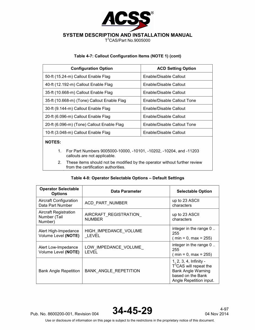
SYSTEM DESCRIPTION AND INSTALLATION MANUAL
T3CAS/Part No.9005000
Table 4-7: Callout Configuration Items (NOTE 1) (cont)
Configuration Option ACD Setting Option
50-ft (15.24-m) Callout Enable Flag Enable/Disable Callout
40-ft (12.192-m) Callout Enable Flag Enable/Disable Callout
35-ft (10.668-m) Callout Enable Flag Enable/Disable Callout
35-ft (10.668-m) (Tone) Callout Enable Flag Enable/Disable Callout Tone
30-ft (9.144-m) Callout Enable Flag Enable/Disable Callout
20-ft (6.096-m) Callout Enable Flag Enable/Disable Callout
20-ft (6.096-m) (Tone) Callout Enable Flag Enable/Disable Callout Tone
10-ft (3.048-m) Callout Enable Flag Enable/Disable Callout
NOTES:
1. For Part Numbers 9005000-10000, -10101, -10202, -10204, and -11203 callouts are not applicable.
2. These items should not be modified by the operator without further review from the certification authorities.
Table 4-8: Operator Selectable Options – Default Settings
Operator Selectable Options Data Parameter Selectable Option
Aircraft Configuration Data Part Number ACD_PART_NUMBER up to 23 ASCII
characters Aircraft Registration Number (Tail Number)
AIRCRAFT_REGISTRATION_ NUMBER
up to 23 ASCII characters
Alert High-Impedance Volume Level (NOTE)
HIGH_IMPEDANCE_VOLUME _LEVEL
integer in the range 0 .. 255 ( min = 0, max = 255)
Alert Low-Impedance Volume Level (NOTE)
LOW_IMPEDANCE_VOLUME_ LEVEL
integer in the range 0 .. 255 ( min = 0, max = 255)
Bank Angle Repetition BANK_ANGLE_REPETITION
1, 2, 3, 4, Infinity - T3CAS will repeat the Bank Angle Warning based on the Bank Angle Repetition input.
Pub. No. 8600200-001, Revision 004 34-45-29 4-97
04 Nov 2014 Use or disclosure of information on this page is subject to the restrictions in the proprietary notice of this document.
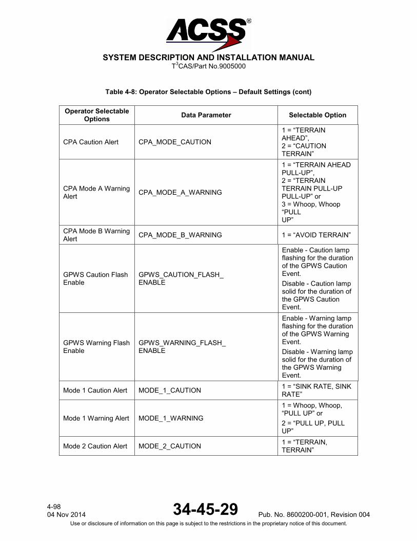
SYSTEM DESCRIPTION AND INSTALLATION MANUAL
T3CAS/Part No.9005000
Table 4-8: Operator Selectable Options – Default Settings (cont)
Operator Selectable Options Data Parameter Selectable Option
CPA Caution Alert CPA_MODE_CAUTION
1 = “TERRAIN AHEAD”, 2 = “CAUTION TERRAIN”
CPA Mode A Warning Alert CPA_MODE_A_WARNING
1 = “TERRAIN AHEAD PULL-UP”, 2 = “TERRAIN TERRAIN PULL-UP PULL-UP” or 3 = Whoop, Whoop “PULL UP”
CPA Mode B Warning Alert CPA_MODE_B_WARNING 1 = “AVOID TERRAIN”
GPWS Caution Flash Enable
GPWS_CAUTION_FLASH_ ENABLE
Enable - Caution lamp flashing for the duration of the GPWS Caution Event. Disable - Caution lamp solid for the duration of the GPWS Caution Event.
GPWS Warning Flash Enable
GPWS_WARNING_FLASH_ ENABLE
Enable - Warning lamp flashing for the duration of the GPWS Warning Event. Disable - Warning lamp solid for the duration of the GPWS Warning Event.
Mode 1 Caution Alert MODE_1_CAUTION 1 = “SINK RATE, SINK RATE”
Mode 1 Warning Alert MODE_1_WARNING
1 = Whoop, Whoop, “PULL UP” or 2 = “PULL UP, PULL UP”
Mode 2 Caution Alert MODE_2_CAUTION 1 = “TERRAIN, TERRAIN”
4-98 04 Nov 2014 34-45-29 Pub. No. 8600200-001, Revision 004
Use or disclosure of information on this page is subject to the restrictions in the proprietary notice of this document.
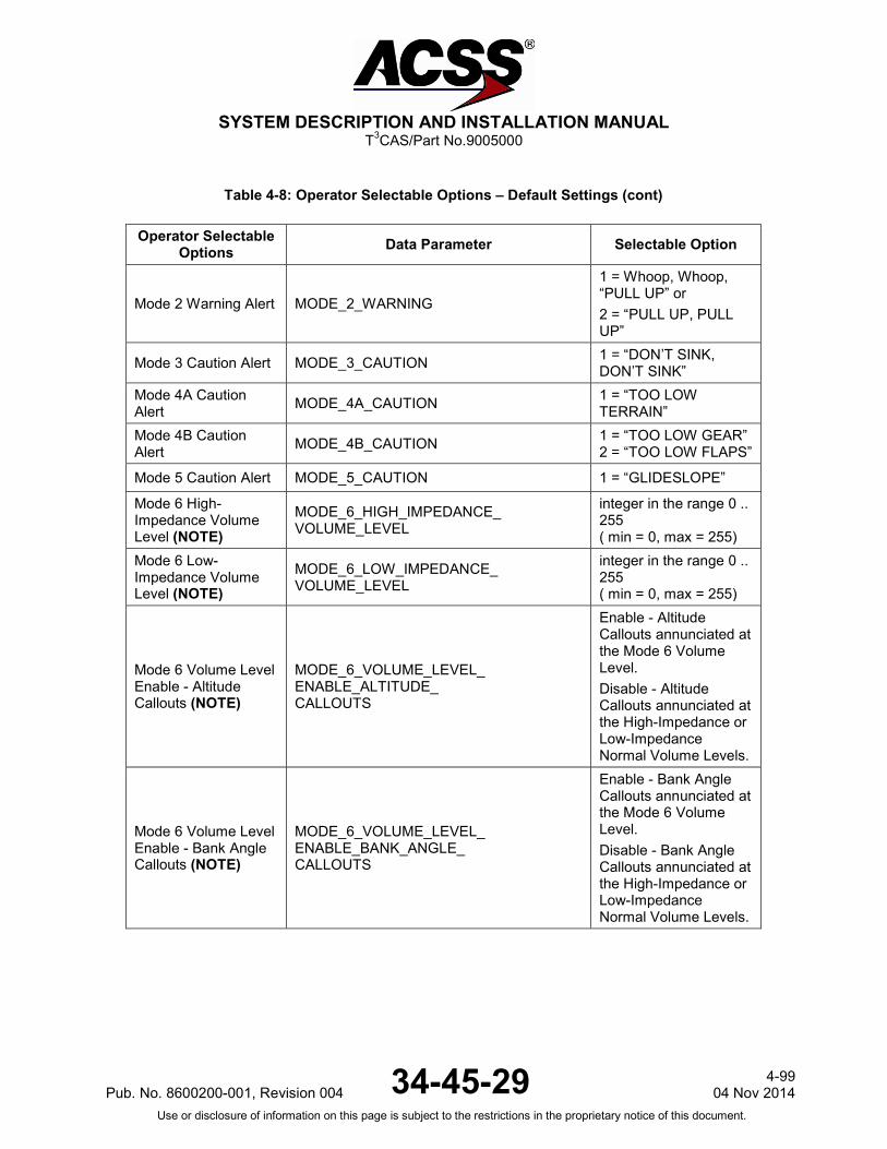
SYSTEM DESCRIPTION AND INSTALLATION MANUAL
T3CAS/Part No.9005000
Table 4-8: Operator Selectable Options – Default Settings (cont)
Operator Selectable Options Data Parameter Selectable Option
Mode 2 Warning Alert MODE_2_WARNING
1 = Whoop, Whoop, “PULL UP” or 2 = “PULL UP, PULL UP”
Mode 3 Caution Alert MODE_3_CAUTION 1 = “DON’T SINK, DON’T SINK”
Mode 4A Caution Alert MODE_4A_CAUTION 1 = “TOO LOW
TERRAIN” Mode 4B Caution Alert MODE_4B_CAUTION 1 = “TOO LOW GEAR”
2 = “TOO LOW FLAPS”
Mode 5 Caution Alert MODE_5_CAUTION 1 = “GLIDESLOPE”
Mode 6 High-Impedance Volume Level (NOTE)
MODE_6_HIGH_IMPEDANCE_ VOLUME_LEVEL
integer in the range 0 .. 255 ( min = 0, max = 255)
Mode 6 Low-Impedance Volume Level (NOTE)
MODE_6_LOW_IMPEDANCE_ VOLUME_LEVEL
integer in the range 0 .. 255 ( min = 0, max = 255)
Mode 6 Volume Level Enable - Altitude Callouts (NOTE)
MODE_6_VOLUME_LEVEL_ ENABLE_ALTITUDE_ CALLOUTS
Enable - Altitude Callouts annunciated at the Mode 6 Volume Level. Disable - Altitude Callouts annunciated at the High-Impedance or Low-Impedance Normal Volume Levels.
Mode 6 Volume Level Enable - Bank Angle Callouts (NOTE)
MODE_6_VOLUME_LEVEL_ ENABLE_BANK_ANGLE_ CALLOUTS
Enable - Bank Angle Callouts annunciated at the Mode 6 Volume Level. Disable - Bank Angle Callouts annunciated at the High-Impedance or Low-Impedance Normal Volume Levels.
Pub. No. 8600200-001, Revision 004 34-45-29 4-99
04 Nov 2014 Use or disclosure of information on this page is subject to the restrictions in the proprietary notice of this document.

SYSTEM DESCRIPTION AND INSTALLATION MANUAL
T3CAS/Part No.9005000
Table 4-8: Operator Selectable Options – Default Settings (cont)
Operator Selectable Options Data Parameter Selectable Option
Mode 6 Volume Level Enable - Minimum Callouts (NOTE)
MODE_6_VOLUME_LEVEL_ ENABLE_MINIMUM_ CALLOUTS
Enable – Minimums Callouts annunciated at the Mode 6 Volume Level. Disable - Minimums Callouts annunciated at the High-Impedance or Low-Impedance Normal Volume Levels.
Mode 6 Volume Level Enable - Mode 5 Callout (NOTE)
MODE_6_VOLUME_LEVEL_ ENABLE_MODE_5_CALLOUT
Enable - Mode 5 Callouts annunciated at the Mode 6 Volume Level. Disable - Mode 5 Callouts annunciated at the High-Impedance or Low-Impedance Normal Volume Levels.
QFE Enable QFE_ENABLE
Enable - Indicates QFE altitude correction is enabled. Disable - QNH altitude correction is used.
4-100 04 Nov 2014 34-45-29 Pub. No. 8600200-001, Revision 004
Use or disclosure of information on this page is subject to the restrictions in the proprietary notice of this document.
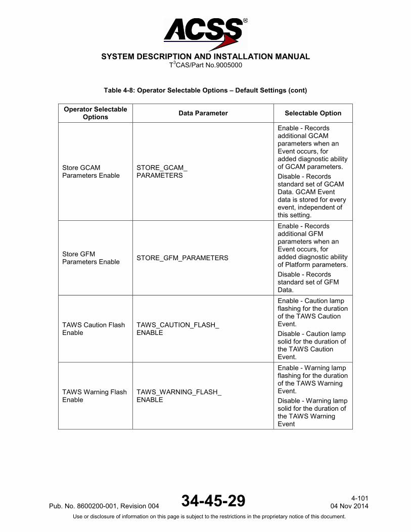
SYSTEM DESCRIPTION AND INSTALLATION MANUAL
T3CAS/Part No.9005000
Table 4-8: Operator Selectable Options – Default Settings (cont)
Operator Selectable Options Data Parameter Selectable Option
Store GCAM Parameters Enable
STORE_GCAM_ PARAMETERS
Enable - Records additional GCAM parameters when an Event occurs, for added diagnostic ability of GCAM parameters. Disable - Records standard set of GCAM Data. GCAM Event data is stored for every event, independent of this setting.
Store GFM Parameters Enable STORE_GFM_PARAMETERS
Enable - Records additional GFM parameters when an Event occurs, for added diagnostic ability of Platform parameters. Disable - Records standard set of GFM Data.
TAWS Caution Flash Enable
TAWS_CAUTION_FLASH_ ENABLE
Enable - Caution lamp flashing for the duration of the TAWS Caution Event. Disable - Caution lamp solid for the duration of the TAWS Caution Event.
TAWS Warning Flash Enable
TAWS_WARNING_FLASH_ ENABLE
Enable - Warning lamp flashing for the duration of the TAWS Warning Event. Disable - Warning lamp solid for the duration of the TAWS Warning Event
Pub. No. 8600200-001, Revision 004 34-45-29 4-101
04 Nov 2014 Use or disclosure of information on this page is subject to the restrictions in the proprietary notice of this document.
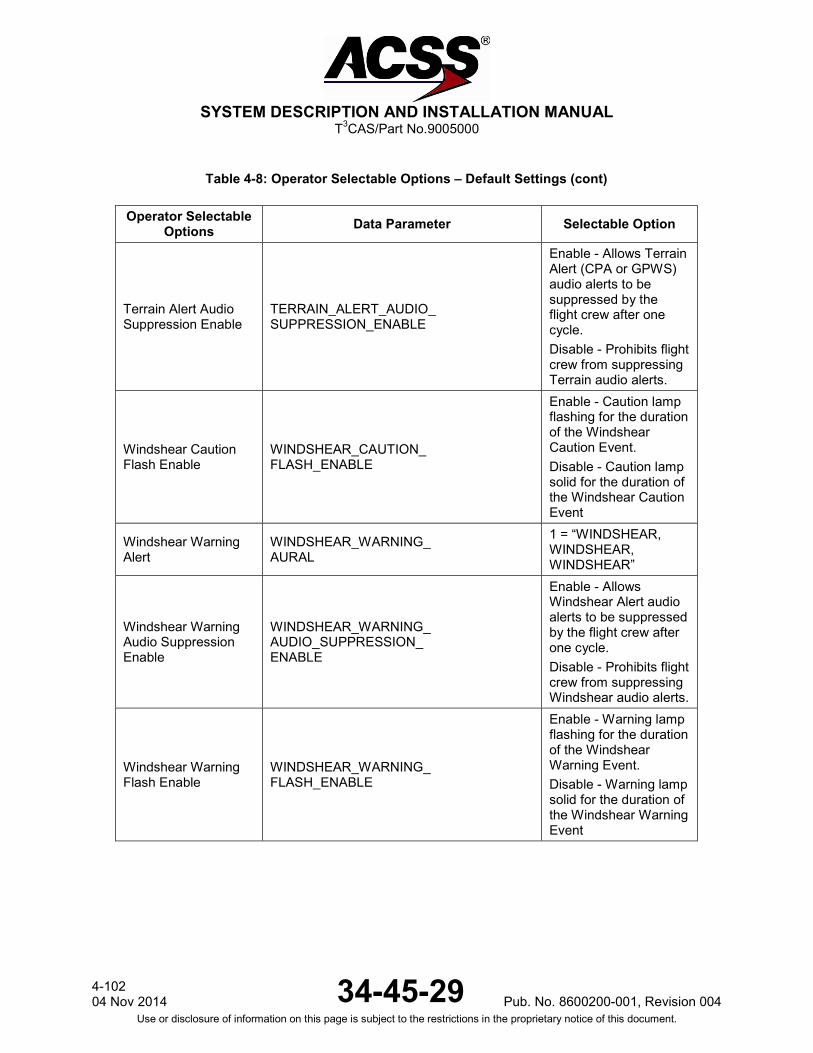
SYSTEM DESCRIPTION AND INSTALLATION MANUAL
T3CAS/Part No.9005000
Table 4-8: Operator Selectable Options – Default Settings (cont)
Operator Selectable Options Data Parameter Selectable Option
Terrain Alert Audio Suppression Enable
TERRAIN_ALERT_AUDIO_ SUPPRESSION_ENABLE
Enable - Allows Terrain Alert (CPA or GPWS) audio alerts to be suppressed by the flight crew after one cycle. Disable - Prohibits flight crew from suppressing Terrain audio alerts.
Windshear Caution Flash Enable
WINDSHEAR_CAUTION_ FLASH_ENABLE
Enable - Caution lamp flashing for the duration of the Windshear Caution Event. Disable - Caution lamp solid for the duration of the Windshear Caution Event
Windshear Warning Alert
WINDSHEAR_WARNING_ AURAL
1 = “WINDSHEAR, WINDSHEAR, WINDSHEAR”
Windshear Warning Audio Suppression Enable
WINDSHEAR_WARNING_ AUDIO_SUPPRESSION_ ENABLE
Enable - Allows Windshear Alert audio alerts to be suppressed by the flight crew after one cycle. Disable - Prohibits flight crew from suppressing Windshear audio alerts.
Windshear Warning Flash Enable
WINDSHEAR_WARNING_ FLASH_ENABLE
Enable - Warning lamp flashing for the duration of the Windshear Warning Event. Disable - Warning lamp solid for the duration of the Windshear Warning Event
4-102 04 Nov 2014 34-45-29 Pub. No. 8600200-001, Revision 004
Use or disclosure of information on this page is subject to the restrictions in the proprietary notice of this document.

SYSTEM DESCRIPTION AND INSTALLATION MANUAL
T3CAS/Part No.9005000
Table 4-8: Operator Selectable Options – Default Settings (cont)
Operator Selectable Options Data Parameter Selectable Option
Aural Alert Prioritization Input 1 Enable
AURAL_ALERT_ PRIORITIZATION_INPUT_1_ ENABLE
Enable - Inhibits Aural alerts that are of lesser priority than Aural Alert Priority 1. Disable - Lesser priority aural alerts Not inhibited.
Visual Alert Prioritization Input 1 Enable (NOTE)
VISUAL_ALERT_ PRIORITIZATION_INPUT_1_ ENABLE
Enable - Inhibits Visual alerts that are of lesser priority than Visual Alert Priority 1. Disable - Lesser priority Visual alerts Not inhibited.
Aural Alert Prioritization Input 2 Enable (NOTE)
AURAL_ALERT_ PRIORITIZATION_INPUT_2_ ENABLE
Enable - Inhibits Aural alerts that are of lesser priority than Aural Alert Priority 2. Disable - Lesser priority aural alerts Not inhibited.
Visual Alert Prioritization Input 2 Enable (NOTE)
VISUAL_ALERT_ PRIORITIZATION_INPUT_2_ ENABLE
Enable - Inhibits Visual alerts that are of lesser priority than Visual Alert Priority 2. Disable - Lesser priority Visual alerts Not inhibited.
Aural Alert Prioritization Input 3 Enable (NOTE)
AURAL_ALERT_ PRIORITIZATION_INPUT_3_ ENABLE
Enable - Inhibits Aural alerts that are of lesser priority than Aural Alert Priority 3. Disable - Lesser priority aural alerts Not inhibited.
Visual Alert Prioritization Input 3 Enable (NOTE)
VISUAL_ALERT_ PRIORITIZATION_INPUT_3_ ENABLE
Enable - Inhibits Visual alerts that are of lesser priority than Visual Alert Priority 3. Disable - Lesser priority Visual alerts Not inhibited.
Pub. No. 8600200-001, Revision 004 34-45-29 4-103
04 Nov 2014 Use or disclosure of information on this page is subject to the restrictions in the proprietary notice of this document.
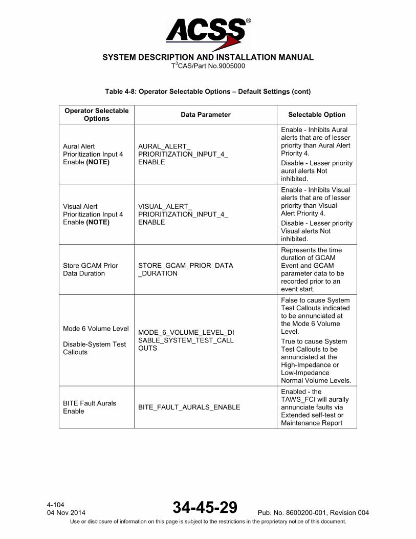
SYSTEM DESCRIPTION AND INSTALLATION MANUAL
T3CAS/Part No.9005000
Table 4-8: Operator Selectable Options – Default Settings (cont)
Operator Selectable Options Data Parameter Selectable Option
Aural Alert Prioritization Input 4 Enable (NOTE)
AURAL_ALERT_ PRIORITIZATION_INPUT_4_ ENABLE
Enable - Inhibits Aural alerts that are of lesser priority than Aural Alert Priority 4. Disable - Lesser priority aural alerts Not inhibited.
Visual Alert Prioritization Input 4 Enable (NOTE)
VISUAL_ALERT_ PRIORITIZATION_INPUT_4_ ENABLE
Enable - Inhibits Visual alerts that are of lesser priority than Visual Alert Priority 4. Disable - Lesser priority Visual alerts Not inhibited.
Store GCAM Prior Data Duration
STORE_GCAM_PRIOR_DATA _DURATION
Represents the time duration of GCAM Event and GCAM parameter data to be recorded prior to an event start.
Mode 6 Volume Level Disable-System Test Callouts
MODE_6_VOLUME_LEVEL_DI SABLE_SYSTEM_TEST_CALL OUTS
False to cause System Test Callouts indicated to be annunciated at the Mode 6 Volume Level. True to cause System Test Callouts to be annunciated at the High-Impedance or Low-Impedance Normal Volume Levels.
BITE Fault Aurals Enable BITE_FAULT_AURALS_ENABLE
Enabled - the TAWS_FCI will aurally annunciate faults via Extended self-test or Maintenance Report
4-104 04 Nov 2014 34-45-29 Pub. No. 8600200-001, Revision 004
Use or disclosure of information on this page is subject to the restrictions in the proprietary notice of this document.
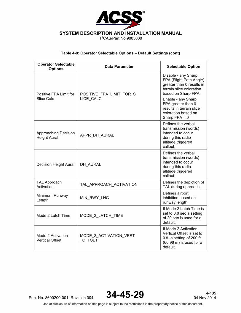
SYSTEM DESCRIPTION AND INSTALLATION MANUAL
T3CAS/Part No.9005000
Table 4-8: Operator Selectable Options – Default Settings (cont)
Operator Selectable Options Data Parameter Selectable Option
Positive FPA Limit for Slice Calc
POSITIVE_FPA_LIMIT_FOR_S LICE_CALC
Disable - any Sharp FPA (Flight Path Angle) greater than 0 results in terrain slice coloration based on Sharp FPA Enable - any Sharp FPA greater than 0 results in terrain slice coloration based on Sharp FPA = 0
Approaching Decision Height Aural APPR_DH_AURAL
Defines the verbal transmission (words) intended to occur during this radio altitude triggered callout.
Decision Height Aural DH_AURAL
Defines the verbal transmission (words) intended to occur during this radio altitude triggered callout.
TAL Approach Activation TAL_APPROACH_ACTIVATION Defines the depiction of
TAL during approach.
Minimum Runway Length MIN_RWY_LNG
Defines airport inhibition based on runway length.
Mode 2 Latch Time MODE_2_LATCH_TIME
If Mode 2 Latch Time is set to 0.0 sec a setting of 20 sec is used for a default.
Mode 2 Activation Vertical Offset
MODE_2_ACTIVATION_VERT _OFFSET
If Mode 2 Activation Vertical Offset is set to 0 ft. a setting of 200 ft (60.96 m) is used for a default.
Pub. No. 8600200-001, Revision 004 34-45-29 4-105
04 Nov 2014 Use or disclosure of information on this page is subject to the restrictions in the proprietary notice of this document.

SYSTEM DESCRIPTION AND INSTALLATION MANUAL
T3CAS/Part No.9005000
Table 4-8: Operator Selectable Options – Default Settings (cont)
Operator Selectable Options Data Parameter Selectable Option
Mode 1 Disable MODE_1_DISABLE
TAL LookAhead 30 Seconds MAAS Disable
TAL_LOOKAHEAD_30S_MAAS_DISABLE
Narrow TAL Roll Limit NARROW_TAL_ROLL_LIMIT
If the value of Narrow TAL Roll Limit is set to 0.00 degrees, a setting of 5.00 degrees is used for a default.
TAL ILS Deviation Limit TAL_ILS_DEV_LIMIT
This option allows for setting the TAL inhibition glideslope deviation limits when glideslope and localizer are both valid. If the value of TAL ILS Deviation Limit is set to 0.000 DDM setting of 0.175 DDM is used for a default.
Display Alert Line Aperture
DISPLAY_ALERT_LINE_APER TURE
This option is used for the determination of the range used by PSS to display TAL. This term is described in half-width and therefore is reflected as a value on either side of center. If the value of Display Alert Line Aperture is set to 0.00 degrees, a setting of 1.35 degrees is used for a default.
Runway Location Error RUNWAY_LOCATION_ERROR
If the value of Runway Location Error is set to 0.0 NMI, a setting of 0.30 NMI is used for a default.
4-106 04 Nov 2014 34-45-29 Pub. No. 8600200-001, Revision 004
Use or disclosure of information on this page is subject to the restrictions in the proprietary notice of this document.

SYSTEM DESCRIPTION AND INSTALLATION MANUAL
T3CAS/Part No.9005000
Table 4-8: Operator Selectable Options – Default Settings (cont)
Operator Selectable Options Data Parameter Selectable Option
Basic Runway Inhibition Annunciation
BASIC_RUNWAY_INHIB_ANNUN
The zero (0) state is the disabled state for this option. The one (1) state enables the ”TERR N/A” annunciator to activate when GCAM indicates Basic Airport.
2500ft/Radio Altitude Valid Aural RADIO_ALTITUDE_VALID_AURAL
This setting defines the verbal transmission (words) intended to occur during this radio altitude-triggered callout.
Windshear Caution Disable WINDSHEAR_CAUTION_DISABLE Not selectable by
customer. Windshear Caution Aural Disable WINDSHEAR_CAUTION_AURAL_DISABLE Not selectable by
customer. Windshear Caution Aural WINDSHEAR_CAUTION_AURAL Not selectable by
customer.
Obstacle Enable OBSTACLE_ENABLE Enable - enables obstacle algorithm.
Obstacle Maximum Display Range OBSTACLE_MAX_DISPLAY_RANGE
The Obstacle Maximum Display Range represents the maximum range setting for the display at which non-alerting obstacles will be displayed. When the display range is set greater than this value, all non-alerting obstacles will be removed. If the value of Obstacle Maximum Display Range is not equal to 5NM, 10NM, 15NM, 20NM, 25NM, 40NM, 80NM, 160NM, or 320NM, a setting of 10NM is used for a default
Pub. No. 8600200-001, Revision 004 34-45-29 4-107
04 Nov 2014 Use or disclosure of information on this page is subject to the restrictions in the proprietary notice of this document.
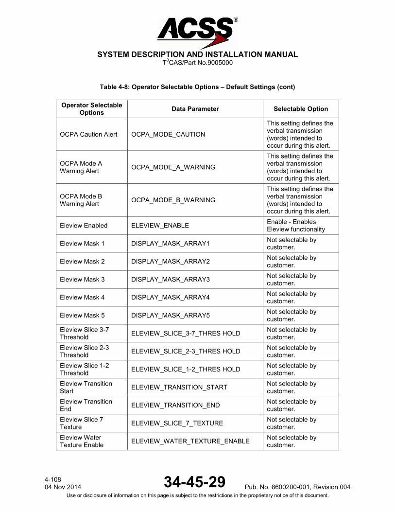
SYSTEM DESCRIPTION AND INSTALLATION MANUAL
T3CAS/Part No.9005000
Table 4-8: Operator Selectable Options – Default Settings (cont)
Operator Selectable Options Data Parameter Selectable Option
OCPA Caution Alert OCPA_MODE_CAUTION
This setting defines the verbal transmission (words) intended to occur during this alert.
OCPA Mode A Warning Alert OCPA_MODE_A_WARNING
This setting defines the verbal transmission (words) intended to occur during this alert.
OCPA Mode B Warning Alert OCPA_MODE_B_WARNING
This setting defines the verbal transmission (words) intended to occur during this alert.
Eleview Enabled ELEVIEW_ENABLE Enable - Enables Eleview functionality
Eleview Mask 1 DISPLAY_MASK_ARRAY1 Not selectable by customer.
Eleview Mask 2 DISPLAY_MASK_ARRAY2 Not selectable by customer.
Eleview Mask 3 DISPLAY_MASK_ARRAY3 Not selectable by customer.
Eleview Mask 4 DISPLAY_MASK_ARRAY4 Not selectable by customer.
Eleview Mask 5 DISPLAY_MASK_ARRAY5 Not selectable by customer.
Eleview Slice 3-7 Threshold ELEVIEW_SLICE_3-7_THRES HOLD Not selectable by
customer. Eleview Slice 2-3 Threshold ELEVIEW_SLICE_2-3_THRES HOLD Not selectable by
customer. Eleview Slice 1-2 Threshold ELEVIEW_SLICE_1-2_THRES HOLD Not selectable by
customer. Eleview Transition Start ELEVIEW_TRANSITION_START Not selectable by
customer. Eleview Transition End ELEVIEW_TRANSITION_END Not selectable by
customer. Eleview Slice 7 Texture ELEVIEW_SLICE_7_TEXTURE Not selectable by
customer. Eleview Water Texture Enable ELEVIEW_WATER_TEXTURE_ENABLE Not selectable by
customer.
4-108 04 Nov 2014 34-45-29 Pub. No. 8600200-001, Revision 004
Use or disclosure of information on this page is subject to the restrictions in the proprietary notice of this document.
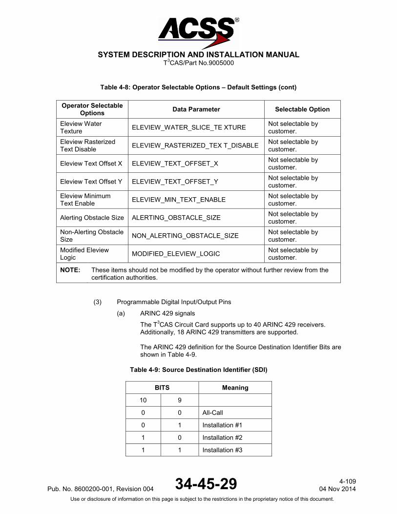
SYSTEM DESCRIPTION AND INSTALLATION MANUAL
T3CAS/Part No.9005000
Table 4-8: Operator Selectable Options – Default Settings (cont)
Operator Selectable Options Data Parameter Selectable Option
Eleview Water Texture ELEVIEW_WATER_SLICE_TE XTURE Not selectable by
customer. Eleview Rasterized Text Disable ELEVIEW_RASTERIZED_TEX T_DISABLE Not selectable by
customer.
Eleview Text Offset X ELEVIEW_TEXT_OFFSET_X Not selectable by customer.
Eleview Text Offset Y ELEVIEW_TEXT_OFFSET_Y Not selectable by customer.
Eleview Minimum Text Enable ELEVIEW_MIN_TEXT_ENABLE Not selectable by
customer.
Alerting Obstacle Size ALERTING_OBSTACLE_SIZE Not selectable by customer.
Non-Alerting Obstacle Size NON_ALERTING_OBSTACLE_SIZE Not selectable by
customer. Modified Eleview Logic MODIFIED_ELEVIEW_LOGIC Not selectable by
customer.
NOTE: These items should not be modified by the operator without further review from the certification authorities.
(3) Programmable Digital Input/Output Pins
(a) ARINC 429 signals
The T3CAS Circuit Card supports up to 40 ARINC 429 receivers. Additionally, 18 ARINC 429 transmitters are supported. The ARINC 429 definition for the Source Destination Identifier Bits are shown in Table 4-9.
Table 4-9: Source Destination Identifier (SDI)
BITS Meaning
10 9
0 0 All-Call
0 1 Installation #1
1 0 Installation #2
1 1 Installation #3
Pub. No. 8600200-001, Revision 004 34-45-29 4-109
04 Nov 2014 Use or disclosure of information on this page is subject to the restrictions in the proprietary notice of this document.
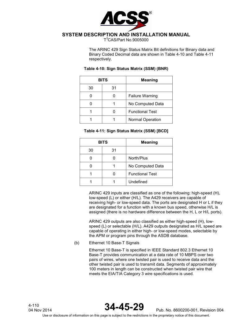
SYSTEM DESCRIPTION AND INSTALLATION MANUAL
T3CAS/Part No.9005000
The ARINC 429 Sign Status Matrix Bit definitions for Binary data and Binary Coded Decimal data are shown in Table 4-10 and Table 4-11 respectively.
Table 4-10: Sign Status Matrix (SSM) (BNR)
BITS Meaning
30 31
0 0 Failure Warning
0 1 No Computed Data
1 0 Functional Test
1 1 Normal Operation
Table 4-11: Sign Status Matrix (SSM) [BCD]
BITS Meaning
30 31
0 0 North/Plus
0 1 No Computed Data
1 0 Functional Test
1 1 Undefined ARINC 429 inputs are classified as one of the following: high-speed (H), low-speed (L) or either (H/L). The A429 receivers are capable of receiving high- or low-speed data. The ports are designated H or L if they are designated for a function with a known bus speed, otherwise H/L is assigned (there is no hardware difference between the H, L or H/L ports). ARINC 429 outputs are also classified as either high-speed (H), low-speed (L) or selectable (H/L). A429 outputs designated as H/L speed are capable of operating in either high- or low-speed modes, selectable by the APM or program pins through the ASDB database.
(b) Ethernet 10 Base-T Signals
Ethernet 10 Base-T is specified in IEEE Standard 802.3 Ethernet 10 Base-T provides communication at a data rate of 10 MBPS over two pairs of wires, where one twisted pair is used to receive data and the other twisted pair is used to transmit data. Segments of approximately 100 meters in length can be constructed when twisted pair wire that meets the EIA/TIA Category 3 wire specifications is used.
4-110 04 Nov 2014 34-45-29 Pub. No. 8600200-001, Revision 004
Use or disclosure of information on this page is subject to the restrictions in the proprietary notice of this document.
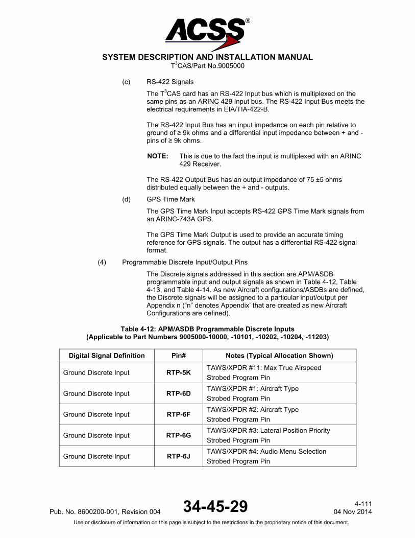
SYSTEM DESCRIPTION AND INSTALLATION MANUAL
T3CAS/Part No.9005000
(c) RS-422 Signals
The T3CAS card has an RS-422 Input bus which is multiplexed on the same pins as an ARINC 429 Input bus. The RS-422 Input Bus meets the electrical requirements in EIA/TIA-422-B. The RS-422 Input Bus has an input impedance on each pin relative to ground of ≥ 9k ohms and a differential input impedance between + and - pins of ≥ 9k ohms. NOTE: This is due to the fact the input is multiplexed with an ARINC
429 Receiver. The RS-422 Output Bus has an output impedance of 75 ±5 ohms distributed equally between the + and - outputs.
(d) GPS Time Mark
The GPS Time Mark Input accepts RS-422 GPS Time Mark signals from an ARINC-743A GPS. The GPS Time Mark Output is used to provide an accurate timing reference for GPS signals. The output has a differential RS-422 signal format.
(4) Programmable Discrete Input/Output Pins
The Discrete signals addressed in this section are APM/ASDB programmable input and output signals as shown in Table 4-12, Table 4-13, and Table 4-14. As new Aircraft configurations/ASDBs are defined, the Discrete signals will be assigned to a particular input/output per Appendix n (“n” denotes Appendix’ that are created as new Aircraft Configurations are defined).
Table 4-12: APM/ASDB Programmable Discrete Inputs (Applicable to Part Numbers 9005000-10000, -10101, -10202, -10204, -11203)
Digital Signal Definition Pin# Notes (Typical Allocation Shown)
Ground Discrete Input RTP-5K TAWS/XPDR #11: Max True Airspeed Strobed Program Pin
Ground Discrete Input RTP-6D TAWS/XPDR #1: Aircraft Type Strobed Program Pin
Ground Discrete Input RTP-6F TAWS/XPDR #2: Aircraft Type Strobed Program Pin
Ground Discrete Input RTP-6G TAWS/XPDR #3: Lateral Position Priority Strobed Program Pin
Ground Discrete Input RTP-6J TAWS/XPDR #4: Audio Menu Selection Strobed Program Pin
Pub. No. 8600200-001, Revision 004 34-45-29 4-111
04 Nov 2014 Use or disclosure of information on this page is subject to the restrictions in the proprietary notice of this document.

SYSTEM DESCRIPTION AND INSTALLATION MANUAL
T3CAS/Part No.9005000
Table 4-12: APM/ASDB Programmable Discrete Inputs (Applicable to Part Numbers 9005000-10000, -10101, -10202, -10204, -11203)
Digital Signal Definition Pin# Notes (Typical Allocation Shown)
Ground Discrete Input RTP-7A TAWS/XPDR #5: CRT-LCD Disp Select Strobed Program Pin
Ground Discrete Input RTP-7C TAWS/XPDR #6: Auto (CPA-THD) Deactivation Strobed Program Pin
Ground Discrete Input RTP-7D TAWS/XPDR #7: Predictive Windshear Present Strobed Program Pin
Ground Discrete Input RTP-7F
TAWS/XPDR #8: Topo Mode ( For Part No.-10000, -10101, -10202, -10204) GPS Source (For Part No.-11203) Strobed Program Pin
Ground Discrete Input RTP-7G
TAWS/XPDR #9: Vertical Display (For Part No.-10000, -10101, -10202, -10204) ADLP Installed (For Part No.-11203) Strobed Program Pin
Ground Discrete Input RTP-7J TAWS/XPDR #10: Attitude Source Selection Strobed Program Pin
Ground Discrete Input RTP-7K TAWS/XPDR #12: Cold Temp Comp Strobed Program Pin
Ground Discrete Input RTP-9J Spare Or DO-260B Config Data #7 (For Part No.-11203)
Ground Discrete Input RTP-9K Spare Or DO-260B Config Data Parity (For Part No.-11203)
Ground Discrete Input RTP-11A TAWS/XPDR #13: Terrain Adv Lines Displayed Strobed Program Pin
Ground Discrete Input RTP-11C TAWS/XPDR #14: Eleview Function Strobed Program Pin
Ground Discrete Input RTP-11F TAWS/XPDR #15: Obstacle Function Strobed Program Pin
Ground Discrete Input RTP-11G TAWS/XPDR #16: Antenna Modes Strobed Program Pin
Ground Discrete Input RTP-11H TAWS/XPDR #17: TAWS/XPDR Installed Strobed Program Pin
Ground Discrete Input RTP-11J TAWS/XPDR #18: Odd Program Pin Parity Strobed Program Pin
Ground Discrete Input RTP-12A Spare Or DO-260B Config Data #1 (For Part No.-11203)
4-112 04 Nov 2014 34-45-29 Pub. No. 8600200-001, Revision 004
Use or disclosure of information on this page is subject to the restrictions in the proprietary notice of this document.

SYSTEM DESCRIPTION AND INSTALLATION MANUAL
T3CAS/Part No.9005000
Table 4-12: APM/ASDB Programmable Discrete Inputs (Applicable to Part Numbers 9005000-10000, -10101, -10202, -10204, -11203)
Digital Signal Definition Pin# Notes (Typical Allocation Shown)
GND Program Input RTP-12B Spare Or DO-260B Config Data #2 (For Part No.-11203)
GND Program Input RTP-12C Spare Or DO-260B Config Data #3 (For Part No.-11203)
GND Program Input RTP-12D Spare Or DO-260B Config Data #4 (For Part No.-11203)
GND Program Input RTP-12E Spare Or DO-260B Config Data #5 (For Part No.-11203)
GND Program Input RTP-12F Spare Or DO-260B Config Data #6 (For Part No.-11203)
+28 V dc Discrete Input RTP-12G Spare
+28 V dc Discrete Input RTP-12H Spare
Ground Discrete Input RMP-3H Merging & Spacing (M&S) Strobed Program Pin
Ground Discrete Input RMP-3J Surface Area Movement Management (SAMM) Strobed Program Pin
Ground Discrete Input RBP-2A In-Trail Procedures (ITP) Strobed Program Pin
Ground Discrete Input RBP-2B CAVS Strobed Program Pin
Ground Discrete Input RBP-2C Spare Strobed Program Pin
Ground Discrete Input RBP-2D Spare Strobed Program Pin
Ground Discrete Input RBP-2E Spare Strobed Program Pin
Ground Discrete Input RBP-2F Spare Strobed Program Pin
Ground Discrete Input RBP-2G Spare Strobed Program Pin
Ground Discrete Input RBP-3F Spare Strobed Program Pin
Ground Discrete Input RBP-3G Parity Strobed Program Pin
Pub. No. 8600200-001, Revision 004 34-45-29 4-113
04 Nov 2014 Use or disclosure of information on this page is subject to the restrictions in the proprietary notice of this document.
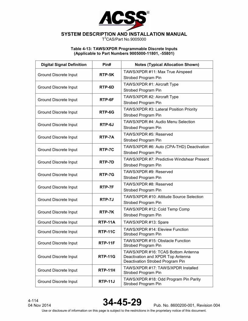
SYSTEM DESCRIPTION AND INSTALLATION MANUAL
T3CAS/Part No.9005000
Table 4-13: TAWS/XPDR Programmable Discrete Inputs (Applicable to Part Numbers 9005000-11801, -55801)
Digital Signal Definition Pin# Notes (Typical Allocation Shown)
Ground Discrete Input RTP-5K TAWS/XPDR #11: Max True Airspeed Strobed Program Pin
Ground Discrete Input RTP-6D TAWS/XPDR #1: Aircraft Type Strobed Program Pin
Ground Discrete Input RTP-6F TAWS/XPDR #2: Aircraft Type Strobed Program Pin
Ground Discrete Input RTP-6G TAWS/XPDR #3: Lateral Position Priority Strobed Program Pin
Ground Discrete Input RTP-6J TAWS/XPDR #4: Audio Menu Selection Strobed Program Pin
Ground Discrete Input RTP-7A TAWS/XPDR #5: Reserved Strobed Program Pin
Ground Discrete Input RTP-7C TAWS/XPDR #6: Auto (CPA-THD) Deactivation Strobed Program Pin
Ground Discrete Input RTP-7D TAWS/XPDR #7: Predictive Windshear Present Strobed Program Pin
Ground Discrete Input RTP-7G TAWS/XPDR #9: Reserved Strobed Program Pin
Ground Discrete Input RTP-7F TAWS/XPDR #8: Reserved Strobed Program Pin
Ground Discrete Input RTP-7J TAWS/XPDR #10: Attitude Source Selection Strobed Program Pin
Ground Discrete Input RTP-7K TAWS/XPDR #12: Cold Temp Comp Strobed Program Pin
Ground Discrete Input RTP-11A TAWS/XPDR #13: Spare
Ground Discrete Input RTP-11C TAWS/XPDR #14: Eleview Function Strobed Program Pin
Ground Discrete Input RTP-11F TAWS/XPDR #15: Obstacle Function Strobed Program Pin
Ground Discrete Input RTP-11G TAWS/XPDR #16: TCAS Bottom Antenna Deactivation and XPDR Top Antenna Deactivation Strobed Program Pin
Ground Discrete Input RTP-11H TAWS/XPDR #17: TAWS/XPDR Installed Strobed Program Pin
Ground Discrete Input RTP-11J TAWS/XPDR #18: Odd Program Pin Parity Strobed Program Pin
4-114 04 Nov 2014 34-45-29 Pub. No. 8600200-001, Revision 004
Use or disclosure of information on this page is subject to the restrictions in the proprietary notice of this document.
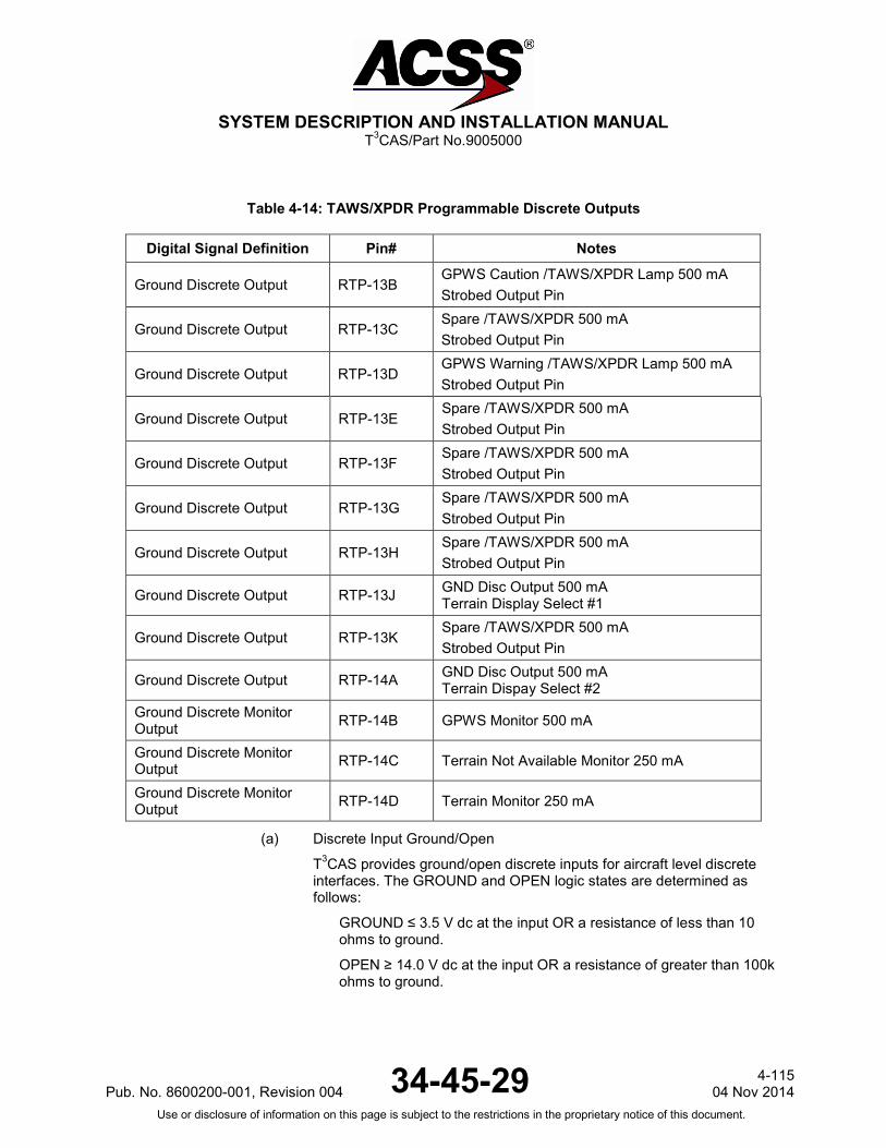
SYSTEM DESCRIPTION AND INSTALLATION MANUAL
T3CAS/Part No.9005000
Table 4-14: TAWS/XPDR Programmable Discrete Outputs
Digital Signal Definition Pin# Notes
Ground Discrete Output RTP-13B GPWS Caution /TAWS/XPDR Lamp 500 mA Strobed Output Pin
Ground Discrete Output RTP-13C Spare /TAWS/XPDR 500 mA Strobed Output Pin
Ground Discrete Output RTP-13D GPWS Warning /TAWS/XPDR Lamp 500 mA Strobed Output Pin
Ground Discrete Output RTP-13E Spare /TAWS/XPDR 500 mA Strobed Output Pin
Ground Discrete Output RTP-13F Spare /TAWS/XPDR 500 mA Strobed Output Pin
Ground Discrete Output RTP-13G Spare /TAWS/XPDR 500 mA Strobed Output Pin
Ground Discrete Output RTP-13H Spare /TAWS/XPDR 500 mA Strobed Output Pin
Ground Discrete Output RTP-13J GND Disc Output 500 mA Terrain Display Select #1
Ground Discrete Output RTP-13K Spare /TAWS/XPDR 500 mA Strobed Output Pin
Ground Discrete Output RTP-14A GND Disc Output 500 mA Terrain Dispay Select #2
Ground Discrete Monitor Output RTP-14B GPWS Monitor 500 mA
Ground Discrete Monitor Output RTP-14C Terrain Not Available Monitor 250 mA
Ground Discrete Monitor Output RTP-14D Terrain Monitor 250 mA
(a) Discrete Input Ground/Open
T3CAS provides ground/open discrete inputs for aircraft level discrete interfaces. The GROUND and OPEN logic states are determined as follows:
GROUND ≤ 3.5 V dc at the input OR a resistance of less than 10 ohms to ground.
OPEN ≥ 14.0 V dc at the input OR a resistance of greater than 100k ohms to ground.
Pub. No. 8600200-001, Revision 004 34-45-29 4-115
04 Nov 2014 Use or disclosure of information on this page is subject to the restrictions in the proprietary notice of this document.

SYSTEM DESCRIPTION AND INSTALLATION MANUAL
T3CAS/Part No.9005000
The discrete inputs source 1.0 ±0.25 mA of current when the input is grounded and has diode-isolation circuitry to prevent the inputs from being loaded to ground when power is removed from the T3CAS.
NOTE: When an input goes to a discrete on both TCAS and TAWS/RWS, the input current is twice the specification for a single discrete.
(b) Discrete Input +28 V dc/Open
T3CAS provides +28 V dc/open discrete inputs for aircraft level discrete interfaces. The +28 V dc and OPEN logic states are determined per the following:
+28 V dc ≥14.0 V dc at the input.
OPEN ≤ 3.5 V dc at the input OR a resistance of greater than 100k ohms to the positive voltage source.
The discrete inputs sink 1.0 ±0.25 mA of current when a +27.5 V dc input and has diode isolation circuitry is applied to prevent the inputs from being loaded to ground when power is removed from the T3CAS.
NOTE: When an input goes to a discrete on both TCAS and TAWS/RWS, the input current is twice the specification for a single discrete.
(c) Discrete Output Ground/Open 500 mA
The discrete outputs listed in this section pertain to ground/open discrete outputs for the TAWS/RWS function. The discrete output in the GROUND logic state has an output voltage of ≤3.0 V dc when sinking 500 mA of current and an output voltage of ≤1.5 V dc when sinking 100 mA of current. The discrete output in the OPEN logic state has an output impedance of ≥ 2.4M ohms to ground for voltages applied to the output of 0.0 to +33.0 V dc and ≥100k ohms to ground for voltages applied to the output of +33.0 to +36.0 V dc. The discrete output circuitry contains a monitor which detects if an over-current condition has occurred and is able to withstand a direct short to +28 V dc for an indefinite period of time. Additionally, the discrete output circuitry contains a monitor which detects if the output voltage is incorrect for the driven state of the discrete output. This section defines the DO-260B Configuration Pins. Table 4-17 outlines the connections necessary to set the DO-260B configuration data. Refer to Table 4-18 for definitions of the DO-260B configuration settings.
4-116 04 Nov 2014 34-45-29 Pub. No. 8600200-001, Revision 004
Use or disclosure of information on this page is subject to the restrictions in the proprietary notice of this document.
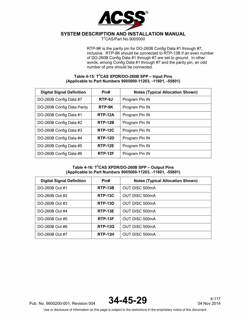
SYSTEM DESCRIPTION AND INSTALLATION MANUAL
T3CAS/Part No.9005000
RTP-9K is the parity pin for DO-260B Config Data #1 through #7, inclusive. RTP-9K should be connected to RTP-13B if an even number of DO-260B Config Data #1 through #7 are set to ground. In other words, among Config Data #1 through #7 and the parity pin, an odd number of pins should be connected.
Table 4-15: T3CAS XPDR/DO-260B SPP – Input Pins (Applicable to Part Numbers 9005000-11203, -11801, -55801)
Digital Signal Definition Pin# Notes (Typical Allocation Shown)
DO-260B Config Data #7 RTP-9J Program Pin IN
DO-260B Config Data Parity RTP-9K Program Pin IN
DO-260B Config Data #1 RTP-12A Program Pin IN
DO-260B Config Data #2 RTP-12B Program Pin IN
DO-260B Config Data #3 RTP-12C Program Pin IN
DO-260B Config Data #4 RTP-12D Program Pin IN
DO-260B Config Data #5 RTP-12E Program Pin IN
DO-260B Config Data #6 RTP-12F Program Pin IN
Table 4-16: T3CAS XPDR/DO-260B SPP – Output Pins (Applicable to Part Numbers 9005000-11203, -11801, -55801)
Digital Signal Definition Pin# Notes (Typical Allocation Shown)
DO-260B Out #1 RTP-13B OUT DISC 500mA
DO-260B Out #2 RTP-13C OUT DISC 500mA
DO-260B Out #3 RTP-13D OUT DISC 500mA
DO-260B Out #4 RTP-13E OUT DISC 500mA
DO-260B Out #5 RTP-13F OUT DISC 500mA
DO-260B Out #6 RTP-13G OUT DISC 500mA
DO-260B Out #7 RTP-13H OUT DISC 500mA
Pub. No. 8600200-001, Revision 004 34-45-29 4-117
04 Nov 2014 Use or disclosure of information on this page is subject to the restrictions in the proprietary notice of this document.

SYSTEM DESCRIPTION AND INSTALLATION MANUAL
T3CAS/Part No.9005000
Table 4-17: DO-260B Configuration Pins (Applicable to Part Numbers 9005000-11203, -11801, -55801)
All OPEN
RTP-13B TAWS/XPDR
Out #1
RTP-13C TAWS/XPDR
Out #2
RTP-13D TAWS/XPDR
Out #3 RTP-12A DO-260B
Config Data #1
Aircraft Vehicle Length/Width bit 0 Aircraft Vehicle Length/Width bit 1 Aircraft Vehicle Length/Width bit 2
0 0 0
0 0 1
0 1 0
0 1 1
RTP-12B DO-260B
Config Data #2
Aircraft Vehicle Length/Width bit 3 GPS Antenna Longitudinal Offset bit 0 GPS Antenna Longitudinal Offset bit 1
0 0 0
0 0 1
0 1 0
0 1 1
RTP-12C DO-260B
Config Data #3
GPS Antenna Longitudinal Offset bit 2 GPS Antenna Longitudinal Offset bit 3 GPS Antenna Longitudinal Offset bit 4
0 0 0
0 0 1
0 1 0
0 1 1
RTP-12D DO-260B
Config Data #4
NACv bit 0 NACv bit 1 SDA bit 0
0 0 0
0 0 1
0 1 0
0 1 1
RTP-12E DO-260B
Config Data #5
SDA bit 1 Aircraft Category bit 0 Aircraft Category bit 1
0 0 0
0 0 1
0 1 0
0 1 1
RTP-12F DO-260B
Config Data #6
Aircraft Category bit 2 ADS-B FAIL Disable bit 0
ADS-B Receive Capability bit 0
0 0 0
0 0 1
0 1 0
0 1 1
RTP-9J DO-260B
Config Data #7
ADS-B Receive Capability bit 1 VFOM Adjust bit 0 VFOM Adjust bit 1
0 0 0
0 0 1
0 1 0
0 1 1
RTP-9K DO-260B
Config Data Parity
NOTE: If the number of DO-260B Config Data #1 through #7 pins connected is
even, connect RTP-9K to RTP-13B, else RTP-9K should be left Open.
If Odd Parity If Even Parity N/A N/A
RTP-13E TAWS/XPDR Out #4
RTP-13F TAWS/XPDR Out #5
RTP-13G TAWS/XPDR Out #6
RTP-13H TAWS/XPDR Out #7
RTP-12A DO-260B
Config Data #1
Aircraft Vehicle Length/Width bit 0 Aircraft Vehicle Length/Width bit 1 Aircraft Vehicle Length/Width bit 2
1 0 0
1 0 1
1 1 0
1 1 1
RTP-12B DO-260B
Config Data #2
Aircraft Vehicle Length/Width bit 3 GPS Antenna Longitudinal Offset bit 0 GPS Antenna Longitudinal Offset bit 1
1 0 0
1 0 1
1 1 0
1 1 1
RTP-12C DO-260B
Config Data #3
GPS Antenna Longitudinal Offset bit 2 GPS Antenna Longitudinal Offset bit 3 GPS Antenna Longitudinal Offset bit 4
1 0 0
1 0 1
1 1 0
1 1 1
RTP-12D DO-260B
Config Data #4
NACv bit 0 NACv bit 1 SDA bit 0
1 0 0
1 0 1
1 1 0
1 1 1
RTP-12E DO-260B
Config Data #5
SDA bit 1 Aircraft Category bit 0 Aircraft Category bit 1
1 0 0
1 0 1
1 1 0
1 1 1
RTP-12F DO-260B
Config Data #6
Aircraft Category bit 2 ADS-B FAIL Disable bit 0
ADS-B Receive Capability bit 0
1 0 0
1 0 1
1 1 0
1 1 1
4-118 04 Nov 2014 34-45-29 Pub. No. 8600200-001, Revision 004
Use or disclosure of information on this page is subject to the restrictions in the proprietary notice of this document.

SYSTEM DESCRIPTION AND INSTALLATION MANUAL
T3CAS/Part No.9005000
Table 4-17: DO-260B Configuration Pins (Applicable to Part Numbers 9005000-11203, -11801, -55801)
RTP-13E TAWS/XPDR Out #4
RTP-13F TAWS/XPDR Out #5
RTP-13G TAWS/XPDR Out #6
RTP-13H TAWS/XPDR Out #7
RTP-9J DO-260B
Config Data #7
ADS-B Receive Capability bit 1 VFOM Adjust bit 0 VFOM Adjust bit 1
1 0 0
1 0 1
1 1 0
1 1 1
RTP-9K DO-260B
Config Data Parity
NOTE: If the number of DO-260B Config Data #1 through #7 pins connected is
even, connect RTP-9K to RTP-13B, else RTP-9K should be left Open.
N/A N/A N/A N/A
Table 4-18: DO-260B Configuration Definitions (Applicable to Part Numbers 9005000-11203, -11801, -55801)
Length Width Code Must be assigned the lowest value code for which the actual length/width is less than or equal to the upper bound of the definition 0 = No Data or Unknown 1 = L – 15m, W – 23m 2 = L – 25m, W – 28.5m 3 = L – 25m, W – 34m 4 = L – 35m, W – 33m 5 = L – 35m, W – 38m 6 = L – 45m, W – 39.5m 7 = L – 45m, W – 45m 8 = L – 55m, W – 45m 9 = L – 55m, W – 52m 10 = L – 65m, W – 59.5m 11 = L – 65m, W – 67m 12 = L – 75m, W – 72.5m 13 = L – 75m, W – 80m 14 = L – 85m, W – 80m 15 = L – 85m, W – 90m
GPS Longitudinal Offset 0 = no data 1 = position offset defined by sensor 2 = 2 meters 3 = 4 … 8 = 14 meters 31 = 60 (all values 2 and above are (value-1)*2 meters)
VFOM Adjust 0 = VFOM adjustment of VFOM label 136 when using GPS MSL 076 is NOT required 1 = VFOM adjustment of VFOM label 136 when using GPS MSL 076 for geometric vertical accuracy is required (adds 30m to VFOM)
ADS-B Fail Disable 0 – Failures of the ADS-B function are declared via asserting the XPDR fail discretes as well as any 429 diagnostic words 1 – Failures of the ADS-B function are not declared via asserting the XPDR fail discretes, but are declared via 429 diagnostic words
Aircraft category 0 = no info 1 = light < 15500 lbs 2 = small (15500 to 75000 lbs) 3 = large (75000 to 300000lbs) 4 = High Vortex Large (a/c such as B-757) 5 = Heavy (>300000lbs) 6 = High Performance (>5g acceleration and > 400knots) 7 = Rotorcraft
NACv 0 = Horizontal velocity error Unknown or >= 10ms 1 = < 10m/s 2 = < 3 m/s 3 = < 1 m/s
ADS-B Receive Capability 0 = no support for UAT in or 1090 in 1 = 1090 in supported 2 = 1090 AND UAT in supported
SDA (system design assurance)
0 = > 1x10⁻³ per flight hour 1 = <= 1x10⁻³ 2 = <= 1x10⁻⁵ 3 = <= 1x10⁻⁷
Pub. No. 8600200-001, Revision 004 34-45-29 4-119
04 Nov 2014 Use or disclosure of information on this page is subject to the restrictions in the proprietary notice of this document.
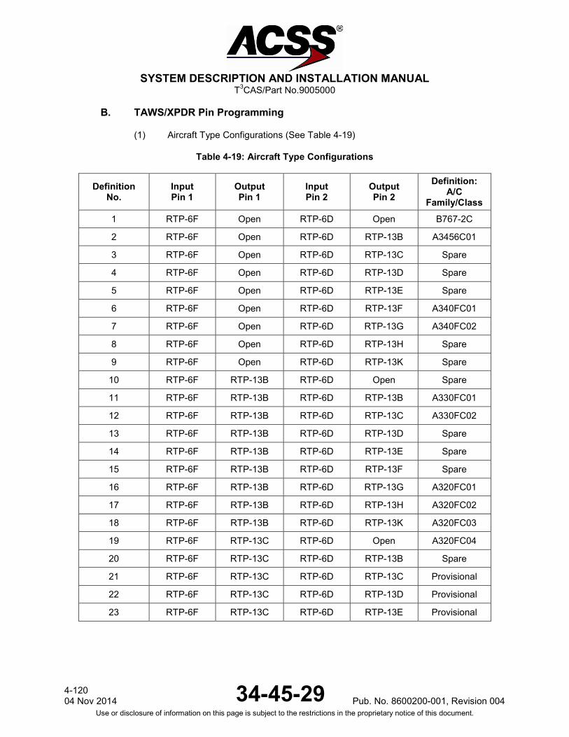
SYSTEM DESCRIPTION AND INSTALLATION MANUAL
T3CAS/Part No.9005000
B. TAWS/XPDR Pin Programming
(1) Aircraft Type Configurations (See Table 4-19)
Table 4-19: Aircraft Type Configurations
Definition No.
Input Pin 1
Output Pin 1
Input Pin 2
Output Pin 2
Definition: A/C
Family/Class 1 RTP-6F Open RTP-6D Open B767-2C
2 RTP-6F Open RTP-6D RTP-13B A3456C01
3 RTP-6F Open RTP-6D RTP-13C Spare
4 RTP-6F Open RTP-6D RTP-13D Spare
5 RTP-6F Open RTP-6D RTP-13E Spare
6 RTP-6F Open RTP-6D RTP-13F A340FC01
7 RTP-6F Open RTP-6D RTP-13G A340FC02
8 RTP-6F Open RTP-6D RTP-13H Spare
9 RTP-6F Open RTP-6D RTP-13K Spare
10 RTP-6F RTP-13B RTP-6D Open Spare
11 RTP-6F RTP-13B RTP-6D RTP-13B A330FC01
12 RTP-6F RTP-13B RTP-6D RTP-13C A330FC02
13 RTP-6F RTP-13B RTP-6D RTP-13D Spare
14 RTP-6F RTP-13B RTP-6D RTP-13E Spare
15 RTP-6F RTP-13B RTP-6D RTP-13F Spare
16 RTP-6F RTP-13B RTP-6D RTP-13G A320FC01
17 RTP-6F RTP-13B RTP-6D RTP-13H A320FC02
18 RTP-6F RTP-13B RTP-6D RTP-13K A320FC03
19 RTP-6F RTP-13C RTP-6D Open A320FC04
20 RTP-6F RTP-13C RTP-6D RTP-13B Spare
21 RTP-6F RTP-13C RTP-6D RTP-13C Provisional
22 RTP-6F RTP-13C RTP-6D RTP-13D Provisional
23 RTP-6F RTP-13C RTP-6D RTP-13E Provisional
4-120 04 Nov 2014 34-45-29 Pub. No. 8600200-001, Revision 004
Use or disclosure of information on this page is subject to the restrictions in the proprietary notice of this document.

SYSTEM DESCRIPTION AND INSTALLATION MANUAL
T3CAS/Part No.9005000
Table 4-19: Aircraft Type Configurations (cont)
Definition No.
Input Pin 1
Output Pin 1
Input Pin 2
Output Pin 2
Definition: A/C
Family/Class
24 RTP-6F RTP-13C RTP-6D RTP-13F Spare
25 RTP-6F RTP-13C RTP-6D RTP-13G Spare
26 RTP-6F RTP-13C RTP-6D RTP-13H A330FC00 (degraded LR)
27 RTP-6F RTP-13C RTP-6D RTP-13K A320FC00 (degraded SA)
28 RTP-6F RTP-13D RTP-6D Open
A300FC00 (degraded
WB) Provisional
29 RTP-6F RTP-13D RTP-6D RTP-13B Spare
30 RTP-6F RTP-13D RTP-6D RTP-13C Spare
31 RTP-6F RTP-13D RTP-6D RTP-13D Spare
32 RTP-6F RTP-13D RTP-6D RTP-13E Spare
33 RTP-6F RTP-13D RTP-6D RTP-13F Spare
34 RTP-6F RTP-13D RTP-6D RTP-13G Spare
35 RTP-6F RTP-13D RTP-6D RTP-13H Spare
36 RTP-6F RTP-13D RTP-6D RTP-13K Spare
37 RTP-6F RTP-13E RTP-6D Open Spare
38 RTP-6F RTP-13E RTP-6D RTP-13B Spare
39 RTP-6F RTP-13E RTP-6D RTP-13C Spare
40 RTP-6F RTP-13E RTP-6D RTP-13D Spare
41 RTP-6F RTP-13E RTP-6D RTP-13E Spare
42 RTP-6F RTP-13E RTP-6D RTP-13F Spare
43 RTP-6F RTP-13E RTP-6D RTP-13G Spare
44 RTP-6F RTP-13E RTP-6D RTP-13H Spare
45 RTP-6F RTP-13E RTP-6D RTP-13K Spare
46 RTP-6F RTP-13F RTP-6D Open Spare
47 RTP-6F RTP-13F RTP-6D RTP-13B Spare
48 RTP-6F RTP-13F RTP-6D RTP-13C Spare
Pub. No. 8600200-001, Revision 004 34-45-29 4-121
04 Nov 2014 Use or disclosure of information on this page is subject to the restrictions in the proprietary notice of this document.

SYSTEM DESCRIPTION AND INSTALLATION MANUAL
T3CAS/Part No.9005000
Table 4-19: Aircraft Type Configurations (cont)
Definition No.
Input Pin 1
Output Pin 1
Input Pin 2
Output Pin 2
Definition: A/C
Family/Class
49 RTP-6F RTP-13F RTP-6D RTP-13D Spare
50 RTP-6F RTP-13F RTP-6D RTP-13E Spare
51 RTP-6F RTP-13F RTP-6D RTP-13F Spare
52 RTP-6F RTP-13F RTP-6D RTP-13G Spare
53 RTP-6F RTP-13F RTP-6D RTP-13H Spare
54 RTP-6F RTP-13F RTP-6D RTP-13K Spare
55 RTP-6F RTP-13G RTP-6D Open Spare
56 RTP-6F RTP-13G RTP-6D RTP-13B Spare
57 RTP-6F RTP-13G RTP-6D RTP-13C Spare
58 RTP-6F RTP-13G RTP-6D RTP-13D Spare
59 RTP-6F RTP-13G RTP-6D RTP-13E Spare
60 RTP-6F RTP-13G RTP-6D RTP-13F Spare
61 RTP-6F RTP-13G RTP-6D RTP-13G Spare
62 RTP-6F RTP-13G RTP-6D RTP-13H Spare
63 RTP-6F RTP-13G RTP-6D RTP-13K Spare
64 RTP-6F RTP-13H RTP-6D Open Spare
65 RTP-6F RTP-13H RTP-6D RTP-13B Spare
66 RTP-6F RTP-13H RTP-6D RTP-13C Spare
67 RTP-6F RTP-13H RTP-6D RTP-13D Spare
68 RTP-6F RTP-13H RTP-6D RTP-13E Spare
69 RTP-6F RTP-13H RTP-6D RTP-13F Spare
70 RTP-6F RTP-13H RTP-6D RTP-13G Spare
71 RTP-6F RTP-13H RTP-6D RTP-13H Spare
72 RTP-6F RTP-13H RTP-6D RTP-13K Spare
73 RTP-6F RTP-13K RTP-6D Open Spare
74 RTP-6F RTP-13K RTP-6D RTP-13B Spare
75 RTP-6F RTP-13K RTP-6D RTP-13C Spare
76 RTP-6F RTP-13K RTP-6D RTP-13D Spare
4-122 04 Nov 2014 34-45-29 Pub. No. 8600200-001, Revision 004
Use or disclosure of information on this page is subject to the restrictions in the proprietary notice of this document.

SYSTEM DESCRIPTION AND INSTALLATION MANUAL
T3CAS/Part No.9005000
Table 4-19: Aircraft Type Configurations (cont)
Definition No.
Input Pin 1
Output Pin 1
Input Pin 2
Output Pin 2
Definition: A/C
Family/Class
77 RTP-6F RTP-13K RTP-6D RTP-13E Spare
78 RTP-6F RTP-13K RTP-6D RTP-13F Spare
79 RTP-6F RTP-13K RTP-6D RTP-13G Spare
80 RTP-6F RTP-13K RTP-6D RTP-13H Spare
81 RTP-6F RTP-13K RTP-6D RTP-13K Embraer KC-390
(2) Spare Configuration/Audio Test Volume/Audio Menu Selection (See Table 4-20).
Table 4-20: Spare Configuration/Audio Test Volume/Audio Menu Selection
Configuration Number Spare Audio test
Volume Audio Menu State Connect RTP- 6J to:
1 Disable Disable Disable (JAA Selected) 000 Open
2 Disable Disable Enable 001 RTP-13B
3 Disable Enable Disable 010 RTP-13C
4 Disable Enable Enable 011 RTP-13D
5 (Spare Conf.) Enable Disable Disable 100 RTP-13E
6 (Spare Conf.) Enable Disable Enable 101 RTP-13F
7 (Spare Conf.) Enable Enable Disable 110 RTP-13G
8 (Spare Conf.) Enable Enable Enable 111 RTP-13H
9 (Spare Conf.) Invalid Invalid Invalid NA RTP-13K
AUDIO TEST VOLUME
Enable - Selects the reduction of the audio test level by -6 dB
AUDIO MENU
CPA Caution (Audio Menu Selection programming Pin is Disabled - JAA) - TERRAIN AHEAD” CPA Caution (Audio Menu Selection programming Pin is Enabled - FAA) - “CAUTION TERRAIN”
CPA Warning (Audio Menu Selection programming Pin is Disabled - JAA) “TERRAIN AHEAD, PULL-UP” CPA Warning (Audio Menu Selection programming Pin is Enabled - FAA) - “TERRAIN TERRAIN, PULL-UP, PULL-UP”
Pub. No. 8600200-001, Revision 004 34-45-29 4-123
04 Nov 2014 Use or disclosure of information on this page is subject to the restrictions in the proprietary notice of this document.

SYSTEM DESCRIPTION AND INSTALLATION MANUAL
T3CAS/Part No.9005000
CPA Warning (Audio Menu Selection programming Pin is a don’t care) - “AVOID TERRAIN” Note that a single “TERRAIN AHEAD, PULL-UP, AVOID TERRAIN” or “TERRAIN TERRAIN, PULL-UP, PULL-UP, AVOID TERRAIN” is provided when an Avoid Terrain condition exist before a Pull-Up occurs. Mode 1 Caution (Audio Menu Selection programming Pin is a don’t care) - “SINK RATE” Mode 1 warning (Audio Menu Selection programming Pin is a don’t care) - “PULL-UP PULL-UP”
Mode 2 Caution (Audio Menu Selection programming Pin is a don’t care) -“TERRAIN TERRAIN” Mode 2 Warning (Audio Menu Selection programming Pin is a don’t care) -“PULL-UP PULL-UP”
Mode 3 Warning (Audio Menu Selection programming Pin is a don’t care) - “DON’T SINK”
Mode 4 Warning (Audio Menu Selection programming Pin is a don’t care) - “TOO LOW GEAR” or “TOO LOW TERRAIN” or “TOO LOW FLAPS” Mode 5 Warning (Audio Menu Selection programming Pin is a don’t care) -“GLIDESLOPE GLIDESLOPE” (3) Spare/CRT-LCD Display Select/Alternate Lamp Format. (See Table 4-21).
Table 4-21: CRT-LCD Display Select and Alternate Lamp Format (Applicable to 9005000-10000, -10101, -10202, -10204, and -11203)
Configuration Number Spare CRT-LCD
Display Alternate
Lamp Format
State Connect RTP- 7A to:
1 Disable CRT Format 2 000 Open
2 Disable CRT Format 1 001 RTP-13B
3 Disable LCD Format 2 010 RTP-13C
4 Disable LCD Format 1 011 RTP-13D
5 (Spare Conf.) Enable CRT Format 2 100 RTP-13E
6 (Spare Conf.) Enable CRT Format 1 101 RTP-13F
7 (Spare Conf.) Enable LCD Format 2 110 RTP-13G
8 (Spare Conf.) Enable LCD Format 1 111 RTP-13H
9 (Invalid) Invalid Invalid Invalid NA RTP-13K
CRT-LCD DISPLAY: Terrain display is either CRT or LCD.
ALTERNATE LAMP FORMAT: Lamp Format 1 - the warning alert discreet output (RTP-13D) are grounded for any alert except the Mode 5 (Glideslope alert) and the caution alert discrete output (RTP-13B) is grounded for Mode 5 (Glideslope) alert only.
4-124 04 Nov 2014 34-45-29 Pub. No. 8600200-001, Revision 004
Use or disclosure of information on this page is subject to the restrictions in the proprietary notice of this document.
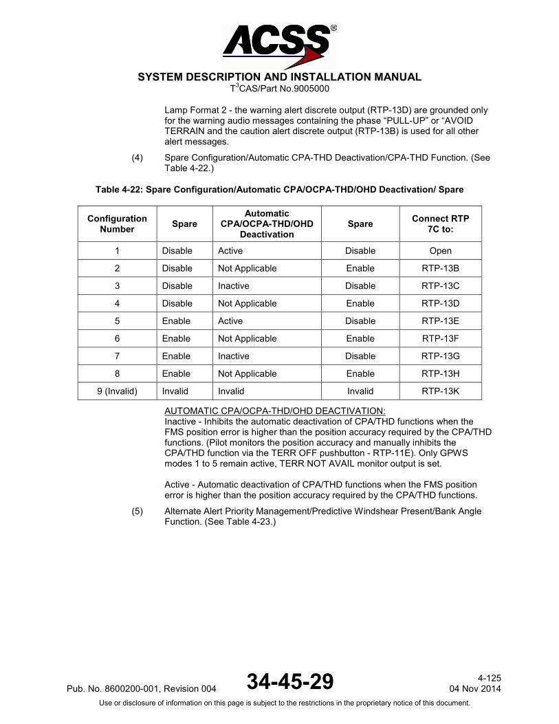
SYSTEM DESCRIPTION AND INSTALLATION MANUAL
T3CAS/Part No.9005000
Lamp Format 2 - the warning alert discrete output (RTP-13D) are grounded only for the warning audio messages containing the phase “PULL-UP” or “AVOID TERRAIN and the caution alert discrete output (RTP-13B) is used for all other alert messages.
(4) Spare Configuration/Automatic CPA-THD Deactivation/CPA-THD Function. (See Table 4-22.)
Table 4-22: Spare Configuration/Automatic CPA/OCPA-THD/OHD Deactivation/ Spare
Configuration Number Spare
Automatic CPA/OCPA-THD/OHD
Deactivation Spare Connect RTP
7C to:
1 Disable Active Disable Open
2 Disable Not Applicable Enable RTP-13B
3 Disable Inactive Disable RTP-13C
4 Disable Not Applicable Enable RTP-13D
5 Enable Active Disable RTP-13E
6 Enable Not Applicable Enable RTP-13F
7 Enable Inactive Disable RTP-13G
8 Enable Not Applicable Enable RTP-13H
9 (Invalid) Invalid Invalid Invalid RTP-13K
AUTOMATIC CPA/OCPA-THD/OHD DEACTIVATION: Inactive - Inhibits the automatic deactivation of CPA/THD functions when the FMS position error is higher than the position accuracy required by the CPA/THD functions. (Pilot monitors the position accuracy and manually inhibits the CPA/THD function via the TERR OFF pushbutton - RTP-11E). Only GPWS modes 1 to 5 remain active, TERR NOT AVAIL monitor output is set. Active - Automatic deactivation of CPA/THD functions when the FMS position error is higher than the position accuracy required by the CPA/THD functions.
(5) Alternate Alert Priority Management/Predictive Windshear Present/Bank Angle Function. (See Table 4-23.)
Pub. No. 8600200-001, Revision 004 34-45-29 4-125
04 Nov 2014 Use or disclosure of information on this page is subject to the restrictions in the proprietary notice of this document.
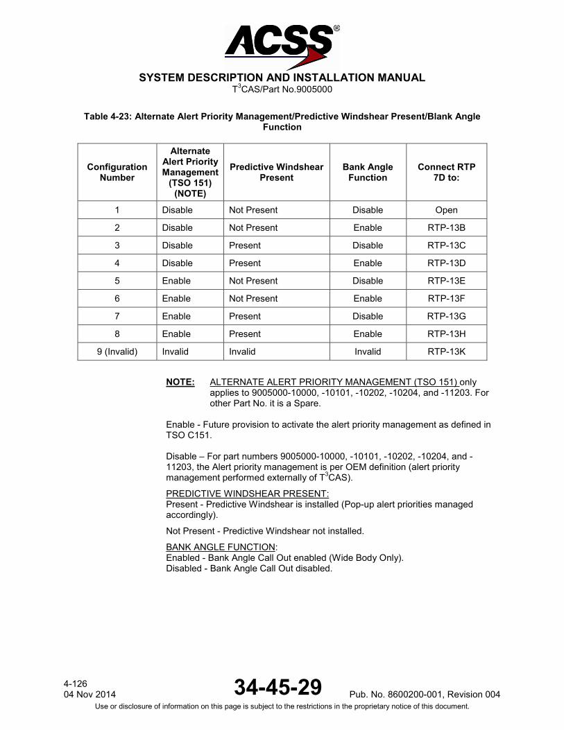
SYSTEM DESCRIPTION AND INSTALLATION MANUAL
T3CAS/Part No.9005000
Table 4-23: Alternate Alert Priority Management/Predictive Windshear Present/Blank Angle Function
Configuration Number
Alternate Alert Priority Management
(TSO 151) (NOTE)
Predictive Windshear Present
Bank Angle Function
Connect RTP 7D to:
1 Disable Not Present Disable Open
2 Disable Not Present Enable RTP-13B
3 Disable Present Disable RTP-13C
4 Disable Present Enable RTP-13D
5 Enable Not Present Disable RTP-13E
6 Enable Not Present Enable RTP-13F
7 Enable Present Disable RTP-13G
8 Enable Present Enable RTP-13H
9 (Invalid) Invalid Invalid Invalid RTP-13K NOTE: ALTERNATE ALERT PRIORITY MANAGEMENT (TSO 151) only
applies to 9005000-10000, -10101, -10202, -10204, and -11203. For other Part No. it is a Spare.
Enable - Future provision to activate the alert priority management as defined in TSO C151. Disable – For part numbers 9005000-10000, -10101, -10202, -10204, and -11203, the Alert priority management is per OEM definition (alert priority management performed externally of T3CAS).
PREDICTIVE WINDSHEAR PRESENT: Present - Predictive Windshear is installed (Pop-up alert priorities managed accordingly).
Not Present - Predictive Windshear not installed.
BANK ANGLE FUNCTION: Enabled - Bank Angle Call Out enabled (Wide Body Only). Disabled - Bank Angle Call Out disabled.
4-126 04 Nov 2014 34-45-29 Pub. No. 8600200-001, Revision 004
Use or disclosure of information on this page is subject to the restrictions in the proprietary notice of this document.
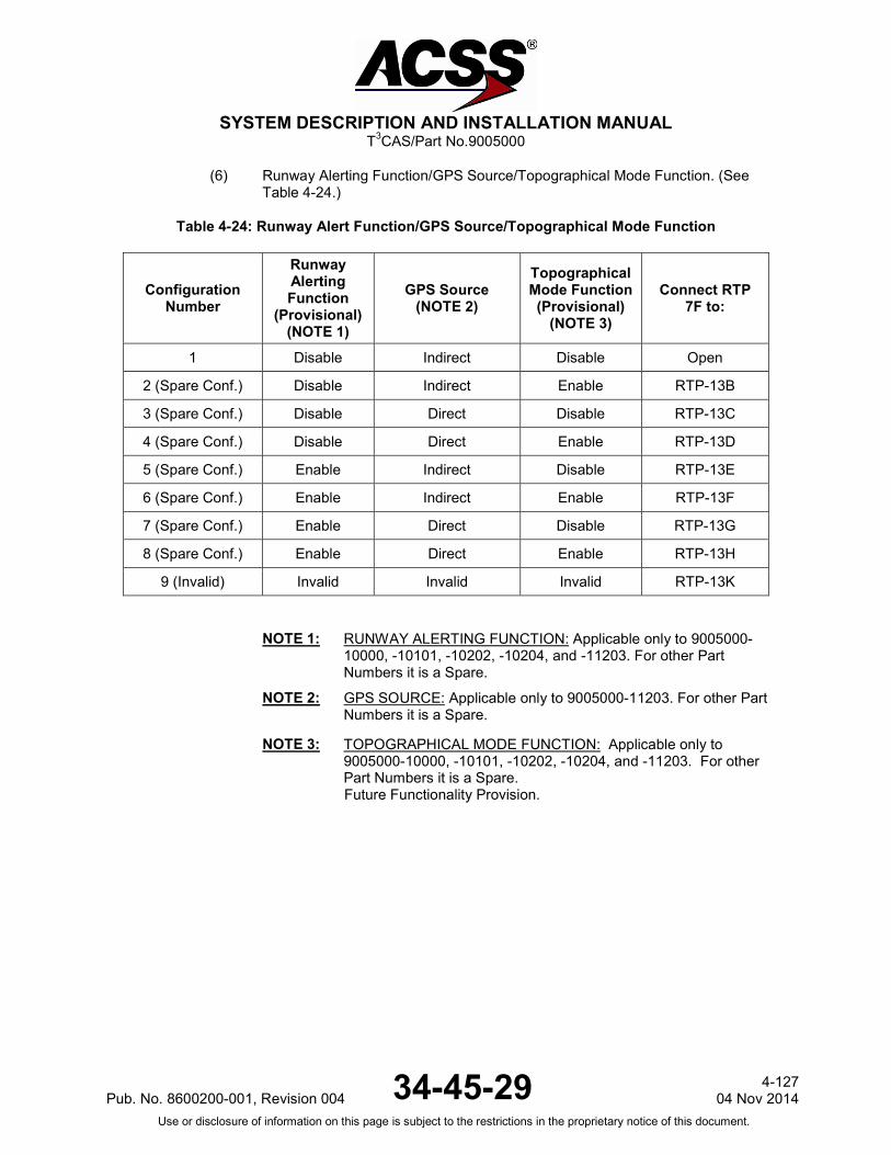
SYSTEM DESCRIPTION AND INSTALLATION MANUAL
T3CAS/Part No.9005000
(6) Runway Alerting Function/GPS Source/Topographical Mode Function. (See Table 4-24.)
Table 4-24: Runway Alert Function/GPS Source/Topographical Mode Function
Configuration Number
Runway Alerting Function
(Provisional) (NOTE 1)
GPS Source (NOTE 2)
Topographical Mode Function (Provisional)
(NOTE 3)
Connect RTP 7F to:
1 Disable Indirect Disable Open
2 (Spare Conf.) Disable Indirect Enable RTP-13B
3 (Spare Conf.) Disable Direct Disable RTP-13C
4 (Spare Conf.) Disable Direct Enable RTP-13D
5 (Spare Conf.) Enable Indirect Disable RTP-13E
6 (Spare Conf.) Enable Indirect Enable RTP-13F
7 (Spare Conf.) Enable Direct Disable RTP-13G
8 (Spare Conf.) Enable Direct Enable RTP-13H
9 (Invalid) Invalid Invalid Invalid RTP-13K
NOTE 1: RUNWAY ALERTING FUNCTION: Applicable only to 9005000-
10000, -10101, -10202, -10204, and -11203. For other Part Numbers it is a Spare.
NOTE 2: GPS SOURCE: Applicable only to 9005000-11203. For other Part Numbers it is a Spare.
NOTE 3: TOPOGRAPHICAL MODE FUNCTION: Applicable only to 9005000-10000, -10101, -10202, -10204, and -11203. For other Part Numbers it is a Spare. Future Functionality Provision.
Pub. No. 8600200-001, Revision 004 34-45-29 4-127
04 Nov 2014 Use or disclosure of information on this page is subject to the restrictions in the proprietary notice of this document.

SYSTEM DESCRIPTION AND INSTALLATION MANUAL
T3CAS/Part No.9005000
(7) ADLP Installed/Terrain Data Comparison Function/Flight Plan Assessment Trajectory Function. (See Table 4-25.)
Table 4-25: ADLP/Terr Data Comparison/Flight Function
Configuration Number
ADLP Installed (NOTE)
Terrain Data Comparison
Function
Flight Plan Assessment Trajectory Function
Connect RTP 7G to:
1 Disable Disable Disable Open
2 (Spare Conf.) Disable Disable Enable RTP-13B
3 (Spare Conf.) Disable Enable Disable RTP-13C
4 (Spare Conf.) Disable Enable Enable RTP-13D
5 (Spare Conf.) Enable Disable Disable RTP-13E
6 (Spare Conf.) Enable Disable Enable RTP-13F
7 (Spare Conf.) Enable Enable Disable RTP-13G
8 (Spare Conf.) Enable Enable Enable RTP-13H
9 (Invalid) Invalid Invalid Invalid RTP-13K
NOTE: ADLP INSTALLED: Applicable only to 9005000-11203, -11801 and -55801.
TERRAIN DATA COMPARISON FUNCTION: Future Functionality Provision.
FLIGHT PLAN ASSESSMENT TRAJECTORY FUNCTION: Future Functionality Provision.
4-128 04 Nov 2014 34-45-29 Pub. No. 8600200-001, Revision 004
Use or disclosure of information on this page is subject to the restrictions in the proprietary notice of this document.
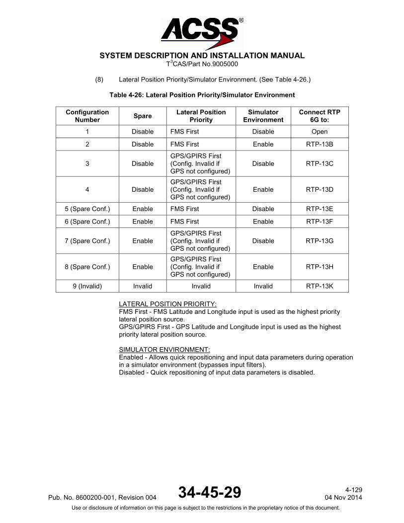
SYSTEM DESCRIPTION AND INSTALLATION MANUAL
T3CAS/Part No.9005000
(8) Lateral Position Priority/Simulator Environment. (See Table 4-26.)
Table 4-26: Lateral Position Priority/Simulator Environment
Configuration Number Spare Lateral Position
Priority Simulator
Environment Connect RTP
6G to:
1 Disable FMS First Disable Open
2 Disable FMS First Enable RTP-13B
3 Disable GPS/GPIRS First (Config. Invalid if GPS not configured)
Disable RTP-13C
4 Disable GPS/GPIRS First (Config. Invalid if GPS not configured)
Enable RTP-13D
5 (Spare Conf.) Enable FMS First Disable RTP-13E
6 (Spare Conf.) Enable FMS First Enable RTP-13F
7 (Spare Conf.) Enable GPS/GPIRS First (Config. Invalid if GPS not configured)
Disable RTP-13G
8 (Spare Conf.) Enable GPS/GPIRS First (Config. Invalid if GPS not configured)
Enable RTP-13H
9 (Invalid) Invalid Invalid Invalid RTP-13K LATERAL POSITION PRIORITY: FMS First - FMS Latitude and Longitude input is used as the highest priority lateral position source. GPS/GPIRS First - GPS Latitude and Longitude input is used as the highest priority lateral position source. SIMULATOR ENVIRONMENT: Enabled - Allows quick repositioning and input data parameters during operation in a simulator environment (bypasses input filters). Disabled - Quick repositioning of input data parameters is disabled.
Pub. No. 8600200-001, Revision 004 34-45-29 4-129
04 Nov 2014 Use or disclosure of information on this page is subject to the restrictions in the proprietary notice of this document.
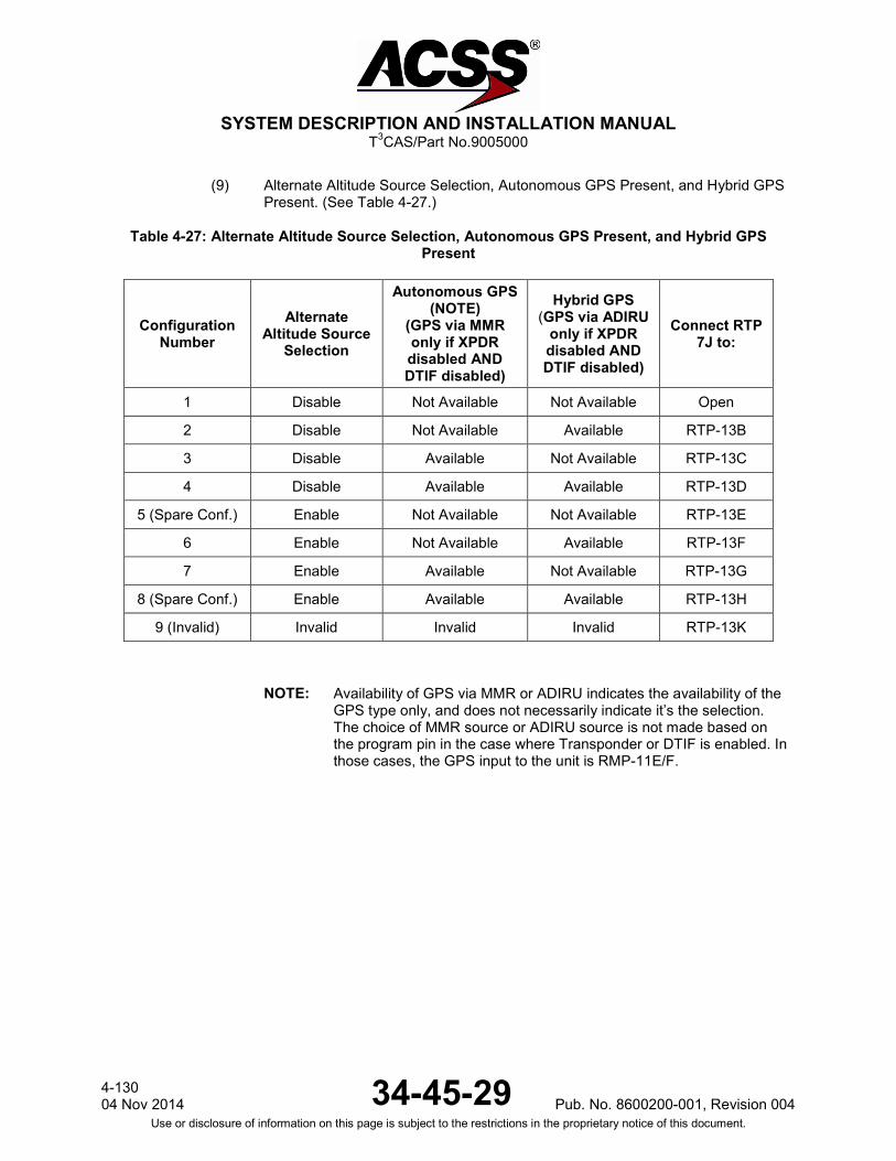
SYSTEM DESCRIPTION AND INSTALLATION MANUAL
T3CAS/Part No.9005000
(9) Alternate Altitude Source Selection, Autonomous GPS Present, and Hybrid GPS Present. (See Table 4-27.)
Table 4-27: Alternate Altitude Source Selection, Autonomous GPS Present, and Hybrid GPS Present
Configuration Number
Alternate Altitude Source
Selection
Autonomous GPS (NOTE)
(GPS via MMR only if XPDR disabled AND DTIF disabled)
Hybrid GPS (GPS via ADIRU
only if XPDR disabled AND DTIF disabled)
Connect RTP 7J to:
1 Disable Not Available Not Available Open
2 Disable Not Available Available RTP-13B
3 Disable Available Not Available RTP-13C
4 Disable Available Available RTP-13D
5 (Spare Conf.) Enable Not Available Not Available RTP-13E
6 Enable Not Available Available RTP-13F
7 Enable Available Not Available RTP-13G
8 (Spare Conf.) Enable Available Available RTP-13H
9 (Invalid) Invalid Invalid Invalid RTP-13K
NOTE: Availability of GPS via MMR or ADIRU indicates the availability of the GPS type only, and does not necessarily indicate it’s the selection. The choice of MMR source or ADIRU source is not made based on the program pin in the case where Transponder or DTIF is enabled. In those cases, the GPS input to the unit is RMP-11E/F.
4-130 04 Nov 2014 34-45-29 Pub. No. 8600200-001, Revision 004
Use or disclosure of information on this page is subject to the restrictions in the proprietary notice of this document.

SYSTEM DESCRIPTION AND INSTALLATION MANUAL
T3CAS/Part No.9005000
(10) Maximum Cruising True Airspeed. (See Table 4-28.)
Table 4-28: Maximum Cruising True Airspeed
Configuration Number Description Connect RTP
5K to:
1 Airspeed between 300 and 600 KTS Open
2 Airspeed up to 75 KTS RTP-13B
3 Airspeed between 75 and 150 KTS RTP-13C
4 Airspeed between 150 and 300 KTS RTP-13D
5 No maximum airspeed available RTP-13E
6 Airspeed between 600 and 1200 KTS RTP-13F
7 Airspeed more than 1200 KTS RTP-13G
8 Not assigned RTP-13H
9 Invalid RTP-13K
(11) Cold Temperature Compensation Function. (See Table 4-29.)
Table 4-29: Cold Temperature Compensation Function
Configuration Number Spare Spare
Cold Temperature
Compensation Function
Connect RTP 7K to:
1 Disable Disable Full Open
2 Disable Disable Light RTP-13B
3(Spare Conf.) Disable Enable Full RTP-13C
4(Spare Conf.) Disable Enable Light RTP-13D
5 (Spare Conf.) Enable Disable Full RTP-13E
6(Spare Conf.) Enable Disable Light RTP-13F
7(Spare Conf.) Enable Enable Full RTP-13G
8 (Spare Conf.) Enable Enable Light RTP-13H
9 (Invalid) Invalid Invalid Invalid RTP-13K
COLD TEMPERATURE COMPENSATION FUNCTION: Enable - Cold Temperature Compensation applied to barometric altitude used for altitude position determination. Disable - Cold Temperature Compensation disabled.
Pub. No. 8600200-001, Revision 004 34-45-29 4-131
04 Nov 2014 Use or disclosure of information on this page is subject to the restrictions in the proprietary notice of this document.
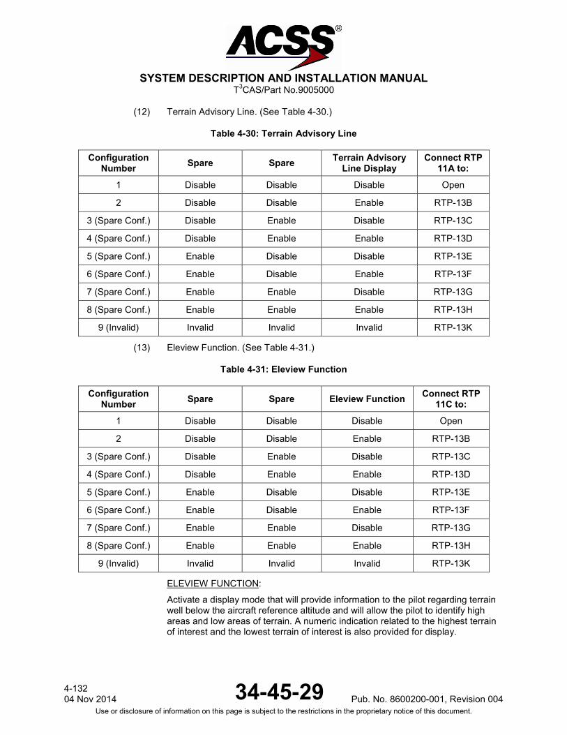
SYSTEM DESCRIPTION AND INSTALLATION MANUAL
T3CAS/Part No.9005000
(12) Terrain Advisory Line. (See Table 4-30.)
Table 4-30: Terrain Advisory Line
Configuration Number Spare Spare Terrain Advisory
Line Display Connect RTP
11A to:
1 Disable Disable Disable Open
2 Disable Disable Enable RTP-13B
3 (Spare Conf.) Disable Enable Disable RTP-13C
4 (Spare Conf.) Disable Enable Enable RTP-13D
5 (Spare Conf.) Enable Disable Disable RTP-13E
6 (Spare Conf.) Enable Disable Enable RTP-13F
7 (Spare Conf.) Enable Enable Disable RTP-13G
8 (Spare Conf.) Enable Enable Enable RTP-13H
9 (Invalid) Invalid Invalid Invalid RTP-13K
(13) Eleview Function. (See Table 4-31.)
Table 4-31: Eleview Function
Configuration Number Spare Spare Eleview Function Connect RTP
11C to:
1 Disable Disable Disable Open
2 Disable Disable Enable RTP-13B
3 (Spare Conf.) Disable Enable Disable RTP-13C
4 (Spare Conf.) Disable Enable Enable RTP-13D
5 (Spare Conf.) Enable Disable Disable RTP-13E
6 (Spare Conf.) Enable Disable Enable RTP-13F
7 (Spare Conf.) Enable Enable Disable RTP-13G
8 (Spare Conf.) Enable Enable Enable RTP-13H
9 (Invalid) Invalid Invalid Invalid RTP-13K
ELEVIEW FUNCTION:
Activate a display mode that will provide information to the pilot regarding terrain well below the aircraft reference altitude and will allow the pilot to identify high areas and low areas of terrain. A numeric indication related to the highest terrain of interest and the lowest terrain of interest is also provided for display.
4-132 04 Nov 2014 34-45-29 Pub. No. 8600200-001, Revision 004
Use or disclosure of information on this page is subject to the restrictions in the proprietary notice of this document.

SYSTEM DESCRIPTION AND INSTALLATION MANUAL
T3CAS/Part No.9005000
(14) Obstacle Function. (See Table 4-32.)
Table 4-32: Obstacle Function
Configuration Number Spare Spare Obstacle Function Connect RTP
11F to:
1 Disable Disable Disable Open
2 Disable Disable Enable RTP-13B
3 (Spare Conf.) Disable Enable Disable RTP-13C
4 (Spare Conf.) Disable Enable Enable RTP-13D
5 (Spare Conf.) Enable Disable Disable RTP-13E
6 (Spare Conf.) Enable Disable Enable RTP-13F
7 (Spare Conf.) Enable Enable Disable RTP-13G
8 (Spare Conf.) Enable Enable Enable RTP-13H
9 (Invalid) Invalid Invalid Invalid RTP-13K
OBSTACLE FUNCTION:
Enable – Activates obstacle functionality. An obstacle database must be loaded in the T3CAS unit to display obstacles.
Disable – Deactivates obstacle function.
(15) Program Pin Parity. (See Table 4-33.)
Table 4-33: Program Pin Parity
Configuration Number Parity Connect
RTP-11J to:
1 Odd Open
2 Even RTP-13B
PROGRAM PIN PARITY: A connection from RTP-11J and RTP-13B is made when the count of all programming pin connections is even (i.e., count of all programming pin connections including the parity must be odd). Parity is determined by counting the number of input pins that are connected to an output. Odd parity is expected, so an even number of connections is considered a parity error. Note the parity is calculated over the following set of input pins for XPDR/TAWS:
Pub. No. 8600200-001, Revision 004 34-45-29 4-133
04 Nov 2014 Use or disclosure of information on this page is subject to the restrictions in the proprietary notice of this document.
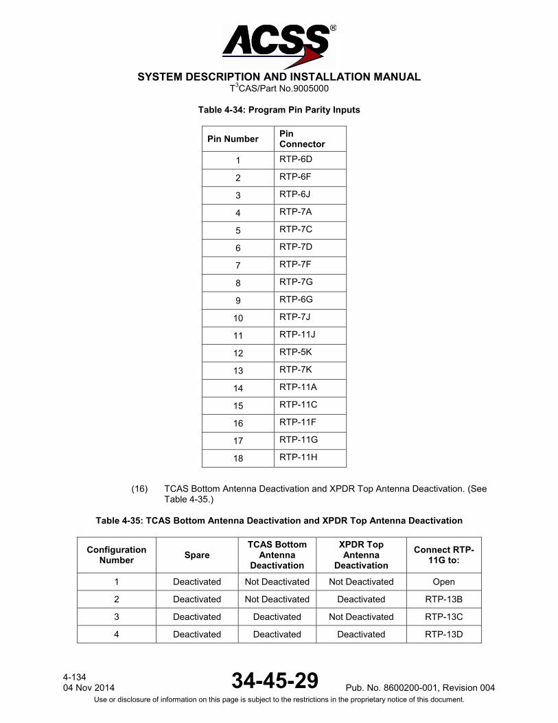
SYSTEM DESCRIPTION AND INSTALLATION MANUAL
T3CAS/Part No.9005000
Table 4-34: Program Pin Parity Inputs
Pin Number Pin Connector
1 RTP-6D
2 RTP-6F
3 RTP-6J
4 RTP-7A
5 RTP-7C
6 RTP-7D
7 RTP-7F
8 RTP-7G
9 RTP-6G
10 RTP-7J
11 RTP-11J
12 RTP-5K
13 RTP-7K
14 RTP-11A
15 RTP-11C
16 RTP-11F
17 RTP-11G
18 RTP-11H
(16) TCAS Bottom Antenna Deactivation and XPDR Top Antenna Deactivation. (See Table 4-35.)
Table 4-35: TCAS Bottom Antenna Deactivation and XPDR Top Antenna Deactivation
Configuration Number Spare
TCAS Bottom Antenna
Deactivation
XPDR Top Antenna
Deactivation Connect RTP-
11G to:
1 Deactivated Not Deactivated Not Deactivated Open
2 Deactivated Not Deactivated Deactivated RTP-13B
3 Deactivated Deactivated Not Deactivated RTP-13C
4 Deactivated Deactivated Deactivated RTP-13D
4-134 04 Nov 2014 34-45-29 Pub. No. 8600200-001, Revision 004
Use or disclosure of information on this page is subject to the restrictions in the proprietary notice of this document.
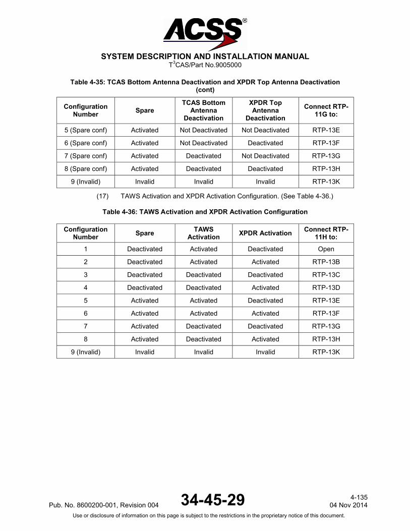
SYSTEM DESCRIPTION AND INSTALLATION MANUAL
T3CAS/Part No.9005000
Table 4-35: TCAS Bottom Antenna Deactivation and XPDR Top Antenna Deactivation (cont)
Configuration Number Spare
TCAS Bottom Antenna
Deactivation
XPDR Top Antenna
Deactivation Connect RTP-
11G to:
5 (Spare conf) Activated Not Deactivated Not Deactivated RTP-13E
6 (Spare conf) Activated Not Deactivated Deactivated RTP-13F
7 (Spare conf) Activated Deactivated Not Deactivated RTP-13G
8 (Spare conf) Activated Deactivated Deactivated RTP-13H
9 (Invalid) Invalid Invalid Invalid RTP-13K
(17) TAWS Activation and XPDR Activation Configuration. (See Table 4-36.)
Table 4-36: TAWS Activation and XPDR Activation Configuration
Configuration Number Spare TAWS
Activation XPDR Activation Connect RTP- 11H to:
1 Deactivated Activated Deactivated Open
2 Deactivated Activated Activated RTP-13B
3 Deactivated Deactivated Deactivated RTP-13C
4 Deactivated Deactivated Activated RTP-13D
5 Activated Activated Deactivated RTP-13E
6 Activated Activated Activated RTP-13F
7 Activated Deactivated Deactivated RTP-13G
8 Activated Deactivated Activated RTP-13H
9 (Invalid) Invalid Invalid Invalid RTP-13K
Pub. No. 8600200-001, Revision 004 34-45-29 4-135
04 Nov 2014 Use or disclosure of information on this page is subject to the restrictions in the proprietary notice of this document.
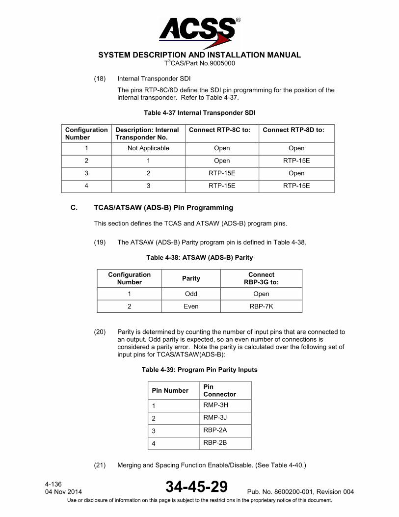
SYSTEM DESCRIPTION AND INSTALLATION MANUAL
T3CAS/Part No.9005000
(18) Internal Transponder SDI
The pins RTP-8C/8D define the SDI pin programming for the position of the internal transponder. Refer to Table 4-37.
Table 4-37 Internal Transponder SDI
Configuration Number
Description: Internal Transponder No.
Connect RTP-8C to: Connect RTP-8D to:
1 Not Applicable Open Open
2 1 Open RTP-15E
3 2 RTP-15E Open
4 3 RTP-15E RTP-15E
C. TCAS/ATSAW (ADS-B) Pin Programming
This section defines the TCAS and ATSAW (ADS-B) program pins.
(19) The ATSAW (ADS-B) Parity program pin is defined in Table 4-38.
Table 4-38: ATSAW (ADS-B) Parity
Configuration Number Parity Connect
RBP-3G to:
1 Odd Open
2 Even RBP-7K
(20) Parity is determined by counting the number of input pins that are connected to an output. Odd parity is expected, so an even number of connections is considered a parity error. Note the parity is calculated over the following set of input pins for TCAS/ATSAW(ADS-B):
Table 4-39: Program Pin Parity Inputs
Pin Number Pin Connector
1 RMP-3H
2 RMP-3J
3 RBP-2A
4 RBP-2B
(21) Merging and Spacing Function Enable/Disable. (See Table 4-40.)
4-136 04 Nov 2014 34-45-29 Pub. No. 8600200-001, Revision 004
Use or disclosure of information on this page is subject to the restrictions in the proprietary notice of this document.
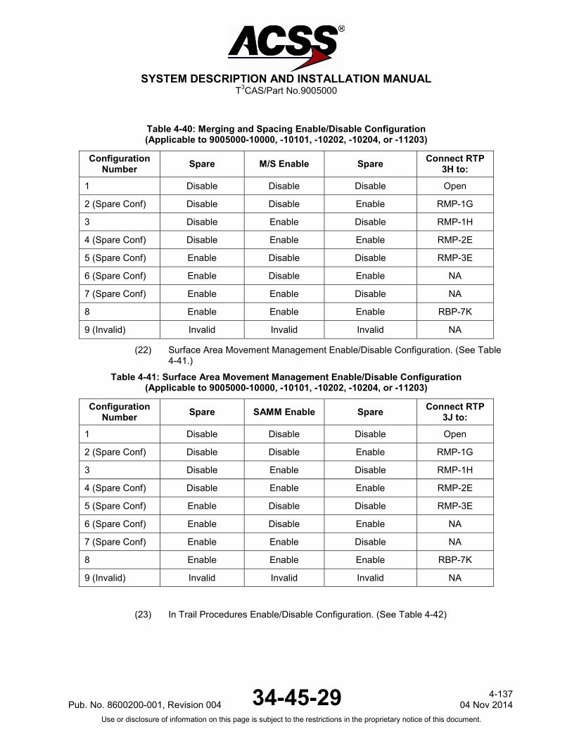
SYSTEM DESCRIPTION AND INSTALLATION MANUAL
T3CAS/Part No.9005000
Table 4-40: Merging and Spacing Enable/Disable Configuration (Applicable to 9005000-10000, -10101, -10202, -10204, or -11203)
Configuration Number Spare M/S Enable Spare Connect RTP
3H to:
1 Disable Disable Disable Open
2 (Spare Conf) Disable Disable Enable RMP-1G
3 Disable Enable Disable RMP-1H
4 (Spare Conf) Disable Enable Enable RMP-2E
5 (Spare Conf) Enable Disable Disable RMP-3E
6 (Spare Conf) Enable Disable Enable NA
7 (Spare Conf) Enable Enable Disable NA
8 Enable Enable Enable RBP-7K
9 (Invalid) Invalid Invalid Invalid NA
(22) Surface Area Movement Management Enable/Disable Configuration. (See Table 4-41.)
Table 4-41: Surface Area Movement Management Enable/Disable Configuration (Applicable to 9005000-10000, -10101, -10202, -10204, or -11203)
Configuration Number Spare SAMM Enable Spare Connect RTP
3J to:
1 Disable Disable Disable Open
2 (Spare Conf) Disable Disable Enable RMP-1G
3 Disable Enable Disable RMP-1H
4 (Spare Conf) Disable Enable Enable RMP-2E
5 (Spare Conf) Enable Disable Disable RMP-3E
6 (Spare Conf) Enable Disable Enable NA
7 (Spare Conf) Enable Enable Disable NA
8 Enable Enable Enable RBP-7K
9 (Invalid) Invalid Invalid Invalid NA
(23) In Trail Procedures Enable/Disable Configuration. (See Table 4-42)
Pub. No. 8600200-001, Revision 004 34-45-29 4-137
04 Nov 2014 Use or disclosure of information on this page is subject to the restrictions in the proprietary notice of this document.
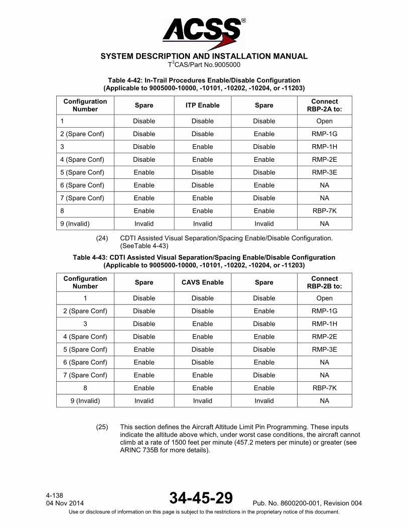
SYSTEM DESCRIPTION AND INSTALLATION MANUAL
T3CAS/Part No.9005000
Table 4-42: In-Trail Procedures Enable/Disable Configuration (Applicable to 9005000-10000, -10101, -10202, -10204, or -11203)
Configuration Number Spare ITP Enable Spare Connect
RBP-2A to:
1 Disable Disable Disable Open
2 (Spare Conf) Disable Disable Enable RMP-1G
3 Disable Enable Disable RMP-1H
4 (Spare Conf) Disable Enable Enable RMP-2E
5 (Spare Conf) Enable Disable Disable RMP-3E
6 (Spare Conf) Enable Disable Enable NA
7 (Spare Conf) Enable Enable Disable NA
8 Enable Enable Enable RBP-7K
9 (Invalid) Invalid Invalid Invalid NA
(24) CDTI Assisted Visual Separation/Spacing Enable/Disable Configuration. (SeeTable 4-43)
Table 4-43: CDTI Assisted Visual Separation/Spacing Enable/Disable Configuration (Applicable to 9005000-10000, -10101, -10202, -10204, or -11203)
Configuration Number Spare CAVS Enable Spare Connect
RBP-2B to:
1 Disable Disable Disable Open
2 (Spare Conf) Disable Disable Enable RMP-1G
3 Disable Enable Disable RMP-1H
4 (Spare Conf) Disable Enable Enable RMP-2E
5 (Spare Conf) Enable Disable Disable RMP-3E
6 (Spare Conf) Enable Disable Enable NA
7 (Spare Conf) Enable Enable Disable NA
8 Enable Enable Enable RBP-7K
9 (Invalid) Invalid Invalid Invalid NA
(25) This section defines the Aircraft Altitude Limit Pin Programming. These inputs indicate the altitude above which, under worst case conditions, the aircraft cannot climb at a rate of 1500 feet per minute (457.2 meters per minute) or greater (see ARINC 735B for more details).
4-138 04 Nov 2014 34-45-29 Pub. No. 8600200-001, Revision 004
Use or disclosure of information on this page is subject to the restrictions in the proprietary notice of this document.

SYSTEM DESCRIPTION AND INSTALLATION MANUAL
T3CAS/Part No.9005000
Table 4-44: Aircraft Altitude Limit
Pin Description Connected to:
RMP 6E 2000 ft (609.6 m) 1 = Connected to RMP – 6 K 0 = Open
RMP 6F 4000 ft (1219.2 m)
RMP 6G 8000 ft (2438.4 m)
RMP 6H 16000 ft (4876.8 m)
RMP 6J 32000 ft (9753.6 m)
(26) This section defines the Display All Traffic Pin Programming.
Table 4-45: Display All Traffic
Configuration Number
Description Connect RBP- 7F to:
1 Display all traffic Open
2 Display TA or RA RBP-7K
(27) This section defines the TA/RA Display Intruder Limit. These 5 program pin inputs are used to encode the maximum number of intruder symbols to be presented on TA/RA displays. The logic of programming is that an “Open” represents “Selected” and a connection to Program Pin Common RBP-7K represents “Not Selected.” A minimum of 8 intruders are displayed, even though a value for less than 8 intruders can be selected.
Table 4-46: TA/RA Display Intruder
Pin Description Connected to:
RBP 8F 16 intruders RBP 7K = Not selected Open = Selected RBP 8G 8 intruders
RBP 8H 4 intruders
RBP 8J 2 intruders
RBP 8K 1 intruder
(28) This section defines the RA Valid Disable Pin Programming.
Table 4-47: RA Valid Disable
Monitoring of valid discretes from RA indicators
Connect RBP 4G to:
Disable RBP 7K
Enable Open
Pub. No. 8600200-001, Revision 004 34-45-29 4-139
04 Nov 2014 Use or disclosure of information on this page is subject to the restrictions in the proprietary notice of this document.
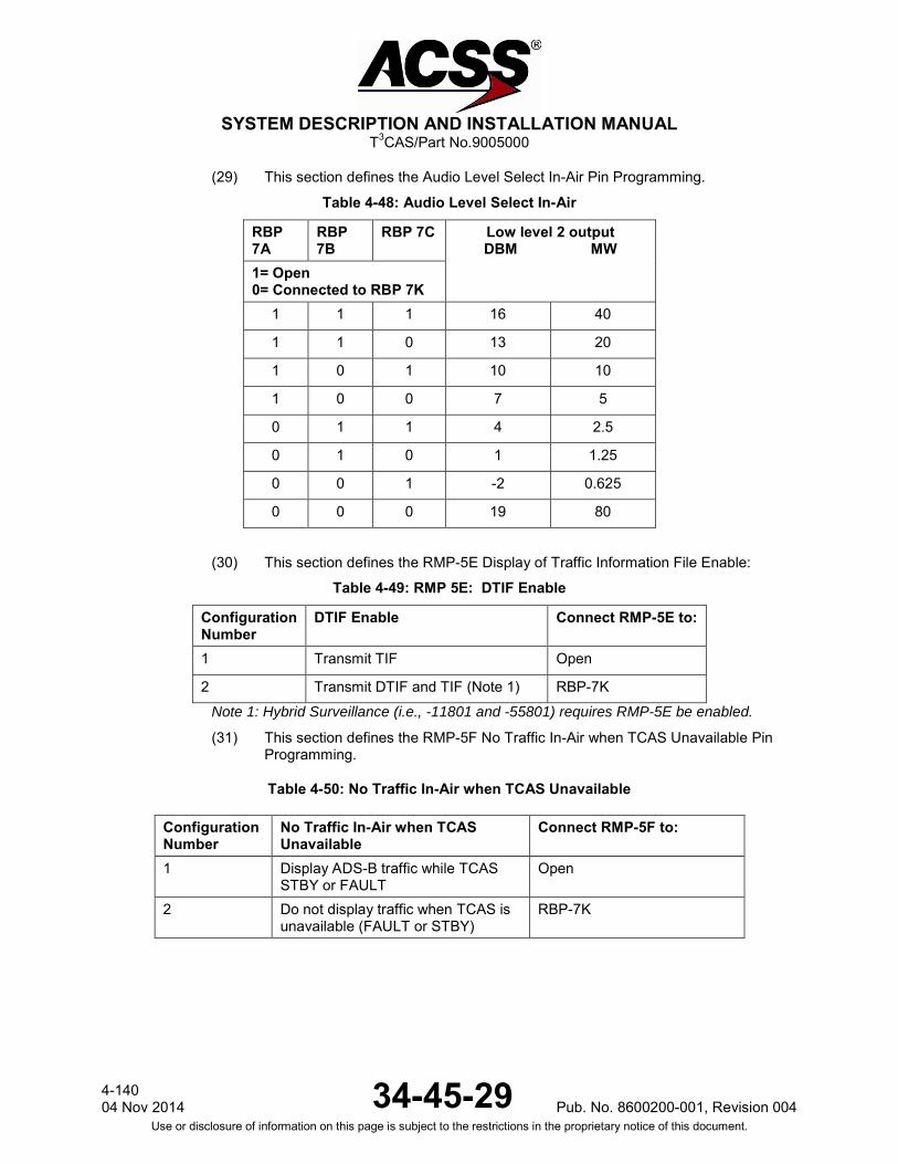
SYSTEM DESCRIPTION AND INSTALLATION MANUAL
T3CAS/Part No.9005000
(29) This section defines the Audio Level Select In-Air Pin Programming.
Table 4-48: Audio Level Select In-Air
RBP 7A
RBP 7B
RBP 7C Low level 2 output DBM MW
1= Open 0= Connected to RBP 7K
1 1 1 16 40
1 1 0 13 20
1 0 1 10 10
1 0 0 7 5
0 1 1 4 2.5
0 1 0 1 1.25
0 0 1 -2 0.625
0 0 0 19 80
(30) This section defines the RMP-5E Display of Traffic Information File Enable:
Table 4-49: RMP 5E: DTIF Enable
Configuration Number
DTIF Enable Connect RMP-5E to:
1 Transmit TIF Open
2 Transmit DTIF and TIF (Note 1) RBP-7K Note 1: Hybrid Surveillance (i.e., -11801 and -55801) requires RMP-5E be enabled.
(31) This section defines the RMP-5F No Traffic In-Air when TCAS Unavailable Pin Programming.
Table 4-50: No Traffic In-Air when TCAS Unavailable
Configuration Number
No Traffic In-Air when TCAS Unavailable
Connect RMP-5F to:
1 Display ADS-B traffic while TCAS STBY or FAULT
Open
2 Do not display traffic when TCAS is unavailable (FAULT or STBY)
RBP-7K
4-140 04 Nov 2014 34-45-29 Pub. No. 8600200-001, Revision 004
Use or disclosure of information on this page is subject to the restrictions in the proprietary notice of this document.

SYSTEM DESCRIPTION AND INSTALLATION MANUAL
T3CAS/Part No.9005000
(32) This section defines the RMP-5G Traffic Simulation Enable Pin Programming:
Table 4-51: RMP 5G: Traffic Simulation Enable
Configuration Number No Traffic In-Air when TCAS Unavailable
Connect RMP-5G to:
1 Traffic Simulation Disable Open
2 Traffic Simulation Enable RBP-7K
D. Invalid Strobable Program Pin Combinations
Table 4-52 defines the program pin combinations of Alternate Altitude and Lateral Position Priority which result in an invalid program pin combination if: • Strapping for non-GPS lateral and vertical, yet requesting Hybrid GPS • Strapping for non-GPS lateral and vertical, yet requesting Standalone GPS • Strapping for both Hybrid and Standalone GPS (only one may be selected) • Strapping for GPS vertical position, yet no GPS is available • Strapping for GPS lateral position, yet no GPS is available • Strapping for both GPS lateral and vertical position, yet no GPS is available
Table 4-52: Invalid Stobable Program Pin Combinations for Alternate Altitude and Lateral Position Priority
Program Pin Set Lat Pos Priority
Alternate Altitude
(Vert Pos) GPS
Standalone Hybrid GPS Invalid Reason
6G to Open 7J to 13B FMS First Disable (no GPS)
Not Available Available
Requesting non-GPS lateral and vertical, yet Hybrid GPS is connected.
6G to 13B 7J to 13B FMS First Disable (no GPS)
Not Available Available
6G to 13E 7J to 13B FMS First Disable (no GPS)
Not Available Available
6G to 13F 7J to 13B FMS First Disable (no GPS)
Not Available Available
6G to Open 7J to 13C FMS First Disable (no GPS) Available Not
Available
Requesting non-GPS lateral and vertical, yet Standalone GPS is connected.
6G to 13B 7J to 13C FMS First Disable (no GPS) Available Not
Available
6G to 13E 7J to 13C FMS First Disable (no GPS) Available Not
Available
6G to 13F 7J to 13C FMS First Disable (no GPS) Available Not
Available
Pub. No. 8600200-001, Revision 004 34-45-29 4-141
04 Nov 2014 Use or disclosure of information on this page is subject to the restrictions in the proprietary notice of this document.
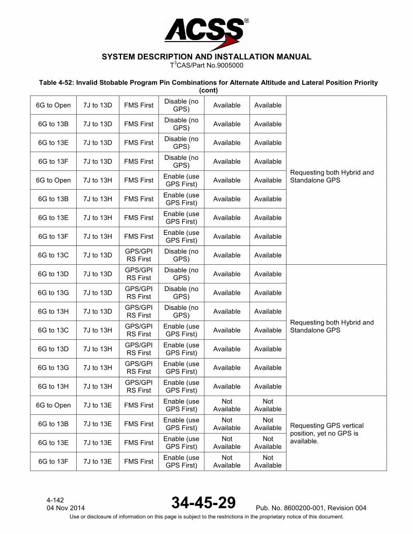
SYSTEM DESCRIPTION AND INSTALLATION MANUAL
T3CAS/Part No.9005000
Table 4-52: Invalid Stobable Program Pin Combinations for Alternate Altitude and Lateral Position Priority (cont)
6G to Open 7J to 13D FMS First Disable (no GPS) Available Available
Requesting both Hybrid and Standalone GPS
6G to 13B 7J to 13D FMS First Disable (no GPS) Available Available
6G to 13E 7J to 13D FMS First Disable (no GPS) Available Available
6G to 13F 7J to 13D FMS First Disable (no GPS) Available Available
6G to Open 7J to 13H FMS First Enable (use GPS First) Available Available
6G to 13B 7J to 13H FMS First Enable (use GPS First) Available Available
6G to 13E 7J to 13H FMS First Enable (use GPS First) Available Available
6G to 13F 7J to 13H FMS First Enable (use GPS First) Available Available
6G to 13C 7J to 13D GPS/GPIRS First
Disable (no GPS) Available Available
6G to 13D 7J to 13D GPS/GPIRS First
Disable (no GPS) Available Available
Requesting both Hybrid and Standalone GPS
6G to 13G 7J to 13D GPS/GPIRS First
Disable (no GPS) Available Available
6G to 13H 7J to 13D GPS/GPIRS First
Disable (no GPS) Available Available
6G to 13C 7J to 13H GPS/GPIRS First
Enable (use GPS First) Available Available
6G to 13D 7J to 13H GPS/GPIRS First
Enable (use GPS First) Available Available
6G to 13G 7J to 13H GPS/GPIRS First
Enable (use GPS First) Available Available
6G to 13H 7J to 13H GPS/GPIRS First
Enable (use GPS First) Available Available
6G to Open 7J to 13E FMS First Enable (use GPS First)
Not Available
Not Available
Requesting GPS vertical position, yet no GPS is available.
6G to 13B 7J to 13E FMS First Enable (use GPS First)
Not Available
Not Available
6G to 13E 7J to 13E FMS First Enable (use GPS First)
Not Available
Not Available
6G to 13F 7J to 13E FMS First Enable (use GPS First)
Not Available
Not Available
4-142 04 Nov 2014 34-45-29 Pub. No. 8600200-001, Revision 004
Use or disclosure of information on this page is subject to the restrictions in the proprietary notice of this document.
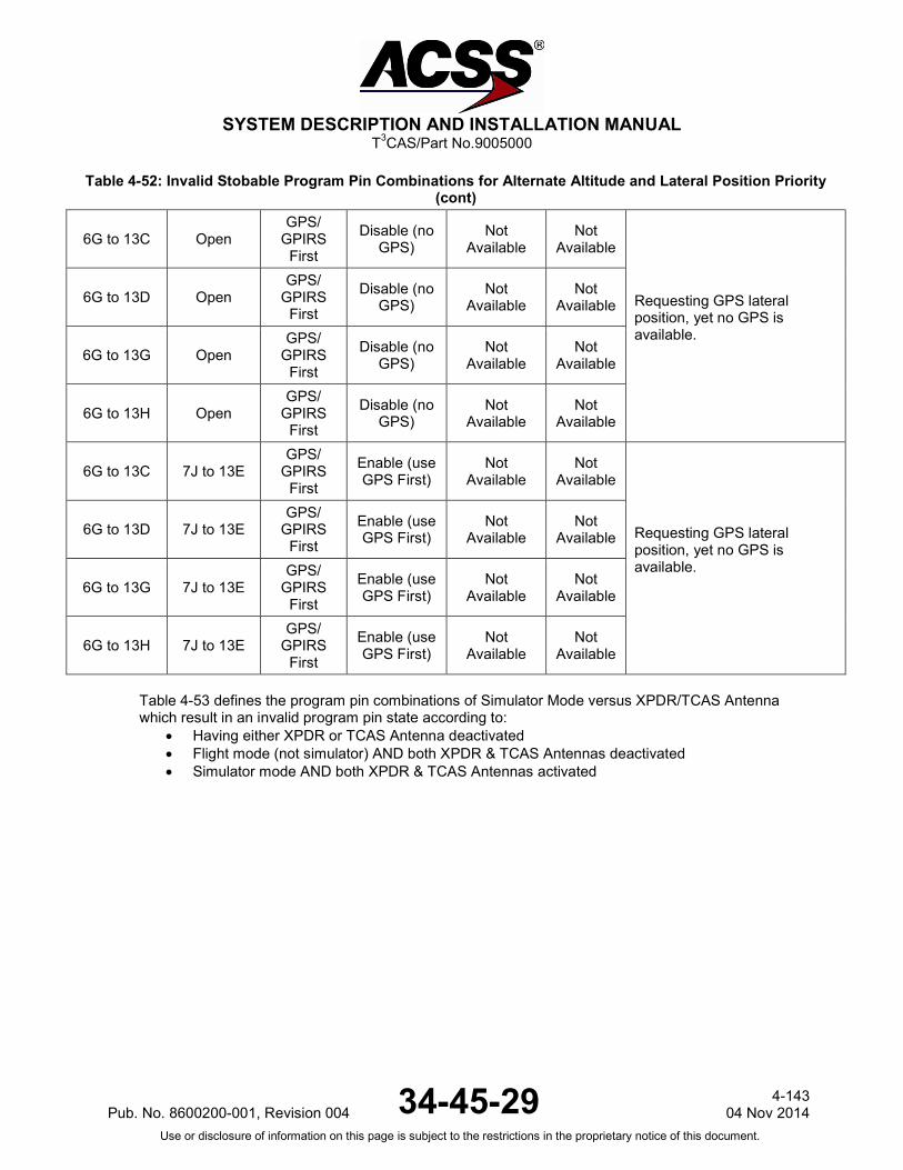
SYSTEM DESCRIPTION AND INSTALLATION MANUAL
T3CAS/Part No.9005000
Table 4-52: Invalid Stobable Program Pin Combinations for Alternate Altitude and Lateral Position Priority (cont)
6G to 13C Open GPS/
GPIRS First
Disable (no GPS)
Not Available
Not Available
Requesting GPS lateral position, yet no GPS is available.
6G to 13D Open GPS/
GPIRS First
Disable (no GPS)
Not Available
Not Available
6G to 13G Open GPS/
GPIRS First
Disable (no GPS)
Not Available
Not Available
6G to 13H Open GPS/
GPIRS First
Disable (no GPS)
Not Available
Not Available
6G to 13C 7J to 13E GPS/
GPIRS First
Enable (use GPS First)
Not Available
Not Available
Requesting GPS lateral position, yet no GPS is available.
6G to 13D 7J to 13E GPS/
GPIRS First
Enable (use GPS First)
Not Available
Not Available
6G to 13G 7J to 13E GPS/
GPIRS First
Enable (use GPS First)
Not Available
Not Available
6G to 13H 7J to 13E GPS/
GPIRS First
Enable (use GPS First)
Not Available
Not Available
Table 4-53 defines the program pin combinations of Simulator Mode versus XPDR/TCAS Antenna which result in an invalid program pin state according to:
• Having either XPDR or TCAS Antenna deactivated • Flight mode (not simulator) AND both XPDR & TCAS Antennas deactivated • Simulator mode AND both XPDR & TCAS Antennas activated
Pub. No. 8600200-001, Revision 004 34-45-29 4-143
04 Nov 2014 Use or disclosure of information on this page is subject to the restrictions in the proprietary notice of this document.

SYSTEM DESCRIPTION AND INSTALLATION MANUAL
T3CAS/Part No.9005000
Table 4-53: Invalid Combination of Simulator Mode vs XPDR/TCAS Antenna Pin Programming
Program Pin Set Invalid Reason Any RTP-11G to RTP-13B
Only one of two antennas deactivated. Any RTP-11G to RTP-13C
Any RTP-11G to RTP-13F
Any RTP-11G to RTP-13G
RTP-6G to open RTP-11G to RTP-13D
Flight mode (not simulator) AND both XPDR & TCAS Antennas deactivated.
RTP-6G to open RTP-11G to RTP-13H
RTP-6G to RTP-13C RTP-11G to RTP-13D
RTP-6G to RTP-13C RTP-11G to RTP-13H
RTP-6G to RTP-13E RTP-11G to RTP-13D
RTP-6G to RTP-13E RTP-11G to RTP-13H
RTP-6G to RTP-13G RTP-11G to RTP-13D
RTP-6G to RTP-13G RTP-11G to RTP-13H
RTP-6G to RTP-13B RTP-11G to Open
Simulator mode AND both XPDR & TCAS Antennas activated.
RTP-6G to RTP-13B RTP-11G to RTP-13E
RTP-6G to RTP-13D RTP-11G to Open
RTP-6G to RTP-13D RTP-11G to RTP-13E
RTP-6G to RTP-13F RTP-11G to Open
RTP-6G to RTP-13F RTP-11G to RTP-13E
RTP-6G to RTP-13H RTP-11G to Open
RTP-6G to RTP-13H RTP-11G to RTP-13E
4-144 04 Nov 2014 34-45-29 Pub. No. 8600200-001, Revision 004
Use or disclosure of information on this page is subject to the restrictions in the proprietary notice of this document.
SYSTEM DESCRIPTION AND INSTALLATION MANUAL
T3CAS/Part No.9005000
E. TAWS/RWS and Transponder Input Data Signals
The T3CAS TAWS/RWS and Transponder functions require a minimum set of data that is needed to perform within the standard specifications (detailed in RTCA DO-161A [GPWS], TSO-C151 [TAWS], TSO-C117 [RWS], TSO-C112 [XPDR], DO-260 [MOPS ADS-B] and DO-181 [MOPS XPDR], refer to NOTE following this paragraph). This section contains the minimum set of TAWS/RWS and XPDR data signals and the information/guidelines that is needed by the installer to obtain the correct analog or digital signal on a specific aircraft. Since the I/O function is very flexible, the installer must keep in mind that the data signal sources listed in this section are typical for the specified signal and that the I/O function can be modified via the ASDB to accommodate other non-typical signal sources.
NOTE: For T3CAS Computer Part No.and applicable FAA TSOs and RTCA DOs, refer to Section 1, Table 1-2 T3CAS Unit Configurations.
RWS is not applicable to Part No.9005000-10000, -10101, -10202, -10204, or -11203.
The information in this section will include External Sensor Input accuracies for specific inputs to T3CAS GCAM function. These External Sensor accuracies must be met for the specified inputs in order for the T3CAS to perform the TAWS/RWS and Transponder functions. Inputs to T3CAS GCAM function consist of errors due to the external system sensor plus measurement errors within the T3CAS LRU. In addition, for analog inputs the internal T3CAS errors due to the hardware circuit are also considered. GNSS equipment interfacing with T3CAS must be compliant with TSO-C129a, Airborne Supplemental Navigation Equipment Using the Global Positioning System (or subsequent), or any revision of TSO-C145, Airborne Navigation Sensors Using the Global Positioning System Augmented by the Satellite Based Augmentation System, TSO-C146, Stand-Alone Airborne Navigation Equipment Using the Global Positioning System Augmented by the Satellite Based Augmentation System, or TSO-C196, Airborne Supplemental Navigation Sensors for Global Positioning System Equipment Using Aircraft-Based Augmentation.
(1) Vertical Speed (Digital/Analog)
The TAWS/RWS Vertical Speed parameter is updated from an Inertial, GPS or Air Data Computer source. The IRS/GPS source can be any one of the following: ADIRS, GPIRS, IRS, AHRS, GPS and ADC.
NOTE: When Vertical Speed is unavailable from an IRS or GPS source, the alternate variable Baro Altitude Rate will be used from an ADC source.
Vertical velocity equipment interfacing with T3CAS must be compliant with TSO-C8, Vertical Velocity Instruments, or TSO-C106, Air Data Computer.
Pub. No. 8600200-001, Revision 004 34-45-29 4-145
04 Nov 2014 Use or disclosure of information on this page is subject to the restrictions in the proprietary notice of this document.

SYSTEM DESCRIPTION AND INSTALLATION MANUAL
T3CAS/Part No.9005000
The minimum External Sensor input accuracy accepted is 68 feet per minute (20.726 meters per minute) when GPS is the source or 30 feet per minute (9.144 meters per minute) when IRS, ADIRS, AHRS or ADC (alternate Baro Altitude Rate variable) is the source.
(a) Digital Input
T3CAS accepts ARINC 429 Vertical Speed inputs from Inertial Systems, GPS Systems and Digital Air Data Systems (DADC). IRS systems supported: ARINC 705 Attitude Reference and Heading System (AHRS), ARINC 738 Air Data Inertial Reference System (ADIRS), and other non-ARINC standard interfaces. GPS systems supported: ARINC 743 or ARINC 743A. DADC systems supported: ARINC 706 Air Data Computer (ADC), ARINC 738 Air Data Inertial Reference System (ADIRS) and other non-ARINC standard interfaces.
(2) Ground Speed
The T3CAS Digital Ground Speed input parameter is updated from a GPS, Flight Management Systems or Inertial source. GPS/FMS would be the primary source, an Inertial source would only be used in the short-term during GPS drop-outs. GPS system supported: ARINC 743/743A. FMC system supported: ARINC 702 Flight Management System and other non-ARINC standard interfaces. Inertial systems supported: ARINC 704 Inertial Reference System (IRS), ARINC 705 Attitude Reference and Heading System (AHRS), ARINC 738 Air Data Inertial Reference System (ADIRS), ARINC 743A GPS and other non-ARINC standard interfaces. The minimum External Sensor input accuracy accepted for Ground Speed is 2 knots from a primary source (GPS/FMS) and 12 knots from a secondary (Inertial) source.
(3) True Track Angle
The T3CAS Digital True Track Angle input parameter is updated from a GPS, Flight Management Systems or Inertial source. GPS/FMS would be the primary source, an Inertial source would only be used in the short-term during GPS drop-outs. Inertial systems supported: ARINC 704 IRS, ARINC 705 AHRS, ARINC 738 ADIRS, and other non-ARINC standard interfaces. GPS system supported: ARINC 743/743A. FMC system supported: ARINC 702 Flight Management System and other non-ARINC standard interfaces.
4-146 04 Nov 2014 34-45-29 Pub. No. 8600200-001, Revision 004
Use or disclosure of information on this page is subject to the restrictions in the proprietary notice of this document.

SYSTEM DESCRIPTION AND INSTALLATION MANUAL
T3CAS/Part No.9005000
The minimum External Sensor input accuracy accepted for True Track Angle is 1 degree from a primary source (GPS/FMS) and 5 degrees from a secondary (Inertial) source.
(4) Radio Altitude (Digital/Analog)
T3CAS accepts up to 3 analog Radio Altitude inputs or 3 Digital ARINC 429 Radio Altitude inputs. Digital Radio Altitude Inputs 1 and 2 are shared with the TCAS function. TAWS, TCAS and RWS require the Radio altitude input. Radio altimeter equipment interfacing with T3CAS must be compliant with TSO-C87 Airborne Low-Range Radio Altimeter, ETSO-2C87, Low Range Radio Altimeters, or RTCA DO-155, Minimum Performance Standards Airborne Low-Range Radar Altimeters. The external LRUs/External Sensors providing the data parameters must provide an input to the T3CAS that is within the range of ±3 feet (0.914 meters) or 4% from 0 to 500 feet (152.4 meters) and 5% when above 500 feet (152.4 meters). The electrical pin connections for the Digital/Analog Radio Altitude is listed under Table 4-1 and Table 4-2 of sub-section 2 T3CAS Interface Description.
(a) Digital Input
The Table below shows the ARINC 429 digital interface characteristics for the ARINC 707 radio altimeter system. Two of the ARINC 429 input busses (RADIO_ALTITUDE_1 and RADIO_ALTITUDE_2) are shared with the TCAS ARINC 429 Radio Altitude Inputs. The TAWS input circuitry is independent from TCAS. (See Table 4-54.)
Table 4-54: Radio Altitude
429 Label: 164 Octal Units: Feet Max Range: ±8,192 Feet Approx. LSB: 0.125 Data Bits:16
13(lsb) – 28(msb) Sign Bit:29 0 = Up, 1 = Down
Pad Bits: 11, 12 Transmit Interval: 25-50 ms
Data Type: Two’s Complement Binary
(b) Analog Input
The Analog Radio Altitude inputs are compatible with an ARINC 552 Radio Altimeter system and may have a number of different input formats as defined for specific aircraft requirements. The external connector pins for Analog Radio Altitude Inputs #1 and #2 are shared by TCAS and TAWS/RWS, both have independent circuitry. The following common mode and differential mode inputs signals are accepted by the T3CAS with the voltage ranges defined:
● (+) input common mode range -5.0 to +40.0 V dc
● (-) input common mode range -2.5 to +2.5 V dc
● Differential (+ to -) range -2.5 to +37.5 V dc
Pub. No. 8600200-001, Revision 004 34-45-29 4-147
04 Nov 2014 Use or disclosure of information on this page is subject to the restrictions in the proprietary notice of this document.
SYSTEM DESCRIPTION AND INSTALLATION MANUAL
T3CAS/Part No.9005000
NOTE: The maximum radio altitude input currently used in TCAS is +37.5 V dc for a metric system. The common mode ranges allow for a ±2.5 V dc ground voltage differential
The minimum input impedance on each pin is 95k ohms relative to ground. The minimum input impedance for inputs which are connected to both TCAS and TAWS/RWS will be one half the minimum number listed.
(5) Flight Path Angle
The T3CAS Digital Flight Path Angle input parameter is updated from an Inertial, Flight Management or GPS source. Inertial systems supported: ARINC 704 IRS, ARINC 705 AHRS, ARINC 738 ADIRS, and other non-ARINC standard interfaces. FMC system supported: ARINC 702 Flight Management System and other non-ARINC standard interfaces. GPS system supported: ARINC 743/743A. The minimum External Sensor input accuracy accepted for Flight Path Angle is 0.3 degrees.
(6) Current Aircraft Weight
The T3CAS updates the Current Aircraft Weight from either an FMS or a Weight and Balance System source. FMC system supported: ARINC 702 Flight Management System and other non-ARINC standard interfaces. The minimum External Sensor input accuracy accepted for Current Aircraft Weight is 220 pounds (99.79 kilograms) with 95% confidence.
(7) Aircraft Position Latitude/Longitude
The T3CAS Aircraft Position input parameter is updated from a GPS or FMS source. The GPS source can be any one of the following: GPIRS or GPS. In addition, an IRS source can be used, but only for short periods of time during GPS or FMS drop-outs GPS system supported: ARINC 743/743A. Primary Horizontal Position Sources interfacing with T3CAS TAWS must come from a GNSS source meeting TSO-C129a or any revision of TSO-C145, TSO-C146, or TSO-C196. As an exception, TAWS equipment intended for installation in aircraft operating under 14 CFR § 121 may be configurable to operate solely on a non-GNSS position source. FMC system supported: ARINC 702 Flight Management System and other non-ARINC standard interfaces.
4-148 04 Nov 2014 34-45-29 Pub. No. 8600200-001, Revision 004
Use or disclosure of information on this page is subject to the restrictions in the proprietary notice of this document.
SYSTEM DESCRIPTION AND INSTALLATION MANUAL
T3CAS/Part No.9005000
Alternate Horizontal Position Sources: Retaining TAWS functionality during GNSS outage or unavailability provides a safety benefit. It is acceptable and recommended to incorporate a secondary, non GNSS position source, to provide horizontal position when the GNSS is not available or reliable. The minimum External Sensor input accuracies accepted for Aircraft Position are: ● Phase I (Take Off) 1 NMI ● Phase II (Outside Terminal or final area) 2 NMI ● Phase III (Terminal area) 1 NMI ● Phase IV (Final area) 0.5 NMI
(8) Aircraft Altitude
The T3CAS Aircraft Altitude input parameter is updated from an ADC or GPS source. The T3CAS uses (but is not limited to) the following altitude types: Corrected Barometric Altitude, GPS Altitude- MSL and Uncorrected Barometric Altitude. Vertical Position Sources: Vertical position for TAWS may come from a barometric source such as an altimeter or an air data computer, or from a geometric source, such as GNSS. GNSS vertical accuracy, at a minimum, must meet RTCA DO-229D section 2.2.3.3.4. Designs that cross check barometric and geometric altitude are recommended. Barometric altitude equipment must be compliant with TSO-C10b, Altimeter, Pressure Actuated, Sensitive Type, or TSO-C106, Air Data Computer. The minimum External Sensor input accuracy accepted for Aircraft Altitude is 95 feet (28.956 meters) with 95% confidence.
(9) Navigation Accuracy
When using GPS or FMS data for aircraft position determination, the T3CAS uses the available GPS or FMS signals to determine accuracy of the position information.
(a) GPS
For a GPS source, the minimum External Sensor input accuracy accepted is 100 meters (333 feet) for an HDOP (Horizontal Dilution of Position) of 1.5 with S/A on.
(b) FMS
The T3CAS determines the Navigation Accuracy parameter by using the RNP data value if a valid RNP data is received AND a valid FMS Discrete Word is received with the Nav Mode set to “High Accuracy”. For FMS Discrete Word - Type 2, bit 15 indicates high or low navigation accuracy and is set independently of the navigation mode, bits 16 - 18. The FMS sets bit 15 (high accuracy) if the estimated error of the FMS position is less than the phase of flight position accuracy tolerance listed in Table 4-55. Otherwise the FMS resets bit 15 (low accuracy).
Pub. No. 8600200-001, Revision 004 34-45-29 4-149
04 Nov 2014 Use or disclosure of information on this page is subject to the restrictions in the proprietary notice of this document.
SYSTEM DESCRIPTION AND INSTALLATION MANUAL
T3CAS/Part No.9005000
Table 4-55: Navigation Accuracy
Phase of Flight Accuracy Tolerance
Approach 0.5 NMI
Terminal 0.5 NMI
Enroute FMS not in Degrade
Oceanic FMS not in Degrade
(10) Static Air Temperature
The T3CAS Static Air Temperature parameter is updated from a Digital ADC or FMS source. The minimum External Sensor input accuracy accepted for Static Air Temperature is 4.5 degrees C, with 95% confidence.
(11) Roll Angle
The T3CAS Roll Angle parameter is updated from an Inertial Reference source (GPIRS, ADIRS, IRS and AHRS). For a T3CAS TAWS only system, the minimum External Sensor input accuracy for Roll Angle is 2 degrees with 95% confidence. For T3CAS equipped with Windshear, the minimum External Sensor input accuracy Roll Angle is 0.5 degrees with 95% confidence.
(12) Computed Airspeed
The T3CAS Computed Airspeed input parameter is updated from an Air Data Computer source. The minimum External Sensor input accuracy accepted for Computed Airspeed is as follows (with 95% confidence):
5 knots @ 60 knots
2 knots @ 100 knots
2 knots @ 200 knots
4 knots @ 450 knots.
(13) Selecting Runway Heading
The T3CAS Selected Runway Heading input parameter is updated using either Selected Runway Heading data OR Selected Course from one of the following LRU data sources: ILS, MCP or FMS. The minimum External Sensor input accuracy accepted for Selected Runway Heading is 2 degrees.
4-150 04 Nov 2014 34-45-29 Pub. No. 8600200-001, Revision 004
Use or disclosure of information on this page is subject to the restrictions in the proprietary notice of this document.
SYSTEM DESCRIPTION AND INSTALLATION MANUAL
T3CAS/Part No.9005000
(14) Glideslope Deviation (Digital/Analog)
The T3CAS Glideslope Deviation input parameter is updated using either Glideslope Deviation data or MLS Elevation Deviation from one of the following LRU data sources: ILS, FMS, DFS, MLS or GPS. The minimum External Sensor input accuracies accepted for Glideslope Deviation are as follows:
● 0.00455 for ddm < 0.0455
● 10% for ddm < 0.175
● Non-decreasing for ddm < 0.800.
(15) Localizer Deviation (Digital/Analog)
The T3CAS Localizer Deviation input parameter is updated using either Localizer Deviation data OR MLS Azimuth Deviation from the following LRU data sources: ILS, FMS, DFS and MLS. The minimum External Sensor input accuracies accepted for Localizer Deviation are as follows:
● 0.00465 for ddm < 0.0465
● 10% for ddm < 0.155
● 20% for ddm < 0.310
● Non-decreasing for ddm < 0.400.
(a) Analog ILS Input
See Glideslope Deviation Analog ILS Input.
(16) Selected Decision Height
The T3CAS Selected Decision Height input parameter is updated using one of the following LRU data sources: EFIS, MCP or FMS. If the Decision Height is not available from one of the above LRU sources, the Decision Height will not be annunciated. The minimum External Sensor input accuracy accepted for Selected Decision Height is 1 foot (0.305 meters).
(17) Minimum Descent Altitude
The T3CAS Minimum Descent Altitude input parameter is updated using one of the following LRU data sources: EFIS, MCP or FMS. The minimum External Sensor input accuracy accepted for Minimum Descent Altitude is 1 foot (0.305 meters).
(18) Body Longitudinal Acceleration (Digital/Analog)
The Body Longitudinal Acceleration input parameter is only used on installations where T3CAS is performing the RWS function.
Pub. No. 8600200-001, Revision 004 34-45-29 4-151
04 Nov 2014 Use or disclosure of information on this page is subject to the restrictions in the proprietary notice of this document.

SYSTEM DESCRIPTION AND INSTALLATION MANUAL
T3CAS/Part No.9005000
The T3CAS Body Longitudinal Acceleration input parameter is updated from one of the following Inertial Reference sources: ADIRS, IRS or AHRS. The minimum External Sensor input accuracy accepted for Body Longitudinal Acceleration is 0.01-g with 95% confidence.
(19) Body Normal Acceleration (Digital/Analog)
The Body Normal Acceleration input parameter is only used on installations where T3CAS is performing the RWS function. The T3CAS Body Normal Acceleration input parameter is updated from one of the following Inertial Reference sources: ADIRS, IRS or AHRS. The minimum External Sensor input accuracy accepted is 0.01-g with 95% confidence.
(20) Pitch Angle
The T3CAS Pitch Angle input parameter is updated from one of the following Inertial Reference sources: GPIRS, ADIRS, IRS or AHRS. For T3CAS equipped with Windshear, the minimum External Sensor input accuracy accepted for Pitch Angle is 0.5 degrees with 95% confidence.
(21) Flap Angle
The T3CAS Flap Angle input parameter is updated with valid Flap Angle data from one of the following LRUs: Flap Slat Electronic/Control Unit, Digital Stall Warning Computer (DSWC), Analog or Discrete. The minimum External Sensor input accuracy accepted for Flap Angle is 2.0 degrees with 95% confidence or the Discrete value setting.
NOTE: Most aircraft types have discrete flap settings, where a range of angles or voltages map into discrete flap settings. For example, 747-1/2/3 has 7 flap settings with 40-50 degrees range per setting
(22) True Airspeed
The True Airspeed input parameter is only used on installations where T3CAS is performing the RWS function. The T3CAS True Air Speed input parameter is updated from one of the following Air Data sources: ADIRS or ADC. The minimum External Sensor input accuracy accepted for True Airspeed is 4.0 knots with 95% confidence.
(23) Angle-of-Attack (AOA) Left/Right
The AOA input parameter is only used on installations where T3CAS is performing the RWS function. The T3CAS AOA input parameter is updated from a Digital Stall Warning Computer or an Analog Left/Right Angle of Attack Vane source.
4-152 04 Nov 2014 34-45-29 Pub. No. 8600200-001, Revision 004
Use or disclosure of information on this page is subject to the restrictions in the proprietary notice of this document.
SYSTEM DESCRIPTION AND INSTALLATION MANUAL
T3CAS/Part No.9005000
The minimum External Sensor input accuracy accepted for AOA is 0.6 degrees with 95% confidence.
(24) Body Axis Normal/Longitudinal Acceleration
The Body Axis Normal/Longitudinal Acceleration input parameters are only used on installations where T3CAS is performing the RWS function. The T3CAS Body Axis Normal/Longitudinal Acceleration input parameters are updated from a Digital Stall Warning Computer or an Analog Body Axis Normal/Longitudinal Acceleration source. The minimum External Sensor input accuracy accepted for Body Axis Normal/Longitudinal Acceleration is X units with 95% confidence.
(25) Magnetic Heading
The T3CAS Magnetic Heading input parameter is updated from one of the following Inertial Reference sources: ADIRS or IRS.
(26) True Display Orientation Left
The T3CAS updates the True Display Orientation Left data based Table 4-56. The minimum External Sensor input accuracy accepted for True Display Orientation Left is the same as what is accepted for True Track Angle, True Heading or Magnetic Heading. NOTE: Apart from the RWS inputs listed above, Bank Angle is also a required
input for the RWS function
Table 4-56: True Display Orientation Left
If Map Mode Orientation Left Indicates: Then True Display Orientation Left =
Track Up True Track Angle
Heading Up True Heading OR (Magnetic Heading – Magnetic Variation)
North Up OR Other INVALID
(27) True Display Orientation Right
The T3CAS updates the True Display Orientation Right data based on Table 4-57. The minimum External Sensor input accuracy accepted for True Display Orientation Left is the same as what is accepted for True Track Angle, True Heading or Magnetic Heading.
Pub. No. 8600200-001, Revision 004 34-45-29 4-153
04 Nov 2014 Use or disclosure of information on this page is subject to the restrictions in the proprietary notice of this document.

SYSTEM DESCRIPTION AND INSTALLATION MANUAL
T3CAS/Part No.9005000
Table 4-57: True Display Orientation Right
If Map Mode Orientation Right Indicates: Then True Display Orientation Right =
Track Up True Track Angle
Heading Up True Heading OR (Magnetic Heading – Magnetic Variation)
North Up OR Other INVALID
(28) Display Range Left/Right
The T3CAS Display Range input parameter is updated from the EFIS Control Panel. The range selections are dependent on the type of Display installed. The minimum External Sensor input accuracy accepted is 1.0 nautical mile.
F. TAWS/RWS Discrete Inputs
The specifics of the following discrete (e.g., ground/open, +28 V dc/open, definition of open/ground states, etc.) are aircraft dependant and will be defined in the ASDB.
(1) Landing Gear Down
This Discrete input is shared between the TCAS and TAWS functions with separate internal wiring. The T3CAS computer unit monitors this discrete to update the landing gear position.
(2) Landing Flap
The Landing Flap Discrete input is used for GPWS Mode 2, GPWS Mode 4 and Windshear Caution/Warning Calculations. This discrete indicates whether or not the flaps are in the correct position for aircraft landing.
(3) Terrain Inhibit
When the Terrain Inhibit switch is engaged, all TAWS aural and visual alerts are inhibited. The Auto Pop-up feature, being based on these alerts, is suppressed as well. The terrain image, if selected for display, is removed and a “TERRAIN INHIBITED” message is displayed. This inhibit feature is typically used to avoid nuisance alerts during operation around airports that are not in the terrain database, or during approach under VFR conditions at airports in close proximity to terrain features. The Terrain Inhibit must be manually de-selected.
(4) Steep Approach
The Steep Approach Discrete input enables Mode 1 Steep Approach alert biasing. This discrete is typically enabled by an Autopilot Flight Deck switch and is used to reduce nuisance alerts during aircraft steep approach landings.
(5) Glideslope Inhibit
4-154 04 Nov 2014 34-45-29 Pub. No. 8600200-001, Revision 004
Use or disclosure of information on this page is subject to the restrictions in the proprietary notice of this document.
SYSTEM DESCRIPTION AND INSTALLATION MANUAL
T3CAS/Part No.9005000
The Glideslope Inhibit Discrete input is used to inhibit Mode 5 Glideslope alerting. This discrete would typically be enabled by a Flight Deck switch during back-course approaches (see ILS Back-Course).
(6) Glideslope Cancel
The Glideslope Cancel Discrete input is typically a Flight Deck switch that is used to cancel Glideslope alerting when an unreliable Glideslope is expected or when maneuvering is required during ILS final approach.
(7) Decision Height/Minimum Descent Altitude Selection (DH/MDA)
The DH/MDA Discrete input is used select either the Decision Height or Minimum Descent Altitude input. The selected DH or MDA is used to determine Altitude Call-Outs.
(8) Below Decision Height
The Below Decision Height Discrete input is to trigger Altitude Call-Outs.
(9) Aircraft On Ground
The Aircraft On Ground Discrete input is shared between the TCAS and TAWS functions with separate internal wiring.
(10) ILS Back Course
The ILS Back Course Discrete input is used to indicate that a back-course landing approach has been selected/detected. A back-course approach is a landing approach in which the localizer signal lobes have been reversed. Typically the back-course switch is selected on the Auto-Pilot control panel and will compensate for the reversal of the localizer radio beams. Additionally, when Back-Course is selected, the Glideslope radio beams become invalid (resulting in the Glideslope Inhibit discrete being set).
Pub. No. 8600200-001, Revision 004 34-45-29 4-155
04 Nov 2014 Use or disclosure of information on this page is subject to the restrictions in the proprietary notice of this document.

SYSTEM DESCRIPTION AND INSTALLATION MANUAL
T3CAS/Part No.9005000
(11) Altitude Callout Disable
The Altitude Callout Disable Discrete input is used to disable all altitude callouts.
NOTE: Altitude callouts are not applicable for part numbers 9005000-10000, -10101, -10202, -10204, and -11203.
(12) Engine Out
When set, the Engine Out discrete indicates that one or more aircraft engines is inoperative. The Engine Out data is used as part of the aircraft performance calculations during a TAWS event.
(13) Audio Inhibit
Audio inhibits all audio until the ground state is transitioned.
(14) GPWS Inhibit Switch
Inhibits GPWS Modes aural alert annunciation.
(15) Terrain Display Select #1 and #2 Momentary Switch (Capt and FO “TERR ON ND” Pushbutton)
NOTE: Cockpit name may differ by installation.
State Transition Initiated to Display/Not Display Terrain Image on the ND. This is a “momentary” discrete input.
(16) Momentary Audio Inhibit
Inhibits TAWS Audio Output for current alert only.
(17) WXR Radar #1 and 2 On/Off
Weather Radar On/Off discrete input.
(18) Simulator Reposition
Enables operation in a simulator environment to allow operations such as parameter freeze, rapid relocation, or repositioning thus avoiding filtering.
G. TAWS/RWS and Transponder Digital Output Data
(1) GCAM Event Data
The T3CAS TAWS events are caused by terrain and weather conditions. An event begins when a terrain or weather condition causes the T3CAS to declare a TAWS caution or warning alert or when the aircraft telemetry causes a Bank Angle Callout. This data is recorded each time an alert occurs (caution or warning) and contains information about the triggering event. The T3CAS then transmits the GCAM Event Data over one of the programmable ARINC 429 output busses in 10.
Table 4-58 shows the GCAM Event Data Labels transmitted on the A429 output Bus.
4-156 04 Nov 2014 34-45-29 Pub. No. 8600200-001, Revision 004
Use or disclosure of information on this page is subject to the restrictions in the proprietary notice of this document.
SYSTEM DESCRIPTION AND INSTALLATION MANUAL
T3CAS/Part No.9005000
Table 4-58: A29 Output Bus GCAM Event Data Labels
Label Number Data Name
100 Vertical speed
101 Ground speed
102 True Track Angle
103 Radio Altitude
104 Flight Path Angle
105 Current aircraft weight
106 Latitude
107 Longitude
110 Altitude
111 Navigation accuracy
112 Static Air temperature
113 Roll Angle
114 Computed Air Speed
115 Selected Runway Heading
116 Glide slope deviation
117 Localizer deviation
120 Body axis longitudinal acceleration
121 Body axis normal acceleration
122 Pitch angle
123 Flap angle
124 Slat angle
125 Baro Altitude Rate
126 True airspeed
127 Body Angle of attack left
130 Body Angle of attack right
131 True Display Orientation #1
132 True Display Orientation #2
133 Display Range #1
Pub. No. 8600200-001, Revision 004 34-45-29 4-157
04 Nov 2014 Use or disclosure of information on this page is subject to the restrictions in the proprietary notice of this document.

SYSTEM DESCRIPTION AND INSTALLATION MANUAL
T3CAS/Part No.9005000
Table 4-58: A29 Output Bus GCAM Event Data Labels (cont)
Label Number Data Name
134 Display Range #2
270 Gear in Landing
(Discrete Data) Flaps in Landing
Terrain Inhibit
GPWS Inhibit
Steep Approach
270 (Continued) Glideslope Inhibit
Glideslope Cancel
DH/MDA Selection
Below Decision Height
ILS Backcourse
Engine Out
Callout Disable
Aircraft On Ground
Warm Start
Flight Phase read at warm start
GCAM Flight Phase
(2) GCAM Data
The GCAM Data output relays information about the GCAM, which is set at each computation cycle.
(3) GCAM General Purpose
The GCAM General Purpose output relays information about the GCAM as set in the ASDB.
(4) Terrain Awareness Display Output
Terrain Awareness Display Images are transmitted to the display using the ARINC 708A format.
NOTE: Although Draft characteristic ARINC 453 is engrained in industry terminology, ARINC 453 was never adopted as a characteristic. ARINC 453 has been superseded and included into the ARINC 708A characteristic.
4-158 04 Nov 2014 34-45-29 Pub. No. 8600200-001, Revision 004
Use or disclosure of information on this page is subject to the restrictions in the proprietary notice of this document.

SYSTEM DESCRIPTION AND INSTALLATION MANUAL
T3CAS/Part No.9005000
The ARINC 708A formatted terrain display is transmitted as a series of 1600-bit words, each word containing color information along a specific angle radial. The refresh rate of the entire image is based on the number of radials transmitted. A transmission interval of 5.00 milliseconds per radial with a total of 513 radials per image results in an image refresh interval of 2.565 seconds with an acceptable level of image clarity.
(5) TAWS and Transponder ARINC 429 Output to OMS
The T3CAS transmits the OMS information listed in Table 4-59 and Table 4-60.
Table 4-59: TAWS ARINC 429 Output Interface to OMS
Label Number Data Name
272 GCAM Input Discrete Status Word 1
273 GCAM Input Discrete Status Word 2
275 GCAM Program Pin Status Word 1
276 GCAM Program Pin Status Word 2
277 GCAM Input NCD Status Word
334 GCAM Status of Input Bus
354 TAWS OMS LRU Identification Initial Word (STX)
354 TAWS OMS LRU Identification Data Words (Intermediate)
354 TAWS OMS LRU Identification Final Word (EOT)
356 TAWS OMS Normal Mode Initial Word (STX With No Faults)
356 TAWS OMS Normal Mode Initial Word (First STX)
356 TAWS OMS Normal Mode Initial Word (Subsequent STX)
356 TAWS OMS Interactive Mode STX Word
356 TAWS OMS Normal Mode Data Words (Intermediate Data Word)
356 TAWS OMS Interactive Mode RTS Word
356 TAWS OMS Interactive Mode Screen Control Words
356 TAWS OMS Mode Final Word (ETX)
356 TAWS OMS Mode Final Word (EOT)
377 Equipment Identification
Pub. No. 8600200-001, Revision 004 34-45-29 4-159
04 Nov 2014 Use or disclosure of information on this page is subject to the restrictions in the proprietary notice of this document.
SYSTEM DESCRIPTION AND INSTALLATION MANUAL
T3CAS/Part No.9005000
Table 4-60: Transponder ARINC 429 Output Interface to OMS
Label Number Data Name
275 Mode S Address Part 1
276 Mode S Address Part 2
350 XPDR Status
352 XPDR Discrete Input Status
353 XPDR P/P Status
354 LRU Identification (P/N - S/N)
356 OMS Normal Mode
377 XPDR Equipment Identification
H. TAWS/RWS Discrete Output Data
(1) Ground Discrete Parameters
This section describes the T3CAS TAWS/RWS ground discrete outputs. The ground discrete outputs are used to drive alert lamps and are not activated when power is removed from the LRU. All Ground discretes in this section are dependent on the aircraft Flight Deck configuration and subsequent ASDB settings.
(a) Alert Prioritization Output 1-4
These discretes exist to inform external LRUs that T3CAS has a higher priority alert. For example, on the input side, if the Alert Prioritization Input 2 Value was ’5’ and the Alert Prioritization Input 2 Discrete became active because an engine-out condition was detected, the T3CAS would suppress all of its alerts of lower priority but still allow output alerts of priority 1 through 4. On the output side, the T3CAS would set only the Alert Prioritization Output # discretes to active whose corresponding values are of lower priority than the alert. Other LRUs capable of sensing the states of these discretes would suppress their own alerts of lower priority.
(b) Audio On
The Audio On output discrete is used to inhibit other audio systems (e.g., TCAS) during GPWS warnings. In addition, it can be used to drive the audio key line input provided on some aircraft audio systems. The Audio On discrete is activated whenever any aural message is being annunciated and it remains activated until the aural message is completed.
4-160 04 Nov 2014 34-45-29 Pub. No. 8600200-001, Revision 004
Use or disclosure of information on this page is subject to the restrictions in the proprietary notice of this document.
SYSTEM DESCRIPTION AND INSTALLATION MANUAL
T3CAS/Part No.9005000
(c) Glideslope Cancel Indicator
The Glideslope Cancel Indicator output discrete is activated when the T3CAS detects the Glideslope Cancel input discrete is active AND the aircraft is at a low altitude (below 2000 feet (609.6 meters) radio altitude).
(d) TAWS Caution Alert
Used to activate the TAWS Caution Alert lamp.
(e) TAWS Warning
Used to activate the TAWS Warning Alert lamp.
(f) Terrain Mode Display #1 Terrain Mode Display #2
The Terrain Display Switch output discretes are used to activate external relays that make the switch between Weather and Terrain. When the relay is activated (IO_TERRAIN_DISPLAY_SWITCH_# is Active), Terrain is displayed. When the relay is de-activated (IO_TERRAIN_DISPLAY_SWITCH_# is Not Active), Weather is displayed. This output discrete can be activated/de-activated by one of two methods: Pilot-selection by the way of a control panel pushbutton, or as a result of the auto pop-up feature. In the event that the TAWS function generates an alert, terrain is automatically selected for display.
(g) Winshear Caution Alert
Used to activate the Windshear Caution Alert lamp.
(h) Winshear Warning Alert
Used to activate the Windshear Warning Alert lamp.
(2) Ground Discrete Monitor Parameters
This section describes the T3CAS TAWS/RWS ground discrete monitor outputs. The ground discrete monitor outputs are used to signal failure conditions and are activated (grounded) when power is cycled on the LRU.
(a) GCAM Fail Indicator
Used to activate the GCAM Fail lamp.
(b) GCAM Inop Indicator
Used to activate the GCAM Inop lamp.
(c) GPWS Fail Indicator
Used to activate the GPWS Fail lamp.
(d) GPWS Inop Indicator
Used to activate the GPWS Inop lamp.
Pub. No. 8600200-001, Revision 004 34-45-29 4-161
04 Nov 2014 Use or disclosure of information on this page is subject to the restrictions in the proprietary notice of this document.

SYSTEM DESCRIPTION AND INSTALLATION MANUAL
T3CAS/Part No.9005000
(e) Terrain Fail Indicator
Used to activate the Terrain Fail lamp.
(f) Terrain Inop Indicator
Used to activate the Terrain Inop lamp.
(g) Windshear Fail Indicator
Used to activate the Windshear Fail lamp.
(h) Windshear Inop Indicator
Used to activate the Windshear Inop lamp.
4-162 04 Nov 2014 34-45-29 Pub. No. 8600200-001, Revision 004
Use or disclosure of information on this page is subject to the restrictions in the proprietary notice of this document.
SYSTEM DESCRIPTION AND INSTALLATION MANUAL
T3CAS/Part No.9005000
ADJUSTMENT/TEST
1. General
The procedures that follow are designed to check for proper operation and satisfactory installation of the T3CAS Integrated Platform system components. Should any failures occur while performing the check out procedures, refer to FAULT ISOLATION as required.
2. Equipment
See Table 5-1 for equipment required to test the unit.
Table 5-1: Equipment
Name Description Source
Digital Multimeter Fluke Model 29 Digital Multimeter John Fluke Mfg Co Inc, Everett, WA
TCAS Ramp Tester TCAS-201 Reply Generator Traffic Alert and Collision Avoidance System Test Set
Aeroflex, Inc. Plainview, NY
XPDR Ramp Tester ATC-601 Mode S/A/C Transponder Ramp Test Set
Aeroflex, Inc. Plainview, NY
TCAS/XPDR Ramp Tester IFR-6000 Ramp Test Set Aeroflex, Inc. Plainview, NY
NOTE: Equivalent alternatives are permitted for equipment in this list.
3. Initial Harness Checkout (New Installations Only)
A. T3CAS Computer Unit Harness Checkout
Check the T3CAS computer unit’s mounting tray connector pins referenced in Table 5-2, to make sure they are not connected or shorted to ground. A ground on these pins can cause damage or degrade system performance.
Pub. No. 8600200-001, Revision 004 34-45-29 5-1
04 Nov 2014 Use or disclosure of information on this page is subject to the restrictions in the proprietary notice of this document.

SYSTEM DESCRIPTION AND INSTALLATION MANUAL
T3CAS/Part No.9005000
Table 5-2: Computer Unit Harness Checkout
Connector Pin No. Pin Function
P1C-1 (LBP) 115 V ac (H) T3CAS Power
P1C-5 (LBP) 115 V ac (H) External Fan
P1C-10 (LBP) 28 V dc T3CAS Power
B. T3CAS Controller and Display Unit Harness Checkout
Refer to the applicable controller and display unit interconnect diagrams to do continuity measurements and to ensure confidence in wiring for these units.
C. LRU Pre-installation Power Checkout
Before you do any operational tests, a power-on check is recommended to reduce the possibility of damage to newly installed system components due to miswired power leads.
(1) Make sure all T3CAS system components are removed from their mounting trays or that their aircraft mating connector(s) are disconnected.
(2) Connect external power to aircraft.
(3) Close all T3CAS system 115-volt, 400-Hz circuit breakers, if applicable, and check for 115 volts ac at the appropriate LRU mating connector pins. Refer to the applicable interconnect diagrams for LRU pin numbers.
(4) If power is misapplied on any connector pin, open the circuit breaker and rework miswired harness.
(5) Remove aircraft power.
D. Initial System Installation Operational Test
The initial checkout of a newly installed system should start with a system self-test and then be followed by a ramp test. The system self-test procedures are referenced in paragraph 4.A. The ramp tests should include a Scenario Test and a Power and Frequency Test. Refer to the applicable TCAS/Transponder Ramp Tester Operation Manual for procedures to do these tests. If an ACSS VSI/TRA is used as the display instrument, it contains a feature that displays some typical installation errors. See Figure 5-1. If an error is detected during initial installation checkout, the VSI/TRA displays the error as follows:
(1) Removes all symbology from the display
(2) Displays a red X that covers the entire screen
(3) Displays a two-digit error code as follows:
● 00 = Invalid discrete setting at power-up
5-2 04 Nov 2014 34-45-29 Pub. No. 8600200-001, Revision 004
Use or disclosure of information on this page is subject to the restrictions in the proprietary notice of this document.
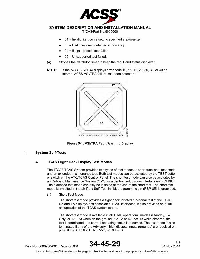
SYSTEM DESCRIPTION AND INSTALLATION MANUAL
T3CAS/Part No.9005000
● 01 = Invalid light curve setting specified at power-up
● 03 = Bad checksum detected at power-up
● 04 = Illegal op-code test failed
● 05 = Unsupported test failed.
(4) Strobes the watchdog timer to keep the red X and status displayed.
NOTE: If the ACSS VSI/TRA displays error code 10, 11, 12, 29, 30, 31, or 40 an internal ACSS VSI/TRA failure has been detected.
Figure 5-1: VSI/TRA Fault Warning Display
4. System Self-Tests
A. TCAS Flight Deck Display Test Modes
The T3CAS TCAS System provides two types of test modes; a short functional test mode and an extended maintenance test. Both test modes can be activated by the TEST button or switch on the ATC/TCAS Control Panel. The short test mode can also be activated by an Onboard Maintenance System (OMS) or a central fault display interface unit (CFDIU). The extended test mode can only be initiated at the end of the short test. The short test mode is inhibited in the air if the Self-Test Inhibit programming pin (RBP-8E) is grounded.
(1) Short Test Mode
The short test mode provides a flight deck initiated functional test of the TCAS RA and TA displays and associated TCAS interfaces. It also provides an aural annunciation of the TCAS system status.
The short test mode is available in all TCAS operational modes (Standby, TA Only, or TA/RA) when on the ground. If a TA or RA occurs while airborne, the test is terminated and normal operating status is resumed. The test mode is also terminated if any of the Advisory Inhibit discrete inputs (grounds) are received on pins RBP-5A, RBP-5B, RBP-5C, or RBP-5D.
Pub. No. 8600200-001, Revision 004 34-45-29 5-3
04 Nov 2014 Use or disclosure of information on this page is subject to the restrictions in the proprietary notice of this document.

SYSTEM DESCRIPTION AND INSTALLATION MANUAL
T3CAS/Part No.9005000
Push and hold the TEST button/switch on the ATC/TCAS controller for a few seconds to start the test. When the test mode becomes active, the words “TCAS Test” are transmitted once aurally. In addition to the TCAS test pattern, RA indications and a white (some displays may be red) TCAS TEST annunciation are displayed on the applicable display(s). Refer to Figure 1-17 for a typical test pattern display on the VSI/TRA.
At the completion of the test (8 seconds), the words “TCAS Test Pass” should be transmitted once aurally. In addition, the test pattern is removed from the display(s) and a TCAS PASS annunciation is displayed.
NOTE: Not all displays will annunciate “TCAS PASS”.
If the test fails, the words “TCAS Test Fail” are transmitted once aurally and a TCAS FAIL annunciation is displayed on the applicable display(s).
If the TCAS short test fails, do the TCAS Computer Unit Self-Test procedures referenced in paragraph 4.C. to determine which LRU or subsystem is not functioning properly. To troubleshoot the system, refer to the procedures in the FAULT ISOLATION section.
(2) Extended Test Mode
The extended test mode provides a flight deck initiated test that displays various pages of text information that is selected by the ATC Mode S control panel 4096 code switches. This test mode is accessible only when on the ground and cannot be initiated while airborne.
The extended test mode is used for maintenance purposes only. It displays various pages of text information containing the TCAS software part number, fault messages, status of program pins, analog and digital inputs, and other aircraft parameters.
NOTE: Not all TCAS displays support this extended test mode. Extended Test
mode is not enabled for T3CAS part numbers 9005000-10000, -10101, -10202, -10204, or -11203.
To start the test, push and hold the TEST button/switch on the ATC/TCAS controller for a minimum of 9 seconds. In addition the conditions that follow must occur:
● TCAS is in Standby
● The selected transponder is in Standby
● Aircraft is on the ground (The AIR/GND discrete [RMP-5K] is grounded)
● Landing gear is extended (Landing Gear discrete [RMP-13F] is grounded).
Once the extended test mode is established, the 4096 code switches on the ATC/TCAS controller are used to select the desired maintenance page for display. Table 5-3 lists the extended mode page names and numbers and the corresponding 4096 Ident Code number.
Table 5-3: Extended Test Menu Selections
5-4 04 Nov 2014 34-45-29 Pub. No. 8600200-001, Revision 004
Use or disclosure of information on this page is subject to the restrictions in the proprietary notice of this document.

SYSTEM DESCRIPTION AND INSTALLATION MANUAL
T3CAS/Part No.9005000
To view the TCAS test menu and system status pages along with the troubleshooting messages, refer to the FAULT ISOLATION section. To exit the extended test mode, set the ATC/TCAS mode selector switch to Mode S ON.
B. TAWS Flight Deck Display Test Modes
The T3CAS System provides three types of test modes: standard self-test, extended self-test, and a maintenance report. All test modes can be activated by the TAWS self-test button (i.e., the switch on the flight deck, not on the LRU face). The standard test mode can also be activated by an onboard maintenance system (OMS) or a central fault display interface unit (CFDIU).
NOTE: The extended self-test and a maintenance report cannot be activated using
4096 Ident Code Number Page Page Number
0000 0 System Status
0001 1 Display Status
0002 2 Rad/Alt Status
0003 3 Xpdr Status
0004 4 Configuration Options Page 1
0005 5 Configuration Options Page 2
0006 6 Configuration Options Page 3
0007 7 Configuration Options Page 4
3000 3000 Help Reference
0010 10 Suppression Bus Help Page
0510 510 Suppression Bus Clear Page
0011 11 Antenna Port Status
0013 13 Part Numbers Page 1
0014 14 Part Numbers Page 2
2000 2000 ADS-B Test Menu Page
0020 20 ADS-B Self Test Page
0030 30 ADS-B Fault Page 1
0031 31 ADS-B Fault Page 2
0032 32 ADS-B Fault Page 3
0033 33 ADS-B Fault Page 4
All Other Codes Blank Default Unassigned Page
Pub. No. 8600200-001, Revision 004 34-45-29 5-5
04 Nov 2014 Use or disclosure of information on this page is subject to the restrictions in the proprietary notice of this document.

SYSTEM DESCRIPTION AND INSTALLATION MANUAL
T3CAS/Part No.9005000
the OMS/CFDIU.
NOTE: The extended self-test is not applicable for T3CAS part numbers 9005000-10000, -10101, -10202, -10204, or -11203.
One of the three types of diagnostic testing can be utilized on the T3CAS to obtain status on the system, depending on the users purpose (status report vs. troubleshooting). First, the standard self-test results in a high-level pass/fail of the unit LRU and overall system status. The standard self-test also allows an option to enter the maintenance pages upon completing the standard self-test. The standard test should be used when a quick confidence check is needed on the TAWS system. Second, the extended self-test performs the same function as the standard self-test but also includes the aural annunciation of the active external faults. The extended self-test however, does not have the option to allow entry into the maintenance pages. Third, the maintenance report performs the same function as the extended self-test but also includes the aural annunciation of external BITE faults for the past five flight legs. In addition, the maintenance report will also automatically enter into the maintenance pages. The extended test and maintenance report should be used as a means of troubleshooting and diagnostic testing. It is not recommended that either test be initiated while airborne. The ability to enter into each type of test is based on the BITE_FAULT_AURALS ACD setting, the activation of the self-test discrete input, and the activation of the OMS self-test input. If the ACD entry for BITE_FAULT_AURALS is enabled, it will allow the system to initiate either an extended self-test or maintenance report. If the ACD entry for BITE_FAULT_AURALS is disabled, it will only allow the system to initiate a standard self-test.
(1) Standard Test Mode
The standard test mode provides a flight deck initiated functional test of the aural annunciations, lamp tests, and display activity. The standard self-test can occur while on the ground only.
The Standard Self-Test is initiated under the following conditions:
● Activating the OMS self-test input
● The ACD entry for BITE_FAULT_AURALS is NOT enabled and the TAWS flight deck self-test pushbutton/switch transitions from not initiated to initiated
● The ACD entry for BITE_FAULT_AURALS is enabled and the TAWS flight deck self-test pushbutton/switch transitions from not initiated to initiated.
NOTE: The standard self-test will be activated regardless of the ACD setting
for BITE_FAULT_AURALS.
Upon activating the Standard Self-Test, the following will occur:
NOTE: The standard self-test will not be initiated if a TAWS alert is present or when either the OMS self-test or a flight deck initiated self-test has already been activated.
NOTE: The windshear function is not enabled for T3CAS part numbers 9005000-10000, -10101, -10202, -10204, or -11203.
5-6 04 Nov 2014 34-45-29 Pub. No. 8600200-001, Revision 004
Use or disclosure of information on this page is subject to the restrictions in the proprietary notice of this document.

SYSTEM DESCRIPTION AND INSTALLATION MANUAL
T3CAS/Part No.9005000
● If the T3CAS unit has the windshear function enabled, the following aural annunciation will occur:
“TERRAIN AWARENESS AND WINDSHEAR TEST START”
● If the T3CAS unit does not have the windshear function enabled, the following aural annunciation will occur:
“TERRAIN AWARENESS TEST START”
During the Standard Self-Test, the following will occur:
All discrete outputs implemented within a specific aircraft installation will be tested for over current and output voltage levels by activating the output for 4.0 seconds (±100 milliseconds), then deactivating the output for 2.0 seconds (±100 milliseconds), and then reactivating the output for approximately 4.0 seconds. Any faults found will be recorded in the T3CAS unit’s nonvolatile memory.
The T3CAS unit will verify the following functional areas in accordance with Figure 1-36.
● Airplane Personality Module (APM not applicable for part numbers 9005000-10000, -10101, -10202, -10204, or -11203)
● Terrain Database CRC
● External System Inputs
The T3CAS unit will display a multicolor test pattern on both the captain’s and first officer’s TAWS displays. Figure 1-37 shows a typical multicolor test pattern.
The T3CAS unit will interrupt the Standard Self-Test with a “SELF TEST ABORTED” annunciated when any of the following alerts occur:
● “WINDSHEAR, WINDSHEAR, WINDSHEAR”
● “TERRAIN AHEAD, PULL UP”
● “TERRAIN TERRAIN, PULL UP PULL UP”
● “[[ PULL UP”
● “TERRAIN AHEAD”
● “TERRAIN CAUTION”
● “AVOID TERRAIN”
● “PULL UP, PULL UP”
● “TERRAIN, TERRAIN”
● “SINK RATE, SINK RATE”
● “DON’T SINK, DON’T SINK”
● “TOO LOW, TERRAIN”
● “TOO LOW, GEAR”
Pub. No. 8600200-001, Revision 004 34-45-29 5-7
04 Nov 2014 Use or disclosure of information on this page is subject to the restrictions in the proprietary notice of this document.

SYSTEM DESCRIPTION AND INSTALLATION MANUAL
T3CAS/Part No.9005000
● “TOO LOW, FLAPS”
● “GLIDESLOPE”.
NOTE: “[[” designates a pair of varying tones from 400 to 800 Hz; where each
tone is 0.3 seconds in duration, separated by 0.1 seconds, and at the end of the pair there is 0.1 seconds of silence.
NOTE: The aural annunciations listed above will depend on the Operator Selectable Options chosen during installation of the T3CAS unit.
Upon completion of the Standard Self-Test T3CAS functional check, the following will occur:
● If the T3CAS unit, the APM and Terrain Database, and Internal System self-tests have passed, the following aural annunciation will occur:
“TERRAIN AWARENESS SYSTEM PASS”
● If the T3CAS unit, the APM and Terrain Database, or Internal System self-tests have failed, the following aural annunciation will occur:
“TERRAIN AWARENESS SYSTEM FAIL”
● If the T3CAS unit, Terrain Database, and Internal System self-test have passed AND the T3CAS BITE has determined that all occurrences of any given required external input parameter has a failed status, the following aural annunciation will occur:
“TERRAIN AWARENESS LRU PASS,
REQUIRED EXTERNAL INPUT FAIL,
TERRAIN AWARENESS SYSTEM FAIL”
● For part numbers 9005000-11801 and -55801, if the T3CAS unit, Terrain Database, and Internal System self-test have passed AND the T3CAS BITE has determined that all occurrences of any given required external input parameter is invalid, the following aural annunciation will occur:
“TERRAIN AWARENESS LRU PASS,
REQUIRED EXTERNAL INPUT UNAVAILABLE,
TERRAIN AWARENESS SYSTEM UNAVAILABLE”
● If the T3CAS unit, Terrain Database, and Internal System self-test have passed AND the T3CAS BITE has determined that all occurrences of any given required external input parameter has an inactive status, (NCD or FT), the following aural annunciation will occur:
“TERRAIN AWARENESS LRU PASS,
REQUIRED EXTERNAL INPUT UNAVAILABLE,
TERRAIN AWARENESS SYSTEM PASS”
Upon completion of the Standard Self-Test, the following will occur:
5-8 04 Nov 2014 34-45-29 Pub. No. 8600200-001, Revision 004
Use or disclosure of information on this page is subject to the restrictions in the proprietary notice of this document.

SYSTEM DESCRIPTION AND INSTALLATION MANUAL
T3CAS/Part No.9005000
● The following aural annunciation will occur:
“TERRAIN AWARENESS TEST COMPLETE”
If the TAWS standard test fails, execute the T3CAS Computer Unit Self-Test procedures referenced in paragraph 4.C. to determine which subsystem is not functioning properly. Execute the Extended Test Mode in paragraph 4.B.(2) to determine which external LRU has failed. To troubleshoot the system, refer to the procedures in the FAULT ISOLATION section.
(2) Extended Test Mode
The TAWS Extended Test Mode provides a flight deck initiated aural annunciation for all active external faults. This test mode will be useful in isolating standard self-test failures annunciated as “TERRAIN AWARENESS LRU PASS, REQUIRED EXTERNAL INPUT UNAVAILABLE (or FAIL), TERRAIN AWARENESS SYSTEM UNAVAILABLE (or FAIL)”. The extended self-test can only be activated while on the ground.
The Extended Test Mode is initiated under the following conditions:
● The ACD entry for BITE_FAULT_AURALS is enabled and the TAWS flight deck self-test pushbutton/switch transitions from not initiated to initiated twice within a 3-second period.
AND
● No other self-test operation (self-test, past fault annunciation, maintenance pages) is currently active.
The Extended self-test provides aural annunciation of the Active External Faults after the standard self-test has completed as shown in Figure 5-2.
NOTE: Further definition and execution detail on the self-test discrete input is
defined in the ASDB and may vary from aircraft to aircraft.
Pub. No. 8600200-001, Revision 004 34-45-29 5-9
04 Nov 2014 Use or disclosure of information on this page is subject to the restrictions in the proprietary notice of this document.
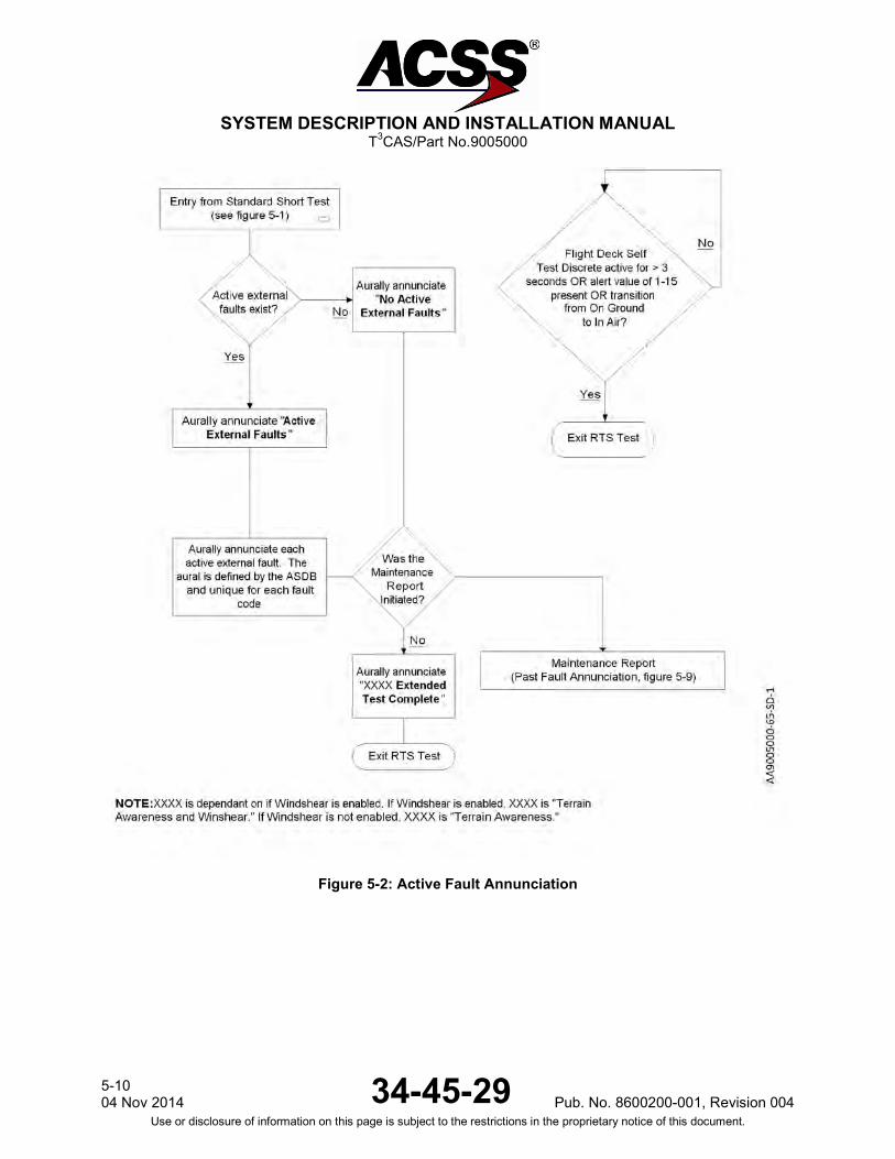
SYSTEM DESCRIPTION AND INSTALLATION MANUAL
T3CAS/Part No.9005000
Figure 5-2: Active Fault Annunciation
5-10 04 Nov 2014 34-45-29 Pub. No. 8600200-001, Revision 004
Use or disclosure of information on this page is subject to the restrictions in the proprietary notice of this document.

SYSTEM DESCRIPTION AND INSTALLATION MANUAL
T3CAS/Part No.9005000
● When the extended TAWS self test mode becomes active the T3CAS will aurally annunciate:
“TERRAIN AWARENESS EXTENDED TEST START”
NOTE: During extended test, the above aural annunciation will be performed in place of the standard self-test annunciations.
Upon completion of the Standard Self-Test, the active faults will be annunciated as follows:
● If one or more active external faults exist in the BITE Log, the Extended Test will aurally annunciate:
“ACTIVE EXTERNAL FAULTS”
● Once “ACTIVE EXTERNAL FAULTS” has been aurally annunciated, the Extended Test aurally annunciates each active external fault in the BITE Log’s current flight leg with the following information:
Identifies the LRU source (for example FMS 1, ADC 2, etc.)
Identifies the connector (for example RTP, LMP, etc.)
Identifies the pin designation (for example 9B, 10C, etc.)
Identifies the status (for example Bus invalid/unavailable, Discrete Invalid, etc.).
● If there are no active faults present, the Extended Self Test will aurally annunciate:
“NO ACTIVE EXTERNAL FAULTS”
● If the flight deck self-test pushbutton/switch is activated for greater than 3 seconds during the extended self-test, the T3CAS will exit the extended self-test, restore the captain’s and first officer’s TAWS displays back to normal operation, and aurally annunciate:
“SELF TEST ABORTED”
Upon completion of the aural annunciation of the current external bite faults, the T3CAS will exit extended self-test by aurally annunciating:
“TERRAIN AWARENESS EXTENDED TEST COMPLETE”
Upon exiting the TAWS extended self-test, T3CAS will restore the captain’s and first officer’s TAWS displays back to normal operation.
(3) Maintenance Report
The TAWS Maintenance Report Test Mode provides a flight deck initiated aural annunciation of all faults for the past five flight legs. The maintenance report provides the same information as the extended test mode plus the aural fault annunciation of the past five flight legs and automatic entry into the maintenance pages. It is recommended that the maintenance report test mode only be activated while on the ground.
Pub. No. 8600200-001, Revision 004 34-45-29 5-11
04 Nov 2014 Use or disclosure of information on this page is subject to the restrictions in the proprietary notice of this document.
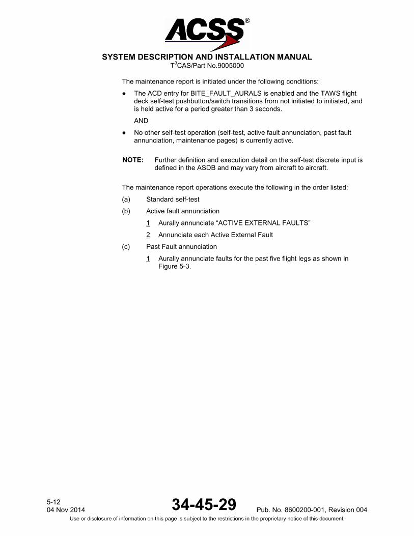
SYSTEM DESCRIPTION AND INSTALLATION MANUAL
T3CAS/Part No.9005000
The maintenance report is initiated under the following conditions:
● The ACD entry for BITE_FAULT_AURALS is enabled and the TAWS flight deck self-test pushbutton/switch transitions from not initiated to initiated, and is held active for a period greater than 3 seconds.
AND
● No other self-test operation (self-test, active fault annunciation, past fault annunciation, maintenance pages) is currently active.
NOTE: Further definition and execution detail on the self-test discrete input is
defined in the ASDB and may vary from aircraft to aircraft.
The maintenance report operations execute the following in the order listed:
(a) Standard self-test
(b) Active fault annunciation
1 Aurally annunciate “ACTIVE EXTERNAL FAULTS”
2 Annunciate each Active External Fault
(c) Past Fault annunciation
1 Aurally annunciate faults for the past five flight legs as shown in Figure 5-3.
5-12 04 Nov 2014 34-45-29 Pub. No. 8600200-001, Revision 004
Use or disclosure of information on this page is subject to the restrictions in the proprietary notice of this document.

SYSTEM DESCRIPTION AND INSTALLATION MANUAL
T3CAS/Part No.9005000
Figure 5-3: Past Fault Annunciation (Non-OMS System)
Pub. No. 8600200-001, Revision 004 34-45-29 5-13
04 Nov 2014 Use or disclosure of information on this page is subject to the restrictions in the proprietary notice of this document.

SYSTEM DESCRIPTION AND INSTALLATION MANUAL
T3CAS/Part No.9005000
Upon activation of the Maintenance Mode, the following will occur:
● The T3CAS will aurally annunciate:
“TERRAIN AWARENESS MAINTENANCE REPORT START”
In order to identify the most recent flight leg, the maintenance report will aurally annunciate:
“MOST RECENT FLIGHT LEG IS FLIGHT LEG 1”
For all flight legs, the maintenance report will aurally annunciate:
“EXTERNAL FAULTS FOR FLIGHT LEG X”
Where X will be the flight leg designator (1, 2, 3, 4, or 5).
Example for flight legs 1 and 2:
“MOST RECENT FLIGHT LEG IS FLIGHT LEG 1” + “EXTERNAL FAULTS FOR FLIGHT LEG 1” + “FMS 1” + “RTP 9B” + “bus invalid”
“EXTERNAL FAULTS FOR FLIGHT LEG 2” + “FMS 1” + “RTP 9B” + “bus invalid”
If there are no faults present on all five flight legs, the Maintenance Report will aurally annunciate:
“NO EXTERNAL FAULTS FOR PAST 5 FLIGHT LEGS”
If there are no faults present on flight leg 1, the maintenance report will aurally annunciate:
“NO PAST EXTERNAL FAULTS FOR FLIGHT LEG 1”
If there are no faults present on a particular flight leg, the maintenance report will aurally annunciate:
“NO EXTERNAL FAULTS FOR FLIGHT LEG X”
Where X will be the flight leg designator (2, 3, 4, or 5).
● If the flight deck self-test pushbutton/switch is activated for greater than 3 seconds during the maintenance report aural annunciation, the T3CAS will exit test, restore the captain’s and first officer’s TAWS displays back to normal operation, and aurally annunciate:
“SELF TEST ABORTED”
Upon completion of the maintenance report, the following will occur:
● The T3CAS unit will aurally annunciate:
“TERRAIN AWARENESS MAINTENANCE REPORT COMPLETE”
Upon completion of the maintenance report aural annunciation, the T3CAS will automatically display the maintenance pages after the multicolor test pattern is removed.
(4) Maintenance Pages
The TAWS maintenance pages provide a flight deck initiated display of the T3CAS part numbers, ACD callouts, and configuration data.
5-14 04 Nov 2014 34-45-29 Pub. No. 8600200-001, Revision 004
Use or disclosure of information on this page is subject to the restrictions in the proprietary notice of this document.

SYSTEM DESCRIPTION AND INSTALLATION MANUAL
T3CAS/Part No.9005000
The maintenance pages are initiated under the following conditions:
● The aircraft is On Ground
AND
● The TAWS flight deck self-test pushbutton/switch is activated (again) either during the standard self-test or within 5 seconds after the end of the standard self test complete annunciation (“TERRAIN AWARENESS TEST COMPLETE”).
● The TAWS flight deck self-test pushbutton/switch is activated for 3 or more seconds.
OR
● The maintenance report was activated.
The maintenance pages operational flow when entered through a standard self-test or maintenance report (past fault annunciation) is shown in Figure 5-4.
Pub. No. 8600200-001, Revision 004 34-45-29 5-15
04 Nov 2014 Use or disclosure of information on this page is subject to the restrictions in the proprietary notice of this document.

SYSTEM DESCRIPTION AND INSTALLATION MANUAL
T3CAS/Part No.9005000
Figure 5-4: Maintenance Pages Flow
5-16 04 Nov 2014 34-45-29 Pub. No. 8600200-001, Revision 004
Use or disclosure of information on this page is subject to the restrictions in the proprietary notice of this document.
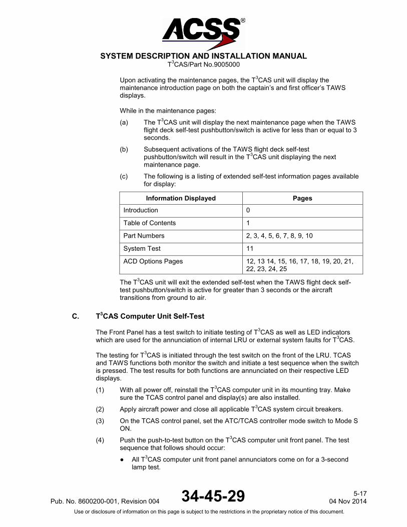
SYSTEM DESCRIPTION AND INSTALLATION MANUAL
T3CAS/Part No.9005000
Upon activating the maintenance pages, the T3CAS unit will display the maintenance introduction page on both the captain’s and first officer’s TAWS displays.
While in the maintenance pages:
(a) The T3CAS unit will display the next maintenance page when the TAWS flight deck self-test pushbutton/switch is active for less than or equal to 3 seconds.
(b) Subsequent activations of the TAWS flight deck self-test pushbutton/switch will result in the T3CAS unit displaying the next maintenance page.
(c) The following is a listing of extended self-test information pages available for display:
Information Displayed Pages
Introduction 0
Table of Contents 1
Part Numbers 2, 3, 4, 5, 6, 7, 8, 9, 10
System Test 11
ACD Options Pages 12, 13 14, 15, 16, 17, 18, 19, 20, 21, 22, 23, 24, 25
The T3CAS unit will exit the extended self-test when the TAWS flight deck self-test pushbutton/switch is active for greater than 3 seconds or the aircraft transitions from ground to air.
C. T3CAS Computer Unit Self-Test
The Front Panel has a test switch to initiate testing of T3CAS as well as LED indicators which are used for the annunciation of internal LRU or external system faults for T3CAS. The testing for T3CAS is initiated through the test switch on the front of the LRU. TCAS and TAWS functions both monitor the switch and initiate a test sequence when the switch is pressed. The test results for both functions are annunciated on their respective LED displays.
(1) With all power off, reinstall the T3CAS computer unit in its mounting tray. Make sure the TCAS control panel and display(s) are also installed.
(2) Apply aircraft power and close all applicable T3CAS system circuit breakers.
(3) On the TCAS control panel, set the ATC/TCAS controller mode switch to Mode S ON.
(4) Push the push-to-test button on the T3CAS computer unit front panel. The test sequence that follows should occur:
● All T3CAS computer unit front panel annunciators come on for a 3-second lamp test.
Pub. No. 8600200-001, Revision 004 34-45-29 5-17
04 Nov 2014 Use or disclosure of information on this page is subject to the restrictions in the proprietary notice of this document.
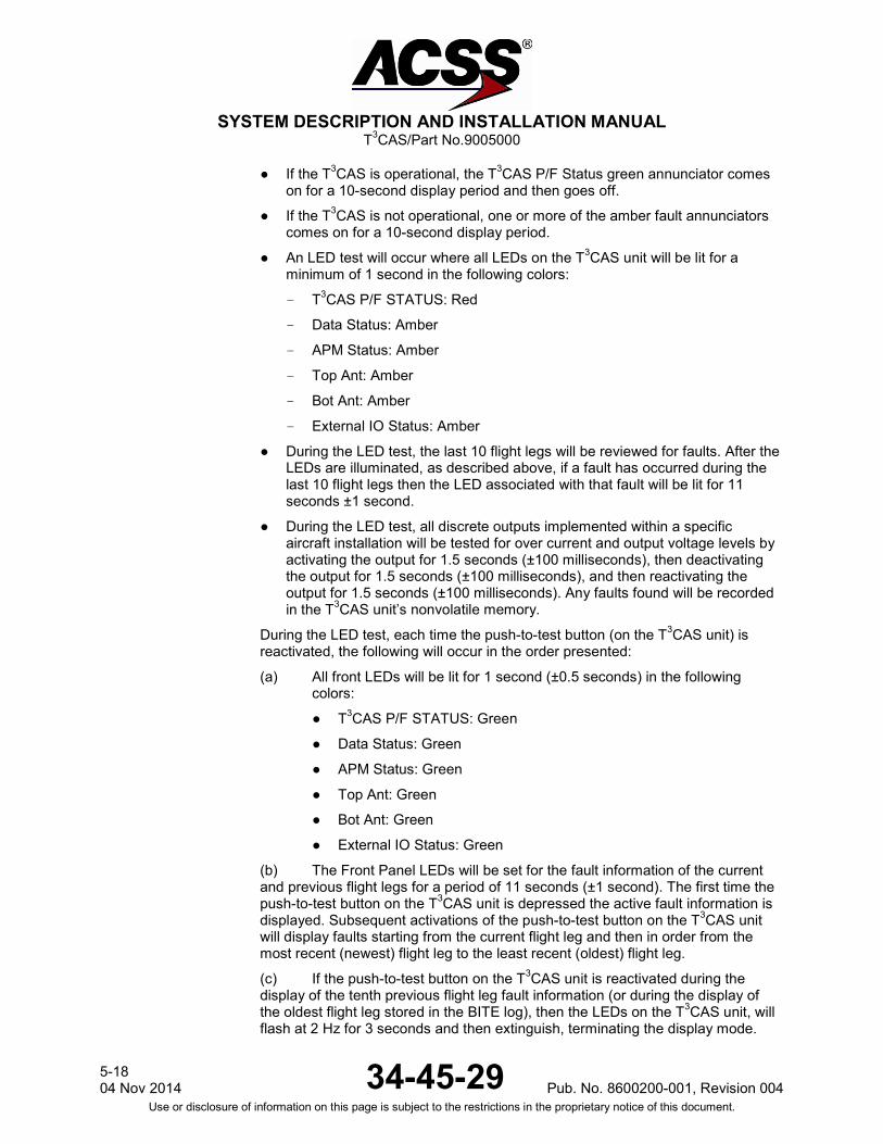
SYSTEM DESCRIPTION AND INSTALLATION MANUAL
T3CAS/Part No.9005000
● If the T3CAS is operational, the T3CAS P/F Status green annunciator comes on for a 10-second display period and then goes off.
● If the T3CAS is not operational, one or more of the amber fault annunciators comes on for a 10-second display period.
● An LED test will occur where all LEDs on the T3CAS unit will be lit for a minimum of 1 second in the following colors:
- T3CAS P/F STATUS: Red
- Data Status: Amber
- APM Status: Amber
- Top Ant: Amber
- Bot Ant: Amber
- External IO Status: Amber
● During the LED test, the last 10 flight legs will be reviewed for faults. After the LEDs are illuminated, as described above, if a fault has occurred during the last 10 flight legs then the LED associated with that fault will be lit for 11 seconds ±1 second.
● During the LED test, all discrete outputs implemented within a specific aircraft installation will be tested for over current and output voltage levels by activating the output for 1.5 seconds (±100 milliseconds), then deactivating the output for 1.5 seconds (±100 milliseconds), and then reactivating the output for 1.5 seconds (±100 milliseconds). Any faults found will be recorded in the T3CAS unit’s nonvolatile memory.
During the LED test, each time the push-to-test button (on the T3CAS unit) is reactivated, the following will occur in the order presented:
(a) All front LEDs will be lit for 1 second (±0.5 seconds) in the following colors:
● T3CAS P/F STATUS: Green
● Data Status: Green
● APM Status: Green
● Top Ant: Green
● Bot Ant: Green
● External IO Status: Green
(b) The Front Panel LEDs will be set for the fault information of the current and previous flight legs for a period of 11 seconds (±1 second). The first time the push-to-test button on the T3CAS unit is depressed the active fault information is displayed. Subsequent activations of the push-to-test button on the T3CAS unit will display faults starting from the current flight leg and then in order from the most recent (newest) flight leg to the least recent (oldest) flight leg.
(c) If the push-to-test button on the T3CAS unit is reactivated during the display of the tenth previous flight leg fault information (or during the display of the oldest flight leg stored in the BITE log), then the LEDs on the T3CAS unit, will flash at 2 Hz for 3 seconds and then extinguish, terminating the display mode.
5-18 04 Nov 2014 34-45-29 Pub. No. 8600200-001, Revision 004
Use or disclosure of information on this page is subject to the restrictions in the proprietary notice of this document.
SYSTEM DESCRIPTION AND INSTALLATION MANUAL
T3CAS/Part No.9005000
(5) If a fault is detected, refer to the Fault Isolation section for troubleshooting information.
5. Return-to-Service Test
Any time a T3CAS LRU or APM is removed and replaced following repair or maintenance, a return-to-service test is required. The System Self-Test procedures referenced in paragraph 4.A. and 4 B. are sufficient to check all system parameters.
NOTE: Anytime the T3CAS APM is removed and replaced, the APM must be reconfigured using the procedures in Section 6.B.
6. Operational Software Loading Using an ARINC 615A Portable Data Loader or Compact Flash Card
When updating the T3CAS Computer Unit with an ARINC 615A data loader or Compact Flash card, verify the current T3CAS Computer Unit software part number prior to continuing for Flight Deck system only.
NOTE: T3CAS part numbers 9005000-10000, -10101, -10202, and -10204 use FAT16 formatting which limits the maximum memory size of the CF card to 2GB. A CF card of at least 128MB is required for the upload of a terrain database.
NOTE: FAT32 formatting is NOT compatible with T3CAS part numbers 9005000-10000, -10101, -10202, and -10204. If reformatting is required, the CF card must reformat in FAT or sometimes referred to as FAT16.
NOTE: T3CAS part numbers 9005000-11203, -11801 and -55801 support both FAT16 and FAT32 formatting.
A. Current Software Verification
NOTE: Software verification using Flight Deck systems ONLY. (1) TCAS Software Verification
Verify the current software part number according to the extended-maintenance capabilities on status page code 0000 in the FAULT ISOLATION section of this manual or the individual AMM (refer to the on-board maintenance system program).
(2) TAWS Software Verification
Verify the current software part number according to the extended-maintenance capabilities Part Number Page.
Pub. No. 8600200-001, Revision 004 34-45-29 5-19
04 Nov 2014 Use or disclosure of information on this page is subject to the restrictions in the proprietary notice of this document.

SYSTEM DESCRIPTION AND INSTALLATION MANUAL
T3CAS/Part No.9005000
B. Compact Flash Card - Operational Software/ACD/ASDB Loading (While Installed on Aircraft)
NOTE: All Aircraft Personality Modules (APMs) directly out of the ACSS factory are blank. The error checking routine of the T3CAS expects the ACD and ASDB to be loaded simultaneously from the same media. If this is not done, the CF Load Status LED will illuminate red after the first software load. However, if the second load is completed, the CF Load Status LED will illuminate green, indicating that the system now passes the error check. In other words, if the ACD is loaded without the ASDB having already been loaded, the CF Load Status LED will illuminate red, indicating that the load has failed. However if the ASDB is then loaded into the box, and successfully loads, the CF Load Status LED will illuminate green and the system will function normally.
The red CF Load Status LED will not illuminate if the APM has already been successfully programmed with both an ACD and ASDB and the operator is simply upgrading the ACD or ASDB, since the other file is already loaded into the APM and the error check will perform normally.
Procedures for uploading data such as the Terrain Database Software, Obstacles Database Software, T3CAS Operational Software, ASDBs, or ACDs.
(1) Obtain the correct software to be loaded to the Computer Unit.
(2) Verify that the aircraft is “on the ground” prior to performing an upload (Pin RMP-5K is grounded). The software cannot be uploaded while the aircraft is airborne.
(3) Apply power to the T3CAS computer unit.
(4) Open the CF card protective door located on the left side the T3CAS computer unit front panel. (See Figure 5-5.)
(5) Insert the CF card with the label facing the T3CAS computer unit front panel LEDs. (See Figure 5-5.)
CAUTION: INSERT THE CARD WITH CARE. (6) All LEDs will illuminate, which indicates a T3CAS computer unit restart.
(7) For ACSS part numbers 9005000-10000, -10101, -10202, and -10204 all LEDs will extinguish and the DATA STATUS LED will blink green once, indicating that the CRC is being checked.
(a) The DATA STATUS LED will then remain a solid green until the CRC check is complete.
(b) The DATA STATUS LED will then resume blinking to indicate the T3CAS is reading the CF card. This may take several minutes.
(c) The DATA STATUS LED will change from blinking to a solid green when the load is complete and there were no errors.
(8) For ACSS part numbers 9005000-11203, -11801 and -55801 all LEDs will extinguish and the DATA STATUS LED will remain solid for one second, indicating Dataloader software has been initiated.
5-20 04 Nov 2014 34-45-29 Pub. No. 8600200-001, Revision 004
Use or disclosure of information on this page is subject to the restrictions in the proprietary notice of this document.
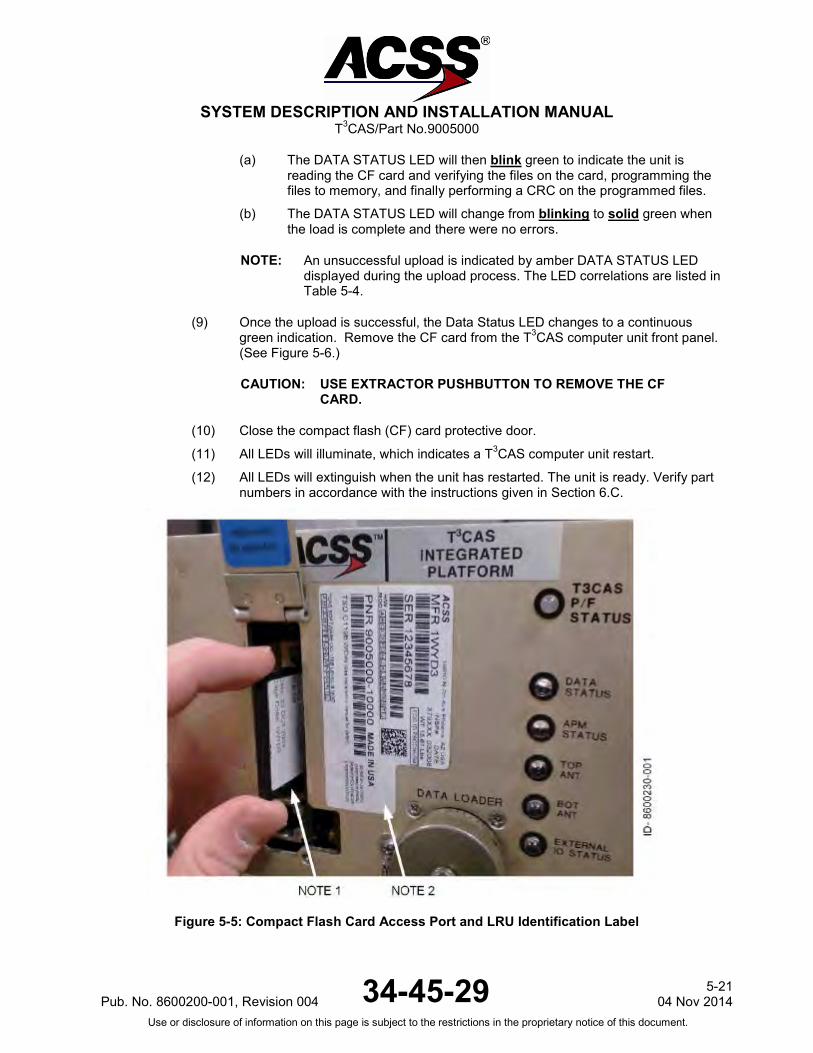
SYSTEM DESCRIPTION AND INSTALLATION MANUAL
T3CAS/Part No.9005000
(a) The DATA STATUS LED will then blink green to indicate the unit is reading the CF card and verifying the files on the card, programming the files to memory, and finally performing a CRC on the programmed files.
(b) The DATA STATUS LED will change from blinking to solid green when the load is complete and there were no errors.
NOTE: An unsuccessful upload is indicated by amber DATA STATUS LED displayed during the upload process. The LED correlations are listed in Table 5-4.
(9) Once the upload is successful, the Data Status LED changes to a continuous green indication. Remove the CF card from the T3CAS computer unit front panel. (See Figure 5-6.)
CAUTION: USE EXTRACTOR PUSHBUTTON TO REMOVE THE CF CARD.
(10) Close the compact flash (CF) card protective door.
(11) All LEDs will illuminate, which indicates a T3CAS computer unit restart.
(12) All LEDs will extinguish when the unit has restarted. The unit is ready. Verify part numbers in accordance with the instructions given in Section 6.C.
Figure 5-5: Compact Flash Card Access Port and LRU Identification Label
Pub. No. 8600200-001, Revision 004 34-45-29 5-21
04 Nov 2014 Use or disclosure of information on this page is subject to the restrictions in the proprietary notice of this document.

SYSTEM DESCRIPTION AND INSTALLATION MANUAL
T3CAS/Part No.9005000
NOTE 1: When inserting compact flash cards, make sure that the part numbers on label are facing in the correct direction, as shown in Figure 5-5.
Align the card with the slot and push in firmly. When removing, use finger to push the ejector at the top of the slot until the card pops out slightly on its own. After that, pull the card freely out of the slot.
NOTE 2: Remove and replace software identification label as detailed in the Accomplishment Summary of the Service Bulletin.
Figure 5-6: Compact Flash Card Ejector Location
5-22 04 Nov 2014 34-45-29 Pub. No. 8600200-001, Revision 004
Use or disclosure of information on this page is subject to the restrictions in the proprietary notice of this document.
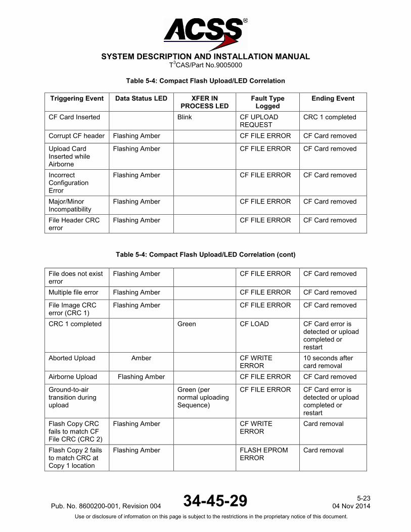
SYSTEM DESCRIPTION AND INSTALLATION MANUAL
T3CAS/Part No.9005000
Table 5-4: Compact Flash Upload/LED Correlation
Triggering Event Data Status LED XFER IN PROCESS LED
Fault Type Logged
Ending Event
CF Card Inserted Blink CF UPLOAD REQUEST
CRC 1 completed
Corrupt CF header Flashing Amber CF FILE ERROR CF Card removed
Upload Card Inserted while Airborne
Flashing Amber CF FILE ERROR CF Card removed
Incorrect Configuration Error
Flashing Amber CF FILE ERROR CF Card removed
Major/Minor Incompatibility
Flashing Amber CF FILE ERROR CF Card removed
File Header CRC error
Flashing Amber CF FILE ERROR CF Card removed
Table 5-4: Compact Flash Upload/LED Correlation (cont)
File does not exist error
Flashing Amber CF FILE ERROR CF Card removed
Multiple file error Flashing Amber CF FILE ERROR CF Card removed
File Image CRC error (CRC 1)
Flashing Amber CF FILE ERROR CF Card removed
CRC 1 completed Green CF LOAD CF Card error is detected or upload completed or restart
Aborted Upload Amber CF WRITE ERROR
10 seconds after card removal
Airborne Upload Flashing Amber CF FILE ERROR CF Card removed
Ground-to-air transition during upload
Green (per normal uploading Sequence)
CF FILE ERROR CF Card error is detected or upload completed or restart
Flash Copy CRC fails to match CF File CRC (CRC 2)
Flashing Amber CF WRITE ERROR
Card removal
Flash Copy 2 fails to match CRC at Copy 1 location
Flashing Amber FLASH EPROM ERROR
Card removal
Pub. No. 8600200-001, Revision 004 34-45-29 5-23
04 Nov 2014 Use or disclosure of information on this page is subject to the restrictions in the proprietary notice of this document.

SYSTEM DESCRIPTION AND INSTALLATION MANUAL
T3CAS/Part No.9005000
C. Updated Software Verification
(1) Software Verification Using Flight Deck Systems ONLY
(a) TCAS
Verify the updated software part number according to the T3CAS TCAS extended-maintenance capabilities on status page code 0000 in the FAULT ISOLATION section of this manual or the individual AMM (refer to the onboard maintenance system program).
(b) TAWS
Verify the current software part number according to the extended-maintenance capabilities Part Number Page, if enabled or using the OMS LRU Identification Page (if configured to work with the OMS).
(2) TCAS Software Verification Using a Remote Connected VSI/TRA ONLY
On some aircraft configurations, software verification may be performed using a remotely connected VSI/TRA (Part No.4067241-XXX) display attached through an adapter cable (Part No.200F-00083) to the J1 front connector of the T3CAS Computer Unit during the extended test mode. (See Figure 5-7.)
Verify that the particular aircraft configuration can support a Flight Deck initiated self-test and be recognized at the 8-second time period after activation.
NOTE: OMS/CFDS activated self-test will not be recognized at the 8-second time period, only an approved TCAS control panel.
NOTE: Extended test mode is accessible only on the ground with the transponder in standby mode.
Figure 5-7: Remote VSI/TRA Interconnect for Viewing Extended Test Mode and Verifying Software Part Numbers
7. Downloading Information from the T3CAS Using a CF Card
Downloading Data such as Maintenance Data, Aircraft Configuration Data (ACD), Event Data, and CRC Part Numbers.
5-24 04 Nov 2014 34-45-29 Pub. No. 8600200-001, Revision 004
Use or disclosure of information on this page is subject to the restrictions in the proprietary notice of this document.

SYSTEM DESCRIPTION AND INSTALLATION MANUAL
T3CAS/Part No.9005000
1. Obtain a New or Blank Compact Flash (CF) card.
2. Copy to the New or Blank CF card the appropriate ‘Header File’
a) Header files are files copied to the New or Blank CF card that will instruct the computer unit what is desired to be downloaded.
b) Header files needed to download Maintenance Data, Event Data and CRC Part Numbers can be obtained from ACSS Customer Services at +1-623-445-7070 or [email protected].
3. For downloading Maintenance Data, Event Data or CRC Part Numbers the aircraft does not need to be in an on-ground configuration.
4. Apply power to the computer unit.
5. Insert the CF card.
6. For ACSS part numbers 9005000-10000, -10101, -10202, and -10204 the DATA STATUS LED will blink green once; this indicates the unit recognized that a CF card was inserted.
a) The DATA STATUS LED will then remain a solid green while reading the header file.
b) The DATA STATUS LED will start blinking to indicate the unit is performing the action defined in the header file.
c) The DATA STATUS LED will change from blinking to a solid green when action is complete.
7. For ACSS part numbers 9005000-11203, -11801 and -55801 the DATA STATUS LED will blink green while reading the header file and performing the action defined in the header file.
a) The DATA STATUS LED will change from blinking to a solid green when action is complete.
NOTE: If the data transfer fails, you will get an amber DATA STATUS LED. If the unit detects a bad media or configuration file, then the DATA STATUS LED will blink amber. If this occurs, inspect the CF, the CF slot and the connections and then attempt the download again.
8. Flight Data Recording
A. Reformatting
1. T3CAS part numbers 9005000-10000, -10101, -10202, and -10204 only support FAT16 CF card formatting. T3CAS part numbers 9005000-11203, -11801 and -55801 support both FAT16 and FAT32 CF card formatting.
B. Flight Data
1. Obtain a New or Blank CF Card.
2. Copy to the New or Blank CF Card the Appropriate Header File.
Pub. No. 8600200-001, Revision 004 34-45-29 5-25
04 Nov 2014 Use or disclosure of information on this page is subject to the restrictions in the proprietary notice of this document.
SYSTEM DESCRIPTION AND INSTALLATION MANUAL
T3CAS/Part No.9005000
3. Header files are files copied to the New or Blank CF card that will instruct the computer unit what is desired to be downloaded.
4. For Flight Data Recording, the aircraft does not need to be in an on-ground configuration.
5. Apply power to the computer unit.
6. Insert the CF card.
a) The DATA STATUS LED will blink green once. This indicates the unit recognized that a CF card was inserted.
b) The DATA STATUS LED will then remain a solid green while reading the header file.
c) The DATA STATUS LED will then blink until data recording is cancelled by removing the CF card.
NOTE: If for any reason the data transfer fails, you wil get an amber DATA STATUS LED. If the unit detects a bad media or configuration file, you will get a blinking amber DATA STATUS LED. If this occurs, inspect the CF card, inspect the CF slot, inspect the connections and attempt the download again.
9. Downloaded Maintenance Data, Event Data And Flight Data May Be Sent To ACSS Customer Services For Analysis
A. Phone
Contact ACSS Customer Services for instructions on where to transmit data files. ACSS Customer Services +1 (623) 445-7070
B. Mail
In the case of flight test data, it may fill a CF card entirely. Flight test data recording uses up to 1 megabyte/minute of flight time. Since these files are large, the card can either be mailed or delivered by courier. Please address your properly packaged CF card to the following address: ACSS Customer Services 19810 N. 7th Avenue Phoenix, AZ, 85027-4741, USA
C. Email
Maintenance data and event data files are around 4 megabyte in size and can be easily emailed to Customer Services at [email protected] for analysis.
5-26 04 Nov 2014 34-45-29 Pub. No. 8600200-001, Revision 004
Use or disclosure of information on this page is subject to the restrictions in the proprietary notice of this document.

SYSTEM DESCRIPTION AND INSTALLATION MANUAL
T3CAS/Part No.9005000
Blank Page
Pub. No. 8600200-001, Revision 004 34-45-29 5-27
04 Nov 2014 Use or disclosure of information on this page is subject to the restrictions in the proprietary notice of this document.
SYSTEM DESCRIPTION AND INSTALLATION MANUAL
T3CAS/Part No.9005000
FAULT ISOLATION
1. General
The T3CAS Integrated Platform has three optional procedures for fault detection and isolation to the LRU level. The first option uses the aircraft OMS or central fault display system (CFDS) if the aircraft is equipped with an onboard maintenance system. The second option uses a digital interface between the T3CAS Computer Unit and the display system (Weather Radar, EFIS, or multifunction display for TAWS/RWS and VSI/TRA flat panel display or EFIS for TCAS). The third option uses the annunciators located on the front panel of the computer unit. The annunciators are activated by a self-test function within the T3CAS Computer Unit. Select the procedural option for fault isolation from Fault Isolation paragraph 3 (Procedure), which is applicable to the type of aircraft and the equipment installed.
2. Equipment and Materials
NOTE: Equivalent alternatives are permitted for equipment in this list.
Digital Multimeter – Fluke Model 29, John fluke Mfg Co. Inc., Everett, WA
3. Procedure
A. OMS or CFDS
Fault information can be displayed from an onboard maintenance system when the aircraft is so equipped. Fault data is accessible only when the aircraft is on the ground. Faults that occur at any time, on the ground or while airborne, are stored in fault memory and reported to the OMS or CFDS. All displayed information is in the English language with abbreviated terms used only as necessary. Refer to the appropriate OMS or CFDS support manual for fault retrieval procedures.
B. Flight Deck Initiates Self-Test/Fault Display Systems
(1) TCAS
The TCAS display system can be used to display system status and fail messages in the Flight Deck, making it more convenient to use than the computer unit front panel annunciators for a quick checkout of the TCAS system. In contrast with the computer unit self-test, which records and stores faults from previous flights, the display system test shows only current status and failure data. To access the Flight Deck display test modes, do the procedures that follow:
Pub. No. 8600200-001, Revision 004 34-45-29 6-1
04 Nov2014 Use or disclosure of information on this page is subject to the restrictions in the proprietary notice of this document.

SYSTEM DESCRIPTION AND INSTALLATION MANUAL
T3CAS/Part No.9005000
NOTES:
1. Fault detection with diagnostics can only be done on the ground. The pilot has the option to do a pass/fail test while airborne if this feature is not inhibited.
2. This procedure is valid when used with either a single or dual control panel.
(a) Make sure the aircraft configuration indicates Aircraft On Ground and Gear Extended.
(b) Set the Mode Select switch on the ATC/TCAS control panel to STBY.
(c) Set ATC/TCAS control panel to ALTITUDE REPORTING ON.
(d) Push and hold the TCAS TEST button for a minimum of 9 seconds.
(e) Set the transponder 4096 Ident Code Number to any code except 0000 thru 0007, 0011, or 0012.
NOTE: Do not use codes 7500, 7600 or 7700, these codes are reserved for emergency operation.
(f) Make sure the TCAS TEST MENU is being displayed on the TCAS display. It should match the screen shown in Figure 6-1.
NOTE: Not all TCAS displays support this extended test mode.
(g) Set the transponder 4096 Ident Code Number to 1000.
(h) If the system passes, a maintenance page similar to that shown on Figure 6-2 is displayed. A failure results in a referral to one or more specific ident codes. Set the indicated code on the ATC/TCAS Control Panel and follow the instructions given.
(i) If the system passes, set the mode switch on the ATC/TCAS Control Panel out of STBY. This allows you to exit the extended test mode.
(j) If a failure is indicated, set the transponder 4096 Ident Code to the codes indicated by the automatic referral system. The remaining screens shown in Figure 6-3 thru Figure 6-14 are examples of the other maintenance pages.
(k) Set system power to OFF and correct faults by replacing indicated LRUs or by repairing any faulty wiring harness.
(l) Test system as required after repair.
(2) TAWS/RWS
The T3CAS TAWS/RWS system provides two fault isolation modes: Extended Self-Test and Maintenance Report. Both test modes can be activated by the TAWS/RWS TEST button/switch on the flight deck, when enabled. The extended self-test offers the first level of diagnostics by providing aural annunciation of the active external faults. The extended self-test however does
6-2 04 Nov 2014 34-45-29 Pub. No. 8600200-001, Revision 004
Use or disclosure of information on this page is subject to the restrictions in the proprietary notice of this document.
SYSTEM DESCRIPTION AND INSTALLATION MANUAL
T3CAS/Part No.9005000
not have the option to allow entry into the maintenance pages. The maintenance report performs the same function as the extended self-test but also includes the aural annunciation of external BITE faults for the past five flight legs. In addition, the maintenance report will also automatically enter into the maintenance pages. The extended self-test and maintenance report should be used as a means of troubleshooting and diagnostic testing. It is not recommended that either test be initiated while airborne. NOTE: TAWS/RWS extended self-test modes are not applicable to T3CAS part
numbers 9005000-10000, -10101, -10202, -10204, or -11203. The ability to enter into each type of test is based on the BITE_FAULT_AURALS ACD setting and the activation of the self-test discrete input. If the ACD entry for BITE_FAULT_AURALS is enabled, it will allow the system to initiate either an extended self-test or maintenance report. If the ACD entry for BITE_FAULT_AURALS is disabled, it will only allow the system to initiate a standard self-test.
(a) Extended Self-Test
● Verify that the aircraft configuration indicates On-Ground.
● Push TAWS/RWS flight deck self-test pushbutton/switch twice within a 3-second period to initiate the extended self-test.
● The extended self-test aurally annunciates each active external fault in the BITE Log’s current flight leg.
● If the flight deck self-test pushbutton/switch is activated for greater than 3 seconds during the extended self-test, the T3CAS will exit the extended self-test.
● Set system power to OFF and correct faults by replacing indicated LRUs or by repairing any faulty wiring harness.
● Test system as required after repair.
(b) Maintenance Report
● Verify that the aircraft configuration indicates On-Ground.
● Push and hold the TAWS/RWS flight deck self-test pushbutton/switch for a period greater than 3 seconds.
● The Maintenance Report operations execute the following in the order listed: standard self-test, active fault annunciation, and past fault annunciation.
● After the standard self-test and active fault annunciation (extended self-test) have completed, the past fault annunciation will begin by identifying the most recent flight leg.
● The most recent flight leg and remaining flight legs will be annunciated as in the following example:
Example for Flight Legs 1 and 2:
“MOST RECENT FLIGHT LEG IS FLIGHT LEG 1” + “EXTERNAL FAULTS FOR FLIGHT LEG 1” + “FMS 1” + “RTP 9B” + “bus invalid”
Pub. No. 8600200-001, Revision 004 34-45-29 6-3
04 Nov2014 Use or disclosure of information on this page is subject to the restrictions in the proprietary notice of this document.

SYSTEM DESCRIPTION AND INSTALLATION MANUAL
T3CAS/Part No.9005000
“EXTERNAL FAULTS FOR FLIGHT LEG 2” + “FMS 1” + “RTP 9B” + “bus invalid”
● If there are no faults present on all 5 flight legs, the maintenance report will aurally annunciate:
“NO EXTERNAL FAULTS FOR THE PAST 5 FLIGHT LEGS”
● If there are no faults present on flight leg 1, the maintenance report will aurally annunciate:
“NO PAST EXTERNAL FAULTS FOR FLIGHT LEG 1”
● If there are no faults present on a particular flight leg, the maintenance report will aurally annunciate:
“NO EXTERNAL FAULTS FOR FLIGHT LEG X”
Where X will be the flight leg designator (1, 2, 3, 4, 5)
● If the flight deck self-test pushbutton/switch is activated for greater than 3 seconds during the maintenance report aural annunciation, the T3CAS will exit the maintenance report.
Upon completion of the maintenance report aural annunciation, the T3CAS will automatically display the maintenance pages after the multicolor test pattern is removed.
NOTE: The maintenance pages can also be activated if the TAWS/RWS flight deck self-test pushbutton/switch is activated for 3 or more seconds either during the standard self-test or within 5 seconds after the standard self-test has completed.
● Once in the maintenance pages as shown in Figure 6-14, the T3CAS unit will display the next maintenance page when the TAWS/RWS flight deck self-test pushbutton/switch is pressed for 3 seconds or less.
● After the system fault isolation test is completed, the maintenance pages can be exited, by pressing the TAWS/RWS flight deck pushbutton/switch for more than 3 seconds.
C. T3CAS Aural and Visual Annunciations
(1) TCAS aural and ACSSVSI/TRA Annunciations
TCAS aural and ACSS VSI/TRA annunciations are given in Table 6-1.
6-4 04 Nov 2014 34-45-29 Pub. No. 8600200-001, Revision 004
Use or disclosure of information on this page is subject to the restrictions in the proprietary notice of this document.

SYSTEM DESCRIPTION AND INSTALLATION MANUAL
T3CAS/Part No.9005000
Table 6-1: TCAS Aural and VSI/TRA Annunciations
Condition Aural
VSI/TRA Annunciation
Notes Upper Left
Upper Right Center Color
TRAFFIC Display Control ON Mode
Normal Range ring and own aircraft in view at all times, along with qualifying traffic.
TRAFFIC Display Control AUTO Mode
Normal Range ring and own aircraft come up with traffic when a TA or RA exists.
Transponder Only Mode
None
TCAS OFF
White TCAS is not operational.
STANDBY Mode None
TCAS OFF
White TCAS is not operational, transponder is in standby.
Vertical Speed Input Failure to Single VSI (Dual VSI Aircraft)
Normal RA FAIL on failed
side
VSI FAIL on failed
side
Yellow Vertical speed needle removed from display with failed data. No RAs posted on failed side. TCAS is operational on remaining side.
VSI Input Failure to Both (Dual VSI Aircraft) or Single VSI (Single VSI Aircraft)
None VSI FAIL on both sides
TCAS FAIL on
both sides
Yellow Vertical speed needle removed from both VSIs (dual VSI aircraft) or only VSI (single VSI aircraft). No RA information posted. TCAS is not operational.
TA Only Mode Traffic-Traffic only
TA ONLY White or
Yellow
Traffic alerts are the only information displayed. No RAs. (The color changes from white to yellow when a TA actually occurs.)
Transponder or Altitude Source Fail
None TCAS FAIL
Yellow TCAS is not operational.
Altitude Reporting OFF
TCAS OFF
White TCAS is not operational
Pub. No. 8600200-001, Revision 004 34-45-29 6-5
04 Nov2014 Use or disclosure of information on this page is subject to the restrictions in the proprietary notice of this document.
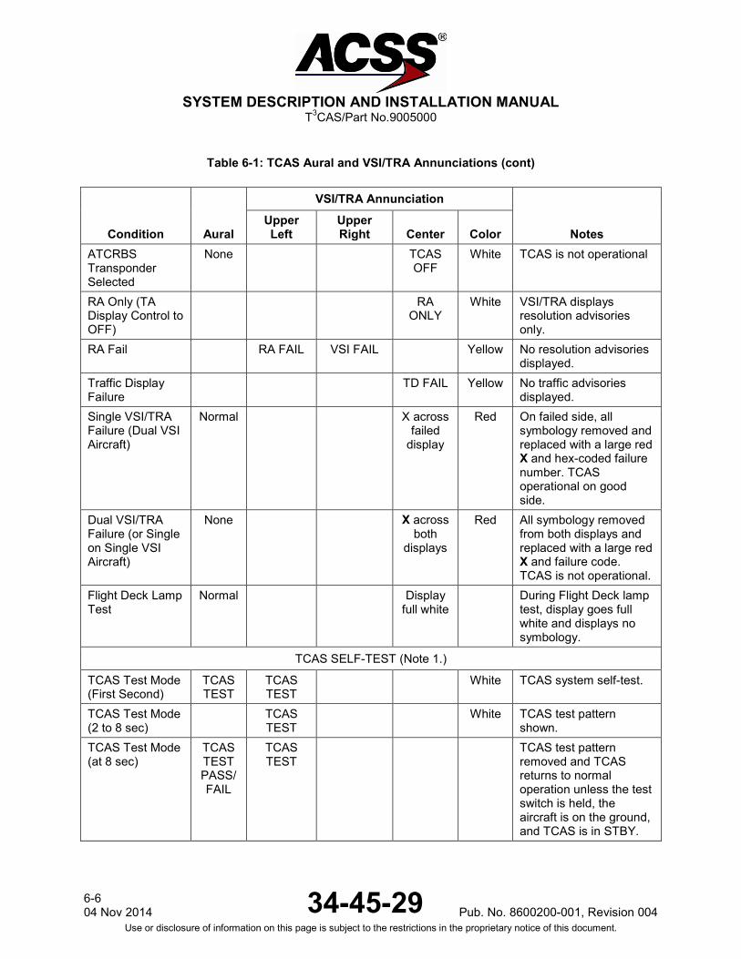
SYSTEM DESCRIPTION AND INSTALLATION MANUAL
T3CAS/Part No.9005000
Table 6-1: TCAS Aural and VSI/TRA Annunciations (cont)
Condition Aural
VSI/TRA Annunciation
Notes Upper Left
Upper Right Center Color
ATCRBS Transponder Selected
None TCAS OFF
White TCAS is not operational
RA Only (TA Display Control to OFF)
RA ONLY
White VSI/TRA displays resolution advisories only.
RA Fail RA FAIL VSI FAIL Yellow No resolution advisories displayed.
Traffic Display Failure
TD FAIL Yellow No traffic advisories displayed.
Single VSI/TRA Failure (Dual VSI Aircraft)
Normal X across failed
display
Red On failed side, all symbology removed and replaced with a large red X and hex-coded failure number. TCAS operational on good side.
Dual VSI/TRA Failure (or Single on Single VSI Aircraft)
None X across both
displays
Red All symbology removed from both displays and replaced with a large red X and failure code. TCAS is not operational.
Flight Deck Lamp Test
Normal Display full white
During Flight Deck lamp test, display goes full white and displays no symbology.
TCAS SELF-TEST (Note 1.)
TCAS Test Mode (First Second)
TCAS TEST
TCAS TEST
White TCAS system self-test.
TCAS Test Mode (2 to 8 sec)
TCAS TEST
White TCAS test pattern shown.
TCAS Test Mode (at 8 sec)
TCAS TEST PASS/FAIL
TCAS TEST
TCAS test pattern removed and TCAS returns to normal operation unless the test switch is held, the aircraft is on the ground, and TCAS is in STBY.
6-6 04 Nov 2014 34-45-29 Pub. No. 8600200-001, Revision 004
Use or disclosure of information on this page is subject to the restrictions in the proprietary notice of this document.

SYSTEM DESCRIPTION AND INSTALLATION MANUAL
T3CAS/Part No.9005000
Table 6-1: TCAS Aural and VSI/TRA Annunciations (cont)
Condition Aural
VSI/TRA Annunciation
Notes Upper Left
Upper Right Center Color
TCAS EXTENDED SELF-TEST (MAINTENANCE ONLY) (Note 2, 3.)
TCAS Extended Test Mode (Test Switch Held at 7 Seconds for 2 Seconds and Aircraft on the Ground Only)
System Information pages
White Current status of the TCAS system transponder antennas, radio altimeters barometric altitude, etc. is presented in a series of pages called by selection of 4096 code.
NOTES: 1. Self-Test should only be run in STANDBY mode in flight or on the ground. 2. Extended Self-Test is not applicable to T3CAS part numbers 9005000-10000, -10101, -10202,
-10204, or -11203. 3. Extended Self-Test provides maintenance information on seven screens selected using 4096
code. This mode is available only on the ground and in STANDBY. Extended Self-Test ends automatically with a TCAS/Transponder mode change or if the aircraft becomes airborne. Not all TCAS displays support this extended test mode.
(2) TAWS/RWS Display and Aural state indications and conditions.
Table 6-2: TAWS/RWS Display Aural State Indications and Conditions
Display Color Aural Conditions Notes
<Normal Operations> (Multiple) <Normal> TAWS Operational and Terrain image
is displayed/selected
Appropriate Terrain image is displayed
“TERR” <Normal Operations>
(Multiple) <Normal> Aircraft dependent based on the ’TAWS Mode
Display Enable’ factory option
Location of the ’TERR’ is configurable, Color of the ’TERR’ is also configurable and changes with CPA Caution and Warning
Pub. No. 8600200-001, Revision 004 34-45-29 6-7
04 Nov2014 Use or disclosure of information on this page is subject to the restrictions in the proprietary notice of this document.

SYSTEM DESCRIPTION AND INSTALLATION MANUAL
T3CAS/Part No.9005000
Table 6-2: TAWS/RWS Display Aural State Indications and Conditions (cont)
Display Color Aural Conditions Notes “OBST” <Normal Operations>
(Multiple) <Normal> Aircraft dependent based on the ’TAWS
Mode Display Enable’ factory
option
Location of the ’OBST’ is configurable, Color of the ’OBST’ is also configurable and changes with OCPA Caution and Warning
<WXR Displayed> <Normal> TAWS Operational and Terrain image is
not displayed/selected
If TAWS is sharing the display with another function (e.g. Weather Radar (WXR) which is active, then TAWS needs to be selected to be displayed
<WXR Displayed> <NONE> TAWS Off (breaker pulled)
TAWS is not operational, check circuit breaker to make sure it is pushed in
<black display or display unit generated error indication>
<Normal> ARINC 708 bus disconnect
This can be caused by unplugging the display, with everything else healthy. Also check TAWS display output wiring.
6-8 04 Nov 2014 34-45-29 Pub. No. 8600200-001, Revision 004
Use or disclosure of information on this page is subject to the restrictions in the proprietary notice of this document.

SYSTEM DESCRIPTION AND INSTALLATION MANUAL
T3CAS/Part No.9005000
Table 6-2: TAWS/RWS Display Aural State Indications and Conditions (cont)
Display Color Aural Conditions Notes “TERRAIN IMAGE NOT AVAILABLE” or <black display>
Yellow
<NONE> Selected Display Range is not
supported OR
External Source is unavailable
OR Terrain Database
corrupted or incorrect
OR APM hardware or database fault (if APM installed)
OR T3CAS LRU Hardware or
Software fault
Select a valid range and/or dump the BITE log and send to Customer Service. Run the extended self-test (if available)
“TERRAIN INHIBITED” Yellow <Normal EXCEPT no CPA alerts>
‘Terrain inhibited’ (by pilot switch in
cockpit
Pub. No. 8600200-001, Revision 004 34-45-29 6-9
04 Nov2014 Use or disclosure of information on this page is subject to the restrictions in the proprietary notice of this document.

SYSTEM DESCRIPTION AND INSTALLATION MANUAL
T3CAS/Part No.9005000
Table 6-2: TAWS/RWS Display Aural State Indications and Conditions (cont)
Display Color Aural Conditions Notes
STANDARD SELF-TEST:
<Multi-Color Test Pattern> (Non-Windshear systems)
(Multiple) “TERRAIN AWARENESS
TEST START” + “TERRAIN
AWARENESS SYSTEM PASS”
OR “TERRAIN
AWARENESS LRU PASS” “REQUIRED EXTERNAL INPUT
UNAVAILABLE” +“TERRAIN
AWARENESS SYSTEM
UNAVAILABLE” OR
“REQUIRED EXTERNAL INPUT FAIL” + “TERRAIN
AWARENESS SYSTEM FAIL”
OR “TERRAIN
AWARENESS SYSTEM FAIL” FOLLOWED BY
“TERRAIN AWARENESS
TEST COMPLETE”
RTS Self-Test TAWS system self-test
6-10 04 Nov 2014 34-45-29 Pub. No. 8600200-001, Revision 004
Use or disclosure of information on this page is subject to the restrictions in the proprietary notice of this document.

SYSTEM DESCRIPTION AND INSTALLATION MANUAL
T3CAS/Part No.9005000
Table 6-2: TAWS/RWS Display Aural State Indications and Conditions (cont)
Display Color Aural Conditions Notes <Multi-Color Test Pattern> (Non-Windshear systems)
“TERRAIN AWARENESS
TEST START + “TERRAIN
AWARENESS SYSTEM PASS”
OR “TERRAIN
AWARENESS LRU PASS” “REQUIRED EXTERNAL INPUT
UNAVAILABLE” +“TERRAIN
AWARENESS SYSTEM FAIL”
OR “TERRAIN
AWARENESS SYSTEM FAIL”
“TERRAIN AWARENESS
TEST COMPLETE”
RTS Self-Test TAWS system self-test
<Multi-Color Test Pattern> (Windshear systems, not applicable to part numbers 9005000-10000, -10101, -10202, -10204, or -11203)
“TERRAIN AWARENESSAND
WINDSHEAR TESTSTART +
“TERRAINAWARENESS
SYSTEMPASS” OR
“TERRAIN AWARENESS LRU PASS” “REQUIRED EXTERNAL INPUT
UNAVAILABLE” +“TERRAIN
AWARENESS SYSTEM FAIL”
OR “TERRAIN
AWARENESS SYSTEM FAIL”
“TERRAIN AWARENESS AND WINDSHEAR TEST
COMPLETE”
RTS Self-Test TAWS system self-test
Pub. No. 8600200-001, Revision 004 34-45-29 6-11
04 Nov2014 Use or disclosure of information on this page is subject to the restrictions in the proprietary notice of this document.

SYSTEM DESCRIPTION AND INSTALLATION MANUAL
T3CAS/Part No.9005000
Table 6-2: TAWS/RWS Display Aural State Indications and Conditions (cont)
Display Color Aural Conditions Notes EXTENDED SELF-TEST (Not applicable to part numbers 9005000-10000, -10101, -10202, -10204, or -11203):
<Multi-Color Test Pattern> (Non-Windshear systems)
(Multiple) “TERRAIN AWARENESS
EXTENDED TEST START“+ “TERRAIN
AWARENESS SYSTEM PASS”
OR “TERRAIN
AWARENESS LRU PASS” “REQUIRED EXTERNAL INPUT UNAVAILABLE” +
“TERRAIN AWARENESS
SYSTEM UNAVAILABLE”
OR “REQUIRED
EXTERNAL INPUT FAIL” + “TERRAIN
AWARENESS SYSTEM FAIL”
OR “TERRAIN
AWARENESS SYSTEM FAIL”
“TERRAIN AWARENESS
EXTENDED TEST COMPLETE”
RTS Extended Self-Test
TAWS system self-test
6-12 04 Nov 2014 34-45-29 Pub. No. 8600200-001, Revision 004
Use or disclosure of information on this page is subject to the restrictions in the proprietary notice of this document.
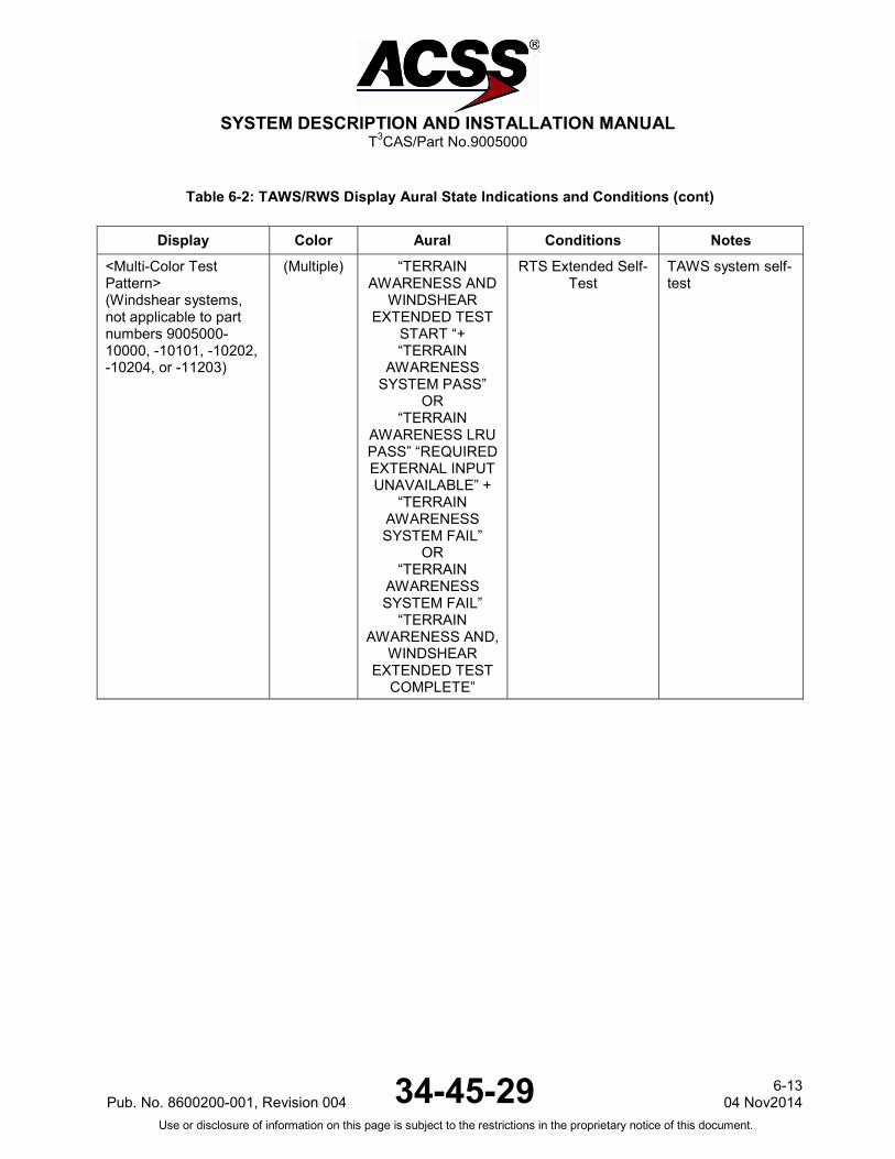
SYSTEM DESCRIPTION AND INSTALLATION MANUAL
T3CAS/Part No.9005000
Table 6-2: TAWS/RWS Display Aural State Indications and Conditions (cont)
Display Color Aural Conditions Notes <Multi-Color Test Pattern> (Windshear systems, not applicable to part numbers 9005000-10000, -10101, -10202, -10204, or -11203)
(Multiple) “TERRAIN AWARENESS AND
WINDSHEAR EXTENDED TEST
START “+ “TERRAIN
AWARENESS SYSTEM PASS”
OR “TERRAIN
AWARENESS LRU PASS” “REQUIRED EXTERNAL INPUT UNAVAILABLE” +
“TERRAIN AWARENESS SYSTEM FAIL”
OR “TERRAIN
AWARENESS SYSTEM FAIL”
“TERRAIN AWARENESS AND,
WINDSHEAR EXTENDED TEST
COMPLETE”
RTS Extended Self-Test
TAWS system self-test
Pub. No. 8600200-001, Revision 004 34-45-29 6-13
04 Nov2014 Use or disclosure of information on this page is subject to the restrictions in the proprietary notice of this document.
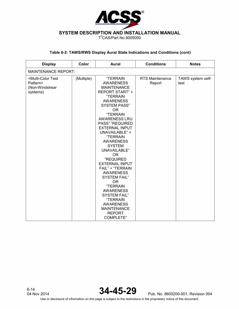
SYSTEM DESCRIPTION AND INSTALLATION MANUAL
T3CAS/Part No.9005000
Table 6-2: TAWS/RWS Display Aural State Indications and Conditions (cont)
Display Color Aural Conditions Notes
MAINTENANCE REPORT:
<Multi-Color Test Pattern> (Non-Windshear systems)
(Multiple) “TERRAIN AWARENESS
MAINTENANCE REPORT START” +
“TERRAIN AWARENESS
SYSTEM PASS” OR
“TERRAIN AWARENESS LRU PASS” “REQUIRED EXTERNAL INPUT UNAVAILABLE” +
“TERRAIN AWARENESS
SYSTEM UNAVAILABLE”
OR “REQUIRED
EXTERNAL INPUT FAIL” + “TERRAIN
AWARENESS SYSTEM FAIL”
OR “TERRAIN
AWARENESS SYSTEM FAIL”
“TERRAIN AWARENESS
MAINTENANCE REPORT
COMPLETE”
RTS Maintenance Report
TAWS system self-test
6-14 04 Nov 2014 34-45-29 Pub. No. 8600200-001, Revision 004
Use or disclosure of information on this page is subject to the restrictions in the proprietary notice of this document.

SYSTEM DESCRIPTION AND INSTALLATION MANUAL
T3CAS/Part No.9005000
Table 6-2: TAWS/RWS Display Aural State Indications and Conditions (cont)
Display Color Aural Conditions Notes <Multi-Color Test Pattern> (Windshear systems, not applicable to part numbers 9005000-10000, -10101, -10202, -10204, or -11203)
“TERRAIN AWARENESS AND
WINDSHEAR MAINTENANCE
REPORT START” + “TERRAIN
AWARENESS SYSTEM PASS”
OR “TERRAIN
AWARENESS LRU PASS” “REQUIRED EXTERNAL INPUT
UNAVAILABLE” +“TERRAIN
AWARENESS SYSTEM FAIL”
OR “TERRAIN
AWARENESS SYSTEM FAIL”
“TERRAIN AWARENESS
ANDWINDSHEAR MAINTENANCE
REPORT COMPLETE”
RTS Maintenance Report
TAWS system self-test
<Multi-Color Test Pattern> (Non-Windshear systems)
(Multiple) “Active External Faults” + <each
active external fault in BITE log>
OR “No Active External Faults” “TERRAIN
AWARENESS EXTENDED TEST
COMPLETE”
RTS Extended Test (Active External
Faults)
Pub. No. 8600200-001, Revision 004 34-45-29 6-15
04 Nov2014 Use or disclosure of information on this page is subject to the restrictions in the proprietary notice of this document.
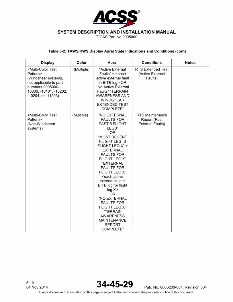
SYSTEM DESCRIPTION AND INSTALLATION MANUAL
T3CAS/Part No.9005000
Table 6-2: TAWS/RWS Display Aural State Indications and Conditions (cont)
Display Color Aural Conditions Notes <Multi-Color Test Pattern> (Windshear systems, not applicable to part numbers 9005000-10000, -10101, -10202, -10204, or -11203)
(Multiple) “Active External Faults” + <each
active external fault in BITE log> OR
“No Active External Faults” “TERRAIN
AWARENESS AND WINDSHEAR
EXTENDED TEST COMPLETE”
RTS Extended Test (Active External
Faults)
<Multi-Color Test Pattern> (Non-Windshear systems)
(Multiple) “NO EXTERNAL FAULTS FOR
PAST 5 FLIGHT LEGS”
OR “MOST RECENT FLIGHT LEG IS
FLIGHT LEG X” + EXTERNAL
FAULTS FOR FLIGHT LEG X”
“EXTERNAL FAULTS FOR
FLIGHT LEG X” <each active
external fault in BITE log for flight
leg X> OR
“NO EXTERNAL FAULTS FOR
FLIGHT LEG X” “TERRAIN
AWARENESS MAINTENANCE
REPORT COMPLETE”
RTS Maintenance Report (Past
External Faults)
6-16 04 Nov 2014 34-45-29 Pub. No. 8600200-001, Revision 004
Use or disclosure of information on this page is subject to the restrictions in the proprietary notice of this document.

SYSTEM DESCRIPTION AND INSTALLATION MANUAL
T3CAS/Part No.9005000
Table 6-2: TAWS/RWS Display Aural State Indications and Conditions (cont)
Display Color Aural Conditions Notes <Multi-Color Test Pattern> (Windshear systems, not applicable to part numbers 9005000-10000, -10101, -10202, -10204, or -11203)
(Multiple) “NO EXTERNAL FAULTS FOR
PAST 5 FLIGHT LEGS”
OR “MOST RECENT FLIGHT LEG IS
FLIGHT LEG X” + EXTERNAL
FAULTS FOR FLIGHT LEG X”
“EXTERNAL FAULTS FOR
FLIGHT LEG X” <each active
external fault in BITE log for flight
leg X> OR
“NO EXTERNAL FAULTS FOR
FLIGHT LEG X” “TERRAIN
AWARENESS AND WINDSHEAR
MAINTENANCE REPORT
COMPLETE”
RTS Maintenance Report (Past
External Faults)
Maintenance Pages (0 to 15)
(Multiple) <Normal>
RTS Maintenance Pages
The Maintenance Pages display the details of the current state of the T3CAS TAWS/RWS function
Pub. No. 8600200-001, Revision 004 34-45-29 6-17
04 Nov2014 Use or disclosure of information on this page is subject to the restrictions in the proprietary notice of this document.
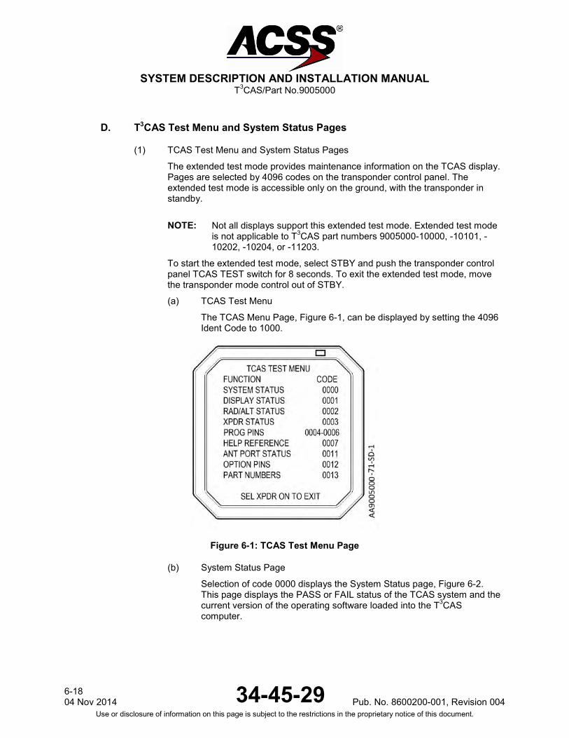
SYSTEM DESCRIPTION AND INSTALLATION MANUAL
T3CAS/Part No.9005000
D. T3CAS Test Menu and System Status Pages
(1) TCAS Test Menu and System Status Pages
The extended test mode provides maintenance information on the TCAS display. Pages are selected by 4096 codes on the transponder control panel. The extended test mode is accessible only on the ground, with the transponder in standby.
NOTE: Not all displays support this extended test mode. Extended test mode is not applicable to T3CAS part numbers 9005000-10000, -10101, -10202, -10204, or -11203.
To start the extended test mode, select STBY and push the transponder control panel TCAS TEST switch for 8 seconds. To exit the extended test mode, move the transponder mode control out of STBY.
(a) TCAS Test Menu
The TCAS Menu Page, Figure 6-1, can be displayed by setting the 4096 Ident Code to 1000.
Figure 6-1: TCAS Test Menu Page
(b) System Status Page
Selection of code 0000 displays the System Status page, Figure 6-2. This page displays the PASS or FAIL status of the TCAS system and the current version of the operating software loaded into the T3CAS computer.
6-18 04 Nov 2014 34-45-29 Pub. No. 8600200-001, Revision 004
Use or disclosure of information on this page is subject to the restrictions in the proprietary notice of this document.

SYSTEM DESCRIPTION AND INSTALLATION MANUAL
T3CAS/Part No.9005000
Figure 6-2: Typical System Status Page
In the event of a detected system failure, one or more of the messages in Table 6-3 are displayed. Lines 6 thru 10 of the display screen are used to display the five highest priority faults within the TCAS system. A maximum of five messages can be displayed.
Table 6-3: System Status Page Fault Messages
Priority Message Description
1 SUPP FAULT GOTO 0010
Suppression bus failure. Select page 0010 for more information.
2 TCAS CU FAIL T3CAS TCAS function has failed BITE test.
3 ANT FAIL TOP Antenna failure. Message field will display TOP, BOT or BOTH to indicate which antenna failed.
4 DISP FAIL GOTO 0001 TCAS has lost valid signal from display. Select page 0001 for more information.
5 RALT FAIL GOTO 0002 TCAS has lost valid signal from radio altimeter. Select page 0002 for more information.
6 XPDR FAIL GOTO 0003 TCAS has lost valid signal from Mode S transponder. Select page 0003 for more information.
7 ANT FAIL GOTO 0011 One of the antenna ports connected to the T3CAS CU has failed. Select page 0011 for more information.
Pub. No. 8600200-001, Revision 004 34-45-29 6-19
04 Nov2014 Use or disclosure of information on this page is subject to the restrictions in the proprietary notice of this document.
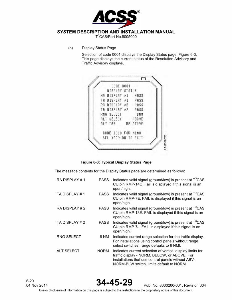
SYSTEM DESCRIPTION AND INSTALLATION MANUAL
T3CAS/Part No.9005000
(c) Display Status Page
Selection of code 0001 displays the Display Status page, Figure 6-3. This page displays the current status of the Resolution Advisory and Traffic Advisory displays.
Figure 6-3: Typical Display Status Page
The message contents for the Display Status page are determined as follows: RA DISPLAY # 1 PASS Indicates valid signal (ground/low) is present at T3CAS
CU pin RMP-14C. Fail is displayed if this signal is an open/high.
TA DISPLAY # 1 PASS Indicates valid signal (ground/low) is present at T3CAS CU pin RMP-7E. FAIL is displayed if this signal is an open/high.
RA DISPLAY # 2 PASS Indicates valid signal (ground/low) is present at T3CAS CU pin RMP-13E. FAIL is displayed if this signal is an open/high.
TA DISPLAY # 2 PASS Indicates valid signal (ground/low) is present at T3CAS CU pin RMP-7J. FAIL is displayed if this signal is an open/high.
RNG SELECT 6 NM Indicates current range selection for the traffic display. For installations using control panels without range select switches, range defaults to 6 NMI.
ALT SELECT NORM Indicates current selection of vertical display limits for traffic display - NORM, BELOW, or ABOVE. For installations that use control panels without ABV-NORM-BLW switch, limits default to NORM.
6-20 04 Nov 2014 34-45-29 Pub. No. 8600200-001, Revision 004
Use or disclosure of information on this page is subject to the restrictions in the proprietary notice of this document.

SYSTEM DESCRIPTION AND INSTALLATION MANUAL
T3CAS/Part No.9005000
ALT TAG RELATIVE Indicates current selection on control panel for type of traffic symbol altitude indication, RELATIVE or FLT LVL. Default is RELATIVE if no switch is available on control panel.
(d) RAD/ALT Status Page
Selection of code 0002 displays the RAD/ALT Status page, Figure 6-4. This page displays the status of the selected radio altimeter interface to the T3CAS.
Figure 6-4: Typical RAD/ALT Status Page
The first information line (line 3) of the RAD/ALT STATUS page indicates which of the two radio altimeter ports is being used by the T3CAS computer. The T3CAS computer attempts to use radio altimeter No.1 first. If it determines this input is invalid, it automatically switches to radio altimeter No.2. The current status of the two radio altimeter ports is displayed on lines 5 and 6. If a signal is valid, the radio altitude value is displayed in either “FT” for English-type altimeters, or “M” for Metric-type altimeters. If one of the radio altitude signals is determined to be invalid, the altitude value is replaced by INACT. Radio altitude INACT indicates the radio altimeter has failed, is not powered, or is not connected. The radio altimeter input is determined to be invalid if, for an analog radio altimeter input, 28 V dc valid is not present at T3CAS CU pin RMP-2K for Radio Alt #1 or pin RMP-3C for Radio Alt #2, or for a digital radio altimeter input, the SSM of the radio altimeter output indicates not valid or no data is present on the digital bus.
Pub. No. 8600200-001, Revision 004 34-45-29 6-21
04 Nov2014 Use or disclosure of information on this page is subject to the restrictions in the proprietary notice of this document.

SYSTEM DESCRIPTION AND INSTALLATION MANUAL
T3CAS/Part No.9005000
If the radio altimeter output is greater than 2,200 feet (670.56 meters) (source is valid, but data is invalid), the radio altitude value is replaced by OVR RNG. When both radio altitude sources are invalid, line 3 is blank.
(e) Transponder (XPDR) Status Page
Selection of code 0003 displays the XPDR Status page Figure 6-5. This page displays data for the transponder selected at the time the extended test mode was entered.
Figure 6-5: Typical Transponder (XPDR) Status Page
The message contents for the XPDR Status page are determined as follows: XPDR #1 PASS Indicates PASS or FAIL status of the selected
transponder (XPDR #1 or XPDR #2) as indicated by the digital transmission from that transponder. FAIL is displayed if no data is received on the bus.
MODE S ADDR 8E78A0H Indicates the Mode S address (in hexadecimal format) of the selected transponder as determined by program pins at the rear connector of the transponder. (See Note 1.)
PRESS. ALT 1133FT Indicates the last pressure altitude being reported by the selected Mode S transponder before the TCAS system was placed into STBY. This value is not updated while in extended test mode.
ALT REPORTING
ON Indicates current position of altitude reporting switch on Mode S/TCAS control panel - ON or OFF. S/W PN PS7021601-903 (See Note 2.)
6-22 04 Nov 2014 34-45-29 Pub. No. 8600200-001, Revision 004
Use or disclosure of information on this page is subject to the restrictions in the proprietary notice of this document.
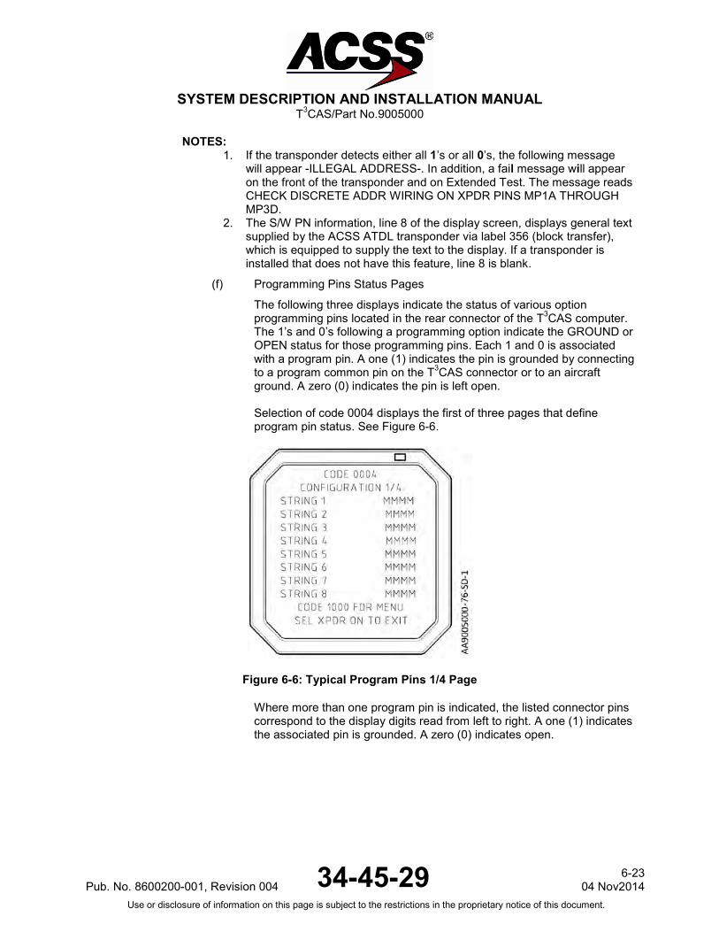
SYSTEM DESCRIPTION AND INSTALLATION MANUAL
T3CAS/Part No.9005000
NOTES: 1. If the transponder detects either all 1’s or all 0’s, the following message
will appear -ILLEGAL ADDRESS-. In addition, a fail message will appear on the front of the transponder and on Extended Test. The message reads CHECK DISCRETE ADDR WIRING ON XPDR PINS MP1A THROUGH MP3D.
2. The S/W PN information, line 8 of the display screen, displays general text supplied by the ACSS ATDL transponder via label 356 (block transfer), which is equipped to supply the text to the display. If a transponder is installed that does not have this feature, line 8 is blank.
(f) Programming Pins Status Pages
The following three displays indicate the status of various option programming pins located in the rear connector of the T3CAS computer. The 1’s and 0’s following a programming option indicate the GROUND or OPEN status for those programming pins. Each 1 and 0 is associated with a program pin. A one (1) indicates the pin is grounded by connecting to a program common pin on the T3CAS connector or to an aircraft ground. A zero (0) indicates the pin is left open. Selection of code 0004 displays the first of three pages that define program pin status. See Figure 6-6.
Figure 6-6: Typical Program Pins 1/4 Page
Where more than one program pin is indicated, the listed connector pins correspond to the display digits read from left to right. A one (1) indicates the associated pin is grounded. A zero (0) indicates open.
Pub. No. 8600200-001, Revision 004 34-45-29 6-23
04 Nov2014 Use or disclosure of information on this page is subject to the restrictions in the proprietary notice of this document.

SYSTEM DESCRIPTION AND INSTALLATION MANUAL
T3CAS/Part No.9005000
CLIMB INH 0000 Climb Inhibit inputs: RMP-1J, RMP-13G, RBP-5J, RBP-5K.
INC CLIMB INH 0000 Increase Climb Inhibit inputs: RBP-5E, RBP-5F, RBP-5G, RBP-5H
ADVISORY INH 0000 Advisory Inhibit inputs: RBP-5A, RBP-5B, RBP-5C, RBP-5D
RADIO ALT TYPE1 0000 Analog Radio Altimeter Type: RMP-12B ARINC 552/552A (0), Collins BCA (1)
VOICE DELAY ENABLE
0 Voice Delay option: RBP-7D Enabled = (1), Disabled = (0)
AUDIO PROG PINS 000 Audio output level selection inputs: RBP-7A, RBP-7B, RBP-7C
CANCEL DISCRETE2 0 Advisory Cancel Discrete option: RMP-3D (0) allows advisories to be cancelled. A (1) does not allow advisories to be cancelled.
DTIF PIN 0 DTIF Enabled Option: RMP-5E Selection of code 0005 displays the second of four pages that define the Program Pins status. See Figure 6-7.
Figure 6-7: Typical Program Pins 2/4 Page
Where more than one program pin is indicated, the listed connector pins correspond to the display digits read from left to right. A one (1) indicates the associated pin is grounded. A zero (0) indicates open. Selection of code 0006 displays the third of four pages that define the Program Pins status. See Figure 6-8.
6-24 04 Nov 2014 34-45-29 Pub. No. 8600200-001, Revision 004
Use or disclosure of information on this page is subject to the restrictions in the proprietary notice of this document.
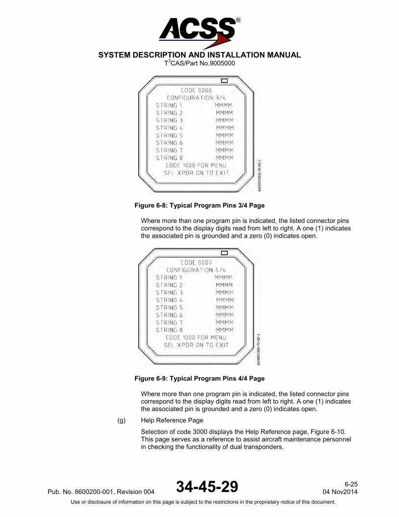
SYSTEM DESCRIPTION AND INSTALLATION MANUAL
T3CAS/Part No.9005000
Figure 6-8: Typical Program Pins 3/4 Page
Where more than one program pin is indicated, the listed connector pins correspond to the display digits read from left to right. A one (1) indicates the associated pin is grounded and a zero (0) indicates open.
Figure 6-9: Typical Program Pins 4/4 Page
Where more than one program pin is indicated, the listed connector pins correspond to the display digits read from left to right. A one (1) indicates the associated pin is grounded and a zero (0) indicates open.
(g) Help Reference Page
Selection of code 3000 displays the Help Reference page, Figure 6-10. This page serves as a reference to assist aircraft maintenance personnel in checking the functionality of dual transponders.
Pub. No. 8600200-001, Revision 004 34-45-29 6-25
04 Nov2014 Use or disclosure of information on this page is subject to the restrictions in the proprietary notice of this document.

SYSTEM DESCRIPTION AND INSTALLATION MANUAL
T3CAS/Part No.9005000
Figure 6-10: Help Reference Page
In addition to the recommended procedure, the number 2 transponder must be selected on the Mode S/TCAS control panel and the mode select switch placed in TA only or TA/RA mode momentarily prior to restarting self-test to enter extended maintenance mode.
(h) Suppression Bus Fail Page
The Suppression Bus Fail page, Figure 6-11, is displayed only when a TCAS suppression bus failure is indicated and the 4096 Ident Code is 0010. This page displays information about detected suppression bus failures. It briefly describes the problem and instructs maintenance personnel to change the 4096 Ident Code to display the Suppression Bus Clear page for clearing instructions. If there is no suppression bus failure, the main menu (0000) is displayed.
Figure 6-11: Suppression Bus Fail Page
6-26 04 Nov 2014 34-45-29 Pub. No. 8600200-001, Revision 004
Use or disclosure of information on this page is subject to the restrictions in the proprietary notice of this document.

SYSTEM DESCRIPTION AND INSTALLATION MANUAL
T3CAS/Part No.9005000
The flight crew may report a unique problem of an intruder displayed which appears to be co-altitude, located on the own aircraft symbol. In many of these cases, TCAS may issue a TA followed by an RA. After the flight crew has initiated the advisory, the intruder may not appear to change relative to the own aircraft symbol. In this type of report, a failure in the mutual suppression bus, which connects the own aircraft transponder to the T3CAS CU, could result in the T3CAS CU developing an intruder track file on its own associated transponder. Simply performing a dc continuity test of the connection between the T3CAS CU and the transponders may not identify the problem. In many cases, a connector termination or pushed back pin may be the cause. That is why it is very important to be monitoring the suppression signal from the active source, on both ends. The following is one method to monitor the signal. Remove the T3CAS CU and the non-selected transponder. With an oscilloscope, monitor the signal at the T3CAS CU rack rear connector for the Mode S transponder suppression signal related to the squitter message sent every second by the selected operational transponder. Repeat the same test with the second transponder after removing the first transponder. To test the T3CAS CU suppression pulse, install the TCAS CU, remove the No.1 transponder and monitor the TCAS suppression pulse during the time of the UF16 broadcast or the WSS while in the air (if possible). This TCAS suppression signal should also be present on the No.2 transponder.
(i) Suppression Bus Clear Page
The Suppression Bus Clear page, Figure 6-12, is displayed only when a TCAS suppression bus failure is indicated and the 4096 Ident Code is 0510. This page briefly describes how to clear suppression bus failures from the fault record by exiting the extended test mode with this page displayed. When the TCAS extended test is exited, the failure indication is cleared and a Suppression Bus Clear code is recorded in the current flight leg.
Pub. No. 8600200-001, Revision 004 34-45-29 6-27
04 Nov2014 Use or disclosure of information on this page is subject to the restrictions in the proprietary notice of this document.
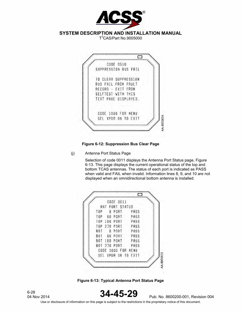
SYSTEM DESCRIPTION AND INSTALLATION MANUAL
T3CAS/Part No.9005000
Figure 6-12: Suppression Bus Clear Page
(j) Antenna Port Status Page
Selection of code 0011 displays the Antenna Port Status page, Figure 6-13. This page displays the current operational status of the top and bottom TCAS antennas. The status of each port is indicated as PASS when valid and FAIL when invalid. Information lines 8, 9, and 10 are not displayed when an omnidirectional bottom antenna is installed.
Figure 6-13: Typical Antenna Port Status Page
6-28 04 Nov 2014 34-45-29 Pub. No. 8600200-001, Revision 004
Use or disclosure of information on this page is subject to the restrictions in the proprietary notice of this document.

SYSTEM DESCRIPTION AND INSTALLATION MANUAL
T3CAS/Part No.9005000
(k) Part Numbers Page 1
The Part Numbers page 1 includes the OP part numbers as well as the IO FPGA part number, RF FPGA part number, and Dataloader Application part number. See Figure 6-14.
Figure 6-14: Part Numbers Page 1 (Code 0013)
(l) Part Numbers Page 2
The Part Numbers page 2 includes the DL part numbers, as well as the ASDB part number, ACD part number and ACD CRC number. See Figure 6-15.
Figure 6-15: Part Numbers Page 2 (Code 0014)
Pub. No. 8600200-001, Revision 004 34-45-29 6-29
04 Nov2014 Use or disclosure of information on this page is subject to the restrictions in the proprietary notice of this document.
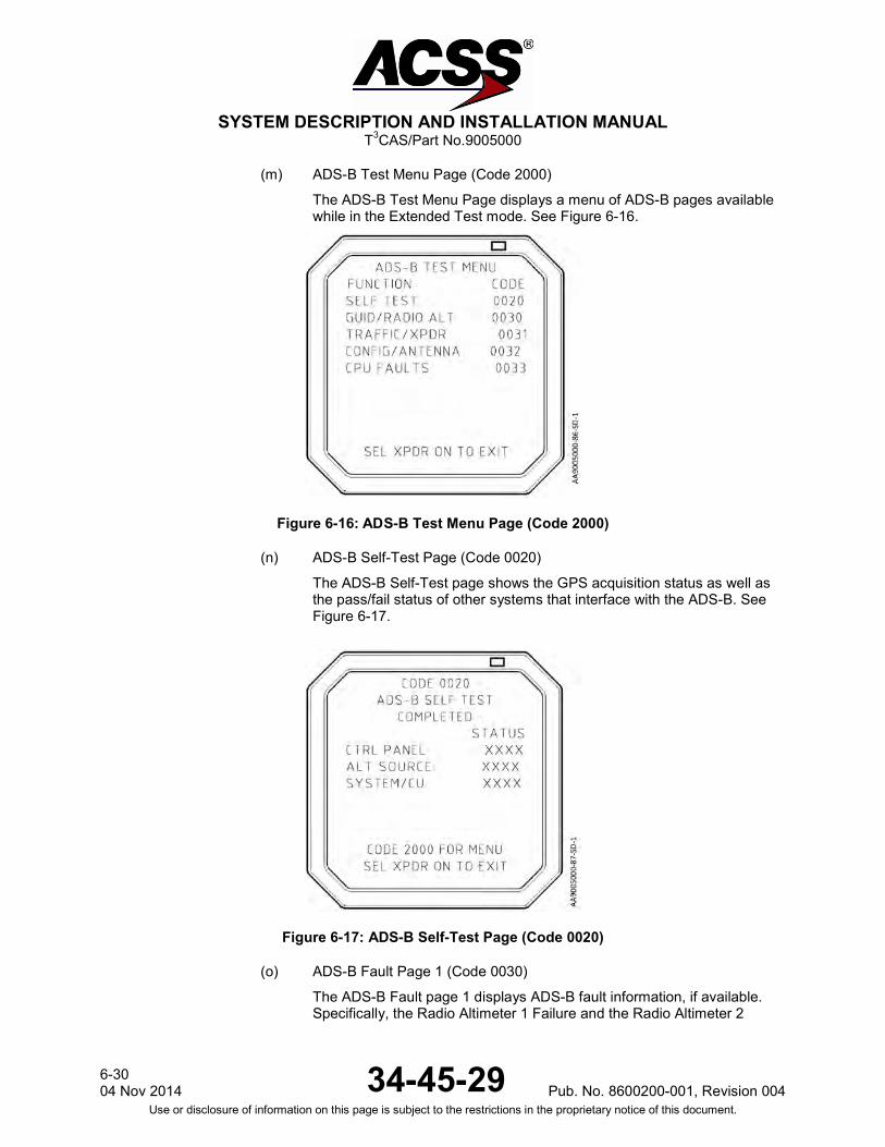
SYSTEM DESCRIPTION AND INSTALLATION MANUAL
T3CAS/Part No.9005000
(m) ADS-B Test Menu Page (Code 2000)
The ADS-B Test Menu Page displays a menu of ADS-B pages available while in the Extended Test mode. See Figure 6-16.
Figure 6-16: ADS-B Test Menu Page (Code 2000)
(n) ADS-B Self-Test Page (Code 0020)
The ADS-B Self-Test page shows the GPS acquisition status as well as the pass/fail status of other systems that interface with the ADS-B. See Figure 6-17.
Figure 6-17: ADS-B Self-Test Page (Code 0020)
(o) ADS-B Fault Page 1 (Code 0030)
The ADS-B Fault page 1 displays ADS-B fault information, if available. Specifically, the Radio Altimeter 1 Failure and the Radio Altimeter 2
6-30 04 Nov 2014 34-45-29 Pub. No. 8600200-001, Revision 004
Use or disclosure of information on this page is subject to the restrictions in the proprietary notice of this document.

SYSTEM DESCRIPTION AND INSTALLATION MANUAL
T3CAS/Part No.9005000
Failure are displayed if active or if the required input is unavailable. See Figure 6-18.
Figure 6-18: ADS-B Fault Page 1 (Code 0030)
(p) ADS-B Fault Page 2 (Code 0031)
The ADS-B Fault page 2 displays ADS-B fault information, if available. Specifically the ADS-B Traffic Display Failure, the Transponder 1 Failure and the Transponder 2 Failure are displayed if active or if the required input is unavailable. See Figure 6-19.
Figure 6-19: ADS-B Fault Page 2 (Code 0031)
(q) ADS-B Fault Page 3 (Code 0032)
The ADS-B Fault page 3 displays ADS-B fault information, if available. Specifically the Configuration File Unavailable, the Top Antenna Failure and the Bottom Antenna Failure are displayed if active or if the required input is unavailable. See Figure 6-20.
Pub. No. 8600200-001, Revision 004 34-45-29 6-31
04 Nov2014 Use or disclosure of information on this page is subject to the restrictions in the proprietary notice of this document.
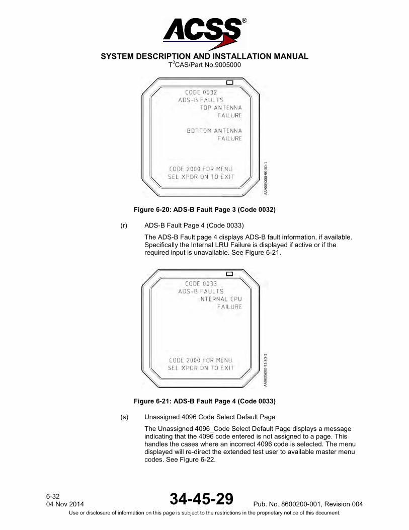
SYSTEM DESCRIPTION AND INSTALLATION MANUAL
T3CAS/Part No.9005000
Figure 6-20: ADS-B Fault Page 3 (Code 0032)
(r) ADS-B Fault Page 4 (Code 0033)
The ADS-B Fault page 4 displays ADS-B fault information, if available. Specifically the Internal LRU Failure is displayed if active or if the required input is unavailable. See Figure 6-21.
Figure 6-21: ADS-B Fault Page 4 (Code 0033)
(s) Unassigned 4096 Code Select Default Page
The Unassigned 4096_Code Select Default Page displays a message indicating that the 4096 code entered is not assigned to a page. This handles the cases where an incorrect 4096 code is selected. The menu displayed will re-direct the extended test user to available master menu codes. See Figure 6-22.
6-32 04 Nov 2014 34-45-29 Pub. No. 8600200-001, Revision 004
Use or disclosure of information on this page is subject to the restrictions in the proprietary notice of this document.

SYSTEM DESCRIPTION AND INSTALLATION MANUAL
T3CAS/Part No.9005000
Figure 6-22: Unassigned 4096 Code Select Default Page
(2) TAWS/RWS Test Menu and System Status Pages
The Maintenance Pages provide maintenance information on the TAWS EFIS/Weather Radar display. Pages are indexed by pressing and holding the TAWS/RWS pushbutton/switch on the flight deck for 3 seconds or less. The Maintenance Pages are accessible only on the ground during the standard self-test or within 5 seconds of completion of the standard self-test or by activating the Maintenance Report as outlined in Section 3.B.(2) of this (FAULT ISOLATION) section.
(a) Maintenance Instruction Page
The first T3CAS TAWS Maintenance page displayed is the Instruction page (Page 0) shown in Figure 6-23. The instruction page contains basic information on how the user can advance through the Maintenance Pages (Press Self-Test button less than 3 seconds) and exit from Maintenance Pages (Press and Hold the Self-Test button for more than 3 seconds).
Figure 6-23: Maintenance Instruction Page (Page 0/25)
Pub. No. 8600200-001, Revision 004 34-45-29 6-33
04 Nov2014 Use or disclosure of information on this page is subject to the restrictions in the proprietary notice of this document.

SYSTEM DESCRIPTION AND INSTALLATION MANUAL
T3CAS/Part No.9005000
(b) Table of Contents Page
The Table of Contents page, shown in Figure 6-24, follows the Instruction page and provides the user with a page breakdown of the remaining Maintenance Pages. The Maintenance Pages are broken down as follows;
● Part Numbers - Pages 2 thru 10
● System Test - Page 11
● ACD Options - Pages 12 thru 25
Figure 6-24: Table of Contents Page (Page 1/25)
(c) Part Numbers Pages
The Part Numbers Page is divided into eight pages. Figure 6-25 shows Maintenance page 2 (Part Number Page 1), which displays the Aircraft Type and Figure 6-26 shows Maintenance page 3 (Part Number Page 2), the OMS Type.
Figure 6-25: Part Numbers (Pages 2/25)
Figure 6-26: Part Numbers (Pages 3/25)
6-34 04 Nov 2014 34-45-29 Pub. No. 8600200-001, Revision 004
Use or disclosure of information on this page is subject to the restrictions in the proprietary notice of this document.
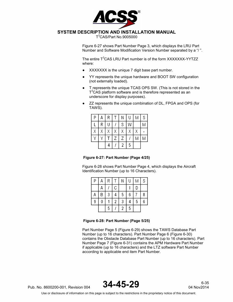
SYSTEM DESCRIPTION AND INSTALLATION MANUAL
T3CAS/Part No.9005000
Figure 6-27 shows Part Number Page 3, which displays the LRU Part Number and Software Modification Version Number separated by a “/ ”. The entire T3CAS LRU Part number is of the form XXXXXXX-YYTZZ where:
● XXXXXXX is the unique 7 digit base part number.
● YY represents the unique hardware and BOOT SW configuration (not externally loaded).
● T represents the unique TCAS OPS SW. (This is not stored in the T3CAS platform software and is therefore represented as an underscore for display purposes).
● ZZ represents the unique combination of DL, FPGA and OPS (for TAWS).
Figure 6-27: Part Number (Page 4/25)
Figure 6-28 shows Part Number Page 4, which displays the Aircraft Identification Number (up to 16 Characters).
Figure 6-28: Part Number (Page 5/25)
Part Number Page 5 (Figure 6-29) shows the TAWS Database Part Number (up to 16 characters). Part Number Page 6 (Figure 6-30) contains the Obstacle Database Part Number (up to 16 characters). Part Number Page 7 (Figure 6-31) contains the APM Hardware Part Number if applicable (up to 16 characters) and the LTZ software Part Number according to applicable end item Part Number.
Pub. No. 8600200-001, Revision 004 34-45-29 6-35
04 Nov2014 Use or disclosure of information on this page is subject to the restrictions in the proprietary notice of this document.

SYSTEM DESCRIPTION AND INSTALLATION MANUAL
T3CAS/Part No.9005000
Figure 6-29: Part Number (Page 6/25)
Figure 6-30: Part Number (Page 7/25)
Figure 6-31: Part Number (Page 8/25)
Part Number Page 8 (Figure 6-32) shows the APM ACD Part Number if applicable (up to 16 characters). Part Number Page 9 (Figure 6-33) contains APM ASDB Part Number if applicable (up to 16 characters).
6-36 04 Nov 2014 34-45-29 Pub. No. 8600200-001, Revision 004
Use or disclosure of information on this page is subject to the restrictions in the proprietary notice of this document.

SYSTEM DESCRIPTION AND INSTALLATION MANUAL
T3CAS/Part No.9005000
Figure 6-32: Part Number (Page 9/25)
Figure 6-33: Part Number (Page 10/25)
(d) System Test Page
The T3CAS Maintenance System Test Page (Figure 6-34) follows the Part Numbers pages. The System Test Page will display the Pass/Fail status of the most recently run Standard Self-Test. The status is displayed as follows:
Figure 6-34: System Test Page (Page 11/25)
The T3CAS Maintenance System Test Page displays “LRU PASS” (PASS displayed in Green) on row 3 if the “Terrain Awareness LRU Pass” aural OR the “Terrain Awareness System Pass” aural has been annunciated.
NOTE: The OR indicates that it is possible for the LRU to pass and the system to fail. This is an indication that a required external input is either invalid or unavailable.
Pub. No. 8600200-001, Revision 004 34-45-29 6-37
04 Nov2014 Use or disclosure of information on this page is subject to the restrictions in the proprietary notice of this document.
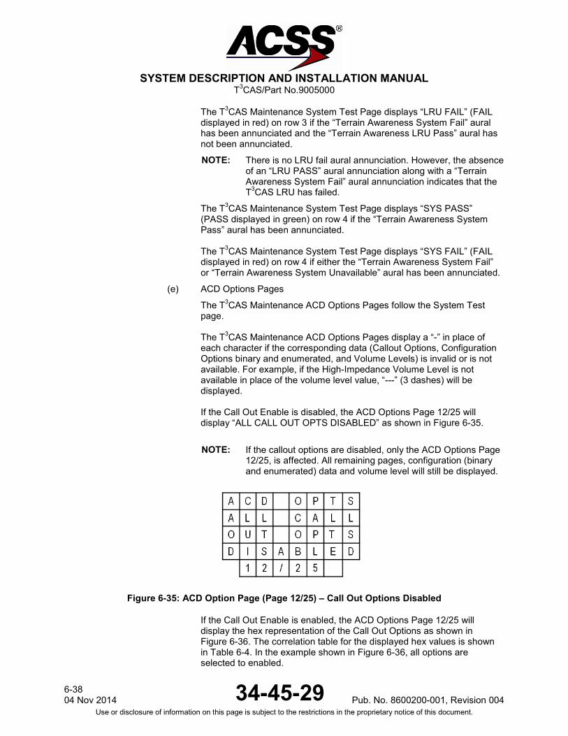
SYSTEM DESCRIPTION AND INSTALLATION MANUAL
T3CAS/Part No.9005000
The T3CAS Maintenance System Test Page displays “LRU FAIL” (FAIL displayed in red) on row 3 if the “Terrain Awareness System Fail” aural has been annunciated and the “Terrain Awareness LRU Pass” aural has not been annunciated.
NOTE: There is no LRU fail aural annunciation. However, the absence of an “LRU PASS” aural annunciation along with a “Terrain Awareness System Fail” aural annunciation indicates that the T3CAS LRU has failed.
The T3CAS Maintenance System Test Page displays “SYS PASS” (PASS displayed in green) on row 4 if the “Terrain Awareness System Pass” aural has been annunciated. The T3CAS Maintenance System Test Page displays “SYS FAIL” (FAIL displayed in red) on row 4 if either the “Terrain Awareness System Fail” or “Terrain Awareness System Unavailable” aural has been annunciated.
(e) ACD Options Pages
The T3CAS Maintenance ACD Options Pages follow the System Test page. The T3CAS Maintenance ACD Options Pages display a “-” in place of each character if the corresponding data (Callout Options, Configuration Options binary and enumerated, and Volume Levels) is invalid or is not available. For example, if the High-Impedance Volume Level is not available in place of the volume level value, “---” (3 dashes) will be displayed. If the Call Out Enable is disabled, the ACD Options Page 12/25 will display “ALL CALL OUT OPTS DISABLED” as shown in Figure 6-35.
NOTE: If the callout options are disabled, only the ACD Options Page 12/25, is affected. All remaining pages, configuration (binary and enumerated) data and volume level will still be displayed.
Figure 6-35: ACD Option Page (Page 12/25) – Call Out Options Disabled
If the Call Out Enable is enabled, the ACD Options Page 12/25 will display the hex representation of the Call Out Options as shown in Figure 6-36. The correlation table for the displayed hex values is shown in Table 6-4. In the example shown in Figure 6-36, all options are selected to enabled.
6-38 04 Nov 2014 34-45-29 Pub. No. 8600200-001, Revision 004
Use or disclosure of information on this page is subject to the restrictions in the proprietary notice of this document.

SYSTEM DESCRIPTION AND INSTALLATION MANUAL
T3CAS/Part No.9005000
NOTE: The MSB is the left most bit in the Hex value (MSB .. LSB).
Figure 6-36: ACD Option Page (Page 12/25) – Call Out Option Enabled
Table 6-4: ACD Callout Options
Callout Option ACD Callout Option Bit Option ACD Callout Option Bit Setting
Bank Angle Callout Enable Flag
Hex Char 1 (MSB), bit 4
1 = Bank Angle Callout Enabled, 0 = Bank Angle Callout Disabled
DH/MDA Switch Available Flag
Hex Char 1 (MSB), bit 3
1 = DH/MDA Switch Available, 0 = DH/MDA Switch Not Available
Decision Height Callout Enable Flag
Hex Char 1 (MSB), bit 2
1 = Decision Height Callout Enabled, 0 = Decision Height Callout Disabled
Minimums Callout Enable Flag Hex Char 1 (MSB), bit 1
1 = Minimums Callout Enabled, 0 = Minimums Callout Disabled
Minimums-Minimums Callout Enable Flag
Hex Char 2 (MSB), bit 4
1 = Minimums-Minimums Callout Enabled, 0 = Minimums-Minimums Callout Disabled
Approaching Decision Height Callout Enable Flag
Hex Char 2 (MSB), bit 3
1 = Approaching Decision Height Callout Enabled, 0 = Approaching Decision Height Callout Disabled
Approaching Minimums Callout Enable Flag
Hex Char 2 (MSB), bit 2
1 = Approaching Minimums Callout Enabled, 0 = Approaching Minimums Callout Disabled
1,000 ft (304.8 m) Callout Enable Flag
Hex Char 2 (MSB), bit 1
1 = 1,000 ft (304.8 m) Callout Enabled, 0 = 1,000 ft (304.8 m) Callout Disabled
Pub. No. 8600200-001, Revision 004 34-45-29 6-39
04 Nov2014 Use or disclosure of information on this page is subject to the restrictions in the proprietary notice of this document.
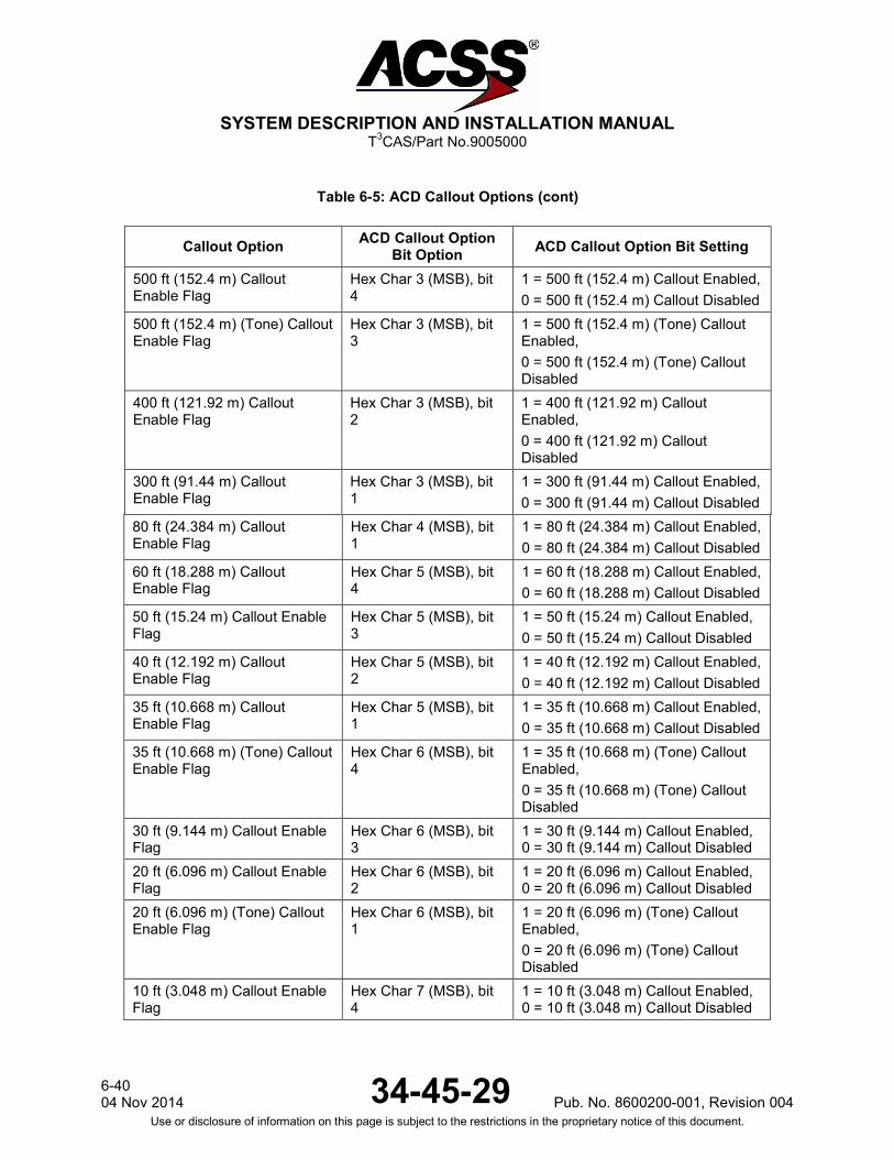
SYSTEM DESCRIPTION AND INSTALLATION MANUAL
T3CAS/Part No.9005000
Table 6-5: ACD Callout Options (cont)
Callout Option ACD Callout Option Bit Option ACD Callout Option Bit Setting
500 ft (152.4 m) Callout Enable Flag
Hex Char 3 (MSB), bit 4
1 = 500 ft (152.4 m) Callout Enabled, 0 = 500 ft (152.4 m) Callout Disabled
500 ft (152.4 m) (Tone) Callout Enable Flag
Hex Char 3 (MSB), bit 3
1 = 500 ft (152.4 m) (Tone) Callout Enabled, 0 = 500 ft (152.4 m) (Tone) Callout Disabled
400 ft (121.92 m) Callout Enable Flag
Hex Char 3 (MSB), bit 2
1 = 400 ft (121.92 m) Callout Enabled, 0 = 400 ft (121.92 m) Callout Disabled
300 ft (91.44 m) Callout Enable Flag
Hex Char 3 (MSB), bit 1
1 = 300 ft (91.44 m) Callout Enabled, 0 = 300 ft (91.44 m) Callout Disabled
80 ft (24.384 m) Callout Enable Flag
Hex Char 4 (MSB), bit 1
1 = 80 ft (24.384 m) Callout Enabled, 0 = 80 ft (24.384 m) Callout Disabled
60 ft (18.288 m) Callout Enable Flag
Hex Char 5 (MSB), bit 4
1 = 60 ft (18.288 m) Callout Enabled, 0 = 60 ft (18.288 m) Callout Disabled
50 ft (15.24 m) Callout Enable Flag
Hex Char 5 (MSB), bit 3
1 = 50 ft (15.24 m) Callout Enabled, 0 = 50 ft (15.24 m) Callout Disabled
40 ft (12.192 m) Callout Enable Flag
Hex Char 5 (MSB), bit 2
1 = 40 ft (12.192 m) Callout Enabled, 0 = 40 ft (12.192 m) Callout Disabled
35 ft (10.668 m) Callout Enable Flag
Hex Char 5 (MSB), bit 1
1 = 35 ft (10.668 m) Callout Enabled, 0 = 35 ft (10.668 m) Callout Disabled
35 ft (10.668 m) (Tone) Callout Enable Flag
Hex Char 6 (MSB), bit 4
1 = 35 ft (10.668 m) (Tone) Callout Enabled, 0 = 35 ft (10.668 m) (Tone) Callout Disabled
30 ft (9.144 m) Callout Enable Flag
Hex Char 6 (MSB), bit 3
1 = 30 ft (9.144 m) Callout Enabled, 0 = 30 ft (9.144 m) Callout Disabled
20 ft (6.096 m) Callout Enable Flag
Hex Char 6 (MSB), bit 2
1 = 20 ft (6.096 m) Callout Enabled, 0 = 20 ft (6.096 m) Callout Disabled
20 ft (6.096 m) (Tone) Callout Enable Flag
Hex Char 6 (MSB), bit 1
1 = 20 ft (6.096 m) (Tone) Callout Enabled, 0 = 20 ft (6.096 m) (Tone) Callout Disabled
10 ft (3.048 m) Callout Enable Flag
Hex Char 7 (MSB), bit 4
1 = 10 ft (3.048 m) Callout Enabled, 0 = 10 ft (3.048 m) Callout Disabled
6-40 04 Nov 2014 34-45-29 Pub. No. 8600200-001, Revision 004
Use or disclosure of information on this page is subject to the restrictions in the proprietary notice of this document.

SYSTEM DESCRIPTION AND INSTALLATION MANUAL
T3CAS/Part No.9005000
Table 6-5: ACD Callout Options (cont)
Callout Option ACD Callout Option Bit Option ACD Callout Option Bit Setting
Unknown Decision Height Hex Char 7 (MSB), bit 3
2,500 ft (762 m) Callout Enable Flag
Hex char 7, bit 2 1 = 2,500 ft (762 m) Callout Enabled 0 = 2,500 ft (762 m) Callout Disabled
Spare bit
The Maintenance ACD Options Page 13/25 displays the hex representation of the ACD Discrete Configuration Options as shown in Figure 6-37. The correlation table for the displayed hex values is shown in Table 6-5. In the example shown in Figure 6-37, all of the options are selected to enabled.
NOTE: The MSB is the left most bit in the Hex value (MSB .. LSB).
Figure 6-37: ACD Option Page (Page 13/25) – Discrete Configuration Options
Table 6-6: ACD Discrete Options
ACD Discrete Option ACD Discrete Option Bit Option ACD Discrete Option Bit Setting
GPWS Caution Flash Enable
Hex Char 1 (MSB), bit 4
1 = Caution lamp flashing for the duration of the GPWS Caution Event, 0 = Caution lamp solid for the duration of the GPWS Caution Event
GPWS Warning Flash Enable
Hex Char 1 (MSB), bit 3
1 = Warning lamp flashing for the duration of the GPWS Warning Event, 0 = Warning lamp solid for the duration of the GPWS Warning Event
Male Voice Enable Hex Char 1 (MSB), bit 2
1 = Enables the male alerting voice, 0 = Alerting voice is a female voice
Pub. No. 8600200-001, Revision 004 34-45-29 6-41
04 Nov2014 Use or disclosure of information on this page is subject to the restrictions in the proprietary notice of this document.
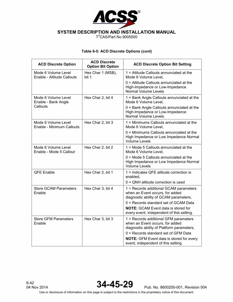
SYSTEM DESCRIPTION AND INSTALLATION MANUAL
T3CAS/Part No.9005000
Table 6-5: ACD Discrete Options (cont)
ACD Discrete Option ACD Discrete Option Bit Option ACD Discrete Option Bit Setting
Mode 6 Volume Level Enable - Altitude Callouts
Hex Char 1 (MSB), bit 1
1 = Altitude Callouts annunciated at the Mode 6 Volume Level, 0 = Altitude Callouts annunciated at the High-Impedance or Low-Impedance Normal Volume Levels
Mode 6 Volume Level Enable - Bank Angle Callouts
Hex Char 2, bit 4 1 = Bank Angle Callouts annunciated at the Mode 6 Volume Level, 0 = Bank Angle Callouts annunciated at the High-Impedance or Low-Impedance Normal Volume Levels
Mode 6 Volume Level Enable - Minimum Callouts
Hex Char 2, bit 3 1 = Minimums Callouts annunciated at the Mode 6 Volume Level, 0 = Minimums Callouts annunciated at the High Impedance or Low Impedance Normal Volume Levels
Mode 6 Volume Level Enable - Mode 5 Callout
Hex Char 2, bit 2 1 = Mode 5 Callouts annunciated at the Mode 6 Volume Level, 0 = Mode 5 Callouts annunciated at the High Impedance or Low Impedance Normal Volume Levels
QFE Enable Hex Char 2, bit 1 1 = Indicates QFE altitude correction is enabled, 0 = QNH altitude correction is used
Store GCAM Parameters Enable
Hex Char 3, bit 4 1 = Records additional GCAM parameters when an Event occurs, for added diagnostic ability of GCAM parameters, 0 = Records standard set of GCAM Data NOTE: GCAM Event data is stored for every event, independent of this setting.
Store GFM Parameters Enable
Hex Char 3, bit 3 1 = Records additional GFM parameters when an Event occurs, for added diagnostic ability of Platform parameters, 0 = Records standard set of GFM Data NOTE: GFM Event data is stored for every event, independent of this setting.
6-42 04 Nov 2014 34-45-29 Pub. No. 8600200-001, Revision 004
Use or disclosure of information on this page is subject to the restrictions in the proprietary notice of this document.
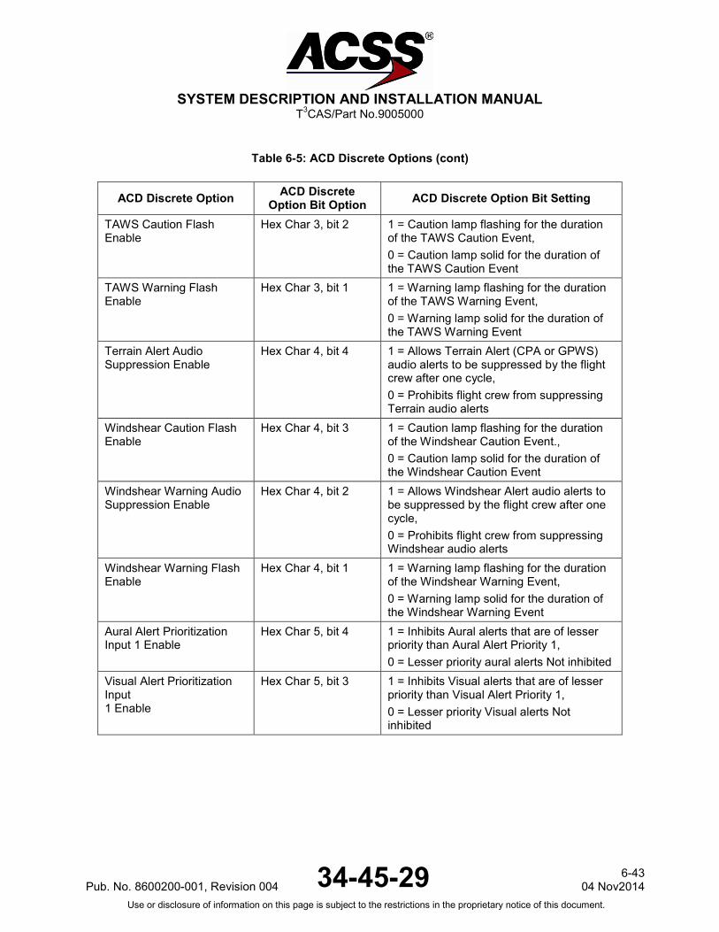
SYSTEM DESCRIPTION AND INSTALLATION MANUAL
T3CAS/Part No.9005000
Table 6-5: ACD Discrete Options (cont)
ACD Discrete Option ACD Discrete Option Bit Option ACD Discrete Option Bit Setting
TAWS Caution Flash Enable
Hex Char 3, bit 2 1 = Caution lamp flashing for the duration of the TAWS Caution Event, 0 = Caution lamp solid for the duration of the TAWS Caution Event
TAWS Warning Flash Enable
Hex Char 3, bit 1 1 = Warning lamp flashing for the duration of the TAWS Warning Event, 0 = Warning lamp solid for the duration of the TAWS Warning Event
Terrain Alert Audio Suppression Enable
Hex Char 4, bit 4 1 = Allows Terrain Alert (CPA or GPWS) audio alerts to be suppressed by the flight crew after one cycle, 0 = Prohibits flight crew from suppressing Terrain audio alerts
Windshear Caution Flash Enable
Hex Char 4, bit 3 1 = Caution lamp flashing for the duration of the Windshear Caution Event., 0 = Caution lamp solid for the duration of the Windshear Caution Event
Windshear Warning Audio Suppression Enable
Hex Char 4, bit 2 1 = Allows Windshear Alert audio alerts to be suppressed by the flight crew after one cycle, 0 = Prohibits flight crew from suppressing Windshear audio alerts
Windshear Warning Flash Enable
Hex Char 4, bit 1 1 = Warning lamp flashing for the duration of the Windshear Warning Event, 0 = Warning lamp solid for the duration of the Windshear Warning Event
Aural Alert Prioritization Input 1 Enable
Hex Char 5, bit 4 1 = Inhibits Aural alerts that are of lesser priority than Aural Alert Priority 1, 0 = Lesser priority aural alerts Not inhibited
Visual Alert Prioritization Input 1 Enable
Hex Char 5, bit 3 1 = Inhibits Visual alerts that are of lesser priority than Visual Alert Priority 1, 0 = Lesser priority Visual alerts Not inhibited
Pub. No. 8600200-001, Revision 004 34-45-29 6-43
04 Nov2014 Use or disclosure of information on this page is subject to the restrictions in the proprietary notice of this document.

SYSTEM DESCRIPTION AND INSTALLATION MANUAL
T3CAS/Part No.9005000
Table 6-5: ACD Discrete Options (cont)
ACD Discrete Option ACD Discrete Option Bit Option ACD Discrete Option Bit Setting
Aural Alert Prioritization Input 2 Enable
Hex Char 5, bit 2 1 = Inhibits Aural alerts that are of lesser priority than Aural Alert Priority 2, 0 = Lesser priority aural alerts Not inhibited
Visual Alert Prioritization Input 2 Enable
Hex Char 5, bit 1 1 = Inhibits Visual alerts that are of lesser priority than Visual Alert Priority 2, 0 = Lesser priority Visual alerts Not inhibited
Aural Alert Prioritization Input 3 Enable
Hex Char 6, bit 4 1 = Inhibits Aural alerts that are of lesser priority than Aural Alert Priority 3, 0 = Lesser priority aural alerts Not inhibited
Visual Alert Prioritization Input 3 Enable
Hex Char 6, bit 3 1 = Inhibits Visual alerts that are of lesser priority than Visual Alert Priority 3, 0 = Lesser priority Visual alerts Not inhibited
Aural Alert Prioritization Input 4 Enable
Hex Char 6, bit 2 1 = Inhibits Aural alerts that are of lesser priority than Aural Alert Priority 4, 0 = Lesser priority aural alerts Not inhibited
Visual Alert Prioritization Input 4 Enable
Hex Char 6, bit 1 1 = Inhibits Visual alerts that are of lesser priority than Visual Alert Priority 4, 0 = Lesser priority Visual alerts Not inhibited
BITE Fault Aurals Enable Hex Char 7, bit 4 1 = Allows aural annunciation of external LRU faults from RTS self-test (ASDB must support maintenance aurals), 0 = Prohibits aural annunciation of external LRU faults from RTS self-test
Store GCAM Prior Data Duration
Hex Char 7, bit 3 1 = Allows aural annunciation of external LRU faults from RTS self-test (ASDB must support maintenance aurals), 0 = Prohibits aural annunciation of external LRU faults from RTS self-test
6-44 04 Nov 2014 34-45-29 Pub. No. 8600200-001, Revision 004
Use or disclosure of information on this page is subject to the restrictions in the proprietary notice of this document.
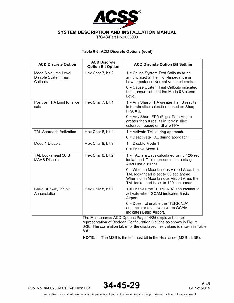
SYSTEM DESCRIPTION AND INSTALLATION MANUAL
T3CAS/Part No.9005000
Table 6-5: ACD Discrete Options (cont)
ACD Discrete Option ACD Discrete Option Bit Option ACD Discrete Option Bit Setting
Mode 6 Volume Level Disable System Test Callouts
Hex Char 7, bit 2 1 = Cause System Test Callouts to be annunciated at the High-Impedance or Low-Impedance Normal Volume Levels. 0 = Cause System Test Callouts indicated to be annunciated at the Mode 6 Volume Level.
Positive FPA Limit for slice calc
Hex Char 7, bit 1 1 = Any Sharp FPA greater than 0 results in terrain slice coloration based on Sharp FPA = 0. 0 = Any Sharp FPA (Flight Path Angle) greater than 0 results in terrain slice coloration based on Sharp FPA.
TAL Approach Activation Hex Char 8, bit 4 1 = Activate TAL during approach. 0 = Deactivate TAL during approach
Mode 1 Disable Hex Char 8, bit 3 1 = Disable Mode 1 0 = Enable Mode 1
TAL Lookahead 30 S MAAS Disable
Hex Char 8, bit 2 1 = TAL is always calculated using 120-sec lookahead. This represents the heritage Alert Line distance. 0 = When in Mountainous Airport Area, the TAL lookahead is set to 30 sec ahead. When not in Mountainous Airport Area, the TAL lookahead is set to 120 sec ahead.
Basic Runway Inhibit Annunciation
Hex Char 8, bit 1 1 = Enables the ”TERR N/A” annunciator to activate when GCAM indicates Basic Airport. 0 = Does not enable the ”TERR N/A” annunciator to activate when GCAM indicates Basic Airport.
The Maintenance ACD Options Page 14/25 displays the hex representation of Boolean Configuration Options as shown in Figure 6-38. The correlation table for the displayed hex values is shown in Table 6-6.
NOTE: The MSB is the left most bit in the Hex value (MSB .. LSB).
Pub. No. 8600200-001, Revision 004 34-45-29 6-45
04 Nov2014 Use or disclosure of information on this page is subject to the restrictions in the proprietary notice of this document.

SYSTEM DESCRIPTION AND INSTALLATION MANUAL
T3CAS/Part No.9005000
Figure 6-38: ACD Option Page (Page 14/25) Boolean Configuration Options
Table 6-7: ACD Boolean Options
ACD Discrete Option ACD Boolean Option Bit Position ACD Selectable Option
Windshear Caution Disable Hex Char 1, bit 4 1 = Windshear Cautions are disabled 0 = Windshear Cautions are enabled
Windshear Caution Aural Disable
Hex Char 1, bit 3 1 = Windshear Caution Aurals are disabled 0 = Windshear Caution Aurals are enabled
Obstacle Enable Hex Char 1, bit 2 1 = GCAM Obstacle Algorithm operates as normal 0 = GCAM Obstacle Algorithm is Disabled
Eleview Enable Hex Char 1, bit 1 1 = Eleview enabled 0 = Eleview disabled
Eleview Water Texture Enable
Hex Char 2, bit 4 1 = Cyan will be used for the water texture. 0 = Cyan will not be used for the water texture.
Eleview Rasterized Text Disable
Hex Char 2, bit 3 1 = Disables rasterized text indication for Eleview on the terrain display. 0 = Enables rasterized text indication for Eleview on the terrain display.
Eleview Min Text Enable Hex Char 2, bit 2 1 = Allows the minimum terrain eleview rasterized text to be transmitted. 0 = Removes the minimum terrain eleview rasterized text.
Modified Eleview Logic Enable
Hex Char 2, bit 1 1 = Selects between flat terrain coloration logic of all black vs all light-density green at terrain spreads less than or equal to 110 ft (33.528 m), removes the maximum elevation readout when over water, removes the minimum elevation readout on label 25 when in flat terrain, and removes the maximum elevation readouts when an airport blackout region is being over-flown. 0 = Does not apply modified eleview logic.
6-46 04 Nov 2014 34-45-29 Pub. No. 8600200-001, Revision 004
Use or disclosure of information on this page is subject to the restrictions in the proprietary notice of this document.
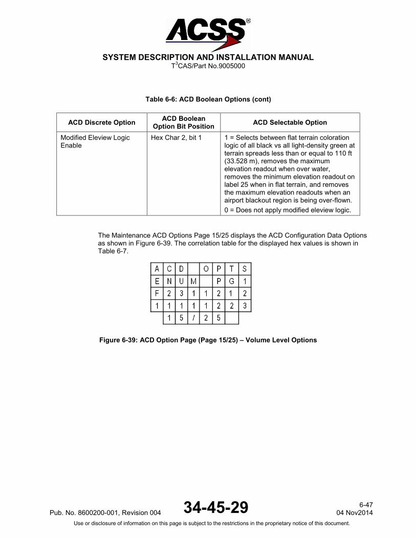
SYSTEM DESCRIPTION AND INSTALLATION MANUAL
T3CAS/Part No.9005000
Table 6-6: ACD Boolean Options (cont)
ACD Discrete Option ACD Boolean Option Bit Position ACD Selectable Option
Modified Eleview Logic Enable
Hex Char 2, bit 1 1 = Selects between flat terrain coloration logic of all black vs all light-density green at terrain spreads less than or equal to 110 ft (33.528 m), removes the maximum elevation readout when over water, removes the minimum elevation readout on label 25 when in flat terrain, and removes the maximum elevation readouts when an airport blackout region is being over-flown. 0 = Does not apply modified eleview logic.
The Maintenance ACD Options Page 15/25 displays the ACD Configuration Data Options as shown in Figure 6-39. The correlation table for the displayed hex values is shown in Table 6-7.
Figure 6-39: ACD Option Page (Page 15/25) – Volume Level Options
Pub. No. 8600200-001, Revision 004 34-45-29 6-47
04 Nov2014 Use or disclosure of information on this page is subject to the restrictions in the proprietary notice of this document.

SYSTEM DESCRIPTION AND INSTALLATION MANUAL
T3CAS/Part No.9005000
Table 6-8: Table of Enumerated Configuration Option
ACD Discrete Option ACD Enumerated Option Bit Position ACD Selectable Option
Bank Angle Repetition Hex Char 1 1, 2, 3, 4, F (infinity) – Bank Angle warning will repeat based on the input number.
CPA Mode Caution Hex Char 2 1 = “Terrain Ahead” 2 = “Caution Terrain”
CPA Mode A Warning Hex Char 3 1 = “Terrain Ahead Pull Up” 2 = “Terrain Terrain Pull Up Pull Up” 3 = Whoop Whoop “Pull Up”
CPA Mode B Warning Hex Char 4 1 = “Avoid Terrain”
Mode 1 Caution Hex Char 5 1 = “Sink Rate”
Mode 1 Warning Hex Char 6 1 = Whoop Whoop “Pull Up” 2 = “Pull Up Pull Up”
Mode 2 Caution Hex Char 7 1 = “Terrain”
Mode 2 Warning Hex Char 8 1 = Whoop Whoop “Pull Up” 2 = “Pull Up Pull Up”
Mode 3 Caution Hex Char 9 1 = “Don’t Sink”
Mode 4A Caution Hex Char 10 1 = “Too Low Gear/Terrain”
Mode 4B Caution Hex Char 11 1 = “Too Low Flaps/Terrain”
Mode 5 Caution Hex Char 12 1 = “Glideslope”
Windshear Warning Aural Hex Char 13 1 = “Windshear Windshear Windshear”
Decision Height Aural Hex Char 14 0 = (undefined) 1 = “Decision Height” 2 = “Minimums”
Approaching Decision Height Aural
Hex Char 15 0 = (undefined) 1 = “Approaching Decision Height” 2 = “Approaching Minimums”
Radio Altitude Valid Aural Hex Char 16 0 = (undefined) 1 = “Radio Altimeter Valid” 2 = “Twenty-Five Hundred” 3 = “Two-Thousand Five-Hundred”
The Enumerated ACD Options Page 16/25 displays the ACD Options, as shown in Figure 6-40. The correlation table for the displayed hex values is shown in Table 6-8.
6-48 04 Nov 2014 34-45-29 Pub. No. 8600200-001, Revision 004
Use or disclosure of information on this page is subject to the restrictions in the proprietary notice of this document.

SYSTEM DESCRIPTION AND INSTALLATION MANUAL
T3CAS/Part No.9005000
Figure 6-40: ACD Option Page (page 16/25) – Volume Level Options
Table 6-9: Table of ACD Enumerated Values
ACD Discrete Option ACD Enumerated Option Bit Position ACD Selectable Option
Windshear Caution Aural Hex Char 1 This parameter controls the format of the Windshear Caution Aural 0 = (Undefined) 1 = “Caution Windshear”
Obstacle Max Display Range Hex Char 2 This value represents the maximum range beyond which no obstacles are displayed. The selections for this value are 5 NMI, 10 NMI,15 NMI, 20 NMI, 25 NMI, 40 NMI, 80 NMI, 160 NMI, or 320 NMI. If the value of the maximum range is not equal to one of these values the PSS defaults the value to 10 NMI. 1 = 5 NMI 2 = 10 NMI 3 = 15 NMI 4 = 20 NMI 5 = 25 NMI 6 = 40 NMI 7 = 80 NMI 8 = 160 NMI 9 = 320 NMI
OCPA Mode Caution Hex Char 3 1 = “OBSTACLE AHEAD” 2 = “CAUTION OBSTACLE”
Pub. No. 8600200-001, Revision 004 34-45-29 6-49
04 Nov2014 Use or disclosure of information on this page is subject to the restrictions in the proprietary notice of this document.

SYSTEM DESCRIPTION AND INSTALLATION MANUAL
T3CAS/Part No.9005000
Table 6-8: Table of ACD Enumerated Values (cont)
ACD Discrete Option ACD Enumerated Option Bit Position ACD Selectable Option
OCPA Mode A Warning Hex Char 4 1 = “OBSTACLE AHEAD PULL-UP“ 2 = “OBSTACLE OBSTACLE PULL-UP PULL-UP” 3 = “~~PULL UP” “~~” Designates a pair of constantly varying tones from 400 to 800 Hz. The tones are 0.3 sec each, separated by 0.1 sec and followed by 0.1 sec of silence.
OCPA Mode B Warning Hex Char 5 1 = “Avoid Obstacle”
Alerting Obstacle Size Hex Char 6 0 = 16 pixel alerting obstacles
1 = 32 pixel alerting obstacles Non Alerting Obstacle Size Hex Char 7 0 = 16 pixel non-alerting obstacles
1 = 32 pixel non-alerting obstacles The Maintenance ACD Options Page 17/25 displays the ACD Volume Level Options, as shown in Figure 6-41. The correlations table for the displayed volume level values is shown in Table 6-9. In the example shown in Figure 6-41, the volume levels are set to a maximum value of 255.
Figure 6-41: ACD Option Page (Page 17/25) - Volume Level Options
Table 6-10: Table of Volume Level Values (for Page 17/25 and 18/25)
ACD Volume Option Range
High-Impedance Volume Level 0 ≤ X ≤ 255
Low-Impedance Volume Level 0 ≤ X ≤ 255
Mode 6 High-Impedance Volume Level 0 ≤ X ≤ 255
Mode 6 Low-Impedance Volume Level 0 ≤ X ≤ 255
6-50 04 Nov 2014 34-45-29 Pub. No. 8600200-001, Revision 004
Use or disclosure of information on this page is subject to the restrictions in the proprietary notice of this document.
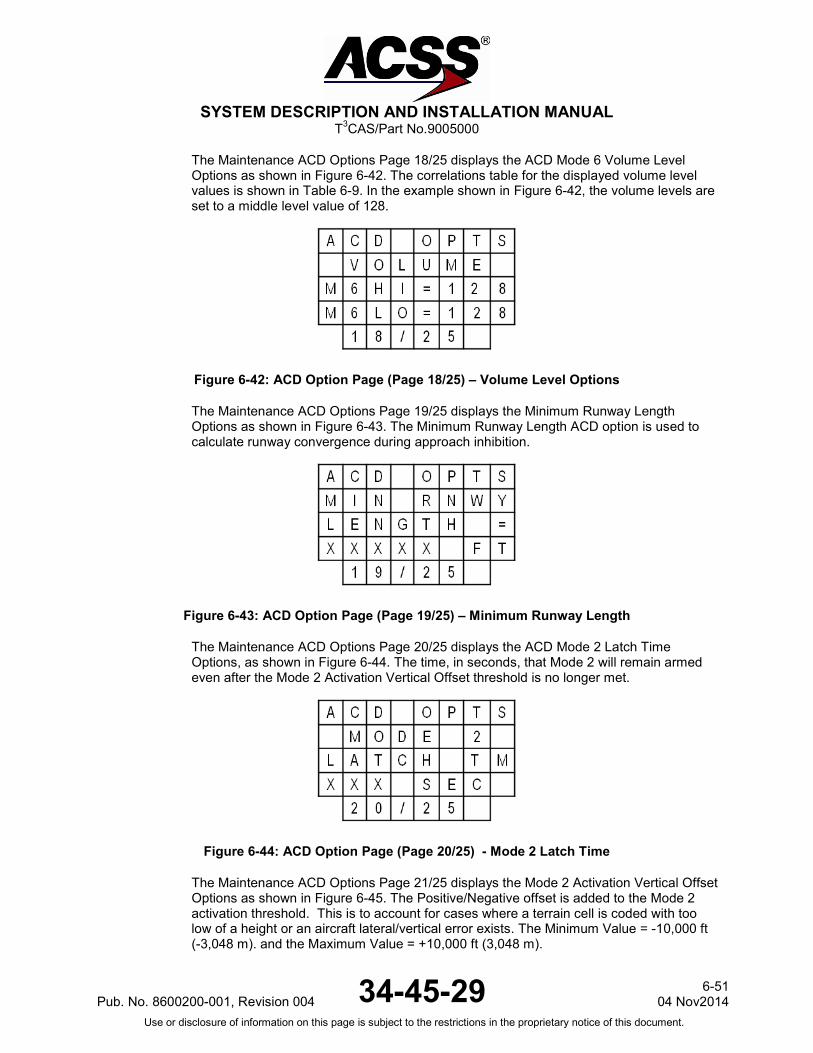
SYSTEM DESCRIPTION AND INSTALLATION MANUAL
T3CAS/Part No.9005000
The Maintenance ACD Options Page 18/25 displays the ACD Mode 6 Volume Level Options as shown in Figure 6-42. The correlations table for the displayed volume level values is shown in Table 6-9. In the example shown in Figure 6-42, the volume levels are set to a middle level value of 128.
Figure 6-42: ACD Option Page (Page 18/25) – Volume Level Options
The Maintenance ACD Options Page 19/25 displays the Minimum Runway Length Options as shown in Figure 6-43. The Minimum Runway Length ACD option is used to calculate runway convergence during approach inhibition.
Figure 6-43: ACD Option Page (Page 19/25) – Minimum Runway Length
The Maintenance ACD Options Page 20/25 displays the ACD Mode 2 Latch Time Options, as shown in Figure 6-44. The time, in seconds, that Mode 2 will remain armed even after the Mode 2 Activation Vertical Offset threshold is no longer met.
Figure 6-44: ACD Option Page (Page 20/25) - Mode 2 Latch Time
The Maintenance ACD Options Page 21/25 displays the Mode 2 Activation Vertical Offset Options as shown in Figure 6-45. The Positive/Negative offset is added to the Mode 2 activation threshold. This is to account for cases where a terrain cell is coded with too low of a height or an aircraft lateral/vertical error exists. The Minimum Value = -10,000 ft (-3,048 m). and the Maximum Value = +10,000 ft (3,048 m).
Pub. No. 8600200-001, Revision 004 34-45-29 6-51
04 Nov2014 Use or disclosure of information on this page is subject to the restrictions in the proprietary notice of this document.

SYSTEM DESCRIPTION AND INSTALLATION MANUAL
T3CAS/Part No.9005000
If set to 0, GCAM will disable Mode 2 when CPA is active.
Figure 6-45: ACD Option Page (Page 21/25) – Mode 2 Activation Vertical Offset
The Maintenance ACD Options Page 22/25 displays the ACD Narrow TAL Roll Limit Options, as shown in Figure 6-46. This ACD option sets the roll angle at which the sensor begins to draw TAL in the direction of the turn.
Figure 6-46: ACD Option Page (Page 22/25) – Narrow TAL Roll Limit
The Maintenance ACD Options Page 23/25 displays the ACD TAL ILS Deviation Limit Options, as shown in Figure 6-47. TAL inhibition glideslope deviation limits when glideslope and localizer are both valid (units of ddm). When the absolute value of the glideslope deviation is greater than this value, TAL is not inhibited. When the absolute value of glideslope deviation is less than this value, TAL is inhibited. If “Disable TAL Approach Inhibition” is disabled, this setting is irrelevant. 1 dot = 0.0875 ddm.
Figure 6-47: ACD Option Page (Page 23/25) – TAL ILS Deviation Limit
The Maintenance ACD Options Page 24/25 displays the ACD Display Alert Line Aperture Options, as shown in Figure 6-48. This parameter sets the width of the look-ahead sensor used to generate the TAL.
6-52 04 Nov 2014 34-45-29 Pub. No. 8600200-001, Revision 004
Use or disclosure of information on this page is subject to the restrictions in the proprietary notice of this document.
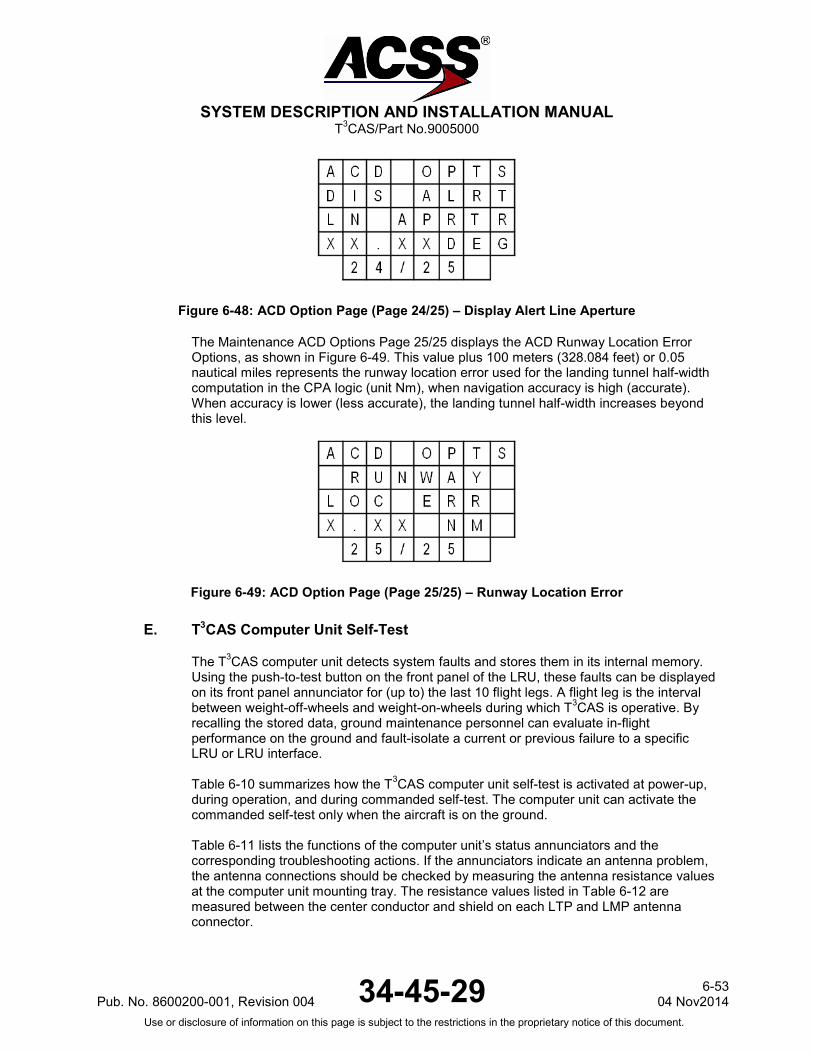
SYSTEM DESCRIPTION AND INSTALLATION MANUAL
T3CAS/Part No.9005000
Figure 6-48: ACD Option Page (Page 24/25) – Display Alert Line Aperture
The Maintenance ACD Options Page 25/25 displays the ACD Runway Location Error Options, as shown in Figure 6-49. This value plus 100 meters (328.084 feet) or 0.05 nautical miles represents the runway location error used for the landing tunnel half-width computation in the CPA logic (unit Nm), when navigation accuracy is high (accurate). When accuracy is lower (less accurate), the landing tunnel half-width increases beyond this level.
Figure 6-49: ACD Option Page (Page 25/25) – Runway Location Error
E. T3CAS Computer Unit Self-Test
The T3CAS computer unit detects system faults and stores them in its internal memory. Using the push-to-test button on the front panel of the LRU, these faults can be displayed on its front panel annunciator for (up to) the last 10 flight legs. A flight leg is the interval between weight-off-wheels and weight-on-wheels during which T3CAS is operative. By recalling the stored data, ground maintenance personnel can evaluate in-flight performance on the ground and fault-isolate a current or previous failure to a specific LRU or LRU interface. Table 6-10 summarizes how the T3CAS computer unit self-test is activated at power-up, during operation, and during commanded self-test. The computer unit can activate the commanded self-test only when the aircraft is on the ground. Table 6-11 lists the functions of the computer unit’s status annunciators and the corresponding troubleshooting actions. If the annunciators indicate an antenna problem, the antenna connections should be checked by measuring the antenna resistance values at the computer unit mounting tray. The resistance values listed in Table 6-12 are measured between the center conductor and shield on each LTP and LMP antenna connector.
Pub. No. 8600200-001, Revision 004 34-45-29 6-53
04 Nov2014 Use or disclosure of information on this page is subject to the restrictions in the proprietary notice of this document.

SYSTEM DESCRIPTION AND INSTALLATION MANUAL
T3CAS/Part No.9005000
Table 6-11: Computer Unit Self-Test Execution
Test Sequence Activation Test Indications
Power On Self-Test Self-Test is activated with each application of system power
No indication unless a fault is detected. System status/fault data is stored in internal memory. These faults can be displayed on its front panel annunciator for (up to) the last 10 flight legs. Data can be recalled by doing the commanded self-test on the ground.
Continuous Self-Test Executed automatically as part of normal TCAS inflight operation
No indication unless a fault is detected. System status/fault data is stored in internal memory. These faults can be displayed on its front panel annunciator for (up to) the last 10 flight legs. Data can be recalled by doing the commanded self-test on the ground.
Commanded Self-Test Push the front panel PUSH-TO-TEST button
● All T3CAS front panel lamps turn on during a 3-sec lamp test. They transition from “Green” to “non-Green”.
● If the T3CAS is operational, the T3CAS P/F Status green lamp turns on for a 10-sec display period and then turns off.
● If the T3CAS is not operational, one or more amber fault lamps turn on for a 11-sec display period. Refer to Table 6-11 for corrective action.
6-54 04 Nov 2014 34-45-29 Pub. No. 8600200-001, Revision 004
Use or disclosure of information on this page is subject to the restrictions in the proprietary notice of this document.

SYSTEM DESCRIPTION AND INSTALLATION MANUAL
T3CAS/Part No.9005000
Table 6-10: Computer Unit Self-Test Execution (cont)
Test Sequence Activation Test Indications
Commanded Self-Test Push the PUSH-TO-TEST button again before the previous 11-sec display period has elapsed
● Previous fault display is aborted. ● All T3CAS lamps come on during a
1-sec lamp test. ● All front T3CAS LEDs will be lit for
1 sec (±0.2 sec) in the following colors: - T3CAS P/F STATUS: Red - Data Status: Amber - APM Status: Amber - Top Ant: Amber - Bot Ant: Amber - External IO Status: Amber
● The T3CAS Status/fault data recorded during the preceding flight leg is displayed for 11 sec.
Push the PUSH-TO-TEST button before the end of each succeeding display period
● T3CAS Status/fault data recorded during a total of 10 flight legs (maximum) is displayed
● When data from the earliest recorded flight leg has been displayed, all lamps flash at approximately a 2-Hz rate for 3 sec if the PUSH-TO-TEST button is pushed. This indicates the end of recorded test data.
Pub. No. 8600200-001, Revision 004 34-45-29 6-55
04 Nov2014 Use or disclosure of information on this page is subject to the restrictions in the proprietary notice of this document.

SYSTEM DESCRIPTION AND INSTALLATION MANUAL
T3CAS/Part No.9005000
Table 6-12: T3CAS Fault Reporting and Corrective Actions
Status Annunciator Failure Possible Corrective Action
T3CAS P/F Status is Green
The T3CAS function passes its own internal BITE test
T3CAS function is operational. If other annunciators are on, the problem is in the indicated subsystem or aircraft wiring.
T3CAS P/F Status is Solid
Red
The T3CAS function has failed its own internal BITE test
Replace the T3CAS computer unit.
T3CAS P/F Status is
Blinking Red
The T3CAS function has failed its own internal BITE test within the Boot
Replace the T3CAS computer unit.
TOP ANT
The top antenna dc resistance test indicates a failure
Remove the T3CAS computer unit. Use a multimeter to measure the dc resistances indicated in Table 6-12 for the top antenna. Repair antenna cables or replace the antenna as required.
BOT ANT
The bottom antenna dc resistance test indicates a failure
Remove the T3CAS computer unit. Use a multimeter to measure the dc resistance indicated in Table 6-12 for the bottom antenna. Repair antenna cable(s) or replace the antenna as required.
Data Status is Solid Amber
Loading Failure Re-attempt the dataload.
Data Status is Blinking Amber
Bad Media or Configuration Failure
Verify the dataload media is not corrupted and that the T3CAS is configured for dataloading.
External IO Status
External IO Interface is Failed
Check wiring and power to external IO devices.
F. Directional Antenna Test/Fault Isolation Procedure
NOTE: These procedures are recommended only if a T3CAS TCAS function BITE or extended test failure of the top or bottom directional antenna has occurred.
(1) Review extended maintenance or flight leg BITE data to determine which antenna has failed.
(2) Remove T3CAS computer unit from mounting tray. Visually examine all antenna coax cable connectors at the mounting tray side as well as the LRU connectors. Remove any foreign material discovered and reinstall the LRU.
(3) Do a system self-test to determine if the fault has cleared. If the failure continues, remove the T3CAS computer unit and proceed.
(4) Do a continuity test at the LRU end of each antenna cable. The resistance values should be as specified in Table 6-12.
6-56 04 Nov 2014 34-45-29 Pub. No. 8600200-001, Revision 004
Use or disclosure of information on this page is subject to the restrictions in the proprietary notice of this document.

SYSTEM DESCRIPTION AND INSTALLATION MANUAL
T3CAS/Part No.9005000
(5) If an open circuit, short circuit, or unacceptable resistance measurement is detected on the directional antenna path, a failure has occurred in the connector, coax cable, or directional antenna.
(6) Locate the directional antenna that has a suspected failure. Remove the coax cable from the antenna port that is suspected to have failed. Isolate which section of the antenna system is at fault by a process of elimination. The resistance values of the antenna ports should be as specified in Table 6-12.
(7) Remove and replace the appropriate failed component in accordance with approved AMM procedures.
Table 6-13: Antenna Wiring Resistance
Antenna Connector Section Pin dc Resistance
Top Directional Antenna LTP 1 2 3 4
1,000 ±100 ohms 8,060 ±800 ohms 4,020 ±400 ohms 2,000 ±200 ohms
Bottom Directional Antenna LMP 1 2 3 4
1,000 ±100 ohms 8,060 ±800 ohms 4,020 ±400 ohms 2,000 ±200 ohms
Optional Bottom Omnidirectional Antenna for part numbers 9005000-11203, -11801 and -55801.
LMP 1 2 3 4
0 to 50 ohms (50 ohms maximum) Infinite (>50k ohms) Infinite (>50k ohms) Infinite (>50k ohms)
NOTE: The procedures that follow are recommended for intermittent antenna system
failures or if the continuity tests have not identified a failed component in the antenna system or if the flight crew detects an unacceptable visual discrepancy between an intruder aircraft and its displayed location.
(8) If the displayed location of an intruder aircraft is believed to be in error, appropriate ramp test equipment can be used to simulate intruder aircraft to check the suspected discrepancy while on the ground.
(9) Remove the suspected TCAS directional antenna and terminate the antenna side of the cable with a 50-ohm termination (Omni-Spectra Part Number 3102-6100-00 or equivalent TNC jack with VSWR ≤1.15 : 1).
(10) Perform a thorough inspection for moisture or contamination of all coax cable assemblies.
(11) Remove the T3CAS LRU and do a VSWR check on the coax cable from the T3CAS computer tray side. Use approved VSWR test equipment and operating procedures. The measured VSWR should be less than 2.0 : 1.
(12) If the VSWR test fails, isolate failed antenna coax section. Remove/repair appropriate cable and/or connector.
Pub. No. 8600200-001, Revision 004 34-45-29 6-57
04 Nov2014 Use or disclosure of information on this page is subject to the restrictions in the proprietary notice of this document.

SYSTEM DESCRIPTION AND INSTALLATION MANUAL
T3CAS/Part No.9005000
(13) An additional procedure for troubleshooting TCAS antenna system failures is to determine the RF insertion loss in the TCAS antenna coaxial cables. RF insertion loss is equivalent to RF IxR (voltage) drop through the coax and is measured in dB rather than volts. Each coax cable is required to have 2.5 dB (±0.5 dB) of insertion loss and the loss in all the coax cables must be within 0.5 dB of each other. Many VSWR meters have a fixed RF source and can be used to measure RF insertion loss. In this test, the VSWR meter is used to measure the loss up one cable and down the other. The total loss should not exceed 6 dB.
NOTE: The VSWR/insertion loss meter should be set up for L-band frequencies (approximately 1.0 GHz).
To perform an RF insertion loss test, do the following:
(a) Connect two of the TCAS antenna coax cables to each other at the antenna end with a dc-shorted coupler.
(b) Before any measurements are taken on the antenna system, the meter and any connectors/cables that are used to connect the meter to the TCAS antenna system must be zeroed out. This is typically done with a calibration adjustment on the VSWR meter.
(c) After the VSWR meter (and associated connectors/cables) have been calibrated for 0 dB, connect the VSWR meter to the TCAS antenna coaxes under test (at the LRU end). Measure and record the RF loss.
(d) Test different combinations of the TCAS antenna coax cables by connecting the coupler (at the antenna end) to different coax cables. By process of elimination, it can be determined if one of the TCAS antenna coax cables has excessive RF insertion loss.
(e) As an example, suppose the following insertion losses have been measured:
Antenna Port Antenna Port Measured Loss
0 90 8.5 dB
0 180 5.5 dB
90 180 8.0 dB
It can be seen that when the coax connected to the 90 degree port is included in the measurement, there is excessive loss. Simple algebra can be used to determine that this coax has 5.5 dB of insertion loss.
NOTE: 1 dB of excessive loss in one cable can result in about 3.5 degrees of intruder bearing error.
(14) If the VSWR tests and RF insertion loss test comply, return the directional antenna to the manufacturer for further testing. Install a new directional antenna in accordance with AMM procedures.
6-58 04 Nov 2014 34-45-29 Pub. No. 8600200-001, Revision 004
Use or disclosure of information on this page is subject to the restrictions in the proprietary notice of this document.
SYSTEM DESCRIPTION AND INSTALLATION MANUAL
T3CAS/Part No.9005000
G. Hybrid Surveillance Test / Fault Isolation Procedure
The installer of the T3CAS unit with hybrid surveillance (Part No. 9005000-11801 and -55801) should be aware of the requirement (TSO-C119d and AC 20-151B) to either have a failure annunciation on the flight deck indicating to the pilot when hybrid surveillance functionality has failed or perform a scheduled maintenance task to verify that the function is (and has been) functional. The recommended scheduled maintenance interval is every 24 months. In addition, a periodic reliability report summarizing all of the hybrid surveillance faults must be provided to the TCAS manufacturer no later than every 18 months. The following paragraphs describe the recommended procedure for performing the maintenance check. Initiate TCAS Short Test. If TCAS Short Test annunciates the fault “Check ADS-B Inputs”, then hybrid surveillance is failed and troubleshooting will be required. Refer to the following paragraphs. If hybrid surveillance is failed, it will be necessary to clear the failure condition and verify that the fault has been cleared. In order to clear the fault, provide a valid GPS position solution and a valid True Heading input to the T3CAS unit. This may require satellite visibility and positioning the aircraft outside the hangar. After this is accomplished, verify the hybrid surveillance fault has been cleared by performing any of the following methods: Initiate TCAS Short Test and verify the aural “Check ADS-B Inputs” is not
annunciated. If a maintenance computer is available, verify the fault
“TCAS_HYBRID_SURV_FAULT” is not reported. Another method for checking for the hybrid surveillance failure is by monitoring the
TA/RA Display output bus (RMP-7C/7D or RMP-7G/7H) or Maintenance Computer output bus (RBP-6E/6F), Label 350 (maintenance word), bit 21 (hybrid surveillance input status). If bit 21 = 1, hybrid surveillance is failed.
If the hybrid surveillance function remains failed after verifying all required hybrid surveillance inputs (i.e. valid GPS Position and True Heading) have been provided to the T3CAS unit, connect the WebEDDIT tool to the T3CAS unit and verify GPS or True Heading faults are not presently logged. Refer to the note below for instructions on how to “Dump Active Faults”. If the hybrid surveillance function remains failed after verifying that GPS or True Heading faults are not presently logged or the tool WebEDDIT is not available, contact ACSS Customer Services. NOTE: If a Windows PC with the ACSS maintenance tool WebEDDIT is available,
connect the tool to the T3CAS unit via an RS-232 interface. The RS-232 cable is connected from the Windows PC communications port (UART) to the T3CAS data loader connector. Open WebEDDIT and establish communication with T3CAS, enter the “Common Maintenance Interface” page from the Main Menu, then enter “Fault Logs and Event Logs” and select “Dump Active Faults”.
Pub. No. 8600200-001, Revision 004 34-45-29 6-59
04 Nov2014 Use or disclosure of information on this page is subject to the restrictions in the proprietary notice of this document.

SYSTEM DESCRIPTION AND INSTALLATION MANUAL
T3CAS/Part No.9005000
Page Break
6-60 04 Nov 2014 34-45-29 Pub. No. 8600200-001, Revision 004
Use or disclosure of information on this page is subject to the restrictions in the proprietary notice of this document.
SYSTEM DESCRIPTION AND INSTALLATION MANUAL
T3CAS/Part No.9005000
MAINTENANCE PRACTICES
1. General
This section provides instructions for removing, reinstalling, and adjusting each LRU of the T3CAS that has been previously installed by the aircraft manufacturer or completion center. Where applicable, instructions for replacing lamps, knobs, and set screws are included. Adjustment information is called out as required.
CAUTION: SHOULD ANY INSTALLATION-CRITICAL CASES ARISE WITH THE REINSTALLATION OF ANY UNIT, YOU MUST COMPLY 100 PERCENT WITH THE INSTRUCTION.
CAUTION: WHEN REMOVING OR INSTALLING THE T3CAS UNIT, OPEN AND TAG THE T3CAS CIRCUIT BREAKER.
2. Equipment and Materials
CAUTION: BEFORE YOU USE A MATERIAL, REFER TO THE MANUFACTURER’S MATERIAL SAFETY DATA SHEETS FOR SAFETY INFORMATION. SOME MATERIALS CAN BE DANGEROUS.
Maintenance materials or equivalent alternatives are to be used as per the Aircraft Maintenance Manual (AMM). NOTE: No special equipment or materials, other than those commonly used by line
maintenance technicians are required to remove and install the units. Do not over-tighten mounting screws and hold-down knobs. Where torque values are not given, it is acceptable to hand tighten the mounting screws and finger-tighten the equipment hold-down knobs.
3. Procedure for the T3CAS Computer Unit
A. Removal and Installation Procedure
(1) Remove the T3CAS computer unit.
(a) Open and tag the T3CAS circuit breaker.
(b) Loosen the mounting tray hold-down knobs.
(c) Slowly pull on the computer’s handle to separate the unit from its mounting tray connector. The computer unit is now free to be removed from its mounting tray.
(d) Place electrostatic protective covers on the computer’s connector.
(2) Reinstall the T3CAS Computer Unit.
(a) Remove the electrostatic protective covers from the computer’s connector.
Pub. No. 8600200-001, Revision 004 34-45-29 7-1
04 Nov 2014 Use or disclosure of information on this page is subject to the restrictions in the proprietary notice of this document.

SYSTEM DESCRIPTION AND INSTALLATION MANUAL
T3CAS/Part No.9005000
(b) Slide the computer unit into its mounting tray.
CAUTION: DO NOT FORCE FIT. IF MATING IS DIFFICULT, REMOVE THE COMPUTER UNIT AND EXAMINE THE CONNECTOR FOR CONTACTS THAT ARE BENT OR OUT OF ALIGNMENT. ALSO CHECK THE ALIGNMENT OF THE CONNECTORS’ POLARIZATION KEYS AND POSTS.
(c) Carefully apply firm pressure until the computer connector mates with the tray connector receptacle.
(d) Tighten mounting tray hold-down knobs to make sure that the connectors are fully engaged.
(e) Remove the tag and close the T3CAS circuit breaker.
B. Adjustment Procedure
Not Applicable.
C. Repair Procedure
Not Applicable.
D. Return-to-Service Procedures
Do the Return-to-Service Test Procedures referenced in the ADJUSTMENT/TEST section of the manual.
7-2 04 Nov 2014 34-45-29 Pub. No. 8600200-001, Revision 004
Use or disclosure of information on this page is subject to the restrictions in the proprietary notice of this document.
SYSTEM DESCRIPTION AND INSTALLATION MANUAL
T3CAS/Part No.9005000
4. Procedure for the APM (Not applicable for part numbers 9005000-10000, -10101, -10202, -10204, or -11203)
A. Removal and Installation Procedure
(1) Remove the APM
(a) If the APM is attached to the T3CAS mounting tray, remove the screws that attach the APM to the T3CAS mounting tray.
(b) Loosen the screws that attach the APM to the APM Mating Connector.
(c) Carefully disconnect the APM from the APM Mating Connector.
(2) Reinstall the APM.
(a) Carefully insert the APM connector plug into the APM Mating Connector.
(b) Tighten the screws that attach the APM to the APM Mating Connector.
(c) If the APM is to be attached to the T3CAS mounting tray, reattach the APM to the T3CAS mounting tray using the provided mounting screws.
NOTE: If a new APM (blank or previously programmed for a different aircraft) is installed, the APM must be reprogrammed as specified in Adjustments/Test, Section 6-D.
B. Adjustment Procedure
Not Applicable.
C. Repair Procedure
The ACSS APM is a non-repairable item. If the APM is damaged or determined to be faulty, it must be replaced with a new APM.
D. Return-to-Service Procedures
Do the Return-to-Service Test Procedures referenced in the ADJUSTMENT/TEST section of this manual.
5. Procedure for the Directional Antenna
A. Removal and Installation Procedure
(1) Remove the directional Antenna.
(a) If applicable, use a phenolic scraper to remove aerodynamic sealant around periphery of antenna.
Pub. No. 8600200-001, Revision 004 34-45-29 7-3
04 Nov 2014 Use or disclosure of information on this page is subject to the restrictions in the proprietary notice of this document.

SYSTEM DESCRIPTION AND INSTALLATION MANUAL
T3CAS/Part No.9005000
(b) Remove four or eight (quantity depends on dash number of antenna) non-Torx drive screws used to attach antenna to fuselage. See Figure 2-8 for location and number of mounting holes for each dash number antenna.
(c) Carefully lift antenna from fuselage, avoiding any damage to the coaxial cables.
(d) Disconnect coaxial cables from antenna connectors J1, J2, J3, and J4.
(e) Put protective covers on the aircraft coaxial cable connectors and the antenna coax connectors.
(2) Reinstall the directional Antenna.
(a) If applicable, remove any existing aerodynamic sealant from antenna and clean antenna mounting area.
(b) Put supplied O-ring in antenna O-ring groove. If antenna is supplied with a Teflon gasket, install gasket between antenna and fuselage.
(c) Remove protective covers from antenna and aircraft coaxial mating connectors.
(d) Examine antenna and coaxial mating connectors to make sure they are clean and secure.
(e) Orient antenna with respect to airframe (arrow painted on radome must point forward). Connect four aircraft coaxial cables to antenna. Refer to Figure 2-8 for wiring information. Note the color bands on the antenna connectors and cables: yellow = J1, black = J2, blue = J3, and red = J4.
NOTE: Do not apply a sealant between antenna base and fuselage. Application of a sealant will reduce lightning protection.
(f) Align antenna mounting holes with holes in fuselage (note the non-
symmetric hole pattern).
(g) Attach antenna to fuselage with four or eight (quantity depends on dash number of antenna) non-Torx drive screws and flat washers. See Tables 3 and 4 of Figure 2-8 for dash number mounting information. Apply a sealant to the screw threads before installing them. Torque mounting screws per AMM.
(h) Apply an aerodynamic sealant around the periphery of the antenna base to prevent seepage of water condensation and preclude corrosion.
B. Adjustment Procedure
Not applicable.
C. Repair Procedure
The ACSS TCAS Directional Antenna is a non-repairable item. If the antenna is damaged or determined to be faulty, it must be replaced with a new antenna.
7-4 04 Nov 2014 34-45-29 Pub. No. 8600200-001, Revision 004
Use or disclosure of information on this page is subject to the restrictions in the proprietary notice of this document.

SYSTEM DESCRIPTION AND INSTALLATION MANUAL
T3CAS/Part No.9005000
D. Return-to-Service Procedures
Do the Return-to-Service Test Procedures referenced in the ADJUSTMENT/TEST section of this manual.
6. Procedure for the Omnidirectional Antenna (Applicable to part numbers 9005000-11203, -11801 and -55801)
A. Removal and Installation Procedure
(1) Remove the Omnidirectional Antenna.
(a) If applicable, use a phenolic scraper to remove aerodynamic sealant around periphery of antenna baseplate.
(b) If applicable, remove sealant from antenna mounting screw holes.
(c) Remove retaining screws used to attach antenna to aircraft fuselage.
(d) Carefully pull antenna from fuselage.
(e) Disconnect coaxial cable from antenna connector.
(f) Put protective covers on the aircraft coaxial cable connector and the antenna connector.
(2) Reinstall the Omnidirectional Antenna.
(a) If applicable, remove any existing aerodynamic sealant from antenna mounting surface and clean antenna mounting area.
(b) Remove and clean sealant from baseplate and baseplate cutout.
(c) Remove protective covers from antenna and coaxial cable connectors.
(d) Examine antenna and coaxial cable connectors to make sure they are clean and secure.
(e) Connect aircraft coaxial cable to antenna connector.
(f) Apply a coating of sealant under heads of antenna mounting screws and position antenna on fuselage mounting surface. Attach antenna to fuselage with mounting screws.
(g) Apply an aerodynamic sealant around the periphery of the antenna baseplate.
B. Adjustment Procedure
Not Applicable.
C. Repair Procedure
Most omnidirectional antennas are non-repairable. If the antenna is damaged or determined to be faulty, it must be replaced with a new antenna.
Pub. No. 8600200-001, Revision 004 34-45-29 7-5
04 Nov 2014 Use or disclosure of information on this page is subject to the restrictions in the proprietary notice of this document.
SYSTEM DESCRIPTION AND INSTALLATION MANUAL
T3CAS/Part No.9005000
D. Return-to-Service Procedures
Do the Return-to-Service Test Procedures referenced in the ADJUSTMENT/TEST section of this manual.
7. Procedure for the Control Panel
A. Removal and Installation Procedure
(1) Remove the Control Panel
(a) Disengage Dzus fasteners on control panel.
(b) Pull control panel out of aircraft mounting location and disconnect aircraft cable connectors. Control panel is now free to be removed from aircraft.
(c) Put electrostatic protective covers on control panel and aircraft mating electrical connectors.
(2) Reinstall the Control Panel.
(a) Remove protective covers from control panel and aircraft mating connectors.
(b) Connect aircraft cables to control panel connectors J1 and J2.
(c) Insert control panel into mounting location.
(d) Engage Dzus fasteners on the control panel to attach it to aircraft structure.
B. Adjustment Procedure
Not Applicable.
C. Repair Procedure
Any repair procedures should be in accordance with the manufacturer’s repair instructions.
D. Return-to-Service Procedures
Do the Return-to-Service Test Procedures referenced in the ADJUSTMENT/TEST section of this manual.
7-6 04 Nov 2014 34-45-29 Pub. No. 8600200-001, Revision 004
Use or disclosure of information on this page is subject to the restrictions in the proprietary notice of this document.

SYSTEM DESCRIPTION AND INSTALLATION MANUAL
T3CAS/Part No.9005000
8. Procedure for the VSI/TRA Display
A. Removal and Installation Procedure
(1) Remove the VSI/TRA Display.
(a) Loosen screws of instrument panel mounting clamp.
NOTE: Most installation clamps require the top screws be loosened to remove the instrument. Other clamps require the diagonal screws be loosened. Refer to the AMM for specific application.
(b) Pull the VSI/TRA out of the instrument panel and disconnect J1 mating
connector.
(c) Disconnect the Pressure Boss (if applicable).
(d) Put electrostatic protective covers on display and aircraft mating electrical connectors.
(2) Reinstall the VSI/TRA Display.
(a) Remove protective covers from display and aircraft mating connectors.
(b) Connect aircraft cable to VSI/TRA connector J1.
(c) Connect the Pressure Boss (if applicable).
(d) Insert the display into the instrument panel and push all the way back against panel.
(e) Tighten the four instrument-mounting clamp screws.
B. Adjustment Procedure
Not Applicable.
C. Repair Procedure
Not Applicable.
D. Return-to-Service Procedures
Do the Return-to-Service Test Procedures referenced in the ADJUSTMENT/TEST section of this manual.
Pub. No. 8600200-001, Revision 004 34-45-29 7-7
04 Nov 2014 Use or disclosure of information on this page is subject to the restrictions in the proprietary notice of this document.

SYSTEM DESCRIPTION AND INSTALLATION MANUAL
T3CAS/Part No.9005000
9. Instructions for Continued Airworthiness, FAR Part 25.1529
Maintenance requirements and instructions for Continued Airworthiness of the T3CAS Traffic Terrain and Collision Avoidance System components are contained in the paragraphs that follow: Installation of the T3CAS on an aircraft by Supplemental Type Certificate or Form 337 obligates the aircraft operator to include the maintenance information provided by this manual in the operator’s AMM and the operator’s Aircraft Scheduled Maintenance Program.
A. T3CAS Installation and Maintenance Information
Installation and maintenance information for the T3CAS is contained in this manual under the following sections:
● The T3CAS system components and description, system operation and basic control are described in Section 1 - SYSTEM DESCRIPTION/SYSTEM OPERATION.
● The T3CAS and associated system component testing/troubleshooting information is contained in Section 6 - FAULT ISOLATION.
● The T3CAS and associated system component removal and installation procedures, including protective treatments, are located in Section 7 (this section) - MAINTENANCE PRACTICES.
● All data relative to structural fastener identification and torque values are located in Section 2 - MECHANICAL INSTALLATION.
● Initial system installation operational test, system self-tests, return-to-service test, software loading and maintenance data downloading instructions are located in Section 5 – ADJUSTMENT/TEST.
● Required information on the T3CAS interfaces is detailed in Section 4 LOADING/GRADIENT SPECIFICATIONS.
B. Tools
There are no special tools required for the removal and installation of the T3CAS unit other than commonly used Line Maintenance support equipment.
C. Part Numbers
LRU part numbers and other necessary part numbers contained in this manual should be placed into the aircraft operator’s appropriate aircraft illustrated parts catalog (IPC).
D. Wiring Diagram Information
Wiring diagram information contained in this manual should be placed into the aircraft operator’s appropriate aircraft Wiring Diagram Manuals. Refer to Section 2 - MECHANICAL INSTALLATION for T3CAS unit and component Outline and Installation
7-8 04 Nov 2014 34-45-29 Pub. No. 8600200-001, Revision 004
Use or disclosure of information on this page is subject to the restrictions in the proprietary notice of this document.

SYSTEM DESCRIPTION AND INSTALLATION MANUAL
T3CAS/Part No.9005000
diagrams and Section 3 – ELECTRICAL INSTALLATION for tray mating connector and connector contact definition.
E. T3CAS Components
The T3CAS components are considered on-condition units and no additional maintenance is required other than a check for security and operation at normal inspection intervals.
F. Inoperative System Component
If a system component is inoperative, remove unit, secure cables and wiring, collar applicable switches and circuit breakers, and placard them inoperative. Revise equipment list and weight and balance as applicable prior to flight and make a log book entry that the unit was removed (refer to FAR Part 91.213 or the aircraft’s Minimum Equipment List [MEL]).
G. T3CAS Component Repair
The T3CAS components can be repaired only at a factory-authorized repair center or an appropriately rated FAA Part 145 repair station.
H. LRU Reinstallation
Once repaired, reinstall the LRU in the aircraft in accordance with the original Form 337 approved data or instructions in this manual. Do a Return-to-Service test of the system and approve it for return to service with a log book entry in accordance with the requirements specified in FAR Part 43.9.
I. Scheduled Maintenance Program Tasks
Scheduled maintenance program tasks to be added to the aircraft operator’s appropriate aircraft maintenance program are as follows: (1) Recommended periodic scheduled servicing tasks: None required.
(2) Recommended periodic inspections are listed in the Continued Airworthiness Limitations section.
(3) Recommended periodic scheduled preventative maintenance tests (Tests to determine system condition and/or latent failures):
● The ACSS T3CAS Computer Unit is designed to detect its own failures as well as failures external to the computer unit itself. This BIT is continuously being executed on a periodic basis. Refer to Section 6 - FAULT ISOLATION.
● No formal periodic maintenance is required for the T3CAS computer unit or the VSI/TRA display other than the 24 calendar month re-certification test required by FAR 91.413.
J. Continued Airworthiness Limitations
Pub. No. 8600200-001, Revision 004 34-45-29 7-9
04 Nov 2014 Use or disclosure of information on this page is subject to the restrictions in the proprietary notice of this document.

SYSTEM DESCRIPTION AND INSTALLATION MANUAL
T3CAS/Part No.9005000
The Airworthiness Limitations section is FAA approved and specifies maintenance required under 14 CFR Secs. 43.16 and 91.403 of the Federal Aviation Regulations unless an alternate program has been FAA approved. Recommended Periodic Inspections are as follows:
● The TCAS directional antennas used with the T3CAS should be removed and the underlying structure inspected for deterioration and corrosion in accordance with the aircraft installation ICA.
● The ATC transponder(s) used with this system have test and inspections that are required by FAR 91.413.
● For installations where hybrid surveillance is available (Applicable to Part No. 9005000-11801 and -55801), the hybrid surveillance function should be inspected in accordance with the aircraft installation ICA. It is recommended that the hybrid surveillance maintenance task be performed every 24 months to demonstrate and verify that hybrid surveillance is (and has been) functional. For the recommended procedure for performing the hybrid surveillance check, refer to Section 6, sub-section Hybrid Surveillance Test / Fault Isolation Procedure.
In addition, per AC 20-151B, a periodic reliability report summarizing all of the hybrid surveillance faults must be provided to the TCAS manufacturer no later than every 18 months.
Instructions for Continued Airworthiness (ICA) documentation should be revised for the following requirement if your aircraft operations are such that the T3CAS could remain continuously powered for periods exceeding 144 hours (6 days).
Affected part numbers 9005000-10000, -10101, -10202.
The requirement for operators with one of the above part numbers, who might expect to have extended periods of continuous power on is as follows: • Re-start the T3CAS unit prior to exceeding 144 hours of continuous power, ensures
correct functionality/behavior. • Re-start can be accomplished by removing T3CAS power for 10 seconds before re-
powering (to induce a cold re-start).
Note: An APU to Ground Power transfer can create a Cold Re-start on LRUs; however the clean power switching of some aircraft in conjunction with the long Hold-Up capability of the T3CAS may not induce a re-powering/cold re-start. Therefore you should not count on aircraft power switching to provide a power reset or cold re-start.
K. ICA Changes
If there are changes to the Instructions for Continued Airworthiness, the installation manual will be revised accordingly. When document revisions are approved, the ACSS Customer Services extranet website is automatically updated. The Extranet site then notifies the affected customers automatically by email, and on next login of the documentation change.
7-10 04 Nov 2014 34-45-29 Pub. No. 8600200-001, Revision 004
Use or disclosure of information on this page is subject to the restrictions in the proprietary notice of this document.

SYSTEM DESCRIPTION AND INSTALLATION MANUAL
T3CAS/Part No.9005000
INSPECTION/CHECK
1. General
The visual check procedures that follow are recommended for the T3CAS Integrated Platform components after they have been installed in the aircraft.
2. Equipment and Materials
None
3. Procedure
CAUTION: BEFORE YOU DO ANY OF THE PROCEDURES THAT FOLLOW, MAKE SURE ALL T3CAS SYSTEM CIRCUIT BREAKERS ARE PULLED.
A. Check T3CAS Computer Unit
(1) Visually examine all external surfaces for possible damage. Check dust cover and external connectors for dust, corrosion, or damage.
(2) Check external parts for loose or damaged hardware.
(3) Make visual check of wiring and connectors for damage.
B. Check Antennas
(1) Visually examine all external surfaces for possible damage.
(2) Check cabling for breaks, burned areas, and damaged insulation.
C. Check Control Panel
(1) Visually examine all external surfaces for possible damage.
(2) Check external parts (connectors, control knobs, annunciators) for looseness or damage.
(3) Check that controller is securely mounted (Dzus fasteners properly engaged).
(4) Check controls for smooth, positive action.
Pub. No. 8600200-001, Revision 004 34-45-29 8-1
04 Nov2014 Use or disclosure of information on this page is subject to the restrictions in the proprietary notice of this document.

SYSTEM DESCRIPTION AND INSTALLATION MANUAL
T3CAS/Part No.9005000
D. Check VSI/TRA Display
(1) Visually examine all external surfaces for possible damage. Check dust cover and external connector including Pressure Boss (if applicable) for dust or damage.
(2) Check that the display is securely mounted (locking mechanism is properly engaged).
(3) Check that the LCD glass is not scratched or cracked.
8-2 04 Nov 2014 34-45-29 Pub. No. 8600200-001, Revision 004
Use or disclosure of information on this page is subject to the restrictions in the proprietary notice of this document.

SYSTEM DESCRIPTION AND INSTALLATION MANUAL
T3CAS/Part No.9005000
CLEANING/PAINTING
1. General
While the T3CAS Integrated Platform is installed in the aircraft, cleaning is limited to the procedures given below. Painting and more extensive cleaning should be done during shop maintenance when the LRUs can be disassembled. Detailed instructions are given in each applicable component-level maintenance manual.
2. Equipment and Materials
WARNING: BEFORE YOU USE A MATERIAL, REFER TO THE MANUFACTURER’S MATERIAL SAFETY DATA SHEETS FOR SAFETY INFORMATION. SOME MATERIALS CAN BE DANGEROUS.
Table 9-1 gives the equipment and materials required for cleaning and painting.
Table 9-1: Equipment and Materials
Name Description Source
Abrasive paper No.600, nonconductive abrasive Optional source
Air supply Air ionizing nozzle gun attachment for compressed air (20 PSI)
Optional source
Cleaning brush Soft, natural-bristle (camel's hair)
Optional source
Glass cleaner Ammoniated Optional source
Lens tissue Lint Free Optional source
Sandpaper Grit sizes 220 and 400 Optional source
AMN 110C878 Catalyst, polyurethane — No. V66V44(-4)
Sherwin-Williams Co, Cleveland, OH
AMN 1113678 Solvent —Isopropanol alcohol, technical grade
Optional source
Lint free cloth Lint free cloth Optional source
AMN 94C2178 Coating, Prolane 2.8TPLUS polyurethane, semigloss WHT, FED-STD--595, Color No.27925— No.F63EXW968--4380
Sherwin-Williams Co, Cleveland, OH
Pub. No. 8600200-001, Revision 004 34-45-29 9-1
04 Nov 2014 Use or disclosure of information on this page is subject to the restrictions in the proprietary notice of this document.

SYSTEM DESCRIPTION AND INSTALLATION MANUAL
T3CAS/Part No.9005000
Table 9-1: Equipment and Materials (cont)
Name Description Source
AMN 9460078 Primer, coating, epoxy, low VOC (MIL-P-23377, Type I, Class 2)
Optional source
NOTES: 1. Equivalent alternatives are permitted for equipment and materials in this list. 2. The AMN codes in the list of materials identify the ACSS Material Number (AMN)
given to each material.
3. Cleaning
CAUTION: IF YOU CLEAN ELECTROSTATIC SENSITIVE COMPONENTS WITH PRESSURIZED AIR, MAKE SURE THE HOSE HAS AN AIR IONIZING NOZZLE OR GUN. AN ELECTROSTATIC CHARGE CAN CAUSE DAMAGE TO THE LRU COMPONENT PARTS IF THE NOZZLE OR GUN ATTACHMENT IS NOT USED.
A. Clean T3CAS Computer Unit and Mounting Tray
(1) Loosen mounting tray hold-down clamps and pull T3CAS computer unit out of mounting tray.
(2) Clean mounting tray with cloth or brush dampened with solvent, then dry with cloths or compressed air.
(3) Clean all dust and foreign matter from front panel and cover air vents with a clean cloth or brush dampened with solvent or clean with compressed air.
B. Clean Antenna
Clean antennas with a cloth dampened with solvent. Dry with a clean cloth or use compressed air.
C. Clean Control Panel
(1) Clean dust and foreign matter from cover and connectors with a brush dampened with solvent, then dry with a clean cloth or compressed air.
(2) Clean front of panel with mild glass cleaner and soft cotton cloth.
D. Clean VSI/TRA Display
(1) Clean front panel of display with a mild glass cleaner and soft cotton cloth.
(2) Clean the glass face with a mild glass cleaner and lens tissue.
9-2 04 Nov 2014 34-45-29 Pub. No. 8600200-001, Revision 004
Use or disclosure of information on this page is subject to the restrictions in the proprietary notice of this document.
SYSTEM DESCRIPTION AND INSTALLATION MANUAL
T3CAS/Part No.9005000
4. Painting
A. TCAS Directional Antennas
(1) Scope
This procedure covers the removal and re-application of coating to the TCAS directional antenna. Localized touch-up is allowable and preferred using airbrush techniques to ensure minimal paint thickness. The touch-up may be applied either with the antenna on the aircraft or removed from the aircraft.
(2) Procedure
WARNING: SOLVENTS AND COATINGS ARE COMBUSTIBLE. KEEP AWAY FROM HEAT AND OPEN FLAME.
(a) Clean
Scrape away all filleting and adhesive material from area to be coated. Remove surface contamination using isopropanol alcohol or reducer.
(b) Scuff Sand
If the entire antenna is to be recoated, sand to primer with 220-grit sandpaper. An orbital sander is preferred. For localized touch-up, feather sand areas of exposed radome material to provide a smooth transition to the painted surface.
(c) Final Sand
If the entire antenna is to be recoated, sand the primer and through-holes using 400-grit sandpaper or Scotch-Brite so the primer is removed except in swirls wherever possible.
(d) Final Clean
Clean the surface to be coated with isopropanol alcohol or reducer.
(e) Prime
NOTE: The pot life of the primer after mixing components is 8 hours.
1 Cover each Torx screw head with an adhesive dot to prevent paint from being applied to the screw heads.
2 Mix primer components in a 1:1 ratio under slow agitation.
3 Allow 15 minutes before spraying.
4 Spray one light coat – wet film thickness of 1.5 mils.
● Viscosity -18 to 20 seconds No.2 Zahn test
● Gun orifice – 363-A needle or equivalent
● Fluid pressure – 5 to 10 PSI recommended
● Air pressure – 50 PSI recommended
Pub. No. 8600200-001, Revision 004 34-45-29 9-3
04 Nov 2014 Use or disclosure of information on this page is subject to the restrictions in the proprietary notice of this document.

SYSTEM DESCRIPTION AND INSTALLATION MANUAL
T3CAS/Part No.9005000
(f) Primer Cure
Allow the primer to air dry for a minimum of one hour and a maximum of 4 hours before applying the top coat.
(g) Paint
1 Mix paint in a base (coating) to catalyst ratio of 6:1 under slow agitation.
NOTE: The percentage of reducer used can vary to meet the applicable color standard.
2 Spray one light tack coat and allow to dry 15 minutes.
● Viscosity -20 to 22 seconds No.2 Zahn test
● Gun orifice – 363-A needle or equivalent
● Fluid pressure – 5 to 10 PSI recommended
● Air pressure – 50 PSI recommended
3 Apply final top coat – total wet film thickness of 3.5 to 4.0 mils.
(h) Drying Cycle
The antenna must air dry overnight or be baked at 85 degrees Celsius (185 degrees Fahrenheit) for 30 minutes minimum before flying. Remove the adhesive dots from the heads of the Torx screws.
NOTE: The TCAS directional antennas, P/N 7514081-9xx and 7415060-9xx, are sealed units. As such, they are not repairable. The testing process for an antenna is as follows:
1 ACSS first performs a preliminary test on the unit.
2 A sanding process to remove the paint from the antenna is performed.
3 The unpainted antenna is inspected for cracks.
4 The antenna is sent to a vendor for painting.
5 The painted antenna is tested a second time.
If the unit fails steps 1, 3, or 5, the unit is declared non-repairable. The operator is then given the option of exchanging the antenna for another unit or having the unit scrapped by ACSS.
(3) Performance Verification Testing
Perform a ramp test per approved aircraft maintenance procedure on the T3CAS system to ensure the bearing accuracy is within specification after the coating application.
B. Other T3CAS System LRUs
Except for minor touch up, painting should only be done after the LRU has been removed from the aircraft or during shop maintenance.
9-4 04 Nov 2014 34-45-29 Pub. No. 8600200-001, Revision 004
Use or disclosure of information on this page is subject to the restrictions in the proprietary notice of this document.

SYSTEM DESCRIPTION AND INSTALLATION MANUAL
T3CAS/Part No.9005000
REPAIRS
1. General
Major repairs to the T3CAS system components are made only during shop maintenance when the equipment is removed from the aircraft. Detailed instructions for repair and adjustment of each of the repairable LRUs are presented in the applicable CMMs given in Table 10-1.
Table 10-1: LRU Maintenance Manual
LRU ACSS Component
Maintenance Manual (CMM) ATA Number T3CAS Computer Unit Part No. 9005000-10000, -10101, -10202, -10204, -11203, -11801 and -55801.
8007552-001 34-09-01
Control Panel Part No.4052190-902, -904, -906, -908
15-3841-01 34-43-01
Control Panel Part No.4052190-903, -905, -907, -909
15-3841-03 34-43-05
VSI/TRA Indicator Part No.4067241-8XX
C15-2254-001 22-54-01
Pub. No. 8600200-001, Revision 004 34-45-29 10-1
04 Nov 2014 Use or disclosure of information on this page is subject to the restrictions in the proprietary notice of this document.

SYSTEM DESCRIPTION AND INSTALLATION MANUAL
T3CAS/Part No.9005000
Blank Page
10-2 04 Nov 2014 34-45-29 Pub. No. 8600200-001, Revision 004
Use or disclosure of information on this page is subject to the restrictions in the proprietary notice of this document.
SYSTEM DESCRIPTION AND INSTALLATION MANUAL
T3CAS/Part No.9005000
APPENDIX A
Pub. No. 8600200-001, Revision 004 34-45-29 A-1
04 Nov 2014 Use or disclosure of information on this page is subject to the restrictions in the proprietary notice of this document.

SYSTEM DESCRIPTION AND INSTALLATION MANUAL
T3CAS/Part No.9005000
Blank Page
A-2 04 Nov 2014 34-45-29 Pub. No. 8600200-001, Revision 004
Use or disclosure of information on this page is subject to the restrictions in the proprietary notice of this document.
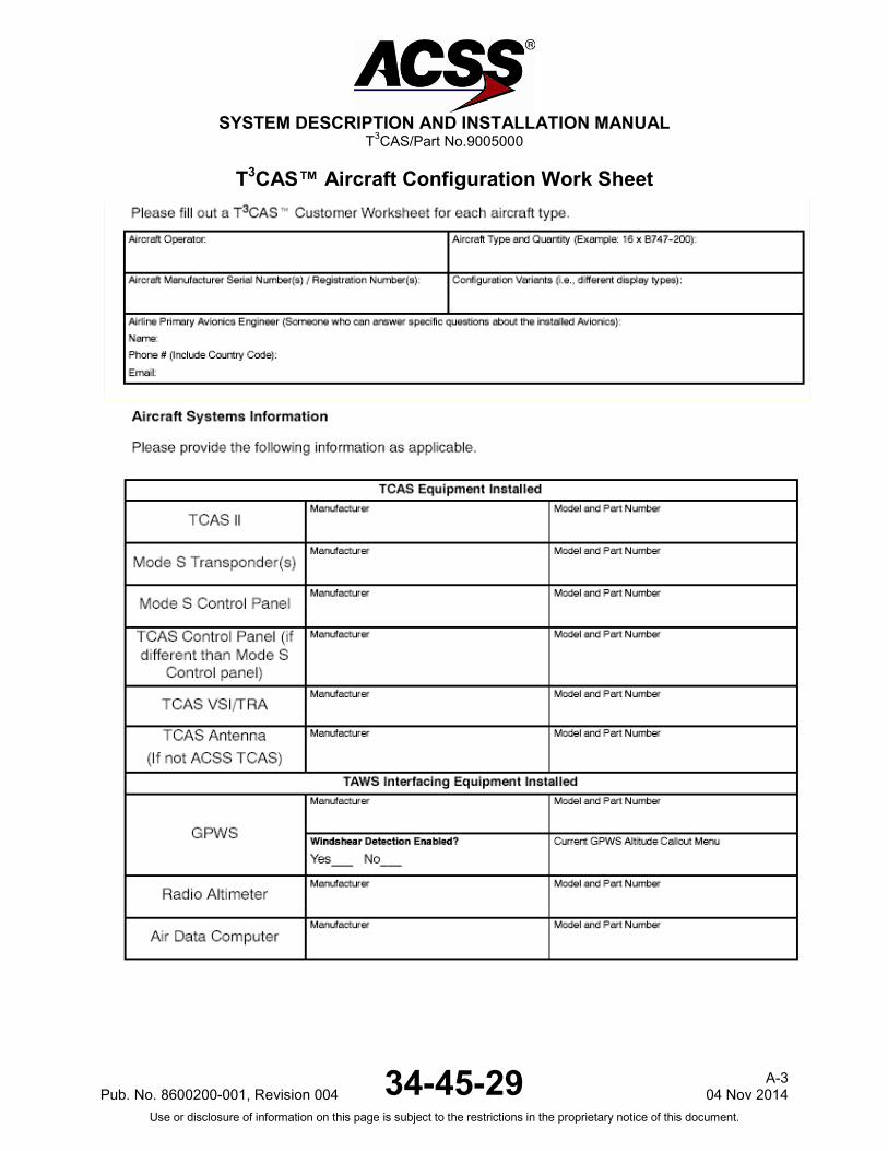
SYSTEM DESCRIPTION AND INSTALLATION MANUAL
T3CAS/Part No.9005000
T3CAS™ Aircraft Configuration Work Sheet
Pub. No. 8600200-001, Revision 004 34-45-29 A-3
04 Nov 2014 Use or disclosure of information on this page is subject to the restrictions in the proprietary notice of this document.
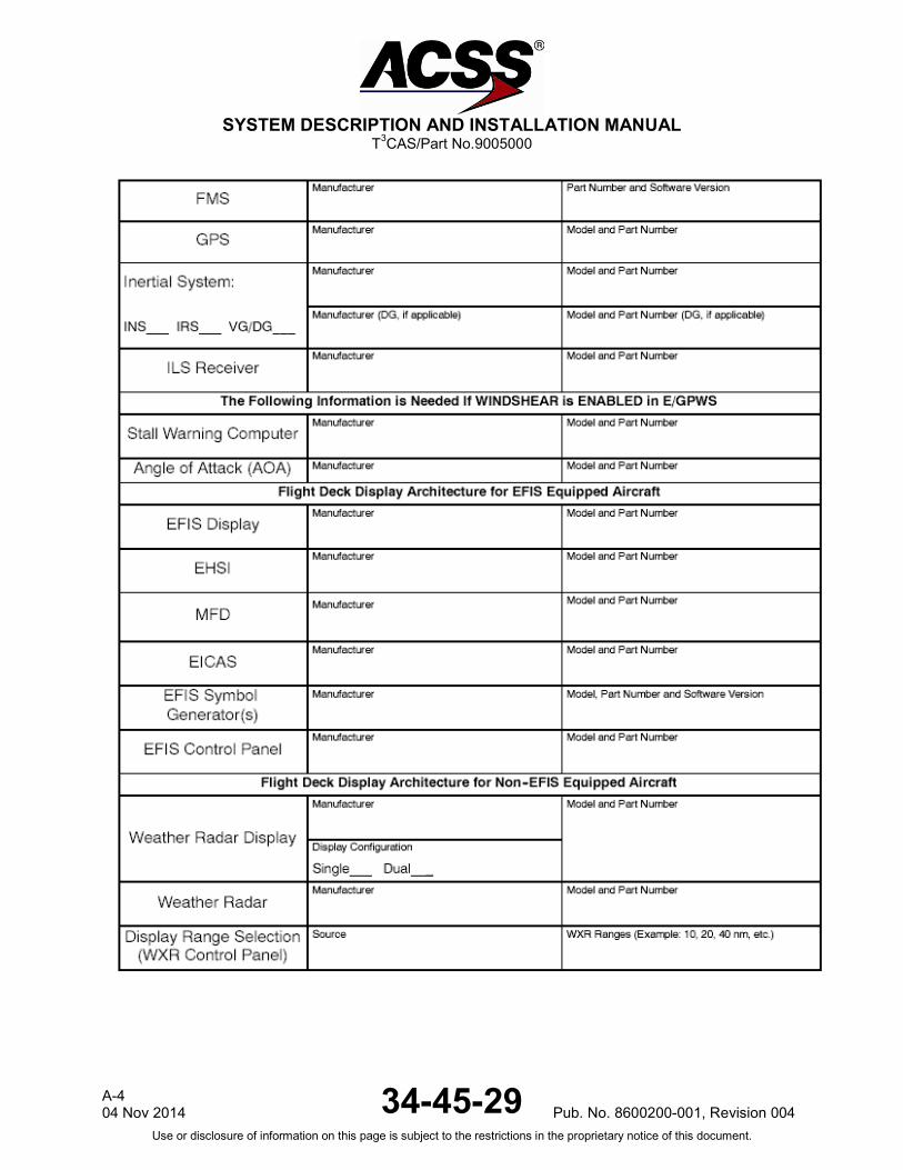
SYSTEM DESCRIPTION AND INSTALLATION MANUAL
T3CAS/Part No.9005000
A-4 04 Nov 2014 34-45-29 Pub. No. 8600200-001, Revision 004
Use or disclosure of information on this page is subject to the restrictions in the proprietary notice of this document.

SYSTEM DESCRIPTION AND INSTALLATION MANUAL
T3CAS/Part No.9005000
Pub. No. 8600200-001, Revision 004 34-45-29 A-5
04 Nov 2014 Use or disclosure of information on this page is subject to the restrictions in the proprietary notice of this document.

SYSTEM DESCRIPTION AND INSTALLATION MANUAL
T3CAS/Part No.9005000
Blank Page
A-6 04 Nov 2014 34-45-29 Pub. No. 8600200-001, Revision 004
Use or disclosure of information on this page is subject to the restrictions in the proprietary notice of this document.