
System Board D2529 for TX300 S4 - Fujitsu …manuals.ts.fujitsu.com/file/3401/d2529-thb-en.pdfSystem...
43
System Board D2529 for TX300 S4 Technical Manual Edition November 2007
Transcript of System Board D2529 for TX300 S4 - Fujitsu …manuals.ts.fujitsu.com/file/3401/d2529-thb-en.pdfSystem...
System Board D2529for TX300 S4 Technical Manual
Edition November 2007
Comments… Suggestions… Corrections…The User Documentation Department would like toknow your opinion of this manual. Your feedback helpsus optimize our documentation to suit your individual needs.
Feel free to send us your comments by e-mail to [email protected].
Certified documentation according to DIN EN ISO 9001:2000To ensure a consistently high quality standard anduser-friendliness, this documentation was created tomeet the regulations of a quality management system which complies with the requirements of the standardDIN EN ISO 9001:2000.
cognitas. Gesellschaft für Technik-Dokumentation mbHwww.cognitas.de
Copyright and TrademarksCopyright © 2007 Fujitsu Siemens Computers GmbH.
All rights reserved.Delivery subject to availability; right of technical modifications reserved.
All hardware and software names used are trademarks of their respective manufacturers.
D2529 (TX300 S4) Technical Manual
Contents
1 Introduction . . . . . . . . . . . . . . . . . . . . . . . . . . . . 5
2 Important notes . . . . . . . . . . . . . . . . . . . . . . . . . . 7
2.1 Notes on safety . . . . . . . . . . . . . . . . . . . . . . . . . . 7
2.2 CE Certificate . . . . . . . . . . . . . . . . . . . . . . . . . . 10
2.3 Environmental Protection . . . . . . . . . . . . . . . . . . . 11
3 Features . . . . . . . . . . . . . . . . . . . . . . . . . . . . . 13
3.1 Overview . . . . . . . . . . . . . . . . . . . . . . . . . . . . 13
3.2 Main memory . . . . . . . . . . . . . . . . . . . . . . . . . . 17
3.3 PCI(e) slots . . . . . . . . . . . . . . . . . . . . . . . . . . . 20
3.4 Screen resolution . . . . . . . . . . . . . . . . . . . . . . . 23
3.5 Temperature / system monitoring . . . . . . . . . . . . . . . 23
3.6 LEDs . . . . . . . . . . . . . . . . . . . . . . . . . . . . . . . 25
3.7 Interfaces and connectors . . . . . . . . . . . . . . . . . . . 283.7.1 External ports . . . . . . . . . . . . . . . . . . . . . . . . . . 30
3.8 Settings with DIP switches . . . . . . . . . . . . . . . . . . 32
4 Replacing the lithium battery . . . . . . . . . . . . . . . . . 35
Abbreviations . . . . . . . . . . . . . . . . . . . . . . . . . . . . . . . 37

D2529 (TX300 S4) Technical Manual 5
1 IntroductionThis technical manual describes the system board D2529, which can be equipped with one or two Intel® processors.
You will find further information in the BIOS description.
Further information about drivers is provided in the readme files on the hard disk, on the supplied “ServerStart“ or “Update“ CDs.
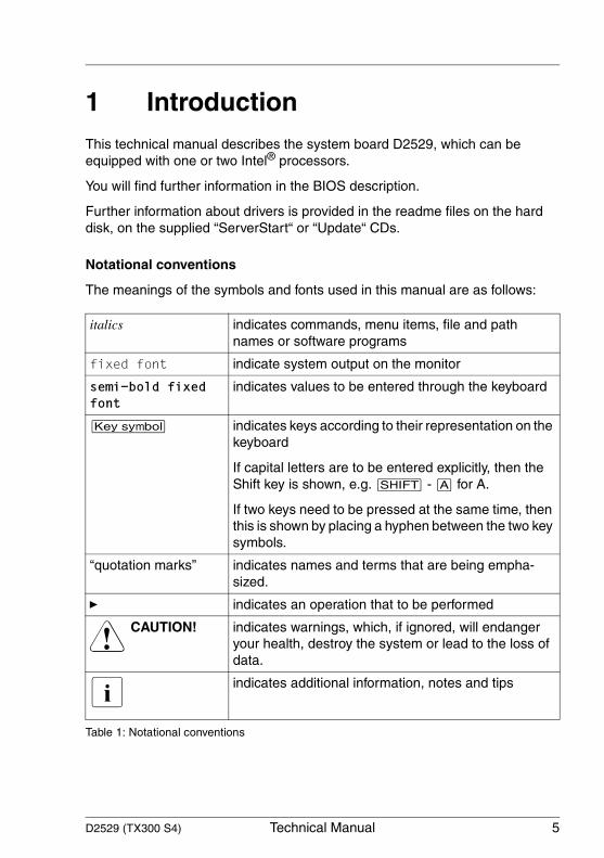
Notational conventions
The meanings of the symbols and fonts used in this manual are as follows:
italics indicates commands, menu items, file and path names or software programs
fixed font indicate system output on the monitor
semi-bold fixed font
indicates values to be entered through the keyboard
[Key symbol] indicates keys according to their representation on the keyboard
If capital letters are to be entered explicitly, then the Shift key is shown, e.g. [SHIFT] - [A] for A.
If two keys need to be pressed at the same time, then this is shown by placing a hyphen between the two key symbols.
“quotation marks” indicates names and terms that are being empha-sized.
Ê indicates an operation that to be performed
V CAUTION! indicates warnings, which, if ignored, will endanger your health, destroy the system or lead to the loss of data.
I indicates additional information, notes and tips
Table 1: Notational conventions

D2529 (TX300 S4) Technical Manual 7
2 Important notesIn this chapter you will find essential information regarding safety when working with your server.
V CAUTION!
With the system board installed you must open the system to access the system board. How to access the system board of your system is described in the appropriate service supplement.
When handling the system board, refer to the specific notes on safety in the operating manual and/or service supplement for the respective server.
2.1 Notes on safety
V CAUTION!
● The actions described in these instructions should only be performed by authorized, qualified personnel. Equipment repairs should only be performed by qualified staff. Any failure to observe the guidelines in this manual, and any unauthorized openings and improper repairs could expose the user to risks (electric shock, fire hazards) and could also damage the equipment. Please note that any unauthorized openings of the device will result in the invalidation of the warranty and exclusion from all liability.
● Transport the device only in the antistatic original packaging or in packaging that protects it from knocks and jolts.
● Only install expansions that are allowed for the system board. If you install other expansions, you may damage the requirements and rules governing safety and electromagnetic compatibility or your system. Information on which system expansions are suitable can be obtained from the customer service centre or your sales outlet.
● The warranty expires if the device is damaged during the installation or replacement of system expansions.
8 Technical Manual D2529 (TX300 S4)
Notes on safety Important notes
V ● Components can become very hot during operation. Ensure you do not touch components when making extensions to the system board. There is a danger of burns!.
● Transmission lines to peripheral devices must be adequately shielded.
● To the LAN wiring the requirements apply in accordance with the standards EN 50173 and EN 50174-1/2. As minimum requirement the use of a protected LAN line of category 5 for 10/100 MBps Ethernet, and/or of category 5e for Gigabit Ethernet is considered. The requirements of the specification ISO/IEC 11801 are to be considered.
● Never connect or disconnect data transmission lines during a storm (lightning hazard).
Batteries
V CAUTION!
● Incorrect replacement of lithium battery may lead to a risk of explosion. The batteries may only be replaced with identical batteries or with a type recommended by the manufacturer.
It is essential to observe the instructions in chapter “Replacing the lithium battery”.
D2529 (TX300 S4) Technical Manual 9
Important notes Notes on safety
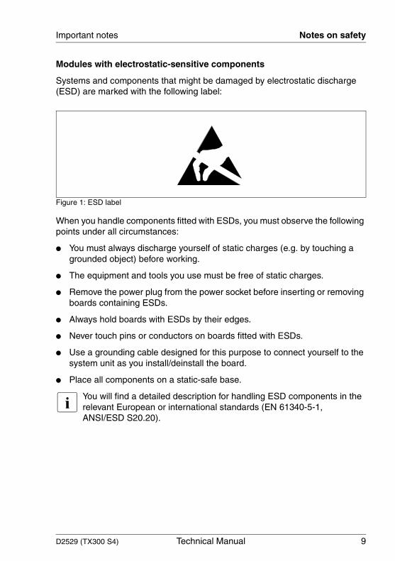
Modules with electrostatic-sensitive components
Systems and components that might be damaged by electrostatic discharge (ESD) are marked with the following label:
Figure 1: ESD label
When you handle components fitted with ESDs, you must observe the following points under all circumstances:
● You must always discharge yourself of static charges (e.g. by touching a grounded object) before working.
● The equipment and tools you use must be free of static charges.
● Remove the power plug from the power socket before inserting or removing boards containing ESDs.
● Always hold boards with ESDs by their edges.
● Never touch pins or conductors on boards fitted with ESDs.
● Use a grounding cable designed for this purpose to connect yourself to the system unit as you install/deinstall the board.
● Place all components on a static-safe base.
I You will find a detailed description for handling ESD components in the relevant European or international standards (EN 61340-5-1, ANSI/ESD S20.20).
10 Technical Manual D2529 (TX300 S4)
CE Certificate Important notes
Notes about boards
● During installation/deinstallation of the system board, observe the specific instructions described in the service manual for the server.
● Remove the plug from the mains outlet so that system and system board are totally disconnected from the mains voltage.
● To prevent damage to the system board, the components and conductors on it, please take great care when you insert or remove boards. Take great care to ensure that extension boards are slotted in straight, without damaging components or conductors on the system board, or any other components, for example EMI spring contacts.
● Be careful with the locking mechanisms (catches, centring pins etc.) when you replace the system board or components on it, for example memory modules or processors.
● Never use sharp objects (screwdrivers) for leverage.
2.2 CE Certificate
The shipped version of this board complies with the requirements of the EEC directive 89/336/EEC "Electromagnetic compatibility".
Compliance was tested in a typical PRIMERGY configuration.

D2529 (TX300 S4) Technical Manual 11
Important notes Environmental Protection
2.3 Environmental Protection
Environmentally friendly product design and development
This product has been designed in accordance with standards for ”environmen-tally friendly product design and development“. This means that the designers have taken into account important criteria such as durability, selection of materials and coding, emissions, packaging, the ease with which the product can be dismantled and the extent to which it can be recycled.
This saves resources and thus reduces the harm done to the environment.
Notes on saving energy
Devices that do not have to be on permanently should not be switched on until they need to be used and should be switched off during long breaks and on completion of work.
Notes on packaging
Please do not throw away the packaging. We recommend that you do not throw away the original packaging in case you need it later for transporting.
Notes on dealing with consumables
Please dispose batteries in accordance with local government regulations.
Do not throw batteries and accumulators into the household waste. They must be disposed of in accordance with local regulations concerning special waste.
All batteries containing pollutants are marked with a symbol (a crossed-out rubbish bin on wheels). In addition, the marking is provided with the chemical symbol of the heavy metal decisive for the classification as a pollutant:
Cd Cadmium Hg Mercury Pb Lead
Notes on labeling plastic housing parts
Please avoid attaching your own labels to plastic housing parts wherever possible, since this makes it difficult to recycle them.
12 Technical Manual D2529 (TX300 S4)
Environmental Protection Important notes
Returning, recycling and disposal
For details on returning and reuse of devices and consumables within Europe, refer to the “Returning used devices” manual, or contact your Fujitsu Siemens Computers branch office/subsidiary or our recycling centre in Paderborn:
Fujitsu Siemens ComputersRecycling CenterD-33106 Paderborn
Tel. +49 5251 8 18010
Fax +49 5251 8 18015
The device may not be disposed of with household rubbish. This appliance is labelled in accordance with European Directive 2002/96/EC concerning used electrical and electronic appliances (waste electrical and electronic equipment - WEEE).The guideline determines the framework for the return and recycling of used appliances as applicable throughout the EU. To return your used device, please use the return and collection systems available to you. You will find further information on this at www.fujitsu-siemens.com/recycling.
D2529 (TX300 S4) Technical Manual 13
3 Features
3.1 Overview
Processors
– 1 or 2 dual or quad core Intel® Xeon™ processors – 2 processor sockets LGA771 for dual core Intel® Xeon™ processors– 1x6, 2x6, 2x4 or 4 MB Second-Level-Cache (on-die unified, 64 byte cache-
line size)– 32 KB L1 Cache (on-die, data per core)– 32 KB L1 Cache (on-die, instruction per core)– 2 x 266 MHz or 333 MHz data bus (equals FSB 1066 or 1333: quadruple
data rate (or quad pumping) delivers 4 bits of data per clock cycle) – 2 VRM 11.0 onboard (EVRD)
Main memory
– 2 sots for memory riser cards with 8 PCI slots each– FBD PC2-4200F or FDB PC2-5300F Fully Buffered DIMM memory modules
with 512 MB, 1 Gbyte, 2 Gbyte and 4 Gbyte– Maximum 64 Gbyte– Minimum 1 Gbyte– Maximum 4x8 Gbyte/s bandwidth– Supports 4 FBD memory channels– ECC multiple bit error detection and single bit error correction– Memory scrubbing function– Single Device Data Correction (SDDC) function (Chipkill™)– Mirroring– Sparing
Chips on the system board
– Intel® Blackford chip set (Intel 5000P chipset)– Single-channel Gigabit LAN controller (Broadcom 5708C)– Super I/O controller (SMSC 47M107) – Flash EPROM for:
– local BIOS; flashable via bootable USB device, LAN or optional floppy disk
– SMSC8700 Fast Ethernet RMII Phy– iRMC S2 with integrated VGA graphic controller
14 Technical Manual D2529 (TX300 S4)
Overview Features
– ADM7462 thermal system management controller
Internal connectors
– 1 floppy disk connector (26 pin)– 1 USB connector– 3 Serial ATA– Power connector 24 pin (12V, -12V, 5V, 3.3V and 5V auxiliary)– Dual 12V power connector– Single 12V power connector– PC98 connector– Front panel– dual USB type C (for USB 2.0 port on front side)– 2 USB for streamer– 4 fan direct connectors– 1 connector for 2 CPU fans– Intrusion connector– 2 slots for memory riser cards– 1 SMB connector– 1 HD LED activity connector
External connectors
– 2 serial ports (COM1, COM2) – 1 parallel port (optional)– 2 PS/2 interfaces for keyboard and mouse– 2 UHCI USB 2.0 ports with 480 Mbits/s (rear side) combined with– 1 RJ45 LAN connector (dedicated service LAN)– 1 VGA port– 1 dual RJ45 LAN connector
PCI slots
– 1 PCI-X 1.0b (64 Bit / 133 MHz)– 2 PCI-Express 1.0a (2 Gbyte/s bandwidth)– 4 PCI-Express 1.0a, alternatively configurable as 4x2 Gbyte/s or
2x4 Gbyte/s bandwidth
D2529 (TX300 S4) Technical Manual 15
Features Overview
BIOS features
– Phoenix System-BIOS V 4.06– SMBIOS 2.4 (DMI)– MultiProcessor Specification 1.4– Server Hardware Design Guide– WfM – ACPI support– USB keyboard/mouse– boot possible from:
– floppy disk drive (USB, Standard)– hard disk (SATA, SAS)– CD/DVD (SATA)– LAN (PXE, iSCSI)
– console redirection support– OEM logo– CPU, memory disable– spare memory support
Environmental protection
3V-Battery in holder for recycling
Form factor
– 290 x 460 mm
– ACPI 2.0, OnNow, PCI-X 1.0b, PCI-Express 1.0a, LPC 1.1, WfM 2.0,SHDG 3.0, MPS 1.4, IPMI 2.0 and PCI Express CardElectromechanical Specification Rev. 1.0, USB2.0, SATAII 1.0
CSS (Customer Self Service)
This system board supports the CSS functionality. You will find a description of CSS functionality in the operating manual of your server.
TPM (option)
The system board is optional equipped with a TPM (Trusted Platform Module) by the manufacturer. This module enables programs from third party manufac-turers to store key information (e.g. drive encryption using Windows Bitlocker Drive Encryption).
16 Technical Manual D2529 (TX300 S4)
Overview Features
The TPM is activated via the BIOS system (for more information, refer to the Fujitsu Siemens Computers BIOS manual).
V CAUTION!
– When using the TPM, note the program descriptions provided by the third party manufacturers.
– You must also create a backup of the TPM content. To do this, follow the third party manufacturer's instructions. Without this backup, if the TPM or the system board is faulty you will not be able to access your data.
– If a failure occurs, please inform your service about the TPM activation before it takes any action, and be prepared to provide them with your backup copies of the TPM content.
D2529 (TX300 S4) Technical Manual 17
Features Main memory
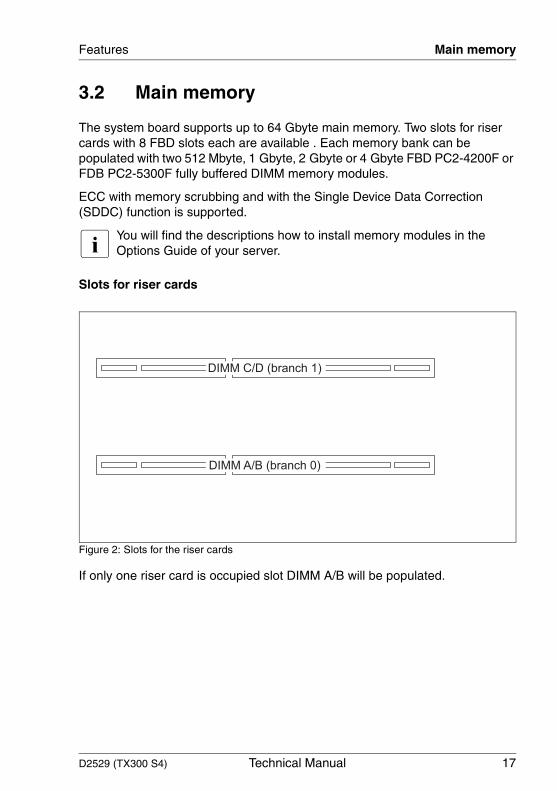
3.2 Main memory
The system board supports up to 64 Gbyte main memory. Two slots for riser cards with 8 FBD slots each are available . Each memory bank can be populated with two 512 Mbyte, 1 Gbyte, 2 Gbyte or 4 Gbyte FBD PC2-4200F or FDB PC2-5300F fully buffered DIMM memory modules.
ECC with memory scrubbing and with the Single Device Data Correction (SDDC) function is supported.
I You will find the descriptions how to install memory modules in the Options Guide of your server.
Slots for riser cards
Figure 2: Slots for the riser cards
If only one riser card is occupied slot DIMM A/B will be populated.
DIMM C/D (branch 1)
DIMM A/B (branch 0)
18 Technical Manual D2529 (TX300 S4)
Main memory Features
Module population
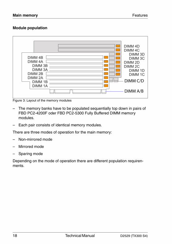
Figure 3: Layout of the memory modules
– The memory banks have to be populated sequentially top down in pairs of FBD PC2-4200F oder FBD PC2-5300 Fully Buffered DIMM memory modules.
– Each pair consists of identical memory modules.
There are three modes of operation for the main memory:
– Non-mirrored mode
– Mirrored mode
– Sparing mode
Depending on the mode of operation there are different population requiren-ments.
DIMM 2D
DIMM 2C
DIMM 1D
DIMM 1C
DIMM 4D
DIMM 4C
DIMM 3C
DIMM 3D
DIMM 2B
DIMM 2A
DIMM 4B
DIMM 4A
DIMM 3A
DIMM 3B
DIMM 1B
DIMM 1A
DIMM C/D
DIMM A/B
D2529 (TX300 S4) Technical Manual 19
Features Main memory
Non-mirrored mode
Using one riser card the module population is as follows:
1A + 1B (minimum configuration) - 2A + 2B - 3A + 3B - 4A + 4B
Using two riser cards the population can be alternating (higher performance) or consecutive.
Mirrored mode
The mirrored mode requires memory modules in matched sets of four, two in each riser card.
1A + 1B, 1C + 1D (minimum configuration)
2A + 2B, 2C + 2D (upgrade 1); 3A + 3B, 3C + 3D (upgrade 2); 4A + 4B, 4C + 4D (upgrade 3)
Riser card A/B Riser card C/D
Alternating population
1A + 1B(minimum configuration)
- -
Upgrade 1 - - 1C + 1D
Upgrade 2 2A + 2B - -
Upgrade 3 - - 2C +2D
Upgrade 4 3A + 3B - -
Upgrade 5 - - 3C + 3D
Upgrade 6 4A + 4B
Upgrade 7 4C + 4D
Consecutive population 1A + 1B(minimum configuration)
- -
Upgrade 2 - 4 2A + 2B3A + 3B4A + 4B
- -
Upgrade 5 - 8 - - 1C + 1D2C + 2D3C + 3D4C + 4D
Table 2: Alternating and consecutive population for 2 riser cards
20 Technical Manual D2529 (TX300 S4)
PCI(e) slots Features
Sparing mode
Only one riser card is required for the sparing mode. The last populated bank will be in hotspare mode.
1A + 1B, 2A +2B minimum configuration, bank 2 in hotspare mode
1A + 1B, 2A +2B, 3A +3Bupgrade 1, bank 3 in hotspare mode
1A + 1B, 2A +2B, 3A +3B, 4A + 4Bupgrade 2, bank 4 in hotspare mode
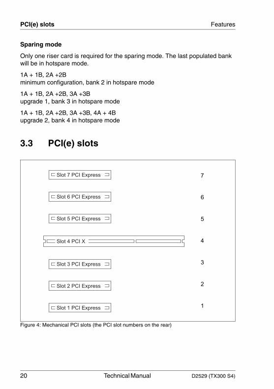
3.3 PCI(e) slots
Figure 4: Mechanical PCI slots (the PCI slot numbers on the rear)
Slot 1 PCI Express
Slot 2 PCI Express
Slot 3 PCI Express
Slot 5 PCI Express
Slot 6 PCI Express
Slot 7 PCI Express
Slot 4 PCI X 4
5
6
7
3
2
1
D2529 (TX300 S4) Technical Manual 21
Features PCI(e) slots
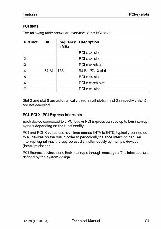
PCI slots
The following table shows an overview of the PCI slots:
Slot 3 and slot 6 are automatically used as x8 slots, if slot 2 respectivly slot 5 are not occupied.
PCI, PCI-X, PCI Express interrupts
Each device connected to a PCI bus or PCI Express can use up to four interrupt signals depending on the functionality.
PCI and PCI-X buses use four lines named INTA to INTD, typically connected to all devices on the bus in order to periodically balance interrupt load. An interrupt signal may thereby be used simultaneously by multiple devices (interrupt sharing).
PCI Express devices send their interrupts through messages. The interrupts are defined by the system design.
PCI slot Bit Frequency in MHz
Description
1 PCI e x4 slot
2 PCI e x4 slot
3 PCI e x4/x8 slot
4 64 Bit 133 64-Bit PCI-X slot
5 PCI e x4 slot
6 PCI e x4/x8 slot
7 PCI e x4 slot
22 Technical Manual D2529 (TX300 S4)
PCI(e) slots Features
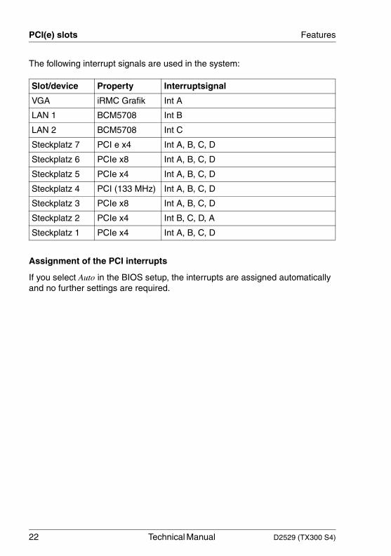
The following interrupt signals are used in the system:
Assignment of the PCI interrupts
If you select Auto in the BIOS setup, the interrupts are assigned automatically and no further settings are required.
Slot/device Property Interruptsignal
VGA iRMC Grafik Int A
LAN 1 BCM5708 Int B
LAN 2 BCM5708 Int C
Steckplatz 7 PCI e x4 Int A, B, C, D
Steckplatz 6 PCIe x8 Int A, B, C, D
Steckplatz 5 PCIe x4 Int A, B, C, D
Steckplatz 4 PCI (133 MHz) Int A, B, C, D
Steckplatz 3 PCIe x8 Int A, B, C, D
Steckplatz 2 PCIe x4 Int B, C, D, A
Steckplatz 1 PCIe x4 Int A, B, C, D
D2529 (TX300 S4) Technical Manual 23
Features Screen resolution
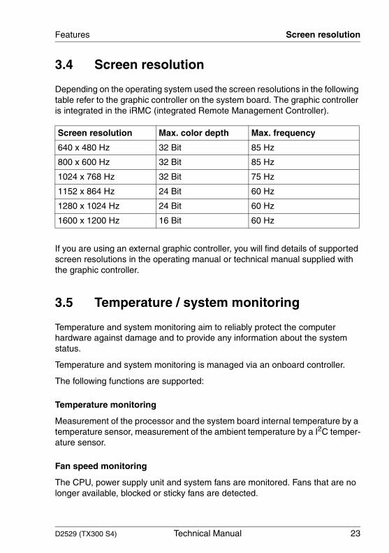
3.4 Screen resolution
Depending on the operating system used the screen resolutions in the following table refer to the graphic controller on the system board. The graphic controller is integrated in the iRMC (integrated Remote Management Controller).
If you are using an external graphic controller, you will find details of supported screen resolutions in the operating manual or technical manual supplied with the graphic controller.
3.5 Temperature / system monitoring
Temperature and system monitoring aim to reliably protect the computer hardware against damage and to provide any information about the system status.
Temperature and system monitoring is managed via an onboard controller.
The following functions are supported:
Temperature monitoring
Measurement of the processor and the system board internal temperature by a temperature sensor, measurement of the ambient temperature by a I2C temper-ature sensor.
Fan speed monitoring
The CPU, power supply unit and system fans are monitored. Fans that are no longer available, blocked or sticky fans are detected.
Screen resolution Max. color depth Max. frequency
640 x 480 Hz 32 Bit 85 Hz
800 x 600 Hz 32 Bit 85 Hz
1024 x 768 Hz 32 Bit 75 Hz
1152 x 864 Hz 24 Bit 60 Hz
1280 x 1024 Hz 24 Bit 60 Hz
1600 x 1200 Hz 16 Bit 60 Hz

24 Technical Manual D2529 (TX300 S4)
Temperature / system monitoring Features
Fan speed control
The fan speed is controlled according to temperature.The criteria are the ambient temperature, the CPU temperature, and the memory temperature.
Sensor monitoring
If the I2C temperature sensor is defect or missing, all fans monitored by this sensor, run with maximum speed to achieve the greatest possible protection of the hardware.
Voltage monitoring (of the internal voltages)
If one of the internal voltages reaches its upper or lower threshold an alarm is generated.
Cover monitoring
Unauthorized opening of the cover is detected, even when the system is switched off (power down mode). However, this will only be indicated when the system is switched on again.
System Event Log (SEL)
All monitored events of the system board are signalized via the Global Error LED and recorded in the System Event Log. They could be retrieved in the BIOS Setup or via ServerView.
PRIMERGY Diagnostic LEDs
LEDs on the system board enable to identify defective modules and compo-nents as well as gaining information on the PDA.
D2529 (TX300 S4) Technical Manual 25
Features LEDs
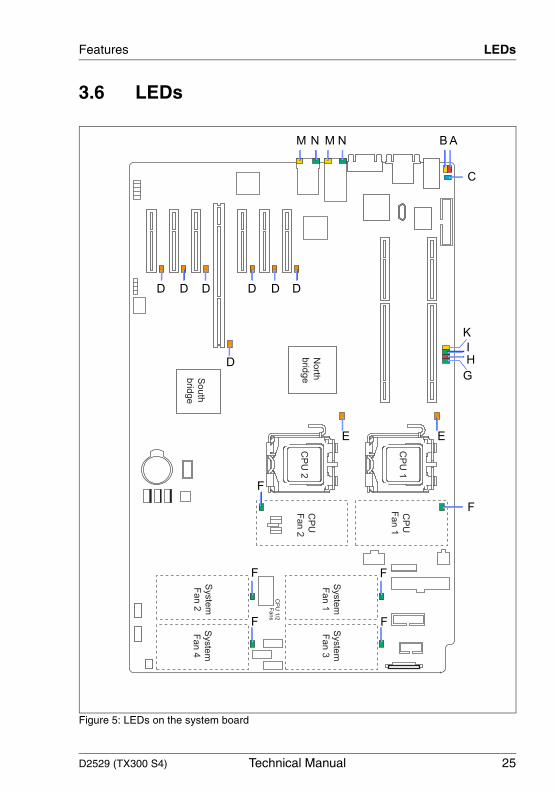
3.6 LEDs
Figure 5: LEDs on the system board
North
brid
geS
ou
th
brid
ge
Syste
m
Fa
n 2
Syste
m
Fa
n 1
Syste
m
Fa
n 3
Syste
m
Fa
n 4
CP
U 1
/2
Fans
CP
U 1
CP
U 2
-
CP
U
Fa
n 2
CP
U
Fa
n 1
ABNMNM
C
K
G
D D D D D D
D
I
H
E E
F
F
F
F F
F
26 Technical Manual D2529 (TX300 S4)
LEDs Features
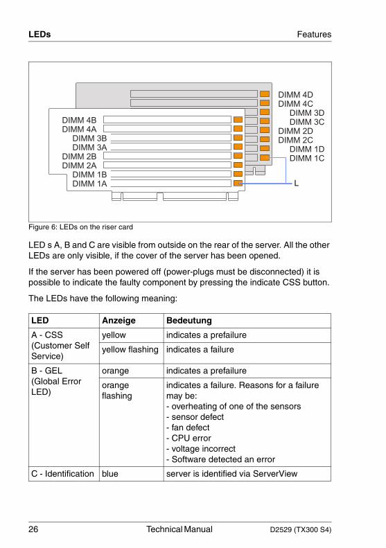
Figure 6: LEDs on the riser card
LED s A, B and C are visible from outside on the rear of the server. All the other LEDs are only visible, if the cover of the server has been opened.
If the server has been powered off (power-plugs must be disconnected) it is possible to indicate the faulty component by pressing the indicate CSS button.
The LEDs have the following meaning:
LED Anzeige Bedeutung
A - CSS(Customer Self Service)
yellow indicates a prefailure
yellow flashing indicates a failure
B - GEL(Global Error LED)
orange indicates a prefailure
orange flashing
indicates a failure. Reasons for a failure may be:- overheating of one of the sensors- sensor defect- fan defect- CPU error- voltage incorrect- Software detected an error
C - Identification blue server is identified via ServerView
DIMM 2D
DIMM 2C
DIMM 1D
DIMM 1C
DIMM 4D
DIMM 4C
DIMM 3C
DIMM 3D
DIMM 2B
DIMM 2A
DIMM 4B
DIMM 4A
DIMM 3A
DIMM 3B
DIMM 1B
DIMM 1A L
D2529 (TX300 S4) Technical Manual 27
Features LEDs
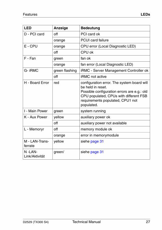
D - PCI card off PCI card ok
orange PCUI card failure
E - CPU orange CPU error (Local Diagnostic LED)
off CPU ok
F - Fan green fan ok
orange fan error (Local Diagnostic LED)
G- iRMC green flashing iRMC - Server Management Controller ok
off iRMC not active
H - Board Error red configuration error. The system board will be held in reset. Possible configuration errors are e.g.: old CPU populated, CPUs with different FSB requirements populated, CPU1 not populated.
I - Main Power green system running
K - Aux Power yellow auxiliary power ok
off auxiliary power not available
L - Memoryr off memory module ok
orange error in memorymodule
M - LAN-Trans-ferrate
yellow siehe page 31
N -LAN-Link/Aktivität
green/ siehe page 31
LED Anzeige Bedeutung
28 Technical Manual D2529 (TX300 S4)
Interfaces and connectors Features
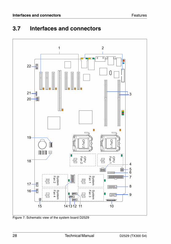
3.7 Interfaces and connectors
Figure 7: Schematic view of the system board D2529
Syste
m
Fan 1
Syste
m
Fan 3
Syste
m
Fan 2
Syste
m
Fan 4
CP
U 1
CP
U 2
CP
U
Fan 2
CP
U
Fan 1
1 2
3
4
56
7
8
9
101112131415
16
17
18
19
20
21
22
D2529 (TX300 S4) Technical Manual 29
Features Interfaces and connectors
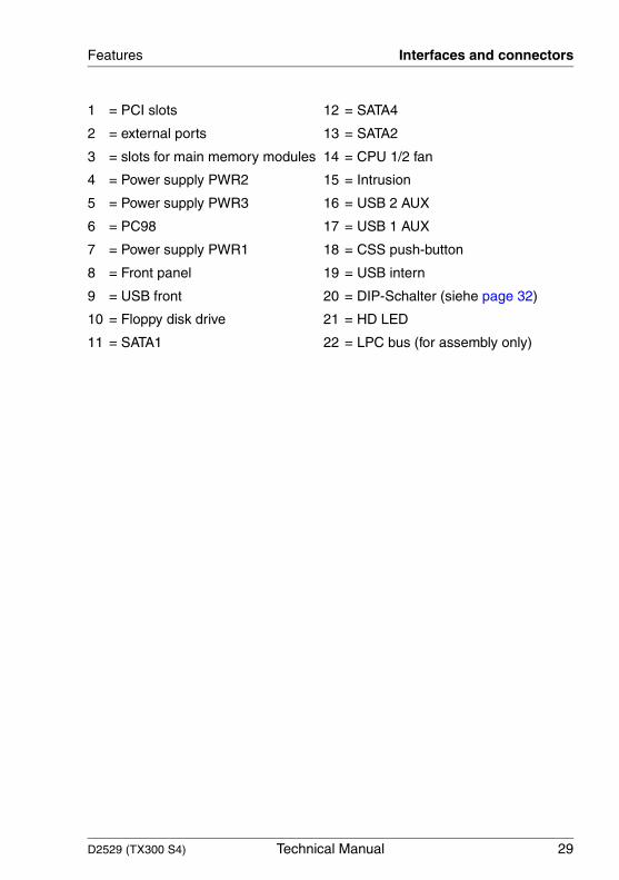
1 = PCI slots 12 = SATA4
2 = external ports 13 = SATA2
3 = slots for main memory modules 14 = CPU 1/2 fan
4 = Power supply PWR2 15 = Intrusion
5 = Power supply PWR3 16 = USB 2 AUX
6 = PC98 17 = USB 1 AUX
7 = Power supply PWR1 18 = CSS push-button
8 = Front panel 19 = USB intern
9 = USB front 20 = DIP-Schalter (siehe page 32)
10 = Floppy disk drive 21 = HD LED
11 = SATA1 22 = LPC bus (for assembly only)

30 Technical Manual D2529 (TX300 S4)
Interfaces and connectors Features
3.7.1 External ports
Figure 8: External ports of the system board D2529
The serial interface COM1 can be used as default interface or to communicate with the iRMC.
1 = Printer port (optional) 7 = USB port 4
2 = PS/2 mouse connector 8 = VGA port
3 = LAN connector (service LAN) 9 = Serial interface COM1
4 = LAN connector 2 10 = Serial interface COM2
5 = LAN connector 1 11 = PS/2 keyboard connector
6 = USB port 3 12 = CSS LED (yellow)/Global Error LED (orange)/Identifications LED (blue)
6 58 710 91112
3 4
1
2
D2529 (TX300 S4) Technical Manual 31
Features Interfaces and connectors
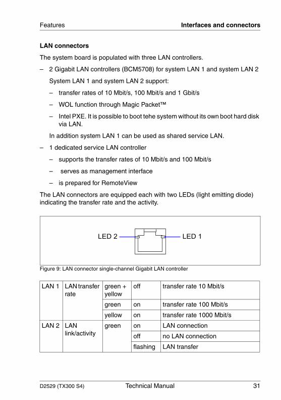
LAN connectors
The system board is populated with three LAN controllers.
– 2 Gigabit LAN controllers (BCM5708) for system LAN 1 and system LAN 2
System LAN 1 and system LAN 2 support:
– transfer rates of 10 Mbit/s, 100 Mbit/s and 1 Gbit/s
– WOL function through Magic Packet™
– Intel PXE. It is possible to boot tehe system without its own boot hard disk via LAN.
In addition system LAN 1 can be used as shared service LAN.
– 1 dedicated service LAN controller
– supports the transfer rates of 10 Mbit/s and 100 Mbit/s
– serves as management interface
– is prepared for RemoteView
The LAN connectors are equipped each with two LEDs (light emitting diode) indicating the transfer rate and the activity.
Figure 9: LAN connector single-channel Gigabit LAN controller
LAN 1 LAN transfer rate
green + yellow
off transfer rate 10 Mbit/s
green on transfer rate 100 Mbit/s
yellow on transfer rate 1000 Mbit/s
LAN 2 LAN link/activity
green on LAN connection
off no LAN connection
flashing LAN transfer
LED 2 LED 1
32 Technical Manual D2529 (TX300 S4)
Settings with DIP switches Features
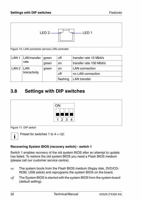
Figure 10: LAN connector service LAN controller
3.8 Settings with DIP switches
Figure 11: DIP switch
I Preset for switches 1 to 4 = Off.
Recovering System BIOS (recovery switch) - switch 1
Switch 1 enables recovery of the old system BIOS after an attempt to update has failed. To restore the old system BIOS you need a Flash BIOS medium (please call our customer service centre).
LAN 1 LAN transfer rate
green off transfer rate 10 Mbit/s
green on transfer rate 100 Mbit/s
LAN 2 LAN link/activity
green on LAN connection
off no LAN connection
flashing LAN transfer
on The system boots from the Flash BIOS medium (floppy disk, DVD/CD-ROM, USB sstick) and reprograms the system BIOS on the board.
off The System BIOS is started with the system BIOS from the system board (default setting).
LED 2 LED 1
D2529 (TX300 S4) Technical Manual 33
Features Settings with DIP switches
Skipping the password query - switch 2
Switch 2 is used to define whether the password is queried at system startup, if the password protection is enabled in BIOS Setup (in Security menu, the Password field must be set to Enabled).
Write protection for Flash BIOS - switch 3
Switch 3 is used to define whether the System BIOS is write protected or not.
Write protection for floppy disks - switch 4
Switch 4 is used to define whether floppy disks can be written or deleted in the floppy disk drive. To write and delete floppy disks, the write-protection in BIOS Setup must be disabled (in menu Security, the field Diskette Write must be set to Enabled).
on The password query is skipped. Passwords are deleted.
off The password query is effective (default setting).
on The System BIOS can neither be written to nor deleted. Flash-BIOS update from floppy disk is not possible.
off The System BIOS can be written or deleted. Flash-BIOS update from floppy disk is possible (default setting)
on The floppy disk drive is write-protected.
off Floppy disks can be read, written and deleted (default setting).
34 Technical Manual D2529 (TX300 S4)
Settings with DIP switches Features
D2529 (TX300 S4) Technical Manual 35
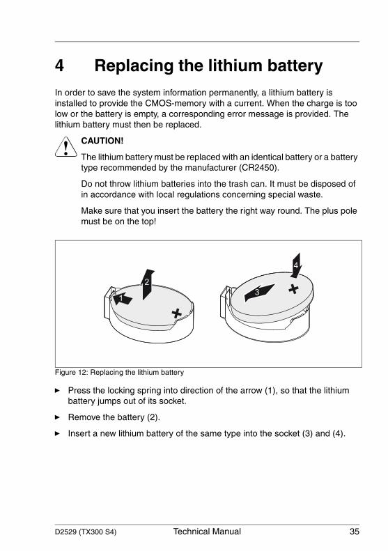
4 Replacing the lithium batteryIn order to save the system information permanently, a lithium battery is installed to provide the CMOS-memory with a current. When the charge is too low or the battery is empty, a corresponding error message is provided. The lithium battery must then be replaced.
V CAUTION!
The lithium battery must be replaced with an identical battery or a battery type recommended by the manufacturer (CR2450).
Do not throw lithium batteries into the trash can. It must be disposed of in accordance with local regulations concerning special waste.
Make sure that you insert the battery the right way round. The plus pole must be on the top!
Figure 12: Replacing the lithium battery
Ê Press the locking spring into direction of the arrow (1), so that the lithium battery jumps out of its socket.
Ê Remove the battery (2).
Ê Insert a new lithium battery of the same type into the socket (3) and (4).
1
2
3
4

D2529 (TX300 S4) Technical Manual 37
AbbreviationsThe technical terms and abbreviations given below represent only a selection of the full list of common technical terms and abbreviations.
Not all technical terms and abbreviations listed here are valid for the described system board.
ACPIAdvanced Configuration and Power Interface
ASR&RAutomatic Server Recovery and Restart
ATAAdvanced Technology Attachment
BBUBattery Backup Unit
BIOSBasic Input Output System
BMCBaseboard Management Controller
CMOSComplementary Metal Oxide Semiconductor
COMCOMmunication port
CPUCentral Processing Unit
DDRDouble Data Rate
DIMMDual In-line Memory Module
38 Technical Manual D2529 (TX300 S4)
Abbreviations
DIPDual In-line Package
DMIDesktop Management Interface
DRAMDynamic Random Access Memory
ECCError Correction Code
EEPROMElectrical Erasable Programmable Read Only Memory
EPROMErasable Programmable Read Only Memory
EMRLEmbedded RAID Logic
EVRDEnterprise VRD
FBDFully Buffered DIMM
HPCHot-plug Controller
ICEIn Circuit Emulation
IDEIntegrated (intelligent) Drive Electronics
IMEIntegrated Mirror Enhanced
IOOPIntelligent Organization Of PCI
D2529 (TX300 S4) Technical Manual 39
Abbreviations
IPMBIntelligent Platform Management Bus
IPMIIntelligent Platform Management Interface
iRMCintegrated Remote Management Controller
iSCSIinternet Small Computer System Interface
LANLocal Area Network
LEDLight Emitting Diode
LPCLow Pin Count
MPSMulti Processor Specification
MTSMegaTransfers per Second
NMINon Maskable Interrupt
OEMOriginal Equipment Manufacturer
OHCIOpen Host Controller Interface
OSOperating System
PCIPeripheral Components Interconnect
40 Technical Manual D2529 (TX300 S4)
Abbreviations
PDAPrefailure Detection and Analyzing
PIOProgrammed Input Output
PLDProgrammable Logic Device
PS(U)Power Supply (Unit)
PWMPuls Wide Modulation
PXEPreboot eXecution Environment
RAIDRedundant Array of Inexpensive Disks
RSBRemote Service Board
RSTReSeT
RTCReal Time Clock
SASSerial Attached SCSI
SATASerial ATA
SCSISmall Computer Systems Interface
SDDCSingle Device Data Correction
D2529 (TX300 S4) Technical Manual 41
Abbreviations
SDRAMSynchronous Dynamic Random Access Memory
SHDGServer Hardware Design Guide
SMBSystem Management Bus
SMMServer Management Mode
SMPSymmetrically Multi Processing
TMPTrusted Platform Module
UHCIUnified Host Controller Interface
USBUniversal Serial Bus
VGAVideo Graphics Adapter
VRDVoltage Regulator Down
VRMVoltage Regulator Module
WfMWired for Management
WOLWake up On LAN

Information on this document On April 1, 2009, Fujitsu became the sole owner of Fujitsu Siemens Compu-ters. This new subsidiary of Fujitsu has been renamed Fujitsu Technology So-lutions.
This document from the document archive refers to a product version which was released a considerable time ago or which is no longer marketed.
Please note that all company references and copyrights in this document have been legally transferred to Fujitsu Technology Solutions.
Contact and support addresses will now be offered by Fujitsu Technology So-lutions and have the format …@ts.fujitsu.com.
The Internet pages of Fujitsu Technology Solutions are available at http://ts.fujitsu.com/... and the user documentation at http://manuals.ts.fujitsu.com.
Copyright Fujitsu Technology Solutions, 2009
Hinweise zum vorliegenden Dokument Zum 1. April 2009 ist Fujitsu Siemens Computers in den alleinigen Besitz von Fujitsu übergegangen. Diese neue Tochtergesellschaft von Fujitsu trägt seit-dem den Namen Fujitsu Technology Solutions.
Das vorliegende Dokument aus dem Dokumentenarchiv bezieht sich auf eine bereits vor längerer Zeit freigegebene oder nicht mehr im Vertrieb befindliche Produktversion.
Bitte beachten Sie, dass alle Firmenbezüge und Copyrights im vorliegenden Dokument rechtlich auf Fujitsu Technology Solutions übergegangen sind.
Kontakt- und Supportadressen werden nun von Fujitsu Technology Solutions angeboten und haben die Form …@ts.fujitsu.com.
Die Internetseiten von Fujitsu Technology Solutions finden Sie unter http://de.ts.fujitsu.com/..., und unter http://manuals.ts.fujitsu.com finden Sie die Benutzerdokumentation.
Copyright Fujitsu Technology Solutions, 2009


![z] 1 /s4 y, ke · 2017. 11. 13. · z] 1 /s4 y, ke. z] 1 /s4 y, ke. z] 1 /s4 y, ke](https://static.fdocuments.us/doc/165x107/60f90cb7bf544418fc224166/-z-1-s4-y-ke-2017-11-13-z-1-s4-y-ke-z-1-s4-y-ke-z-1-s4-y-ke.jpg)


