System Board D2619 for RX/TX300 S5 - Fujitsumanuals.ts.fujitsu.com/file/8419/d2619-thb-en.pdf · 8...
36
System Board D2619 for RX/TX300 S5 Technical Manual Edition April 2009
Transcript of System Board D2619 for RX/TX300 S5 - Fujitsumanuals.ts.fujitsu.com/file/8419/d2619-thb-en.pdf · 8...

System Board D2619for RX/TX300 S5 Technical Manual
Edition April 2009

Comments… Suggestions… Corrections…The User Documentation Department would like toknow your opinion of this manual. Your feedback helpsus optimize our documentation to suit your individual needs.
Feel free to send us your comments by e-mail to [email protected].
Certified documentation according to DIN EN ISO 9001:2000To ensure a consistently high quality standard anduser-friendliness, this documentation was created tomeet the regulations of a quality management system which complies with the requirements of the standardDIN EN ISO 9001:2000.
cognitas. Gesellschaft für Technik-Dokumentation mbHwww.cognitas.de
Copyright and TrademarksCopyright © 2009 Fujitsu Technology Solutions GmbH.
All rights reserved.Delivery subject to availability; right of technical modifications reserved.
All hardware and software names used are trademarks of their respective manufacturers.

D2619 (RX/TX300 S5) Technical Manual
Contents
1 Introduction . . . . . . . . . . . . . . . . . . . . . . . . . . . . 5
2 Important notes . . . . . . . . . . . . . . . . . . . . . . . . . . 7
2.1 Notes on safety . . . . . . . . . . . . . . . . . . . . . . . . . . 7
2.2 CE Certificate . . . . . . . . . . . . . . . . . . . . . . . . . . 10
2.3 Environmental Protection . . . . . . . . . . . . . . . . . . . 11
3 Features . . . . . . . . . . . . . . . . . . . . . . . . . . . . . 13
3.1 Overview . . . . . . . . . . . . . . . . . . . . . . . . . . . . 13
3.2 Main memory . . . . . . . . . . . . . . . . . . . . . . . . . . 18
3.3 PCI bus . . . . . . . . . . . . . . . . . . . . . . . . . . . . . 24
3.4 Screen resolution . . . . . . . . . . . . . . . . . . . . . . . 25
3.5 Temperature/system monitoring . . . . . . . . . . . . . . . 25
3.6 LEDs . . . . . . . . . . . . . . . . . . . . . . . . . . . . . . . 27
3.7 Interfaces and connectors . . . . . . . . . . . . . . . . . . . 293.7.1 External ports . . . . . . . . . . . . . . . . . . . . . . . . . . 31
3.8 Settings with switches and jumpers . . . . . . . . . . . . . 33
4 Replacing the lithium battery . . . . . . . . . . . . . . . . . 35


D2619 (RX/TX300 S5) Technical Manual 5
1 IntroductionThis technical manual describes the system board D2619, which is equipped with one Intel® processor.
Further information about drivers is provided in the readme files on the hard disk, on the supplied “ServerStart“ or “Update“ CDs.
You will find further information in the BIOS description.
Notational conventions
The meanings of the symbols and fonts used in this manual are as follows:
italics indicates commands, menu items, file and path names or software programs.
fixed font indicate system output on the monitor.
semi-bold fixed font
indicates values to be entered through the keyboard.
[Key symbol] indicates keys according to their representation on the keyboard.
If capital letters are to be entered explicitly, then the Shift key is shown, e.g. [SHIFT] - [A] for A.
If two keys need to be pressed at the same time, then this is shown by placing a hyphen between the two key symbols.
“quotation marks” indicates names and terms that are being empha-sized.
Ê indicates an operation that to be performed.
V CAUTION! indicates warnings, which, if ignored, will endanger your health, destroy the system or lead to the loss of data.
I indicates additional information, notes and tips.
Table 1: Notational conventions


D2619 (RX/TX300 S5) Technical Manual 7
2 Important notesIn this chapter you will find essential information regarding safety when working with your server.
V CAUTION!
With the system board installed you must open the system to access the system board. How to access the system board of your system is described in the appropriate service supplement.
When handling the system board, refer to the specific notes on safety in the operating manual and/or service supplement for the respective server.
2.1 Notes on safety
V CAUTION!
● The actions described in these instructions should only be performed by authorized, qualified personnel. Equipment repairs should only be performed by qualified staff. Any failure to observe the guidelines in this manual, and any unauthorized openings and improper repairs could expose the user to risks (electric shock, fire hazards) and could also damage the equipment. Please note that any unauthorized openings of the device will result in the invalidation of the warranty and exclusion from all liability.
● Transport the device only in the antistatic original packaging or in packaging that protects it from knocks and jolts.
● Only install expansions that are allowed for the system board. If you install other expansions, you may damage the requirements and rules governing safety and electromagnetic compatibility or your system. Information on which system expansions are suitable can be obtained from the customer service centre or your sales outlet.
● The warranty expires if the device is damaged during the installation or replacement of system expansions.

8 Technical Manual D2619 (RX/TX300 S5)
Notes on safety Important notes
V ● Components can become very hot during operation. Ensure you do not touch components when making extensions to the system board. There is a danger of burns!
● Transmission lines to peripheral devices must be adequately shielded.
● To the LAN wiring the requirements apply in accordance with the standards EN 50173 and EN 50174-1/2. As minimum requirement the use of a protected LAN line of category 5 for 10/100 MBit/s Ethernet, and/or of category 5e for Gigabit Ethernet is considered. The requirements of the specification ISO/IEC 11801 are to be considered.
● Never connect or disconnect data transmission lines during a storm (lightning hazard).
Batteries
V CAUTION!
● Incorrect replacement of lithium battery may lead to a risk of explosion. The batteries may only be replaced with identical batteries or with a type recommended by the manufacturer.
It is essential to observe the instructions in chapter “Replacing the lithium battery”.

D2619 (RX/TX300 S5) Technical Manual 9
Important notes Notes on safety
Modules with electrostatic-sensitive components
Systems and components that might be damaged by electrostatic discharge (ESD) are marked with the following label:
Figure 1: ESD label
When you handle components fitted with ESDs, you must observe the following points under all circumstances:
● You must always discharge yourself of static charges (e.g. by touching a grounded object) before working.
● The equipment and tools you use must be free of static charges.
● Remove the power plug from the power socket before inserting or removing boards containing ESDs.
● Always hold boards with ESDs by their edges.
● Never touch pins or conductors on boards fitted with ESDs.
● Use a grounding cable designed for this purpose to connect yourself to the system unit as you install/deinstall the board.
● Place all components on a static-safe base.
I You will find a detailed description for handling ESD components in the relevant European or international standards (EN 61340-5-1, ANSI/ESD S20.20).

10 Technical Manual D2619 (RX/TX300 S5)
CE Certificate Important notes
Notes about boards
● During installation/deinstallation of the system board, observe the specific instructions described in the service manual for the server.
● Remove the plug from the mains outlet so that system and system board are totally disconnected from the mains voltage.
● To prevent damage to the system board, the components and conductors on it, please take great care when you insert or remove boards. Take great care to ensure that extension boards are slotted in straight, without damaging components or conductors on the system board, or any other components, for example EMI spring contacts.
● Be careful with the locking mechanisms (catches, centring pins etc.) when you replace the system board or components on it, for example memory modules or processors.
● Never use sharp objects (screwdrivers) for leverage.
2.2 CE Certificate
The board complies with the requirements of the EC directives 2004/108/EC regarding “Electromagnetic Compatibility” and 2006/95/EC “Low Voltage Directive”. This is indicated by the CE marking (CE = Communauté Européenne).
Compliance was tested in a typical PRIMERGY configuration.
D2619 (RX/TX300 S5) Technical Manual 11
Important notes Environmental Protection
2.3 Environmental Protection
Environmentally friendly product design and development
This product has been designed in accordance with standards for ”environmen-tally friendly product design and development“. This means that the designers have taken into account important criteria such as durability, selection of materials and coding, emissions, packaging, the ease with which the product can be dismantled and the extent to which it can be recycled.
This saves resources and thus reduces the harm done to the environment.
Notes on saving energy
Devices that do not have to be on permanently should not be switched on until they need to be used and should be switched off during long breaks and on completion of work.
I The ON/OFF switch does not separate the server from the line voltage. For the complete separation from the line voltage you must pull the power supply plugs.
Notes on packaging
Please do not throw away the packaging. We recommend that you do not throw away the original packaging in case you need it later for transporting.
Notes on dealing with consumables
Please dispose batteries in accordance with local government regulations.
Do not throw batteries and accumulators into the household waste. They must be disposed of in accordance with local regulations concerning special waste.
All batteries containing pollutants are marked with a symbol (a crossed-out rubbish bin on wheels). In addition, the marking is provided with the chemical symbol of the heavy metal decisive for the classification as a pollutant:
Cd Cadmium Hg Mercury Pb Lead

12 Technical Manual D2619 (RX/TX300 S5)
Environmental Protection Important notes
Notes on labeling plastic housing parts
Please avoid attaching your own labels to plastic housing parts wherever possible, since this makes it difficult to recycle them.
Returning, recycling and disposal
For details on returning and reuse of devices and consumables within Europe, refer to the “Returning used devices” manual, or contact your Fujitsu Technology Solutions branch office/subsidiary or our recycling centre in Paderborn:
Fujitsu Technology SolutionsRecycling CenterD-33106 Paderborn
Tel. +49 5251 8 18010
Fax +49 5251 8 18015
The device may not be disposed of with household rubbish. This appliance is labelled in accordance with European Directive 2002/96/EC concerning used electrical and electronic appliances (waste electrical and electronic equipment - WEEE).The guideline determines the framework for the return and recycling of used appliances as applicable throughout the EU. To return your used device, please use the return and collection systems available to you. You will find further information on this at www.ts.fujitsu.com/recycling.

D2619 (RX/TX300 S5) Technical Manual 13
3 Features
3.1 Overview
Processors
– 1 or 2 Intel® Xeon™ processors of the 5500 serie– 2 processor sockets LGA1366 for Intel® Xeon™ processors– integrated memory controller– 32 KB L1 cache (on-die, data per core)– 32 KB L1 cache (on-die, instruction per core)– 256 KB second level cache per core– up to 8 MB onchip shared third level cache– 2 Intel® QuickPath Interconnect with up to 6,4 GT/s in each direction– 2x VRM 11.1 onboard (EVRD)
Main memory
– 2x 9 slots for main memory DDR3 800 / 1066 / 1333 single-, dual- or quad-ranked RDIMM memory modules with 2 GB, 4 GB and 8 GB
– maximum 144 GB of memory– minimum 2 GB (1 memory module)– maximum 32 Gbit/s band width (DDR3)– up to 3 dual or 2 quad memory rows per channel– ECC multiple-bit error detection and single-bit error correction– memory scrubbing functionality– Single Device Data Correction (SDDC) function (Chipkill™)– Mirroring– Sparing
Chips on the system board
– Intel® 5520 chipset – Intel® ICH10 Base (Intel® 82801JIB)– Intel® dual-port Gigabit Ethernet controller Intel 82575EB– TPM 1.2 Infineon SLB9635 TT1.2 card– 2 MByte SPI flash (BIOS / iSCSI, PXE Bootcode) – Server Management controller iRMC S2 with integrated graphic controller– 16 MByte SPI flash (code) for iRMC S2– 1 MByte SPI flash (data) for iRMC S2– 32Mx16-667 DDR2 SRAM for iRMC S2

14 Technical Manual D2619 (RX/TX300 S5)
Overview Features
– SMSC8700 Fast Ethernet– ADT7462 temperature/system monitoring controller
Graphic
– integrated VGA controller with PCIe x1 interface (Matrox G200)– 8 MB graphic memory available via driver– VESA compatible
LAN – Ethernet controller
– 1x Intel® 82575EB dual-port 10/100/1000 MBit/s Base-T Ethernet controller– PXE 2.0 and iSCSI boot support– IPV6 header offloading
Storage devices
– 2x SATA2 (3 Gbit/s)– 2x USB 2.0 (internal USB backup drives and USB FDD)– 1x internal USB2.0 memory stick
External connectors
– 2x serial interfaces (COM) – 4x USB 2.0 interfaces with 480 Mbit/s at the rear side– 1x VGA– 2x RJ45 LAN– 1x RJ45 service LAN
Internal connectors– 2x serial ATA– 1x operating panel– 1x VGA port at the front side– 1x universal USB port– 1x USB port for 3 USB ports at the front side– 2x USB ports for USB tape drives– 1x intrusion detection (only in TX300 S5)– 7x PCI Express slots– 18x slots for DDR3 memory modules– 1x HDD activity LED– 1x power supply (12 V and 5 V auxiliary supply)– 1x combined connector for HDD power supply and fan
D2619 (RX/TX300 S5) Technical Manual 15
Features Overview
– 2x power supply connectors
PCI slots
– 2x PCI Express 2.0 x8 slots– 1x PCI Express 2.0 x4 slot– 4x PCI Express 2.0 x4 slots, can be alternatively configured as 4 x4 slots or
2 x8 slots (if the neighbour slot isn’t equipped)
iRMC S2 Server Management controller
– basic functionalities: fan control, voltage supervision for onboard voltages, temperature monitoring, System Event Log and ASR&R (Automatic Server Reconfiguration and Restart)
– PDA– Global Error/CSS/ID LED– HD LED support (SAS, IDE, SATA, SCSI)– Inventory Identification Control– pre-failure warranty for memory– CSS functionality– power consumption control– text console redirection– Advanced Video Redirection - AVR– remote storage
Security features
– system and BIOS password– recovery BIOS support– flash write protection against virus
Power management
– ACPI (states S0, S1, S5)– 3.3 V standby power on the PCI Express slots– on/off/sleep/wake by power button– on/off by software– wake on by RTC, external serial ports, LAN, PCI Express controller and
iRMC S2– power on by power button, external serial ports, LAN, PCI Express controller
and iRMC S2
16 Technical Manual D2619 (RX/TX300 S5)
Overview Features
BIOS features
– Phoenix SecureCore– SMBIOS 2.5 (DMI)– MultiProcessor specification– Server Hardware Design Guide– WfM– ACPI support– LSI SAS/RAID BIOS– USB keyboard/mouse– boot possible from:
– hard disk (SATA, SAS, SCSI, USB)– USB stick– CD/DVD (SATA, SAS)– LAN
– console redirection support– OEM logo– CPU, memory disable– Mirroring and Spare memory support
Environmental protection
Battery in holder for recycling
Form factor, slot compatibility list
– 415 x 417mm– ACPI 2.0, OnNow, PCI Express 2.0, LPC 1.1, WfM 2.0, SHDG 3.0, MPS 1.4,
IPMI 1.5, PCI SHPC 1.0 and PCI Express card electromechanical specifi-cation rev. 1.0, USB2.0, SATAII 2.0
CSS (Customer Self Service)
This system board supports the CSS functionality. You will find a description of CSS functionality in the operating manual of your server.
uSSD Solid State Disk (option)
By the manufacturer the system board is equipped with a slot for an uSSD Solid State disk.
I The slot for “USB stick internal“ and “uSSD Solid State Disk“ can not be used at the same time. Only an internal USB stick or an uSSD is allowed.
D2619 (RX/TX300 S5) Technical Manual 17
Features Overview
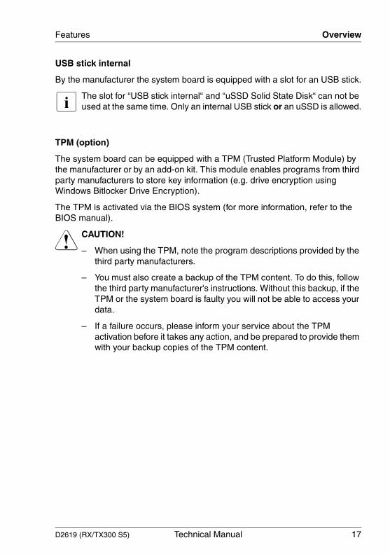
USB stick internal
By the manufacturer the system board is equipped with a slot for an USB stick.
I The slot for “USB stick internal“ and “uSSD Solid State Disk“ can not be used at the same time. Only an internal USB stick or an uSSD is allowed.
TPM (option)
The system board can be equipped with a TPM (Trusted Platform Module) by the manufacturer or by an add-on kit. This module enables programs from third party manufacturers to store key information (e.g. drive encryption using Windows Bitlocker Drive Encryption).
The TPM is activated via the BIOS system (for more information, refer to the BIOS manual).
V CAUTION!
– When using the TPM, note the program descriptions provided by the third party manufacturers.
– You must also create a backup of the TPM content. To do this, follow the third party manufacturer's instructions. Without this backup, if the TPM or the system board is faulty you will not be able to access your data.
– If a failure occurs, please inform your service about the TPM activation before it takes any action, and be prepared to provide them with your backup copies of the TPM content.

18 Technical Manual D2619 (RX/TX300 S5)
Main memory Features
3.2 Main memory
The system board supports up to 144 GB main memory. 18 slots for main memory are available. Each slot can be populated with 2 GB, 4 GB or 8 GB single-, dual- oder quad-ranked RDIMM memory modules.The minimum population in the independent channel mode is one DIMM.
ECC with memory scrubbing and with the Single Device Data Correction (SDDC) function is supported.
I You will find the descriptions how to install memory modules in the Options Guide of your server.
Module population
Figure 2: Assembly of the main memory in channels and slots
The arrows in figure 2 show the direction of the population of the memory slots.
● The memory modules are organized in 6 channels (A - F). Each channel has three slots (1-3).
● The channels A - C are controlled by CPU 1 and the channels D - F are controlled by CPU 2.
● Only x4 organized registered DIMMs with ECC are supported.
CPU 2
Channel A Channel B Channel C
DIM
M-1
D
Channel DChannel EChannel F
CPU 1
DIM
M 3
A
DIM
M 3
D
DIM
M 1
C
DIM
M 2
C
DIM
M 3
C
DIM
M 1
B
DIM
M 2
B
DIM
M 3
B
DIM
M 1
A
DIM
M 2
A
DIM
M 1
F
DIM
M 2
F
DIM
M 3
F
DIM
M 1
E
DIM
M 2
E
DIM
M 3
E
DIM
M 1
D
DIM
M 2
D

D2619 (RX/TX300 S5) Technical Manual 19
Features Main memory
There are three operational modes for the main memory:
– Independent channel mode (maxium population)
The populated memory of the six channels (A - F) can be used completely (max. 144 GB).
– Mirrored channel mode (maximum security)
Only the populated memory of the two channels A and D can be used (max. 48 GB). The channels B and E serve as safeguarding against failure. The memory belonging to the channels B and E contain the mirrored data of the memory belonging to channel A und D. The channels C und F are not used.
– Spare channel mode (large population and large security)
Only the populated memory of the four channels A, B, D and E can be used (max. 96 GB). The channels C and F serve as safeguarding against failure.
Depending on the mode of operation there are different population require-ments for the main memory.

20 Technical Manual D2619 (RX/TX300 S5)
Main memory Features
Independent channel mode
Figure 3: Independent channel mode
In figure 3 you can see the slots that must be populated for a minimum config-uration and for the first two upgrades.
Independent channel mode allows for channels to be populated in any order and no matching between channels is required.
● All channels in a system will run at the fastest common frequency.
● Can run with differently rated DIMMs and use the settings of the slowest DIMM within a channel.
● Timings other than frequency can vary between channels.
C P U1
C hannel AC hannel BC hannel C
C P U1
C hannel AC hannel BC hannel C
C P U1
DIM
M-3
A
C hannel AC hannel BC hannel C
DIM
M-2
A
DIM
M-1
A
DIM
M-3
B
DIM
M-2
B
DIM
M-1
B
DIM
M-3
C
DIM
M-2
C
DIM
M-1
C
DIM
M-3
A
DIM
M-2
A
DIM
M-3
B
DIM
M-2
B
DIM
M-3
C
DIM
M-2
C
DIM
M-1
C
DIM
M-1
A
DIM
M-1
B
DIM
M-3
A
DIM
M-2
A
DIM
M-3
B
DIM
M-2
B
DIM
M-3
C
DIM
M-2
C
DIM
M-1
A
DIM
M-1
B
DIM
M-1
C
1st U pg rade
2nd U pgrade
M in im um M em ory C onfiguration

D2619 (RX/TX300 S5) Technical Manual 21
Features Main memory
Mirrored channel mode
Figure 4: Mirrored channel mode
In figure 4 you can see the slots that must be populated for a minimum config-uration and for the first two upgrades.
In this mode channel A and channel B are exact copies of each other.
● Channel A and channel B must be populated identically (channel C is not usable in this mode).
● Memory slot populations within a channel do not have to be identical but the same memory slot location across channel A and B must be populated the same way.
C P U1
C hannel AC hannel BC hannel C
C P U1
C hannel AC hannel BC hannel C
C P U1
DIM
M-3
A
C hannel AC hannel BC hannel C
DIM
M-2
A
DIM
M-1
A
DIM
M-3
B
DIM
M-2
B
DIM
M-3
C
DIM
M-2
C
DIM
M-1
C
DIM
M-3
A
DIM
M-3
B
DIM
M-3
C
DIM
M-2
C
DIM
M-1
C
DIM
M-1
A
DIM
M-1
B
DIM
M-3
C
DIM
M-2
C
DIM
M-1
A
DIM
M-1
B
1st U pgrade
2nd U pgrade
M in im um M em ory C onfiguration (M irro red M ode )
DIM
M-1
B
DIM
M-2
A
DIM
M-2
B
DIM
M-3
A
DIM
M-2
A
DIM
M-3
B
DIM
M-2
B
DIM
M-1
C
22 Technical Manual D2619 (RX/TX300 S5)
Main memory Features
● Can run with differently rated memory modules and use the settings of the slowest memory module on both channels.
● The total physical memory available to the system is half of what is populated.
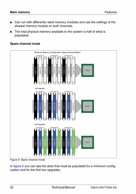
Spare channel mode
Figure 5: Spare channel mode
In figure 5 you can see the slots that must be populated for a minimum config-uration and for the first two upgrades.
C hannel AC hannel BC hannel C
C P U1
C hannel AC hannel BC hannel C
C P U1
C hannel AC hannel BC hannel C
C P U1
DIM
M-2
A
DIM
M-1
A
DIM
M-2
B
DIM
M-1
B
DIM
M-2
C
DIM
M-1
C
DIM
M-3
A
DIM
M-2
A
DIM
M-1
A
DIM
M-3
B
DIM
M-2
B
DIM
M-1
B
DIM
M-3
C
DIM
M-2
C
DIM
M-1
C
DIM
M-3
A
DIM
M-3
B
DIM
M-2
B
DIM
M-3
C
DIM
M-2
C
DIM
M-1
A
DIM
M-1
B
DIM
M-1
C
DIM
M-3
A
DIM
M-3
B
DIM
M-3
C
M in im u m M em ory C onfiguration (S pare C hanne l M ode )
DIM
M-2
A
1st U p g rade
2n d U p grade

D2619 (RX/TX300 S5) Technical Manual 23
Features Main memory
In this mode, the channel C is a spare of the two active channels A and B. The channel C is not available as system memory.
● All three channels must be populated identically with regards to size and organization.
● Memory slot populations within a channel do not have to be identical but the same memory slot location across three channels must be populated the same way.
● Can run with differently rated memory modules and use the settings of the slowest memory module within a channel.
● Timings in the active channels (A and B) and the spare channel (C) can be set to different values.
● Only 2/3 of the maximum memory bandwidth is achievable.
● The total physical memory available to the system is 2/3 of what is populated.

24 Technical Manual D2619 (RX/TX300 S5)
PCI bus Features
3.3 PCI bus
The system board offers seven PCI Express expansion slots. The slots 1-5 are wired as x4 interfaces. If the slots 2 and 4 remain free, the slots 3 and 5 can be used as x8 interfaces.
I Slot 1 is the preferred slot for the HDD controller (bootable).
Figure 6: PCIe slots
The following table shows an overview of the PCIe slots:
PCI slot Description
1 PCIe x4 slot for RAID controller
2 PCIe x4 slot
3 PCIe x4 slot (slot 2 free: x8)
4 PCIe x4 slot
5 PCIe x4 slot (slot 4 free: x8)
6 PCIe x8 slot
7 PCIe x8 slot

D2619 (RX/TX300 S5) Technical Manual 25
Features Screen resolution
3.4 Screen resolution
Depending on the operating system used the screen resolutions in the following table refer to the graphic controller on the system board. The graphic controller is integrated in the iRMC (integrated Remote Management Controller).
If you are using an external graphic controller, you will find details of supported screen resolutions in the documentation supplied with the graphic controller.
3.5 Temperature/system monitoring
Temperature and system monitoring aim to reliably protect the computer hardware against damage caused by overheating. In addition, any unnecessary noise is also prevented by reducing the fan speed, and information is provided about the system status.
The temperature and system monitoring are controlled by the iRMC S2 (integrated Remote Management Controller).
The following functions are supported:
Temperature monitoring
Measurement of the processor and the system internal temperature by an onboard temperature sensor, measurement of the ambient temperature by a I2C temperature sensor.
Fan monitoring
The CPU, power supply unit and system fans are monitored. Fans that are no longer available, blocked or sticky fans are detected.
Screen resolution Max. color depth Max. frequency
640 x 480 Hz 32 Bit 85 Hz
800 x 600 Hz 32 Bit 85 Hz
1024 x 768 Hz 32 Bit 75 Hz
1152 x 864 Hz 16 Bit 60 Hz
1280 x 1024 Hz 24 Bit 60 Hz
1600 x 1200 Hz 16 Bit 60 Hz

26 Technical Manual D2619 (RX/TX300 S5)
Temperature/system monitoring Features
Fan control
The fans are regulated according to temperature.
Sensor monitoring
The removal of, or a fault in, a temperature sensor is detected. Should this happen all fans monitored by this sensor run at maximum speed, to achieve the greatest possible protection of the hardware.
Voltage monitoring
When voltage exceeds warning level high or falls below warning level low an alert will be generated.
System Event Log (SEL)
All monitored events of the system board are signalized via the Global Error LED and recorded in the System Event Log. They could be retrieved in the BIOS Setup or via ServerView.
Diagnostic LEDs
For signalisation of failures LEDs are situated on the system board.

D2619 (RX/TX300 S5) Technical Manual 27
Features LEDs
3.6 LEDs
Figure 7: LEDs
LED s A, B, C, D and E are visible from outside on the rear of the server. All the other LEDs are only visible, if the cover of the server has been opened.

28 Technical Manual D2619 (RX/TX300 S5)
LEDs Features
The LEDs have the following meaning:
By pressing the Indicate CSS button (INDICATE CSS BUTTON near the DIMM slots for CPU2) the defective component can also be indicated in the power-off condition (power supply plug disconnected).
LED LED Indicator Meaning
A Identification blue server is identified via ServerView
B Customer Self Service
on indicates a prefailure
yellow flashing indicates a failure
C Global Error LED red indicates a prefailure
red flashing indicates a failure. Reasons for a failure may be:- overheating of one of the sensors- sensor defect- fan defect- CPU error- software detected an error
D LAN activity green connection available
green flashing LAN transfer
E LAN speed off 10 Mbit/s
green 100 Mbit/s
yellow 1000 Mbit/s
F Controller orange controller failure
G CPU orange CPU failure
H Memory Module orange memory failure
I PS CTRL OK green power supply ok
K PS CTRL ERROR orange power supply failure
L Main Power green main power is ok
M Aux Power yellow auxiliary power is ok
N Board Error red system board is faulty
O iRMC green flashing iRMC (integrated Remote Management Controller) is okay
D2619 (RX/TX300 S5) Technical Manual 29
Features Interfaces and connectors
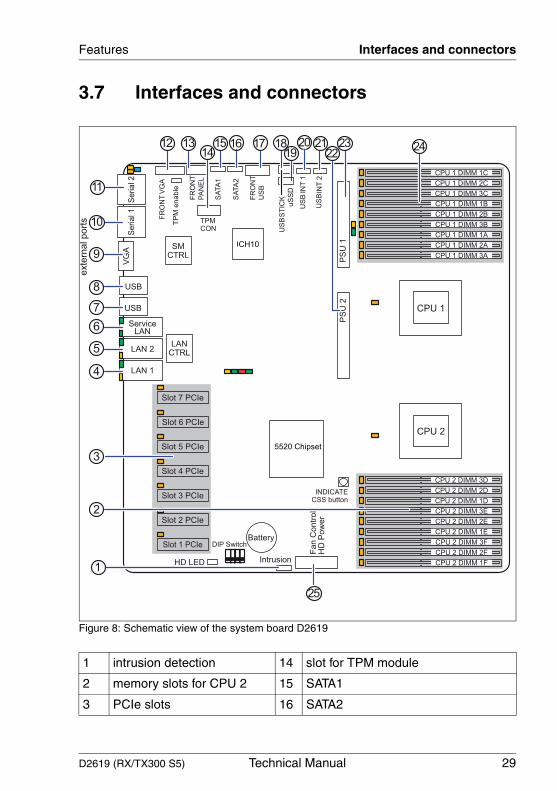
3.7 Interfaces and connectors
Figure 8: Schematic view of the system board D2619
1 intrusion detection 14 slot for TPM module
2 memory slots for CPU 2 15 SATA1
3 PCIe slots 16 SATA2
4
5
6
7
8
9
11
12 13 2014
15 16 17 1819
21
10
2223
TP
M e
nable
24
25
3
2
1

30 Technical Manual D2619 (RX/TX300 S5)
Interfaces and connectors Features
4 LAN 1 17 front USB
5 LAN 2 18 USB stick
6 Service LAN 19 uSSD
7 USB 1/2 20 USB internal 1
8 USB 3/4 21 USB internal 2
9 VGA 22 power supply 2
10 serial 1 23 power supply1
11 serial 2 24 memory slots for CPU 1
12 front VGA 25 power supply for fans and HDDs
13 front panel
D2619 (RX/TX300 S5) Technical Manual 31
Features Interfaces and connectors
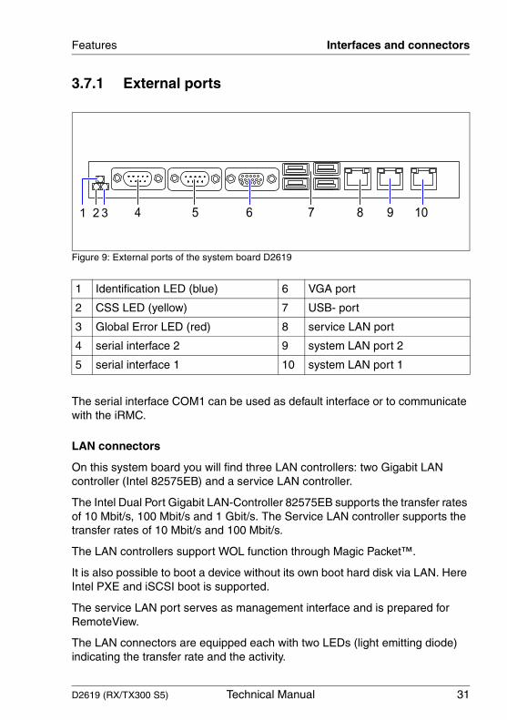
3.7.1 External ports
Figure 9: External ports of the system board D2619
The serial interface COM1 can be used as default interface or to communicate with the iRMC.
LAN connectors
On this system board you will find three LAN controllers: two Gigabit LAN controller (Intel 82575EB) and a service LAN controller.
The Intel Dual Port Gigabit LAN-Controller 82575EB supports the transfer rates of 10 Mbit/s, 100 Mbit/s and 1 Gbit/s. The Service LAN controller supports the transfer rates of 10 Mbit/s and 100 Mbit/s.
The LAN controllers support WOL function through Magic Packet™.
It is also possible to boot a device without its own boot hard disk via LAN. Here Intel PXE and iSCSI boot is supported.
The service LAN port serves as management interface and is prepared for RemoteView.
The LAN connectors are equipped each with two LEDs (light emitting diode) indicating the transfer rate and the activity.
1 Identification LED (blue) 6 VGA port
2 CSS LED (yellow) 7 USB- port
3 Global Error LED (red) 8 service LAN port
4 serial interface 2 9 system LAN port 2
5 serial interface 1 10 system LAN port 1
8 104 6 97521 3
32 Technical Manual D2619 (RX/TX300 S5)
Interfaces and connectors Features
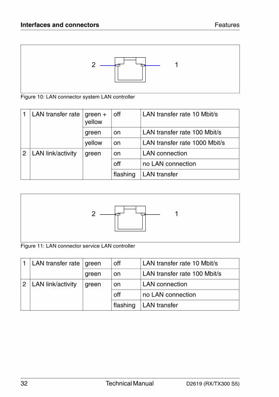
Figure 10: LAN connector system LAN controller
Figure 11: LAN connector service LAN controller
1 LAN transfer rate green + yellow
off LAN transfer rate 10 Mbit/s
green on LAN transfer rate 100 Mbit/s
yellow on LAN transfer rate 1000 Mbit/s
2 LAN link/activity green on LAN connection
off no LAN connection
flashing LAN transfer
1 LAN transfer rate green off LAN transfer rate 10 Mbit/s
green on LAN transfer rate 100 Mbit/s
2 LAN link/activity green on LAN connection
off no LAN connection
flashing LAN transfer
2 1
2 1

D2619 (RX/TX300 S5) Technical Manual 33
Features Settings with switches and jumpers
3.8 Settings with switches and jumpers
DIP switches
Figure 12: DIP switches
I Default setting switch 1 to 4 is Off.
Recovering system BIOS - switch 1
Switch 1 enables recovery of the old system BIOS after an attempt to update has failed. To restore the old system BIOS you need a Flash BIOS medium (see the BIOS manual or please call our customer service centre).
Skipping the password query - switch 2
Switch 2 is used to define whether the password is queried at system startup, if the password protection is enabled in BIOS Setup (in Security menu, the Password on boot field must be set to Enabled).
on The system boots from the “Flash BIOS medium“ (floppy disk, ODD, USB stick) and reprograms the system BIOS on the board.
off The System BIOS is started with the system BIOS from the system board (default setting).
on The password query is skipped. Passwords are deleted.
off The password query is effective (default setting).
ON
1 2 3 4

34 Technical Manual D2619 (RX/TX300 S5)
Settings with switches and jumpers Features
Write protection for Flash BIOS - switch 3
Switch 3 is used to define whether the System BIOS is write protected or not.
Switch 4
not used
TPM jumper
Figure 13: Position of the TPM jumper (TPM enable)
I As default the jumper (1-2) is set. Without jumper the TPM function is disabled.
on The System BIOS can not be written. Flash-BIOS update from floppy disk is not possible.
off The System BIOS can be written. Flash-BIOS update from floppy disk is possible (default setting).
Pin Signal Description
1 TPM RESET L Reset of the TPM module
2 ICH TMP DIS L Reset of ICH10
TPM enable
TPM CON

D2619 (RX/TX300 S5) Technical Manual 35
4 Replacing the lithium batteryIn order to save the system information permanently, a lithium battery is installed to provide the CMOS-memory with a current. When the charge is too low or the battery is empty, a corresponding error message is provided. The lithium battery must then be replaced.
V CAUTION!
The lithium battery must be replaced with an identical battery or a battery type recommended by the manufacturer (CR2450).
Do not throw lithium batteries into the trash can. It must be disposed of in accordance with local regulations concerning special waste.
Make sure that you insert the battery the right way round. The plus pole must be on the top!
Figure 14: Replacing the lithium battery
Ê Press the locking spring into direction of the arrow (1), so that the lithium battery jumps out of its socket.
Ê Remove the battery (2).
Ê Insert a new lithium battery of the same type into the socket (3) and (4).
1
2
3
4