
Sysmac Library User's Manual for Visual Feedback Alignment ...
190
Sysmac Library User's Manual for Visual Feedback Alignment Library SYSMAC-XR018 W608-E1-02
Transcript of Sysmac Library User's Manual for Visual Feedback Alignment ...

Sysmac Library
User's Manual for Visual Feedback Alignment Library
SYSMAC-XR018
W608-E1-02

NOTE
(1) All rights reserved. No part of this publication may be reproduced, stored in a retrieval system, ortransmitted, in any form, or by any means, mechanical, electronic, photocopying, recording, orotherwise, without the prior written permission of OMRON.
(2) No patent liability is assumed with respect to the use of the information contained herein.Moreover, because OMRON is constantly striving to improve its high-quality products, the infor-mation contained in this manual is subject to change without notice.
(3) Every precaution has been taken in the preparation of this manual. Nevertheless, OMRON as-sumes no responsibility for errors or omissions.Neither is any liability assumed for damages resulting from the use of the information containedin this publication.
Trademarks• Sysmac and SYSMAC are trademarks or registered trademarks of OMRON Corporation in Japan
and other countries for OMRON factory automation products.• Microsoft, Windows, Windows Vista, Excel, and Visual Basic are either registered trademarks or
trademarks of Microsoft Corporation in the United States and other countries.
• EtherCAT® is a patented technology and registered trademark, licensed by Beckhoff AutomationGmbH, Germany.
• ODVA, CIP, CompoNet, DeviceNet, and EtherNet/IP are trademarks of ODVA.
• The SD and SDHC logos are trademarks of SD-3C, LLC.
Other company names and product names in this document are the trademarks or registered trade-marks of their respective companies.
Copyrights• Microsoft product screen shots reprinted with permission from Microsoft Corporation.
IntroductionThank you for purchasing an NJ/NX-series CPU Unit, PC for NY-series production.This manual contains information that is necessary to use the Functions (sometimes abbreviated asFUN) and Function blocks (sometimes abbreviated as FB) in Visual Feedback Alignment Library.Please read this manual and make sure you understand the functions and capabilities before you at-tempt to use it in a control system.This manual provides FB (Function block) specifications. It does not describe application restrictions orcombination restrictions for Controllers, Units, and components.Make sure to read the user's manual for each product before use.Keep this manual in a safe place where it will be available for reference during operation.
Features of the LibraryThe Visual Feedback Alignment Library is a set of software function components for alignment appli-cations employing visual feedback.
Intended AudienceThis manual is intended for the following personnel,who must also have knowledge of electrical systems (an electrical engineer or the equivalent).• Personnel in charge of introducing FA systems.• Personnel in charge of designing FA systems.• Personnel in charge of installing and maintaining FA systems.• Personnel in charge of managing FA systems and facilities.For programming, this manual is intended for personnel who understand the programming languagespecifications in international standard IEC 61131-3 or Japanese standard JIS B 3503.
Applicable ProductsFor the model numbers and versions of an NJ/NX-series CPU Unit, NY-series Industrial PC, and theSysmac Studio that this library supports, refer to Sysmac Library Version Information in the SYSMAC-XR£££ Sysmac Library Catalog (Cat. No. P102). This catalog can be downloaded from the OMRONwebsite (http://www.ia.omron.com/products/family/3459/download/catalog.html).
Introduction
1Sysmac Library User's Manual for Visual Feedback Alignment Library (W608)
Manual Structure
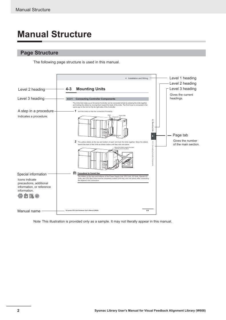
Page StructureThe following page structure is used in this manual.
4-9
4 Installation and Wiring
NJ-series CPU Unit Hardware User’s Manual (W500)
sti
nU
gni
tn
uo
M
3-4
4
s tn
en
op
mo
C r
ellor
tn
oC
gni
tc
en
no
C
1-3-
4
4-3 Mounting Units
The Units that make up an NJ-series Controller can be connected simply by pressing the Units together
and locking the sliders by moving them toward the back of the Units. The End Cover is connected in the
same way to the Unit on the far right side of the Controller.
1 Join the Units so that the connectors fit exactly.
2 The yellow sliders at the top and bottom of each Unit lock the Units together. Move the sliders
toward the back of the Units as shown below until they click into place.
Precautions for Correct UsePrecautions for Correct Use
4-3-1 Connecting Controller Components
Connector
Hook Hook holes
Slider
Lock
Release
Move the sliders toward the back until they lock into place.
Level 1 heading
Level 2 heading
Level 3 headingLevel 2 heading
A step in a procedure
Manual name
Special information
Level 3 heading
Page tab
Gives the current
headings.
Indicates a procedure.
Icons indicate
precautions, additional
information, or reference
information.
Gives the number
of the main section.
The sliders on the tops and bottoms of the Power Supply Unit, CPU Unit, I/O Units, Special I/O
Units, and CPU Bus Units must be completely locked (until they click into place) after connecting
the adjacent Unit connectors.
Note This illustration is provided only as a sample. It may not literally appear in this manual.
Manual Structure
2 Sysmac Library User's Manual for Visual Feedback Alignment Library (W608)
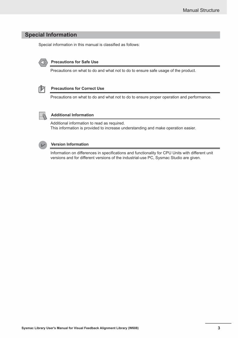
Special InformationSpecial information in this manual is classified as follows:
Precautions for Safe Use
Precautions on what to do and what not to do to ensure safe usage of the product.
Precautions for Correct Use
Precautions on what to do and what not to do to ensure proper operation and performance.
Additional Information
Additional information to read as required.This information is provided to increase understanding and make operation easier.
Version Information
Information on differences in specifications and functionality for CPU Units with different unitversions and for different versions of the industrial-use PC, Sysmac Studio are given.
Manual Structure
3Sysmac Library User's Manual for Visual Feedback Alignment Library (W608)

Manual Structure
4 Sysmac Library User's Manual for Visual Feedback Alignment Library (W608)
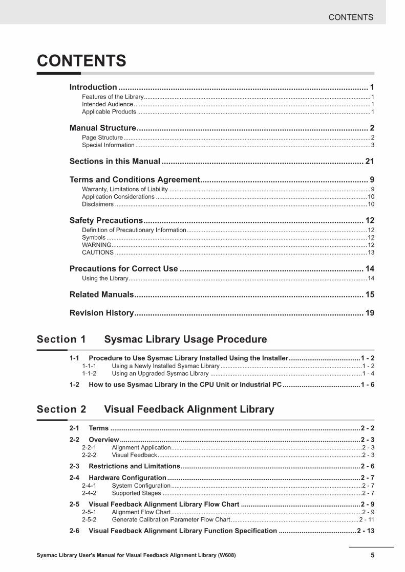
CONTENTSIntroduction .............................................................................................................. 1
Features of the Library.....................................................................................................................................1Intended Audience...........................................................................................................................................1Applicable Products .........................................................................................................................................1
Manual Structure...................................................................................................... 2Page Structure.................................................................................................................................................2Special Information ..........................................................................................................................................3
Sections in this Manual ......................................................................................... 21
Terms and Conditions Agreement.......................................................................... 9Warranty, Limitations of Liability ......................................................................................................................9Application Considerations ............................................................................................................................10Disclaimers ....................................................................................................................................................10
Safety Precautions................................................................................................. 12Definition of Precautionary Information..........................................................................................................12Symbols .........................................................................................................................................................12WARNING......................................................................................................................................................12CAUTIONS ....................................................................................................................................................13
Precautions for Correct Use ................................................................................. 14Using the Library............................................................................................................................................14
Related Manuals..................................................................................................... 15
Revision History..................................................................................................... 19
Section 1 Sysmac Library Usage Procedure1-1 Procedure to Use Sysmac Library Installed Using the Installer......................................1 - 2
1-1-1 Using a Newly Installed Sysmac Library ...................................................................................1 - 21-1-2 Using an Upgraded Sysmac Library .........................................................................................1 - 4
1-2 How to use Sysmac Library in the CPU Unit or Industrial PC.........................................1 - 6
Section 2 Visual Feedback Alignment Library2-1 Terms ....................................................................................................................................2 - 22-2 Overview...............................................................................................................................2 - 3
2-2-1 Alignment Application................................................................................................................2 - 32-2-2 Visual Feedback........................................................................................................................2 - 3
2-3 Restrictions and Limitations...............................................................................................2 - 62-4 Hardware Configuration ......................................................................................................2 - 7
2-4-1 System Configuration................................................................................................................2 - 72-4-2 Supported Stages .....................................................................................................................2 - 7
2-5 Visual Feedback Alignment Library Flow Chart ...............................................................2 - 92-5-1 Alignment Flow Chart ................................................................................................................2 - 92-5-2 Generate Calibration Parameter Flow Chart ...........................................................................2 - 11
2-6 Visual Feedback Alignment Library Function Specification .........................................2 - 13
CONTENTS
5Sysmac Library User's Manual for Visual Feedback Alignment Library (W608)

2-6-1 Function Overview ..................................................................................................................2 - 132-6-2 Coordinate Systems................................................................................................................2 - 142-6-3 Control Blocks .........................................................................................................................2 - 152-6-4 Execute Measurement (Imaging of Workpiece) ......................................................................2 - 172-6-5 When Vision Sensor NG Measurement Occurs ......................................................................2 - 17
Section 3 Common Specifications of Function Blocks3-1 Common Variables...............................................................................................................3 - 2
3-1-1 Definition of Input Variables and Output Variables ....................................................................3 - 23-1-2 Execute-type Function Blocks...................................................................................................3 - 33-1-3 Enable-type Function Blocks.....................................................................................................3 - 5
3-2 Precautions ..........................................................................................................................3 - 73-2-1 Nesting ......................................................................................................................................3 - 73-2-2 Instruction Options ....................................................................................................................3 - 73-2-3 Re-execution of Function Blocks...............................................................................................3 - 7
Section 4 Individual Specifications of FB/FUNStructure .........................................................................................................................................4 - 2
XYθ Position (sPOSITION).........................................................................................................................4 - 2Calibration Parameter (sCALIB_PARAMS) ................................................................................................4 - 2Alignment Control Parameter (sALIGNMENT_PARAMS) ..........................................................................4 - 2Stage Parameter (sSTAGE_PARAMS).......................................................................................................4 - 3XYθ Stage Parameter (sXYTH_STAGE_PARAMS) ...................................................................................4 - 4UVWR Stage Parameter (sUVWR_STAGE_PARAMS)..............................................................................4 - 5UVWR Axis Parameter (sUVWR_PARAMS) ..............................................................................................4 - 6Forward/Reverse Kinematics Calculation Parameter (sKINEMATICS_PARAMS) .....................................4 - 9Virtual XYθ Stage Axis Position/Velocity Calculation Parameter (sCALCVIRTUALMOVE_PARAMS) ....4 - 10Axis Motion Parameter (sAXIS_MOVE_PARAMS)...................................................................................4 - 11Fifth Order Trajectory Calculation Parameter (sCALCURVE_PARAMS)..................................................4 - 13Imaging Parameter (sIMAGING_PARAMS)..............................................................................................4 - 14Done Judgment Parameter (JUDGE_PARAMS) ......................................................................................4 - 14Calibration Axis Motion Parameter (sCALIB_MOVE_PARAMS) ..............................................................4 - 15FB/FUN Structure Usage..........................................................................................................................4 - 17
AffineTrans ...................................................................................................................................4 - 22Function Block and Function Information .................................................................................................4 - 22Variables ...................................................................................................................................................4 - 22Function ....................................................................................................................................................4 - 23Precautions for Correct Use .....................................................................................................................4 - 24Sample Programming ...............................................................................................................................4 - 24Troubleshooting (Error Codes and Corrective Actions) ............................................................................4 - 24
CalcPosAngle ...............................................................................................................................4 - 25Function Block and Function Information .................................................................................................4 - 25Variables ...................................................................................................................................................4 - 25Function ....................................................................................................................................................4 - 26Precautions for Correct Use .....................................................................................................................4 - 28Sample Programming ...............................................................................................................................4 - 28Troubleshooting (Error Codes and Corrective Actions) ............................................................................4 - 28
CalcMultiPosAngle.......................................................................................................................4 - 30Function Block and Function Information .................................................................................................4 - 30Variables ...................................................................................................................................................4 - 30Function ....................................................................................................................................................4 - 32Precautions for Correct Use .....................................................................................................................4 - 33Sample Programming ...............................................................................................................................4 - 34Troubleshooting (Error Codes and Corrective Actions) ............................................................................4 - 34
CtrlStage .......................................................................................................................................4 - 35Function Block and Function Information .................................................................................................4 - 35
CONTENTS
6 Sysmac Library User's Manual for Visual Feedback Alignment Library (W608)
Variables ...................................................................................................................................................4 - 36Function ....................................................................................................................................................4 - 38Timing Charts............................................................................................................................................4 - 40Precautions for Correct Use .....................................................................................................................4 - 42Sample Programming ...............................................................................................................................4 - 43Troubleshooting (Error Codes and Corrective Actions) ............................................................................4 - 43
CalcMovement..............................................................................................................................4 - 45Function Block and Function Information .................................................................................................4 - 45Variables ...................................................................................................................................................4 - 45Function ....................................................................................................................................................4 - 46Precautions for Correct Use .....................................................................................................................4 - 47Sample Programming ...............................................................................................................................4 - 47Troubleshooting (Error Codes and Corrective Actions) ............................................................................4 - 47
CalcInverseKinematics................................................................................................................4 - 48Function Block and Function Information .................................................................................................4 - 48Variables ...................................................................................................................................................4 - 48Function ....................................................................................................................................................4 - 49Precautions for Correct Use .....................................................................................................................4 - 50Sample Programming ...............................................................................................................................4 - 50Troubleshooting (Error Codes and Corrective Actions) ............................................................................4 - 50
CalcForwardKinematics ..............................................................................................................4 - 51Function Block and Function Information .................................................................................................4 - 51Variables ...................................................................................................................................................4 - 51Function ....................................................................................................................................................4 - 52Precautions for Correct Use .....................................................................................................................4 - 52Sample Programming ...............................................................................................................................4 - 53Troubleshooting (Error Codes and Corrective Actions) ............................................................................4 - 53
CalcAxisVelocity ..........................................................................................................................4 - 54Function Block and Function Information .................................................................................................4 - 54Variables ...................................................................................................................................................4 - 55Function ....................................................................................................................................................4 - 57Precautions for Correct Use .....................................................................................................................4 - 63Sample Programming ...............................................................................................................................4 - 63Troubleshooting (Error Codes and Corrective Actions) ............................................................................4 - 63
JudgeAlignmentComplete...........................................................................................................4 - 64Function Block and Function Information .................................................................................................4 - 64Variables ...................................................................................................................................................4 - 65Function ....................................................................................................................................................4 - 67Precautions for Correct Use .....................................................................................................................4 - 71Sample Programming ...............................................................................................................................4 - 71Troubleshooting (Error Codes and Corrective Actions) ............................................................................4 - 71
GenerateTrigger ...........................................................................................................................4 - 73Function Block and Function Information .................................................................................................4 - 73Variables ...................................................................................................................................................4 - 73Function ....................................................................................................................................................4 - 75Precautions for Correct Use .....................................................................................................................4 - 77Sample Programming ...............................................................................................................................4 - 77Troubleshooting (Error Codes and Corrective Actions) ............................................................................4 - 77
GenerateCalibParams..................................................................................................................4 - 78Function Block and Function Information .................................................................................................4 - 78Variables ...................................................................................................................................................4 - 78Function ....................................................................................................................................................4 - 80Precautions for Correct Use .....................................................................................................................4 - 87Sample Programming ...............................................................................................................................4 - 88Troubleshooting (Error Codes and Corrective Actions) ............................................................................4 - 88
Sample Programming..................................................................................................................4 - 90Overview...................................................................................................................................................4 - 90Auto-calibration.........................................................................................................................................4 - 93Alignment Control ...................................................................................................................................4 - 106
CONTENTS
7Sysmac Library User's Manual for Visual Feedback Alignment Library (W608)
AppendixA-1 Referring to Library Information........................................................................................ A - 2
A-1-1 Library Attributes, and FB or FUN Attributes............................................................................ A - 2A-1-2 Referring to Attributes of Libraries, Function Blocks, and Functions ....................................... A - 3
A-2 Referring to Function Block and Function Source Codes.............................................. A - 5
Index
CONTENTS
8 Sysmac Library User's Manual for Visual Feedback Alignment Library (W608)
Terms and Conditions Agreement
Warranty, Limitations of Liability
Warranties
l Exclusive WarrantyOmron’s exclusive warranty is that the Products will be free from defects in materials and work-manship for a period of twelve months from the date of sale by Omron (or such other period ex-pressed in writing by Omron). Omron disclaims all other warranties, express or implied.
l LimitationsOMRON MAKES NO WARRANTY OR REPRESENTATION, EXPRESS OR IMPLIED, ABOUTNON-INFRINGEMENT, MERCHANTABILITY OR FITNESS FOR A PARTICULAR PURPOSE OFTHE PRODUCTS. BUYER ACKNOWLEDGES THAT IT ALONE HAS DETERMINED THAT THEPRODUCTS WILL SUITABLY MEET THE REQUIREMENTS OF THEIR INTENDED USE.
Omron further disclaims all warranties and responsibility of any type for claims or expenses basedon infringement by the Products or otherwise of any intellectual property right.
l Buyer RemedyOmron’s sole obligation hereunder shall be, at Omron’s election, to (i) replace (in the form originallyshipped with Buyer responsible for labor charges for removal or replacement thereof) the non-com-plying Product, (ii) repair the non-complying Product, or (iii) repay or credit Buyer an amount equalto the purchase price of the non-complying Product; provided that in no event shall Omron be re-sponsible for warranty, repair, indemnity or any other claims or expenses regarding the Productsunless Omron’s analysis confirms that the Products were properly handled, stored, installed andmaintained and not subject to contamination, abuse, misuse or inappropriate modification. Returnof any Products by Buyer must be approved in writing by Omron before shipment. Omron Compa-nies shall not be liable for the suitability or unsuitability or the results from the use of Products incombination with any electrical or electronic components, circuits, system assemblies or any othermaterials or substances or environments. Any advice, recommendations or information given orallyor in writing, are not to be construed as an amendment or addition to the above warranty.
See http://www.omron.com/global/ or contact your Omron representative for published information.
Limitation on Liability; EtcOMRON COMPANIES SHALL NOT BE LIABLE FOR SPECIAL, INDIRECT, INCIDENTAL, OR CON-SEQUENTIAL DAMAGES, LOSS OF PROFITS OR PRODUCTION OR COMMERCIAL LOSS IN ANY
Terms and Conditions Agreement
9Sysmac Library User's Manual for Visual Feedback Alignment Library (W608)

WAY CONNECTED WITH THE PRODUCTS, WHETHER SUCH CLAIM IS BASED IN CONTRACT,WARRANTY, NEGLIGENCE OR STRICT LIABILITY.
Further, in no event shall liability of Omron Companies exceed the individual price of the Product onwhich liability is asserted.
Application Considerations
Suitability of UseOmron Companies shall not be responsible for conformity with any standards, codes or regulationswhich apply to the combination of the Product in the Buyer’s application or use of the Product. At Buy-er’s request, Omron will provide applicable third party certification documents identifying ratings andlimitations of use which apply to the Product. This information by itself is not sufficient for a completedetermination of the suitability of the Product in combination with the end product, machine, system, orother application or use. Buyer shall be solely responsible for determining appropriateness of the par-ticular Product with respect to Buyer’s application, product or system. Buyer shall take application re-sponsibility in all cases.
NEVER USE THE PRODUCT FOR AN APPLICATION INVOLVING SERIOUS RISK TO LIFE ORPROPERTY OR IN LARGE QUANTITIES WITHOUT ENSURING THAT THE SYSTEM AS A WHOLEHAS BEEN DESIGNED TO ADDRESS THE RISKS, AND THAT THE OMRON PRODUCT(S) ISPROPERLY RATED AND INSTALLED FOR THE INTENDED USE WITHIN THE OVERALL EQUIP-MENT OR SYSTEM.
Programmable ProductsOmron Companies shall not be responsible for the user’s programming of a programmable Product, orany consequence thereof.
Disclaimers
Performance DataData presented in Omron Company websites, catalogs and other materials is provided as a guide forthe user in determining suitability and does not constitute a warranty. It may represent the result ofOmron’s test conditions, and the user must correlate it to actual application requirements. Actual per-formance is subject to the Omron’s Warranty and Limitations of Liability.
Change in SpecificationsProduct specifications and accessories may be changed at any time based on improvements and oth-er reasons. It is our practice to change part numbers when published ratings or features are changed,or when significant construction changes are made. However, some specifications of the Product may
Terms and Conditions Agreement
10 Sysmac Library User's Manual for Visual Feedback Alignment Library (W608)
be changed without any notice. When in doubt, special part numbers may be assigned to fix or estab-lish key specifications for your application. Please consult with your Omron’s representative at anytime to confirm actual specifications of purchased Product.
Errors and OmissionsInformation presented by Omron Companies has been checked and is believed to be accurate; how-ever, no responsibility is assumed for clerical, typographical or proofreading errors or omissions.
Terms and Conditions Agreement
11Sysmac Library User's Manual for Visual Feedback Alignment Library (W608)
Safety Precautions
Definition of Precautionary InformationThe following notation is used in this user's manual to provide precautions required to ensure safe us-age of this library on the NJ/NX-series CPU Unit, PC for NY-series production.The safety precautions that are provided are extremely important for safety. Always read and heed theinformation provided in all safety precautions.The following notation is used.
Indicates a potentially hazardous situation which, if not avoided, could result in death or serious injury. Additionally, there may be severe property damage.
Indicates a potentially hazardous situation which, if not avoided, may result in minor or moderate injury, or property damage.
WARNING
Caution
Symbols
The circle and slash symbol indicates operations that you must not do.The specific operation is shown in the circle and explained in text.This example indicates that disassembly is prohibited.The triangle symbol indicates precautions (including warnings).The specific operation is shown in the triangle and explained in text.This example indicates a precaution for electric shock.The triangle symbol indicates precautions (including warnings).The specific operation is shown in the triangle and explained in text.This example indicates a general precaution.The filled circle symbol indicates operations that you must do.The specific operation is shown in the circle and explained in text.This example shows a general precaution for something that you must do.
WARNING
WARNING
Emergency stop circuits, interlock circuits, limit circuits, and similar safety measures must be pro-vided in external control circuits.
Check the user program, data, and parameter settings for proper execution before you use themfor actual operation.
Safety Precautions
12 Sysmac Library User's Manual for Visual Feedback Alignment Library (W608)
Perform the test run by holding an emergency stop switch in hand or otherwise prepare for rapidmotor operation in an application to control the motor.Also perform the test run by using the parameters for which the motor does not rapidly accelerateor decelerate before you gradually adjust the parameters.In the FB/FUN of this library, some values for Input variables and Input/Output variables are "Sys-tem reserved" variables. For "System reserved" variables, please set them in the range, formatand timing specified in this manual. If they are not set as specified, there is a possibility that theoperation of the control target may be incorrect.
CAUTIONS
Caution
Read all related manuals carefully before you use this library.
The Sysmac Library and manuals are intended for and assumed to be used by the personnel in-dicated in the "Intended Audience" section of this manual, or those under the supervision of thosepersonnel.You must confirm that the user program and parameter values are appropriate to the specifica-tions and operation methods of the devices.
The sample programming shows only the portion of a program that uses the function or functionblock from the library.
When you use the actual device, include user programming for device safety instructions, inter-locks, I/O with other devices, and other control procedures.
Understand the contents of sample programming before you use the sample programming andcreate the user program.
Create a user program that will produce the intended device operation.
Safety Precautions
13Sysmac Library User's Manual for Visual Feedback Alignment Library (W608)
Precautions for Correct Use
Using the Library• Specify the values of the input parameters within the valid ranges.• In a function or function block with an Enabled output variable, if the value of Enabled is FALSE, do
not use the processing result of the function or function block as a command value to the controltarget.
• For FUN with a return value of Out, if the value for Out is one that indicates an error, do not use thecalculation result of FUN as the command value to the control target.
• In the function block with Execute, do not perform re-execution by the same instance. The valuesoutput by the FB returns to the initial values.
• For FB and FUN with output variable Error or return value Out, when Error is TRUE, or return valueOut is a value that indicated an error, do not use the calculation result of FB or FUN as the com-mand value to the control target.
• The multi-execution (buffer mode) cannot be performed in the Sysmac Library.
Precautions for Correct Use
14 Sysmac Library User's Manual for Visual Feedback Alignment Library (W608)
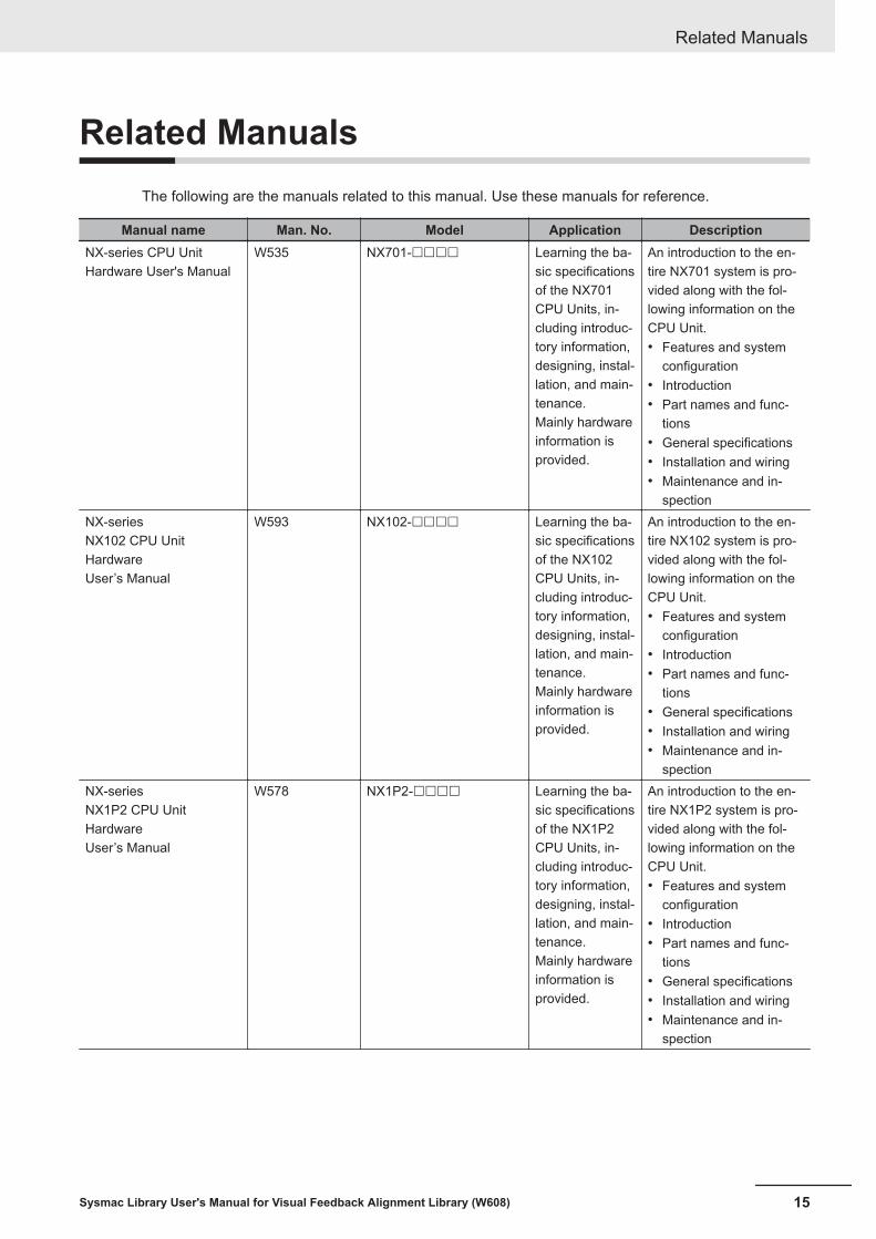
Related ManualsThe following are the manuals related to this manual. Use these manuals for reference.
Manual name Man. No. Model Application DescriptionNX-series CPU UnitHardware User's Manual
W535 NX701-££££ Learning the ba-sic specificationsof the NX701CPU Units, in-cluding introduc-tory information,designing, instal-lation, and main-tenance.Mainly hardwareinformation isprovided.
An introduction to the en-tire NX701 system is pro-vided along with the fol-lowing information on theCPU Unit.• Features and system
configuration• Introduction• Part names and func-
tions• General specifications• Installation and wiring• Maintenance and in-
spectionNX-seriesNX102 CPU UnitHardwareUser’s Manual
W593 NX102-££££ Learning the ba-sic specificationsof the NX102CPU Units, in-cluding introduc-tory information,designing, instal-lation, and main-tenance.Mainly hardwareinformation isprovided.
An introduction to the en-tire NX102 system is pro-vided along with the fol-lowing information on theCPU Unit.• Features and system
configuration• Introduction• Part names and func-
tions• General specifications• Installation and wiring• Maintenance and in-
spectionNX-seriesNX1P2 CPU UnitHardwareUser’s Manual
W578 NX1P2-££££ Learning the ba-sic specificationsof the NX1P2CPU Units, in-cluding introduc-tory information,designing, instal-lation, and main-tenance.Mainly hardwareinformation isprovided.
An introduction to the en-tire NX1P2 system is pro-vided along with the fol-lowing information on theCPU Unit.• Features and system
configuration• Introduction• Part names and func-
tions• General specifications• Installation and wiring• Maintenance and in-
spection
Related Manuals
15Sysmac Library User's Manual for Visual Feedback Alignment Library (W608)
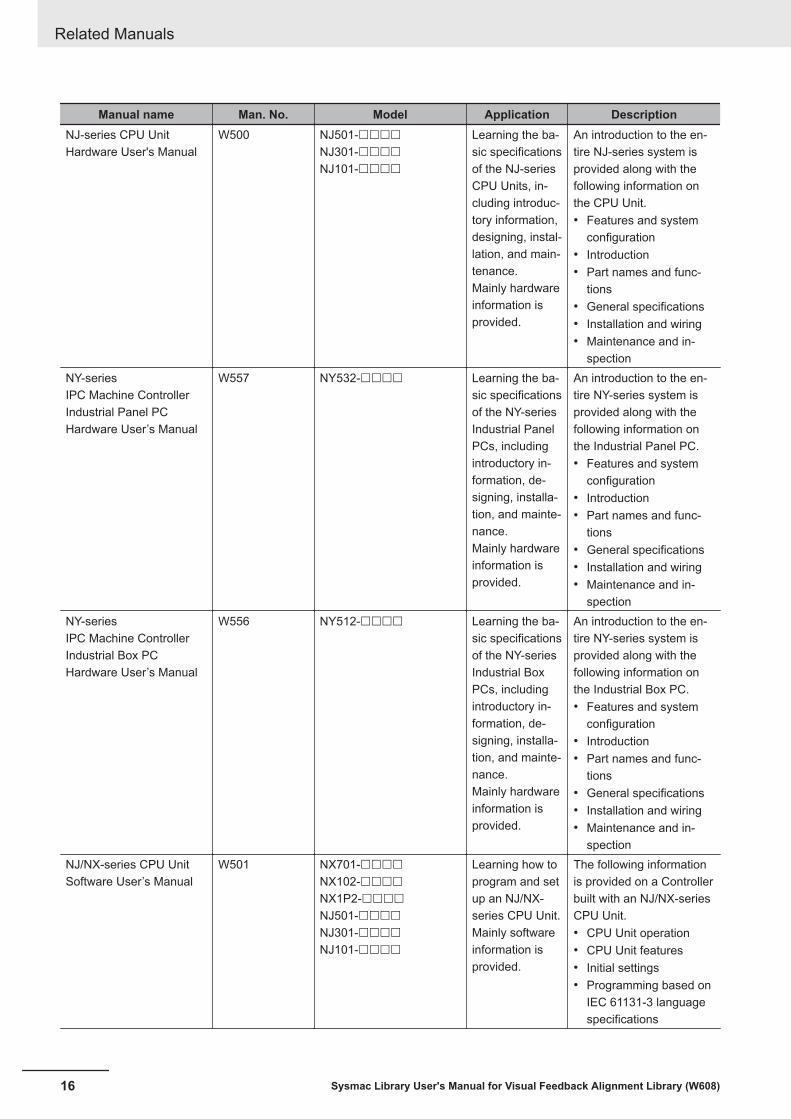
Manual name Man. No. Model Application DescriptionNJ-series CPU UnitHardware User's Manual
W500 NJ501-££££NJ301-££££NJ101-££££
Learning the ba-sic specificationsof the NJ-seriesCPU Units, in-cluding introduc-tory information,designing, instal-lation, and main-tenance.Mainly hardwareinformation isprovided.
An introduction to the en-tire NJ-series system isprovided along with thefollowing information onthe CPU Unit.• Features and system
configuration• Introduction• Part names and func-
tions• General specifications• Installation and wiring• Maintenance and in-
spectionNY-seriesIPC Machine ControllerIndustrial Panel PCHardware User’s Manual
W557 NY532-££££ Learning the ba-sic specificationsof the NY-seriesIndustrial PanelPCs, includingintroductory in-formation, de-signing, installa-tion, and mainte-nance.Mainly hardwareinformation isprovided.
An introduction to the en-tire NY-series system isprovided along with thefollowing information onthe Industrial Panel PC.• Features and system
configuration• Introduction• Part names and func-
tions• General specifications• Installation and wiring• Maintenance and in-
spectionNY-seriesIPC Machine ControllerIndustrial Box PCHardware User’s Manual
W556 NY512-££££ Learning the ba-sic specificationsof the NY-seriesIndustrial BoxPCs, includingintroductory in-formation, de-signing, installa-tion, and mainte-nance.Mainly hardwareinformation isprovided.
An introduction to the en-tire NY-series system isprovided along with thefollowing information onthe Industrial Box PC.• Features and system
configuration• Introduction• Part names and func-
tions• General specifications• Installation and wiring• Maintenance and in-
spectionNJ/NX-series CPU UnitSoftware User’s Manual
W501 NX701-££££NX102-££££NX1P2-££££NJ501-££££NJ301-££££NJ101-££££
Learning how toprogram and setup an NJ/NX-series CPU Unit.Mainly softwareinformation isprovided.
The following informationis provided on a Controllerbuilt with an NJ/NX-seriesCPU Unit.• CPU Unit operation• CPU Unit features• Initial settings• Programming based on
IEC 61131-3 languagespecifications
Related Manuals
16 Sysmac Library User's Manual for Visual Feedback Alignment Library (W608)
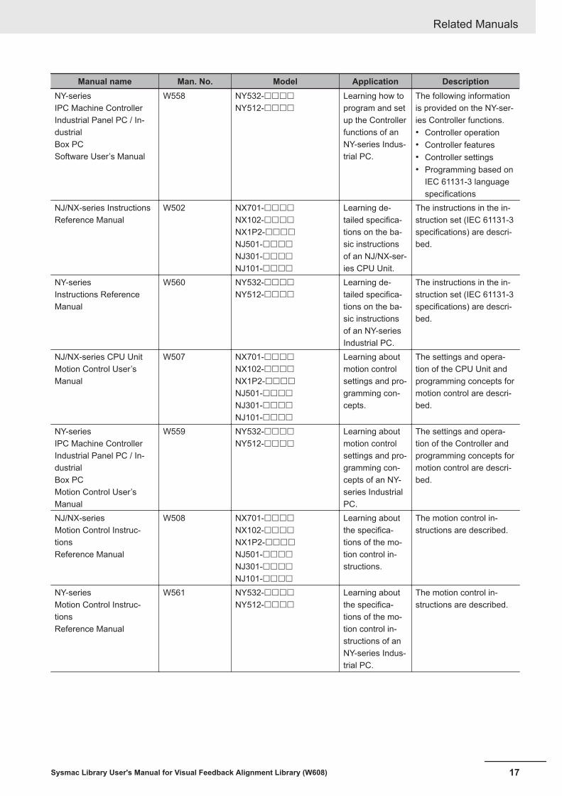
Manual name Man. No. Model Application DescriptionNY-seriesIPC Machine ControllerIndustrial Panel PC / In-dustrialBox PCSoftware User’s Manual
W558 NY532-££££NY512-££££
Learning how toprogram and setup the Controllerfunctions of anNY-series Indus-trial PC.
The following informationis provided on the NY-ser-ies Controller functions.• Controller operation• Controller features• Controller settings• Programming based on
IEC 61131-3 languagespecifications
NJ/NX-series InstructionsReference Manual
W502 NX701-££££NX102-££££NX1P2-££££NJ501-££££NJ301-££££NJ101-££££
Learning de-tailed specifica-tions on the ba-sic instructionsof an NJ/NX-ser-ies CPU Unit.
The instructions in the in-struction set (IEC 61131-3specifications) are descri-bed.
NY-seriesInstructions ReferenceManual
W560 NY532-££££NY512-££££
Learning de-tailed specifica-tions on the ba-sic instructionsof an NY-seriesIndustrial PC.
The instructions in the in-struction set (IEC 61131-3specifications) are descri-bed.
NJ/NX-series CPU UnitMotion Control User’sManual
W507 NX701-££££NX102-££££NX1P2-££££NJ501-££££NJ301-££££NJ101-££££
Learning aboutmotion controlsettings and pro-gramming con-cepts.
The settings and opera-tion of the CPU Unit andprogramming concepts formotion control are descri-bed.
NY-seriesIPC Machine ControllerIndustrial Panel PC / In-dustrialBox PCMotion Control User’sManual
W559 NY532-££££NY512-££££
Learning aboutmotion controlsettings and pro-gramming con-cepts of an NY-series IndustrialPC.
The settings and opera-tion of the Controller andprogramming concepts formotion control are descri-bed.
NJ/NX-seriesMotion Control Instruc-tionsReference Manual
W508 NX701-££££NX102-££££NX1P2-££££NJ501-££££NJ301-££££NJ101-££££
Learning aboutthe specifica-tions of the mo-tion control in-structions.
The motion control in-structions are described.
NY-seriesMotion Control Instruc-tionsReference Manual
W561 NY532-££££NY512-££££
Learning aboutthe specifica-tions of the mo-tion control in-structions of anNY-series Indus-trial PC.
The motion control in-structions are described.
Related Manuals
17Sysmac Library User's Manual for Visual Feedback Alignment Library (W608)
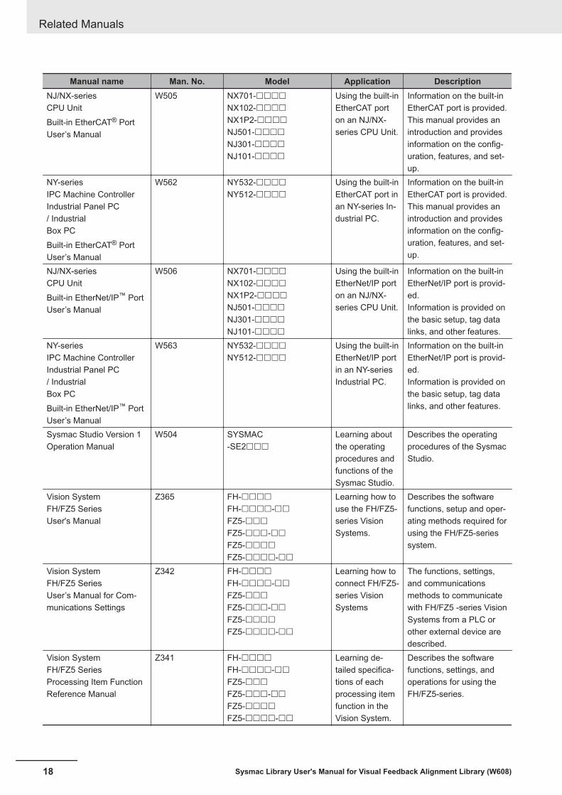
Manual name Man. No. Model Application DescriptionNJ/NX-seriesCPU UnitBuilt-in EtherCAT® PortUser’s Manual
W505 NX701-££££NX102-££££NX1P2-££££NJ501-££££NJ301-££££NJ101-££££
Using the built-inEtherCAT porton an NJ/NX-series CPU Unit.
Information on the built-inEtherCAT port is provided.This manual provides anintroduction and providesinformation on the config-uration, features, and set-up.
NY-seriesIPC Machine ControllerIndustrial Panel PC/ IndustrialBox PCBuilt-in EtherCAT® PortUser’s Manual
W562 NY532-££££NY512-££££
Using the built-inEtherCAT port inan NY-series In-dustrial PC.
Information on the built-inEtherCAT port is provided.This manual provides anintroduction and providesinformation on the config-uration, features, and set-up.
NJ/NX-seriesCPU UnitBuilt-in EtherNet/IP™ PortUser’s Manual
W506 NX701-££££NX102-££££NX1P2-££££NJ501-££££NJ301-££££NJ101-££££
Using the built-inEtherNet/IP porton an NJ/NX-series CPU Unit.
Information on the built-inEtherNet/IP port is provid-ed.Information is provided onthe basic setup, tag datalinks, and other features.
NY-seriesIPC Machine ControllerIndustrial Panel PC/ IndustrialBox PCBuilt-in EtherNet/IP™ PortUser’s Manual
W563 NY532-££££NY512-££££
Using the built-inEtherNet/IP portin an NY-seriesIndustrial PC.
Information on the built-inEtherNet/IP port is provid-ed.Information is provided onthe basic setup, tag datalinks, and other features.
Sysmac Studio Version 1Operation Manual
W504 SYSMAC-SE2£££
Learning aboutthe operatingprocedures andfunctions of theSysmac Studio.
Describes the operatingprocedures of the SysmacStudio.
Vision SystemFH/FZ5 SeriesUser's Manual
Z365 FH-££££FH-££££-££FZ5-£££FZ5-£££-££FZ5-££££FZ5-££££-££
Learning how touse the FH/FZ5-series VisionSystems.
Describes the softwarefunctions, setup and oper-ating methods required forusing the FH/FZ5-seriessystem.
Vision SystemFH/FZ5 SeriesUser’s Manual for Com-munications Settings
Z342 FH-££££FH-££££-££FZ5-£££FZ5-£££-££FZ5-££££FZ5-££££-££
Learning how toconnect FH/FZ5-series VisionSystems
The functions, settings,and communicationsmethods to communicatewith FH/FZ5 -series VisionSystems from a PLC orother external device aredescribed.
Vision SystemFH/FZ5 SeriesProcessing Item FunctionReference Manual
Z341 FH-££££FH-££££-££FZ5-£££FZ5-£££-££FZ5-££££FZ5-££££-££
Learning de-tailed specifica-tions of eachprocessing itemfunction in theVision System.
Describes the softwarefunctions, settings, andoperations for using theFH/FZ5-series.
Related Manuals
18 Sysmac Library User's Manual for Visual Feedback Alignment Library (W608)

Revision HistoryA manual revision code appears as a suffix to the catalog number on the front and back covers of themanual.
W608-E1-02
Revision code
Revisioncode Date Revised content
01 July 2018 Original production02 January 2019 Added the target model number.
Revision History
19Sysmac Library User's Manual for Visual Feedback Alignment Library (W608)

Revision History
20 Sysmac Library User's Manual for Visual Feedback Alignment Library (W608)
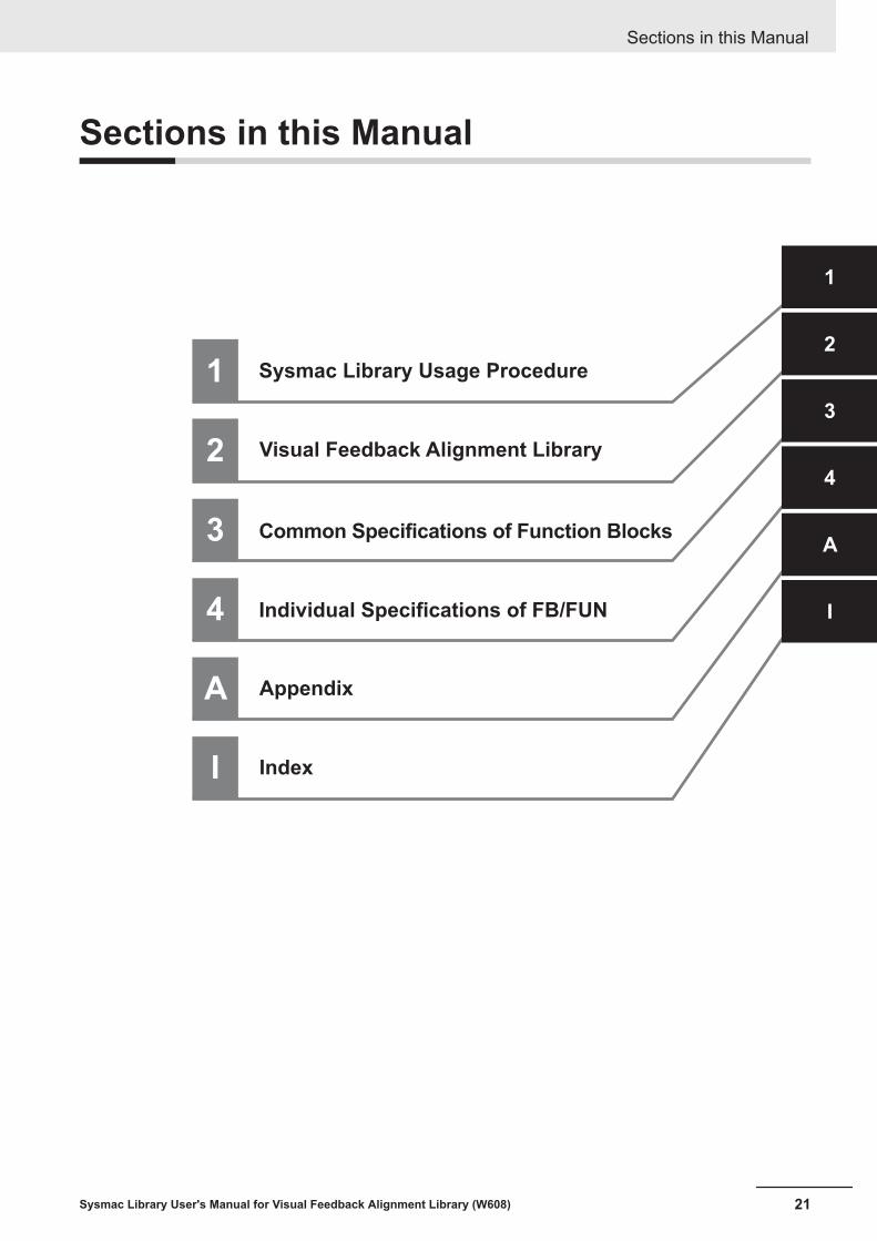
Sections in this Manual
1
2
3
Sysmac Library Usage Procedure
Common Specifications of Function Blocks
Individual Specifications of FB/FUN
Visual Feedback Alignment Library
1
2
3
4
A
I4
A Appendix
I Index
Sections in this Manual
21Sysmac Library User's Manual for Visual Feedback Alignment Library (W608)

Sections in this Manual
22 Sysmac Library User's Manual for Visual Feedback Alignment Library (W608)
1Sysmac Library Usage Procedure
The section describes the procedure to use Sysmac Library installed using the instal-ler, and Sysmac Library in the CPU unit or Industrial PC.
1-1 Procedure to Use Sysmac Library Installed Using the Installer .............. 1 - 21-1-1 Using a Newly Installed Sysmac Library....................................................... 1 - 21-1-2 Using an Upgraded Sysmac Library ............................................................. 1 - 4
1-2 How to use Sysmac Library in the CPU Unit or Industrial PC ................. 1 - 6
1 - 1Sysmac Library User's Manual for Visual Feedback Alignment Library (W608)
1

1-1 Procedure to Use Sysmac Library In-stalled Using the Installer
This section describes the procedure to use Sysmac Library installed using the installer.There are two ways to use libraries.• Using a newly installed Sysmac Library• Using an upgraded Sysmac Library
Version Information
To use Sysmac Library, you need Sysmac Studio Ver.1.14 or higher.
1-1-1 Using a Newly Installed Sysmac Library
1 Start the Sysmac Studio and open a project using Sysmac Library, or create a new one.
Precautions for Correct Use
If you create a new project, be sure to configure the settings as follows to enable use of theSysmac Library. Without the settings below, you cannot proceed to Step 2 and later steps.• Set the project type to Standard Project or Library Project.• Set the device category to Controller.• For the setting of Controller and Version in the Select Device section, refer to .
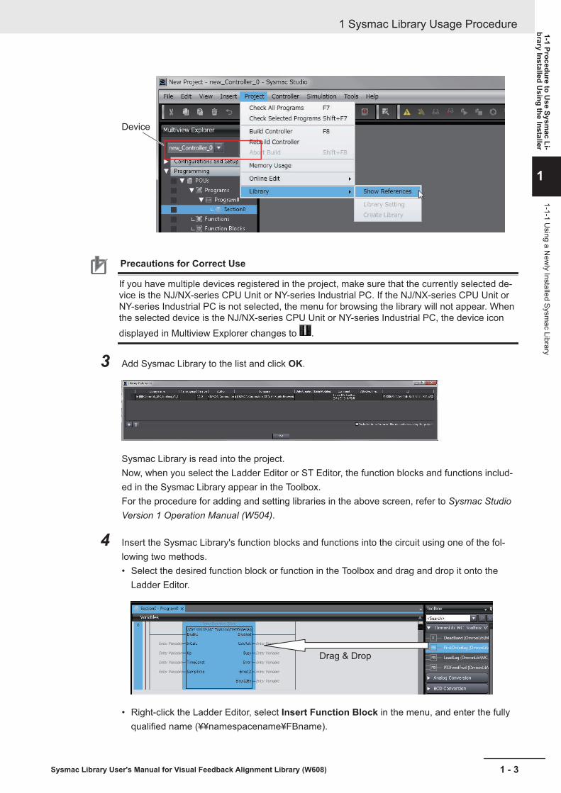
2 Select Project - Library - Show References.
1 Sysmac Library Usage Procedure
1 - 2 Sysmac Library User's Manual for Visual Feedback Alignment Library (W608)
Device
Precautions for Correct Use
If you have multiple devices registered in the project, make sure that the currently selected de-vice is the NJ/NX-series CPU Unit or NY-series Industrial PC. If the NJ/NX-series CPU Unit orNY-series Industrial PC is not selected, the menu for browsing the library will not appear. Whenthe selected device is the NJ/NX-series CPU Unit or NY-series Industrial PC, the device icondisplayed in Multiview Explorer changes to .
3 Add Sysmac Library to the list and click OK.
Sysmac Library is read into the project.Now, when you select the Ladder Editor or ST Editor, the function blocks and functions includ-ed in the Sysmac Library appear in the Toolbox.For the procedure for adding and setting libraries in the above screen, refer to Sysmac StudioVersion 1 Operation Manual (W504).
4 Insert the Sysmac Library's function blocks and functions into the circuit using one of the fol-lowing two methods.• Select the desired function block or function in the Toolbox and drag and drop it onto the
Ladder Editor.
Drag & Drop
• Right-click the Ladder Editor, select Insert Function Block in the menu, and enter the fullyqualified name (¥¥namespacename¥FBname).
1 Sysmac Library Usage Procedure
1 - 3Sysmac Library User's Manual for Visual Feedback Alignment Library (W608)
1-1 Procedure to Use Sysm
ac Li-brary Installed U
sing the Installer
1
1-1-1 Using a N
ewly Installed Sysm
ac Library
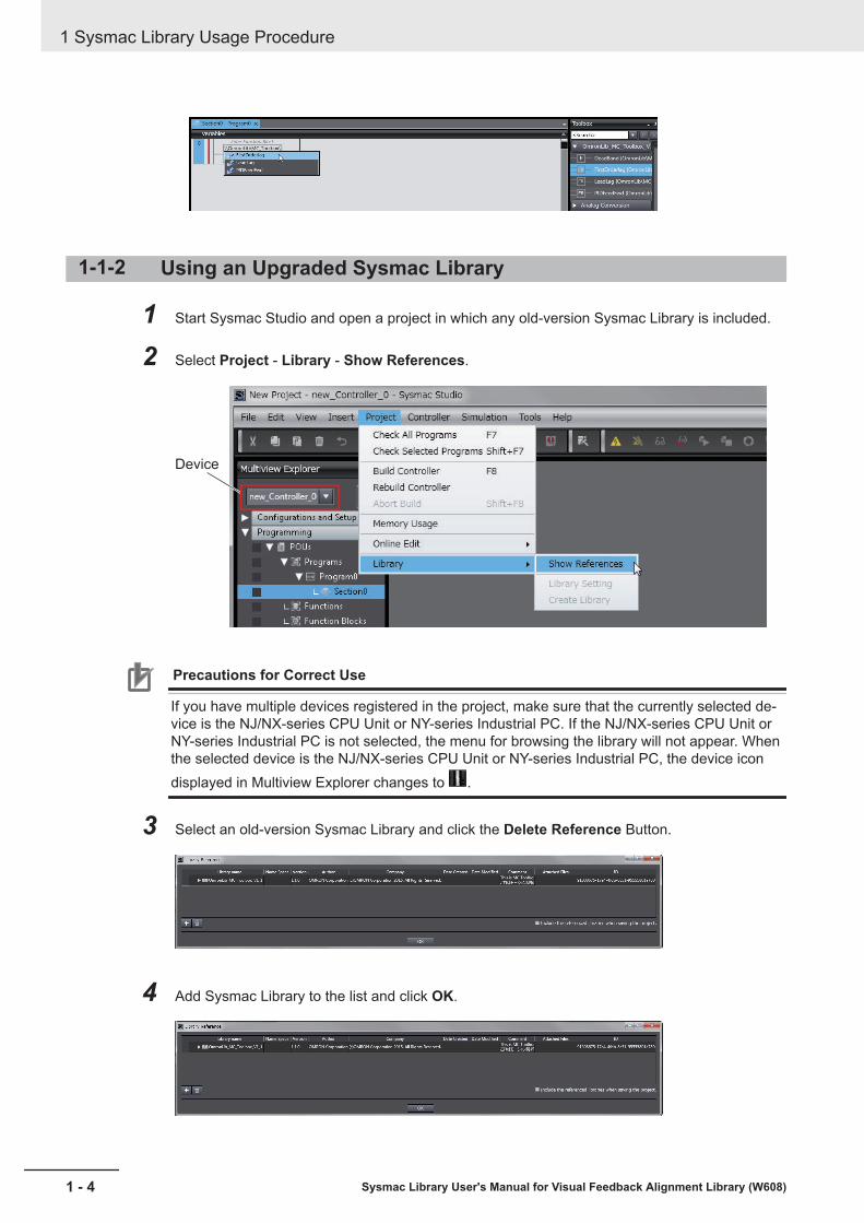
1-1-2 Using an Upgraded Sysmac Library
1 Start Sysmac Studio and open a project in which any old-version Sysmac Library is included.
2 Select Project - Library - Show References.
Device
Precautions for Correct Use
If you have multiple devices registered in the project, make sure that the currently selected de-vice is the NJ/NX-series CPU Unit or NY-series Industrial PC. If the NJ/NX-series CPU Unit orNY-series Industrial PC is not selected, the menu for browsing the library will not appear. Whenthe selected device is the NJ/NX-series CPU Unit or NY-series Industrial PC, the device icondisplayed in Multiview Explorer changes to .
3 Select an old-version Sysmac Library and click the Delete Reference Button.
4 Add Sysmac Library to the list and click OK.
1 Sysmac Library Usage Procedure
1 - 4 Sysmac Library User's Manual for Visual Feedback Alignment Library (W608)

Precautions for Correct Use
Upgrade the Sysmac Library version, and then execute All Program Check, and confirm thatthere are no errors in the Build Window Program Check results.From the Main Menu, select Project - All Program Check.
1 Sysmac Library Usage Procedure
1 - 5Sysmac Library User's Manual for Visual Feedback Alignment Library (W608)
1-1 Procedure to Use Sysm
ac Li-brary Installed U
sing the Installer
1
1-1-2 Using an U
pgraded Sysmac Library

1-2 How to use Sysmac Library in theCPU Unit or Industrial PC
Even when Sysmac Library is not installed on your computer, you can use Sysmac Library by upload-ing it from the CPU Unit or Industrial PC to your computer.The procedure to use Sysmac Library in the CPU Unit or Industrial PC is as follows.
Version Information
To use Sysmac Library, you need Sysmac Studio Ver.1.14 or higher.
1 Start the Sysmac Studio and create a new project in which you want to use Sysmac Library.
2 Connect online to the CPU Unit or Industrial PC.
3 Upload the POUs in which Sysmac Library is used.Now, when you select the Ladder Editor or ST Editor, the function blocks and functions includ-ed in the Sysmac Library used in the uploaded POUs appear in the Toolbox.
4 Insert the Sysmac Library's function blocks and functions into the circuit using one of the fol-lowing two methods.• Select the desired function block or function in the Toolbox and drag and drop it onto the
Ladder Editor.
Drag & Drop
• Right-click the Ladder Editor, select Insert Function Block in the menu, and enter the fullyqualified name (¥¥namespacename¥FBname).
1 Sysmac Library Usage Procedure
1 - 6 Sysmac Library User's Manual for Visual Feedback Alignment Library (W608)
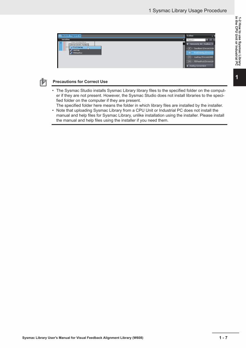
Precautions for Correct Use
• The Sysmac Studio installs Sysmac Library library files to the specified folder on the comput-er if they are not present. However, the Sysmac Studio does not install libraries to the speci-fied folder on the computer if they are present.The specified folder here means the folder in which library files are installed by the installer.
• Note that uploading Sysmac Library from a CPU Unit or Industrial PC does not install themanual and help files for Sysmac Library, unlike installation using the installer. Please installthe manual and help files using the installer if you need them.
1 Sysmac Library Usage Procedure
1 - 7Sysmac Library User's Manual for Visual Feedback Alignment Library (W608)
1-2 How
to use Sysmac Library
in the CPU
Unit or Industrial PC
1

1 Sysmac Library Usage Procedure
1 - 8 Sysmac Library User's Manual for Visual Feedback Alignment Library (W608)
2Visual Feedback Alignment Li-brary
An explanation of the common specifications for each Function (FUN) and FunctionBlock (FB) in the Visual Feedback Alignment Library.
2-1 Terms............................................................................................................. 2 - 22-2 Overview ....................................................................................................... 2 - 3
2-2-1 Alignment Application ................................................................................... 2 - 32-2-2 Visual Feedback ........................................................................................... 2 - 3
2-3 Restrictions and Limitations....................................................................... 2 - 62-4 Hardware Configuration .............................................................................. 2 - 7
2-4-1 System Configuration ................................................................................... 2 - 72-4-2 Supported Stages ......................................................................................... 2 - 7
2-5 Visual Feedback Alignment Library Flow Chart........................................ 2 - 92-5-1 Alignment Flow Chart ................................................................................... 2 - 92-5-2 Generate Calibration Parameter Flow Chart ...............................................2 - 11
2-6 Visual Feedback Alignment Library Function Specification.................. 2 - 132-6-1 Function Overview ...................................................................................... 2 - 132-6-2 Coordinate Systems ................................................................................... 2 - 142-6-3 Control Blocks............................................................................................. 2 - 152-6-4 Execute Measurement (Imaging of Workpiece).......................................... 2 - 172-6-5 When Vision Sensor NG Measurement Occurs.......................................... 2 - 17
2 - 1Sysmac Library User's Manual for Visual Feedback Alignment Library (W608)
2

2-1 TermsTerms used in this document and their meanings are as follows.
Term MeaningCamera coordinates X and Y coordinates on an image from a camera, in units of pixels, where
the X coordinate is in the horizontal direction and the Y coordinate is inthe vertical direction starting from the upper left of the image. The unit ofrotation direction on the XY plane is degree (°).
Reference mark position Coordinates for a mark on a reference workpiece object when performingalignment control.
Calibration Control and calculations for calculating calibration parameters.Calibration parameter The conversion coefficient used for coordinate conversion (converting
camera coordinates to stage coordinates).Measurement The vision sensor capturing an image of an object and outputting the
measurement position/angle of the object.Measurement mark position The coordinates for a mark on a workpiece object to be measured for the
purpose of alignment control.Coordinate conversion Conversion of camera coordinates to stage coordinates using calibration
parameters.Axis coordinates Rotation coordinates specific to each axis, or linear motion coordinates.
These are in units called Axis Instruction Units.Axis Instruction Unit Units representing the position and distance which are used by the mo-
tion control function of the controller.Value converted from position units and electronic gears.
Stage coordinates Stage-specific Cartesian coordinates.The target position for moving the stage is calculated by the position ofthe stage coordinates. These are in units called Axis Instruction Units.The unit of rotation direction on the Cartesian plane is degree (°).
Visual Feedback A system that performs feedback control using position information ac-quired from the vision sensor as its input.
2 Visual Feedback Alignment Library
2 - 2 Sysmac Library User's Manual for Visual Feedback Alignment Library (W608)

2-2 OverviewThe Visual Feedback Alignment Library is a set of software function components for alignment appli-cations employing visual feedback.
2-2-1 Alignment ApplicationThe alignment application is a method of detecting the position/angle of a workpiece object to bemeasured (hereinafter, referred to as "measurement workpiece") with a vision sensor in reference toan object placed at an arbitrary position/angle on the alignment stage (hereinafter, referred to as"stage"). By moving the alignment stage based on the above information, it controls the positioning sothat the measurement position/angle matches with the target position/angle (hereinafter, referred to as"reference position/angle").The image capture on which to detect the reference position/angle is referred to as the referenceworkpiece. The following illustration is an example of Position Alignment of two workpieces. In this ex-ample, the reference workpiece, which becomes the reference for alignment, does not move evenwhen the stage is moved, while the measurement workpiece is moved and Position Alignment is per-formed.In the case of the XYθ, θXY stage, there are three control axes in the θ direction corresponding to therotation direction on the XY plane in addition to the X direction and the Y direction which are the per-pendicular direction in the XY plane.
Reference workpiece
Measurement workpiece
Measurement workpiece
Reference workpiece
θ direction
X direction
Y directionY direction
θ direction
After execute alignment
Alignment stage
With this library, the stage is controlled using visual feedback of the measurement position/angle of theworkpiece object as measured by the vision sensor.
2-2-2 Visual FeedbackWhen you want the control target to be in a target state, you can apply a feedback control that takesthe difference between the value representing the current state of the control target and the value rep-resenting its target state and perform the operation according to the difference.Visual feedback means to obtain the state of the control target from the visual information in feedbackcontrol. It uses the vision sensor to acquire and measure the image of the control target, and performs
2 Visual Feedback Alignment Library
2 - 3Sysmac Library User's Manual for Visual Feedback Alignment Library (W608)
2-2 Overview
2
2-2-1 Alignment Application

feedback control based on that information. By using visual information, it is possible to have controlaccording to the state of the factory/actual workpiece.
Reference workpieceMeasurement
workpiece
Camera
Vision sensorcontroller
Position relationship of workpiece(Set point)
Controller
Control target: Position relationship of workpiece
Stage position adjustment
+
-
This library is a set of software components (Function Blocks (FB) / Functions (FUN)) that realizes thealignment application with visual feedback. By combining FB / FUN provided with this library, it is pos-sible to build alignment control that applies visual feedback with the user program on the controller.
With this library, calculations to determine the stage travel distance required for alignment are madebased on the position/distance of the object measured with the vision sensor. Then it performs visualfeedback control by giving control that is proportional to the travel distance.
Alignmenttravel
distance calculation
Alignment calculation
Controller
Feedback control
Visual feedback calculation
Position estimation
interpolation
Trajectory calculation
Position command Servo
Drive
Stage drivemotor
Work-piece
Vision sensor
Target object position/distance
Image
Current position
With the visual feedback control provided by this library, a trajectory of feedback control is generatedfor the calculated alignment travel distance. The generated feedback trajectory is given as a commandto drive the stage with limits defined by the specified maximum acceleration/deceleration and maxi-mum velocity.
2 Visual Feedback Alignment Library
2 - 4 Sysmac Library User's Manual for Visual Feedback Alignment Library (W608)

Stage drivemotor velocity
Maximum velocity
Maximum acceleration/deceleration
Command velocity
Time
Feedback trajectory
2 Visual Feedback Alignment Library
2 - 5Sysmac Library User's Manual for Visual Feedback Alignment Library (W608)
2-2 Overview
2
2-2-2 Visual Feedback
2-3 Restrictions and Limitations• Because the alignment control provided by this library uses visual feedback control, it is necessary
that the measurement position and reference position are always both within the measurable rangeof the vision sensor.
• Regarding the Image mode of the vision sensor: Alignment cannot be performed using this library ifeither Camera Through image is selected for the camera image mode or the Multi-input function isused.
• This library does not do any correction for camera tilt or image distortion caused by the camera lens.To perform this correction if needed, please use in combination with the Precise Calibration functionprovided in the vision sensor.
2 Visual Feedback Alignment Library
2 - 6 Sysmac Library User's Manual for Visual Feedback Alignment Library (W608)

2-4 Hardware Configuration
2-4-1 System ConfigurationThe following is an example of the typical system configuration for alignment control using this library.
Controller
Vision sensorcontroller
Servo Drive Camera
Alignmentstage
2-4-2 Supported StagesThis library supports the following types of stages.
XY Stage XYθ Stage θXY Stage
X(Y) Stage Xθ(Yθ) Stage θX(θY) Stage
UVW Stage UVWR Stage
Regarding the control of θ axis used in XYθ, θXY, Xθ(Yθ), θX(θY) stage types, both direct drive (thedrive system by which the θ axis rotation is aligned to the rotary axis of a Servomotor) and Linear drive(the drive system by which rotation control of the θ axis is done by linear movement) are supported.
2 Visual Feedback Alignment Library
2 - 7Sysmac Library User's Manual for Visual Feedback Alignment Library (W608)
2-4 Hardw
are Configuration
2
2-4-1 System C
onfiguration

Servomotor
Direct drive
Servomotor
Linear drive
Precautions for Correct Use
The θ axis is the rotary axis, but it does not support multi-rotation. Therefore, when using it inLinear Mode or Rotary Mode, it is necessary to set the Count Mode of the axis parameter sothat it does not rotate multiple times. This can be done using the various software limits.The UVW stage and the UVWR stages correspond to two fulcrum types: direct movement androtation. Refer to UVWR Stage Parameter (sUVWR_STAGE_PARAMS) on page 4 - 5 for de-tail.
2 Visual Feedback Alignment Library
2 - 8 Sysmac Library User's Manual for Visual Feedback Alignment Library (W608)
2-5 Visual Feedback Alignment LibraryFlow Chart
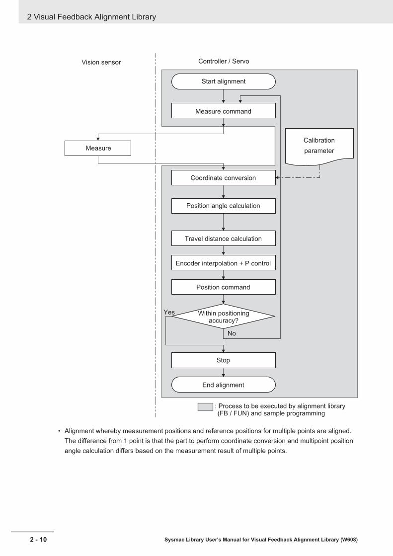
2-5-1 Alignment Flow ChartThe following is a flow chart showing how alignment is done with the use of this library.• Alignment whereby one measurement position/angle is aligned to a corresponding reference posi-
tion/angle
2 Visual Feedback Alignment Library
2 - 9Sysmac Library User's Manual for Visual Feedback Alignment Library (W608)
2-5 Visual Feedback Alignm
ent Library FlowC
hart
2
2-5-1 Alignment Flow
Chart
Vision sensor
Start alignment
Calibration
parameter
Coordinate conversion
Position angle calculation
Travel distance calculation
Encoder interpolation + P control
Position command
Within positioning accuracy?
Stop
End alignment
Yes
No
: Process to be executed by alignment library (FB / FUN) and sample programming
Controller / Servo
Measure command
Measure
• Alignment whereby measurement positions and reference positions for multiple points are aligned.The difference from 1 point is that the part to perform coordinate conversion and multipoint positionangle calculation differs based on the measurement result of multiple points.
2 Visual Feedback Alignment Library
2 - 10 Sysmac Library User's Manual for Visual Feedback Alignment Library (W608)

Vision sensor
Start alignment
Calibration
parameter
Coordinate conversion
Multipoint position angle calculation
Travel distance calculation
Encoder interpolation + P control
Position command
Within positioning accuracy?
Stop
End alignment
Yes
No
: Process to be executed by alignment library
(FB / FUN) and sample programming
Controller / Servo
Measure command
Measure
2-5-2 Generate Calibration Parameter Flow ChartThe following is a flow chart showing how calibration parameters are generated using this library.
2 Visual Feedback Alignment Library
2 - 11Sysmac Library User's Manual for Visual Feedback Alignment Library (W608)
2-5 Visual Feedback Alignm
ent Library FlowC
hart
2
2-5-2 Generate C
alibration Parameter Flow
Chart
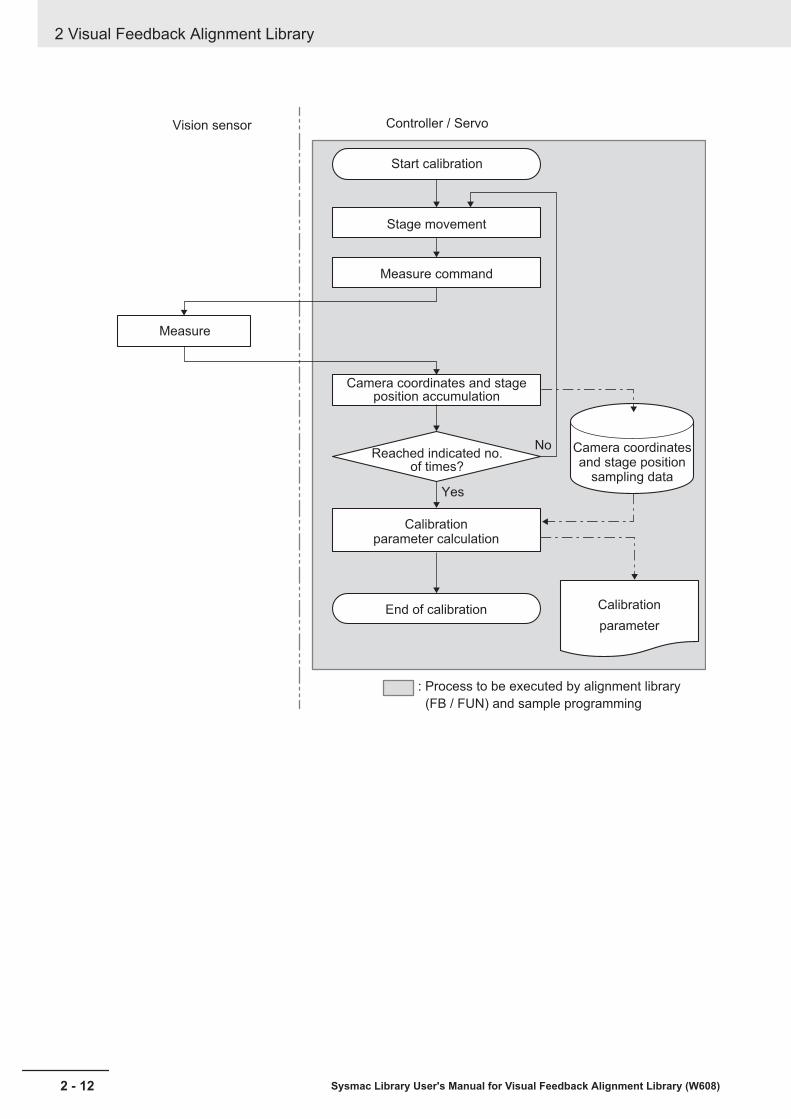
Vision sensor
Start calibration
Camera coordinates and stage position
sampling data
Camera coordinates and stage position accumulation
Calibrationparameter calculation
Reached indicated no. of times?
End of calibration
Yes
No
: Process to be executed by alignment library
(FB / FUN) and sample programming
Controller / Servo
Stage movement
Measure command
Measure
Calibration
parameter
2 Visual Feedback Alignment Library
2 - 12 Sysmac Library User's Manual for Visual Feedback Alignment Library (W608)

2-6 Visual Feedback Alignment LibraryFunction Specification
2-6-1 Function OverviewThe functions needed for alignment control can be classified into the following three major items.(1) Position measurement of an alignment mark on a workpiece or specific features of the workpiecesuch as a corner by a vision sensor.(2) Travel distance calculation of the stage for aligning the workpiece to a predetermined position (ref-erence position) based on the measurement result.(3) Position control of the stage according to the travel distance.
Also in (1), the following function is required to conform to the alignment control in order to convert theunit of dimension in the image captured by the camera into the unit of dimension in stage operation.(4) The Calibration function aligns the stage coordinates and the camera coordinates.
In general, the vision sensor controller is responsible for (1), (2) and (4) and the controller gives acommand to the motor driver that drives the stage (3) according to the output from the vision sensorcontroller.
In this library, the vision sensor controller is responsible for only the position measurement of (1) and(4), and the controller performs the various calculations of (2), (3) and (4) as well as Stage drive.
• Alignment (workpiece alignment)Measure features of a workpiece object to get a measurement position in camera coordinates. Thefeatures to use include alignment marks on workpiece and specific features of the workpiece suchas corners. Next, using the calibration parameter calculated by calibration, convert the measure-ment position to the stage coordinates. Finally, calculate the axis travel distance required to align themeasurement position with the reference position, and apply the control to the stage position.
Camera 0
StageMove instruction to reference position
Camera 1
Controller
Measurement position (Camera coordinates)
Vision sensor controller
• CalibrationBecause coordinate systems differ between camera and stage, prior to measurements, calculationsmust be done to make the coordinate systems compatible with each other. That process is referredto as Calibration.The controller moves the stage and calculates the calibration parameter by continually repeating aset operation pattern of move workpiece → position measurement.
2 Visual Feedback Alignment Library
2 - 13Sysmac Library User's Manual for Visual Feedback Alignment Library (W608)
2-6 Visual Feedback Alignm
ent LibraryFunction Specification
2
2-6-1 Function Overview

Camera 0
Stage
Camera 1 : Stage coordinates
: Camera coordinates
Correspondence
(= Execute calibration)
Controller
Vision sensor controller
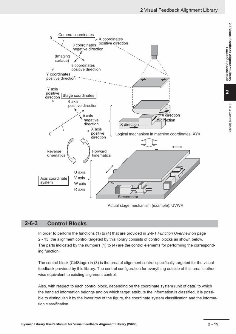
2-6-2 Coordinate SystemsThere are three types of coordinate systems handled in the alignment control targeted by this library.In this library, calculations of the alignment application are all converted into XYθ stage. For the controloutput of this computational XYθ stage (hereinafter referred to as the virtual XYθ stage), kinematicstransformation according to the actual stage mechanism is performed and the stage mechanism iscontrolled.
Type Overview Definition UnitCameracoordi-nates
The Coordinate Sys-tem for camera imag-ing
The upper left corner of the captured image isset to be zero, the X coordinate is the positivedirection in the horizontal direction, the Y coordi-nate is the positive direction in the vertical direc-tion, the θ coordinate (rotation angle) is the pos-itive direction in the clockwise direction on theXY plane.
X,Y: Pixelsθ: ° (degree)
Stage co-ordinates
The Coordinate Sys-tem on a stage
Zero is the home of the stage and from it isformed the XY plane in the right-handed system(Main system) of Cartesian coordinates with re-spect to the direction of movement of the stage.In the stage coordinates, location managementis performed according to the virtual XYθ stage,regardless of the mechanism of the actualstage.
X,Y: mmθ: ° (degree)
Axis Coor-dinateSystem(ACS)
The Coordinate Sys-tem of the stage driveaxis
The position coordinates of the individual driveaxes determined by the stage mechanism aredetermined with respect to the position of thestage coordinates. The position coordinates ofparticular stage coordinates are converted intothe position (rotation distance) of each axis bysolving the reverse kinematics with respect tothe mechanism. Conversely, when each axis po-sition (rotation distance) is obtained, the stageposition determined by that position becomesclear by solving the forward kinematics.
Each axis: Dependson stage mechanism
2 Visual Feedback Alignment Library
2 - 14 Sysmac Library User's Manual for Visual Feedback Alignment Library (W608)
Camera coordinates
Stage coordinates
Axis coordinate system
U axis
V axis
W axis
R axis
Logical mechanism in machine coordinates: XYθ
Actual stage mechanism (example): UVWR
Forward kinematics
Reverse kinematics
Servomotor
(Imaging surface)
θ coordinates negative direction
X coordinates
θ coordinates positive direction
θ axis
θ axis
negative direction
positive direction
positive direction
Y coordinatespositive direction
X axispositive direction
Y axispositive direction
0
0
θ direction
X directionY directionY direction
θ direction
2-6-3 Control BlocksIn order to perform the functions (1) to (4) that are provided in 2-6-1 Function Overview on page2 - 13, the alignment control targeted by this library consists of control blocks as shown below.The parts indicated by the numbers (1) to (4) are the control elements for performing the correspond-ing function.
The control block (CtrlStage) in (3) is the area of alignment control specifically targeted for the visualfeedback provided by this library. The control configuration for everything outside of this area is other-wise equivalent to existing alignment control.
Also, with respect to each control block, depending on the coordinate system (unit of data) to whichthe handled information belongs and on which target attribute the information is classified, it is possi-ble to distinguish it by the lower row of the figure, the coordinate system classification and the informa-tion classification.
2 Visual Feedback Alignment Library
2 - 15Sysmac Library User's Manual for Visual Feedback Alignment Library (W608)
2-6 Visual Feedback Alignm
ent LibraryFunction Specification
2
2-6-3 Control Blocks

: P
OU
pro
vid
ed
in
th
is lib
rary
(F
un
ctio
n B
lock / F
un
ctio
n)
Blo
ck d
iag
ram
of a
lign
me
nt co
ntr
ol fu
nctio
n
Ge
ne
rate
ca
libra
tio
n p
ara
me
ter
functio
n b
lock
Re
fere
nce
ma
rk p
ositio
n
(Ca
me
ra c
oo
rdin
ate
s)
Ima
ge
m
ea
su
re-
me
nt
Re
fere
nce
ma
rk p
ositio
n(S
tag
e c
oo
rdin
ate
s)
Refe
ren
ce
ma
rk
po
sitio
n(A
lign
me
nt
co
ntr
ol)
Me
asu
rem
en
t m
ark
po
sitio
n(A
lign
me
nt
co
ntr
ol)
(1)
(2)
(3)
(1)
(4)
(3)
Me
asu
rem
en
t m
ark
po
sitio
n
(Ca
me
ra c
oo
rdin
ate
s)
Me
asu
rem
en
t m
ark
po
sitio
n
(Sta
ge
co
ord
ina
tes)
Affin
e
Tra
ns
Ca
lc
Po
sA
ng
le
Calc
Mu
lti
Po
sA
ng
le
or
Ctr
lSta
ge
XY
θ a
xis
tra
ve
l d
ista
nce
XY
θ a
xis
ve
locity
XY
θ a
xis
tra
ve
l d
ista
nce
Ca
lc
Mo
ve
me
nt
Ca
lcA
xis
Ve
locity
Ge
ne
rate
Trig
ge
r
Ca
lc
Invers
e
Kin
em
atics
MC
_S
yn
c
Mo
ve
Ab
so
lute
Ca
lc
Fo
rwa
rd
Kin
em
atics
Pa
th tim
e
Virtu
al X
Yθ s
tag
e
po
sitio
n
Virtu
al X
Yθ
sta
ge
po
sitio
n
Ta
rge
t p
ositio
n fo
r e
ach
sta
ge
axis
Po
sitio
n
co
mm
an
d
Se
rvo
Drive
X/U
axis
Y/V
axis
θ/W
axis
R a
xis
Ima
gin
g trig
ge
r
Cu
rre
nt a
xis
p
ositio
n
Vis
ion
se
nso
r
Sta
ge
Se
rvo
Drive
X/U
axis
Y/V
axis
θ/W
axis
Sta
ge
Ca
ptu
red
im
ag
eIm
ag
ing
me
tho
d
(Ca
me
ra)
Pe
rfo
rm im
ag
ing
Ph
ysic
al p
ositio
n r
ela
tio
nsh
ip b
etw
ee
n w
ork
pie
ce
an
d s
tage
Ca
libra
tio
n
pa
ram
ete
r
Ge
ne
rate
ca
libra
tio
np
ara
me
ter
Po
sitio
n c
om
ma
nd
Ima
gin
g
trig
ge
r
Ph
ysic
al p
ositio
n r
ela
tion
sh
ip b
etw
ee
n w
ork
pie
ce
an
d s
tag
e
Ge
ne
rate
Ca
libP
ara
ms
Vis
ion
se
nso
r
Pe
rfo
rmim
ag
ing
Ima
gin
g
me
tho
d
(Ca
me
ra)
Ca
ptu
red
im
ag
e
Ima
ge
m
ea
su
re-
me
nt
Re
fere
nce
m
ark
po
sitio
n
(Ca
me
ra)
Co
ord
ina
te s
yste
m c
lassific
atio
n
Info
rma
tio
n c
lassific
atio
n
Ca
me
ra c
oo
rdin
ate
s
Po
sitio
n c
oo
rdin
ate
s o
f a
lignm
ent m
ark
Sta
ge
po
sitio
n c
oo
rdin
ate
s
Sta
ge c
oo
rdin
ate
s*1
Axis
co
ord
ina
te s
yste
m
Axis
po
sitio
n in
form
atio
n
* 1. W
ith
th
is lib
rary
, th
e a
xis
tra
ve
l d
ista
nce
an
d a
xis
ve
locity fo
r a
lign
me
nt co
ntr
ol a
re c
alc
ula
ted
ba
se
d o
n th
e v
irtu
al X
Yθ s
tag
e.
T
he
refo
re, e
ach
axis
po
sitio
n o
f th
e s
tag
e is c
on
ve
rte
d in
to p
ositio
n c
oo
rdin
ate
s o
n th
e v
irtu
al X
Yθ s
tag
e c
oo
rdin
ate
s b
y C
alc
Fo
rwa
rdK
ine
matics (
forw
ard
kin
em
atics c
alc
ula
tio
n),
an
d th
e a
xis
tra
ve
l
dis
tan
ce
/ a
xis
ve
locity o
n th
e c
alc
ula
ted
virtu
al X
Yθ s
tag
e c
oo
rdin
ate
s is c
on
ve
rte
d b
y C
alc
Invers
eK
inem
atics (
reve
rse
kin
em
atics c
alc
ula
tio
n)
into
th
e ta
rge
t p
ositio
n o
f th
e s
tag
e a
xis
.
With
th
is m
eth
od
, it is p
ossib
le to p
erf
orm
alig
nm
en
t co
ntr
ol w
ith
th
e s
am
e m
od
ule
co
nfig
ura
tio
n fo
r a
ll th
e s
tag
es d
escrib
ed
in
2-4
-2 S
up
po
rte
d S
tag
es.
Ju
dg
e
Alig
nm
en
t
Co
mp
lete
2 Visual Feedback Alignment Library
2 - 16 Sysmac Library User's Manual for Visual Feedback Alignment Library (W608)

2-6-4 Execute Measurement (Imaging of Workpiece)
The vision sensor takes an image of the measurement workpiece or the reference workpiece andmeasures it with a "Search" type processing item to get the measurement position/angle and refer-ence position/angle in camera coordinates.These measurements in camera coordinates are the input to the controller (library).Even if a "reference workpiece" is not imaged, but the reference position is set to a fixed position, thereference position is entered into the controller (library) with camera coordinates.This library supports the use of 1 point to 4 points to specify the reference position and the measure-ment position.Since the vision sensor does not perform coordinate conversion (outputs the camera coordinates asthey are), cases where multiple reference positions or measurement positions are detected by onecamera and cases where multiple cameras detect reference positions or measurement positions arehandled in the same way.
Example: When the reference position or measurement position is determined by 2 points
When detecting 2 points with 1 camera
Handled similarly on the controller (library) side
Point 0 (X = 100,Y = 100)
Point 1 (X = 900,Y = 100)
Point 0 (X = 300,Y = 200)
Point 1 (X = 200,Y = 300)
When detecting 2 points with 2 cameras
Point 0Point 0 Point 0Point 0Point 1Point 1 Point 1Point 1
2-6-5 When Vision Sensor NG Measurement OccursWhen the measurement result from the vision sensor is an NG measurement result (an output ofTRUE for Overall Judgment (TotalJudgment)), the alignment control block ignores the measurementNG and continues control based on the previous measurement position/angle. Even after a measure-ment NG occurs, a measurement trigger is generated according to the Generate trigger condition.Therefore, when the next measurement is successfully done, alignment control based on the updatedmeasurement position/angle is performed.The generate calibration parameter (GenerateCalibParams) is aborted (CommandAborted) when themeasurement result of the vision sensor is an NG measurement.
2 Visual Feedback Alignment Library
2 - 17Sysmac Library User's Manual for Visual Feedback Alignment Library (W608)
2-6 Visual Feedback Alignm
ent LibraryFunction Specification
2
2-6-4 Execute Measurem
ent (Imaging of W
orkpiece)
2 Visual Feedback Alignment Library
2 - 18 Sysmac Library User's Manual for Visual Feedback Alignment Library (W608)
3Common Specifications of Func-tion Blocks
This section describes the shared specifications of each FB in the Sysmac Library.
3-1 Common Variables....................................................................................... 3 - 23-1-1 Definition of Input Variables and Output Variables........................................ 3 - 23-1-2 Execute-type Function Blocks ...................................................................... 3 - 33-1-3 Enable-type Function Blocks ........................................................................ 3 - 5
3-2 Precautions................................................................................................... 3 - 73-2-1 Nesting.......................................................................................................... 3 - 73-2-2 Instruction Options........................................................................................ 3 - 73-2-3 Re-execution of Function Blocks .................................................................. 3 - 7
3 - 1Sysmac Library User's Manual for Visual Feedback Alignment Library (W608)
3
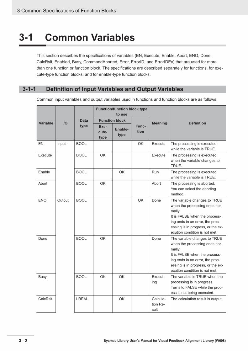
3-1 Common VariablesThis section describes the specifications of variables (EN, Execute, Enable, Abort, ENO, Done,CalcRslt, Enabled, Busy, CommandAborted, Error, ErrorID, and ErrorIDEx) that are used for morethan one function or function block. The specifications are described separately for functions, for exe-cute-type function blocks, and for enable-type function blocks.
3-1-1 Definition of Input Variables and Output VariablesCommon input variables and output variables used in functions and function blocks are as follows.
Variable I/O Datatype
Function/function block typeto use
Meaning DefinitionFunction blockFunc-tion
Exe-cute-type
Enable-type
EN Input BOOL OK Execute The processing is executedwhile the variable is TRUE.
Execute BOOL OK Execute The processing is executedwhen the variable changes toTRUE.
Enable BOOL OK Run The processing is executedwhile the variable is TRUE.
Abort BOOL OK Abort The processing is aborted.You can select the abortingmethod.
ENO Output BOOL OK Done The variable changes to TRUEwhen the processing ends nor-mally.It is FALSE when the process-ing ends in an error, the proc-essing is in progress, or the ex-ecution condition is not met.
Done BOOL OK Done The variable changes to TRUEwhen the processing ends nor-mally.It is FALSE when the process-ing ends in an error, the proc-essing is in progress, or the ex-ecution condition is not met.
Busy BOOL OK OK Execut-ing
The variable is TRUE when theprocessing is in progress.Turns to FALSE while the proc-ess is not being executed.
CalcRslt LREAL OK Calcula-tion Re-sult
The calculation result is output.
3 Common Specifications of Function Blocks
3 - 2 Sysmac Library User's Manual for Visual Feedback Alignment Library (W608)

Variable I/O Datatype
Function/function block typeto use
Meaning DefinitionFunction blockFunc-tion
Exe-cute-type
Enable-type
Enabled BOOL OK Enabled The variable is TRUE when theoutput is enabled. It is used tocalculate the control amount formotion control, temperaturecontrol, etc.
Com-mandAborted
BOOL OK Com-mandAborted
The variable changes to TRUEwhen the processing is aborted.It changes to FALSE when theprocessing is executed the nexttime again.
Error BOOL OK OK Error This variable is TRUE whilethere is an error.It is FALSE when the process-ing ends normally, the process-ing is in progress, or the execu-tion condition is not met.
ErrorID WORD OK OK ErrorCode
An error code is output.
ErrorI-DEx
DWORD OK OK Expan-sion Er-ror Code
An expansion error code is out-put.
3-1-2 Execute-type Function Blocks• Processing starts when Execute changes to TRUE.• When Execute changes to TRUE, Busy also changes to TRUE. When processing is completed nor-
mally, Busy changes to FALSE and Done changes to TRUE.• When continuously executing function blocks of the same instance, change the next Execute to
TRUE for at least one task period after Done changes to FALSE in the previous execution.• If the function block has a CommandAborted (Instruction Aborted) output variable and processing is
aborted, CommandAborted changes to TRUE and Busy changes to FALSE.• If an error occurs in the function block, Error changes to TRUE and Busy changes to FALSE.• For function blocks that output the result of calculations for motion control and temperature control,
you can use the BOOL input variable Abort to abort the FB process. When Abort changes to TRUE,CommandAborted changes to TRUE and the execution of the function block is aborted.
Abcd_instance
InOut_Val InOut_Val
DoneBusy
CommandAborted
ErrorErrorID
ErrorIDEx
Execute
Abort
Abcd
Input-Output Variables
Input Variables
Input-Output Variables
Output Variables
3 Common Specifications of Function Blocks
3 - 3Sysmac Library User's Manual for Visual Feedback Alignment Library (W608)
3-1 Com
mon Variables
3
3-1-2 Execute-type Function Blocks
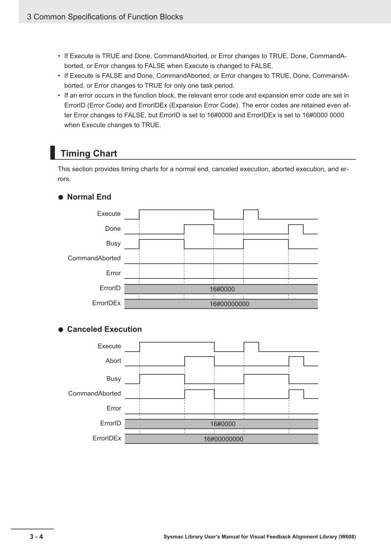
• If Execute is TRUE and Done, CommandAborted, or Error changes to TRUE, Done, CommandA-borted, or Error changes to FALSE when Execute is changed to FALSE.
• If Execute is FALSE and Done, CommandAborted, or Error changes to TRUE, Done, CommandA-borted, or Error changes to TRUE for only one task period.
• If an error occurs in the function block, the relevant error code and expansion error code are set inErrorID (Error Code) and ErrorIDEx (Expansion Error Code). The error codes are retained even af-ter Error changes to FALSE, but ErrorID is set to 16#0000 and ErrorIDEx is set to 16#0000 0000when Execute changes to TRUE.
Timing ChartThis section provides timing charts for a normal end, canceled execution, aborted execution, and er-rors.
l Normal End
Execute
Done
Busy
Error
ErrorID
ErrorIDEx
CommandAborted
16#0000
16#00000000
l Canceled Execution
Execute
Abort
Busy
Error
ErrorID
ErrorIDEx
CommandAborted
16#0000
16#00000000
3 Common Specifications of Function Blocks
3 - 4 Sysmac Library User's Manual for Visual Feedback Alignment Library (W608)
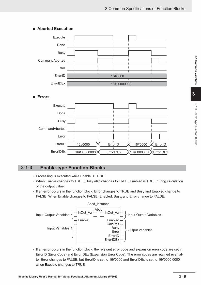
l Aborted Execution
Execute
Done
Busy
Error
ErrorID
ErrorIDEx
CommandAborted
16#0000
16#00000000
l Errors
Execute
Done
Busy
Error
ErrorID ErrorID
ErrorIDEx ErrorIDEx ErrorIDEx
CommandAborted
16#0000 16#0000
16#00000000 16#00000000
ErrorID
3-1-3 Enable-type Function Blocks• Processing is executed while Enable is TRUE.• When Enable changes to TRUE, Busy also changes to TRUE. Enabled is TRUE during calculation
of the output value.• If an error occurs in the function block, Error changes to TRUE and Busy and Enabled change to
FALSE. When Enable changes to FALSE, Enabled, Busy, and Error change to FALSE.
Abcd_instance
InOut_Val
Enable EnabledCalcRslt
BusyError
ErrorIDErrorIDEx
InOut_ValAbcd
Input-Output Variables
Input Variables
Input-Output Variables
Output Variables
• If an error occurs in the function block, the relevant error code and expansion error code are set inErrorID (Error Code) and ErrorIDEx (Expansion Error Code). The error codes are retained even af-ter Error changes to FALSE, but ErrorID is set to 16#0000 and ErrorIDEx is set to 16#0000 0000when Execute changes to TRUE.
3 Common Specifications of Function Blocks
3 - 5Sysmac Library User's Manual for Visual Feedback Alignment Library (W608)
3-1 Com
mon Variables
3
3-1-3 Enable-type Function Blocks

• For function blocks that calculate the control amount for motion control, temperature control, etc.,Enabled is FALSE when the value of CalcRslt (Calculation Result) is incorrect. In such a case, donot use CalcRslt. In addition, after the function block ends normally or after an error occurs, the val-ue of CalcRslt is retained until Enable changes to TRUE. The control amount will be calculatedbased on the retained CalcRslt value, if it is the same instance of the function block that changedEnable to TRUE. If it is a different instance of the function block, the control amount will be calculat-ed based on the initial value.
Timing ChartsThis section provides timing charts for a normal end and errors.
l Normal End
Enable
Enabled
CalcRslt
Busy
Error
ErrorID
ErrorIDEx
16#0000
16#00000000
RetentionRetention
l Errors
16#0000
ErrorID
Enable
Enabled
CalcRslt
Busy
Error
ErrorID ErrorID
ErrorIDEx
16#0000 16#0000
16#00000000
16#00000000
ErrorIDEx
ErrorID ErrorID
ErrorIDEx
RetentionRetention
3 Common Specifications of Function Blocks
3 - 6 Sysmac Library User's Manual for Visual Feedback Alignment Library (W608)
3-2 PrecautionsThis section provides precautions for the use of this function block.
3-2-1 NestingYou can nest calls to this function block for up to four levels.Refer to NJ/NX-series CPU Unit Software User's Manual (Cat. No. W501) or NY-series IPC MachineController Industrial Panel PC / Industrial Box PC Software User's Manual (Cat. No. W558) for detailson the nesting function block.
3-2-2 Instruction OptionsYou cannot use the upward differentiation option for this function block.
3-2-3 Re-execution of Function BlocksExecute-type function blocks cannot be re-executed by the same instance.If you do so, the output value will be the initial value.Refer to NJ/NX-series CPU Unit Motion Control User's Manual (Cat. No. W507) or NY-series IPCMachine Controller Industrial Panel PC / Industrial Box PC Motion Control User's Manual (Cat. No.W509) for details on re-execution.
3 Common Specifications of Function Blocks
3 - 7Sysmac Library User's Manual for Visual Feedback Alignment Library (W608)
3-2 Precautions
3
3-2-1 Nesting

3 Common Specifications of Function Blocks
3 - 8 Sysmac Library User's Manual for Visual Feedback Alignment Library (W608)

4Individual Specifications ofFB/FUN
This section describes the individual specifications for each Function (FUN) and Func-tion Block (FB) in the Visual Feedback Alignment Library.
Structure.................................................................................................................. 4 - 2AffineTrans............................................................................................................ 4 - 22CalcPosAngle ....................................................................................................... 4 - 25CalcMultiPosAngle............................................................................................... 4 - 30CtrlStage................................................................................................................ 4 - 35CalcMovement ...................................................................................................... 4 - 45CalcInverseKinematics ........................................................................................ 4 - 48CalcForwardKinematics ...................................................................................... 4 - 51CalcAxisVelocity................................................................................................... 4 - 54JudgeAlignmentComplete................................................................................... 4 - 64GenerateTrigger.................................................................................................... 4 - 73GenerateCalibParams .......................................................................................... 4 - 78Sample Programming .......................................................................................... 4 - 90
4 - 1Sysmac Library User's Manual for Visual Feedback Alignment Library (W608)
4
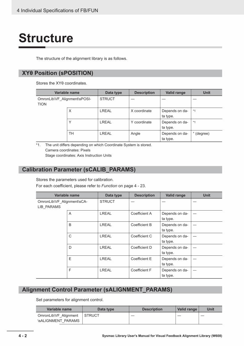
StructureThe structure of the alignment library is as follows.
XYθ Position (sPOSITION)Stores the XYθ coordinates.
Variable name Data type Description Valid range UnitOmronLib\VF_Alignment\sPOSI-TION
STRUCT — — —
X LREAL X coordinate Depends on da-ta type.
*1
Y LREAL Y coordinate Depends on da-ta type.
*1
TH LREAL Angle Depends on da-ta type.
° (degree)
*1. The unit differs depending on which Coordinate System is stored.Camera coordinates: PixelsStage coordinates: Axis Instruction Units
Calibration Parameter (sCALIB_PARAMS)Stores the parameters used for calibration.For each coefficient, please refer to Function on page 4 - 23.
Variable name Data type Description Valid range UnitOmronLib\VF_Alignment\sCA-LIB_PARAMS
STRUCT ― ― ―
A LREAL Coefficient A Depends on da-ta type.
―
B LREAL Coefficient B Depends on da-ta type.
―
C LREAL Coefficient C Depends on da-ta type.
―
D LREAL Coefficient D Depends on da-ta type.
―
E LREAL Coefficient E Depends on da-ta type.
―
F LREAL Coefficient F Depends on da-ta type.
―
Alignment Control Parameter (sALIGNMENT_PARAMS)Set parameters for alignment control.
Variable name Data type Description Valid range UnitOmronLib\VF_Alignment\sALIGNMENT_PARAMS
STRUCT ― ― ―
4 Individual Specifications of FB/FUN
4 - 2 Sysmac Library User's Manual for Visual Feedback Alignment Library (W608)

Variable name Data type Description Valid range UnitStagePar-ams
OmronLib\VF_Alignment\sSTAGE_PARAMS
Sets stage parameter. ― ―
Kinematic-sParams
OmronLib\VF_Alignment\sKINEMATICS_PARAMS
Sets forward/reversekinemetics calculation pa-rameter.
― ―
CalcVirtual-MovePar-ams
OmronLib\VF_Alignment\sCALCVIRTUAL-MOVE_PARAMS
Sets the parameters forvirtual XYθ stage axis po-sition/velocity calculationparameter.
― ―
CalcCurve-Params
OmronLib\VF_Alignment\sCALCURVE_PARAMS
Sets the fifth order trajec-tory calculation parame-ter.
― ―
Imaging-Params
OmronLib\VF_Alignment\sIMAGING_PARAMS
Set the imaging parame-ters.
― ―
JudgePar-ams
OmronLib\VF_Alignment\sJUDGE_PARAMS
Set the Done judgmentparameters.
― ―
Stage Parameter (sSTAGE_PARAMS)Stores stage settings.
Variable name Data type Description Valid range UnitOmronLib\VF_Alignment\sSTAGE_PARAMS
STRUCT ― ― ―
StageType UINT Stage type0 : XY1 : XYθ2 : θXY3 : X4 : Y5 : Xθ6 : Yθ7 : θX8 : θY9 : UVW10 : UVWR
0 to 10 ―
AxNo ARRAY[0..3] OFUINT
Sets the axis number (Ax-is variable.Cfg.AxNo).It is not necessary to setan unused axis.[0]: X/U axis[1]: Y/V axis[2]: θ/W axis[3]: R axis
*1 ―
StopDec ARRAY[0..3] OFLREAL
Deceleration speed at De-celeration stopIt is not necessary to setan unused axis.[0]: X/U axis[1]: Y/V axis[2]: θ/W axis[3]: R axis
Positivenumber or0
Axis Instruction Unit/s2
4 Individual Specifications of FB/FUN
4 - 3Sysmac Library User's Manual for Visual Feedback Alignment Library (W608)
Structure
4
Stage Parameter (sSTAG
E_PARAM
S)
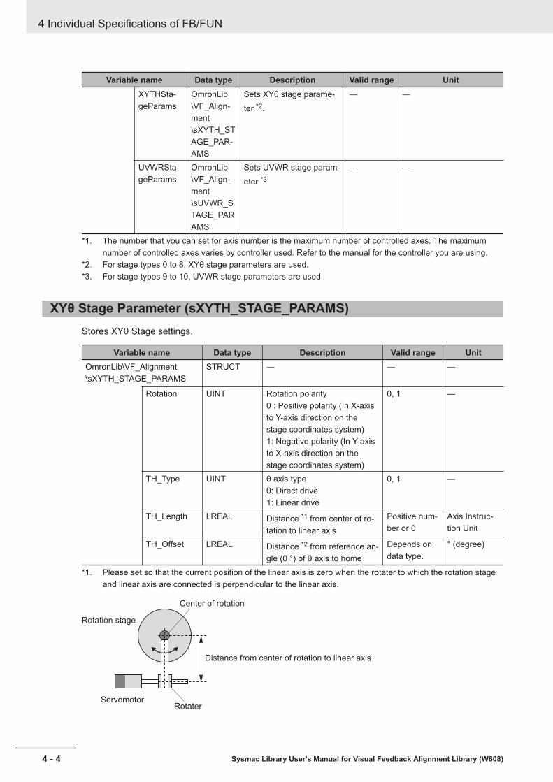
Variable name Data type Description Valid range UnitXYTHSta-geParams
OmronLib\VF_Align-ment\sXYTH_STAGE_PAR-AMS
Sets XYθ stage parame-ter *2.
― ―
UVWRSta-geParams
OmronLib\VF_Align-ment\sUVWR_STAGE_PARAMS
Sets UVWR stage param-eter *3.
― ―
*1. The number that you can set for axis number is the maximum number of controlled axes. The maximumnumber of controlled axes varies by controller used. Refer to the manual for the controller you are using.
*2. For stage types 0 to 8, XYθ stage parameters are used.*3. For stage types 9 to 10, UVWR stage parameters are used.
XYθ Stage Parameter (sXYTH_STAGE_PARAMS)Stores XYθ Stage settings.
Variable name Data type Description Valid range UnitOmronLib\VF_Alignment\sXYTH_STAGE_PARAMS
STRUCT ― ― ―
Rotation UINT Rotation polarity0 : Positive polarity (In X-axisto Y-axis direction on thestage coordinates system)1: Negative polarity (In Y-axisto X-axis direction on thestage coordinates system)
0, 1 ―
TH_Type UINT θ axis type0: Direct drive1: Linear drive
0, 1 ―
TH_Length LREAL Distance *1 from center of ro-tation to linear axis
Positive num-ber or 0
Axis Instruc-tion Unit
TH_Offset LREAL Distance *2 from reference an-gle (0 °) of θ axis to home
Depends ondata type.
° (degree)
*1. Please set so that the current position of the linear axis is zero when the rotater to which the rotation stageand linear axis are connected is perpendicular to the linear axis.
Rotation stage
Center of rotation
Distance from center of rotation to linear axis
ServomotorRotater
4 Individual Specifications of FB/FUN
4 - 4 Sysmac Library User's Manual for Visual Feedback Alignment Library (W608)
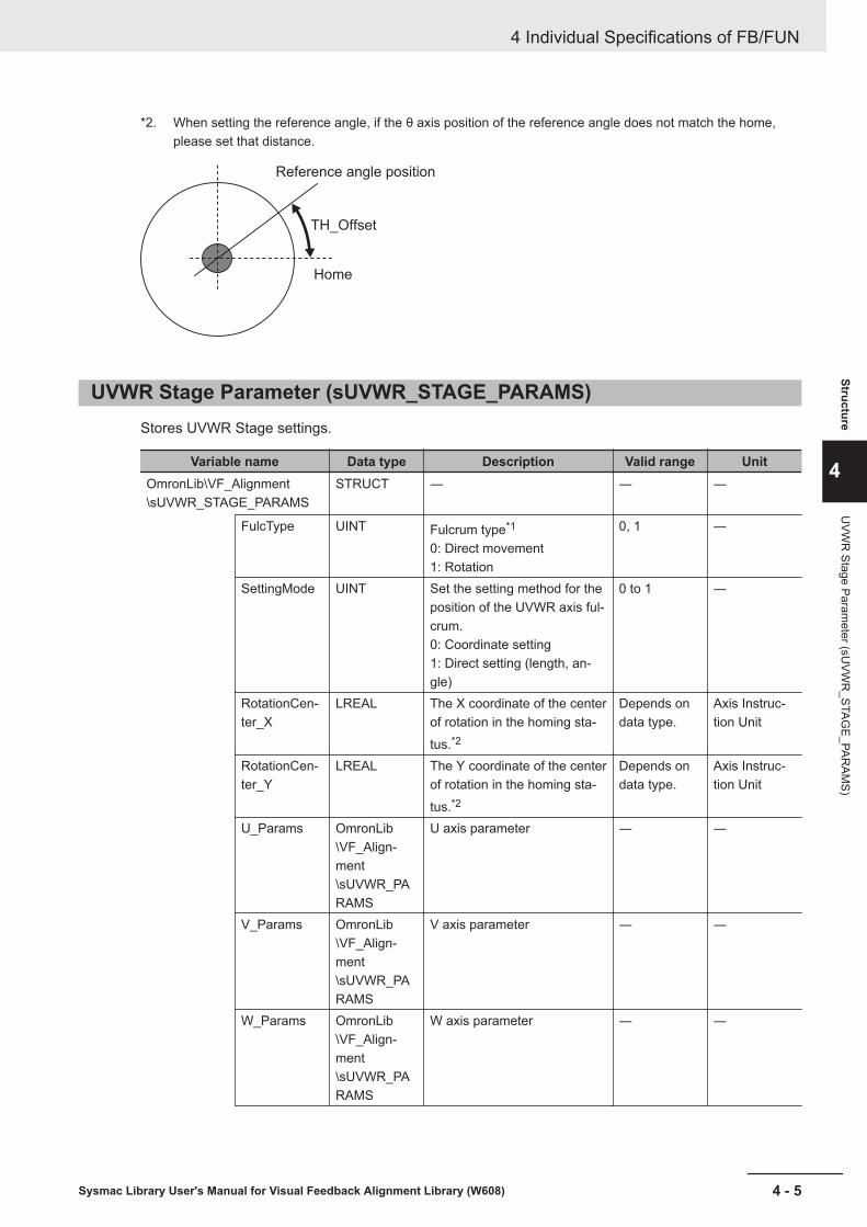
*2. When setting the reference angle, if the θ axis position of the reference angle does not match the home,please set that distance.
Reference angle position
Home
TH_Offset
UVWR Stage Parameter (sUVWR_STAGE_PARAMS)Stores UVWR Stage settings.
Variable name Data type Description Valid range UnitOmronLib\VF_Alignment\sUVWR_STAGE_PARAMS
STRUCT ― ― ―
FulcType UINT Fulcrum type*1
0: Direct movement1: Rotation
0, 1 ―
SettingMode UINT Set the setting method for theposition of the UVWR axis ful-crum.0: Coordinate setting1: Direct setting (length, an-gle)
0 to 1 ―
RotationCen-ter_X
LREAL The X coordinate of the centerof rotation in the homing sta-tus.*2
Depends ondata type.
Axis Instruc-tion Unit
RotationCen-ter_Y
LREAL The Y coordinate of the centerof rotation in the homing sta-tus.*2
Depends ondata type.
Axis Instruc-tion Unit
U_Params OmronLib\VF_Align-ment\sUVWR_PARAMS
U axis parameter ― ―
V_Params OmronLib\VF_Align-ment\sUVWR_PARAMS
V axis parameter ― ―
W_Params OmronLib\VF_Align-ment\sUVWR_PARAMS
W axis parameter ― ―
4 Individual Specifications of FB/FUN
4 - 5Sysmac Library User's Manual for Visual Feedback Alignment Library (W608)
Structure
4
UVW
R Stage Param
eter (sUVW
R_STAG
E_PARAM
S)
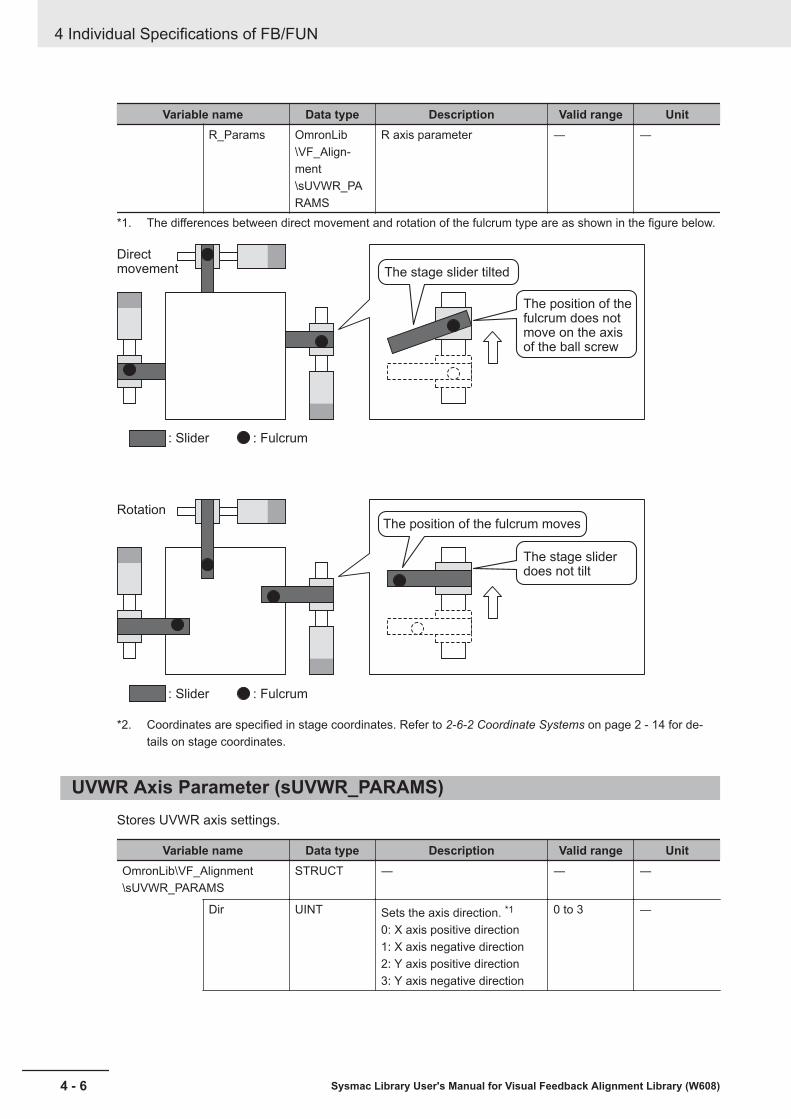
Variable name Data type Description Valid range UnitR_Params OmronLib
\VF_Align-ment\sUVWR_PARAMS
R axis parameter ― ―
*1. The differences between direct movement and rotation of the fulcrum type are as shown in the figure below.
The stage slider tilted
Direct movement
Rotation
: Slider : Fulcrum
: Slider : Fulcrum
The position of the fulcrum does not move on the axis of the ball screw
The position of the fulcrum moves
The stage slider does not tilt
*2. Coordinates are specified in stage coordinates. Refer to 2-6-2 Coordinate Systems on page 2 - 14 for de-tails on stage coordinates.
UVWR Axis Parameter (sUVWR_PARAMS)Stores UVWR axis settings.
Variable name Data type Description Valid range UnitOmronLib\VF_Alignment\sUVWR_PARAMS
STRUCT ― ― ―
Dir UINT Sets the axis direction. *1
0: X axis positive direction1: X axis negative direction2: Y axis positive direction3: Y axis negative direction
0 to 3 ―
4 Individual Specifications of FB/FUN
4 - 6 Sysmac Library User's Manual for Visual Feedback Alignment Library (W608)

Variable name Data type Description Valid range UnitX LREAL When sUVWR_STAGE_PAR-
AMS.SettingMode is 0: Coor-dinate setting, please set theX coordinate of the fulcrum.When the Stage Control FB(CtrlStage) is executed, thissetting value is converted intothe length (Length) of the linesegment connecting the cen-ter of rotation of the stage andthe pivot point and the angleof the fulcrum (Angle). *2
Depends ondata type.
Axis Instruc-tion Unit
Y LREAL When sUVWR_STAGE_PAR-AMS.SettingMode is 0: Coor-dinate setting, please set theY coordinate of the fulcrum.When the stage control FB(CtrlStage) is executed, thissetting value is converted intothe length (Length) of the linesegment connecting the cen-ter of rotation of the stage andthe pivot point and the angleof the fulcrum (Angle). *2
Depends ondata type.
Axis Instruc-tion Unit
Length LREAL When sUVWR_STAGE_PAR-AMS.SettingMode is 1: Directsetting, please set the linesegment connecting the cen-ter of rotation of the stage andthe fulcrum. *3
Positive num-ber
Axis Instruc-tion Unit
Angle LREAL When sUVWR_STAGE_PAR-AMS.SettingMode is 1: Directsetting, also set the angle ofthe fulcrum. *3
0° ≤ Angle <360°
° (degree)
*1. Set the direction of each axis of the UVWR axis to be either positive, or negative direction with respect tothe X axis or Y axis direction at the XY coordinates (stage coordinates) where the center of rotation is thehome. This will be either parallel or perpendicular to each UVWR axis.The center of rotation of the stage is specified with the UVWR stage parameters X coordinate of the centerof rotation in the homing status and Y coordinate of the center of rotation in the homing status.In the case of the figure below, the setting is as follows.U axis: Negative direction on the Y axisV axis: Positive direction on the X axisW axis: Positive direction on the Y axisR axis: Negative direction on the X axis
4 Individual Specifications of FB/FUN
4 - 7Sysmac Library User's Manual for Visual Feedback Alignment Library (W608)
Structure
4
UVW
R Axis Param
eter (sUVW
R_PAR
AMS)

U axis
R axis
V axis
Center of rotation
StageCoordi-nates
Y axis
X axis
W axis
*2. Sets the coordinates of each axis at the homing status.When the Stage Control FB (CtrlStage) is executed, this setting value is converted to the length (Length) ofthe line segment connecting the center of rotation of the stage and the fulcrum. It is also converted to theangle (Angle) of the fulcrum by the following arithmetic expression done on that same set value. This thenupdates the Length and Angle of the structure member. Reverse kinematics calculation FUN (CalcInverse-Kinematics) and forward kinematics calculation FUN (CalcForwardKinematics) refer to Length and Angle.The center of rotation of the stage is specified with the UVWR stage parameters X coordinate of the centerof rotation in the homing status and Y coordinate of the center of rotation in the homing status.
Center of rotation
An XY Coordinate System that is parallel or perpendicular toeach UVWR axis
Each UVWR fulcrum in homing status
Y axis
X axis
W axis fulcrum coordinates
(X,Y)
U axis fulcrum coordinates
(X,Y)
V axis fulcrum coordinates
(X,Y)
R axis fulcrum coordinates (X,Y)
Y axis
X axis
ΔX
Angle
Length
Coordinates of fulcrum in homing status (X,Y)
Center of rotation
(RotationCenter_X,RotationCenter_Y)
Fulcrum length (Length) and fulcrum angle
(Angle) in homing status
(RotationCenter_X, RotationCenter_Y)
(X,Y)
ΔYΔY
4 Individual Specifications of FB/FUN
4 - 8 Sysmac Library User's Manual for Visual Feedback Alignment Library (W608)
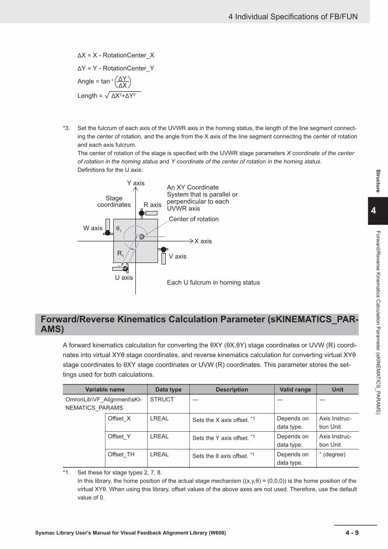
ΔX = X - RotationCenter_X
ΔY = Y - RotationCenter_Y
Angle = tan-1
Length = ΔX2+ΔY2
ΔYΔX
*3. Set the fulcrum of each axis of the UVWR axis in the homing status, the length of the line segment connect-ing the center of rotation, and the angle from the X axis of the line segment connecting the center of rotationand each axis fulcrum.The center of rotation of the stage is specified with the UVWR stage parameters X coordinate of the centerof rotation in the homing status and Y coordinate of the center of rotation in the homing status.Definitions for the U axis:
Center of rotation
An XY Coordinate System that is parallel or perpendicular to each UVWR axis
Each U fulcrum in homing status
Y axis
R axis
V axis
X axis
θ1
R1
U axis
W axis
Stage coordinates
Forward/Reverse Kinematics Calculation Parameter (sKINEMATICS_PAR-AMS)
A forward kinematics calculation for converting the θXY (θX,θY) stage coordinates or UVW (R) coordi-nates into virtual XYθ stage coordinates, and reverse kinematics calculation for converting virtual XYθstage coordinates to θXY stage coordinates or UVW (R) coordinates. This parameter stores the set-tings used for both calculations.
Variable name Data type Description Valid range UnitOmronLib\VF_Alignment\sKI-NEMATICS_PARAMS
STRUCT ― ― ―
Offset_X LREAL Sets the X axis offset. *1 Depends ondata type.
Axis Instruc-tion Unit
Offset_Y LREAL Sets the Y axis offset. *1 Depends ondata type.
Axis Instruc-tion Unit
Offset_TH LREAL Sets the θ axis offset. *1 Depends ondata type.
° (degree)
*1. Set these for stage types 2, 7, 8.In this library, the home position of the actual stage mechanism ((x,y,θ) = (0,0,0)) is the home position of thevirtual XYθ. When using this library, offset values of the above axes are not used. Therefore, use the defaultvalue of 0.
4 Individual Specifications of FB/FUN
4 - 9Sysmac Library User's Manual for Visual Feedback Alignment Library (W608)
Structure
4
Forward/R
everse Kinematics C
alculation Parameter (sKIN
EMATIC
S_PARAM
S)

Stage coordinates Y
(Virtual XYθ stage)
X axis travel distance on θXY stage
Current θ axis position on θXY stage
The X axis offset of a θXY stage home relative to a XYθ stage home
Current X axis position on θXY stage
Y axis travel distance on θXY stage
The θ axis offset of a θXY stage home relative to a XYθ stage homeThe Y axis offset of a θXY stage home relative to a XYθ stage home
Current X axis position on θXY stage
Curr
ent Y
axi
s posi
tion o
n θ
XY
sta
ge
Curr
ent Y
axi
s posi
tion o
n θ
XY
sta
ge
Virtual XYθ Stage Axis Position/Velocity Calculation Parameter (sCALC-VIRTUALMOVE_PARAMS)
Set the parameters to be used to calculate the axis position and velocity on the Virtual XYθ Stage co-ordinates for alignment control.
Variable name Data type Description Valid range UnitOmronLib\VF_Alignment\sCALCVIRTUALMOVE_PAR-AMS
STRUCT ― ― ―
MovePar-ams_X
OmronLib\VF_Align-ment\sAX-IS_MOVE_PARAMS
X axis motion parameter ― ―
MovePar-ams_Y
OmronLib\VF_Align-ment\sAX-IS_MOVE_PARAMS
Y axis motion parameter ― ―
MovePar-ams_TH
OmronLib\VF_Align-ment\sAX-IS_MOVE_PARAMS
θ axis motion parameter ― ―
InPosMode UINT In-Position Judgment Mode0: Diameter / Angle1: XYθ Position
0 to 1 ―
4 Individual Specifications of FB/FUN
4 - 10 Sysmac Library User's Manual for Visual Feedback Alignment Library (W608)
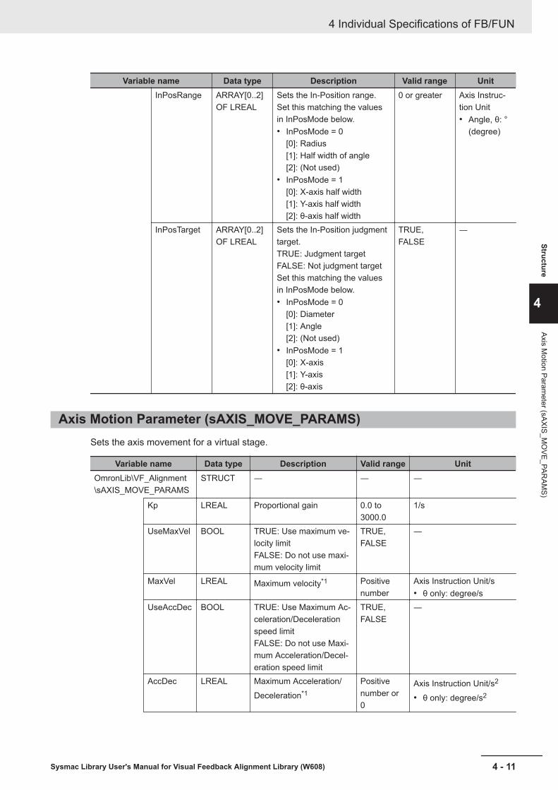
Variable name Data type Description Valid range UnitInPosRange ARRAY[0..2]
OF LREALSets the In-Position range.Set this matching the valuesin InPosMode below.• InPosMode = 0
[0]: Radius[1]: Half width of angle[2]: (Not used)
• InPosMode = 1[0]: X-axis half width[1]: Y-axis half width[2]: θ-axis half width
0 or greater Axis Instruc-tion Unit• Angle, θ: °
(degree)
InPosTarget ARRAY[0..2]OF LREAL
Sets the In-Position judgmenttarget.TRUE: Judgment targetFALSE: Not judgment targetSet this matching the valuesin InPosMode below.• InPosMode = 0
[0]: Diameter[1]: Angle[2]: (Not used)
• InPosMode = 1[0]: X-axis[1]: Y-axis[2]: θ-axis
TRUE,FALSE
―
Axis Motion Parameter (sAXIS_MOVE_PARAMS)Sets the axis movement for a virtual stage.
Variable name Data type Description Valid range UnitOmronLib\VF_Alignment\sAXIS_MOVE_PARAMS
STRUCT ― ― ―
Kp LREAL Proportional gain 0.0 to3000.0
1/s
UseMaxVel BOOL TRUE: Use maximum ve-locity limitFALSE: Do not use maxi-mum velocity limit
TRUE,FALSE
―
MaxVel LREAL Maximum velocity*1 Positivenumber
Axis Instruction Unit/s• θ only: degree/s
UseAccDec BOOL TRUE: Use Maximum Ac-celeration/Decelerationspeed limitFALSE: Do not use Maxi-mum Acceleration/Decel-eration speed limit
TRUE,FALSE
―
AccDec LREAL Maximum Acceleration/Deceleration*1
Positivenumber or0
Axis Instruction Unit/s2
• θ only: degree/s2
4 Individual Specifications of FB/FUN
4 - 11Sysmac Library User's Manual for Visual Feedback Alignment Library (W608)
Structure
4
Axis Motion Param
eter (sAXIS_MO
VE_PARAM
S)

Variable name Data type Description Valid range UnitImagingLi-mitVel
LREAL Image capture speed lim-it*1
Positivenumber
Axis Instruction Unit/s• θ only: degree/s
*1. These setting values are in relation to the commands generated by this library. If the motion control parame-ters - Operation Setting - maximum velocity, maximum acceleration, and maximum deceleration are set, theactual stage operation will follow those settings.
The axis motion parameters are for the motion of X, Y, and θ axes on the Virtual XYθ Stage coordi-nates that perform the alignment control calculation. Please set this parameter converted to XYθ stageoperation. For the velocity of the feedback control calculated from the measurement result of the vi-sion sensor, the set values of the maximum velocity and the maximum acceleration/deceleration arereflected as shown below.
Stage drive motor velocity
(XYθ stage conversion)
Maximum velocity
Maximum acceleration/deceleration
Time
Feedback trajectory
Movement velocity
Image capture speed limit
Start alignment(Get initial measurement result)
Next imaging trigger output
As a guide for each stage mechanism, specify as follows.XY, XYθ, θXY, X, Y, Xθ, Yθ, θX, θY: Set the maximum velocity and maximum acceleration/decelerationof X, Y, θ axes for each stage typeUVW, UVWR: Set the maximum velocity and maximum acceleration/deceleration that is common toeach axis for UVW (R) as the axis motion parameters of X, Y, θ axes.The unit of the θ axis motion parameter is angle (degree) (velocity: degree/s, acceleration/decelera-
tion: degree/s2).Set the following calculated value as a guide by using the length to the fulcrum relative to the center ofrotation of the U/V/W/R stage.
θ velocity = tan-1 (U/V/W/R axis velocity / length to the fulcrum relative to the center of rotation)
θ Acceleration/Deceleration = tan-1 (U/V/W/R Axis Acceleration/Deceleration / length to the fulcrumrelative to the center of rotation)
When you want to reduce the occurrence of measurement errors due to shaking of the workpiece ob-ject, specify the upper velocity limit of the stage drive axis that outputs the second and subsequentmeasurement triggers (virtual XYθ stage conversion) using the Image capture speed limit. The follow-ing measurement trigger is output when any condition is satisfied with respect to the velocity limitspecified for the XYθ axes.For the Image capture speed limit, please set the following calculated value as a guide against thetarget accuracy of alignment and camera exposure time (1/shutter speed).
Image capture speed limit = target accuracy × 20/camera exposure time
4 Individual Specifications of FB/FUN
4 - 12 Sysmac Library User's Manual for Visual Feedback Alignment Library (W608)

Proportional gain specifies the degree of how much stage operation should be performed with respectto the alignment travel distance calculated based on the reference position and measurement positionmeasured by the vision sensor in visual feedback control. Increasing the value will try to resolve thecalculated alignment travel distance in a short time, but if it is too large, the motion will become abruptor oscillatory. If the value is small, the operation will be smooth, but it will require alignment time.The proportional gain must be determined according to the time lag of the lag element of the align-ment system being used. For the time lag between command position and feedback position when thestage is operated at a constant velocity, set the following calculated values as a guide and adjust ac-cording to the operation result.
Stage Position, Velocity
(XYθ stage conversion)
Command velocity
Command velocity
TimeResponse time t
Command position
Actual position
Proportional gain = 0.1/Response time t
Fifth Order Trajectory Calculation Parameter (sCALCURVE_PARAMS)Sets the fifth order trajectory calculation parameters used for axis velocity calculation Function Block(FB).
Variable name Data type Description Valid range UnitOmronLib\VF_Alignment\sCALCURVE_PARAMS
STRUCT ― ― ―
UseCurve BOOL TRUE: Use fifth order trajecto-ryFALSE: Do not use fifth ordertrajectory
TRUE,FALSE
―
DistNumber*1 UINT Sets the number of distribu-tions.If "0" is set, it will change to"1".
0 to 9999 ―
UseCurveSe-quence
BOOL TRUE: Use fifth order trajecto-ry sequenceFALSE: Do not use fifth ordertrajectory sequence
TRUE,FALSE
―
UseConnec-tingVel
BOOL TRUE: Use connecting veloci-tyFALSE: Do not use connect-ing velocity
TRUE,FALSE
―
4 Individual Specifications of FB/FUN
4 - 13Sysmac Library User's Manual for Visual Feedback Alignment Library (W608)
Structure
4
Fifth Order Trajectory C
alculation Parameter (sC
ALCU
RVE_PAR
AMS)
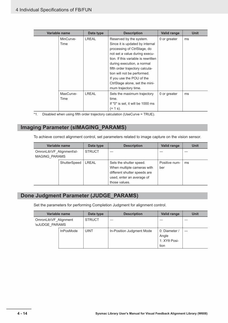
Variable name Data type Description Valid range UnitMinCurve-Time
LREAL Reserved by the system.Since it is updated by internalprocessing of CtrlStage, donot set a value during execu-tion. If this variable is rewrittenduring execution, a normalfifth order trajectory calcula-tion will not be performed.If you use the POU of theCtrlStage alone, set the mini-mum trajectory time.
0 or greater ms
MaxCurve-Time
LREAL Sets the maximum trajectorytime.If "0" is set, it will be 1000 ms(= 1 s).
0 or greater ms
*1. Disabled when using fifth order trajectory calculation (UseCurve = TRUE).
Imaging Parameter (sIMAGING_PARAMS)To achieve correct alignment control, set parameters related to image capture on the vision sensor.
Variable name Data type Description Valid range UnitOmronLib\VF_Alignment\sI-MAGING_PARAMS
STRUCT ― ― ―
ShutterSpeed LREAL Sets the shutter speed.When multiple cameras withdifferent shutter speeds areused, enter an average ofthose values.
Positive num-ber
ms
Done Judgment Parameter (JUDGE_PARAMS)Set the parameters for performing Completion Judgment for alignment control.
Variable name Data type Description Valid range UnitOmronLib\VF_Alignment\sJUDGE_PARAMS
STRUCT ― ― ―
InPosMode UINT In-Position Judgment Mode 0: Diameter /Angle1: XYθ Posi-tion
―
4 Individual Specifications of FB/FUN
4 - 14 Sysmac Library User's Manual for Visual Feedback Alignment Library (W608)
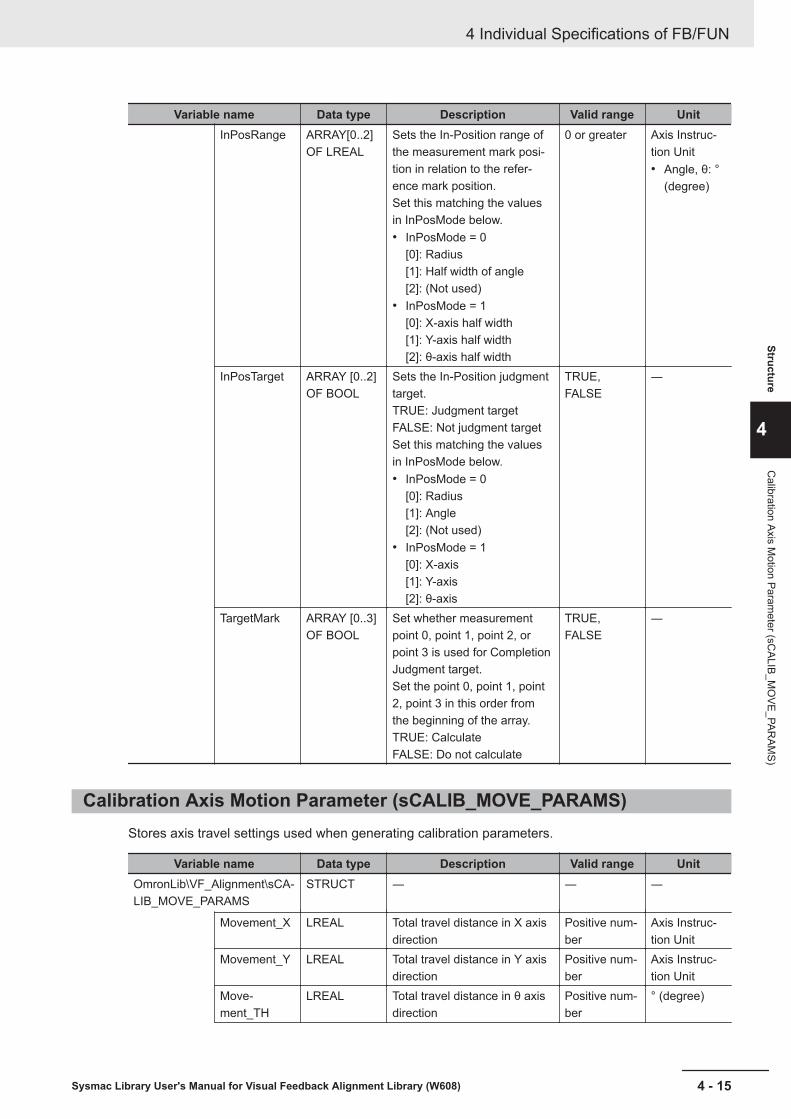
Variable name Data type Description Valid range UnitInPosRange ARRAY[0..2]
OF LREALSets the In-Position range ofthe measurement mark posi-tion in relation to the refer-ence mark position.Set this matching the valuesin InPosMode below.• InPosMode = 0
[0]: Radius[1]: Half width of angle[2]: (Not used)
• InPosMode = 1[0]: X-axis half width[1]: Y-axis half width[2]: θ-axis half width
0 or greater Axis Instruc-tion Unit• Angle, θ: °
(degree)
InPosTarget ARRAY [0..2]OF BOOL
Sets the In-Position judgmenttarget.TRUE: Judgment targetFALSE: Not judgment targetSet this matching the valuesin InPosMode below.• InPosMode = 0
[0]: Radius[1]: Angle[2]: (Not used)
• InPosMode = 1[0]: X-axis[1]: Y-axis[2]: θ-axis
TRUE,FALSE
―
TargetMark ARRAY [0..3]OF BOOL
Set whether measurementpoint 0, point 1, point 2, orpoint 3 is used for CompletionJudgment target.Set the point 0, point 1, point2, point 3 in this order fromthe beginning of the array.TRUE: CalculateFALSE: Do not calculate
TRUE,FALSE
―
Calibration Axis Motion Parameter (sCALIB_MOVE_PARAMS)Stores axis travel settings used when generating calibration parameters.
Variable name Data type Description Valid range UnitOmronLib\VF_Alignment\sCA-LIB_MOVE_PARAMS
STRUCT ― ― ―
Movement_X LREAL Total travel distance in X axisdirection
Positive num-ber
Axis Instruc-tion Unit
Movement_Y LREAL Total travel distance in Y axisdirection
Positive num-ber
Axis Instruc-tion Unit
Move-ment_TH
LREAL Total travel distance in θ axisdirection
Positive num-ber
° (degree)
4 Individual Specifications of FB/FUN
4 - 15Sysmac Library User's Manual for Visual Feedback Alignment Library (W608)
Structure
4
Calibration Axis M
otion Parameter (sC
ALIB_MO
VE_PARAM
S)
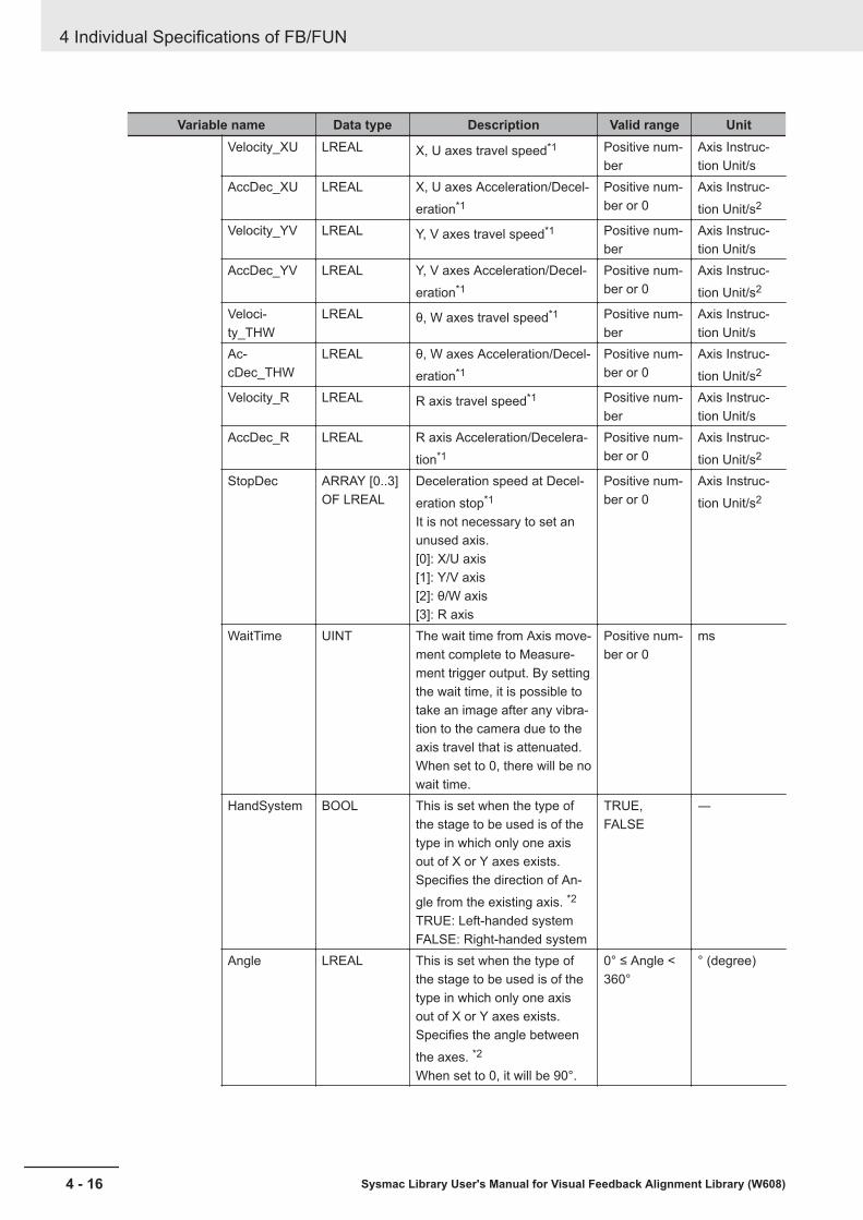
Variable name Data type Description Valid range UnitVelocity_XU LREAL X, U axes travel speed*1 Positive num-
berAxis Instruc-tion Unit/s
AccDec_XU LREAL X, U axes Acceleration/Decel-eration*1
Positive num-ber or 0
Axis Instruc-tion Unit/s2
Velocity_YV LREAL Y, V axes travel speed*1 Positive num-ber
Axis Instruc-tion Unit/s
AccDec_YV LREAL Y, V axes Acceleration/Decel-eration*1
Positive num-ber or 0
Axis Instruc-tion Unit/s2
Veloci-ty_THW
LREAL θ, W axes travel speed*1 Positive num-ber
Axis Instruc-tion Unit/s
Ac-cDec_THW
LREAL θ, W axes Acceleration/Decel-eration*1
Positive num-ber or 0
Axis Instruc-tion Unit/s2
Velocity_R LREAL R axis travel speed*1 Positive num-ber
Axis Instruc-tion Unit/s
AccDec_R LREAL R axis Acceleration/Decelera-tion*1
Positive num-ber or 0
Axis Instruc-tion Unit/s2
StopDec ARRAY [0..3]OF LREAL
Deceleration speed at Decel-eration stop*1
It is not necessary to set anunused axis.[0]: X/U axis[1]: Y/V axis[2]: θ/W axis[3]: R axis
Positive num-ber or 0
Axis Instruc-tion Unit/s2
WaitTime UINT The wait time from Axis move-ment complete to Measure-ment trigger output. By settingthe wait time, it is possible totake an image after any vibra-tion to the camera due to theaxis travel that is attenuated.When set to 0, there will be nowait time.
Positive num-ber or 0
ms
HandSystem BOOL This is set when the type ofthe stage to be used is of thetype in which only one axisout of X or Y axes exists.Specifies the direction of An-gle from the existing axis. *2
TRUE: Left-handed systemFALSE: Right-handed system
TRUE,FALSE
―
Angle LREAL This is set when the type ofthe stage to be used is of thetype in which only one axisout of X or Y axes exists.Specifies the angle betweenthe axes. *2
When set to 0, it will be 90°.
0° ≤ Angle <360°
° (degree)
4 Individual Specifications of FB/FUN
4 - 16 Sysmac Library User's Manual for Visual Feedback Alignment Library (W608)
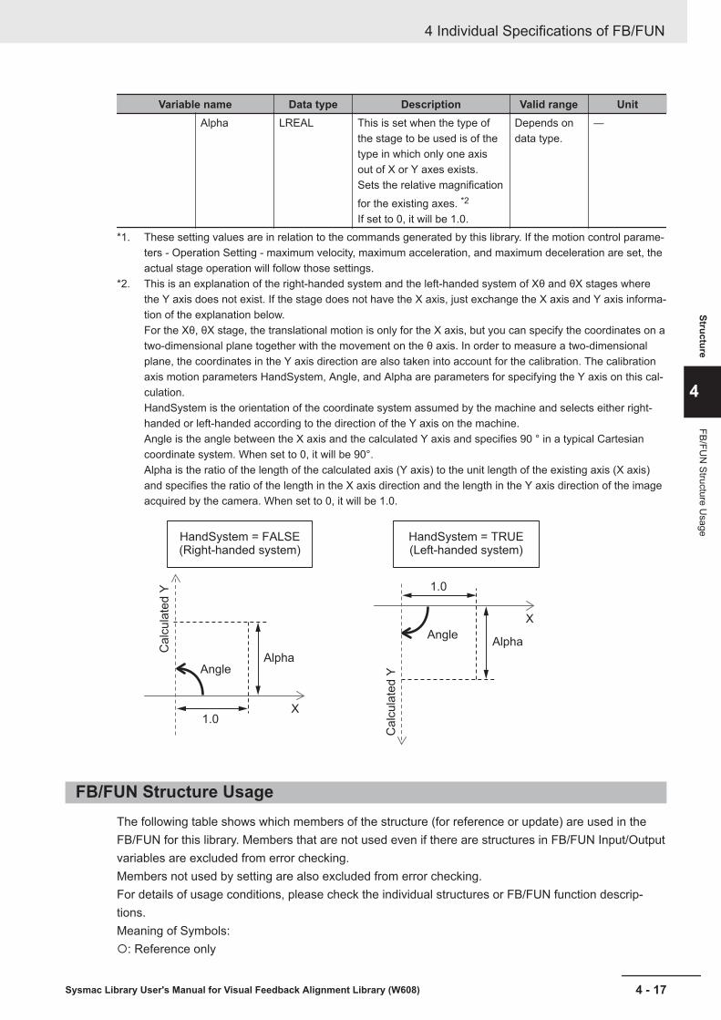
Variable name Data type Description Valid range UnitAlpha LREAL This is set when the type of
the stage to be used is of thetype in which only one axisout of X or Y axes exists.Sets the relative magnificationfor the existing axes. *2
If set to 0, it will be 1.0.
Depends ondata type.
―
*1. These setting values are in relation to the commands generated by this library. If the motion control parame-ters - Operation Setting - maximum velocity, maximum acceleration, and maximum deceleration are set, theactual stage operation will follow those settings.
*2. This is an explanation of the right-handed system and the left-handed system of Xθ and θX stages wherethe Y axis does not exist. If the stage does not have the X axis, just exchange the X axis and Y axis informa-tion of the explanation below.For the Xθ, θX stage, the translational motion is only for the X axis, but you can specify the coordinates on atwo-dimensional plane together with the movement on the θ axis. In order to measure a two-dimensionalplane, the coordinates in the Y axis direction are also taken into account for the calibration. The calibrationaxis motion parameters HandSystem, Angle, and Alpha are parameters for specifying the Y axis on this cal-culation.HandSystem is the orientation of the coordinate system assumed by the machine and selects either right-handed or left-handed according to the direction of the Y axis on the machine.Angle is the angle between the X axis and the calculated Y axis and specifies 90 ° in a typical Cartesiancoordinate system. When set to 0, it will be 90°.Alpha is the ratio of the length of the calculated axis (Y axis) to the unit length of the existing axis (X axis)and specifies the ratio of the length in the X axis direction and the length in the Y axis direction of the imageacquired by the camera. When set to 0, it will be 1.0.
HandSystem = FALSE(Right-handed system)
Ca
lcu
late
d Y
Ca
lcu
late
d Y
Angle
Angle
1.0
1.0
X
X
Alpha
Alpha
HandSystem = TRUE(Left-handed system)
FB/FUN Structure UsageThe following table shows which members of the structure (for reference or update) are used in theFB/FUN for this library. Members that are not used even if there are structures in FB/FUN Input/Outputvariables are excluded from error checking.Members not used by setting are also excluded from error checking.For details of usage conditions, please check the individual structures or FB/FUN function descrip-tions.Meaning of Symbols:¡: Reference only
4 Individual Specifications of FB/FUN
4 - 17Sysmac Library User's Manual for Visual Feedback Alignment Library (W608)
Structure
4
FB/FUN
Structure Usage
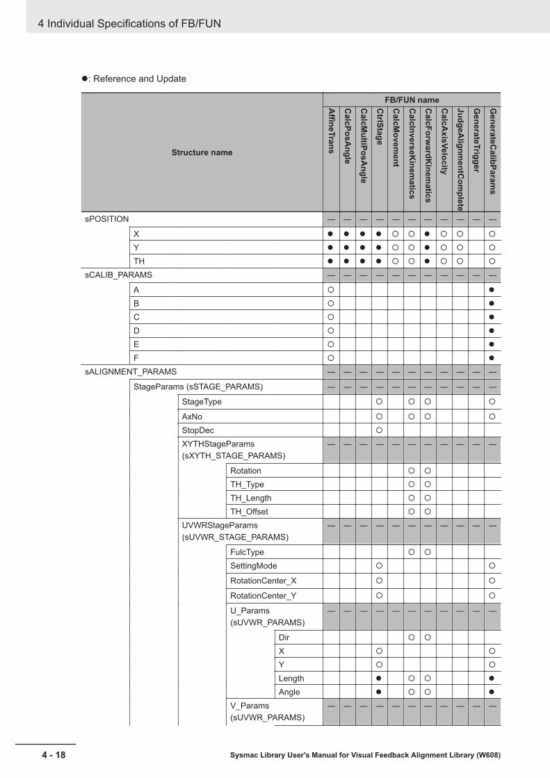
l: Reference and Update
Structure name
FB/FUN nameAffineTrans
CalcPosA
ngle
CalcM
ultiPosAngle
CtrlStage
CalcM
ovement
CalcInverseK
inematics
CalcForw
ardKinem
atics
CalcA
xisVelocity
JudgeAlignm
entCom
plete
GenerateTrigger
GenerateC
alibParams
sPOSITION ― ― ― ― ― ― ― ― ― ― ―
X l l l l ¡ ¡ l ¡ ¡ ¡
Y l l l l ¡ ¡ l ¡ ¡ ¡
TH l l l l ¡ ¡ l ¡ ¡ ¡
sCALIB_PARAMS ― ― ― ― ― ― ― ― ― ― ―
A ¡ l
B ¡ l
C ¡ l
D ¡ l
E ¡ l
F ¡ l
sALIGNMENT_PARAMS ― ― ― ― ― ― ― ― ― ― ―
StageParams (sSTAGE_PARAMS) ― ― ― ― ― ― ― ― ― ― ―
StageType ¡ ¡ ¡ ¡
AxNo ¡ ¡ ¡ ¡
StopDec ¡
XYTHStageParams(sXYTH_STAGE_PARAMS)
― ― ― ― ― ― ― ― ― ― ―
Rotation ¡ ¡
TH_Type ¡ ¡
TH_Length ¡ ¡
TH_Offset ¡ ¡
UVWRStageParams(sUVWR_STAGE_PARAMS)
― ― ― ― ― ― ― ― ― ― ―
FulcType ¡ ¡
SettingMode ¡ ¡
RotationCenter_X ¡ ¡
RotationCenter_Y ¡ ¡
U_Params(sUVWR_PARAMS)
― ― ― ― ― ― ― ― ― ― ―
Dir ¡ ¡
X ¡ ¡
Y ¡ ¡
Length l ¡ ¡ l
Angle l ¡ ¡ l
V_Params(sUVWR_PARAMS)
― ― ― ― ― ― ― ― ― ― ―
4 Individual Specifications of FB/FUN
4 - 18 Sysmac Library User's Manual for Visual Feedback Alignment Library (W608)
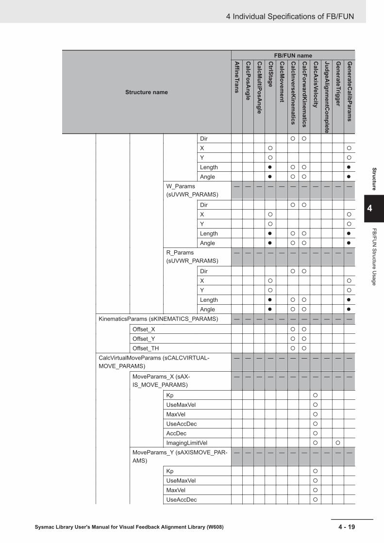
Structure name
FB/FUN nameAffineTrans
CalcPosA
ngle
CalcM
ultiPosAngle
CtrlStage
CalcM
ovement
CalcInverseK
inematics
CalcForw
ardKinem
atics
CalcA
xisVelocity
JudgeAlignm
entCom
plete
GenerateTrigger
GenerateC
alibParams
Dir ¡ ¡
X ¡ ¡
Y ¡ ¡
Length l ¡ ¡ l
Angle l ¡ ¡ l
W_Params(sUVWR_PARAMS)
― ― ― ― ― ― ― ― ― ― ―
Dir ¡ ¡
X ¡ ¡
Y ¡ ¡
Length l ¡ ¡ l
Angle l ¡ ¡ l
R_Params(sUVWR_PARAMS)
― ― ― ― ― ― ― ― ― ― ―
Dir ¡ ¡
X ¡ ¡
Y ¡ ¡
Length l ¡ ¡ l
Angle l ¡ ¡ l
KinematicsParams (sKINEMATICS_PARAMS) ― ― ― ― ― ― ― ― ― ― ―
Offset_X ¡ ¡
Offset_Y ¡ ¡
Offset_TH ¡ ¡
CalcVirtualMoveParams (sCALCVIRTUAL-MOVE_PARAMS)
― ― ― ― ― ― ― ― ― ― ―
MoveParams_X (sAX-IS_MOVE_PARAMS)
― ― ― ― ― ― ― ― ― ― ―
Kp ¡
UseMaxVel ¡
MaxVel ¡
UseAccDec ¡
AccDec ¡
ImagingLimitVel ¡ ¡
MoveParams_Y (sAXISMOVE_PAR-AMS)
― ― ― ― ― ― ― ― ― ― ―
Kp ¡
UseMaxVel ¡
MaxVel ¡
UseAccDec ¡
4 Individual Specifications of FB/FUN
4 - 19Sysmac Library User's Manual for Visual Feedback Alignment Library (W608)
Structure
4
FB/FUN
Structure Usage

Structure name
FB/FUN nameAffineTrans
CalcPosA
ngle
CalcM
ultiPosAngle
CtrlStage
CalcM
ovement
CalcInverseK
inematics
CalcForw
ardKinem
atics
CalcA
xisVelocity
JudgeAlignm
entCom
plete
GenerateTrigger
GenerateC
alibParams
AccDec ¡
ImagingLimitVel ¡ ¡
MoveParams_TH (sAXIS-MOVE_PARAMS)
― ― ― ― ― ― ― ― ― ― ―
Kp ¡
UseMaxVel ¡
MaxVel ¡
UseAccDec ¡
AccDec ¡
ImagingLimitVel ¡ ¡
InPosMode ¡
InPosRange ¡
InPosTarget ¡
CalcCurveParams (sCALCURVE_PARAMS) ― ― ― ― ― ― ― ― ― ― ―
UseCurve ¡ ¡
DistNumber ¡
UseCurveSequence ¡
UseConnectingVel ¡
MinCurveTime l ¡ ¡
MaxCurveTime ¡
ImagingParams (sIMAGING_PARAMS) ― ― ― ― ― ― ― ― ― ― ―
ShutterSpeed ¡
JudgeParams (sJUDGE_PARAMS) ― ― ― ― ― ― ― ― ― ― ―
InPosMode ¡
InPosRange ¡
InPosTarget ¡
TargetMark ¡
sCALIB_MOVE_PARAMS ― ― ― ― ― ― ― ― ― ― ―
Movement_X ¡
Movement_Y ¡
Movement_TH ¡
Velocity_XU ¡
AccDec_XU ¡
Velocity_YV ¡
AccDec_YV ¡
Velocity_THW ¡
AccDec_THW ¡
Velocity_R ¡
AccDec_R ¡
4 Individual Specifications of FB/FUN
4 - 20 Sysmac Library User's Manual for Visual Feedback Alignment Library (W608)
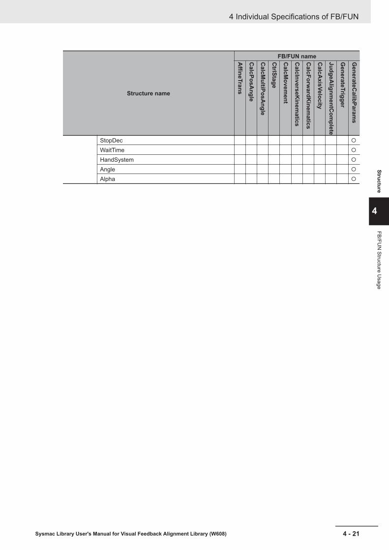
Structure name
FB/FUN nameAffineTrans
CalcPosA
ngle
CalcM
ultiPosAngle
CtrlStage
CalcM
ovement
CalcInverseK
inematics
CalcForw
ardKinem
atics
CalcA
xisVelocity
JudgeAlignm
entCom
plete
GenerateTrigger
GenerateC
alibParams
StopDec ¡
WaitTime ¡
HandSystem ¡
Angle ¡
Alpha ¡
4 Individual Specifications of FB/FUN
4 - 21Sysmac Library User's Manual for Visual Feedback Alignment Library (W608)
Structure
4
FB/FUN
Structure Usage
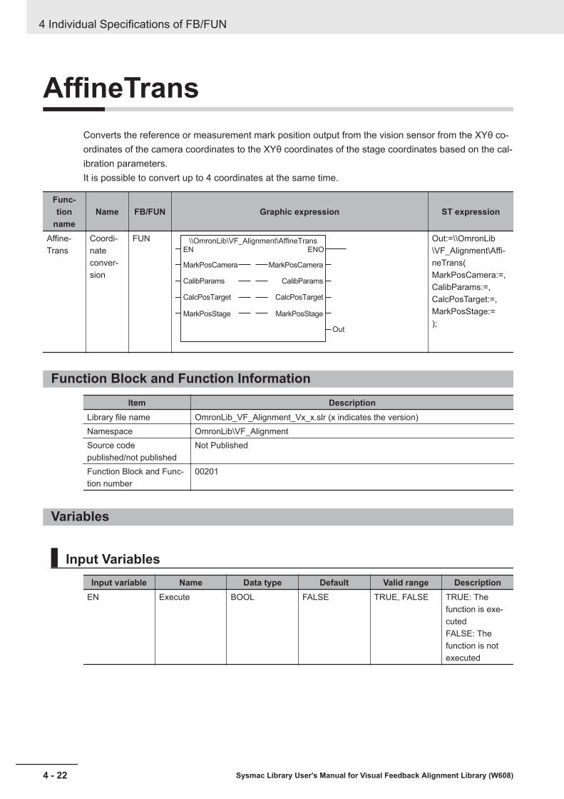
AffineTransConverts the reference or measurement mark position output from the vision sensor from the XYθ co-ordinates of the camera coordinates to the XYθ coordinates of the stage coordinates based on the cal-ibration parameters.It is possible to convert up to 4 coordinates at the same time.
Func-tion
nameName FB/FUN Graphic expression ST expression
Affine-Trans
Coordi-nateconver-sion
FUN \\OmronLib\VF_Alignment\AffineTransEN
MarkPosCamera
CalibParams
CalcPosTarget
MarkPosStage
ENO
Out
MarkPosCamera
CalibParams
CalcPosTarget
MarkPosStage
Out:=\\OmronLib\VF_Alignment\Affi-neTrans(MarkPosCamera:=,CalibParams:=,CalcPosTarget:=,MarkPosStage:=);
Function Block and Function InformationItem Description
Library file name OmronLib_VF_Alignment_Vx_x.slr (x indicates the version)Namespace OmronLib\VF_AlignmentSource codepublished/not published
Not Published
Function Block and Func-tion number
00201
Variables
Input VariablesInput variable Name Data type Default Valid range Description
EN Execute BOOL FALSE TRUE, FALSE TRUE: Thefunction is exe-cutedFALSE: Thefunction is notexecuted
4 Individual Specifications of FB/FUN
4 - 22 Sysmac Library User's Manual for Visual Feedback Alignment Library (W608)

Output VariablesOutput varia-
ble Name Data type Valid range Description
ENO ENO BOOL TRUE,FALSE
Only ladder diagram program is always outputas TRUE.
Out Return Value UINT *1 Output detailed conversion results.
*1. Refer to Troubleshooting (Error Codes and Corrective Actions) on page 4 - 24 for details.
Input-Output VariablesInput-out-put varia-
bleName Data type Valid
range Description
MarkPo-sCamera
Mark po-sition(Cameracoordi-nates)
ARRAY[0..3] OF OmronLib\VF_Alignment\sPOSITION
― Enter the mark position output fromthe vision sensor.Set the point 0, point 1, point 2,point 3 in this order from the begin-ning of the array.
CalibPar-ams
Calibra-tion pa-rameter
ARRAY[0..3] OF OmronLib\VF_Alignment\sCALIB_PARAMS
― Enter the calibration parameters foreach point.Set the point 0, point 1, point 2,point 3 in this order from the begin-ning of the array.
CalcPos-Target
Numberto process
ARRAY[0..3] OF BOOL TRUE,FALSE
Sets whether each element of theMarkPosCamera array is to be cal-culated.Set the point 0, point 1, point 2,point 3 in this order from the begin-ning of the array.TRUE: CalculateFALSE: Do not calculate
MarkPos-Stage
Mark po-sition(Stage co-ordinates)
ARRAY[0..3] OF OmronLib\VF_Alignment\sPOSITION
― Outputs mark position converted tothe stage coordinates.
FunctionAffine conversion is used for converting (coordinate conversion) from the camera coordinates to thestage coordinates.As the following diagram illustrates, in the affine conversion, it is necessary to calculate the calibrationparameters including the individual magnifications of the X axis and the Y axis (the magnification to beconverted from the pixel to the Axis Instruction Unit), the offset, and the rotation in the θ direction withrespect to the coordinates of the camera coordinates. It converts all of these from the camera coordi-nates to the stage coordinates.
4 Individual Specifications of FB/FUN
4 - 23Sysmac Library User's Manual for Visual Feedback Alignment Library (W608)
AffineTrans
4
Function

Y axis Y axis
Camera coordinatesCamera coordinates
Pixel
Offset
Offset Pixel
Command unit
Command unitStage coordinates Stage coordinates
X axis X axis
Magnification Rotation
Magnification
Trapezoidal distortion correction and lens distortion correction can not be performed.The point set as TRUE in the number to process (CalcPosTarget) is used in the calculation.No calculation is done for points set to FALSE and MarkPosStage does not change.
Precautions for Correct UsePlease set 0 for any coordinate value which can not be acquired from the vision sensor.Example: If only XY coordinates can be acquired, put 0 in for θ.
Calculations cannot be done in the following cases.A non-zero value is output to the return value (Out), and MarkPosStage does not change.For more information on the output value from Out, refer to Troubleshooting (Error Codes and Correc-tive Actions) on page 4 - 24.• When all elements of CalcPosTarget array are FALSE• If the calculation result for any of X, Y, or θ for MarkPosStage is non-numeric (±∞).
Sample ProgrammingPlease refer to Sample Programming on page 4 - 90.
Troubleshooting (Error Codes and Corrective Actions)Out Status Description Corrective action
0 Conversion suc-cessful
— —
1 Nothing to calcu-late
When all elements of CalcPosTargetarray are FALSE
Please set so that at least one pointcan be calculated.
2 Invalid calculationresult
The result of XYθ calculation is non-numeric (±∞).
Please check whether the values en-tered for CalibParams and MarkPo-sCamera are ones that can be used incalculations.
4 Individual Specifications of FB/FUN
4 - 24 Sysmac Library User's Manual for Visual Feedback Alignment Library (W608)
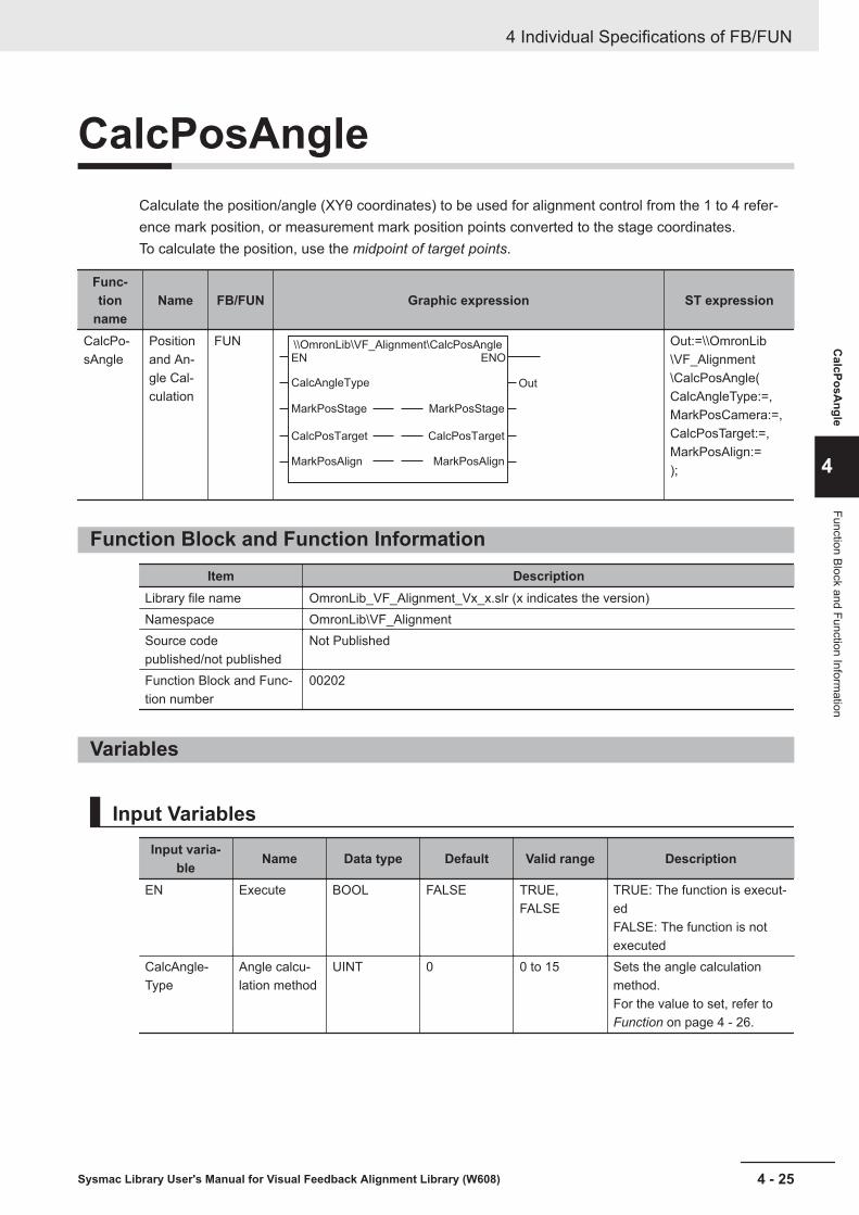
CalcPosAngleCalculate the position/angle (XYθ coordinates) to be used for alignment control from the 1 to 4 refer-ence mark position, or measurement mark position points converted to the stage coordinates.To calculate the position, use the midpoint of target points.
Func-tion
nameName FB/FUN Graphic expression ST expression
CalcPo-sAngle
Positionand An-gle Cal-culation
FUN \\OmronLib\VF_Alignment\CalcPosAngleEN
CalcAngleType
MarkPosStage
CalcPosTarget
MarkPosAlign
ENO
Out
MarkPosStage
CalcPosTarget
MarkPosAlign
Out:=\\OmronLib\VF_Alignment\CalcPosAngle(CalcAngleType:=,MarkPosCamera:=,CalcPosTarget:=,MarkPosAlign:=);
Function Block and Function InformationItem Description
Library file name OmronLib_VF_Alignment_Vx_x.slr (x indicates the version)Namespace OmronLib\VF_AlignmentSource codepublished/not published
Not Published
Function Block and Func-tion number
00202
Variables
Input VariablesInput varia-
ble Name Data type Default Valid range Description
EN Execute BOOL FALSE TRUE,FALSE
TRUE: The function is execut-edFALSE: The function is notexecuted
CalcAngle-Type
Angle calcu-lation method
UINT 0 0 to 15 Sets the angle calculationmethod.For the value to set, refer to Function on page 4 - 26.
4 Individual Specifications of FB/FUN
4 - 25Sysmac Library User's Manual for Visual Feedback Alignment Library (W608)
CalcPosA
ngle
4
Function Block and Function Information
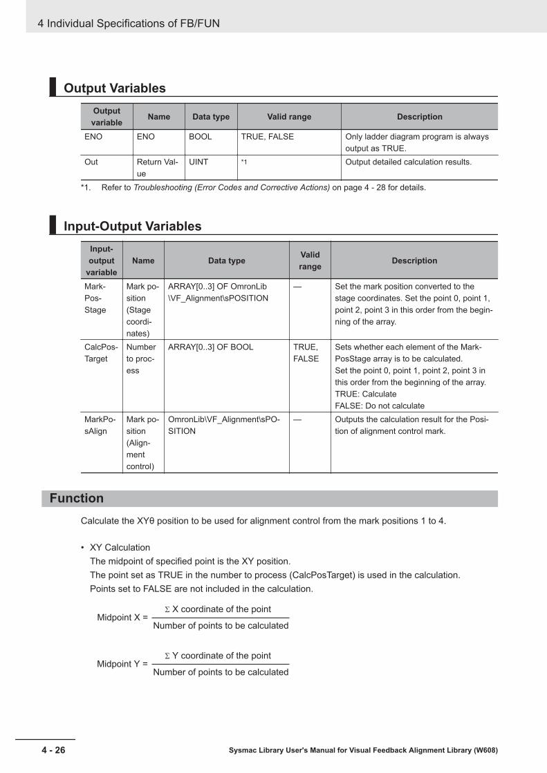
Output VariablesOutputvariable Name Data type Valid range Description
ENO ENO BOOL TRUE, FALSE Only ladder diagram program is alwaysoutput as TRUE.
Out Return Val-ue
UINT *1 Output detailed calculation results.
*1. Refer to Troubleshooting (Error Codes and Corrective Actions) on page 4 - 28 for details.
Input-Output VariablesInput-output
variableName Data type Valid
range Description
Mark-Pos-Stage
Mark po-sition(Stagecoordi-nates)
ARRAY[0..3] OF OmronLib\VF_Alignment\sPOSITION
— Set the mark position converted to thestage coordinates. Set the point 0, point 1,point 2, point 3 in this order from the begin-ning of the array.
CalcPos-Target
Numberto proc-ess
ARRAY[0..3] OF BOOL TRUE,FALSE
Sets whether each element of the Mark-PosStage array is to be calculated.Set the point 0, point 1, point 2, point 3 inthis order from the beginning of the array.TRUE: CalculateFALSE: Do not calculate
MarkPo-sAlign
Mark po-sition(Align-mentcontrol)
OmronLib\VF_Alignment\sPO-SITION
— Outputs the calculation result for the Posi-tion of alignment control mark.
FunctionCalculate the XYθ position to be used for alignment control from the mark positions 1 to 4.
• XY CalculationThe midpoint of specified point is the XY position.The point set as TRUE in the number to process (CalcPosTarget) is used in the calculation.Points set to FALSE are not included in the calculation.
Midpoint X =
Midpoint Y =
S X coordinate of the point
Number of points to be calculated
S Y coordinate of the point
Number of points to be calculated
4 Individual Specifications of FB/FUN
4 - 26 Sysmac Library User's Manual for Visual Feedback Alignment Library (W608)

Y axis
When using 2 points
Point 0 (1,6)
Point 1 (5,2)
Midpoint (3,4)
X axis
Y axis
When using 3 points
Point 0 (2,6)
Point 2 (5,3)
Midpoint (4,5)
X axis
Point 1 (5,6)
Y axis
When using 4 points
Point 0 (1,6)
Point 3 (5,2)
Midpoint (3,4)
X axis
Point 1 (5,6)
Point 2 (1,2)
• Angle calculationThe angle is calculated based on the value set for the angle calculation method.
Values for "CalcAngleType" Calculation method0 Angle of point 01 Angle of point 12 Angle of point 23 Angle of point 34 Angle formed by points 0 to 15 Angle formed by points 1 to 06 Angle formed by points 2 to 07 Angle formed by points 3 to 08 Angle formed by points 0 to 29 Angle formed by points 1 to 210 Angle formed by points 2 to 111 Angle formed by points 3 to 112 Angle formed by points 0 to 313 Angle formed by points 1 to 314 Angle formed by points 2 to 315 Angle formed by points 3 to 2
CalcAngleType = 0 to 3Set the input θ of the specified point to the output θ.
CalcAngleType = 4 to 15For Output θ, set the angle formed between the points M to N where there is a straight line drawn frompoint M in the positive direction on the X axis and the straight line drawn from the point M to the pointN.
• Angle example
4 Individual Specifications of FB/FUN
4 - 27Sysmac Library User's Manual for Visual Feedback Alignment Library (W608)
CalcPosA
ngle
4
Function

Y axis
Point 0
Point 1
Angle(θ)
Angle formed by points 0 to 1
X axis
Y axis
Point 0
Point 1
Angle(θ)
Angle formed by points 1 to 0
X axis
Precautions for Correct UseEnter the mark position to the MarkPosStage array in stage coordinates. If you enter the mark positionin camera coordinates, the correct result can not be obtained.
Perform the conversion calculation of the reference mark position and measurement mark position tothe position for alignment control with the same function and calculation method.If alignment control is performed according to positions calculated by different functions and calcula-tion methods, correct control can not be performed.
Calculations cannot be done in the following cases.A non-zero value is output to the return value (Out), and MarkPosAlign does not change.Please refer to Troubleshooting (Error Codes and Corrective Actions) on page 4 - 28 for output val-ues for Out.• When all elements of CalcPosTarget array are FALSE• When the value set for "CalcAngleType" is outside of the valid range• When the point specified by "CalcAngleType" does not exist in the "MarkPosStage" array
Example: CalcPosTarget [3] = FALSE if CalcAngleType=15 (angle formed by point 3-2)• When the calculation result of MarkPosAlign is non-numeric (±∞)
Sample ProgrammingPlease refer to Sample Programming on page 4 - 90.
Troubleshooting (Error Codes and Corrective Actions)Out Status Description Corrective action
0 Calculation Suc-cessful
— —
1 Nothing to calcu-late
When all elements of CalcPosTargetarray are FALSE.
Please set so that at least one pointcan be calculated.
2 CalcAngleTypeOutside validrange
The value set for CalcAngleType isoutside of the valid range.
Correct the value for CalcAngleType.
4 Individual Specifications of FB/FUN
4 - 28 Sysmac Library User's Manual for Visual Feedback Alignment Library (W608)

Out Status Description Corrective action3 CalcAngleType
IncorrectWhen the point specified by "CalcAn-gleType" does not exist in the "Mark-PosStage" array.
Correct the value for CalcAngleType.
4 Invalid calculationresult
The calculation result for MarkPosAlignis non-numeric (±∞).
Please check whether the values en-tered for MarkPosAlign are ones thatcan be used in calculations.
4 Individual Specifications of FB/FUN
4 - 29Sysmac Library User's Manual for Visual Feedback Alignment Library (W608)
CalcPosA
ngle
4
Troubleshooting (Error Codes and C
orrective Actions)

CalcMultiPosAngleCalculate the position/angle (XYθ coordinates) to be used for alignment control from the 2 to 4 refer-ence mark position, or measurement mark position points converted to the stage coordinates.To calculate the position, you can select from two methods, least squares method and Maximum ErrorMinimization method.
Func-tion
nameName FB/FUN Graphic expression ST expression
CalcMul-tiPosAn-gle
Multi-point Po-sitionand An-gle Cal-culation
FUN \\OmronLib\VF_Alignment\CalcMultiPosAngle
EN ENO
OutCalcType
ExistRotationAxis
TargetMarkPosStage
MeasMarkPosStage
CalcPosTarget
TargetMarkPosAlign
MeasMarkPosAlign
TargetMarkPosStage
MeasMarkPosStage
CalcPosTarget
TargetMarkPosAlign
MeasMarkPosAlign
Out:=\\OmronLib\VF_Alignment\CalcMultiPosAngle(CalcType:=,ExistRotationAxis:=,TargetMarkPos-Stage:=,MeasMarkPos-Stage:=,CalcPosTarget:=,TargetMarkPosA-lign:=,MeasMarkPosA-lign:=);
Function Block and Function InformationItem Description
Library file name OmronLib_VF_Alignment_Vx_x.slr (x indicates the version)Namespace OmronLib\VF_AlignmentSource codepublished/not published
Not Published
Function Block and Func-tion number
00203
Variables
Input VariablesInput varia-
ble Name Data type Default Valid range Description
EN Execute BOOL FALSE TRUE,FALSE
TRUE: The function is execut-edFALSE: The function is notexecuted
CalcType Calculationmethod
UINT 0 0 to 1 Sets the calculation method.For the value to set, refer to Function on page 4 - 32.
4 Individual Specifications of FB/FUN
4 - 30 Sysmac Library User's Manual for Visual Feedback Alignment Library (W608)
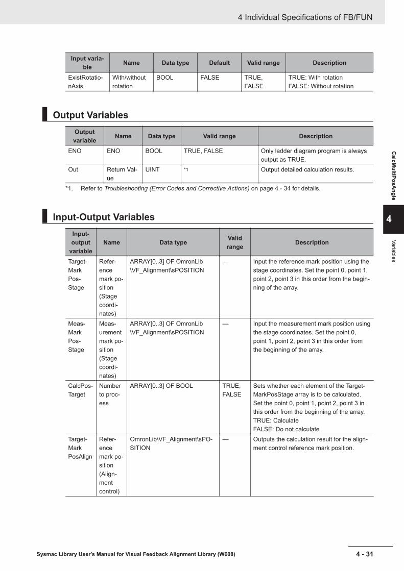
Input varia-ble Name Data type Default Valid range Description
ExistRotatio-nAxis
With/withoutrotation
BOOL FALSE TRUE,FALSE
TRUE: With rotationFALSE: Without rotation
Output VariablesOutputvariable Name Data type Valid range Description
ENO ENO BOOL TRUE, FALSE Only ladder diagram program is alwaysoutput as TRUE.
Out Return Val-ue
UINT *1 Output detailed calculation results.
*1. Refer to Troubleshooting (Error Codes and Corrective Actions) on page 4 - 34 for details.
Input-Output VariablesInput-output
variableName Data type Valid
range Description
Target-MarkPos-Stage
Refer-encemark po-sition(Stagecoordi-nates)
ARRAY[0..3] OF OmronLib\VF_Alignment\sPOSITION
— Input the reference mark position using thestage coordinates. Set the point 0, point 1,point 2, point 3 in this order from the begin-ning of the array.
Meas-MarkPos-Stage
Meas-urementmark po-sition(Stagecoordi-nates)
ARRAY[0..3] OF OmronLib\VF_Alignment\sPOSITION
— Input the measurement mark position usingthe stage coordinates. Set the point 0,point 1, point 2, point 3 in this order fromthe beginning of the array.
CalcPos-Target
Numberto proc-ess
ARRAY[0..3] OF BOOL TRUE,FALSE
Sets whether each element of the Target-MarkPosStage array is to be calculated.Set the point 0, point 1, point 2, point 3 inthis order from the beginning of the array.TRUE: CalculateFALSE: Do not calculate
Target-MarkPosAlign
Refer-encemark po-sition(Align-mentcontrol)
OmronLib\VF_Alignment\sPO-SITION
— Outputs the calculation result for the align-ment control reference mark position.
4 Individual Specifications of FB/FUN
4 - 31Sysmac Library User's Manual for Visual Feedback Alignment Library (W608)
CalcM
ultiPosAngle
4
Variables
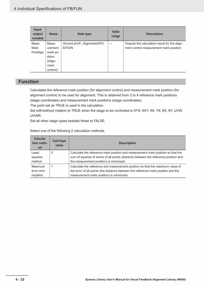
Input-output
variableName Data type Valid
range Description
Meas-MarkPosAlign
Meas-urementmark po-sition(Align-mentcontrol)
OmronLib\VF_Alignment\sPO-SITION
— Outputs the calculation result for the align-ment control measurement mark position.
FunctionCalculates the reference mark position (for alignment control) and measurement mark position (foralignment control) to be used for alignment. This is obtained from 2 to 4 reference mark positions(stage coordinates) and measurement mark positions (stage coordinates).The point set as TRUE is used in the calculation.Set with/without rotation to TRUE when the stage to be controlled is XYθ, θXY, Xθ, Yθ, θX, θY, UVW,UVWR.Set all other stage types besides these to FALSE.
Select one of the following 2 calculation methods.
Calcula-tion meth-
od
CalcTypevalue Description
Leastsquaresmethod
0 Calculate the reference mark position and measurement mark position so that thesum of squares of errors of all points (distance between the reference position andthe measurement position) is minimized.
Maximumerror mini-mization
1 Calculate the reference and measurement position so that the maximum value ofthe error of all points (the distance between the reference mark position and themeasurement mark position) is minimized.
4 Individual Specifications of FB/FUN
4 - 32 Sysmac Library User's Manual for Visual Feedback Alignment Library (W608)
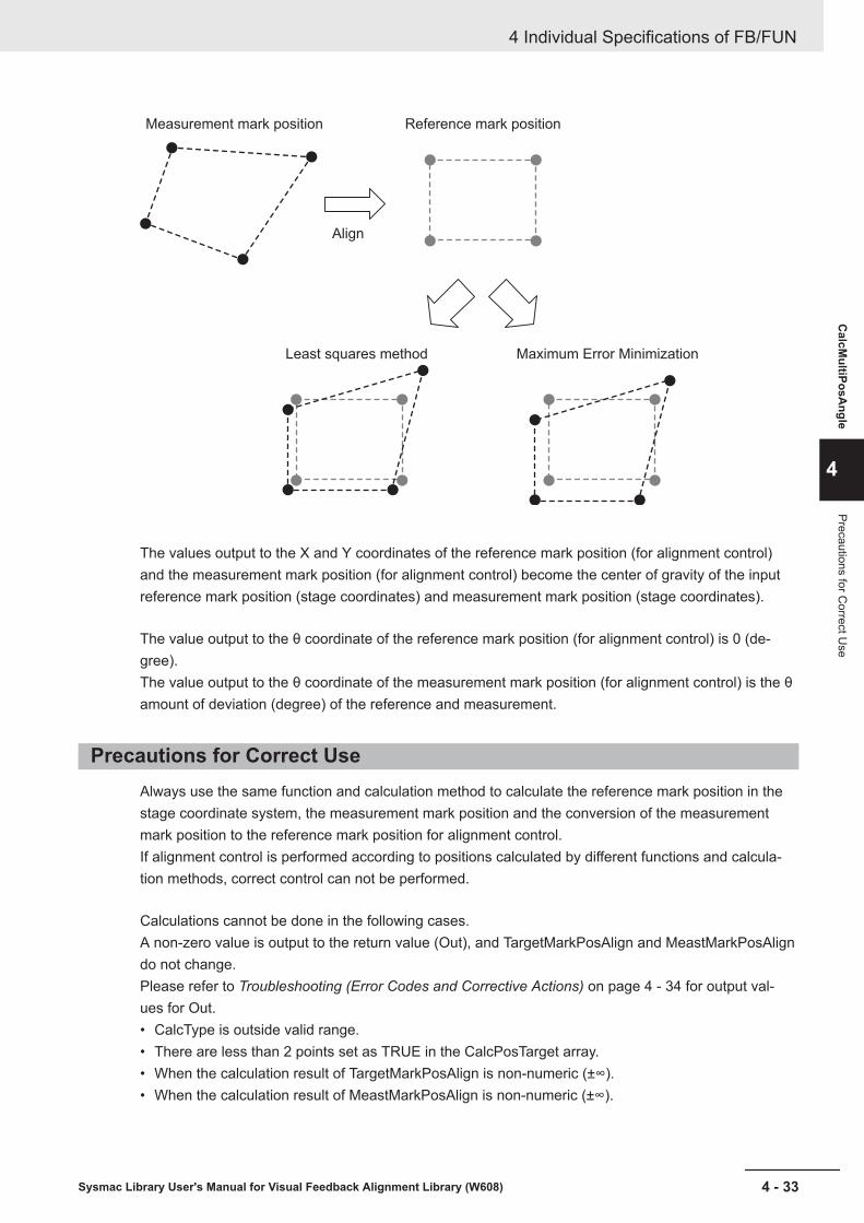
Measurement mark position
Align
Least squares method Maximum Error Minimization
Reference mark position
The values output to the X and Y coordinates of the reference mark position (for alignment control)and the measurement mark position (for alignment control) become the center of gravity of the inputreference mark position (stage coordinates) and measurement mark position (stage coordinates).
The value output to the θ coordinate of the reference mark position (for alignment control) is 0 (de-gree).The value output to the θ coordinate of the measurement mark position (for alignment control) is the θamount of deviation (degree) of the reference and measurement.
Precautions for Correct UseAlways use the same function and calculation method to calculate the reference mark position in thestage coordinate system, the measurement mark position and the conversion of the measurementmark position to the reference mark position for alignment control.If alignment control is performed according to positions calculated by different functions and calcula-tion methods, correct control can not be performed.
Calculations cannot be done in the following cases.A non-zero value is output to the return value (Out), and TargetMarkPosAlign and MeastMarkPosAligndo not change.Please refer to Troubleshooting (Error Codes and Corrective Actions) on page 4 - 34 for output val-ues for Out.• CalcType is outside valid range.• There are less than 2 points set as TRUE in the CalcPosTarget array.• When the calculation result of TargetMarkPosAlign is non-numeric (±∞).• When the calculation result of MeastMarkPosAlign is non-numeric (±∞).
4 Individual Specifications of FB/FUN
4 - 33Sysmac Library User's Manual for Visual Feedback Alignment Library (W608)
CalcM
ultiPosAngle
4
Precautions for Correct U
se
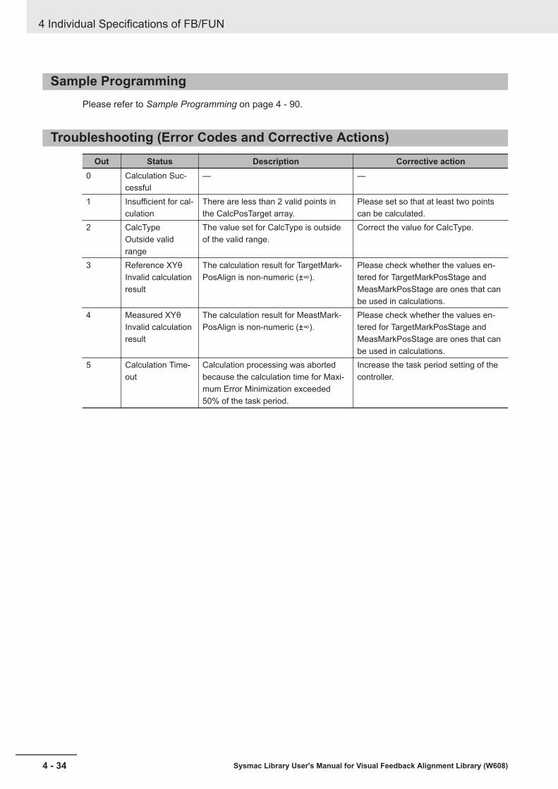
Sample ProgrammingPlease refer to Sample Programming on page 4 - 90.
Troubleshooting (Error Codes and Corrective Actions)Out Status Description Corrective action
0 Calculation Suc-cessful
— —
1 Insufficient for cal-culation
There are less than 2 valid points inthe CalcPosTarget array.
Please set so that at least two pointscan be calculated.
2 CalcTypeOutside validrange
The value set for CalcType is outsideof the valid range.
Correct the value for CalcType.
3 Reference XYθInvalid calculationresult
The calculation result for TargetMark-PosAlign is non-numeric (±∞).
Please check whether the values en-tered for TargetMarkPosStage andMeasMarkPosStage are ones that canbe used in calculations.
4 Measured XYθInvalid calculationresult
The calculation result for MeastMark-PosAlign is non-numeric (±∞).
Please check whether the values en-tered for TargetMarkPosStage andMeasMarkPosStage are ones that canbe used in calculations.
5 Calculation Time-out
Calculation processing was abortedbecause the calculation time for Maxi-mum Error Minimization exceeded50% of the task period.
Increase the task period setting of thecontroller.
4 Individual Specifications of FB/FUN
4 - 34 Sysmac Library User's Manual for Visual Feedback Alignment Library (W608)

CtrlStageAlignment control is performed to make the reference XYθ position align with the measurement XYθposition.Visual feedback control is used for axis travel distance calculation and axis movement control.
FBname Name FB/FUN Graphic expression ST expression
CtrlStage
StageControl
FB
\\OmronLib\VF_Alignment\CtrlStage
CtrlStage_instance
Execute
TargetMarkPosAlign
MeasMarkPosAlign
TriggerAck
TriggerBusy
ResultNotification
TotalJudgment
Abort
AlignmentParams
MeasMarkPosStage
TargetMarkPosStage
Done
Busy
Active
Trigger
VirtualStagePos
Difference_X
Difference_Y
Difference_TH
AlignmentParams
MeasMarkPosStage
CommandAborted
Error
ErrorID
ErrorIDEx
TargetMarkPosStage
CtrlStage_instance(Execute:=,TargetMarkPosA-lign:=,MeasMarkPosA-lign:=,TriggerAck:=,TriggerBusy:=,ResultNotification:=,TotalJudgment:=,Abort:=,Done=>,Busy=>,Active=>,Trigger=>,VirtualStagePos=>,Difference_X=>,Difference_Y=>,Difference_TH=>,CommandAbort-ed=>,Error=>,ErrorID=>,ErrorIDEx=>,AlignmentParams:=,TargetMarkPos-Stage:=,MeasMarkPos-Stage:=);
Function Block and Function InformationItem Description
Library file name OmronLib_VF_Alignment_Vx_x.slr (x indicates the version)Namespace OmronLib\VF_AlignmentSource codepublished/not published
Not Published
Function Block and Func-tion number
00204
4 Individual Specifications of FB/FUN
4 - 35Sysmac Library User's Manual for Visual Feedback Alignment Library (W608)
CtrlStage
4
Function Block and Function Information
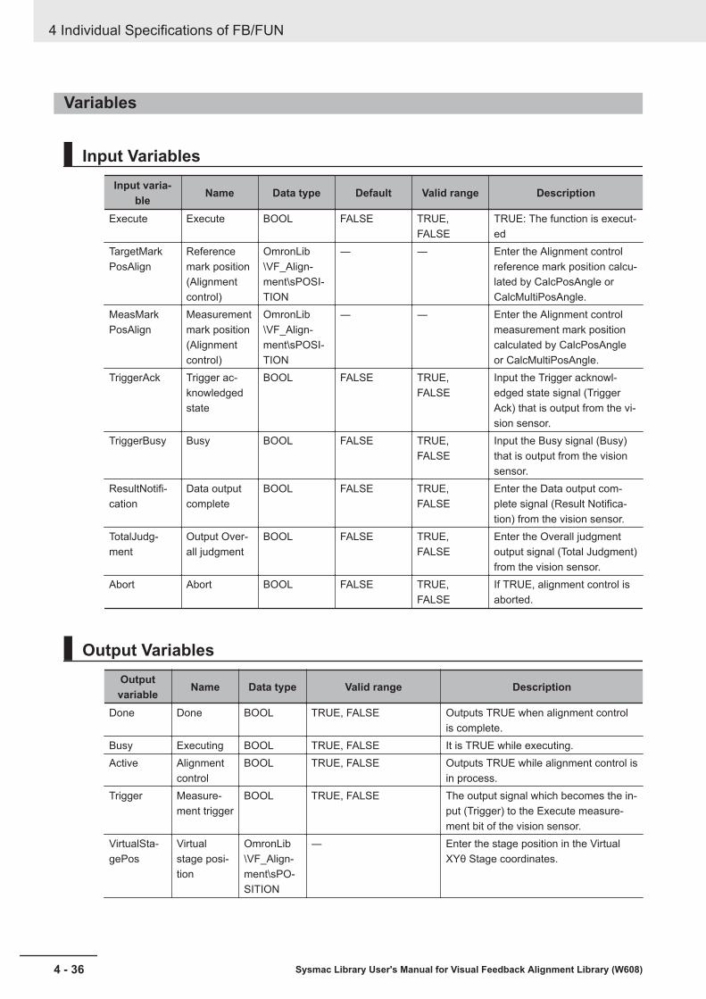
Variables
Input VariablesInput varia-
ble Name Data type Default Valid range Description
Execute Execute BOOL FALSE TRUE,FALSE
TRUE: The function is execut-ed
TargetMarkPosAlign
Referencemark position(Alignmentcontrol)
OmronLib\VF_Align-ment\sPOSI-TION
― ― Enter the Alignment controlreference mark position calcu-lated by CalcPosAngle orCalcMultiPosAngle.
MeasMarkPosAlign
Measurementmark position(Alignmentcontrol)
OmronLib\VF_Align-ment\sPOSI-TION
― ― Enter the Alignment controlmeasurement mark positioncalculated by CalcPosAngleor CalcMultiPosAngle.
TriggerAck Trigger ac-knowledgedstate
BOOL FALSE TRUE,FALSE
Input the Trigger acknowl-edged state signal (TriggerAck) that is output from the vi-sion sensor.
TriggerBusy Busy BOOL FALSE TRUE,FALSE
Input the Busy signal (Busy)that is output from the visionsensor.
ResultNotifi-cation
Data outputcomplete
BOOL FALSE TRUE,FALSE
Enter the Data output com-plete signal (Result Notifica-tion) from the vision sensor.
TotalJudg-ment
Output Over-all judgment
BOOL FALSE TRUE,FALSE
Enter the Overall judgmentoutput signal (Total Judgment)from the vision sensor.
Abort Abort BOOL FALSE TRUE,FALSE
If TRUE, alignment control isaborted.
Output VariablesOutputvariable Name Data type Valid range Description
Done Done BOOL TRUE, FALSE Outputs TRUE when alignment controlis complete.
Busy Executing BOOL TRUE, FALSE It is TRUE while executing.Active Alignment
controlBOOL TRUE, FALSE Outputs TRUE while alignment control is
in process.Trigger Measure-
ment triggerBOOL TRUE, FALSE The output signal which becomes the in-
put (Trigger) to the Execute measure-ment bit of the vision sensor.
VirtualSta-gePos
Virtualstage posi-tion
OmronLib\VF_Align-ment\sPO-SITION
― Enter the stage position in the VirtualXYθ Stage coordinates.
4 Individual Specifications of FB/FUN
4 - 36 Sysmac Library User's Manual for Visual Feedback Alignment Library (W608)
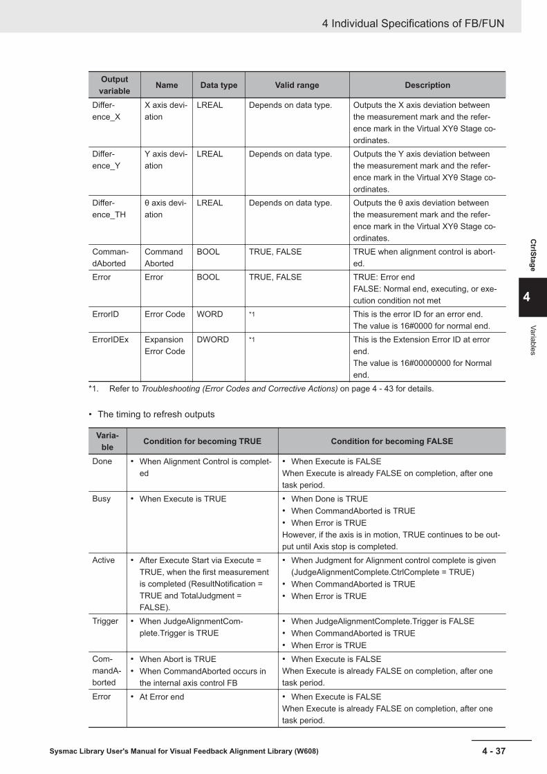
Outputvariable Name Data type Valid range Description
Differ-ence_X
X axis devi-ation
LREAL Depends on data type. Outputs the X axis deviation betweenthe measurement mark and the refer-ence mark in the Virtual XYθ Stage co-ordinates.
Differ-ence_Y
Y axis devi-ation
LREAL Depends on data type. Outputs the Y axis deviation betweenthe measurement mark and the refer-ence mark in the Virtual XYθ Stage co-ordinates.
Differ-ence_TH
θ axis devi-ation
LREAL Depends on data type. Outputs the θ axis deviation betweenthe measurement mark and the refer-ence mark in the Virtual XYθ Stage co-ordinates.
Comman-dAborted
CommandAborted
BOOL TRUE, FALSE TRUE when alignment control is abort-ed.
Error Error BOOL TRUE, FALSE TRUE: Error endFALSE: Normal end, executing, or exe-cution condition not met
ErrorID Error Code WORD *1 This is the error ID for an error end.The value is 16#0000 for normal end.
ErrorIDEx ExpansionError Code
DWORD *1 This is the Extension Error ID at errorend.The value is 16#00000000 for Normalend.
*1. Refer to Troubleshooting (Error Codes and Corrective Actions) on page 4 - 43 for details.
• The timing to refresh outputs
Varia-ble Condition for becoming TRUE Condition for becoming FALSE
Done • When Alignment Control is complet-ed
• When Execute is FALSEWhen Execute is already FALSE on completion, after onetask period.
Busy • When Execute is TRUE • When Done is TRUE• When CommandAborted is TRUE• When Error is TRUEHowever, if the axis is in motion, TRUE continues to be out-put until Axis stop is completed.
Active • After Execute Start via Execute =TRUE, when the first measurementis completed (ResultNotification =TRUE and TotalJudgment =FALSE).
• When Judgment for Alignment control complete is given(JudgeAlignmentComplete.CtrlComplete = TRUE)
• When CommandAborted is TRUE• When Error is TRUE
Trigger • When JudgeAlignmentCom-plete.Trigger is TRUE
• When JudgeAlignmentComplete.Trigger is FALSE• When CommandAborted is TRUE• When Error is TRUE
Com-mandA-borted
• When Abort is TRUE• When CommandAborted occurs in
the internal axis control FB
• When Execute is FALSEWhen Execute is already FALSE on completion, after onetask period.
Error • At Error end • When Execute is FALSEWhen Execute is already FALSE on completion, after onetask period.
4 Individual Specifications of FB/FUN
4 - 37Sysmac Library User's Manual for Visual Feedback Alignment Library (W608)
CtrlStage
4
Variables
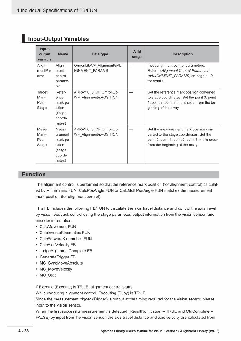
Input-Output VariablesInput-output
variableName Data type Valid
range Description
Align-mentPar-ams
Align-mentcontrolparame-ter
OmronLib\VF_Alignment\sAL-IGNMENT_PARAMS
— Input alignment control parameters.Refer to Alignment Control Parameter(sALIGNMENT_PARAMS) on page 4 - 2for details.
Target-Mark-Pos-Stage
Refer-encemark po-sition(Stagecoordi-nates)
ARRAY[0..3] OF OmronLib\VF_Alignment\sPOSITION
— Set the reference mark position convertedto stage coordinates. Set the point 0, point1, point 2, point 3 in this order from the be-ginning of the array.
Meas-Mark-Pos-Stage
Meas-urementmark po-sition(Stagecoordi-nates)
ARRAY[0..3] OF OmronLib\VF_Alignment\sPOSITION
— Set the measurement mark position con-verted to the stage coordinates. Set thepoint 0, point 1, point 2, point 3 in this orderfrom the beginning of the array.
FunctionThe alignment control is performed so that the reference mark position (for alignment control) calculat-ed by AffineTrans FUN, CalcPosAngle FUN or CalcMultiPosAngle FUN matches the measurementmark position (for alignment control).
This FB includes the following FB/FUN to calculate the axis travel distance and control the axis travelby visual feedback control using the stage parameter, output information from the vision sensor, andencoder information.• CalcMovement FUN• CalcInverseKinematics FUN• CalcForwardKinematics FUN• CalcAxisVelocity FB• JudgeAlignmentComplete FB• GenerateTrigger FB• MC_SyncMoveAbsolute• MC_MoveVelocity• MC_Stop
If Execute (Execute) is TRUE, alignment control starts.While executing alignment control, Executing (Busy) is TRUE.Since the measurement trigger (Trigger) is output at the timing required for the vision sensor, pleaseinput to the vision sensor.When the first successful measurement is detected (ResultNotification = TRUE and CtrlComplete =FALSE) by input from the vision sensor, the axis travel distance and axis velocity are calculated from
4 Individual Specifications of FB/FUN
4 - 38 Sysmac Library User's Manual for Visual Feedback Alignment Library (W608)
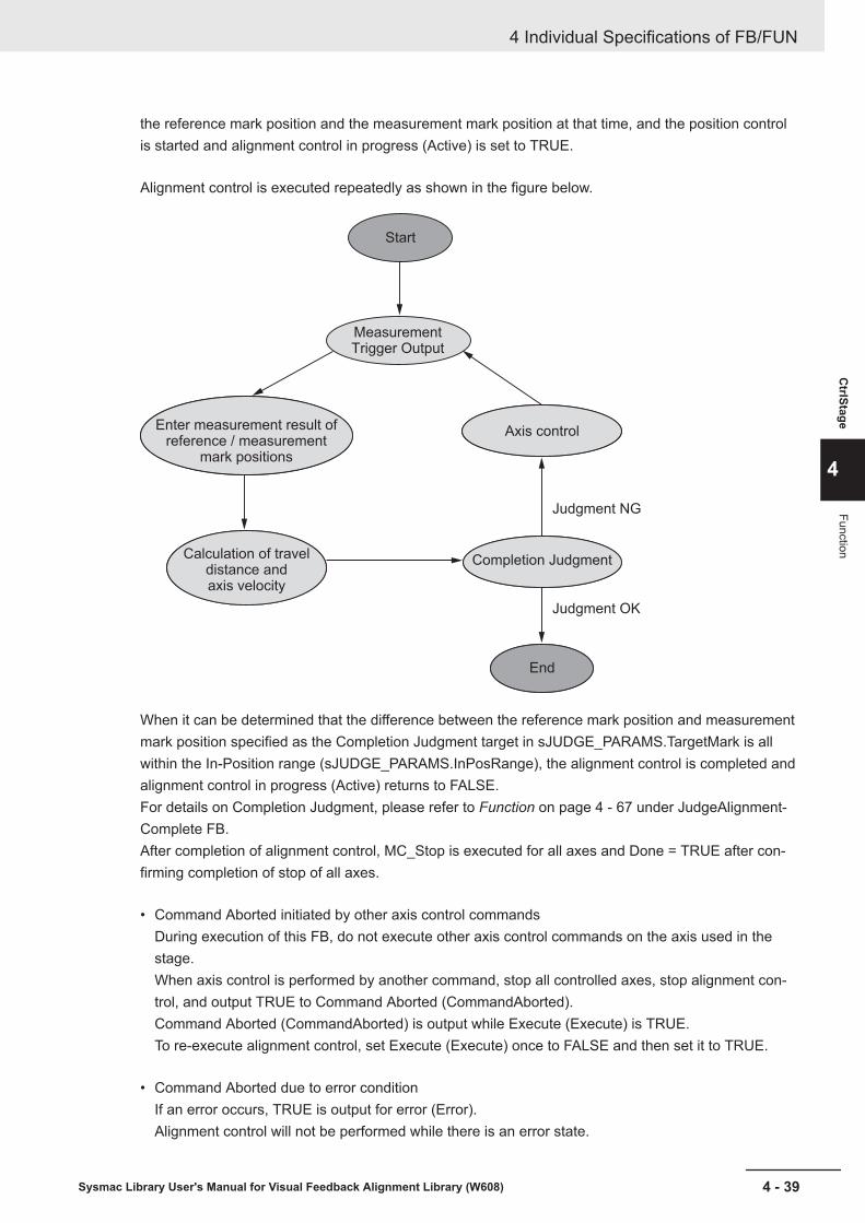
the reference mark position and the measurement mark position at that time, and the position controlis started and alignment control in progress (Active) is set to TRUE.
Alignment control is executed repeatedly as shown in the figure below.
Start
Measurement Trigger Output
Enter measurement result ofreference / measurement
mark positions
Axis control
Completion Judgment
End
Judgment OK
Judgment NG
Calculation of travel distance andaxis velocity
When it can be determined that the difference between the reference mark position and measurementmark position specified as the Completion Judgment target in sJUDGE_PARAMS.TargetMark is allwithin the In-Position range (sJUDGE_PARAMS.InPosRange), the alignment control is completed andalignment control in progress (Active) returns to FALSE.For details on Completion Judgment, please refer to Function on page 4 - 67 under JudgeAlignment-Complete FB.After completion of alignment control, MC_Stop is executed for all axes and Done = TRUE after con-firming completion of stop of all axes.
• Command Aborted initiated by other axis control commandsDuring execution of this FB, do not execute other axis control commands on the axis used in thestage.When axis control is performed by another command, stop all controlled axes, stop alignment con-trol, and output TRUE to Command Aborted (CommandAborted).Command Aborted (CommandAborted) is output while Execute (Execute) is TRUE.To re-execute alignment control, set Execute (Execute) once to FALSE and then set it to TRUE.
• Command Aborted due to error conditionIf an error occurs, TRUE is output for error (Error).Alignment control will not be performed while there is an error state.
4 Individual Specifications of FB/FUN
4 - 39Sysmac Library User's Manual for Visual Feedback Alignment Library (W608)
CtrlStage
4
Function

Please refer to Precautions for Correct Use on page 4 - 42 for the conditions that cause errors.To re-execute alignment control, set Execute (Execute) to FALSE, correct the cause of the error andset Execute (Execute) to TRUE again.
• The relevant axis decelerates to a stop.This FB stops the controlled axis by using the MC_Stop instruction after decelerating withMC_MoveVelocity if the following conditions occur.a) Alignment control completeb) If Abort is enteredc) When an internal error in this FB occurs (except for MC_SyncMoveAbsolute command and
MC_MoveVelocity command errors).d) When there is a CommandAborted in MC_SyncMoveAbosluteSCALIB_MOVE_PARAMS.StopDec is applied to the deceleration rate (MC_Stop.Deceleration) atthis time.If an error (Error) of the MC_SyncMoveAbsolute instruction or the MC_MoveVelocity instruction oran abort of the execution of the MC_MoveVelocity instruction (CommandAborted) occurs, stop im-mediately with the MC_Stop instruction.When an error (Error) or Command Aborted (CommandAborted) for MC_Stop instruction occurs, itis treated the same as Done of the MC_Stop command and it is assumed that the immediate stophas been completed.
• Parameter settingPlease refer to FB/FUN Structure Usage on page 4 - 17 for the use of the members belonging toeach structure.
• Changing input parametersThe alignment control parameter retains the value at the start of execution.Changes during execution are not reflected in the control.If you want to make changes effective, restart Execute (Execute) after completing (Done = TRUE),aborting execution (CommandAborted = TRUE), and terminating the error (Error = TRUE). It is notpossible to reboot while executing this.
Timing ChartsThe timing charts are shown below.• If Execute (Execute) is TRUE, alignment control starts.• If an error occurs during execution of this function block, end calculation and Error (Error) changes
to TRUE.Alignment control will not be performed while there is an error state.You can find out the cause of the error by accessing the values output to Error Code (ErrorID) andExpansion Error Code (ErrorIDEx).
• While Execute (Execute) is TRUE, it will stay in the Error (Error) state.The Error Code (ErrorID) or Expansion Error Code (ErrorIDEx) is maintained until Execute is re-exe-cuted.Alignment control will not be performed while there is an error state.
• If another axis control command is executed while this FB is being executed, Command Aborted(CommandAborted) becomes TRUE.
• While Execute (Execute) is TRUE, Command Aborted (CommandAborted) will be maintained.
4 Individual Specifications of FB/FUN
4 - 40 Sysmac Library User's Manual for Visual Feedback Alignment Library (W608)
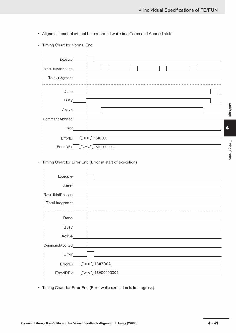
• Alignment control will not be performed while in a Command Aborted state.
• Timing Chart for Normal End
16#0000
16#00000000ErrorIDEx
ErrorID
Error
Active
CommandAborted
Busy
Done
Execute
TotalJudgment
ResultNotification
• Timing Chart for Error End (Error at start of execution)
16#3D0A
16#00000001ErrorIDEx
ErrorID
CommandAborted
Busy
Active
Done
TotalJudgment
Execute
Error
ResultNotification
Abort
• Timing Chart for Error End (Error while execution is in progress)
4 Individual Specifications of FB/FUN
4 - 41Sysmac Library User's Manual for Visual Feedback Alignment Library (W608)
CtrlStage
4
Timing C
harts
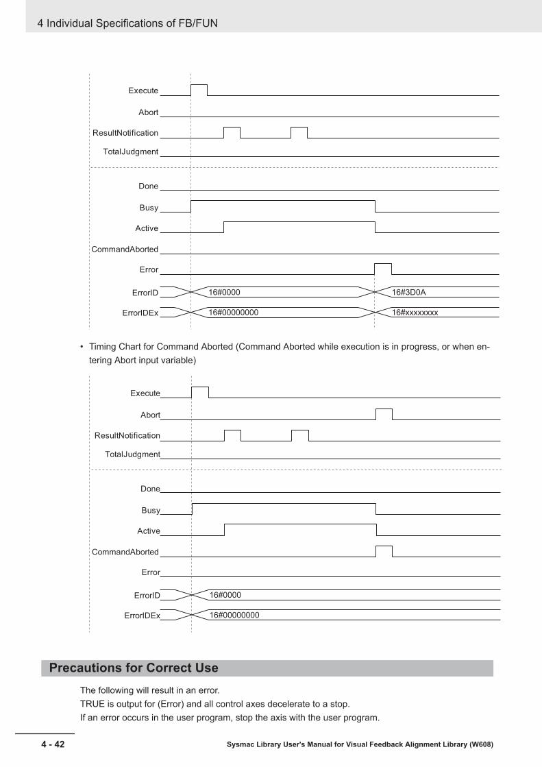
16#0000
16#00000000
16#3D0A
16#xxxxxxxxErrorIDEx
ErrorID
CommandAborted
Busy
Active
Done
TotalJudgment
Execute
Error
ResultNotification
Abort
• Timing Chart for Command Aborted (Command Aborted while execution is in progress, or when en-tering Abort input variable)
16#0000
16#00000000ErrorIDEx
ErrorID
CommandAborted
Busy
Active
Done
TotalJudgment
Execute
Error
ResultNotification
Abort
Precautions for Correct UseThe following will result in an error.TRUE is output for (Error) and all control axes decelerate to a stop.If an error occurs in the user program, stop the axis with the user program.
4 Individual Specifications of FB/FUN
4 - 42 Sysmac Library User's Manual for Visual Feedback Alignment Library (W608)
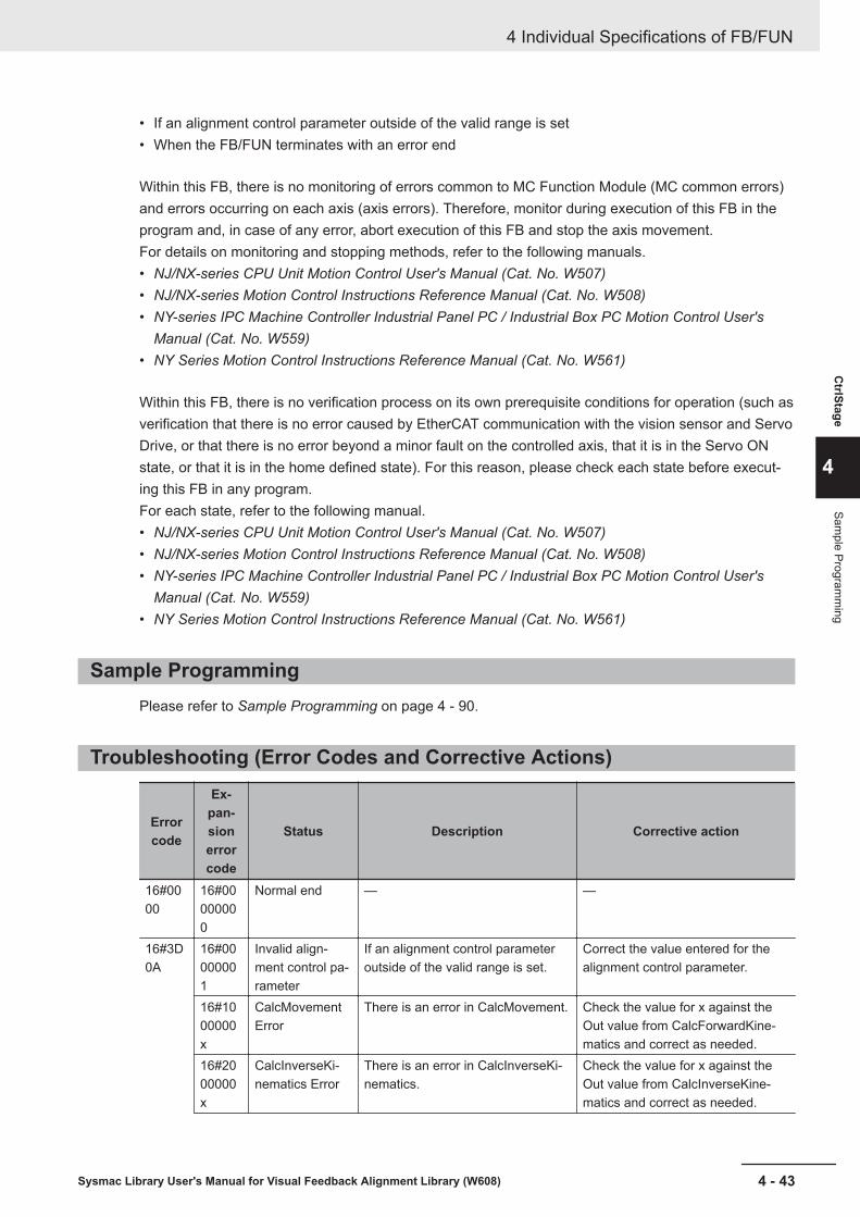
• If an alignment control parameter outside of the valid range is set• When the FB/FUN terminates with an error end
Within this FB, there is no monitoring of errors common to MC Function Module (MC common errors)and errors occurring on each axis (axis errors). Therefore, monitor during execution of this FB in theprogram and, in case of any error, abort execution of this FB and stop the axis movement.For details on monitoring and stopping methods, refer to the following manuals.• NJ/NX-series CPU Unit Motion Control User's Manual (Cat. No. W507)• NJ/NX-series Motion Control Instructions Reference Manual (Cat. No. W508)• NY-series IPC Machine Controller Industrial Panel PC / Industrial Box PC Motion Control User's
Manual (Cat. No. W559)• NY Series Motion Control Instructions Reference Manual (Cat. No. W561)
Within this FB, there is no verification process on its own prerequisite conditions for operation (such asverification that there is no error caused by EtherCAT communication with the vision sensor and ServoDrive, or that there is no error beyond a minor fault on the controlled axis, that it is in the Servo ONstate, or that it is in the home defined state). For this reason, please check each state before execut-ing this FB in any program.For each state, refer to the following manual.• NJ/NX-series CPU Unit Motion Control User's Manual (Cat. No. W507)• NJ/NX-series Motion Control Instructions Reference Manual (Cat. No. W508)• NY-series IPC Machine Controller Industrial Panel PC / Industrial Box PC Motion Control User's
Manual (Cat. No. W559)• NY Series Motion Control Instructions Reference Manual (Cat. No. W561)
Sample ProgrammingPlease refer to Sample Programming on page 4 - 90.
Troubleshooting (Error Codes and Corrective Actions)
Errorcode
Ex-pan-sionerrorcode
Status Description Corrective action
16#0000
16#00000000
Normal end — —
16#3D0A
16#00000001
Invalid align-ment control pa-rameter
If an alignment control parameteroutside of the valid range is set.
Correct the value entered for thealignment control parameter.
16#1000000x
CalcMovementError
There is an error in CalcMovement. Check the value for x against theOut value from CalcForwardKine-matics and correct as needed.
16#2000000x
CalcInverseKi-nematics Error
There is an error in CalcInverseKi-nematics.
Check the value for x against theOut value from CalcInverseKine-matics and correct as needed.
4 Individual Specifications of FB/FUN
4 - 43Sysmac Library User's Manual for Visual Feedback Alignment Library (W608)
CtrlStage
4
Sample Program
ming
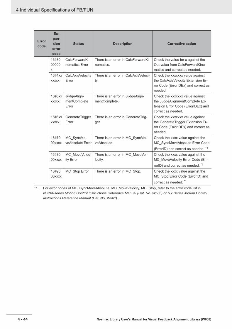
Errorcode
Ex-pan-sionerrorcode
Status Description Corrective action
16#3000000x
CalcForwardKi-nematics Error
There is an error in CalcForwardKi-nematics.
Check the value for x against theOut value from CalcForwardKine-matics and correct as needed.
16#4xxxxxxx
CalcAxisVelocityError
There is an error in CalcAxisVeloci-ty.
Check the xxxxxxx value againstthe CalcAxisVelocity Extension Er-ror Code (ErrorIDEx) and correct asneeded.
16#5xxxxxxx
JudgeAlign-mentCompleteError
There is an error in JudgeAlign-mentComplete.
Check the xxxxxxx value againstthe JudgeAlignmentComplete Ex-tension Error Code (ErrorIDEx) andcorrect as needed.
16#6xxxxxxx
GenerateTriggerError
There is an error in GenerateTrig-ger.
Check the xxxxxxx value againstthe GenerateTrigger Extension Er-ror Code (ErrorIDEx) and correct asneeded.
16#7000xxxx
MC_SyncMo-veAbsolute Error
There is an error in MC_SyncMo-veAbsolute.
Check the xxxx value against theMC_SyncMoveAbsolute Error Code(ErrorID) and correct as needed. *1
16#8000xxxx
MC_MoveVeloc-ity Error
There is an error in MC_MoveVe-locity.
Check the xxxx value against theMC_MoveVelocity Error Code (Er-rorID) and correct as needed. *1
16#9000xxxx
MC_Stop Error There is an error in MC_Stop. Check the xxxx value against theMC_Stop Error Code (ErrorID) andcorrect as needed. *1
*1. For error codes of MC_SyncMoveAbsolute, MC_MoveVelocity, MC_Stop, refer to the error code list inNJ/NX-series Motion Control Instructions Reference Manual (Cat. No. W508) or NY Series Motion ControlInstructions Reference Manual (Cat. No. W561).
4 Individual Specifications of FB/FUN
4 - 44 Sysmac Library User's Manual for Visual Feedback Alignment Library (W608)
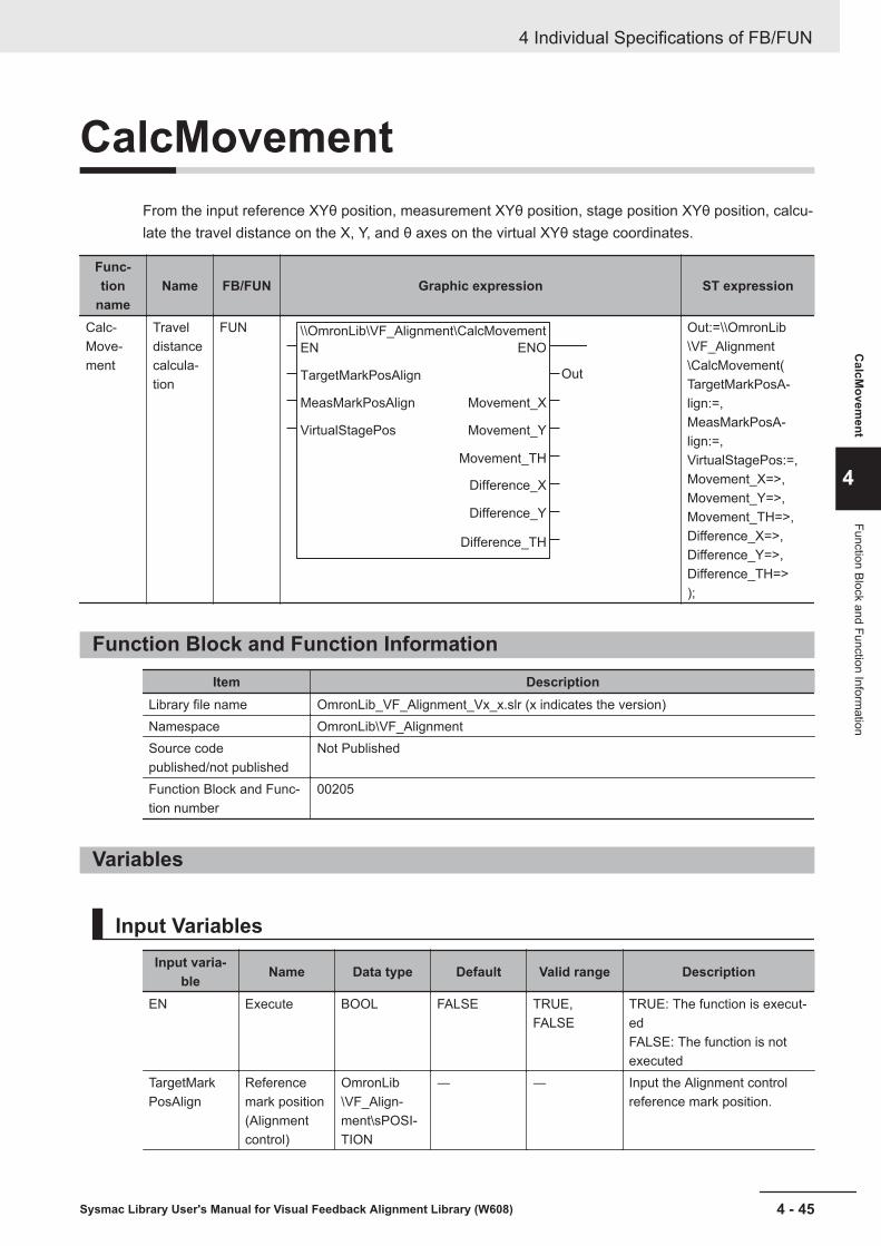
CalcMovementFrom the input reference XYθ position, measurement XYθ position, stage position XYθ position, calcu-late the travel distance on the X, Y, and θ axes on the virtual XYθ stage coordinates.
Func-tion
nameName FB/FUN Graphic expression ST expression
Calc-Move-ment
Traveldistancecalcula-tion
FUN \\OmronLib\VF_Alignment\CalcMovement
EN
TargetMarkPosAlign
MeasMarkPosAlign
VirtualStagePos
ENO
Out
Movement_X
Movement_Y
Movement_TH
Difference_X
Difference_Y
Difference_TH
Out:=\\OmronLib\VF_Alignment\CalcMovement(TargetMarkPosA-lign:=,MeasMarkPosA-lign:=,VirtualStagePos:=,Movement_X=>,Movement_Y=>,Movement_TH=>,Difference_X=>,Difference_Y=>,Difference_TH=>);
Function Block and Function InformationItem Description
Library file name OmronLib_VF_Alignment_Vx_x.slr (x indicates the version)Namespace OmronLib\VF_AlignmentSource codepublished/not published
Not Published
Function Block and Func-tion number
00205
Variables
Input VariablesInput varia-
ble Name Data type Default Valid range Description
EN Execute BOOL FALSE TRUE,FALSE
TRUE: The function is execut-edFALSE: The function is notexecuted
TargetMarkPosAlign
Referencemark position(Alignmentcontrol)
OmronLib\VF_Align-ment\sPOSI-TION
― ― Input the Alignment controlreference mark position.
4 Individual Specifications of FB/FUN
4 - 45Sysmac Library User's Manual for Visual Feedback Alignment Library (W608)
CalcM
ovement
4
Function Block and Function Information
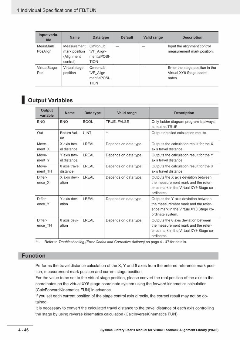
Input varia-ble Name Data type Default Valid range Description
MeasMarkPosAlign
Measurementmark position(Alignmentcontrol)
OmronLib\VF_Align-ment\sPOSI-TION
― ― Input the alignment controlmeasurement mark position.
VirtualStage-Pos
Virtual stageposition
OmronLib\VF_Align-ment\sPOSI-TION
― ― Enter the stage position in theVirtual XYθ Stage coordi-nates.
Output VariablesOutputvariable Name Data type Valid range Description
ENO ENO BOOL TRUE, FALSE Only ladder diagram program is alwaysoutput as TRUE.
Out Return Val-ue
UINT *1 Output detailed calculation results.
Move-ment_X
X axis trav-el distance
LREAL Depends on data type. Outputs the calculation result for the Xaxis travel distance.
Move-ment_Y
Y axis trav-el distance
LREAL Depends on data type. Outputs the calculation result for the Yaxis travel distance.
Move-ment_TH
θ axis traveldistance
LREAL Depends on data type. Outputs the calculation result for the θaxis travel distance.
Differ-ence_X
X axis devi-ation
LREAL Depends on data type. Outputs the X axis deviation betweenthe measurement mark and the refer-ence mark in the Virtual XYθ Stage co-ordinates.
Differ-ence_Y
Y axis devi-ation
LREAL Depends on data type. Outputs the Y axis deviation betweenthe measurement mark and the refer-ence mark in the Virtual XYθ Stage co-ordinate system.
Differ-ence_TH
θ axis devi-ation
LREAL Depends on data type. Outputs the θ axis deviation betweenthe measurement mark and the refer-ence mark in the Virtual XYθ Stage co-ordinates.
*1. Refer to Troubleshooting (Error Codes and Corrective Actions) on page 4 - 47 for details.
FunctionPerforms the travel distance calculation of the X, Y and θ axes from the entered reference mark posi-tion, measurement mark position and current stage position.For the value to be set to the virtual stage position, please convert the real position of the axis to thecoordinates on the virtual XYθ stage coordinate system using the forward kinematics calculation(CalcForwardKinematics FUN) in advance.If you set each current position of the stage control axis directly, the correct result may not be ob-tained.It is necessary to convert the calculated travel distance to the travel distance of each axis controllingthe stage by using reverse kinematics calculation (CalcInverseKinematics FUN).
4 Individual Specifications of FB/FUN
4 - 46 Sysmac Library User's Manual for Visual Feedback Alignment Library (W608)

• Diagram of converted image
(MX,MY,Mθ)
(SX,SY,Sθ)
(CX,CY)
(RX,RY,Sθ)
Home
Dθ
DX
DY
Y axis
X axis
Reference position/angle (SX,SY,Sθ)
Measurement position/angle (MX,MY,Mθ)
Current axis position (CX,CY)
≈ Position of center of rotation
Axis travel distance (DX,DY,Dθ)
Midpoint position (RX,RY)
≈ Measurement position when measurement angle
matches reference angle
• DeviationDuring execution, the differences between the X coordinate, Y coordinate, and θ coordinate of thereference mark position and measurement mark position are stored in Difference_X, Difference_Y,Difference_TH.
• Parameter settingPlease refer to FB/FUN Structure Usage on page 4 - 17 for the use of the members belonging toeach structure.
Precautions for Correct UseCalculations cannot be done in the following cases.A non-zero value is output to the return value (Out) and 0 (zero) is output for Movement_X, Move-ment_Y, Movement_TH.Please refer to Troubleshooting (Error Codes and Corrective Actions) on page 4 - 47 for output val-ues for Out.• When the calculation result of Movement_X, Movement_Y, Movement_TH is non-numeric (±∞).• When the calculation result of Difference_X, Difference_Y, Difference_TH is non-numeric (±∞).
Sample ProgrammingPlease refer to Sample Programming on page 4 - 90.
Troubleshooting (Error Codes and Corrective Actions)Out Status Description Corrective action
0 Calculation Suc-cessful
— —
1 Invalid X, Y, θ axismovement calcu-lation result
The calculation result of X, Y, θ axestravel distance is non-numeric (±∞).
Please check whether the values en-tered for TargetMarkPosAlign, Meas-MarkPosAlign and VirtualStagePos areones that can be used in calculations.
2 Invalid X,Y,θ devi-ation calculationresult
The calculation result of X,Y,θ devia-tion is non-numeric (±∞).
Please check whether the values en-tered for TargetMarkPosAlign, Meas-MarkPosAlign and VirtualStagePos areones that can be used in calculations.
4 Individual Specifications of FB/FUN
4 - 47Sysmac Library User's Manual for Visual Feedback Alignment Library (W608)
CalcM
ovement
4
Precautions for Correct U
se
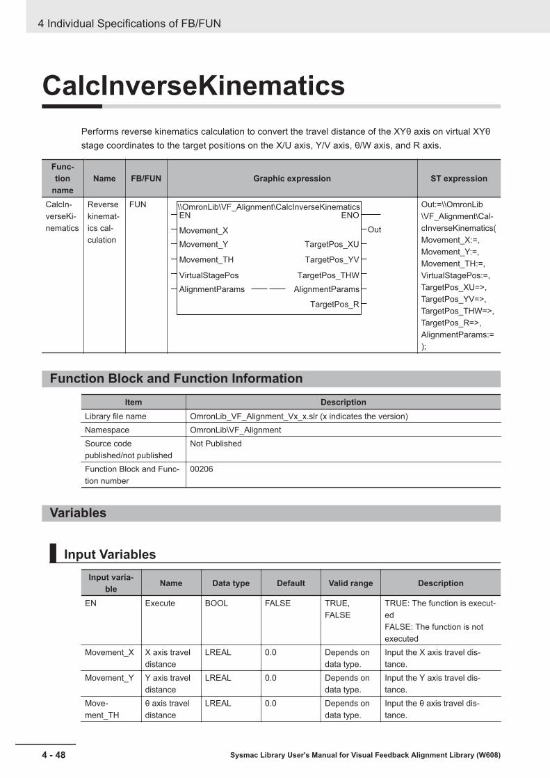
CalcInverseKinematicsPerforms reverse kinematics calculation to convert the travel distance of the XYθ axis on virtual XYθstage coordinates to the target positions on the X/U axis, Y/V axis, θ/W axis, and R axis.
Func-tion
nameName FB/FUN Graphic expression ST expression
CalcIn-verseKi-nematics
Reversekinemat-ics cal-culation
FUN \\OmronLib\VF_Alignment\CalcInverseKinematicsEN
Movement_X
Movement_Y
Movement_TH
VirtualStagePos
AlignmentParams
ENO
Out
TargetPos_XU
TargetPos_YV
TargetPos_THW
AlignmentParams
TargetPos_R
Out:=\\OmronLib\VF_Alignment\Cal-cInverseKinematics(Movement_X:=,Movement_Y:=,Movement_TH:=,VirtualStagePos:=,TargetPos_XU=>,TargetPos_YV=>,TargetPos_THW=>,TargetPos_R=>,AlignmentParams:=);
Function Block and Function InformationItem Description
Library file name OmronLib_VF_Alignment_Vx_x.slr (x indicates the version)Namespace OmronLib\VF_AlignmentSource codepublished/not published
Not Published
Function Block and Func-tion number
00206
Variables
Input VariablesInput varia-
ble Name Data type Default Valid range Description
EN Execute BOOL FALSE TRUE,FALSE
TRUE: The function is execut-edFALSE: The function is notexecuted
Movement_X X axis traveldistance
LREAL 0.0 Depends ondata type.
Input the X axis travel dis-tance.
Movement_Y Y axis traveldistance
LREAL 0.0 Depends ondata type.
Input the Y axis travel dis-tance.
Move-ment_TH
θ axis traveldistance
LREAL 0.0 Depends ondata type.
Input the θ axis travel dis-tance.
4 Individual Specifications of FB/FUN
4 - 48 Sysmac Library User's Manual for Visual Feedback Alignment Library (W608)
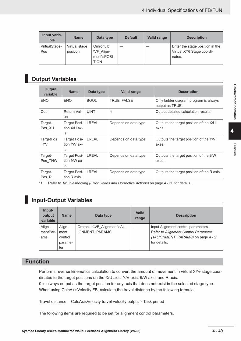
Input varia-ble Name Data type Default Valid range Description
VirtualStage-Pos
Virtual stageposition
OmronLib\VF_Align-ment\sPOSI-TION
― ― Enter the stage position in theVirtual XYθ Stage coordi-nates.
Output VariablesOutputvariable Name Data type Valid range Description
ENO ENO BOOL TRUE, FALSE Only ladder diagram program is alwaysoutput as TRUE.
Out Return Val-ue
UINT *1 Output detailed calculation results.
Target-Pos_XU
Target Posi-tion X/U ax-is
LREAL Depends on data type. Outputs the target position of the X/Uaxes.
TargetPos_YV
Target Posi-tion Y/V ax-is
LREAL Depends on data type. Outputs the target position of the Y/Vaxes.
Target-Pos_THW
Target Posi-tion θ/W ax-is
LREAL Depends on data type. Outputs the target position of the θ/Waxes.
Target-Pos_R
Target Posi-tion R axis
LREAL Depends on data type. Outputs the target position of the R axis.
*1. Refer to Troubleshooting (Error Codes and Corrective Actions) on page 4 - 50 for details.
Input-Output VariablesInput-output
variableName Data type Valid
range Description
Align-mentPar-ams
Align-mentcontrolparame-ter
OmronLib\VF_Alignment\sAL-IGNMENT_PARAMS
— Input Alignment control parameters.Refer to Alignment Control Parameter(sALIGNMENT_PARAMS) on page 4 - 2for details.
FunctionPerforms reverse kinematics calculation to convert the amount of movement in virtual XYθ stage coor-dinates to the target positions on the X/U axis, Y/V axis, θ/W axis, and R axis.0 is always output as the target position for any axis that does not exist in the selected stage type.When using CalcAxisVelocity FB, calculate the travel distance by the following formula.
Travel distance = CalcAxisVelocity travel velocity output × Task period
The following items are required to be set for alignment control parameters.
4 Individual Specifications of FB/FUN
4 - 49Sysmac Library User's Manual for Visual Feedback Alignment Library (W608)
CalcInverseK
inematics
4
Function

Meaning of Symbols¡ : Required settingÍ : Settings not required (Not referenced)
Variable name XY stage XYθ stage θXY stage UVW stageStageParams StageType ¡ ¡ ¡ ¡
StageType setting values (0,3,4) (1,5,6) (2,7,8) (9,10)AxNo ¡ ¡ ¡ ¡
XYTHStageParams Í ¡ ¡ Í
UVWRStageParams Í Í Í ¡
Kinematics_Params Í Í ¡ Í
• Parameter settingPlease refer to FB/FUN Structure Usage on page 4 - 17 for the use of the members belonging toeach structure.
Precautions for Correct UseCalculations cannot be done in the following cases.A non-zero value is output to the return value (Out) and Current Axis Position is output for Target-Pos_XU, TargetPos_YV, TargetPos_THW, and TargetPos_R.However, a value of 0 is output as the target position of the axis that does not exist on the stage.Please refer to Troubleshooting (Error Codes and Corrective Actions) on page 4 - 50 for output val-ues for Out.• If an alignment control parameter outside of the valid range is set• When the calculation result for TargetPos_XU, TargetPos_YV, TargetPos_THW, or TargetPos_R is
non-numeric (±∞)
Sample ProgrammingPlease refer to Sample Programming on page 4 - 90.
Troubleshooting (Error Codes and Corrective Actions)Out Status Description Corrective action
0 Calculation Suc-cessful
— —
1 Invalid alignmentcontrol parameter
If an alignment control parameter out-side of the valid range is set.
Correct the value entered for the align-ment control parameter.
2 Invalid target posi-tion calculation
Calculation results for X/U, Y/V, θ/W, Raxes target positions are non-numeric(±∞).
Please check whether the values en-tered for Movement_X, Movement_Y,Movement_TH, VirtualStagePos areones that can be used in calculations.Correct the value so it can be calculat-ed as an alignment control parameter.
4 Individual Specifications of FB/FUN
4 - 50 Sysmac Library User's Manual for Visual Feedback Alignment Library (W608)
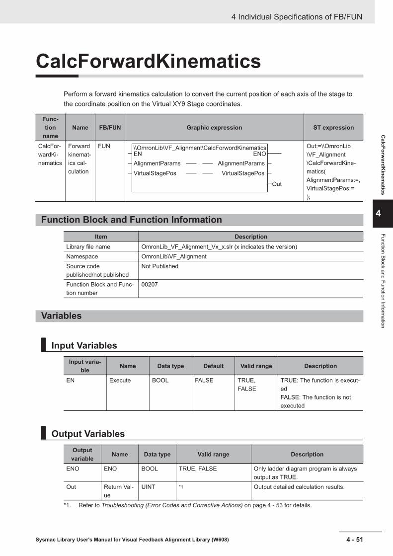
CalcForwardKinematicsPerform a forward kinematics calculation to convert the current position of each axis of the stage tothe coordinate position on the Virtual XYθ Stage coordinates.
Func-tion
nameName FB/FUN Graphic expression ST expression
CalcFor-wardKi-nematics
Forwardkinemat-ics cal-culation
FUN \\OmronLib\VF_Alignment\CalcForwordKinematicsEN
AlignmentParams
VirtualStagePos
Out
ENO
AlignmentParams
VirtualStagePos
Out:=\\OmronLib\VF_Alignment\CalcForwardKine-matics(AlignmentParams:=,VirtualStagePos:=);
Function Block and Function InformationItem Description
Library file name OmronLib_VF_Alignment_Vx_x.slr (x indicates the version)Namespace OmronLib\VF_AlignmentSource codepublished/not published
Not Published
Function Block and Func-tion number
00207
Variables
Input VariablesInput varia-
ble Name Data type Default Valid range Description
EN Execute BOOL FALSE TRUE,FALSE
TRUE: The function is execut-edFALSE: The function is notexecuted
Output VariablesOutputvariable Name Data type Valid range Description
ENO ENO BOOL TRUE, FALSE Only ladder diagram program is alwaysoutput as TRUE.
Out Return Val-ue
UINT *1 Output detailed calculation results.
*1. Refer to Troubleshooting (Error Codes and Corrective Actions) on page 4 - 53 for details.
4 Individual Specifications of FB/FUN
4 - 51Sysmac Library User's Manual for Visual Feedback Alignment Library (W608)
CalcForw
ardKinem
atics
4
Function Block and Function Information

Input-Output VariablesInput-output
variableName Data type Valid
range Description
Align-mentPar-ams
Align-mentcontrolparame-ter
OmronLib\VF_Alignment\sAL-IGNMENT_PARAMS
— Input Alignment control parameters.Refer to Alignment Control Parameter(sALIGNMENT_PARAMS) on page 4 - 2for details.
Virtual-Stage-Pos
Virtualstageposition
OmronLib\VF_Alignment\sPO-SITION
— Enter the stage position calculation resultin the Virtual XYθ Stage coordinates.
FunctionPerform a forward kinematics calculation to convert from the current position of each axis on the stageto the coordinate position on the virtual XYθ stage coordinates.Enter the value that this FUN outputs as the input to virtual stage position (VirtualStagePos) in Calc-Movement and CalcInverseKinematics.
The following items are required settings for alignment control parameters.Meaning of Symbols¡ : Required settingÍ : Settings not required (Not referenced)
Variable name XY stage XYθ stage θXY stage UVW stageStageParams StageType ¡ ¡ ¡ ¡
StageType set-ting values
(0,3,4) (1,5,6) (2,7,8) (9,10)
AxNo ¡ ¡ ¡ ¡
XYTHStagePar-ams
Í ¡ ¡ Í
UVWRStage-Params
Í Í Í ¡
KinematicsParams Í Í ¡ Í
• Parameter settingPlease refer to FB/FUN Structure Usage on page 4 - 17 for the use of the members belonging toeach structure.
Precautions for Correct UseCalculations cannot be done in the following cases.A non-zero value is output to the return value (Out), and VirtualStagePos does not change.Please refer to Troubleshooting (Error Codes and Corrective Actions) on page 4 - 53 for output val-ues for Out.• If an alignment control parameter outside of the valid range is set• If the calculation result for virtual stage position is non-numeric (±∞)
4 Individual Specifications of FB/FUN
4 - 52 Sysmac Library User's Manual for Visual Feedback Alignment Library (W608)

Sample ProgrammingPlease refer to Sample Programming on page 4 - 90.
Troubleshooting (Error Codes and Corrective Actions)Out Status Description Corrective action
0 Calculation Suc-cessful
— —
1 Invalid alignmentcontrol parameter
If an alignment control parameter out-side of the valid range is set.
Correct the value entered for the align-ment control parameter.
2 Invalid calculationresult
The virtual stage position calculationresult is non-numeric (±∞).
Correct the value so it can be calculat-ed as an alignment control parameter.
4 Individual Specifications of FB/FUN
4 - 53Sysmac Library User's Manual for Visual Feedback Alignment Library (W608)
CalcForw
ardKinem
atics
4
Sample Program
ming

CalcAxisVelocityThe axis movement velocity for each task period is output from the travel distance of each axis on theVirtual XYθ Stage coordinates and from the current stage position.Since the task period of the controller is shorter than the calculation time of the vision sensor, in thetask period where the measurement result is not output from the vision sensor, the axis movement ve-locity is output by interpolation calculation.
FBname Name FB/FUN Graphic expression ST expression
CalcAx-isVeloci-ty
Axis ve-locitycalcula-tion
FB\\OmronLib\VF_Alignment\CalcAxisVelocity
CalcAxisVelocity_instance
Enable
Movement_X
Movement_Y
Movement_TH
VirtualStagePos
TriggerInput
TriggerAck
TriggerBusy
ResultNotification
TotalJudgment
AlignmentParams
Enabled
Velocity_X
Velocity_Y
Velocity_TH
CurveTime_X
CurveTime_Y
CurveTime_TH
MeasDataRefresh
InpositionPV
Error
AlignmentParams
ErrorID
ErrorIDEx
CalcAxisVelocity_in-stance(Enable:=,Movement_X:=,Movement_Y:=,Movement_TH:=,VirtualStagePos:=,TriggerInput:=,TriggerAck:=,TriggerBusy:=,ResultNotification:=,TotalJudgment:=,Enabled=>,Velocity_X=>,Velocity_Y=>,Velocity_TH=>,CurveTime_X=>,CurveTime_Y=>,CurveTime_TH=>,MeasDataRe-fresh=>,InpositionPV=>,Error=>,ErrorID=>,ErrorIDEx=>,AlignmentParams:=);
Function Block and Function InformationItem Description
Library file name OmronLib_VF_Alignment_Vx_x.slr (x indicates the version)Namespace OmronLib\VF_AlignmentSource codepublished/not published
Not Published
Function Block and Func-tion number
00208
4 Individual Specifications of FB/FUN
4 - 54 Sysmac Library User's Manual for Visual Feedback Alignment Library (W608)

Variables
Input VariablesInput varia-
ble Name Data type Default Valid range Description
Enable Execute BOOL FALSE TRUE,FALSE
TRUE: ExecuteFALSE: Do not execute
Movement_X X axis traveldistance
LREAL 0 Depends ondata type.
Input the X axis travel dis-tance.
Movement_Y Y axis traveldistance
LREAL 0 Depends ondata type.
Input the Y axis travel dis-tance.
Move-ment_TH
θ axis traveldistance
LREAL 0 Depends ondata type.
Input the θ axis travel dis-tance.
VirtualStage-Pos
Virtual stageposition
OmronLib\VF_Align-ment\sPOSI-TION
― ― Enter the stage position in theVirtual XYθ Stage coordi-nates.
TriggerInput Measurementtrigger input
BOOL FALSE TRUE,FALSE
Inputs the measurement trig-ger input to the vision sensor.
TriggerAck Trigger ac-knowledgedstate
BOOL FALSE TRUE,FALSE
Input the Trigger acknowl-edged state signal (TriggerAck) that is output from the vi-sion sensor.
TriggerBusy Busy BOOL FALSE TRUE,FALSE
Input the Busy signal (Busy)that is output from the visionsensor.
ResultNotifi-cation
Data outputcomplete
BOOL FALSE TRUE,FALSE
Enter the Data output com-plete signal (Result Notifica-tion) from the vision sensor.
TotalJudg-ment
Output Over-all judgment
BOOL FALSE TRUE,FALSE
Enter the Overall judgmentoutput signal (Total Judgment)from the vision sensor.
Output VariablesOutputvariable Name Data type Valid range Description
Enabled Executing BOOL TRUE, FALSE It is TRUE while executing.Velocity_X X axis
movementvelocity
LREAL Depends on data type. Unit: Axis Instruction Unit/sOutputs the calculated X axis movementvelocity.
Velocity_Y Y axismovementvelocity
LREAL Depends on data type. Unit: Axis Instruction Unit/sOutputs the calculated Y axis movementvelocity.
Velocity_TH θ axismovementvelocity
LREAL Depends on data type. Unit: degree/sOutputs the calculated θ axis movementvelocity.
Curve-Time_X
X axis pathtime
LREAL Depends on data type. Unit: msOutputs the calculated X axis path time.
4 Individual Specifications of FB/FUN
4 - 55Sysmac Library User's Manual for Visual Feedback Alignment Library (W608)
CalcA
xisVelocity
4
Variables
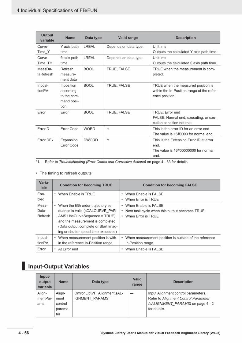
Outputvariable Name Data type Valid range Description
Curve-Time_Y
Y axis pathtime
LREAL Depends on data type. Unit: msOutputs the calculated Y axis path time.
Curve-Time_TH
θ axis pathtime
LREAL Depends on data type. Unit: msOutputs the calculated θ axis path time.
MeasDa-taRefresh
Refreshmeasure-ment data
BOOL TRUE, FALSE TRUE when the measurement is com-pleted.
Inposi-tionPV
Inpositionaccordingto the com-mand posi-tion
BOOL TRUE, FALSE TRUE when the measured position iswithin the In-Position range of the refer-ence position.
Error Error BOOL TRUE, FALSE TRUE: Error endFALSE: Normal end, executing, or exe-cution condition not met
ErrorID Error Code WORD *1 This is the error ID for an error end.The value is 16#0000 for normal end.
ErrorIDEx ExpansionError Code
DWORD *1 This is the Extension Error ID at errorend.The value is 16#00000000 for normalend.
*1. Refer to Troubleshooting (Error Codes and Corrective Actions) on page 4 - 63 for details.
• The timing to refresh outputs
Varia-ble Condition for becoming TRUE Condition for becoming FALSE
Ena-bled
• When Enable is TRUE • When Enable is FALSE• When Error is TRUE
Meas-Data-Refresh
• When the fifth order trajectory se-quence is valid (sCALCURVE_PAR-AMS.UseCurveSequence = TRUE)and the measurement is completed(Data output complete or Start imag-ing or shutter speed time exceeded)
• When Enable is FALSE• Next task cycle when this output becomes TRUE• When Error is TRUE
Inposi-tionPV
• When measurement position is with-in the reference In-Position range
• When measurement position is outside of the referenceIn-Position range
Error • At Error end • When Enable is FALSE
Input-Output VariablesInput-output
variableName Data type Valid
range Description
Align-mentPar-ams
Align-mentcontrolparame-ter
OmronLib\VF_Alignment\sAL-IGNMENT_PARAMS
― Input Alignment control parameters.Refer to Alignment Control Parameter(sALIGNMENT_PARAMS) on page 4 - 2for details.
4 Individual Specifications of FB/FUN
4 - 56 Sysmac Library User's Manual for Visual Feedback Alignment Library (W608)
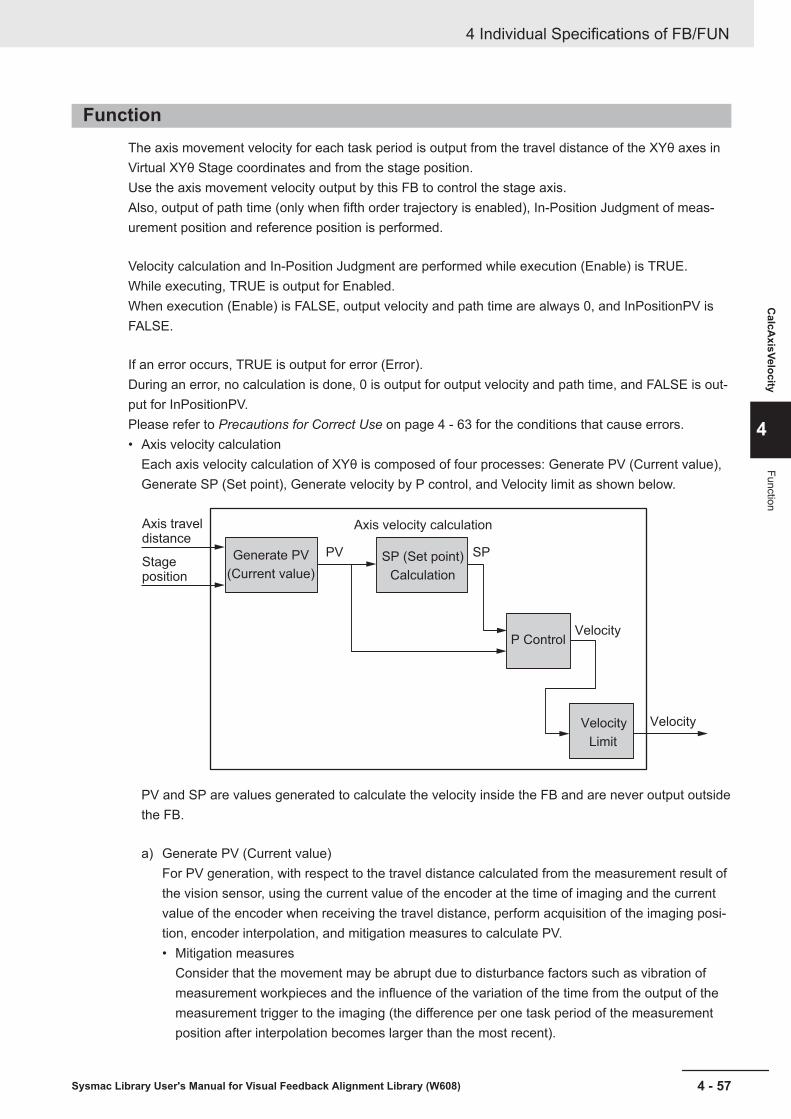
FunctionThe axis movement velocity for each task period is output from the travel distance of the XYθ axes inVirtual XYθ Stage coordinates and from the stage position.Use the axis movement velocity output by this FB to control the stage axis.Also, output of path time (only when fifth order trajectory is enabled), In-Position Judgment of meas-urement position and reference position is performed.
Velocity calculation and In-Position Judgment are performed while execution (Enable) is TRUE.While executing, TRUE is output for Enabled.When execution (Enable) is FALSE, output velocity and path time are always 0, and InPositionPV isFALSE.
If an error occurs, TRUE is output for error (Error).During an error, no calculation is done, 0 is output for output velocity and path time, and FALSE is out-put for InPositionPV.Please refer to Precautions for Correct Use on page 4 - 63 for the conditions that cause errors.• Axis velocity calculation
Each axis velocity calculation of XYθ is composed of four processes: Generate PV (Current value),Generate SP (Set point), Generate velocity by P control, and Velocity limit as shown below.
Generate PV
(Current value)
SP (Set point)
Calculation
P Control
Velocity
Limit
Axis travel distance
PV SP
Velocity
Velocity
Stage position
Axis velocity calculation
PV and SP are values generated to calculate the velocity inside the FB and are never output outsidethe FB.
a) Generate PV (Current value)For PV generation, with respect to the travel distance calculated from the measurement result ofthe vision sensor, using the current value of the encoder at the time of imaging and the currentvalue of the encoder when receiving the travel distance, perform acquisition of the imaging posi-tion, encoder interpolation, and mitigation measures to calculate PV.• Mitigation measures
Consider that the movement may be abrupt due to disturbance factors such as vibration ofmeasurement workpieces and the influence of the variation of the time from the output of themeasurement trigger to the imaging (the difference per one task period of the measurementposition after interpolation becomes larger than the most recent).
4 Individual Specifications of FB/FUN
4 - 57Sysmac Library User's Manual for Visual Feedback Alignment Library (W608)
CalcA
xisVelocity
4
Function

In the latter stage of the encoder interpolation, since axis control is performed by P control, thesharp movement of the measurement position after interpolation becomes abrupt movementof the axis.In order to alleviate this behavior, a mitigation measure reflects the difference per one task pe-riod in the measurement position after interpolation immediately after the measurement endnormally over multiple task periods rather than reflecting it in one task period.
Disturbance
Time
Position
Abrupt movement
: Position when relaxed
: Position when not relaxed
(1)
(3)
(2)
It is assumed that the position (2) where the difference between the temporary position (1) andthe position (3) in the case where the slope is not the same as the previous task period is div-ided by the number of distributions is relaxed.This processing is done to reduce the occurrence of sudden velocity when trajectory calcula-tion is not performed for P control.In case of using the fifth order trajectory for trajectory computation for P control, this process isnot executed because there is no sudden change in velocity.
b) Generate SP (Set point)In order to perform high speed movement and smooth Start / Stop, generate SP using fifth orderpolynomial.Use PV in Generate SP when the SP is used for a fifth order polynomial.When generating an SP which uses a fifth order polynomial, set sCALCURVE_PARAMS.Use-Curve to TRUE.If fifth order polynomial is not used, calculate P control with SP set to 0.
4 Individual Specifications of FB/FUN
4 - 58 Sysmac Library User's Manual for Visual Feedback Alignment Library (W608)

The fifth order polynomial is generated as shown below using the set value of the axis motionparameter for the travel distance calculated from the measurement result of the vision sensor.The maximum acceleration is the upper limit of the acceleration specified by the axis motion pa-rameter (sAXIS_MOVE_PARAMS.AccDec).The path time is corrected to be sCALCURVE_PARAMS.MinCurveTime or more and sCAL-CURVE_PARAMS.MaxCurveTime or less.
Stage drivemotor velocity
(XYθ stage conversion)
Measurement from vision sensor, travel distance calculation
Maximum velocity *1
Path time
Movement velocity
Trajectory of fifth order polynomial
Maximum acceleration
Time
*1. After generating fifth order polynomial, the maximum velocity is limited by the maximum ve-locity (MaxVel) specified by the axis motion parameter (sAXIS_MOVE_PARAMS). If the velocityis lower than the maximum velocity of the generated fifth order polynomial, the actual operationtime will be longer than the specified path time.
SP is generated for measurement results from all cameras, and velocity command value is gen-erated from PV and SP.After updating the fifth order polynomial, the command value will be close to 0.For this reason, we have a connecting velocity function to enable us to take over the previousvelocity.There is also a fifth order trajectory sequence function that prevents updating the trajectory dur-ing vision sensor imaging.• Connecting velocity
When using this function, set sCALCURVE_PARAMS.UseConnectingVel to be TRUE.• Fifth order trajectory sequence
This function is to prevent updating the trajectory while imaging with the vision sensor.Specifically, there is a case where the next imaging starts immediately after the imaging iscompleted, and updating the fifth order trajectory after the imaging will increase the deviationonly by the velocity limit described later.For this reason, update fifth order trajectory after the shutter speed time elapses from triggerinput of the next imaging. In other words, it does not update the trajectory until the shutterspeed time elapses from the trigger input for the next imaging.When using this function, set sCALCURVE_PARAMS.UseCurveSequence to be TRUE.
c) P ControlFor generating axis velocity, calculate by applying proportional gain (P control) to the differencebetween PV and SP.
Axis velocity = (-SP + PV) × Proportional gain
4 Individual Specifications of FB/FUN
4 - 59Sysmac Library User's Manual for Visual Feedback Alignment Library (W608)
CalcA
xisVelocity
4
Function

The proportional gain is the axis motion parameter (sAXIS_MOVE_PARAMS.Kp).d) Velocity limit
According to the settings of the axis motion parameter (sAXIS_MOVE_PARAMS), the axis veloc-ity calculated above can be limited.When the maximum velocity limit is valid, the axis velocity for each task period never exceedsthe set value.When the maximum acceleration/deceleration speed limit is valid, the axis velocity increase ordecrease for each task period never exceeds the set value.If fifth order trajectory is enabled, the axis velocity for each task period will not exceed the imagecapture speed limit until the shutter speed time elapses from the trigger.When multiple restrictions are valid, the limitation on the smallest velocity value is applied.
Limit name Enable condition Setting valueMaximumvelocity limit
sAXIS_MOVE_PARAMS.UseMax-Vel=TRUE
sAXIS_MOVE_PARAMS.MaxVel
MaximumAcceleration/Decelerationspeed limit
sAXIS_MOVE_PARAMS.UseAcc-Dec=TRUE
sAXIS_MOVE_PARAMS.AccDec
Velocity Limitat imagecapture
sCALCAXVEL_PARAMS.UseCurve=TRUE sAXIS_MOVE_PARAMS.ImagingLimitVel
• Path time outputWhen fifth order trajectory is valid, it outputs the path time on the X axis, Y axis, θ axis calculatedabove.When fifth order trajectory is invalid, 0 is output.
• In-Position Judgment by command positionIn-Position Judgment is done by two methods; Diameter / Angle judgment and XYθ position judg-ment.Set this with sCALCVIRTUALMOVE_PARAMS.InPosMode.InpositionPV = TRUE when all targets set to TRUE in the judgment target (sCALCVIRTUAL-MOVE_PARAMS.InPosTarget) are within the In-Position range. If any one of them is outside of theIn-Position range, InpositionPV = FALSE.a) Diameter / Angle (InPosMode = 0)
Judgment done by diameter and angle.Diameter In-Position Judgment is based on the reference mark position as a center, within thecircle with the In-Position range (sCALCVIRTUALMOVE_PARAMS.InPosRange [0]) as the radi-us, if the command position is included, it is within the In-Position, when it is outside the circle itwill be outside the In-Position.
Within In-position
Reference position
In-Position range
Outside of In-PositionWithin In-Position
4 Individual Specifications of FB/FUN
4 - 60 Sysmac Library User's Manual for Visual Feedback Alignment Library (W608)
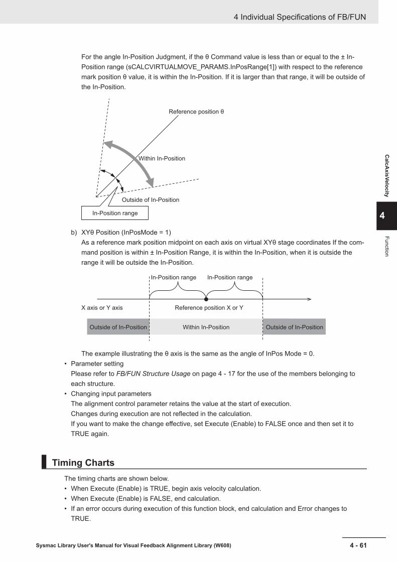
For the angle In-Position Judgment, if the θ Command value is less than or equal to the ± In-Position range (sCALCVIRTUALMOVE_PARAMS.InPosRange[1]) with respect to the referencemark position θ value, it is within the In-Position. If it is larger than that range, it will be outside ofthe In-Position.
Reference position θ
Outside of In-Position
In-Position range
Within In-Position
b) XYθ Position (InPosMode = 1)As a reference mark position midpoint on each axis on virtual XYθ stage coordinates If the com-mand position is within ± In-Position Range, it is within the In-Position, when it is outside therange it will be outside the In-Position.
In-Position range
Outside of In-Position Outside of In-PositionWithin In-Position
Reference position X or YX axis or Y axis
In-Position range
The example illustrating the θ axis is the same as the angle of InPos Mode = 0.• Parameter setting
Please refer to FB/FUN Structure Usage on page 4 - 17 for the use of the members belonging toeach structure.
• Changing input parametersThe alignment control parameter retains the value at the start of execution.Changes during execution are not reflected in the calculation.If you want to make the change effective, set Execute (Enable) to FALSE once and then set it toTRUE again.
Timing ChartsThe timing charts are shown below.• When Execute (Enable) is TRUE, begin axis velocity calculation.• When Execute (Enable) is FALSE, end calculation.• If an error occurs during execution of this function block, end calculation and Error changes to
TRUE.
4 Individual Specifications of FB/FUN
4 - 61Sysmac Library User's Manual for Visual Feedback Alignment Library (W608)
CalcA
xisVelocity
4
Function

While in Error state, 0 is output for axis velocity.You can find out the cause of the error by accessing the values output to Error Code (ErrorID) andExpansion Error Code (ErrorIDEx).
• Error (Error) is maintained while Execute (Enable) remains TRUE.The Error Code (ErrorID) or Expansion Error Code (ErrorIDEx) is maintained until Execute is per-formed again.
• Timing Chart for Normal End
16#0000
0 0Axis velocity
16#00000000ErrorIDEx
ErrorID
Error
Velocity_X,Y,TH
InpositionPV
Enabled
Enable
ResultNotification
TotalJudgment
MeasTrig
• Timing Chart for Error End (Error at start of execution)
16#0000
0 Axis velocity
16#00000000
16#0000
16#00000000
Error Code
Expansion Error CodeErrorIDEx
ErrorID
Error
Velocity_X,Y,TH
InpositionPV
Enabled
Enable
ResultNotification
TotalJudgment
MeasTrig
• Timing Chart for Error End (Error while execution is in progress)
4 Individual Specifications of FB/FUN
4 - 62 Sysmac Library User's Manual for Visual Feedback Alignment Library (W608)
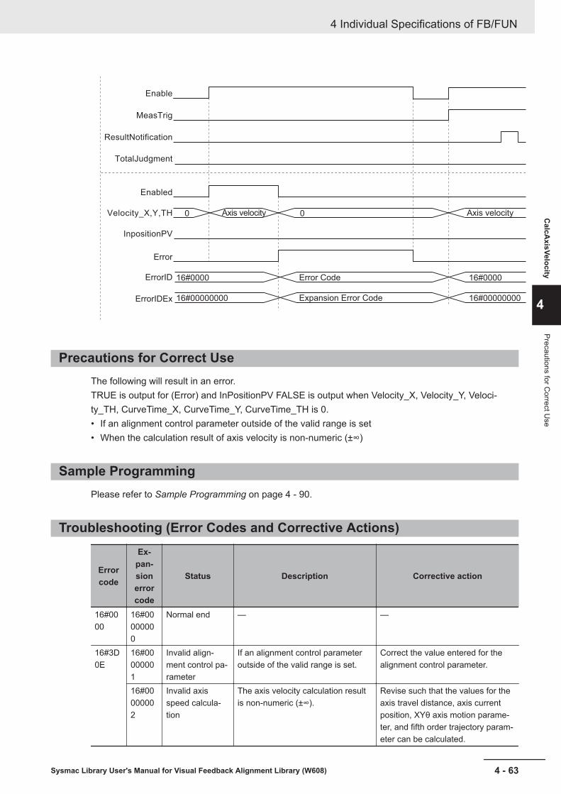
16#0000
0 0Axis velocity Axis velocity
16#00000000
16#0000
16#00000000
Error Code
Expansion Error CodeErrorIDEx
ErrorID
Error
Velocity_X,Y,TH
InpositionPV
Enabled
Enable
ResultNotification
TotalJudgment
MeasTrig
Precautions for Correct UseThe following will result in an error.TRUE is output for (Error) and InPositionPV FALSE is output when Velocity_X, Velocity_Y, Veloci-ty_TH, CurveTime_X, CurveTime_Y, CurveTime_TH is 0.• If an alignment control parameter outside of the valid range is set• When the calculation result of axis velocity is non-numeric (±∞)
Sample ProgrammingPlease refer to Sample Programming on page 4 - 90.
Troubleshooting (Error Codes and Corrective Actions)
Errorcode
Ex-pan-sionerrorcode
Status Description Corrective action
16#0000
16#00000000
Normal end — —
16#3D0E
16#00000001
Invalid align-ment control pa-rameter
If an alignment control parameteroutside of the valid range is set.
Correct the value entered for thealignment control parameter.
16#00000002
Invalid axisspeed calcula-tion
The axis velocity calculation resultis non-numeric (±∞).
Revise such that the values for theaxis travel distance, axis currentposition, XYθ axis motion parame-ter, and fifth order trajectory param-eter can be calculated.
4 Individual Specifications of FB/FUN
4 - 63Sysmac Library User's Manual for Visual Feedback Alignment Library (W608)
CalcA
xisVelocity
4
Precautions for Correct U
se

JudgeAlignmentCompleteIn-Position Judgment performed for the measurement mark position with respect to the reference markposition. This is the means for judging completion of alignment control. Also, it is the judgment to de-termine whether to ultimately output the measurement trigger output from the Generate trigger FB(GenerateTrigger) to the vision sensor.
FBname Name FB/FUN Graphic expression ST expression
JudgeA-lign-ment-Com-plete
Align-mentcontrolcompletejudg-ment
FB\\OmronLib\VF_Alignment\JudgeAlignmentComplete
JudgeAlignmentComplete_instance
Enable
TriggerInput
TriggerAck
TriggerBusy
ResultNotification
TotalJudgment
InpositionPV
InputVelocityAX
InpositionAX
TargetMarkPosStage
MeasMarkPosStage
AlignmentParams
Enabled
Trigger
OutputVelocityAX
CtrlComplete
Error
ErrorID
ErrorIDEx
TargetMarkPosStage
MeasMarkPosStage
AlignmentParams
JudgeAlignment-Complete_instance(Enable:=,TriggerInput:=,TriggerAck:=,TriggerBusy:=,ResultNotification:=,TotalJudgment:=,InpositionPV:=,InpositionAX:=,InputVelocityAX:=,Enabled=>,Trigger=>,CtrlComplete=>,OutputVeloci-tyAX=>,Error=>,ErrorID=>,ErrorIDEx=>,TargetMarkPos-Stage:=,MeasMarkPos-Stage:=,AlignmentParams:=);
Function Block and Function InformationItem Description
Library file name OmronLib_VF_Alignment_Vx_x.slr (x indicates the version)Namespace OmronLib\VF_AlignmentSource codepublished/not published
Not Published
Function Block and Func-tion number
00211
4 Individual Specifications of FB/FUN
4 - 64 Sysmac Library User's Manual for Visual Feedback Alignment Library (W608)
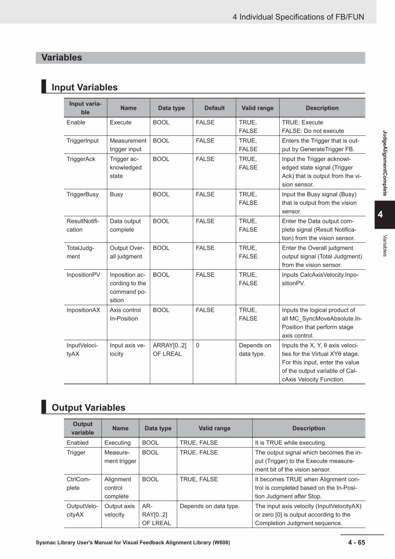
Variables
Input VariablesInput varia-
ble Name Data type Default Valid range Description
Enable Execute BOOL FALSE TRUE,FALSE
TRUE: ExecuteFALSE: Do not execute
TriggerInput Measurementtrigger input
BOOL FALSE TRUE,FALSE
Enters the Trigger that is out-put by GenerateTrigger FB.
TriggerAck Trigger ac-knowledgedstate
BOOL FALSE TRUE,FALSE
Input the Trigger acknowl-edged state signal (TriggerAck) that is output from the vi-sion sensor.
TriggerBusy Busy BOOL FALSE TRUE,FALSE
Input the Busy signal (Busy)that is output from the visionsensor.
ResultNotifi-cation
Data outputcomplete
BOOL FALSE TRUE,FALSE
Enter the Data output com-plete signal (Result Notifica-tion) from the vision sensor.
TotalJudg-ment
Output Over-all judgment
BOOL FALSE TRUE,FALSE
Enter the Overall judgmentoutput signal (Total Judgment)from the vision sensor.
InpositionPV Inposition ac-cording to thecommand po-sition
BOOL FALSE TRUE,FALSE
Inputs CalcAxisVelocity.Inpo-sitionPV.
InpositionAX Axis controlIn-Position
BOOL FALSE TRUE,FALSE
Inputs the logical product ofall MC_SyncMoveAbsolute.In-Position that perform stageaxis control.
InputVeloci-tyAX
Input axis ve-locity
ARRAY[0..2]OF LREAL
0 Depends ondata type.
Inputs the X, Y, θ axis veloci-ties for the Virtual XYθ stage.For this input, enter the valueof the output variable of Cal-cAxis Velocity Function.
Output VariablesOutputvariable Name Data type Valid range Description
Enabled Executing BOOL TRUE, FALSE It is TRUE while executing.Trigger Measure-
ment triggerBOOL TRUE, FALSE The output signal which becomes the in-
put (Trigger) to the Execute measure-ment bit of the vision sensor.
CtrlCom-plete
Alignmentcontrolcomplete
BOOL TRUE, FALSE It becomes TRUE when Alignment con-trol is completed based on the In-Posi-tion Judgment after Stop.
OutputVelo-cityAX
Output axisvelocity
AR-RAY[0..2]OF LREAL
Depends on data type. The input axis velocity (InputVelocityAX)or zero [0] is output according to theCompletion Judgment sequence.
4 Individual Specifications of FB/FUN
4 - 65Sysmac Library User's Manual for Visual Feedback Alignment Library (W608)
JudgeAlignm
entCom
plete
4
Variables

Outputvariable Name Data type Valid range Description
Error Error BOOL TRUE, FALSE TRUE: Error endFALSE: Normal end, executing, or exe-cution condition not met
ErrorID Error Code WORD *1 This is the error ID for an error end.The value is 16#0000 for normal end.
ErrorIDEx ExpansionError Code
DWORD *1 This is the Extension Error ID at errorend.The value is 16#00000000 for normalend.
*1. Refer to Troubleshooting (Error Codes and Corrective Actions) on page 4 - 71 for details.
• The timing to refresh outputs
Varia-ble Condition for becoming TRUE Condition for becoming FALSE
Ena-bled
• When Enable is TRUE • When Enable is FALSE• When CtrlComplete is TRUE• When Error is TRUE
Trigger • When TriggerInput is TRUE• When the vision sensor is given
command to measure
• When Enable is FALSE• While TriggerInput is FALSE• When TriggerAck is FALSE• When Error is TRUE
CtrlComplete
• When In-Position Judgment is OKafter Stop
• When Enable is FALSE
Error • At Error end • When Enable is FALSE
Input-Output VariablesInput-output
variableName Data type Valid
range Description
Target-Mark-Pos-Stage
Refer-encemark po-sition(Stagecoordi-nates)
ARRAY[0..3] OF OmronLib\VF_Alignment\sPOSITION
― Input the reference mark position using thestage coordinates. Set the point 0, point 1,point 2, point 3 in this order from the begin-ning of the array.
Meas-Mark-Pos-Stage
Meas-urementmark po-sition(Stagecoordi-nates)
ARRAY[0..3] OF OmronLib\VF_Alignment\sPOSITION
― Input the measurement mark position usingthe stage coordinates. Set the point 0,point 1, point 2, point 3 in this order fromthe beginning of the array.
Align-mentPar-ams
Align-mentcontrolparame-ter
OmronLib\VF_Alignment\sAL-IGNMENT_PARAMS
― Input alignment control parameters.Refer to Alignment Control Parameter(sALIGNMENT_PARAMS) on page 4 - 2for details.
4 Individual Specifications of FB/FUN
4 - 66 Sysmac Library User's Manual for Visual Feedback Alignment Library (W608)

FunctionThis FB is specially designed based on the vision sensor and Generate trigger FB (GenerateTrigger)and the following connection. When using this FB, make the following connection and use it.
Vision sensor
Trigger Trigger
Trigger
GenerateTrigger FB JudgeAlignmentComplete FB
∙ TriggerAck
∙ TriggerBusy
∙ ResultNotification
∙ TotalJudgment
TriggerInput
In-Position Judgment performed for the measurement mark position with respect to the reference markposition. This is the means for judging completion of alignment control.It performs Completion Judgment while execution (Enable) is TRUE. During execution, TRUE is outputduring execution (Enabled).Execute this FB at the same time as alignment control is started and end alignment control when theAlignment control complete (CtrlComplete) output by this FB becomes TRUE.The Completion Judgment consists of the following three stages.
(1) In-Position Judgment before Stop
(2) Stop Judgment
(3) In-Position Judgment after Stop
The control and judgment functions at each stage are as follows.
(1) In-Position Judgment before StopThe judgment is started when InpositionPV judged by CalcAxisVelocity becomes TRUE.For the conditions in which InpositionPV becomes TRUE, please refer to Function on page 4 - 57in CalcAxisVelocity.
In-Position Judgment is performed from the reference mark position and the measurement markposition which is the judgment target (below) when the first measurement after the start of In-Posi-tion Judgment before Stop succeeds (ResultNotification = TRUE and CtrlComplete = FALSE).If In-Position Judgment before Stop is OK, transition to Stop Judgment.If the In-Position Judgment before Stop is NG, continue In-Position Judgment before Stop andwait for the measurement to succeed.To the output axis velocity (OutputVelocityAX), the value of the input axis velocity (InputVeloci-tyAX) is output as it is.• In-Position Judgment Method
In-Position Judgment is done by two methods; Diameter / Angle judgment and XYθ positionjudgment.Set this with sJUDGE_PARAMS.InPosMode.
4 Individual Specifications of FB/FUN
4 - 67Sysmac Library User's Manual for Visual Feedback Alignment Library (W608)
JudgeAlignm
entCom
plete
4
Function

Judgment is OK when all targets set to TRUE in the judgment target (sJUDGE_PARAMS.In-PosTarget) are within the In-Position range.
Please specify sJUDGE_PARAMS.TargetMark as the judgment target for reference / measure-ment marks for up to 4 points.In-Position Judgment is performed only for points set to TRUE.Points set to FALSE are not subject to the judgment and have no effect on the judgment result.If all are FALSE, a Parameter Error occurs.As shown in the figure below, when alignment control is performed on an object in which onlyPoint 2 of the measurement mark is different from the reference mark, it is possible to performStop Judgment using the setting below which takes Point 2 out of the Judgment target.TargetMark[0]:=TRUE;TargetMark[1]:=TRUE;TargetMark[2]:=FALSE;TargetMark[3]:=TRUE;
In-Position range
Reference mark
Point 1Point 0
Point 2Point 3
Measurement mark
a) Diameter / Angle (InPosMode = 0)Judgment done by diameter and angle.For the In-Position Judgment of Diameter, when the XY coordinates of the measurement markposition are included in the circle whose center is the reference mark position XY coordinatesand the In-Position range (sJUDGE_PARAMS.InPosRange [0]) is the radius, it is within the In-Position. If it is outside of that circle, it will be outside of the In-Position.
Within In-position
Reference position
In-Position range
Outside of In-PositionWithin In-Position
For the Angle In-Position Judgment, if the measurement mark position θ value is less than orequal to the ± In-Position range (sJUDGE_PARAMS.InPosRange[1]) with respect to the refer-ence mark θ position θ value, it is within the In-Position. If it is larger than that range, it will beoutside of the In-Position.
4 Individual Specifications of FB/FUN
4 - 68 Sysmac Library User's Manual for Visual Feedback Alignment Library (W608)

Reference position θ
Outside of In-Position
In-Position range
Within In-Position
b) XYθ Position (InPosMode = 1)When the command position is included within ± In-Position range around the reference markposition XY coordinates, it is within In-Position, and when it is outside the range, it will be out-side the In-Position.
In-Position range
Outside of In-Position Outside of In-PositionWithin In-Position
Reference position X or YX axis or Y axis
In-Position range
The example illustrating the θ axis is the same as the angle of InPos Mode = 0.
(2) Stop JudgmentIt outputs zero to the output axis velocity (OutputVelocityAX) and waits for the axis stop.For the Axis Stop judgment, use the In-Position Check function (setting: axis parameter - Opera-tion Setting - In-Position range) of the MC Function Module.Please refer to InPosition output of MC_SyncMoveAbsolute used for axis control and input TRUEto InpositionAX when InPosition of all axes becomes TRUE.After Axis Stop is completed, TRUE is output to Trigger, and it transitions to In-Position Judgmentafter Stop.
(3) In-Position Judgment after StopIn-Position Judgment is performed from the reference mark position and the measurement markposition which is the judgment target when the first measurement after the start of In-PositionJudgment after Stop is successful. (ResultNotification = TRUE and CtrlComplete = FALSE).If Judgment is OK, TRUE is output to CtrlComplete.Please terminate the alignment control.In case of Judgment NG, (1) return to In-Position Judgment before Stop.State transition diagram
4 Individual Specifications of FB/FUN
4 - 69Sysmac Library User's Manual for Visual Feedback Alignment Library (W608)
JudgeAlignm
entCom
plete
4
Function

Idle
Judgment NG
Judgment NG
Axis outside of In-Position
Judgment OK
During axis operation
All axes stop.Stop Judgment
Judgment OK
Enable = TRUE
Enable = FALSE
Awaiting completion
In-Position Judgmentafter Stop
In-Position Judgmentbefore Stop
After an OK judgment for In-Position Judgment after Stop, it will continue to wait until the execu-tion (Enable) becomes FALSE.During this time, even if the input variable changes, re-judgment will not be done.To re-confirm the completion judgment, set execute (Enable) to FALSE and then set it to TRUEagain.When execute (Enable) is set to FALSE during the judgment, execution ends.If execution (Enable) is set to TRUE again, the Completion Judgment is performed from Idle in theabove state transition diagram to In-Position Judgment before Stop.
If the axis travel (InpositionPV = FALSE, InpositionAX = FALSE) is detected during the judgmentof (2) and (3), it will transition to the In-Position Judgment before Stop and the judgment will berepeated from (1) In-Position Judgment before Stop.
• Measurement Trigger OutputWhile InpositionPV is FALSE, the value of TriggerInput input from Generate trigger FB (Generate-Trigger) is output to Trigger.While InpositionPV is TRUE, the value of TriggerInput is ignored and Trigger becomes TRUE whenmeasurement is required according to the above judgment processing.
• Parameter settingPlease refer to Done Judgment Parameter (JUDGE_PARAMS) on page 4 - 14 and FB/FUN Struc-ture Usage on page 4 - 17 for the use of the members belonging to each structure.
• Changing input parametersThe alignment control parameter retains the value at the start of execution.Changes during execution are not reflected in the judgment.If you want to make the change effective, set Execute (Enable) to FALSE once and then set it toTRUE again.
4 Individual Specifications of FB/FUN
4 - 70 Sysmac Library User's Manual for Visual Feedback Alignment Library (W608)

Timing ChartProcessing steps for
Done Judgement
Alignment control complete
Enable
InpositionPV
ResultNotification
InpositionAX
Enabled
Trigger
CtrlComplete
Error
ErrorID
ErrorIDEx 16#00000000
16#0000
Precautions for Correct UseThe following will result in an error.TRUE is output for Error (Error) and FALSE is output for Enabled, Trigger and CtrlComplete.• If an alignment control parameter outside of the valid range is set• When all elements of the sJUDGE_PARAMS.TargetMark array are FALSE
Sample ProgrammingPlease refer to Sample Programming on page 4 - 90.
Troubleshooting (Error Codes and Corrective Actions)
Errorcode
Ex-pan-sionerrorcode
Status Description Corrective action
16#0000
16#00000000
Normal end — —
16#3D11
16#00000001
Invalid align-ment control pa-rameter
If an alignment control parameteroutside of the valid range is set.
Correct the value entered for thealignment control parameter.
4 Individual Specifications of FB/FUN
4 - 71Sysmac Library User's Manual for Visual Feedback Alignment Library (W608)
JudgeAlignm
entCom
plete
4
Precautions for Correct U
se

Errorcode
Ex-pan-sionerrorcode
Status Description Corrective action
16#00000002
Nothing to cal-culate
All elements of sJUDGE_PAR-AMS.TargetMark array are FALSE.
Please set so that at least one pointcan be calculated.
4 Individual Specifications of FB/FUN
4 - 72 Sysmac Library User's Manual for Visual Feedback Alignment Library (W608)

GenerateTriggerA measurement trigger is generated and it instructs the vision sensor to perform a measurement.
FBname Name FB/FUN Graphic expression ST expression
Genera-teTrigger
Triggergenera-tion
FB\\OmronLib\VF_Alignment\GenerateTrigger
GenerateTrigger_instance
Enable
CurveTime_X
CurveTime_Y
CurveTime_TH
MeasDataRefresh
TriggerAck
TriggerBusy
ResultNotification
TotalJudgment
VirtualStagePos
AlignmentParams
Enabled
Trigger
Error
ErrorID
ErrorIDEx
AlignmentParams
GenerateTrigger_in-stance(Enable:=,CurveTime_X:=,CurveTime_Y:=,CurveTime_TH:=,MeasDataRe-fresh:=,TriggerAck:=,TriggerBusy:=,ResultNotification:=,TotalJudg-ment:=,VirtualSta-gePos:=Enabled=>,Trigger=>,Error=>,ErrorID=>,ErrorIDEx=>,AlignmentParams:=);
Function Block and Function InformationItem Description
Library file name OmronLib_VF_Alignment_Vx_x.slr (x indicates the version)Namespace OmronLib\VF_AlignmentSource codepublished/not published
Not Published
Function Block and Func-tion number
00212
Variables
Input VariablesInput varia-
ble Name Data type Default Valid range Description
Enable Execute BOOL FALSE TRUE,FALSE
TRUE: ExecuteFALSE: Do not execute
CurveTime_X X axis pathtime
LREAL 0.0 Depends ondata type.
Unit: msInput CalcAxisVelocity.Curve-Time_X.
4 Individual Specifications of FB/FUN
4 - 73Sysmac Library User's Manual for Visual Feedback Alignment Library (W608)
GenerateTrigger
4
Function Block and Function Information

Input varia-ble Name Data type Default Valid range Description
CurveTime_Y Y axis pathtime
LREAL 0.0 Depends ondata type.
Unit: msInput CalcAxisVelocity.Curve-Time_Y.
Curve-Time_TH
θ axis pathtime
LREAL 0.0 Depends ondata type.
Unit: msInput CalcAxisVelocity.Curve-Time_TH.
MeasDataRe-fresh
Refreshmeasurementdata
BOOL FALSE TRUE,FALSE
Input CalcAxisVelocity.Meas-DataRefresh.
TriggerAck Trigger ac-knowledgedstate
BOOL FALSE TRUE,FALSE
Input the Trigger acknowl-edged state signal (TriggerAck) that is output from the vi-sion sensor.
TriggerBusy Busy BOOL FALSE TRUE,FALSE
Input the Busy signal (Busy)that is output from the visionsensor.
ResultNotifi-cation
Data outputcomplete
BOOL FALSE TRUE,FALSE
Enter the Data output com-plete signal (Result Notifica-tion) that is output from the vi-sion sensor.
TotalJudg-ment
Output Over-all judgment
BOOL FALSE TRUE,FALSE
Enter the Overall judgmentoutput signal (Total Judgment)that is output from the visionsensor.
VirtualStage-Pos
Virtual stageposition
OmronLib\VF_Align-ment\sPOSI-TION
― ― Enter the stage position in theVirtual XYθ Stage coordi-nates.
Output VariablesOutputvariable Name Data type Valid range Description
Enabled Executing BOOL TRUE, FALSE It is TRUE while executing.Trigger Measure-
ment triggerBOOL TRUE, FALSE The output signal which becomes the in-
put (Trigger) to the Execute measure-ment bit of the vision sensor.
Error Error BOOL TRUE, FALSE TRUE: Error endFALSE: Normal end, executing, or exe-cution condition not met
ErrorID Error Code WORD *1 This is the error ID for an error end.The value is 16#0000 for normal end.
ErrorIDEx ExpansionError Code
DWORD *1 This is the Extension Error ID at errorend.The value is 16#00000000 for normalend.
*1. Refer to Troubleshooting (Error Codes and Corrective Actions) on page 4 - 77 for details.
• The timing to refresh outputs
4 Individual Specifications of FB/FUN
4 - 74 Sysmac Library User's Manual for Visual Feedback Alignment Library (W608)
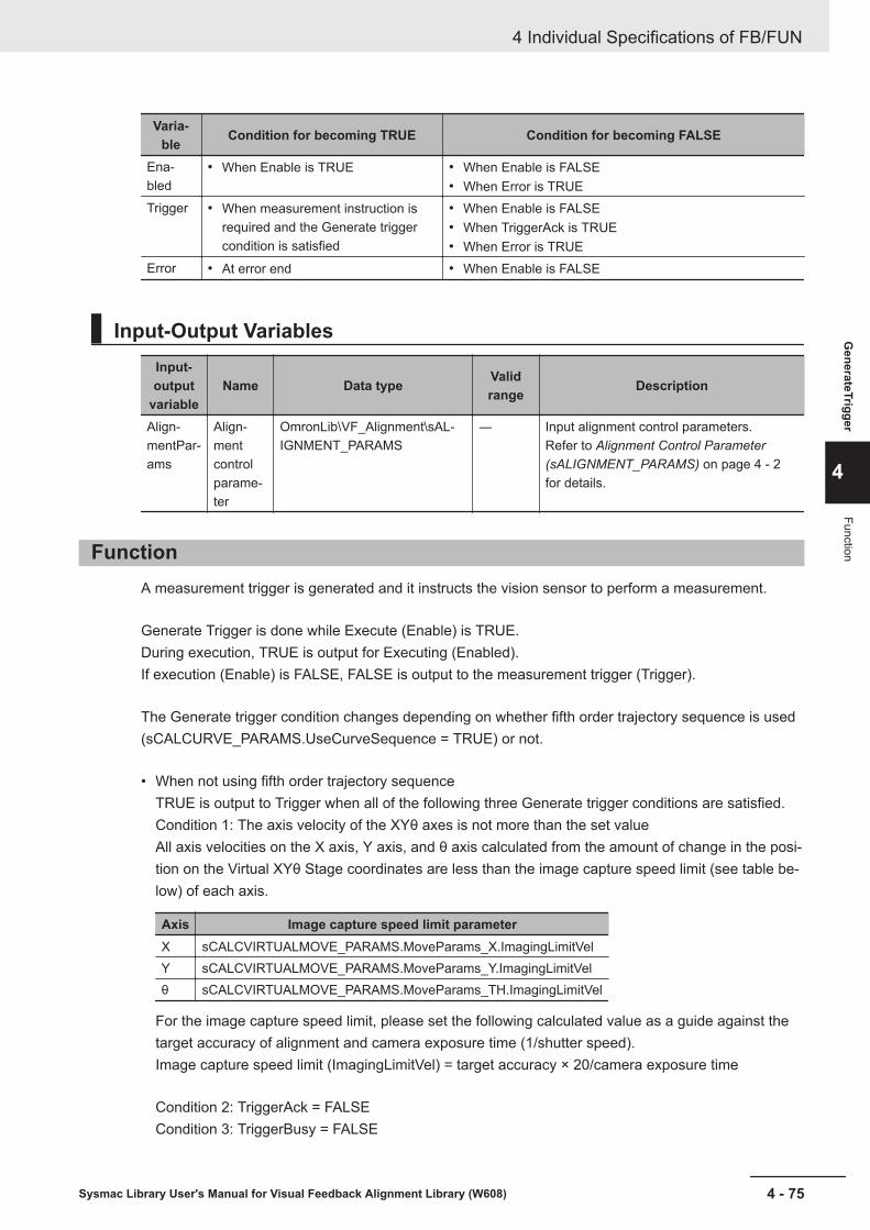
Varia-ble Condition for becoming TRUE Condition for becoming FALSE
Ena-bled
• When Enable is TRUE • When Enable is FALSE• When Error is TRUE
Trigger • When measurement instruction isrequired and the Generate triggercondition is satisfied
• When Enable is FALSE• When TriggerAck is TRUE• When Error is TRUE
Error • At error end • When Enable is FALSE
Input-Output VariablesInput-output
variableName Data type Valid
range Description
Align-mentPar-ams
Align-mentcontrolparame-ter
OmronLib\VF_Alignment\sAL-IGNMENT_PARAMS
― Input alignment control parameters.Refer to Alignment Control Parameter(sALIGNMENT_PARAMS) on page 4 - 2for details.
FunctionA measurement trigger is generated and it instructs the vision sensor to perform a measurement.
Generate Trigger is done while Execute (Enable) is TRUE.During execution, TRUE is output for Executing (Enabled).If execution (Enable) is FALSE, FALSE is output to the measurement trigger (Trigger).
The Generate trigger condition changes depending on whether fifth order trajectory sequence is used(sCALCURVE_PARAMS.UseCurveSequence = TRUE) or not.
• When not using fifth order trajectory sequenceTRUE is output to Trigger when all of the following three Generate trigger conditions are satisfied.Condition 1: The axis velocity of the XYθ axes is not more than the set valueAll axis velocities on the X axis, Y axis, and θ axis calculated from the amount of change in the posi-tion on the Virtual XYθ Stage coordinates are less than the image capture speed limit (see table be-low) of each axis.
Axis Image capture speed limit parameterX sCALCVIRTUALMOVE_PARAMS.MoveParams_X.ImagingLimitVelY sCALCVIRTUALMOVE_PARAMS.MoveParams_Y.ImagingLimitVelθ sCALCVIRTUALMOVE_PARAMS.MoveParams_TH.ImagingLimitVel
For the image capture speed limit, please set the following calculated value as a guide against thetarget accuracy of alignment and camera exposure time (1/shutter speed).Image capture speed limit (ImagingLimitVel) = target accuracy × 20/camera exposure time
Condition 2: TriggerAck = FALSECondition 3: TriggerBusy = FALSE
4 Individual Specifications of FB/FUN
4 - 75Sysmac Library User's Manual for Visual Feedback Alignment Library (W608)
GenerateTrigger
4
Function
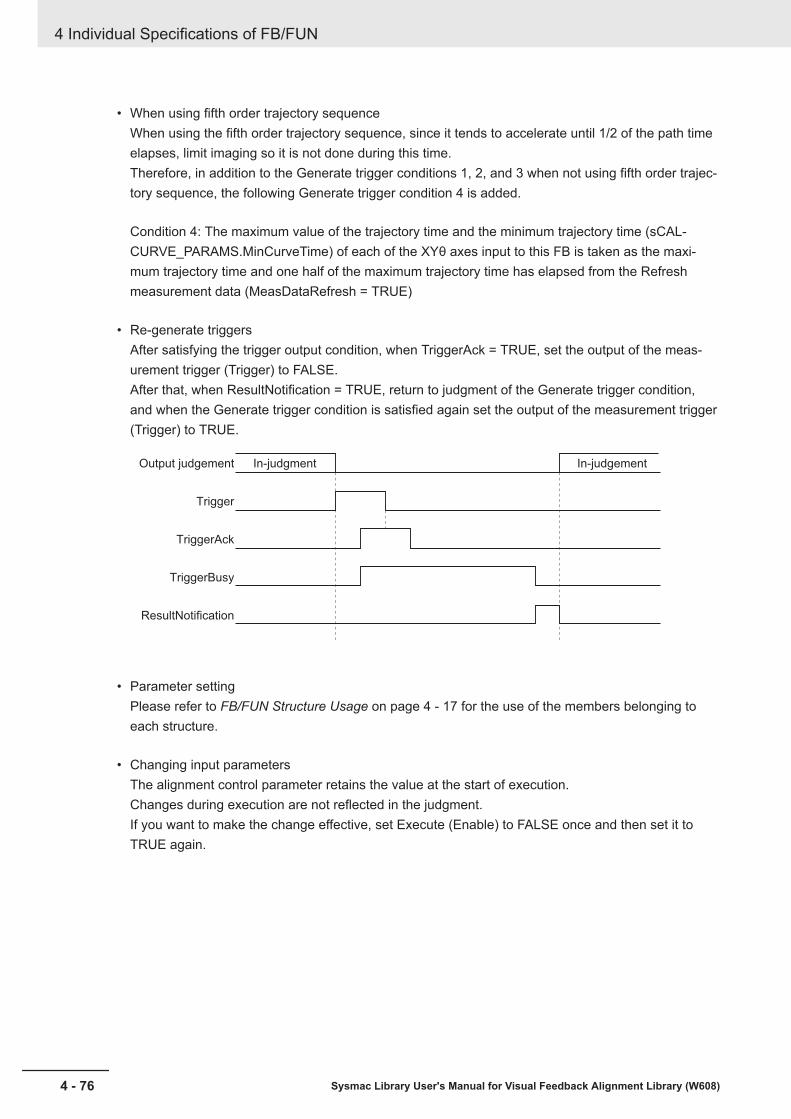
• When using fifth order trajectory sequenceWhen using the fifth order trajectory sequence, since it tends to accelerate until 1/2 of the path timeelapses, limit imaging so it is not done during this time.Therefore, in addition to the Generate trigger conditions 1, 2, and 3 when not using fifth order trajec-tory sequence, the following Generate trigger condition 4 is added.
Condition 4: The maximum value of the trajectory time and the minimum trajectory time (sCAL-CURVE_PARAMS.MinCurveTime) of each of the XYθ axes input to this FB is taken as the maxi-mum trajectory time and one half of the maximum trajectory time has elapsed from the Refreshmeasurement data (MeasDataRefresh = TRUE)
• Re-generate triggersAfter satisfying the trigger output condition, when TriggerAck = TRUE, set the output of the meas-urement trigger (Trigger) to FALSE.After that, when ResultNotification = TRUE, return to judgment of the Generate trigger condition,and when the Generate trigger condition is satisfied again set the output of the measurement trigger(Trigger) to TRUE.
Output judgement In-judgment In-judgement
Trigger
TriggerAck
TriggerBusy
ResultNotification
• Parameter settingPlease refer to FB/FUN Structure Usage on page 4 - 17 for the use of the members belonging toeach structure.
• Changing input parametersThe alignment control parameter retains the value at the start of execution.Changes during execution are not reflected in the judgment.If you want to make the change effective, set Execute (Enable) to FALSE once and then set it toTRUE again.
4 Individual Specifications of FB/FUN
4 - 76 Sysmac Library User's Manual for Visual Feedback Alignment Library (W608)

Timing Chart
Enable
TriggerAck
TriggerBusy
ResultNotification
Enabled
Trigger
Error
ErrorID
ErrorIDEx
16#0000
16#00000000
Precautions for Correct UseThe following will result in an error.TRUE is output for Error (Error) and FALSE is output for Trigger.• If an alignment control parameter outside of the valid range is set
Sample ProgrammingPlease refer to Sample Programming on page 4 - 90.
Troubleshooting (Error Codes and Corrective Actions)
Errorcode
Ex-pan-sionerrorcode
Status Description Corrective action
16#0000
16#00000000
Normal end — —
16#3D12
16#00000001
Invalid align-ment control pa-rameter
If an alignment control parameteroutside of the valid range is set.
Correct the value entered for thealignment control parameter.
4 Individual Specifications of FB/FUN
4 - 77Sysmac Library User's Manual for Visual Feedback Alignment Library (W608)
GenerateTrigger
4
Precautions for Correct U
se
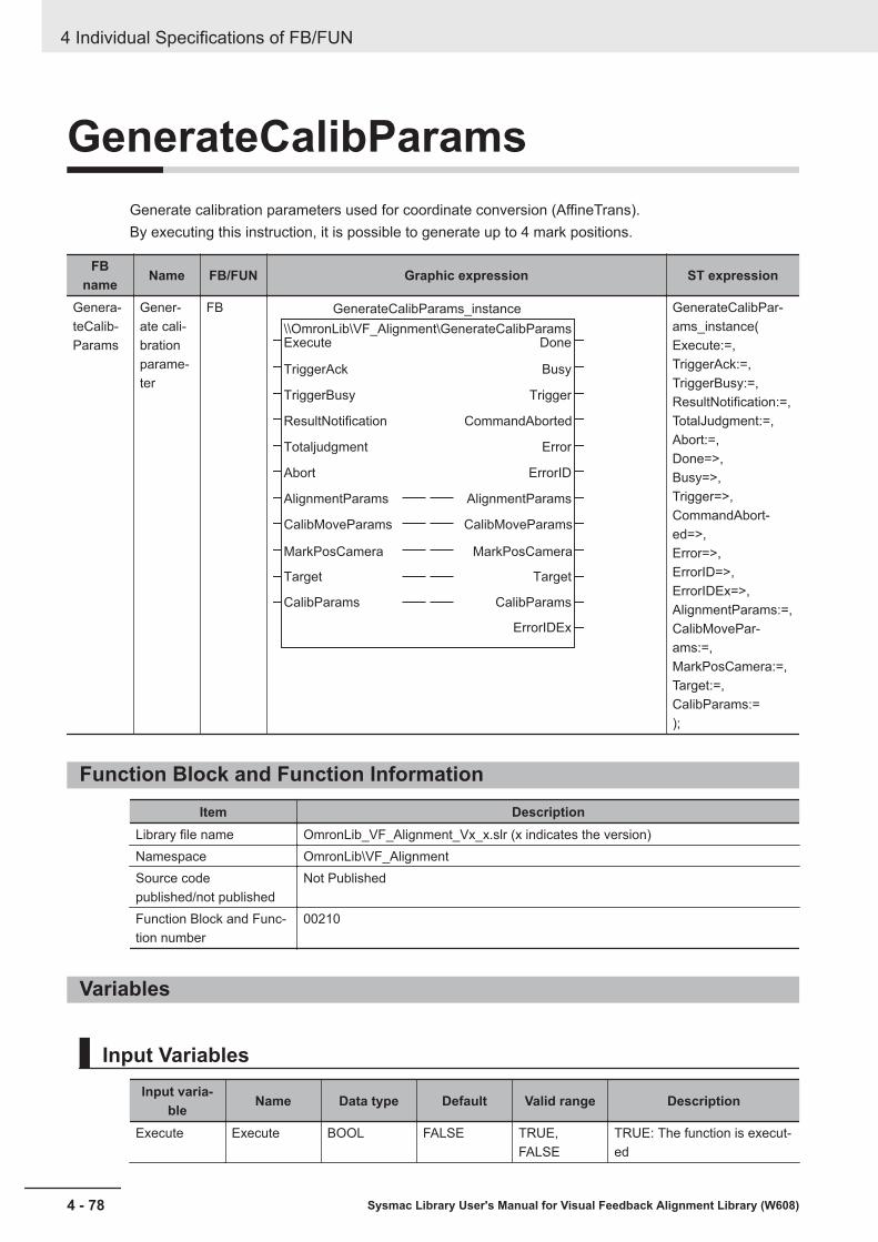
GenerateCalibParamsGenerate calibration parameters used for coordinate conversion (AffineTrans).By executing this instruction, it is possible to generate up to 4 mark positions.
FBname Name FB/FUN Graphic expression ST expression
Genera-teCalib-Params
Gener-ate cali-brationparame-ter
FB GenerateCalibParams_instance
\\OmronLib\VF_Alignment\GenerateCalibParams
AlignmentParams
CalibMoveParams
MarkPosCamera
Target
CalibParams
Abort
Totaljudgment
ResultNotification
TriggerBusy
TriggerAck
Execute
AlignmentParams
CalibMoveParams
MarkPosCamera
Target
CalibParams
ErrorIDEx
ErrorID
Error
CommandAborted
Trigger
Busy
Done
GenerateCalibPar-ams_instance(Execute:=,TriggerAck:=,TriggerBusy:=,ResultNotification:=,TotalJudgment:=,Abort:=,Done=>,Busy=>,Trigger=>,CommandAbort-ed=>,Error=>,ErrorID=>,ErrorIDEx=>,AlignmentParams:=,CalibMovePar-ams:=,MarkPosCamera:=,Target:=,CalibParams:=);
Function Block and Function InformationItem Description
Library file name OmronLib_VF_Alignment_Vx_x.slr (x indicates the version)Namespace OmronLib\VF_AlignmentSource codepublished/not published
Not Published
Function Block and Func-tion number
00210
Variables
Input VariablesInput varia-
ble Name Data type Default Valid range Description
Execute Execute BOOL FALSE TRUE,FALSE
TRUE: The function is execut-ed
4 Individual Specifications of FB/FUN
4 - 78 Sysmac Library User's Manual for Visual Feedback Alignment Library (W608)
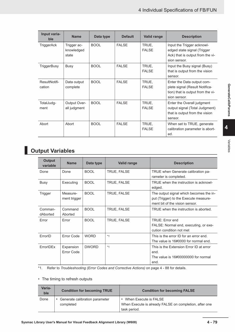
Input varia-ble Name Data type Default Valid range Description
TriggerAck Trigger ac-knowledgedstate
BOOL FALSE TRUE,FALSE
Input the Trigger acknowl-edged state signal (TriggerAck) that is output from the vi-sion sensor.
TriggerBusy Busy BOOL FALSE TRUE,FALSE
Input the Busy signal (Busy)that is output from the visionsensor.
ResultNotifi-cation
Data outputcomplete
BOOL FALSE TRUE,FALSE
Enter the Data output com-plete signal (Result Notifica-tion) that is output from the vi-sion sensor.
TotalJudg-ment
Output Over-all judgment
BOOL FALSE TRUE,FALSE
Enter the Overall judgmentoutput signal (Total Judgment)that is output from the visionsensor.
Abort Abort BOOL FALSE TRUE,FALSE
When set to TRUE, generatecalibration parameter is abort-ed.
Output VariablesOutputvariable Name Data type Valid range Description
Done Done BOOL TRUE, FALSE TRUE when Generate calibration pa-rameter is completed.
Busy Executing BOOL TRUE, FALSE TRUE when the instruction is acknowl-edged.
Trigger Measure-ment trigger
BOOL TRUE, FALSE The output signal which becomes the in-put (Trigger) to the Execute measure-ment bit of the vision sensor.
Comman-dAborted
CommandAborted
BOOL TRUE, FALSE TRUE when the instruction is aborted.
Error Error BOOL TRUE, FALSE TRUE: Error endFALSE: Normal end, executing, or exe-cution condition not met
ErrorID Error Code WORD *1 This is the error ID for an error end.The value is 16#0000 for normal end.
ErrorIDEx ExpansionError Code
DWORD *1 This is the Extension Error ID at errorend.The value is 16#00000000 for normalend.
*1. Refer to Troubleshooting (Error Codes and Corrective Actions) on page 4 - 88 for details.
• The timing to refresh outputs
Varia-ble Condition for becoming TRUE Condition for becoming FALSE
Done • Generate calibration parametercompleted
• When Execute is FALSEWhen Execute is already FALSE on completion, after onetask period.
4 Individual Specifications of FB/FUN
4 - 79Sysmac Library User's Manual for Visual Feedback Alignment Library (W608)
GenerateC
alibParams
4
Variables

Varia-ble Condition for becoming TRUE Condition for becoming FALSE
Busy • When Execute is TRUE • When Done is TRUE• When CommandAborted is TRUE• When Error is TRUEHowever, if the axis is in motion, TRUE continues to be out-put until Axis stop is completed.
Trigger • When the vision sensor is givencommand to measure
• When TriggerAck is TRUE• When CommandAborted is TRUE• When Error is TRUE
Com-mandA-borted
• When Abort is TRUE• When TotalJudgment is TRUE• When CommandAborted occurs in
the internal axis control FB
• When Execute is FALSEWhen Execute is already FALSE on completion, after onetask period.
Error • At Error end • When Execute is FALSEWhen Execute is already FALSE on completion, after onetask period.
Input-Output VariablesInput-output
variableName Data type Valid
range Description
Align-mentPar-ams
Align-mentcontrolparame-ter
OmronLib\VF_Alignment\sAL-IGNMENT_PARAMS
― Input alignment control parameters.Refer to Alignment Control Parameter(sALIGNMENT_PARAMS) on page 4 - 2for details.
CalibMo-vePar-ams
Calibra-tion axismotionparame-ter
OmronLib\VF_Alignment\sCA-LIB_MOVE_PARAMS
― Set calibration axis motion parameters.Refer to Calibration Axis Motion Parameter(sCALIB_MOVE_PARAMS) on page 4 - 15for details.
MarkPo-sCamera
Mark po-sition(Cameracoordi-nates)
ARRAY[0..3] OF OmronLib\VF_Alignment\sPOSITION
― Enter the mark position output from the vi-sion sensor.Set the point 0, point 1, point 2, point 3 inthis order from the beginning of the array.
Target Calibra-tion tar-get
ARRAY[0..3] OF BOOL TRUE,FALSE
Set the points for which to generate thecalibration parameters.Set the point 0, point 1, point 2, point 3 inthis order from the beginning of the array.TRUE: CalculateFALSE: Do not calculate
Calib-Params
Calibra-tion pa-rameter
ARRAY[0..3] OF OmronLib\VF_Alignment\sCALIB_PAR-AMS
― Outputs the calibration parameters for eachpoint.It is output from the top of the array in orderof point 0, point 1, point 2, point 3.
FunctionGenerate calibration parameters used for coordinate conversion (AffineTrans).
4 Individual Specifications of FB/FUN
4 - 80 Sysmac Library User's Manual for Visual Feedback Alignment Library (W608)

Since this FB performs axis control, it can not be executed simultaneously with alignment control.
This FB is an equivalent function to the "Vision Master Calibration" processing item of the vision sen-sor, except for the following differences.
Item Vision Master Calibration Generate calibration parameterFB
External device setting Supports 8 stage types and 2 robottypes
Supports 8 stage types
Number of calibration data seg-ments
Maximum 8 data Maximum 4 data
Input method for mark position(Camera coordinates)
Input by arithmetic expression Use the input value as it is
Output method for amount of move-ment
Select from absolute position or rel-ative position
No selection
Trapezoidal distortion, Lens distor-tion
Applicable Cannot be used
Select homing method Select Enable/Disable No selectionOperate disabled
Initial calibration YesProcess for finding the range ofmovement for this calibration
Not supportedThe range of movement for this cal-ibration is set according to the inputparameter.
This calibration Effective rangeof the field ofview
1 to 100% No settingIt operates within the range on theaxis coordinate specified by the cal-ibration axis motion parameter(sCALIB_MOVE_PARAMS)
Sampling meth-od
Data one by one / All data at sametime
No selectionAll data is applied at the same timeBy executing this FB multiple times,it is possible to realize the sameoperation as data one by one
Parallel move-ment samplingsetting, rotation-al movementsampling setting
Number of distribution rows (2 to10), number of distribution columns(2 to 10), number of distributionpoints (2 to 100)
Total travel distance (X, Y, θ)Number of distribution rows at Xaxis & Y axis operation, Number ofdistribution columns at θ axis oper-ation is 9 points, Number of distri-bution points fixed at 11 points
Advanced set-tings
Stop criteria for rotation samplingNo. of points for error calculationUpper limit of error evaluation value
None
A calibration parameter is generated for the point set as TRUE in the calibration target (Target).Generate is not done for points set to FALSE, and the calibration parameters do not change.
Start (Execute) is set to TRUE to start Generate calibration parameter.It is TRUE while executing (Busy).When Generate is completed, Busy is FALSE and Completed (Done) is TRUE.Even if FALSE (Execute) is set to FALSE or TRUE again during execution, this FB will not be canceledor re-executed. It will continue to run until it is done (Done), aborted (CommandAborted), or there is anerror end (Error).
4 Individual Specifications of FB/FUN
4 - 81Sysmac Library User's Manual for Visual Feedback Alignment Library (W608)
GenerateC
alibParams
4
Function

• Generate calibration parameterBased on the starting position, move the X axis, Y axis, and θ axis as the relative amount of eachaxis specified by the calibration axis motion parameter (sCALIB_MOVE_PARAMS) as the relativeamount.Start position → X axis & Y axis movement → Start position → θ axis movement → Start position.This is the movement.
By setting CalibMoveParams.WaitTime, it is possible to reduce the time from after travel operationcomplete to the imaging, attenuate the vibration caused by the movement, and to reduce the influ-ence of vibration on the image.
• X axis & Y axis movement
Y axis (X-4,Y
4)
Yone
(X4,Y
4)
(X2,Y
2)
(X1,Y
1)
Start position (X0,Y
0)
(X-1,Y
-1)
Xone (X-4,Y
-4)
Movement_Y
Movement_Y
Movement_X Movement_X X axis
Final position (X4,Y
-4)
Movement_X: Total travel distance (X)Movement_Y: Total travel distance (Y)Xone: 1 time travel distance (X) Xone = Movement_X/ 4Yone: 1 time travel distance (Y) Yone = Movement_Y/ 4
Axis coordi-nates
Relative amount based on starting positionNotes
X axis Y axis(X0, Y0) 0 0 Start position
(X1, Y0) Xone 0
(X1, Y1) Xone Yone
(X0, Y1) 0 Yone
(X-1, Y1) -Xone Yone
(X-1, Y0) -Xone 0
(X-1, Y-1) -Xone -Yone
(X0, Y-1) 0 -Yone
(X1, Y-1) Xone -Yone
(X2, Y-1) Xone × 2 -Yone
(X2, Y0) Xone × 2 0
(X2, Y1) Xone × 2 Yone
(X2, Y2) Xone × 2 Yone × 2
:
4 Individual Specifications of FB/FUN
4 - 82 Sysmac Library User's Manual for Visual Feedback Alignment Library (W608)
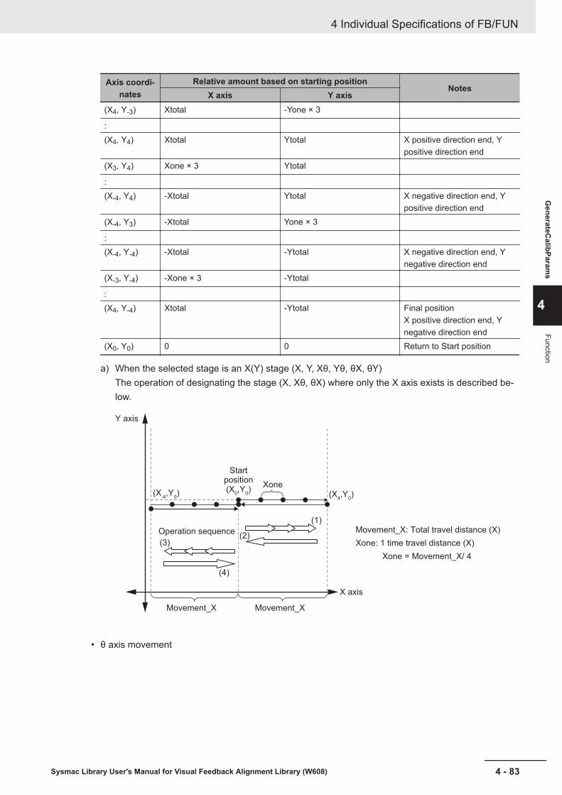
Axis coordi-nates
Relative amount based on starting positionNotes
X axis Y axis(X4, Y-3) Xtotal -Yone × 3
:(X4, Y4) Xtotal Ytotal X positive direction end, Y
positive direction end(X3, Y4) Xone × 3 Ytotal
:(X-4, Y4) -Xtotal Ytotal X negative direction end, Y
positive direction end(X-4, Y3) -Xtotal Yone × 3
:(X-4, Y-4) -Xtotal -Ytotal X negative direction end, Y
negative direction end(X-3, Y-4) -Xone × 3 -Ytotal
:(X4, Y-4) Xtotal -Ytotal Final position
X positive direction end, Ynegative direction end
(X0, Y0) 0 0 Return to Start position
a) When the selected stage is an X(Y) stage (X, Y, Xθ, Yθ, θX, θY)The operation of designating the stage (X, Xθ, θX) where only the X axis exists is described be-low.
Movement_X: Total travel distance (X)
Xone: 1 time travel distance (X)
Xone = Movement_X/ 4
Start position(X
0,Y
0)
Y axis
(1)
Xone
(2)(3)
Operation sequence
(4)
X axis
Movement_X Movement_X
(X-4,Y
0) (X
4,Y
0)
• θ axis movement
4 Individual Specifications of FB/FUN
4 - 83Sysmac Library User's Manual for Visual Feedback Alignment Library (W608)
GenerateC
alibParams
4
Function
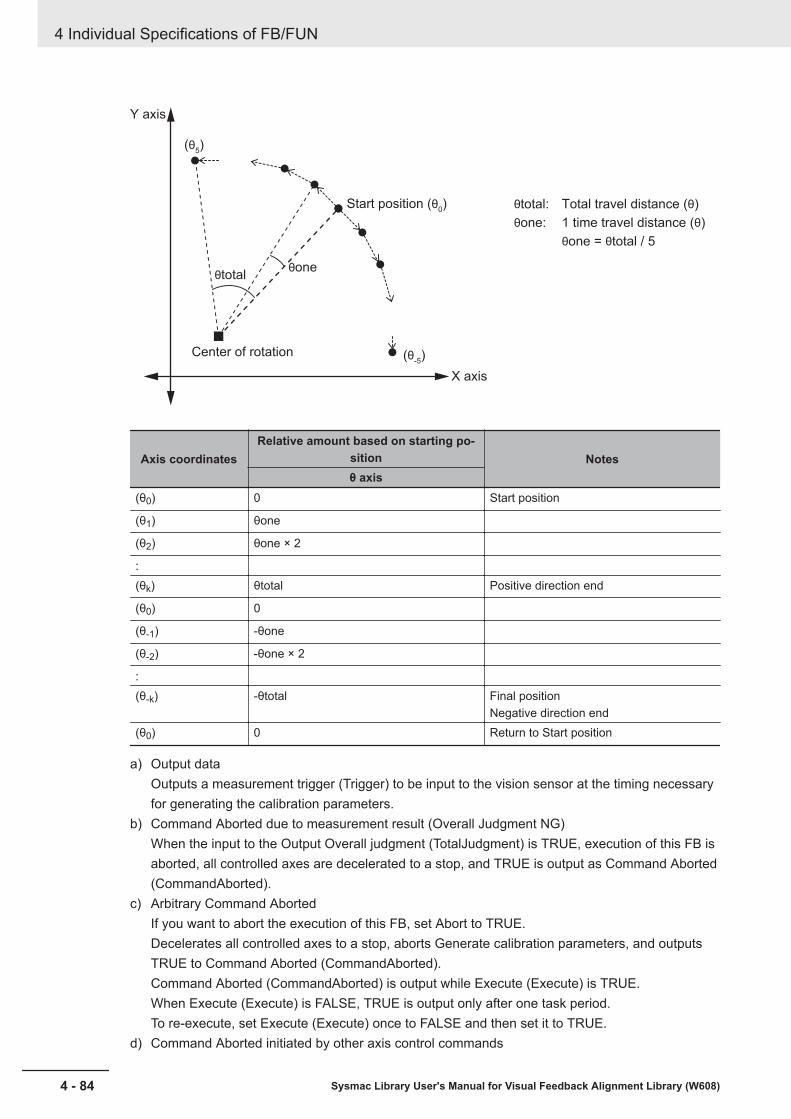
Y axis
X axis
(θ5)
θoneθtotal
(θ-5)
Start position (θ0)
Center of rotation
θtotal: Total travel distance (θ)
θone: 1 time travel distance (θ)
θone = θtotal / 5
Axis coordinatesRelative amount based on starting po-
sition Notesθ axis
(θ0) 0 Start position
(θ1) θone
(θ2) θone × 2
:(θk) θtotal Positive direction end
(θ0) 0
(θ-1) -θone
(θ-2) -θone × 2
:(θ-k) -θtotal Final position
Negative direction end(θ0) 0 Return to Start position
a) Output dataOutputs a measurement trigger (Trigger) to be input to the vision sensor at the timing necessaryfor generating the calibration parameters.
b) Command Aborted due to measurement result (Overall Judgment NG)When the input to the Output Overall judgment (TotalJudgment) is TRUE, execution of this FB isaborted, all controlled axes are decelerated to a stop, and TRUE is output as Command Aborted(CommandAborted).
c) Arbitrary Command AbortedIf you want to abort the execution of this FB, set Abort to TRUE.Decelerates all controlled axes to a stop, aborts Generate calibration parameters, and outputsTRUE to Command Aborted (CommandAborted).Command Aborted (CommandAborted) is output while Execute (Execute) is TRUE.When Execute (Execute) is FALSE, TRUE is output only after one task period.To re-execute, set Execute (Execute) once to FALSE and then set it to TRUE.
d) Command Aborted initiated by other axis control commands
4 Individual Specifications of FB/FUN
4 - 84 Sysmac Library User's Manual for Visual Feedback Alignment Library (W608)

During execution of this FB, do not execute other axis control commands on the axis used in thestage.When axis control is performed by another command, it decelerates all controlled axes to a stop,aborts Generate calibration parameters, and outputs TRUE to Command Aborted (CommandA-borted).Command Aborted (CommandAborted) is output while Execute (Execute) is TRUE.When Execute (Execute) is FALSE, TRUE is output only after one task period.To re-execute, set Execute (Execute) once to FALSE and then set it to TRUE.
e) Command Aborted due to error conditionWhen an error occurs, it decelerates all controlled axes to a stop, aborts Generate calibrationparameters, and outputs TRUE to error (Error).Please refer to Precautions for Correct Use on page 4 - 87 for the conditions that cause errors.To re-execute, set Execute (Execute) to FALSE, correct the cause of the error and set Execute(Execute) to TRUE again.
f) Axis deceleration stopIf a Command Aborted occurs during execution, this FB uses the MC_Stop command to deceler-ate the controlled axes to a stop.SCALIB_MOVE_PARAMS.StopDec is applied to the deceleration rate (MC_Stop.Deceleration)at this time.If an error (Error) or Command Aborted (CommandAborted) occurs in the MC_MoveAbsolute in-struction and the MC_Stop instruction during deceleration stop, immediately stop with theMC_Stop instruction.
g) Parameter settingPlease refer to FB/FUN Structure Usage on page 4 - 17 for the use of the members belonging toeach structure.
h) Changing input parametersAlignment control parameters, calibration axis motion parameters, and calibration targets at thestart of execution are retained.Changes during execution are not reflected in the calculation.If you want to make changes effective, please set it to TRUE again after completion.
Timing ChartsThe timing charts are shown below.• Executing (Busy) becomes TRUE at the start of Execute (Execute), and generate calibration param-
eters is started.• When generate calibration parameters is completed, Done (Done) becomes TRUE.• If an error occurs during execution of this function block, end calculation and Error changes to
TRUE.Generate calibration parameter will not be performed while in an error state.You can find out the cause of the error by accessing the values output to Error Code (ErrorID) andExpansion Error Code (ErrorIDEx).
• While error (Error) is TRUE, it will stay in the error (Error) state.The Error Code (ErrorID) or Expansion Error Code (ErrorIDEx) is maintained until Execute is per-formed again.
• If another axis control command is executed while this FB is being executed, Command Aborted(CommandAborted) becomes TRUE.
4 Individual Specifications of FB/FUN
4 - 85Sysmac Library User's Manual for Visual Feedback Alignment Library (W608)
GenerateC
alibParams
4
Function

• While Execute (Execute) is TRUE, Command Aborted (CommandAborted) will be maintained.Generate calibration parameter will not be performed while in Command Aborted (CommandAbort-ed) state.
• Timing Chart for Normal End
16#0000
16#00000000ErrorIDEx
ErrorID
Error
Trigger
CommandAborted
Busy
Done
Execute
TotalJudgment
ResultNotification
• Timing Chart for Error End (Error at start of execution)
16#0000
16#00000000
16#0000
16#00000000
Error Code
Expansion Error CodeErrorIDEx
ErrorID
Error
Trigger
CommandAborted
Busy
Done
Execute
TotalJudgment
ResultNotification
• Timing Chart for Error End (Error while execution is in progress)
4 Individual Specifications of FB/FUN
4 - 86 Sysmac Library User's Manual for Visual Feedback Alignment Library (W608)

16#0000
16#00000000
16#0000
16#00000000
Error Code
Expansion Error CodeErrorIDEx
ErrorID
Error
Trigger
CommandAborted
Busy
Done
Execute
TotalJudgment
ResultNotification
• Timing Chart for Command Aborted (Command Aborted while execution is in progress, or when en-tering Abort input variable)
16#0000
16#00000000ErrorIDEx
ErrorID
Error
Trigger
CommandAborted
Busy
Done
Abort
Execute
TotalJudgment
ResultNotification
Precautions for Correct UseThe following will result in an error.TRUE is output for Error (Error) and the calibration parameter is not updated.• If an alignment control parameter outside of the valid range is set• If the value set for the calibration axis motion parameter is outside the valid range• When all elements of the Target array are FALSE
4 Individual Specifications of FB/FUN
4 - 87Sysmac Library User's Manual for Visual Feedback Alignment Library (W608)
GenerateC
alibParams
4
Precautions for Correct U
se

• When the result of calibration parameter calculation is non-numeric (±∞)• When the FB/FUN terminates with an error endWithin this FB, there is no monitoring of errors common to MC Function Module (MC common errors)and errors occurring on each axis (axis errors). Therefore, monitor during execution of this FB in theprogram and, in case of any error, abort execution of this FB and stop the axis movement. For detailson monitoring and stopping methods, refer to the following manuals.• NJ/NX-series CPU Unit Motion Control User's Manual (Cat. No. W507)• NJ/NX-series Motion Control Instructions Reference Manual (Cat. No. W508)• NY-series IPC Machine Controller Industrial Panel PC / Industrial Box PC Motion Control User's
Manual (Cat. No. W559)• NY Series Motion Control Instructions Reference Manual (Cat. No. W561)Within this FB, there is no verification process on its own prerequisite conditions for operation (such asverification that there is no error caused by EtherCAT communication with the vision sensor and ServoDrive, or that there is no error beyond a minor fault on the controlled axis, that it is in the Servo ONstate, or that it is in the home defined state). For this reason, please check each state before execut-ing this FB in any program.For each state, refer to the following manual.• NJ/NX-series CPU Unit Motion Control User's Manual (Cat. No. W507)• NJ/NX-series Motion Control Instructions Reference Manual (Cat. No. W508)• NY-series IPC Machine Controller Industrial Panel PC / Industrial Box PC Motion Control User's
Manual (Cat. No. W559)• NY Series Motion Control Instructions Reference Manual (Cat. No. W561)
Sample ProgrammingPlease refer to Sample Programming on page 4 - 90.
Troubleshooting (Error Codes and Corrective Actions)
Errorcode
Ex-pan-sionerrorcode
Status Description Corrective action
16#0000
16#00000000
Normal end — —
16#3D10
16#00000001
Invalid axismovement pa-rameter for cali-bration
The value set for the calibration ax-is motion parameter is outside thevalid range.
Correct and reset the calibrationaxis motion parameter.
16#00000002
Invalid align-ment control pa-rameter
If an alignment control parameteroutside of the valid range is set.
Correct the value entered for thealignment control parameter.
16#00000004
Nothing to cal-culate
All elements of the Target array areFALSE.
Please set so that at least one pointcan be calculated.
4 Individual Specifications of FB/FUN
4 - 88 Sysmac Library User's Manual for Visual Feedback Alignment Library (W608)

Errorcode
Ex-pan-sionerrorcode
Status Description Corrective action
16#00000005
Invalid calcula-tion of calibra-tion parameter
The result of calibration parametercalculation is non-numeric (±∞).
Revise such that the magnification,calibration axis motion parameter,stage parameter, and camera coor-dinate position can be calculated.
16#2000000x
CalcInverseKi-nematics error
There is an error in CalcInverseKi-nematics.
Check the value for x against theOut value from CalcInverseKine-matics and correct as needed.
16#3000000x
CalcForwardKi-nematics error
There is an error in CalcForwardKi-nematics.
Check the value for x against theOut value from CalcForwardKine-matics and correct as needed.
16#7000xxxx
MC_MoveAbso-lute error
There is an error in MC_SyncMo-veAbsolute.
Check the xxxx value against theMC_SyncMoveAbsolute error code(ErrorID) and correct as needed. *1
16#9000xxxx
MC_Stop Error There is an error in MC_Stop. Check the xxxx value against theMC_Stop error code (ErrorID) andcorrect as needed. *1
*1. For error codes of MC_MoveVelocity, MC_Stop, refer to the error code list in NJ/NX-series Motion ControlInstructions Reference Manual (Cat. No. W508) or NY Series Motion Control Instructions Reference Manual(Cat. No. W561)
4 Individual Specifications of FB/FUN
4 - 89Sysmac Library User's Manual for Visual Feedback Alignment Library (W608)
GenerateC
alibParams
4
Troubleshooting (Error Codes and C
orrective Actions)

Sample ProgrammingSample programming for executing alignment control of XYθ stage using the Visual Feedback Align-ment Library is shown.The sample programming is provided as a Sysmac Studio project file. The descriptions in this sectionare based on this project file. Ask your OMRON representative for details on obtaining the project file.
Overview
Overview of OperationAlignment control of XY positions and θ angle on a workpiece, or XY axis position and θ axis rotationangle of a stage is performed based on two alignment marks made on the workpiece object.In this sample programming, the position of each alignment mark is measured with two cameras con-nected to the vision sensor controller, and the stage is controlled so that the alignment mark alignswith a predetermined reference position on each camera control screen.
Workpiece
Camera 0 image Camera 1 image
Alignment mark on workpiece
Alignment reference position
Camera 1 imageCamera 0 image
XY axis position
θ axis rotation angle
System ConfigurationThis sample programming is for the following system configuration.
4 Individual Specifications of FB/FUN
4 - 90 Sysmac Library User's Manual for Visual Feedback Alignment Library (W608)

Controller
Vision sensor
controller
Servo Drive
Camera 0
Axis 0
(X axis)
Axis 1
(Y axis)
Axis 2
(θ axis)
Camera 1
XYθ stage
Configura-tion element Name Model Notes
Controller Machine Automation Control-ler NJ/NX Series
NJ301-1100 Ver. 1.08 or later
Vision sensorcontroller
Vision System FH Series FH-3050-20 Ver. 5.50 or later
Camera High speed digital CMOScamera
FH-SM02 Monochrome 2 Megapixel *1
Lens C Mount High resolution tele-centric lens for 2/3-inch imag-ing element
3Z4S-LE VS-TCH4-65-O 4x Telecentric lens *1
Servo Drive AC Servo Driver (G5 Series) R88D-KNA5L-ECT Ver. 1.0 or laterStage XYθ Stage CTLH120M-1010 + AT120
(IKO)An XYθ configuration com-prised of a combination ofCTLH120M (XY Stage) andAT120 (θ Stage)
Software Sysmac Studio AutomationSoftware
SYSMAC-SE2£££ Ver. 1.18 or higher
*1. The resolutions based on this combination of cameras and lenses are as follows.
Configuration Item PerformanceCamera (Standalone) Imaging element size (H × V) 11.26 × 5.98 mm
Effective pixels (H × V) 2040 × 1088 pixelPixel resolution (H × V) 5.52 × 5.50 um/pixel
Camera + Lens Field of view size (H × V) 2.82 × 1.50 mmPixel resolution (H × V) 1.38 × 1.37 um/pixel
Controller, vision sensor controller and Servo Drive are connected by EtherCAT communication.With this sample program, the vision sensor controller, given the imaging instructions from the control-ler, measures the position of the alignment mark on an image and outputs it to the controller.Based on the measured position and the reference position information (the target position of thealignment), the controller calculates the stage movement for alignment control and gives an operationcommand to the Servo Drive that drives the stage.
4 Individual Specifications of FB/FUN
4 - 91Sysmac Library User's Manual for Visual Feedback Alignment Library (W608)
Sample Program
ming
4
Overview
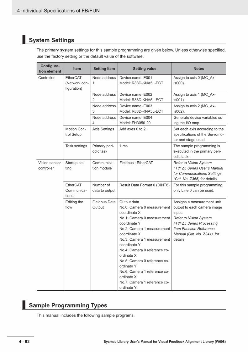
System SettingsThe primary system settings for this sample programming are given below. Unless otherwise specified,use the factory setting or the default value of the software.
Configura-tion element Item Setting item Setting value Notes
Controller EtherCAT(Network con-figuration)
Node address1
Device name: E001Model: R88D-KNA5L-ECT
Assign to axis 0 (MC_Ax-is000).
Node address2
Device name: E002Model: R88D-KNA5L-ECT
Assign to axis 1 (MC_Ax-is001).
Node address3
Device name: E003Model: R88D-KNA5L-ECT
Assign to axis 2 (MC_Ax-is002).
Node address4
Device name: E004Model: FH3050-20
Generate device variables us-ing the I/O map.
Motion Con-trol Setup
Axis Settings Add axes 0 to 2. Set each axis according to thespecifications of the Servomo-tor and stage used.
Task settings Primary peri-odic task
1 ms The sample programming isexecuted in the primary peri-odic task.
Vision sensorcontroller
Startup set-ting
Communica-tion module
Fieldbus : EtherCAT Refer to Vision SystemFH/FZ5 Series User’s Manualfor Communications Settings(Cat. No. Z365) for details.
EtherCATCommunica-tions
Number ofdata to output
Result Data Format 0 (DINT8) For this sample programming,only Line 0 can be used.
Editing theflow
Fieldbus DataOutput
Output dataNo.0: Camera 0 measurementcoordinate XNo.1: Camera 0 measurementcoordinate YNo.2: Camera 1 measurementcoordinate XNo.3: Camera 1 measurementcoordinate YNo.4: Camera 0 reference co-ordinate XNo.5: Camera 0 reference co-ordinate YNo.6: Camera 1 reference co-ordinate XNo.7: Camera 1 reference co-ordinate Y
Assigns a measurement unitoutput to each camera imageinput.Refer to Vision SystemFH/FZ5 Series ProcessingItem Function ReferenceManual (Cat. No. Z341). fordetails.
Sample Programming TypesThis manual includes the following sample programs.
4 Individual Specifications of FB/FUN
4 - 92 Sysmac Library User's Manual for Visual Feedback Alignment Library (W608)
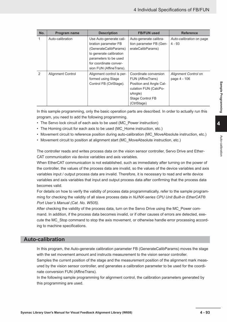
No. Program name Description FB/FUN used Reference1 Auto-calibration Use Auto-generate cali-
bration parameter FB(GenerateCalibParams)to generate calibrationparameters to be usedfor coordinate conver-sion FUN (AffineTrans).
Auto-generate calibra-tion parameter FB (Gen-erateCalibParams)
Auto-calibration on page4 - 93
2 Alignment Control Alignment control is per-formed using StageControl FB (CtrlStage).
Coordinate conversionFUN (AffineTrans)Position and Angle Cal-culation FUN (CalcPo-sAngle)Stage Control FB(CtrlStage)
Alignment Control onpage 4 - 106
In this sample programming, only the basic operation parts are described. In order to actually run thisprogram, you need to add the following programming.• The Servo lock circuit of each axis to be used (MC_Power instruction)• The Homing circuit for each axis to be used (MC_Home instruction, etc.)• Movement circuit to reference position during auto-calibration (MC_MoveAbsolute instruction, etc.)• Movement circuit to position at alignment start (MC_MoveAbsolute instruction, etc.)
The controller reads and writes process data on the vision sensor controller, Servo Drive and Ether-CAT communication via device variables and axis variables.When EtherCAT communication is not established, such as immediately after turning on the power ofthe controller, the values of the process data are invalid, so the values of the device variables and axisvariables input / output process data are invalid. Therefore, it is necessary to read and write devicevariables and axis variables that input and output process data after confirming that the process databecomes valid.For details on how to verify the validity of process data programmatically, refer to the sample program-ming for checking the validity of all slave process data in NJ/NX-series CPU Unit Built-in EtherCAT®Port User’s Manual (Cat. No. W505).After checking the validity of the process data, turn on the Servo Drive using the MC_Power com-mand. In addition, if the process data becomes invalid, or if other causes of errors are detected, exe-cute the MC_Stop command to stop the axis movement, or otherwise handle error processing accord-ing to machine specifications.
Auto-calibrationIn this program, the Auto-generate calibration parameter FB (GenerateCalibParams) moves the stagewith the set movement amount and instructs measurement to the vision sensor controller.Samples the current position of the stage and the measurement position of the alignment mark meas-ured by the vision sensor controller, and generates a calibration parameter to be used for the coordi-nate conversion FUN (AffineTrans).In the following sample programming for alignment control, the calibration parameters generated bythis programming are used.
4 Individual Specifications of FB/FUN
4 - 93Sysmac Library User's Manual for Visual Feedback Alignment Library (W608)
Sample Program
ming
4
Auto-calibration

Vision Sensor Controller Processing FlowThe vision sensor controller images the alignment mark with two cameras in response to the imaginginstruction given from the controller. On the captured image, it detects the shape of the pre-registeredalignment mark and measures its detection point coordinates.The measurement result (measurement position) is output to the controller via EtherCAT communica-tion.
Camera imaging (No.0)
Camera 0 model detection (No.1)
Camera switching (No.2)
Camera 1 model detection (No.3)
Data output (No.4)
No. Item Unit Function Settings0 Camera imaging Camera Image Input FH Image capture of a mark
using camera 0 andcamera 1. The object tobe measured at thistime is from camera 0.
Set the Shutter speedand Gain for camera 0and camera 1.
1 Camera 0 model detec-tion
Shape Search III Measure the position ofthe feature (mark) regis-tered from the image ofcamera 0.
The feature (mark) to bedetected by the camera0 is registered as amodel.
2 Camera switching Camera switching Switch the measure-ment target to camera 1.
Set camera 1 in the se-lection setting.
3 Camera 1 model detec-tion
Shape Search III Measure the position ofthe feature (mark) regis-tered from the image ofcamera 1.
The feature (mark) to bedetected by the camera1 is registered as amodel.
4 Data Output Fieldbus Data Output In the EtherCAT com-munication, the meas-urement position ofMark 0 and Mark 1 areoutput.
Set the data to be out-put (Measurement posi-tion, Overall Judgment).
Overview of Sample ProgrammingThe sample programming for auto-calibration is roughly divided into the following processes.Section Structure
4 Individual Specifications of FB/FUN
4 - 94 Sysmac Library User's Manual for Visual Feedback Alignment Library (W608)
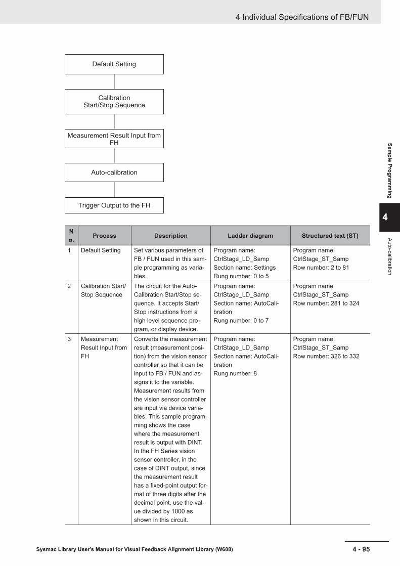
Default Setting
CalibrationStart/Stop Sequence
Measurement Result Input from FH
Auto-calibration
Trigger Output to the FH
No. Process Description Ladder diagram Structured text (ST)
1 Default Setting Set various parameters ofFB / FUN used in this sam-ple programming as varia-bles.
Program name:CtrlStage_LD_SampSection name: SettingsRung number: 0 to 5
Program name:CtrlStage_ST_SampRow number: 2 to 81
2 Calibration Start/Stop Sequence
The circuit for the Auto-Calibration Start/Stop se-quence. It accepts Start/Stop instructions from ahigh level sequence pro-gram, or display device.
Program name:CtrlStage_LD_SampSection name: AutoCali-brationRung number: 0 to 7
Program name:CtrlStage_ST_SampRow number: 281 to 324
3 MeasurementResult Input fromFH
Converts the measurementresult (measurement posi-tion) from the vision sensorcontroller so that it can beinput to FB / FUN and as-signs it to the variable.Measurement results fromthe vision sensor controllerare input via device varia-bles. This sample program-ming shows the casewhere the measurementresult is output with DINT.In the FH Series visionsensor controller, in thecase of DINT output, sincethe measurement resulthas a fixed-point output for-mat of three digits after thedecimal point, use the val-ue divided by 1000 asshown in this circuit.
Program name:CtrlStage_LD_SampSection name: AutoCali-brationRung number: 8
Program name:CtrlStage_ST_SampRow number: 326 to 332
4 Individual Specifications of FB/FUN
4 - 95Sysmac Library User's Manual for Visual Feedback Alignment Library (W608)
Sample Program
ming
4
Auto-calibration

No. Process Description Ladder diagram Structured text (ST)
4 Auto-calibration Based on the default set-ting, it gives imaging in-struction to the vision sen-sor controller while movingthe stage position. Con-verts the measurement po-sition obtained from the vi-sion sensor controller tothe stage coordinate sys-tem, calculates the calibra-tion parameter by corre-spondence to the stage'scurrent position.The following FB/FUN areused.Auto-generate calibrationparameter FB (Generate-CalibParams)
Program name:CtrlStage_LD_SampSection name: AutoCali-brationRung number: 9
Program name:CtrlStage_ST_SampRow number: 334 to 353
5 Trigger Output tothe FH
Sends the measurementsensor trigger output fromthe Auto-generate calibra-tion parameter FB (Gener-ateCalibParams) to the vi-sion sensor controller.The measurement triggeroutput to the vision sensorcontroller is output using adevice variable.
Program name:CtrlStage_LD_SampSection name: FH_ControlRung number: 0
Program name:CtrlStage_ST_SampRow number: 355 to 356
Primary VariablesName Data type Default Comment
CalibPar-ams
ARRAY[0..3] OF OmronLib\VF_Align-ment\sCALIB_PARAMS
— Variables for storing the calibration pa-rameters.
Alignment-Params
OmronLib\VF_Alignment\sALIGN-MENT_PARAMS
— Variables for storing the alignment pa-rameters.
CalibMove-Params
OmronLib\VF_Alignment\sCA-LIB_MOVE_PARAMS
— Variables for storing the movement pa-rameters used for calibration.
CalibStart BOOL FALSE Alignment control starts when this varia-ble changes from FALSE to TRUE.
CalibStop BOOL FALSE Alignment control stops when this varia-ble changes from FALSE to TRUE.
Reset BOOL FALSE Fault Reset is executed when this varia-ble changes from FALSE to TRUE.
ServoON_X BOOL FALSE This variable is TRUE when the X axisServo is ON.
ServoON_Y BOOL FALSE This variable is TRUE when the Y axisServo is ON.
Ser-voON_TH
BOOL FALSE This variable is TRUE when the θ axisServo is ON.
4 Individual Specifications of FB/FUN
4 - 96 Sysmac Library User's Manual for Visual Feedback Alignment Library (W608)

Name Data type Default CommentAutoCalib-HomePos
BOOL FALSE An internal relay indicating when theCalibration Control Sequence can bestarted.
AutoCalib-Start
BOOL FALSE An internal variable that starts the Cali-bration Control Sequence.
AutoCalib-Stop
BOOL FALSE An internal variable that stops the Cali-bration Control Sequence.
AutoCali-bEnd
BOOL FALSE An internal variable that ends the Cali-bration Control Sequence.
AL_Auto-CalibT-OVER
BOOL FALSE This is an alarm flag indicating that aCalibration Control timeout occurred.
AL_Gener-ateCalib-Params
BOOL FALSE This is an alarm flag indicating that anerror occurred in GenerateCalibParams.
AL_MC_EC_Error
BOOL FALSE This is an alarm flag that indicates thatan error occurred in the Motion ControlFunction Module of the CPU Unit or inthe EtherCAT Master Function Module.
CalibAlarm BOOL FALSE This becomes TRUE when there is anAuto-calibration alarm.
Generate-CalibPar-ams_TOver
TON — This becomes TRUE when the time forAuto-calibration exceeds the set time.
Generate-CalibPar-ams_Done
BOOL FALSE This is a variable for storing Done outputfrom GenerateCalibParams.
Generate-CalibPar-ams_Busy
BOOL FALSE This is a variable for storing Busy outputfrom GenerateCalibParams.
Generate-CalibPar-ams_Error
BOOL FALSE This is a variable for storing Error outputfrom GenerateCalibParams.
Generate-CalibPar-ams_Trig-ger
BOOL FALSE This is a variable that outputs the imag-ing trigger to send to the vision sensor.
MeasMark-PosCamera
ARRAY[0..3] OF OmronLib\VF_Align-ment\sPOSITION
— Variables for storing the measurementposition for cameras 0 and 1. Index 0 ofthe array is camera 0, and Index 1 is themeasurement position of camera 1.
CalcPos-Target
ARRAY[0..3] OF BOOL FALSE Set the points for which to generate thecalibration parameters. In this sampleprogramming, the array elements [0]and [1] are set to TRUE because theyare for point 0 and point 1.
Generate-CalibPar-ams_in-stance
\\Omronlib\VF_Alignment\GenerateCa-libParams
— This is an instance of calibration param-eter automatic generation FB (Genera-teCalibParams).
4 Individual Specifications of FB/FUN
4 - 97Sysmac Library User's Manual for Visual Feedback Alignment Library (W608)
Sample Program
ming
4
Auto-calibration

Ladder DiagramDefault setting
Calibration Control Start/Stop sequence
4 Individual Specifications of FB/FUN
4 - 98 Sysmac Library User's Manual for Visual Feedback Alignment Library (W608)

This circuit in the alignment control sample programming is a common circuit for both the Motion Control Func-tion Module of the CPU Unit and the Fault Monitoring circuit of the EtherCAT Master Function Module.
Measurement Result Input from FH
4 Individual Specifications of FB/FUN
4 - 99Sysmac Library User's Manual for Visual Feedback Alignment Library (W608)
Sample Program
ming
4
Auto-calibration
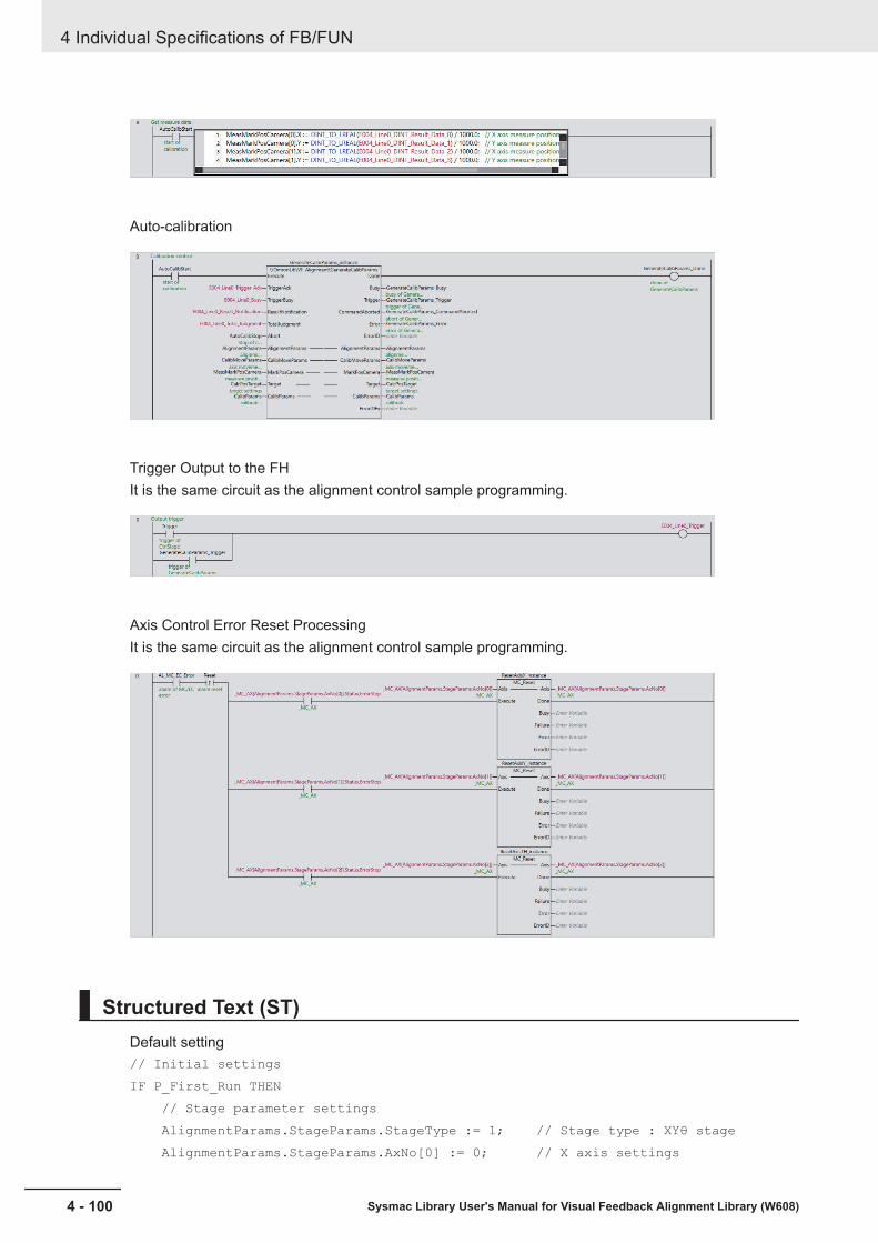
Auto-calibration
Trigger Output to the FHIt is the same circuit as the alignment control sample programming.
Axis Control Error Reset ProcessingIt is the same circuit as the alignment control sample programming.
Structured Text (ST)Default setting// Initial settingsIF P_First_Run THEN // Stage parameter settings AlignmentParams.StageParams.StageType := 1; // Stage type : XYθ stage AlignmentParams.StageParams.AxNo[0] := 0; // X axis settings
4 Individual Specifications of FB/FUN
4 - 100 Sysmac Library User's Manual for Visual Feedback Alignment Library (W608)
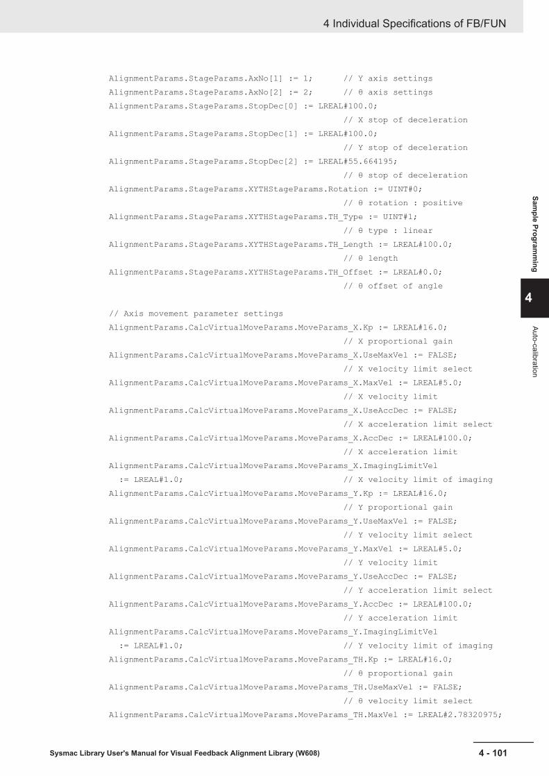
AlignmentParams.StageParams.AxNo[1] := 1; // Y axis settings AlignmentParams.StageParams.AxNo[2] := 2; // θ axis settings AlignmentParams.StageParams.StopDec[0] := LREAL#100.0; // X stop of deceleration AlignmentParams.StageParams.StopDec[1] := LREAL#100.0; // Y stop of deceleration AlignmentParams.StageParams.StopDec[2] := LREAL#55.664195; // θ stop of deceleration AlignmentParams.StageParams.XYTHStageParams.Rotation := UINT#0; // θ rotation : positive AlignmentParams.StageParams.XYTHStageParams.TH_Type := UINT#1; // θ type : linear AlignmentParams.StageParams.XYTHStageParams.TH_Length := LREAL#100.0; // θ length AlignmentParams.StageParams.XYTHStageParams.TH_Offset := LREAL#0.0; // θ offset of angle
// Axis movement parameter settings AlignmentParams.CalcVirtualMoveParams.MoveParams_X.Kp := LREAL#16.0; // X proportional gain AlignmentParams.CalcVirtualMoveParams.MoveParams_X.UseMaxVel := FALSE; // X velocity limit select AlignmentParams.CalcVirtualMoveParams.MoveParams_X.MaxVel := LREAL#5.0; // X velocity limit AlignmentParams.CalcVirtualMoveParams.MoveParams_X.UseAccDec := FALSE; // X acceleration limit select AlignmentParams.CalcVirtualMoveParams.MoveParams_X.AccDec := LREAL#100.0; // X acceleration limit AlignmentParams.CalcVirtualMoveParams.MoveParams_X.ImagingLimitVel := LREAL#1.0; // X velocity limit of imaging AlignmentParams.CalcVirtualMoveParams.MoveParams_Y.Kp := LREAL#16.0; // Y proportional gain AlignmentParams.CalcVirtualMoveParams.MoveParams_Y.UseMaxVel := FALSE; // Y velocity limit select AlignmentParams.CalcVirtualMoveParams.MoveParams_Y.MaxVel := LREAL#5.0; // Y velocity limit AlignmentParams.CalcVirtualMoveParams.MoveParams_Y.UseAccDec := FALSE; // Y acceleration limit select AlignmentParams.CalcVirtualMoveParams.MoveParams_Y.AccDec := LREAL#100.0; // Y acceleration limit AlignmentParams.CalcVirtualMoveParams.MoveParams_Y.ImagingLimitVel := LREAL#1.0; // Y velocity limit of imaging AlignmentParams.CalcVirtualMoveParams.MoveParams_TH.Kp := LREAL#16.0; // θ proportional gain AlignmentParams.CalcVirtualMoveParams.MoveParams_TH.UseMaxVel := FALSE; // θ velocity limit select AlignmentParams.CalcVirtualMoveParams.MoveParams_TH.MaxVel := LREAL#2.78320975;
4 Individual Specifications of FB/FUN
4 - 101Sysmac Library User's Manual for Visual Feedback Alignment Library (W608)
Sample Program
ming
4
Auto-calibration
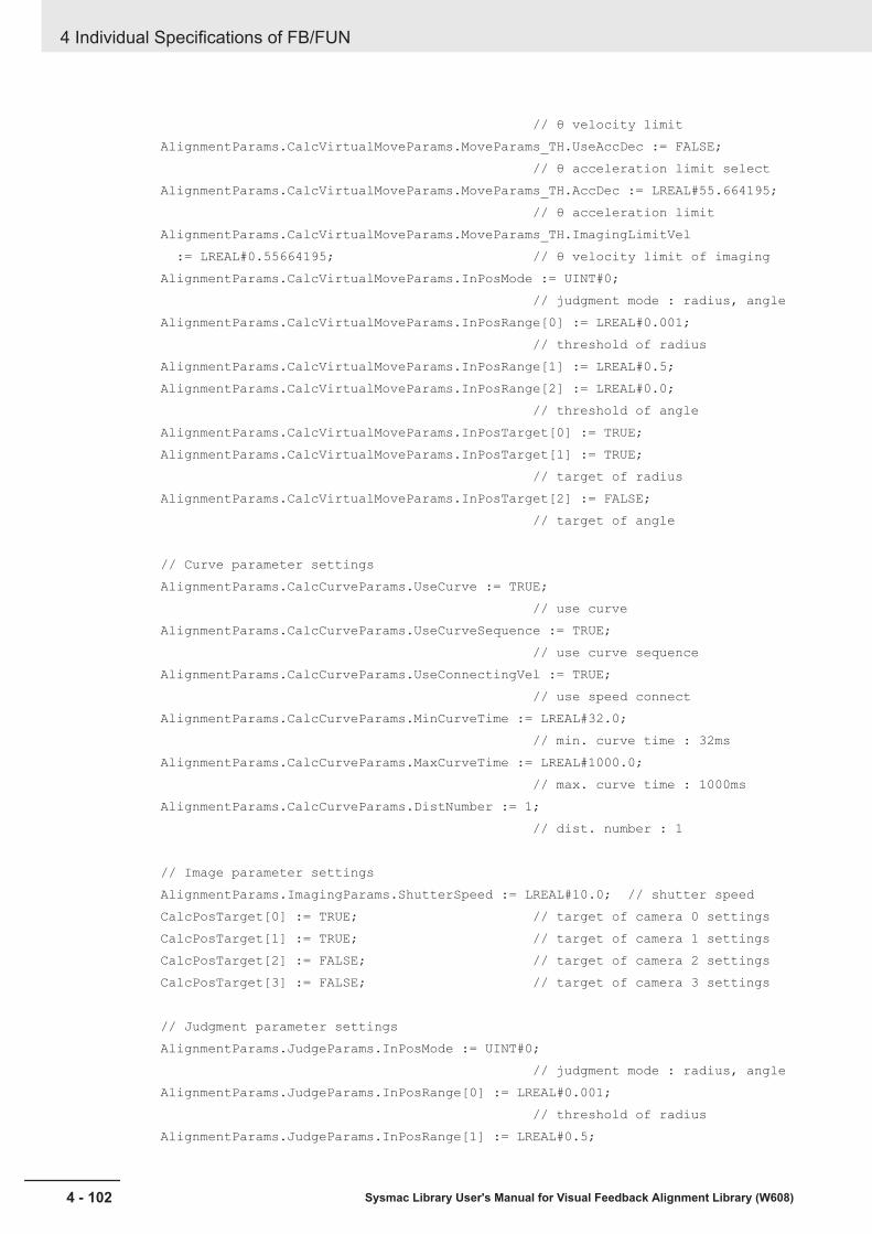
// θ velocity limit AlignmentParams.CalcVirtualMoveParams.MoveParams_TH.UseAccDec := FALSE; // θ acceleration limit select AlignmentParams.CalcVirtualMoveParams.MoveParams_TH.AccDec := LREAL#55.664195; // θ acceleration limit AlignmentParams.CalcVirtualMoveParams.MoveParams_TH.ImagingLimitVel := LREAL#0.55664195; // θ velocity limit of imaging AlignmentParams.CalcVirtualMoveParams.InPosMode := UINT#0; // judgment mode : radius, angle AlignmentParams.CalcVirtualMoveParams.InPosRange[0] := LREAL#0.001; // threshold of radius AlignmentParams.CalcVirtualMoveParams.InPosRange[1] := LREAL#0.5; AlignmentParams.CalcVirtualMoveParams.InPosRange[2] := LREAL#0.0; // threshold of angle AlignmentParams.CalcVirtualMoveParams.InPosTarget[0] := TRUE; AlignmentParams.CalcVirtualMoveParams.InPosTarget[1] := TRUE; // target of radius AlignmentParams.CalcVirtualMoveParams.InPosTarget[2] := FALSE; // target of angle
// Curve parameter settings AlignmentParams.CalcCurveParams.UseCurve := TRUE; // use curve AlignmentParams.CalcCurveParams.UseCurveSequence := TRUE; // use curve sequence AlignmentParams.CalcCurveParams.UseConnectingVel := TRUE; // use speed connect AlignmentParams.CalcCurveParams.MinCurveTime := LREAL#32.0; // min. curve time : 32ms AlignmentParams.CalcCurveParams.MaxCurveTime := LREAL#1000.0; // max. curve time : 1000ms AlignmentParams.CalcCurveParams.DistNumber := 1; // dist. number : 1
// Image parameter settings AlignmentParams.ImagingParams.ShutterSpeed := LREAL#10.0; // shutter speed CalcPosTarget[0] := TRUE; // target of camera 0 settings CalcPosTarget[1] := TRUE; // target of camera 1 settings CalcPosTarget[2] := FALSE; // target of camera 2 settings CalcPosTarget[3] := FALSE; // target of camera 3 settings
// Judgment parameter settings AlignmentParams.JudgeParams.InPosMode := UINT#0; // judgment mode : radius, angle AlignmentParams.JudgeParams.InPosRange[0] := LREAL#0.001; // threshold of radius AlignmentParams.JudgeParams.InPosRange[1] := LREAL#0.5;
4 Individual Specifications of FB/FUN
4 - 102 Sysmac Library User's Manual for Visual Feedback Alignment Library (W608)
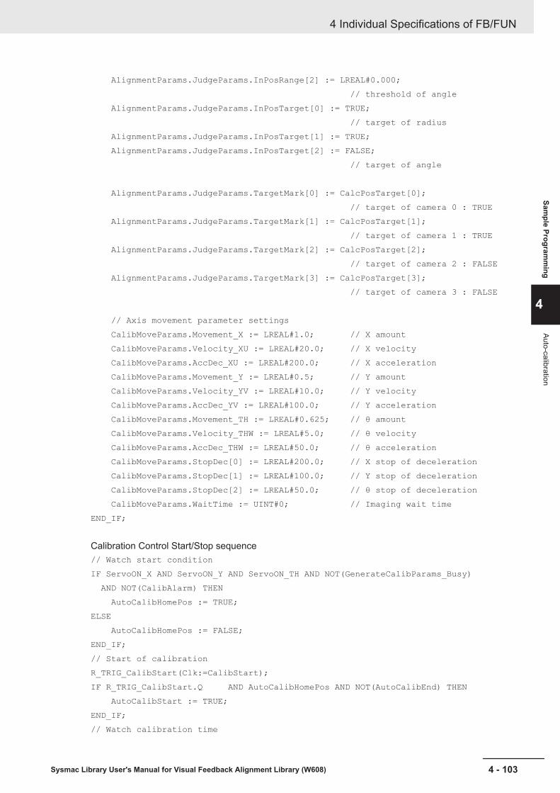
AlignmentParams.JudgeParams.InPosRange[2] := LREAL#0.000; // threshold of angle AlignmentParams.JudgeParams.InPosTarget[0] := TRUE; // target of radius AlignmentParams.JudgeParams.InPosTarget[1] := TRUE; AlignmentParams.JudgeParams.InPosTarget[2] := FALSE; // target of angle AlignmentParams.JudgeParams.TargetMark[0] := CalcPosTarget[0]; // target of camera 0 : TRUE AlignmentParams.JudgeParams.TargetMark[1] := CalcPosTarget[1]; // target of camera 1 : TRUE AlignmentParams.JudgeParams.TargetMark[2] := CalcPosTarget[2]; // target of camera 2 : FALSE AlignmentParams.JudgeParams.TargetMark[3] := CalcPosTarget[3]; // target of camera 3 : FALSE
// Axis movement parameter settings CalibMoveParams.Movement_X := LREAL#1.0; // X amount CalibMoveParams.Velocity_XU := LREAL#20.0; // X velocity CalibMoveParams.AccDec_XU := LREAL#200.0; // X acceleration CalibMoveParams.Movement_Y := LREAL#0.5; // Y amount CalibMoveParams.Velocity_YV := LREAL#10.0; // Y velocity CalibMoveParams.AccDec_YV := LREAL#100.0; // Y acceleration CalibMoveParams.Movement_TH := LREAL#0.625; // θ amount CalibMoveParams.Velocity_THW := LREAL#5.0; // θ velocity CalibMoveParams.AccDec_THW := LREAL#50.0; // θ acceleration CalibMoveParams.StopDec[0] := LREAL#200.0; // X stop of deceleration CalibMoveParams.StopDec[1] := LREAL#100.0; // Y stop of deceleration CalibMoveParams.StopDec[2] := LREAL#50.0; // θ stop of deceleration CalibMoveParams.WaitTime := UINT#0; // Imaging wait timeEND_IF;
Calibration Control Start/Stop sequence// Watch start conditionIF ServoON_X AND ServoON_Y AND ServoON_TH AND NOT(GenerateCalibParams_Busy) AND NOT(CalibAlarm) THEN AutoCalibHomePos := TRUE;ELSE AutoCalibHomePos := FALSE;END_IF;// Start of calibrationR_TRIG_CalibStart(Clk:=CalibStart);IF R_TRIG_CalibStart.Q AND AutoCalibHomePos AND NOT(AutoCalibEnd) THEN AutoCalibStart := TRUE;END_IF;// Watch calibration time
4 Individual Specifications of FB/FUN
4 - 103Sysmac Library User's Manual for Visual Feedback Alignment Library (W608)
Sample Program
ming
4
Auto-calibration
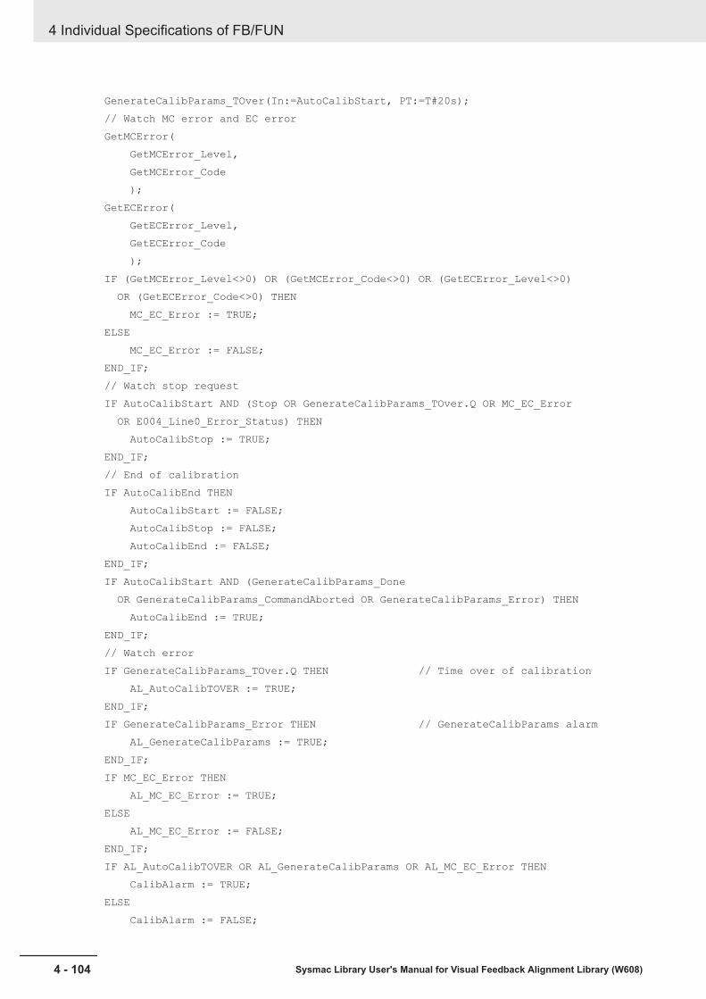
GenerateCalibParams_TOver(In:=AutoCalibStart, PT:=T#20s);// Watch MC error and EC errorGetMCError( GetMCError_Level, GetMCError_Code );GetECError( GetECError_Level, GetECError_Code );IF (GetMCError_Level<>0) OR (GetMCError_Code<>0) OR (GetECError_Level<>0) OR (GetECError_Code<>0) THEN MC_EC_Error := TRUE;ELSE MC_EC_Error := FALSE;END_IF;// Watch stop requestIF AutoCalibStart AND (Stop OR GenerateCalibParams_TOver.Q OR MC_EC_Error OR E004_Line0_Error_Status) THEN AutoCalibStop := TRUE;END_IF;// End of calibrationIF AutoCalibEnd THEN AutoCalibStart := FALSE; AutoCalibStop := FALSE; AutoCalibEnd := FALSE;END_IF;IF AutoCalibStart AND (GenerateCalibParams_Done OR GenerateCalibParams_CommandAborted OR GenerateCalibParams_Error) THEN AutoCalibEnd := TRUE;END_IF;// Watch errorIF GenerateCalibParams_TOver.Q THEN // Time over of calibration AL_AutoCalibTOVER := TRUE;END_IF;IF GenerateCalibParams_Error THEN // GenerateCalibParams alarm AL_GenerateCalibParams := TRUE;END_IF;IF MC_EC_Error THEN AL_MC_EC_Error := TRUE;ELSE AL_MC_EC_Error := FALSE;END_IF;IF AL_AutoCalibTOVER OR AL_GenerateCalibParams OR AL_MC_EC_Error THEN CalibAlarm := TRUE;ELSE CalibAlarm := FALSE;
4 Individual Specifications of FB/FUN
4 - 104 Sysmac Library User's Manual for Visual Feedback Alignment Library (W608)

END_IF;// Alarm resetIF Reset AND NOT(AutoCalibStart) THEN AL_AutoCalibTOVER := FALSE; AL_GenerateCalibParams := FALSE;END_IF;
Measurement Result Input from FH// Get measure dataIF AutoCalibStart THEN MeasMarkPosCamera[0].X := DINT_TO_LREAL(E004_Line0_DINT_Result_Data_0) / LREAL#1000.0; // X axis measure position of camera 0 MeasMarkPosCamera[0].Y := DINT_TO_LREAL(E004_Line0_DINT_Result_Data_1) / LREAL#1000.0; // Y axis measure position of camera 0 MeasMarkPosCamera[1].X := DINT_TO_LREAL(E004_Line0_DINT_Result_Data_2) / LREAL#1000.0; // X axis measure position of camera 1 MeasMarkPosCamera[1].Y := DINT_TO_LREAL(E004_Line0_DINT_Result_Data_3) / LREAL#1000.0; // Y axis measure position of camera 1END_IF;
Auto-calibration// Calibration controlR_TRIG_AutoCalibStart(Clk:=AutoCalibStart);GenerateCalibParams_instance( Execute := R_TRIG_AutoCalibStart.Q, TriggerAck := E004_Line0_Trigger_Ack, TriggerBusy := E004_Line0_Busy, ResultNotification := E004_Line0_Result_Notification, TotalJudgment := E004_Line0_Total_Judgment, Abort := AutoCalibStop, AlignmentParams := AlignmentParams, CalibMoveParams := CalibMoveParams, MarkPosCamera := MeasMarkPosCamera, Target := CalcPosTarget, CalibParams := CalibParams, Done => GenerateCalibParams_Done, Busy => GenerateCalibParams_Busy, Trigger => CalibTrigger, CommandAborted => GenerateCalibParams_CommandAborted, Error => GenerateCalibParams_Error );
Trigger Output to the FHIt is the same circuit as the alignment control sample programming.// Output triggerE004_Line0_Trigger := (Trigger OR CalibTrigger);
Axis Control Error Reset Processing
4 Individual Specifications of FB/FUN
4 - 105Sysmac Library User's Manual for Visual Feedback Alignment Library (W608)
Sample Program
ming
4
Auto-calibration
It is the same circuit as the alignment control sample programming.// ResetResetAxisX_instance( Execute := (AL_MC_EC_Error AND R_TRIG_Reset.Q AND _MC_AX[AlignmentParams.StageParams.AxNo[0]].Status.ErrorStop), Axis := _MC_AX[AlignmentParams.StageParams.AxNo[0]] );ResetAxisY_instance( Execute := (AL_MC_EC_Error AND R_TRIG_Reset.Q AND _MC_AX[AlignmentParams.StageParams.AxNo[1]].Status.ErrorStop), Axis := _MC_AX[AlignmentParams.StageParams.AxNo[1]] );ResetAxisTH_instance( Execute := (AL_MC_EC_Error AND R_TRIG_Reset.Q AND _MC_AX[AlignmentParams.StageParams.AxNo[2]].Status.ErrorStop), Axis := _MC_AX[AlignmentParams.StageParams.AxNo[2]] );
Alignment ControlThis program performs the following two processes. First, an imaging instruction is given to the visionsensor controller, and the measurement position obtained from the captured image and the alignmenttarget position (reference position) set in advance by the vision sensor controller are converted to thestage coordinates by the coordinate conversion FUN (AffineTrans). Then, alignment control is per-formed using the Position and Angle Calculation FUN (CalcPosAngle) and the Stage Control FB(CtrlStage) based on the measurement position and reference position in the stage coordinates.
Vision Sensor Controller Processing FlowThe vision sensor controller images the alignment mark with two cameras in response to the imaginginstruction given from the controller. On the captured image, it detects the shape of the pre-registeredalignment mark and measures its detection point coordinates.The measurement result (measurement position) and the reference position (the target position for thealignment) are output to the controller via EtherCAT communication.
4 Individual Specifications of FB/FUN
4 - 106 Sysmac Library User's Manual for Visual Feedback Alignment Library (W608)

Camera imaging (No.0)
Camera 0 model detection (No.1)
Camera switching (No.2)
Camera 1 model detection (No.3)
Data output (No.4)
No. Item Unit Function Settings0 Camera imaging Camera Image Input FH Image capture of a mark
using camera 0 andcamera 1. The object tobe measured at thistime is from camera 0.
Set the Shutter speedand Gain for camera 0and camera 1.
1 Camera 0 model detec-tion
Shape Search III Measure the position ofthe feature (mark) regis-tered from the image ofcamera 0.
The feature (mark) to bedetected by the camera0 is registered as amodel.
2 Camera switching Camera switching Switch the measure-ment target to camera 1.
Set camera 1 in the se-lection setting.
3 Camera 1 model detec-tion
Shape Search III Measure the position ofthe feature (mark) regis-tered from the image ofcamera 1.
The feature (mark) to bedetected by the camera1 is registered as amodel.
4 Data Output Fieldbus Data Output In the EtherCAT com-munication, the refer-ence position and meas-urement position ofMark 0 and Mark 1 areoutput.
Set the data to be out-put (Reference position,Measurement position,Overall Judgment).
Overview of Sample ProgrammingThe sample programming for alignment control is roughly divided into the following processes.Section Structure
4 Individual Specifications of FB/FUN
4 - 107Sysmac Library User's Manual for Visual Feedback Alignment Library (W608)
Sample Program
ming
4
Alignment C
ontrol
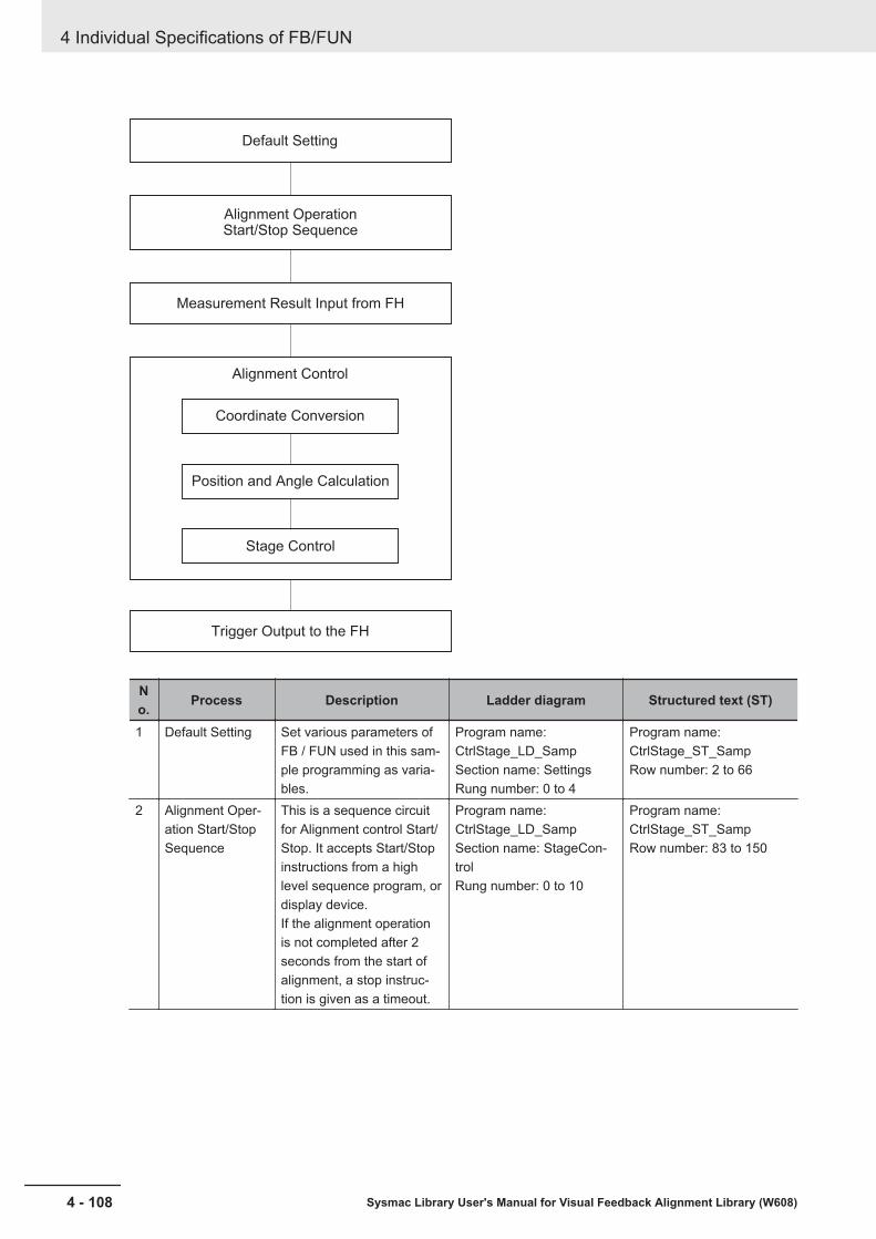
Coordinate Conversion
Position and Angle Calculation
Stage Control
Alignment Control
Default Setting
Alignment OperationStart/Stop Sequence
Measurement Result Input from FH
Trigger Output to the FH
No. Process Description Ladder diagram Structured text (ST)
1 Default Setting Set various parameters ofFB / FUN used in this sam-ple programming as varia-bles.
Program name:CtrlStage_LD_SampSection name: SettingsRung number: 0 to 4
Program name:CtrlStage_ST_SampRow number: 2 to 66
2 Alignment Oper-ation Start/StopSequence
This is a sequence circuitfor Alignment control Start/Stop. It accepts Start/Stopinstructions from a highlevel sequence program, ordisplay device.If the alignment operationis not completed after 2seconds from the start ofalignment, a stop instruc-tion is given as a timeout.
Program name:CtrlStage_LD_SampSection name: StageCon-trolRung number: 0 to 10
Program name:CtrlStage_ST_SampRow number: 83 to 150
4 Individual Specifications of FB/FUN
4 - 108 Sysmac Library User's Manual for Visual Feedback Alignment Library (W608)

No. Process Description Ladder diagram Structured text (ST)
3 MeasurementResult Input fromFH
Converts the measurementresult (reference position,measurement position)from the vision sensor con-troller so that it can be in-put to FB / FUN and as-signs it to a variable.Measurement results fromthe vision sensor controllerare input via device varia-bles. This sample program-ming shows the casewhere the measurementresult is output with DINT.In the FH Series visionsensor controller, in thecase of DINT output, sincethe measurement resulthas a fixed-point output for-mat of three digits after thedecimal point, use the val-ue divided by 1000 asshown in this circuit.
Program name:CtrlStage_LD_SampSection name: StageCon-trolRung number: 11
Program name:CtrlStage_ST_SampRow number: 152 to 162
4 Alignment Con-trol
Converts the reference po-sition and measurementposition obtained from thevision sensor controller tothe stage coordinates andcalculates the position andangle. The stage is movedbased on the obtained po-sition and angle informa-tion.The following FB/FUN areused.Coordinate conversionFUN (AffineTrans)Position and Angle Calcu-lation FUN (CalcPosAngle)Stage Control FB(CtrlStage)
Program name:CtrlStage_LD_SampSection name: StageCon-trolRung number: 12 to 18
Program name:CtrlStage_ST_SampRow number: 164 to 227
5 Trigger Output tothe FH
Sends the measurementtrigger output that theStage Control FB(CtrlStage) outputs to thevision sensor controller.The measurement triggeroutput to the vision sensorcontroller is output using adevice variable.
Program name:CtrlStage_LD_SampSection name: FH_ControlRung number: 0
Program name:CtrlStage_ST_SampRow number: 355 to 356
4 Individual Specifications of FB/FUN
4 - 109Sysmac Library User's Manual for Visual Feedback Alignment Library (W608)
Sample Program
ming
4
Alignment C
ontrol
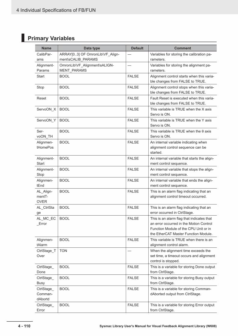
Primary VariablesName Data type Default Comment
CalibPar-ams
ARRAY[0..3] OF OmronLib\VF_Align-ment\sCALIB_PARAMS
— Variables for storing the calibration pa-rameters.
Alignment-Params
OmronLib\VF_Alignment\sALIGN-MENT_PARAMS
— Variables for storing the alignment pa-rameters.
Start BOOL FALSE Alignment control starts when this varia-ble changes from FALSE to TRUE.
Stop BOOL FALSE Alignment control stops when this varia-ble changes from FALSE to TRUE.
Reset BOOL FALSE Fault Reset is executed when this varia-ble changes from FALSE to TRUE.
ServoON_X BOOL FALSE This variable is TRUE when the X axisServo is ON.
ServoON_Y BOOL FALSE This variable is TRUE when the Y axisServo is ON.
Ser-voON_TH
BOOL FALSE This variable is TRUE when the θ axisServo is ON.
Alignmen-tHomePos
BOOL FALSE An internal variable indicating whenalignment control sequence can bestarted.
Alignment-Start
BOOL FALSE An internal variable that starts the align-ment control sequence.
Alignment-Stop
BOOL FALSE An internal variable that stops the align-ment control sequence.
Alignmen-tEnd
BOOL FALSE An internal variable that ends the align-ment control sequence.
AL_Align-mentT-OVER
BOOL FALSE This is an alarm flag indicating that analignment control timeout occurred.
AL_CtrlStage
BOOL FALSE This is an alarm flag indicating that anerror occurred in CtrlStage.
AL_MC_EC_Error
BOOL FALSE This is an alarm flag that indicates thatan error occurred in the Motion ControlFunction Module of the CPU Unit or inthe EtherCAT Master Function Module.
Alignmen-tAlarm
BOOL FALSE This variable is TRUE when there is analignment control alarm.
CtrlStage_TOver
TON — When the alignment time exceeds theset time, a timeout occurs and alignmentcontrol is stopped.
CtrlStage_Done
BOOL FALSE This is a variable for storing Done outputfrom CtrlStage.
CtrlStage_Busy
BOOL FALSE This is a variable for storing Busy outputfrom CtrlStage.
CtrlStage_Comman-dAbortd
BOOL FALSE This is a variable for storing Comman-dAborted output from CtrlStage.
CtrlStage_Error
BOOL FALSE This is a variable for storing Error outputfrom CtrlStage.
4 Individual Specifications of FB/FUN
4 - 110 Sysmac Library User's Manual for Visual Feedback Alignment Library (W608)

Name Data type Default CommentTrigger BOOL FALSE This is a variable that outputs the imag-
ing trigger to send to the vision sensor.TargetMark-PosCamera
ARRAY[0..3] OF OmronLib\VF_Align-ment\sPOSITION
— Variables for storing the reference posi-tion for cameras 0 and 1. Index 0 of thearray is camera 0, and Index 1 is the ref-erence position of camera 1.
MeasMark-PosCamera
ARRAY[0..3] OF OmronLib\VF_Align-ment\sPOSITION
— Variables for storing the measurementposition for cameras 0 and 1. Index 0 ofthe array is camera 0, and Index 1 is themeasurement position of camera 1.
TargetMark-PosStage
ARRAY[0..3] OF OmronLib\VF_Align-ment\sPOSITION
— Variables for storing the reference posi-tion after Affine conversion.
MeasMark-PosStage
ARRAY[0..3] OF OmronLib\VF_Align-ment\sPOSITION
— Variables for storing the measurementposition after Affine conversion.
TargetMark-PosAlign
OmronLib\VF_Alignment\sPOSITION — Variables for storing the reference posi-tion of the position angle calculation.
MeasMark-PosAlign
OmronLib\VF_Alignment\sPOSITION — Variables for storing the measurementposition of the position angle calculation.
ret_Tar-get_Affine-Trans
UINT 0 Variable to store the returned value ofAffineTrans when calculating the refer-ence position.
ret_Meas_AffineTrans
UINT 0 Variable to store the returned value ofAffineTrans when calculating the meas-urement position.
ret_Tar-get_Calc-PosAngle
UINT 0 Variable to store the returned value ofCalcPosAngle when calculating the ref-erence position.
ret_Meas_CalcPosAn-gle
UINT 0 Variable to store the returned value ofCalcPosAngle when calculating themeasurement position.
TargetMark-Pos-Stage_OK
ARRAY[0..3] OF OmronLib\VF_Align-ment\sPOSITION
— Variables for storing the reference posi-tion after Affine conversion ends normal-ly.
MeasMark-Pos-Stage_OK
ARRAY[0..3] OF OmronLib\VF_Align-ment\sPOSITION
— Variables for storing the measurementposition after Affine conversion endsnormally.
TargetMark-PosA-lign_OK
OmronLib\VF_Alignment\sPOSITION — Variables for storing the reference posi-tion when position angle calculationends normally.
MeasMark-PosA-lign_OK
OmronLib\VF_Alignment\sPOSITION — Variables for storing the measurementposition when position angle calculationends normally.
CalcPos-Target
ARRAY[0..3] OF BOOL FALSE Set the points for position angle calcula-tion. Since this sample programming ap-plies to points 0 and 1, set Index 0 andIndex 1 of the array to TRUE.
CtrlStage_instance
\\OmronLib\VF_Alignment\CtrlStage — Instance of the Stage Control FB(CtrlStage).
4 Individual Specifications of FB/FUN
4 - 111Sysmac Library User's Manual for Visual Feedback Alignment Library (W608)
Sample Program
ming
4
Alignment C
ontrol
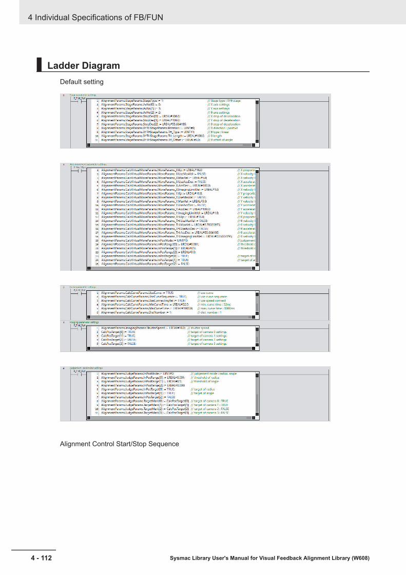
Ladder DiagramDefault setting
Alignment Control Start/Stop Sequence
4 Individual Specifications of FB/FUN
4 - 112 Sysmac Library User's Manual for Visual Feedback Alignment Library (W608)

Measurement Result Input from FH
Alignment Control
4 Individual Specifications of FB/FUN
4 - 113Sysmac Library User's Manual for Visual Feedback Alignment Library (W608)
Sample Program
ming
4
Alignment C
ontrol

Trigger Output to the FHIt is the same circuit as the auto-calibration sample programming.
Axis Control Error Reset ProcessingIt is the same circuit as the auto-calibration sample programming.
4 Individual Specifications of FB/FUN
4 - 114 Sysmac Library User's Manual for Visual Feedback Alignment Library (W608)
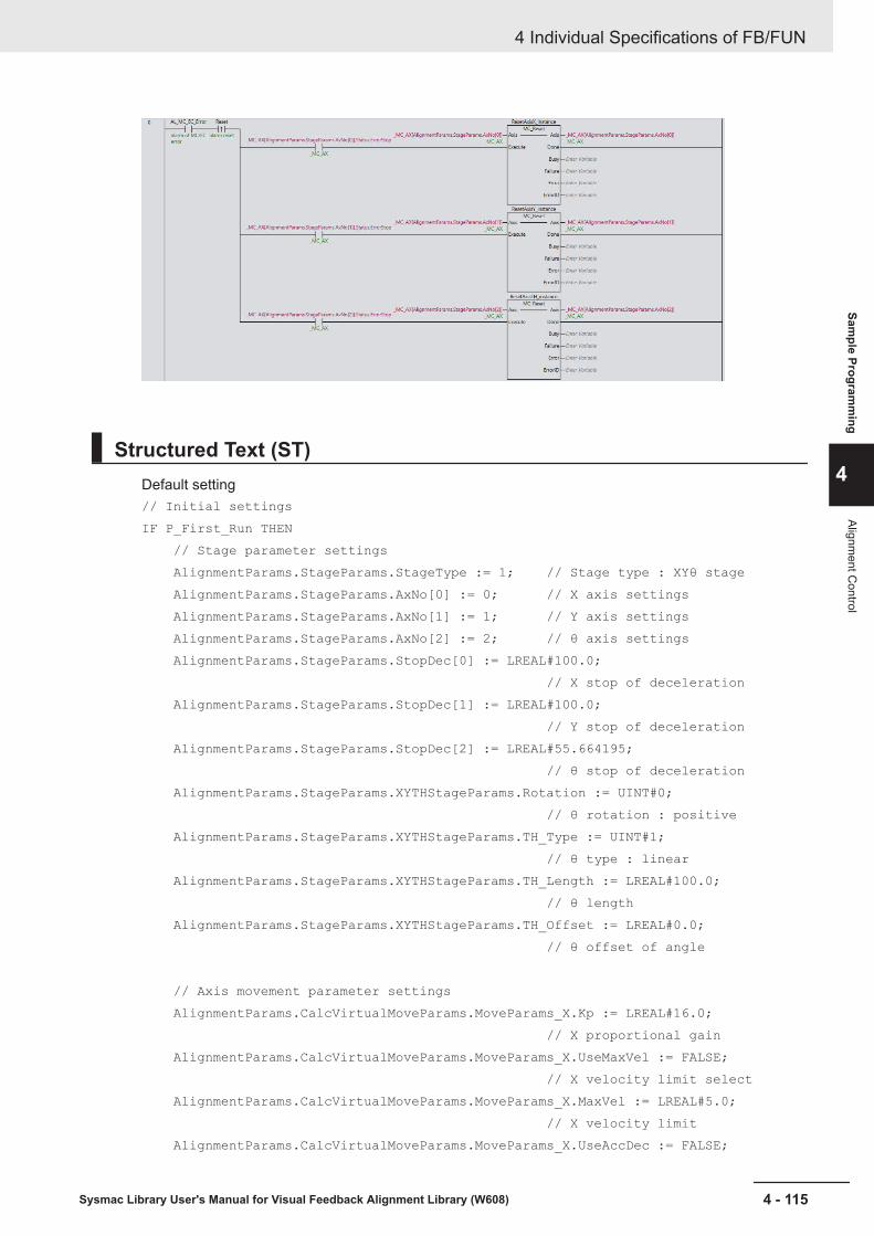
Structured Text (ST)Default setting// Initial settingsIF P_First_Run THEN // Stage parameter settings AlignmentParams.StageParams.StageType := 1; // Stage type : XYθ stage AlignmentParams.StageParams.AxNo[0] := 0; // X axis settings AlignmentParams.StageParams.AxNo[1] := 1; // Y axis settings AlignmentParams.StageParams.AxNo[2] := 2; // θ axis settings AlignmentParams.StageParams.StopDec[0] := LREAL#100.0; // X stop of deceleration AlignmentParams.StageParams.StopDec[1] := LREAL#100.0; // Y stop of deceleration AlignmentParams.StageParams.StopDec[2] := LREAL#55.664195; // θ stop of deceleration AlignmentParams.StageParams.XYTHStageParams.Rotation := UINT#0; // θ rotation : positive AlignmentParams.StageParams.XYTHStageParams.TH_Type := UINT#1; // θ type : linear AlignmentParams.StageParams.XYTHStageParams.TH_Length := LREAL#100.0; // θ length AlignmentParams.StageParams.XYTHStageParams.TH_Offset := LREAL#0.0; // θ offset of angle
// Axis movement parameter settings AlignmentParams.CalcVirtualMoveParams.MoveParams_X.Kp := LREAL#16.0; // X proportional gain AlignmentParams.CalcVirtualMoveParams.MoveParams_X.UseMaxVel := FALSE; // X velocity limit select AlignmentParams.CalcVirtualMoveParams.MoveParams_X.MaxVel := LREAL#5.0; // X velocity limit AlignmentParams.CalcVirtualMoveParams.MoveParams_X.UseAccDec := FALSE;
4 Individual Specifications of FB/FUN
4 - 115Sysmac Library User's Manual for Visual Feedback Alignment Library (W608)
Sample Program
ming
4
Alignment C
ontrol

// X acceleration limit select AlignmentParams.CalcVirtualMoveParams.MoveParams_X.AccDec := LREAL#100.0; // X acceleration limit AlignmentParams.CalcVirtualMoveParams.MoveParams_X.ImagingLimitVel := LREAL#1.0; // X velocity limit of imaging AlignmentParams.CalcVirtualMoveParams.MoveParams_Y.Kp := LREAL#16.0; // Y proportional gain AlignmentParams.CalcVirtualMoveParams.MoveParams_Y.UseMaxVel := FALSE; // Y velocity limit select AlignmentParams.CalcVirtualMoveParams.MoveParams_Y.MaxVel := LREAL#5.0; // Y velocity limit AlignmentParams.CalcVirtualMoveParams.MoveParams_Y.UseAccDec := FALSE; // Y acceleration limit select AlignmentParams.CalcVirtualMoveParams.MoveParams_Y.AccDec := LREAL#100.0; // Y acceleration limit AlignmentParams.CalcVirtualMoveParams.MoveParams_Y.ImagingLimitVel := LREAL#1.0; // Y velocity limit of imaging AlignmentParams.CalcVirtualMoveParams.MoveParams_TH.Kp := LREAL#16.0; // θ proportional gain AlignmentParams.CalcVirtualMoveParams.MoveParams_TH.UseMaxVel := FALSE; // θ velocity limit select AlignmentParams.CalcVirtualMoveParams.MoveParams_TH.MaxVel := LREAL#2.78320975; // θ velocity limit AlignmentParams.CalcVirtualMoveParams.MoveParams_TH.UseAccDec := FALSE; // θ acceleration limit select AlignmentParams.CalcVirtualMoveParams.MoveParams_TH.AccDec := LREAL#55.664195; // θ acceleration limit AlignmentParams.CalcVirtualMoveParams.MoveParams_TH.ImagingLimitVel := LREAL#0.55664195; // θ velocity limit of imaging AlignmentParams.CalcVirtualMoveParams.InPosMode := UINT#0; // judgment mode : radius, angle AlignmentParams.CalcVirtualMoveParams.InPosRange[0] := LREAL#0.001; // threshold of radius AlignmentParams.CalcVirtualMoveParams.InPosRange[1] := LREAL#0.5; AlignmentParams.CalcVirtualMoveParams.InPosRange[2] := LREAL#0.0; // threshold of angle AlignmentParams.CalcVirtualMoveParams.InPosTarget[0] := TRUE; // target of radius AlignmentParams.CalcVirtualMoveParams.InPosTarget[1] := TRUE; AlignmentParams.CalcVirtualMoveParams.InPosTarget[2] := FALSE; // target of angle
// Curve parameter settings AlignmentParams.CalcCurveParams.UseCurve := TRUE; // use curve AlignmentParams.CalcCurveParams.UseCurveSequence := TRUE;
4 Individual Specifications of FB/FUN
4 - 116 Sysmac Library User's Manual for Visual Feedback Alignment Library (W608)

// use curve sequence AlignmentParams.CalcCurveParams.UseConnectingVel := TRUE; // use speed connect AlignmentParams.CalcCurveParams.MinCurveTime := LREAL#32.0; // min. curve time : 32ms AlignmentParams.CalcCurveParams.MaxCurveTime := LREAL#1000.0; // max. curve time : 1000ms AlignmentParams.CalcCurveParams.DistNumber := 1; // dist. number : 1
// Image parameter settings AlignmentParams.ImagingParams.ShutterSpeed := LREAL#10.0; // shutter speed CalcPosTarget[0] := TRUE; // target of camera 0 settings CalcPosTarget[1] := TRUE; // target of camera 1 settings CalcPosTarget[2] := FALSE; // target of camera 2 settings CalcPosTarget[3] := FALSE; // target of camera 3 settings
// Judgment parameter settings AlignmentParams.JudgeParams.InPosMode := UINT#0; // judgment mode : radius, angle AlignmentParams.JudgeParams.InPosRange[0] := LREAL#0.001; // threshold of radius AlignmentParams.JudgeParams.InPosRange[1] := LREAL#0.5; // threshold of angle AlignmentParams.JudgeParams.InPosRange[2] := LREAL#0.000; AlignmentParams.JudgeParams.InPosTarget[0] := TRUE; // target of radius AlignmentParams.JudgeParams.InPosTarget[1] := TRUE; AlignmentParams.JudgeParams.InPosTarget[2] := FALSE; // target of angle AlignmentParams.JudgeParams.TargetMark[0] := CalcPosTarget[0]; // target of camera 0 : TRUE AlignmentParams.JudgeParams.TargetMark[1] := CalcPosTarget[1]; // target of camera 1 : TRUE AlignmentParams.JudgeParams.TargetMark[2] := CalcPosTarget[2]; // target of camera 2 : FALSE AlignmentParams.JudgeParams.TargetMark[3] := CalcPosTarget[3]; // target of camera 3 : FALSEEND_IF;
Alignment Control Start/Stop Sequence// VF alignment Start/Stop sequenceR_TRIG_Start(Clk:=Start);// Watch start conditionIF ServoOn_X AND ServoOn_Y AND ServoOn_TH AND NOT(CtrlStage_Busy) AND NOT(AlignmentAlarm) THEN AlignmentHomePos := TRUE;
4 Individual Specifications of FB/FUN
4 - 117Sysmac Library User's Manual for Visual Feedback Alignment Library (W608)
Sample Program
ming
4
Alignment C
ontrol

ELSE AlignmentHomePos := FALSE;END_IF;// Start of VF alignmentIF R_TRIG_Start.Q AND AlignmentHomePos AND NOT(AlignmentEnd) THEN AlignmentStart := TRUE;END_IF;// Watch VF alignment timeCtrlStage_TOver(In:=AlignmentStart, PT:=T#2.0s);// Watch MC error and ECAT errorGetMCError( GetMCError_Level, GetMCError_Code );GetECError( GetECError_Level, GetECError_Code );IF (GetMCError_Level<>0) OR (GetMCError_Code<>0) OR (GetECError_Level<>0) OR (GetECError_Code<>0) THEN MC_EC_Error := TRUE;ELSE MC_EC_Error := FALSE;END_IF;// Watch stop requestIF AlignmentStart AND (Stop OR CtrlStage_TOver.Q OR MC_EC_Error OR E004_Line0_Error_Status) AND NOT(AlignmentEnd) THEN AlignmentStop := TRUE;END_IF;IF AlignmentEnd THEN AlignmentStart := FALSE; AlignmentStop := FALSE; AlignmentEnd := FALSE; Clear(TargetMarkPosAlign); Clear(MeasMarkPosAlign); Clear(TargetMarkPosStage); Clear(MeasMarkPosStage);END_IF;// End of VF alignmentIF AlignmentStart AND (CtrlStage_Done OR CtrlStage_CommandAborted OR CtrlStage_Error) THEN AlignmentEnd := TRUE;END_IF;// Watch errorIF CtrlStage_TOver.Q THEN AL_AlignmentTOVER := TRUE; // Time over of VF alignment
4 Individual Specifications of FB/FUN
4 - 118 Sysmac Library User's Manual for Visual Feedback Alignment Library (W608)

END_IF;IF CtrlStage_Error THEN AL_CtrlStage := TRUE; // CtrlStage alarmEND_IF;IF MC_EC_Error THEN AL_MC_EC_Error := TRUE;ELSE AL_MC_EC_Error := FALSE;END_IF;IF AL_AlignmentTOVER OR AL_CtrlStage OR AL_MC_EC_Error THEN AlignmentAlarm := TRUE;END_IF;// Alarm resetR_TRIG_Reset(Clk:=Reset);IF R_TRIG_Reset.Q AND NOT(AlignmentStart) THEN AL_AlignmentTOVER := FALSE; AL_CtrlStage := FALSE; AlignmentAlarm := FALSE;END_IF;
Measurement Result Input from FH// Get measure dataIF AlignmentStart THEN MeasMarkPosCamera[0].X := DINT_TO_LREAL(E004_Line0_DINT_Result_Data_0) / LREAL#1000.0; // X axis measure position of camera 0 MeasMarkPosCamera[0].Y := DINT_TO_LREAL(E004_Line0_DINT_Result_Data_1) / LREAL#1000.0; // Y axis measure position of camera 0 MeasMarkPosCamera[1].X := DINT_TO_LREAL(E004_Line0_DINT_Result_Data_2) / LREAL#1000.0; // X axis measure position of camera 1 MeasMarkPosCamera[1].Y := DINT_TO_LREAL(E004_Line0_DINT_Result_Data_3) / LREAL#1000.0; // Y axis measure position of camera 1 TargetMarkPosCamera[0].X := DINT_TO_LREAL(E004_Line0_DINT_Result_Data_4) / LREAL#1000.0; // X axis reference position of camera 0 TargetMarkPosCamera[0].Y := DINT_TO_LREAL(E004_Line0_DINT_Result_Data_5) / LREAL#1000.0; // Y axis reference position of camera 0 TargetMarkPosCamera[1].X := DINT_TO_LREAL(E004_Line0_DINT_Result_Data_6) / LREAL#1000.0; // X axis reference position of camera 1 TargetMarkPosCamera[1].Y := DINT_TO_LREAL(E004_Line0_DINT_Result_Data_7) / LREAL#1000.0; // Y axis reference position of camera1END_IF;
Alignment Control// Alignment controlIF AlignmentStart THEN // Affine transformation ret_Meas_AffineTrans := \\OmronLib\VF_Alignment\AffineTrans( MarkPosCamera := MeasMarkPosCamera,
4 Individual Specifications of FB/FUN
4 - 119Sysmac Library User's Manual for Visual Feedback Alignment Library (W608)
Sample Program
ming
4
Alignment C
ontrol
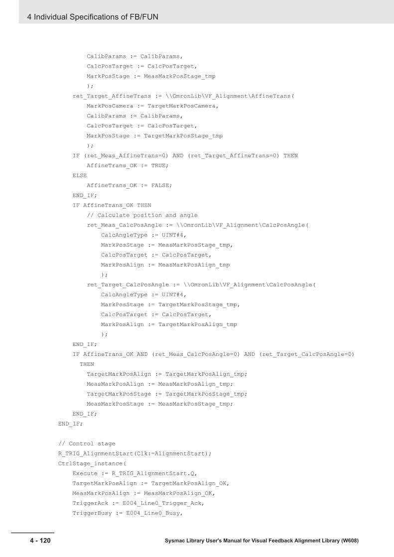
CalibParams := CalibParams, CalcPosTarget := CalcPosTarget, MarkPosStage := MeasMarkPosStage_tmp ); ret_Target_AffineTrans := \\OmronLib\VF_Alignment\AffineTrans( MarkPosCamera := TargetMarkPosCamera, CalibParams := CalibParams, CalcPosTarget := CalcPosTarget, MarkPosStage := TargetMarkPosStage_tmp ); IF (ret_Meas_AffineTrans=0) AND (ret_Target_AffineTrans=0) THEN AffineTrans_OK := TRUE; ELSE AffineTrans_OK := FALSE; END_IF; IF AffineTrans_OK THEN // Calculate position and angle ret_Meas_CalcPosAngle := \\OmronLib\VF_Alignment\CalcPosAngle( CalcAngleType := UINT#4, MarkPosStage := MeasMarkPosStage_tmp, CalcPosTarget := CalcPosTarget, MarkPosAlign := MeasMarkPosAlign_tmp ); ret_Target_CalcPosAngle := \\OmronLib\VF_Alignment\CalcPosAngle( CalcAngleType := UINT#4, MarkPosStage := TargetMarkPosStage_tmp, CalcPosTarget := CalcPosTarget, MarkPosAlign := TargetMarkPosAlign_tmp ); END_IF; IF AffineTrans_OK AND (ret_Meas_CalcPosAngle=0) AND (ret_Target_CalcPosAngle=0) THEN TargetMarkPosAlign := TargetMarkPosAlign_tmp; MeasMarkPosAlign := MeasMarkPosAlign_tmp; TargetMarkPosStage := TargetMarkPosStage_tmp; MeasMarkPosStage := MeasMarkPosStage_tmp; END_IF;END_IF;
// Control stageR_TRIG_AlignmentStart(Clk:=AlignmentStart);CtrlStage_instance( Execute := R_TRIG_AlignmentStart.Q, TargetMarkPosAlign := TargetMarkPosAlign_OK, MeasMarkPosAlign := MeasMarkPosAlign_OK, TriggerAck := E004_Line0_Trigger_Ack, TriggerBusy := E004_Line0_Busy,
4 Individual Specifications of FB/FUN
4 - 120 Sysmac Library User's Manual for Visual Feedback Alignment Library (W608)

ResultNotification := E004_Line0_Result_Notification, TotalJudgment := E004_Line0_Total_Judgment, Abort := AlignmentStop, AlignmentParams := AlignmentParams, TargetMarkPosStage := TargetMarkPosStage_OK, MeasMarkPosStage := MeasMarkPosStage_OK, Done => CtrlStage_Done, Busy => CtrlStage_Busy, Trigger => Trigger, VirtualStagePos => VirtualStagePos, CommandAborted => CtrlStage_CommandAborted, Error => CtrlStage_Error );
Trigger Output to the FHIt is the same circuit as the auto-calibration sample programming.// Output triggerE004_Line0_Trigger := (Trigger OR CalibTrigger);
Axis Control Error Reset ProcessingIt is the same circuit as the auto-calibration sample programming.// ResetResetAxisX_instance( Execute := (AL_MC_EC_Error AND R_TRIG_Reset.Q AND _MC_AX[AlignmentParams.StageParams.AxNo[0]].Status.ErrorStop), Axis := _MC_AX[AlignmentParams.StageParams.AxNo[0]] );ResetAxisY_instance( Execute := (AL_MC_EC_Error AND R_TRIG_Reset.Q AND _MC_AX[AlignmentParams.StageParams.AxNo[1]].Status.ErrorStop), Axis := _MC_AX[AlignmentParams.StageParams.AxNo[1]] );ResetAxisTH_instance( Execute := (AL_MC_EC_Error AND R_TRIG_Reset.Q AND _MC_AX[AlignmentParams.StageParams.AxNo[2]].Status.ErrorStop), Axis := _MC_AX[AlignmentParams.StageParams.AxNo[2]] );
Additional Information
In this program, the Position and Angle Calculation FUN (CalcPosAngle) is used to calculatethe position and rotation angle with respect to the measurement position and reference position.When using two or more alignment marks, an alignment control program can be constructed byreplacing Position and Angle Calculation FUN (CalcPosAngle) with Multi-point Position and An-gle Calculation FUN (CalcMultiPosAngle). Position and Angle Calculation FUN (CalcPosAngle)uses functions for each measurement position and reference position, but when using Multi-point Position and Angle Calculation FUN (CalcMultiPosAngle), both the measurement positionand reference position variables are given to one function.
4 Individual Specifications of FB/FUN
4 - 121Sysmac Library User's Manual for Visual Feedback Alignment Library (W608)
Sample Program
ming
4
Alignment C
ontrol
4 Individual Specifications of FB/FUN
4 - 122 Sysmac Library User's Manual for Visual Feedback Alignment Library (W608)

AAppendix
This section describes information that is convenient to know, such as library informa-tion reference methods, FB or FUN source code reference methods, etc.
A-1 Referring to Library Information................................................................ A - 2A-1-1 Library Attributes, and FB or FUN Attributes ................................................A - 2A-1-2 Referring to Attributes of Libraries, Function Blocks, and Functions ............A - 3
A-2 Referring to Function Block and Function Source Codes ...................... A - 5
A - 1Sysmac Library User's Manual for Visual Feedback Alignment Library (W608)
A
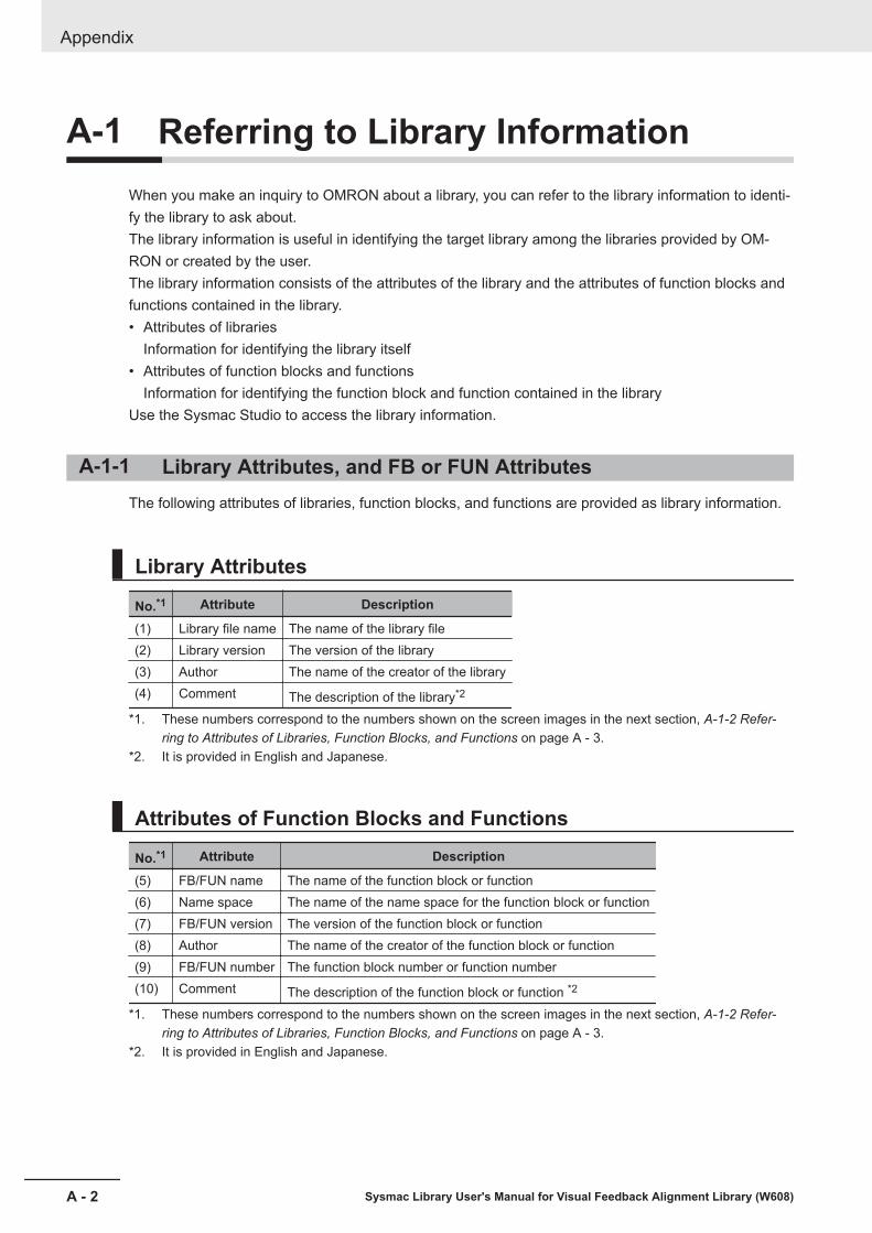
A-1 Referring to Library InformationWhen you make an inquiry to OMRON about a library, you can refer to the library information to identi-fy the library to ask about.The library information is useful in identifying the target library among the libraries provided by OM-RON or created by the user.The library information consists of the attributes of the library and the attributes of function blocks andfunctions contained in the library.• Attributes of libraries
Information for identifying the library itself• Attributes of function blocks and functions
Information for identifying the function block and function contained in the libraryUse the Sysmac Studio to access the library information.
A-1-1 Library Attributes, and FB or FUN AttributesThe following attributes of libraries, function blocks, and functions are provided as library information.
Library Attributes
No.*1 Attribute Description
(1) Library file name The name of the library file(2) Library version The version of the library(3) Author The name of the creator of the library(4) Comment The description of the library*2
*1. These numbers correspond to the numbers shown on the screen images in the next section, A-1-2 Refer-ring to Attributes of Libraries, Function Blocks, and Functions on page A - 3.
*2. It is provided in English and Japanese.
Attributes of Function Blocks and Functions
No.*1 Attribute Description
(5) FB/FUN name The name of the function block or function(6) Name space The name of the name space for the function block or function(7) FB/FUN version The version of the function block or function(8) Author The name of the creator of the function block or function(9) FB/FUN number The function block number or function number(10) Comment The description of the function block or function *2
*1. These numbers correspond to the numbers shown on the screen images in the next section, A-1-2 Refer-ring to Attributes of Libraries, Function Blocks, and Functions on page A - 3.
*2. It is provided in English and Japanese.
Appendix
A - 2 Sysmac Library User's Manual for Visual Feedback Alignment Library (W608)

A-1-2 Referring to Attributes of Libraries, Function Blocks, and Func-tions
You can refer to the library attributes of library information, and FB or FUN attributes at the followingSysmac Studio locations.• Library Reference Dialog Box• Toolbox• Programming screen
Library Reference Dialog BoxWhen you refer to the libraries, the library information is displayed at the locations shown below.
(2) Library version(1) Library file name (3) Library creator (4) Library comments
(5)FB/FUN name
(7) FB/FUN version
(8) FB/FUN creator (10)FB/FUN comments
(6)Name space
ToolboxSelect a function block or function to display its library information at the bottom of the Toolbox Pane.The text "by OMRON" which is shown on the right of the library name (1) indicates that this librarywas provided by OMRON.
Appendix
A - 3Sysmac Library User's Manual for Visual Feedback Alignment Library (W608)
A-1 R
eferring to Library Information
A
A-1-2 Referring to Attributes of Libraries, Function Blocks, and Functions

(5)FB/FUN name (6)Name space(1)Library file name(9)FB/FUN number(10)FB/FUN comment(7)FB/FUN version(8)FB/FUN author
Programming ScreenPlace the mouse on a function block and function to display the library information in a tooltip.
(6)Name space(5)FB/FUN name
(10)FB/FUN comment
(9)FB/FUN number
Appendix
A - 4 Sysmac Library User's Manual for Visual Feedback Alignment Library (W608)
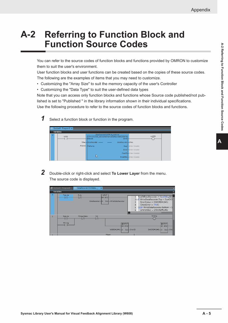
A-2 Referring to Function Block andFunction Source Codes
You can refer to the source codes of function blocks and functions provided by OMRON to customizethem to suit the user's environment.User function blocks and user functions can be created based on the copies of these source codes.The following are the examples of items that you may need to customize.• Customizing the "Array Size" to suit the memory capacity of the user's Controller• Customizing the "Data Type" to suit the user-defined data typesNote that you can access only function blocks and functions whose Source code published/not pub-lished is set to "Published " in the library information shown in their individual specifications.Use the following procedure to refer to the source codes of function blocks and functions.
1 Select a function block or function in the program.
2 Double-click or right-click and select To Lower Layer from the menu.The source code is displayed.
Appendix
A - 5Sysmac Library User's Manual for Visual Feedback Alignment Library (W608)
A-2 R
eferring to Function Block and Function Source C
odes
A

Precautions for Correct Use
• For function blocks and functions whose source codes are not published, the following dialogbox is displayed in the above step 2. Click the Cancel button.
Appendix
A - 6 Sysmac Library User's Manual for Visual Feedback Alignment Library (W608)
IIndex
I - 1Sysmac Library User's Manual for Visual Feedback Alignment Library (W608)
I

IndexA
AffineTrans.................................................................... 4 - 22
C
CalcAxisVelocity............................................................ 4 - 54CalcForwardKinematics.................................................4 - 51CalcInverseKinematics.................................................. 4 - 48CalcMovement...............................................................4 - 45CalcMultiPosAngle........................................................ 4 - 30CalcPosAngle................................................................ 4 - 25CtrlStage........................................................................4 - 35
G
GenerateCalibParams................................................... 4 - 78GenerateTrigger............................................................ 4 - 73
J
JudgeAlignmentComplete............................................. 4 - 64
S
sALIGNMENT_PARAMS.................................................4 - 2sAXIS_MOVE_PARAMS............................................... 4 - 11sCALCURVE_PARAMS................................................ 4 - 13sCALCVIRTUALMOVE_PARAMS.................................4 - 10sCALIB_MOVE_PARAMS.............................................4 - 15sCALIB_PARAMS............................................................4 - 2sIMAGING_PARAMS.................................................... 4 - 14sJUDGE_PARAMS........................................................4 - 14sKINEMATICS_PARAMS................................................ 4 - 9sPOSITION......................................................................4 - 2sSTAGE_PARAMS.......................................................... 4 - 3sUVWR_PARAMS...........................................................4 - 6sUVWR_STAGE_PARAMS............................................. 4 - 5sXYTH_STAGE_PARAMS.............................................. 4 - 4
Index
I - 2 Sysmac Library User's Manual for Visual Feedback Alignment Library (W608)


Authorized Distributor:
In the interest of product improvement, specifications are subject to change without notice.
Cat. No. W608-E1-02 0119
© OMRON Corporation 2018-2019 All Rights Reserved.
OMRON Corporation Industrial Automation Company
OMRON ELECTRONICS LLC2895 Greenspoint Parkway, Suite 200 Hoffman Estates, IL 60169 U.S.A.Tel: (1) 847-843-7900/Fax: (1) 847-843-7787
Regional Headquarters
OMRON EUROPE B.V.Wegalaan 67-69, 2132 JD HoofddorpThe NetherlandsTel: (31)2356-81-300/Fax: (31)2356-81-388
Contact: www.ia.omron.com
Kyoto, JAPAN
OMRON ASIA PACIFIC PTE. LTD.No. 438A Alexandra Road # 05-05/08 (Lobby 2), Alexandra Technopark, Singapore 119967Tel: (65) 6835-3011/Fax: (65) 6835-2711
OMRON (CHINA) CO., LTD.Room 2211, Bank of China Tower, 200 Yin Cheng Zhong Road, PuDong New Area, Shanghai, 200120, ChinaTel: (86) 21-5037-2222/Fax: (86) 21-5037-2200


![EtherNet/IPTM Connection Guide OMRON CorporationNJ ENetIP... · 2018. 8. 22. · TM. Port User's Manual W504 SYSMAC-SE2[][][] Sysmac Studio Version 1 Operation Manual W472 CJ2H-CPU6[]-EIP](https://static.fdocuments.us/doc/165x107/60c9b4344512ef53df69e53c/ethernetiptm-connection-guide-omron-corporation-nj-enetip-2018-8-22-tm.jpg)


