SYNDYNE CORPORATION CS2464 COMBINATION … · BENDING OR ROUGH HANDLING ... LS12MS ROTARY MEMORY...
27
SYNDYNE CORPORATION CS2464 COMBINATION ACTION REV. 3-20-2006 CS2464 COMBINATION ACTION MANUAL THIS MANUAL COVERS THE INSTALLATION AND PROGRAMMING OF A FULLY FEATURED CS2464 COMBINATION ACTION SYSTEM Control System Installed By ____________________ Date Installed ____________ Installer Telephone ______________ Fax _______ Email ____________________ Control System Maintained By __________________ Maintenance Telephone __________ Email ______ Fax ___________________
Transcript of SYNDYNE CORPORATION CS2464 COMBINATION … · BENDING OR ROUGH HANDLING ... LS12MS ROTARY MEMORY...
SYNDYNE CORPORATION CS2464 COMBINATION ACTION
REV. 3-20-2006
CS2464 COMBINATION ACTION MANUAL
THIS MANUAL COVERS THE INSTALLATION AND PROGRAMMING OF A FULLY FEATURED CS2464 COMBINATION ACTION SYSTEM
Control System Installed By ____________________ Date Installed ____________Installer Telephone ______________ Fax _______ Email ____________________
Control System Maintained By __________________Maintenance Telephone __________ Email ______ Fax ___________________

SYNDYN
E CORP
ORATIO
N
THIS PAGE LEFT INTENTIONALLY BLANK

SYNDYNE CORPORATION CS2464 COMBINATION ACTION
REV. 3-20-2006 TABLE OF CONTENTS PAGE 1-3
TABLE OF CONTENTSTABLE OF CONTENTS ................................................................. 1-3SYSTEM OVERVIEW .................................................................... 2-1SYSTEM DIAGRAM ....................................................................................................2-2
LIMITED WARRANTY ..................................................................................................2-3
UNPACKING AND HANDLING .................................................................................2-4STATIC WARNING.................................................................................................................... 2-4BENDING OR ROUGH HANDLING .......................................................................................... 2-4BOARD IDENTIFICATION ......................................................................................................... 2-4
CS2464 SYSTEM COMPONENTS ...............................................................................2-5CS2464 COMBINATION ACTION BOARD .............................................................................. 2-5LS12MS ROTARY MEMORY LEVEL CONTROLLERS .................................................................. 2-7LS64MS ROTARY MEMORY LEVEL CONTROLLERS .................................................................. 2-7LS32/64/128EMS ELECTRONIC MEMORY LEVEL CONTROLLERS ........................................... 2-8LS4REV REVERSIBLE CONTROLLER .......................................................................................... 2-9LS64P PISTON EXPANDER BOARD ........................................................................................ 2-10SFZ56 SFORZANDO CONTROLLER ........................................................................................ 2-10
SYSTEM WIRING ......................................................................... 3-1CS2464 BOARD PIN LAYOUT ....................................................................................3-2
OVERVIEW.................................................................................................................3-3POWER ..................................................................................................................................... 3-3FUSING..................................................................................................................................... 3-3BOARD LAYOUT SUGGESTIONS .............................................................................................. 3-3
WIRING STOPS AND SETTING STOP SENSE FEED ......................................................3-4WIRING STOP SENSE ................................................................................................................ 3-4REVERSIBLE STOPS ................................................................................................................... 3-4WIRING STOP COILS................................................................................................................ 3-4SETTING STOP SENSE FEED ...................................................................................................... 3-4

SYNDYNE CORPORATION CS2464 COMBINATION ACTION
REV. 3-20-2006 TABLE OF CONTENTS PAGE 1-4
WIRING PISTONS AND SETTING PISTON FEED ..........................................................3-5SYNDYNE PISTONS .................................................................................................................. 3-5WIRING GC, SET, AND SPECIAL PISTONS ............................................................................... 3-5WIRING LOCKOUTS ................................................................................................................. 3-5SETTING PISTON FEED (COMMON) ........................................................................................ 3-5WIRING REVERSIBLE PISTONS ................................................................................................. 3-5WIRING GENERAL PISTONS .................................................................................................... 3-6WIRING DIVISIONAL PISTONS ............................................................................................... 3-6
WIRING THE MEMORY LEVEL CONTROLLER .............................................................3-7WIRING USING THE LS2403K CONTROL PANEL ...................................................................... 3-7WIRING THE LS12MS ................................................................................................................ 3-7WIRING THE LS64MS ................................................................................................................ 3-7WIRING THE LS32/64/128EMS ................................................................................................. 3-7
WIRING THE SFZ56 SFORZANDO CONTROLLER BOARD ..........................................3-8
SYSTEM PROGRAMMING .......................................................... 4-1PROGRAMMING THE CS2464 ..................................................................................4-2
ASSOCIATION OF STOPS 19 AND 20 ..................................................................................... 4-2ASSOCIATION OF STOPS 21 AND 22 ..................................................................................... 4-2ASSOCIATION OF STOPS 23 AND 24 ..................................................................................... 4-2GENERAL CANCEL AT POWERUP ........................................................................................... 4-2PISTON SEQUENCER THROUGH MEMORY LEVELS ................................................................. 4-3PISTON SEQUENCER MODE EUROPEAN/AMERICAN ............................................................ 4-3LAST GENERAL PISTON NUMBER FOR PISTON SEQUENCER ................................................... 4-3DIVISION NUMBER DIP SWITCHES .......................................................................................... 4-3
APPENDIX A: SOLDERING TIPS ...............................................AP-1

SYNDYNE CORPORATION CS2464 COMBINATION ACTION
REV. 3-20-2006 SYSTEM OVERVIEW PAGE 2-1
SYSTEM OVERVIEWSYSTEM DIAGRAM ....................................................................................................2-2
LIMITED WARRANTY ..................................................................................................2-3
UNPACKING AND HANDLING .................................................................................2-4STATIC WARNING.................................................................................................................... 2-4BENDING OR ROUGH HANDLING .......................................................................................... 2-4BOARD IDENTIFICATION ......................................................................................................... 2-4
CS2464 SYSTEM COMPONENTS ...............................................................................2-5CS2464 COMBINATION ACTION BOARD .............................................................................. 2-5LS12MS ROTARY MEMORY LEVEL CONTROLLERS .................................................................. 2-7LS64MS ROTARY MEMORY LEVEL CONTROLLERS .................................................................. 2-7LS32/64/128EMS ELECTRONIC MEMORY LEVEL CONTROLLERS ........................................... 2-8LS4REV REVERSIBLE CONTROLLER .......................................................................................... 2-9LS64P PISTON EXPANDER BOARD ........................................................................................ 2-10SFZ56 SFORZANDO CONTROLLER ........................................................................................ 2-10

SYNDYNE CORPORATION CS2464 COMBINATION ACTION
REV. 3-20-2006 SYSTEM OVERVIEW PAGE 2-2
SYSTEM DIAGRAM
Division 3CS2464
Stops 1-24
Division 3CS2464
Stops 25-48
CouplersCS2464
Stops 25-48Stop Sense and Stop Coils
Divisional Pistons and Reversible Pistons
Stops 1-24Stop Sense and Stop Coils
DIVISION 3
Division 2CS2464
Division 1CS2464
General Pistons
Memory Level Controller
SFZ56
SFZ56 Sforzando Controller
Crescendo, Sforzando, and Memory Lockouts
Stop Sense and Stop Coils
Couplers
Reversible Pistons
Stop Sense and Stop Coils
DIVISION 2
Divisional and Reversible Pistons
Stop Sense and Stop Coils
DIVISION 1
Divisional and Reversible Pistons
Each of the items in this box must be connected to
all the CS2464 boards in the System.
Couplers Not Affectedby Divisional Pistons
SYNDYNE CORPORATION CS2464 COMBINATION ACTION
REV. 3-20-2006 SYSTEM OVERVIEW PAGE 2-3
Syndyne warrants, to the original purchaser, the equipment that it manufactures for use in the organ industry to be free from material defects and defects of workmanship under normal use and service, for a period of TEN (10) years from the date the product was shipped to the customer or from the date of the original Syndyne Corporation invoice, whichever is earlier. Syndyne’s sole obligation under this warranty shall be to, at its option, repair or replace any Syndyne products which have been deemed by Syndyne to contain material defects and/or defects of workmanship. Transportation charges for return of the products must be prepaid by the buyer. Syndyne has the sole right under this warranty agreement to inspect any product or part thereof, to determine whether or not the defect is covered by the terms of this warranty. Written notice of all claimed defect(s) must be given within thirty (30) days after such defect is fi rst discovered.
This warranty does not cover parts which have been repaired by anyone other than Syndyne when such repairs are inconsistent with Syndyne’s decided level of quality and/or workmanship. This warranty does not apply to products which have been used improperly, abused, altered, damaged, subjected to accident, fl ood, fi re, acts of God, and/or used with components made by another company in a manner unauthorized by Syndyne. Products on which serial numbers or part numbers have been altered, defaced, removed, or tampered with, shall not be covered by this warranty. Syndyne will not be responsible for any charges from dismantling, reassembly, reinstallation, and/or travel time.
Products which are manufactured by another company and distributed by Syndyne are not covered by this warranty. Contact the manufacturer directly for issues regarding warranty of these products.
This warranty is in lieu of all other warranties expressed or implied, including, but not limited to, warranty for merchantability and fi tness for a particular purpose as well as all other representations made to the purchaser. Syndyne does not authorize and will not be held responsible for warranties given by persons or companies outside of Syndyne Corporation except when such warranty is agreed to by Syndyne Corporation in writing. Syndyne will not be liable for any special, indirect, incidental, or consequential damages, including, but not limited to, damages claimed in connection with any rescission of this agreement by the buyer.
This warranty embodies the entire warranty agreement between Syndyne and the product’s original purchaser. Syndyne’s warranty, as described in this agreement, shall not be diminished, enlarged, or changed by, and no obligations or liability shall arise or grow out of, any technical advice or service rendered by Syndyne Corporation. This warranty provides certain legal rights and additional rights may exist in an individual’s state and may vary on a state to state basis.
LIMITED WARRANTY

SYNDYNE CORPORATION CS2464 COMBINATION ACTION
REV. 3-20-2006 SYSTEM OVERVIEW PAGE 2-4
UNPACKING AND HANDLING
STATIC WARNINGThe Syndyne LS5600K System containts electrical components that are suseptible to damage by static discharge. To avoid damage, use antistatic handling materials and make sure you are well grounded at all times. It is recommended that all electrical components be kept in their original packaging until installed.
BENDING OR ROUGH HANDLINGUse care when handling the products. Dropping or other rough handling can result in the products becoming damaged. Electrical components may also break if excessive bending occurs.
BOARD IDENTIFICATIONFor Identifi cation Purposes each component is labeled with a part number, a serial number, and a name/description.

SYNDYNE CORPORATION CS2464 COMBINATION ACTION
REV. 3-20-2006 SYSTEM OVERVIEW PAGE 2-5
FEATURES• 4 different models: Moving Stop, Blind, Syndyne
Lighted, and European Lighted (This Instruction Manual covers Moving Stop Model Only)
• Firmware is not custom and is on-sight upgradeable for future enhancements
• No battery back-ups• Installer confi gurable• 24 Stops• 6 reversibles• Settable output pulse time from 0.1 – 0.6 seconds• Associate Reversibles in pairs• Up to 128 levels of memory• 16 general pistons plus 16 division pistons• General Piston Sequencer• Negative or Positive Outputs• Negative/Positive Stop Feed (installer confi gured
with jumpers) • Negative/Positive Piston Feed (installer confi gured
with jumpers)• Built-in Fuse Protection• 12-24VDC operation
DESIGN INTENTThe CS2464 is a Modular Combination Action suitable for moderate to large size organs. The CS2464 can be used with existing organ keying systems or as a companion to the Syndyne Keying System. A Sforzando can be added to the moving version with the addition of an FSZ56 board.
MECHANICALLength 10”Width 8”Height 1-1/4”
MOUNTING¼” high standoffs for #6 screws are built into the circuit board for mounting purposes.
ELECTRICALA standard regulated DC power supply between 12-24 volts is required. Current draw with all outputs off is approximately 0.1Amps. Each output is capable of switching 0.240Amps continuously or 0.500Amps for 0.6
seconds.
CONNECTIONSConnectors and Terminal Blocks are provided for all connections. See Section 3 “System Wiring” for wiring instructions.
OUTPUTSAll outputs are fused and have a fl y-back diode to suppress reverse voltage spikes that are generated when an energized magnet is released. The output pulse time (Moving version only) is settable from 0.1 - 0.6 Seconds in 0.05 Second increments. See page 3-4 in Section 3 “System Wiring” for wiring instructions.
STOP SENSE INPUTSThe 24 stop inputs, will operate from either a negative or positive feed. The Stop Sense polarity is selected by moving the STOP SENSE FEED jumper to the appro-priate polarity. See page 3-4 in Section 3 “System Wiring” for wiring instructions.
REVERSIBLE STOPSSix reversible piston inputs are available as reversible controls for the last two stops in each manual and the last four stops in the pedal. These piston inputs will operate from either a negative or positive feed. The piston feed polarity is selected by moving the PISTON FEED jumper to the appropriate polarity.
ASSOCIATE REVERSIBLES SWITCHThis feature, when enabled, associates reversible stops in pairs. Stops 19 and 20 make up one pair, stops 21 and 22 make up another pair, and stops 23 and 24 make up another pair. If both stops in a pair are on and one of the pair is turned off then the other stop will go off as well. For instance if stops 23 and 24 are on and Reversible S24 piston is pressed both stops will be turned off.
SET, CANCEL, UP, DOWN AND SFORZANDO PISTON INPUTS
The Set, Cancel, Sequence – Up, Sequence - Down and the eight reversible piston inputs will operate from either a negative or positive feed. The piston feed polarity is selected by moving the PISTON FEED jumper to the appropriate polarity. See page 3-5 in Section 3 “System Wiring” for wiring instructions.
CS2464 COMBINATION ACTION BOARD
CS2464 SYSTEM COMPONENTS

SYNDYNE CORPORATION CS2464 COMBINATION ACTION
REV. 3-20-2006 SYSTEM OVERVIEW PAGE 2-6
STOP POLLINGStop Polling is the technique of monitoring stops and only moving the stops as necessary.
SFORZANDOA Sforzando can be added to the CS2464 - Moving version by adding an SFZ56 Sforzando board. See page 2-10 in this section for details on the SFZ56 board. The Sforzando piston input, Sforzando lockout input and Sforzando output are provided to operate with the SFZ56 board. The Sforzando lockout disables the Set piston (Moving version only). See page 3-7 in Section 3 “System Wiring” for wiring instructions.
CRESCENDO LOCKOUTA Crescendo Lockout (Moving version only) input is available for systems requiring this feature. The Crescendo lockout disables the Set piston. See page 3-5 in Section 3 “System Wiring” for wiring instructions.
GENERAL PISTON INPUTSThere are 16 general piston Inputs. They are grouped together under the label “GENERAL PISTONS” and the pins are labeled “1” through “16”. See page 3-6 in Section 3 “System Wiring” for general piston wiring instructions.
DIVISIONAL PISTON INPUTSThere are 16 divisional pistons. They are grouped together under the label “DIVISIONAL PISTONS” and the pins are labeled “1” through “16”. See page 3-6 in Section 3 “System Wiring” for divisional piston wiring instructions.
MEMORY LEVELA maximum of 128 memory levels are available. Rotary and digital memory level selectors are available. A Memory Lockout (prevents memory levels for being set) input is available for memory level selectors with this capability. See page 3-8 in Section 3 “System Wiring” for wiring instructions.
GENERAL CANCEL AT POWER-UP SWITCHWhen this feature is enabled a General Cancel when fi rst powered up will occur. See Section 4 “System Programming” for programming instructions.
LAST GENERAL PISTON SWITCHThe Last General Piston switch works in conjunction with the general piston sequencer. It communicates to the sequencer how many general pistons are available. If the sequencer is used it is important to not skip any piston inputs and to wire the fi rst general piston to input-1. See Section 4 “System Programming” for general piston programming instructions.
SEQUENCE MEMORY LEVELS SWITCHThe Sequence Memory Levels switch works in conjunction with the general piston sequencer. It confi gures the sequencer to sequence up/down through memory levels too. See Section 4 “System Programming” for programming instructions.
SEQUENCE MODE SWITCHThe Sequence Mode switch confi gures the sequencer for European mode or American mode. In European mode the sequencer will sequence up/down through the general pistons. In American mode (this mode is currently not available) the sequencer will sequence up/down through a captured sequence. The sequence is captured through the use of the Set Sequence piston input. See Section 4 “System Programming” for programming instructions.
SYNDYNE CORPORATION CS2464 COMBINATION ACTION
REV. 3-20-2006 SYSTEM OVERVIEW PAGE 2-7
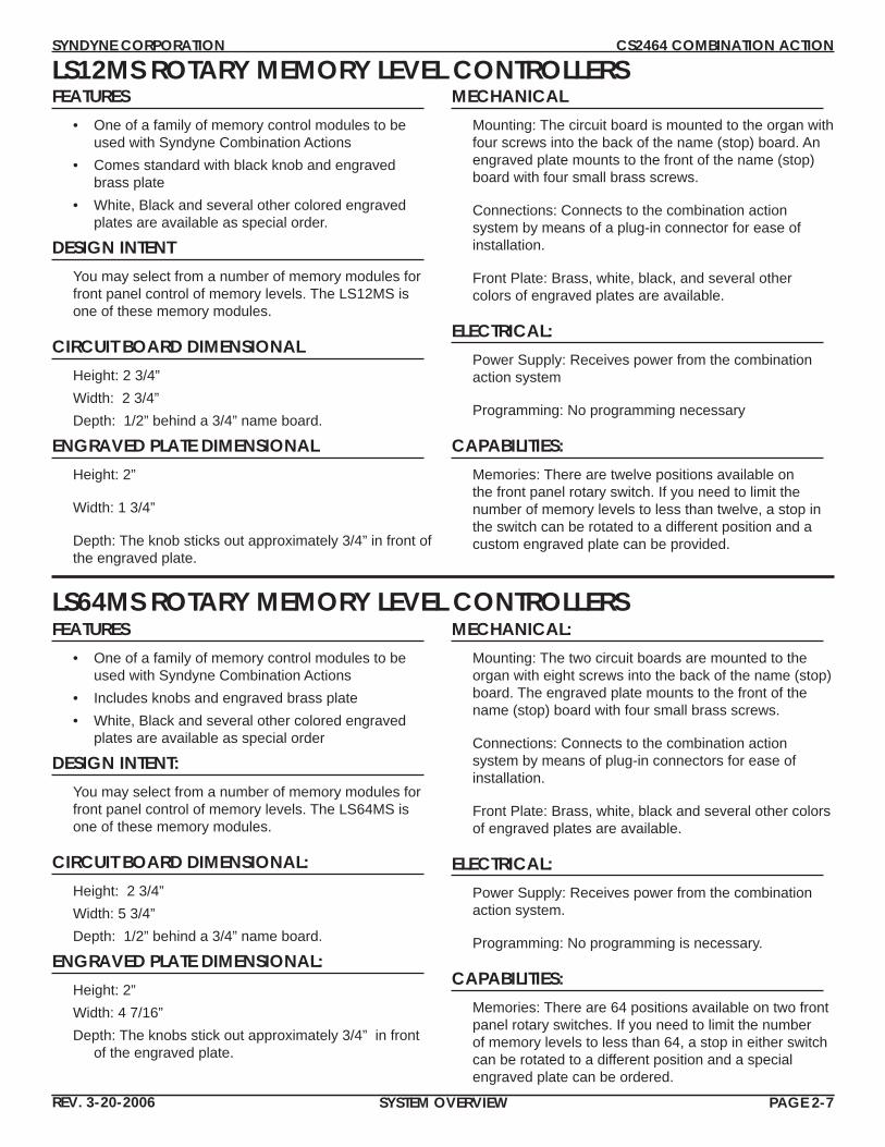
LS12MS ROTARY MEMORY LEVEL CONTROLLERSFEATURES
• One of a family of memory control modules to be used with Syndyne Combination Actions
• Comes standard with black knob and engraved brass plate
• White, Black and several other colored engraved plates are available as special order.
DESIGN INTENTYou may select from a number of memory modules for front panel control of memory levels. The LS12MS is one of these memory modules.
CIRCUIT BOARD DIMENSIONALHeight: 2 3/4”Width: 2 3/4” Depth: 1/2” behind a 3/4” name board.
ENGRAVED PLATE DIMENSIONALHeight: 2”
Width: 1 3/4”
Depth: The knob sticks out approximately 3/4” in front of the engraved plate.
MECHANICALMounting: The circuit board is mounted to the organ with four screws into the back of the name (stop) board. An engraved plate mounts to the front of the name (stop) board with four small brass screws.
Connections: Connects to the combination action system by means of a plug-in connector for ease of installation.
Front Plate: Brass, white, black, and several other colors of engraved plates are available.
ELECTRICAL:Power Supply: Receives power from the combination action system
Programming: No programming necessary
CAPABILITIES:Memories: There are twelve positions available on the front panel rotary switch. If you need to limit the number of memory levels to less than twelve, a stop in the switch can be rotated to a different position and a custom engraved plate can be provided.
LS64MS ROTARY MEMORY LEVEL CONTROLLERSFEATURES
• One of a family of memory control modules to be used with Syndyne Combination Actions
• Includes knobs and engraved brass plate• White, Black and several other colored engraved
plates are available as special order
DESIGN INTENT:You may select from a number of memory modules for front panel control of memory levels. The LS64MS is one of these memory modules.
CIRCUIT BOARD DIMENSIONAL:Height: 2 3/4”Width: 5 3/4” Depth: 1/2” behind a 3/4” name board.
ENGRAVED PLATE DIMENSIONAL:Height: 2”Width: 4 7/16”Depth: The knobs stick out approximately 3/4” in front
of the engraved plate.
MECHANICAL:Mounting: The two circuit boards are mounted to the organ with eight screws into the back of the name (stop) board. The engraved plate mounts to the front of the name (stop) board with four small brass screws.
Connections: Connects to the combination action system by means of plug-in connectors for ease of installation.
Front Plate: Brass, white, black and several other colors of engraved plates are available.
ELECTRICAL:Power Supply: Receives power from the combination action system.
Programming: No programming is necessary.
CAPABILITIES:Memories: There are 64 positions available on two front panel rotary switches. If you need to limit the number of memory levels to less than 64, a stop in either switch can be rotated to a different position and a special engraved plate can be ordered.

SYNDYNE CORPORATION CS2464 COMBINATION ACTION
REV. 3-20-2006 SYSTEM OVERVIEW PAGE 2-8
LS32/64/128EMS ELECTRONIC MEMORY LEVEL CONTROLLERSFEATURES
• Large 0.4” Red LED display • Available as an 32, 64, & 128 Memory Level Con-
troller • 8 different confi gurable memory partitions with up to
5 key locks • Brushed brass plate with black lettering • Available without brass plate and off board Up and
Down buttons
DESIGN INTENTThe LS__EMS Memory Level Controller is designed to work in conjunction with Syndyne Combination Actions and to mount through most name boards.
MECHANICALPrinted Circuit BoardHeight 2 ½”Width 3”Depth 1 ½”Brass Mounting PlateHeight 3”Width 3 ½”
ELECTRICALA regulated DC power supply between 12-24 volts is required to power the board. Current draw is approxi-mately 0.100Amps
CONNECTIONSConnectors or Terminal Blocks are provided for all connections
MOUNTING WITH THE BRASS PLATE:
Cut a hole in the desired location that measures 2 9/16” high and 3 1/16” wide. Caution, the mounting screws may breakout into cutout if cutout is oversized. Feed connecting wires out through the hole and connect to the memory level controller. Position the memory level controller in the hole and fasten securely using the four decorative brass screws. The memory level controller is suspended from the brass mounting plate.
MOUNTING WITHOUT THE BRASS PLATE: Cut a hole in the desired location for the lens that measures 1 3/16” high and 1 3/4” wide and secure the lens with RTV or double-sided tape in the cut-out. Mount memory level Up and Down pistons in the desired locations and connect to the UP DOWN and COM pins on the memory level controller. Make all other necessary connections to the memory level controller and then scroll to the highest memory level. Hint: the memory level will wrap to the highest level by scrolling down from the lowest memory level. Position the memory level controller so that the LED display is properly visible through the lens then fasten it securely through the mounting spacers on the PCB using four #6 screws. Note it may be necessary to recess (route into name board) the memory level controller so that it can be viewed from a wider angle.

SYNDYNE CORPORATION CS2464 COMBINATION ACTION
REV. 3-20-2006 SYSTEM OVERVIEW PAGE 2-9
LS4REV REVERSIBLE CONTROLLERFEATURES
• 4 piston inputs and 8 corresponding outputs (2 out-puts/piston)
• Each can be individually confi gured as either a latch-ing piston or a reversible stop controller
• Latching pistons can be confi gured to Step in pairs• Reversible stops can be confi gured to Associate in
pairs• Negative and/or Positive Stop Sense are selectable• 8 discrete transistor outputs can drive up to a
1/2Amp load each, are fl y-back protected and can be ordered in either Negative or Positive polarity
SYSTEM DESIGN INTENTAn excellent option for when you need a latching reversible piston or you just want to add a few reversible stops. There are 4 piston inputs and 8 corresponding outputs (2 outputs/piston) that can be individually confi gured as either a latching piston or a reversible stop controller. Latching pistons can be confi gured to Step in pairs and reversible stops can be confi gured to associate in pairs. Negative and/or Positive Stop Sense and piston feed are selectable. The 8 discrete transistor outputs can drive up to a 1/2Amp load each, are fl y-back protected and can be ordered in either a Negative or Positive polarity.
DIMENSIONALLength: 4”Width: 5 7/8”Height: 1 1/4”
MECHANICAL: Mounting: Four built-in standoffs for screw mounting.
Connections: A large terminal block is provided to connect power to the board and plug-in connectors are provided for input and output connections.
ELECTRICAL Power Supply: Operates on typical regulated organ power between 12-28VDC.
CAPABILITIES• Reversible Stop Mode: Each of the piston inputs
operates its respective stop output independently. When a piston is pressed the stop is toggled to the alternate state, On to Off or Off to On. The stop out-puts are momentarily pulsed for a settable duration.
• Associate Operation: This function only works on reversible stop pairs (1 & 2, 3 & 4). When enabled if both paired stops are on and one of the pair is turned off then the other stop will go off with it. For instance if Stop-1 and Stop-2 are on and piston-2 is pressed both stops will be turned off.
• Latching Reversible Mode: Each of the piston inputs operates its respective output independently. The fi rst time a piston is pressed its corresponding outputs will be turned on. These outputs will remain latched on until the piston is pressed again at which time the corresponding outputs will be turned off.
• Step Operation: This function only works on latch-ing pistons pairs (1 & 2, 3 & 4). When enabled only one of the stepped pistons can be on at a time. For instance if piston-1 is on and piston-2 is pressed the outputs for piston-1 will turn off and the outputs for piston-2 will turn on.
• General Cancel: When this piston (GC) is pressed all latched outputs and stops that are on will be turned off.
• Output Pulse Time: The output pulse time is settable from 0.1Sec to 0.6Sec. in 0.05Sec increments. Hold down the GC piston and apply power to the organ to enter this mode. To exit this mode turn off the organ, wait until power has fully decayed (approximately 1 minute), and turn the organ back on; normal opera-tion will resume. Once entering the Pulse Time Set mode the stop outputs will toggle On/Off with every piston push. Every time the GC piston is pressed the pulse time will increment by 0.05Sec.. Once the desired pulse time has been achieved simply exit this mode by turning off the organ for 1 minute the pulse time will automatically be remembered.
SYNDYNE CORPORATION CS2464 COMBINATION ACTION
REV. 3-20-2006 SYSTEM OVERVIEW PAGE 2-10
SFZ56 SFORZANDO CONTROLLER
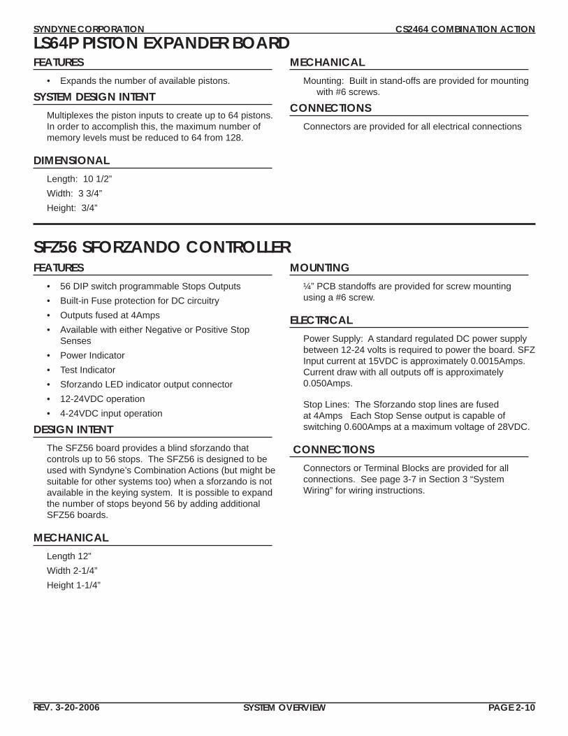
LS64P PISTON EXPANDER BOARDFEATURES
• Expands the number of available pistons.
SYSTEM DESIGN INTENTMultiplexes the piston inputs to create up to 64 pistons. In order to accomplish this, the maximum number of memory levels must be reduced to 64 from 128.
DIMENSIONALLength: 10 1/2”Width: 3 3/4”Height: 3/4”
MECHANICALMounting: Built in stand-offs are provided for mounting
with #6 screws.
CONNECTIONS Connectors are provided for all electrical connections
FEATURES• 56 DIP switch programmable Stops Outputs • Built-in Fuse protection for DC circuitry • Outputs fused at 4Amps • Available with either Negative or Positive Stop
Senses • Power Indicator • Test Indicator • Sforzando LED indicator output connector • 12-24VDC operation • 4-24VDC input operation
DESIGN INTENTThe SFZ56 board provides a blind sforzando that controls up to 56 stops. The SFZ56 is designed to be used with Syndyne’s Combination Actions (but might be suitable for other systems too) when a sforzando is not available in the keying system. It is possible to expand the number of stops beyond 56 by adding additional SFZ56 boards.
MECHANICALLength 12”Width 2-1/4”Height 1-1/4”
MOUNTING¼” PCB standoffs are provided for screw mounting using a #6 screw.
ELECTRICALPower Supply: A standard regulated DC power supply between 12-24 volts is required to power the board. SFZ Input current at 15VDC is approximately 0.0015Amps. Current draw with all outputs off is approximately 0.050Amps.
Stop Lines: The Sforzando stop lines are fused at 4Amps Each Stop Sense output is capable of switching 0.600Amps at a maximum voltage of 28VDC.
CONNECTIONSConnectors or Terminal Blocks are provided for all connections. See page 3-7 in Section 3 “System Wiring” for wiring instructions.
SYNDYNE CORPORATION CS2464 COMBINATION ACTION
REV. 3-20-2006 SYSTEM WIRING PAGE 3-1
SYSTEM WIRINGCS2464 BOARD PIN LAYOUT ....................................................................................3-2
OVERVIEW.................................................................................................................3-3POWER ..................................................................................................................................... 3-3FUSING..................................................................................................................................... 3-3BOARD LAYOUT SUGGESTIONS .............................................................................................. 3-3
WIRING STOPS AND SETTING STOP SENSE FEED ......................................................3-4WIRING STOP SENSE ................................................................................................................ 3-4REVERSIBLE STOPS ................................................................................................................... 3-4WIRING STOP COILS................................................................................................................ 3-4SETTING STOP SENSE FEED ...................................................................................................... 3-4
WIRING PISTONS AND SETTING PISTON FEED ..........................................................3-5SYNDYNE PISTONS .................................................................................................................. 3-5WIRING GC, SET, AND SPECIAL PISTONS ............................................................................... 3-5WIRING LOCKOUTS ................................................................................................................. 3-5SETTING PISTON FEED (COMMON) ........................................................................................ 3-5WIRING REVERSIBLE PISTONS ................................................................................................. 3-5WIRING GENERAL PISTONS .................................................................................................... 3-6WIRING DIVISIONAL PISTONS ............................................................................................... 3-6
WIRING THE MEMORY LEVEL CONTROLLER .............................................................3-7WIRING USING THE LS2403K CONTROL PANEL ...................................................................... 3-7WIRING THE LS12MS ................................................................................................................ 3-7WIRING THE LS64MS ................................................................................................................ 3-7WIRING THE LS32/64/128EMS ................................................................................................. 3-7
WIRING THE SFZ56 SFORZANDO CONTROLLER BOARD ..........................................3-8

SYNDYNE CORPORATION CS2464 COMBINATION ACTION
REV. 3-20-2006 SYSTEM WIRING PAGE 3-2
CS2464 BOARD PIN LAYOUT
12345678
910111213141516
12345678
1718192021222324
StopSense
1-ON1-OFF2-ON2-OFF3-ON3-OFF4-ON4-OFF
5-ON5-OFF6-ON6-OFF7-ON7-OFF8-ON8-OFF
9-ON9-OFF
10-ON10-OFF11-ON11-OFF12-ON12-OFF
13-ON13-OFF14-ON14-OFF15-ON15-OFF16-ON16-OFF
17-ON17-OFF18-ON18-OFF
124816SPARE
LAST
GEN
-P
ASSOC 23/24ASSOC 21/22ASSOC 19/20POWER UP GCSEQ MLsSEQ MODE E/A
STO
PSE
NSE
FEED
PIST
ON
FEED
StopCoils
DivisionalPistons
MemoryLevel
Controller
GeneralPistons
12-24VDCPower
Connector
910111213141516
12345678
910111213141516
G-CAND-CAN
M-LOCKC-LOCKS-LOCKSEQ UPSEQ DWN
SET
SET SEQ.SFZ
S20S21S22S23S24
S19
19-ON19-OFF20-ON20-OFF
21-ON21-OFF22-ON22-OFF23-ON23-OFF24-ON24-OFF
GFEDCBA
RETURN
ML-LOCKNCNC
SFORZANDO
1248STOPS 1-24/25-48NOT USED
ReversiblePistons
Pistonsand Lockouts Sforzando
Output
Future Use
Future Use
DIVI
SIO
NNU
MBE
R
SYN
DYN
E C
OR
P
SN
CS
2464
-
SYNDYNE CORPORATION CS2464 COMBINATION ACTION
REV. 3-20-2006 SYSTEM WIRING PAGE 3-3
OVERVIEW
This section explains the wiring done within the console. Syndyne strongly recommends reading Section 1: “System Overview,” completely and the operation of each board be understood before proceeding with this section. After mounting the boards in suitable locations route power and feeds then wire the inputs and outputs per design require-ments. Compliance with local codes and NEC (National Electric Code) guidelines in determining wire sizes is strongly recommended. Additional consideration maybe necessary to eliminate excessive voltage drops in wiring. See Appendix A “Soldering Tips” for soldering techniques.
POWEROnly clean regulated 12-24VDC power supplies should be used. If it is permissible with local codes we recommend not connecting any negative terminals to earth ground; this is to minimize the risk of damage due to a direct lightning strike. Daisy chaining of power connections is not recommended. Each board’s power should be routed individually to a common buss.
Due to risk of accidental shorting, wires should never be routed beneath boards.
FUSINGThe use of fuses to protect all electrical circuits from accidental shorting and compliance with local NEC (National Electric Code) guide lines is highly recommended.
BOARD LAYOUT SUGGESTIONSSyndyne system boards can be mounted in many different locations, with different spacings and layouts. Syndyne offers wiring solutions that prewire boards to customer specifi cations. The majority of these installations follow similar specifi cations. The syndyne wiring team studied these similarities to offer suggestions on board layout. Syndyne suggests that all boards be spaced at least 1/2” on edges without connectors and at least 2” for edges with connectors. This will leave suffi cient room for wiring to exist between boards. It also provides enough room in the event that additional wires must be added after original wiring has been completed. Providing enough room prevents mistakes such as routing wires underneath boards.
SYNDYNE CORPORATION CS2464 COMBINATION ACTION
REV. 3-20-2006 SYSTEM WIRING PAGE 3-4
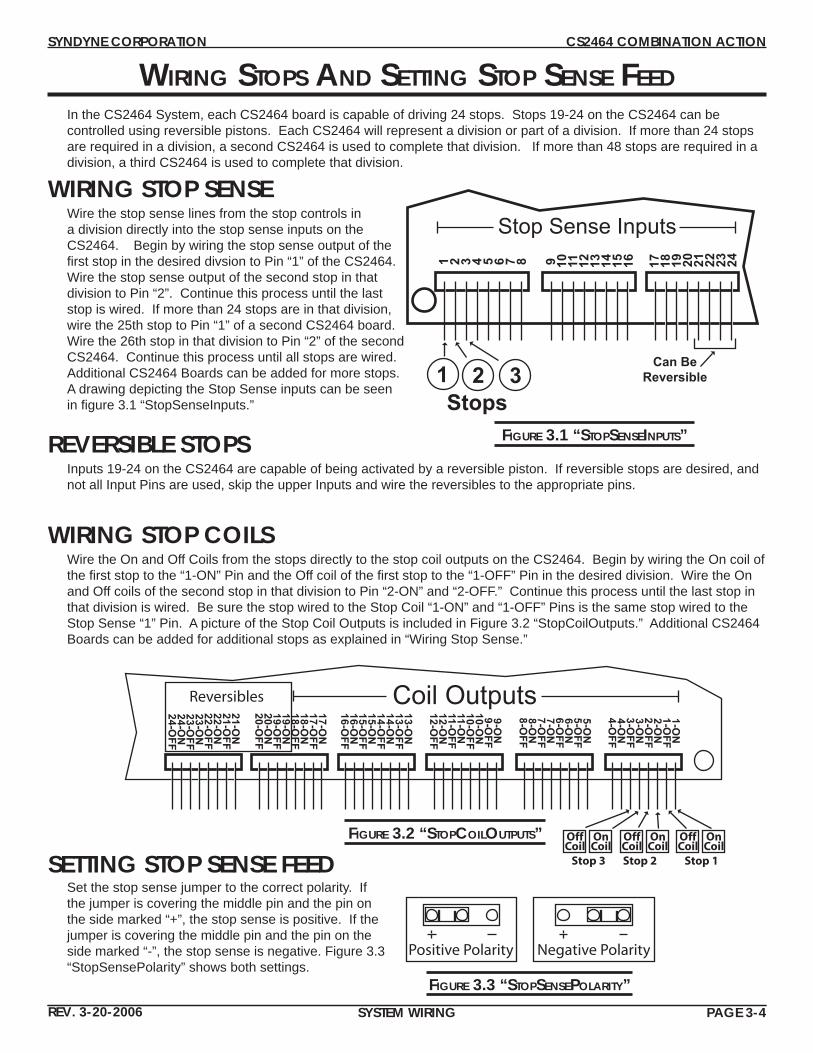
FIGURE 3.1 “STOPSENSEINPUTS”
FIGURE 3.2 “STOPCOILOUTPUTS”
Positive Polarity Negative Polarity
FIGURE 3.3 “STOPSENSEPOLARITY”
Set the stop sense jumper to the correct polarity. If the jumper is covering the middle pin and the pin on the side marked “+”, the stop sense is positive. If the jumper is covering the middle pin and the pin on the side marked “-”, the stop sense is negative. Figure 3.3 “StopSensePolarity” shows both settings.
SETTING STOP SENSE FEED
WIRING STOP COILSWire the On and Off Coils from the stops directly to the stop coil outputs on the CS2464. Begin by wiring the On coil of the fi rst stop to the “1-ON” Pin and the Off coil of the fi rst stop to the “1-OFF” Pin in the desired division. Wire the On and Off coils of the second stop in that division to Pin “2-ON” and “2-OFF.” Continue this process until the last stop in that division is wired. Be sure the stop wired to the Stop Coil “1-ON” and “1-OFF” Pins is the same stop wired to the Stop Sense “1” Pin. A picture of the Stop Coil Outputs is included in Figure 3.2 “StopCoilOutputs.” Additional CS2464 Boards can be added for additional stops as explained in “Wiring Stop Sense.”
WIRING STOP SENSEWire the stop sense lines from the stop controls in a division directly into the stop sense inputs on the CS2464. Begin by wiring the stop sense output of the fi rst stop in the desired divsion to Pin “1” of the CS2464. Wire the stop sense output of the second stop in that division to Pin “2”. Continue this process until the last stop is wired. If more than 24 stops are in that division, wire the 25th stop to Pin “1” of a second CS2464 board. Wire the 26th stop in that division to Pin “2” of the second CS2464. Continue this process until all stops are wired. Additional CS2464 Boards can be added for more stops. A drawing depicting the Stop Sense inputs can be seen in fi gure 3.1 “StopSenseInputs.”
REVERSIBLE STOPSInputs 19-24 on the CS2464 are capable of being activated by a reversible piston. If reversible stops are desired, and not all Input Pins are used, skip the upper Inputs and wire the reversibles to the appropriate pins.
In the CS2464 System, each CS2464 board is capable of driving 24 stops. Stops 19-24 on the CS2464 can be controlled using reversible pistons. Each CS2464 will represent a division or part of a division. If more than 24 stops are required in a division, a second CS2464 is used to complete that division. If more than 48 stops are required in a division, a third CS2464 is used to complete that division.
WIRING STOPS AND SETTING STOP SENSE FEED
1 2 3 4 5 6 7 8 9 10 11 12 13 14 15 16
Stop Sense Inputs
Can BeReversible
Stops1 2 3
17 18 19 20 21 22 23 24
1-ON
1-OFF
2-ON
2-OFF
3-ON
3-OFF
4-ON
4-OFF
5-ON
5-OFF
6-ON
6-OFF
7-ON
7-OFF
8-ON
8-OFF
9-ON
9-OFF
10-ON
10-OFF
11-ON
11-OFF
12-ON
12-OFF
13-ON
13-OFF
14-ON
14-OFF
15-ON
15-OFF
16-ON
16-OFF
17-ON
17-OFF
18-ON
18-OFF
19-ON
19-OFF
20-ON
20-OFF
Coil Outputs
OnCoil
OffCoil
Stop 1
OnCoil
OffCoilStop 2
OnCoil
OffCoil
Stop 3
21-ON
21-OFF
22-ON
22-OFF
23-ON
23-OFF
24-ON
24-OFF
Reversibles
SYNDYNE CORPORATION CS2464 COMBINATION ACTION
REV. 3-20-2006 SYSTEM WIRING PAGE 3-5
WIRING PISTONS AND SETTING PISTON FEED
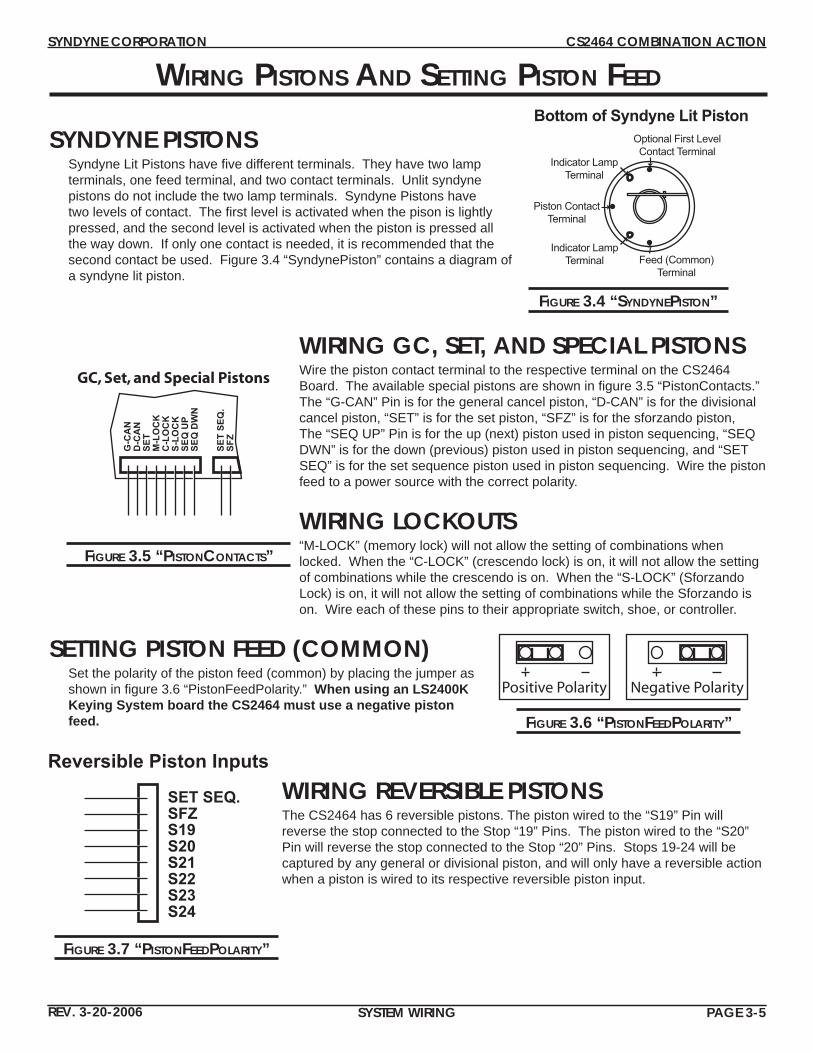
SYNDYNE PISTONSSyndyne Lit Pistons have fi ve different terminals. They have two lamp terminals, one feed terminal, and two contact terminals. Unlit syndyne pistons do not include the two lamp terminals. Syndyne Pistons have two levels of contact. The fi rst level is activated when the pison is lightly pressed, and the second level is activated when the piston is pressed all the way down. If only one contact is needed, it is recommended that the second contact be used. Figure 3.4 “SyndynePiston” contains a diagram of a syndyne lit piston.
WIRING GC, SET, AND SPECIAL PISTONSWire the piston contact terminal to the respective terminal on the CS2464 Board. The available special pistons are shown in fi gure 3.5 “PistonContacts.” The “G-CAN” Pin is for the general cancel piston, “D-CAN” is for the divisional cancel piston, “SET” is for the set piston, “SFZ” is for the sforzando piston, The “SEQ UP” Pin is for the up (next) piston used in piston sequencing, “SEQ DWN” is for the down (previous) piston used in piston sequencing, and “SET SEQ” is for the set sequence piston used in piston sequencing. Wire the piston feed to a power source with the correct polarity.
WIRING LOCKOUTS“M-LOCK” (memory lock) will not allow the setting of combinations when locked. When the “C-LOCK” (crescendo lock) is on, it will not allow the setting of combinations while the crescendo is on. When the “S-LOCK” (Sforzando Lock) is on, it will not allow the setting of combinations while the Sforzando is on. Wire each of these pins to their appropriate switch, shoe, or controller.
SETTING PISTON FEED (COMMON)Set the polarity of the piston feed (common) by placing the jumper as shown in fi gure 3.6 “PistonFeedPolarity.” When using an LS2400K Keying System board the CS2464 must use a negative piston feed.
WIRING REVERSIBLE PISTONSThe CS2464 has 6 reversible pistons. The piston wired to the “S19” Pin will reverse the stop connected to the Stop “19” Pins. The piston wired to the “S20” Pin will reverse the stop connected to the Stop “20” Pins. Stops 19-24 will be captured by any general or divisional piston, and will only have a reversible action when a piston is wired to its respective reversible piston input.
FIGURE 3.4 “SYNDYNEPISTON”
FIGURE 3.5 “PISTONCONTACTS”
FIGURE 3.6 “PISTONFEEDPOLARITY”
FIGURE 3.7 “PISTONFEEDPOLARITY”
Optional First LevelContact Terminal
Indicator LampTerminal
Piston ContactTerminal
Indicator LampTerminal Feed (Common)
Terminal
Bottom of Syndyne Lit Piston
Reversible Piston Inputs
SET SEQ.SFZ
S20S21S22S23S24
S19
GC, Set, and Special Pistons
G-C
AN
D-C
AN
M-L
OC
KC
-LO
CK
S-LO
CK
SEQ
UP
SEQ
DW
N
SET
SET
SEQ
.SF
Z
Positive Polarity Negative Polarity

SYNDYNE CORPORATION CS2464 COMBINATION ACTION
REV. 3-20-2006 SYSTEM WIRING PAGE 3-6
WIRING GENERAL PISTONS The CS2464 has 32 piston inputs, see fi gure 3.10 “GeneralAndDivisionalPistons” for a diagram of these piston inputs. Of these 32 inputs, 16 are labeled general pistons. When wiring the general pistons each general piston needs to be tied to the corresponding general piston pin on each CS2464. For example, in a four division system with 4 CS2464’s general piston 1 must be tied to the general piston pin “1” on each CS2464. General piston 2 must be tied to the general piston pin “2” on each CS2464. General piston 3 must be tied to the general piston pin “3” on each CS2464. Repeat this processes until all general pistons are wired. For a diagram of this example, see fi gure 3.8 “General-Pistons.” If more than 16 generals are needed, the divisional pistons can be used as generals by wiring to every CS2464 just like the other general pistons. However, the piston sequencer will not include the divisional pistons even if they are being used as generals. When using the LS2400K Keying System in conjunction with a CS2464 Combination Action, the general pistons are wired to both the CS2464 and the LS2400K in order to set transposer levels and MIDI Patch Changes on general pistons. If these two features are not needed, then there is no need to wire the general pistons to the LS2400K Board.
1 2 3 4 5 6 7 8 9 10 11 12 13 14 15 16 1 2 3 4 5 6 7 8 9 10 11 12 13 14 15 16
GENERAL PISTONS DIVISIONAL PISTONS
FIGURE 3.8 “GENERALPISTONWIRING”
FIGURE 3.10 “GENERALANDDIVISIONALPISTONS”
WIRING DIVISIONAL PISTONS The CS2464 has 32 piston inputs, see fi gure 3.10 “GeneralAndDivisionalPistons” for a diagram of these piston inputs. Of these 32 inputs, 16 are labeled divisional pistons. The divisional pistons should be wired to the divisional piston inputs on the CS2464 for the required division. If there are multiple CS2464s used in a single division, the divisional pistons inputs of each CS2464s in that division should be tied together. This process is similar to the example included in the “Wiring General Pistons” section above. For a diagram of wiring divisional pistons see fi gure 3.9 “Divisional Pistons.”
FIGURE 3.9 “DIVISIONALPISTONWIRING”
GeneralPistons
1
2
3
Division 4CS2464
Division 3CS2464
Division 2CS2464
Division 1CS2464
1 2 3 1 2 31 2 3 1 2 3
Division’sFirst CS2464
1 2 3
Division’sSecond CS2464
1 2 3
DivisionalPistons
1
2
3
DivisionCS2464
1 2 3
DivisionalPistons
1
2
3
Two CS2464’s a DivisionOne CS2464 in Division
SYNDYNE CORPORATION CS2464 COMBINATION ACTION
REV. 3-20-2006 SYSTEM WIRING PAGE 3-7
WIRING THE MEMORY LEVEL CONTROLLER
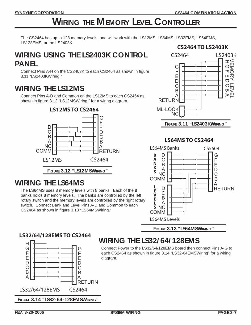
The CS2464 has up to 128 memory levels, and will work with the LS12MS, LS64MS, LS32EMS, LS64EMS, LS128EMS, or the LS2403K.
WIRING USING THE LS2403K CONTROL PANEL
Connect Pins A-H on the CS2403K to each CS2464 as shown in fi gure 3.11 “LS2403KWiring.”
WIRING THE LS12MSConnect Pins A-D and Common on the LS12MS to each CS2464 as shown in fi gure 3.12 “LS12MSWiring.” for a wiring diagram.
FIGURE 3.12 “LS12MSWIRING”
FIGURE 3.14 “LS32-64-128EMSWIRING”
FIGURE 3.13 “LS64MSWIRING”
FIGURE 3.11 “LS2403KWIRING”
AB
CD
EF
GH ME
MO
RY LE
VE
L
GFEDCBA
RETURN
CS2464 TO LS2403K
CS2464 LS2403K
ML-LOCKNC
GFEDCBARETURN
LS12MS TO CS2464
CS2464LS12MS
DCBA
NCCOMM
GFEDCBARETURN
LS64MS TO CS2464
CS5608LS64MS Banks
DCBA
NCCOMM
LS64MS Levels
DCBA
NCCOMM
GFEDCBARETURN
LS32/64/128EMS TO CS2464
CS2464LS32/64/128EMS
HGFEDCBA
WIRING THE LS64MSThe LS64MS uses 8 memory levels with 8 banks. Each of the 8 banks holds 8 memory levels. The banks are controlled by the left rotary switch and the memory levels are controlled by the right rotary switch. Connect Bank and Level Pins A-D and Common to each CS2464 as shown in fi gure 3.13 “LS64MSWiring.”
WIRING THE LS32/64/128EMSConnect Power to the LS32/64/128EMS board then connect Pins A-G to each CS2464 as shown in fi gure 3.14 “LS32-64EMSWiring” for a wiring diagram.
SYNDYNE CORPORATION CS2464 COMBINATION ACTION
REV. 3-20-2006 SYSTEM WIRING PAGE 3-8
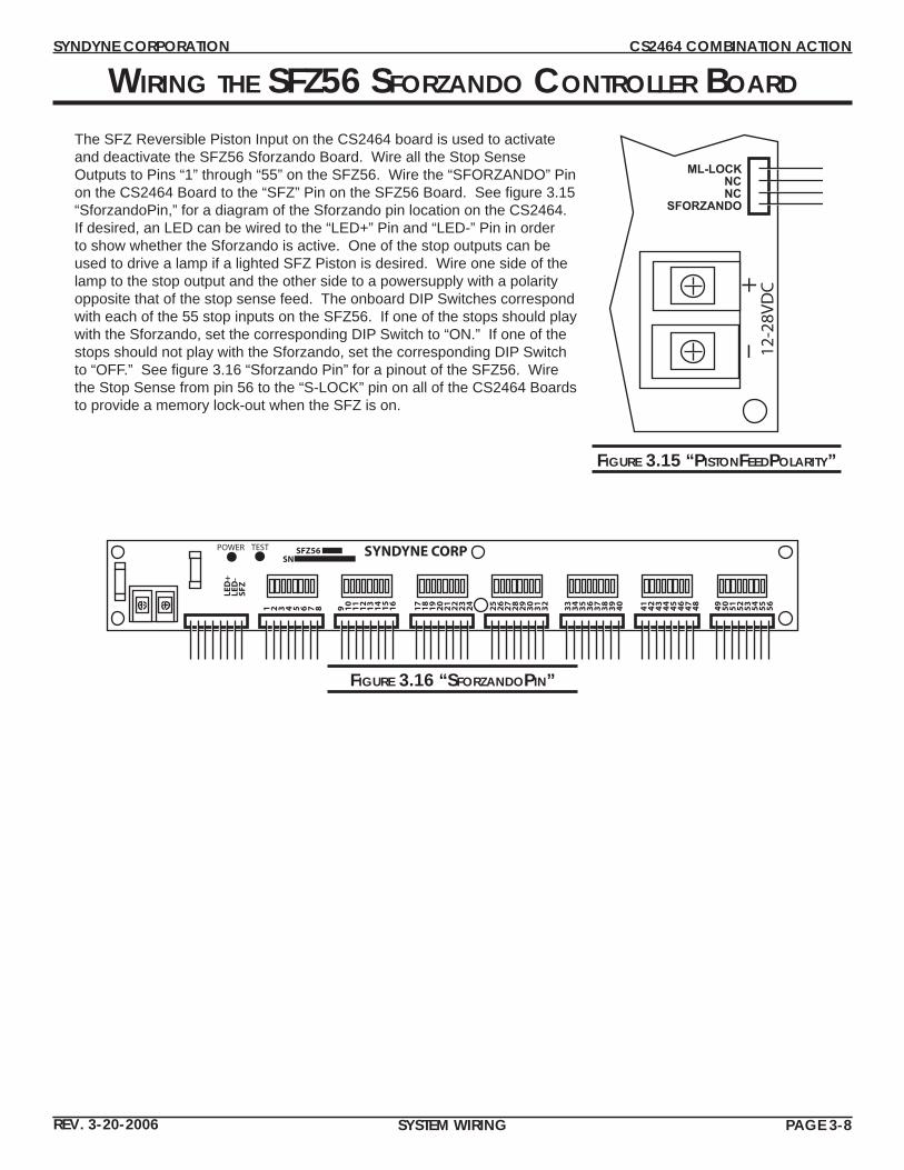
WIRING THE SFZ56 SFORZANDO CONTROLLER BOARD
The SFZ Reversible Piston Input on the CS2464 board is used to activate and deactivate the SFZ56 Sforzando Board. Wire all the Stop Sense Outputs to Pins “1” through “55” on the SFZ56. Wire the “SFORZANDO” Pin on the CS2464 Board to the “SFZ” Pin on the SFZ56 Board. See fi gure 3.15 “SforzandoPin,” for a diagram of the Sforzando pin location on the CS2464. If desired, an LED can be wired to the “LED+” Pin and “LED-” Pin in order to show whether the Sforzando is active. One of the stop outputs can be used to drive a lamp if a lighted SFZ Piston is desired. Wire one side of the lamp to the stop output and the other side to a powersupply with a polarity opposite that of the stop sense feed. The onboard DIP Switches correspond with each of the 55 stop inputs on the SFZ56. If one of the stops should play with the Sforzando, set the corresponding DIP Switch to “ON.” If one of the stops should not play with the Sforzando, set the corresponding DIP Switch to “OFF.” See fi gure 3.16 “Sforzando Pin” for a pinout of the SFZ56. Wire the Stop Sense from pin 56 to the “S-LOCK” pin on all of the CS2464 Boards to provide a memory lock-out when the SFZ is on.
17
18
19
20
21
22
23
24
25
26
27
28
29
30
31
32
33
34
35
36
37
38
39
40
41
42
43
44
45
46
47
48
49
50
51
52
53
54
55
56
9 10
11
12
14
16
1 2 3 4 5 6 7 8 13 15
LED
+LE
D-
SFZ
SYNDYNE CORPPOWER TEST SFZ56SN
FIGURE 3.16 “SFORZANDOPIN”
ML-LOCKNCNC
SFORZANDO
12-2
8VD
C+-
FIGURE 3.15 “PISTONFEEDPOLARITY”

SYNDYNE CORPORATION CS2464 COMBINATION ACTION
REV. 3-20-2006 SYSTEM PROGRAMMING PAGE 4-1
SYSTEM PROGRAMMINGPROGRAMMING THE CS2464 ..................................................................................4-2
ASSOCIATION OF STOPS 19 AND 20 ..................................................................................... 4-2ASSOCIATION OF STOPS 21 AND 22 ..................................................................................... 4-2ASSOCIATION OF STOPS 23 AND 24 ..................................................................................... 4-2GENERAL CANCEL AT POWER UP .......................................................................................... 4-2PISTON SEQUENCER THROUGH MEMORY LEVELS ................................................................. 4-3PISTON SEQUENCER MODE EUROPEAN/AMERICAN ............................................................ 4-3LAST GENERAL PISTON NUMBER FOR PISTON SEQUENCER ................................................... 4-3DIVISION NUMBER DIP SWITCHES .......................................................................................... 4-3
SYNDYNE CORPORATION CS2464 COMBINATION ACTION
REV. 3-20-2006 SYSTEM PROGRAMMING PAGE 4-2
PROGRAMMING THE CS2464
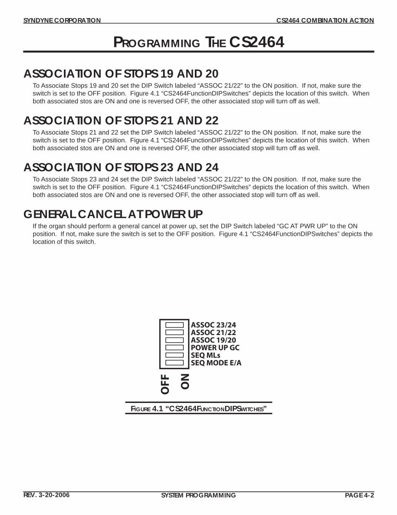
ASSOCIATION OF STOPS 19 AND 20To Associate Stops 19 and 20 set the DIP Switch labeled “ASSOC 21/22” to the ON position. If not, make sure the switch is set to the OFF position. Figure 4.1 “CS2464FunctionDIPSwitches” depicts the location of this switch. When both associated stos are ON and one is reversed OFF, the other associated stop will turn off as well.
ASSOCIATION OF STOPS 21 AND 22To Associate Stops 21 and 22 set the DIP Switch labeled “ASSOC 21/22” to the ON position. If not, make sure the switch is set to the OFF position. Figure 4.1 “CS2464FunctionDIPSwitches” depicts the location of this switch. When both associated stos are ON and one is reversed OFF, the other associated stop will turn off as well.
ASSOCIATION OF STOPS 23 AND 24To Associate Stops 23 and 24 set the DIP Switch labeled “ASSOC 21/22” to the ON position. If not, make sure the switch is set to the OFF position. Figure 4.1 “CS2464FunctionDIPSwitches” depicts the location of this switch. When both associated stos are ON and one is reversed OFF, the other associated stop will turn off as well.
GENERAL CANCEL AT POWER UPIf the organ should perform a general cancel at power up, set the DIP Switch labeled “GC AT PWR UP” to the ON position. If not, make sure the switch is set to the OFF position. Figure 4.1 “CS2464FunctionDIPSwitches” depicts the location of this switch.
FIGURE 4.1 “CS2464FUNCTIONDIPSWITCHES”
ON
OFF
ASSOC 23/24ASSOC 21/22ASSOC 19/20POWER UP GCSEQ MLsSEQ MODE E/A
SYNDYNE CORPORATION CS2464 COMBINATION ACTION
REV. 3-20-2006 SYSTEM PROGRAMMING PAGE 4-3
FIGURE 4.3 “CS2464LASTGENERALPISTON”
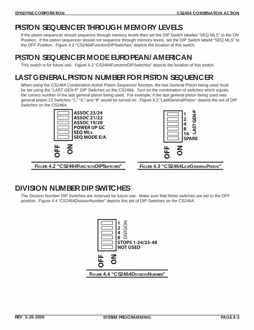
PISTON SEQUENCER THROUGH MEMORY LEVELSIf the piston sequencer should sequence through memory levels then set the DIP Switch labeled “SEQ MLS” to the ON Position. If the piston sequencer should not sequence through memory levels, set the DIP Switch labeld “SEQ MLS” to the OFF Position. Figure 4.2 “CS2464FunctionDIPSwitches” depicts the location of this switch.
PISTON SEQUENCER MODE EUROPEAN/AMERICANThis switch is for future use. Figure 4.2 “CS2464FunctionDIPSwitches” depicts the location of this switch.
LAST GENERAL PISTON NUMBER FOR PISTON SEQUENCERWhen using the CS2464 Combination Action Piston Sequencer function, the last General Piston being used must be set using the “LAST GEN-P” DIP Switches on the CS2464. Turn on the combination of switches which equals the correct number of the last general piston being used. For example, if the last general piston being used was general piston 13 Switches “1,” “4,” and “8” would be turned on. Figure 4.3 “LastGeneralPiston” depicts the set of DIP Switches on the CS2464.
FIGURE 4.2 “CS2464FUNCTIONDIPSWITCHES”
ON
OFF
ASSOC 23/24ASSOC 21/22ASSOC 19/20POWER UP GCSEQ MLsSEQ MODE E/A
DIVISION NUMBER DIP SWITCHESThe Division Number DIP Switches are reserved for future use. Make sure that these switches are set to the OFF position. Figure 4.4 “CS2464DivisionNumber” depicts this set of DIP Switches on the CS2464.
FIGURE 4.4 “CS2464DIVISIONNUMBER”
ON
OFF
124816SPARE
LAST
GEN
-P
ON
OFF
1248STOPS 1-24/25-48NOT USED
DIV
ISIO
N

SYNDYN
E CORP
ORATIO
N
THIS PAGE LEFT INTENTIONALLY BLANK
SYNDYNE CORPORATION CS2464 COMBINATION ACTION
REV. 3-20-2006 APPENDIX PAGE AP-1
APPENDIX A: SOLDERING TIPSWiring the CS2464 can be quick and easy if the proper technique becomes familiar. Although there are many ways to make a solder joint, the wiring team at Syndyne has found a simple method that provides a quality connection as quickly as possible. It is important to remember that as with anything else in life, soldering becomes easier with practice, so it is best not to become discouraged if the process seems diffi cult in the beginning. Here is the syndyne wiring team’s suggested soldering method. Also please keep in mind that syndyne offers full wire harnessing services for those who do not want to wire the system themselves.
1. Strip the wire or wires that will be used in the solder joint.2. Place shrink tube on the wire(s) as far away from the bare end of the wire as possible. When soldering, the wire
heats up close to the solder joint, and this heat can shrink the shrink tube before it is ready to cover the joint.3. Use a damp sponge to clean any old solder from the tip of the soldering iron before tinning.4. Apply some solder to the tip of the soldering iron and place the solder from the tip of the iron to both the bare end of
the wire(s) and the connector terminal. This process is called pretinning and is highly recommended for increased speed, accuracy, and joint integrity.
5. Use a damp sponge to clean any old solder from the tip of the soldering iron.6. Apply solder to the tip of the soldering iron.7. If single soldering, hold the pretinned wire on the pretinned connector terminal. If double soldering, hold both pre-
tinned wires parallel with eachother. Hold both wires on the pretinned connector terminal. 8. Place the tip of the iron on the connector end of the bare wire(s).8. Once the solder fl ows over the connection, run the iron over the wire up to the shielded end of the stripped wire.
Do not touch the wire shielding with the iron or it may melt.9. Let the solder joint cool and test its integrity by pulling lightly on both the connector and the wire in opposite direc-
tions.10. Do not pull shrink tube over the solder joint at this time. First, complete all wiring to the connector then pull up and
heat the shrink tube for each solder joint all at the same time. Otherwise, the shrink tube from one wire can get in the way when soldering the wire next to the shrink tube.