Switch-Mode Continuously Variable Transmission Prototype...
12
American Institute of Aeronautics and Astronautics 1 Switch-Mode Continuously Variable Transmission Prototype Design and Testing Jeffrey J. Araujo 1 , Michael A. DeMalia 2 , Christopher M. Lambusta 3 , Anthony J. Morocco 4 , and James D. Van de Ven 5 Worcester Polytechnic Institute, Worcester, MA, 01609 Energy consumption is a major issue for the global society. A hybrid drive train can significantly improve the energy efficiency of ground vehicles. The combination of high energy density and high power density make a flywheel hybrid system a promising option. A primary challenge of a flywheel hybrid system is coupling a high speed flywheel to a vehicle's drive train. A unique way of accomplishing this task is using a switch-mode continuously variable transmission (CVT), which is the mechanical analog of a DC-DC power electronics converter. Modeling and analysis were conducted of the major components of a full size passenger vehicle switch-mode CVT. This model was scaled down to allow for the design and manufacturing of a laboratory prototype. Experimental data taken from the prototype was used to verify proof-of-concept and quantify the nature and magnitude of system losses. The results demonstrate the correct operation of the system on a high level, but future work is required before reliable experimental data is acquired. I. Introduction N the automotive industry, there is a strong emphasis being placed on fuel efficiency. This demand for efficiency is driven primarily by fluctuating fuel costs and a desire to reduce emissions. In response to this demand, hybrid vehicle sales have increased. Hybrid vehicles improve efficiency because they draw their power from an internal combustion engine coupled with an auxiliary power source capable of energy recovery. Although electric hybrid power trains and were the first hybrid technology to be mass produced, utilizing a flywheel for the auxiliary power source enables an order of magnitude increase in power density over electric systems while maintaining similar energy density. 1 However, the major problem with flywheel hybrids is coupling the high speed flywheel to the drive train of the vehicle. The transmission for this application must be efficient, continuously variable, and have a large reduction ratio. A continuously variable transmission (CVT) provides a step-less transition across the range of speed variation. Previously proposed CVTs for flywheel hybrid vehicles include hydraulics, belt drives, and toroidal drives. 2 A novel solution to this problem, which serves as the focus of this paper, is the switch-mode continuously variable transmission. A switch-mode transmission using two clutches and a spring connected to ground was previously described and tested by Gilbert et al. This system transmitted low levels of power through a limited range of 1:3.2 and 1.3:1. 3 This design did not enable energy storage and relied on oscillating the spring connected to ground for operation. The switch-mode CVT architecture discussed in this paper, a schematic of which is seen in Fig. 1, uses a flywheel, clutch, anti-reverse ratchet, and spring to transmit torque from the input shaft to the output shaft. 1 This system is the mechanical analog of a DC-DC boost converter from power electronics. In order to understand how torque is transmitted through the system, it is necessary to describe the function of each component in the system and their interaction. 1 Undergraduate Student, Mechanical Engineering Department, 100 Institute Rd. 2 Undergraduate Student, Mechanical Engineering Department, 100 Institute Rd. 3 Undergraduate Student, Mechanical Engineering Department, 100 Institute Rd. 4 Undergraduate Student, Mechanical Engineering Department, 100 Institute Rd. 5 Assistant Professor, Mechanical Engineering Dept, 100 Institute Rd., AIAA Member, Corresponding Author. I
-
Upload
phungkhanh -
Category
Documents
-
view
216 -
download
0
Transcript of Switch-Mode Continuously Variable Transmission Prototype...

American Institute of Aeronautics and Astronautics
1
Switch-Mode Continuously Variable Transmission Prototype Design and Testing
Jeffrey J. Araujo1, Michael A. DeMalia2, Christopher M. Lambusta3, Anthony J. Morocco4, and James D. Van de Ven5
Worcester Polytechnic Institute, Worcester, MA, 01609
Energy consumption is a major issue for the global society. A hybrid drive train can significantly improve the energy efficiency of ground vehicles. The combination of high energy density and high power density make a flywheel hybrid system a promising option. A primary challenge of a flywheel hybrid system is coupling a high speed flywheel to a vehicle's drive train. A unique way of accomplishing this task is using a switch-mode continuously variable transmission (CVT), which is the mechanical analog of a DC-DC power electronics converter. Modeling and analysis were conducted of the major components of a full size passenger vehicle switch-mode CVT. This model was scaled down to allow for the design and manufacturing of a laboratory prototype. Experimental data taken from the prototype was used to verify proof-of-concept and quantify the nature and magnitude of system losses. The results demonstrate the correct operation of the system on a high level, but future work is required before reliable experimental data is acquired.
I. Introduction N the automotive industry, there is a strong emphasis being placed on fuel efficiency. This demand for efficiency is driven primarily by fluctuating fuel costs and a desire to reduce emissions. In response to this demand, hybrid
vehicle sales have increased. Hybrid vehicles improve efficiency because they draw their power from an internal combustion engine coupled with an auxiliary power source capable of energy recovery. Although electric hybrid power trains and were the first hybrid technology to be mass produced, utilizing a flywheel for the auxiliary power source enables an order of magnitude increase in power density over electric systems while maintaining similar energy density.1
However, the major problem with flywheel hybrids is coupling the high speed flywheel to the drive train of the vehicle. The transmission for this application must be efficient, continuously variable, and have a large reduction ratio. A continuously variable transmission (CVT) provides a step-less transition across the range of speed variation. Previously proposed CVTs for flywheel hybrid vehicles include hydraulics, belt drives, and toroidal drives.2
A novel solution to this problem, which serves as the focus of this paper, is the switch-mode continuously variable transmission. A switch-mode transmission using two clutches and a spring connected to ground was previously described and tested by Gilbert et al. This system transmitted low levels of power through a limited range of 1:3.2 and 1.3:1.3 This design did not enable energy storage and relied on oscillating the spring connected to ground for operation. The switch-mode CVT architecture discussed in this paper, a schematic of which is seen in Fig. 1, uses a flywheel, clutch, anti-reverse ratchet, and spring to transmit torque from the input shaft to the output shaft.1 This system is the mechanical analog of a DC-DC boost converter from power electronics. In order to understand how torque is transmitted through the system, it is necessary to describe the function of each component in the system and their interaction.
1 Undergraduate Student, Mechanical Engineering Department, 100 Institute Rd. 2 Undergraduate Student, Mechanical Engineering Department, 100 Institute Rd. 3 Undergraduate Student, Mechanical Engineering Department, 100 Institute Rd. 4 Undergraduate Student, Mechanical Engineering Department, 100 Institute Rd. 5 Assistant Professor, Mechanical Engineering Dept, 100 Institute Rd., AIAA Member, Corresponding Author.
I
American Institute of Aeronautics and Astronautics
2
Flywheel On/Off Clutch Input
Shaft Output Shaft
Spring
Anti-reverse Ratchet
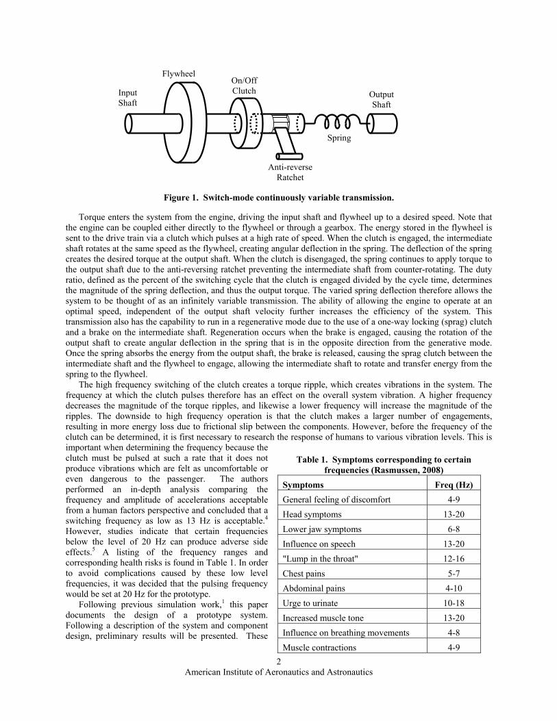
Figure 1. Switch-mode continuously variable transmission.
Torque enters the system from the engine, driving the input shaft and flywheel up to a desired speed. Note that the engine can be coupled either directly to the flywheel or through a gearbox. The energy stored in the flywheel is sent to the drive train via a clutch which pulses at a high rate of speed. When the clutch is engaged, the intermediate shaft rotates at the same speed as the flywheel, creating angular deflection in the spring. The deflection of the spring creates the desired torque at the output shaft. When the clutch is disengaged, the spring continues to apply torque to the output shaft due to the anti-reversing ratchet preventing the intermediate shaft from counter-rotating. The duty ratio, defined as the percent of the switching cycle that the clutch is engaged divided by the cycle time, determines the magnitude of the spring deflection, and thus the output torque. The varied spring deflection therefore allows the system to be thought of as an infinitely variable transmission. The ability of allowing the engine to operate at an optimal speed, independent of the output shaft velocity further increases the efficiency of the system. This transmission also has the capability to run in a regenerative mode due to the use of a one-way locking (sprag) clutch and a brake on the intermediate shaft. Regeneration occurs when the brake is engaged, causing the rotation of the output shaft to create angular deflection in the spring that is in the opposite direction from the generative mode. Once the spring absorbs the energy from the output shaft, the brake is released, causing the sprag clutch between the intermediate shaft and the flywheel to engage, allowing the intermediate shaft to rotate and transfer energy from the spring to the flywheel.
The high frequency switching of the clutch creates a torque ripple, which creates vibrations in the system. The frequency at which the clutch pulses therefore has an effect on the overall system vibration. A higher frequency decreases the magnitude of the torque ripples, and likewise a lower frequency will increase the magnitude of the ripples. The downside to high frequency operation is that the clutch makes a larger number of engagements, resulting in more energy loss due to frictional slip between the components. However, before the frequency of the clutch can be determined, it is first necessary to research the response of humans to various vibration levels. This is important when determining the frequency because the clutch must be pulsed at such a rate that it does not produce vibrations which are felt as uncomfortable or even dangerous to the passenger. The authors performed an in-depth analysis comparing the frequency and amplitude of accelerations acceptable from a human factors perspective and concluded that a switching frequency as low as 13 Hz is acceptable.4 However, studies indicate that certain frequencies below the level of 20 Hz can produce adverse side effects.5 A listing of the frequency ranges and corresponding health risks is found in Table 1. In order to avoid complications caused by these low level frequencies, it was decided that the pulsing frequency would be set at 20 Hz for the prototype.
Following previous simulation work,1 this paper documents the design of a prototype system. Following a description of the system and component design, preliminary results will be presented. These
Table 1. Symptoms corresponding to certain frequencies (Rasmussen, 2008)
Symptoms Freq (Hz) General feeling of discomfort 4-9 Head symptoms 13-20 Lower jaw symptoms 6-8 Influence on speech 13-20 "Lump in the throat" 12-16 Chest pains 5-7 Abdominal pains 4-10 Urge to urinate 10-18 Increased muscle tone 13-20 Influence on breathing movements 4-8 Muscle contractions 4-9

American Institute of Aeronautics and Astronautics
3
results will then be discussed, followed by concluding remarks and recommendations for future work.
II. Design To validate the switch-mode CVT concept and generate experimental results, a scaled prototype was designed.
For laboratory testing purposes, the linear kinetic energy of the vehicle was replaced with rotating kinetic energy in the form of a flywheel on the output shaft, as seen in Fig. 2. From simulation results, system parameters were developed for a full-size flywheel hybrid passenger vehicle, such as a desired energy storage capacity of 18.5 MJ for “plug in” type operation.4 From the full-size vehicle specifications, the system was scaled to a laboratory prototype system based on the desired energy and power requirements and the availability of off-the-shelf components. After selecting the components and assembling the prototype, a data acquisition system was set up to monitor the prototype and pulse the clutch at the appropriate times. Finally, an enclosure was created for safety considerations. The following is an in depth analysis of the individual components that comprise the switch-mode CVT.
Input Flywheel
On/Off Clutch
Input Shaft
Output Shaft
Spring
Anti-reverse Ratchet
Output Flywheel
Figure 2. Switch-mode continuously variable transmission.
A. Clutches The clutch was the major limiting factor when designing the prototype. The only commercially available clutch
with an engagement time fast enough to allow for a pulsing frequency of 20 Hertz was the EC75 electromechanical clutch manufactured by REELL. According to the manufacturer's specifications, the clutch can engage in as little as three milliseconds at a maximum speed of 1400 RPM. Although the speed of the clutch engagement was adequate, the maximum torque transfer through the clutch was limited to 6.8 N*m (75 in*lb).
B. Flywheels The input flywheel was scaled down for the prototype system. Based on the maximum angular velocity of the
clutch of 1400 RPM, the scaled flywheel was designed to store 1850 J of energy. The output flywheel was sized to achieve the same acceleration of the output flywheel as the full-size system, based on the torque limitations of the clutch. While the full-scale system would like to use carbon fiber for an energy dense flywheel, the low energy density requirement of the scaled system and the associated manufacturing cost of a carbon fiber made it impractical for the prototype. For that reason, low carbon steel was chosen. A summary of the dimensions and properties of the input flywheel can be seen in Table 2.
Table 2. Input and output flywheel dimensions Input Flywheel Output Flywheel Outer Radius (mm) 127 102 Inner Radius (mm) 9.5 9.5 Thickness (mm) 57 76 Mass (kg) 22.587 19.3 Moment of Inertia (kg*m2) 0.182 0.116
C. Spring Design Another main component of the system was the torsion spring, as it transmitted torque through the system in
both the generative and regenerative mode. Multiple spring designs were considered to achieve the performance criteria. These criteria were to have a modest packaging size, the ability to transmit torque in two directions, and a desired spring constant. Three existing designs were examined for their applicability, including the solid bar, helical spring, and torsion spring. The solid bar was deemed unacceptable due to the large length and size of the bar to

American Institute of Aeronautics and Astronautics
4
generate the desired spring constant. The helical spring was unacceptable because it needed large coils that did not satisfy the packaging constraint and the spring torque does not increase with angular deflection. Finally, the watch-style torsion spring could only transmit torque in one direction and again is a constant torque spring.
To meet the requirements a novel spring was designed. The design used a series of bars connected around a circular cap to transfer torque by loading the bars in both bending and torsion. For the full-scale system, a spring constant of 685 N*m/rad was needed. The spring needed to deflect 110 degrees at maximum torque.
The first iteration of the spring design, seen below in Fig. 3, used two sets of rectangular bars set at different radii from the center. In order to find the effects of different size and shapes of bars each design was modeled using SolidWorks and analysis was run using COSMOSWorks Designer. The simulation was set up by fixing one cap in space and applying a torque around the other cap which had not been grounded. A summary of bar configuration, size, and results pertaining to deflection and stress can be seen in Tables 3 and 4. The first two columns of the table shows the number of bars in the configuration and their dimensions, the third and fourth columns show how far away the bars are from the center of the cap and the overall length of the bars, respectively, and finally, the last two columns provide the angular deflection and the total stresses seen in the bars.
Figure 3. Spring iteration 1
Table 3. Staggered configurations
Outer Bars(mm)
Inner Bars(mm)
Outer Bar Radius(mm)
Inner Bar Radius(mm)
Bar Length (mm)
Angular Deflection (deg)
Von-Mises Stress (MPa)
8 Rec (12.7 x 10.2)
6 Rec (12.7 x 10.2) 50.8 25.4 914 41.97 634
8 Rec (12.7 x 10.2)
6 Rec (12.7 x 10.2) 38.1 12.7 914 33.40 623
18 Rec (12.7 x 6.4)
5 Cir (12.7 dia) 38.1 12.7 914 41.67 604
18 Rec (12.7 x 6.4)
5 Cir (12.7 dia) 38.1 12.7 1219 55.82 601
The staggered strategy lead to disappointing results due to the aspect ratio of individual bars resulting in a
torsion dominated spring force. To achieve a bending dominated spring, another iteration used a single set of rectangular bars evenly spaced around the cap, as shown in Table 4. This strategy allowed for acceptable displacements. This iteration was adjusted numerous times by reducing the number of bars and overall length to obtain the desired deflection of 110 degrees. The most effective way to increase deflection was to decrease bar thickness and increase length. It was found that changing the bar radius had minimal effects on deflection and it was therefore minimized for more effective packaging. The final design can be seen in Fig. 4.
Figure 4. Final spring design

American Institute of Aeronautics and Astronautics
5
Table 4. Non-staggered configurations
Outer Bars (mm)
Radius of Outer Bar
(mm) Bar Length
(mm) Angular
Deflection (deg) Von-Mises Stress (MPa) 18 Rec
(12.7 x 5.1) 25.4 1219 149.74 1620 15 Rec
(12.7 x 5.1) 25.4 914 133.34 1807 15 Rec
(15.2 x 5.1) 25.4 914 108.08 1489 14 Rec
(15.2 x 5.1) 25.4 914 113.48 1583
Once the desired displacement was reached, a material needed to be found that could safely withstand the stresses. As seen in Fig. 5 below, the stresses are concentrated in the middle of each bar and peak at 1.583GPa. Alloy steel, AISI 9255 tempered and quenched was found to be a suitable material using CES EduPack.
Figure 5. Stresses of final spring design
For the scaled prototype, the width and thickness of the spring bars were selected based on commercially
available products. The material chosen was 4130 sheet steel, with a thickness of 1 mm. The length of the bars was chosen to be 533 mm overall and the width was chosen to be 12.7 mm. The spring bars were created by purchasing 36" by 6" sheets of 4130 steel and cutting six pieces to size by using a metal shear. The six cut steel pieces were clamped between two 12.7 mm steel plates. The clamped and contained parts were then heat treated. The spring bars were placed in between the pieces of the end cap while a press forced the two together, creating a compression fit. The CAD model of the spring can be seen in Fig. 6 and the manufactured spring is shown in Fig. 7.
Figure 6. CAD model of the scaled torsion spring

American Institute of Aeronautics and Astronautics
6
Figure 7. Manufactured torsion spring
In order to validate the design, a finite element analysis was performed on the spring assembly. The
displacement under maximum loading conditions and the stress distribution were determined. The results obtained were verified by calculating the combined deflection due to the bending and torsion of the assembly. Figure 8 and Fig. 9 show the deflection and stress, respectively.
Figure 8: Deflection in scale model spring
Figure 9: Stresses in scale model spring
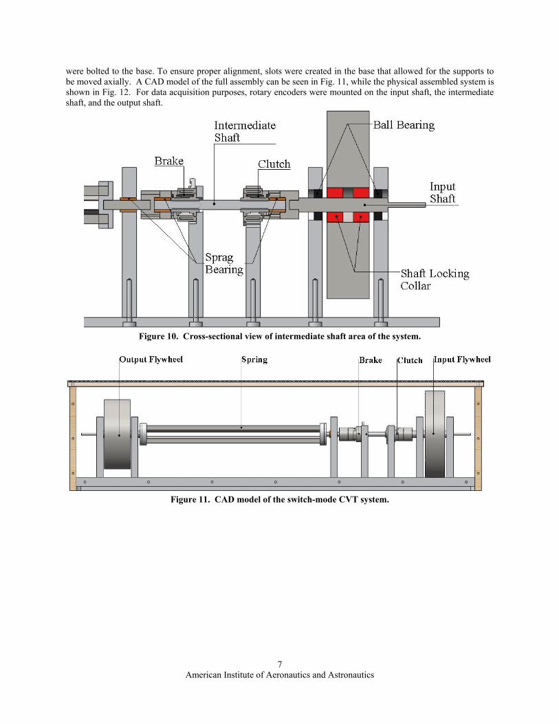
D. System Integration After having sized all of the components, the full CAD model was assembled. A schematic of the model with the
major components labeled can be seen Fig. 10. As illustrated in the figure, the input flywheel is attached to the input shaft with shaft locking collars. Ball bearings were placed in the flywheel supports, to suspend the flywheel while still allowing it to spin with minimal friction. The intermediate shaft connects the input of the system to the spring. Two one-way locking bearings, located on both sides of the intermediate shaft, enabled it to transfer torque in one direction while free-wheeling in the other. One one-way locking bearing was grounded to prevent the spring from transferring torque in the opposite direction. All of the components were elevated with supports, and the supports
American Institute of Aeronautics and Astronautics
7
were bolted to the base. To ensure proper alignment, slots were created in the base that allowed for the supports to be moved axially. A CAD model of the full assembly can be seen in Fig. 11, while the physical assembled system is shown in Fig. 12. For data acquisition purposes, rotary encoders were mounted on the input shaft, the intermediate shaft, and the output shaft.
Figure 10. Cross-sectional view of intermediate shaft area of the system.
Figure 11. CAD model of the switch-mode CVT system.

American Institute of Aeronautics and Astronautics
8
Figure 12. Photograph of the physical prototype in the protective lexan shield.
III. Results Following assembly of the prototype, preliminary experiments were conducted on the system. In order to obtain
experimental data from the prototype, a testing procedure was created and employed. The experimental method is explained in detail in the capstone design paper, which is available online.4 In summary, the testing procedure involves:
1) All three encoders turned on to track the position of the various components of the system. 2) Input flywheel spun to the desired angular velocity using a friction drive wheel powered by a 24 volt DC
motor. 3) Clutch pulsing program started once input flywheel achieved desired velocity. Using this testing procedure, data was obtained at varying angular velocities of the input flywheel. For
illustrative purposes, two data sets are presented using input speeds of 500 and 900 rpm and a clutch pulsing frequency of 5 Hz and a duty ratio of 0.3. For the input, intermediate, and output shafts the position was recorded using the optical rotary encoders. The velocity of the shafts was obtained by taking the derivative of the position data. The velocity of the input shaft and output shaft are presented in Figs. 13 and 15 respectively, while the position of the intermediate shaft is shown in Fig. 14. As can be seen from the velocity plots, the numerical average creates a large amount of noise, suggesting that a smoothing or averaging technique be applied. It should be noted that the longer time scale of the input shaft velocity plot shows spinning the flywheel up to speed with the DC motor, and then the beginning of the clutch pulsing.

American Institute of Aeronautics and Astronautics
9
Figure 13. Input shaft velocities
Figure 14. Intermediate shaft positions

American Institute of Aeronautics and Astronautics
10
Figure 15. Output flywheel velocities
While the velocity of the input and output shafts should be relatively smooth due to the energy storage in the input and output flywheels, the velocity of the intermediate shaft should vary greatly during each pulse of the clutch. By taking the derivative of the intermediate shaft position data and applying a 10 place moving average, Fig. 16, a zoomed plot of five clutch pulses is created.
Figure 16. Zoomed plot of the intermediate shaft velocity
American Institute of Aeronautics and Astronautics
11
IV. Discussion The preliminary data appear to confirm the expected operation of the system. When the clutch begins pulsing,
energy is transferred from the input flywheel to the output shaft. This transfer in energy is observed by a decrease in the angular velocity of the input shaft and an increase in the angular velocity of the output shaft.
It is noted from Fig. 16 that the intermediate shaft advances in rapid steps of angular velocity as the shaft advances during each pulse of the clutch. In the modeled system, this velocity profile would be a trapezoid with the slope on each end corresponding to the slipping engagement of the clutch. In contrast to the model, each pulse has a quite unique shape. The exact cause of the different velocity pulse shapes is not known, but it is speculated that dynamics of the torsion spring bars are creating vibrations that influence the intermediate shaft velocity.
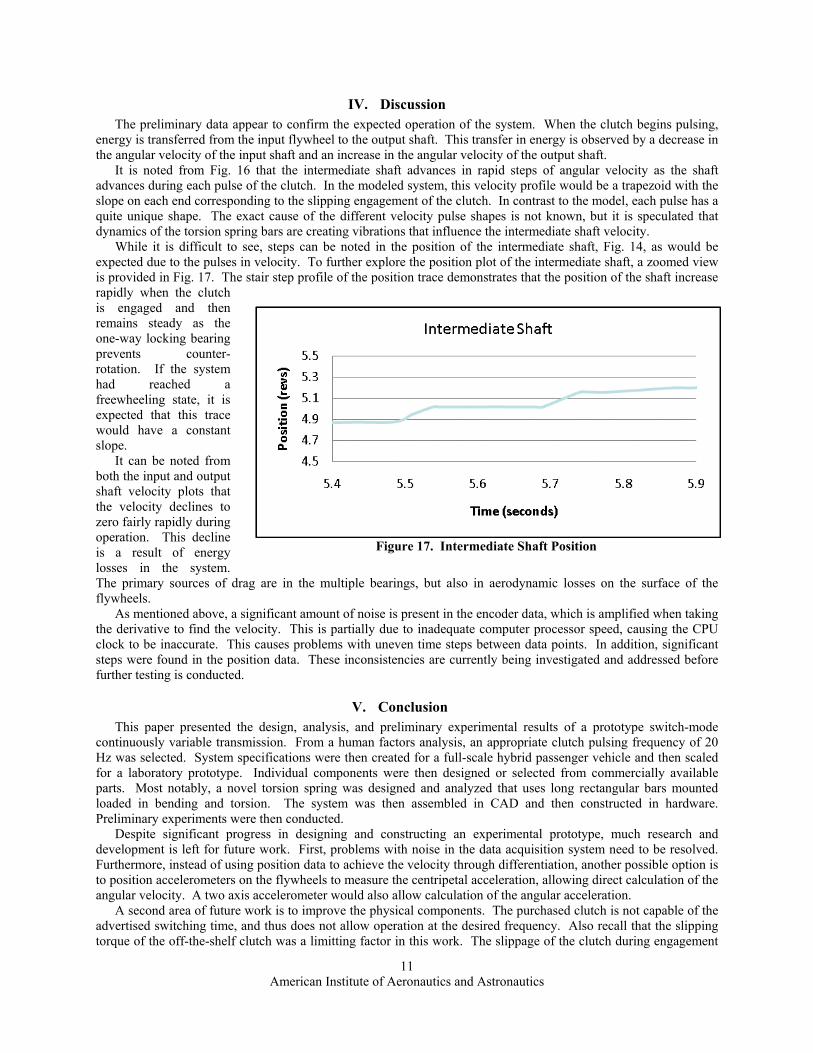
While it is difficult to see, steps can be noted in the position of the intermediate shaft, Fig. 14, as would be expected due to the pulses in velocity. To further explore the position plot of the intermediate shaft, a zoomed view is provided in Fig. 17. The stair step profile of the position trace demonstrates that the position of the shaft increase rapidly when the clutch is engaged and then remains steady as the one-way locking bearing prevents counter-rotation. If the system had reached a freewheeling state, it is expected that this trace would have a constant slope.
It can be noted from both the input and output shaft velocity plots that the velocity declines to zero fairly rapidly during operation. This decline is a result of energy losses in the system. The primary sources of drag are in the multiple bearings, but also in aerodynamic losses on the surface of the flywheels.
As mentioned above, a significant amount of noise is present in the encoder data, which is amplified when taking the derivative to find the velocity. This is partially due to inadequate computer processor speed, causing the CPU clock to be inaccurate. This causes problems with uneven time steps between data points. In addition, significant steps were found in the position data. These inconsistencies are currently being investigated and addressed before further testing is conducted.
V. Conclusion This paper presented the design, analysis, and preliminary experimental results of a prototype switch-mode
continuously variable transmission. From a human factors analysis, an appropriate clutch pulsing frequency of 20 Hz was selected. System specifications were then created for a full-scale hybrid passenger vehicle and then scaled for a laboratory prototype. Individual components were then designed or selected from commercially available parts. Most notably, a novel torsion spring was designed and analyzed that uses long rectangular bars mounted loaded in bending and torsion. The system was then assembled in CAD and then constructed in hardware. Preliminary experiments were then conducted.
Despite significant progress in designing and constructing an experimental prototype, much research and development is left for future work. First, problems with noise in the data acquisition system need to be resolved. Furthermore, instead of using position data to achieve the velocity through differentiation, another possible option is to position accelerometers on the flywheels to measure the centripetal acceleration, allowing direct calculation of the angular velocity. A two axis accelerometer would also allow calculation of the angular acceleration.
A second area of future work is to improve the physical components. The purchased clutch is not capable of the advertised switching time, and thus does not allow operation at the desired frequency. Also recall that the slipping torque of the off-the-shelf clutch was a limitting factor in this work. The slippage of the clutch during engagement
Figure 17. Intermediate Shaft Position

American Institute of Aeronautics and Astronautics
12
and disengagement is a major source of energy loss. To meet the needs of this unique application at a high efficiency, a custom clutch will likely be required with short switching time and adequate torque capacity. Another area of component development is the spring design. Due to the long bars, it is hypothesized that vibrations are created that negatively impact the performance of the system. Furthermore, an alternative design might allow improvement in compactness of the overall system. The final design aspect needing to be addressed is the significant drag in the system. Due to the design of the system, the co-axial alignment of multiple shafts is critical to preventing bearings from binding. Furthermore, more care is needed in selecting components specifically to reduce frictional losses.
Once the physical system and data acquisition systems are improved, further testing is needed to validate the previously constructed numerical model and further understand the dynamics of the system. Part of this testing will also involve using the brake on the intermediate shaft to simulate regenerative operation.
Overall, the switch-mode CVT shows a great deal of promise. The designed and constructed experimental prototype demonstrated successful system operation on a high level. Numerous areas of interesting future work exist before it is ready to implement in a hybrid vehicle. This new technology has the potential to improve the efficiency of hybrid vehicles, help to minimize the consumption of fossil fuels, and minimize vehicle greenhouse gas emissions.
Acknowledgments The authors wish to thank SolidWorks Corporation for their support of this work.
References 1Forbes, T., and Van de Ven, J., "Switch-Mode Continuously Variable Transmission with Flywheel Energy Storage," ASME International Mechanical Engineering Congress and Exposition, Vol., Boston, MA, 2008. 2Beachley, N. H., and Frank, A. A., 1979, "Flywheel Energy Management Systems for Improving the Fuel Economy of Motor Vehicles." DOT/RSPA/DPB-50/79/1, University of Wisconsin, Madison, WI. 3Gilbert, J. M., Oldaker, R. S., Grindley, J. E., and Taylor, P. M., "Control of a Novel Switched Mode Variable Ratio Drive," UKACC International Conference on Control, Vol. 1, University of Exeter, UK, 1996, pp. 412-417. 4Araujo, J. M., DeMalia, M. A., Lambusta, C. M., and Morocco, A. J., 2009, "Switch-Mode Continuously Variable Transmission." ME-JDV-0902, Major Qualifying Project Report, Worcester Polytechnic Insititute, <http://www.wpi.edu/Pubs/E-project/Available/E-project-042709-172500/>. 5Rasmussen, G., "Human Body Vibration Exposure and Its Measurement," Journal of Acoustical Society of America, Vol. 73, No. 6, 1983, pp. 2229.