SW User Guide - telit.com · PDF fileSW User Guide 1VV0301282, Rev. 02 ... manual test mode....
17
SW User Guide 1VV0301282, Rev. 02 – 2016-05-24
Transcript of SW User Guide - telit.com · PDF fileSW User Guide 1VV0301282, Rev. 02 ... manual test mode....

SW User Guide 1VV0301282, Rev. 02 – 2016-05-24

BlueDev+S/ANT
Development Kit User Guide
Stollmann is a Telit brand.
Page 2 of 17
BlueDev+S/ANT
Development Kit User Guide
Release r02

BlueDev+S/ANT
Development Kit User Guide
Stollmann is a Telit brand.
Page 3 of 17
Table of Contents
1 Introduction ....................................................................................................... 5
2 Package Content ............................................................................................... 5
3 Hardware ........................................................................................................... 5
3.1 BlueMod+S ................................................................................................... 5
3.2 Reset ............................................................................................................ 6
3.3 USB Interface ............................................................................................... 6
3.4 LEDs ............................................................................................................. 6
3.5 External Low Power Oscillator ...................................................................... 6
3.6 Connectors / Jumpers ................................................................................... 7
3.6.1 Jumper J1 and Jumper J2 ................................................................... 7
3.6.2 Jumper J3 ........................................................................................... 7
3.6.3 Jumper J4 ........................................................................................... 7
3.6.4 Connector X2 ...................................................................................... 7
3.6.5 Connector X3 ...................................................................................... 8
3.6.6 Connector X4 ...................................................................................... 9
3.6.7 Connector X5 ...................................................................................... 9
3.7 Current Measurement ................................................................................... 9
3.8 External Power Supply .................................................................................. 9
3.9 Battery Holder ............................................................................................... 9
3.10 Buzzer .......................................................................................................... 9
3.11 Push Button ................................................................................................ 10
3.12 How To Interface the UART Lines on TTL level .......................................... 10
3.13 Default Configuration .................................................................................. 11
4 Setup ............................................................................................................... 12
4.1 System Requirements ................................................................................. 12
4.2 Startup ........................................................................................................ 12
4.3 Installation of the BlueDev+S USB Driver ................................................... 12
4.4 Installing the Debugger ............................................................................... 13
4.5 Connecting the nRF51 DK to the BlueDev+S .............................................. 13
4.6 Downloading and Installing the nRF51 SDK ................................................ 13

BlueDev+S/ANT
Development Kit User Guide
Stollmann is a Telit brand.
Page 4 of 17
5 Usage of the BlueDev+S ................................................................................. 14
5.1 Stollmann Demo Source Code .................................................................... 14
5.2 BlueDev+S Software Package Structure ..................................................... 14
5.2.1 The Directory “app_template” ............................................................ 14
5.2.2 The Directory “common” .................................................................... 14
5.2.3 The Directory “include” ...................................................................... 15
5.3 Using the Demo Application ........................................................................ 15
5.3.1 Demo Application Advertising ........................................................... 15
5.3.2 Stollmann Test Mode ........................................................................ 15
6 Related Documents ......................................................................................... 16
7 History ............................................................................................................. 16

BlueDev+S/ANT
Development Kit User Guide
Stollmann is a Telit brand.
Page 5 of 17
1 Introduction
This documentation describes the usage of the development kit for the Bluetooth
module BlueMod+S/ANT. In the context of this document BlueMod+S refers to
BlueMod+S/ANT.
2 Package Content
The BlueDev+S package contains the following components:
Stollmann demo source code (requires nRF51 SDK v9.0.0, not included)
1 x BlueDev+S board (extended BlueEva+S board)
1 x Mini USB cable
1 x Battery CR2032
1 x 9-pin debugger cable
1 x Printed card with download instructions
3 Hardware
Figure 1: BlueDev+S
3.1 BlueMod+S
The BlueDev+S is equipped with a BlueMod+S Bluetooth module.
BlueDev+S/ANT
Development Kit User Guide
Stollmann is a Telit brand.
Page 6 of 17
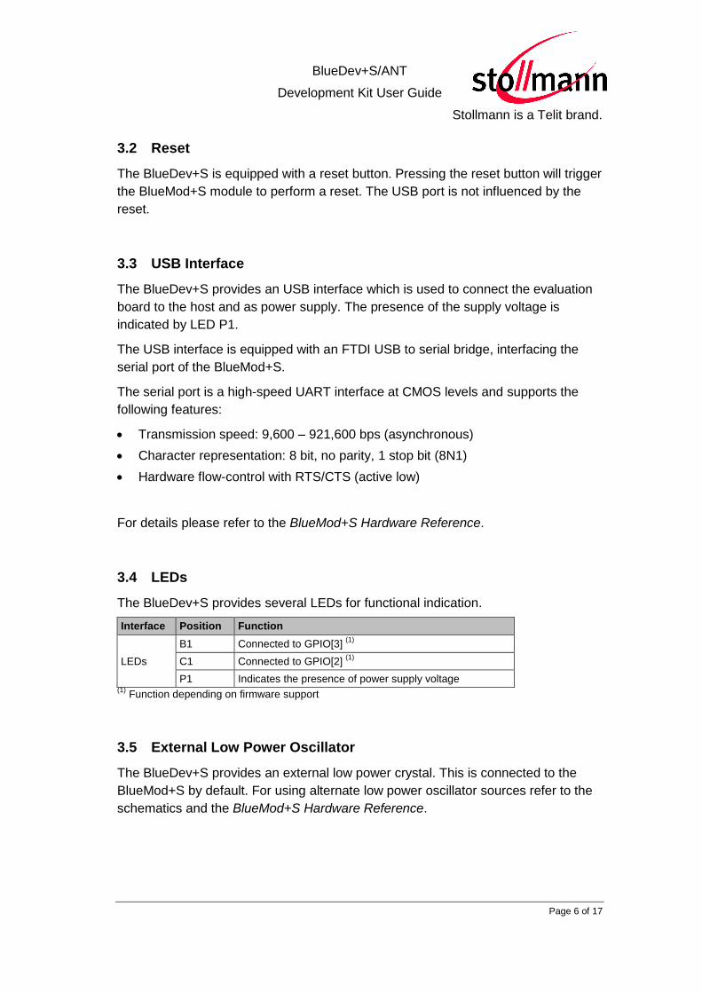
3.2 Reset
The BlueDev+S is equipped with a reset button. Pressing the reset button will trigger
the BlueMod+S module to perform a reset. The USB port is not influenced by the
reset.
3.3 USB Interface
The BlueDev+S provides an USB interface which is used to connect the evaluation
board to the host and as power supply. The presence of the supply voltage is
indicated by LED P1.
The USB interface is equipped with an FTDI USB to serial bridge, interfacing the
serial port of the BlueMod+S.
The serial port is a high-speed UART interface at CMOS levels and supports the
following features:
Transmission speed: 9,600 – 921,600 bps (asynchronous)
Character representation: 8 bit, no parity, 1 stop bit (8N1)
Hardware flow-control with RTS/CTS (active low)
For details please refer to the BlueMod+S Hardware Reference.
3.4 LEDs
The BlueDev+S provides several LEDs for functional indication.
Interface Position Function
LEDs
B1 Connected to GPIO[3] (1)
C1 Connected to GPIO[2] (1)
P1 Indicates the presence of power supply voltage (1)
Function depending on firmware support
3.5 External Low Power Oscillator
The BlueDev+S provides an external low power crystal. This is connected to the
BlueMod+S by default. For using alternate low power oscillator sources refer to the
schematics and the BlueMod+S Hardware Reference.

BlueDev+S/ANT
Development Kit User Guide
Stollmann is a Telit brand.
Page 7 of 17
3.6 Connectors / Jumpers
3.6.1 Jumper J1 and Jumper J2
Jumper J1 is used in conjunction with the provided demo application to enter
manual test mode. J1 has to be set to position 2-3 and Jumper J2 has to be set to
position 1-2 to enter manual test mode.
Jumper J2 is used in conjunction with the provided demo application to enter the
direct test mode (DTM). J1 and J2 have to be set to position 2-3 to enter DTM.
J1 Position J2 Position Function
1-2 1-2 Normal application start
2-3 1-2 Start manual test mode
2-3 2-3 Start Direct Test Mode (DTM)
1-2 2-3 Not used in demo application.
3.6.2 Jumper J3
Jumper J3 is used to switch The PC DTR# pin to two different module pins.
Jumper Number Position Function
J3 1-2 DTR# connected to IUR-IN#
J3 2-3 DTR# connected to GPIO[4]
3.6.3 Jumper J4
Jumper J4 provides the possibility to disable (by closing it with a soldering point) the
USB to serial bridge. With a closed jumper J4, the modules serial port is routed to
Connector X3 see chapter 3.12.
3.6.4 Connector X2
Connector X2 is used as “Debug in” to connect a debugger to the BlueMod+S
module.

BlueDev+S/ANT
Development Kit User Guide
Stollmann is a Telit brand.
Page 8 of 17
3.6.5 Connector X3
Connector X3 is a 28 pin extension header exposing all module signals.
Pin Number Signal Type Description
1 +3V0 PWR Supply voltage output
2 +3V0 PWR Supply voltage output
3 GND PWR Ground
4 GND PWR Ground
5 GPIO[0] I/O GPIO (1)
6 GPIO[1] I/O GPIO (1)
7 GPIO[2] I/O LED C1, user IO
8 GPIO[3] I/O LED B1, user IO
9 GPIO[4] I/O GPIO (1)
10 GPIO[5] I/O GPIO (1)
11 GPIO[6] I/O GPIO (1)
12 GPIO[7] I/O GPIO (1)
13 GPIO[8] I/O GPIO (1)
14 GPIO[9] I/O GPIO (1)
15 GPIO[10] I/O GPIO (1)
16 GPIO[11] I/O GPIO (1)
17 GPIO[12] I/O GPIO (1)
18 GPIO[13] I/O GPIO (1)
19 GPIO[14] I/O GPIO (1)
20 PO26_AIN0 See schematic (1)
21 PO27_AIN1 See schematic (1)
22 EXT-RES# I-PU User reset
23 UART-TXD O-PP IUR data OUT
24 UART-RXD I IUR data IN
25 UART-CTS# I Flow control
26 UART-RTS# O-PP Flow control
27 IUR-IN# I/O GPIO (1)
28 IUR-OUT# I/O GPIO (1)
PU = PullUp, PD = PullDown, PP = PushPull, I-DIS = InputBufferDisconnected
(1) Function depending on firmware support

BlueDev+S/ANT
Development Kit User Guide
Stollmann is a Telit brand.
Page 9 of 17
3.6.6 Connector X4
Connector X4 provides the possibility to measure the supply current of the
BlueMod+S and to power the evaluation board with an external power supply.
Pin Number Signal
1 GND
2 ext. PWR
3 +3V0
4 +3V0-BT
3.6.7 Connector X5
Connector X5 could be used to insert an external low frequency clock to the
nRF51422. Please open the cut off jumper J11 and J12 to disable the onboard
crystal before using connector X5.
3.7 Current Measurement
Current measurement of the BlueMod+S can be performed by opening (cut off)
jumper J14 and measuring the current between pin 3 and 4 of connector X4.
For measuring the minimum current the FTDI chip must be disconnected from the
module. This can be achieved by closing solder jumper J4.
3.8 External Power Supply
Pin 1 and 2 of connector X4 provides the possibility to connect an external power
supply (see BlueMod+S Hardware Reference).
3.9 Battery Holder
The battery holder provides the possibility to run the BlueDev+S without external
power (via USB or external power supply) by using a 3V coin cell battery CR2032.
3.10 Buzzer
The Buzzer can be used to generate alarm and other audible signals. It is connected
to GPIO[5].

BlueDev+S/ANT
Development Kit User Guide
Stollmann is a Telit brand.
Page 10 of 17
3.11 Push Button
The Push Button can be used as input for human interaction. It is connected to
GPIO[1].
3.12 How To Interface the UART Lines on TTL level
If you want to access the UART lines directly you can disable the onboard USB to
serial bridge by closing jumper J4 with a soldering point. All signals are available at
connector X3 and can be connected to your application.
Figure 2: MCU connected to UART lines
MCU
UART-CTS#
UART-RTS#
UART-TXD
UART-RXD
GND
CTS
RTS
TxD
RxD
GND

BlueDev+S/ANT
Development Kit User Guide
Stollmann is a Telit brand.
Page 11 of 17
3.13 Default Configuration
The BlueDev+S is preconfigured as described below:
Jumper Number Position Function
J1 1-2 Normal operation mode at start-up
J2 1-2 Normal operation mode at start-up
J3 2-3 DTR# connected to GPIO[4]
Figure 3: BlueDev+S default configuration
BlueDev+S/ANT
Development Kit User Guide
Stollmann is a Telit brand.
Page 12 of 17
4 Setup
4.1 System Requirements
PC with Windows® XP or higher
1-2 free USB ports
Adobe Acrobat® Reader for reading the documentation
Keil Microcontroller Development Kit for compiling the demo application
Cortex M0 debugger hardware or Nordics nRF51 DK to be used in debugger
mode connected to connector X2
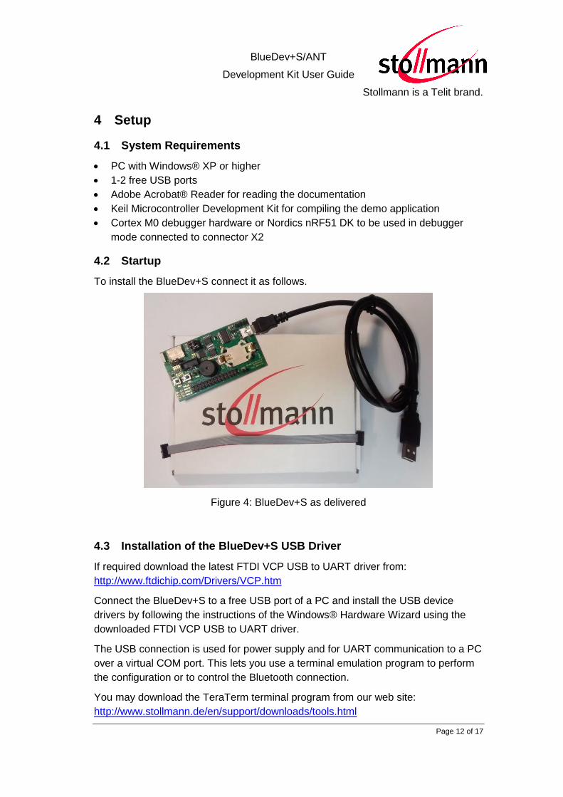
4.2 Startup
To install the BlueDev+S connect it as follows.
Figure 4: BlueDev+S as delivered
4.3 Installation of the BlueDev+S USB Driver
If required download the latest FTDI VCP USB to UART driver from:
http://www.ftdichip.com/Drivers/VCP.htm
Connect the BlueDev+S to a free USB port of a PC and install the USB device
drivers by following the instructions of the Windows® Hardware Wizard using the
downloaded FTDI VCP USB to UART driver.
The USB connection is used for power supply and for UART communication to a PC
over a virtual COM port. This lets you use a terminal emulation program to perform
the configuration or to control the Bluetooth connection.
You may download the TeraTerm terminal program from our web site:
http://www.stollmann.de/en/support/downloads/tools.html

BlueDev+S/ANT
Development Kit User Guide
Stollmann is a Telit brand.
Page 13 of 17
4.4 Installing the Debugger
If you don’t have a Cortex M0 debugger hardware in use right now, Stollmann
recommends the use of Nordics nRF51 DK.
Please refer to the Nordic web site for more information on the nRF51 DK.
4.5 Connecting the nRF51 DK to the BlueDev+S
Use the provided 9-Pin debugger cable to connect the BlueDev+S connector X2
with the debug out connector on the Nordic PCA10028 board.
Figure 5: nRF51 DK board PCA10028 connected to BlueDev+S board
4.6 Downloading and Installing the nRF51 SDK
The Stollmann demo source code is based on the nRF51 SDK v9.0.0.
Please download the SDK from http://developer.nordicsemi.com.
Please use the repository file nRF51_SDK_9.0.0_xxxxxxx.zip of the SDK.
After installing the nRF51 SDK please compile the peripheral BLE app template
project with the Keil compiler to make sure that the installation succeeded. The
demo is found in the directory
<nRF51 SDK 9.0.0 PATH>\examples\ble_peripheral\ble_app_template.

BlueDev+S/ANT
Development Kit User Guide
Stollmann is a Telit brand.
Page 14 of 17
5 Usage of the BlueDev+S
The provided BlueDev+S development package requires an installed nRF51 SDK
v9.0.0.
Please copy the directory stoDevKit to the <nRF51 SDK 9.0.0 PATH>\external\
path. The resulting structure should be as follows:
<nRF51 SDK 9.0.0 PATH>\external\stoDevKit\...
5.1 Stollmann Demo Source Code
The provided Stollmann demo source code is based on the
<nRF51 SDK 9.0.0 PATH>\examples\ble_peripheral\ble_app_template .
The code and project have been modified to support the Stollmann manual test
mode and the Direct Test Mode defined by the Bluetooth SIG. It is also possible to
assign a public Bluetooth address to be used by the firmware.
The Stollmann manual test mode is required if you want Stollmann E+V GmbH
to manufacture modules with your own firmware. Please contact Stollmann
E+V GmbH for more details on the manufacturing procedure.
5.2 BlueDev+S Software Package Structure
The directory stoDevKit contains all software provided by Stollmann. It uses the
nRF51 SDK files to build an example project.
5.2.1 The Directory “app_template”
The directory “app_template” contains the modified demo software. Please use the
app_template.uvmpw file to start the Keil IDE.
The file main.c contains the modifications which are clearly marked by “Stollmann E+V Gmbh specific functionality”.
5.2.2 The Directory “common”
The directory “common” contains source code files for the Stollmann manual test
mode and the DTM interface software.
Source file Description
sto_testmode.c Stollmann test mode implementation. GPIO control is done in this file. Starts Stollmann manual test mode, DTM or passes control back to the application code dependent on GPIO state
sto_dtmmode.c DTM interface code. Is called by sto_testmode.c dependent on GPIO state
sto_util.c Contains general utility functions
BlueDev+S/ANT
Development Kit User Guide
Stollmann is a Telit brand.
Page 15 of 17
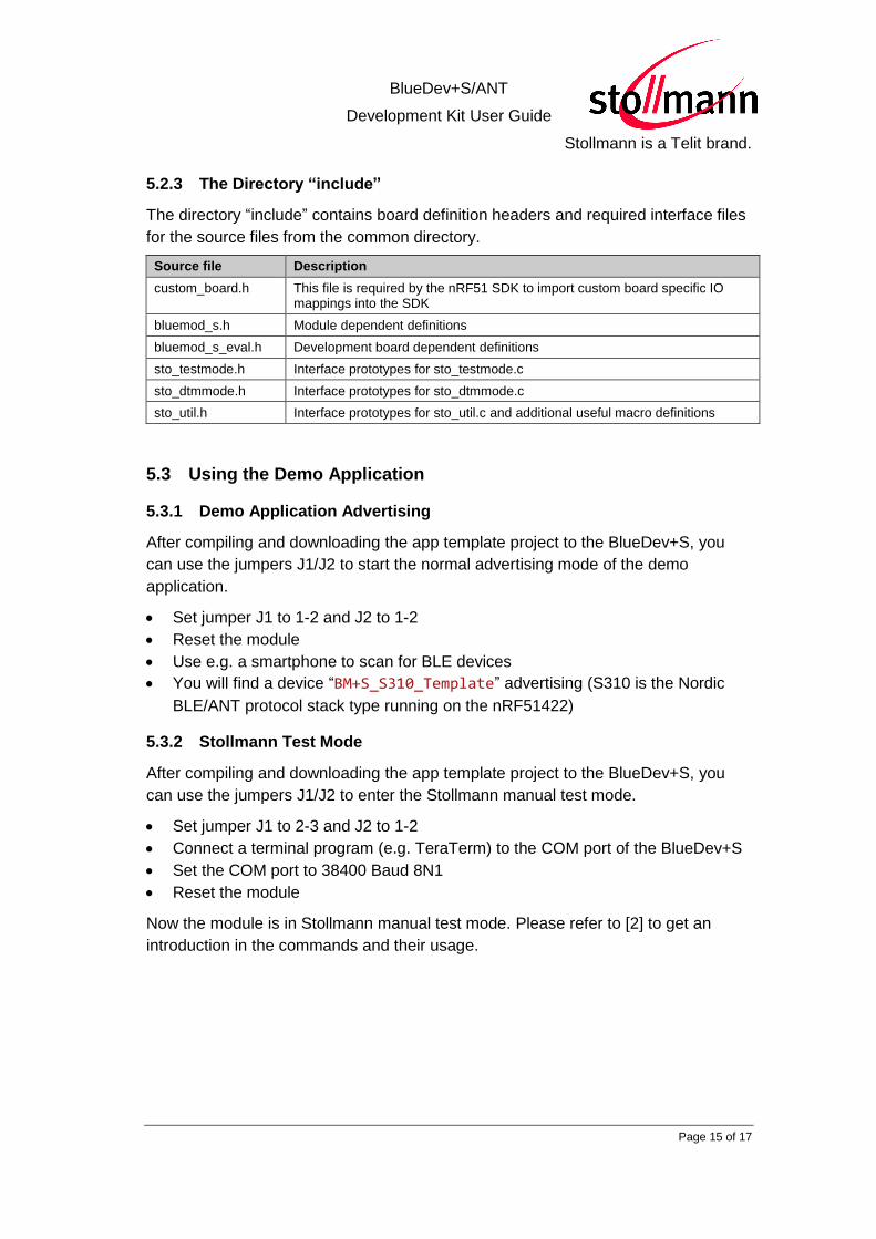
5.2.3 The Directory “include”
The directory “include” contains board definition headers and required interface files
for the source files from the common directory.
Source file Description
custom_board.h This file is required by the nRF51 SDK to import custom board specific IO mappings into the SDK
bluemod_s.h Module dependent definitions
bluemod_s_eval.h Development board dependent definitions
sto_testmode.h Interface prototypes for sto_testmode.c
sto_dtmmode.h Interface prototypes for sto_dtmmode.c
sto_util.h Interface prototypes for sto_util.c and additional useful macro definitions
5.3 Using the Demo Application
5.3.1 Demo Application Advertising
After compiling and downloading the app template project to the BlueDev+S, you
can use the jumpers J1/J2 to start the normal advertising mode of the demo
application.
Set jumper J1 to 1-2 and J2 to 1-2
Reset the module
Use e.g. a smartphone to scan for BLE devices
You will find a device “BM+S_S310_Template” advertising (S310 is the Nordic
BLE/ANT protocol stack type running on the nRF51422)
5.3.2 Stollmann Test Mode
After compiling and downloading the app template project to the BlueDev+S, you
can use the jumpers J1/J2 to enter the Stollmann manual test mode.
Set jumper J1 to 2-3 and J2 to 1-2
Connect a terminal program (e.g. TeraTerm) to the COM port of the BlueDev+S
Set the COM port to 38400 Baud 8N1
Reset the module
Now the module is in Stollmann manual test mode. Please refer to [2] to get an
introduction in the commands and their usage.

BlueDev+S/ANT
Development Kit User Guide
Stollmann is a Telit brand.
Page 16 of 17
6 Related Documents
[1] BlueMod+S Hardware Reference
[2] BlueMod+S Test Mode Reference
[3] BlueDev+S Schematic
7 History
Version Release Date By Change description
r01 20.08.2015 MJ Initial version
r02 24.05.2016 BG Telit cover page added.
Telit Wireless Solutions GmbH
Mendelssohnstraße 15 D
22761 Hamburg
Germany
Phone: +49 (0)40 890 88-0
Fax: +49 (0)40 890 88-444
E-mail: [email protected]
www.telit.com