Surviving an Extended Power Outage after a Breakdown … to the immediate steps taken in the...
12
Surviving an Extended Power Outage after a Breakdown in the Sub Station Roman Düssel 1 and Till Reek 2 1. Reduction Manager, TRIMET Aluminium SE, Aluminiumallee 1 Essen, Germany 2. Plant Manager, TRIMET Aluminium SE, Schleusenstraße 11, Voerde, Germany Corresponding author: [email protected] Abstract TRIMET Aluminium SE operates the Essen aluminium smelter with three potlines in Germany. On 12 April 2016 a smoke alarm in the substation triggered an emergency shutdown of the whole plant. The smoke alarm was triggered by a short circuit on a 21 kV bus bar. While Potline II and III could be restarted within two hours, the damaged bus bar had to be removed, separating Potline I from the redundant high voltage power supply and fixing it on a single 220 kV transformer. When Potline I was able to be restarted, the 220 kV transformer was found to have an insulation fault. An emergency bus bar replacement was welded in place and Potline I could be re-energized after 5 hours 50 minutes and 30 seconds. Due to the immediate steps taken in the potrooms, any pot loss could be prevented and the potline was back to normal operation in 12 hours. Keywords: Power outage, aluminium reduction, recovery from power outage. 1. Introduction The aluminium reduction process is an electrochemical process operating close to 960 °C. This temperature is necessary to keep the electrolyte in a molten state. Typically, the process temperature is only a few degrees Celsius above the liquidus temperature of the molten electrolyte. The sole heating agent is electrical current pathing through the cell and enforcing the electrolytic reduction of alumina. As soon the heating is interrupted, the cells start to cool and immediately the superheat of the electrolyte is reduced to around zero °C and solidification starts. As pure cryolite starts to solidify first, the concentration of additives in the electrolyte, such as AlF 3 increases and in turn keeps the bulk of the electrolyte liquid. As long as enough electrolyte is liquid in all of the cells, the potline can be restarted. Typically, this period is stated as 4 hours by Øye and Sørlie [1] and 3 to 5 hours by Tabereaux [2]. Continuity in electrical power supply is therefore of very high importance for operating a smelter. However, there are regular instances of power outages affecting aluminum smelters. Nevertheless, detailed publications on power outages and their effects on potlines are limited. Øye and Sørlie detail some outages, but seldom is the exact duration or the cause given and measures to preserve heat in the cells or steps taken to re-energize the potline are typically not discussed. Effects vary from little effect, to 10 - 20 % of the production being shut down, to failures of full potlines, References [3, 4 and 5]. Effectively, this limits successes of recovery to the experience (and nerves) of the staff on site. While there can be no universal emergency plan, there are some simple rules and guidelines to at least increase the chances for success for re-energizing the potline. This paper summarizes the experiences made in Essen during a 6-hour power outage in one of the potlines. Travaux 46, Proceedings of 35th International ICSOBA Conference, Hamburg, Germany, 2 – 5 October, 2017. 891
Transcript of Surviving an Extended Power Outage after a Breakdown … to the immediate steps taken in the...

Surviving an Extended Power Outage after a Breakdown in the Sub Station
Roman Düssel1 and Till Reek2
1. Reduction Manager, TRIMET Aluminium SE, Aluminiumallee 1 Essen, Germany 2. Plant Manager, TRIMET Aluminium SE, Schleusenstraße 11, Voerde, Germany
Corresponding author: [email protected]
Abstract
TRIMET Aluminium SE operates the Essen aluminium smelter with three potlines in Germany. On 12 April 2016 a smoke alarm in the substation triggered an emergency shutdown of the whole plant. The smoke alarm was triggered by a short circuit on a 21 kV bus bar. While Potline II and III could be restarted within two hours, the damaged bus bar had to be removed, separating Potline I from the redundant high voltage power supply and fixing it on a single 220 kV transformer. When Potline I was able to be restarted, the 220 kV transformer was found to have an insulation fault. An emergency bus bar replacement was welded in place and Potline I could be re-energized after 5 hours 50 minutes and 30 seconds. Due to the immediate steps taken in the potrooms, any pot loss could be prevented and the potline was back to normal operation in 12 hours. Keywords: Power outage, aluminium reduction, recovery from power outage. 1. Introduction The aluminium reduction process is an electrochemical process operating close to 960 °C. This temperature is necessary to keep the electrolyte in a molten state. Typically, the process temperature is only a few degrees Celsius above the liquidus temperature of the molten electrolyte. The sole heating agent is electrical current pathing through the cell and enforcing the electrolytic reduction of alumina. As soon the heating is interrupted, the cells start to cool and immediately the superheat of the electrolyte is reduced to around zero °C and solidification starts. As pure cryolite starts to solidify first, the concentration of additives in the electrolyte, such as AlF3 increases and in turn keeps the bulk of the electrolyte liquid. As long as enough electrolyte is liquid in all of the cells, the potline can be restarted. Typically, this period is stated as 4 hours by Øye and Sørlie [1] and 3 to 5 hours by Tabereaux [2]. Continuity in electrical power supply is therefore of very high importance for operating a smelter. However, there are regular instances of power outages affecting aluminum smelters. Nevertheless, detailed publications on power outages and their effects on potlines are limited. Øye and Sørlie detail some outages, but seldom is the exact duration or the cause given and measures to preserve heat in the cells or steps taken to re-energize the potline are typically not discussed. Effects vary from little effect, to 10 - 20 % of the production being shut down, to failures of full potlines, References [3, 4 and 5]. Effectively, this limits successes of recovery to the experience (and nerves) of the staff on site. While there can be no universal emergency plan, there are some simple rules and guidelines to at least increase the chances for success for re-energizing the potline. This paper summarizes the experiences made in Essen during a 6-hour power outage in one of the potlines.
Travaux 46, Proceedings of 35th International ICSOBA Conference, Hamburg, Germany, 2 – 5 October, 2017.
891
2. Course of Events On 12 April 2016 at 05:10:35 h the full plant dropped off-line while a smoke alarm in the building of the medium-high voltage was detected. The fire brigade was called to investigate the cause and did not find a fire source. After ventilation, maintenance was cleared to enter the building (still devoid of power) and found partly scorched and melted bus bars in the 21 kV switch room. The damaged section was a redundancy cross link enabling potline I to receive electricity from another than a single 220 kV transformer. Thus, the bus bar was perceived as uncritical for the immediate restart. The damaged section is shown in Figure 1.
Figure 1. Scorched 21 kV busbar.
The damaged section was removed and the plant including the compressed air station, cast house and GTC were smoothly restarted. Potline III and potline II could be restarted at 7:23 am and 7:25 am respectively with slightly more than 2 hours power outage. Potline I could not be energized. Isolating and removing the damaged 21 kV bus bar had isolated potline one on a single 220 kV transformer. When this transformer was switched on, it immediately failed. With the usual redundancy removed and isolated on a damaged transformer, a contingency plan was needed. The potroom relining department, who also repairs and modifies potroom bus bars when damaged, were called in to prepare an emergency weld to bridge the gap the removed bus bars had created. While this was in preparation the plant was scourged for material that could be used as 21 kV bus bar – both in material quality as well as in diameter and length. Replacement bus bars were welded in place on all three phases and the potline could be reenergized at 11:01am, close to 6 hours after the initial power outage. Post event analysis showed the course of events leading to the damage as follows:
- In one 21 kV panel for the auxiliary power a cable end sealing of one phase failed in isolation towards earth.
- This led to an arcing short circuit with a neighboring phase. - About 10 ms later a full 3-phase short circuit developed with a short-circuit current of
up to 25 kA. - About 100 ms later the vacuum power switch disconnected the affected transformer as
expected.
Travaux 46, Proceedings of 35th International ICSOBA Conference, Hamburg, Germany, 2 – 5 October, 2017.
892
- This dropped the auxiliary power for the plant off-line and consequently dropping the potlines as well.
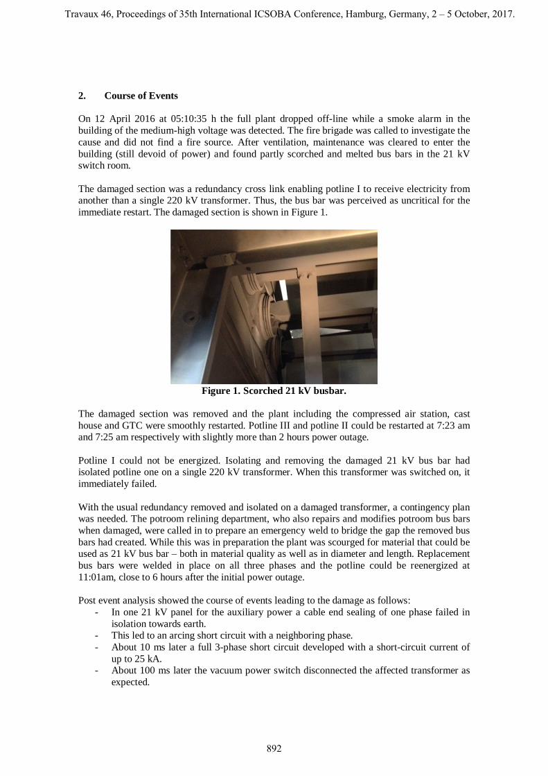
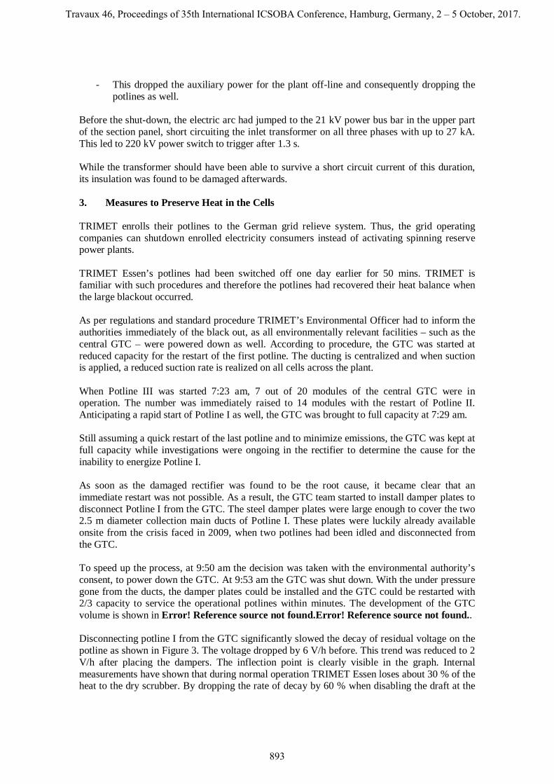
Before the shut-down, the electric arc had jumped to the 21 kV power bus bar in the upper part of the section panel, short circuiting the inlet transformer on all three phases with up to 27 kA. This led to 220 kV power switch to trigger after 1.3 s. While the transformer should have been able to survive a short circuit current of this duration, its insulation was found to be damaged afterwards. 3. Measures to Preserve Heat in the Cells TRIMET enrolls their potlines to the German grid relieve system. Thus, the grid operating companies can shutdown enrolled electricity consumers instead of activating spinning reserve power plants. TRIMET Essen’s potlines had been switched off one day earlier for 50 mins. TRIMET is familiar with such procedures and therefore the potlines had recovered their heat balance when the large blackout occurred. As per regulations and standard procedure TRIMET’s Environmental Officer had to inform the authorities immediately of the black out, as all environmentally relevant facilities – such as the central GTC – were powered down as well. According to procedure, the GTC was started at reduced capacity for the restart of the first potline. The ducting is centralized and when suction is applied, a reduced suction rate is realized on all cells across the plant. When Potline III was started 7:23 am, 7 out of 20 modules of the central GTC were in operation. The number was immediately raised to 14 modules with the restart of Potline II. Anticipating a rapid start of Potline I as well, the GTC was brought to full capacity at 7:29 am. Still assuming a quick restart of the last potline and to minimize emissions, the GTC was kept at full capacity while investigations were ongoing in the rectifier to determine the cause for the inability to energize Potline I. As soon as the damaged rectifier was found to be the root cause, it became clear that an immediate restart was not possible. As a result, the GTC team started to install damper plates to disconnect Potline I from the GTC. The steel damper plates were large enough to cover the two 2.5 m diameter collection main ducts of Potline I. These plates were luckily already available onsite from the crisis faced in 2009, when two potlines had been idled and disconnected from the GTC. To speed up the process, at 9:50 am the decision was taken with the environmental authority’s consent, to power down the GTC. At 9:53 am the GTC was shut down. With the under pressure gone from the ducts, the damper plates could be installed and the GTC could be restarted with 2/3 capacity to service the operational potlines within minutes. The development of the GTC volume is shown in Error! Reference source not found.Error! Reference source not found.. Disconnecting potline I from the GTC significantly slowed the decay of residual voltage on the potline as shown in Figure 3. The voltage dropped by 6 V/h before. This trend was reduced to 2 V/h after placing the dampers. The inflection point is clearly visible in the graph. Internal measurements have shown that during normal operation TRIMET Essen loses about 30 % of the heat to the dry scrubber. By dropping the rate of decay by 60 % when disabling the draft at the
Travaux 46, Proceedings of 35th International ICSOBA Conference, Hamburg, Germany, 2 – 5 October, 2017.
893
top side of the cells, the mechanics for heat loss during power outage appears to be significantly different.
Figure 2. Line amperage (blue) and GTC capacity (red) during the power outage.
Figure 3. Residual voltage of Potline I.
Additional measures to preserve heat were also discussed. Most notably was the idea to apply additional cover material to the top of the crust to reduce the heat loss even further. To judge the possible impact of cover spillage into the cooled electrolyte, one single electrolyte height measurement was performed on a cell. Only 8 cm of a very sludgy electrolyte was found. The risk of cover material spillage into the cell cavity was deemed to risk and not followed up on. It was decided to leave the cells as they were for the remainder of the outage. 4. Decision to Restart and Preparation Drawing on previous experiences and difficulties of successfully restarting the potline after close to 4 hours of power outage after storm damage in 2002, discussions with the CEO started at about 9:30 h for an orderly shutdown and removing the anodes from the electrolyte. Informed of the situation in the potrooms, the casthouse had kept all furnaces empty and waited on standby for potroom metal, in case a controlled shut down of Potline I was decided.
Travaux 46, Proceedings of 35th International ICSOBA Conference, Hamburg, Germany, 2 – 5 October, 2017.
894

Previous experience of tapping metal more than one shift after shutting down a cell resulted in the assessment that in an ideal case, 400 t or 30 % of the metal inventory could be salvaged before the cells would be frozen. The outlook was bleak and the team was close to being in a position that all would be lost, when the supervisor for the rectifiers checked the residual voltage of the potline and found it to be 37 V. The rectifier supervisor had been on site at the power outage in 2002 and recalled that the residual voltage had decayed to 30 V after 4 hours at that time. Based on this knowledge the situation was re-assessed and it was decided that the potline was still in a condition to be restarted as soon as the bus bar welding had finished. During the whole power outage, normal work routines had not been resumed, not even in the potlines back in operation as lead times for necessary work during a restart in Potline I was to be kept to a minimum and all work routes for anode transport and metal delivery would have led through Potline I. With the restart decision made and a time frame of less than one hour until electricity should be restored, further preparations were made in the potrooms, this included the distribution of a large number of wooden poles at every other pot in the potline for quenching anode effects after current pickup. In addition, in Potline II, two cells were originally scheduled to be started after gas preheating on that day, however the decision was taken to postpone the start-up by one day. The electrolyte gathered in donor pots for this scheduled pot startup was to be redirected for use to increase liquid electrolyte levels when needed after the Potline I restart. However, the amount of electrolyte was deemed to be insufficient as the need for massive electrolyte amounts was anticipated. To provide electrolyte easily, 10 additional cells in Potline II were forced into anode effect by switching off the alumina feeding. Crushed electrolyte was prepared in large buckets so that it could be added to the cell in anode effect to melt it quickly. With re-energizing the potline after more than 5 hours, the risk of clad failures due to overloading of single anodes was expected. It was decided to have hot anodes available as replacements if needed. Anodes in the middle of their life were removed from cells in Potline II and III. In total 20 anodes in Potline II and III were removed, ready to be introduced into Potline I cells if needed While these restart measures were being organized, the Essen potrooms manager sought advice from all other TRIMET smelters (3 other smelters) on how to manage the restart. The main items of advice were:
- Block feeding on all cells until potline has been operational for some time to prevent sludging.
- Increase line current as fast as possible to at least 120 kA (75 %) to get heat into the cells and to exceed the lower feeding limit of 80 kA (The rate is shown in Figure 4).
- Buzz down all beams for 1 to 2 seconds to optimize wetting of the anodes by the remaining electrolyte as soon as line current was back to improve the wetting of the anodes with liquid electrolyte.
- Deactivate automatic anode effect quenching to avoid short circuits. - Have as many operators as possible in the line for anode effect termination. - Have one engineer at a computer for changing parameters (e.g. unblock feeding). - Have a permanent phone line to the rectifier until the potline seems safe to minimize
reaction time. 4.1. Restart
Travaux 46, Proceedings of 35th International ICSOBA Conference, Hamburg, Germany, 2 – 5 October, 2017.
895

The restart was carried out at 11:01:05, 5 hours 50 minutes and 30 seconds after the initial power outage. At restart the residual line voltage was measured at 35 volts. The whole potline was evacuated as it was not known how the pots and especially bottlenecks such as the bimetal clads would react. In case of rapid clad failure, open electrical arcs were expected as the open circuit protection had been deactivated. It was important to start with an amperage that would not result in too high total line voltage to avoid overloading the rectifiers. 60 kA was targeted and achieved after a short amperage spike up to 100 kA. The line voltage jumped from 35 V residual load to 350 V almost immediately. Within a few minutes line voltage increased to 600 V. The normal line voltage before the outage had been 512 V, however 600 V is still safely within the operational limits of the rectifier. With this information and the knowledge that the amperage had stayed on for a few minutes without any noticeable problems, 20 operators were deployed into the potroom to manually buzz down the beam of every single pot. As anticipated this increased the wetting of the anodes with the remaining liquid electrolyte and potline voltage dropped to 450 V. This freed capacity in the rectifier to further increase line current. As a plan, the line current was increased at a rate which allowed the line voltage to be at or below 600 V. The line current was increased continuously in coordination between potrooms and rectifier. Within 20 minutes after restart, 140 kA was reached (Figure 4Error! Reference source not found.). The rectifier was able to hold the line amperage stable. Line voltage had dropped continuously peaking at 635 V, but during the time it was still around 600 V at 140 kA.
Figure 4. Line current development immediately after re-energizing.
Having stabilized the potline, the attention turned to individual pots. At reaching 140 kA pot voltages varied between 1 V and 20 V (see Figure 5). Even though 32 out of 120 cells reported cell voltages below 2 V, these cells appeared stable. Anodic current distribution showed wide swings, but visual inspection on some cells showed no red stubs or other indications of too high current load. Obviously, a number of anodes had been pushed into the metal to carry the current safely. The cell would not recover by themselves, but ohmic heating was deemed sufficient to avoid further freezing of the cell.
Travaux 46, Proceedings of 35th International ICSOBA Conference, Hamburg, Germany, 2 – 5 October, 2017.
896

Figure 5. Boxplots of cell voltages in Potline I. Note that there are many outliers (marked
with * in the graph). These are the cells that need most attention. With the line current being stable, the decision was taken to re-activate the alumina feeding. The cells below 2 V should not receive alumina to not sludge even more, but voltages that low were registered by the process control system as cut-out and alumina feeding was deactivated automatically. Due to the high traffic on the communication bus, parameter changes had to be sent multiple times to individual cell controls and all cell controls had to be checked manually if they had received the new parameters. A team was established to continuously measure anodic current distribution on cells with both low and high voltage and to check electrolyte levels. The anode setting team was ordered to re-set anodes with high current load, if electrolyte levels permitted. Electrolyte levels varied widely. Some cells had regained electrolyte levels of 15 cm or more, while the most critical cells were found with only 5 cm of electrolyte. Another team was deployed to start electrolyte transfers from the operational potlines and targeting those cells. Typically cells with low pot voltages showed low bath levels as well. With sufficient electrolyte additions, the anode beam was raised, targeting regular pot voltages. For some cells this was achieved by moving the beam only a few millimeters, while other beams were raised up to 10 mm with little response. Electrolyte transfer capacity and electrolyte availability was limited even though steps as described above had been taken to generate additional electrolyte. Due to these limitations, the team was forced to raise beams of low voltage pots without electrolyte addition. This was done while carefully monitoring the electrolyte level in the cell. This restored several cells to normal working condition. Even though this process was considered risky, no problems occurred. If a beam raise of 10 mm did not result in a gain of pot voltage, the cell was scheduled for the next available electrolyte addition. It is notable, that during the early hours of the restart, clad failures did not occur. Several cells in potline I had damaged cathodes and had been targeted for cut out earlier. No action had been taken during the power outage and cutting out any additional cell after the restart would have necessitated another shut down for at least 30 min or more as short circuiting a cell in Essen is
Travaux 46, Proceedings of 35th International ICSOBA Conference, Hamburg, Germany, 2 – 5 October, 2017.
897
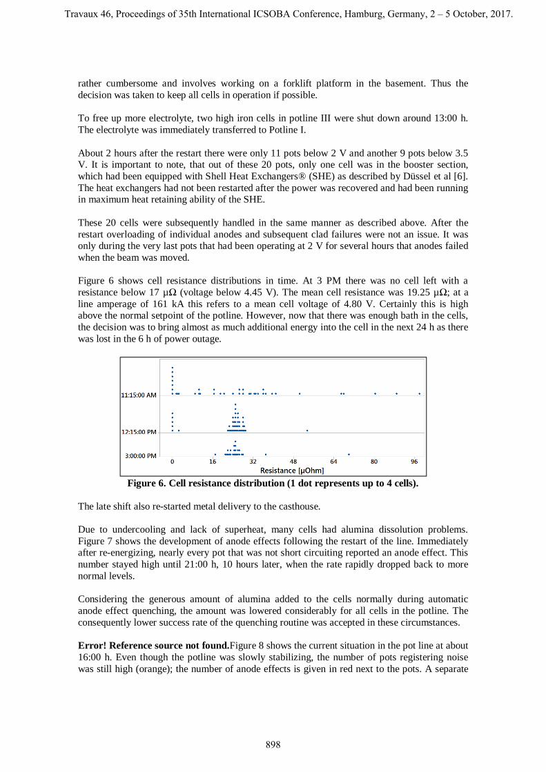
rather cumbersome and involves working on a forklift platform in the basement. Thus the decision was taken to keep all cells in operation if possible. To free up more electrolyte, two high iron cells in potline III were shut down around 13:00 h. The electrolyte was immediately transferred to Potline I. About 2 hours after the restart there were only 11 pots below 2 V and another 9 pots below 3.5 V. It is important to note, that out of these 20 pots, only one cell was in the booster section, which had been equipped with Shell Heat Exchangers® (SHE) as described by Düssel et al [6]. The heat exchangers had not been restarted after the power was recovered and had been running in maximum heat retaining ability of the SHE. These 20 cells were subsequently handled in the same manner as described above. After the restart overloading of individual anodes and subsequent clad failures were not an issue. It was only during the very last pots that had been operating at 2 V for several hours that anodes failed when the beam was moved. Figure 6 shows cell resistance distributions in time. At 3 PM there was no cell left with a resistance below 17 µΩ (voltage below 4.45 V). The mean cell resistance was 19.25 µΩ; at a line amperage of 161 kA this refers to a mean cell voltage of 4.80 V. Certainly this is high above the normal setpoint of the potline. However, now that there was enough bath in the cells, the decision was to bring almost as much additional energy into the cell in the next 24 h as there was lost in the 6 h of power outage.
Figure 6. Cell resistance distribution (1 dot represents up to 4 cells).
The late shift also re-started metal delivery to the casthouse. Due to undercooling and lack of superheat, many cells had alumina dissolution problems. Figure 7 shows the development of anode effects following the restart of the line. Immediately after re-energizing, nearly every pot that was not short circuiting reported an anode effect. This number stayed high until 21:00 h, 10 hours later, when the rate rapidly dropped back to more normal levels. Considering the generous amount of alumina added to the cells normally during automatic anode effect quenching, the amount was lowered considerably for all cells in the potline. The consequently lower success rate of the quenching routine was accepted in these circumstances. Error! Reference source not found.Figure 8 shows the current situation in the pot line at about 16:00 h. Even though the potline was slowly stabilizing, the number of pots registering noise was still high (orange); the number of anode effects is given in red next to the pots. A separate
Travaux 46, Proceedings of 35th International ICSOBA Conference, Hamburg, Germany, 2 – 5 October, 2017.
898
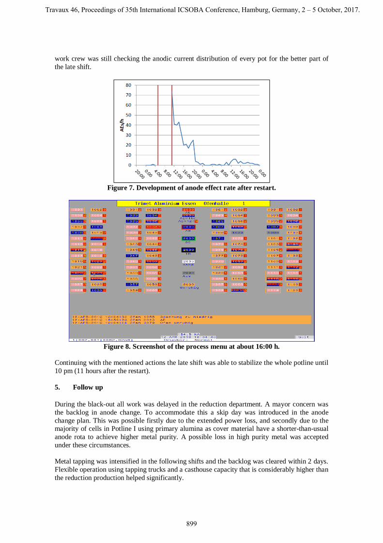
work crew was still checking the anodic current distribution of every pot for the better part of the late shift.
Figure 7. Development of anode effect rate after restart.
Figure 8. Screenshot of the process menu at about 16:00 h.
Continuing with the mentioned actions the late shift was able to stabilize the whole potline until 10 pm (11 hours after the restart). 5. Follow up During the black-out all work was delayed in the reduction department. A mayor concern was the backlog in anode change. To accommodate this a skip day was introduced in the anode change plan. This was possible firstly due to the extended power loss, and secondly due to the majority of cells in Potline I using primary alumina as cover material have a shorter-than-usual anode rota to achieve higher metal purity. A possible loss in high purity metal was accepted under these circumstances. Metal tapping was intensified in the following shifts and the backlog was cleared within 2 days. Flexible operation using tapping trucks and a casthouse capacity that is considerably higher than the reduction production helped significantly.
Travaux 46, Proceedings of 35th International ICSOBA Conference, Hamburg, Germany, 2 – 5 October, 2017.
899

Another shut down for 1.5 hours for further repair on the 21 kV bus bars had to be made the following day and was coped with easily. The temperature measurements after the outage recorded a significant drop to 946 °C as average electrolyte temperature in Potline I the following day (Figure 9). Manual additions of soda and raised cell voltages recovered temperatures and chemistry within 4 days (Figure 10). Unfortunately, the chemical additions lead to a swinging of the temperature and liquidus temperature of 1 cycle that lasted for about 2 weeks. Nevertheless, the decision was made to act in the same way if a similar power outage would happen again. Simply the counteraction of AlF3 a week later was analysed to not overshoot in the opposite direction again. The standard deviation in Figure 9 shows that individual pot caring was made appropriate so that there did not develop 2 areas of cold and hot cells.
Figure 9. Mean temperature and standard deviation of Potline I.
Figure 10. Boxplots of the AlF3 deviation in Potline I. Note that there are a few outliers (marked with * in the graph) with very high values. These are the cells that need most
attention. Summarizing total damages to the potline due to the power outage, 2 cells in Potline III were cut out as they were iron pots and the electrolyte was deemed necessary. In total only 14 clad
Travaux 46, Proceedings of 35th International ICSOBA Conference, Hamburg, Germany, 2 – 5 October, 2017.
900

failures were recorded on the day of the restart. On that day and the following, 19 anode spikes were found and removed from the cells – 10 of which were in Potline I. 6. Conclusions The Essen smelter survived a major power outage in one of the 3 potlines. The potline was without power for close to 6 hours. The recovery was considered smooth and the potline was operating in a stable condition within 11 hours after restart and electrolyte temperatures normalized within 4 days. The section equipped with Shell Heat Exchangers® showed less impact to the power outage than the rest of the line. The following key points can be highlighted as critical for this success during the power outage:
- Install an emergency team and communicate all relevant information, - Retain heat in the cells, - Do not touch the cells, - Prepare for all options while there is time (emergency shut-down teams, logistics, on-
call response people), - Prepare electrolyte, - Prepare hot anodes, - Distribute the work and name responsible persons, - Let these people do their job, - Prepare contingency plans.
During the restart:
- Block alumina feeding for the restart, - Block automatic AE quenching, - Buzz down all beams for 1 second when the energy is back.
Last but not least, it should be mentioned that such a crisis cannot be managed if the whole team in the plant is not working hand in hand to solve any issue that might arise. A big ‘thank you’ to everybody who was involved in the restart and the subsequent recovery.
7. References 1. Harald A. Øye and Morten Sørlie, Power failure, restart and repair, Aluminium
International Today, 2011, http://www.aluminiumtoday.com/contentimages/features/Oyeweb.pdf, accessed on 5 August 2017.
2. Alton Tabereaux, Electrical power outages and potline recovery with partially frozen bath, The 35th International Course on Process Metallurgy of Aluminium, Trondheim, Norway, 29 May – 2 June, 2017.
3. Hydro Årdal power outage has limited effect on production, http://www.hydro.com/en/press-room/Archive/2016/Hydro-Ardal-power-outage-has-limited-effect-on-production/, 1 February 2016, accessed on 5 August 2017.
4. Sarmad Khan, Power outage slows Dubai smelter, November 10, 2008, https://www.thenational.ae/business/power-outage-slows-dubai-smelter-1.503397, accessed on 5 August 2017.
5. Power Outage Idles Two of Noranda’s Three Smelters, http://aluminiuminsider.com/power-outage-idles-two-of-norandas-three-smelters/, accessed on 5 August 2017.
6. N. Depree, Romel Düssel et al., The 'Virtual Battery' – Operating an Aluminium Smelter with Flexible Energy Input, Light Metals 2016, 571-576.
Travaux 46, Proceedings of 35th International ICSOBA Conference, Hamburg, Germany, 2 – 5 October, 2017.
901

Travaux 46, Proceedings of 35th International ICSOBA Conference, Hamburg, Germany, 2 – 5 October, 2017.
902