Surv eillance Receiv er - hp70000.com · con v ection in to and out of the instrumen t m ust not b...
238
-
Upload
hoanghuong -
Category
Documents
-
view
213 -
download
0
Transcript of Surv eillance Receiv er - hp70000.com · con v ection in to and out of the instrumen t m ust not b...

User's Guide
HP 71910A Wide-Bandwidth
Surveillance Receiver
ABCDE
HP Part No. 71910-90002
Printed in USA December 1996
Edition A.0.0

Notice
The information contained in this document is subject to change without notice.
Hewlett-Packard makes no warranty of any kind with regard to this material, including,but not limited to, the implied warranties of merchantability and �tness for a particularpurpose. Hewlett-Packard shall not be liable for errors contained herein or for incidental orconsequential damages in connection with the furnishing, performance, or use of this material.
Restricted Rights Legend.
Use, duplication, or disclosure by the U.S. Government is subject to restrictions as set forthin subparagraph (c) (1) (ii) of the Rights in Technical Data and Computer Software clauseat DFARS 252.227-7013 for DOD agencies, and subparagraphs (c) (1) and (c) (2) of theCommercial Computer Software Restricted Rights clause at FAR 52.227-19 for other agencies.
This instrument has been designed and tested in accordance with IEC Publication 348, SafetyRequirements for Electronic Measuring Apparatus, and has been supplied in a safe condition.The instruction documentation contains information and warnings which must be followed bythe user to ensure safe operation and to maintain the instrument in a safe condition.
c Copyright Hewlett-Packard Company 1994{1996
All Rights Reserved. Reproduction, adaptation, or translation without prior writtenpermission is prohibited, except as allowed under the copyright laws.1400 Fountaingrove Parkway, Santa Rosa, CA 95403-1799, USA

Safety
WARNING No operator serviceable parts inside. Refer servicing to qualified personnel. To
prevent electrical shock, do not remove covers.
WARNING For continued protection against fire hazard, replace line fuse only with same
type and ratings (type 6.3A/250V). The use of other fuses or materials is
prohibited.
CAUTION Always use the three-prong ac power cord supplied with this instrument.Failure to ensure adequate earth grounding by not using this cord may causeinstrument damage.
WARNING This is a Safety Class 1 Product (provided with a protective earthing ground
incorporated in the power cord.) The mains plug shall only be inserted in a
socket outlet provided with a protective earth contact. Any interruption of the
protective conductor inside or outside of the instrument is likely to make the
instrument dangerous. Intentional interruption is prohibited.
CAUTION This instrument is designed for use in Installation Category II and PollutionDegree 2 per IEC 1010 and 664 respectively.
CAUTION Ventilation Requirements: When installing the instrument in a cabinet, theconvection into and out of the instrument must not be restricted. The ambienttemperature (outside the cabinet) must be less than the maximum operatingtemperature of the instrument by 4 �C for every 100 watts dissipated in thecabinet. If the total power dissipated in the cabinet is greater than 800 watts,then forced convection must be used.
WARNING If this instrument is not used as specified, the protection provided by the
equipment could be impaired. This instrument must be used in a normal
condition (in which all means for protection are intact) only.
iii

Surveillance with the HP 71910A
The HP 71910A Wide-Bandwidth Surveillance Receiver provides both signal search and signalcollection capability from 100 Hz to 26.5 GHz. It is optimized for surveillance and signalmonitoring applications. The HP 71910A can be operated in either of the following twoinstrument modes:
Spectrum analyzer operation for signal searches
Maximum resolution BW : : : : : : : : : : : : : : : : : : : : : : : : : : : : : : : : : : : : : : : : : : : : : : : : : 3 MHz
Wide-bandwidth receiver operation for signal collection
IF BW : : : : : : : : : : : : : : : : : : : : : : : : : : : : : : : : : : : : : : : : : : : : : : : : : : : : : : : : : : : 10 to 100 MHz
Note When you use the wide-bandwidth surveillance receiver, remember that inspectrum analyzer mode the maximum resolution bandwidth is 3 MHz; it isnot a 100 MHz bandwidth spectrum analyzer.
The receiver's IF and video outputs can be examined by oscilloscopes, demodulators,digitizers, FFT baseband analyzers, and other instruments.
HP 71910A Wide-Bandwidth Surveillance Receiver
iv

HP 71910A Option 011
When �rst turned on, the wide-bandwidth surveillance receiver operates as a spectrumanalyzer. This allows you to view signals across a large frequency range. Once you've locateda signal, switch to the �xed-tuned receiver mode to downconvert the signal.
The downconverted signal is available at the rear panel for processing and analyzing byexternal devices. The Option 011 version of the instrument is primarily used as a collectionreceiver; it has very limited spectrum analyzer capability due to linear detection and 3 MHzmaximum peak detection bandwidth. (Option 013 adds an HP 70902A to provide a morecomplete spectrum analyzer.)
IF outputs are available at the rear panel
In receiver mode, the downconverted signal is available at the instrument's rear panel. Thestandard rear-panel output is centered at 321.4 MHz. Option 001 and 002 instruments provideadditional 70 MHz and 140 MHz IF signals respectively. Refer to Chapter 3 for examples ofprocessing these signals.
v

Demodulated outputs are available at the front panel
The front-panel VIDEO connector provides AM and pulse demodulation. Option 004 providesadditional I/Q outputs and Option 005 provides an additional FM output. Refer to Chapter 3for examples of processing these signals.
Option 004 instruments (together with an external oscilloscope in XY mode), provide aconvenient method of identifying modulation formats such as 8 PSK, 16 QAM, and 64 QAM.With typical receivers, the constellations \spin" due to the o�set in frequency between thereceiver and the signal. This makes format identi�cation very di�cult. But, because of thewide-bandwidth surveillance receiver's 1 Hz frequency tuning, this spinning movement can beslowed to the point where it is almost stopped.
256 QAM Constellation Displayed on Oscilloscope
vi

Switch between operating mode with the press of a button
Press �USER� and thenNNNNNNNNNNNNNNNNNNNNNNNRX_MODE for use as a wide-bandwidth surveillance receiver.
Press �MENU� for use as a spectrum analyzer.
This is the default state when the instrument is �rst turned on.
Press �DISPLAY� to access functions for controlling the display.
You will seldom need to use this key. For information on functions accessed with this key,refer to the HP 70004A DISPLAY Operating Manual .
Press �INSTR� to switch between multiple instrument windows.
Multiple instrument windows must �rst be con�gured as shown in Chapter 3.
vii

Changing measurement parameters is easy
Use the front-panel knob, step keys, or numeric keypad to enter new measurements settings.For example, press the �CENTER� key to change the displayed center frequency. After changingthe setting, pressing the �HOLD� key disables the keypad, knob, and step keys until anotherfunction is selected.
Use the ��� (backspace) key to speed your navigation through softkey menus. When pressed,the previous softkey menu is displayed. Also, use this key to backspace over numbers enteredusing the data-entry keypad.
Conventions
The following key conventions are used in this guide:
�Front-panel key� Text shown like this represents a key physically located on the receiver.NNNNNNNNNNNNNNNNNNNNNNNSoftkey Text shown like this represents a softkey. (The softkeys are located next to
the softkey labels, and the softkey labels are the annotation on the right orleft side of the spectrum analyzer display.)
Screen Text Text printed in this typeface indicates text displayed on the instrument'sscreen.
viii

Instrument Markings
L The instruction documentation symbol. The product is marked with this symbol whenit is necessary for the user to refer to the instructions in the documentation.
\CE" The CE mark is a registered trademark of the European Community. (If accompaniedby a year, it is when the design was proven.)
\ISM1-A" This is a symbol of an Industrial Scienti�c and Medical Group 1 Class A product.
\CSA" The CSA mark is a registered trademark of the Canadian Standards Association.
CAUTION Caution denotes a hazard. It calls attention to a procedure that, if notcorrectly performed or adhered to, could result in damage to or destruction ofthe instrument. Do not proceed beyond a caution note until the indicatedconditions are fully understood and met.
WARNING Warning denotes a hazard. It calls attention to a procedure which, if not
correctly performed or adhered to, could result in injury or loss of life. Do
not proceed beyond a warning note until the indicated conditions are fully
understood and met.
ix

Assistance
Product maintenance agreements and other customer assistance agreements are available forHewlett-Packard products. For any assistance, contact your nearest Hewlett-Packard Salesand Service O�ce.
Regulatory Information
Regulatory information is located in Chapter 5, \Speci�cations and Characteristics."
Certification
Hewlett-Packard Company certi�es that this product met its published speci�cations at thetime of shipment from the factory. Hewlett-Packard further certi�es that its calibrationmeasurements are traceable to the United States National Institute of Standards andTechnology, to the extent allowed by the Institute's calibration facility, and to the calibrationfacilities of other International Standards Organization members.
x

Warranty
This Hewlett-Packard instrument product is warranted against defects in material andworkmanship for a period of one year from date of shipment. During the warranty period,Hewlett-Packard Company will, at its option, either repair or replace products which prove tobe defective.
For warranty service or repair, this product must be returned to a service facility designatedby Hewlett-Packard. Buyer shall prepay shipping charges to Hewlett-Packard andHewlett-Packard shall pay shipping charges to return the product to Buyer. However, Buyershall pay all shipping charges, duties, and taxes for products returned to Hewlett-Packardfrom another country.
Hewlett-Packard warrants that its software and �rmware designated by Hewlett-Packard foruse with an instrument will execute its programming instructions when properly installed onthat instrument. Hewlett-Packard does not warrant that the operation of the instrument, orsoftware, or �rmware will be uninterrupted or error-free.
Limitation of Warranty
The foregoing warranty shall not apply to defects resulting from improper or inadequatemaintenance by Buyer, Buyer-supplied software or interfacing, unauthorized modi�cation ormisuse, operation outside of the environmental speci�cations for the product, or impropersite preparation or maintenance.
NO OTHER WARRANTY IS EXPRESSED OR IMPLIED. HEWLETT-PACKARDSPECIFICALLY DISCLAIMS THE IMPLIED WARRANTIES OF MERCHANTABILITYAND FITNESS FOR A PARTICULAR PURPOSE.
Exclusive Remedies
THE REMEDIES PROVIDED HEREIN ARE BUYER'S SOLE AND EXCLUSIVEREMEDIES. HEWLETT-PACKARD SHALL NOT BE LIABLE FOR ANY DIRECT,INDIRECT, SPECIAL, INCIDENTAL, OR CONSEQUENTIAL DAMAGES, WHETHERBASED ON CONTRACT, TORT, OR ANY OTHER LEGAL THEORY.
xi

xii

Contents
1. Getting Started
To install the receiver . . . . . . . . . . . . . . . . . . . . . . . . . 1-2To install an Option 011 receiver . . . . . . . . . . . . . . . . . . . . 1-12To install an HP 70911A into an HP 71209A . . . . . . . . . . . . . . . 1-14To install an HP 70620B preamp . . . . . . . . . . . . . . . . . . . . 1-25Maintaining the Receiver . . . . . . . . . . . . . . . . . . . . . . . 1-28To clean the HP 70004A's screen . . . . . . . . . . . . . . . . . . . 1-28To change the mainframe's fuse . . . . . . . . . . . . . . . . . . . . 1-28To change the custom keypad . . . . . . . . . . . . . . . . . . . . 1-29To locate a module's serial number . . . . . . . . . . . . . . . . . . 1-30
Reinstalling the Receiver Personality . . . . . . . . . . . . . . . . . . 1-31To install from the memory card . . . . . . . . . . . . . . . . . . . 1-32To install from a 3.5-inch diskette drive . . . . . . . . . . . . . . . . 1-33To install in an Option 011 instrument . . . . . . . . . . . . . . . . 1-34
Returning the Receiver for Service . . . . . . . . . . . . . . . . . . . 1-35To return a receiver for service . . . . . . . . . . . . . . . . . . . . 1-35
2. System Veri�cation of Operation
3. Operating
Calibrating the HP 71910A . . . . . . . . . . . . . . . . . . . . . . 3-3To perform a calibration . . . . . . . . . . . . . . . . . . . . . . . 3-3To perform a calibration with HP 70620B preamp . . . . . . . . . . . . 3-3
Searching for Signals (spectrum analyzer mode) . . . . . . . . . . . . . . 3-4Locating Signals . . . . . . . . . . . . . . . . . . . . . . . . . . 3-5To change the frequency range . . . . . . . . . . . . . . . . . . . 3-6To return to full span . . . . . . . . . . . . . . . . . . . . . . . 3-7To change the reference level and amplitude scale . . . . . . . . . . . 3-7To change the amplitude units . . . . . . . . . . . . . . . . . . . 3-7
Using Markers . . . . . . . . . . . . . . . . . . . . . . . . . . . 3-8To view a signal using markers . . . . . . . . . . . . . . . . . . . 3-8
Resolving Signals . . . . . . . . . . . . . . . . . . . . . . . . . . 3-10To resolve closely spaced signals . . . . . . . . . . . . . . . . . . 3-10
Reducing Displayed Noise . . . . . . . . . . . . . . . . . . . . . . 3-11To reduce the displayed noise . . . . . . . . . . . . . . . . . . . . 3-11
Controlling the Sweep . . . . . . . . . . . . . . . . . . . . . . . . 3-12To change the sweep time . . . . . . . . . . . . . . . . . . . . . 3-12To set continuous or single sweeps . . . . . . . . . . . . . . . . . . 3-12
Changing Center-Frequency Step Size . . . . . . . . . . . . . . . . . 3-13To change the center frequency step size . . . . . . . . . . . . . . . 3-13
Collecting Signals (receiver mode) . . . . . . . . . . . . . . . . . . . . 3-14Changing to Receiver Mode . . . . . . . . . . . . . . . . . . . . . 3-16
Contents-1

To switch to receiver mode . . . . . . . . . . . . . . . . . . . . . 3-16To select a new signal . . . . . . . . . . . . . . . . . . . . . . . 3-18To return to spectrum analyzer mode . . . . . . . . . . . . . . . . 3-18
Selecting IF Outputs and Channel Filters . . . . . . . . . . . . . . . 3-19To select an IF output . . . . . . . . . . . . . . . . . . . . . . . 3-22To adjust the IF and video bandwidth . . . . . . . . . . . . . . . . 3-22To change the IF-to-video bandwidth ratio . . . . . . . . . . . . . . 3-22To increase the 321.4 MHz bandwidth (preselector bypass) . . . . . . . 3-23To adjust the IF gain and RF attenuation . . . . . . . . . . . . . . 3-23To select an Option 007 channel �lter . . . . . . . . . . . . . . . . 3-23
Demodulating Signals . . . . . . . . . . . . . . . . . . . . . . . . 3-25To demodulate the signal . . . . . . . . . . . . . . . . . . . . . 3-27To adjust IQ gain, o�set, and quadrature . . . . . . . . . . . . . . 3-27
Viewing the Signal's Average Amplitude Level . . . . . . . . . . . . . 3-28To view the average amplitude . . . . . . . . . . . . . . . . . . . 3-28
Measurement Examples . . . . . . . . . . . . . . . . . . . . . . . 3-29To search for and collect a pulsed RF signal . . . . . . . . . . . . . 3-29To characterize a wide-bandwidth FM signal . . . . . . . . . . . . . 3-34To characterize a wide-bandwidth digital transmission . . . . . . . . . 3-38
Manually Collecting Signals . . . . . . . . . . . . . . . . . . . . . . 3-41Using Manual Mode . . . . . . . . . . . . . . . . . . . . . . . . . 3-43To manually enter collection receiver mode . . . . . . . . . . . . . . 3-45
To search for and collect a pulsed RF signal . . . . . . . . . . . . . . 3-46Using a Preampli�er . . . . . . . . . . . . . . . . . . . . . . . . . . 3-49To use the HP 70620B preamp . . . . . . . . . . . . . . . . . . . . 3-50To turn o� the preamp in receiver mode . . . . . . . . . . . . . . . . 3-50
Extending the Frequency Range with External Mixers . . . . . . . . . . . 3-51Controlling System Con�guration . . . . . . . . . . . . . . . . . . . . 3-52To save a receiver state . . . . . . . . . . . . . . . . . . . . . . . 3-53To recall or delete a receiver state . . . . . . . . . . . . . . . . . . . 3-55To view two instrument windows . . . . . . . . . . . . . . . . . . . 3-56To blank the display . . . . . . . . . . . . . . . . . . . . . . . . 3-56To write a title on the screen . . . . . . . . . . . . . . . . . . . . . 3-57
Block Diagrams . . . . . . . . . . . . . . . . . . . . . . . . . . . . 3-59If You Have a Problem . . . . . . . . . . . . . . . . . . . . . . . . 3-62If UNCOR is displayed . . . . . . . . . . . . . . . . . . . . . . . 3-63If UNCAL and Usable RBW limited is displayed . . . . . . . . . . . . 3-64If UNCAL and Usable VBW limited is displayed . . . . . . . . . . . . 3-65If Possible compression is displayed . . . . . . . . . . . . . . . . . . 3-66If the PREAMP On O� softkey doesn't work . . . . . . . . . . . . . . 3-67If there is a frequency shift in an HP 70911A output . . . . . . . . . . 3-68
Contents-2

4. Programming
Getting Started . . . . . . . . . . . . . . . . . . . . . . . . . . . . 4-2To connect the equipment . . . . . . . . . . . . . . . . . . . . . . 4-3
HP BASIC Programming Example . . . . . . . . . . . . . . . . . . . 4-4Communicating with the Receiver . . . . . . . . . . . . . . . . . . . . 4-5Initial Commands . . . . . . . . . . . . . . . . . . . . . . . . . . 4-5Executing Remote Commands . . . . . . . . . . . . . . . . . . . . 4-5Local and Remote Control . . . . . . . . . . . . . . . . . . . . . 4-6
Transfering Data to the Computer . . . . . . . . . . . . . . . . . . . 4-7Monitoring System Operation . . . . . . . . . . . . . . . . . . . . . 4-8Interrupt Process . . . . . . . . . . . . . . . . . . . . . . . . . . 4-8Receiver Status Byte . . . . . . . . . . . . . . . . . . . . . . . 4-8The Service-Request Mask . . . . . . . . . . . . . . . . . . . . . 4-9
Monitoring System Operation without Using Service Requests . . . . . . 4-10
5. Speci�cations and Characteristics
De�nitions of Terms . . . . . . . . . . . . . . . . . . . . . . . . . . 5-2HP 71910A Collection Receiver Speci�cations . . . . . . . . . . . . . . 5-3HP 71910A Search Receiver Speci�cations . . . . . . . . . . . . . . . . 5-9General Speci�cations . . . . . . . . . . . . . . . . . . . . . . . . . 5-15Physical Dimensions of Mainframes . . . . . . . . . . . . . . . . . . . 5-16Regulatory Information . . . . . . . . . . . . . . . . . . . . . . . . 5-17Notice for Germany: Noise Declaration . . . . . . . . . . . . . . . . 5-18
6. Menu Maps
7. Dictionary Reference
Alphabetical Listing . . . . . . . . . . . . . . . . . . . . . . . . . . 7-2NNNNNNNNNNNNNNNNNNNNNNNNNN1.25 MHz . . . . . . . . . . . . . . . . . . . . . . . . . . . . . 7-2NNNNNNNNNNNNNNNNN5 MHz . . . . . . . . . . . . . . . . . . . . . . . . . . . . . . . 7-2NNNNNNNNNNNNNNNNNNNN10 MHz . . . . . . . . . . . . . . . . . . . . . . . . . . . . . . 7-2NNNNNNNNNNNNNNNNNNNN20 MHz . . . . . . . . . . . . . . . . . . . . . . . . . . . . . . 7-2NNNNNNNNNNNNNNNNNNNN36 MHz . . . . . . . . . . . . . . . . . . . . . . . . . . . . . . 7-2NNNNNNNNNNNNNNNNNNNN70 MHz . . . . . . . . . . . . . . . . . . . . . . . . . . . . . . 7-270 MHz OUT . . . . . . . . . . . . . . . . . . . . . . . . . . . 7-2140 MHz OUT . . . . . . . . . . . . . . . . . . . . . . . . . . . 7-2300 MHz IN . . . . . . . . . . . . . . . . . . . . . . . . . . . . 7-3300 MHz OUT . . . . . . . . . . . . . . . . . . . . . . . . . . . 7-3321.4 MHz IN . . . . . . . . . . . . . . . . . . . . . . . . . . . 7-3321.4 MHz OPT IN . . . . . . . . . . . . . . . . . . . . . . . . . 7-3321.4 MHz OPT OUT . . . . . . . . . . . . . . . . . . . . . . . . 7-3321.4 MHz OUT . . . . . . . . . . . . . . . . . . . . . . . . . . 7-3NNNNNNNNNNNNNNNNNNNNNNNNNNNNNNNNNNNNNNNNN70911 OPTIONS . . . . . . . . . . . . . . . . . . . . . . . . . . 7-3
��� . . . . . . . . . . . . . . . . . . . . . . . . . . . . . . . . 7-3��� �� . . . . . . . . . . . . . . . . . . . . . . . . . . . . . . . 7-4��� . . . . . . . . . . . . . . . . . . . . . . . . . . . . . . . . 7-4NNNNNNNNNNNNNNNNNNNNNNNNNNNNNNNNNNNNNNNNNNNNNNNA UNITS AutoMan . . . . . . . . . . . . . . . . . . . . . . . . . 7-4NNNNNNNNAM . . . . . . . . . . . . . . . . . . . . . . . . . . . . . . . . 7-4NNNNNNNNNNNNNNNNNNNNBYPASS . . . . . . . . . . . . . . . . . . . . . . . . . . . . . . 7-4
Contents-3
NNNNNNNNBW . . . . . . . . . . . . . . . . . . . . . . . . . . . . . . . . 7-4
�CENTER� . . . . . . . . . . . . . . . . . . . . . . . . . . . . . . 7-4NNNNNNNNNNNNNNNNNNNNCENTER . . . . . . . . . . . . . . . . . . . . . . . . . . . . . . 7-5NNNNNNNNNNNNNNNNNNNNNNNNNNNNNNNNNNNNNNNNNNNNNNNCF STEP AutoMan . . . . . . . . . . . . . . . . . . . . . . . . . 7-5NNNNNNNNNNNNNNNNNNNNNNNNNNNNNNNNNNNNNNNNNNNNNNNchannel filters . . . . . . . . . . . . . . . . . . . . . . . . . 7-5NNNNNNNNNNNdBm . . . . . . . . . . . . . . . . . . . . . . . . . . . . . . . . 7-5NNNNNNNNNNNNNNdBmV . . . . . . . . . . . . . . . . . . . . . . . . . . . . . . . 7-5NNNNNNNNNNNNNNdBuV . . . . . . . . . . . . . . . . . . . . . . . . . . . . . . . 7-5NNNNNNNNNNNNNNNNNNNNNNNNNNNNNNNNNNNNNNDEL RX STATE . . . . . . . . . . . . . . . . . . . . . . . . . . . 7-5NNNNNNNNNNNNNNNNNDemod . . . . . . . . . . . . . . . . . . . . . . . . . . . . . . . 7-5NNNNNNNNNNNNNNNNNNNNNNNNNNNNNNNNNNNNNNNNNNNNDISPLAY On Off . . . . . . . . . . . . . . . . . . . . . . . . . . 7-6FM . . . . . . . . . . . . . . . . . . . . . . . . . . . . . . . . 7-6NNNNNNNNNNNNNNNNNFM NB . . . . . . . . . . . . . . . . . . . . . . . . . . . . . . . 7-6NNNNNNNNNNNNNNNNNFM WB . . . . . . . . . . . . . . . . . . . . . . . . . . . . . . . 7-6NNNNNNNNNNNNNNFreq . . . . . . . . . . . . . . . . . . . . . . . . . . . . . . . 7-6NNNNNNNNNNNNNNNNNNNNNNNNNNNNNFULL SPAN . . . . . . . . . . . . . . . . . . . . . . . . . . . . 7-6NNNNNNNNNNNNNNGain . . . . . . . . . . . . . . . . . . . . . . . . . . . . . . . 7-7NNNNNNNNNNNNNNNNNNNNNNNNNNNNNNNNNNNHelp On Off . . . . . . . . . . . . . . . . . . . . . . . . . . . 7-7
�HOLD� . . . . . . . . . . . . . . . . . . . . . . . . . . . . . . . 7-7NNNNNNNNNNNNNNNNNNNNNNNNNNNNNNNNNNNNNNHP-MSIB CARD . . . . . . . . . . . . . . . . . . . . . . . . . . . 7-7NNNNNNNNNNNNNNNNNNNNNNNNNNNNNHPIB DISK . . . . . . . . . . . . . . . . . . . . . . . . . . . . 7-7I . . . . . . . . . . . . . . . . . . . . . . . . . . . . . . . . . 7-8NNNNNNNNNNNNNNNNNNNNI GAIN . . . . . . . . . . . . . . . . . . . . . . . . . . . . . . 7-8NNNNNNNNNNNNNNNNNNNNNNNNNNI OFFSET . . . . . . . . . . . . . . . . . . . . . . . . . . . . . 7-8NNNNNNNNNNNNNNNNNIF BW . . . . . . . . . . . . . . . . . . . . . . . . . . . . . . . 7-8NNNNNNNNNNNNNNNNNNNNNNNNNNNNNNNNNNNNNNNNNNNNNNNIF GAIN AutoMan . . . . . . . . . . . . . . . . . . . . . . . . . 7-9
�INSTR� . . . . . . . . . . . . . . . . . . . . . . . . . . . . . . . 7-9�INSTR PRESET� . . . . . . . . . . . . . . . . . . . . . . . . . . . 7-9NNNNNNNNNNNNNNNNNNNNNNNNNNNNNNNNNNNNNNNNNINTRNL MEMORY . . . . . . . . . . . . . . . . . . . . . . . . . . 7-10NNNNNNNNIQ . . . . . . . . . . . . . . . . . . . . . . . . . . . . . . . . 7-10NNNNNNNNNNNNNNNNNNNNNNNNNNNNNNNNLAST STATE . . . . . . . . . . . . . . . . . . . . . . . . . . . . 7-10
�MENU� . . . . . . . . . . . . . . . . . . . . . . . . . . . . . . . 7-10NNNNNNNNNNNNNNMisc . . . . . . . . . . . . . . . . . . . . . . . . . . . . . . . 7-10NNNNNNNNNNNNNNNNNNNNNNNNNNNNNNNNNNNNARROW SPAN . . . . . . . . . . . . . . . . . . . . . . . . . . . 7-10NB VID IN . . . . . . . . . . . . . . . . . . . . . . . . . . . . 7-10�NEXT PEAK� . . . . . . . . . . . . . . . . . . . . . . . . . . . . 7-11�NORMAL� . . . . . . . . . . . . . . . . . . . . . . . . . . . . . . 7-11�PEAK SEARCH� . . . . . . . . . . . . . . . . . . . . . . . . . . . . 7-11�PLOT� . . . . . . . . . . . . . . . . . . . . . . . . . . . . . . . 7-11NNNNNNNNNNNNNNNNNNNNNNNNNNNNNNNNNNNNNNNNNPREAMP On Off . . . . . . . . . . . . . . . . . . . . . . . . . . 7-11NNNNNNNNNNNNNNNNNNNNNNNNNNNNNNNNNNNNNNNNNPRESEL On Off . . . . . . . . . . . . . . . . . . . . . . . . . . 7-11
�PRINT� . . . . . . . . . . . . . . . . . . . . . . . . . . . . . . . 7-12NNNNNNNNNNNNNNNNNPULSE . . . . . . . . . . . . . . . . . . . . . . . . . . . . . . . 7-12
Contents-4

Q . . . . . . . . . . . . . . . . . . . . . . . . . . . . . . . . . 7-12NNNNNNNNNNNNNNNNNNNNQ GAIN . . . . . . . . . . . . . . . . . . . . . . . . . . . . . . 7-12NNNNNNNNNNNNNNNNNNNNNNNNNNQ OFFSET . . . . . . . . . . . . . . . . . . . . . . . . . . . . . 7-13NNNNNNNNNNNNNNNNNNNNNNNNNNNNNNNNQUADRATURE . . . . . . . . . . . . . . . . . . . . . . . . . . . . 7-13NNNNNNNNNNNNNNNNNNNNNNNNNNNNNNNNNNNNNNRCL RX STATE . . . . . . . . . . . . . . . . . . . . . . . . . . . 7-13
�RECALL� . . . . . . . . . . . . . . . . . . . . . . . . . . . . . . 7-13NNNNNNNNNNNNNNNNNNNNNNNNNNNNNNNNNNNNNNNNNNNNNNNRECEIVR VERSION . . . . . . . . . . . . . . . . . . . . . . . . . 7-14
�REF LEVEL� . . . . . . . . . . . . . . . . . . . . . . . . . . . . . 7-14NNNNNNNNNNNNNNNNNNNNNNNNNNNNNNNNNNNNNNNNNReturn to S/A . . . . . . . . . . . . . . . . . . . . . . . . . . 7-14NNNNNNNNNNNNNNNNNNNNNNNNNNNNNNNNNNNNNNNNNNNNNNNRF ATTN AutoMan . . . . . . . . . . . . . . . . . . . . . . . . . 7-14
RF/IF Gain: . . . . . . . . . . . . . . . . . . . . . . . . . . . . 7-14NNNNNNNNNNNNNNNNNNNNNNNNNNNNNNNNNNNNNNNNNsave & recall . . . . . . . . . . . . . . . . . . . . . . . . . . 7-15NNNNNNNNNNNNNNNNNNNNNNNNNNNNNNNNNNNNNNNNNSAVE RX STATE . . . . . . . . . . . . . . . . . . . . . . . . . . 7-15NNNNNNNNNNNNNNNNNNNNNNNNNNNNNNNNNNNNNNNNNNNNSIG LVL On Off . . . . . . . . . . . . . . . . . . . . . . . . . . 7-15
�SIGNAL TRACK� . . . . . . . . . . . . . . . . . . . . . . . . . . . 7-16�SPAN� . . . . . . . . . . . . . . . . . . . . . . . . . . . . . . . 7-16NNNNNNNNNNNNNNSPAN . . . . . . . . . . . . . . . . . . . . . . . . . . . . . . . 7-16
�START FREQ� . . . . . . . . . . . . . . . . . . . . . . . . . . . . 7-16�STOP FREQ� . . . . . . . . . . . . . . . . . . . . . . . . . . . . 7-16NNNNNNNNNNNNNNNNNNNNNNNNNNNNNNNNNNNNNNtemp compens . . . . . . . . . . . . . . . . . . . . . . . . . . . 7-16NNNNNNNNNNNNNNNNNTITLE . . . . . . . . . . . . . . . . . . . . . . . . . . . . . . . 7-17NNNNNNNNNNNNNNNNNNNNNNNNNNNNNNNNunits menu . . . . . . . . . . . . . . . . . . . . . . . . . . . . 7-17
�USER� . . . . . . . . . . . . . . . . . . . . . . . . . . . . . . . 7-17NNNNNNNNNNNNNNNNNNNNNNNNNNNNNNNNNNNNNNNNNVBW/IFB RATIO . . . . . . . . . . . . . . . . . . . . . . . . . . 7-17NNNNNNNNNNNNNNNNNNNNNNNNNNNNNNNNNNNNNNNNNNNNVID BW AutoMan . . . . . . . . . . . . . . . . . . . . . . . . . . 7-17VID OUT TO L.O. . . . . . . . . . . . . . . . . . . . . . . . . . 7-17VIDEO . . . . . . . . . . . . . . . . . . . . . . . . . . . . . . 7-17NNNNNNNNNNNNNNVOLT . . . . . . . . . . . . . . . . . . . . . . . . . . . . . . . 7-18NNNNNNNNNNNNNNWATT . . . . . . . . . . . . . . . . . . . . . . . . . . . . . . . 7-18WB VID IN . . . . . . . . . . . . . . . . . . . . . . . . . . . . 7-18WB VID OUT . . . . . . . . . . . . . . . . . . . . . . . . . . . 7-18
8. Programming Commands
Syntax Conventions . . . . . . . . . . . . . . . . . . . . . . . . . . 8-2Softkeys Versus Commands . . . . . . . . . . . . . . . . . . . . . . 8-4RXRMT CHANFILT . . . . . . . . . . . . . . . . . . . . . . . . . 8-6RXRMT CHANPATH . . . . . . . . . . . . . . . . . . . . . . . . . 8-8RXRMT DELETERX . . . . . . . . . . . . . . . . . . . . . . . . . 8-10RXRMT DEMOD . . . . . . . . . . . . . . . . . . . . . . . . . . 8-11RXRMT FMOFF . . . . . . . . . . . . . . . . . . . . . . . . . . . 8-13RXRMT IFGAIN . . . . . . . . . . . . . . . . . . . . . . . . . . . 8-15RXRMT IGAIN . . . . . . . . . . . . . . . . . . . . . . . . . . . 8-16RXRMT INIT . . . . . . . . . . . . . . . . . . . . . . . . . . . . 8-17RXRMT IOFFSET . . . . . . . . . . . . . . . . . . . . . . . . . . 8-18RXRMT OPTIONS? . . . . . . . . . . . . . . . . . . . . . . . . . 8-19RXRMT QGAIN . . . . . . . . . . . . . . . . . . . . . . . . . . . 8-20
Contents-5

RXRMT QOFFSET . . . . . . . . . . . . . . . . . . . . . . . . . 8-21RXRMT QUAD . . . . . . . . . . . . . . . . . . . . . . . . . . . 8-22RXRMT RECALLRX . . . . . . . . . . . . . . . . . . . . . . . . . 8-24RXRMT SAVERX . . . . . . . . . . . . . . . . . . . . . . . . . . 8-25RXRMT TEMPCOMP . . . . . . . . . . . . . . . . . . . . . . . . 8-26RXRMT VERSION? . . . . . . . . . . . . . . . . . . . . . . . . . 8-27
9. Error Messages
Error Message Descriptions . . . . . . . . . . . . . . . . . . . . . . 9-2Troubleshooting Features . . . . . . . . . . . . . . . . . . . . . . . 9-6
10. Tables and Charts
11. Con�guring and Addressing
Modular Measurement System Terms . . . . . . . . . . . . . . . . . . 11-2Functional Terms . . . . . . . . . . . . . . . . . . . . . . . . . . 11-2Element . . . . . . . . . . . . . . . . . . . . . . . . . . . . . 11-2Master . . . . . . . . . . . . . . . . . . . . . . . . . . . . . 11-2Sub-master . . . . . . . . . . . . . . . . . . . . . . . . . . . . 11-2Slave . . . . . . . . . . . . . . . . . . . . . . . . . . . . . . 11-2Independent element . . . . . . . . . . . . . . . . . . . . . . . 11-2Instrument . . . . . . . . . . . . . . . . . . . . . . . . . . . . 11-2
Structural Terms . . . . . . . . . . . . . . . . . . . . . . . . . . 11-2Mainframe . . . . . . . . . . . . . . . . . . . . . . . . . . . . 11-2Module . . . . . . . . . . . . . . . . . . . . . . . . . . . . . 11-2Stand-Alone Instrument . . . . . . . . . . . . . . . . . . . . . . 11-3
Address Map Protocol . . . . . . . . . . . . . . . . . . . . . . . . . 11-4Address Matrix . . . . . . . . . . . . . . . . . . . . . . . . . . . 11-4Display-Response Area . . . . . . . . . . . . . . . . . . . . . . . 11-5HP-IB Access . . . . . . . . . . . . . . . . . . . . . . . . . . . 11-5
Addressing Elements . . . . . . . . . . . . . . . . . . . . . . . . . 11-6Master Elements . . . . . . . . . . . . . . . . . . . . . . . . . . 11-6Sub-Master Elements . . . . . . . . . . . . . . . . . . . . . . . . 11-6Slave Elements . . . . . . . . . . . . . . . . . . . . . . . . . . . 11-7Slave Area Boundaries . . . . . . . . . . . . . . . . . . . . . . . . 11-7Independent Elements . . . . . . . . . . . . . . . . . . . . . . . . 11-8
Addressing Order Requirements . . . . . . . . . . . . . . . . . . . . 11-9Default Addressing for Con�gured HP 70000 Systems . . . . . . . . . . 11-9Addressing Criteria . . . . . . . . . . . . . . . . . . . . . . . . . 11-9HP 70900B local oscillator source . . . . . . . . . . . . . . . . . . 11-9HP 70902A IF section . . . . . . . . . . . . . . . . . . . . . . . 11-9HP 70700A digitizer . . . . . . . . . . . . . . . . . . . . . . . . 11-10HP 70911A ultra-wide bandwidth IF section . . . . . . . . . . . . . 11-10HP 70903A IF section . . . . . . . . . . . . . . . . . . . . . . . 11-10HP 70907B . . . . . . . . . . . . . . . . . . . . . . . . . . . . 11-10RF section . . . . . . . . . . . . . . . . . . . . . . . . . . . . 11-10HP 70600A preselector/HP 70601A preselector . . . . . . . . . . . . 11-10HP 70300A RF tracking generator . . . . . . . . . . . . . . . . . 11-10HP 70301A microwave tracking generator . . . . . . . . . . . . . . 11-10HP 70310A precision frequency reference . . . . . . . . . . . . . . . 11-10HP 70621A or HP 70620B preampli�ers . . . . . . . . . . . . . . . 11-10
Contents-6

Row Addressing Priority . . . . . . . . . . . . . . . . . . . . . . . 11-11Address Switches . . . . . . . . . . . . . . . . . . . . . . . . . . . 11-12Master Address Switches . . . . . . . . . . . . . . . . . . . . . . . 11-12HP-IB ON/OFF . . . . . . . . . . . . . . . . . . . . . . . . . 11-13SW1/MEM . . . . . . . . . . . . . . . . . . . . . . . . . . . 11-13MAS/SLA . . . . . . . . . . . . . . . . . . . . . . . . . . . . 11-13NRML/TEST . . . . . . . . . . . . . . . . . . . . . . . . . . 11-13COLUMNs 1|5 . . . . . . . . . . . . . . . . . . . . . . . . . 11-13ROWs 1|3 . . . . . . . . . . . . . . . . . . . . . . . . . . . 11-13
Slave Address Switches . . . . . . . . . . . . . . . . . . . . . . . 11-14Rows 1|3 . . . . . . . . . . . . . . . . . . . . . . . . . . . . 11-14Columns 1|5 . . . . . . . . . . . . . . . . . . . . . . . . . . 11-14
Display Address Switches . . . . . . . . . . . . . . . . . . . . . . 11-14HP-IB ON/OFF . . . . . . . . . . . . . . . . . . . . . . . . . 11-14A1|A5 . . . . . . . . . . . . . . . . . . . . . . . . . . . . . 11-14TALK ONLY . . . . . . . . . . . . . . . . . . . . . . . . . . . 11-15SYSTEM CONTROLLER . . . . . . . . . . . . . . . . . . . . . 11-15TEST MODE . . . . . . . . . . . . . . . . . . . . . . . . . . 11-15
Index
Contents-7

Tables
10-1. Hewlett-Packard Sales and Service O�ces . . . . . . . . . . . . . . . 10-4
Contents-8

1
Getting Started
This chapter shows you how to install and maintain the HP 71910A and its various options.In addition, there is a procedure for installing an HP 70911A wide bandwidth IF module intoan existing HP 71209A Option 001 spectrum analyzer.
No special tools are required except for the procedure \To install an HP 70911A in yourHP 71209A." This procedure requires an 8 mm ball driver. Be careful to observe all notes,cautions, and warnings in the procedures.
Contents
To install the receiver : : : : : : : : : : : : : : : : : : : : : : : : : : : : : : : : : : : : : : : : : : : : : : : : : : : : : : : : : : : : : : : : : :1-2To install an Option 011 receiver : : : : : : : : : : : : : : : : : : : : : : : : : : : : : : : : : : : : : : : : : : : : : : : : : : : : : :1-12To install an HP 70911A into an HP 71209A : : : : : : : : : : : : : : : : : : : : : : : : : : : : : : : : : : : : : : : : : : 1-14To install an HP 70620B preamp : : : : : : : : : : : : : : : : : : : : : : : : : : : : : : : : : : : : : : : : : : : : : : : : : : : : : :1-25
Maintaining the Receiver : : : : : : : : : : : : : : : : : : : : : : : : : : : : : : : : : : : : : : : : : : : : : : : : : : : : : : : : : : : : : 1-28To clean the HP 70004A's screen : : : : : : : : : : : : : : : : : : : : : : : : : : : : : : : : : : : : : : : : : : : : : : : : : : :1-28To change the mainframe's fuse : : : : : : : : : : : : : : : : : : : : : : : : : : : : : : : : : : : : : : : : : : : : : : : : : : : : 1-28To change the custom keypad : : : : : : : : : : : : : : : : : : : : : : : : : : : : : : : : : : : : : : : : : : : : : : : : : : : : : :1-29To locate a module's serial number : : : : : : : : : : : : : : : : : : : : : : : : : : : : : : : : : : : : : : : : : : : : : : : : :1-30
Reinstalling the Receiver Personality : : : : : : : : : : : : : : : : : : : : : : : : : : : : : : : : : : : : : : : : : : : : : : : : : :1-31To install from the memory card : : : : : : : : : : : : : : : : : : : : : : : : : : : : : : : : : : : : : : : : : : : : : : : : : : : 1-32To install from a 3.5-inch diskette drive : : : : : : : : : : : : : : : : : : : : : : : : : : : : : : : : : : : : : : : : : : : : 1-33To install in an Option 011 instrument : : : : : : : : : : : : : : : : : : : : : : : : : : : : : : : : : : : : : : : : : : : : :1-34
Returning the Receiver for Service : : : : : : : : : : : : : : : : : : : : : : : : : : : : : : : : : : : : : : : : : : : : : : : : : : : : 1-35To return a receiver for service : : : : : : : : : : : : : : : : : : : : : : : : : : : : : : : : : : : : : : : : : : : : : : : : : : : : :1-35
Note The following installation procedure applies to both the HP 71910A widebandwidth surveillance receiver and the HP 71910P wide bandwidthsurveillance receiver. In a \P" system, the HP 70207A PC Display for MMSreplaces the HP 70004A color display.
There are no speci�cation changes between the \P" and \A" systems, onlymodule placement and rear-panel cabling are di�erent.
Refer to the HP 70207A User's Guide for complete installation instructions ofthe HP 70207A PC Display for MMS, the MSIB interface card, and the MSIBY-cable that is used with a \P" system.
Getting Started 1-1

To install the receiver
1. Inspect the shipping container or cushioning material for damage.
If there is damage or a defect, save the packing materials, �le a claim with the carrier,then contact the nearest Hewlett-Packard sales and service o�ce for immediate repairor replacement.
2. Make sure the instrument's line-voltage selectors are set to the same voltage as the powersource.
CAUTION Before turning the instrument on, be sure the LINE VOLTAGE SELECTOR is setto the correct voltage for the power source. Failure to do this may causedamage (a blown fuse) to the system when the power cable is plugged in.
Note Option 400 instruments for 400 Hz operation come with an external in-lineisolation transformer for use with the HP 70001A mainframe. The isolationtransformer protects the user from shock hazard. The in-line isolationtransformer must be removed for 60 Hz power-source operation. Failure toremove the in-line transformer may result in a blown fuse. The HP 70004Adisplay/mainframe does not require an option to operate on 400 Hz.
WARNING Do not operate a 400 Hz option receiver on a 400 Hz power line without the
attached in-line isolation transformer for the HP 70001A mainframe. Failure to
follow this precaution can result in personal injury.
1-2 Getting Started

3. If you're installing a standard HP 71910A, connect the rear-panel cables as shown in thefollowing �gure:
Rear-Panel Connections for the Standard HP 71910A
Getting Started 1-3

4. If you're installing an HP 71910A that has an option, connect the rear-panel cables asshown in the following �gure:
Rear-Panel Connections for the HP 71910A with Options
1-4 Getting Started

5. If you're installing a standard HP 71910P, connect the rear-panel cables as shown in thefollowing �gure:
Rear-Panel Connections for the Standard HP 71910P
Getting Started 1-5
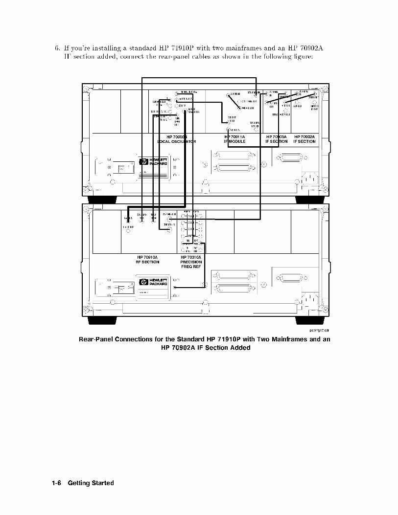
6. If you're installing a standard HP 71910P with two mainframes and an HP 70902AIF section added, connect the rear-panel cables as shown in the following �gure:
Rear-Panel Connections for the Standard HP 71910P with Two Mainframes and an
HP 70902A IF Section Added
1-6 Getting Started

7. If you're installing a standard HP 71910P with two mainframes and an HP 70620Bpreampli�er added, connect the rear-panel cables as shown in the following �gure:
Rear-Panel Connections for the Standard HP 71910P with Two Mainframes and an
HP 70620B Preamplifier Added
Getting Started 1-7

8. If you're connecting the MSIB cables on an HP 71910A, connect the MSIB cables asshown in the following �gure:
MSIB Cabling from the HP 70001A Mainframe to the HP 70004A Color Display
a. Connect an MSIB cable between the HP 70004A color display's MSIB OUT connectorand the HP 70001A mainframe's MSIB IN connector.
b. Connect an MSIB cable between the HP 70001A mainframe's MSIB OUT connectorand the HP 70004A color display's MSIB IN connector.
The MSIB cables are connected serially, coupling the input of one element to theoutput of the next until the loop is completed.
1-8 Getting Started

9. If you're connecting the MSIB Y-Cable on an HP 71910P, connect the cables as shown inthe following �gure:
CAUTION Care should be taken when connecting the MSIB Y-cable to theMSIB interface card. Damage can occur if the MSIB Y-cable connection isnot properly aligned. Ensure power is not applied while making or removingconnections.
a. Remove the protective cap from the MSIB Y-cable and inspect the pins for damage ormisalignment. Do not install MSIB Y-cable if pins are bent or damaged. If necessary, obtainservice from Hewlett-Packard. Refer to \Returning the Receiver for Service".
b. Align the MSIB Y-cable to the MSIB interface card's MSIB connector (1).Do not force the connectors together! (See the above caution.)
c. Tighten the captive-screws on the MSIB Y-cable to the MSIB interface card.Do not over tighten the screws!
d. Connect the two free-ends of the MSIB Y-cable (that are not connected to theMSIB interface card) to the HP 70001A mainframe's IN and OUT MSIB connectors (2).
The MSIB cables are connected serially, coupling the input of one HP 70001A mainframe tothe output of the next until a loop is completed.
e. Connect the ac line cord to your computer and display.
Note Refer to the HP 70207A User's Guide for complete installation instructions ofthe HP 70207A PC Display for MMS, the MSIB interface card, and the MSIBY-cable.
Getting Started 1-9

10. Connect the power cables to both instrument mainframes �rst, then plug the cables intothe power outlet.
11. Set the HP 70001A mainframe's � � LINE switch to ON, and listen to verify that theventilation fan starts up.
12. If an HP 70004A color display is being used in your system (such as the HP 71910A), setthe � � LINE switch to ON, and listen to verify that the ventilation fan starts up.
13. Except on the IF sections, each module's front-panel ACT LED should be lit. Only one ofthe IF sections will have its ACT light on.
14. On the display, the left-side softkeys shown in the following �gure should be displayed.
1-10 Getting Started
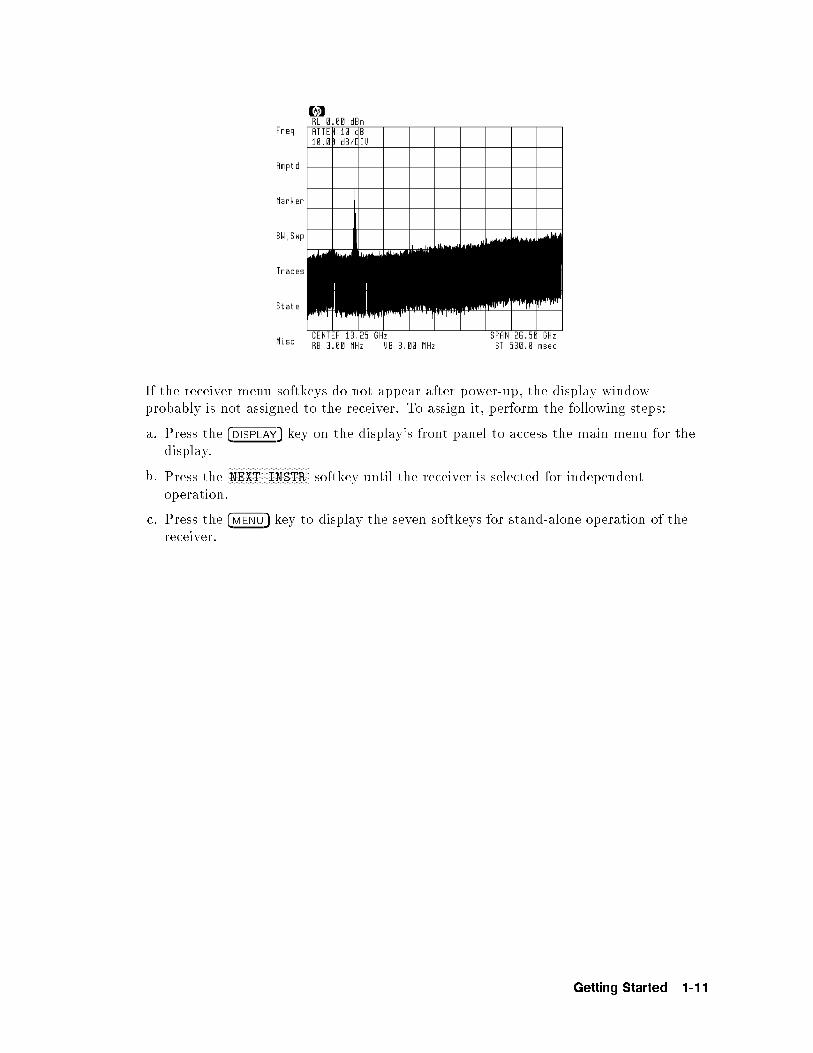
If the receiver menu softkeys do not appear after power-up, the display windowprobably is not assigned to the receiver. To assign it, perform the following steps:
a. Press the �DISPLAY� key on the display's front panel to access the main menu for thedisplay.
b. Press theNNNNNNNNNNNNNNNNNNNNNNNNNNNNNNNNNEXT INSTR softkey until the receiver is selected for independent
operation.
c. Press the �MENU� key to display the seven softkeys for stand-alone operation of thereceiver.
Getting Started 1-11

To install an Option 011 receiver
1. Inspect the shipping container or cushioning material for damage.
If there is damage or a defect, save the packing materials, �le a claim with the carrier,then contact the nearest Hewlett-Packard sales and service o�ce for immediate repair orreplacement.
2. Connect the rear-panel cables as shown in one of the following two �gures:
Standard Rear-Panel Connections
Rear-Panel Connections for Receiver with Options
3. Make sure the HP 70001A mainframe's line-voltage selector is set to the same voltage asthe power source.
1-12 Getting Started

CAUTION Before turning the instrument on, be sure the LINE VOLTAGE SELECTOR is setto the correct voltage for the power source. Failure to do this may causedamage (a blown fuse) to the system when the power cable is plugged in.
Note Option 400 instruments for 400 Hz operation come with an external in-lineisolation transformer for use with the HP 70001A mainframe. The isolationtransformer protects the user from shock hazard. The in-line isolationtransformer must be removed for 60 Hz power-source operation. Failure toremove the in-line transformer may result in a blown fuse.
WARNING Do not operate a 400 Hz option receiver on a 400 Hz power line without the
attached in-line isolation transformer for the HP 70001A mainframe. Failure to
follow this precaution can result in personal injury.
4. Connect the power cable to the HP 70001A mainframe �rst, then plug the cable into thepower outlet.
5. Set the HP 70001A mainframe's � � LINE switch to ON, and listen to verify that theventilation fan starts up.
6. Check to see that each module's front-panel ACT LED lights.
Getting Started 1-13

To install an HP 70911A into an HP 71209A
This procedure shows you how to install an HP 70911A module into an already existing HP71209A Option 001 spectrum analyzer. Option 001 spectrum analyzers have an HP 70910Awide-bandwidth RF module instead of the standard HP 70909A RF module.
Older HP 71209A Option 001 spectrum analyzers may need to be modi�ed before you caninstall the HP 70911A ultra-wide bandwidth section which includes options. This is explainedin the following paragraphs.
HP 70001A mainframe upgrade
If the HP 70001A mainframe has a serial number of 3327A05741 or earlier, an upgrade kitmust be installed that increases the power and air ow capability. The serial number is locatedby opening the HP 70001A's front-panel door to expose the hex-lock screws that are used forinstalling modules. The serial number label is located behind this door on the inside of theright frame section.
WARNING In order to provide proper cooling for the HP 70911A module which includes
options, the HP 70001A mainframe must have a serial number higher than
3327A05741. If the HP 70001A serial number is 3327A05741 or below, contact
your local Hewlett-Packard sales and service office for information on installing
an upgrade kit. HP 70911A modules that do not include option cards will not
require the retrofit kit.
HP 70900B LO upgrade
The HP 70900B local oscillator module must have �rmware 940120 or later and include the 1MByte memory option. To view the �rmware date code, do the following steps:
1. Press �MENU�.2. Press the left-side
NNNNNNNNNNNNNNMisc softkey.
3. PressNNNNNNNNNNNNNNNNNNNNNNNNNNNNNNNNNNNMORE 1 of 3 and then
NNNNNNNNNNNNNNNNNNNNNNNservice .
4. PressNNNNNNNNNNNNNNNNNNNNNNNNNNNNNNNNNNNROM VERSION .
When upgrading an existing HP 71209A Option 001, order the HP 70911A Option 099 or098 to obtain the LO �rmware and memory upgrade. An HP 71910A system already includesthese items. To determine which option (098 or 099) is required, do the following steps:
1. Press �MENU�.2. Press the left-side
NNNNNNNNNNNNNNNNNState softkey.
3. PressNNNNNNNNNNNNNNNNNNNNNNNNNNNNNNNNNNNMORE 1 of 4 ,
NNNNNNNNNNNNNNNNNNNNNNNNNNNNNNNNNNNMORE 2 of 4 , and then
NNNNNNNNNNNNNNNNNNNNNNNNNNNNNNNNNNNshow states .
4. PressNNNNNNNNNNNNNNNNNNNNNNNNNNNNNNNNNNNNNNEXTEND STATE .
5. Find the CPU: heading that is displayed on the screen.6. If the entry reads 68000, the HP 70911A Option 098 is required. If the entry reads 68020,
the HP 70911A Option 099 is required.
1-14 Getting Started

HP 70910A RF section upgrade
The HP 71910A includes an HP 70910A RF section with �rmware enhancements formoderately faster tuning than older HP 70910A RF sections. HP 70910A's with serial number3409A00170 and later include this newer �rmware. The newer �rmware is not necessary forproper operation. Contact an HP service center for upgrade information.
Tools needed
Install the module requires one of the following drivers:
8 mm hex-ball driver (long) : : : : : : : : : : : : : : : : : : : : : : : : : : : : : : : : : : : :HP part number 8710-13078 mm hex-ball driver (short) : : : : : : : : : : : : : : : : : : : : : : : : : : : : : : : : : : : HP part number 8710-1651
Antistatic precautions
Electrical components are easily damaged by small amounts of static electricity. If possible,work at a static-free work station.
Procedure
1. Inspect the shipping container or cushioning material for damage.
If there is damage or a defect, save the packing materials, �le a claim with the carrier,then contact the nearest Hewlett-Packard sales and service o�ce for immediate repairor replacement.
2. Turn on your HP 71209A Option 001 spectrum analyzer.
3. Press �DISPLAY� and then the left-sideNNNNNNNNNNNNNNNNNNNNNNNNNNNNNNNNNNNAddress Map softkey.
4. Turn the front-panel knob to scroll the address map so that the modules are shown. Theaddress map should look like the one displayed in the following �gure.
Address Map of HP 71209A
The HP 70911A has a default MMS address of 3,18 which places it between theHP 70903A and HP 70902A modules in the above �gure. If this space is unavailable,you may need to change the address of the HP 70911A. For a general discussion ofMMS addressing, refer to Chapter 11. The following �gure shows the address switches
Getting Started 1-15

on the HP 70911A module. The switches are set to the default MMS address of ROW 3and COLUMN 18.
5. Turn o� the ac line power to the HP 71209A, and remove the two line-power cords fromthe mainframes.
1-16 Getting Started
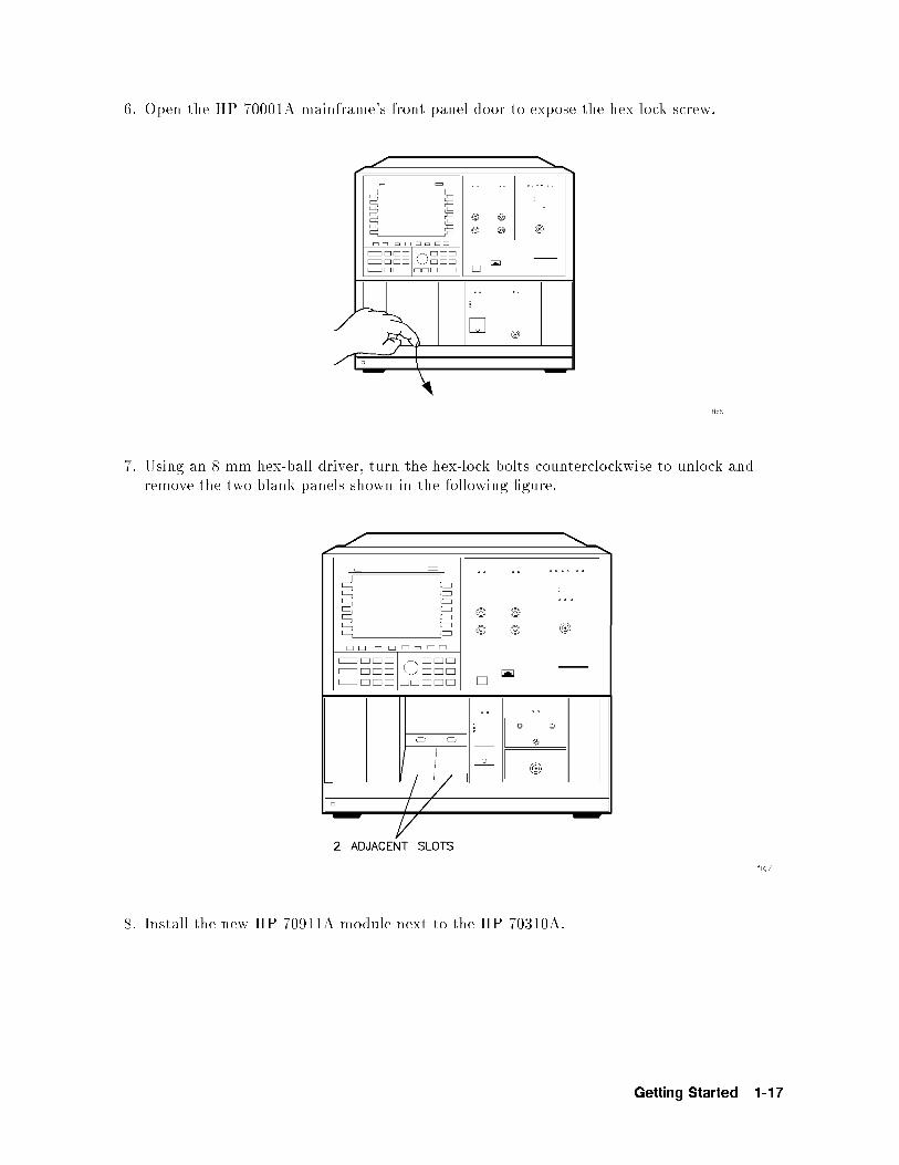
6. Open the HP 70001A mainframe's front-panel door to expose the hex-lock screw.
7. Using an 8 mm hex-ball driver, turn the hex-lock bolts counterclockwise to unlock andremove the two blank panels shown in the following �gure.
8. Install the new HP 70911A module next to the HP 70310A.
Getting Started 1-17

1-18 Getting Started

9. If you're installing a standard HP 70911A module, connect the rear-panel cables as shownin the following �gure.
Rear-Panel Connections for Standard Configuration
Note If you have an HP 71910P con�guration, refer to the section, \To install thereceiver", which is located at the beginning of this chapter.
Getting Started 1-19
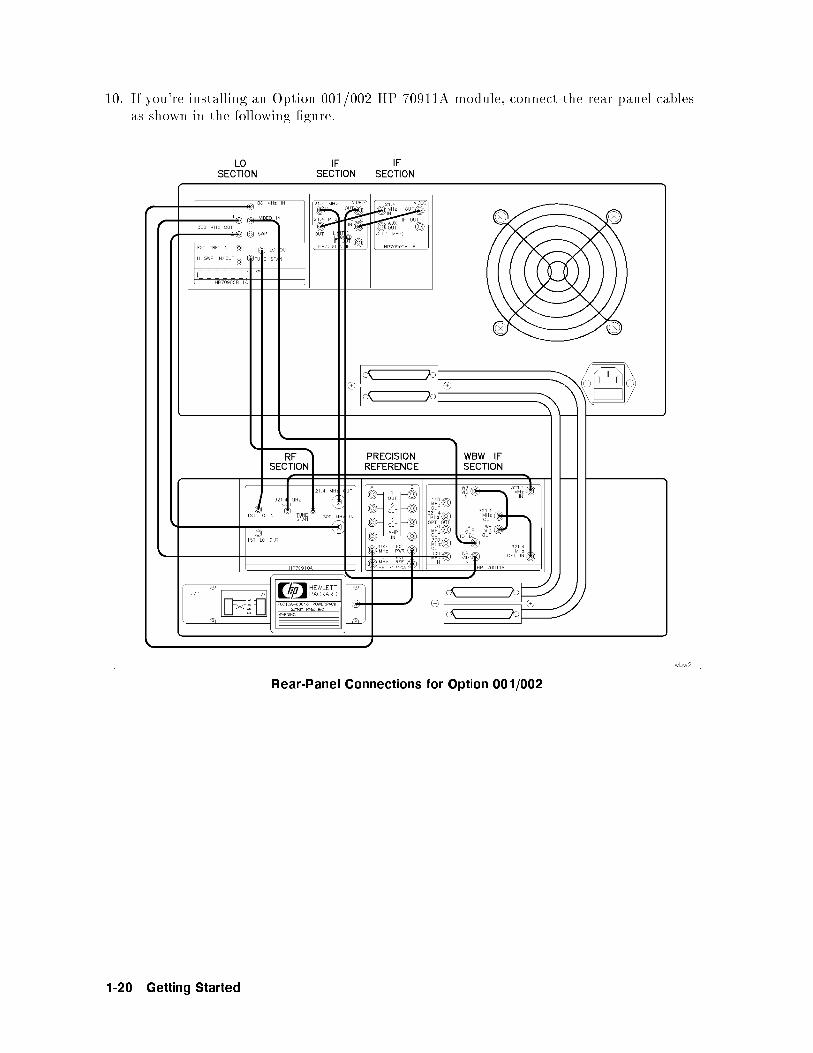
10. If you're installing an Option 001/002 HP 70911A module, connect the rear-panel cablesas shown in the following �gure.
Rear-Panel Connections for Option 001/002
1-20 Getting Started

11. Connect the power cables to both instrument mainframes �rst, then plug the cables intothe power outlet.
12. Set the HP 70001A mainframe's � � LINE switch to ON, and listen to verify that theventilation fan starts up.
13. If an HP 70004A color display is being used in your system (such as the HP 71910A), setthe � � LINE switch to ON, and listen to verify that the ventilation fan starts up.
14. Check to see that each module's front-panel ACT LED lights. When two IF sections are inthe system, only the one that is selected will have its ACT light on.
15. If an ERR LED remains on, check the address map as described in the following steps.
a. Press �DISPLAY�.
b. Press the left-sideNNNNNNNNNNNNNNNNNNNNNNNNNNNNNNNNNNNAddress Map softkey.
c. Turn the front-panel knob to scroll the address map so that it looks similar the oneshown in the following �gure. Make sure that the order of the modules is such that theROW addresses (highest to lowest) are as shown in the following �gure. For example,the HP 70911A must be \above" the HP 70902A and \below" the HP 70903A. Thelocation of the empty ROW addresses is not important.
Getting Started 1-21

Example of a Correct Address Map
16. Press the �DISPLAY� key on the display's front panel to access the main menu for thedisplay.
17. Press theNNNNNNNNNNNNNNNNNNNNNNNNNNNNNNNNNEXT INSTR softkey until the left-side softkeys shown in the following �gure are
displayed.
18. Press the �MENU� key to display the seven softkeys for stand-alone operation of thereceiver.
19. Locate the memory card containing the receiver personality.
20. Locate the arrow printed on one end of the card.
1-22 Getting Started

21. Insert the card into the HP 70004A display's front-panel card slot. Match the card'sarrow with the arrow printed above the card slot.
22. Press �MENU� and then the left-sideNNNNNNNNNNNNNNMisc softkey.
23. PressNNNNNNNNNNNNNNNNNNNNNNNNNNNNNNNNNNNMORE 1 of 3 and then
NNNNNNNNNNNNNNNNNNNNNNNNNNNNNNNNNNNNNNNNNcatalog & MSI .
24. PressNNNNNNNNNNNNNNNNNNNNNNNNNNNNNNNNNNNNNNHP-MSIB CARD to display all �les contained on the memory card.
If 2053 Storage device error is displayed, either the card is missing, the card'swrite-protect switch is in the SAFE position, or the card's HP-MSIB address is listedincorrectly. The HP-MSIB address for the card is the same address as the display'sHP-IB address and is normally set to 4. If the address is not correct, enter the correctaddress using the numeric keypad.
25. PressNNNNNNNNNNNNNNNNNNNNNNNNNNNNNLOAD FILE , and enter 1 for the �le number.
26. PressNNNNNNNNNNNNNNNNNENTER .
The front-panel LED next to the card slot lights indicating that the �les are beingcopied into the �USER� menu. This process takes approximately 60 seconds.
27. Press �USER� and thenNNNNNNNNNNNNNNNNNNNNNNNRX_MODE to start the receiver personality.
28. The left-side softkeys, shown in the following �gure, should be visible.
Getting Started 1-23

1-24 Getting Started

To install an HP 70620B preamp
Tools needed
Install the module requires one of the following drivers:
8 mm hex-ball driver (long) : : : : : : : : : : : : : : : : : : : : : : : : : : : : : : : : : : : :HP part number 8710-13078 mm hex-ball driver (short) : : : : : : : : : : : : : : : : : : : : : : : : : : : : : : : : : : : HP part number 8710-1651
Procedure
1. Turn on your HP 71910A receiver.
2. Press �DISPLAY� and then the left-sideNNNNNNNNNNNNNNNNNNNNNNNNNNNNNNNNNNNAddress Map softkey.
3. Turn the front-panel knob to scroll the address map so that the modules are shown. Theaddress map should look like the one displayed in the following �gure.
Address Map of HP 71910A
4. Locate the HP 70620B preampli�er's address switch. Make sure that the switches areset to a value of ROW 6 and COLUMN 19. This will position the HP 70620B below anyHP 70310A precision frequency reference that might be present.
5. Turn o� the ac line power to the HP 71209A, and remove the two line-power cords fromthe mainframes.
Getting Started 1-25
6. Open the HP 70001A mainframe's front-panel door to expose the hex-lock screw.
7. Using an 8 mm hex-ball driver, turn the hex-lock bolt to remove the blank panel that islocated to the right of the HP 70910A RF section.
8. Install the HP 70620B in the empty slot.
9. Connect a cable between the HP 70620B's front-panel RF INPUT connector and theHP 70910A's front-pane RF OUTPUT connector.
10. Set the HP 70001A mainframe's � � LINE switch to ON.
11. Set the HP 70004A mainframe's � � LINE switch to ON.
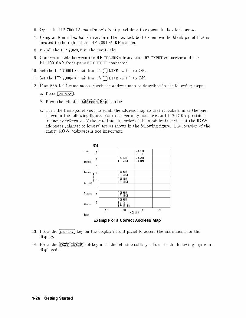
12. If an ERR LED remains on, check the address map as described in the following steps.
a. Press �DISPLAY�.
b. Press the left-sideNNNNNNNNNNNNNNNNNNNNNNNNNNNNNNNNNNNAddress Map softkey.
c. Turn the front-panel knob to scroll the address map so that it looks similar the oneshown in the following �gure. Your receiver may not have an HP 70310A precisionfrequency reference. Make sure that the order of the modules is such that the ROWaddresses (highest to lowest) are as shown in the following �gure. The location of theempty ROW addresses is not important.
Example of a Correct Address Map
13. Press the �DISPLAY� key on the display's front panel to access the main menu for thedisplay.
14. Press theNNNNNNNNNNNNNNNNNNNNNNNNNNNNNNNNNEXT INSTR softkey until the left-side softkeys shown in the following �gure are
displayed.
1-26 Getting Started

15. Calibrate the two available RF INPUTs using the calibration procedure listed in\Calibrating the HP 71910A" in Chapter 3. The procedure is entitled \To perform apartial calibration with HP 70620B preamp."
Getting Started 1-27

Maintaining the Receiver
The following procedures will help you to maintain the appearance and operation of the HP71910A Wide-Bandwidth Surveillance Receiver.
To clean the HP 70004A's screen
Use a thin-�lm cleaner and abrasion-free cleaning tissue or soft cloth to clean the display.
An example of a proper thin-�lm cleaner is the Hewlett-Packard Display Cleaner (HPpart number 8500-2163).
CAUTION Do not use hands or paper towels to clean the display's screen. These abrasivematerials may scratch the screen coating.
To change the mainframe's fuse
This procedure applies to either the HP 70001A mainframe or HP 70004A display/mainframe.
1. Turn o� the ac line power to the receiver, and remove the line-power cables from the poweroutlet.
2. Remove the line-power cable from the connector located on the mainframe's rear panel.The fuse holder is located is the line-power cable connector.
3. Use a small at-blade screwdriver to prey out the fuse holder as shown in the following�gure.
4. Check the fuse for damage. As shown in the �gure, a spare fuse is included in the assembly.
The metric 6.3A fuse (HP part number 2110-0703) can be used with both 120V and230V power sources.
1-28 Getting Started

To change the custom keypad
The custom keypad snaps into the HP 70004A mainframe's front panel. This keypad givesyou quick access to common instrument functions.
In the unlikely event that you need to change the keypad, perform the following step:
Push the tip of a small at-bladed screwdriver straight into the removal hole, and thekeypad will pop out.
CAUTION Be sure to insert the screwdriver straight into the removal hole; do not pry thecustom keypad out.
Getting Started 1-29

To locate a module's serial number
A two-part serial number appears on the mylar label attached to the front frame of themodules. The �rst four digits and the letter are the serial number pre�x; the last �vedigits, the su�x. Identical receivers have the same pre�x, which changes only for signi�cantmodi�cation. The su�x is di�erent for each receiver.
1. Open the front-panel door to expose the hex-lock screw.
2. The serial number label is attached to the module's front frame.
1-30 Getting Started

Reinstalling the Receiver Personality
In the unlikely event that the receiver personality becomes corrupted or is deleted frommemory, this section shows how to reinstall it into the HP 71910A. To determine if thereceiver personality is installed, press �USER� and then
NNNNNNNNNNNNNNNNNNNNNNNRX_MODE . The receiver softkey menus
should appear on the display.
Receiver Softkey Menu
Backup copies of the receiver personality are provided in the following forms:
Memory card.
3.5-inch diskette (HP-LIF format).
For standard HP 71910A systems, copy the receiver personality from the memory card. Ifyour HP 71910A is an Option 011 (without HP 70004A display), you must copy the programsfrom an external HP-IB disk drive. The diskette containing the receiver personality uses theLIF format.
Getting Started 1-31

To install from the memory card
1. Locate the memory card containing the receiver personality.
2. Locate the arrow printed on one end of the card.
3. Insert the card into the HP 70004A display's front-panel card slot. Match the card's arrowwith the arrow printed above the card slot as shown in the following �gure.
4. Press �MENU� and then the left-sideNNNNNNNNNNNNNNMisc softkey.
5. PressNNNNNNNNNNNNNNNNNNNNNNNNNNNNNNNNNNNMORE 1 of 3 and then
NNNNNNNNNNNNNNNNNNNNNNNNNNNNNNNNNNNNNNNNNcatalog & MSI .
6. PressNNNNNNNNNNNNNNNNNNNNNNNNNNNNNNNNNNNNNNHP-MSIB CARD to display all �les contained on the memory card.
If 2053 Storage device error is displayed, either the card is missing, the card'swrite-protect switch is in the SAFE position, or the card's HP-MSIB address is listedincorrectly. The HP-MSIB address for the card is the same address as the display'sHP-IB address and is normally set to 4. If the address is not correct, enter the correctaddress using the numeric keypad.
7. PressNNNNNNNNNNNNNNNNNNNNNNNNNNNNNLOAD FILE , and enter 1 for the �le number.
8. PressNNNNNNNNNNNNNNNNNENTER .
The front-panel LED next to the card slot lights indicating that the �les are being copiedinto the �USER� menu. This process takes approximately 60 seconds.
9. Press �USER� and thenNNNNNNNNNNNNNNNNNNNNNNNRX_MODE to start the receiver personality.
1-32 Getting Started

To install from a 3.5-inch diskette drive
This procedure reinstalls the personality into a standard HP 71910A system. If you have anOption 011 system, perform the next procedure in this section. The disk drive must be a 3.5inch, CS80-compatible drive, such as an HP 9122.
1. Connect a 3.5-inch diskette drive to the HP 70004A display or HP 70001A mainframe.Use an HP-IB cable.
2. Insert the diskette containing the receiver personality into the diskette drive.
3. Press �MENU�.
4. Press the left-sideNNNNNNNNNNNNNNMisc softkey.
5. PressNNNNNNNNNNNNNNNNNNNNNNNNNNNNNNNNNNNMORE 1 of 3 and then
NNNNNNNNNNNNNNNNNNNNNNNNNNNNNNNNNNNNNNNNNcatalog & MSI .
6. PressNNNNNNNNNNNNNNNNNNNNNNNHP DISK , and use the numeric keypad to enter the diskette drive's address.
The default address is 0, unit 0, and volume 0. New addresses are entered in the formA.UV , where:
A is a digit from 1 to 30, representing the drive's HP-IB address.
U is a digit from 0 to 9, representing the unit number. The unit number is typically0 or 1 and refers to an individual disk drive slot.
V is a digit from 0 to 9, representing the volume number. Volume numbers are usedfor hard disk drives. So, for reading diskettes, the volume number should be 0.
For example, entering 3.00 indicates an address of 3, a unit number of 0 and a volumenumber of 0. This accesses a diskette in the left drive of an external diskette drive atHP-IB address 3.
7. Press theNNNNNNNNNNNNNNNNNENTER softkey.
If 2053 Storage device error is displayed, either a diskette is not in the drive, or thedrive's code is incorrectly entered.
8. PressNNNNNNNNNNNNNNNNNNNNNNNNNNNNNLOAD FILE , and enter a 1 for the �le number.
9. PressNNNNNNNNNNNNNNNNNENTER to reinstall the �le.
The front-panel LED next to the card slot lights indicating that the �les are beingcopied into the �USER� menu. This process takes approximately 60 seconds.
10. Press �USER� to and thenNNNNNNNNNNNNNNNNNNNNNNNRX_MODE to start the receiver personality.
Getting Started 1-33

To install in an Option 011 instrument
This procedure reinstalls the personality into an Option 011 instrument. It requires the useof a computer and an HP-IB disk drive. The disk drive must be a 3.5 inch, CS80-compatibledrive, such as an HP 9122.
In order to use this procedure, you must �rst write a program that sends a string to theHP 70900B instructing it to load the personality. The string includes a \wait" command thatdelays the loading of the personality for 20 seconds. This pause gives you time to move theHP-IB cable from the computer to the disk drive. If you need more time, increase this waitvalue in the command WAIT 20.
1. Write a program that sends the following string to the HP 70900B module. (The HP-IBaddress of the HP 70900B is equal to the HP-MSIB column address of the HP 70900B.)
MSI HPIB,0.1; WAIT 20; LOAD /RX/;
In the string, the digit 0 represents the disk drive's HP-IB address. The digit 1represents the individual disk drive slot. This number is typically 0 or 1.
2. Use an HP-IB cable to connect the computer to the HP 70001A mainframe. Do notconnect the disk drive to the HP 70001A mainframe or computer.
3. Insert the diskette with the personality into the disk drive.
4. Run the program that you wrote in step 1 of this procedure. You have 20 seconds tocomplete the next step.
5. Disconnect the HP-IB cable from the computer, and connect it to the disk drive. The diskdrive should now be connected to the HP 70001A mainframe.
6. Wait for the personality to load into the HP 70900B.
1-34 Getting Started

Returning the Receiver for Service
Repackaging a receiver requires original shipping containers and materials or their equivalents.Hewlett-Packard o�ces can provide packaging materials identical to the original materials.Refer to Table 10-1 for the Hewlett-Packard sales and service o�ce nearest you.
CAUTION Packaging materials not speci�ed can result in instrument damage. Neveruse styrene pellets to package electronic instruments. The pellets do notadequately cushion the instrument, do not prevent all instrument movement,and can generate static electricity.
To return a receiver for service
1. Fill out a blue repair card (located at the end of this chapter) and attach it to theinstrument. Send a copy of any noted error messages or other helpful performance data. Ifa blue repair card is not available, include at least the following information:
a. Type of service requiredb. Description of the problem and whether it is constant or intermittentc. Name and telephone number of technical contact persond. Return addresse. Model number of returned instrumentf. Full serial number of returned instrumentg. List of any accessories returned with instrument
2. To help prevent damage during transit, pack the instrument in the factory packagingmaterials. Original shipping materials or equivalents are best; however, the followinginstructions result in acceptable packaging.
a. Wrap the instrument in anti-static plastic to reduce the possibility of ESD damage.b. For instruments that weigh less than 54 kg (120 lb), use a double-walled, corrugated
cardboard carton of 159 kg (350 lb) test strength. The carton must be both largeenough and strong enough to accommodate the instrument. Allow at least three to fourinches on all sides of the instrument for packing material.
c. Surround the equipment with three to four inches of packing material to protect themodule and to prevent movement in the carton. If packing foam is not available,the best alternative is S.D.-240 Air CapTM from Sealed Air Corporation, Hayward,California 94545. Air Cap is plastic sheeting �lled with 1-1/4 inch air bubbles. Usepink anti-static Air Cap. Wrapping the instrument several times in this material shouldprovide su�cient protection and also prevent movement in the carton.
3. Seal the carton with strong nylon adhesive tape.
4. Mark the carton FRAGILE, HANDLE WITH CARE.
5. Retain copies of all shipping papers.
Getting Started 1-35

1-36 Getting Started

2
System Verification of Operation
Use automated tests to verify operation
The operation veri�cation tests for the HP 71910A are automated tests that are designed togive a high con�dence level in the operation of the receiver in a reasonable time. For completeinformation on requirements, loading, and running the veri�cation test software, refer to theHP 70000 Modular Spectrum Analyzer Installation and Veri�cation Manual .
Verify performance once every three years
It is recommended that a complete performance veri�cation be performed once every threeyears. This can be accomplished by either returning the receiver to Hewlett-Packard or bypurchasing the HP 11990A System Performance Tests software.
System Verification of Operation 2-1

2-2 System Verification of Operation

3
Operating
This chapter shows how to perform measurements using the HP 71910A. Measurementsgenerally involve the following two steps:
1. Use the instrument's spectrum analyzer features to search for a signal.
2. Switch the HP 71910A to receiver mode to downconvert the signal for signal collection.
Entering receiver mode replaces the standard spectrum analyzer softkey menus with newreceiver menus. Refer to Chapter 6 for diagrams of the receiver menus. Diagrams of thespectrum analyzer menus are located in the HP 70000 Modular Spectrum Analyzer OperatingManual .
Contents
Calibrating the HP 71910A : : : : : : : : : : : : : : : : : : : : : : : : : : : : : : : : : : : : : : : : : : : : : : : : : : : : : : : : : : : : 3-3To perform a calibration : : : : : : : : : : : : : : : : : : : : : : : : : : : : : : : : : : : : : : : : : : : : : : : : : : : : : : : : : : : : 3-3To perform a calibration with HP 70620B preamp : : : : : : : : : : : : : : : : : : : : : : : : : : : : : : : : : : :3-3
Searching for Signals (spectrum analyzer mode) : : : : : : : : : : : : : : : : : : : : : : : : : : : : : : : : : : : : : : : : 3-5Locating Signals : : : : : : : : : : : : : : : : : : : : : : : : : : : : : : : : : : : : : : : : : : : : : : : : : : : : : : : : : : : : : : : : : : : : 3-6
To change the frequency range : : : : : : : : : : : : : : : : : : : : : : : : : : : : : : : : : : : : : : : : : : : : : : : : : : : 3-7To return to full span : : : : : : : : : : : : : : : : : : : : : : : : : : : : : : : : : : : : : : : : : : : : : : : : : : : : : : : : : : : :3-8To change the reference level and amplitude scale : : : : : : : : : : : : : : : : : : : : : : : : : : : : : : : : 3-8To change the amplitude units : : : : : : : : : : : : : : : : : : : : : : : : : : : : : : : : : : : : : : : : : : : : : : : : : : : 3-8
Using Markers : : : : : : : : : : : : : : : : : : : : : : : : : : : : : : : : : : : : : : : : : : : : : : : : : : : : : : : : : : : : : : : : : : : : : : 3-9To view a signal using markers : : : : : : : : : : : : : : : : : : : : : : : : : : : : : : : : : : : : : : : : : : : : : : : : : : :3-9
Resolving Signals : : : : : : : : : : : : : : : : : : : : : : : : : : : : : : : : : : : : : : : : : : : : : : : : : : : : : : : : : : : : : : : : : : 3-11To resolve closely spaced signals : : : : : : : : : : : : : : : : : : : : : : : : : : : : : : : : : : : : : : : : : : : : : : : : 3-11
Reducing Displayed Noise : : : : : : : : : : : : : : : : : : : : : : : : : : : : : : : : : : : : : : : : : : : : : : : : : : : : : : : : : :3-12To reduce the displayed noise : : : : : : : : : : : : : : : : : : : : : : : : : : : : : : : : : : : : : : : : : : : : : : : : : : : 3-12
Controlling the Sweep : : : : : : : : : : : : : : : : : : : : : : : : : : : : : : : : : : : : : : : : : : : : : : : : : : : : : : : : : : : : : 3-13To change the sweep time : : : : : : : : : : : : : : : : : : : : : : : : : : : : : : : : : : : : : : : : : : : : : : : : : : : : : : :3-13To set continuous or single sweeps : : : : : : : : : : : : : : : : : : : : : : : : : : : : : : : : : : : : : : : : : : : : : : 3-13
Changing Center-Frequency Step Size : : : : : : : : : : : : : : : : : : : : : : : : : : : : : : : : : : : : : : : : : : : : : : 3-14To change the center frequency step size : : : : : : : : : : : : : : : : : : : : : : : : : : : : : : : : : : : : : : : : 3-14
Collecting Signals (receiver mode) : : : : : : : : : : : : : : : : : : : : : : : : : : : : : : : : : : : : : : : : : : : : : : : : : : : : 3-15Changing to Receiver Mode : : : : : : : : : : : : : : : : : : : : : : : : : : : : : : : : : : : : : : : : : : : : : : : : : : : : : : : :3-17
To switch to receiver mode : : : : : : : : : : : : : : : : : : : : : : : : : : : : : : : : : : : : : : : : : : : : : : : : : : : : : 3-17To select a new signal : : : : : : : : : : : : : : : : : : : : : : : : : : : : : : : : : : : : : : : : : : : : : : : : : : : : : : : : : : 3-19To return to spectrum analyzer mode : : : : : : : : : : : : : : : : : : : : : : : : : : : : : : : : : : : : : : : : : : : 3-19
Selecting IF Outputs and Channel Filters : : : : : : : : : : : : : : : : : : : : : : : : : : : : : : : : : : : : : : : : : : 3-20To select an IF output : : : : : : : : : : : : : : : : : : : : : : : : : : : : : : : : : : : : : : : : : : : : : : : : : : : : : : : : : : 3-23To adjust the IF and video bandwidth : : : : : : : : : : : : : : : : : : : : : : : : : : : : : : : : : : : : : : : : : : 3-23To change the IF-to-video bandwidth ratio : : : : : : : : : : : : : : : : : : : : : : : : : : : : : : : : : : : : : : 3-23To increase the 321.4 MHz bandwidth
Operating 3-1

(preselector bypass) : : : : : : : : : : : : : : : : : : : : : : : : : : : : : : : : : : : : : : : : : : : : : : : : : : : : : : : : : : 3-24To adjust the IF gain and RF attenuation : : : : : : : : : : : : : : : : : : : : : : : : : : : : : : : : : : : : : : :3-24To select an Option 007 channel �lter : : : : : : : : : : : : : : : : : : : : : : : : : : : : : : : : : : : : : : : : : : : 3-24
Demodulating Signals : : : : : : : : : : : : : : : : : : : : : : : : : : : : : : : : : : : : : : : : : : : : : : : : : : : : : : : : : : : : : :3-26To demodulate the signal : : : : : : : : : : : : : : : : : : : : : : : : : : : : : : : : : : : : : : : : : : : : : : : : : : : : : : : 3-28To adjust IQ gain, o�set, and quadrature : : : : : : : : : : : : : : : : : : : : : : : : : : : : : : : : : : : : : : : 3-28
Viewing the Signal's Average Amplitude Level : : : : : : : : : : : : : : : : : : : : : : : : : : : : : : : : : : : : : 3-30To view the average amplitude : : : : : : : : : : : : : : : : : : : : : : : : : : : : : : : : : : : : : : : : : : : : : : : : : :3-30
Measurement Examples : : : : : : : : : : : : : : : : : : : : : : : : : : : : : : : : : : : : : : : : : : : : : : : : : : : : : : : : : : : :3-31To search for and collect a pulsed RF signal : : : : : : : : : : : : : : : : : : : : : : : : : : : : : : : : : : : : :3-31To characterize a wide-bandwidth FM signal : : : : : : : : : : : : : : : : : : : : : : : : : : : : : : : : : : : : 3-36To characterize a wide-bandwidth digital transmission : : : : : : : : : : : : : : : : : : : : : : : : : : :3-41
Manually Collecting Signals : : : : : : : : : : : : : : : : : : : : : : : : : : : : : : : : : : : : : : : : : : : : : : : : : : : : : : : : : : :3-44Using Manual Mode : : : : : : : : : : : : : : : : : : : : : : : : : : : : : : : : : : : : : : : : : : : : : : : : : : : : : : : : : : : : : : : 3-46
To manually enter collection receiver mode : : : : : : : : : : : : : : : : : : : : : : : : : : : : : : : : : : : : : :3-47To search for and collect a pulsed RF signal : : : : : : : : : : : : : : : : : : : : : : : : : : : : : : : : : : : : : : : :3-49
Using a Preampli�er : : : : : : : : : : : : : : : : : : : : : : : : : : : : : : : : : : : : : : : : : : : : : : : : : : : : : : : : : : : : : : : : : : 3-52To use the HP 70620B preamp : : : : : : : : : : : : : : : : : : : : : : : : : : : : : : : : : : : : : : : : : : : : : : : : : : : : :3-53To turn o� the preamp in receiver mode : : : : : : : : : : : : : : : : : : : : : : : : : : : : : : : : : : : : : : : : : : : 3-53
Extending the Frequency Range with External Mixers : : : : : : : : : : : : : : : : : : : : : : : : : : : : : : : : :3-54Controlling System Con�guration : : : : : : : : : : : : : : : : : : : : : : : : : : : : : : : : : : : : : : : : : : : : : : : : : : : : : 3-55
To save a receiver state : : : : : : : : : : : : : : : : : : : : : : : : : : : : : : : : : : : : : : : : : : : : : : : : : : : : : : : : : : : : 3-56To recall or delete a receiver state : : : : : : : : : : : : : : : : : : : : : : : : : : : : : : : : : : : : : : : : : : : : : : : : : :3-58To view two instrument windows : : : : : : : : : : : : : : : : : : : : : : : : : : : : : : : : : : : : : : : : : : : : : : : : : : :3-59To blank the display : : : : : : : : : : : : : : : : : : : : : : : : : : : : : : : : : : : : : : : : : : : : : : : : : : : : : : : : : : : : : : :3-59To write a title on the screen : : : : : : : : : : : : : : : : : : : : : : : : : : : : : : : : : : : : : : : : : : : : : : : : : : : : : : 3-60
Block Diagrams : : : : : : : : : : : : : : : : : : : : : : : : : : : : : : : : : : : : : : : : : : : : : : : : : : : : : : : : : : : : : : : : : : : : : : 3-62If You Have a Problem : : : : : : : : : : : : : : : : : : : : : : : : : : : : : : : : : : : : : : : : : : : : : : : : : : : : : : : : : : : : : : : 3-65
If UNCOR is displayed : : : : : : : : : : : : : : : : : : : : : : : : : : : : : : : : : : : : : : : : : : : : : : : : : : : : : : : : : : : : 3-66If UNCAL and Usable RBW limited is displayed : : : : : : : : : : : : : : : : : : : : : : : : : : : : : : : : : : : 3-67If UNCAL and Usable VBW limited is displayed : : : : : : : : : : : : : : : : : : : : : : : : : : : : : : : : : : : 3-68If Possible compression is displayed : : : : : : : : : : : : : : : : : : : : : : : : : : : : : : : : : : : : : : : : : : : : : : : : 3-69If the PREAMP On O� softkey doesn't work : : : : : : : : : : : : : : : : : : : : : : : : : : : : : : : : : : : : : : 3-70If there is a frequency shift in an HP 70911A output : : : : : : : : : : : : : : : : : : : : : : : : : : : : : : : 3-71
3-2 Operating

Calibrating the HP 71910A
The built-in calibration routine described in this section ensures maximum frequencyand amplitude accuracy as speci�ed in Chapter 5 of this manual. The calibration routinedetermines amplitude and frequency error factors for a number of parameters. For example, atemperature compensation routine is included which decreases temperature induced errors onthe HP 70911A. Calibration only requires a few minutes to run.
To perform a calibration
1. Connect the HP 70900B module's front-panel CALIBRATOR to the HP 70910A RF section'sfront-panel RF INPUT connector.
2. Press �MENU�.
3. Press the left-sideNNNNNNNNNNNNNNNNNAmptd softkey.
4. PressNNNNNNNNNNNNNNNNNNNNNNNCAL ALL .
The calibration takes three or four minutes to complete.
To perform a calibration with HP 70620B preamp
This procedure calibrates the instrument for both RF INPUT connectors. One input connectoris on the HP 70910A RF section and one input is on the HP 70620B preamp.
1. Connect the HP 70900B module's front-panel CALIBRATOR to the HP 70910A RF section'sfront-panel RF INPUT connector.
2. Press �MENU�.
3. Press the left-sideNNNNNNNNNNNNNNNNNState softkey.
4. PressNNNNNNNNNNNNNNNNNNNNNNNNNNNNNNNNNNNNNNselect input and then
NNNNNNNNNNNNNNNNNNNNNNNNNNNNNNNNNNNNNNNNNNNNIN 2 RF 70910A to select the HP 70910A's RF INPUT
connector.
5. Press the left-sideNNNNNNNNNNNNNNNNNAmptd softkey.
6. PressNNNNNNNNNNNNNNNNNNNNNNNCAL ALL . The calibration takes three or four minutes to complete.
7. When the calibration is �nished, disconnect the cable from the HP 70910A RF section'sfront-panel RF INPUT connector, and connect the cable to the HP 70620B preampli�er's RFINPUT connector.
8. Press the left-sideNNNNNNNNNNNNNNNNNState softkey.
9. PressNNNNNNNNNNNNNNNNNNNNNNNNNNNNNNNNNNNNNNselect input and then
NNNNNNNNNNNNNNNNNNNNNNNNNNNNNNNNNNNIN 1 70620B to select HP 70620B preampli�er's RF
INPUT connector.
10. Press the left-sideNNNNNNNNNNNNNNNNNAmptd softkey.
11. PressNNNNNNNNNNNNNNNNNNNNNNNCAL ALL . The calibration takes three or four minutes to complete.
Operating 3-3

Searching for Signals (spectrum analyzer mode)
This section shows you two methods of searching for signals using the spectrum analyzerfunctions. With the �rst method, signals are located by changing the displayed frequencyand amplitude range. The second method makes use of powerful marker functions. If yourwide-bandwidth surveillance receiver is an Option 011 single mainframe con�guration, thissearch capability will only be available through programming via the HP-IB bus.
Additional spectrum analyzer capabilities are described in the HP 70900B User's Guide forHP 70900B Instruments and includes explanations of the following features:
Three separate color traces.
Smart marker features including next peak, signal track, and marker pause.
Oversweep capability for faster sweeps.
Limit lines and audible beeps for detecting signals above a threshold.
Three dimensional waterfall displays for time varying signals.
Note If at any time you want to return the instrument to its start-up condition,press the front-panel �IP� key. This resets all operating parameters withouthaving to turn the power o�.
Note Do not select a resolution bandwidth wider than 3 MHz while searching forsignals. If you do, the instrument will not operate as a normal spectrumanalyzer. For example, since only linear detection is used for IF bandwidthsof 10 MHz to 100 MHz, displayed dynamic range will limit its use for signalsearches. For more information, refer to \Manually Collecting Signals" in thischapter.
3-4 Operating
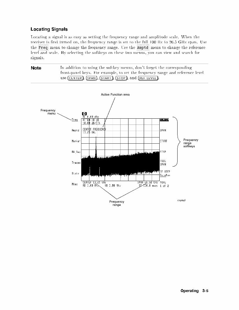
Locating Signals
Locating a signal is as easy as setting the frequency range and amplitude scale. When thereceiver is �rst turned on, the frequency range is set to the full 100 Hz to 26.5 GHz span. Usethe
NNNNNNNNNNNNNNFreq menu to change the frequency range. Use the
NNNNNNNNNNNNNNNNNAmptd menu to change the reference
level and scale. By selecting the softkeys on these two menus, you can view and search forsignals.
Note In addition to using the softkey menus, don't forget the correspondingfront-panel keys. For example, to set the frequency range and reference leveluse �CENTER�, �SPAN�, �START�, �STOP�, and �REF LEVEL�.
Operating 3-5
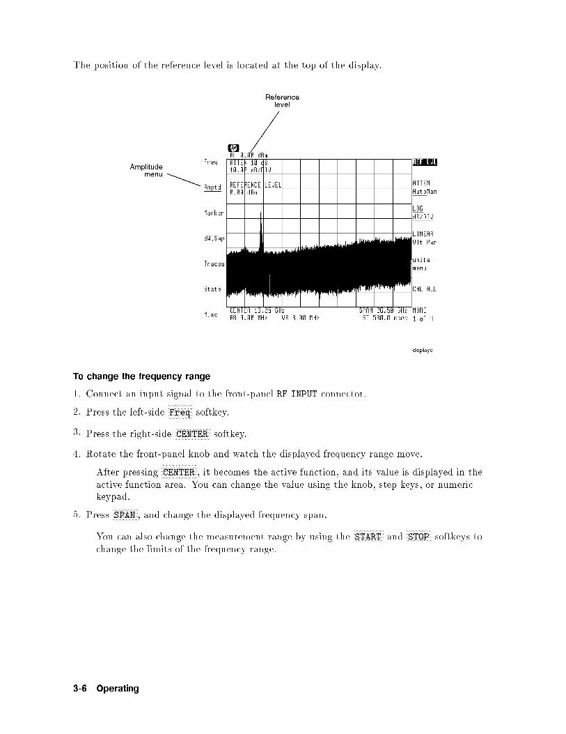
The position of the reference level is located at the top of the display.
To change the frequency range
1. Connect an input signal to the front-panel RF INPUT connector.
2. Press the left-sideNNNNNNNNNNNNNNFreq softkey.
3. Press the right-sideNNNNNNNNNNNNNNNNNNNNCENTER softkey.
4. Rotate the front-panel knob and watch the displayed frequency range move.
After pressingNNNNNNNNNNNNNNNNNNNNCENTER , it becomes the active function, and its value is displayed in the
active function area. You can change the value using the knob, step keys, or numerickeypad.
5. PressNNNNNNNNNNNNNNSPAN , and change the displayed frequency span.
You can also change the measurement range by using theNNNNNNNNNNNNNNNNNSTART and
NNNNNNNNNNNNNNSTOP softkeys to
change the limits of the frequency range.
3-6 Operating

To return to full span
1. Press the left-sideNNNNNNNNNNNNNNFreq softkey.
2. PressNNNNNNNNNNNNNNNNNNNNNNNNNNNNNFULL SPAN .
To change the reference level and amplitude scale
1. Press the left-sideNNNNNNNNNNNNNNNNNAmptd softkey.
2. PressNNNNNNNNNNNNNNNNNNNNNNNREF LVL , and change the reference level using the knob, step keys, or numeric
keypad.
3. PressNNNNNNNNNNNNNNNNNNNNLINEAR to select a linear scale, or press
NNNNNNNNNNNNNNNNNNNNNNNNNNNNNNNNLOG dB/DIV to select a logarithmic scale.
Then, enter the scale using the knob, step keys, or numeric keypad.
To change the amplitude units
1. Press the left-sideNNNNNNNNNNNNNNNNNAmptd softkey.
2. PressNNNNNNNNNNNNNNNNNNNNNNNNNNNNNNNNunits menu .
PressingNNNNNNNNNNNNNNNNNNNNNNNNNNNNNNNNNNNNNNNNNNNNNNNA UNITS AutoMan allows the receiver to select the annotation automatically.
TheNNNNNNNNNNNNNNAuto selection is the receiver's default setting.
PressingNNNNNNNNNNNdBm selects annotation in decibels relative to 1 mW.
PressingNNNNNNNNNNNNNNWATT selects annotation in watts.
Operating 3-7

Using Markers
Markers are small diamond shaped icons that can be moved to any trace point on the display.Markers provide a fast and powerful tool for centering signals on the screen. The frequencyand amplitude of the marked trace point are displayed at the top of the screen.
To view a signal using markers
1. Press �PEAK SEARCH� to activate a marker and place it on the highest trace point.
2. If the signal you want to center is not the highest peak, rotate the knob to place themarker at the desired peak.
3. Press the left-sideNNNNNNNNNNNNNNNNNNNNNNNmarkers softkey.
4. PressNNNNNNNNNNNNNNNNN-> CF to move the marked signal to the center of the screen as shown in the
following �gure.
3-8 Operating

5. Press �SPAN�, and use the �� key to reduce the frequency range. Here is an example of apulsed RF signal in a 500 MHz span.
Operating 3-9

Resolving Signals
Often, two signals are closely spaced in frequency. The ability to display such signals as twodistinct responses is determined by the instrument's resolution bandwidth setting. Normally,the spectrum analyzer automatically selects the optimum resolution bandwidth based onthe selected frequency span. As the following �gures show, a resolution bandwidth that istoo wide causes adjacent signals to appear as one. If a wide resolution bandwidth can hidesignals, why not always use the narrowest possible resolution bandwidth? The answer is thatas the resolution bandwidth is reduced, the sweep time increases and may slow down signalsearches. Manual resolution bandwidths are indicated by an asterisk (*RB) next to the screenannotation.
Wide Resolution Bandwidth Narrower Resolution Bandwidth
To resolve closely spaced signals
1. Press the left-sideNNNNNNNNNNNNNNNNNNNNBW,Swp softkey.
2. PressNNNNNNNNNNNNNNNNNNNNNNNNNNNNNNNNNNNNNNNNNNNNRES BW AutoMan .
3. Press �� to reduce the resolution bandwidth. Or, use the knob or numeric keypad to entera reduced resolution bandwidth.
4. To return to auto coupled resolution bandwidths, press theNNNNNNNNNNNNNNNNNNNNNNNNNNNNNNNNNNNNNNNNNNNNNNNNNNRES BW AutoMan softkey so
thatNNNNNNNNNNNNNNAuto is underlined.
3-10 Operating

Reducing Displayed Noise
The displayed noise level (peak-to-peak noise variation) can be averaged by changing the videobandwidth or by averaging successive traces. Changing the resolution bandwidth changes theabsolute level. Normally, the video bandwidth is coupled to the resolution bandwidth and isautomatically set. Manually entering a video bandwidth breaks this coupling. Manual videobandwidths are indicated by an asterisk (*VB) next to the screen annotation.
3 KHz Video Filtering 10 Hz Video Filtering
To reduce the displayed noise
Via video bandwidth:
1. Press the left-sideNNNNNNNNNNNNNNNNNNNNBW,Swp softkey.
2. PressNNNNNNNNNNNNNNNNNNNNNNNNNNNNNNNNNNNNNNNNNNNNVID BW AutoMan and use the knob, numeric keypad, or �� key to reduce the video
bandwidth.
3. To return to auto coupled video bandwidths, press theNNNNNNNNNNNNNNNNNNNNNNNNNNNNNNNNNNNNNNNNNNNNNNNNNNVID BW AutoMan softkey so
thatNNNNNNNNNNNNNNAuto is underlined.
Via video averaging:
1. Press the left-sideNNNNNNNNNNNNNNNNNNNNTraces softkey to enter the Traces menu. Trace A must be in the
clear-write mode.
2. PressNNNNNNNNNNNNNNNNNNNNNNNNNNNNNNNNNNNMORE 1 of 4 and then
NNNNNNNNNNNNNNNNNNNNNNNNNNNNNNNNNNNMORE 2 of 4 .
3. Press theNNNNNNNNNNNNNNNNNNNNNNNNNNNNNNNNNNNNNNNNNNNNVID AVG On Off softkey so that
NNNNNNNNOn is underlined.
4. Enter the number of sweeps to average the displayed trace. Or, use the default of 100trace averages.
5. PressNNNNNNNNNNNNNNNNNNNNNNNNNNNNNNNNNNNNNNNNNNNNVID AVG On Off to
NNNNNNNNNNNOff and then
NNNNNNNNOn to restart averaging at any time.
Operating 3-11

Controlling the Sweep
The sweep speed is automatically set by the receiver. In fact, the receiver always uses thefastest sweep possible while still maintaining a calibrated display. Manually setting the sweeptime disrupts the coupling used to maintain a calibrated display. Whenever a sweep time isselected that degrades accuracy, the uncalibrated warning, UNCAL, appears on the display.
To change the sweep time
1. Press the left-sideNNNNNNNNNNNNNNNNNNNNBW,Swp softkey.
2. Use the knob, step keys, or numeric keypad to enter the desired sweep time.
3. To reestablish sweep time coupling, pressNNNNNNNNNNNNNNNNNNNNNNNNNNNNNNNNNNNNNNNNNNNNNNNSWPTIME AutoMan so that
NNNNNNNNNNNNNNAuto is underlined.
To set continuous or single sweeps
1. Press the left-sideNNNNNNNNNNNNNNNNNNNNBW,Swp softkey.
2. Press one of the following softkeys:NNNNNNNNNNNNNNNNNNNNNNNNNNNNNNNNCONT SWEEP to use continuous sweeping.
NNNNNNNNNNNNNNNNNNNNNNNNNNNNNNNNNNNNNNSINGLE SWEEP to sweep the measurement range once.
To repeat another single sweep, pressNNNNNNNNNNNNNNNNNNNNNNNNNNNNNNNNNNNNNNSINGLE SWEEP again.
3-12 Operating
Changing Center-Frequency Step Size
When center frequency is the active function, pressing the ��� and �� keys steps the centerfrequency to a new value. The default step size is one tenth of the displayed frequency span.You can change the size of the steps to meet your search needs. The value you enter does notdepend upon the displayed span; you can jump to frequencies that are not currently displayed.
To change the center frequency step size
1. Press the left-sideNNNNNNNNNNNNNNFreq softkey.
2. Press theNNNNNNNNNNNNNNNNNNNNNNNNNNNNNNNNNNNMORE 1 of 2 softkey.
3. PressNNNNNNNNNNNNNNNNNNNNNNNNNNNNNNNNNNNNNNNNNNNNNNNNNNNNNFREQ STEP AutoMan and use the knob, step keys, or numeric keypad to enter a new
center frequency step size.
4. Press �CENTER� to activate the center frequency function.
5. Press ��� or �� to step the center frequency.
Operating 3-13

Collecting Signals (receiver mode)
This section shows you how to use the receiver mode. Entering receiver mode changesinstrument operation in the following manner:
Displays receiver menus.Sets �xed-tuned operation (zero span with the display showing amplitude versus time.)Sets center frequency to the marker frequency or, if no marker is displayed, to the frequencyof the highest amplitude input signal.Sets amplitude scale to linear.Places reference level relative to the highest peak.The reference level is set to the next highest multiple of 10 dB from the peak's value. Forexample, if the signal peak measures 26 dBm, the reference level is set to 30 dBm.
Downconverts the signal for analysis.Selects a 10 MHz or wider IF bandwidth.Selects a 10 MHz or wider video bandwidth.Selects AM demodulation.Provides visual feedback that the signal is present (an amplitude versus time display). Onlylinear detection (not logarithmic) is available when IF bandwidths are greater than or equalto 10 MHz.
Press �USER� to enter receiver mode.
3-14 Operating

Note Receiver mode is actually a special program called a \personality" or\downloadable program." Personalities provides new menus and features andare accessed through the front-panel �USER� key. You can even write your ownpersonalities. To learn how to create your own personalities, refer to the HP70900B Programmer's Guide for HP 70900B Instruments .
Note Due to harmonic mixing process utilized in the receiver, the signals at the IF,FM, and IQ outputs will be inverted when the receiver is tuned to frequenciesof 12.8 GHz and below. The \minus" mixing mode is used for this tuningrange. The \plus" mixing mode is used when the receiver is tuned from 12.6to 26.5 GHz, so no inversion occurs for this range.
In receiver mode, online help is available for each softkey. To access online help, press theleft-side
NNNNNNNNNNNNNNNNNNNNNNNNNNNNNNNNNNNHelp On Off softkey so that
NNNNNNNNOn is underlined. Then, press a softkey to learn about
its application.
Online Help forNNNNNNNNNNNNNNNNNNNNNNNNNNNNNNNNNNNNNNNNNNNIF GAIN AutoMan Softkey
Note The receiver mode is accessed with the �USER� key. In addition, it is possible touse many of the keys found under the �MENU� key, such as markers. However,
to access certain functions, such asNNNNNNNNNNNNNNNNNNNNNNNCAL ALL , �rst exit the receiver mode, and
use the spectrum analyzer functions found in the �MENU� key area.
Operating 3-15

Changing to Receiver Mode
The procedures in this section show you how to switch between receiver and spectrumanalyzer modes. In receiver mode, a small display shows the input signal's amplitude versustime. Use this display to quickly con�rm that the signal is present and that the receiveris properly tuned. For convenience, this �xed-tuned display can be changed to the normalspectrum analyzer display. This allows you to select another signal for down conversionwithout leaving receiver mode. Because a linear amplitude scale is used (and a lineardetector), the displayed dynamic range is limited.
To switch to receiver mode
1. Press �USER� and thenNNNNNNNNNNNNNNNNNNNNNNNRX_MODE .
If there are no markers shown on the screen, the instrument automatically tunes to thehighest displayed peak.
If a marker is on, the instrument tunes to the signal at the marked frequency.
TheNNNNNNNNNNNNNNNNNNNNNRX_MODE Softkey
2. Once the receiver is �x-tuned to the desired signal, the downconverted IF signal is availableat the HP 70911A module's rear panel for processing.
The standard rear-panel IF output is centered at 321.4 MHz. Option 001 and 002provide additional 70 MHz and 140 MHz IF signals respectively. For more informationon IF outputs including Option 007 channel �lters, refer to the next section in thischapter.
3-16 Operating

The receiver personality menus.
3. To demodulate the downconverted signal, perform the following steps:
a. Press the left-sideNNNNNNNNNNNNNNNNNDemod softkey, and then press the softkey that corresponds to the
type of demodulation desired.NNNNNNNNAM and
NNNNNNNNNNNNNNNNNPULSE demodulation formats are standard on the HP 71910A. Option 004
and 005 provide additional I/Q and FM formats respectively.
b. Connect the appropriate external test equipment to the front-panel demodulationoutput connector. AM and pulse are accessed via the VIDEO output. FM and I/Q areclearly marked if those options are present.
Note The demodulated outputs are always \on" at the front-panel connectors,regardless of whether they are selected by the
NNNNNNNNNNNNNNNNNDemod softkey. The softkey
is necessary to toggle between AM and pulse modes which share the sameVIDEO connector. The softkey also toggles between FM wideband and FMnarrowband which share the same FM connector. The softkey also o�erscertain adjustments to the FM and IQ modes as described in this chapter.
Operating 3-17

To select a new signal
1. PressNNNNNNNNNNNNNNSPAN .
2. Use the front-panel knob, step keys, or numeric keypad to change the displayed frequencyspan.
3. Press the left-sideNNNNNNNNNNNNNNFreq softkey.
4. PressNNNNNNNNNNNNNNNNNNNNCENTER , and use the front-panel knob, step keys, or numeric keypad to enter a new
receiver frequency.
5. To return to �xed-tuned operation, pressNNNNNNNNNNNNNNSPAN and enter a span of 0 Hz.
To return to spectrum analyzer mode
Press the left-sideNNNNNNNNNNNNNNNNNNNNNNNNNNNNNNNNNNNNNNNNNReturn to S/A softkey, and select one of the following to return to the
search receiver mode:NNNNNNNNNNNNNNNNNNNNNNNNNNNNNNNNLAST STATE to return the spectrum analyzer to the state it was in before the personalitywas started.NNNNNNNNNNNNNNNNNNNNNNNNNNNNNFULL SPAN to return the spectrum analyzer to its widest frequency span. (100 Hz | 26.5
GHz Instrument Preset condition.)NNNNNNNNNNNNNNNNNNNNNNNNNNNNNNNNNNNNARROW SPAN to return the spectrum analyzer to a frequency span wide enough to
display the input signal. (The span is set to a value of ten times the IF bandwidth. TheIF bandwidth is not changed.)
3-18 Operating

Selecting IF Outputs and Channel Filters
The IF outputs are available at the HP 70911A module's rear panel.
Standard IF Outputs
Option 001 and Option 002 IF Outputs
The level of the IF signal can be adjusted to the requirements of the external equipment byapplying RF attenuation or IF gain. Up to 65 dB of attenuation is available in 5 dB steps.The amount of gain applied to the input signal is displayed on the screen as RF/IF Gain. Thisrepresents the gain from the front-panel RF INPUT connector to the Option 001 rear-panel 70MHz output connector. Without an HP 70620B preampli�er present, the RF/IF Gain is de�nedby the following equation:
RF=IF Gain = IF gain�RF attenuation
For more information on how this gain is calculated, refer to \RF/IF Gain" in Chapter 7.
Operating 3-19

With 0 dB RF attenuation and 0 dB IF gain, the RF/IF gain from the HP 70910A's RF INPUT
connector to the HP 70911A's IF output connectors is as follows:
321.4 MHz IF output : : : : : : : : : : : : : : : : : : : : : : : : : : : : : : : : : : : : : : : : : : : : : : : : : : : : : : :+5 dB70 MHz IF output : : : : : : : : : : : : : : : : : : : : : : : : : : : : : : : : : : : : : : : : : : : : : : : : : : : : : : : : : : : : 0 dB140 MHz IF output : : : : : : : : : : : : : : : : : : : : : : : : : : : : : : : : : : : : : : : : : : : : : : : : : : : : : : : :�10 dB
You can apply up to 70 dB of IF gain in 10 dB steps using the step keys or 1 dB steps usingthe knob or data entry keys. This gain is manually applied; there is no automatic gaincontrol.
Note When Option 001 or 002 is installed, the 321.4 MHz IF is available atthe rear-panel 321.4 MHz OPT OUT connector. This 321.4 MHz output hasdegraded IF bandwidth accuracy.
Note If you need to preserve the phase information of a signal, use an oscilloscopeor deep-memory IF digitizer to process the 70 MHz IF output of the receiver.
If you're downconverting signals between 2.7 and 26.5 GHz, you must turn o� the microwavepreselector to obtain the widest possible IF bandwidth. For example, if you select a 100 MHzIF bandwidth, but the microwave preselector is on, the e�ective bandwidth will be limitedto greater than 36 MHz at the HP 70911A's 321.4 MHz IF output. This is shown in thefollowing table:
3-20 Operating

Approximate Widest Bandwidth of HP 70911A IF Outputs
Frequency 321.4 MHz
Output
70 MHz
Output1140 MHz
Output2
100 Hz|2.9 GHz >48 MHz 40 MHz >48 MHz
2.7|26.5 GHz
preselector on >36 MHz3 >36 MHz >36 MHz
preselector o� 100 MHz 40 MHz 70 MHz
1 Option 001
2 Option 002
3 The preselector's bandwidth increases at higherfrequencies and is nearly 60 MHz at a center frequencyof 20 GHz.
Operating 3-21

To select an IF output
The 321.4 MHz IF output is always available at the HP 70911A module's rear panel.On Option 001 instruments, the 70 MHz IF output is always available. On Option 002instruments, the 140 MHz IF output is always available.
To adjust the IF and video bandwidth
1. Press the left-sideNNNNNNNNBW softkey.
2. PressNNNNNNNNNNNNNNNNNIF BW , and use the front-panel knob, step keys, or numeric keypad to change the IF
bandwidth. The IF �lters are adjustable in 10% increments (10 MHz, 11.1 MHz, 12.2 MHz,etc.) using the knob. The �lters are synchronously tuned (Gaussian approximation).
WhenNNNNNNNNNNNMan is underlined in the softkey, the IF bandwidth is uncoupling from the video
bandwidth. To recouple these parameters, press the softkey so thatNNNNNNNNNNNNNNAuto is underlined.
3. PressNNNNNNNNNNNNNNNNNNNNNNNNNNNNNNNNNNNMORE 1 of 2 .
4. PressNNNNNNNNNNNNNNNNNNNNNNNNNNNNNNNNNNNNNNNNNNNNVID BW AutoMan , and use the front-panel knob, step keys, or numeric keypad to
change the video bandwidth.
WhenNNNNNNNNNNNMan is underlined in the softkey, the IF bandwidth is uncoupling from the IF
bandwidth. To recouple these parameters, press the softkey so thatNNNNNNNNNNNNNNAuto is underlined.
To change the IF-to-video bandwidth ratio
1. Press the left-sideNNNNNNNNBW softkey.
2. PressNNNNNNNNNNNNNNNNNNNNNNNNNNNNNNNNNNNMORE 1 of 2 .
3. PressNNNNNNNNNNNNNNNNNNNNNNNNNNNNNNNNNNNNNNNNNVBW/IFB RATIO , and use the front-panel knob, step keys, or numeric keypad to
change the ratio.
3-22 Operating

To increase the 321.4 MHz bandwidth (preselector bypass)
1. Press the left-sideNNNNNNNNBW softkey.
2. PressNNNNNNNNNNNNNNNNNNNNNNNNNNNNNNNNNNNNNNNNNPRESEL On Off so that
NNNNNNNNNNNOff is underlined.
To adjust the IF gain and RF attenuation
1. Press the left-sideNNNNNNNNNNNNNNGain softkey.
2. To adjust the IF gain, pressNNNNNNNNNNNNNNNNNNNNNNNNNNNNNNNNNNNNNNNNNNNNNNNIF GAIN AutoMan , and use the front-panel knob, step keys, or
numeric keypad to change the displayed value.
3. To adjust the RF attenuation, pressNNNNNNNNNNNNNNNNNNNNNNNNNNNNNNNNNNNNNNNNNNNNNNNRF ATTN AutoMan , and use the front-panel knob, step
keys, or numeric keypad to change the displayed value.
The amount of gain applied to the input signal from the RF input connector to the 70MHz IF output is displayed on the screen as RF/IF Gain.
To select an Option 007 channel filter
With Option 007 installed, Chebyshev channel �lters can be switched into the Option 001 70MHz IF path. These �lters provide bandwidths of 1.25, 5, 10, 20, and 36 MHz. The following�gure shows the shape of the 5 MHz channel �lter. It was created by viewing the 70 MHzoutput on a separate spectrum analyzer.
Option 007 5 MHz Channel Filter
Note This procedure requires that Option 007 be installed in the HP 71910A.
1. With Option 007 installed, press the left-sideNNNNNNNNBW softkey.
Operating 3-23

The �gure shown above is an example of a custom channel �lter option which includes a15 MHz bandwidth �lter instead of a 20 MHz bandwidth �lter. Custom channel �ltersare available as factory-installed options.
2. PressNNNNNNNNNNNNNNNNNNNNNNNNNNNNNNNNNNNNNNNNNNNNNNNchannel filters and then
NNNNNNNNNNNNNNNNNNNN70 MHz .
3. Press a softkey to select one of the following choices:NNNNNNNNNNNNNNNNNNNNNNNNNN1.25 MHz ,
NNNNNNNNNNNNNNNNN5 MHz ,
NNNNNNNNNNNNNNNNNNNNNNN10 MHz ,
NNNNNNNNNNNNNNNNNNNN20 MHz , or
NNNNNNNNNNNNNNNNNNNN36 MHz to select the desired IF �lter
bandwidth.NNNNNNNNNNNNNNNNNNNNBYPASS to prevent any channel �ltering.
3-24 Operating
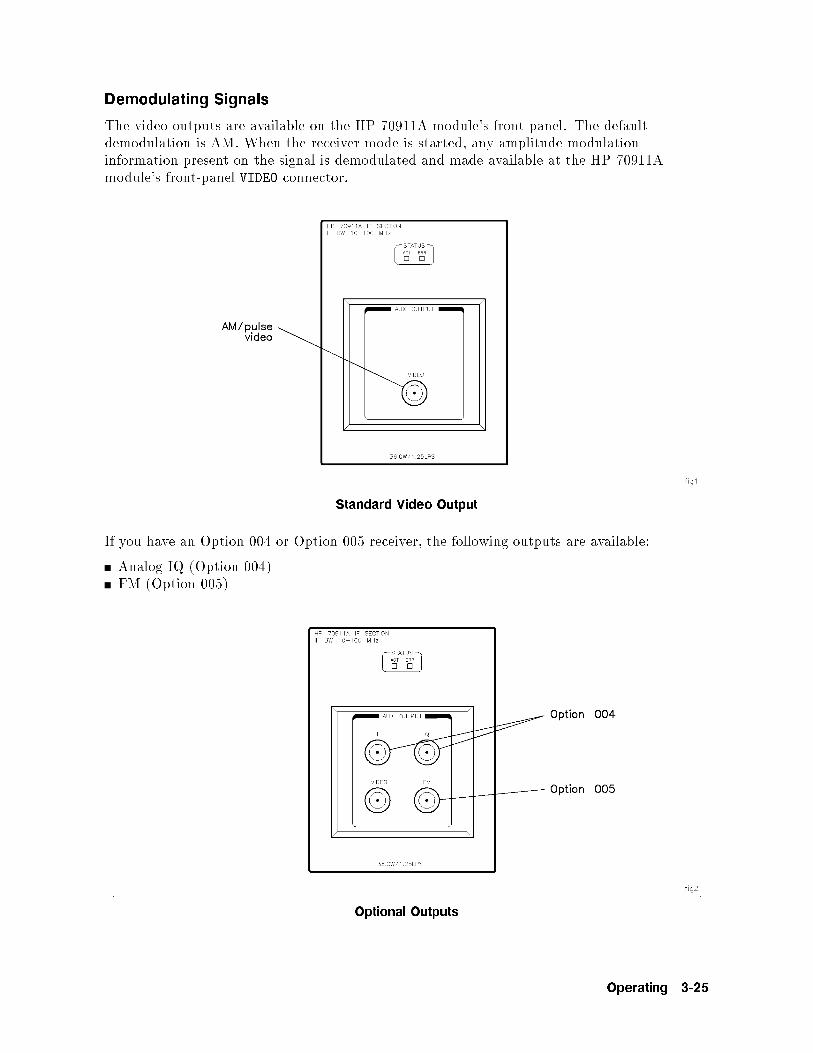
Demodulating Signals
The video outputs are available on the HP 70911A module's front panel. The defaultdemodulation is AM. When the receiver mode is started, any amplitude modulationinformation present on the signal is demodulated and made available at the HP 70911Amodule's front-panel VIDEO connector.
Standard Video Output
If you have an Option 004 or Option 005 receiver, the following outputs are available:
Analog IQ (Option 004)FM (Option 005)
Optional Outputs
Operating 3-25

Two FM discriminator gains are available
Option 005 provides FM discriminators selections for 10 MHz and 40 MHz deviation.The discriminator is based on a delay line design. Modulation frequencies up to half thebandwidth can be demodulated (up to 12 MHz maximum). For example, with a deviation of10 MHz, a modulation frequency of 5 MHz can be processed.
Use analog IQ for constellation displays
Option 004 analog IQ demodulation is useful for applications requiring constellation displays.You'll need a two-channel oscilloscope in X-Y mode to display a constellation. Because eachoutput has a bandwidth of 50 MHz, the overall bandwidth is 100 MHz.
You can adjust the gain, o�set, and quadrature of the IQ outputs. The o�set should beadjusted to zero volts for each output. Quadrature adjusts the phase di�erence between theoutputs to 90� and, along with gain, is used to optimize the shape of constellations that aredisplayed on an oscilloscope.
If maximum bandwidth is important
In situations where maximum bandwidth is important, the IQ demodulation o�ers anadvantage over using 70 MHz or 140 MHz down conversion as shown in the following table.
Bandwidth Comparison
Bandwidth
Option 001 70 MHz IF 40 MHz
Option 002 140 MHz IF 70 MHz
Option 004 Analog IQ 100 MHz
3-26 Operating

To demodulate the signal
1. Press the left-sideNNNNNNNNNNNNNNNNNDemod softkey.
2. Select from one of the following demodulation formats:NNNNNNNNAM selects AM demodulation of the downconverted signal. The demodulated output is
available at the front-panel VIDEO connector. (video bandwidth = 0.3 x IF bandwidth.)NNNNNNNNNNNNNNNNNPULSE selects pulse demodulation of the IF signal. The demodulated output is available
at the front-panel VIDEO connector. (Video bandwidth is set to 100 MHz.)NNNNNNNNNNNNNNNNNFM WB selects wide-bandwidth FM demodulation of the IF signal. This softkey isonly available on Option 005 instruments. The demodulated output is available atthe front-panel FM connector. (FM peak-to-peak deviation of 40 MHz or less can bedemodulated.)NNNNNNNNNNNNNNNNNFM NB selects narrow-bandwidth FM demodulation of the IF signal. This softkey isonly available on Option 005 instruments. The demodulated output is available atthe front-panel FM connector. (FM peak-to-peak deviation of 10 MHz or less can bedemodulated.)NNNNNNNNIQ selects analog IQ processing of the IF signal. This softkey is only available on Option004 instruments. The output is available at the front-panel I and Q connectors.
The o�set and gain of the I and Q channels can be independently adjusted asdescribed in \To adjust IQ gain and o�set" in this section.
To adjust IQ gain, offset, and quadrature
1. Connect an oscilloscope or voltmeter to the front-panel I and Q outputs so that they can bemonitored.
2. Press the left-sideNNNNNNNNNNNNNNNNNDemod softkey.
3. Press theNNNNNNNNIQ softkey.
4. PressNNNNNNNNNNNNNNNNNNNNI GAIN or
NNNNNNNNNNNNNNNNNNNNQ GAIN and rotate the front-panel knob to adjust the gain of each output
so that they are equal.
The displayed gain setting is a unitless digital-to-analog (DAC) value between 0 and4095.
5. PressNNNNNNNNNNNNNNNNNNNNNNNNNNI OFFSET or
NNNNNNNNNNNNNNNNNNNNNNNNNNQ OFFSET , and rotate the front-panel knob to adjust the o�set of each
output to zero volts.
The displayed o�set setting is a unitless digital-to-analog (DAC) value between 0 and4095.
6. PressNNNNNNNNNNNNNNNNNNNNNNNNNNNNNNNNQUADRATURE and rotate the front-panel knob to optimize the shape of the displayed
constellation,.
The displayed o�set setting is a unitless digital-to-analog (DAC) value between 0 and4095.
Operating 3-27

Viewing the Signal's Average Amplitude Level
You can display the signal's average amplitude level in receiver mode. The average iscomputed at the end of every sweep and is shown in either linear or logarithmic units. Youcan select the units that are used.
To view the average amplitude
1. Press the left-sideNNNNNNNNNNNNNNGain softkey.
2. PressNNNNNNNNNNNNNNNNNNNNNNNNNNNNNNNNunits menu .
3. Press the softkey corresponding to the desired units.
To return to the default units, pressNNNNNNNNNNNNNNNNNNNNNNNNNNNNNNNNNNNNNNNNNNNNNNNA UNITS AutoMan so that
NNNNNNNNNNNNNNAuto is underlined.
4. PressNNNNNNNNNNNNNNNNNNNNNNNNNNNNNprev menu .
5. PressNNNNNNNNNNNNNNNNNNNNNNNNNNNNNNNNNNNNNNNNNNNNSIG LVL On Off to display the average amplitude value.
Note Pulse modulated signals having narrow pulse widths (and corresponding largedesensitization) will have lower average level readings than actual due to thepeak detector bandwidth of the digitizing hardware used to display the signal.
3-28 Operating

Measurement Examples
The following measurement examples provide step-by-step instructions on using the receiver.
To search for and collect a pulsed RF signal
This procedure shows how to search for and collect (demodulate) a pulsed RF signal.The demodulated video signal is viewed on an HP 70703A Digitizing Oscilloscope. (TheHP 70703A is sold separately and is not included in with the HP 71910A.) Of course, you cansubstitute any suitable oscilloscope.
The HP 70703A oscilloscope's 8 bit, 20 Ms/s digitizer is useful for signals which are greaterthan 100 MHz in bandwidth and are repetitive in nature. Because the oscilloscope is an MMSproduct both its display and that of the spectrum analyzer can be viewed simultaneously onthe screen.
1. Connect the signal to the HP 71910A's front-panel RF INPUT connector.
2. Connect the HP 70911A's front-panel VIDEO connector to the HP 70703A oscilloscope'sfront-panel channel 1 connector.
3. On the HP 71910A, press �PEAK SEARCH� to position a marker on the highest signal.
4. If this is not the desired signal, use the �NEXT PEAK� key. Or, pressNNNNNNNNNNNNNNNNNNNNMarker and use the
front-panel knob to place a marker on the signal of interest.
5. Press �USER� and thenNNNNNNNNNNNNNNNNNNNNNNNRX_MODE to start the receiver personality.
Receiver mode will perform a peak search if no marker has been turned on. It thencenters the signal and �x tunes the local oscillator (zero span).
Operating 3-29

6. Press the left-sideNNNNNNNNBW softkey.
Notice that theNNNNNNNNNNNNNNNNNIF BW function is automatically selected.
7. Press the �"� key twice to set the IF bandwidth to 100 MHz.
8. If the signal's center frequency is above 2.7 GHz, pressNNNNNNNNNNNNNNNNNNNNNNNNNNNNNNNNNNNNNNNNNPRESEL On Off so that
NNNNNNNNNNNOff is
underlined.
This step increases the bandwidth by turning o� the microwave preselector
9. If you need to adjust the IF gain, perform the following steps:
a. Press the left-sideNNNNNNNNNNNNNNGain softkey. The
NNNNNNNNNNNNNNNNNNNNNNNNNNNNNNNNNNNNNNNNNNNNNNNIF GAIN AutoMan function is automatically
selected.
b. Use the �#� and �"� keys to change the IF gain to a value suitable for the signal level.
10. Press the left-sideNNNNNNNNNNNNNNNNNDemod softkey and then press
NNNNNNNNNNNNNNNNNPULSE .
This sets the video bandwidth equal to 100 MHz bandwidth. With the default AMdemodulation, the video bandwidth is equal to approximately one third the value of theIF bandwidth.
11. Press �DISPLAY�.
12. Press the left-sideNNNNNNNNNNNNNNNNNNNNNNNNNNNNNNNNNNNNNNNNNNNNConfig Display softkey.
13. PressNNNNNNNNNNNNNNNNNNNNNNNNNNNNNNNNNNNNNNbuild window and then
NNNNNNNNNNNNNNNNNNNNNNNNNNNNNNNNNNNNNNNNNNNNNNNSTACK 2 WINDOWS .
Notice that when two windows are displayed, the receiver's small frequency-versus-timescreen is removed.
3-30 Operating

14. Press �INSTR�.
15. Press left-sideNNNNNNNNNNNNNNNNNNNN70703A softkey to select the oscilloscope as the active instrument window.
The oscilloscope's softkeys now appear.
16. Press �USER� to display additional oscilloscope softkeys.
17. PressNNNNNNNNNNNNNNNNNNNNNNNNNNNNNNNNAUTO SCALE .
Operating 3-31

18. If the sweep time needs to be adjusted, perform the following steps:
a. Press the �USER� key.
b. PressNNNNNNNNNNNNNNNNNNNNNNNSEC/DIV , and change the sweep time as needed.
c. Press the �MENU� key.
19. Press the �MENU� key so that the left-sideNNNNNNNNNNNNNNNNNNNNNNNTrigger softkey is displayed.
20. Use the front-panel knob to adjust the trigger level for a stable display.
21. Press the left-sideNNNNNNNNNNNNNNNNNNNNNNNMeasure softkey.
22. PressNNNNNNNNNNNNNNNNNNNNNNNNNNNNNNNNNNNmore 1 of 4 , and select the desired measurements.
23. Press �INSTR� and thenNNNNNNNNNNNNNNNNNNNN70900B to return to the receiver menus.
3-32 Operating

24. To search for another pulse signal to downconvert, do the following steps:
a. Press �USER� to view the receiver personality's menus.
b. PressNNNNNNNNNNNNNNNNNNNNNNNNNNNNNNNNNNNNNNNNNReturn to S/A .
c. PressNNNNNNNNNNNNNNNNNNNNNNNNNNNNNFULL SPAN .
Note Since the receiver is no longer in zero span (�x tuned), the oscilloscope displaywill appear random.
Operating 3-33

To characterize a wide-bandwidth FM signal
This procedure demonstrates how to characterize frequency chirp that is present on aradar pulse. The demodulated video signal is viewed on an MMS HP 70703A DigitizingOscilloscope. The HP 70703A is not part of the HP 71910A and must be ordered separately.Of course, you can substitute any suitable oscilloscope.
Note In order to perform this task, the HP 71910A must have Option 005 installed.
1. Connect the signal to the HP 71910A's front-panel RF INPUT connector.
2. Press the left-sideNNNNNNNNNNNNNNNNNNNNBW,Swp softkey.
3. PressNNNNNNNNNNNNNNNNNNNNNNNNNNNNNNNNNNNNNNNNNNNNNNNSWPTIME AutoMan , �1�, and then
NNNNNs to increase the sweep time to 1 second.
Increasing the sweep time allows the spectral lobes of the radar signal to be viewed.
4. Repeat the following steps until a main lobe of the signal is displayed as shown in thefollowing �gure:
a. Press �PEAK SEARCH�.
b. Use the front-panel knob or �NEXT PEAK� key to place the displayed marker on thesignal.
c. Press the left-sideNNNNNNNNNNNNNNNNNNNNMarker softkey.
d. PressNNNNNNNNNNNNNNNNN-> CF to center the signal.
e. Press �SPAN�, and use the �#� key to reduce the frequency span so that the main lobes ofthe signal are displayed.
Note Because the displayed spectrum may have several peak amplitudes, thereceiver personality may not be able to identify the correct center frequency.To avoid this, the following steps manually place the spectrum analyzer in zerospan before entering the receiver mode.
3-34 Operating

5. Press �CENTER� and rotate the front panel knob to center the displayed response. Then,
press �SPAN�, �0�, and thenNNNNNNNNHz .
6. Connect HP 70911A's front-panel FM connector to the HP 70703A oscilloscope module'sfront-panel channel 1 connector.
7. Press �USER�.
8. PressNNNNNNNNNNNNNNNNNNNNNNNRX_MODE .
9. Press the left-sideNNNNNNNNBW softkey.
Notice that theNNNNNNNNNNNNNNNNNIF BW function is automatically selected.
10. Press the �"� key several times to set the IF bandwidth to 100 MHz.
11. If the signal's center frequency is above 2.7 GHz, pressNNNNNNNNNNNNNNNNNNNNNNNNNNNNNNNNNNNNNNNNNPRESEL On Off so that
NNNNNNNNNNNOff is
underlined.
This step increases the bandwidth by bypassing the microwave preselector
12. If you need to adjust the IF gain, perform the following steps:
a. Press the left-sideNNNNNNNNNNNNNNGain softkey. The
NNNNNNNNNNNNNNNNNNNNNNNNNNNNNNNNNNNNNNNNNNNNNNNIF GAIN AutoMan function is automatically
selected.
b. Use the �#� and �"� keys to change the IF gain.
13. Press the left-sideNNNNNNNNNNNNNNNNNDemod softkey.
14. PressNNNNNNNNNNNNNNNNNFM WB .
This selects the FM wide-bandwidth (40 MHz) discriminator.
15. Press �DISPLAY�.
16. Press the left-sideNNNNNNNNNNNNNNNNNNNNNNNNNNNNNNNNNNNNNNNNNNNNConfig Display softkey.
17. PressNNNNNNNNNNNNNNNNNNNNNNNNNNNNNNNNNNNNNNbuild window and then
NNNNNNNNNNNNNNNNNNNNNNNNNNNNNNNNNNNNNNNNNNNNNNNSTACK 2 WINDOWS .
Operating 3-35

Notice that when two windows are displayed, the receiver's small frequency versus timescreen is not displayed.
18. Press �INSTR�.
19. Press left-sideNNNNNNNNNNNNNNNNNNNN70703A softkey to select the oscilloscope as the active instrument window.
The oscilloscope's softkeys now appear.
20. Press �USER� to display additional oscilloscope softkeys.
21. PressNNNNNNNNNNNNNNNNNNNNNNNNNNNNNNNNAUTO SCALE .
22. Press the �MENU� key so that the left-sideNNNNNNNNNNNNNNNNNNNNNNNTrigger softkey is displayed.
You may need to pressNNNNNNNNNNNNNNNNNNNNNNNTrigger several times.
23. Use the front-panel knob to adjust the trigger level for a stable display.
Note Due to the harmonic mixing process utilized in the receiver, frequency chirpsmay appear backwards. That is, negative sloped chirps may display showingpositive slope and visa versa. This phenomena occurs in frequency bandswhere a minus mixing mode is used (100 Hz | 12.8 GHz). Because the HP71910A's FM demodulator has a maximum bandwidth of 40 MHz, frequencychirps having a wider bandwidth will appear distorted.
24. If the sweep time needs to be adjusted, perform the following steps:
a. Press the �USER� key.
b. PressNNNNNNNNNNNNNNNNNNNNNNNSEC/DIV and then use the �#� and �"� keys to change the sweep time.
c. Press the �MENU� key.
25. Press the left-sideNNNNNNNNNNNNNNNNNNNNNNNMeasure softkey, and use the right-side menus to perform various
measurements.
26. PressNNNNNNNNNNNNNNNNNNNNNNNNNNNNNNNNNNNmore 1 of 4 , and select the desired measurements.
3-36 Operating

Note The HP 70703A oscilloscope display shows amplitude versus time. To obtainfrequency versus time, you must perform an appropriate calibration.
27. Press �INSTR� and thenNNNNNNNNNNNNNNNNNNNN70900B to return to the receiver menus.
28. To search for another pulse signal to downconvert, do the following steps:
a. Press �USER�.
b. PressNNNNNNNNNNNNNNNNNNNNNNNNNNNNNNNNNNNNNNNNNReturn to S/A .
c. PressNNNNNNNNNNNNNNNNNNNNNNNNNNNNNFULL SPAN .
Operating 3-37

To characterize a wide-bandwidth digital transmission
This procedure shows how to display modulation constellations on an oscilloscope display.The �gures in this procedure are of an HP 54602A oscilloscope. You can substitute anysuitable oscilloscope.
Note In order to perform this procedure, the HP 71910A must have Option 004installed.
1. Connect the signal to the HP 71910A's front-panel RF INPUT connector.
2. Connect the HP 70911A's front-panel I output to one of the oscilloscope's input channels.
3. Connect the HP 70911A's Q output to another oscilloscope input channel.
4. Repeat the following steps until the signal is displayed as shown in the following �gure:
a. Press �PEAK SEARCH�.
b. Use the front-panel knob or �NEXT PEAK� key to place the displayed marker on thesignal.
c. Press the left-sideNNNNNNNNNNNNNNNNNNNNMarker softkey.
d. PressNNNNNNNNNNNNNNNNN-> CF to center the signal.
e. Press �SPAN�, and use the �#� key to reduce the frequency span so that the main lobes ofthe signal are displayed.
5. Press �USER� and thenNNNNNNNNNNNNNNNNNNNNNNNRX_MODE .
6. Press the left-sideNNNNNNNNBW softkey.
Notice that theNNNNNNNNNNNNNNNNNIF BW function is automatically selected.
7. Press the �"� key several times to set the IF bandwidth to 100 MHz.
8. Press the left-sideNNNNNNNNNNNNNNNNNDemod softkey.
3-38 Operating

9. PressNNNNNNNNIQ and then
NNNNNNNNNNNNNNNNNNNNNNNNNNNNNprev menu .
Note The IQ output signals are always present. Pressing IQ displays a menu thatallows you to adjust the gain, o�set, and quadrature of the channels.
10. Con�gure the oscilloscope for XY operation. For example, on an HP 54602A oscilloscope,do the following steps:
a. Press �Autoscale�.
b. Press �Main Delayed�.
c. PressNNNNNNNNXY .
d. Adjust the horizontal and vertical positions so that the displayed pattern is centered.
Oscilloscope Display of 16 QAM Modulation
Note The constellation spins because the input signal and the receiver are not tunedto the exact same frequency. In other words, their time bases are not locked.
11. To stop, or at least minimize the spin, do the following steps:
Operating 3-39

a. On the HP 71910A, press the left-sideNNNNNNNNNNNNNNFreq softkey.
b. PressNNNNNNNNNNNNNNNNNNNNNNNNNNNNNNNNNNNNNNNNNNNNNNNCF STEP AutoMan , �1�, and then
NNNNNNNNHz .
c. Press �CENTER�.
d. Press the �"� or �#� key repeatedly until the constellation pattern on the oscilloscope'sdisplay reaches its slowest spin rate.
This step may require 10 or 20 key presses. If the constellation's spinning doesnot slow down, the center frequency of the receiver may not be close enough tothe carrier's frequency. Change the receiver's center frequency to be closer to thefrequency of the carrier.
3-40 Operating
Manually Collecting Signals
If the receiver personality becomes erased and a backup media is not available, manualoperation without the personality is possible. This section describes manual operation.Chapter 1 contains a procedure for reinstalling the receiver personality.
Disadvantage of manually collecting signals
The disadvantage of manually collecting signals is that you loose the following capabilitiesthat are only available from the receiver menus:
Ability to use Option 007 70 MHz IF channel �lters.
Access to the Option 005 FM discriminator selection.
Ability to adjust Option 005 FM o�set.
Ability to adjust Option 004 IQ gain, o�set, and quadrature.
Display of average signal level.
Access to the temperature compensation routine.
Ability to change IF gain in 1 dB steps.
Operating 3-41

Spectrum analyzer operation
As long as the resolution bandwidth (IF bandwidth) is 3 MHz or less, the spectrum analyzeroperates normally. However, when a resolution bandwidth of 10 MHz or greater is selected,spectrum analyzer operation works within the following limitations:
Logarithmic amplitude detection is no longer available.This limits the displayed dynamic range to approximately 35 dB. Although a lineardetector is employed, signals are displayed using a logarithmic display format.
Widest peak detection bandwidth is 3 MHz.Fastest digitizer rate in HP 70900B module is 80 kHz
Reduced Dynamic Range (IF BW �10 MHz)
Use IF bandwidths less than or equal to 3 MHz to search for a signal. Then, when you'vefound the signal, manually switch to zero span and increase the bandwidth.
3-42 Operating

Using Manual Mode
3 MHz Spectrum Analyzer
Although you can use the spectrum analyzer with resolution bandwidths selected above 3MHz, this does not give you a wider bandwidth spectrum analyzer. For example, selectinga 100 MHz resolution bandwidth does not produce a 100 MHz spectrum analyzer. Onelimitation is that the instrument has no logarithmic ampli�ers with bandwidths greater than 3MHz. However, display can still show a logarithmic scale that is limited to 35 dB of dynamicrange.
Increasing Available Bandwidth
If you're downconverting signals between 2.7 and 26.5 GHz, you must turn o� the microwavepreselector to obtain the widest possible IF bandwidth. For example, if you select a 100 MHzIF bandwidth, but the microwave preselector is on, the e�ective bandwidth will be limited to36 MHz. This is shown in the following table:
HP 70911A 321.4 MHz IF Ouput
Frequency Approximate Widest Bandwidth
100 Hz|2.9 GHz >48 MHz
2.7|26.5 GHz
preselector on >36 MHz1
preselector o� 100 MHz
1 The preselector's bandwidth increases at higher frequencies and is nearly 60 MHz at a20 GHz center frequency.
Demodulating AM signal
When demodulating AM signals, be sure that the video bandwidth is set no more that onethird the value of the resolution bandwidth.
Operating 3-43
Warning Messages
The following error messages can appear when using manual signal collection.
Possible compression: IF step gain is in manual mode and is set to a value that mayoverload the spectrum analyzer's IF circuits.
UNCAL: Indicates one of the following problems exists:
An IF bandwidth is selected that is wider than the available bandwidth of theinstrument's RF front end. Refer to the table shown above. For example, this messageappears if a 100 MHz bandwidth is selected while the preselector is on.A video bandwidth wider than 3 MHz is selected. This is because the bandwidth is beinglimited by a digitizer which is used to display the signal on the screen. Its peak detectorbandwidth is approximately 3 MHz.
UNCOR: An IF bandwidth is set greater than 40 MHz. This occurs because the amplitudecalibration data is not applied for bandwidths wider than 40 MHz. It is applied tobandwidths up to 30 MHz and is interpolated for bandwidths between 30 MHz and 40 MHz.
usable RBW limited: Indicates that an IF bandwidth is selected that is wider than theavailable bandwidth of the instrument's RF front end. Refer to the table shown above. Forexample, this message appears if a 100 MHz bandwidth is selected while the preselector ison.
3-44 Operating

To manually enter collection receiver mode
1. Press the left-sideNNNNNNNNNNNNNNNNNNNNNNNBW, Swp softkey.
2. PressNNNNNNNNNNNNNNNNNNNNNNNNNNNNNNNNNNNNNNNNNNNNRES BW AutoMan , and enter an IF bandwidth of 3 MHz or less.
3. Use the normal spectrum analyzer functions to locate a signal.
4. Press the left-sideNNNNNNNNNNNNNNNNNNNNMarker softkey.
5. PressNNNNNNNNNNNNNNNNNNNNNNNNNNNNNNNNNNNNNNNNNNNNMKR NRM On Off so that
NNNNNNNNOn is underlined.
6. Place a marker on the signal's peak.
7. PressNNNNNNNNNNNNNNNNNNNNNNNNNNNNNNNNNNNNNNNNNNNNSIG TRK On Off so that
NNNNNNNNOn is underlined.
8. Press �SPAN�, and enter a value of 10 MHz.
Automatically tracks a CW signal and keeps it centered as the span is reduced.
9. PressNNNNNNNNNNNNNNNNNNNNNNNNNNNNNNNNNNNNNNNNNNNNSIG TRK On Off so that
NNNNNNNNNNNOff is underlined.
10. Press �SPAN�, and enter a value of 0 Hz.
11. Maximum bandwidth is achieved when the spectrum analyzer's microwave preselector isbypassed. To bypass the preselector, perform the following steps:
a. Press the left-sideNNNNNNNNNNNNNNFreq softkey.
b. PressNNNNNNNNNNNNNNNNNNNNNNNNNNNNNNNNNNNMORE 1 of 3 and then
NNNNNNNNNNNNNNNNNNNNNNNNNNNNNpreselect .
c. PressNNNNNNNNNNNNNNNNNNNNNNNNNNNNNNNNNNNNNNNNNPRESEL On Off so that
NNNNNNNNNNNOff is underlined.
12. Press the left-sideNNNNNNNNNNNNNNNNNNNNNNNBW, Swp softkey.
13. PressNNNNNNNNNNNNNNNNNNNNNNNNNNNNNNNNNNNNNNNNNNNNRES BW AutoMan , and enter an IF bandwidth greater than 3 MHz.
14. Signals are displayed using a logarithmic scale. To switch to a linear scale, perform thefollowing steps:
a. Press the left-sideNNNNNNNNNNNNNNNNNAmptd softkey.
b. PressNNNNNNNNNNNNNNNNNNNNLINEAR .
15. To select the IF gain, perform the following steps:
a. Press the left-sideNNNNNNNNNNNNNNNNNAmptd softkey.
b. PressNNNNNNNNNNNNNNNNNNNNNNNNNNNNNNNNNNNMORE 1 of 4 ,
NNNNNNNNNNNNNNNNNNNNNNNNNNNNNNNNNNNMORE 2 of 4 , and then
NNNNNNNNNNNNNNNNNNNNNNNNNNNNNNNNNNNMORE 3 of 4 .
c. PressNNNNNNNNNNNNNNNNNNNNNNNNNNNNNNNNNNNNNNNNNNNNNNNNNNSTP GAIN AutoMan , and change the amount of step gain that is applied.
16. The downconverted signal is now available at the HP 70911A module's rear-panel 321.4MHz OUT connector.
Operating 3-45

To search for and collect a pulsed RF signal
1. Connect the signal to the HP 71910A's front-panel RF INPUT connector.
2. On the HP 71910A, press �PEAK SEARCH�, and position the marker on the signal's peak.
3. PressNNNNNNNNNNNNNNNNNNNNNNNNNNNNNNNNNNNNNNNNNNNNSIG TRK On Off so that
NNNNNNNNOn is underlined.
4. Press �SPAN�, and enter a value of 10 MHz.
Automatically tracks signal and keep it centered as the span is reduced.
5. PressNNNNNNNNNNNNNNNNNNNNNNNNNNNNNNNNNNNNNNNNNNNNSIG TRK On Off so that
NNNNNNNNNNNOff is underlined.
6. Press �SPAN�, and enter a value of 0 Hz.
7. Press the left-sideNNNNNNNNNNNNNNNNNNNNBW,Swp softkey.
8. PressNNNNNNNNNNNNNNNNNNNNNNNNNNNNNNNNNNNNNNNNNNNNRES BW AutoMan , and enter a 100 MHz resolution bandwidth.
The resolution bandwidth function is the IF bandwidth.
Note The UNCOR and UNCAL messages appear on the display indicating thatthe displayed video is not corrected. UNCOR indicates that the resolutionbandwidth is set to a value whose center frequency is not corrected by thecalibration routine. UNCAL indicates that the video bandwidth is set widerthan 3 MHz or that the resolution bandwidth is limited by the preselector�lter.
3-46 Operating

UNCOR and UNCAL Messages
9. If the center frequency of the signal being downconverted is above 2.7 GHz, you canincrease the available bandwidth by bypassing the preselector. Perform the followingsteps:
a. Press the left-sideNNNNNNNNNNNNNNNNNState softkey.
b. PressNNNNNNNNNNNNNNNNNNNNNNNNNNNNNpreselect .
c. PressNNNNNNNNNNNNNNNNNNNNNNNNNNNNNNNNNNNNNNNNNPRESEL On Off so that
NNNNNNNNNNNOff is underlined.
10. If you need to change the IF gain, perform the following steps:
a. Press the left-sideNNNNNNNNNNNNNNNNNAmptd softkey.
b. PressNNNNNNNNNNNNNNNNNNNNNNNNNNNNNNNNNNNMORE 1 of 4 ,
NNNNNNNNNNNNNNNNNNNNNNNNNNNNNNNNNNNMORE 2 of 4 , and then
NNNNNNNNNNNNNNNNNNNNNNNNNNNNNNNNNNNMORE 3 of 4 .
c. PressNNNNNNNNNNNNNNNNNNNNNNNNNNNNNNNNNNNNNNNNNNNNNNNSTPGAIN AutoMan and use the �"� and �#� keys to change the step gain.
11. The following output signals are available for characterizing:
IF signals at the HP 70911A module's rear panel.
AM and pulse demodulation signals at the HP 70911A module's front-panel VIDEOconnector.
On Option 004 instruments, analog IQ signals are available at the HP 70911A module'sfront-panel I and Q connectors.
On Option 005 instruments, FM demodulation is available at the HP 70911A module'sfront-panel FM connector.
Operating 3-47

HP 70703A Oscilloscope Display of VIDEO Output
Note Refer to \Controlling System Con�guration" in this chapter for information onhow to simultaneously display two instruments as shown in the above �gure.
3-48 Operating

Using a Preamplifier
An HP 70620B or HP 70621A preampli�er provides approximately 30 dB of gain to the inputsignal. (The actual gain varies slightly with the center frequency setting.) In receiver mode,the actual preamp gain is shown in the RF/IF Gain annotation; it is the numerical value thatis surrounded by brackets and is shown in the following �gure as [33.3]. Remember that theRF/IF Gain value represents the amount of signal gain from the preampli�er's front-panel RFINPUT connector to the HP 70911A's rear-panel 70 MHz connector. This is displayed as 8.3 dBin the following �gure.
The RF/IF Gain value is calculated as shown in the following equation:
RF=IF Gain = preamp gain+ IF gain�RF attenuation
The RF/IF Gain Annotation
The HP 70620B preamp can be switched on or o�. When the preamp is turned o�, thereis a slight loss (approximately 1 dB) through the preamp. This loss is displayed with theRF/IF Gain values as a negative value. Before switching to receiver mode, be sure to set thereference level so that the signal is at the top of the display.
Note Compression occurs whenever signals that are �30 dBm or greater areinput to the preampli�er. Because this compression occurs before the RFattenuator, changing the RF attenuation or reference level values will not solvethis problem.
Operating 3-49

To use the HP 70620B preamp
1. Install the HP 70620B into the mainframe as described in Chapter 1.
2. Perform a front-panel calibration as described in this chapter's �rst section.
3. Press �MENU� and then the left-sideNNNNNNNNNNNNNNNNNState softkey.
4. PressNNNNNNNNNNNNNNNNNNNNNNNNNNNNNNNNNNNNNNselect input
5. PressNNNNNNNNNNNNNNNNNNNNNNNNNNNNNNNNNNNIN 1 70620B to select HP 70620B preampli�er's RF INPUT.
6. PressNNNNNNNNNNNNNNNNNNNNNNNNNNNNNprev menu .
7. PressNNNNNNNNNNNNNNNNNNNNNNNNNNNNNNNNNNNMORE 1 of 4 and then
NNNNNNNNNNNNNNNNNNNNNNNNNNNNNNNNNNNNNNNNNNNNpreamp control .
8. PressNNNNNNNNNNNNNNNNNNNNNNNNNNNNNNNNNNNNNNNNNPREAMP On Off so that
NNNNNNNNOn is underlined.
To turn off the preamp in receiver mode
Note TheNNNNNNNNNNNNNNNNNNNNNNNNNNNNNNNNNNNNNNNNNPREAMP On Off softkey does not operate unless the HP 70620B's RF
INPUT connector is �rst selected. This is accomplished using the �MENU� menusas described in \To use the HP 70620B preamp" above.
Note If the reference level is approximately �40 dBm or higher, turning thepreampli�er on adds more RF attenuation to the HP 70910A RF section.
1. Press the left-sideNNNNNNNNNNNNNNGain softkey.
2. PressNNNNNNNNNNNNNNNNNNNNNNNNNNNNNNNNNNNNNNNNNPREAMP On Off so that
NNNNNNNNNNNOff is underlined.
3-50 Operating

Extending the Frequency Range with External Mixers
By adding an HP 11974 series preselected millimeter mixer, the HP 71910A receiver can betuned to signals that are above 26.5 GHz. These mixers extend operation up to 75 GHz. Thefollowing table shows the HP 11974 mixers with their frequency ranges.
External Mixers
Mixer Frequency Range
HP 11974A 26.5|40 GHz
HP 11974Q 33|50 GHz
HP 11974U 40|60 GHz
HP 11974V 50|75 GHz
Normally, only one external mixer can be connected to the HP 71910A. To add more externalmixers, you must install an HP 70907B external mixer interface module. Refer to the HP70900B User's Guide for HP 70900B Instruments for more information on external mixeroperation.
Operating 3-51
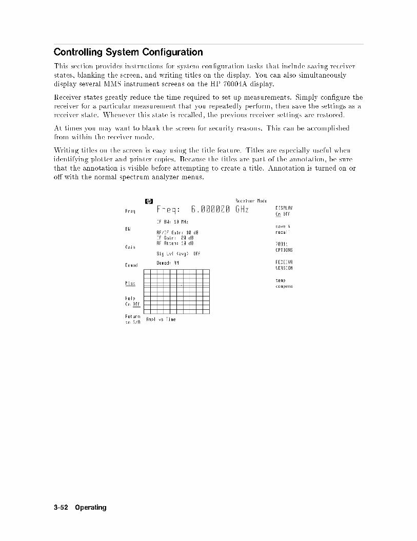
Controlling System Configuration
This section provides instructions for system con�guration tasks that include saving receiverstates, blanking the screen, and writing titles on the display. You can also simultaneouslydisplay several MMS instrument screens on the HP 70004A display.
Receiver states greatly reduce the time required to set up measurements. Simply con�gure thereceiver for a particular measurement that you repeatedly perform, then save the settings as areceiver state. Whenever this state is recalled, the previous receiver settings are restored.
At times you may want to blank the screen for security reasons. This can be accomplishedfrom within the receiver mode.
Writing titles on the screen is easy using the title feature. Titles are especially useful whenidentifying plotter and printer copies. Because the titles are part of the annotation, be surethat the annotation is visible before attempting to create a title. Annotation is turned on oro� with the normal spectrum analyzer menus.
3-52 Operating

To save a receiver state
During this procedure, you'll be asked to enter a name for the saved receiver state. If youhave a HIL accessory keyboard, entering the text is much easier. The keyboard plugs into anHP-HIL connector on the front-panel of HP 70004A displays. The keyboard and associatedcable have the following part numbers:
HIL keyboard : : : : : : : : : : : : : : : : : : : : : : : : : : : : : : : : : : : : : : : : : : : : : : : : : : : : : : : : :HP 46021Akeyboard cable : : : : : : : : : : : : : : : : : : : : : : : : : : : : : : : : : : : : : : : : : : : : : : : : : : : : : : : 46020-60001
1. Press �USER� and thenNNNNNNNNNNNNNNNNNNNNNNNRX_MODE to start the receiver collection personality.
2. Press the left-sideNNNNNNNNNNNNNNMisc softkey.
3. PressNNNNNNNNNNNNNNNNNNNNNNNNNNNNNNNNNNNMORE 1 of 3 .
4. PressNNNNNNNNNNNNNNNNNNNNNNNNNNNNNNNNNNNNNNNNNsave & recall .
5. Press one of the following softkeys to select the memory where the receiver state will bestored:
NNNNNNNNNNNNNNNNNNNNNNNNNNNNNNNNNNNNNNNNNINTRNL MEMORY indicates the instrument's internal memory.
NNNNNNNNNNNNNNNNNNNNNNNNNNNNNNNNNNNNNNHP-MSIB CARD indicates a memory card in the optical spectrum analyzer's front-panelcard slot.
Remember to insert the card before pressingNNNNNNNNNNNNNNNNNNNNNNNNNNNNNNNNNNNNNNHP-MSIB CARD . If 2053 Storage
device error is displayed, either the card is missing, the card's write-protect switchis in the SAFE position, or the card's HP-MSIB address is incorrectly listed. TheHP-MSIB address for the card is the same address as the display's HP-IB address andis normally set to 4. If the address is not correct, enter the correct address using thenumeric keypad.
NNNNNNNNNNNNNNNNNNNNNNNNNNNNNHPIB DISK indicates an external HP-IB disk drive. Refer to Chapter 1 for informationon connecting the disk drive.
6. Enter a title for the receiver state. If you do not have a keyboard, use the followinginstructions to create the title text:
Turn the front-panel knob to select a character.Press the �� and ��� keys (beneath the front-panel knob) to move the command-entrycursor.Press
NNNNNNNNNNNNNNNNNNNNNNNNNNNNNNNNNNNSELECT CHAR to enter a character at the character-select cursor.
Press the numeric keypad to enter numbers or a minus sign.Press
NNNNNNNNNNNNNNNNNSPACE to add a space character.
TheNNNNNNNNNNNNNNNNNNNNNNNNNNNNNNNNNNNNNNNNNNNNNNNINSERT or . . . softkey determines the action of the
NNNNNNNNNNNNNNNNNNNNNNNNNNNNNNNNNNNSELECT CHAR softkey.
Choices are INSERT a character, REPLACE an existing character, or DELETE acharacter.Use the
NNNNNNNNNNNNNNNNNNNNNNNNNNNNNNNNNNNNNNCLEAR TO END softkey to remove characters from the command-entry cursor to
the end of the command.The space character is located after the Z character on the display.
Operating 3-53

7. Press theNNNNNNNNNNNNNNNNNNNNNNNNNNNNNNNNENTER LINE softkey to place the title on the screen.
8. PressNNNNNNNNNNNNNNNNNNNNNNNNNNNNNprev menu .
9. PressNNNNNNNNNNNNNNNNNNNNNNNNNNNNNNNNNNNNNNNNNSAVE RX STATE , and use the numeric keypad to enter a number for the �le.
3-54 Operating

To recall or delete a receiver state
1. Press �USER� and thenNNNNNNNNNNNNNNNNNNNNNNNRX_MODE to start the receiver collection personality.
2. Press the left-sideNNNNNNNNNNNNNNMisc softkey.
3. PressNNNNNNNNNNNNNNNNNNNNNNNNNNNNNNNNNNNMORE 1 of 3 .
4. PressNNNNNNNNNNNNNNNNNNNNNNNNNNNNNNNNNNNNNNNNNsave & recall .
5. Press a softkey to select the memory where the receiver state will be stored:NNNNNNNNNNNNNNNNNNNNNNNNNNNNNNNNNNNNNNNNNINTRNL MEMORY indicates the instrument's internal memory.
NNNNNNNNNNNNNNNNNNNNNNNNNNNNNNNNNNNNNNHP-MSIB CARD indicates a memory card in the optical spectrum analyzer's front-panelcard slot.
Remember to insert the card before pressingNNNNNNNNNNNNNNNNNNNNNNNNNNNNNNNNNNNNNNHP-MSIB CARD . If 2053 Storage
device error is displayed, either the card is missing, the card's write-protect switchis in the SAFE position, or the card's HP-MSIB address is incorrectly listed. TheHP-MSIB address for the card is the same address as the display's HP-IB address andis normally set to 4. If the address is not correct, enter the correct address using thenumeric keypad.
NNNNNNNNNNNNNNNNNNNNNNNNNNNNNHPIB DISK indicates an external HP-IB disk drive. Refer to Chapter 1 for informationon connecting the disk drive.
6. Perform one of the following tasks:
To recall a receiver state, pressNNNNNNNNNNNNNNNNNNNNNNNNNNNNNNNNNNNNNNRCL RX STATE , and enter the number that identi�es the
�le.
To delete a receiver state, pressNNNNNNNNNNNNNNNNNNNNNNNNNNNNNNNNNNNNNNDEL RX STATE , and enter the number that identi�es the
�le. Then, pressNNNNNNNNNNNNNNNNNENTER .
Operating 3-55

To view two instrument windows
This procedure display's two instrument windows on the HP 70004A's display. This isespecially useful if you are using your HP 71910A with an HP 70703A Digitizing Oscilloscope.
1. Press the �DISPLAY� key.
2. Press the left-sideNNNNNNNNNNNNNNNNNNNNNNNNNNNNNNNNNNNNNNNNNNNNConfig Display softkey.
3. PressNNNNNNNNNNNNNNNNNNNNNNNNNNNNNNNNNNNNNNbuild window and then
NNNNNNNNNNNNNNNNNNNNNNNNNNNNNNNNNNNNNNNNNNNNNNNSTACK 2 WINDOWS .
4. Press �INSTR�.
5. Press the left-side softkey that is next to the instrument window that you want to select.
For example, to select the HP 71910A, pressNNNNNNNNNNNNNNNNNNNN70900B . To select the HP 70703A, pressNNNNNNNNNNNNNNNNNNNN
70703A . The instrument's softkeys will now appear.
6. To switch control to the next instrument window, press �INSTR� and then the appropriatesoftkey.
To blank the display
1. Press the left-sideNNNNNNNNNNNNNNMisc softkey.
2. PressNNNNNNNNNNNNNNNNNNNNNNNNNNNNNNNNNNNNNNNNNNNNDISPLAY On Off so that
NNNNNNNNOn is underlined.
3-56 Operating

To write a title on the screen
Note If you have a HIL keyboard, entering the text is much easier. The keyboardplugs into an HP-HIL connector on the front-panel of HP 70004A displays.The keyboard and associated cable have the following part numbers:
HIL keyboard : : : : : : : : : : : : : : : : : : : : : : : : : : : : : : : : : : : : : : : : : HP 46021Akeyboard cable : : : : : : : : : : : : : : : : : : : : : : : : : : : : : : : : : : : : : : : :46020-60001
1. Press the left-sideNNNNNNNNNNNNNNMisc softkey to enter the Miscellaneous menu.
2. PressNNNNNNNNNNNNNNNNNNNNNNNNNNNNNNNNNNNNNNNNNsave & recall .
3. Press theNNNNNNNNNNNNNNNNNTITLE softkey to enter the Title menu.
4. Use the following instructions to create the title text:
Turn the front-panel knob to select a character.Press the �� and ��� keys (beneath the front-panel knob) to move the command-entrycursor.Press
NNNNNNNNNNNNNNNNNNNNNNNNNNNNNNNNNNNSELECT CHAR to enter a character at the character-select cursor.
Press the numeric keypad to enter numbers or a minus sign.Press
NNNNNNNNNNNNNNNNNSPACE to add a space character.
TheNNNNNNNNNNNNNNNNNNNNNNNNNNNNNNNNNNNNNNNNNNNNNNNINSERT or . . . softkey determines the action of the
NNNNNNNNNNNNNNNNNNNNNNNNNNNNNNNNNNNSELECT CHAR softkey.
Choices are INSERT a character, REPLACE an existing character, or DELETE acharacter.Use the
NNNNNNNNNNNNNNNNNNNNNNNNNNNNNNNNNNNNNNCLEAR TO END softkey to remove characters from the command-entry cursor to
the end of the command.The space character is located after the Z character on the display.
5. Press theNNNNNNNNNNNNNNNNNNNNNNNNNNNNNNNNENTER LINE softkey to place the title on the screen.
Operating 3-57

3-58 Operating

Block Diagrams
HP 71910A System Block Diagram
Operating 3-59

HP 70910A RF Section Block Diagram
3-60 Operating

HP 70911A IF Module Block Diagram
Operating 3-61

If You Have a Problem
Your wide-bandwidth surveillance receiver is built to provide dependable operation. It isunlikely you will experience a problem, but in the event something goes wrong, this sectionprovides solutions to common problems.
Error messages can be displayed for a variety of reasons. Most messages indicate a harmlesssituation. For example, they may simply indicate that you attempted to enter a value thatwas out of a particular function's range. However, if an error message remains after pressingseveral keys, it may indicate a more serious problem. Refer to Chapter 9 for a list of errormessages.
3-62 Operating

If UNCOR is displayed
UNCOR indicates that the displayed amplitude data is not corrected.
Note The information provided in this section refers to operating the HP 71910A inmanual mode versus using the receiver personality.
Symptoms
To solve this problem
Ignore this message when collecting signals.
This message refers to displayed data. UNCOR is displayed when the HP 71910A is in manualmode and the resolution bandwidth is set to a value greater than 40 MHz. This is because thecalibration routine does not correct for bandwidths that are wider than 40 MHz.
Note The display shown above shows the 30 dB amplitude range of the lineardetector. A logarithmic ampli�er is not present for IF bandwidths of 10 MHzto 100 MHz. Use resolution bandwidths of 3 MHz or less for signal searchessince a logarithmic ampli�er is present for those bandwidths.
Operating 3-63

If UNCAL and Usable RBW limited is displayed
UNCAL and Usable RBW limited is displayed indicates that the RF module is limiting theavailable bandwidth.
Note The information provided in this section refers to operating the HP 71910A inmanual mode versus using the receiver personality.
Symptoms
To solve this problem
If the signal is in the microwave bands (2.7 GHz to 26.5 GHz), and the preselector is on, themaximum bandwidth is limited to greater than 36 MHz. Turn the preselector o� (bypassmode) using the procedure contained in this section.
If the signal is in the RF bands (100 Hz to 2.9 GHz) the maximum bandwidth isapproximately 48 MHz. There is no bypass for this frequency range. So, UNCAL will appear.
To bypass the preselector
When the preselector is on, its bandwidth depends on the center frequency. The bandwidthincreases as the frequency increases. At 20 GHz, the bandwidth is greater than 50 MHz.
1. On the HP 71910A, press the left-sideNNNNNNNNNNNNNNNNNState softkey.
2. PressNNNNNNNNNNNNNNNNNNNNNNNNNNNNNpreselect .
3. PressNNNNNNNNNNNNNNNNNNNNNNNNNNNNNNNNNNNNNNNNNPRESEL On Off so that
NNNNNNNNNNNOff is underlined.
3-64 Operating

If UNCAL and Usable VBW limited is displayed
This message only refers to displayed data and not the HP 71910A's IF, VIDEO, FM, or IQoutputs. The message appears when the video bandwidth is set greater than the 3 MHz videobandwidth limit of the HP 70900B module's peak detector.
Note The information provided in this section refers to operating the HP 71910A inmanual mode versus using the receiver personality.
Symptoms
To solve this problem
Ignore this message when collecting signals. Realize that the spectrum analyzer's displayis uncalibrated. This is particularly true for signals such as pulsed RF which result indesensitized amplitude displays.
Operating 3-65

If Possible compression is displayed
Possible compression indicates that the signal is overdriving the IF and is beingcompressed.
Note The information provided in this section refers to operating the HP 71910A inmanual mode versus using the receiver personality.
Symptoms
To solve this problem
1. Press the left-sideNNNNNNNNNNNNNNNNNAmptd softkey.
2. PressNNNNNNNNNNNNNNNNNNNNNNNNNNNNNNNNNNNMORE 1 of 4 ,
NNNNNNNNNNNNNNNNNNNNNNNNNNNNNNNNNNNMORE 2 of 4 , and then
NNNNNNNNNNNNNNNNNNNNNNNNNNNNNNNNNNNMORE 3 of 4 .
3. Do one of the following:
PressNNNNNNNNNNNNNNNNNNNNNNNNNNNNNNNNNNNNNNNNNNNNNNNSTPGAIN AutoMan so that
NNNNNNNNNNNNNNAuto is underlined.
PressNNNNNNNNNNNNNNNNNNNNNNNNNNNNNNNNNNNNNNNNNNNNNNNSTPGAIN AutoMan and reduce the IF step gain.
3-66 Operating

If the PREAMP On Off softkey doesn't work
Note The information provided in this section refers to operating the HP 71910Awith an HP 70620B or HP 70621A preampli�er.
Symptoms
Pressing theNNNNNNNNNNNNNNNNNNNNNNNNNNNNNNNNNNNNNNNNNPREAMP On Off softkey does not toggle the softkey highlighting between the
NNNNNNNNOn
andNNNNNNNNNNNOff conditions.
To solve this problem
The preampli�er's RF INPUT connector must �rst be selected.
1. Press �MENU� and then the left-sideNNNNNNNNNNNNNNNNNState softkey.
2. PressNNNNNNNNNNNNNNNNNNNNNNNNNNNNNNNNNNNNNNselect input .
CAUTION The following step presets the receiver's state which causes many of themeasurement settings to change.
3. PressNNNNNNNNNNNNNNNNNNNNNNNNNNNNNNNNNNNIN 1 70620B to select HP 70620B preampli�er's RF INPUT.
4. If you are using the receiver personality, perform the following steps:
a. Press �USER�.
b. Press the left-sideNNNNNNNNNNNNNNGain softkey.
c. PressNNNNNNNNNNNNNNNNNNNNNNNNNNNNNNNNNNNNNNNNNPREAMP On Off to turn the HP 70620B preamp on or o�.
5. If you are not using the receiver personality, perform the following steps:
a. Press the left-sideNNNNNNNNNNNNNNNNNState softkey.
b. PressNNNNNNNNNNNNNNNNNNNNNNNNNNNNNNNNNNNMORE 1 of 4 and then
NNNNNNNNNNNNNNNNNNNNNNNNNNNNNNNNNNNNNNNNNNNNpreamp control .
c. PressNNNNNNNNNNNNNNNNNNNNNNNNNNNNNNNNNNNNNNNNNPREAMP On Off to turn the HP 70620B preamp on or o�.
Operating 3-67

If there is a frequency shift in an HP 70911A output
Symptoms
An HP 70911A IF, FM, or IQ output is frequency shifted.
A displayed constellation spins when resolution bandwidth of 3 MHz or lower is selected.
When simultaneously analyzing an IF output of one of the spectrum analyzer IF modules (HP 70902A or HP 70903A) and an IF, FM, or IQ output from the HP 70911A ultra-widebandwidth IF module, you may notice a slight frequency shift in the output of the HP 70911Aoutputs. This occurs when a resolution bandwidth of 3 MHz or lower is selected and when thecalibration has been run (that is, no UNCOR message appears on the screen). For example,this frequency shift may be evident when viewing a constellation display using the analogIQ outputs of the HP 70911A. The constellation may be �xed (not rotating) when an IFbandwidth of 10 MHz or greater is selected. However, when a resolution bandwidth of 3 MHzor lower is selected, the constellation starts spinning. The frequency shift only occurs whenbandwidths of 3 MHz or lower are selected.
To solve this problem
1. Press �MENU�.
2. Press the left-sideNNNNNNNNNNNNNNNNNAmptd softkey.
3. PressNNNNNNNNNNNNNNNNNNNNNNNNNNNNNNNNNNNMORE 1 of 4 ,
NNNNNNNNNNNNNNNNNNNNNNNNNNcal menu , and then
NNNNNNNNNNNNNNNNNNNNNNNNNNNNNNNNcal enable .
4. PressNNNNNNNNNNNNNNNNNNNNNNNRBW FRQ so that it is o�.
The UNCOR screen annotation will appear as long as theNNNNNNNNNNNNNNNNNNNNNNNRBW FRQ is o�.
3-68 Operating

4
Programming
This chapter describes operation via a remote computer. The topics covered in this chapterare listed below:
Contents
Getting Started : : : : : : : : : : : : : : : : : : : : : : : : : : : : : : : : : : : : : : : : : : : : : : : : : : : : : : : : : : : : : : : : : : : : : : : :4-2HP BASIC Programming Example : : : : : : : : : : : : : : : : : : : : : : : : : : : : : : : : : : : : : : : : : : : : : : : : : : : : :4-4Communicating with the Receiver : : : : : : : : : : : : : : : : : : : : : : : : : : : : : : : : : : : : : : : : : : : : : : : : : : : : : :4-5Transferring Data to the Computer : : : : : : : : : : : : : : : : : : : : : : : : : : : : : : : : : : : : : : : : : : : : : : : : : : : : 4-7Monitoring System Operation : : : : : : : : : : : : : : : : : : : : : : : : : : : : : : : : : : : : : : : : : : : : : : : : : : : : : : : : : :4-8
Programming 4-1

Getting Started
The HP 71910A Wide Bandwidth Surveillance Receiver has a rich set of programmingcommands. These commands are divided into two groups: those that control spectrumanalyzer features and those that control features provided by the receiver personality. To learnabout the spectrum analyzer commands, refer to the HP 70900B Programmer's Guide for HP70900B Instruments . To learn about receiver personality commands, refer to Chapter 8 in thisbook.
Use the spectrum analyzer commands for signal searches and the receiver commands forsignal collection. For example, perform basic spectrum analyzer search tasks such as settingthe start and stop frequencies and using markers to search for signals. Then, use the receiverpersonality commands to perform collection tasks such as selecting signal demodulation (AM,PULSE, FM narrowband, FM wideband, and IQ) and Option 007 IF channel �lters.
The spectrum analyzer commands and the receiver personality commands are both sent to theHP-IB address of the HP 70900B module. This address is equal to the column address of theHP 70900B module which has a default value of 18.
Initialize the personality
Before using any receiver personality commands, initialize the personality by sending theRXRMT INIT command. It is recommended that the personality not be running when sendingthe RXRMT INIT command or using the any of the remote commands documented in thischapter; these commands execute faster if the personality is not manually running. This isdue to the time required to update the display.
Note Before you can use any of the receiver personality commands, you mustinitialize the personality by sending the RXRMT INIT command.
Important spectrum analyzer commands
The following is a list of commands documented in the HP 70900B Programmer's Guide forHP 70900B Instruments that are speci�c to receiver operation:
CPLDET: Controls the coupling between the logarithmic scale (LG command), linear scale(LN command) and the detector used for trace data (See DETSEL below).
DETSEL: Selects the hardware detector used for trace data (logarithmic or linear).
PC: Perform preselector centering.
PCDELTA: Adjust the delta value for performing preselector centering.
PRSENABLE: Turns the preselector on and o�.
SG: Controls the step gain in the signal path.
SS: Sets the center frequency step size.
4-2 Programming

To connect the equipment
The following procedure describes how to connect your equipment for remote operation.
1. Connect the computer, MMS mainframe, and other peripherals with HP-IB cables.
2. After the HP-IB cables are installed, reset all instruments connected to the bus. If you arenot sure how to reset a device, switch its line power o�, then on, to reset it.
3. Check the column address of the HP 70900B module on the address map. Use this value asthe HP-IB address to send receiver commands.
To view the address map, press the �DISPLAY� key on the display front-panel, then press
theNNNNNNNNNNNNNNNNNNNNNNNNNNNNNNNNNNNAddress Map softkey.
Programming 4-3

HP BASIC Programming Example
The following HP BASIC example illustrates some simple techniques used to search for asignal, initialize the receiver personality, and collect the data.
1 ASSIGN @Rx to 718 Assign the HP 70900B's HP-IB address.
2 CLEAR @Rx
3 OUTPUT @Rx;"IP;" Preset the instrument.
4 OUTPUT @Rx;"SNGLS;" Select single sweeps.
5 OUTPUT @Rx;"FA1GHZ;FB2GHZ;" Set frequency range.
6 OUTPUT @Rx;"TS;" Take a single sweep.
7 OUTPUT @Rx;"MKPK HI;MKCF;" Move highest peak to center of screen.
8 OUTPUT @Rx;"RXRMT INIT;" Initialize receiver personality.
9 OUTPUT @Rx;"RXRMT CHANPATH 70E6,5E6;" Select Option 007 5 MHz �lter in 70 MHz IF path.
10 OUTPUT @Rx;"RXRMT DEMOD FM;" Select FM demodulation.
11 OUTPUT @Rx;"RXRMT SAVERX 1;" Save receiver settings for later recall.
4-4 Programming

Communicating with the Receiver
This section develops some fundamental techniques for controlling and obtaining reliablemeasurement results using HP BASIC. It is important to understand how messages arecommunicated to the receiver; therefore, enter and output statements and command syntaxdiscussed in this chapter should be understood before proceeding. HP BASIC is used for allexamples in this manual.
Initial Commands
Programs should begin with a series of HP BASIC statements and receiver commands thatform a good starting point for measurements. The following example shows how to initializethe receiver.
10 ASSIGN @Rx to 718
20 CLEAR @Rx
30 OUTPUT @Rx;"IP;"
The ASSIGN statement creates an I/O path name and assigns that name to an I/O device. Inthe example above, the I/O path name is @Rx. It is assigned to the device at interface selectcode 7 (the HP-IB interface), and at HP-IB address 18.
Using the ASSIGN statement in a program makes it easier to change the address of thereceiver. In applications where speed is important, using ASSIGN can also improve programperformance.
CLEAR is an HP BASIC statement that clears the input bu�er, the output bu�er, and thecommand parser of the speci�ed instrument, so that it is ready for operation. This commandmay be used to clear devices on the bus singly or in unison. It is often desirable to clear onlyone instrument so that other instruments on the bus are not a�ected.
To clear only the receiver, CLEAR @Rx should be used.
To clear all devices at select code 7, CLEAR 7 must be used.
IP, the instrument preset command, presets all of the parameters of the spectrum analyzerand is a good starting point for all measurement processes.
Executing Remote Commands
The computer communicates with the receiver on the Hewlett-Packard Interface Bus (HP-IB),using HP BASIC OUTPUT and ENTER statements. An OUTPUT statement tells the computerto send a message to the receiver (HP 70900B LO module). For example, executing thestatement below selects the receiver's AM demodulation:
OUTPUT 718;"RXRMT DEMOD,AM;"
An ENTER statement used in conjunction with a receiver query returns information to thecomputer. To return the demodulation selection to the computer, �rst form a query by addinga question mark (?) to the command:
OUTPUT 718;"RXRMT DEMOD?;"
Next, the ENTER statement is used to assign the returned value to a variable in the computer:The returned value above is placed in the variable named \demod". The variable may beprinted, stored, or used for other computer functions.
ENTER 718; demod$
Programming 4-5

Local and Remote Control
Whenever the receiver is remotely addressed, the display front-panel softkeys are disabled andblanked. Pressing the �LOCAL� key or executing the HP BASIC statement LOCAL reactivatesoperation of the softkeys.
The front-panel indicators on the HP 71910A receiver light under the following conditionswhen the HP-IB interface is used:
When the receiver is addressed, the RMT indicator lights.
When the receiver receives information, the LSN indicator lights.
When the receiver sends information, the TLK indicator lights.
When a measurement event (for example, end of the sweep) has occurred and the receiver isrequesting computer attention, the SRQ indicator lights (provided that the service-requestmask is set to allow SRQ on end-of-sweep).
4-6 Programming

Transfering Data to the Computer
The receiver returns information as decimal values in fundamental units shown in thefollowing table. The receiver also applies these units to data received from the computerwhich do not explicitly specify units.
Units for Returned Data
Measured
Data
Fundamental Unit
Amplitude dBm, watt
Power dBm, watt
Ratio dB
Responsivity volt/watt
Use the AUNITS (amplitude units) command is used to select the desired unit. The AUNITScommand can either specify a single unit to be used for all power and amplitude information,or it can be set to automatically select the units, based on certain measurement settings.
Refer to the description of the AUNITS command in the HP 70900B Programmer's Guide forHP 70900B Instruments for more information.
Programming 4-7

Monitoring System Operation
The programming techniques discussed so far describe communication between the receiverand the computer, where the sequence of all data transfer is controlled by a computerprogram. This section describes how the receiver can interrupt computer operation uponattaining a particular state.
The interrupting process is called a service request. Service requests have many applications.They facilitate economical use of computer-processing time when the receiver is part of alarge measurement system. For example, after the computer initiates a receiver measurement,the computer can make calculations or control other devices via HP-IB while the receiveris measuring. When the receiver is through, it signals the computer with a service request.The computer's service-request subprogram then determines what the computer will do next.Service requests can also be used to report errors.
Interrupt Process
The interrupt process begins when the receiver \requests" attention by setting the HP-IBservice-request line (SRQ) true. The computer must be programmed to respond to this event.Typically, the computer is programmed to interrupt normal program execution and call auser-speci�ed subroutine when the service request occurs. This subroutine must determinewhich instrument(s) on HP-IB caused the service request. Then, it may be necessary tocall another subroutine which determines why a particular instrument requested service(since there may be more than one possible cause). Finally, a subroutine(s) will be called torespond to the indicated event(s). Note that more than one instrument may request servicesimultaneously, and each instrument may have more than one event to report. These steps aresummarized below.
1. Computer monitors HP-IB service request line (SRQ).
2. Receiver requests service by setting the SRQ line true.
3. Computer branches to routine that determines the instrument(s) that caused the SRQ.
4. Computer branches to routine that determines why a particular instrument is requestingservice.
5. Computer branches to routine to process a speci�c event in a particular instrument.
Some of the routines above may be omitted, if only one instrument has been instructed to usethe SRQ line, or if a particular instrument has been instructed to use the SRQ line for onlyone event.
Several system-level statements are required to make the computer responsive to servicerequests. The HP BASIC statement, ENABLE INTR (enable interrupt), tells the computer tomonitor the service-request line. The on-interrupt statement, ON INTR, speci�es where thecomputer program will branch when a service request occurs. If more than one instrumentcould cause the service request, or if an instrument can cause a service request for more thanone reason, the serial-poll statement, SPOLL, is used. The serial-poll statement is alwaysrequired to clear the service request being generated by the instrument.
Receiver Status Byte
The status byte indicates the status or occurrence of certain receiver functions. The statusbyte contains eight bits, numbered 0|7 with bit 0 being the least signi�cant bit.
4-8 Programming

Bits 0, 1, 2, 3, 4, 5, and 7 represent speci�c conditions or events. These bits are referred to ascondition bits and event bits. Condition bits re ect a condition in the receiver which may bepresent or absent at any given moment. Event bits re ect the occurrence of a transition orevent within the receiver.
Bit 6 is set by the receiver to indicate whether or not it is requesting service.
When the receiver is instructed not to use the service request line on HP-IB, the status bitsalways re ect the current condition of the receiver. In this situation, the event bits in thestatus byte should not be used. Event bits are only true at the exact instant of a transition inthe receiver and as such are not reliable when service requests are disabled.
When the receiver is instructed to generate service requests for one or more conditions orevents, the status bits re ect the current condition of the receiver until a service request isgenerated. Then, the bits which are generating the service request are held true until thestatus byte is read out of the receiver (by the HP BASIC SPOLL system-level statement), bythe STB? command, or until an HP-IB DEVICE CLEAR (HP BASIC CLEAR system-levelstatement) is received. These actions clear the status byte to once again re ect the currentconditions and events within the receiver.
The Service-Request Mask
The service-request mode is enabled and controlled by the request-service-conditioncommand, RQS. It de�nes a service-request mask that speci�es which of the status-bytebits may generate a service request. Below, RQS speci�es the ERROR-PRESENT andCOMMAND-COMPLETE states (bits 5 and 4) for service requests.
OUTPUT @Rx;"RQS 48;" Selects bit 5 and 4 (32+16) to enable service request mode for ERROR-PRESENT andCOMMAND-COMPLETE.
OUTPUT @Rx;"RQS ";DVAL("00110000",2) Also selects bits 5 and 4 as above, but is somewhat easier to read.
Once RQS is executed, the receiver requests service by setting the SRQ line true when thedesired conditions or events occur.
Receiver Status Byte
Bit
Number
Decimal
Equivalent
Receiver
State
Description Bit
Type
7 128 OUT OF RANGE
6 64 RQS Set when service request is being generated. |
5 32 ERROR-PRESENT Set when error register contains an error. condition
4 16 COMMAND-COMPLETE Set at completion of command execution. event
3 8 ZEROING
2 4 Not Used
1 2 MESSAGE Set when messages are displayed. condition
0 1 Not Used
Programming 4-9

Monitoring System Operation without Using Service Requests
The STB command may be used to monitor the value of the status byte at any time.Executing STB? returns the decimal equivalent of the status byte to the computer. ExecutingSTB is similar to conducting a serial poll of the status byte. When STB is executed, thestatus-byte is updated to re ect current receiver conditions.
4-10 Programming
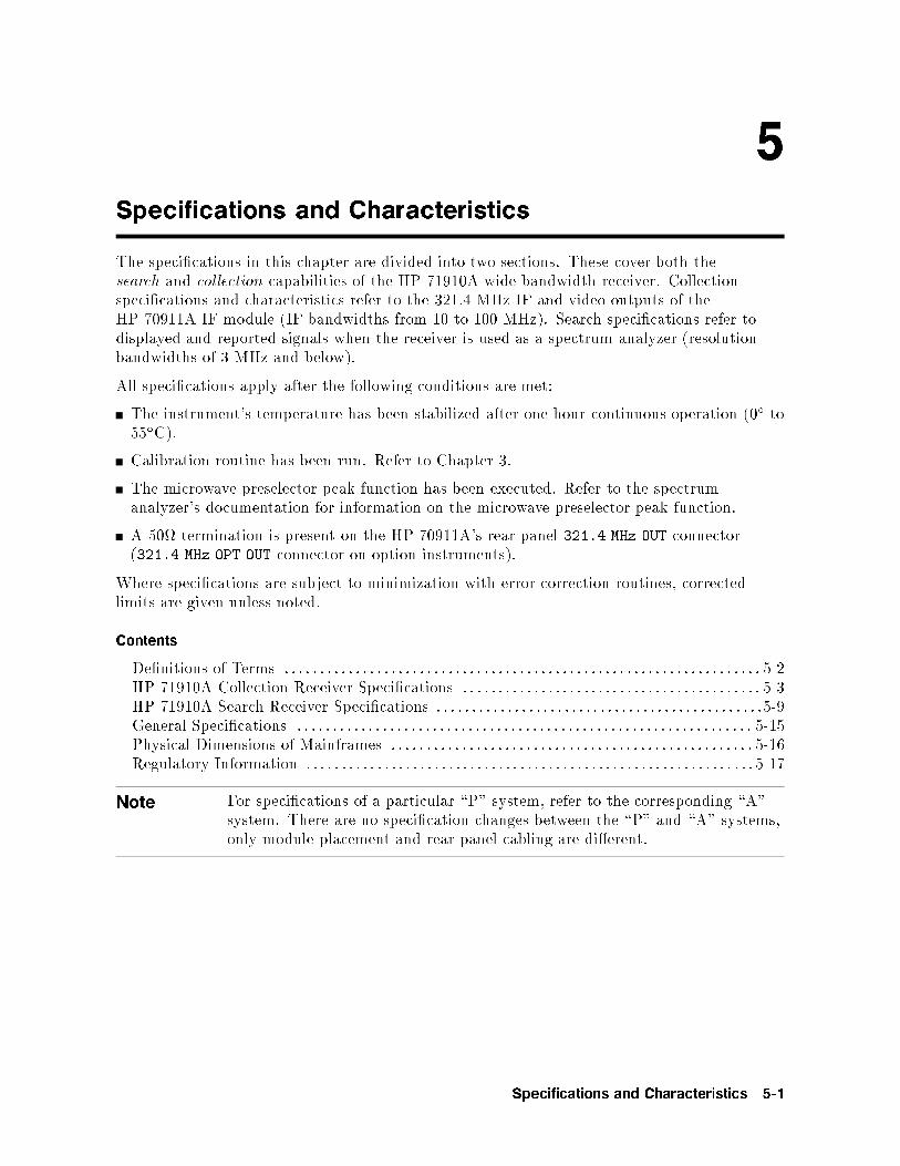
5
Specifications and Characteristics
The speci�cations in this chapter are divided into two sections. These cover both thesearch and collection capabilities of the HP 71910A wide bandwidth receiver. Collectionspeci�cations and characteristics refer to the 321.4 MHz IF and video outputs of theHP 70911A IF module (IF bandwidths from 10 to 100 MHz). Search speci�cations refer todisplayed and reported signals when the receiver is used as a spectrum analyzer (resolutionbandwidths of 3 MHz and below).
All speci�cations apply after the following conditions are met:
The instrument's temperature has been stabilized after one-hour continuous operation (0� to55�C).
Calibration routine has been run. Refer to Chapter 3.
The microwave preselector peak function has been executed. Refer to the spectrumanalyzer's documentation for information on the microwave preselector peak function.
A 50 termination is present on the HP 70911A's rear panel 321.4 MHz OUT connector(321.4 MHz OPT OUT connector on option instruments).
Where speci�cations are subject to minimization with error correction routines, correctedlimits are given unless noted.
Contents
De�nitions of Terms : : : : : : : : : : : : : : : : : : : : : : : : : : : : : : : : : : : : : : : : : : : : : : : : : : : : : : : : : : : : : : : : : : : 5-2HP 71910A Collection Receiver Speci�cations : : : : : : : : : : : : : : : : : : : : : : : : : : : : : : : : : : : : : : : : : : 5-3HP 71910A Search Receiver Speci�cations : : : : : : : : : : : : : : : : : : : : : : : : : : : : : : : : : : : : : : : : : : : : : :5-9General Speci�cations : : : : : : : : : : : : : : : : : : : : : : : : : : : : : : : : : : : : : : : : : : : : : : : : : : : : : : : : : : : : : : : : 5-15Physical Dimensions of Mainframes : : : : : : : : : : : : : : : : : : : : : : : : : : : : : : : : : : : : : : : : : : : : : : : : : : : 5-16Regulatory Information : : : : : : : : : : : : : : : : : : : : : : : : : : : : : : : : : : : : : : : : : : : : : : : : : : : : : : : : : : : : : : : 5-17
Note For speci�cations of a particular \P" system, refer to the corresponding \A"system. There are no speci�cation changes between the \P" and \A" systems,only module placement and rear-panel cabling are di�erent.
Specifications and Characteristics 5-1

Definitions of Terms
The distinction between speci�cations, characteristics , typical performance, and nominalvalues is described as follows:
Speci�cations describe warranted performance over the temperature range 0� to 55�C(unless otherwise noted).
Characteristics provide useful, but nonwarranted information about the functions andperformance of the instrument. Characteristics are printed in italics .
Typical Performance, where listed, is nonwarranted, but indicates performance which mostunits will exhibit.
Nominal Value is an expected, but nonwarranted, value of the parameter.
5-2 Specifications and Characteristics
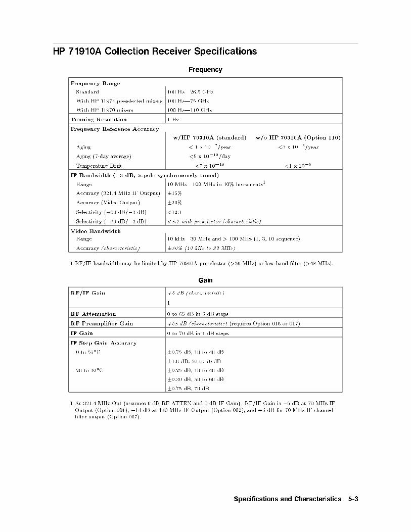
HP 71910A Collection Receiver Specifications
Frequency
Frequency Range
Standard 100 Hz|26.5 GHz
With HP 11974 preselected mixers 100 Hz|75 GHz
With HP 11970 mixers 100 Hz|110 GHz
Tunning Resolution 1 Hz
Frequency Reference Accuracy
w/HP 70310A (standard) w/o HP 70310A (Option 110)
Aging < 1 x 10�7/year <3 x 10�6/year
Aging (7-day average) <5 x 10�10/day
Temperature Drift <7 x 10�10 <1 x 10�5
IF Bandwidth (�3 dB, 5-pole synchronously tuned)
Range 10 MHz|100 MHz in 10% increments1
Accuracy (321.4 MHz IF Output) �15%
Accuracy (Video Output) �20%
Selectivity (�60 dB/�3 dB) <12:1
Selectivity (�60 dB/�3 dB) <8:1 with preselector (characteristic)
Video Bandwidth
Range 10 kHz|30 MHz and > 100 MHz (1, 3, 10 sequence)
Accuracy (characteristic) �30% (10 kHz to 30 MHz)
1 RF/IF bandwidth may be limited by HP 70910A preselector (>36 MHz) or low-band �lter (>48 MHz).
Gain
RF/IF Gain +5 dB (characteristic)
1
RF Attenuation 0 to 65 dB in 5 dB steps
RF Preampli�er Gain +28 dB (characteristic) (requires Option 016 or 017)
IF Gain 0 to 70 dB in 1 dB steps
IF Step Gain Accuracy
0 to 55�C �0.75 dB, 10 to 40 dB
�1.0 dB, 50 to 70 dB
20 to 30�C �0.25 dB, 10 to 40 dB
�0.30 dB, 50 to 60 dB
�0.75 dB, 70 dB
1 At 321.4 MHz Out (assumes 0 dB RF ATTEN and 0 dB IF Gain). RF/IF Gain is �5 dB at 70 MHz IFOutput (Option 001), �14 dB at 140 MHz IF Output (Option 002), and +5 dB for 70 MHz IF channel�lter output (Option 007).
Specifications and Characteristics 5-3

Dynamic Range
Third-Order Intercept Standard Option 016 or 0171(characteristic)
Preamp Bypass Preamp On
20 MHz|2.9 GHz 9 dBm 11 dBm �16 dBm
2.7 GHz|6.2 GHz 4 dBm 6 dBm �21 dBm
6.0 GHz|26.5 GHz 2 dBm 4 dBm �23 dBm
1 dB Gain Compression (characteristic)
Standard Option 016 or 0171
Preamp Bypass Preamp On
��5 dBm ��5 dBm ��33 dBm
One-Tone Spurious-Free Dynamic Range2(characteristic)
10 MHz|12.0 GHz 67 dB 70 dB 56 dB
12.0 GHz|26.5 GHz 70 dB 70 dB 70 dB
Image Rejection3 Image Frequency Center Frequency Rejection
642.8 MHz 100 kHz|2.9 GHz �85 dBc
642.8 MHz 2.7|18.0 GHz �70 dBc
642.8 MHz 18.0|26.5 GHz �60 dBc
Internally Generated Spurs4 �60 dBm (characteristic)
Linear Detector Dynamic
Range530 dB (characteristic)
1 Use preamp bypass characteristics below 100 kHz for Option 016 and below 1 GHz for Option 017. Noise�gure, TOI, and dynamic range with preampli�er on are measured with 5 dB RF attenuation. 1 dB gaincompression with preampli�er on is measured with 10 dB attenuation.
2 Normalized to 1 MHz IF bandwidth. Values given for 0 dB step gain. Varies with step gain.
3 For RF input levels <0 dBm, input attenuation >10 dB.
4 300 MHz residual generated in low band of HP 70910A module. Appears 21.4 MHz away from IF centerfrequency. Applies only to center frequency <2.9 GHz and IF bandwidth >30 MHz.
5 Refers to dynamic range of video output of HP 70911A. Assumes IF Gain set properly.
5-4 Specifications and Characteristics

Noise
Noise Figure Standard Option 016 or 0171
Preamp Bypass Preamp On
1 MHz|12.8 GHz 32 dB 33 dB 13 dB
12.6 GHz|22.0 GHz 39 dB 41 dB 18 dB
22.0 GHz|26.5 GHz 43 dB 46 dB 21 dB
Phase Noise Noise Sideband2 (dBc/Hz)
N=1 N=2 N=4
10 kHz carrier o�set <�108 <�102 <�96
Phase Jitter, SSB, 100 Hz|25 MHz (characteristic)
10 MHz|6.2 GHz 0.2� RMS
6.0 GHz|12.8 GHz 0.4� RMS
12.6 GHz|26.5 GHz 0.8� RMS
1 Use preamp bypass characteristics below 100 kHz for Option 016 and below 1 GHz for Option 017.Noise �gure, TOI, and dynamic range with preampli�er on are measured with 5 dB RF attenuation. 1dB gain compression with preampli�er on is measured with 10 dB attenuation.
2 N is the harmonic mixing number, N=1� from 100 kHz to 6.2 GHz, N=2� from 6.0 GHz to 12.8 GHz,and N=4+ from 12.6 GHz to 26.5 GHz.
HP 70900B LO Section Inputs and Outputs Characteristics
300 MHz Calibrator Output
Connector BNC (f), 50 (nominal)
Output Power �10 dBm �0.3 dB (speci�ed)
Specifications and Characteristics 5-5

HP 70910A Wide Bandwidth RF Section Inputs and Outputs Characteristics
RF Input1
Connector APC 3.5, 50 (nominal)
VSWR (>10 dB attenuation)
0|6.2 GHz <1.4:1
6.0 GHz|26.5 GHz <2.0:1
VSWR (<10 dB attenuation) <3.0:1
LO emissions (>10 dB attenuation) Preselector On Preselector Bypass
0|2.9 GHz <�100 dBm <�80 dBm
2.7 GHz|26.5 GHz <�100 dBm <�50 dBm
RF Bandwidth2 Preselector On Preselector Bypass
0|2.9 GHz >48 MHz >48 MHz
2.7 GHz|26.5 GHz >36 MHz >200 MHz
Maximum Safe Input Level (speci�cation)
dc �0 Volts
ac (attenuation = 0) +15 dBm
ac (attenuation �10 dB) +30 dBm
Pulse 100W, 10�s (attenuation �50 dB)
321.4 MHz External Mixer IF Input1
Connector SMA (f), 50 (nominal)
Return Loss �14 dB from 271.4 to 371.4 MHz
Maximum safe Input Level (spec.) ac: 0 dBm, dc: �3V
Noise Figure <7.0 dB
SHI >(+30 � conversion loss) dBm
TOI >(+10 � conversion loss) dBm
Tune and Span Output1
Connector BNC (f), >10 k load impedance
Voltage Range 0 to +13.25V
Tuning Sensitivity
RF input chosen 0.5 V/GHz RF frequency
External mixer 1.5 V/GHz LO frequency
First LO Output1
Connector SMB (f), 50 VSWR <2.1:1
Frequency Range 3.0 to 6.6 GHz
Output Power (speci�cation) 25�C �5�C 0�C|55�C
Minimum 14.5 dBm 14.0 dBm
Maximum 17.0 dBm 17.5 dBm
1 Characteristics except where noted.
2 Measured at RF Section 321.4 MHz IF Output. For access, user must disconnect from HP 70911A 321.4MHz IF Input.
5-6 Specifications and Characteristics

HP 70911A Ultra-Wide Bandwidth IF Section Inputs and Outputs
Characteristics
Video Output1
Connector BNC (f), 50 (nominal)
Bandwidth (�3 dB) As selected by IF and video BW 2
Level 0|1 Volts
VSWR <1.5:1
Risetime <10 ns
321.4 MHz Out1,3
Connector4 Rear panel SMB (m), 50 (nominal)
Bandwidth (�3 dB) IF Bandwidth, as selected2
Group Delay Variation5 5 ns, (preselector bypassed) 0 to 55�C
3 ns, (preselector bypassed) 20 to 30�C
VSWR <2.0:1
321.4 MHz Option Output1,3
Connector Rear panel SMB (m), 50 (nominal)
Bandwidth (�3 dB) IF bandwidth, as selected2
VSWR <2.0:1
I and Q Video Outputs (Option 004)1,3
Connector BNC (f), 50 (nominal)
Level �0.5V
Bandwidth (�3 dB) 50 MHz (each channel)
Quadrature Error 6�
I/Q Gain Imbalance 1.25 dB
Total Harmonic Distortion <1% (<�40 dBc)
Spurious Emissions <�70 dBc (non-harmonic)
Rise Time (10|90%) �10 ns
Residual dc O�set �25 mV
VSWR <1.5:1
FM Video Output (Option 005)1,3
Connector BNC (f), 50 (nominal)
Level �0.5V
VSWR <1.5:1
Pk-Pk Deviation FM Sensitivity Linearity
10 MHz 0.1V/MHz �0.5%
40 MHz 0.025V/MHz �0.15%
Modulation Frequency 12 MHz (maximum)
Spurious Emissions �35 dBm
1 Characteristics except where noted.
2 Maximum IF bandwidth equals 100 MHz for center frequencies between 2.7 GHz and 26.5 GHz andpreselector in bypass. Preselector limits bandwidth to >36 MHz. For center frequency less than 2.9GHz, HP 70910A �lter limits bandwidth to >48 MHz. (A special option is available for wider �lter.)
3 IF and demod outputs are inverted for center frequency <12.8 GHz due to \minus" harmonic mixing.
4 For access, disconnect from 321.4 MHz OPT IN.
5 Maximum peak-to-peak variation over 80% of the selected IF bandwidth.
Specifications and Characteristics 5-7

HP 70911A Ultra-Wide Bandwidth IF Section Inputs and Outputs
Characteristics (continued)
70 and 140 MHz IF Outputs1,2,3
Connector Rear panel SMB (m), 50 (nominal)
VSWR <1.5:1 (70 MHz); <2.0:1 (140 MHz)
IF Frequency
Bandwidth (�3 dB) 70 MHz 140 MHz
Preselector On 36 MHz 36 MHz
Preselector Bypass 40 MHz 70 MHz
Group Delay Variation4
Preselector On 25 ns 25 ns
Preselector Bypass 25 ns 25 ns
Amplitude Variation4 2.0 dB 4.5 dB
Symbol Error Rate5 1 x 10�6 for Eb/N0 >25 dB
Noise Power Ratio6 >40 dB, asymptotic
70 MHz IF Channel Filters7 Five switchable channel �lters. 6-pole, 0.1 dB ripple Chebyshev.�3 dB IF bandwidths are 1.25, 5, 10, 20, and 36 MHz.
Custom Channel Filters8 Up to �ve �lters, installed and tested by HP.
1 Characteristics except where noted.
2 IF and demod outputs are inverted for center frequency <12.8 GHz due to \minus" harmonic mixing.
3 Requires Options 001 and 002, respectively.
4 Maximum peak-to-peak variation over 80% of the IF output bandwidth.
5 Measured with 64 QAM signal at 150 Mbits/s with 2 GHz < center frequency < 12 GHz.
6 For 2700 channel loading in a 36 MHz band with 2 GHz < center frequency < 12 GHz.
7 Requires Options 001 and 007.
8 Requires Options 001 or Option 002 and special option.
5-8 Specifications and Characteristics

HP 71910A Search Receiver Specifications
Frequency
Frequency Range See HP 71910A Collection Receiver Speci�cations in thischapter.
Frequency Readout Accuracy1
Span �10 MHz x N �[(freq. readout)(freq. ref. accuracy)+1.0% of span + 10 Hz]
Span >10 MHz x N
Sweep �20 ms �[(freq. readout)(freq. ref. accuracy)+1.5% of span + 10 Hz]
10 ms � sweep < 20 ms �[(freq. readout)(freq. ref. accuracy) +2.5% of span + 10 Hz]
Frequency Span1
Range 0|26.5 GHz in 0.5% increments
Accuracy
Span �10 MHz x N �[1% of span + (span)(freq. ref. accuracy)]
Span >10 MHz x N
sweep �50 ms �[1.5% of span+(span)(freq. reference accuracy)]
50 ms > sweep � 20 ms �[2.5% of span+(span)(freq. reference accuracy)]
20 ms > sweep �10 ms �[4.0% of span+(span)(freq. reference accuracy)]
Tuning Resolution See HP 71910A Collection Receiver speci�cations in thischapter.
Frequency Reference Accuracy See HP 71910A Collection Receiver Speci�cations in thischapter.
Spectral Purity Noise Sideband1 (dBc/Hz)(characteristic)
Carrier O�set N=1 N=2 N=4
100 Hz �85 �79 �73
300 Hz �88 �82 �76
1 kHz �94 �88 �82
3 kHz �104 �98 � 92
10 kHz (speci�cation) <�108 <�102 <�96
30 kHz �111 �105 �99
100 kHz �115 �109 �103
300 kHz �123 �117 �111
1 MHz �135 �129 �123
3 MHz �145 �139 �133
10 MHz �153 �147 �141
Line and System Related <�65 dBc + 20 log N
Sidebands1
1 In the equations, N is the harmonic mixing number, N=1� from 100 kHz to 6.2 GHz, N=2� from 6.0GHz to 12.8 GHz, and N=4+ from 12.6 GHz to 26.5 GHz.
Specifications and Characteristics 5-9
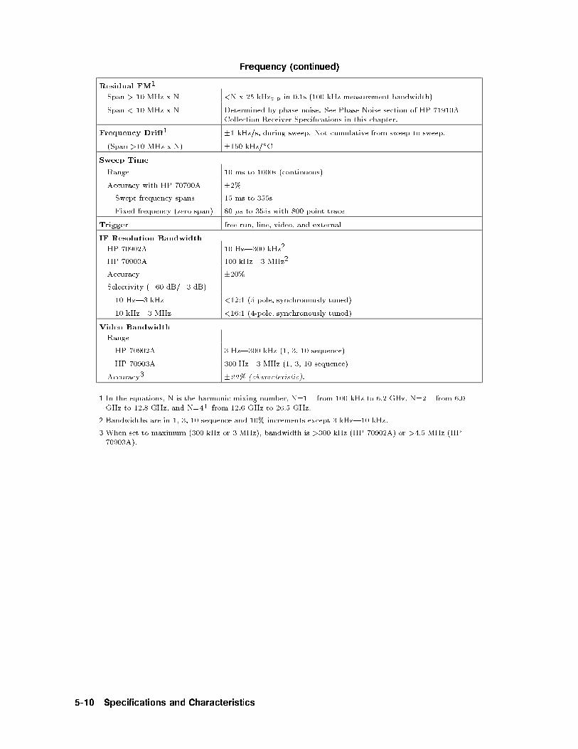
Frequency (continued)
Residual FM1
Span > 10 MHz x N <N x 25 kHzp-p in 0.1s (100 kHz measurement bandwidth)
Span < 10 MHz x N Determined by phase noise. See Phase Noise section of HP 71910ACollection Receiver Speci�cations in this chapter.
Frequency Drift1 �1 kHz/s, during sweep. Not cumulative from sweep to sweep.
(Span >10 MHz x N) �150 kHz/�C
Sweep Time
Range 10 ms to 1000s (continuous)
Accuracy with HP 70700A �2%
Swept frequency spans 15 ms to 355s
Fixed frequency (zero span) 80 �s to 355s with 800 point trace
Trigger free run, line, video, and external
IF Resolution Bandwidth
HP 70902A 10 Hz|300 kHz2
HP 70903A 100 kHz|3 MHz2
Accuracy �20%
Selectivity (�60 dB/�3 dB)
10 Hz|3 kHz <12:1 (5-pole, synchronously tuned)
10 kHz|3 MHz <16:1 (4-pole, synchronously tuned)
Video Bandwidth
Range
HP 70902A 3 Hz|300 kHz (1, 3, 10 sequence)
HP 70903A 300 Hz|3 MHz (1, 3, 10 sequence)
Accuracy3 �20% (characteristic).
1 In the equations, N is the harmonic mixing number, N=1� from 100 kHz to 6.2 GHz, N=2� from 6.0GHz to 12.8 GHz, and N=4+ from 12.6 GHz to 26.5 GHz.
2 Bandwidths are in 1, 3, 10 sequence and 10% increments except 3 kHz|10 kHz.
3 When set to maximum (300 kHz or 3 MHz), bandwidth is >300 kHz (HP 70902A) or >4.5 MHz (HP70903A).
5-10 Specifications and Characteristics

Amplitude
Total Amplitude Range �138 to +30 dBm
Displayed Average Noise Level Frequency DANL
Standard1 100 Hz <�92 dBm (characteristic)
300 Hz <�95 dBm (characteristic)
1 kHz <�101 dBm (characteristic)
3 kHz <�111 dBm (characteristic)
10 kHz <�118 dBm (characteristic)
30 kHz <�118 dBm (characteristic)
100 kHz <�122 dBm (characteristic)
300 kHz <�130 dBm (characteristic)
1 MHz <�139 dBm (characteristic)
3 MHz <�139 dBm (characteristic)
10 MHz|2.0 GHz <�138 dBm
2.0|12.8 GHz <�137 dBm
12.6|22.0 GHz <�130 dBm
22.0|26.5 GHz <�128 dBm
With HP 70620B (Option 016/017) 1.0|12.8 GHz <�155 dBm
12.6|22.0 GHz <�150 dBm
22.0|26.5 GHz <�148 dBm
Gain Compression Level2 �0.5 dB for signal levels �0 dBm
Spurious Responses3 Band Response
100 Hz|10 MHz <�60 dBc
10 MHz|26.5 GHz(preselector ON)
<�70 dBc
Second Harmonic Distortion(preselector on)
Band Response
100 Hz|20 MHz <�60 dBc
20 MHz|2.9 GHz <�75 dBc
2.9|26.5 GHz <�100 dBc
1 10 Hz Res BW, 0 dB attenuation, 3 Hz Video BW, Ref Level <�75 dBm.
2 10 dB input attenuation.
3 For <�30 dBm total signal power at the RF input with 10 dB attenuation. Exceptions noted.
Specifications and Characteristics 5-11

Amplitude (continued)
Third-Order Intermodulation Center Frequency Intermodulation
Products
Equivalent TOI
HP 70902A1 100 Hz|20 MHz <�64 dBc +2 dBm
20 MHz|2.9 GHz <�78 dBc +9 dBm
2.7|6.2 GHz <�68 dBc +4 dBm
6.0|26.5 GHz <�64 dBc +2 dBm
HP 70903A2 100 Hz|20 MHz <�54 dBc +2 dBm
20 MHz|2.9 GHz <�68 dBc +9 dBm
2.7|6.2 GHz <�58 dBc +4 dBm
6.0|26.5 GHz <�54 dBc +2 dBm
Image Responses3
6 MHz <�85 dBc
42.8 MHz <�85 dBc
642.8 MHz See Image Rejection section of HP 71910A Collection Receiverspeci�cations in this chapter.
Residual Responses (0 dB attenuation, input terminated)
10 MHz|26.5 GHz <�100 dBm
Multiple and Out-of-Band
Responses4<�70 dBc
Display Range (10 divisions)
Scale (logarithmic) 0.01|20 dB/div in 0.5% increments
Scale (linear) 10% of reference level per division
Reference Level (logarithmic) +30 to �140 dBm
Reference Level (linear) 7.07V to 22 nV
Frequency Response (10 dB attenuation, preselector peaked)
0|55�C 20|30�C 0|55�C
Peak Variation Referenced to
Calibrator5Referenced to
Calibrator5
100 Hz|2.9 GHz �1.5 dB �2.0 dB �2.0 dB
2.7|6.2 GHz �2.0 dB �2.0 dB �3.0 dB
6.0|12.8 GHz �2.0 dB �2.0 dB �3.0 dB
12.6|22.0 GHz �2.0 dB �2.0 dB �3.5 dB
22.0|26.5 GHz �2.5 dB �2.5 dB �4.0 dB
2.7|22 GHz6 +2.0, �3.0 dB (characteristic)
22.0|26.5 GHz6 +2.5, �3.5 dB (characteristic)
1 For two signals each ��20 dBm total signal power at RF input, 10 dB attenuation, 20|30 �C.
2 For two signals each ��15 dBm at the RF input, 10 dB attenuation, 20|30�C.
3 RF input �0 dBm, attenuation �10 dB.
4 For inputs �26.5 GHz and RF levels �0 dBm, �10 dB attenuation, preselector on.
5 Referenced to 300 MHz, �10 dBm calibrator. Does not include �0.3 dB calibrator amplitude error.
6 Preset preselector DAC, 20|30�C, referenced to calibrator for spans �100 MHz.
5-12 Specifications and Characteristics

Amplitude (continued)
Input Attenuator
Range 0 to 65 dB in 5 dB steps.
Switching Repeatability �0.2 dB
Accuracy1 (characteristic)
0|2.9 GHz �1.2 dB
2.9|12.7 GHz �2.3 dB
12.7|19.9 GHz �2.8 dB
19.9|26.5 GHz �4.8 dB
Preselector Bypass Switch <�0.2 dB
Repeatability
IF Gain Accuracy
Gain 20|30�C 0|55�C
HP 70902A 10 dB �0.2 dB �0.2 dB
20 dB �0.2 dB �0.2 dB
30 dB �0.2 dB �0.3 dB
40 dB �0.2 dB �0.5 dB
50 dB �0.2 dB �0.6 dB
60 dB �0.4 dB �0.8 dB
HP 70903A 10 dB �0.1 dB
20 dB �0.3 dB
Scale Fidelity
Log (corrected) Bandwidth Fidelity
HP 70902A (0 to 90 dB) <30 Hz �0.7 dB
30 Hz to 100 kHz �0.5 dB
>100 kHz �0.7 dB
HP 70903A (0 to 75 dB) �1 MHz �0.5 dB
�1 MHz �0.7 dB
Log (uncorrected) all �3.0 dB
Incremental Fidelity 0.1 dB/dB, all bandwidths
Linear �7.5% of reference level
Amplitude Temperature Drift (characteristic)2
HP 70902A �0.05 dB/�C at 300 MHz, 100 Hz Resolution BW 3
HP 70903A �0.05 dB/�C at 300 MHz, 300 kHz resolution BW 3
Resolution Bandwidth Switching Repeatability
�0.2 dB in 1, 3, 10 sequence
�3 dB (uncorrected)
Marker Resolution �0.03 dB
1 Referenced to 10 dB setting.
2 �10 dBm reference level, 10 dB input attenuation
3 Accumulated error is eliminated by running internal correction routine.
Specifications and Characteristics 5-13

Inputs and Outputs
HP 70900B LO Section See HP 71910A Collection Receiver Speci�cations in this chapter.
HP 70910A Wide Band RF
section
See HP 71910A Collection Receiver Speci�cations in this chapter.
HP 70911A Ultra-Wideband IF
section
See HP 71910A Collection Receiver Speci�cations in this chapter.
HP 70902A IF section
Auxiliary Video Output BNC (f), 0|1V, 1k (nominal)
3 MHz IF Output (linear) BNC (f), 50 <1.5:1 VSWR (characteristic)
Output Level �15 dBm (nominal) with �10 dBm at RF input, 0 dBattenuation, �10 dBm reference level.
HP 70903A IF section
Auxiliary Video Output BNC (f), 0|1V, 100 (nominal)
21.4 MHz IF Output BNC (f), 50 <1.5:1 VSWR (characteristic)
Output Level �15 dBm (nominal) with �10 dBm at RF input, 0 dBattenuation, �10 dBm reference level.
HP-IB Codes SH1 AH1 T6 L4 SR1 RL1 DC1 PP0 DT1 E2 C1
5-14 Specifications and Characteristics

General Specifications
HP 71910A System Components
HP 70001A mainframeHP 70004A display/mainframeHP 70900B Option 512 local oscillator (2 slots)HP 70310A precision frequency reference (1 slot)HP 70902A IF section (1 slot)HP 70903A IF section (1 slot)HP 70910A wide bandwidth RF section (2 slots)HP 70911A ultra-wide bandwidth IF section (2 slots)
Environmental Temperature
Operational 0 to 55�C
Storage �40 to +75�C
Humidity
Operational 0 to 95% relative humidity at 45�C
EMC: Conducted and radiated interference is in compliance with CISPR pub 11, FTZ526/1979, and MIL-STD 461B, RE02/part 7.
Power Requirements (characteristic)
HP 71910A 404W
HP 70900B 57.2W
HP 70902A 22W
HP 70903A 18.7W
HP 70910A 39.6W
HP 70911A 36W standard; 50W full card cage
HP 70310A 20.9W
HP 70001A 42W1
HP 70004A 137W1
Weight (nominal)
HP 71910A standard 55.6 kg (122.3 lbs.)
Dimensions
HP 70001A mainframe
height 177 mm (7 in.)
width 426 mm (16.75 in.)
length 526 mm (20.7 in.)
HP 70004A display/mainframe
height 222 mm (8.7 in.)
width 426 mm (16.75 in.)
length 526 mm (20.7 in.)
Calibration Cycle 3 years recommended
1 Accounts for power supply e�ciency in standard con�guration.
Specifications and Characteristics 5-15

Physical Dimensions of Mainframes
HP 70004A Display/Mainframe Physical Dimensions
HP 70001A Mainframe Physical Dimensions
5-16 Specifications and Characteristics

Regulatory Information
Specifications and Characteristics 5-17

Notice for Germany: Noise Declaration
LpA < 70 dBam Arbeitsplatz (operator position)normaler Betrieb (normal position)nach DIN 45635 T. 19 (per ISO 7779)
5-18 Specifications and Characteristics

6
Menu Maps
This chapter contains a menu map for the receiver personality. The menu map graphicallyrepresents all top-level menus and their associated lower-level softkeys. To view these softkeyson the HP 71910A, press �USER� and then
NNNNNNNNNNNNNNNNNNNNNNNRX_MODE . Refer to the HP 70000 Modular Spectrum
Analyzer Operating Manual for menu maps of the spectrum analyzer softkeys; these softkeysare displayed when the receiver is �rst turned on and when �MENU� is pressed.
Menu Maps 6-1

Receiver Personality Softkeys (1 of 2)
6-2 Menu Maps

Receiver Personality Softkeys (2 of 2)
Menu Maps 6-3

6-4 Menu Maps

7
Dictionary Reference
This chapter contains a description of the following items:
Receiver personality softkeys.
Front-panel keys
HP 70911A module front and rear panel connectors.
Refer to the HP 70000 Modular Spectrum Analyzer Operating Manual for information on thefollowing items:
Softkeys accessed by pressing �MENU�.
Front and rear panel connectors not listed in this chapter.
For information on softkeys available through the �DISPLAY� key, refer to the HP 70004A ColorDisplay User's Guide (when using the HP 71910A) or the HP 70207A User's Guide (whenusing the HP 71910P).
Dictionary Reference 7-1
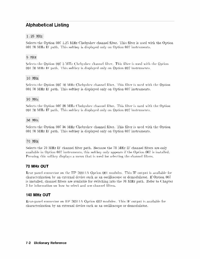
Alphabetical Listing
WWWWWWWWWWWWWWWWWWWWWWWWWWWW1.25 MHz
Selects the Option 007 1.25 MHz Chebyshev channel �lter. This �lter is used with the Option001 70 MHz IF path. This softkey is displayed only on Option 007 instruments.
WWWWWWWWWWWWWWWWWW5 MHz
Selects the Option 007 5 MHz Chebyshev channel �lter. This �lter is used with the Option001 70 MHz IF path. This softkey is displayed only on Option 007 instruments.
WWWWWWWWWWWWWWWWWWWWW10 MHz
Selects the Option 007 10 MHz Chebyshev channel �lter. This �lter is used with the Option001 70 MHz IF path. This softkey is displayed only on Option 007 instruments.
WWWWWWWWWWWWWWWWWWWWW20 MHz
Selects the Option 007 20 MHz Chebyshev channel �lter. This �lter is used with the Option001 70 MHz IF path. This softkey is displayed only on Option 007 instruments.
WWWWWWWWWWWWWWWWWWWWW36 MHz
Selects the Option 007 36 MHz Chebyshev channel �lter. This �lter is used with the Option001 70 MHz IF path. This softkey is displayed only on Option 007 instruments.
WWWWWWWWWWWWWWWWWWWWW70 MHz
Selects the 70 MHz IF channel �lter path. Because the 70 MHz IF channel �lters are onlyavailable in Option 007 instruments, this softkey only appears if the Option 007 is installed.Pressing this softkey displays a menu that is used for selecting the channel �lters.
70 MHz OUT
Rear-panel connector on the HP 70911A Option 001 modules. This IF output is available forcharacterization by an external device such as an oscilloscope or demodulator. If Option 007is installed, channel �lters are available for switching into the 70 MHz path. Refer to Chapter3 for information on how to select and use channel �lters.
140 MHz OUT
Rear-panel connector on HP 70911A Option 002 modules. This IF output is available forcharacterization by an external device such as an oscilloscope or demodulator.
7-2 Dictionary Reference

300 MHz IN
Rear-panel connector on the HP 70911A Option 001 or Option 002 modules. Connect thisinput to a 300 MHz OUT connector on the HP 70900B local oscillator module.
300 MHz OUT
Rear-panel connector on the HP 70911A Option 001 or Option 002 modules. This signaloriginates on the HP 70900B local oscillator module.
321.4 MHz IN
Rear-panel connector on the HP 70911A module. This connection receives the 321.4 MHz IFoutput of the HP 70910A wide bandwidth RF module.
321.4 MHz OPT IN
Rear-panel connector on the HP 70911A Option 001 or Option 002 modules. This input isconnected to the rear-panel 321.4 MHz OUT connector.
321.4 MHz OPT OUT
Rear-panel connector on the HP 70911A Option 001 or Option 002 modules. This outputis the IF signal input to the 321.4 MHz OPT IN connector. It can be input into an externaldevice such as an oscilloscope for characterization. This 321.4 MHz IF output has degradedIF bandwidth uncertainty when compared to the 321.4 MHz OUT connector on standardinstruments.
321.4 MHz OUT
Rear-panel connector on the HP 70911A module. With standard instruments, this IF outputcan be input into an external device such as an oscilloscope for characterization. On Option001 and Option 002 instruments, this output connects to the 321.4 MHz OPT IN connector.
WWWWWWWWWWWWWWWWWWWWWWWWWWWWWWWWWWWWWWWWWWWW70911 OPTIONS
Lists, on the display, all options that are installed in the HP 70911A wide-bandwidth IFmodule.
���
Use the ��� (backspace) key to backspace the cursor while entering text and to displayprevious softkey menus (in the �MENU� menus).
Dictionary Reference 7-3

��� ��
The step keys increase or decrease active parameter values. For example, if frequency span isthe active parameter, pressing ��� increases the span; pressing �� decreases the span.
���
Displays delta markers, which display the frequency and amplitude di�erences between twosignals.
WWWWWWWWWWWWWWWWWWWWWWWWWWWWWWWWWWWWWWWWWWWWWWWWWWA UNITS AutoMan
Selects the displayed amplitude units. In the default condition,NNNNNNNNNNNNNNAuto is underlined and the
receiver personality automatically selects the appropriate units. WhenNNNNNNNNNNNMan underlined, you
can choose from dB, volts, and watts .
WWWWWWWWWAM
Selects demodulation of amplitude modulated signals. This is the default demodulationselected when the receiver mode is started. The ratio between the IF and video bandwidths isset to 0.3. The video bandwidth is only applied to the displayed signal and does not a�ect thedownconverted signal that is available at the rear-panel outputs.
WWWWWWWWWWWWWWWWWWWWWBYPASS
Selects the Option 007 bypass path which switches the Chebyshev channel �lters out of the IFsignal path. This softkey is displayed only on Option 007 instruments.
WWWWWWWWWBW
Displays a menu for changing the IF and video bandwidths, enabling a custom �lter, orupdating the video to-IF-bandwidth ratio.
�CENTER�
Speci�es the frequency displayed at the center of the screen when the instrument is in searchmode. In collection mode (zero span) use this key to specify the �x-tuned frequency. Whenactivated, the frequency at center screen can be changed using the front-panel knob, stepkeys, or numeric keypad. When the receiver mode is �rst entered, the center frequency isautomatically set to the marker position. If no marker is present, the receiver sets the centerfrequency to the value of the signal having the highest peak.
7-4 Dictionary Reference

WWWWWWWWWWWWWWWWWWWWWCENTER
Refer to �CENTER�.
WWWWWWWWWWWWWWWWWWWWWWWWWWWWWWWWWWWWWWWWWWWWWWWWWWCF STEP AutoMan
Changes the center-frequency step size. This is the change in center frequency that occurswhen the ��� and �� step keys are pressed. The default step size is 10 percent of the
frequency span. This is the applied value whenever theNNNNNNNNNNNNNNNNNNNNNNNNNNNNNNNNNNNNNNNNNNNNNNNNNNCF STEP AutoMan softkey is set to
automatic. To change the step size, pressNNNNNNNNNNNNNNNNNNNNNNNNNNNNNNNNNNNNNNNNNNNNNNNCF STEP AutoMan and enter a value. Available step
sizes vary with the span setting.
WWWWWWWWWWWWWWWWWWWWWWWWWWWWWWWWWWWWWWWWWWWWWWWWWWchannel filters
Allows you to select channel �lters on Option 007 instruments. After pressing this softkey, amenu is displayed for choosing IF �ltering bandwidths of 1.25, 5, 10, 20, and 36 MHz. Youcan also select a bypass path which has a 40 MHz bandwidth.
WWWWWWWWWWWWdBm
Displays the average value of the signal in decibels relative to 1 milliwatt.
WWWWWWWWWWWWWWWdBmV
Displays the average value of the signal in decibels relative to 1 millivolt.
WWWWWWWWWWWWWWWdBuV
Displays the average value of the signal in decibels relative to 1 microvolt.
WWWWWWWWWWWWWWWWWWWWWWWWWWWWWWWWWWWWWWWWWDEL RX STATE
Deletes a receiver state �le that has been previously saved using theNNNNNNNNNNNNNNNNNNNNNNNNNNNNNNNNNNNNNNNNNSAVE RX STATE softkey.
WWWWWWWWWWWWWWWWWWDemod
Displays a menu for selecting the type of demodulation used. Choices are: AM, pulse,FM narrowband or wideband (Option 005), or I/Q (Option 004). The default is AMdemodulation.
With Option 005, the FM wideband and narrowband discriminator o�set DACS can beadjusted. With Option 004, the gain and o�set of both I and Q outputs can be adjusted. Thequadrature is also adjustable.
Dictionary Reference 7-5
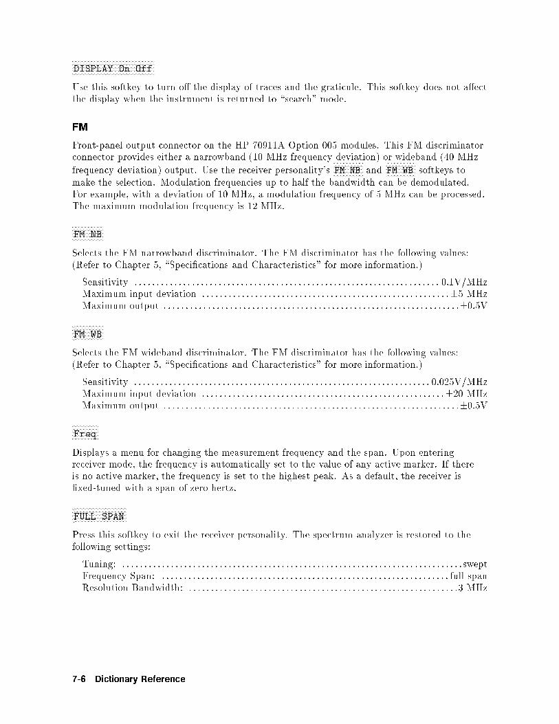
WWWWWWWWWWWWWWWWWWWWWWWWWWWWWWWWWWWWWWWWWWWWWWWDISPLAY On Off
Use this softkey to turn o� the display of traces and the graticule. This softkey does not a�ectthe display when the instrument is returned to \search" mode.
FM
Front-panel output connector on the HP 70911A Option 005 modules. This FM discriminatorconnector provides either a narrowband (10 MHz frequency deviation) or wideband (40 MHz
frequency deviation) output. Use the receiver personality'sNNNNNNNNNNNNNNNNNFM NB and
NNNNNNNNNNNNNNNNNFM WB softkeys to
make the selection. Modulation frequencies up to half the bandwidth can be demodulated.For example, with a deviation of 10 MHz, a modulation frequency of 5 MHz can be processed.The maximum modulation frequency is 12 MHz.
WWWWWWWWWWWWWWWWWWFM NB
Selects the FM narrowband discriminator. The FM discriminator has the following values:(Refer to Chapter 5, \Speci�cations and Characteristics" for more information.)
Sensitivity : : : : : : : : : : : : : : : : : : : : : : : : : : : : : : : : : : : : : : : : : : : : : : : : : : : : : : : : : : : : : : : : : : : : : 0.1V/MHzMaximum input deviation : : : : : : : : : : : : : : : : : : : : : : : : : : : : : : : : : : : : : : : : : : : : : : : : : : : : : : : :�5 MHzMaximum output : : : : : : : : : : : : : : : : : : : : : : : : : : : : : : : : : : : : : : : : : : : : : : : : : : : : : : : : : : : : : : : : : : :�0.5V
WWWWWWWWWWWWWWWWWWFM WB
Selects the FM wideband discriminator. The FM discriminator has the following values:(Refer to Chapter 5, \Speci�cations and Characteristics" for more information.)
Sensitivity : : : : : : : : : : : : : : : : : : : : : : : : : : : : : : : : : : : : : : : : : : : : : : : : : : : : : : : : : : : : : : : : : : : 0.025V/MHzMaximum input deviation : : : : : : : : : : : : : : : : : : : : : : : : : : : : : : : : : : : : : : : : : : : : : : : : : : : : : : :�20 MHzMaximum output : : : : : : : : : : : : : : : : : : : : : : : : : : : : : : : : : : : : : : : : : : : : : : : : : : : : : : : : : : : : : : : : : : :�0.5V
WWWWWWWWWWWWWWWFreq
Displays a menu for changing the measurement frequency and the span. Upon enteringreceiver mode, the frequency is automatically set to the value of any active marker. If thereis no active marker, the frequency is set to the highest peak. As a default, the receiver is�xed-tuned with a span of zero hertz.
WWWWWWWWWWWWWWWWWWWWWWWWWWWWWWWFULL SPAN
Press this softkey to exit the receiver personality. The spectrum analyzer is restored to thefollowing settings:
Tuning: : : : : : : : : : : : : : : : : : : : : : : : : : : : : : : : : : : : : : : : : : : : : : : : : : : : : : : : : : : : : : : : : : : : : : : : : : : : : :sweptFrequency Span: : : : : : : : : : : : : : : : : : : : : : : : : : : : : : : : : : : : : : : : : : : : : : : : : : : : : : : : : : : : : : : : : : full spanResolution Bandwidth: : : : : : : : : : : : : : : : : : : : : : : : : : : : : : : : : : : : : : : : : : : : : : : : : : : : : : : : : : : : : :3 MHz
7-6 Dictionary Reference

WWWWWWWWWWWWWWWGain
Displays a menu for controlling IF gain, RF input attenuation, and signal averaging, Inaddition, you can select the amplitude units displayed for signal averaging.
WWWWWWWWWWWWWWWWWWWWWWWWWWWWWWWWWWWWWHelp On Off
Turns online help on and o�. When on, pressing any softkey displays a de�nition of thesoftkey's function. The function is not invoked.
�HOLD�
Deactivates an active function to prevent accidental setting changes. In addition to protectingagainst accidental changes, �HOLD� removes the active function readout from the display andturns o� the inverse video of an active softkey. For example, if the receiver personality'sNNNNNNNNNNNNNNNNNNNNCENTER softkey has just been set to 1 GHz,
NNNNNNNNNNNNNNNNNNNNCENTER remains the active function. So if the
knob is turned or the step keys are accidentally pressed, the center frequency changes to a newvalue. Pressing �HOLD� protects the center frequency from knob or step key changes.
WWWWWWWWWWWWWWWWWWWWWWWWWWWWWWWWWWWWWWWWWHP-MSIB CARD
Accesses various types of external memory that are available through an HP-MSIB device.The
NNNNNNNNNNNNNNNNNNNNNNNNNNNNNNNNNNNNNNHP-MSIB CARD softkey is used to select an HP-MSIB address. The type of external
memory that is accessed must �rst be selected using the mass storage functions of theHP-MSIB device. For example, the
NNNNNNNNNNNNNNNNNNNNNNNNNNNNNNNNNNNNNNHP-MSIB CARD softkey can be used to access articles in
a memory card on an HP 70004A color display. Be sure that access to the memory card isselected, using the mass storage softkeys for the HP 70004A color display.
TheNNNNNNNNNNNNNNNNNNNNNNNNNNNNNNNNNNNNNNHP-MSIB CARD softkey can access a disk drive through an HP-IB port that is connected
to another HP-MSIB device or display. Be sure that access to the HP-IB port is selected usingthe mass storage softkeys for the HP-MSIB device. The
NNNNNNNNNNNNNNNNNNNNNNNNNNNNNNNNNNNNNNHP-MSIB CARD softkey selects the
HP-MSIB address of an HP-MSIB device. The default device address is the HP-MSIB addressof the display (for example, an HP 70004A color display) that is connected to the analyzer.
The number thatNNNNNNNNNNNNNNNNNNNNNNNNNNNNNNNNNNNNNNHP-MSIB CARD speci�es is the column address.
To look up the HP-MSIB address of a device or display, press �DISPLAY�,NNNNNNNNNNNNNNNNNNNNNNNNNNNNNNNNNNNaddress map . Use
the front-panel knob to locate the desired device address.
WWWWWWWWWWWWWWWWWWWWWWWWWWWWWWWHPIB DISK
Selects external memory that is accessed on an HP-IB device (for example, a disk drive) thatis connected to the receiver's HP-IB port.
The receiver's HP-IB port is located on the display (HP 70004A color display) or mainframe(70001A) that contains the local-oscillator module (70900B). HP-IB protocol does not allowmore than one controller on HP-IB. When using the receiver as a controller, disconnect anyexternal controller from the HP-IB.
When storing data on a disk drive, useNNNNNNNNNNNNNNNNNNNNNNNNNNNNNHPIB DISK to specify the HP-IB address, unit, and
volume number of the disk drive. The default selection is HP-IB address 0, unit 0, volume 0.
Dictionary Reference 7-7

To enter new values, pressNNNNNNNNNNNNNNNNNNNNNNNNNNNNNHPIB DISK , and enter numbers in the following sequence. The �rst
number is for the HP-IB address. The second number is for unit. The third number is forvolume. The second and third numbers are preceded by a period. For example,
NNNNNNNNNNNNNNNNNNNNNNNNNNNNNHPIB DISK 1
NNNNNNNNNNNNNNNNNENTER selects HP-IB address 1, unit 0, volume 0.
NNNNNNNNNNNNNNNNNNNNNNNNNNNNNHPIB DISK 0.1
NNNNNNNNNNNNNNNNNENTER selects address 0, unit 1, volume 0.
NNNNNNNNNNNNNNNNNNNNNNNNNNNNNHPIB DISK 1.01
NNNNNNNNNNNNNNNNNENTER selects address 1, unit 0, volume 1.
Ranges of Entered Values
Parameter Value Range
HP-IB address 0 { 30
unit number 0 { 9
volume number 0 { 9
I
Front-panel output connector on the HP 70911A Option 004 modules. The I and Q connectorsprovide an analog IQ output for applications requiring constellation displays. Connect atwo-channel oscilloscope in X-Y mode to these connectors. Use the
NNNNNNNNNNNNNNNNNNNNI GAIN and
NNNNNNNNNNNNNNNNNNNNNNNNNNI OFFSET
softkeys to adjust the gain and dc o�set of this channel. Use theNNNNNNNNNNNNNNNNNNNNNNNNNNNNNNNNQUADRATURE softkey to
adjust the phase between the I and Q outputs to 90�.
WWWWWWWWWWWWWWWWWWWWWI GAIN
Sets the gain of the analog I channel. Because this output is only available on Option 004instruments, this softkey only appears if this option is installed. The analog IQ outputs areuseful for applications that require constellation displays. The adjustment values are unitlessnumbers that range from 0 to 4095.
WWWWWWWWWWWWWWWWWWWWWWWWWWWWI OFFSET
Adjusts the dc o�set of the analog I channel to zero volts. Because this output is onlyavailable on Option 004 instruments, this softkey only appears if this option is installed.The analog IQ outputs are useful for applications that require constellation displays. Theadjustment values are unitless numbers that range from 0 to 4095.
WWWWWWWWWWWWWWWWWWIF BW
Speci�es the width of the IF bandwidth. The default IF bandwidth is 10 MHz. If you use theNNNNNNNNNNNNNNSPAN softkey to change the receiver from zero span, the IF bandwidth changes to a value thatis optimized for the current span.
7-8 Dictionary Reference

WWWWWWWWWWWWWWWWWWWWWWWWWWWWWWWWWWWWWWWWWWWWWWWWWWIF GAIN AutoMan
Sets the amount of IF gain applied to the signal. When Auto is underlined, the receiverautomatically selects the proper value. When Man is underlined, you can manually change theIF gain.
�INSTR�
Assigns the HP 70004A display's front-panel keys to selected master modules. HP 70004Adisplays can display up to 4 windows with each window showing the display of a mastermodule. (HP 70900B is an example of master module.) For example, suppose you had anMMS mainframe with an HP 70703A oscilloscope master module installed. After connectingthe MMS mainframe to the HP 70004A display, you could display the screen of bothanalyzers on the HP 70004A display in separate windows. The �INSTR� key allows you to movefront-panel key control between each master module in the system. Refer to the display'soperation manual for information on building and displaying windows.
When the �INSTR� key is pressed, the display draws colored borders around the currentlyde�ned windows. Window location, pen number, and the normal colors assigned to thosewindows are de�ned in the following table.
INSTR Key Window Assignments
Window Location Pen
Number
Normal Color
1 Lower Left 2 Yellow
2 Upper Left 3 Cyan
3 Upper Right 4 Pink
4 Lower Right 5 Green
Next to each displayed window is a softkey containing the �rst seven characters in theinstrument's model number on the �rst line, and the module's HP-MSIB address (row,column) on the second. This softkey is displayed in reverse video in the same color as theassociated window border. Press the softkey, and the keyboard is o�ered to that window'smaster module. If the module accepts the keyboard, it displays its menu keys as if the �MENU�key had been pressed.
�INSTR PRESET�
Resets the instrument to a known preset state.
Pressing �INSTR PRESET� aborts any current operations, resets the instrument to a knownpreset state, and clears the HP-IB output queue. This function will not modify the HP-IB orHP-MSIB interfaces, the display's address map, or calibration data.
Dictionary Reference 7-9

WWWWWWWWWWWWWWWWWWWWWWWWWWWWWWWWWWWWWWWWWWWWINTRNL MEMORY
Sets the location for saving or recalling �les to internal memory. Internal memory is located inthe HP 70900B.
WWWWWWWWWIQ
Selects the optional IQ outputs. The analog IQ outputs are useful for applications thatrequire constellation displays. For example, connect these outputs to a two-channeloscilloscope in X-Y mode to identify modulation formats such as QPSK, 8 PSK, 16 QAM, and64 QAM. Both I and Q output signals have a bandwidth of 50 MHz (combined bandwidth of100 MHz).
If Option 004 is installed, pressing this softkey presents a menus for adjusting the gain and dco�set of each output.
WWWWWWWWWWWWWWWWWWWWWWWWWWWWWWWWWWLAST STATE
Press this softkey to exit the receiver personality. The spectrum analyzer is restored to thesettings used before the receiver personality was invoked.
�MENU�
Displays the softkeys for the search receiver mode (HP 71209A spectrum analyzer). If the�DISPLAY� front-panel key is pressed, softkey menus dedicated to controlling display functionsare displayed. Press the �MENU� key to return to spectrum analyzer menus.
WWWWWWWWWWWWWWWMisc
Displays a menu of miscellaneous receiver functions. These include turning the graticuledisplay o� or on, saving or recalling receiver states, and displaying any installed HP 70911Aoptions.
WWWWWWWWWWWWWWWWWWWWWWWWWWWWWWWWWWWWWNARROW SPAN
Press this softkey to exit the receiver personality. The spectrum analyzer is restored to thefollowing settings:
Tuning: : : : : : : : : : : : : : : : : : : : : : : : : : : : : : : : : : : : : : : : : : : : : : : : : : swept at current center frequencyFrequency Span: : : : : : : : : : : : : : : : : : : : : : : : : : : : : : : : : : : : : : : : : : : : : : : : 10 times the IF bandwidth
NB VID IN
Rear-panel connector on the HP 70911A module. This input video signal comes from the HP70903A IF module's rear-panel VIDEO OUT connector.
7-10 Dictionary Reference

�NEXT PEAK�
Moves a displayed marker to the next-highest signal peak.
�NORMAL�
Activates a frequency marker at the center of the screen on the active trace. The datacontrols are used to position the marker. An annotation in the active function area and in theupper-right corner indicate the frequency and amplitude of the marker.
�PEAK SEARCH�
Places an active marker on the highest amplitude trace point.
�PLOT�
Plots the display on a Hewlett-Packard plotter.
When pressed, �PLOT� sends vector plot data (HPGL graphics format) over HP-IB to theplotter speci�ed in the HP 70004A's �DISPLAY� menu. Press the �DISPLAY� front-panel key and
then theNNNNNNNNNNNNNNNNNNNNNNNNNNNNNHard Copy and
NNNNNNNNNNNNNNNNNNNNNNNNNNNNNNNNNNNNNNNNNNNNNNNplotter address softkeys to change the default plotter address.
Press the �MENU� front-panel key to return to the spectrum analyzer menus.
The plotter's default HP-IB address is set to address 5. The default plotter limits are those ofthe HP 7470A and HP 7475A plotters. These allow 0.5 inch margins on standard A-size paper(8.5 by 11 inches).
WWWWWWWWWWWWWWWWWWWWWWWWWWWWWWWWWWWWWWWWWWWWPREAMP On Off
Turns an HP 70620B preampli�er on or o�. The preampli�er is installed as an option to theHP 71910A receiver. It provides approximately 30 dB of signal ampli�cation before the HP70910A RF section. This softkey only appears if the HP 70620B's RF INPUT is selected.
WWWWWWWWWWWWWWWWWWWWWWWWWWWWWWWWWWWWWWWWWWWWPRESEL On Off
If you're downconverting signals between 2.7 and 26.5 GHz, you must turn o� the microwavepreselector to obtain the widest possible IF bandwidth. For example, if you select a 100 MHzIF bandwidth, but the microwave preselector is on, the e�ective bandwidth will be limitedto approximately 40 MHz. This is shown in the following table. One advantage of leavingthe preselector on is a slight improvement in sensitivity. More importantly, the preselectorprevents multiple responses.
Dictionary Reference 7-11

Available Bandwidth of HP 70911A 321.4 MHz IF Output
Frequency Mode Approximate Bandwidth
100 Hz|2.9 GHz >48 MHz1
2.7|26.5 GHz
preselected on >36 MHz2
preselector o� 100 MHz
1 This bandwidth is due to a �lter in the RF pathand not to the Microwave preselector.
2 The preselector's bandwidth increases at higherfrequencies and is nearly 60 MHz at a 20 GHzcenter frequency.
�PRINT�
Prints the display on a Hewlett-Packard graphics printer. When pressed, �PRINT� sends rasterprint data over HP-IB to the printer speci�ed in the �DISPLAY� menu. Select printer types
by pressing the �DISPLAY� front-panel key and then theNNNNNNNNNNNNNNNNNNNNNNNNNNNNNHard Copy and
NNNNNNNNNNNNNNNNNNNNNNNNNNNNNNNNNNNNNNNNNNNNprinter config
softkeys. Press the �DISPLAY� front-panel key and then theNNNNNNNNNNNNNNNNNNNNNNNNNNNNNHard Copy and
NNNNNNNNNNNNNNNNNNNNNNNNNNNNNNNNNNNNNNNNNNNNNNNprinter address
softkeys to change the default printer address. The printer's default HP-IB address is set toaddress 1. Press the �MENU� front-panel key to return to the spectrum analyzer menus.
The print data is formatted in the HP-PCL (printer command language) graphics format.
WWWWWWWWWWWWWWWWWWPULSE
Selects demodulation of pulse-modulated signals. The video bandwidth is set to a valuethat is greater than 100 MHz. Because the video bandwidth is only applied to the displayedsignal, its value does not a�ect the downconverted signal that is available at the rear-panel IFoutputs. It does a�ect the signal available at the front-panel VIDEO output.
Q
Front-panel output connector on the HP 70911A Option 004 modules. The I and Q connectorsprovide an analog IQ output for applications requiring constellation displays. Connect atwo-channel oscilloscope in X-Y mode to these connectors. Use the
NNNNNNNNNNNNNNNNNNNNQ GAIN and
NNNNNNNNNNNNNNNNNNNNNNNNNNQ OFFSET
softkeys to adjust the gain and dc o�set of this channel. Use theNNNNNNNNNNNNNNNNNNNNNNNNNNNNNNNNQUADRATURE softkey to
adjust the phase between the I and Q outputs to 90�.
WWWWWWWWWWWWWWWWWWWWWQ GAIN
Sets the gain of the analog Q channel. Because this output is only available on Option 004instruments, this softkey only appears if this option is installed. The analog IQ outputs areuseful for applications that require constellation displays. The adjustment values are unitlessnumbers that range from 0 to 4095.
7-12 Dictionary Reference
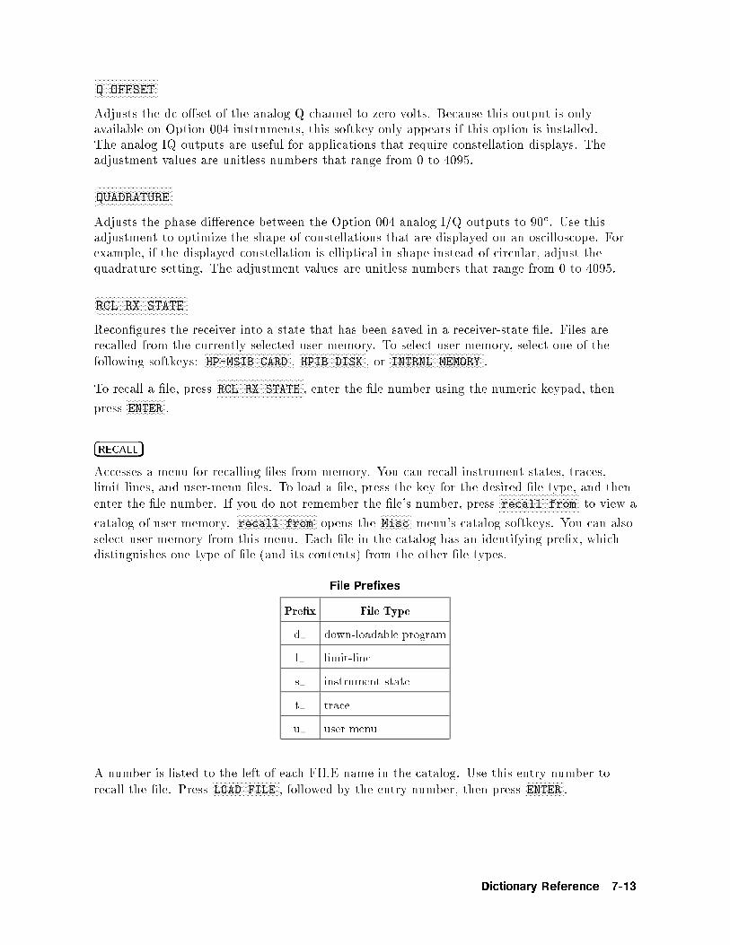
WWWWWWWWWWWWWWWWWWWWWWWWWWWWQ OFFSET
Adjusts the dc o�set of the analog Q channel to zero volts. Because this output is onlyavailable on Option 004 instruments, this softkey only appears if this option is installed.The analog IQ outputs are useful for applications that require constellation displays. Theadjustment values are unitless numbers that range from 0 to 4095.
WWWWWWWWWWWWWWWWWWWWWWWWWWWWWWWWWWQUADRATURE
Adjusts the phase di�erence between the Option 004 analog I/Q outputs to 90�. Use thisadjustment to optimize the shape of constellations that are displayed on an oscilloscope. Forexample, if the displayed constellation is elliptical in shape instead of circular, adjust thequadrature setting. The adjustment values are unitless numbers that range from 0 to 4095.
WWWWWWWWWWWWWWWWWWWWWWWWWWWWWWWWWWWWWWWWWRCL RX STATE
Recon�gures the receiver into a state that has been saved in a receiver-state �le. Files arerecalled from the currently selected user memory. To select user-memory, select one of thefollowing softkeys:
NNNNNNNNNNNNNNNNNNNNNNNNNNNNNNNNNNNNNNHP-MSIB CARD ,
NNNNNNNNNNNNNNNNNNNNNNNNNNNNNHPIB DISK , or
NNNNNNNNNNNNNNNNNNNNNNNNNNNNNNNNNNNNNNNNNINTRNL MEMORY .
To recall a �le, pressNNNNNNNNNNNNNNNNNNNNNNNNNNNNNNNNNNNNNNRCL RX STATE , enter the �le number using the numeric keypad, then
pressNNNNNNNNNNNNNNNNNENTER .
�RECALL�
Accesses a menu for recalling �les from memory. You can recall instrument states, traces,limit lines, and user-menu �les. To load a �le, press the key for the desired �le type, and thenenter the �le number. If you do not remember the �le's number, press
NNNNNNNNNNNNNNNNNNNNNNNNNNNNNNNNNNNrecall from to view a
catalog of user-memory.NNNNNNNNNNNNNNNNNNNNNNNNNNNNNNNNNNNrecall from opens the
NNNNNNNNNNNNNNMisc menu's catalog softkeys. You can also
select user memory from this menu. Each �le in the catalog has an identifying pre�x, whichdistinguishes one type of �le (and its contents) from the other �le types.
File Prefixes
Pre�x File Type
d down-loadable program
l limit-line
s instrument state
t trace
u user menu
A number is listed to the left of each FILE name in the catalog. Use this entry number torecall the �le. Press
NNNNNNNNNNNNNNNNNNNNNNNNNNNNNLOAD FILE , followed by the entry number, then press
NNNNNNNNNNNNNNNNNENTER .
Dictionary Reference 7-13

WWWWWWWWWWWWWWWWWWWWWWWWWWWWWWWWWWWWWWWWWWWWWWWWWWRECEIVR VERSION
Displays the version of the receiver program.
�REF LEVEL�
Sets the reference level which is the absolute amplitude power or voltage represented by thescreen's top graticule. Enter the desired reference level value using the front-panel knob, stepkeys, or numeric keypad.
WWWWWWWWWWWWWWWWWWWWWWWWWWWWWWWWWWWWWWWWWWWWReturn to S/A
Displays a menu for exiting the receiver personality and returning to the spectrum analyzermode. You can recall the state the analyzer was in upon entering the receiver mode, issue aninstrument preset, or set the span to 10 times the IF bandwidth.
WWWWWWWWWWWWWWWWWWWWWWWWWWWWWWWWWWWWWWWWWWWWWWWWWWRF ATTN AutoMan
Varies RF input attenuation from 0 to 65 dB in 5 dB increments.
Input attenuation is normally coupled to the reference level. When coupled, the attenuatorchanges as the reference level changes to limit the signal level to the �rst mixer, as speci�edby the setting of the
NNNNNNNNNNNNNNNNNNNNNNNNNNNNNNNNNNNNNNNNNMAX MXR LEVEL softkey. (
NNNNNNNNNNNNNNNNNNNNNNNNNNNNNNNNNNNNNNNNNMAX MXR LEVEL is a spectrum analyzer
softkey located in a menu displayed by pressing �MENU�.) The signal level to the mixer islimited to avoid amplitude inaccuracies and damage to the receiver.
Note Because an RF or microwave spectrum analyzer can be damaged easily wheninput attenuation is not present, input attenuation below 10 dB can be setonly with the numeric keypad or a remote programming command.
To change the attenuation level, pressNNNNNNNNNNNNNNNNNNNNNNNNNNNNNNNNNNNNNNNNNNNNNNNRF ATTN AutoMan so that
NNNNNNNNNNNMan is underlined,
and enter the desired level of attenuation. When the reference-level and attenuationfunctions are uncoupled, an asterisk appears next to ATTEN on the analyzer display. PressNNNNNNNNNNNNNNNNNNNNNNNNNNNNNNNNNNNNNNNNNNNNNNNRF ATTN AutoMan so that
NNNNNNNNNNNNNNAuto is underlined to recouple the functions.
RF/IF Gain:
Parameter displayed on receiver personality's screen. The displayed value represents theamount of gain applied to the input signal from the front-panel RF INPUT connector to theOption 001 rear-panel 70 MHz output connector. The rear-panel 321.4 MHz IF output level is5 dB higher than the 70 MHz output. The 140 MHz IF output level is 10 dB lower than the70 MHz output.
If an HP 70620B preampli�er is not present, the RF/IF Gain is expressed by the followingequation:
RF=IF Gain = IF gain� RF attenuation
where:
7-14 Dictionary Reference

IF gain (implemented in the HP 70911A ultra wide-bandwidth IF section) is a value
from 0 to 70 dB. IF gain can be set from the receiver personality or from theNNNNNNNNNNNNNNNNNAmptd
softkey accessed by pressing �MENU�.
RF attenuation (implemented in the HP 70910A RF section) is a value from 0 to 65 dB.
It is set within the receiver personality or from theNNNNNNNNNNNNNNNNNAmptd softkey accessed by pressing
�MENU�.
IF gain steps are in 10 dB increments. RF attenuation is in 5 dB increments.
If an HP 70620B preampli�er is present, the RF/IF Gain is expressed by the followingequation:
RF=IF Gain = IF gain�RF attenuation+ preamplifier gain� preamplifier correction
where:
preampli�er gain is nominally 28 dB. However, at some frequencies, it is a more and atothers is less.
preampli�er correction factor is the o�set value from 28 dB of preampli�er gain. Themaximum correction factor is generally 6 dB but is usually around 1 dB or 2 dB.
Note that when you turn the preampli�er on, the RF attenuator is automatically set to avalue roughly enough to compensate for the preampli�er gain. The RF attenuation maychange from 10 dB to 35 dB or 45 dB when the preampli�er is turned on; this helps to protectthe mixer accidental damage. If the level is safe enough, you can then reduce RF attenuationto 10 dB to actually realize the preampli�er's bene�t of a lower noise oor.
The receiver personality only sets the correct values of RF/IF gain for the HP 70910A andHP 70909A RF sections and not the HP 70908A. The HP 70908A RF section does not have aprogrammable gain ampli�er and therefore the equation would not be the same.
WWWWWWWWWWWWWWWWWWWWWWWWWWWWWWWWWWWWWWWWWWWWsave & recall
Displays a menu for saving and recalling receiver-state �les. State �les record the currentsetting of the instrument. When recalled, these �les restore the receiver to the saved settings.Receiver-state �les can be saved to internal memory, a memory card, or an HP-IB disk drive.
WWWWWWWWWWWWWWWWWWWWWWWWWWWWWWWWWWWWWWWWWWWWSAVE RX STATE
Saves the receiver's current state in a �le. Recalling the �le restores the receiver to the savedsettings.
WWWWWWWWWWWWWWWWWWWWWWWWWWWWWWWWWWWWWWWWWWWWWWWSIG LVL On Off
Turns on or o� a display of the signal's average amplitude level. The average is computed atthe end of every sweep. Use the
NNNNNNNNNNNNNNNNNNNNNNNNNNNNNNNNunits menu softkey to select the amplitude units that are
displayed.
Dictionary Reference 7-15

�SIGNAL TRACK�
Allows the receiver in search mode to automatically maintain drifting signals at the centerof the screen. As the signal drifts, the spectrum analyzer is returned to bring the signal andmarker to the center of the screen. This allows real-time monitoring of the change.
�SPAN�
Changes the total display frequency range symmetrically about the center frequency.
WWWWWWWWWWWWWWWSPAN
This receiver personality softkey allows you to temporary view the spectrum without leavingthe personality. The receiver mode's default frequency span is 0 Hz. After pressing thissoftkey, use the front-panel knob, step keys, or numeric keypad to enter the desired frequencyspan. To return to �xed-tuned operation, enter a span of 0 Hz.
When the span is changed from 0 Hz and theNNNNNNNNNNNNNNNNNNNNNNNNNNNNNNNNNNNNNNNNNIF BW AutoMan softkey is set to Auto, the IF
bandwidth is coupled to the span and may change.
�START FREQ�
Sets the start frequency at the left side of the display. Use the �START FREQ� and �STOP FREQ�keys to de�ne the frequency measurement range of the horizontal axis. The measurementrange of the horizontal axis can also be set using the �CENTER� and �SPAN� keys.
�STOP FREQ�
Sets the stop frequency at the right side of the display. Use the �START FREQ� and �STOP FREQ�keys to de�ne the frequency measurement range of the horizontal axis. The measurementrange of the horizontal axis can also be set using the �CENTER� and �SPAN� keys.
WWWWWWWWWWWWWWWWWWWWWWWWWWWWWWWWWWWWWWWWWtemp compens
Displays a menu with instructions on how to run the HP 70911A temperature compensationroutine. This routine decreases temperature induced errors, improves the �delity of the videodetector, and reduces DC o�sets on the internal FM assembly. Running this routine requiresthat you �rst connect the front-panel 300 MHz CALIBRATOR output to the RF INPUT connector.Run this routine whenever the ambient air temperature has changed by 5�C or more since thelast front-panel calibration. This routine is automatically performed as part of the front-panelcalibration as described in Chapter 3 of this manual.
Do not run this temperature compensation routine if you have manually adjusted the FMo�set as part of the customer calibration.
7-16 Dictionary Reference

WWWWWWWWWWWWWWWWWWTITLE
Allows you to write a short description before saving the current state in a �le.
WWWWWWWWWWWWWWWWWWWWWWWWWWWWWWWWWWunits menu
Displays a menu for selecting the amplitude units used for the displayed average signal level.To view the average signal level, turn
NNNNNNNNNNNNNNNNNNNNNNNNNNNNNNNNNNNNNNNNNNNNSIG LVL On Off so that
NNNNNNNNOn is underlined. Normally,
the receiver personality automatically selects the units.
�USER�
Front-panel key that presents the �USER� menu. The �USER� menu displays softkeys for anyadvanced measurement program. For example, the receiver personality is accessed throughthis menu by pressing
NNNNNNNNNNNNNNNNNNNNNNNRX_MODE .
WWWWWWWWWWWWWWWWWWWWWWWWWWWWWWWWWWWWWWWWWWWWVBW/IFB RATIO
Speci�es the ratio between the video and IF bandwidths that is maintained when theirsettings are coupled. The default value is 0.3.
video bandwidth = (resolution bandwidth) (0:5)
The ratio can be set between 10�100 and 10+100.
WWWWWWWWWWWWWWWWWWWWWWWWWWWWWWWWWWWWWWWWWWWWWWWVID BW AutoMan
Speci�es the width of the video-bandwidth �lter and controls the coupling between theIF bandwidth and video-bandwidth �lter settings. With
NNNNNNNNNNNNNNAuto underlined, the receiver
automatically selects a bandwidth based on the video-to-IF bandwidth ratio of 0.3. Use theNNNNNNNNNNNNNNNNNNNNNNNNNNNNNNNNNNNNNNNNNVBW/IFB RATIO softkey to change the default video-to-IF bandwidth ratio. When
NNNNNNNNNNNMan is
underlined, the video bandwidth is decoupled from the IF bandwidth and can be manuallyset.
VID OUT TO L.O.
Rear-panel connector on the HP 70911A module. This video output signal goes to the HP70900B's rear-panel VIDEO IN connector.
VIDEO
Front-panel connector on the HP 70911A module. This output provides the 10 kHz to 100MHz wide-bandwidth video signal.
Dictionary Reference 7-17

WWWWWWWWWWWWWWWVOLT
Displays the average value of the signal in volts.
WWWWWWWWWWWWWWWWATT
Displays the average value of the signal in watts.
WB VID IN
Rear-panel connector on the HP 70911A module. This input signal connects to the rear-panelWB VID OUT connector.
WB VID OUT
Rear-panel connector on the HP 70911A module. This output signal goes to the rear-panel WBVID IN connector.
7-18 Dictionary Reference

8
Programming Commands
This chapter documents the commands that are used to control the receiver personality.When these commands are combined with the commands documented in the HP 70000Modular Spectrum Analyzer Programming Manual , you have all the commands that are usedto program the instrument.
Both the receiver personality commands and the HP 70900B commands are sent to theaddress of the HP 70900B module as described in Chapter 4 of this manual.
Contents
Syntax Conventions : : : : : : : : : : : : : : : : : : : : : : : : : : : : : : : : : : : : : : : : : : : : : : : : : : : : : : : : : : : : : : : : : : : :8-2Softkeys Versus Commands : : : : : : : : : : : : : : : : : : : : : : : : : : : : : : : : : : : : : : : : : : : : : : : : : : : : : : : : : : : : 8-4RXRMT CHANFILT : : : : : : : : : : : : : : : : : : : : : : : : : : : : : : : : : : : : : : : : : : : : : : : : : : : : : : : : : : : : : : : : : : 8-6RXRMT CHANPATH : : : : : : : : : : : : : : : : : : : : : : : : : : : : : : : : : : : : : : : : : : : : : : : : : : : : : : : : : : : : : : : : : 8-7RXRMT DELETERX : : : : : : : : : : : : : : : : : : : : : : : : : : : : : : : : : : : : : : : : : : : : : : : : : : : : : : : : : : : : : : : : : 8-8RXRMT DEMOD : : : : : : : : : : : : : : : : : : : : : : : : : : : : : : : : : : : : : : : : : : : : : : : : : : : : : : : : : : : : : : : : : : : : : 8-9RXRMT FMOFF : : : : : : : : : : : : : : : : : : : : : : : : : : : : : : : : : : : : : : : : : : : : : : : : : : : : : : : : : : : : : : : : : : : : 8-11RXRMT IFGAIN : : : : : : : : : : : : : : : : : : : : : : : : : : : : : : : : : : : : : : : : : : : : : : : : : : : : : : : : : : : : : : : : : : : : 8-12RXRMT IGAIN : : : : : : : : : : : : : : : : : : : : : : : : : : : : : : : : : : : : : : : : : : : : : : : : : : : : : : : : : : : : : : : : : : : : : : 8-13RXRMT INIT : : : : : : : : : : : : : : : : : : : : : : : : : : : : : : : : : : : : : : : : : : : : : : : : : : : : : : : : : : : : : : : : : : : : : : : :8-14RXRMT IOFFSET : : : : : : : : : : : : : : : : : : : : : : : : : : : : : : : : : : : : : : : : : : : : : : : : : : : : : : : : : : : : : : : : : : :8-15RXRMT OPTIONS? : : : : : : : : : : : : : : : : : : : : : : : : : : : : : : : : : : : : : : : : : : : : : : : : : : : : : : : : : : : : : : : : : 8-16RXRMT QGAIN : : : : : : : : : : : : : : : : : : : : : : : : : : : : : : : : : : : : : : : : : : : : : : : : : : : : : : : : : : : : : : : : : : : : : 8-17RXRMT QOFFSET : : : : : : : : : : : : : : : : : : : : : : : : : : : : : : : : : : : : : : : : : : : : : : : : : : : : : : : : : : : : : : : : : :8-18RXRMT QUAD : : : : : : : : : : : : : : : : : : : : : : : : : : : : : : : : : : : : : : : : : : : : : : : : : : : : : : : : : : : : : : : : : : : : : :8-19RXRMT RECALLRX : : : : : : : : : : : : : : : : : : : : : : : : : : : : : : : : : : : : : : : : : : : : : : : : : : : : : : : : : : : : : : : : 8-21RXRMT SAVERX : : : : : : : : : : : : : : : : : : : : : : : : : : : : : : : : : : : : : : : : : : : : : : : : : : : : : : : : : : : : : : : : : : : 8-22RXRMT TEMPCOMP : : : : : : : : : : : : : : : : : : : : : : : : : : : : : : : : : : : : : : : : : : : : : : : : : : : : : : : : : : : : : : : 8-23RXRMT VERSION? : : : : : : : : : : : : : : : : : : : : : : : : : : : : : : : : : : : : : : : : : : : : : : : : : : : : : : : : : : : : : : : : : 8-24
Programming Commands 8-1

Syntax Conventions
Documented with each command is a syntax diagram, a program example, and a completedescription. Command syntax is represented pictorially as shown in the following �gure.
Characters enclosed by an oval are commands and their arguments and must be enteredexactly as shown.
Characters enclosed by a circle are separators or terminators and must be entered as shown.
Syntax-diagram elements are connected by solid and dotted lines. Any combination ofelements generated by following the lines in the proper direction is correct syntactically.Solid-line paths are recommended.
The following two tables de�ne the syntax diagram elements used in this manual.
Terminators, Separators, and Commonly Used Arguments
Item Description
, Comma. ASCII-decimal number 44.
; Semicolon. ASCII-decimal number 59.
SP Space. ASCII-decimal number 32.
CR Carriage return. ASCII-decimal number 13.
LF Line feed. ASCII-decimal number 10.
DN Down. Change function value by step increment. Simulates press of �� key.
UP Up. Change function value by step increment. Simulates press of ��� key.
EP Enter parameter. Suspend program operation until number is entered with front-panel controls
(step keys, knob, or numeric keypad.) PressingFFFFFFFFFFFFFFFFFFFFFFFFFFFFACCEPT VALUE enters the number and resumes
program operation.
? Query. Returns current value of function to computer.
TRA Select trace A for operation.
TRB Select trace B for operation.
TRC Select trace C for operation.
8-2 Programming Commands
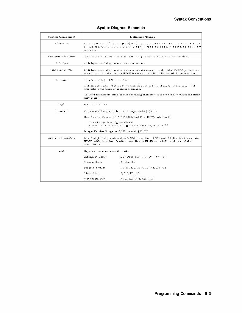
Syntax Conventions
Syntax Diagram Elements
Syntax Component De�nition/Range
character SP * - < = > @ ^ f j g ~ ! " # $ % & ' ( ) + , . / 0 1 2 3 4 5 6 7 8 9 : ; A B C D E F G H
I J K L M N O P Q R S T U V W X Y Z [ n ] ? `j a b c d e f g h i j k l m n o p q r s t u v
w x y z
compatible function Any spectrum-analyzer command in this chapter that operates on other functions.
data byte 8-bit byte containing numeric or character data.
data byte & EOI 8-bit byte containing numeric or character data sent with end-or-identify (EOI) condition,
where the EOI control line on HP-IB is asserted to indicate the end of the transmission.
delimiter ~ j n @ = < > / ^ $ % ! 0 ' : " &
Matching characters that mark the beginning and end of a character string, or a list of
user-de�ned functions or analyzer commands.
To avoid misinterpretation, choose delimiting characters that are not also within the string
they delimit.
digit 0 1 2 3 4 5 6 7 8 9
number Expressed as integer, decimal, or in exponential (E) form.
Real Number Range: � 1.797,693,134,862,315 � 10308, including 0.
Up to 15 signi�cant �gures allowed.
Numbers may be as small as � 2.225,073,858,507,202 � 10-308
Integer Number Range: �32,768 through +32,767
output termination Line feed (LF) with end-or-identify (EOI) condition. ASCII code 10 (line feed) is sent via
HP-IB, with the end-or-identify control line on HP-IB set to indicate the end of the
transmission.
units Represent standard scienti�c units.
Amplitude Units: DB, DBM, MW, NW, PW, UW, W
Current Units: A, MA, UA
Frequency Units: HZ, KHZ, MHZ, GHZ, KZ, MZ, GZ
Time Units: S, MS, US, SC
Wavelength Units: ANG, KM, NM, UM, PM
Programming Commands 8-3

Syntax Conventions
Softkeys Versus Commands
Softkeys versus Commands
Softkey Equivalent
Programming Command
De�nition
1.25 MHz RXRMT CHANPATH Selects the 1.25 MHz channel �lter on an option board.
5 MHz RXRMT CHANPATH Selects the 5 MHz channel �lter on an option board.
10 MHz RXRMT CHANPATH Selects the 10 MHz channel �lter on an option board.
20 MHz RXRMT CHANPATH Selects the 20 MHz channel �lter on an option board.
36 MHz RXRMT CHANPATH Selects the 36 MHz channel �lter on an option board.
70 MHz RXRMT CHANFILT,70E6? Returns a list of available �lters for the 70 MHz option board.
140 MHz RXRMT CHANFILT,140E6? Returns a list of available �lters for the 140 MHz option board.
70911 OPTIONS RXRMT OPTIONS? Returns a list of installed options.
A UNITS AutoMan AUNITS1 Selects units for amplitude annotation and data.
AM RXRMT DEMOD,AM Selects demodulation of amplitude modulated signals.
BW Displays a menu for changing bandwidth values.
CENTER CF1 Activates the center frequency tuning.
channel �lters RXRMT CHANFILT? Displays menu for selecting channel IF �lters.
CF STEP AutoMan SS1 Sets the center frequency step size.
dBm AUNITS DBM1 Displays the average value of the signal in decibels relative to 1 milliwatt.
dBmV AUNITS DBMV1 Displays the average value of the signal in decibels relative to 1 millivolt.
dBuV AUNITS DBUV1 Displays the average value of the signal in decibels relative to 1 microvolt.
DEL RX STATE RXRMT DELETERX Deletes a receiver state �le that has been previously saved using the????????????????????????save rx state softkey.
Demod Displays a menu for selecting the type of demodulation used.
DISPLAY On O� GRAT OFF;TRDSP TRA,OFF1 Use this softkey to turn o� the display of traces and the graticule.
FM NB RXRMT DEMOD,FMNB;RXRMT
FMOFF,NB,2048
Selects the FM narrowband discriminator, and adjusts the FM narrowband
discriminator's o�set DAC.
FM WB RXRMT DEMOD,FMWB;RXRMT
FMOFF,WB,2048
Selects the FM wideband discriminator, and adjusts the FM narrowband
discriminator's o�set DAC.
Freq Displays a menu for changing the measurement frequency and the span.
FULL SPAN IP1 Restores spectrum analyzer mode with full span.
Gain Displays a menu for controlling receiver gain, attenuation, amplitude units
Help On O� Turns online help on and o�.
HP-MSIB CARD MSI CARD1 Accesses various types of external memory available via HP-MSIB.
HPIB DISK MSI HPIB1 Selects external memory accessed via HP-IB
I GAIN RXRMT IGAIN Adjusts signal gain applied to front-panel I output (Option 004).
I OFFSET RXRMT IOFFSET Adjusts dc o�set at front-panel I output (Option 004).
IF GAIN AutoMan RXRMT IFGAIN Sets the amount of IF gain applied to the signal.
IF BW RB1 Speci�es the width of the IF bandwidth.
INTRNL MEMORY MSI INT1 Speci�es saving �les to internal memory.
1 Refer to the HP 70000 Modular Spectrum Analyzer Programming Manual for HP 70900B Local-Oscillator-ControlledModules.
8-4 Programming Commands

Softkeys Versus Commands
Softkeys versus Commands (continued)
Softkey Equivalent
Programming Command
De�nition
IQ RXRMT DEMOD,IQ Selects demodulation of IQ modulated signals.
LAST STATE LOAD \SA s 0"1 Restores last used spectrum analyzer settings.
Misc Displays a menu of miscellaneous receiver functions.
NARROW SPAN MPY SP,10,RB;1 Restores spectrum analyzer mode with narrow span.
PRESEL On O� PSENABLE1 Turns preselector on and o�.
PULSE RXRMT DEMOD,PULSE Selects demodulation of pulse-modulated signals.
Q GAIN RXRMT QGAIN Adjusts signal gain applied to front-panel Q output (Option 004).
Q OFFSET RXRMT QOFFSET Adjusts dc o�set at front-panel Q output (Option 004).
QUAD RATURE RXRMT QUAD Adjusts the phase between the front-panel I and Q outputs.
RCL RX STATE RXRMT RECALLRX Recon�gures the receiver into a state that has been saved in a receiver-state
�le.
RECEIVER VERSION RXRMT VERSION? Displays the date code of the receiver program.
Return to S/A Displays menu to restore spectrum analyzer mode.
RF ATTN AutoMan AT1 Varies RF input attenuation
RX MODE RXRMT INIT Initializes receiver mode but does not display receiver menus.
SAVE RX STATE RXRMT SAVERX Saves the receiver's current state in a �le.
save & recall Displays a menu for saving and recalling receiver-state �les.
save rx state Displays a set of instructions for saving the RX state in a �le.
SIG LVL On O�
SPAN SP1 Changes frequency span.
temp compens RXRMT TEMPCOMP Performs a temperature compensation routine.
TITLE TITLE1 Allows you to write titles on the screen in an area reserved for titles.
units menu AUNITS1 Displays a menu for selecting the average amplitude units.
VBW/IFB RATIO VBR1 Speci�es the coupling ratio between the video and IF bandwidths.
VID BW AutoMan VB1 Changes video bandwidth.
VOLT AUNITS V1 Displays the average value of the signal in volts.
WATT AUNITS W1 Displays the average value of the signal in watts.
1 Refer to the HP 70000 Modular Spectrum Analyzer Programming Manual for HP 70900B Local-Oscillator-ControlledModules.
Programming Commands 8-5

Softkeys Versus Commands
RXRMT CHANFILT
Queries a list of available channel IF �lters.
Example
OUTPUT 718;"RXRMT CHANFILT 70E6?;" Query the �lters in the 70 MHz �lter path.
ENTER 718; FILTERS$
Description
The RXRMT CHANFILT command returns to the controller a list of all optional IF boardsor all channel �lters on a speci�c option board. Items in the returned list are separated bycommas.
Required Instrument Options
IF Path Required Option
70 MHz Option 001
140 MHz Option 002
8-6 Programming Commands

RXRMT CHANFILT
Query Response
Programming Commands 8-7

RXRMT CHANPATH
Selects a �lter or queries the channel �lter that is currently active on an option board.
Example
OUTPUT 718;"RXRMT CHANPATH 140E6,5E6;" Select the 5 MHz �lter.
OUTPUT 718;"RXRMT CHANPATH 140E6?;" Query the selected �lter in the 140 MHz path.
ENTER 718; Path$
OUTPUT 718;RXRMT CHANPATH 70E6,0; Select the through path on the 70 MHz option board.
Description
The RXRMT CHANPATH command selects an IF channel �lter that is loaded on an optionboard. The following channel �lters are available in the 70 MHz option path:
1.25 MHz5 MHz10 MHz20 MHz36 MHz
You can select a \through" path by sending an argument that speci�es a 0 MHz �lter. TheRXRMT CHANPATH command can also be used to query the active �lter on the 70 MHzor 140 MHz option boards. (These options are �lter cards installed in the HP 70911A widebandwidth IF module.) You must specify which IF path that the �lter is located: 70 MHz or140 MHz.
8-8 Programming Commands

RXRMT CHANPATH
Query Response
See Also
RXRMT CHANFILT
Programming Commands 8-9

RXRMT DELETERX
Deletes a receiver state �le that has been previously saved.
Item Description
number An integer between 1 and 999.
Example
OUTPUT 718;"MSI INT;" Selects internal memory.
OUTPUT 718;"RXRMT DELETERX 7;" Deletes �le number 7.
Description
The RXRMT DELETERX command erases a receiver state �le from default memory. Use theHP 70900B's MSI command to select the location of default memory.
See Also
RXRMT RECALLRX and RXRMT SAVERX
8-10 Programming Commands

RXRMT DEMOD
RXRMT DEMOD
Selects the demodulation.
Item Description
Preset State AM
Example
OUTPUT 718;"RXRMT DEMOD IQ;"
Description
AM and pulse demodulation formats are always available. FM wideband, FM narrowband,and IQ demodulation require the options shown in the following table. The defaultdemodulation is AM. When pulse demodulation is selected, the video bandwidth is changed to100 MHz.
Required Instrument Options
Demodulation Required Option
I/Q Option 004 Analog I/Q output
FM Option 005 FM output
The FM discriminators have the following characteristics:
�5 MHz Narrowband discriminator:
FM Sensitivity : : : : : : : : : : : : : : : : : : : : : : : : : : : : : : : : : : : : : : : : : : : : : : : : : : : : : : : : : : : : : : 0.1 V/MHzMaximum output : : : : : : : : : : : : : : : : : : : : : : : : : : : : : : : : : : : : : : : : : : : : : : : : : : : : : : : : : : : : : : : : �0.5V
�20 MHz Wideband discriminator:
FM Sensitivity : : : : : : : : : : : : : : : : : : : : : : : : : : : : : : : : : : : : : : : : : : : : : : : : : : : : : : : : : : : :0.025 V/MHzMaximum output : : : : : : : : : : : : : : : : : : : : : : : : : : : : : : : : : : : : : : : : : : : : : : : : : : : : : : : : : : : : : : : : �0.5V
Programming Commands 8-11

RXRMT DEMOD
Query Response
8-12 Programming Commands

RXRMT FMOFF
RXRMT FMOFF
Adjusts the FM discriminator's output to zero volts.
Note In order to use this command, Option 005, FM output, must be installed inthe HP 70911A module.
Item Description
Adjustment range 0 to 4095
Preset value 2048
Example
OUTPUT 718;"RXRMT DEMOD FMNB;" Select narrowband discriminator.
OUTPUT 718;"RXRMT FMOFF NB 2092;" Adjust discriminator's dc output.
Description
The RXRMT FMOFF command adjusts the FM narrowband or wideband discriminator'soutput to 0 volts. The command's argument represents a unitless digital-to-analog (DAC)value. The default settings is 2048. You must specify either the narrowband (NB) orwideband (WB) discriminator with this command.
To adjust the discriminator, input an unmodulated signal to the receiver, and select FMwideband or narrowband demodulation. Then, while monitoring the dc voltage output at thefront-panel FM output connector, send the RXRMT FMOFF command to vary the value foran output of 0V.
Programming Commands 8-13

RXRMT FMOFF
Query Response
8-14 Programming Commands

RXRMT IFGAIN
RXRMT IFGAIN
Adjusts the amount of IF gain applied to the signal.
Item Description
Adjustment range The range of values allowed for thiscommand are signal path, and thushardware, dependent.
Preset value Step-gain value minus the HP 70911Acalibration attenuation.
Example
OUTPUT 718;"RXRMT IFGAIN 20;" Select 20 dB of gain.
Description
The RXRMT IFGAIN command is used to query or select the amount of IF gain applied tothe signal. When AUTO is selected, the receiver automatically selects the proper value.
Query Response
Programming Commands 8-15

RXRMT IGAIN
Adjusts the signal gain applied at the front-panel I output.
Note In order to use this command, Option 004, Analog I/Q output, must beinstalled in the HP 70911A module.
Item Description
Adjustment range 0 to 4095
Preset value 2048
Example
OUTPUT 718;"RXRMT IGAIN 2074;"
Description
The RXRMT IGAIN command can be used during IQ demodulation to adjust the gainpresent on the I output to equal the gain on the Q output. The command's argumentrepresents a unitless digital-to-analog (DAC) value. The default settings is 2048.
Query Response
See Also
RXRMT DEMOD and RXRMT QGAIN
8-16 Programming Commands

RXRMT INIT
RXRMT INIT
Starts and initializes receiver program.
Example
OUTPUT 718;"RXRMT INIT;"
Description
The RXRMT INIT command starts the receiver program and initializes it. It must always bethe �rst command that you send to the receiver program. You do not have to manually startthe program (by pressing �USER� and then
NNNNNNNNNNNNNNNNNNNNNNNRX_MODE ) before sending this command. In fact,
your programs will run faster if you do not manually start the program. This is due to thetime that is required to update the display.
If you want the receiver program displayed while under remote control, manually start theprogram, and then continue controlling the program remotely.
If the program is exited at any time, this command must be used to reinitialize the programbefore any receiver commands can be sent again.
Note Always send this command before sending any other programming commandsthat are documented in this book.
Programming Commands 8-17

RXRMT IOFFSET
Adjusts the dc voltage o�set at the front-panel I connector to zero volts.
Note In order to use this command, Option 004, Analog I/Q output, must beinstalled in the HP 70911A module.
Item Description
Adjustment range 0 to 4095
Preset value 2048
Example
OUTPUT 718;"RXRMT IOFFSET 2095;"
Description
The RXRMT IOFFSET command adjusts the I output during IQ demodulation to 0 volts.The command's argument represents a unitless digital-to-analog (DAC) value. The defaultsettings is 2048.
To adjust the output, input an unmodulated signal to the receiver, and select IQdemodulation. Then, while monitoring the dc voltage output at the front-panel I connector,send the RXRMT IOFFSET command to vary the value for an output of 0V.
Query Response
See Also
RXRMT DEMOD and RXRMT QOFFSET
8-18 Programming Commands

RXRMT OPTIONS?
RXRMT OPTIONS?
Returns a list of installed options.
Example
OUTPUT 718;"RXRMT OPTIONS?;" Query the option numbers in the HP 70911A.
ENTER 718;Options$;
Description
The RXRMT OPTIONS? command returns a list of the HP 70911A options that arecurrently installed in the system. The returned ASCII string consists of comma separatednumbers that correspond to the descriptions that are shown in the following table.
Option Numbers Returned by OPTIONS?
ASCII Number Description
001 70 MHz IF output
002 140 MHz IF output
004 Analog IQ output
005 FM output
Query Response
Programming Commands 8-19

RXRMT QGAIN
Adjusts the signal gain applied at the front-panel Q output.
Note In order to use this command, Option 004, Analog I/Q output, must beinstalled in the HP 70911A module.
Item Description
Adjustment range 0 to 4095
Preset value 2048
Example
OUTPUT 718;"RXRMT QGAIN 2010;"
Description
The RXRMT QGAIN command can be used during IQ demodulation to adjust the gainpresent on the Q output to equal the gain on the I output. The command's argumentrepresents a unitless digital-to-analog (DAC) value. The default settings is 2048.
Query Response
See Also
RXRMT DEMOD and RXRMT IGAIN
8-20 Programming Commands

RXRMT QOFFSET
RXRMT QOFFSET
Adjusts the dc voltage o�set at the front-panel Q output connector to zero volts.
Note In order to use this command, Option 004, Analog I/Q output, must beinstalled in the HP 70911A module.
Item Description
Adjustment range 0 to 4095
Preset value 2048
Example
OUTPUT 718;"RXRMT QOFFSET 2095;"
Description
The RXRMT QOFFSET command adjusts the Q output to 0 volts. The command'sargument represents a unitless digital-to-analog (DAC) value. The default settings is 2048.
To adjust the output, input an unmodulated signal to the receiver, and select IQdemodulation. Then, while monitoring the dc voltage output at the front-panel Q connector,send the RXRMT QOFFSET command to vary the value for an output of 0V.
Query Response
See Also
RXRMT DEMOD and RXRMT IOFFSET
Programming Commands 8-21
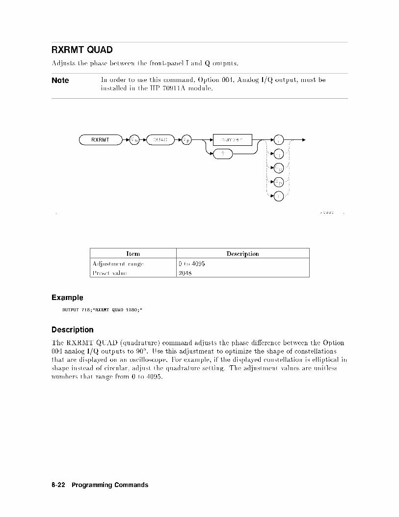
RXRMT QUAD
Adjusts the phase between the front-panel I and Q outputs.
Note In order to use this command, Option 004, Analog I/Q output, must beinstalled in the HP 70911A module.
Item Description
Adjustment range 0 to 4095
Preset value 2048
Example
OUTPUT 718;"RXRMT QUAD 1080;"
Description
The RXRMT QUAD (quadrature) command adjusts the phase di�erence between the Option004 analog I/Q outputs to 90�. Use this adjustment to optimize the shape of constellationsthat are displayed on an oscilloscope. For example, if the displayed constellation is elliptical inshape instead of circular, adjust the quadrature setting. The adjustment values are unitlessnumbers that range from 0 to 4095.
8-22 Programming Commands

RXRMT QUAD
Query Response
See Also
RXRMT DEMOD
Programming Commands 8-23

RXRMT RECALLRX
Recon�gures the receiver into a state that has been saved in a receiver-state �le.
Item Description
number An integer between 1 and 999.
Example
OUTPUT 718;"MSI INT;" Selects internal memory.
OUTPUT 718;"RXRMT RECALLRX 8;" Recalls �le number 8.
Description
The RXRMT RECALLRX command recalls a receiver state �le from default memory. Usethe HP 70900B's MSI command to select the location of default memory.
See Also
RXRMT SAVERX and RXRMT DELETERX
8-24 Programming Commands

RXRMT SAVERX
RXRMT SAVERX
Writes a receiver state to a �le.
Item Description
number An integer between 1 and 999.
Example
OUTPUT 718;"MSI INT;" Selects internal memory.
OUTPUT 718;"RXRMT SAVERX 2;" Saves state in �le number 2.
Description
The RXRMT SAVERX command saves a receiver state �le from internal memory to defaultmemory. Use the HP 70900B's MSI command to select the location of default memory.
See Also
RXRMT RECALLRX and RXRMT DELETERX
Programming Commands 8-25

RXRMT TEMPCOMP
Runs a temperature compensation routine.
Example
OUTPUT 718;"RXRMT TEMPCOMP;"
Description
Decreases temperature induced errors, improves the �delity of the video detector, and reducesDC o�sets on the internal FM assembly. Running this routine requires that you �rst connectthe front-panel 300 MHz CALIBRATOR output to the RF INPUT connector. Run this routinewhenever the ambient air temperature has changed by 5�C or more since the last front-panelcalibration.
8-26 Programming Commands

RXRMT VERSION?
RXRMT VERSION?
Returns the version of the receiver program.
Example
OUTPUT 718;"RXRMT VERSION?;"
ENTER 718;STRING$;
Description
The RXRMT VERSION? command returns the version number of the receiver program.
Query Response
Programming Commands 8-27


9
Error Messages
This chapter provides a list of receiver speci�c error messages and troubleshootinginformation. For de�nitions of general error messages not found in this manual, refer to theHP 70000 Modular Spectrum Analyzer Installation and Veri�cation Manual .
Error messages can be the result of incorrect operating procedures, illegal programmingcommands, or hardware failures. Normally, the instrument removes error messages from thescreen as soon as the error conditions are corrected. If you have a computer, error messagescan also be retrieved via HP-IB by executing the ERR? programming command. Refer to theHP 70000 Modular Spectrum Analyzer Programming Manual for information on the ERR?command and programming.
Contents
Error Message Descriptions : : : : : : : : : : : : : : : : : : : : : : : : : : : : : : : : : : : : : : : : : : : : : : : : : : : : : : : : : : : : 9-2Troubleshooting Features : : : : : : : : : : : : : : : : : : : : : : : : : : : : : : : : : : : : : : : : : : : : : : : : : : : : : : : : : : : : : : 9-6
Note For complete troubleshooting instructions related to the HP 70207APC Display for MMS, the MSIB interface card, and the MSIB Y-cable, refer tothe HP 70207A User's Guide.
Error Messages 9-1

Error Message Descriptions
For a complete listing of HP 71910A error messages, refer to the HP 70000 Modular SpectrumAnalyzer Programmer's Guide for HP 70900B Local-Oscillator-Controlled Modules .
3100 Can't get fstring namegPart of the receiver personality is missing. Try reloading the personality. Or, contact anHP service representative.
3101 Enter # >=0 & <=4095The parameter used must be between 0 and 4095.
3102 Can't alloc fstring namegMemory is not available for the requested allocation.
3103 Not enough parameters
A receiver personality command is missing an argument.
3104 Bad handle size
The size of a data allocation is not what is should be. Contact an HP servicerepresentative.
3105 Can't �nd 70911
An HP 70911A module is not present in the system.
3106 FM Discr not present
Option 005 FM output is not installed in the HP 70911A module. You must installOption 005 before using any of the following programming commands:RXRMT FMNB
RXRMT FMWB
RXRMT FMOFF
3107 Invalid input param
An illegal input parameter was send with a receiver personality command.
3108 Enter integer > 0
An illegal attempt was made to enter an integer less than zero.
3109 Can't write fstring namegThe receiver personality cannot create the receiver-state �le speci�ed by the RXRMTSAVERX command. Check to see if memory is available to write the �le.
3110 Can't read fstring namegThe receiver-state �le speci�ed in the RXRMT RECALLRX command cannot be read.
3111 Can't open fstring namegThe receiver state �le speci�ed in the RXRMT RECALLRX command cannot be located.Either the �le does not exist or default memory is not properly selected. Use the HP70900B's MSI command to select default memory. Use the HP 70900B's DSPTEXT CAT?
command to catalog the contents of the selected default memory.
9-2 Error Messages

3112 Enter integer < 1000
An illegal attempt was made to enter an integer greater than 1000.
3113 Wrong 70900 �rmware
The �rmware revision of the HP 70900A local oscillator module does not support thereceiver personality commands.
3114 No channel �lters
No channel �lters have been detected by the system. Check that the RXRMT INITcommand has been executed which will �nd any channel �lters that are present.
3116 IQ optn not present
Option 004 Analog I/Q output is not installed in the HP 70911A. An attempt was madeto use an Option 004 feature without the required hardware.
3117 Unsupported scrn siz
The screen size is too small to properly display the HP 71910A Receiver personality.
3118 Screen too small
The screen size is too small to display the graticule and trace.
3119 Signal too low
The highest peak is too low to perform the desired function.
3120 Signal too high
The highest peak is too high to perform the desired function.
3121 Wrong 70900 �rmware
The �rmware revision of the HP 70911A wide-bandwidth IF module does not support theselected function.
3194 Send-only keyword
An illegal attempt was made to query data from the receiver personality. The errantprogramming command can not be used to query data; look for an improper ? character.
3195 Query-only keyword
A programming command has been sent to the receiver personality which is missing a ?character. This command can only be used to query data.
3196 Missing Rx parm
An incomplete programming command was sent to the receiver personality. Check thecommands with the de�nitions given in Chapter 8 to determine the missing parameter.
3197 Missing parameter
An incomplete programming command was sent to the receiver personality. Check thecommands with the de�nitions given in the HP 70900A Programmer's Guide for HP70900B Instruments.
Error Messages 9-3

3198 Parm out of range
An attempt was made to set a parameter outside its allowable range.
3199 Illegal Rx keyword
An incorrect programming command was sent to the receiver personality. Check fortypographical errors. Make sure that each receiver personality command is precededby RXRMT. Refer to Chapter 8 for a complete description of each receiver personalitycommand.
6020 Sys O�set > 100mV
During a calibration, the o�set voltage at the HP 70911A's rear panel VID OUT TO
LO connector is greater than 100 mV. A linear detector calibration is not performed.The calibration measures the o�set voltage. If the o�set is greater than 100 mV, thecalibration is stopped.
6021 Sys O�set Corr > 60
Could not correct for o�set at the HP 70911A's rear panel VID OUT TO LO connector.
6022 FM O�set > 250mV
The o�set voltage at the HP 70911A's front panel FM connector is too high. If the o�set isgreater than 250 mV, the calibration stops.
6023 FM O�set Corr > 200
Could not correct for o�set at the HP 70911A's front panel FM connector.
7080 70MHz LO Unlocked
The 70 MHz downconverter's LO is unlocked. Check that the 300 MHz input signal ispresent.
7081 140MHz LO Unlocked
The 140MHz downconverter's LO is unlocked. Check that the 300 MHz input signal ispresent.
7082 160MHz LO Unlocked
The 160MHz downconverter's LO is unlocked. Check that the 300 MHz input signal ispresent.
7083 LO Board Unlocked
The IQ's LO is unlocked. Check that the 300 MHz input signal is present.
7084 Filter Not Present
The channel �lter board is broken or is not installed.
7085 Table Not Pres
A programming error occurred during alignment where an attempt was made to write thewrong alignment data table.
7086 Align Data
A programming error occurred during alignment where an attempt was made to write thewrong alignment data table.
9-4 Error Messages

7087 Duplicate Table
A programming error occurred during alignment. Alignment data table not identical.
7088 CAP STRING
A programming error occurred during alignment. The cap string was not input.
7089 EAROM full error
A programming error occurred during alignment.
Error Messages 9-5

Troubleshooting Features
The receiver has two types of front-panel status indicators. The ERR (error) indicatorsindicates a fault of some kind. The ACT (active) indicator shows that the receiver is active,controlled, or accessed. In addition, four indicators ag HP-IB activities:
RMT (remote)LSN (listen)TLK (talk)SRQ (service request)
A fault in a receiver lights the ERR indicator. The ERR indicator goes out when the faultcondition is cleared and is reported. A fault in the receiver also causes the appearance of theE indicator on the display.
An ERR indicator ashing slowly at about 1 Hz means the receiver cannot communicate onthe HP-MSIB. The module is probably defective if the ERR (Error) indicator is ashing inthis manner.
When the address map cursor is at the address of an element, the element's active indicatorlights. It is thus possible to determine an element's address by scrolling through the map.
9-6 Error Messages
10
Tables and Charts
Contents
Instrument Options : : : : : : : : : : : : : : : : : : : : : : : : : : : : : : : : : : : : : : : : : : : : : : : : : : : : : : : : : : : : : : : : : : :10-2Accessories Supplied with the Product : : : : : : : : : : : : : : : : : : : : : : : : : : : : : : : : : : : : : : : : : : : : : : : : 10-2Line-power Cables : : : : : : : : : : : : : : : : : : : : : : : : : : : : : : : : : : : : : : : : : : : : : : : : : : : : : : : : : : : : : : : : : : : : 10-3Hewlett-Packard Sales and Service O�ces : : : : : : : : : : : : : : : : : : : : : : : : : : : : : : : : : : : : : : : : : : : : : 10-4
Tables and Charts 10-1

Instrument Options
Option Description
001 70 MHz IF output
002 140 MHz IF output
004 Analog IQ output
005 FM output
007 70 MHz IF channel �lters (requires Option 001)
011 Single mainframe con�guration (deletes HP 70004A, 70902A, and 70903A)
012 Option 011 plus HP 70310A
013 Option 011 plus HP 70902A
014 Option 011 plus HP 70903A
015 Option 011 plus HP 70500A real-time controller
016 Option 011 plus HP 70620B Option 001 preampli�er (100 kHz - 26.5 GHz)
017 Option 011 plus HP 70620B preampli�er (1 GHz - 26.5 GHz)
100 Delete HP 70902A IF from standard con�guration
101 Delete HP 70903A IF from standard con�guration
110 Delete HP 70310A IF from standard con�guration
121 Add distribution ampli�er to HP 70310A
122 Delete oven from HP 70310A
200 Delete HP 70004A display/mainframe
205 Substitute HP 70205A display
400 Add 400 Hz power line frequency operation to HP 70001A mainframe
660 Adds HP 8566B programming manual
810 Rack mount slide kit for both HP 70001A mainframe and HP 70004A display/mainframe
0B1 Extra user manual set
0B3 Service manual and software
AX4 Rack ange kit to mount HP 70001A mainframe and HP 70004A display/mainframe without handles.
AXE Rack ange kit to mount HP 70001A mainframe and HP 70004A display/mainframe with handles.
Accessories Supplied with the Product
Accessory Qty HP PartNumber
Receiver Personality 3.5-inch diskette 1 70911-10001
Receiver Personality ROM card 1 70911-10002
10-2 Tables and Charts
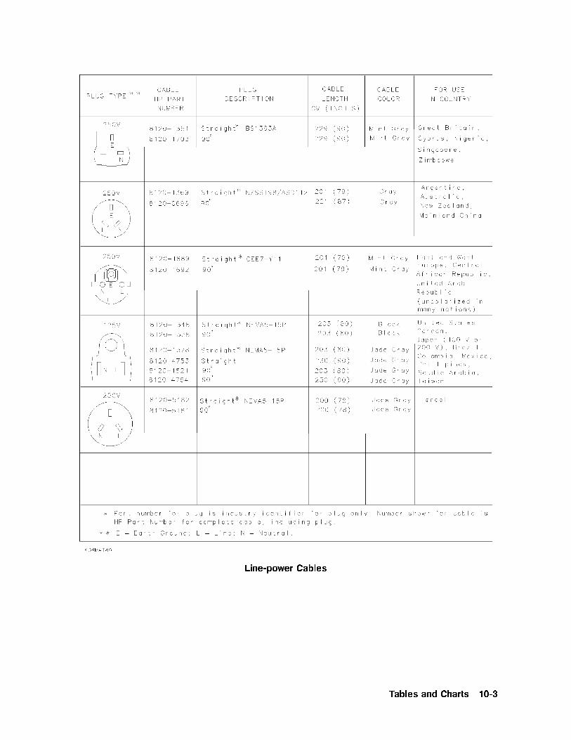
Line-power Cables
Tables and Charts 10-3

Table 10-1. Hewlett-Packard Sales and Service Offices
US FIELD OPERATIONS EUROPEAN OPERATIONS INTERCON OPERATIONS
HEADQUARTERS HEADQUARTERS HEADQUARTERS
Hewlett-Packard Company Hewlett-Packard S.A. Hewlett-Packard Company19320 Pruneridge Avenue 150, Route du Nant-d'Avril 3495 Deer Creek Rd.Cupertino, CA 95014, USA 1217 Meyrin 2/Geneva Palo Alto, California 94304-1316(800) 752-0900 Switzerland (415) 857-5027
(41 22) 780.8111California Australia
Hewlett-Packard Co. France Hewlett-Packard Australia Ltd.1421 South Manhattan Ave. Hewlett-Packard France 31-41 Joseph Street (P.O. Box 221)Fullerton, CA 92631 1 Avenue Du Canada Blackburn, Victoria 3130(714) 999-6700 Zone D'Activite De Courtaboeuf (61 3) 895-2895
F-91947 Les Ulis CedexHewlett-Packard Co. France Canada
301 E. Evelyn (33 1) 69 82 60 60 Hewlett-Packard (Canada) Ltd.Mountain View, CA 94041 17500 South Service Road(415) 694-2000 Germany Trans-Canada Highway
Hewlett-Packard GmbH Kirkland, Quebec H9J 2X8Colorado Hewlett-Packard-Strasse CanadaHewlett-Packard Co. 61352 Bad Homburg (514) 697-423224 Inverness Place, East GermanyEnglewood, CO 80112 (+49 6172) 16-0(303) 649-5000 Japan
Great Britain Yokogawa-Hewlett-Packard Ltd.Georgia Hewlett-Packard Ltd. 1-27-15 Yabe, SagamiharaHewlett-Packard Co. Eskdale Road, Winnersh Triangle Kanagawa 229, Japan2124 Barrett Park Drive Wokingham, Berkshire RG11 5DZ (81 427) 59-1311Kennesaw, GA 30144 England(404) 955-1500 (44 734) 696622
China
Illinois China Hewlett-Packard, Co.Hewlett-Packard Co. 38 Bei San Huan X1 Road5201 Tollview Drive Shuang Yu ShuRolling Meadows, IL 60008 Hai Dian District(708) 342-2000 Beijing, China
(86 1) 256-6888New Jersey
Hewlett-Packard Co. Singapore
150 Green Pond Road Hewlett-Packard SingaporeRockaway, NJ 07866 Pte. Ltd.(201) 586-5400 Alexandra P.O. Box 87
Singapore 9115Texas (65) 271-9444Hewlett-Packard Co.930 E. Campbell Rd. Taiwan
Richardson, TX 75081 Hewlett-Packard Taiwan(214) 231-6101 8th Floor, H-P Building
337 Fu Hsing North RoadTaipei, Taiwan(886 2) 712-0404
10-4 Tables and Charts

11
Configuring and Addressing
This chapter presents a basic addressing principles for HP 70000 Series modular systems. Itdoes not contain installation information for the HP 71910A wide-bandwidth surveillancereceiver. Refer to Chapter 1 for installation information.
The factory ships HP 70000 Series modular systems with all system components installedand addressed. All cables, however, are subject to removal for shipment. An element in anHP 70000 modular measurement system is a system component able to communicate withother modules over HP-MSIB. Element addresses must adhere to the set of rules de�ned inthis section. HP-MSIB addressing is di�erent from HP-IB addressing, and is explained in thischapter. Correct addressing requires an understanding of the concepts in this chapter.
Contents
Modular Measurement System Terms : : : : : : : : : : : : : : : : : : : : : : : : : : : : : : : : : : : : : : : : : : : : : : : : : 11-2Address Map Protocol : : : : : : : : : : : : : : : : : : : : : : : : : : : : : : : : : : : : : : : : : : : : : : : : : : : : : : : : : : : : : : : : 11-4Addressing Elements : : : : : : : : : : : : : : : : : : : : : : : : : : : : : : : : : : : : : : : : : : : : : : : : : : : : : : : : : : : : : : : : : 11-6Addressing Order Requirements : : : : : : : : : : : : : : : : : : : : : : : : : : : : : : : : : : : : : : : : : : : : : : : : : : : : : : :11-9Address Switches : : : : : : : : : : : : : : : : : : : : : : : : : : : : : : : : : : : : : : : : : : : : : : : : : : : : : : : : : : : : : : : : : : : : 11-13
Configuring and Addressing 11-1

Modular Measurement System Terms
Understanding the following terms is essential to understanding HP-MSIB addressing and thestructural relationship of modular measurement system devices.
Functional Terms
The devices of a modular system may be combined in such a way to allow them tocommunicate and operate as an instrument. The following terms identify the interrelationshipamong devices within a modular instrument.
Element
Any device that communicates over the HP-MSIB (for example, HP 70902A IF section). Incontrast, the HP 70001A mainframe controls all HP-MSIB communication, but does notcommunicate over the HP-MSIB and therefore is not an element.
Master
An element that controls other elements.
Sub-master
An element that simultaneously controls other elements and is controlled by another element.
Slave
An element that is controlled by another element.
Independent element
An element that is neither a master nor a slave (for example, HP 70004A color display).
Instrument
A module, or group of modules, that performs an independent function (for example, HP71910A receiver).
Structural Terms
Modular systems consist of hardware structures dedicated to speci�c functions. The structuralterms used in reference to these functions are described below.
Mainframe
A housing for modules which also provides power, cooling, interconnection for HP-MSIBand HP-IB, and HP-MSIB communications control for up to eight 1/8-width modules. TheHP 70004A color display also provides the same functions for up to four 1/8-width modules.
Module
Modules are devices that plug into an HP 70001A mainframe or HP 70004A color display.Modules cannot function without these independent elements.
11-2 Configuring and Addressing

Stand-Alone Instrument
An HP-MSIB element capable of performing its functions without a mainframe or HP 70004Acolor display.
Configuring and Addressing 11-3

Address Map Protocol
Protocol for master, sub-master, slave, and independent element addressing is explained inthis section. The factors governing proper system communication and system function arebased on adherence to the addressing protocol of modular spectrum analyzers.
By de�nition, a master is an element addressed to control another element, or is thecontrolling element of a system. Slave elements are addressed within the area a mastercontrols, called the slave area. Independent elements are addressed so that they are neithermasters nor slaves, though they may have functions that appear to control other elements.For example, the graphics display front panel keys are used to select LO functions, but the LOis not a slave to the display.
Address Matrix
The address matrix is a graphic representation of assigned and available HP-MSIB addresses.The address assigned to each element appears on the matrix and indicates the relationshipamong master, sub-master, slave, and independent elements. Module function, access toHP-IB communication, and error reporting are all based on the location of the module addresson the matrix. See the following �gure. The 8-row by 32-column matrix implies that 256addresses are available; however, there are actually 255 legal addresses plus an illegal addressat row 0, column 31.
Address Matrix
Each element must have a unique 8-bit binary HP-MSIB address correctly placed on theaddress matrix. The three most signi�cant bits (MSB) determine the row address; the �veleast signi�cant bits (LSB), the column address. This manual refers to the decimal equivalentof a binary address.
Decimal Equivalent of Binary Address
Row
MSB
Column
LSB
Binary 010 11000
Decimal 2 24
11-4 Configuring and Addressing

Display-Response Area
A display-response area exists at row 0. The display'sNNNNNNNNNNNNNNNNNNNNNNNNNNNNNNNNNNNNNNNNNREPORT ERRORS menu key function
can only access a module addressed at row 0. A display must be assigned to an instrumentbefore communication between the two is initiated. This can be done automatically ormanually. The automatic assignment function (
NNNNNNNNNNNNNNNNNNNNNNNNNNNNNNNNNNNNNNNNNNNNNNNNNNNNNSELECT INSTRUMENT menu key) searches the
display-response area (row 0) when it assigns itself to an instrument. The display can beassigned to a module at any other row, but this assignment must be done manually using theNNNNNNNNNNNNNNNNNNNNNNNNNNNNNNNNNNNNNNNNNNNNNNNASSIGN KEYBOARD and
NNNNNNNNNNNNNNNNNNNNNNNNNNNNNNNNNNNNNNNNNASSIGN WINDOW menu keys.
Note To be addressed at row 0, a module must be designed to interface with thedisplay and report errors. If a module that does not have these capabilities isaddressed at row 0, the system will cease to communicate.
HP-IB Access
The HP-IB access area is at row 0 of the address matrix. Address row 0, column 31, however,is an illegal address location for any element. Modules that have been designed for HP-IBaccess are able to use HP-IB only if their addresses are in the HP-IB access area (row 0,columns 0 through 30).
Note Address row 0, column 31 is an illegal address for any element.
Configuring and Addressing 11-5
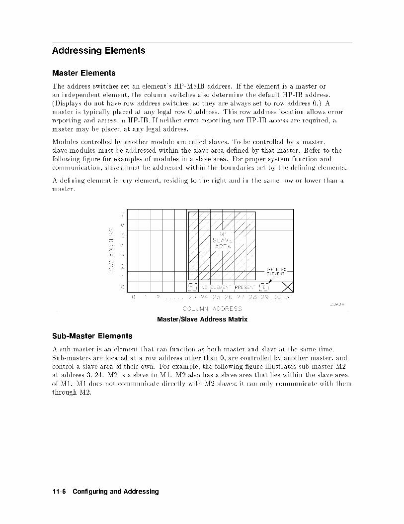
Addressing Elements
Master Elements
The address switches set an element's HP-MSIB address. If the element is a master oran independent element, the column switches also determine the default HP-IB address.(Displays do not have row address switches, so they are always set to row address 0.) Amaster is typically placed at any legal row 0 address. This row address location allows errorreporting and access to HP-IB. If neither error reporting nor HP-IB access are required, amaster may be placed at any legal address.
Modules controlled by another module are called slaves. To be controlled by a master,slave modules must be addressed within the slave area de�ned by that master. Refer to thefollowing �gure for examples of modules in a slave area. For proper system function andcommunication, slaves must be addressed within the boundaries set by the de�ning elements.
A de�ning element is any element, residing to the right and in the same row or lower than amaster.
Master/Slave Address Matrix
Sub-Master Elements
A sub-master is an element that can function as both master and slave at the same time.Sub-masters are located at a row address other than 0, are controlled by another master, andcontrol a slave area of their own. For example, the following �gure illustrates sub-master M2at address 3, 24. M2 is a slave to M1. M2 also has a slave area that lies within the slave areaof M1. M1 does not communicate directly with M2 slaves; it can only communicate with themthrough M2.
11-6 Configuring and Addressing

Sub-Master Address Matrix
Slave Elements
For an instrument to function properly, the master must determine the slave area it controlson the address matrix. Master modules establish their slave area by determining thelocation of the de�ning element on the address matrix. The de�ning element establishes theboundaries of the slave area. Any module located within this area is a slave to the mastermodule.
The HP-MSIB address requirements of a de�ning element are as follows:
The column address of a de�ning element must be greater than the column address of themaster. In the previous Master/Slave Address Matrix �gure, for the master addressed incolumn 23, the de�ning element must be addressed in column 24 or above. In the previousSub-Master Address Matrix �gure, for M2 addressed in column 24, the de�ning elementmust be addressed in column 25 or above.
The row address of a de�ning element must be equal to or less than the row address of amaster. In the Master/Slave Address Matrix �gure the address of the master at row 0 hasa de�ning element addressed at row 0. The Sub-Master Address Matrix �gure shows twomasters, M1 and M2. The de�ning element for M1 is located at row 0 and the de�ningelement for M2 is located at row 3.
Slave Area Boundaries
The master determines its slave-area boundaries by �rst searching upward in its own columnstarting in the master's row, then in each higher column starting in the master's row. Thesearch stops at the boundary column or, if there is no de�ning element, after searching column31.
After a master locates the de�ning element of its slave area, the slave area boundaries are setby using the following criteria:
The column address of the master is the left-hand boundary of the slave area. In theMaster/Slave Address Matrix �gure, the left-hand boundary is column 23.
The right-hand boundary of the slave area is equal to one less than the column address ofthe de�ning element. For the master at column 23 in the Master/Slave Address Matrix�gure, the right-hand boundary is at column 28. If there is no de�ning element, theright-hand boundary of the slave area extends through column 31.
Configuring and Addressing 11-7

The lower boundary of the slave area is one row greater than the row address of the master.For the master in row 0 in the Master/Slave Address Matrix �gure, the lower boundary is atrow 1.
The upper boundary of the slave area is the top row of the matrix (row 7).
If a new module is added to the area labeled \No Element Present" in the Master/SlaveAddress Matrix �gure, this module becomes the new de�ning element and the right-handboundary moves toward the master.
Independent Elements
An independent element, such as a display, is neither a master nor a slave. Displays areconsidered independent elements and separate instruments. Because they do not have rowaddress switches, displays automatically are at row address 0. The typical address for adisplay is row 0, column 4.
11-8 Configuring and Addressing

Addressing Order Requirements
HP-MSIB addresses are set by switches located on each module. The address consists oftwo parts: a row number and a column number. A module's address can be determined byviewing the address map or selecting the con�guration screen.
Measurement systems are composed of more than one module. When this is true, the moduleswill assume master/slave relationships to simplify the user interface. Each master has speci�cslave addressing requirements and expectations.
The HP 70900B local oscillator source is the master of many possible spectrum analyzersystem con�gurations. It will automatically con�gure itself into a system with the slaves thatit �nds available in its slave area on the address map. It searches for these slaves with aspeci�c pattern and expects to �nd them in a certain order.
The HP 70900B local oscillator source searches the address map by starting in the columnwhere it is addressed and looking for a module in the row directly above it. It continues tolook up that column row by row until it reaches the top. It then moves to the next columnto the right. Again, it begins its search at the row above its own location, searching up thecolumn to the top. It continues this process until it has searched its entire slave area. In thisway it identi�es the slave modules that it will con�gure into a system. For a more detaileddescription of how a master's slave area is de�ned, refer to \Address Map Protocol" in thischapter.
Default Addressing for Configured HP 70000 Systems
Default addresses have been set up to allow for current and future addressing considerations.The use of these default addresses will permit adding additional modules to a system with aminimum of address manipulation. Individual modules shipped from the factory will havetheir HP-MSIB address set as de�ned in the default address map.
Addressing Criteria
Each module, or type of module, has addressing criteria that impact address selection. Thedescriptions below are written as if the modules are in the same column; however, this is nota requirement as long as their relative position is maintained with respect to the HP 70900Blocal oscillator source search pattern.
HP 70900B local oscillator source
A single HP 70900B local oscillator source master module may control up to 16 slave modules.
HP 70902A IF section
The HP 70902A IF section, if present, must be closest to the local oscillator (that is, theHP 70902A IF section should be immediately above the HP 70900B local oscillator source inthe address map. It must be the �rst module that the HP 70900B local oscillator source �ndswhen it searches the slave area.)
Configuring and Addressing 11-9

HP 70700A digitizer
When the HP 70700A digitizer is present and used as a slave to the HP 70900B local oscillatorsource, it should be addressed above the HP 70902A IF section (if present). It should also beaddressed below the HP 70903A IF section (if present).
HP 70911A ultra-wide bandwidth IF section
When both HP 70902A and HP 70903A IF sections are present, the HP 70911A must beplaced at a column address that is between these two modules.
HP 70903A IF section
The HP 70903A IF section, if present, should be above the HP 70902A IF section. It shouldbe the next module that the HP 70900B local oscillator source �nds when it searches theslave area. If the HP 70902A IF section is not present, the HP 70903A IF section should beabove the local oscillator. If all three of the previously mentioned modules are present whenthe HP 70900B local oscillator source searches the slave area, it should �nd the HP 70902AIF section, then the HP 70700A digitizer, and then the HP 70903A IF section.
HP 70907B
An HP 70907B should be addressed immediately below the RF section. Multiple externalmixer interface modules should follow each other in the addressing order.
RF section
Only one RF Section may be used with a single HP 70900B local oscillator source. The RFsection should be immediately above the IF sections or external mixer interface module.
HP 70600A preselector/HP 70601A preselector
The HP 70600A preselector/HP 70601A preselector, if present, should be immediately abovethe HP 70905B or HP 70906B. It should normally be the next module that the HP 70900Blocal oscillator source �nds after the RF section when it searches the slave area.
HP 70300A RF tracking generator
The HP 70300A RF tracking generator should be addressed just above an HP 70301Amicrowave tracking generator, if one is present.
HP 70301A microwave tracking generator
The HP 70301A microwave tracking generator should be addressed just below an HP 70300ARF tracking generator, if one is present.
HP 70310A precision frequency reference
The HP 70310A precision frequency reference may be addressed anywhere.
HP 70621A or HP 70620B preamplifiers
The preampli�ers should be addressed above the module that it is providing preampli�cationfor. Multiple preampli�er modules may be used in the same system. When the HP 70900Blocal oscillator source searches its slave area, each preampli�er must be found above themodule (for example, RF section, preselector, preampli�er) that its output is connected to.
11-10 Configuring and Addressing

Row Addressing Priority
The row addressing priority for systems is shown below. Notice that this order is a relativerow-address ranking only. The individual modules do not require consecutive row addresses(that is, there can be empty rows between modules). Also, note that all modules need not bein the same column. They need only fall in the slave area of the master module.
Highest RowHP 70620B or HP 70621A preampli�er (only if preamplifying the lightwave section'sinput signal)HP 70310A precision frequency referenceHP 70300A RF tracking generatorHP 70301A microwave tracking generatorHP 70620B or HP 70621A preampli�er (if preamplifying the preselector's or the RFsection's input signal)HP 70600A preselector or HP 70601A preselectorHP 70904A RF section, HP 70905A RF section, HP 70905B RF section HP 70906ARF section, HP 70906B RF section HP 70908A RF section, HP 70909A RF section,HP 70910A RF section (one only)HP 70907B (several allowed)HP 70903A IF sectionHP 70911A WB IF sectionHP 70700A digitizerHP 70902A IF sectionHP 70900B local oscillator source (Row 0)
Lowest Row
Note HP-MSIB addresses must be unique. Setting two HP 70000 elements to thesame address will create an error and make the local system bus (HP-MSIB)inoperative. If the cursor cannot be moved about within the address map aftera module has been readdressed, check to see if two modules have the same rowand column address.
Configuring and Addressing 11-11

Address Switches
The row and column address switches set the HP-MSIB address of a module; the columnaddress switch also sets the HP-IB address for masters and independent elements.
To establish proper system function and HP-MSIB communication, each module has anaddress switch that is set to a binary, 8-bit HP-MSIB address. Each element in a systemmust be assigned a unique address. The row address of the HP-MSIB address is determinedby three address bits, and the column address is determined by �ve address bits. Each systemhas 8 row and 32 column addresses. Address row 0, column 31 is an illegal address; therefore,255 HP-MSIB addresses are available. The decimal equivalents of the binary row and columnaddresses are referred to throughout this manual. For example, see the table below.
Row Column
Binary 010 11000
Decimal 2 24
The following three sections describe the address switch functions for each of the elements andindependent elements available.
Master Address Switches
Slave Address Switches
Display Address Switches
The address switches may be found on the top, side, or rear of the modules, and at the rear ofthe HP 70004A color display and HP 70206A system graphics display. The location of addressswitches is de�ned in each element's installation and veri�cation manual.
Master Address Switches
The HP-MSIB column address is the same as the default HP-IB address of a master. It isde�ned by the position of the column address switches.
The HP-IB address of any master (for example, HP 70900B local oscillator source) can, undercertain conditions, be set from the front panel of a display. At power-up, this address willoverride the actual address switch settings. For additional information on how to set theHP-IB address from the front panel, refer to HP 70000 Modular Spectrum Analyzer OperatingManual .
The following �gure is an illustration of address switches found on an HP 70900B localoscillator source.
11-12 Configuring and Addressing

HP 70900B Address Switch
HP-IB ON/OFF
With this switch set to o�, the HP 70900B local oscillator source is switched o� the HP-IBand uses only the HP-MSIB for communication.
SW1/MEM
In the SW1 position, the HP-IB address is determined exclusively by the column addressswitches. In the MEM position, the HP-IB address is determined by HP 70900B localoscillator source memory and can be set from the front panel of the display. The HP 70900Blocal oscillator source is normally shipped with this switch in the MEM position.
MAS/SLA
With this set to the MAS position, the HP 70900B local oscillator source can function as amaster or sub-master; with it set to the SLA position, the HP 70900B local oscillator source isa slave.
NRML/TEST
This switch should be set to NRML for normal operation. The TEST position is used for ahard reset and during production.
COLUMNs 1|5
These set the HP-MSIB column address, which is also the default HP-IB address.
ROWs 1|3
These set the HP-MSIB row address.
Configuring and Addressing 11-13

Slave Address Switches
The following �gure is an illustration of typical address switches found on a slave element.
Slave Element Address Switches
Rows 1|3
These switches set the HP-MSIB row address.
Columns 1|5
These switches set the HP-MSIB column address.
Display Address Switches
A system graphics display is an example of an independent element. It may be assigned bothHP-MSIB and HP-IB addresses. The following �gures illustrate the address switches of theHP 70004A color display. For more information on HP-MSIB and HP-IB addressing, refer to\Address Map Protocol".
HP 70004A Address Switches
HP-IB ON/OFF
This switches the display on or o� the HP-IB without disrupting instrument operation.
A1|A5
These address switches set the HP-MSIB column address, which is also the default HP-IBaddress. (This HP-IB address is overridden when the HP-IB address is set from the frontpanel.)
11-14 Configuring and Addressing

TALK ONLY
When this is set to 1 (on) the display can talk on HP-IB without requiring a reply, since someplotters cannot reply. This switch is set to 0 (o�) for normal operation.
SYSTEM CONTROLLER
When this is set to 1 (on), the display functions as a system controller on HP-IB. This switchis set to 0 (o�) at the factory.
TEST MODE
When this is set to 1 (on), the display goes into a special test mode at power-up. This switchis set to 0 (o�) for normal operation.
Configuring and Addressing 11-15


Index
1
10 MHz softkey, 3-24, 7-21.25 MHz softkey, 3-24, 7-2140 MHz IFconnector, 3-16, 3-23maximum bandwidth, 3-26
140 MHz OUT connector, 7-216 QAM Modulation, 3-39
2
20 MHz softkey, 3-24, 7-2
3
300 MHz IN connector, 7-3300 MHz OUT connector, 7-33100 Can't get, 9-23101 Enter # >=0 & <=4095, 9-23102 Can't alloc, 9-23103 Not enough parameters, 9-23104 Bad handle size, 9-23105 Can't �nd 70911, 9-23106 FM Discr not present, 9-23107 Invalid input param, 9-23108 Enter integer > 0, 9-23109 Can't write, 9-23110 Can't read, 9-23111 Can't open, 9-23112 Enter integer < 1000, 9-33113 Wrong 70900 �rmware, 9-33114 No channel �lters, 9-33116 IQ optn not present, 9-33117 Unsupported scrn siz, 9-33118 Screen too small, 9-33119 Signal too low, 9-33120 Signal too high, 9-33121 Wrong 70900 �rmware, 9-33194 Send-only keyword, 9-33195 Query-only keyword, 9-33196 Missing Rx parm, 9-33197 Missing parameter, 9-33198 Parm out of range, 9-43199 Illegal Rx keyword, 9-4321.4 MHz IF connector, 3-16, 3-20321.4 MHz IN connector, 7-3321.4 MHz OPT IN connector, 7-3
321.4 MHz OPT OUT connector, 3-20, 7-3321.4 MHz OUT connector, 7-336 MHz softkey, 3-24, 7-2
5
5 MHz softkey, 3-24, 7-2
6
6021 Sys O�set Corr > 60 , 9-46022 FM O�set > 250mV, 9-46023 FM O�set Corr > 200 , 9-4
7
7080 70MHz LO Unlocked, 9-47081 140MHz LO Unlocked , 9-47082 160MHz LO Unlocked , 9-47083 LO Board Unlocked, 9-47084 Filter Not Present , 9-47085 Table Not Pres, 9-47086 Align Data, 9-47087 Duplicate Table, 9-57088 CAP STRING, 9-57089 EAROM full error , 9-570911 OPTIONS softkey, 7-370 MHz IFand maximum bandwidth, 3-26connector, 3-23output, 3-16
70 MHz OUT connector, 7-270 MHz softkey, 7-2
8
8 mm hex-ball driver, 1-15, 1-25
A
A1|A5, switches, 11-14access area, HP-IB, 11-5accessories, 10-2active function, 3-6active status indicator, 9-6ACT status indicator, 9-6addressingbinary and decimal equivalent, 11-5elements, 11-6HP 70621A preampli�er, 11-10
Index-1

HP 70900B local oscillator source, 11-9HP 70902A IF section, 11-9HP 70903A IF section, 11-10HP 70907B, 11-10HP 70910A RF section, 1-16HP 70911A ultra wide-bandwidth IF section,
1-16HP-IB external device, 7-7least signi�cant bits, 11-4most signi�cant bits, 11-4of display, 11-6order requirements, 11-9override, 11-12RF section, 11-10switches, 11-6
addressing criteriaHP 70910A RF section, 1-16HP 70911A ultra wide-bandwidth IF section,
1-16address map, 1-16, 1-21, 1-26cursor, 9-6protocol, 11-4
address matrix, 11-4master/slave, 11-6sub-master, 11-7
address switchescolumn address, 11-12HP 70004A, 11-14HP 70900B local oscillator source, 11-13master, 11-12row address, 11-12slave element, 11-14
AM connector, 3-25amplitudedetection, 3-42IF signal, 3-20reference level, 7-14scale, 3-5, 3-7, 3-16units, 3-7, 3-28, 7-4
Amptd softkey, 3-5AM softkey, 3-17, 3-27, 7-4analog IQ demodulation, 3-26analyzer command, 8-3antistatic precautions, 1-15ASSIGN KEYBOARD, display menu key, 11-5ASSIGN statements, 4-5ASSIGN WINDOW, display menu key, 11-5assistance, xA status indicator, 9-6attenuationRF, 3-20, 7-14
attenuatorcoupled to reference level, 7-14inability to set to 0 dB, 7-14RF, 7-14
A UNITS AutoMan softkey, 3-7, 3-28, 7-4AUNITS command, 4-7average amplitude level, 3-28
B
���, viii, 7-3bandwidthmaximum, ivmaximum available, 3-43search receiver mode, 3-4
binary address, decimal equivalent, 11-5blankingannotation, 3-52graticules, 3-52
block diagrams, 3-59build window softkey, 3-56BW softkey, 3-22, 3-23, 7-4BYPASS softkey, 3-24, 7-4
C
cableskeyboard, 3-53line-power, 10-3
calibration, 3-3full, 2-1
CALIBRATOR connector, 3-3caution symbol, ixCE instrument marking, ix�CENTER�, 3-5, 7-4center frequencyjumps in, 3-13step size, 3-13
CENTER softkey, 3-6, 7-5certi�cation, xCF STEP AutoMan softkey, 3-40, 7-5channel �lters, 3-19softkey, 3-24, 7-5
chirp, frequency, 3-34CLEAR statements, 4-5CLEAR TO END softkey, 3-53, 3-57collecting signals, 3-14manually, 3-45
color traces, 3-4COLUMNs 1|5, switches, 11-13commandsHP 70900B, 4-2receiver personality, 4-2required �rst, 8-17versus softkeys, 8-4
communication, receiver, 4-5compatible function, 8-3Con�g Display softkey, 3-56connectorFM, 7-6
constellation, 3-38, 3-68
Index-2

diagrams, viminimizing spinning e�ect, 3-39
CONT SWEEP softkey, 3-12CSA instrument marking, ixcustom �lters, 3-23custom keypad, changing, 1-29
D
data byte & EOI, 8-3data transfer, 4-7dBm softkey, 3-7, 7-5dBmV softkey, 7-5dBuV softkey, 7-5decimal equivalent, binary address, 11-5defaultaddressing, 11-9HP-IB address, 11-6, 11-13
de�nitionanalyzer command, 8-3compatible function, 8-3data byte & EOI, 8-3de�ning element, 11-7delimiter, 8-3independent elements, 11-4, 11-8master, 11-4number, 8-3output termination, 8-3slave, 11-4, 11-6slave area, 11-7sub-master, 11-4, 11-6units, 8-3
DELETE or . . . softkey, 3-53, 3-57delimiter, 8-3DEL RX STATE softkey, 3-55, 7-5Demod softkey, 3-17, 3-27, 7-5demodulating a signal, 3-25demodulation, 3-27default, 3-25formats, 3-17IQ, 3-26options, 8-11selecting remotely, 8-11
discriminators, 3-26disk driveaddressing, 1-33type, 1-33
displayA1|A5, switches, 11-14address switches, 11-14blanking for security, 3-56cleaner, 1-28HP 70004A windows, 3-52, 3-56HP-IB ON/OFF, switches, 11-14limits with manual collection, 3-43receiver mode, 3-16
response area, 11-5selecting memory card or HP-IB disk, 7-7SYSTEM CONTROLLER, switches, 11-15TALK ONLY, switches, 11-15TEST MODE, switches, 11-15
�DISPLAY�, vii, 3-56displayed dynamic range, 3-16displayed noise, 3-11reducing, 3-11
display menu keyASSIGN KEYBOARD, 11-5ASSIGN WINDOW, 11-5REPORT ERRORS, 11-5SELECT INSTRUMENT, 11-5
DISPLAY On O� softkey, 7-6display-response areaautomatic assignment, 11-5manual assignment, 11-5
��, 7-4downconverting, 3-142.7 to 26.5 GHz, 3-20
dynamic range, 3-16, 3-42
E
element, MMS term, 11-1, 11-2ENTER LINE softkey, 3-54, 3-57ENTER statements, 4-5error message, 3-44, 9-2ERR command, 9-1Possible compression, 3-44, 3-66reporting, 9-6UNCAL, 3-44, 3-64, 3-65UNCOR, 3-44, 3-63usable RBW limited, 3-44Usable RBW limited is displayed, 3-64Usable VBW limited is displayed, 3-65
ERR status indicator, 9-6E status indicator, 9-6examples, 3-29pulsed RF signal, 3-29, 3-46wide-bandwidth digital transmission, 3-38wide-bandwidth FM signal, 3-34
EXTEND STATE softkey, 1-14external mixers, 3-51
F
�le recall, 7-13�rmware date code, HP 70900B, 1-14�xed-tuned operation, 3-14FMconnector, 3-27, 7-6discriminators, 3-26signals, 3-34
FM NB softkey, 3-27, 7-6
Index-3

FM WB softkey, 3-27, 7-6Freq softkey, 3-5, 3-18, 7-6frequencycenter, 7-4, 7-5changing, 3-6changing in personality, 3-18chirp, 3-34extended range, 3-7menu, 3-5range, 3-5range, extending, 3-51resolution, 3-10returning to full span, 3-7span, 7-16start, 7-16stop, 7-16
frequency shift, 3-68front-panel��� , 7-3�CENTER�, 7-4��, 7-4FM connector, 7-6�HOLD�, 7-7HP-HIL connector, 3-53, 3-57I connector, 7-8�INSTR�, 7-9LSN indicators, 4-6�MENU�, 7-10�PLOT�, 7-11�PRINT�, 7-12Q connector, 7-12�REF LEVEL�, 7-14RMT indicators, 4-6SRQ indicators, 4-6�START FREQ�, 7-16�STOP FREQ�, 7-16TLK indicators, 4-6���, 7-4VIDEO connector, 7-17
FULL SPAN softkey, 3-7, 3-18, 7-6functional terms, 11-2fundamental units, 4-7fuse, changing, 1-28
G
gainanalog IQ, 3-26IF, 3-20RF to IF, 3-20, 7-14
Gain softkey, 3-23, 3-28, 7-7
H
hard reset, TEST position, 11-13Help On O� softkey, 3-15, 7-7highest peak, 7-11�HOLD�, viii, 7-7How toconnect the MSIB Y-Cable, 1-9
HP 11974 mixers, 3-51HP 11990A System Performance Tests, 2-1HP 54602A oscilloscope, 3-38HP 70001A mainframephysical dimensions, 5-16
HP 70004A display/mainframe, 3-56address switches, 11-14cleaning the screen, 1-28external HP-MSIB device, 7-7memory card or HP-IB disk, 7-7physical dimensions, 5-16
HP 70620B preamp, 3-49HP 70620B preampli�er, 7-11, 7-14HP 70703A oscilloscope, 3-29HP 70900B local oscillator sourceaddress switches, 11-13COLUMNs 1|5, switches, 11-13HP-IB ON/OFF, switches, 11-13MAS/SLA, switches, 11-13NRML/TEST, switches, 11-13ROWs 1|3, switches, 11-13SW1/MEM, switches, 11-13
HP 70911A module's rear panel, 3-19HP 71209A, upgrading, 1-14HP DISK softkey, 1-33HP-HIL keyboard, 3-53, 3-57HP-IBaddressing external device, 7-7HP 71910A address, 4-3status indicator, 9-6
HPIB DISK softkey, 1-33, 3-53, 7-7, 7-13, 7-15HP-IB ON/OFF, switches, 11-14HP-LIF format, 1-31HP-MSIBaccessing HP-IB disk, 7-7accessing memory of an external device, 7-7default device address, 7-7row address, setting, 11-13selecting memory card or HP-IB disk, 7-7
HP-MSIB CARD softkey, 3-53, 3-55, 7-7, 7-13,7-15
I
Iconnector, 3-27front panel connector, 7-8
IF
Index-4

available frequencies, 3-16bandwidth, 3-14, 3-22digitizer, 3-20�lters, 8-8gain, 3-20, 3-22, 3-23outputs, 3-19video bandwidth ratio, 3-22
IF BW softkey, 3-22, 7-8IF gain, 3-19IF GAIN AutoMan softkey, 3-23, 7-9I GAIN softkey, 7-8illegal address, 11-5IN 1 70620B softkey, 3-50, 3-67independent elementaddressing, 11-4de�nition, 11-4
independent, MMS term, 11-2initial commands, 4-5initializingreceiver personality, 4-2receiver program, 8-17
INSERT or . . . softkey, 3-53, 3-57installinginto HP 71209A Option 001, 1-14Option 011, 1-12receiver personality, 1-31standard instrument, 1-2
�INSTR�, 3-56, 7-9�INSTR PRESET�, 7-9instrumentMMS term, 11-2preset, 3-4, 4-5, 7-9returning to spectrum analyzer mode, 3-18switching between modes, 3-16windows, 3-56
interrupt process, 4-8INTRNL MEMORY softkey, 3-53, 3-55, 7-10,
7-13, 7-15I/O error status indicator, 9-6I OFFSET softkey, 3-27, 7-8�IP�, 3-4IQdemodulation, 3-26gain and o�set, 3-27softkey, 3-27, 7-10
ISM1-A instrument marking, ixISO/IEC, 5-17
K
keyboard, 3-53, 3-57
L
LAST STATE softkey, 3-18, 7-10least signi�cant bits, 11-4legal addresses, 11-4limit lines, 3-4LINEAR softkey, 3-7line-power cables, 10-3local control, 4-6LOCAL key, 4-6locating signals, 3-5LOG dB/DIV softkey, 3-7LSN status indicator, 9-6
M
mainframe, MMS term, 11-2maintaining the receiver, 1-28markersactivating normal markers, 7-11disabling all markers, 7-11entering receiver mode, 3-16moving signals, 3-8positioning, 7-11to next highest peak, 7-11
MAS/SLA, switches, 11-13masteraddress switches, 11-12de�nition, 11-4elements, 11-6function as a slave, 11-13function as a sub-master, 11-13MMS term, 11-2
master/slave address matrix, 11-6measurement examples, 3-29digital transmission, 3-38pulsed RF signals, 3-29pulsed RF signals in manual mode, 3-46
memoryrecalling �les, 7-13selecting an HP-IB disk, 7-7selecting external memory, 7-7selecting internal memory, 7-10selecting storage device, 7-7
�MENU�, vii, 7-10menu map, 6-2messageserror, 9-1
microwave preselector, 3-43, 7-11bandwidth, 3-20bypassing, 3-64
Misc softkey, 7-10MMS termelement, 11-2independent, 11-2instrument, 11-2
Index-5

mainframe, 11-2master, 11-2module, 11-2slave, 11-2stand-alone instrument, 11-3sub-master, 11-2
modulation identi�cation, vimoduleMMS term, 11-2
monitoring system operation, 4-8, 4-10most signi�cant bits, 11-4MSIB Y-cableconnecting to an MMS mainframe, 1-9
N
NARROW SPAN softkey, 3-18, 7-10NB VID IN connector, 7-10�NEXT PEAK�, 7-11No Element Present, in address map, 11-8noise declaration, 5-18�NORMAL�, 7-11NRML/TEST, switches, 11-13number, 8-3
O
o�set, analog IQ, 3-26operation, 3-14modes, ivveri�cation, 2-1
Option 001, 3-16, 3-23, 7-2Option 002, 3-16, 3-23Option 004, 3-17, 3-25, 3-26, 3-27, 8-16, 8-18,
8-20, 8-21, 8-22Option 005, 3-17, 3-25, 3-26, 3-27, 8-13Option 007, 3-16, 3-20, 3-23, 7-2Option 011, 1-12options, 10-2OUTPUT statements, 4-5output termination, 8-3
P
�PEAK SEARCH�, 3-9, 7-11performance tests, 2-1personality, 3-15downconverting without, 3-41exiting, 3-18
phase information, 3-20phase information, preserving , 3-20physical dimensionsHP 70001A mainframe, 5-16HP 70004A display/mainframe, 5-16
�PLOT�, 7-11Possible compression error message, 3-44, 3-66preampli�er, using, 7-11
PREAMP On O� softkey, 3-50, 3-67, 7-11preselector, turning o�, 3-23PRESEL On O� softkey, 3-23, 3-30preset instrument, 7-9�PRINT�, 7-12problems ashing ERR indicator, 9-6
programmingcommands, 4-2, 8-6example, 4-4fundamentals, 4-1
\P" system con�gurations, 1-5pulsed RFdemodulating, 3-29downconverting, 3-46
PULSE softkey, 3-17, 3-27, 7-12
Q
Qconnector, 3-27front panel connector, 7-12
Q GAIN softkey, 7-12Q OFFSET softkey, 3-27, 7-13quadrature, 3-26QUADRATURE softkey, 3-27, 7-13
R
*RB annotation, 3-10RCL RX STATE softkey, 3-55, 7-13rear-panel connectionsoption, 1-4Option 011, 1-12Option 011 and Option 001/002, 1-12standard con�guration, 1-3
rear panel, HP 70911A, 3-19�RECALL�, 7-13receiverdescription, 1-1mode, 3-14Option 011, 3-4personality, 3-16remote control, 4-5status byte, 4-8
receiver personalityreinstalling, 1-31
receiver state, 3-52deleting, 3-55recalling, 3-55saving, 3-53
RECEIVR VERSION softkey, 7-14reference level, 3-5, 3-14changing, 3-7setting, 7-14
�REF LEVEL�, 3-5, 7-14�REF LVL�, 3-9
Index-6
REF LVL softkey, 3-7regulatory information, x, 5-17remote control, 4-6ASSIGN statements, 4-5CLEAR statements, 4-5ENTER statements, 4-5OUTPUT statements, 4-5query, 4-5setup procedure, 4-3
repackaging for service, 1-35REPLACE or . . . softkey, 3-53, 3-57REPORT ERRORS, display menu key, 11-5reporting errors, 11-5RES BW AutoMan softkey, 3-10resetting instrument parameters, 3-4resolution bandwidth, 3-4decreasing, 3-10manual mode, 3-10
returning for service, 1-35Return to S/A softkey, 3-18, 7-14RF attenuation, 3-20, 3-23, 7-14RF ATTN AutoMan softkey, 3-23, 7-14RF/IF Gain, 3-20, 7-14RF INPUT connector, 3-3RMT status indicator, 9-6row addressing priority, 11-11ROWs 1|3, switches, 11-13RX MODE softkey, vii, 3-16RXRMT CHANFILT command, 8-6RXRMT CHANPATH command, 8-8RXRMT DELETERX command, 8-10RXRMT DEMOD command, 8-11RXRMT FMOFF command, 8-13RXRMT IFGAIN command, 8-15RXRMT IGAIN command, 8-16RXRMT INIT command, 8-17RXRMT IOFFSET command, 8-18RXRMT OPTIONS? command, 8-19RXRMT QGAIN command, 8-20RXRMT QOFFSET command, 8-21RXRMT QUAD command, 8-22RXRMT RECALLRX command, 8-24RXRMT SAVERX command, 8-25RXRMT TEMPCOMP command, 8-26RXRMT VERSION? command, 8-27
S
safety symbols, ixsave & recall softkey, 3-53, 7-15SAVE RX STATE softkey, 3-54, 7-15saving receiver state, 3-53screenblanking for security, 3-52cleaning, 1-28titles, 3-57
searching for signals, 3-4SELECT CHAR softkey, 3-53, 3-57selecting IF �lters, 8-8SELECT INSTRUMENT, display menu key,
11-5SENS AutoMan softkey, 3-11serial number, locating, 1-30service, 1-35foam inserts, 1-35repackaging, 1-35return to factory, 1-35
service requests, 4-8settingHP-MSIB row address, 11-13slave area boundaries, 11-7
setup procedure for remote control, 4-3SIG LVL On O� softkey, 3-28, 7-15signalcollecting, 3-14collecting manually, 3-41level, 3-20searching for, 3-4
�SIGNAL TRACK�, 7-16single sweeps, 3-12SINGLE SWEEP softkey, 3-12slaveaddress switches, 11-14area boundaries, 11-7area of master, 11-11de�nition, 11-4element address switches, 11-14elements, 11-7MMS term, 11-2
slave con�guration, 11-9softkeydescriptions, 7-2map, 6-2
SPACE softkey, 3-53, 3-57�SPAN�, 3-5, 3-9, 7-16SPAN softkey, 3-18, 7-16speci�cationcollection receiver, 5-3search receiver, 5-9
spectrum analyzerbandwidth, 3-42commands, 4-2mode, 3-4
spinning constellations, 3-39, 3-68SRQ status indicator, 9-6STACK 2 WINDOWS softkey, 3-56stand-alone instrument, MMS term, 11-3stand-alone operation, 1-1�START�, 3-5�START FREQ�, 7-16static precautions, 1-15
Index-7

status indicators, 9-6A, 9-6ACT, 9-6active, 9-6E, 9-6ERR, 9-6HP-IB, 9-6I/O error, 9-6LSN, 9-6RMT, 9-6SRQ, 9-6TLK, 9-6
STB command, 4-10stepping the center frequency, 3-13step size, center frequency, 3-13�STOP�, 3-5�STOP FREQ�, 7-16sub-masteraddress matrix, 11-7de�nition, 11-4elements, 11-6function as a master, 11-13MMS term, 11-2
sweepcontrolling, 3-12
sweep time, 3-12switchesA1|A5, 11-14COLUMNs 1|5, 11-13HP-IB ON/OFF, 11-13, 11-14MAS/SLA, 11-13NRML/TEST, 11-13ROWs 1|3, 11-13SW1/MEM, 11-13SYSTEM CONTROLLER, 11-15TALK ONLY, 11-15TEST MODE, 11-15
SWPTIME AutoMan softkey, 3-12syntaxargument, 8-2terminator, 8-2
Sys O�set > 100mV , 9-4SYSTEM CONTROLLER, switches, 11-15system operation monitoring, 4-8
T
TALK ONLY, switches, 11-15temp compens softkey, 7-16temperature compensation, 3-3terminators, 8-2TEST MODE, switches, 11-15TEST position, hard reset, 11-13three dimensional waterfall display, 3-4titles, 3-52, 3-57TITLE softkey, 3-57, 7-17
TLK status indicator, 9-6trace data units, 8-3troubleshooting, 9-1HP 70207A PC Display for MMS, 9-1MSIB interface card, 9-1MSIB Y-cable, 9-1
U
���, 7-4UNCAL error message, 3-12, 3-44, 3-64, 3-65UNCOR, error message, 3-68UNCOR error message, 3-44, 3-63units, 8-3dBm, 3-7watts, 3-7
units menu softkey, 3-7, 3-28, 7-17���, 7-4upgrading an HP 71209A, 1-14Usable RBW limited error message, 3-44, 3-64Usable VBW limited error message, 3-65�USER�, 3-16, 7-17�USER� , 3-15
V
variable, 8-3*VB annotation, 3-11VBW/IFB RATIO softkey, 3-22, 7-17ventilation requirements, iiiVID AVG On O� softkey, 3-11VID BW AutoMan softkey, 3-11, 3-22, 7-17video bandwidth, 3-14, 3-22�ltering, 3-11manual mode, 3-11
video bandwidth to resolution bandwidth ratio,7-17
VIDEO connector, 3-27, 7-17VID OUT TO L.O. connector, 7-17VOLT softkey, 7-18
W
WARN 16003, 3-64WARN 16004, 3-65WARN 16007, 3-66warning symbol, ixwarranty, xiWATT softkey, 3-7, 7-18WB VID IN connector, 7-18WB VID OUT connector, 7-18wide-bandwidthdigital transmissions, 3-38FM signal, 3-34
Z
zero span operation, 3-14
Index-8