Surgical Technique - · PDF fileMRI, myelography, discography, patient history and physical...
32
Optio-C ™ Anterior Cervical PEEK Interbody System Surgical Technique
Transcript of Surgical Technique - · PDF fileMRI, myelography, discography, patient history and physical...

Optio-C™ Anterior Cervical PEEK Interbody SystemSurgical Technique

2 Optio-C Anterior Cervical PEEK Interbody System – Surgical Technique
Optio-C Anterior Cervical PEEK Interbody System
Surgical Technique
Description, Indications & Contraindications . . . . . . . . . . . . . . . . . . 3
Optio-C System Overview. . . . . . . . . . . . . . . . . . . . . . . . . . . . . . . . . . . 4
Optio-C System Surgical Technique . . . . . . . . . . . . . . . . . . . . . . . . . . 6
ATO Inserter Guide Optional Surgical Technique . . . . . . . . . . . . . . . 14
Freehand Screw Insertion Surgical Technique . . . . . . . . . . . . . . . . . 19
Implant Revision/Removal Surgical Technique . . . . . . . . . . . . . . . . 23
Tray Layouts . . . . . . . . . . . . . . . . . . . . . . . . . . . . . . . . . . . . . . . . . . . . 24
Instrument Visual Guide. . . . . . . . . . . . . . . . . . . . . . . . . . . . . . . . . . . 28
Warnings and Precautions . . . . . . . . . . . . . . . . . . . . . . . . . . . . . . . . . 30

Optio-C Anterior Cervical PEEK Interbody System – Surgical Technique 3
Description, Indications & Contraindications
DESCRIPTION
The Optio-C System is comprised of one Optio-C PEEK IBF Spacer, one Optio-C Anterior Cervical Plate and three Optio-C Bone Screws. The Optio-C Device is secured by an anti-migration system that is designed to maintain no profile. The Optio-C System is designed to maximize fusion with a unique load-sharing interface and multiple implant footprints.
INDICATIONS
The Optio-C Anterior Cervical Intervertebral Body Fusion Device (IBFD) is indicated for stand-alone anterior cervical interbody fusion procedures in skeletally mature patients with cervical degenerative disc disease at one level from C2 to T1. Degenerative disc disease (DDD) is defined as neck pain of discogenic origin with degeneration of the disc confirmed by history and radiographic studies. The Optio-C IBFD is comprised of one Optio-C PEEK IBF Spacer, one Optio-C Anterior Cervical Plate and three Optio-C bone screws.
The Optio-C IBFD is to be used with autograft and implanted via an open, anterior approach in patients who have had six weeks of non-operative treatment.
CONTRAINDICATIONS
1. Disease conditions which have been shown to be safely and predictably managed without the use of internal fixation devices are relative contraindications to the use of these devices.
2. Active systemic infection or infection localized to the site of the proposed implantation are contraindications to implantation.
3. Severe osteoporosis is a relative contraindication because it may increase the occurrence of subsidence.
4. Any entity or condition that totally precludes the possibility of fusion, i.e. cancer, kidney dialysis or osteopenia, is a relative contraindication.
5. Obesity
6. Pregnancy
7. Certain degenerative disease
8. Foreign body sensitivity
9. The patient’s occupation or activity level or mental capacity may be relative contraindications to this surgery. Specifically, some patients may, because of their occupation or lifestyle, or because of conditions such as mental illness, alcoholism or drug abuse, place undue stresses on the implant.
10. Metabolic disorders that may impair bone formation.
11. Inadequate bone stock to support the device.
12. Poor prognosis for good wound healing (e.g., decubitis ulcer, end-stage diabetes, severe protein deficiency and/or malnutrition).
13. Known patient sensitivity to device materials (titanium alloy, Ti-6Al-4V ELI or polyetheretherketone [PEEK]).
14. Use in the posterior elements (pedicles) of the cervical, thoracic, or lumbar vertebrae.
15. Where attempted correction exceeds the limits of physiological conditions.
16. Any condition not described in the indications for use.
See also the WARNINGS and PRECAUTIONS section of this document.
MATERIALS
Implants: The Optio-C plate and bone screws are manufactured from Titanium alloy (Ti-6Al-4V ELI) per ASTM F-136. The Optio-C Anterior Cervical PEEK Intervertebral Body Fusion (IBF) Spacer is manufactured from polyetheretherketone (PEEK) per ASTM F2026. Since PEEK is radiolucent, the PEEK IBF devices contain radiographic markers comprised of Titanium Alloy (Ti-6Al-4V ELI) per ASTM F-136.
Instruments: The Optio-C System instrumentation is made from medical/surgical grade stainless steel, plastic, aluminum, and silicone.
Do not use any of the Optio-C System components with the components from any other system or company unless stated in this document.

4 Optio-C Anterior Cervical PEEK Interbody System – Surgical Technique
The Optio-C PEEK Implant is comprised of one Optio-C PEEK IBF Spacer (PEEK spacer), one Optio-C Anterior Cervical Plate and three Optio-C bone screws. The Optio-C PEEK Implant is used to provide structural stability in skeletally mature individuals following discectomy and is offered in multiple contours, lordotic angles, footprints and heights in order to accommodate variations in cervical anatomy.
Optio-C Plates
Optio-C Plates are available in heights of 6mm to 12mm. All plates are 16mm in width.
The Optio-C Plate features a one-step screw locking mechanism to prevent screw migration. The plate midline is indicated by a black stripe on the anterior face of the plate.
Optio-C PEEK Spacers
Optio-C Implants must be assembled prior to use as described in this document. The implants are provided in three footprints to meet varying patient anatomy: 12x14mm, 14x16mm, and 15x18mm (depth x width including plate depth connected to PEEK spacer).
Optio-C System PEEK spacers are available in heights from 6mm to 12mm, in Lordotic (6°) and Parallel (0°). The height and lordosis are marked on the lateral sides of the PEEK spacer. A Titanium alloy radiographic marker pin is located 1mm from the posterior aspect of all Optio-C Implants to help confirm implant positioning under fluoroscopy.
Optio-C Plate (6–12mm, 1mm increments)07.01873.006 – 012
Optio-C System Overview
PARALLELLORDOTIC PARALLEL
Lordotic
Description (L x W x H, Degrees) Item#
12 x 14 x 6 – 12mm, 6° 07.01858.006 – 012
14 x 16 x 6 – 12mm, 6° 07.01859.006 – 012
15 x 18 x 6 – 12mm, 6° 07.01860.006 – 012
Parallel
Description (L x W x H, Degrees) Item#
12 x 14 x 6 – 12mm, 0° 07.01855.006 – 012
14 x 16 x 6 – 12mm, 0° 07.01856.006 – 012
15 x 18 x 6 – 12mm, 0° 07.01857.006 – 012

Optio-C Anterior Cervical PEEK Interbody System – Surgical Technique 5
All Optio-C System PEEK spacers have two notches and a groove to accommodate Optio-C System bone screws.
For the Lordotic spacers, the anterior height is equal to the size specified and the posterior height is approximately 1mm smaller (e.g., for a 7mm Optio-C System lordotic spacer, the posterior height is 6mm).
Optio-C Screws
All Optio-C System bone screws are 3.3mm diameter, variable angle. Both self-drilling DiamondTip and self-tapping screw configurations are available in 12, 14, and 16mm lengths. Screws feature dual-single lead, cortico-cancellous thread form and are color coded by length. Optio-C screws provide a lag effect to ensure the interbody device fits snugly to the anatomy.
Self-drilling screws may reduce the surgical steps required to penetrate the cortex of the vertebral body and are distinguished by black stripes on the top of the screw head.
Optio-C Plate/Screw Angulation
Optio-C System Plates and Screws allow for variable angle placement as follows:
The appropriate angle ranges for the lateral screws are 35° to 45° cephalad/caudal and -5° to 5° medial/lateral.
The appropriate angle ranges for the midline screw are 35° to 45° cephalad/caudal and 0° to 10° medial/lateral.
The midline screw is offset by 1mm from the plate midline, and angles 5° medial toward midline.
The Optio-C PEEK Implant can be implanted in two orientations:
Standard orientation, two screws cephalad and one screw caudal
Inverted orientation, one screw cephalad and two screws caudal
Optio-C System Screw Length
Optio-C System screw lengths will terminate at the approximate anterior-posterior distances shown when inserted at nominal trajectory.
3.3mm Self-Drilling Variable Angle Screws07.01875.012 – 016
3.3mm Self-Tapping Variable Angle Screws07.01874.012 – 016
Standard Inverted
Notches
Groove
Optio-C PEEK Footprint 12x14mm 14x16mm 15x18mm
Screw Length 12mm 14mm 16mm

6 Optio-C Anterior Cervical PEEK Interbody System – Surgical Technique
Instruments
Pre-Operative Planning and Patient Positioning
Exposure and Location, and Site Preparation
Optio-C System
Surgical Technique
Step 1
Pre-operatively, the surgeon must identify the proper intervertebral level to fuse using diagnostic techniques such as radiographs, MRI, myelography, discography, patient history and physical examination. Place the patient in a supine position. Support the posterior cervical spine to maintain normal lordosis and choose a right- or left-sided approach. Identify the symptomatic level and make a skin incision to the corresponding pathology. (Fig. 1)
Step 2
The anterior cervical anatomy is exposed in the standard fashion by identifying a dissection plane between the trachea and esophagus. Exposure is then held in place utilizing self-retaining retractors. (Fig. 2)
Fig. 1 � Fig. 2 �

Optio-C Anterior Cervical PEEK Interbody System – Surgical Technique 7
Step 4
Prepare the anatomy to accommodate placement of the Optio-C Implant. It is recommended to insert the Optio-C Implant under distraction. (Fig. 4)
Fig. 3 �
Step 5
Choose a parallel or lordotic Trial to match the height and contour of the intervertebral space. Select the appropriate Trial to assess the height of the disc space. Connect the Modular Impaction Cap Handle to the Trial. Ensure the Trial fits snugly in the disc space when distraction is released.
Once the height is determined, select the appropriate implant footprint by using the Trials and Rasps (12x14, 14x16, or 15x18). These instruments equal the shape of the assembled implant (plate + PEEK spacer). (Fig. 5)
Fig. 4 � Fig. 5 �
Implant Sizing
Instruments
NOTE: Intra-operative imaging may be used to confirm implant sizing. Optio-C System Trials and Rasps are designed to be line-to-line with the implant.
WARNING: When preparing the disc space, care should be taken to ensure an appropriate amount of bone is removed; excessive removal of bone has the potential to cause subsidence, while failing to remove enough bone has the potential to cause poor fusion.
Trial and Rasp Color Code
Size and Configuration Color
12mm x14mm x 0° Black
12mm x14mm x 6° Blue
14mm x16mm x 0° Green
14mm x16mm x 6° Yellow
15mm x18mm x 0° Tan
15mm x18mm x 6° Orange
Step 3
For placement adjacent to existing plate hardware, the Optio-C Distraction Pin Instruments may be used with a Caspar Distractor over the existing plate hardware in lieu of a Caspar Pin in that vertebral segment. (Fig. 3)
WARNING: If existing hardware is present, compatibility between the Distraction Pin and the existing hardware should be verified prior to use. When the Distraction Pin is used with existing hardware, extreme care should be taken to prevent damage to existing hardware.
NOTE: Ensure contacting surfaces between the Distraction Pin and existing hardware are clear of bone or soft tissue.
NOTE: Optio-C Distraction Pins are intended for single use only and should be disposed of after one use.
Distraction Pins 07.01911.001 Single Prong 07.01911.002 Double Prong
Modular Handle - Impaction Cap 07.01903.001
Implant Trials - Parallel and Lordotic07.01877.006 – 012, .026, .046
07.01879.006 – 012
Implant Rasps - Parallel and Lordotic07.01878.006 – 012, .026, .046
07.01880.006 – 012

8 Optio-C Anterior Cervical PEEK Interbody System – Surgical Technique
Fig. 6 �
Step 6
The Optio-C Implant must be assembled prior to use. Confirm the chosen implant size and then remove the Optio-C Plate and Optio-C Spacer from their respective sterile packaging. (Fig. 6)
Step 7
Select the Implant Assembly Block station to match the chosen implant footprint. Slide the plate over the short, angled pin. Guide the pin into the plate midline hole until the plate sits flat in the appropriate footprint station. (Fig. 7)
Fig. 7 � Fig. 8 �
Implant Assembly Implant Assembly
Instruments
Implant Assembly Block07.01884.001
NOTE: Optio-C Plate height and spacer height must match. For example, if the 7mm Trial fits appropriately, then a 7mm plate and 7mm spacer are used.
NOTE: The sizing scale on the Implant Assembly Fixture may be used to confirm implant sizes prior to assembly.
NOTE: The gold locking cap needs to be located on the left side of the angled pin.
Step 8
Before connecting the spacer to the plate, ensure the spacer notches for the lateral screws are facing upward. Place the spacer into the Implant Assembly Block behind the plate between the four alignment pins. (Fig. 8)

Optio-C Anterior Cervical PEEK Interbody System – Surgical Technique 9
Step 11
Assemble the Inserter Guide to the Modular Impaction Cap Handle. Ensure the Inserter sleeve is in the unlocked position by pulling it toward the Modular Handle. With the gold locking screw oriented on the left and guide circular markings facing upward, insert the Inserter Guide tubes into the plate screw holes until the positive stops are in contact with the plate. (Fig. 11)
Fig. 9 �
Step 10
Confirm visually that the implant is assembled appropriately. Ensure the plate and spacer sizes match and that the plate screw holes and spacer notches are aligned.
Fill the graft hole with desired autograft bone graft. The Implant Assembly Tamp may be used to gently pack the graft material. (Fig. 10)
Fig. 10 � Fig. 11 �
Attaching Implant: Inserter Guide
Instruments
NOTE: The circular markings on the Inserter Guide should face upward when assembling the plate to the Inserter. These markings are for orientation only, indicating the direction of the two lateral screws (2 dots cephalad, 2 screws point cephalad).
Step 9
Use the Implant Assembly Tamp to connect the spacer to the plate until an audible click is heard. (Fig. 9)
NOTE: The Optio-C Implant may be loaded onto either Optio-C Inserter Guide directly from the Implant Assembly Block.
Implant Assembly Block07.01884.001
Modular Handle – Impaction Cap 07.01903.001
Implant Assembly Tamp07.01885.001
Inserter Guide07.01886.001

10 Optio-C Anterior Cervical PEEK Interbody System – Surgical Technique
Fig. 12 �
Step 13
Secure the implant by sliding the Inserter Guide sleeve toward the plate until it bottoms out on the distal end of the Inserter Guide. (Fig. 13)
Step 14
Once the implant is securely attached to the inserter, insert the implant into the distracted segment. If necessary, use light impaction to advance the plate into the disc space. (Fig. 14)
Fig. 13 � Fig. 14 �
Implant Placement: Inserter Guide
Instruments
Step 12
Ensure the inserter is fully seated in the plate holes and that the Inserter Guide positive stop is in contact with the plate. Verify the guide holes and lateral plate holes are aligned, and that the inserter axis is perpendicular to the anterior face of the plate. (Fig. 12) NOTE: Positive stops position the implant flush
with the anterior aspect of the vertebral bodies.
WARNING: When inserting the implant, ensure a tight fit between the inserter and implant. Release distraction prior to drilling to prevent shifting.
WARNING: When inserting the implant, care should be taken to avoid using excessive force, which has the potential to cause damage to the implant or surrounding tissue.
Modular Handle – Impaction Cap 07.01903.001
Inserter Guide07.01886.001

Optio-C Anterior Cervical PEEK Interbody System – Surgical Technique 11
Fig. 15 �
Step 16
Assemble the Awl or Drill to the Modular Spin Cap Handle. Create a pilot hole for the first lateral screw hole by placing the Awl/Drill through the guide hole of the Inserter Guide until the positive stop on the Awl/Drill contacts the guide. The Awl/Drill will create a pilot hole 6mm deep on the screw hole axis (40°).
The Inserter Guide allows the Awl and/or Drill (Straight, Flexible or U-Joint options) to pass through the guide holes to prepare the two lateral screw holes while the Inserter Guide is secured to the Implant.
Intra-operative imaging should be used to verify Awl/Drill position and determine the appropriate length screw. Remove the Awl/Drill. Repeat the same steps on the contralateral side. Remove the Inserter Guide
Fig. 16 �
Lateral Screw Hole Preparation / Screw Placement: Inserter Guide
Instruments
Step 15
Ensure the implant fits snugly between the adjacent vertebrae, and then release distraction while leaving the Inserter Guide attached to the plate. The Modular Handle may be temporarily removed from the inserter to increase visibility for screw preparation and delivery. (Fig. 15)
by pulling the inserter sleeve towards the Modular Impaction Cap Handle and pulling the inserter away from the implant. (Fig. 16)
NOTE: If using the Distraction Pin, remove the Distraction Pin with the Caspar Distractor.
NOTE: Lateral screw preparation and placement should precede midline screw preparation and placement.
Modular Handle – Spin Cap07.01902.001
U-Joint Sleeve07.01904.001
U-Joint Sleeve Tube07.01905.001
U-Joint Sleeve Tip
Awls 07.01894.001 Straight 07.01897.001 Flexible 07.01890.001 U-Joint
Drills 07.01893.001 Straight 07.01896.001 Flexible 07.01891.001 U-Joint
Modular Handle – Impaction Cap07.01903.001
NOTE: An optional Tissue Sleeve assembly may be used over the u-joint instrumentation if desired. The Tissue Sleeve assembly helps shield the u-joint from tissue and fixes the instrument tip at a 40° angle. Prior to attaching the Modular Spin Cap Handle to the u-joint instrument, the U-joint Sleeve Tip is threaded clockwise onto the U-joint Sleeve Tube to encase the universal joint.
12 Optio-C Anterior Cervical PEEK Interbody System – Surgical Technique
Fig. 17 �
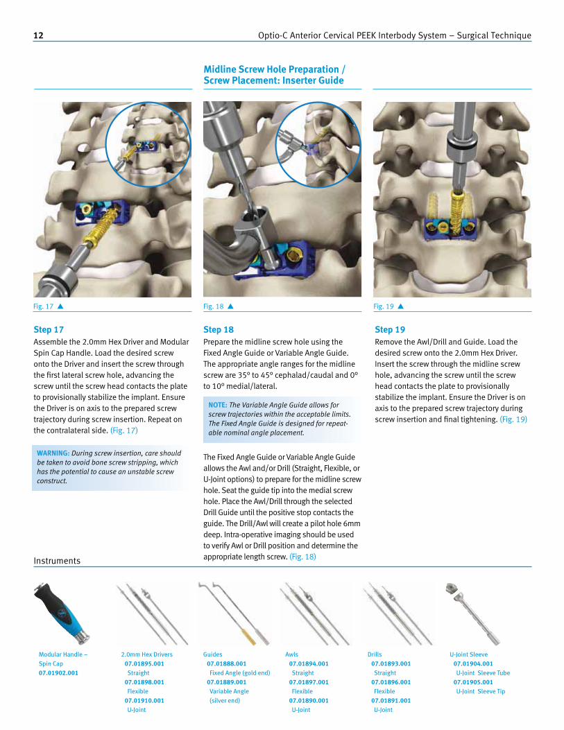
Step 17
Assemble the 2.0mm Hex Driver and Modular Spin Cap Handle. Load the desired screw onto the Driver and insert the screw through the first lateral screw hole, advancing the screw until the screw head contacts the plate to provisionally stabilize the implant. Ensure the Driver is on axis to the prepared screw trajectory during screw insertion. Repeat on the contralateral side. (Fig. 17)
Step 18
Prepare the midline screw hole using the Fixed Angle Guide or Variable Angle Guide. The appropriate angle ranges for the midline screw are 35° to 45° cephalad/caudal and 0° to 10° medial/lateral.
The Fixed Angle Guide or Variable Angle Guide allows the Awl and/or Drill (Straight, Flexible, or U-Joint options) to prepare for the midline screw hole. Seat the guide tip into the medial screw hole. Place the Awl/Drill through the selected Drill Guide until the positive stop contacts the guide. The Drill/Awl will create a pilot hole 6mm deep. Intra-operative imaging should be used to verify Awl or Drill position and determine the appropriate length screw. (Fig. 18)
Fig. 18 � Fig. 19 �
Midline Screw Hole Preparation / Screw Placement: Inserter Guide
Instruments
Step 19
Remove the Awl/Drill and Guide. Load the desired screw onto the 2.0mm Hex Driver. Insert the screw through the midline screw hole, advancing the screw until the screw head contacts the plate to provisionally stabilize the implant. Ensure the Driver is on axis to the prepared screw trajectory during screw insertion and final tightening. (Fig. 19)
WARNING: During screw insertion, care should be taken to avoid bone screw stripping, which has the potential to cause an unstable screw construct.
NOTE: The Variable Angle Guide allows for screw trajectories within the acceptable limits. The Fixed Angle Guide is designed for repeat-able nominal angle placement.
Modular Handle – Spin Cap07.01902.001
2.0mm Hex Drivers 07.01895.001
Straight 07.01898.001
Flexible 07.01910.001
U-Joint
Guides 07.01888.001
Fixed Angle (gold end) 07.01889.001
Variable Angle (silver end)
Awls 07.01894.001
Straight 07.01897.001
Flexible 07.01890.001
U-Joint
Drills 07.01893.001
Straight 07.01896.001
Flexible 07.01891.001
U-Joint
U-Joint Sleeve 07.01904.001
U-Joint Sleeve Tube 07.01905.001
U-Joint Sleeve Tip

Optio-C Anterior Cervical PEEK Interbody System – Surgical Technique 13
Fig. 20 �
Step 20
Completely engage the 2.0mm Hex Driver in each screw head and fully seat all bone screws. (Fig. 20)
Fig. 21 � Fig. 22 �
Final Tightening of Bone Screws Securing the Locking Cap
Instruments
Step 21
Once all screws are fully seated within the plate, assemble the gold Locking Cap Driver and Torque Limiting Handle. Insert the Locking Cap Driver into the gold locking screw. Ensure the tip of the Driver is fully seated in the screw pocket and the Driver is on axis to the locking screw. (Fig. 21)
Turn the Driver clockwise. As the screw tightens, the teal locking cap will slide over the screw heads. Turn the Torque Limiting Handle until an audible click is heard when the Locking Mechanism is tightened to 4in-lb. The Locking Mechanism and Torque Limiting Handle will provide visual, audible and tactile confirmation that the locking mechanism is fully secured and the screw heads are partially covered. (Fig. 22)
NOTE: Failure to fully seat the screws could interfere with the final tightening of the locking mechanism.
NOTE: The locking mechanism comes in the unlocked position. Do not turn the gold locking screw counter-clockwise for any reason other than revision surgery.
NOTE: Confirm the screws are fully seated before securing the gold locking screw. If the teal locking cap does not move freely over the screw heads, re-check whether the bone screws are fully seated.
Torque Limiting Handle07.01901.001
Locking Cap Driver07.01900.001

14 Optio-C Anterior Cervical PEEK Interbody System – Surgical Technique
Instruments
Planning, Positioning and Exposure Attaching the Implant to the ATO Inserter Guide
ATO Inserter Guide
Optional Surgical
Technique
Step 1
Repeat step 1, Pre-Operative Planning, through step 10, Implant Assembly, on pages 6–9. (Fig. 23)
Step 2
Assemble the ATO Inserter Guide to the Modular Impaction Cap Handle. The ATO Inserter Guide grasps the outside of the plate by engaging the plate pockets. With the gold locking screw oriented on the left and guide circular markings facing upward, attach the ATO Inserter Guide around the outside of the plate. The ATO Inserter Guide snaps into place when the tabs are fully seated in the plate pockets. (Fig. 24, top)
Fig. 23 � Fig. 24 �
NOTE: The circular markings on the ATO Inserter Guide should face upward when assembling the plate to the inserter. These markings are for orientation only, indicating the direction the two lateral screws will point in situ. (Fig. 24, bottom)
ATO Inserter Guide07.01887.001
Optional instrument. Available upon request.
Modular Handle – Impaction Cap 07.01903.001

Optio-C Anterior Cervical PEEK Interbody System – Surgical Technique 15
Fig. 25 �
Step 3
Ensure the inserter is fully seated on the implant by verifying the ATO Inserter Guide positive stops are in contact with the plate. Verify that the guide holes and lateral plate holes are aligned, and that the inserter axis is perpendicular to the anterior face of the plate. (Fig. 25)
Secure the implant by sliding the ATO Inserter Guide sleeve toward the implant until it bottoms out on the distal end of the ATO Inserter Guide. (Fig. 25 inset)
Step 4
Insert the implant into the distracted segment. If necessary, use light impaction to advance the implant into the disc space. (Fig. 26)
Step 5
Ensure the implant fits snugly between the adjacent vertebrae, and then release distraction while leaving the ATO Inserter Guide attached to the implant construct. The Modular Handle may be temporarily removed from the inserter to increase visibility for screw preparation and delivery. (Fig. 27)
Fig. 26 � Fig. 27 �
Implant Placement: ATO Inserter Guide
Instruments
NOTE: If using the Distraction Pin, remove the Distraction Pin with the Caspar Distractor.
NOTE: Positive stops position the implant flush with the anterior aspect of the vertebral bodies.
WARNING: When inserting the implant, care should be taken to avoid using excessive force, which has the potential to cause damage to the implant or surrounding tissue.
WARNING: When inserting the implant, ensure a tight fit between the inserter and implant. Release distraction prior to drilling to prevent shifting.
NOTE: When using the ATO Inserter Guide, care should be taken to insert the implant in line to the disc space. Avoid off-axis loading or torsion of the ATO Inserter Guide during insertion of the implant to reduce risk of separating the Optio-C plate from the PEEK spacer.
ATO Inserter Guide07.01887.001
Optional instrument. Available upon request.
Modular Handle – Impaction Cap 07.01903.001
16 Optio-C Anterior Cervical PEEK Interbody System – Surgical Technique
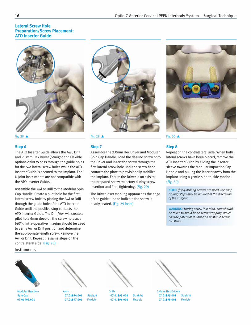
Fig. 28 �
Step 6 The ATO Inserter Guide allows the Awl, Drill and 2.0mm Hex Driver (Straight and Flexible options only) to pass through the guide holes for the two lateral screw holes while the ATO Inserter Guide is secured to the implant. The U-Joint instruments are not compatible with the ATO Inserter Guide.
Assemble the Awl or Drill to the Modular Spin Cap Handle. Create a pilot hole for the first lateral screw hole by placing the Awl or Drill through the guide hole of the ATO Inserter Guide until the positive stop contacts the ATO Inserter Guide. The Drill/Awl will create a pilot hole 6mm deep on the screw hole axis (40°). Intra-operative imaging should be used to verify Awl or Drill position and determine the appropriate length screw. Remove the Awl or Drill. Repeat the same steps on the contralateral side. (Fig. 28)
Step 7
Assemble the 2.0mm Hex Driver and Modular Spin Cap Handle. Load the desired screw onto the Driver and insert the screw through the first lateral screw hole until the screw head contacts the plate to provisionally stabilize the implant. Ensure the Driver is on axis to the prepared screw trajectory during screw insertion and final tightening. (Fig. 29)
The Driver laser marking approaches the edge of the guide tube to indicate the screw is nearly seated. (Fig. 29 inset)
Fig. 29 � Fig. 30 �
Step 8 Repeat on the contralateral side. When both lateral screws have been placed, remove the ATO Inserter Guide by sliding the inserter sleeve towards the Modular Impaction Cap Handle and pulling the inserter away from the implant using a gentle side-to-side motion. (Fig. 30)
NOTE: If self-drilling screws are used, the awl/drilling steps may be omitted at the discretion of the surgeon.
Instruments
WARNING: During screw insertion, care should be taken to avoid bone screw stripping, which has the potential to cause an unstable screw construct.
Lateral Screw Hole Preparation/Screw Placement: ATO Inserter Guide
Modular Handle – Spin Cap07.01902.001
Awls 07.01894.001 Straight 07.01897.001 Flexible
Drills 07.01893.001 Straight 07.01896.001 Flexible
2.0mm Hex Drivers 07.01895.001 Straight 07.01898.001 Flexible

Optio-C Anterior Cervical PEEK Interbody System – Surgical Technique 17
Fig. 31 �
Step 9 Prepare the midline screw hole using the Fixed or Variable Drill Guide. The appropriate angle ranges for the midline screws are 35° to 45° cephalad/caudal and 0° to 10° medial/lateral. (Fig. 31)
The Fixed or Variable Drill allows the Awl and/or Drill (Straight, Flexible, or U-Joint options) to prepare for the midline screw hole. Seat the guide tip into the medial screw hole. Place the Awl/Drill through the selected Drill Guide until the positive stop contacts the guide. The Drill/Awl will create a pilot hole 6mm deep. Intra-operative imaging should be used to verify Awl or Drill position and determine the appropriate length screw. (Fig. 32)
Fig. 32 �
Instruments
NOTE: The Variable Angle Guide allows for screw trajectories within the acceptable limits. The Fixed Angle Guide is designed for repeat-able nominal angle placement.
Step 10
Remove the Awl/Drill and Guide. Load the desired screw onto the 2.0mm Hex Driver. Insert the screw through the midline screw hole, advancing the screw until the screw head contacts the plate to provisionally stabilize the implant. Ensure the Driver is on axis to the prepared screw trajectory during screw insertion and final tightening. (Fig. 33)
Fig. 33 �
WARNING: During screw insertion, care should be taken to avoid bone screw stripping, which has the potential to cause an unstable screw construct.
Midline Screw Hole Preparation/ Screw Placement: ATO Inserter Guide
Guides 07.01888.001
Fixed Angle (gold end) 07.01889.001
Variable Angle (silver end)
Modular Handle – Spin Cap07.01902.001
Awls 07.01894.001
Straight 07.01897.001
Flexible 07.01890.001
U-Joint
Drills 07.01893.001
Straight 07.01896.001
Flexible 07.01891.001
U-Joint
2.0mm Hex Drivers 07.01895.001
Straight 07.01898.001
Flexible 07.01910.001
U-Joint
U-Joint Sleeve 07.01904.001
U-Joint Sleeve Tube 07.01905.001
U-Joint Sleeve Tip
NOTE: An optional Tissue Sleeve assembly may be used over the u-joint instrumentation if desired. The Tissue Sleeve assembly helps shield the u-joint from tissue and fixes the instrument tip at a 40° angle. Prior to attaching the Modular Spin Cap Handle to the u-joint instrument, the U-joint Sleeve Tip is threaded clockwise onto the U-joint Sleeve Tube to encase the universal joint.

18 Optio-C Anterior Cervical PEEK Interbody System – Surgical Technique
Fig. 34 �
Step 11
Completely engage the Driver in each screw head and fully seat all bone screws. (Fig. 34)
Step 12 Once all screws are fully seated within the plate, assemble the gold Locking Cap Driver and Torque Limiting Handle. Insert the Locking Cap Driver into the gold locking screw. Ensure the tip of the Driver is fully seated in the screw pocket and the Driver is on axis to the locking screw. (Fig. 35)
Fig. 35 � Fig. 36 �
Instruments
Final Tightening of Bone Screws: ATO Inserter Guide
Securing the Locking Cap: ATO Inserter Guide
NOTE: Failure to fully seat the screws could interfere with the final tightening of the locking mechanism.
NOTE: The locking mechanism comes in the unlocked position. Do not turn the gold locking screw counter-clockwise for any reason other than revision surgery.
NOTE: Confirm the screws are fully seated before securing the gold locking screw. If the teal locking cap does not move freely over the screw heads, re-check whether the bone screws are fully seated.
Turn the Driver clockwise. As the screw tightens, the teal locking cap will slide over the screw heads. Turn the Torque Limiting Handle until an audible click is heard when the locking mechanism is tightened to 4in-lb. The locking mechanism and Torque Limiting Handle will provide visual, audible and tactile confirmation that the locking mechanism is fully secured and the screw heads are partially covered. (Fig. 36)
Locking Cap Driver07.01900.001
Torque Limiting Handle07.01901.001

Optio-C Anterior Cervical PEEK Interbody System – Surgical Technique 19
Instruments
Planning, Positioning and Exposure Implant Insertion: Freehand Screw Insertion
Freehand Screw Insertion
Surgical Technique
Step 1
Repeat step 1, Pre-Operative Planning, through step 13, Attaching the Implant to the Inserter, on pages 6–10. (Fig. 37)
Step 2
Once the implant is securely attached to the inserter, insert the implant into the distracted segment. If necessary, use light impaction to advance the plate into the disc space. (Fig. 38)
Fig. 37 � Fig. 38 �
NOTE: Positive stops position the implant flush with the anterior aspect of the vertebral bodies.
WARNING: When inserting the implant, ensure a tight fit between the inserter and implant. Release distraction prior to drilling to prevent shifting.
WARNING: When inserting the implant, care should be taken to avoid using excessive force which has the potential to cause damage to the implant or surrounding tissue.
Inserter Guide07.01886.001
Modular Handle – Impaction Cap 07.01903.001

20 Optio-C Anterior Cervical PEEK Interbody System – Surgical Technique
Fig. 39 �
Step 3
Remove the inserter from the implant. Assemble the Awl or Drill and the Modular Spin Cap Handle. Place the Fixed Angle Guide or Variable Angle Guide in the selected screw hole. Ensure the guide tip is fully seated.
The appropriate angle ranges for the midline screw are 35° to 45° cephalad/caudal and 0° to 10° medial/lateral.
The appropriate angle ranges for the lateral screws are 35° to 45° cephalad/caudal and -5° to 5° medial/lateral.
Prepare the midline screw hole using the Fixed or Variable Drill Guide. The Fixed or Variable Drill allows the Awl and/or Drill (Straight, Flexible, or U-Joint options) to prepare for the midline screw hole. Seat the guide tip into the medial screw hole. Place the Awl/Drill through the selected Drill Guide until the positive stop contacts the guide. The Drill/Awl will create a pilot hole 6mm deep. Intra-operative imaging should be used to verify Awl or Drill position and determine the appropriate length screw. (Fig. 39)
Fig. 40 �
Step 4
Remove the Awl/Drill and Guide. Load the desired screw onto the 2.0mm Hex Driver. Insert the screw through the midline screw hole, advancing the screw until the screw head contacts the plate to provisionally stabilize the implant. (Fig. 40)
Instruments
Screw Hole Preparation/ Screw Placement: Freehand Screw Insertion
NOTE: The Variable Angle Guide allows for screw trajectories within the acceptable limits. The Fixed Angle Guide is designed for repeat-able nominal angle placement.
NOTE: The Optio-C System includes an optional Tamp that can be used with the Modular Impaction Cap Handle to provide minor adjustments to the plate in situ. Adjustments should only be made under slight distraction. Care should be taken when using the Tamp because it does not have a positive stop.
NOTE: An optional Tissue Sleeve assembly may be used over the u-joint instrumentation if desired. The Tissue Sleeve assembly helps shield the u-joint from tissue and fixes the instrument tip at a 40° angle. Prior to attaching the Modular Spin Cap Handle to the u-joint instrument, the U-joint Sleeve Tip is threaded clockwise onto the U-joint Sleeve Tube to encase the universal joint.
Modular Handle – Spin Cap07.01902.001
Awls 07.01894.001
Straight 07.01897.001
Flexible 07.01890.001
U-Joint
Drills 07.01893.001
Straight 07.01896.001
Flexible 07.01891.001
U-Joint
Tamp (optional)07.01899.001
U-Joint Sleeve 07.01904.001
U-Joint Sleeve Tube 07.01905.001
U-Joint Sleeve Tip
2.0mm Hex Drivers 07.01895.001
Straight 07.01898.001
Flexible 07.01910.001
U-Joint
Guides 07.01888.001
Fixed Angle (gold end) 07.01889.001
Variable Angle (silver end)

Optio-C Anterior Cervical PEEK Interbody System – Surgical Technique 21
Step 5
Repeat these steps for the lateral screws, using the same “drill and fill” technique. (Fig. 41)
NOTE: Failure to fully seat the screws could interfere with the final tightening of the locking mechanism.
NOTE: The locking mechanism comes in the unlocked position. Do not turn the gold locking screw counter-clockwise for any reason other than revision surgery.
NOTE: Confirm the screws are fully seated before securing the gold locking screw. If the teal locking cap does not move freely over the screw heads, re-check whether the bone screws are fully seated.
NOTE: Use care to maintain the implant positioning while preparing the screw hole.
WARNING: During screw insertion, care should be taken to avoid bone screw stripping, which has the potential to cause an unstable screw construct.
Fig. 41 �
Step 6
Completely engage the 2.0mm Hex Driver in each screw head and fully seat all bone screws. (Fig. 42)
Step 7
Once all screws are fully seated within the plate, assemble the gold Locking Cap Driver and Torque Limiting Handle. Insert the Locking Cap Driver into the gold locking screw. Ensure the tip of the Driver is fully seated in the screw pocket and the Driver is on axis to the locking screw. (Fig. 43)
Fig. 42 � Fig. 43 �
Final Tightening of Bone Screws: Freehand Screw Insertion
Securing the Locking Cap: Freehand Screw Insertion
Instruments
Torque Limiting Handle07.01901.001
Locking Cap Driver07.01900.001
2.0mm Hex Drivers 07.01895.001 Straight 07.01898.001 Flexible 07.01910.001 U-Joint
Modular Handle – Spin Cap07.01902.001
22 Optio-C Anterior Cervical PEEK Interbody System – Surgical Technique
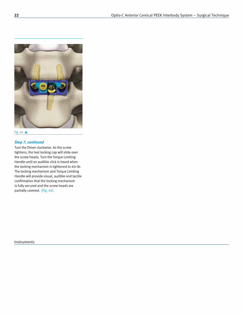
Step 7, continuedTurn the Driver clockwise. As the screw tightens, the teal locking cap will slide over the screw heads. Turn the Torque Limiting Handle until an audible click is heard when the locking mechanism is tightened to 4in-lb. The locking mechanism and Torque Limiting Handle will provide visual, audible and tactile confirmation that the locking mechanism is fully secured and the screw heads are partially covered. (Fig. 44)
Fig. 44 �
Instruments

Optio-C Anterior Cervical PEEK Interbody System – Surgical Technique 23
Instruments
Implant Revision/RemovalImplant Revision/Removal
Surgical Technique
Step 1
The gold Locking Cap Driver, Torque Limiting Handle, 2.0mm Hex Driver, Modular Spin Cap Handle, Inserter Guide and Modular Impaction Cap Handle are needed for revision/removal cases.
Once the implant has been sufficiently exposed, seat the Locking Cap Driver/Modular Handle assembly into the gold locking screw. Turn the gold locking mechanism screw counter-clockwise until the teal locking cap can move freely. Do not rotate the gold cap more than 1.5 turns.
Slide the teal locking cap to uncover all three bone screws using a forceps or other general surgical instrument. (Fig. 45)
Step 2 Seat the 2.0mm Hex Driver/Modular Handle Assembly into the exposed screw head. Ensure the Driver is fully seated in the screw head. Remove each screw by rotating the driver counter-clockwise. Repeat these steps until each screw has been removed. Ensure the Driver is on axis to the screw trajectory during screw removal.
Attach the Inserter Guide or or use a general surgical instrument to remove the implant through the surgical opening. (Fig. 46)
Fig. 45 � Fig. 46 �
NOTE: Appropriate distraction is required to remove the implant from the disc space.
NOTE: Do not reuse an implant after removal.
Locking Cap Driver07.01900.001
Torque Limiting Handle07.01901.001
2.0mm Hex Drivers 07.01895.001
Straight 07.01898.001
Flexible 07.01910.001
U-Joint
Modular Handle – Spin Cap07.01902.001
Inserter Guide07.01886.001
Modular Handle – Impaction Cap 07.01903.001

24 Optio-C Anterior Cervical PEEK Interbody System – Surgical Technique
Part Number Description Quantity Reference
07.01260.001 Generic Lid 1 -
07.01874.012 Optio-C Screw, 12 mm, Variable, Self-tapping 12 (Q)
07.01874.014 Optio-C Screw, 14 mm, Variable, Self-tapping 12 (Q)
07.01874.016 Optio-C Screw, 16 mm, Variable, Self-tapping 6 (Q)
07.01875.012 Optio-C Screw, 12 mm, Variable, Self-drilling 12 (Q)
07.01875.014 Optio-C Screw, 14 mm, Variable, Self-drilling 12 (Q)
07.01875.016 Optio-C Screw, 16 mm, Variable, Self-drilling 6 (Q)
07.01886.001 Inserter Guide 1 K
07.01888.001 Fixed Angle Guide 1 U
07.01889.001 Variable Angle Guide 1 T
07.01890.001 U-Joint Awl 1 G
07.01891.001 U-Joint Drill 1 H
07.01893.001 Straight Drill 2 B
07.01894.001 Straight Awl 1 A
07.01895.001 2.0 mm Straight Hex Driver 2 C
07.01896.001 Flexible Drill 1 E
07.01897.001 Flexible Awl 1 D
07.01898.001 2.0mm Flexible Hex Driver 1 F
07.01899.001 Tamp 1 J
07.01900.001 Locking Cap Driver 2 R
07.01901.001 Torque Limiting Handle 1 S
07.01902.001 Modular Handle, Spin Cap 3 L
07.01903.001 Modular Handle, Impaction Cap 1 N
07.01904.001 U-Joint Sleeve, Tube 2 P
07.01905.001 U-Joint Sleeve, Tip 2 O
07.01907.001 Core Tray 1 -
07.01908.001 Screw Caddy Lid 1 -
07.01909.001 Screw Caddy 1 Q
07.01910.001 2.0 mm U-Joint Hex Driver 1 I
07.01911.001 Distraction Pin, Single Prong 2 (M)
07.01911.002 Distraction Pin, Double Prong 2 (M)
07.01912.001 Distraction Pin Caddy 1 M
07.01913.001 Distraction Pin Caddy Lid 1 -
07.01964.001 Optio-C System Non-Sterile Implant and Instrument IFU 1 -
Optio-C System Core Instrument Set07.01974.402
Tray Layouts
BC
DE
FG
H
A
I
J
K
*
M
N
O PL
* 07.01887.001 ATO Inserter Guide. This instrument is optional and must be ordered separately. Tray location is for the ATO Inserter Guide placement which meets validated sterilization parameters.
L
Q
R
S
TU

Optio-C Anterior Cervical PEEK Interbody System – Surgical Technique 25
Optio-C System Bone Prep Instrument Set07.01974.401
Part Number Description Quantity Reference
07.01260.001 Generic Lid 1 -
07.01877.006 Parallel Trial, 12x14x6 mm 1 A
07.01877.007 Parallel Trial, 12x14x7 mm 1 A
07.01877.008 Parallel Trial, 12x14x8 mm 1 A
07.01877.009 Parallel Trial, 12x14x9 mm 1 A
07.01877.010 Parallel Trial, 12x14x10 mm 1 A
07.01877.011 Parallel Trial, 12x14x11 mm 1 A
07.01877.012 Parallel Trial, 12x14x12 mm 1 A
07.01877.026 Parallel Trial, 14x16x6 mm 1 F
07.01877.046 Parallel Trial, 15x18x6 mm 1 G
07.01878.006 Parallel Rasp, 12x14x6 mm 1 B
07.01878.007 Parallel Rasp, 12x14x7 mm 1 B
07.01878.008 Parallel Rasp, 12x14x8 mm 1 B
07.01878.009 Parallel Rasp, 12x14x9 mm 1 B
07.01878.010 Parallel Rasp, 12x14x10 mm 1 B
07.01878.011 Parallel Rasp, 12x14x11 mm 1 B
07.01878.012 Parallel Rasp, 12x14x12 mm 1 B
07.01878.026 Parallel Rasp, 14x16x6 mm 1 I
07.01878.046 Parallel Rasp, 15x18x6 mm 1 J
07.01879.006 Lordotic Trial, 12x14x6 mm 1 C
07.01879.007 Lordotic Trial, 12x14x7 mm 1 C
07.01879.008 Lordotic Trial, 12x14x8mm 1 C
07.01879.009 Lordotic Trial, 12x14x9 mm 1 C
07.01879.010 Lordotic Trial, 12x14x10 mm 1 C
07.01879.011 Lordotic Trial, 12x14x11 mm 1 C
07.01879.012 Lordotic Trial, 12x14x12 mm 1 C
07.01880.006 Lordotic Rasp, 12x14x6 mm 1 D
07.01880.007 Lordotic Rasp, 12x14x7 mm 1 D
07.01880.008 Lordotic Rasp, 12x14x8 mm 1 D
07.01880.009 Lordotic Rasp, 12x14x9 mm 1 D
07.01880.010 Lordotic Rasp, 12x14x10 mm 1 D
07.01880.011 Lordotic Rasp, 12x14x11 mm 1 D
07.01880.012 Lordotic Rasp, 12x14x12 mm 1 D
07.01884.001 Implant Assembly Block 1 H
07.01885.001 Implant Assembly Tamp 1 K
07.01903.001 Modular Handle, Impaction Cap 4 E
07.01906.001 Bone Prep Tray 1 -
07.01964.001 Optio-C System Non-Sterile Implant and Instrument IFU 1 -
B
C
D
E
FG
H
A
IJ
K
E
E
26 Optio-C Anterior Cervical PEEK Interbody System – Surgical Technique
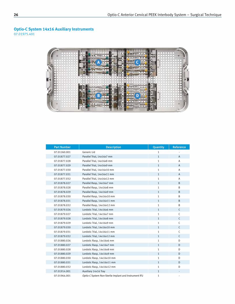
Part Number Description Quantity Reference
07.01260.001 Generic Lid 1 -
07.01877.027 Parallel Trial, 14x16x7 mm 1 A
07.01877.028 Parallel Trial, 14x16x8 mm 1 A
07.01877.029 Parallel Trial, 14x16x9 mm 1 A
07.01877.030 Parallel Trial, 14x16x10 mm 1 A
07.01877.031 Parallel Trial, 14x16x11 mm 1 A
07.01877.032 Parallel Trial, 14x16x12 mm 1 A
07.01878.027 Parallel Rasp, 14x16x7 mm 1 B
07.01878.028 Parallel Rasp, 14x16x8 mm 1 B
07.01878.029 Parallel Rasp, 14x16x9 mm 1 B
07.01878.030 Parallel Rasp, 14x16x10 mm 1 B
07.01878.031 Parallel Rasp, 14x16x11 mm 1 B
07.01878.032 Parallel Rasp, 14x16x12 mm 1 B
07.01879.026 Lordotic Trial, 14x16x6 mm 1 C
07.01879.027 Lordotic Trial, 14x16x7 mm 1 C
07.01879.028 Lordotic Trial, 14x16x8 mm 1 C
07.01879.029 Lordotic Trial, 14x16x9 mm 1 C
07.01879.030 Lordotic Trial, 14x16x10 mm 1 C
07.01879.031 Lordotic Trial, 14x16x11 mm 1 C
07.01879.032 Lordotic Trial, 14x16x12 mm 1 C
07.01880.026 Lordotic Rasp, 14x16x6 mm 1 D
07.01880.027 Lordotic Rasp, 14x16x7 mm 1 D
07.01880.028 Lordotic Rasp, 14x16x8 mm 1 D
07.01880.029 Lordotic Rasp, 14x16x9 mm 1 D
07.01880.030 Lordotic Rasp, 14x16x10 mm 1 D
07.01880.031 Lordotic Rasp, 14x16x11 mm 1 D
07.01880.032 Lordotic Rasp, 14x16x12 mm 1 D
07.01914.001 Auxiliary 14x16 Tray 1 -
07.01964.001 Optio-C System Non-Sterile Implant and Instrument IFU 1 -
Optio-C System 14x16 Auxiliary Instruments07.01975.401
B
C
D
A

Optio-C Anterior Cervical PEEK Interbody System – Surgical Technique 27
Optio-C System 15x18 Auxiliary Instruments07.01976.401
Part Number Description Quantity Reference
07.01260.001 Generic Lid 1 -
07.01877.047 Parallel Trial, 15x18x7 mm 1 A
07.01877.048 Parallel Trial, 15x18x8 mm 1 A
07.01877.049 Parallel Trial, 15x18x9 mm 1 A
07.01877.050 Parallel Trial, 15x18x10 mm 1 A
07.01877.051 Parallel Trial, 15x18x11 mm 1 A
07.01877.052 Parallel Trial, 15x18x12 mm 1 A
07.01878.047 Parallel Rasp, 15x18x7 mm 1 B
07.01878.048 Parallel Rasp, 15x18x8 mm 1 B
07.01878.049 Parallel Rasp, 15x18x9 mm 1 B
07.01878.050 Parallel Rasp, 15x18x10 mm 1 B
07.01878.051 Parallel Rasp, 15x18x11 mm 1 B
07.01878.052 Parallel Rasp, 15x18x12 mm 1 B
07.01879.046 Lordotic Trial, 15x18x6 mm 1 C
07.01879.047 Lordotic Trial, 15x18x7 mm 1 C
07.01879.048 Lordotic Trial, 15x18x8 mm 1 C
07.01879.049 Lordotic Trial, 15x18x9 mm 1 C
07.01879.050 Lordotic Trial, 15x18x10 mm 1 C
07.01879.051 Lordotic Trial, 15x18x11 mm 1 C
07.01879.052 Lordotic Trial, 15x18x12 mm 1 C
07.01880.046 Lordotic Rasp, 15x18x6 mm 1 D
07.01880.047 Lordotic Rasp, 15x18x7 mm 1 D
07.01880.048 Lordotic Rasp, 15x18x8 mm 1 D
07.01880.049 Lordotic Rasp, 15x18x9 mm 1 D
07.01880.050 Lordotic Rasp, 15x18x10 mm 1 D
07.01880.051 Lordotic Rasp, 15x18x11 mm 1 D
07.01880.052 Lordotic Rasp, 15x18x12 mm 1 D
07.01915.001 Auxialiary 15x18 Tray 1 -
07.01964.001 Optio-C System Non-Sterile Implant and Instrument IFU 1 -
B
C
D
A

28 Optio-C Anterior Cervical PEEK Interbody System – Surgical Technique
Torque Limiting Handle07.01901.001
Modular Handle – Spin Cap07.01902.001
Modular Handle – Impaction Cap07.01903.001
Distraction Pins07.01911.001 Single Prong07.01911.002 Double Prong
Implant Trials – Parallel and Lordotic Parallel Trial 12x14, 6 – 12mm (1mm increments) 07.01877.006 – 07.01877.012
Parallel Trial 14x16, 6 mm 07.01877.026
Parallel Trial 15x18, 6 mm 07.01877.046
Lordotic Trial 12x14, 6 – 12mm (1mm increments) 07.01879.006 – 07.01879.012
Implant Rasps – Parallel and Lordotic Parallel Rasp 12x14, 6 – 12mm (1mm increments) 07.01878.006 – 07.01878.012
Parallel Rasp 14x16, 6 mm 07.01878.026
Parallel Rasp 15x18, 6 mm 07.01878.046
Lordotic Rasp 12x14, 6 – 12mm (1mm increments) 07.01880.006 – 07.01880.012
Inserter Guide07.01886.001
ATO Inserter Guide* (optional)07.01887.001
Fixed Angle Guide07.01888.001
Variable Angle Guide07.01889.001
Tamp 07.01899.001
Locking Cap Driver07.01900.001
Instrument Visual Guide
* Must be ordered separately.

Optio-C Anterior Cervical PEEK Interbody System – Surgical Technique 29
U-Joint InstrumentsU-Joint Awl07.01890.001
U-Joint Drill07.01891.001
U-Joint 2.0 Hex Driver07.01910.001
U-Joint Sleeve Tube07.01904.001
U-Joint Sleeve Tip07.01905.001
Straight InstrumentsStraight Awl07.01894.001
Straight Drill07.01893.001
Straight 2.0mm Hex Driver07.01895.001
Flexible InstrumentsFlexible Awl07.01897.001
Flexible Drill07.01896.001
Flexible 2.0mm Hex Driver07.01898.001
Implant Assembly Block07.01884.001
Implant Assembly Tamp 07.01885.001

30 Optio-C Anterior Cervical PEEK Interbody System – Surgical Technique
Warnings and Precautions
WARNINGS
1. Implants and Instruments should be stored in their original packaging in a dry environment, away from aggressive or oily chemicals.
2. When inserting the implant, care should be taken to avoid using excessive force which has the potential to cause damage to the implant or surrounding tissue.
3. When preparing the disc space, care should be taken to ensure an appropriate amount of bone is removed; excessive removal of bone has the potential to cause subsidence while failing to remove enough bone has the potential to cause poor fusion.
4. During screw insertion, care should be taken to avoid bone screw stripping which has the potential to cause an unstable screw construct.
5. Care should be taken when handling the flexible instruments. Specifically, the flexible tip should be maintained in the guide to prevent soft tissue damage.
6. When inserting the implant, ensure a tight fit between the inserter and implant. Release distraction prior to drilling to prevent shifting.
7. During distraction of the disc space, care should be taken to prevent over-distraction or under-distraction which has the potential to cause irreversible damage to the patient or an unstable implant construct.
8. If existing hardware is present, compatibility between the distraction pin and the existing hardware should be verified prior to use. When the distraction pin is used with existing hardware, extreme care should be taken to prevent damage to existing hardware.
9. Potential risks identified with the use of this device system, which may require additional surgery, include:
a) Device component fracture.b) Loss of fixation.c) Non-union. d) Neurological injury.e) Vascular or visceral injury.
10. Do not use this product for other than labeled indications (off-label use).
11. Components of competitive spinal systems should not be used with the Optio-C Devices.
12. Patient selection shall consider the following factors which are important to the success of the procedure and the performance of the device: a) The patient’s weight. An overweight
or obese patient can produce loads on the device that can lead to a loss of interbody height or failure of the device and/or the operation.
b) The patient’s occupation or activity. If the patient is involved in an occupation or activity that includes substantial walking, running, lifting or muscle strain, the resultant forces can cause loss of disc height and/or failure of the device.
c) A condition of senility, mental illness, alcoholism, or drug abuse. These conditions, among others, may cause the patient to ignore certain necessary limitations and precautions in the use of the appliance, leading to implant failure or other complications.
d) Certain degenerative diseases. In some cases, the progression of degenerative disease may be so advanced at the time of implantation that it may substantially decrease the expected useful life of the appliance. For such cases, orthopaedic devices can only be considered a delaying technique or temporary relief.
e) Foreign body sensitivity. Where material sensitivity is suspected, appropriate tests should be made prior to material selection or implantation.
f) Smoking. Patients who smoke have been observed to experience higher rates of pseudarthrosis following surgical procedures where bone graft is used.
13. Implants can break when subjected to the increased loading associated with delayed union or non-union. Spinal implants are load sharing devices which are used to obtain an alignment until normal healing occurs. If healing is delayed or does not occur, the implant may eventually break due to fatigue. The degree or success of union, loads produced by weight bearing, and activity levels will, among other conditions, dictate the longevity of the implant. Notches, scratches or bending of the implant during the course of surgery may also contribute to early failure. Patients should be fully informed of the risks of implant failure.
14. These warnings do not include all adverse effects that can occur with surgery in general. General surgical risks should be explained to the patients prior to surgery.
15. The Optio-C Anterior Cervical Intervertebral Body Fusion Device (IBFD) is not intended for screw attachment or fixation to the posterior elements (pedicles) of the cervical, thoracic or lumbar spine.
16. The Optio-C PEEK IBF Spacer is not to be used alone.
17. The Optio-C Anterior Cervical Plate is not to be used alone.

Optio-C Anterior Cervical PEEK Interbody System – Surgical Technique 31
PRECAUTIONS
It is strongly recommended that the patient be informed of the risks associated with surgical procedures and components:
1. Surgical implants must never be reused. An explanted implant should never be re-implanted. Even though the device appears undamaged, it may have small defects and internal stress patterns that may lead to early breakage. Reuse of a single use device that has contacted blood, bone, tissue or other body fluids may lead to patient or user injury. Risks associated with re-use of single use devices include:
2. Based on the fatigue testing results, the physician/surgeon should consider the levels of implantation, patient weight, patient activity level, other patient conditions, etc. which may impact the performance of the system
3. Adequately instruct the patient. Postoperative care and the patient’s ability and willingness to follow instructions are one of the most important aspects of successful bone healing. The patient must be made aware of the limitations of the implant and that physical activity and full weight bearing have been implicated in fracture. The patient should understand that an implant is not as strong as normal, healthy bone and will fracture if excessive demands are placed on it in the absence of complete bone healing. An active, debilitated, or demented patient who cannot properly use weight-supporting devices may be particularly at risk during postoperative rehabilitation.
4. The Optio-C IBFD device should only be used after the spinal surgeon has had training in this method of fixation and has become thoroughly knowledgeable about the spinal anatomy and biomechanics.
5. The Surgical Technique is not a substitute for training and is for informational purposes only.
6. Carefully read all instructions and be familiar with the Optio-C Anterior Cervical PEEK Interbody System surgical technique prior to use.

Disclaimer:
This documentation is intended exclusively for physicians and is not intended for laypersons.
Information on the products and procedures contained in this document is of a general nature and does not represent and does not constitute medical advice or recommendations. Because this information does not purport to constitute any diagnostic or therapeutic statement with regard to any individual medical case, each patient must be examined and advised individually, and this document does not replace the need for such examination and/or advice in whole or in part.
Please refer to the package inserts for important product information, including, but not limited to, indications, contraindications, warnings, precautions and adverse effects.
Caution: Federal (USA) law restricts this device to sale by or on the order of a physician. Please see the product Instructions for Use for a complete listing of the indications, contraindications, warnings, precautions and adverse effects.
Printed in U.S.A. Subject to change without notice.
Contact your Zimmer Spine representative or visit us at www.zimmerspine.com
Manufactured by:
Zimmer Spine7375 Bush Lake RoadMinneapolis, MN 55439800.655.2614
zimmerspine.com
L1635 Rev. A (2014-02)(851S-1001-00)© 2014 Zimmer Spine, Inc.
Zimmer LimitedSN3 4FP, U.K.+44.1793.58.4500


![P. DIAGNOSTIK NEURO-2.ppt [Read-Only]ocw.usu.ac.id/.../bms166_slide_prosedur_diagnostik.pdf · MYELOGRAPHY • By injecting 5‐25ml of radiopaque dye (iopamidol/ ...](https://static.fdocuments.us/doc/165x107/5aa37daa7f8b9aa0108ea7ab/p-diagnostik-neuro-2ppt-read-onlyocwusuacidbms166slideprosedur-.jpg)