“Surface Treatments for Industrial Applications” PROTOCOL ...
68
UNIVERSITA’ DEGLI STUDI ISTITUTO NAZIONALE DI PADOVA DI FISICA NUCLEARE Dipartimento di Fisica e Astronomia Dipartimento di Ingegneria Industriale Laboratori Nazionali di Legnaro MASTER THESIS/TESI DI MASTER in “Surface Treatments for Industrial Applications” PROTOCOL FOR THE PREPARATION OF ALUMINA/METAL BRAZED JOINTS. Supervisor: Prof. V. Palmieri Co-Supervisor: Dott. Hanna Skliarova Student: Ramones García, Manuel Alejandro. N. Matr.: 1087789 Academic Year 2013-2014
Transcript of “Surface Treatments for Industrial Applications” PROTOCOL ...

UNIVERSITA’ DEGLI STUDI ISTITUTO NAZIONALE DI PADOVA DI FISICA NUCLEARE Dipartimento di Fisica e Astronomia
Dipartimento di Ingegneria Industriale Laboratori Nazionali di Legnaro
MASTER THESIS/TESI DI MASTER
in
“Surface Treatments for Industrial Applications”
PROTOCOL FOR THE PREPARATION OF
ALUMINA/METAL BRAZED JOINTS.
Supervisor: Prof. V. Palmieri
Co-Supervisor: Dott. Hanna Skliarova
Student: Ramones García, Manuel Alejandro.
N. Matr.: 1087789
Academic Year 2013-2014

ii

iii
ABSTRACT
Brazing is the joining of materials through the use of heat and a filler metal with a melting temperature above 450°C but below the melting point of the metals being joined. This technique joins parts by creating a metallurgical bond between the filler metal and the surfaces of the two materials joined.
There are several factors which have direct influence on the final quality of a brazed piece: the filler metal selection, the heating technique, the atmosphere in which the process is performed, the cleaning procedure, the assembly of pieces, etc.
In metal-ceramic junctions, ceramic surfaces, especially oxides, are very stable chemically, consequently, molten metals do not wet them well. There are several techniques that allow to overcome the chemical challenge.
In order to develop a procedure that ensures the conditions to achieve a successful brazing process, several techniques for metal-ceramic brazing in a controlled atmosphere (vacuum) were tested. Brazing using active filler metals and direct brazing using ceramic metallization by sputtering were studied in this work.
Alumina (Al2O3) was chosen as the ceramic part, whereas stainless steel 304 and Inconel were chosen as metallic components, cylindrical samples were assembled in lap configuration and were heated by IR lamps.
The pieces were cut and the cross-section was studied by Scanning Electron Microscope SEM and energy-dispersive X-ray spectroscopy (EDS, EDX) searching for evidence of filler metal uniform spread and diffusion.
The samples brazed using Pallabraze 850 disc of 0.01 mm of thickness for braze Inconel and Metallized alumina with 1�m of Titanium and using Argon atmosphere showed the more uniform distribution and diffusion.

iv

v
To my mother Yajaira and my sisters and nephew Maria, Claudia and Alessandro. Family is always the most important thing in life.
To make you proud.

vi

vii
ACKNOWLEDGEMENTS
Special thanks to my family: my mother Yajaira, who has always taught me the important
of perseverance and effort, my sisters Claudia and Maria, who always send me their love
and encouragement, my nephew Alessandro and my girlfriend Angy the for giving me all
the love and support, the reason because I want to be better every day is you, you are my
inspiration.
Thank you to my brother of life Jesus Vasquez, thanks to believe in me.
Thanks to Professor Laszlo Sajo, to believe and trust me, thanks for being our guide.
Thanks to Professor Enzo Palmieri to give me the opportunity to live this great experience
in Italy.
Thanks to my Co-Supervisor Hanna Skliarova for always being disposed to guide me and
transmit her valuable knowledge.
Thanks Oscar Azzolini you are like my second co-supervisor, always there for give me an
advice, a constructive observation, an answer, thanks for transmit your knowledge. To Alex
Battistello for been there with the best intention to help.
Finally to my Venezuelan family in Italy: Judilka Bermudez, Gabriela Acosta, Winder
Gonzalez, Daniel Franco, Andrea Camacho, Mary Padron without you this experience had
not been what it was, you are special beings.
viii
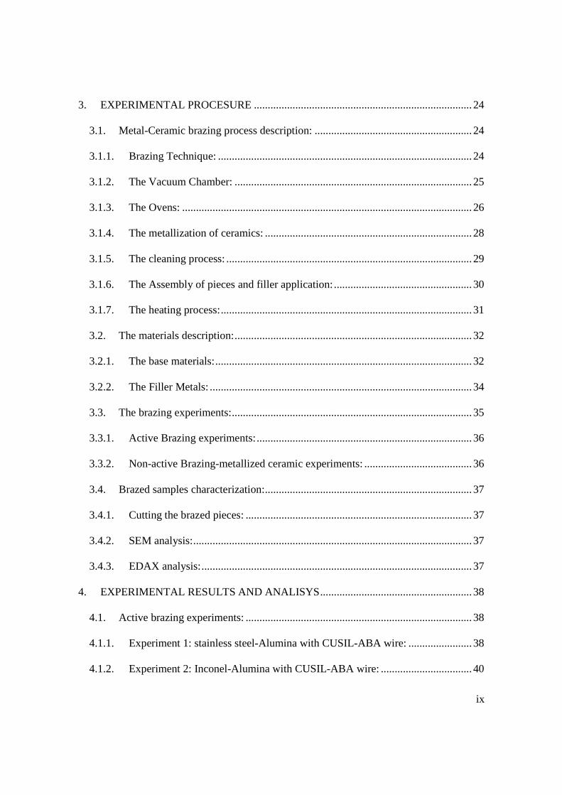
INDEX
ABSTRACT .......................................................................................................................... iii
ACKNOWLEDGEMENTS ................................................................................................. vii
INDEX ................................................................................................................................. viii
1. INTRODUCTION .......................................................................................................... 1
2. THEORETICAL BASES ............................................................................................... 3
2.1. Fundamental of Brazing ........................................................................................... 3
2.1.1. Base-Material characteristics: .............................................................................. 5
2.1.2. Filler-Metal characteristics:.................................................................................. 7
2.1.3. Desires joint properties: ..................................................................................... 10
2.2. Metal-Ceramic Brazing: ........................................................................................ 11
2.2.1. Molybdenum-Manganese/nickel plating Method: ............................................. 12
2.2.2. Thin-film Method: .............................................................................................. 13
2.2.3. Active filler-metal brazing: ................................................................................ 14
2.3. Pre-brazing considerations: .................................................................................... 14
2.3.1. Surface Preparation: ........................................................................................... 15
2.3.2. Joint design and clearance: ................................................................................. 16
2.3.3. Filler Metal selection:......................................................................................... 19
2.3.4. Heating Methods: ............................................................................................... 20
2.4. Post-Brazing treatments and inspection: ................................................................ 23
ix
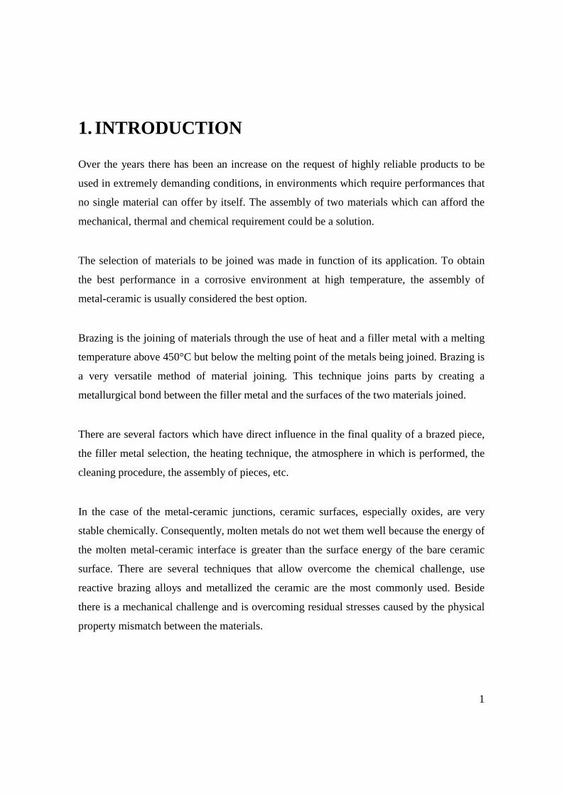
3. EXPERIMENTAL PROCESURE ............................................................................... 24
3.1. Metal-Ceramic brazing process description: ......................................................... 24
3.1.1. Brazing Technique: ............................................................................................ 24
3.1.2. The Vacuum Chamber: ...................................................................................... 25
3.1.3. The Ovens: ......................................................................................................... 26
3.1.4. The metallization of ceramics: ........................................................................... 28
3.1.5. The cleaning process: ......................................................................................... 29
3.1.6. The Assembly of pieces and filler application: .................................................. 30
3.1.7. The heating process: ........................................................................................... 31
3.2. The materials description: ...................................................................................... 32
3.2.1. The base materials: ............................................................................................. 32
3.2.2. The Filler Metals: ............................................................................................... 34
3.3. The brazing experiments: ....................................................................................... 35
3.3.1. Active Brazing experiments: .............................................................................. 36
3.3.2. Non-active Brazing-metallized ceramic experiments: ....................................... 36
3.4. Brazed samples characterization: ........................................................................... 37
3.4.1. Cutting the brazed pieces: .................................................................................. 37
3.4.2. SEM analysis: ..................................................................................................... 37
3.4.3. EDAX analysis: .................................................................................................. 37
4. EXPERIMENTAL RESULTS AND ANALISYS ....................................................... 38
4.1. Active brazing experiments: .................................................................................. 38
4.1.1. Experiment 1: stainless steel-Alumina with CUSIL-ABA wire: ....................... 38
4.1.2. Experiment 2: Inconel-Alumina with CUSIL-ABA wire: ................................. 40

x
4.1.3. Experiment 3: Stainless steel-Alumina with CUSIL-ABA foil: ........................ 41
4.1.4. Experiment 4: Inconel-Alumina with CUSIL-ABA foil: ................................... 43
4.2. Non-active brazing-metallized ceramic: ................................................................ 45
4.2.1. Experiment 5: Stainless Steel- Ti metallized Alumina with Pallabraze 850: .... 45
4.2.2. Experiment 6: Inconel- Ti metallized Alumina with Pallabraze 850: ................ 47
4.2.3. Experiment 7: Stainless Steel- Ti&Ag metallized Alumina with copper: ......... 50
4.2.4. Experiment 8: Inconel- Ti&Ag metallized Alumina with copper: .................... 52
5. Conclusions: ................................................................................................................. 54
REFERENCES ..................................................................................................................... 56
ANNEXES ........................................................................................................................... 58
1
1. INTRODUCTION
Over the years there has been an increase on the request of highly reliable products to be
used in extremely demanding conditions, in environments which require performances that
no single material can offer by itself. The assembly of two materials which can afford the
mechanical, thermal and chemical requirement could be a solution.
The selection of materials to be joined was made in function of its application. To obtain
the best performance in a corrosive environment at high temperature, the assembly of
metal-ceramic is usually considered the best option.
Brazing is the joining of materials through the use of heat and a filler metal with a melting
temperature above 450°C but below the melting point of the metals being joined. Brazing is
a very versatile method of material joining. This technique joins parts by creating a
metallurgical bond between the filler metal and the surfaces of the two materials joined.
There are several factors which have direct influence in the final quality of a brazed piece,
the filler metal selection, the heating technique, the atmosphere in which is performed, the
cleaning procedure, the assembly of pieces, etc.
In the case of the metal-ceramic junctions, ceramic surfaces, especially oxides, are very
stable chemically. Consequently, molten metals do not wet them well because the energy of
the molten metal-ceramic interface is greater than the surface energy of the bare ceramic
surface. There are several techniques that allow overcome the chemical challenge, use
reactive brazing alloys and metallized the ceramic are the most commonly used. Beside
there is a mechanical challenge and is overcoming residual stresses caused by the physical
property mismatch between the materials.

2
A protocol of preparation for metal-ceramic joints is necessary in order to take into account
these factors and develop a procedure that ensures the conditions for achieve a successful
brazing process.
This work is focus in the study of several techniques for metal-ceramic brazing in a
controlled atmosphere (vacuum). Active filler metals are used and several methods of
ceramic metallization are studied in order to use no-active brazing filler metals.
The Alumina (Al2O3) is chosen as the ceramic component of the assembly, whereas
stainless steel 304, the most versatile and commonly used kind of stainless steel, and
INCONEL , a family of nickel-chromium based super alloys, were chosen as metallic
component.
The pieces characterizing are going to be made by scanning electron microscope SEM and
energy-dispersive X-ray spectroscopy (EDS, EDX) searching for evidence of filler metal
uniform spread and diffusion.

3
2. THEORETICAL BASES
The following chapter presents an overview of brazing theory and other relevant concept
that support this research. Fundamentals of brazing, metal-ceramics brazing, surface
treatments, joint design, heating methods are issues that will be discussed in this chapter.
2.1. Fundamental of Brazing
The term brazing comprises a group of welding processes that produce coalescence of
materials by heating them to the brazing temperature in the presence of a filler metal having
a liquidus above 450 °C (890 °F) and below the solidus of the base material. The brazing
filler metal turns liquid and is distributed between the closely fitted faying surfaces of the
joint by capillary action then creates an alloy bond with the faying surfaces. Brazed joint,
could be strong as or stronger than the base materials, this depends of the design of the joint
and the filler metal.
Use brazing technique brings the following advantages:
• Economical fabrication of complex and multicomponent assemblies.
• Simple method to obtain extensive joint area or joint length.
• Excellent stress distribution and heat-transfer properties
• Ability to join nonmetals to metals.
• Ability to join dissimilar metals.
• Capability for precision production tolerance.
• Reproducible and reliable quality-control technique.
Strong, uniform, leak-proof joints can be made rapidly, inexpensively, and even
simultaneously. Joints that are inaccessible and parts that may not be joinable at all by other
methods often can be joined by brazing.

4
There are several physical principles which are important for the brazing process. Capillary
flow is the dominant physical phenomenon that ensures good brazements when both faying
surfaces to be joined are wet by the molten filler metal. The capillary action as a result of
the relative attraction of the molecules of liquid to each other and those of the solid
influence the brazing filler metal flow, the joint must be properly spaced to permit efficient
capillary action and coalescence. In actual practice, brazing filler metal flow characteristic
are also influenced by dynamic considerations involving fluidity, viscosity, vapor pressure,
gravity, and, especially, by the effect of any metallurgical reactions between the filler metal
and the base material [1].
The ability of a liquid to maintain contact with a solid surface is called wetting, this is the
result of intermolecular interactions between them (solid and liquid). Wettability describes
the trend of a solid to be in contact with a liquid rather than another. A drop of a wetting
fluid has a tendency to spread over the surface, increasing its contact area; on the other
hand, a non-wetting fluid has a tendency to compress itself, decreasing the contact area.
The phenomena of wetting and spreading are very important to the formation of brazed
joint, a good wettability condition guarantees that liquid brazing filler metal is going to
adhere to the surface of the material in solid state and, when cooled below its solidus
temperature, to make a strong bond with this material. Wetting is a function not only of the
nature of the filler metal, but the degree of interaction between materials to be joined. There
is considerable evidence that in order to wet well, a molten metal must be capable of
dissolving or alloying with, some of the metals through which flows [2]. Another factor
that affect wetting is the cleanliness of the surfaces to be wetted. Oxide layers inhibit
wetting and spreading, as do grease dirt, and other contaminants, that prevent good contact
between the brazing filler metal and the base materials.

5
A very simple way to describe the diffusion is the transport of mass by atomic motion, this
phenomenon occurs when a system is not in equilibrium, diffusion has two primary
properties it is random in nature, and transport is from region of high concentration to low
concentration.
Base material and filler metal interact through diffusion, the atoms of the filler metal in
liquid state diffuses into the base material forming diffusion-bonds. Once formed,
diffusion-bonded joints are stable to high temperatures so that the service temperature of
the assembly can actually exceed the peak temperature of the joining process without risk
of the joint remelting. [3]
The rate of diffusion is proportional to the temperature. At brazing temperatures, the
possibility of diffusion is very high. Diffusion of the filler metal into the base metal should
be at a minimum for the best joint quality, and diffusion can be minimized by minimizing
the heat input at brazing temperature [4].
In a properly designed brazing process, an oxide-grease-free surface promote wetting and
spreading of the filler metal, with the suitable joint design, the molten filler metal is drawn
completely through the joint area without any voids or gap, at the right temperature and
time, the diffusion occurs, and the filler metal diffuse into the base material forming bond
which will keep the junction.
2.1.1. Base-Material characteristics:
The base metal has an important effect on joint strength; a high-strength base metal
produces joints of greater strength than those made with softer base metals, also the larger
number of complex metallurgical reactions in hardness metals can cause changes in the
base-metal hardenability and residual stress, therefore the joint strength become less
predictable.

6
The coefficient of thermal expansion (CTE’s) is another important parameter because
differences on CTE’s generate the residual stress that may produce distortion, depending on
the joint design and can affect the strength of the joint.
There are several metallurgical phenomena that influence the behavior of brazed joints.
Among these base-metal effect are: alloying, carbide precipitation, stress cracking,
hydrogen and oxide stability.
The brazing cycle by itself can affect the properties of the base-metal, if the brazing-
process temperature and time are in the annealing range of a fortified by cold work alloy,
this will be annealed and the joint strength reduced.
One of the advantages of brazing process is the possibility of joint dissimilar materials;
some applications involve the junction of a metal and a ceramic. These inorganic and non-
metal materials have very different properties from metals, normally, higher melting
temperature, lower thermal expansion coefficient. The oxide in its surface avoids the
wetting by most of fillers metals. In this case the designers have to select the right filler
metal, the right method and consider the difference of the properties between the materials
in order to avoid the residual stress.

7
2.1.2. Filler-Metal characteristics:
Most of the brazing filler are alloys which melt in a range of temperature and depending of
the base-metal properties can react or not during the brazing process. Several metal-filler
base materials are describes in table N°2.1.
Base
Material
Nickel (Ni) Cobalt (Co) Silver (Ag) Gold (Au) Aluminum
(Al)
Copper (Cu)
ASTM
Designation
BNi BCo BAg BAu BAlSi BCu
Braze
Range (°C)
927-1205 1175-1245 620–980 890-1230 570–620 705–1150
Max Service
Temperatur
e (°C)
980 1040 370 800 150 370
Applications Alloy steels
Carbon
Steels
Copper
Alloys
Stainless
Steel
Nickel-
Cobalt alloys
Cobalt alloys Alloy steels
Carbon steels
Cast iron
Copper
alloys
Nickel alloys
Stainless
steel
Tool steels
Alloy steels
Carbon steels
Cooper
alloys
Nickel-
cobalt alloys
Stainless
steels
Tool steels
Aluminum
alloys
Alloy steels
Carbon steels
Cast iron
Cooper
alloys
Nickel alloys
Stainless
steels
Tool steels
Table 2.1. Meta-Filler base materials for brazing.
A specific filler metal cannot be chosen to produce a specific joint strength. Actually,
brazing can provide strong joints with almost any good commercial filler metal if the
brazing methods and joint design are selected and applied correctly.

8
Several characteristics desirable in a filler-metal are:
• Proper fluidity at the brazing temperature to ensure flow by capillarity action and
provide full alloy distribution. A high liquid surface tension, low contact angle, and
low viscosity are desirable for promoting filler-metal flow.
• Ability to alloy or combine with parent metal to form an alloy with higher melting
temperature.
• Stability to avoid premature release of low-melting-point elements for filler metals
at brazing temperature.
• Ability to wet the base-metal joint surface, a low contact angle, which implies
wetting, is necessary but is not a sufficient condition for flow, viscosity is also
important.
The joint strength depends on many factor as joint design, state of stress, brazing
temperature, amount of filler metal applied, location and method of application, heating
rate, holding time at the peak temperature, and many other.
Diffusion is an essential part of the metallurgical process, through diffusion the filler metals
penetrate and alloy with base metals during brazing; it is generally good practice to select a
filler metal that diffuses readily and alloys with base metal.
The melting method used and working temperature in brazing is related directly to the
strength of the brazed-joint. Filler metals in which the solidus and liquidus are close
together do not usually exhibit a strong tendency to separate and they are relatively fluid,
figure N° 2.1 presents typical brazing temperature ranges for various filler metals.

9
Figure 2.1. Typical brazing temperature ranges for various filler metals.
Depending on the application other important filler-metal properties are: corrosion
resistance, such as oxidation and galvanic corrosion with other part of the assembly and
service environment, color match to base metal, electrical and thermal conductivity,
hardness and machinability, ductility, etc.
The filler-metal must be able to form a strong and permanent bond with the base materials,
but this can be difficult to achieve when oxides are present in the brazing joint. Brazing
ceramics, such as alumina, are examples of this king of process, the amount of oxide in
Alumina make difficult wetting over its surface; therefore the filler-metal does not diffuse
correctly.
If the base materials are not wetted by “conventional” brazed, a reactive metal (usually
Titanium) is added to metal-filler, the addition of reactive metal to several braze alloy
compositions results in increased reactivity and considerable improvement in wetting
behavior.

10
In ceramic brazing case, the reactive metal (titanium) act as strong “getter” of oxygen, that
means joining process will depend very much on the ability of titanium in the filler to react
at brazing temperature with these oxides that are present in the ceramic structure.
Since reactive metal (titanium) will react with any oxygen that it can, an early “reaction” of
reactive metal, such as with free oxygen or water-vapor in the furnace atmosphere, or with
metal-oxides on the metal surfaces during heat-up, would result in a considerable reduction
of joining/bonding of ceramic-to-metal. To keep the reactive metal addition as "active" as
possible during this high-temperature joining process, it is wise to use a good vacuum
brazing furnace to exclude as much oxygen as possible from the furnace throughout the
entire brazing cycle. Vacuum levels on the order of 10-5 to 10-6 Torr are often used,
additionally; the vacuum furnace should be very clean, with no significant contamination
on the inner cold-walls of the chamber.
2.1.3. Desires joint properties:
The main desirable features of a brazing joint are:
Shear Strength: The ability to resist the angular deformation, calculated as the sideways
displacement of two adjacent planes divided by the distance between them.
Butt Tensile Strength: The ability to resist a force applied perpendicular to a given plane
without rupturing.
Stress Rupture: A fracture caused as a result of repeated physical strain.
Hardness: The ability of a material to resist scratching, abrasion, indentation or machining,
as measured by a specifically chosen method or standard.
Corrosion Resistance: The ability of a material to resist attack resulting from
environmental, chemical or galvanic action.

11
Oxidation Resistance: The ability of a material, particularly a metal, to resist reaction with
oxygen, which can cause a loss of structural integrity resulting from the formation of
undesirable oxide compounds.
Microstructure: The composition and microscopic structure of a material, as studied using
metallographic methods.
Joint Configuration: The design and shape of the joint chosen to join members that will
meet or exceed structural requirements in service. Types of joint configurations include lap,
butt, tee, tubing, tube plate and scarf (see section on Joint Configuration).
2.2. Metal-Ceramic Brazing:
The joining of dissimilar materials is often the only solution to fulfill the complex
requirements of high technology applications. Metal-ceramic brazing is particularly useful
for fabricating high-reliability devices such as those used in high-voltage applications or
requiring hermetically sealed joints.
Most of the time, joining different materials is not an easy task. Atoms, ions, or molecules
in materials of different classes are joined together in different ways, and therefore
characterized by particular combinations of physical-chemical and mechanical properties.
Joining dissimilar materials implies a property mismatches and structure discontinuities. In
metal-to-ceramic brazing, ceramics relies on wetting (spreading) of the ceramic surface by
some kind of metal, which is often hindered by the covalent nature of the ceramics. Besides
that, the differences in thermal expansion coefficient result in the development of residual
stresses which can compromise the integrity and quality of the final piece.
Metal-to-ceramic brazing can be accomplished by several methods, among them the
application of metallic layer onto the ceramic surfaces or brazing directly to the unmodified
ceramic surface (oxide) using active brazing alloys.

12
There are several metallization methods, the most used for joining metal to ceramic are
Molybdenum-Manganese/nickel plating and Physical-vapor deposition or thin-film method
[5].
2.2.1. Molybdenum-Manganese/nickel plating Method:
Also known as moly-manganese (Mo-Mn) metallization, a coating of molybdenum and
manganese particles mixed with glass additives and volatile carriers is applied to the
ceramic surface to be brazed, after air drying; the coating is heated in a wet hydrogen
environment (15°–30°C dew point) at 1450°–1600°C leaving a “glassy” metallic coating
300–500 micro-inches (7.6–12.7 �m) thick. The fired coating is subsequently plated with a
0.001–0.003 in. (25.4–76.2 �m) layer of nickel. The nickel plating is sinter-fired at 850°–
950°C in a dry hydrogen (–50°C dew point or less) atmosphere leaving a finished metallic
surface that can be readily brazed using standard braze filler metals [5].
The figure 2.2 summarizes the process of Mo-Mn metallization:
Figure 2.2: Moly-manganese metallization process.

13
2.2.2. Thin-film Method:
A combination of materials, usually two or three, are deposited onto the nonmetallic
surface using a physical vapor deposition (PVD) method, such as evaporation or sputtering.
The first layer deposited, often titanium, is typically 0.25-1 μm thick. Other oxygen-getter
elements such as hafnium, zirconium, chromium, niobium, etc. may be chosen depending
on the application and service temperature. Occasionally, an intermediate layer or layers are
deposited to prevent unwanted metallurgical reactions between the initial metal layer and
the braze filler metal. The top, or outer, layer is normally a noble metal such as gold,
platinum, or palladium that is 0.25–1.0 μm thick. A noble metal is chosen in order to
prevent the underlying layer from oxidizing and subsequently preventing proper brazes
filler metal wetting and flow [5].
The figure 2.3 summarizes the process of thin-film metallization:
Figure 2.3: Thin-film metallization process.

14
2.2.3. Active filler-metal brazing:
Active filler metals display good wetting with most ceramic materials. Active filler metal
brazing is a metal-ceramic joining method that permits the use of standard brazing
techniques when making metal-to-ceramic brazing without the need to apply any
metallization to the ceramic substrate, as shown in of Fig. 2.4, the metal and non-metal
substrates are cleaned, and the active filler metal is applied between the faying surfaces of
the brazements. The brazing operation is usually performed in an inert or ultrahigh vacuum
environment, this because excessive oxygen in the atmosphere can react with the active
element in the active braze filler metal and compromise joint strength and integrity [6]
Figure 2.4: Active filler-metal brazing process.
2.3. Pre-brazing considerations:
Many factors can affect the quality of the brazing joint, among these, presence of oxide,
grease or dirt, a wide clearance, extensive exposure to high temperature, etc. in order to
avoid this factors some considerations have to be done before the process:

15
2.3.1. Surface Preparation:
In order to obtain uniform quality in brazing process is imperative to have a clean and
nearly oxide-free surface, all grease, oil, wax, dirt, and nearly all oxide have to be carefully
removed from the base and filler metals before brazing.
It is important to realize that metal surfaces actually consist of a thin layer of oxide crystals
formed by reactions with other metals or with oxygen in the air. Only after penetration
trough the metal oxide layer the atoms of metal itself are encountered and then the bond
could be achieved.
Much of the effort expended in surface preparation is devoted to removing those materials.
Moreover, brazing is recommended to be done as soon as possible after the parts have been
cleaned [7].
Cleaning is commonly divided into two major categories: chemical and mechanical.
Chemical cleaning is the most effective, means the removing all traces of oil or grease.
Those vary from simple manual immersion to complex multistage operations. Chemical
methods include alkaline cleaning, solvent cleaning, vapor degreasing, and acid pickling.
The selection of the chemical cleaning agent depends on the nature of the contaminants, the
base metal, the surface condition, and the joint design. Regardless the cleaning agent or the
method used, it is important that all residue or surface film are removed from the cleaned
parts by adequate rinsing to prevent the formation of other equally undesirable films on the
faying surfaces.
Mechanical cleaning may be adequate, in cases that the design must permit it; the
mechanical methods most used are dry and wet abrasive blast cleaning. The blasting
technique is commonly used for surface preparation; the purpose of blasting is to remove
all oxide film and to roughen the surfaces in order to increase the capillary attraction of the
filler metal. The blasting material must be clean and must be of a type that does not leave
on the surfaces to be joined any deposit.
16
Another technique in surface preparation is the use of solid and liquid fluxes; those
compounds prevent, dissolve or facilitate removing of oxides and other undesirable surface
substances.
2.3.2. Joint design and clearance:
The quality and strength of a brazing joint depends on many factors. Among them, the
design of a brazed joint, this requires some special considerations, dictated by the nature of
the joining process.
Because brazing depends on the principle of capillary attraction for distribution of the
molten filler metal; joint clearance is a critical factor affecting the brazing process. Also,
the application of the brazed piece has to be considered. It is preferred that any load on a
brazed joint is transmitted as shear stress rather than tensile stress. Other factors to be
considered are air flux and displacement, the composition and strength of the filler metal
and the base metal.
The type and bonding area of the joint are important factors, as well clearance between
members. Both of these affect not only the strength of the completed joint but also the ease
of brazing [8]. There are basically only two types of brazed joints: butt and lap. All other
joints are really only modifications of these two basic types.
The butt joint has the advantage of a single thickness at the joint, preparation is relatively
simple, and the joint has sufficient strength for many applications. However, the strength of
any joint depends on the bonding area available, and in a butt joint, this area is determined
by the thinnest member of the joint. The thinnest member, therefore, dictates the maximum
strength of the joint. Some advantages of the butt joint are ease of preparation and single
thickness at the joint, which reduces stress concentrations.
The bonding area of a lap joint can be made larger than that of a butt joint. In fact, the area
of overlap may be varied so that the joint is as strong as the weaker member, even when a
lower-strength filler metal is used or when small defects are present in the final braze. The

17
lap joint has a double thickness at the joint, but the load is transmitted primarily as shear
stress, which is desirable.
Table 2.2 shows the common types of brazed joints.
Table 2.2. Common types of brazed joints.
The butt-lap and the scarf joint are attempts to combine the advantage of a single thickness
with maximum bonding area and strength. It requires more preparation than straight lap or
butt joints and may not be applicable to thin members.
The Clearance, the distance between the faying surfaces to be joined, is the most important
design consideration to achieve a good brazed joint. The clearance affects the mechanical
18
performance of the final piece and is strongly related with the amount of intermetallic
phases present in the layers, the possibility of voids, the Tensile strength of the final piece
and the capillarity action which accounts for filler metal distribution.
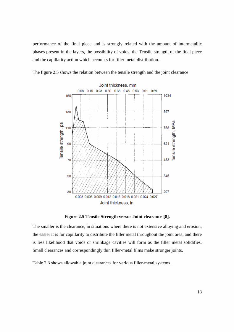
The figure 2.5 shows the relation between the tensile strength and the joint clearance
Figure 2.5 Tensile Strength versus Joint clearance [8].
The smaller is the clearance, in situations where there is not extensive alloying and erosion,
the easier it is for capillarity to distribute the filler metal throughout the joint area, and there
is less likelihood that voids or shrinkage cavities will form as the filler metal solidifies.
Small clearances and correspondingly thin filler-metal films make stronger joints.
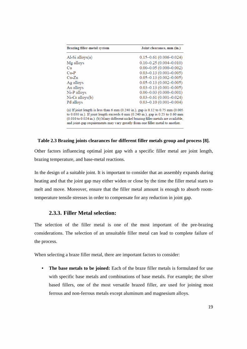
Table 2.3 shows allowable joint clearances for various filler-metal systems.
19
Table 2.3 Brazing joints clearances for different filler metals group and process [8].
Other factors influencing optimal joint gap with a specific filler metal are joint length,
brazing temperature, and base-metal reactions.
In the design of a suitable joint. It is important to consider that an assembly expands during
heating and that the joint gap may either widen or close by the time the filler metal starts to
melt and move. Moreover, ensure that the filler metal amount is enough to absorb room-
temperature tensile stresses in order to compensate for any reduction in joint gap.
2.3.3. Filler Metal selection:
The selection of the filler metal is one of the most important of the pre-brazing
considerations. The selection of an unsuitable filler metal can lead to complete failure of
the process.
When selecting a braze filler metal, there are important factors to consider:
• The base metals to be joined: Each of the braze filler metals is formulated for use
with specific base metals and combinations of base metals. For example; the silver
based fillers, one of the most versatile brazed filler, are used for joining most
ferrous and non-ferrous metals except aluminum and magnesium alloys.

20
• The brazing process to be used: Depending on the filler metal composition a
special brazing method can be necessary; some metal fillers react very quickly with
the environment while others need a particular temperature thus the filler metal
should be selected considering also the brazing method available.
• The design of the joint and method to apply the braze filler metal: There is a
limited number of ways the braze filler metal can be introduced between the base
metal faying surfaces. The filler may be pre-placed prior to heating in the joint, or
manually face fed after heating. The joint design and brazing process will drive the
selection of way to apply the filler metal.
• The environment and the service of the joint: The work temperature, corrosion
environment, stress conditions, electrical and thermal conductivities, etc. are
considerations to take into account when selecting the filler metal.
2.3.4. Heating Methods:
Effective capillary joining requires efficient transfer of heat from the heat source into the
joint. The rate of heating, thermal gradients, cooling rates, the size of individual assemblies,
and the rate of production are factors which influence in the selection of the heating
method.
The joint can be heated in many ways, which are commonly categorized by the actual
method of heating. There are six commonly used methods:
• Torch Brazing: Manual torch brazing is the method most frequently used because
of its relatively low cost and portability, a torch is used to focus flame against the
work at the joint. Normally a reducing flame is used to prevent the oxidation. The
flame is generated by the combustion of a combination of oxygen and a fuel gas.
The process itself give the chance to the use low-melting filler metals, which have
excellent flow characteristics, in order to avoid the oxide on the surfaces to be
brazed, specials fluxes are normally required to remove these contaminants.

21
• Induction brazing: uses electrical resistance of workpiece and high frequency
current induced into the same as a source of heat generation. The parts are pre-
loaded with the filler metal and placed in a high frequency AC field. The
Frequencies ranging from 5 to 5000 kHz are used. High frequency power source
provides surface heating; however, low frequency causes deeper heating into the
workpieces. Low frequency current is recommended for heavier and big sections
(workpieces). Any production rate, low to high, can be achieved by this process.
• Resistance Brazing: Resistance brazing is most applicable to relatively simple
joints in metals that have high electrical conductivity. The workpiece, with filler
metal preplaced, is part of an electric circuit, which means; heat to melt the filler
metal is obtained by resistance to flow of electric current through the joint. Rapid
heating cycles can be achieved in resistance Brazing.
• Dip brazing: In this case heating of the joint is done by immersing it into the
molten soft bath or molten metal bath. In case of salt bath method, filler metal is
pre-loaded into the joint and flux is contained inside the hot salt bath. The filler
metal melts inside the joint when it is submerged into the hot bath. Its solidification
and formation of the joint takes place after taking out the workpiece from the bath.
In case of metal bath method, the bath contains molten filler metal. The joint is
applied with flux and dipped to the bath. Molten filler metal fills the joint through
capillary action. The joint forms during its solidification after taking it out from
molten metal bath. Fast heating is possible in this case. It is recommended for
making multiple joints in a single workpiece or joining multiple pairs of workpieces
simultaneously.
• Furnace brazing: In this case, furnace is used to heat the workpieces to be joined
by brazing operation. This is a medium- to high-volume production process for self-
fixture assemblies with preplaced filler metal. The furnace is purged with a gaseous
atmosphere or evacuated from air and heated to a temperature above the liquidus of
the filler metal but, less than the melting point of the base metals. The brazements
are then cooled or quenched by appropriate methods to minimize distortion and
produce the required properties in the filler and base materials. This cycle is

22
designed to produce the required molten and solidification of the filler metal to join
the components without molten or impairing the properties or shape of the base
metals.
Figure 2.6 shows the typical braze cycle for furnace brazing; A brazing cycle consist of an
initial pumpdown temperature, initial heating ramp, cement burn-off, stabilizing soak,
heating ramp to brazing temperature, brazing soak and cooling down.
Figure 2.6 Typical braze cycle for furnace brazing.
The pumpdown temperature allows solvents or water in the paste or binder vehicle to
outgas from the braze alloy deposit, helps to prevent eruptions (holes) in the braze deposit
and restore the atmosphere quality which can degrade from gasses. The burn-off
temperature allows the organics (not liquids) in the braze vehicle sufficient time to become
gaseous and to be removed through the pumping system, beside allows time to achieve the
suitable level of vacuum. The preheat or stabilizing soak allows the temperature throughout
the load to equalize, so all parts in the load will reach brazing temperature at approximately
the same time during the next heating cycle and it ensure that vacuum pressure levels are
23
low enough before proceeding to brazing temperature. The braze soak allows sufficient
time for the alloy to melt and flow into the joint, usually the lowest satisfactory brazing
temperature are preferred in order to economize the heat energy required, minimize the heat
effect on base metal, minimize the base-metal/filler-metal interactions.
2.4. Post-Brazing treatments and inspection:
Parts that are brazed in a suitable atmosphere should be bright and clean and should require
no further processing. However, if flux or stop off material is present, it should be
thoroughly removed. If the brazements require heat treatment, it must be done below the
solidus or re-melt temperature of the filler metal.
A quality control system should be adequate for both general and critical applications.
Inspection of finished brazed assemblies includes visual inspection, leak testing and
radiographic examination. Visual inspection is the most widely used nondestructive
method. Fluorescent penetrant inspection (FPI) is used for machined surfaces only; parts
should be inspected for cracks or voids in brazed joint. Leak testing is most advantageous
where gas or liquid tightness or brazed joints is required. Radiography (or ultrasonic
inspection) should be used for braze joints to detect sub-surfaces or internal defects.

24
3. EXPERIMENTAL PROCESURE
3.1. Metal-Ceramic brazing process description:
3.1.1. Brazing Technique:
Depending on the heating method several brazing techniques were descripted in chapter III.
Since the present of oxide in the faying surfaces to be joined is detrimental to brazing
process and consequently to brazed piece quality, an oxygen-free environment is
preferential for successful brazing. The active metals in the filler act like as “oxygen-getter”
and an “oxygen-free” environment could be advantageous to improve the wettability of the
ceramics.
There are two common ways to obtain the “oxygen-free” environment; use fluxes or a
vacuum chamber. Fluxes prevent the formation of oxide on the faying surfaces to be joined
but if the piece is exposed to high temperatures for a long time the flux could be evaporated
and the process could be compromise.
The purity levels of atmosphere achieved in vacuum chamber are much higher than these
obtained using fluxes. Also oxide layers on brazing parts are decomposed in a vacuum at
high temperature, which improves base metal wetting resulting, in better joints properties as
strength, minimum porosity, etc. [9]
Considering that a controllable oxygen-free environment helps to avoid the formation of
oxide on the surface, increase the probability of “oxygen-getter” in the active filler react
with the oxygen on the ceramics and not with oxygen in environment and consequently
contribute to improve the joints properties the Vacuum Furnace was selected as brazing
technique.

25
3.1.2. The Vacuum Chamber:
A multi-purpose chambers system is used to perform the furnace brazing process (figure
3.1.a). The system consists of four vacuum chambers connected through a central zone and
separated one of another by pneumatic gates. A chamber is used to develop the experiments
(figure 3.1b).
A working chamber vacuum pressure up to 10E-6 mbar is reached by a two stages pumping
system, the Pfeiffer turbo molecular pump of 360 l/min and Varian Dry Scroll Pump 210
l/min as a primary pump. The entire system is controlled by a HMI (human-machine
interface) (figure 3.1c).
Figure 3.1: a) Multi-purpose chambers system for furnace brazing. b) Vacuum chamber for brazing experiments. c) HMI to control the entire system.
3.1b
3.1c 3.1a

26
3.1.3. The Ovens:
To increase the temperature inside the vacuum chamber, there are two common options;
heat through a set of resistances located inside the chamber or by inductive heating. Both
methods are clean, accurate and easily automatized but using inductive heating some
important parameters as the shape and dimensions of the coil, the penetration of the
magnetic field and consequently the concentration of energy (heat) inside the sample
depend on the shape and dimensions of the samples. It is a great disadvantage for
experimental purposes. On the other hand, heating by a set of resistances represents a more
versatile option.
The vacuum furnace temperature is increased by two ovens located on top and bottom of
the vacuum chamber (figure 3.2). Each Oven (figure 3.3) consists of a sample holder, an IR
lamp of 5000 W, a shield to concentrate the heat around the sample holder, a thermocouple
of type K and the electrical connections for lamp and thermocouple.
Figure 3.2: Top and bottom oven on the vacuum chamber.

27
The figure 3.3 shows the parts of the bottom oven.
Figure 3.3: Parts of oven a) Sample holder. b) 5000 W IR lamp. c) Shield for lamp. d)
Thermocouple K. e) Connections for thermocouple and lamp. f) Bottom oven assembled
The top oven has a special configuration which allows it to change the distance between the samples holders of each oven. Figure 3.4 shows an illustration of the top oven.
Figure 3.4: Illustration of the top oven.
3.3a
3.3d
3.3b 3.3c
3.3e 3.3f

28
3.1.4. The metallization of ceramics:
The ceramic samples were metallized by DC Magnetron sputtering technique. Deposition
was carried out on a second chamber of the same vacuum system. Base pressure of
5�10���� was reached.
Figure 3.5 shows several magnetrons used on these experiments.
Figure 3.5: Magnetrons for DC Sputtering.
Table 3.1 summarizes the parameter used for these depositions:
Titanium Depositon Titanium and Silver deposition.
Ti deposition Ag deposition
Base pressure : x10��mbars x10��mbars x� ��mbars
Argon flux: 6,4 sccm 6,4 sccm 6 sccm
Work pressure: x10��mbars x10��mbars x10��mbars
Current level: 0.5 A 0.5 A 0.25 A
Sample/Magnetron distance
9 cm 9 cm 9 cm
Time ~10 min ~15 min ~120 min
Table 3.1 Parameter of magnetron sputtering for ceramic metallization.

29
There are two procedures for ceramics metallization:
• Procedure 1: The Ti metallization, a thin layer of Titanium (0.25-2�m) is
deposited on the ceramic.
• Procedure 2: The Ti-Ag metallization, this is a two steps process, first a thin layer
of Titanium (0.3-0.5 �m) is deposited on the ceramic. Then a thin layer of silver
(10-15 �m) is deposited over the Titanium coating.
Figure 3.6 shows several ceramic samples metallized.
Figure 3.6: Alumina metallized samples.
3.1.5. The cleaning process:
Each sample was cleaned before brazing process following this procedure:
• Washing in ultrasonic bath into soap solution (Rodaclean) for 30 min at 40°C.
• Washing in ultrasonic bath into deionized water for 30 min at room temperature.
• Rinsing in Ethanol.
• Drying with nitrogen gas.
Figure 3.7 shows the process of cleaning of stainless steel sample.
Figure 3.7: Process of cleaning of stainless steel sample.
30
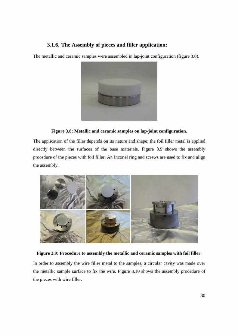
3.1.6. The Assembly of pieces and filler application:
The metallic and ceramic samples were assembled in lap-joint configuration (figure 3.8).
Figure 3.8: Metallic and ceramic samples on lap-joint configuration.
The application of the filler depends on its nature and shape; the foil filler metal is applied
directly between the surfaces of the base materials. Figure 3.9 shows the assembly
procedure of the pieces with foil filler. An Inconel ring and screws are used to fix and align
the assembly.
Figure 3.9: Procedure to assembly the metallic and ceramic samples with foil filler.
In order to assembly the wire filler metal to the samples, a circular cavity was made over
the metallic sample surface to fix the wire. Figure 3.10 shows the assembly procedure of
the pieces with wire filler.

31
Figure 3.10: Procedure to assembly the metallic and ceramic samples with wire filler.
The assembly is fixed to the sample holder of the bottom oven by an Inconel ring in order
to maintain the pieces aligned. Then the top oven was placed near to the assembly, in this
way both ovens can irradiate heat to the piece.
Figure 3.11 shows the two ovens and the piece assembled.
Figure 3.11: The piece assembled to the bottom oven and the top oven.
3.1.7. The heating process:
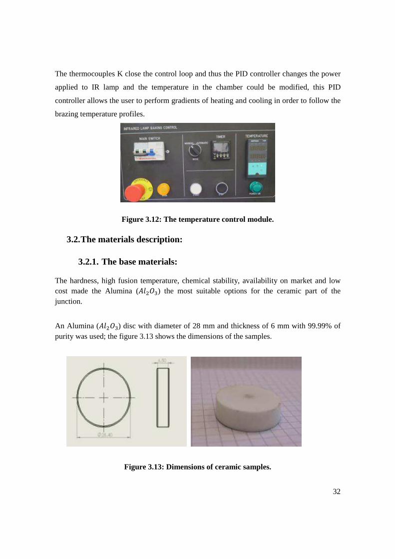
The vacuum chamber heating was carried out by IR lamps. A temperature control module
(figure 3.12) based on a commercial temperature control device and a power controller
device is used to perform the temperature profiles.
32
The thermocouples K close the control loop and thus the PID controller changes the power
applied to IR lamp and the temperature in the chamber could be modified, this PID
controller allows the user to perform gradients of heating and cooling in order to follow the
brazing temperature profiles.
Figure 3.12: The temperature control module.
3.2. The materials description:
3.2.1. The base materials:
The hardness, high fusion temperature, chemical stability, availability on market and low cost made the Alumina (�����) the most suitable options for the ceramic part of the junction.
An Alumina (�����) disc with diameter of 28 mm and thickness of 6 mm with 99.99% of purity was used; the figure 3.13 shows the dimensions of the samples.
Figure 3.13: Dimensions of ceramic samples.

33
Stainless steel 304, the most versatile and commonly used kind of Stainless steel, was selected as the metallic component of the assembly.
INCONEL , a family of nickel-chromium based super alloys, has been chosen as additional variant of metallic component of assembly because of its relatively low thermal expansion coefficient (more close to the one of ceramic materials chosen).
A Stainless steel 304 and INCONEL discs with diameter of 28 mm and thickness of 5.5 mm were used; the figure 3.14 shows the dimensions of the samples.
Figure 3.14: Dimensions of metallic samples.
The table 3.2 shows the composition of the stainless steel 304 family, while the table 3.3 shows the composition of INCONEL family.
Grade C Mn Si P S Cr Ni N
304 max - - - - - 18.0 8.0 - min 0.08 2.0 0.75 0.045 0.030 20 10.5 0.10
304L max - - - - - 18.0 8.0 - min 0.030 2.0 0.75 0.045 0.030 20.0 12.0 0.10
304H max 0.04 - - - - 18.0 8.0 - min 0.10 2.0 0.75 0.045 0.030 20.0 10.5 -
Table 3.2 – Composition of Stainless steel 304 family.

34
Inconel Ni Cr Fe Mo Nb Co Mn Cu Al Ti Si C S P B 600 min - 14.0 6.0 - - - - - - - - - - - -
max 72.0 17.0 10.0 - - - 1.0 0.5 - - 0.5 0.15 0.015 - -
617 min 44.2 20.0 - 8.0 - 10.0 - - 0.8 - - - - - - max 56.0 24.0 3.0 10.0 - 15.0 0.5 0.5 1.5 0.6 0.5 0.15 0.015 0.015 0.006
625 min - 20.0 - 8.0 3.15 - - - - - - - - - - max 58.0 23.0 5.0 10.0 4.15 1.0 0.5 - 0.4 0.4 0.5 0.1 0.015 0.015 -
690 min - - - - - - - - - - - - - - - max 59.5 30 9.2 - - - 0.35 0.01 0.02 - 0.35 0.019 0.003 - -
718 min 50.0 17.0 balance
2.8 4.75 - - 0.2 0.65 - - - - - - max 55.0 21.0 3.3 5.5 1.0 0.35 0.8 1.15 0.3 0.35 0.08 0.015 0.015 0.006
X-750
min - 14.0 5.0 - 0.7 - - - 0.4 2.25 - - - - - max 70 17.0 9.0 - 1.2 1.0 1.0 0.5 1.0 2.75 0.5 0.08 0.01 - -
Table 3.3 – Composition of INCONEL family.
3.2.2. The Filler Metals:
In order to select the suitable filler-metals these considerations were taken into account:
• The ability to “wet” the base materials.
• Suitable melting and flow properties to permit distribution by capillary attraction.
• The ability to make a strong bond to the base material.
• The filler-metal must be able to produce a braze joint that will meet the service requirements specified.
Considering these arguments the brazing filler metals on the table 3.4 and 3.5 were selected:
Brazing Filler-Metals Manufacturer Composition
Ag% Cu% Pd% Pallabraze 850 Johnson Matthey 58.5 31.5 10
Copper Good fellow 0 100 0
Table 3.4 - Non-active brazing filler-metals.
Active Brazing Alloys
Manufacturer Composition
Ag% Cu% Ti%
Cusil ABA WESGO metal 63 35.25 1.75
Table 3.5 - Active brazing filler-metals.

35
The most manufacturers or providers can supply five basic forms of filler-metals: wire,
powder, foil, paste and performs. Taking into account factors as joint type, clearance
between pieces, the filler-metal application mode and the brazing technique; wire, disc pre-
form, and foils were chosen as filler metal forms for these experiments.
The wire selected has 0.8 mm of diameter; the disc of Pallabraze 850 has the same diameter
of the samples and 0.3 mm of thickness; whereas the foil of CUSIL-ABA and copper has
the same diameter of the samples and 8-10 �m of thickness, figure 3.15 shows the
dimensions of some of these filler-metals forms.
Figure 3.15: Dimensions and real pictures of pallabraze 850 discs.
3.3. The brazing experiments:
Depending on the base materials, the filler metal; composition (active or no active) and
form (wire or disc) and the ceramic metallization technique, there are several brazing
experiments, classified as:

36
3.3.1. Active Brazing experiments:
These include different combinations of base materials and different forms of CUSIL-ABA,
resulting in the following experiments:
Denomination Base materials Filler Metal
Commercial name
Form
Experiment 1 Stainless Steel 303 -Alumina CUSIL-ABA Wire
Experiment 2 Inconel 600-Alumina CUSIL-ABA Wire
Experiment 3 Stainless Steel 304-Alumina CUSIL-ABA Foil
Experiment 4 Inconel 600-Alumina CUSIL-ABA Foil
Table 3.6 Active brazing experiments.
3.3.2. Non-active Brazing-metallized ceramic experiments:
These include different combinations of base materials, different forms of Pallabraze 850
and different methods of metallization; resulting in the following experiments:
Denomination Base materials Filler Metal
Commercial name
Form
Experiment 5 Stainless Steel 303 –Ti Alumina Pallabraze 850 Foil
Experiment 6 Inconel 600-Ti Alumina Pallabraze 850 Foil
Experiment 7 Stainless Steel 304- Ti&Ag Alumina Copper Foil
Experiment 8 Inconel 600- Ti&Ag Alumina Copper Foil
Table 3.6 Non-active brazing experiments.
37
3.4. Brazed samples characterization:
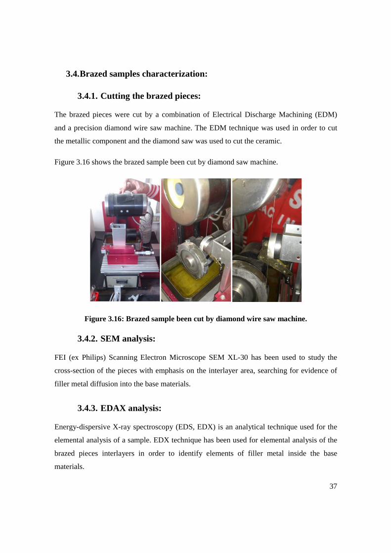
3.4.1. Cutting the brazed pieces:
The brazed pieces were cut by a combination of Electrical Discharge Machining (EDM)
and a precision diamond wire saw machine. The EDM technique was used in order to cut
the metallic component and the diamond saw was used to cut the ceramic.
Figure 3.16 shows the brazed sample been cut by diamond saw machine.
Figure 3.16: Brazed sample been cut by diamond wire saw machine.
3.4.2. SEM analysis:
FEI (ex Philips) Scanning Electron Microscope SEM XL-30 has been used to study the
cross-section of the pieces with emphasis on the interlayer area, searching for evidence of
filler metal diffusion into the base materials.
3.4.3. EDAX analysis:
Energy-dispersive X-ray spectroscopy (EDS, EDX) is an analytical technique used for the
elemental analysis of a sample. EDX technique has been used for elemental analysis of the
brazed pieces interlayers in order to identify elements of filler metal inside the base
materials.
38
4. EXPERIMENTAL RESULTS AND ANALISYS
4.1. Active brazing experiments:
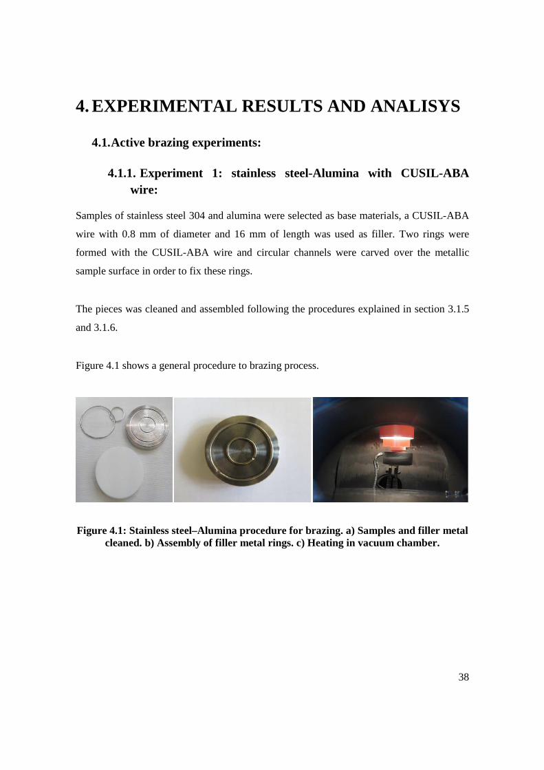
4.1.1. Experiment 1: stainless steel-Alumina with CUSIL-ABA wire:
Samples of stainless steel 304 and alumina were selected as base materials, a CUSIL-ABA
wire with 0.8 mm of diameter and 16 mm of length was used as filler. Two rings were
formed with the CUSIL-ABA wire and circular channels were carved over the metallic
sample surface in order to fix these rings.
The pieces was cleaned and assembled following the procedures explained in section 3.1.5
and 3.1.6.
Figure 4.1 shows a general procedure to brazing process.
Figure 4.1: Stainless steel–Alumina procedure for brazing. a) Samples and filler metal cleaned. b) Assembly of filler metal rings. c) Heating in vacuum chamber.

39
The figure 4.2 shows the profile of temperature. A brazing temperature of 848 °C was
reached and maintained for 15 min then a cooling down profile of 8-10°C min was applied.
Figure 4.2: Profile of temperature in Stainless steel-Alumina brazing process with CUSIL-ABA.
Figure 4.3 shows the Stainless steel-Alumina assembly after brazing, several cracks could
be observed on the ceramic component. When a minimal amount of force was applied to
the joint area the ceramic was shattered.
Figure 4.3: Stainless steel-Alumina brazed with CUSIL-ABA wire.
0
100
200
300
400
500
600
700
800
900
0 50 100 150 200 250 300
Tem
pe
ratu
re o
n b
ott
om
ov
en
°C
Time (min)

40
4.1.2. Experiment 2: Inconel-Alumina with CUSIL-ABA wire:
Samples of inconel and alumina were selected as base materials, a CUSIL-ABA wire with
0.8 mm of diameter and 16 mm of length was used as filler. The wire was applied with
spiral shape and a spiral cavity was carved over the metallic sample surface in order to fix
the filler. The pieces was cleaned and assembled following the procedures explained in
section 3.1.5 and 3.1.6.
The figure 4.4 shows the profile of temperature measured on both ovens. A brazing
temperature of 859 °C was reached and maintained for 15 min, for this experiment a more
aggressive ramp of temperature was applied to the ceramic piece, on the other hand in
cooling down a ramp of 5-8°C min was applied to the Inconel component whereas the
temperature was decreased till 750 °C on the ceramic component and maintained for
several minutes and then cooled down.
Figure 4.4: Profile of temperature in Inconel-Alumina brazing process with CUSIL-ABA.
0
100
200
300
400
500
600
700
800
900
1000
0 100 200 300 400 500 600
Te
mp
era
ture
(°C
)
Time (min)
Temperature top oven (°C) (Al2O3) Temperature Bottom oven (°C) (INCONEL)

41
Figure 4.5 shows the Inconel-Alumina assembly after brazing, in this case several cracks
could be observed on the ceramic component too and when a minimal amount of force was
applied to the joint area the ceramic was shattered. This behaviour in both experiments
could be caused by the residual stress due the different of thermal expansion between the
base materials.
Figure 4.5: Stainless steel-Alumina brazed with CUSIL-ABA wire.
4.1.3. Experiment 3: Stainless steel-Alumina with CUSIL-ABA foil:
Samples of stainless steel and alumina were selected as base materials, a CUSIL-ABA foils
were used as filler. The foil was applied between the faying surfaces of the brazements.
The pieces were cleaned and assembled following the procedures explained in section 3.1.5
and 3.1.6.
The figure 4.6 shows the profile of temperature of a brazing process using a CUSIL-ABA
disc of 28 mm of diameter and 8~10 �m of thickness. A brazing temperature of 865 °C was
reached and maintained for 15 min, a cooling down a ramp of 3-5°C min was applied to the
metallic component.

42
Figure 4.6: Profile of temperature in Stainless steel-Alumina brazing process with CUSIL-ABA.
Figure 4.7 shows the stainless steel-Alumina assembly after brazing, in this case no cracks
were observed on ceramic component unlike the previous experiments.
Figure 4.7: Stainless steel-Alumina brazed with CUSIL-ABA foil.
0
100
200
300
400
500
600
700
800
900
1000
0 50 100 150 200 250 300 350
Te
mp
era
ture
(°C
)
Time (min)
Temperature top oven (Stainless steel) Temperature down oven (Al2O3)

43
4.1.4. Experiment 4: Inconel-Alumina with CUSIL-ABA foil:
Samples of inconel and alumina were selected as base materials, a CUSIL-ABA foils of
several dimensions were used as filler. The foil was applied between the faying surfaces of
the brazements.
The pieces were cleaned and assembled following the procedures explained in section 3.1.5
and 3.1.6.
The figure 4.8 shows the profile of temperature of a brazing process using a CUSIL-ABA
disc of 28 mm of diameter and 8~10 �m of thickness. A brazing temperature of 863 °C was
reached and maintained for 10 min, a cooling down a ramp of 3-5°C min was applied.
Figure 4.8: Profile of temperature in Inconel-Alumina brazing process with CUSIL-ABA.
0
100
200
300
400
500
600
700
800
900
1000
0 100 200 300 400 500 600
Te
mp
era
ture
(°C
)
Time (min)
Temperature down oven (Al2O3) Temperature top oven (INCONEL)

44
Figure 4.9 shows a stainless steel-Alumina assembly after brazing, in this case no cracks
were observed on ceramic component too. These results in both experiments could be
consequence of a uniform distribution of residual stress due the uniform distribution of the
filler on the lapping area, also due the application of a slower cooling down ramp in order
to avoid the residual stress caused by different on thermal expansion.
Figure 4.9: Inconel-Alumina brazed with CUSIL-ABA foil.
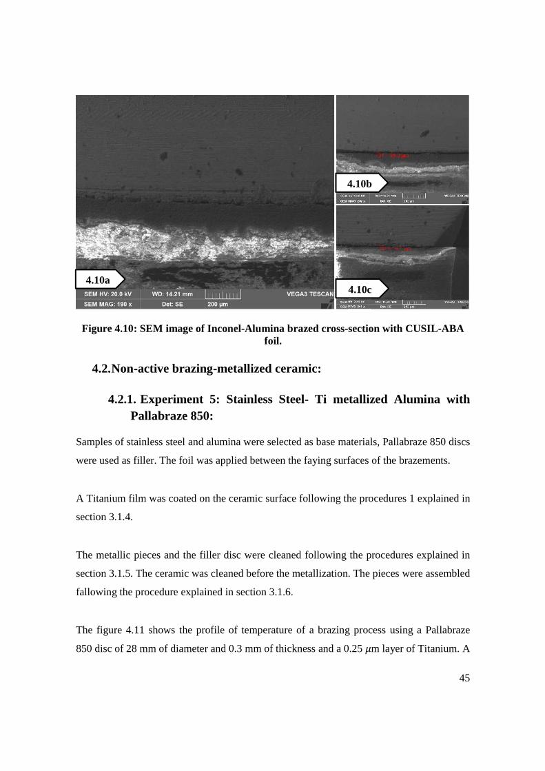
A scanning electron microscope (SEM) image of the sample described above is shown on
figure 4.10a. In the cross-section a several micro empty spaces could be observed in the
interlayer or reaction zone, these empty spaces could be caused by some contamination on
the assembled part surfaces, these impurities often could contain ingredients that tend to
volatilize and outgas at the elevated temperatures involved in brazing [10], on the other
hand, figure 4.10b and 4.10c show the cross-section of samples in which lowers amount of
filler were used, a gap between the ceramic and the filler metal could be observe, this gap
could be a consequence of a shortfall in the amount of filler metal.
An energy-dispersive X-ray spectroscopy (EDS-EDX) on the cross-section of the sample in
figure 4.10a reveals elements of the filler metal as titanium, silver and copper on the base
material nearby to the junction area, the presence of these elements could be evidence of
filler metal diffusion in this area, otherwise EDS-EDX analysis reveals no signs of filler
metal in the base materials nearby to the junction in figure 4.10b and 4.10c samples.
45
Figure 4.10: SEM image of Inconel-Alumina brazed cross-section with CUSIL-ABA foil.
4.2. Non-active brazing-metallized ceramic:
4.2.1. Experiment 5: Stainless Steel- Ti metallized Alumina with Pallabraze 850:
Samples of stainless steel and alumina were selected as base materials, Pallabraze 850 discs
were used as filler. The foil was applied between the faying surfaces of the brazements.
A Titanium film was coated on the ceramic surface following the procedures 1 explained in
section 3.1.4.
The metallic pieces and the filler disc were cleaned following the procedures explained in
section 3.1.5. The ceramic was cleaned before the metallization. The pieces were assembled
fallowing the procedure explained in section 3.1.6.
The figure 4.11 shows the profile of temperature of a brazing process using a Pallabraze
850 disc of 28 mm of diameter and 0.3 mm of thickness and a 0.25 �m layer of Titanium. A
4.10a 4.10c
4.10b

46
brazing temperature of 865 °C was reached and maintained for 10 min, a cooling down a
ramp of 3-5°C min was applied.
Figure 4.11: Profile of temperature in stainless steel – Ti metallized Alumina brazing process with Pallabraze 850.
Figure 4.12 shows a stainless steel- Ti metallized Alumina brazed.
Figure 4.12: Stainless steel- Ti metallized Alumina brazed with Pallabraze 850 foil.
0
100
200
300
400
500
600
700
800
900
1000
0 50 100 150 200 250 300 350
Te
mp
era
ture
(°C
)
Time (min)
Temperature top oven (Stainless steel) Temperature bottom oven (Alumina)

47
A scanning electron microscope (SEM) image of the sample described above is shown on
figure 4.13a. A uniform distribution of the filler metal could be seen; however as was
observed on the experiment with CUSIL-ABA foils, several micro empty spaces appear
again.
An energy-dispersive X-ray spectroscopy (EDS-EDX) on the cross-section of the sample in
figure 4.13a reveals elements of the filler metal as palladium, silver and copper on the base
material nearby to the junction area.
Figure 4.13: SEM image of stainless steel – Ti metallized alumina brazed cross-section with Pallabraze 850 foil.
4.2.2. Experiment 6: Inconel- Ti metallized Alumina with Pallabraze 850:
Samples of inconel and alumina were selected as base materials, Pallabraze 850 discs of
several sizes were used as filler. The foil was applied between the faying surfaces of the
brazements.
A Titanium film was coated on the ceramic surface following the procedures 1 explained in
section 4.1.2. The metallic pieces and the filler disc were cleaned following the procedures
4.13a 4.13b

48
explained in section 4.1.3. The ceramic was cleaned before the metallization. The pieces
were assembled fallowing the procedure explained in section 4.1.4.
Figure 4.14 shows the profile of temperature of a brazing process using a Pallabraze 850
disc of 28 mm of diameter and 0.1 mm of thickness and a 1 �m layer of Titanium. The
process started with a pressure of 2�10����, then the chamber was filled with argon
gas till achieve a pressure of 3.2�10����. A brazing temperature of 851 °C was reached
and maintained for 5 min, a cooling down a ramp of 3-5°C min was applied.
Figure 4.14: Profile of temperature in Inconel – Ti metallized Alumina brazing
process with Pallabraze 850.
A scanning electron microscope (SEM) image of the sample described above is shown on
figure 4.15a. In the cross-section could be seen a uniform distribution of the filler metal and
no empty spaces could be observed. On the other hand, Figure 4.15b and 4.15c show the
cross-section of samples in which a lower amount of filler metal and higher pressure were
used, empty spaces and gaps could be observed.
An energy-dispersive X-ray spectroscopy (EDS-EDX) on the cross-section of the sample in
figure 4.15a reveals elements of the filler metal as palladium, silver and copper on the
0
100
200
300
400
500
600
700
800
900
0 50 100 150 200 250 300 350
Te
mp
era
ture
(°C
)
Time (min)
Temperature top oven (inconel) Temperature bottom oven (inconel_ring)

49
Inconel nearby to the junction area, the presence of these elements could be evidence of
filler metal diffusion in this area, on the other hand EDS-EDX analysis on the samples in
figure 4.15b and 4.15c reveals presence of these elements too but there are no adhesion to
ceramic.
Figure 4.15: SEM image of several Inconel– Ti metallized alumina brazed cross-sections with Pallabraze 850 foil.
The presence of these element as Titanium, silver and copper detected on EDS-EDX
analysis could be an evidence that it is diffusion of the filler metals inside the metal
component of the junction but in the cases in which the pressure was higher than
�10���� a gap or groups or gaps were observed and these voids decrement the
adhesion with the alumina, in the opposite case, when the chamber was refilled with argon
gas and a pressure of �10���� was achieved, the gap was not observed, this
phenomenon could be caused because by increasing the pressure the vaporization
temperature also increase [10].
4.15a
4.15b
4.15c

50
4.2.3. Experiment 7: Stainless Steel- Ti&Ag metallized Alumina with copper:
Samples of stainless steel and alumina were selected as base materials, a copper disc of
several dimensions were used as filler. The foil was applied between the faying surfaces of
the brazements.
Two films one of titanium and other of silver were coated on ceramic surface following the
procedures 2 explained in section 3.1.4. The metallic pieces and the copper disc were
cleaned following the procedures explained in section 3.1.5. The ceramic was cleaned
before the metallization. The pieces were assembled fallowing the procedure explained in
section 3.1.6.
Figure 4.17 shows the profile of temperature of a brazing process using a copper foil with
28 mm of diameter and 8~10 �m of thickness, also the ceramic was metallized with 0.40
�m layer of Titanium and 15 �m layer of Silver. A brazing temperature of 830 °C was
reached and maintained for 10 min, a cooling down a ramp of 3-5°C min was applied.
Figure 4.17: Profile of temperature in Stainless steel- Ti&Ag metallized Alumina
brazing process with copper foil.
0
100
200
300
400
500
600
700
800
900
0 50 100 150 200 250 300 350
Tem
pe
ratu
re (
°C)
Time (min)
Temperature down oven (Stainless steel) Temperature top oven (Alumina)

51
A scanning electron microscope (SEM) image of the sample described above is shown on
figure 4.18a. A uniform distribution of the filler metal could be observed but empty spaces
could be seen in the interlayer, on the other hand, figure 4.18b and 4.18c; show the cross-
section of samples in which a lower amount of filler metal was used, empty spaces and
gaps could be observed.
An EDS-EDX analysis on the cross-section of the sample in figure 4.18a reveals elements
of the filler metal as Titanium, silver and copper on the metal nearby to the junction area on
the cross-section on the samples in Figure 4.18b and 4.18c reveals no content of filler
metals in the stainless steel nearby to the junction area, this fact could be evidence of poor
diffusion in this area.
Figure 4.18: SEM image of stainless steel- Ti&Ag metallized alumina brazed cross-
section with copper foil.
4.18a
4.18b
4.18c

52
4.2.4. Experiment 8: Inconel- Ti&Ag metallized Alumina wit h copper:
Samples of Inconel and Alumina were selected as base materials; copper discs were used as
filler. The foil was applied between the faying surfaces of the brazements.
Two films one of titanium and other of silver were coated on ceramic surface following the
procedures 2 explained in section 3.1.4. The metallic pieces and the copper disc were
cleaned following the procedures explained in section 3.1.5. The ceramic was cleaned
before the metallization. The pieces were assembled fallowing the procedure explained in
section 3.1.6.
The figure 4.19a shows the profile of temperature of a brazing process using a copper foil
with 28 mm of diameter and 8~10 �m of thickness, also the ceramic was metallized with
0.40 �m layer of Titanium and 15 �m layer of Silver. The process started with a pressure
of 6.2�10����, then the chamber was refilled with Argon gas till achieve a pressure of
4.2�10����. A brazing temperature of 893 °C was reached and maintained for 10 min,
a cooling down a ramp of 10-15°C min was applied.
0
100
200
300
400
500
600
700
800
900
1000
0 50 100 150 200 250 300 350
Te
mp
era
ture
(°C
)
Time (min)
Temperature top oven (Inconel) Temperature bottom oven (Alumina)

53
Figure 4.19: Profile of temperature in Inconel- Ti&Ag metallized Alumina brazing process with copper foil.
A scanning electron microscope (SEM) image of the sample described above is shown on
figure 4.20a. In the cross-section could be seen a uniform distribution of the filler metal and
no empty spaces could be observed. On the other hand, Figure 4.20b and 4.20c show the
cross-section of samples in which higher pressure were used, empty spaces and gaps could
be observed.
An EDS-EDX analysis on the cross-section of the sample in figure 4.20a reveals content of
filler metals as titanium, silver or copper in the inconel nearby to the junction area.
Figure 4.20: SEM image of inconel- Ti&Ag metallized alumina brazed cross-section with copper foil.
In these experiments we observed the same phenomenon in experiments with Pallabraze
850, there was presence of filler metal elements inside the metal component but in the cases
in which the pressure was higher than �10���� a gap or groups or gaps were observed,
unlike the case when the chamber was refilled with argon gas and the gap was not
observed.
4.20a
4.20b
4.20c
54
5. Conclusions:
The aim of these studies was to obtain a procedure that leads to achieve a successful Metal-
ceramic brazing process in a controlled environment, including the most important phases
as the filler metal selection (active or no-active), filler metal shape (foil, disc or wire), the
metallic component (Inconel or stainless steel), cleaning procedure, the heating source, etc.
For lap joints, the application of filler-metal on wire form do not seem like the most
appropriate, due it is more difficult for the motel filler to spread over the complete
interlayer surface, most of the residual stress, result of thermal expansion difference, tends
to concentrated on the area near to wire location and consequently the ceramic pieces tends
to break.
The amount of brazing filler metal has a key influence in the final brazed piece quality, it
seems that using a brazing filler metal amount much lower than the necessary to achieve a
successful brazed piece could cause the appearance of empty spaces in the interlayer, this
could be a consequence of non-uniform distribution of the molten alloy due a weak
capillarity action. On the other hand, an excess amount of filler can cause spillage of the
same.
In order to avoid cracks on the ceramic, due residual stress, heating ramps of 10-15 °C /min
and cooling down ramp of 3-5 °C/min showed the best results. In fact, when faster ramps of
temperatures were applied some cracks were observed in the ceramics. Also the time on
brazing temperature has an influence in this behavior, times of 10 min showed the best
results.
The amount and size of empty spaces on the interlayer were significantly reduced when the
chamber was filled with argon gas till achieve a pressure around 4�10����.

55
The most uniform distribution in the interlayer and diffusion of the filler metal into the
brazed materials were observed when a Pallabraze 850 disc of 0.01 mm of thickness was
used as filler metal and Inconel and Metallized alumina with 1�m of Titanium were
selected as base materials for a brazing process with Argon atmosphere.

56
REFERENCES
[1] M. M. Schwartz, "Adhesion, Wetting, Spreading and Capillary action," in Brazing, Ohio, ASM international, 2003, pp. 7-13.
[2] M. M. Schwartz, "Effects of Capillary Attraction and Wetting on Brazing," in Brazing, Ohio, ASM international, 2003, pp. 7-13.
[3] American Welding Society, "Diffusion brazing," in Brazing Handbook, 1991, p. 239.
[4] M. S. N. a. A. K. S. K. Gupta, "A study on the effect of brazing time on element diffusion," Welding Journal, pp. 47-50, 2007.
[5] C. A. W. a. V. C. Hodges, "Comparing metal-ceramics brazing methods," Welding Journal, pp. 43-50, 2008.
[6] ASM International, "Active brazing filler metals," in Principles of Brazing, Ohio, ASM international, 2005, p. 243.
[7] M. M. Schwartz, "Surface treatment before brazing," in Brazing, Ohio, ASM international, 2003, pp. 297-308.
[8] M. M. Schwartz, "Joint clearance," in Brazing, Ohio, ASM International, 2003, pp. 315-319.

57
[9] J. K. a. J. Szczurek, "Issues in vacuum brazing," ASM international, Dallas, 2006.
[10] D. Kay, "KayBrazing," Kay & associates brazing consultan, 2010. [Online]. Available: http://www.kaybrazing.com/brazing-articles/833-voids-in-brazed-joints.html. [Accessed 10 11 2014].
[11] H. Mizuhara, "Ceramic-to-Metal Joining: Past, Current and Future," Welding Journal, pp. 278-283, 2000.

58
ANNEXES
Material
CTE (mm/m/°C)
Young’s Modulus
(GPa)
0.2% YS (MPa)
20°C 800°C 20°C 800°C 20°C 800°C
Stainless steel 304 15 18 200 128 254 90
Inconel 600 13 15 214 164 280 100
Alumina 7 8.5 366 366� - -
Physical properties of base materials at 20°C to 800°C.
Material CTE (mm/m/°C)
Young’s Modulus
(GPa)
0.2% YS (MPa)
Density (g/���)
Copper 19.4 125 69 8.9
CUSIL-ABA 18.5 83 271 9.8
Pallabraze 850 18.5 - 327 10
Physical properties of filler metals.