Surface and Superficial Dose for Chestwalls
8
Surface and superficial dose dosimetric verification for postmastectomy radiotherapy An-Cheng Shiau, M.S.,* †‡ Min-Chi Chiu, M.S., § Tung-Ho Chen, M.S., § Jeng-Fong Chiou, M.D., Ph.D., § Pei-Wei Shueng, M.D., †¶ Shang-Wen Chen, M.D., Wei-Li Chen, Ph.D.,* and Wei-Peng Kuan, Ph.D.* *Department of Biomedical Imaging and Radiological Sciences, National Yang-Ming University, Taipei City, Taiwan; † Department of Radiation Oncology, Far Eastern Memorial Hospital, New Taipei City, Taiwan; ‡ Department of Biomedical Imaging and Radiological Science, China Medical University, Taichung, Taiwan; § Cancer Center and Department of Radiation Oncology, Taipei Medical University, Taipei, Taiwan; ¶ Department of Radiation Oncology, Tri-Service General Hospital, National Defense Medical Center, Taipei, Taiwan; and School of Medicine, China Medical University, Taichung, Taiwan ARTICLE INFO Article history: Received 16 June 2011 Accepted 15 March 2012 ABSTRACT In patients given postmastectomy radiotherapy (PMRT), the chest wall is a very thin layer of soft tissue with a low-density lung tissue behind. Chest wall treated in this situation with a high-energy photon beam presents a high dosimetric uncertainty region for both calculation and measurement. The purpose of this study was to measure and to evaluate the surface and superficial doses for patients requiring PMRT with different treatment techniques. An elliptic cylinder cork and superflab boluses were used to simulate the lung and the chest wall, respectively. Sets of computed tomography (CT) images with different chest wall thicknesses were acquired for the study phantom. Hypothetical clinical target volumes (CTVs) were outlined and modified to fit a margin of 1–3 mm, depending on the chest wall thickness, away from the surface for the sets of CT images. The planning target volume (PTV) was initially created by expanding an isotropic 3-mm margin from the CTV, and then a margin of 3 mm was shrunk from the phantom surface to avoid artifact-driven results in the beam-let intensity. Treatment techniques using a pair of tangential wedged fields (TWFs) and 4-field intensity-modulated radiation therapy (IMRT) were designed with a prescribed fraction dose (D p ) of 180 cGy. Superficial dose profiles around the phantom circumference at depths of 0, 1, 2, 3, and 5 mm were obtained for each treatment technique using radiochromic external beam therapy (EBT) films. EBT film exhibits good characteristics for dose measurements in the buildup region. Underdoses at the median and lateral regions of the TWF plans were shown. The dose profiles at shallow depths for the TWF plans show a dose buildup about 3 mm at the median and lateral tangential incident regions with a surface dose of about 52% of D p . The dose was gradually increased toward the most obliquely tangential angle with a maximum dose of about 118% of D p. Dose profiles were more uniform in the PTV region for the 4-F IMRT plans. Most of the PTV region had doses 94% of D p at depths 1 mm. The mean surface dose was about 65% of D p for the 4-F IMRT plans. The maximum dose for the 4-F IMRT plans was 118.4% of D p . The application of added bolus has to consider the treatment technique, tumor coverage, and possible skin reactions. For PMRT, if the chest surface and wall are treated adequately, at least 3 mm bolus should be added to the chest wall when tangential beams and 6-MV photon energy are arranged. However, when the surface and superficial regions are not high-risk areas, an IMRT plan with tangential beams and 6-MV photon energy can provide uniform dose distributions within the PTV, spare the skin reaction, and deliver sufficient doses to the chest wall at depths 1 mm. 2012 American Association of Medical Dosimetrists. Keywords: Breast cancer Mastectomy Radiotherapy EBT film dosimetry Dose in the buildup region Superficial dose Introduction Postmastectomy radiotherapy (PMRT) has been proven to reduce local-regional failure (LRF) and also increase disease-free survival and overall survival rates in patients with breast cancer. 1–3 Reports of treatment guidelines for PMRT were published 4,5 and suggest that the chest wall should be treated adequately. In clinical radiation therapy, Reprint requests to: Min-Chi Chiu, M.S., Cancer Center and Department of Radiation Oncology, Taipei Medical University, No.21, Sec. 2, Nanya S. Rd., Banqiao Dist., New Taipei City 220, Taiwan. E-mail: [email protected] Medical Dosimetry 37 (2012) 417-424 Medical Dosimetry journal homepage: www.meddos.org 0958-3947/$ – see front matter Copyright 2012 American Association of Medical Dosimetrists http://dx.doi.org/10.1016/j.meddos.2012.03.005
-
Upload
bineyam-kassahun -
Category
Documents
-
view
213 -
download
1
description
Â
Transcript of Surface and Superficial Dose for Chestwalls

O
OT
Medical Dosimetry 37 (2012) 417-424
Medical Dosimetry
journal homepage: www.meddos.org
h
Surface and superficial dose dosimetric verification for postmastectomyradiotherapy
An-Cheng Shiau, M.S.,*†‡ Min-Chi Chiu, M.S.,§ Tung-Ho Chen, M.S.,§ Jeng-Fong Chiou, M.D., Ph.D.,§
Pei-Wei Shueng, M.D.,†¶ Shang-Wen Chen, M.D.,� Wei-Li Chen, Ph.D.,* and Wei-Peng Kuan, Ph.D.**Department of Biomedical Imaging and Radiological Sciences, National Yang-Ming University, Taipei City, Taiwan; †Department of Radiation Oncology, Far Eastern Memorial Hospital,New Taipei City, Taiwan; ‡Department of Biomedical Imaging and Radiological Science, China Medical University, Taichung, Taiwan; §Cancer Center and Department of Radiationncology, Taipei Medical University, Taipei, Taiwan; ¶Department of Radiation Oncology, Tri-Service General Hospital, National Defense Medical Center, Taipei, Taiwan; and �School of
Medicine, China Medical University, Taichung, Taiwan
A R T I C L E I N F O
Article history:Received 16 June 2011
A B S T R A C T
In patients given postmastectomy radiotherapy (PMRT), the chest wall is a very thin layer of soft tissue
Accepted 15 March 2012with a low-density lung tissue behind. Chest wall treated in this situation with a high-energy photon beampresents a high dosimetric uncertainty region for both calculation and measurement. The purpose of thisstudy was to measure and to evaluate the surface and superficial doses for patients requiring PMRT with
different treatment techniques. An elliptic cylinder cork and superflab boluses were used to simulate thelung and the chest wall, respectively. Sets of computed tomography (CT) images with different chest wallthicknesses were acquired for the study phantom. Hypothetical clinical target volumes (CTVs) wereoutlined and modified to fit a margin of 1–3 mm, depending on the chest wall thickness, away from thesurface for the sets of CT images. The planning target volume (PTV) was initially created by expanding anisotropic 3-mm margin from the CTV, and then a margin of 3 mm was shrunk from the phantomsurface to avoid artifact-driven results in the beam-let intensity. Treatment techniques using a pair oftangential wedged fields (TWFs) and 4-field intensity-modulated radiation therapy (IMRT) weredesigned with a prescribed fraction dose (Dp) of 180 cGy. Superficial dose profiles around the phantomcircumference at depths of 0, 1, 2, 3, and 5 mm were obtained for each treatment technique usingradiochromic external beam therapy (EBT) films. EBT film exhibits good characteristics for dosemeasurements in the buildup region. Underdoses at the median and lateral regions of the TWF planswere shown. The dose profiles at shallow depths for the TWF plans show a dose buildup about 3 mm atthe median and lateral tangential incident regions with a surface dose of about 52% of Dp. The dosewas gradually increased toward the most obliquely tangential angle with a maximum dose of about118% of Dp. Dose profiles were more uniform in the PTV region for the 4-F IMRT plans. Most of the PTVregion had doses �94% of Dp at depths �1 mm. The mean surface dose was about 65% of Dp for the 4-FIMRT plans. The maximum dose for the 4-F IMRT plans was �118.4% of Dp. The application of addedbolus has to consider the treatment technique, tumor coverage, and possible skin reactions. For PMRT,if the chest surface and wall are treated adequately, at least 3 mm bolus should be added to the chestwall when tangential beams and 6-MV photon energy are arranged. However, when the surface andsuperficial regions are not high-risk areas, an IMRT plan with tangential beams and 6-MV photonenergy can provide uniform dose distributions within the PTV, spare the skin reaction, and deliversufficient doses to the chest wall at depths �1 mm.� 2012 American Association of Medical Dosimetrists.
Keywords:Breast cancerMastectomyRadiotherapyEBT film dosimetryDose in the buildup regionSuperficial dose
t
Reprint requests to:Min-Chi Chiu,M.S., Cancer Center andDepartment of Radiationncology, Taipei Medical University, No.21, Sec. 2, Nanya S. Rd., Banqiao Dist., New
caipei City 220, Taiwan.
E-mail: [email protected]
0958-3947/$ – see front matter Copyright � 2012 American Association of Medical Dosimetrttp://dx.doi.org/10.1016/j.meddos.2012.03.005
Introduction
Postmastectomy radiotherapy (PMRT) has been proven to reducelocal-regional failure (LRF) and also increase disease-free survival andoverall survival rates in patients with breast cancer.1–3 Reports ofreatment guidelines for PMRTwere published4,5 and suggest that the
hest wall should be treated adequately. In clinical radiation therapy,ists
wbi3rhodaePbm
fipiw
c
A.-C. Shiau et al. / Medical Dosimetry 37 (2012) 417-424418
most patients have different degrees of skin reactions. Erythema iscommon after a skin dose of about 3000 cGy. Dry desquamation mayappear after doses of about 4000 cGy to the skin. Moist desquamationoccurswhen doses to the skin exceed 5000 cGy.6 Skin reactions can bepainful, and may require interruption of the treatment. However, inpatients given PMRT, the chest wall is a thin layer of soft tissue withthickness in the middle area of the ipsilateral side, usually �1 cm. Inthis situation, especially with a low-density lung tissue behind thethin tissue layer, irradiation with a high-energy photon beam usuallypresents a high dosimetric uncertainty region at the thin tissue layerfor both dose calculation and dose measurement. Assessments forskin and superficial doses are difficult in this area. To ensure thatthe chest wall is encompassed by an adequate dose level, a tissue-equivalent bolusmaterial is placed on the skin surface in some hospi-tals to increase the skin dose, especially when high-energy photonbeams are used. However, there is a wide variation in radiotherapyregimens with respect to bolus use in PMRT.7 In regards to whether abolus in PMRT is needed, the chest wall dose distributions in PMRTshould be evaluated well.
The clinical application of intensity-modulated radiation therapy(IMRT) for adjuvant treatment of breast cancer has been used8–15
with the aim of improving dose homogeneity in the entire target vol-ume while reducing doses to the heart and ipsilateral lung. On thebasis of previous studies, treatment techniques using a pair of tangen-tial wedged fields (TWFs) and 4-field IMRT (4-F IMRT) were designedin this study. Cork and superflab tissue-equivalent materials wereused to simulate the lung and the chest wall, respectively. Radiochro-mic external beam therapy (EBT) filmwith high spatial resolution andthin configuration (thickness of 0.234mmand effectivemeasurementdepth of 0.153 mm in a layer) has been proven as a viable tool forexternal beam dosimetry in the superficial region,16–19 which wasused for dose measurements in this study.
This study investigates the dose distributions in surface and shal-low regions for patients who underwent PMRT with different chestwall thicknesses and different treatment techniques. Solutions thatensure sufficient doses to the structures at high risk, while not ex-ceeding the skin tolerance dose, are presented.
Methods and Materials
Facilities and phantom
A Varian 600 C/D linac system (VarianMedical Systems, Palo Alto, CA) with a 6-MVphoton beam and a millennium 120-leaf multileaf collimator (MLC) system were used
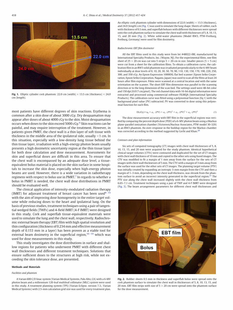
Fig. 1. Elliptic cylinder cork phantom: 22.0 cm (width) � 13.5 cm (thickness) � 24.0m (length).
in this study. A treatment planning system (TPS) (Varian Eclipse, version 7.3.; VarianMedical Systems)with 2.5-mm calculation grid sizewas used for every treatment plan. f
An elliptic cork phantom cylinder with dimensions of 22.0 (width) � 13.5 (thickness),and 24.0 (length) cm (Fig. 1)was used to simulate the lung shape. Sheets of rubber, eachwith thickness of 0.5mm, and superflab boluseswith different thicknesseswere spreadonto the corkphantomsurface to simulate the chestwallwith thicknesses of 5, 8, 10, 13,15, and 20 mm (Fig. 2). White solid-water phantoms (Model RW3, PTW-Freiburg,Freiburg, Germany) were used for film dosimetry.
Radiochromic EBT film dosimeter
All the EBT films used in this study were from lot #48022-08I, manufactured byInternational Specialty Products, Inc. (Wayne, NJ). For the experimental films, one filmsheet of 25 � 20 cm was cut into 5 strips 5 � 20 cm in size. Smaller pieces (5 � 5 cm)ere cut from a sheet for the calibration films. To obtain a calibration curve, the cali-rationfilm in anRW3 solid phantomwas irradiated perpendicularly to the 6-MVbeamndividually at dose levels of 0, 10, 20, 30, 50, 70, 90, 110, 130, 150, 170, 190, 220, 250,00, and 350 cGy. An Epson Expression 10000XL flat bed scanner (Epson Seiko Corpo-ation, Epson Seiko Corporation, Nagano, Japan)was used to scan all the films at least 24ours after film exposure. Films were scanned at a central location and with the samerientation on the scanner. The short EBT film dimension was parallel to the scanningirection or to the long dimension of the scan bed. The settings used were 48-bit colornd 150 dpi (0.017 cm/pixel). The red channel datawith 16-bit digital informationwerextracted and processed using commercial software FILMQA (International Specialtyroducts). The calibration curve was fitted using a polynomial function (Eq 1) with theackground pixel value (PV) subtracted. PV was converted to dose using this polyno-ial function for each film.
D�cGy��a0 � a1 . (PV) � a2 . (PV)2 � a3 . (PV)3 � a4 . (PV)4 (1)
The dose measurement accuracy with EBT film in the superficial regions was veri-ed by comparing the percent depth dose (PDD) of a 6-MVphoton beamusing aMarkuslane-parallel ionization chamber (Victoreen/Nuclear Associates, PTW model 30-329)n an RW3 phantom. An over-response in the buildup region for the Markus chamberas corrected according to the method suggested by Gerbi and Khan.20
Contours and plan information
Six sets of computed tomography (CT) images with chest wall thicknesses of 5, 8,10, 13, 15, and 20 mm were acquired for the study phantom. Identical hypotheticalclinical target volumes (CTVs) were contoured and duplicated for the set of CT imageswith chestwall thickness of 10mmand copied to the other sets using fused images. TheCTV was modified to fit a margin of 1 mm away from the surface for the sets of CTimageswith chestwall thicknesses of 5mm. The CTVwith amargin of 3mmaway fromthe surface was used for the other sets of CT images. The planning target volume (PTV)was initially created by expanding an isotropic 3-mmmargin from the CTV and then amargin of 1–3 mm, depending on the chest wall thickness, was shrunk from the phan-tom surface to avoid an incorrect intensity generated in the superficial region.21 ThePTV size along the chest wall increased slightly with the chest wall thickness from6.65–7.1 cm. Treatment techniques using a pair of TWF and 4-F IMRT were designed(Fig. 3). The beam arrangement parameters for different chest wall thicknesses and
Fig. 2. Rubber sheets 0.5 mm in thickness and superflab bolus were spread onto thecork phantom surface to simulate the chest wall in thicknesses of 5, 8, 10, 13, 15, and
20 mm. EBT film strips with size of 5 � 20 cm were spread onto the phantom surfaceor the dose measurement.
vwd
nt tec
TT
Gt
A.-C. Shiau et al. / Medical Dosimetry 37 (2012) 417-424 419
treatment techniques are listed in Table 1. The prescribed fraction dose (Dp) for PTVwas180 cGy and the dose rate was maintained at 400 MU/min. Identical optimizationconstraints were used and “no normalization” method was selected for every IMRTplan. The maximum and minimum dose constraints for CTV and PTV were 110% and100%, respectively, of the Dp. Themaximum dose constraint for the nontarget area (theolume excluding PTV)was 106% of the Dp. The dose constraint hypothetical structuresere used tomake the IMRT planswith amore uniformdose to the PTV and sparing theose to the ipsilateral lung (Fig. 4). Each plan used the same number of iterations. In
Fig. 3. Beam arrangement for treatme
able 1he beam arrangement and dose-volume correlation parameters for different chest wa
Chest wall thicknessTreatment technique
5 mm 8 mm 10 mm
TWF IMRT TWF IMRT TWF
GM 300 295,320 298 295,320 299GL 120 95,125 118 95,125 119WM 45 — 30 — 45WL 45 — 45 — 30Dmax (%) 110.0 109.8 109.3 110.0 110.0V95% (%) 95.3 97.6 95.4 95.4 97.6
M � median gantry angle; GL � lateral gantry angle; WM � median side wedge angle; WL �
arget volume in % encompassed by 95% of the Dp.
total, 12 treatment planswere designed in this study (2 treatment techniques for 6 setsof CT images with different chest wall thicknesses).
Dose measurements
Two strips of EBT film were spread onto the breast phantom surface with 15-mmspacing (Fig. 2). Superficial doses around the simulated chest wall at depths of 0, 1, 2, 3,
hniques of (A) TWF and (B) 4-F IMRT.
knesses and treatment techniques
13 mm 15 mm 20 mm
RT TWF IMRT TWF IMRT TWF IMRT
,320 298 295,320 298 295,320 300 295,320,125 119 95,125 118 95,125 120 95,125
30 — 30 — 15 —15 — 15 — 15 —
110.0 109.8 110.0 110.9 110.0 110.0 109.295.0 98.0 95.3 98.1 95.1 98.1 97.2
ll thic
IM
29595
——
lateral side wedge angle; Dmax (%) � maximum dose in % relative to the Dp; V95% (%) �

afn
E
a4p1rtPrDp1s
(
A.-C. Shiau et al. / Medical Dosimetry 37 (2012) 417-424420
and 5 mm were measured with EBT film for each treatment technique and each chestwall thickness.
Results
EBT film calibration
The pixel values of the calibrated EBT films and the fitted calibra-tion curve and the polynomial function coefficients are shown inFig. 5. The calibration curve was fitted well with the fitting curve.In Fig. 6, EBTfilmexhibits good characteristics for dosemeasurementsin the buildup region. The difference of PDD in the buildup regionbetween EBT film and the plane-parallel ion chamber was within amaximum of 5.7% at surface and within 1.5% at 3-mm depth.
Dose distributions of treatment plans
For each plan, the 95% of Dp was received by at least 95% of PTV,nd the maximum dose was �110% of Dp. The dose-volume analysisor different chest wall thicknesses and different treatment tech-iques was shown in Table 1.
Fig. 4. The phantom axial image, which displays the hypothetical target structuresand the constraint object.
Fig. 5. The pixel values of the calibrated EBT films and the fitting curve and the polynomi
BT film measurements
Figure 7 showed the measured dose profiles at depths of 0, 1, 2, 3,nd 5mm for chest wall thicknesses of 5, 8, and 20mmwith TWF and-F IMRT treatment techniques, respectively. FromFig. 7A for the TWFlans,within the region of PTV, the superficial doses range from87.0–21.0, 138.4–177.4, and 160.9–192.2 cGy for 0-, 1-, and 2-mmdepths,espectively. Underdoses at median and lateral regions of the tangen-ial beams are shown in Fig. 7A. Doses �93% of Dpwithin the region ofTV were shown at a depth of 3 mm. Lower doses at the incidentegion of median tangential at 5-mm depth were noticed in Fig. 7A.ose profilesweremore uniform in the region of PTV for the 4-F IMRTlans. From Fig. 7B, the superficial doses range from 96.6–118.9,50.7–187.9, and 170.7–198.5 cGy for 0-, 1-, and 2-mm depths, re-pectively. Most of the region of PTV was with doses �94% of Dp atdepths �1 mm for the 4-F IMRT plans.
From Fig. 7A, 7C, and 7E, TWF plans showed similar dose profiles.Themean surface doses at the incident point of PTV are 91.4 cGy (51%of Dp), range from 87.0–93.9 cGy at the lateral, and 99.9 cGy (56% ofDp), range from 94.1–103.8 cGy at the median tangential. Because ofthe dose enhancement effect with oblique incidence, dose increases
0.0
20.0
40.0
60.0
80.0
100.0
120.0
0 3 6 9 12 15 18
Depth (mm)
Percen
tdep
thdo
se(%
)
Markus ion chamber
EBT film
Fig. 6. PDD curves measured by plane-parallel ion chamber ( ) and EBT film----------) for a 6-MV photon beam and 10 � 10-cm open field.
al function coefficients. The calibration curve fit well with the polynomial function.

t1
dtb
m
t3
D
a
t
A.-C. Shiau et al. / Medical Dosimetry 37 (2012) 417-424 421
gradually toward the most obliquely tangential angle. However, themaximum surface dosewas�135 cGy (75% of Dp), and the range from121–134 cGy gradually increased with the chest wall thickness. Thedoses increase significantly with depth. The maximum doses for theTWF plans at different depths and different chest wall thicknesseswere �211.7 cGy (117.6% of Dp). In general, the dose profiles at shal-low depths for the TWF plans show a dose buildup of about 3 mm atthe median and the lateral tangential incident regions, with a surfacedose of about 52% of Dp, and the dose gradually increases towardhe most obliquely tangential angle with a maximum dose of about18% of Dp.In Fig. 7B, 7D, and 7F, 4-F IMRT plans show a more uniform dose
istribution than TWF plans within the PTV region. The obliquity fac-or is not obviously seen in the 4-F IMRT plans. Shallower dose
Fig. 7. The measured dose profiles at depths of 0, 1, 2, 3, and 5 mm for chest wall oechniques.
uildup ranges of about 2 mm are shown in the 4-F IMRT plans. The t
ean surface dosewithin the PTV is 116.4 cGy (65% of Dp), range from96.6–127.5 cGy. The doses increase more significantly with depththan the TWF plans. The maximum doses for the 4-F IMRT plans atdifferent depths anddifferent chestwall thicknesseswere�213.2 cGy(118.4% Dp). Doses higher than Dp at depth �2 mm are obtained formost of the regionwithin the PTV. In Fig. 7B, the dose profile of 5-mmdepth shows a dose lower than the Dp at the median incidence posi-ion andwith significantly lower doses than the dose profiles of 2- and-mm depths.
iscussion and Conclusion
Target shapes for patients given PMRT are a thin curving layerwithlow-density lung tissue behind. Irradiation with a high-energy pho-
nesses of 5 (A, B); 8 (C, D); and 20 mm (E, F) with the TWF and 4-F IMRT treatment
f thickon beam to this area ought to recognize the dose distribution affected

rpmlpmd5
Cont
A.-C. Shiau et al. / Medical Dosimetry 37 (2012) 417-424422
by the lateral electron contribution and the obliquely incident factor.For obliquely incident beams, the dose buildupwith depth is differentfrom normally incident beams. For 6-MV photon beams, the obliquityfactor (OF) on the surface can be 2.25–2.5 for a 70� incident angle and1.75–2.0 for a 60� incident angle, and decrease sharply with depth.22
On the basis of this study for the TWF plans, the doses increase withthe angle of incidence and the increases are insignificant for depths�3 mm. This means that for a TWF plan, the minimum dose for eachscenario is at the surface of beam entry position and the dose in-creases gradually to the maximum at the most obliquely tangentialangle. In Fig. 7A–7F, significant underdoses are shown in the medianand lateral incidence regions at depths �2 mm. The dose enhance-ment effect caused by the oblique incidence is modulated and re-duced in the IMRT plans. More uniform dose distributions within thePTV are obtained with the 4-F IMRT plans. In addition, the intensity-
Fig. 7.
modulated effect to the median and lateral incident regions produces
the 4-F IMRT plan with a shallower dose buildup range. However,when IMRT plan was used for PMRT with multiple beam anglesaround the lesion but not only the tangential angles, as the skin dosedecreases with decreasing the incident angle, the surface and super-ficial doses will be lower than the situation in this study.
The skin dose on a chest wall phantomwas measured by Quach etal,23 who used a hemicylindrical solid water phantom with 7.5-cmadius irradiated with 6-MV x-rays. On the basis of Quach et al.’s re-ort, the surface doses at the 30� beam entry position angle and at theaximum dose position were 53.0% and 73.2% of the prescribedmid-
ine dose. A similar experimental condition in our study involved TWFlanmeasurements at the lateral incidence for the phantomwith a 20m chest wall thickness (Fig. 7E). Under this scenario, the surfaceoses at the beam entrance and the maximum dose position were1.8% and 74.6% of D , which had a variation �3.0% compared with
inued
p
Quach’s report.

dbwmca
wncu
Ftit
stit
Cont
A.-C. Shiau et al. / Medical Dosimetry 37 (2012) 417-424 423
Current TPSs can accurately calculate doses for most treatmentregions. However, because of the steep dose gradient and the compli-cated distributions of the contaminating electrons, the accuracy ofdose calculation in the buildup region still needs to be verified. On thebasis of our previous study,24 most of the calculated points are withoses lower than the measured points, and the difference of doseecomes more significant in the shallower regions. Similar resultsere found in this study. Differences �15% between calculations andeasurements can be found at depths �3 mm. The accuracy of dosealculation ismore reliable at a deeper depth; the difference is �8% atdepth of 5.0 mm.The dose influence from the low-density cork behind the chest
all is shown in Fig. 7A. In the situation of a chest wall with a thick-ess of 5 mm and with a low-density lung behind, lack of scatterontributions from the lung tissue and the chest wall itself caused
Fig. 7.
nderdoses at and nearby the adjacent chest wall and lung areas. In
igure 7A, 7B, the dose profile at 5-mmdepth showed lower dose thanhe dose profile at 3-mm depth. The dose reduction was more signif-cant in the 4-F IMRTplanswith 2 less obliquely added incident beamshan the TWF plan.
For patients who underwent PMRT, based on the results of thistudy, a bolus with thickness �3mm is necessary to ensure the PTV isreated with an adequate dose when the TWF technique is used. Ow-ng to the shallower dose buildup in the 4-F IMRT plan, a bolus thickerhan 2 mm is enough to give doses higher than Dp to the PTV. ForPMRT, most institutions in the US treat the chest wall to total doses ofapproximately 5000 cGy in 180–200 cGy daily fractions. Based on thisstudy, if 4-F IMRT is used for PMRT with prescribed dose of 5000 cGyto the chest wall, in the scenario of no bolus is added on the chest walland 6-MVphoton beams are used, the skin dose is about 3200 cGy andthe superficial dose at 1-mm depth is about 4930 cGy (4186–5443
inued
cGy). In addition, if the chest wall thickness is �8 mm the superficial

rg
naaegtds
R
A.-C. Shiau et al. / Medical Dosimetry 37 (2012) 417-424424
dose at 1-mm depth is about 4950 cGy (4605–5443 cGy), which ishigher than 92%ofDp for thewhole PTV. Under this condition, the skineaction might be mild and sufficient doses can be achieved for re-ions at depths �1 mmwithin the PTV.The added bolus application has to consider the treatment tech-
ique, tumor coverage, and possible skin reactions. If the chest wallnd surface are treated adequately, at least a 3-mm bolus should bedded onto the chest wall when tangential beams and 6-MV photonnergy are arranged. However, when the surface and superficial re-ions at depths �1 mm are not high-risk areas, an IMRT plan withangential beams and 6-MV photon energy can provide uniform doseistributions within the PTV and spare the skin reaction and deliverufficient doses to the chest wall at depths �1 mm.
eferences
1. Overgaard,M.;Hansen, P.S.; Overgaard, J.; et al. Postoperative radiotherapy inhigh-risk premenopausal women with breast cancer who receive adjuvant chemother-apy. Danish Breast Cancer CooperativeGroup82b Trial.N. Engl. J.Med.337:949–55;1997.
2. Ragaz, J.; Jackson, S.M.; Le, N.; et al. Adjuvant radiotherapy and chemotherapy innode-positive premenopausal womenwith breast cancer.N. Engl. J. Med. 337:956–62; 1997.
3. Overgaard,M.; Jensen,M.B.; Overgaard, J.; et al. Postoperative radiotherapy inhigh-risk postmenopausal breast-cancer patients given adjuvant tamoxifen: DanishBreast Cancer Cooperative Group DBCG 82c randomised trial. Lancet. 353:1641–8;1999.
4. Recht, A.; Edge, S.B.; Solin, L.J.; et al. Postmastectomy radiotherapy: Clinical practiceguidelines of the American Society of Clinical Oncology. J. Clin. Oncol. 19:1539–69;2001.
5. Truong, P.T.; Olivotto, I.A.;Whelan, T.J.; et al. Clinical practice guidelines for the careand treatment of breast cancer: 16. Locoregional post-mastectomy radiotherapy.CMAJ 13:1263–73; 2004.
6. Uschold, G.M. Breast cancer. In: CharlesM., Dennis T., editors. Principles and practiceof radiation therapy. 2nd ed. St. Louis: C.V. Mosby; 2004:843–74.
7. Vu, T.T.T.; Pignol, J.P.; Rakovitch, E.; et al. Variability in radiation oncologists’ opin-
ion on the indication of a bolus in post-mastectomy radiotherapy: An Internationalsurvey. Clin. Oncol. 19:115–9; 2007.8. Chui, C.S.; Hong, L.;McCormick, B. Intensity-modulated radiotherapy technique forthree-field breast treatment. Int. J. Radiat. Oncol. Biol. Phys. 62:1217–23; 2005.
9. Beckham,W.A.; Popescu, C.C.; Patenaude, V.V.; et al. Ismultibeam IMRT better thanstandard treatment for patients with left-sided breast cancer? Int. J. Radiat. Oncol.Biol. Phys. 69:918–24; 2007.
10. Kestin, L.L.; Sharpe, M.B.; Frazier, R.C.; et al. Intensity modulation to improve doseuniformity with tangential breast radiotherapy: Initial clinical experience. Int. J.Radiat. Oncol. Biol. Phys. 48:1559–68; 2000.
11. Hong, L.; Hunt, M.; Chui, C.; et al. Intensity-modulated tangential beam irradiationof the intact breast. Int. J. Radiat. Oncol. Biol. Phys. 44:1155–64; 1999.
12. Krueger, E.A.; Fraass, B.A.;Mcshan, D.L.; et al. Potential gains for irradiation of chestwall and regional nodeswith intensitymodulated radiotherapy. Int. J. Radiat. Oncol.Biol. Phys. 56:1023–37; 2003.
13. Remouchamps, V.M.; Vicini, F.A.; Sharpe, M.B.; et al. Significant reductions in heartand lung doses using deep inspiration breath hold with active breathing controland intensity-modulated radiation therapy for patients treated with locoregionalbreast irradiation. Int. J. Radiat. Oncol. Biol. Phys. 55:392–406; 2003.
14. Saibishkumar, E.P.; Mackenzie, M.A.; Severin, D.; et al. Skin-sparing radiation usingintensity-modulated radiotherapy after conservative surgery in early-stage breastcancer: A planning study. Int. J. Radiat. Oncol. Biol. Phys. 70:485–91; 2008.
15. Evans, P.M.; Donovan, E.M.; Partridge,M.; et al. The delivery of intensitymodulatedradiotherapy to the breast using multiple static fields. Radiother. Oncol. 57:79–89;2000.
16. Chiu-Tsao, S.T.; Chan,M.F. Photon beamdosimetry in the superficial buildup regionusing radiochromic EBT film stack.Med. Phys. 36:2074–83; 2009.
17. Devic, S.; Seuntjens, J.; Abdel-Rahman,W.; et al. Accurate skin dosemeasurementsusing radiochromic film in clinical applications.Med. Phys. 33:1116–24; 2006.
18. Fiandra, C.; Ricardi, U.; Ragona, R.; et al. Clinical use of EBT model Gafchromic filmin radiotherapy.Med. Phys. 33:4314–9; 2006.
19. Chiu-Tsao, S.T.; Ho, Y.; Shankar, R.; et al. Energy dependence of response of newhigh sensitivity radiochromic films for megavoltage and kilovoltage radiation en-ergies.Med. Phys. 32:3350–4; 2005.
20. Gerbi, B.J.; Khan, F.M. Measurement of dose in the buildup region using fixed-separation plane-parallel ionization chambers.Med. Phys. 17:17–26; 1990.
21. Ezzell, G.A.; Galvin, J.M.; Low, D.; et al. Guidance document on delivery, treatmentplanning, and clinical implementation of IMRT: Report of the IMRT subcommitteeof the AAPM radiation therapy committee.Med. Phys. 30:2089–115; 2003.
22. Gerbi, B.J.; Meigooni, A.S.; Khan, F.M. Dose buildup for obliquely incident photonbeams.Med. Phys. 14:393–9; 1987.
23. Quach, K.Y.; Morales, J.; Butson,M.J.; et al. Measurement of radiotherapy x-ray skindose on a chest wall phantom.Med. Phys. 27:1676–80; 2000.
24. Shiau, A.C.; Lai, P.L.; Liang, J.A.; et al. Dosimetric verification of surface and super-
ficial doses for head and neck IMRT with different PTV shrinkage margins. Med.Phys. 38:1435–43; 2011.