Supplemental Material—Chapter 13 Object Selection Filters · PDF fileAutoCAD reports the...
6
Object Selection Filters 1 Copyright Goodheart-Willcox Co., Inc. May not be reproduced or posted to a publicly accessible website. AutoCAD and Its Applications BASICS Supplemental Material—Chapter 13 Object Selection Filters The FILTER command allows you to create a selection set according to a specific list of property criteria. You can create filter lists at any time, and filter lists are select- able at any Select objects: prompt. Access the FILTER command to display the Object Selection Filters dialog box, shown in Figure 13A-1. The list box displays current filter list data. Use the Select Filter area to specify filter criteria. Use the Named Filters area to save filters for future use. Entering Filter Data Entering Filter Data Use the Select Filter area to enter filter data. Select an option from the drop-down list to enable specific filter characteristics. Figure 13A-2 shows the options available to filter using the Arc, Arc Center , or Arc Radius option. Notice that the settings are specific to the geometry of the selected filter. The Select… button is enabled for many filter settings, including layer, linetype, and color. Pick the Select… button to display the appropriate dialog box. For example, if you select the Color filter, pick the Select… button to display the Select Color dialog box. Once you select a filter and specify appropriate values, pick the Add to List: button to add the filter to the filter list at the top of the dialog box. FILTER Type FILTER FI Figure 13A-1. The Object Selection Filters dialog box. Edit item in filter list Delete a highlighted item from the list Erase all items in filter List of filtered items Filter options Add item to filter Enter name for new filter Save a new filter
Transcript of Supplemental Material—Chapter 13 Object Selection Filters · PDF fileAutoCAD reports the...

Object Selection Filters 1Copyright Goodheart-Willcox Co., Inc.
May not be reproduced or posted to a publicly accessible website.
AutoCAD and Its Applications BASICSSupplemental Material—Chapter 13
Object Selection Filters
The FILTER command allows you to create a selection set according to a specifi c list of property criteria. You can create fi lter lists at any time, and fi lter lists are select-able at any Select objects: prompt. Access the FILTER command to display the Object
Selection Filters dialog box, shown in Figure 13A-1. The list box displays current fi lter list data. Use the Select Filter area to specify fi lter criteria. Use the Named Filters area to save fi lters for future use.
Entering Filter DataEntering Filter DataUse the Select Filter area to enter fi lter data. Select an option from the drop-down
list to enable specifi c fi lter characteristics. Figure 13A-2 shows the options available to fi lter using the Arc, Arc Center, or Arc Radius option. Notice that the settings are specifi c to the geometry of the selected fi lter.
The Select… button is enabled for many fi lter settings, including layer, linetype, and color. Pick the Select… button to display the appropriate dialog box. For example, if you select the Color fi lter, pick the Select… button to display the Select Color dialog box. Once you select a fi lter and specify appropriate values, pick the Add to List: button to add the fi lter to the fi lter list at the top of the dialog box.
FIL
TE
RType
FILTERFI
Figure 13A-1. The Object Selection Filters dialog box.
Edit itemin filter list
Delete ahighlighted itemfrom the list
Erase allitems in filter
List offiltered items
Filter options
Additem to filter
Enter name fornew filter
Savea new filter
Object Selection Filters 2Copyright Goodheart-Willcox Co., Inc.
May not be reproduced or posted to a publicly accessible website.
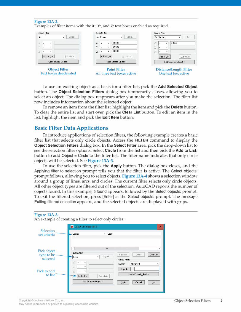
To use an existing object as a basis for a fi lter list, pick the Add Selected Object button. The Object Selection Filters dialog box temporarily closes, allowing you to select an object. The dialog box reappears after you make the selection. The fi lter list now includes information about the selected object.
To remove an item from the fi lter list, highlight the item and pick the Delete button. To clear the entire list and start over, pick the Clear List button. To edit an item in the list, highlight the item and pick the Edit Item button.
Basic Filter Data ApplicationsTo introduce applications of selection fi lters, the following example creates a basic
fi lter list that selects only circle objects. Access the FILTER command to display the Object Selection Filters dialog box. In the Select Filter area, pick the drop-down list to see the selection fi lter options. Select Circle from the list and then pick the Add to List: button to add Object = Circle to the fi lter list. The fi lter name indicates that only circle objects will be selected. See Figure 13A-3.
To use the selection fi lter, pick the Apply button. The dialog box closes, and the Applying filter to selection prompt tells you that the fi lter is active. The Select objects: prompt follows, allowing you to select objects. Figure 13A-4 shows a selection window around a group of lines, arcs, and circles. The current fi lter selects only circle objects. All other object types are fi ltered out of the selection. AutoCAD reports the number of objects found. In this example, 5 found appears, followed by the Select objects: prompt. To exit the fi ltered selection, press [Enter] at the Select objects: prompt. The message Exiting filtered selection appears, and the selected objects are displayed with grips.
Figure 13A-2. Examples of filter items with the X:, Y:, and Z: text boxes enabled as required.
Object FilterText boxes deactivated
Point FilterAll three text boxes active
Distance/Length FilterOne text box active
Figure 13A-3. An example of creating a filter to select only circles.
Selectionset criteria
Pick objecttype to be
selected
Pick to addto list

Object Selection Filters 3Copyright Goodheart-Willcox Co., Inc.
May not be reproduced or posted to a publicly accessible website.
You can expand fi lter lists to select only objects that have specifi c properties. The next example creates a fi lter list that selects only line objects that have a CENTER line-type. Access the FILTER command to display the Object Selection Filters dialog box. Pick the Clear List button to clear the list box and start a new fi lter list. In the Select
Filter area, select Line from the drop-down list. Then pick the Add to List: button to add Object = Line to the fi lter list. The fi lter name indicates that only line objects will be selected. Select Linetype in the drop-down list and pick the Select… button to display the Select Linetype(s) dialog box. Select the CENTER linetype and pick the OK button. Pick the Add to List: button to create the fi lter shown in Figure 13A-5.
By adding more fi lters to the fi lter list, you can make a fi lter extremely specifi c when needed. You can use fi lters for a specifi c location or a specifi c text string to help select items in very large, complex drawings.
Figure 13A-4. All objects are filtered out except for the circles.
Selectionwindow
Figure 13A-5. Creating a filter to select only line objects with the CENTER linetype.
Pick Select… to display available linetypes

Object Selection Filters 4Copyright Goodheart-Willcox Co., Inc.
May not be reproduced or posted to a publicly accessible website.
Working with Relative OperatorsWorking with Relative OperatorsRelative operator relationships include equality, inequality, greater than, less than,
and combinations such as “greater than or equal to” and “less than or equal to.” A rela-tive operator fl yout precedes each text box in the Select Filter area. The default operator is “equal to.” Select an appropriate relative operator for each data fi eld.
For example, to use a relative operator to select all arcs that have a radius of 2.5 or greater, set the fi lter specifi cation to Arc Radius and enter 2.5 in the text box. Then select the “greater than or equal to” symbol (>=) in the relative operator fl yout. See Figure 13A-6. The chart in Figure 13A-7 shows the relative operator functions.
Editing the Filter ListEditing the Filter ListTo correct an accidental entry or incorrect fi lter specifi cation, highlight the item
in the fi lter list and pick the Edit Item button. The values for the selected specifi cation appear in the Select Filter area, allowing you to make changes. Change the values as necessary. Pick the Substitute button when you are fi nished. The highlighted item is substituted for the original fi lter specifi cation. Be sure to pick Substitute and not Add
to List:; otherwise, you will create two different values for the same fi lter specifi cation in the fi lter list.
To remove an item from the fi lter list, highlight it and select the Delete button. You can only delete one fi lter specifi cation at a time using this method. To remove all of the current specifi cations and start over, pick the Clear List button.
Figure 13A-6. Filtering using the greater than or equal to relative operator.
Enter settingvalue
Pick after editingan item from thefilter list
Relative operatordrop-down list
Pick to select anobject with properties
to be filtered
Figure 13A-7. Relative operators available for filtering.
Symbol Meaning
= Equal to
!= Not equal to
< Less than
<= Less than or equal to
> Greater than
>= Greater than or equal to
* Equal to any value
Object Selection Filters 5Copyright Goodheart-Willcox Co., Inc.
May not be reproduced or posted to a publicly accessible website.
Creating Named FiltersCreating Named FiltersComplex fi lter lists can be time-consuming to develop. AutoCAD provides the
option of naming and saving fi lter lists for future use. The Named Filters area of the Object Selection Filters dialog box allows you to create and manage named fi lters. After you build and test the fi lter list, pick in the text box to the right of the Save As: button to name and save the list. Type a descriptive name up to 18 characters long in the text box. Pick the Save As: button to save the named fi lter. Named fi lters are stored in a fi le named filter.nfl and are available until deleted.
To delete a saved fi lter, make the fi lter current by picking its name in the Current: drop-down list. Then pick the Delete Current Filter List button.
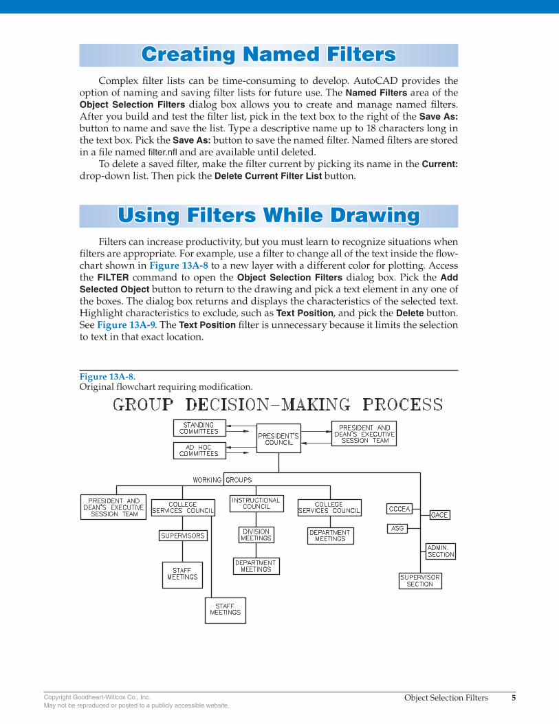
Using Filters While DrawingUsing Filters While DrawingFilters can increase productivity, but you must learn to recognize situations when
fi lters are appropriate. For example, use a fi lter to change all of the text inside the fl ow-chart shown in Figure 13A-8 to a new layer with a different color for plotting. Access the FILTER command to open the Object Selection Filters dialog box. Pick the Add
Selected Object button to return to the drawing and pick a text element in any one of the boxes. The dialog box returns and displays the characteristics of the selected text. Highlight characteristics to exclude, such as Text Position, and pick the Delete button. See Figure 13A-9. The Text Position fi lter is unnecessary because it limits the selection to text in that exact location.
Figure 13A-8. Original flowchart requiring modification.
Object Selection Filters 6Copyright Goodheart-Willcox Co., Inc.
May not be reproduced or posted to a publicly accessible website.
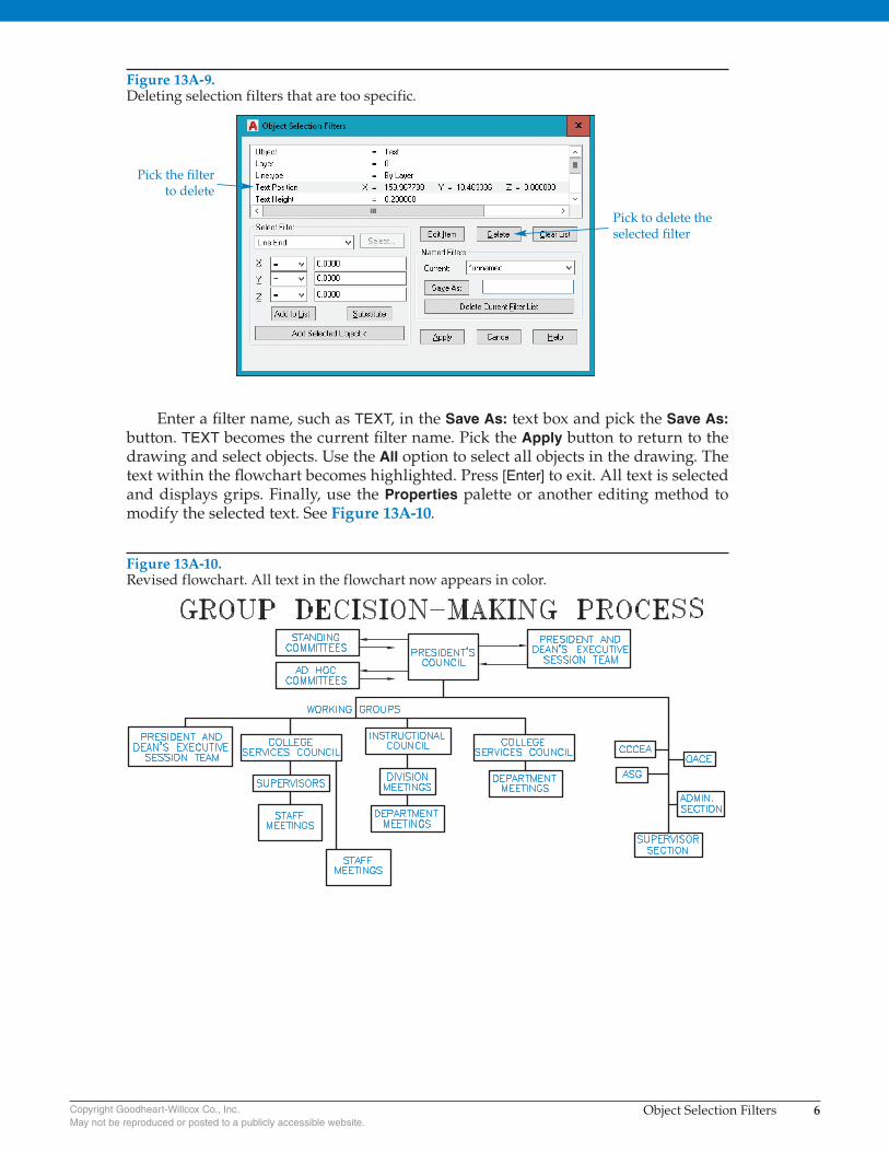
Enter a fi lter name, such as TEXT, in the Save As: text box and pick the Save As: button. TEXT becomes the current fi lter name. Pick the Apply button to return to the drawing and select objects. Use the All option to select all objects in the drawing. The text within the fl owchart becomes highlighted. Press [Enter] to exit. All text is selected and displays grips. Finally, use the Properties palette or another editing method to modify the selected text. See Figure 13A-10.
Figure 13A-9. Deleting selection filters that are too specific.
Pick to delete theselected filter
Pick the filterto delete
Figure 13A-10. Revised flowchart. All text in the flowchart now appears in color.