Supplemental Manual for Brooks FOUNDATION™ Fieldbus .../media/brooks/documentation... ·...
144
Installation and Operation Manual X-DPT-Foundation Fieldbus-SLA5800-SLAMf Series-eng Part Number: 541B115AAG February, 2009 Supplemental Manual for Brooks ® FOUNDATION™ Fieldbus Digital Mass Flow and Pressure Controllers For SLA5800 Series and SLAMf Series
Transcript of Supplemental Manual for Brooks FOUNDATION™ Fieldbus .../media/brooks/documentation... ·...

Installation and Operation Manual X-DPT-Foundation Fieldbus-SLA5800-SLAMf Series-eng Part Number: 541B115AAG February, 2009
Supplemental Manual for Brooks® FOUNDATION™ Fieldbus Digital Mass Flow and Pressure Controllers
For SLA5800 Series and SLAMf Series

Installation and Operation Manual X-DPT-Foundation Fieldbus-SLA5800-SLAMf Series-eng Part Number: 541B115AAG February, 2009
2
Brooks FOUNDATION Fieldbus on SLA Series
Essential Instructions
Read this page before proceeding! Brooks Instrument designs, manufactures and tests its products to meet many national and international standards. Because these instruments are sophisticated technical products, you must properly install, use and maintain them to ensure they continue to operate within their normal specifications. The following instructions must be adhered to and integrated into your safety program when installing, using and maintaining Brooks Products.
Read all instructions prior to installing, operating and servicing the product. If this instruction manual is not the correct manual, please see back cover for local sales office contact information. Save this instruction manual for future reference.
If you do not understand any of the instructions, contact your Brooks Instrument representative for clarification.
Follow all warnings, cautions and instructions supplied with the product.
Inform and educate your personnel in the proper installation, operation and maintenance of the product.
Install your equipment as specified in the installation instructions of the appropriate instruction manual and per applicable local and national codes. Connect all products to the proper electrical and pressure sources.
To ensure proper performance, use qualified personnel to install, operate, update, program and maintain the product.
When replacement parts are required, ensure that qualified people use replacement parts specified by Brooks Instrument. Unauthorized parts and procedures can affect the product's performance and place the safe operation of your process at risk. Look-alike substitutions may result in fire, electrical hazards or improper operation.
Ensure that all equipment doors are closed and protective covers are in place, except when maintenance is being performed by qualified persons, to prevent electrical shock and personal injury.
ESD (Electrostatic Discharge)
This instrument contains electronic components that are susceptible to damage by electricity. Proper handling procedures must be observed during the removal, installation, or other handling of internal circuit boards or devices.
Handling Procedure: 1. Power to unit must be removed. 2. Personnel must be grounded, via a wrist strap or other safe, suitable means before any printed circuit card or other internal device is installed, removed
or adjusted. 3. Printed circuit cards must be transported in a conductive container. Boards must not be removed from protective enclosure until immediately before
installation. Removed boards must immediately be placed in protective container for transport, storage or return to factory. Comments This instrument is not unique in its content of ESD (electrostatic discharge) sensitive components. Most modern electronic designs contain components that utilize metal oxide technology (NMOS, SMOS, etc.). Experience has proven that even small amounts of static electricity can damage or destroy these devices. Damaged components, even though they appear to function properly, exhibit early failure.
Installation and Operation Manual X-DPT-Foundation Fieldbus-SLA5800-SLAMf Series-eng Part Number: 541B115AAG February, 2009
iii
Brooks FOUNDATION Fieldbus on SLA Series
Dear Customer, We recommend that you read this manual in its entirety as this will enable efficient and proper use of the FOUNDATION Fieldbus SLA58xx and SLAMfxx Series devices. Should you require any additional information concerning these devices, please feel free to contact your local Brooks Sales and Service Office; see back cover for contact information, or visit us on the web at www.BrooksInstrument.com. We appreciate this opportunity to service your fluid measurement and control requirements, and trust that we will be able to provide you with further assistance in future. Yours sincerely, Brooks Instrument

Installation and Operation Manual X-DPT-Foundation Fieldbus-SLA5800-SLAMf Series-eng Part Number: 541B115AAG February, 2009
iv
Brooks FOUNDATION Fieldbus on SLA Series
THIS PAGE WAS INTENTIONALLY
LEFT BLANK

Installation and Operation Manual X-DPT-Foundation Fieldbus-SLA5800-SLAMf Series-eng Part Number: 541B115AAG February, 2009
v
Contents
Brooks FOUNDATION Fieldbus on SLA Series
Contents
1. Introduction..............................................................................................................................................1
1.1. Description.................................................................................................................................1 1.1.1. General Description...................................................................................................1 1.1.2. FOUNDATION Fieldbus Description..............................................................................1
1.2. How to Use This Manual ...........................................................................................................2 1.3. Glossary.....................................................................................................................................4
2. Installation................................................................................................................................................5
2.1. FOUNDATION Fieldbus Technology .............................................................................................6 2.2. Requirements ............................................................................................................................6 2.3. Device Servicing........................................................................................................................7 2.4. Device Connection ....................................................................................................................7
2.4.1. FF Communication – EuroFast Connector................................................................8 2.4.2. Power Connection – PicoFast Connector .................................................................9 2.4.3. MFxx Wiring.............................................................................................................10
2.4.3.1. EuroFast Option ......................................................................................10 2.4.3.2. Conduit Option.........................................................................................11
2.4.4. 58xx Wiring..............................................................................................................12 2.5. Device Addressing...................................................................................................................13
3. Hardware Information ...........................................................................................................................15
3.1. Communication System...........................................................................................................15 3.2. LED interface...........................................................................................................................16
4. Function Block Implementations.........................................................................................................17
4.1. Function Block .........................................................................................................................18 4.1.1. AI – Flow..................................................................................................................18 4.1.2. AI – Pressure...........................................................................................................18 4.1.3. AI – Temperature.....................................................................................................18 4.1.4. AI – Valve position...................................................................................................19 4.1.5. AO – Setpoint ..........................................................................................................19 4.1.6. AO – Valve Control..................................................................................................20 4.1.7. DO – Valve Override ...............................................................................................21 4.1.8. PID – Cascade PID .................................................................................................21
4.2. Function Blocks Implementation for Mass Flow Controllers (MFCs) ......................................22

Installation and Operation Manual X-DPT-Foundation Fieldbus-SLA5800-SLAMf Series-eng Part Number: 541B115AAG February, 2009
vi
Contents
Brooks FOUNDATION Fieldbus on SLA Series
4.2.1. MFC Available Channels.........................................................................................23 4.2.2. Function Block Units for MFC..................................................................................23
4.3. Function Blocks Implementation for Mass Flow Meters (MFMs) ............................................25 4.3.1. MFM Available Channels.........................................................................................26 4.3.2. Function Blocks Units for MFM ...............................................................................27
4.4. Function Blocks Implementation for Pressure Controllers (PCs) ............................................29 4.4.1. PC Available Channels............................................................................................29 4.4.2. Function Blocks Units for PC...................................................................................30
5. FOUNDATION Fieldbus Function Blocks ................................................................................................33
5.1. Introduction..............................................................................................................................33 5.1.1. Function Blocks .......................................................................................................33 5.1.2. Block Operation .......................................................................................................34
5.2. Analog Input Function Block....................................................................................................34 5.2.1. Simulation................................................................................................................38 5.2.2. Filtering....................................................................................................................38 5.2.3. Signal Conversion ...................................................................................................39
5.2.3.1. Direct .......................................................................................................39 5.2.3.2. Indirect.....................................................................................................39 5.2.3.3. Indirect Square Root ...............................................................................39
5.2.4. Block Errors .............................................................................................................40 5.2.5. Modes......................................................................................................................41 5.2.6. Alarm Detection .......................................................................................................41 5.2.7. Status Handling .......................................................................................................42 5.2.8. Advanced Features .................................................................................................43 5.2.9. Troubleshooting.......................................................................................................43
5.3. Analog Output Function Block.................................................................................................44 5.3.1. Setting the Output....................................................................................................45 5.3.2. Setpoint Selection and Limiting ...............................................................................46 5.3.3. Conversion and Status Calculation .........................................................................47 5.3.4. Action on Fault Detection ........................................................................................47 5.3.5. Block Errors .............................................................................................................48 5.3.6. Modes......................................................................................................................49 5.3.7. Status Handling .......................................................................................................49
5.4. Digital Output Function Block ..................................................................................................50 5.4.1. Setting the Output....................................................................................................51 5.4.2. Simulation................................................................................................................52 5.4.3. Action on Fault Detection ........................................................................................53 5.4.4. Block Errors .............................................................................................................53

Installation and Operation Manual X-DPT-Foundation Fieldbus-SLA5800-SLAMf Series-eng Part Number: 541B115AAG February, 2009
vii
Contents
Brooks FOUNDATION Fieldbus on SLA Series
5.4.5. Modes......................................................................................................................54 5.4.6. Status Handling / Action on Failure .........................................................................54
5.5. Proportional/Integral/Derivative Function Block ......................................................................55 5.5.1. Setpoint Selection and Limiting ...............................................................................60 5.5.2. Filtering....................................................................................................................61 5.5.3. Feedforward Calculation..........................................................................................61 5.5.4. Tracking...................................................................................................................62 5.5.5. Output Selection and Limiting .................................................................................62 5.5.6. Bumpless Transfer and Setpoint Tracking ..............................................................62 5.5.7. PID Equation Structures..........................................................................................63 5.5.8. Reverse and Direct Action.......................................................................................63 5.5.9. Reset Limiting..........................................................................................................64 5.5.10. Block Errors ...........................................................................................................64 5.5.11. Modes....................................................................................................................65 5.5.12. Alarm Detection .....................................................................................................66 5.5.13. Status Handling .....................................................................................................67 5.5.14. Troubleshooting.....................................................................................................67
6. Resource Block Reference ...................................................................................................................69
6.1. Introduction..............................................................................................................................69 6.2. Resource Block Overview .......................................................................................................69 6.3. Block Parameters ....................................................................................................................69 6.4. Block View ...............................................................................................................................80 6.5. PlantWeb Alarm Descriptions..................................................................................................82
6.5.1. Available PlantWeb Alerts .......................................................................................83 6.5.1.1. Temperature Sensor Connection Failure ................................................83 6.5.1.2. Firmware Checksum Failure ...................................................................83 6.5.1.3. NV – Memory Write Failure .....................................................................83 6.5.1.4. RAM Write Failure ...................................................................................83 6.5.1.5. RB Electronics Failure.............................................................................84 6.5.1.6. Zero Drift Alarm .......................................................................................84 6.5.1.7. Device Overhaul Due ..............................................................................84 6.5.1.8. Device Recalibration Due........................................................................84 6.5.1.9. Valve Spring Life .....................................................................................84 6.5.1.10. Valve Response ....................................................................................85 6.5.1.11. Valve Signature .....................................................................................85 6.5.1.12. No Flow .................................................................................................85 6.5.1.13. Reverse Flow.........................................................................................85 6.5.1.14. Flow Totalizer Alarm..............................................................................85 6.5.1.15. Time Totalizer Alarm .............................................................................85 6.5.1.16. PWA Simulate Active ............................................................................86

Installation and Operation Manual X-DPT-Foundation Fieldbus-SLA5800-SLAMf Series-eng Part Number: 541B115AAG February, 2009
viii
Contents
Brooks FOUNDATION Fieldbus on SLA Series
7. Transducer Blocks Reference..............................................................................................................91
7.1. Introduction..............................................................................................................................91 7.2. Transducer Block Overview.....................................................................................................91 7.3. Transducer block Methods ......................................................................................................91
7.3.1. Sensor Zero Trim.....................................................................................................91 7.4. Block Parameters Tables ........................................................................................................92
7.4.1. Multi-Variable Common Transducer Block..............................................................92 7.4.2. Standard Flow with Calibration Transducer Block ..................................................93
7.4.2.1. Overview..................................................................................................96 7.4.2.2. Schematic................................................................................................97 7.4.2.3. Description...............................................................................................97 7.4.2.4. Supported Modes ....................................................................................99 7.4.2.5. User Selectable Modes ...........................................................................99 7.4.2.6. Alarm Types ............................................................................................99 7.4.2.7. Mode Handling ........................................................................................99 7.4.2.8. Initialization..............................................................................................99 7.4.2.9. Channel Assignments .............................................................................99
7.4.3. Pressure Transducer Block .....................................................................................99 7.4.3.1. Overview................................................................................................101 7.4.3.2. Schematic..............................................................................................102 7.4.3.3. Description.............................................................................................102 7.4.3.4. Supported Modes ..................................................................................104 7.4.3.5. User Selectable Modes .........................................................................104 7.4.3.6. Alarm Types ..........................................................................................104 7.4.3.7. Mode Handling ......................................................................................104 7.4.3.8. Initialization............................................................................................104 7.4.3.9. Channel Assignments ...........................................................................104
7.4.4. Temperature Transducer Block.............................................................................104 7.4.4.1. Overview................................................................................................106 7.4.4.2. Schematic..............................................................................................107 7.4.4.3. Description.............................................................................................107 7.4.4.4. Supported Modes ..................................................................................108 7.4.4.5. User Selectable Modes .........................................................................109 7.4.4.6. Alarm Types ..........................................................................................109 7.4.4.7. Mode Handling ......................................................................................109 7.4.4.8. Initialization............................................................................................109 7.4.4.9. Channel Assignments ...........................................................................109
7.4.5. Brooks Instrument Custom Valve Controller Transducer Block ............................109 7.4.5.1. Overview................................................................................................110 7.4.5.2. Schematic..............................................................................................111 7.4.5.3. Description.............................................................................................112 7.4.5.4. Supported Modes ..................................................................................113 7.4.5.5. User Selectable Modes .........................................................................114 7.4.5.6. Alarm Types ..........................................................................................114 7.4.5.7. Mode Handling ......................................................................................114

Installation and Operation Manual X-DPT-Foundation Fieldbus-SLA5800-SLAMf Series-eng Part Number: 541B115AAG February, 2009
ix
Contents
Brooks FOUNDATION Fieldbus on SLA Series
7.4.5.8. Initialization............................................................................................114 7.4.5.9. Channel Assignments ...........................................................................114
7.4.6. Brooks Specific custom data .................................................................................114 7.4.6.1. Flow Sensor Calibration information .....................................................115 7.4.6.2. Pressure Application Information ..........................................................116 7.4.6.3. Alarm Setup...........................................................................................116 7.4.6.4. Diagnostic Data .....................................................................................118 7.4.6.5. Firmware Information.............................................................................119
7.4.7. Block View .............................................................................................................120
8. Troubleshooting ..................................................................................................................................125
8.1. Data write NIF_ERR_EXCEED_LIMIT..................................................................................125 8.2. AI Function block stays in OOS or status is BAD..................................................................125 8.3. AO Function block stays in OOS or status is bad .................................................................126 8.4. DO Function block stays in OOS or status is bad .................................................................126 8.5. Transducer block stays in OOS.............................................................................................127 8.6. Device does not appear on the network................................................................................127
9. Appendix: (Informative) Calibration ..................................................................................................129

Installation and Operation Manual X-DPT-Foundation Fieldbus-SLA5800-SLAMf Series-eng Part Number: 541B115AAG February, 2009
x
Contents
Brooks FOUNDATION Fieldbus on SLA Series
Tables Table 1-1 Manual Cross-Reference ..............................................................................................................2 Table 2-1 Device Power Consumption..........................................................................................................6 Table 2-2 Device Communication Connection ..............................................................................................8 Table 2-3 Device Power Consumption..........................................................................................................9 Table 3-1 SLA58xx Series LED Indicators ..................................................................................................16 Table 4-1 Function Blocks – General Information .......................................................................................17 Table 4-2 Function Blocks – Channel Number............................................................................................17 Table 4-3 Function Blocks – Channel Number............................................................................................21 Table 4-4 MFC – Available Channels..........................................................................................................23 Table 4-5 MFC – Volumetric and Flow Unit ................................................................................................23 Table 4-6 MFC – Temperature Unit.............................................................................................................24 Table 4-7 MFC – Valve position Unit...........................................................................................................25 Table 4-8 MFM – Available Channels .........................................................................................................26 Table 4-9 MFM – Volumetric and Flow Unit ................................................................................................27 Table 4-10 MFC – Temperature Unit...........................................................................................................28 Table 4-11 PC – Available Channels...........................................................................................................29 Table 4-12 MFC – Pressure Unit.................................................................................................................30 Table 4-13 MFC – Valve Position Unit ........................................................................................................31 Table 5-1 Definitions of Analog Input Function Block System Parameters.................................................35 Table 5-2 BLOCK_ERR Conditions.............................................................................................................40 Table 5-3 Alarm Priority Levels ...................................................................................................................42 Table 5-4 Troubleshooting the AI Function Block .......................................................................................43 Table 5-5 Analog Output Function Block System Parameters....................................................................44 Table 5-6 Discrete Output Function Block System Parameters..................................................................50 Table 5-7 PID Function Block System Parameters .....................................................................................56 Table 5-8 BLOCK_ERR Conditions.............................................................................................................64 Table 5-9 Alarm Priority Levels ...................................................................................................................66 Table 5-10 Troubleshooting the PID Function Block...................................................................................67 Table 6-1 PlantWeb Alerts...........................................................................................................................87 Table 6-2 XD_ERROR Values ....................................................................................................................88 Table 6-3 BLOCK_ERR Values...................................................................................................................89 Table 6-4. Summary Status.........................................................................................................................89 Table 7-1 Device Information Transducer Block Parameters......................................................................92 Table 7-2 Flow Sensor Transducer Block Parameters................................................................................94 Table 7-3 Pressure Sensor Transducer Block Parameters.......................................................................100 Table 7-4 Temperature Sensor Transducer Block Parameters ................................................................105 Table 7-5 Valve Controller Transducer Block Parameters ........................................................................109 Table 7-6 Flow Sensor Calibration Block Parameters...............................................................................115 Table 7-7 Pressure Sensor Calibration Block Parameters........................................................................116 Table 7-8 Alarm Information Block Parameters ........................................................................................116 Table 7-9 Diagnostic Block Parameters ....................................................................................................118 Table 7-10 Firmware Information Block Parameters.................................................................................119 Table 7-11 Flow Sensor Transducer Block Views.....................................................................................120

Installation and Operation Manual X-DPT-Foundation Fieldbus-SLA5800-SLAMf Series-eng Part Number: 541B115AAG February, 2009
xi
Contents
Brooks FOUNDATION Fieldbus on SLA Series
Figures Figure 2-1 Typical FOUNDATION Fieldbus Installation ....................................................................................5 Figure 2-2 EuroFast Connector Pin-outs.......................................................................................................8 Figure 2-3 PicoFast Connector Pin-outs .......................................................................................................9 Figure 2-4 EuroFast Option Connections....................................................................................................10 Figure 2-5 Terminals for Conduit Option .....................................................................................................11 Figure 2-6 Terminals Board Connection......................................................................................................11 Figure 2-7 58xx Connections.......................................................................................................................12 Figure 3-1 Sample FOUNDATION Fieldbus Network Diagram.......................................................................15 Figure 4-1 MFC Function Blocks Implementation .......................................................................................22 Figure 4-2 MFM Function Blocks Implementation.......................................................................................25 Figure 4-3 PC Function Blocks Implementation ..........................................................................................29 Figure 5-1 Analog Input Function Block ......................................................................................................34 Figure 5-2 Analog Input Function Block Timing ..........................................................................................38 Figure 5-3 Analog Output Function Block ...................................................................................................44 Figure 5-4 Analog Output Function Block Timing........................................................................................46 Figure 5-5 Digital Output Function Block.....................................................................................................50 Figure 5-6 Discrete Input Function Block Schematic ..................................................................................51 Figure 5-7 Proportional/Integral/Derivative Function Block.........................................................................55 Figure 5-8 PID Function Block Setpoint ......................................................................................................61 Figure 7-1 Flow Transducer Block Schematic.............................................................................................97 Figure 7-2 Pressure Transducer Block Schematic....................................................................................102 Figure 7-3 Temperature Transducer Block Schematic..............................................................................107 Figure 7-4 Custom Valve Controller Transducer Block Schematic ...........................................................111 Figure 9-1 Upper and Lower Sensor Limits...............................................................................................129

Installation and Operation Manual X-DPT-Foundation Fieldbus-SLA5800-SLAMf Series-eng Part Number: 541B115AAG February, 2009
xii
Contents
Brooks FOUNDATION Fieldbus on SLA Series
THIS PAGE WAS INTENTIONALLY
LEFT BLANK

Installation and Operation Manual X-DPT-Foundation Fieldbus-SLA5800-SLAMf Series-eng Part Number: 541B115AAG February, 2009
1
Section 1 - Introduction
Brooks FOUNDATION Fieldbus on SLA Series
1. Introduction
1.1. Description
1.1.1. General Description
The SLA58xx and SLAMFxx series offers a complete line of Mass Flow Meter, Controller and Pressure Controller devices to use in you low flow applications.
The SLA series has the ability to support industrial networking and communication. For a complete list, please contact your local Brooks Sales and Service Office; see the back cover for contact information, or visit us on the web at www.BrooksInstrument.com..
1.1.2. FOUNDATION Fieldbus Description
In addition to the features provided by the SLA series devices, Brooks Instrument offers the option of FOUNDATION Fieldbus H1 digital communication. Due to the power consumption of the electronically valve control system, these devices use a separate power source and use only a minimum amount of power from the Fieldbus network to ensure proper communication.
These devices fully comply with FOUNDATION Fieldbus specification, allowing their use with the host of your choice.
Each device contains:
1 Standard Resource Block
2 Standard Analog Output Blocks
4 Standard Analog Input Blocks

Installation and Operation Manual X-DPT-Foundation Fieldbus-SLA5800-SLAMf Series-eng Part Number: 541B115AAG February, 2009
2
Section 1 - Introduction
Brooks FOUNDATION Fieldbus on SLA Series
1 Standard Digital Output Block
1 PID Block
1 Multivariable Transducer Block
To take advantage of the advanced diagnostics, Brooks Instrument is using the PlantWeb® Alerts platform1. These diagnostics include critical information on the device health and may indicate important change in the process. Preventive maintenance information is also available through PlantWeb.
1.2. How to Use This Manual
It is recommended that you read this manual before installing or using the FOUNDATION Fieldbus device.
The manual assumes that you are already familiar with the Brooks Instrument SLA devices and FOUNDATION Fieldbus.
Please refer to the user manual associated to the device for a complete description of usage.
Table 1-1 Manual Cross-Reference
Device Type Manual Part number
SLAMfxx (Mass Flow Devices) X-TMF-SLAMf-MFC-ENG 541B032AHG
SLA58xx (Mass Flow Devices) X-TMF-5800-MFC-ENG 541B027AHG
SLA58xx (Pressure Devices) X-TMF-5800-PC-ENG 541B091AHG
For more information on FOUNDATION Fieldbus, please visit the following web site for more detailed information; www.fieldbus.org .
This manual is organized into the following sections:
Section 1: introduction
Section 2: Installation
Section 3: Hardware Information
Section 4: Function Block Implementations
Section 5: FOUNDATION Fieldbus Function Blocks
1 PlantWeb® is available only with an Emerson Process host. Data may still be read through other host but, usually, cannot generate alerts and warning automatically

Installation and Operation Manual X-DPT-Foundation Fieldbus-SLA5800-SLAMf Series-eng Part Number: 541B115AAG February, 2009
3
Section 1 - Introduction
Brooks FOUNDATION Fieldbus on SLA Series
Section 6: FOUNDATION Fieldbus Resource Block
Section 7: Transducer Blocks Reference
Section 8: Troubleshooting
Section 9: (Informative) Calibration

Installation and Operation Manual X-DPT-Foundation Fieldbus-SLA5800-SLAMf Series-eng Part Number: 541B115AAG February, 2009
4
Section 1 - Introduction
Brooks FOUNDATION Fieldbus on SLA Series
1.3. Glossary
AI Analog Input
AO Analog Output
Auto Automatic state
CFF Common File Format files
DD Device Description files
DO Discrete Output
FF FOUNDATION fieldbus
ITK Interoperability Test Kit
Macro Cycle FOUNDATION Fieldbus token ring cycle time
MFC Mass Flow Controller
MFM Mass Flow Meter
OOS Out of service device state
PC Pressure Controller
Segment Single line of communication on FOUNDATION Fieldbus

Installation and Operation Manual X-DPT-Foundation Fieldbus-SLA5800-SLAMf Series-eng Part Number: 541B115AAG February, 2009
5
Section 2 - Installation
Brooks FOUNDATION Fieldbus on SLA Series
2. Installation
Safe operation is dependent on proper installation and validation of the system and software.
Installation of the FOUNDATION Fieldbus devices is specific to the host; please refer to the host manual to properly install your device. The latest Device Description (DD) and Common File Format (CFF) files can be found in the Registered Product Catalog section of the FOUNDATION Fieldbus web site: www.fieldbus.org. Our device (click here to directly go to the web site) is filed as “Brooks Instrument SLA Series” under “Emerson Process Management” manufacturer and the “Flow” category
The following diagram represents a typical installation. Brooks Instrument FOUNDATION Fieldbus devices are H1 compatible only.
Figure 2-1 Typical FOUNDATION Fieldbus Installation
Linking Device
HSE (High Speed Ethernet) Segment 100 Mbps (or 10 Mbps) Communications only Requires communication grade wire
Control Module
Engineering Station
Operator Station
HSE
H1 Segment Power & communications on the same wire Intrinsically safe Twisted pair wiring
H1

Installation and Operation Manual X-DPT-Foundation Fieldbus-SLA5800-SLAMf Series-eng Part Number: 541B115AAG February, 2009
6
Section 2 - Installation
Brooks FOUNDATION Fieldbus on SLA Series
2.1. FOUNDATION Fieldbus Technology
FOUNDATION fieldbus is an all digital, serial, two-way communication system that interconnects field equipment such as sensors, actuators, and controllers. Fieldbus is a Local Area Network (LAN) for instruments used in both process and manufacturing automation with built-in capability to distribute the control application across the network. The fieldbus environment is the base level group of digital networks in the hierarchy of plant networks.
The fieldbus retains the desirable features of the 4–20 mA analog system, including a standardized physical interface to the wire, bus powered devices on a single wire, and intrinsic safety options, and enables additional capabilities, such as:
Increased capabilities due to full digital communications
Reduced wiring and wire terminations due to multiple devices on one set of wires
Increased selection of suppliers due to interoperability
Reduced loading on control room equipment with the distribution of some control and input/output functions to field devices
2.2. Requirements
The device must be used within the range of calibration; failure to do so may lead to hazardous situation endangering the user. Please refer to the device user manual for proper usage and installation.
FOUNDATION Fieldbus power requirements must be met.
Table 2-1 Device Power Consumption
DC Voltage Current Consumption
14 to 27 V 491 mA for controllers, 245 mA for meters
Device grounding must be provided, either by cable shielding or mechanical ground connection.
Shielded power cable is recommended. Please use part #: PKG 4M-*/S90/S101 from Turck® (www.turck.com) or equivalent.

Installation and Operation Manual X-DPT-Foundation Fieldbus-SLA5800-SLAMf Series-eng Part Number: 541B115AAG February, 2009
7
Section 2 - Installation
Brooks FOUNDATION Fieldbus on SLA Series
The FOUNDATION Fieldbus communication connection must respect the host specification, especially in matter of number of devices allowed per segment and network speed.
Shielded FOUNDATION Fieldbus Communication cable is recommended. For Eurofast connection, please use part #: RKS 4.4T-* from Turck® (www.turck.com) or equivalent.
Discrete connections must comply with the FOUNDATION Fieldbus specification. Refer to the FOUNDATION Fieldbus web site, www.fieldbus.org, for more information.
2.3. Device Servicing
Please refer to the associated user manual (for a listing of the manuals, refer to Table 1-1 on page 2) for a complete description on how to properly service the device.
2.4. Device Connection
Wiring of the device is realized through direct connection with the exception of the conduit option. There is no internal device wiring required.
Note: For ease of installation, the Brooks Instrument FOUNDATION Fieldbus devices are designed to be insensitive to the polarity of the network cable. FOUNDATION Fieldbus network polarity may be specified in the rest of this manual for reference only.
Installation and Operation Manual X-DPT-Foundation Fieldbus-SLA5800-SLAMf Series-eng Part Number: 541B115AAG February, 2009
8
Section 2 - Installation
Brooks FOUNDATION Fieldbus on SLA Series
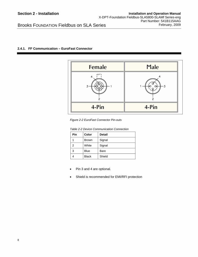
2.4.1. FF Communication – EuroFast Connector
Figure 2-2 EuroFast Connector Pin-outs
Table 2-2 Device Communication Connection
Pin Color Detail
1 Brown Signal
2 White Signal
3 Blue Bare
4 Black Shield
Pin 3 and 4 are optional.
Shield is recommended for EMI/RFI protection

Installation and Operation Manual X-DPT-Foundation Fieldbus-SLA5800-SLAMf Series-eng Part Number: 541B115AAG February, 2009
9
Section 2 - Installation
Brooks FOUNDATION Fieldbus on SLA Series
2.4.2. Power Connection – PicoFast Connector
Figure 2-3 PicoFast Connector Pin-outs
Table 2-3 Device Power Consumption
Pin Color Detail
1 Brown VCC (14 to 27 VDC)
2 White Not Connected
3 Blue DC Ground
4 Black Not Connected
Shield is recommended for EMI/RFI protection.
Installation and Operation Manual X-DPT-Foundation Fieldbus-SLA5800-SLAMf Series-eng Part Number: 541B115AAG February, 2009
10
Section 2 - Installation
Brooks FOUNDATION Fieldbus on SLA Series
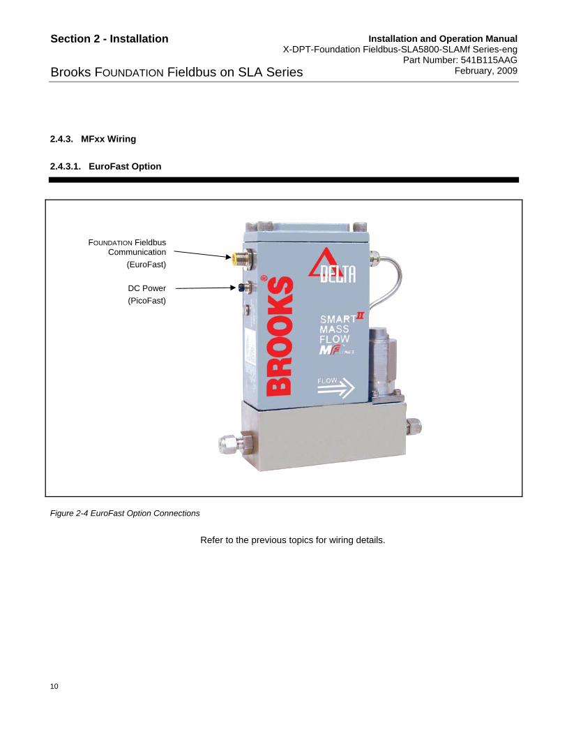
2.4.3. MFxx Wiring
2.4.3.1. EuroFast Option
Figure 2-4 EuroFast Option Connections
Refer to the previous topics for wiring details.
DC Power
(PicoFast)
FOUNDATION Fieldbus Communication
(EuroFast)

Installation and Operation Manual X-DPT-Foundation Fieldbus-SLA5800-SLAMf Series-eng Part Number: 541B115AAG February, 2009
11
Section 2 - Installation
Brooks FOUNDATION Fieldbus on SLA Series
2.4.3.2. Conduit Option
Figure 2-5 Terminals for Conduit Option
To connect to the device using a conduit:
1. Open the top part of the MFxx device and the Interface PC will be exposed.
2. Insert the power and communication cable through the appropriate fitting.
3. Use the screw terminals to establish network and power connection.
Figure 2-6 Terminals Board Connection
Valve connection
(No polarity)
Network and Power Shield 14 to 27 VDC
FF Network
(No Polarity) DC Ground
GT1 J1
J2
FF
FF
VC
C
GN
D
SH
IELD
SERVICE PORTBUS DEV

Installation and Operation Manual X-DPT-Foundation Fieldbus-SLA5800-SLAMf Series-eng Part Number: 541B115AAG February, 2009
12
Section 2 - Installation
Brooks FOUNDATION Fieldbus on SLA Series
2.4.4. 58xx Wiring
Figure 2-7 58xx Connections
Refer to the previous topics for wiring details.
DC Power
(PicoFast) FF Communication
(EuroFast)

Installation and Operation Manual X-DPT-Foundation Fieldbus-SLA5800-SLAMf Series-eng Part Number: 541B115AAG February, 2009
13
Section 2 - Installation
Brooks FOUNDATION Fieldbus on SLA Series
2.5. Device Addressing
With a new device and depending on the host system, a first time device addressing may take up to 3 minutes. Typically, when the device has been already addressed, the device will appear on the network in less than 45 seconds.
Typically, when the device is connected to the FF, the Master will appear with a unique address (DEV_ID); for example 0002461000-BROOKS-0x….. , where:
000246 is the Brooks Instrument Manufacturer code. This registered with the FOUNDATION Fieldbus.
1000-BROOKS is the device identification. All the devices of the SLAxx series are using the same device identification. Distinction between the devices is represented buy the Module Type in the Resource Block.
The final part of the DEV_ID is the serial number of the FOUNDATION Fieldbus communication board.
The DEV_ID will be replaced by a unique electronic TAG if requested upon order.

Installation and Operation Manual X-DPT-Foundation Fieldbus-SLA5800-SLAMf Series-eng Part Number: 541B115AAG February, 2009
14
Section 2 - Installation
Brooks FOUNDATION Fieldbus on SLA Series
THIS PAGE WAS INTENTIONALLY
LEFT BLANK
Installation and Operation Manual X-DPT-Foundation Fieldbus-SLA5800-SLAMf Series-eng Part Number: 541B115AAG February, 2009
15
Section 3 - Hardware Information
Brooks FOUNDATION Fieldbus on SLA Series
3. Hardware Information
3.1. Communication System
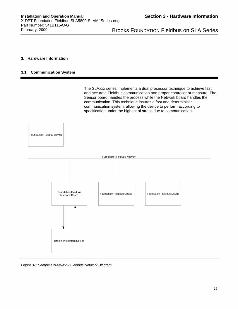
The SLAxxx series implements a dual processor technique to achieve fast and accurate Fieldbus communication and proper controller or measure. The Sensor board handles the process while the Network board handles the communication. This technique insures a fast and deterministic communication system, allowing the device to perform according to specification under the highest of stress due to communication.
Foundation Fieldbus Device
Foundation Fieldbus Network
Foundation FieldbusInterface Board
Brooks Instrument Device
Foundation Fieldbus Device Foundation Fieldbus Device
Figure 3-1 Sample FOUNDATION Fieldbus Network Diagram

Installation and Operation Manual X-DPT-Foundation Fieldbus-SLA5800-SLAMf Series-eng Part Number: 541B115AAG February, 2009
16
Section 3 - Hardware Information
Brooks FOUNDATION Fieldbus on SLA Series
3.2. LED interface
The SLA58xx series has two LEDs that indicate the device and network status.
Table 3-1 SLA58xx Series LED Indicators
DEV LED BUS LED Device Status
Off Off Device is not powered.
Blinking Off Device is Resetting.
Green Blinking Device is Ready but not connected to a Master.
Green Green Device is Ready and is connected to a Master.
Green Red Internal communication was lost, the device will not perform.
Green Off Internal Communication never occurred, the device will not perform.
Red Any Critical Error, the device will not perform.

Installation and Operation Manual X-DPT-Foundation Fieldbus-SLA5800-SLAMf Series-eng Part Number: 541B115AAG February, 2009
17
Section 4 - Function Blocks Implementation
Brooks FOUNDATION Fieldbus on SLA Series
4. Function Block Implementations
All devices have the ability to support multiple function blocks.
Table 4-1 Function Blocks – General Information
Type Quantity Timing Possible Linked
AO 2 8 ms Flow or pressure Setpoint Valve position
AI 4 5 ms Flow Pressure Flow Sensor Temperature Current Valve Position
DO 1 8 ms Valve override function
PID 1 8 ms PID control for cascade process
Some hosts will use the Common File Format (CFF) file to link the function blocks to the fixed channel number. If those channels are not set properly, the value will not be readable, the device will stay in Out Of Service (OOS) state, or the value return will have a ‘Bad’ Status.
Table 4-2 Function Blocks – Channel Number
Device Data Type Type Channel
Setpoint (Flow or pressure) AO 1
Valve Control AO 2
Flow AI 3
Pressure AI 4
Valve Position AI 5
Flow sensor Temperature AI 6
Valve Override DO 7
Cascade PID PID N/A
Note: AO, AI and DO function blocks do not need to be cascaded to use the device.

Installation and Operation Manual X-DPT-Foundation Fieldbus-SLA5800-SLAMf Series-eng Part Number: 541B115AAG February, 2009
18
Section 4 - Function Blocks Implementation
Brooks FOUNDATION Fieldbus on SLA Series
4.1. Function Block
4.1.1. AI – Flow
The AI – Flow represents the current flow detected by the device sensor. This AI is valid only for MFC and MFM devices. Querying the AI – Flow on a PC will return a Bad status. This information is valid only if the transducer block and the AI – Flow function block are in Auto mode.
If an invalid engineering unit is selected, the function block will stay in ‘OOS’ mode and the block error will indicate “Configuration Error”.
4.1.2. AI – Pressure
The AI – Pressure represents the current pressure detected by the device sensor. This AI is valid only for PC devices. Querying the AI – Pressure on a MFM or a MFC will return a Bad status. This information is valid only if the transducer block and the AI – Pressure function block are in Auto mode.
If an invalid engineering unit is selected, the function block will stay in ‘OOS’ mode and the block error will indicate “Configuration Error”.
4.1.3. AI – Temperature
The AI – Temperature represents the current flow sensor temperature detected by the device sensor. This AI is valid only for MFC and MFM devices. Querying the AI – Temperature on a PC will return a Bad status. This information is valid only if the transducer block and the AI – Temperature function block are in Auto mode.
Sensor temperature is available only in Celsius. This information may be used use for diagnostics, alarms, or trending. The value returned by the device represents the internal temperature of the flow sensor, not the processed gas temperature.

Installation and Operation Manual X-DPT-Foundation Fieldbus-SLA5800-SLAMf Series-eng Part Number: 541B115AAG February, 2009
19
Section 4 - Function Blocks Implementation
Brooks FOUNDATION Fieldbus on SLA Series
4.1.4. AI – Valve position
The AI – Valve Position represents the current valve position in percent of drive. This AI is valid only for controller (MFC and PC) devices. Querying the AI – Valve Position on a MFM will return a Bad status. This information is valid only if the transducer block and the AI – Temperature function block are in Auto mode.
The valve position varies from 0 to 100% of drive. Normal range of operation is indicated by the VALVE_SPAN and VALVE_OFFSET (refer to “Brooks Instrument Custom Valve Controller Transducer Block” on page 38). This value may be use to indicate for diagnostics, alarms, and trending. Change in process and device failure will drastically change the valve drive during normal operation. The user may use an alarm on those values to preemptively detect process failure.
Example:
A device will operate from 27.3% of drive (VALVE_OFFSET) to 54.7% (VALVE_SPAN) during normal operation, controlling from 0 to 100% of full scale at the calibrated range of pressure. If the valve position reports a value outside this range (+ or – a reasonable amount of uncertainty of 10%), it could conclude that either:
The process gas property has changed. Change in density or pressure will affect the amount of opening of the valve.
The device is having trouble to properly control the process due to valve or sensor clogging. Trending the valve position versus the setpoint over a long period of time can generate enough historical data to indicate that a device is on the verge of failure.
These values are specific per device and process; alarms values need to be adjusted accordingly by the user.
4.1.5. AO – Setpoint
The AO – Setpoint represents the requested value of control. This value is device specific; setpoint is in flow units for MFCs and pressure units for PCs. AO – Setpoint is not valid for MFM and will return a bad status.

Installation and Operation Manual X-DPT-Foundation Fieldbus-SLA5800-SLAMf Series-eng Part Number: 541B115AAG February, 2009
20
Section 4 - Function Blocks Implementation
Brooks FOUNDATION Fieldbus on SLA Series
AO – Setpoint is controlling the internal PID. In order to satisfy the PID loop (output equals the requested input) XD_SCALE must match the corresponding AI (flow for MFCs and pressure for PCs) XD_SCALE. If the XD_SCALE unit is different from the corresponding AI or the requested value is out of range, the block will switch mode to IMAN and a Bad status will be returned.
AO – Setpoint is used only if the Valve override DO is set to ‘Normal’ (State 0).
AO – Setpoint allows the device to use its internal PID controller. The internal controller is running at a much faster rate that the FOUNDATION Fieldbus PID. The controller device can match only specification by using the internal PID. Although available, disabling the internal PID controller is not recommended, as the FOUNDATION Fieldbus PID controller will have to run at the macro cycle rate.
4.1.6. AO – Valve Control
The AO – Valve Control represents the requested value of valve position. AO – Valve Control is not valid for MFM and will return a Bad status.
The AO – Valve Control varies from 0 to 100% of drive.
AO – Valve control is used only if the Valve override DO is set to ‘Open Loop’ (State 1).
Controlling the valve directly allows device calibration and process specific operation such as venting or cascade control.
Although not recommended, AO – Valve control also allows using the predefined FOUNDATION Fieldbus PID control of the valve. Valve control timing will be linked to the macro cycle. At the point, the device cannot guaranty that overshoot and response time are within specifications.

Installation and Operation Manual X-DPT-Foundation Fieldbus-SLA5800-SLAMf Series-eng Part Number: 541B115AAG February, 2009
21
Section 4 - Function Blocks Implementation
Brooks FOUNDATION Fieldbus on SLA Series
4.1.7. DO – Valve Override
DO – Valve Override controls the valve behavior according to a preset number of cases. DO – Valve Override is not valid for MFM and will return a Bad status.
DO – Valve Override offers the following states.
Table 4-3 Function Blocks – Channel Number
DO State VOR State Description
State 0 Normal The valve is controlled by the internal PID and is responding to AO – Setpoint changes.
State 1 Open loop The valve is controlled by the AO – Valve Control.
State 2 Valve closed The valve is internally commanded to fully close.
State 3 Valve open The valve is internally commanded to fully open.
State 4 Valve Off Remove all power to the valve; valve position depends on the device configuration (normally open or normally closed).
State 5 Valve Hold Valve power stays constant to the last applied value.
State 6 Valve On Apply maximum power to the valve; valve position depends on the device configuration (normally open or normally closed).
4.1.8. PID – Cascade PID
This function block is not linked to any internal data within the device. It can be used to the discretion of the user. It is recommended to use this function block as a cascade PID controlling the setpoint. Please refer to the host manual on how to setup this function block. Note that the PID function block executes in 8 ms and can be connected from and to other devices’ function blocks, reducing macro cycle timing.

Installation and Operation Manual X-DPT-Foundation Fieldbus-SLA5800-SLAMf Series-eng Part Number: 541B115AAG February, 2009
22
Section 4 - Function Blocks Implementation
Brooks FOUNDATION Fieldbus on SLA Series
4.2. Function Blocks Implementation for Mass Flow Controllers (MFCs)
Figure 4-1 MFC Function Blocks Implementation

Installation and Operation Manual X-DPT-Foundation Fieldbus-SLA5800-SLAMf Series-eng Part Number: 541B115AAG February, 2009
23
Section 4 - Function Blocks Implementation
Brooks FOUNDATION Fieldbus on SLA Series
4.2.1. MFC Available Channels
Table 4-4 MFC – Available Channels
Device Data Type Type Channel
Setpoint (Flow) AO 1
Valve Control AO 2
Flow AI 3
Valve Position AI 5
Flow sensor Temperature AI 6
Valve Override DO 7
Cascade PID PID N/A
4.2.2. Function Block Units for MFC
AO – Setpoint and AI – Flow
Table 4-5 MFC – Volumetric and Flow Unit
Value Description (Host dependent)
Flow Rate
1342 Percent (%)
1684 Standard Cubic Centimeter per Minute
1537 Standard Liter per Second
1538 Standard Liter per Minute
1539 Standard Liter per Hour
1347 Cubic Meter per Second
1348 Cubic Meter per Minute
1349 Cubic Meter per Hour
1356 Cubic Feet per Second
1357 Cubic Feet per Minute
1358 Cubic Feet per Hour
1362 Gallon Per Second
1363 Gallon Per Minute

Installation and Operation Manual X-DPT-Foundation Fieldbus-SLA5800-SLAMf Series-eng Part Number: 541B115AAG February, 2009
24
Section 4 - Function Blocks Implementation
Brooks FOUNDATION Fieldbus on SLA Series
Value Description (Host dependent)
1364 Gallon Per Hour
1367 Imperial Gallon per Second
1368 Imperial Gallon per Minute
1369 Imperial Gallon per Hour
1371 Barrel per seconds
1372 Barrel per minutes
1373 Barrel per hours
Mass Rate
1342 Percent (%)
1318 Gram per Second
1319 Gram per Minutes
1320 Gram per Hours
1322 Kilogram per Second
1323 Kilogram per Minute
1324 Kilogram per Hour
1326 Metric Ton per Second
1327 Metric Ton per Minute
1328 Metric Ton per Hour
1330 Pound per Second
1331 Pound per Minute
1332 Pound per Hour
1334 Tons per Second
1335 Tons per Minute
1336 Tons per Hour
AI – Sensor Temperature
Table 4-6 MFC – Temperature Unit
Value Description (Host dependent)
Temperature
1001 Degree Celsius

Installation and Operation Manual X-DPT-Foundation Fieldbus-SLA5800-SLAMf Series-eng Part Number: 541B115AAG February, 2009
25
Section 4 - Function Blocks Implementation
Brooks FOUNDATION Fieldbus on SLA Series
AO – Valve Control and AI – Valve position
Table 4-7 MFC – Valve position Unit
Value Description (Host dependent)
Valve position
1342 Percent (%)
Valve position and control are always expressed in % and controlled from 0 to 100.
4.3. Function Blocks Implementation for Mass Flow Meters (MFMs)
Figure 4-2 MFM Function Blocks Implementation
Installation and Operation Manual X-DPT-Foundation Fieldbus-SLA5800-SLAMf Series-eng Part Number: 541B115AAG February, 2009
26
Section 4 - Function Blocks Implementation
Brooks FOUNDATION Fieldbus on SLA Series
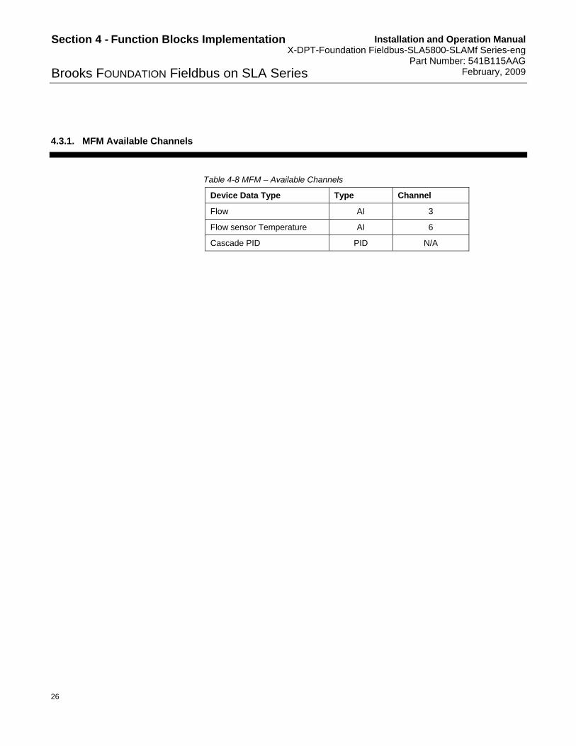
4.3.1. MFM Available Channels
Table 4-8 MFM – Available Channels
Device Data Type Type Channel
Flow AI 3
Flow sensor Temperature AI 6
Cascade PID PID N/A
Installation and Operation Manual X-DPT-Foundation Fieldbus-SLA5800-SLAMf Series-eng Part Number: 541B115AAG February, 2009
27
Section 4 - Function Blocks Implementation
Brooks FOUNDATION Fieldbus on SLA Series
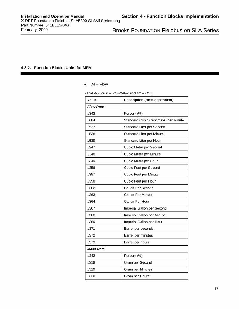
4.3.2. Function Blocks Units for MFM
AI – Flow
Table 4-9 MFM – Volumetric and Flow Unit
Value Description (Host dependent)
Flow Rate
1342 Percent (%)
1684 Standard Cubic Centimeter per Minute
1537 Standard Liter per Second
1538 Standard Liter per Minute
1539 Standard Liter per Hour
1347 Cubic Meter per Second
1348 Cubic Meter per Minute
1349 Cubic Meter per Hour
1356 Cubic Feet per Second
1357 Cubic Feet per Minute
1358 Cubic Feet per Hour
1362 Gallon Per Second
1363 Gallon Per Minute
1364 Gallon Per Hour
1367 Imperial Gallon per Second
1368 Imperial Gallon per Minute
1369 Imperial Gallon per Hour
1371 Barrel per seconds
1372 Barrel per minutes
1373 Barrel per hours
Mass Rate
1342 Percent (%)
1318 Gram per Second
1319 Gram per Minutes
1320 Gram per Hours

Installation and Operation Manual X-DPT-Foundation Fieldbus-SLA5800-SLAMf Series-eng Part Number: 541B115AAG February, 2009
28
Section 4 - Function Blocks Implementation
Brooks FOUNDATION Fieldbus on SLA Series
Value Description (Host dependent)
1322 Kilogram per Second
1323 Kilogram per Minute
1324 Kilogram per Hour
1326 Metric Ton per Second
1327 Metric Ton per Minute
1328 Metric Ton per Hour
1330 Pound per Second
1331 Pound per Minute
1332 Pound per Hour
1334 Tons per Second
1335 Tons per Minute
1336 Tons per Hour
AI – Sensor Temperature
Table 4-10 MFC – Temperature Unit
Value Description (Host dependent)
Temperature
1001 Degree Celsius

Installation and Operation Manual X-DPT-Foundation Fieldbus-SLA5800-SLAMf Series-eng Part Number: 541B115AAG February, 2009
29
Section 4 - Function Blocks Implementation
Brooks FOUNDATION Fieldbus on SLA Series
4.4. Function Blocks Implementation for Pressure Controllers (PCs)
Figure 4-3 PC Function Blocks Implementation
4.4.1. PC Available Channels
Table 4-11 PC – Available Channels
Device Data Type Type Channel
Setpoint (Pressure) AO 1
Valve Control AO 2
Pressure AI 4
Valve Position AI 5
Valve Override DO 7
Cascade PID PID N/A

Installation and Operation Manual X-DPT-Foundation Fieldbus-SLA5800-SLAMf Series-eng Part Number: 541B115AAG February, 2009
30
Section 4 - Function Blocks Implementation
Brooks FOUNDATION Fieldbus on SLA Series
4.4.2. Function Blocks Units for PC
AO – Setpoint and AI - Pressure
Table 4-12 MFC – Pressure Unit
Value Description (Host dependent)
Pressure
1342 Percent (%)
1141 Pound per Square Inch
1139 Torr
1685 milliTorr
1158 Millimeters of Mercury (mmHg)
1156 Inches of Mercury (inHg)
1149 Millimeters of Water (mmH2O)
1146 Inches of Water (inH2O)
1137 Bar
1138 Millibar
1130 Pascal
1133 Kilopascal
1140 Atmosphere
1144 Grams per Square centimeter
1145 Kilograms per Square centimeter
Setpoint and pressure units (XD_SCALE) must match; failure to do so will result on the function block will return a “Bad” status and the BlockErr will show an output failure.
Range of XD_SCALE varies according to the device calibration.
AO – Valve Control and AI – Valve position

Installation and Operation Manual X-DPT-Foundation Fieldbus-SLA5800-SLAMf Series-eng Part Number: 541B115AAG February, 2009
31
Section 4 - Function Blocks Implementation
Brooks FOUNDATION Fieldbus on SLA Series
Table 4-13 MFC – Valve Position Unit
Value Description (Host dependent)
Valve Position
1342 Percent (%)
Valve position and control are always expressed in % and controlled from 0 to 100.

Installation and Operation Manual X-DPT-Foundation Fieldbus-SLA5800-SLAMf Series-eng Part Number: 541B115AAG February, 2009
32
Section 4 - Function Blocks Implementation
Brooks FOUNDATION Fieldbus on SLA Series
THIS PAGE WAS INTENTIONALLY
LEFT BLANK
Installation and Operation Manual X-DPT-Foundation Fieldbus-SLA5800-SLAMf Series-eng Part Number: 541B115AAG February, 2009
33
Section 5 - FOUNDATION Fieldbus Function Block
Brooks FOUNDATION Fieldbus on SLA Series
5. FOUNDATION Fieldbus Function Blocks
This section introduces fieldbus systems that are common to all fieldbus devices, including AI, AO, DO, and PID function blocks. The transducer function blocks present in the SLA Series transmitter are documented in Section 6.
5.1. Introduction
A fieldbus system is a distributed system composed of field devices and control and monitoring equipment integrated into the physical environment of a plant or factory. Fieldbus devices work together to provide I/O and control for automated processes and operations. The Fieldbus FOUNDATION provides a framework for describing these systems as a collection of physical devices interconnected by a fieldbus network. One of the ways the physical devices are used is to perform their portion of the total system operation by implementing one or more function blocks.
5.1.1. Function Blocks
Function blocks within the fieldbus device perform the various functions required for process control. Because each system is different, the mix and configuration of functions are different. Therefore, the Fieldbus FOUNDATION has designed a range of function blocks, each addressing a different need.
The Fieldbus FOUNDATION has established the function blocks by defining a small set of parameters used in all function blocks called universal parameters. They have also published definitions for transducer blocks commonly used with standard function blocks. Examples include temperature, pressure, level, and flow transducer blocks.
A block is a tagged logical processing unit. The tag is the name of the block. System management services locate a block by its tag. Thus the service personnel need only know the tag of the block to access or change the appropriate block parameters. Function blocks are also capable of performing short-term data collection and storage for reviewing blocks and their parameters.

Installation and Operation Manual X-DPT-Foundation Fieldbus-SLA5800-SLAMf Series-eng Part Number: 541B115AAG February, 2009
34
Section 5 - FOUNDATION Fieldbus Function Block
Brooks FOUNDATION Fieldbus on SLA Series
5.1.2. Block Operation
In addition to function blocks, fieldbus devices contain two other block types to support the function blocks. These are the resource block and the transducer block. The resource block contains the hardware specific characteristics associated with a device. Transducer blocks couple the function blocks to local I/O functions.
5.2. Analog Input Function Block
OUT = The block output value and status OUT_D = Discrete output that signals a selected alarm condition
Figure 5-1 Analog Input Function Block
The analog input (AI) function block processes field device measurements and makes them available to other function blocks. The output value from the AI block is in engineering units and contains a status indicating the quality of the measurement. The measuring device may have several measurements or derived values available in different channels. Use the channel number to define the variable that the AI block processes.
The AI block supports alarming, signal scaling, signal filtering, signal status calculation, mode control, and simulation. In Automatic mode, the block’s output parameter (OUT) reflects the process variable (PV) value and status. In Manual mode, OUT may be set manually. The Manual mode is reflected on the output status. A discrete output (OUT_D) is provided to indicate whether a selected alarm condition is active. Alarm detection is based on the OUT value and user specified alarm limits. Table 5-1 on page 35 lists the AI block parameters and their units of measure, descriptions, and index numbers. AI block timing is illustrated in Figure 5-2 on page 38.

Installation and Operation Manual X-DPT-Foundation Fieldbus-SLA5800-SLAMf Series-eng Part Number: 541B115AAG February, 2009
35
Section 5 - FOUNDATION Fieldbus Function Block
Brooks FOUNDATION Fieldbus on SLA Series
Table 5-1 Definitions of Analog Input Function Block System Parameters
Parameter Index Number Units Description
ACK_OPTION 23 None Used to set auto acknowledgment of alarm
ALARM_HYS 24 % The amount the alarm value must return within the alarm limit before the associated active alarm condition clears
ALARM_SEL 38 None Used to select the process alarm conditions that will cause the OUT_D parameter to be set
ALARM_SUM 22 None The summary alarm is used for all process alarms in the block. The cause of the alert is entered in the subcode field. The first alert to become active will set the Active status in the Status parameter. As soon as the Unreported status is cleared by the alert reporting task, another block alert may be reported without clearing the Active status, if the subcode has changed.
ALERT_KEY 04 None The identification number of the plant unit. This information may be used in the host for sorting alarms, etc.
BLOCK_ALM 21 None The block alarm is used for all configuration, hardware and connection failure or system problems in the block. The cause of the alert is entered in the subcode field. The first alert to become active will set the Active status in the Status parameter. As soon as the Unreported status is cleared by the alert reporting task, another block alert may be reported without clearing the Active status, if the subcode has changed.
BLOCK_ERR 06 None This parameter reflects the error status associated with the hardware or software components associated with a block. It is a bit string, so that multiple errors may be shown.
CHANNEL 15 None The CHANNEL value is used to select the measurement value. Refer to the appropriate device manual for information about the specific channels available in each device. You must configure the CHANNEL parameter before you can configure the XD_SCALE parameter.
FIELD_VAL 19 % The value and status from the transducer block
GRANT_DENY 12 None Options for controlling access of host computers and local control panels to operating, tuning, and alarm parameters of the block. Not used by device.

Installation and Operation Manual X-DPT-Foundation Fieldbus-SLA5800-SLAMf Series-eng Part Number: 541B115AAG February, 2009
36
Section 5 - FOUNDATION Fieldbus Function Block
Brooks FOUNDATION Fieldbus on SLA Series
Parameter Index Number Units Description
HI_ALM 34 None The HI alarm data, which includes a value of the alarm, a timestamp of occurrence, and the state of the alarm
HI_HI_ALM 33 None The HI HI alarm data, which includes a value of the alarm, a timestamp of occurrence, and the state of the alarm
HI_HI_LIM 26 EU of PV_SCALE
The setting for the alarm limit used to detect the HI HI alarm condition
HI_HI_PRI 25 None The priority of the HI HI alarm
HI_LIM 28 EU of PV_SCALE
The setting for the alarm limit used to detect the HI alarm condition
HI_PRI 27 None The priority of the HI alarm
IO_OPTS 13 None Allows the selection of I/O options used to alter the PV. Low cutoff enabled is the only selectable option.
L_TYPE 16 None Linearization type. Determines whether the field value is used directly (Direct), is converted linearly (Indirect), or is converted with the square root (Indirect Square Root).
LO_ALM 35 None The LO alarm data, which includes a value of the alarm, a timestamp of occurrence, and the state of the alarm
LO_LIM 30 EU of PV_SCALE
The setting for the alarm limit used to detect the LO alarm condition
LO_LO_ALM 36 None The LO LO alarm data, which includes a value of the alarm, a timestamp of occurrence, and the state of the alarm
LO_LO_LIM 32 EU of PV_SCALE
The setting for the alarm limit used to detect the LO LO alarm condition
LO_LO_PRI 31 None The priority of the LO LO alarm
LO_PRI 29 None The priority of the LO alarm
LOW_CUT 17 % If percentage value of transducer input fails below this, PV = 0.
MODE_BLK 05 None The actual, target, permitted, and normal modes of the block. Target: The mode to “go to” Actual: The mode the “block is currently in” Permitted: Allowed modes that target may take on Normal: Most common mode for target
OUT 08 EU of OUT_SCALE
The block output value and status
OUT_D 37 None Discrete output to indicate a selected alarm condition

Installation and Operation Manual X-DPT-Foundation Fieldbus-SLA5800-SLAMf Series-eng Part Number: 541B115AAG February, 2009
37
Section 5 - FOUNDATION Fieldbus Function Block
Brooks FOUNDATION Fieldbus on SLA Series
Parameter Index Number Units Description
OUT_SCALE 11 None The high and low scale values, engineering units code, and number of digits to the right of the decimal point associated with OUT
PV 07 EU of XD_SCALE
The process variable used in block execution
PV_FTIME 18 Seconds The time constant of the first-order PV filter. It is the time required for a 63% change in the IN value.
STRATEGY 03 None The strategy field can be used to identify grouping of blocks. This data is not checked or processed by the block.
ST_REV 01 None The revision level of the static data associated with the function block. The revision value will be incremented each time a static parameter value in the block is changed.
TAG_DESC 02 None The user description of the intended application of the block
UPDATE_EVT 20 None This alert is generated by any change to the static data.
VAR_INDEX 39 % of OUT Range
The average absolute error between the PV and its previous mean value over that evaluation time defined by VAR_SCAN
VAR_SCAN 40 Seconds The time over which the VAR_INDEX is evaluated
XD_SCALE 10 None The high and low scale values, engineering unit code, and number of digits to the right of the decimal point associated with the channel input value. The XD_SCALE unit code must match the unit code of the measurement channel in the transducer block. If the units do not match, the block will not transition to MAN or AUTO.

Installation and Operation Manual X-DPT-Foundation Fieldbus-SLA5800-SLAMf Series-eng Part Number: 541B115AAG February, 2009
38
Section 5 - FOUNDATION Fieldbus Function Block
Brooks FOUNDATION Fieldbus on SLA Series
5.2.1. Simulation
To support testing, you can either, change the mode of the block to manual and adjust the output value, or you can enable simulation through the configuration tool and manually enter a value for the measurement value and its status. In both cases, you must first set the ENABLE jumper on the field device.
Note: All fieldbus instruments have a simulation jumper. As a safety measure, the jumper has to be reset every time there is a power interruption. This measure is to prevent devices that went through simulation in the staging process from being installed with simulation enabled.
With simulation enabled, the actual measurement value has no impact on the OUT value or the status.
Figure 5-2 Analog Input Function Block Timing
5.2.2. Filtering
The filtering feature changes the response time of the device to smooth variations in output readings caused by rapid changes in input. You can adjust the filter time constant (in seconds) using the PV_FTIME parameter. Set the filter time constant to zero to disable the filter feature.

Installation and Operation Manual X-DPT-Foundation Fieldbus-SLA5800-SLAMf Series-eng Part Number: 541B115AAG February, 2009
39
Section 5 - FOUNDATION Fieldbus Function Block
Brooks FOUNDATION Fieldbus on SLA Series
5.2.3. Signal Conversion
You can set the signal conversion type with the Linearization Type (L_TYPE) parameter. You can view the converted signal (in percent of XD_SCALE) through the FIELD_VAL parameter.
You can choose from direct, indirect, or indirect square root signal conversion with the L_TYPE parameter.
5.2.3.1. Direct
Direct signal conversion allows the signal to pass through the accessed channel input value.
5.2.3.2. Indirect
Indirect signal conversion converts the signal linearly to the accessed channel input value from its specified range (XD_SCALE) to the range and units of the PV and OUT parameters (OUT_SCALE).
5.2.3.3. Indirect Square Root
Indirect square root signal conversion takes the square root of the value computed with the indirect signal conversion and scales it to the range and units of the PV and OUT parameters.

Installation and Operation Manual X-DPT-Foundation Fieldbus-SLA5800-SLAMf Series-eng Part Number: 541B115AAG February, 2009
40
Section 5 - FOUNDATION Fieldbus Function Block
Brooks FOUNDATION Fieldbus on SLA Series
When the converted input value is below the limit specified by the LOW_CUT parameter, and the low cutoff I/O option (IO_OPTS) is enabled (True), a value of zero is used for the converted value (PV). This option is useful to eliminate false readings when the differential pressure measurement is close to zero, and it may also be useful with zero-based measurement devices such as flowmeters.
Note: Low cutoff is the only I/O option supported by the AI block. You can set the I/O option in manual or out of service mode only.
5.2.4. Block Errors
The following table lists conditions reported in the BLOCK_ERR parameter. Conditions in italics are inactive for the AI block and are given here only for your reference.
Table 5-2 BLOCK_ERR Conditions
Condition Number Condition Name and Description
0 Other
1 Block Configuration Error: The selected channel carries a measurement that is incompatible with the engineering units selected in XD_SCALE, the L_TYPE parameter is not configured, or CHANNEL = zero.
2 Link Configuration Error
4 Local Override
5 Device Fault State Set
6 Device Needs Maintenance Soon
7 Input Failure/Process Variable has Bad Status: The hardware is bad, or a bad status is being generated.
8 Output Failure: The output is bad based primarily upon a bad input.
9 Memory Failure
10 Lost Static Data
11 Lost NV Data
12 Readback Check Failed
13 Device Needs Maintenance Now
14 Power Up
15 Out of Service: The actual mode is out of service.

Installation and Operation Manual X-DPT-Foundation Fieldbus-SLA5800-SLAMf Series-eng Part Number: 541B115AAG February, 2009
41
Section 5 - FOUNDATION Fieldbus Function Block
Brooks FOUNDATION Fieldbus on SLA Series
5.2.5. Modes
The AI function Block supports three modes of operation as defined by the MODE_BLK parameter:
Manual (Man). The block output (OUT) may be set manually.
Automatic (Auto). OUT reflects the analog input.
Out of Service (O/S). The block is not processed. FIELD_VAL and PV are not updated and the OUT status is set to Bad: Out of Service. The BLOCK_ERR parameter shows Out of Service. In this mode, you can make changes to all configured parameters. The target mode of a block may be restricted to one or more of the supported modes.
5.2.6. Alarm Detection
A block alarm will be generated whenever the BLOCK_ERR has an error bit set. The types of block error for the AI block are defined in Table 5-2.
Process alarm detection is based on the OUT value. You can configure the alarm limits of the following standard alarms:
High (HI_LIM)
High high (HI_HI_LIM)
Low (LO_LIM)
Low low (LO_LO_LIM)
In order to avoid alarm chattering when the variable is oscillating around the alarm limit, an alarm hysteresis in percent of the PV span can be set using the ALARM_HYS parameter. The priority of each alarm is set in the following parameters:
HI_PRI
HI_HI_PRI
LO_PRI
LO_LO_PRI
The following table shows the five alarm priority levels.

Installation and Operation Manual X-DPT-Foundation Fieldbus-SLA5800-SLAMf Series-eng Part Number: 541B115AAG February, 2009
42
Section 5 - FOUNDATION Fieldbus Function Block
Brooks FOUNDATION Fieldbus on SLA Series
Table 5-3 Alarm Priority Levels
Priority Number
Priority Description
0 The priority of an alarm condition changes to 0 after the condition that caused the alarm is corrected.
1 An alarm condition with a priority of 1 is recognized by the system, but is not reported to the operator.
2 An alarm condition with a priority of 2 is reported to the operator, but does not require operator attention. Examples include diagnostics and system alerts.
3–7 Alarm conditions of priority 3 to 7 are advisory alarms of increasing priority.
8–15 Alarm conditions of priority 8 to 15 are critical alarms of increasing priority.
5.2.7. Status Handling
Normally, the status of the PV reflects the status of the measurement value, the operating condition of the I/O card, and any active alarm condition. In Auto mode, OUT reflects the value and status quality of the PV. In Man mode, the OUT status constant limit is set to indicate that the value is a constant and the OUT status is Good.
The Uncertain. EU range violation status is always set, and the PV status is set high-or low-limited if the sensor limits for conversion are exceeded
In the STATUS_OPTS parameter, you can select from the following options to control the status handling:
BAD if Limited. Sets the OUT status quality of Bad when the value is higher or lower than the sensor limits
Uncertain if Limited. Sets the OUT status quality to Uncertain when the value is higher or lower than the sensor limits
Uncertain if in Manual mode. The status of the Output is set to Uncertain when the mode is set to Manual
Note: The instrument must be in Manual or Out of Service mode to set the status option.
Note: The AI block only supports the ‘BAD if Limited’ option. Unsupported options are not grayed out; they appear on the screen in the same manner as supported options.

Installation and Operation Manual X-DPT-Foundation Fieldbus-SLA5800-SLAMf Series-eng Part Number: 541B115AAG February, 2009
43
Section 5 - FOUNDATION Fieldbus Function Block
Brooks FOUNDATION Fieldbus on SLA Series
5.2.8. Advanced Features
The AI function block provided with Fisher-Rosemount fieldbus devices provides added capability through the addition of the following parameters:
ALARM_TYPE. Allows one or more of the process alarm conditions detected by the AI function block to be used in setting its OUT_D parameter.
OUT_D. Discrete output of the AI function block based on the detection of process alarm condition(s). This parameter may be linked to other function blocks that require a discrete input based on the detected alarm condition.
VAR_SCAN. Time period in seconds over which the variability index (VAR_INDEX) is computed.
VAR_INDEX. Process variability index measured as the integral of average absolute error between PV and its mean value over the previous evaluation period. This index is calculated as a percent of OUT span and is updated at the end of the time period defined by VAR_SCAN.
5.2.9. Troubleshooting
Refer to the following table to troubleshoot any problems that you encounter with the AI function block.
Table 5-4 Troubleshooting the AI Function Block
Symptom Possible Causes Corrective Action
Target mode not set
Set target mode to something other than OOS. Mode will not leave OOS
Configuration error
BLOCK_ERR will show the configuration error bit set. The following are parameters that must be set before the block is allowed out of OOS: • CHANNEL must be set to a valid value and cannot be left at initial value of 0. • XD_SCALE.UNITS_INDX must match the units in the transducer block channel value. • L_TYPE must be set to Direct, Indirect, or Indirect Square Root and cannot be left at initial value of 0.
Resource Block The actual mode of the Resource block is OOS.
Schedule Block is not scheduled and therefore cannot execute to go to Target Mode. Schedule the block to execute.

Installation and Operation Manual X-DPT-Foundation Fieldbus-SLA5800-SLAMf Series-eng Part Number: 541B115AAG February, 2009
44
Section 5 - FOUNDATION Fieldbus Function Block
Brooks FOUNDATION Fieldbus on SLA Series
Symptom Possible Causes Corrective Action
Features FEATURES_SEL does not have Alerts enabled. Enable the Alerts bit.
Notification LIM_NOTIFY is not high enough. Set equal to MAX_NOTIFY.
Process and/or block alarms will not work
Status Options STATUS_OPTS has Propagate Fault Forward bit set. This should be cleared to cause an alarm to occur.
Cannot set HI_LIMIT, HI_HI_LIMIT, LO_LIMIT, LO_LO_LIMIT Values
Scaling Limit values are outside the OUT_SCALE.EUO and OUT_SCALE.EU100 values. Change OUT_SCALE or set values within range.
5.3. Analog Output Function Block
CAS_IN = The remote setpoint value from another function block
BKCAL_OUT = The value and status required by the BKCAL_IN input of another block to prevent reset windup and to provide bumpless transfer to closed loop control
OUT = The block output and status
Figure 5-3 Analog Output Function Block
The analog Output (AO) function block assigns an output value to a field device through a specified I/O channel. The block supports mode control, signal status calculation, and simulation. The following table lists the definitions of the system parameters. AO block timing is illustrated in Figure 5-4 on page 46.
Table 5-5 Analog Output Function Block System Parameters
Parameters Units Description
BKCAL_OUT EU of PV_SCALE The value and status required by the BKCAL_IN input of another block to prevent reset windup and to provide bumpless transfer to closed loop control
BLOCK_ERR None The summary of active error conditions associated with the block. The block errors for the AO block are Input Failure/Process Variable has Bad Status, Output Failure, Read back Failed, and Out of Service.

Installation and Operation Manual X-DPT-Foundation Fieldbus-SLA5800-SLAMf Series-eng Part Number: 541B115AAG February, 2009
45
Section 5 - FOUNDATION Fieldbus Function Block
Brooks FOUNDATION Fieldbus on SLA Series
Parameters Units Description
CAS_IN EU of PV_SCALE The remote setpoint value from another function block
IO_OPTS None Allows you to select how the I/O signals are processed. The supported I/O options for the AO function block are SP_PV Track in Man, Increase to Close, and Use PV for BKCAL_OUT.
CHANNEL None Defines the output that drives the field device
MODE None Enumerated attribute used to request and show the source of the setpoint and/or output used by the block
OUT EU of XD_SCALE
The primary value and status calculated by the block in Auto mode. OUT may be set manually in Man mode
PV EU of PV_SCALE The process variable used in block execution. This value is converted from READBACK to show the actuator position in the same units as the setpoint value.
PV_SCALE None The high and low scale values, the engineering units code, and the number of digits to the right of the decimal point associated with the PV
READBACK EU of XD_SCALE The measured or implied actuator position associated with the OUT value
SIMULATE EU of XD_SCALE Enables simulation and allows you to enter an input value and status.
SP EU of PV_SCALE The target block output value (setpoint)
SP_HI_LIM EU of PV_SCALE The highest setpoint value allowed
SP_LO_LIM EU of PV_SCALE The lowest setpoint value allowed
SP_RATE_DN EU of PV_SCALE per second
Ramp rate for downward setpoint changes. When the ramp rate is set to 0, the setpoint is used immediately.
SP_RATE_UP EU of PV_SCALE per second
Ramp rate for upward setpoint changes. When the ramp rate is set to zero, the setpoint is used immediately.
SP_WRK EU of PV_SCALE The working setpoint of the block. It is the result of setpoint rate-of-change limiting. The value is converted to percent to obtain the block’s OUT value.
5.3.1. Setting the Output
To set the output for the AO block, you must first set the mode to define the manner in which the block determines its setpoint. In Manual mode the value of the output attribute (OUT) must be set manually by the user, and is independent of the setpoint. In Automatic mode, OUT is set automatically based on the value specified by the setpoint (SP) in engineering units and the I/O options attribute (IO_OPTS). In addition, you can limit the SP value and the rate at which a change in the SP is passed to OUT.

Installation and Operation Manual X-DPT-Foundation Fieldbus-SLA5800-SLAMf Series-eng Part Number: 541B115AAG February, 2009
46
Section 5 - FOUNDATION Fieldbus Function Block
Brooks FOUNDATION Fieldbus on SLA Series
In Cascade mode, the cascade input connection (CAS_IN) is used to update the SP. The back calculation output (BKCAL_OUT) is wired to the back calculation input (BKCAL_IN) of the upstream block that provides CAS_IN. This provides bumpless transfer on mode changes and windup protection in the upstream block. The OUT attribute or an analog readback value, such as valve position, is shown by the process value (PV) attribute in engineering units.
To support testing, you can enable simulation, which allows you to manually set the channel feedback. There is no alarm detection in the AO function block. To select the manner of processing the SP and the channel output value, configure the setpoint limiting options, the tracking options, and the conversion and status calculations.
Figure 5-4 Analog Output Function Block Timing
5.3.2. Setpoint Selection and Limiting
To select the source of the SP value uses the MODE attribute. In Auto mode, the local, manually-entered SP is used. In Cascade (Cas) mode, the SP comes from another block through the CAS_IN input connector. In Remote Cascade (RCas) mode, the SP comes from a host computer that writes to RCAS_IN. The range and units of the SP are defined by the PV_SCALE attribute.
In Man mode the SP automatically tracks the PV value when you select the SP_PV Track in Man I/O option. The SP value is set equal to the PV value when the block is in manual mode, and is enabled (True) as a default. You can disable this option in Man or O/S mode only.

Installation and Operation Manual X-DPT-Foundation Fieldbus-SLA5800-SLAMf Series-eng Part Number: 541B115AAG February, 2009
47
Section 5 - FOUNDATION Fieldbus Function Block
Brooks FOUNDATION Fieldbus on SLA Series
The SP value is limited to the range defined by the setpoint high limit attribute (SP_HI_LIM) and the setpoint low limit attribute (SP_LO_LIM) In Auto mode, the rate at which a change in the SP is passed to OUT is limited by the values of the setpoint upward rate limit attribute (SP_RATE_UP) and the setpoint downward rate limit attribute (SP_RATE_DN). A limit of zero prevents rate limiting, even in Auto mode.
5.3.3. Conversion and Status Calculation
The working setpoint (SP_WRK) is the setpoint value after limiting. You can choose to reverse the conversion range, which will reverse the range of PV_SCALE to calculate the OUT attribute, by selecting the Increase to Close I/O option. This will invert the OUT value with respect to the setpoint based on the PV_SCALE and XD_SCALE.
In Auto mode, the converted SP value is stored in the OUT attribute. In Man mode, the OUT attribute is set manually, and is used to set the analog output defined by the CHANNEL parameter. You can access the actuator position associated with the output channel through the READBACK parameter (in OUT units) and in the PV attribute (in engineering units). If the actuator does not support position feedback, the PV and READBACK values are based on the OUT attribute.
The working setpoint (SP_WRK) is the value normally used for the BKCAL_OUT attribute. However, for those cases where the READBACK signal directly (linearly) reflects the OUT channel, you can choose to allow the PV to be used for BKCAL_OUT by selecting the Use PV for BKCAL_OUT I/O option.
Note: SP_PV Track in Man, Increase to Close, and Use PV for BKCAL_OUT are the only I/O options that the AO block supports. You can set I/O options in Manual or Out of service mode only.
5.3.4. Action on Fault Detection
To define the state to which you wish the valve to enter when the CAS_IN input detects a bad status and the block is in CAS mode, configure the following parameters:
FSTATE_TIME. The length of time that the AO block will wait to position the OUT value to the FSTATE_VAL value upon the detection of a fault condition. When the block has a target mode of CAS, a fault condition will be detected if the CAS_IN has a BAD status or an Initiate Fault State substatus is received from the upstream block.

Installation and Operation Manual X-DPT-Foundation Fieldbus-SLA5800-SLAMf Series-eng Part Number: 541B115AAG February, 2009
48
Section 5 - FOUNDATION Fieldbus Function Block
Brooks FOUNDATION Fieldbus on SLA Series
FSTATE_VAL. The value to which the OUT value transitions after FSTATE_TIME elapses and the fault condition has not cleared. You can configure the channel to hold the value at the start of the failure action condition or to go to the failure action value (FAIL_ACTION_VAL).
5.3.5. Block Errors
The following conditions are reported in the BLOCK_ERR attribute:
Input failure/process variable has Bad status. The hardware is bad; the Device Signal Tag (DST) does not exist.
O/S. The block is in Out of Service mode.
Output failure. The output hardware is bad.
Readback failed. The readback failed.

Installation and Operation Manual X-DPT-Foundation Fieldbus-SLA5800-SLAMf Series-eng Part Number: 541B115AAG February, 2009
49
Section 5 - FOUNDATION Fieldbus Function Block
Brooks FOUNDATION Fieldbus on SLA Series
5.3.6. Modes
The analog output function block supports the following modes:
Man. You can manually set the output to the I/O channel through the OUT attribute. This mode is used primarily for maintenance and troubleshooting.
Auto. The block output (OUT) reflects the target operating pint specified by the setpoint (SP) attribute.
Cas. The SP attribute is set by another function block through a connection to CAS_IN. The SP value is used to set the OUT attribute automatically.
RCas. The SP is set by a host computer by writing to the RCAS_IN parameter. The SP value is used to set the OUT attribute automatically.
O/S. The block is not processed. The output channel is maintained at the last value and the status of OUT is set to Bad: Out of Service. The BLOCK_ERR attribute shows Out of Service.
Initialization Manual (Iman). The path to the output hardware is broken and the output will remain at the last position.
Local Override (LO). The output of the block is not responding to OUT because the resource block has been placed into LO mode or fault state action is active. The target mode of the block may be restricted to one or more of the following modes: Man, Auto, Cas, RCas, or O/S.
5.3.7. Status Handling
Output or readback fault detection are reflected in the status of PV, OUT, and BKCAL_OUT. A limited SP condition is reflected in the BKCAL_OUT status. When simulation is enabled through the SIMULATE attribute, you can set the value and status for PV and READBACK.
When the block is in Cas mode and the CAS_IN input goes bad, the block sheds mode to the next permitted mode.

Installation and Operation Manual X-DPT-Foundation Fieldbus-SLA5800-SLAMf Series-eng Part Number: 541B115AAG February, 2009
50
Section 5 - FOUNDATION Fieldbus Function Block
Brooks FOUNDATION Fieldbus on SLA Series
5.4. Digital Output Function Block
CAS_IN_D = The remote setpoint value from another function block.
BKCAL_OUT_D = The output value and status required by BKCAL_IN_D input of another block for output tracking.
OUT_D = The discrete output value and status
Figure 5-5 Digital Output Function Block
The Discrete Output (DO) function block processes a discrete setpoint and saves it to a specified channel to produce an output signal. The block supports mode control, output tracking, and simulation. There is no process alarm detection in the block. In operation, the DO function block determines its setpoint, sets the output, and, as an option, checks a feedback signal from the field device to confirm the physical output operation. Figure 5-6 on page 51 illustrates the internal components of the DO function block, and the following table lists the system parameters.
Table 5-6 Discrete Output Function Block System Parameters
Parameters Units Description
BKCAL_OUT_D None The value and status required by the BKCAL_IN_D input of another block for output tracking.
BLOCK_ERR None The summary of active error conditions associated with the block. The supported block errors in the Discrete Output function block are Input failure/process variable has Bad status, Output failure, read back failed, and Out of service. See System Support
CAS_IN_D None The remote set point value from another block.
IO_OPTS None Allows you to select how the I/O signals are processed. The supported I/O options for the Discrete Output function block are SP_PV Track in Man, Invert, and Use PV for BKCAL_OUT.
CHANNEL None Defines the output that drives the field device.
MODE None The mode record of the block. Contains the actual, target, permitted, and normal modes.
OUT_D None The discrete output value and status.

Installation and Operation Manual X-DPT-Foundation Fieldbus-SLA5800-SLAMf Series-eng Part Number: 541B115AAG February, 2009
51
Section 5 - FOUNDATION Fieldbus Function Block
Brooks FOUNDATION Fieldbus on SLA Series
Parameters Units Description
PV_D None The discrete process variable calculated from READBACK_D.
READBACK_D None The discrete feedback from the output.
SIMULATE_D None Enables simulation.
SP_D None The discrete target block output value (setpoint).
Figure 5-6 Discrete Input Function Block Schematic
5.4.1. Setting the Output
To set the output for the DO block, you must first set the mode to define the manner in which the block determines its setpoint. In Cascade mode, the setpoint equals the input value (CAS_IN_D). In Automatic or Manual mode, the setpoint must be entered manually by the user. In Remote Cascade mode, the setpoint is determined by a host computer that is writing to the RCAS_IN_D parameter.
To further customize the output, configure the SP_PV Track in Man, Invert, and Use PV for BKCAL_OUT I/O options.

Installation and Operation Manual X-DPT-Foundation Fieldbus-SLA5800-SLAMf Series-eng Part Number: 541B115AAG February, 2009
52
Section 5 - FOUNDATION Fieldbus Function Block
Brooks FOUNDATION Fieldbus on SLA Series
Note: SP_PV Track in Man, Invert, and Use PV for BKCAL_OUT are the only I/O options supported by the DO block. You can configure I/O options in Manual or Out of Service mode only.
The SP_PV Track in Man option permits the setpoint to track the process variable when the block is in Manual mode. With this option enabled, the setpoint (SP_D) becomes a copy of the process variable (PV_D), and a manually-entered SP_D value is overwritten on the block’s next execution cycle. This option can prevent a state change when transitional from Manual to Automatic mode. You can disable this option in Manual or Out of Service mode only.
The Invert option inverts the setpoint (SP_D) before it is stored in OUT_D. With this option enabled, OUT_D becomes an inverted copy of SP_D. With this option disabled, OUT_D is a direct copy of SP_D. If discrete output feedback is not supported by the field device, a copy of OUT_D is used in its place (with a delay of one execution time) to become READBACK_D. The readback value is processed through the Invert option to become PV_D, which normally matches SP_D in Auto, Cas, or RCas mode.
The Use PV for BKCAL_OUT option specifies that BKCAL _OUT equal the value of the process variable (PV_D) instead of the setpoint (SP_D). If you do not enable this option, BKCAL_OUT will equal SP_D.
5.4.2. Simulation
With SIMULATE_D enabled, the specified value and status is reflected in READBACK_D. If SIMULATE_D is not enabled, and the mode is not Out of Service, the value of OUT_D is sent to the hardware.

Installation and Operation Manual X-DPT-Foundation Fieldbus-SLA5800-SLAMf Series-eng Part Number: 541B115AAG February, 2009
53
Section 5 - FOUNDATION Fieldbus Function Block
Brooks FOUNDATION Fieldbus on SLA Series
5.4.3. Action on Fault Detection
To determine the state to which the output goes if the block is in CAS mode and the CAS_IN input has a BAD status, configure the following parameters:
FSTATE_TIME The length of time that the AO block delays before setting OUT equal to FSTATE_VAL upon the detection of a fault condition. If the block’s target mode is Cascade, a fault condition will be detected if the CAS_IN has a BAD status, or an Initiate Fault State substatus is received from the upstream block.
FSTATE_VALD The value to which the OUT_D attribute transitions if the length of time specified in FSTATE_TIME passes and the fault condition has not cleared. You can configure the channel to hold the value at the start of the fault action condition or to go to the Fault Action Value (FAULT_ACTION_VAL).
5.4.4. Block Errors
The following conditions are reported in the BLOCK_ERR attribute:
Simulate active SIMULATE_D is enabled; therefore, PV_D is not real.
Input failure/process variable has Bad status
The readback value is bad.
Output failure The output hardware or the configured channel is invalid.
Readback failed The hardware providing readback is bad.
Out of service The block is not being processed.
Installation and Operation Manual X-DPT-Foundation Fieldbus-SLA5800-SLAMf Series-eng Part Number: 541B115AAG February, 2009
54
Section 5 - FOUNDATION Fieldbus Function Block
Brooks FOUNDATION Fieldbus on SLA Series
5.4.5. Modes
The DO block supports the following modes:
Manual (Man) The block output (OUT_D) may be entered manually.
Automatic (Auto) The block algorithm uses the local setpoint value (SP_D) to determine OUT_D.
Cascade (Cas) The block uses a setpoint supplied by another function block.
RemoteCascade (RCas) The block uses a setpoint supplied by a host computer.
Out of Service (O/S) The block is not processed and the output is not transferred to I/O. The BLOCK_ERR attribute shows Out of service.
5.4.6. Status Handling / Action on Failure
Under normal operating conditions, the output statuses (OUT_D and BKCAL_OUT_D) are Good: Cascade. If the output hardware fails, the status of BKCAL_OUT_D is set to Bad: DeviceFail, and the BLOCK_ERR attribute shows Output Failure. If the hardware used for output feedback fails, the status of READBACK_D and PV_D is set to Bad: DeviceFail, and the BLOCK_ERR attribute shows Bad PV and Readback Failed.

Installation and Operation Manual X-DPT-Foundation Fieldbus-SLA5800-SLAMf Series-eng Part Number: 541B115AAG February, 2009
55
Section 5 - FOUNDATION Fieldbus Function Block
Brooks FOUNDATION Fieldbus on SLA Series
5.5. Proportional/Integral/Derivative Function Block
BKCAL_IN =The analog input value and status from another block’s
BKCAL_OUT = Output that is used for backward output tracking for bumpless transfer and to pass limit status mode
CAS_IN = The remote setpoint value from another function block
FF_VAL = The feedforward control input value and status
IN = The connection for the process variable from another function block
TRK_IN_D = Initiates the external tracking function
TRK_VAL = The value after scaling applied to OUT in Local Override
BKCAL_OUT = The value and status required by the BKCAL_IN input of another function block to prevent reset windup and to provide bumpless transfer to closed loop control
OUT = The block output and status
Figure 5-7 Proportional/Integral/Derivative Function Block
The PID function block combines all of the necessary logic to perform proportional/integral/derivative (PID) control. The block supports mode control, signal scaling and limiting, feedforward control, override tracking, alarm limit detection, and signal status propagation.
The block supports two forms of the PID equation: Standard and Series. You can choose the appropriate equation using the FORM parameter. The Standard ISA PIK equation is the default selection.
Where
Gain: proportional gain value
r : integral action time constant (RATE parameter) in seconds
s: laplace operator
d: derivative action time constant (RATE parameter)

Installation and Operation Manual X-DPT-Foundation Fieldbus-SLA5800-SLAMf Series-eng Part Number: 541B115AAG February, 2009
56
Section 5 - FOUNDATION Fieldbus Function Block
Brooks FOUNDATION Fieldbus on SLA Series
: fixed smoothing factor of 0.1 applied to RATE
F: feedforward control contribution from the feedforward input (FF_VAL parameter)
e: error between setpoint and process variable
To further customize the block for use in your application, you can configure filtering, feedforward inputs, tracking inputs, setpoint and output limiting, PID equation structures, and block output action. The following table lists the PID block parameters and their descriptions, units of measure, and index numbers.
Table 5-7 PID Function Block System Parameters
Parameter Number Index Units Description
ACK_OPTION 46 None Used to set auto acknowledgment of alarms
ALARM_HYS 47 % The amount the alarm value must return to within the alarm
limit before the associated active alarm condition clears
ALARM_SUM 45 None The summary alarm is used for all process alarms in the block. The cause of the alert is entered in the subcode field. The first alert to become active will set the Active status in the Status parameter. As soon as the Unreported status is cleared by the alert reporting task, another block alert may be reported without clearing the Active status, if the subcode has changed.
ALERT_KEY 04 None The identification number of the plant unit. This information
may be used in the host for sorting alarms, etc.
ALG_TYPE 74 None Selects filtering algorithm as Backward or Bilinear
BAL_TIME 25 Seconds The specified time for the internal working value of bias to return to the operator-set bias. Also used to specify the time constant at which the integral term will move to obtain balance when the output is limited and the mode is AUTO, CAS, or RCAS.
BIAS 66 EU of OUT_SCALE
The bias value used to calculate output for a PD type controller.
BKCAL_HYS 30 % The amount that the output value must change away from its output limit before limit status is turned off, expressed as a percent of the span of the output
BKCAL_IN 27 EU of OUT_SCALE
The analog input value and status from another block’s BKCAL_OUT output that is used for backward output tracking for bumpless transfer and to pass limit status
BKCAL_OUT 31 EU of PV_SCALE
The value and status required by the BKCAL_IN input of another block to prevent reset windup and to provide bumpless transfer of closed loop control

Installation and Operation Manual X-DPT-Foundation Fieldbus-SLA5800-SLAMf Series-eng Part Number: 541B115AAG February, 2009
57
Section 5 - FOUNDATION Fieldbus Function Block
Brooks FOUNDATION Fieldbus on SLA Series
Parameter Number Index Units Description
BLOCK_ALM 44 None The block alarm is used for all configuration, hardware, connection failure, or system problems in the block. The cause of the alert is entered in the subcode field. The first alert to become active will set the active status in the status parameter. As soon as the Unreported status is cleared by the alert reporting task, another block alert may be reported without clearing the Active status, if the subcode has changed.
BLOCK_ERR 06 None This parameter reflects the error status associated with the hardware or software components associated with a block. It is a bit string so that multiple errors may be shown.
BYPASS 17 None Used to override the calculation of the block. When enabled, the SP is sent directly to the output.
CAS_IN 18 EU of PV_SCALE
The remote setpoint value from another block
CONTROL_OPTS 13 None Allows you to specify control strategy options. The supported control options for the PID block are Track enable, Track in Manual, SP-PV Track in Man, SP-PV Track in LO or IMAN. Use PV for BKCAL_OUT and Direct Acting.
DV_HI_ALM 64 None The DV HI alarm data, which includes a value of the alarm, a timestamp of occurrence, and the state of the alarm
DV_HI_LIM 57 EU of PV_SCALE
The setting for the alarm limit used to detect the deviation high alarm condition
DV_HI_PRI 56 None The priority of the deviation high alarm
DV_LO_ALM 65 None The DV LO alarm data, which includes a value of the alarm, a timestamp of occurrence, and the state of the alarm
DV_LO_LIM 59 EU of PV_SCALE
The setting for the alarm limit used to detect the deviation low alarm condition
DV_LO_PRI 58 None The priority of the deviation low alarm
ERROR 67 EU of PV_SCALE
The error (SP-PV) used to determine the control action
FF_ENABLE 70 None Enables the use of feedforward calculations
FF_GAIN 42 None The feedforward gain value. FF_VAL is multiplied by FF_GAIN before it is added to the calculated control output.
FF_SCALE 41 None The high and low scale values, engineering units code, and number of digits to the right of the decimal point associated with the feedforward value (FF_VAL)
FF_VAL 40 EU of FF_SCALE
The feedforward control input value and status
GAIN 23 None The proportional gain value. This value cannot = 0.

Installation and Operation Manual X-DPT-Foundation Fieldbus-SLA5800-SLAMf Series-eng Part Number: 541B115AAG February, 2009
58
Section 5 - FOUNDATION Fieldbus Function Block
Brooks FOUNDATION Fieldbus on SLA Series
Parameter Number Index Units Description
GRANT_DENY 12 None Options for controlling access of host computers and local control panels to operating, tuning, and alarm parameters of the block. Not used by the device.
HI_ALM 61 None The HI alarm data, which includes a value of the alarm, a timestamp of occurrence, and the state of the alarm
HI_HI_ALM 60 None The HI HI alarm data, which includes a value of the alarm, a timestamp of occurrence, and the state of the alarm
HI_HI_LIM 49 EU of PV_SCALE
The setting for the alarm limit used to detect the HI HI alarm condition
HI_HI_PRI 48 None The priority of the HI HI alarm
HI_LIM 51 EU of PV_SCALE
The setting for the alarm limit used to detect the HI alarm condition
HI_PRI 50 None The priority of the HI alarm
IN 15 EU of PV_SCALE
The connection for the PV input from another block
LO_ALM 62 None The LO alarm data, which includes a value of the alarm, a timestamp of occurrence, and the state of the alarm
LO_LIM 53 EU of PV_SCALE
The setting for the alarm limit used to detect the LO alarm condition
LO_LO_ALM 63 None The LO LO alarm data, which includes a value of the alarm, a timestamp of occurrence, and the state of the alarm
LO_LO_LIM 55 EU of PV_SCALE
The setting for the alarm limit used to detect the LO LO alarm condition
LO_LO_PRI 54 None The priority of the LO LO alarm
LO_PRI 52 None The priority of the LO alarm
MATH_FORM 73 None Selects equation form (series or standard)
MODE_BLK 05 None The actual, target, permitted, and normal modes of the block Target: The mode to “go to” Actual: The mode the “block is currently in” Permitted: Allowed modes that target may take on Normal: Most common mode for target
OUT 09 EU of OUT_SCALE
The block input value and status
OUT_HI_LIM 28 EU of OUT_SCALE
The maximum output value allowed
OUT_LO_LIM 29 EU of OUT_SCALE
The minimum output value allowed

Installation and Operation Manual X-DPT-Foundation Fieldbus-SLA5800-SLAMf Series-eng Part Number: 541B115AAG February, 2009
59
Section 5 - FOUNDATION Fieldbus Function Block
Brooks FOUNDATION Fieldbus on SLA Series
Parameter Number Index Units Description
OUT_SCALE 11 None The high and low scale values, engineering units code, and number of digits to the right of the decimal point associated with OUT
PV 07 EU of PV_SCALE
The process variable used in block execution
PV_FTIME 16 Seconds The time constant of the first-order PV filter. It is the time required for a 63 percent change in the IN value.
PV_SCALE 10 None The high and low scale values, engineering units code, and number of digits to the right of the decimal point associated with PV
RATE 26 Seconds The derivative action time constant
RCAS_IN 32 EU of PV_SCALE
Target setpoint and status that is provided by a supervisory host. Used when mode is RCAS.
RCAS_OUT 35 EU of PV_SCALE
Block setpoint and status after ramping, filtering, and limiting that are provided to a supervisory host for back calculation to allow action to be taken under limiting conditions or mode change. Used when mode is RCAS.
RESET 24 Seconds per repeat
The integral action time constant
ROUT_IN 33 EU of OUT_SCALE
Target output and status that is provided by a supervisory host. Used when mode is ROUT.
ROUT_OUT 36 EU of OUT_SCALE
Block output that is provided to a supervisory host for a back calculation to allow action to be taken under limiting conditions or mode change. Used when mode is RCAS.
SHED_OPT 34 None Defines action to be taken on remote control device timeout
SP 08 EU of PV_SCALE
The target block setpoint value. It is the result of setpoint limiting and setpoint rate of change limiting.
SP_FTIME 69 Seconds The time constant of the first-order SP filter. It is the time required for a 63 percent change in the IN value.
SP_HI_LIM 21 EU of PV_SCALE
The highest SP value allowed
SP_LO_LIM 22 EU of PV_SCALE
The lowest SP value allowed
SP_RATE_DN 19 EU of PV_SCALE per second
Ramp rate for downward SP changes. When the ramp rate is set to zero, the SP is used immediately.
SP_RATE_UP 20 EU of PV_SCALE
Ramp rate for upward SP changes. When the ramp rate is set to zero, the SP is used immediately.

Installation and Operation Manual X-DPT-Foundation Fieldbus-SLA5800-SLAMf Series-eng Part Number: 541B115AAG February, 2009
60
Section 5 - FOUNDATION Fieldbus Function Block
Brooks FOUNDATION Fieldbus on SLA Series
Parameter Number Index Units Description
SP_WORK 68 EU of PV_SCALE
The working setpoint of the block after limiting and filtering is applied
STATUS_OPTS 14 None Allows you to select options for status handling and processing. The supported status option for the PID block is Target to Manual is Bad IN.
STRATEGY 03 None The strategy field can be used to identify grouping of blocks. This data is not checked or processed by the block.
ST_REV 01 None The revision level of the static data associated with the function block. The revision value will be incremented each time a static parameter value in the block is changed.
STRUCTURE.CONFIG 75 None Defines PID equation structure to apply controller action
TAG_DESC 02 None The user description of the intended application of the block
TRK_IN_D 38 None Discrete input that initiates external tracking
TRK_SCALE 37 None The high and low scale values, engineering units code, and number of digits to the right of the decimal point associated with the external tracking value (TRK_VAL)
TRK_VAL 39 EU of TRK_SCALE
The value (after scaling from TRK_SCALE) APPLIED to OUT in LO mode
UBETA 72 % Used to set disturbance rejection vs. tracking response action for a 2.0 degree of freedom PID
UGAMMA 71 % Used to set disturbance rejection vs. tracking response action for a 2.0 degree of freedom PID
UPDATE_EVT 43 None This alert is generated by any changes to the static data.
5.5.1. Setpoint Selection and Limiting
The setpoint of the PID block is determined by the mode. You can configure the SP_HI_LIM and SP_LO_LIM parameters to limit the setpoint. In Cascade or RemoteCascade mode, the setpoint is adjusted by another function block or by a host computer, and the output is computed based on the setpoint.
In Automatic mode, the setpoint is entered manually by the operator, and the output is computed based on the setpoint. In Auto mode, you can also adjust the setpoint limit and the setpoint rate of change using the SP_RATE_UP and SP_RATE_DN parameters.

Installation and Operation Manual X-DPT-Foundation Fieldbus-SLA5800-SLAMf Series-eng Part Number: 541B115AAG February, 2009
61
Section 5 - FOUNDATION Fieldbus Function Block
Brooks FOUNDATION Fieldbus on SLA Series
In Manual mode the output is entered manually by the operator, and is independent of the setpoint. In Remote Output mode, the output is entered by a host computer, and is independent of the setpoint. The following figure illustrates the method for setpoint selection.
Figure 5-8 PID Function Block Setpoint
5.5.2. Filtering
The filtering feature changes the response time of the device to smooth variations in output reading caused by rapid changes in input. You can configure the filtering feature with the FILTER_TYPE parameter, and you can adjust the filter time constant (in seconds) using the PV_FTIME or SP_FTIME parameters. Set the filter time constant to zero to disable the filter feature.
5.5.3. Feedforward Calculation
The feedforward value (FF_VAL) is scaled (FF_SCALE) to a common range for compatibility with the output scale (OUT_SCALE). A gain value (FF_GAIN) is applied to achieve the total feedforward contribution.

Installation and Operation Manual X-DPT-Foundation Fieldbus-SLA5800-SLAMf Series-eng Part Number: 541B115AAG February, 2009
62
Section 5 - FOUNDATION Fieldbus Function Block
Brooks FOUNDATION Fieldbus on SLA Series
5.5.4. Tracking
You enable the use of output tracking through the control options. You can set control options in Manual or Out of Service mode only. The Track Enable control option must be set to “True” for the track function to operate. When the Track in Manual control option is set to “True”, tracking can be activated and maintained only when the block is in Manual mode. When Track in Manual is False, the operator can override the tracking function when the block is in Manual mode. Activating the track function causes the block’s actual mode to revert to Local Override.
The TRK_VAL parameter specifies the value to be converted and tracked into the output when the track function is operating. The TRK_SCALE parameter specifies the range of TRK_VAL. When the TRK_IN_D parameter is “True” and the Track Enable control option is “True”, the TRK_VAL input is converted to the appropriate value and output in units of OUT_SCALE.
5.5.5. Output Selection and Limiting
Output selection is determined by the mode and the setpoint. In Automatic, Cascade, or Remote Cascade mode, the output is computed by the PID control equation. In Manual and RemoteOutput mode, the output may be entered manually. You can limit the output by configuring the OUT_HI_LIM and OUT_LO_LIM parameters.
5.5.6. Bumpless Transfer and Setpoint Tracking
You can configure the method for tracking the setpoint by configuring the following control options (CONTROL_OPTS):
SP-PV Track in Man. Permits the SP to track the PV when the target mode of the block is Man.
SP-PV Track in Local Override (LO) or IMan. Permits the SP to track the PV when the actual mode of the block is LO or IMan.
When one of these options is set, the SP value is set to the PV value while in the specified mode.

Installation and Operation Manual X-DPT-Foundation Fieldbus-SLA5800-SLAMf Series-eng Part Number: 541B115AAG February, 2009
63
Section 5 - FOUNDATION Fieldbus Function Block
Brooks FOUNDATION Fieldbus on SLA Series
You can select the value that a master controller uses for tracking by configuring the Use PV for BKCAL_OUT control option. The BKCAL_OUT value tracks the PV value. BKCAL_IN on a master controller connected to BKCAL_OUT on the PID block in an open cascade strategy forces its OUT to match BKCAL_IN, thus tracking the PV from the slave PID block into its cascade input connection (CAS_IN). If the Use PV for BKCAL_OUT option is not selected, the working setpoint (SP_WRK) is used for BKCAL_OUT.
You can set control options in Manual or O/S mode only. When the mode is set to Auto, the SP will remain at the last value (it will no longer follow the PV).
5.5.7. PID Equation Structures
Configure the STRUCTURES parameter to select the PID equation structure. You can select one of the following choices:
PI Action on Error, D Action on PV
PID Action on Error
Action on Error, PD Action on PV
Set RESET to zero to configure the PID block to perform integral only control regardless of the STRUCTURE parameter selection. When RESET equals zero, the equation reduces to an integrator equation with a gain value applied to the error:
Where
Gain: proportional gain value
e: error
s: laplace operator
5.5.8. Reverse and Direct Action
To configure the block output action, enable the Direct Acting control option. This option defines the relationship between a change in PV and the corresponding change in output. With Direct Acting enabled (True), an increase in PV results in an increase in the output.

Installation and Operation Manual X-DPT-Foundation Fieldbus-SLA5800-SLAMf Series-eng Part Number: 541B115AAG February, 2009
64
Section 5 - FOUNDATION Fieldbus Function Block
Brooks FOUNDATION Fieldbus on SLA Series
You can set control options in Manual or O/S mode only.
Note: Track Enable, Track in Manual, SP-PV Track in Man, SP-PV Track in LO or IMan, Use PV for BKCAK_OUT, and Direct Acting are the only control options supported by the PID function block. Unsupported options are not grayed out; they appear on the screen in the same manner as supported options.
5.5.9. Reset Limiting
The PID function block provides a modified version of feedback reset limiting that prevents windup when output or input limits are encountered, and provides the proper behavior in selector applications.
5.5.10. Block Errors
Table 5-8 lists conditions reported in the BLOCK_ERR parameter. Conditions in italics are inactive for the PID block and are given here only for your reference.
Table 5-8 BLOCK_ERR Conditions
Condition Number Condition Name and Description
0 Other
1 Block Configuration Error: The BY_PASS parameter is not configured and is set to 0, the SP_HI_LIM is less than the SP_LO_LIM, or the OUT_HI_LIM is less than the OUT_LO_LIM.
2 Link Configuration Error
3 Simulate Active
4 Local Override: The actual mode is LO.
5 Device Fault State Set
6 Device Needs Maintenance Soon
7 Input Failure/Process Variable has Bad Status: The parameter linked to IN is indicating a Bad status
8 Output Failure
9 Memory Failure
10 Lost Static Data
11 Lost NV Data
12 Readback Check Failed

Installation and Operation Manual X-DPT-Foundation Fieldbus-SLA5800-SLAMf Series-eng Part Number: 541B115AAG February, 2009
65
Section 5 - FOUNDATION Fieldbus Function Block
Brooks FOUNDATION Fieldbus on SLA Series
Condition Number Condition Name and Description
13 Device Needs Maintenance Now
14 Power Up
15 Out of Service: The actual mode is out of service
5.5.11. Modes
The PID function block supports the following modes:
Man. The block output (OUT) may be set manually.
Auto. The SP may be set manually and the block algorithm calculates OUT. Cas. The SP is calculated in another block and is provided to the PID block through the CAS_IN connection.
RCas. The SP is provided by a host computer that writes to the RCAS_IN parameter.
Rout. The OUT IS provided by a host computer that writes to the ROUT_IN parameter.
Local Override (LO). The track function is active. OUT is set by TRK_VAL. The BLOCK_ERR parameter shows Local override.
IMan. The output path is not complete (for example, the cascade-to-slave path might not be open). In IMan mode, OUT tracks BKCAL_IN.
O/S. The block is not processed. The Out status is set to Bad: Out of Service. The BLOCK_ERR parameter shows Out of service. You can configure the Man, Auto, Cas and O/S modes as permitted modes for operator entry.

Installation and Operation Manual X-DPT-Foundation Fieldbus-SLA5800-SLAMf Series-eng Part Number: 541B115AAG February, 2009
66
Section 5 - FOUNDATION Fieldbus Function Block
Brooks FOUNDATION Fieldbus on SLA Series
5.5.12. Alarm Detection
A block alarm will be generated whenever the BLOCK_ERR has an error bit set. The types of block error for the PID block are defined above. Process alarm detection is based on the PV value. You can configure the alarm limits of the following standard alarms:
High (HI_LIM)
High high (HI_HI_LIM)
Low (LO_LIM)
Low low (LO_LO_LIM)
Additional process alarm detection is based on the difference between SP and PV values and can be configured via the following parameters:
HI_PRI
HI_HO_PRI
LO_PRI
LO_LO_PRI
DV_HI_PRI
The following table shows the five alarm priority levels.
Table 5-9 Alarm Priority Levels
Priority Number Priority Description
0 The priority of an alarm condition changes to 0 after the condition that caused the alarm is corrected.
1 An alarm condition with a priority of 1 is recognized by the system, but is not reported to the operator.
2 An alarm condition with a priority of 2 is reported to the operator, but does not require operator attention (such as diagnostics and system alerts).
3–7 Alarm conditions of priority 3 to 7 are advisory alarms of increasing priority.
8–17 Alarm conditions of priority 8 to 15 are critical alarms of increasing priority.

Installation and Operation Manual X-DPT-Foundation Fieldbus-SLA5800-SLAMf Series-eng Part Number: 541B115AAG February, 2009
67
Section 5 - FOUNDATION Fieldbus Function Block
Brooks FOUNDATION Fieldbus on SLA Series
5.5.13. Status Handling
If the input status on the PID block is Bad, the mode of the block reverts to Manual. In addition, you can select the Target to “Manually if Bad IN” status option to direct the target mode to revert to manual. You can set the status option in Manual or Out of Service mode only.
Note: Target to Manual if Bad IN is the only status option supported by the PID function block. Unsupported options are not grayed out; they appear on the screen in the same manner as supported options.
5.5.14. Troubleshooting
Refer to the following table to troubleshoot any problems that you encounter with the PID function block.
Table 5-10 Troubleshooting the PID Function Block
Symptom Possible Causes Corrective Action
Target mode not set
Set target mode to something other than OOS.
Configuration error BLOCK_ERR will show the configuration error bit set. The following are parameters that must be set before the block is allowed out of OOS:
BYPASS must be off or on and cannot be left at initial value of 0.
OUT_HI_LIM must be less than or equal to OUT_LO_LIM.
SP_HI_LIM must be less than or equal to SP_LO_LIM.
Resource block The actual mode of the Resource block is OOS.
Mode will not leave OOS
Schedule Block is not scheduled and therefore cannot execute to go to Target Mode. Schedule the block to execute.
Mode will not leave IMAN Back Calculation BKCAL_IN
The link is not configured (the status would show “Not Connected”). Configure the BKCAL_IN link to the downstream block.
The downstream block is sending back a Quality of “Bad” or a Status of “Not Invited.”

Installation and Operation Manual X-DPT-Foundation Fieldbus-SLA5800-SLAMf Series-eng Part Number: 541B115AAG February, 2009
68
Section 5 - FOUNDATION Fieldbus Function Block
Brooks FOUNDATION Fieldbus on SLA Series
Symptom Possible Causes Corrective Action
Target mode not set
Set target mode to something other than OOS. Mode will not change to CAS
Cascade CAS_IN
The link is not configured (the status would show “Not Connected”). Configure the CAS_IN link to the block.
The upstream block is sending back a Quality of “Bad” or a Status of “Not Invited.” See the appropriate up stream block diagnostics for corrective action.
Remote Cascade Value
Host system is not writing RCAS_IN with a quality and status of “good cascade” within shed time
Mode sheds from RCAS to AUTO
Shed Timer The mode shed timer, SHED_RCAS in the resource block is set too low. Increase the value
Remote output value
Host system is not writing ROUT_IN with a quality and status of “good cascade” within shed time
Mode sheds from ROUT to MAN
Shed timer The mode shed timer, SHED_RCAS, in the resource block is set too low. Increase the value
Features FEATURES_SEL does not have Alerts enabled. Enable the Alerts bit.
Notification LIM_NOTIFY is not high enough. Set equal to MAX_NOTIFY.
Process and/or block alarms will not work.
Status Options STATUS_OPTS has Propagate Fault Forward bit set. This should be cleared to cause an alarm to occur.

Installation and Operation Manual X-DPT-Foundation Fieldbus-SLA5800-SLAMf Series-eng Part Number: 541B115AAG February, 2009
69
Section 6 - FOUNDATION Fieldbus Resource Block
Brooks FOUNDATION Fieldbus on SLA Series
6. Resource Block Reference
6.1. Introduction
The Brooks devices have one resource block. The parameters and views are listed in this section.
6.2. Resource Block Overview
The resource block contains the hardware specific characteristics associated with a device; it has no input or output parameters. The resource block monitors and controls the general operation of other blocks within the device. For example, when the mode of the resource block is Out of Service, it impacts all function blocks.
6.3. Block Parameters
OD
In
dex
OD
Su
bin
dex
Parameter Mnemonic Description D
ata
Typ
e
Valid Values
Default Value
Un
its
Rea
d O
nly
or
Rea
d/
Wri
te
1 ST_REV The revision level of the static data. Increments by one each time a static parameter changes. Static parameters are: 2, 3, 4, 5.3, 5.4, 9, 10, 11, 12, 13, 15, 17, 18, 19, 20, 21, 22, 23, 26, 27, 31, 32, 33, 34, 37.4, 38, 39
U16 0 to 65535 0 none
2 TAG_DESC The user description of the intended application of the block.
Octet String
7 bit ASCII spaces N/A
3 STRATEGY Used to help identify grouping of blocks. This data is not checked or processed by the block.
U16 0 to 65535 0 none ALL
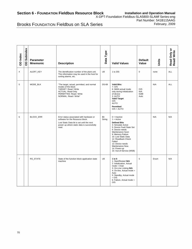
Installation and Operation Manual X-DPT-Foundation Fieldbus-SLA5800-SLAMf Series-eng Part Number: 541B115AAG February, 2009
70
Section 6 - FOUNDATION Fieldbus Resource Block
Brooks FOUNDATION Fieldbus on SLA Series O
D I
nd
ex
OD
Su
bin
dex
Parameter Mnemonic Description D
ata
Typ
e
Valid Values
Default Value
Un
its
Rea
d O
nly
or
Rea
d/
Wri
te
4 ALERT_KEY The identification number of the plant unit. This information may be used in the host for sorting alarms, etc.
U8 1 to 255 0 none ALL
5 MODE_BLK "The target, actual, permitted, and normal modes of the block TARGET: Read / Write ACTUAL: Read Only PERMITTED: Read / Write NORMAL: Read / Write"
DS-69 Valid Bits: 7: O/S 6: IMAN actual mode only during initialization of device 3: AUTO Valid Target O/S AUTO
Permitted: O/S + AUTO
O/S N/A 0x88 Auto
N/A ALL
6 BLOCK_ERR Error status associated with hardware or software for the Resource block.
Lost Static Data bit is set until the next power up where static data is successfully read.
Bit String
0 = Inactive 1 = Active
Defined Bits 3: Simulate Active 5: Device Fault State Set 6: Device needs Maintenance Soon 9: Memory Failure 10: Lost Static Data 12: Readback Check Failed 13: Device needs Maintenance Now. 14: Power-up 15: Out-of-Service (MSB)
N/A N/A
7 RS_STATE State of the function block application state machine
U8 1 to 6 1: Start/Restart N/A 2: Initialization, Actual mode = Iman 3: On-Line Linking N/A 4: On-line, Actual mode = Auto 5: Standby, Actual mode = O/S 6: Failure, Actual mode = O/S
5 Enum N/A

Installation and Operation Manual X-DPT-Foundation Fieldbus-SLA5800-SLAMf Series-eng Part Number: 541B115AAG February, 2009
71
Section 6 - FOUNDATION Fieldbus Resource Block
Brooks FOUNDATION Fieldbus on SLA SeriesO
D I
nd
ex
OD
Su
bin
dex
Parameter Mnemonic Description D
ata
Typ
e
Valid Values
Default Value
Un
its
Rea
d O
nly
or
Rea
d/
Wri
te
8 TEST_RW Read/Write Test Parameter
This parameter may be used in interoperability testing to read and write all standard data types supported by the Fieldbus Foundation.
The last value written will be maintained by the device until reset.
Order is 1 – Boolean 2 – Integer8 3 – Interger16 4 – Interger326 5 – Unisigned8 6 – Unisigned16 7 – Unisigned32 8 – Floating point 9 – Visible String 10 – Octet String 11 – Date 12 – Time of Day 13 – Time Difference 14 – Bit String 15 – Time Value (DLL time)
DS-85 0 or “ “ 0 none ALL
9 DD_RESOURCE String identifying the VFD tag of the resource which contains the Device Description for this resource
Visible String
spaces N/A
10 MANUFAC_ID Manufacturer identification number, used by an interface device to locate the DD file for the resource
U32 0x0246 N/A
11 DEV_TYPE Manufacturer’s model number associated with the resource - used by an interface device to locate the DD for the resource
U16 SC=4601 N/A
12 DEV_REV Manufacturer’s revision number associated with the resource - used by an interface device to locate the DD file for the resource.
U8 0x01 N/A
13 DD_REV Minimum compatible DD Revision of the DD associated with this device - used by an interface device to locate the DD file for the resource
U8 0x01 N/A
14 GRANT_DENY Options for controlling access of host computer and local control panels to operating, tuning, and alarm parameters of the block. GRANT DENY
DS-70 Valid Bits: 0: Program 1: Tune 2: Alarm 3: Local
Grant = 0x00 Deny = 0x00

Installation and Operation Manual X-DPT-Foundation Fieldbus-SLA5800-SLAMf Series-eng Part Number: 541B115AAG February, 2009
72
Section 6 - FOUNDATION Fieldbus Resource Block
Brooks FOUNDATION Fieldbus on SLA Series O
D I
nd
ex
OD
Su
bin
dex
Parameter Mnemonic Description D
ata
Typ
e
Valid Values
Default Value
Un
its
Rea
d O
nly
or
Rea
d/
Wri
te
15 HARD_TYPES The types of hardware available as channel numbers on this resource
Bit String
Valid Bits 0 - Scalar Input (LSB) 1 - Scalar output 2 - Discrete input 3 - Discrete output
0x000A N/A
16 RESTART Allows a manual restart to be initiated. Several degrees of restart are possible. They are: 1: Run 2: Restart resource 3: Restart with defaults 4: Restart Processor
U8 1 to 4 1: Run 2: Restart resource 3: Restart with defaults 4: Restart Processor
1 Enumerated ALL
17 FEATURES Bit string that shows the supported resource block options
Bit String
Valid Bits 0 - Unicode strings, N/A 1 - Reports supported 2 - Fault State supported 3 - Soft Write lock supported 4 - Hard Write lock supported, N/A 5 - Output readback supported 6 - Direct write to output hardware, N/A 10 - Reannuciation Supported 11 - PW Alarms set PV Status 12 - DO Block Active
0x2E N/A N/A
18 FEATURE_SEL Bit string that shows the selected resource block options.
Reports supported ( bit 1) clear to cause all alerts to be immediately confirmed even though the alarm is not sent.
Fault State supported ( bit 2) clear to disable Fault State behavior in the AO block.
Soft Write lock supported (bit 3) clear to disable soft write lock behavior in parameter 34.
Output readback supported (bit 5) clear to set AO READBACK parameter to track the AO OUT parameter, if set AO READBACK parameter tracks Transducer Final Position Value. Note: Readback and Final Position Value will not be identical due to calculation differences.
Bit String
Valid Bits
0 - Unicode strings N/A
1 - Reports supported 2 - Fault State supported 3 - Soft Write lock supported 4 - Hard Write lock supported N/A 5 - Output readback supported 6 - Direct write to output hardware N/A 10 - Reannuciation Supported 11 - PW Alarms set PV Status 12 - DO Block Active
0 per spec
0x2C
FCS
N/A ALL
19 CYCLE_TYPE Bit string identifying the block execution routines available for this resource
Bit String
Valid Bits 0 - Scheduled (LSB) 1 - Completion of block execution N/A 2 - Manufacturer specific N/A
0x0001
FCS
N/A N/A

Installation and Operation Manual X-DPT-Foundation Fieldbus-SLA5800-SLAMf Series-eng Part Number: 541B115AAG February, 2009
73
Section 6 - FOUNDATION Fieldbus Resource Block
Brooks FOUNDATION Fieldbus on SLA SeriesO
D I
nd
ex
OD
Su
bin
dex
Parameter Mnemonic Description D
ata
Typ
e
Valid Values
Default Value
Un
its
Rea
d O
nly
or
Rea
d/
Wri
te
20 CYCLE_SEL Bit string identifying the block execution routine selected for this resource
Bit String
Valid Bits 0 - Scheduled (LSB) 1 - Completion of block execution N/A 2 - Manufacturer specific N/A
0x0000 N/A ALL
21 MIN_CYCLE_T Time duration of the shortest cycle interval of which the resource is capable
U32 Set by FCS 3200 1/32 millisec N/A
22 MEMORY_SIZE Available configuration memory in the empty resource. To be checked before attempting a download.
U16 Set by FCS 0 Kbytes N/A
23 NV_CYCLE_T Interval between writing copies of NV parameters to non-volatile memory. Zero means only on external writes.
U32 Positive 5760,0 1/32 millisec N/A
24 FREE_SPACE Percent of memory available for further configuration . Zero in a preconfigured resource
Float 0 to 100 % 0 % N/A
25 FREE_TIME Percent of the block processing time that is free to process additional blocks.
Float 0 to 100 % 0 % N/A
26 SHED_RCAS Time duration at which to give up on computer writes to function block RCAS locations.
U32 Positive 640000 1/32 millisec ALL
27 SHED_ROUT Time duration at which to give up on computer writes to function block ROUT locations.
U32 Positive 640000 1/32 millisec ALL
28 FAULT_STATE Forces output function blocks to the FAULT_STATE condition if active and the output function blocks will perform their FAULT_STATE action specified in the IO_OPS bit 6.
U8 1: Clear 2: Active
1 Enumerated N/A
29 SET_FSTATE Writing a set to this parameter will cause the FAULT_STATE parameter to read active and the FAULT_STATE condition to be manually initiated. This parameter always reads off.
U8 1: Off 2: Set
1 Enumerated ALL
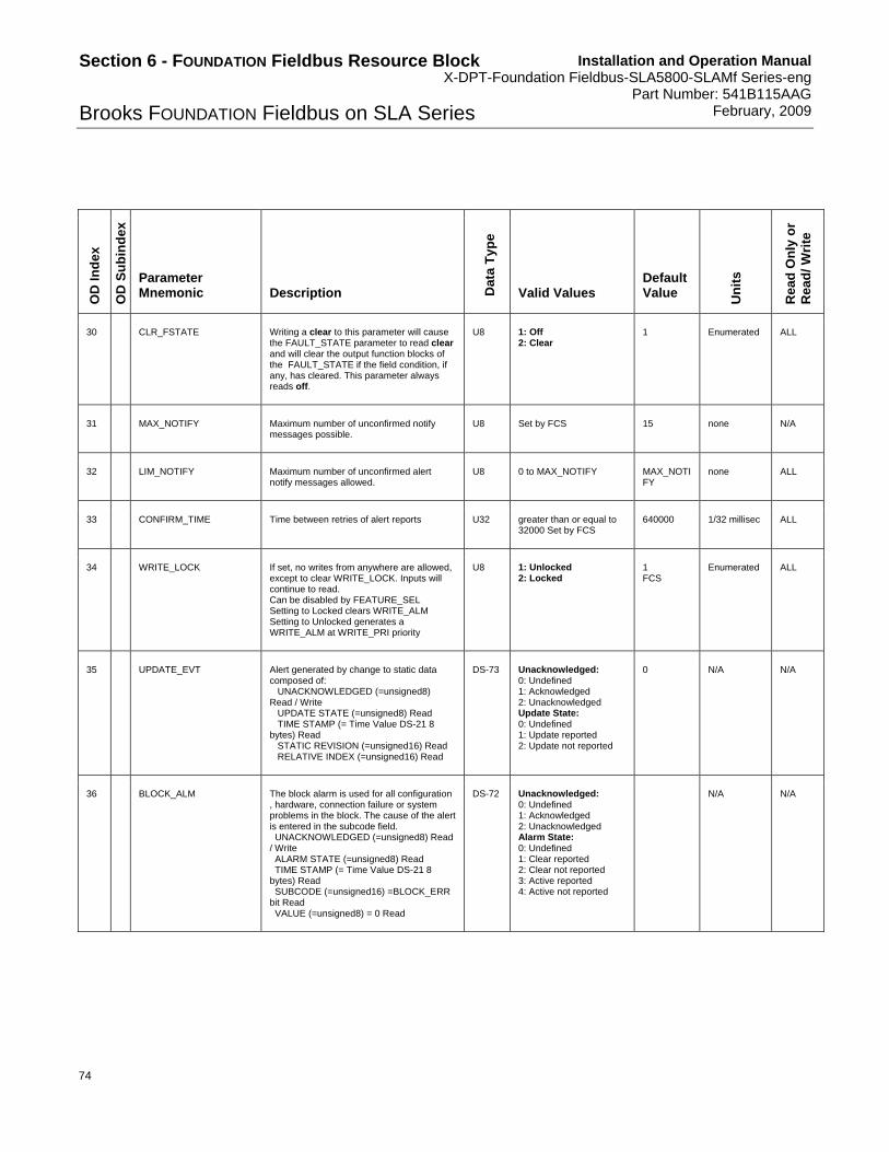
Installation and Operation Manual X-DPT-Foundation Fieldbus-SLA5800-SLAMf Series-eng Part Number: 541B115AAG February, 2009
74
Section 6 - FOUNDATION Fieldbus Resource Block
Brooks FOUNDATION Fieldbus on SLA Series O
D I
nd
ex
OD
Su
bin
dex
Parameter Mnemonic Description D
ata
Typ
e
Valid Values
Default Value
Un
its
Rea
d O
nly
or
Rea
d/
Wri
te
30 CLR_FSTATE Writing a clear to this parameter will cause the FAULT_STATE parameter to read clear and will clear the output function blocks of the FAULT_STATE if the field condition, if any, has cleared. This parameter always reads off.
U8 1: Off 2: Clear
1 Enumerated ALL
31 MAX_NOTIFY Maximum number of unconfirmed notify messages possible.
U8 Set by FCS 15 none N/A
32 LIM_NOTIFY Maximum number of unconfirmed alert notify messages allowed.
U8 0 to MAX_NOTIFY MAX_NOTIFY
none ALL
33 CONFIRM_TIME Time between retries of alert reports U32 greater than or equal to 32000 Set by FCS
640000 1/32 millisec ALL
34 WRITE_LOCK If set, no writes from anywhere are allowed, except to clear WRITE_LOCK. Inputs will continue to read. Can be disabled by FEATURE_SEL Setting to Locked clears WRITE_ALM Setting to Unlocked generates a WRITE_ALM at WRITE_PRI priority
U8 1: Unlocked 2: Locked
1 FCS
Enumerated ALL
35 UPDATE_EVT Alert generated by change to static data composed of: UNACKNOWLEDGED (=unsigned8) Read / Write UPDATE STATE (=unsigned8) Read TIME STAMP (= Time Value DS-21 8 bytes) Read STATIC REVISION (=unsigned16) Read RELATIVE INDEX (=unsigned16) Read
DS-73 Unacknowledged: 0: Undefined 1: Acknowledged 2: Unacknowledged Update State: 0: Undefined 1: Update reported 2: Update not reported
0 N/A N/A
36 BLOCK_ALM The block alarm is used for all configuration , hardware, connection failure or system problems in the block. The cause of the alert is entered in the subcode field. UNACKNOWLEDGED (=unsigned8) Read / Write ALARM STATE (=unsigned8) Read TIME STAMP (= Time Value DS-21 8 bytes) Read SUBCODE (=unsigned16) =BLOCK_ERR bit Read VALUE (=unsigned8) = 0 Read
DS-72 Unacknowledged: 0: Undefined 1: Acknowledged 2: Unacknowledged Alarm State: 0: Undefined 1: Clear reported 2: Clear not reported 3: Active reported 4: Active not reported
N/A N/A

Installation and Operation Manual X-DPT-Foundation Fieldbus-SLA5800-SLAMf Series-eng Part Number: 541B115AAG February, 2009
75
Section 6 - FOUNDATION Fieldbus Resource Block
Brooks FOUNDATION Fieldbus on SLA SeriesO
D I
nd
ex
OD
Su
bin
dex
Parameter Mnemonic Description D
ata
Typ
e
Valid Values
Default Value
Un
its
Rea
d O
nly
or
Rea
d/
Wri
te
37 ALARM_SUM Current alert status, unacknowledged states, unreported states, and disabled states of the alarms associated with the function block. CURRENT (=bitstring16) Read UNACKNOWLEDGED (=bitstring16) Read UNREPORTED (=bitstring16) Read DISABLED (=bitstring16) Read / Write
DS-74 VALID BITS: 0: Discrete alarm (LSB) Set when write lock is turned off. 1: High High Alarm N/A 2: High Alarm N/A 3: Low low alarm N/A 4: Low alarm N/A 5: Deviation High Alarm N/A 6: Deviation Low Alarm N/A 7: Block Alarm 8-15: Defined by Block Profile N/A
N/A ALL
38 ACK_OPTION Selection of whether alarms associated with the block will be automatically acknowledged.
Bit String
0: Discrete alarm (LSB) 7: Block Alarm 0 to Disable, 1 to Enable
0 N/A ALL
39 WRITE_PRI Priority of the alarm generated by clearing the write lock
U8 0 to 15 0 none ALL
40 WRITE_ALM This alert is generated if the write lock is cleared UNACKNOWLEDGED (=unsigned8) Read / Write ALARM STATE (=unsigned8) Read TIME STAMP (= Time Value DS-21 8 bytes) Read SUBCODE (=unsigned16) = 0 Read VALUE (=unsigned8) = 0 Read
DS-72 Unacknowledged: 0: Undefined 1: Acknowledged 2: Unacknowledged Alarm State: 0: Undefined 1: Clear reported 2: Clear not reported 3: Active reported 4: Active not reported
0 N/A N/A
41 ITK_VER Major version if ITK test this device has been tested to. Parameters below here are Emerson extensions.
U16 Set by FF 4 N/A
42 DISTRIBUTOR Private label distributor U32 settable by ValveLink 0x5100 E N/A
43 DEV_STRING This is used to load new licensing into the device. The value can be written but will always read back with a value of 0.
array of 8 U32
Random Number
N/A OOS
44 XB_OPTIONS

Installation and Operation Manual X-DPT-Foundation Fieldbus-SLA5800-SLAMf Series-eng Part Number: 541B115AAG February, 2009
76
Section 6 - FOUNDATION Fieldbus Resource Block
Brooks FOUNDATION Fieldbus on SLA Series O
D I
nd
ex
OD
Su
bin
dex
Parameter Mnemonic Description D
ata
Typ
e
Valid Values
Default Value
Un
its
Rea
d O
nly
or
Rea
d/
Wri
te
45 FB_OPTIONS Indicates which function block licensing options are enabled. One bit for each block type that is supported. Bits: 0=AO 1 = DO 2 = AI 3 = DI 4 = PID 5 = IS 6 = OS
bit string
0x3F 0x3F N/A N/A
46 DIAG_OPTIONS Indicates which diagnostics licensing options are enabled.
ENUM 1:FD Fieldbus Diagnostics 2:AD Advanced Diagnostics 3:PD Performance Diagnostics
1 - FD N/A N/A
47 MISC_OPTIONS Indicates which miscellaneous licensing options are enabled.
bit string
Bit
31-11: NOT USED
10: Travel Control Capable
0: Software Download
0x501 N/A N/A
48 RB_SFTWR_REV_MAJOR
U8
49 RB_SFTWR_REV_MINOR U8
50 RB_SFTWR_REV_BUILD U8
51 RB_SFTWR_REV_ALL octet string
52 HARDWARE_REV Single 8-bit integer indicating the hardware revision.
U8 Hardware revision number
Factory Set N/A N/A
53 OUTPUT_BOARD_SN Set by factory. U32 Factory Set N/A
54 FINAL_ASSY_SN Set by factory. U32 N/A N/A

Installation and Operation Manual X-DPT-Foundation Fieldbus-SLA5800-SLAMf Series-eng Part Number: 541B115AAG February, 2009
77
Section 6 - FOUNDATION Fieldbus Resource Block
Brooks FOUNDATION Fieldbus on SLA SeriesO
D I
nd
ex
OD
Su
bin
dex
Parameter Mnemonic Description D
ata
Typ
e
Valid Values
Default Value
Un
its
Rea
d O
nly
or
Rea
d/
Wri
te
55 DETAILED_STATUS Additional status bit string (4 bytes)
Byte 0: bit 0-7 - Rosemount Common Practice
Byte 1: bit 0-7 - Rosemount Common Practice
Byte 2: bit 0-7 - transmitter specific
Comm Prac Rev: G.3
bit string
N/A
56 SUMMARY_STATUS Comm Prac Rev: G.3 U8
57 MESSAGE_DATE
Comm Prac Rev: G.3
Time Of Day
58 MESSAGE_TEXT Comm Prac Rev: G.3
octet string
59 SELF_TEST Comm Prac Rev: G.3 U8
60 DEFINE_WRITE_LOCK Comm Prac Rev: G.3 U8
61 SAVE_CONFIG_NOW Comm Prac Rev: G.3 U8
62 SAVE_CONFIG_BLOCKS Comm Prac Rev: G.3 U16
63 START_WITH_DEFAULTS Comm Prac Rev: G.3
U8
64 SIMULATE_IO Comm Prac Rev: G.3 U8
65 SECURITY_IO Comm Prac Rev: G.3 U8
66 SIMULATE_STATE Comm Prac Rev: G.3 U8
67 DOWNLOAD_MODE Comm Prac Rev: G.3 U8
68 RECOMMENDED_ACTION Comm Prac Rev: G.3
U16

Installation and Operation Manual X-DPT-Foundation Fieldbus-SLA5800-SLAMf Series-eng Part Number: 541B115AAG February, 2009
78
Section 6 - FOUNDATION Fieldbus Resource Block
Brooks FOUNDATION Fieldbus on SLA Series O
D I
nd
ex
OD
Su
bin
dex
Parameter Mnemonic Description D
ata
Typ
e
Valid Values
Default Value
Un
its
Rea
d O
nly
or
Rea
d/
Wri
te
69 FAILED_PRI Comm Prac Rev: G.3 U8
70 FAILED_ENABLE Comm Prac Rev: G.3
Bit String
71 FAILED_MASK Comm Prac Rev: G.3
Bit String
72 FAILED_ACTIVE Comm Prac Rev: G.3
Bit String
FAILED_ALM Comm Prac Rev: G.3
1 UNACKNOWLEDGED
Comm Prac Rev: G.3
U8 0: Undefined 1: Acknowledged 2: Unacknowledged
73
2 ALARM STATE
Comm Prac Rev: G.3
U8 0: Undefined 1: Clear - reported 2: Clear - not reported 3: Active - reported 4: Active - not reported
74 MAINT_PRI Comm Prac Rev: G.3 U8
75 MAINT_ENABLE Comm Prac Rev: G.3
Bit String
76 MAINT_MASK Comm Prac Rev: G.3
Bit String
77 MAINT_ACTIVE Comm Prac Rev: G.3
Bit String
MAINT_ALM Comm Prac Rev: G.3
1 UNACKNOWLEDGED
Comm Prac Rev: G.3
U8 0: Undefined 1: Acknowledged 2: Unacknowledged
78
2 ALARM STATE
Comm Prac Rev: G.3
U8 0: Undefined 1: Clear - reported 2: Clear - not reported 3: Active - reported 4: Active - not reported

Installation and Operation Manual X-DPT-Foundation Fieldbus-SLA5800-SLAMf Series-eng Part Number: 541B115AAG February, 2009
79
Section 6 - FOUNDATION Fieldbus Resource Block
Brooks FOUNDATION Fieldbus on SLA SeriesO
D I
nd
ex
OD
Su
bin
dex
Parameter Mnemonic Description D
ata
Typ
e
Valid Values
Default Value
Un
its
Rea
d O
nly
or
Rea
d/
Wri
te
79 ADVISE_PRI Comm Prac Rev: G.3 U8
80 ADVISE_ENABLE Comm Prac Rev: G.3
Bit String
81 ADVISE_MASK Comm Prac Rev: G.3
Bit String
82 ADVISE_ACTIVE Comm Prac Rev: G.3
Bit String
ADVISE_ALM Comm Prac Rev: G.3
1 UNACKNOWLEDGED
Comm Prac Rev: G.3
U8 0: Undefined 1: Acknowledged 2: Unacknowledged
83
2 ALARM STATE
Comm Prac Rev: G.3
U8 0: Undefined 1: Clear - reported 2: Clear - not reported 3: Active - reported 4: Active - not reported
84 HEALTH_INDEX Comm Prac Rev: G.3 U8
85 PWA_SIMULATE Comm Prac Rev: G.3 U8
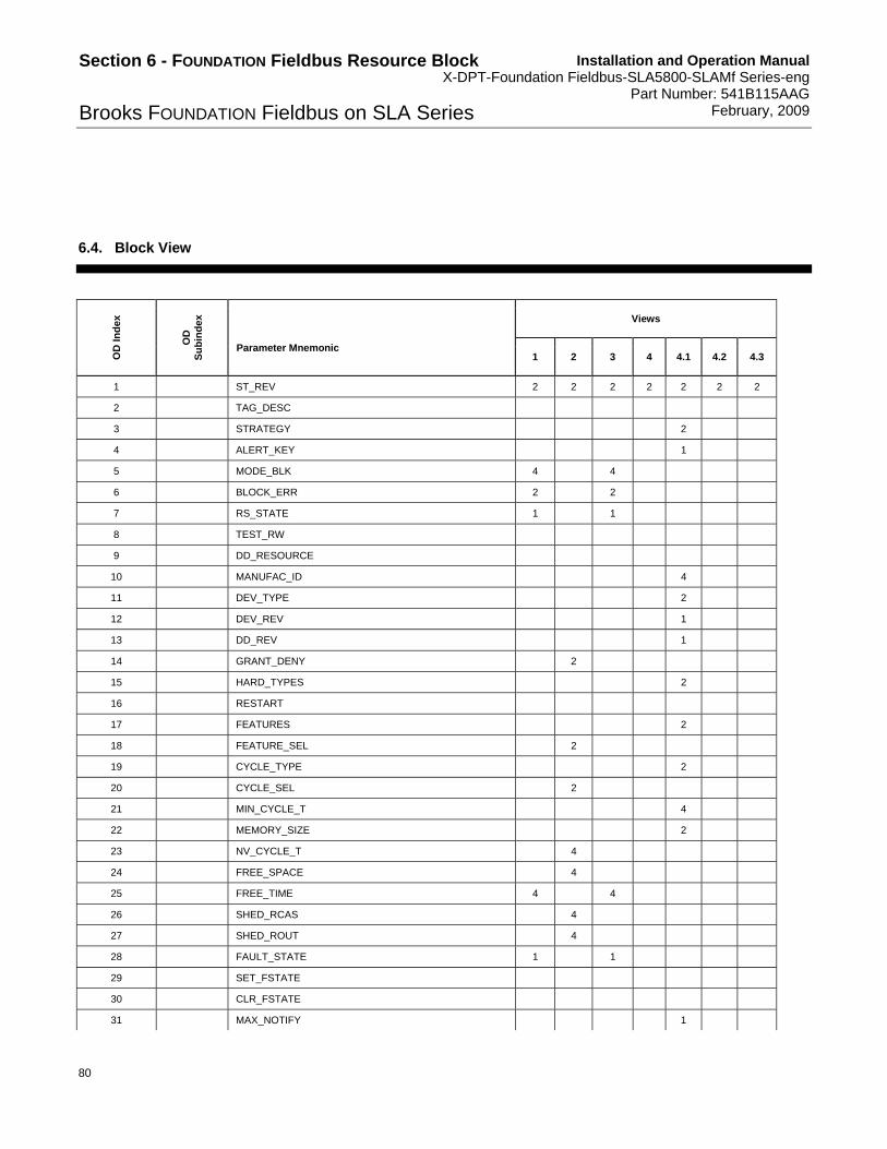
Installation and Operation Manual X-DPT-Foundation Fieldbus-SLA5800-SLAMf Series-eng Part Number: 541B115AAG February, 2009
80
Section 6 - FOUNDATION Fieldbus Resource Block
Brooks FOUNDATION Fieldbus on SLA Series
6.4. Block View
Views
OD
In
dex
OD
S
ub
ind
ex
Parameter Mnemonic 1 2 3 4 4.1 4.2 4.3
1 ST_REV 2 2 2 2 2 2 2
2 TAG_DESC
3 STRATEGY 2
4 ALERT_KEY 1
5 MODE_BLK 4 4
6 BLOCK_ERR 2 2
7 RS_STATE 1 1
8 TEST_RW
9 DD_RESOURCE
10 MANUFAC_ID 4
11 DEV_TYPE 2
12 DEV_REV 1
13 DD_REV 1
14 GRANT_DENY 2
15 HARD_TYPES 2
16 RESTART
17 FEATURES 2
18 FEATURE_SEL 2
19 CYCLE_TYPE 2
20 CYCLE_SEL 2
21 MIN_CYCLE_T 4
22 MEMORY_SIZE 2
23 NV_CYCLE_T 4
24 FREE_SPACE 4
25 FREE_TIME 4 4
26 SHED_RCAS 4
27 SHED_ROUT 4
28 FAULT_STATE 1 1
29 SET_FSTATE
30 CLR_FSTATE
31 MAX_NOTIFY 1

Installation and Operation Manual X-DPT-Foundation Fieldbus-SLA5800-SLAMf Series-eng Part Number: 541B115AAG February, 2009
81
Section 6 - FOUNDATION Fieldbus Resource Block
Brooks FOUNDATION Fieldbus on SLA Series
Views
OD
In
dex
OD
S
ub
ind
ex
Parameter Mnemonic 1 2 3 4 4.1 4.2 4.3
32 LIM_NOTIFY 1
33 CONFIRM_TIME 4
34 WRITE_LOCK 1
35 UPDATE_EVT
36 BLOCK_ALM
37 ALARM_SUM 8 8
38 ACK_OPTION 2
39 WRITE_PRI 1
40 WRITE_ALM
41 ITK_VER 2
42 DISTRIBUTOR 4
43 DEV_STRING 32
44 XB_OPTIONS 4
45 FB_OPTIONS 4
46 DIAG_OPTIONS 4
47 MISC_OPTIONS 4
48 RB_SFTWR_REV_MAJOR
49 RB_SFTWR_REV_MINOR
50 RB_SFTWR_REV_BUILD
51 RB_SFTWR_REV_ALL 48
52 HARDWARE_REV 1
53 OUTPUT_BOARD_SN 4
54 FINAL_ASSY_SN 4
55 DETAILED_STATUS 4
56 SUMMARY_STATUS 1
57 MESSAGE_DATE 6
58 MESSAGE_TEXT 48
59 SELF_TEST 1
60 DEFINE_WRITE_LOCK 1
61 SAVE_CONFIG_NOW 1
62 SAVE_CONFIG_BLOCKS 1 1
63 START_WITH_DEFAULTS 1 1
64 SIMULATE_IO 1
65 SECURITY_IO 1
66 SIMULATE_STATE 1

Installation and Operation Manual X-DPT-Foundation Fieldbus-SLA5800-SLAMf Series-eng Part Number: 541B115AAG February, 2009
82
Section 6 - FOUNDATION Fieldbus Resource Block
Brooks FOUNDATION Fieldbus on SLA Series
Views
OD
In
dex
OD
S
ub
ind
ex
Parameter Mnemonic 1 2 3 4 4.1 4.2 4.3
67 DOWNLOAD_MODE
68 RECOMMENDED_ACTION 2
69 FAILED_PRI 1
70 FAILED_ENABLE 4
71 FAILED_MASK 4
72 FAILED_ACTIVE 4
FAILED_ALM 13
1 UNACKNOWLEDGED
73
2 ALARM STATE
74 MAINT_PRI 1
75 MAINT_ENABLE 4
76 MAINT_MASK 4
77 MAINT_ACTIVE 4
MAINT_ALM 13
1 UNACKNOWLEDGED
78
2 ALARM STATE
79 ADVISE_PRI 1
80 ADVISE_ENABLE 4
81 ADVISE_MASK 4
82 ADVISE_ACTIVE 4
ADVISE_ALM 13
1 UNACKNOWLEDGED
83
2 ALARM STATE
84 HEALTH_INDEX 1
85 PWA_SIMULATE 1
25 31 22 67 31 117 78
6.5. PlantWeb Alarm Descriptions
PlantWeb alarms are available only if using an Emerson DeltaV system or compatible host. Please refer to the DeltaV manual for setup and usage.

Installation and Operation Manual X-DPT-Foundation Fieldbus-SLA5800-SLAMf Series-eng Part Number: 541B115AAG February, 2009
83
Section 6 - FOUNDATION Fieldbus Resource Block
Brooks FOUNDATION Fieldbus on SLA Series
6.5.1. Available PlantWeb Alerts
6.5.1.1. Temperature Sensor Connection Failure
The device has detected that a temperature sensor connection failure. This is an unrecoverable error and the device needs to be inspected for unplugged or damaged sensor connection. In rare occasions, the alert could also indicate the value read by the temperature sensor is outside the allowed range for the device (from -10˚C to 100˚C).
6.5.1.2. Firmware Checksum Failure
The device performs a background diagnostics of the firmware data. If this error occurs, the firmware within the device is corrupted either by loss of data or by component failure. Power cycle the device. If the problem persists, the device needs to be returned to Brooks Instrument.
6.5.1.3. NV – Memory Write Failure
When data is written to the non-volatile memory, a background diagnostics verifies if the data is stable and corresponds to the intended written value. If this error occurs, the non-volatile memory is corrupted and is not representing the expected saved value. Power cycle the device. If the problem persists, the device needs to be returned to Brooks Instrument.
6.5.1.4. RAM Write Failure
When data is written to the RAM, a background check verifies if the data is stable and corresponds to the intended written value. If this error occurs, the RAM is corrupted and is not representing the expected dynamic value. Power cycle the device. If the problem persists, the device needs to be returned to Brooks Instrument.

Installation and Operation Manual X-DPT-Foundation Fieldbus-SLA5800-SLAMf Series-eng Part Number: 541B115AAG February, 2009
84
Section 6 - FOUNDATION Fieldbus Resource Block
Brooks FOUNDATION Fieldbus on SLA Series
6.5.1.5. RB Electronics Failure
The FOUNDATION Fieldbus interface board has detected an electronic failure. This is an unrecoverable error; the FOUNDATION Fieldbus board needs to be replaced. Device TAG Name and ID will be changed; refer to your host manual on how to replace a device in your process. The device does not need to be recalibrated.
6.5.1.6. Zero Drift Alarm
This is an option on the MFC devices allowing detection of sensor zero drift or valve leak-by.
To detect true zero drift, the device needs to be placed in a specific environment. Please refer to the Zero Drift Alarm procedure to ensure proper re-zeroing of the device.
Leak by may be induced by a faulty valve, clogged valve, or over pressure downstream off the device. Any of these conditions will require troubleshooting and maintenance of the device.
6.5.1.7. Device Overhaul Due
This is a user settable preventive maintenance indicator. Device overhaul is due. A typical life span for a device is three years. The device will need to be cleaned and returned to the Brooks Instrument service center for an overhaul of the device. Please contact your service center for details.
6.5.1.8. Device Recalibration Due
This is a user settable preventive maintenance indicator. Device calibration is due. A typical recalibration is due after 2,000 hours of usage. Recalibration must be performed by a qualified calibration center. Please contact your service center for details.
6.5.1.9. Valve Spring Life
This is a user settable preventive maintenance indicator. The life of the valve spring has been exceeded. Please contact your service center for a replacement spring.

Installation and Operation Manual X-DPT-Foundation Fieldbus-SLA5800-SLAMf Series-eng Part Number: 541B115AAG February, 2009
85
Section 6 - FOUNDATION Fieldbus Resource Block
Brooks FOUNDATION Fieldbus on SLA Series
6.5.1.10. Valve Response
Valve response is out of specification. Either the device is control is too slow, the device control cannot match setpoint, or the device detects large overshoot. This indicates process error, improper usage of the device, or a faulty device. Troubleshooting is needed to determine what is the cause of the problem.
6.5.1.11. Valve Signature
A valve signature alert represents a slow shift in device response over a specific control position. Historical data needs to be accumulated before this alert can be generated. This alert indicates that the device may become unusable soon and preventive maintenance is required.
6.5.1.12. No Flow
This alert is triggered by the flow value staying below an adjustable threshold after an adjustable period of time. This may indicate process or device error. Investigate for possible clog, closed system valve, or fluid not present.
6.5.1.13. Reverse Flow
This alert is triggered by the flow value staying below an adjustable negative threshold after an adjustable period of time. This may indicate incorrect installation, process problem, or device error. Investigate pressure or temperature imbalance in the system, or re-zero the device if the error occurs when the device setpoint is zero.
6.5.1.14. Flow Totalizer Alarm
This alert is triggered by the user adjustable time de-counter value reaching zero (0). This is a process indicator and should be used for advanced device control.
6.5.1.15. Time Totalizer Alarm
This alert is triggered by the adjustable time de-counter value reaching zero (0). This is a process indicator and should be used for advanced device control.
Installation and Operation Manual X-DPT-Foundation Fieldbus-SLA5800-SLAMf Series-eng Part Number: 541B115AAG February, 2009
86
Section 6 - FOUNDATION Fieldbus Resource Block
Brooks FOUNDATION Fieldbus on SLA Series
6.5.1.16. PWA Simulate Active
The PlantWeb Alert simulation is activated. This is not a state for normal operation. Please disable PlantWeb simulation to properly continue with the device.
The following tables represent the PlantWeb alerts implementation detail and is provided for reference only.

Installation and Operation Manual X-DPT-Foundation Fieldbus-SLA5800-SLAMf Series-eng Part Number: 541B115AAG February, 2009
87
Section 6 - FOUNDATION Fieldbus Resource Block
Brooks FOUNDATION Fieldbus on SLA Series
Table 6-1 PlantWeb Alerts
Fai
l
Mai
nten
ance
Adv
ise
Tra
nsdu
cer
Blo
ck
Tra
nsdu
cer
Blo
ck
Res
ourc
e B
lock
Res
ourc
e B
lock
Res
ourc
e B
lock
Resource Block
Ena
ble
- D
efau
lt
Ena
ble
- D
efau
lt
Ena
ble
- D
efau
lt
BLO
CK
_E
RR
XD
_ER
RO
R_
x DE
TA
ILE
D_S
TA
TU
S
SU
MM
AR
Y_
ST
AT
US
BLO
CK
_E
RR
-
chan
ged
ba
sed
on
user
se
lect
ion
Recommended Actions
bit 2: Temperature sensor connection 1 0 0 Sensor Failure
I/O Failure Transducer Error
Call service center
Maintenance Now
Connection to the temperature sensor has been lost. Device need to be repaired.
Bit 3: Firmware Checksum 1 0 0 Memory Failure
Electronics Failure
Transducer Error
Call service center
Maintenance Now
Recycle device power. If problem persists, contact Brooks.
bit 4: Non Volatile Memory 1 0 0 Memory Failure
Electronics Failure
Transducer Error
Call service center
Maintenance Now
Recycle device power. If problem persists, contact Brooks.
bit 5: RAM 1 0 0 Memory Failure
Electronics Failure
Transducer Error
Call service center
Maintenance Now
Recycle device power. If problem persists, contact Brooks.
bit 6: RB-Electronics Failure 1 0 0 0 0 RB Electronics fail
Call service center
Maintenance Now
The device has detected an electronics component failure on the fieldbus board. Replace fieldbus board.
Bit 7: RB-NV Memory Failure 1 0 0 0 0 RB NV memory Fail
Call service center
Maintenance Now
The device has detected NV memory failure on the Fieldbus board.
bit 10: Zero Drift /Leak-by 0 1 0 Other 0 0 Repairable Maintenance Soon
Investigate device zero per instruction manual. Then investigate valve leak-by.
bit 11: Device overhaul due 0 1 0 Other 0 0 Repairable Maintenance Soon
Return device to Brooks for device overhaul.
bit 12: Calibration due 0 1 0 Other 0 0 Repairable Maintenance Soon
Schedule device recalibration
Bit 13: Valve spring life 0 1 0 Other 0 0 Repairable Maintenance Soon
Return device to Brooks for valve maintenance.
bit 14:Valve Signature 0 1 0 Other 0 0 Repairable Maintenance Soon
Valve signature has changed, this indicates a change of condition or the valve is not responding as expected.
bit 15: Valve Response 0 1 0 Other 0 0 Repairable Maintenance Soon
Valve response is greatly different than specifications, the device may not be able to handle the current process
bit 18: No Flow 0 0 1 Other 0 0 ok 0 Possible clog, closed system valve, or fluid not present.
bit 19: Reverse Flow 0 0 1 Other 0 0 ok 0 Investigate pressure or temperature imbalance in system or re-zero device.
bit 20: Flow totalizer 0 0 1 Other 0 0 ok 0 User alarm Flow totalizer has reached zero
bit 21: Time totalizer 0 0 1 Other 0 0 ok 0 User alarm Time totalizer has reached zero
bit 22: PWA Simulate Active 0 0 1 0 0 0 ok Simulate Active
Plantweb Alerts are being overwritten by the user.

Installation and Operation Manual X-DPT-Foundation Fieldbus-SLA5800-SLAMf Series-eng Part Number: 541B115AAG February, 2009
88
Section 6 - FOUNDATION Fieldbus Resource Block
Brooks FOUNDATION Fieldbus on SLA Series
Table 6-2 XD_ERROR Values
Value Description Detail
16 Unspecified error An error has occurred that was not identified.
17 General error An error has occurred that could not be classified as one of the errors below.
18 Calibration error An error occurred during calibration of the device or a calibration error has been detected during operation of the device.
19 Configuration error An error occurred during configuration of the device or a configuration error has been detected during operation of the device.
20 Electronics Failure An electronic component has failed.
21 Mechanical Failure A mechanical component has failed.
22 I/O Failure An I/O failure has occurred
23 Data Integrity Error Indicates that data stored within the system may no longer be valid due to NVM checksum failure, Data verify after write failure, etc.
24 Software Error The software has detected an error. This could be caused by an improper interrupt service routine, an arithmetic overflow, a watchdog timer, etc.
25 Algorithm Error The algorithm used in the transducer block produced an error. This could be due to an overflow, data reasonableness failure, etc.

Installation and Operation Manual X-DPT-Foundation Fieldbus-SLA5800-SLAMf Series-eng Part Number: 541B115AAG February, 2009
89
Section 6 - FOUNDATION Fieldbus Resource Block
Brooks FOUNDATION Fieldbus on SLA Series
Table 6-3 BLOCK_ERR Values
Value Description
0 Other (LSB)
1 Block Configuration Error
2 Link Configuration Error
3 Simulate Active
4 Local Override
5 Device Fault State Set
6 Device Needs Maintenance Soon
7 Sensor Failure detected by this block/process variable has a status of BAD, Sensor Failure
8 Output Failure detected by this block/back calculation input has a status of BAD, Device Failure
9 Memory Failure
10 Lost Static Data
11 Lost NV Data
12 Readback Check Failed
13 Device Needs Maintenance Now
14 Power-up
15 Out-of-Service (MSB)
Table 6-4. Summary Status
Value Description
0 Uninitialized
1 No repair needed
2 Repairable
3 Call service center

Installation and Operation Manual X-DPT-Foundation Fieldbus-SLA5800-SLAMf Series-eng Part Number: 541B115AAG February, 2009
90
Section 6 - FOUNDATION Fieldbus Resource Block
Brooks FOUNDATION Fieldbus on SLA Series
THIS PAGE WAS INTENTIONALLY
LEFT BLANK

Installation and Operation Manual X-DPT-Foundation Fieldbus-SLA5800-SLAMf Series-eng Part Number: 541B115AAG February, 2009
91
Section 7 - Transducer Block Reference
Brooks FOUNDATION Fieldbus on SLA Series
7. Transducer Blocks Reference
7.1. Introduction
The Brooks devices have one multi-variable transducer block. The parameters and views are listed in this section.
7.2. Transducer Block Overview
The purpose of a Transducer Block Definition is to describe base parameter collections and characteristics common to the specific aspects of a class of device. The same parameter collections can be applied to a device whose primary or only function is the specific aspect covered by a Transducer Block Definition, or the collection can be applied by other field devices that have the specific aspect as a secondary variable.
This Transducer Block Definition describes base parameter collections and characteristics common to the measurement of pressure.
7.3. Transducer block Methods
7.3.1. Sensor Zero Trim
Only available on the Mass Flow meter and Mass flow controllers, this method allows the user to reset the zero value of the flow sensor with the current read value.
Note: Before zeroing the instrument, zero pressure differential MUST be established across the device. If there is pressure across the instrument during the zero process, any detected flow through the sensor will be misinterpreted as the zero flow reading. This will result in calibration inaccuracy during normal operation. Once zero differential pressure is established and verified, execute Zero-Trim function. The zeroing process requires approximately 10 seconds.

Installation and Operation Manual X-DPT-Foundation Fieldbus-SLA5800-SLAMf Series-eng Part Number: 541B115AAG February, 2009
92
Section 7 - Transducer Block Reference
Brooks FOUNDATION Fieldbus on SLA Series
7.4. Block Parameters Tables
7.4.1. Multi-Variable Common Transducer Block
The Brooks Instrument devices respect the FOUNDATION Fieldbus implementation of the multi-variable transducer block known as FF-902 of March 2004. Please refer to the FOUNDATION for more detail on this implementation.
The following information is for reference only. DD and CFF files are the preferred way for device installation.
Table 7-1 Device Information Transducer Block Parameters
OD
In
dex
OD
Su
bin
dex
Parameter Mnemonic Description Sto
re/R
ate
(Hz)
Siz
e Data Type Valid Values
Default Value U
nit
s
Mo
de
for
Wri
tes
Rea
d O
nly
or
Rea
d/
Wri
te
1 ST_REV Static data revision. Updated when static data is changed
x 2 UINT16 0 to 65535 N/A N/A RO
2 TAG_DESC The user description of the intended application of the block.
S 32
STRING N/A ALL RW
3 STRATEGY Used to help identify grouping of blocks. This data is not checked or processed by the block.
S 2 UINT16 0 to 65535 0 ALL RW
4 ALERT_KEY The identification number of the plant unit. This information may be used in the host for sorting alarms, etc.
S 1 UNIT8 1 to 255 1 per FCS define
ALL RW
5 MODE_BLK DS-69
1 TARGET N 1 Bit
String 0x01: OOS 0x10: AUTO
0x01 (OOS)
ALL RW
2 ACTUAL ACTUAL D 1 Bit
String Same as TARGET 0x01
(OOS) N/A RO
3 PERMITTED PERMITTED S 1 Bit
String Same as TARGET 0x11 ALL RW
4 NORMAL NORMAL S 1 Bit
String AUTO 0x10 ALL RW
6 BLOCK_ERR 0 = Inactive, 1 = Active D 2 Bit String
N/A N/A RO

Installation and Operation Manual X-DPT-Foundation Fieldbus-SLA5800-SLAMf Series-eng Part Number: 541B115AAG February, 2009
93
Section 7 - Transducer Block Reference
Brooks FOUNDATION Fieldbus on SLA SeriesO
D I
nd
ex
OD
Su
bin
dex
Parameter Mnemonic Description Sto
re/R
ate
(Hz)
Siz
e Data Type Valid Values
Default Value U
nit
s
Mo
de
for
Wri
tes
Rea
d O
nly
or
Rea
d/
Wri
te
7 UPDATE_EVT Used to tell other devices (displays, historians) that a change has occurred in the static data of this block.
DS-73
1 UNACKNOWLEDGED D 1 UINT8 0: Undefined
1: Acknowledged 2: Unacknowledged
N/A ALL RW
2 UPDATE STATE D 1 UINT8 0: Undefined 1: Update reported 2: Update not reported
N/A N/A RO
3 TIME STAMP D 8 DS-21 N/A N/A RO
4 STATIC REVISION D 2 UINT16 N/A N/A RO
5 RELATIVE INDEX D 2 UINT16 N/A N/A RO
8 BLOCK_ALM Alarm generated by block_err.
DS-72
1 UNACKNOWLEDGED D 1 UINT8 0: Undefined
1: Acknowledged 2: Unacknowledged
0 ALL RW
2 ALARM STATE D 1 UINT8 0: Undefined 1: Clear - reported 2: Clear - not reported 3: Active - reported 4: Active - not reported
0 N/A RO
3 TIME STAMP D 8 DS-21 0 N/A RO
4 SUBCODE D 2 UINT16 Subcode: = TDC
ALARM SUMMARY CURRENT
0 N/A RO
5 VALUE D 1 UINT8 Value of parameter at alarm time for single alarm, 0 for multiple alarms
0 N/A RO
7.4.2. Standard Flow with Calibration Transducer Block
The Brooks Instrument devices respect the early FOUNDATION Fieldbus implementation of the Standard Flow with Calibration Transducer Block known as FF-903 of April 1998 [Transducer Blocks (Part 2) Preliminary Specification FF-903 Rev PS 3.0]. Refer to the FOUNDATION for more detail on this implementation.

Installation and Operation Manual X-DPT-Foundation Fieldbus-SLA5800-SLAMf Series-eng Part Number: 541B115AAG February, 2009
94
Section 7 - Transducer Block Reference
Brooks FOUNDATION Fieldbus on SLA Series
The following information is for reference only. DD and CFF files are the preferred way for device installation.
Table 7-2 Flow Sensor Transducer Block Parameters
OD
In
dex
OD
Su
bin
dex
Parameter Mnemonic Description Sto
re/R
ate
(Hz)
Siz
e Data Type Valid Values
Default Value U
nit
s
Mo
de
for
Wri
tes
Rea
d O
nly
or
Rea
d/
Wri
te
10 TRANSDUCER_TYPE_1 Identifies the transducer that follows.
S 2 ENUM 65535 N/A RO
11 XD_ERROR_1 Extensions to BLOCK_ERR indicated by the “OTHER” bit 0 being set.
D 1 ENUM Valid Numbers: 0 = No Error
0 N/A RO
12 COLLECTION_DIRECTORY_1 The directory that specifies the number, starting indices, and DD Item IDs of the data collections for this transducer block.
S 4 Array [1] of UINT32
0 0 N/A RO
13 PRIMARY_VALUE_TYPE_1 Depends of Eng. Units S 2 ENUM 100: Mass Flow 101: Volumetric Flow
OOS RW
14 PRIMARY_VALUE_1 The measured value and status available to the function block
1 STATUS D 1 UINT8 0 = Bad, 128 = Good N/A RO
2 VALUE D 4 FLOAT N/A RO
15 PRIMARY_VALUE_RANGE_1 The High and Low range limit values, the engineering units code, and the number of digits to the right of the decimal point to be used to display the Primary Value.
1 EU_100 EU_100 S 4 FLOAT 1000 UI N/A RO
2 EU_0 EU_0 S 4 FLOAT 0 UI N/A RO
3 UNITS_INDEX UNITS_INDEX S 2 UINT16 See Flow and Mass Eng. Units
SSCM N/A RO
4 DECIMAL DECIMAL S 1 UINT8 4 N/A RO
16 CAL_POINT_HI_1 The highest calibrated value for this block
S 4 FLOAT 1000 CU OOS RW
17 CAL_POINT_LO_1 The lowest calibrated value for this block.
S 4 FLOAT 0 CU OOS RW
18 CAL_MIN_SPAN_1 The minimum calibration span value allowed. This minimum span information is necessary to ensure that when calibration is done, the two calibrated points (high and low) are not too close together.
S 4 FLOAT 1000 CU N/A RO
19 CAL_UNIT_1 The Device Description engineering units code index for the calibration values.
S 2 UINT16 See Flow and Mass Eng. Units
SSCM OOS RW

Installation and Operation Manual X-DPT-Foundation Fieldbus-SLA5800-SLAMf Series-eng Part Number: 541B115AAG February, 2009
95
Section 7 - Transducer Block Reference
Brooks FOUNDATION Fieldbus on SLA SeriesO
D I
nd
ex
OD
Su
bin
dex
Parameter Mnemonic Description Sto
re/R
ate
(Hz)
Siz
e Data Type Valid Values
Default Value U
nit
s
Mo
de
for
Wri
tes
Rea
d O
nly
or
Rea
d/
Wri
te
20 SENSOR_TYPE_1 The type of sensor as defined in the Fieldbus Standard Tables Specification (FF-131).
S 2 ENUM 100: Flow Sensor Unknown
100 OOS RW
21 SENSOR_RANGE_1 The high and low range limit values, the engineering units code, and the number of digits to the right of the decimal point for the sensor.
1 EU_100 EU_100 S 4 FLOAT 1000 UI N/A RO
2 EU_0 EU_0 S 4 FLOAT 0 UI N/A RO
3 UNITS_INDEX UNITS_INDEX S 2 UINT16 See Flow and Mass Eng. Units
SSCM N/A RO
4 DECIMAL DECIMAL S 1 UINT8 4 N/A RO
22 SENSOR_SN_1 The sensor serial number. S 32
Visible String
Spaces N/A RO
23 SENSOR_CAL_METHOD_1 The method of this sensor’s last calibration. ISO defines several standard methods of calibration. This parameter is intended to record that method, or if some other method was used.
S 1 ENUM 105: factory trim special calibration
105 OOS RW
24 SENSOR_CAL_LOC_1 The location of this sensor’s last calibration. This describes the physical location at which the calibration was performed.
S 32
Visible String
Spaces OOS RW
25 SENSOR_CAL_DATE_1 The date of the sensor’s last calibration. This is intended to reflect the calibration of that part of the sensor that is usually wetted by the process.
S 7 Date 0 OOS RW
26 SENSOR_CAL_WHO_1 The name of the person responsible for the last sensor calibration.
S 32
VISIBLE STRING
Spaces OOS RW
27 LIN_TYPE_1 The linearization type used to describe the behavior of this sensor output as defined in the Fieldbus Standard Tables Specification (FF-131).
S 1 UINT8 2: Linear with output
OOS RW
28 GAS_DENSITY Gas density to be use with Mass Flow control
S 4 FLOAT Eng Unit
ALL RW

Installation and Operation Manual X-DPT-Foundation Fieldbus-SLA5800-SLAMf Series-eng Part Number: 541B115AAG February, 2009
96
Section 7 - Transducer Block Reference
Brooks FOUNDATION Fieldbus on SLA Series
This transducer variable respects the early FF-903 specification. GAS_DENSITY has been added to allow the user to report values in Mass Flow instead of Volumetric Flow. Density must be calculated by the user if the gas flow is different from the gas used for calibration.
The following information is from the early FF-903 specifications.
7.4.2.1. Overview
This section describes the flow specific aspects of a device application process used in the transducer block application process. For the purpose of transducer specifications, flow devices are those measurement devices whose primary process sensors measure flow, including mass flow, volumetric flow, average mass flow, and average volumetric flow. The Standard Flow with Calibration Definition was constructed to provide the user with a flexible list of basic parameters that define transducer operating limits, sensor characteristics and parameters used for calibration. Refer to the Transducer Block Application Process – Part 1 (FF-902) for details of the characteristics that apply to all of the devices that are included in this definition.
Flow is one of the basic measurements, so a full transducer block will be defined with ordered parameters. The grouping of parameters into device description collections will also be defined, so that the flow parameters may be used as part of a more complex device. Any device whose primary purpose is to measure flow and includes calibration should use the defined transducer block for those aspects of the device, and add any additional parameters to the end of the definition.
Channel numbers will be defined for the flow with calibration basic device (i.e., a transducer block which only functions as a single flow with calibration transducer block), but not for a more complex device.
Physical data for the basic flow device will be defined as device description collections that are to be attached to the device resource block described in FF-890 and FF-891. Alternately, a physical collection could be added instead.
One flow transducer will be used for primary sensor data.

Installation and Operation Manual X-DPT-Foundation Fieldbus-SLA5800-SLAMf Series-eng Part Number: 541B115AAG February, 2009
97
Section 7 - Transducer Block Reference
Brooks FOUNDATION Fieldbus on SLA Series
7.4.2.2. Schematic
Figure 7-1 Flow Transducer Block Schematic
7.4.2.3. Description
The primary measurement will be mass flow, volumetric flow, average mass flow, or average volumetric flow. This will be identified by the PRIMARY_VALUE_TYPE parameter. Should the sensor provide more than one flow measurement type, such as mass flow and volumetric flow, the set of parameters for mass flow should be followed by the set of parameters for volumetric flow.
The flow technology transducer computes its output using primary sensor data and parameters. The calculation can be modeled as shown in the schematic above. The parameters configure the device application processes for their intended function. The parameters are organized into DD collections.
Note the addition of a parameter, linearization type (LIN_TYPE), that may require some clarification. Though Analog Input function blocks also have a linearization type (L_TYPE), it is limited to direct (no scaling), indirect (scaling), and indirect square root (scaling with a square root function). But, LIN_TYPE as used here provides many more options for the device developer.

Installation and Operation Manual X-DPT-Foundation Fieldbus-SLA5800-SLAMf Series-eng Part Number: 541B115AAG February, 2009
98
Section 7 - Transducer Block Reference
Brooks FOUNDATION Fieldbus on SLA Series
The sensor with calibration calculation collection contains seven parameters that define the channel value and the means used to get that value from the sensor. For each channel of measurement, these parameters are repeated.
PRIMARY_VALUE_TYPE Defines the type of calculation, from the list in Section 4.1 Primary Value Types.
PRIMARY_VALUE The value and status that appears on channel 1.
PRIMARY_VALUE_RANGE Defines the ends of the PRIMARY_VALUE, the units of the PRIMARY_VALUE, and the decimal point position (number of significant digits to the right of the point). The engineering units must match the units selected in the parameter XD_SCALE of the Analog Input Block that reads the channel with this value.
CAL_POINT_HI Defines the upper calibrated value. Must be at least CAL_MIN_SPAN away from CAL_POINT_LO, and at or below the high range value of SENSOR_RANGE. Refer to the Appendix on page 129 for more information on calibration.
CAL_POINT_LO Defines the lower calibrated value. Must be at least CAL_MIN_SPAN away from CAL_POINT_HI, and at or above the low range value of SENSOR_RANGE.
CAL_MIN_SPAN Defines the absolute minimum span between CAL_POINT_HI and CAL_POINT_LO.
CAL_UNIT Defines the engineering units to be used when calibrating the device.
SENSOR_TYPE This parameter contains the index code for the sensor type descriptor.
SENSOR_RANGE Defines the absolute maximum ends of the sensor range, the units of those limits, and the decimal point position (number of significant digits to the right of the point).
SENSOR_SN Shows the sensor serial number.
SENSOR_CAL_METHOD Last calibration method.
SENSOR_CAL_LOC Last calibration location.
SENSOR_CAL_DATE Last calibration date.
SENSOR_CAL_WHO Identifies the person that last calibrated the sensor.
LIN_TYPE Contains the linearization type used to describe the behavior of the sensor output.

Installation and Operation Manual X-DPT-Foundation Fieldbus-SLA5800-SLAMf Series-eng Part Number: 541B115AAG February, 2009
99
Section 7 - Transducer Block Reference
Brooks FOUNDATION Fieldbus on SLA Series
The secondary value technology collection contains two parameters that pertain to the sensor. These parameters are repeated as necessary.
7.4.2.4. Supported Modes
O/S, Manual, and Auto.
7.4.2.5. User Selectable Modes
O/S and Auto.
7.4.2.6. Alarm Types
Standard block alarm.
7.4.2.7. Mode Handling
Standard transition in and out of O/S.
7.4.2.8. Initialization
Standard initialization.
7.4.2.9. Channel Assignments
1. Primary Value (flow)
7.4.3. Pressure Transducer Block
The Brooks Instrument devices respect the FOUNDATION Fieldbus implementation of the Pressure Transducer Block known as FF-903 of March 2004 (Pressure Transducer Block Specification FF-903 Rev FS 1.0). Please refer to the FOUNDATION for more detail on this implementation.
The following information is for reference only. DD and CFF files are the preferred way for device installation.

Installation and Operation Manual X-DPT-Foundation Fieldbus-SLA5800-SLAMf Series-eng Part Number: 541B115AAG February, 2009
100
Section 7 - Transducer Block Reference
Brooks FOUNDATION Fieldbus on SLA Series
Table 7-3 Pressure Sensor Transducer Block Parameters
OD
In
dex
OD
Su
bin
dex
Parameter Mnemonic Description Sto
re/R
ate
(Hz)
Siz
e Data Type Valid Values
Default Value U
nit
s
Mo
de
for
Wri
tes
Rea
d O
nly
or
Rea
d/
Wri
te
29 TRANSDUCER_TYPE_2 S 2 ENUM 100: Standard Pressure with Calibration
100 N/A RO
30 XD_ERROR_2 Extensions to BLOCK_ERR indicated by the “OTHER” bit 0 being set.
D 1 ENUM Valid Numbers: 0 = No Error
0 N/A RO
31 COLLECTION_DIRECTORY_2 S 4 Array [1] of UINT32
0 0 N/A RO
32 PRIMARY_VALUE_TYPE_2 S 2 ENUM 109: Absolute pressure
N/A RO
33 PRIMARY_VALUE_2
1 STATUS D 1 UINT8 IDLE N/A RO
2 VALUE D 4 FLOAT
Depends on Sensor Safe
N/A RO
34 PRIMARY_VALUE_RANGE_2
1 EU_100 EU_100 S 4 FLOAT 1000 UI N/A RO
2 EU_0 EU_0 S 4 FLOAT 0 UI N/A RO
3 UNITS_INDEX UNITS_INDEX S 2 UINT16 See Pressure Eng. Units
Torr N/A RO
4 DECIMAL DECIMAL S 1 UINT8 4 N/A RO
35 CAL_POINT_HI_2 S 4 FLOAT 1000 CU OOS RW
36 CAL_POINT_LO_2 S 4 FLOAT 0 CU OOS RW
37 CAL_MIN_SPAN_2 S 4 FLOAT 1000 CU N/A RO
38 CAL_UNIT_2 S 2 UINT16 See Pressure Eng. Units
Torr OOS RW
39 SENSOR_TYPE_2 S 2 ENUM 125: Piezo resistive 125 OOS RW
40 SENSOR_RANGE_2
1 EU_100 EU_100 S 4 FLOAT 1000 UI N/A RO
2 EU_0 EU_0 S 4 FLOAT 0 UI N/A RO
3 UNITS_INDEX UNITS_INDEX S 2 UINT16 See Pressure Eng. Units
Torr N/A RO
4 DECIMAL DECIMAL S 1 UINT8 4 N/A RO
41 SENSOR_SN_2 S 32
Visible String
Spaces N/A RO
42 SENSOR_CAL_METHOD_2 S 1 ENUM 105: factory trim special calibration
105 OOS RW
43 SENSOR_CAL_LOC_2 S 32
Visible String
Spaces OOS RW

Installation and Operation Manual X-DPT-Foundation Fieldbus-SLA5800-SLAMf Series-eng Part Number: 541B115AAG February, 2009
101
Section 7 - Transducer Block Reference
Brooks FOUNDATION Fieldbus on SLA SeriesO
D I
nd
ex
OD
Su
bin
dex
Parameter Mnemonic Description Sto
re/R
ate
(Hz)
Siz
e Data Type Valid Values
Default Value U
nit
s
Mo
de
for
Wri
tes
Rea
d O
nly
or
Rea
d/
Wri
te
44 SENSOR_CAL_DATE_2 S 7 Date OOS RW
45 SENSOR_CAL_WHO_2 S 32
Visible String
Spaces OOS RW
46 SENSOR_ISOLATOR_MTL_2 S 2 ENUM 251: None N/A RO
47 SENSOR_FILL_FLUID_2 S 2 UENUM 251: None N/A RO
7.4.3.1. Overview
This section describes the pressure specific aspects of a device application process used in a transducer. For the purpose of transducer specifications, pressure devices are those measurement devices whose primary process sensors measure pressure, or differential pressure. The Standard Pressure with Calibration Definition was constructed to provide the user with a flexible list of basic parameters that define transducer operating limits, sensor characteristics and parameters used for calibration. See the Transducer Block Common Structures Specification (FF-902) for details of the characteristics that apply to all of the devices that are included in this definition.
Pressure is one of the basic measurements, so a full transducer block will be defined with ordered parameters. The grouping of parameters into device description collections will also be defined, so that the pressure parameters may be used as part of a more complex device. Any device whose primary purpose is to measure pressure and includes calibration should use the defined transducer block for those aspects of the device, and add any additional parameters to the end of the definition.
Channel numbers will be defined for the pressure with calibration simple device (i.e., a transducer block which only functions as a single pressure with calibration transducer block), but not for a more complex device.
A multi-measurement device is not a simple device. However, this transducer definition will include a secondary value that is often sensor temperature in the simple device. This is included since there is almost always a method for temperature compensation of the pressure sensor in a pressure device.
Physical data for the simple pressure device will be defined as device description collections that are to be attached to the device resource block described in FF-890 and FF-891. Alternately, a physical collection could be added instead.

Installation and Operation Manual X-DPT-Foundation Fieldbus-SLA5800-SLAMf Series-eng Part Number: 541B115AAG February, 2009
102
Section 7 - Transducer Block Reference
Brooks FOUNDATION Fieldbus on SLA Series
One pressure transducer will be used for primary sensor data.
7.4.3.2. Schematic
Figure 7-2 Pressure Transducer Block Schematic
7.4.3.3. Description
The primary measurement will be differential, absolute or gauge pressure. This will be identified by the PRIMARY_VALUE_TYPE parameter. Should the sensor provide more than one pressure measurement type, such as differential pressure and/or static pressure, the set of parameters for differential pressure should be followed by the set of parameters for static pressure.
The pressure technology transducer computes its output using primary sensor data and parameters. The calculation can be modeled as shown in Figure 7-2 above. The parameters configure the device application processes for their intended function. The parameters are organized into DD collections.
The sensor with calibration calculation collection contains seven parameters that define the channel value and the means used to get that value from the sensor. If there are multiple channels of measurement, each of these parameters will have the suffix _x where x starts at 1 and is incremented for each additional channel of measurement.

Installation and Operation Manual X-DPT-Foundation Fieldbus-SLA5800-SLAMf Series-eng Part Number: 541B115AAG February, 2009
103
Section 7 - Transducer Block Reference
Brooks FOUNDATION Fieldbus on SLA Series
PRIMARY_VALUE_TYPE Defines the type of calculation, from the list found in the Standard Table Specification (FF-131).
PRIMARY_VALUE The value and status that appears on channel 1 as defined in this definition.
PRIMARY_VALUE_RANGE Defines the ends of the PRIMARY_VALUE, the units of the PRIMARY_VALUE, and the decimal point position (number of significant digits to the right of the point). The engineering units must match the units selected in the parameter XD_SCALE of the Analog Input Block that reads the channel with this value.
CAL_POINT_HI Defines the upper calibrated value. Must be at least CAL_MIN_SPAN away from CAL_POINT_LO, and at or below the high range value of SENSOR_RANGE. Refer to the Appendix on page 129 for more information on calibration.
CAL_POINT_LO Defines the lower calibrated value. Must be at least CAL_MIN_SPAN away from CAL_POINT_HI, and at or above the low range value of SENSOR_RANGE.
CAL_MIN_SPAN Defines the absolute minimum span between CAL_POINT_HI and CAL_POINT_LO.
CAL_UNIT Defines the engineering units to be used when calibrating the device.
SENSOR_TYPE Defines the type of sensor, from the list the Standard Table Specification (FF-131).
SENSOR_RANGE Defines the absolute maximum ends of the sensor range, the units of those limits, and the decimal point position (number of significant digits to the right of the point).
SENSOR_SN Shows the sensor serial number.
SENSOR_CAL_METHOD Last calibration method.
SENSOR_CAL_LOC Last calibration location.
SENSOR_CAL_DATE Last calibration date.
SENSOR_CAL_WHO Identifies the person that last calibrated the sensor.
SENSOR_ISOLATOR_MTL Defines the material used in the sensor isolation diaphragms.
SENSOR_FILL_FLUID Shows the type of fill fluid used in the sensor.
Installation and Operation Manual X-DPT-Foundation Fieldbus-SLA5800-SLAMf Series-eng Part Number: 541B115AAG February, 2009
104
Section 7 - Transducer Block Reference
Brooks FOUNDATION Fieldbus on SLA Series
7.4.3.4. Supported Modes
O/S, Manual, and Auto.
7.4.3.5. User Selectable Modes
O/S and Auto.
7.4.3.6. Alarm Types
Standard block alarm.
7.4.3.7. Mode Handling
Standard transition in and out of O/S.
7.4.3.8. Initialization
Standard initialization.
7.4.3.9. Channel Assignments
1. Primary Value (pressure) sensor
7.4.4. Temperature Transducer Block
The Brooks Instrument devices respect the FOUNDATION Fieldbus implementation of the Temperature Transducer Block known as FF-904 of March 2004 (Pressure Transducer Block Specification FF-904 Rev DPS 1.0). Please refer to the FOUNDATION for more detail on this implementation.
The following information is for reference only. DD and CFF files are the preferred way for device installation.

Installation and Operation Manual X-DPT-Foundation Fieldbus-SLA5800-SLAMf Series-eng Part Number: 541B115AAG February, 2009
105
Section 7 - Transducer Block Reference
Brooks FOUNDATION Fieldbus on SLA Series
Table 7-4 Temperature Sensor Transducer Block Parameters
OD
In
dex
OD
Su
bin
dex
Parameter Mnemonic Description Sto
re/R
ate
(Hz)
Siz
e Data Type Valid Values
Default Value U
nit
s
Mo
de
for
Wri
tes
Rea
d O
nly
or
Rea
d/
Wri
te
48 TRANSDUCER_TYPE_3 S 2 ENUM 101: Standard Temperature With Calibration
101 N/A RO
49 XD_ERROR_3 Extensions to BLOCK_ERR indicated by the “OTHER” bit 0 being set.
D 1 ENUM Valid Numbers: 0 = No Error
0 N/A RO
50 COLLECTION_DIRECTORY_3 S 4 Array [1] of UINT32
0 0 N/A RO
51 PRIMARY_VALUE_TYPE_3 S 2 ENUM 104: Process Temperature 105: Non Process Temperature
105 N/A RO
52 PRIMARY_VALUE_3
1 STATUS D 1 UINT8 N/A RO
2 VALUE D 4 FLOAT N/A RO
53 PRIMARY_VALUE_RANGE_3
1 EU_100 EU_100 S 4 FLOAT 65 UI N/A RO
2 EU_0 EU_0 S 4 FLOAT 5 UI N/A RO
3 UNITS_INDEX UNITS_INDEX S 2 UINT16 See Pressure Eng. Units
DegC N/A RO
4 DECIMAL DECIMAL S 1 UINT8 4 N/A RO
54 CAL_POINT_HI_3 S 4 FLOAT 65 CU OOS RW
55 CAL_POINT_LO_3 S 4 FLOAT 5 CU OOS RW
56 CAL_MIN_SPAN_3 S 4 FLOAT 60 CU N/A RO
57 CAL_UNIT_3 S 2 UINT16 See Pressure Eng. Units
DegC OOS RW
58 SENSOR_TYPE_3 S 2 ENUM 127:Unknown 127 OOS RW
59 SENSOR_RANGE_3
1 EU_100 EU_100 S 4 FLOAT 65 UI N/A RO
2 EU_0 EU_0 S 4 FLOAT 5 UI N/A RO
3 UNITS_INDEX UNITS_INDEX S 2 UINT16 See Temperature Eng. Units
DegC N/A RO
4 DECIMAL DECIMAL S 1 UINT8 4 N/A RO
60 SENSOR_SN_3 S 32
Visible String
N/A RO
61 SENSOR_CAL_METHOD_3 S 1 ENUM 105: factory trim special calibration
OOS RW
62 SENSOR_CAL_LOC_3 S 32
Visible String
Spaces OOS RW

Installation and Operation Manual X-DPT-Foundation Fieldbus-SLA5800-SLAMf Series-eng Part Number: 541B115AAG February, 2009
106
Section 7 - Transducer Block Reference
Brooks FOUNDATION Fieldbus on SLA Series O
D I
nd
ex
OD
Su
bin
dex
Parameter Mnemonic Description Sto
re/R
ate
(Hz)
Siz
e Data Type Valid Values
Default Value U
nit
s
Mo
de
for
Wri
tes
Rea
d O
nly
or
Rea
d/
Wri
te
63 SENSOR_CAL_DATE_3 S 7 Date OOS RW
64 SENSOR_CAL_WHO_3 S 32
Visible String
Spaces OOS RW
65 SENSOR_CONNECTION_3 S 1 ENUM 4 - wire N/A RO
7.4.4.1. Overview
This subsection describes the temperature specific aspects of a device application process used in a transducer block. For the purpose of transducer specifications, temperature devices are those measurement devices whose primary process sensors measure temperature, or differential temperature. The Standard Temperature with Calibration definition was constructed to provide the user with a flexible list of basic parameters that define transducer operating limits, sensor characteristics and parameters used for calibration. See the Transducer Block Common Structures Specification (FF-902) for details of the characteristics that apply to all of the devices that are included in this area.
Temperature is one of the basic measurements, so a full transducer block will be defined with ordered parameters. The grouping of parameters into device description collections will also be defined, so that the temperature parameters may be used as part of a more complex device. Any device whose primary purpose is to measure temperature should use the defined transducer block for temperature, and add any additional parameters to the end of the definition.
Channel numbers will be defined for the temperature with calibration basic device (i.e., a transducer block which only functions as a single temperature with calibration transducer block), but not for a more complex device.
A multi-measurement device is not a basic device. However, this definition will include body temperature in the basic device, because it is almost universally used for temperature compensation and/or cold junction compensation of the temperature sensor.
Physical data for the basic temperature device will be defined as device description collections that are to be attached to the device resource block described in FF-890 and FF-891. Alternately, a physical collection could be added instead.

Installation and Operation Manual X-DPT-Foundation Fieldbus-SLA5800-SLAMf Series-eng Part Number: 541B115AAG February, 2009
107
Section 7 - Transducer Block Reference
Brooks FOUNDATION Fieldbus on SLA Series
One temperature transducer will be used for primary sensor data.
7.4.4.2. Schematic
Figure 7-3 Temperature Transducer Block Schematic
7.4.4.3. Description
The primary measurement will be process, non-process or differential temperature. This will be identified by the PRIMARY_VALUE_TYPE parameter. Should the sensor provide more than one temperature measurement type, like differential temperature and process temperature, the set of parameters for process temperature should be followed by the set of parameters for differential temperature.
The temperature technology transducer computes its output using primary sensor data and parameters. The calculation can be modeled as shown in Figure 7-3 above. The parameters configure the device application processes for their intended function. The parameters are organized into DD collections.
The sensor with calibration calculation collection contains seven parameters that define the channel value and the means used to get that value from the sensor. For each channel of measurement, these parameters are repeated.
PRIMARY_VALUE_TYPE Defines the type of calculation, from the list found in the Standard Table Specification (FF-131).

Installation and Operation Manual X-DPT-Foundation Fieldbus-SLA5800-SLAMf Series-eng Part Number: 541B115AAG February, 2009
108
Section 7 - Transducer Block Reference
Brooks FOUNDATION Fieldbus on SLA Series
PRIMARY_VALUE The value and status that appears on channel 1 as defined in this definition.
PRIMARY_VALUE_RANGE Defines the ends of the PRIMARY_VALUE, the units of the PRIMARY_VALUE, and the decimal point position (number of significant digits to the right of the point). The engineering units must match the units selected in the parameter XD_SCALE of the Analog Input Block that reads the channel with this value.
CAL_POINT_HI Defines the upper calibrated value. Must be at least CAL_MIN_SPAN away from CAL_POINT_LO, and at or below the high range value of SENSOR_RANGE. Refer to the Appendix on page 129 for more information on calibration.
CAL_POINT_LO Defines the lower calibrated value. Must be at least CAL_MIN_SPAN away from CAL_POINT_HI, and at or above the low range value of SENSOR_RANGE.
CAL_MIN_SPAN Defines the absolute minimum span between CAL_POINT_HI and CAL_POINT_LO.
CAL_UNIT Defines the engineering units to be used when calibrating the device.
SENSOR_TYPE Defines the type of sensor, from the list the Standard Table Specification (FF-131).
SENSOR_RANGE Defines the absolute maximum ends of the sensor range, the units of those limits, and the decimal point position (number of significant digits to the right of the point).
SENSOR_SN Shows the sensor serial number.
SENSOR_CAL_METHOD Last calibration method.
SENSOR_CAL_LOC Last calibration location.
SENSOR_CAL_DATE Last calibration date.
SENSOR_CAL_WHO Identifies the person that last calibrated the sensor.
SENSOR_CONNECTION Defines the connections used by the sensor.
7.4.4.4. Supported Modes
O/S, Manual, and Auto.

Installation and Operation Manual X-DPT-Foundation Fieldbus-SLA5800-SLAMf Series-eng Part Number: 541B115AAG February, 2009
109
Section 7 - Transducer Block Reference
Brooks FOUNDATION Fieldbus on SLA Series
7.4.4.5. User Selectable Modes
O/S and Auto.
7.4.4.6. Alarm Types
Standard block alarm.
7.4.4.7. Mode Handling
Standard transition in and out of O/S.
7.4.4.8. Initialization
Standard initialization.
7.4.4.9. Channel Assignments
1. Primary Value (Temperature)
7.4.5. Brooks Instrument Custom Valve Controller Transducer Block
The following data describes the Brooks Instrument custom implementation of a valve controller on FOUNDATION Fieldbus.
Table 7-5 Valve Controller Transducer Block Parameters
OD
In
dex
OD
Su
bin
dex
Parameter Mnemonic Description Sto
re/R
ate
(Hz)
Siz
e Data Type Valid Values
Default Value U
nit
s
Mo
de
for
Wri
tes
Rea
d O
nly
or
Rea
d/
Wri
te
66 TRANSDUCER_TYPE_4 S 2 ENUM 65535 N/A RO
67 XD_ERROR_4 Extensions to BLOCK_ERR indicated by the “OTHER” bit 0 being set.
D 1 ENUM Valid Numbers: 0 = No Error
0 N/A RO
68 FINAL_VALUE_4 Targeted value for flow control

Installation and Operation Manual X-DPT-Foundation Fieldbus-SLA5800-SLAMf Series-eng Part Number: 541B115AAG February, 2009
110
Section 7 - Transducer Block Reference
Brooks FOUNDATION Fieldbus on SLA Series O
D I
nd
ex
OD
Su
bin
dex
Parameter Mnemonic Description Sto
re/R
ate
(Hz)
Siz
e Data Type Valid Values
Default Value U
nit
s
Mo
de
for
Wri
tes
Rea
d O
nly
or
Rea
d/
Wri
te
1 STATUS D 1 UINT8 N/A RO
2 VALUE D 4 FLOAT FVR N/A RO
69 ACT_FAIL_ACTION_4 S 1 ENUM 1 - Self closing;
2 - Self opening;
3 - Hold last value
1 - Self closing
ALL RW
70 CAL_VALVE_SPAN Valve position to achieve full scale
S 4 FLOAT *do not default
FVR ALL RW
71 CAL_VALVE_OFFSET Minimum Valve position before flowing gas
S 4 FLOAT *do not default
FVR ALL RW
72 CAL_VALVE_KP Proportional Gain of internal PID
S 4 FLOAT *do not default
ALL RW
73 CAL_VALVE_KI Integral Gain of internal PID
S 4 FLOAT *do not default
ALL RW
74 CAL_VALVE_KD Derivative Gain of internal PID
S 4 FLOAT *do not default
ALL RW
75 VALVE_OVERRIDE
Valve Override (Service) allows manual control of the valve position (Open loop control)
S 1 ENUM 0:Normal
1:Open Loop
2:Valve Close
3:Valve Open
4:Valve Off
5:Valve Hold
6:Valve On
Normal N/A RO
76 SECONDARY_FINAL_VALUE_4 Target valve opening in percent
1 STATUS D 1 UINT8 N/A RO
2 VALUE D 4 FLOAT FVR N/A RO
77 SECONDARY_FINAL_POSITION_ VALUE
Current Valve open value
1 STATUS D 1 UINT8 N/A RO
2 VALUE D 4 FLOAT FVR N/A RO
7.4.5.1. Overview
This section describes the valve controller specific aspects of a device application process used in a transducer block. For the purpose of transducer specifications, controller devices are those devices whose primary process actuator controls a setpoint relative to the sensor already represented in the device. A secondary process actuator directly controls the valve position. Secondary Final valve position is provided. Control of the final element is selected through a Digital Output block.

Installation and Operation Manual X-DPT-Foundation Fieldbus-SLA5800-SLAMf Series-eng Part Number: 541B115AAG February, 2009
111
Section 7 - Transducer Block Reference
Brooks FOUNDATION Fieldbus on SLA Series
Channel numbers will be defined for the valve controller.
7.4.5.2. Schematic
Figure 7-4 Custom Valve Controller Transducer Block Schematic

Installation and Operation Manual X-DPT-Foundation Fieldbus-SLA5800-SLAMf Series-eng Part Number: 541B115AAG February, 2009
112
Section 7 - Transducer Block Reference
Brooks FOUNDATION Fieldbus on SLA Series
7.4.5.3. Description
The Custom valve controller transducer uses the output of two AO Blocks as a setpoint to position an automated valve with software configurable capability utilizing an Electric final element. The final element modifies the process in response to the OUT parameter sent from one of the AO Blocks. The OUT parameter provides the basis for determining the setpoint (desired controlled position) of the transducer.
Typically the final element is controlled within the device.
The Custom valve controller transducer will respond to remote changes in setpoint carried through Fieldbus. It will position the final element to satisfy the internal close loop using the available input (flow or pressure). The remote adjustments of KI, KP, and KD allow change in response of the close loop system.
The FINAL_VALUE AO Block OUT parameter is scaled by SENSOR_VALUE_RANGE of the available sensor input (flow or pressure), within the transducer block, to scale the range of FINAL_VALUE, which is carried via internal, manufacturer-specific means to the final element. Adjustment of CAL_VALVE_KI, CAL_VALVE_KP, and CAL_VALVE_KD modifies the value of the output signal according to the Brooks Instrument-specific algorithm.
The SECONDARY_FINAL_VALUE AO Block OUT is provided for direct control of the valve position, without using the Brooks Instrument-specific algorithm. The range of the secondary value is always in % of drive from 0 to 100.
The SECONDARY_FINAL_POSITION_VALUE represents the actual requested position either controlled by the internal Brooks Instrument PID algorithm or controlled by the SECONDARY_FINAL_VALUE. The range of the secondary final position value is always in % of drive from 0 to 100.
The DO Block out allows the selection between the AO blocks, FINAL_VALUE, and SECONDARY_FINAL_VALUE or internal control of the final element for specific actions such as Valve override.
FINAL_VALUE The requested setpoint position and status written by the Function Block.
ACT_FAIL_ACTION Specifies the action the actuator takes in case of failure:
1. Self-Closing
2. Self-Opening
3. Hold Last Value

Installation and Operation Manual X-DPT-Foundation Fieldbus-SLA5800-SLAMf Series-eng Part Number: 541B115AAG February, 2009
113
Section 7 - Transducer Block Reference
Brooks FOUNDATION Fieldbus on SLA Series
CAL_VALVE_SPAN Valve position in % of drive to achieve full scale at calibration condition.
CAL_VALVE_OFFSET Minimum valve position in % of drive before flowing gas at calibration condition.
CAL_VALVE_KP Proportional gain of the Brooks Instrument-specific control algorithm.
CAL_VALVE_KI Integral gain of the Brooks Instrument-specific control algorithm.
CAL_VALVE_KD Derivative gain of the Brooks Instrument-specific control algorithm.
VALVE_OVERRIDE The requested valve control type written by the Function block.
1. Normal, valve position is controlled internally by the Brooks Instrument-specific algorithm. FINAL_VALUE or setpoint is in sensor unit. Value read by the sensor must be equal to the setpoint to satisfy the close loop.
2. Open Loop, valve position is controlled by the SECONDARY_FINAL_VALUE in % of drive.
3. Closed, final element is driven internal to satisfy a fully closed valve. Depending of the valve technology (normally closed or normally opened), this could be full or no power.
4. Open, final element is driven internal to satisfy a fully opened valve. Depending of the valve technology (normally closed or normally opened), this could be full or no power.
5. Drive Off, no power to the valve. Depending of the valve technology (normally closed or normally opened), the valve could be opened or closed.
6. Hold, the valve power is constant and equal to the last controlled value from any source.
7. Drive On, full power to the valve. Depending of the valve technology (normally closed or normally opened), the valve could be opened or closed.
SECONDARY_FINAL_VALUE The requested valve position and status written by the Function Block.
SECONDARY_FINAL_POSITION_VALUE
The actual valve position and status, reported by the AI block.
7.4.5.4. Supported Modes
O/S, Manual, and Auto.

Installation and Operation Manual X-DPT-Foundation Fieldbus-SLA5800-SLAMf Series-eng Part Number: 541B115AAG February, 2009
114
Section 7 - Transducer Block Reference
Brooks FOUNDATION Fieldbus on SLA Series
7.4.5.5. User Selectable Modes
O/S and Auto.
7.4.5.6. Alarm Types
Standard block alarm.
7.4.5.7. Mode Handling
Standard transition in and out of O/S.
7.4.5.8. Initialization
Standard initialization.
7.4.5.9. Channel Assignments
1. Final Value (AO Setpoint)
2. Secondary Value (AO Valve control)
3. Secondary Final Value (AI Valve position)
4. Valve override request (DO Valve override)
7.4.6. Brooks Specific custom data
Brooks Instrument devices provide access to some internal data. Those data are commonly available to allow the user a flexible usage of the device.

Installation and Operation Manual X-DPT-Foundation Fieldbus-SLA5800-SLAMf Series-eng Part Number: 541B115AAG February, 2009
115
Section 7 - Transducer Block Reference
Brooks FOUNDATION Fieldbus on SLA Series
7.4.6.1. Flow Sensor Calibration information
Table 7-6 Flow Sensor Calibration Block Parameters
OD
In
dex
OD
Su
bin
dex
Parameter Mnemonic Description Sto
re/R
ate
(Hz)
Siz
e Data Type Valid Values
Default Value U
nit
s
Mo
de
for
Wri
tes
Rea
d O
nly
or
Rea
d/
Wri
te
78 GAS_CALIBRATION
1 CAL_PRESSURE Calibration Pressure in kPa
S 4 FLOAT *do not default
Kpa N/A RO
2 CAL_TEMP Calibration Temp. in Deg C
S 4 FLOAT *do not default
Deg C N/A RO
3 CAL_GAS Calibration Gas Number
S 1 UINT8 *do not default
N/A RO
4 CAL_ID Selection among the 10 Flow Calibration ID
S 1 UINT8 1 to 10 *do not default
OOS RW
Flow devices allow storage for 10 different gas calibrations. Those calibrations must be requested when ordering the device. These data allow selection and reading of calibration information. Gas calibration affects KP, KI, KD, Valve span, valve offset, and sensor calibration to reflect the gas properties.
GAS_CALIBRATION Structure representing the currently selected gas calibration.
CAL_PRESSURE Pressure in which the device was calibrated.
CAL_TEMP Temperature in which the device was calibrated.
CAL_GAS Standard gas number.
CAL_ID Number from 1 to 10 that selected the calibration database used by the device. If the selected value is out of range or does not exist, the request will be ignored and the currently selected calibration will be used.

Installation and Operation Manual X-DPT-Foundation Fieldbus-SLA5800-SLAMf Series-eng Part Number: 541B115AAG February, 2009
116
Section 7 - Transducer Block Reference
Brooks FOUNDATION Fieldbus on SLA Series
7.4.6.2. Pressure Application Information
Table 7-7 Pressure Sensor Calibration Block Parameters
OD
In
dex
OD
Su
bin
dex
Parameter Mnemonic Description Sto
re/R
ate
(Hz)
Siz
e Data Type Valid Values
Default Value U
nit
s
Mo
de
for
Wri
tes
Rea
d O
nly
or
Rea
d/
Wri
te
79 PRESS_APP_ID Selection among the 10 Pressure Application ID
S 1 UINT8 1 to 10 *do not default
OOS RW
Pressure devices allow storage for 10 different applications. Those applications must be requested when ordering the device. These data allow selection and reading of calibration information. Gas calibration affects KP, KI, KD, Valve span, and Valve offset.
PRESS_APP_ID Number from 1 to 10 that selected the application database used by the device. If the selected value is out of range or does not exist, the request will be ignored and the currently selected application will be used.
7.4.6.3. Alarm Setup
Table 7-8 Alarm Information Block Parameters
OD
In
dex
OD
Su
bin
dex
Parameter Mnemonic Description Sto
re/R
ate
(Hz)
Siz
e Data Type Valid Values
Default Value U
nit
s
Mo
de
for
Wri
tes
Rea
d O
nly
or
Rea
d/
Wri
te
82 ALARM_SETUP Control the different alarm settings
1 TIME_TOTALIZER Total time usage in seconds. Restable by user
D 4 UINT32 Seconds ALL RW
2 FLOW_TOTALIZER Total flow usage in amount of full scale. Resetable by user
D 4 FLOAT Eng Unit ALL RW
3 VALVE_SPRING_LIFE Remaining valve spring life, in amount of full stroke
D 4 UINT32 % of Full Stroke
ALL RW
4 CALIBRATION_DUE Remaining hours before device calibration is due
D 4 UINT32 2000 Hours ALL RW
5 OVERHAUL_DUE Remaining hours before device overhaul is due
D 4 UINT32 26280 Hours ALL RW

Installation and Operation Manual X-DPT-Foundation Fieldbus-SLA5800-SLAMf Series-eng Part Number: 541B115AAG February, 2009
117
Section 7 - Transducer Block Reference
Brooks FOUNDATION Fieldbus on SLA SeriesO
D I
nd
ex
OD
Su
bin
dex
Parameter Mnemonic Description Sto
re/R
ate
(Hz)
Siz
e Data Type Valid Values
Default Value U
nit
s
Mo
de
for
Wri
tes
Rea
d O
nly
or
Rea
d/
Wri
te
6 REMAINING_FLOW_TOTALIZER Remaining quantity before Flow alarm
D 4 FLOAT 0 to 262143 * full scale
0 Eng. Unit ALL RW
7 REMAINING_TIME_TOTALIZER Remaining seconds before Timer alarm
D 4 UINT32 0 Seconds ALL RW
Alarm setup will adjust behavior on some of the reported PlantWeb alerts.
TIME_TOTALIZER Represents the amount of time, in seconds, the device controlled gas.
FLOW_TOTALIZER Only available for MFM and MFC, represents the total amount of volume in % of full scale flown through the device. A value of 1 will indicate that 100% of full scale has been accumulated through the sensor. If full scale is 1 SL/m, 1 Standard Liter (SL) of calibrated gas has been provided.
VALVE_SPRING_LIFE Remaining number of stroke available before the internal spring may show fatigue.
CALIBRATION_DUE Remaining number of hours before the calibration of the device is due.
OVERHAUL_DUE Remaining number of hours before the device overhaul is due.
REMAINING_FLOW_TOTALIZER Amount of full scale of flow before the device generates the flow totalizer alert.
REMAINING_TIME_TOTALIZER Amount of seconds before the device generates the time totalizer alert.

Installation and Operation Manual X-DPT-Foundation Fieldbus-SLA5800-SLAMf Series-eng Part Number: 541B115AAG February, 2009
118
Section 7 - Transducer Block Reference
Brooks FOUNDATION Fieldbus on SLA Series
7.4.6.4. Diagnostic Data
Table 7-9 Diagnostic Block Parameters
OD
In
dex
OD
Su
bin
dex
Parameter Mnemonic Description Sto
re/R
ate
(Hz)
Siz
e Data Type Valid Values
Default Value U
nit
s
Mo
de
for
Wri
tes
Rea
d O
nly
or
Rea
d/
Wri
te
83 DIAGNOSTIC_DATA Data from the device
1 NO_FLOW_DELAY Delay in seconds before no flow alarm
S 4 FLOAT 30 Seconds ALL RW
2 NO_FLOW_THRESHOLD Flow threshold indicating No Flow
S 4 FLOAT 0 to 100 1.0 % ALL RW
3 NEGATIVE_FLOW_THRESHOLD Negative flow threshold value
S 4 FLOAT -33 TO 0 -1.0 % ALL RW
4 ZDD_ERROR_LIMIT ZDD Error limit S 4 FLOAT 0 to 100 1.0 % ALL RW
5 ZDD_ADJUST_LIMIT ZDD Adjust error limit for temperature
S 1 UINT8 0-1 1 ALL RW
6 ZDD_ALARM_DELAY ZDD Alarm delay S 4 FLOAT 1 Seconds ALL RW
7 ZDD_INTERLOCK_DELAY ZDD Interlock Delay S 4 FLOAT 5 Minutes ALL RW
8 ZDD_SAFE_STATE ZDD Safe State Enabled S 1 ENUM 1 - Self closing
2 - Self opening
3 - Hold last value
1 - Self closing
ALL RW
Diagnostic data will adjust behavior on some of the reported PlantWeb alerts.
NO_FLOW_DELAY Delay in seconds before the no flow alarm is generated. The No Flow alarm will be generated only if the flow stays below the NO_FLOW_THRESHOLD for at least this amount of time.
NO_FLOW_THRESHOLD Threshold below which the no flow alarm will be generated.
NEGATIVE_FLOW_THRESHOLD Flow below which the device will generate an alarm.
ZDD_* Zero drift adjustment. Refer to the separate Zero Drift Diagnostic for adjustment. This option must be purchased to be activated.

Installation and Operation Manual X-DPT-Foundation Fieldbus-SLA5800-SLAMf Series-eng Part Number: 541B115AAG February, 2009
119
Section 7 - Transducer Block Reference
Brooks FOUNDATION Fieldbus on SLA Series
7.4.6.5. Firmware Information
Table 7-10 Firmware Information Block Parameters
OD
In
dex
OD
Su
bin
dex
Parameter Mnemonic Description Sto
re/R
ate
(Hz)
Siz
e Data Type Valid Values
Default Value U
nit
s
Mo
de
for
Wri
tes
Rea
d O
nly
or
Rea
d/
Wri
te
84 SENSOR_BRD_VERSION S 12
Visible String
N/A N/A RO
85 MODULE_TYPE Manufacturer’s model number
S 2 ENUM 0x1000 = "58xx MFC"; 0x1001 = "58xx MFM"; 0x1002 = "58xx PC"; 0x1100 = "MF MFC"; 0x1101 = "MF MFM"; 0x1102 = "MF PC"
0x1000 N/A N/A RO
Main sensor board information.
SENSOR_BRD_VERSION Version of firmware stored in the sensor board (or main board). Typically, AA, AB, etc.
MODULE_TYPE Model number of the Fieldbus device
0x1000 = "58xx MFC";
0x1001 = "58xx MFM";
0x1002 = "58xx PC";
0x1100 = "MF MFC";
0x1101 = "MF MFM";
0x1102 = "MF PC”

Installation and Operation Manual X-DPT-Foundation Fieldbus-SLA5800-SLAMf Series-eng Part Number: 541B115AAG February, 2009
120
Section 7 - Transducer Block Reference
Brooks FOUNDATION Fieldbus on SLA Series
7.4.7. Block View
Table 7-11 Flow Sensor Transducer Block Views
Views
OD
In
dex
OD
Su
bin
dex
Parameter Mnemonic 1 2 3 4 4.1 4.2 4.3 4.4
10 TRANSDUCER_TYPE_1 2 2 2 2
11 XD_ERROR_1 1 1
12 COLLECTION_DIRECTORY_1
13 PRIMARY_VALUE_TYPE_1 2
14 PRIMARY_VALUE_1 DS-65
1 STATUS 1 1
2 VALUE 4 4
15 PRIMARY_VALUE_RANGE_1 DS-68
1 EU_100 4
2 EU_0 4
3 UNITS_INDEX 2
4 DECIMAL 1
16 CAL_POINT_HI_1 4
17 CAL_POINT_LO_1 4
18 CAL_MIN_SPAN_1 4
19 CAL_UNIT_1 2
20 SENSOR_TYPE_1 2
21 SENSOR_RANGE_1 DS-68
1 EU_100 4
2 EU_0 4
3 UNITS_INDEX 2
4 DECIMAL 1
22 SENSOR_SN_1 32
23 SENSOR_CAL_METHOD_1 1
24 SENSOR_CAL_LOC_1 32
25 SENSOR_CAL_DATE_1 7
26 SENSOR_CAL_WHO_1 32
27 LIN_TYPE_1 1

Installation and Operation Manual X-DPT-Foundation Fieldbus-SLA5800-SLAMf Series-eng Part Number: 541B115AAG February, 2009
121
Section 7 - Transducer Block Reference
Brooks FOUNDATION Fieldbus on SLA Series
Views
OD
In
dex
OD
Su
bin
dex
Parameter Mnemonic 1 2 3 4 4.1 4.2 4.3 4.4
28 GAS_DENSITY 4
29 TRANSDUCER_TYPE_2 2 2 2 2
30 XD_ERROR_2 1 1
31 COLLECTION_DIRECTORY_2
32 PRIMARY_VALUE_TYPE_2 2
33 PRIMARY_VALUE_2 DS-65
1 STATUS 1 1
2 VALUE 4 4
34 PRIMARY_VALUE_RANGE_2 DS-68
1 EU_100 4
2 EU_0 4
3 UNITS_INDEX 2
4 DECIMAL 1
35 CAL_POINT_HI_2 4
36 CAL_POINT_LO_2 4
37 CAL_MIN_SPAN_2 4
38 CAL_UNIT_2 2
39 SENSOR_TYPE_2 2
40 SENSOR_RANGE_2 DS-68
1 EU_100 4
2 EU_0 4
3 UNITS_INDEX 2
4 DECIMAL 1
41 SENSOR_SN_2 32
42 SENSOR_CAL_METHOD_2 1
43 SENSOR_CAL_LOC_2 32
44 SENSOR_CAL_DATE_2 7
45 SENSOR_CAL_WHO_2 32
46 SENSOR_ISOLATOR_MTL_2 2
47 SENSOR_FILL_FLUID_2 2
48 TRANSDUCER_TYPE_3 2 2 2 2
49 XD_ERROR_3 1 1
50 COLLECTION_DIRECTORY_3

Installation and Operation Manual X-DPT-Foundation Fieldbus-SLA5800-SLAMf Series-eng Part Number: 541B115AAG February, 2009
122
Section 7 - Transducer Block Reference
Brooks FOUNDATION Fieldbus on SLA Series
Views
OD
In
dex
OD
Su
bin
dex
Parameter Mnemonic 1 2 3 4 4.1 4.2 4.3 4.4
51 PRIMARY_VALUE_TYPE_3 2
52 PRIMARY_VALUE_3 DS-65
1 STATUS 1 1
2 VALUE 4 4
53 PRIMARY_VALUE_RANGE_3 DS-68
1 EU_100 4
2 EU_0 4
3 UNITS_INDEX 2
4 DECIMAL 1
54 CAL_POINT_HI_3 4
55 CAL_POINT_LO_3 4
56 CAL_MIN_SPAN_3 4
57 CAL_UNIT_3 2
58 SENSOR_TYPE_3 2
59 SENSOR_RANGE_3 DS-68
1 EU_100 4
2 EU_0 4
3 UNITS_INDEX 2
4 DECIMAL 1
60 SENSOR_SN_3 32
61 SENSOR_CAL_METHOD_3 1
62 SENSOR_CAL_LOC_3 32
63 SENSOR_CAL_DATE_3 7
64 SENSOR_CAL_WHO_3 32
65 SENSOR_CONNECTION_3 1
66 TRANSDUCER_TYPE_4 2 2 2 2
67 XD_ERROR_4 1 1
68 FINAL_VALUE_4 DS-65
1 STATUS 1 1
2 VALUE 4 4
69 ACT_FAIL_ACTION_4 1
70 CAL_VALVE_SPAN 4

Installation and Operation Manual X-DPT-Foundation Fieldbus-SLA5800-SLAMf Series-eng Part Number: 541B115AAG February, 2009
123
Section 7 - Transducer Block Reference
Brooks FOUNDATION Fieldbus on SLA Series
Views
OD
In
dex
OD
Su
bin
dex
Parameter Mnemonic 1 2 3 4 4.1 4.2 4.3 4.4
71 CAL_VALVE_OFFSET 4
72 CAL_VALVE_KP 4
73 CAL_VALVE_KI 4
74 CAL_VALVE_KD 4
75 VALVE_OVERRIDE 1
76 SECONDARY_FINAL_VALUE_4 DS-65
1 STATUS 1 1
2 VALUE 4 4
77 SECONDARY_FINAL_POSITION_VALUE DS-65
1 STATUS 1 1
2 VALUE 4 4
78 GAS_CALIBRATION
1 CAL_PRESSURE 4
2 CAL_TEMP 4
3 CAL_GAS 1
4 CAL_ID 1
79 PRESS_APP_ID 1
82 ALARM_SETUP
1 TIME_TOTALIZER 4 4
2 FLOW_TOTALIZER 4 4
3 VALVE_SPRING_LIFE 4 4
4 CALIBRATION_DUE 4 4
5 OVERHAUL_DUE 4 4
6 REMAINING_FLOW_TOTALIZER 4 4
7 REMAINING_TIME_TOTALIZER 4 4
83 DIAGNOSTIC_DATA
1 NO_FLOW_DELAY 4
2 NO_FLOW_THRESHOLD 4
3 NEGATIVE_FLOW_THRESHOLD 4
4 ZDD_ERROR_LIMIT 4
5 ZDD_ADJUST_LIMIT 1
6 ZDD_ALARM_DELAY 4
7 ZDD_INTERLOCK_DELAY 4

Installation and Operation Manual X-DPT-Foundation Fieldbus-SLA5800-SLAMf Series-eng Part Number: 541B115AAG February, 2009
124
Section 7 - Transducer Block Reference
Brooks FOUNDATION Fieldbus on SLA Series
Views
OD
In
dex
OD
Su
bin
dex
Parameter Mnemonic 1 2 3 4 4.1 4.2 4.3 4.4
8 ZDD_SAFE_STATE 1
84 SENSOR_BRD_VERSION 12
85 MODULE_TYPE 2
72 42 78 114 110 117 111 52

Installation and Operation Manual X-DPT-Foundation Fieldbus-SLA5800-SLAMf Series-eng Part Number: 541B115AAG February, 2009
125
Section 8 - Troubleshooting
Brooks FOUNDATION Fieldbus on SLA Series
8. Troubleshooting
Information in this troubleshooting guide must be used within context. Please report problems to Brooks Instrument in order to extend this manual.
The first step of troubleshooting is to make sure power and communication are adequate to the system.
Make sure the Transducer block is in Auto mode. The default mode for the transducer block is OOS; none of the function block will execute if the transducer block is OOS.
8.1. Data write NIF_ERR_EXCEED_LIMIT
The value being returned exceeds the valid range, please change the transducer block table for a complete list of range.
8.2. AI Function block stays in OOS or status is BAD
Check Channel, channel must match the type of data requested. Channel needs to be checked if the device is moved from one type of host controller to another.
Block Error indicates “InputFailure”:
The transducer block may not be in Auto mode.
Check the channel assignment (for more information, refer to “Function Block” on page 18).
Block Error indicates “BlockConfiguration|InputFailure”; the AI block may be referring to an invalid data such as pressure for on a MFC or MFM.
Block Error indicates “Configuration Error”, scaling may not be set properly:
L_TYPE set to Direct, the Engineering unit must be part of the available unit for the sensor (for more information, refer to “Function Block Units for MFC” on page 23 or “Function Blocks Implementation for Pressure Controllers (PCs)” on page 29).

Installation and Operation Manual X-DPT-Foundation Fieldbus-SLA5800-SLAMf Series-eng Part Number: 541B115AAG February, 2009
126
Section 8 - Troubleshooting
Brooks FOUNDATION Fieldbus on SLA Series
L_TYPE set to Indirect, XD_SCALE and OUT_SCALE must be adjusted to report a value corresponding to the current process. When set to indirect, the usual unit for XD_SCALE is percent (%).
8.3. AO Function block stays in OOS or status is bad
Check Channel, channel must match the type of data requested. Channel needs to be checked if the device is moved from one type of host controller to another.
The setpoint XD_SCALE must match the controlled sensor (Flow for MFC, Pressure for PC) PRIMARY_VALUE_RANGE information. The setpoint XD_SCALE must be Identical to the corresponding AI block.
For example, if the device is a Mass Flow controller and the AI block XD_SACLE for flow is set as follow:
INDEX_UNIT = SL/min EU_100 = 100 EU_0 = 0 L_TYPE = DIRECT
EU_100 and EU_0 are not ignored as the L_TYPE is direct, check the PRIMARY_VALUE_RANGE_1 in the transducer block in order to determinate the scale. In this example:
PRIMARY_VALUE_RANGE_1.EU_100 = 1 PRIMARY_VALUE_RANGE_1.EU_0 = 0
The AO block XD_SCALE must be set as followed:
INDEX_UNIT = SL/min EU_100 = 1 EU_0 = 0
8.4. DO Function block stays in OOS or status is bad
Check Channel, channel must match the type of data requested. Channel needs to be checked if the device is moved from one type of host controller to another.

Installation and Operation Manual X-DPT-Foundation Fieldbus-SLA5800-SLAMf Series-eng Part Number: 541B115AAG February, 2009
127
Section 8 - Troubleshooting
Brooks FOUNDATION Fieldbus on SLA Series
8.5. Transducer block stays in OOS
Make sure no alarms are present in the system, some alarms, such as Temperature sensor connection, will also indicated a complete device failure. The default device state is forced to OOS and the Dev. LED will be red.
Device memory may have been erased and no calibration record can be selected. Please return the device to a Brooks Instrument service center to restore the calibration database.
After a fieldbus or device firmware update, the device may need to be power cycle a second time.
8.6. Device does not appear on the network
Please verify all power connection and the LED status to determinate the problem. The device will only appear on the network if both LEDs are study green.
First time connection, the device information is not initialized and it may take some time for the device to acquire a permanent address (dependant of the host system).

Installation and Operation Manual X-DPT-Foundation Fieldbus-SLA5800-SLAMf Series-eng Part Number: 541B115AAG February, 2009
128
Section 8 - Troubleshooting
Brooks FOUNDATION Fieldbus on SLA Series
THIS PAGE WAS INTENTIONALLY
LEFT BLANK

Installation and Operation Manual X-DPT-Foundation Fieldbus-SLA5800-SLAMf Series-eng Part Number: 541B115AAG February, 2009
129
Section 9 - Appendix
Brooks FOUNDATION Fieldbus on SLA Series
9. Appendix: (Informative) Calibration
This information is provided to recommend parameters for a common user measurement calibration procedure.
The calibration process is used to match the channel value reading with the applied input. The calibration of the sensor itself is not changed, because that is a factory procedure. Five parameters are defined to configure this process: CAL_POINT_HI, CAL_POINT_LO, CAL_MIN_SPAN, CAL_UNIT, and SENSOR_RANGE. The CAL_* parameters define the highest and lowest calibrated values for this sensor, and the minimum allowable span value for calibration (if necessary). CAL_UNIT allows the user to select different units for calibration purposes than the units defined by SENSOR_RANGE.
The SENSOR_RANGE parameter defines the maximum and minimum values the sensor is capable of indicating, the engineering units used, and the decimal position. The upper and lower sensor limits shown in the figure are part of the SENSOR_RANGE parameter.
Figure 9-1 Upper and Lower Sensor Limits

Installation and Operation Manual X-DPT-Foundation Fieldbus-SLA5800-SLAMf Series-eng Part Number: 541B115AAG February, 2009
130
Section 9 - Appendix
Brooks FOUNDATION Fieldbus on SLA Series
THIS PAGE WAS INTENTIONALLY
LEFT BLANK

Installation and Operation Manual X-DPT-Foundation Fieldbus-SLA5800-SLAMf Series-eng Part Number: 541B115AAG February, 2009
131
Brooks FOUNDATION Fieldbus on SLA Series
THIS PAGE WAS INTENTIONALLY
LEFT BLANK
Installation and Operation Manual X-DPT-Foundation Fieldbus-SLA5800-SLAMf Series-eng
Part Number: 541B115AAG February, 2009
Brooks FOUNDATION Fieldbus on SLA Series
LIMITED WARRANTY Seller warrants that the Goods manufactured by Seller will be free from defects in materials or workmanship under normal use and service and that the Software will execute the programming instructions provided by Seller until the expiration of the earlier of twelve (12) months from the June, 2008 of initial installation or eighteen (18) months from the June, 2008 of shipment by Seller.
Products purchased by Seller from a third party for resale to Buyer (“Resale Products”) shall carry only the warranty extended by the original manufacturer.
All replacements or repairs necessitated by inadequate preventive maintenance, or by normal wear and usage, or by fault of Buyer, or by unsuitable power sources or by attack or deterioration under unsuitable environmental conditions, or by abuse, accident, alteration, misuse, improper installation, modification, repair, storage or handling, or any other cause not the fault of Seller are not covered by this limited warranty, and shall be at Buyer’s expense.
Goods repaired and parts replaced during the warranty period shall be in warranty for the remainder of the original warranty period or ninety (90) days, whichever is longer. This limited warranty is the only warranty made by Seller and can be amended only in a writing signed by an authorized representative of Seller.
BROOKS LOCAL AND WORLDWIDE SUPPORT Brooks Instrument provides sales and service facilities around the world, ensuring quick delivery from local stock, timely repairs and local based sales and service facilities.
Our dedicated flow experts provide consultation and support, assuring successful applications of the Brooks flow measurement and control products.
Calibration facilities are available in local sales and service offices. The primary standard calibration equipment to calibrate our flow products is certified by our local Weights and Measures Authorities and traceable to the relevant international standard.
START-UP SERVICE AND IN-SITU CALIBRATION Brooks Instrument can provide start-up service prior to operation when required. For some process applications, where ISO-9001 Quality Certification is important, it is mandatory to verify and/or (re)calibrate the products periodically. In many cases this services can be provided under in-situ conditions, and the results will be traceable to the relevant international quality standard.
CUSTOMER SEMINARS AND TRAINING Brooks Instrument can provide customer seminars and dedicated training to engineers, end users and maintenance persons. Please contact your nearest sales representative for more details.
HELP DESK In case you need technical assistance, Americas +(1) 888 554 FLOW Europe +31 (0) 318 549 290 Asia +81 (0) 3 5633 7100 Due to Brooks Instrument’s commitment to continuous improvement of our products, all specifications are subject to change without notice. TRADEMARKS
Brooks . ................................................................ Brooks Instrument, LLC DeltaV ............................................................... Emerson Electric Co. PlantWeb........................................................... Emerson Electric Co. FOUNDATION Fieldbus................................Fieldbus FOUNDATION Org. ITK.............................................................Fieldbus FOUNDATION Org. Turck ................................................................................ TURCK Inc.