DS-PR-SLA5800-SLAMf-Series-RevB-PC-RT-eng June, 2016 …/media/brooks/documentation... · *Alarm...
12
The SLA Series pressure controllers and pressure controlling flowmeters have gained broad acceptance as the standard for accuracy, stability and reliability. These products have a wide pressure measurement and control range and are suitable for a broad range of operating conditions making them well suited for applications in thin film processes, chemical and petrochemical research, laboratory, analytical, fuel cell and life science among others. Highlights of the SLA Series pressure controller product include: industry leading long term stability, accuracy backed by superior metrology systems and methods using primary flow calibration systems directly traceable to international standards, and a broad range of analog and digital I/O options to suit virtually any application. An independent diagnostic/service port permits users to troubleshoot or change process conditions without removing the pressure controller from service. This product is also available with a NEMA 4X/IP66 approved enclosure, making it perfect for hosedown/washdown applications. Based on the core control technology present in our industry-leading thermal mass flow controllers, Brooks’ SLA Pressure Controllers are able to control the pressure of a gas based on a set point signal by replacing the thermal mass flow sensor with a pressure sensor. It utilizes closed-loop control, which eliminates the droop and hysteresis associated with traditional mechanical spring diaphragm pressure regulators. With the wide range of options and features available, the SLA Pressure Controller Series provides users with a single platform to support a broad range of applications. Data Sheet SLA5810/20/40 SLAMf10/20 Series Pressure Controller (Thermal Mass Flow) Overview Overview Overview Overview Overview Pr Pr Pr Pr Product Description oduct Description oduct Description oduct Description oduct Description Elastomer Sealed, Digital, Upstream, Downstream, and Remote Transducer Pressure Controllers Featur Featur Featur Featur Features and Benefits es and Benefits es and Benefits es and Benefits es and Benefits DS-PR-SLA5800-SLAMf-Series-RevB-PC-RT-eng June, 2016 Featur Featur Featur Featur Features es es es es Benefits Benefits Benefits Benefits Benefits Closed loop control Eliminates droop & hysteresis associated with traditional mechanical spring diaphragm pressure regulators User accessible service port Simplified installation, start-up, troubleshooting and access to diagnostics provides maximum uptime Wide pressure range capabilities Ability to control up to 4500 psig, giving it one of the widest pressure ranges on the market today Advanced diagnostics Ensures device is operating within user specified limits for high process yield and maximum uptime Superior valve technology Minimum leak-by, maximum turndown, fast response reduces overall gas panel cost and increases throughput Adaptable mechanical configurations Easily retrofit to existing systems Primary standard calibration systems Ensures measurement accuracy is traceable to international standards Simple modular design Easy-to-service elastomer sealed design provides options for factory or field service maximizing uptime and reducing total cost of ownership IP66/NEMA 4X rated enclosure Weatherproof protection optional for “Hosedown” applications such as: Food, Beverage, Pharmaceutical & Biotech Hazardous area approvals Designed to operate in non-incendive (Division 2/Zone 2) environments Model SLA5810/20/40 Model SLAMf10/20
Transcript of DS-PR-SLA5800-SLAMf-Series-RevB-PC-RT-eng June, 2016 …/media/brooks/documentation... · *Alarm...

1
The SLA Series pressure controllers and pressure controlling flowmeters have gained broadacceptance as the standard for accuracy, stability and reliability. These products have a widepressure measurement and control range and are suitable for a broad range of operatingconditions making them well suited for applications in thin film processes, chemical andpetrochemical research, laboratory, analytical, fuel cell and life science among others.
Highlights of the SLA Series pressure controller product include: industry leading long termstability, accuracy backed by superior metrology systems and methods using primary flowcalibration systems directly traceable to international standards, and a broad range of analogand digital I/O options to suit virtually any application. An independent diagnostic/serviceport permits users to troubleshoot or change process conditions without removing the pressurecontroller from service. This product is also available with a NEMA 4X/IP66 approved enclosure,making it perfect for hosedown/washdown applications.
Based on the core control technology present in our industry-leading thermal mass flowcontrollers, Brooks’ SLA Pressure Controllers are able to control the pressure of a gas basedon a set point signal by replacing the thermal mass flow sensor with a pressure sensor. Itutilizes closed-loop control, which eliminates the droop and hysteresis associated withtraditional mechanical spring diaphragm pressure regulators. With the wide range of optionsand features available, the SLA Pressure Controller Series provides users with a single platformto support a broad range of applications.
Data Sheet
SLA5810/20/40SLAMf10/20 Series
Pressure Controller (Thermal Mass Flow)
OverviewOverviewOverviewOverviewOverview
PrPrPrPrProduct Descriptionoduct Descriptionoduct Descriptionoduct Descriptionoduct Description
Elastomer Sealed, Digital, Upstream,Downstream, and Remote Transducer
Pressure Controllers
FeaturFeaturFeaturFeaturFeatures and Benefitses and Benefitses and Benefitses and Benefitses and Benefits
DS-PR-SLA5800-SLAMf-Series-RevB-PC-RT-engJune, 2016
FeaturFeaturFeaturFeaturFeatureseseseses BenefitsBenefitsBenefitsBenefitsBenefits
Closed loop control Eliminates droop & hysteresis associated with traditional mechanical spring diaphragm pressure regulators
User accessible service port Simplified installation, start-up, troubleshooting and access to diagnostics provides maximum uptime
Wide pressure range capabilities Ability to control up to 4500 psig, giving it one of the widest pressure ranges on the market today
Advanced diagnostics Ensures device is operating within user specified limits for high process yield and maximum uptime
Superior valve technology Minimum leak-by, maximum turndown, fast response reduces overall gas panel cost and increases throughput
Adaptable mechanical configurations Easily retrofit to existing systems
Primary standard calibration systems Ensures measurement accuracy is traceable to international standards
Simple modular design Easy-to-service elastomer sealed design provides options for factory or field service maximizing uptimeand reducing total cost of ownership
IP66/NEMA 4X rated enclosure Weatherproof protection optional for “Hosedown” applications such as: Food, Beverage, Pharmaceutical & Biotech
Hazardous area approvals Designed to operate in non-incendive (Division 2/Zone 2) environments
Model SLA5810/20/40Model SLAMf10/20

2
PrPrPrPrProduct Descriptionoduct Descriptionoduct Descriptionoduct Descriptionoduct Description
Flexible Pressure Control CapabilitiesFlexible Pressure Control CapabilitiesFlexible Pressure Control CapabilitiesFlexible Pressure Control CapabilitiesFlexible Pressure Control CapabilitiesBrooks’ Pressure Controllers can be built for both upstreampressure control and downstream pressure control. Thesedesignations are determined by the location of the vesselwhere the pressure is being controlled. Our upstream pressurecontrollers can also be considered back pressure regulators,and our downstream pressure controllers can also beconsidered pressure regulators. In addition, a remotetransducer configuration can be used to combine the benefitsof pressure control and flow measurement.
Advanced DiagnosticsAdvanced DiagnosticsAdvanced DiagnosticsAdvanced DiagnosticsAdvanced DiagnosticsPressure Controllers can be some of the most complexcomponents in a gas delivery system, but they are typicallycritical to the tool’s success. When dealing with highly toxic orcorrosive gases, removing the pressure controller to determineif it is faulty should be the last resort. In response to this,Brooks pioneered smarter products with embedded self testroutines and introduced an independent diagnostic/service portand software to provide the user with a simple interface, fortroubleshooting without disturbing pressure controller operation.
Wide Pressure RangeWide Pressure RangeWide Pressure RangeWide Pressure RangeWide Pressure RangeThe SLA Pressure Controller Series covers an extremely broadrange of pressures. Brooks Pressure Controllers can controlpressures ranging from sub-atmosphere all the way to 4500 psi(310 bar), giving it the widest pressure range on the markettoday! Even with major changes to the flowrate, BrooksPressure Controllers are able to maintain stable pressure whichkeeps processes running smoothly and efficiently.
Broad Array of Communication OptionsBroad Array of Communication OptionsBroad Array of Communication OptionsBroad Array of Communication OptionsBroad Array of Communication OptionsBrooks offers traditional analog options as well as RS-485digital communications (“S-protocol”, based on HART) Brooksalso offers control interfaces via digital network protocols likeDeviceNet (DeviceNet not available on SLAMf 10/20), a highspeed (up to 500k baud) digital communication network, andProfibus. Brooks' communication capabilities and device-profiles have been certified by the ODVA (Open DeviceNetVendor's Association) and the ITK (Interoperability Test Kit).Other network protocols are in development. Talk to yourBrooks representative about your specific needs.
WWWWWash-down Enclosureash-down Enclosureash-down Enclosureash-down Enclosureash-down EnclosureThe SLAMf Series comes equipped with an IP66 / NEMA4X ratedenclosure. This makes these instruments perfect for wash-downor outdoor environments. So no matter how harsh the
surroundings, the SLAMf Series keeps the process under control.
Hazardous Area ApprovalsHazardous Area ApprovalsHazardous Area ApprovalsHazardous Area ApprovalsHazardous Area ApprovalsBrooks SLA Pressure Controller products come with variouslevels of Hazardous Area Approvals. The SLA5800 SeriesPressure Controllers are approved for Class I, Division 2/Zone 2areas, while the SLAMF Series Pressure Controllers haveenclosures that can be used in Class II & Class III, Division 2/Zone 2.

3
PrPrPrPrProduct oduct oduct oduct oduct ApplicationsApplicationsApplicationsApplicationsApplications
Blanketing in Food ProcessingBlanketing in Food ProcessingBlanketing in Food ProcessingBlanketing in Food ProcessingBlanketing in Food ProcessingBrooks Instrument has a long history of finding uniquesolutions to ensure that customers are obtaining superiorresults.
By using a Downstream Pressure Controller, the head pressurein a tank where the liquid level is constantly changing can bekept constant. Our NEMA 4X/IP66 Pressure Controllers preventunwanted moisture or contamination from damaging the MFC,making it perfect for applications such as food processing.
Vacuum ProcessesBrooks offers many products that deliver exceptionalperformance for vacuum processes. Brooks’ pressure cotrollersoffer a number of different solutions for these applications,including the ability to use remote signals to maintain thepressure in a vessel. Combining this flexibility with the largevariety of digital and analog communication options makesBrooks pressure controllers ideal for bubbler and chamberpressure control.
Combining electronic pressure controllers with the Brooks DLIVaporizer, a highly efficient vaporizer system, will exponentiallyimprove system results. See DLI Vaporizer data sheet for moredetails on this great product.
SLAMf Series
Pressure Controller
Brooks Instrument
TM
PRECISION MASS FLOW
Pressure
BiorBiorBiorBiorBioreactorseactorseactorseactorseactorsBrooks has earned a leading reputation in controlling of gasflows for bioreactor applications.
In addition to maintaining the levels of dissolved oxygen andthe pH of bioreactors, it is also critical that the pressure in thechamber be kept constant during the fermentation process.Brooks’ pressure controllers add another dimension of controlto bioreactors due to their ability to control a wide range ofpressures. These pressure controllers can be offered with aNEMA 4X/IP66 enclosure to prevent dust/moisture ingress andcan also be used in a washdown area.
4
PrPrPrPrProduct Specificationsoduct Specificationsoduct Specificationsoduct Specificationsoduct Specifications
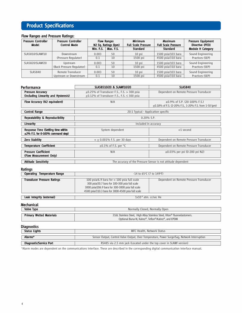
*Alarm modes are dependent on the communications interface. These are described in the corresponding digital communication interface manual.
Flow Ranges and PrFlow Ranges and PrFlow Ranges and PrFlow Ranges and PrFlow Ranges and Pressuressuressuressuressure Ratings:e Ratings:e Ratings:e Ratings:e Ratings:
Pressure ControllerPressure ControllerPressure ControllerPressure ControllerPressure Controller Pressure ControllerPressure ControllerPressure ControllerPressure ControllerPressure Controller Flow RangesFlow RangesFlow RangesFlow RangesFlow Ranges MinimumMinimumMinimumMinimumMinimum MaximumMaximumMaximumMaximumMaximum Pressure EquipmentPressure EquipmentPressure EquipmentPressure EquipmentPressure EquipmentModelModelModelModelModel Control ModeControl ModeControl ModeControl ModeControl Mode N2 Eq. Ratings (lpm) N2 Eq. Ratings (lpm) N2 Eq. Ratings (lpm) N2 Eq. Ratings (lpm) N2 Eq. Ratings (lpm) Full Scale PressureFull Scale PressureFull Scale PressureFull Scale PressureFull Scale Pressure Full Scale PressureFull Scale PressureFull Scale PressureFull Scale PressureFull Scale Pressure Directive (PED)Directive (PED)Directive (PED)Directive (PED)Directive (PED)
Min. F.S.Min. F.S.Min. F.S.Min. F.S.Min. F.S. Max. F.S.Max. F.S.Max. F.S.Max. F.S.Max. F.S. StandardStandardStandardStandardStandard StandardStandardStandardStandardStandard Module H CategoryModule H CategoryModule H CategoryModule H CategoryModule H Category
SLA5810/SLAMf10 Downstream 0.003 50 10 psi 1500 psia/103 bara Sound Engineering(Pressure Regulator) 0.1 10 1500 psi 4500 psia/310 bara Practices (SEP)
SLA5820/SLAMf20 Upstream 0.003 50 10 psi 1500 psia/103 bara Sound Engineering(Back Pressure Regulator) 0.1 10 1500 psi 4500 psia/310 bara Practices (SEP)
SLA5840 Remote Transducer 0.003 50 10 psi 1500 psia/103 bara Sound EngineeringUpstream or Downstream 0.1 10 1500 psi 4500 psia/310 bara Practices (SEP)
PerformancePerformancePerformancePerformancePerformancePressure AccuracyPressure AccuracyPressure AccuracyPressure AccuracyPressure Accuracy +0.25% of Transducer F.S., F.S. > 300 psia Dependent on Remote Pressure Transducer(Including Linearity and Hysteresis)(Including Linearity and Hysteresis)(Including Linearity and Hysteresis)(Including Linearity and Hysteresis)(Including Linearity and Hysteresis) +0.12% of Transducer F.S., F.S. ≤ 300 psia
Flow Accuracy (N2 equivalent)Flow Accuracy (N2 equivalent)Flow Accuracy (N2 equivalent)Flow Accuracy (N2 equivalent)Flow Accuracy (N2 equivalent) N/A ±0.9% of S.P. (20-100% F.S.)+0.18% of F.S. (2-20% F.S., 1-20% F.S. from 1-50 lpm)
Control RangeControl RangeControl RangeControl RangeControl Range 20:1 Typical - Application specific
Repeatability & ReproducibilityRepeatability & ReproducibilityRepeatability & ReproducibilityRepeatability & ReproducibilityRepeatability & Reproducibility 0.20% S.P.
LinearityLinearityLinearityLinearityLinearity Included in accuracy
Response Time (Response Time (Response Time (Response Time (Response Time (Settling time withinSettling time withinSettling time withinSettling time withinSettling time within System dependent <1 second±2% F.S. for 0-100% command step)±2% F.S. for 0-100% command step)±2% F.S. for 0-100% command step)±2% F.S. for 0-100% command step)±2% F.S. for 0-100% command step)
Zero StabilityZero StabilityZero StabilityZero StabilityZero Stability < + 0.001% F.S. per 30 days Dependent on Remote Pressure Transducer
Temperature CoefficientTemperature CoefficientTemperature CoefficientTemperature CoefficientTemperature Coefficient ±0.1% of F.S. per °C Dependent on Remote Pressure Transducer
Pressure CoefficientPressure CoefficientPressure CoefficientPressure CoefficientPressure Coefficient N/A ±0.03% per psi (0-200 psi N2)(Flow Measurement Only)(Flow Measurement Only)(Flow Measurement Only)(Flow Measurement Only)(Flow Measurement Only)
Attitude SensitivityAttitude SensitivityAttitude SensitivityAttitude SensitivityAttitude Sensitivity The accuracy of the Pressure Sensor is not attitude dependent
RatingsRatingsRatingsRatingsRatingsOperating Temperature RangeOperating Temperature RangeOperating Temperature RangeOperating Temperature RangeOperating Temperature Range -14 to 65oC (7 to 149oF)
Transducer Pressure RatingsTransducer Pressure RatingsTransducer Pressure RatingsTransducer Pressure RatingsTransducer Pressure Ratings 100 psia/6.9 bara for < 100 psia full scale Dependent on Remote Pressure Transducer300 psia/20.7 bara for 100-300 psia full scale
3000 psia/206.9 bara for 300-3000 psia full scale4500 psia/310.3 bara for 3000-4500 psia full scale
Leak Integrity (external)Leak Integrity (external)Leak Integrity (external)Leak Integrity (external)Leak Integrity (external) 1x10⁻⁹ atm. cc/sec He
MechanicalMechanicalMechanicalMechanicalMechanicalValve TypeValve TypeValve TypeValve TypeValve Type Normally Closed, Normally Open
Primary Wetted MaterialsPrimary Wetted MaterialsPrimary Wetted MaterialsPrimary Wetted MaterialsPrimary Wetted Materials 316L Stainless Steel, High Alloy Stainless Steel, Viton® fluoroelastomers.Optional Buna-N, Kalrez®, Teflon®/Kalrez®, and EPDM
DiagnosticsDiagnosticsDiagnosticsDiagnosticsDiagnosticsStatus LightsStatus LightsStatus LightsStatus LightsStatus Lights MFC Health, Network Status
Alarms*Alarms*Alarms*Alarms*Alarms* Sensor Output, Control Valve Output, Over Temperature, Power Surge/Sag, Network Interruption
Diagnostic/Service PortDiagnostic/Service PortDiagnostic/Service PortDiagnostic/Service PortDiagnostic/Service Port RS485 via 2.5 mm jack (Located under the top cover in SLAMf version)
SLA58510/20 & SLAMf10/20SLA58510/20 & SLAMf10/20SLA58510/20 & SLAMf10/20SLA58510/20 & SLAMf10/20SLA58510/20 & SLAMf10/20 SLA5840SLA5840SLA5840SLA5840SLA5840

5
Electrical SpecificationsElectrical SpecificationsElectrical SpecificationsElectrical SpecificationsElectrical Specifications
Communication ProtocolCommunication ProtocolCommunication ProtocolCommunication ProtocolCommunication Protocol RS485RS485RS485RS485RS485 ProfibusProfibusProfibusProfibusProfibus®®®®® DeviceNetDeviceNetDeviceNetDeviceNetDeviceNet®®®®® ***************
Electrical Connection (SLA58xx)Electrical Connection (SLA58xx)Electrical Connection (SLA58xx)Electrical Connection (SLA58xx)Electrical Connection (SLA58xx) 1 x 15-pin Male Sub-D, (A) 1 x 15-pin Male Sub-D 1 M12 with threaded1 x 9-pin Female Sub-D coupling nut (B)
Electrical Connection (SLAMf)Electrical Connection (SLAMf)Electrical Connection (SLAMf)Electrical Connection (SLAMf)Electrical Connection (SLAMf) PG11 Cable Gland, 1/2” NPT (F) Conduit, M20 x 1.5 Conduit N/A
Analog I/OAnalog I/OAnalog I/OAnalog I/OAnalog I/O 0-5 V, 1-5 V, 0-10 V, 0-20 mA, 4-20 mA N/A
Power Max./PurgePower Max./PurgePower Max./PurgePower Max./PurgePower Max./Purge From +13.5 Vdc to +27 Vdc From +11 Vdc to +25 Vdc
Power Requirements Watts, Max.Power Requirements Watts, Max.Power Requirements Watts, Max.Power Requirements Watts, Max.Power Requirements Watts, Max. Valve Orifice > 0.032”: 8.7 Watts Valve Orifice > 0.032”: 10 WattsValve Orifice ≤ 0.032”: 5.2 Watts Valve Orifice ≤ 0.032”: 7 Watts
Voltage Set Point Input SpecificationsVoltage Set Point Input SpecificationsVoltage Set Point Input SpecificationsVoltage Set Point Input SpecificationsVoltage Set Point Input Specifications
Nominal RangeNominal RangeNominal RangeNominal RangeNominal Range 0-5 Vdc, 1-5 Vdc or 0-10 Vdc N/A
Full RangeFull RangeFull RangeFull RangeFull Range (-0.5)-11 Vdc N/A
Absolute Max.Absolute Max.Absolute Max.Absolute Max.Absolute Max. 18 V (without damage) N/A
Input ImpedenceInput ImpedenceInput ImpedenceInput ImpedenceInput Impedence >990 kOhms N/A
Current Set Point Input SpecificationsCurrent Set Point Input SpecificationsCurrent Set Point Input SpecificationsCurrent Set Point Input SpecificationsCurrent Set Point Input Specifications
Nominal RangeNominal RangeNominal RangeNominal RangeNominal Range 4-20 mA or 0-20 mA N/A
Full RangeFull RangeFull RangeFull RangeFull Range 0-22 mA N/A
Absolute Max.Absolute Max.Absolute Max.Absolute Max.Absolute Max. 24 mA (without damage) N/A
Input ImpedenceInput ImpedenceInput ImpedenceInput ImpedenceInput Impedence 100 Ohms N/A
Flow Output (Voltage) SpecificationsFlow Output (Voltage) SpecificationsFlow Output (Voltage) SpecificationsFlow Output (Voltage) SpecificationsFlow Output (Voltage) Specifications
Nominal RangeNominal RangeNominal RangeNominal RangeNominal Range 0-5 Vdc, 1-5 Vdc or 0-10 Vdc N/A
Full RangeFull RangeFull RangeFull RangeFull Range (-1)-11 Vdc N/A
Min Load ResistanceMin Load ResistanceMin Load ResistanceMin Load ResistanceMin Load Resistance 2 kOhms N/A
Flow Output (Current) SpecificationsFlow Output (Current) SpecificationsFlow Output (Current) SpecificationsFlow Output (Current) SpecificationsFlow Output (Current) Specifications
Nominal RangeNominal RangeNominal RangeNominal RangeNominal Range 0-20 mA or 4-20 mA N/A
Full RangeFull RangeFull RangeFull RangeFull Range 0-22 mA N/A
Max. LoadMax. LoadMax. LoadMax. LoadMax. Load 380 Ohms N/A
Analog I/O Alarm Ouput*Analog I/O Alarm Ouput*Analog I/O Alarm Ouput*Analog I/O Alarm Ouput*Analog I/O Alarm Ouput*
TypeTypeTypeTypeType Open Collector N/A
Max. Closed (On) CurrentMax. Closed (On) CurrentMax. Closed (On) CurrentMax. Closed (On) CurrentMax. Closed (On) Current 25 mA N/A
Max. Open (Off) LeakageMax. Open (Off) LeakageMax. Open (Off) LeakageMax. Open (Off) LeakageMax. Open (Off) Leakage 1μA N/A
Max. Open (Off) VoltageMax. Open (Off) VoltageMax. Open (Off) VoltageMax. Open (Off) VoltageMax. Open (Off) Voltage 30 Vdc N/A
Analog I/O Valve Override Signal Specifications**Analog I/O Valve Override Signal Specifications**Analog I/O Valve Override Signal Specifications**Analog I/O Valve Override Signal Specifications**Analog I/O Valve Override Signal Specifications**
Floating/UnconnectedFloating/UnconnectedFloating/UnconnectedFloating/UnconnectedFloating/Unconnected Instrument controls valve to command set point N/A
VOR < 0.3 VdcVOR < 0.3 VdcVOR < 0.3 VdcVOR < 0.3 VdcVOR < 0.3 Vdc Valve Closed N/A
0.3 Vdc < VOR < 4.8 Vdc0.3 Vdc < VOR < 4.8 Vdc0.3 Vdc < VOR < 4.8 Vdc0.3 Vdc < VOR < 4.8 Vdc0.3 Vdc < VOR < 4.8 Vdc Undefined N/A
VOR > 4.8 VdcVOR > 4.8 VdcVOR > 4.8 VdcVOR > 4.8 VdcVOR > 4.8 Vdc Valve Open N/A
Input ImpedenceInput ImpedenceInput ImpedenceInput ImpedenceInput Impedence 60 kOhms N/A
Absolute Max. InputAbsolute Max. InputAbsolute Max. InputAbsolute Max. InputAbsolute Max. Input (-25 Vdc) < VOR < 25 Vdc (without damage) N/A
*The Alarm Output is an open collector or "contact type" that is CLOSED (on) whenever an alarm is active.The Alarm Output may be set to indicate any one of various alarm conditions.
** The Valve Override Signal (VOR) is implemented as an analog input which measures the voltage at the input and controls thevalve based upon the measured reading as shown in this section.
*** Available on SLA5810/20/40 only.

6
PrPrPrPrProduct Dimensionsoduct Dimensionsoduct Dimensionsoduct Dimensionsoduct Dimensions
SLA5810/20, Thru-Flow, Profibus
SLA5810/20, Thru-Flow, RS485
Note : Aux. Input only used for RemoteTransducer Pressure Controllers.
Note : Aux. Input only used for RemoteTransducer Pressure Controllers.

7
PrPrPrPrProduct Dimensions (conoduct Dimensions (conoduct Dimensions (conoduct Dimensions (conoduct Dimensions (continued)tinued)tinued)tinued)tinued)
SLA5840, Thru-Flow, Profibus
SLA5810/20, Thru-Flow, DeviceNet
Note : Aux. Input only used for RemoteTransducer Pressure Controllers.
Note : Aux. Input only used for RemoteTransducer Pressure Controllers.

8
PrPrPrPrProduct Dimensions (conoduct Dimensions (conoduct Dimensions (conoduct Dimensions (conoduct Dimensions (continued)tinued)tinued)tinued)tinued)
SLA5840, Thru-Flow, DeviceNet
SLAMf10/20, Thru-Flow, RS485
Note : Aux. Input only used for RemoteTransducer Pressure Controllers.
Note : Aux. Input onlyused for Remote
Transducer PressureControllers.

9
PrPrPrPrProduct Dimensions (conoduct Dimensions (conoduct Dimensions (conoduct Dimensions (conoduct Dimensions (continued)tinued)tinued)tinued)tinued)
SLAMf10/20, Thru-Flow, Profibus
Note : Aux. Input only used for RemoteTransducer Pressure Controllers.

10
Model CodeModel CodeModel CodeModel CodeModel CodeCode DescriptionCode DescriptionCode DescriptionCode DescriptionCode Description Code OptionCode OptionCode OptionCode OptionCode Option Option DescriptionOption DescriptionOption DescriptionOption DescriptionOption Description
I.I.I.I.I. Base Model Numbers SLASLASLASLASLA Smart Link Advantage
II.II.II.II.II. Package / Finish Specifications 5858585858 Standard Elastomer SeriesMFMFMFMFMF Standard Elastomer Series (NEMA 4X/IP66 Housing)
III.III.III.III.III. Function 11111 Downstream Pressure Controller22222 Upstream Pressure Controller44444 Remote Transducer Pressure Controller (SLA58xx only)
IV.IV.IV.IV.IV. Gas or Range 00000 3 ccm - 50 lpm
V.V.V.V.V. Digital I/O Communication AAAAA None (select applicable analog I/O)(SLA58xx Pressure Controllers) DDDDD DeviceNet I/O (with 5-pin micro connector) (Only on SLA5810/20/40)
PPPPP Profibus (2x sub-D)SSSSS RS485 (select applicable analog I/O)
V.V.V.V.V. Digital I/O Communication AAAAA None (select applicable analog I/O)(SLAMfxx Pressure Controllers) PPPPP Profibus (5-pin female M12, M20 x 1.5 conduit)
RRRRR Profibus (5-pin female M12, PG11 cable gland)TTTTT Profibus (5-pin female M12, 1/2” NPT (F) conduit)SSSSS RS485 (select applicable analog I/O)
VI.VI.VI.VI.VI. Mechanical Connection 1A1A1A1A1A Without adapters, 9/16” - 18 UNF1B1B1B1B1B 1/4” tube compression1C1C1C1C1C 1/8” tube compression1D1D1D1D1D 3/8” tube compression1E1E1E1E1E 1/4” VCR1F1F1F1F1F 1/4” VCO1G1G1G1G1G 1/4” NPT1H1H1H1H1H 6mm tube compression1J1J1J1J1J 10mm tube compression1L1L1L1L1L 3/8”-1/2” VCR1M1M1M1M1M 3/8”-1/2” VCO1P1P1P1P1P 1/2” tube compression1T1T1T1T1T 1/4” RC (BSP)1Y1Y1Y1Y1Y 3mm tube compressionB1B1B1B1B1 1/4” tube compression w/filterC1C1C1C1C1 1/8” tube compression w/filterD1D1D1D1D1 3/8” tube compression w/filterE1E1E1E1E1 1/4” VCR w/filterF1F1F1F1F1 1/4” VCO w/filterG1G1G1G1G1 1/4” NPT w/filterH1H1H1H1H1 6mm tube compression w/filterJ1J1J1J1J1 10mm tube compression w/filterL1L1L1L1L1 3/8”-1/2” VCR w/filterM1M1M1M1M1 3/8”-1/2” VCO w/filterP1P1P1P1P1 1/2” tube compression w/filterT1T1T1T1T1 1/4” RC (BSP) w/filterY1Y1Y1Y1Y1 3mm tube compression w/filter
VII.VII.VII.VII.VII. O-ring Material AAAAA VitonBBBBB BunaCCCCC PTFEDDDDD KalrezEEEEE EPDMJJJJJ FDA/USP Class VI - VitonLLLLL FDA/USP Class VI - EPDM
VIII.VIII.VIII.VIII.VIII. Valve Seat BBBBB VitonCCCCC BunaDDDDD KalrezEEEEE EPDMFFFFF PTFEGGGGG Metal (SLA5810/20/40 Only)
IX.IX.IX.IX.IX. Valve Type 11111 Normally closed (≤ 1500 psi)44444 Normally closed High Pressure (1500 - 4500 psi)55555 Normally open (SLA5810/20 Only) (≤ 1500 psi)

11
Model Code (conModel Code (conModel Code (conModel Code (conModel Code (continued)tinued)tinued)tinued)tinued)
Sample Standard Model CodeSample Standard Model CodeSample Standard Model CodeSample Standard Model CodeSample Standard Model Code
IIIII IIIIIIIIII IIIIIIIIIIIIIII IVIVIVIVIV VVVVV VIVIVIVIVI VIIVIIVIIVIIVII VIIIVIIIVIIIVIIIVIII IXIXIXIXIX XXXXX XIXIXIXIXI XIIXIIXIIXIIXII XIIIXIIIXIIIXIIIXIII
SLASLASLASLASLA 5858585858 55555 00000 AAAAA 1A1A1A1A1A AAAAA BBBBB 11111 BBBBB 11111 AAAAA 11111
Code DescriptionCode DescriptionCode DescriptionCode DescriptionCode Description Code OptionCode OptionCode OptionCode OptionCode Option Option DescriptionOption DescriptionOption DescriptionOption DescriptionOption DescriptionX.X.X.X.X. Analog I/O AAAAA None - Digital Communications only
Communications BBBBB 0-5 Volt 0-5 Volt(SLA58xx Pressure Controllers) CCCCC 4-20 mA 4-20 mA
LLLLL 1-5 Volt 1-5 VoltMMMMM 0-20 mA 0-20 mA00000 0-10 Volt 0-10 Volt11111 0-5 Volt 4-20 mA22222 0-5 Volt 0-20 mA33333 4-20 mA 0-5 Volt44444 0-20 mA 0-5 Volt99999 0-10 Volt 0-5 Volt
X.X.X.X.X. Analog I/O AAAAA None - Digital Communications onlyCommunications EEEEE 4-20 mA 0-5 Volt PG11 Gland(SLAMfxx Pressure Controllers) FFFFF 0-5 Volt 0-5 Volt PG11 Gland
GGGGG 4-20 mA 4-20 mA PG11 GlandHHHHH 0-5 Volt 4-20 mA PG11 GlandIIIII 0-5 Volt 0-20 mA PG11 GlandJJJJJ 0-5 Volt 0-5 Volt 1/2” NPT (F) ConduitKKKKK 4-20 mA 4-20 mA 1/2” NPT (F) ConduitNNNNN 0-5 Volt 4-20 mA M20 x 1.5 ConduitOOOOO 0-5 Volt 0-20 mA M20 x 1.5 ConduitPPPPP 4-20 mA 0-5 Volt M20 x 1.5 ConduitQQQQQ 0-20 mA 0-5 Volt M20 x 1.5 ConduitRRRRR 1-5 Volt 1-5 Volt PG11 GlandSSSSS 0-20 mA 0-20 mA PG11 GlandTTTTT 1-5 Volt 1-5 Volt 1/2” NPT (F) ConduitUUUUU 0-20 mA 0-20 mA 1/2” NPT (F) ConduitVVVVV 0-5 Volt 0-5 Volt M20 x 1.5 ConduitWWWWW 1-5 Volt 1-5 Volt M20 x 1.5 ConduitXXXXX 0-20 mA 0-20 mA M20 x 1.5 ConduitYYYYY 4-20 mA 4-20 mA M20 x 1.5 ConduitZZZZZ 0-20 mA 0-5 Volt PG11 Gland55555 0-5 Volt 4-20 mA 1/2” NPT (F) Conduit66666 0-5 Volt 0-20 mA 1/2” NPT (F) Conduit77777 4-20 mA 0-5 Volt 1/2” NPT (F) Conduit88888 0-20 mA 0-5 Volt 1/2” NPT (F) Conduit
XI.XI.XI.XI.XI. Power Supply Inputs 11111 ±15 Vdc22222 24 Vdc
XII.XII.XII.XII.XII. Output Enhancements AAAAA Standard response
BBBBB Fast response
XIII.XIII.XIII.XIII.XIII. Certification 11111 Safe Area
22222 For Zone II Atex/IECEx
Certifications - SLA58XXCertifications - SLA58XXCertifications - SLA58XXCertifications - SLA58XXCertifications - SLA58XX
CertificationsCertificationsCertificationsCertificationsCertifications
Mark Agency Certification ApplicableStandard Details
UL(Recogonized)
Class I, Div 2, Group A, B, C, D Class I, Zone 2, IIC T4 Class II, Zone 22
UL & CSA Standards E73889 Vol 3, Sec 4
ATEXII 3 G Ex nA IIC T4 Gc EN60079-0:2012
EN 60079-15:2010 KEMA 04ATEX 1118X
IECEx II 3 G Ex nA IIC T4 Gc IEC 60079-0:2011
IEC 60079-15:2010 IECEx DEK 14.0072X
KOSHA Ex nA IIC T4 15-AV4BO-0641 15-AV4BO-0640
CEEMC Directive 2014/30/EU Directive 2011/65/EU
EN:61326-1:2013 EMCRoHS

12
BrBrBrBrBrooks Service and Supportooks Service and Supportooks Service and Supportooks Service and Supportooks Service and Support
Brooks is committed to assuring all of our customers receive the ideal flow solution for their application, along with outstandingservice and support to back it up. We operate first class repair facilities located around the world to provide rapid response andsupport. Each location utilizes primary standard calibration equipment to ensure accuracy and reliability for repairs andrecalibration and is certified by our local Weights and Measures Authorities and traceable to the relevant International Standards.
Visit www.BrooksInstrument.com to locate the service location nearest to you.
STSTSTSTSTARARARARARTTTTT-UP SERVICE -UP SERVICE -UP SERVICE -UP SERVICE -UP SERVICE AND IN-SITU CALIBRAAND IN-SITU CALIBRAAND IN-SITU CALIBRAAND IN-SITU CALIBRAAND IN-SITU CALIBRATIONTIONTIONTIONTION
Brooks Instrument can provide start-up service prior to operation when required. For some process applications, where ISO-9001Quality Certification is important, it is mandatory to verify and/or (re)calibrate the products periodically. In many cases this servicecan be provided under in-situ conditions, and the results will be traceable to the relevant international quality standards.
CUSTCUSTCUSTCUSTCUSTOMER SEMINARS OMER SEMINARS OMER SEMINARS OMER SEMINARS OMER SEMINARS AND AND AND AND AND TRAININGTRAININGTRAININGTRAININGTRAINING
Brooks Instrument can provide customer seminars and dedicated training to engineers, end users, and maintenance persons.
Please contact your nearest sales representative for more details.
HELP DESKHELP DESKHELP DESKHELP DESKHELP DESK
In case you need technical assistance:Americas 1 888 554 FLOW Europe +31 (0) 318 549 290 Asia +81 3 (0) 5633 7100
Due to Brooks Instrument's commitment to continuous improvement of our products, all specifications are subject to change without notice.
TRADEMARKSBrooks, Quantim and Sho-Rate are marks of Brooks Instrument, LLCAll other marks are property of their respective owners.
Certifications (ConCertifications (ConCertifications (ConCertifications (ConCertifications (Continued)tinued)tinued)tinued)tinued)
Certifications -SLAMfxxCertifications -SLAMfxxCertifications -SLAMfxxCertifications -SLAMfxxCertifications -SLAMfxx
Mark Agency Certification Applicable Standard Details
UL(Recogonized)
Class I, Div 2, Group A, B, C, D Class I, Zone 2, IIC T4 Class II, Zone 22 IP66 UL & CSA Standards E73889 Vol 3, Sec 4
UL (Listed)
Class I, Div 2, Group A, B, C, D Class I, Zone 2, IIC T4 Class II, Zone 22 IP66 UL & CSA Standards E73889 Vol 1, Sec 25
ATEX
II 3 G Ex nA IIC T4 Gc II 3 D Ex tc IIIC T 85 oC Dc
IP66
EN 60079 0 : 2012 +A11 : 2013EN 60079 15 : 2010EN 60079 31 : 2014 KEMA 04ATEX1290 X
IECEx
Ex nA IIC T4 Gc Ex tc IIIC T 85 oC Dc
IP66
IEC 60079 0 : 2011 +Corr. 2012 + Cor.2013IEC 60079 15 : 2010IEC 60079 31 : 2013 IEC KEM 07.0043X
KOSHA Ex nA IIC T4 15-AV4BO-0638 15-AV4BO-0639
CE EMC Directive 2014/30/EU Directive 2011/65/EU
EN:61326-1:2013 EMCRoHS