SunVTS 6.0 Test Reference Manual · pour l’industrie del’informatique.Sun détientunelicensenon...
392
Submit comments about this document at: http://www.sun.com/hwdocs/feedback SunVTS™ 6.0 Test Reference Manual Part No. 817-7665-10 March 2005, Revision A Sun Microsystems, Inc. www.sun.com
Transcript of SunVTS 6.0 Test Reference Manual · pour l’industrie del’informatique.Sun détientunelicensenon...
Submit comments about th
SunVTS™ 6.0 Test ReferenceManual
Part No. 817-7665-10March 2005, Revision A
Sun Microsystems, Inc.www.sun.com
is document at: http://www.sun.com/hwdocs/feedback
Copyright 2005 Sun Microsystems, Inc., 4150 Network Circle, Santa Clara, California 95054, U.S.A. All rights reserved.
Sun Microsystems, Inc. has intellectual property rights relating to technology embodied in the product that is described in this document. Inparticular, and without limitation, these intellectual property rights may include one or more of the U.S. patents listed athttp://www.sun.com/patents, and one or more additional patents or pending patent applications in the U.S. and in other countries.
This document and the product to which it pertains are distributed under licenses restricting their use, copying, distribution, anddecompilation. No part of the product or of this document may be reproduced in any form by any means without prior written authorization ofSun and its licensors, if any.
Third-party software, including font technology, is copyrighted and licensed from Sun suppliers.
Parts of the product may be derived from Berkeley BSD systems, licensed from the University of California. UNIX is a registered trademark inthe U.S. and other countries, exclusively licensed through X/Open Company, Ltd.
Sun, Sun Microsystems, the Sun logo, AnswerBook2, docs.sun.com, SunVTS, and Solaris are trademarks, registered trademarks, or servicemarks of Sun Microsystems, Inc. in the U.S. and other countries.
All SPARC trademarks are used under license and are trademarks or registered trademarks of SPARC International, Inc. in the U.S. and othercountries. Products bearing SPARC trademarks are based upon an architecture developed by Sun Microsystems, Inc.
The OPEN LOOK and Sun™ Graphical User Interface was developed by Sun Microsystems, Inc. for its users and licensees. Sun acknowledgesthe pioneering efforts of Xerox in researching and developing the concept of visual or graphical user interfaces for the computer industry. Sunholds a non-exclusive license from Xerox to the Xerox Graphical User Interface, which license also covers Sun’s licensees who implement OPENLOOK GUIs and otherwise comply with Sun’s written license agreements.
Use, duplication, or disclosure by the U.S. Government is subject to restrictions set forth in the Sun Microsystems, Inc. license agreements and asprovided in DFARS 227.7202-1(a) and 227.7202-3(a) (1995), DFARS 252.227-7013(c)(1)(ii) (Oct. 1998), FAR 12.212(a) (1995), FAR 52.227-19, orFAR 52.227-14 (ALT III), as applicable.
DOCUMENTATION IS PROVIDED “AS IS” AND ALL EXPRESS OR IMPLIED CONDITIONS, REPRESENTATIONS AND WARRANTIES,INCLUDING ANY IMPLIED WARRANTY OF MERCHANTABILITY, FITNESS FOR A PARTICULAR PURPOSE OR NON-INFRINGEMENT,ARE DISCLAIMED, EXCEPT TO THE EXTENT THAT SUCH DISCLAIMERS ARE HELD TO BE LEGALLY INVALID.
Copyright 2005 Sun Microsystems, Inc., 4150 Network Circle, Santa Clara, California 95054, Etats-Unis. Tous droits réservés.
Sun Microsystems, Inc. a les droits de propriété intellectuels relatants à la technologie incorporée dans le produit qui est décrit dans cedocument. En particulier, et sans la limitation, ces droits de propriété intellectuels peuvent inclure un ou plus des brevets américains énumérésà http://www.sun.com/patents et un ou les brevets plus supplémentaires ou les applications de brevet en attente dans les Etats-Unis et dansles autres pays.
Ce produit ou document est protégé par un copyright et distribué avec des licences qui en restreignent l’utilisation, la copie, la distribution, et ladécompilation. Aucune partie de ce produit ou document ne peut être reproduite sous aucune forme, parquelque moyen que ce soit, sansl’autorisation préalable et écrite de Sun et de ses bailleurs de licence, s’il y ena.
Le logiciel détenu par des tiers, et qui comprend la technologie relative aux polices de caractères, est protégé par un copyright et licencié par desfournisseurs de Sun.
Des parties de ce produit pourront être dérivées des systèmes Berkeley BSD licenciés par l’Université de Californie. UNIX est une marquedéposée aux Etats-Unis et dans d’autres pays et licenciée exclusivement par X/Open Company, Ltd.
Sun, Sun Microsystems, le logo Sun, AnswerBook2, docs.sun.com, SunVTS, et Solaris sont des marques de fabrique ou des marques déposéesde Sun Microsystems, Inc. aux Etats-Unis et dans d’autres pays.
Toutes les marques SPARC sont utilisées sous licence et sont des marques de fabrique ou des marques déposées de SPARC International, Inc.aux Etats-Unis et dans d’autres pays. Les produits protant les marques SPARC sont basés sur une architecture développée par SunMicrosystems, Inc.
L’interface d’utilisation graphique OPEN LOOK et Sun™ a été développée par Sun Microsystems, Inc. pour ses utilisateurs et licenciés. Sunreconnaît les efforts de pionniers de Xerox pour la recherche et le développment du concept des interfaces d’utilisation visuelle ou graphiquepour l’industrie de l’informatique. Sun détient une license non exclusive do Xerox sur l’interface d’utilisation graphique Xerox, cette licencecouvrant également les licenciées de Sun qui mettent en place l’interface d ’utilisation graphique OPEN LOOK et qui en outre se conformentaux licences écrites de Sun.
LA DOCUMENTATION EST FOURNIE "EN L’ÉTAT" ET TOUTES AUTRES CONDITIONS, DECLARATIONS ET GARANTIES EXPRESSESOU TACITES SONT FORMELLEMENT EXCLUES, DANS LA MESURE AUTORISEE PAR LA LOI APPLICABLE, Y COMPRIS NOTAMMENTTOUTE GARANTIE IMPLICITE RELATIVE A LA QUALITE MARCHANDE, A L’APTITUDE A UNE UTILISATION PARTICULIERE OU AL’ABSENCE DE CONTREFAÇON.

Contents
1. Introduction 1
x86 Solaris Support 2
New and Consolidated Tests 3
Test Requirements 4
Collection of SunVTS Tests 4
32-Bit and 64-Bit Tests 5
SunVTS User Interfaces 5
Running a Test From a User Interface 6
Test Parameter Options Dialog Box 6
Running a Test From the Command Line 8
Standard Command-Line Arguments 9
Test-Specific Arguments 10
Testing Frame Buffers 10
Testing Multiple Frame Buffers 11
Remote Testing of Frame Buffers 12
2. SunATM Adapter Test (atmtest ) 13
atmtest Test Requirements 13
atmtest Options 14
atmtest Test Modes 17
iii
atmtest Command-Line Syntax 17
3. Audio Test (audiotest ) 19
audiotest Subtests 20
audiotest Options 21
audiotest Test Modes 23
audiotest Command-Line Syntax 23
4. Blade Support Chip Test (bsctest ) 27
bsctest Options 27
bsctest Test Modes 29
bsctest Command-Line Syntax 29
5. Optical Disk Drive Test (cddvdtest ) 31
Volume Management 31
cddvdtest Hardware and Software Requirements 32
CD-ROM and DVD-ROM 32
CD-RW and DVD-RW 33
cddvdtest Subtests 33
CD-RW and DVD-RW 34
cddvdtest Options 34
CD-ROM Test Options 35
DVD-ROM Test Options 37
CD-RW Test Options 38
DVD-RW Test Options 40
cddvdtest Supported Test Modes 41
CD-ROM Test Modes 42
DVD-ROM Test Modes 42
CD-RW and DVD-RW Test Modes 43
cddvdtest Command-Line Syntax 43
iv SunVTS 6.0 Test Reference Manual • March 2005
CD-ROM Command-Line Syntax 44
DVD-ROM Command-Line Syntax 44
CD-RW Command-Line Syntax 45
DVD-RW Command-Line Syntax 45
6. Chip Multi-Threading Test (cmttest ) 47
cmttest Options 47
cmttest Test Modes 50
cmttest Command-Line Syntax 50
7. CPU Power Management Test (cpupmtest ) 53
cpupmtest Options 53
cpupmtest Test Modes 55
cpupmtest Command-Line Syntax 55
8. CPU Test (cputest ) 57
cputest Options 58
cputest Test Modes 61
cputest Command-Line Syntax 61
9. Disk and Floppy Drives Test (disktest ) 63
disktest Test Requirements 64
disktest Subtests 66
disktest Test Options 67
disktest Test Modes 72
disktest Command-Line Syntax for SPARC Platforms 72
disktest Command-Line Syntax for x86 Platforms 76
10. Netra-CT 820 DMC Test (dmctest ) 79
dmcatest Options 82
dmcstest Options 85
v
dmctest Supported Test Modes 88
dmcatest Command-Line Syntax 88
dmcstest Command-Line Syntax 89
11. Sun Fire™ V880 FC-AL Disk Backplane Test (dpmtest ) 91
dpmtest Options 91
dpmtest Test Modes 94
dpmtest Command-Line Syntax 94
12. Data Translation Look-aside Buffer (dtlbtest ) 97
dtlbtest Options 98
dtlbtest Command-Line Syntax 99
13. Environmental Test (envtest ) 101
envtest Options 101
envtest Test Modes 103
envtest Command-Line Syntax 104
14. Environmental Test (env2test ) 105
env2test Options 105
env2test Test Modes 107
env2test Command-Line Syntax 108
15. Environmental Test (env3test ) 109
env3test Options 110
env3test Test Modes 113
env3test Command-Line Syntax 113
16. Environmental Test (env5test ) 115
env5test Test Requirements 115
env5test Options 116
vi SunVTS 6.0 Test Reference Manual • March 2005

env5test Test Modes 118
env5test Command-Line Syntax 118
17. Environmental Test (env6test ) 119
env6test Options 119
env6test Test Modes 121
env6test Command-Line Syntax 121
18. Floating Point Unit Test (fputest ) 123
fputest Subtests 123
fputest Options 124
fputest Test Modes 126
fputest Command-Line Syntax 126
19. IEEE 1394 Camera Test (fwcamtest ) 129
fwcamtest Test Requirements 129
Start a Window Environment 129
Testing Through a Remote Connection 130
fwcamtest Subtests 130
fwcamtest Options 130
fwcamtest Test Modes 132
fwcamtest Command-Line Syntax 132
20. I2C Bus Test (i2ctest ) 133
i2ctest Test Requirements 133
i2ctest Options 134
i2ctest Test Modes 135
i2ctest Command-Line Syntax 135
21. I2C Inter-Integrated Circuit Test (i2c2test ) 137
i2c2test Options 137
vii

i2c2test Test Modes 139
i2c2test Command-Line Syntax 139
22. Expert3D Frame Buffer Test (ifbtest ) 141
ifbtest Test Requirements 141
Preparation for ifbtest 142
ifbtest Options 143
ifbtest Test Modes 147
ifbtest Command-Line Syntax 147
23. Intelligent Fibre Channel Processor Test (ifptest ) 149
ifptest Subtests 149
ifptest Options 150
ifptest Test Modes 152
ifptest Command-Line Syntax 153
24. Integer Unit Test (iutest ) 155
iutest Options 155
iutest Test Modes 157
iutest Command-Line Syntax 157
25. Sun™ XVR-1200 Graphics Accelerator Test (jfbtest ) 159
jfbtest Test Requirements 159
Preparation for jfbtest 160
jfbtest Options 161
jfbtest Test Modes 166
jfbtest Command-Line Syntax 166
26. JNI 2GB FC HBA Test (jnifctest ) 169
jnifctest Options 170
jnifctest Supported Test Modes 172
viii SunVTS 6.0 Test Reference Manual • March 2005
jnifctest Command-Line Syntax 172
27. Level 1 Data Cache Test (l1dcachetest ) 173
l1dcachetest Options 173
l1dcachetest Test Modes 176
l1dcachetest Command-Line Syntax 176
28. Level 2 Cache Test (l2sramtest ) 179
l2sramtest Options 179
l2sramtest Test Modes 181
l2sramtest Command-Line Syntax 181
29. LOMlite Alarm Test (lomlitetest ) 183
lomlitetest Requirements 183
lomlitetest Subtests 184
lomlitetest Options 185
lomlitetest Test Modes 186
lomlitetest Command-Line Syntax 186
30. M64 Video Board Test (m64test ) 187
m64test Options 188
m64test Test Modes 190
m64test Command-Line Syntax 191
31. Multiprocessor Test (mptest ) 193
mptest Options 193
mptest Test Modes 197
mptest Command-Line Syntax 197
32. Sun Netra Alarm Card Test (nalmtest ) 201
nalmtest Options 201
ix
nalmtest Test Modes 203
nalmtest Command-Line Syntax 203
33. Ethernet Loopback Test (netlbtest ) 205
netlbtest Test Requirements 206
netlbtest Options 207
netlbtest Test Modes 208
netlbtest Command-Line Syntax 209
34. Network Hardware Test (nettest ) 211
nettest Options 212
nettest Test Modes 214
nettest Command-Line Syntax 215
35. Netra CT-820 IPMI Test (nipmitest ) 217
nipmitest Options 217
nipmitest Supported Test Modes 219
nipmitest Command-Line Syntax 219
36. PCMCIA Modem Card Test (pcsertest ) 221
pcsertest Options 221
pcsertest Test Mode 223
pcsertest Command-Line Syntax 223
37. Sun™ XVR-100 Graphics Accelerator Test (pfbtest ) 225
pfbtest Options 226
pfbtest Test Modes 228
pfbtest Command-Line Syntax 229
38. Physical Memory Test (pmemtest ) 231
pmemtest Options 231
x SunVTS 6.0 Test Reference Manual • March 2005
pmemtest Test Modes 234
pmemtest Command-Line Syntax 234
39. Parallel Port Printer Test (pptest ) 237
Hardware and Software Requirements 237
pptest Subtests 238
pptest Options 238
pptest Test Modes 241
pptest Command Line Syntax 241
40. Qlogic 2202 Board Test (qlctest ) 243
qlctest Subtests 243
qlctest Options 244
qlctest Test Modes 247
qlctest Command-Line Syntax 247
41. RAM Test (ramtest ) 249
ramtest Options 249
ramtest Test Modes 253
ramtest Command-Line Syntax 253
42. Remote System Control (rsctest) 259
rsctest Subtests 259
rsctest Options 261
rsctest Test Modes 264
rsctest Command-Line Syntax 264
43. Serial Asynchronous Interface (PCI)Test (saiptest ) 267
saiptest Hardware Requirements 267
saiptest Options 268
xi

saiptest Test Modes 272
saiptest Command-Line Syntax 272
44. Internal I2C Smartcard Reader Test (sc2test ) 275
sc2test Subtests 275
sc2test Options 276
sc2test Test Modes 278
sc2test Command-Line Syntax 278
45. SEEPROM Test (seepromtest ) 279
seepromtest Options 279
seepromtest Test Modes 281
seepromtest Command-Line Syntax 281
46. Serial Ports Test (serialtest ) 283
Loopback Connectors 283
serialtest Synchronous Testing Software Requirements 284
▼ To Create Synchronous Devices 284
Mode and Description 285
Asynchronous Testing 285
Synchronous Testing 285
serialtest Options 286
serialtest Test Modes 290
serialtest Command-Line Syntax 290
47. Serial Parallel Controller Test (spiftest ) 293
spiftest Hardware Requirements 293
spiftest Options 294
spiftest Test Modes 297
spiftest Command-Line Syntax 297
xii SunVTS 6.0 Test Reference Manual • March 2005
48. System Service Processor Test (ssptest) 299
ssptest Subtests 299
ssptest Options 301
ssptest Test Modes 304
ssptest Command-Line Syntax 305
49. SunHSI Board Test (sunlink ) 307
sunlink Test Requirements 307
sunlink Options 308
sunlink Loopback Connectors 309
sunlink Test Modes 310
sunlink Command-Line Syntax 310
50. SunPCi II Test (sunpci2test ) 313
sunpci2test Test Requirements 313
▼ To Shut Down Microsoft Windows and the SunPCi II Card: 313
sunpci2test Options 314
sunpci2test Test Modes 315
sunpci2test Command-Line Syntax 315
51. System Test (systest ) 317
systest Options 317
systest Test Modes 320
systest Command-Line Syntax 320
Recommended Option Selection 321
Command-Line Examples 321
52. Tape Drive Test (tapetest ) 323
tapetest Test Requirements 323
tapetest Options 323
xiii
tapetest Test Modes 327
tapetest Command-Line Syntax 327
53. USB Device Test (usbtest ) 329
usbtest Subtests 329
usbtest Options 330
usbtest Test Modes 332
usbtest Command Line Syntax 332
54. Virtual Memory Test (vmemtest ) 335
vmemtest Swap Space Requirements 335
vmemtest Options 336
vmemtest Test Modes 340
vmemtest Command-Line Syntax 340
A. Loopback Connectors 343
25-Pin RS-232 Loopback Plug 345
25-Pin RS-232 Port-to-Port Loopback Cable 345
8-Pin to 8-Pin Loopback Cable 346
8-Pin Loopback Plug 347
25-Pin Port A-to-Port B Loopback Plug 348
25-Pin Port A-to-A Port B-to-B
Loopback Plug 348
96-Pin Female Loopback Connector 349
96-Pin Female Special Loopback Connector 351
37-Pin RS-449 Loopback Cable 352
37-Pin RS-449 Loopback Plug 353
9-Pin Male Single-Port Loopback Plug 354
9-Pin Female Single-Port Loopback Plug 354
9-Pin to 25-Pin Port-to-Port Loopback Cable 355
xiv SunVTS 6.0 Test Reference Manual • March 2005
9-Pin to 9-Pin Port-to-Port Loopback Cable 356
NT to TE Loopback Cable 356
Twisted-Pair Ethernet (TPE) Loopback Cable for Fast Ethernet 357
TPE Loopback Cable for Gigabit and 10/100 Ethernet 357
x86 Platform RJ-45 Serial Port Loopback Connector 358
9-Pin Male Single-Port Loopback Plug 358
9-Pin Female Single-Port Loopback Plug 359
9-Pin Male DB-9 External Loopback Connector 359
9-Pin Female DB-9 External Loopback Connector 360
Glossary 363
Index 367
xv

xvi SunVTS 6.0 Test Reference Manual • March 2005
Preface
SunVTS™ is the Sun Microsystems™ Validation Test Suite. SunVTS is a
comprehensive software diagnostic package that tests and validates Sun™ hardware
by verifying the configuration and functionality of most hardware controllers,
devices, and platforms.
SunVTS is primarily used from a graphical user interface (GUI), for the Common
Desktop Environment (CDE). This book describes SunVTS tests that run on
machines with SPARC™ and x86 architectures. The descriptions include specific test
options, procedures, and error messages.
This book is primarily written as a reference for SunVTS test specific information.
Refer to the SunVTS User’s Guide for overall SunVTS information.
Developers or experienced users who want to run the SunVTS diagnostic application
will find these documents useful.
Note – The Solaris release with which this version of SunVTS is delivered supports
systems that use the SPARC® and x86 families of processor architectures:
UltraSPARC®, SPARC64, AMD64, Pentium, and Xeon EM64T. The supported
systems appear in the Solaris 10 Hardware Compatibility List at
http://www.sun.com/bigadmin/hcl . This document cites any implementation
differences between the platform types.
In this document the term x86 refers to 64-bit and 32-bit systems manufactured
using processors compatible with the AMD64 or Intel Xeon/Pentium product
families. For supported systems, see the Solaris 10 Hardware Compatibility List.
xvii
Before You Read This Book
In order to fully use the information in this document, you must have thorough
knowledge of the topics discussed in these books:
■ SunVTS User’s Guide■ SunVTS Quick Reference Card
How This Book Is Organized
This book is organized as follows:
Chapter 1 describes SunVTS requirements, test modes, user interfaces, the collection
of tests, and how to run a test from the command line.
The remaining chapters describe the individual SunVTS tests, their options,
applicable test modes, and command-line syntax. These chapters are arranged in
alphabetical order according to each test name.
Appendix A provides information about the serial and parallel port loopback
connectors that are required by some of the SunVTS tests.
Using UNIX Commands
This document might not contain information on basic UNIX® commands and
procedures such as shutting down the system, booting the system, and configuring
devices.
Refer to one or more of the following for this information:
■ Solaris Handbook for Sun Peripherals
■ Software documentation that you received with your system
■ Solaris™ Operating System documentation, which is at
http://docs.sun.com
xviii SunVTS 6.0 Test Reference Manual • March 2005
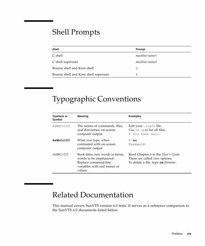
Shell Prompts
Typographic Conventions
Related Documentation
This manual covers SunVTS version 6.0 tests. It serves as a reference companion to
the SunVTS 6.0 documents listed below.
Shell Prompt
C shell machine-name%
C shell superuser machine-name#
Bourne shell and Korn shell $
Bourne shell and Korn shell superuser #
Typeface orSymbol
Meaning Examples
AaBbCc123 The names of commands, files,
and directories; on-screen
computer output
Edit your .login file.
Use ls -a to list all files.
% You have mail.
AaBbCc123 What you type, when
contrasted with on-screen
computer output
% suPassword:
AaBbCc123 Book titles, new words or terms,
words to be emphasized.
Replace command-line
variables with real names or
values.
Read Chapter 6 in the User’s Guide.
These are called class options.
To delete a file, type rm filename.
Preface xix
Accessing Sun Documentation
You can view, print, or purchase a broad selection of Sun documentation, including
localized versions, at:
http://www.sun.com/documentation
Third-Party Web Sites
Sun is not responsible for the availability of third-party web sites mentioned in this
document. Sun does not endorse and is not responsible or liable for any content,
advertising, products, or other materials that are available on or through such sites
or resources. Sun will not be responsible or liable for any actual or alleged damage
or loss caused by or in connection with the use of or reliance on any such content,
goods, or services that are available on or through such sites or resources.
Contacting Sun Technical Support
If you have technical questions about this product that are not answered in this
document, go to:
http://www.sun.com/service/contacting
Application Title Part Number
Installation and Navigation SunVTS 6.0 User’s Guide 817-7664-10
Quick Reference Card SunVTS Quick Reference Card 817-7686-10
xx SunVTS 6.0 Test Reference Manual • March 2005

Sun Welcomes Your Comments
Sun is interested in improving its documentation and welcomes your comments and
suggestions. You can submit your comments by going to:
http://www.sun.com/hwdocs/feedback
Please include the title and part number of your document with your feedback:
SunVTS 6.0 Test Reference Manual, part number 817-7665-10
Preface xxi

xxii SunVTS 6.0 Test Reference Manual • March 2005
CHAPTER 1
Introduction
This manual describes SunVTS™ Version 6.0 tests that are distributed on the
Solaris 10 Software CDs.
The Sun™ Validation and Test Suite (SunVTS) software performs multiple diagnostic
hardware tests from a single user interface. SunVTS verifies the connectivity,
functionality, and reliability of most hardware controllers and devices.
SunVTS is composed of many individual tests that support testing of a wide range
of products and peripherals. Most of the tests are capable of testing devices in a
32-bit or 64-bit Solaris™ environment.
Only the following tests are supported on x86 (and SPARC) platforms. The current
x86 support is for the 32-bit operating system only. See “x86 Solaris Support” on
page 2.
■ CD DVD Test (cddvdtest )
■ CPU Test (cputest )
■ Disk and Floppy Drives Test (disktest )
■ Data Translation Look-aside Buffer (dtlbtest )
■ Floating Point Unit Test (fputest )
■ Network Hardware Test (nettest )
■ Ethernet Loopback Test (netlbtest )
■ Physical Memory Test (pmemtest )
■ Serial Port Test (serialtest )
■ System Test (systest )
■ Universal Serial Board Test (usbtest )
■ Virtual Memory Test (vmemtest )
Use SunVTS to test one device or multiple devices. Some of the major test categories
are:
■ Audio tests
■ Communication (serial and parallel) tests
■ Graphic/video tests
■ Memory tests
■ Network tests
1
■ Peripherals (disks, tape, CD-ROM, DVD-ROM, printer, floppy) tests
■ Processor tests
■ Storage tests
Such flexibility means that the proper test modes and options need to be selected to
maximize its effectiveness. This book covers the individual test options, modes, and
requirements. For overall test configuration modes and options refer to the SunVTSUser’s Guide.
Note – When an error occurs in VTS testing, the test message window displays the
error number, the error description, the probable cause of the error, and the
recommended actions. Because this information is displayed at the time of the error,
error messages are not included in this manual.
The default installation directory for SunVTS is /opt/SUNWvts. However, when
you are installing SunVTS, you can specify a different directory. Refer to the SunVTSUser’s Guide for installation information.
Note – SunVTS does not support processor sets. If processor sets are defined, you
must first delete the processor sets before running SunVTS.
x86 Solaris Support
Starting with Solaris 10, the SunVTS infrastructure and a few core diagnostics are
available for x86 Solaris platforms. The current x86 support is for the 32-bit
operating system only. x86 support was first delivered with Solaris 10 Beta 6.
You must install the x86 version of the SunVTS packages to be able to perform
SunVTS on x86 platforms. The software packages use the same names as in the
SPARC environment. The SunVTS packages delivered separately for both x86 and
SPARC Solaris platforms are as follows:
■ SUNWvts – Contains the SunVTS core framework that includes the kernel and
user interface.
■ SUNWvtsmn– Contains the SunVTS online manual pages
■ SUNWvtsr – Contains the SunVTS framework configuration files in the root
partition (Superuser).
■ SUNWvtsts – Contains the SunVTS test binaries.
The SunVTS components available for x86 Solaris platforms are as follows.
Infrastructure:
2 SunVTS 6.0 Test Reference Manual • March 2005
■ sunvts■ vtsk■ vts_cmd■ vtstty■ vtsui■ vtsprobe
SunVTS Tests:
■ CD DVD Test (cddvdtest )
■ CPU Test (cputest )
■ Disk and Floppy Drives Test (disktest )
■ Data Translation Look-aside Buffer (dtlbtest )
■ Floating Point Unit Test (fputest )
■ Network Hardware Test (nettest )
■ Ethernet Loopback Test (netlbtest )
■ Physical Memory Test (pmemtest )
■ Serial Port Test (serialtest )
■ System Test (systest )
■ Universal Serial Board Test (usbtest )
■ Virtual Memory Test (vmemtest )
New and Consolidated Tests
The following tests are new in this release:
■ CD and DVD Test (cddvdtest ) – a consolidation of cdtest , cddvdrwtest , and
dvdtest .
■ Ethernet Loopback Test (netlbtest )
■ Serial Port Test (serialtest ) – a consolidation of sptest and sutest .
■ Universal Serial Board Test (usbtest ) – a consolidation of usbaudiotest ,
usbkbtest , and usbppptest .
■ Parallel Port Printer Test (pptest ) – a consolidation of bpptest and ecpptest .
The following tests were consolidated in this release:
■ cdtest , cddvdrwtest , and sutest are consolidated into cddvdtest .
■ sptest and sutest are consolidated into serialtest■ usbaudiotest , usbkbtest , and usbppptest are consolidated into usbtest .
■ bpptest and ecpptest are consolidated into pptest .
Chapter 1 Introduction 3

Test Requirements
SunVTS Version 6.0 was first introduced and designed to run in the Solaris 10
operating system and later releases. SunVTS 6.0 is not supported on earlier relases of
the Solaris operating system.
The operating system kernel must be configured to support all peripherals that are
to be tested.
Some SunVTS tests have special requirements such as the connection of loopback
connectors, installation of test media, or the availability of disk space. These
requirements are listed for each test in the corresponding chapter in this book.
Collection of SunVTS Tests
Many individual tests make up the collection of tests in the SunVTS application.
Each test is a separate process from the SunVTS kernel. Each test can be run
individually from the command line or from the SunVTS user interface.
When SunVTS is started, the SunVTS kernel automatically probes the system kernel
to determine the hardware devices. The devices are then displayed on the SunVTS
control panel with the appropriate tests and test options. This provides a quick
check of your hardware configuration, and no time is wasted trying to run tests that
are not applicable to your configuration.
During testing, the hardware tests send the test status and messages to the SunVTS
kernel through interprocess communication (IPC) protocols. The kernel passes the
status to the user interface and logs the messages.
SunVTS has a shared object library that contains test-specific probing routines. At
runtime, the SunVTS kernel dynamically links in and calls these probing routines to
initialize its data structure with test-specific information. You can add new tests into
the SunVTS environment without recompiling the SunVTS source code.
As of SunVTS 3.0, the SunVTS kernel and most tests support 32-bit and 64-bit
operating systems. When the sunvts command is used to start SunVTS, the
appropriate tests (32-bit or 64-bit versions) are presented.
4 SunVTS 6.0 Test Reference Manual • March 2005
32-Bit and 64-Bit Tests
Because each test is a separate program, you can run individual tests directly from
the command line. When this is done, care must be taken to run the appropriate test
(32-bit or 64-bit) that corresponds to the operating system that is running (32-bit or
64-bit). This is done by running tests from specific directories as follows:
■ 32-bit tests—/opt/SUNWvts/bin/ testname
■ 64-bit tests—/opt/SUNWvts/bin/sparcv9/ testname
■ The test is an actual 64-bit binary test if testname is a binary file.
■ The test is a 32-bit test capable of running in the 64-bit environment if testnameis a symbolic link.
Note – The SUNWvtsx package must be installed for 64-bit SunVTS support. For
more information on SunVTS packages and installation procedures refer to the
SunVTS User’s Guide.
If you use the sunvts command to run SunVTS, SunVTS automatically allocates 32-
bit or 64-bit tests based on the 32-bit or 64-bit Solaris operating environment that is
running. Therefore, the only time that you need to be concerned with the 32-bit or
64-bit operation is when you run the SunVTS kernel or SunVTS tests from the
command line.
If you are not sure which operating system is running, refer to the Solaris System
Administration manuals. In Solaris 10, the following command can be used to
identify the application support of your system.
Note – The isainfo command is not available in Solaris 2.6 or earlier releases.
SunVTS User Interfaces
You can run SunVTS tests from various interfaces: The CDE graphical user
interfaces, or the TTY interface. SunVTS tests can also be run individually from a
shell tool command line, using the command-line syntax for each test (refer to
# isainfo -v
Chapter 1 Introduction 5
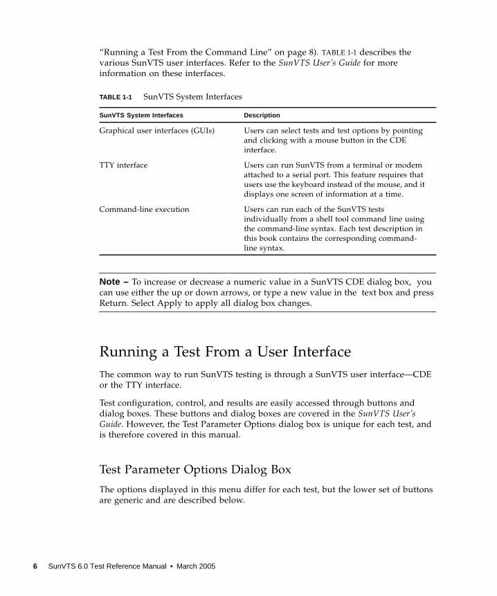
“Running a Test From the Command Line” on page 8). TABLE 1-1 describes the
various SunVTS user interfaces. Refer to the SunVTS User’s Guide for more
information on these interfaces.
Note – To increase or decrease a numeric value in a SunVTS CDE dialog box, you
can use either the up or down arrows, or type a new value in the text box and press
Return. Select Apply to apply all dialog box changes.
Running a Test From a User Interface
The common way to run SunVTS testing is through a SunVTS user interface—CDE
or the TTY interface.
Test configuration, control, and results are easily accessed through buttons and
dialog boxes. These buttons and dialog boxes are covered in the SunVTS User’sGuide. However, the Test Parameter Options dialog box is unique for each test, and
is therefore covered in this manual.
Test Parameter Options Dialog Box
The options displayed in this menu differ for each test, but the lower set of buttons
are generic and are described below.
TABLE 1-1 SunVTS System Interfaces
SunVTS System Interfaces Description
Graphical user interfaces (GUIs) Users can select tests and test options by pointing
and clicking with a mouse button in the CDE
interface.
TTY interface Users can run SunVTS from a terminal or modem
attached to a serial port. This feature requires that
users use the keyboard instead of the mouse, and it
displays one screen of information at a time.
Command-line execution Users can run each of the SunVTS tests
individually from a shell tool command line using
the command-line syntax. Each test description in
this book contains the corresponding command-
line syntax.
6 SunVTS 6.0 Test Reference Manual • March 2005
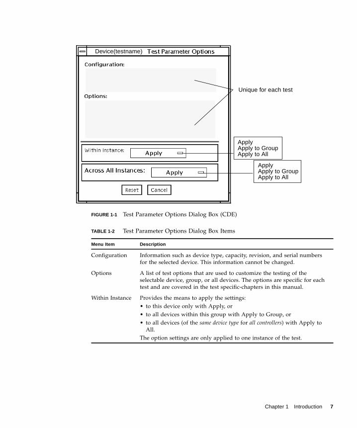
FIGURE 1-1 Test Parameter Options Dialog Box (CDE)
TABLE 1-2 Test Parameter Options Dialog Box Items
Menu Item Description
Configuration Information such as device type, capacity, revision, and serial numbers
for the selected device. This information cannot be changed.
Options A list of test options that are used to customize the testing of the
selectable device, group, or all devices. The options are specific for each
test and are covered in the test specific-chapters in this manual.
Within Instance Provides the means to apply the settings:
• to this device only with Apply, or
• to all devices within this group with Apply to Group, or
• to all devices (of the same device type for all controllers) with Apply to
All.
The option settings are only applied to one instance of the test.
Unique for each test
ApplyApply to GroupApply to All
ApplyApply to GroupApply to All
Device(testname)
Chapter 1 Introduction 7
Note – The Test Parameter Options Dialog Box descriptions also apply to the Test
Parameter Options menu in the TTY interface.
Running a Test From the Command Line
In some cases it may be more convenient to run a single SunVTS test from the
command line rather than through a SunVTS user interface. The following
information describes how to do this.
Unless specified, the test runs without the SunVTS kernel (vtsk ). All events and
errors are sent to stdout or stderr and are not logged in the log files.
When you run a test in this way, you must specify all test options in the form of
command-line arguments.
There are two types of command-line arguments:
■ Standard arguments—common to all tests. Refer to TABLE 1-3 for details.
■ Test specific arguments—unique to a specific test. Refer to the test-specific
chapters in this book for details.
The standard syntax for all SunVTS tests is:
testname [ -scruvdtelnf ] [ -i number] [ -w number][ -o test_specific_arguments]
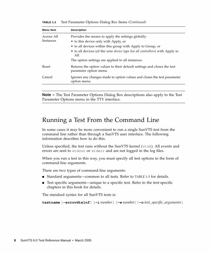
Across All
Instances
Provides the means to apply the settings globally:
• to this device only with Apply, or
• to all devices within this group with Apply to Group, or
• to all devices (of the same device type for all controllers) with Apply to
All.
The option settings are applied to all instances.
Reset Returns the option values to their default settings and closes the test
parameter option menu.
Cancel Ignores any changes made to option values and closes the test parameter
option menu.
TABLE 1-2 Test Parameter Options Dialog Box Items (Continued)
Menu Item Description
8 SunVTS 6.0 Test Reference Manual • March 2005
Note – 64-bit tests are located in the sparcv9 subdirectory:
/opt/SUNWvts/bin/sparcv9/ testname, or the relative path to which you installed
SunVTS. If a test is not present in this directory, then it might be available as a 32-bit
test only. For more information, see “32-Bit and 64-Bit Tests” on page 5.
Standard Command-Line Arguments
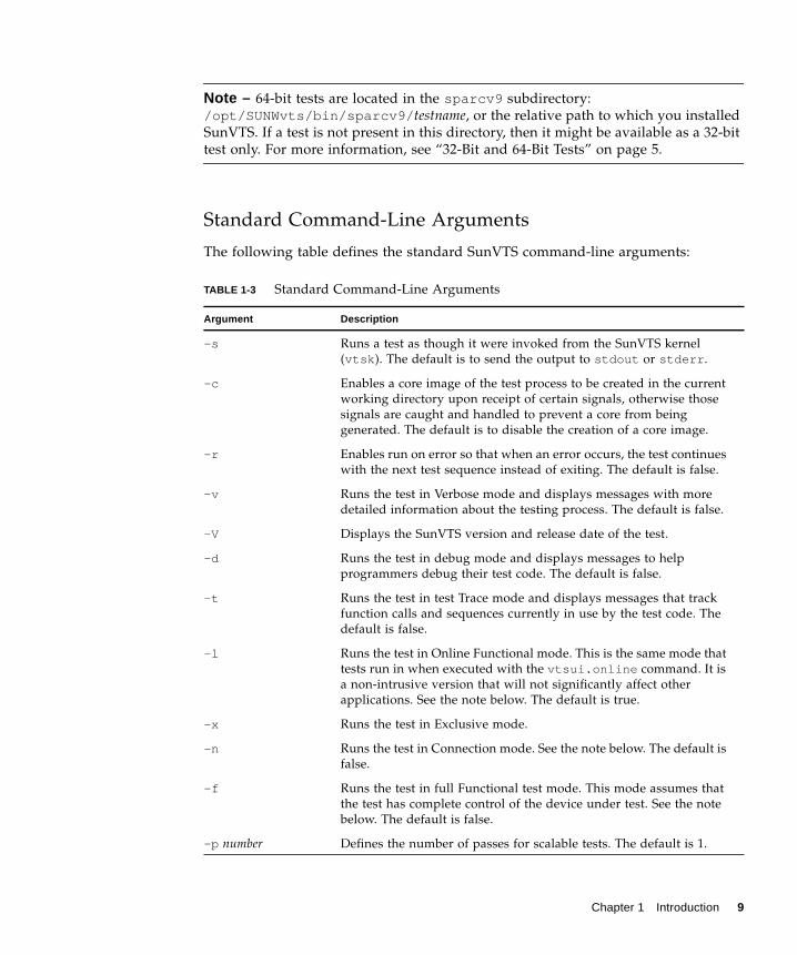
The following table defines the standard SunVTS command-line arguments:
TABLE 1-3 Standard Command-Line Arguments
Argument Description
-s Runs a test as though it were invoked from the SunVTS kernel
(vtsk ). The default is to send the output to stdout or stderr .
-c Enables a core image of the test process to be created in the current
working directory upon receipt of certain signals, otherwise those
signals are caught and handled to prevent a core from being
generated. The default is to disable the creation of a core image.
-r Enables run on error so that when an error occurs, the test continues
with the next test sequence instead of exiting. The default is false.
-v Runs the test in Verbose mode and displays messages with more
detailed information about the testing process. The default is false.
-V Displays the SunVTS version and release date of the test.
-d Runs the test in debug mode and displays messages to help
programmers debug their test code. The default is false.
-t Runs the test in test Trace mode and displays messages that track
function calls and sequences currently in use by the test code. The
default is false.
-l Runs the test in Online Functional mode. This is the same mode that
tests run in when executed with the vtsui.online command. It is
a non-intrusive version that will not significantly affect other
applications. See the note below. The default is true.
-x Runs the test in Exclusive mode.
-n Runs the test in Connection mode. See the note below. The default is
false.
-f Runs the test in full Functional test mode. This mode assumes that
the test has complete control of the device under test. See the note
below. The default is false.
-p number Defines the number of passes for scalable tests. The default is 1.
Chapter 1 Introduction 9
Note – Separate each test-specific argument by commas, with no space after each
comma.
Note – If you choose to specify a test mode with the l , n, or f option, specify only
one option at a time because only one test mode can be selected at a time.
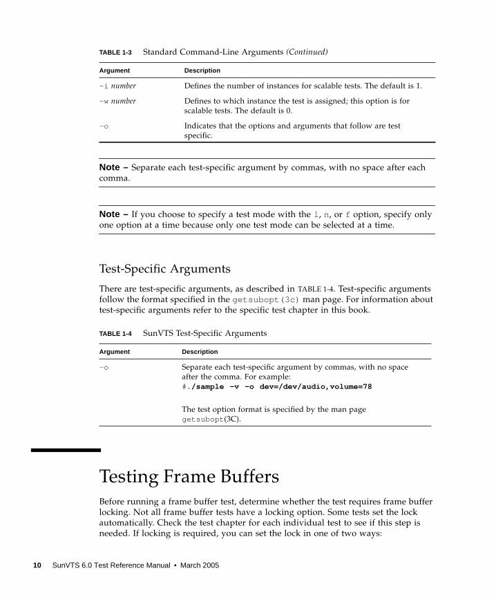
Test-Specific Arguments
There are test-specific arguments, as described in TABLE 1-4. Test-specific arguments
follow the format specified in the getsubopt(3c) man page. For information about
test-specific arguments refer to the specific test chapter in this book.
Testing Frame Buffers
Before running a frame buffer test, determine whether the test requires frame buffer
locking. Not all frame buffer tests have a locking option. Some tests set the lock
automatically. Check the test chapter for each individual test to see if this step is
needed. If locking is required, you can set the lock in one of two ways:
-i number Defines the number of instances for scalable tests. The default is 1.
-w number Defines to which instance the test is assigned; this option is for
scalable tests. The default is 0.
-o Indicates that the options and arguments that follow are test
specific.
TABLE 1-4 SunVTS Test-Specific Arguments
Argument Description
-o Separate each test-specific argument by commas, with no space
after the comma. For example:
#./sample -v -o dev=/dev/audio,volume=78
The test option format is specified by the man page
getsubopt (3C).
TABLE 1-3 Standard Command-Line Arguments (Continued)
Argument Description
10 SunVTS 6.0 Test Reference Manual • March 2005

■ If you are using the CDE SunVTS interface, go to the Option menu of the graphic
test and select Enable for the frame buffer locking option.
■ If you are working from the command line, you can enable frame buffer locking
with the lock=e/d option. For example, to run the generic frame buffer test
(fbtest ) with a locked frame buffer, enter:
(See the test command line argument descriptions in this manual.)
Caution – If frame buffer locking is disabled (unlocked) on frame buffers that are
running vtsui , or if you move the mouse, you will receive false error messages.
Even a slight mouse movement can cause a test to fail.
Caution – Disable the Power Management screen saver option and the
Save/Resume option before you run any of the SunVTS frame buffer tests. For
information on disabling these Power Management features, refer to the Power
Management chapter in the Solaris Common Desktop Environment: Users’s Guide in the
Solaris 9 User Collection. This document is available at:
docs.sun.com .
Caution – If you are using the CDE interface for SunVTS, do not conduct frame
buffer tests through the dtlogin window. Log in as root and disable the auto-
logout option.
Caution – Do not run TTY mode and frame buffer tests concurrently on the console
monitor. The frame buffer test may fail.
Testing Multiple Frame Buffers
The following rules apply when you test multiple frame buffers (displays)
simultaneously:
■ Only the console monitor can run the window environment (such as CDE). The
console monitor is the monitor connected to the frame buffer appointed by
/dev/fb . SunVTS enables frame buffer locking on the console monitor by
default.
# ./fbtest -o dev=cgthree0,lock=enable
Chapter 1 Introduction 11
■ The frame buffer that is running the window environment must have window
locking enabled to avoid false test failures. All other frame buffers must have
window locking disabled.
Remote Testing of Frame Buffers
If you start sunvts or vtsk from a screen other than the console monitor, frame
buffer locking is not available. In this case:
■ Disable the window locking option on the remote screen by setting it to d.
■ Enable frame buffer locking for the console monitor, as shown in the example
above. The SunVTS user interface cannot display on a monitor if locking is
disabled.
Do not run any graphic programs (including vtsui ) on the remote frame buffer
during graphic testing.
12 SunVTS 6.0 Test Reference Manual • March 2005
CHAPTER 2
SunATM Adapter Test (atmtest )
The atmtest checks the functionality of the SunATM™-155 and SunATM-622 SBus
and PCI bus adapters.
It runs only in loopback (external or internal) mode. The asynchronous transfer
mode (ATM) adapter, and ATM device driver must be present. To run the atmtestin external loopback mode, a loopback connector must be attached to the ATM
adapter. The internal loopback mode does not require a loopback connector.
atmtest uses DLPI RAW mode to talk to the device driver. It establishes a virtual
circuit (VC) to send a message, receive a message, and compare messages. If the
message does not match, or the message is out of sequence, it displays an error
message.
Using a random number generator, atmtest sends data into a data buffer and then
sends each message from a different starting point. This assures that no two
consecutive messages are the same.
atmtest can test more than one virtual circuit. The more virtual circuits used
increases the stress level of the test. atmtest automatically selects the virtual circuit
number which is unique to the test.
atmtest is nonscalable because it provides multiple virtual circuits to be tested by a
single instance.
atmtest Test Requirements
atmtest can only be selected when the Intervention mode is enabled since it
requires a loopback connector for external loopback testing. While Intervention
mode is enabled, atmtest and nettest are both available as default selections;
however, you must deselect nettest when testing the ATM device.
13
Bring the ATM interface down to make sure that the interface is in offline mode
before running atmtest .
Note – Do not run nettest while running atmtest .
Note – The external optical loopback test requires a 62.5 micron cable.
atmtest Options
To reach the dialog box below, right-click on the test name in the System Map and
select Test Parameter Options. If you do not see this test in the System Map, you
might need to expand the collapsed groups, or your system may not include the
device appropriate to this test. Refer to the SunVTS User’s Guide for more details.
14 SunVTS 6.0 Test Reference Manual • March 2005
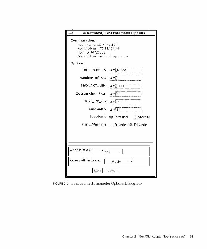
FIGURE 2-1 atmtest Test Parameter Options Dialog Box
S
Chapter 2 SunATM Adapter Test (atmtest ) 15
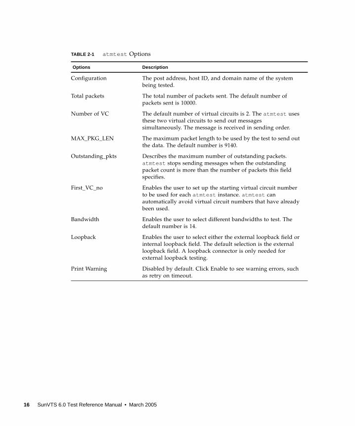
TABLE 2-1 atmtest Options
Options Description
Configuration The post address, host ID, and domain name of the system
being tested.
Total packets The total number of packets sent. The default number of
packets sent is 10000.
Number of VC The default number of virtual circuits is 2. The atmtest uses
these two virtual circuits to send out messages
simultaneously. The message is received in sending order.
MAX_PKG_LEN The maximum packet length to be used by the test to send out
the data. The default number is 9140.
Outstanding_pkts Describes the maximum number of outstanding packets.
atmtest stops sending messages when the outstanding
packet count is more than the number of packets this field
specifies.
First_VC_no Enables the user to set up the starting virtual circuit number
to be used for each atmtest instance. atmtest can
automatically avoid virtual circuit numbers that have already
been used.
Bandwidth Enables the user to select different bandwidths to test. The
default number is 14.
Loopback Enables the user to select either the external loopback field or
internal loopback field. The default selection is the external
loopback field. A loopback connector is only needed for
external loopback testing.
Print Warning Disabled by default. Click Enable to see warning errors, such
as retry on timeout.
16 SunVTS 6.0 Test Reference Manual • March 2005
atmtest Test Modes
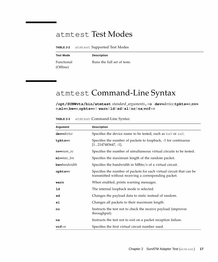
atmtest Command-Line Syntax
/opt/SUNWvts/bin/atmtest standard_arguments,-o dev= device,tpkts= n,nv=n,ml= n,bw=n,opkts= n| warn |ld |sd |sl |nc |ns ,vcf =n
TABLE 2-2 atmtest Supported Test Modes
Test Mode Description
Functional
(Offline)
Runs the full set of tests.
TABLE 2-3 atmtest Command-Line Syntax
Argument Description
dev= device Specifies the device name to be tested, such as ba0 or sa0 .
tpkts= n Specifies the number of packets to loopback, -1 for continuous
[1...2147483647, -1].
nv= num_vc Specifies the number of simultaneous virtual circuits to be tested.
ml= max_len Specifies the maximum length of the random packet.
bw=bandwidth Specifies the bandwidth in MBits/s of a virtual circuit.
opkts= n Specifies the number of packets for each virtual circuit that can be
transmitted without receiving a corresponding packet.
warn When enabled, prints warning messages.
ld The internal loopback mode is selected.
sd Changes the payload data to static instead of random.
sl Changes all packets to their maximum length.
nc Instructs the test not to check the receive payload (improves
throughput).
ns Instructs the test not to exit on a packet reception failure.
vcf =n Specifies the first virtual circuit number used.
Chapter 2 SunATM Adapter Test (atmtest ) 17

Note – 64-bit tests are located in the sparcv9 subdirectory:
/opt/SUNWvts/bin/sparcv9/ testname, or the relative path to which you installed
SunVTS. If a test is not present in this directory, then it might be available as a 32-bit
test only. For more information, see “32-Bit and 64-Bit Tests” on page 5.
18 SunVTS 6.0 Test Reference Manual • March 2005
CHAPTER 3
Audio Test (audiotest )
The audiotest verifies the hardware and software components of the audiosubsystem. This test supports all Sun audio implementations.
This test will work with exclusive access devices (only one process or application
available at a time), or with newer audio devices which support the software mixer
feature available in the Solaris 8 operating environment.
Note – audiotest turns the mixer off automatically at run time. Shut down all
audio applications before running audiotest , as Online mode is not supported.
The mixer is restored after testing.
This test is not scalable.
The availability of the following subtests depends on the particular audioimplementation being tested.
19
audiotest Subtests
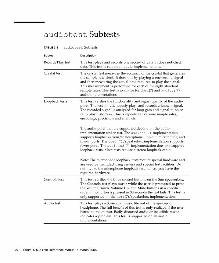
TABLE 3-1 audiotest Subtests
Subtest Description
Record/Play test This test plays and records one second of data. It does not check
data. This test is run on all audio implementations.
Crystal test The crystal test measures the accuracy of the crystal that generates
the sample rate clock. It does this by playing a one-second signal
and then measuring the actual time required to play the signal.
This measurement is performed for each of the eight standard
sample rates. This test is available for dbri (7) and audiocs (7)
audio implementations
Loopback tests This test verifies the functionality and signal quality of the audio
ports. The test simultaneously plays and records a known signal.
The recorded signal is analyzed for loop gain and signal-to-noise
ratio plus distortion. This is repeated at various sample rates,
encodings, precisions and channels.
The audio ports that are supported depend on the audio
implementation under test. The audiocs(7) implementation
supports loopbacks from/to headphone, line-out, microphone, and
line-in ports. The dbri(7) /speakerbox implementation supports
fewer ports. The audioamd(7) implementation does not support
loopback tests. Most tests require a stereo loopback cable.
Note: The microphone loopback tests require special hardware and
are used by manufacturing centers and special test facilities. Do
not invoke the microphone loopback tests unless you have the
required hardware.
Controls test This test verifies the three control buttons on the Sun speakerbox.
The Controls test plays music while the user is prompted to press
the Volume Down, Volume Up, and Mute buttons in a specific
order. If no button is pressed in 30 seconds the test fails. This test is
only supported on the dbri (7)/speakerbox implementation.
Audio test This test plays a 30-second music file out of the speaker or
headphone. The full benefit of this test is only realized if the user
listens to the output. Badly distorted audio or inaudible music
indicates a problem. This test is supported on all audio
implementations.
20 SunVTS 6.0 Test Reference Manual • March 2005

audiotest Options
To reach the dialog box below, right-click on the test name in the System Map and
select Test Parameter Options. If you do not see this test in the System Map, you
might need to expand the collapsed groups, or your system may not include the
device appropriate to this test. Refer to the SunVTS User’s Guide for more details.
FIGURE 3-1 audiotest Test Parameter Options Dialog Box
Note – Upon startup, the SunVTS probe utility determines which audio
implementation is present and adjusts the audiotest Option menu appropriately.
Your dialog box may look different than the one pictured here, but will contain some
or all of these options.
Chapter 3 Audio Test (audiotest ) 21
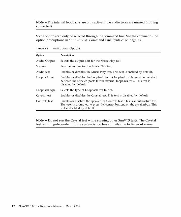
Note – The internal loopbacks are only active if the audio jacks are unused (nothing
connected).
Some options can only be selected through the command line. See the command-line
option descriptions in “audiotest Command-Line Syntax” on page 23.
Note – Do not run the Crystal test while running other SunVTS tests. The Crystal
test is timing-dependent. If the system is too busy, it fails due to time-out errors.
TABLE 3-2 audiotest Options
Option Description
Audio Output Selects the output port for the Music Play test.
Volume Sets the volume for the Music Play test.
Audio test Enables or disables the Music Play test. This test is enabled by default.
Loopback test Enables or disables the Loopback test. A loopback cable must be installed
between the selected ports to run external loopback tests. This test is
disabled by default.
Loopback type Selects the type of Loopback test to run.
Crystal test Enables or disables the Crystal test. This test is disabled by default.
Controls test Enables or disables the speakerbox Controls test. This is an interactive test.
The user is prompted to press the control buttons on the speakerbox. This
test is disabled by default.
22 SunVTS 6.0 Test Reference Manual • March 2005
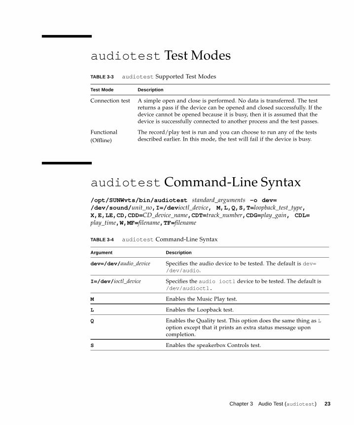
audiotest Test Modes
audiotest Command-Line Syntax
/opt/SUNWvts/bin/audiotest standard_arguments -o dev=/dev/sound/ unit_no,I=/dev ioctl_device, M,L,Q,S,T= loopback_test_type,X,E,LE,CD,CDD= CD_device_name,CDT=track_number,CDG=play_gain, CDL=play_time,W,MF=filename,TF= filename
TABLE 3-3 audiotest Supported Test Modes
Test Mode Description
Connection test A simple open and close is performed. No data is transferred. The test
returns a pass if the device can be opened and closed successfully. If the
device cannot be opened because it is busy, then it is assumed that the
device is successfully connected to another process and the test passes.
Functional
(Offline)
The record/play test is run and you can choose to run any of the tests
described earlier. In this mode, the test will fail if the device is busy.
TABLE 3-4 audiotest Command-Line Syntax
Argument Description
dev=/dev/ audio_device Specifies the audio device to be tested. The default is dev=/dev/audio .
I=/dev/ ioctl_device Specifies the audio ioctl device to be tested. The default is
/dev/audioctl.
M Enables the Music Play test.
L Enables the Loopback test.
Q Enables the Quality test. This option does the same thing as Loption except that it prints an extra status message upon
completion.
S Enables the speakerbox Controls test.
Chapter 3 Audio Test (audiotest ) 23
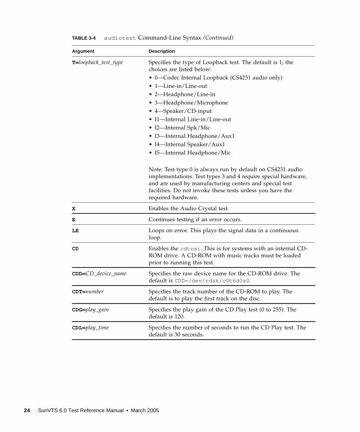
T=loopback_test_type Specifies the type of Loopback test. The default is 1; the
choices are listed below:
• 0—Codec Internal Loopback (CS4231 audio only)
• 1—Line-in/Line-out
• 2—Headphone/Line-in
• 3—Headphone/Microphone
• 4—Speaker/CD-input
• I1—Internal Line-in/Line-out
• I2—Internal Spk/Mic
• I3—Internal Headphone/Aux1
• I4—Internal Speaker/Aux1
• I5—Internal Headphone/Mic
Note: Test type 0 is always run by default on CS4231 audio
implementations. Test types 3 and 4 require special hardware,
and are used by manufacturing centers and special test
facilities. Do not invoke these tests unless you have the
required hardware.
X Enables the Audio Crystal test.
E Continues testing if an error occurs.
LE Loops on error. This plays the signal data in a continuous
loop.
CD Enables the cdtest . This is for systems with an internal CD-
ROM drive. A CD-ROM with music tracks must be loaded
prior to running this test.
CDD=CD_device_name Specifies the raw device name for the CD-ROM drive. The
default is CDD=/dev/rdsk/c0t6d0s0 .
CDT=number Specifies the track number of the CD-ROM to play. The
default is to play the first track on the disc.
CDG=play_gain Specifies the play gain of the CD Play test (0 to 255). The
default is 120.
CDL=play_time Specifies the number of seconds to run the CD Play test. The
default is 30 seconds.
TABLE 3-4 audiotest Command-Line Syntax (Continued)
Argument Description
24 SunVTS 6.0 Test Reference Manual • March 2005
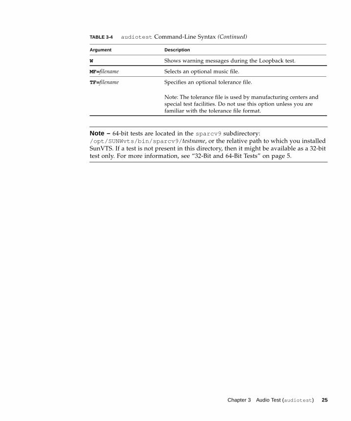
Note – 64-bit tests are located in the sparcv9 subdirectory:
/opt/SUNWvts/bin/sparcv9/ testname, or the relative path to which you installed
SunVTS. If a test is not present in this directory, then it might be available as a 32-bit
test only. For more information, see “32-Bit and 64-Bit Tests” on page 5.
W Shows warning messages during the Loopback test.
MF=filename Selects an optional music file.
TF=filename Specifies an optional tolerance file.
Note: The tolerance file is used by manufacturing centers and
special test facilities. Do not use this option unless you are
familiar with the tolerance file format.
TABLE 3-4 audiotest Command-Line Syntax (Continued)
Argument Description
Chapter 3 Audio Test (audiotest ) 25

26 SunVTS 6.0 Test Reference Manual • March 2005
CHAPTER 4
Blade Support Chip Test (bsctest )
Caution – The bsctest exercises the Blade Support Chip and supporting hardware
used in Sun Fire B100 blade systems. This includes the Open Boot Prom (OBP) and
Time of Day (ToD) Prom chips.
Caution – If the LED subtest is selected, please be aware that LEDs on the blade
will change. They will return to their correct state when the test is completed.
bsctest Options
To reach the dialog box below, right-click on the test name in the System Map and
select Test Parameter Options. If you do not see this test in the System Map, you
might need to expand the collapsed groups, or your system may not include the
device appropriate to this test. Refer to the SunVTS User’s Guide for more details.
27
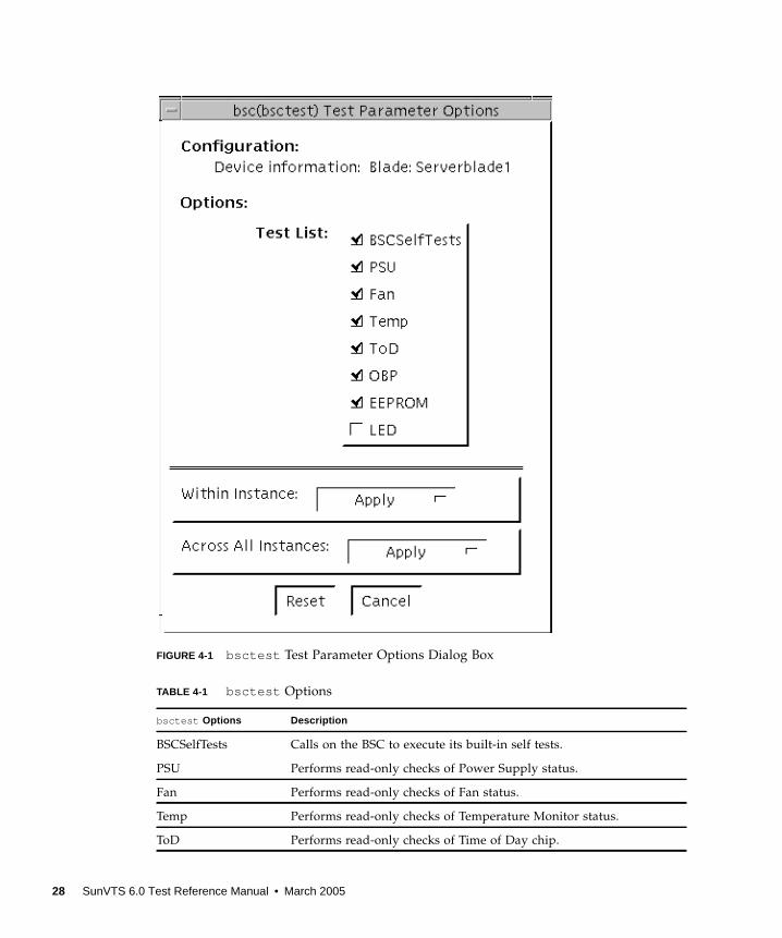
FIGURE 4-1 bsctest Test Parameter Options Dialog Box
TABLE 4-1 bsctest Options
bsctest Options Description
BSCSelfTests Calls on the BSC to execute its built-in self tests.
PSU Performs read-only checks of Power Supply status.
Fan Performs read-only checks of Fan status.
Temp Performs read-only checks of Temperature Monitor status.
ToD Performs read-only checks of Time of Day chip.
28 SunVTS 6.0 Test Reference Manual • March 2005
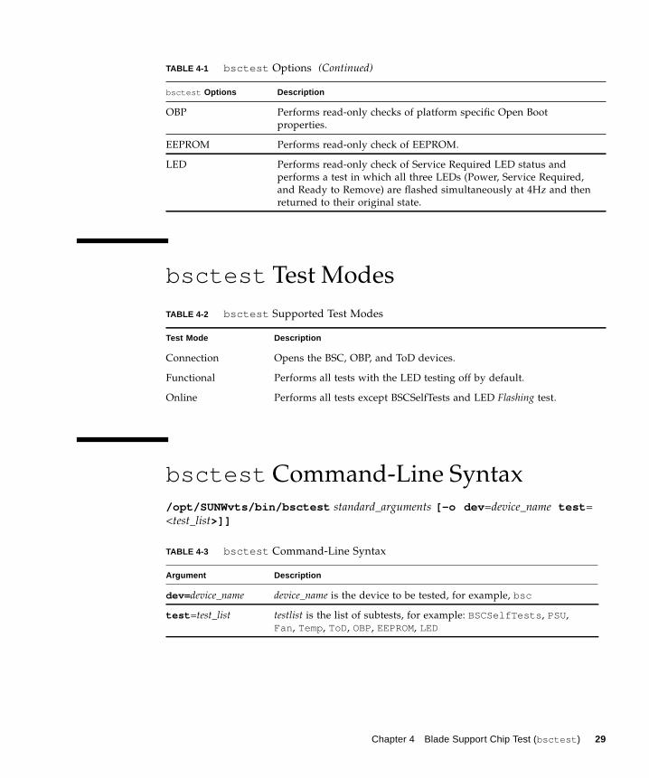
bsctest Test Modes
bsctest Command-Line Syntax
/opt/SUNWvts/bin/bsctest standard_arguments [-o dev =device_name test =
<test_list>]]
OBP Performs read-only checks of platform specific Open Boot
properties.
EEPROM Performs read-only check of EEPROM.
LED Performs read-only check of Service Required LED status and
performs a test in which all three LEDs (Power, Service Required,
and Ready to Remove) are flashed simultaneously at 4Hz and then
returned to their original state.
TABLE 4-2 bsctest Supported Test Modes
Test Mode Description
Connection Opens the BSC, OBP, and ToD devices.
Functional Performs all tests with the LED testing off by default.
Online Performs all tests except BSCSelfTests and LED Flashing test.
TABLE 4-3 bsctest Command-Line Syntax
Argument Description
dev= device_name device_name is the device to be tested, for example, bsc
test =test_list testlist is the list of subtests, for example: BSCSelfTests , PSU,
Fan , Temp, ToD, OBP, EEPROM, LED
TABLE 4-1 bsctest Options (Continued)
bsctest Options Description
Chapter 4 Blade Support Chip Test (bsctest ) 29

Note – 64-bit tests are located in the sparcv9 subdirectory:
/opt/SUNWvts/bin/sparcv9/ testname, or the relative path to which you installed
SunVTS. If a test is not present in this directory, then it might be available as a 32-bit
test only. For more information, see “32-Bit and 64-Bit Tests” on page 5.
30 SunVTS 6.0 Test Reference Manual • March 2005
CHAPTER 5
Optical Disk Drive Test(cddvdtest )
cddvdtest verifies the functionality of optical disk drives.The disktest probe
detects the media type in the drive and shows the test options for the media found.
If inserted media is not supported by the drive, the disktest probe shows an error
and registers options for CD-ROM as default.
Note – cddvdtest is a newly consolidated test which is used to test the optical
media drives such as the CD-ROM, DVD-ROM and CD-DVD-RW drives.
cddvdtest supports the same set of options for both SPARC and x86.
Volume Management
cddvdtest tests the optical drive(s) even if the Volume Manager is not running. If
the Volume Manager is running and no media is installed in the drive(s), SunVTS
prompts you to install media in the drive before selecting the test. The test fails if
you try to run it without media in the drive.
Note – When testing rewritable media, the media can be either blank or contain the
SunVTS test data. When testing the write-once media, the media (such as CD-R) has
to be blank at the start to run the write test. Such media could still run multiple
passes of the test because after the first write test, the subsequent invocations will
treat the media as Read Only and perform the test accordingly.
For CD-ROM and DVD-ROM drives, the test checks the unit by reading either the
CD or DVD. For CD-ROM, each track is classified as follows:
■ Mode 1 uses error detection/correction code (288 bytes).
■ Mode 2 uses that space for auxiliary data or as an audio track.
31

For rewritable CD media, the test can write one or more tracks in one test pass.
cddvdtest writes tracks on next available space on the media. If the media is full,
cddvdtest automatically erases the whole media and starts the next test pass from
the beginning of the media.
For rewritable DVD media, the test writes only one track in one test pass (because
there is only one track in DVD format). cddvdtest blanks the media when starting
the test, if the media is not already blank.
For rewritable media types, the test verifies write, read, and other supporting
functions of CD and DVD RW drives. The supported media include the following:
■ CD-R (must be blank)
■ CD-RW (can either be blank or contain the SunVTS test data)
■ DVD-R (must be blank)
■ DVD+R (must be blank)
■ DVD-RW
■ DVD+RW
Note – cddvdtest is not a scalable test.
cddvdtest Hardware and SoftwareRequirements
cddvdtest has different set of test requirements based on the media type as
described below.
CD-ROM and DVD-ROM
The drive must have the appropriate CD-ROM or the DVD-ROM media before
performing the test.
When a CD-ROM is loaded in the drive, cddvdtest uses CD-ROM specific options
to test the drive. When a DVD-ROM is loaded, the test uses DVD-ROM specific
options. Whenever you change the media in the drive you must perform a reprobe
(refer to the SunVTS User’s Guide for details) so the SunVTS kernel associates the
correct test options based on the media that is loaded in the drive.
32 SunVTS 6.0 Test Reference Manual • March 2005

CD-RW and DVD-RW
When testing rewritable media, reprobing is required if the media is changed. To
prevent accidentally erasing useful data on a media used for testing, cddvdtest
accepts the test media only if it is blank or it contains SunVTS test data (data that is
written by cddvdtest itself). The test checks these conditions at probe time and at
the start of test.
In case of non-blank media OR the media with non-SunVTS test data, the media
must be blanked first by using the cdrw utility. Because -R or +R media can be
written only once, only a blank media should be used for write testing. Such media
could still run multiple passes of the test because after the first write test, the
subsequent invocations will treat the media as Read Only and perform the test
accordingly.
To prevent media corruption, if stopped during a write, finalize, format, or erase, the
test posts a Warning message and continues until the current operation is completed.
Wait until the test completes before doing any operation on the drive.
Do not stop the test in the middle of a writing operation. Doing so may cause
damage to the media in some cases. It is better to set a limited number of passes for
cddvdtest , instead of setting Max Passes=0 (unlimited) and stop the test manually.
If a media is damaged, you should blank the media with cdrw command.
Note – DVD+RW media can not be blanked.
The default Delay between two passes for the Read Write media is three minutes.
This setting is intended to make the test run less passes in long hours testing to
preserve the media. It is also intended to give plenty of time to stop the test between
passes.
cddvdtest Subtests
cddvdtest has different subtests based on the media type as described below.
Chapter 33
CD-RW and DVD-RW
cddvdtest Options
To reach the dialog boxes below, right-click on the test name in the System Map and
select Test Parameter Options. If you do not see this test in the System Map, you
might need to expand the collapsed groups, or your system may not include the
device appropriate to this test. Refer to the SunVTS User’s Guide for more details.
cddvdtest has different test options based on the media type as described below.
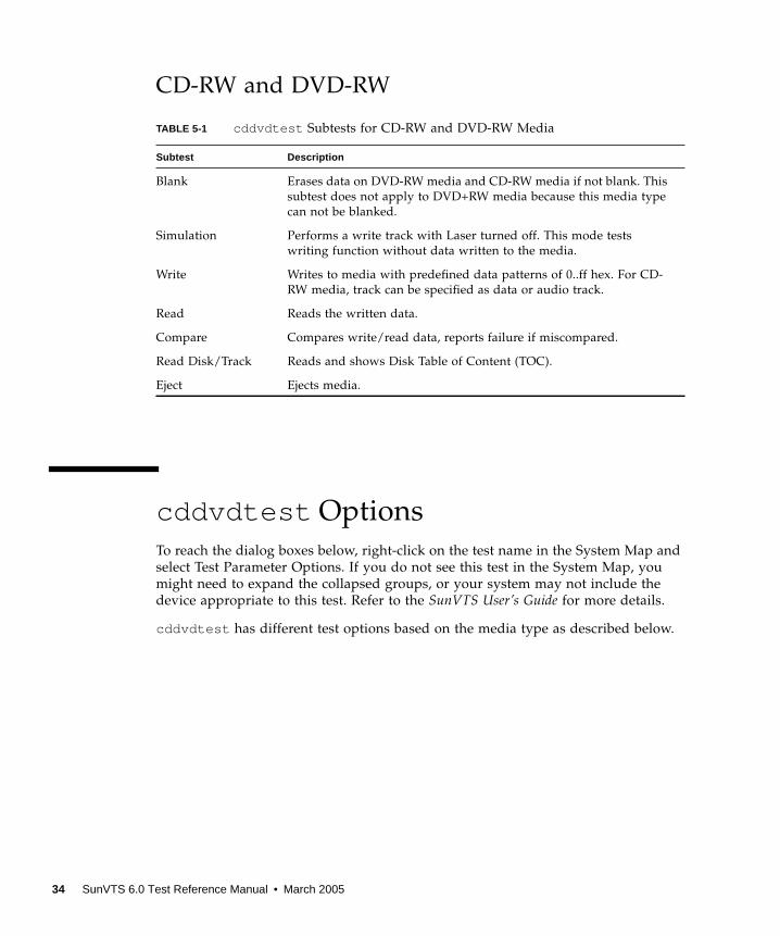
TABLE 5-1 cddvdtest Subtests for CD-RW and DVD-RW Media
Subtest Description
Blank Erases data on DVD-RW media and CD-RW media if not blank. This
subtest does not apply to DVD+RW media because this media type
can not be blanked.
Simulation Performs a write track with Laser turned off. This mode tests
writing function without data written to the media.
Write Writes to media with predefined data patterns of 0..ff hex. For CD-
RW media, track can be specified as data or audio track.
Read Reads the written data.
Compare Compares write/read data, reports failure if miscompared.
Read Disk/Track Reads and shows Disk Table of Content (TOC).
Eject Ejects media.
34 SunVTS 6.0 Test Reference Manual • March 2005
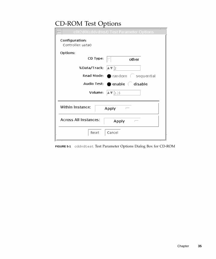
CD-ROM Test Options
FIGURE 5-1 cddvdtest Test Parameter Options Dialog Box for CD-ROM
Chapter 35
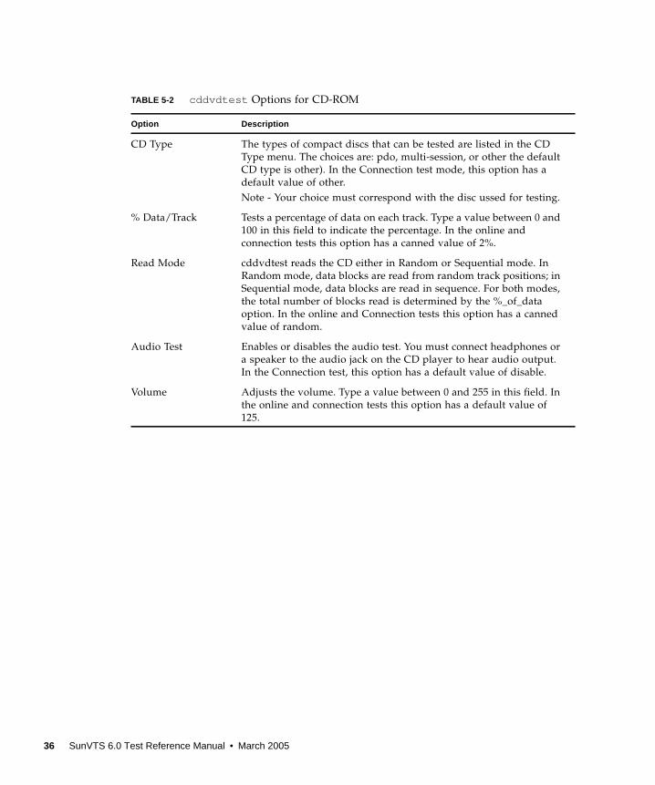
TABLE 5-2 cddvdtest Options for CD-ROM
Option Description
CD Type The types of compact discs that can be tested are listed in the CD
Type menu. The choices are: pdo, multi-session, or other the default
CD type is other). In the Connection test mode, this option has a
default value of other.
Note - Your choice must correspond with the disc ussed for testing.
% Data/Track Tests a percentage of data on each track. Type a value between 0 and
100 in this field to indicate the percentage. In the online and
connection tests this option has a canned value of 2%.
Read Mode cddvdtest reads the CD either in Random or Sequential mode. In
Random mode, data blocks are read from random track positions; in
Sequential mode, data blocks are read in sequence. For both modes,
the total number of blocks read is determined by the %_of_data
option. In the online and Connection tests this option has a canned
value of random.
Audio Test Enables or disables the audio test. You must connect headphones or
a speaker to the audio jack on the CD player to hear audio output.
In the Connection test, this option has a default value of disable.
Volume Adjusts the volume. Type a value between 0 and 255 in this field. In
the online and connection tests this option has a default value of
125.
36 SunVTS 6.0 Test Reference Manual • March 2005
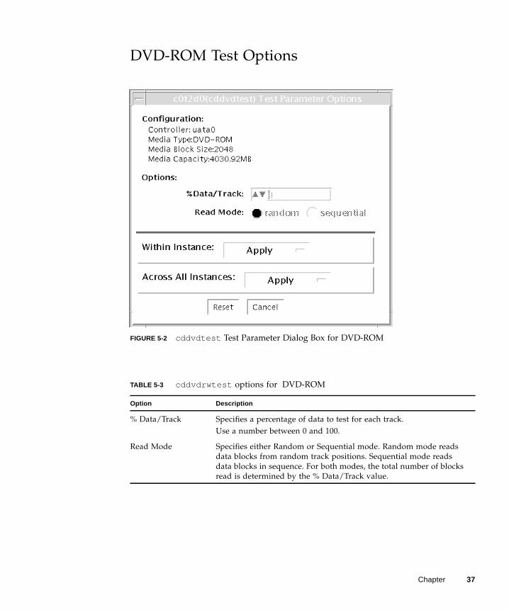
DVD-ROM Test Options
FIGURE 5-2 cddvdtest Test Parameter Dialog Box for DVD-ROM
TABLE 5-3 cddvdrwtest options for DVD-ROM
Option Description
% Data/Track Specifies a percentage of data to test for each track.
Use a number between 0 and 100.
Read Mode Specifies either Random or Sequential mode. Random mode reads
data blocks from random track positions. Sequential mode reads
data blocks in sequence. For both modes, the total number of blocks
read is determined by the % Data/Track value.
Chapter 37
CD-RW Test Options
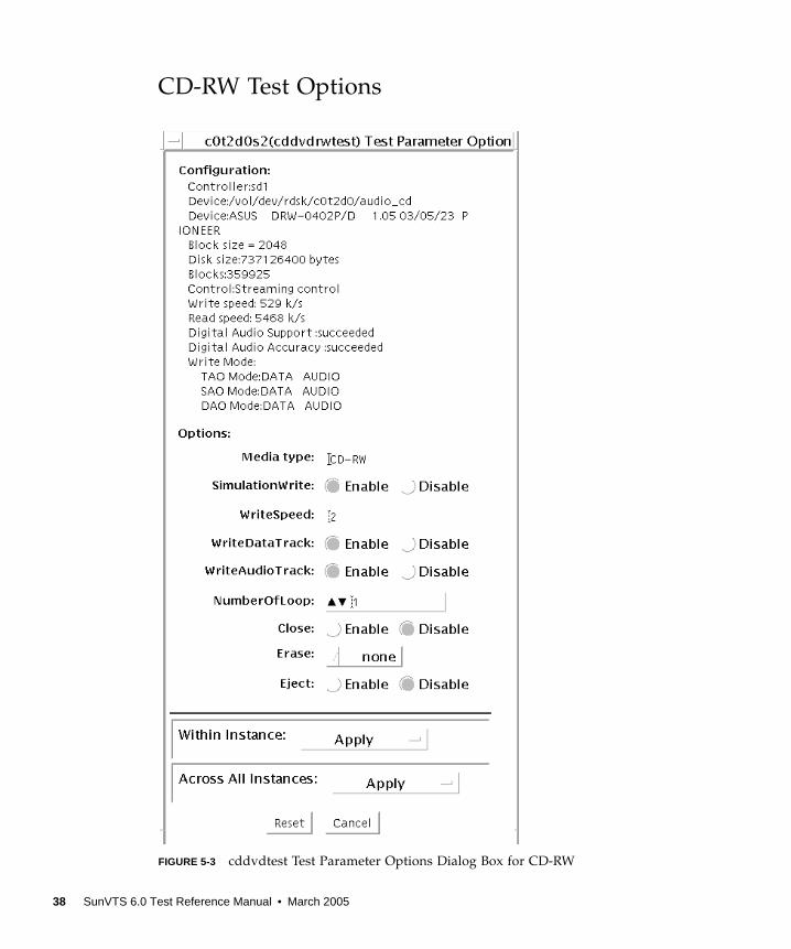
FIGURE 5-3 cddvdtest Test Parameter Options Dialog Box for CD-RW
38 SunVTS 6.0 Test Reference Manual • March 2005
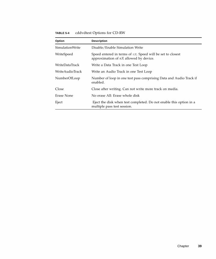
TABLE 5-4 cddvdtest Options for CD-RW
Option Description
SimulationWrite Disable/Enable Simulation Write
WriteSpeed Speed entered in terms of nX. Speed will be set to closest
approximation of nX allowed by device.
WriteDataTrack Write a Data Track in one Test Loop
WriteAudioTrack Write an Audio Track in one Test Loop
NumberOfLoop Number of loop in one test pass comprising Data and Audio Track if
enabled.
Close Close after writing. Can not write more track on media.
Erase None No erase All: Erase whole disk
Eject Eject the disk when test completed. Do not enable this option in a
multiple pass test session.
Chapter 39
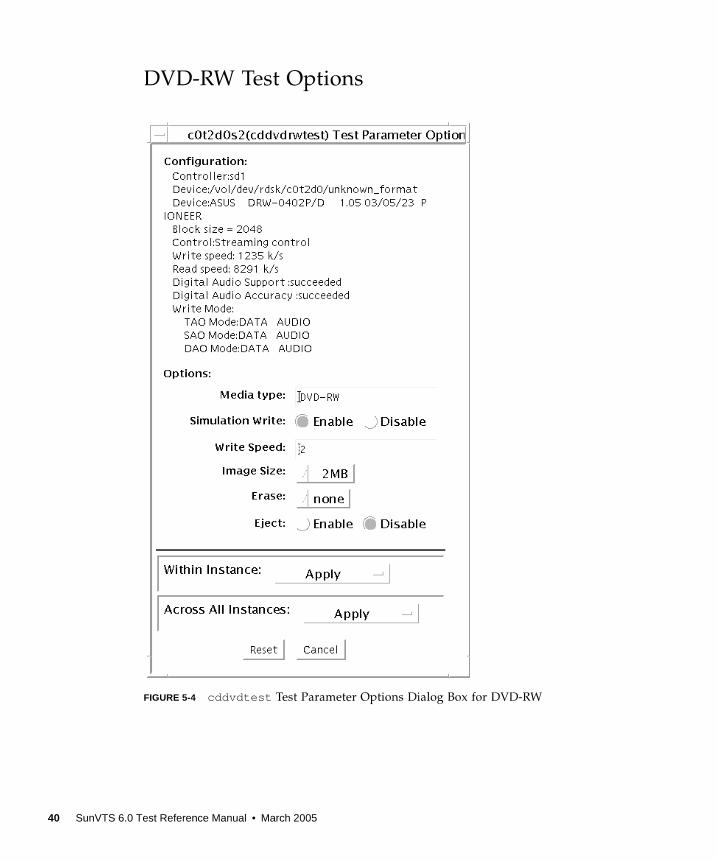
DVD-RW Test Options
FIGURE 5-4 cddvdtest Test Parameter Options Dialog Box for DVD-RW
40 SunVTS 6.0 Test Reference Manual • March 2005
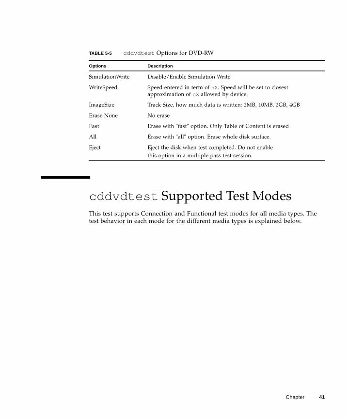
cddvdtest Supported Test Modes
This test supports Connection and Functional test modes for all media types. The
test behavior in each mode for the different media types is explained below.
TABLE 5-5 cddvdtest Options for DVD-RW
Options Description
SimulationWrite Disable/Enable Simulation Write
WriteSpeed Speed entered in term of nX. Speed will be set to closest
approximation of nX allowed by device.
ImageSize Track Size, how much data is written: 2MB, 10MB, 2GB, 4GB
Erase None No erase
Fast Erase with "fast" option. Only Table of Content is erased
All Erase with "all" option. Erase whole disk surface.
Eject Eject the disk when test completed. Do not enable
this option in a multiple pass test session.
Chapter 41

CD-ROM Test Modes
DVD-ROM Test Modes
TABLE 5-6 Supportted Test Modes for CD-ROM
Test Mode Description
Connection In this mode, cddvdtest verifies that a CD-ROM drive is connected
to and configured in the system.
Functional In this mode, the test registers a failure if the device is found to be
busy. This is because SunVTS tests make the assumption that all the
resources will be available for testing in the Functional test and the
unavailability of a device is interpreted as an indication of a fault
condition.
TABLE 5-7 Supported Test Modes for DVD-ROM
Test Mode Description
Connection Requests and displays information from the drive and reads two
blocks of data from the media to confirm connectivity. An error is
reported if no media is loaded in the drive.
Functional Requests and displays information from the drive, then reads data
from the media based on the options that are set in the Test
Parameter Options Dialog Box. An error is reported if no media is
loaded in the drive.
42 SunVTS 6.0 Test Reference Manual • March 2005
CD-RW and DVD-RW Test Modes
cddvdtest Command-Line Syntax
cddvdtest has different command line syntax based on the media type as
described below.
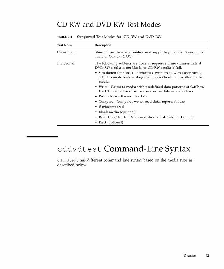
TABLE 5-8 Supported Test Modes for CD-RW and DVD-RW
Test Mode Description
Connection Shows basic drive information and supporting modes. Shows disk
Table of Content (TOC)
Functional The following subtests are done in sequence:Erase - Erases data if
DVD-RW media is not blank, or CD-RW media if full.
• Simulation (optional) - Performs a write track with Laser turned
off. This mode tests writing function without data written to the
media.
• Write - Writes to media with predefined data patterns of 0..ff hex.
For CD media track can be specified as data or audio track.
• Read - Reads the written data
• Compare - Compares write/read data, reports failure
• if miscompared.
• Blank media (optional)
• Read Disk/Track - Reads and shows Disk Table of Content.
• Eject (optional)
Chapter 43
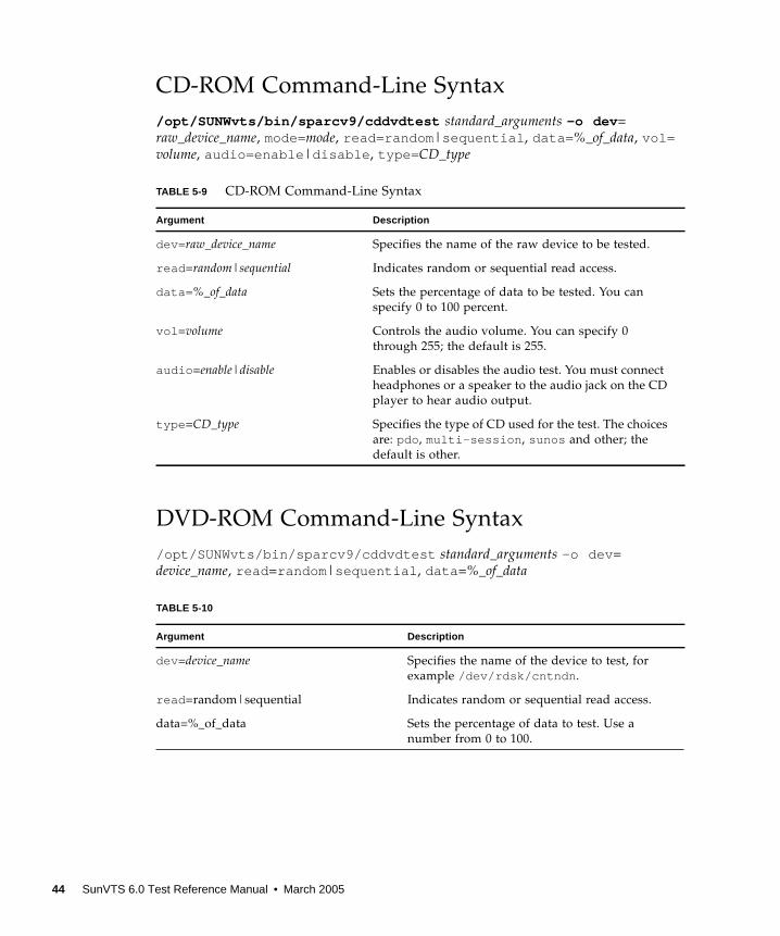
CD-ROM Command-Line Syntax
/opt/SUNWvts/bin/sparcv9/cddvdtest standard_arguments -o dev =
raw_device_name, mode=mode, read=random |sequential , data= %_of_data, vol=volume, audio=enable |disable , type= CD_type
DVD-ROM Command-Line Syntax
/opt/SUNWvts/bin/sparcv9/cddvdtest standard_arguments -o dev =
device_name, read =random |sequential , data =%_of_data
TABLE 5-9 CD-ROM Command-Line Syntax
Argument Description
dev= raw_device_name Specifies the name of the raw device to be tested.
read =random|sequential Indicates random or sequential read access.
data= %_of_data Sets the percentage of data to be tested. You can
specify 0 to 100 percent.
vol =volume Controls the audio volume. You can specify 0
through 255; the default is 255.
audio =enable|disable Enables or disables the audio test. You must connect
headphones or a speaker to the audio jack on the CD
player to hear audio output.
type =CD_type Specifies the type of CD used for the test. The choices
are: pdo , multi-session , sunos and other; the
default is other.
TABLE 5-10
Argument Description
dev =device_name Specifies the name of the device to test, for
example /dev/rdsk/cntndn .
read =random|sequential Indicates random or sequential read access.
data=%_of_data Sets the percentage of data to test. Use a
number from 0 to 100.
44 SunVTS 6.0 Test Reference Manual • March 2005
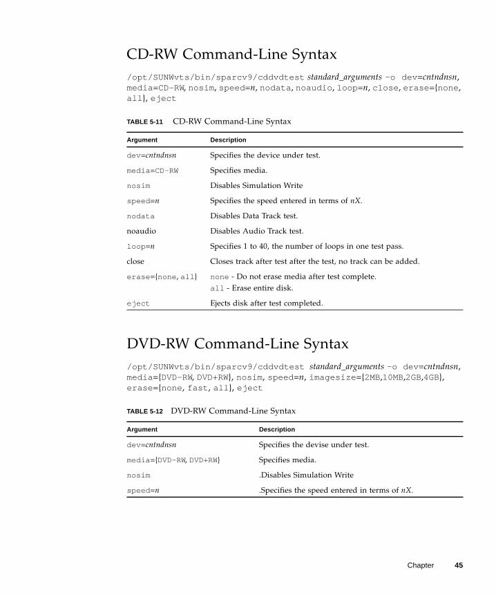
CD-RW Command-Line Syntax
/opt/SUNWvts/bin/sparcv9/cddvdtest standard_arguments -o dev =cntndnsn,
media =CD-RW, nosim , speed =n, nodata , noaudio , loop =n, close , erase ={none ,
all }, eject
DVD-RW Command-Line Syntax
/opt/SUNWvts/bin/sparcv9/cddvdtest standard_arguments -o dev =cntndnsn,
media ={DVD-RW, DVD+RW}, nosim , speed =n, imagesize ={2MB,10MB,2GB,4GB},
erase ={none , fast , all }, eject
TABLE 5-11 CD-RW Command-Line Syntax
Argument Description
dev =cntndnsn Specifies the device under test.
media =CD-RW Specifies media.
nosim Disables Simulation Write
speed =n Specifies the speed entered in terms of nX.
nodata Disables Data Track test.
noaudio Disables Audio Track test.
loop =n Specifies 1 to 40, the number of loops in one test pass.
close Closes track after test after the test, no track can be added.
erase ={none , all } none - Do not erase media after test complete.
all - Erase entire disk.
eject Ejects disk after test completed.
TABLE 5-12 DVD-RW Command-Line Syntax
Argument Description
dev =cntndnsn Specifies the devise under test.
media ={DVD-RW, DVD+RW} Specifies media.
nosim .Disables Simulation Write
speed =n .Specifies the speed entered in terms of nX.
Chapter 45
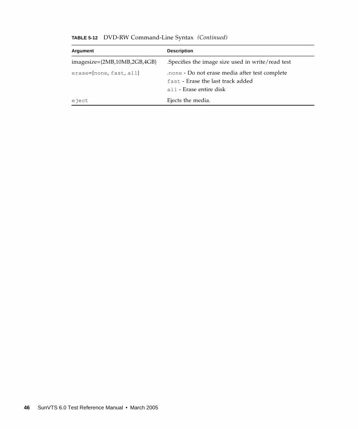
imagesize={2MB,10MB,2GB,4GB} .Specifies the image size used in write/read test
erase ={none , fast , all } .none - Do not erase media after test complete
fast - Erase the last track added
all - Erase entire disk
eject Ejects the media.
TABLE 5-12 DVD-RW Command-Line Syntax (Continued)
Argument Description
46 SunVTS 6.0 Test Reference Manual • March 2005

CHAPTER 6
Chip Multi-Threading Test(cmttest )
cmttest verifies the proper functioning of the multiprocessor hardware with
multiple cores in one CPU. cmttest tests the path between the cores on the same
CPU in addition to performing CPU specific testing. cmttest uses the Cache
Coherence, Shared Memory, and RAM subtests. The Cache Coherence subtest is
used to test the coherence among all of the Cores in a CMT (Chip Multiprocessor).
The Shared Memory subtest is used to test the shared memory among all the cores in
a CMT. The RAM subtest is used to test the memory. The RAM subtest covers TLB,
MMU, and bus balancing.
Only one cmttest is registered and cmttest is present under the logical name
Processor(s). There is no physical name provided. The probe routine of cmttestprobes all CMTs in which at least two cores are online.
cmttest was named cmptest in previous SunVTS releases.
cmttest Options
To reach the dialog box below, right-click on the test name in the System Map and
select Test Parameter Options. If you do not see this test in the System Map, you
might need to expand the collapsed groups, or your system may not include the
device appropriate to this test. Refer to the SunVTS User’s Guide for more details.
47
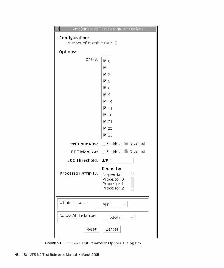
FIGURE 6-1 cmttest Test Parameter Options Dialog Box
48 SunVTS 6.0 Test Reference Manual • March 2005
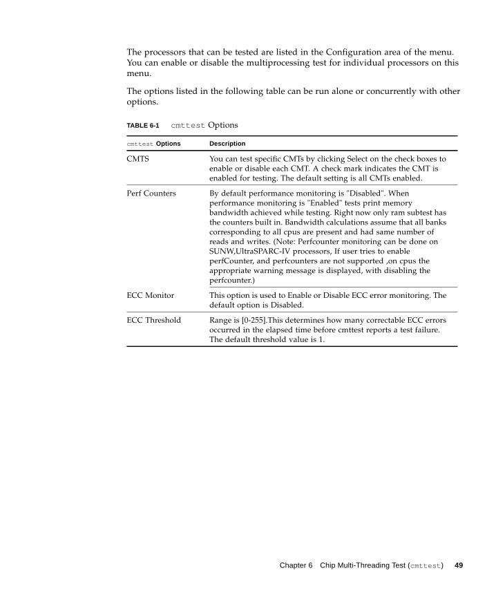
The processors that can be tested are listed in the Configuration area of the menu.
You can enable or disable the multiprocessing test for individual processors on this
menu.
The options listed in the following table can be run alone or concurrently with other
options.
TABLE 6-1 cmttest Options
cmttest Options Description
CMTS You can test specific CMTs by clicking Select on the check boxes to
enable or disable each CMT. A check mark indicates the CMT is
enabled for testing. The default setting is all CMTs enabled.
Perf Counters By default performance monitoring is "Disabled". When
performance monitoring is "Enabled" tests print memory
bandwidth achieved while testing. Right now only ram subtest has
the counters built in. Bandwidth calculations assume that all banks
corresponding to all cpus are present and had same number of
reads and writes. (Note: Perfcounter monitoring can be done on
SUNW,UltraSPARC-IV processors, If user tries to enable
perfCounter, and perfcounters are not supported ,on cpus the
appropriate warning message is displayed, with disabling the
perfcounter.)
ECC Monitor This option is used to Enable or Disable ECC error monitoring. The
default option is Disabled.
ECC Threshold Range is [0-255].This determines how many correctable ECC errors
occurred in the elapsed time before cmttest reports a test failure.
The default threshold value is 1.
Chapter 6 Chip Multi-Threading Test (cmttest ) 49
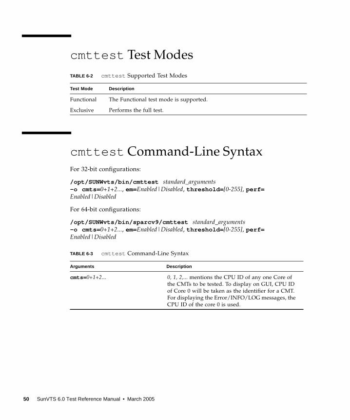
cmttest Test Modes
cmttest Command-Line Syntax
For 32-bit configurations:
/opt/SUNWvts/bin/cmttest standard_arguments-o cmts= 0+1+2..., em=Enabled|Disabled, threshold= [0-255], perf=Enabled|Disabled
For 64-bit configurations:
/opt/SUNWvts/bin/sparcv9/cmttest standard_arguments-o cmts= 0+1+2..., em=Enabled|Disabled, threshold= [0-255], perf=Enabled|Disabled
TABLE 6-2 cmttest Supported Test Modes
Test Mode Description
Functional The Functional test mode is supported.
Exclusive Performs the full test.
TABLE 6-3 cmttest Command-Line Syntax
Arguments Description
cmts= 0+1+2... 0, 1, 2,... mentions the CPU ID of any one Core of
the CMTs to be tested. To display on GUI, CPU ID
of Core 0 will be taken as the identifier for a CMT.
For displaying the Error/INFO/LOG messages, the
CPU ID of the core 0 is used.
50 SunVTS 6.0 Test Reference Manual • March 2005
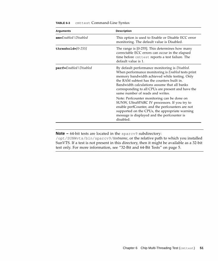
Note – 64-bit tests are located in the sparcv9 subdirectory:
/opt/SUNWvts/bin/sparcv9/ testname, or the relative path to which you installed
SunVTS. If a test is not present in this directory, then it might be available as a 32-bit
test only. For more information, see “32-Bit and 64-Bit Tests” on page 5.
em=Enabled|Disabled This option is used to Enable or Disable ECC error
monitoring. The default value is Disabled.
threshold= [0-255] The range is [0-255]. This determines how many
correctable ECC errors can occur in the elapsed
time before cmttest reports a test failure. The
default value is 1.
perf= Enabled|Disabled By default performance monitoring is Disabled.
When performance monitoring is Enabled tests print
memory bandwidth achieved while testing. Only
the RAM subtest has the counters built in.
Bandwidth calculations assume that all banks
corresponding to all CPUs are present and have the
same number of reads and writes.
Note: Perfcounter monitoring can be done on
SUNW, UltraSPARC IV processors. If you try to
enable perfCounter, and the perfcounters are not
supported on the CPUs, the appropriate warning
message is displayed and the perfcounter is
disabled.
TABLE 6-3 cmttest Command-Line Syntax
Arguments Description
Chapter 6 Chip Multi-Threading Test (cmttest ) 51

52 SunVTS 6.0 Test Reference Manual • March 2005
CHAPTER 7
CPU Power Management Test(cpupmtest )
cpupmtest cycles a CPU through its Power Management™ states. The CPU is run
for user-defined periods of time from full speed, to half speed, to lowest speed, back
up to half speed, and to full speed, in that order, at various levels. cpupmtest test
verifies that the CPU speed changes correctly for each state.
You can also run this test concurrently with device tests, to monitor whether CPU
speed changes are affecting device performance. Use cpupmtest to check that all
devices function correctly during different Power Management modes.
Note – The number of speed levels available for testing depends on the type of CPU
being tested, Enter an appropriate number of arguments for your CPU: speed1 ,
speed2 .. speedn , where speed1 is the CPU’s lowest speed and speedn is the
CPU’s highest speed.
cpupmtest is currently supported on Sun Blade™ 100 and Sun Blade 1000 systems.
Note – SunVTS does not support processor sets. If processor sets are defined, you
must first delete the processor sets before running SunVTS.
cpupmtest Options
To reach the dialog box below, right-click on the test name in the System Map and
select Test Parameter Options. If you do not see this test in the System Map, you
might need to expand the collapsed groups, or your system may not include the
device appropriate to this test. Refer to the SunVTS User’s Guide for more details.
53
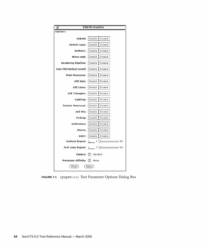
FIGURE 7-1 cpupmtest Test Parameter Options Dialog Box
54 SunVTS 6.0 Test Reference Manual • March 2005
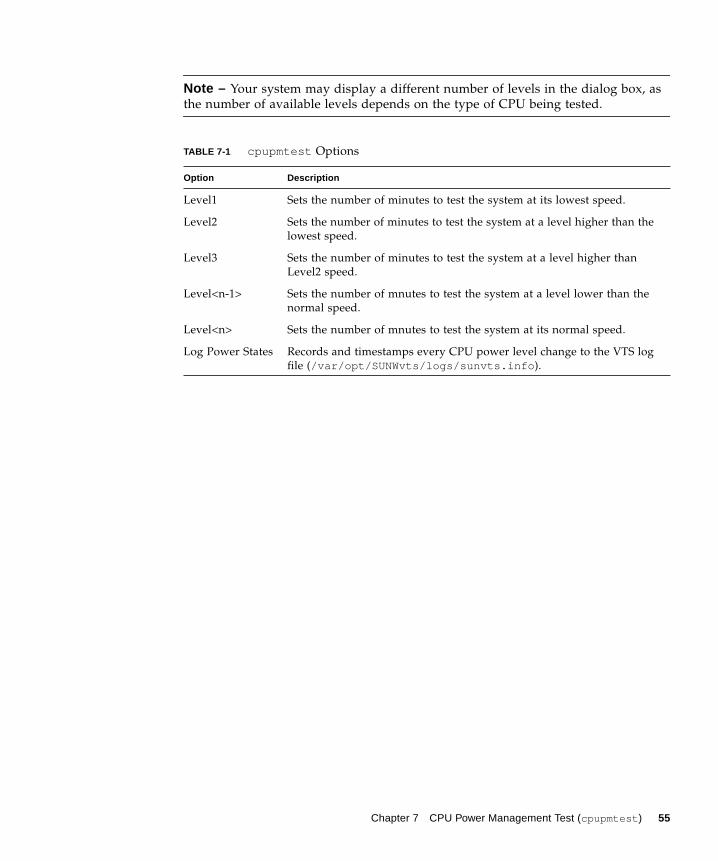
Note – Your system may display a different number of levels in the dialog box, as
the number of available levels depends on the type of CPU being tested.
TABLE 7-1 cpupmtest Options
Option Description
Level1 Sets the number of minutes to test the system at its lowest speed.
Level2 Sets the number of minutes to test the system at a level higher than the
lowest speed.
Level3 Sets the number of minutes to test the system at a level higher than
Level2 speed.
Level<n-1> Sets the number of mnutes to test the system at a level lower than the
normal speed.
Level<n> Sets the number of mnutes to test the system at its normal speed.
Log Power States Records and timestamps every CPU power level change to the VTS log
file (/var/opt/SUNWvts/logs/sunvts.info ).
Chapter 7 CPU Power Management Test (cpupmtest ) 55

cpupmtest Test Modes
cpupmtest Command-Line Syntax
/opt/SUNWvts/bin/cpupmtest standard_arguments-o dev= cpupm,speed1= mn,speed2= mn,speed n=mn
TABLE 7-2 cpupmtest Supported Test Modes
Test Mode Description
Exclusive Runs the full test.
TABLE 7-3 cpupmtest Command-Line Syntax
Argument Description
dev= cpupm Specifies the name of the device.
speed1= mn Sets the number of minutes to test the system at its lowest speed.
speed2= mn Sets the number of minutes to test the system at the next level of speed.
speed n=mn Sets the number of minutes to test the system at its highest speed.
56 SunVTS 6.0 Test Reference Manual • March 2005

CHAPTER 8
CPU Test (cputest )
The cputest checks specific aspects of SPARC V9 processor datapath functionality.
Note – cputest does support x86 platforms that use the Solaris operating system.
The cputest comprises of two subtests:
■ g0 subtest—tests a processor’s g0 register functionality. The g0 subtest is only
supported on UltraSPARC-based systems. This subtest is not supported on x86
platforms.
■ CUC subtest—tests a processor’s ability to correctly execute a
Compress/Uncompress/Compare (cmp) command sequence on machines with
the SPARC-V9 architecture.
As the CUC subtest runs, it creates four files in the /tmp/sunvts directory. The
CUC subtest uses the following file naming conventions where nnn represents the
processor unit number and x represents a random character string appended to
the file name:
■ PnnnPx— original pattern file (size determined by the cputest File Size
option)
■ PnnnZx— compressed version of the pattern file
■ PnnnUx— uncompressed data from the PnnnZx file
■ PnnnCx— comparison data between the PnnnPx and PnnnUx files
With the cputest file retention mode, you can control whether these files are
deleted or not, so that in the event of a miscompare, you can view the contents of the
files to analyze the miscompared data. The exact names of the files are displayed in
the SunVTS message window whenever the files are saved such as when there is a
compression miscompare or when the file retention mode is set to save. Refer to
“cputest Options” on page 58 for more details.
57

Caution – Do not run the CUC subtest with the retention mode set to save for
numerous passes, otherwise the files that are saved in /tmp/sunvts can fill the
/tmp capacity. If /tmp is mounted to the swap area, the swap space may become
filled to capacity.
Note – Only one instance of cputest per processor is possible.
Note – When cputest is run with other tests, it may give the error message "exec’d
program compress failed with code 1". This can be an indication of a failed
compression program, not necessarily a failed CPU. If this occurs, stop all other tests
and run cputest alone. If the message occurs again, the CPU is failing.
Note – The cputest only runs on SPARC V9 systems.
Note – SunVTS does not support processor sets. If processor sets are defined, you
must first delete the processor sets before running SunVTS.
cputest Options
To reach the dialog box below, right-click on the test name in the System Map and
select Test Parameter Options. If you do not see this test in the System Map, you
might need to expand the collapsed groups, or your system may not include the
device appropriate to this test. Refer to the SunVTS User’s Guide for more details.
58 SunVTS 6.0 Test Reference Manual • March 2005

FIGURE 8-1 cputest Test Parameter Options Dialog Box
Chapter 8 CPU Test (cputest ) 59
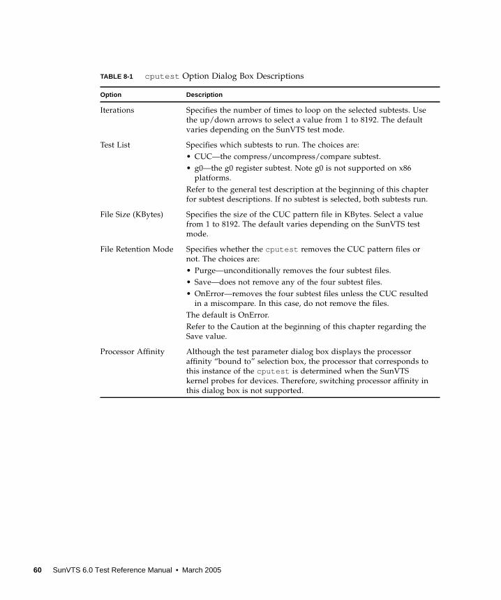
TABLE 8-1 cputest Option Dialog Box Descriptions
Option Description
Iterations Specifies the number of times to loop on the selected subtests. Use
the up/down arrows to select a value from 1 to 8192. The default
varies depending on the SunVTS test mode.
Test List Specifies which subtests to run. The choices are:
• CUC—the compress/uncompress/compare subtest.
• g0—the g0 register subtest. Note g0 is not supported on x86
platforms.
Refer to the general test description at the beginning of this chapter
for subtest descriptions. If no subtest is selected, both subtests run.
File Size (KBytes) Specifies the size of the CUC pattern file in KBytes. Select a value
from 1 to 8192. The default varies depending on the SunVTS test
mode.
File Retention Mode Specifies whether the cputest removes the CUC pattern files or
not. The choices are:
• Purge—unconditionally removes the four subtest files.
• Save—does not remove any of the four subtest files.
• OnError—removes the four subtest files unless the CUC resulted
in a miscompare. In this case, do not remove the files.
The default is OnError.
Refer to the Caution at the beginning of this chapter regarding the
Save value.
Processor Affinity Although the test parameter dialog box displays the processor
affinity “bound to” selection box, the processor that corresponds to
this instance of the cputest is determined when the SunVTS
kernel probes for devices. Therefore, switching processor affinity in
this dialog box is not supported.
60 SunVTS 6.0 Test Reference Manual • March 2005
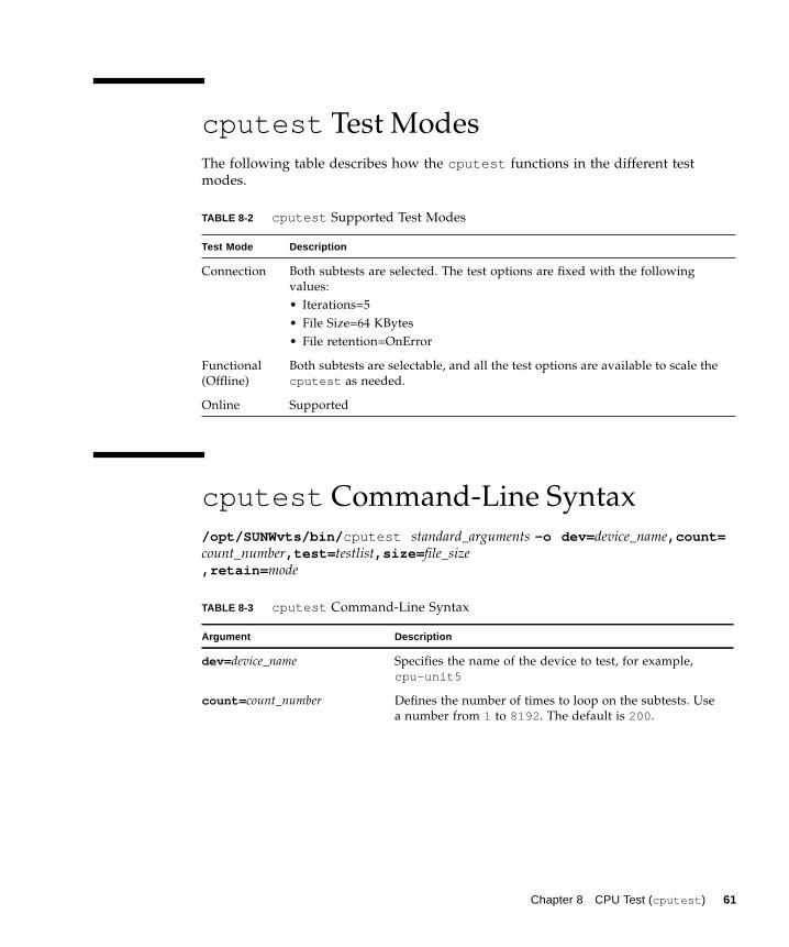
cputest Test Modes
The following table describes how the cputest functions in the different test
modes.
cputest Command-Line Syntax
/opt/SUNWvts/bin/ cputest standard_arguments -o dev= device_name,count=count_number,test= testlist,size= file_size,retain= mode
TABLE 8-2 cputest Supported Test Modes
Test Mode Description
Connection Both subtests are selected. The test options are fixed with the following
values:
• Iterations=5
• File Size=64 KBytes
• File retention=OnError
Functional
(Offline)
Both subtests are selectable, and all the test options are available to scale the
cputest as needed.
Online Supported
TABLE 8-3 cputest Command-Line Syntax
Argument Description
dev= device_name Specifies the name of the device to test, for example,
cpu-unit5
count= count_number Defines the number of times to loop on the subtests. Use
a number from 1 to 8192 . The default is 200 .
Chapter 8 CPU Test (cputest ) 61
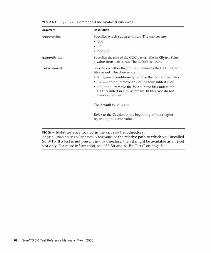
Note – 64-bit tests are located in the sparcv9 subdirectory:
/opt/SUNWvts/bin/sparcv9/ testname, or the relative path to which you installed
SunVTS. If a test is not present in this directory, then it might be available as a 32-bit
test only. For more information, see “32-Bit and 64-Bit Tests” on page 5.
test= testlist Specifies which subtests to run. The choices are:
• CUC
• g0
• CUC+g0
size= file_size Specifies the size of the CUC pattern file in KBytes. Select
a value from 1 to 8192 . The default is 1024 .
retain= mode Specifies whether the cputest removes the CUC pattern
files or not. The choices are:
• Purge —unconditionally remove the four subtest files
• Save—do not remove any of the four subtest files
• OnError —remove the four subtest files unless the
CUC resulted in a miscompare. In this case do not
remove the files.
The default is OnError .
Refer to the Caution at the beginning of this chapter
regarding the Save value.
TABLE 8-3 cputest Command-Line Syntax (Continued)
Argument Description
62 SunVTS 6.0 Test Reference Manual • March 2005

CHAPTER 9
Disk and Floppy Drives Test(disktest )
disktest verifies the functionality of hard drives and diskette drives using three
subtests (see TABLE 9-1): Media, File System, and Asynchronous I/O.
Note – disktest does support x86 platforms on Solaris.
Most disk drives, such as SCSI disks, native or SCSI floppy disks, IPI, and so on, are
supported. The type of drive being tested is displayed at the top of the Test
Parameter Options dialog box.
Note – disktest is supported on x86 platforms that use the Solaris operating
system for the Read-Only mode only. None of the WriteRead or the File System
related tests are supported on x86 at this time. For disks on x86 machines, the disk
partitions could range from 0 to 15. disktest can be performed on any of these
selected partitions.
The disktest Test Parameter Options dialog box shows all the partitions that are
available for testing. The file System subtest can only be run if the selected partition
is mounted (described below). The WriteRead option of the Media subtest is allowed
only if a selected partition is not mounted.
63

disktest Test Requirements
By default, disktest does not mount any partitions. To have SunVTS pre-mount all
mountable partitions, set the environment variable BYPASS_FS_PROBEto 0 (zero)
before starting SunVTS. Pre-mounting can be disabled by unsetting
BYPASS_FS_PROBEor changing it to a value other than 0 (zero).
The mount point used by disktest is the word disktest appended by the name of
the disk partition. For example, if the disk partition name is /dev/dsk/c0t3d0s0 ,
disktest mounts it as superuser under the name /disktest_c0t3d0s0 .
Caution – If a power failure occurs OR if the disktest is terminated abruptly while
the Media subtest is running in WriteRead mode, disk data may be corrupted.
Caution – Running the Media subtest on a disk partition in the WriteRead mode
may cause data corruption if the same partition is being used by other applications.
Please run SunVTS in the offline mode only when there are no other applications
running.
disktest tests the floppy drive regardless of whether the Volume Management
software is running or not. The following mount point names are used:
■ If the Volume Management software is running, disktest tests the disk drive
with the mount point name in the /etc/mnttab file.
■ If the Volume Management software is not running, disktest tests the disk drive
with the device name dev=/dev/diskette. Do not edit the /etc/vold.conffile to change the diskette drives. Currently, the SunVTS software is hard-coded to
use these path names as the default logic names.
Loading an option file (refer to the SunVTS User’s Guide for option file details) that
was created when BYPASS_FS_PROBEwas set to 0 (zero) might not work if the
BYPASS_FS_PROBEenvironment variable is no longer set to 0. Testing may fail with
the following error:
This error is caused when SunVTS expects to use the predefined mount point names
that are created when BYPASS_FS_PROBEis set to 0 (zero), but these mount points
do not exist while BYPASS_FS_PROBEis not set to 0.
SUNWvts.disktest.8088 07/24/98 15:47:22 disktest c0t0d0 FATAL:“Couldn’t get file system information on /disktest_s0t0d0s0,statvfs() system call failure error: No such file or directory.
64 SunVTS 6.0 Test Reference Manual • March 2005
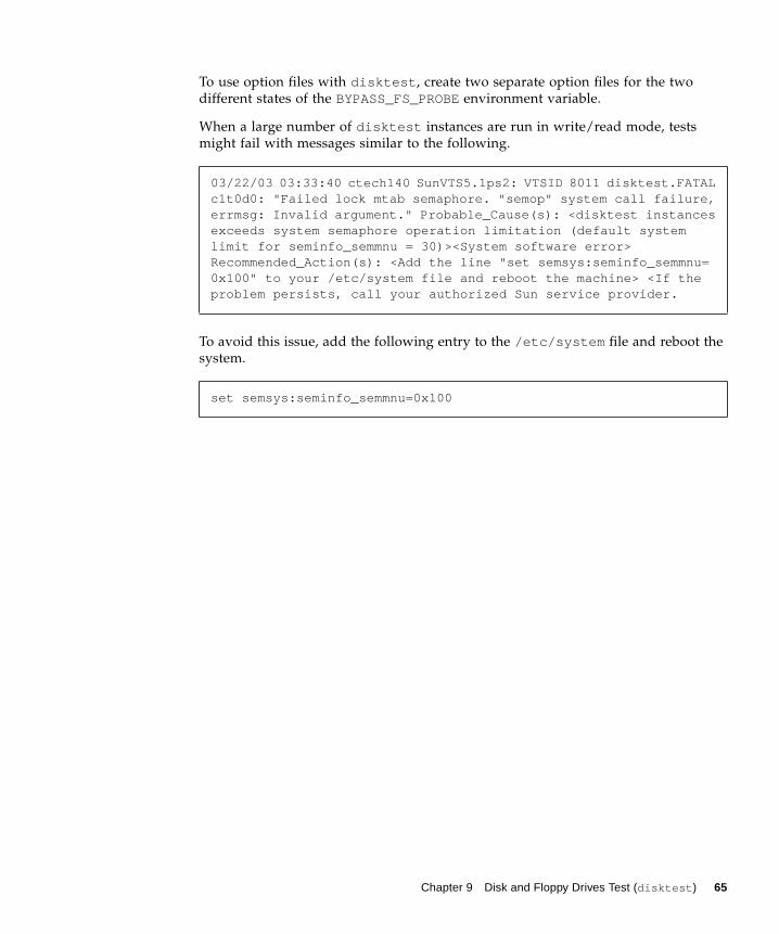
To use option files with disktest , create two separate option files for the two
different states of the BYPASS_FS_PROBEenvironment variable.
When a large number of disktest instances are run in write/read mode, tests
might fail with messages similar to the following.
To avoid this issue, add the following entry to the /etc/system file and reboot the
system.
03/22/03 03:33:40 ctech140 SunVTS5.1ps2: VTSID 8011 disktest.FATALc1t0d0: "Failed lock mtab semaphore. "semop" system call failure,errmsg: Invalid argument." Probable_Cause(s): <disktest instancesexceeds system semaphore operation limitation (default systemlimit for seminfo_semmnu = 30)><System software error>Recommended_Action(s): <Add the line "set semsys:seminfo_semmnu=0x100" to your /etc/system file and reboot the machine> <If theproblem persists, call your authorized Sun service provider.
set semsys:seminfo_semmnu=0x100
Chapter 9 Disk and Floppy Drives Test (disktest ) 65
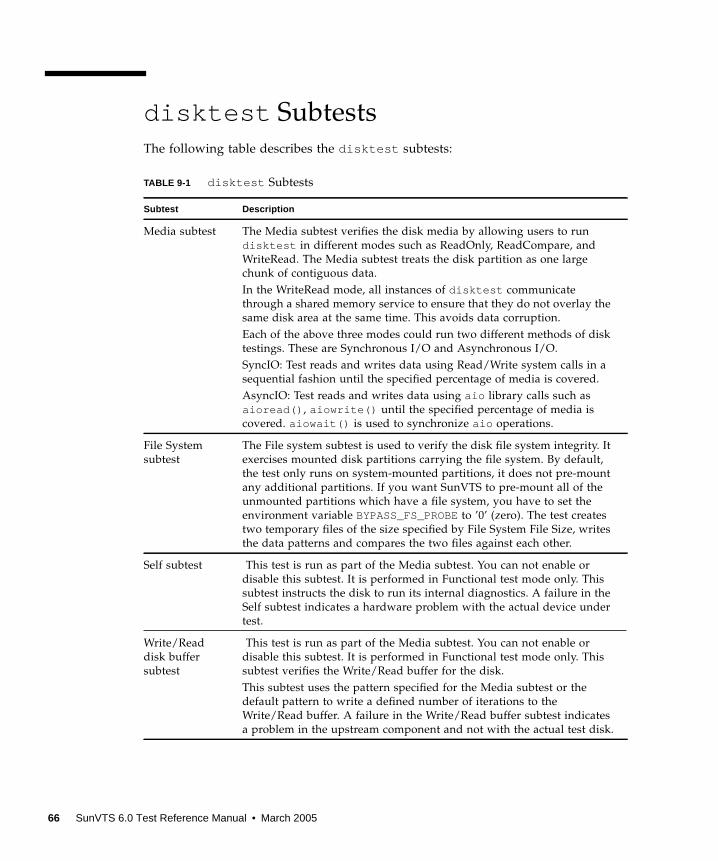
disktest Subtests
The following table describes the disktest subtests:
TABLE 9-1 disktest Subtests
Subtest Description
Media subtest The Media subtest verifies the disk media by allowing users to run
disktest in different modes such as ReadOnly, ReadCompare, and
WriteRead. The Media subtest treats the disk partition as one large
chunk of contiguous data.
In the WriteRead mode, all instances of disktest communicate
through a shared memory service to ensure that they do not overlay the
same disk area at the same time. This avoids data corruption.
Each of the above three modes could run two different methods of disk
testings. These are Synchronous I/O and Asynchronous I/O.
SyncIO: Test reads and writes data using Read/Write system calls in a
sequential fashion until the specified percentage of media is covered.
AsyncIO: Test reads and writes data using aio library calls such as
aioread() , aiowrite() until the specified percentage of media is
covered. aiowait() is used to synchronize aio operations.
File System
subtest
The File system subtest is used to verify the disk file system integrity. It
exercises mounted disk partitions carrying the file system. By default,
the test only runs on system-mounted partitions, it does not pre-mount
any additional partitions. If you want SunVTS to pre-mount all of the
unmounted partitions which have a file system, you have to set the
environment variable BYPASS_FS_PROBEto ’0’ (zero). The test creates
two temporary files of the size specified by File System File Size, writes
the data patterns and compares the two files against each other.
Self subtest This test is run as part of the Media subtest. You can not enable or
disable this subtest. It is performed in Functional test mode only. This
subtest instructs the disk to run its internal diagnostics. A failure in the
Self subtest indicates a hardware problem with the actual device under
test.
Write/Read
disk buffer
subtest
This test is run as part of the Media subtest. You can not enable or
disable this subtest. It is performed in Functional test mode only. This
subtest verifies the Write/Read buffer for the disk.
This subtest uses the pattern specified for the Media subtest or the
default pattern to write a defined number of iterations to the
Write/Read buffer. A failure in the Write/Read buffer subtest indicates
a problem in the upstream component and not with the actual test disk.
66 SunVTS 6.0 Test Reference Manual • March 2005
disktest Test Options
To reach the dialog box below, right-click on the test name in the System Map and
select Test Parameter Options. If you do not see this test in the System Map, you
might need to expand the collapsed groups, or your system may not include the
device appropriate to this test. Refer to the SunVTS User’s Guide for more details.
Chapter 9 Disk and Floppy Drives Test (disktest ) 67
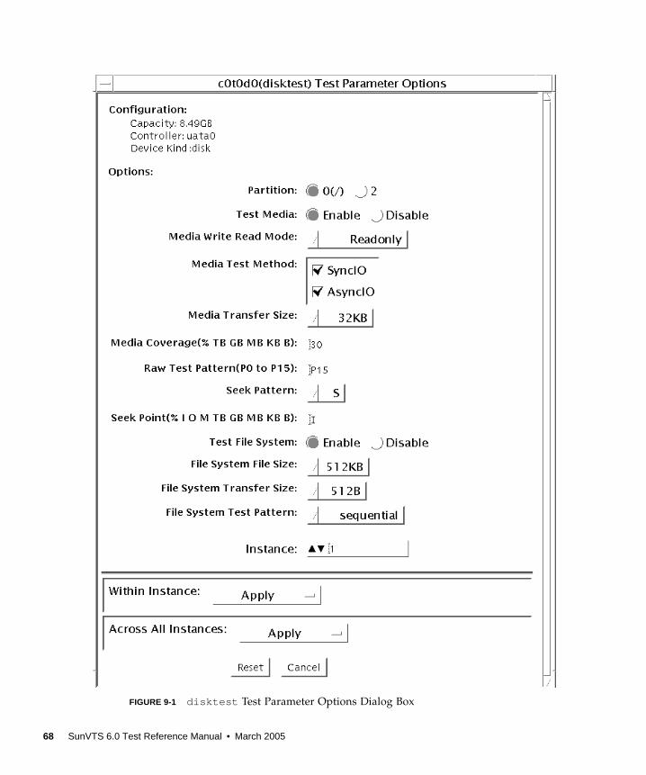
FIGURE 9-1 disktest Test Parameter Options Dialog Box
68 SunVTS 6.0 Test Reference Manual • March 2005
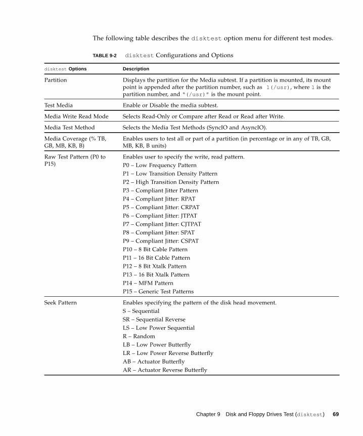
The following table describes the disktest option menu for different test modes.
TABLE 9-2 disktest Configurations and Options
disktest Options Description
Partition Displays the partition for the Media subtest. If a partition is mounted, its mount
point is appended after the partition number, such as 1(/usr) , where 1 is the
partition number, and “(/usr)” is the mount point.
Test Media Enable or Disable the media subtest.
Media Write Read Mode Selects Read-Only or Compare after Read or Read after Write.
Media Test Method Selects the Media Test Methods (SyncIO and AsyncIO).
Media Coverage (% TB,
GB, MB, KB, B)
Enables users to test all or part of a partition (in percentage or in any of TB, GB,
MB, KB, B units)
Raw Test Pattern (P0 to
P15)
Enables user to specify the write, read pattern.
P0 – Low Frequency Pattern
P1 – Low Transition Density Pattern
P2 – High Transition Density Pattern
P3 – Compliant Jitter Pattern
P4 – Compliant Jitter: RPAT
P5 – Compliant Jitter: CRPAT
P6 – Compliant Jitter: JTPAT
P7 – Compliant Jitter: CJTPAT
P8 – Compliant Jitter: SPAT
P9 – Compliant Jitter: CSPAT
P10 – 8 Bit Cable Pattern
P11 – 16 Bit Cable Pattern
P12 – 8 Bit Xtalk Pattern
P13 – 16 Bit Xtalk Pattern
P14 – MFM Pattern
P15 – Generic Test Patterns
Seek Pattern Enables specifying the pattern of the disk head movement.
S – Sequential
SR – Sequential Reverse
LS – Low Power Sequential
R – Random
LB – Low Power Butterfly
LR – Low Power Reverse Butterfly
AB – Actuator Butterfly
AR – Actuator Reverse Butterfly
Chapter 9 Disk and Floppy Drives Test (disktest ) 69
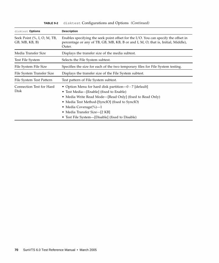
Seek Point (%, I, O, M, TB,
GB, MB, KB, B)
Enables specifying the seek point offset for the I/O. You can specify the offset in
percentage or any of TB, GB, MB, KB, B or and I, M, O; that is, Initial, Middle),
Outer.
Media Transfer Size Displays the transfer size of the media subtest.
Test File System Selects the File System subtest.
File System File Size Specifies the size for each of the two temporary files for File System testing.
File System Transfer Size Displays the transfer size of the File System subtest.
File System Test Pattern Test pattern of File System subtest.
Connection Test for Hard
Disk
• Option Menu for hard disk partition—0 - 7 [default]
• Test Media—[Enable] (fixed to Enable)
• Media Write Read Mode—[Read Only] (fixed to Read Only)
• Media Test Method-[SyncIO] (fixed to SyncIO)
• Media Coverage(%)—1
• Media Transfer Size—[2 KB]
• Test File System—[Disable] (fixed to Disable)
TABLE 9-2 disktest Configurations and Options (Continued)
disktest Options Description
70 SunVTS 6.0 Test Reference Manual • March 2005
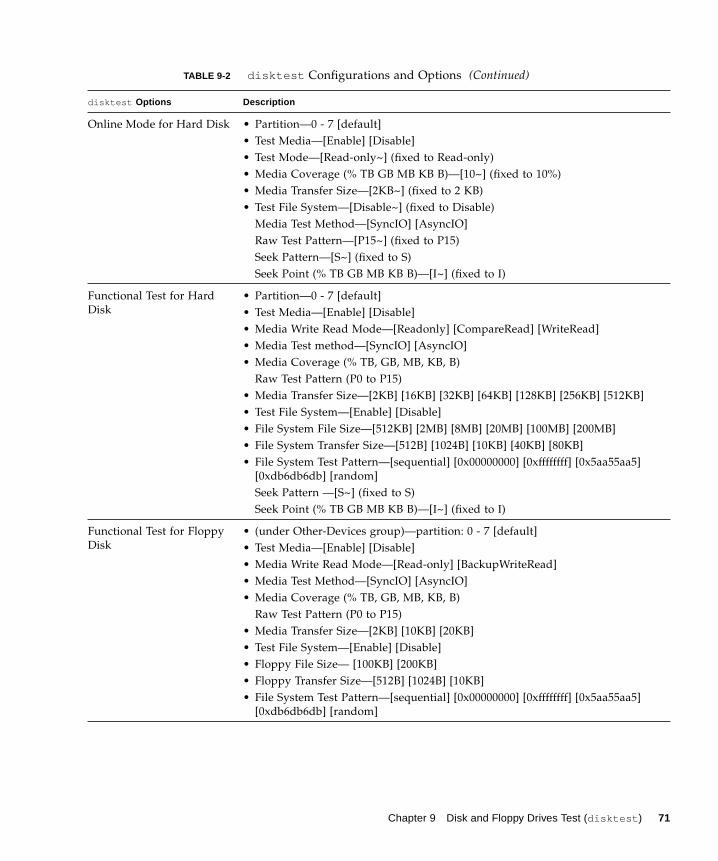
Online Mode for Hard Disk • Partition—0 - 7 [default]
• Test Media—[Enable] [Disable]
• Test Mode—[Read-only~] (fixed to Read-only)
• Media Coverage (% TB GB MB KB B)—[10~] (fixed to 10%)
• Media Transfer Size—[2KB~] (fixed to 2 KB)
• Test File System—[Disable~] (fixed to Disable)
Media Test Method—[SyncIO] [AsyncIO]
Raw Test Pattern—[P15~] (fixed to P15)
Seek Pattern—[S~] (fixed to S)
Seek Point (% TB GB MB KB B)—[I~] (fixed to I)
Functional Test for Hard
Disk
• Partition—0 - 7 [default]
• Test Media—[Enable] [Disable]
• Media Write Read Mode—[Readonly] [CompareRead] [WriteRead]
• Media Test method—[SyncIO] [AsyncIO]
• Media Coverage (% TB, GB, MB, KB, B)
Raw Test Pattern (P0 to P15)
• Media Transfer Size—[2KB] [16KB] [32KB] [64KB] [128KB] [256KB] [512KB]
• Test File System—[Enable] [Disable]
• File System File Size—[512KB] [2MB] [8MB] [20MB] [100MB] [200MB]
• File System Transfer Size—[512B] [1024B] [10KB] [40KB] [80KB]
• File System Test Pattern—[sequential] [0x00000000] [0xffffffff] [0x5aa55aa5]
[0xdb6db6db] [random]
Seek Pattern —[S~] (fixed to S)
Seek Point (% TB GB MB KB B)—[I~] (fixed to I)
Functional Test for Floppy
Disk
• (under Other-Devices group)—partition: 0 - 7 [default]
• Test Media—[Enable] [Disable]
• Media Write Read Mode—[Read-only] [BackupWriteRead]
• Media Test Method—[SyncIO] [AsyncIO]
• Media Coverage (% TB, GB, MB, KB, B)
Raw Test Pattern (P0 to P15)
• Media Transfer Size—[2KB] [10KB] [20KB]
• Test File System—[Enable] [Disable]
• Floppy File Size— [100KB] [200KB]
• Floppy Transfer Size—[512B] [1024B] [10KB]
• File System Test Pattern—[sequential] [0x00000000] [0xffffffff] [0x5aa55aa5]
[0xdb6db6db] [random]
TABLE 9-2 disktest Configurations and Options (Continued)
disktest Options Description
Chapter 9 Disk and Floppy Drives Test (disktest ) 71

disktest Test Modes
disktest Command-Line Syntax forSPARC Platforms
/opt/SUNWvts/bin/disktest standard_arguments -o partition= <0-7>[“<(mount_point)>”], rawsub= E(nable)|D(isable), rawrw=Readonly|CompareRead|WriteRead, rawiosize= <number>{...|KB|kb...}|random,rawcover= <number>|<number>{TB|GB|MB|KB|B|tb|gb|mb|kb|b}rawpattern= P(<0-15>)|0x<8 digit data pattern>, seekpattern={S|SR|LS|R|LB|LR|AB|AR}, seekpoint= {i|m|o|<number>}, method=
TABLE 9-3 disktest Supported Test Modes
Test Mode Description
Connection Only one instance of disktest (which monitors UNIX error messages) is
allowed for each disk device. disktest displays messages and reports
errors. The test also opens the hard disk, checks the disk configuration,
reads a few blocks, and then closes the hard disk. No File System subtest is
run. No Write option is available in Connection test mode.
Functional More than one instance of disktest is allowed for one disk device. The
File System subtest, Media subtests, and floppy test can be run in Functional
test mode.
In Functional mode, disktest performs two additional subtests (Self subtest
and Write/Read device buffer subtest) for enclosures.
These two additional subtests help in isolating the errors and are completed
before disktest continues with the Media subtest or File System subtest.
In Functional test mode, disktest also monitors enclosures by checking
for errors in the Read link status counters and issues a warning if any errors
are detected.
Online SunVTS disktest runs the Read Only rawtest with fixed transfer size
and fixed rawtest pattern. Both SyncIO and AsyncIO test methods are
available. The File system subtest is disabled in the Online test mode. Only
one disktest instance could be run in the Online test mode.
Online Supported
72 SunVTS 6.0 Test Reference Manual • March 2005
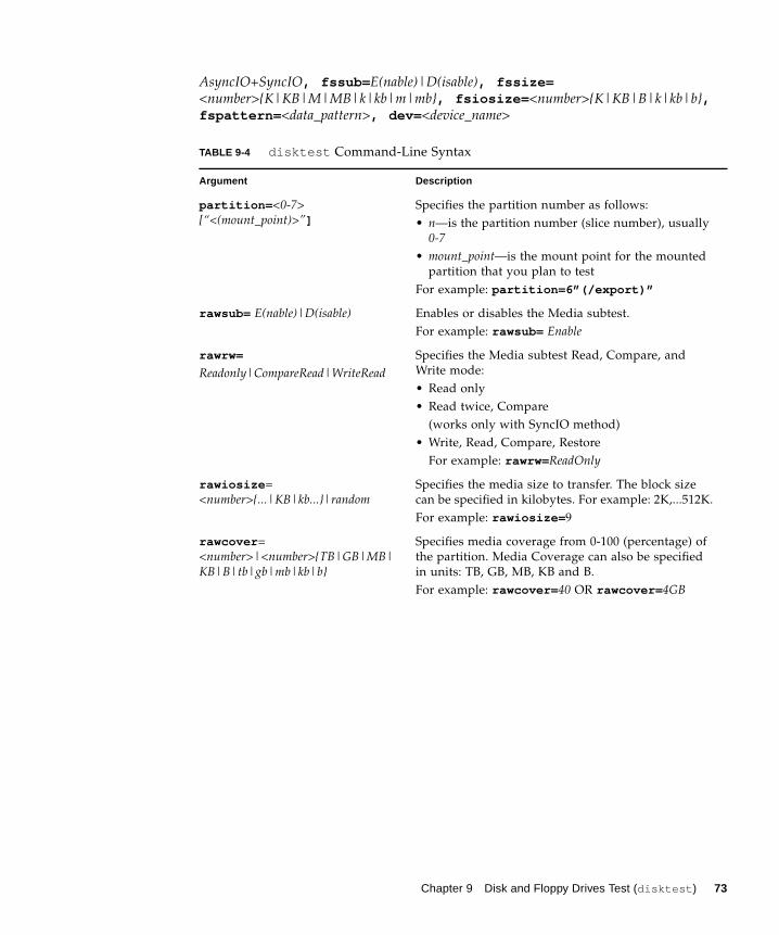
AsyncIO+SyncIO, fssub= E(nable)|D(isable), fssize=<number>{K|KB|M|MB|k|kb|m|mb}, fsiosize= <number>{K|KB|B|k|kb|b},fspattern= <data_pattern>, dev= <device_name>
TABLE 9-4 disktest Command-Line Syntax
Argument Description
partition= <0-7>[“<(mount_point)>”]
Specifies the partition number as follows:
• n—is the partition number (slice number), usually
0-7• mount_point—is the mount point for the mounted
partition that you plan to test
For example: partition=6”(/export)”
rawsub= E(nable)|D(isable) Enables or disables the Media subtest.
For example: rawsub= Enable
rawrw=
Readonly|CompareRead|WriteReadSpecifies the Media subtest Read, Compare, and
Write mode:
• Read only
• Read twice, Compare
(works only with SyncIO method)
• Write, Read, Compare, Restore
For example: rawrw= ReadOnly
rawiosize =
<number>{...|KB|kb...}|randomSpecifies the media size to transfer. The block size
can be specified in kilobytes. For example: 2K,...512K.
For example: rawiosize= 9
rawcover =
<number>|<number>{TB|GB|MB|KB|B|tb|gb|mb|kb|b}
Specifies media coverage from 0-100 (percentage) of
the partition. Media Coverage can also be specified
in units: TB, GB, MB, KB and B.
For example: rawcover= 40 OR rawcover= 4GB
Chapter 9 Disk and Floppy Drives Test (disktest ) 73
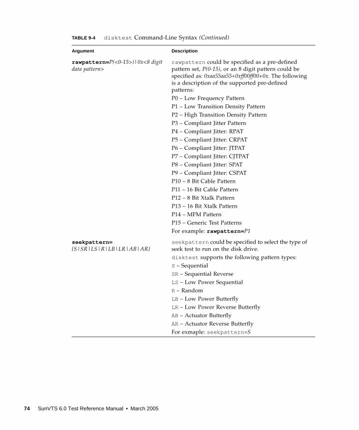
rawpattern= P(<0-15>)|0x<8 digitdata pattern>
rawpattern could be specified as a pre-defined
pattern set, P(0-15), or an 8 digit pattern could be
specified as: 0xaa55aa55+0xff00ff00+0x. The following
is a description of the supported pre-defined
patterns:
P0 – Low Frequency Pattern
P1 – Low Transition Density Pattern
P2 – High Transition Density Pattern
P3 – Compliant Jitter Pattern
P4 – Compliant Jitter: RPAT
P5 – Compliant Jitter: CRPAT
P6 – Compliant Jitter: JTPAT
P7 – Compliant Jitter: CJTPAT
P8 – Compliant Jitter: SPAT
P9 – Compliant Jitter: CSPAT
P10 – 8 Bit Cable Pattern
P11 – 16 Bit Cable Pattern
P12 – 8 Bit Xtalk Pattern
P13 – 16 Bit Xtalk Pattern
P14 – MFM Pattern
P15 – Generic Test Patterns
For example: rawpattern= P1
seekpattern={S|SR|LS|R|LB|LR|AB|AR}
seekpattern could be specified to select the type of
seek test to run on the disk drive.
disktest supports the following pattern types:
S – Sequential
SR– Sequential Reverse
LS – Low Power Sequential
R – Random
LB – Low Power Butterfly
LR – Low Power Reverse Butterfly
AB – Actuator Butterfly
AR– Actuator Reverse Butterfly
For exmaple: seekpattern= S
TABLE 9-4 disktest Command-Line Syntax (Continued)
Argument Description
74 SunVTS 6.0 Test Reference Manual • March 2005

seekpoint= {i|m|o|<number>} Specify the seek-point for the I/O. This could be
specified either in terms of the range - inner, middle
and outer. Or in terms of absolute seek location.
The absolute location is specied by a number
followed by any of the following units
{TB|GB|MB|KB|B|tb|gb|mb|kb|b}.
For example:
a) seekpoint= I, start the I/O from block 1.
b) seekpoint= M, start the I/O from middle offset
of the partition.
method= AsyncIO+SyncIO Specifies the Media access method. You can choose to
use either or both methods . If you use both access
methods together, you must insert a ‘+’ between the
two:
AsyncIO: Runs the asynchronous I/O test, using the
async read/write feature of the Solaris disk driver
SyncIO: Runs the synchronous I/O test.
For example: method= AsyncIO
fssub= E(nable)|D(isable) Enables or disables the File System subtest. File
system subtest runs on a mounted partition with a
file system.
fspattern= <data_pattern> Specifies the file system data pattern as sequential or
random or one of the patterns selected from the list.
{seq(uential)|0x0(0000000)|0xf(fffffff)|0xa (5a5a5a5)|0x5(a5a5a5a)|ran(dom)|0xd(b6db6db)}For example:
a) fspattern= 0xaa) fspattern= seq
fssize=<number>{K|KB|M|MB|k|kb|m|mb}
Indicates the file system subtest size in Megabytes or
Kilobytes:
• K|k|KB|kb – kilobytes
• M|m|MB|mb– megabytes
512KB|2MB| 8MB| 20MB|100MB|200MB
fsiosize=<number>{K|KB|B|k|kb|b}
Indicates the size of the file system subtest I/O
transfer in bytes or Kilobytes:
• B|b – bytes
• K|k|KB|kb – Kilobytes
512B|1024B|10KB|40KB|80KB
dev= device_name Specifies the name of the disk to be tested.
For example: c0t3d0.
TABLE 9-4 disktest Command-Line Syntax (Continued)
Argument Description
Chapter 9 Disk and Floppy Drives Test (disktest ) 75
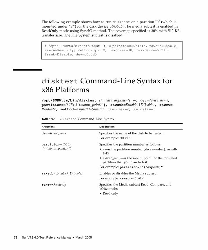
The following example shows how to run disktest on a partition "0" (which is
mounted under “/”) for the disk device c0t0d0 . The media subtest is enabled in
ReadOnly mode using SyncIO method. The coverage specified is 30% with 512 KB
transfer size. The File System subtest is disabled.
disktest Command-Line Syntax forx86 Platforms
/opt/SUNWvts/bin/disktest standard_arguments -o dev= device_name,
partition= <0-15> [“(mount_point)”], rawsub= E(nable)|D(isable), rawrw=Readonly, method= AsyncIO+SyncIO, rawcover= n, rawiosize= n
# /opt/SUNWvts/bin/disktest -f -o partition=0"(/)", rawsub=Enable,rawrw=ReadOnly, method=SyncIO, rawcover=30, rawiosize=512KB,fssub=Disable, dev=c0t0d0
TABLE 9-5 disktest Command-Line Syntax
Argument Description
dev= device_name Specifies the name of the disk to be tested.
For example: c0t3d0.
partition= <1-15>[“<(mount_point)>”]
Specifies the partition number as follows:
• n—is the partition number (slice number), usually
1-15
• mount_point—is the mount point for the mounted
partition that you plan to test
For example: partition=6”(/export)”
rawsub= E(nable)|D(isable) Enables or disables the Media subtest.
For example: rawsub= Enable
rawrw= Readonly Specifies the Media subtest Read, Compare, and
Write mode:
• Read only
76 SunVTS 6.0 Test Reference Manual • March 2005
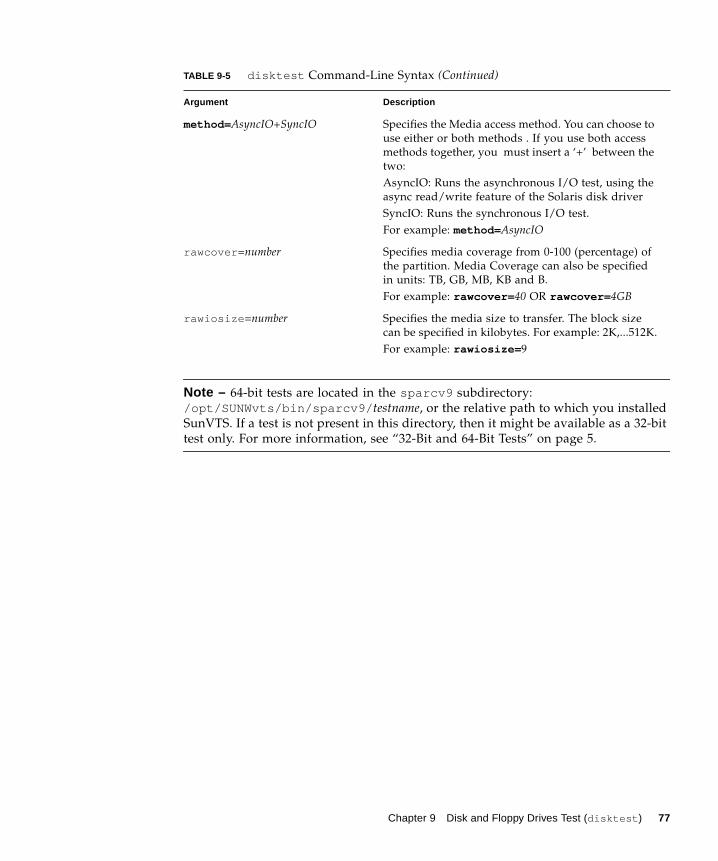
Note – 64-bit tests are located in the sparcv9 subdirectory:
/opt/SUNWvts/bin/sparcv9/ testname, or the relative path to which you installed
SunVTS. If a test is not present in this directory, then it might be available as a 32-bit
test only. For more information, see “32-Bit and 64-Bit Tests” on page 5.
method= AsyncIO+SyncIO Specifies the Media access method. You can choose to
use either or both methods . If you use both access
methods together, you must insert a ‘+’ between the
two:
AsyncIO: Runs the asynchronous I/O test, using the
async read/write feature of the Solaris disk driver
SyncIO: Runs the synchronous I/O test.
For example: method= AsyncIO
rawcover =number Specifies media coverage from 0-100 (percentage) of
the partition. Media Coverage can also be specified
in units: TB, GB, MB, KB and B.
For example: rawcover= 40 OR rawcover= 4GB
rawiosize =number Specifies the media size to transfer. The block size
can be specified in kilobytes. For example: 2K,...512K.
For example: rawiosize= 9
TABLE 9-5 disktest Command-Line Syntax (Continued)
Argument Description
Chapter 9 Disk and Floppy Drives Test (disktest ) 77

78 SunVTS 6.0 Test Reference Manual • March 2005
CHAPTER 10
Netra-CT 820 DMC Test (dmctest )
The dmctest tests major components in the drawer management controller (DMC)
card. The components tested on the card include Flash memory, SDRAM, FPGA,
RTC, I2C devices, UART chip, Fast Ethernet controller and PHY, Muxes, Alarm LEDs
and so on. This test supports both the active (dmcatest ) and standby (dmcstest )
DMC card testing. The traces to be tested on the board include address bus, data
bus, I2C bus, KCS, IPMI bus, Interrupt lines, and cPCI connector.
dmctest has the following subtests:
■ Ethernet test
The Ethernet test performs test on SCC Ethernet device. The test covers Phy,
Internal, and External loopback. The Ethernet Ping test uses the FEC port. The
Ethernet test is supported on both DMC Active and DMC Standby cards, and
performs the following tests: External loopback test, Internal loopback test, Phy
test, Ping test. The Ethernet test requires an external loopback connector plugged
in to be able to perform the External loopback test.
■ Flash test
This test reads the entire 24 Mbyte flash area and performs a checksum test. The
test is supported on both DMC Active and Standby cards.
■ Alarm Port test
This test toggles all four alarm ports: Critical, Major, Minor and Warning and
reports Pass or Fail status. The test is supported on both DMC Active and
Standby cards.
■ Health test
79
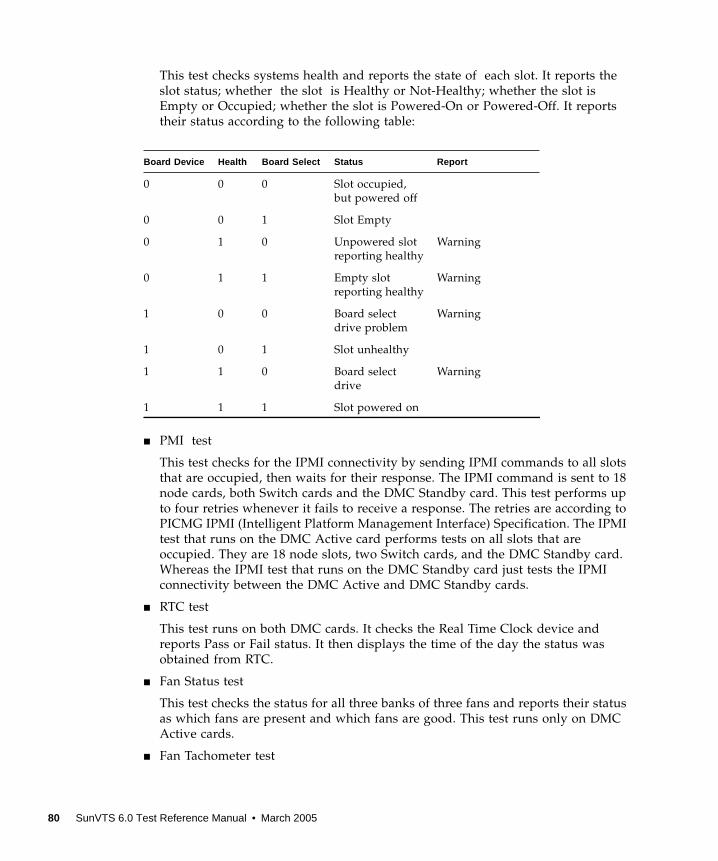
This test checks systems health and reports the state of each slot. It reports the
slot status; whether the slot is Healthy or Not-Healthy; whether the slot is
Empty or Occupied; whether the slot is Powered-On or Powered-Off. It reports
their status according to the following table:
■ PMI test
This test checks for the IPMI connectivity by sending IPMI commands to all slots
that are occupied, then waits for their response. The IPMI command is sent to 18
node cards, both Switch cards and the DMC Standby card. This test performs up
to four retries whenever it fails to receive a response. The retries are according to
PICMG IPMI (Intelligent Platform Management Interface) Specification. The IPMI
test that runs on the DMC Active card performs tests on all slots that are
occupied. They are 18 node slots, two Switch cards, and the DMC Standby card.
Whereas the IPMI test that runs on the DMC Standby card just tests the IPMI
connectivity between the DMC Active and DMC Standby cards.
■ RTC test
This test runs on both DMC cards. It checks the Real Time Clock device and
reports Pass or Fail status. It then displays the time of the day the status was
obtained from RTC.
■ Fan Status test
This test checks the status for all three banks of three fans and reports their status
as which fans are present and which fans are good. This test runs only on DMC
Active cards.
■ Fan Tachometer test
Board Device Health Board Select Status Report
0 0 0 Slot occupied,
but powered off
0 0 1 Slot Empty
0 1 0 Unpowered slot
reporting healthy
Warning
0 1 1 Empty slot
reporting healthy
Warning
1 0 0 Board select
drive problem
Warning
1 0 1 Slot unhealthy
1 1 0 Board select
drive
Warning
1 1 1 Slot powered on
80 SunVTS 6.0 Test Reference Manual • March 2005
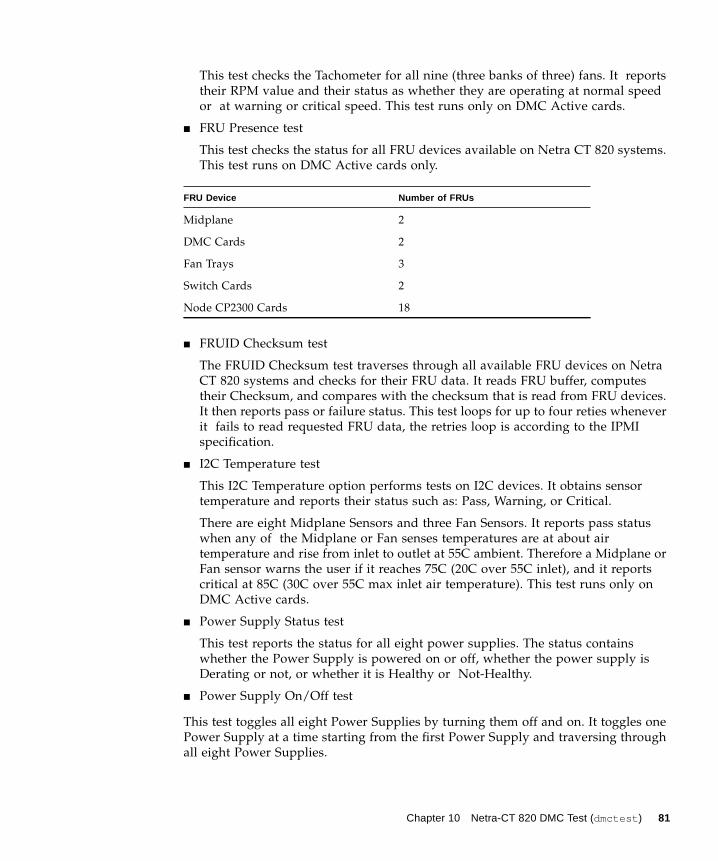
This test checks the Tachometer for all nine (three banks of three) fans. It reports
their RPM value and their status as whether they are operating at normal speed
or at warning or critical speed. This test runs only on DMC Active cards.
■ FRU Presence test
This test checks the status for all FRU devices available on Netra CT 820 systems.
This test runs on DMC Active cards only.
■ FRUID Checksum test
The FRUID Checksum test traverses through all available FRU devices on Netra
CT 820 systems and checks for their FRU data. It reads FRU buffer, computes
their Checksum, and compares with the checksum that is read from FRU devices.
It then reports pass or failure status. This test loops for up to four reties whenever
it fails to read requested FRU data, the retries loop is according to the IPMI
specification.
■ I2C Temperature test
This I2C Temperature option performs tests on I2C devices. It obtains sensor
temperature and reports their status such as: Pass, Warning, or Critical.
There are eight Midplane Sensors and three Fan Sensors. It reports pass status
when any of the Midplane or Fan senses temperatures are at about air
temperature and rise from inlet to outlet at 55C ambient. Therefore a Midplane or
Fan sensor warns the user if it reaches 75C (20C over 55C inlet), and it reports
critical at 85C (30C over 55C max inlet air temperature). This test runs only on
DMC Active cards.
■ Power Supply Status test
This test reports the status for all eight power supplies. The status contains
whether the Power Supply is powered on or off, whether the power supply is
Derating or not, or whether it is Healthy or Not-Healthy.
■ Power Supply On/Off test
This test toggles all eight Power Supplies by turning them off and on. It toggles one
Power Supply at a time starting from the first Power Supply and traversing through
all eight Power Supplies.
FRU Device Number of FRUs
Midplane 2
DMC Cards 2
Fan Trays 3
Switch Cards 2
Node CP2300 Cards 18
Chapter 10 Netra-CT 820 DMC Test (dmctest ) 81
Note – Enable the Power Supply On/Off test for only a limited number of runs; this
test might degrade the life cycle of Power Supplies. This test runs on DMC Active
cards only.
There is only one serial communication port available on DMC cards and this port is
used for the Console. The serial port test is covered to enable entering commands in
the console window and receiving responses from CLI commands—such as:
showhealth or showipmode , and ping .
dmcatest Options
To reach the dialog box below, right-click on the test name in the System Map and
select Test Parameter Options. If you do not see this test in the System Map, you
might need to expand the collapsed groups, or your system may not include the
device appropriate to this test. Refer to the SunVTS User’s Guide for more details.
82 SunVTS 6.0 Test Reference Manual • March 2005
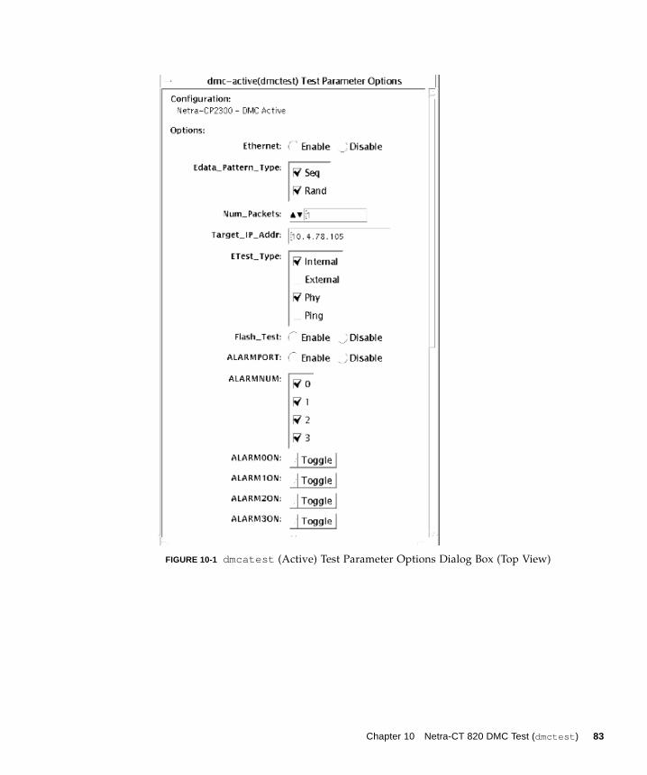
FIGURE 10-1 dmcatest (Active) Test Parameter Options Dialog Box (Top View)
Chapter 10 Netra-CT 820 DMC Test (dmctest ) 83
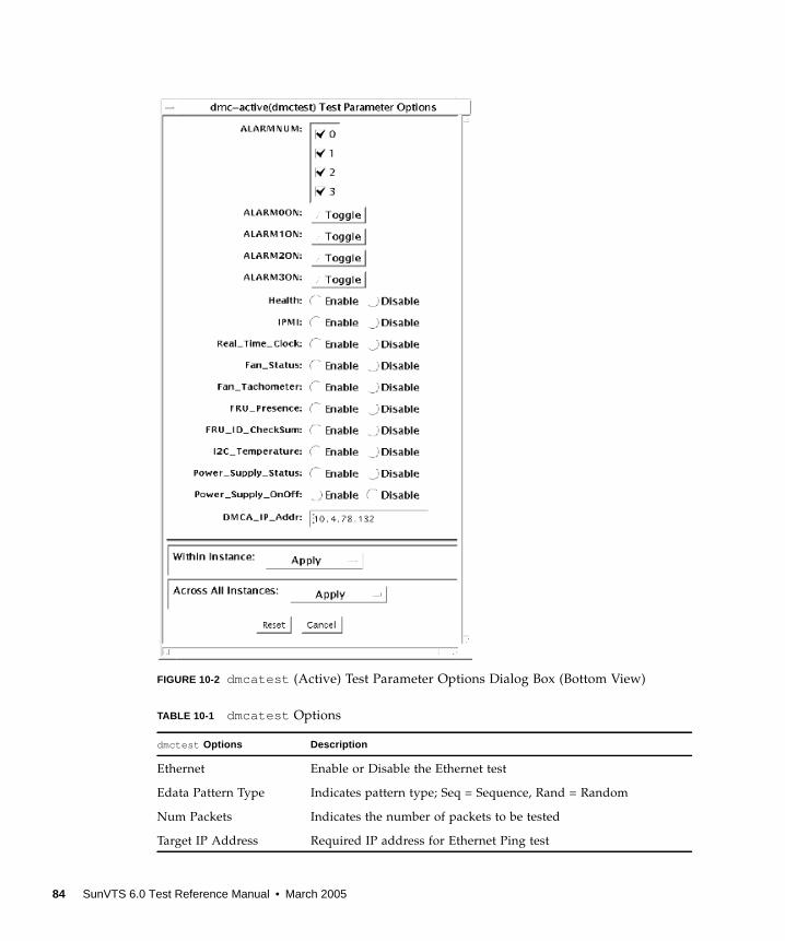
FIGURE 10-2 dmcatest (Active) Test Parameter Options Dialog Box (Bottom View)
TABLE 10-1 dmcatest Options
dmctest Options Description
Ethernet Enable or Disable the Ethernet test
Edata Pattern Type Indicates pattern type; Seq = Sequence, Rand = Random
Num Packets Indicates the number of packets to be tested
Target IP Address Required IP address for Ethernet Ping test
84 SunVTS 6.0 Test Reference Manual • March 2005
dmcstest Options
To reach the dialog box below, right-click on the test name in the System Map and
select Test Parameter Options. If you do not see this test in the System Map, you
might need to expand the collapsed groups, or your system may not include the
device appropriate to this test. Refer to the SunVTS User’s Guide for more details.
Etest Type Indicates the type of data to test
Flash Test Enable or Disable the Flash test
ALARMPORT Enable or Disable the ALARMPORT
ALARMNUM Indicates the Alarm Number
ALARM00N Toggles
ALARM10N Toggles
ALARM20N Toggles
ALARM30N Toggles
Health Enable or Disable the Health test
IPMI Enable or Disable the IPMI test
Real Time Clock Enable or Disable the Real Time Clock test
Fan Status Enable or Disable the Fan Status test
Fan Tachometer Enable or Disable the Fan Tachometer test
FRU Presence Enable or Disable the FRU Presence test
FRU ID CheckSum Enable or Disable the FRU ID Checksum test
I2CTemperature Enable or Disable the I2C Tempature test
Power Supply Status Enable or Disable the Power Supply Status test
Power Supply On/Off Enable or Disable the Power Supply On/Off test; the default is
Disable
DMCA IP Address Required DMCA IP address
TABLE 10-1 dmcatest Options (Continued)
dmctest Options Description
Chapter 10 Netra-CT 820 DMC Test (dmctest ) 85
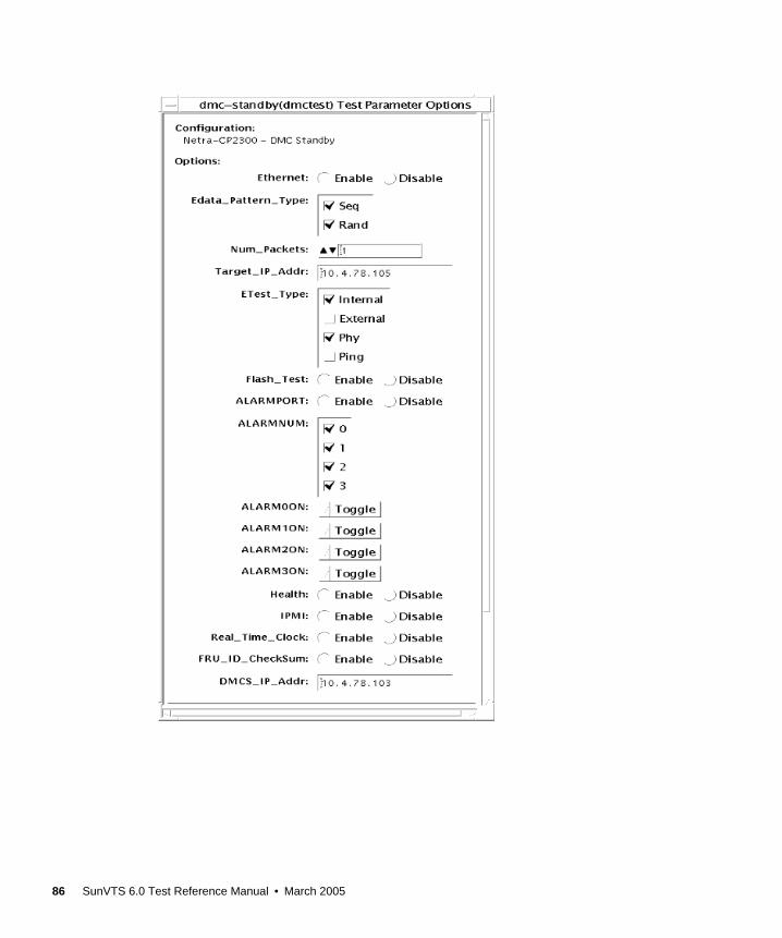
86 SunVTS 6.0 Test Reference Manual • March 2005
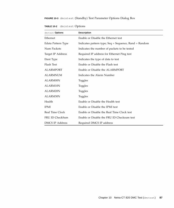
FIGURE 10-3 dmcstest (Standby) Test Parameter Options Dialog Box
TABLE 10-2 dmcstest Options
dmctest Options Description
Ethernet Enable or Disable the Ethernet test
Edata Pattern Type Indicates pattern type; Seq = Sequence, Rand = Random
Num Packets Indicates the number of packets to be tested
Target IP Address Required IP address for Ethernet Ping test
Etest Type Indicates the type of data to test
Flash Test Enable or Disable the Flash test
ALARMPORT Enable or Disable the ALARMPORT
ALARMNUM Indicates the Alarm Number
ALARM00N Toggles
ALARM10N Toggles
ALARM20N Toggles
ALARM30N Toggles
Health Enable or Disable the Health test
IPMI Enable or Disable the IPMI test
Real Time Clock Enable or Disable the Real Time Clock test
FRU ID CheckSum Enable or Disable the FRU ID Checksum test
DMCS IP Address Required DMCS IP address
Chapter 10 Netra-CT 820 DMC Test (dmctest ) 87
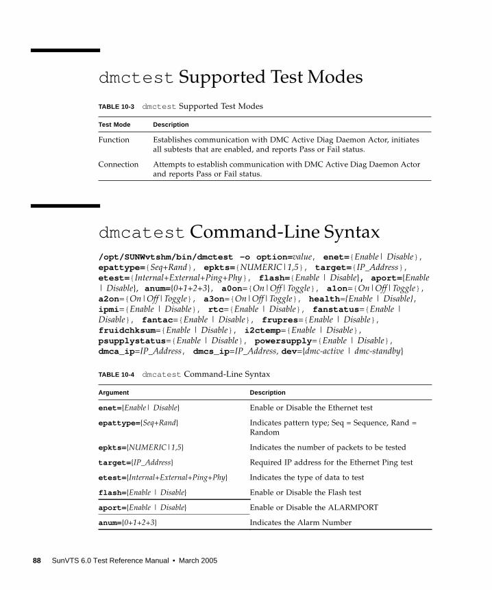
dmctest Supported Test Modes
dmcatest Command-Line Syntax
/opt/SUNWvtshm/bin/dmctest -o option= value, enet= { Enable| Disable},epattype= { Seq+Rand}, epkts= { NUMERIC|1,5}, target= { IP_Address},etest= { Internal+External+Ping+Phy}, flash= { Enable | Disable}, aport= {Enable| Disable}, anum={0+1+2+3}, a0on ={ On|Off|Toggle}, a1on ={ On|Off|Toggle},a2on ={ On|Off|Toggle}, a3on ={ On|Off|Toggle}, health ={Enable | Disable},ipmi ={ Enable | Disable}, rtc ={ Enable | Disable}, fanstatus ={ Enable |Disable}, fantac ={ Enable | Disable}, frupres ={ Enable | Disable},fruidchksum ={ Enable | Disable}, i2ctemp ={ Enable | Disable},psupplystatus ={ Enable | Disable}, powersupply ={ Enable | Disable},dmca_ip =IP_Address, dmcs_ip =IP_Address, dev ={dmc-active | dmc-standby}
TABLE 10-3 dmctest Supported Test Modes
Test Mode Description
Function Establishes communication with DMC Active Diag Daemon Actor, initiates
all subtests that are enabled, and reports Pass or Fail status.
Connection Attempts to establish communication with DMC Active Diag Daemon Actor
and reports Pass or Fail status.
TABLE 10-4 dmcatest Command-Line Syntax
Argument Description
enet= {Enable| Disable} Enable or Disable the Ethernet test
epattype= {Seq+Rand} Indicates pattern type; Seq = Sequence, Rand =
Random
epkts= {NUMERIC|1,5} Indicates the number of packets to be tested
target= {IP_Address} Required IP address for the Ethernet Ping test
etest= {Internal+External+Ping+Phy} Indicates the type of data to test
flash= {Enable | Disable} Enable or Disable the Flash test
aport= {Enable | Disable} Enable or Disable the ALARMPORT
anum={0+1+2+3} Indicates the Alarm Number
88 SunVTS 6.0 Test Reference Manual • March 2005
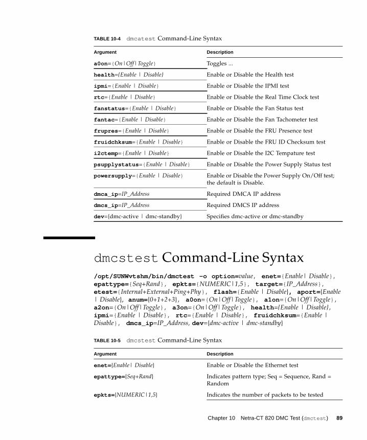
dmcstest Command-Line Syntax
/opt/SUNWvtshm/bin/dmctest -o option= value, enet= { Enable| Disable},epattype= { Seq+Rand}, epkts= { NUMERIC|1,5}, target= { IP_Address},etest= { Internal+External+Ping+Phy}, flash= { Enable | Disable}, aport= {Enable| Disable}, anum={0+1+2+3}, a0on ={ On|Off|Toggle}, a1on ={ On|Off|Toggle},a2on ={ On|Off|Toggle}, a3on ={ On|Off|Toggle}, health ={Enable | Disable},ipmi ={ Enable | Disable}, rtc ={ Enable | Disable}, fruidchksum ={ Enable |Disable}, dmcs_ip =IP_Address, dev ={dmc-active | dmc-standby}
a0on ={ On|Off|Toggle} Toggles ...
health ={Enable | Disable} Enable or Disable the Health test
ipmi ={ Enable | Disable} Enable or Disable the IPMI test
rtc ={ Enable | Disable} Enable or Disable the Real Time Clock test
fanstatus ={ Enable | Disable} Enable or Disable the Fan Status test
fantac ={ Enable | Disable} Enable or Disable the Fan Tachometer test
frupres ={ Enable | Disable} Enable or Disable the FRU Presence test
fruidchksum ={ Enable | Disable} Enable or Disable the FRU ID Checksum test
i2ctemp ={ Enable | Disable} Enable or Disable the I2C Tempature test
psupplystatus ={ Enable | Disable} Enable or Disable the Power Supply Status test
powersupply ={ Enable | Disable} Enable or Disable the Power Supply On/Off test;
the default is Disable.
dmca_ip =IP_Address Required DMCA IP address
dmcs_ip =IP_Address Required DMCS IP address
dev ={dmc-active | dmc-standby} Specifies dmc-active or dmc-standby
TABLE 10-5 dmcstest Command-Line Syntax
Argument Description
enet= {Enable| Disable} Enable or Disable the Ethernet test
epattype= {Seq+Rand} Indicates pattern type; Seq = Sequence, Rand =
Random
epkts= {NUMERIC|1,5} Indicates the number of packets to be tested
TABLE 10-4 dmcatest Command-Line Syntax
Argument Description
Chapter 10 Netra-CT 820 DMC Test (dmctest ) 89
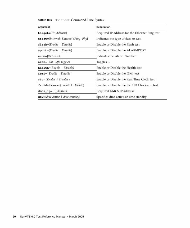
target= {IP_Address} Required IP address for the Ethernet Ping test
etest= {Internal+External+Ping+Phy} Indicates the type of data to test
flash= {Enable | Disable} Enable or Disable the Flash test
aport= {Enable | Disable} Enable or Disable the ALARMPORT
anum={0+1+2+3} Indicates the Alarm Number
a0on ={ On|Off|Toggle} Toggles ...
health ={Enable | Disable} Enable or Disable the Health test
ipmi ={ Enable | Disable} Enable or Disable the IPMI test
rtc ={ Enable | Disable} Enable or Disable the Real Time Clock test
fruidchksum ={ Enable | Disable} Enable or Disable the FRU ID Checksum test
dmcs_ip =IP_Address Required DMCS IP address
dev ={dmc-active | dmc-standby} Specifies dmc-active or dmc-standby
TABLE 10-5 dmcstest Command-Line Syntax
Argument Description
90 SunVTS 6.0 Test Reference Manual • March 2005
CHAPTER 11
Sun Fire™ V880 FC-AL DiskBackplane Test (dpmtest )
dpmtest exercises and verifies the Fibre-Channel Mass Storage Subsystem in Sun
Fire V880 product line platforms. dpmtest exercises various tests in the Fibre-
Channel Backplane firmware for validating the mass storage system.
No special hardware is required to run the dpmtest test.
dpmtest Options
To reach the dialog box below, right-click on the test name in the System Map and
select Test Parameter Options. If you do not see this test in the System Map, you
might need to expand the collapsed groups, or your system may not include the
device appropriate to this test. Refer to the SunVTS User’s Guide for more details.
91
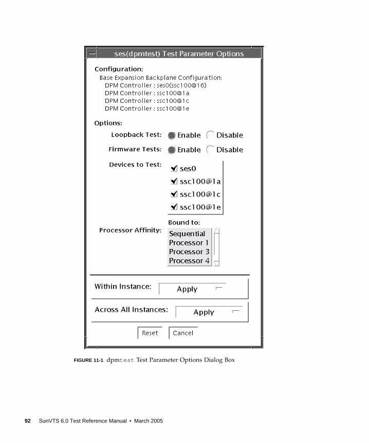
FIGURE 11-1 dpmtest Test Parameter Options Dialog Box
92 SunVTS 6.0 Test Reference Manual • March 2005
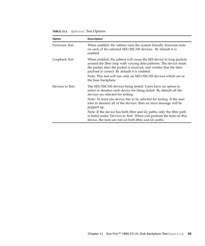
TABLE 11-1 dpmtest Test Options
Option Description
Firmware Test When enabled, the subtest runs the system friendly firmware tests
on each of the selected SES/SSC100 devices. By default it is
enabled.
Loopback Test When enabled, the subtest will cause the SES device to loop packets
around the fiber loop with varying data patterns. The device reads
the packet after the packet is received, and verifies that the data
payload is correct. By default it is enabled.
Note: This test will run only on SES/SSC100 devices which are in
the base backplane.
Devices to Test The SES/SSC100 devices being tested. Users have an option to
select or deselect each device for being tested. By default all the
devices are selected for testing.
Note: At least one device has to be selected for testing. If the user
tries to deselect all of the devices, then an error message will be
popped up.
Note: If the device has both fibre and i2c paths, only the fibre path
is listed under ’Devices to Test’. When you perform the tests on this
device, the tests are run on both fibre and i2c paths.
Chapter 11 Sun Fire™ V880 FC-AL Disk Backplane Test (dpmtest ) 93
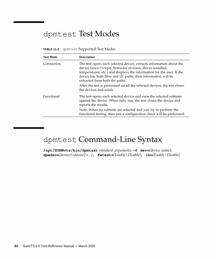
dpmtest Test Modes
dpmtest Command-Line Syntax
/opt/SUNWvts/bin/dpmtest standard_arguments -0 dev= [device name],dpmdev=[device1+device2+...], fwtest= [Enable|Disable], lb= [Enable|Disable]
TABLE 11-2 dpmtest Supported Test Modes
Test Mode Description
Connection The test opens each selected device, extracts information about the
device (wwn/wwpn, firmware revision, drives installed,
temperatures, etc.) and displays the information for the user. If the
device has both fibre and i2c paths, then information will be
extracted from both the paths.
After the test is performed on all the selected devices, the test closes
the devices and exists.
Functional The test opens each selected device and runs the selected subtests
against the device. When fully run, the test closes the device and
reports the results.
Note: When no subtests are selected and you try to perform the
functional testing, then just a configuration check will be performed.
94 SunVTS 6.0 Test Reference Manual • March 2005
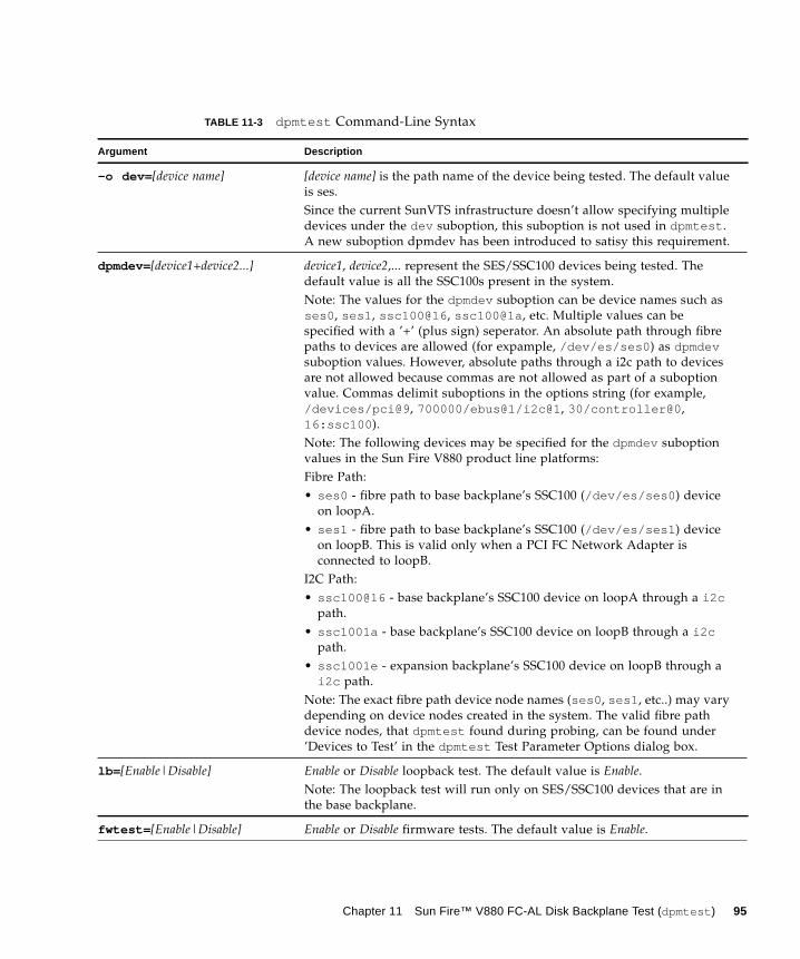
TABLE 11-3 dpmtest Command-Line Syntax
Argument Description
-o dev= [device name] [device name] is the path name of the device being tested. The default value
is ses.
Since the current SunVTS infrastructure doesn’t allow specifying multiple
devices under the dev suboption, this suboption is not used in dpmtest .
A new suboption dpmdev has been introduced to satisy this requirement.
dpmdev=[device1+device2...] device1, device2,... represent the SES/SSC100 devices being tested. The
default value is all the SSC100s present in the system.
Note: The values for the dpmdev suboption can be device names such as
ses0 , ses1 , ssc100@16 , ssc100@1a , etc. Multiple values can be
specified with a ’+’ (plus sign) seperator. An absolute path through fibre
paths to devices are allowed (for expample, /dev/es/ses0 ) as dpmdevsuboption values. However, absolute paths through a i2c path to devices
are not allowed because commas are not allowed as part of a suboption
value. Commas delimit suboptions in the options string (for example,
/devices/pci@9 , 700000/ebus@1/i2c@1 , 30/controller@0 ,
16:ssc100 ).
Note: The following devices may be specified for the dpmdev suboption
values in the Sun Fire V880 product line platforms:
Fibre Path:
• ses0 - fibre path to base backplane’s SSC100 (/dev/es/ses0 ) device
on loopA.
• ses1 - fibre path to base backplane’s SSC100 (/dev/es/ses1 ) device
on loopB. This is valid only when a PCI FC Network Adapter is
connected to loopB.
I2C Path:
• ssc100@16 - base backplane’s SSC100 device on loopA through a i2cpath.
• ssc1001a - base backplane’s SSC100 device on loopB through a i2cpath.
• ssc1001e - expansion backplane’s SSC100 device on loopB through a
i2c path.
Note: The exact fibre path device node names (ses0 , ses1 , etc..) may vary
depending on device nodes created in the system. The valid fibre path
device nodes, that dpmtest found during probing, can be found under
’Devices to Test’ in the dpmtest Test Parameter Options dialog box.
lb= [Enable|Disable] Enable or Disable loopback test. The default value is Enable.
Note: The loopback test will run only on SES/SSC100 devices that are in
the base backplane.
fwtest= [Enable|Disable] Enable or Disable firmware tests. The default value is Enable.
Chapter 11 Sun Fire™ V880 FC-AL Disk Backplane Test (dpmtest ) 95

96 SunVTS 6.0 Test Reference Manual • March 2005
CHAPTER 12
Data Translation Look-aside Buffer(dtlbtest )
The dtlbtest verifies the proper functioning of DTLBs, but it does not measure
performance of DTLBs.
Note – dtlbtest does support x86 platforms on Solaris.
This test verifies the following function of DTLBs:
1. Hit/miss tests: Stress DTLBs by generating large numbers of TLB hits and misses.
2. Address Pattern tests: Verify DTLBs correctly translate virtual addresses to
physical addresses with stressful address patterns.
dtlbtest detects the installed CPU type and handles it’s architectures in full
extent.
dtlbtest is classified as an exclusive SunVTS test as its accuracy and coverage
depends significantly on the system’s background quietness. For the best result,
avoid performing any other SunVTS tests in the background, and also disable all
user processes and nonessential daemons.
97
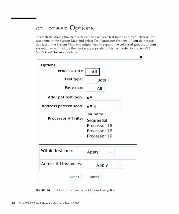
dtlbtest Options
To reach the dialog box below, select the exclusive test mode and right-click on the
test name in the System Map and select Test Parameter Options. If you do not see
this test in the System Map, you might need to expand the collapsed groups, or your
system may not include the device appropriate to this test. Refer to the SunVTSUser’s Guide for more details.
FIGURE 12-1 dtlbtest Test Parameter Options Dialog Box
98 SunVTS 6.0 Test Reference Manual • March 2005
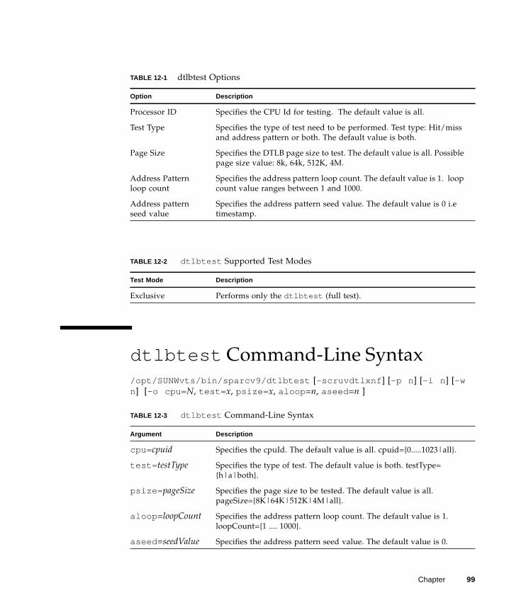
dtlbtest Command-Line Syntax
/opt/SUNWvts/bin/sparcv9/dtlbtest [-scruvdtlxnf ] [-p n ] [-i n ] [-wn] [-o cpu= N, test= x, psize= x, aloop =n, aseed =n ]
TABLE 12-1 dtlbtest Options
Option Description
Processor ID Specifies the CPU Id for testing. The default value is all.
Test Type Specifies the type of test need to be performed. Test type: Hit/miss
and address pattern or both. The default value is both.
Page Size Specifies the DTLB page size to test. The default value is all. Possible
page size value: 8k, 64k, 512K, 4M.
Address Pattern
loop count
Specifies the address pattern loop count. The default value is 1. loop
count value ranges between 1 and 1000.
Address pattern
seed value
Specifies the address pattern seed value. The default value is 0 i.e
timestamp.
TABLE 12-2 dtlbtest Supported Test Modes
Test Mode Description
Exclusive Performs only the dtlbtest (full test).
TABLE 12-3 dtlbtest Command-Line Syntax
Argument Description
cpu= cpuid Specifies the cpuId. The default value is all. cpuid={0.....1023|all}.
test= testType Specifies the type of test. The default value is both. testType=
{h|a|both}.
psize= pageSize Specifies the page size to be tested. The default value is all.
pageSize={8K|64K|512K|4M|all}.
aloop =loopCount Specifies the address pattern loop count. The default value is 1.
loopCount={1 .... 1000}.
aseed =seedValue Specifies the address pattern seed value. The default value is 0.
Chapter 99

100 SunVTS 6.0 Test Reference Manual • March 2005

CHAPTER 13
Environmental Test (envtest )
envtest exercises the I2C bus on the Sun Enterprise™ 450 product line. envtestcontains five subtests to test and report on the power supply status, system
temperature status, fan speed, disk LEDs, and front panel and keyswitch.
envtest is not scalable.
Note – Do not run envtest while the system is under a heavy load or false failures
may be reported.
envtest Options
To reach the dialog box below, right-click on the test name in the System Map and
select Test Parameter Options. If you do not see this test in the System Map, you
might need to expand the collapsed groups, or your system may not include the
device appropriate to this test. Refer to the SunVTS User’s Guide for more details.
101
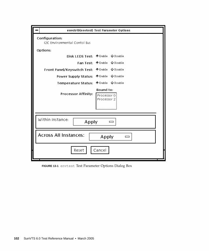
FIGURE 13-1 envtest Test Parameter Options Dialog Box
102 SunVTS 6.0 Test Reference Manual • March 2005
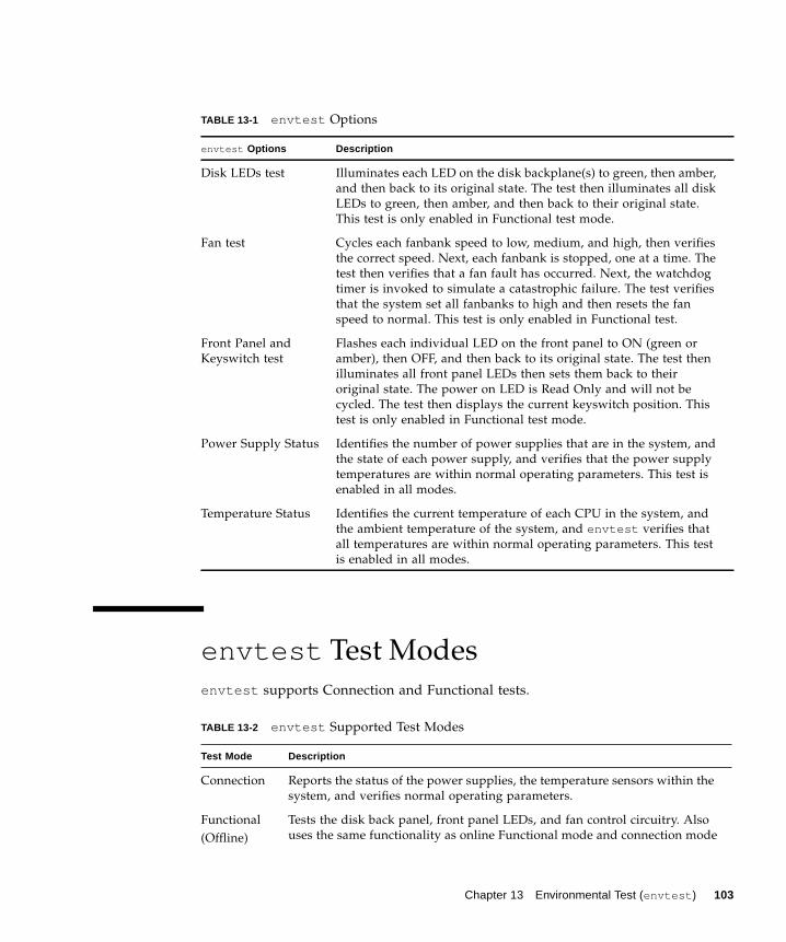
envtest Test Modes
envtest supports Connection and Functional tests.
TABLE 13-1 envtest Options
envtest Options Description
Disk LEDs test Illuminates each LED on the disk backplane(s) to green, then amber,
and then back to its original state. The test then illuminates all disk
LEDs to green, then amber, and then back to their original state.
This test is only enabled in Functional test mode.
Fan test Cycles each fanbank speed to low, medium, and high, then verifies
the correct speed. Next, each fanbank is stopped, one at a time. The
test then verifies that a fan fault has occurred. Next, the watchdog
timer is invoked to simulate a catastrophic failure. The test verifies
that the system set all fanbanks to high and then resets the fan
speed to normal. This test is only enabled in Functional test.
Front Panel and
Keyswitch test
Flashes each individual LED on the front panel to ON (green or
amber), then OFF, and then back to its original state. The test then
illuminates all front panel LEDs then sets them back to their
original state. The power on LED is Read Only and will not be
cycled. The test then displays the current keyswitch position. This
test is only enabled in Functional test mode.
Power Supply Status Identifies the number of power supplies that are in the system, and
the state of each power supply, and verifies that the power supply
temperatures are within normal operating parameters. This test is
enabled in all modes.
Temperature Status Identifies the current temperature of each CPU in the system, and
the ambient temperature of the system, and envtest verifies that
all temperatures are within normal operating parameters. This test
is enabled in all modes.
TABLE 13-2 envtest Supported Test Modes
Test Mode Description
Connection Reports the status of the power supplies, the temperature sensors within the
system, and verifies normal operating parameters.
Functional
(Offline)
Tests the disk back panel, front panel LEDs, and fan control circuitry. Also
uses the same functionality as online Functional mode and connection mode
Chapter 13 Environmental Test (envtest ) 103
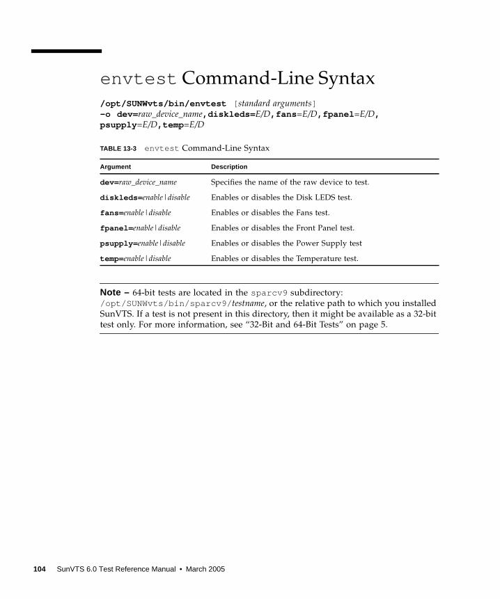
envtest Command-Line Syntax
/opt/SUNWvts/bin/envtest [ standard arguments]-o dev= raw_device_name,diskleds= E/D,fans =E/D,fpanel =E/D,psupply =E/D,temp =E/D
Note – 64-bit tests are located in the sparcv9 subdirectory:
/opt/SUNWvts/bin/sparcv9/ testname, or the relative path to which you installed
SunVTS. If a test is not present in this directory, then it might be available as a 32-bit
test only. For more information, see “32-Bit and 64-Bit Tests” on page 5.
TABLE 13-3 envtest Command-Line Syntax
Argument Description
dev= raw_device_name Specifies the name of the raw device to test.
diskleds= enable|disable Enables or disables the Disk LEDS test.
fans= enable|disable Enables or disables the Fans test.
fpanel= enable|disable Enables or disables the Front Panel test.
psupply= enable|disable Enables or disables the Power Supply test
temp= enable|disable Enables or disables the Temperature test.
104 SunVTS 6.0 Test Reference Manual • March 2005

CHAPTER 14
Environmental Test (env2test )
env2test exercises and validates the I2C bus on the Sun Enterprise 250 systems.
Five subtests in env2test test and report the status of the power supply, system
temperature, fan speed, disk LEDs, front panel, and keyswitch.
env2test is not scalable.
Note – Do not run env2test while the system is under a heavy load or false
failures may be reported.
env2test Options
To reach the dialog box below, right-click on the test name in the System Map and
select Test Parameter Options. If you do not see this test in the System Map, you
might need to expand the collapsed groups, or your system may not include the
device appropriate to this test. Refer to the SunVTS User’s Guide for more details.
105
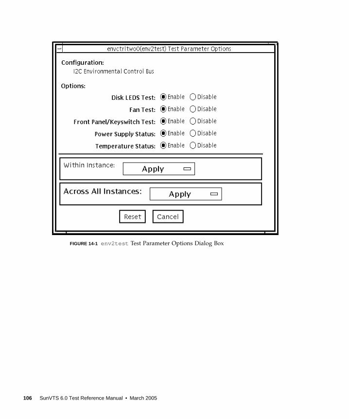
FIGURE 14-1 env2test Test Parameter Options Dialog Box
106 SunVTS 6.0 Test Reference Manual • March 2005
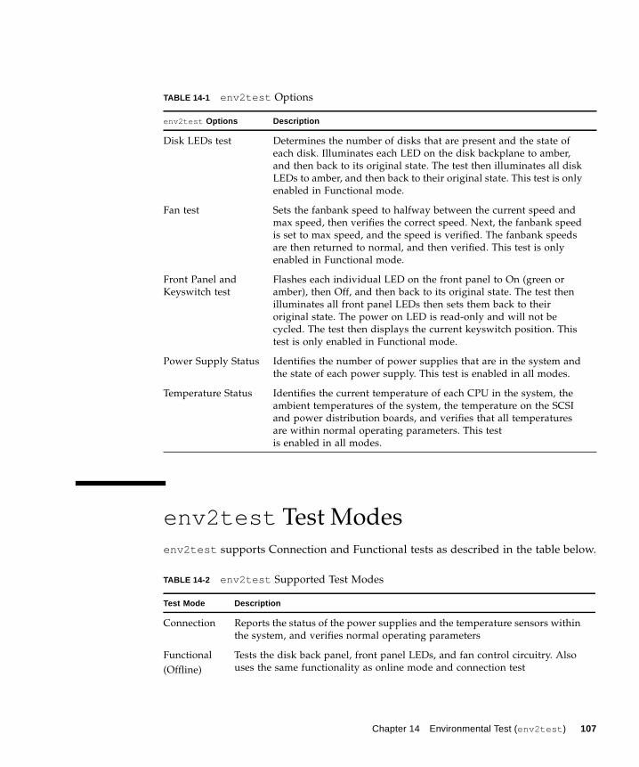
env2test Test Modes
env2test supports Connection and Functional tests as described in the table below.
TABLE 14-1 env2test Options
env2test Options Description
Disk LEDs test Determines the number of disks that are present and the state of
each disk. Illuminates each LED on the disk backplane to amber,
and then back to its original state. The test then illuminates all disk
LEDs to amber, and then back to their original state. This test is only
enabled in Functional mode.
Fan test Sets the fanbank speed to halfway between the current speed and
max speed, then verifies the correct speed. Next, the fanbank speed
is set to max speed, and the speed is verified. The fanbank speeds
are then returned to normal, and then verified. This test is only
enabled in Functional mode.
Front Panel and
Keyswitch test
Flashes each individual LED on the front panel to On (green or
amber), then Off, and then back to its original state. The test then
illuminates all front panel LEDs then sets them back to their
original state. The power on LED is read-only and will not be
cycled. The test then displays the current keyswitch position. This
test is only enabled in Functional mode.
Power Supply Status Identifies the number of power supplies that are in the system and
the state of each power supply. This test is enabled in all modes.
Temperature Status Identifies the current temperature of each CPU in the system, the
ambient temperatures of the system, the temperature on the SCSI
and power distribution boards, and verifies that all temperatures
are within normal operating parameters. This test
is enabled in all modes.
TABLE 14-2 env2test Supported Test Modes
Test Mode Description
Connection Reports the status of the power supplies and the temperature sensors within
the system, and verifies normal operating parameters
Functional
(Offline)
Tests the disk back panel, front panel LEDs, and fan control circuitry. Also
uses the same functionality as online mode and connection test
Chapter 14 Environmental Test (env2test ) 107
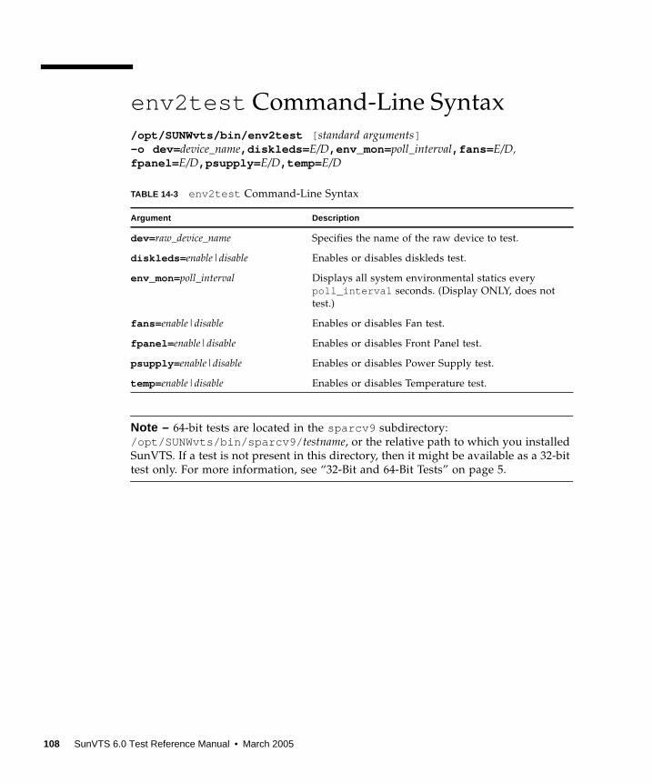
env2test Command-Line Syntax
/opt/SUNWvts/bin/env2test [ standard arguments]-o dev= device_name,diskleds= E/D,env_mon= poll_interval,fans= E/D,fpanel= E/D,psupply= E/D,temp= E/D
Note – 64-bit tests are located in the sparcv9 subdirectory:
/opt/SUNWvts/bin/sparcv9/ testname, or the relative path to which you installed
SunVTS. If a test is not present in this directory, then it might be available as a 32-bit
test only. For more information, see “32-Bit and 64-Bit Tests” on page 5.
TABLE 14-3 env2test Command-Line Syntax
Argument Description
dev= raw_device_name Specifies the name of the raw device to test.
diskleds= enable|disable Enables or disables diskleds test.
env_mon=poll_interval Displays all system environmental statics every
poll_interval seconds. (Display ONLY, does not
test.)
fans= enable|disable Enables or disables Fan test.
fpanel= enable|disable Enables or disables Front Panel test.
psupply= enable|disable Enables or disables Power Supply test.
temp= enable|disable Enables or disables Temperature test.
108 SunVTS 6.0 Test Reference Manual • March 2005
CHAPTER 15
Environmental Test (env3test )
env3test is an environmental control test for the Sun Blade 1000/2000, Sun Blade
100/150 and Sun Blade 1500/2500 workstation systems. Althought the central
function of this test is regarding environmentals and hence common to all the
platforms mentioned above, the exact behavior of the test is platform specific.
For Sun Blade 100/150 and 1000/2000, the test monitors the system by reading
temperatures and fan speeds, as well as their limits. It reports whether the
temperatures and fan speeds fall within system environmental condition limits. The
MAX1617 temperature sensor keeps a set of hard limits for the maximum and
minimum temperatures allowed within the system. If the temperature passes one of
these limits, the system performs a hard shutdown to protect hardware components.
env3test also checks against the environmental monitor daemon, which keeps its
own limits. By reading these temperature values, the test reports the possibility of a
failure of the system environmental feedback loop between the fans and the
temperature sensors.
For Sun Blade 1500 and 2500, the test displays the temperature sensors and
temperatures, and all the fans and their speeds in RPM. It has an option for logging
this information. The test will fail if one or more fans are bad(don’t spin), are
disconnected or are weak. An appropriate error message will indicate a
disconnected/bad case against a weak fan case.
For SunBlade 1500 and 2500, the env3test supports the exclusive mode and
connectivity mode testing.
Note – (Sun Blade 100/150, 1000/2000) - If env3test fails to register temperature
values, the system temperature indicators may be faulty.
109
Note – (Sun Blade 1500/2500) - env3test will fail if a fan is bad or is disconnected or
if it is weak. Please check corresponding error message for the exact case. For
SunBlade 1500, the outtake-fan rpm cannot be monitored due to hardware
limitation.
Note – (Sun Blade 100/150, 1000/2000) - env3test will not run on operating
environments earlier than the Solaris 8 10/00 operating environment.
env3test Options
To reach the dialog box below, right-click on the test name in the System Map and
select Test Parameter Options. If you do not see this test in the System Map, you
might need to expand the collapsed groups, or your system may not include the
device appropriate to this test. Refer to the SunVTS User’s Guide for more details.
110 SunVTS 6.0 Test Reference Manual • March 2005
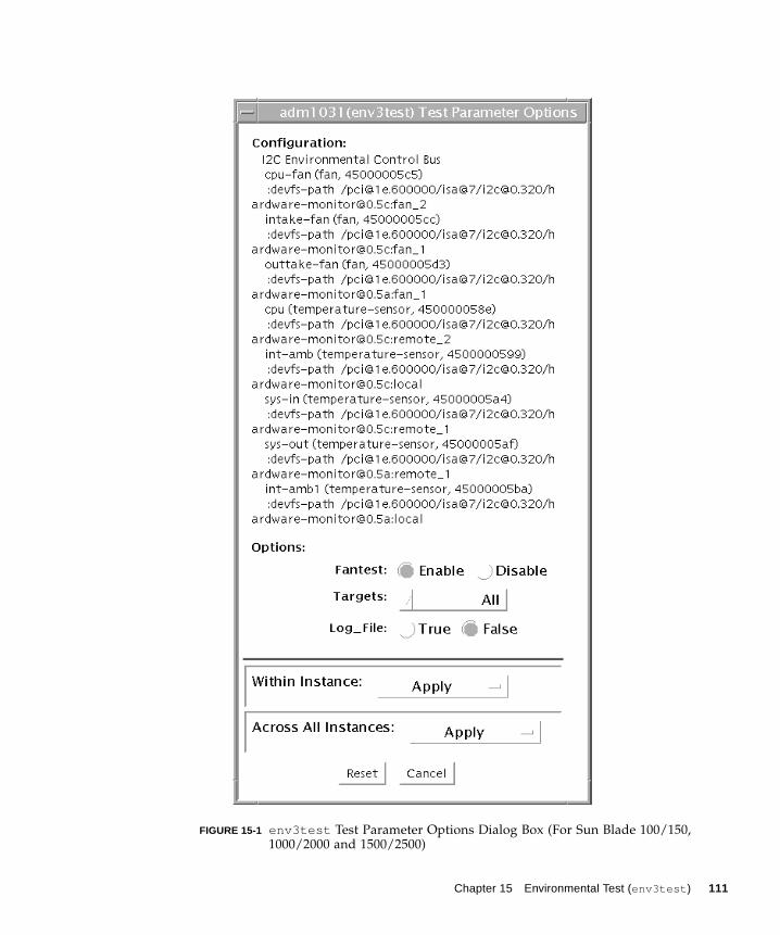
FIGURE 15-1 env3test Test Parameter Options Dialog Box (For Sun Blade 100/150,1000/2000 and 1500/2500)
Chapter 15 Environmental Test (env3test ) 111
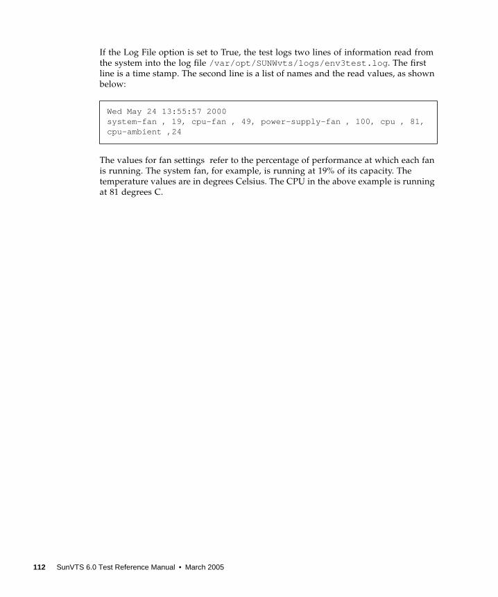
If the Log File option is set to True, the test logs two lines of information read from
the system into the log file /var/opt/SUNWvts/logs/env3test.log . The first
line is a time stamp. The second line is a list of names and the read values, as shown
below:
The values for fan settings refer to the percentage of performance at which each fan
is running. The system fan, for example, is running at 19% of its capacity. The
temperature values are in degrees Celsius. The CPU in the above example is running
at 81 degrees C.
Wed May 24 13:55:57 2000system-fan , 19, cpu-fan , 49, power-supply-fan , 100, cpu , 81,cpu-ambient ,24
112 SunVTS 6.0 Test Reference Manual • March 2005
env3test Test Modes
env3test Command-Line Syntax
/opt/SUNWvts/bin/env3test [ standard arguments] -o dev= driver_name,logging= true|false, fantest =enable, fan =All/intake-fan+outtake-fan
Note – 64-bit tests are located in the sparcv9 subdirectory:
/opt/SUNWvts/bin/sparcv9/ testname, or the relative path to which you installed
SunVTS. If a test is not present in this directory, then it might be available as a 32-bit
test only. For more information, see “32-Bit and 64-Bit Tests” on page 5.
TABLE 15-1 env3test Supported Test Modes
Test Mode Description
Connection Attempts connection to the device. Supported on SB1500/SB2500 systems.
Functional Reports the received information to the GUI logging window in verbose
mode. Supported on SB150/SB1000 systems.
Exclusive Reports the received information to the GUI logging window in verbose
mode. Supported on SB1500/SB2500 systems.
TABLE 15-2 env3test Command-Line Syntax
Argument Description
dev= driver_name Specifies the driver name for this test. The driver for the
Sun Blade 1000 is max1617 .
logging= true|false Enables or disables the logging feature.
fantest =enable Enable fan test.
fan =All/intake-fan+outtake-fan Specifies fan to be tested (i.e. cpu-fan, intake-fan, outtake-
fan).
The keyword "All" specifies all the fan env3test probe
found.
Chapter 15 Environmental Test (env3test ) 113

114 SunVTS 6.0 Test Reference Manual • March 2005
CHAPTER 16
Environmental Test (env5test )
env5test exercises and validates the environmental subsytems of the Sunfire 280R
product line. This test contains subtests to exercise a system’s fans, keyswitch, LEDs,
power supplies and temperature sensors.
This test is not scalable.
Note – Only the 64-bit version of this test is supported.
env5test Test Requirements■ You must install the SUNWpiclh , SUNWpiclr , SUNWpiclu , and SUNWpiclx picl
packages correctly before running env5test .
■ Verify that the picld daemon is running by typing the following:
If the daemon is not running, run the script to restart it by typing the following:
# ps -ef |grep picldroot 100077 1 0 Sep 11 ? 23:40 /usr/lib/picl/picld
# /etc/init.d/picld start
115
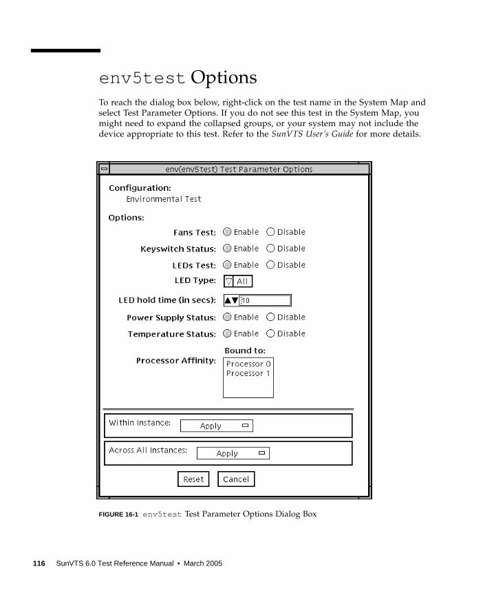
env5test Options
To reach the dialog box below, right-click on the test name in the System Map and
select Test Parameter Options. If you do not see this test in the System Map, you
might need to expand the collapsed groups, or your system may not include the
device appropriate to this test. Refer to the SunVTS User’s Guide for more details.
FIGURE 16-1 env5test Test Parameter Options Dialog Box
116 SunVTS 6.0 Test Reference Manual • March 2005
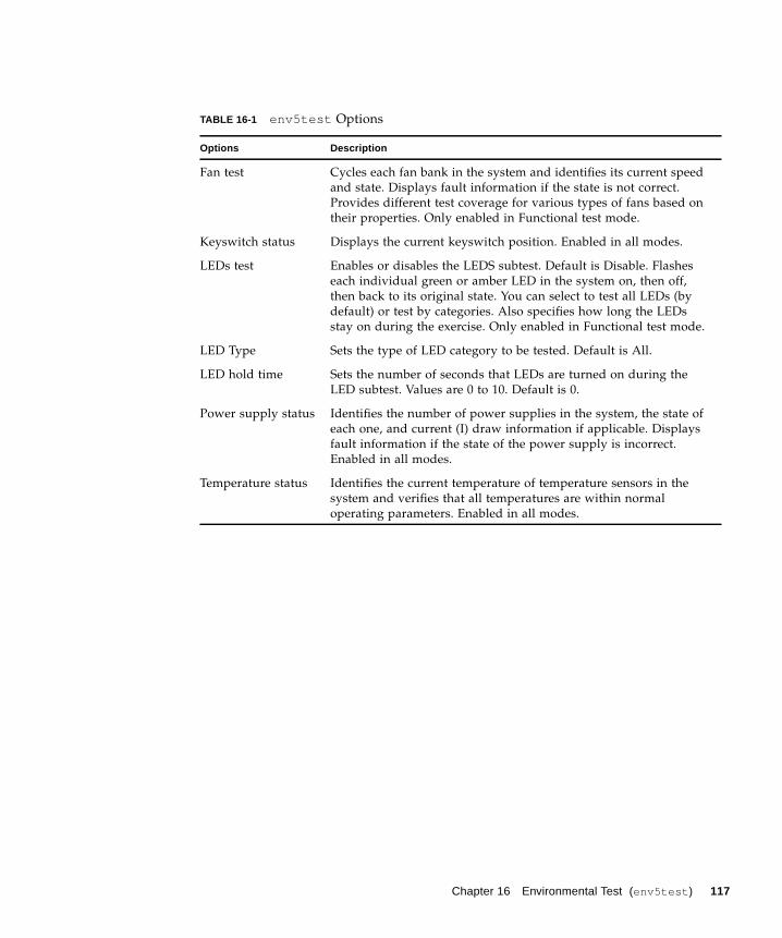
TABLE 16-1 env5test Options
Options Description
Fan test Cycles each fan bank in the system and identifies its current speed
and state. Displays fault information if the state is not correct.
Provides different test coverage for various types of fans based on
their properties. Only enabled in Functional test mode.
Keyswitch status Displays the current keyswitch position. Enabled in all modes.
LEDs test Enables or disables the LEDS subtest. Default is Disable. Flashes
each individual green or amber LED in the system on, then off,
then back to its original state. You can select to test all LEDs (by
default) or test by categories. Also specifies how long the LEDs
stay on during the exercise. Only enabled in Functional test mode.
LED Type Sets the type of LED category to be tested. Default is All.
LED hold time Sets the number of seconds that LEDs are turned on during the
LED subtest. Values are 0 to 10. Default is 0.
Power supply status Identifies the number of power supplies in the system, the state of
each one, and current (I) draw information if applicable. Displays
fault information if the state of the power supply is incorrect.
Enabled in all modes.
Temperature status Identifies the current temperature of temperature sensors in the
system and verifies that all temperatures are within normal
operating parameters. Enabled in all modes.
Chapter 16 Environmental Test (env5test ) 117
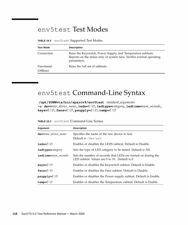
env5test Test Modes
env5test Command-Line Syntax
/opt/SUNWvts/bin/sparcv9/env5test standard_arguments-o dev= raw_device_name,leds= E|D,ledtype= category,ledtime= num_seconds,keys= E|D,fans= E|D,psupply= E|D,temp= E|D
TABLE 16-2 env5test Supported Test Modes
Test Mode Description
Connection Runs the Keyswitch, Power Supply, and Temperature subtests.
Reports on the status only of system fans. Verifies normal operating
parameters.
Functional
(Offline)
Runs the full set of subtests.
TABLE 16-3 env5test Command-Line Syntax
Argument Description
dev= raw_device_name Specifies the name of the raw device to test.
Default is /dev/env
leds= E|D Enables or disables the LEDS subtest. Default is Disable.
ledtype= category Sets the type of LED category to be tested. Default is All.
ledtime= num_seconds Sets the number of seconds that LEDs are turned on during the
LED subtest. Values are 0 to 10. Default is 0.
keys= E|D Enables or disables the Keyswitch subtest. Default is Enable.
fans= E|D Enables or disables the Fans subtest. Default is Disable.
psupply= E|D Enables or disables the Power supply subtest. Default is Enable.
temp= E|D Enables or disables the Temperature subtest. Default is Enable.
118 SunVTS 6.0 Test Reference Manual • March 2005
CHAPTER 17
Environmental Test (env6test )
env6test exercises and validates environmental subsytems. This test contains
subtests to exercise a system’s fans, keyswitch, LEDs, power supplies, and
temperature sensors.
This test is not scalable.
env6test Options
To reach the dialog box below, right-click on the test name in the System Map and
select Test Parameter Options. If you do not see this test in the System Map, you
might need to expand the collapsed groups, or your system may not include the
device appropriate to this test. Refer to the SunVTS User’s Guide for more details.
119

FIGURE 17-1 env6test Test Parameter Options Dialog Box
TABLE 17-1 env6test Options
env6test Options Description
Fan Test Checks the status, tolerance, and speed of the system’s fans. Default
is Disable.
LED Test Checks overall status of system’s LEDs by switching them ON and
OFF. Default is Disable.
120 SunVTS 6.0 Test Reference Manual • March 2005

env6test Test Modes
env6test Command-Line Syntax
/opt/SUNWvts/bin/env6test standard_arguments-o dev= raw_device_name,led= Enable|Disable,fan= Enable|Disable
Note – 64-bit tests are located in the sparcv9 subdirectory:
/opt/SUNWvts/bin/sparcv9/ testname, or the relative path to which you installed
SunVTS. If a test is not present in this directory, then it might be available as a 32-bit
test only. For more information, see “32-Bit and 64-Bit Tests” on page 5.
TABLE 17-2 env6test Supported Test Modes
Test Mode Description
Connection Reports current state of devices.
Exclusive Performs all tests including the Fan and LED subtests if they are
enabled.
TABLE 17-3 env6test Command-Line Syntax
Argument Description
dev= raw_device_name Specifies the name of the raw device to test.
Default is /dev/env
led= Enable|Disable Enables or disables the LEDS subtest. Default is Disable.
fan= Enable|Disable Enables or disables the Fans subtest. Default is Disable.
Chapter 17 Environmental Test (env6test ) 121

122 SunVTS 6.0 Test Reference Manual • March 2005

CHAPTER 18
Floating Point Unit Test (fputest )
The fputest checks the functionality of the floating point unit in a Sun SPARC
based CPU. The test verifies the functionality by various arithmetic operations. In
addition, the fputest stresses the CPU with the use of benchmarks. Both single and
double precision numbers are used for the operations.
Note – fputest does support x86 platforms on Solaris.
Note – Three benchmarks of fputest —cparanoia , kcdiv , and kcsqrt —have
been ported over for x86 systems. The x86 version of fputest only uses the Double
Precision operations for rounding, chopping, sticky bit, and so on.
When fputest is chosen in Exclusive test mode from the SunVTS graphical user
interface, it may run multiple instances in parallel on different CPUs. The number of
such instances that may be running in parallel at the same time is dynamically
determined depending on system resources.
fputest Subtests
Instruction tests:
■ FSR Register test
■ Registers test
■ NACK test
■ Move Registers test
■ Positive to Negative test
■ Negative to Positive test
■ Absolute test
■ Single-Precision Integer to Floating Point test
123
■ Double-Precision Integer to Floating Point test
■ Single-Precision Floating Point to Integer test
■ Double-Precision Floating Point to Integer test
■ Single-Precision Round Toward Zero test
■ Double-Precision Round Toward Zero test
■ Single to Double-Precision Format Conversion test
■ Double to Single-Precision Format Conversion test
■ Single and Double-Precision Addition, Subtraction, Multiplication, Square-root,
Division, and Compare tests
■ Single and Double-Precision Compare and Exception if Unordered tests
■ Branching and No Branching on Condition Instructions tests
■ Single and Double-Precision Chaining tests
■ Weitek Status tests
■ Lock test
■ Single and Double-Precision Datapath tests
■ Timing (load) test
Benchmark tests:
■ Linpack test
■ Cparanoia test
■ Kcsqrt test
■ Kcdiv test
■ Clorenz test
■ Cvector test
fputest Options
To reach the dialog box below, right-click on the test name in the System Map and
select Test Parameter Options. If you do not see this test in the System Map, you
might need to expand the collapsed groups, or your system may not include the
device appropriate to this test. Refer to the SunVTS User’s Guide for more details.
124 SunVTS 6.0 Test Reference Manual • March 2005
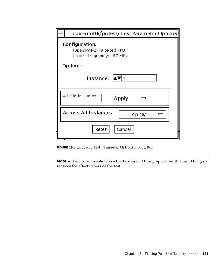
FIGURE 18-1 fputest Test Parameter Options Dialog Box
Note – It is not advisable to use the Processor Affinity option for this test. Doing so
reduces the effectiveness of the test.
Chapter 18 Floating Point Unit Test (fputest ) 125

fputest Test Modes
fputest Command-Line Syntax
/opt/SUNWvts/bin/fputest [-scruvdtlxnf ] [-p n ] [-i n ] [-w n ] [-o dev=cpu-unit N]
Note – Options -s , -p , -i , and -w are not applicable when tests are invoked from
the command line.
TABLE 18-1 fputest Supported Test Modes
Test Mode Description
Connection Includes all the instruction tests.
Functional
(Offline)
Performs all the instruction tests and all the benchmark tests.
Stress mode Performs several fpu benchmark tests.
Online Supported
Exclusive Supported
TABLE 18-2 fputest Command-Line Syntax
Argument Description
-s Enables SunVTS mode
-c Enables core file
-r Enables run on error
-u Enables list usage
-v Enables verbose mode
-d Enables debug mode
-t Enables test function trace mode
-l Enables online mode
-x Enables exlusive mode
126 SunVTS 6.0 Test Reference Manual • March 2005
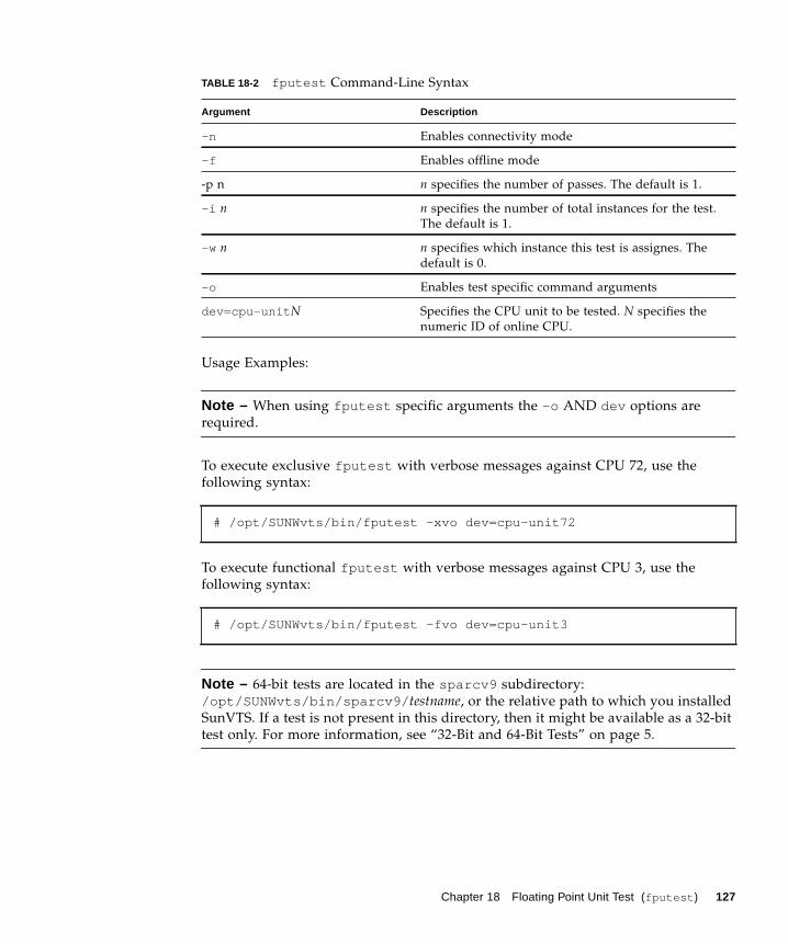
Usage Examples:
Note – When using fputest specific arguments the -o AND dev options are
required.
To execute exclusive fputest with verbose messages against CPU 72, use the
following syntax:
To execute functional fputest with verbose messages against CPU 3, use the
following syntax:
Note – 64-bit tests are located in the sparcv9 subdirectory:
/opt/SUNWvts/bin/sparcv9/ testname, or the relative path to which you installed
SunVTS. If a test is not present in this directory, then it might be available as a 32-bit
test only. For more information, see “32-Bit and 64-Bit Tests” on page 5.
-n Enables connectivity mode
-f Enables offline mode
-p n n specifies the number of passes. The default is 1.
-i n n specifies the number of total instances for the test.
The default is 1.
-w n n specifies which instance this test is assignes. The
default is 0.
-o Enables test specific command arguments
dev=cpu-unit N Specifies the CPU unit to be tested. N specifies the
numeric ID of online CPU.
# /opt/SUNWvts/bin/fputest -xvo dev=cpu-unit72
# /opt/SUNWvts/bin/fputest -fvo dev=cpu-unit3
TABLE 18-2 fputest Command-Line Syntax
Argument Description
Chapter 18 Floating Point Unit Test (fputest ) 127

128 SunVTS 6.0 Test Reference Manual • March 2005
CHAPTER 19
IEEE 1394 Camera Test(fwcamtest )
fwcamtest tests the parameters and display functions of an IEEE 1394 digital
camera, such as vid mode, frame rate, and frames received. This test currently
supports the LG PC-10 camera.
Note – Do not run the fwcamtest and vmemtest at the same time on any
Sun Blade™ system. This may cause the tests to fail.
Note – Do not start Sunforum™ (or any application that uses the dcam0 device)
while fwcamtest is running. This causes the test to fail.
fwcamtest Test Requirements
Start a Window Environment
The system that runs fwcamtest must already be running a window environment,
such as CDE. If the system has no window environment, or is only displaying the
login window, fwcamtest will neither pass nor fail.
Note – Your window system must be operating in 24-bit depth to run the display
test. Instructions for changing this setting are below.
129
If you are working in CDE, you can change your system to 24-bit depth by editing
the file /usr/dt/config/Xservers or /etc/dt/config/Xservers . The file
/etc/dt/config/Xservers overrides the file /usr/dt/config/Xservers . Edit
the appropriate file to include the following line:
Testing Through a Remote Connection
While running fwcamtest through a remote connection (such as a telnet session), if
the DISPLAY variable is not set properly, it will cause numerous warning messages
to display. These messages are logged and can fill up the log files. To avoid this, set
your DISPLAY variable for the local host, and perform xhost remote_host on the
local host before you start SunVTS and run fwcamtest .
fwcamtest Subtests
fwcamtest has three subtests:
■ Parameter Test—Tests the digital camera parameters such as vid mode and
brightness.
■ Framereceive Test—Initializes the vid mode, framerate and ring buffer capacity
parameters, then checks for the frame received.
■ Display Test—Displays the captured frames. This display test sets up the 1394 bus
for asynchronous transfer mode. The display test will only display the frames on
the host running the test; it cannot display on a remote host.
fwcamtest Options
To reach the dialog box below, right-click on the test name in the System Map and
select Test Parameter Options. If you do not see this test in the System Map, you
might need to expand the collapsed groups, or your system may not include the
device appropriate to this test. Refer to the SunVTS User’s Guide for more details.
:0 Local local_uid@console root /usr/openwin/bin/Xsun :0-nobanner -dev /dev/fbs/ffb0 defdepth 24 defclass TrueColor
130 SunVTS 6.0 Test Reference Manual • March 2005
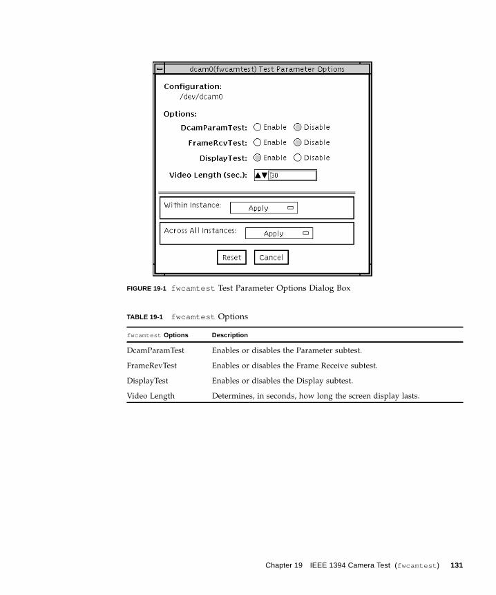
FIGURE 19-1 fwcamtest Test Parameter Options Dialog Box
TABLE 19-1 fwcamtest Options
fwcamtest Options Description
DcamParamTest Enables or disables the Parameter subtest.
FrameRevTest Enables or disables the Frame Receive subtest.
DisplayTest Enables or disables the Display subtest.
Video Length Determines, in seconds, how long the screen display lasts.
Chapter 19 IEEE 1394 Camera Test (fwcamtest ) 131
fwcamtest Test Modes
fwcamtest Command-Line Syntax
/opt/SUNWvts/bin/fwcamtest standard_arguments-o dev= dcam0,dcamparam= E(nable)|D(isable),framercv= E|D,display= E|D,T=seconds
Note – 64-bit tests are located in the sparcv9 subdirectory:
/opt/SUNWvts/bin/sparcv9/ testname, or the relative path to which you installed
SunVTS. If a test is not present in this directory, then it might be available as a 32-bit
test only. For more information, see “32-Bit and 64-Bit Tests” on page 5.
TABLE 19-2 fwcamtest Supported Test Modes
Test Mode Description
Functional
(Offline)
Runs the full set of tests.
TABLE 19-3 fwcamtest Command-Line Syntax
Argument Description
dev= dcam0 Specifies the device name for this test.
dcamparam= E(nable)|D(isable) Enables or disables the Parameter subtest.
framercv= E|D Enables or disables the Frame Receive subtest.
display= E|D Enables or disables the Display subtest.
T=seconds Specifies the time period of the display test in seconds.
132 SunVTS 6.0 Test Reference Manual • March 2005
CHAPTER 20
I2C Bus Test (i2ctest )
i2ctest checks each I2C bus for the status of its devices. i2ctest then determines
any device faults based on the information it collects, and displays a report.
i2ctest also detects and reports hung I2C bus segments.
This test is scalable.
Note – Only the 64-bit version of this test is supported.
i2ctest Test Requirements■ You must have the SUNWpiclh , SUNWpiclr , SUNWpiclu , and SUNWpiclx picl
packages installed correctly before running the test.
■ Verify that the picld daemon is running by typing the following:
If the daemon is not running, run the script to restart it by typing the following:
# ps -ef |grep picldroot 100077 1 0 Sep 11 ? 23:40 /usr/lib/picl/picld
# /etc/init.d/picld start
133
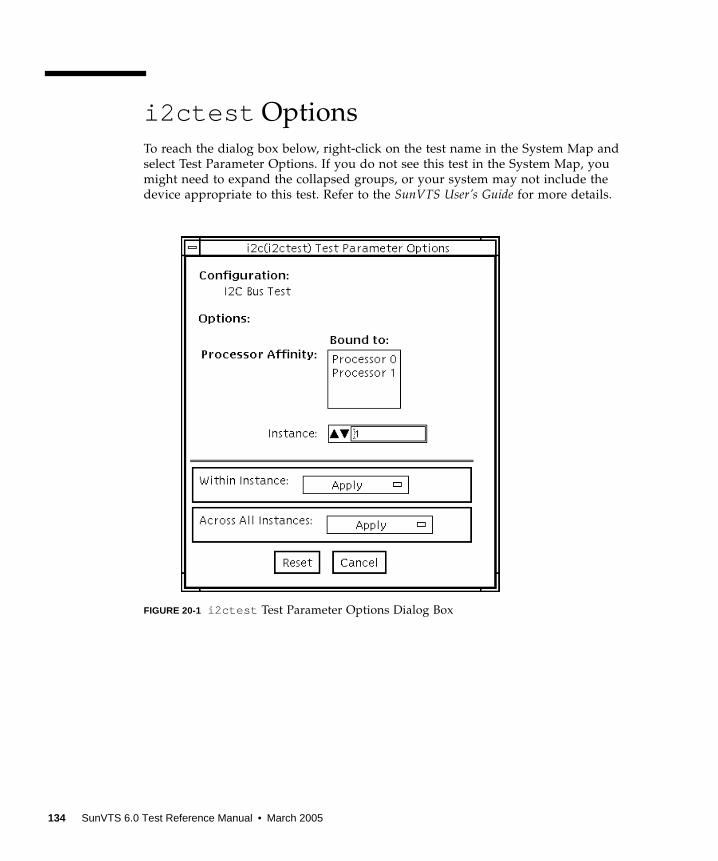
i2ctest Options
To reach the dialog box below, right-click on the test name in the System Map and
select Test Parameter Options. If you do not see this test in the System Map, you
might need to expand the collapsed groups, or your system may not include the
device appropriate to this test. Refer to the SunVTS User’s Guide for more details.
FIGURE 20-1 i2ctest Test Parameter Options Dialog Box
134 SunVTS 6.0 Test Reference Manual • March 2005

i2ctest Test Modes
i2ctest Command-Line Syntax
/opt/SUNWvts/bin/sparcv9/i2ctest standard_arguments-o dev= raw_device_name
TABLE 20-1 i2ctest Supported Test Modes
Test Mode Description
Connection Runs the full test.
Functional
(Offline)
Runs the full test.
TABLE 20-2 i2ctest Command-Line Syntax
Argument Description
dev= raw_device_name Specifies the name of the raw device to test.
Chapter 20 I2C Bus Test (i2ctest ) 135

136 SunVTS 6.0 Test Reference Manual • March 2005

CHAPTER 21
I2C Inter-Integrated Circuit Test(i2c2test )
The i2c2test is designed to verify the proper placement, operation, and data
integrity on the various I2C devices.
This test is not scalable.
i2c2test Options
To reach the dialog box below, right-click on the test name in the System Map and
select Test Parameter Options. If you do not see this test in the System Map, you
might need to expand the collapsed groups, or your system may not include the
device appropriate to this test. Refer to the SunVTS User’s Guide for more details.
137
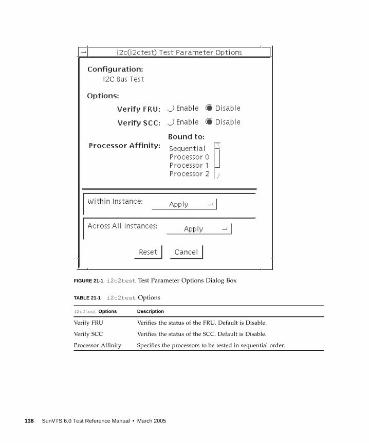
FIGURE 21-1 i2c2test Test Parameter Options Dialog Box
TABLE 21-1 i2c2test Options
i2c2test Options Description
Verify FRU Verifies the status of the FRU. Default is Disable.
Verify SCC Verifies the status of the SCC. Default is Disable.
Processor Affinity Specifies the processors to be tested in sequential order.
138 SunVTS 6.0 Test Reference Manual • March 2005
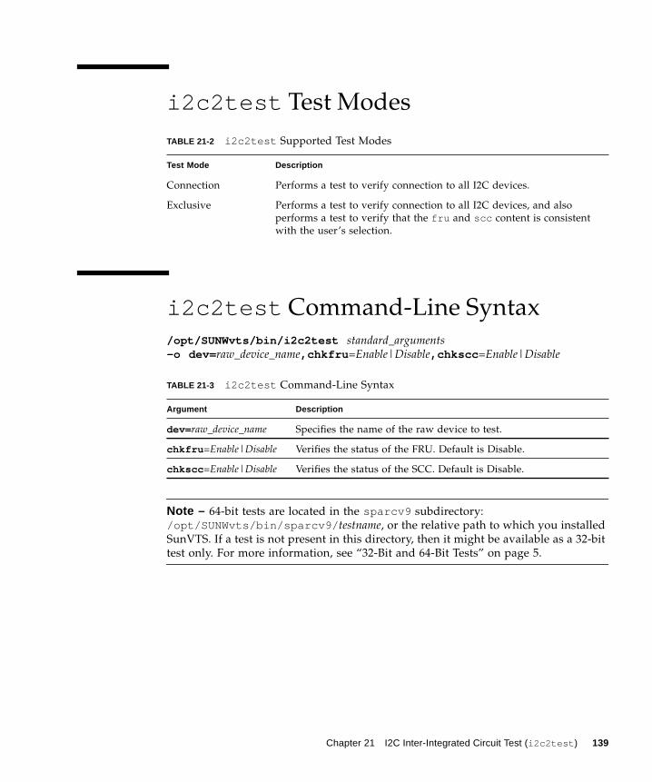
i2c2test Test Modes
i2c2test Command-Line Syntax
/opt/SUNWvts/bin/i2c2test standard_arguments-o dev= raw_device_name,chkfru =Enable|Disable,chkscc =Enable|Disable
Note – 64-bit tests are located in the sparcv9 subdirectory:
/opt/SUNWvts/bin/sparcv9/ testname, or the relative path to which you installed
SunVTS. If a test is not present in this directory, then it might be available as a 32-bit
test only. For more information, see “32-Bit and 64-Bit Tests” on page 5.
TABLE 21-2 i2c2test Supported Test Modes
Test Mode Description
Connection Performs a test to verify connection to all I2C devices.
Exclusive Performs a test to verify connection to all I2C devices, and also
performs a test to verify that the fru and scc content is consistent
with the user’s selection.
TABLE 21-3 i2c2test Command-Line Syntax
Argument Description
dev= raw_device_name Specifies the name of the raw device to test.
chkfru =Enable|Disable Verifies the status of the FRU. Default is Disable.
chkscc =Enable|Disable Verifies the status of the SCC. Default is Disable.
Chapter 21 I2C Inter-Integrated Circuit Test (i2c2test ) 139

140 SunVTS 6.0 Test Reference Manual • March 2005
CHAPTER 22
Expert3D Frame Buffer Test(ifbtest )
ifbtest verifies the functionality of the Expert3D frame buffer.
ifbtest can detect and adapt to many video modes of the Expert3D frame buffer.
All tests can run at a resolution of 1024x768 or higher.
You can interrupt ifbtest using Control-C.
Test accuracy is checked using direct image comparison against compressed images.
Failed pixel locations are printed as error messages.
Caution – Do not run any other application or screen saver program that uses the
Expert3D accelerator port while running ifbtest . This combination causes SunVTS
to return incorrect errors.
ifbtest Test Requirements
Disable all screen savers before testing any graphics device. To disable the Solaris
screen saver, type the following at a UNIX prompt:
To turn Power Management off, type the following at a UNIX prompt:
# xset s off
141
The display resolution must be 1024x768 or higher (the standard resolution). To
change resolution, go to a UNIX prompt and type:
For full instructions on testing frame buffers, see “Testing Frame Buffers” on page
10.
Preparation for ifbtest
You should complete a few steps in advance to ensure that ifbtest runs as
smoothly as possible.
If you are running ifbtest in a window system (such as CDE):
■ Turn Power Management off, if it is enabled. The following is an alternate way to
turn Power Management off. Change allowFBPM=1 to allowFBPM=0 in
/platform/sun4u/kernal/drv/ifb.conf file.
■ Make sure that no other program is running that might modify the screen during
the test.
■ Make sure you have permission to lock the X server. ifbtest is designed to lock
the X server during testing to prevent screen changes.
■ The CDE login window should not be displayed during testing.
■ Check that the window system is only running on one Expert3D frame buffer.
If you are not running ifbtest in a window system:
■ Turn Power Management off, if it is enabled. The following is an alternate way to
turn Power Management off. Change allowFBPM=1 to allowFBPM=0 in
/platform/sun4u/kernal/drv/ifb.conf file.
■ Make sure that no other program is running that might modify the screen during
the test.
■ Make sure the Expert3D frame buffer being tested is not the console device.
Console messages may modify the screen.
# xset -dpms
# fbconfig -res 1280x1024x76
142 SunVTS 6.0 Test Reference Manual • March 2005
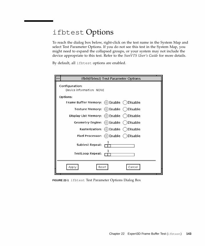
ifbtest Options
To reach the dialog box below, right-click on the test name in the System Map and
select Test Parameter Options. If you do not see this test in the System Map, you
might need to expand the collapsed groups, or your system may not include the
device appropriate to this test. Refer to the SunVTS User’s Guide for more details.
By default, all ifbtest options are enabled.
FIGURE 22-1 ifbtest Test Parameter Options Dialog Box
Chapter 22 Expert3D Frame Buffer Test (ifbtest ) 143

TABLE 22-1 ifbtest Options
ifbtest Options Description
Frame Buffer
Memory test
Thoroughly tests the Expert3D video memory by using read and
write requests. Tests for shorts or failed connections on the data bus
by writing the following values to every address:
• 0xFFFFFFFF
• 0xFFFF0000
• 0x0000FFFF
• 0xFF00FF00
• 0x00FF00FF
• 0xF0F0F0F0
• 0x0F0F0F0F
• 0xCCCCCCCC
• 0x33333333
• 0xAAAAAAAA
• 0x55555555
Tests for shorts or failed connections on the address bus by writing
the offset of each memory location to each location and reading
them back. This may also catch speed-related problems due to the
volume of read/writes.
Errors in the test are reported as an error in a particular address, not
attributed to a specific chip. To help distinguish bit-related errors,
the errors are summarized to list which bits had at least one error in
the test.
This test shows on the screen as random pixels.
Texture Memory test This test is identical in process to the frame buffer memory test
(above). Since this test produces no visible effect, rectangles are
drawn in rows across the screen to show progress.
Display List Memory
test
This test is identical in process to the frame buffer memory and
texture memory tests (above), and is applied to direct burst
memory.
This test takes little time and no progress is displayed.
Geometry Engine
test
Loads diagnostic microcode into the geometry engine and confirms
that the processor operates correctly. This is a pass/fail test.
This test takes little time and no progress is displayed.
144 SunVTS 6.0 Test Reference Manual • March 2005

Rasterization test Renders many primitives with minimal fragment processing, to test
the rasterization of the primitives.
The primitives used are:
• Dots
• Anti-aliased dots
• Lines using all for line-drawing primitives
• Anti-aliased lines using all for line-drawing primitives
• Triangles, Quads, and Polygons in point, line, and fill modes
• Rectangles
This tests for the following rasterization attributes:
• pixel coverage
• constant value registers for color, Z, and stencil
• interpolation of color, Z, and texture coordinates along lines and
spans in polygons
• texture map sampling
Resulting images are compared against stored images. Errors
indicate which operation type and value was being tested, and the
coordinate of the failed pixel.
TABLE 22-1 ifbtest Options
ifbtest Options Description
Chapter 22 Expert3D Frame Buffer Test (ifbtest ) 145
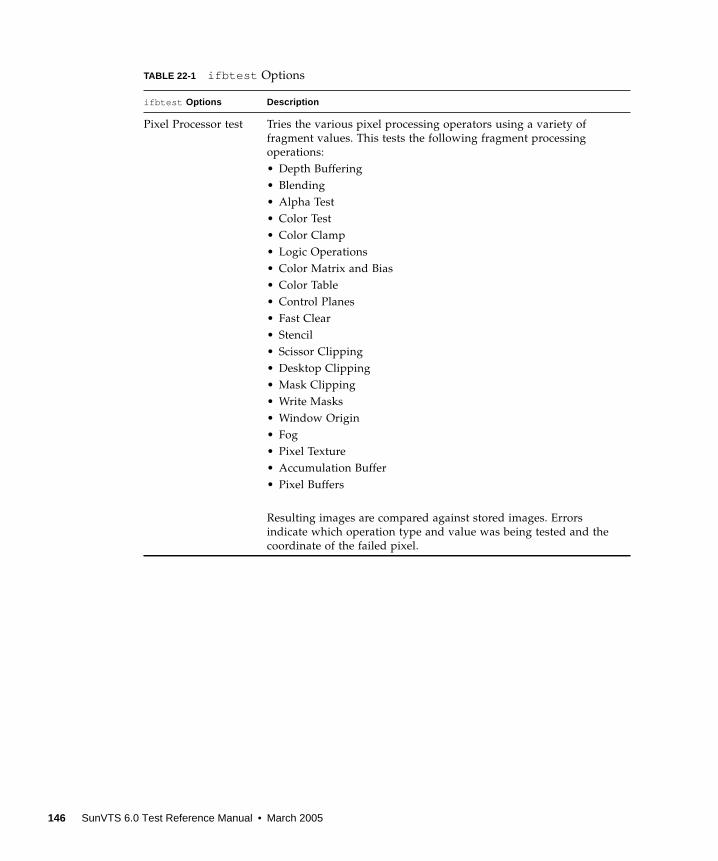
Pixel Processor test Tries the various pixel processing operators using a variety of
fragment values. This tests the following fragment processing
operations:
• Depth Buffering
• Blending
• Alpha Test
• Color Test
• Color Clamp
• Logic Operations
• Color Matrix and Bias
• Color Table
• Control Planes
• Fast Clear
• Stencil
• Scissor Clipping
• Desktop Clipping
• Mask Clipping
• Write Masks
• Window Origin
• Fog
• Pixel Texture
• Accumulation Buffer
• Pixel Buffers
Resulting images are compared against stored images. Errors
indicate which operation type and value was being tested and the
coordinate of the failed pixel.
TABLE 22-1 ifbtest Options
ifbtest Options Description
146 SunVTS 6.0 Test Reference Manual • March 2005
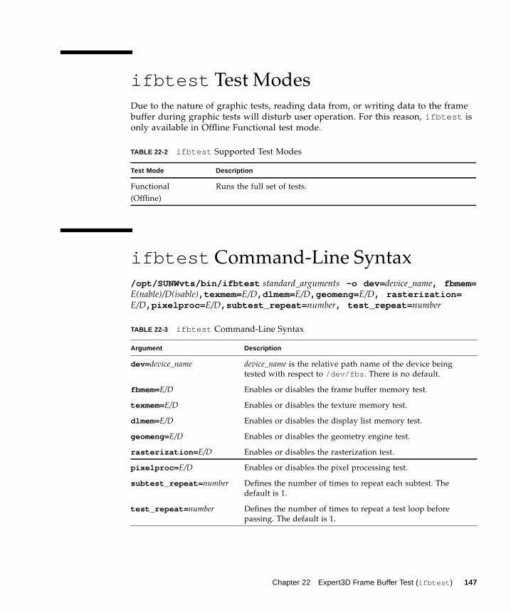
ifbtest Test Modes
Due to the nature of graphic tests, reading data from, or writing data to the frame
buffer during graphic tests will disturb user operation. For this reason, ifbtest is
only available in Offline Functional test mode.
ifbtest Command-Line Syntax
/opt/SUNWvts/bin/ifbtest standard_arguments -o dev= device_name, fbmem=E(nable)/D(isable),texmem= E/D,dlmem= E/D,geomeng= E/D, rasterization=E/D,pixelproc= E/D,subtest_repeat= number, test_repeat= number
TABLE 22-2 ifbtest Supported Test Modes
Test Mode Description
Functional
(Offline)
Runs the full set of tests.
TABLE 22-3 ifbtest Command-Line Syntax
Argument Description
dev= device_name device_name is the relative path name of the device being
tested with respect to /dev/fbs . There is no default.
fbmem=E/D Enables or disables the frame buffer memory test.
texmem=E/D Enables or disables the texture memory test.
dlmem=E/D Enables or disables the display list memory test.
geomeng=E/D Enables or disables the geometry engine test.
rasterization= E/D Enables or disables the rasterization test.
pixelproc= E/D Enables or disables the pixel processing test.
subtest_repeat= number Defines the number of times to repeat each subtest. The
default is 1.
test_repeat= number Defines the number of times to repeat a test loop before
passing. The default is 1.
Chapter 22 Expert3D Frame Buffer Test (ifbtest ) 147

Note – 64-bit tests are located in the sparcv9 subdirectory:
/opt/SUNWvts/bin/sparcv9/ testname, or the relative path to which you installed
SunVTS. If a test is not present in this directory, then it might be available as a 32-bit
test only. For more information, see “32-Bit and 64-Bit Tests” on page 5.
148 SunVTS 6.0 Test Reference Manual • March 2005
CHAPTER 23
Intelligent Fibre Channel ProcessorTest (ifptest )
ifptest tests the functionality of the PCI FC-AL card when there are no devices
attached to the loop. The driver checks for devices on the fibre loop. If devices are
detected the driver blocks any diagnostic commands.
Note – When devices are attached to the loop, do not run ifptest . Instead, run
disktest tests on the individual devices. This will test the whole subsystem
including the FC-AL controller.
ifptest uses the “mailbox” interface to the card. This interface allows certain
firmware operations to be performed that normally would not be available to the
application layer.
ifptest Subtests
Four subtests are run in online and functional modes:
■ Mailbox Loopback test
Loads a series of registers into the input mailboxes on the card and then reads the
output mailboxes and compares results. This verifies that the system side of the card
is operating correctly, and that the internal data paths are okay.
■ Firmware revision check
Reads the firmware revision from the firmware and compares it against a revision
loaded by the driver.
149
■ Checksum firmware test
Runs an internal checksum test on the installed firmware. This verifies that the RISC
RAM on the card is fully functional and that the installed firmware is still intact.
This test also serves as a quick RAM check of the RISC RAM.
■ Dump revision levels
Extracts the hardware and firmware revision levels of different submodules on the
card.
ifptest Options
To reach the dialog box below, right-click on the test name in the System Map and
select Test Parameter Options. If you do not see this test in the System Map, you
might need to expand the collapsed groups, or your system may not include the
device appropriate to this test. Refer to the SunVTS User’s Guide for more details.
150 SunVTS 6.0 Test Reference Manual • March 2005
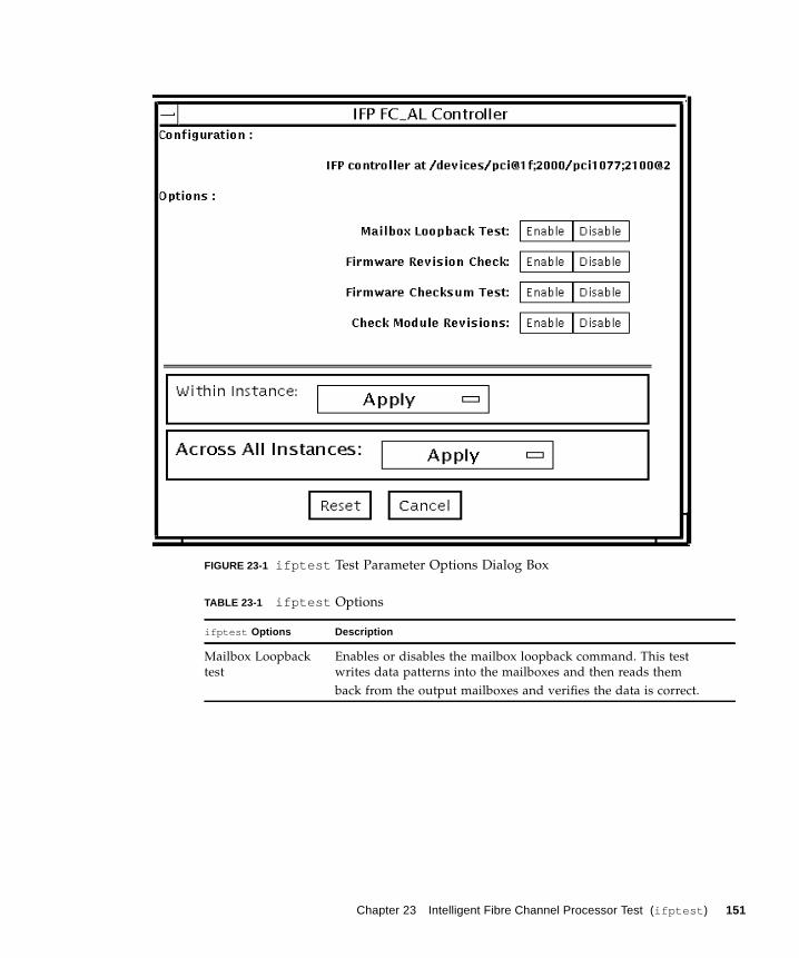
FIGURE 23-1 ifptest Test Parameter Options Dialog Box
TABLE 23-1 ifptest Options
ifptest Options Description
Mailbox Loopback
test
Enables or disables the mailbox loopback command. This test
writes data patterns into the mailboxes and then reads them
back from the output mailboxes and verifies the data is correct.
Chapter 23 Intelligent Fibre Channel Processor Test (ifptest ) 151

ifptest Test Modes
Note – Connection test mode will only open the controller to verify that the path is
still viable.
Firmware revision
check
Enables or disables the firmware revision check command. This
test extracts the firmware revision from the RISC firmware code
and verifies against expected values.
Firmware checksum
test
Enables or disables the firmware checksum command.
This command instructs the interface's RISC processor to calculate
the checksum on the current microcode and then compare it
against the checksum that was loaded in with the microcode.
Check Module
Revisions
Enables or disables the firmware check module command. This
command returns the revision level of several submodules on the
interface card. Although this test is executed when enabled, the
module revision levels are only printed out in VERBOSE mode.
TABLE 23-2 ifptest Supported Test Modes
Test Mode Description
Connection Performs only an open/close operation.
Functional
(Offline)
Runs the full set of mailbox tests.
TABLE 23-1 ifptest Options
ifptest Options Description
152 SunVTS 6.0 Test Reference Manual • March 2005
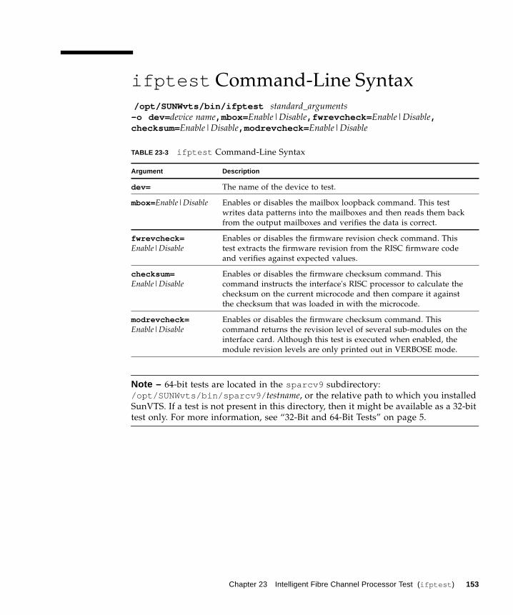
ifptest Command-Line Syntax
/opt/SUNWvts/bin/ifptest standard_arguments-o dev= device name,mbox= Enable|Disable,fwrevcheck= Enable|Disable,checksum= Enable|Disable,modrevcheck= Enable|Disable
Note – 64-bit tests are located in the sparcv9 subdirectory:
/opt/SUNWvts/bin/sparcv9/ testname, or the relative path to which you installed
SunVTS. If a test is not present in this directory, then it might be available as a 32-bit
test only. For more information, see “32-Bit and 64-Bit Tests” on page 5.
TABLE 23-3 ifptest Command-Line Syntax
Argument Description
dev= The name of the device to test.
mbox=Enable|Disable Enables or disables the mailbox loopback command. This test
writes data patterns into the mailboxes and then reads them back
from the output mailboxes and verifies the data is correct.
fwrevcheck=Enable|Disable
Enables or disables the firmware revision check command. This
test extracts the firmware revision from the RISC firmware code
and verifies against expected values.
checksum=Enable|Disable
Enables or disables the firmware checksum command. This
command instructs the interface's RISC processor to calculate the
checksum on the current microcode and then compare it against
the checksum that was loaded in with the microcode.
modrevcheck=Enable|Disable
Enables or disables the firmware checksum command. This
command returns the revision level of several sub-modules on the
interface card. Although this test is executed when enabled, the
module revision levels are only printed out in VERBOSE mode.
Chapter 23 Intelligent Fibre Channel Processor Test (ifptest ) 153

154 SunVTS 6.0 Test Reference Manual • March 2005
CHAPTER 24
Integer Unit Test (iutest )
The Integer Unit Test (iutest ) tests the resident integer unit in Sun SPARC CPUs. It
exercises all of the register windows present in the Integer Unit of the CPU. The
successful completion of the test implies that all of the register windows are
functioning properly and failure implies a faulty register.
iutest Options
To reach the dialog box below, right-click on the test name in the System Map and
select Test Parameter Options. If you do not see this test in the System Map, you
might need to expand the collapsed groups, or your system may not include the
device appropriate to this test. Refer to the SunVTS User’s Guide for more details.
155
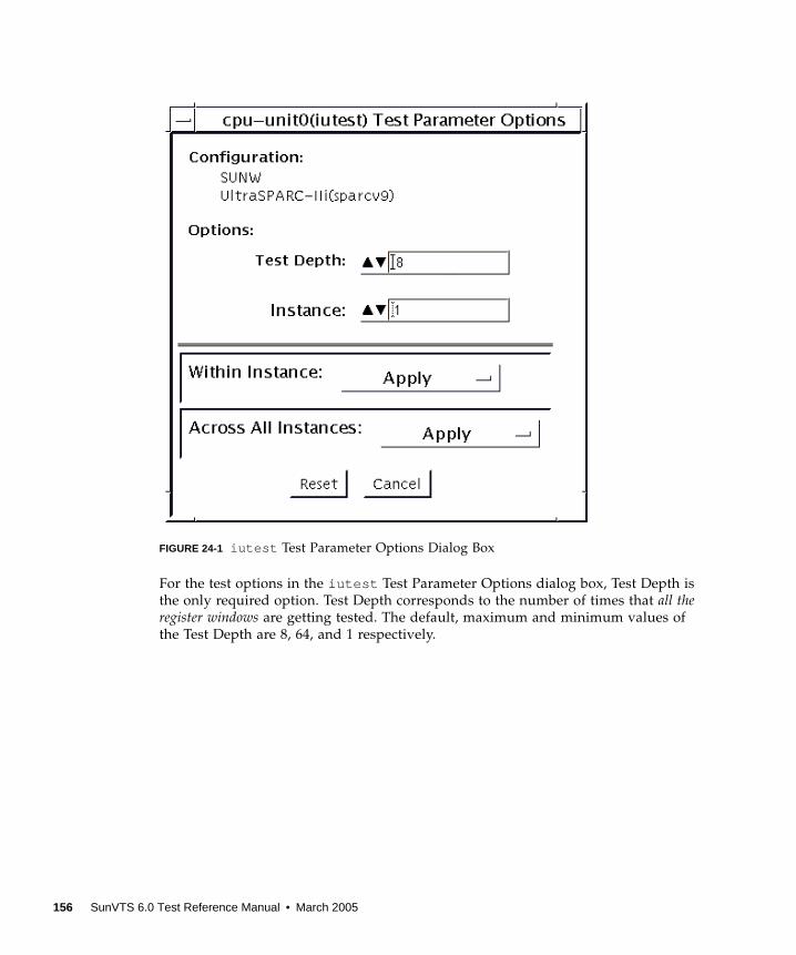
FIGURE 24-1 iutest Test Parameter Options Dialog Box
For the test options in the iutest Test Parameter Options dialog box, Test Depth is
the only required option. Test Depth corresponds to the number of times that all theregister windows are getting tested. The default, maximum and minimum values of
the Test Depth are 8, 64, and 1 respectively.
156 SunVTS 6.0 Test Reference Manual • March 2005
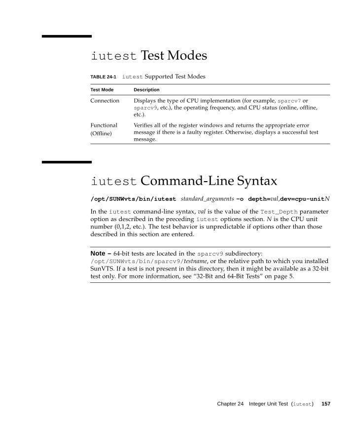
iutest Test Modes
iutest Command-Line Syntax
/opt/SUNWvts/bin/iutest standard_arguments -o depth= val,dev=cpu-unit N
In the iutest command-line syntax, val is the value of the Test_Depth parameter
option as described in the preceding iutest options section. N is the CPU unit
number (0,1,2, etc.). The test behavior is unpredictable if options other than those
described in this section are entered.
Note – 64-bit tests are located in the sparcv9 subdirectory:
/opt/SUNWvts/bin/sparcv9/ testname, or the relative path to which you installed
SunVTS. If a test is not present in this directory, then it might be available as a 32-bit
test only. For more information, see “32-Bit and 64-Bit Tests” on page 5.
TABLE 24-1 iutest Supported Test Modes
Test Mode Description
Connection Displays the type of CPU implementation (for example, sparcv7 or
sparcv9 , etc.), the operating frequency, and CPU status (online, offline,
etc.).
Functional
(Offline)
Verifies all of the register windows and returns the appropriate error
message if there is a faulty register. Otherwise, displays a successful test
message.
Chapter 24 Integer Unit Test (iutest ) 157

158 SunVTS 6.0 Test Reference Manual • March 2005

CHAPTER 25
Sun™ XVR-1200 GraphicsAccelerator Test (jfbtest )
jfbtest verifies the proper functioning of the Sun™ XVR-1200 graphics accelerator.
jfbtest can detect and adapt to many video modes of the Sun XVR-1200 graphics
accelerator. All tests can run at a resolution of 1024x768 or higher.
You can interrupt jfbtest using Control-C.
Test accuracy is checked using direct image comparison against compressed images.
Failed pixel locations are printed as error messages.
Caution – Do not run any other application or screen saver program that uses the
Sun XVR-1200 graphics accelerator port while running jfbtest. This combination
causes SunVTS to return incorrect errors.
jfbtest Test Requirements
Disable all screen savers before testing any graphics device. To disable the Solaris
screen saver, type the following at a UNIX prompt:
To turn Power Management off, type the following at a UNIX prompt:
# xset s off
159
The display resolution must be 1024x768 or higher (the standard resolution). To
change resolution, go to a UNIX prompt and type:
For full instructions on testing frame buffers, see “Testing Frame Buffers” on page
10.
Preparation for jfbtest
You should complete a few steps in advance to ensure that jfbtest runs as
smoothly as possible.
If you are running jfbtest in a window system (such as CDE):
■ Turn Power Management off, if it is enabled. The following is an alternate way to
turn Power Management off. Change allowFBPM=1 to allowFBPM=0 in
/platform/sun4u/kernal/drv/jfb.conf file.
■ Make sure that no other program is running that might modify the screen during
the test.
■ Make sure you have permission to lock the X server. jfbtest is designed to lock
the X server during testing to prevent screen changes.
■ The CDE login window should not be displayed during testing.
■ Check that the window system is only running on one Sun XVR-1200 graphics
accelerator.
If you are not running jfbtest in a window system:
■ Turn Power Management off, if it is enabled. The following is an alternate way to
turn Power Management off. Change allowFBPM=1 to allowFBPM=0 in
/platform/sun4u/kernal/drv/jfb.conf file.
■ Make sure that no other program is running that might modify the screen during
the test.
■ Make sure the Sun XVR-1200 graphics accelerator being tested is not the console
device. Console messages may modify the screen.
# xset -dpms
# fbconfig -res 1280x1024x76
160 SunVTS 6.0 Test Reference Manual • March 2005
jfbtest Options
To reach the dialog box below, right-click on the test name in the System Map and
select Test Parameter Options. If you do not see this test in the System Map, you
might need to expand the collapsed groups, or your system may not include the
device appropriate to this test. Refer to the SunVTS User’s Guide for more details.
By default, all jfbtest options are enabled.
Chapter 25 Sun™ XVR-1200 Graphics Accelerator Test (jfbtest ) 161
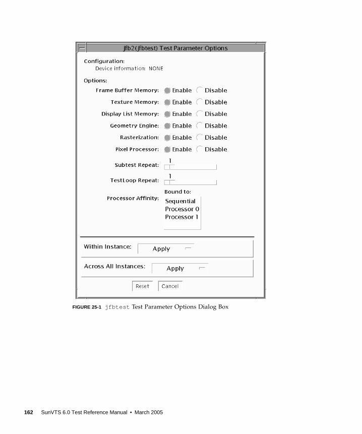
FIGURE 25-1 jfbtest Test Parameter Options Dialog Box
162 SunVTS 6.0 Test Reference Manual • March 2005
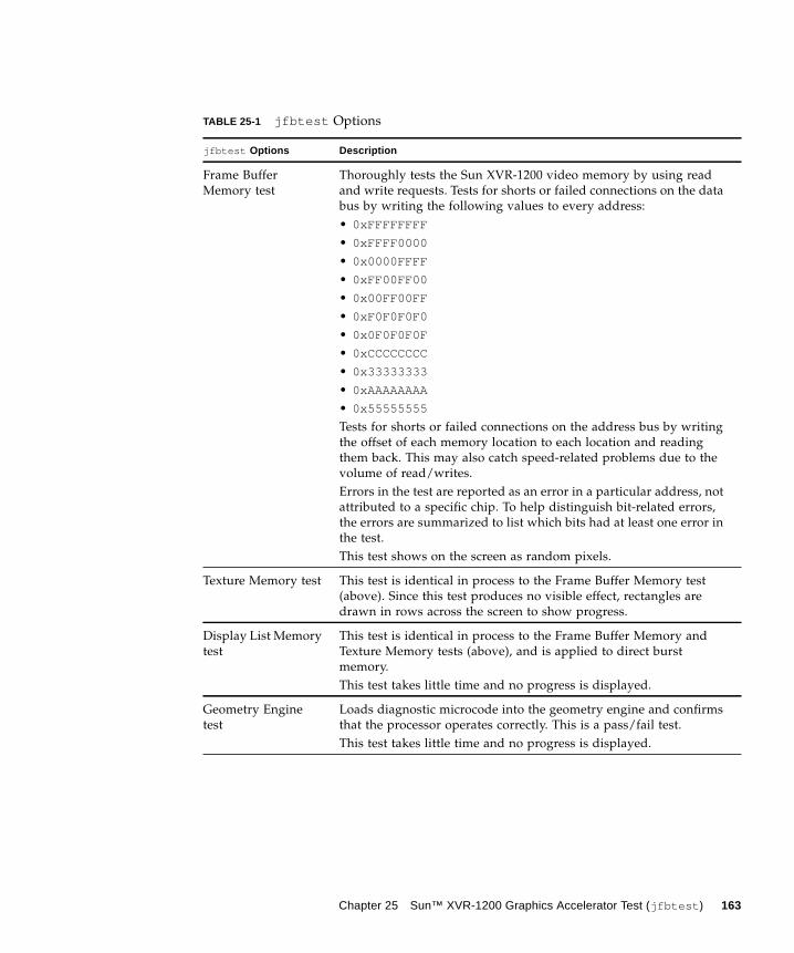
TABLE 25-1 jfbtest Options
jfbtest Options Description
Frame Buffer
Memory test
Thoroughly tests the Sun XVR-1200 video memory by using read
and write requests. Tests for shorts or failed connections on the data
bus by writing the following values to every address:
• 0xFFFFFFFF
• 0xFFFF0000
• 0x0000FFFF
• 0xFF00FF00
• 0x00FF00FF
• 0xF0F0F0F0
• 0x0F0F0F0F
• 0xCCCCCCCC
• 0x33333333
• 0xAAAAAAAA
• 0x55555555
Tests for shorts or failed connections on the address bus by writing
the offset of each memory location to each location and reading
them back. This may also catch speed-related problems due to the
volume of read/writes.
Errors in the test are reported as an error in a particular address, not
attributed to a specific chip. To help distinguish bit-related errors,
the errors are summarized to list which bits had at least one error in
the test.
This test shows on the screen as random pixels.
Texture Memory test This test is identical in process to the Frame Buffer Memory test
(above). Since this test produces no visible effect, rectangles are
drawn in rows across the screen to show progress.
Display List Memory
test
This test is identical in process to the Frame Buffer Memory and
Texture Memory tests (above), and is applied to direct burst
memory.
This test takes little time and no progress is displayed.
Geometry Engine
test
Loads diagnostic microcode into the geometry engine and confirms
that the processor operates correctly. This is a pass/fail test.
This test takes little time and no progress is displayed.
Chapter 25 Sun™ XVR-1200 Graphics Accelerator Test (jfbtest ) 163
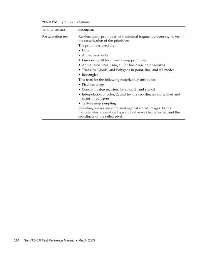
Rasterization test Renders many primitives with minimal fragment processing, to test
the rasterization of the primitives.
The primitives used are:
• Dots
• Anti-aliased dots
• Lines using all for line-drawing primitives
• Anti-aliased lines using all for line-drawing primitives
• Triangles, Quads, and Polygons in point, line, and fill modes
• Rectangles
This tests for the following rasterization attributes:
• Pixel coverage
• Constant value registers for color, Z, and stencil
• Interpolation of color, Z, and texture coordinates along lines and
spans in polygons
• Texture map sampling
Resulting images are compared against stored images. Errors
indicate which operation type and value was being tested, and the
coordinate of the failed pixel.
TABLE 25-1 jfbtest Options
jfbtest Options Description
164 SunVTS 6.0 Test Reference Manual • March 2005
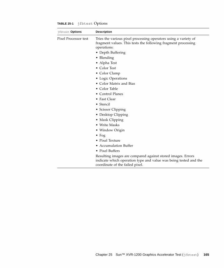
Pixel Processor test Tries the various pixel processing operators using a variety of
fragment values. This tests the following fragment processing
operations:
• Depth Buffering
• Blending
• Alpha Test
• Color Test
• Color Clamp
• Logic Operations
• Color Matrix and Bias
• Color Table
• Control Planes
• Fast Clear
• Stencil
• Scissor Clipping
• Desktop Clipping
• Mask Clipping
• Write Masks
• Window Origin
• Fog
• Pixel Texture
• Accumulation Buffer
• Pixel Buffers
Resulting images are compared against stored images. Errors
indicate which operation type and value was being tested and the
coordinate of the failed pixel.
TABLE 25-1 jfbtest Options
jfbtest Options Description
Chapter 25 Sun™ XVR-1200 Graphics Accelerator Test (jfbtest ) 165
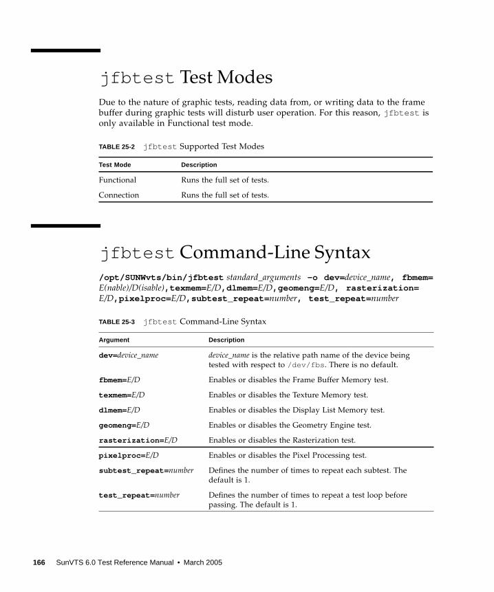
jfbtest Test Modes
Due to the nature of graphic tests, reading data from, or writing data to the frame
buffer during graphic tests will disturb user operation. For this reason, jfbtest is
only available in Functional test mode.
jfbtest Command-Line Syntax
/opt/SUNWvts/bin/jfbtest standard_arguments -o dev= device_name, fbmem=E(nable)/D(isable),texmem= E/D,dlmem= E/D,geomeng= E/D, rasterization=E/D,pixelproc= E/D,subtest_repeat= number, test_repeat= number
TABLE 25-2 jfbtest Supported Test Modes
Test Mode Description
Functional Runs the full set of tests.
Connection Runs the full set of tests.
TABLE 25-3 jfbtest Command-Line Syntax
Argument Description
dev= device_name device_name is the relative path name of the device being
tested with respect to /dev/fbs . There is no default.
fbmem=E/D Enables or disables the Frame Buffer Memory test.
texmem=E/D Enables or disables the Texture Memory test.
dlmem=E/D Enables or disables the Display List Memory test.
geomeng=E/D Enables or disables the Geometry Engine test.
rasterization= E/D Enables or disables the Rasterization test.
pixelproc= E/D Enables or disables the Pixel Processing test.
subtest_repeat= number Defines the number of times to repeat each subtest. The
default is 1.
test_repeat= number Defines the number of times to repeat a test loop before
passing. The default is 1.
166 SunVTS 6.0 Test Reference Manual • March 2005
Note – 64-bit tests are located in the sparcv9 subdirectory:
/opt/SUNWvts/bin/sparcv9/ testname, or the relative path to which you installed
SunVTS. If a test is not present in this directory, then it might be available as a 32-bit
test only. For more information, see “32-Bit and 64-Bit Tests” on page 5.
Chapter 25 Sun™ XVR-1200 Graphics Accelerator Test (jfbtest ) 167

168 SunVTS 6.0 Test Reference Manual • March 2005
CHAPTER 26
JNI 2GB FC HBA Test (jnifctest )
The jnifctest tests the functionality of the JNI FC HBA. There are three tests: a
self-test, an internal loopback test, and an external loopback test. The self-test tests
the internal consistency of the board’s internal computer. The loopback tests send
out blocks of data to the HBA, receives blocks echoed back to the HBA, and
compares the echoed packets to the original. If jnifctest detects problems in the
self-test, problems sending or receiving the data, or any changes in the content of the
data in the loopback tests, it sends out a descriptive error message to the SunVTS
console and error log.
There are a small list of patterns that are most likely to detect problems on a FC
network; these "critical" patterns are the default. There is also a longer list of
patterns and a means for a user to input his own data pattern for testing.
Internal loopback tests require having a loopback plug or cable connected to the
port. External loopback tests can be run on a port connected to storage, to a switch,
or with a loopback plug or cable. The simplest way to get the greatest test coverage
is to have all ports connected with a cable and run both the self-test and the external
loopback test. These two tests are enabled by default.
The jnifctest runs in exclusive mode. Any storage behind a particular port will
be inaccessable while the tests are running. Also, system console log messages
reporting renegotiation of the link status may be generated for ports connected to a
switch or storage when jnifctest is run.
jnifctest has three subtests available:
■ Online selftest
■ Internal loopback test
■ External loopback test
169
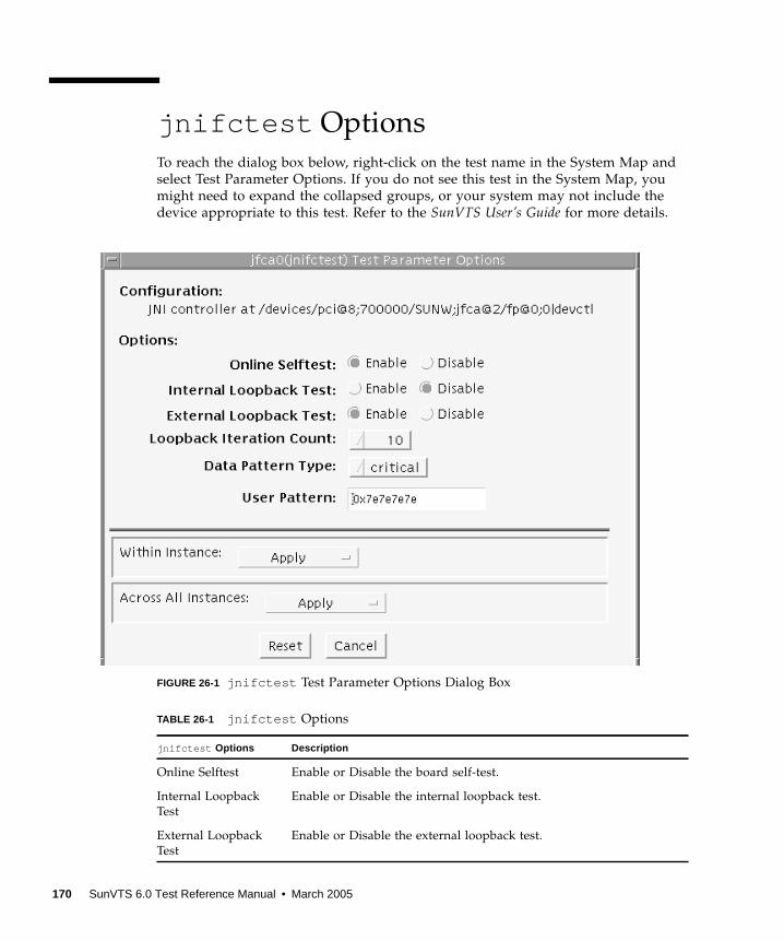
jnifctest Options
To reach the dialog box below, right-click on the test name in the System Map and
select Test Parameter Options. If you do not see this test in the System Map, you
might need to expand the collapsed groups, or your system may not include the
device appropriate to this test. Refer to the SunVTS User’s Guide for more details.
FIGURE 26-1 jnifctest Test Parameter Options Dialog Box
TABLE 26-1 jnifctest Options
jnifctest Options Description
Online Selftest Enable or Disable the board self-test.
Internal Loopback
Test
Enable or Disable the internal loopback test.
External Loopback
Test
Enable or Disable the external loopback test.
170 SunVTS 6.0 Test Reference Manual • March 2005
The default values are for the Online Selftest and External Loopback test to be
enabled. The Internal Loopback test is disabled. The Loopback Iteration count
defaults to 10 iterations. The default Data Pattern Type is Critical and the default
User Pattern is 0x7e7e7e7e.
Loopback Iteration Number of iterations to run the loopback test.
Data Pattern Type: What type of data to send in the loopback tests. Critical patterns are
a dozen patterns which are optimized to cause errors in marginal
FC networks. With a small number of patterns, the test will run
more rapidly. All patterns is a list of approximately 256 patterns,
including the Critical patterns. The User pattern is a single pattern
that you can specify to test with.
User Pattern A 32-bit data pattern which is used if ’user’ is specified in the Data
Pattern Type option. The User Pattern should be input in the form
0x12345678
TABLE 26-1 jnifctest Options (Continued)
jnifctest Options Description
Chapter 26 JNI 2GB FC HBA Test (jnifctest ) 171
jnifctest Supported Test Modes
jnifctest Command-Line Syntax
/opt/SUNWvtshm/bin/jnifctest -vf -o dev= jfca0, selftest= {enable|disable}, ilb= {enable|disable}, elb= {enable|disable},iterations= {1 – 1000000}, selectpattern= {critical|all|user},userpattern= { hex-value}
TABLE 26-2 jnifctest Supported Test Modes
Test Mode Description
Exclusive Runs full set of tests.
TABLE 26-3 jnifctest Command-Line Syntax
Argument Description
dev =device Specifies device to be tested—for example, jfca0, jfca1, and so
on.
selftest=Enable|Disable Enables or disable the self-test.
ilb= Enable|Disable Enables or disables the Internal loopback test.
elb= Enable|Disable Enables or disables the External loopback test.
iterations= 1 – 1000000 Specifies the number of iterations of the tests. The possible
range of this parameter is 1 – 1,000,000. The most practical
range is 10 – 5000.
selectpattern= user |critical | all
Specifies which data patterns are used for the loopback tests:
the small list of critical hex-value data patterns, or the larger
list of all hex-value data patterns. The critical hex-value data
pattern list is 12 hex-value patterns. The all hex-value data
pattern is a significantly larger list of hex-value data patterns.
userpattern= hex-value If the selectpattern option is specified as user, this option
specifies the data pattern that should be used for the loopback
tests. The hex-value pattern is specified with 8 hex digits—for
example, 0x12345678, 0x7e7e7e7e, or 0xcafebaba.
172 SunVTS 6.0 Test Reference Manual • March 2005
CHAPTER 27
Level 1 Data Cache Test(l1dcachetest )
l1dcachetest exercises the level1 Data cache in the CPU module of Sun systems.
The test writes, reads, and verifies access of multiple virtual addresses. The virtual
addresses are so chosen that they cause targeted hits and misses in the cache. The
test dynamically determines the size and organization of the cache and tunes the test
accordingly to be effective on the l1dcache.
l1dcachetest provides data path testing of on-chip buses. With rapid move to
deep sub-micron (DSM) designs, GHz clock frequencies, feature size process of 0.18
micron and below, ensuring the integrity of signals as they traverse conductors on a
chip is becoming challenge. l1dcachetest subtests induce crosstalk noise in on-
chip data buses by using Maximum Aggressor Fault (MAF) models.
l1dcahetest is self scaling and adaptive. It scales with the size of system.
l1dcachetest is mult-threaded. Although, selection of CPU IDs, is kept as one of
the options but if its not specified, it automatically retrieves the number of CPUs in
the system and internally creates that many threads of l1dcachetest to give
coverage to the whole system at a given time. The test also determines the sizes and
organization of l1cache.
l1dcachetest Options
To reach the dialog box below, right-click on the test name in the System Map and
select Test Parameter Options. If you do not see this test in the System Map, you
might need to expand the collapsed groups, or your system may not include the
device appropriate to this test. Refer to the SunVTS User’s Guide for more details.
173
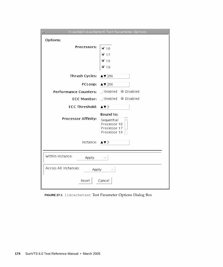
FIGURE 27-1 l1dcachetest Test Parameter Options Dialog Box
174 SunVTS 6.0 Test Reference Manual • March 2005
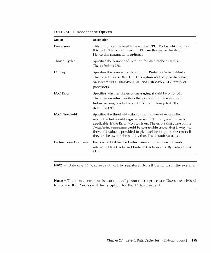
Note – Only one l1dcachetest will be registered for all the CPUs in the system.
Note – The l1dcachetest is automatically bound to a processor. Users are advised
to not use the Processor Affinity option for the l1dcachetest .
TABLE 27-1 l1dcachetest Options
Option Description
Processors This option can be used to select the CPU IDs for which to run
this test. The test will use all CPUs on the system by default.
Hence this parameter is optional.
Thrash Cycles Specifies the number of iteration for data cache subtests.
The default is 256.
PCLoop Specifies the number of iteration for Prefetch Cache Subtests.
The default is 256. (NOTE : This option will only be displayed
on system with UltraSPARC-III and UltraSPARC-IV family of
processors.
ECC Error Specifies whether the error messaging should be on or off.
The error monitor monitors the /var/adm/messages file for
failure messages which could be caused during test. The
default is OFF.
ECC Threshold Specifies the threshold value of the number of errors after
which the test would register an error. This argument is only
applicable, if the Error Monitor is on. The errors that come on the
/var/adm/messages could be correctable errors, that is why the
threshold value is provided to give facility to ignore the errors if
they are below the threshold value. The default value is 1.
Performance Counters Enables or Diables the Performance counter measurements
related to Data Cache and Prefetch Cache events. By Default, it is
OFF.
Chapter 27 Level 1 Data Cache Test (l1dcachetest ) 175

l1dcachetest Test Modes
l1dcachetest Command-Line Syntax
/opt/SUNWvts/bin/l1dcachetest standard_arguments -o [[ M=1+2+3... ] ,[ count =number ] , [ pcloop =number ], [em=Enabled|Disabled],
[threshold =1,255], [perf =Enabled|Disabled], [dev =l1cache] ]
TABLE 27-2 l1dcachetest Supported Test Modes
Test Mode Description
Connection Performs the Connection subtest.
Exclusive Performs only the l1dcachetest (full test).
TABLE 27-3 l1dcachetest Command-Line Syntax
Argument Description
M=1+2+3... This option can be used to select the CPU IDs for which to run
this test. The test will use all CPUs on the system by default.
Hence this parameter is optional.
The CPU IDs currently present in the system can be retrieved
with psrinfo(1M) command. Specifying a CPU ID not present in
the system or one which is currently offline induces an
appropriate error messages from the test. Example: If you want
to select CPU IDs 4, 5, 6, and 7 , specify : M=4+5+6+7
count =number Specifies the number of iteration for Data Cache Subtests. The
default is 256.
pcloop =number Specifies the number of iteration for Prefetch Cache Subtests.
The default is 256. (NOTE : This option s only for system with
UltraSPARC-III and UltraSPARC-IV family of processors. For
others, it will ignored.
em=Enabled|Disabled Specifies whether the error messaging should be on or off.
The error monitor monitors the /var/adm/messages file for
failure messages which could be caused during test. The default
is OFF.
176 SunVTS 6.0 Test Reference Manual • March 2005
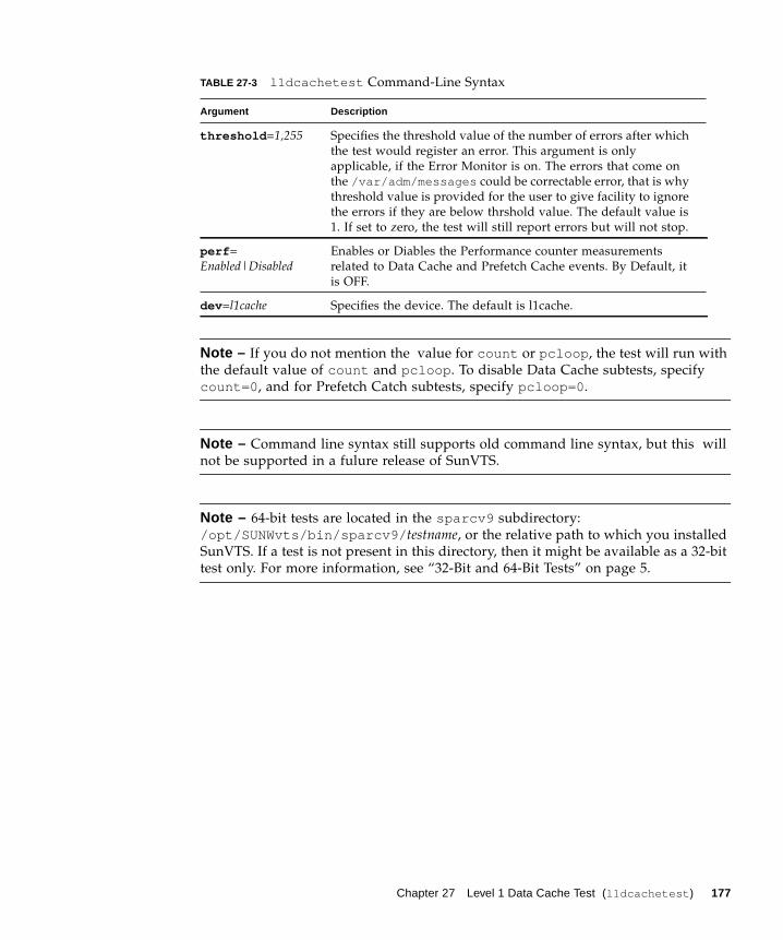
Note – If you do not mention the value for count or pcloop , the test will run with
the default value of count and pcloop . To disable Data Cache subtests, specify
count=0 , and for Prefetch Catch subtests, specify pcloop=0 .
Note – Command line syntax still supports old command line syntax, but this will
not be supported in a fulure release of SunVTS.
Note – 64-bit tests are located in the sparcv9 subdirectory:
/opt/SUNWvts/bin/sparcv9/ testname, or the relative path to which you installed
SunVTS. If a test is not present in this directory, then it might be available as a 32-bit
test only. For more information, see “32-Bit and 64-Bit Tests” on page 5.
threshold =1,255 Specifies the threshold value of the number of errors after which
the test would register an error. This argument is only
applicable, if the Error Monitor is on. The errors that come on
the /var/adm/messages could be correctable error, that is why
threshold value is provided for the user to give facility to ignore
the errors if they are below thrshold value. The default value is
1. If set to zero, the test will still report errors but will not stop.
perf =
Enabled|DisabledEnables or Diables the Performance counter measurements
related to Data Cache and Prefetch Cache events. By Default, it
is OFF.
dev =l1cache Specifies the device. The default is l1cache.
TABLE 27-3 l1dcachetest Command-Line Syntax
Argument Description
Chapter 27 Level 1 Data Cache Test (l1dcachetest ) 177

178 SunVTS 6.0 Test Reference Manual • March 2005
CHAPTER 28
Level 2 Cache Test (l2sramtest )
l2sramtest exercises the level2 cache in the CPU module of Sun systems. In most
CPUs, the level2 cache is also the external cache, but in some cases the level2 cache
is on the chip. This test writes, reads, and verifies access of multiple virtual
addresses. This test contains multiple subtests that try to exercise the l2cache by
causing hits/misses, performing marching patterns on the l2cache cells, and writing
patterns that cause electrical stress.
l2sramtest is self scaling and adaptive. It scales with the size of the system. It will
automatically retrieve the number of CPUs in the system and internally create that
many threads of l2sramtest to give coverage to the whole system at a given time.
This test also dynamically determines the size and organization of the l2cache. The
user does not have to input these values.
l2sramtest Options
To reach the dialog box below, right-click on the test name in the System Map and
select Test Parameter Options. If you do not see this test in the System Map, you
might need to expand the collapsed groups, or your system may not include the
device appropriate to this test. Refer to the SunVTS User’s Guide for more details.
179
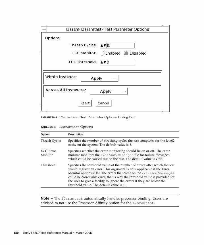
FIGURE 28-1 l2sramtest Test Parameter Options Dialog Box
Note – The l2sramtest automatically handles processor binding. Users are
advised to not use the Processor Affinity option for the l2sramtest .
TABLE 28-1 l2sramtest Options
Option Description
Thrash Cycles Specifies the number of thrashing cycles the test completes for the level2
cache on the system. The default value is 8.
ECC Error
Monitor
Specifies whether the error monitoring should be on or off. The error
monitor monitors the /var/adm/messages file for failure messages
which could be caused due to the test. The default value is OFF.
Threshold Specifies the threshold value of the number of errors after which the test
would register an error. This argument is only applicable if the Error
Monitor option is ON. The errors that come on the /var/adm/messagescould be correctable error, that is why the threshold value is provided for
the user to give a facility to ignore the errors if they are below the
threshold value. The default value is 1.
180 SunVTS 6.0 Test Reference Manual • March 2005
l2sramtest Test Modes
l2sramtest Command-Line Syntax
/opt/SUNWvts/bin/sparcv9/l2sramtest - standard_arguments -o [dev=l2sram, count= [1...1023], em=[Enabled,Disabled], threshold= [0..255]]
Note – The l2sramtest is not a per CPU test. There will be only one l2sramtestfor the whole system (one image of Solaris). It will run on all the CPUs of the
domain.
TABLE 28-2 l2sramtest Supported Test Modes
Test Mode Description
Exclusive Performs only the l2sramtest (full test).
TABLE 28-3 l2sramtest Command-Line Syntax
Argument Description
dev= l2sram Specifies the device. The default value is l2sram .
count= number Specifies the number of thrashing cycles that the test completes for
the level2 cache on the system. Default value for Offline mode is 8.
em=Enabled/Disabled Specifies the enabling or disabling of the ECC Error Monitor. The
default value is Disabled.
threshold= number Specifies the threshold value of how many correctable ECC errors
can occur in the elapsed time before l2sramtest reports a test
failure. The default value is 1.
Chapter 28 Level 2 Cache Test (l2sramtest ) 181

182 SunVTS 6.0 Test Reference Manual • March 2005
CHAPTER 29
LOMlite Alarm Test(lomlitetest )
lomlitetest tests the functionality of LOMlite and LOMlite 2 system monitoring,
alarms, and lights-out management (LOM) processors currently used in Netra™ T
platforms. This test also tests the legacy TSalarms alarm card used in some Netra t
11xx systems. lomlitetest exercises the hardware and device drivers for the
LOMlite, LOMlite 2, or TSalarms device, and tests the system and environmental
monitoring functions of the device.
This test is not scalable.
Note – During offline functional testing, messages from the LOM processor are seen
on the system console. This is normal and does not indicate a fault.
lomlitetest Requirements■ The LOMlite or TSalarms device driver must be installed
■ In the Netra t 11xx or Netra t 14xx platforms, the LOMlite or TSalarms plug-in
card must be installed
183
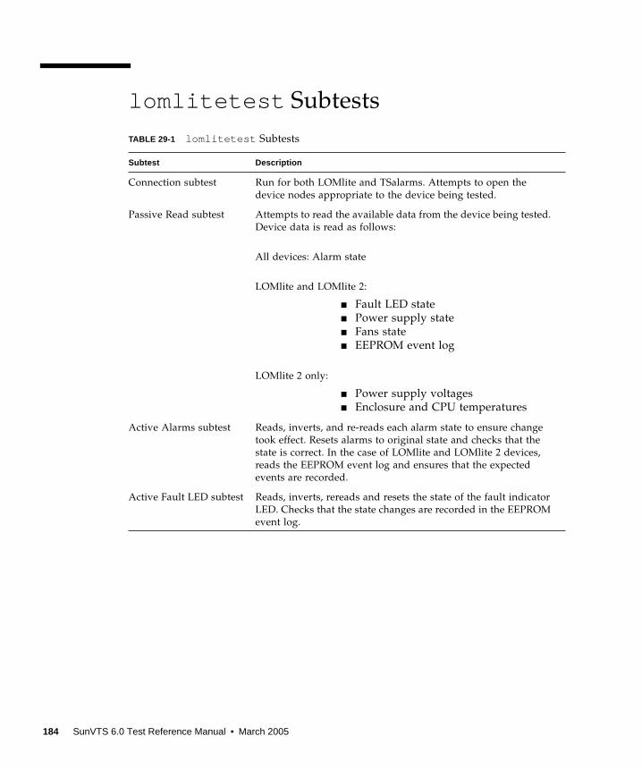
lomlitetest Subtests
TABLE 29-1 lomlitetest Subtests
Subtest Description
Connection subtest Run for both LOMlite and TSalarms. Attempts to open the
device nodes appropriate to the device being tested.
Passive Read subtest Attempts to read the available data from the device being tested.
Device data is read as follows:
All devices: Alarm state
LOMlite and LOMlite 2:
■ Fault LED state
■ Power supply state
■ Fans state
■ EEPROM event log
LOMlite 2 only:
■ Power supply voltages
■ Enclosure and CPU temperatures
Active Alarms subtest Reads, inverts, and re-reads each alarm state to ensure change
took effect. Resets alarms to original state and checks that the
state is correct. In the case of LOMlite and LOMlite 2 devices,
reads the EEPROM event log and ensures that the expected
events are recorded.
Active Fault LED subtest Reads, inverts, rereads and resets the state of the fault indicator
LED. Checks that the state changes are recorded in the EEPROM
event log.
184 SunVTS 6.0 Test Reference Manual • March 2005
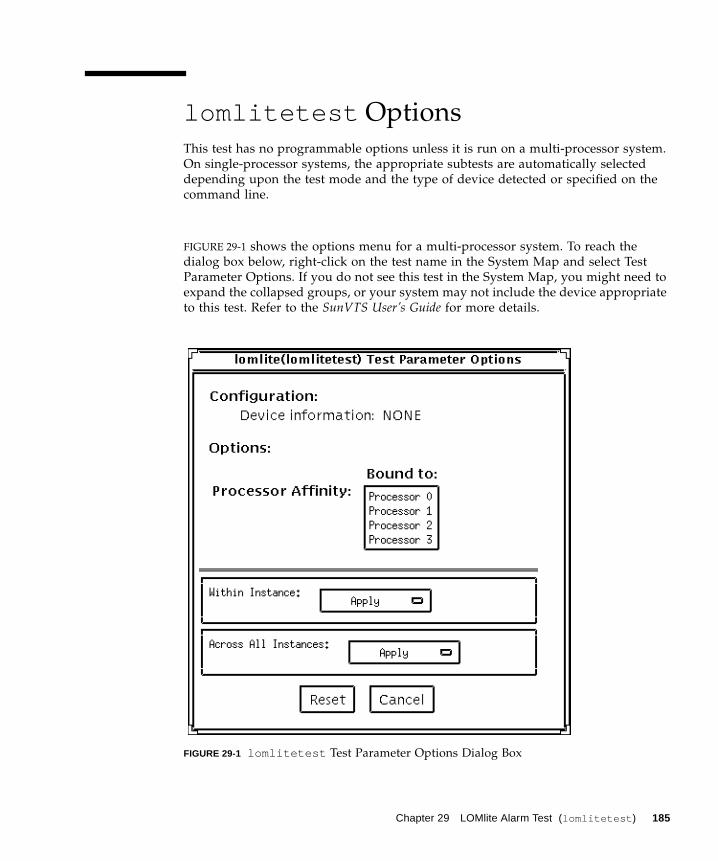
lomlitetest Options
This test has no programmable options unless it is run on a multi-processor system.
On single-processor systems, the appropriate subtests are automatically selected
depending upon the test mode and the type of device detected or specified on the
command line.
FIGURE 29-1 shows the options menu for a multi-processor system. To reach the
dialog box below, right-click on the test name in the System Map and select Test
Parameter Options. If you do not see this test in the System Map, you might need to
expand the collapsed groups, or your system may not include the device appropriate
to this test. Refer to the SunVTS User’s Guide for more details.
FIGURE 29-1 lomlitetest Test Parameter Options Dialog Box
Chapter 29 LOMlite Alarm Test (lomlitetest ) 185
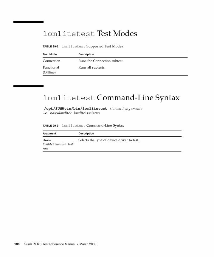
lomlitetest Test Modes
lomlitetest Command-Line Syntax
/opt/SUNWvts/bin/lomlitetest standard_arguments-o dev= lomlite2|lomlite|tsalarms
TABLE 29-2 lomlitetest Supported Test Modes
Test Mode Description
Connection Runs the Connection subtest.
Functional
(Offline)
Runs all subtests.
TABLE 29-3 lomlitetest Command-Line Syntax
Argument Description
dev=lomlite2|lomlite|tsalarms
Selects the type of device driver to test.
186 SunVTS 6.0 Test Reference Manual • March 2005
CHAPTER 30
M64 Video Board Test (m64test )
m64test tests the PCI-based M64 video board by performing the following subtests:
■ Video Memory test
■ RAMDAC test
■ Accelerator Port test
Caution – Do not run any other application or screen saver program that uses the
M64 video board while running m64test . Do not run Power Management™
software. These programs cause SunVTS to return incorrect errors.
Note – Disable all screen savers before testing any graphics device. Type
xset s off at a UNIX prompt to disable the Solaris screen saver. Type
xset -dpms (to turn off power management) or type xset s noblank (to turn
off screen saver). Disable Power Management software if it is running.
Note – To start SunVTS with vtsui , but without vtsk , you must add the host
name to xhost as: xhost + hostname.
For full instructions on testing frame buffers, see “Testing Frame Buffers” on page
10.
187
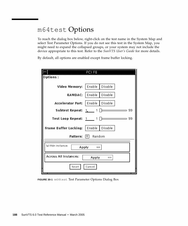
m64test Options
To reach the dialog box below, right-click on the test name in the System Map and
select Test Parameter Options. If you do not see this test in the System Map, you
might need to expand the collapsed groups, or your system may not include the
device appropriate to this test. Refer to the SunVTS User’s Guide for more details.
By default, all options are enabled except frame buffer locking.
FIGURE 30-1 m64test Test Parameter Options Dialog Box
188 SunVTS 6.0 Test Reference Manual • March 2005
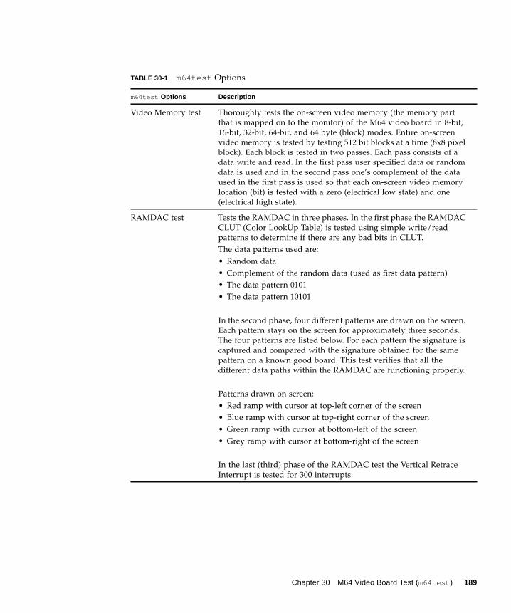
TABLE 30-1 m64test Options
m64test Options Description
Video Memory test Thoroughly tests the on-screen video memory (the memory part
that is mapped on to the monitor) of the M64 video board in 8-bit,
16-bit, 32-bit, 64-bit, and 64 byte (block) modes. Entire on-screen
video memory is tested by testing 512 bit blocks at a time (8x8 pixel
block). Each block is tested in two passes. Each pass consists of a
data write and read. In the first pass user specified data or random
data is used and in the second pass one’s complement of the data
used in the first pass is used so that each on-screen video memory
location (bit) is tested with a zero (electrical low state) and one
(electrical high state).
RAMDAC test Tests the RAMDAC in three phases. In the first phase the RAMDAC
CLUT (Color LookUp Table) is tested using simple write/read
patterns to determine if there are any bad bits in CLUT.
The data patterns used are:
• Random data
• Complement of the random data (used as first data pattern)
• The data pattern 0101
• The data pattern 10101
In the second phase, four different patterns are drawn on the screen.
Each pattern stays on the screen for approximately three seconds.
The four patterns are listed below. For each pattern the signature is
captured and compared with the signature obtained for the same
pattern on a known good board. This test verifies that all the
different data paths within the RAMDAC are functioning properly.
Patterns drawn on screen:
• Red ramp with cursor at top-left corner of the screen
• Blue ramp with cursor at top-right corner of the screen
• Green ramp with cursor at bottom-left of the screen
• Grey ramp with cursor at bottom-right of the screen
In the last (third) phase of the RAMDAC test the Vertical Retrace
Interrupt is tested for 300 interrupts.
Chapter 30 M64 Video Board Test (m64test ) 189
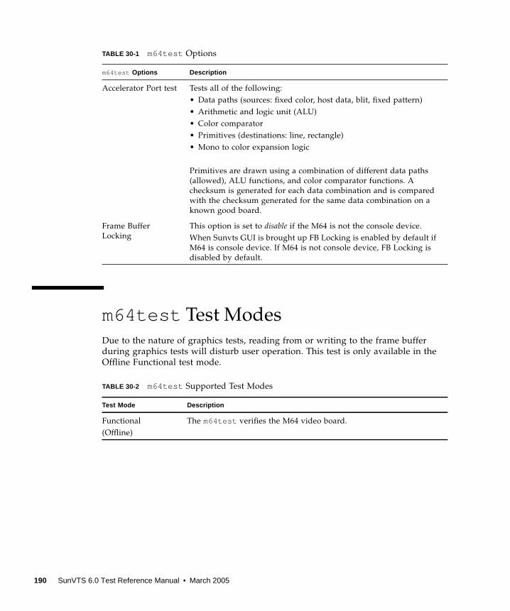
m64test Test Modes
Due to the nature of graphics tests, reading from or writing to the frame buffer
during graphics tests will disturb user operation. This test is only available in the
Offline Functional test mode.
Accelerator Port test Tests all of the following:
• Data paths (sources: fixed color, host data, blit, fixed pattern)
• Arithmetic and logic unit (ALU)
• Color comparator
• Primitives (destinations: line, rectangle)
• Mono to color expansion logic
Primitives are drawn using a combination of different data paths
(allowed), ALU functions, and color comparator functions. A
checksum is generated for each data combination and is compared
with the checksum generated for the same data combination on a
known good board.
Frame Buffer
Locking
This option is set to disable if the M64 is not the console device.
When Sunvts GUI is brought up FB Locking is enabled by default if
M64 is console device. If M64 is not console device, FB Locking is
disabled by default.
TABLE 30-2 m64test Supported Test Modes
Test Mode Description
Functional
(Offline)
The m64test verifies the M64 video board.
TABLE 30-1 m64test Options
m64test Options Description
190 SunVTS 6.0 Test Reference Manual • March 2005

m64test Command-Line Syntax
/opt/SUNWvts/bin/m64test standard_arguments -o dev= device_name, S=subtest_number,F=#_of_subtest_loops,B=#_of_test_loops,L= disable,P= test_pattern
Note – 64-bit tests are located in the sparcv9 subdirectory:
/opt/SUNWvts/bin/sparcv9/ testname, or the relative path to which you installed
SunVTS. If a test is not present in this directory, then it might be available as a 32-bit
test only. For more information, see “32-Bit and 64-Bit Tests” on page 5.
TABLE 30-3 m64test Command-Line Syntax
Argument Description
dev= device_name device_name is the relative path name of the device being tested
with respect to /dev/fbs. The default is m640.
S=subtest_number subtest_number is the test number of the subtest to be run. Select
from the subtests below. You can run multiple subtests by adding
the subtest numbers. For example, n=0x00003 runs both test
00001 and test 00002; n=0x00005 runs both test 0x00001 and test
0x00004. Note that you do not need the leading zeros.
• n—0x00001 VRAM
• n—0x00002 RAMDAC
• n—0x00004 Accelerator port test (RenderingPipeline)
More than one test can be selected by ORing subtest numbers. For
example: n = 0x00005 means VRAM and Rendering Pipeline tests.
A hex number must be preceded by 0x, decimal numbers are also
acceptable.
F=#_of_subtest_loops Specifies the number of times to repeat each subtest. The default is
1.
B=#_of_test_loops Specifies the number of times to repeat a test loop before passing;
default is 1.
L=disable Disables the frame buffer lock. Disable the lock when the m64 is
not the console or when the server is not running on the m64
under test.
P=test_pattern Specifies the test pattern number. The default is r , for random
patterns. You may also choose 0 for 0x0000000 , 3 for0x3333333 , 5 for 0x5555555 , or 9 for 0x9999999 .
Chapter 30 M64 Video Board Test (m64test ) 191
Note – Errors returned by m64test are nonspecific. It is not possible to determine
which component caused a failure. In all error conditions, the field replaceable unit
(FRU) is the entire M64 video board.
192 SunVTS 6.0 Test Reference Manual • March 2005
CHAPTER 31
Multiprocessor Test (mptest )
The mptest verifies the hardware functionality of multiprocessor hardware. The test
provides diagnostic test coverage for different aspects of multiprocessor
functionality like E-Cache Coherency, Synchronization Primitives, I/O Cache
Coherency and Shared Memory, and Interprocessor Interrupts.
The mptest is adaptive to different cache size and line sizes. The test causes cache
coherency operations for E-Cache and I/O Cache. It also tests the synchronization
primitives provided by the sparcv8 /sparcv9 architecture.
Note – mptest is not supported on sun4m platforms in SunVTS 5.1 PS6 onward.
Caution – mptest by default selects the CPUXCall class of test method. If
CPUXCall is selected, and mptest is run, the machine might seem hung for a few
minutes. The duration is dependent on the number of CPUs.
mptest Options
To reach the dialog box below, right-click on the test name in the System Map and
select Test Parameter Options. If you do not see this test in the System Map, you
might need to expand the collapsed groups, or your system may not include the
device appropriate to this test. Refer to the SunVTS User’s Guide for more details.
193

FIGURE 31-1 mptest Test Parameter Options Dialog Box
194 SunVTS 6.0 Test Reference Manual • March 2005
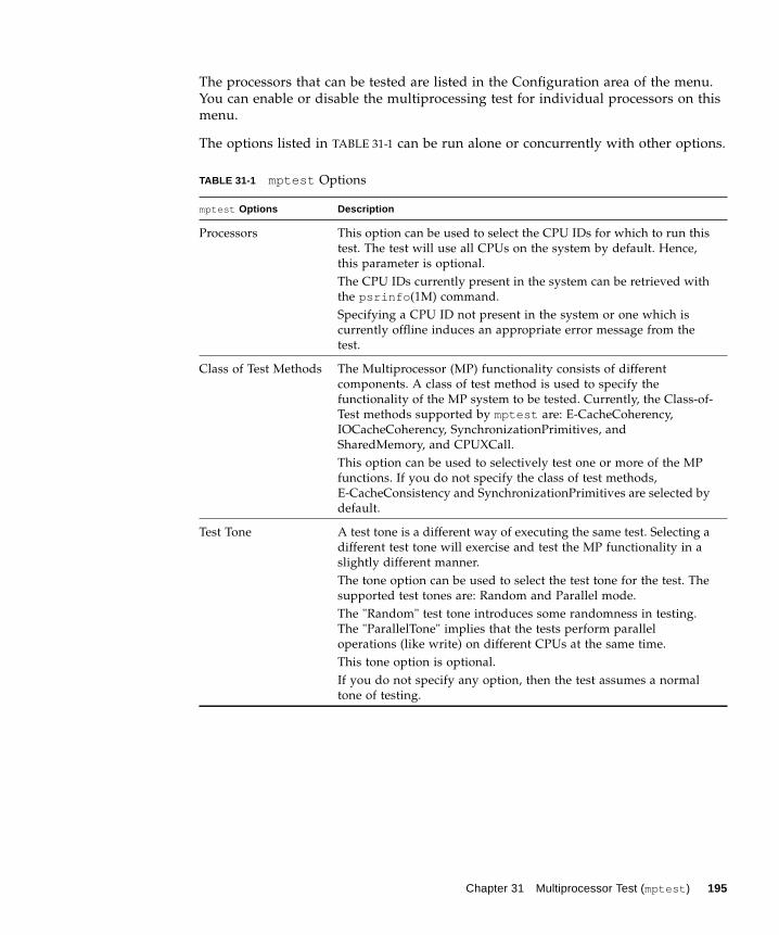
The processors that can be tested are listed in the Configuration area of the menu.
You can enable or disable the multiprocessing test for individual processors on this
menu.
The options listed in TABLE 31-1 can be run alone or concurrently with other options.
TABLE 31-1 mptest Options
mptest Options Description
Processors This option can be used to select the CPU IDs for which to run this
test. The test will use all CPUs on the system by default. Hence,
this parameter is optional.
The CPU IDs currently present in the system can be retrieved with
the psrinfo (1M) command.
Specifying a CPU ID not present in the system or one which is
currently offline induces an appropriate error message from the
test.
Class of Test Methods The Multiprocessor (MP) functionality consists of different
components. A class of test method is used to specify the
functionality of the MP system to be tested. Currently, the Class-of-
Test methods supported by mptest are: E-CacheCoherency,
IOCacheCoherency, SynchronizationPrimitives, and
SharedMemory, and CPUXCall.
This option can be used to selectively test one or more of the MP
functions. If you do not specify the class of test methods,
E-CacheConsistency and SynchronizationPrimitives are selected by
default.
Test Tone A test tone is a different way of executing the same test. Selecting a
different test tone will exercise and test the MP functionality in a
slightly different manner.
The tone option can be used to select the test tone for the test. The
supported test tones are: Random and Parallel mode.
The "Random" test tone introduces some randomness in testing.
The "ParallelTone" implies that the tests perform parallel
operations (like write) on different CPUs at the same time.
This tone option is optional.
If you do not specify any option, then the test assumes a normal
tone of testing.
Chapter 31 Multiprocessor Test (mptest ) 195
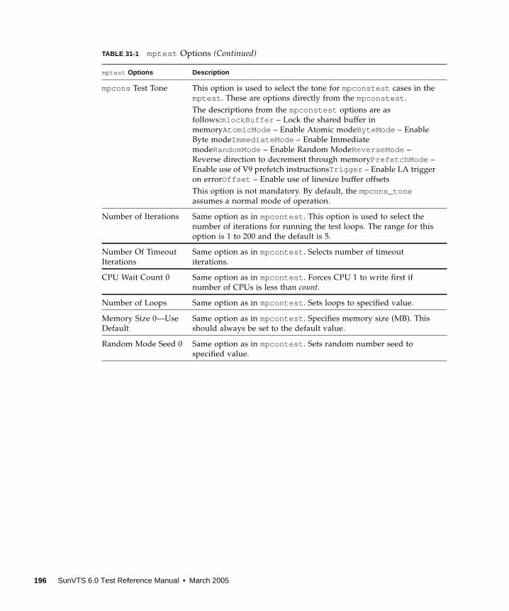
mpcons Test Tone This option is used to select the tone for mpconstest cases in the
mptest . These are options directly from the mpconstest .
The descriptions from the mpconstest options are as
follows:mlockBuffer – Lock the shared buffer in
memoryAtomicMode – Enable Atomic modeByteMode – Enable
Byte modeImmediateMode – Enable Immediate
modeRandomMode– Enable Random ModeReverseMode –
Reverse direction to decrement through memoryPrefetchMode –
Enable use of V9 prefetch instructionsTrigger – Enable LA trigger
on errorOffset – Enable use of linesize buffer offsets
This option is not mandatory. By default, the mpcons_toneassumes a normal mode of operation.
Number of Iterations Same option as in mpcontest . This option is used to select the
number of iterations for running the test loops. The range for this
option is 1 to 200 and the default is 5.
Number Of Timeout
Iterations
Same option as in mpcontest . Selects number of timeout
iterations.
CPU Wait Count 0 Same option as in mpcontest . Forces CPU 1 to write first if
number of CPUs is less than count.
Number of Loops Same option as in mpcontest . Sets loops to specified value.
Memory Size 0—Use
Default
Same option as in mpcontest . Specifies memory size (MB). This
should always be set to the default value.
Random Mode Seed 0 Same option as in mpcontest . Sets random number seed to
specified value.
TABLE 31-1 mptest Options (Continued)
mptest Options Description
196 SunVTS 6.0 Test Reference Manual • March 2005
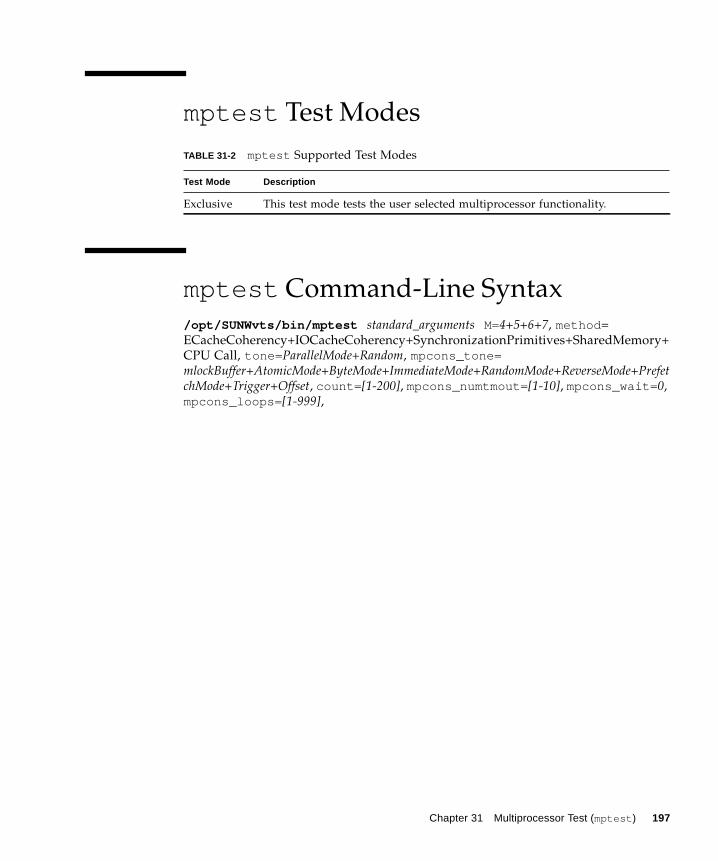
mptest Test Modes
mptest Command-Line Syntax
/opt/SUNWvts/bin/mptest standard_arguments M=4+5+6+7, method =
ECacheCoherency+IOCacheCoherency+SynchronizationPrimitives+SharedMemory+
CPU Call, tone= ParallelMode+Random, mpcons_tone=mlockBuffer+AtomicMode+ByteMode+ImmediateMode+RandomMode+ReverseMode+PrefetchMode+Trigger+Offset, count= [1-200], mpcons_numtmout= [1-10], mpcons_wait= 0,
mpcons_loops= [1-999],
TABLE 31-2 mptest Supported Test Modes
Test Mode Description
Exclusive This test mode tests the user selected multiprocessor functionality.
Chapter 31 Multiprocessor Test (mptest ) 197
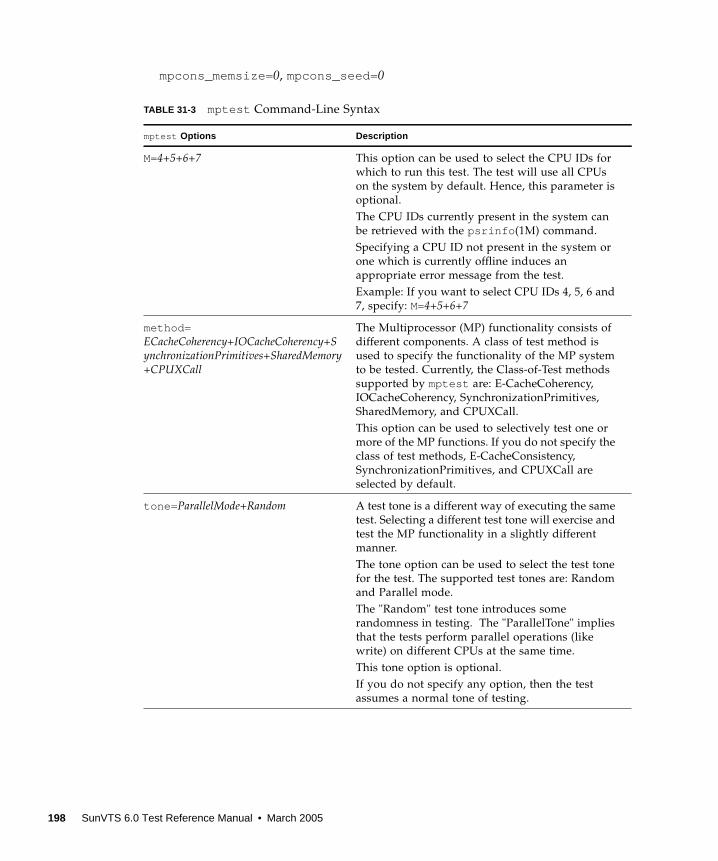
mpcons_memsize= 0, mpcons_seed= 0
TABLE 31-3 mptest Command-Line Syntax
mptest Options Description
M=4+5+6+7 This option can be used to select the CPU IDs for
which to run this test. The test will use all CPUs
on the system by default. Hence, this parameter is
optional.
The CPU IDs currently present in the system can
be retrieved with the psrinfo (1M) command.
Specifying a CPU ID not present in the system or
one which is currently offline induces an
appropriate error message from the test.
Example: If you want to select CPU IDs 4, 5, 6 and
7, specify: M=4+5+6+7
method=ECacheCoherency+IOCacheCoherency+SynchronizationPrimitives+SharedMemory+CPUXCall
The Multiprocessor (MP) functionality consists of
different components. A class of test method is
used to specify the functionality of the MP system
to be tested. Currently, the Class-of-Test methods
supported by mptest are: E-CacheCoherency,
IOCacheCoherency, SynchronizationPrimitives,
SharedMemory, and CPUXCall.
This option can be used to selectively test one or
more of the MP functions. If you do not specify the
class of test methods, E-CacheConsistency,
SynchronizationPrimitives, and CPUXCall are
selected by default.
tone= ParallelMode+Random A test tone is a different way of executing the same
test. Selecting a different test tone will exercise and
test the MP functionality in a slightly different
manner.
The tone option can be used to select the test tone
for the test. The supported test tones are: Random
and Parallel mode.
The "Random" test tone introduces some
randomness in testing. The "ParallelTone" implies
that the tests perform parallel operations (like
write) on different CPUs at the same time.
This tone option is optional.
If you do not specify any option, then the test
assumes a normal tone of testing.
198 SunVTS 6.0 Test Reference Manual • March 2005
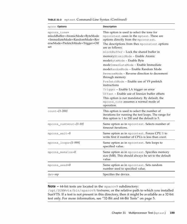
Note – 64-bit tests are located in the sparcv9 subdirectory:
/opt/SUNWvts/bin/sparcv9/ testname, or the relative path to which you installed
SunVTS. If a test is not present in this directory, then it might be available as a 32-bit
test only. For more information, see “32-Bit and 64-Bit Tests” on page 5.
mpcons_tone =
mlockBuffer+AtomicMode+ByteMode
+ImmediateMode+RandomMode+Rev
erseMode+PrefetchMode+Trigger+Off
set
This option is used to select the tone for
mpconstest cases in the mptest . These are
options directly from the mpconstest .
The descriptions from thes mpconstest options
are as follows:
mlockBuffer – Lock the shared buffer in
memoryAtomicMode – Enable Atomic
modeByteMode – Enable Byte
modeImmediateMode – Enable Immediate
modeRandomMode– Enable Random Mode
ReverseMode – Reverse direction to decrement
through memory
PrefetchMode – Enable use of V9 prefetch
instructions
Trigger – Enable LA trigger on error
Offset – Enable use of linesize buffer offsets
This option is not mandatory. By default, the
mpcons_tone assumes a normal mode of
operation.
count= [1-200] This option is used to select the number of
iterations for running the test loops. The range for
this option is 1 to 200 and the default is 5.
mpcons_numtmout= [1-10] Same option as in mpcontest . Selects number of
timeout iterations.
mpcons_wait= 0 Same option as in mpcontest . Forces CPU 1 to
write first if number of CPUs is less than count.
mpcons_loops= [1-999] Same option as in mpcontest . Sets loops to
specified value.
mpcons_memsize= 0 Same option as in mpcontest . Specifies memory
size (MB). This should always be set to the default
value.
mpcons_seed =0 Same option as in mpcontest . Sets random
number seed to specified value.
dev= mp Specifies the device.
TABLE 31-3 mptest Command-Line Syntax (Continued)
mptest Options Description
Chapter 31 Multiprocessor Test (mptest ) 199
Known Problem
On Se/Si platforms with UltraSPARC IV 2.3/2.4 parts mpcons subtest (mpcons5 and
mpcons8 ) could possibly cause a fatal reset with PERR. This error has not been
produced on the Enterprise Server family and Sun Fire 15K UltraSPARC III
platforms.
Workaround: Deactivate mpcons5 and mpcons8 when performing mptest . The
functions of mpcons5 mpcons8 were modified to perform as mpcons4 and mpcons7respectively.
200 SunVTS 6.0 Test Reference Manual • March 2005
CHAPTER 32
Sun Netra Alarm Card Test(nalmtest )
nalmtest is designed to test the alarm card on Sun Netra 240 and Sun Netra 440
servers.
Note – The Sun Netra Alarm Card Test (nalmtest ) was previously titled Sun Netra
240 Alarm Card Test (n240atest ) in SunVTS 5.1 PS5. The reason for this change is
that this test now supports the Sun Netra 440 alarm card in addition to the Sun
Netra 240 alarm card.
Caution – Solaris 8 2/02 operating system or later is required to perform the
nalmtest .
nalmtest Options
To reach the dialog box below, right-click on the test name in the System Map and
select Test Parameter Options. If you do not see this test in the System Map, you
might need to expand the collapsed groups. Refer to the SunVTS User’s Guide for
more details.
201
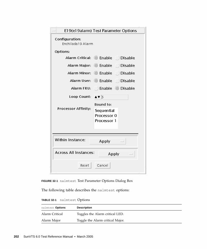
FIGURE 32-1 nalmtest Test Parameter Options Dialog Box
The following table describes the nalmtest options:
TABLE 32-1 nalmtest Options
nalmtest Options Description
Alarm Critical Toggles the Alarm critical LED.
Alarm Major Toggle the Alarm critical Major.
202 SunVTS 6.0 Test Reference Manual • March 2005
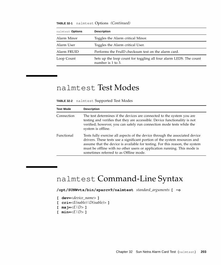
nalmtest Test Modes
nalmtest Command-Line Syntax
/opt/SUNWvts/bin/sparcv9/nalmtest standard_arguments [ -o
[ dev= <device_name> ][ cri= <E(nable)|D(isable)> ][ maj= <E|D> ][ min= <E|D> ]
Alarm Minor Toggles the Alarm critical Minor.
Alarm User Toggles the Alarm critical User.
Alarm FRUID Performs the FruID checksum test on the alarm card.
Loop Count Sets up the loop count for toggling all four alarm LEDS. The count
number is 1 to 3.
TABLE 32-2 nalmtest Supported Test Modes
Test Mode Description
Connection The test determines if the devices are connected to the system you are
testing and verifies that they are accessible. Device functionality is not
verified; however, you can safely run connection mode tests while the
system is offline.
Functional Tests fully exercise all aspects of the device through the associated device
drivers. These tests use a significant portion of the system resources and
assume that the device is available for testing. For this reason, the system
must be offline with no other users or application running. This mode is
sometimes referred to as Offline mode.
TABLE 32-1 nalmtest Options (Continued)
nalmtest Options Description
Chapter 32 Sun Netra Alarm Card Test (nalmtest ) 203
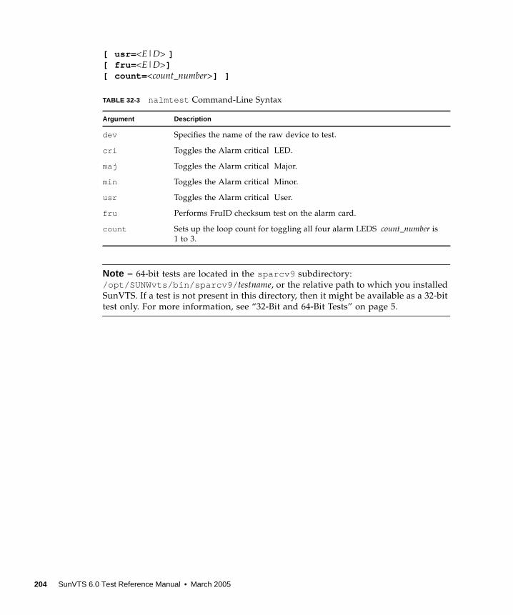
[ usr= <E|D> ][ fru= <E|D>][ count= <count_number>] ]
Note – 64-bit tests are located in the sparcv9 subdirectory:
/opt/SUNWvts/bin/sparcv9/ testname, or the relative path to which you installed
SunVTS. If a test is not present in this directory, then it might be available as a 32-bit
test only. For more information, see “32-Bit and 64-Bit Tests” on page 5.
TABLE 32-3 nalmtest Command-Line Syntax
Argument Description
dev Specifies the name of the raw device to test.
cri Toggles the Alarm critical LED.
maj Toggles the Alarm critical Major.
min Toggles the Alarm critical Minor.
usr Toggles the Alarm critical User.
fru Performs FruID checksum test on the alarm card.
count Sets up the loop count for toggling all four alarm LEDS count_number is
1 to 3.
204 SunVTS 6.0 Test Reference Manual • March 2005
CHAPTER 33
Ethernet Loopback Test(netlbtest )
The netlbtest replaces the gemtest previously included in SunVTS. It provides
functional test coverage of the devices which have device drivers that support the
Ethernet loopback test. These devices include eri (the Ethernet device in the RIO
chip) and ge (Gigabit Ethernet), ce (GigaSwift Ethernet), dmfe (10/100 Mbps
Ethernet), and vca (Sun Crypto Accelerator 4000). The netlbtest runs in loopback
(external/internal) mode.
Note – netlbtest does support x86 platforms on Solaris.
Note – For x86 platforms, netlbtest only supports network drivers that have
been ported over to x86 Solaris platforms. netlbtest has been tested with Sun
GigaSwift based cards on x86 systems.
The netlbtest uses DLPI RAW mode to talk to the device driver. For the purpose
of this test, a packet is defined as an Ethernet header followed by the Ethernet data
payload (refer to the IEEE 802.3z standard). The test generates and sends out the
desired number of packets (a tunable parameter) and expects to receive the same
number of packets through the loopback interface, external or internal. If an error
occurs (for example, packet mismatch or timeout), an error message indicating the
type of error, its probable cause(s), and recommended action(s) is displayed on the
SunVTS console.
The data sent out is generated by a random number generator, and put into a data
buffer. Each time a packet is sent, it is selected from a different starting point of the
data buffer, so that any two consecutively transmitted packets will not be the same.
Note – Do not run nettest and netlbtest at the same time or the tests may fail.
205
A new debugging capability has been added in netlbtest . After one packet is not
received, four more packets are transmitted. If all of them are not received within the
timeout time, the test will stop with the error message, "timed out for receiving ...".
If up to four packets are missing, the test will stop with an error message, "Missed
%d packet(s)...". If a packet is received late and the current transmitted packet is not
received, the test will stop with a warning message, "Packet delay...". If the packets
arrived late but within five times the timeout value and no packet is missing, the test
will pass.
netlbtest Test Requirements
You must have the Ethernet card and the device driver installed, a loopback
connector in place, and Intervention mode enabled before running netlbtest .
netlbtest cannot run and will not appear in the GUI if the network interface is
connected to a live network; netlbtest also requires that the ethernet device be
configured offline before running the test. Use the ifconfig(1M) command to
bring the Ethernet device down before running netlbtest . Enter the following
commands to bring the interface down:
To run netlbtest , a loopback connector must be connected to the Ethernet
interface. A loopback connector provides the network interface driver the necessary
link for testing, while maintaining isolation from a live network. The loopback
connector is required for both internal and external tests of the Ethernet device.
The loopback cable for ge and Sun GigaSwift Ethernet MMF adapter (ce fiber) is
based on the following specifications: multimode, duplex, 62.5/125 micron, sc
connector, 850nm. The cable can be made by splitting a standard fiber optic cable in
two. The two ends of the cable should be connected to the TX and RX ports of the
adapter (the order does not matter), thus forming a loop.
The loopback connector for the eri device is a standard RJ-45 connector. See
Appendix A in the SunVTS User’s Guide for the diagram. The loopback connector
for a Sun GigaSwift Ethernet UTP adapter (ce copper) is a standard RJ-45 with all 8
pins connected. See Appendix A of the SunVTS User’s Guide for the diagram.
# ifconfig interface down# ifconfig interface unplumb
206 SunVTS 6.0 Test Reference Manual • March 2005
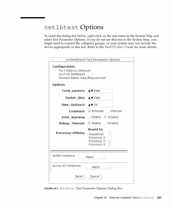
netlbtest Options
To reach the dialog box below, right-click on the test name in the System Map and
select Test Parameter Options. If you do not see this test in the System Map, you
might need to expand the collapsed groups, or your system may not include the
device appropriate to this test. Refer to the SunVTS User’s Guide for more details.
FIGURE 33-1 netlbtest Test Parameter Options Dialog Box
Chapter 33 Ethernet Loopback Test (netlbtest ) 207
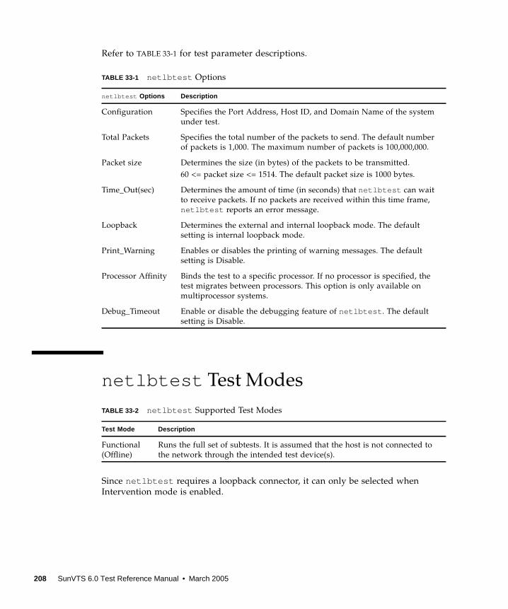
Refer to TABLE 33-1 for test parameter descriptions.
netlbtest Test Modes
Since netlbtest requires a loopback connector, it can only be selected when
Intervention mode is enabled.
TABLE 33-1 netlbtest Options
netlbtest Options Description
Configuration Specifies the Port Address, Host ID, and Domain Name of the system
under test.
Total Packets Specifies the total number of the packets to send. The default number
of packets is 1,000. The maximum number of packets is 100,000,000.
Packet size Determines the size (in bytes) of the packets to be transmitted.
60 <= packet size <= 1514. The default packet size is 1000 bytes.
Time_Out(sec) Determines the amount of time (in seconds) that netlbtest can wait
to receive packets. If no packets are received within this time frame,
netlbtest reports an error message.
Loopback Determines the external and internal loopback mode. The default
setting is internal loopback mode.
Print_Warning Enables or disables the printing of warning messages. The default
setting is Disable.
Processor Affinity Binds the test to a specific processor. If no processor is specified, the
test migrates between processors. This option is only available on
multiprocessor systems.
Debug_Timeout Enable or disable the debugging feature of netlbtest . The default
setting is Disable.
TABLE 33-2 netlbtest Supported Test Modes
Test Mode Description
Functional
(Offline)
Runs the full set of subtests. It is assumed that the host is not connected to
the network through the intended test device(s).
208 SunVTS 6.0 Test Reference Manual • March 2005

netlbtest Command-Line Syntax
/opt/SUNWvts/bin/netlbtest standard_arguments-o dev= device, tpkts= n, pksz= pkt_size, lb= Internal, warn= Disable,timeout= number_of_seconds
Note – 64-bit tests are located in the sparcv9 subdirectory:
/opt/SUNWvts/bin/sparcv9/ testname, or the relative path to which you installed
SunVTS. If a test is not present in this directory, then it might be available as a 32-bit
test only. For more information, see “32-Bit and 64-Bit Tests” on page 5.
TABLE 33-3 netlbtest Command-Line Syntax
Argument Description
dev= device_name Specifies the device to test such as ge0 or eri0 .
tpkts= n [1...100000], count of packets to loopback. The maximum number
of packets is 100,000,000.
pksz= pkt_size [60... 1514], packet size in bytes.
lb= Internal Selects internal (or external) loopback mode.
warn= Disable Enables or disables printing of warning messages.
timeout=number_of_seconds
Determines the amount of time (in seconds) that netlbtest can
wait to receive packets. If no packets are received within this time
frame, netlbtest reports an error message. The range for timeout
is from 1 to 1,000 seconds.
Chapter 33 Ethernet Loopback Test (netlbtest ) 209

210 SunVTS 6.0 Test Reference Manual • March 2005

CHAPTER 34
Network Hardware Test (nettest )
nettest checks all the networking hardware on the system CPU board and
separate networking controllers (for example, a second SBus Ethernet controller). For
this test to be meaningful, the machine under test must be attached to a network
with at least one other system on the network.
Note – nettest does support x86 platforms that use the Solaris operating system.
nettest supports the same set of options for both SPARC and x86 platforms. If
there is a new x86 specific network interface, for which there is no entry in the
nettest.conf file, then nettest will fail.
Note – This version of nettest is used for all networking devices, including
Ethernet (ie and le ), token ring (tr , trp ), quad Ethernet (QED), fiber optic (fddi ,
nf , bf , pf ), SPARCcluster™ 1 system (em), ATM (sa , ba), HiPPI, 100-Mbits per
second Ethernet (be,hme ), and GigaSwift Ethernet (ce ) devices.
The nettest mainly uses the Internet Control Message Protocol (ICMP), and
requires at least two machines on a network—the machine under test and another
machine reliable enough to be a test target. Both machines must support the
Transmission Control Protocol/Internet Protocol (TCP/IP) (ICMP is part of TCP/IP).
The target machine must either be configured to respond to ICMP broadcast or to
RPC broadcast.
First nettest determines the target machine(s) to test against. If no targets are
specified, it sends an ICMP broadcast to find them. If it fails to find all necessary
targets, it tries RPC broadcast to the RPC port mapper daemon. If you specify the
targets, nettest uses the specified target(s) instead.
After finding the necessary targets, nettest performs the following tests:
■ Random test—sends out 256 packets with random data length and random data.
211
■ Incremental test—sends out packets with length from minimum to maximum
packet size using incremental data. (Minimum and maximum values differ for
each device.)
■ Pattern test—sends 256 packets of maximum length, where each packet contains
one test pattern, and all byte patterns (0 to 0xFF hex) are used. That is, the first
packet contains pattern 0, the second packet contains pattern 1, and so on, until
the last packet pattern of 0xFF.
Note – nettest is a scalable test. However, the maximum number of networked
devices allowed on a system is 255, and the number of instances for each device is
limited to 2. So, if you start the SunVTS exerciser using the -i option to specify a
default number of instances for all tests, nettest cannot assign more than 2
instances per each networked device.
nettest Options
To reach the dialog box below, right-click on the test name in the System Map and
select Test Parameter Options. If you do not see this test in the System Map, you
might need to expand the collapsed groups, or your system may not include the
device appropriate to this test. Refer to the SunVTS User’s Guide for more details.
212 SunVTS 6.0 Test Reference Manual • March 2005
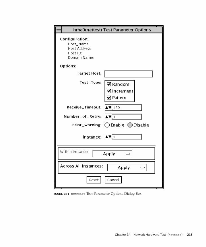
FIGURE 34-1 nettest Test Parameter Options Dialog Box
Chapter 34 Network Hardware Test (nettest ) 213
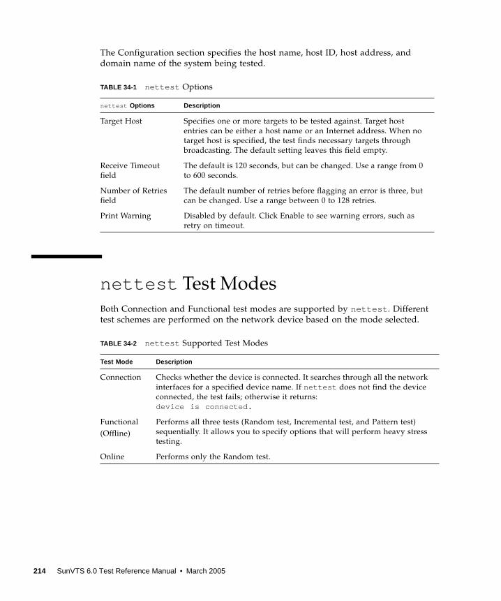
The Configuration section specifies the host name, host ID, host address, and
domain name of the system being tested.
nettest Test Modes
Both Connection and Functional test modes are supported by nettest . Different
test schemes are performed on the network device based on the mode selected.
TABLE 34-1 nettest Options
nettest Options Description
Target Host Specifies one or more targets to be tested against. Target host
entries can be either a host name or an Internet address. When no
target host is specified, the test finds necessary targets through
broadcasting. The default setting leaves this field empty.
Receive Timeout
field
The default is 120 seconds, but can be changed. Use a range from 0
to 600 seconds.
Number of Retries
field
The default number of retries before flagging an error is three, but
can be changed. Use a range between 0 to 128 retries.
Print Warning Disabled by default. Click Enable to see warning errors, such as
retry on timeout.
TABLE 34-2 nettest Supported Test Modes
Test Mode Description
Connection Checks whether the device is connected. It searches through all the network
interfaces for a specified device name. If nettest does not find the device
connected, the test fails; otherwise it returns:
device is connected.
Functional
(Offline)
Performs all three tests (Random test, Incremental test, and Pattern test)
sequentially. It allows you to specify options that will perform heavy stress
testing.
Online Performs only the Random test.
214 SunVTS 6.0 Test Reference Manual • March 2005
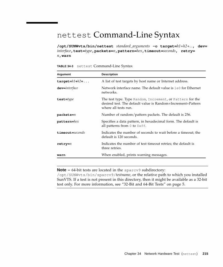
nettest Command-Line Syntax
/opt/SUNWvts/bin/nettest standard_arguments -o target= h1+h2+..., dev=interface,test= type,packets= n,pattern= hex,timeout= seconds, retry=n,warn
Note – 64-bit tests are located in the sparcv9 subdirectory:
/opt/SUNWvts/bin/sparcv9/ testname, or the relative path to which you installed
SunVTS. If a test is not present in this directory, then it might be available as a 32-bit
test only. For more information, see “32-Bit and 64-Bit Tests” on page 5.
TABLE 34-3 nettest Command-Line Syntax
Argument Description
target= h1+h2+... A list of test targets by host name or Internet address.
dev= interface Network interface name. The default value is le0 for Ethernet
networks.
test= type The test type. Type Random, Increment , or Pattern for the
desired test. The default value is Random+Increment+Pattern
where all tests run.
packets= n Number of random/pattern packets. The default is 256.
pattern= hex Specifies a data pattern, in hexadecimal form. The default is
all patterns from 0 to 0xff .
timeout= seconds Indicates the number of seconds to wait before a timeout; the
default is 120 seconds.
retry= n Indicates the number of test timeout retries; the default is
three retries.
warn When enabled, prints warning messages.
Chapter 34 Network Hardware Test (nettest ) 215

216 SunVTS 6.0 Test Reference Manual • March 2005
CHAPTER 35
Netra CT-820 IPMI Test(nipmitest )
The nipmitest exercises and verifies the basic operation of the IPMI bus and
communications between the CP2300 board to the DMC (distributed management
controller) board. The test sends IPMI commands and waits for a response. The test
retries up to three times no response is received.
nipmitest Options
To reach the dialog box below, right-click on the test name in the System Map and
select Test Parameter Options. If you do not see this test in the System Map, you
might need to expand the collapsed groups, or your system may not include the
device appropriate to this test. Refer to the SunVTS User’s Guide for more details.
217
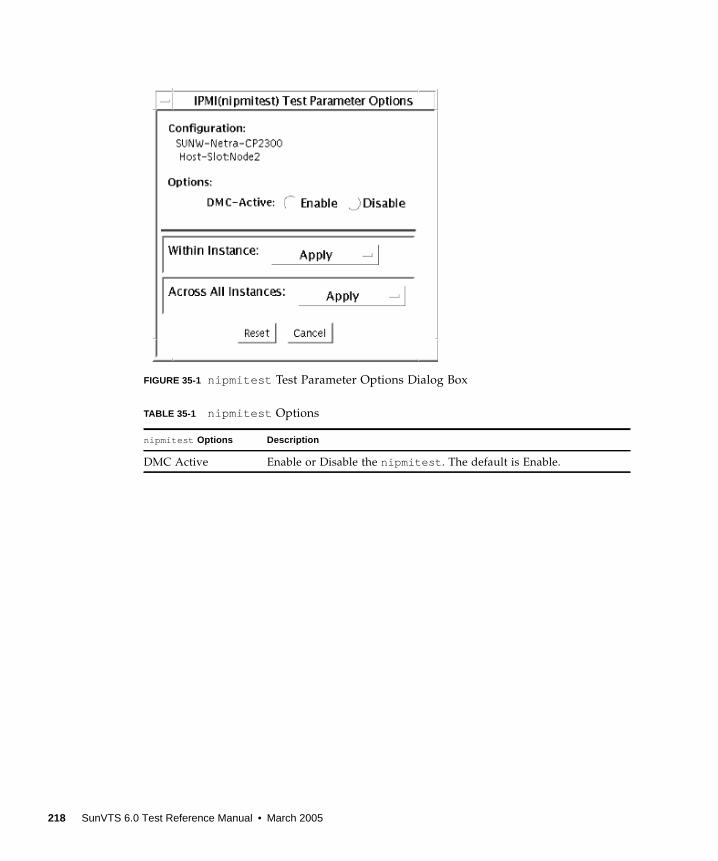
FIGURE 35-1 nipmitest Test Parameter Options Dialog Box
TABLE 35-1 nipmitest Options
nipmitest Options Description
DMC Active Enable or Disable the nipmitest . The default is Enable.
218 SunVTS 6.0 Test Reference Manual • March 2005
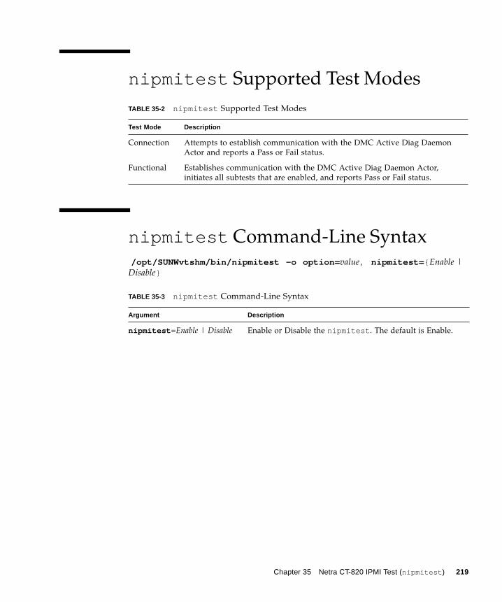
nipmitest Supported Test Modes
nipmitest Command-Line Syntax
/opt/SUNWvtshm/bin/nipmitest -o option= value, nipmitest= { Enable |Disable}
TABLE 35-2 nipmitest Supported Test Modes
Test Mode Description
Connection Attempts to establish communication with the DMC Active Diag Daemon
Actor and reports a Pass or Fail status.
Functional Establishes communication with the DMC Active Diag Daemon Actor,
initiates all subtests that are enabled, and reports Pass or Fail status.
TABLE 35-3 nipmitest Command-Line Syntax
Argument Description
nipmitest =Enable | Disable Enable or Disable the nipmitest . The default is Enable.
Chapter 35 Netra CT-820 IPMI Test (nipmitest ) 219

220 SunVTS 6.0 Test Reference Manual • March 2005
CHAPTER 36
PCMCIA Modem Card Test(pcsertest )
PCMCIA is a technology that provides small, easy to use peripheral devices.
PCMCIA stands for Personal Computer Memory Card International Association. It
is a PC Card standard for mobile computing I/O cards. These cards range from
memory, FAX/modems, serial I/O, SCSI, video, sound, and so on.
The pcsertest verifies the functionality of PCMCIA modem card and PCMCIA
serial I/O socket card. It does not test any other PCMCIA devices.
The pcsertest issues a series of commands to the modem to initiate a local analog
loopback test and verifies this functionality.
As an option, the pcsertest tests serial I/O socket cards. This test writes a pattern
of incrementing data to the serial I/O socket card, which is then looped back, read
and verified.
Note – When testing serial I/O socket cards, a 9-pin loopback connector is required.
However, no loopback connector is required when testing the default modem card.
See Appendix A for loopback connector wiring instructions.
pcsertest Options
To reach the dialog box below, right-click on the test name in the System Map and
select Test Parameter Options. If you do not see this test in the System Map, you
might need to expand the collapsed groups, or your system may not include the
device appropriate to this test. Refer to the SunVTS User’s Guide for more details.
221
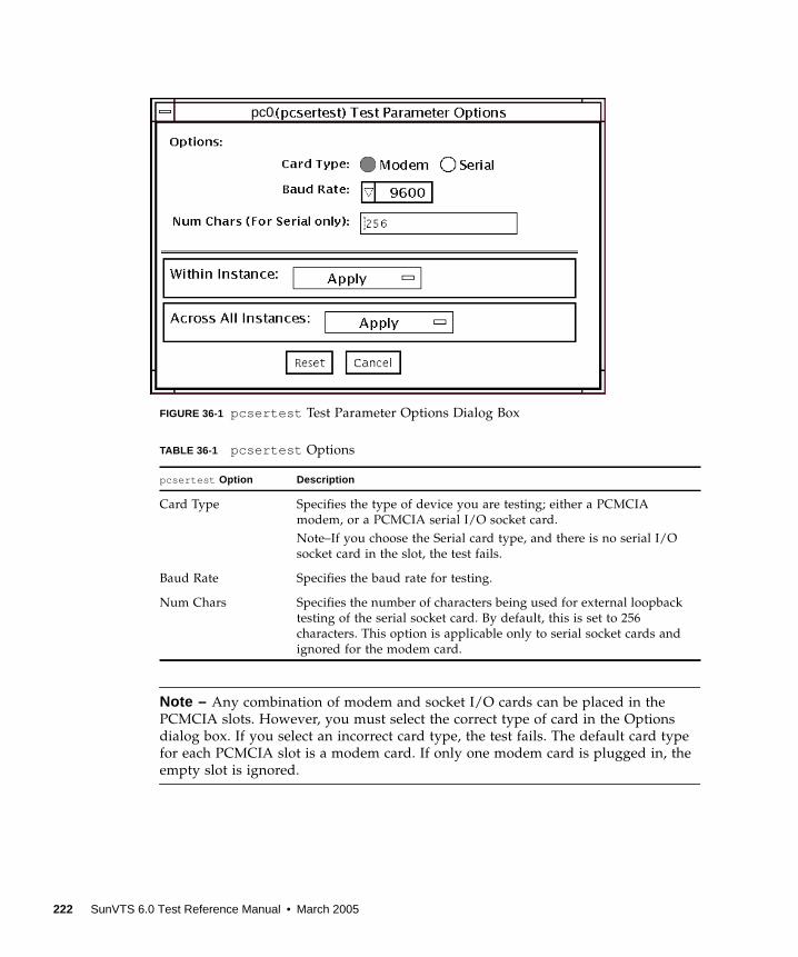
FIGURE 36-1 pcsertest Test Parameter Options Dialog Box
Note – Any combination of modem and socket I/O cards can be placed in the
PCMCIA slots. However, you must select the correct type of card in the Options
dialog box. If you select an incorrect card type, the test fails. The default card type
for each PCMCIA slot is a modem card. If only one modem card is plugged in, the
empty slot is ignored.
TABLE 36-1 pcsertest Options
pcsertest Option Description
Card Type Specifies the type of device you are testing; either a PCMCIA
modem, or a PCMCIA serial I/O socket card.
Note–If you choose the Serial card type, and there is no serial I/O
socket card in the slot, the test fails.
Baud Rate Specifies the baud rate for testing.
Num Chars Specifies the number of characters being used for external loopback
testing of the serial socket card. By default, this is set to 256
characters. This option is applicable only to serial socket cards and
ignored for the modem card.
pc0
222 SunVTS 6.0 Test Reference Manual • March 2005
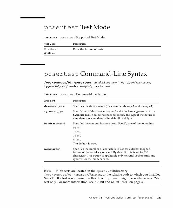
pcsertest Test Mode
pcsertest Command-Line Syntax
/opt/SUNWvts/bin/pcsertest standard_arguments -o dev= device_name,type= card_type,baudrate= speed,numchars= n
Note – 64-bit tests are located in the sparcv9 subdirectory:
/opt/SUNWvts/bin/sparcv9/ testname, or the relative path to which you installed
SunVTS. If a test is not present in this directory, then it might be available as a 32-bit
test only. For more information, see “32-Bit and 64-Bit Tests” on page 5.
TABLE 36-2 pcsertest Supported Test Modes
Test Mode Description
Functional
(Offline)
Runs the full set of tests.
TABLE 36-3 pcsertest Command-Line Syntax
Argument Description
dev= device_name Specifies the device name (for example, dev=pc0 and dev=pc1 )
type= card_type Specify one of the two card types for the device ( type=serial or
type=modem ). You do not need to specify the type if the device is
a modem, since modem is the default card type.
baudrate= speed Specifies the communication speed. Specify one of the following:
9600
19200
38400
57600
The default is 9600 .
numchars= n Specifies the number of characters to use for external loopback
testing of the serial socket card. By default, this is set to 256characters. This option is applicable only to serial socket cards and
ignored for the modem card.
Chapter 36 PCMCIA Modem Card Test (pcsertest ) 223

224 SunVTS 6.0 Test Reference Manual • March 2005
CHAPTER 37
Sun™ XVR-100 GraphicsAccelerator Test (pfbtest )
pfbtest tests the PCI-based Sun™ XVR-100 graphics accelerator by performing the
following subtests:
■ Video Memory test
■ RAMDAC test
■ Accelerator Port test
Caution – Do not run any other application or screen saver program that uses the
Sun XVR-100 graphics accelerator port while running pfbtest . This program
causes SunVTS to return incorrect errors.
Caution – If pfb0b is set to display, an error similar to the following occurs:
Accelerator: signature err or in test Ramdac.
Display should always be set to pfb0a when running SunVTS.
Note – Disable all screen savers before testing any graphics device. Type
xset s off at a UNIX prompt to disable the Solaris screen saver. Type
xset -dpms (to turn off power management) or type xset s noblank (to turn
off screen saver). Disable Power Management software if it is running.
Note – To start SunVTS with vtsui , but without vtsk , you must add the host
name to xhost as: xhost + hostname.
For full instructions on testing frame buffers, refer to the Testing Frame Buffers
section of the SunVTS 5.1 Test Reference Manual.
225
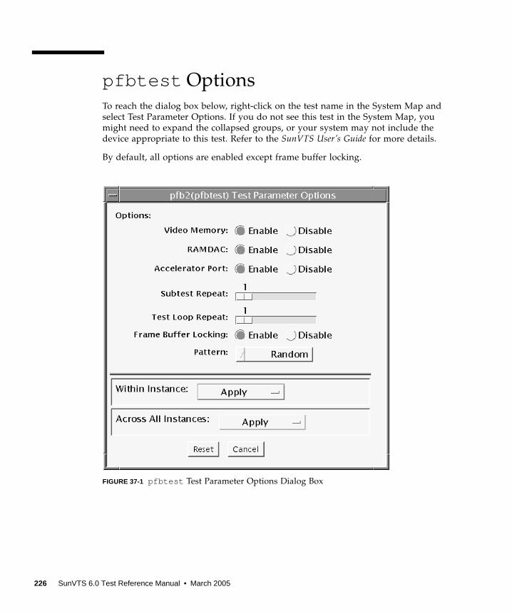
pfbtest Options
To reach the dialog box below, right-click on the test name in the System Map and
select Test Parameter Options. If you do not see this test in the System Map, you
might need to expand the collapsed groups, or your system may not include the
device appropriate to this test. Refer to the SunVTS User’s Guide for more details.
By default, all options are enabled except frame buffer locking.
FIGURE 37-1 pfbtest Test Parameter Options Dialog Box
226 SunVTS 6.0 Test Reference Manual • March 2005
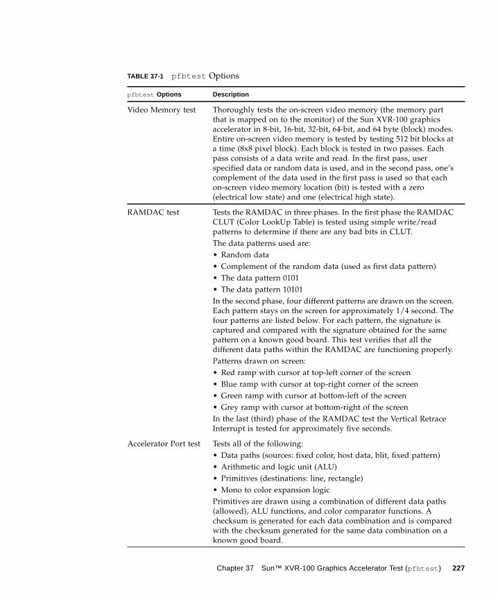
TABLE 37-1 pfbtest Options
pfbtest Options Description
Video Memory test Thoroughly tests the on-screen video memory (the memory part
that is mapped on to the monitor) of the Sun XVR-100 graphics
accelerator in 8-bit, 16-bit, 32-bit, 64-bit, and 64 byte (block) modes.
Entire on-screen video memory is tested by testing 512 bit blocks at
a time (8x8 pixel block). Each block is tested in two passes. Each
pass consists of a data write and read. In the first pass, user
specified data or random data is used, and in the second pass, one’s
complement of the data used in the first pass is used so that each
on-screen video memory location (bit) is tested with a zero
(electrical low state) and one (electrical high state).
RAMDAC test Tests the RAMDAC in three phases. In the first phase the RAMDAC
CLUT (Color LookUp Table) is tested using simple write/read
patterns to determine if there are any bad bits in CLUT.
The data patterns used are:
• Random data
• Complement of the random data (used as first data pattern)
• The data pattern 0101
• The data pattern 10101
In the second phase, four different patterns are drawn on the screen.
Each pattern stays on the screen for approximately 1/4 second. The
four patterns are listed below. For each pattern, the signature is
captured and compared with the signature obtained for the same
pattern on a known good board. This test verifies that all the
different data paths within the RAMDAC are functioning properly.
Patterns drawn on screen:
• Red ramp with cursor at top-left corner of the screen
• Blue ramp with cursor at top-right corner of the screen
• Green ramp with cursor at bottom-left of the screen
• Grey ramp with cursor at bottom-right of the screen
In the last (third) phase of the RAMDAC test the Vertical Retrace
Interrupt is tested for approximately five seconds.
Accelerator Port test Tests all of the following:
• Data paths (sources: fixed color, host data, blit, fixed pattern)
• Arithmetic and logic unit (ALU)
• Primitives (destinations: line, rectangle)
• Mono to color expansion logic
Primitives are drawn using a combination of different data paths
(allowed), ALU functions, and color comparator functions. A
checksum is generated for each data combination and is compared
with the checksum generated for the same data combination on a
known good board.
Chapter 37 Sun™ XVR-100 Graphics Accelerator Test (pfbtest ) 227
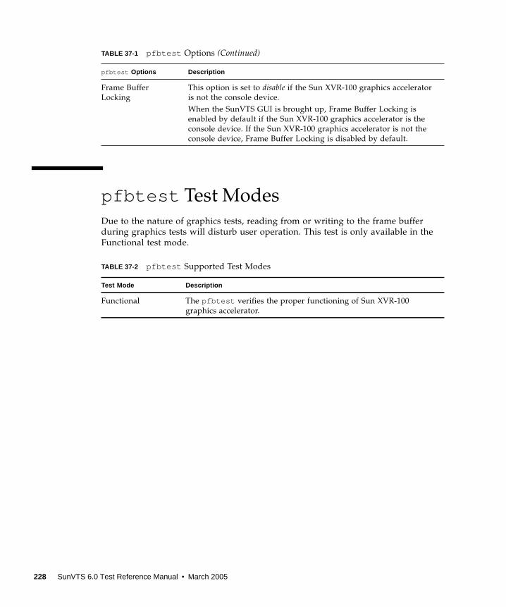
pfbtest Test Modes
Due to the nature of graphics tests, reading from or writing to the frame buffer
during graphics tests will disturb user operation. This test is only available in the
Functional test mode.
Frame Buffer
Locking
This option is set to disable if the Sun XVR-100 graphics accelerator
is not the console device.
When the SunVTS GUI is brought up, Frame Buffer Locking is
enabled by default if the Sun XVR-100 graphics accelerator is the
console device. If the Sun XVR-100 graphics accelerator is not the
console device, Frame Buffer Locking is disabled by default.
TABLE 37-2 pfbtest Supported Test Modes
Test Mode Description
Functional The pfbtest verifies the proper functioning of Sun XVR-100
graphics accelerator.
TABLE 37-1 pfbtest Options (Continued)
pfbtest Options Description
228 SunVTS 6.0 Test Reference Manual • March 2005
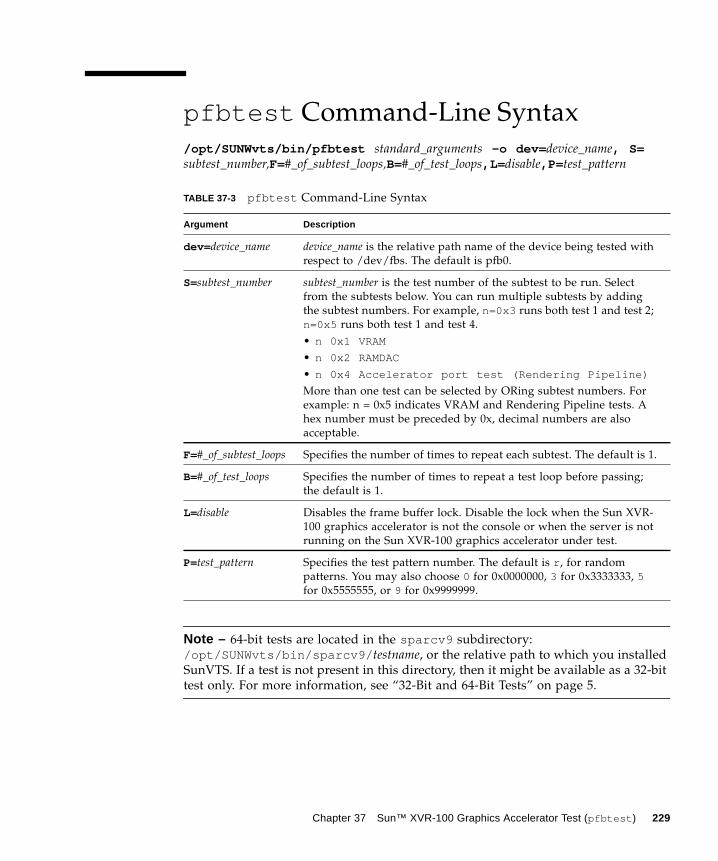
pfbtest Command-Line Syntax
/opt/SUNWvts/bin/pfbtest standard_arguments -o dev= device_name, S=subtest_number,F=#_of_subtest_loops,B=#_of_test_loops,L= disable,P= test_pattern
Note – 64-bit tests are located in the sparcv9 subdirectory:
/opt/SUNWvts/bin/sparcv9/ testname, or the relative path to which you installed
SunVTS. If a test is not present in this directory, then it might be available as a 32-bit
test only. For more information, see “32-Bit and 64-Bit Tests” on page 5.
TABLE 37-3 pfbtest Command-Line Syntax
Argument Description
dev= device_name device_name is the relative path name of the device being tested with
respect to /dev/fbs. The default is pfb0.
S=subtest_number subtest_number is the test number of the subtest to be run. Select
from the subtests below. You can run multiple subtests by adding
the subtest numbers. For example, n=0x3 runs both test 1 and test 2;
n=0x5 runs both test 1 and test 4.
• n 0x1 VRAM
• n 0x2 RAMDAC
• n 0x4 Accelerator port test (Rendering Pipeline)
More than one test can be selected by ORing subtest numbers. For
example: n = 0x5 indicates VRAM and Rendering Pipeline tests. A
hex number must be preceded by 0x, decimal numbers are also
acceptable.
F=#_of_subtest_loops Specifies the number of times to repeat each subtest. The default is 1.
B=#_of_test_loops Specifies the number of times to repeat a test loop before passing;
the default is 1.
L=disable Disables the frame buffer lock. Disable the lock when the Sun XVR-
100 graphics accelerator is not the console or when the server is not
running on the Sun XVR-100 graphics accelerator under test.
P=test_pattern Specifies the test pattern number. The default is r , for random
patterns. You may also choose 0 for 0x0000000, 3 for 0x3333333, 5for 0x5555555, or 9 for 0x9999999.
Chapter 37 Sun™ XVR-100 Graphics Accelerator Test (pfbtest ) 229
Note – Errors returned by pfbtest are nonspecific. It is not possible to determine
which component caused a failure. In all error conditions, the field replaceable unit
(FRU) is the entire Sun XVR-100 graphics accelerator.
230 SunVTS 6.0 Test Reference Manual • March 2005
CHAPTER 38
Physical Memory Test (pmemtest )
The pmemtest checks the physical memory of the system and reports hard and soft
error correction code (ECC) errors, memory read errors, and addressing problems.
The pseudo driver memis used to read the physical memory.
Note – pmemtest supports the same set of options for both SPARC and x86
platforms.
This test reads through all the available physical memory. It does not write to any
physical memory location.
pmemtest Options
pmemtest is supported both in physical mapping and logical mapping displays in
the UI. In physical mapping, pmemtest provides support to test the memory on a
per-board basis; users can select the pmemtest which is displayed under the
physical memory board, which is to be tested and test only that board. In logical
mapping, the pmemtest options apply to the complete memory across the boards.
231
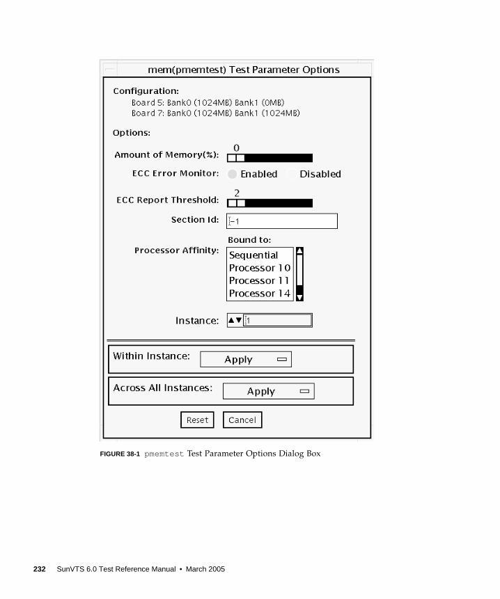
FIGURE 38-1 pmemtest Test Parameter Options Dialog Box
232 SunVTS 6.0 Test Reference Manual • March 2005

Note – The amount of memory option is specified on a “per instance” basis. The
real memory coverage for one test pass depends on the amount of memory option
and the number of instances. For example, if there are four instances, and each
instance specifies “50%” for the amount of memory option, then this will result in
“200%” (4 times 50%) coverage on each test pass. For guaranteed 100% memory
coverage for each test pass, choose default percentage size option as 0% for all
instances.
TABLE 38-1 pmemtest Options
pmemtest Options Description
Configuration Shows the total amount of physical memory, rounded up to the
nearest megabyte, probed by the SunVTS kernel.
Amount of Memory Specifies the percentage of the physical memory to be tested. The
default 0% ensures dividing the total memory equally among
instances which results in 100% coverage at the completion of every
test pass. Note that one test pass includes one pass each by all
instances.
ECC Error Monitor This option is used to enable or disable ECC error monitoring.
ECC Report
Threshold
Determines how many correctable ECC errors occurred in the
elapsed time before pmemtest reports a test failure. A value of zero
results in no report of any correctable ECC errors. The default is 2.
This option is only available on UltraSPARC systems.
Section ID When set to -1, pmemtest will test one memory section in each pass,
automatically testing each subsequent memory section as testing
progresses. When set to a number other than -1, only the section
specified will be tested. A section is defined by the pass and
instance number settings. This option is only available on
UltraSPARC systems.
Instance Instances are the number of copies of pmemtest to run
simultaneously on the memory being tested.
Chapter 38 Physical Memory Test (pmemtest ) 233
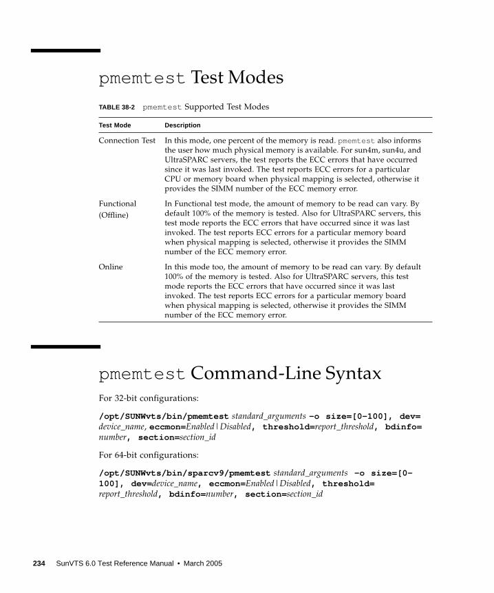
pmemtest Test Modes
pmemtest Command-Line Syntax
For 32-bit configurations:
/opt/SUNWvts/bin/pmemtest standard_arguments -o size=[0-100], dev=device_name, eccmon=Enabled|Disabled, threshold= report_threshold, bdinfo=number, section= section_id
For 64-bit configurations:
/opt/SUNWvts/bin/sparcv9/pmemtest standard_arguments -o size=[0-100], dev= device_name, eccmon= Enabled|Disabled, threshold=report_threshold, bdinfo= number, section= section_id
TABLE 38-2 pmemtest Supported Test Modes
Test Mode Description
Connection Test In this mode, one percent of the memory is read. pmemtest also informs
the user how much physical memory is available. For sun4m, sun4u, and
UltraSPARC servers, the test reports the ECC errors that have occurred
since it was last invoked. The test reports ECC errors for a particular
CPU or memory board when physical mapping is selected, otherwise it
provides the SIMM number of the ECC memory error.
Functional
(Offline)
In Functional test mode, the amount of memory to be read can vary. By
default 100% of the memory is tested. Also for UltraSPARC servers, this
test mode reports the ECC errors that have occurred since it was last
invoked. The test reports ECC errors for a particular memory board
when physical mapping is selected, otherwise it provides the SIMM
number of the ECC memory error.
Online In this mode too, the amount of memory to be read can vary. By default
100% of the memory is tested. Also for UltraSPARC servers, this test
mode reports the ECC errors that have occurred since it was last
invoked. The test reports ECC errors for a particular memory board
when physical mapping is selected, otherwise it provides the SIMM
number of the ECC memory error.
234 SunVTS 6.0 Test Reference Manual • March 2005
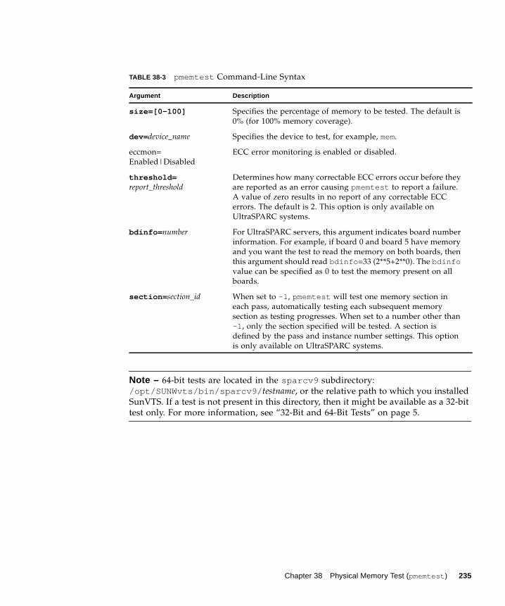
Note – 64-bit tests are located in the sparcv9 subdirectory:
/opt/SUNWvts/bin/sparcv9/ testname, or the relative path to which you installed
SunVTS. If a test is not present in this directory, then it might be available as a 32-bit
test only. For more information, see “32-Bit and 64-Bit Tests” on page 5.
TABLE 38-3 pmemtest Command-Line Syntax
Argument Description
size=[0-100] Specifies the percentage of memory to be tested. The default is
0% (for 100% memory coverage).
dev= device_name Specifies the device to test, for example, mem.
eccmon=
Enabled|Disabled
ECC error monitoring is enabled or disabled.
threshold=report_threshold
Determines how many correctable ECC errors occur before they
are reported as an error causing pmemtest to report a failure.
A value of zero results in no report of any correctable ECC
errors. The default is 2. This option is only available on
UltraSPARC systems.
bdinfo= number For UltraSPARC servers, this argument indicates board number
information. For example, if board 0 and board 5 have memory
and you want the test to read the memory on both boards, then
this argument should read bdinfo =33 (2**5+2**0). The bdinfovalue can be specified as 0 to test the memory present on all
boards.
section= section_id When set to -1 , pmemtest will test one memory section in
each pass, automatically testing each subsequent memory
section as testing progresses. When set to a number other than
-1 , only the section specified will be tested. A section is
defined by the pass and instance number settings. This option
is only available on UltraSPARC systems.
Chapter 38 Physical Memory Test (pmemtest ) 235

236 SunVTS 6.0 Test Reference Manual • March 2005
CHAPTER 39
Parallel Port Printer Test (pptest )
The pptest exercises the parallel port devices. The test supports Sbus parallel port
and IEEE 1286 complaint parallel port.
The parallel port device is an exclusive use device. Only one application can
interface with it at a time.
This test is not scalable.
Hardware and Software Requirements
The SBus printer card or IEEE 1284 compliant parallel port device and device drivers
must be installed to run pptest. To run the optional printer subtest, a printer must be
attached to the printer port, and be powered-up.
To run the optional external loopback test on IEEE 1284 compliant parallel port
device, a passive loopback connector must be installed on the printer port.
Note – The external loopback test for IEEE 1284 compliant parallel port device is
intended for Sun internal manufacturing use only. It requires a custom loopback
connector not available to an external customer.
Large PostScript files or raster files may require that the printer has 2 MB or more of
memory. Otherwise, the printout may appear on two different sheets of paper
237
pptest Subtests
pptest supports the following subtests.
pptest Options
To reach the dialog box below, right-click on the test name in the System Map and
select Test Parameter Options. If you do not see this test in the System Map, you
might need to expand the collapsed groups, or your system may not include the
device appropriate to this test. Refer to the SunVTS User’s Guide for more details.
TABLE 39-1
Subtest Description
Internal Test FIFO
Loopback
Verifies DMA and PIO accesses to the ecpp device. It uses an
Internal Test FIFO on the ecpp device. There are no printer or
loopback connectors required. This test is always executed on an
IEEE 1284 compatible printer device.
External Passive
Loopback
This verifies the parallel port I/O connections to the back panel
connector. This test requires a passive loopback connector (Sun part
no. 270-2965-01). This test is disabled by default and must be
manually enabled by the user. The test is supported only on an IEEE
1284 compatible printer device.
Note: The external loopback test is intended for Sun internal
manufacturing use only. It requires a custom loopback connector
that is not available to an external customer.
Printer test This verifies the parallel port
printer operation. It outputs a half
page of data. The user must verify that
data printed properly.
This test is disabled by default and
must be manually enabled by the user.
238 SunVTS 6.0 Test Reference Manual • March 2005
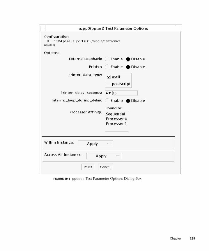
FIGURE 39-1 pptest Test Parameter Options Dialog Box
Chapter 239
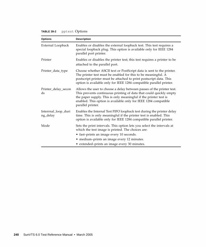
TABLE 39-2 pptest Options
Options Description
External Loopback Enables or disables the external loopback test. This test requires a
special loopback plug. This option is available only for IEEE 1284
parallel port printer.
Printer Enables or disables the printer test; this test requires a printer to be
attached to the parallel port.
Printer_data_type Choose whether ASCII text or PostScript data is sent to the printer.
The printer test must be enabled for this to be meaningful. A
postscript printer must be attached to print postscript data. This
option is available only for IEEE 1284 compatible parallel printer.
Printer_delay_secon
ds
Allows the user to choose a delay between passes of the printer test.
This prevents continuous printing of data that could quickly empty
the paper supply. This is only meaningful if the printer test is
enabled. This option is available only for IEEE 1284 compatible
parallel printer.
Interrnal_loop_duri
ng_delay
Enables the Internal Test FIFO loopback test during the printer delay
time. This is only meaningful if the printer test is enabled. This
option is available only for IEEE 1284 compatible parallel printer.
Mode Sets the print intervals. This option lets you select the intervals at
which the test image is printed. The choices are:
• fast–prints an image every 10 seconds.
• medium–prints an image every 12 minutes.
• extended–prints an image every 30 minutes.
240 SunVTS 6.0 Test Reference Manual • March 2005
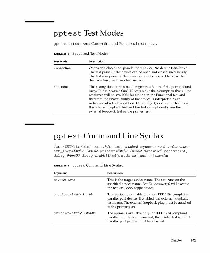
pptest Test Modes
pptest test supports Connection and Functional test modes.
pptest Command Line Syntax
/opt/SUNWvts/bin/sparcv9/pptest standard_arguments -o dev =dev-name,
ext_loop =Enable|Disable, printer =Enable|Disable, data =ascii, postscript ,
delay =0-86400, dloop =Enable|Disable, mode=fast|medium|extended
TABLE 39-3 Supported Test Modes
Test Mode Description
Connection Opens and closes the parallel port device. No data is transferred.
The test passes if the device can be open and closed successfully.
The test also passes if the device cannot be opened because the
device is busy with another process.
Functional The testing done in this mode registers a failure if the port is found
busy. This is because SunVTS tests make the assumption that all the
resources will be available for testing in the Functional test and
therefore the unavailability of the device is interpreted as an
indication of a fault condition. On ecpp (7D) devices the test runs
the internal loopback test and the test can optionally run the
external loopback test or the printer test.
TABLE 39-4 pptest Command Line Syntax
Argument Description
dev =dev-name This is the target device name. The test runs on the
specified device name. For Ex. dev =ecpp0 will execute
the test on /dev/ecpp0 device.
ext_loop =Enable|Disable This option is available only for IEEE 1284 complaint
parallel port device. If enabled, the external loopback
test is run. The external loopback plug must be attached
to the printer port.
printer =Enable|Disable The option is available only for IEEE 1284 complaint
parallel port device. If enabled, the printer test is run. A
parallel port printer must be attached.
Chapter 241
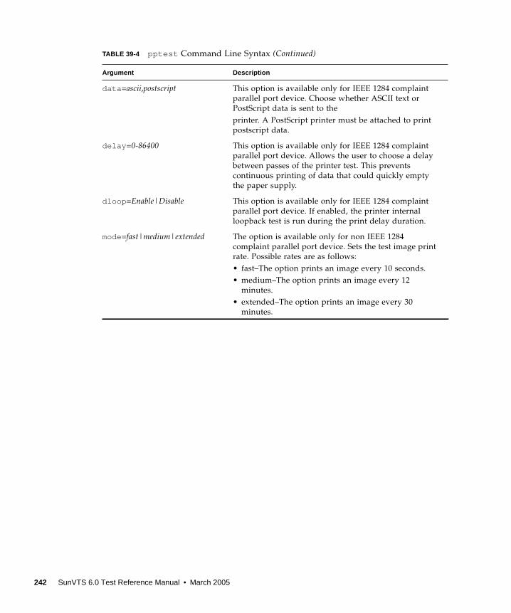
data =ascii,postscript This option is available only for IEEE 1284 complaint
parallel port device. Choose whether ASCII text or
PostScript data is sent to the
printer. A PostScript printer must be attached to print
postscript data.
delay =0-86400 This option is available only for IEEE 1284 complaint
parallel port device. Allows the user to choose a delay
between passes of the printer test. This prevents
continuous printing of data that could quickly empty
the paper supply.
dloop =Enable|Disable This option is available only for IEEE 1284 complaint
parallel port device. If enabled, the printer internal
loopback test is run during the print delay duration.
mode=fast|medium|extended The option is available only for non IEEE 1284
complaint parallel port device. Sets the test image print
rate. Possible rates are as follows:
• fast–The option prints an image every 10 seconds.
• medium–The option prints an image every 12
minutes.
• extended–The option prints an image every 30
minutes.
TABLE 39-4 pptest Command Line Syntax (Continued)
Argument Description
242 SunVTS 6.0 Test Reference Manual • March 2005
CHAPTER 40
Qlogic 2202 Board Test (qlctest )
qlctest is made up of several subtests that test the functions of the Qlogic 2202
FC/AL Crystal. Unlike the earlier single-port Q2100 board, the Q2202 is a two-port
board which has greater diagnostic support.
This test is not scalable.
Note – Do not run customer data while running qlctest , as the test will take
priority over customer data requests. The customer will be unable to access data
while qlctest is running.
Note – Do not run other tests while qlctest is running. qlctest may cause other
tests to fail.
Note – qlctest is an intervention mode test. No subtests can be selected unless
intervention is set.
qlctest Subtests
There are nine possible subtests to run in intervention and functional modes:
■ Fcode revision check
■ Firmware revision check
■ Board revision check
■ Checksum Firmware subtest
■ Selftest
■ Mailbox Loopback subtest
243
■ Internal 10-bit Loopback subtest
■ Internal 1-bit Loopback subtest
■ External Loopback subtest
The external loopback test is an intervention test. To test the fibre loop, leave the
QLC port attached to the storage. In the Test Parameters Options dialog box, set the
"Test if Connected to Storage" option to "Yes". To test the Qlogic 2202 board alone,
connect a loopback cable to the QLC port. This cable can be made by taking a
regular cable and splitting it apart. Then loop the transmitter side of the port to the
receiver side of the port.
For subtest descriptions, see TABLE 40-1.
qlctest Options
To reach the dialog box below, right-click on the test name in the System Map and
select Test Parameter Options. If you do not see this test in the System Map, you
might need to expand the collapsed groups, or your system may not include the
device appropriate to this test. Refer to the SunVTS User’s Guide for more details.
244 SunVTS 6.0 Test Reference Manual • March 2005
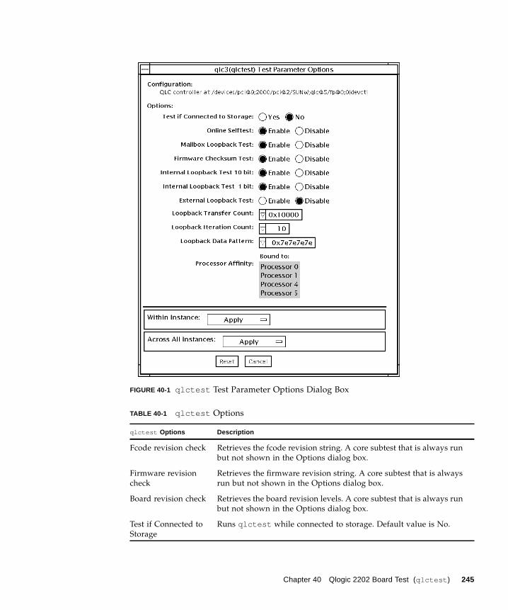
FIGURE 40-1 qlctest Test Parameter Options Dialog Box
TABLE 40-1 qlctest Options
qlctest Options Description
Fcode revision check Retrieves the fcode revision string. A core subtest that is always run
but not shown in the Options dialog box.
Firmware revision
check
Retrieves the firmware revision string. A core subtest that is always
run but not shown in the Options dialog box.
Board revision check Retrieves the board revision levels. A core subtest that is always run
but not shown in the Options dialog box.
Test if Connected to
Storage
Runs qlctest while connected to storage. Default value is No.
Chapter 40 Qlogic 2202 Board Test (qlctest ) 245

Selftest Evaluates the functionality of ISP hardware by performing the
following tests:
• Transmit FIFO test
• Receive FIFO test
• SRAM test
• Misc. Register tests
Run by default, but can be deselected.
Mailbox Loopback
subtest
Loads a series of registers into the input mailboxes on the card and
then reads the output mailboxes and compares results. This verifies
that the system side of the card is operating correctly, and that the
internal data paths are correct. Run by default, but can be
deselected.
Firmware Checksum
subtest
Runs an internal checksum test on the installed firmware. This
verifies that the RISC RAM on the card is fully functional and that
the installed firmware is still intact. This test also serves as a quick
RAM check of the RISC RAM. Run by default, but can be
deselected.
Internal 10-bit
Loopback subtest
Performs internal loopback test within the host adapter ISP
hardware at the 10-bit interface. This test is done with data sourcing
from the system memory and going to the system memory. The
desired data pattern, transfer length, and iteration count can be
selected via the test parameters menu. Run by default, but can be
deselected.
Internal 1-bit
Loopback subtest
Performs internal loopback test within the host adapter ISP
hardware at the 1-bit interface. This test is done with data sourcing
from the system memory and going to the system memory. The
desired data pattern, transfer length, and iteration count can be
selected via the test parameters menu. Run by default, but can be
deselected.
External Loopback
subtest
Performs an external loopback test. This test is done with data
sourcing from the system memory and going to the system memory.
The desired data pattern, transfer length, and iteration count can be
selected via the test parameters menu. This is an intervention test,
because a loopback cable is needed from the transceiver to the
receiver of the QLC port when testing this port by itself. This
subtest can also test the entire fibre channel loop when the loop is
connected to the storage to be tested. Not run by default, but can be
selected.
TABLE 40-1 qlctest Options
qlctest Options Description
246 SunVTS 6.0 Test Reference Manual • March 2005
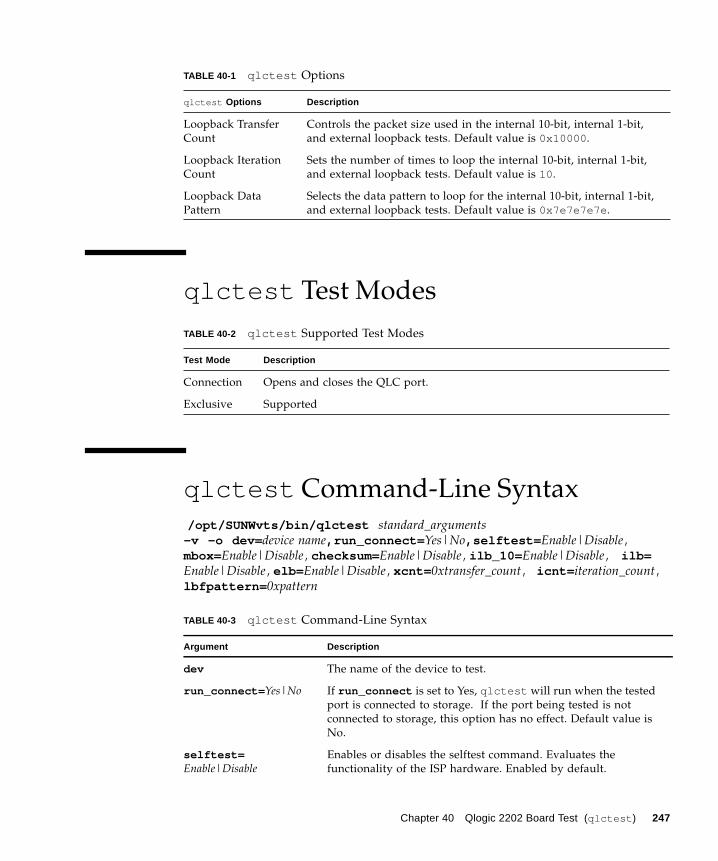
qlctest Test Modes
qlctest Command-Line Syntax
/opt/SUNWvts/bin/qlctest standard_arguments-v -o dev= device name,run_connect= Yes|No,selftest= Enable|Disable,mbox=Enable|Disable, checksum= Enable|Disable, ilb_10= Enable|Disable, ilb=Enable|Disable, elb= Enable|Disable, xcnt= 0xtransfer_count, icnt= iteration_count,lbfpattern= 0xpattern
Loopback Transfer
Count
Controls the packet size used in the internal 10-bit, internal 1-bit,
and external loopback tests. Default value is 0x10000 .
Loopback Iteration
Count
Sets the number of times to loop the internal 10-bit, internal 1-bit,
and external loopback tests. Default value is 10 .
Loopback Data
Pattern
Selects the data pattern to loop for the internal 10-bit, internal 1-bit,
and external loopback tests. Default value is 0x7e7e7e7e .
TABLE 40-2 qlctest Supported Test Modes
Test Mode Description
Connection Opens and closes the QLC port.
Exclusive Supported
TABLE 40-3 qlctest Command-Line Syntax
Argument Description
dev The name of the device to test.
run_connect= Yes|No If run_connect is set to Yes, qlctest will run when the tested
port is connected to storage. If the port being tested is not
connected to storage, this option has no effect. Default value is
No.
selftest=Enable|Disable
Enables or disables the selftest command. Evaluates the
functionality of the ISP hardware. Enabled by default.
TABLE 40-1 qlctest Options
qlctest Options Description
Chapter 40 Qlogic 2202 Board Test (qlctest ) 247
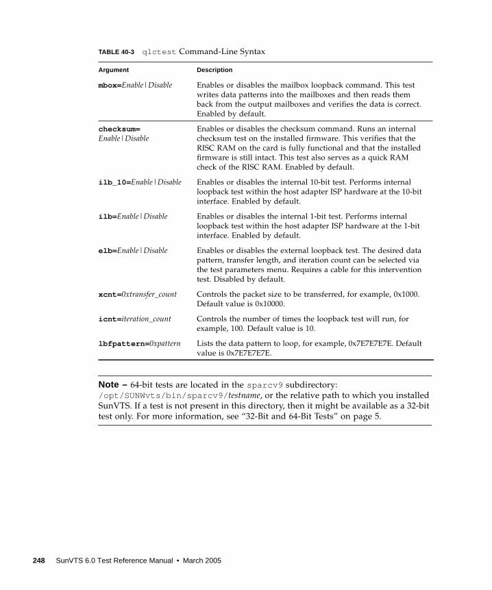
Note – 64-bit tests are located in the sparcv9 subdirectory:
/opt/SUNWvts/bin/sparcv9/ testname, or the relative path to which you installed
SunVTS. If a test is not present in this directory, then it might be available as a 32-bit
test only. For more information, see “32-Bit and 64-Bit Tests” on page 5.
mbox=Enable|Disable Enables or disables the mailbox loopback command. This test
writes data patterns into the mailboxes and then reads them
back from the output mailboxes and verifies the data is correct.
Enabled by default.
checksum=Enable|Disable
Enables or disables the checksum command. Runs an internal
checksum test on the installed firmware. This verifies that the
RISC RAM on the card is fully functional and that the installed
firmware is still intact. This test also serves as a quick RAM
check of the RISC RAM. Enabled by default.
ilb_10= Enable|Disable Enables or disables the internal 10-bit test. Performs internal
loopback test within the host adapter ISP hardware at the 10-bit
interface. Enabled by default.
ilb= Enable|Disable Enables or disables the internal 1-bit test. Performs internal
loopback test within the host adapter ISP hardware at the 1-bit
interface. Enabled by default.
elb= Enable|Disable Enables or disables the external loopback test. The desired data
pattern, transfer length, and iteration count can be selected via
the test parameters menu. Requires a cable for this intervention
test. Disabled by default.
xcnt= 0xtransfer_count Controls the packet size to be transferred, for example, 0x1000.
Default value is 0x10000.
icnt= iteration_count Controls the number of times the loopback test will run, for
example, 100. Default value is 10.
lbfpattern= 0xpattern Lists the data pattern to loop, for example, 0x7E7E7E7E. Default
value is 0x7E7E7E7E.
TABLE 40-3 qlctest Command-Line Syntax
Argument Description
248 SunVTS 6.0 Test Reference Manual • March 2005
CHAPTER 41
RAM Test (ramtest )
ramtest is designed to stress the memory modules (RAM) instead of the whole
memory subsystem. The test is optimized to achieve large memory bandwidth on
UltraSPARC III (USIII) and UltraSPARC II (USII) class of CPUs. ramtest has an
integrated ECC error monitor which reports the ECC errors found during the test
run.
This test is being added only for the Exclusive mode testing because of the high
stress it puts on the memory and the system interconnect. ramtest assumes that no
other application is running at the same time.
Caution – This is an Exclusive mode test. No other application should be running
during this test.
ramtest Options
To reach the dialog box below, right-click on the test name in the System Map and
select Test Parameter Options. If you do not see this test in the System Map, you
might need to expand the collapsed groups. Refer to the SunVTS User’s Guide for
more details.
249
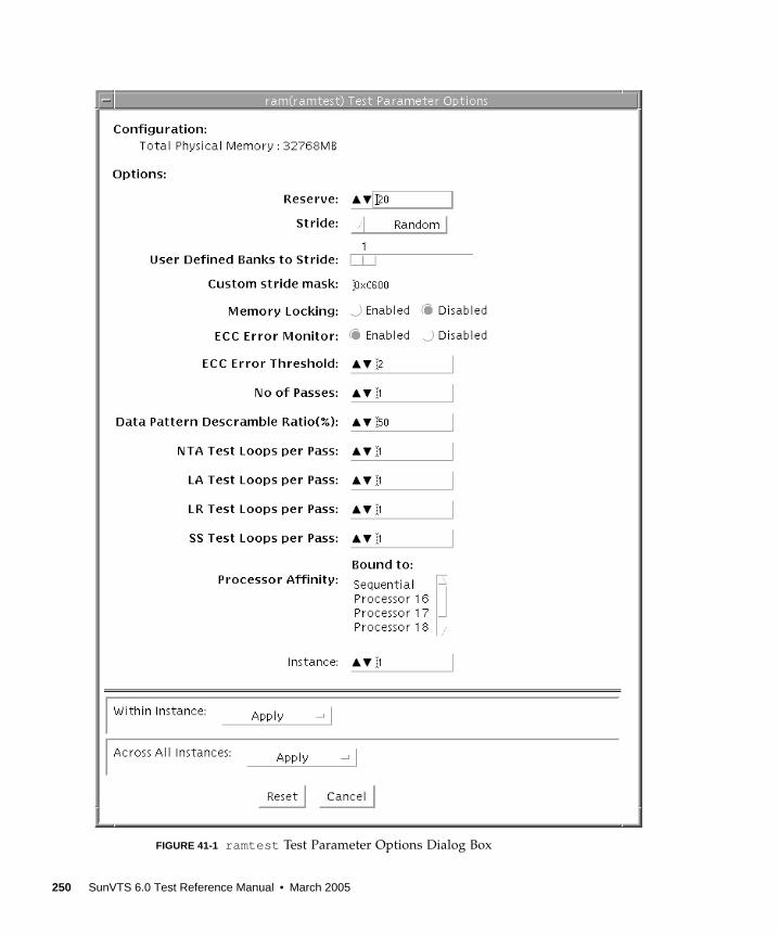
FIGURE 41-1 ramtest Test Parameter Options Dialog Box
250 SunVTS 6.0 Test Reference Manual • March 2005
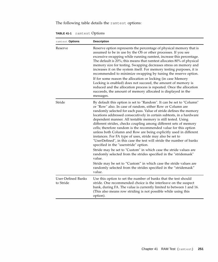
The following table details the ramtest options:
TABLE 41-1 ramtest Options
ramtest Options Description
Reserve Reserve option represents the percentage of physical memory that is
assumed to be in use by the OS or other processes. If you see
excessive swapping while running ramtest, increase this percentage.
The default is 20%; this means that ramtest allocates 80% of physical
memory size for testing. Swapping decreases stress on memory and
increases it on the system itself. For memory testing purposes, it is
recommended to minimize swapping by tuning the reserve option.
If for some reason the allocation or locking (in case Memory
Locking is enabled) does not succeed, the amount of memory is
reduced and the allocation process is repeated. Once the allocation
succeeds, the amount of memory allocated is displayed in the
messages.
Stride By default this option is set to "Random". It can be set to "Column"
or "Row" also. In case of random, either Row or Column are
randomly selected for each pass. Value of stride defines the memory
locations addressed consecutively in certain subtests, in a hardware
dependent manner. All testable memory is still tested. Using
different strides, checks coupling among different sets of memory
cells; therefore random is the recommended value for this option
unless both Column and Row are being explicitly used in different
instances. For FA type of uses, stride may also be set to
"UserDefined", in this case the test will stride the number of banks
specified in the "userstride" option.
Stride may be set to "Custom" in which case the stride values are
randomly selected from the strides specified in the "stridemask"
value.
Stride may be set to “Custom” in which case the stride values are
randomly selected from the strides specified in the “stridemask”
value.
User-Defined Banks
to Stride
Use this option to set the number of banks that the test should
stride. One recommended choice is the interleave on the suspect
bank, during FA. The value is currently limited to between 1 and 16.
(This also means row striding is not possible while using this
option).
Chapter 41 RAM Test (ramtest ) 251
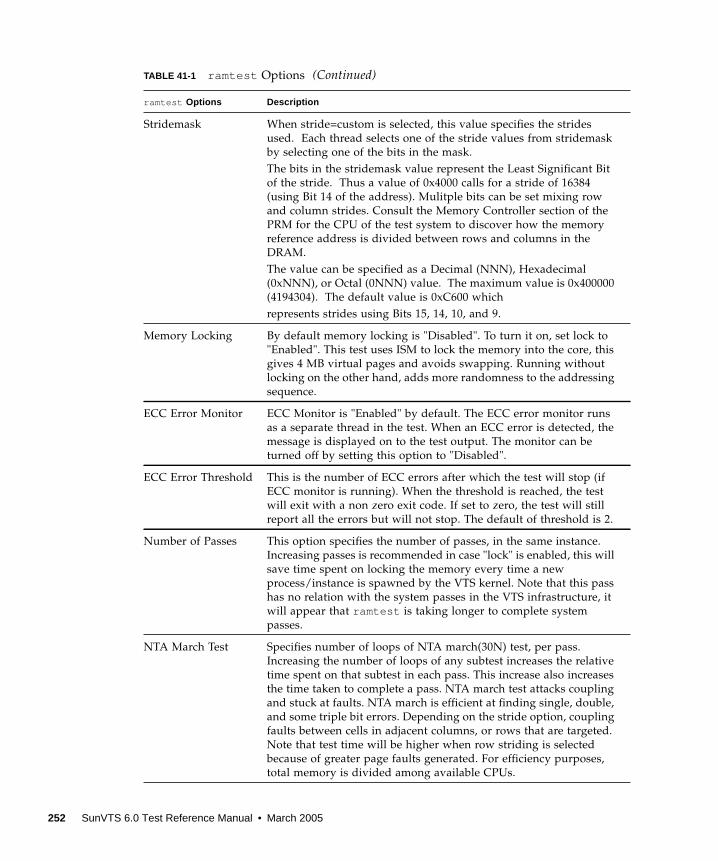
Stridemask When stride=custom is selected, this value specifies the strides
used. Each thread selects one of the stride values from stridemask
by selecting one of the bits in the mask.
The bits in the stridemask value represent the Least Significant Bit
of the stride. Thus a value of 0x4000 calls for a stride of 16384
(using Bit 14 of the address). Mulitple bits can be set mixing row
and column strides. Consult the Memory Controller section of the
PRM for the CPU of the test system to discover how the memory
reference address is divided between rows and columns in the
DRAM.
The value can be specified as a Decimal (NNN), Hexadecimal
(0xNNN), or Octal (0NNN) value. The maximum value is 0x400000
(4194304). The default value is 0xC600 which
represents strides using Bits 15, 14, 10, and 9.
Memory Locking By default memory locking is "Disabled". To turn it on, set lock to
"Enabled". This test uses ISM to lock the memory into the core, this
gives 4 MB virtual pages and avoids swapping. Running without
locking on the other hand, adds more randomness to the addressing
sequence.
ECC Error Monitor ECC Monitor is "Enabled" by default. The ECC error monitor runs
as a separate thread in the test. When an ECC error is detected, the
message is displayed on to the test output. The monitor can be
turned off by setting this option to "Disabled".
ECC Error Threshold This is the number of ECC errors after which the test will stop (if
ECC monitor is running). When the threshold is reached, the test
will exit with a non zero exit code. If set to zero, the test will still
report all the errors but will not stop. The default of threshold is 2.
Number of Passes This option specifies the number of passes, in the same instance.
Increasing passes is recommended in case "lock" is enabled, this will
save time spent on locking the memory every time a new
process/instance is spawned by the VTS kernel. Note that this pass
has no relation with the system passes in the VTS infrastructure, it
will appear that ramtest is taking longer to complete system
passes.
NTA March Test Specifies number of loops of NTA march(30N) test, per pass.
Increasing the number of loops of any subtest increases the relative
time spent on that subtest in each pass. This increase also increases
the time taken to complete a pass. NTA march test attacks coupling
and stuck at faults. NTA march is efficient at finding single, double,
and some triple bit errors. Depending on the stride option, coupling
faults between cells in adjacent columns, or rows that are targeted.
Note that test time will be higher when row striding is selected
because of greater page faults generated. For efficiency purposes,
total memory is divided among available CPUs.
TABLE 41-1 ramtest Options (Continued)
ramtest Options Description
252 SunVTS 6.0 Test Reference Manual • March 2005
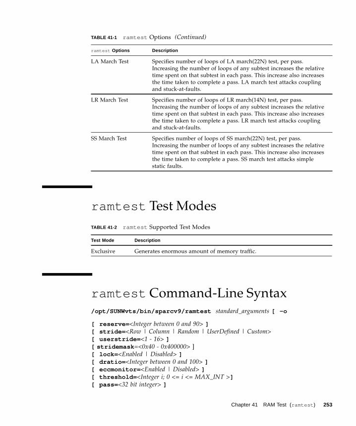
ramtest Test Modes
ramtest Command-Line Syntax
/opt/SUNWvts/bin/sparcv9/ramtest standard_arguments [ -o
[ reserve= <Integer between 0 and 90> ][ stride= <Row | Column | Random | UserDefined | Custom>[ userstride= <1 - 16> ][ stridemask =<0x40 - 0x400000> ]
[ lock= <Enabled | Disabled> ][ dratio= <Integer between 0 and 100> ][ eccmonitor= <Enabled | Disabled> ][ threshold= <Integer i; 0 <= i <= MAX_INT >][ pass= <32 bit integer> ]
LA March Test Specifies number of loops of LA march(22N) test, per pass.
Increasing the number of loops of any subtest increases the relative
time spent on that subtest in each pass. This increase also increases
the time taken to complete a pass. LA march test attacks coupling
and stuck-at-faults.
LR March Test Specifies number of loops of LR march(14N) test, per pass.
Increasing the number of loops of any subtest increases the relative
time spent on that subtest in each pass. This increase also increases
the time taken to complete a pass. LR march test attacks coupling
and stuck-at-faults.
SS March Test Specifies number of loops of SS march(22N) test, per pass.
Increasing the number of loops of any subtest increases the relative
time spent on that subtest in each pass. This increase also increases
the time taken to complete a pass. SS march test attacks simple
static faults.
TABLE 41-2 ramtest Supported Test Modes
Test Mode Description
Exclusive Generates enormous amount of memory traffic.
TABLE 41-1 ramtest Options (Continued)
ramtest Options Description
Chapter 41 RAM Test (ramtest ) 253
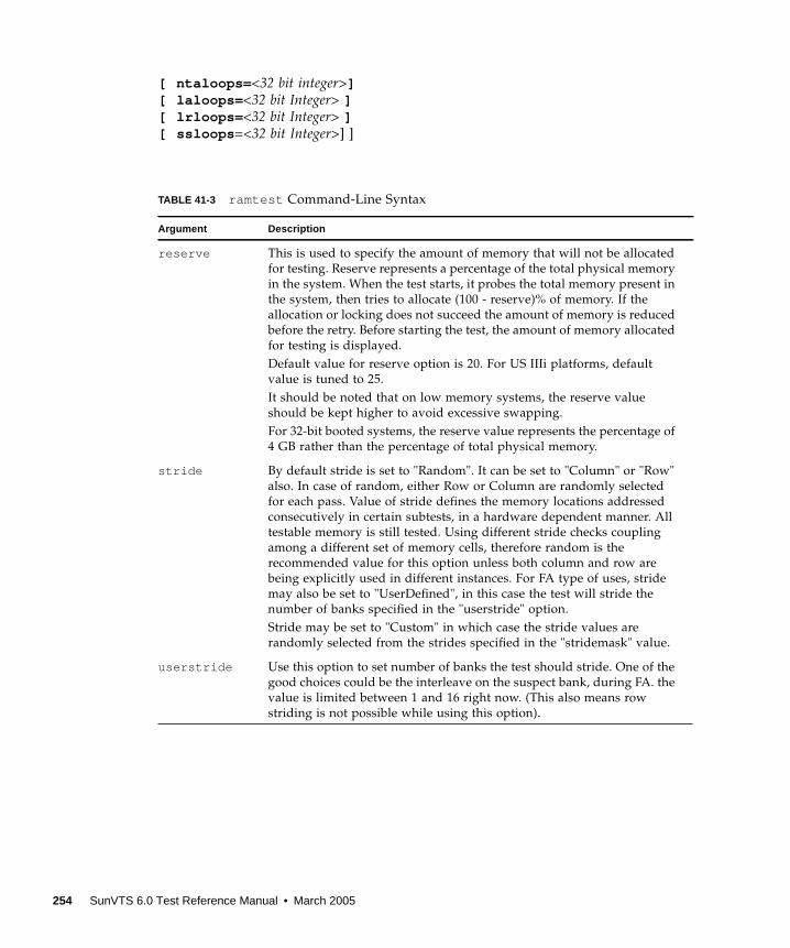
[ ntaloops= <32 bit integer>][ laloops= <32 bit Integer> ][ lrloops= <32 bit Integer> ][ ssloops =<32 bit Integer>] ]
TABLE 41-3 ramtest Command-Line Syntax
Argument Description
reserve This is used to specify the amount of memory that will not be allocated
for testing. Reserve represents a percentage of the total physical memory
in the system. When the test starts, it probes the total memory present in
the system, then tries to allocate (100 - reserve)% of memory. If the
allocation or locking does not succeed the amount of memory is reduced
before the retry. Before starting the test, the amount of memory allocated
for testing is displayed.
Default value for reserve option is 20. For US IIIi platforms, default
value is tuned to 25.
It should be noted that on low memory systems, the reserve value
should be kept higher to avoid excessive swapping.
For 32-bit booted systems, the reserve value represents the percentage of
4 GB rather than the percentage of total physical memory.
stride By default stride is set to "Random". It can be set to "Column" or "Row"
also. In case of random, either Row or Column are randomly selected
for each pass. Value of stride defines the memory locations addressed
consecutively in certain subtests, in a hardware dependent manner. All
testable memory is still tested. Using different stride checks coupling
among a different set of memory cells, therefore random is the
recommended value for this option unless both column and row are
being explicitly used in different instances. For FA type of uses, stride
may also be set to "UserDefined", in this case the test will stride the
number of banks specified in the "userstride" option.
Stride may be set to "Custom" in which case the stride values are
randomly selected from the strides specified in the "stridemask" value.
userstride Use this option to set number of banks the test should stride. One of the
good choices could be the interleave on the suspect bank, during FA. the
value is limited between 1 and 16 right now. (This also means row
striding is not possible while using this option).
254 SunVTS 6.0 Test Reference Manual • March 2005

stridemask When stride=custom is selected, this value specifies the strides used.
Each thread selects one of the stride values from stridemask by selecting
one of the bits in the mask.
The bits in the stridemask value represent the Least Significant Bit of the
stride. Thus a value of 0x4000 calls for a stride of 16384 (using Bit 14 of
the address). Mulitple bits can be set mixing row and column strides.
Consult the Memory Controller section of the PRM for the CPU of the
test system to discover how the memory reference address is divided
between rows and columns in the DRAM.
The value can be specified as a Decimal (NNN), Hexadecimal (0xNNN),
or Octal (0NNN) value. The maximum value is 0x400000 (4194304).
The default value is 0xC600 which represents strides using Bits 15, 14,
10, and 9.
lock By default memory locking is "Disabled". To turn it on set lock to
"Enabled". The test uses ISM to lock the memory into the core, this gives
4 MB virtual pages and avoids swapping. Running without locking on
the other hand, adds more randomness to the addressing sequence.
It should be noted that on low memory systems, this option can be
"Enabled" to avoid excessive swapping.
In case the test is unable to lock the memory, the user should put the
following lines in /etc/system and reboot the machine.
set shmsys:shminfo_shmmax=0xFFFFFFFFFFFFFFFF
set shmsys:shminfo_shmmin=1
set shmsys:shminfo_shmmni=100
set shmsys:shminfo_shmseg=10
eccmonitor ECC Monitor is "Enabled" by default. The ECC error monitor runs as a
separate thread in the test. When an ECC error is detected, the message
is displayed on to the test output. The monitor can be turned off by
setting this option to "Disabled".
threshold This is the number of ECC errors after which the test will stop (if ECC
monitor is running). When the threshold is reached the test will exit
with a non zero exit code. If set to zero, the test will still report all the
errors but will not stop. The default threshold is 2.
pass This option specifies number of passes, in the same instance. Increasing
pass is recommended in case "lock" is enabled, this will save time spent
on locking the memory every time a new process/instance is spawned
by the VTS kernel. Note that this pass has no relation with the system
passes in the VTS infrastructure, it will appear that ramtest is taking
longer to complete system passes.
TABLE 41-3 ramtest Command-Line Syntax
Argument Description
Chapter 41 RAM Test (ramtest ) 255
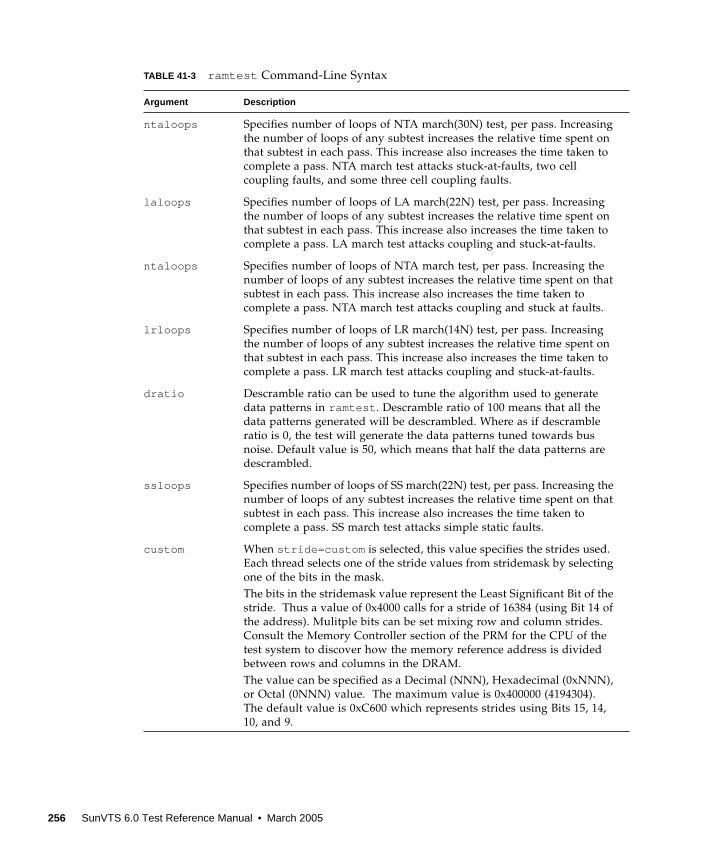
ntaloops Specifies number of loops of NTA march(30N) test, per pass. Increasing
the number of loops of any subtest increases the relative time spent on
that subtest in each pass. This increase also increases the time taken to
complete a pass. NTA march test attacks stuck-at-faults, two cell
coupling faults, and some three cell coupling faults.
laloops Specifies number of loops of LA march(22N) test, per pass. Increasing
the number of loops of any subtest increases the relative time spent on
that subtest in each pass. This increase also increases the time taken to
complete a pass. LA march test attacks coupling and stuck-at-faults.
ntaloops Specifies number of loops of NTA march test, per pass. Increasing the
number of loops of any subtest increases the relative time spent on that
subtest in each pass. This increase also increases the time taken to
complete a pass. NTA march test attacks coupling and stuck at faults.
lrloops Specifies number of loops of LR march(14N) test, per pass. Increasing
the number of loops of any subtest increases the relative time spent on
that subtest in each pass. This increase also increases the time taken to
complete a pass. LR march test attacks coupling and stuck-at-faults.
dratio Descramble ratio can be used to tune the algorithm used to generate
data patterns in ramtest . Descramble ratio of 100 means that all the
data patterns generated will be descrambled. Where as if descramble
ratio is 0, the test will generate the data patterns tuned towards bus
noise. Default value is 50, which means that half the data patterns are
descrambled.
ssloops Specifies number of loops of SS march(22N) test, per pass. Increasing the
number of loops of any subtest increases the relative time spent on that
subtest in each pass. This increase also increases the time taken to
complete a pass. SS march test attacks simple static faults.
custom When stride=custom is selected, this value specifies the strides used.
Each thread selects one of the stride values from stridemask by selecting
one of the bits in the mask.
The bits in the stridemask value represent the Least Significant Bit of the
stride. Thus a value of 0x4000 calls for a stride of 16384 (using Bit 14 of
the address). Mulitple bits can be set mixing row and column strides.
Consult the Memory Controller section of the PRM for the CPU of the
test system to discover how the memory reference address is divided
between rows and columns in the DRAM.
The value can be specified as a Decimal (NNN), Hexadecimal (0xNNN),
or Octal (0NNN) value. The maximum value is 0x400000 (4194304).
The default value is 0xC600 which represents strides using Bits 15, 14,
10, and 9.
TABLE 41-3 ramtest Command-Line Syntax
Argument Description
256 SunVTS 6.0 Test Reference Manual • March 2005
Note – 32-bit tests are located in the bin subdirectory,
/opt/SUNWvts/bin/ testname.
Note – ECC errors returned by ramtest are actually detected by the operating
system and are logged in the /var/adm/messages file. Please review this file for
more detailed information regarding errors.
Note – 64-bit tests are located in the sparcv9 subdirectory:
/opt/SUNWvts/bin/sparcv9/ testname, or the relative path to which you installed
SunVTS. If a test is not present in this directory, then it might be available as a 32-bit
test only. For more information, see “32-Bit and 64-Bit Tests” on page 5.
Chapter 41 RAM Test (ramtest ) 257

258 SunVTS 6.0 Test Reference Manual • March 2005
CHAPTER 42
Remote System Control (rsctest)
The rsctest exercises the Remote System Control (RSC) feature, which is
integrated on the Sun Enterprise 250 as well as the next-generation RSC 2.0 plug-in
card introduced with the Sun Fire 280R line.
The RSC provides secure remote access for system monitoring, firmware updates,
and failure recovery. The RSC communicates with the host through two internal
serial lines, the I2C bus, and reset lines.
The RSC 1.0 hardware consists of the controller, flash, SEEPROM, 10MB Ethernet
port, and an external console serial port.
The RSC 2.0 plug-in card hardware consists of the controller, flash, SEEPROM, 10MB
Ethernet port, FRUSEEPROM, Time Of Day (TOD) device, internal PCMCIA modem
card, and battery backup.
rsctest is not scalable.
rsctest Subtests
The rsctest will present different subtests and options based on which revision of
the RSC hardware it is testing.
259

The subtests common to both RSC 1.0 and 2.0 include:
rsctest also presents the following subtests when running on the RSC 2.0
hardware:
The subtests call test modlets that are written in the native Real Time Operating
System (RTOS) that resides in the RSC firmware. The rsctest subtests execute the
test modlets, passes parameters, and retrieves results from the RSC using a test
protocol on the host to RSC internal serial lines.
TABLE 42-1 Subtests for both RSC 1.0 and 2.0
Subtest Description
Ethernet Allows for internal loopback testing, on the Ethernet device with
user specified data, size, and number of packets.
Allows for external loopback testing with user-specified data, size,
and number of packets. This requires a connection to a 10MB hub or
switch for RSC 1.0, or a passive loopback connector for RSC 2.0.
Allows for a ping to be sent to a specified host and checks the
response.
Flash CRC Performs a checksum test on the flash device.
SEEPROM CRC Performs a checksum test on the SEEPROM device.
Serial Allows internal loopback testing with user-specified data and size
on the two internal serial ports.
Allows for internal and/or external testing on the external ttyuport. The external test requires a passive loopback connector.
TABLE 42-2 Subtests for RSC 2.0 Only
Subtest Description
FRU SEEPROM CRC Performs a checksum test on the SEEPROM device.
I2C Tests the i2c bus connection between the host and the RSC.
TOD Performs multiple reads to the TOD device and verifies that the
time is incrementing.
Modem Verifies that the modem is installed. Displays the manufacture
information, in Verbose mode. Performs AT inquiry commands.
260 SunVTS 6.0 Test Reference Manual • March 2005
rsctest Options
To reach the dialog box below, right-click on the test name in the System Map and
select Test Parameter Options. If you do not see this test in the System Map, you
might need to expand the collapsed groups, or your system may not include the
device appropriate to this test. Refer to the SunVTS User’s Guide for more details.
Chapter 42 Remote System Control (rsctest) 261
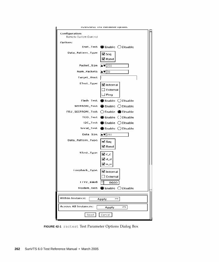
FIGURE 42-1 rsctest Test Parameter Options Dialog Box
262 SunVTS 6.0 Test Reference Manual • March 2005
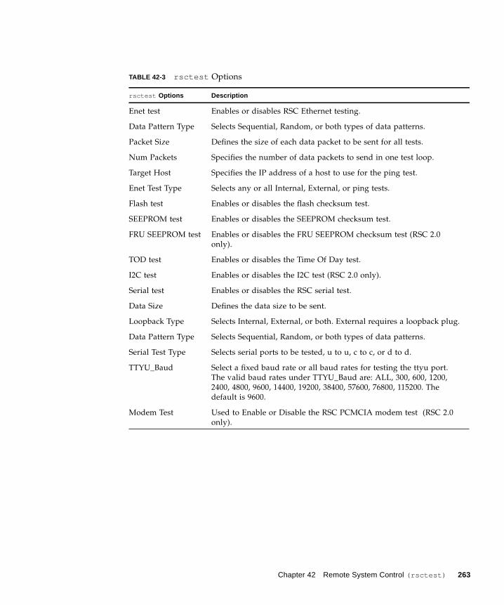
TABLE 42-3 rsctest Options
rsctest Options Description
Enet test Enables or disables RSC Ethernet testing.
Data Pattern Type Selects Sequential, Random, or both types of data patterns.
Packet Size Defines the size of each data packet to be sent for all tests.
Num Packets Specifies the number of data packets to send in one test loop.
Target Host Specifies the IP address of a host to use for the ping test.
Enet Test Type Selects any or all Internal, External, or ping tests.
Flash test Enables or disables the flash checksum test.
SEEPROM test Enables or disables the SEEPROM checksum test.
FRU SEEPROM test Enables or disables the FRU SEEPROM checksum test (RSC 2.0
only).
TOD test Enables or disables the Time Of Day test.
I2C test Enables or disables the I2C test (RSC 2.0 only).
Serial test Enables or disables the RSC serial test.
Data Size Defines the data size to be sent.
Loopback Type Selects Internal, External, or both. External requires a loopback plug.
Data Pattern Type Selects Sequential, Random, or both types of data patterns.
Serial Test Type Selects serial ports to be tested, u to u, c to c, or d to d.
TTYU_Baud Select a fixed baud rate or all baud rates for testing the ttyu port.
The valid baud rates under TTYU_Baud are: ALL, 300, 600, 1200,
2400, 4800, 9600, 14400, 19200, 38400, 57600, 76800, 115200. The
default is 9600.
Modem Test Used to Enable or Disable the RSC PCMCIA modem test (RSC 2.0
only).
Chapter 42 Remote System Control (rsctest) 263
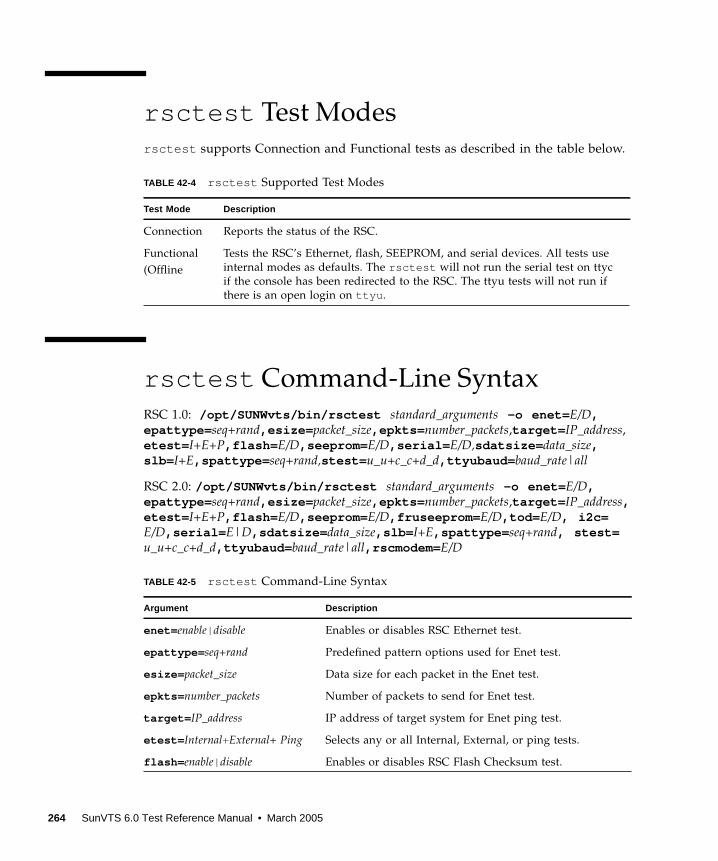
rsctest Test Modes
rsctest supports Connection and Functional tests as described in the table below.
rsctest Command-Line Syntax
RSC 1.0: /opt/SUNWvts/bin/rsctest standard_arguments -o enet= E/D,epattype= seq+rand,esize= packet_size,epkts= number_packets,target= IP_address,
etest= I+E+P,flash= E/D,seeprom= E/D,serial= E/D,sdatsize= data_size,slb= I+E,spattype= seq+rand,stest= u_u+c_c+d_d,ttyubaud= baud_rate|all
RSC 2.0: /opt/SUNWvts/bin/rsctest standard_arguments -o enet= E/D,epattype= seq+rand,esize= packet_size,epkts= number_packets,target= IP_address,etest= I+E+P,flash= E/D,seeprom= E/D,fruseeprom= E/D,tod= E/D, i2c=E/D,serial= E|D,sdatsize= data_size,slb= I+E,spattype= seq+rand, stest=u_u+c_c+d_d,ttyubaud= baud_rate|all,rscmodem= E/D
TABLE 42-4 rsctest Supported Test Modes
Test Mode Description
Connection Reports the status of the RSC.
Functional
(Offline
Tests the RSC’s Ethernet, flash, SEEPROM, and serial devices. All tests use
internal modes as defaults. The rsctest will not run the serial test on ttyc
if the console has been redirected to the RSC. The ttyu tests will not run if
there is an open login on ttyu .
TABLE 42-5 rsctest Command-Line Syntax
Argument Description
enet= enable| disable Enables or disables RSC Ethernet test.
epattype= seq+rand Predefined pattern options used for Enet test.
esize= packet_size Data size for each packet in the Enet test.
epkts= number_packets Number of packets to send for Enet test.
target= IP_address IP address of target system for Enet ping test.
etest= Internal+External+ Ping Selects any or all Internal, External, or ping tests.
flash= enable| disable Enables or disables RSC Flash Checksum test.
264 SunVTS 6.0 Test Reference Manual • March 2005
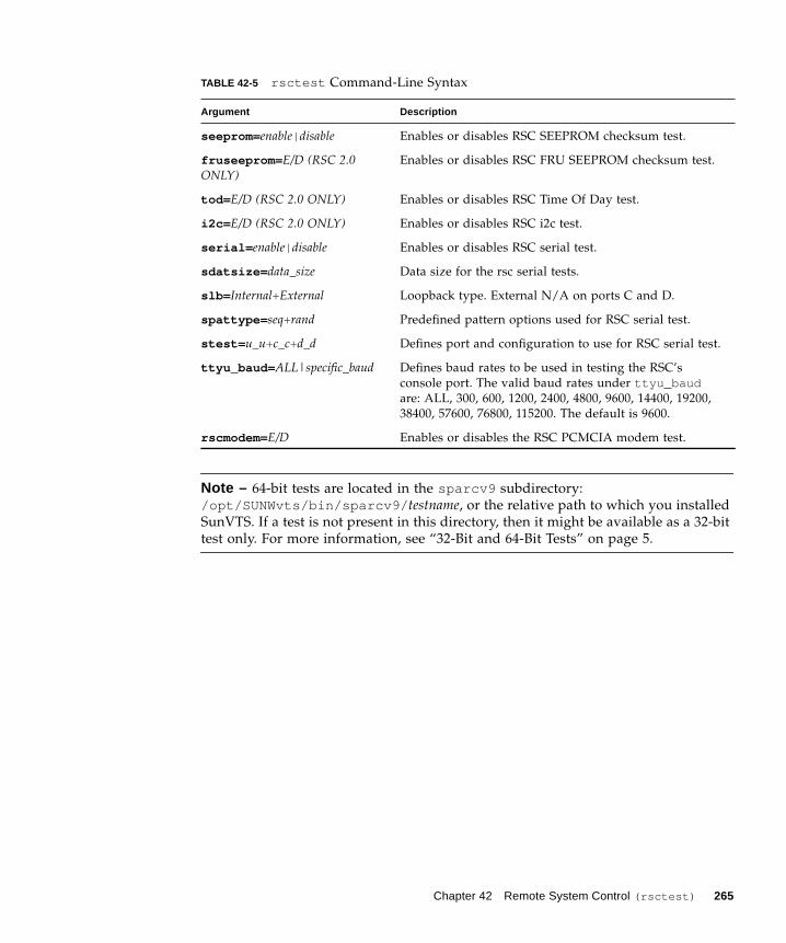
Note – 64-bit tests are located in the sparcv9 subdirectory:
/opt/SUNWvts/bin/sparcv9/ testname, or the relative path to which you installed
SunVTS. If a test is not present in this directory, then it might be available as a 32-bit
test only. For more information, see “32-Bit and 64-Bit Tests” on page 5.
seeprom= enable| disable Enables or disables RSC SEEPROM checksum test.
fruseeprom= E/D (RSC 2.0ONLY)
Enables or disables RSC FRU SEEPROM checksum test.
tod= E/D (RSC 2.0 ONLY) Enables or disables RSC Time Of Day test.
i2c= E/D (RSC 2.0 ONLY) Enables or disables RSC i2c test.
serial= enable| disable Enables or disables RSC serial test.
sdatsize= data_size Data size for the rsc serial tests.
slb= Internal+External Loopback type. External N/A on ports C and D.
spattype= seq+rand Predefined pattern options used for RSC serial test.
stest= u_u+c_c+d_d Defines port and configuration to use for RSC serial test.
ttyu_baud= ALL|specific_baud Defines baud rates to be used in testing the RSC’s
console port. The valid baud rates under ttyu_baudare: ALL, 300, 600, 1200, 2400, 4800, 9600, 14400, 19200,
38400, 57600, 76800, 115200. The default is 9600.
rscmodem= E/D Enables or disables the RSC PCMCIA modem test.
TABLE 42-5 rsctest Command-Line Syntax
Argument Description
Chapter 42 Remote System Control (rsctest) 265

266 SunVTS 6.0 Test Reference Manual • March 2005
CHAPTER 43
Serial Asynchronous Interface (PCI)Test (saiptest )
saiptest checks the functionality of the serial asynchronous interface (SAI) card
through its device driver.
Note – You must have Patch ID 109338 installed on the system where you plan to
run the saiptest .
saiptest Hardware Requirements
Before running the SunVTS diagnostics software, make sure you install the device
driver and the cards to be tested. Also, you should reboot your system with the
boot -r command to reconfigure the system and allow the SunVTS kernel to
recognize the new driver.
Note – You must run the saiptest in Intervention mode.
Note – You must have Patch ID 109338 installed on the system where you plan to
run the sapitest .
The following minimum hardware configuration is required to successfully run the
Internal test:
■ PCI-based SPARC system with a PCI slot
■ Serial asynchronous interface card, installed in one of the PCI slots
267
The following hardware is also required to run other SunVTS Serial Asynchronous
Interface tests:
■ Serial asynchronous interface patch panel (part no. 370-2810)
■ 25-pin serial loopback plugs (part no. 540-1558)
■ RS-232 serial cables (part no. 530-1685)
■ TTY terminal
saiptest Options
To reach the dialog box below, right-click on the test name in the System Map and
select Test Parameter Options. If you do not see this test in the System Map, you
might need to expand the collapsed groups, or your system may not include the
device appropriate to this test. Refer to the SunVTS User’s Guide for more details.
268 SunVTS 6.0 Test Reference Manual • March 2005
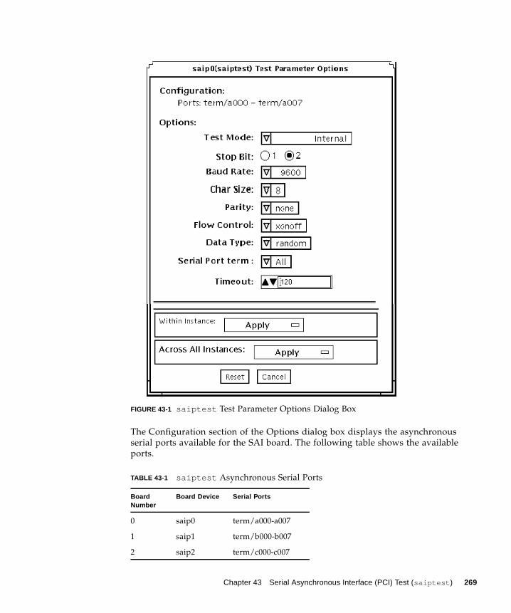
FIGURE 43-1 saiptest Test Parameter Options Dialog Box
The Configuration section of the Options dialog box displays the asynchronous
serial ports available for the SAI board. The following table shows the available
ports.
TABLE 43-1 saiptest Asynchronous Serial Ports
BoardNumber
Board Device Serial Ports
0 saip0 term/a000-a007
1 saip1 term/b000-b007
2 saip2 term/c000-c007
Chapter 43 Serial Asynchronous Interface (PCI) Test (saiptest ) 269
3 saip3 term/d000-d007
4 saip4 term/e000-e007
5 saip5 term/f000-f007
6 saip6 term/g000-g007
7 saip7 term/h000-h007
8 saip8 term/i000-i007
9 saip9 term/j000-j007
10 saip10 term/k000-k007
11 saip11 term/l000-l007
12 saip12 term/m000-m007
13 saip 13 term/n000-n007
14 saip 14 term/o000-o007
15 saip 15 term/p00-p007
TABLE 43-1 saiptest Asynchronous Serial Ports (Continued)
BoardNumber
Board Device Serial Ports
270 SunVTS 6.0 Test Reference Manual • March 2005
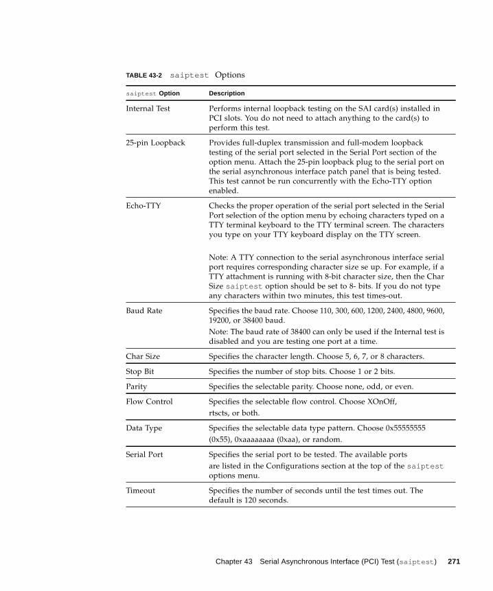
TABLE 43-2 saiptest Options
saiptest Option Description
Internal Test Performs internal loopback testing on the SAI card(s) installed in
PCI slots. You do not need to attach anything to the card(s) to
perform this test.
25-pin Loopback Provides full-duplex transmission and full-modem loopback
testing of the serial port selected in the Serial Port section of the
option menu. Attach the 25-pin loopback plug to the serial port on
the serial asynchronous interface patch panel that is being tested.
This test cannot be run concurrently with the Echo-TTY option
enabled.
Echo-TTY Checks the proper operation of the serial port selected in the Serial
Port selection of the option menu by echoing characters typed on a
TTY terminal keyboard to the TTY terminal screen. The characters
you type on your TTY keyboard display on the TTY screen.
Note: A TTY connection to the serial asynchronous interface serial
port requires corresponding character size se up. For example, if a
TTY attachment is running with 8-bit character size, then the Char
Size saiptest option should be set to 8- bits. If you do not type
any characters within two minutes, this test times-out.
Baud Rate Specifies the baud rate. Choose 110, 300, 600, 1200, 2400, 4800, 9600,
19200, or 38400 baud.
Note: The baud rate of 38400 can only be used if the Internal test is
disabled and you are testing one port at a time.
Char Size Specifies the character length. Choose 5, 6, 7, or 8 characters.
Stop Bit Specifies the number of stop bits. Choose 1 or 2 bits.
Parity Specifies the selectable parity. Choose none, odd, or even.
Flow Control Specifies the selectable flow control. Choose XOnOff,
rtscts, or both.
Data Type Specifies the selectable data type pattern. Choose 0x55555555
(0x55), 0xaaaaaaaa (0xaa), or random.
Serial Port Specifies the serial port to be tested. The available ports
are listed in the Configurations section at the top of the saiptestoptions menu.
Timeout Specifies the number of seconds until the test times out. The
default is 120 seconds.
Chapter 43 Serial Asynchronous Interface (PCI) Test (saiptest ) 271
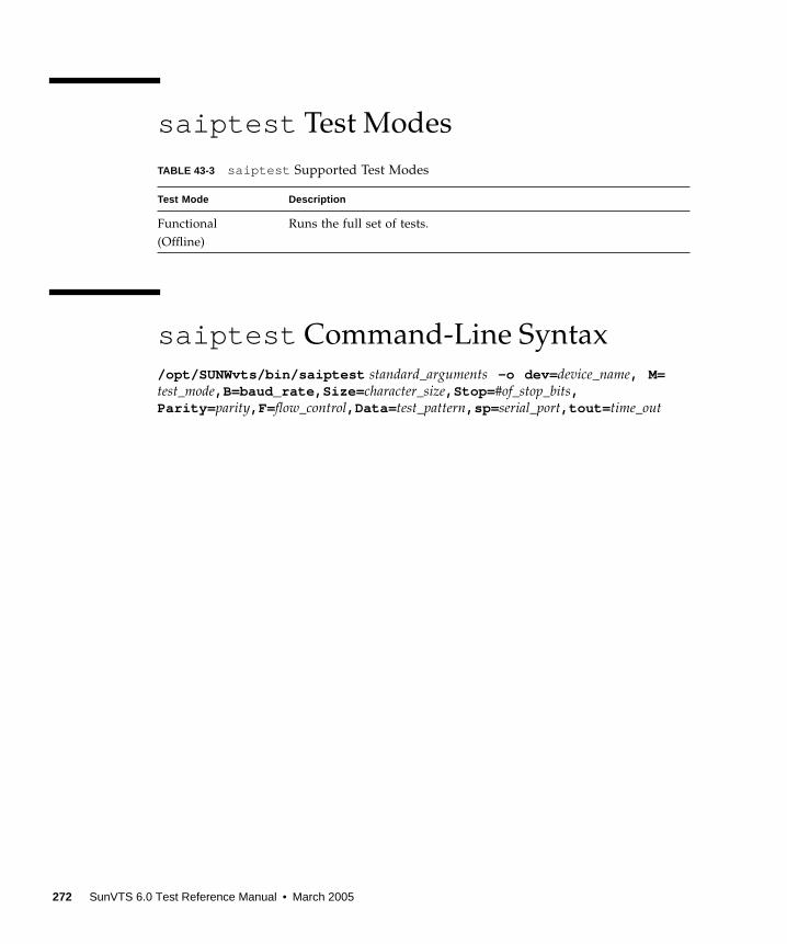
saiptest Test Modes
saiptest Command-Line Syntax
/opt/SUNWvts/bin/saiptest standard_arguments -o dev= device_name, M=test_mode,B=baud_rate,Size= character_size,Stop= #of_stop_bits,Parity= parity,F= flow_control,Data= test_pattern,sp= serial_port,tout= time_out
TABLE 43-3 saiptest Supported Test Modes
Test Mode Description
Functional
(Offline)
Runs the full set of tests.
272 SunVTS 6.0 Test Reference Manual • March 2005

TABLE 43-4 saiptest Command-Line Syntax
Argument Description
dev= device_name Specifies the asynchronous serial ports of the PCI card slots tested.
Since there is no default, you must type a device name—either a
board(saip0-16) or an individual port (term/x000-term/x007, where
x is a-p):
•saip0 = the 8 asynchronous serial ports in the first card
•saip1 = the 8 asynchronous serial ports in the second card
•saip2 = the 8 asynchronous serial ports in the third card
•saip3 = the 8 asynchronous serial ports in the fourth card
•saip4 = the 8 asynchronous serial ports in the fifth card
•saip5 = the 8 asynchronous serial ports in the sixth card
•saip6 = the 8 asynchronous serial ports in the seventh card
•saip7 = the 8 asynchronous serial ports in the eighth card
•saip8 = the 8 asynchronous serial ports in the ninth card
•saip9 = the 8 asynchronous serial ports in the tenth card
•saip10 = the 8 asynchronous serial ports in the eleventh card
•saip11 = the 8 asynchronous serial ports in the twelfth card
•saip12 = the 8 asynchronous serial ports in the thirteenth card
•saip13 = the 8 asynchronous serial ports in the fourteenth card
•saip14 = the 8 asynchronous serial ports in the fifteenth card
•saip15 = the 8 asynchronous serial ports in the sixteenth card
or
/dev/term/x00 mWhere x is a-p and m is 0 to 7 (any of the asynchronous serial
ports in PCI card slots).
M=test_mode Specifies Internal, 25_pin_loopback, or Echo_TTY test mode.
B=baud_rate Sets the baud rate to 110, 300, 600, 1200, 2400, 4800, 9600, 19200,
38400; the default is 9600.
Stop= #of_stop_bits Toggles the number of stop bits between 1 or 2. The default is 1.
Size= character_size Sets the character size as an integer between 5 and 8.
Parity= parity Specifies the parity as none, odd, or even. The default is none.
F=flow_control Specifies flow control as xonoff, rtscts, or both.
Data= test_pattern Specifies test pattern as 0x55555555, 0xAAAAAAAA, or random.
sp= serial_port Specifies the terminal and asynchronous serial port number, such as
term/a00n (sp=n).
tout= time_out Specifies the number of seconds until the test times out. The default
is 120 seconds.
Chapter 43 Serial Asynchronous Interface (PCI) Test (saiptest ) 273
Note – 64-bit tests are located in the sparcv9 subdirectory:
/opt/SUNWvts/bin/sparcv9/ testname, or the relative path to which you installed
SunVTS. If a test is not present in this directory, then it might be available as a 32-bit
test only. For more information, see “32-Bit and 64-Bit Tests” on page 5.
Note – The saiptest error messages are generated when the SunVTS Serial
Asynchronous Interface discovers errors. The error descriptions that appear in the
VTS interface identify probable causes for the card or test failure, and identify the
Field Replaceable Unit (FRU) and recommended action, if possible. The two FRUs
under test are: the Serial Asynchronous Interface card, and the patch panel with the
cable attached.
274 SunVTS 6.0 Test Reference Manual • March 2005

CHAPTER 44
Internal I2C Smartcard Reader Test(sc2test )
The sc2test verifies the proper functioning and integrity of the internal I2C
Smartcard reader by testing the scmi2c(7d) driver.
sc2test Subtests
The sc2test consists of the following subtests:
■ Register subtests:
Register read subtest
The Register read subtest performs read access to selected scmi2c reader
registers via ioctl() .
Walking 1s subtest
The Walking 1s subtest performs walking 1s to selected scmi2c reader registers;
registers under test are saved and restored.
■ AnswerToReset (ATR) subtest
The sc2test initializes the card reader. It will power manage and reset the card.
After reset, the test attempts multiple tries to read the ATRs from the insertcard to
verify against a list of recognized ATRs. The cards supported are the Cyberflex
and Payflex cards.
■ APDU unique-ID subtest
Based on the result of the ATR, the Application Protocol Data Unit (APDU)
uniqure-ID subtest exchanges selected ISO 7816 APDUs between the card and the
reader to retreive the card’s unique ID.
275
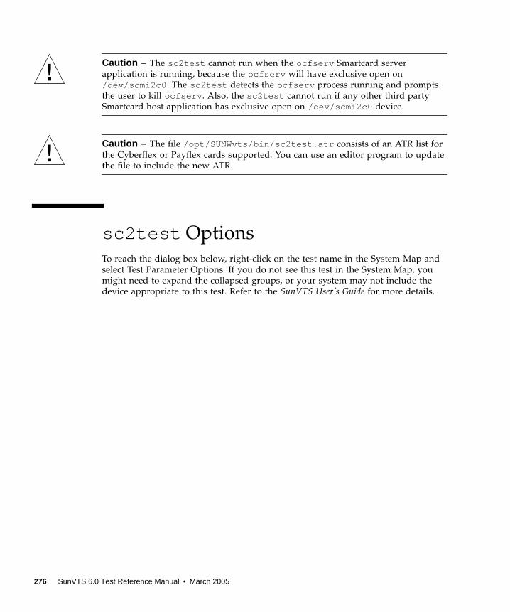
Caution – The sc2test cannot run when the ocfserv Smartcard server
application is running, because the ocfserv will have exclusive open on
/dev/scmi2c0 . The sc2test detects the ocfserv process running and prompts
the user to kill ocfserv . Also, the sc2test cannot run if any other third party
Smartcard host application has exclusive open on /dev/scmi2c0 device.
Caution – The file /opt/SUNWvts/bin/sc2test.atr consists of an ATR list for
the Cyberflex or Payflex cards supported. You can use an editor program to update
the file to include the new ATR.
sc2test Options
To reach the dialog box below, right-click on the test name in the System Map and
select Test Parameter Options. If you do not see this test in the System Map, you
might need to expand the collapsed groups, or your system may not include the
device appropriate to this test. Refer to the SunVTS User’s Guide for more details.
276 SunVTS 6.0 Test Reference Manual • March 2005
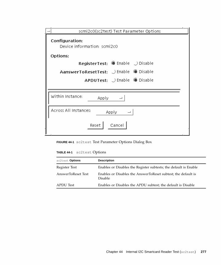
FIGURE 44-1 sc2test Test Parameter Options Dialog Box
TABLE 44-1 sc2test Options
sc2test Options Description
Register Test Enables or Disables the Register subtests; the default is Enable
AnswerToReset Test Enables or Disables the AnswerToReset subtest; the default is
Disable
APDU Test Enables or Disables the APDU subtest; the default is Disable
Chapter 44 Internal I2C Smartcard Reader Test (sc2test ) 277

sc2test Test Modes
sc2test Command-Line Syntax
/opt/SUNWvts/bin/sc2test standard_arguments -o [[ dev= device_logical_name ][ regs= enable|disable ][ atr= enable|disable ][ apdu= enable|disable ] ]
Note – 64-bit tests are located in the sparcv9 subdirectory:
/opt/SUNWvts/bin/sparcv9/ testname, or the relative path to which you installed
SunVTS. If a test is not present in this directory, then it might be available as a 32-bit
test only. For more information, see “32-Bit and 64-Bit Tests” on page 5.
TABLE 44-2 sc2test Supported Test Modes
Test Mode Description
Connection Performs the Register read and Walking 1s subtests
Functional
(Offline)
Performs the Register subtests, AnswerToReset subtest, and the APDU
unique-ID subtest
TABLE 44-3 sc2test Command-Line Syntax
Argument Description
dev= device_name device_name is the logical device name to be tested, for
example, dev=scmi2c0
reg= enable|disable Enables or disables the Register tests; the default is enable
atr= enable|disable Enables or disables the ATR test; the default is disable
apdu= enable|disable Enables or disables the APDU unique-id test; the default is
disable
278 SunVTS 6.0 Test Reference Manual • March 2005
CHAPTER 45
SEEPROM Test (seepromtest )
The seepromtest verifies the functionality of the SEEPROM. The probing portion
of the seepromtest traces the PICL (Platform Information and Control Library)
tree and finds the SEEPROM nodes with physical addresses. In addition, the probing
portion of seepromtest verifies the size of the physical parent of the SEEPROM.
Once the probing portion is complete, seepromtest reads each byte of the
SEEPROM devices to verify that the SEEPROM is the correct size. Finally, the
seepromtest checks the Read operation of the SEEPROM devices.
Note – seepromtest can only be performed on platforms with one or more
SEEPROM physical address in the PICL tree. Currently, seepromtest is only
supported on the Sun Blade 1000/2000 workstations.
seepromtest Options
To reach the dialog box below, right-click on the test name in the System Map and
select Test Parameter Options. If you do not see this test in the System Map, you
might need to expand the collapsed groups, or your system may not include the
device appropriate to this test. Refer to the SunVTS User’s Guide for more details.
279
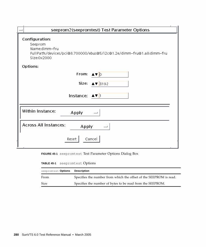
FIGURE 45-1 seepromtest Test Parameter Options Dialog Box
TABLE 45-1 seepromtest Options
seepromtest Options Description
From Specifies the number from which the offset of the SEEPROM is read.
Size Specifies the number of bytes to be read from the SEEPROM.
280 SunVTS 6.0 Test Reference Manual • March 2005
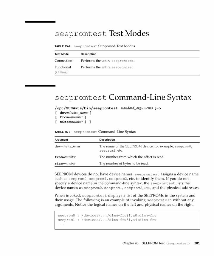
seepromtest Test Modes
seepromtest Command-Line Syntax
/opt/SUNWvts/bin/seepromtest standard_arguments [-o[ dev= device_name ][ from= number ][ size= number ] ]
SEEPROM devices do not have device names. seepromtest assigns a device name
such as seeprom0 , seeprom1 , seeprom2 , etc. to identify them. If you do not
specify a device name in the command-line syntax, the seepromtest lists the
device names as seeprom0 , seeprom1 , seeprom2 , etc., and the physical addresses.
When invoked, seepromtest displays a list of the SEEPROMs in the system and
their usage. The following is an example of invoking seepromtest without any
arguments. Notice the logical names on the left and physical names on the right.
TABLE 45-2 seepromtest Supported Test Modes
Test Mode Description
Connection Performs the entire seepromtest .
Functional
(Offline)
Performs the entire seepromtest .
TABLE 45-3 seepromtest Command-Line Syntax
Argument Description
dev= device_name The name of the SEEPROM device, for example, seeprom0 ,
seeprom1 , etc.
from= number The number from which the offset is read.
size= number The number of bytes to be read.
seeprom0 : /devices/.../dimm-fru@1,a0:dimm-fruseeprom1 : /devices/.../dimm-fru@1,a4:dimm-fru...
Chapter 45 SEEPROM Test (seepromtest ) 281

Note – 64-bit tests are located in the sparcv9 subdirectory:
/opt/SUNWvts/bin/sparcv9/ testname, or the relative path to which you installed
SunVTS. If a test is not present in this directory, then it might be available as a 32-bit
test only. For more information, see “32-Bit and 64-Bit Tests” on page 5.
282 SunVTS 6.0 Test Reference Manual • March 2005
CHAPTER 46
Serial Ports Test (serialtest )
serialtest checks the system’s on-board serial ports (su[0,1] , zs[0,1] ,
zsh[0,1] , se[0,1] , se_hdlc[0,1] , asy[0,1] ), and any multi-terminal interface
(ALM2) boards (mcp[0-3] ). Data is written and read in asynchronous and
synchronous modes using various loopback paths. However, the x86 UART driver
does not support internal loopback and synchronous mode.
Note – serialtest now supports testing the asy driver (16550 UART). The 16550
device only works in asynchronous mode. The maximum baud rate is 115200.
Note – The 16550 UART can support 2 devices but some systems only carry one
physical port (ttyS1 or ttyb , /dev/term/b , better known as COM2in the x86
environment). Do not try to test port a. The operating system shows two ports but
physically there is only one port.
Note – serialtest does support x86 platforms that use the Solaris Operating
System. The internal loopback and synchronous modes of this test are not supported
on x86 platforms and the maximum baud rate supported on x86 platforms is 115200.
Intervention mode must be enabled to run this test.
This test is nonscalable.
Loopback Connectors
The loopback test requires null modem and plug connectors, which are described in
Appendix A.
283
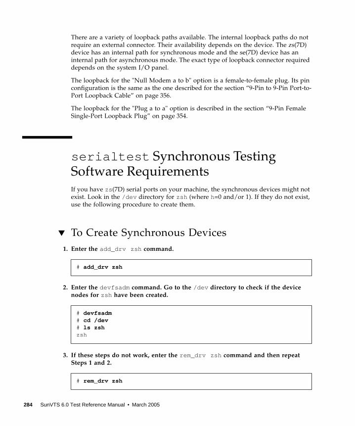
There are a variety of loopback paths available. The internal loopback paths do not
require an external connector. Their availability depends on the device. The zs(7D)
device has an internal path for synchronous mode and the se(7D) device has an
internal path for asynchronous mode. The exact type of loopback connector required
depends on the system I/O panel.
The loopback for the "Null Modem a to b" option is a female-to-female plug. Its pin
configuration is the same as the one described for the section “9-Pin to 9-Pin Port-to-
Port Loopback Cable” on page 356.
The loopback for the "Plug a to a" option is described in the section “9-Pin Female
Single-Port Loopback Plug” on page 354.
serialtest Synchronous TestingSoftware Requirements
If you have zs (7D) serial ports on your machine, the synchronous devices might not
exist. Look in the /dev directory for zsh (where h=0 and/or 1). If they do not exist,
use the following procedure to create them.
▼ To Create Synchronous Devices
1. Enter the add_drv zsh command.
2. Enter the devfsadm command. Go to the /dev directory to check if the devicenodes for zsh have been created.
3. If these steps do not work, enter the rem_drv zsh command and then repeatSteps 1 and 2.
# add_drv zsh
# devfsadm# cd /dev# ls zshzsh
# rem_drv zsh
284 SunVTS 6.0 Test Reference Manual • March 2005
Mode and Description
Asynchronous Testing
This mode uses the asynchronous communication protocol as described in the
zs (7D)and se (7D) man pages. The termio (7I) interface is used for configuring port
characteristics.
The user can select the loopback paths to use, the amount of data to transfer, and the
baud rate to be used for the transfer.
The test writes and reads data through the loopback path and compares the data to
the original data. The test first sends a single character. If no errors or timeouts are
detected, the rest of the data is simultaneously written and read, then compared for
data integrity.
Synchronous Testing
Note – Synchronous mode is not supported on x86 platforms.
This mode uses the synchronous hdlc-framing interface as described in the zsh (7D)
and se_hdlc (7D) man pages. Data is written and read in checksum-protected
packets.
The user can select the loopback paths to use and the clock rate.
The synchronous test runs in three phases:
1. The first phase looks for activity on the port. If no activity is detected for at leastfour seconds, the test proceeds to the next phase. If activity is detected,serialtest exits with an error.
2. The second phase attempts to send and receive one packet. If no packets aredetected after five attempts, the test exits with an error. If a packet is returned, theresult is compared to the original. If the length and content of the packets do notmatch exactly, the test exits with an error.
3. The third phase attempts to send many packets through the loop. Some packetdrops are to be expected especially on a heavily loaded system. The test allows apercentage of the packets to be dropped. The user can set the drop tolerancebetween 0 percent and 99 percent.
The default is 20 percent. If the system is extremely busy, the drop tolerance should
be increased. Each packet is compared with its original for length and content. If a
mismatch is detected, the test exits with an error.
Chapter 285

This mode of testing is not available for devices connected to the super I/O port. It
is, however, available for all other supported I/O ports.
serialtest Options
To reach the dialog box below, right-click on the test name in the System Map and
select Test Parameter Options. If you do not see this test in the System Map, you
might need to expand the collapsed groups, or your system may not include the
device appropriate to this test. Refer to the SunVTS User’s Guide for more details.
286 SunVTS 6.0 Test Reference Manual • March 2005
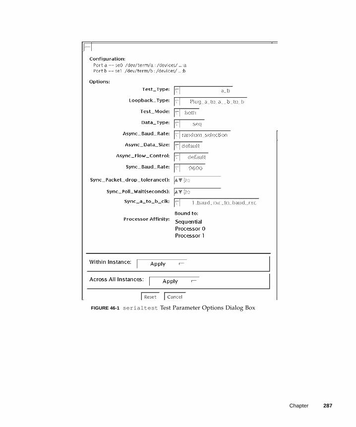
FIGURE 46-1 serialtest Test Parameter Options Dialog Box
Chapter 287
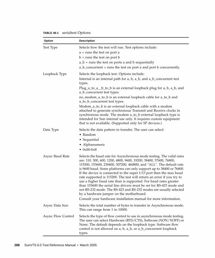
TABLE 46-1 serialtest Options
Option Description
Test Type Selects how the test will run. Test options include:
a = runs the test on port a
b = runs the test on port b
a_b = runs the test on ports a and b sequentially
a_b_concurrent = runs the test on port a and port b concurrently.
Loopback Type Selects the loopback test. Options include:
Internal is an internal path for a, b, a_b, and a_b_concurrent test
types.
Plug_a_to_a__b_to_b is an external loopback plug for a, b, a_b, and
a_b_concurrent test types.
no_modem_a_to_b is an external loopback cable for a_to_b and
a_to_b_concurrent test types.
Modem_a_to_b is an external loopback cable with a modem
attached to generate synchronous Transmit and Receive clocks in
synchronous mode. The modem a_to_b external loopback type is
intended for Sun internal use only. It requires custom equipment
that is not available. (Supported only for SP devices.)
Data Type Selects the data pattern to transfer. The user can select:
• Random
• Sequential
• Alphanumeric
• 0x00-0xff
Async Baud Rate Selects the baud rate for Asynchronous mode testing. The valid rates
are: 110, 300, 600, 1200, 4800, 9600, 19200, 38400, 57600, 76800,
115200, 153600, 230400, 307200, 460800, and "ALL". The default rate
is 9600 baud. Some platforms can only support up to 38400 or 76800.
If the device is connected to the super I/O port then the max baud
rate supported is 115200. The test will return an error if you try to
use a higher baud rate than is supported. For baud rates greater
than 153600 the serial line drivers must be set for RS-423 mode and
not RS-232 mode. The RS-423 and RS-232 modes are usually selected
by a hardware jumper on the motherboard.
Consult your hardware installation manual for more information.
Async Data Size Selects the total number of bytes to transfer in Asynchronous mode.
This can range from 1 to 10000.
Async Flow Control Selects the type of flow control to use in asynchronous mode testing.
The user can select Hardware (RTS/CTS), Software (XON/XOFF) or
None. The default depends on the loopback type. Software flow
control is not allowed on a, b, a_b, or a_b_concurrent loopback
types.
288 SunVTS 6.0 Test Reference Manual • March 2005

The following options are not available for the devices connected to the super I/O port. They areavailable for all other supported I/O ports.
Test Mode Selects the mode to run the test in. The modes available are
Asynchronous, Synchronous or Both. When Both is selected, the test
runs first in Asynchronous mode then Synchronous mode.
Sync Baud Rate Selects the device generated clock rate for synchronous mode
testing. The valid rates are from 110 to 230400. The rate does not
have to be a specific value as required for async mode baud rates.
The default rate is 9600. Some platforms can only support up to
38400 or 76800. The test will return an error if you try to use a
higher rate than is supported. For rates greater than 100000, the
serial line drivers must be set for RS-423 mode and not RS-232
mode. The RS-423 and RS-232 modes are usually selected by a
hardware jumper on the motherboard.
Consult your hardware installation manual for more information.
Sync Packet Selects the tolerance level of Synchronous mode dropped packets
during the many_packets subtest. The default is Drop20 percent.
The valid range is from 0 percent to 99 percent. Some packet drops
are expected especially at higher Toleranceclock rates and on a
heavily loaded system.
Sync Poll Wait Selects the number of seconds in additional time to wait for a
Synchronous mode packet to be sent. Additional time may be
needed when there is heavy system activity and time-outs are being
detected. In general, the user can decrease the value to 0 when the
system load is light or increase the value when there is a heavy
system load.
The following option is available only for devices connected to the super I/O port. They do not applyto any other supported I/O ports.
User Defined Baud
Rate
Allows the user to set new baud rate values for the test. First select
the User Defined option from the Async menu. Then enter the new
value in the User Defined Baud Rate field.
TABLE 46-1 serialtest Options (Continued)
Option Description
Chapter 289

serialtest Test Modes
serialtest Command-Line Syntax
/opt/SUNWvts/bin/sparcv9/serialtest standard_arguments -o dev =
device_name, porta =port_name, T=test_type, L=loopback_type, M=mode, D=data_pattern,
AB=async_baud_rate, S=async_data_size, par =none|even|odd , BS=
1|10|100|1000|3000|5000|10000 , F=flow_control, B=sync_baud_rate , DP=
sync_drop_tolerance, P=sync_poll_wait
Command-line syntax for devices connected to the super I/O port:
TABLE 46-2 serialtest Supported Test Modes
Mode Description
Connection Attempts to open the port to determine if the device is connected. If
it fails and the port is not busy, the test exits with an error. If it is
successful or fails with a busy or exclusive use error, then the port is
considered connected, and the test passes.
Functional Performs the selected loopback test.
290 SunVTS 6.0 Test Reference Manual • March 2005

/opt/SUNWvts/bin/sparcv9/serialtest standard_arguments -o dev =
device_name, porta =port_name, T=test_type, L=loopback_type, D=data_pattern, AB=
async_baud_rate, BS=1|10|100|1000|3000|5000|10000 , F=flow_control, UAB=
User_Baud_Rate
TABLE 46-3 serialtest Command-Line Syntax
Argument Description
dev =device_name Identifies the serial port(s) to test. There is no
default value. You must specify a device name
such as:
• se0
• zs0 , zs1
• zs2 , zs3
• su0
porta =port_name The name of the first device of a serial device pair.
The default is a.
T=test_type Specifies the type of test to run:
• a = runs the test on port a.
• b = runs the test on port b.
• a_b = runs the test on ports a and b sequentially.
• a_b_concurrent = runs the test on port a and
port b concurrently.
• a_to_b = runs the test from port a to port b.
L=loopback_type The type of loopback connector attached to ports:
• No_modem_a_to_b
• Internal_a_to_a__b_to_b
• Plug_a_to_a__b_to_b
• Modem_a_to_b
M=mode The default test mode is asynchronous. Specify
one of the following modes:
• asynch
• synch
• both
D=data_pattern Selects the data pattern to transfer. The user can
select:
• Random
• Sequential
• Alphanumeric
• 0x00-0xFF
Chapter 291
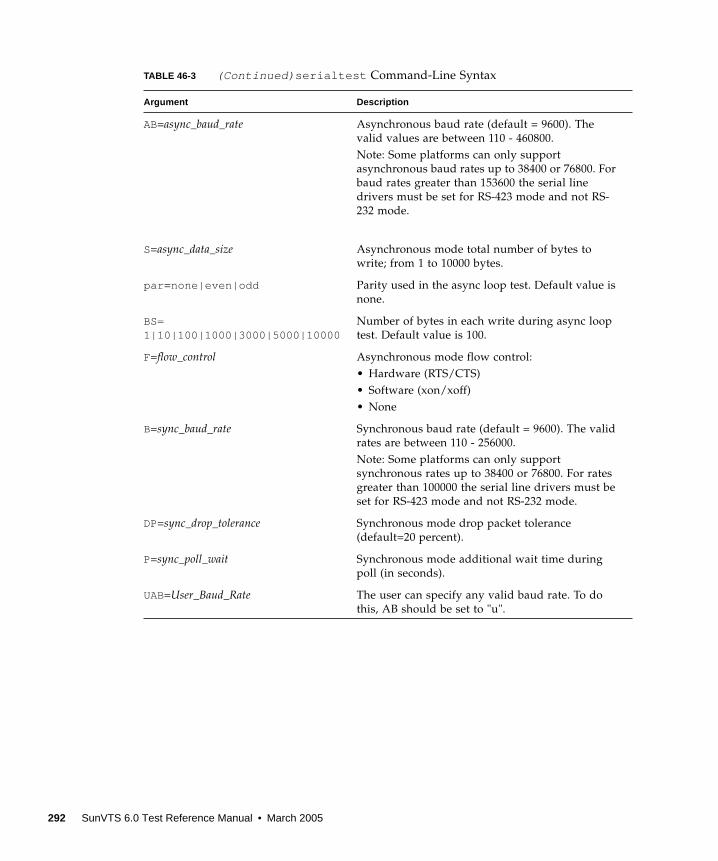
AB=async_baud_rate Asynchronous baud rate (default = 9600). The
valid values are between 110 - 460800.
Note: Some platforms can only support
asynchronous baud rates up to 38400 or 76800. For
baud rates greater than 153600 the serial line
drivers must be set for RS-423 mode and not RS-
232 mode.
S=async_data_size Asynchronous mode total number of bytes to
write; from 1 to 10000 bytes.
par =none|even|odd Parity used in the async loop test. Default value is
none.
BS=1|10|100|1000|3000|5000|10000
Number of bytes in each write during async loop
test. Default value is 100.
F=flow_control Asynchronous mode flow control:
• Hardware (RTS/CTS)
• Software (xon/xoff)
• None
B=sync_baud_rate Synchronous baud rate (default = 9600). The valid
rates are between 110 - 256000.
Note: Some platforms can only support
synchronous rates up to 38400 or 76800. For rates
greater than 100000 the serial line drivers must be
set for RS-423 mode and not RS-232 mode.
DP=sync_drop_tolerance Synchronous mode drop packet tolerance
(default=20 percent).
P=sync_poll_wait Synchronous mode additional wait time during
poll (in seconds).
UAB=User_Baud_Rate The user can specify any valid baud rate. To do
this, AB should be set to "u".
TABLE 46-3 (Continued) serialtest Command-Line Syntax
Argument Description
292 SunVTS 6.0 Test Reference Manual • March 2005
CHAPTER 47
Serial Parallel Controller Test(spiftest )
The spiftest accesses card components such as the cd-180 and ppc2 chips, and the
serial and parallel ports through the serial parallel controller device driver.
spiftest Hardware Requirements
Before running the SunVTS system exerciser, make sure you install the cards to be
tested and the device driver. You should also reboot your system with the
boot -r command to reconfigure the system and allow the SunVTS kernel to
recognize the new driver.
Note – The spiftest must be run in Intervention mode.
The following minimum hardware configuration is required to successfully run the
Internal test:
■ SBus-based SPARC desktop system with an SBus slot
■ Serial parallel controller card, installed in one of the SBus slots
The following hardware is also required to run the other SunVTS serial parallel
controller tests:
■ Serial parallel controller patch panel (part number 540-2007)
■ 96-pin loopback plugs (part number 370-1366)
■ 25-pin serial loopback plugs (part number 540-1558)
■ RS-232 serial cables (part number 530-1685)
■ TTY terminal
293
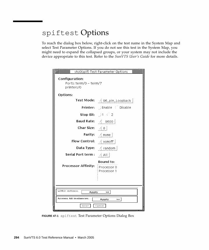
spiftest Options
To reach the dialog box below, right-click on the test name in the System Map and
select Test Parameter Options. If you do not see this test in the System Map, you
might need to expand the collapsed groups, or your system may not include the
device appropriate to this test. Refer to the SunVTS User’s Guide for more details.
FIGURE 47-1 spiftest Test Parameter Options Dialog Box
294 SunVTS 6.0 Test Reference Manual • March 2005
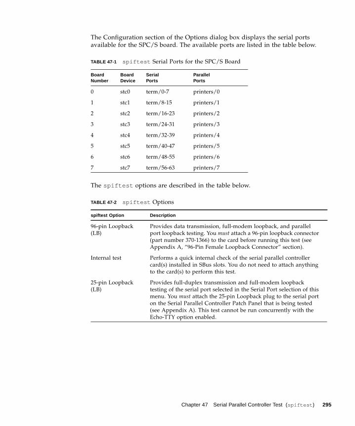
The Configuration section of the Options dialog box displays the serial ports
available for the SPC/S board. The available ports are listed in the table below.
The spiftest options are described in the table below.
TABLE 47-1 spiftest Serial Ports for the SPC/S Board
BoardNumber
BoardDevice
SerialPorts
ParallelPorts
0 stc0 term/0-7 printers/0
1 stc1 term/8-15 printers/1
2 stc2 term/16-23 printers/2
3 stc3 term/24-31 printers/3
4 stc4 term/32-39 printers/4
5 stc5 term/40-47 printers/5
6 stc6 term/48-55 printers/6
7 stc7 term/56-63 printers/7
TABLE 47-2 spiftest Options
spiftest Option Description
96-pin Loopback
(LB)
Provides data transmission, full-modem loopback, and parallel
port loopback testing. You must attach a 96-pin loopback connector
(part number 370-1366) to the card before running this test (see
Appendix A, “96-Pin Female Loopback Connector” section).
Internal test Performs a quick internal check of the serial parallel controller
card(s) installed in SBus slots. You do not need to attach anything
to the card(s) to perform this test.
25-pin Loopback
(LB)
Provides full-duplex transmission and full-modem loopback
testing of the serial port selected in the Serial Port selection of this
menu. You must attach the 25-pin Loopback plug to the serial port
on the Serial Parallel Controller Patch Panel that is being tested
(see Appendix A). This test cannot be run concurrently with the
Echo-TTY option enabled.
Chapter 47 Serial Parallel Controller Test (spiftest ) 295
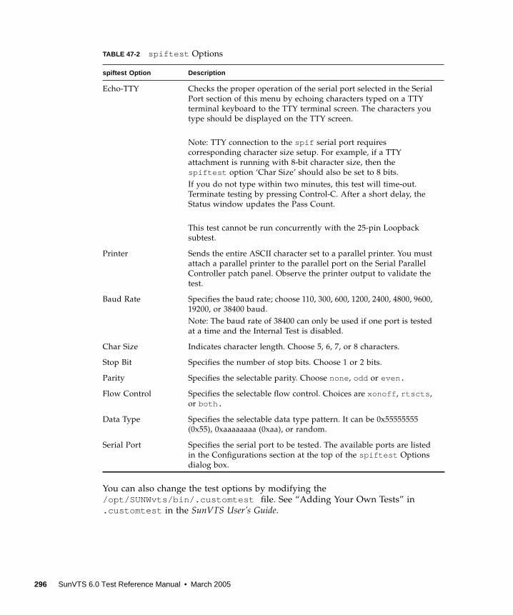
You can also change the test options by modifying the
/opt/SUNWvts/bin/.customtest file. See “Adding Your Own Tests” in
.customtest in the SunVTS User’s Guide.
Echo-TTY Checks the proper operation of the serial port selected in the Serial
Port section of this menu by echoing characters typed on a TTY
terminal keyboard to the TTY terminal screen. The characters you
type should be displayed on the TTY screen.
Note: TTY connection to the spif serial port requires
corresponding character size setup. For example, if a TTY
attachment is running with 8-bit character size, then the
spiftest option ‘Char Size’ should also be set to 8 bits.
If you do not type within two minutes, this test will time-out.
Terminate testing by pressing Control-C. After a short delay, the
Status window updates the Pass Count.
This test cannot be run concurrently with the 25-pin Loopback
subtest.
Printer Sends the entire ASCII character set to a parallel printer. You must
attach a parallel printer to the parallel port on the Serial Parallel
Controller patch panel. Observe the printer output to validate the
test.
Baud Rate Specifies the baud rate; choose 110, 300, 600, 1200, 2400, 4800, 9600,
19200, or 38400 baud.
Note: The baud rate of 38400 can only be used if one port is tested
at a time and the Internal Test is disabled.
Char Size Indicates character length. Choose 5, 6, 7, or 8 characters.
Stop Bit Specifies the number of stop bits. Choose 1 or 2 bits.
Parity Specifies the selectable parity. Choose none , odd or even.
Flow Control Specifies the selectable flow control. Choices are xonoff , rtscts ,
or both.
Data Type Specifies the selectable data type pattern. It can be 0x55555555
(0x55), 0xaaaaaaaa (0xaa), or random.
Serial Port Specifies the serial port to be tested. The available ports are listed
in the Configurations section at the top of the spiftest Options
dialog box.
TABLE 47-2 spiftest Options
spiftest Option Description
296 SunVTS 6.0 Test Reference Manual • March 2005
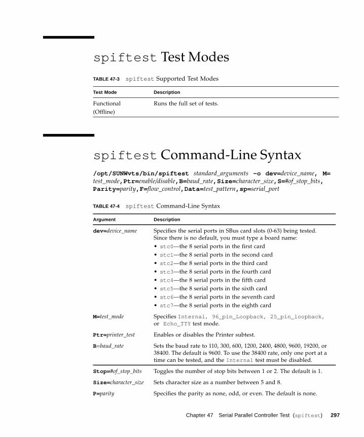
spiftest Test Modes
spiftest Command-Line Syntax
/opt/SUNWvts/bin/spiftest standard_arguments -o dev= device_name, M=test_mode,Ptr= enable/disable,B= baud_rate,Size= character_size,S= #of_stop_bits,Parity= parity,F= flow_control,Data= test_pattern,sp= serial_port
TABLE 47-3 spiftest Supported Test Modes
Test Mode Description
Functional
(Offline)
Runs the full set of tests.
TABLE 47-4 spiftest Command-Line Syntax
Argument Description
dev= device_name Specifies the serial ports in SBus card slots (0-63) being tested.
Since there is no default, you must type a board name:
• stc0 —the 8 serial ports in the first card
• stc1 —the 8 serial ports in the second card
• stc2 —the 8 serial ports in the third card
• stc3 —the 8 serial ports in the fourth card
• stc4 —the 8 serial ports in the fifth card
• stc5 —the 8 serial ports in the sixth card
• stc6 —the 8 serial ports in the seventh card
• stc7 —the 8 serial ports in the eighth card
M=test_mode Specifies Internal, 96_pin_Loopback, 25_pin_loopback,or Echo_TTY test mode.
Ptr= printer_test Enables or disables the Printer subtest.
B=baud_rate Sets the baud rate to 110, 300, 600, 1200, 2400, 4800, 9600, 19200, or
38400. The default is 9600. To use the 38400 rate, only one port at a
time can be tested, and the Internal test must be disabled.
Stop= #of_stop_bits Toggles the number of stop bits between 1 or 2. The default is 1.
Size= character_size Sets character size as a number between 5 and 8.
P=parity Specifies the parity as none, odd, or even. The default is none.
Chapter 47 Serial Parallel Controller Test (spiftest ) 297

Note – 64-bit tests are located in the sparcv9 subdirectory:
/opt/SUNWvts/bin/sparcv9/ testname, or the relative path to which you installed
SunVTS. If a test is not present in this directory, then it might be available as a 32-bit
test only. For more information, see “32-Bit and 64-Bit Tests” on page 5.
F=flow_control Specifies flow control as xonxoff,rtscts , or both.
Data= test_pattern Specifies test pattern as 0x55555555, 0xAAAAAAAA, or random.
sp= serial_port Specifies the terminal and serial port number, such as term/3 .
TABLE 47-4 spiftest Command-Line Syntax
Argument Description
298 SunVTS 6.0 Test Reference Manual • March 2005
CHAPTER 48
System Service Processor Test(ssptest)
The ssptest exercises the Remote System Control (RSC) feature, which is
integrated on the Sun Enterprise 250 as well as the next-generation RSC 2.0 plug-in
card introduced with the Sun Fire 280R line, and Advanced Lights-Out
Management (ALOM) feature. The ALOM feature is integrated into the Sun Fire
V210, Sun Fire V240, Sun Fire V440, and Sun Netra 440 systems.
The RSC or ALOM provides secure remote access for system monitoring, firmware
updates, and failure recovery. The RSC or ALOM communicates with the host
through two internal serial lines, the I2C bus, and reset lines.
The RSC 1.0 hardware consists of the controller, flash, SEEPROM, 10MB Ethernet
port, and an external console serial port.
The RSC 2.0 plug-in card hardware consists of the controller, flash, SEEPROM, 10MB
Ethernet port, FRUSEEPROM, Time of Day (ToD) device, internal PCMCIA modem
card, and battery backup.
The ALOM hardware consists of a Motorola MPC850 processor, flash, SEEPROM,
10MB/100MB Ethernet Port, FRUSEEPROM, Time of Day (ToD) device, Serial
Transceiver, and battery backup.
ssptest is not scalable.
ssptest Subtests
The ssptest will present different subtests and options based on which type of
hardware (RSC or ALOM) and which version of RSC hardware (1.0 or 2.0) it is
testing.
299
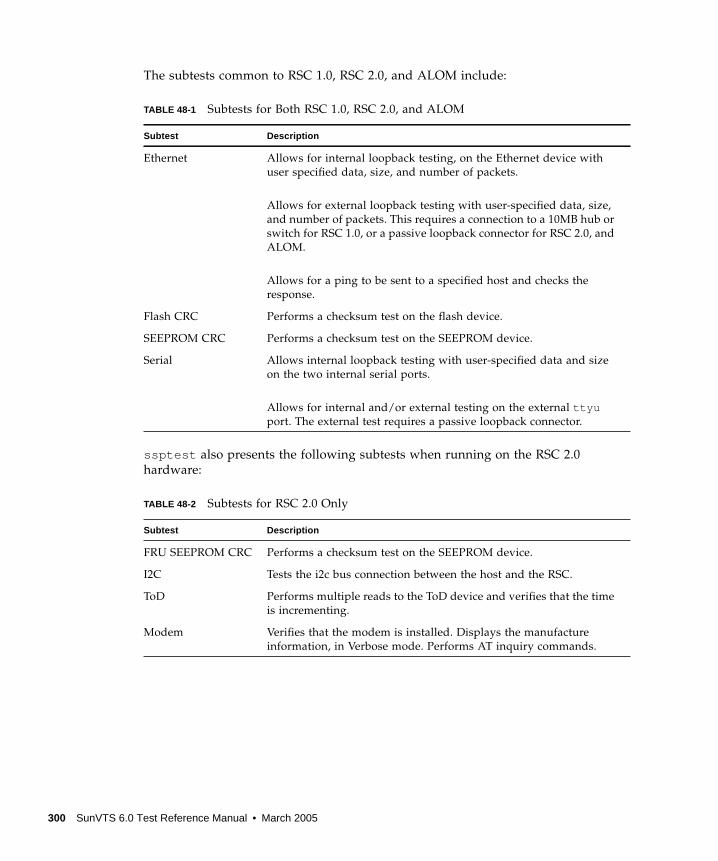
The subtests common to RSC 1.0, RSC 2.0, and ALOM include:
ssptest also presents the following subtests when running on the RSC 2.0
hardware:
TABLE 48-1 Subtests for Both RSC 1.0, RSC 2.0, and ALOM
Subtest Description
Ethernet Allows for internal loopback testing, on the Ethernet device with
user specified data, size, and number of packets.
Allows for external loopback testing with user-specified data, size,
and number of packets. This requires a connection to a 10MB hub or
switch for RSC 1.0, or a passive loopback connector for RSC 2.0, and
ALOM.
Allows for a ping to be sent to a specified host and checks the
response.
Flash CRC Performs a checksum test on the flash device.
SEEPROM CRC Performs a checksum test on the SEEPROM device.
Serial Allows internal loopback testing with user-specified data and size
on the two internal serial ports.
Allows for internal and/or external testing on the external ttyuport. The external test requires a passive loopback connector.
TABLE 48-2 Subtests for RSC 2.0 Only
Subtest Description
FRU SEEPROM CRC Performs a checksum test on the SEEPROM device.
I2C Tests the i2c bus connection between the host and the RSC.
ToD Performs multiple reads to the ToD device and verifies that the time
is incrementing.
Modem Verifies that the modem is installed. Displays the manufacture
information, in Verbose mode. Performs AT inquiry commands.
300 SunVTS 6.0 Test Reference Manual • March 2005
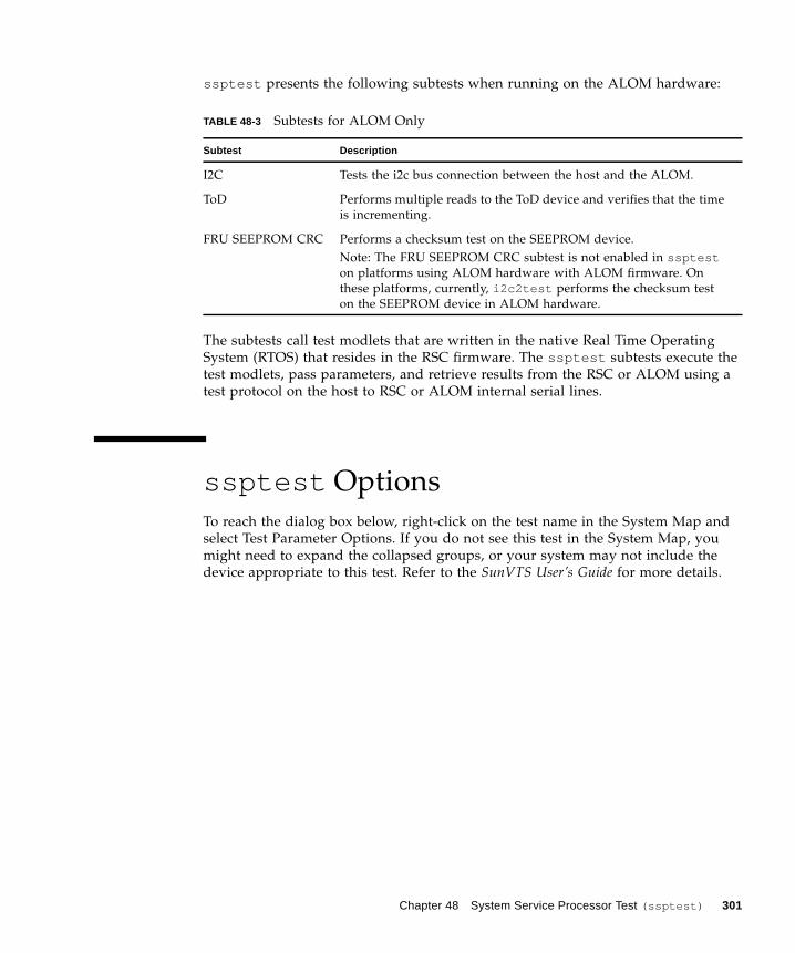
ssptest presents the following subtests when running on the ALOM hardware:
The subtests call test modlets that are written in the native Real Time Operating
System (RTOS) that resides in the RSC firmware. The ssptest subtests execute the
test modlets, pass parameters, and retrieve results from the RSC or ALOM using a
test protocol on the host to RSC or ALOM internal serial lines.
ssptest Options
To reach the dialog box below, right-click on the test name in the System Map and
select Test Parameter Options. If you do not see this test in the System Map, you
might need to expand the collapsed groups, or your system may not include the
device appropriate to this test. Refer to the SunVTS User’s Guide for more details.
TABLE 48-3 Subtests for ALOM Only
Subtest Description
I2C Tests the i2c bus connection between the host and the ALOM.
ToD Performs multiple reads to the ToD device and verifies that the time
is incrementing.
FRU SEEPROM CRC Performs a checksum test on the SEEPROM device.
Note: The FRU SEEPROM CRC subtest is not enabled in sspteston platforms using ALOM hardware with ALOM firmware. On
these platforms, currently, i2c2test performs the checksum test
on the SEEPROM device in ALOM hardware.
Chapter 48 System Service Processor Test (ssptest) 301
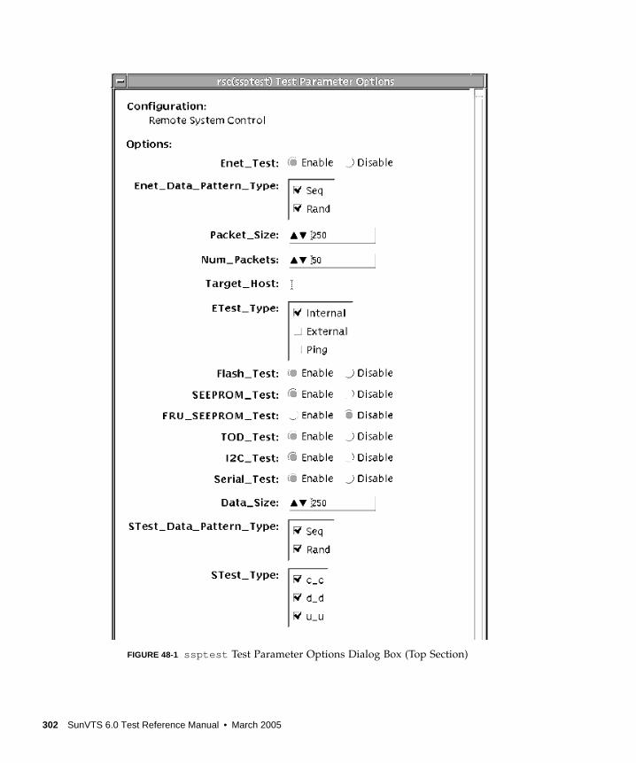
FIGURE 48-1 ssptest Test Parameter Options Dialog Box (Top Section)
302 SunVTS 6.0 Test Reference Manual • March 2005
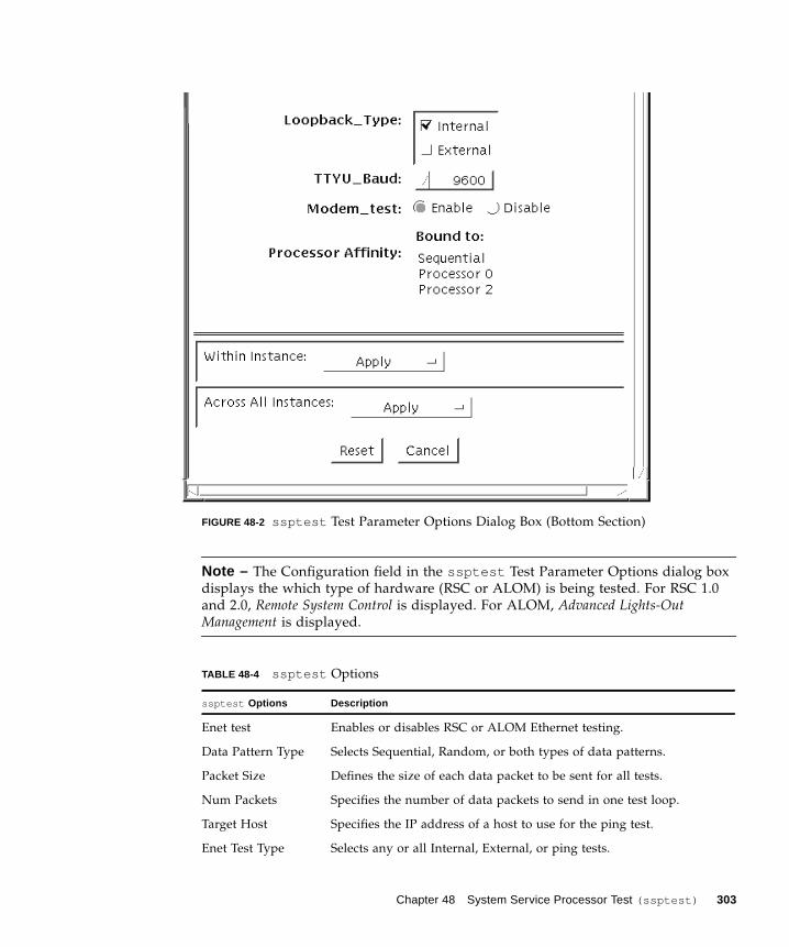
FIGURE 48-2 ssptest Test Parameter Options Dialog Box (Bottom Section)
Note – The Configuration field in the ssptest Test Parameter Options dialog box
displays the which type of hardware (RSC or ALOM) is being tested. For RSC 1.0
and 2.0, Remote System Control is displayed. For ALOM, Advanced Lights-OutManagement is displayed.
TABLE 48-4 ssptest Options
ssptest Options Description
Enet test Enables or disables RSC or ALOM Ethernet testing.
Data Pattern Type Selects Sequential, Random, or both types of data patterns.
Packet Size Defines the size of each data packet to be sent for all tests.
Num Packets Specifies the number of data packets to send in one test loop.
Target Host Specifies the IP address of a host to use for the ping test.
Enet Test Type Selects any or all Internal, External, or ping tests.
Chapter 48 System Service Processor Test (ssptest) 303
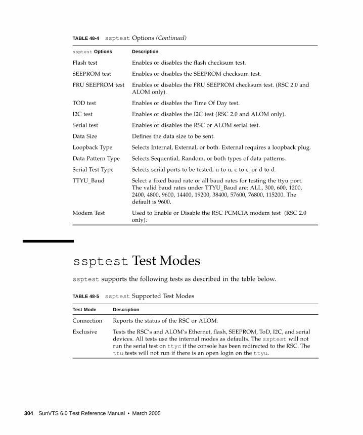
ssptest Test Modes
ssptest supports the following tests as described in the table below.
Flash test Enables or disables the flash checksum test.
SEEPROM test Enables or disables the SEEPROM checksum test.
FRU SEEPROM test Enables or disables the FRU SEEPROM checksum test. (RSC 2.0 and
ALOM only).
TOD test Enables or disables the Time Of Day test.
I2C test Enables or disables the I2C test (RSC 2.0 and ALOM only).
Serial test Enables or disables the RSC or ALOM serial test.
Data Size Defines the data size to be sent.
Loopback Type Selects Internal, External, or both. External requires a loopback plug.
Data Pattern Type Selects Sequential, Random, or both types of data patterns.
Serial Test Type Selects serial ports to be tested, u to u, c to c, or d to d.
TTYU_Baud Select a fixed baud rate or all baud rates for testing the ttyu port.
The valid baud rates under TTYU_Baud are: ALL, 300, 600, 1200,
2400, 4800, 9600, 14400, 19200, 38400, 57600, 76800, 115200. The
default is 9600.
Modem Test Used to Enable or Disable the RSC PCMCIA modem test (RSC 2.0
only).
TABLE 48-5 ssptest Supported Test Modes
Test Mode Description
Connection Reports the status of the RSC or ALOM.
Exclusive Tests the RSC’s and ALOM’s Ethernet, flash, SEEPROM, ToD, I2C, and serial
devices. All tests use the internal modes as defaults. The ssptest will not
run the serial test on ttyc if the console has been redirected to the RSC. The
ttu tests will not run if there is an open login on the ttyu .
TABLE 48-4 ssptest Options (Continued)
ssptest Options Description
304 SunVTS 6.0 Test Reference Manual • March 2005
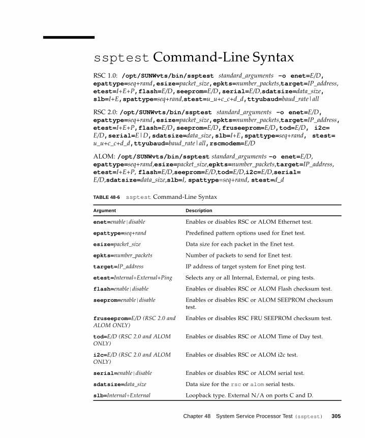
ssptest Command-Line Syntax
RSC 1.0: /opt/SUNWvts/bin/ssptest standard_arguments -o enet= E/D,epattype= seq+rand,esize= packet_size,epkts= number_packets,target= IP_address,
etest= I+E+P,flash= E/D,seeprom= E/D,serial= E/D,sdatsize= data_size,slb= I+E,spattype= seq+rand,stest= u_u+c_c+d_d,ttyubaud= baud_rate|all
RSC 2.0: /opt/SUNWvts/bin/ssptest standard_arguments -o enet= E/D,epattype= seq+rand,esize= packet_size,epkts= number_packets,target= IP_address,etest= I+E+P,flash= E/D,seeprom= E/D,fruseeprom= E/D,tod= E/D, i2c=E/D,serial= E|D,sdatsize= data_size,slb= I+E,spattype= seq+rand, stest=u_u+c_c+d_d,ttyubaud= baud_rate|all,rscmodem= E/D
ALOM: /opt/SUNWvts/bin/ssptest standard_arguments -o enet= E/D,
epattype= seq+rand,esize= packet_size,epkts= number_packets,target= IP_address,
etest= I+E+P, flash= E/D,seeprom= E/D,tod= E/D,i2c= E/D,serial=E/D,sdatsize= data_size,slb= I, spattype =seq+rand, stest= d_d
TABLE 48-6 ssptest Command-Line Syntax
Argument Description
enet= enable| disable Enables or disables RSC or ALOM Ethernet test.
epattype= seq+rand Predefined pattern options used for Enet test.
esize= packet_size Data size for each packet in the Enet test.
epkts= number_packets Number of packets to send for Enet test.
target= IP_address IP address of target system for Enet ping test.
etest= Internal+External+Ping Selects any or all Internal, External, or ping tests.
flash= enable| disable Enables or disables RSC or ALOM Flash checksum test.
seeprom= enable| disable Enables or disables RSC or ALOM SEEPROM checksum
test.
fruseeprom= E/D (RSC 2.0 andALOM ONLY)
Enables or disables RSC FRU SEEPROM checksum test.
tod= E/D (RSC 2.0 and ALOMONLY)
Enables or disables RSC or ALOM Time of Day test.
i2c= E/D (RSC 2.0 and ALOMONLY)
Enables or disables RSC or ALOM i2c test.
serial= enable| disable Enables or disables RSC or ALOM serial test.
sdatsize= data_size Data size for the rsc or alom serial tests.
slb= Internal+External Loopback type. External N/A on ports C and D.
Chapter 48 System Service Processor Test (ssptest) 305

Note – 64-bit tests are located in the sparcv9 subdirectory:
/opt/SUNWvts/bin/sparcv9/ testname, or the relative path to which you installed
SunVTS. If a test is not present in this directory, then it might be available as a 32-bit
test only. For more information, see “32-Bit and 64-Bit Tests” on page 5.
spattype= seq+rand Predefined pattern options used for RSC or ALOM serial
test.
stest= u_u+c_c+d_d Defines port and configuration to use for RSC or ALOM
serial test.
ttyu_baud= ALL|specific_baud Defines baud rates to be used in testing the RSC’s
console port. The valid baud rates under ttu_baud are:
ALL, 300, 600, 1200, 2400, 4800, 9600, 14400, 19200,
38400, 57600, 76800, 115200. The default is 9600.
rscmodem= E/D (RSC2.0 Only) Enables or disables the RSC PCMCIA modem test.
TABLE 48-6 ssptest Command-Line Syntax (Continued)
Argument Description
306 SunVTS 6.0 Test Reference Manual • March 2005
CHAPTER 49
SunHSI Board Test (sunlink )
The sunlink test verifies the functionality of the SBus and PCI bus SunHSI™
boards by using the HDLC protocol. sunlink initializes and configures the selected
channel.
Next, sunlink opens a datagram socket and tries to modify the socket to accept
ioctl communications with the driver, and receive synchronous mode information
from it.
sunlink then opens the ports, linking the upper and lower layers with ioctl calls.
After initialization, this test checks for activity before attempting to send or receive
data. An error message is returned if activity is detected; otherwise the transmit
buffer is filled with random data. Random data is used by default. You may also
specify other patterns. The data is then transmitted. If the transmission succeeds,
sunlink then receives the returned data and verifies that it is identical to what was
sent. Finally, statistics about the send and receive are gathered from the socket.
A full sunlink test takes approximately eight minutes per port and makes a brief
check of the board ports before the actual test begins. If the port is bad, the test
immediately aborts and returns an error message.
sunlink Test Requirements
This test will not pass unless you install the correct loopback connectors or port to
port cables on the ports you are testing. The ports specified for test in the Options
dialog box must have loopback connectors attached. See Appendix A for loopback
connector part numbers and wiring instructions.
307
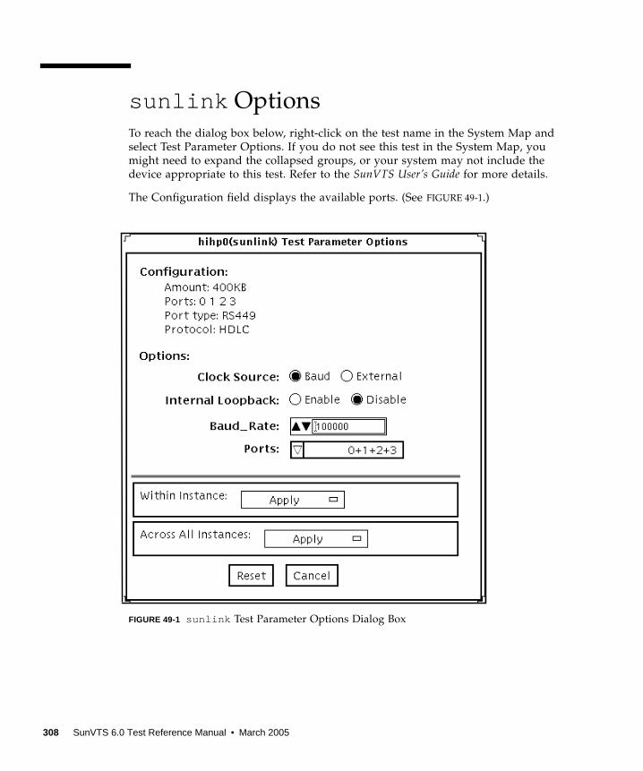
sunlink Options
To reach the dialog box below, right-click on the test name in the System Map and
select Test Parameter Options. If you do not see this test in the System Map, you
might need to expand the collapsed groups, or your system may not include the
device appropriate to this test. Refer to the SunVTS User’s Guide for more details.
The Configuration field displays the available ports. (See FIGURE 49-1.)
FIGURE 49-1 sunlink Test Parameter Options Dialog Box
308 SunVTS 6.0 Test Reference Manual • March 2005
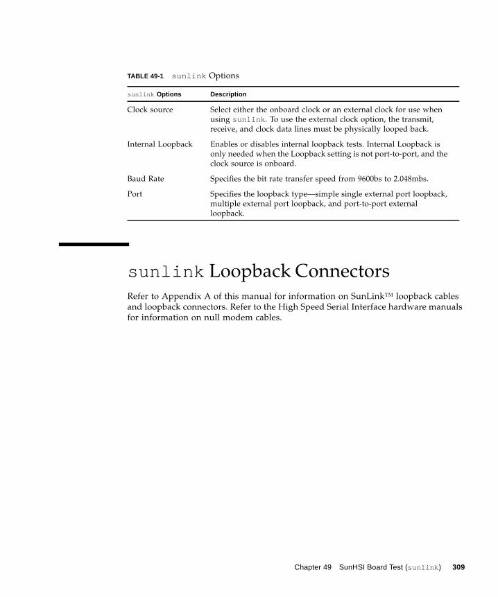
sunlink Loopback Connectors
Refer to Appendix A of this manual for information on SunLink™ loopback cables
and loopback connectors. Refer to the High Speed Serial Interface hardware manuals
for information on null modem cables.
TABLE 49-1 sunlink Options
sunlink Options Description
Clock source Select either the onboard clock or an external clock for use when
using sunlink . To use the external clock option, the transmit,
receive, and clock data lines must be physically looped back.
Internal Loopback Enables or disables internal loopback tests. Internal Loopback is
only needed when the Loopback setting is not port-to-port, and the
clock source is onboard.
Baud Rate Specifies the bit rate transfer speed from 9600bs to 2.048mbs.
Port Specifies the loopback type—simple single external port loopback,
multiple external port loopback, and port-to-port external
loopback.
Chapter 49 SunHSI Board Test (sunlink ) 309
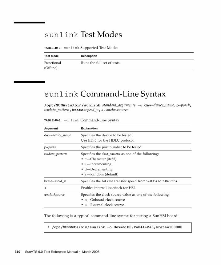
sunlink Test Modes
sunlink Command-Line Syntax
/opt/SUNWvts/bin/sunlink standard_arguments -o dev= device_name,p= port#,P=data_pattern,brate =speed_n,I,C= clocksource
The following is a typical command-line syntax for testing a SunHSI board:
TABLE 49-2 sunlink Supported Test Modes
Test Mode Description
Functional
(Offline)
Runs the full set of tests.
TABLE 49-3 sunlink Command-Line Syntax
Argument Explanation
dev= device_name Specifies the device to be tested.
Use hih0 for the HDLC protocol.
p=ports Specifies the port number to be tested.
P=data_pattern Specifies the data_pattern as one of the following:
• c—Character (0x55)
• i —Incrementing
• d—Decrementing
• r —Random (default)
brate=speed_n Specifies the bit rate transfer speed from 9600bs to 2.048mbs.
I Enables internal loopback for HSI.
c=clocksource Specifies the clock source value as one of the following:
• B—Onboard clock source
• E—External clock source
# /opt/SUNWvts/bin/sunlink -o dev=hih0,P=0+1+2+3,brate=100000
310 SunVTS 6.0 Test Reference Manual • March 2005
This command tests the internal loopback for ports 0, 1, 2, and 3. It does not run for
the port to port internal loopback test.
Note – 64-bit tests are located in the sparcv9 subdirectory:
/opt/SUNWvts/bin/sparcv9/ testname, or the relative path to which you installed
SunVTS. If a test is not present in this directory, then it might be available as a 32-bit
test only. For more information, see “32-Bit and 64-Bit Tests” on page 5.
Chapter 49 SunHSI Board Test (sunlink ) 311

312 SunVTS 6.0 Test Reference Manual • March 2005
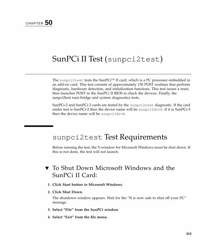
CHAPTER 50
SunPCi II Test (sunpci2test )
The sunpci2test tests the SunPCi™ II card, which is a PC processor embedded in
an add-on card. This test consists of approximately 150 POST routines that perform
diagnostic, hardware detection, and initialization functions. This test issues a reset,
then launches POST in the SunPCi II BIOS to check the devices. Finally, the
sunpci2test runs bridge and system diagnostics tests.
SunPCi-2 and SunPCi-3 cards are tested by the sunpci2test diagnostic. If the card
under test is SunPCi-2 then the device name will be sunpci2drvX . If it is SunPCi-3
then the device name will be sunpci3drvX .
sunpci2test Test Requirements
Before running the test, the X-window for Microsoft Windows must be shut down. If
this is not done, the test will not launch.
▼ To Shut Down Microsoft Windows and the
SunPCi II Card:
1. Click Start button in Microsoft Windows.
2. Click Shut Down.
The shutdown window appears. Wait for the “It is now safe to shut off your PC”
message.
3. Select “File” from the SunPCi window.
4. Select “Exit” from the file menu.
313

5. Click OK.
sunpci2test Options
To reach the dialog box below, right-click on the test name in the System Map and
select Test Parameter Options. If you do not see this test in the System Map, you
might need to expand the collapsed groups, or your system may not include the
device appropriate to this test. Refer to the SunVTS User’s Guide for more details.
FIGURE 50-1 sunpci2test Test Parameter Options Dialog Box
sunpci2test only runs with the default parameters in place. Thus, this test does
not allow any options to be configured specifically for an individual system. The
number of instances is preset to 1 (the default value), as only one local copy of the
test is supported.
314 SunVTS 6.0 Test Reference Manual • March 2005

sunpci2test Test Modes
sunpci2test Command-Line Syntax
/opt/SUNWvts/bin/sunpci2test standard_arguments
Note – There are no test-specific options for sunpci2test .
Note – 64-bit tests are located in the sparcv9 subdirectory:
/opt/SUNWvts/bin/sparcv9/ testname, or the relative path to which you installed
SunVTS. If a test is not present in this directory, then it might be available as a 32-bit
test only. For more information, see “32-Bit and 64-Bit Tests” on page 5.
TABLE 50-1 sunpci2test Supported Test Modes
Test Mode Description
Connection Runs the full set of tests.
Functional
(Offline)
Runs the full set of tests.
Chapter 50 SunPCi II Test (sunpci2test ) 315

316 SunVTS 6.0 Test Reference Manual • March 2005
CHAPTER 51
System Test (systest )
The systest checks the overall functionality of a Sun system by exercising the
CPU, I/O, and Memory channels simultaneously.
Note – systest does support x86 platforms on Solaris.
Note – systest has been enhanced to enable the Cpu Test subtest on x86 systems.
systest now supports the same set of options for both SPARC and x86.
The test ensures the concurrency of the different channels by the use of Solaris
threads. The test aims at stimulating failures that might be caused due to the
interaction of the various different hardware modules in the system. It is very
stressful on the CPU, and stresses the parallel computational capability of a
multiprocessor system.
systest Options
To reach the dialog box below, right-click on the test name in the System Map and
select Test Parameter Options. If you do not see this test in the System Map, you
might need to expand the collapsed groups, or your system may not include the
device appropriate to this test. Refer to the SunVTS User’s Guide for more details.
317
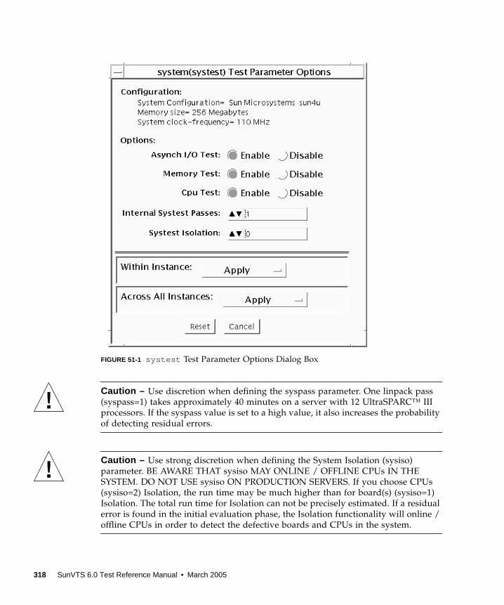
FIGURE 51-1 systest Test Parameter Options Dialog Box
Caution – Use discretion when defining the syspass parameter. One linpack pass
(syspass=1) takes approximately 40 minutes on a server with 12 UltraSPARC™ III
processors. If the syspass value is set to a high value, it also increases the probability
of detecting residual errors.
Caution – Use strong discretion when defining the System Isolation (sysiso)
parameter. BE AWARE THAT sysiso MAY ONLINE / OFFLINE CPUs IN THE
SYSTEM. DO NOT USE sysiso ON PRODUCTION SERVERS. If you choose CPUs
(sysiso=2) Isolation, the run time may be much higher than for board(s) (sysiso=1)
Isolation. The total run time for Isolation can not be precisely estimated. If a residual
error is found in the initial evaluation phase, the Isolation functionality will online /
offline CPUs in order to detect the defective boards and CPUs in the system.
318 SunVTS 6.0 Test Reference Manual • March 2005
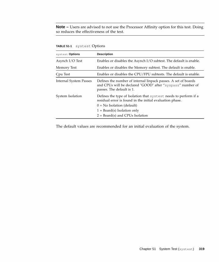
Note – Users are advised to not use the Processor Affinity option for this test. Doing
so reduces the effectiveness of the test.
The default values are recommended for an initial evaluation of the system.
TABLE 51-1 systest Options
systest Options Description
Asynch I/O Test Enables or disables the Asynch I/O subtest. The default is enable.
Memory Test Enables or disables the Memory subtest. The default is enable.
Cpu Test Enables or disables the CPU/FPU subtests. The default is enable.
Internal System Passes Defines the number of internal linpack passes. A set of boards
and CPUs will be declared "GOOD" after “syspass ” number of
passes. The default is 1.
System Isolation Defines the type of Isolation that systest needs to perform if a
residual error is found in the initial evaluation phase.
0 = No Isolation (default)
1 = Board(s) Isolation only
2 = Board(s) and CPUs Isolation
Chapter 51 System Test (systest ) 319
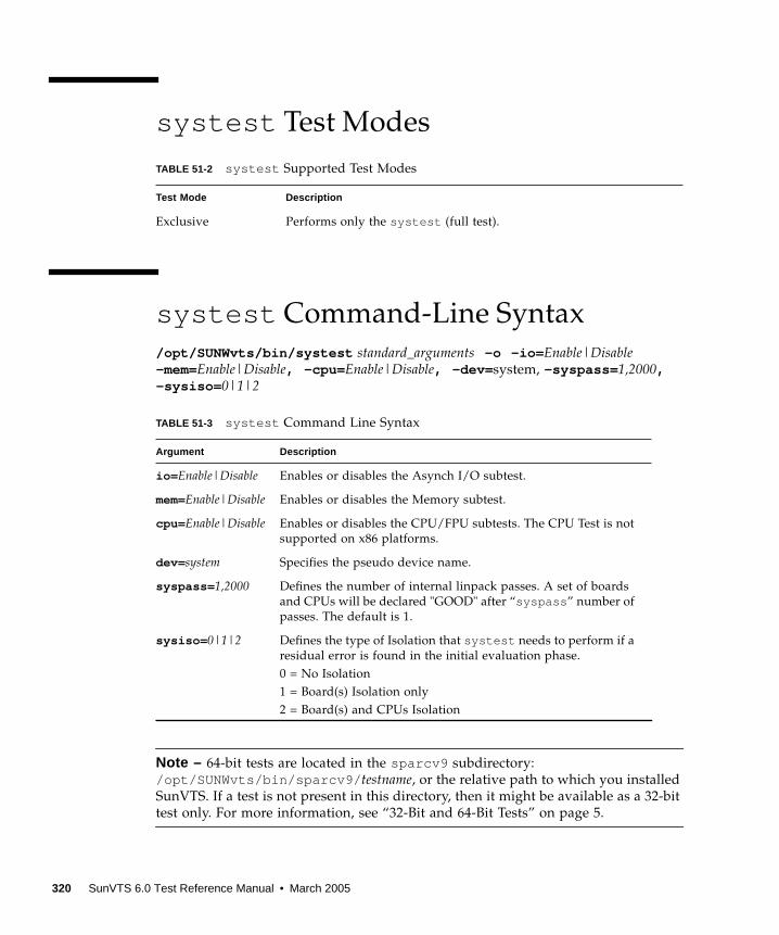
systest Test Modes
systest Command-Line Syntax
/opt/SUNWvts/bin/systest standard_arguments -o -io= Enable|Disable-mem=Enable|Disable, -cpu= Enable|Disable, -dev= system, -syspass= 1,2000,-sysiso= 0|1|2
Note – 64-bit tests are located in the sparcv9 subdirectory:
/opt/SUNWvts/bin/sparcv9/ testname, or the relative path to which you installed
SunVTS. If a test is not present in this directory, then it might be available as a 32-bit
test only. For more information, see “32-Bit and 64-Bit Tests” on page 5.
TABLE 51-2 systest Supported Test Modes
Test Mode Description
Exclusive Performs only the systest (full test).
TABLE 51-3 systest Command Line Syntax
Argument Description
io= Enable|Disable Enables or disables the Asynch I/O subtest.
mem=Enable|Disable Enables or disables the Memory subtest.
cpu= Enable|Disable Enables or disables the CPU/FPU subtests. The CPU Test is not
supported on x86 platforms.
dev= system Specifies the pseudo device name.
syspass= 1,2000 Defines the number of internal linpack passes. A set of boards
and CPUs will be declared "GOOD" after “syspass ” number of
passes. The default is 1.
sysiso= 0|1|2 Defines the type of Isolation that systest needs to perform if a
residual error is found in the initial evaluation phase.
0 = No Isolation
1 = Board(s) Isolation only
2 = Board(s) and CPUs Isolation
320 SunVTS 6.0 Test Reference Manual • March 2005

Recommended Option Selection
The default values are recommended for an initial evaluation of the system.
Command-Line Examples
The following examples assume the user wants to execute systest from the
command-line with verbose enabled.
Example 1:
The above example invokes the following:
■ systest with default parameter values
■ I/O, MEM, and CPU subtests. The CPU Test is not supported on x86 platforms.
■ One internal pass of linpack and no Isolation
Example 2:
The above example invokes the following:
■ systest without the I/O subtest
■ MEM and CPU subtests. The CPU Test is not supported on x86 platforms.
■ One internal pass of linpack and no Isolation
Caution – Do not perform the following systest examples (3 and 4) on production
servers because systest may online / offline CPUs.
Example 3:
The above example invokes the following:
■ I/O, MEM, and CPU subtests. The CPU Test is not supported on x86 platforms.
■ Declares a set of boards free from residual errors after 15 internal passes of the
linpack algorithm
■ If an error is found, systest will perform boards isolation
# ./systest -xv
# ./systest -xv -o io=Disable,mem=Enable,cpu=Enable,dev=system
# ./systest -xv -o syspass=15,sysiso=1
Chapter 51 System Test (systest ) 321
Example 4:
The above example invokes the following:
■ I/O, MEM, and CPU subtests. The CPU Test is not supported on x86 platforms.
■ Declares a set of boards AND CPUs free from residual errors after 10 internal
passes of the linpack algorithm
■ If an error is found, systest will perform boards AND CPUs isolation
# ./systest -xv -o syspass=10,sysiso=2
322 SunVTS 6.0 Test Reference Manual • March 2005
CHAPTER 52
Tape Drive Test (tapetest )
The tapetest synchronous I/O test writes a pattern to a specified number of
blocks (or, for a SCSI tape, writes to the end of the tape). The tapetest then
rewinds the tape and reads and compares the data just written. The tapetestasynchronous I/O test sends a series of up to five asynchronous read/write requests
to the tape drive, writing to the tape and then reading and comparing the data. The
terms asynchronous and synchronous referred to here, and in the “method” field are
not related to the scsi messaging terms of the same name. The tapetest file test
writes four files to the tape and then reads them back, comparing the data. For tape
library testing, the pass count is incremented only after all tapes in the library have
been tested. The read/write algorithms fare enhanced for DLT tape by using a
random data pattern (1.5:1 compression) and a more robust read compare algorithm.
Some default parameters have also changed.
tapetest Test Requirements
If you have a tape drive in your system, load a blank writable tape (scratch tape)
before you start SunVTS. If you fail to do this, the tapetest option may display
drive type:unknown on the option menu for the tapetest .
tapetest Options
To reach the dialog box below, right-click on the test name in the System Map and
select Test Parameter Options. If you do not see this test in the System Map, you
might need to expand the collapsed groups, or your system may not include the
device appropriate to this test. Refer to the SunVTS User’s Guide for more details.
323
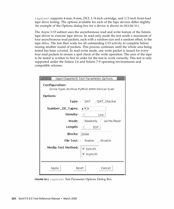
tapetest supports 4-mm, 8-mm, DLT, 1/4-inch cartridge, and 1/2-inch front-load
tape drive testing. The options available for each of the tape devices differ slightly.
An example of the Options dialog box for a device is shown in FIGURE 52-1.
The Async I/O subtest uses the asynchronous read and write feature of the Solaris
tape driver to exercise tape drives. In read-only mode the test sends a maximum of
four asynchronous read packets, each with a random size and a random offset, to the
tape drive. The test then waits for all outstanding I/O activity to complete before
issuing another round of packets. This process continues until the whole area being
tested has been covered. In read-write mode, one write packet is issued for every
four read packets to ensure a spot check of the write operation. The area of the tape
to be tested is written to first in order for the test to work correctly. This test is only
supported under the Solaris 2.6 and Solaris 7-9 operating environments and
compatible releases.
FIGURE 52-1 tapetest Test Parameter Options Dialog Box
324 SunVTS 6.0 Test Reference Manual • March 2005

Note – This test does not immediately stop after being disabled.
Note – Selecting non-default options can significantly increase the run time for the
test.
Note – The Options dialog box for the 1/4-inch, 1/2-inch, DLT, and 8-mm tape
drives differ slightly from FIGURE 52-1.
TABLE 52-1 tapetest Options
tapetest Options Description
Type Normal tape drive or tape library (stacker).
# of Tapes The number of tapes in the tape library. tapetest registers a single tape
library pass only after all tapes in the library pass.
Density The following settings are available for most tape drives:
• Low—Tests the l tape device.
• Medium—Tests the mtape device.
• Compression—Tests the c tape device.
• All—Tests the l , m, and c tape devices.
For half-inch tape drives, the available settings are 800, 1600, and 6250
BPI (blocks per inch).
For certain QIC drives, select QIC-11 (1-byte block ID) mode, QIC-24 (4-
byte block ID) mode, or Both .
Note: On a DLT drive, the l and m settings both use no compression.
tapetest does not support changing DLT capacity settings indicated on
the front panel.
Mode If you enable Write/Read mode, the test first writes to the tape and then
reads it back to compare. If you enable Read_Only mode, the test
assumes the tape has been properly written and merely reads and
compares. This mode is useful to check proper head alignment.
Note: If a read only pass is attempted and the tape was not previously
written by tapetest, using the same test parameters currently set, a “Big
Read Failure” will occur.
Chapter 52 Tape Drive Test (tapetest ) 325
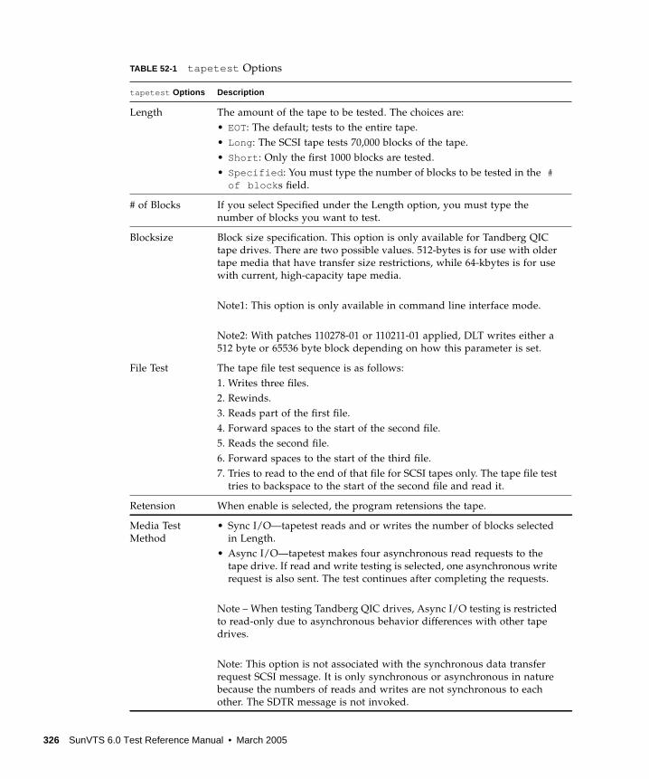
Length The amount of the tape to be tested. The choices are:
• EOT: The default; tests to the entire tape.
• Long : The SCSI tape tests 70,000 blocks of the tape.
• Short : Only the first 1000 blocks are tested.
• Specified : You must type the number of blocks to be tested in the #of block s field.
# of Blocks If you select Specified under the Length option, you must type the
number of blocks you want to test.
Blocksize Block size specification. This option is only available for Tandberg QIC
tape drives. There are two possible values. 512-bytes is for use with older
tape media that have transfer size restrictions, while 64-kbytes is for use
with current, high-capacity tape media.
Note1: This option is only available in command line interface mode.
Note2: With patches 110278-01 or 110211-01 applied, DLT writes either a
512 byte or 65536 byte block depending on how this parameter is set.
File Test The tape file test sequence is as follows:
1. Writes three files.
2. Rewinds.
3. Reads part of the first file.
4. Forward spaces to the start of the second file.
5. Reads the second file.
6. Forward spaces to the start of the third file.
7. Tries to read to the end of that file for SCSI tapes only. The tape file test
tries to backspace to the start of the second file and read it.
Retension When enable is selected, the program retensions the tape.
Media Test
Method
• Sync I/O—tapetest reads and or writes the number of blocks selected
in Length.
• Async I/O—tapetest makes four asynchronous read requests to the
tape drive. If read and write testing is selected, one asynchronous write
request is also sent. The test continues after completing the requests.
Note – When testing Tandberg QIC drives, Async I/O testing is restricted
to read-only due to asynchronous behavior differences with other tape
drives.
Note: This option is not associated with the synchronous data transfer
request SCSI message. It is only synchronous or asynchronous in nature
because the numbers of reads and writes are not synchronous to each
other. The SDTR message is not invoked.
TABLE 52-1 tapetest Options
tapetest Options Description
326 SunVTS 6.0 Test Reference Manual • March 2005
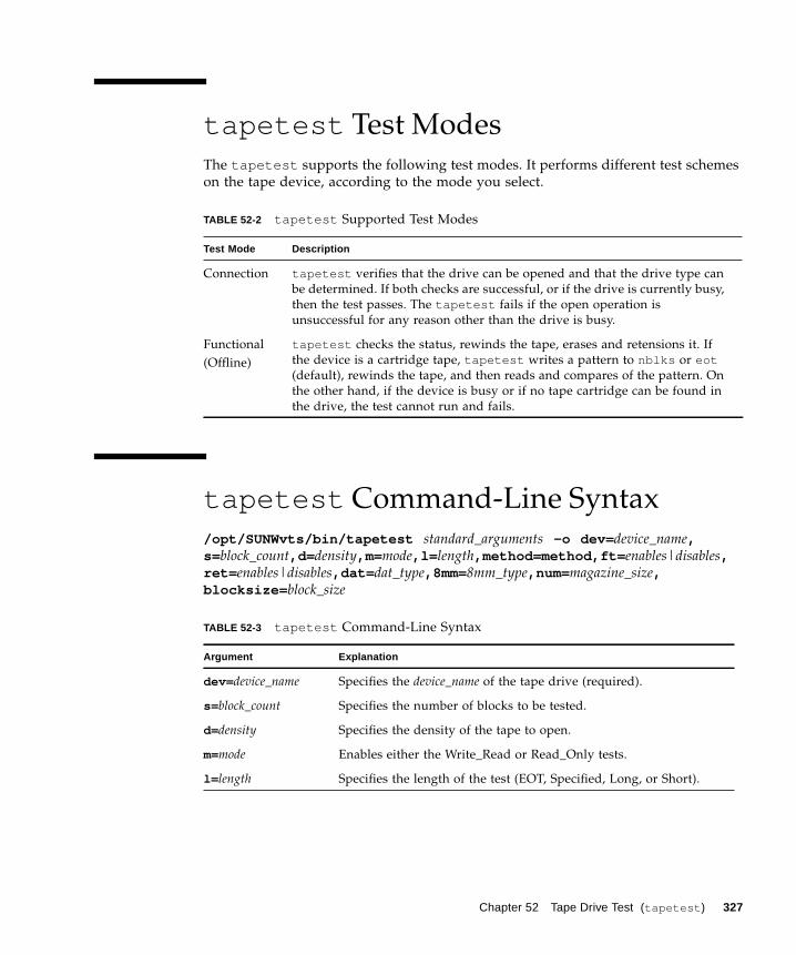
tapetest Test Modes
The tapetest supports the following test modes. It performs different test schemes
on the tape device, according to the mode you select.
tapetest Command-Line Syntax
/opt/SUNWvts/bin/tapetest standard_arguments -o dev= device_name,s=block_count,d= density,m=mode,l= length,method=method,ft= enables|disables,ret= enables|disables,dat= dat_type,8mm=8mm_type,num= magazine_size,blocksize= block_size
TABLE 52-2 tapetest Supported Test Modes
Test Mode Description
Connection tapetest verifies that the drive can be opened and that the drive type can
be determined. If both checks are successful, or if the drive is currently busy,
then the test passes. The tapetest fails if the open operation is
unsuccessful for any reason other than the drive is busy.
Functional
(Offline)
tapetest checks the status, rewinds the tape, erases and retensions it. If
the device is a cartridge tape, tapetest writes a pattern to nblks or eot(default), rewinds the tape, and then reads and compares of the pattern. On
the other hand, if the device is busy or if no tape cartridge can be found in
the drive, the test cannot run and fails.
TABLE 52-3 tapetest Command-Line Syntax
Argument Explanation
dev= device_name Specifies the device_name of the tape drive (required).
s=block_count Specifies the number of blocks to be tested.
d=density Specifies the density of the tape to open.
m=mode Enables either the Write_Read or Read_Only tests.
l= length Specifies the length of the test (EOT, Specified, Long, or Short).
Chapter 52 Tape Drive Test (tapetest ) 327
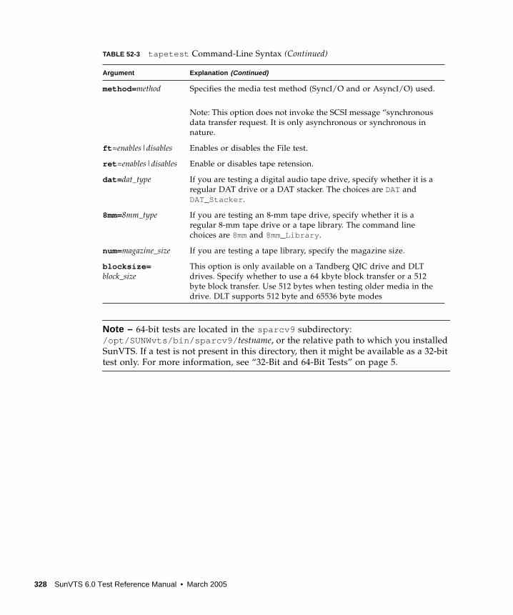
Note – 64-bit tests are located in the sparcv9 subdirectory:
/opt/SUNWvts/bin/sparcv9/ testname, or the relative path to which you installed
SunVTS. If a test is not present in this directory, then it might be available as a 32-bit
test only. For more information, see “32-Bit and 64-Bit Tests” on page 5.
method= method Specifies the media test method (SyncI/O and or AsyncI/O) used.
Note: This option does not invoke the SCSI message “synchronous
data transfer request. It is only asynchronous or synchronous in
nature.
ft =enables|disables Enables or disables the File test.
ret =enables|disables Enable or disables tape retension.
dat= dat_type If you are testing a digital audio tape drive, specify whether it is a
regular DAT drive or a DAT stacker. The choices are DATand
DAT_Stacker .
8mm=8mm_type If you are testing an 8-mm tape drive, specify whether it is a
regular 8-mm tape drive or a tape library. The command line
choices are 8mmand 8mm_Library .
num=magazine_size If you are testing a tape library, specify the magazine size.
blocksize=block_size
This option is only available on a Tandberg QIC drive and DLT
drives. Specify whether to use a 64 kbyte block transfer or a 512
byte block transfer. Use 512 bytes when testing older media in the
drive. DLT supports 512 byte and 65536 byte modes
TABLE 52-3 tapetest Command-Line Syntax (Continued)
Argument Explanation (Continued)
328 SunVTS 6.0 Test Reference Manual • March 2005
CHAPTER 53
USB Device Test (usbtest )
The usbtest verifies the proper functioning of the hardware of the USB subsystem.
The test supports audio, keyboard and printer devices. The usbtest for audio verifies
the proper functioning of the hardware and software components of the USB audio
subsystem. Specifically, the test tests the USB audio devices: USB microphones and
speakers.
Note – usbtest is a newly consolidated test which is used to test the USB ports
using various USB devices such as the USB key board, the USB printer or the USB
audio devices. usbtest supports the same set of options for both SPARC and x86.
For keyboard, the test verifies whether the keyboard(s) attached to the USB bus are
USB compliant. The test will flash the LEDs of a compliant keyboard. The usbtest for
printer verifies the proper functioning and integrity of the USB parallel port devices.
The test data, either ASCII or a postscript file, is sent to the printer through the USB
bulk transfer. The test saves and restores the printer settings.
The usbtest options and subtest available depends on the peripheral device
attached to the USB port.
usbtest Subtests
Subtests for the USB audio device:
■ Tone subtest
The Tone subtest is only performed in the Connectivity test mode. This subtest is
user-interactive in that the user must listen when the test is performed. This
subtest generates two seconds of sound which is output to the speakers.
■ Record/Play subtest
329
This subtest performs a simple check that records and plays one second of
random data at 8kHz sampling. It simply reads random data from the USB
microphone port and plays back to the USB speakers.
■ Audio subtest
This subtest plays a 30 second music file which is output to the speakers. This is a
partially user-interactive test. If there are no system call errors, the user must
decide, by listening, if the test passed or failed. Things to listen for are distortion
or lack of music.
Subtests for the USB printer device:
■ getdevid subtest
The getdevid subtest retrieves the IEEE 1284 ID string of the printer.
■ Printer subtest
The Printer subtest prints strings of ASCII characters (from 0x32 to 0x7e), and can
also print the postscript file usbpppdata.ps to the printer.
usbtest Options
To reach the dialog box below, right-click on the test name in the System Map and
select Test Parameter Options. If you do not see this test in the System Map, you
might need to expand the collapsed groups, or your system may not include the
device appropriate to this test. Refer to the SunVTS User’s Guide for more details.
330 SunVTS 6.0 Test Reference Manual • March 2005
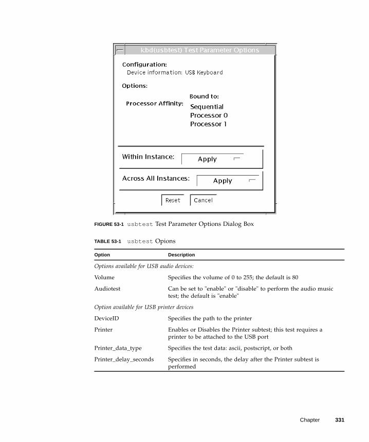
FIGURE 53-1 usbtest Test Parameter Options Dialog Box
TABLE 53-1 usbtest Opions
Option Description
Options available for USB audio devices:
Volume Specifies the volume of 0 to 255; the default is 80
Audiotest Can be set to "enable" or "disable" to perform the audio music
test; the default is "enable"
Option available for USB printer devices
DeviceID Specifies the path to the printer
Printer Enables or Disables the Printer subtest; this test requires a
printer to be attached to the USB port
Printer_data_type Specifies the test data: ascii, postscript, or both
Printer_delay_seconds Specifies in seconds, the delay after the Printer subtest is
performed
Chapter 331
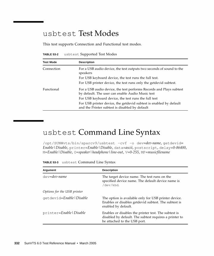
usbtest Test Modes
This test supports Connection and Functional test modes.
usbtest Command Line Syntax
/opt/SUNWvts/bin/sparcv9/usbtest -cvf -o dev =dev-name, getdevid =
Enable|Disable, printer =Enable|Disable, data =ascii, postscript , delay =0-86400,
M=Enable|Disable, O=speaker|headphone|line-out, V=0-255, MF=musicfilename
TABLE 53-2 usbtest Supported Test Modes
Test Mode Description
Connection For a USB audio device, the test outputs two seconds of sound to the
speakers
For USB keyboard device, the test runs the full test.
For USB printer device, the test runs only the getdevid subtest.
Functional For a USB audio device, the test performs Records and Plays subtest
by default. The user can enable Audio Music test
For USB keyboard device, the test runs the full test
For USB printer device, the getdevid subtest is enabled by default
and the Printer subtest is disabled by default
TABLE 53-3 usbtest Command Line Syntax
Argument Description
dev =dev-name The target device name. The test runs on the
specified device name. The default device name is
/dev/kbd .
Options for the USB printer
getdevid =Enable|Disable The option is available only for USB printer device.
Enables or disables getdevid subtest. The subtest is
enabled by default.
printer =Enable|Disable Enables or disables the printer test. The subtest is
disabled by default. The subtest requires a printer to
be attached to the USB port.
332 SunVTS 6.0 Test Reference Manual • March 2005
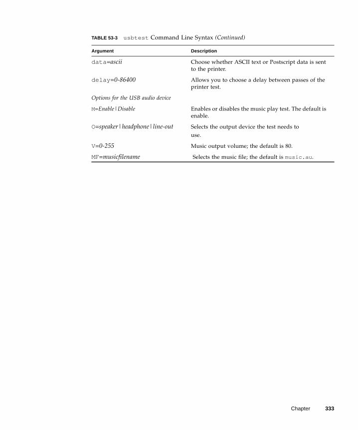
data =ascii Choose whether ASCII text or Postscript data is sent
to the printer.
delay =0-86400 Allows you to choose a delay between passes of the
printer test.
Options for the USB audio device
M=Enable|Disable Enables or disables the music play test. The default is
enable.
O=speaker|headphone|line-out Selects the output device the test needs to
use.
V=0-255 Music output volume; the default is 80.
MF=musicfilename Selects the music file; the default is music.au .
TABLE 53-3 usbtest Command Line Syntax (Continued)
Argument Description
Chapter 333

334 SunVTS 6.0 Test Reference Manual • March 2005
CHAPTER 54
Virtual Memory Test (vmemtest )
The vmemtest checks virtual memory; that is, it tests the combination of physical
memory and the swap partitions of the disk(s).
Note – This test may not stop immediately after being disabled.
Note – vmemtest supports the same set of options for both SPARC and x86
platforms.
This test uses the Solaris valloc (page aligned) system call to allocate, write, read,
and compare virtual memory. These operations normally cause heavy paging
activity on the system and simulate a stressful environment for the operating
system. This test also detects ECC parity errors, memory read errors, and addressing
problems, and displays the corresponding virtual memory addresses on failure.
Note – Do not run the vmemtest with fwcamtest at the same time on any
Sun Blade™ system. This will cause the test to fail.
vmemtest Swap Space Requirements
Running this test places a significant burden on the operating system, since it uses
the majority of swap space available for testing. You should use the vmemtest swap
space reserve option when non-SunVTS test processes are started after SunVTS
testing has started. See “Swap Space Requirements” in the SunVTS User’s Guide for a
complete discussion of swap space requirements.
335
vmemtest Options
To reach the dialog box below, right-click on the test name in the System Map and
select Test Parameter Options. If you do not see this test in the System Map, you
might need to expand the collapsed groups, or your system may not include the
device appropriate to this test. Refer to the SunVTS User’s Guide for more details.
336 SunVTS 6.0 Test Reference Manual • March 2005
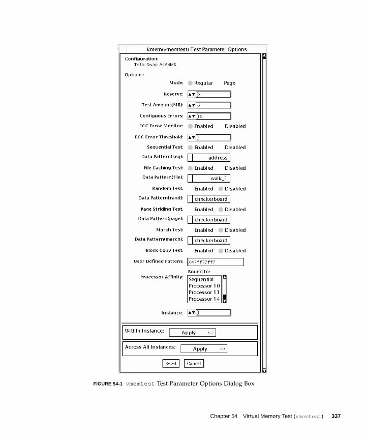
FIGURE 54-1 vmemtest Test Parameter Options Dialog Box
Chapter 54 Virtual Memory Test (vmemtest ) 337
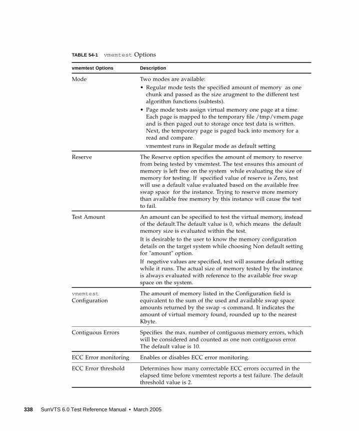
TABLE 54-1 vmemtest Options
vmemtest Options Description
Mode Two modes are available:
• Regular mode tests the specified amount of memory as one
chunk and passed as the size arugment to the different test
algorithm functions (subtests).
• Page mode tests assign virtual memory one page at a time.
Each page is mapped to the temporary file /tmp/vmem.page
and is then paged out to storage once test data is written.
Next, the temporary page is paged back into memory for a
read and compare.
vmemtest runs in Regular mode as default setting
Reserve The Reserve option specifies the amount of memory to reserve
from being tested by vmemtest. The test ensures this amount of
memory is left free on the system while evaluating the size of
memory for testing. If specified value of reserve is Zero, test
will use a default value evaluated based on the available free
swap space for the instance. Trying to reserve more memory
than available free memory by this instance will cause the test
to fail.
Test Amount An amount can be specified to test the virtual memory, instead
of the default.The default value is 0, which means the default
memory size is evaluated within the test.
It is desirable to the user to know the memory configuration
details on the target system while choosing Non default setting
for "amount" option.
If negetive values are specified, test will assume default setting
while it runs. The actual size of memory tested by the instance
is always evaluated with reference to the available free swap
space on the system.
vmemtestConfiguration
The amount of memory listed in the Configuration field is
equivalent to the sum of the used and available swap space
amounts returned by the swap -s command. It indicates the
amount of virtual memory found, rounded up to the nearest
Kbyte.
Contiguous Errors Specifies the max. number of contiguous memory errors, which
will be considered and counted as one non contiguous error.
The default value is 10.
ECC Error monitoring Enables or disables ECC error monitoring.
ECC Error threshold Determines how many correctable ECC errors occurred in the
elapsed time before vmemtest reports a test failure. The default
threshold value is 2.
338 SunVTS 6.0 Test Reference Manual • March 2005
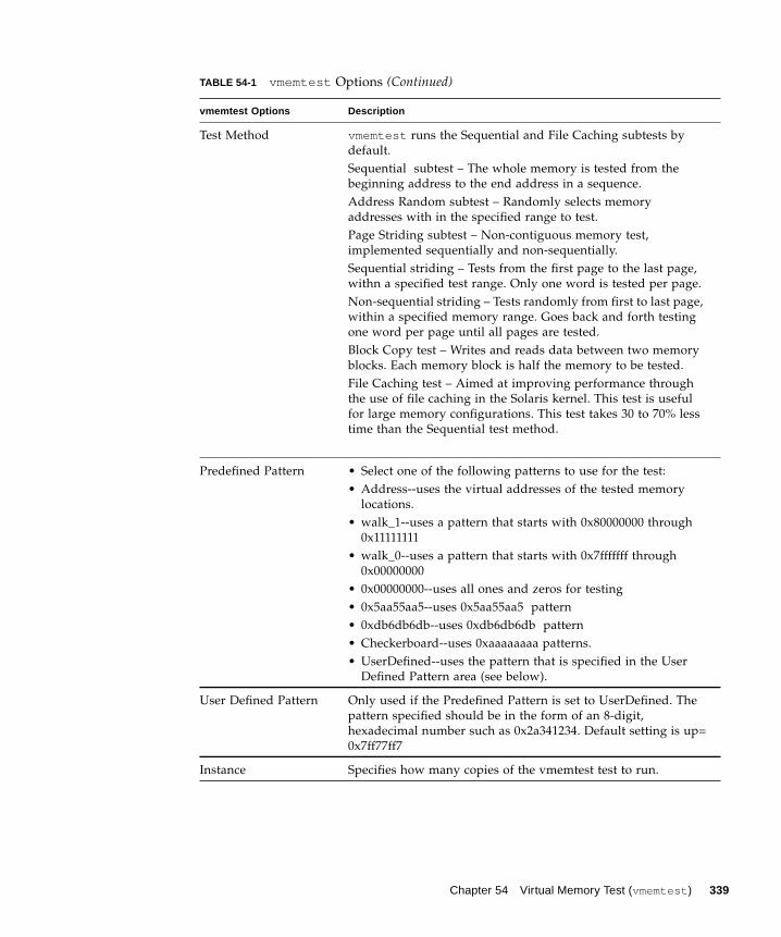
Test Method vmemtest runs the Sequential and File Caching subtests by
default.
Sequential subtest – The whole memory is tested from the
beginning address to the end address in a sequence.
Address Random subtest – Randomly selects memory
addresses with in the specified range to test.
Page Striding subtest – Non-contiguous memory test,
implemented sequentially and non-sequentially.
Sequential striding – Tests from the first page to the last page,
withn a specified test range. Only one word is tested per page.
Non-sequential striding – Tests randomly from first to last page,
within a specified memory range. Goes back and forth testing
one word per page until all pages are tested.
Block Copy test – Writes and reads data between two memory
blocks. Each memory block is half the memory to be tested.
File Caching test – Aimed at improving performance through
the use of file caching in the Solaris kernel. This test is useful
for large memory configurations. This test takes 30 to 70% less
time than the Sequential test method.
Predefined Pattern • Select one of the following patterns to use for the test:
• Address--uses the virtual addresses of the tested memory
locations.
• walk_1--uses a pattern that starts with 0x80000000 through
0x11111111
• walk_0--uses a pattern that starts with 0x7fffffff through
0x00000000
• 0x00000000--uses all ones and zeros for testing
• 0x5aa55aa5--uses 0x5aa55aa5 pattern
• 0xdb6db6db--uses 0xdb6db6db pattern
• Checkerboard--uses 0xaaaaaaaa patterns.
• UserDefined--uses the pattern that is specified in the User
Defined Pattern area (see below).
User Defined Pattern Only used if the Predefined Pattern is set to UserDefined. The
pattern specified should be in the form of an 8-digit,
hexadecimal number such as 0x2a341234. Default setting is up=
0x7ff77ff7
Instance Specifies how many copies of the vmemtest test to run.
TABLE 54-1 vmemtest Options (Continued)
vmemtest Options Description
Chapter 54 Virtual Memory Test (vmemtest ) 339
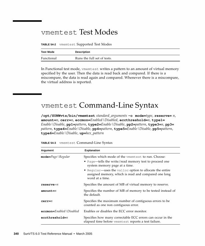
vmemtest Test Modes
In Functional test mode, vmemtest writes a pattern to an amount of virtual memory
specified by the user. Then the data is read back and compared. If there is a
miscompare, the data is read again and compared. Whenever there is a miscompare,
the virtual address is reported.
vmemtest Command-Line Syntax
/opt/SUNWvts/bin/vmemtest standard_arguments -o mode= type, reserve= n,
amount= n, cerr= n, eccmon=Enabled|Disabled, eccthreshold= n, type1=Enable|Disable, pp1= pattern, type2= Enable|Disable, pp2= pattern, type3= n, pp3=pattern, type4= Enable|Disable, pp4= pattern, type5= Enable|Disable, pp5= pattern,
type6= Enable|Disable, up=hex_pattern
TABLE 54-2 vmemtest Supported Test Modes
Test Mode Description
Functional Runs the full set of tests.
TABLE 54-3 vmemtest Command-Line Syntax
Argument Explanation
mode=Page|Regular Specifies which mode of the vmemtest to run. Choose:
• Page—tells the write/read memory test to proceed one
system memory page at a time.
• Regular —uses the valloc option to allocate the entire
assigned memory, which is read and compared one long
word at a time.
reserve =n Specifies the amount of MB of virtual memory to reserve.
amount= n Specifies the number of MB of memory to be tested instead of
the default.
cerr= n Specifies the maximum number of contiguous errors to be
counted as one non contiguous error.
eccmon=Enabled|Disabled Enables or disables the ECC error monitor.
eccthreshold= n Specifies how many correctable ECC errors can occur in the
elapsed time before vmemtest reports a test failure.
340 SunVTS 6.0 Test Reference Manual • March 2005

type1= valuepp1= pattern
type1 is sequential test. The value is Enabled or Disabled; the
default is Enabled. The default for the pp1 pattern is address ;
select the pp1 pattern from:
address ,walk_0 ,walk_1 ,Checkerboard ,
0x00000000 ,0xffffffff ,0x5aa55aa5 ,
0xdb6db6db ,random ,UserDefined
type2= valuepp1= pattern
type2 is File cache test. The value is Enabled or Disabled; the
default is Enabled. The default for the pp1 pattern is address ;
select the pp1 pattern from:
address ,walk_0 ,walk_1 ,Checkerboard ,
0x00000000 ,0xffffffff ,0x5aa55aa5 ,0xdb6db6db ,
random ,UserDefined
type3= valuepp3= pattern
type3 is Random address test. The value is Enabled or
Disabled; the default is Disabled. The default of the pp3pattern is checkerboard ; select the pp3 pattern from:
Checkerboard ,0x00000000 ,0xffffffff ,
0x5aa55aa5 ,0xdb6db6db ,UserDefined
type4= valuepp4= pattern
type4 is page_striding test. The value is Enabled or
Disabled; the default is Disabled. The default of the pp4pattern is checkerboard ; select the pp4 pattern from:
Checkerboard ,0x00000000 ,0xffffffff ,
0x5aa55aa5 ,0xdb6db6db ,UserDefined
type5= valuepp5= pattern
type5 is march_c test. The value is Enabled or Disabled; the
default is Disabled. The default for the pp5 pattern is
checkerboard ; select the pp5 pattern from:
Checkerboard ,0x00000000 ,0xffffffff ,
0x5aa55aa5 ,0xdb6db6db ,UserDefined
type6= value type6 is Block_Copy test. The value is Enabled or Disabled;
the default is Disabled.
Note – The Block_Copy subtest uses its own set of the data
patterns predefined in the test. It does not require any user
specified data patterns for testing.
up=hex_address Only used if the pp argument is set to UserDefined . The
pattern specified should be in the form of a 8-digit,
hexadecimal number such as 0x2a341234 .
TABLE 54-3 vmemtest Command-Line Syntax
Argument (Continued) Explanation
Chapter 54 Virtual Memory Test (vmemtest ) 341
Note – 64-bit tests are located in the sparcv9 subdirectory:
/opt/SUNWvts/bin/sparcv9/ testname, or the relative path to which you installed
SunVTS. If a test is not present in this directory, then it might be available as a 32-bit
test only. For more information, see “32-Bit and 64-Bit Tests” on page 5.
342 SunVTS 6.0 Test Reference Manual • March 2005
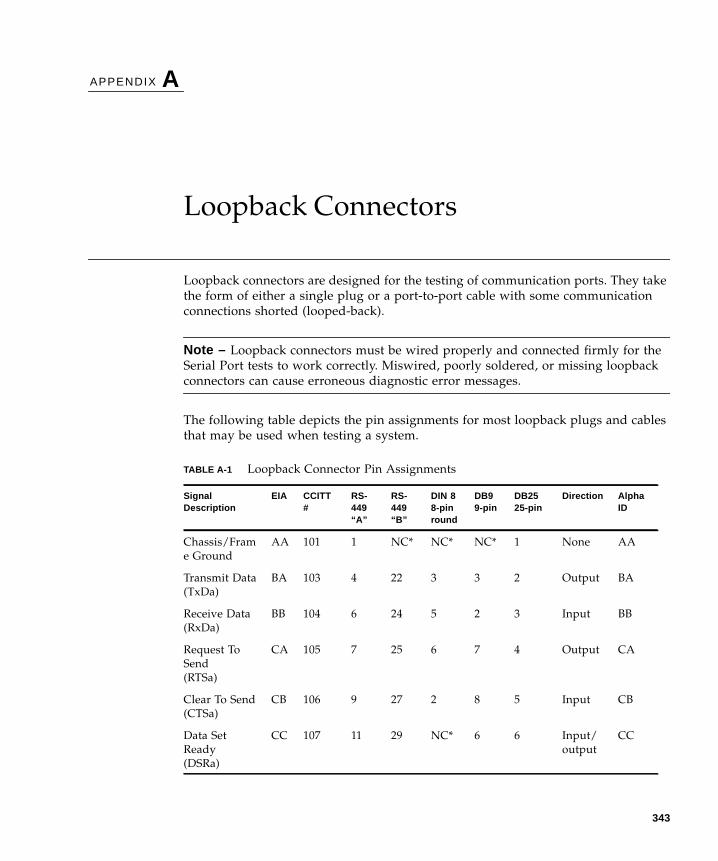
APPENDIX A
Loopback Connectors
Loopback connectors are designed for the testing of communication ports. They take
the form of either a single plug or a port-to-port cable with some communication
connections shorted (looped-back).
Note – Loopback connectors must be wired properly and connected firmly for the
Serial Port tests to work correctly. Miswired, poorly soldered, or missing loopback
connectors can cause erroneous diagnostic error messages.
The following table depicts the pin assignments for most loopback plugs and cables
that may be used when testing a system.
TABLE A-1 Loopback Connector Pin Assignments
SignalDescription
EIA CCITT#
RS-449“A”
RS-449“B”
DIN 88-pinround
DB99-pin
DB2525-pin
Direction AlphaID
Chassis/Fram
e Ground
AA 101 1 NC* NC* NC* 1 None AA
Transmit Data
(TxDa)
BA 103 4 22 3 3 2 Output BA
Receive Data
(RxDa)
BB 104 6 24 5 2 3 Input BB
Request To
Send
(RTSa)
CA 105 7 25 6 7 4 Output CA
Clear To Send
(CTSa)
CB 106 9 27 2 8 5 Input CB
Data Set
Ready
(DSRa)
CC 107 11 29 NC* 6 6 Input/
output
CC
343
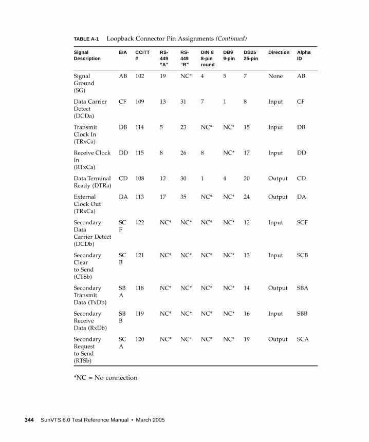
*NC = No connection
Signal
Ground
(SG)
AB 102 19 NC* 4 5 7 None AB
Data Carrier
Detect
(DCDa)
CF 109 13 31 7 1 8 Input CF
Transmit
Clock In
(TRxCa)
DB 114 5 23 NC* NC* 15 Input DB
Receive Clock
In
(RTxCa)
DD 115 8 26 8 NC* 17 Input DD
Data Terminal
Ready (DTRa)
CD 108 12 30 1 4 20 Output CD
External
Clock Out
(TRxCa)
DA 113 17 35 NC* NC* 24 Output DA
Secondary
Data
Carrier Detect
(DCDb)
SC
F
122 NC* NC* NC* NC* 12 Input SCF
Secondary
Clear
to Send
(CTSb)
SC
B
121 NC* NC* NC* NC* 13 Input SCB
Secondary
Transmit
Data (TxDb)
SB
A
118 NC* NC* NC* NC* 14 Output SBA
Secondary
Receive
Data (RxDb)
SB
B
119 NC* NC* NC* NC* 16 Input SBB
Secondary
Request
to Send
(RTSb)
SC
A
120 NC* NC* NC* NC* 19 Output SCA
TABLE A-1 Loopback Connector Pin Assignments (Continued)
SignalDescription
EIA CCITT#
RS-449“A”
RS-449“B”
DIN 88-pinround
DB99-pin
DB2525-pin
Direction AlphaID
344 SunVTS 6.0 Test Reference Manual • March 2005
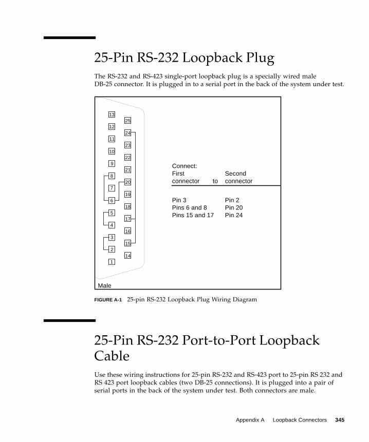
25-Pin RS-232 Loopback Plug
The RS-232 and RS-423 single-port loopback plug is a specially wired male
DB-25 connector. It is plugged in to a serial port in the back of the system under test.
FIGURE A-1 25-pin RS-232 Loopback Plug Wiring Diagram
25-Pin RS-232 Port-to-Port LoopbackCable
Use these wiring instructions for 25-pin RS-232 and RS-423 port to 25-pin RS 232 and
RS 423 port loopback cables (two DB-25 connections). It is plugged into a pair of
serial ports in the back of the system under test. Both connectors are male.
1
2
3
4
5
6
7
8
9
10
11
12
1325
24
23
22
21
20
19
18
17
16
15
14
Male
Connect:First Secondconnector to connector
Pin 3 Pin 2Pins 6 and 8 Pin 20Pins 15 and 17 Pin 24
Appendix A Loopback Connectors 345

FIGURE A-2 25-pin RS-232 Port-to-Port Loopback Cable Wiring Diagram
8-Pin to 8-Pin Loopback Cable
Use these wiring directions for 8-pin round DIN RS-232 port to RS-423 to 8-pin
round-DIN RS-232 and RS-423 port loopback cable. Both connectors are male.
1
2
3
4
5
6
7
8
9
10
11
12
1325
24
23
22
21
20
19
18
17
16
15
141
2
3
4
5
6
7
8
9
10
11
12
1325
24
23
22
21
20
19
18
17
16
15
14
Connect:First Secondconnector to connector
Pin 2 Pin 3Pin 3 Pin 2Pin 4 Pin 5Pin 5 Pin 4Pins 6 and 8 Pin 20Pin 7 Pin 7Pins 15 and 17 Pin 24Pin 20 Pins 6 and 8Pin 24 Pins 15 and 17
Male Male
346 SunVTS 6.0 Test Reference Manual • March 2005
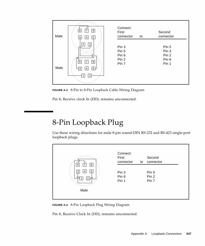
FIGURE A-3 8-Pin to 8-Pin Loopback Cable Wiring Diagram
Pin 8, Receive clock In (DD), remains unconnected.
8-Pin Loopback Plug
Use these wiring directions for male 8-pin round-DIN RS-232 and RS-423 single-port
loopback plugs.
FIGURE A-4 8-Pin Loopback Plug Wiring Diagram
Pin 8, Receive Clock In (DD), remains unconnected.
Connect:First Secondconnector to connector
Pin 3 Pin 5Pin 5 Pin 3Pin 6 Pin 2Pin 2 Pin 6Pin 7 Pin 1
1 2
3 4 5
6 7 8
1 2
3 4 5
6 7 8
Male
Male
1 2
3 4 5
6 7 8
Male
Connect:First Secondconnector to connector
Pin 3 Pin 5Pin 6 Pin 2Pin 1 Pin 7
Appendix A Loopback Connectors 347
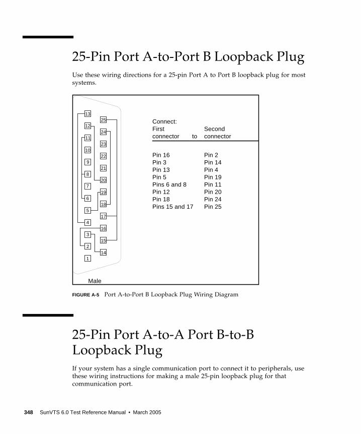
25-Pin Port A-to-Port B Loopback Plug
Use these wiring directions for a 25-pin Port A to Port B loopback plug for most
systems.
FIGURE A-5 Port A-to-Port B Loopback Plug Wiring Diagram
25-Pin Port A-to-A Port B-to-BLoopback Plug
If your system has a single communication port to connect it to peripherals, use
these wiring instructions for making a male 25-pin loopback plug for that
communication port.
1
2
3
4
5
6
7
8
9
10
11
12
1325
24
23
22
21
20
19
18
17
16
15
14
Male
Connect:First Secondconnector to connector
Pin 16 Pin 2Pin 3 Pin 14Pin 13 Pin 4Pin 5 Pin 19Pins 6 and 8 Pin 11Pin 12 Pin 20Pin 18 Pin 24Pins 15 and 17 Pin 25
348 SunVTS 6.0 Test Reference Manual • March 2005
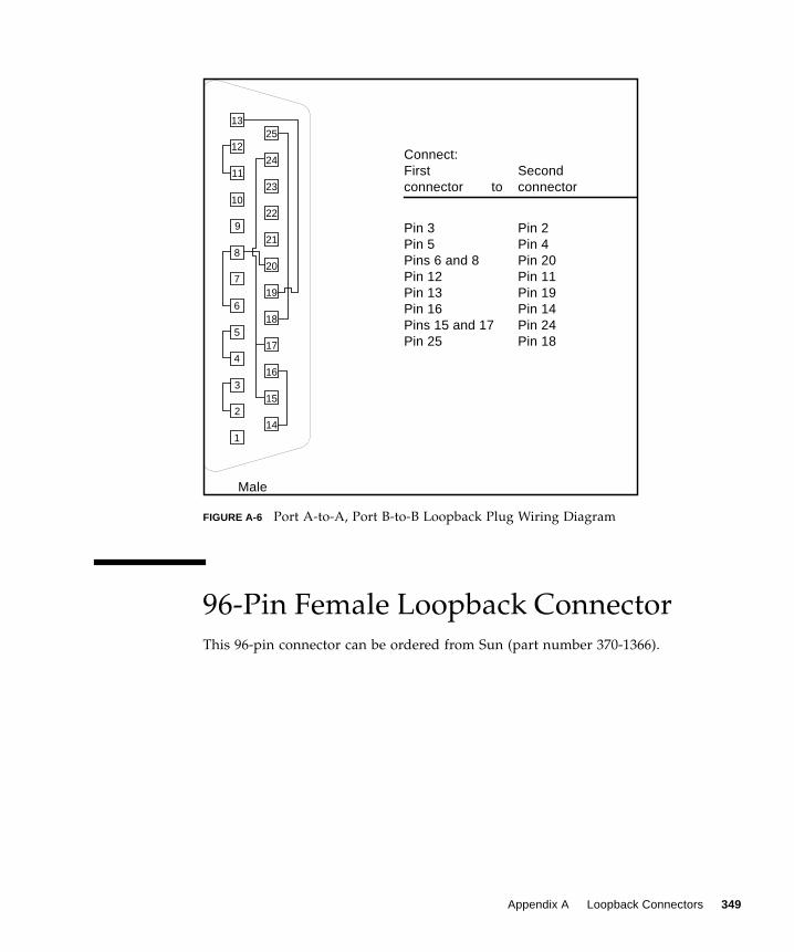
FIGURE A-6 Port A-to-A, Port B-to-B Loopback Plug Wiring Diagram
96-Pin Female Loopback Connector
This 96-pin connector can be ordered from Sun (part number 370-1366).
1
2
3
4
5
6
7
8
9
10
11
12
1325
24
23
22
21
20
19
18
17
16
15
14
Male
Connect:First Secondconnector to connector
Pin 3 Pin 2Pin 5 Pin 4Pins 6 and 8 Pin 20Pin 12 Pin 11Pin 13 Pin 19Pin 16 Pin 14Pins 15 and 17 Pin 24Pin 25 Pin 18
Appendix A Loopback Connectors 349
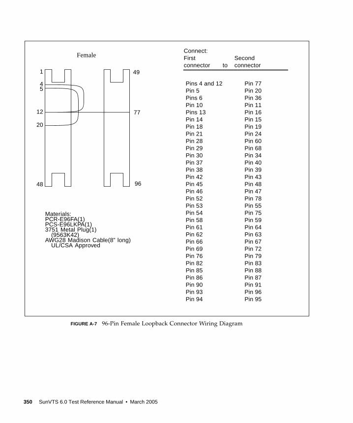
FIGURE A-7 96-Pin Female Loopback Connector Wiring Diagram
Female
Materials:PCR-E96FA(1)PCS-E96LKPA(1)3751 Metal Plug(1)
(9563K42)AWG28 Madison Cable(8” long)
UL/CSA Approved
1
48
49
96
45
12
20
77
Connect:First Secondconnector to connector
Pins 4 and 12 Pin 77Pin 5 Pin 20Pins 6 Pin 36Pin 10 Pin 11Pins 13 Pin 16Pin 14 Pin 15Pin 18 Pin 19Pin 21 Pin 24Pin 28 Pin 60Pin 29 Pin 68Pin 30 Pin 34Pin 37 Pin 40Pin 38 Pin 39Pin 42 Pin 43Pin 45 Pin 48Pin 46 Pin 47Pin 52 Pin 78Pin 53 Pin 55Pin 54 Pin 75Pin 58 Pin 59Pin 61 Pin 64Pin 62 Pin 63Pin 66 Pin 67Pin 69 Pin 72Pin 76 Pin 79Pin 82 Pin 83Pin 85 Pin 88Pin 86 Pin 87Pin 90 Pin 91Pin 93 Pin 96Pin 94 Pin 95
350 SunVTS 6.0 Test Reference Manual • March 2005
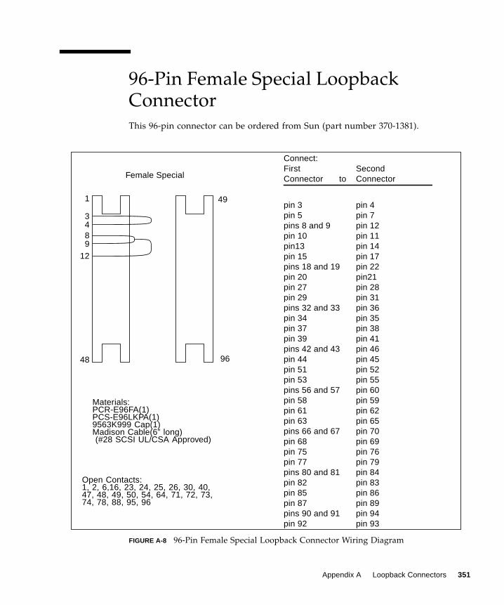
96-Pin Female Special LoopbackConnector
This 96-pin connector can be ordered from Sun (part number 370-1381).
FIGURE A-8 96-Pin Female Special Loopback Connector Wiring Diagram
Female Special
Materials:PCR-E96FA(1)PCS-E96LKPA(1)9563K999 Cap(1)Madison Cable(6” long)(#28 SCSI UL/CSA Approved)
1
48
49
96
3
12
4
Open Contacts:1, 2, 6,16, 23, 24, 25, 26, 30, 40,47, 48, 49, 50, 54, 64, 71, 72, 73,74, 78, 88, 95, 96
89
Connect:First SecondConnector to Connector
pin 3 pin 4pin 5 pin 7pins 8 and 9 pin 12pin 10 pin 11pin13 pin 14pin 15 pin 17pins 18 and 19 pin 22pin 20 pin21pin 27 pin 28pin 29 pin 31pins 32 and 33 pin 36pin 34 pin 35pin 37 pin 38pin 39 pin 41pins 42 and 43 pin 46pin 44 pin 45pin 51 pin 52pin 53 pin 55pins 56 and 57 pin 60pin 58 pin 59pin 61 pin 62pin 63 pin 65pins 66 and 67 pin 70pin 68 pin 69pin 75 pin 76pin 77 pin 79pins 80 and 81 pin 84pin 82 pin 83pin 85 pin 86pin 87 pin 89pins 90 and 91 pin 94pin 92 pin 93
Appendix A Loopback Connectors 351
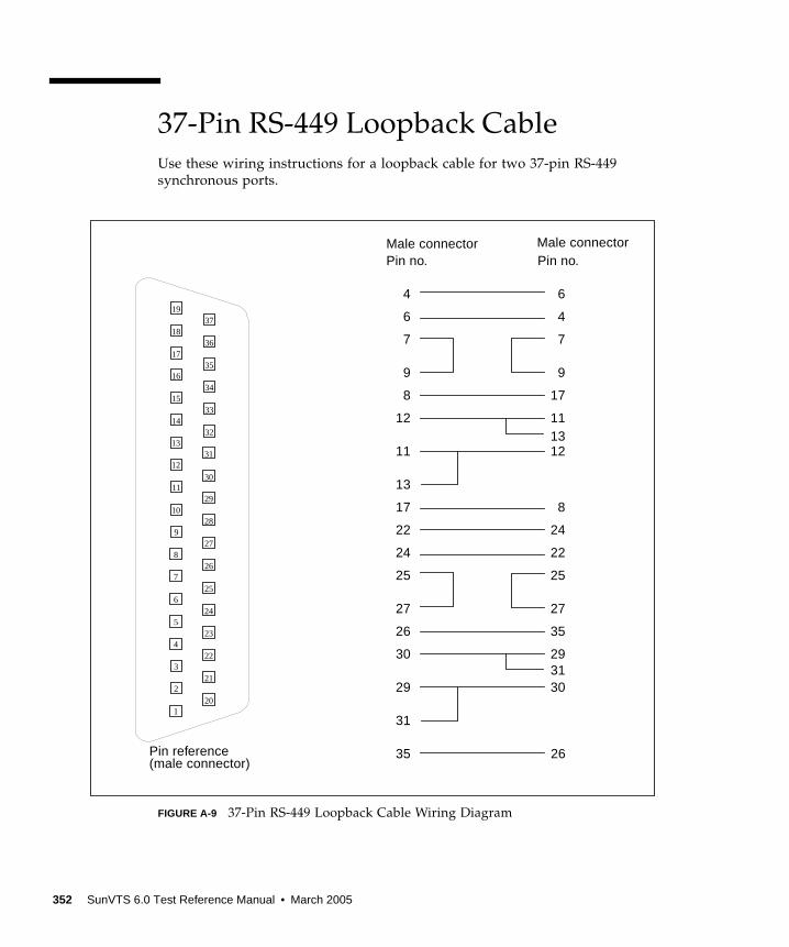
37-Pin RS-449 Loopback Cable
Use these wiring instructions for a loopback cable for two 37-pin RS-449
synchronous ports.
FIGURE A-9 37-Pin RS-449 Loopback Cable Wiring Diagram
Male connectorPin no.
4
6
7
9
8
12
11
13
17
22
24
25
27
26
30
29
35
Pin no.
6
4
7
9
17
111312
8
24
22
25
27
35
293130
26
31
Male connector
1
2
3
4
5
6
7
8
9
10
11
12
13
14
15
16
17
18
1937
36
35
34
33
32
31
30
29
28
27
26
25
24
23
22
21
20
Pin reference(male connector)
352 SunVTS 6.0 Test Reference Manual • March 2005
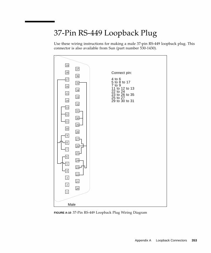
37-Pin RS-449 Loopback Plug
Use these wiring instructions for making a male 37-pin RS-449 loopback plug. This
connector is also available from Sun (part number 530-1430).
FIGURE A-10 37-Pin RS-449 Loopback Plug Wiring Diagram
1
2
3
4
5
6
7
8
9
10
11
12
13
14
15
16
17
18
1937
36
35
34
33
32
31
30
29
28
27
26
25
24
23
22
21
20
Connect pin:
4 to 65 to 8 to 177 to 911 to 12 to 1322 to 2423 to 26 to 3525 to 2729 to 30 to 31
Male
Appendix A Loopback Connectors 353

9-Pin Male Single-Port Loopback Plug
Use these wiring instructions for male 9-pin RS-232 and RS-423 single-port loopback
plugs.
FIGURE A-11 9-Pin Male Single-Port Loopback Plug Wiring Diagram
9-Pin Female Single-Port Loopback Plug
Use these wiring directions for female 9-pin RS-232 and RS-423 single-port loopback
plugs. Use this loopback plug with the pcmciatest .
FIGURE A-12 9-Pin Female Single-Port Loopback Plug Wiring Diagram
1
2
3
4
5
6
7
8
9
Male
Connect:First Secondconnector to connector
Pin 2 Pin 3Pin 1 Pins 4 and 6Pin 7 Pin 8
1
2
3
4
5
6
7
8
9
Female
Connect:First Secondconnector to connector
Pin 2 Pin 3Pin 1 Pins 4 and 6Pin 7 Pins 8 and 9
354 SunVTS 6.0 Test Reference Manual • March 2005
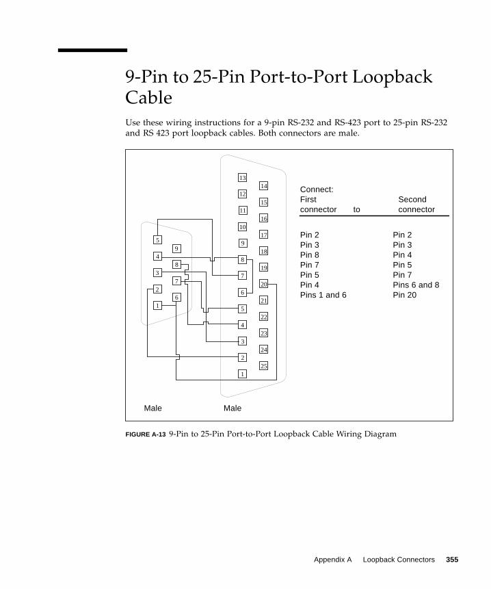
9-Pin to 25-Pin Port-to-Port LoopbackCable
Use these wiring instructions for a 9-pin RS-232 and RS-423 port to 25-pin RS-232
and RS 423 port loopback cables. Both connectors are male.
FIGURE A-13 9-Pin to 25-Pin Port-to-Port Loopback Cable Wiring Diagram
1
2
3
4
5
6
7
8
9
Connect:First Secondconnector to connector
Pin 2 Pin 2Pin 3 Pin 3Pin 8 Pin 4Pin 7 Pin 5Pin 5 Pin 7Pin 4 Pins 6 and 8Pins 1 and 6 Pin 20
1
2
3
4
5
6
7
8
9
10
11
12
1314
15
16
17
18
19
20
21
22
23
24
25
Male Male
Appendix A Loopback Connectors 355
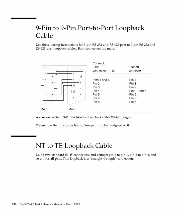
9-Pin to 9-Pin Port-to-Port LoopbackCable
Use these wiring instructions for 9-pin RS-232 and RS 423 port to 9-pin RS-232 and
RS-423 port loopback cables. Both connectors are male.
FIGURE A-14 9-Pin to 9-Pin Port-to-Port Loopback Cable Wiring Diagram
Please note that this cable has no Sun part number assigned to it.
NT to TE Loopback Cable
Using two standard RJ-45 connectors, and connect pin 1 to pin 1, pin 2 to pin 2, and
so on, for all pins. This loopback is a “straight-through” connection.
1
2
3
4
5
6
7
8
9
Connect:First Secondconnector to connector
Pins 1 and 6 Pin 4Pin 2 Pin 3Pin 3 Pin 2Pin 4 Pins 1 and 6Pin 5 Pin 5Pin 7 Pin 8Pin 8 Pin 7
1
2
3
4
5
6
7
8
9
Male Male
356 SunVTS 6.0 Test Reference Manual • March 2005
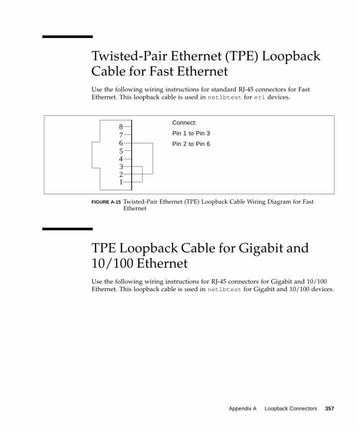
Twisted-Pair Ethernet (TPE) LoopbackCable for Fast Ethernet
Use the following wiring instructions for standard RJ-45 connectors for Fast
Ethernet. This loopback cable is used in netlbtest for eri devices.
FIGURE A-15 Twisted-Pair Ethernet (TPE) Loopback Cable Wiring Diagram for FastEthernet
TPE Loopback Cable for Gigabit and10/100 Ethernet
Use the following wiring instructions for RJ-45 connectors for Gigabit and 10/100
Ethernet. This loopback cable is used in netlbtest for Gigabit and 10/100 devices.
Connect:
Pin 1 to Pin 3
Pin 2 to Pin 6
87654321
Appendix A Loopback Connectors 357
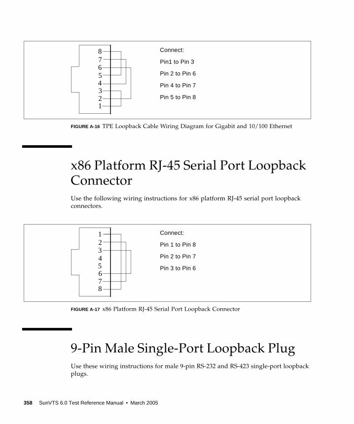
FIGURE A-16 TPE Loopback Cable Wiring Diagram for Gigabit and 10/100 Ethernet
x86 Platform RJ-45 Serial Port LoopbackConnector
Use the following wiring instructions for x86 platform RJ-45 serial port loopback
connectors.
FIGURE A-17 x86 Platform RJ-45 Serial Port Loopback Connector
9-Pin Male Single-Port Loopback Plug
Use these wiring instructions for male 9-pin RS-232 and RS-423 single-port loopback
plugs.
Connect:
Pin1 to Pin 3
Pin 2 to Pin 6
Pin 4 to Pin 7
Pin 5 to Pin 8
87654321
Connect:
Pin 1 to Pin 8
Pin 2 to Pin 7
Pin 3 to Pin 6
12345678
358 SunVTS 6.0 Test Reference Manual • March 2005
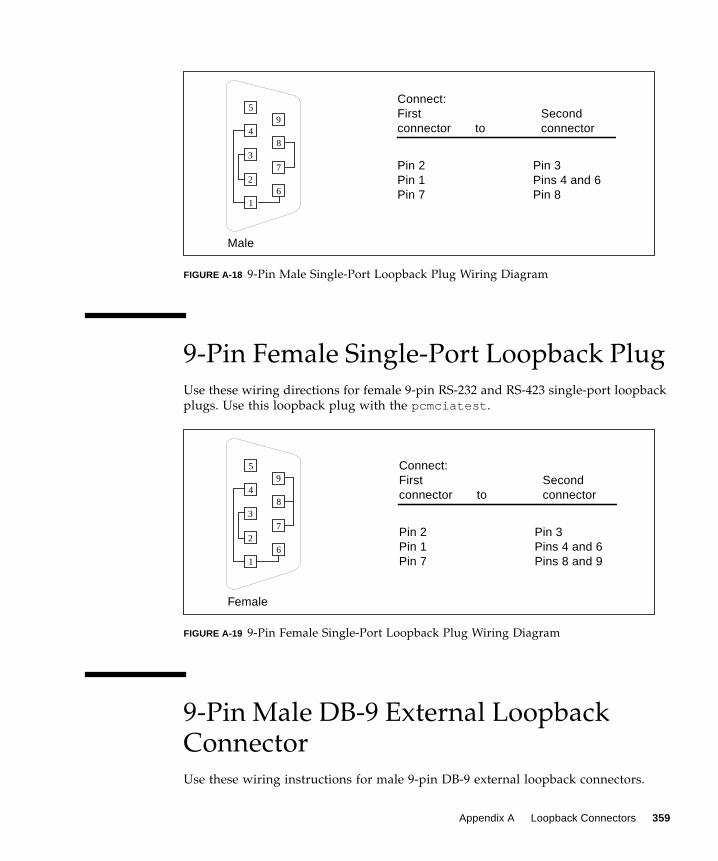
FIGURE A-18 9-Pin Male Single-Port Loopback Plug Wiring Diagram
9-Pin Female Single-Port Loopback Plug
Use these wiring directions for female 9-pin RS-232 and RS-423 single-port loopback
plugs. Use this loopback plug with the pcmciatest .
FIGURE A-19 9-Pin Female Single-Port Loopback Plug Wiring Diagram
9-Pin Male DB-9 External LoopbackConnector
Use these wiring instructions for male 9-pin DB-9 external loopback connectors.
1
2
3
4
5
6
7
8
9
Male
Connect:First Secondconnector to connector
Pin 2 Pin 3Pin 1 Pins 4 and 6Pin 7 Pin 8
1
2
3
4
5
6
7
8
9
Female
Connect:First Secondconnector to connector
Pin 2 Pin 3Pin 1 Pins 4 and 6Pin 7 Pins 8 and 9
Appendix A Loopback Connectors 359
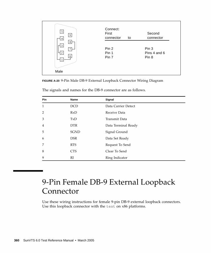
FIGURE A-20 9-Pin Male DB-9 External Loopback Connector Wiring Diagram
The signals and names for the DB-9 connector are as follows.
9-Pin Female DB-9 External LoopbackConnector
Use these wiring instructions for female 9-pin DB-9 external loopback connectors.
Use this loopback connector with the test on x86 platforms.
Pin Name Signal
1 DCD Data Carrier Detect
2 RxD Receive Data
3 TxD Transmit Data
4 DTR Data Terminal Ready
5 SGND Signal Ground
6 DSR Data Set Ready
7 RTS Request To Send
8 CTS Clear To Send
9 RI Ring Indicator
1
2
3
4
5
6
7
8
9
Male
Connect:First Secondconnector to connector
Pin 2 Pin 3Pin 1 Pins 4 and 6Pin 7 Pin 8
360 SunVTS 6.0 Test Reference Manual • March 2005
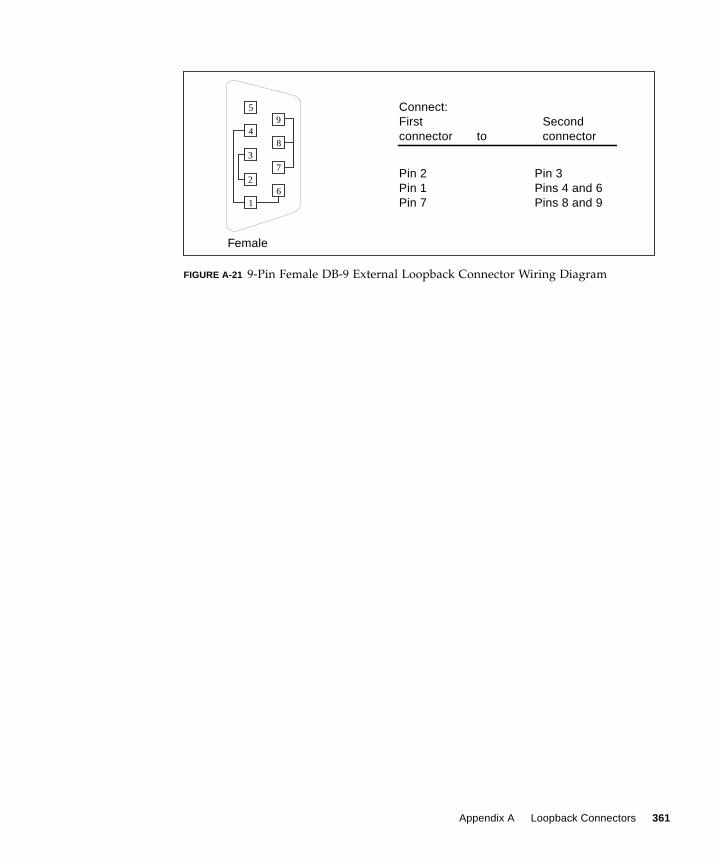
FIGURE A-21 9-Pin Female DB-9 External Loopback Connector Wiring Diagram
1
2
3
4
5
6
7
8
9
Female
Connect:First Secondconnector to connector
Pin 2 Pin 3Pin 1 Pins 4 and 6Pin 7 Pins 8 and 9
Appendix A Loopback Connectors 361

362 SunVTS 6.0 Test Reference Manual • March 2005
Glossary
administrativedomain An arbitrary collection of hosts and networks that are monitored by the
software as a single hierarchal entity. You may choose to divide their enterprise
into several domains, each to be managed by different users.
agent A software process, usually corresponding to a particular local managed host,
that carries out manager requests and makes local system and application
information available to remote users.
bus A point-to-point network component. Used by the software to represent a
network link to which many other hosts may be connected.
community A string similar to a password that is used to authenticate access to an agent’s
monitored data.
COMA Cache Only Memory Architecture. In a COMA machine, additional hardware
including tag and state memory is added to the DRAM of each processing
node to convert it into a kind of cache called attraction memory. See also
NUMA.
CTQ Critical to Quality. A SunSigma terminology, used to identify key issues for a
product based on voice of the customer.
diagnosis Correct interpretation and reporting of error.
diagnosability Ability of system to detect and correctly report errors when they occur.
diagnostics A test to uncover faults. These tests are used in design and validation to find
margins and set limits on error protection, and stress tests used in operations
to screen finished product for escapes.
diagnostic harness The harness or environment that schedules, manages and control execution of
diagnostic tests on a platform.
363
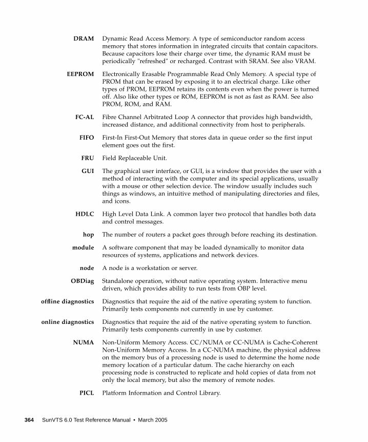
DRAM Dynamic Read Access Memory. A type of semiconductor random access
memory that stores information in integrated circuits that contain capacitors.
Because capacitors lose their charge over time, the dynamic RAM must be
periodically "refreshed" or recharged. Contrast with SRAM. See also VRAM.
EEPROM Electronically Erasable Programmable Read Only Memory. A special type of
PROM that can be erased by exposing it to an electrical charge. Like other
types of PROM, EEPROM retains its contents even when the power is turned
off. Also like other types or ROM, EEPROM is not as fast as RAM. See also
PROM, ROM, and RAM.
FC-AL Fibre Channel Arbitrated Loop A connector that provides high bandwidth,
increased distance, and additional connectivity from host to peripherals.
FIFO First-In First-Out Memory that stores data in queue order so the first input
element goes out the first.
FRU Field Replaceable Unit.
GUI The graphical user interface, or GUI, is a window that provides the user with a
method of interacting with the computer and its special applications, usually
with a mouse or other selection device. The window usually includes such
things as windows, an intuitive method of manipulating directories and files,
and icons.
HDLC High Level Data Link. A common layer two protocol that handles both data
and control messages.
hop The number of routers a packet goes through before reaching its destination.
module A software component that may be loaded dynamically to monitor data
resources of systems, applications and network devices.
node A node is a workstation or server.
OBDiag Standalone operation, without native operating system. Interactive menu
driven, which provides ability to run tests from OBP level.
offline diagnostics Diagnostics that require the aid of the native operating system to function.
Primarily tests components not currently in use by customer.
online diagnostics Diagnostics that require the aid of the native operating system to function.
Primarily tests components currently in use by customer.
NUMA Non-Uniform Memory Access. CC/NUMA or CC-NUMA is Cache-Coherent
Non-Uniform Memory Access. In a CC-NUMA machine, the physical address
on the memory bus of a processing node is used to determine the home node
memory location of a particular datum. The cache hierarchy on each
processing node is constructed to replicate and hold copies of data from not
only the local memory, but also the memory of remote nodes.
PICL Platform Information and Control Library.
364 SunVTS 6.0 Test Reference Manual • March 2005

POST Power on Self Test. Standalone operation, without native operating system.
Mostly non interactive, automated tests, run when power is applied to the
system.
productionenvironment One of two environments in which software is deployed. The production
environment is a “real” environment (as opposed to a test environment) in
which you manage and monitor your hardware.
PROM Programmable Read Only Memory A memory chip on which data can be
written only once. When a program has been written onto a PROM, it remains
there forever. Unlike RAM, PROMs retain their data even when the power is
turned off. See also RAM.
RAM Random Access Memory A type of computer memory that can be accessed
randomly; that is, any byte of memory can be accessed without touching the
preceding bytes. RAM is the most common type of computer and device
memory.
ROM Read Only Memory Computer memory on which data has been prerecorded.
Once data has been written onto a ROM chip, it cannot be removed and can
only be read.
RTS/CTS Ready to Send/Clear to Send A hardware flow control handshake protocol
used with serial lines.
SEEPROM Serial EEPROM. See also EEPROM.
segment An object representing a “segment” of the network, and used as a basis for a
local network.
SNMP Simple Network Management Protocol. A simple protocol designed to allow
networked entities (hosts, routers, and so on) to exchange monitoring
information.
SNMPv2 usec SNMP version 2, user-based security model security standards.
SRAM Static Random Access Memory. A faster and more reliable RAM than dynamic
random access memory (DRAM). DRAM offers access times of about 60
nanoseconds, while SRAM access can be as low as 10 nanoseconds. It is static
because it does not require refreshment as does DRAM. See also VRAM.
standalonediagnostics Diagnostics that run without the aid of the native operating system. Usually an
operating environment is built to provide basic scheduling capabilities.
standard error An open file normally connected directly to a primary output device, such as a
terminal, printer, or screen. Error messages and other diagnostic output
normally go to this file and then to the output device. You can redirect the
standard error output into another file instead of to the printer or screen.
365
standard input (Standard input device) The device from which a program or system normally
takes its input. Usually a terminal or the keyboard.
standard output (Standard output device) The device to which a program or system normally
sends its output. Usually a terminal or the screen.
URL Uniform Resource Locator. A URL is a textual specification describing a
resource which is network-accessible.
VRAM Video Random Access Memory. A type of dynamic RAM (DRAM) used in
high-speed graphics frame buffers. With conventional DRAM, both the
processor and the frame buffer logic must access RAM by sharing the same
signal lines or buses on the RAM chips. VRAM provides separate buses for the
processor and the frame buffer logic. See also DRAM, SRAM.
366 SunVTS 6.0 Test Reference Manual • March 2005
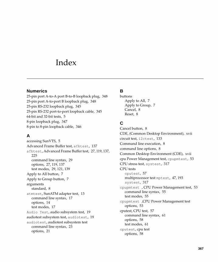
Index
Numerics25-pin port A-to-A port B-to-B loopback plug, 348
25-pin port A-to-port B loopback plug, 348
25-pin RS-232 loopback plug, 345
25-pin RS-232 port-to-port loopback cable, 345
64-bit and 32-bit tests, 5
8-pin loopback plug, 347
8-pin to 8-pin loopback cable, 346
Aaccessing SunVTS, 5
Advanced Frame Buffer test, afbtest , 137
afbtest , Advanced Frame Buffer test, 27, 119, 137,
225
command line syntax, 29
options, 27, 119, 137
test modes, 29, 121, 139
Apply to All button, 7
Apply to Group button, 7
arguments
standard, 8
atmtest , SunATM adapter test, 13
command line syntax, 17
options, 14
test modes, 17
Audio Test , audio subsystem test, 19
audiotest subsystem test, audiotest , 19
audiotest , audiotest subsystem test
command line syntax, 23
options, 21
Bbuttons
Apply to All, 7
Apply to Group, 7
Cancel, 8
Reset, 8
CCancel button, 8
CDE, (Common Desktop Environment), xvii
circuit test, i2ctest , 133
Command line execution, 8
command line options, 8
Common Desktop Environment (CDE), xvii
cpu Power Management test, cpupmtest , 53
CPU stress test, systest , 317
CPU tests
cputest , 57
multiprocessor test mptest , 47, 193
systest , 317
cpupmtest , CPU Power Management test, 53
command line syntax, 55
test modes, 55
cpupmtest ,CPU Power Management test
options, 53
cputest, CPU test, 57
command line syntax, 61
options, 58
test modes, 61
cputest , cpu test
options, 58
367

Ddisk drive test, 63
disktest , disk and floppy test, 63
command line syntax, 72, 76
subtests, 64
test modes, 72
dpmtest , Sun Fire 880 FC-AL Disk Backplane
options, 91
dpmtest , Sun Fire 880 FC-Al DIsk Backplane
test modes, 94
dpmtest , Sun Fire 880 FC-AL DIsk Backplane test
command line syntax, 94
dpmtest , Sun Fire 880 FC-AL Disk Backplane
test, 91
Eenv2test , I2C bus test, 105
options, 105
test modes, 107
env3test , Environmental Hardware test, 109
command line syntax, 113
env5test , Environmental test, 115
env5test , environmental test
command line syntax, 118, 121
options, 116
test modes, 118
test requirements, 115
Environmental hardware tests
env3test , 109
envtest , 101
environmental test, env5test , 115
envtest , I2C bus test, 101
command line syntax, 104
Ethernet hardware test, nettest , 211
ethernet loopback test, netlbtest , 205
Expert3D Frame Buffer test, ifbtest , 141, 159
Ffiber optic test, nettest , 211
floppy drive and disk test, disktest , 63
fputest , floating Point Unit test, 123, 155, 201, 249,
275, 279
command line syntax, 126, 157, 203, 253, 278,
281
options, 124, 155, 201, 249, 276, 279
frame buffer
multiple, 11
testing, 11
fwcamtest , Fire Wire Camera test, 129
command line syntax, 132
options, 130
test modes, 132
Ggraphical user interface (GUI), xvii
GUI (graphical user interface), xvii
Hhard drive and floppy test, disktest , 63
HDLC and SDLC test (for the HSI),sunlink , 307
HSI board test, sunlink , 307
II2C bus test, env2test , 105
I2C bus test, envtest , 101
i2C Bus tests
i2ctest , 133
i2ctest , i2c bus test, 133
command line syntax, 135, 139
options, 134
test modes, 135
test requirements, 133
ifbtest , Expert3D Frame Buffer test, 141, 159
command line syntax, 147, 166
options, 143, 161
test modes, 147, 166
Test Requirements, 141, 159
ifptest , PCI FC_AL card test
command line syntax, 153
options, 150
test modes, 152
ifptest , PCI FC_AL card test, 149
Installation directory, 2
Internet control message protocol (ICMP) and
nettest , 211
interprocess communication protocols, 4
IPC (interprocess communication), 4
IPI tests
disktest , 63
Ll1dcachetest , level 1 data cache test, 173
368 SunVTS 6.0 Test Reference Manual • March 2005
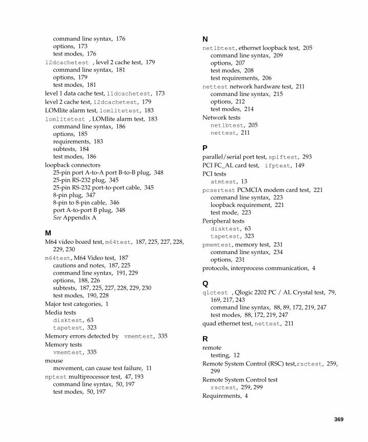
command line syntax, 176
options, 173
test modes, 176
l2dcachetest , level 2 cache test, 179
command line syntax, 181
options, 179
test modes, 181
level 1 data cache test, l1dcachetest , 173
level 2 cache test, l2dcachetest , 179
LOMlite alarm test, lomlitetest , 183
lomlitetest , LOMlite alarm test, 183
command line syntax, 186
options, 185
requirements, 183
subtests, 184
test modes, 186
loopback connectors
25-pin port A-to-A port B-to-B plug, 348
25-pin RS-232 plug, 345
25-pin RS-232 port-to-port cable, 345
8-pin plug, 347
8-pin to 8-pin cable, 346
port A-to-port B plug, 348
See Appendix A
MM64 video board test, m64test , 187, 225, 227, 228,
229, 230
m64test , M64 Video test, 187
cautions and notes, 187, 225
command line syntax, 191, 229
options, 188, 226
subtests, 187, 225, 227, 228, 229, 230
test modes, 190, 228
Major test categories, 1
Media tests
disktest , 63
tapetest , 323
Memory errors detected by vmemtest , 335
Memory tests
vmemtest , 335
mouse
movement, can cause test failure, 11
mptest multiprocessor test, 47, 193
command line syntax, 50, 197
test modes, 50, 197
Nnetlbtest , ethernet loopback test, 205
command line syntax, 209
options, 207
test modes, 208
test requirements, 206
nettest network hardware test, 211
command line syntax, 215
options, 212
test modes, 214
Network tests
netlbtest , 205
nettest , 211
Pparallel/serial port test, spiftest , 293
PCI FC_AL card test, ifptest , 149
PCI tests
atmtest , 13
pcsertest PCMCIA modem card test, 221
command line syntax, 223
loopback requirement, 221
test mode, 223
Peripheral tests
disktest , 63
tapetest , 323
pmemtest , memory test, 231
command line syntax, 234
options, 231
protocols, interprocess communication, 4
Qqlctest , Qlogic 2202 PC / AL Crystal test, 79,
169, 217, 243
command line syntax, 88, 89, 172, 219, 247
test modes, 88, 172, 219, 247
quad ethernet test, nettest , 211
Rremote
testing, 12
Remote System Control (RSC) test,rsctest , 259,
299
Remote System Control test
rsctest , 259, 299
Requirements, 4
369
Reset button, 8
rsctestRemote System Control test modes, 264, 304
rsctest , Remote System Control test, 259, 299
Command line syntax, 264, 305
rsctest Remote System Control test
options, 48, 302, 303
Ssaiptest , Serial Asynchronous Interface (PCI)
test, 267
available ports, 271
command line syntax, 272
hardware requirements, 267
saiptest , Serial Asyncronous Interface (PCI) test
options, 268
test modes, 272
SBus tests
atmtest , 13
SCSI tests
disktest , 63
Serial Asynchronous Interface test, saiptest , 267
serial/parallel port test, spiftest , 293
SPARCstation tests
audiotest , 19
spiftest , serial/parallel port test, 293
available ports, 295
command line syntax, 297
hardware requirements, 293
options, 294
test modes, 297
standard
command line arguments, 8
usage, 8
standard_arguments, 8
Sun Enterprise 450 bus test, envtest , 101
Sun Fire 880 FC-AL DIsk Backplane test,
dpmtest , 91
SunATM adapter test, atmtest , 13
sunlink , HSI/S board test, 307
command line syntax, 310
loopback connectors, 309
options, 308
requirements, 307
test modes, 310
sunpci2test , Sun PCi2 test, 313
command line syntax, 315
test requirements, 313
SunVTS
accessing, 5
interfaces
CDE, 5
OPEN LOOK, 5
TTY, 5
systest , CPU stress test, 317
command line syntax, 320
options, 317
test modes, 320
Ttapetest , tape drive test, 323
command line syntax, 327
options, 323
test modes, 327
test requirements, 323
test options, 8
Test Parameter menu, 6
testing
remotely, 12
Tests
32-bit and 64-bit tests, 5
Tests, overall description of, 4
Test-specific arguments, 10
Test-specific menu, 6
Test-specific options, 7
token ring test, nettest , 211
VVideo tests
m64test , 187, 225
virtual memory test, vmemtest , 335
vmemtest , virtual memory test, 335
command line syntax, 340
swap space, and, 335
test modes, 340
Volume Management and disktest , 64
Wwindow
locking disabled, 12
locking enabled, 12
370 SunVTS 6.0 Test Reference Manual • March 2005