
Summacut D60 Maintenance Manual
111
Service Manual SummaCut D60 and D120 Summa NV Rochesterlaan 6 8470 Gistel Belgium
-
Upload
modaviesuk -
Category
Documents
-
view
3.613 -
download
436
description
Summa Vinyl Cutter D60 Maintenance Manual
Transcript of Summacut D60 Maintenance Manual
Service Manual
SummaCut D60 and D120
Summa NVRochesterlaan 6
8470 GistelBelgium
Service Manual SummaCut D60-D120
TABLE OF CONTENTS......................................................................Page
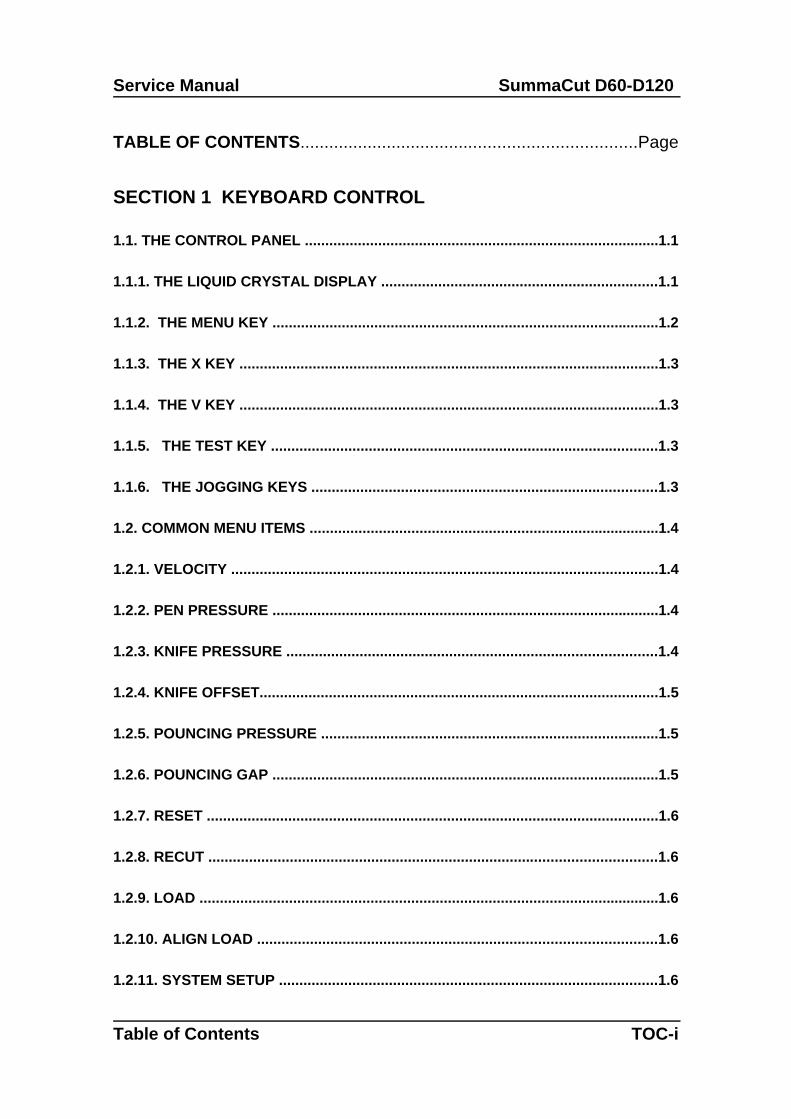
SECTION 1 KEYBOARD CONTROL
1.1. THE CONTROL PANEL .......................................................................................1.1
1.1.1. THE LIQUID CRYSTAL DISPLAY ....................................................................1.1
1.1.2. THE MENU KEY ...............................................................................................1.2
1.1.3. THE X KEY .......................................................................................................1.3
1.1.4. THE V KEY .......................................................................................................1.3
1.1.5. THE TEST KEY ...............................................................................................1.3
1.1.6. THE JOGGING KEYS .....................................................................................1.3
1.2. COMMON MENU ITEMS ......................................................................................1.4
1.2.1. VELOCITY .........................................................................................................1.4
1.2.2. PEN PRESSURE ...............................................................................................1.4
1.2.3. KNIFE PRESSURE ...........................................................................................1.4
1.2.4. KNIFE OFFSET..................................................................................................1.5
1.2.5. POUNCING PRESSURE ...................................................................................1.5
1.2.6. POUNCING GAP ...............................................................................................1.5
1.2.7. RESET ...............................................................................................................1.6
1.2.8. RECUT ..............................................................................................................1.6
1.2.9. LOAD .................................................................................................................1.6
1.2.10. ALIGN LOAD ..................................................................................................1.6
1.2.11. SYSTEM SETUP .............................................................................................1.6
Table of Contents TOC-i
SummaCut D60-D120 Service Manual
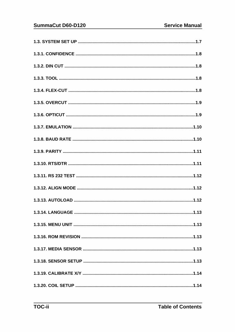
1.3. SYSTEM SET UP .................................................................................................1.7
1.3.1. CONFIDENCE ...................................................................................................1.8
1.3.2. DIN CUT ............................................................................................................1.8
1.3.3. TOOL .................................................................................................................1.8
1.3.4. FLEX-CUT .........................................................................................................1.8
1.3.5. OVERCUT .........................................................................................................1.9
1.3.6. OPTICUT ...........................................................................................................1.9
1.3.7. EMULATION ...................................................................................................1.10
1.3.8. BAUD RATE ....................................................................................................1.10
1.3.9. PARITY ............................................................................................................1.11
1.3.10. RTS/DTR .......................................................................................................1.11
1.3.11. RS 232 TEST .................................................................................................1.12
1.3.12. ALIGN MODE ................................................................................................1.12
1.3.13. AUTOLOAD ..................................................................................................1.12
1.3.14. LANGUAGE ..................................................................................................1.13
1.3.15. MENU UNIT ...................................................................................................1.13
1.3.16. ROM REVISION ............................................................................................1.13
1.3.17. MEDIA SENSOR ...........................................................................................1.13
1.3.18. SENSOR SETUP ...........................................................................................1.13
1.3.19. CALIBRATE X/Y ...........................................................................................1.14
1.3.20. COIL SETUP .................................................................................................1.14
TOC-ii Table of Contents
Service Manual SummaCut D60-D120
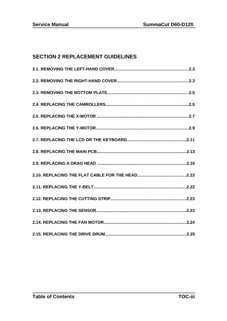
SECTION 2 REPLACEMENT GUIDELINES
2.1. REMOVING THE LEFT-HAND COVER................................................................2.3
2.2. REMOVING THE RIGHT-HAND COVER..............................................................2.3
2.3. REMOVING THE BOTTOM PLATE......................................................................2.5
2.4. REPLACING THE CAMROLLERS.......................................................................2.5
2.5. REPLACING THE X-MOTOR ..............................................................................2.7
2.6. REPLACING THE Y-MOTOR...............................................................................2.9
2.7. REPLACING THE LCD OR THE KEYBOARD...................................................2.11
2.8. REPLACING THE MAIN PCB.............................................................................2.13
2.9. REPLACING A DRAG HEAD ............................................................................2.16
2.10. REPLACING THE FLAT CABLE FOR THE HEAD..........................................2.22
2.11. REPLACING THE Y-BELT...............................................................................2.22
2.12. REPLACING THE CUTTING STRIP.................................................................2.23
2.13. REPLACING THE SENSOR.............................................................................2.23
2.14. REPLACING THE FAN MOTOR.......................................................................2.24
2.15. REPLACING THE DRIVE DRUM......................................................................2.25
Table of Contents TOC-iii
SummaCut D60-D120 Service Manual
SECTION 3 MAINTENANCE
3.1. MAINTENANCE & CLEANING.............................................................................3.2
3.1.1. CLEANING THE DRIVE SYSTEM.....................................................................3.2
3.1.2. CLEANING THE SENSORS..............................................................................3.3
3.2. OPERATING VOLTAGE.......................................................................................3.4
SECTION 4 CALIBRATION
4.1. MEDIA CALIBRATION.........................................................................................4.2
4.2. HEAD CALIBRATION...........................................................................................4.4
I. KNIFE CALIBRATION .............................................................................................4.4
II. COIL CALIBRATION...............................................................................................4.4
4.3.MACHINE TYPE.....................................................................................................4.6
4.4. SENSOR TESTS...................................................................................................4.8
4.5. AUTOMATIC TESTS............................................................................................4.9
SECTION 5 ERROR CODES - TROUBLESHOOTING
TOC-iv Table of Contents
Service Manual SummaCut D60-D120
5.1. ERROR IN X-AXIS................................................................................................5.2
5.2. ERROR IN Y-AXIS POSITION..............................................................................5.3
5.3. SYNTAX ERROR..................................................................................................5.3
5.4. NVRAM FAILURES AND MESSAGES.................................................................5.4
5.5. RS232 ERROR......................................................................................................5.4
5.6. INTERNAL ERRORS............................................................................................5.5
5.7. FLASHING ERRORS AND MESSAGES .............................................................5.6
5.8. RAM ERROR.........................................................................................................5.6
SECTION 6 FIGURES
FRONT SIDE................................................................................................................6-2
REAR SIDE .................................................................................................................6-3
D120 X MOTOR...........................................................................................................6-4
BRAKE.........................................................................................................................6-5
KEYBOARD.................................................................................................................6-6
KEYBOARD.................................................................................................................6-7
BOTTOM PLATE.........................................................................................................6-8
RIGHT SIDE.................................................................................................................6-9
LEFT SIDE.................................................................................................................6-10
Table of Contents TOC-v
SummaCut D60-D120 Service Manual
MEDIA SENSOR SYSTEM........................................................................................6-11
D60 X-MOTOR ..........................................................................................................6-12
DRUM ASSY..............................................................................................................6-13
MEDIA GUIDE SYSTEM............................................................................................6-14
CARRIAGE.................................................................................................................6-15
FRONT SIDE..............................................................................................................6-16
BOARDS....................................................................................................................6-17
COVERS.....................................................................................................................6-18
CARRIAGE.................................................................................................................6-19
MOTOR CONNECTIONS...........................................................................................6-20
MEDIA SELECT.........................................................................................................6-21
SECTION 7 SPARE PARTS LIST
SUMMACUT D60 SPARE PARTS...............................................................................7-1
SUMMACUT D120 SPARE PARTS.............................................................................7-3
TOC-vi Table of Contents
INTRODUCTION
1. OVERVIEW
This is the Summa Service Manual for the SummaCut D60 and D120 cutters. Itprovides information for servicing the cutters. All repairs are to be made by, or underthe direction of, authorised Summa service personnel.
This manual is copyrighted by Summa 1999. Summa reserves the right to change anyinformation contained in this manual without prior notice. Unauthorised copying,modification, distribution, or display is prohibited. All rights reserved.
2. MANUAL ORGANIZATION
This manual is divided into the following sections:
Table of Contents
Introduction
Keyboard controls
General replacement guidelines
Maintenance
Calibration
Troubleshooting
List recommended spare parts with pictures
Keyboard control contains the following:
INTRODUCTION I-1
SummaCut D60-D120 Service Manual
This part contains an overview of the various tests and configurations that can beaccessed via the keyboard.
General replacement guidelines contains the following:
An overview of the removal and the replacement of various parts of the unit in the formof separate chapters. It is advisable to carefully read the procedure described in eachof the chapters prior to removing or replacing a particular part. In addition tostraightforward step by step procedures you will often find Notes and Cautions. Makesure you read these remarks as they will often facilitate re-installation and avoidmalfunctioning.
Maintenance contains the following:
An overview of the maintenance of various parts of the unit. It is advisable to carefullyread the procedure described in each of the chapters prior to removing or replacing aparticular part. You will often find Notes and Cautions. Make sure you read theseremarks as they will often avoid malfunctioning.
Calibration:
An overview of all the possible calibrations of the unit. Each time the machine isserviced check this section to see if any recalibration needs to be done.
Troubleshooting:
An overview of all the possible error messages that could appear on the LCD screen,and the possible solutions
Spare parts list
An overview of all the recommended spare parts. Normally only the parts figuring onthis list will be provided by Summa.
I-2 Introduction
Service Manual SummaCut D60-D120
3. KNOWING YOUR CUTTER
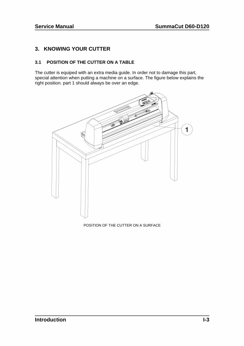
3.1 POSITION OF THE CUTTER ON A TABLE
The cutter is equiped with an extra media guide. In order not to damage this part,special attention when putting a machine on a surface. The figure below explains theright position. part 1 should always be over an edge.
POSITION OF THE CUTTER ON A SURFACE
Introduction I-3
SummaCut D60-D120 Service Manual
3.2. CUTTER COMPONENTS
In order to get acquainted with your SummaCut D60 and D120, read the followingdescription of components.
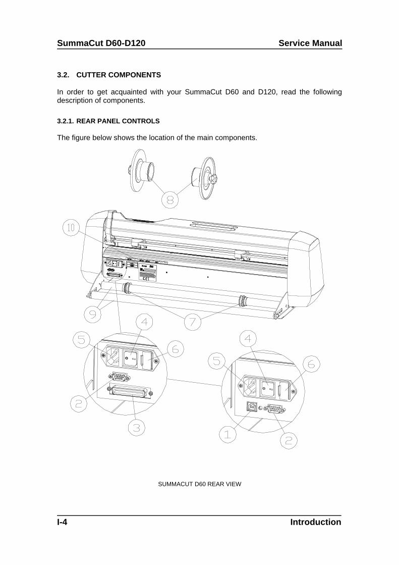
3.2.1. REAR PANEL CONTROLS
The figure below shows the location of the main components.
SUMMACUT D60 REAR VIEW
I-4 Introduction
Service Manual SummaCut D60-D120
1. USB interface: - This interface is based on the standards specified in UniversalSerial Bus Specifications Revision 1.1. It allows a high-speed serial bi-directionalcommunication between the host computer and the cutter.
2. RS-232-C Port: - This DB-9P connector provides the communication linkbetween the cutter and a host computer. It allows bi-directional communicationbetween the host computer and the cutter.
3. Parallel Port: - This IEEE1284 -B connector provides a bi-directionalcommunication link between the cutter and a host computer. Note: only one interface can be active at a time.The first port that receives data will be the active interface until the cutter is reset.
4. Power ON/OFF switch - This rocker switch sets the cutter’s power to ON or OFF.To switch the power ON, press the “I” side of the rocker switch. To switch thepower OFF, press the “O” side of the rocker switch.
5. Power Entry Module: - The fuse box and the AC power cord receptacle arelocated in the power entry module. The power-up procedure is explained in detail in Section 1.6.
6. Fuse box: - For information about changing of the fuse, see Section 4.2.
7. Roll Media Guide Bushes: - The two guide bushes serve to keep the media roll inplace when media is pulled from the roll.
8. Media Flanges: - The media flanges ensure proper routing of the media roll.
9. Media Support Roller: - Rotating support rollers for the media roll.
10. Alignment Strip: - Rear alignment strip for easier media loading.
Introduction I-5
SummaCut D60-D120 Service Manual
3.2.2. FRONT PANEL CONTROLS
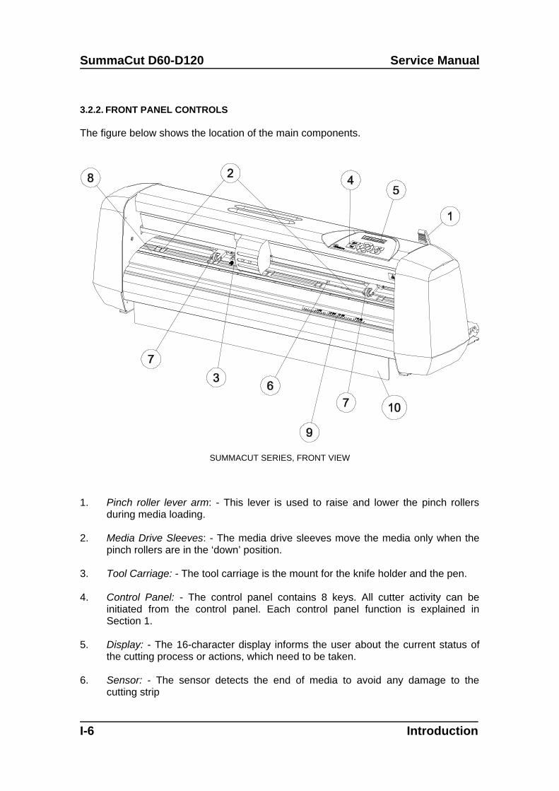
The figure below shows the location of the main components.
SUMMACUT SERIES, FRONT VIEW
1. Pinch roller lever arm: - This lever is used to raise and lower the pinch rollersduring media loading.
2. Media Drive Sleeves: - The media drive sleeves move the media only when thepinch rollers are in the ‘down’ position.
3. Tool Carriage: - The tool carriage is the mount for the knife holder and the pen.
4. Control Panel: - The control panel contains 8 keys. All cutter activity can beinitiated from the control panel. Each control panel function is explained inSection 1.
5. Display: - The 16-character display informs the user about the current status ofthe cutting process or actions, which need to be taken.
6. Sensor: - The sensor detects the end of media to avoid any damage to thecutting strip
I-6 Introduction
Service Manual SummaCut D60-D120
7. Pinch rollers: - The pinch rollers (one at each side) hold the media clampedbetween the rubber rollers and the media drive sleeves. (The D120 has an extraguidin pinch roller in the middle)
8. Cutting strip: - Soft strip to avoid any damage to the knife tip when no media hasbeen loaded. Since cutting is done on the cutting strip it is essential that thecutting strip remains intact.
9. Alignment strip: - Front alignment strip for easier media loading.
10. Media guide : - Extra guide to prevent badly curled up media from jammingunder the cutter (not in 120 Model)
Introduction I-7

SECTION 1
Keyboard control
1.1. THE CONTROL PANEL
The figure below shows the control panel of the SummaCut D60 and the D120. Themain functions of the liquid crystal display (LCD) and the control panel keys areexplained in the following paragraphs.
CONTROL PANEL SUMMACUT D60
1.1.1. THE LIQUID CRYSTAL DISPLAY
The liquid crystal display (LCD) contains one line of 16 characters. The LCD providescutter status information during operations and displays menu options for theconfiguration of the cutter.
The various menu and submenu items are always presented in a loop, which meansthat, when the last menu or submenu item is displayed, pressing the appropriate keywill automatically take you back to the first item of the same menu or submenu.
1.1.2. THE MENU KEY
Keyboardcontrols 1-1
SummaCut D60-D120 Service Manual
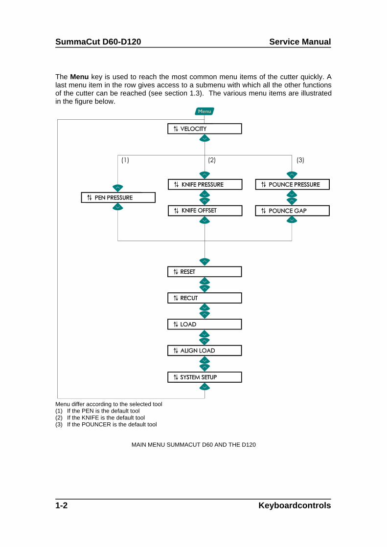
The Menu key is used to reach the most common menu items of the cutter quickly. Alast menu item in the row gives access to a submenu with which all the other functionsof the cutter can be reached (see section 1.3). The various menu items are illustratedin the figure below.
Menu differ according to the selected tool(1) If the PEN is the default tool(2) If the KNIFE is the default tool(3) If the POUNCER is the default tool
MAIN MENU SUMMACUT D60 AND THE D120
1-2 Keyboardcontrols
Service Manual SummaCut D60-D120
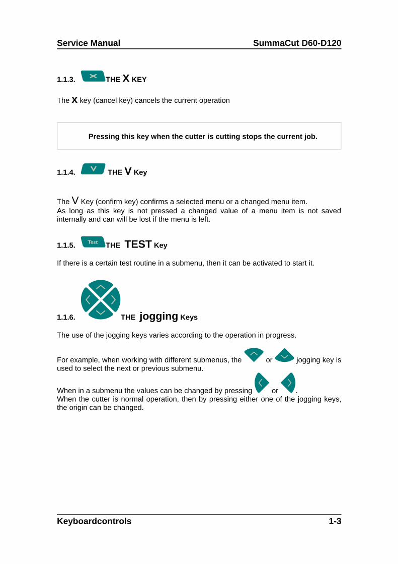
1.1.3. THE X KEY
The x key (cancel key) cancels the current operation
Pressing this key when the cutter is cutting stops the current job.
1.1.4. THE V Key
The V Key (confirm key) confirms a selected menu or a changed menu item.As long as this key is not pressed a changed value of a menu item is not savedinternally and can will be lost if the menu is left.
1.1.5. THE TEST Key
If there is a certain test routine in a submenu, then it can be activated to start it.
1.1.6. THE jogging Keys
The use of the jogging keys varies according to the operation in progress.
For example, when working with different submenus, the or jogging key isused to select the next or previous submenu.
When in a submenu the values can be changed by pressing or .When the cutter is normal operation, then by pressing either one of the jogging keys,the origin can be changed.
Keyboardcontrols 1-3
SummaCut D60-D120 Service Manual
1.2. COMMON MENU ITEMS
Following paragraphs explain the different submenus.
1.2.1 VELOCITY
The VELOCITY submenu is used to set or modify the velocity of the tool.The default velocity is 700 mm/s (20 ips).
After pressing the key then press the or jogging key until the desired
speed is displayed on the LCD and press to confirm.The velocity can be set between 50 mm/s (2 ips) and 800 mm/s (40 ips).On the LCD, the active plotting speed is marked with an “*”.
1.2.2 PEN PRESSURE
The PEN PRESSURE parameter is used to set or modify the cutting pressure of thepen.The default pen pressure value is 80 grams.
After pressing the key then press the or jogging key until the desired
pressure is displayed on the LCD and press to confirm.The pen pressure can be set between 0 and 400 grams.The pen pressure value is set in 5 gram increments.On the LCD, the active pen pressure is marked with an “*”.
1.2.3 KNIFE PRESSURE
The KNIFE PRESSURE parameter is used to set or modify the cutting pressure of theknife.The default knife pressure value is 120 grams.
After pressing the key then press the or jogging key until the desired
pressure is displayed on the LCD and press to confirm.The knife pressure can be set between 0 and 400 grams.The knife pressure value is set in 5 gram increments.On the LCD, the active knife pressure is marked with an “*”.
1-4 Keyboardcontrols
Service Manual SummaCut D60-D120
1.2.4 KNIFE OFFSET
The KNIFE OFFSET parameter is used to set or modify the distance between the knifeblade tip and the centre axis.The default knife offset value is .45 mm.
After pressing the key then press the or jogging key until the desired
knife offset is displayed on the LCD and press to confirm.
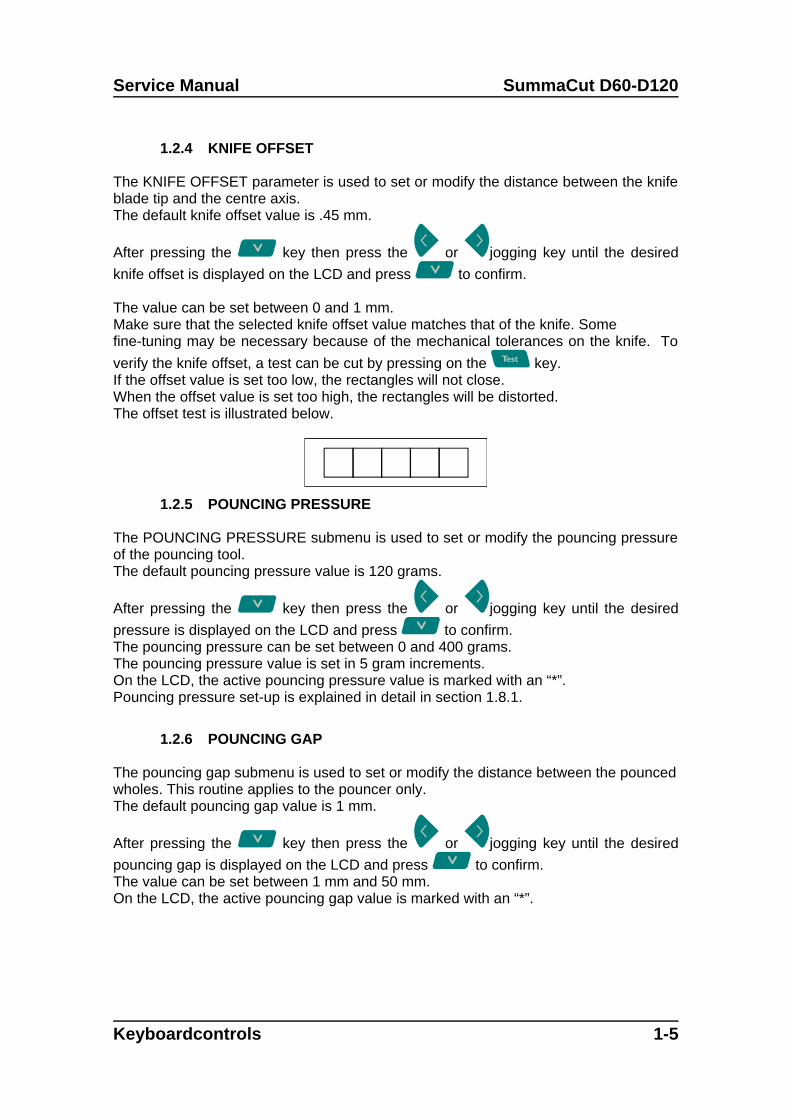
The value can be set between 0 and 1 mm.Make sure that the selected knife offset value matches that of the knife. Somefine-tuning may be necessary because of the mechanical tolerances on the knife. To
verify the knife offset, a test can be cut by pressing on the key.If the offset value is set too low, the rectangles will not close. When the offset value is set too high, the rectangles will be distorted.The offset test is illustrated below.
1.2.5 POUNCING PRESSURE
The POUNCING PRESSURE submenu is used to set or modify the pouncing pressureof the pouncing tool.The default pouncing pressure value is 120 grams.
After pressing the key then press the or jogging key until the desired
pressure is displayed on the LCD and press to confirm.The pouncing pressure can be set between 0 and 400 grams.The pouncing pressure value is set in 5 gram increments.On the LCD, the active pouncing pressure value is marked with an “*”.Pouncing pressure set-up is explained in detail in section 1.8.1.
1.2.6 POUNCING GAP
The pouncing gap submenu is used to set or modify the distance between the pouncedwholes. This routine applies to the pouncer only.The default pouncing gap value is 1 mm.
After pressing the key then press the or jogging key until the desired
pouncing gap is displayed on the LCD and press to confirm.The value can be set between 1 mm and 50 mm.On the LCD, the active pouncing gap value is marked with an “*”.
Keyboardcontrols 1-5
SummaCut D60-D120 Service Manual
1.2.7 RESET
The RESET instruction performs a complete reset of the cutter. Press the key toexecute a reset.
1.2.8 RECUT
The RECUT instruction recuts the last file sent to the cutter (provided that it fitted into
the buffer). Press the key to execute the instruction.
1.2.9 LOAD
The LOAD instruction is used to initiate a load sequence. Press the key to
execute. First the origin can be changed if necessary. Press the or jogging key
to change the origin in the Y-direction. Press the or jogging key to change
the origin in the x-direction. Press the key to confirm. Then the media window
can be changed. Press the or jogging key to change the length of the
window or press the key to change the value of the length of the media window.
The or jogging key change the value in steps of 100mm, the orjogging key change it in steps of 10mm (When the machine is set up in English units,
the step sizes are respectively 0.5” and 2.5”). Then press the key to finish theload procedure.
1.2.10 ALIGN LOAD
The Align load sub menu is used for contour cutting. Refer to section 3 in the User’smanual for the complete explanation on contour cutting. Section 1.3.11 explains how to
change the align method. Press the key to execute.
1.2.11 SYSTEM SETUP
The SYSTEM SETUP submenu covers the menu items you normally only need whenestablishing the initial set-up e.g. when you install the cutter in combination with thesoftware you use.Press the confirmation key to access the different submenu items, which are explainedin section 1.3.
1-6 Keyboardcontrols
Service Manual SummaCut D60-D120
1.3. SYSTEM SETUP
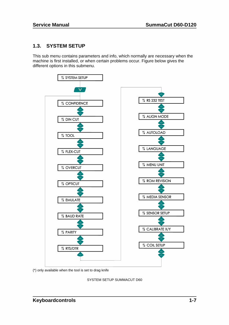
This sub menu contains parameters and info, which normally are necessary when themachine is first installed, or when certain problems occur. Figure below gives thedifferent options in this submenu.
(*) only available when the tool is set to drag knife
SYSTEM SETUP SUMMACUT D60
Keyboardcontrols 1-7
SummaCut D60-D120 Service Manual
1.3.1. CONFIDENCE
The CONFIDENCE cut performs an electrical and mechanical test of the cutter to makesure that the cutter is fully operational. A media sheet of at least A3/A- size should beused for this plot.
Press the key to execute.
1.3.2. DIN CUT
The DIN CUT also performs an electrical and mechanical test of the cutter, in order tocheck the cut quality, but also provides the user with feedback on knife setting, knifepressure, knife offset and cutting depth.
This cut is always run as a DIN A4 portrait/A-size image, regardless of the actual sizeof the media loaded. If the media loaded is smaller than DIN A4/A-size, part of theouter box will be clipped (not cut). This cut is always executed in the sequenceprescribed by the ISO DIN standard.
Press the key to execute.
1.3.3. TOOL
The TOOL submenu is used to select the default tool at power up.
After pressing the key then press the or jogging key until the desired
tool is displayed on the LCD and press to confirm.To configure the cutter for plotting operations, select PEN.To configure the cutter for cutting operations, select the DRAG KNIFE option.To configure the cutter for pouncing operations, select the POUNCING TOOL option.On the LCD, the active tool setting is marked with an “*”.
1.3.4. FLEX-CUT
FLEX-CUT can be set to OFF, to Mode 1 or Mode 2. When the cutter is set to mode 1or mode 2, it will alternately cut one length with full pressure, and one length withreduced pressure (length is later referred to as “HALF”. The feature FLEX-CUT offersthe advantage that it cuts completely through the material, yet allowing the material tostay together by means of the small media bridges.MODE 1 is the quickest mode, but it is less precise because the pressure changesduring the cutting. MODE 2 is a lot slower, but at the same time it is much moreprecise, as the cutter stops at every change of pressure.
1-8 Keyboardcontrols
Service Manual SummaCut D60-D120
After pressing the key then press the or jogging key until the desired
mode is displayed on the LCD and press to confirm.On the LCD, the active setting is marked with an “*”.
Pressing the key will activate the configuration menu. The different configuration
sub menus can be accessed by pressing the or jogging key. All thevalues are metric regardless the “MENU UNITS” setting.1. CUT
This parameter determines the length that is cut with full pressure. Press the or
jogging key to change the value. By pressing the key, the FLEX-CUT testpattern will be cut.2. HALFThis parameter determines the length that will be cut with reduced pressure or without
pressure. Press the or jogging key to change the value. By pressing thekey, the FLEX-CUT pattern will be cut.3. PRES
This parameter determines the pressure of “HALF”. Press the or jogging key to
change the value. By pressing the key, the FLEX-CUT test pattern is cut.
1.3.5. OVERCUT
The OVERCUT submenu enables you to generate an overcut in order to facilitate
weeding the cut. Press the or jogging key to change the value.The default overcut is set to 1.The overcut setting can be disabled (=0) or set to any value between 0(=off) and 10.One unit is about 0.1 mm or 0.004 ".On the LCD, the active value is marked with an “*”.
1.3.6. OPTICUT
The OPTICUT submenu enables you to generate an enhanced overcut in order tofacilitate weeding the cut. This feature however does leave little scratch on your designand may not be appropriate for some media.
Press the or jogging key to change the value.The default value is set to OFF.On the LCD, the active value is marked with an “*”.
Keyboardcontrols 1-9
SummaCut D60-D120 Service Manual
1.3.7. EMULATE
The EMULATE submenu is used to select the active cutting/plotting language for thecutter.
After pressing the key then press the or jogging key until the desired
language is displayed on the LCD and press to confirm.The SummaCut D60 and theD120 supports DM/PL , HP/GL and HP/GL/2.On the LCD, the active plotting language setting is marked with an “*”.
NOTE
The active cutting/plotting language MUST match the cutting software.
Always select a language that is supported by the host computer's cuttingsoftware.
Whenever possible, select the DM/PL menu option to set the active cutting/plottinglanguage to Houston Instrument Digital Microprocessor/Plotting Language (DM/PL).This selection will allow the cutter to operate with DM/PL-based cutting / plottingsoftware. This language, having special command extensions for cutting, normallygives superior cutting performance.
1.3.8. BAUD RATE
The BAUD RATE submenu is used to set or modify the operating baud rate for RS-232-C serial communications between your cutter and the host computer.The default baud rate is 9600 bps.
After pressing the key then press the or jogging key until the desired
baud rate is displayed on the LCD and press to confirm.The baud rate can be set to any of the following values: 2400 bps, 4800 bps, 9600 bps,19200 and 38400 bps.On the LCD, the active baud rate value is marked with an “*”.
NOTE
The baud rate setting of your cutter MUST match the host computer's baudrate setting.
1-10 Keyboardcontrols
Service Manual SummaCut D60-D120
1.3.9. PARITY
The PARITY submenu is used to set or modify the byte format and parity type for RS-232-C serial communications between your cutter and the host computer.The default parity setting is bit 8 = 0 (8 data bits, no parity, the 8th bit being a low bit).The parity can be set to any of the following values:
LCD information Parity setting RemarksBIT 8 = 0 8 data bits, no parity bit 8 = low (0)BIT 8 = 1 8 data bits, no parity bit 8 = high (1)EVEN 7 data bits, 1 parity bit parity bit = evenODD 7 data bits, 1 parity bit parity bit = odd
After pressing the key then press the or jogging key until the desired
setting is displayed on the LCD and press to confirm.RTS/DTR can be set to TOGGLE (hardware handshaking) or HIGH (softwarehandshaking).On the LCD, the active parity setting is marked with an “*”.
NOTE
The parity setting of your cutter MUST match the host computer’ s paritysetting.
1.3.10. RTS/DTR
The RTS/DTR submenu controls the Request To Send (RTS) and Data TerminalReady (DTR) signals of the cutter's RS-232-C serial communications interface forhardware handshaking.The RTS/DTR default value is TOGGLE.
After pressing the key then press the or jogging key until the desired
setting is displayed on the LCD and press to confirm.RTS/DTR can be set to TOGGLE (hardware handshaking) or HIGH (softwarehandshaking).On the LCD, the active handshaking setting is marked with an “*”.
Keyboardcontrols 1-11
SummaCut D60-D120 Service Manual
1.3.11. RS 232 TEST
The RS232 TEST routine verifies the cutter’s RS-232-C serial communications(transmit data, receive data, and hardware handshaking) circuits. This test does notrequire pen, knife or media to be loaded.
To run the RS-232-C test, proceed as follows:
1. Unplug the RS-232-C data cable from the rear panel of the cutter.
2. Use a loopback test cable to connect pin 2 of the cutter’s data connector to pin 3and pin 7 to pin 8.
3. With RS232 TEST displayed, press the key. The cutter will starttransmitting and receiving data at all available baud rates and parity settings. Thelength of the transmissions will vary because of the different baud rates used.The unit then checks the hardware handshake lines.
If the RS232 port is not working correct, then the cutter returns an error message.
1.3.12. ALIGN MODE
The parameter ALIGN MODE in the menu determines which alignment method is used.(See section 3 in User’s Manual for complete explanation)
After pressing the key then press the or jogging key until the desired
setting is displayed on the LCD and press to confirm.On the LCD display, the active setting is marked with an “*”.
1.3.13. AUTOLOAD
The AUTOLOAD option enables the user to the change the vinyl unroll proceedings.When AUTOLOAD is ON, the cutter will automatically unroll the vinyl when needed.When the AUTOLOAD option is OFF, the operator himself should unroll enough mediabefore starting to cut.The default setting is ON. The best results and performance are guaranteed whenusing this setting.
After pressing the key then press the or jogging key until the desired
setting is displayed on the LCD and press to confirm.On the LCD display, the active setting is marked with an “*”.
1-12 Keyboardcontrols
Service Manual SummaCut D60-D120
1.3.14. LANGUAGE
The MENU LANGUAGE submenu is used to set or modify the dialogue language on
the LCD. After pressing the key then press the or jogging key until the
desired language is displayed on the LCD and press to confirm.The information on the LCD can be displayed in English, French, German, Spanish,Italian or Dutch. On the LCD, the active plotting language setting is marked with an “*”.
1.3.15. MENU UNIT
The MENU UNITS submenu allows you to select English or metric menu units.
After pressing the key then press the or jogging key until the desired
menu unit is displayed on the LCD and press to confirm.On the LCD, the active menu units setting is marked with an “*”.
1.3.16. ROM REVISION
Selecting the ROM REVISION option, by pressing the key will furnish the detailson the cutter’s ROM revision. This information is often helpful to technicians whendiagnosing problems over the telephone.
1.3.17. MEDIA SENSOR
The MEDIA SENSOR submenu is used to activate or deactivate the media sensor. Thesensor detects the end of media. In that way the sensor prevents damage to the cuttingstrip and knife tip.
After pressing the key then press the or jogging key until the desired
setting is displayed on the LCD and press to confirm.On the LCD, the active setting is marked with an “*”.
1.3.18. SENSOR SETUP
The SENSOR SETUP submenu is used to activate or deactivate the media. After
pressing the key follow the instructions on the LCD. Put a piece of media half on
the sensor and then press the key. The machine will show on the LCD whetherthe sensor works or not.
Keyboardcontrols 1-13
SummaCut D60-D120 Service Manual
1.3.19. CALIBRATE X/Y
Calibration allows changing the length of the lines that are cut to be adjusted to withinthe specifications.For instance, if a cut line should measure 100 mm exactly, the cutter can be adjusted
for any discrepancy. First make sure the media is loaded, and then press thekey to perform a test. Measure the lines and enter the measured x-value by
pressing the jogging keys. The or jogging key change the values in big steps,
the or jogging key change the value in small steps. After pressing the
key, the y-value can be changed in the same way. Do not perform this test when the machine is working properly.
1.3.20. COIL SETUP
This test is used to calibrate knife and pen pressure and to set the knife and pen“landing”.After adjustment, the value is saved in the system’s non-volatile RAM.To execute this test a tension gauge of ± 100 gr. and ± 500 gr. is required.In the upper line of the display the desired pressure appears and in the bottom line ofthe display the value that has to be sent to the head to reach this pressure (this value
is between 0 and 127). Press the key to enter the test and follow the guidelineson the LCD screen.
CAUTION
Do not perform the coil test when the machine is workingproperly. Changing the parameters to a wrong value mayseriously affect the quality and even damage the cutter.
1-14 Keyboardcontrols
SECTION 2
Replacements guidelines
General
This section contains information on replacing defective parts and adjustment procedures. A step-by-step removal/assembly procedure is provided in this section. On the left page you will find drawingsindicating the position of the parts.
Precautions
Observe simple, common sense rules and procedures whilst servicing the unit. They include, but arenot limited to the following:
The base of the unit has been assembled on a fixture to assure straightness all along the y-axis.To keep this :DO NOT REMOVE THE Y-GUIDING.
Unplug the line cords and host cables before transporting the unit to other places.
Reassemble ALL parts (screws, ferrite shield, etc.) to maintain EMI integrity, and guide the loosewires afterwards with tie-wrap in the same manner they were before
Watch for sharp edges on the metal strips etc.
When the covers are off or open:
The printed circuits boards are electrostatically sensitive; use the proper handlingtechniques.
Keep sensors free of scratches and dirt.
Keep the guiding, at least dirtfree where the wheels of the carriage pass.
Replacements Guidelines 2-1
SummaCut D60-D120 Service Manual
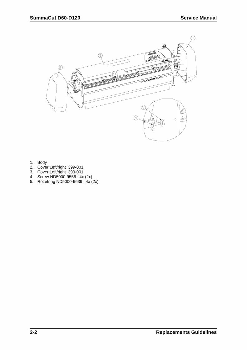
1. Body2. Cover Left/right 399-0013. Cover Left/right 399-0014. Screw ND5000-9556 : 4x (2x)5. Rozetring ND5000-9639 : 4x (2x)
2-2 Replacements Guidelines
Service Manual SummaCut D60-D120
2.1. REMOVING THE LEFT-HAND COVER
To remove the left-hand cover, proceed as follows:
1. Remove the four screws holding the left-hand cover in place. Two are located at the front and twoat the rear. Pay close attention to where each of the screws goes. They should be returned totheir original location when re-installed.
2. Gently tap the top of the cover.
3. Remove the cover.
To re-install, proceed in the reverse order of removal. Make sure to firmly tighten all screws.
2.2. REMOVING THE RIGHT-HAND COVER
To remove the right-hand cover, proceed as follows:
1. Remove the four screws holding the right-hand cover in place. Two are located at the front andtwo at the rear. Pay close attention to where each of the screws goes. They should be returned totheir original location when re-installed.
2. Gently tap the top of the cover.
3. Remove the cover.
To re-install, proceed in the reverse order of removal. Make sure to firmly tighten all screws.
1.!
CAUTION2.3. Make sure that you do not jam any wires between the cover and the sideplate as this may cause considerable damage.4. Give special attention to the flat cables.
5.
Replacement Guidelines 2-3
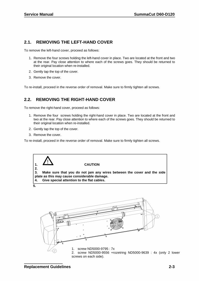
1. screw ND5000-9795 : 7x2. screw ND5000-9556 +rozetring ND5000-9639 : 4x (only 2 lowerscrews on each side).
SummaCut D60-D120 Service Manual
6.
7.8.
2-4 Replacements Guidelines
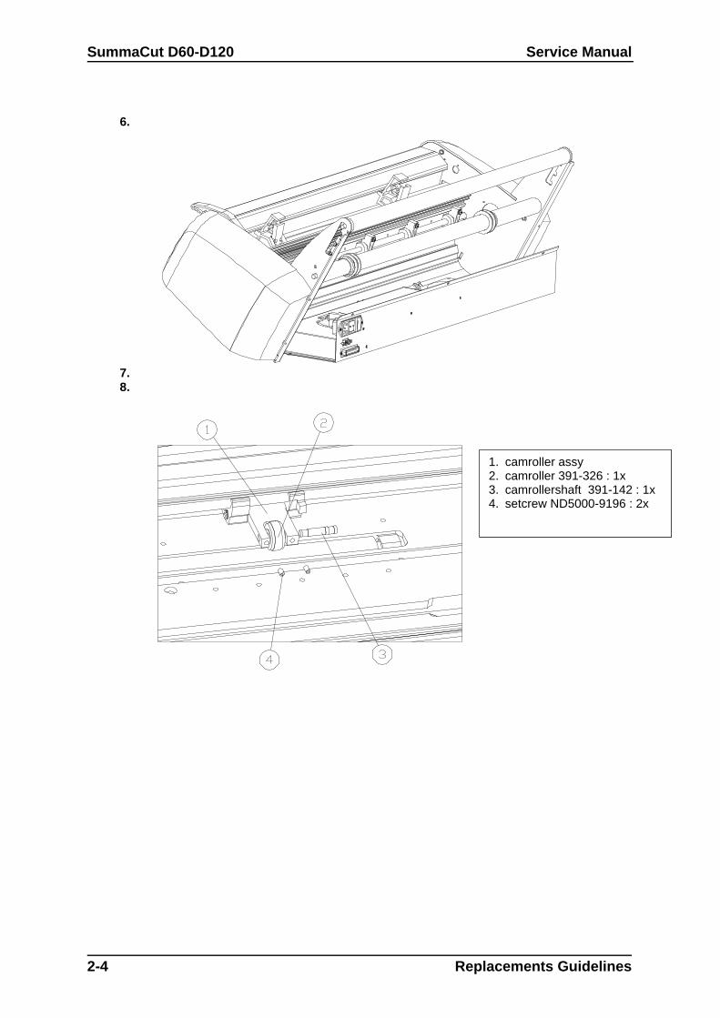
1. camroller assy2. camroller 391-326 : 1x3. camrollershaft 391-142 : 1x4. setcrew ND5000-9196 : 2x
Service Manual SummaCut D60-D120
2.3. REMOVING THE BOTTOM PLATE
To remove the bottom plate, proceed as follows:
1. Turn the unit in a position that front of the unit is facing to the bench.
2. Remove 2 lower screws of each cover.
3. Remove the screws holding the bottom plate in place. Unscrew first the bottom screws (4 screws)Then remove the 3 top screws.
4. Remove the bottom plate.
To re-install, proceed in the reverse order of removal. Make sure to firmly tighten all screws.
9. Note:10. Make sure the bottom plate is placed correctly and no wires are are beendamaged.
11.
2.4. REPLACING THE CAM ROLLERS
To replace the cam rollers, proceed as follows:
1. Remove the set screw on either side of the cam rollers .
2. Remove the cam roller shaft (push against the left side of the shaft).
3. Remove the cam roller.
12. Note:13.14. Cam rollers come in pairs. When one is malfunctioning or broken, both camrollers need to be replaced.15.
To re-install, proceed in the reverse order of removal. Make sure to firmly tighten all screws.
16. Note:17.18. It is extremely important that the cam roller be stable and stationary. To achievethis, press one side of the camshaft while tightening the set screws.19.
Replacement Guidelines 2-5
SummaCut D60-D120 Service Manual
2-6 Replacements Guidelines
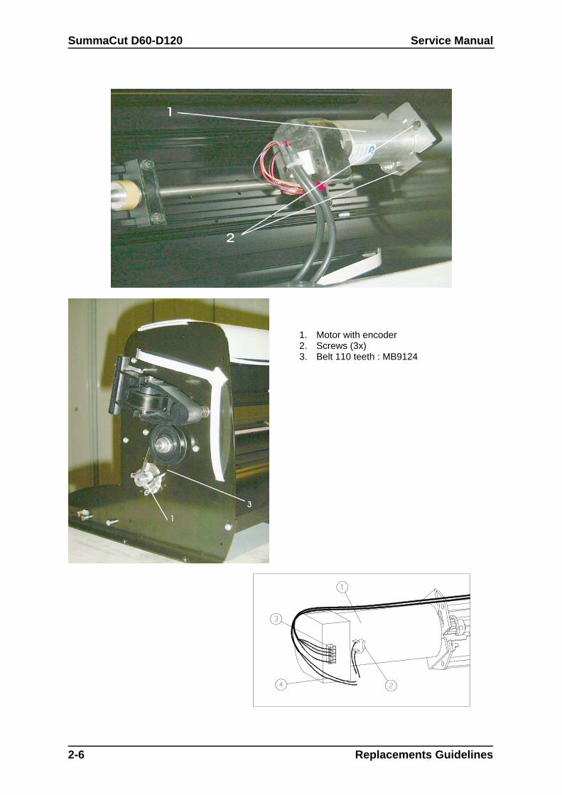
1. Motor with encoder2. Screws (3x)3. Belt 110 teeth : MB9124

Service Manual SummaCut D60-D120
2.5. REPLACING THE X-MOTOR
To replace the X-motor in these models, proceed as follows:
1. Remove the left hand cover (see Chapter 2.1, Removing the left hand cover).
2. Remove the Bottom plate (see Chapter 2.3, Removing the bottom plate).
3. Push the motor towards the drum and gently remove the belt.
4. Remove the connector from the encoder and solder off the black and the red wire to expose theX-motor.
5. Remove the three screws holding the X-motor in place.
6. Remove the X-motor.
To re-install, proceed in the reverse order of removal. Make sure to firmly tighten all screws.
20. Note:
21. When re-installing:
22. a.Make sure the wire of the connector attached to the encoder runs outward.
23. b.Make sure to solder the black wire to the minus (-) entry and the red wire tothe plus (+) entry. The (+) and (-) signs are located in the corners of the motor's label.
24. c.Be extremely careful to plug the connector into the correct holes of theencoder.
Move the pulley on the motor shaft to prevent the belt from slipping against the big pulley. Make sureto firmly tighten the set-screw.
The D120 han in the X axis 2 motors, one with an encoder and one without an encoder.
Replacement Guidelines 2-7
1 motor2 capacitor3 connector encoder WATCH ORIENTATION !4 wires motor
SummaCut D60-D120 Service Manual
2-8 Replacements Guidelines
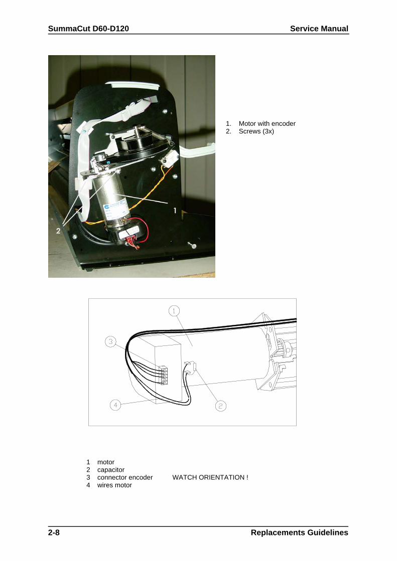
1 motor2 capacitor3 connector encoder WATCH ORIENTATION !4 wires motor
1. Motor with encoder2. Screws (3x)
Service Manual SummaCut D60-D120
2.6. REPLACING THE Y-MOTOR
To replace the Y-motor, proceed as follows:
1. Remove the right-hand cover (see Chapter 2.1, Removing the right-hand cover).
2. Remove the connector from the encoder and solder off the black and the red wire to expose theY-motor.
3. Remove the three screws holding the Y-motor in place.
4. Remove the Y-motor.
To re-install, proceed in the reverse order of removal. Make sure to firmly tighten all screws.
25. Note:
26. When re-installing:
27. a.Make sure the wire of the connector attached to the encoder runs outward.
28. b.Make sure to solder the black wire to the minus (-) entry and the red wire tothe plus (+) entry. The (+) and (-) signs are located in the corners of the motor's label.
29. c.Be extremely careful to plug the connector into the correct holes of theencoder.
30. d.Move the pulley on the motor shaft to prevent the belt from slipping againstthe big pulley. Make sure to firmly tighten the set-screw.
31.
Replacement Guidelines 2-9
SummaCut D60-D120 Service Manual
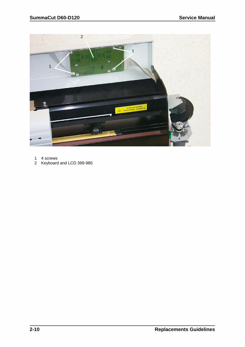
1 4 screws 2 Keyboard and LCD 399-985
2-10 Replacements Guidelines
1
1
2
Service Manual SummaCut D60-D120
2.7. REPLACING THE LCD OR THE KEYBOARD
To replace the keyboard, proceed as follows:
1. Remove the right-hand cover and the left hand cover (see Chapter 2.2, Removing the right-handcover).
2. Take off the top beam. The keyboard and LCD are mounted on a PCB that is mounted in the topbeam.
3. Pull the flat cable off the PCB.
4. Remove the four screws holding the keyboard in place.
5. Remove the keyboard PCB.
To re-install, proceed in the reverse order of removal. Make sure to firmly tighten all screws.
Replacement Guidelines 2-11
SummaCut D60-D120 Service Manual
2-12 Replacements Guidelines
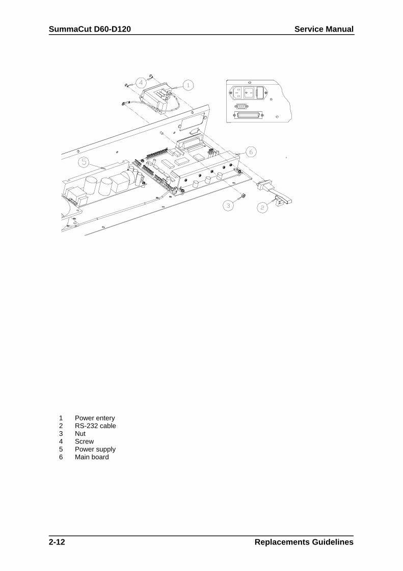
1 Power entery2 RS-232 cable3 Nut4 Screw5 Power supply6 Main board
Service Manual SummaCut D60-D120
2.8. REPLACING THE MAIN PCB
To replace a PCB, proceed as follows:
1. Remove the bottom cover and the protection sheeld.
2. Disconnect the various connectors. Pay close attention to the positioning of the connectors. Theyshould be returned to their original location when re-installed.
3. Remove the flat cable for the head by pulling the flat cable connector up. On both sides of theconnector cover there is a small protuberance that you can pry up using a screwdriver. Gentlypull the flat cable out of the connector.
4. Remove the flat cable for the keyboard.
5. Remove the flat cable for the LCD.
At the rear of the PCB
6. Remove the safeguard located a few inches above the grounding wires.
Loosen the two grounding clamps so that the earthing wires can be removed.
Replacement Guidelines 2-13
SummaCut D60-D120 Service Manual
At the front of the PCB
8. Remove the left screw holding the power entry module in place and sufficiently loosen the rightscrew of the power entry module.
At the side of the PCB
9. Remove the three vertically-aligned screws located on the right-hand cover.
On the bottom of the PCB
10.Remove the fan motor connector.
32. Note:33. In the Type 1 models the connectors for the sensors also have to be removed.
11.Remove the PCB.
To re-install, proceed in the reverse order of removal. Make sure to firmly tighten all screws.
34. Note:
35. a. When re-installing, be extremely careful to plug the connectors into thecorrect holes.
36.
37. Each connector on the PCB has a reference.
38. b. Once the new PCB has been installed, it is very important that the datastored on the PCB be brought in line with the head and vice versa. See section 4 oncalibration.
2-14 Replacements Guidelines

Service Manual SummaCut D60-D120
Replacement Guidelines 2-15
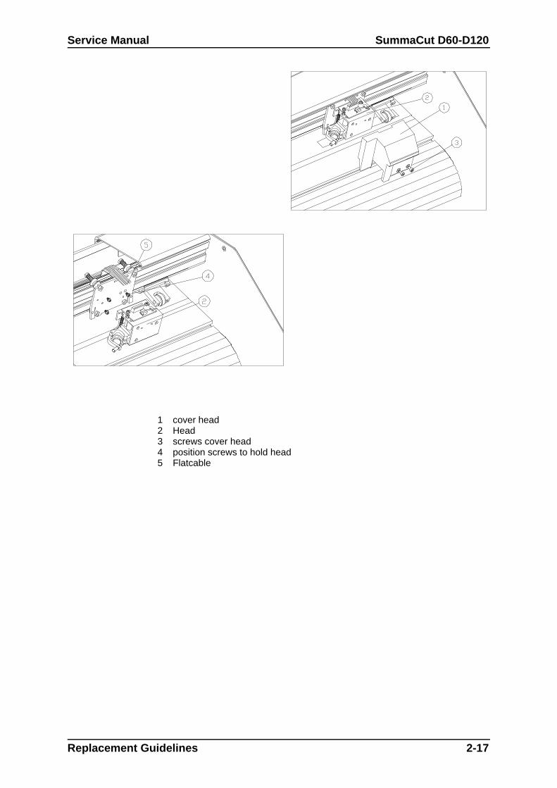
1 cover head2 Head3 screws cover head4 position screws to hold head5 Flatcable
SummaCut D60-D120 Service Manual
2.9. REPLACING A DRAG HEAD
Below is the description for the replacement of a standard drag head. To remove the drag head, proceed as follows:
1. Take the knife holder out of the drag head.
2. Remove the front cover of the drag head by loosening the two screws .
3. Loosen the flat cable by pulling the flat cable connector cover up. On both sides of the connectorcover there is a small protuberance that you can pry up using a screwdriver. Gently pull the flatcable out of the connector
4. Remove the drag head. To do this, loosen the three screws with two counterclockwise rotationsusing a small diameter screw driver and lift the head upwards to remove it from the screws.
To re-install the drag head, proceed as follows:
1. Place the head back onto the screws. Tighten the screws with a 1 1/2 clockwise rotation. Do nottighten them firmly because the height and position of the head still need to be adjusted.
2. Put the knife holder into the drag head.
39. Caution:40. Make sure the tip of the knife does not protrude.
3. Secure the knife holder.
4. Adjust the height and position of the head.
2-16 Replacements Guidelines
Service Manual SummaCut D60-D120
Replacement Guidelines 2-17
1 cover head2 Head3 screws cover head4 position screws to hold head5 Flatcable
SummaCut D60-D120 Service Manual
Apart from the standard adjustment tools used in the standardoperating procedure, you can use an ordinary 3½" disk toadjust the height and position of the head. To do this, proceedas follows:
a. Put the disk against the drag head (the same way as youwould put an adjustment plate against it) to verify that the draghead is positioned perpendicularly to the cutting surface.
b. Slide the disk under the knife holder. If the disk touches theknife holder this means that the head is mounted too low.Readjust the mounting of the head.
5. Firmly tighten the screws once the drag head is properly positioned.
6. Put the flat cable back into the connector and close the connector. To ensure good contact, theflat cable must be positioned as deeply as possible and in the middle of the connector.
7. Remount the front cover of the head and firmly tighten the screws.
8. Proceed in the reverse order of removal. Make sure to firmly tighten all screws.
41. Note:42. Now that you have replaced the head, it is extremely important that you bring thedata stored on the PCB in line with the head and vice versa. See Chapter 11,Configuration of the head or the PCB for detailed information on how to do this.43.44.
2-18 Replacements Guidelines
Service Manual SummaCut D60-D120
45. Replacing the flat cable for the head
Below is the description for the replacement of the flat cable in small cutters.To replace the flat cable for the head, proceed as follows:
1. Remove the left-hand cover (see Chapter 1, Removing the left-hand cover).
2. Remove the right-hand cover (see Chapter 2, Removing the right-hand cover).
3. Remove the two screws on either side of the top cover on the D120 on the D60 there are noscrews.
4. Remove the top cover.
5. Remove the bottom cover
6. Loosen one end of the flat cable (the one attached to the PCB) by pulling the flat cable connectorcover up. On both sides of the connector cover there is a small protuberance that you can pry upusing a screwdriver. Gently pull the flat cable out of the connector.
7. Pull the flat cable for the head off the flat cable for the keyboard.
46. Note: 47. Pay close attention to the way the flat cable has been folded. It is advisable tofold the flat cable in exactly the same way when re-installed.
7. Loosen the flat cable which has been glued to the inner side of the shaft's upright edge.
8. Remove the two screws of the top cover of the head holding the flat cable in place.
9. Remove the cover.
48. Note:49. Pay close attention to the way the flat cable has been folded. The flat cable willneed to be folded in exactly the same way when re-installed.50. Loosen the end of the flat cable attached to the head. Follow the sameprocedure as before (see point 5).
Replacement Guidelines 2-19
SummaCut D60-D120 Service Manual
2-20 Replacements Guidelines
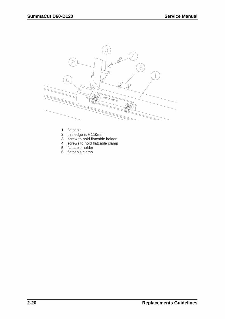
1 flatcable2 this edge is 110mm3 screw to hold flatcable holder4 screws to hold flatcable clamp5 flatcable holder6 flatcable clamp
Service Manual SummaCut D60-D120
To re-install, proceed as follows:
1. Put the flat cable into the connector of the head and close the connector. To ensure goodcontact, the flat cable must be positioned as deeply as possible and in the middle of theconnector.
2. Put the flat cable across the top of the head and fold it correctly .
3. Remount the top cover of the head. Press the cover down while firmly tightening the screws.Check that the up/down part of the head can move freely.
4. Remount the flat cable clamp. Check that the flat cable runs parallel to the inner side of theshaft's upright edge and that the up/down part of the head can move freely.
5. Slide the flat cable in between the upright edge of the shaft and the top of the head.
6. Bring the head all the way to the left. Make a loop to allow the head to move unhampered alongthe length of the unit.
51. Caution:52. Make sure the loop is neither too long nor too short. A very long loop may getcaught behind other parts and break. A very short loop may break as the head movesalong the length of the unit.
7. Glue the flat cable to the inner side of the shaft's upright edge, starting from the middle.
8. Slide the flat cable through the slot on the right-hand side of the shaft.
9. Put the flat cable into the connector and close the connector. The flat cable must be positioned asdeeply as possible in the middle of the connector to have good contact.
10.Fold the cable into the correct position and press it onto the flat cable for the keyboard.
11.Proceed in the reverse order of removal. Make sure to firmly tighten all screws.
Replacement Guidelines 2-21
SummaCut D60-D120 Service Manual
2.10. REPLACING THE Y-BELT
To replace the belt, proceed as follows:
1. Remove the left-hand cover (see Chapter 2. 1, Removing the left-hand cover).
2. Remove the right-hand cover (see Chapter 2.2, Removing the right-hand cover).
3. Remove the 2 screws holding the belt against the carriage plate. One is located to the left of thehead and the other to the right.
4. Remove the belt.
To re-install, proceed as follows:
1. Screw one end of the belt firmly against the carriage plate.
2. Put the belt around the left-hand pulley. Pull it along the length of the unit and put it around theright-hand pulley.
3. Screw the other end of the belt firmly to the carriage plate.
4. Proceed in the reverse order of removal. Make sure to firmly tighten all screws.
53. Note:54. Because the belt is equipped with a springload system, the belt tension neednot be adjusted.
2.11. REPLACING THE CUTTING STRIP
To replace the cutting strip, proceed as follows:
1. Loosen the cutting strip on the left-hand (or right-hand) side .
2. Gently pull the cutting strip out of the strip slot.
3. Cut the new cutting strip to the correct length and stick it to the unit.
4. Cut the new strip to the correct length and stick it to the unit.
2-22 Replacements Guidelines
Service Manual SummaCut D60-D120
2.12. REPLACING THE SENSOR
Cutters are equipped with one sensors. The sensor is lockated at the rear of the machine.
To replace the sensors, proceed as follows:
1. Turn the unit upside down.
2. Remove the bottom plate (see Chapter 2.3, Removing the bottom plate).
3. Remove the screws holding the sensor in place. Pay close attention to the positioning of thedistance sleeves. They should be returned to their original location when re-installed.
4. Disconnect the sensor wire from the sensor PCB.
5. Remove the sensors.
To re-install, proceed in the reverse order of removal. Make sure to firmly tighten all screws.
55. Caution:56. Make sure the sensor wire does not touch the drum. The rotating drum maydamage the wire and cause malfunctioning.
2.13. REPLACING THE FAN MOTOR
To replace the fan motor, proceed as follows:
1. Turn the unit upside down.
2. Remove the bottom plate (see Chapter 2.3, Removing the bottom plate)
3. Remove the four screws holding the fan motor in place.
4. Disconnect the other end of the fan motor wire from the PCB.
5. Remove the fan motor.
To re-install, proceed in the reverse order of removal. Make sure to firmly tighten all screws.
57. Caution:58. Do not overtighten the 4 screws holding the fan in place as this may damagethe fan's mounting flanges and cause malfunction.
59.
Replacement Guidelines 2-23
SummaCut D60-D120 Service Manual
60.
2-24 Replacements Guidelines
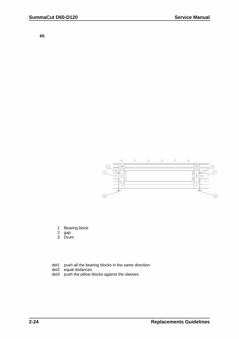
1 Bearing block2 gap3 Drum
det1 push all the bearing blocks in the same directiondet2 equal distancesdet3 push the pillow blocks against the sleeves
Service Manual SummaCut D60-D120
2.14. 2.15. REPLACING THE DRIVE DRUM
To replace the drive drum, proceed as follows:
1. Remove the left-hand cover (see Chapter 2. 1, Removing the left-hand cover).
2. Turn the unit upside down.
3. Remove the bottom plate (see Chapter 2.3, Removing the bottom plate).
4. Remove the various screws holding the drum sleeves in place. The number of sleeves variesdepending on the cutter type.
5. Remove the three screws holding the X-motor(s) in place and put the motor to the side. It is notnecessary to disconnect the wires connected to the motor. On the D120 remove the 2 X motors.
6. Remove the belt.
7. Loosen the two setscrews holding the drive drum pulley in place.
8. Pull the pulley out to its full extent. The pulley need not be removed from the unit.
9. Remove the drive drum.
61. Note:62. Because all the sleeves of the drive drum are accurately matched, it is notpossible to replace just one sleeve.
To re-install, proceed as follows:
1. Put the drum into the shaft in the correct position. The largest sleeve should be to the side of thekeyboard.
2. Put the screws into the blocks but do not tighten them yet.
63. Note:64. It is very important that the drive drum be stable and stationary to prevent themedia from shifting about. To achieve this, proceed as follows:65. a.Secure the block to the left (or right) of the large sleeve by tightening itsscrews. Make sure the block is positioned perpendicularly over the holes and that thelong sleeve is positioned in the middle of the hole in the base plate.66. b.Press the block situatedto the right (or left) of the large sleeve firmly againstthe sleeve and tighten the screws of the block.
3. Now firmly tighten the screws of the other blocks. Make sure they are positioned straight and thatthey do not have any play. Gently press the blocks against the sleeves when tightening thescrews.
4. Thoroughly clean the strip slot.
5. Push the pulley back into its place.
Replacement Guidelines 2-25
SummaCut D60-D120 Service Manual
67. Note:68. Make sure the setscrew is positioned correctly so that it locks itself into theslot.
6. Firmly tighten the screws of the drive drum pulley.
7. Put the belt back into its original position.
8. Re-install the X-motor. Make sure to properly tighten all screws.
9. Proceed in the reverse order of removal. Make sure to firmly tighten all screws.
69. Caution:70. Make sure the sensor wire does not touch the drive drum. The rotating drummay damage the wire and cause malfunctioning.
71.
2-26 Replacements Guidelines
SECTION 3
MAINTENANCE
The SummaCut D60 and D120 cutter range has a number of sliding surfaces made ofsmooth metals and plastics. They are virtually friction-free and require no lubrication.They will, however, collect dust and lint which may affect the performance of the cutter.Keep the cutter as clean as possible by using a dust cover. When necessary, clean theunit with a soft cloth dampened with isopropyl alcohol or mild detergent. Do not useabrasives.
Maintenance and Cleaning 3-1
SummaCut D60-D120 Service Manual
3.1.
3.2. MAINTENANCE & CLEANING
The SummaCut D60 and D120 has a number of sliding surfaces made of smooth metals andplastics. They are virtually friction-free and require no lubrication. They will, however, collectdust and lint, which may affect the performance of the cutter. Keep the cutter as clean aspossible by using a dust cover. When necessary, clean the unit with a soft cloth dampened withisopropyl alcohol or mild detergent. Do not use abrasives.
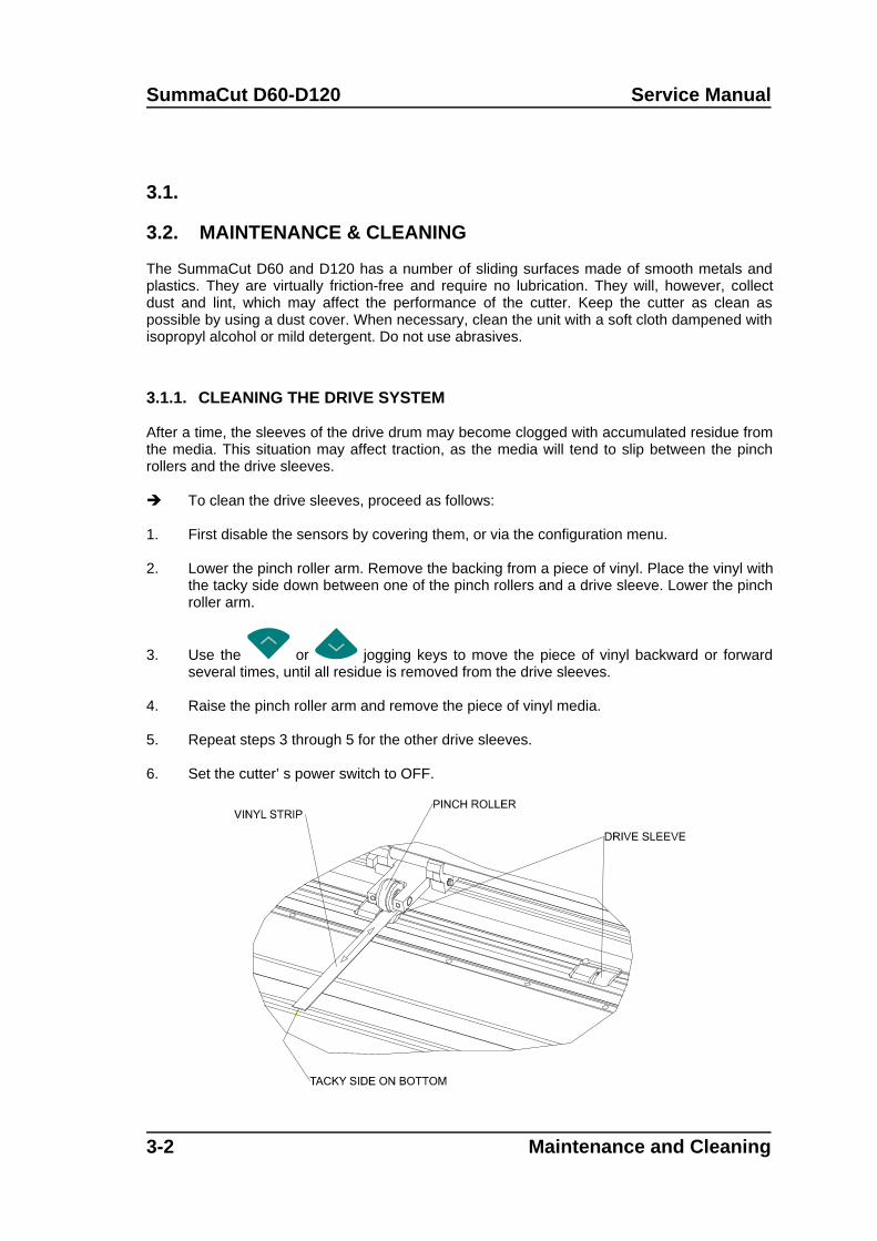
3.1.1. CLEANING THE DRIVE SYSTEM
After a time, the sleeves of the drive drum may become clogged with accumulated residue fromthe media. This situation may affect traction, as the media will tend to slip between the pinchrollers and the drive sleeves.
To clean the drive sleeves, proceed as follows:
1. First disable the sensors by covering them, or via the configuration menu.
2. Lower the pinch roller arm. Remove the backing from a piece of vinyl. Place the vinyl withthe tacky side down between one of the pinch rollers and a drive sleeve. Lower the pinchroller arm.
3. Use the or jogging keys to move the piece of vinyl backward or forwardseveral times, until all residue is removed from the drive sleeves.
4. Raise the pinch roller arm and remove the piece of vinyl media.
5. Repeat steps 3 through 5 for the other drive sleeves.
6. Set the cutter’ s power switch to OFF.
3-2 Maintenance and Cleaning
Service Manual SummaCut D60-D120
CLEANING THE DRIVE SLEEVES
3.1.2. CLEANING THE SENSORS
After a certain time, the sensor may become dirty with accumulated residue from the media.This situation may cause malfunctioning of the cutter.
To clean the sensor area, proceed as follows:
1. The sensor is located on the cutter’ s right side just behind the right big sleeve .
2. To keep the sensor clean, it is sufficient to wipe it out now and then with a cotton swab.
Maintenance and Cleaning 3-3
SummaCut D60-D120 Service Manual
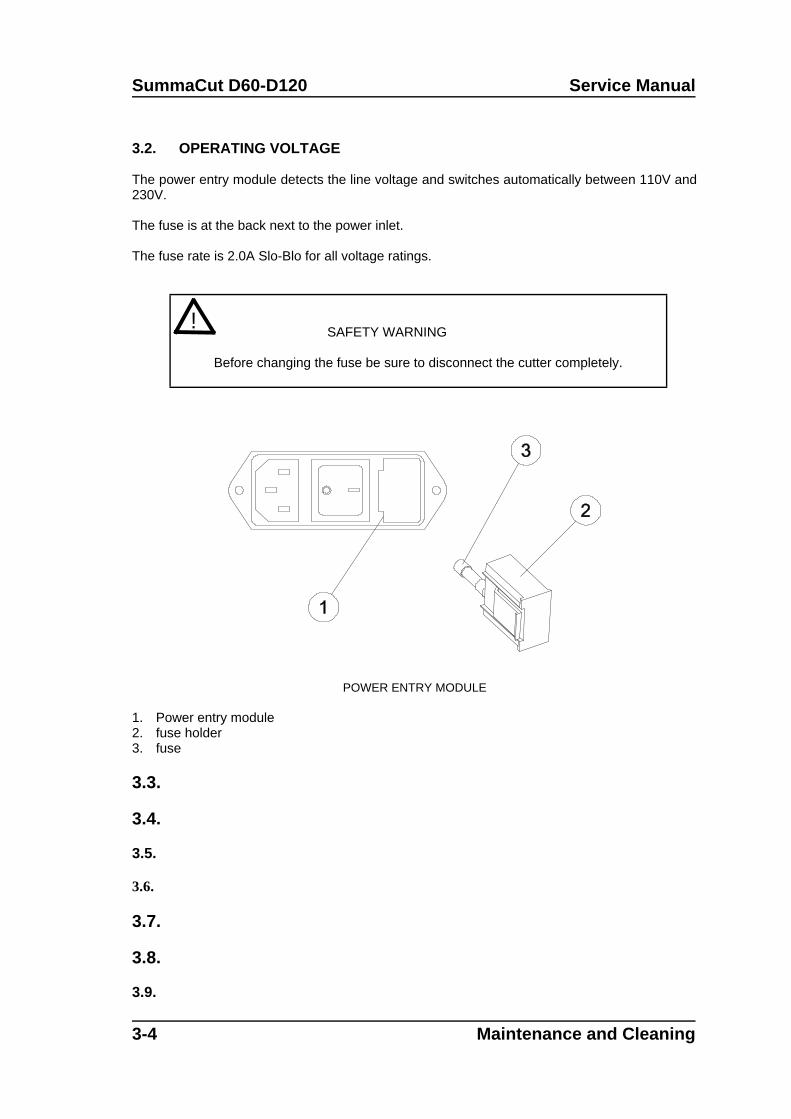
3.2. OPERATING VOLTAGE
The power entry module detects the line voltage and switches automatically between 110V and230V.
The fuse is at the back next to the power inlet.
The fuse rate is 2.0A Slo-Blo for all voltage ratings.
! SAFETY WARNING
Before changing the fuse be sure to disconnect the cutter completely.
POWER ENTRY MODULE
1. Power entry module2. fuse holder3. fuse
3.3.
3.4.
3.5.
3.6.
3.7.
3.8.
3.9.
3-4 Maintenance and Cleaning
Service Manual SummaCut D60-D120
3.10.
3.11.
3.12.
3.13.
3.14.
3.15.
3.16.
3.17.
3.18.
3.19.
3.20.
3.21.
3.22.
3.23.
3.24.
3.25.
3.26.
Maintenance and Cleaning 3-5
SummaCut D60-D120 Service Manual
3.27.
3.28.
3.29.
3.30.
3.31.
3.32.
3.33.
3.34.
3.35.
3.36.
3.37.
3.38.
3-6 Maintenance and Cleaning
Service Manual SummaCut D60-D120
3.39.
3.40.
3.41.
Maintenance and Cleaning 3-7
SummaCut D60-D120 Service Manual
3.42.
3.43.
3.44.
3.45.
3.46.
3.47.
3.48.
3.49.
3.50.
3.51.
3.52.
3-8 Maintenance and Cleaning
Service Manual SummaCut D60-D120
3.53.
3.54.
Maintenance and Cleaning 3-9
SECTION 4
Calibration
General
This section contains information on the calibration of replaced parts and on the recalibrationof worn down parts. Each time a unit is serviced, check this section to see which calibrationhas to be or can be done.
Calibration 4-1
SummaCut D60-120 Service Manual
4.1.
1.
1.2.
3.4.
5.6.
4-2 Calibration
Service Manual SummaCut D60-120
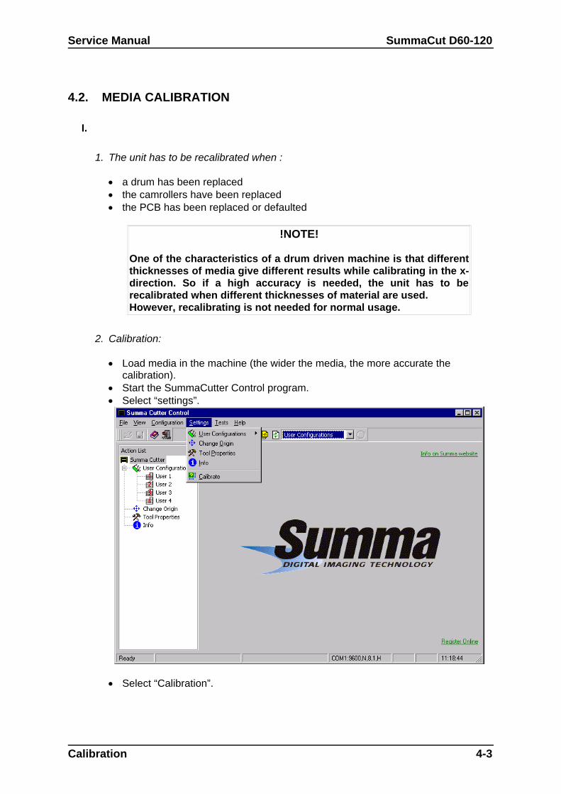
4.2. MEDIA CALIBRATION
I.
1. The unit has to be recalibrated when :
a drum has been replaced the camrollers have been replaced the PCB has been replaced or defaulted
!NOTE!
One of the characteristics of a drum driven machine is that differentthicknesses of media give different results while calibrating in the x-direction. So if a high accuracy is needed, the unit has to berecalibrated when different thicknesses of material are used.However, recalibrating is not needed for normal usage.
2. Calibration:
Load media in the machine (the wider the media, the more accurate thecalibration).
Start the SummaCutter Control program. Select “settings”.
Select “Calibration”.
Calibration 4-3
SummaCut D60-120 Service Manual
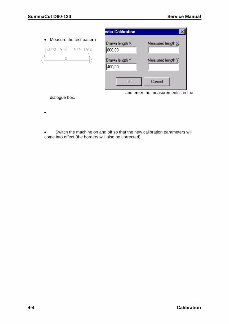
Measure the test pattern
and enter the measurementsit in thedialogue box.
Switch the machine on and off so that the new calibration parameters willcome into effect (the borders will also be corrected).
4-4 Calibration

Service Manual SummaCut D60-120
Calibration 4-5
SummaCut D60-120 Service Manual
II.
1.
2.
4.3. HEAD CALIBRATION
4-6 Calibration
Service Manual SummaCut D60-120
4.4.
I. KNIFE CALIBRATION ( offset)
It is recommended to recalibrate the knife each time it is changed. See section1.2.4. for the calibration procedure.
II. COIL CALIBRATION
1. The coil has to be recalibrated when:
the head is changed the PCB is changed when the cut quality is dubious
2. Calibration:
Power the machine up when there is no media loaded and while the knife isturned up and the camrollers are down for smallest media.
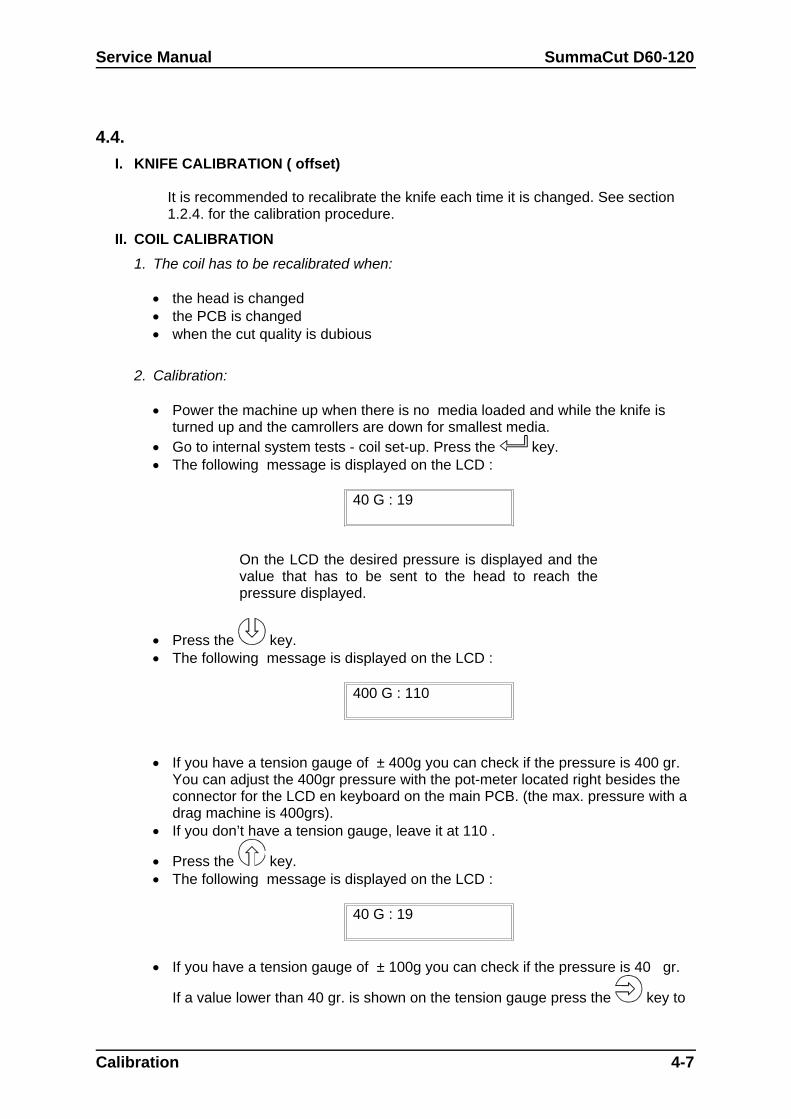
Go to internal system tests - coil set-up. Press the key. The following message is displayed on the LCD :
40 G : 19
On the LCD the desired pressure is displayed and thevalue that has to be sent to the head to reach thepressure displayed.
Press the key. The following message is displayed on the LCD :
400 G : 110
If you have a tension gauge of ± 400g you can check if the pressure is 400 gr.You can adjust the 400gr pressure with the pot-meter located right besides theconnector for the LCD en keyboard on the main PCB. (the max. pressure with adrag machine is 400grs).
If you don’t have a tension gauge, leave it at 110 .
Press the key. The following message is displayed on the LCD :
40 G : 19
If you have a tension gauge of ± 100g you can check if the pressure is 40 gr.
If a value lower than 40 gr. is shown on the tension gauge press the key to
Calibration 4-7
SummaCut D60-120 Service Manual
adjust. If a value higher then than 40 gr. is recorded on the tension gauge use
the key to adjust. If you don’t have a tension gauge leave it at 19.
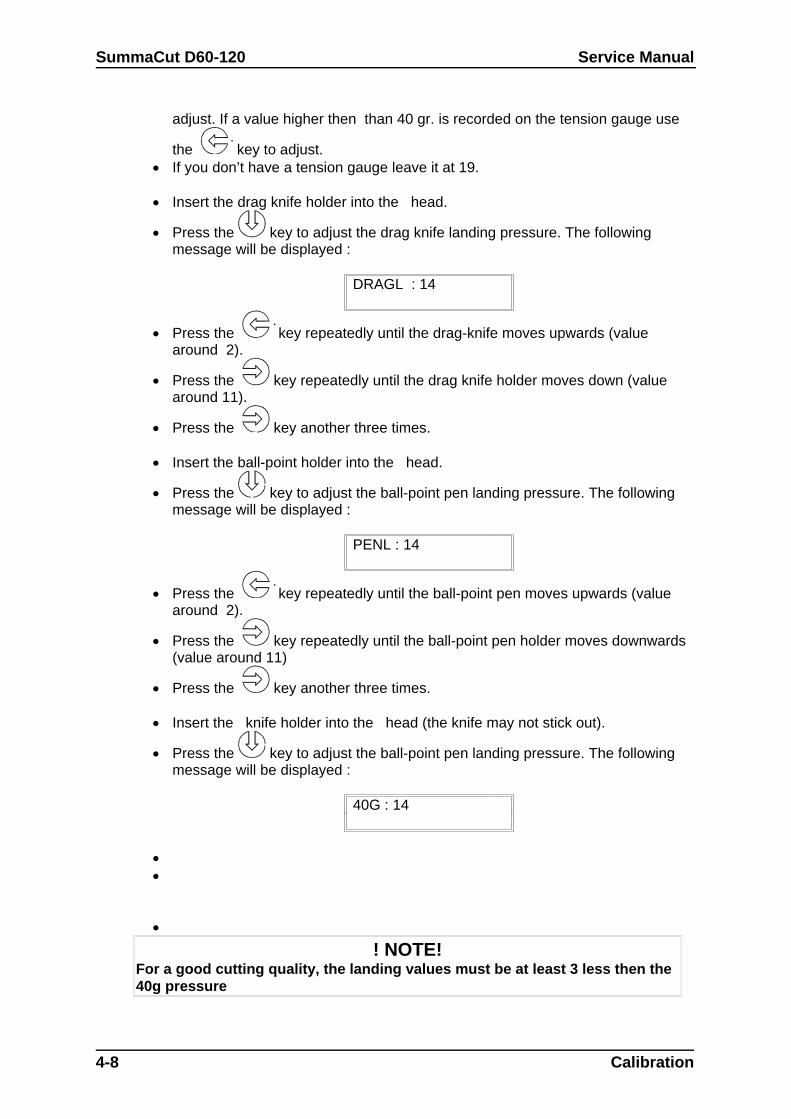
Insert the drag knife holder into the head.
Press the key to adjust the drag knife landing pressure. The followingmessage will be displayed :
DRAGL : 14
Press the key repeatedly until the drag-knife moves upwards (valuearound 2).
Press the key repeatedly until the drag knife holder moves down (valuearound 11).
Press the key another three times.
Insert the ball-point holder into the head.
Press the key to adjust the ball-point pen landing pressure. The followingmessage will be displayed :
PENL : 14
Press the key repeatedly until the ball-point pen moves upwards (valuearound 2).
Press the key repeatedly until the ball-point pen holder moves downwards(value around 11)
Press the key another three times.
Insert the knife holder into the head (the knife may not stick out).
Press the key to adjust the ball-point pen landing pressure. The followingmessage will be displayed :
40G : 14
! NOTE!For a good cutting quality, the landing values must be at least 3 less then the40g pressure
4-8 Calibration
Service Manual SummaCut D60-120
4.3. MACHINE TYPE
The machine type has to be reset when:
The pcb has been changed a “special init” has been done
1.Configuration of the pcb:
via keyboard:
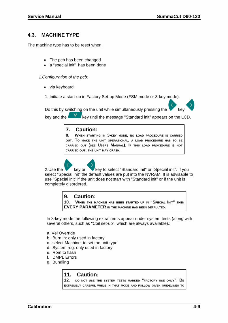
1. Initiate a start-up in Factory Set-up Mode (FSM mode or 3-key mode).
Do this by switching on the unit while simultaneously pressing the key
key and the key until the message "Standard init" appears on the LCD.
7. Caution:8. WHEN STARTING IN 3-KEY MODE, NO LOAD PROCEDURE IS CARRIED
OUT. TO MAKE THE UNIT OPERATIONAL, A LOAD PROCEDURE HAS TO BE
CARRIED OUT (SEE USERS MANUAL). IF THIS LOAD PROCEDURE IS NOT
CARRIED OUT, THE UNIT MAY CRASH.
2.Use the key or key to select "Standard init" or "Special init". If youselect "Special init" the default values are put into the NVRAM. It is advisable touse "Special init" if the unit does not start with "Standard init" or if the unit iscompletely disordered.
9. Caution:10. WHEN THE MACHINE HAS BEEN STARTED UP IN “SPECIAL INIT” THEN
EVERY PARAMETER IN THE MACHINE HAS BEEN DEFAULTED.
In 3-key mode the following extra items appear under system tests (along withseveral others, such as "Coil set-up", which are always available).:
a. Vel Overrideb. Burn in: only used in factoryc. select Machine: to set the unit typed. System reg: only used in factorye. Rom to flashf. DMPL Errorsg. Bundling
11. Caution:12. DO NOT USE THE SYSTEM TESTS MARKED “FACTORY USE ONLY”. BE
EXTREMELY CAREFUL WHILE IN THAT MODE AND FOLLOW GIVEN GUIDELINES TO
Calibration 4-9
SummaCut D60-120 Service Manual
THE LETTER. YOU CAN INFLICT SERIOUS DAMAGE BEYOND REPAIR TO THE
MACHINE IF THE WRONG PARAMETERS ARE CHANGED.
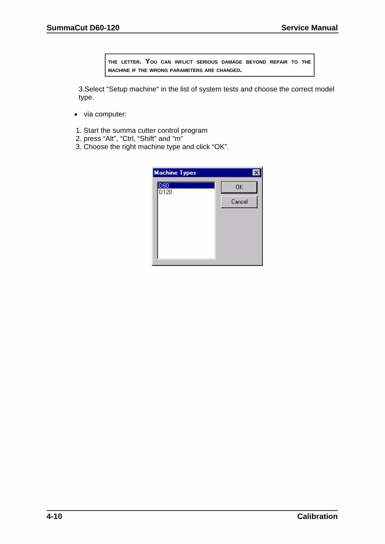
3.Select "Setup machine" in the list of system tests and choose the correct modeltype.
via computer:
1. Start the summa cutter control program2. press “Alt”, “Ctrl, “Shift” and “m”3. Choose the right machine type and click “OK”.
4-10 Calibration

Service Manual SummaCut D60-120
4.5.
4.6.
4.7.
I.
4. Press the
Press the
Weed carefully with tweezers the rectangle cut and press the
Calibration 4-11
SummaCut D60-120 Service Manual
4.8. SENSOR TEST
4.9.
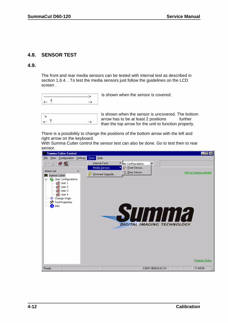
The front and rear media sensors can be tested with internal test as described insection 1.6.4. . To test the media sensors just follow the guidelines on the LCDscreen .
is shown when the sensor is covered.
is shown when the sensor is uncovered. The bottomarrow has to be at least 2 positions furtherthan the top arrow for the unit to function properly.
There is a possibility to change the positions of the bottom arrow with the left andright arrow on the keyboard.With Summa Cutter control the sensor test can also be done. Go to test then to rearsensor.
4-12 Calibration
-------------------------------->
>
Service Manual SummaCut D60-120
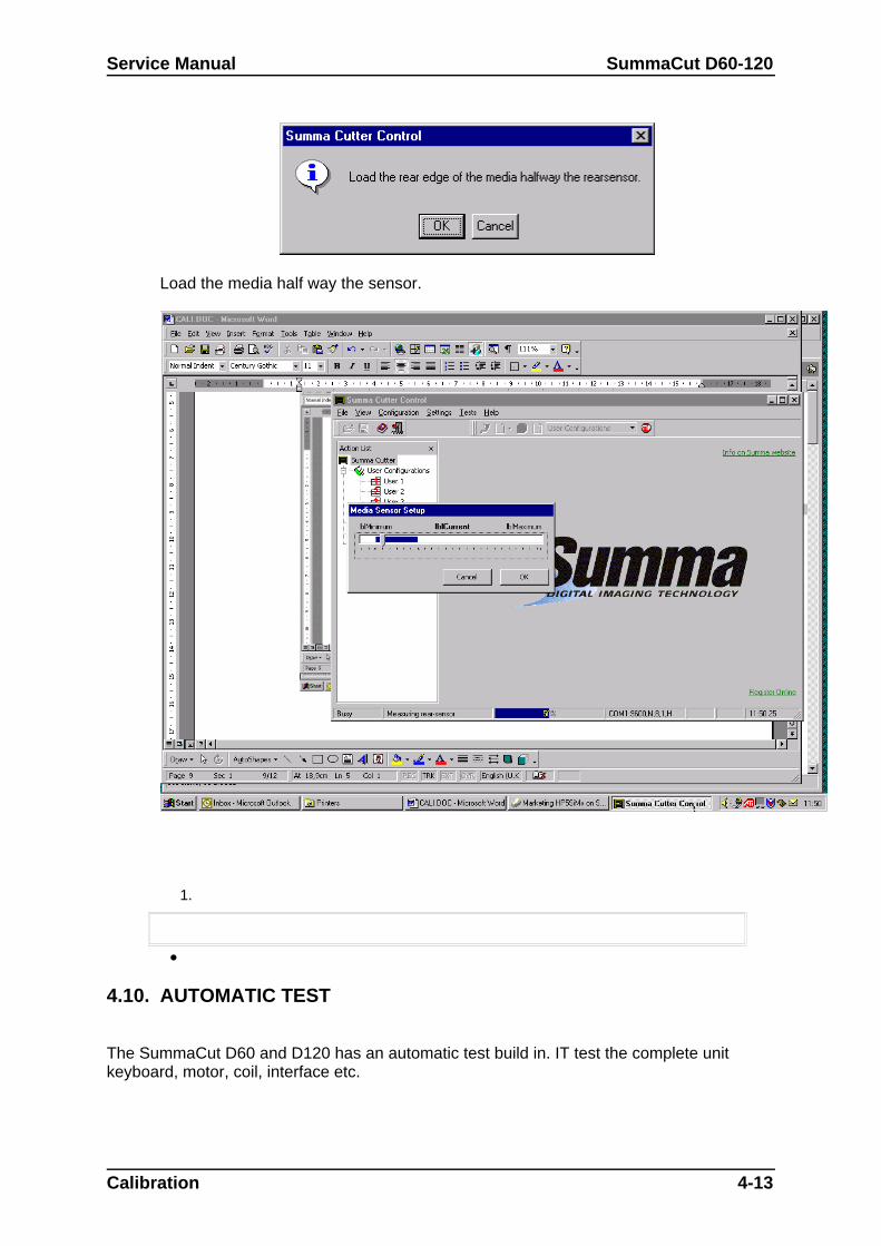
Load the media half way the sensor.
1.
4.10. AUTOMATIC TEST
The SummaCut D60 and D120 has an automatic test build in. IT test the complete unitkeyboard, motor, coil, interface etc.
Calibration 4-13
SummaCut D60-120 Service Manual
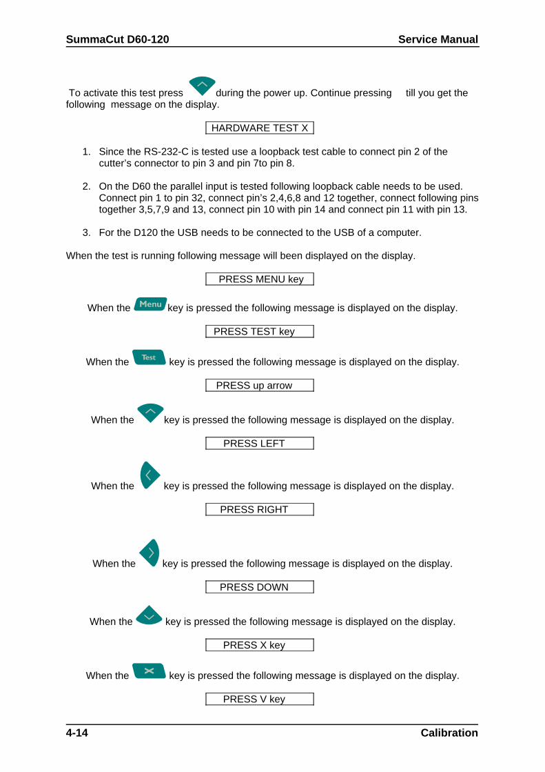
To activate this test press during the power up. Continue pressing till you get thefollowing message on the display.
HARDWARE TEST X
1. Since the RS-232-C is tested use a loopback test cable to connect pin 2 of thecutter’s connector to pin 3 and pin 7to pin 8.
2. On the D60 the parallel input is tested following loopback cable needs to be used.Connect pin 1 to pin 32, connect pin’s 2,4,6,8 and 12 together, connect following pinstogether 3,5,7,9 and 13, connect pin 10 with pin 14 and connect pin 11 with pin 13.
3. For the D120 the USB needs to be connected to the USB of a computer.
When the test is running following message will been displayed on the display.
PRESS MENU key
When the key is pressed the following message is displayed on the display.
PRESS TEST key
When the key is pressed the following message is displayed on the display.
PRESS up arrow
When the key is pressed the following message is displayed on the display.
PRESS LEFT
When the key is pressed the following message is displayed on the display.
PRESS RIGHT
When the key is pressed the following message is displayed on the display.
PRESS DOWN
When the key is pressed the following message is displayed on the display.
PRESS X key
When the key is pressed the following message is displayed on the display.
PRESS V key
4-14 Calibration
Service Manual SummaCut D60-120
When the key is pressed the following message is displayed on the display.
OPEN CAM SWITCH
When the handle is opened the following message is displayed and the cam switch is tested.
CLOSE CAM SWITCH
When the handle is closed the following message is displayed .
DAC TEST
At this moment the cutter is testing the DAC.
COIL TEST
During this moment the coil is tested.
MOTOR TEST
The X and the Y motor are moving and the motors are tested.
X2 TEST
This test is only possible with the D120 and not with the D60.
When pressing the or the additional motor in the X axis is rotating and tested to
continuing the test press . Then following message will be displayed.
cover back sensor
When the sensor is activated the sensor is tested and following message will be displayed.
Baud rate 2400
Be sure that the plotter has a loop installed on the RS-232-C connector. If this loop is notconnected the plotter will display an RS-232-C error. When the loop back is installed all the
different Baud rates will be displayed and tested. When the test was successful following message will be displayed on the D60 with a Parallel
port.
RAR. TEST
When the connections are been made on the parallel port this port will be tested.
On the D120 with the USB port following message will be displayed.
USB TEST
When the cutter is connected with a USB port on the computer the USB port will be tested.When the test was successful the following message will be diplayed.
Calibration 4-15
SummaCut D60-120 Service Manual
USB TEST PASSED
13.
4-16 Calibration
SECTION 5
Troubleshooting - Error codes
General
This section contains information on the error codes which can appear on the LCD screen. Astep-by-step procedure is provided in this section to prevent this error.
Troubleshooting-Error Codes 5-1
SummaCut D60-D120 Service Manual
5.1. ERROR IN X-AXIS
Cause:
The drum motor cannot move to the required position. This is a fatal error. It can only besolved by turning the power off and then on again. This error is usually caused by a mediacrash in the machine.
Action:
1. Remove the crashed media and restart the machine. Should this happen ratherfrequently, the cause can be :
knife depth or pressure is not well set. bad tracking because an unstabilised media type is used. bad tracking because the humidity is too high or too low. bad tracking because an unapproved type of media is used. the media hit something on the floor while cutting. the media shows already different tracks, so that the media does not know
which track to follow.2. Lower the speed of the media.3. Check whether the drive drum turns smoothly (first turn the power off and place the
cam rollers in the up-position).4. If the error in the x-axis happens at start-up, check the x-axis motor, the encoder
connectors and the cables.5. Replace the X-motor encoder.6. Replace the PCB.
5-2 Troubleshooting-Error Codes
Service Manual SummaSign
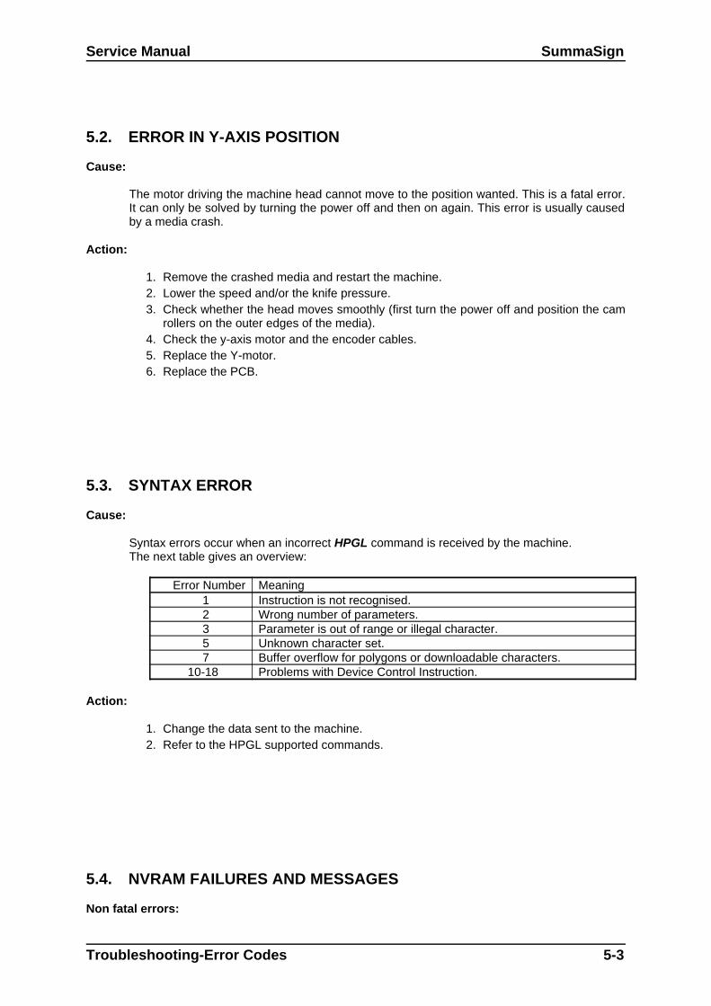
5.2. ERROR IN Y-AXIS POSITION
Cause:
The motor driving the machine head cannot move to the position wanted. This is a fatal error.It can only be solved by turning the power off and then on again. This error is usually causedby a media crash.
Action:
1. Remove the crashed media and restart the machine.2. Lower the speed and/or the knife pressure.3. Check whether the head moves smoothly (first turn the power off and position the cam
rollers on the outer edges of the media).4. Check the y-axis motor and the encoder cables.5. Replace the Y-motor.6. Replace the PCB.
5.3. SYNTAX ERROR
Cause:
Syntax errors occur when an incorrect HPGL command is received by the machine.The next table gives an overview:
Error Number Meaning 1 Instruction is not recognised. 2 Wrong number of parameters. 3 Parameter is out of range or illegal character. 5 Unknown character set. 7 Buffer overflow for polygons or downloadable characters.
10-18 Problems with Device Control Instruction.
Action:
1. Change the data sent to the machine. 2. Refer to the HPGL supported commands.
5.4. NVRAM FAILURES AND MESSAGES
Non fatal errors:
Troubleshooting-Error Codes 5-3
SummaCut D60-D120 Service Manual
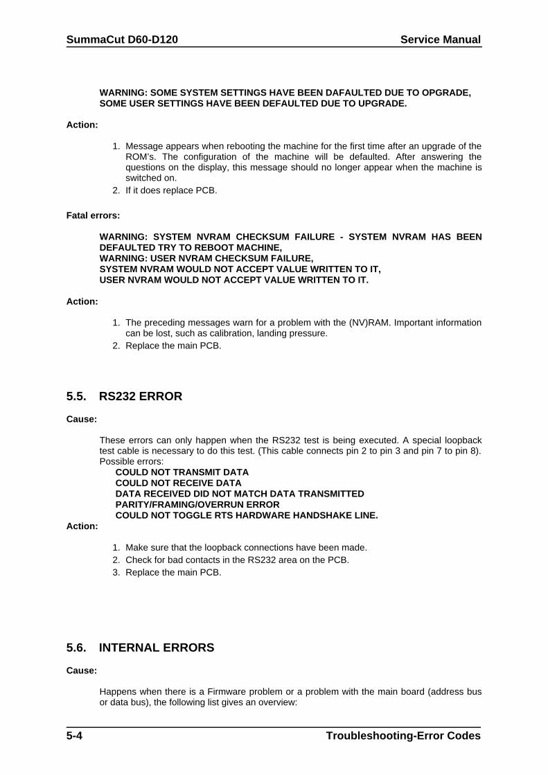
WARNING: SOME SYSTEM SETTINGS HAVE BEEN DAFAULTED DUE TO OPGRADE,SOME USER SETTINGS HAVE BEEN DEFAULTED DUE TO UPGRADE.
Action:
1. Message appears when rebooting the machine for the first time after an upgrade of theROM’s. The configuration of the machine will be defaulted. After answering thequestions on the display, this message should no longer appear when the machine isswitched on.
2. If it does replace PCB.
Fatal errors:
WARNING: SYSTEM NVRAM CHECKSUM FAILURE - SYSTEM NVRAM HAS BEENDEFAULTED TRY TO REBOOT MACHINE,WARNING: USER NVRAM CHECKSUM FAILURE,SYSTEM NVRAM WOULD NOT ACCEPT VALUE WRITTEN TO IT,USER NVRAM WOULD NOT ACCEPT VALUE WRITTEN TO IT.
Action:
1. The preceding messages warn for a problem with the (NV)RAM. Important informationcan be lost, such as calibration, landing pressure.
2. Replace the main PCB.
5.5. RS232 ERROR
Cause:
These errors can only happen when the RS232 test is being executed. A special loopbacktest cable is necessary to do this test. (This cable connects pin 2 to pin 3 and pin 7 to pin 8).Possible errors:
COULD NOT TRANSMIT DATACOULD NOT RECEIVE DATADATA RECEIVED DID NOT MATCH DATA TRANSMITTEDPARITY/FRAMING/OVERRUN ERRORCOULD NOT TOGGLE RTS HARDWARE HANDSHAKE LINE.
Action:
1. Make sure that the loopback connections have been made. 2. Check for bad contacts in the RS232 area on the PCB.3. Replace the main PCB.
5.6. INTERNAL ERRORS
Cause:
Happens when there is a Firmware problem or a problem with the main board (address busor data bus), the following list gives an overview:
5-4 Troubleshooting-Error Codes
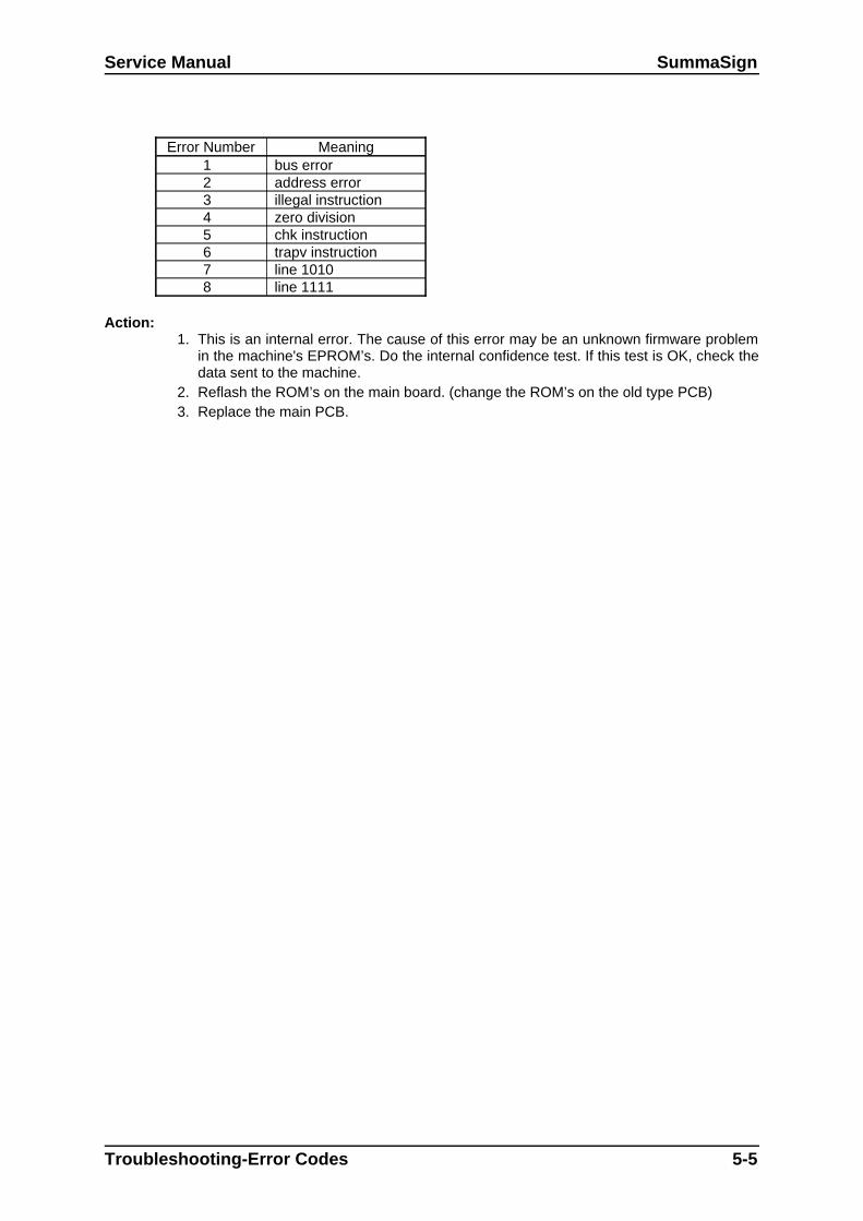
Service Manual SummaSign
Error Number Meaning1 bus error2 address error3 illegal instruction4 zero division5 chk instruction6 trapv instruction7 line 10108 line 1111
Action:1. This is an internal error. The cause of this error may be an unknown firmware problem
in the machine's EPROM’s. Do the internal confidence test. If this test is OK, check thedata sent to the machine.
2. Reflash the ROM’s on the main board. (change the ROM’s on the old type PCB)3. Replace the main PCB.
Troubleshooting-Error Codes 5-5
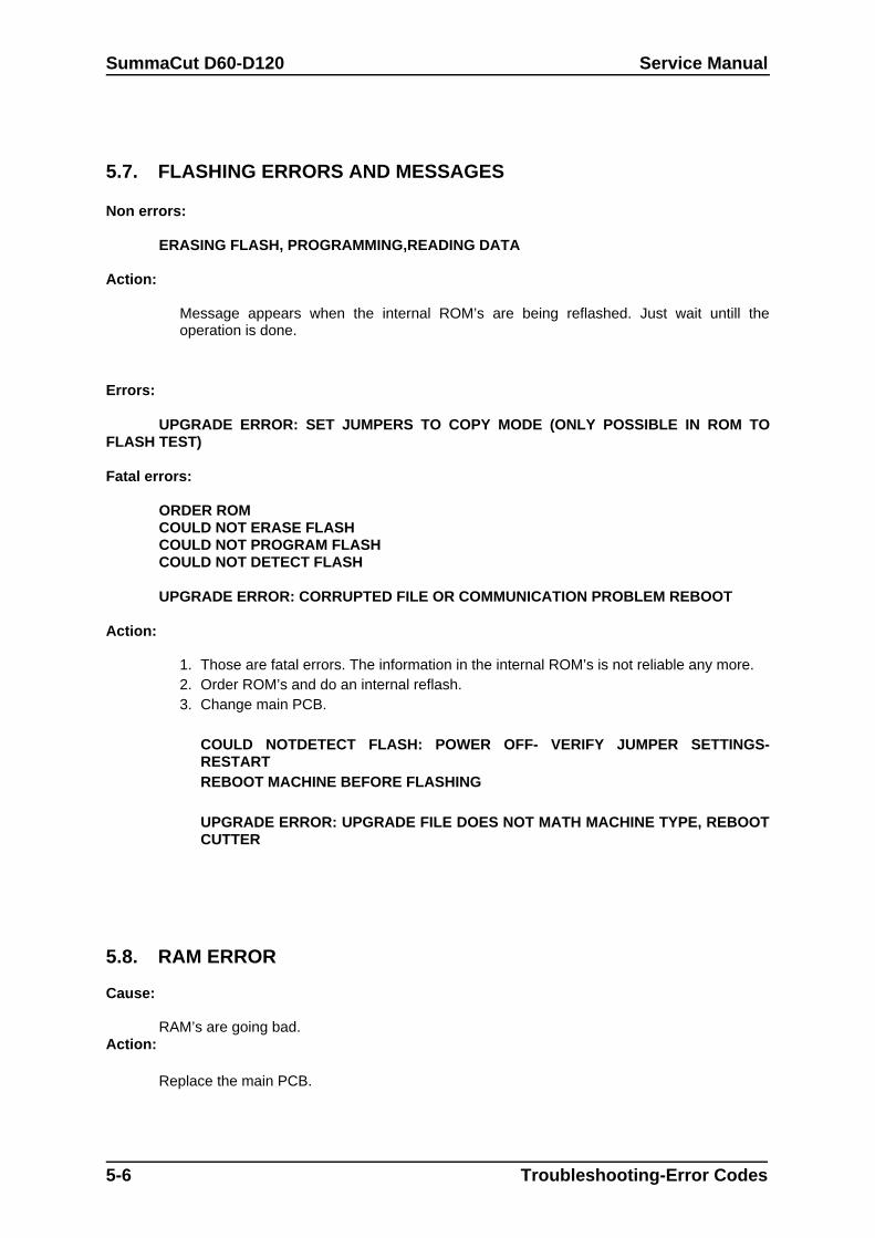
SummaCut D60-D120 Service Manual
5.7. FLASHING ERRORS AND MESSAGES
Non errors:
ERASING FLASH, PROGRAMMING,READING DATA
Action:
Message appears when the internal ROM’s are being reflashed. Just wait untill theoperation is done.
Errors:
UPGRADE ERROR: SET JUMPERS TO COPY MODE (ONLY POSSIBLE IN ROM TOFLASH TEST)
Fatal errors:
ORDER ROMCOULD NOT ERASE FLASH COULD NOT PROGRAM FLASHCOULD NOT DETECT FLASH
UPGRADE ERROR: CORRUPTED FILE OR COMMUNICATION PROBLEM REBOOT
Action:
1. Those are fatal errors. The information in the internal ROM’s is not reliable any more.2. Order ROM’s and do an internal reflash.3. Change main PCB.
COULD NOTDETECT FLASH: POWER OFF- VERIFY JUMPER SETTINGS-RESTARTREBOOT MACHINE BEFORE FLASHING
UPGRADE ERROR: UPGRADE FILE DOES NOT MATH MACHINE TYPE, REBOOTCUTTER
5.8. RAM ERROR
Cause:
RAM’s are going bad.Action:
Replace the main PCB.
5-6 Troubleshooting-Error Codes

Service Manual SummaSign
Troubleshooting-Error Codes 5-7
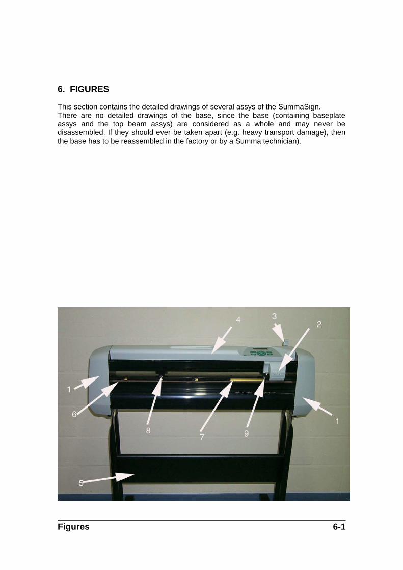
6. FIGURES
This section contains the detailed drawings of several assys of the SummaSign.There are no detailed drawings of the base, since the base (containing baseplateassys and the top beam assys) are considered as a whole and may never bedisassembled. If they should ever be taken apart (e.g. heavy transport damage), thenthe base has to be reassembled in the factory or by a Summa technician).
Figures 6-1
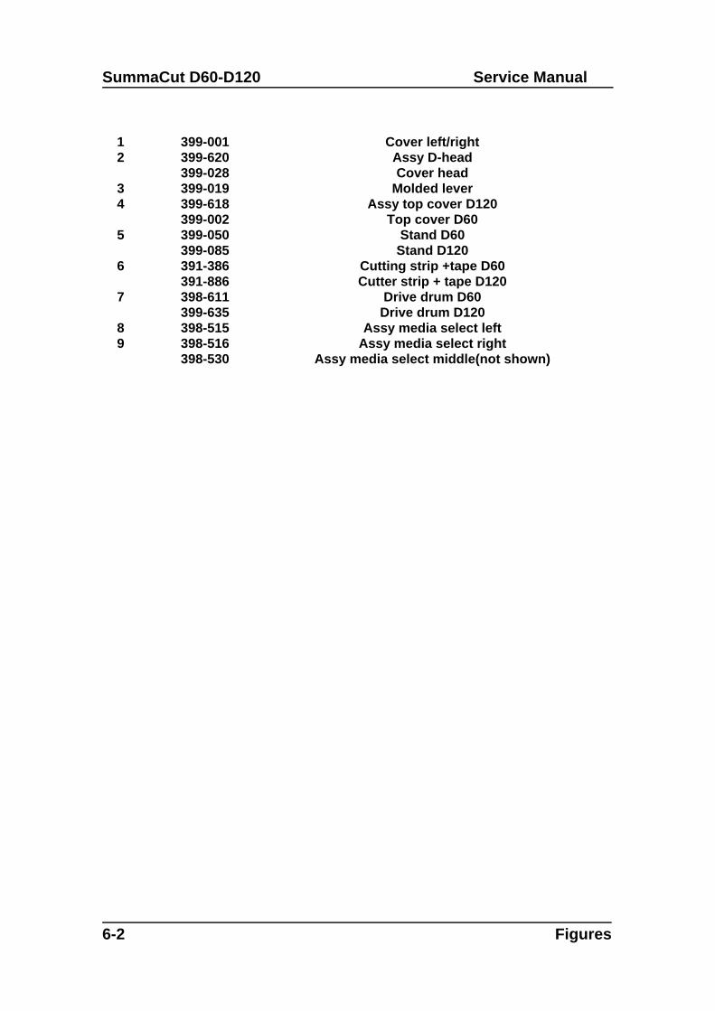
SummaCut D60-D120 Service Manual
1 399-001 Cover left/right2 399-620
399-028Assy D-headCover head
3 399-019 Molded lever4 399-618
399-002Assy top cover D120
Top cover D605 399-050
399-085Stand D60
Stand D1206 391-386
391-886Cutting strip +tape D60Cutter strip + tape D120
7 398-611399-635
Drive drum D60Drive drum D120
8 398-515 Assy media select left9 398-516
398-530Assy media select right
Assy media select middle(not shown)
6-2 Figures
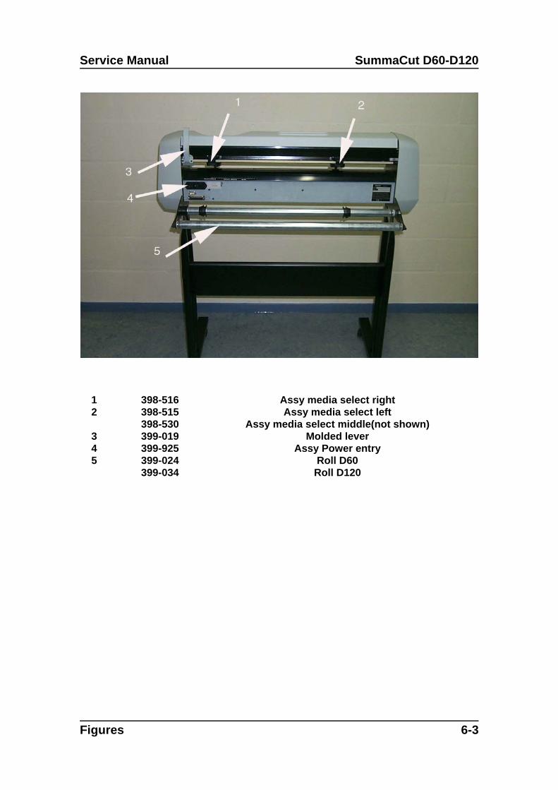
Service Manual SummaCut D60-D120
1 398-516 Assy media select right2 398-515
398-530Assy media select left
Assy media select middle(not shown)3 399-019 Molded lever4 399-925 Assy Power entry5 399-024
399-034Roll D60Roll D120
Figures 6-3
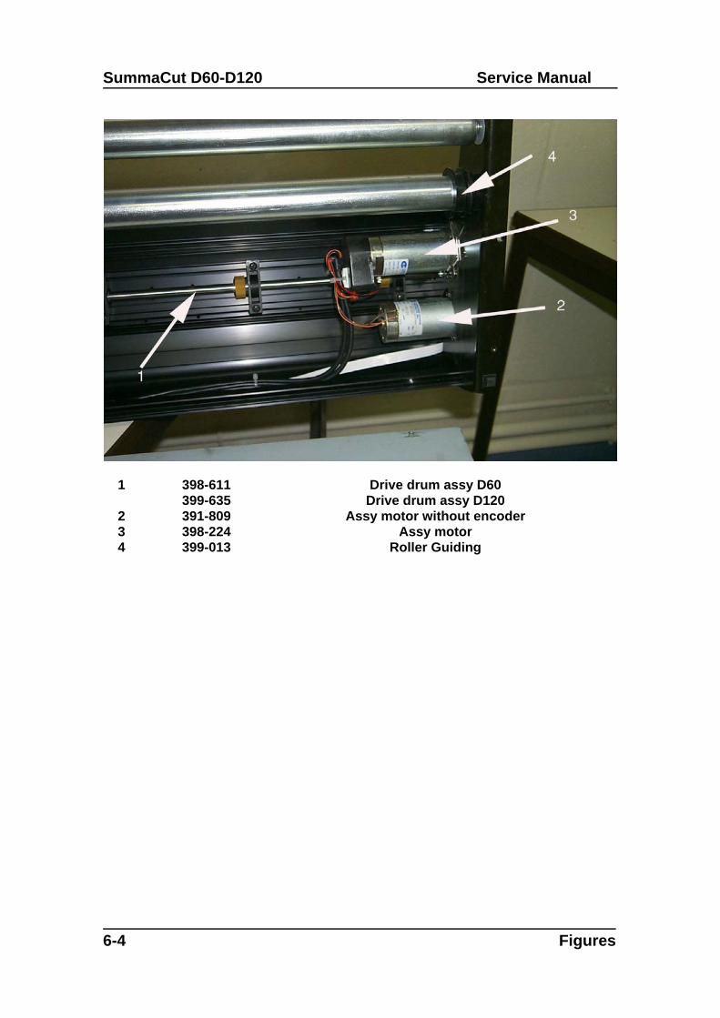
SummaCut D60-D120 Service Manual
1 398-611399-635
Drive drum assy D60Drive drum assy D120
2 391-809 Assy motor without encoder3 398-224 Assy motor4 399-013 Roller Guiding
6-4 Figures
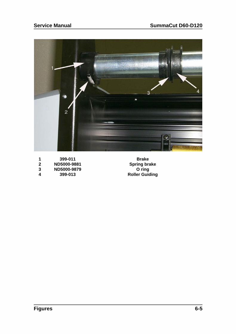
Service Manual SummaCut D60-D120
1 399-011 Brake2 ND5000-9881 Spring brake3 ND5000-9879 O ring4 399-013 Roller Guiding
Figures 6-5
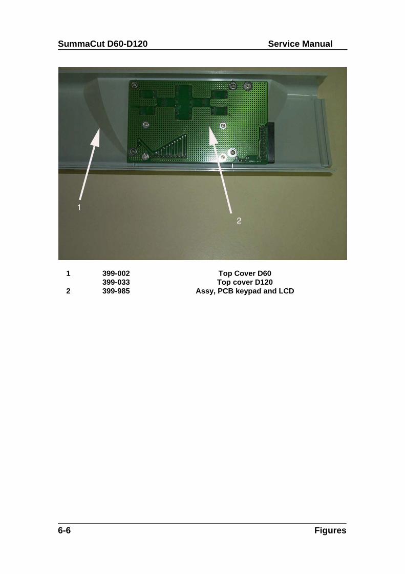
SummaCut D60-D120 Service Manual
1 399-002399-033
Top Cover D60Top cover D120
2 399-985 Assy, PCB keypad and LCD
6-6 Figures
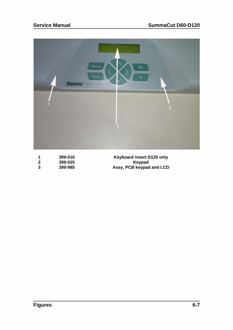
Service Manual SummaCut D60-D120
1 399-016 Keyboard insert D120 only2 399-025 Keypad3 399-985 Assy, PCB keypad and LCD
Figures 6-7
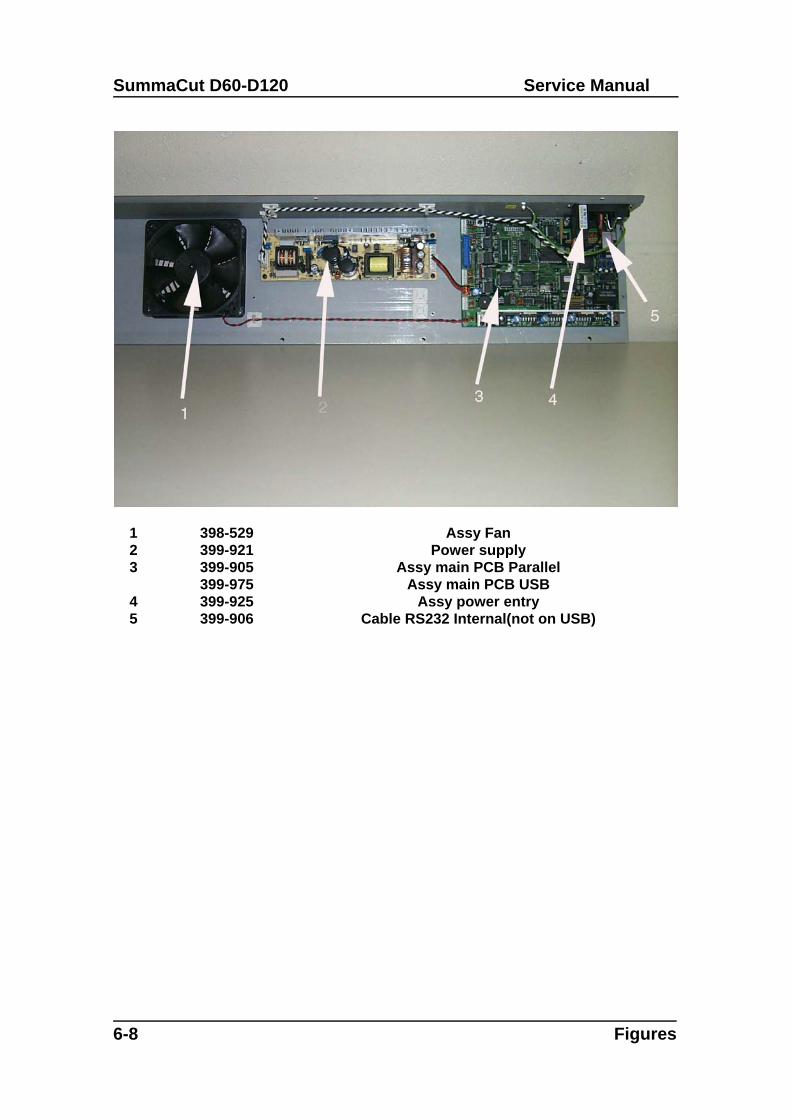
SummaCut D60-D120 Service Manual
1 398-529 Assy Fan2 399-921 Power supply3 399-905
399-975Assy main PCB Parallel
Assy main PCB USB4 399-925 Assy power entry5 399-906 Cable RS232 Internal(not on USB)
6-8 Figures
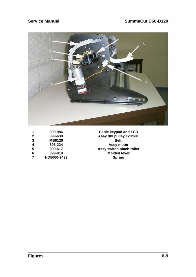
Service Manual SummaCut D60-D120
1 399-986 Cable keypad and LCD2 399-639 Assy dbl pulley 120/60T3 MB9129 Belt 4 398-224 Assy motor5 399-617 Assy switch pinch roller6 399-019 Molded lever7 ND5000-9439 Spring
Figures 6-9
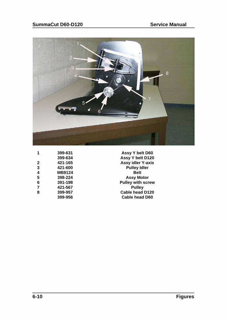
SummaCut D60-D120 Service Manual
1 399-631399-634
Assy Y belt D60Assy Y belt D120
2 421-165 Assy idler Y-axis3 421-600 Pulley Idler4 MB9124 Belt5 398-224 Assy Motor6 391-198 Pulley with screw7 421-567 Pulley8 399-957
399-956Cable head D120Cable head D60
6-10 Figures
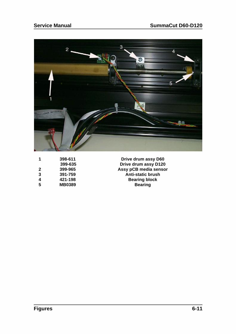
Service Manual SummaCut D60-D120
1 398-611 399-635
Drive drum assy D60Drive drum assy D120
2 399-965 Assy pCB media sensor3 391-759 Anti-static brush4 421-198 Bearing block5 MB0389 Bearing
Figures 6-11
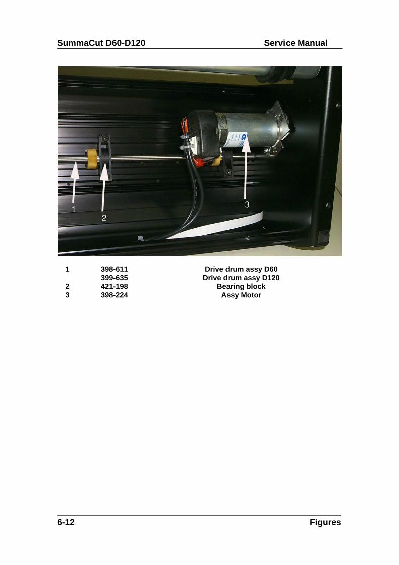
SummaCut D60-D120 Service Manual
1 398-611399-635
Drive drum assy D60Drive drum assy D120
2 421-198 Bearing block3 398-224 Assy Motor
6-12 Figures
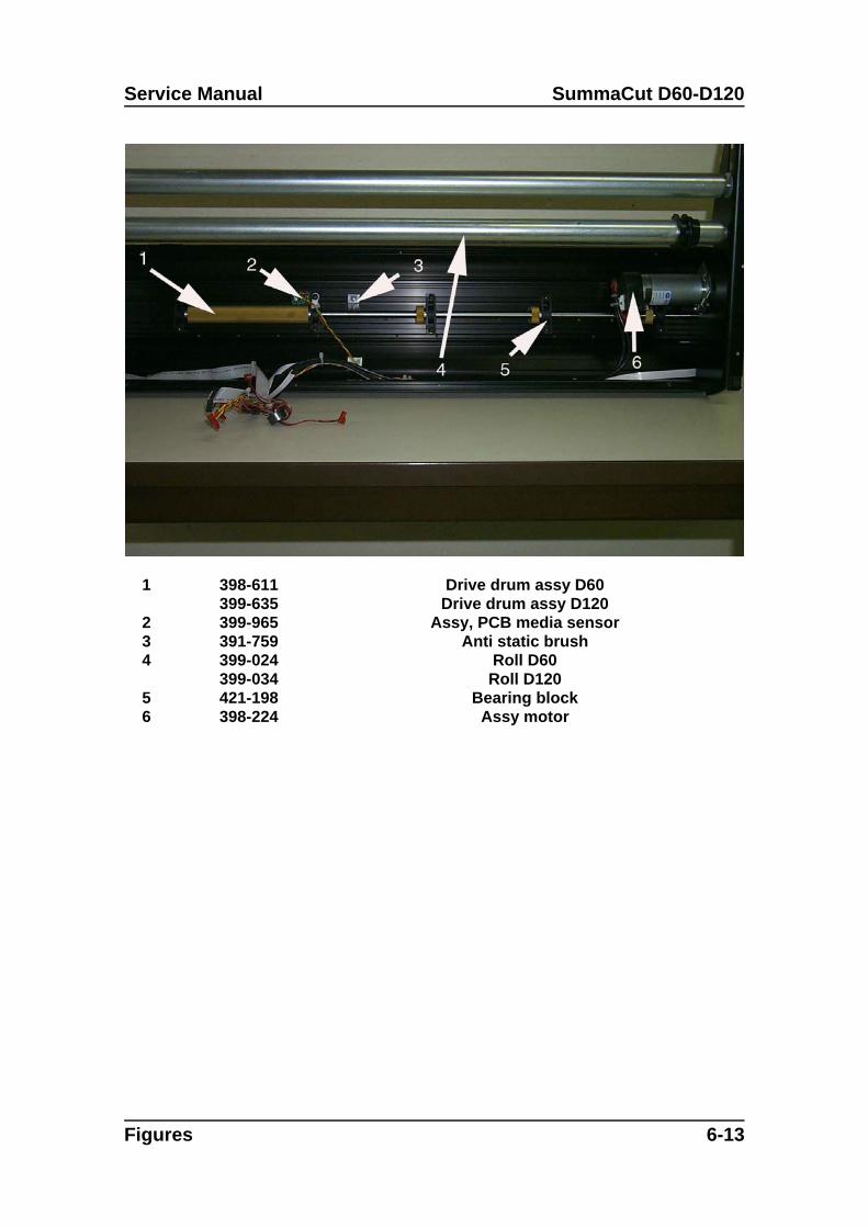
Service Manual SummaCut D60-D120
1 398-611399-635
Drive drum assy D60Drive drum assy D120
2 399-965 Assy, PCB media sensor3 391-759 Anti static brush4 399-024
399-034Roll D60Roll D120
5 421-198 Bearing block6 398-224 Assy motor
Figures 6-13
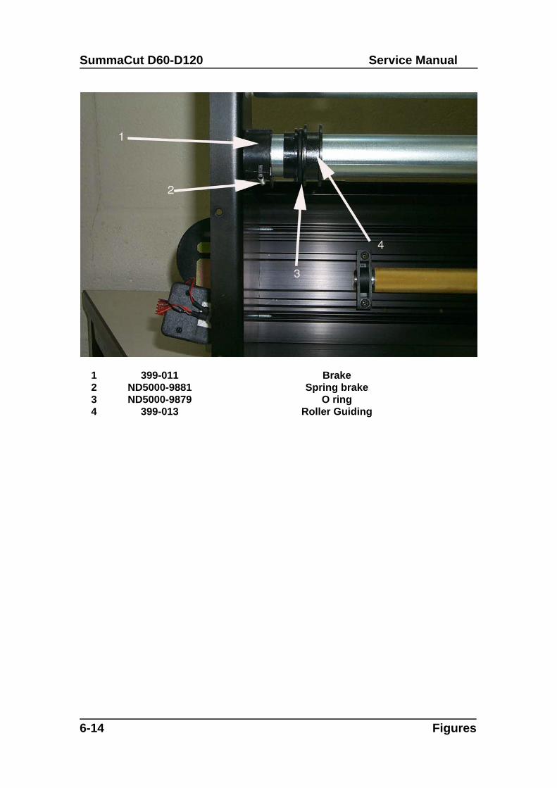
SummaCut D60-D120 Service Manual
1 399-011 Brake2 ND5000-9881 Spring brake3 ND5000-9879 O ring4 399-013 Roller Guiding
6-14 Figures
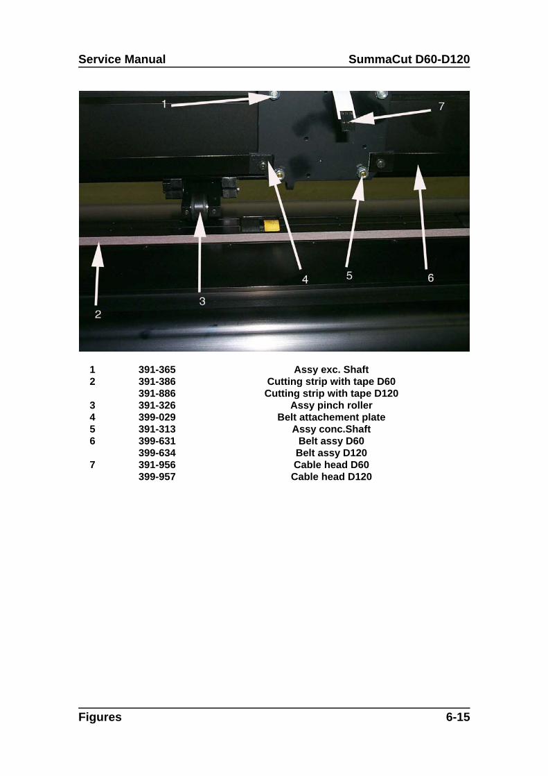
Service Manual SummaCut D60-D120
1 391-365 Assy exc. Shaft2 391-386
391-886Cutting strip with tape D60Cutting strip with tape D120
3 391-326 Assy pinch roller4 399-029 Belt attachement plate5 391-313 Assy conc.Shaft6 399-631
399-634Belt assy D60
Belt assy D1207 391-956
399-957Cable head D60
Cable head D120
Figures 6-15
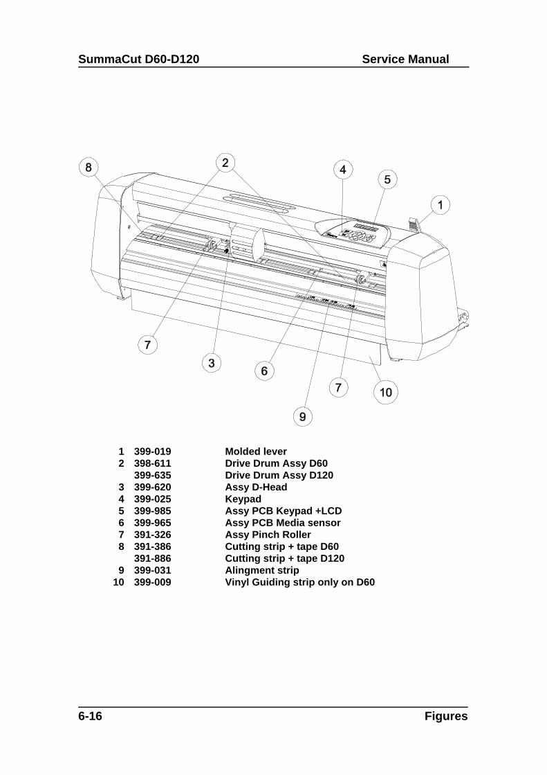
SummaCut D60-D120 Service Manual
6-16 Figures
1 399-019 Molded lever2 398-611
399-635Drive Drum Assy D60Drive Drum Assy D120
3 399-620 Assy D-Head 4 399-025 Keypad5 399-985 Assy PCB Keypad +LCD6 399-965 Assy PCB Media sensor7 391-326 Assy Pinch Roller8 391-386
391-886Cutting strip + tape D60Cutting strip + tape D120
9 399-031 Alingment strip10 399-009 Vinyl Guiding strip only on D60
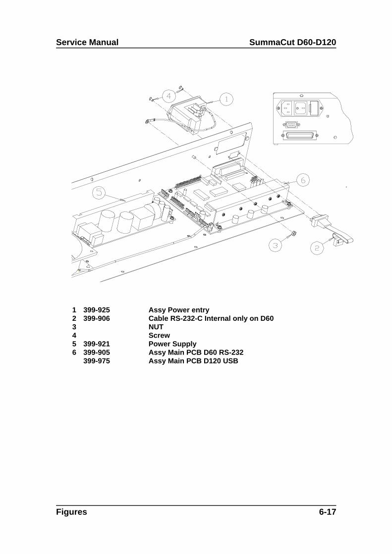
Service Manual SummaCut D60-D120
Figures 6-17
1 399-925 Assy Power entry2 399-906 Cable RS-232-C Internal only on D603 NUT 4 Screw5 399-921 Power Supply6 399-905
399-975Assy Main PCB D60 RS-232Assy Main PCB D120 USB
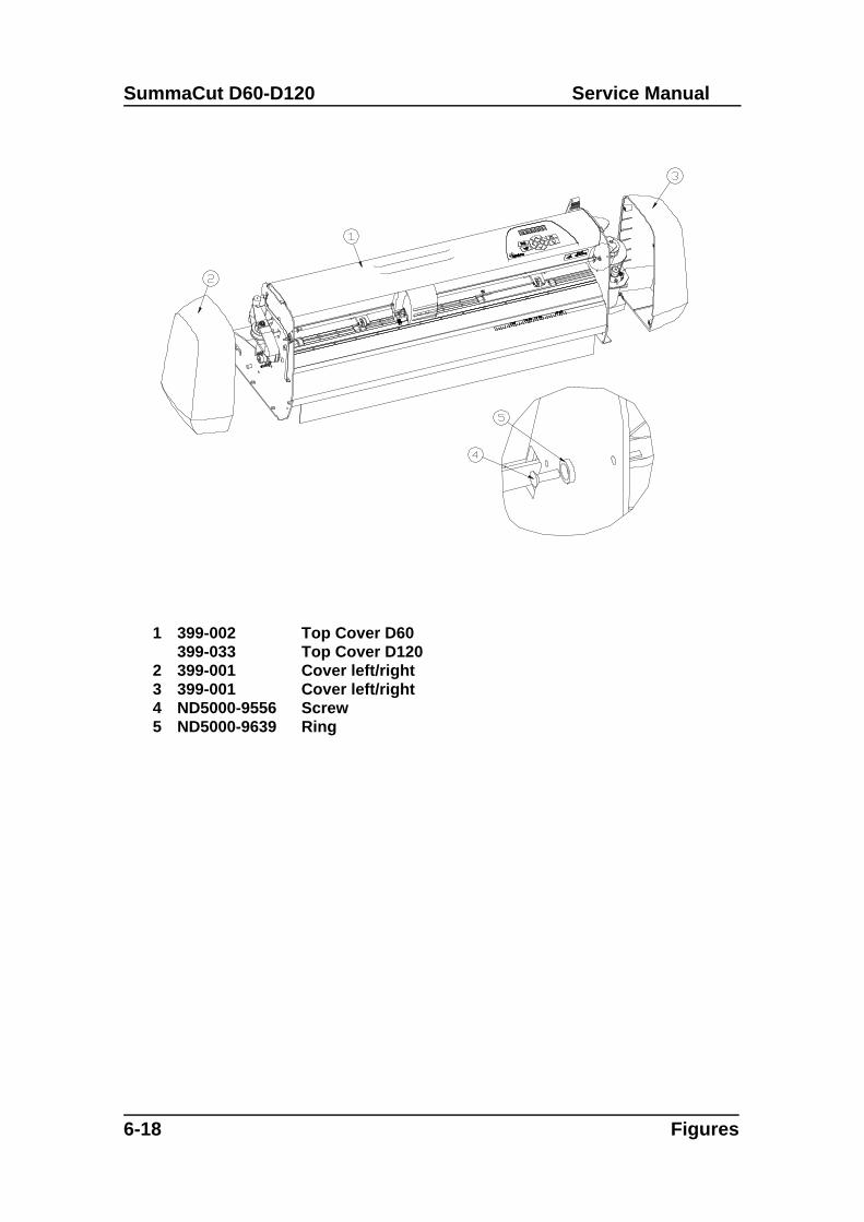
SummaCut D60-D120 Service Manual
6-18 Figures
1 399-002399-033
Top Cover D60Top Cover D120
2 399-001 Cover left/right3 399-001 Cover left/right4 ND5000-9556 Screw5 ND5000-9639 Ring
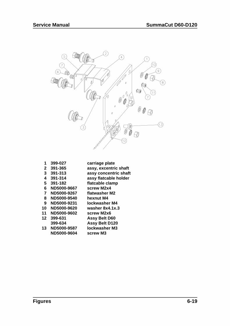
Service Manual SummaCut D60-D120
Figures 6-19
1 399-027 carriage plate 2 391-365 assy, excentric shaft3 391-313 assy concentric shaft4 391-314 assy flatcable holder5 391-182 flatcable clamp6 ND5000-9667 screw M2x4 7 ND5000-9267 flatwasher M28 ND5000-9540 hexnut M49 ND5000-9231 lockwasher M4
10 ND5000-9620 washer 8x4.1x.311 ND5000-9602 screw M2x612 399-631
399-634Assy Belt D60Assy Belt D120
13 ND5000-9587ND5000-9604
lockwasher M3screw M3
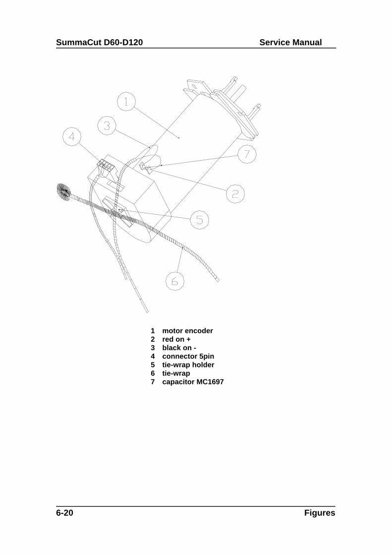
SummaCut D60-D120 Service Manual
6-20 Figures
1 motor encoder2 red on +3 black on -4 connector 5pin5 tie-wrap holder6 tie-wrap7 capacitor MC1697
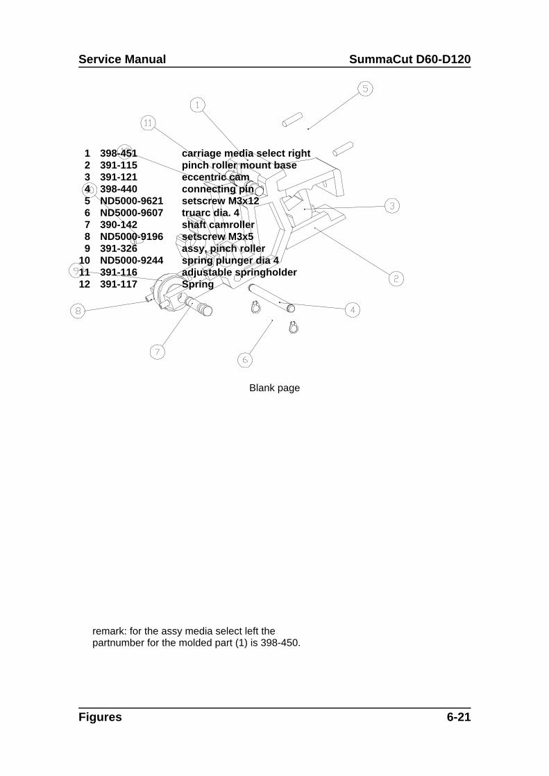
Service Manual SummaCut D60-D120
Figures 6-21
1 398-451 carriage media select right2 391-115 pinch roller mount base3 391-121 eccentric cam4 398-440 connecting pin5 ND5000-9621 setscrew M3x126 ND5000-9607 truarc dia. 47 390-142 shaft camroller8 ND5000-9196 setscrew M3x59 391-326 assy, pinch roller
10 ND5000-9244 spring plunger dia 411 391-116 adjustable springholder12 391-117 Spring
remark: for the assy media select left thepartnumber for the molded part (1) is 398-450.
Blank page
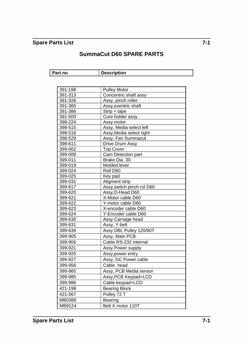
Spare Parts List 7-1
SummaCut D60 SPARE PARTS
Part no Description
391-198 Pulley Motor391-313 Concentric shaft assy391-326 Assy, pinch roller391-365 Assy,exentric shaft391-386 Strip + tape391-500 Core holder assy398-224 Assy motor398-515 Assy, Media select left398-516 Assy,Media select right398-529 Assy, Fan Summacut398-611 Drive Drum Assy399-002 Top Cover399-008 Cam Detection part399-011 Brake Dia .30399-019 Molded lever399-024 Roll D60399-025 Key pad399-031 Aligment strip399-617 Assy,switch pinch rol D60399-620 Assy,D-Head D60399-621 X-Motor cable D60399-622 Y-motor cable D60399-623 X-encoder cable D60399-624 Y-Encoder cable D60399-630 Assy Carriage head399-631 Assy, Y-belt399-639 Assy DBL Pulley 120/60T399-905 Assy, Main PCB399-906 Cable RS-232 internal399-921 Assy Power supply399-925 Assy,power entry399-927 Assy, DC Power cable399-956 Cable head399-965 Assy, PCB Media sensor399-985 Assy,PCB Keypad+LCD399-986 Cable keypad+LCD421-198 Bearing Block421-567 Pulley 72 TMB0389 BearingMB9124 Belt X motor 110T
Spare Parts List 7-1
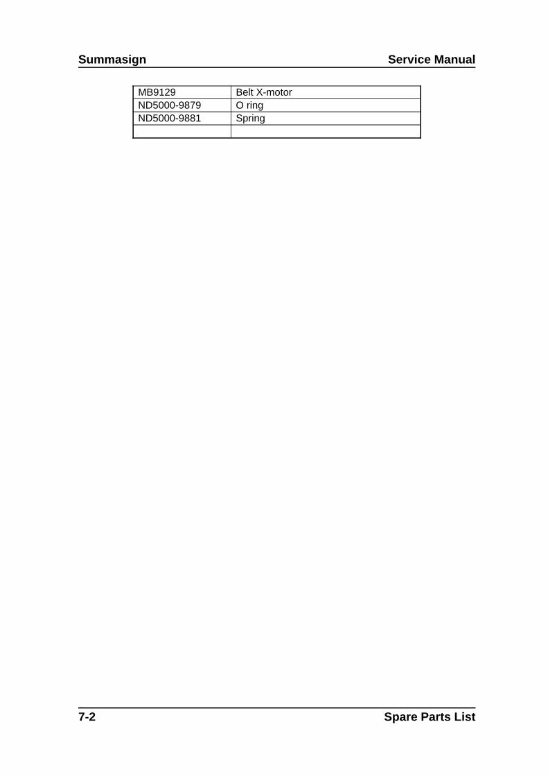
Summasign Service Manual
MB9129 Belt X-motorND5000-9879 O ringND5000-9881 Spring
7-2 Spare Parts List
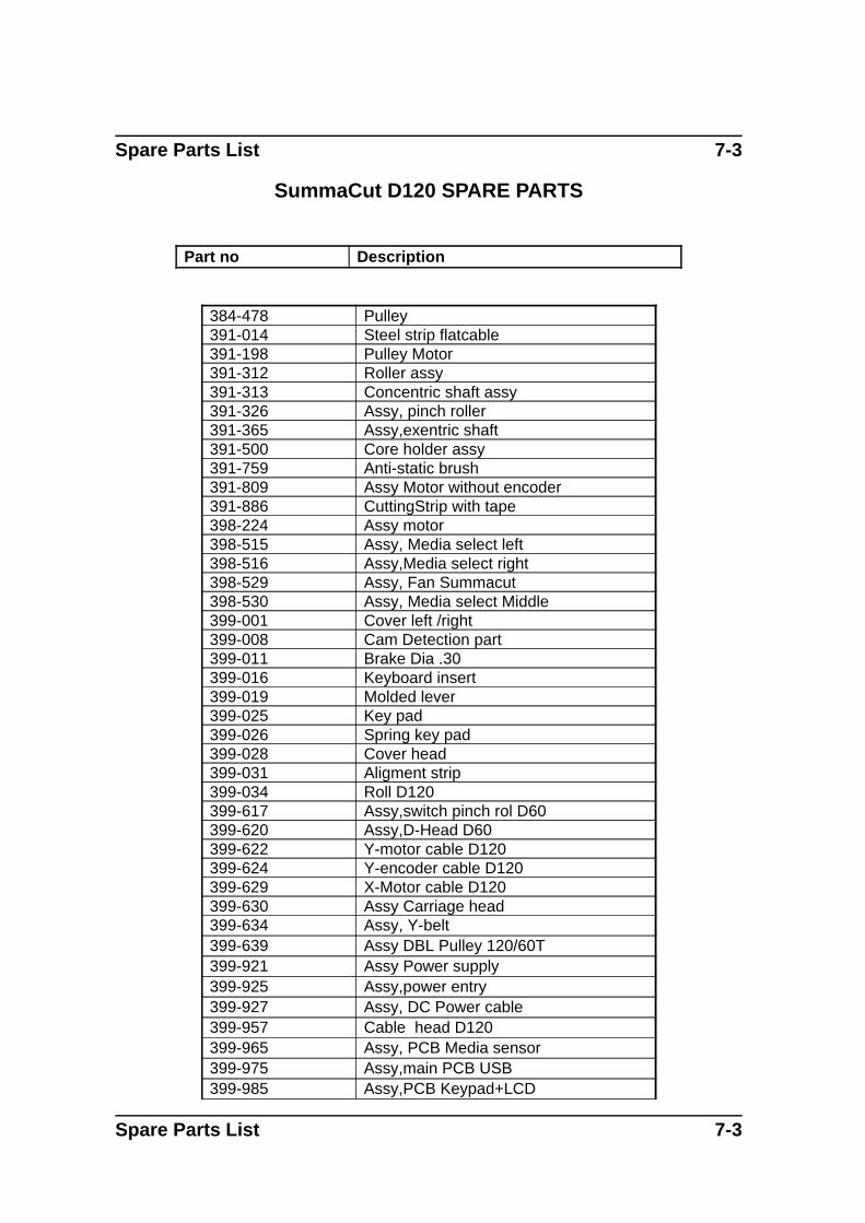
Spare Parts List 7-3
SummaCut D120 SPARE PARTS
Part no Description
384-478 Pulley391-014 Steel strip flatcable391-198 Pulley Motor391-312 Roller assy391-313 Concentric shaft assy391-326 Assy, pinch roller391-365 Assy,exentric shaft391-500 Core holder assy391-759 Anti-static brush391-809 Assy Motor without encoder391-886 CuttingStrip with tape398-224 Assy motor398-515 Assy, Media select left398-516 Assy,Media select right398-529 Assy, Fan Summacut398-530 Assy, Media select Middle399-001 Cover left /right399-008 Cam Detection part399-011 Brake Dia .30399-016 Keyboard insert399-019 Molded lever399-025 Key pad399-026 Spring key pad399-028 Cover head399-031 Aligment strip399-034 Roll D120399-617 Assy,switch pinch rol D60399-620 Assy,D-Head D60399-622 Y-motor cable D120399-624 Y-encoder cable D120399-629 X-Motor cable D120399-630 Assy Carriage head399-634 Assy, Y-belt399-639 Assy DBL Pulley 120/60T399-921 Assy Power supply399-925 Assy,power entry399-927 Assy, DC Power cable399-957 Cable head D120399-965 Assy, PCB Media sensor399-975 Assy,main PCB USB399-985 Assy,PCB Keypad+LCD
Spare Parts List 7-3
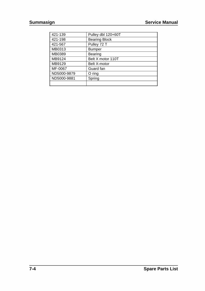
Summasign Service Manual
421-139 Pulley dbl 120+60T421-198 Bearing Block421-567 Pulley 72 TMB0313 BumperMB0389 BearingMB9124 Belt X motor 110TMB9129 Belt X-motorMF-0067 Guard fanND5000-9879 O ringND5000-9881 Spring
7-4 Spare Parts List