SUMMA INSTALLATION MANUAL - Calrec Installation... · Connecting the Surface to the Core 12 Hydra...
96
calrec.com Putting Sound in the Picture Networked Audio Production System SUMMA INSTALLATION MANUAL
Transcript of SUMMA INSTALLATION MANUAL - Calrec Installation... · Connecting the Surface to the Core 12 Hydra...

calrec.com Putting Sound in the Picture
Networked Audio Production System
SUMMA INSTALLATION MANUAL

Calrec Audio LtdNutclough MillHebden BridgeWest YorkshireEngland UKHX7 8EZ
Tel: +44 (0)1422 842159Fax: +44 (0)1422 845244Email: [email protected]
calrec.com
No part of this manual may be reproduced
or transmitted in any form or by any means,
electronic or mechanical, including photocopying
and scanning, for any purpose, without the prior
written consent of Calrec Audio Ltd.
Whilst the Company ensures that all details in this
document are correct at the time of publication,
we reserve the right to alter specifications and
equipment without notice. Any changes we make
will be reflected in subsequent issues of this
document. The latest version will be available
upon request. This publication is for International
usage.
Calrec Audio Ltd reserve the right to change
specifications without notice. E & O.E.
The established policy of Calrec Audio
Ltd. is to seek improvements to the design,
specifications and manufacture of all products.
It is not always possible to provide notice outside
the company of the alterations that take place
continually.
Despite considerable effort to produce up to
date information, no literature published by
the company nor any other material that may
be provided should be regarded as an infallible
guide to the specifications available nor does
it constitute an offer for sale of any particular
product.
Apollo, Artemis, Summa, Brio, RP1, Hydra Audio
Networking and Bluefin High Density Signal
Processing (HDSP) are trade marks of Calrec
Audio Ltd. Dolby®E is a registered trade mark of
Dolby Laboratories, Inc. All other trade marks are
acknowledged.
© 2017 Calrec Audio Ltd. All Rights Reserved.

SUMMACONTENTSInformation� 5Health and Safety 8Package Contents 9
Getting�Started� 11Connecting the Surface to the Core 12Hydra IDs 14
ID configuration 14
Changing an I/O Box’s HID 14
Port Labels and SW-P-08 Settings 14
Duplicate HIDs 14
Spare/Replacement I/O Boxes 14
Setting Hydra IDs for Fixed Format I/O 15Address 2 15
Extended ID Addressing 15
Setting Hydra IDs for Modular I/O 16Connecting I/O to the core 17Hardware Power Connections 19Connecting a Laptop to the Core 20Setting the Date and time 21Configuring LAN Ports 22Upgrading from v2.1 23
Control�Surface� 25Surface Measurements 26Surface components 29Headphone and Talkback Microphone Connections 31
Talkback Mic and Headphone Connections 31
Surface Power Supply Unit 33Connecting the Surface PSU 33
Disconnecting the Surface PSU 33
Power Distribution 33
Surface Button Caps 35
Processing�Core� 37Core Dimensions and Mounting 38
Airflow 38
Support 38
Card types & Layout 39Connections 39
Card layout 39
Installing / removing cards 39
Redundancy 39
Reset & sync interface card 40
Standard status LEDs 40
Control Processor Module 40
DSP 41
Router 41
Power supply 41
Pre-2015 Cores 42Standard status LEDs 42
Obsolete Control Processor 42
Airflow 43
Support 43
Setting Console IDs for 2015 Processing Cores 44Customer ID 44
Core ID 44
Excluded customer IDs 44
Connection�Information� 45Small Form-Factor Pluggable (SFP) Overview 46
SFP slot orientation 46
SFP latching and extraction 46
SFP slot covers 47
Loose SFP storage 47
Copper SFP Connectivity 48Shielded cables and connectors 48
Maximum cable length 48
Cable routing considerations 48
Termination - strain relief 48
Termination - pin-out 49
Testing/certification 49
Temporary / reusable cables 49
Fibre SFP Connectivity 50Singlemode vs Multimode 50
Identification 50
Duplex Connectors / Terminations 50
Single Strand, Bi-Directional SFPs 50
SFP Fibre Specifications 50
Fibre - General Rules 52Testing / Certification 52
Areas of Loss 52

4 SUMM A Networked Audio Production System
Fibre Handling Practise 52
Ruggedised Fibre 52
Cleaning and Preventative Maintenance 52
Cleaning Fibre Optic Cables and Connectors 53
Cleaning Procedure 53
Additional Notes 53
Cleaning Optical Transceivers 53
Cleaning Procedure 53
Synchronisation 54Audio I/O Connections 55
Audio Formats 55
Power 55
ID configuration 55
Modular I/O card slots 55
Hydra2 connection 55
GPIO Connections 58GPI (inputs) 58
GPO (outputs) 58
Dry closure only outputs 58
Connecting to Other Consoles/Routers 62
Remote�Control�and�Production�Automation� 65SW-P-08 Source to Destination Router Remote Control 66
Connection and redundancy 66
Connection configuration 66
SW-P-08 I/O mapping configuration 66
Ember Remote Control 67Remote Control–Calrec Serial Control Protocol 68
CSCP versions 68
Faders controlled by CSCP 68
Controls available via CSCP 68
Connection 68
Secondary connections 68
Multiple consoles 68
Connecting via Corporate LAN 68
Configuration 70
User & boot up enable/disable 70
RS232/422 Serial to TCP/IP Conversion 71Perle IOLAN Configuration 72
Telnet IP configuration 72
Main configuration - Web Manager 73
Setup�-�User�Logging� 77User Control Logging Setup 78
Path Controls Logged 79
User Logs 81
Specifications� 83General Specifications 84Power/Environmental Specifications 85Audio Performance Specification 90Unit List 94Small Parts List 95

calrec.com Putting Sound in the Picture
SUMMAINFORMATION

6 SUMM A Networked Audio Production System Information
Should you require any technical assistance with your Calrec product please contact your regional Calrec distributor. Customers within the UK or Ireland should contact Calrec directly.
For a complete list of worldwide distributors by region, go to www.calrec.com or contact us for more information.
For pre-delivery technical enquiries, UK and Ireland customers should contact the Calrec project manager assigned to their order. Post delivery, the Calrec Customer Support team will take care of your technical enquiries.
Our UK customer support team works closely with our global distributor network to provide the highest level of after sales support. Your distributor should be your first point of contact and will often be able to provide an instant solution, be it technical advice, spares or a site visit by an engineer.
Calrec UK customer support and our global technical team provide free of charge technical support and advice to all customers by phone or e-mail.
Calrec�after�sales�support�includes:• Free of charge comprehensive
technical advice and support by phone and e-mail.
• Repairs.• Quick supply of replacement or loan
hardware in the event of a failure.• Provision of export documentation for
the return of faulty parts.• Operational training.• Maintenance / technical training.• Supply of replacement components.• Supply of documentation.• Service contracts.
We offer a range service contracts to our UK and Ireland customers, from 24/7 telephone support, regular health checks and extended warranty, amongst other benefits. Please contact our customer support team for more information on service contracts.
Product�WarrantyA full list of our conditions and warranties relating to goods services is contained in Calrec’s standard terms and conditions. A copy of this is available on request.
RepairsIf you need to return goods to Calrec for whatever reason, please contact your regional distributor, or Calrec customer support beforehand for guidance, as well as to log the details of the problem and receive a reference number. For customers outside the UK and Ireland, shipping via the distributor saves customers from dealing with exportation paperwork. If there is a need to send direct to Calrec, contact us beforehand to log the incoming repair and for assistance with exportation documents.
Standard�of�ServiceEnsuring the highest standards is a priority, if you have any comments on
the level of service, product quality or documentation offered to you by Calrec, please contact the Calrec Customer Support team in the UK who will endeavour to address your issues. Calrec welcomes all customer feedback.
For feedback specific to this document, please contact [email protected].
Whenever you contact Calrec Customer Support please have the following information to hand:
• Name.• Company.• Email Address.• Full details of enquiry (e.g. fault report).• Serial number of faulty hardware (if
applicable).
Once this information has been provided, a service ticket will be created to log your enquiry. The service ticket reference number will be given via email.
Serial�NumbersAll units produced by Calrec are given a serial number and are booked into a central record system at the time of manufacture. These records are updated whenever a piece of hardware is dispatched to or received from a customer.
When contacting Calrec Customer Support with a hardware inquiry it is important that the correct Calrec serial number is provided to enable the customer support team to provide a high level of service. Summa serial numbers can be found on the label on the rear of the chassis as shown below.
Telephone: (9:00am-5.30pm) +44 (0) 1422 842159
Email - Technical: [email protected]
Email - General: [email protected]
Postal Address:
Calrec Audio Ltd.Nutclough Mill,Hebden Bridge,West Yorkshire,HX7 8EZ,UK
Fax: +44 (0) 1422 842159
Website: www.calrec.comMade in UK by CALREC AUDIO Ltd.
Nutclough Mill, Hebden Bridge, West Yorkshire, HX7 8EZEmail: [email protected] Tel: +44(0)1422 842 159 www.calrec.com
36+8 fader
123456
JAN 2014
100-240V AC ~2.16-1.00A RMS 50/60Hz
This device complies with part 15 of the FCC Rules. Operation is subject to the following two conditions: (1) This device may not cause harmful interference, and (2) this device must accept
interference received, including interference that may cause undesired operation.
WARNING: THIS APPARATUS MUST BE EARTHEDDO NOT RESTRICT VENTILATION HOLES
ENSURE ALL COVERS & SCREWS ARE FITTEDMAX. AMBIENT OPERATING TEMPERATURE 40OC
Laite on liitettävä suojamaadoituskoskettimilla varustettuun pistorasiaan.Apparatet må tilkoples jordet stikkontakt.Apparaten skall anslutas till jordat uttag.
!MODEL:
SERIAL NO:
DATE OF MANUFACTURE:
INPUT RATING(MAX):
S U M M A C A L R E Cby
EXAMPLE OF LABEL ON REAR OF CHASSIS SHOWING SERIAL NUMBER

CA LREC Putting Sound in the Picture 7
After�Sales�ModificationsPlease be aware that any modifications other than those made or approved by Calrec Audio Limited or their agents, may invalidate the console’s warranty. This includes changes to cabling provided by Calrec and variations to the recommended installation as detailed in Calrec documentation.
Modifications to this equipment by any party other than Calrec Audio Limited may invalidate EMC and safety features designed into the equipment. Calrec Audio Limited can not be liable for any legal proceedings or problems that may arise relating to such modifications.
If in doubt, please contact Calrec Audio Limited for guidance prior to commencing any modification work.
InstallationIn many installations the AC power connectors will not be readily accessible, effectively making the equipment permanently connected. The installation should be carried out in accordance with all applicable installation rules and regulations.
Service�PersonnelThe AC power disconnect devices are the 2 x IEC (IEC60320-1 C13/C14) couplers located at the rear of each unit. WARNING: The apparatus has a dual power system. It is essential that BOTH AC power IEC couplers are disconnected to prevent exposure to hazardous voltage within the unit.
Third�Party�EquipmentIntegrating third party equipment into a Calrec system may compromise the product’s ability to comply with the radiated emission limits set in the latest EMC (Electro Magnetic Compatibility) standard.
Calrec Audio Limited can not be responsible for any non-conformities due to use of third party equipment. If in doubt, please contact Calrec Audio Limited for guidance prior to integrating any third party equipment.
ESD�(Static)�Handling�ProceduresIn its completed form, this equipment has been designed to have a high level of immunity to static discharges. However, when handling individual boards and modules, many highly static sensitive parts are exposed. In order to protect these devices from damage and to protect your warranty, please observe static handling procedures, for example, use an appropriately grounded anti-static wrist band. Calrec will supply an electrostatic cord and wrist strap with all of its digital products.
All modules and cards should be returned to Calrec Audio Limited in anti-static wrapping. Calrec Audio Limited can supply anti-static wrapping upon request.
This applies particularly to digital products due to the types of devices and very small geometries used in their fabrication, analogue parts can, however, still be affected.
RoHS�LegislationIn order to comply with European RoHS (Reduction of Hazardous Substances) legislation, Calrec PCB and cable assemblies are produced with lead-free (tin/copper/silver) solder instead of tin/lead solder.
In the unlikely event of a customer having to carry out any re-soldering on Apollo, Artemis or Hydra2 hardware, it is imperative that lead-free solder is used; contaminating lead-free solder with
UKAS AND RAB REGISTRATION
LEAD FREE STICKERLEAD FREE
leaded solder is likely to have an adverse effect on the long-term reliability of the product. Circuit boards assembled with lead-free solder can be identified (in accordance with IPC/JEDEC standards) by a small oval logo (see below) on the top-side of the circuit board near the PCB reference number (8xx-xxx). The same logo is used on the connector hoods of soldered cable assemblies.
If in doubt, please check with a Calrec customer support engineer before carrying out any form of re-soldering
ISO�9001�and�RAB�RegisteredCalrec Audio Ltd has been issued the ISO9001: 2008 standard by the Governing Board of ISOQAR.
The award, for both UKAS and RAB registration (see below), is the most comprehensive of the ISO9000 international standards. Granted in recognition of excellence across design, development, manufacture and after-sales support, the certification follows a rigorous and thorough review of Calrec’s internal and external communication and business procedures.

8 SUMM A Networked Audio Production System Information
HEALTH AND SAFETY
Important�Safety�Instructions:• Read these instructions.• Keep these instructions.• Heed all warnings.• Follow all instructions.• Do not use this apparatus near water.• Do not block any ventilation openings.
Install in accordance with the manufacturer’s instructions.
• Do not install near any heat sources such as radiators, heat registers, stoves, or other apparatus (including amplifiers) that produce heat.
• Protect the power cord from being walked on or pinched particularly at the plugs, convenience receptacles, and the point where they exit from the apparatus.
• Use only with the cart, stand, tripod, bracket, or table specified by the manufacturer, or sold with the apparatus. When a cart is used, use caution when moving the cart/apparatus combination to avoid injury from tip-over.
• Refer all servicing to qualified service personnel. Servicing is required when the apparatus has been damaged in any way, such as power-supply cord or plug is damaged, liquid has been spilled or objects have fallen into the apparatus, the apparatus has been exposed to rain or moisture, does not operator normally, or has been dropped.
• Warning: To reduce the risk of fire or electric shock, do not expose this apparatus to rain or moisture.
• Not intended for outdoor use.• This equipment must be EARTHED. • Before starting any servicing operation,
equipment must be isolated from the AC power supply. The disconnect devices are the 2 x IEC connectors (IEC 60320-1 C13/C14 couplers).
• Do not allow ventilation slots to be blocked.
• Do not leave the equipment powered up with the dust cover fitted.
CleaningFor cleaning the front panels of the equipment we recommend using a soft anti-static cloth, lightly dampened with water if required.
Explanation�of�Warning�SymbolsTriangular warning symbols contain a black symbol on a yellow background, surrounded by a black border.
The lightning flash with arrow head symbol within an equilateral triangle, as shown on this page, is intended to alert the user to the presence of dangerous voltages and energy levels within the product’s enclosure that may be of sufficient magnitude to constitute a risk of electric shock or injury.
The exclamation mark within an equilateral triangle, as shown on this page, is intended to prompt the user to refer to important operating or maintenance instructions in the documentation supplied with the product.
EarthingThis is a Class I product. An Earth connection MUST be provided in each AC power cord.
The Earth Bolt connection at the rear of the console is provided for those users who wish to have a separate ground/earth connection using Earth cable at least 6 mm2 in cross section (10 AWG).
As the Summa surface has very low leakage / touch current power supplies, this connection is optional and is NOT a requirement to comply with safety standards.
Lithium�Battery�Replacement���Caution: Danger of explosion if battery is incorrectly replaced. Replace only with the same or equivalent type. Batteries must not be exposed to excessive heat such as sunshine, fire or the like
This device complies with part 15 of the FCC Rules. Operation is subject to the following two conditions:
1. This device may not cause harmful interference.
2. This device must accept any interference received, including interference that may cause undesired operation.
DANGEROUS VOLTAGES
IMPORTANT INSTRUCTIONS

CA LREC Putting Sound in the Picture 9
PACKAGE CONTENTS
There are a number of options when ordering Summa systems: surface size, connectivity type and I/O options.
Every system includes a control surface and Summa Core processing core. Small format pluggable transceivers (SFPs) are required for both surface to core connections, and Hydra2 I/O box connections and can be provided by Calrec. I/O packages are optional. The following table shows all Summa options:
Surface and Core Packs
Summa Surface
All Summa surfaces have a number of faders, each with dedicated metering and two control cells above, and eight Master section faders. Alps faders are supplied as standard, with Penny and Giles faders available on request. The surface size options are: 12 + 8, 24 + 8 or 36 + 8
Summa comes with CUT button caps fitted for each fader and an equal quantity of ON button caps are also be provided for instances when CUT/ON buttons are switched to ‘ON’ functionality from the user interface. 12 user button caps are fitted, under which customised labels can be inserted.
Summa CorePower, Router, Control Processor, and DSP redundancy is optional for a Summa with 128 channels, and is provided as standard for a Summa with 180 channels.
SFPsOne of the following four options: LX SFP Pack; SX SFP Pack; Bi-Directional SFP Pack; none, you supply your own.
CablingThree 2.4m IEC Y-Cords for supplying power to the surface, the core and the PC. One 2m Ethernet cable to connect the PC to the core.
I/O packs
I/O
One Modular I/O box fitted with the following modules:
2 x Analogue Mic/Line Input (balanced 8 in, 37-way D-type)—AD6057
2 x Analogue Line Output (balanced 8 out, 37-way D-type)—DA5839-3
1 x GPIO (8 in, 16 out, 50-way D-type)—WY5859-3
SFPsOne of the following SFP pack options: LX SFP Pack; SX SFP Pack; Bi-Directional SFP Pack; Copper SFP Pack; none, you supply your own.
Cabling One 2.4 m IEC Y-Cord for supplying power to the Modular I/O Box
SFP Packs
LX SFP Pack 4 x Single Mode SFPs
SX SFP Pack 4 x Multimode SFPs
Bi-Directional SFP Pack 2 x bi-directional SFPs (type A) and two bi-directional SFPs (type B)
Copper SFP Pack 4 x copper SFPs

10 SUMMA Networked Audio Production System

calrec.com Putting Sound in the Picture
SUMMAGETTING STARTED

12 SUMM A Networked Audio Production System Get ting Star ted
CONNECTING THE SURFACE TO THE CORE
The Summa surface requires fibre connections to the core via singlemode or multimode LC SFPs. For a redundant system two connections are required, primary and secondary. In the diagram on the next page the primary connection is the solid line and the secondary connection is the dashed line. If you are running a non-redundant Summa 128, only the primary connection is required and the cards on the right of the core will be replaced by blanking plates.
Calrec do not provide interconnecting fibres/cables, as the length, type and quality will vary for each installation. SFPs can be supplied with your Summa system if specified at the time of order.
SUMMA CONSOLE TO CORE CONNECTIONS
To�Primary�Control�Processor�‘Surface�1’�connection
To�Secondary�Control�Processor�‘Surface�1’�connection
Status�LEDs
To Control Processor
TalkbackMicrophone
Output
HeadphoneInputs
Left Right
1 21
2
For more information on fibre and different connection types please see “Connection Information” on page 45.
The two control surface connections are located on the back panel next to the PSU unit and below the XLR connectors. The left hand SFP, when viewed from the back of the surface, is the primary connection and on the right is the secondary connection.
In the processing core, the left hand Control Processor is the primary, the right hand is the secondary.
A fibre connection should be fitted between the primary surface connection and the primary Control Processor’s
‘Surface 1’ connector. Unless a non-redundant system has been chosen, a backup connection should be fitted between the secondary surface connection and the secondary Control Processor’s ‘Surface 1’ connector for redundancy.
Note, the ‘surface 1’ connection is labelled ‘MAC 7’ on some control processor models.
It is important to ensure that these connections are made correctly - primary to primary, secondary to secondary and using the correct fibre SFPs.

CA LREC Putting Sound in the Picture 13
SUMMA CONSOLE TO CORE CONNECTIONS – 2

14 SUMM A Networked Audio Production System Get ting Star ted
HYDRA IDs
Hydra2 I/O boxes with valid Hydra IDs (HIDs), are automatically detected and added to the Hydra database when first plugged in to the network. This database entry will remain until it is manually deleted via the network management organiser, H2O.
It is important that careful consideration is given to HID settings prior to connecting any I/O boxes to the network, especially if future networking of standalone systems is a possibility.
As an example, consider two Calrec systems, each with several I/O boxes with HIDs starting at ‘1’ and set in ascending numerical order. If you later decide to network these two systems together you will have multiple I/O boxes with the same HIDs on the network.
In this scenario when a Show/Memory containing patches is loaded, there is no way of controlling which patches will be made to which I/O box. Instead we recommend using a separate numbering range for each standalone system so no conflicts can arise in the future.
ID�configurationEach I/O box in a system needs to be given a unique hydra ID (HID), set using DIP switches accessible from the rear of a fixed format box, or on the side of the controller card within a modular I/O box.
I/O box IDs are pre-set to ‘0’ at the Calrec factory to effectively set the boxes into an ‘off’ state to avoid issues in the event of multiple boxes being placed on the network with the same HID.
Before connecting each I/O box to the network ensure you set a unique HID by following the instructions on the following pages.
Note, Some customers may find that their I/O boxes have been pre-configured with unique HIDs at the Calrec factory, prior to dispatch.
Changing�an�I/O�Box’s�HIDIf you have already connected and powered up an I/O box and then wish to change its HID you will need to follow these steps:
1. Power off the I/O box.2. Change the HID to a new, unique value
by following the instructions on the following pages.
3. Remove the I/O box from the console’s required list (see Summa User Manual)
4. Remove the I/O box from Hydra database in H2O (‘I/O box and port labels’ tab).
5. Remove Shows/memories/patches which reference the I/O box.
6. Reset the router by simultaneously pressing ENABLE and ROUTER on the front of the core.
7. Once the reset has completed, power up the I/O box.
If you plan to reuse the original HID it is important that you follow these steps including removing patches (or entire Show/memories) which patch to the original I/O box, otherwise these patches may be made to the ‘new’ I/O box next time the Show/Memory containing the patch is loaded.
Port�Labels�and�SW-P-08�SettingsWhen you change a box’s HID, its associated port labels and SW-P-08 settings will be lost. If you would like to back them up to re-associate with the I/O box once you have changed the HID, simply follow these steps:
1. Open Chrome and navigate to H2O.2. Export Label and SW-P-08 information
to a CSV file by following the instructions in the ‘Label & SW-P-08 Data Import/Export’ section of the H2O User Guide.
3. Open the CSV file in an editor, such as Microsoft Excel.
4. For each entry, update the HID to your new value.
5. Import the CSV file back in to H2O for the correct I/O box.
Duplicate�HIDsWhat happens if you connect two I/O boxes with the same HID to your Hydra2 network?
Firstly, the system will be unpredictable in terms of its use of the ports across the two boxes. A patch to output port 1 could pick either box’s output port to patch to, and each time the patch is made, either port may be chosen.
Secondly, there will be confusion between different I/O types. For example, in the scenario above one I/O box may be analogue and the other digital.
Spare/Replacement�I/O�BoxesReplacement I/O boxes of equivalent type should be set with the same IDs as the units they are replacing to allow them to function as drop-in replacements with existing user memories, requiring no further configuration.
Care should be taken when setting HIDs to avoid accidentally duplicating the same HID on more than one box.
Do not add extra I/O to the system unless you are confident it will not cause a conflict on the network.

CA LREC Putting Sound in the Picture 15
SETTING HYDRA IDs FOR FIXED FORMAT I/O
The 8-way DIP switch on the rear of all fixed format I/O boxes is set as an 8-bit binary representation of the HID value with the left hand switch used for the most significant bit, and the right hand switch for the least significant bit. A switch in the down/off position represents a binary 0 and a switch set in the up/on position represents a binary 1. Each switch/binary-bit equates to a decimal value, starting at 1, for the least significant bit. The remaining switches are double the value of their less significant neighbour, making the 8th/most significant bit equate to a decimal value of 128.
All fixed format I/O box ID switches are orientated the same way, though some boxes, such as MADI units, use a different style switch with more pronounced labelling. Ignore any labels on the switch itself and always refer to the Calrec labelling on the surrounding panel which will show the most significant bit switch on the left and the binary 1 position as up.
Address�2Some I/O boxes, such as MADI units are fitted with 2 banks of DIP switches Address 1 and Address 2, please note that Address 2 should all be set to the off position.
Extended�ID�AddressingFrom V8.1, the number of unique Hydra2 IDs available for I/O boxes has increased from 254 to 511, to increase the total number of I/O boxes that can sit on a network.
By configuring an I/O box to operate in the “extended” range, its HID becomes the value set by the physical DIP switch + 1024.
SETTING THE HID ON A FIXED FORMAT I/O BOX
HID range is set by the presence of an “Extends” file, located on each I/O box. If a box has Extends file version 0.0.1, it will operate in the extended HID range. If a box does not have an Extends file, or if it has Extends file version 0.0.0, then it will operate in the normal HID range of 1-255.
Program Updater can be used to add or change the Extends file on each I/O box. Extends files are available in the MaintenanceUpdates folder of a software release package, under Hydra2 or Modular I/O depending on box type:
1. Using Program Updater, go to File>Select-Release-Directory, browse to, then select the appropriate Maintenance Updates folder for the I/O type to be configured.
2. Click “Upgrade Hydra Network” in Program Updater’s header to scan for connected I/O boxes.
3. Find the desired I/O box in the listing. If an Extends file is already on that box, it will be listed under it. Right clicking on the extends file allows you to choose between v0.0.0 & v0.0.1 through “Update Application”.
4. If no Extends file is present on a box, right clicking the blue heading line for the box allows one to be added through “Add Application”
5. If no Extends files are offered by the Add/Update dialogue, check that the correct release directory has been selected for the box type as per step 1.
6. If a file is being added or changed, it will be highlighted in the listing. Click Download from the header to program the file into the I/O box.
Note, fixed format MADI, and Br.IO boxes do not support the use of extended HIDs.

16 SUMM A Networked Audio Production System Get ting Star ted
SETTING HYDRA IDs FOR MODULAR I/O
The HID for modular I/O boxes is set by a DIP switch on the controller card and is only accessible by removing the card. Refer to the Hydra2 installation manual and ensure ESD precautions are observed before removing any modular I/O box cards.
Ignore any labelling on the DIP switch itself and refer to the Calrec labelling printed on the circuit board around the switch to clarify its orientation.
When viewing the card from the side, the most significant bit is on the left and the least significant bit on the right. Pulling a switch towards you sets it as a binary 1, away from you as a binary 0.
The following illustration shows the ID switch on the modular I/O controller card. A decimal value of 39 is used for the example. These illustrations, along with simple instructions, are displayed on the top of the modular I/O box itself.
REMOVING A MOD I/O CONTROLLER CARD AND SETTING ITS HID
CA LREC Putting Sound in the Picture 17
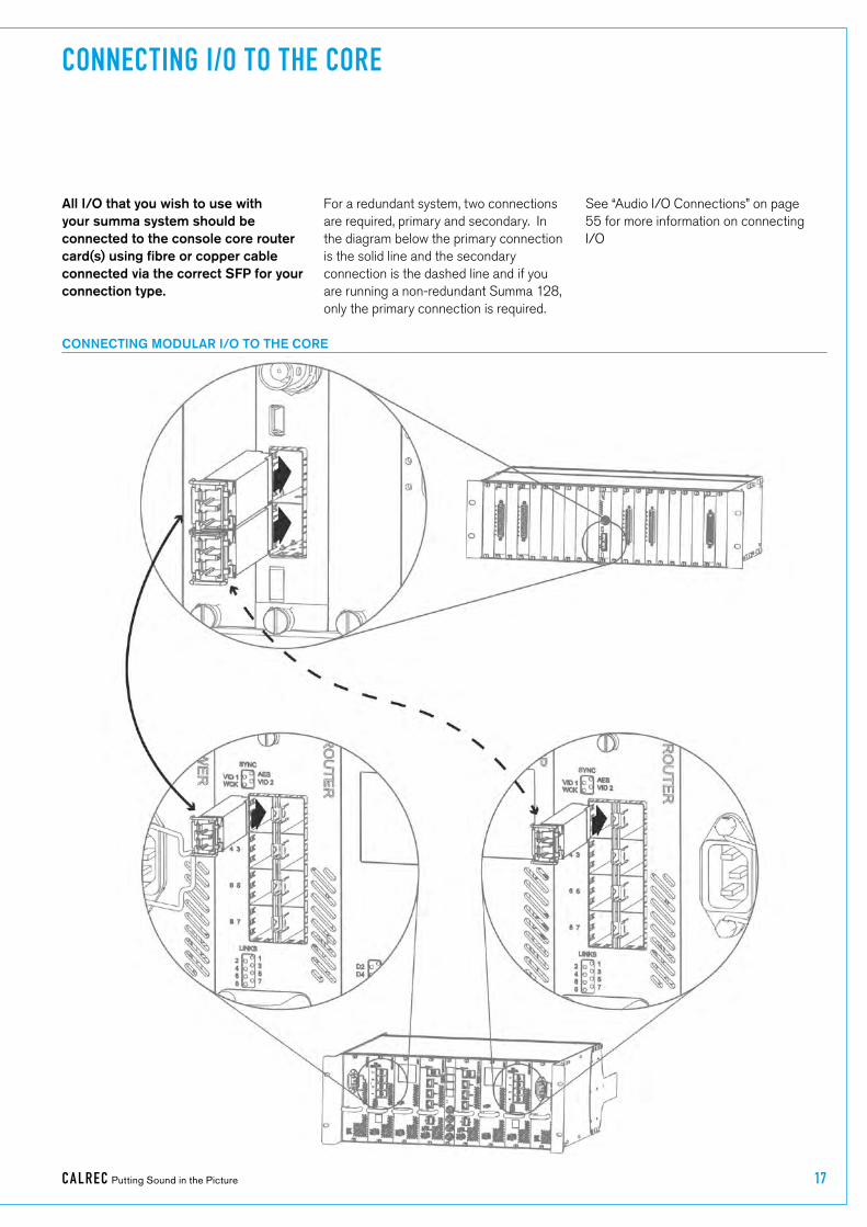
CONNECTING I/O TO THE CORE
All I/O that you wish to use with your summa system should be connected to the console core router card(s) using fibre or copper cable connected via the correct SFP for your connection type.
For a redundant system, two connections are required, primary and secondary. In the diagram below the primary connection is the solid line and the secondary connection is the dashed line and if you are running a non-redundant Summa 128, only the primary connection is required.
See “Audio I/O Connections” on page 55 for more information on connecting I/O
CONNECTING MODULAR I/O TO THE CORE

18 SUMM A Networked Audio Production System Get ting Star ted
CONNECTING FIXED FORMAT I/O TO THE CORE
Note:-�The�connections�to�the�Pre�2015�core�and�2015�core�are�the�same.

CA LREC Putting Sound in the Picture 19
HARDWARE POWER CONNECTIONS
POWER CONNECTIONS TO THE SURFACE
POWER CONNECTIONS TO THE 2015 CORE
All Summa Hydra2 hardware requires mains power via standard IEC connections.
While Calrec hardware can be run off one power connection, it is advised, for redundancy, that you connect a separate power source to the primary and secondary power inlets. In the following diagrams the primary power connection is indicated by a solid arrow and the secondary connection by a dashed arrow.
POWER CONNECTIONS TO A MODULAR I/O BOX
POWER CONNECTIONS TO A FIXED FORMAT I/O BOX

20 SUMM A Networked Audio Production System Get ting Star ted
CONNECTING A LAPTOP TO THE CORE
A laptop may be connected to the core to provide access to software applications and diagnostic tools for interacting with the Summa system and the wider Hydra2 network.
The laptop will need to have a one gigabit ethernet port which should be connected to the ‘Surface 2’ (MAC 6 on some models) connection on the primary control processor which is located in the Summa Core.
A USB to Ethernet adapter is provided for all other networking needs.
CONNECTING A LAPTOP FOR APPLICATION SUPPORT

CA LREC Putting Sound in the Picture 21
SETTING THE DATE AND TIME
Shows and memories are time-stamped, making them easier to identify. When you first start up your summa system it is important to set the current date and time.
To do this:
Tap SYSTEM�SETTINGS�in the top right hand corner of the touch display.
Tap the + and - buttons to set the current date and time.
SETTING THE DATE AND TIME

22 SUMM A Networked Audio Production System Get ting Star ted
CONFIGURING LAN PORTS
If your Summa core control processors have three ports labelled LAN (or Ethernet) 1, 2 and 3, these ports can be used to connect the Summa system to other corporate networks. If your Summa core has ports labelled MAC 3, 4 and 5 an Ethernet to USB adapter can be connected to one of the USB ports on the front of the control processor to serve the same purpose.
Tap SYSTEM�SETTINGS in the top right of the screen and select LAN�CONFIGURATION from the left hand menu. In the LAN configuration window you can define the adaptor settings for each port and create multiple static routes for each port as required.
If you have a non-redundant system there will only be one tab in the LAN configuration window as there is only one control processor installed.
LAN CONFIGURATION SCREEN
CONTROL PROCESSOR

CA LREC Putting Sound in the Picture 23
UPGRADING FROM V2.1
Users can carry out system wide software updates on Summa systems running version 2.1 or higher.
Note that systems running pre V2.1 software will require Calrec engineers or distributors to upgrade. At this time, any spares should also be upgraded to V2.1 using the same Windows-based process.
For guidance on carrying out a software upgrade to a Summa V2.1+ system, please refer to the System Settings>Software screen on the surface’s touchscreen UI (see FIGURE 1).
Users will need to connect a laptop/PC to the processing core, and understand how to set a static IP address on their device.
Users should avoid hot-plugging or removing hardware whilst system software is being reprogrammed.
Take care to notice on-screen warnings and do not disconnect, reset or power down during the process.
I/O boxes require user confirmation before reprogramming in order to avoid them being accidentally disconnected or powered down during the process.
From v2.1, users will be able to access the new web-application version of Software Updater to backup and restore user data, but no automatic checking of software compatibility or reprogramming will occur until a valid ‘Atomic’ software package is subsequently uploaded. An Atomic v2.1 package will be made available to users to enable auto-compatibility checking and reprogramming. This will allow hardware to be replaced with off the shelf spares, or with hardware from other systems without requiring manual configuration and reprogramming.
FIGURE 1: SYSTEM SETTINGS > SOFTWARE
The primary controller card is the reference for the rest of the system. Should the primary controller card need to be replaced for any reason, it is recommended to power down the system and to remove the faulty primary and replace it with the controller card from the secondary slot, allowing for the replacement, whose software version and user data may be unknown, to be fitted as a secondary. On power up and boot, the replacement will take on the software and user data from the primary. The process of ensuring replacement controllers are fitted as secondary’s whilst powered down ensures that they take on the configuration of the system, rather than the system being reconfigured to match the replacement, whose configuration may be unknown.
As well as displaying reprogramming notifications and progress within the web-application, notifications and progress are displayed on the surface (if it’s running). If the system is functional whilst components are being reprogrammed in the background, this information is accessible by tapping on the ‘System Reprogramming’ tab in the touchscreen header (see FIGURE 2). Confirmation for I/O box reprogramming is also available from the surface.
If an I/O box is repeatedly flagged as needing an update, even after the system has been updated, a manual reset of the box should resolve the issue.

24 SUMM A Networked Audio Production System Get ting Star ted
If the system is running actively on a secondary controller card however, the replacement can be hot-plugged into the primary controller slot and it will automatically take on the software and user data running on the active secondary card. Whilst this can avoid powering the system down, it is not recommended practise.
For compatibility checks and auto-reprogramming across the system, the primary controller needs to be active. Whilst a system is running on a secondary controller card, only a hot-plugged primary controller will be checked/reprogrammed.
System User data is automatically copied from the active controller to the alternate. Before carrying out system wide software upgrades, users should choose to back-up the user data as a precaution via the Software Updater application. Should a system lose user data, e.g. a controller card failure in a system that does not have a secondary fitted, user data can be restored by the Software Updater in order to recover a system back to its previous identity.
Router cards also contain system specific user configuration. This is not currently covered by the user data backup, and custom configuration settings are not automatically copied between the primary and secondary router. In the event that a router card needs to be replaced, users should contact customer Support for guidance on Router configuration.
If a controller card fails to reprogram, the system will not attempt to retry. To retry, upload the software package again (or a different one) via the Software Updater application.
FIGURE 2: SYSTEM REPROGRAMMING

calrec.com Putting Sound in the Picture
SUMMACONTROL SURFACE

26 SUMM A Networked Audio Production System Control Surface
SIDE VIEW WITH DIMENSIONS
The Summa control surface is available in three standard sizes: 12 + 8 fader, 24 + 8 fader and 36 + 8 fader. Summa’s format and feature set is the same regardless of which size is chosen and includes multi-function control cells and permanent metering for all faders within the 12 fader sections. All Summa surfaces also have an additional 8 fader section.
The following diagrams show the different surface options along with their measurements.
SURFACE MEASUREMENTS
675.0 mm [26.57”]
596.6 mm [23.49”]
27.0 mm [1.06”]
275.5 mm [10.85”]
5.5
mm
[0.2
2”]
68.9
mm
[2.7
1”]
89.0
mm
[3.5
1”]
156.
0 m
m [6
.14”
]
5.6 mm
[0.22”]
204.
9 m
m [8
.07”
]
12.2 mm
[0.48”]
65.3 mm [2.57”]
405.
5 m
m [1
5.96
”]
392.
5 m
m [1
5.45
”]
132.6 mm [5.22”]

CA LREC Putting Sound in the Picture 27
12 + 8 FADER TOP VIEW
24 + 8 FADER TOP VIEW
875.50 mm [34.47”]
1308.0 mm [51.5”]

28 SUMM A Networked Audio Production System Control Surface
36 FADER TOP VIEW - WIDTH
1740.5 mm [68.5”]

CA LREC Putting Sound in the Picture 29
The
follo
win
g di
agra
m s
how
s ho
w S
umm
a’s
inte
rnal
com
pone
nts
are
conn
ecte
d to
geth
er. T
he im
age
is b
ased
on
Sum
ma
12 +
8.
Your
Sum
ma
surf
ace
may
hav
e m
ore
than
one
12
fade
r S
ectio
n. S
umm
a ha
s a
mod
ular
con
nect
ion
syst
em a
nd t
he e
xtra
12
Fade
r S
ectio
n co
nnec
tion
poin
ts a
re c
lear
ly in
dica
ted
.
SURFACE COMPONENTS
12 F
ader
Sec
tion
CPU
(UN
6144
)
Pow
er 4
8VIN
(J2)
PSU
CTR
L (J
1)
Upp
er L
eft (
J21)
Upp
er R
ight
(J22
)
Low
er L
eft (
J24)
Low
er R
ight
(J23
)
Port
4 (J
14)
LED
Back
light
(J3)
TFT
Disp
lay
(J4)
Pow
er 4
8VIN
(J2)
PSU
CTR
L (J
1)
Upp
er L
eft (
J21)
Upp
er R
ight
(J22
)
Low
er L
eft (
J24)
Low
er R
ight
(J23
)
Port
0 (J
5)
LED
Back
light
(J3)
TFT
Disp
lay
(J4)
8 Fa
der S
ectio
n CP
U (U
N61
43)
Port
3 (J
12)
Port
2 (J
9)
Port
1 (J
6)
Prim
ary
SFP
Seco
ndar
y SF
P(lo
cate
d at
rear
of s
urfa
ce -
to b
e co
nnec
ted
to S
umm
a Co
re p
roce
ssin
g ra
ck)
USB
/Res
et
(J15
)
Touc
h U
SB (J
7)
12 F
ader
Pan
el (I
C616
2/IC
6212
)
12 F
ader
Pan
el
Boar
d (C
Y613
6)
6 M
otor
ized
Fa
ders
6 M
otor
ized
Fa
ders
6 Fa
der
Disp
lays
6 Fa
der
Disp
lays
12 F
ader
Pan
el
Boar
d (C
Y613
6)
Conn
ectio
n to
12
Fade
r Se
ctio
n CP
U (J
1)Co
nnec
tion
to 1
2 Fa
der
Sect
ion
CPU
(J1)
8 Fa
der P
anel
(IM
6158
/IM62
15)
8 Fa
der P
anel
Boa
rd
(left
) (G
Y613
8)8
Fade
r Pan
el B
oard
(r
ight
) (G
Y613
9)
4 Fa
der
Disp
lays
4 Fa
der
Disp
lays
Conn
ectio
n to
8 F
ader
Se
ctio
n CP
U (J
1)Co
nnec
tion
to 8
Fad
er
Sect
ion
CPU
(J2)
4 M
otor
ized
Fa
ders
4 M
otor
ized
Fa
ders
Mon
itor P
anel
(ML6
157)
Mon
itor P
anel
Boa
rd
(ML6
137)
Conn
ectio
n to
8 F
ader
Se
ctio
n CP
U (J
1)
USB
and
Res
et B
oard
(RI6
147)
Conn
ectio
n to
8 F
ader
Sec
tion
CPU
(J4)
USB 2
USB 3
USB 1
Mic
Pre
amp
O/P
(J6)
I/P
(J5)
Status LED
Reset
(Loc
ated
on
surf
ace)
(Tal
kbac
k M
icro
phon
e Lo
cate
d on
Mon
itor
Pane
l)
Cont
rol C
ell P
anel
(CA6
161)
Cont
rol C
ell P
anel
Bo
ard
(CC6
135)
12 C
ontr
ol C
ell
Disp
lays
Conn
ectio
n to
12
Fade
r Se
ctio
n CP
U (J
1)
Cont
rol C
ell P
anel
Bo
ard
(CC6
135)
12 C
ontr
ol C
ell
Disp
lays
Conn
ectio
n to
12
Fade
r Se
ctio
n CP
U (J
1)
Met
er D
ispl
ay P
anel
(MD6
171)
TFT
Disp
lay
(Dat
a)
LED
Back
light
Touc
h Di
spla
y Pa
nel (
MD6
170)
TFT
Disp
lay
(Dat
a)LE
D Ba
cklig
htTo
uch
USB
1/4”
Hea
dpho
ne
Jack
Hea
dpho
ne &
Ta
lkba
ck B
oard
(P
T615
5)
XLR
(M
ale)
Talk
back
Mic
Pr
e (J
6)
Pow
er 4
8V (J
1)2
x XL
R
(Fem
ale)
H/P
Jac
k (J
3)
Hea
dpho
ne
Amp
Conn
ect t
o I/
O b
ox P
orts
Pow
er a
nd R
eset
Dis
trib
utio
n Bo
ard
(ZN
6142
) Res
et &
ID S
elec
t
Section 1 (J8)
Section 2 (J9)
Section 3 (J10)
Section 4 (J11)
Section 5 (J12)
6 x
Pow
er 4
8V
SAM
TEC
MPS
C Pl
ug (J
1)
Surf
ace
PSU
(ZN
6163
)(c
onta
ins
two
sepa
rate
PSU
s fo
r re
dund
ancy
)
IEC
Sock
et 1
IEC
Sock
et 2
SAM
TEC
MPS
C (S
ocke
t)
(J2)
(J3)
(J4)
(J5)
(J6)
(J7)
(Loc
ated
in 8
Fad
er S
ectio
n)
12 Fader Section 2
12 Fader Section 3
Spare
Spare
To 1
2 Fa
der
Sect
ions
in o
rder
(le
ft to
righ
t)
Sect
ion
2Se
ctio
n 3
Spar
e
Not
Con
nect
ed
Mai
ns P
ower
Inpu
t 1
Mai
ns P
ower
Inpu
t 1
12 F
ader
Sec
tion
8 Fa
der S
ectio
n
HR
S DF
14 (3
0 w
ay))
Res
et a
nd ID
cab
le (1
0 w
ay fo
r Fad
er s
ectio
n Pr
oces
sor C
ard)
Ethe
rnet
Con
nect
ion
Audi
o
Pow
er
Res
et a
nd ID
cab
le (9
way
for M
ain
sect
ion
Proc
esso
r Car
d)
IDC
Sock
et (3
4 w
ay)
RJ4
5
Mol
ex K
K (1
0 w
ay)
Mol
ex M
inifi
t JR
(2 w
ay)
JST
EH-7
(7 w
ay)
IDC
Sock
et (2
0 w
ay)
SFP
Oth
erKE
Y
Data
/Oth
er

30 SUMM A Networked Audio Production System Control Surface
* 100mm Alps faders with motor driven overpress fitted as standard (P&G faders available on request)
The Summa surface is modular. Summa 12+8 is shown here, the smallest control surface option, which is made up of one 12 fader section, and one 8 fader section. Summa 24+8 has an extra 12 fader section and Summa 36+8 has two extra 12 fader sections. Each section is made up of three panels.
Each panel is interleaved with the panels directly above and below it. This interleaving dictates the order that the panels must be removed for maintenance (See the Summa Maintenance Manual for more information):
1. 12 Fader/ 8 Fader panel*2. Control Cell/Monitor panel3. Meter Display/Touch Display panel
SUMMA SURFACE SECTIONS
12 Fader Section 8 Fader Section
12 Fader Panel
Control Cell Panel
Meter Display
Panel
Touchscreen Panel
Monitor Panel
8 Fader Panel
Control Modes
Console Monitors Studio Monitors ParameterAdjust
SurfaceReset
1
2
3
DimAdjust
AFLTrim
PFLLevel
Downmix
Level
Status
10
5
0
5
10
20
30
405060∞
10
5
0
5
10
20
30
405060∞
10
5
0
5
10
20
30
405060∞
10
5
0
5
10
20
30
405060∞
10
5
0
5
10
20
30
405060∞
10
5
0
5
10
20
30
405060∞
10
5
0
5
10
20
30
405060∞
10
5
0
5
10
20
30
405060∞
User Buttons
Layers
10
5
0
5
10
20
30
405060∞
10
5
0
5
10
20
30
405060∞
10
5
0
5
10
20
30
405060∞
10
5
0
5
10
20
30
405060∞
10
5
0
5
10
20
30
405060∞
10
5
0
5
10
20
30
405060∞
10
5
0
5
10
Links
20
30
405060∞
10
5
0
5
10
20
30
405060∞
10
5
0
5
10
20
30
405060∞
10
5
0
5
10
20
30
405060∞
10
5
0
5
10
20
30
405060∞
10
5
0
5
10
20
30
405060∞
InputGain
InputGain
InputGain
InputGain
InputGain
InputGain
InputGain
InputGain
InputGain
InputGain
InputGain
InputGain C A L R E C
MADE IN ENGLAND
byS U M M A
PFL AFL
CUT
Access
TB
Link
PFL AFL
CUT
Access
TB
Link
PFL AFL
CUT
Access
TB
Link
PFL AFL
CUT
Access
TB
Link
PFL AFL
CUT
Access
TB
Link
PFL AFL
CUT
Access
TB
Link
PFL AFL
CUT
Access
TB
Link
PFL AFL
CUT
Access
TB
Link
PFL AFL
CUT
Access
TB
Link
PFL AFL
CUT
Access
TB
Link
PFL AFL
CUT
Access
TB
Link
PFL AFL
CUT
Access
TB
Link
CUT
PFL AFL
Access
TB
LinkClear
CUT
PFL AFL
Access
TB
Link
CUT
PFL AFL
Access
TB
Link
CUT
PFL AFL
Access
TB
Link
CUT
PFL AFL
Access
TB
Link
CUT
PFL AFL
Access
TB
Link
CUT
PFL AFL
Access
TB
Link
CUT
PFL AFL
Access
TB
Link
1 4
2 5
3 6
Access Preset1
Preset2
Input Pan AutoMixing
Delay Width PathOutputs
Aux 9Aux 10
Aux 1Aux 2
Aux 3Aux 4
Aux 5Aux 6
Aux 7Aux 8
Aux 15Aux 16
Aux 13Aux 14
Aux 11Aux 12
Dim Cut Mute TB
Stereo
SmallLS
PFLto Mon
Mute TB
Mute TB
A B
C D
E F
G H
I J
K L
Mono

CA LREC Putting Sound in the Picture 31
All audio processing is performed within the Summa Core, no audio is passed to the surface for routing or processing. The only audio connections on the Summa surface are for the built-in talkback microphone and the headphone socket, both of which must be connected to I/O box ports via the surface back panel, to receive and transmit audio.
These two figures show all Summa’s surface audio connections. For details on power connections see “Surface Power Supply Unit” on page 33 and for information on connecting the surface to the processing core see “Connecting the Surface to the Core” on page 12.
HEADPHONE AND TALKBACK MICROPHONE CONNECTIONS
Please note, the built-in Summa headphone socket and talkback microphone must be accounted for when deciding on the number and placement of Hydra2 I/O boxes during the ordering process.
Talkback�Mic�and�Headphone�ConnectionsSumma’s built-in talkback microphone is situated close to the Summa logo in the Monitor panel, directly under the Touch Display. The headphone socket is fixed to the front right of the surface, just under the arm rest.
The talkback microphone is connected internally to an amplifier unit, and from there to the male XLR plug on the rear
panel. In order to use the built-in talkback microphone, this male XLR must be connected to an I/O box input port.
The headphone socket is connected internally to the output of a headphone amplifier, the inputs of which are wired directly to the two female XLR sockets on the rear panel. In order to use the headphone socket, these two XLR sockets must be connected to two I/O box output ports.
To Control Processor
TalkbackMicrophone
Output
HeadphoneInputs
Left Right
1 21
2
REAR PANEL CONNECTIONS

32 SUMM A Networked Audio Production System Control Surface
FRONT PANEL CONNECTIONS
Headphone�Output

CA LREC Putting Sound in the Picture 33
SURFACE POWER SUPPLY UNIT
Summa’s surface power supply unit (PSU) contains two power supply units which are supplied with AC power by two independent male IEC inlets. These dual power supplies provide full power redundancy, a feature of all Calrec products.
It is recommended that, to ensure power redundancy, these two IEC inlets should be supplied by separate AC power supplies.
Although Summa will run with only one PSU powered on, it is recommended that both IECs are connected and powered up to ensure power redundancy. A PSU failure or a loss of AC power input will generate a system status error message (See the Summa User manual for more information on system status monitoring).
If one PSU fails, the other will automatically take over with no loss of audio or operation.
Connecting�the�Surface�PSUThe AC/DC surface PSU connects as a single unit to the rear of the console. Two dowelling rods and two keyhole studs act as guides to ensure the PSU module fits correctly into the power inlet. The Surface power inlet is a SAMTEC MPSC plug and the surface PSU connects via a SAMTEC MPSC socket. A single latch locks the surface PSU in place and a large handle provides an easy way to support it during connection and disconnection.
Two air vents along the top of the PSU module line up with air vents in the main chassis, allowing increased air flow and temperature control through the rear of the console. Air vents should be kept clear at all times when the console is in operation.
Disconnecting�the�Surface�PSUInstructions for safely disconnecting the surface PSU can be found on the rear of the console, as shown on the next page.
Power�DistributionThe power supply module connects to an internal PSU connector board which supplies 48 V DC power to Summa’s internal components. The PSU connector board also includes reset and system
PSU UNIT FRONT VIEW
monitoring connections for each internal component. Each DC power outlet is fitted with its own 1.85A self-resetting fuse.
The Meter Display and Touch Display are powered (5 V) via their connections to their CPU cards. Each Meter Display/Touch Display also has a backlight which is powered via a separate 12 V DC connection from their CPU cards.
PSU UNIT REAR VIEW
Keyhole�Studs
Dowelling�Rods

34 SUMM A Networked Audio Production System Control Surface
PSU UNIT - INTERNAL
AC Power Plugs: PSU1 AC In - Near PSU2 AC In - Far
Disconnect AC power plugs
Grab Handle before release
Release PSU Latch to unlock
Lower to release PSU
1.
2.
3.
4.
TO REMOVE PSU:
Warning: PSU weighs 3.6Kg
POWER SUPPLY UNIT
!
S U M M A C A L R E Cby
Made in UK by CALREC AUDIO Ltd.Nutclough Mill, Hebden Bridge, West Yorkshire, HX7 8EZ
Email: [email protected] Tel: +44(0)1422 842 159 www.calrec.com
36+8 fader
154388
JAN 2014
100-240V AC ~2.16-1.00A RMS 50/60Hz
This device complies with part 15 of the FCC Rules. Operation is subject to the following two conditions: (1) This device may not cause harmful interference, and (2) this device must accept
interference recieved, including interference that may cause undesired operation.
WARNING: THIS APPARATUS MUST BE EARTHEDDO NOT RESTRICT VENTILATION HOLES
ENSURE ALL COVERS & SCREWS ARE FITTEDMAX. AMBIENT OPERATING TEMPERATURE 40OC
Laite on liitettävä suojamaadoituskoskettimilla varustettuun pistorasiaan.Apparatet må tilkoples jordet stikkontakt.Apparaten skall anslutas till jordat uttag.
!MODEL:
SERIAL NO:
DATE OF MANUFACTURE:
INPUT RATING(MAX):
Locked
Unlocked
PSU Latch
S U M M A C A L R E Cby
SUMMA REAR VIEW SHOWING PSU DISCONNECT LABELLING

CA LREC Putting Sound in the Picture 35
SURFACE BUTTON CAPS
Every Summa fader has a CUT/ON button associated with it. The function of these buttons can be set from ‘System Settings’ on the touch display interface.
With functionality set to CUT, the path attached to the fader will be CUT when the button is in its ‘ON’ state. If functionality is set to ON, the path attached to the fader will be switched ON when button is in its ‘ON’ state, and so CUT when in its ‘Off’ state. These buttons are latching when pressed and momentary when held.
CUT/ON buttons are made up of blank key-mats, to which button caps can be fitted which display the correct ON or CUT labels depending on how the buttons are set to function. Summa comes with a full set of CUT and ON button caps.
CUT BUTTON
Summa has a bank of 12 User Buttons which can be assigned, using the GPIO system, to control external devices, See GPIO in the User Manual for more information.
Each User Button is lit by a white LED when activated, either by being pushed or via a GPI signal.
A template is available to download from the Calrec website which you can use to create your own bespoke User Button labels to be inserted under the User Button caps.
Alternatively if you wish to make your own labels without the template, the inner dimensions of the button caps are: 9mm x 14mm.
USER BUTTONS
Button�Operation
Latching: A latching button stays in its ‘on’ state after being pressed, for example, the caps lock key on a QWERTY keyboard is a latching button.
Momentary: A momentary button only remains in its ‘on’ state whilst it is being pressed, for example, the Shift key on a QWERTY keyboard is a momentary button.

36 SUMMA Networked Audio Production System

calrec.com Putting Sound in the Picture
SUMMAPROCESSING CORE

38 SUMM A Networked Audio Production System Processing Core
CORE DIMENSIONS AND MOUNTING
SIDE PROFILE VIEW - DIMENSIONS AND AIR FLOW
SIDE PROFILE VIEW - DIMENSIONS WITH REAR SUPPORTS FITTED
OVERHEAD VIEW
The Summa processing core is a 4U 19’ rack mount unit designed for installation into standard 19’ equipment bays.
AirflowThe core is cooled by fan assisted convection. Air is drawn in through inlets at the base/front and exits via 3 fans mounted to the rear of the core. The speed of each fan is monitored and System Status error reports are generated for any failures. Air inlets and fans should be left clear and unobstructed to ensure air can flow through the card frame. No clearance is required above or below the core for cooling.
SupportThe weight at the rear of the core should be adequately supported to prevent stress on the front racking angles. This is particularly important when the units are mounted in mobile installations. Calrec will not accept liability for damage caused by insufficient support.
Calrec supply adjustable rear support rails with each Summa core that can be fitted during installation if required. The support rails can be fitted in different positions depending on the depth of the bay being used. Rear racking angles slide over the support rails so the depth can be adjusted to match the position of the rear core fixings in the equipment bay.
Air drawn in through inlets at the base/front and exits via 3 rear-mounted fans
CA LREC Putting Sound in the Picture 39
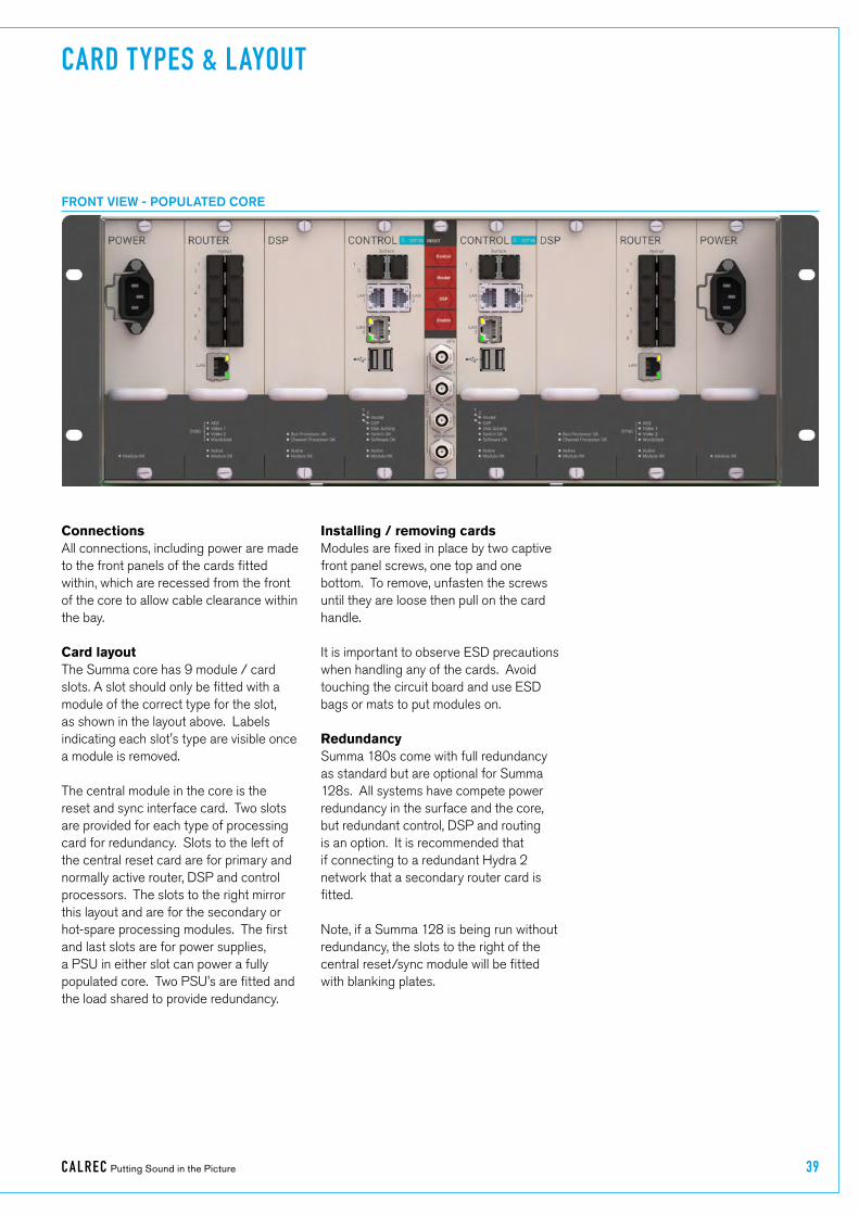
CARD TYPES & LAYOUT
ConnectionsAll connections, including power are made to the front panels of the cards fitted within, which are recessed from the front of the core to allow cable clearance within the bay.
Card�layoutThe Summa core has 9 module / card slots. A slot should only be fitted with a module of the correct type for the slot, as shown in the layout above. Labels indicating each slot's type are visible once a module is removed.
The central module in the core is the reset and sync interface card. Two slots are provided for each type of processing card for redundancy. Slots to the left of the central reset card are for primary and normally active router, DSP and control processors. The slots to the right mirror this layout and are for the secondary or hot-spare processing modules. The first and last slots are for power supplies, a PSU in either slot can power a fully populated core. Two PSU's are fitted and the load shared to provide redundancy.
FRONT VIEW - POPULATED CORE
Installing�/�removing�cardsModules are fixed in place by two captive front panel screws, one top and one bottom. To remove, unfasten the screws until they are loose then pull on the card handle.
It is important to observe ESD precautions when handling any of the cards. Avoid touching the circuit board and use ESD bags or mats to put modules on.
RedundancySumma 180s come with full redundancy as standard but are optional for Summa 128s. All systems have compete power redundancy in the surface and the core, but redundant control, DSP and routing is an option. It is recommended that if connecting to a redundant Hydra 2 network that a secondary router card is fitted.
Note, if a Summa 128 is being run without redundancy, the slots to the right of the central reset/sync module will be fitted with blanking plates.

40 SUMM A Networked Audio Production System Processing Core
Standard�status�LEDs• Active - all modules (apart from the
PSU), indicate when the module is actively in control of the system. Modules in hot-spare mode, ready to take over in the event of a failure, do not have their active LED lit.
• Module OK - indicates the module booted, and is running either actively or as a hot-spare.
Control�Processor�ModuleControl Processors are located in slots 4 & 6 on either side of the reset & sync card. The left hand slot is for the primary, normally active card, the right hand slot for the secondary, hot-spare card.
Two SFP slots at the top of the module can be fitted with copper or fibre SFPs and are the data connection point for the control surface. The 'Surface 1' port of the primary control processor connects to the primary surface switch within the control surface. 'Surface 1' on the secondary Control Processor card connects to the secondary surface switch. 'Surface 2' ports are only used for very large consoles with a second pair of surface switches, or for sidecars containing their own surface switches.
Any of the 3 LAN ports can be used for CSCP mixer remote control.
If the core is configured as a Master Router, a standalone (outside of a console) PC can be connected to any of the 3 LAN ports for accessing H20; the network administrator's user interface.
LEDs are also provided to show the status of the primary and secondary DSP and Router cards. Disk Activity indicates write activity to the module's compact flash card. Switch OK and Software OK show the card processing status.
Reset�&�sync�interface�cardThis module fits in the central, 5th card slot of the Summa processing core. Three buttons can individually reset the control, router and DSP cards within the core. The bottom ‘Reset Enable’ button is a safety precaution which must be held whilst pressing any reset button.
4 x BNC connectors provide sync inputs, allowing for redundancy and a range of formats. Two inputs are for SD/HD video sync signals, one for AES DARS and one for TTL Wordclock.
RESET & SYNC INTERFACE CARD
CONTROL PROCESSOR MODULE

CA LREC Putting Sound in the Picture 41
DSPThe primary, normally active DSP card fits in slot 3, to the immediate left of the primary Control Processor. The secondary, hot-spare DSP card fits in slot 7, to the immediate right of the secondary Control Processor.
This audio signal processing card has no front panel connections. All audio and data is passed to / from the Master Control and router cards via the core backplane.
Bus Processor OK and Channel Processor OK indicate processing status within the module.
RouterCard slot 2 is for the primary / normally active router module, slot 8 is for the secondary / hot-spare router module.
The Summa router card has 8 SFP ports that can be fitted with copper or fibre SFP's to allow connection of Hydra2 I/O boxes and connections to other consoles or standalone Hydra2 router cores.
A single RJ45 port labelled LAN allows for 3rd party equipment supporting the SW-P-08 or Ember protocols to interface for remote control.
As well as the standard status LED's there are front panel indicators to show the active sync source and for activity on the RJ45 and SFP ports.
Power�supplyCard slots 1 & 8 are for PSU modules. Both slots share the power load for the whole core. One card is sufficient to power a fully populated core, two are fitted to provide redundancy. Each card has an IEC AC mains input connector, requiring 100–240V AC.
ROUTER MODULEDSP MODULE POWER SUPPLY MODULE

42 SUMM A Networked Audio Production System Processing Core
OBSOLETE CONTROLPROCESSOR MODULE
Cores made pre-2015 have a slightly taller internal card slot. Pre-2015 cores cannot be fitted with cards designed for the new cores. Pre-2015 cores can be identified by having a plain metal finish on the front panel.
Standard�status�LEDs
• POK - Power OK, module is receiving power.
• MA - Module Active. Indicates when the module is actively in control.
• PRI - Indicates if the module is fitted in a primary slot.
• RST - Illuminates when the module receives a reset command.
• MOK - Module OK, indicates the module is running, either actively or as a hot-spare.
• NOK - Neighbour OK, indicates the presence and status of the alternate card of the same type. Neighbours are primary / secondary counterparts rather than physically adjacent cards.
• ST1 and ST2 are Calrec engineering status LED's, the function of which varies by card type and can be subject to change with software versions.
Obsolete�Control�ProcessorTwo SFP slots at the top of the module can be fitted with copper or fibre SFPs and are the data connection point for the control surface. The left hand ‘MAC7’ port of the left hand, primary control processor card connects to the primary surface switch within the control surface. MAC7 on the secondary Control processor card connects to the secondary surface switch. MAC6 ports are only used for very large console with a second pair of surface switches fitted, or for sidecars containing their own surface switches.
If the core is configured as a Master Router, RJ45 port MAC5 should be used to connect standalone (outside of a console) PCs for accessing H20; the network administrator user interface. Ports MAC4 and MAC3 are for use by Calrec engineers only.
As well as the standard status LEDs, LEDs are provided to show activity on the RJ45 and SFP ports. LEDs are also provided to show the heartbeat status of other cards within the core: D0 for the primary DSP; D1 for the secondary DSP; R0 for the primary router; and R1 for the secondary router. The CF LED indicates write activity to the module's compact flash card and LO BAT is a low battery warning for the module's BIOS. The Master Control module's ST1 & ST2 LEDs indicate the heartbeats from the modules two processing cores.
PRE-2015 CORES
CA LREC Putting Sound in the Picture 43
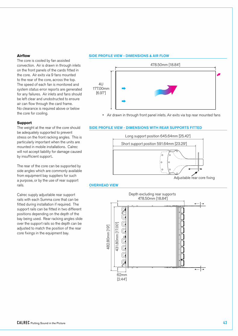
SIDE PROFILE VIEW - DIMENSIONS & AIR FLOW
SIDE PROFILE VIEW - DIMENSIONS WITH REAR SUPPORTS FITTED
OVERHEAD VIEW
478.50mm [18.84’]
4U177.00mm
[6.97’]
• Air drawn in through front panel inlets. Air exits via top rear mounted fans
Long support position 645.64mm [25.42’]
Short support position 591.64mm [23.29’]
Depth excluding rear supports 478.50mm [18.84’]
431
.80
mm
[17.
00
’]
482
.80
mm
[19
’]
62mm[2.44’]
AirflowThe core is cooled by fan assisted convection. Air is drawn in through inlets on the front panels of the cards fitted in the core. Air exits via 9 fans mounted to the rear of the core, across the top. The speed of each fan is monitored and system status error reports are generated for any failures. Air inlets and fans should be left clear and unobstructed to ensure air can flow through the card frame. No clearance is required above or below the core for cooling.
SupportThe weight at the rear of the core should be adequately supported to prevent stress on the front racking angles. This is particularly important when the units are mounted in mobile installations. Calrec will not accept liability for damage caused by insufficient support..
The rear of the core can be supported by side angles which are commonly available from equipment bay suppliers for such a purpose, or by the use of rear support rails.
Calrec supply adjustable rear support rails with each Summa core that can be fitted during installation if required. The support rails can be fitted in two different positions depending on the depth of the bay being used. Rear racking angles slide over the support rails so the depth can be adjusted to match the position of the rear core fixings in the equipment bay.
Adjustable rear core fixing

44 SUMMA Networked Audio Production System
SETTING CONSOLE IDs FOR 2015 PROCESSING CORES
Unlike Apollo, Artemis Shine and Beam consoles using 8RU cores, and Artemis Light and Summa consoles using Pre-2015 cores, where the Console IDs are set up in:- /home/MasterControl/guardian/console.config on both of the MCS Control processors, Summa consoles running on V3.0 software and above using the newer 2015 Com-E based processing cores use the two sets of DIP switches on the JN6209 sync card shown right to define the Console Id’s first two octets of the IP address range which is made up from the Customer ID and the Core ID.
Note: the earlier JN6178 sync card also has these switches and if V3.0 is installed on a console with this sync card it will also use its DIP switches to define the customer ID.
JN6209 SYNC CARD AND ITS CONSOLE ID SETTING DIP SWITCHES
The DIP switches are arranged as per the diagram on the right (same orientation as the above pictures, with the BNC connectors to the left).The screen print on the PCB board allocates 10 bits to the customer ID and 6 bits to the core ID. This is related to a potential future development to allow for a greater number of customer IDs. This has not yet been implemented, meaning both IDs remain 8 bit.
Customer�IDThe customer ID is set by DIP switches C0 to C7, where C0 is the least significant bit (1) and C7 is the most significant bit (128). A switch is set to on (1) when the switch is down (ie: closest to the PCB) and set to off (0) when the switch is up (ie: away from the PCB).
Normally a console is allocated a customer ID by Calrec, however Summa is designed to be fully configurable by the customer, so any value (with the exception of the values listed below) can be selected.Logically, multiple consoles owned by the same customer should have the same customer ID, but again this is not vital.
Core�IDThe core ID is set by DIP switches R0 to R5 and C8 to C9 (ie: C8 is equivalent to R6; C9 is equivalent to R7), where R0 is the least significant bit (1) and C9 is the most significant bit (128). A switch is set to on (1) when the switch is down (ie: closest to the PCB) and set to off (0) when the switch is up (ie: away from the PCB).
Normally a console is allocated a core ID by Calrec, however Summa is designed to be configured by the customer, so any value can be selected. Logically, multiple consoles owned by the same customer should each have a unique core ID. This is vital if two consoles are to be networked.
Excluded�customer�IDsCertain IP addresses are reserved within the Linux environment and as such cannot be used as a customer ID (1st octet of the IP address).
If excluded customer ID’s are used, the console will boot into an unusable state where neither control processor becomes active. In such an event, the only solution is to: power down the processing core; remove the sync card; modify the customer ID to a legal value’ reinsert the sync card; and repower the processing core.
Excluded customer IDs are: 0 – 3 Calrec reserved 127 local host 224 – 239 multi-cast 240 – 255 Linux reserved
If the potential development to provide 10 bit customer IDs is implemented, the following customer IDs will also be excluded: 256 – 259 Calrec reserved 383 local host 480 – 495 multi-cast 496 – 511 Linux reserved 512 – 515 Calrec reserved 639 local host 736 – 751 multi-cast 752 – 767 Linux reserved 768 – 771 Calrec reserved 895 local host 992 – 1007 multi-cast 1008 – 1023 Linux reserved
Note: Core IDs are unaffected and can be any value

calrec.com Putting Sound in the Picture
SUMMACONNECTION INFORMATION

46 SUMM A Networked Audio Production System Connection Information
SMALL FORM-FACTOR PLUGGABLE (SFP) OVERVIEW
Connections between the control surface and processing core, all Hydra2 network connections, connections between I/O boxes and routers and router-to-router connections between cores, are all made via SFP modules.
SFPs can be provided for RJ45 copper connections, as well as singlemode or multimode fibre on LC connectors. This allows for each port’s connection type to be chosen to suit cable-run distances and the existing infrastructure. SFPs can be changed easily on a port by port basis, as and when required.
Note, only fibre SFPs can be used for Summa surface to core connections.
If Calrec are supplying SFPs for your installation, the correct quantity of SFPs are supplied pre-fitted. The type of each connection—copper, singlemode fibre or multimode fibre—should be specified at the time of order to ensure the correct SFP types are supplied. Additional SFP modules can be ordered if required. If a system is to be connected to an existing Hydra2 network, please discuss this with your Calrec project leader, sales person or local distributor to ensure that SFPs are provided and ports provisioned for the additional router to router connections.
SFP�slot�orientationSFP modules plug into front panel slots on router and modular I/O controller cards and rear panel slots on fixed format I/O boxes. The modules can be fitted or removed whilst the system is powered up and without removing or opening any card or box casings.
Note the orientation of the SFP modules as shown in the illustrations on this page. Modules fitted in even numbered router ports (left hand column) are fitted the opposite way around to those in the odd numbered router ports (right hand column). Likewise for fixed format I/O boxes, the primary SFP module is the opposite way around to the secondary SFP module. The modules are orientated so that the release catch for the RJ45/LC connector plugs, once inserted, are on the outside edge.
For modular I/O box controller cards, both SFP slots are orientated so that the release catch on the cable/fibre connector is on the right-hand side.
SFP�latching�and�extractionCalrec source SFP modules from various manufacturers. All types used conform to the same specification, however the latching mechanisms can vary slightly.
The standard copper SFP and some fibre SFPs, as shown in the photograph on the previous page, have latch/extraction handles. On insertion, the handles should be set against the outer edge (the same side as the release catch on the RJ45 / LC connector plug that fits into the SFP) to lock it into place and prevent accidental removal if cables are pulled.
To remove this style of SFP, remove the cable/fibre and slide the handle (copper) or lift the handle out (fibre) to the inside edge, as shown in the diagram to the right. The module can then be removed by pulling on the handle.
SFP MODULES
1
3
5
7
2
4
6
8
16 15
SFPPORTS
2
INTERFACE
67 5 4 3 2 1 0ADDRESS 1
100
1
RYH D A1
ROUTER CARD SFP ORIENTATION
FIXED FORMAT I/O BOX SFPS
• Router card shown with copper SFPs fitted in ports 1-4, singlemode fibre (button release) in ports 5-8.
• I/O box shown with singlemode fibre SFPs (button release) fitted.
• Both SFP types above have a handle latching mechanism, shown in the locked position. The unit on the left is a singlemode duplex LC fibre module. The unit on the right is a copper RJ45 module.
STATUSH2 I/F
RESET
WCLK OUT
1
2
HB1
SOFT
CTRL2
AUD2
PSU2
H_ACT
HB2
CTRL1
AUD1
PSU1
FAN1FAN2
FAN 12V
MODULAR I/O BOX SFPS
• Modular I/O controller card SFPs are both orientated the same way around (Button release singlemode fibre SFPs shown).

CA LREC Putting Sound in the Picture 47
12
12
SFPS WITH HANDLES - LATCHED
• Both SFPs shown are locked in place - Latch / extraction handles in outer position (or ‘down’ position for fibre).
SFPS WITH HANDLES - UNLATCHED
• Both SFPs free to remove - Latch / extraction handles in inner (or ‘Lifted’ for fibre) position.
AUTO-LATCHING SFP
• Depress the release button to remove.
Other SFPs automatically latch into place when they are inserted fully and they have a release button on their inside edge. The fibre SFPs shown in the orientation diagrams and on this page are of this type and have blue release buttons. To remove, depress the button using a small flat blade, screwdriver or similar tool. The SFP module will then be free to be removed.
SFP�slot�coversDust covers should be fitted to all SFP slots that do not have SFP modules fitted in them in order to maintain connection reliability.
Loose�SFP�storageSFP modules are small, yet reasonably expensive devices. When removing or changing SFPs, take care to keep track of them and store loose modules in a clean, dry, and anti-static environment. Fibre SFPs should always have a dust cover fitted into their optical transceiver end when no fibre is connected to them.
Calrec will not be liable for lost or missing SFP modules, or damage due to poor storage.
SFP design varies depending on the manufacturer, please ensure that SFPs are correctly latched in place after fitting them. In the event that a connection is not automatically established after hot-plugging an SFP, please reset the unit the SFP is plugged in to.

48 SUMM A Networked Audio Production System Connection Information
COPPER SFP CONNECTIVITY
Hydra2 network connections can be made via copper SFP modules. Copper connections require shielded F/UTP Category 5e or Category 6 cables with shielded RJ45 mating connectors. Surface to Core connections can only be made using optical/fibre SFP modules.
Calrec do not supply copper cables as it is often preferable to terminate them after they have been run through cable ducting to avoid damaging the terminations, and to be able to cut them to the precise length required.
Shielded�cables�and�connectorsShielded cabling and connectors are required in order to meet EMC (Electro-magnetic compatibility) standards to comply with the radiated emission limits set in the EN55022 standard, as well as to guarantee performance in electrically noisy environments.
F/UTP Cat5e/Cat6 cable has an overall foil shield around the conductor cores. Shielded RJ45 connector plugs have a metallic shield around them which should be clamped/bonded to the shield within the cable. The connector shield connects with the chassis of the RJ45 socket that it is plugged into, providing an earth to the cable shield.
The method of attaching the connector shield to the cable shield can vary. Please refer to the connector manufacturer’s information for further guidance.
Maximum�cable�lengthThe maximum length of Cat5e/Cat6 cables is 90 m/295 ft. This is the absolute maximum and needs to include any patch points and cables that may be in the path. Hydra2 cable runs can NOT be extended using Ethernet switches, hubs or repeaters. If a run between Hydra2 hardware exceeds the maximum recommended distance for copper cabling, fibre and optical SFPs should be used instead.
Cable�routing�considerationsThe layout and twist rate of the data cores within Cat5e/Cat6 cables are integral to their performance at high speed over distance. Poor practise during installation can seriously impact upon this. The following are general rules of good practise but please refer to the cable manufacturer’s information for comprehensive installation rules:
• When running Cat5e/Cat6 network cabling, it is important to avoid kinking the cable. Kinks can seriously impair performance. Cable manufacturers advise that kinked cables should be discarded and replaced as the damage caused cannot be addressed simply by straightening them out.
• Cables should not be bent in tight angles, this too can seriously impair performance. Please refer to the cable manufacturer’s specification on minimum bend radii.
• Excessive pulling force when routing cables can deform the twist rate of the cable cores, causing irreparable damage. Cable manufacturers specify a maximum pulling tension.
• Cable ties should not be over-tightened as this deforms the internal structure of the cable. Cable ties should be tight enough to support the cable weight but not so tight as to cause any visible deformation to the cable’s outer jacket. Large, heavy bundles of cables can be difficult to support using cable ties without causing damage. ‘Velcro’ style hook-and-loop cable straps can be a good alternative to plastic cable ties.
• Whilst neatly bundled parallel cable runs are tidy and aesthetically pleasing, they can increase cross-talk, which can impact on performance. Avoid neat bundling of network cables over any kind of distance—the majority of a cables length is normally unseen, running under floor or through ducting where they should be loosely laid rather than neatly bundled.
Termination�-�strain�reliefPoor termination and lack of strain relief is one of the most common causes of high speed network cable problems. To properly relieve strain on the data cores, the outer jacket of the cable should be inserted into the RJ45 housing and held in place once crimped at the strain-relief point, as shown in the diagram above. This also maintains the integrity of the twist rate and shield into the termination, ensuring the full length of the cable conforms to its specification. Slide on outer boots offer additional strain-relief protection but are not sufficient on their own. In order to be able to crimp the cable jacket inside the RJ45 and land the data cores on the terminals, the amount that the jacket is stripped back in relation to the cores needs to be accurate. Cables with exposed data cores should not be used as they will be unreliable.
SHIELDED RJ45 CONNECTOR
Conductive connector mating screen clamped / bonded to cable shield
Crimp points
Cable outer jacket
Strain relief
STRAIN RELIEVED RJ45 TERMINATION
• Note, this is a simplified diagram that does not include the shield.

CA LREC Putting Sound in the Picture 49
Termination�-�pin-outHydra2 network cables use the standard gigabit Ethernet pin-out. Performance relies on the positive and negative leg of each signal pair using cores that are twisted together. Calrec recommends that ‘straight-through’ or ‘pin-for-pin’ cables are used. ‘Cross-over’ style cables can be used, however they must be gigabit standard cross-over. Older pin-outs, designed for use with slower Ethernet standards only use two of the four pairs, even though all four pairs are terminated. Cross-over variants of this style only cross the pairs that are used (A & B). Gigabit cross-over cables require that the blue (C) pair is crossed with the brown (D) pair as well as the orange (A) pair being crossed with the blue (B) pair.
Testing/certificationCalrec strongly recommend that all Hydra2 network cabling is properly tested or certified prior to on-site commissioning of the system. Simple test devices that only check the pin-out of the terminations are not sufficient to prove the performance and reliability of high speed data cabling. Certification level test equipment can give a simple pass/fail response but in doing so will test various important factors as well as pin-out. Certification type tests include determining cable length, measuring skew (timing differences between pairings due to variations in length caused by intentional differences in twist rate), measuring for loss, signal to noise ratio and BERT error checking on data.
Cables that fail certification tests or fail to perform, may appear to function fine in other applications, such as a PC LAN connection where errors leading to retries
and therefore delays are acceptable and often unnoticed.
Temporary�/�reusable�cablesCabling that is not part of a permanent infrastructure, such as temporary runs used for outside broadcasts, should be carefully coiled and uncoiled to avoid kinking and they should be regularly tested. Cables showing any sign of damage should be replaced.
STANDARD HYDRA2 RJ45 PIN-OUT
Pin Colour Signal
1 Orange-White A+
2 Orange A -
3 Green-White B+
4 Blue C+
5 Blue-White C -
6 Green B -
7 Brown-White D+
8 Brown D -
1 8
Top
Front
1 8
RJ45 PIN NUMBERING
• For standard wiring, both ends of the cable should be terminated as above

50 SUMM A Networked Audio Production System Connection Information
FIBRE SFP CONNECTIVITY
Optical SFP modules for fibre connectivity can be used for console to processing core, router to router, and router to I/O connections.
Fibre connectivity is required when the cable run between units exceeds the 90 m maximum permissible length for Cat5e/Cat6 copper cabling. Fibre can also be used for shorter runs if it is simply the preferred medium.
Note, this section only concerns fibre connections made via SFPs. Like all I/O boxes, MADI units have pluggable SFPs for their Hydra2 connections to routers, but they also have fibre connectors that pass the actual MADI audio format in and out of the system. The MADI I/O format fibre connectors are of a fixed type which has no relation to SFP choice. Various MADI I/O boxes are available to provide different types of MADI fibre interface. Please refer to the Hydra2 installation manual for more details on MADI I/O options.
Singlemode�vs�MultimodeThe core within multimode fibre is relatively thick when compared to singlemode. Light travels through multimode fibre at multiple angles, ‘bouncing’ off the sides of the core as it travels, taking multiple paths or ‘modes’ of varying length from one end to the other, resulting in pulses being lengthened as they travel. Singlemode fibre has a very fine core and light travels in a single, direct path from one end to the other without
affecting pulse length. The result is that singlemode fibre has a higher bandwidth capacity and, importantly, low signal loss allowing much greater distances to be achieved. Light can be transmitted into multimode fibre using LEDs or low powered lasers whilst singlemode requires a higher powered laser.
Calrec recommend the use of singlemode fibre whenever possible in order to maximise the flexibility in the location of hardware and maintain uniformity across the system by using a single type. If a multimode infrastructure is in place, fibre length, the number of inter-connects and equipment location become more important.
SFP modules are available for both singlemode and multimode fibre types. It is important to select the correct SFP for the type of fibre being used in the installation. If using a mixture of singlemode and multimode fibre, it is important to ensure the correct SFPs are matched to the correct fibre type.
IdentificationThe release button/handles of fibre SFPs are colour coded - Blue for singlemode, Black for multimode. Blue LC connectors, as shown here, should be used to terminate singlemode fibre and beige coloured connectors for multimode.
Duplex�Connectors�/�TerminationsStandard Calrec fibre SFPs, both multimode and singlemode, use duplex
LC connectors. The duplex termination requires two fibres per connection, one is a send path, the other is a receive path. When terminating the fibre, the send from one end should connect to the receive of the other and therefore they ‘cross-over’, terminated A to B and B to A.
Single�Strand,�Bi-Directional�SFPsTo reduce the amount of fibre, Calrec can supply singlemode SFPs that send and receive over a single, or simplex LC connector. In order to be able to pass data in both directions over a single strand, the light travelling in one direction needs to be of a different wavelength to the light travelling in the other direction. Therefore, bi-directional SFPs come as either type A or type B (as indicated by an A or B at the end of the model number) and they need to be paired up; a fibre should connect between a type A and a type B, and not between two bi-directional SFPs of the same type/wavelength. The units are colour coded to aid identification between A types & B types.
SFP�Fibre�SpecificationsSpecifications are shown in the table to the right. The maximum distances shown here assume a single point-to-point connection with no intermediary interconnections. Losses should be measured across the total signal path including interconnects - between points of SFP transceiver connection. Losses need to be less than the optical power budget of the SFP transceivers being used.
DUPLEX LC FIBRES CORRECTLY TERMINATED A TO B & B TO A
BI-DIRECTIONAL LC FIBRE CORRECTLY CONNECTED, TYPE A TO TYPE B
A
AB
B
A B

CA LREC Putting Sound in the Picture 51
SFP Type Connector Power Budget Fibre Type Max Distance
SX Multimode LC Duplex 7.5 dB
62.5/125 µm 275 m
50/125 µm 550 m
LX Singlemode LC Duplex 8 dB 8/125 µm 10 km
LX Singlemode bi-di LC Simplex 11.5 dB 9/125 µm 10 km
LH Singlemode LC Duplex 23 dB 8/125 µm 70 km
SFP/FIBRE SPECIFICATIONS

52 SUMM A Networked Audio Production System Connection Information
FIBRE - GENERAL RULES
Testing�/�CertificationCalrec strongly recommends that all fibres are properly tested or certified prior to on-site commissioning of the system. A certain amount of signal loss occurs over the length of a fibre path. If the total loss of a path exceeds the optical power budget of the SFPs in use, the system will be unreliable.
Areas�of�LossSignal loss occurs in various areas. Splice loss occurs in terminations—at the point where the fibre meets the connector. Typically splice loss should be <0.3 dB per termination. Poor termination results in higher loss.
Connector loss occurs at the point where the connector meets the SFP/optical transceiver, or other connectors, such as extension interconnects or patch-points. Connector loss should typically be <0.5 dB per interconnect. Dust or other contamination between interconnects or scratches on the end surface contact point of the fibre will substantially increase the amount of loss. As such, dust covers should always be fitted to optical SFPs when no fibre is connected, and to fibre connectors that are not landed.
As well as splice and connector loss, the fibre itself has inherent loss over distance, typically fibre loss will vary from 3.5 dB per km for multimode down to 0.4 dB per km for singlemode. Poor installation practise and lack of care can damage the fibre and result in substantially increased losses.
Fibre�Handling�PractiseIt is important to follow the fibre manufacturer’s guidelines when handling fibre and installing fibre runs. Some of the main points of concern are:
• Minimum bend radii—fibre should not be bent through too tight an angle. Tight angles can cause significant losses and permanent damage to the fibre. Fibres may pass initial installation testing but can fail at a later date due to stresses on the core of the fibre caused by tight bends.
• Twists, snags and kinks—Twists in fibre runs add stresses to the core which can cause damage over time. Avoid snagging on other cables or conduit which will cause excessive tensions when pulling and can cause kinks and excessive bends in the fibre. When routing through angled conduit, provide enough clearance around corners to avoid the fibres being pulled sharply around the inside of the angle.
• Pulling—observe the manufacturers maximum pulling tension specification. Use pulling tools and lubrication where appropriate. Never pull on the connector.
• Strain relief—fibres should have adequate strain relief to prevent tension on terminations, however use of plastic cable ties can crush the internal construction of the cable. Hook-and-loop ‘Velcro’ straps are harder to over-tighten and offer more gentle support and a greater surface area to dissipate the pressure.
• Crushing—never place heavy items on top of unprotected fibre.
Ruggedised�FibreTemporary/re-usable fibre runs, or runs unprotected by conduit and likely to be exposed to the elements, snagging or to being stood on, should always be of a ruggedised/armoured type to protect the internal construction of the core.
Cleaning�and�Preventative�MaintenanceContamination of transceiver and fibre mating contact points causes signal loss and can cause permanent damage by scratching.
Dust covers should be fitted to all fibre connectors and SFP optical transceivers when they are not mated. It is also important to ensure that dust covers themselves are kept clean.
When handling fibres without dust covers, do not allow the ends to come into contact with any surface.
Specialist materials should be used for the cleaning of mating contact points to avoid further contamination or scratching. The following items are low cost and readily available from camera shops and laboratory suppliers:
• Canned compressed air—it is important to use specialist filtered, clean, dry air, free of contaminants and moisture.
• Isopropyl alcohol—Use with cotton swabs or lint-free wipes to ensure no residue is left.
• Lint free wipes/long fibre, low ash lens paper—needs to be free from chemical additives.
• Ensure wipes and swabs are stored in a clean environment and are not reused.

CA LREC Putting Sound in the Picture 53
WARNING
Never look into the end of an optical transceiver or fibre when in use. Laser radiation can be harmful to the human eye and should be avoided.
Remember that when disconnecting a fibre, the transmitting device at the other end may still be active.
Cleaning�Fibre�Optic�Cables�and�ConnectorsThere are multiple ways to clean fibre-optic cables and connectors. Included below are some helpful tips:
• Do not allow the end of the fibre optic cable to make contact with any surface.
• Do not excessively bend the fibre cable as this may cause internal breaks along the fibre resulting in poor performance or instability.
• Optics and optic coatings are easily chipped and/or scratched. Use of finger cots or powder free surgical gloves while handling fibre optic cables, will help ensure cleanliness.
• Only fresh (dry) spectroscopic grade Isopropyl Alcohol should be used as a cleaning solvent.
• Ensure that the module power is off and that other light sources are disabled.
Cleaning�Procedure1. Blow the fibre surface with a stream of
Clean Dry Air, this will dislodge larger loose particles.
2. Place 1-3 drops of spectroscopic grade Isopropyl Alcohol in the centre of a lens tissue.
3. Hold the fibre by the connector or cable, place the wet portion of the lens tissue on the optical surface and slowly drag it across.
4. Examine the surface of the fibre end under high intensity light using a direct magnifying inspection microscope or an indirect video inspection tool if available. If streaks or contaminants still remain, repeat the process using a fresh lens tissue.
5. Immediately install a protective cover over the end of the cable to avoid re-contamination or insert the fibre back into the previously cleaned receptacle for immediate use.
Additional�Notes• Do not tip the can of Clean Dry Air
whilst aerosol spraying as liquid may be released contaminating the surface of the fibre.
• Do not use dry lens paper as it is extremely abrasive.
• Do not use Acetone as a cleaning solvent on the fibre optical surfaces.
• To ensure the purity of the Isopropyl Alcohol, do not insert the lens tissue, swabs, etc into the liquid, instead, drip the liquid on to the material.
Cleaning�Optical�TransceiversThe best way to clean a transceiver port is to remove particles using a stream of Clean Dry Air. Included below are some helpful tips to properly clean fibre optic modules:
• Always handle optical SFP modules in an ESD safe manner using the proper safety precautions.
• Ensure that the module is powered off and handle the modules with care.
• Always use Clean Dry Air or an approved canned compressed air supply.
• Always hold the can of compressed air upright. Tipping may release liquids into the air stream.
• Do not touch the inner surfaces of the module including the Optical Sub-Assemblies (OSA), or insert any foreign objects into the ports.
• Use of finger cots or powder free surgical gloves are not required but may be used for cleanliness.
Cleaning�ProcedureWith the clean dry air, blow the inner barrel of the Transmitter and Receiver Optical Sub-Assemblies (OSA). This will dislodge loose particles.
Examine the surface of the OSA lens under high intensity light using an inspection microscope. If contaminants still remain, repeat the process.
Following these guidelines should provide a successful installation and ensure optimum reliability and system performance.
For further information or advice please feel free to contact Calrec.

54 SUMM A Networked Audio Production System Connection Information
SYNCHRONISATION
The Summa processing core has 4 BNC connections for external synchronisation. If no external sync is connected and selected, the console will free-run on its own internal clock generated by the active router card.
General rules of good practise require that all equipment connected to the audio console’s digital inputs and outputs are locked to the same referenced sync source as the console to ensure clean audio.
In systems with multiple Calrec processing cores connected together, it is of paramount importance that all connected processing cores are locked to the same referenced sync source.
If one or more cores receives a sync signal that is not locked from the same clock reference as other cores, interruptions to both audio and data carried by routers can be caused. This can lead to false error warnings and I/O boxes going offline. Therefore, it is essential to consider a robust sync distribution design for a facility and to ensure all points in the chain are correctly configured to lock to the appropriate input and no elements, such as sync regenerators, are free-running or making changes to the reference source.
It is also recommended that backup sync sources and paths are considered to maintain full functionality in the event of the loss of any part of the facility’s sync distribution system.
External sync sources can be fed to the BNC connectors at the top of the processing core. Two inputs are available for video formats, as well as an input for TTL Wordclock and an input for AES3 digital audio reference.
See the Summa User manual for information on how to set up synchronisation priority.
SYNC INPUTS
Sync�Inputs

CA LREC Putting Sound in the Picture 55
AUDIO I/O CONNECTIONS
All audio inputs and outputs to and from the console processing core are Hydra2 based.
Audio�FormatsHydra2 I/O units come in a variety of formats and connector types, including MADI and SDI embedders/de-embedders, AES digital and mic/line analogue formats, all with a variety of connector types. Please refer to the Hydra2 installation manual for full details on I/O.
PowerAll Hydra2 I/O units are fitted with dual power supplies and IEC AC power input connectors operating from 100-240 VAC. Both power inputs should be fed, preferably from two separate AC sources, to provide full redundancy. IEC ‘Y’ cords are supplied to allow both inputs to be fed from a single cable source, in the event
that only one supply is available, to ensure both PSUs can always be fed.
ID�configurationEach I/O box in a system needs to be given a unique hydra ID (HID), see “Hydra IDs” on page 14 for further information.
Modular�I/O�card�slotsPlease note that changing the card type fitted in a modular I/O box slot requires a change to the network configuration. If the order that cards are fitted in a modular frame is important in your installation, please discuss this with your Calrec project engineer prior to delivery. If for any reason the card order needs to be changed post delivery, please contact our Customer Support team or your local distributor for guidance. Cards of the same type can be interchanged with no configuration change required. Additional
cards can be fitted in previously empty slots without further configuration.
Hydra2�connectionI/O boxes require a direct connection to a front panel Hydra2 port on the main router card. Each I/O box has two Hydra2 ports to provide redundancy. Port 1 should always connect to a primary main router and port 2 to the secondary main router located in the same core.
Like the Hydra2 ports on the router card, Hydra2 connections on I/O boxes are SFPs and therefore the connection type required (copper/single mode fibre/multimode fibre) needs to be specified during the ordering process.
Note, any fixed RJ45s on the rear of Hydra2 I/O boxes are not functional, if copper connections are required, copper SFPs should be specified.
Connection�from�Primary�Router�card
Connection�from�Secondary�Router�card
No�Connection
FIXED FORMAT I/O REAR CONNECTIONS

56 SUMM A Networked Audio Production System Connection Information
MODULAR HYDRA2 I/O, CONTROLLER CARD FRONT INTERFACE
Connect�from�Primary�Router�card
Connect�from�Secondary�Router�card
AD6300 - BR-IO EXTERNAL I/O RACK FRONT INTERFACE.
Connect�fromSecondary�Router
Connect�fromPrimary�Router
Note:�From�version�8.1�BR-IO�Rack�is�available�as�an�I/O�rack�for�Summa.

CA LREC Putting Sound in the Picture 57
FIXED FORMAT MADI HYDRA2 I/O, REAR INTERFACE
Connect�from�Primary�Router�card
Connect�from�Secondary�Router�card
PROCESSING 2015 CORE—ROUTER I/O PORTS FOR CONNECTING TO I/O BOXES
Primary�I/O�Ports Secondary�I/O�Ports

58 SUMM A Networked Audio Production System Connection Information
GPIO CONNECTIONS
GPIO cards provide logic inputs and outputs, which can be assigned to various functions from the Summa interface. GPIO allows console functions to trigger external devices e.g. fader starts for playback devices, and for external devices to trigger console functions, e.g. auto-fades controlled by a video switcher.
If GPIO is required, please discuss this with your sales person or project engineer. Optional GPIO cards can be fitted in modular Hydra2 I/O frames, or any fixed format Hydra2 box with a height of 2U or greater. Multiple boxes can be fitted with GPIO cards to make up the required quantity of GPIO ports. The physical location of I/O boxes within the installation should be considered when choosing which to fit with GPIO cards.
A fixed format I/O box fitted with a GPIO card has two D25 connectors on the rear—female for inputs, male for outputs. GPIO cards for modular frames have a single D50 connector on the front for both inputs and outputs. Two versions of modular card are available, one with 8 changeover relay outputs and one with 16 normally open relay closures.
GPI�(inputs)Each GPIO card type has 8 opto-isolated inputs allowing for remote triggering of console functions. Applying DC or AC voltage across the positive and negative pins of an input will trigger it. A common way to trigger a GP input is by providing a dry closure from a relay with no voltage on it. If using a dry closure, it should not simply be wired across the +/- terminals of the opto input - one half of the closure should be connected to a ground on the GPIO card, the other half of the closure to an opto input, and the other input should be linked in the connector hood to a GPIO card +5V pin, as shown below. This prevents potential problems in connecting power between different manufacturers’ hardware.
GPO�(outputs)The fixed format I/O box GPIO card and the WY5858 modular GPIO card both have 8 changeover relays, each with access to the normally open, normally closed and either common relay pins or normally open/closed negative pins, to provide flexibility in use. If required, these contacts can be used to switch audio. If being used to trigger external equipment expecting a ground, the relay common should be connected to a ground from the external equipment and either the normally open or normally closed contact used as the trigger line.
If a dry closure is required by the external equipment, this can be achieved by wiring one leg to either the normally open or normally closed contact and the other leg to the common or normally open/closed negative contact.
Normally open (NO) contacts short to the common or negative pin when the relay is activated by the selected function. Normally closed (NC) contacts are shorted to common or negative when the function is not active.
Dry�closure�only�outputsThe WY5859 version of modular I/O card provides the same 8 inputs along with 16 dry closure only relay connections, which short when activated (NO+ & NO-).
Pin-outs for all GPIO card types are shown the on following pages.
0V
+IN
-IN
+5V
Trigger
GP Input
External
Closure
Calrec GPIO card
+5V
(Dry)
External wiring
GP INPUT WIRING EXAMPLE CHANGEOVER OUTPUT EXAMPLE #1
changeover relay(shown inactive)
Calrec Fixed Format GPIO cardExternal wiring
Com
NO
NC
changeover relay(shown inactive)
Calrec modular GPIO WY5858
NO-
NO+
NC+
NC-
Connect NC- and NO- to
make common
• Changeover relay shown wired to provide a dry closure when activated. For WY5859 treat NO- as common
changeover relay(shown inactive)
Calrec GPIO cardExternal wiring
Com
NO
NM
• Changeover relay shown wired to provide a ground when activated. The ground can come from a 0V pin in the GPIO card connector itself as long as the receiving equipment has the same ground reference. For WY5858 and WY5859 common setup see above.
CHANGEOVER OUTPUT EXAMPLE #2

CA LREC Putting Sound in the Picture 59
FIXED FORMAT GPIO CONNECTIONS - 8 IN, 8 OUT
Function Pin
Opto 1+ 1- 14
Opto 2+ 15- 3
Opto 3+ 4- 17
Opto 4+ 18- 6
Opto 5+ 7- 20
Opto 6+ 21- 9
Opto 7+ 10- 23
Opto 8+ 24- 12
+5V
25811
Ground
1619222513
25 Pin Male D-Type - Wiring side of connecting cable
252423222120191817161514
13121110987654321
Function Pin
Relay 1Common 1
Normally Open 14Normally Made 2
Relay 2Common 15
Normally Open 3Normally Made 16
Relay 3Common 4
Normally Open 17Normally Made 5
Relay 4Common 18
Normally Open 6Normally Made 19
Relay 5Common 7
Normally Open 20Normally Made 8
Relay 6Common 21
Normally Open 9Normally Made 22
Relay 7Common 10
Normally Open 23Normally Made 11
Relay 8Common 24
Normally Open 12Normally Made 25
Ground 13
25 24 23 22 21 20 19 18 17 16 15 14
13 12 11 10 9 8 7 6 5 4 3 2
25 Pin Female D-Type - Wiring side of connecting cable
1
• Calrec connector is female, requiring male terminated cable
Function Pin
Relay 1
Common 1
Normally Open 14
Normally Made 2
Relay 2
Common 15
Normally Open 3
Normally Made 16
Relay 3
Common 4
Normally Open 17
Normally Made 5
Relay 4
Common 18
Normally Open 6
Normally Made 19
Relay 5
Common 7
Normally Open 20
Normally Made 8
Relay 6
Common 21
Normally Open 9
Normally Made 22
Relay 7
Common 10
Normally Open 23
Normally Made 11
Relay 8
Common 24
Normally Open 12
Normally Made 25
Ground 13
Function Pin
Opto 1+ 1
- 14
Opto 2+ 15
- 3
Opto 3+ 4
- 17
Opto 4+ 18
- 6
Opto 5+ 7
- 20
Opto 6+ 21
- 9
Opto 7+ 10
- 23
Opto 8+ 24
- 12
+5V
2
5
8
11
Ground
16
19
22
25
13
• Calrec connector is male, requiring female terminated cable

60 SUMM A Networked Audio Production System Connection Information
WY5858 - MODULAR GPIO 8 IN + 8 OUT
STATUS
8 IN / 8 OUTCHANGEOVER
GPIO
Function Pin
GPI 1+ 1
- 34
GPI 2+ 18
- 2
GPI 3+ 35
- 19
GPI 4+ 3
- 36
GPI 5+ 20
- 4
GPI 6+ 37
- 21
GPI 7+ 5
- 38
GPI 8+ 22
- 6
Supply -5V 17
Supply 0V 50
Function Pin
GPO 1
NO+ 39
NO- 23
NC+ 7
NC- 40
GPO 2
NO+ 24
NO- 8
NC+ 41
NC- 25
GPO 3
NO+ 9
NO- 42
NC+ 26
NC- 10
GPO 4
NO+ 43
NO- 27
NC+ 11
NC- 44
GPO 5
NO+ 28
NO- 12
NC+ 45
NC- 29
GPO 6
NO+ 13
NO- 46
NC+ 30
NC- 14
GPO 7
NO+ 47
NO- 31
NC+ 15
NC- 48
GPO 8
NO+ 32
NO- 16
NC+ 49
NC- 33
Function Pin
GPI 1+ 1- 34
GPI 2+ 18- 2
GPI 3+ 35- 19
GPI 4+ 3- 36
GPI 5+ 20- 4
GPI 6+ 37- 21
GPI 7+ 5- 38
GPI 8+ 22- 6
Supply +5 V 17Supply 0 V 50
50 Pin Male D-Type - Wiring side of connecting cable
5034
18 33
171
Normally Open relay
Calrec GPIO card
NO+
NO- Normally Closed relay
Calrec GPIO card
NC+
NC-

CA LREC Putting Sound in the Picture 61
Function Pin
GPI 1+ 1- 34
GPI 2+ 18- 2
GPI 3+ 35- 19
GPI 4+ 3- 36
GPI 5+ 20- 4
GPI 6+ 37- 21
GPI 7+ 5- 38
GPI 8+ 22- 6
Supply +5 V 17Supply 0 V 50
50 Pin Male D-Type - Wiring side of connecting cable
5034
18 33
171
WY5859 - MODULAR GPIO, 8 IN + 16 CLOSURE OUTPUT
Normally Open relay
Calrec GPIO card
NO+
NO-
Function Pin
GPI 1+ 1
- 34
GPI 2+ 18
- 2
GPI 3+ 35
- 19
GPI 4+ 3
- 36
GPI 5+ 20
- 4
GPI 6+ 37
- 21
GPI 7+ 5
- 38
GPI 8+ 22
- 6
Supply -5V 17
Supply 0V 50
Function Pin
GPO 1NO+ 39
NO- 23
GPO 2NO+ 7
NO- 40
GPO 3NO+ 24
NO- 8
GPO 4NO+ 41
NO- 25
GPO 5NO+ 9
NO- 42
GPO 6NO+ 26
NO- 10
GPO 7NO+ 43
NO- 27
GPO 8NO+ 11
NO- 44
GPO 9NO+ 28
NO- 12
GPO 10NO+ 45
NO- 29
GPO 11NO+ 13
NO- 46
GPO 12NO+ 30
NO- 14
GPO 13NO+ 47
NO- 31
GPO 14NO+ 15
NO- 48
GPO 15NO+ 32
NO- 16
GPO 16NO+ 49
NO- 33

62 SUMM A Networked Audio Production System Connection Information
CONNECTING TO OTHER CONSOLES/ROUTERS
Multiple Calrec Hydra2 consoles can be connected together and to standalone Hydra2 routers, allowing them to share each other’s I/O resources.
Before connecting a console to an active Hydra2 network it is essential to be aware of IP address compatibility and of the Master Router status.
A single, standalone console along with its processing core and connected I/O units, forms a basic Hydra2 network. All Hydra2 networks require one, and only one, of the processing cores to be configured as the Master Router. Therefore, consoles specified during the ordering process to be standalone will have their processing core pre-configured as a Master Router. It is vital that this is changed before connecting to an active Hydra2 network.
A console specified to be part of a wider Hydra2 network will not function reliably until it is connected to a network with a Master Router, or has its own core changed to become the Master. Please contact Calrec support for guidance on configuring router master/slave status.
Each processing core is configured with a unique IP address within the network. When connecting a console/Master Router to an existing network it is important to ensure that the new IP address does not conflict with the current IP address range used on the existing network.
To provide redundancy, for each primary router to router link, there should also be a (normally inactive) link fitted between the secondary router cards in the same cores.
When multiple cores are networked, it is essential that they are all locked to the same sync reference.
Each Hydra2 link can carry 512 channels of audio simultaneously in each direction.
Bandwidth between cores can be increased in multiples of 512 audio channels by adding additional links to form ‘Trunk Links’.
Trunk links should only be fitted if they have been configured. Please contact Calrec Customer Support or your local representative for guidance on trunk link configuration.
It is important that there is only one path (not counting dedicated secondaries and configured trunks) between any two points on the network. It is important to note that the path between I/O port and console router may pass through other routers. The second image above shows an incorrectly connected network. Here, the addition of a third router to router link creates duplicate paths in the network. This will cause network collisions as data has the option to take two paths between any two routers—one path is direct, the other is via the third router. Removing any one of the three router to router links
corrects this, effectively changing the topology to match that shown the basic star network shown above.
For large systems, network topology should be considered to manage bandwidth. Using a processing core as a central point to connect other processing core, rather than daisy-chaining them together, minimises the number of cores a signal has to pass through to get between I/O and console, optimising the available bandwidth of each router to router link.
Please refer to the Hydra2 installation manual and H20 user guide for more information regarding Hydra2 and I/O.
Router / Processing
Core
Audio I/O Audio I/O
Audio I/OAudio I/O
Router / Processing
Core
Audio I/O Audio I/O
Audio I/OAudio I/O
Router / Processing
Core
Audio I/O Audio I/O
Audio I/OAudio I/O
Router / Processing
Core
Audio I/O Audio I/O
Audio I/OAudio I/O
Router / Processing
Core
Audio I/O Audio I/O
Audio I/OAudio I/O
Router / Processing
Core
Audio I/O Audio I/O
Audio I/OAudio I/O
FIGURE 1 - CORRECT CONNECTION OF A THREE CONSOLE NETWORK
FIGURE 2 - INCORRECT CONNECTION OF A THREE CONSOLE NETWORK
Three router cores connected with no duplicate paths.
Incorrect connection! The additional link creates a duplicate path.

CA LREC Putting Sound in the Picture 63
MAIN ROUTER PORTS AVAILABLE FOR ROUTER TO ROUTER CONNECTIONS
Primary�Router�Ports Secondary�Router�Ports

64 SUMMA Networked Audio Production System

calrec.com Putting Sound in the Picture
SUMMAREMOTE CONTROL AND PRODUCTION AUTOMATION

66 SUMM A Networked Audio Production System Remote Control and Production Automation
SW-P-08 SOURCE TO DESTINATION ROUTER REMOTE CONTROL
The Hydra2 router allows for 1-to-n source to destination routing of Hydra2 inputs to Hydra2 outputs, without using console DSP, or control surface space. Control over input to output cross-point routing can be carried out from the Summa touch screen interface, a standalone PC running the Hydra2 Organiser (H2O), or via 3rd party controllers supporting the SW-P-08 protocol.
As well as physical Hydra2 I/O ports, the H2O application and SW-P-08 controllers also have access to Hydra Patchbays, providing access to route console DSP outputs and the ability to change sources feeding console inputs. See the Summa User manual for more information on Hydra Patchbays.
SW-P-08 is a well proven communications protocol with a very wide uptake by router and controller manufacturers, allowing their equipment to control, or to be controlled by, other manufacturers’ equipment. Although in widespread use, there is no official standard and there can be slight variations in different manufacturers’ interpretation. As such, where possible, Calrec prefer to test communications with specific systems before they are used for the first time, allowing for software changes to be made if required.
The following 3rd party SW-P-08 control systems have so far been factory-proven by Calrec:
• L-S-B VSM• Colledia BNCS• Grass Valley Jupiter• Evertz• NVision• Axon Cortex• Harris Edge
Please refer to the relevant manufacturer’s guidance for specific information relating to their products.
Connection�and�redundancySW-P-08 controllers connect to the front panel RJ45 sockets labelled ‘Ethernet’ on the Main primary router card (slot 2 of the processing core).
In multi-console/multi-core networked systems, the connection should be made to the router card in the core configured as the Master. Slaved router cores do not support SW-P-08 connections. An SW-P-08 connection made to the network’s Master Router can be given access to all of the I/O and Hydra Patchbays on the network, irrespective of which core the I/O connects to directly, or which console the Hydra Patchbays are configured for.
In the event of a router failure, the secondary router card will take over and continue SW-P-08 communications via the connection made to the primary card’s front panel. If supported by the 3rd party controller, a secondary connection can also be made to the secondary router card in the same core, providing additional redundancy against cable, port, and external third party switch/controller failure.
If required, multiple SW-P-08 controllers can be connected simultaneously to the same RJ45 via an external Ethernet switch/hub.
The router card’s front panel Ethernet connector uses a standard Ethernet pin-out and passes data via TCP/IP. Screened Cat5e cabling should be used to ensure performance in electrically noisy environments.
For 3rd party controllers that pass SW-P-08 data over RS232/RS422, serial to TCP/IP conversion is required. Converter units, such as the Perle IOLAN can be supplied by Calrec.
Connection�configurationThe 3rd party controller (or the serial to TCP/IP converter if used) will need
to be configured to connect using the IP address of the Calrec Master Router card (and the secondary if a backup connection is being made).
In addition to the IP address, the system will need to be configured to use TCP socket port 61000.
The default IP addresses for router cards are xxx.yyy.5.0 for a primary and xxx.yyy.6.0 for a secondary, xxx.yyy is different for each processing core and can be confirmed using the Calrec Program Updater application. If the default IP addresses are unsatisfactory, Calrec routers can be configured with alternative IP addresses of choice. Configuring alternative IP addresses should only be done by, or under the guidance of a Calrec engineer. Please contact your sales representative, assigned project leader or customer support to discuss any alternative addressing requirements.
Note, Calrec default IP addresses are defined by the core and slot the cards are fitted in. Alternate, aliased IP addresses are configured on the cards themselves, and will therefore follow the card if it is moved to a different slot or core.
SW-P-08�I/O�mapping�configurationPhysical I/O and Hydra Patchbays that are to be accessible to 3rd party controllers need to be given SW-P-08 source/destination values which correspond to values configured in the 3rd party controller. SW-P-08 values can be manually typed for each input source/output destination, or they can be imported (and exported) in the form of CSV files.
SW-P-08 mapping requires the use of the Calrec H2O GUI, please refer to the H2O user guide for more details.

CA LREC Putting Sound in the Picture 67
EMBER REMOTE CONTROL
The EMBER protocol is a sophisticated data exchange mechanism that has potential for controlling many functions across varied equipment types.
EMBER control has been incorporated into Calrec’s product range to allow remote control functionality over both mixing consoles, and the wider Hydra2 network.
Currently, Calrec have tested, and have users on-air with the following EMBER controllers:
• L-S-B VSM• Colledia BNCS
Please refer to the relevant manufacturer’s guidance for specific information relating to their products.
Currently, EMBER has the ability to control the following features when connected to a Calrec Hydra2 network:
• Loading of shows and user memories onto control surfaces.
• Input port settings - mic input gain, mic input phantom power switching and SRC switching on digital inputs.
• View and edit the H20 based Hydra2 I/O box and port labels.
• Inserting SMPTE2020 metadata into Hydra2 SDI embedder outputs—Metadata sets can be uploaded and edited using the H20 application. EMBER controllers can select any of the available metadata sets for insertion to, or removal from any of the SDI embedder outputs on the network.
• EMBER controllers can selectively mute any of the audio channels within the SDI outputs of Hydra2 embedders.
Connection�and�redundancyEMBER clients connect to the front panel RJ45, labelled ‘Ethernet’, on the Main primary router card (slot 2 of the processing core).
In multi-console/multi-core networked systems, the connection should be made to the Router card in the core configured as the Master. Slaved router cores do not support EMBER connections. An EMBER connection made to the network’s Master Router has access to all of the I/O and mixing consoles on the Hydra2 network.
In the event of a router failure, the secondary router card will take over and continue EMBER communications via the connection made to the primary card’s front panel. If supported by the 3rd party controller, a secondary connection can also be made to the secondary router card in the same core, providing additional redundancy against cable, port, and external third party switch/controller failure.
If required, other controllers can be connected to the same RJ45 on the router at the same time, by using an external Ethernet switch/hub.
The router card’s front panel Ethernet connector uses a standard Ethernet pin-out and passes data via TCP/IP. Screened Cat5e cabling should be used to ensure performance in electrically noisy environments.
For 3rd party controllers that pass EMBER data over RS232/RS422, serial to TCP/IP conversion is required. Converter units, such as the Perle IOLAN can be supplied by Calrec.
Connection�configurationThe 3rd party EMBER controller will need to be configured to connect using the IP address of the Calrec Master Router card (and the secondary if a backup connection is being made).
In addition to the IP address, the system will need to be configured to use TCP socket port 62000.
The default IP addresses for router cards are xxx.yyy.5.0 for a primary and xxx.yyy.6.0 for a secondary, xxx.yyy is different for each processing core and can be confirmed using the Calrec Program Updater application. If the default IP addresses are unsatisfactory, Calrec routers can be configured with alternative IP addresses of choice. Configuring alternative IP addresses should only be done by, or under the guidance of a Calrec engineer. Please contact your sales representative, assigned project leader or customer support to discuss any alternative addressing requirements.
Note, Calrec default IP addresses are defined by the core and slot the cards are fitted in. Alternate, aliased IP addresses are configured on the cards themselves, and will therefore follow the card if it is moved to a different slot or core.
Control�configuration�and�enablingWith a valid connection made, all parameters accessible to EMBER are made available. No further Calrec configuration is required.
Summa users can enable or disable EMBER controllers from being able to change their control surface shows/user memory from the Summa touch screen interface.

68 SUMM A Networked Audio Production System Remote Control and Production Automation
REMOTE CONTROL–CALREC SERIAL CONTROL PROTOCOL
The Calrec Serial Control Protocol (CSCP) allows for remote control over mixing console operational functions by 3rd party systems such as video switchers and production automation systems.
Several broadcast equipment manufacturers provide serial control protocols that are compatible with CSCP. The following systems are currently in use around the world, actively controlling Calrec audio mixing consoles for live, on-air applications:
• Ross Overdrive (Automated Production Control system) & Ross video switchers.
• Sony ELC.• Snell Kahuna.• Mosart.• Grass Valley Ignite.
Please refer to the manufacturer’s guidance for specific information relating to their products.
CSCP�versionsAdditional controls have been made accessible via CSCP since it was first introduced, requiring new commands to be added to the protocol, and new versions released. If 3rd party equipment receives CSCP data it does not understand, it should simply ignore it, however Calrec cannot guarantee the operation of third parties, and as such makes all CSCP versions available for use on Summa.
Faders�controlled�by�CSCPThird party systems with a CSCP connection to a Summa console have access to control and read back the status of 192 path faders. Starting with the lowest numbered fader (usually number 1) on layer 1, up to the highest consecutively numbered fader, followed by the same fader numbers on layer 2 etc. up to a total of 192 faders.
Controls�available�via�CSCPCSCP V1.0 allows third party controllers:
• Control over and read-back of the position of 192 path faders.
• Read-back of the 192 faders’ path/port labels.
• Control over and read-back of the Cut/On status for the same 192 faders.
• Control over and read-back of the PFL status for the same 192 faders.
• Control over and read-back of Main output bus levels and PFL status.
• Read-back of the console’s name/ID.
CSCP V2.0 provides the same functionality as V1.0 with the following additional features:
• Control over and status read-back of the same 192 faders’ routing to the first 20 Auxiliary output buses (all 16 for Summa).
• Control over and read-back of the first 20 Aux bus output levels (all 16 for Summa).
• Read-back of the path types allocated to the 192 faders.
CSCP V2.1 provides all the functionality of V1.0 & V2.0 along with the following additional features:
• Control and status read-back over the 192 faders’ routing to Main output buses.
• Control and status read-back over ‘Left to Both’ and ‘Right to Both’ input controls for stereo paths on the same 192 faders.
ConnectionAlthough the protocol is based on and passes serial data, the Calrec connection is made via TCP/IP. If you wish to interface to third party systems that only support point to point RS232/422 serial connections, TCP/IP conversion will be required. For this purpose, Calrec support the use of, and can supply Perle IOLAN units.
The CSCP connection should be made to one of the RJ45 ports labelled Ethernet 1, 2 or 3*, on the front of the primary control processor of the console to be controlled (unlike H2O/SW-P-08/EMBER connections, which are always made to the Hydra2 network’s Master Router core). If multiple consoles are to be controlled, each will require its own CSCP connection.
*Alternatively, if your control processor RJ45s are labelled MAC 3, 4 and 5 you should use one of the USB ports on the front of the primary control processor of the console which is to be controlled—using the D-Link USB to Ethernet adapter which is provided with every Summa system
Secondary�connectionsThird party CSCP controllers that support redundant secondary connections should be connected to RJ45/USB ports on both the primary and secondary Calrec controller cards to provide complete redundancy, protecting against cable/port failure and card removal. If required, this connection can be via an Ethernet switch, e.g. to allow a single RJ45 port on a 3rd party controller to connect to both primary and secondary Calrec ports.
Multiple�consolesIf your control processor RJ45 ports are labelled MAC 3, 4 and 5 and CSCP connections from multiple Calrec consoles are to be networked together, the consoles need to connect via a layer3 (IP) Ethernet switch in order to prevent MAC address conflicts.
Connecting�via�Corporate�LANIf CSCP control is to be supplied over a corporate LAN, it is important that the IP address of the USB to ethernet is set to be in range of the corporate network.

CA LREC Putting Sound in the Picture 69
PORTS AVAILABLE FOR CSCP CONNECTIONS
Primary�Calrec�Controller�Ports Secondary�Calrec�Controller�Ports

70 SUMM A Networked Audio Production System Remote Control and Production Automation
ConfigurationPlease discuss your installation requirements with your Calrec sales representative or distributor prior to delivery. CSCP connections should be configured and tested by, or under the guidance of a Calrec approved engineer. The following points should be noted when communicating your requirements:
The default Calrec IP addresses are xxx.yyy.1.0 for the primary, and xxx.yyy.2.0 for the secondary Control Processor cards. xxx.yyy is unique for each Summa/standalone router processing core and can be confirmed by running the Program Updater GUI on a laptop. If the default addresses are not suitable, please supply alternative IP addresses and a subnet mask which can be configured pre-delivery or during commissioning.
If required, the Calrec system can be configured to connect via an IP gateway. In addition to connecting by IP address, both the Calrec system and the 3rd party require configuring to use the same TCP socket port. The default TCP socket port for CSCP is 49200.
User�&�boot�up�enable/disableOnce configured, CSCP can be enabled or disabled from the touch screen interface. CSCP settings are not saved as part of the show or user memory and will therefore not change when different shows/memories are loaded onto the control surface.

CA LREC Putting Sound in the Picture 71
RS232/422 SERIAL TO TCP/IP CONVERSION
Remote control connections to Calrec Hydra2 systems are made via TCP/IP. Third party controllers that use point to point true RS232/422 serial will require converters to connect to the Calrec system.
Various options are available for serial to TCP/IP conversion. Calrec recommend the use of, and can supply dual PSU Perle IOLAN SCS8 units. Calrec chose this unit specifically for its dual power supply option, its 1U rack mount enclosure, and its flexible data routing options.
The Perle IOLAN SCS8 is fitted with 8 x RS232 serial ports and 2 x Ethernet ports. Data can be routed from a single serial port controller to both primary and secondary Calrec connections. Controllers with a backup port, or systems with backup controllers can route the normally active port to the Calrec primary card, and the backup to the secondary.
For 3rd party controllers that operate on RS422, Calrec can also supply in-line RS232-422 cable converters (Calrec stock code 312-269) to use in conjunction with the Perle SCS8.
The Perle unit needs to be configured to connect to the Calrec Hydra2 network’s Master Router card(s) (SW-P-08) or each console’s Controller card(s) (CSCP) by their IP addresses. In cases where the default Calrec card IP addresses are not suitable, as can be the case if data is being passed over a shared Ethernet infrastructure, the Calrec hardware can be configured to be accessed by alternative IP addresses.
PERLE IOLAN SCS8 - FRONT
PERLE IOLAN SCS8 - REAR
PERLE RS232 SERIAL RJ45 PIN-OUT
Perle RJ45 Pins Signal (Perle I/O) Standard D9 Pins
1 DCD (in) 1
2 RTS (out) 7
3 DSR (in) 6
4 TxD (out) 3
5 RxD (in) 2
6 Gnd 5
7 CTS (in) 8
8 DTR (out) 4
RJ45 RS232 Console port
8 x RJ45 RS232 serial ports 2 x RJ45 Ethernet ports
CONNECTIVITY EXAMPLES

72 SUMM A Networked Audio Production System Remote Control and Production Automation
PERLE IOLAN CONFIGURATION
Perle units supplied by Calrec can be pre-configured if the connectivity requirements are communicated prior to delivery. Please discuss 3rd party control integration with your Calrec sales representative or assigned project leader.
Configuration requires that the IP addresses of the Perle unit itself are known. If the addresses are not known, or have yet to be configured, the first stage requires a serial Telnet connection to the front panel console port, labelled Admin.
Telnet�IP�configurationThe front panel Admin console port, like the rear panel serial ports, is RS232 on an RJ45 connector.
Perle supply various cable adapters with their units. Use the female D9 to RJ45 socket adapter, along with an Ethernet cable, to connect a PC’s serial port to the Perle front panel Admin console port (the RJ45 plug to RJ45 socket cable adapter labelled ‘Console Port’ is not required).
Launch a Telnet application on the PC. The following instructions are based around using Putty, which can be freely installed on windows PCs (see www.putty.org for more information).
On starting a new Putty session, you are shown a configuration screen. Select the COM port to which you have connected the Perle unit, the default is COM 1. Also under the Configuration>Destination menu, select ‘Serial’.
Enter the port settings in the relevant sections as follows:
• bits per second: 9600• data bits: 8 • parity: none • stop bits: 1 • flow control: none.
Once these settings have been entered and the PC is physically connected to the Perle unit, power up the Perle unit. On boot up, messages from the Perle unit should be displayed in the Putty window. Once booted, you should be greeted with a login prompt.
To login, enter admin and for the password enter superuser. A successful login is greeted with the unit’s model number (SCS8#).
Enter the following to set the IP address for the Perle Ethernet port 1:
set server internet eth1 xxx.xxx.xxx.xxx (substituting xxx.xxx.xxx.xxx with the de-sired IP address) Enter the following to set port 2:
set server internet eth2 xxx.xxx.xxx.xxx
Enter save then y to confirm and accept the changes.
Note, the IP addresses chosen for the Perle unit need to be in a range compatible with those of the Calrec cards being connected to (or their alternate, aliased IP addresses).
Cycle the power to the Perle unit to reboot and view the startup messaging to confirm the IP addresses have been set correctly. Note, in the boot up messaging, port 1 is displayed as ‘eth0’ and port 2 ‘eth1’ —this is contrary to the commands required to set the IP addresses.

CA LREC Putting Sound in the Picture 73
Select the Hardware tab and enter serial port settings that match that of the 3rd party controller and click APPLY. Common settings are:
• Serial Interface: EIA-232 • Speed: 115200• Data Bits: 8• Parity: Odd• Stop Bits: 1• Flow Control: None
If a backup controller serial connection is being used, repeat the above for serial port 2.
Select the General tab for serial port 1. Check CONNECT TO, and select the primary Calrec card from the Host drop-down list (as was previously defined from the Network>Advanced page). Enter a TCP Port number to match the protocol being setup (61000 for SW-P-08, 62000 for EMBER. The CSCP port is selectable, as defined by Calrec StudioSetup, the default value being 49200).
Main�configuration�-�Web�ManagerOnce the Perle unit IP addresses are known, the main configuration can be carried out.
Connect an Ethernet cable from a PC Ethernet port to one of the two Ethernet ports on the rear of the Perle unit. Configure the network connection of the PC to be in a compatible IP address range with the Perle unit. Launch a web browser on the PC and enter the IP address of the Perle unit’s port 1 into the browsers address field to bring up the Perle Web Manager application. Enter username: admin and password: superuser to log in.
Select the Configuration>Network>IP Address/IP Settings page, either from the tree on the left, or the selection buttons in the main screen (screenshot shown overleaf). The addresses of both Perle ports are shown on the IPv4 settings page. If required, the subnet mask for each port can be changed, and also the IP addresses themselves can be changed. Click APPLY if any changes are made.
Note, Web Manager page changes can be slow and do not always fully display the content. If content is missing, change away from the page and back, rather than just refreshing. Check the browser’s progress bar to see when pages have finished loading.
Select the Network>Advanced page (Not Network>IP Address>Advanced). Click ADD to add a new host to the host table. Enter a name, eg ‘Calrec-Primary’ and the IP address (or alternate, aliased IP address) of the primary Calrec card that the Perle will connect to. Repeat to add the secondary Calrec card as another host. Click APPLY to save the changes.
Select the Serial>Serial Port page. Select port 1 and click EDIT to view the details for the serial port. At the top of the page, below the port label, click CHANGE to select the TCP sockets profile, click APPLY and then return to Serial 1.
Select ‘Initiate Connection Automatically’, and check ‘Send Name On Connect’.
If Ethernet cable and port redundancy is required from a single serial port controller, check ‘Connect To Multiple Hosts’, then click DEFINE ADDITIONAL HOSTS. Click ADD and select the Calrec secondary card from the Host list, and enter the TCP port number required for the protocol being used. Click OK. Ensure that ‘Define Primary and Backup Hosts to Connect to’ is NOT selected, and then click APPLY.
If there is a backup 3rd party controller serial connection, do not select serial port 1 to connect to multiple hosts. Instead, Configure serial port 2 to connect to the Calrec secondary card.
Once completed, click Reboot IOLAN or cycle the power to the unit for the configuration changes to take effect.

74 SUMM A Networked Audio Production System Remote Control and Production Automation
PERLE WEB MANAGER - NETWORK>IP ADDRESS PAGE
PERLE WEB MANAGER - NETWORK>ADVANCED PAGE
192.168.1.10 192.168.2.10192.168.1.10
255.255.0.0 255.255.0.0
192.1681.0192.168.2.0
192.168.1.10

CA LREC Putting Sound in the Picture 75
PERLE WEB MANAGER - SERIAL>SERIAL PORT PAGE
PERLE WEB MANAGER - SERIAL>SERIAL PORT, PORT 1, GENERAL PAGE
192.168.1.10192.168.1.10
192.168.1.10

76 SUMMA Networked Audio Production System
PERLE WEB MANAGER - SERIAL>SERIAL PORT, PORT 1, HARDWARE PAGE
ADDITIONAL HOSTS
192.168.1.10

calrec.com Putting Sound in the Picture
SUMMASETUP - USER LOGGING

78 SUMM A Networked Audio Production System Setup - User Logging
USER CONTROL LOGGING SETUP
The requirement for comprehensive control change logging, has been provided to allow after-the-fact analysis of production problems.
Basically the system captures control data and attaches a timestamp to establish when various controls changes were applied by the operator on Apollo, Artemis and Summa Consoles and puts the results into a logging file. The logging file is held on the MCS cards and requires the following entry to be added to the Studio Setup File as shown below:-
Once the User Logs are created on the MCS cards they can be opened using a Web-Browser which initially displays a Directory of User Logs. When the required log a selected log is accessed a timestamped Table of Control data appears for further analysis.
As well as memory, preset, fader open/close, path copy/paste,time, CSCP and Path events, logging is implemented for as many of the desk controls listed below as possible.. These are shown in a list of Path Controls on the following pages.
Those marked as (U) are unavailable and indicate that either the control was not available or that the control does not exist..
Filtered events (F) will only be filtered when showing absolute values (‘set to’) but not when showing changes i.e. (‘modified by’).
############################################################################################################# User Logging# ############################################################################################################# set to ‘true’ if wanting to enable user logging i.e. ‘UserLoggingEnabled = true’ (if commented out or # missing it will default to false)UserLoggingEnabled = true# The time between file updates in seconds e.g ‘UserLoggingFileUpdatePeriod = 5’ Minimum value is 1 second# (if commented out, missing or too low it will default to 1 sec). Note that this also affects the refresh# period of the shaft and fader level logging so, if you want more resolution on fader movement, then make# this number smaller, or bigger if you want less fader/shaft messagesUserLoggingFileUpdatePeriod = 1# Clock time when the current logging file is closed and a new one is started. Format is 24 hour format# hour:minutes e.g. ‘UserLoggingFileRolloverTime = 08:04’ (if commented out or missing it will default to # 00:00). Range is 00:00 to 23:59UserLoggingFileRolloverTime = 00:00# The maximum disk space on the Master Controller card to allocate to the logging files in MB. When this# space is exceeded, older files shall be deleted e.g ‘UserLoggingFileFolderMaxStorage = 5’ (if commented# out or missing it will default to 10 MB). It is up to the user to put in sensible values here but, as a # guide, 100MB would be much much more than you ever needed.UserLoggingFileFolderMaxStorage = 10# You can filter out event types that are logged by adding them to the following list where:# 0 = PATH_CONTROL_EVENT# 1 = DESK_CONTROL_EVENT (fader section and panel events)# 2 = MEMORY_EVENT# 3 = PRESET_EVENT # 4 = TIME_EVENT# 5 = FADER_OPENCLOSE_EVENT # 6 = PATH_COPYPASTE_EVENT# 7 = CSCP_EVENT # So, for example, if you only wanted Path and fader open/close events but wanted to know when a logged fader# event might be caused by CSCP then you would use: ‘UserLoggingIncludeEvents = 1,2,3,4,6’. If not present # then all events are enabled# UserLoggingFilterEvents = 0,1,2,3,4,5,6,7# Note: User logs can be found in /home/MasterControl/Jetty/webapps/root/UserLogs and are accessible by the# user from a web browser at <MCS IP address>:8080/UserLogs e.g. 192.178.1.0:8080/UserLogs
STUDIO SETUP FILE - USER CONTROL LOGGING SECTION

CA LREC Putting Sound in the Picture 79
Path�Controls�Logged
Memory save/load
Preset loadPreset copyPreset Paste
Time change
CSCP Aux Send On CSCP Fader Cut CSCP Fader PFLCSCP Fader LevelCSCP Input LB CSCP Main Route
Fader copy/pasteFader Open/CloseFader Level (F) Fader Shaft Level (F) Fader Level defaultFader Level line-up
Downmix Level (F)Downmix Shaft Level (F)Downmix Level default
Fader AFL Fader PFLFader CutFader ext controlFader rear AFLFader Sidechain Listen
Main Pre/Post DelayMain RoutingGroup Pre/Post DelayGroup RoutingWidth Control (F)Width In
Pan Centre OnlyFront Back Pan (F)Front Back Pan InFront Pan Divergence (F)Front Pan Divergence InFront LR Pan (F)Front Pan InFront Pan LCR
Pan Joystick ActivePan LFE Level (F)Pan LFE InPan Non-LFE Level (F)Pan Non-LFE InPan Bypass Pan Front FormatPan MonoPan Rotate (F) (U)Pan Rotate In (U)Rear Pan Divergence (F) (U)Rear Pan Divergence In (U)Rear LR Pan (F)Rear Pan InRear LCR Pan (U)
Mix Minus AFLMix Minus Level (F) Mix Minus Talkback Mix Minus Tone
Output Delay AssignOutput Delay InOutput Delay Time (F)
Input Balance (F)Input RBInput LBInput Leg Routing LBRB Input MSInput Patch (disabled)Input SelectInput ToneInput TrimInput Trim Link
Master Input GainMaster Nudge Input GainMaster Input Phantom Power Master Input Phantom Power LeftMaster Input Phantom Power RightMaster Input SRC Master Input SRC LeftMaster Input SRC rightMaster Input Phase ReverseMaster Input Phase Rev LeftMaster Input Phase Rev Right
Mono Input GainMono Nudge Input GainMono Input Phantom PowerMono Input Phantom Power Left Mono Input Phantom Power RightMono Input SRCMono Input SRC Left Mono Input SRC RightMono Input Phase ReverseMono Input Phase Rev LeftMono Input Phase Rev Right
Input Delay AssignInput Delay InInput Delay Time (F)Input Delay Nudge (F)
Insert AllocateInsert InInsert Position
Direct Output AFLDirect Output Apply SpillDirect Output Defeat DownmixDirect Output Delay InDirect Output Delay Time (F)Direct Output Level (F)Direct Output Mix Minus BusDirect Output Mix Minus OnDirect Output MM Position Direct Output OPLDirect Output PositionDirect Output Talk BackDirect Output Tone
Track Send PositionTrack Route All Track Send RoutingTrack Send Apply SpillTrack Send Defeat DownmixTrack Send Level (F)Track Send Split
Path Delay InPath Delay Time (F)Path Delay Position

80 SUMM A Networked Audio Production System Setup - User Logging
Aux Send PositionAux Send RoutingAux Send apply spillAux Send Defeat DownmixAux Send Level (F)Aux Route All
Dyn Automixer InDyn Automix Link Dyn Bypass Dyn Comp Auto Dyn Comp InDyn Compressor Active Dyn Comp Sidechain Iso Dyn Soft AttackDyn Control Independence Dyn Automix Disable Dyn Exp Gate Auto Dyn Exp Gate Fast Attack Dyn Exp Gate In Dyn Exp Ratio 2:1/Var Dyn Exp Gate Sidechain Iso Dyn Follow Primary Dyn Gate Dyn Key Input (U)Dyn Key Invert (U)Dyn Link Dyn Link Independence Dyn Link Select Dyn Primary Position Dyn Secondary Position Dyn Sidechain Listen Dyn Automix Link Select (F) Dyn Automix Weight (F) Dyn Comp Attack (F)Dyn Comp Knee (F) Dyn Comp Ratio Fine (F) Dyn Comp Ratio (F)Dyn Comp Recovery (F) Dyn Comp DSP Threshold (U) (F)Dyn Comp Threshold (F)Dyn Automix Attack (F)Dyn Automix Recovery (F)Dyn Exp Gate Attack (F)
Dyn Exp Gate Recovery (F)Dyn DSP Threshold (U) (F) Dyn Threshold (F) Dyn Gate Delay (F) Dyn Gate Depth (F) Dyn Link Select (F) Dyn Make Up Gain (F)Direct Input Patch (disabled) (U)Direct Input On (U)Direct Input Level (F) (U)
External Input Patch (disabled) (U)
Auto Minus Position (U)Auto Minus Routing (U)Auto Minus Apply Spills (U)Auto Minus Defeat Downmix (U)
All EQ InEQ Alt = NormalEQ AlternateEQ Bypass EQ Dyn Selected EQ Reset EQ In EQ Independence EQ Level (F)EQ A = EQ BEQ Q (F)EQ Response EQ Response Type (F)EQ Frequency (F)
Delay Popup Coarse Up (F)Delay Popup Coarse Down (F)
Tone In

CA LREC Putting Sound in the Picture 81
User�LogsThe logging files are written to:----------->
These logs can be found on each of the MCS cards and in order to view the files the user can access them via a Web-Browser at the following address:-
<MCS IP address>:8080/UserLogs where the MCS IP address can be found from Program Updater so in this example:-
192.178.1.0:8080/UserLogs
Once accessed the directory of user logs appears as shown right:
The logs are saved as .txt files and has a naming convention that allows easy sorting of oldest to newest:---------------->
e.g. if started at 30th September 2015 at 15:14:39 then this becomes:
150930_151439_UserControlLog.txt
Once the selected log has been accessed the data appears as a formatted table showing Date, Time, Event Type, Layer-Fader Number Sub Layer, Label, Control and Value all ordered by earliest timestamp first as shown right:
The table can then be searched and analysed to find out the sequence of events that occurred around the time of interest.
/home/MasterControl/Jetty/webapps/root/UserLogs
<YearMonthDay_HoursMinutesSeconds>_UserControlLog.txt

82 SUMMA Networked Audio Production System

calrec.com Putting Sound in the Picture
SUMMASPECIFICATIONS

84 SUMM A Networked Audio Production System Specif ications
CONTROL SURFACE
Summa 12 + 8 24 + 8 36 + 8
Physical Faders 20 32 44
Talkback Microphone Built-In Built-In Built-In
Headphone Output Stereo, 1/4’ TRS Jack Stereo, 1/4’ TRS Jack Stereo, 1/4’ TRS Jack
Weight (inc. PSU 3.6 kg) 33 kg 47 kg 61 kg
Summa
Integral Router 40962
Hydra2 Connections8 redundant connections for connecting I/O boxes and
networking consoles
Audio Channels Per Port Up to 512
ROUTER
GENERAL SPECIFICATIONS
Summa
Input Channels 180/128
Main Outputs 4 (mono, stereo or 5.1)
Audio Sub-Groups 8 (mono, stereo or 5.1)
Track Outputs 32 (mono or stereo)
Aux Outputs 16 (mono or stereo)
Direct Outputs 1 per Channel *
Mix Minus Outputs 1 per Channel*
Insert Sends & Returns 1 per Channel, Group, Main and Console Monitor Output
Auto Minus Bus 1
Off Air Conference Bus 1
External Monitor/Meter Inputs 152
VCA Groups Unlimited
EQ 6-Band Parametric EQ on every Channel, Group, Main
Dynamics Processing2 x Compressor/Limiter, Expander, Gate, Side Chain EQ/
Filters on every Channel, Group, Main
Input Delay 2.73 s per Channel from a pool of 128 blocks
Path Delay 2.73s for every path
Output Delay 2.73 s per Channel from a pool of 128 blocks
* from a pool of 188 resources shared between Direct outputs and Mix Minus Outputs
SIGNAL PROCESSING

CA LREC Putting Sound in the Picture 85
POWER/ENVIRONMENTAL SPECIFICATIONS
The console has two IEC AC power inlets feeding two sets of internal power distribution. Although the console will operate with one inlet supply we recommend both inlets are powered. This will ensure continued operation should a PSU or AC source fail.
The operating AC supply voltage is 100 V - 240 V +/-10%.
The average half-cycle r.m.s inrush current per inlet:
• On initial switch-on <5 A• After 5 s interruption <10 A
CONTROL SURFACE
Summa 12 + 8 240V Operation 115V Operation 100V Operation
Supply Current 0.52 A 0.98 A 1.12 A
Power Factor 0.86 0.97 0.97
Power Dissipation (Heat) - Maximum Brightness
108 W 109 W 109 W
Power Dissipation (Heat) - Dark Mode
69 W 70 W 70 W
CoolingThe control surface is cooled by natural air convection. The air intake is on the underside of the console and the outtake is along the top rear of the console. At least 50mm (2’)
clearance must be maintained for these vents.
Operating Ambient Air Temperature
5°C - 40°C
CONTROL SURFACE
Summa 24 + 8 240V Operation 115V Operation 100V Operation
Supply Current 0.77 A 1.43 A 1.64 A
Power Factor 0.86 0.97 0.97
Power Dissipation (Heat) - Maximum Brightness
158 W 159 W 159 W
Power Dissipation (Heat) - Dark Mode
93 W 94 W 94 W
CoolingThe control surface is cooled by natural air convection. The air intake is on the underside of the console and the outtake is along the top rear of the console. At least 50mm (2’)
clearance must be maintained for these vents.
Operating Ambient Air Temperature
5°C - 40°C

86 SUMM A Networked Audio Production System Specif ications
Summa 36 + 8 240V Operation 115V Operation 100V Operation
Supply Current 1.00 A 1.90 A 2.16 A
Power Factor 0.865 0.96 0.97
Power Dissipation (Heat) - Maximum Brightness
208 W 210 W 210 W
Power Dissipation (Heat) - Dark Mode
115 W 116 W 116 W
CoolingThe control surface is cooled by natural air convection. The air intake is on the underside of the console and the outtake is along the top rear of the console. At least 50mm (2’)
clearance must be maintained for these vents.
Operating Ambient Air Temperature
5°C - 40°C
CONTROL SURFACE

CA LREC Putting Sound in the Picture 87
The processing core is fitted with two AC power supply modules. The core will be fully functional on one PSU, however both should be fitted and fed where possible from separate sources to provide redundancy against both PSU failure and external power loss.
The operating AC supply voltage is 100 V - 240 V +/-10%.
The inrush current is actively limited to 13 A peak at 230 V (6.5 A at 115 V) per power supply module. This much reduces the chance of a nuisance trip or fuse blow from a hot start after a momentary brownout or blackout of the AC power.
Active PFC (Power Factor Correction) is employed in the power supplies and the PF (Power Factor) is greater than 0.89 under all operating conditions.
PROCESSING CORE
Summa Core 240V Operation 115V Operation 100V Operation
Supply Current 0.78 A TBC 1.71 A
Power Factor 0.89 TBC 0.98
Power Dissipation (Heat) 167 W TBC 167 W
Cooling
The core is cooled by fan assisted convection. Fan speed is monitored and system status warnings are generated if any fan slows or stops.
The Summa Core is fitted with 9 x 40mm low power, low speed and low noise fans, mounted at the top of the rear of the core outputting air. Air is drawn in through the front panels of the card modules fitted in the core.
This design allows them to be fitted in bays with no clearance above or below.
At least 50mm (2’) clearance must be maintained at the top of the rear of the cores to allow the fans / vents to dissipate air. The 4U front panel inlets should not be blocked and allowed sufficient clearance to maintain cooling.
The core may be mounted in an open bay providing the ambient air temperature is within limits (see below). The core may also be housed in an air conditioned bay providing the air pressure is negative. Consult factory for positive air pressure systems.
Operating Ambient Air Temperature
0°C - 40°CNote, set fan speed switch to high in PSU modules for 30-40°C operation.
Relative Humidity 5% - 80% Non-Condensing
Acoustic Noise 43 dBA (at 1 m)

88 SUMM A Networked Audio Production System Specif ications
HYDRA2 FIXED FORMAT I/O
Fixed Format I/O
Power
All fixed format Hydra2 I/O units have two IEC AC power inlets and are fitted with dual power supplies. Units will be fully functional on one PSU, however both should be fed where possible from separate sources to provide redundancy against both PSU failure and external power loss.
The operating AC supply voltage is 100 V - 240 V +/-10%.
The peak inrush current is limited (cold start). Figures are available for all units. This reduces the chance of a nuisance trip or fuse blow from power up. The RMS quiescent current figures are specified on the rating label for all types of I/O box and are available within the individual data sheets in the Hydra2 Installation Manual.
Power Factor
All fixed format Hydra2 I/O units require less than 75W of input power. The internal power supplies fitted have passive filtering (as opposed to active power factor correction) to reduce the harmonics to within the limits of the standard EN61000-3-2. At the time of writing the standard does not apply to equipment <75W. If the lower limit is ever reduced the units will be compliant and as such are future proof.
Heat Output and Efficiency
The Heat output from fixed format Hydra2 I/O units depends on the supply voltage and loading. Typically it is 0.55 times the RMS VA (Volts x Amperes) at 230V and 0.7 times the RMS VA at 115V. Heat output figures are available for all types of I/O box.
The low power PSU efficiency is again dependant on supply voltage and loading, generally >70%.
Cooling
All fixed format Hydra2 I/O units of 2U or greater are cooled under control with fan assistance. Operation is not dependant on the fan; it is there to extend the operating life of the unit. There is an 80mm low power, low speed and low noise fan mounted to the right hand side panel of each unit venting air. Fan speed is monitored and system status warnings are generated if fans slow or fail. Air is drawn in through the left hand side panel.
1U Hydra2 I/O boxes do not require fan assistance having sufficient surface area to radiate heat adequately.The side panels of all fixed format Hydra2 I/O units should be unobstructed with at least 50mm (2’) clearance to allow airflow. No clearance is required above or below the unit.
I/O units may be mounted in an open bay providing the ambient air temperature is within limits (see below). The units may also be housed in any air conditioned bay.
Acoustic Noise <27 dB SPL (A-weighted, 1m from front).
Operating Ambient Air Temperature
0°C - 40°C
Relative Humidity 5% - 80% Non-Condensing

CA LREC Putting Sound in the Picture 89
HYDRA2 MODULAR I/O
Hydra2 Modular I/O
Power
Modular Hydra2 I/O frames are fitted with dual power supplies and have 2 IEC AC power input connectors. Units will be fully functional on one PSU, however both should be fed where possible from separate sources to provide redundancy against both PSU failure and external power loss.
The operating AC supply voltage is 100 V - 240 V +/-10%.
The peak inrush current is limited (cold start). This reduces the chance of a nuisance trip or fuse blow from power up. The RMS quiescent and peak inrush current figures are dependant upon the quantity and type of I/O cards fitted. Please refer to the Hydra2 installation manual for more details on modular I/O.
Heat Output and EfficiencyThe Heat output from modular Hydra2 I/O units depends upon the quantity and card types fitted, please refer to the Hydra2 installation manual for more detail on modular I/O.
Cooling
Fans mounted to the PSUs at the back of the core draw air through the PSUs and the core itself. Air is drawn up through the base of the core which is recessed to allow air to enter through the side, and for the units to be mounted with no clearance above or below. The bottom of the sides of the modular I/O box should be unobstructed with at least 50mm (2’) clearance to allow airflow.
Modular I/O units may be mounted in an open bay providing the ambient air temperature is within limits (see below). The units may also be housed in air conditioned bays.
Acoustic Noise <27 dB SPL (A-weighted, 1m from front).
Operating Ambient Air Temperature
0°C - 35°C
Relative Humidity 5% - 80% Non-Condensing

90 SUMM A Networked Audio Production System Specif ications
AUDIO PERFORMANCE SPECIFICATION
HYDRA2 AES3ID UNBALANCED DIGITAL INPUTS
HYDRA2 AES3ID UNBALANCED DIGITAL OUTPUTS
HYDRA2 ANALOGUE INPUT SPECS
Format AES/EBU (AES3) 24-bit. Also suitable for use with SPDIF (IEC958 type 2) signals
Interface, Input Sensitivity 75 Ohm unbalanced (BNC), 0.3V-1.2V Pk-Pk
Sample Rate Conversion 24-Bit switchable on all AES inputs, SRC Range 30kHz to 100kHz
SRC THD+N -117dB @ 1kHz, 0.00014%
Format AES/EBU (AES3) 24-bit
Interface 75 Ohm unbalanced 1V Pk-Pk (nominal) into 75 Ohm load (BNC)
Jitter <0.015UI (2.5ns) peak
HYDRA2 AES3 BALANCED DIGITAL INPUTS (MODULAR I/O ONLY)
HYDRA2 AES3 BALANCED DIGITAL OUTPUTS (MODULAR I/O ONLY)
Format AES/EBU (AES3) 24-bit.
Interface, Input sensitivity 110 Ohm balanced (XLR or D-Type). 0.2V-7V Pk-Pk
Sample Rate Conversion 24-Bit switchable on all AES inputs, SRC Range 30kHz to 100kHz
SRC THD+N -117dB @ 1kHz, 0.00014%
Format AES/EBU (AES3) 24-bit
Interface 110 Ohm balanced (XLR or D-Type)
Jitter <0.015UI (2.5ns) peak
Analogue - Digital Conversion
24 Bit
Input Electronically Balanced
Input Impedance2k Ohms at mic level gain settings10k Ohms at line level gain settings
Sensitivity +18 / -78dB for Mic/Line Inputs
Equivalent Input Noise -127dB (150 Ohm source)
Distortion-1dBFS @ 1kHz - Better than 0.003%-20dBFS @ 1kHz - Better than 0.006%-60 dBFS @ 1kHz - Better than 0.3%
Frequency Response 20Hz to 20kHz +/- 0.5dB on Mic/Line Inputs
Input CMR(Common Mode Rejection)
>75dB (Typical 85dB) on Mic/Line inputs
Crosstalk -105dB or better on adjacent channels with 0dBFS tone at 1kHZ on Source
Notes
Analogue input for 0dBFS can be pre-set globally to +28, +24, +22, +20, +18 or +15dBUPre-fader headroom on mic inputs is adjustable globally from +24 to +36dB in 2dB stepsFor analogue inputs/outputs the system can handle analogue levels of up to +27 dBu from analogue input to analogue output at line upThese levels must be attenuated in the system before they are fed to digital outputs

CA LREC Putting Sound in the Picture 91
SYNCHRONISATION INPUTS
AUDIO PERFORMANCE DATA
HYDRA2 ANALOGUE OUTPUT SPECS
Digital - Analogue Conversion
24 Bit
Output Balance Electronically balanced. 20Hz to 20KHz, better than -35dB, typically -45dB
Output Impedance <40 Ohms
Distortion-1dBFS @ 1kHz - Better than 0.006%-20dBFS @ 1kHz - Better than 0.003%-60 dBFS @ 1kHz - Better than 0.3%
Frequency Response 20Hz to 20kHz +/- 0.25dB
Notes Analogue output for 0dBFS matches input setting into >1kOhms (+24dBu max into 600 Ohms)
Digital to Digital (AES3) Distortion
-1dBFS, 20Hz to 10kHz - Better than 0.0001%
Digital to Digital (AES3 with SRC) Distortion
-1dBFS, 20Hz to 10kHz - Better than 0.0002%
Frequency Response(Analogue Input to Output)
20Hz to 20kHz +/- 0.5dB
48KHz Synchronisation
NTSC/PAL VideoTri-LevelInternal Crystal ReferenceTTL Wordclock (48kHz)AES/EBU (AES3) Digital Input (48kHz)
LATENCY @ 48KHZ SAMPLE RATE *
From To Via Samples =ms
AES3 inputs (SRC off)
AES3 Outputs Port to port 18 0.375
AES3 Outputs channel, group, and aux, track or main output 30 0.625
Analogue Outputs
Port to port 65 1.354
Analogue Outputs
channel, group, and aux, track or main output 77 1.604
Turning SRC on adds to the above: + 39 + 0.813
Mic/Line inputs
AES3 Outputs Port to port 43 0.896
AES3 Outputs channel, group, and aux, track or main output 55 1.146Analogue Outputs
Port to port 90 1.875
Analogue Outputs
channel, group, and aux, track or main output 102 2.125
* Note: These latency figures are for a system with a single Router/DSP core rack. Add 2 samples for each input, and 2 samples for each output, for each additional core rack in the relevant part of the signal path.

92 SUMM A Networked Audio Production System Specif ications
DYNAMIC RANGE FOR ANALOGUE AND AES3 (INPUTS)
HYDRA2 Analogue INPUTS system set for
to Digital Outputs with 0 dB gain +18 dBu = 0 dBFS 110 dB
+24 dBu = 0 dBFS 116 dB
to Analogue Outputs with 0 dB gain * N/A 118 dB
HYDRA2 AES3 UNBALANCED DIGITAL INPUTS
system set for SRC on I/P SRC on I/P
to Digital Outputs with 0 dB gain N/A off 138 dB on 130 dB
to Analogue Outputs with 0 dB gain +18 dBu = 0 dBFS off 111 dB on 111 dB
+24 dBu = 0 dBFS off 117 dB on 117 dB
HYDRA2 AES3 BALANCED DIGITAL INPUTS (MODULAR I/O ONLY)
system set for SRC on I/P SRC on I/P
to Digital Outputs with 0 dB gain N/A off 138 dB on 130 dB
to Analogue Outputs with 0 dB gain +18 dBu = 0 dBFS off 111 dB on 111 dB
+24 dBu = 0 dBFS off 117 dB on 117 dB
* The analogue to analogue dynamic range is achieved because the system can accept analogue signals of up to +28 dBu from input to output at 0 dB gain. Obviously, an analogue input of up to +28 dBu must be attenuated to output this digitally, but this attenuation will maintain the Dynamic Range of the input, as the analogue input noise will be attenuated by the same amount as the signal, and the analogue input noise will still be dominant above the noise floor of the digital system.

CA LREC Putting Sound in the Picture 93
HYDRA2 Analogue OUTPUTS system set for SRC on I/P SRC on I/P
from Digital Inputs with 0 dB gain +18 dBu = 0 dBFS off 111 dB on 111 dB
+24 dBu = 0 dBFS off 117 dB on 117 dB
from Analogue Inputs with 0 dB gain * N/A N/A 118 dB
DYNAMIC RANGE FOR ANALOGUE AND AES3 (OUTPUTS)
HYDRA2 AES3 UNBALANCED DIGITAL OUTPUTS
system set for SRC on I/P SRC on I/P
from Digital Inputs with 0 dB gain N/A off 138 dB on 130 dB
from Analogue Inputs with 0 dB gain +18 dBu = 0 dBFS N/A 110 dB N/A
+24 dBu = 0 dBFS N/A 116 dB N/A
HYDRA2 AES3 BALANCED DIGITAL OUTPUTS (MODULAR I/O ONLY)
system set for SRC on I/P SRC on I/P
from Digital Inputs with 0 dB gain N/A off 138 dB on 130 dB
from Analogue Inputs with 0 dB gain +18 dBu = 0 dBFS N/A 110 dB N/A
+24 dBu = 0 dBFS N/A 116 dB N/A
* The analogue to analogue dynamic range is achieved because the system can accept analogue signals of up to +28 dBu from input to output at 0 dB gain. Obviously, an analogue input of up to +28 dBu must be attenuated to output this digitally, but this attenuation will maintain the Dynamic Range of the input, as the analogue input noise will be attenuated by the same amount as the signal, and the analogue input noise will still be dominant above the noise floor of the digital system.

94 SUMM A Networked Audio Production System Specif ications
UNIT LIST
Section Variation Unit Number
Chassis 12+8 EC6190
24+8 EC6159
36+8 EC6160
12 Fader Section 12 Fader Panel (Alps)* IC6212
12 Fader Panel (P&G)* IC6162
Control Cell Panel CA6161
Meter Display MD6171
12 Fader Section CPU UN6144
8 Fader Section 8 Fader Panel (Alps)* IM6215
8 Fader Panel (P&G)* IM6158
Monitor Panel ML6157
Touchscreen MU6170
8 Fader Section CPU UN6143
Power Surface PSU ZN6163
Power Distribution Board ZN6142
Headphone and Talkback Board Circuit Board PT6155
USB and Reset Board Circuit Board RI6147
Processing Core Enclosure ED6207
Back Plane HN6208
Sync Card JN6209
Router Card RY6181
DSP Card UD6180
Processor UN6210
PSU Module ZN6177
Modular I/O Box Enclosure EE5833
* Summa control surfaces feature Alps faders as standard, with Penny and Giles faders available on request

CA LREC Putting Sound in the Picture 95
SMALL PARTS LIST
Part Number
P&G Motorised Fader 430-439
P&G Fader Knob 430-392
Alps Fader Motorised 430-441
Alps Fader Knob 430-440
Fader Fixing Screw 350-604
Fader/Control Cell Display 200-309
Fader/Control Cell Display Window 330-813
Key Mat (IC6162 Fader Lower) 704-078
CUT Button Cap 704-087
ON Button Cap 704-079
Key Mat (IM6158 L) 704-081
Key Mat (IM6158 R) 704-082
User Button Cap 704-084
Key Mat (CA6161 Fader Upper) 704-080
Rotary Controller (with push switch) 230-795
Rotary Controller (no push switch) 230-796
Grey Rotary Knob (white top) 341-111
Large Rotary Knob (white top) 341-110
Key Mat (ML6157 Main Upper) 704-083
Key Mat (ML6157 Main Reset) 704-XXX
Electret Microphone 430-438
Display Fixing Screw (M4 HEX) 350-585
CMOS Battery 330-745
MicroSD card 491-208
Power Supply 250-105
Headphone Socket (with cable) 312-295

(926-192 Iss.10)
Calrec�Audio�LtdNutclough Mill Hebden Bridge West Yorkshire England UK HX7 8EZ
Tel +44 (0)1422 842159 Fax +44 (0)1422 845244 Email [email protected]
calrec.com