Delivering climate services for farmers and pastoralists ...
SubSurface Dams :
a simple, safe and affordable
technology for pastoralists
A manual on SubSurface Dams construction
based on an experience of Vétérinaires Sans Frontières
in Turkana District (Kenya)September 2006
ACKNOWLEDGMENT
VSF-Belgium and the TLDP-project wish to thank the Belgian Survival Fund
for their fi nancial support for the realisation of this project
and for the realisation of this manual.
We would also like to thank the grass root communities and their leaders whom we
have collaborated with to ensure a good advocacy and inception of the subsurface
dam technology in the project area.
We also recognize the collaboration accorded by the line government Ministry of
Water Resources and Irrigation in all aspects pertaining to the technical back up.
And also to all individuals and organizations who have either directly or indirectly
offered vital information; we toss a big THANK YOU.
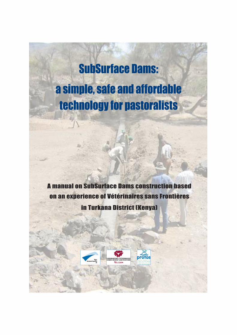
SubSurface Dams:
a simple, safe and affordable technology for pastoralists
A manual on SubSurface Dams construction based
on an experience of Vétérinaires sans Frontières
in Turkana District (Kenya)
LIST OF ACRONYMS AND ABBREVIATIONS
Adakar village comprising several households for purposes of joint security of their livestock herdsBSF Belgian Survival FundDWO District Water OfficerGoK Government of KenyaKSh Kenyan ShillingLS LivestockNGO Non Governmental OrganizationPRA Participatory Rural AppraisalShoats Sheep and goatsSSD Subsurface damTLDP Turkana Livestock Development ProjectVSF-DZG Vétérinaires Sans Frontières-Dierenartsen Zonder Grenzen
�5�
T 1/ Preface ~~~~~~~~~~~~~~~~~~~~~~~~~~~~~~~~~~~~~~~~~~~~~~~~~~~~~~~~~~~~~~~~~~~~~~~~~~~~~~~~~~~~~ 5
2/ Summary ~~~~~~~~~~~~~~~~~~~~~~~~~~~~~~~~~~~~~~~~~~~~~~~~~~~~~~~~~~~~~~~~~~~~~~~~~~~~~~~~~~ 6
3/ Context ~~~~~~~~~~~~~~~~~~~~~~~~~~~~~~~~~~~~~~~~~~~~~~~~~~~~~~~~~~~~~~~~~~~~~~~~~~~~~~~~~~~~~ 7
3.1. Brief comment on the Turkana and on the VSF(TLDP)-project ~~~~~~~~~~ 7
3.2. Access to water, use of water, women's role and presence of SSD in
in Turkana District ~~~~~~~~~~~~~~~~~~~~~~~~~~~~~~~~~~~~~~~~~~~~~~~~~~~~~~~~~~~~~~~~~ 9
4/ Subsurface dams (SSD)-technology ~~~~~~~~~~~~~~~~~~~~~~~~~~~~~~~~~~~~~~~~~~~~~~~ 11
4.1. Basic principles of ground water dams and subsurface dams ~~~~~~~~~~~ 114.1.1. what are ground water dams:
subsurface dams and sand storage dams? ~~~~~~~~~~~~~~~~~~~~~~~~~~ 11
4.1.2. advantages of subsurface dams ~~~~~~~~~~~~~~~~~~~~~~~~~~~~~~~~~~~~~~~ 13
4.1.3. difference between subsurface dams and sand storage dams ~~ 15
4.2. Where to construct SSD ~~~~~~~~~~~~~~~~~~~~~~~~~~~~~~~~~~~~~~~~~~~~~~~~~~~~~~~~ 16
4.2.1. technical aspects ~~~~~~~~~~~~~~~~~~~~~~~~~~~~~~~~~~~~~~~~~~~~~~~~~~~~~~~~~ 16
4.2.2. social aspects ~~~~~~~~~~~~~~~~~~~~~~~~~~~~~~~~~~~~~~~~~~~~~~~~~~~~~~~~~~~~~ 17
4.3. Technical design of SSD ~~~~~~~~~~~~~~~~~~~~~~~~~~~~~~~~~~~~~~~~~~~~~~~~~~~~~~~~ 18
4.3.1. technical assessment of site suitability ~~~~~~~~~~~~~~~~~~~~~~~~~~~~~~~ 18
4.3.2. assessment of subsurface dams as part of a wider-areaplan ~~~ 21
4.3.3. simple methods for technical assessment ~~~~~~~~~~~~~~~~~~~~~~~~~~ 22
4.3.4. construction ~~~~~~~~~~~~~~~~~~~~~~~~~~~~~~~~~~~~~~~~~~~~~~~~~~~~~~~~~~~~~~~ 29
4.3.5. bill of quantities ~~~~~~~~~~~~~~~~~~~~~~~~~~~~~~~~~~~~~~~~~~~~~~~~~~~~~~~~~~ 32
5/ Social design of SSD/community participation ~~~~~~~~~~~~~~~~~~~~~~~~~~~~~~~~~~ 34
5.1. List of requirements for action ~~~~~~~~~~~~~~~~~~~~~~~~~~~~~~~~~~~~~~~~~~~~~~~~~ 35
5.2. Different steps in the process ~~~~~~~~~~~~~~~~~~~~~~~~~~~~~~~~~~~~~~~~~~~~~~~~~ 36
6/ Impact of Assessment ~~~~~~~~~~~~~~~~~~~~~~~~~~~~~~~~~~~~~~~~~~~~~~~~~~~~~~~~~~~~~~~~ 42
6.1. Gender ~~~~~~~~~~~~~~~~~~~~~~~~~~~~~~~~~~~~~~~~~~~~~~~~~~~~~~~~~~~~~~~~~~~~~~~~~~~~~ 42
6.2. Environment ~~~~~~~~~~~~~~~~~~~~~~~~~~~~~~~~~~~~~~~~~~~~~~~~~~~~~~~~~~~~~~~~~~~~~~ 42
6.3. Technical assessment ~~~~~~~~~~~~~~~~~~~~~~~~~~~~~~~~~~~~~~~~~~~~~~~~~~~~~~~~~~ 43
7/ Lessons learnt ~~~~~~~~~~~~~~~~~~~~~~~~~~~~~~~~~~~~~~~~~~~~~~~~~~~~~~~~~~~~~~~~~~~~~~~~~~ 44
Bibliography ~~~~~~~~~~~~~~~~~~~~~~~~~~~~~~~~~~~~~~~~~~~~~~~~~~~~~~~~~~~~~~~~~~~~~~~~~~~~~~~~~ 48
ABLE OF CONTENT
�6�
�7�
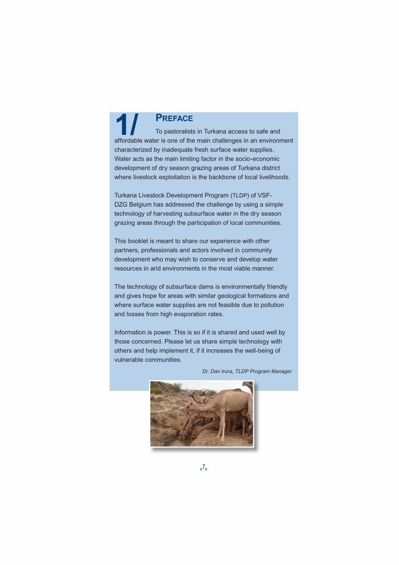
1/ PREFACETo pastoralists in Turkana access to safe and
affordable water is one of the main challenges in an environment characterized by inadequate fresh surface water supplies. Water acts as the main limiting factor in the socio-economic development of dry season grazing areas of Turkana district where livestock exploitation is the backbone of local livelihoods.
Turkana Livestock Development Program (TLDP) of VSF-DZG Belgium has addressed the challenge by using a simple technology of harvesting subsurface water in the dry season grazing areas through the participation of local communities.
This booklet is meant to share our experience with other partners, professionals and actors involved in community development who may wish to conserve and develop water resources in arid environments in the most viable manner.
The technology of subsurface dams is environmentally friendly and gives hope for areas with similar geological formations and where surface water supplies are not feasible due to pollution and losses from high evaporation rates.
Information is power. This is so if it is shared and used well by those concerned. Please let us share simple technology with others and help implement it, if it increases the well-being of vulnerable communities.
Dr. Dan Irura, TLDP Program Manager
�8�
2/ SUMMARYSoil and water conservation is a high priority in the drier areas of sub-
Saharan Africa. Storage of water from the rainy season to the dry season, or even from wet years to dry years is highly important. Groundwater dams, which store water under the ground, can store sufficient quantities of water for livestock and minor irrigation as well as for domestic use. If sited and built properly, dams can give an appropriate answer to the waterneed. Unfortunately there are also many examples of groundwater dams which have not been successful due to insufficient technical and social assessment and design. Lack of appropriate investigation for identifying suitable sites to construct the underground dyke often leads to subsurface lateral loss of water.For a better livestock health and access to water and dry season grazing lands, the TLDP-project applied the simple, affordable, replicable technology of subsurface dams. By building an underground dam in the bed of a dry river, rain and groundwater is filtered, collected and stored underground.Apart from a technical and social assessment phase, technical and social design of SSD has to be done very carefully. Community participation and awareness creation (empowerment) are essential to the success of the intervention.This manual builds on the experience with subsurface dams of Vétérinaires sans Frontières in the Turkana-District in the North West of Kenya, explaining all phases from the initial assessment to the design of the dams based on the own lessons learnt with this specific technique.
© T
.Gee
nen
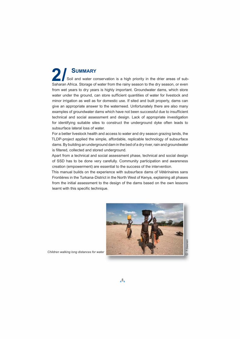
Children walking long distances for water
�9�
3/ CONTEXT
3.1. BRIEF COMMENT ON THE TURKANA AND THE VSF (TLDP)-PROJECT
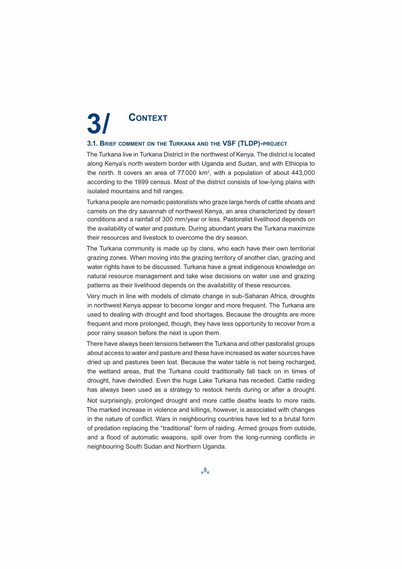
The Turkana live in Turkana District in the northwest of Kenya. The district is located along Kenya’s north western border with Uganda and Sudan, and with Ethiopia to the north. It covers an area of 77.000 km2, with a population of about 443,000 according to the 1999 census. Most of the district consists of low-lying plains with isolated mountains and hill ranges.
Turkana people are nomadic pastoralists who graze large herds of cattle shoats and camels on the dry savannah of northwest Kenya, an area characterized by desert conditions and a rainfall of 300 mm/year or less. Pastoralist livelihood depends on the availability of water and pasture. During abundant years the Turkana maximize their resources and livestock to overcome the dry season.
The Turkana community is made up by clans, who each have their own territorial grazing zones. When moving into the grazing territory of another clan, grazing and water rights have to be discussed. Turkana have a great indigenous knowledge on natural resource management and take wise decisions on water use and grazing patterns as their livelihood depends on the availability of these resources.
Very much in line with models of climate change in sub-Saharan Africa, droughts in northwest Kenya appear to become longer and more frequent. The Turkana are used to dealing with drought and food shortages. Because the droughts are more frequent and more prolonged, though, they have less opportunity to recover from a poor rainy season before the next is upon them.
There have always been tensions between the Turkana and other pastoralist groups about access to water and pasture and these have increased as water sources have dried up and pastures been lost. Because the water table is not being recharged, the wetland areas, that the Turkana could traditionally fall back on in times of drought, have dwindled. Even the huge Lake Turkana has receded. Cattle raiding has always been used as a strategy to restock herds during or after a drought.
Not surprisingly, prolonged drought and more cattle deaths leads to more raids. The marked increase in violence and killings, however, is associated with changes in the nature of conflict. Wars in neighbouring countries have led to a brutal form of predation replacing the “traditional” form of raiding. Armed groups from outside, and a flood of automatic weapons, spill over from the long-running conflicts in neighbouring South Sudan and Northern Uganda.
�10�
As a result of the droughts and growing insecurity, the Turkana have moved from a state in which they are able to cope most of the time, to one in which destitution and vulnerability to famine is a constant danger. The life of Turkana people is inevitably changing. Droughts and increasing conflicts are the basis of loss of traditional social and political structures. More people are settling in and around towns.
Since 1999, VSF-Belgium manages the Livestock Development Program (TLDP), covering the southwest part of Turkana district, financed by the Belgian Survival Fund. This project intends to cope with the specific problems of the Turkana people. The overall aim of the program is to improve the viability of the pastoralist way of life by improving animal health and production, increasing access to dry season grazing areas, improving opportunities for livestock marketing, and increasing pastoralists’ involvement in their own development.The project develops activities like training local Turkana-nomadic technical persons, chosen by the local communities, and developing a local network of veterinary services. The project facilitates better access to (weekly cattle) markets with better marketing procedures, giving the nomads a right price for their cattle. The project also supports the process between conflicting groups to maintain peace in the region.
© T
.Gee
nen
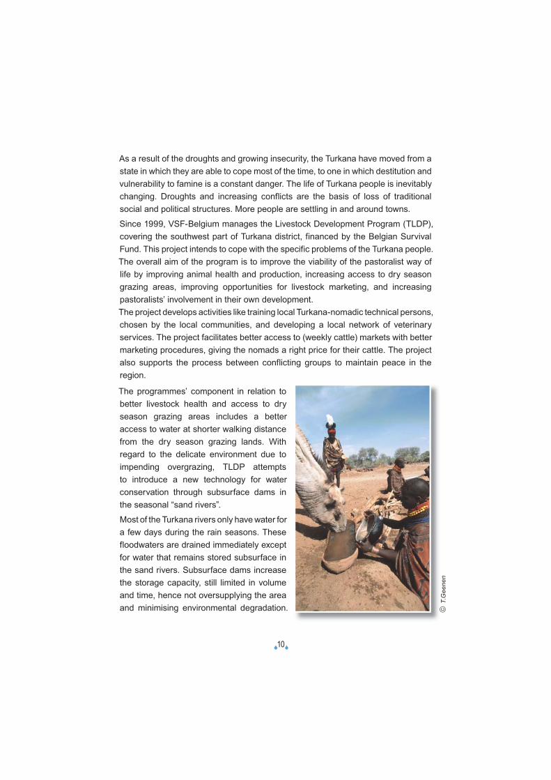
The programmes’ component in relation to better livestock health and access to dry season grazing areas includes a better access to water at shorter walking distance from the dry season grazing lands. With regard to the delicate environment due to impending overgrazing, TLDP attempts to introduce a new technology for water conservation through subsurface dams in the seasonal “sand rivers”.
Most of the Turkana rivers only have water for a few days during the rain seasons. These floodwaters are drained immediately except for water that remains stored subsurface in the sand rivers. Subsurface dams increase the storage capacity, still limited in volume and time, hence not oversupplying the area and minimising environmental degradation.

�11�
3.2. ACCESS TO WATER, USE OF WATER, WOMEN’S ROLE AND PRESENCE OF SSDS IN TURKANA DISTRICT
In general, only 41% of the Turkana people have access to a reliable drinking water source(1).Many water points have been created by the TRP (Turkana Rehabilitation Program), by the EC (European Community), the TWP (Turkana Water Project, carried out by the Diocese of Lodwar) and other actors. By April 1999 there were 350 bore holes in the district, of which only 183 were functioning. The majority of the pumps are hand driven; others are gas oil, solar or wind driven. TRP also constructed 310 shallow wells in the district, of which 161 are functioning.
These water sources, with a few exceptions, have been created to serve the settled communities. Few of them serve the pastoralist population and in most cases these sources of water are located close to rivers and other sources of water. Consequently, few of them serve the pastoralists, even though they do fall back on them in times of stress.
Pastoralists access water from different types of water sources. Fortunately, the district is endowed with a number of seasonal rivers and water courses. Although dictated by the amount of rainfall and season, shallow wells and traditional scoop holes in the river are a common source of water for the pastoralists.
Water points are mostly identified through trial and error method and are located at isolated spots on the riverbeds. Water is drawn from unlined depths of up to 8m below riverbeds, as is the case in Lokidodokae and Nakurio water points. One has to keep on changing wells as the water disappears.
1) Source: Pulling Apart, Facts and Figures of Inequality in Kenya, Society for International Development, 2004.
�12�
The Turkana pastoralists extract their water from underground by scooping the top soil and sand from dry river beds to reach the water table. This method especially involves women, for whom it is their main task, as they take care of the watering of the animals. Women play an important role in livestock management related activities in a Turkana setting(2).
Both the surface and subsurface runoff are not meaningfully utilized but left, flowing to waste in exception of some minor recovery for irrigation along the Kerio and Turkwel river lines.
More than 300 sand storage dams and SSDs have been built in other parts of Kenya by various projects (in south Eastern Machakos, Kitui and Makueni) through the following Organizations/Programme:
• African Land Development (ALDEV) in the 1950’s.• Machakos Integrated Development project (MIDP) in the 1980’s.• Kitui ASAL Programme in the 1980’s.• The Green Valley Project (DANIDA) in the 1970’s.• ASALCON – Makueni and Kibwezi in the 1980’s.
In Turkana district, TLDP constructed clay subsurface dams in Lokichoggio and Kocheede in Lorugum on trial basis in 1999, but due to poor workmanship and lack of technical supervision, the activities nearly discouraged inception of the idea by the community.
Learning about this fi rst experience further development by TLDP was very successful. First the TLDP-project constructed 9 SSDs with concrete at a higher cost of 245 to 584,000 KSh, with a capacity of 380 to 1,800 m³ of water (and one containing even 4,047 m³). Because of the high cost other designs were developed, basically made out of clay (with only a concrete top layer for stabilisation purposes). On this basis 12 clay SSDs were constructed, with a capacity of 425 to 1,342 m³ and at a cost of 63,000 to 114,000 KSh.
2) The following list of activities gives an idea of the responsibilities of women concerning the livestock: milking (goats, camels, cows), taking care of calves, identifying sick animals (by colour, smell, taste of milk, by close observation of hooves, skin, eyes, etc.), construction of animal shed, watering animals, counting animals, bleeding animals (goats, camels, cows), removing ticks from young animals, make calabash/through for watering animals, preparing sour milk, drying milk, preparing hides and skins, etc.
�13�
4/ SUBSURFACE DAMS (SSD)-TECHNOLOGY
4.1. BASIC PRINCIPLES OF GROUNDWATER DAMS: SUBSURFACE DAMS AND SANDSTORAGE DAMS
4.1.1. WHAT ARE GROUNDWATER DAMS: SUBSURFACE DAMS AND SANDSTORAGE DAMS?
Subsurface dams are groundwater dams, which are structures that intercept or obstruct the natural flow of groundwater and provide storage for water underground. They have been used in several parts of the world, notably India, Africa and Brazil. They are used in areas where flows of groundwater vary considerably during the course of the year, from very high flows following rain to negligible flows during the dry season. Groundwater dams can be divided in two types: subsurface dams and sandstorage dams.
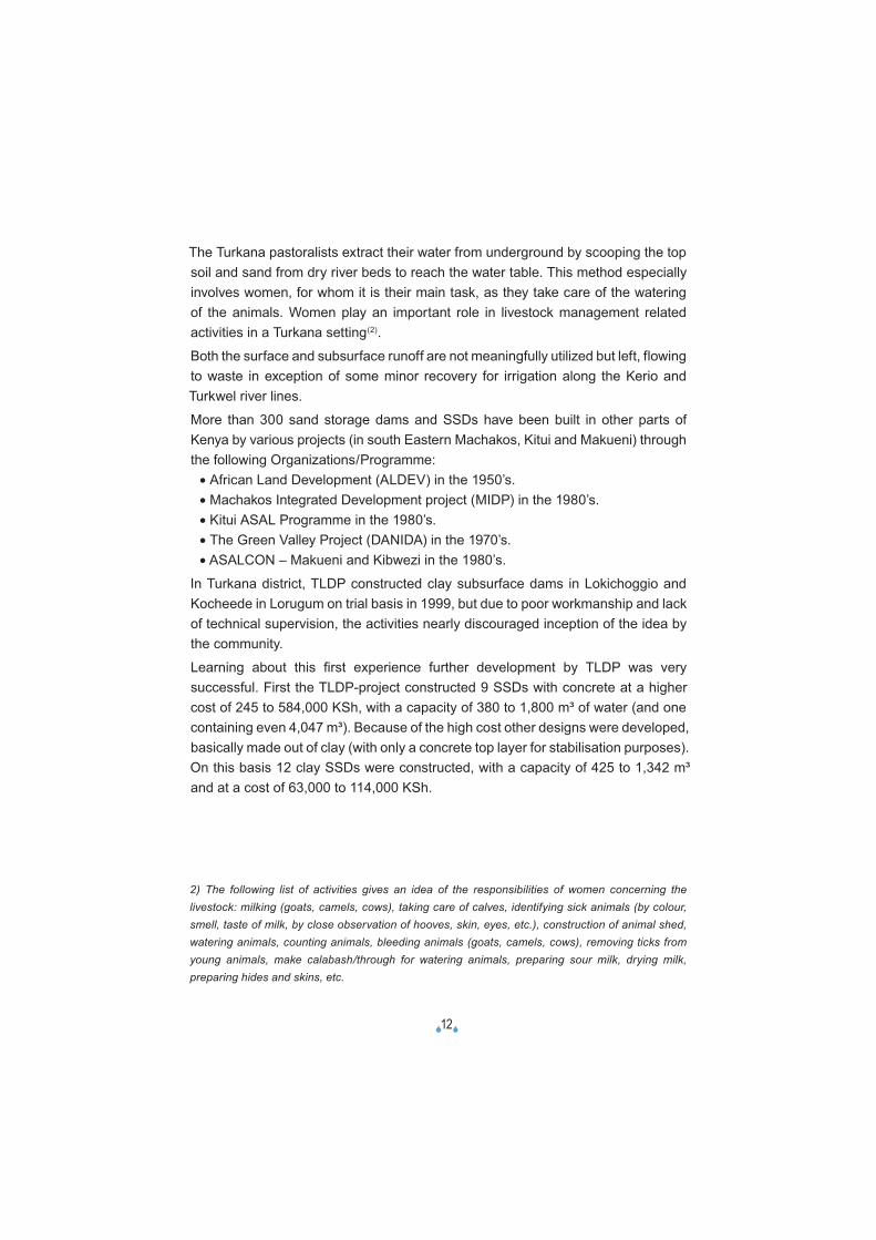
A subsurface dam intercepts or obstructs the flow of an aquifer and reduces the variation of the level of the groundwater table upstream of the dam. It is built entirely under the ground (see figure)
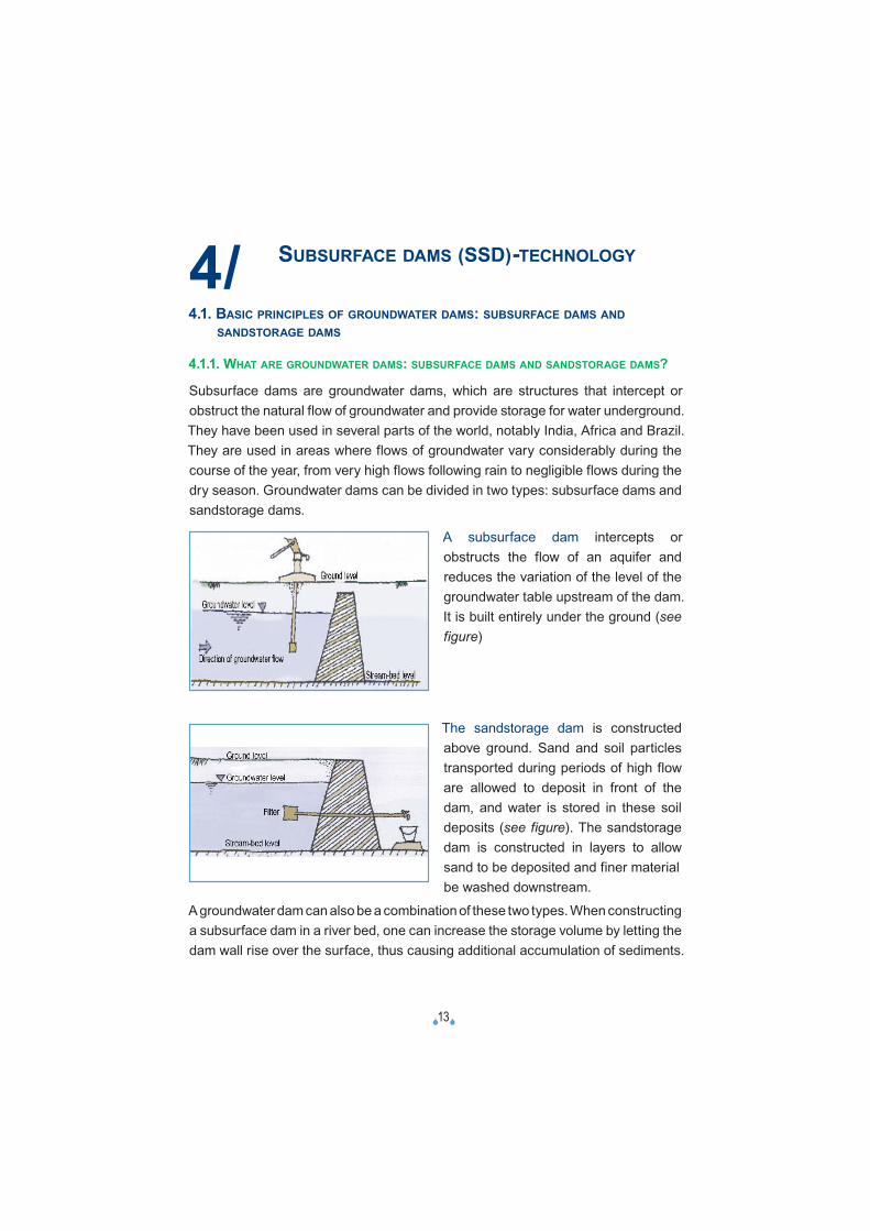
The sandstorage dam is constructed above ground. Sand and soil particles transported during periods of high flow are allowed to deposit in front of the dam, and water is stored in these soil deposits (see figure). The sandstorage dam is constructed in layers to allow sand to be deposited and finer material
be washed downstream.
A groundwater dam can also be a combination of these two types. When constructing a subsurface dam in a river bed, one can increase the storage volume by letting the dam wall rise over the surface, thus causing additional accumulation of sediments.
�14�
Similarly, when a sandstorage dam is constructed it is necessary to excavate a trench in the sand bed in order to reach bedrock, which can be used to create a subsurface dam too.
Groundwater dams are built across streams or valleys. A trench is dug across the valley or stream, reaching to the bedrock or other stable layer like clay. An impervious wall is constructed in the trench, which is then refilled with the excavated material.
A subsurface dam is constructed below ground level and arrests the flow in a natural aquifer.The best sites for construction of groundwater dams are those where the soil consists of sands and gravel, with rock or an impermeable layer at a few metres’ depth. Ideally, the dam should be built there where rainwater from a large catchment area flows through a narrow passage.
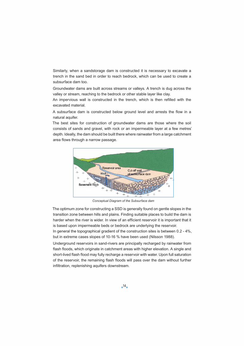
The optimum zone for constructing a SSD is generally found on gentle slopes in the transition zone between hills and plains. Finding suitable places to build the dam is harder when the river is wider. In view of an efficient reservoir it is important that it is based upon impermeable beds or bedrock are underlying the reservoir.In general the topographical gradient of the construction sites is between 0.2 - 4%, but in extreme cases slopes of 10-16 % have been used (Nilsson 1988).
Underground reservoirs in sand-rivers are principally recharged by rainwater from flash floods, which originate in catchment areas with higher elevation. A single and short-lived flash flood may fully recharge a reservoir with water. Upon full saturation of the reservoir, the remaining flash floods will pass over the dam without further infiltration, replenishing aquifers downstream.
Conceptual Diagram of the Subsurface dam
�15�
A few hours after the passing of a flash flood, the surface of the sand-river may look dry again, but the water which in the meantime has been stored in the reservoir can be drawn for many months.
In subsurface dams water may be obtained from the underground reservoir from a well upstream of the dam. The subsurface dam technology is designed to block underground water flow at shallow depth, so that traditional watering points will be lasting longer and new watering points will be created to develop unused grazing areas.
4.1.2. ADVANTAGES/DISADVANTAGES OF SUBSURFACE DAMS
The basic principle of the groundwater dam is this: instead of storing the water in surface reservoirs, water is stored underground. It is composed of a cut-off wall by which the groundwater flow is dammed (or intrusion of the seawater is prevented), and facilities (like wells, intake shaft and pumps) that draw up the stored groundwater.
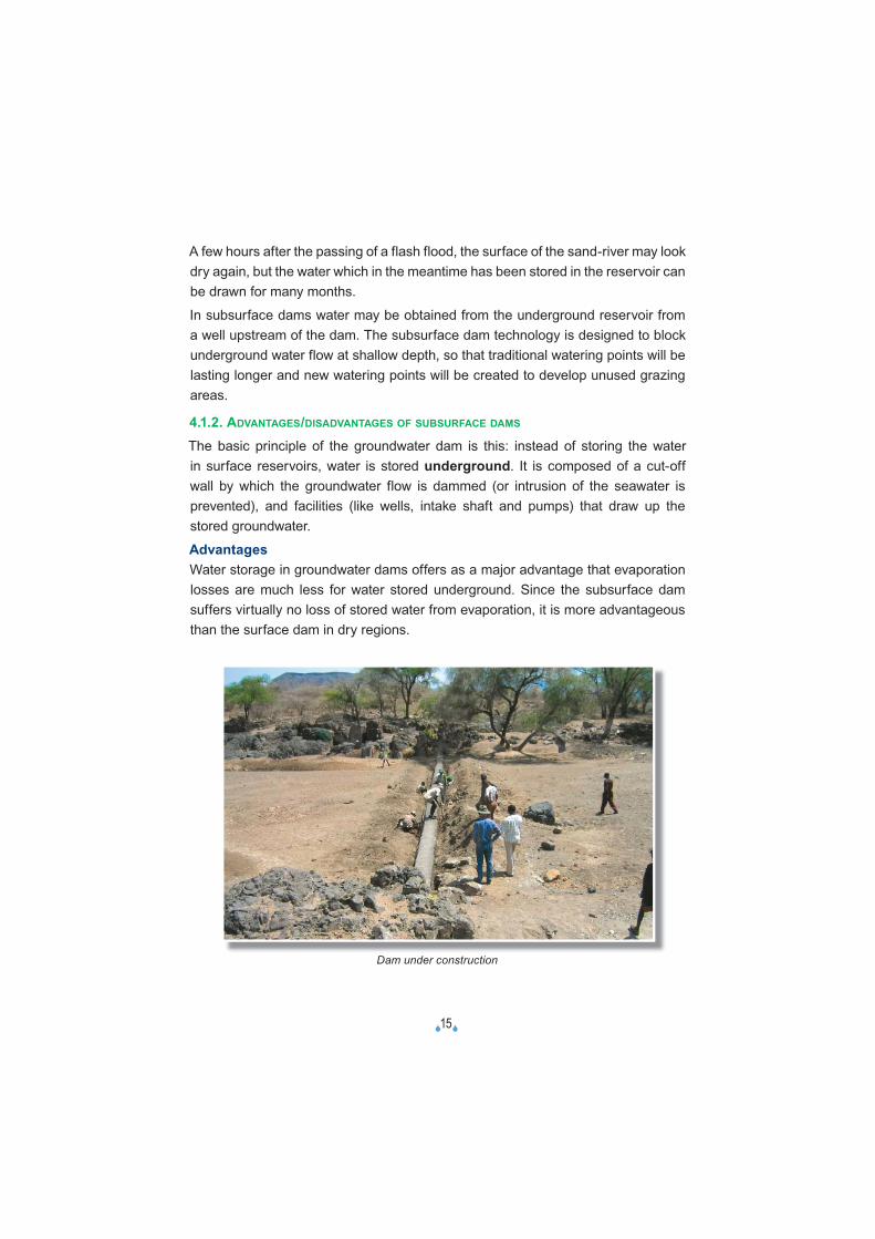
AdvantagesWater storage in groundwater dams offers as a major advantage that evaporation losses are much less for water stored underground. Since the subsurface dam suffers virtually no loss of stored water from evaporation, it is more advantageous than the surface dam in dry regions.
Dam under construction
�16�
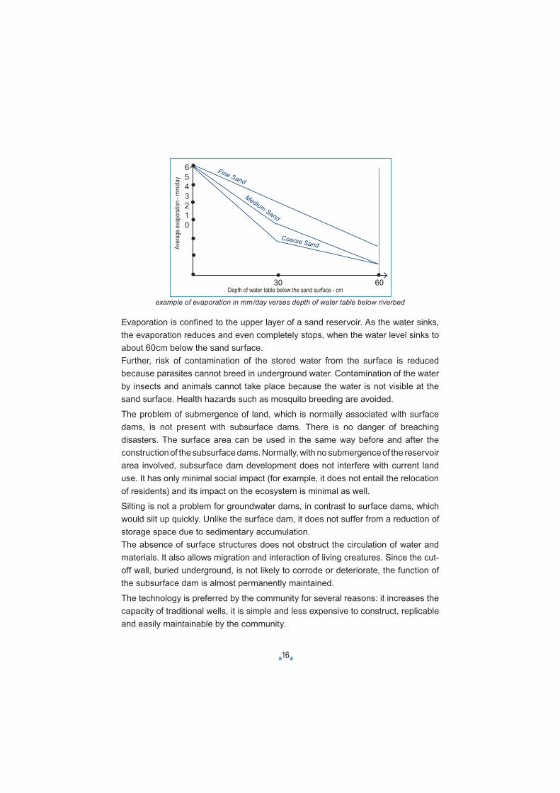
Evaporation is confined to the upper layer of a sand reservoir. As the water sinks, the evaporation reduces and even completely stops, when the water level sinks to about 60cm below the sand surface.Further, risk of contamination of the stored water from the surface is reduced because parasites cannot breed in underground water. Contamination of the water by insects and animals cannot take place because the water is not visible at the sand surface. Health hazards such as mosquito breeding are avoided.
The problem of submergence of land, which is normally associated with surface dams, is not present with subsurface dams. There is no danger of breaching disasters. The surface area can be used in the same way before and after the construction of the subsurface dams. Normally, with no submergence of the reservoir area involved, subsurface dam development does not interfere with current land use. It has only minimal social impact (for example, it does not entail the relocation of residents) and its impact on the ecosystem is minimal as well.
Silting is not a problem for groundwater dams, in contrast to surface dams, which would silt up quickly. Unlike the surface dam, it does not suffer from a reduction of storage space due to sedimentary accumulation.The absence of surface structures does not obstruct the circulation of water and materials. It also allows migration and interaction of living creatures. Since the cut-off wall, buried underground, is not likely to corrode or deteriorate, the function of the subsurface dam is almost permanently maintained.
The technology is preferred by the community for several reasons: it increases the capacity of traditional wells, it is simple and less expensive to construct, replicable and easily maintainable by the community.
example of evaporation in mm/day verses depth of water table below riverbed
Depth of water table below the sand surface - cm
6543210
30 60
•
•
•
•
•
•
• ••
Fine Sand
Medium Sand
Coarse SandAver
age e
vapo
ratio
n - m
m/da
y
�17�
Further it causes less contamination of water and a temporary availability of water avoids attracting permanent human settlement. Maintenance is simple. Construction costs are relatively low.
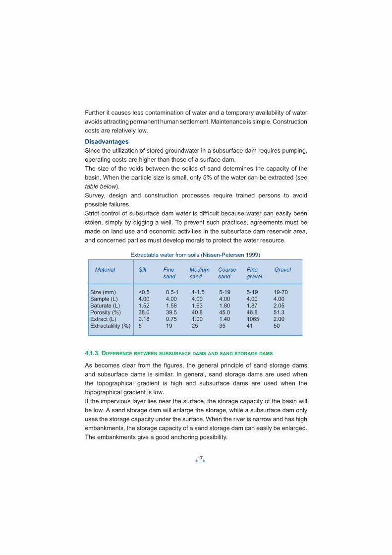
DisadvantagesSince the utilization of stored groundwater in a subsurface dam requires pumping, operating costs are higher than those of a surface dam.The size of the voids between the solids of sand determines the capacity of the basin. When the particle size is small, only 5% of the water can be extracted (see table below).Survey, design and construction processes require trained persons to avoid possible failures.Strict control of subsurface dam water is difficult because water can easily been stolen, simply by digging a well. To prevent such practices, agreements must be made on land use and economic activities in the subsurface dam reservoir area, and concerned parties must develop morals to protect the water resource.
4.1.3. DIFFERENCE BETWEEN SUBSURFACE DAMS AND SAND STORAGE DAMS
As becomes clear from the figures, the general principle of sand storage dams and subsurface dams is similar. In general, sand storage dams are used when the topographical gradient is high and subsurface dams are used when the topographical gradient is low.If the impervious layer lies near the surface, the storage capacity of the basin will be low. A sand storage dam will enlarge the storage, while a subsurface dam only uses the storage capacity under the surface. When the river is narrow and has high embankments, the storage capacity of a sand storage dam can easily be enlarged. The embankments give a good anchoring possibility.
Extractable water from soils (Nissen-Petersen 1999)
Material Silt Fine Medium Coarse Fine Gravel sand sand sand gravel
Size (mm) <0.5 0.5-1 1-1.5 5-19 5-19 19-70Sample (L) 4.00 4.00 4.00 4.00 4.00 4.00Saturate (L) 1.52 1.58 1.63 1.80 1.87 2.05Porosity (%) 38.0 39.5 40.8 45.0 46.8 51.3Extract (L) 0.18 0.75 1.00 1.40 1065 2.00Extractalility (%) 5 19 25 35 41 50
�18�
An advantage of subsurface dams over sand storage dams is their simple design. Water does not flow through the dam and no spillway is needed. Unlike a sand storage dam, a subsurface dam is not exposed to forces of flowing water. It is clear that different circumstances ask for different solutions.
4.2. WHERE TO CONSTRUCT SSD
4.2.1. TECHNICAL ASPECTS
Geography, topography, hydrology and geologyThe construction of a subsurface dam generally requires cutting off where a subsurface valley is covered by an aquifer. Subsurface valleys are usually formed where the ground is undulating. Similar to surface dams, effective sites for subsurface dam development (suitable slopes) can be easily found by tracing subsurface valleys.
River banks must be well-defi ned and stable. Rocky banks and gorges are the best features. Wide meandering rivers in sand are an indication that no lateral confi nement is present and so the risk of lateral fl ow and leakages is high.
With increasing depth, the thickness of different rock beds varies from place to place due to their natural activities of deposition and erosion. Therefore, fi eld exploration / investigation are advised to ascertain the status of each selected site.Soil types with large porosity, which can hold large volumes of water, including the alluvial gravel layer, limestone and volcanic rocks are good for SSD construction.A minimum topographic riverbed slope is required. Suitable gradients lie between 0.2% and 4%. This is usually the case in the transition zones between hills and plains.The river stream must be reasonably narrow for the obvious reason of economizing on the materials and labour.For the Turkana district, geologically, two major classes of rocks are lying beneath; metamorphic and volcanic. Lithological materials, which are ideal for dam construction, because they are dense and can be very well compacted, are present in wide areas of the district. Turkana district being in the Rift Valley basin, the drainage system is naturally designed to favour subsurface reservoirs.
The data to collect for the technical assessment They include topographic maps (on a scale of approximately 1 to 200,000), geological maps (on a scale of approximately 1 to 200,000) and aerial photographs. The analysis of aerial photographs may help in estimating the subsurface valley shape. The other data that must be collected include the rainfall, river discharge, groundwater level and water quality. The collection of available data preferably goes back to the past 10 years at least. The targets of analysis are groundwater level fl uctuations (seasonal and yearly) and water quality deterioration.
�19�
Looking for tree species as an indicator for water rich undergroundA dense and green vegetation is an obvious sign of a water rich underground. There are commonly known tree species that are used to indicate wetness and water table underground. In Turkana, there are Ekalale (Ziziphus maruritiana), Esanyanait (Acacia elatior) and Etesiro (Calatropics procera).
4.2.2. SOCIAL ASPECTS
Ownership/number of benefi ciariesThe owner(s) of the land adjacent to the dam site should agree and give way to the site. The dams should not be located on private property or interest.A good number of households should be present for better cost-effectiveness.An area with cultural believes should be avoided at most and if no other site is available, cultural rituals will be done in favour of a safe construction.
Participation and involvement of all users of the water of SSDParticipatory approaches are necessary for sustainability and appropriation of the action by the benefi ciaries. This starts with the community: it defi nes its problems, sets its priorities, and makes decisions on how to solve them. External organisations can be catalysts or facilitators. Participative approaches recognize that local people in a given area have a better knowledge of the problems they face than anyone else; they know the natural and human resources available, and know what may or may not work in a given situation. By encouraging the local community to seek their own solutions rather than imposing solutions from outside, the initiative, knowledge and talents of the people are challenged, the community is empowered and the likelihood that development measures will be sustained is greatly enhanced.
During pre-feasibility studies acquiring data at the level of the communities on the history of the respective aquifers can be important.
Data could include, among others, the seasons and duration pastoralists have been accessing the water, the type and population of livestock served, distance trek between pasture and watering points etc.
Several potential target groups such as farmers, peri-urban populations, nomads,... use the same natural resources in an area, however having different goals and methods and having a differential impact on both the natural environment (including wildlife and domestic animals). The different goals and aspirations of these groups should be taken into consideration and brought together in a participative way to come to an integrated approach and joint planning on the future water- and land use.
�20�
SecurityThis cannot be overemphasized because SSD sites are watering points where a large population of livestock and producers converge. Sites should be areas guaranteed of peace. Matters on land ownership and tenure should be amicably predetermined not to arouse any animosity or confrontation.
The timing of constructionThe question being answered here is: “When is the opportune time to do the construction?” The best time to undertake construction is at the peak of the dry season, because:• the lowest possible water table level is reached so that maximum water reserve
is acquired.• water logging during construction is minimized and intermediate work pauses are
curbed so that the activity is completed on time and within budget.• it is the time water demand by pastoralists is at its highest; community mobilization
will be simplifi ed and a big community turn-out for participation will be realized.• it is the most peaceful time when the state of livestock health does not provoke
rustling.
4.3. TECHNICAL DESIGN OF SSD
4.3.1. TECHNICAL ASSESSMENT OF SITE SUITABILITY
Criteria (checklist)Criteria based on experiences in Kenya are given below; they should be treated as examples, not as fi nal lists. For every site, specifi c issues may need to be taken into account.
• Scoop holes where people fetch water at least for a month or more after the rainy season, are located. These indicate the former natural subsurface water streams and aquifers to be replenished. Scoop holes provide an indication of present natural barriers. Scoop holes that dry up during the dry season are considered good locations for a dam. ‘Wet’ scoop holes already provide water all through the year. This information is obtained from users.
• Specifi c tree species which can indicate a high water table are looked for.
• Gradient and recharge possibilities are used as an indication of the volume of a reservoir. A smaller gradient makes a larger reservoir; more recharge will also increase the volume of the reservoir. The depth of the rocks upstream of the dam location is measured: the deeper the rock, the larger the reservoir volume.
�21�
• Banks of at least 1.5 m high are recommended to prevent the construction from being too large. If they are not available, though, and tree species or scope holes indicate water presence, subsurface dams can be constructed.
• Locations are sought out with a solid rock foundation. The rock at the base should not be porous.
• The local materials for construction should be readily available and in good number. Clay or termite heaps should be present. Water needed for the construction must be available in a maximum radius of 1 km.
• Risks of bypass: a dam can’t be built in a bend, since this will cause bypasses.
• A natural barrier can be used as foundation for a dam. Note: there are risks of seepage when the rock is not impermeable. Scoop holes upstream that dry up very fast after the rainy season are suspicious.
• There must be enough infl ow (in mainstreams this is never a problem).
• The river must fl ow from time to time:• to provide water for storage;• to provide a sand load to fi ll the reservoir in front of the dam
• The site in question should be accessible to the benefi ciaries and should have at least some reasonable distance from the main road.
• At least 30 households must be participating for 2 reasons:• there is enough labour power available;• more people benefi t from one dam. This enlarges cost-effectiveness.
• The water quality at the upstream side of the site should be responding to its future use and the water should be very saline.
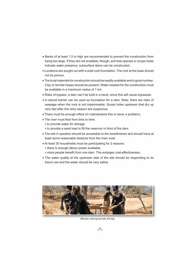
Women sieving termite hill day
�22�
3) A feature of the Turkana pastoralists is that they are still locked up in raiding hostilities with neighbouring tribes. This has forced them to move in secure groups, called ngadakarin, led by “Generals” in the north and protected by home guards in both the north and the south.
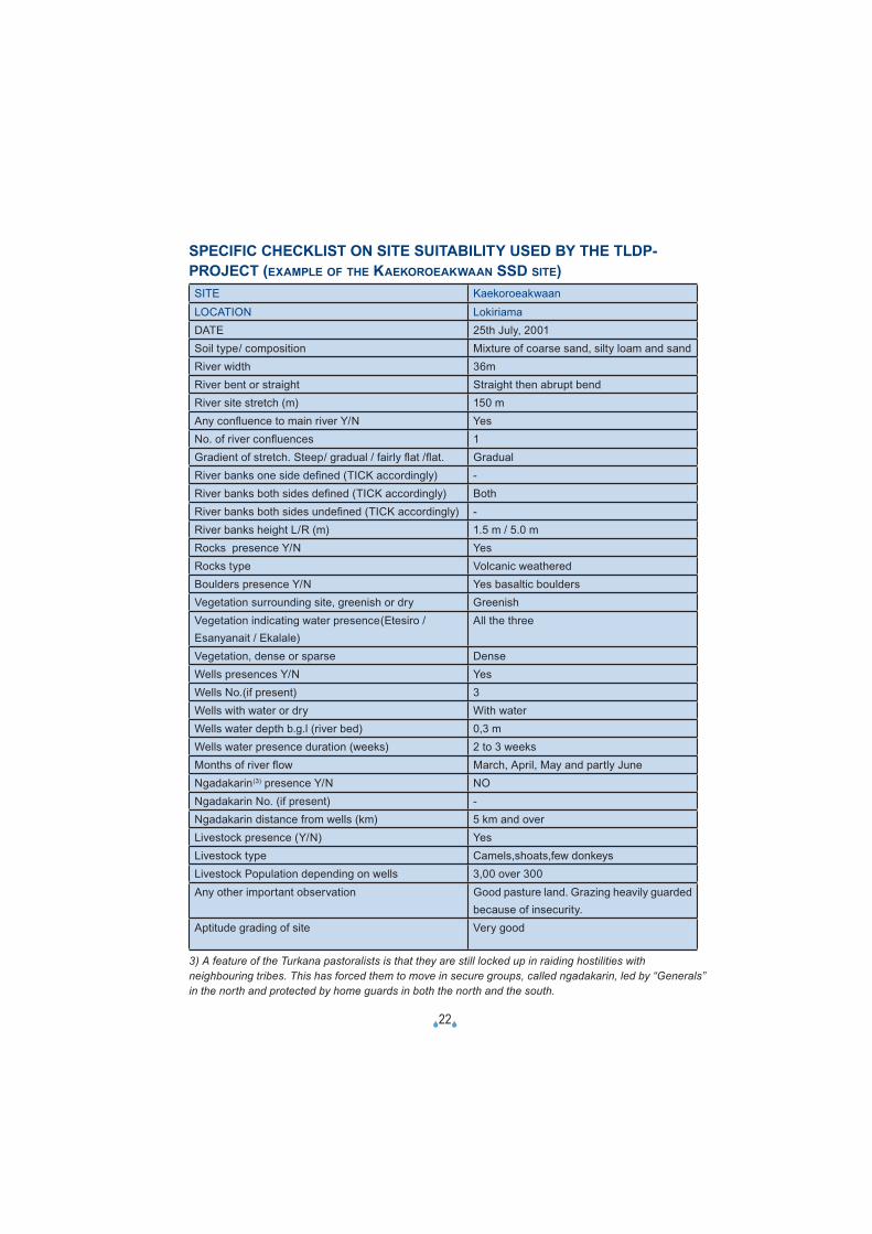
SPECIFIC CHECKLIST ON SITE SUITABILITY USED BY THE TLDP-PROJECT (EXAMPLE OF THE KAEKOROEAKWAAN SSD SITE)SITE Kaekoroeakwaan
LOCATION LokiriamaDATE 25th July, 2001Soil type/ composition Mixture of coarse sand, silty loam and sandRiver width 36mRiver bent or straight Straight then abrupt bendRiver site stretch (m) 150 mAny confl uence to main river Y/N YesNo. of river confl uences 1Gradient of stretch. Steep/ gradual / fairly fl at /fl at. GradualRiver banks one side defi ned (TICK accordingly) -River banks both sides defi ned (TICK accordingly) BothRiver banks both sides undefi ned (TICK accordingly) -River banks height L/R (m) 1.5 m / 5.0 mRocks presence Y/N YesRocks type Volcanic weatheredBoulders presence Y/N Yes basaltic bouldersVegetation surrounding site, greenish or dry GreenishVegetation indicating water presence(Etesiro / Esanyanait / Ekalale)
All the three
Vegetation, dense or sparse DenseWells presences Y/N YesWells No.(if present) 3Wells with water or dry With waterWells water depth b.g.l (river bed) 0,3 mWells water presence duration (weeks) 2 to 3 weeksMonths of river fl ow March, April, May and partly JuneNgadakarin(3) presence Y/N NONgadakarin No. (if present) -Ngadakarin distance from wells (km) 5 km and overLivestock presence (Y/N) YesLivestock type Camels,shoats,few donkeysLivestock Population depending on wells 3,00 over 300 Any other important observation Good pasture land. Grazing heavily guarded
because of insecurity.Aptitude grading of site Very good
�23�
4.3.2. ASSESSMENT OF SUBSURFACE DAMS AS A PART OF A WIDER-AREA PLAN
With a goal of integrating the subsurface dam in the wide-area water supply and utilization network (basin or subbassin plan), the following studies need to be done.
1 Basic studyThe basic study is designed to examine, -while considering regional natural conditions-, the possibility of large-scale water source development such as the construction of subsurface dams, and prepare data necessary for producing a realistic Master Plan.
2 Drafting of the comprehensive basic plan for regional development: Master PlanThe Master Plan is a general wide-area plan that incorporates consideration for the water demand (water utilization plan) and the economic and fi nancial state in the target region.
3 Feasibility StudyThe feasibility study is designed to form consensus among concerned individuals, review the Master Plan based on the consensus and fi nalize individual project plans. It is particularly important during the feasibility study to carefully examine the sustainability of each development project.
4 Detailed designThe detailed design gives detailed designs prior to construction.
5 Implementation of the projectBilateral or multilateral economic and technical cooperation.
6 Maintenance and management
�24�
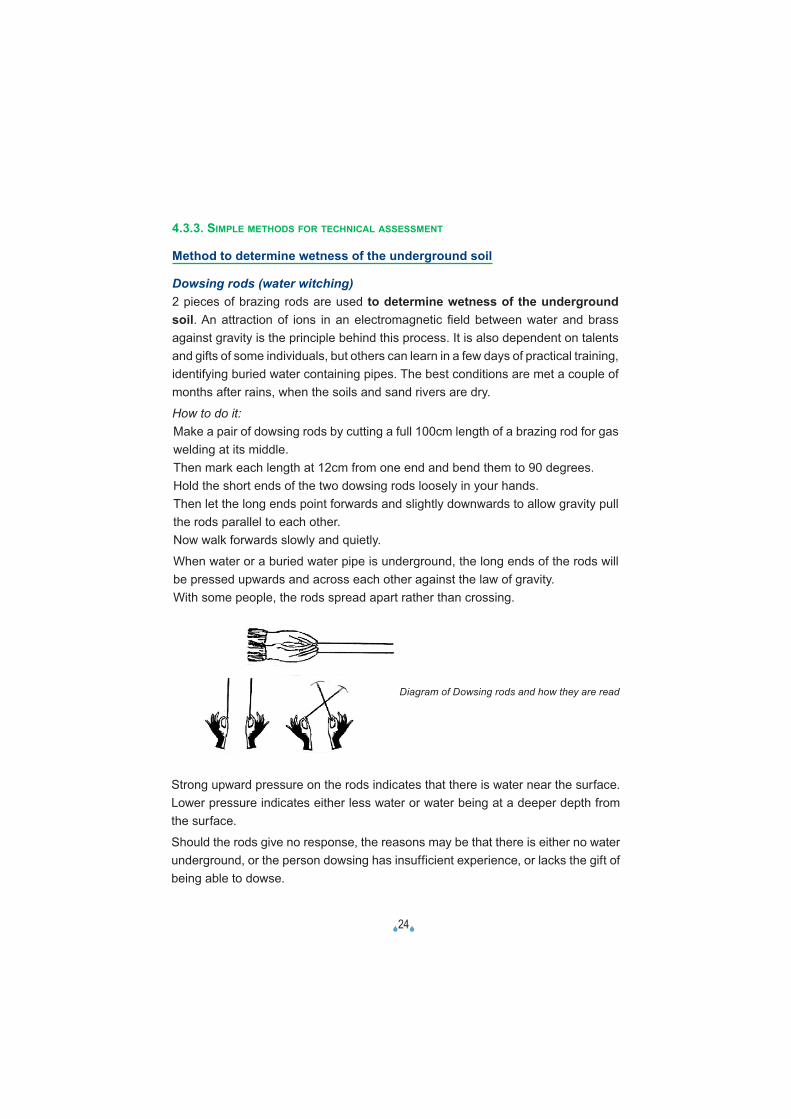
Strong upward pressure on the rods indicates that there is water near the surface. Lower pressure indicates either less water or water being at a deeper depth from the surface.
Should the rods give no response, the reasons may be that there is either no water underground, or the person dowsing has insufficient experience, or lacks the gift of being able to dowse.
Diagram of Dowsing rods and how they are read
4.3.3. SIMPLE METHODS FOR TECHNICAL ASSESSMENT
Method to determine wetness of the underground soil
Dowsing rods (water witching)2 pieces of brazing rods are used to determine wetness of the underground soil. An attraction of ions in an electromagnetic fi eld between water and brass against gravity is the principle behind this process. It is also dependent on talents and gifts of some individuals, but others can learn in a few days of practical training, identifying buried water containing pipes. The best conditions are met a couple of months after rains, when the soils and sand rivers are dry.
How to do it:Make a pair of dowsing rods by cutting a full 100cm length of a brazing rod for gas welding at its middle.Then mark each length at 12cm from one end and bend them to 90 degrees.Hold the short ends of the two dowsing rods loosely in your hands. Then let the long ends point forwards and slightly downwards to allow gravity pull the rods parallel to each other. Now walk forwards slowly and quietly.
When water or a buried water pipe is underground, the long ends of the rods will be pressed upwards and across each other against the law of gravity.With some people, the rods spread apart rather than crossing.
�25�
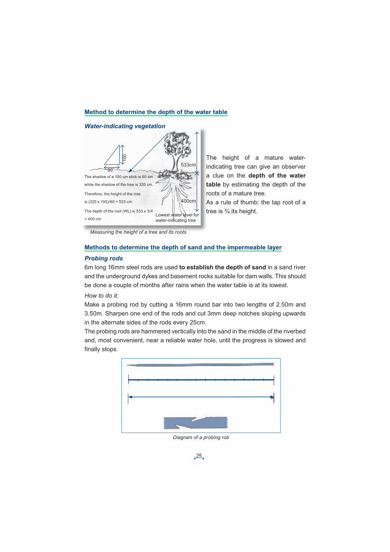
The shadow of a 100 cm stick is 60 cm
while the shadow of the tree is 320 cm.
Therefore, the height of the tree
is (320 x 100)/60 = 533 cm
The depth of the root (WL) is 533 x 3/4
= 400 cmLowest water level forwater-indicating tree
60
100
Method to determine the depth of the water table
Water-indicating vegetation
The height of a mature water-indicating tree can give an observer a clue on the depth of the water table by estimating the depth of the roots of a mature tree.As a rule of thumb: the tap root of a tree is ¾ its height.
Measuring the height of a tree and its roots
Methods to determine the depth of sand and the impermeable layer
Probing rods6m long 16mm steel rods are used to establish the depth of sand in a sand river and the underground dykes and basement rocks suitable for dam walls. This should be done a couple of months after rains when the water table is at its lowest.
How to do it:Make a probing rod by cutting a 16mm round bar into two lengths of 2.50m and 3.50m. Sharpen one end of the rods and cut 3mm deep notches sloping upwards in the alternate sides of the rods every 25cm. The probing rods are hammered vertically into the sand in the middle of the riverbed and, most convenient, near a reliable water hole, until the progress is slowed and finally stops.
533cm
400cm
Diagram of a probing rob
25 25 25 25 25 25 25 25 25 25 25 25 25 25 25 25 25 25 25 25 25 25 25 25 25 25 25 25
350 cm
�26�
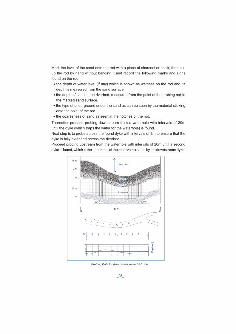
Mark the level of the sand onto the rod with a piece of charcoal or chalk, then pull up the rod by hand without bending it and record the following marks and signs found on the rod:
• the depth of water level (if any) which is shown as wetness on the rod and its depth is measured from the sand surface.
• the depth of sand in the riverbed, measured from the point of the probing rod to the marked sand surface.
• the type of underground under the sand as can be seen by the material sticking onto the point of the rod.
• the coarseness of sand as seen in the notches of the rod.
Thereafter proceed probing downstream from a waterhole with intervals of 20m until the dyke (which traps the water for the waterhole) is found.Next step is to probe across the found dyke with intervals of 3m to ensure that the dyke is fully extended across the riverbed.Proceed probing upstream from the waterhole with intervals of 20m until a second dyke is found, which is the upper end of the reservoir created by the downstream dyke.
1,5 m
2 m
1 m
2,5 m
1 m
Probing Data for Kaekoroeakwaan SSD site
Sand 4m
Granite
Clay
Limestone
60°60°
50 m
109
8 7 6 5 4 32
1
10 9 8 7 6 5 4 3 2 1
01234
Dep
th (m
)
�27�
Then probe across the dyke to ensure it is fully extended across the riverbed. The common constraint here is the encounter of big stone pebbles of boulders in the riverbed, which might give a wrong impression of reaching an underground dyke. At times rods are blunted or broken thereby causing delays and tiredness.
AuguringThis is based on the same principle as probing, but it is tiresome to use augur drills (although auguring gives more definite results). For auguring, drill bits are screwed into the underground. Through the spiral threads on the drill bits, information about the underground soil is determined, just similar to data collected from the probing rods. Big stone pebbles or boulders are mostly the hindrance as they give the wrong impression of reaching an underground dyke by not penetrating deeper. The situation may change, when the drill bit is placed elsewhere nearby. The auguring kits are far from being affordable for the respective economically poor communities.
Trial pitsAlthough used to determine water table depths, it also provides information on the soil patterns.
Methods to determine the soil porosity and the (potential) available volume of water
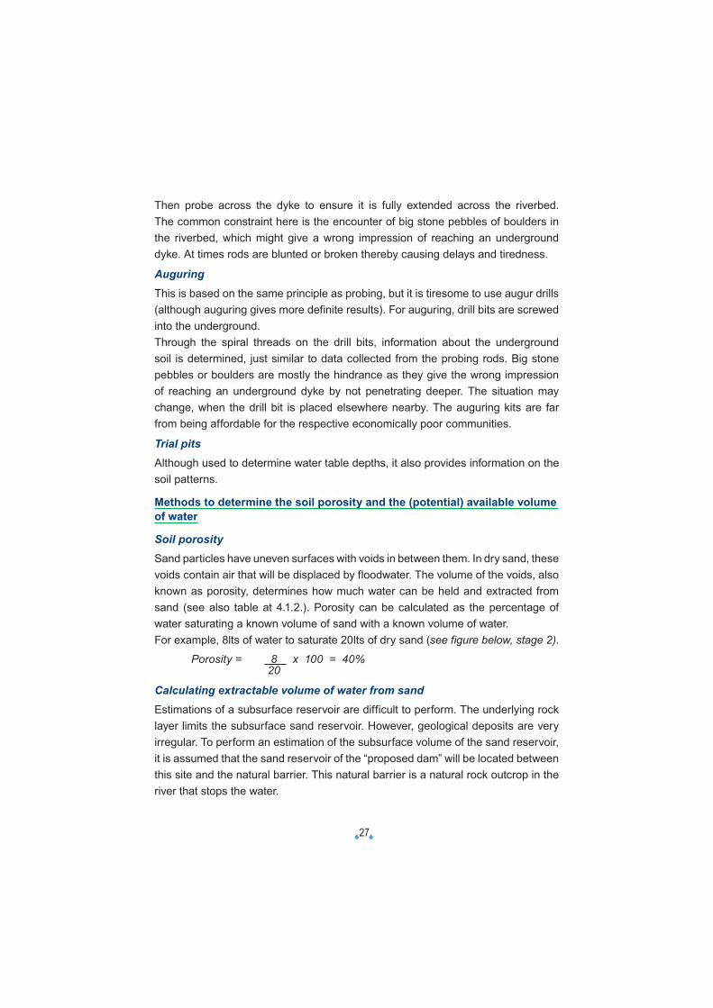
Soil porositySand particles have uneven surfaces with voids in between them. In dry sand, these voids contain air that will be displaced by floodwater. The volume of the voids, also known as porosity, determines how much water can be held and extracted from sand (see also table at 4.1.2.). Porosity can be calculated as the percentage of water saturating a known volume of sand with a known volume of water.For example, 8lts of water to saturate 20lts of dry sand (see figure below, stage 2).
Porosity = 8 x 100 = 40% 20
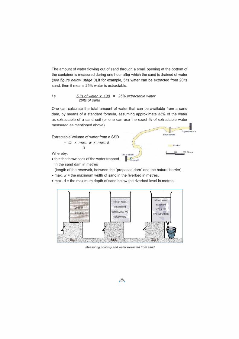
Calculating extractable volume of water from sandEstimations of a subsurface reservoir are difficult to perform. The underlying rock layer limits the subsurface sand reservoir. However, geological deposits are very irregular. To perform an estimation of the subsurface volume of the sand reservoir, it is assumed that the sand reservoir of the “proposed dam” will be located between this site and the natural barrier. This natural barrier is a natural rock outcrop in the river that stops the water.
�28�
The amount of water flowing out of sand through a small opening at the bottom of the container is measured during one hour after which the sand is drained of water (see figure below, stage 3).If for example, 5lts water can be extracted from 20lts sand, then it means 25% water is extractable.
i.e. 5 lts of water x 100 = 25% extractable water 20lts of sand
One can calculate the total amount of water that can be available from a sand dam, by means of a standard formula, assuming approximate 33% of the water as extractable of a sand soil (or one can use the exact % of extractable water measured as mentioned above).
Extractable Volume of water from a SSD = tb x max. w x max. d 3Whereby:• tb = the throw back of the water trapped
in the sand dam in metres(length of the reservoir, between the “proposed dam” and the natural barrier).
• max. w = the maximum width of sand in the riverbed in metres.• max. d = the maximum depth of sand below the riverbed level in metres.
Measuring porosity and water extracted from sand
20 lts of
dry sand
8 lts of water
to saturated
sand 8/20 x 100
40%porosity
5 lts of waterextracted5/20 x 100
25% extractable
�29�
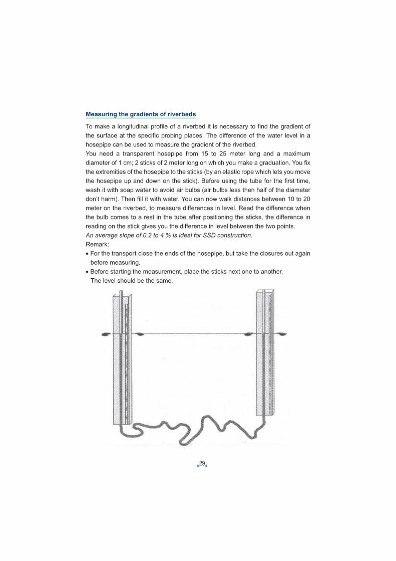
Measuring the gradients of riverbeds
To make a longitudinal profile of a riverbed it is necessary to find the gradient of the surface at the specific probing places. The difference of the water level in a hosepipe can be used to measure the gradient of the riverbed. You need a transparent hosepipe from 15 to 25 meter long and a maximum diameter of 1 cm; 2 sticks of 2 meter long on which you make a graduation. You fi x the extremities of the hosepipe to the sticks (by an elastic rope which lets you move the hosepipe up and down on the stick). Before using the tube for the fi rst time, wash it with soap water to avoid air bulbs (air bulbs less then half of the diameter don’t harm). Then fi ll it with water. You can now walk distances between 10 to 20 meter on the riverbed, to measure differences in level. Read the difference when the bulb comes to a rest in the tube after positioning the sticks, the difference in reading on the stick gives you the difference in level between the two points.An average slope of 0,2 to 4 % is ideal for SSD construction. Remark:• For the transport close the ends of the hosepipe, but take the closures out again
before measuring.• Before starting the measurement, place the sticks next one to another. The level should be the same.
�30�
Water with double or triple conductivity is only used when no other water is available.The concentration limit for livestock is around 5,000 mg/l TDS (7,800 µS/cm) but there are indications by osmotic effect that, maximum concentrations of up to 17,000 mg/l (23,400 µS/cm) might be tolerated.Microbiological quality is generally measured by the number of thermo- tolerant Escherichia coli bacteria present in the water (the WHO-standard is that 0 E.coli/100ml should be present in the water).Evaluation of the water quality for livestock and/or human use should be done according WHO-standards (or eventually national available standards).Semi-structured interviews can give historical guidance on water related epidemics to both human and livestock. Data on potential risks of (natural) toxic chemicals in the aquifer should be checked (fluoride, arsenic,…). Also human activities giving potential contamination should be checked (agriculture using pesticides, mining activities).
Other more sophisticated methods for technical assessment
Hydro geological /Seismic soundingsThis refers to the use of an electronic instrument called a Terrameter. It is mostly used in the drilling of boreholes. The following information can be obtained by the equipment after analysis of its data:
• type of soil and rock formations underground.• presence of aquifers, depth of water tables and dykes / basements / beddings.• state of weathering of formations.• identification of discontinuities, joints, faults and shear planes.
The main point to note here is the lack of affordability of such equipment by the local communities/local technicians.
Water samplingWater is sampled to determine its chemical and microbiological contamination levels and palatability (by a specialised laboratory). Available water has to meet the required standards acceptable for both human or livestock consumption. Major parameters usually analyzed are TDS (total dissolved solids), pH, and toxicchemical elements. Salinity is expressed as TDS in mg/l , but is mostly measured in terms of electrical conductance (EC = Electrical Conductivity in µS/cm, with 1,000 µS/cm equivalent to 640 mg/l TDS). Groundwater with EC values < 1,000 µS/cm is considered as fresh, between 1,000 and 3,000 µS/cm the quality is acceptable, and EC values > 3,000 µS/cm is salty and is not acceptable for drinking purposes.
�31�
4.3.4. CONSTRUCTION
The community is expected at this time to have completed clearing of the access road to the identified SSD site, the construction of a storage structure and all the required amount of clay soil is heaped on site.
ExcavationExcavation is usually done by strong and healthy men up to the rock bar / bedrock / basement rock / impervious layer. This depth usually varies site to site and ranges between 0.5m to 3.00m below riverbed level.
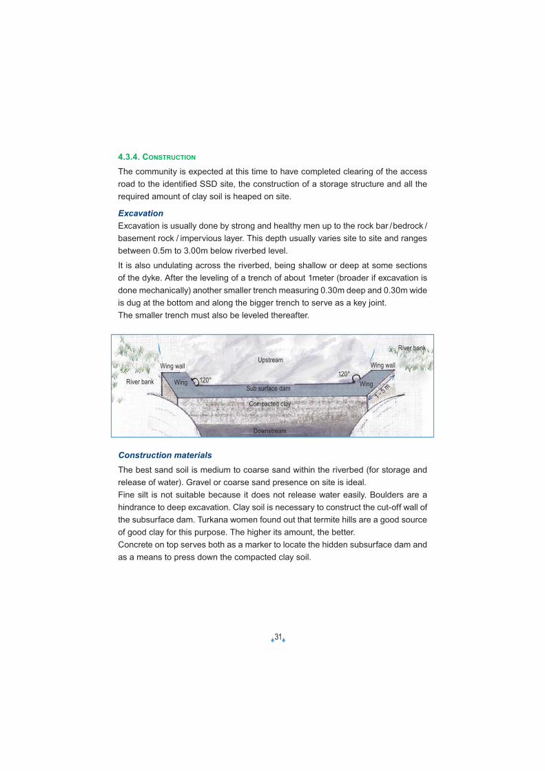
It is also undulating across the riverbed, being shallow or deep at some sections of the dyke. After the leveling of a trench of about 1meter (broader if excavation is done mechanically) another smaller trench measuring 0.30m deep and 0.30m wide is dug at the bottom and along the bigger trench to serve as a key joint. The smaller trench must also be leveled thereafter.
Construction materialsThe best sand soil is medium to coarse sand within the riverbed (for storage and release of water). Gravel or coarse sand presence on site is ideal.Fine silt is not suitable because it does not release water easily. Boulders are a hindrance to deep excavation. Clay soil is necessary to construct the cut-off wall of the subsurface dam. Turkana women found out that termite hills are a good source of good clay for this purpose. The higher its amount, the better.Concrete on top serves both as a marker to locate the hidden subsurface dam and as a means to press down the compacted clay soil.
River bank
Upstream
Sub surface dam
Compacted clay
Downstream
Wing wallWing wall
Wing Wing120°120°
1 - 5 m
� �River bank
�32�
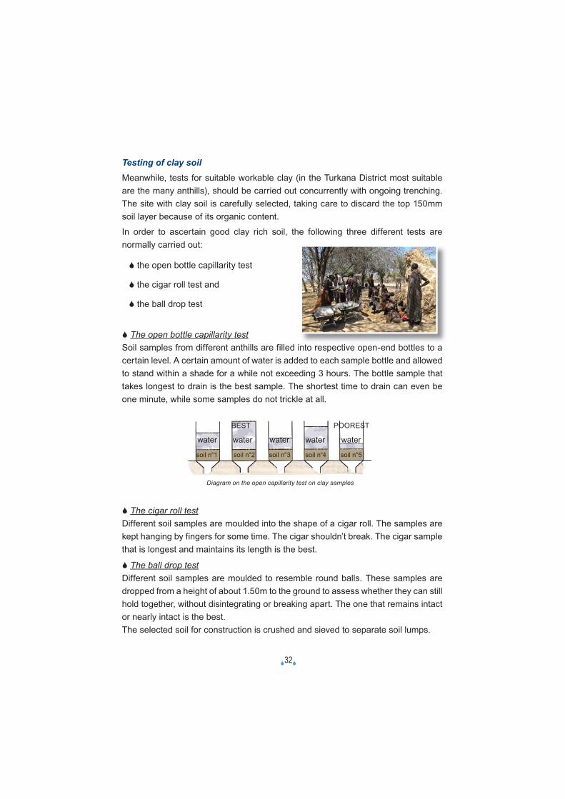
Testing of clay soilMeanwhile, tests for suitable workable clay (in the Turkana District most suitable are the many anthills), should be carried out concurrently with ongoing trenching. The site with clay soil is carefully selected, taking care to discard the top 150mm soil layer because of its organic content.
In order to ascertain good clay rich soil, the following three different tests are normally carried out:
� the open bottle capillarity test
� the cigar roll test and
� the ball drop test
� The open bottle capillarity testSoil samples from different anthills are filled into respective open-end bottles to a certain level. A certain amount of water is added to each sample bottle and allowed to stand within a shade for a while not exceeding 3 hours. The bottle sample that takes longest to drain is the best sample. The shortest time to drain can even be one minute, while some samples do not trickle at all.
BEST POOREST
water water water water water
soil n°1 soil n°2 soil n°3 soil n°4 soil n°5
� The cigar roll testDifferent soil samples are moulded into the shape of a cigar roll. The samples are kept hanging by fingers for some time. The cigar shouldn’t break. The cigar sample that is longest and maintains its length is the best.
� The ball drop testDifferent soil samples are moulded to resemble round balls. These samples are dropped from a height of about 1.50m to the ground to assess whether they can still hold together, without disintegrating or breaking apart. The one that remains intact or nearly intact is the best.The selected soil for construction is crushed and sieved to separate soil lumps.
Diagram on the open capillarity test on clay samples
�33�
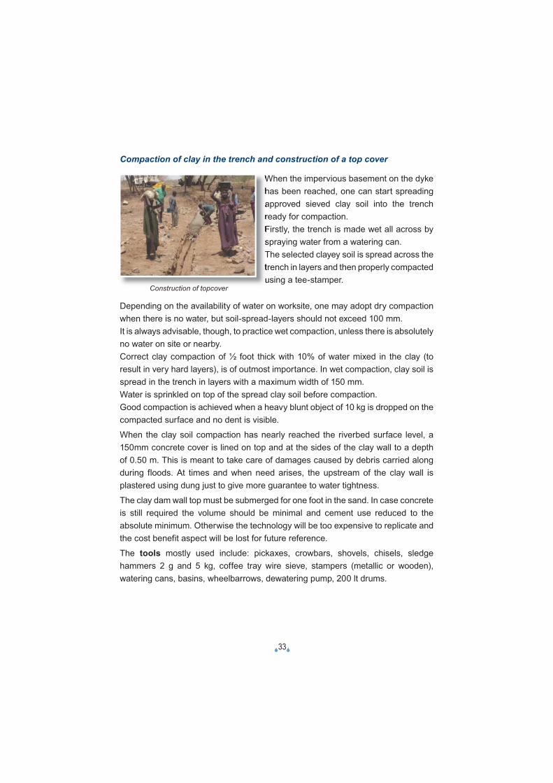
Compaction of clay in the trench and construction of a top cover
When the impervious basement on the dyke has been reached, one can start spreading approved sieved clay soil into the trench ready for compaction.Firstly, the trench is made wet all across by spraying water from a watering can.The selected clayey soil is spread across the trench in layers and then properly compacted using a tee-stamper.
Depending on the availability of water on worksite, one may adopt dry compaction when there is no water, but soil-spread-layers should not exceed 100 mm.It is always advisable, though, to practice wet compaction, unless there is absolutely no water on site or nearby.Correct clay compaction of ½ foot thick with 10% of water mixed in the clay (to result in very hard layers), is of outmost importance. In wet compaction, clay soil is spread in the trench in layers with a maximum width of 150 mm.Water is sprinkled on top of the spread clay soil before compaction. Good compaction is achieved when a heavy blunt object of 10 kg is dropped on the compacted surface and no dent is visible.
When the clay soil compaction has nearly reached the riverbed surface level, a 150mm concrete cover is lined on top and at the sides of the clay wall to a depth of 0.50 m. This is meant to take care of damages caused by debris carried along during floods. At times and when need arises, the upstream of the clay wall is plastered using dung just to give more guarantee to water tightness.
The clay dam wall top must be submerged for one foot in the sand. In case concrete is still required the volume should be minimal and cement use reduced to the absolute minimum. Otherwise the technology will be too expensive to replicate and the cost benefit aspect will be lost for future reference.
The tools mostly used include: pickaxes, crowbars, shovels, chisels, sledge hammers 2 g and 5 kg, coffee tray wire sieve, stampers (metallic or wooden), watering cans, basins, wheelbarrows, dewatering pump, 200 lt drums.
Construction of topcover
�34�
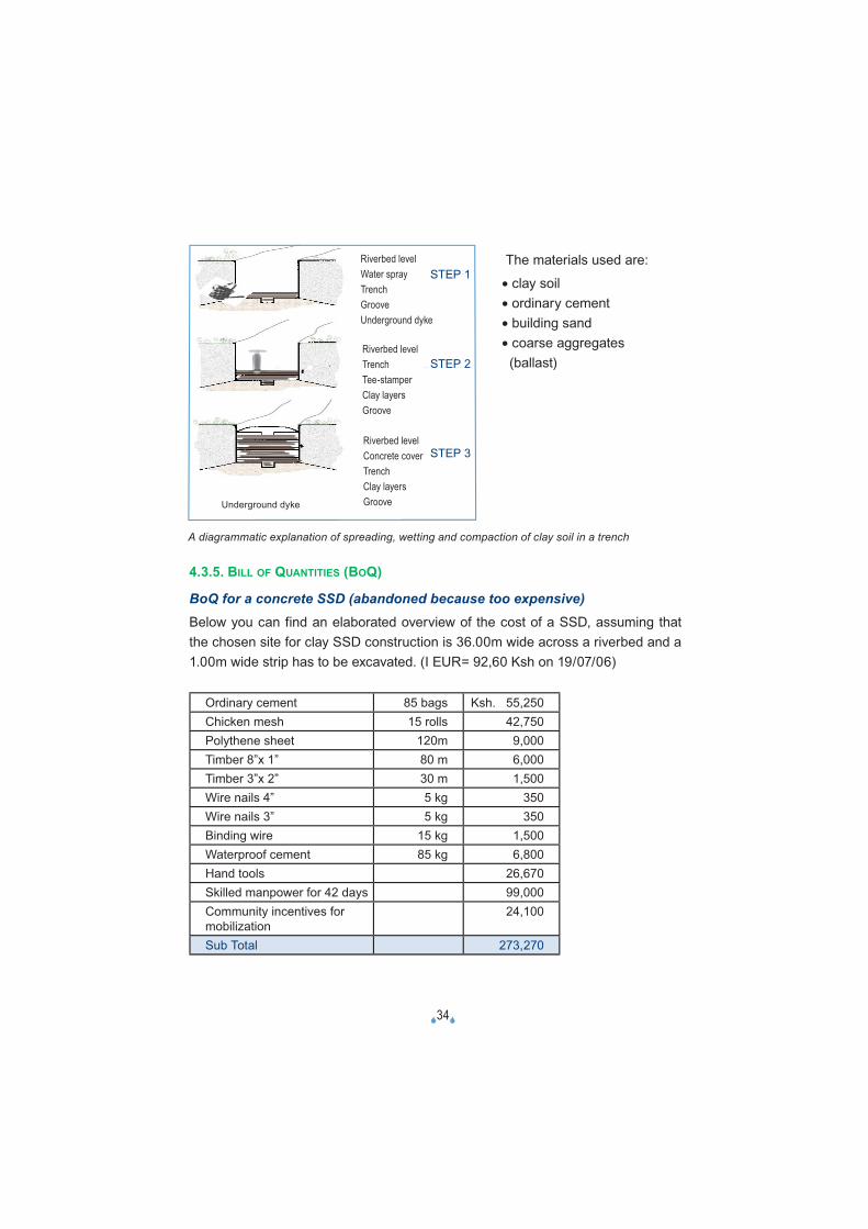
A diagrammatic explanation of spreading, wetting and compaction of clay soil in a trench
The materials used are:
• clay soil • ordinary cement • building sand • coarse aggregates
(ballast)
4.3.5. BILL OF QUANTITIES (BOQ)
BoQ for a concrete SSD (abandoned because too expensive)Below you can find an elaborated overview of the cost of a SSD, assuming that the chosen site for clay SSD construction is 36.00m wide across a riverbed and a 1.00m wide strip has to be excavated. (I EUR= 92,60 Ksh on 19/07/06)
Ordinary cement 85 bags Ksh. 55,250 Chicken mesh 15 rolls 42,750Polythene sheet 120m 9,000Timber 8”x 1” 80 m 6,000Timber 3”x 2” 30 m 1,500Wire nails 4” 5 kg 350Wire nails 3” 5 kg 350Binding wire 15 kg 1,500Waterproof cement 85 kg 6,800Hand tools 26,670Skilled manpower for 42 days 99,000Community incentives for mobilization
24,100
Sub Total 273,270
Underground dyke
STEP 2
Riverbed levelWater sprayTrenchGrooveUnderground dyke
Riverbed levelTrenchTee-stamperClay layersGroove
Riverbed levelConcrete coverTrenchClay layersGroove
STEP 1
STEP 2
STEP 3
�35�
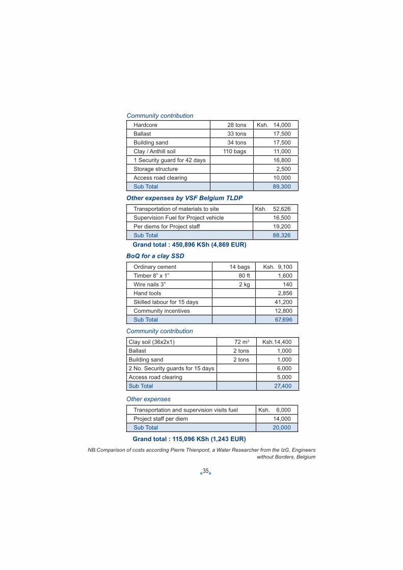
Hardcore 28 tons Ksh. 14,000Ballast 33 tons 17,500Building sand 34 tons 17,500Clay / Anthill soil 110 bags 11,0001 Security guard for 42 days 16,800Storage structure 2,500Access road clearing 10,000Sub Total 89,300
Other expenses by VSF Belgium TLDPTransportation of materials to site Ksh. 52,626Supervision Fuel for Project vehicle 16,500Per diems for Project staff 19,200Sub Total 88,326Grand total : 450,896 KSh (4,869 EUR)
BoQ for a clay SSDOrdinary cement 14 bags Ksh. 9,100Timber 8” x 1” 80 ft 1,600Wire nails 3” 2 kg 140Hand tools 2,856Skilled labour for 15 days 41,200Community incentives 12,800Sub Total 67,696
Community contribution
Clay soil (36x2x1) 72 m3 Ksh.14,400Ballast 2 tons 1,000Building sand 2 tons 1,0002 No. Security guards for 15 days 6,000Access road clearing 5,000Sub Total 27,400
Other expenses
Transportation and supervision visits fuel Ksh. 6,000Project staff per diem 14,000Sub Total 20,000
Grand total : 115,096 KSh (1,243 EUR)
Community contribution
NB:Comparison of costs according Pierre Thienpont, a Water Researcher from the IzG, Engineers without Borders, Belgium
�36�
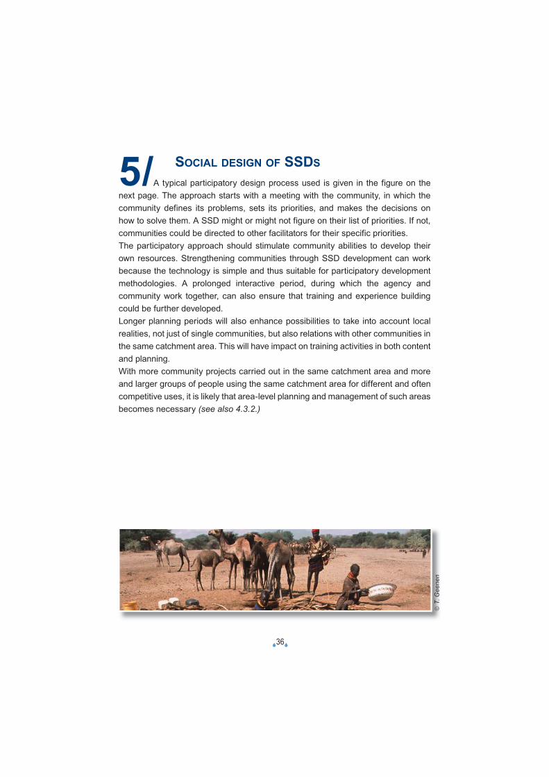
5/ SOCIAL DESIGN OF SSDS
A typical participatory design process used is given in the figure on the next page. The approach starts with a meeting with the community, in which the community defines its problems, sets its priorities, and makes the decisions on how to solve them. A SSD might or might not figure on their list of priorities. If not, communities could be directed to other facilitators for their specific priorities.The participatory approach should stimulate community abilities to develop their own resources. Strengthening communities through SSD development can work because the technology is simple and thus suitable for participatory development methodologies. A prolonged interactive period, during which the agency and community work together, can also ensure that training and experience building could be further developed.Longer planning periods will also enhance possibilities to take into account local realities, not just of single communities, but also relations with other communities in the same catchment area. This will have impact on training activities in both content and planning.With more community projects carried out in the same catchment area and more and larger groups of people using the same catchment area for different and often competitive uses, it is likely that area-level planning and management of such areas becomes necessary (see also 4.3.2.)
© T
. Gee
nen
�37�
5.1. LIST OF REQUIREMENTS FOR PROPER ACTION
• Map of the project areas produced during the community dialogue, indicating the communities’ areas of living, together with wet and dry season grazing lands and the inventory of existing and potential watering points.
• Drawings (or sketches) with dimensions and info of each of the existing site conditions with size of river information and about traditional wells.
• PRA report to confirm the communities’ priorities and willingness to participate.• Maps (or sketches) and technical assessment info of the watering points in the
area for e.g. a radius of 25 km (or half of it) as a standard for maximum walking distance for livestock.
• Records of the technical assessment visits, design, bill of quantities and construction.
• Environmental condition indicators.• Records of activities of the TLDP team, before and during the implementation time.• Daily records from the site during construction.• Cost benefits analysis.• Final report for each project site.• The final reports will allow the project to evaluate the cost benefit analysis and
incorporate the experience for future action planning.
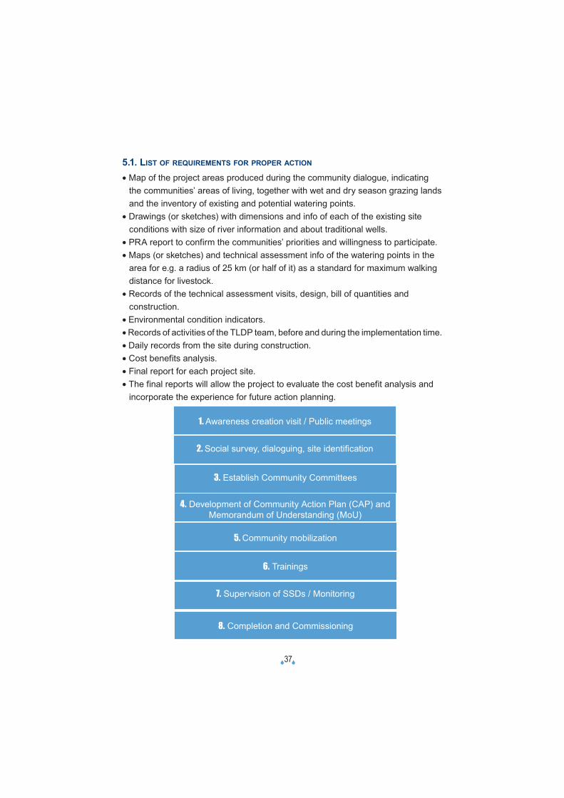
1. Awareness creation visit / Public meetings
2. Social survey, dialoguing, site identifi cation
3. Establish Community Committees
4. Development of Community Action Plan (CAP) and Memorandum of Understanding (MoU)
5. Community mobilization
6. Trainings
7. Supervision of SSDs / Monitoring
8. Completion and Commissioning
�38�
5.2. DIFFERENT STEPS IN THE PROCESS
Typical participatory design / construction process1. Awareness creation visit / Public meetingsThis is usually a visit paid to an area by Project Staff a day preceding a Community Dialogue. It is meant to create awareness. The whole community that is going to benefit from the intended/planned intervention, including chiefs, elders (male and female), opinion leaders, politicians, group leaders, development workers, youth and children, are contacted. The outcome of the visit is the agreement on the need to hold a community dialogue. The participants, venue and time are all agreed upon by consensus.
2. Social survey, dialoguing, site identifi cation, technical and social assessment
Project Staff and Community members (including influential persons e.g. administrators, politicians, elders (both men and women), youth leaders and any other development agencies within the area) hold a meeting during which concerns of the area are discussed. Through a participatory approach and the use of PRA tools, inherent problems are identified and ranked.
Mostly, they involve insecurity, inadequate animal health services, insufficientwater and inadequate markets for livestock and products. Plans on how to solve the problems are discussed plenary. Ownership, number of beneficiaries and their participation and involvement, timing of construction are discussed (see 4.2.2.).In the case of water problems, community members are educated on the various types of water extraction technologies and their advantages and disadvantages are compared. Here, the SSD technology mostly happens to outdo the others on its advantages. The community members are then informed of the suitable site selection criteria for a subsurface dam construction.Finally, the participants are asked to name such sites in their respective areas. These sites are documented for the next course of action, and that is a technical assessment. Technical assessment (see checklists 4.3.1.) of sites recommended by participants as suitable for SSD construction is undertaken in collaboration with the Department of Water Resources. The assessment ranks the visited sites in order of their suitability.
�39�
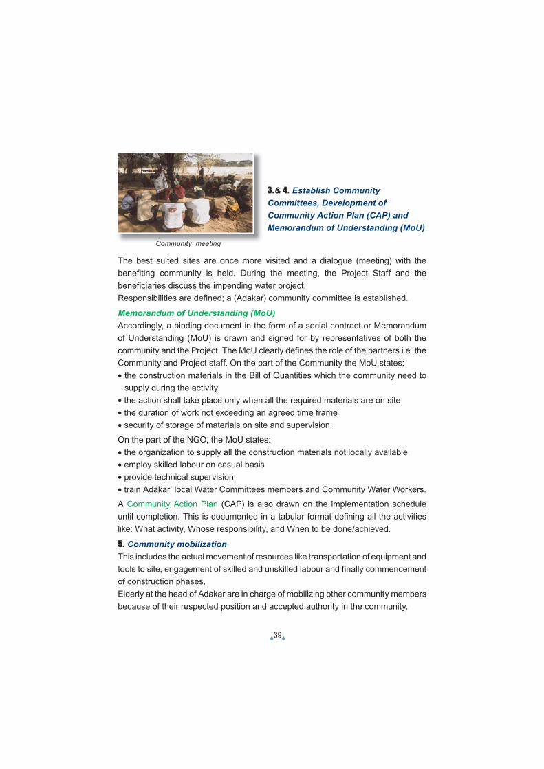
3.& 4. Establish Community Committees, Development of Community Action Plan (CAP) and Memorandum of Understanding (MoU)
The best suited sites are once more visited and a dialogue (meeting) with the benefiting community is held. During the meeting, the Project Staff and the beneficiaries discuss the impending water project.Responsibilities are defined; a (Adakar) community committee is established.
Memorandum of Understanding (MoU)Accordingly, a binding document in the form of a social contract or Memorandum of Understanding (MoU) is drawn and signed for by representatives of both the community and the Project. The MoU clearly defines the role of the partners i.e. the Community and Project staff. On the part of the Community the MoU states:• the construction materials in the Bill of Quantities which the community need to
supply during the activity• the action shall take place only when all the required materials are on site• the duration of work not exceeding an agreed time frame• security of storage of materials on site and supervision.
On the part of the NGO, the MoU states:• the organization to supply all the construction materials not locally available• employ skilled labour on casual basis• provide technical supervision• train Adakar’ local Water Committees members and Community Water Workers.
A Community Action Plan (CAP) is also drawn on the implementation schedule until completion. This is documented in a tabular format defining all the activities like: What activity, Whose responsibility, and When to be done/achieved.
5. Community mobilizationThis includes the actual movement of resources like transportation of equipment and tools to site, engagement of skilled and unskilled labour and finally commencement of construction phases.Elderly at the head of Adakar are in charge of mobilizing other community members because of their respected position and accepted authority in the community.
Community meeting

�40�
• A member of Adakar Water Committee will be representing the community in other forums like workshops and meetings. He/she receives some facilitation allowance for the task of mobilization and during workshops/meetings.• Assistant Chief. As a GoK representative at the grassroots’ level, he/she is in charge of coordinating all development activities. He/she advises elderly on community mobilization and participation.He/she receives an allowance during workshops and meeting.• Women from the Adakar- Construct temporary storage structure for materials at work sites- Dig quality clay from anthills and transport it to work sites- Sieve quality clay ready for compaction- Deliver clay to compaction team- Fetch water for use at working site and for clay compaction.Other women remain behind and carry out the usual normal homes chores and duties. They receive food during working hours.• Men from the Adakar- Clear the access road to work site- Excavate dam trenches- Collect and deliver building sand and ballast to site- Spread, moist and compact clay in the trench- Assist CWW (Community Water Workers) in concrete mixing and casting of the wall cover
- Provide security at both the site and the Adakar area.They receive food during working hours. Cash allowances for those assisting the CWWs.• Community Water Workers (CWWs) / Dam Site Foremen- In charge of all work activities on site- Ensure work progress according to plan- Carrying out clay suitability tests- Provide training on the job to other community members on site.Cash incentive after successful completion of activity.• GoK Water Department- Back up technical support during Community Dialogues- Technical assessment for SSD site suitability- Impact assessment, monitoring and evaluation of the activities• VSF (Belgium) - TLP organisation- Create awareness on the subsurface water extraction technology- Liase with community on SSD site selection.
�41�
6. TrainingsCommunity Water workersA Curriculum agreed upon between the District Water Officer and TLDP Water Development Officer, is used for Community Water Workers training.The objective of the training curriculum is to impart the community nominees with:
• basic technical skills that would be useful for suitable SSD site identification.• knowledge to read and translate simple construction designs.• SSD construction and maintenance skills.
The training content is spread through a 5 day training duration venued within the project area nearest to some completed SSDs or under construction.
Training manuel content:• technical drawings• means of water extraction• hydrogeology – river courses and underground formations• SSD technology• well shafts and hydrodynamic wellhead designs• construction and materials• hand pumps installations• community mobilization, organization and management.
Two trainees are nominated from each completed SSD area for such training.Tool boxes containing masonry kits are issued to the best graduates who are now in the verge of becoming Dam Constructors. Some further advanced training is necessary before they get commissioned to stand on their own.
Adakarin water committeesThese are village level water committees who are trained to manage their respective water facilities. The curriculum is jointly designed by the District Social Development Officer, the District Water Officer and the TLDP Water Development Officer.Participants are derived from all Adakar Water Committees at the completion of SSD's. The training objective is to enhance community awareness on their roles in proper use, operation, maintenance and sustenance of the available water resources under their jurisdiction through Management Committees of their respective water facilities.
�42�
The 3-day duration training covers the following content:
• formulation of an Adakar Water Committee.• roles and responsibilities of Management Committees.• SSD technology – value, criteria and construction.• natural Resources Management and Maintenance – water points and environment.• constitution of by-laws.• conflict resolutions.• elementary bookkeeping.
The Adakarin water committees that were trained in Turkana are now active in their respective areas of operation.- Conduct technical assessment of SSD sit suitability.- Facilitate CAPs/MoUs development.- Supervise construction works including approval of clay for SSD construction work.- Provide ordinary cement fo SSD tot cover concrete casting.
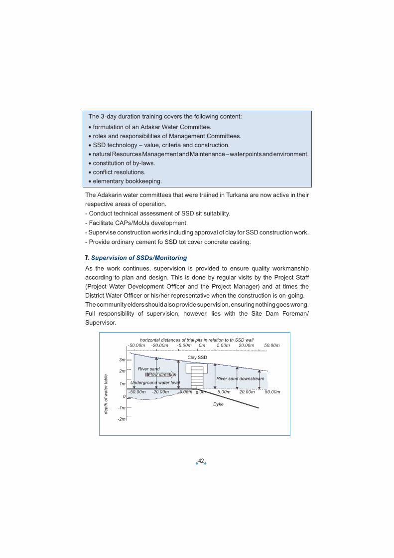
7. Supervision of SSDs/MonitoringAs the work continues, supervision is provided to ensure quality workmanship according to plan and design. This is done by regular visits by the Project Staff (Project Water Development Officer and the Project Manager) and at times the District Water Officer or his/her representative when the construction is on-going.The community elders should also provide supervision, ensuring nothing goes wrong.Full responsibility of supervision, however, lies with the Site Dam Foreman/Supervisor.
dept
h of
wat
er ta
ble
horizontal distances of trial pits in relation to th SSD wall-50.00m -20.00m -5.00m 0m 5.00m 20.00m 50.00m
3m
2m
1m
0
-1m
-2m
River sand Flow direction
Underground water levelRiver sand downstream
Dyke
-50.00m -20.00m -5.00m 0m 5.00m 20.00m 50.00m
Clay SSD
�43�
MonitoringData from each completed SSD are collected on a regular (monthly) basis for at least the first 6 months.
This information is meant to give guidance on water use by livestock against time or saison. It also gives monthly comparison and one is able to monitor the water table of the SSDs.
A good watertight SSD maintains water at higher level at the upstream at the downstream. If the lwater level at the upstream is the same downstream, then one is bound to suspect wall leakage or lateral escape of water.
8. Completion and commissioningAfter completion of the construction works, a final inspection is done jointly withthe community elders, local administrators and community members. This is meant to certify that the works were successful completed. Any suspected defects or poorly done sections are noted. Those that require immediate corrections are acted upon. The rains are waited for to test water tightness.There is usually a handing over ceremony whereby the responsibilities of managing the water facility are handed over to an elected interim Adakar Water Committee. Two trainees are selected and recommended by the community members for training on Basic Construction Skills. The organization takes note of all these and reminds the community of their role of monitoring the water use and behaviour of the water table.
�44�
6/ IMPACT ASSESSMENT
6.1. GENDER
Effect on women• Walking distances to watering points reduced.• As a result of a high water table, an increased number of Livestock is watered
effectively e.g. a single woman serves 120 shoats per hour.• Time is saved for other domestic chores and attending to the young shoats and
sicklings at home.
Effect on men• Less time and effort spent in scouting for grazing areas.• Social development and family cohesion as they spend more time with their
wives.• More time directed to maintaining security.
Effects on community • Fully accessing pastures in the dry season grazing areas.• Improved animal health, enhanced animal production.• Assured food security, healthy people and finally decreased vulnerabilities.• Watering period is extended; say from 1-month to 3-months depending on the
rainfall coverage, intensity, water catchments and storage capacity.
6.2. ENVIRONMENT
It is a known fact that many water development interventions have done more harm than good because of the associated overgrazing and soil degradation. Perennial water is risk-enhancing compared to seasonal water supplies. This has specifically been the case with bore-holes which yield large quantities of ‘easy’ water.Also it is believed that development of water sources in already overgrazed areas will only increase the effects of overgrazing and soil degradation, leading to desertification. Undoubtedly this holds true in very many cases, where the land is already used up to its maximum capacity. However, evidence suggests convincingly that Turkana is currently being under stocked.Areas with evidence of environmental degradation are surrounding settlements, through burning of charcoal and firewood collection.
�45�
Large areas of Turkana District are underexploited for different reasons, lack of water sources and insecurity being the major ones. Ecosystems ltd. present data that show that in 37% of the study area (South Turkana) livestock production is moderately to seriously constrained by lack of water.
According to the elders the areas directly aligning the rivers are also being overused in the dry season. All other water sources dry up and all people concentrate along the rivers. The development of additional water sources would make people scatter more, thus decreasing the pressure on resources.
The areas proposed by VSF-Belgium for development of water sources are all within the areas with high potential for livestock development and consequently away from the rivers.
Nevertheless, there was no visible environmental degradation around the SSD water points. The proof of positive impact as perceived by communities can be found in their reporting that each of the 4 successful dams had increased water supply from the wells; more livestock was served for longer time after rains (doubling from 4 to 8 weeks).
6.3. TECHNICAL ASSESSMENT
For the sake of replication of the technology by concerned communities, minimal cement may be used when absolutely necessary e.g. foundation, upstream plaster or dam wall cover. This is to reduce costs and make reasonable the cost benefit aspect.
Borehole water can only serve 60 LS(1)/hr (Livestock Units per Hour) but SSDs can supply hundreds at the same time. A hand pump installed in a borehole is limited to 60 LS units per hour, while traditional wells in sand riverbeds can each produce 5 to 10 times more (serving 300 to 600 LS units per hour). Each SSD has easily 10 traditional wells. Hence SSDs deliver 100 times more water during the time after rains (when most required).
The people confirm that hand pumping of ground water for LS is too time-consuming and cumbersome.
1) The standard of a Livestock Unit (LS Unit) equals 3 local cows or 15 local shoats. One LS Unit takes daily 25lts water.
�46�
7/ LESSONS LEARNT
1. Water accessibility for the livestock and human beings has increased. On average a SSD stocks water that allows 200,000 Livestock Units (or 3.000 LS Units per day) to drink during 60 days (impact report Van Rompaey). Given the fact that the water is stored in the sand the evaporation is limited and also the quality of the water remains good. Where in the past herders had to herd the livestock especially the goats and cattle every other day to a water point at 15 km distance, several grazing areas became more permanently accessible. Given the facts that the SSD gives only water for a certain period and the awareness of the livestock keepers and their capacities to deal with the environment the cases of overgrazing or environmental problems are limited.
2. The project cost per LS unit is very small. One LS unit is e.g. 3 cows. The external cost for the concrete dams was already low (for exemple Kshs 135 per LS unit or Kshs 45 per local cow) with an estimated value of one cow of Kshs 10 000 each. Hence the investment cost is 0.45% only of one cow. The external cost is now minimised to almost 1/3 of the initial cost for the clay SSDs with concrete top cover.
3. Women especially are satisfied with the SSD because water is more easily accessible to them and the animals that they water. Before the TLDP intervention they had to dig sometimes “shallow” wells that were two persons deep to get some water with the risk of collapsing. They gain a lot of time that they can invest in other activities such as taking better care of the animals during milking, investing more in the household, spending more time in collecting wild fruits and berries.Women generally were very proud of their participation. It gave them satisfaction “to be part of men in the work”. Their contribution was valued as much as the men’s which gave them a lot of self-esteem, self-confidence and proud ness.
�47�
4. The participation of the livestock keepers especially in the selection of the sites and the construction is a very important factor in the success of the SSD. People identify themselves with the SSD. The technology is very simple and the population assisted by the water technicians can do the maintenance.
5. Local knowledge was crucial to develop the SSD technology. Women for example were able to determine clay sources around anthills which is best quality for constructing and compacting purposes of this SSDs.
6. The importance of local management is recognised nowadays as a prerequisite for longterm use of the facilities. Local management does not start after construction of the dam, but during the design and construction.
7. The SSD are a very appropriate technology for the mountainous areas in the district. The river may not be too wide -15 to 30 meters- and you need a rocky and stable underground and riverbanks. A rough estimates shows that the technology is applicable in 25 % of the area. In the other areas water pans and sand or clay dams can be an alternative, although not as efficient because of the high evaporation.From the first experiences with simple clay SSDs (not resistant enough); to concrete SSDs (too expensive) the TLDP-project developed a replicable technology based on clay with only a small quantity of cement for the top cover.
8. The hydro-geological conditions at the sites have to be known. Proper investigations have to be carried out, but as the dams and the volumes of water usually are relatively small, costs of research should be kept to a minimum.Thus, investigations have to be simple too.
9. SSDs should not be above the existing natural sand level, but 1 foot submerged. Unskilled people cannot predict the water forces if the dam wall is sticking out and exposed to the floodwater forces. SSDs can be done without external assistance if this prior condition is implemented.
�48�
10. The objective was to arrive to a cost-effective design manageable by the beneficiaries after phasing out of the TLDP project. Although the original idea was the use of clay for subsurface dam construction, flaws and failures in the first two constructions at Lokichogio and Kocheede, compelled the organization to embark on improved, guaranteed strong concrete SSDs, reinforced with chicken mesh, polythene lining and water proofing. This option, although technically sound, is too expensive.
Thus only the former was considered sustainable because of the low cost and ease of replication by pastoralists and to have their own involvement maximized.
The cost of one SSD has now drastically been reduced to about a quarter of the cost (for a strong concrete SSD). The SSD is built of clay and with a concrete top cover of the dam). It is now manageable and the communities needing a water intervention may now reproduce the same with minimal financial strains.
11. Taking into account all the above considerations, and examining technical possibilities in the area, subsurface dams appear as the most appropriate technique:
• They can be maintained by the community itself.
• The supply of water is semi-reliable, thus minimising the risk of attracting settlement.
• The community can be involved in all stages: identification of the area, construction of the dam and maintenance. This ensures the integration of indigenous knowledge, thus minimising the risk of increased conflict rate or environmental degradation.
• The involvement of the community also creates a sense of ownership and responsibility, which greatly increases sustainability.
• This technique increases the capacity of the traditional well, which means that no alternative management system has to be put in place; the traditional system can easily incorporate the new technique.
• The technique is easily replicable, thus providing a suitable tool for the community in terms of capacity building. The know-how can be handed over to the community which enhances its self-reliance: the building of a subsurface dam is an initiative that can easily be taken by the community itself, which will provide them with a way to take charge of the development of their land.
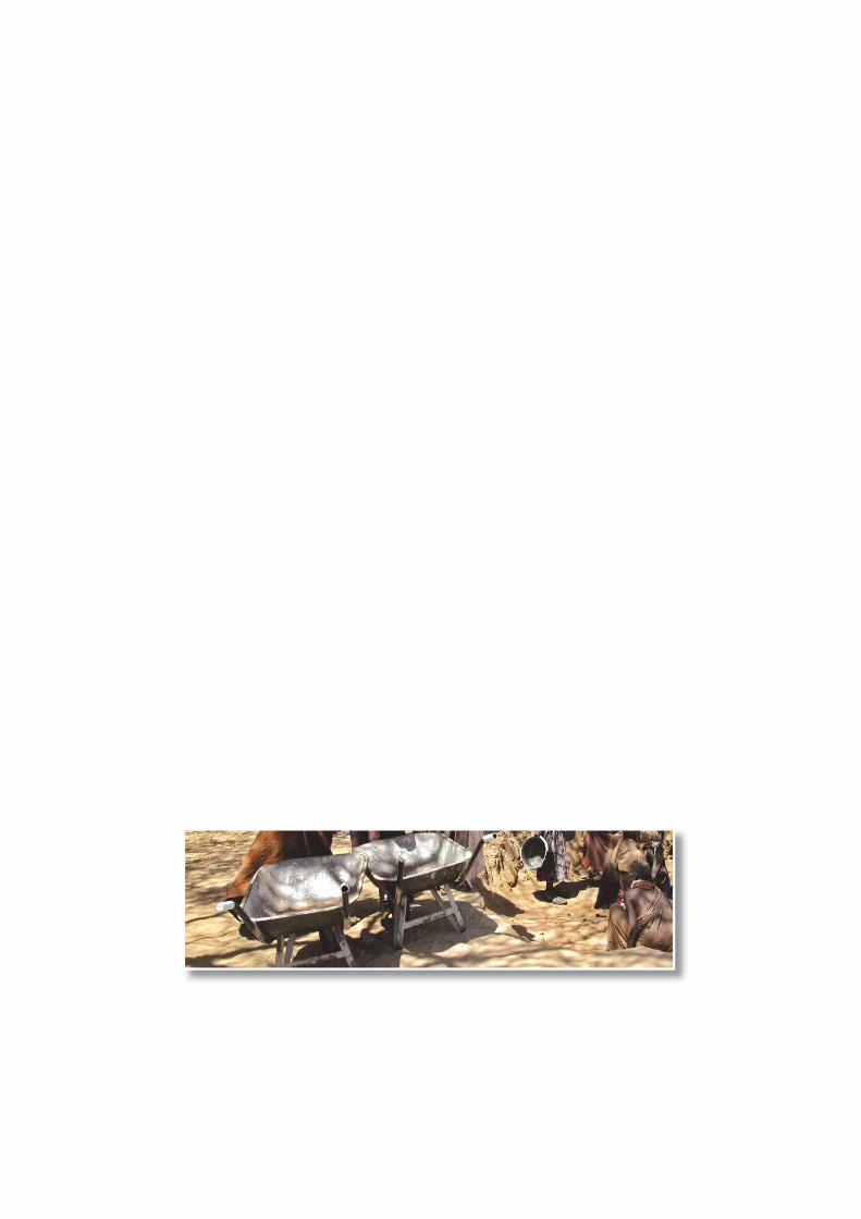
�50�
BIBLIOGRAPHY
� Building small scale Water Harvesting Dams, Mohamed Majzoub Fidiel, june 2005, 23p.
� Conflicts and influence on Turkana way of life, Leber Katia, December 2005, 6p.
� Hydraulique et sécurisation des systèmes pastoraux au Sahel, IRAM, août 2005, 28p.
� Manual on Rehydrating the Earth in Arid Lands (REAL), Delft University of Technology,PROTOS et al, 2003
� Mid-term Review Turkana Livestock Development Programme (TLDP)(IN 18608/11) for the Belgian Survival Fund – Kenya, South Research, June 2004, 95p.
� Ontwikkelingsbestuur bij de Turkana, Dirk Beke & Patrick Wymeersch, Herwerkte versie 2000, 18p.
� Pulling Apart, Facts and Figures on Inequality in Kenya, SID, 2004.
� Rain Catchment and Water Supply in Rural Africa: a Manual, Erik Niessen-Petersen, 1982, 83p.
� Report on the Technical Evaluation and Impact Assessment of Subsurface dams (SSDs),Luc Vanrompay, March 2003, 23p.
� Technical Reference for Effective Groundwater Development, Japan Green Resources Agenct,March 2004, 325p.
�51�
VÉTÉRINAIRES SANS FRONTIÈRES HELPS THE DEVELOPMENT OF LIVESTOCK IN AFRICA
The aim of Vétérinaires Sans Frontières is to improve the living conditions of vulnerable people
in developing countries who depend directly or indirectly on livestock by improving livestock
keeping. In the third world, livestock often signifi es the beginning and end of all life.
Livestock plays a crucial role in providing food and for the income of families. Veterinary
medicine, and hence the guarantee of a healthy herd, is often non-existent or inappropriate.
VSF vets support local livestock owners with training, technology and know-how about animal
production, animal health and using livestock to sustain and develop themselves.
The activities are only implemented after thorough consultation with all stakeholders involved.
PARTICIPATORY APPROACH
The aim in the longer term is to achieve self-determination and the continuation of the various
projects by local livestock owners themselves, even if they start off as emergency interventions.
Therefore a participatory approach is central to the VSF philosophy: structural solutions
can only be implemented in close cooperation with the local communities in order to hand back
their destiny to the people. We always work with a local partner or, alternatively, assist livestock
owners to organize themselves.
VSF FOCUSES ON SUPPORTING SMALL LIVESTOCK KEEPERS IN SUSTAINABLE LIVESTOCK DEVELOPMENT,
ALWAYS RESPECTING THE LAND, ANIMALS AND THE PEOPLE.
VSF-BelgiumAvenue Paul Deschanellaan 36-38
1030 Brussels℡ +32 (2) 539 09 89� + 32 (2) 539 34 [email protected]
http://www.vsf-belgium.org